


Cellular Reinforced Ceramics Parametric Vaulting System JUANJO GONZÁLEZ - CASTELLÓN M.Arch. Emergent Technologies and Design | 2009/2011 Architectural Association School of Architecture from a limited amount of components 110211 March Dissertat on indd 1 110211_March Dissertation.indd 1 2/12/2011 2:10:58 AM 2:10:58
Architectural Association School of Architecture | Graduate Programme
DISSERTATION SUBMISSION
Emergent Techonologies and Design program
COVERSHEET FOR COURSE SUBMISSIONS 2009 / 2011
PROGRAMME: Master of Architecture, Emergent Technologies and Design
COURSE: Emergent Technologies and Design
TUTORS: Michael Weinstock, George Jeronimidis
STUDENT NAME(S): JUAN JOSÉ GONZÁLEZ - CASTELLÓN
SUBMISSION TITLE: Cellular Reinforced Ceramics
SUBMISSION DATE: 14 February 2011
DECLARATION:
Signature of Student(s):
“ I certify that this piece of work is entirely my own and that any quotation or paraphrase from the published or unpublished work of others is duly acknowledged.”
Contents
Abstract | 006 1. Domain | 008 2. Methods | 030 3. Experiments | 058 4. Design Development | 092 5. Design Proposal | 104 6. Conclusion & Further Development | 110 Images & Diagrams Credits | 116 Bibliography | 129 Acknowledgements | 135
This proposal is focused in the design and fabrication of a parametric vaulting system by the assembly of a limited amount of ceramic components. In order to archive that, the project is deployed at 3 main areas of research:
1. The development of a new material system that combines the outstanding properties of ceramics with aluminum honeycomb mesh reinforcement. This combination is based in the evolution of the traditional Catalan vault technique and, particularly, the works developed by the Spanish architect Rafael Guastavino and the Uruguayan engineer Eladio Dieste.
2. The exploration of a geometrical and computational system capable to generate parametric surfaces by the combination and assembly of a limited amount of components. This system aims to achive variation and reduce complexity in the industrial fabrication process.
3. The design of a vaulting space that deploys, architecturally, the structural, environmental and spatial potential of the system.
Abstract
Cellular Reinforced Ceramics | Juanjo G. Castellon
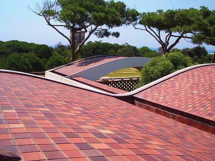
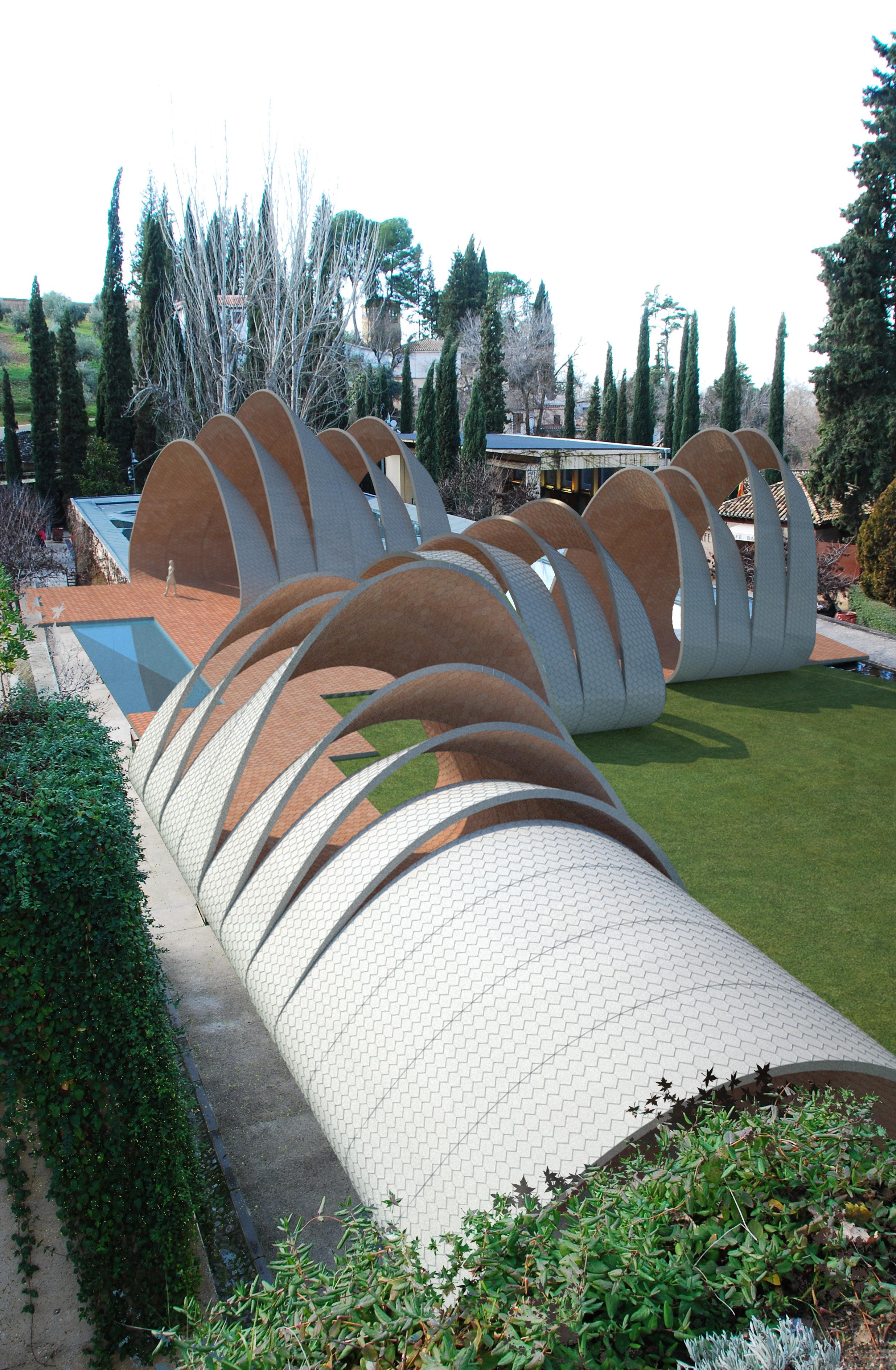 Fig. 1.00 | Proposed Vaulting System in “La Alhambra”. Granada. Spain.
1. Domain
1.1 Introduction
1.2 Ceramics
1.3 Vernacular Brick Construction
1.3.1 Catalan Vault | Smart Brick Construction
1.3.2 Cohesive Construction | Rafael Guastavino
1.3.3 Case Study | Pines Calyx Project
1.3.4 Gaussian Vault | Eladio Dieste
1.4 Contemporary Free-Form Construction
1.5 Summary
1.6 Questions
009
1.1 Introduction Toward a Parametric Free-Form Architecture
The use and application of free-form geometries has been a constant aspiration in the history of architecture. Nowadays, due to the appearance and development of powerful parametric tools and technologies, this aspiration has become reality. The amazing potential of these tools enables architects to produce and fabricate almost any imaginable form. The paradox lies on that, this capability to easily produce and generate complex forms, is directly related, in some of the cases, with a lack of understanding of the geometrical principles behind it. The designer doesn’t need to understand a form to produce it and, consequently, an enormous effort has to be made “a posteriori” in order to make these forms buildable and economically feasible.
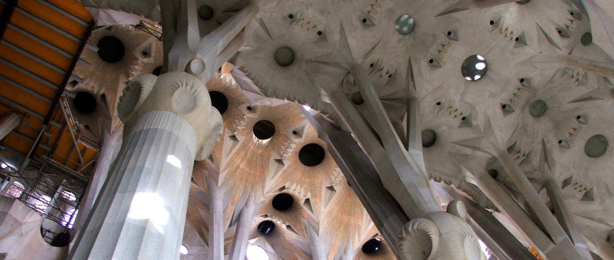
On the other hand, there are many precedents in the history of architecture demonstrating that it is possible to build complex and interesting architecture by applying simple logics and smart techniques. Buildings such as La Sagrada Familia designed by Antoni Gaudí (Fig. 1.01) or La Atlántida Church by Eladio Dieste are good examples of it. Both buildings were designed and built without computers but with clear geometrical rules and structural understanding. In addition, both masterpieces were built in collaboration with very skilled man-power and a network of experienced fabricators. Moreover, La Sagrada Familia is a unique and paradigmatic case since its construction started by the end of the 19th century and it is still a work in progress project (Fig. 1.02). Consequently, its construction process has evolved in parallel to the available tools, from crafts to di-gital.
Nowadays, there is a wide field to explore in order to find new methods of design where contemporary parametric tools are part of the design process. In this search, geometrical logics and principles can be applied to minimize or even avoid any translation between design and fabrication processes.
The aim of this research is to develop a form finding process by the use and application of simple geometrical rules and advanced material system in order to build a vaulted space. This structure will be the result of the fabrication and assembly of a limited amount of three-dimensional components.
Starting from a simple brick and analysing specific techniques from traditional Catalan architecture, some experiments will be deployed in order to achieve architecture by the implementation of traditional techniques with contemporary tools.
1. Domain | 1.1 Introduction
Cellular Reinforced Ceramics | Juanjo G. Castellon

011
Fig. 1.01 | La Sagrada Familia. 1882 -. Barcelona. Antoni Gaudí. Main Façade
Fig. 1.02 | La Sagrada Familia. 2008 -. Barcelona. Antoni Gaudí. Contemporary extension
1.2 Ceramics A tradicional and advanced material
Mediterranean tradition is based in the use and applications of handmade and humble materials such as ceramics. There is some simplicity and humbleness inherent in ceramic materials. All the raw materials to make ceramics come from the earth (clay) and they just need water and heat to obtain a high quality product. Consequently, ceramic tiles or bricks are a highly sustainable material. Furthermore, ceramics is a local material available in almost all cultures with a strong connection with the earth and man’s evolution. Its production has been strongly linked to man’s development throughout history improving his living and environmental conditions. Thus, ceramics technology is a good example of man’s progress throughout ages and witness of its technological evolution1. Even nowadays is one of the cutting edge materials in terms of research and new applications (Fig. 1.03, 1.04).
Regarding its technical properties, the process of firing ceramics confers it notable physical and mechanical properties. Ceramics is hard, it has excellent compression strength, high melting point and a good resistance to chemicals2. Moreover it is waterproof and thermally very efficient when it is fired at high temperature and its cost and manufacture is sensibly lower than other industries. All these properties make ceramics a very suitable material for architecture. In addition, it is an excellent material in terms of plasticity, allowing any kind of forms including double curved (Fig. 1.06) and an infinite range of colours and finishes can be applied by glazing techniques and pigments addition. With regards of sustainability and environmental factors, ceramics may be produced locally and contain lower embodied energy than many alternative sheathing materials3.
On the other hand, it has bad performance under tensile strength, requires firing under high temperatures in order to make it waterproof and, finally, its form depends on a mould. Consequently, Mould-making process becomes an extremely key factor in the current research. Mould-making can be expensive and time consuming, particularly, when the aim is to produce variation in opposition to the classical flat piece standard repetition. In addition, the appearance of composite technologies opens new possibilities of hybrid material systems where the few weakness of ceramics (specially its low structural performance under tensile strength) can be highly improved by its combination with another material systems such as metal meshes or fibers. This new field of contemporary research is called Advanced Ceramics and one of the examples of these new applications is Alumina which can be combined with Kevlar mesh, extremely good in tension. Consequently, the development of a material system based in the combination of metal meshes or fibers is a potential solution for advanced ceramics and its application in architecture.
1 ASCER. The Spanish ceramic tiles industry. Cevisama 2009.
2 Lefteri, Chris. Ceramics: Material for inspirational design. Rotovision.2003
3 Celento, David.Harrow, Del. CeramiSKIN Digital Possibilities for Ceramic Cladding Systems. ACADIA 08
1. Domain | 1.2 Ceramics
Cellular Reinforced Ceramics | Juanjo G. Castellon

013
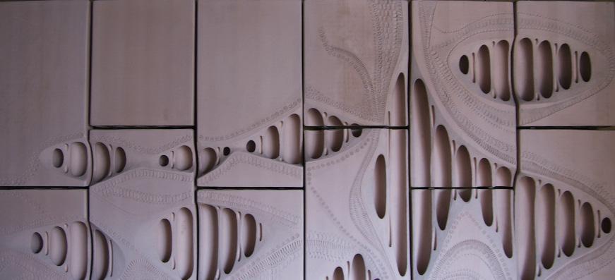
Fig. 1.03 | Ceramic Patterns. Toni Cumella
Fig. 1.04 | The Programmed Wall. 2006. Gramazio & Kohler. ETH Zurich
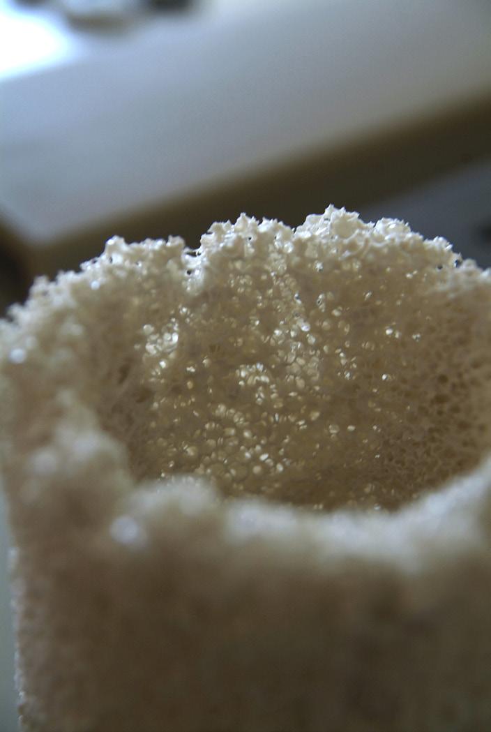
Fig. 1.05 | Ceramic + Sponge after firing
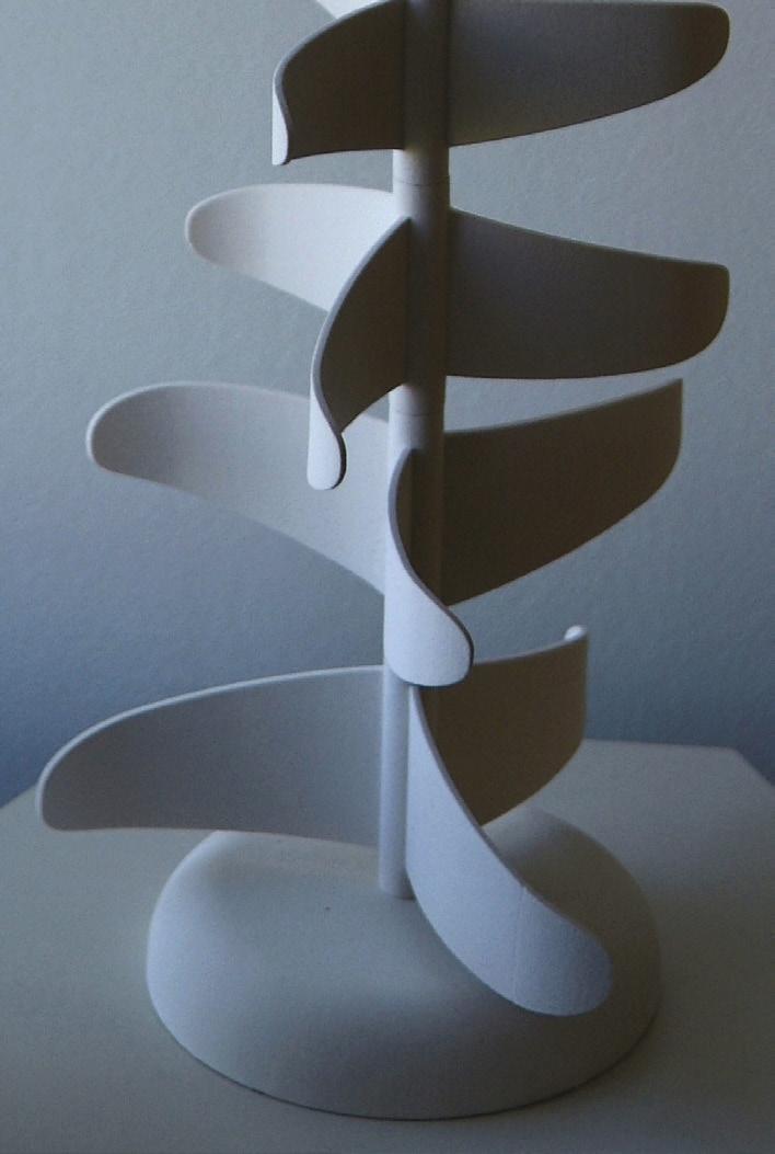
Fig. 1.06 | Double - curved Fins
1.3
Vernacular Brick Construction
1.3.1 Catalan Vault | Smart Brick Construction
1.3.2 Cohesive Construction | Rafael Guastavino
1.3.3 Case Study | Pines Calyx Project
1. Domain | 1.3 Vernacular Brick Construction
1.3.4 Gaussian Vault | Eladio Dieste
Cellular Reinforced Ceramics | Juanjo G. Castellon
015
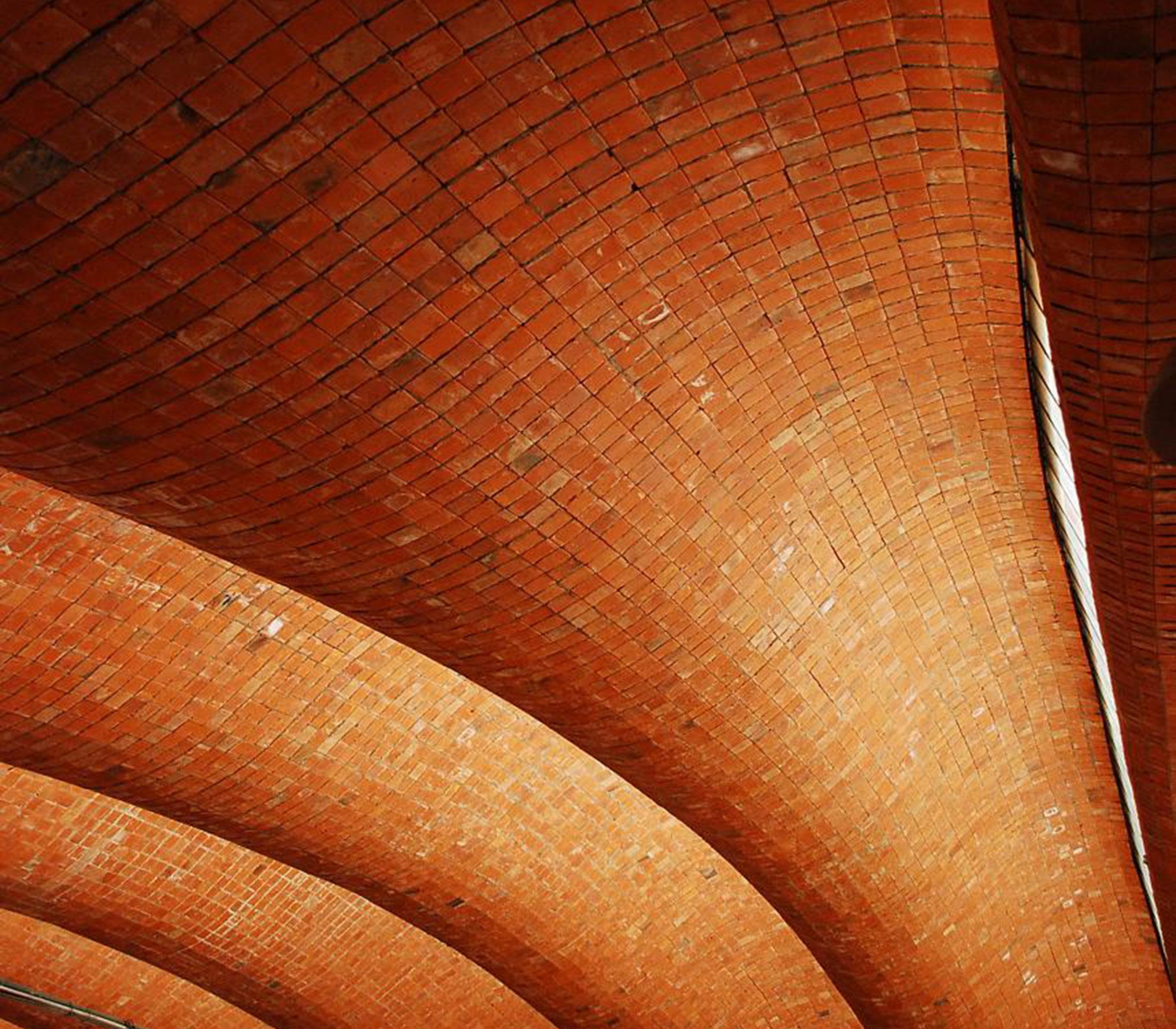
Fig. 1.07 | Port Warehouse.Montevideo. 1977-1979 , Eladio Dieste
1.3.1 Catalan Vault Smart Brick Construction
The brick is an ancient material system designed and produced in order to build by the addition and specific arrangement of a simple component. A brick is based in a fabrication process where its form and composition are controlled by an industrial process. Although the first durable constructions were built with stone, brick construction is the first industrial process component based. Its constructive logics are based in its prismatic geometry and its combination with mortar to assembly them following different arrangements.
The appearance of brick dates from around 10.000 years, in Mesopotamia, and its conception is consequence of the lack of stone and wood. A great part of masonry techniques were developed from Romans and expanded along the Mediterranean for centuries. One of these ancient masonry techniques is the Catalan vaulting system4. Although its origin is coming from different countries along the Mediterranean, Catalonia in Spain was the place where this technique achieved the highest level of quality and refinement.
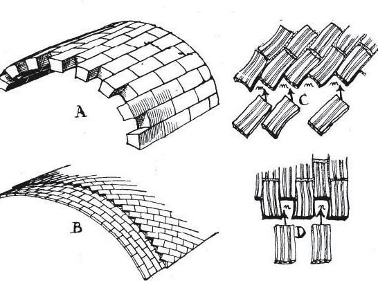
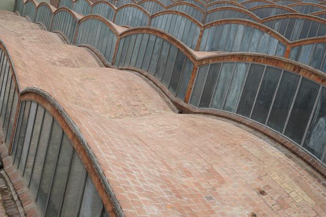
Catalan vaulting technique relies on fast setting mortar for construction and structural form for strenght5. Its success is due to the use of selected materials and highly skilled work labour. This technique is based in a specific arrangement and assembly of thin bricks (Fig. 1.10) called rasillas6. Rasilla is a simple brick thinner than the standard one (24 x 11,5 x 2,5 cm). The weight of the Catalan rasilla is less than 1.25 Kg. which allows an easy manipulation for its precise assembly. Previously this kind of planar bricks were used by the Romans as a lost formwork for concrete.
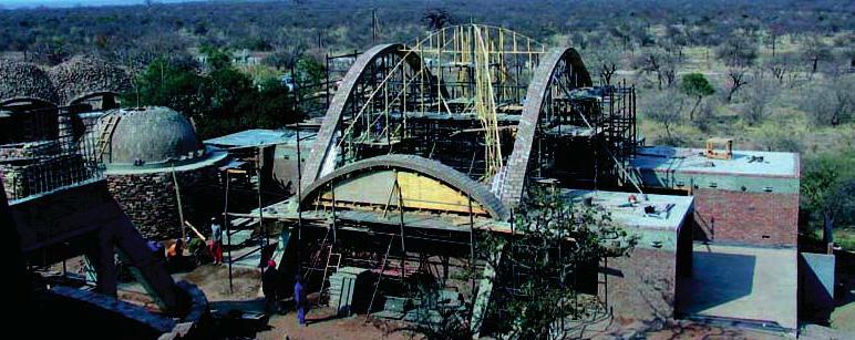
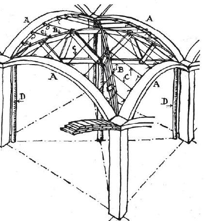
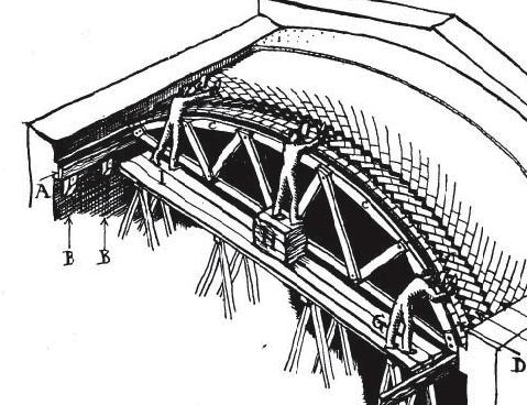
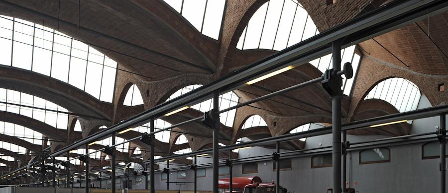
This traditional technique can be applied in the construction of different vaults typologies such as groin vaults or cylindrical vaults (Fig. 1.08, 1.09). One of the main advantages of Catalan vaults is that it can be built without formwork (just with the help of provisional scaffolding like sliding trusses) by assembling the planar bricks in several layers (Fig. 1.13). The first one is assembled using fastsetting plaster of Paris and the rest with cement mortar (slower setting but more resistant). Catalan vaults were built without structural calculations and its construction was based in the experience accumulated throughout centuries7. The total thickness of a Catalan vault for a 2 layer system is about 10 cm including mortar and finishes. Furthermore, Catalan vault is an economic construction system and it has very efficient structural performance under pure compression covering large spans without any columns. Two good architectural examples where this technique was applied with outstanding results were the Aymerich, Amat i Jover textile mill in Terrassa (Fig. 1.12, 1.14) and La Ricarda House in Barcelona (Fig. 1.11).
4 Collins, George R. “The Transfer of Thin Masonry Vaulting from Spain to America”. American Society of Architectural Journal 1968 Oct., v. 27, n. 3, p. 176-201.
5 Ramage, Michael H. Building a Catalan vault. 2004
6 “Hollow brick, thiner than the standard one, used to build vaults and other masonry works”. Diccionario de la Real Academia de la Lengua Española
7 Bassegoda, Buenaventura. “Bóvedas Tabicadas” . Curso Superior de Materiales Cerámicos. Consejo Superior de Investigaciones Científicas. 1952
1. Domain | 1.3 Vernacular Brick Construction Cellular
Reinforced Ceramics | Juanjo G. Castellon
017
Fig. 1.10 | Comparison: stone (A) and rasilla (B) system
Fig. 1.11 | La Ricarda House. 1963. Barcelona. Antoni Bonet
Fig. 1.08 | Preparation for a groin vault construction
Fig. 1.12 | Aymerich, Amat i Jover Textile Mill. 1907. Lluis Muncunill
Fig. 1.09 | Construction of a groin vault applying catalan vault technique. South Africa. Michael H. Ramage
Fig. 1.13 | Cylindrical Vault construction with slidding truss Fig. 1.14 | Aymerich, Amat i Jover Textile Mill. 1907. Lluis Muncunill
1.3.2 Cohesive Construction System | Rafael Guastavino
The Spanish architect Rafael Guastavino (1842-1908) was fascinated by the potential of the Catalan vault technique and, for that reason, he developed his own construction system based on it. His works represent an inspiring example of how traditional techniques can be explored and evolved8.
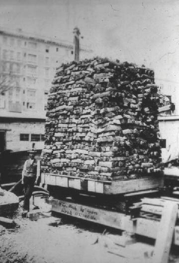
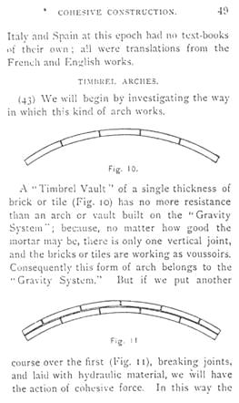
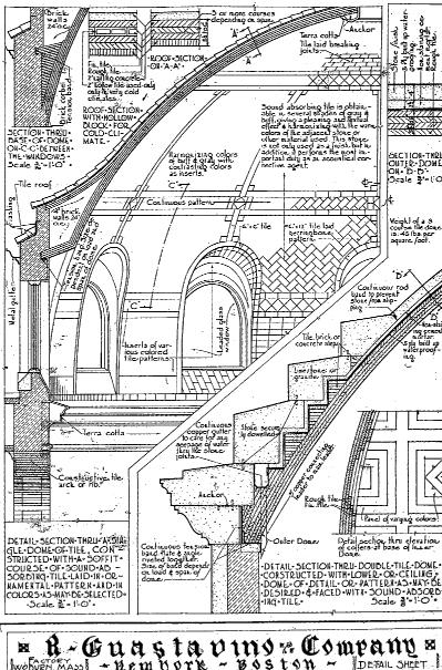
Rafael Guastavino applied his system in over 1000 buildings in Catalonia and United States based on what he called Cohesive Construction. He was the first architect who tried to describe scientifically the structural behaviour of the Catalan Vaulting system. On 1892, he published Essay on the Theory and History of Cohesive Construction9. This paper describes cohesive cons-truction as a method of building that relies on the adhesion of materials as opposed to the friction of the more commonly used gravity system. While mechanical construction (or by gravity) is based in the resistance of any solid to gravity when is counteracted by another solid, cohesive construction is based in the cohesive properties between different materials. Consequently, Vaults built using cohesive construction are composed by several layers of tiles and mortar and their main characteristics are their thinness, strength and non-combustible properties. His illustrations (Fig. 1.16) clearly show that in a vault of single thickness with only one vertical joint, it is gravity alone that keeps the elements in place. According to Guastavino, the fact of adding a second layer with staggered joints and mortar, decreases significantly the weight of the vault and provides greater load capacity due to the cohesion of the materials (Fig. 1.17). Its behaviour responds, according to Guastavino, to similar principles found in conglomerates produced by Nature. He was fascinated by the idea of building by the agglomeration of several small pieces in the same manner that Nature does to form its conglomerates.
Cohesive construction, in its most common form “timbrel vault”, uses little or no steel. It can usually be constructed using little or no false-work since the masonry is self-supporting. This fact, combined with the use of quick-setting mortar, greatly reduces the time and cost of construction compared to conventional masonry vaulting. Both, tiles and mortar, form a homogeneous structure infallible even to accidental penetrations10
8 Ochsendorf, John. The Guastavinos and tile vaults in North America. Informes de la Construccion. Vol 56. N496. March-April 2005
9 Guastavino, Rafael. Essay on the theory and history of cohesive construction. Ticknor.1893
10 Mroszczyk, Lisa J. Rafael Guastavino and the Boston Public Library. Massachusetts Institute of Technology.June 2004
1. Domain | 1.3 Vernacular Brick Construction
Cellular Reinforced Ceramics | Juanjo G. Castellon

019
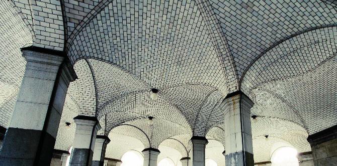
Fig. 1.15 | City Hall Station. 1900. New York. Rafael Guastavino
Fig. 1.16 | Diagram comparing mechanical arch and “cohesive” arch. Guastavino
Fig. 1.17 | Cohesive Construction Technique on site.
Fig. 1.18 | Guastavino Vault. Loading test
Guastavino started applying his vaulting system in Catalonia in buildings such as Batlló Brothers Factory in 1869 and Vilassar Theater in 1880. In 1881 he moved to United States to develop further his technique. One of the main reasons for this moving was the greater existing supply of Portland cement, one of his major improvements on traditional Catalan vault construction.
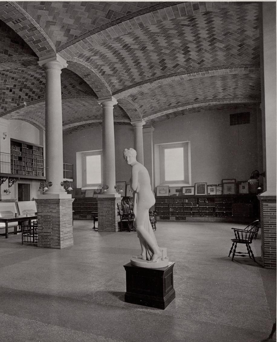
In 1889, Guastavino built his first important work, the Boston Library (Fig. 1.21, 1.22) and the fame and prestige obtained, enabled him to found his own company Guastavino Fireproof Construction Co.
The main reason of the success achieved by Guastavino’s Vaulting System, apart from its lightness and amazing structural performance (Fig. 1.18), was its notable resistance against fire.
Guastavino built all sorts of vault typologies: cylindrical, groin, neo-gothic and spherical vaults. Provably, this last typo-logy was the most used by Guastavino and the most acknowledged. One of the greatest examples is Saint John’s Divine Cathedral in New York with a 30 meters span.
Finally, a set of vaults that cannot be classified in any typology were just buildable due to the talent and skills of Guastavino and his team. One of these special cases is the City Hall Station (Fig 1.15).
Guastavino faced with low quality ceramics available in American market and, consequently, he researched and patented his own ceramic tiles that enabled him to build his vaults in a high quality standards. Based in his knowledge about ceramics in Catalonia, he kept the traditional ceramic tile geometry called “rasilla” but fired at a higher temperature in order to improve its durability and waterproof properties. Another prove of the high quality of Guastavino’s vaults is the fact that they were exposed showing the precise arrangement and colour of the tiles with no additional finishes. The main beauty of Guastavino’s vaults relies on the simplicity of the system where structure, space and finishes were, essentially, the same thing.
His son Rafael Guastavino Exposito continued with his father’s company. His main contribution was the study of the vaults system under tensile strength. He analysed the parts of the structure with critical tension stresses and introduced metal reinforcements. Moreover, he developed in collaboration with Wallace C. Sabine11, an absorbent acoustic brick which added a very good acoustic performance to the Timbrel vault in addition to its fireproof, waterproof and structural advantages.
Despite of the fact that the theories written by Rafael Guastavino about cohesive construction had some imprecisions and were not completely correct, he demonstrated empirically the potential of his system using his excellent intuition and skills. Furthermore, he realized that the problem of the masonry vaulting construction was not the understanding of resistance but geometry12.
11Wallace C. Sabine was professor at Harvard University and at Columbia University and was the pioneer of modern acoustic applied to architecture. He developed some new materials such as “Mumford brick” and “Akoustolith”.
12 Huerta, Santiago. La construcción tabicada y la teoráa cohesiva de Rafael Guastavino. Cedex.2006.
--------------------------------------------------
1. Domain | 1.3 Vernacular Brick Construction
Cellular Reinforced Ceramics | Juanjo G. Castellon


021
Fig. 1.19 | Ellis Island Hall 1900. New York. Rafael Guastavino
Fig. 1.20 | Guastavino vaulting system. Section
Fig. 1.21
| Boston library. Construction process
Fig. 1.22
| Boston library. Interior View
1.3.3 Case Study | Pinex Calyx
Researchers from the Massachusetts Institute of Technology (MIT) studied the Catalan vault technique and applied it in the design and construction of a vaulted space at the Pines Calyx in Kent. This case will be taken as a model to describe typical process of a Catalan vault construction13.

The ‘Timbrel’14 technique involves using tile, laid on edge and built up in layers to produce the necessary structural thickness. In this case three layers of tiles were used, with a waterproof cement screed covering the extrados acting as a fourth layer. All the tiles used are approximately 300 x 150 x 20mm. Each layer must be built in concentric rings and each ring must be completed before beginning the next.
Firstly, there are wooden formers attached to the central pole (Fig. 1.23). The shape that this first layer has to achieve is shown by 2 types of formwork. The first layer is fixed using plaster to hold the tiles in place (Fig.1.24). Radiating out from the central pole are springing lines at regular intervals around the circumference. In between each of the formers, a cintrel15 is used. Heavier grog tile is used for the 2nd and 3rd layers. Both of these layers are laid using cement mortar and are fixed directly on top of the first layer. Each layer is built using a different bond. The first layer uses stretcher bond, the second has the tiles laid at a 45° angle (Fig. 1.25) and the third uses soldier bond (Fig.1.26).
The finished roof (Fig.1.27) is extremely strong and can take the loads of the overlying layers of insulation, earth and turf without any stresses to the structure16
13 Part of the text is extracted from Pines Calyx project website www.pinescalyx.co.uk
14 Timbrel: meaning tambourine, because when you slap a single layer it resounds like a drum. Other names include Catalan, Rousollin or Guastavino vaulting depending on where they are built and who built them.
15 A length of wire, or similar, whose ends are attached at the top and bottom of the central pole. The middle wire is pulled out to form a triangle and the point of this triangle provides the level and radius of each tile course
16 Ramage, Michael H. Building a Catalan vault. 2004
--------------------------------------------------
1. Domain | 1.3 Vernacular Brick Construction
Fig. 1.29 | Top view of the vault
Cellular Reinforced Ceramics | Juanjo G. Castellon
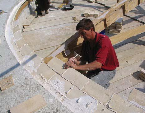
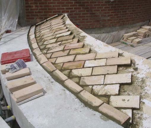
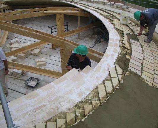
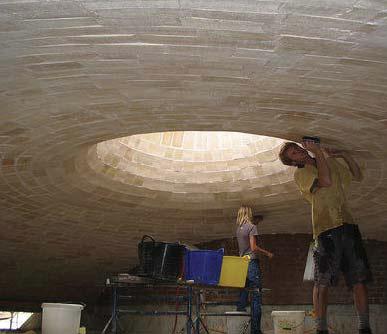
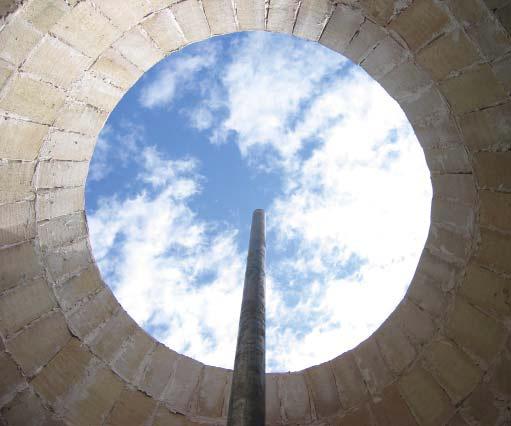
 Fig. 1.23 | Wooden formers attached to the central pole
Fig. 1.24 | Fist layer setting
Fig. 1.26 | Third layer of tiles at 90º
Fig. 1.25 | Second layer arranged in 45º pattern
Fig. 1.27 | Interior view
023
Fig. 1.28 | Final form. View of the opening
1.3.4 Gaussian Vault | Eladio Dieste
“The resistant virtues of the structures that we seek depend on their form; it is through their form that they are stable, not because of the awkward accumulation of material. There is nothing more noble and elegant from and intellectual viewpoint that this: to resist through form.” Eladio
Dieste
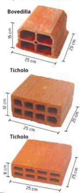
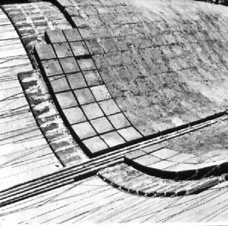
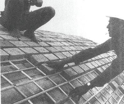
Eladio Dieste (1917-2000) was a Uruguayan engineer that built from 1945 to 1975 a set of buildings based on his invention of “reinforced ceramic construction”17. This hybrid technique developed by Dieste, combines a simple traditional brick technique with metal reinforcements (Fig. 1.31A). This combination confers to the system the ductility and mechanical capacity of reinforced concrete and compensates the lack of tensile strength of masonry. Dieste employed, in the construction of his vaulting system, hollow bricks or ticholos ( Fig. 1.31B) usually from 8 to 12 cm thickness arranged in a grid. Consequently, the only way to place reinforcements was to insert metal bars between the joints following the isostatic lines (Fig. 1.35). This process was difficult and time consuming.
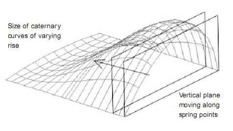
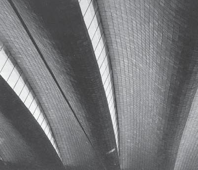
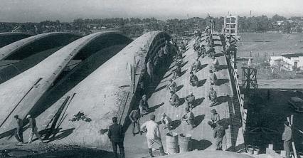
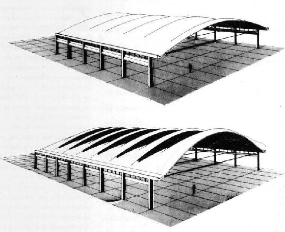
On the other hand, Dieste’s vaults were able to save up to 50 meters span without columns. Eladio Dieste’s reinforced brickwork vaults can be divided two main typologies: the free-standing barrel vault and the Gaussian vault . The first type encompasses single-curvature shells whose direct follows a catenaries curve. The second type, the Gaussian vault, is a double-curved thin-walled shell that is designed to be resistant to buckling (Fig. 1.33). What makes Eladio Dieste’s vaults especially fascinating is that they consist of a single layer of brickwork (Fig. 1.34), creating beautiful large-span shells18. The method applied for Dieste to analyse the structural behaviour of his “ceramic shells” was the same employed for the calculation of cylindrical concrete shells. The Lundgren method, also known as “beam theory”, assumes that the whole shell performs as a great beam whose cross section is the arch defined by the laminar profile selected19. The conglomerate of brick, cement and steel is more heterogeneous than ferro-concrete (Fig. 1.32). The tensile stresses are absorbed by the steel while the compression stress goes to the brick and mortar compound. Dieste’s solution was focused in the behaviour of the vaults in both the longitudinal direction and the cross sections which consisted of either catenaries profiles or double curvature segments (Fig. 1.30). Reinforced brickwork played a fundamental role in the success of his structures. On one hand, by reducing the need for continuous scaffolding and permitting a higher standardization a nd control during execution and, on the other hand, optimizing the use of the local skills and materials and achieving both structural and economic efficiency20

17 Anderson, S. Eladio Dieste, Innovation in Structural Art. Princeton Architectural Press. New York. 2004
18 Shenk, Mark. On the shape of Cables, Arches, Vaults and Thin Shells. 2009
19 Lundgren, H .Cylindrical Shells. Vol.1 of Cylindrical Roofs .Danish Technical Press . Copenhagen. 1949.
20 Theodossopoulos ,D. Sinha ,B.P. A study on the free-standing masonry vaults of Eladio Dieste. 2007
B A
4. Portland Cement finishing with steel mesh
3. Re-bars at the gaps between the bricks
2. Hollow Ceramic Bricks “Ticholo”
1. Wooden Formwork
1. Domain | 1.3 Vernacular Brick Construction
Fig. 1.32 | Reinforced Ceramics System. Detail
Fig. 1.30 | Reinforced Ceramics System. Detail
Fig. 1.31 | A. Construction and Layers in a Gaussian Vault B. Hollow Bricks. Types and dimensions.
Cellular Reinforced Ceramics | Juanjo G. Castellon


025
Fig. 1.38 | Port Warehouse. Montevideo ( Uruguay ). 1979. Eladio Dieste.
Fig. 1.36 | Port Warehouse. Montevideo ( Uruguay ). 1979. Eladio Dieste. Construction Process
Fig. 1.37 | Don Bosco School Gymnasium.Montevideo. 1984. Eladio Dieste
Fig. 1.35 | Placement of reinforcing bars between the bricks
Fig. 1.34 | Gaussian Vault. Section and Detail.
Fig. 1.33 | Gaussian Vault. Perspective.
Window Cement Air Brick Steel Steel
Example: Montevideo Shopping Center
Reference: Dieste & Montañez, Gonzalo Larrambere, Walter Vilches Section
Gaussian Vault
1.4 Contemporary Free-Form Construction
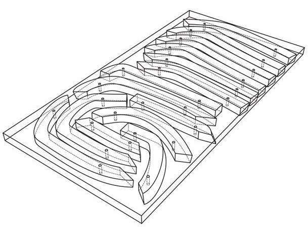
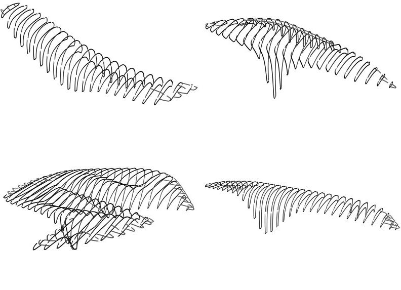
The fast development of parametric tools and the evolution of new fabrication techniques have dramatically changed construction processes. In opposition to traditional construction techniques where technologies and resources were limited, there is now an enormous workflow of information between design and fabrication processes. Free-forms and complex forms can be easily designed with parametric tools and this complexity has to be transformed and translated in order to become buildable and economically feasible. Consequently, a new professional profile is emerging from this process, a sort of translator between architects and constructors who receives complex designs and deals with their geometrical principles and material properties to make them feasible.
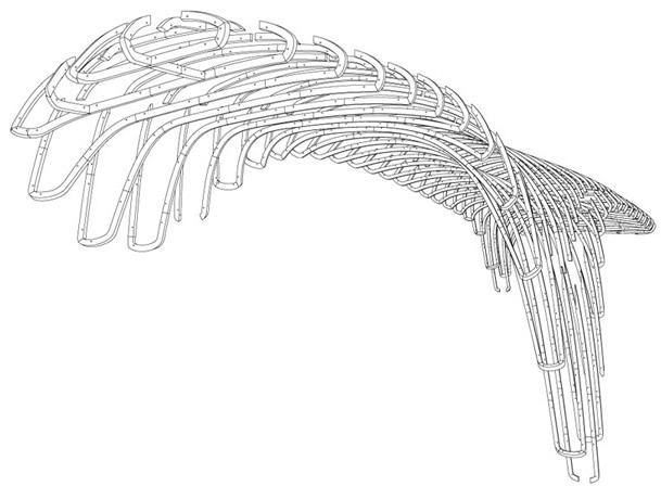
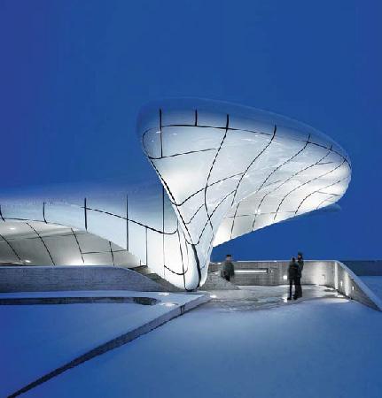
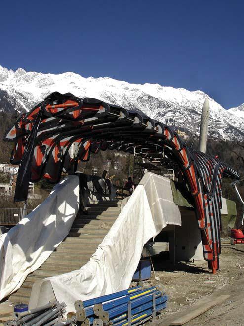
Projects such as Hungerburg Funicular Station (Fig. 1.43) were built following this model process. The four stations designed by Zaha Hadid Architects contain over 2,500 unique custom-cut polyethylene profiles (Fig. 1.42) which connect the glass cladding of the roof to the steel ribs of the supporting structure. The Swiss company Design to Production implemented an automated workflow for detailing and fabrication planning of the profiles. The process started with a CAD-model provided by the engineers and ended with delivering machine-ready manufacturing data (Fig.1.40) directly to the five-axis CNC-router that cut the profiles21 .
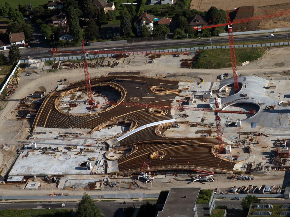
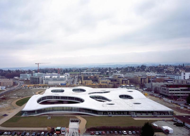
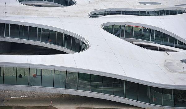
Another example is the Rolex Learning Center in Laussane by SANAA (Fig.1.44). This building is a result of a complex construction process where customized formworks and reinforcements (Fig.1.46) were produced to build the 3-dimensional curved concrete shells. The concrete execution had to be precise because of the complex facade system that needed to absorb both the concrete shell deflection movement and the construction tolerances. One example of precise execution was the use of laser-cut 2.5m x 2.5m wooden formwork to generate the 1400 different moulds for concrete, which were positioned using GPS technology on site22.
In both cases, the actual form was designed by the architect and all the digital construction tools and processes were deployed “a posteriori” by external consultants in order to accomplish the structural, technical and economical requirements.
21 Notes taken from Design To Production website: www.designtoproduction.com
22 From article found at the website: www.designboom.com
1. Domain | 1.4 Contemporary Free-Form Construction
Fig. 1.41 | Hungerburg Funicular Station. Substructure
Fig. 1.40 | Hungerburg Funicular Station. Profiles
Cellular
Fig. 1.39 | Funicular Stations. Austria. Substructure Studies
Reinforced Ceramics | Juanjo G. Castellon
027
Fig. 1.42 | Hungerburg Funicular Station. Substructure on site .
Fig. 1.43 | Hungerburg Funicular Station .2007. Innsbruck. Zaha Hadid
Fig. 1.46 | Rolex Learning Center. 2010. Laussane. Switzerland. SANAA. Works on site
Fig. 1.45 | Rolex Learning Center. 2010. SANAA.
Fig. 1.44 | Rolex Learning Center. 2010. SANAA. Aereal View
1.5 Summary
A. Ceramic materials are excellent materials with outstanding properties for architectural applications. They have been used throughout centuries and even now are key materials in the development of new composites. On the other hand, ceramics perform poorly under tensile strength and require firing.
B. Traditional masonry techniques such as the Catalan vault were based on a clear understanding of ceramic brick logic and its structural applications.
C. Rafael Guastavino evolved this traditional technique by applying his “cohesive construction” principles. With this technique based in the adhesion of different material layers in a precise geometry and arrangement he was able to build all sorts of vaults in a very efficient and aesthetic manner.
D. Eladio Dieste evolved the vault system adding metal reinforcements and using form to improve its structural behaviour. Furthermore, he was able to build his double-curved Gaussian vaults achieving an elegant and beautiful result.
E. These traditional techniques became obsolete due to the lack of qualified manpower and the appearance of reinforced concrete.
F. New parametric tools allow architectural designs to challenge new formal experimentations and fabrication techniques. On the other hand, the large amount of data and workflow generates, often, a gap between design and production.
G. Some architects are trying to eliminate this gap merging parametric design and fabrication in a single process.
1. Domain | 1.5 Summary Cellular Reinforced Ceramics | Juanjo G. Castellon
1.6 Questions
1.How to improve the structural performance of ceramics?
2.How to introduce variation in the fabrication process?
3.How to implement design processes with parametric tools?

029
2. Methods
2.1 Introduction
2.2 Materials
2.2.1 Ceramics. Fabricators Network
2.2.2 Case Study. Flex-Brick. Vicente Sarrablo
2.2.3 Honeycomb Aluminum Mesh
2.2.4 Case Study. Bruges Pavilion. Toyo Ito
2.3 Traditional Manufacture
2.3.1 Extrusion Process
2.3.2 Slip Casting Process
2.4 Contemporary Manufacture
2.4.1 Digital Fabrication
2.4.2 CAD-CAM & CRAFTS
2.5 Evaluation & Summary
031
2.1 Introduction
The relationship between design and fabrication is the key topic in the new paradigm of contemporary architecture. The appearance of parametric tools such as Grasshopper, Generative Components or VbScript, unveils a new field of research for an architecture that incorporates evolution, variation and adaptation in response to environmental, structural and spatial aspects. In addition, this new approach to architecture has to face with factors such as feasibility and costs in order to enable the construction process.
Following the first stage of research, an accurate description of the materials and industrial manufacturing processes regarding ceramics will be described. All the data and information required was compiled during a field trip to Barcelona and Valencia to visit a fabricators network. This network is composed by several professionals and companies that work with ceramics at different scales and with different philosophies.
Finally, some case studies will be presented to define the intellectual framework that relates this research with another contemporary and traditional design approaches.
2. Methods | 2.1 Introduction
Cellular Reinforced Ceramics | Juanjo G. Castellon
033
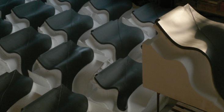
Fig. 2.01 | Villa Nurbs. Girona. Cloud 9. Moulding process developed in collaboration with Ceramica Cumella
2.2 Materials
2.2.1 Ceramics
2.2.2 Honeycomb Aluminum Mesh
2. Methods | 2.2 Materials
2.2.3 Case Study
Cellular Reinforced Ceramics | Juanjo G. Castellon
035
Fig. 2.02
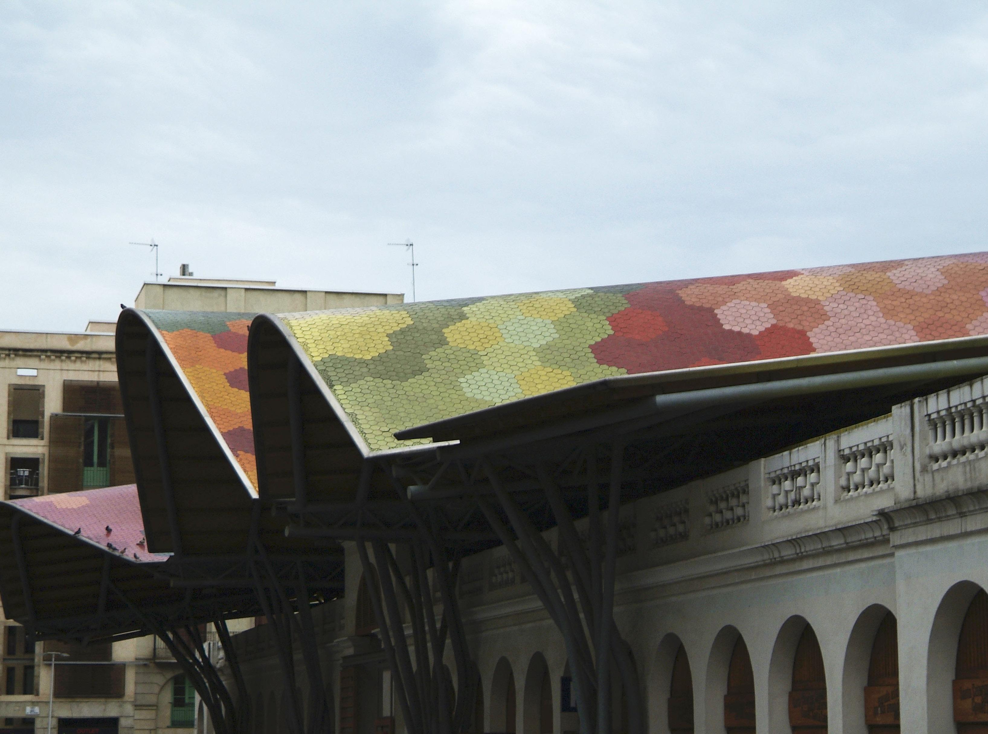
| Santa Caterina Market. Barcelona. 2005. EMBT
2.2.1 Ceramics. Fabricators Network
Ceramics is classified as non-metallic material that is produced by firing. There is a wide palette of clay ceramic materials (Fig. 2.3). Clay-based ceramics are those associated with pottery and include earthenware, stoneware and porcelain. They are fine-grained materials made of clay minerals (aluminium silicate), quartz and rock fragments. Historically, the quality of the ingredients differed according to their location. Today, clay can be easily purchased from manufacturers that produce raw materials. High performance ceramics have less impurities than clay-based ceramics and, therefore, superior properties. They are resistant to high temperatures, most chemicals and corrosion and outperform metals in several applications. However, like clay-based ceramics they are hard and brittle, and their porous structure has high compression strength but low tensile strength. Regarding architectural applications, ceramics can be divided in 3 main categories: Terracotta, Stoneware and Porcelain. In order to understand the different scales and applications of ceramics, a field trip was made to Barcelona and Castellon. Both cities have a prestigious tradition working with ceramics and form an important fabricators network.
1st Fabricator: The artist. Jordi Serra. ( Barcelona ). Terracotta
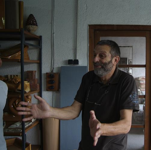
Jordi Serra (Fig. 2.5) represents the third generation of ceramists in Barcelona but he is, as well, an artist and a chemical engineer. Consequently, his profile moves between art and science which enables him to experiment with metallic reflections, colours and transparencies in his pieces.
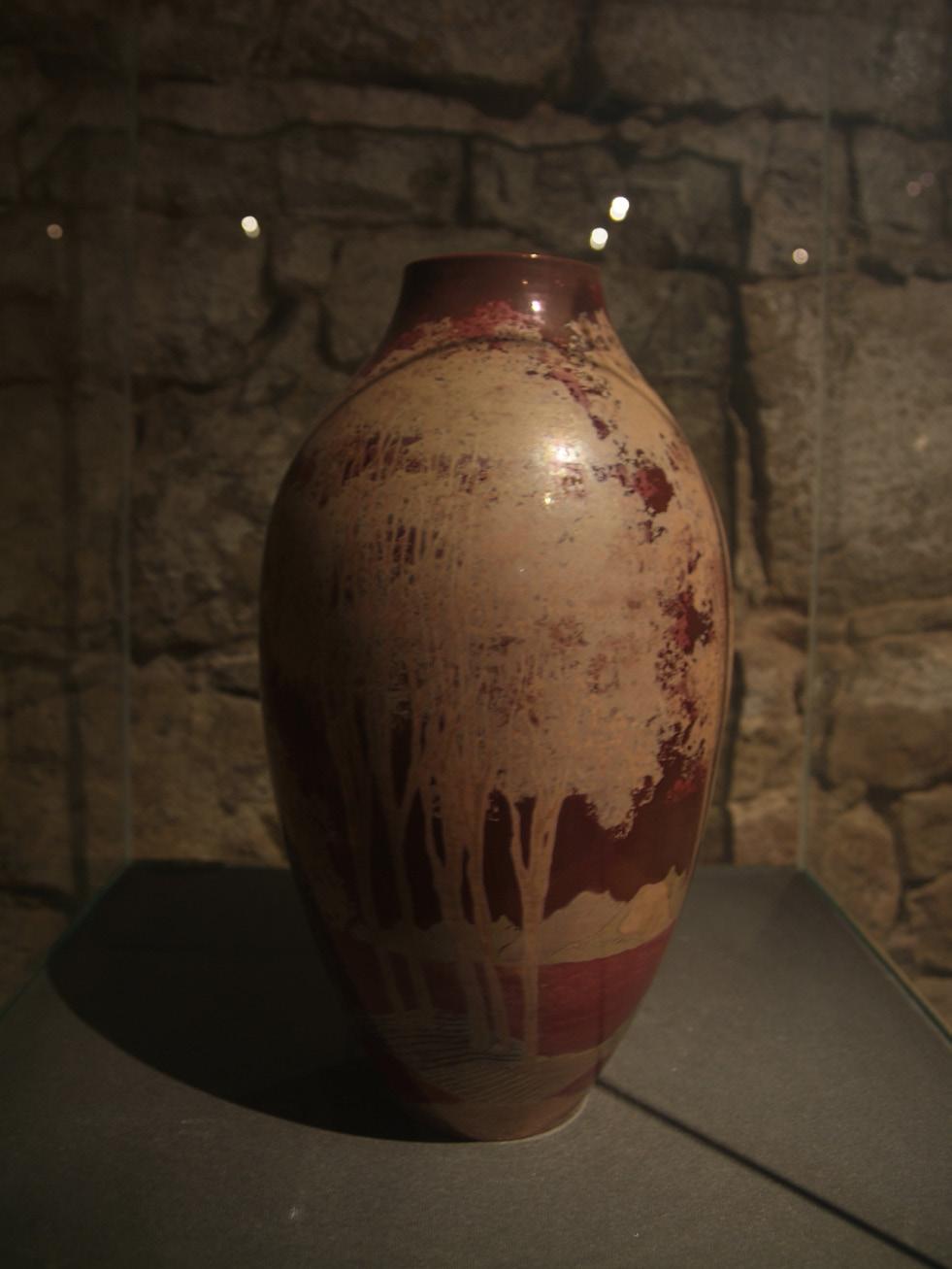
He works, basically, with terracotta fired in a small and handmade kiln. In order to obtain terracotta, the clay mixture is fired between 850 and 1000 ºC. Nowadays, Terracotta is not widely used for architectural applications since it is quite porous and not waterproof. Furthermore, the fact of working with a small kiln and the refinement of the techniques applied reduce the production to a few pieces per month. Consequently, this sort of practice is related with the production of a limited amount of art pieces, mainly vases (Fig. 2.04).
2nd Fabricator: The Industry. Ceracasa S.A. ( Castellon ). Porcelain
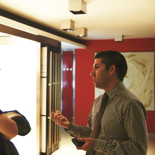
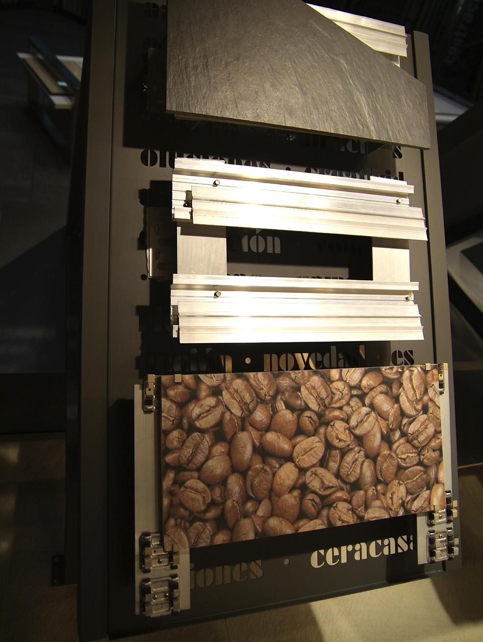
Ceracasa is a company allocated in Castellon, one of the most important industrial areas devoted to ceramics in the world. They have one of the most modern installations in the sector dedicated to the production, management and logistics for ceramic products. They mainly work with porcelain to offer high durability, resistance to chemicals, precision and high control of the quality in the final product. In order to obtain porcelain, the mixture has to be fired at temperatures between 1300 and 1500 ºC. Moreover the production process is highly advanced, applying technologies such as laser guide and digital injection in their tiles. Finally, they work with a catalogue based in variations of a standard product: planar tiles with a maximum dimension of 60 x 40 cm, usually for flooring or wall coverings (Fig. 2.8).
3rd Fabricator: The Workshop. Ceramica Cumella. ( Barcelona ). Stoneware
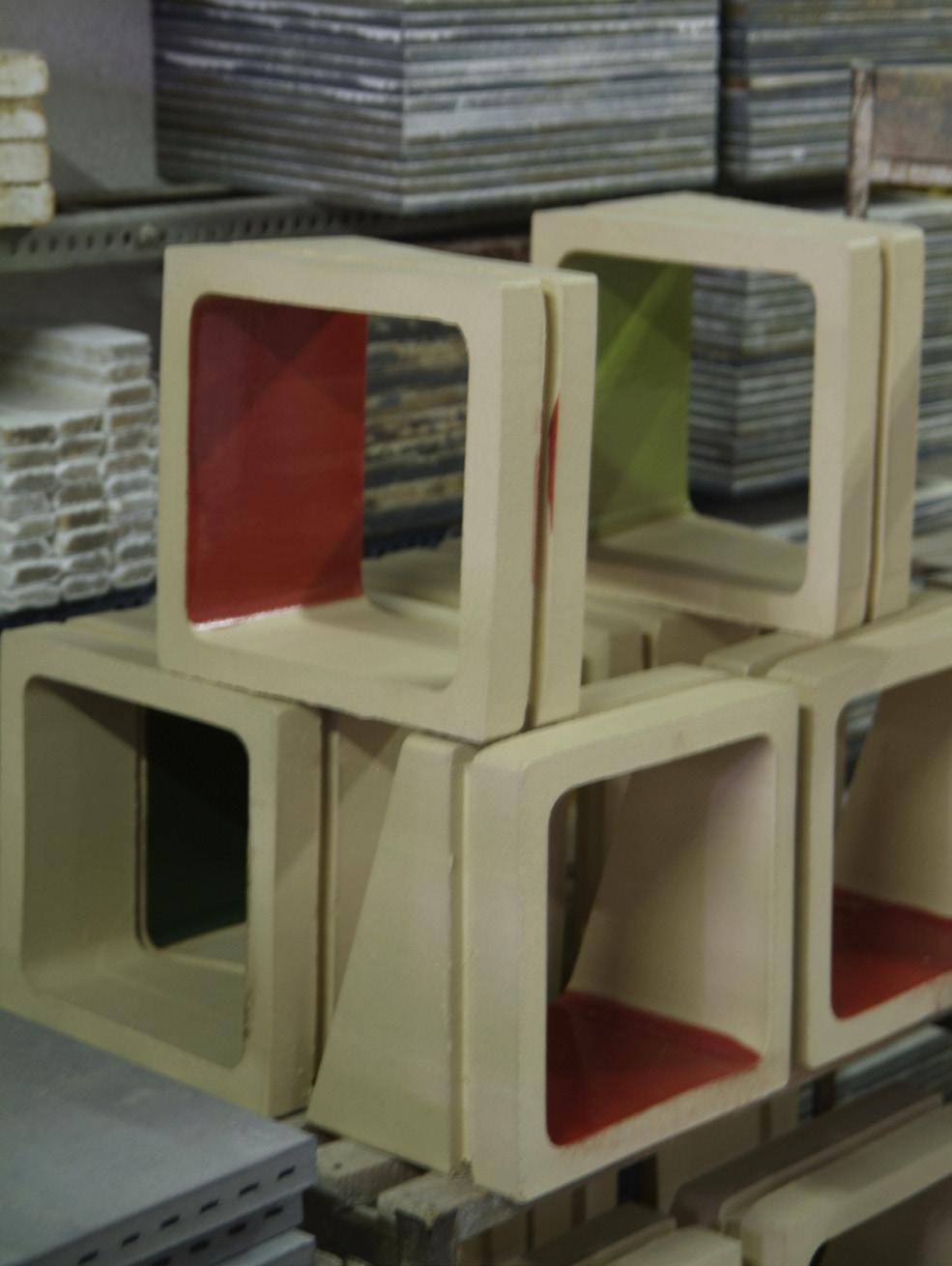
Toni Cumella (Fig. 2.7) also belongs to a family of ceramists but he has shifted his profile towards a close collaboration with architects. His process is based on Stoneware, a suitable product for architectural applications. Stoneware is obtained by firing the clay mixture at temperatures from 1000 to 1300 ºC. His workshop produces basically serial pieces (Fig 2.6) – floorings, tiles, modular elementsand special pieces. Cumella looks for an integration of technical tradition and innovative processes and has been collaborating with architects such as Enric Miralles or Alejandro Zaera in the development of customized ceramic projects. Instead of a catalogue of products, Cumella relies on the process linking craftsmanship with serial production, and personalization with culture.
2. Methods | 2.2 Materials
Cellular Reinforced Ceramics | Juanjo G. Castellon

037
Fig.2.03 | Ceramics Classification
Fig. 2.04 | Ceramic Vase. Jordi Serra
Fig. 2.06 | Ceramic Blocks
Fig. 2.08 | Samples of Ceramic Tiles for Ventilated Facades.
Fig. 2.05 | Ceramica Serra Traditional Craftsmanship
Fig. 2.07 | Ceramica Cumella Ceramics Workshop
Fig. 2.09 | Ceracasa Ceramics Industry
2.2.2 Case Study | Flexi-Brick. Vicente Sarrablo
After visiting the Fabricators Network, the field trip finished with a visit to Vicente Sarrablo. He is professor at the Universitat Internacional de Catalunya (UIC) and he has developed a system to build single curved structural coverings with ceramic tiles.
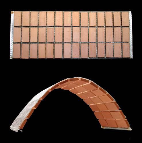
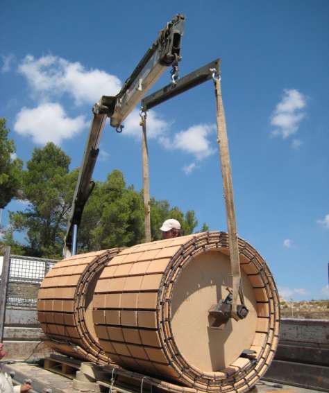
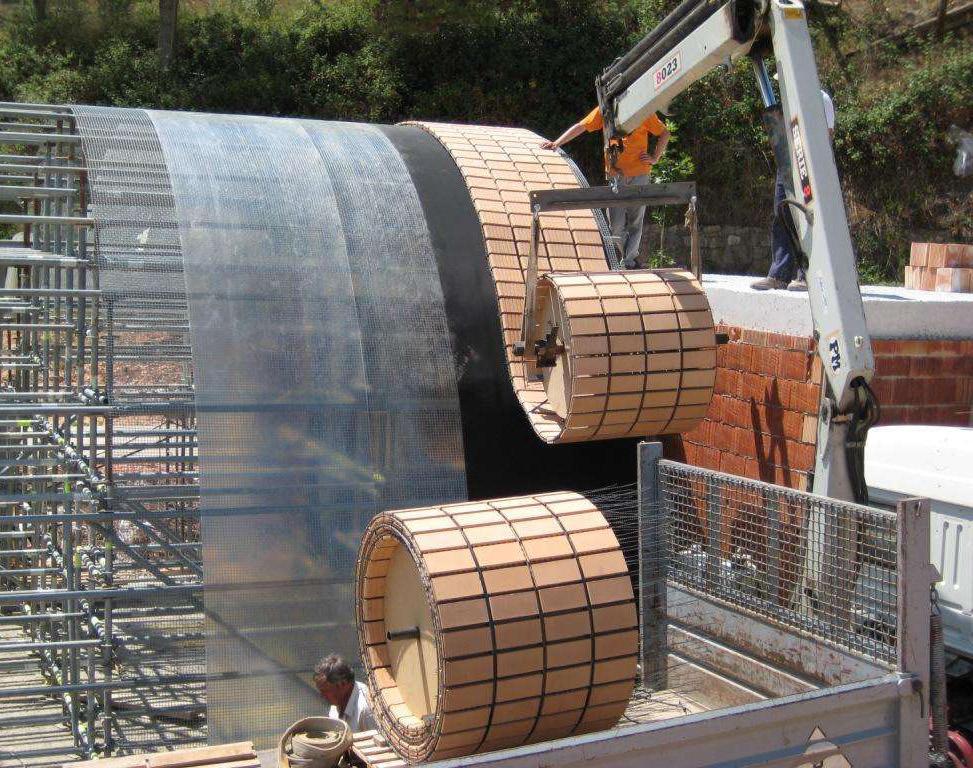
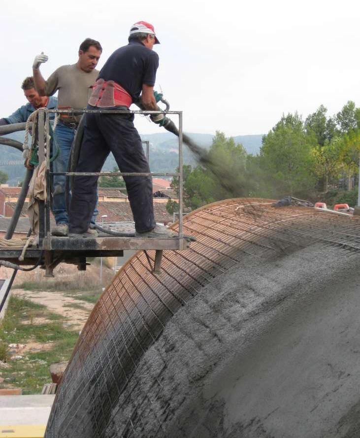
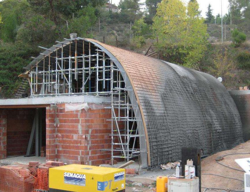
The system is based in the development of a ceramic fabric called Flex-Brick1 (Fig. 2.10) that performs as part of a composite ceramic surface. This fabric is built by the assembly of two layers of ceramic tiles with thin metal reinforcements in between. The system is flexible and is provided in a reel (Fig. 2.11) and is easy to store and transport. Once received on site, the mesh is unrolled using a crane (Fig. 2.12). In order to achieve the final form, a scaffolding system is required (Fig 2.13) that performs as a formwork. Once all the FlexiBrick has been unrolled, a second layer of reinforced bars is deployed. The system is then ready to pour concrete on it (Fig.2.14). The concrete fills in the joints between the ceramic tiles and covers the metallic reinforced bars. Through this process, made “in situ”, the final composite form reaches its structural performance (Fig. 2.15).

--------------------------------------------------
2. Methods | 2.2 Materials
1 Sarrablo, V. Innovación en el uso de la ceramic en arquitectura. El Tejido Cerámico Estructural. Seminário sobre Paredes de Alvenaria, P.B. Lourenço (eds.). 2007
Fig.2.10 | Flexi-Brick System.
Fig.2.11 | Flexi-Brick System. Reel ready to go.
Cellular Reinforced Ceramics | Juanjo G. Castellon
039
Fig.2.12 | Reel of Flexi-Brick arrives to site
Fig.2.14 | Pouring concrete on top of the metal reinforcement
Fig.2.13 | System unrolled on top of the scafolding
Fig.2.15 | Work in progress
2.2.3 Honeycomb Aluminum Mesh
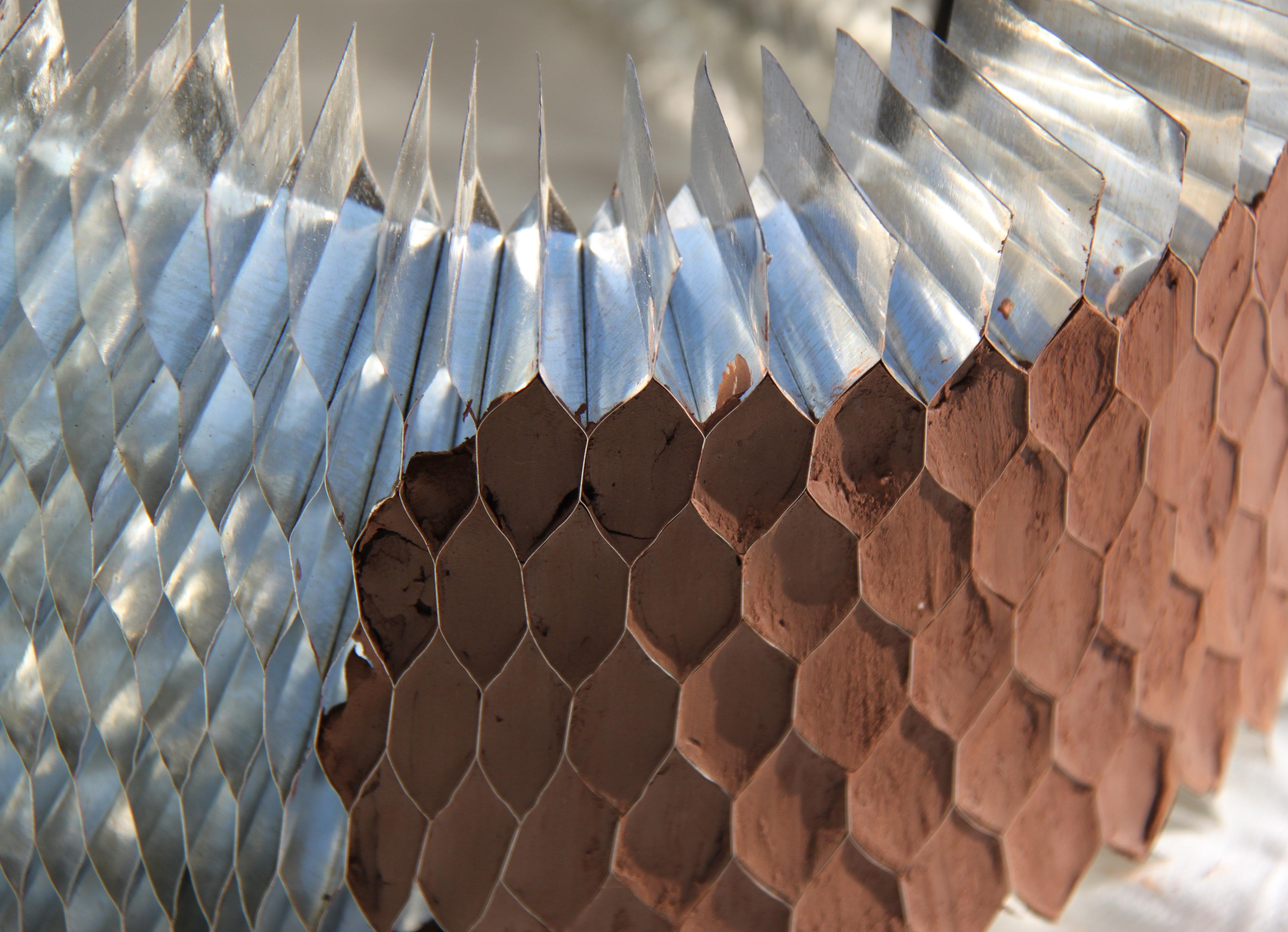
The Honeycomb is a flexible mesh of hexagonal cells that is mainly used for structural core reinforcements of flat sandwich panels. It is a type of cellular solid made of aluminium strips thermally welded forming a network of cells.
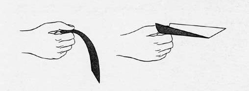
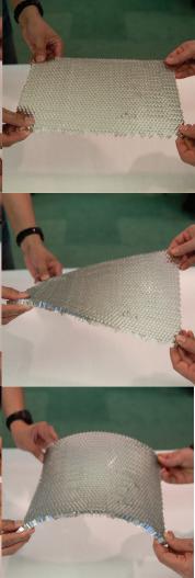
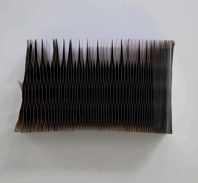
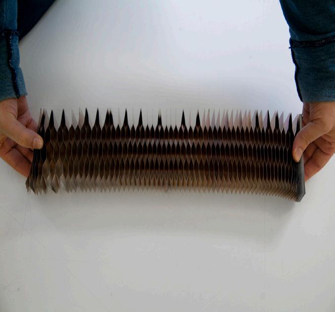
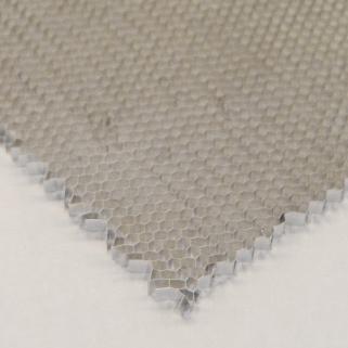
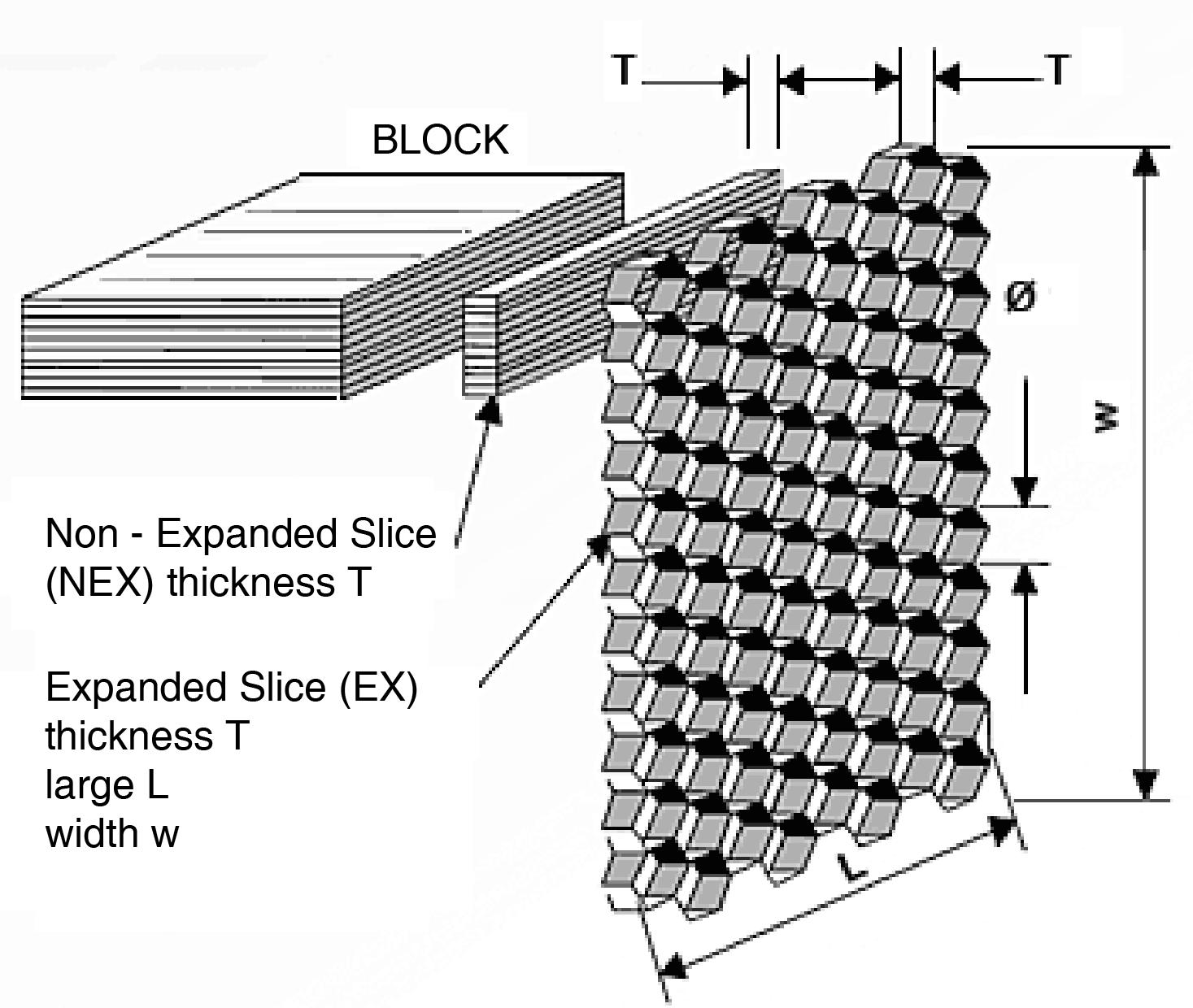
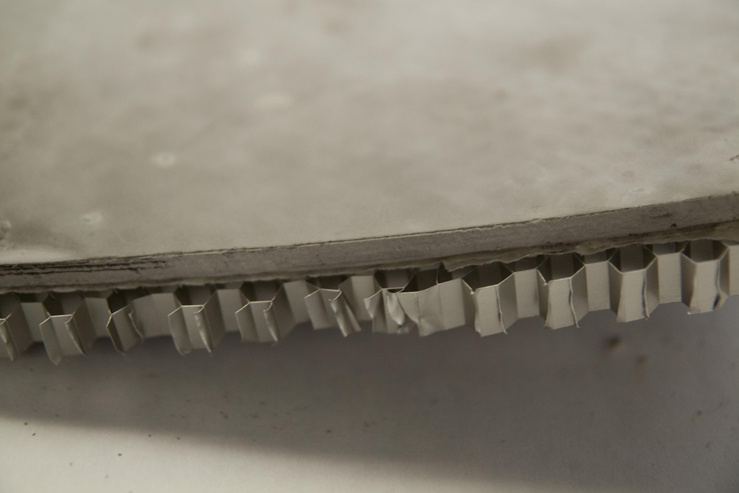
One interesting aspect of the honeycomb aluminium panel is its fabrication process (Fig. 2.19). The mesh is produced in standard with a foil thickness of 50 and 70 microns. These foils are firstly arranged in an aluminum block and thermally welded following the desired pattern. Secondly, the block is cut into slices of the required thickness creating non-expanded panels (NEX). These non-expanded slices are extremely flexible (Fig.2.20). Finally the slice is stretched in order to form the actual panel with a homogeneous cell size (Fig. 2.17). Cell sizes can vary from 6 to 19 mm in a standard product and different densities and properties can be obtained by combining the foil thickness with the cell size (Fig. 2.18).
When used as core material in a sandwich panel, the honeycomb aluminum panel has de following properties2:
• Light, resistant and strong in compression and shear
• Incombustible, recyclable and corrosion resistant
• Extremely flat
• Electrical and thermal conductor
Due to its flexibility, the honeycomb panel is also suitable for the fabrication of curved elements, for example in planes and cars components. The most general way to produce those curvatures in the honeycomb is by using a vacuum bag moulding process where a curved mould is used in combination with a surface-laminating process. The honeycomb is made into a suitable shape by the vacuum mould and then held in place until the surfaces are attached to the honeycomb. Despite of its limitation of curvature, it can be increased by altering the honeycomb cell size and thickness.
2 Information provided by Alucoat Conversion
--------------------------------------------------
2. Methods | 2.2 Materials Cellular
|
Reinforced Ceramics
Juanjo G. Castellon



041
Fig. 2.16 | Examples of cellular solids: (a) a two-dimensional honeycomb: (b) a three-dimensional foam with open cells: (c) a three-dimensional foam with closed cells.
Fig.2.17 | Expanded Slice. 6 mm cell size
Fig.2.20 | Non-Expanded Slice. 19 mm cell size
Fig.2.19 | Honeycomb Aluminum Mesh. Fabrication process
Fig.2.18 | Honeycomb Aluminum Mesh. Technical Data
2.2.4 Case Study | Bruges Pavilion. Toyo Ito
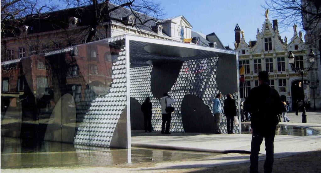
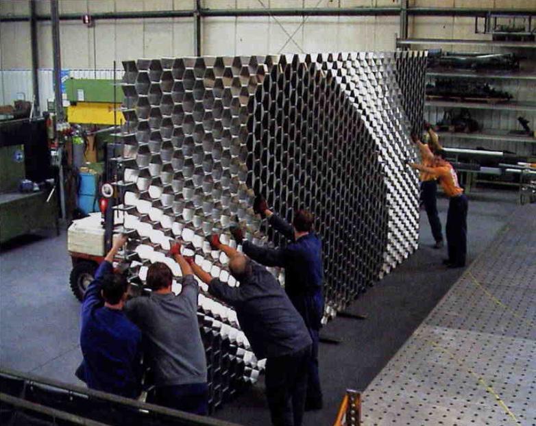
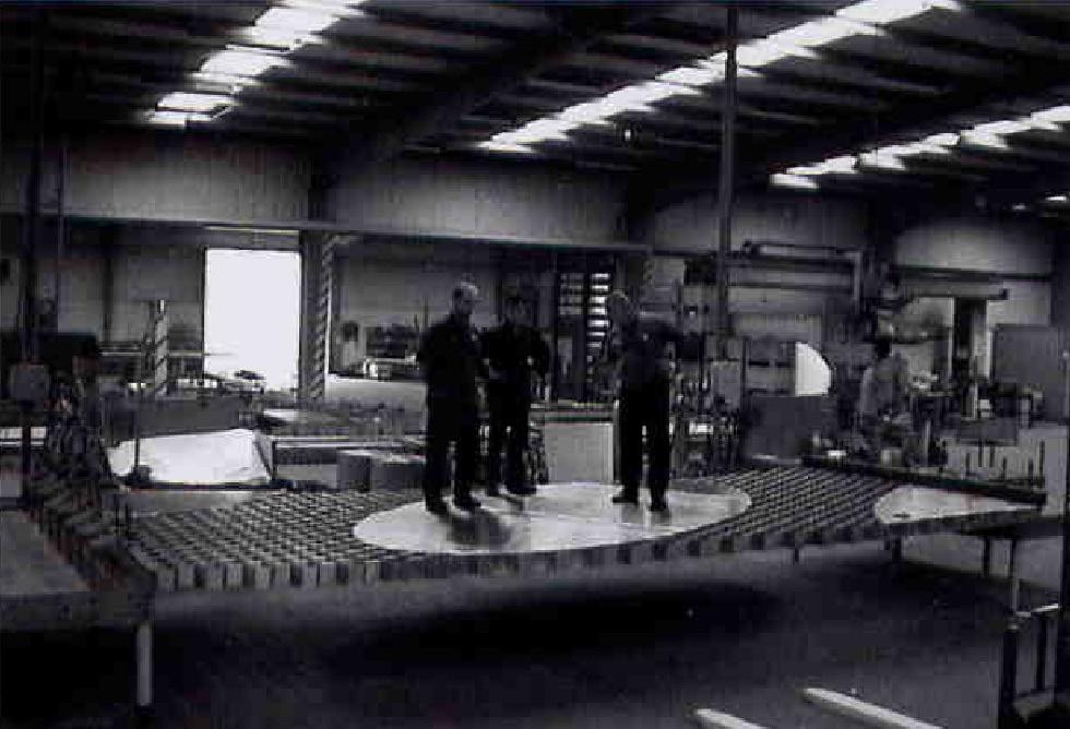
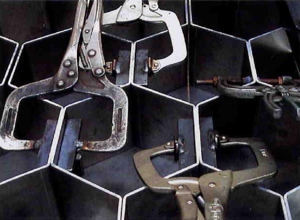
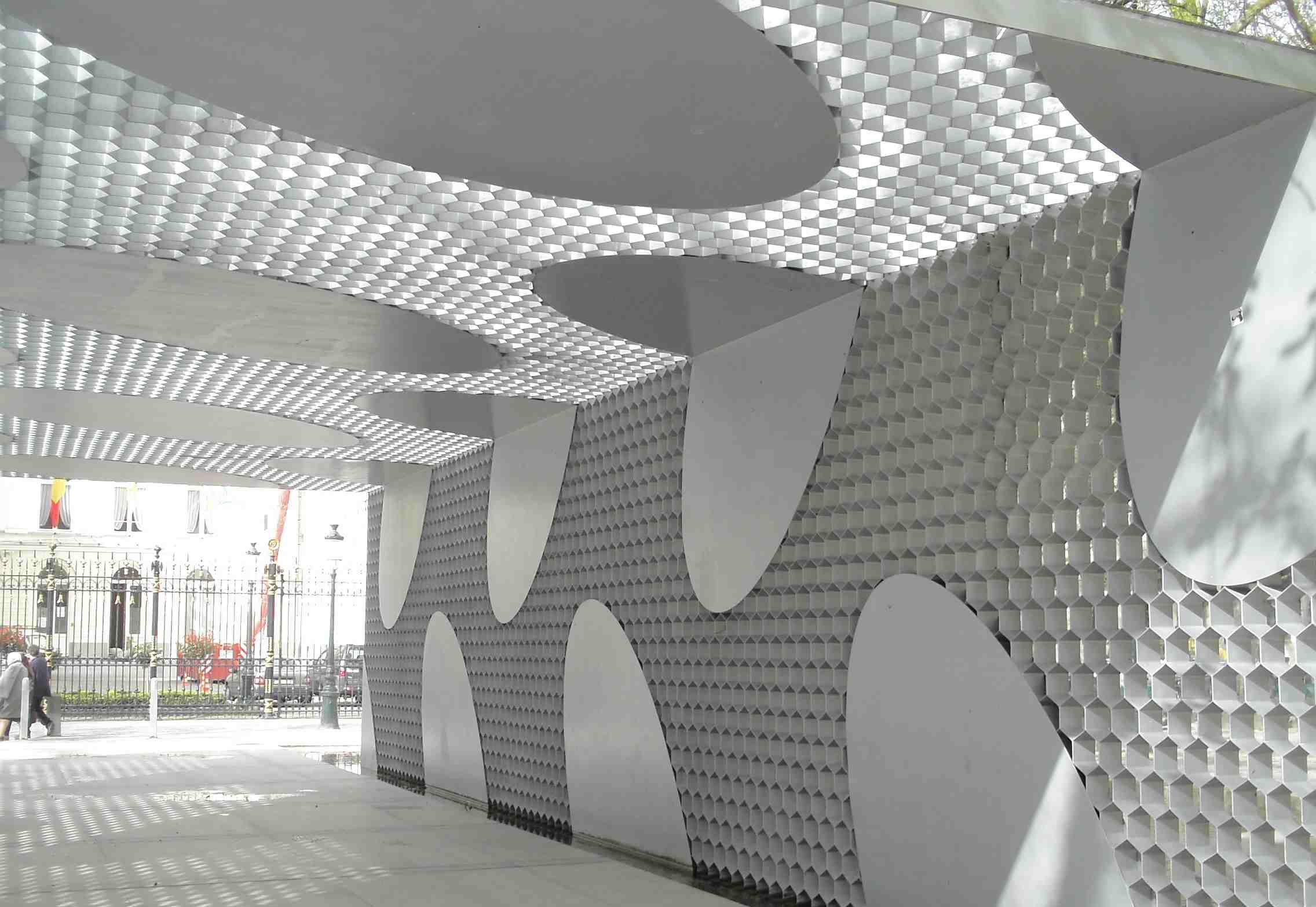
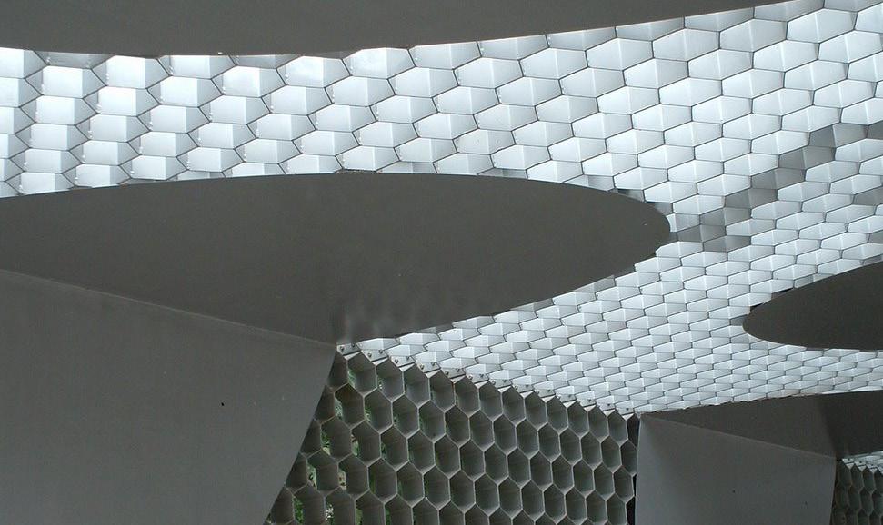
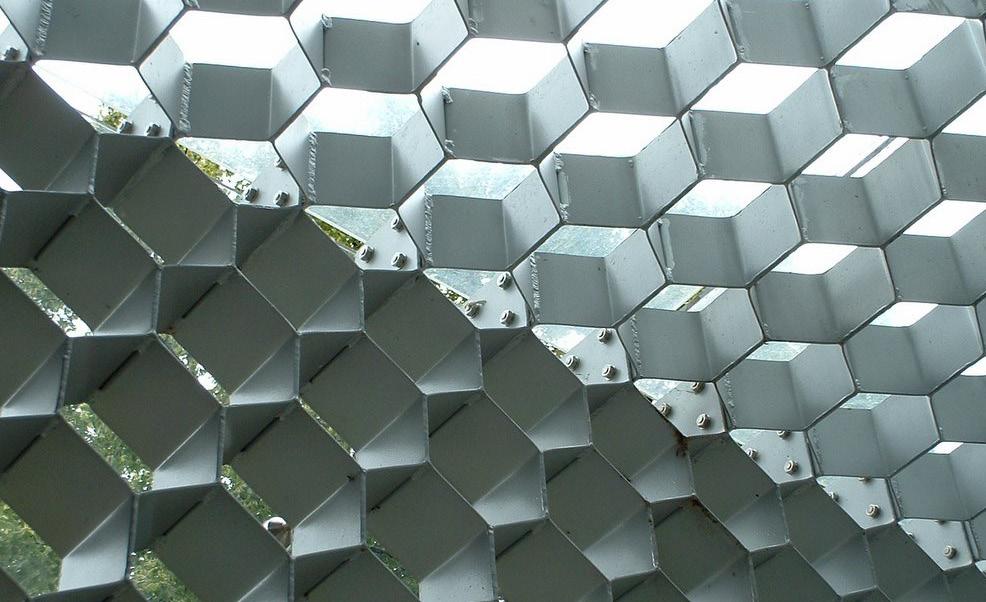
In this pavilion for Bruges, Toyo Ito tested the load-bearing relationship between a honeycomb core and the stiffening facing by minimizing the materials as far as possible. Focusing initially on the honeycomb structures built from aluminum strips, experiments were conducted on models to explore the possibilities for reinforcing the structure with partially attached elliptical patches (Fig.2.25). The design impact on the pavilion’s appearance was investigated on every scale, from paper and aluminum models to a life-size mock-up in the steel workshop. In the final construction, a honeycomb structure (Fig.2.26) measuring 12.5 cm in depth was overlaid with 3 mm thick elliptical aluminum plates that were calculated to provide sufficient reinforcement and form a load-bearing composite structure. The plates were welded to the honeycomb mesh like in a sandwich structure. Finally, the final flat panels (Fig.2.27), fabricated at the steel workshop, were transported to the site and bolted where the vertical walls meet the horizontal roof (Fig.2.23)
The entire construction was covered in a skin of transparent polycarbonate panels of 12 mm for protection against the weather conditions. The result (Fig.2.21) is an extremely light, semi-transparent shell of high aesthetic appeal with surfaces that resemble the patterns of traditional Belgian lacework3.
2. Methods | 2.2 Materials
3 Sauer, C. Made Of .New Materials Sourcebook for Architecture and Design .Gestalten. 2010
Fig.2.21 | Bruges Pavilion. 2002. Bruges. Belgium. Toyo Ito
Cellular Reinforced Ceramics | Juanjo G. Castellon
043
Fig.2.23 | Detail of the bolted joints
Fig.2.22 | Interior. Detail
Fig.2.25 | Structural test
Fig.2.26 | Honeycomb mesh. Fabrication process
Fig.2.24 | Interior Perspective
Fig.2.27 | Assembled Panel ready for transportation.
2.3 Traditional Manufacture
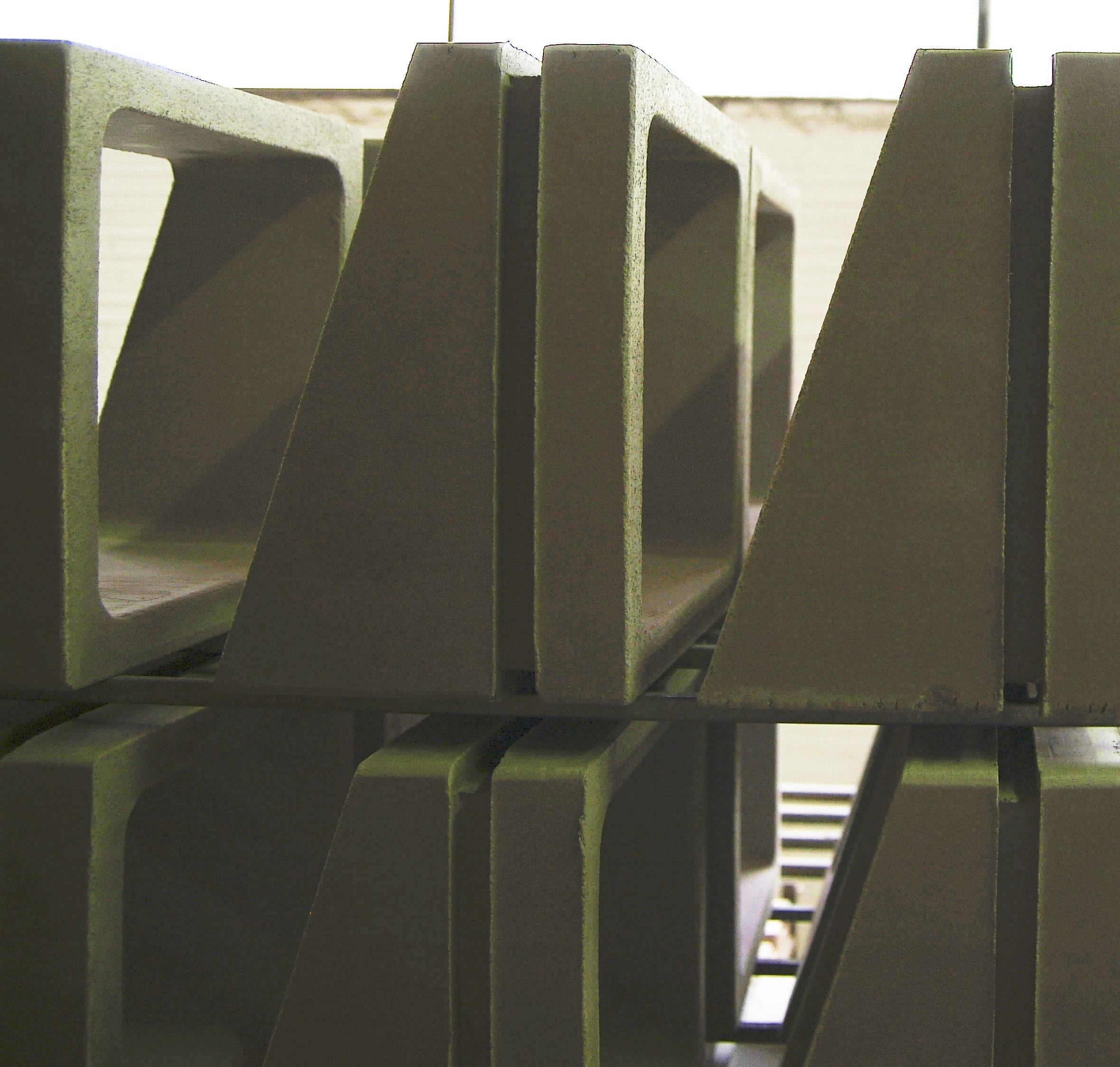
2.3.1 Extrusion Process
2. Methods | 2.3 Traditional Manufacture
2.3.2 Slip Casting Process
Cellular Reinforced Ceramics | Juanjo G. Castellon
045
2.3.1 Extrusion Process
STEP 1. Ingredients
The first step in the process is to select the proper ingredients for the clay. Additives, minerals and pigments (Fig. 2.28) are combined in order to achieve the required color and strength in the final piece.
STEP 2. Mixture
The raw materials are combined with water to obtain the clay mixture. It is very important to keep a constant dose by controlling digitally the precise amount of water and additives (Fig. 2.29, 2.30). The mixture is then blended in a tank (Fig. 2.31).
STEP 3. Moulding
A key part in the extrusion process is the molding design. The extrusion profile is made in steel and attached by bolts to the extrusion machine (Fig. 2.32). It is important to mention that obviously the mould is one of the most expensive elements in the process so the more variation you want, the more expensive the process is.
For extruding the clay through the sectional moulding there are two parameters that have to remain constant during the extrusion process: pressure and temperature (Fig. 2.33). These two inputs are digitally controlled to guarantee a homogeneous finish in all the pieces.
STEP 4. Mechanization
Finally, the continuous and homogeneous extrusion of clay is cut according to the depth required for the ceramic component. The piece can be cut in a specific and precise angle (Fig. 2.35).
If the final piece is correct in terms of geometry and quality, then some final refinement can be manually done in the piece, for example the preparation of the joinery system (Fig. 2.38). If any imperfection is observed in the final piece, then it is compiled (Fig. 2.36) and recycled by putting it back in the mixture tank. Consequently, there is no wasted material in the process.
STEP 5. Kiln and Dryer
The pieces are stored and ready to be fired into the kiln (Fig. 2.39). The process of firing the pieces is time consuming. Stoneware elements need temperatures from 1,250 to 1,300 ºC and about 5 hours of firing. For this reason it is important to avoid stopping the process and, in order to do that, several kilns (Fig. 2.40) work alternately.
The firing process produces shrinkage in the pieces. This change in the geometry has to be taken into account in the piece design. Afterwards, the pieces are moved to the drying machine (Fig. 2.41) where the remaining moisture is evaporated.
STEP 6. Glazing
Finally, the pieces are ready for the glazing process (Fig. 2.42). A wide palette of colors and finishes are available for glazing (Fig. 2.43). Once the glazing has been applied, the piece is fired again to obtain the final finishing.
CONCLUSIONS:
Some conclusions arise from understanding the extrusion process:
1. Firstly, a good choice in the raw materials selection for the mixture is a key part in the process in order to control the consistency and colour of the final piece.
2. In terms of geometry, two conditions have to be taken into account. On the one hand the limitation of the directionality of extrusion and, on the other hand, a reasonable shrinkage has to be taken into account due to the firing process.
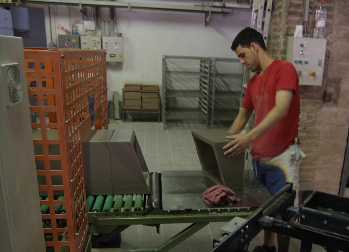
One last thought regarding the whole process is the need of manpower in almost all the steps in the process. The extrusion machine fabricates the piece but the final quality regarding performance and aesthetics relies in human criteria and experience
2. Methods | 2.3 Traditional Manufacture
Cellular Reinforced Ceramics | Juanjo G. Castellon


047 2.28 2.29 2.30 2.31 2.32 2.33 2.34 2.35 2.36 2.38 2.37 2.44 2.39 2.40 2.41 2.42 2.43
STEP 1,2| INGREDIENTS AND MIXTURE PREPARATION STEP 3 | EXTRUSION MOULD. TEMPERATURE AND PRESSURE CONTROL
STEP 4 | CUTTING AND MECHANIZATION
STEP 5 | PIECES STORAGE
STEP 5 | FIRING & DRYING
STEP 6 | GLAZING
Fig.2.28-2.44 | Steps in the Fabrication process
2.3.2 Slip Casting Process
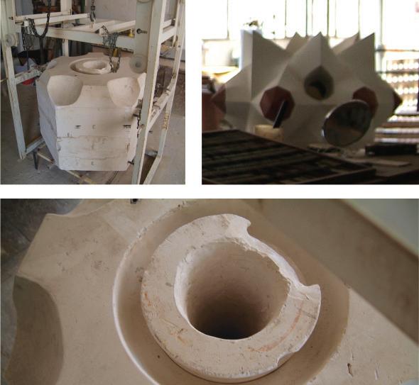
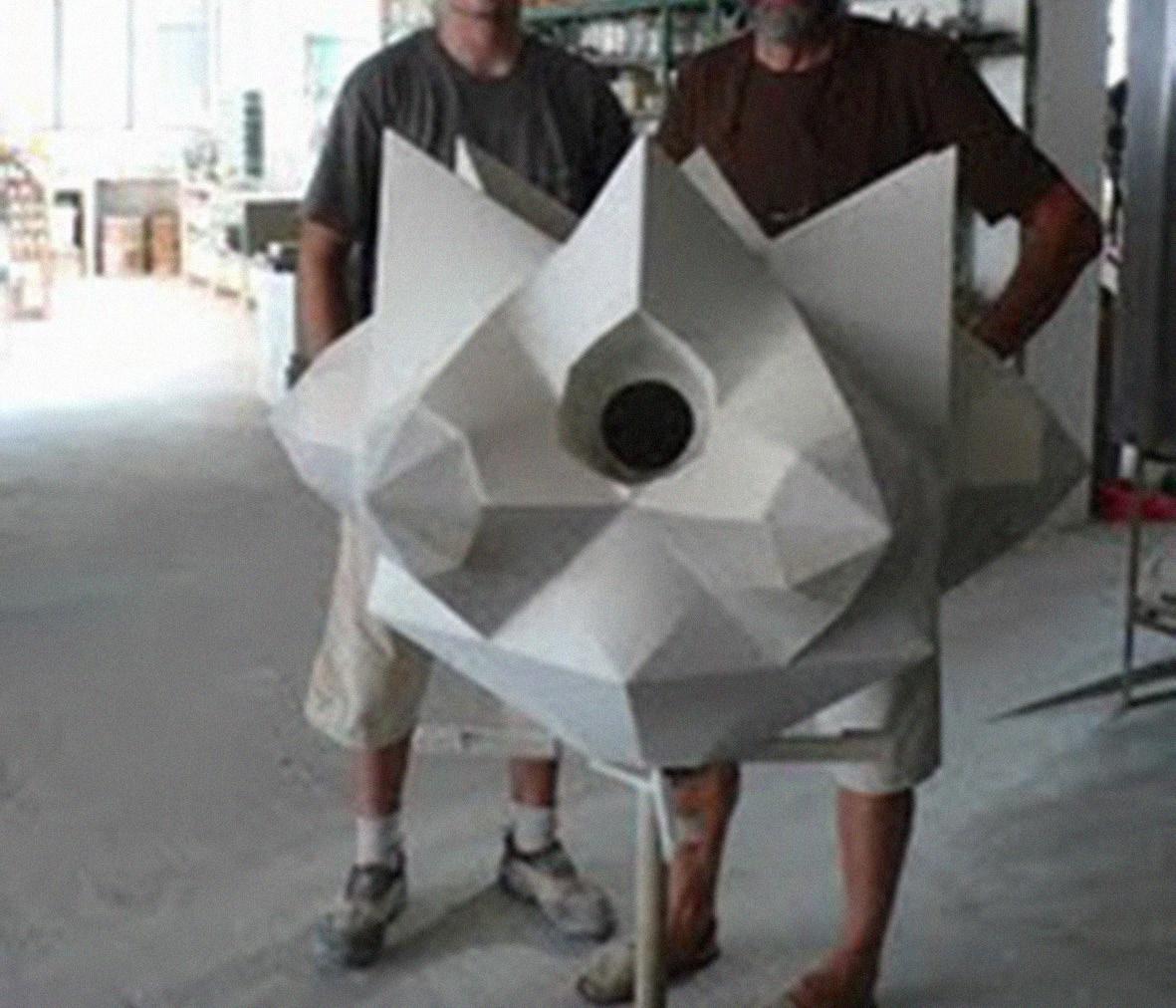
The second fabrication process analyzed, regarding ceramics production, is the slip casting. This technique is mainly applied for the fabrication of threedimensional pieces with especial complexity. One clear example of these applications are some pieces produced for the contemporary extension of “La Sagrada Familia” in Barcelona (Fig. 2.46). This process requires the design and fabrication of a complex mold. Its production is expensive and time consuming.
STEP 1. Material
The first step in the process is common with the extrusion process and the aim is to find the right ingredients for the clay. This decision is based on a continuous test of different combinations of additives, minerals and pigments and furthermore on a wide experience accumulated throughout years.
STEP 2. Moulding
For this sort of process the moulding fabrication is the most important part. Firstly, because the geometry is completely controlled and defined by the mold and , secondly, because depending on the piece’s complexity and its scale, the mould cost can be really high. It means that the piece’s production is quite limited and each piece requires a large amount of work and dedication. In the particular case of the pieces for “La Sagrada Familia” and due to the piece’s complexity, the mould was split into several pieces (Fig. 2.45) and each piece requires, at the same time, a mold for its fabrication. This master mould is usually made of wood or steel, depending on the quality, finishing and precision required. In this case, the mold is split in 3 pieces. These pieces are casted independently in stoneware and become the negative mould of our final piece. Each mold has to be very precise for a perfect assembly.
STEP 3. Pouring
A hole in the mold enables to pour the mixture and to extract the remaining mixture once the thickness required for the final piece has been achieved (Fig. 2.47).
When the liquid mixture is poured, and the mold is filled up, then starts the process of hardening. The more time you wait, the thicker the surface becomes. Once the desired thickness is achieved, the next step is to empty the mould, extracting the remaining mixture and then disassemble the mold into its pieces. The final piece is then released and ready to be fired in the kiln. The rest of the process (firing, drying and glazing) is exactly the same as the one followed for the extrusion process.
CONCLUSIONS:
Some conclusions arise from the understanding of the slip casting process:
1. Due to the time required for each piece in the process, this technique is not suitable for a construction system that aims variation. It only makes sense for the fabrication of special pieces.
2. The moulding fabrication is even more complex and important that the final piece so many pieces need to be done in order to afford the molding cost.
Cellular Reinforced Ceramics | Juanjo G. Castellon 2. Methods | 2.3 Traditional Manufacture
049
2.45
2.47
2.46
Fig.2.45-2.47 | Slip Casting process. Mould and final piece
2.4 Contemporary Manufacture
2.4.1 Digital Fabrication
2.4.2 CAD-CAM & CRAFTS
2. Methods | 2.4 Contemporary Manufacture
Cellular Reinforced Ceramics | Juanjo G. Castellon
051
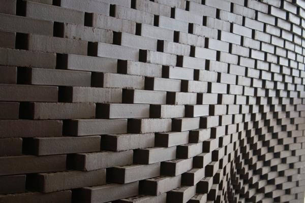
Fig.2.48 | The Programmed Wall. Gramazio & Kohler
2.4.1 Digital Fabrication
The fast development of digital tools has represented a revolution in contemporary design and fabrication. The application of CADCAM technologies and the appearance of digital fabrication tools such as Laser-Cutter ,CNC milling machine, Rapid Prototyping or Water-Jet Cutting machine has enabled innovative manufacture processes. In most of these cases, manpower has been significantly reduced and the quality of the final product relies almost completely on the machine. Suddenly there is no plan, no geometry, no drawing produced in the first instance. Instead, there is a page of instructions written in the machine’s command language4.
In this new scenario, some architects and fabricators have found a new source of collaboration in order to find new ways of building and to enable integrated processes of design and fabrication. Architects such as Gramazio & Kohler or fabricators such as Enrico Dini are developing contemporary strategies where design and parametric fabrication merge into one single process.
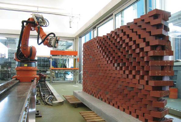
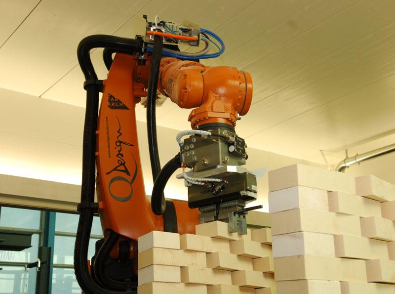
Gramazio & Kohler’s research is based on robotic fabrication. They have set up several experiments using a robot with an articulated arm and a brick as a basic and simple component. One example of these experiments was The Programmed Wall (Fig. 2.48) a project developed at the ETH Zurich in 2006. In this process the form of the wall is a result of a set of instructions programmed enabling the robot to produce different configurations according of the implicit geometry defined for the brick assembly. Nevertheless, for Gramazio & Kohler the final form is not important. Their main interest relies on the implementation of parametric tools in the fabrication process and its incidence in the new architect role. From this point of view, tools are transforming the architect profile towards a sort of architect-programmer. This new role enables the architect to recover the control of the construction process.
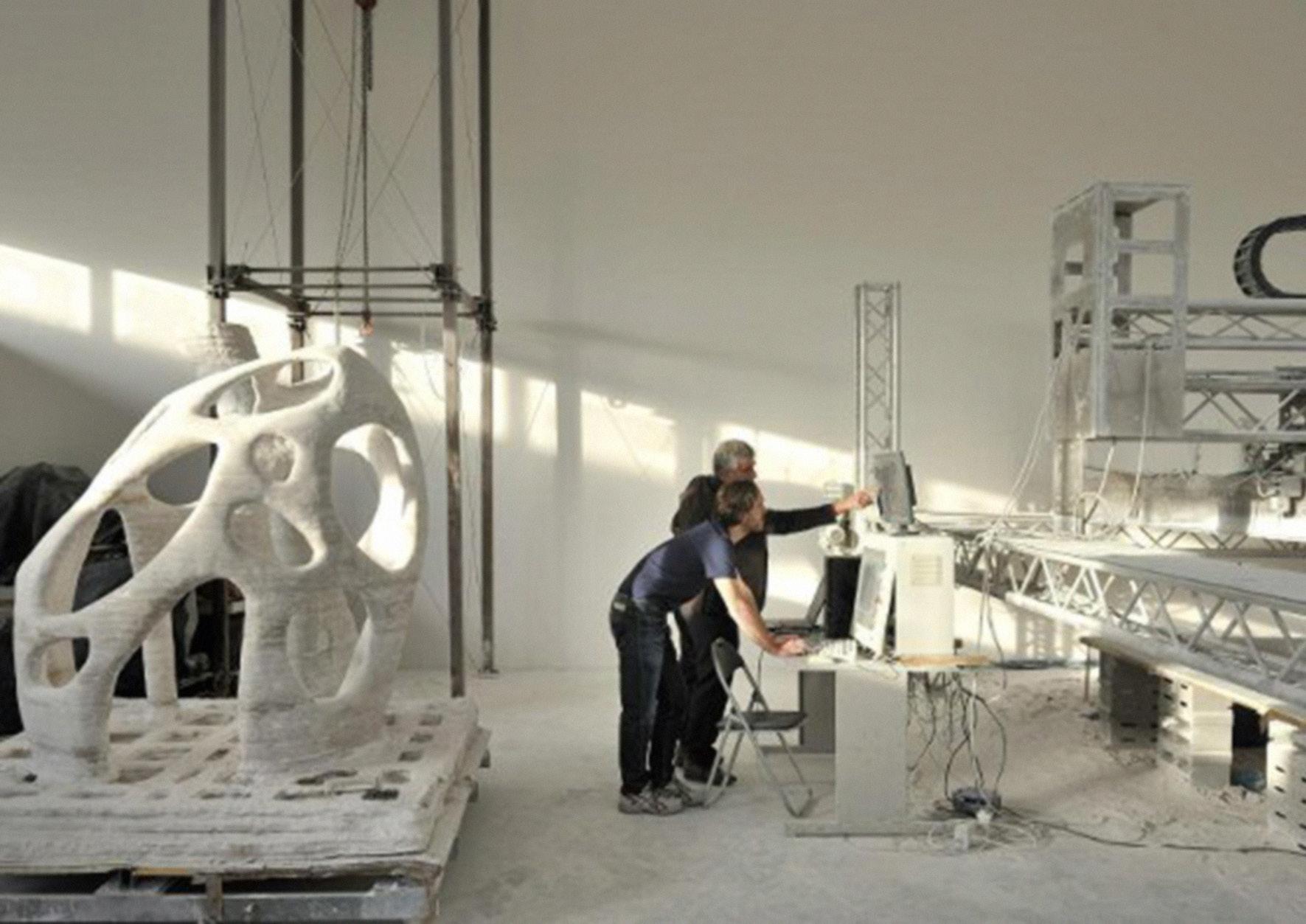
On the other hand, Enrico Dini, Italian engineer, invented, developed and patented the D-Shape Technology. His system is based on the stereolithography technique, also known as 3D printing. This technology enables to manufacture 3D objects from CAD drawings usually in small scale. The D-Shape system translates this process to a full scale fabrication. In 2004, Enrico Dini began experimenting with 3D printing using epoxy resin, inventing and patenting a full-scale 3D printing method that used epoxy to bind sand. In 2007 he got a new patent for a system using an inorganic binding material and any old sand to 3D print buildings5. Much of his expertise is highly specialised, marrying CAD-driven informatics and top-end robotics to a chemical process he doesn’t fully understand6.
Enrico Dini is currently working in collaboration with the architect Andrea Morgante in the design and construction of the Radiolaria Pavilion ( Fig.2.49) in Pontedera ( Italy ). The building will be built in parts before assembling it on site.
4 Kohler, M. The Robot and the Architect are Friends .Icon Magazine .July .2010
5 Abrahams, T. The World’s First Printed Building .Blueprint Magazine .March .2010
6 Kidman, H.. D-Shape. www.d-shape.com .July .2009
2. Methods | 2.4 Contemporary Manufacture
Cellular Reinforced Ceramics | Juanjo G. Castellon
053
Fig.2.48 | The Programmed Wall. 2006. ETH Zurich. Gramazio & Kohler
Fig.2.49 | Radiolaria Pavilion Prototype. 2009. Pontedera. Italy. Shiro Studio + D-Shape
2.4.2 CAD-CAM & CRAFTS |
Villa Nurbs. Cloud9 + Toni Cumella
Taking into account the potential of new digital fabrication tools and the experience achieved by traditional manufacturers throughout decades, a third option appears in the horizon. This third alternative is what I would like to call CAD-CAM & CRAFTS, a hybrid approach that combines the benefits of using new technologies with the experience and skills of traditional manufacturers.
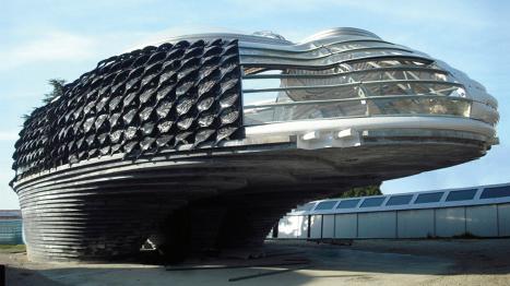
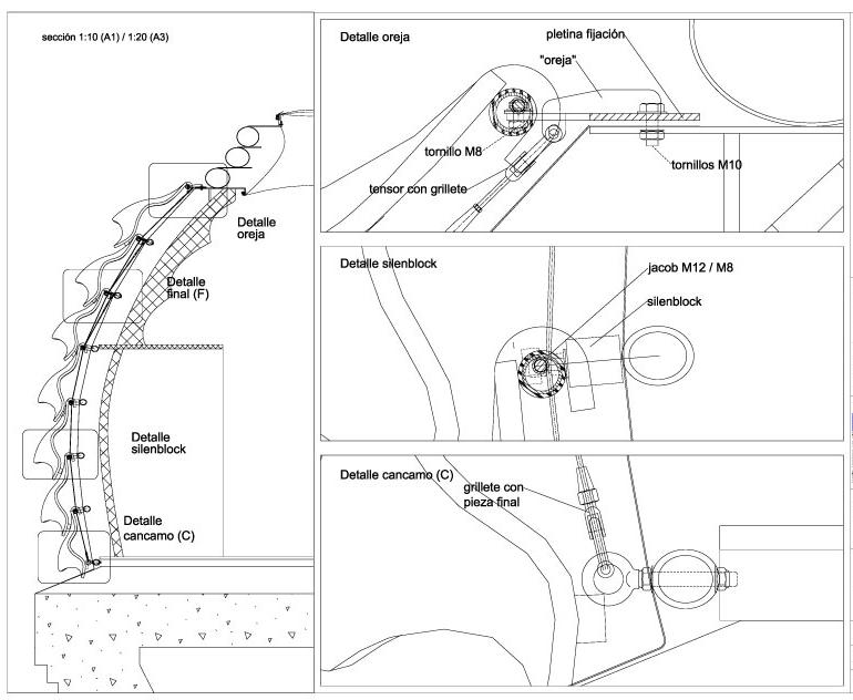
One interesting example of this hybrid approach was applied in the design and fabrication of the ceramic skin system for the Villa Nurbs (Fig.2.50). This project is the result of a collaboration between an architect, a ceramist and an artist and combines in its fabrication process CAD-CAM technologies with traditional industrial processes (Fig.2.54).
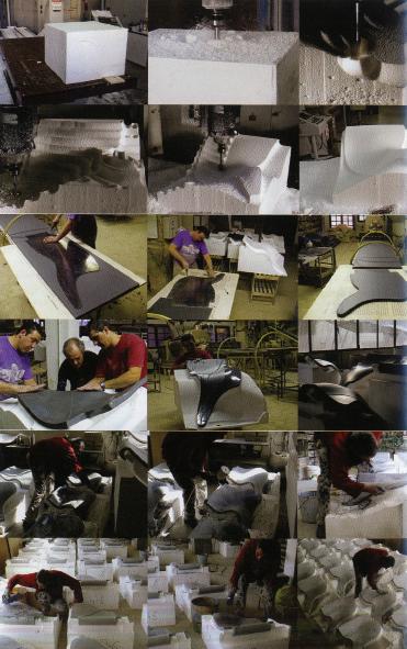
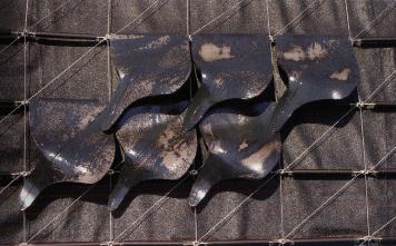
Using CAD-CAM technologies, 23 different molds are generated by a CNC-milling machine. On the other hand a sheet of clay is generated with a standard extrusion process. In parallel, 23 metal templates are produced with a Laser-Cutter. These templates are used to cut manually the profile of the ceramic piece. Next the cut pieces are placed again manually on top of the 3D molds. The pieces are then fired and finally the artist Frederic Amat applies the glazing.
This project is an interesting reference of how contemporary and traditional techniques can be merged in a hybrid and provocative process.
Fig. 2.50 | Villa Nurbs. Girona. Spain. 2011. Cloud9
2. Methods | 2.4 Contemporary Manufacture
Cellular Reinforced Ceramics | Juanjo G. Castellon

055
Fig. 2.53 | Ceramic skin. Configurations.
Fig. 2.52 | Ceramic skin. Facade Structure.
Fig. 2.54 | Ceramic Skin. Fabrication process. CAD-CAM & Crafts
Fig. 2.51 | Ceramic Skin. Detailed Plan
2.5 Evaluation & Summary
From the analysis and evaluation of the methods selected, some conclusions arise:
1. Workshop vs. Company.
Traditionally, there is a clear relationship between production volume and industrial process. For a high production volume, the industrial process is highly technological and controlled, and, therefore the final product is standardized. Customization is, in this case, just possible in terms of finishes. The more production volume decreases the higher is the degree of potential freedom and experimentation.
2. Process vs. Catalogue.
Likewise, the fabrication process in a workshop promotes the development of processes. Tools and methods are adapted, in this case, to the specific requirements of the project which promotes customization. On the other hand, mass production promotes working with a catalogue of pre-defined products.
3. Digital vs. Analog.
Contemporary construction aims to incorporate digital tools into the process whereas traditional construction involves analog tools and processes. In this scenario two main new approaches arise:
- DIGITAL FABRICATION removes the existing gap between design and construction transforming the traditional role of the architect into a designer-programmer. The architect recovers, in that way, the control of the process.
- CAD-CAM & CRAFTS is a hybrid process that involves analog and digital techniques in order to combine precision, variation, customization and, at the same time, tradition, experience and refinement.
2. Methods | 2.5 Evaluation & Summary Cellular Reinforced Ceramics | Juanjo G. Castellon


Digital Analog
Fig. 2.59 | CAD-CAM & Crafts. Analog + Digital
Fig. 2.55 | Analog Technology. Pressure and Temperature control
Fig. 2.56 | Analog Technology. Manpower required
Fig. 2.57 | Digital Technology. Parametric Control Tools
057
Fig. 2.58 | Digital Technology. Robotic Fabrication
3. Experiments
3.1 Introduction
3.2 Experiment 01 | Advanced Cohesive Fabrication
3.2.1 Parametric Moulding System. Prototype 01
3.2.2 Material System. Honeycomb & Cement Composite
3.2.3 Parametric Moulding System. Prototype 02
3.2.4 Material System. Honeycomb & Ceramics Composite
3.2.5 Parametric Moulding System. Prototype 03
3.2.6 Parametric Model. Generative Process
3.2.7 Parametric Model. Assebly Logics
3.2.8 Parametric Model. Panelization System
3.3 Experiment 02 | Cellular Reinforced Ceramics
3.3.1 Aluminium Honeycomb | Deformation Behaviour
3.3.2 Material System | NEX Honeycomb Mesh + Ceramic Bricks
3.3.3 Parametric Model | Geometrical Logics
3.3.4 CAD-CAM & CRAFTS| Non-Uniform Extrusion
3.4 Evaluation & Summary
059
3.1 Introduction
After defining the theoretical framework, a set of experiments were deployed. These experiments were developed using both physical-analog and virtual-digital models. The main goal is to provoke an interaction between both platforms enabling, potentially, an innovative design and fabrication process.
The first set of experiments, based in the works developed by Rafael Guastavino and Eladio Dieste, is focused in the research of a material and parametric molding system that involves cement, ceramics and honeycomb aluminum mesh. The aim is to investigate an updated version of the traditional brick by incorporating better performance under tensile strength and variation in the fabrication process.
The second set of experiments is developed following the same strategy but working with non-expanded honeycomb aluminum mesh and blowing up the scale.
Both experiments are implemented by the use and application of parametric tools in order to explore the geometrical, spatial and structural potential of the system.
3. Experiments | 3.1 Introduction
Cellular Reinforced Ceramics | Juanjo G. Castellon
061
3.2 Experiment 01|
Cellular Reinforced Ceramics | Juanjo G. Castellon
Advanced
Cohesive Fabrication 3.2.1 Parametric Moulding System. Prototype 01
3.2.2 Material System. Honeycomb & Cement Composite
3.2.3 Parametric Moulding System. Prototype 02
3. Experiments | 3.2 Experiment 01
3.2.4 Material System: Honeycomb & Ceramics Composite 3.2.5 Parametric Moulding System. Prototype 03 3.2.6 Parametric Model. Generative Process 3.2.7 Parametric Model. Assembly Logics 3.2.8 Parametric Model. Panelization System
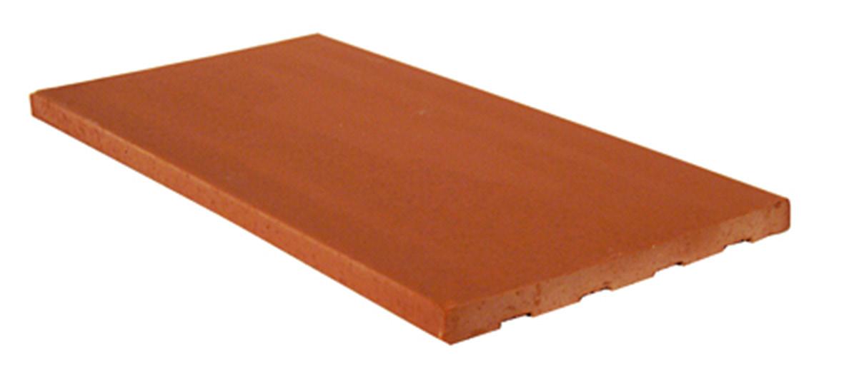
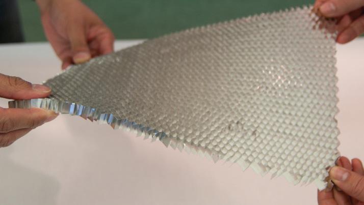
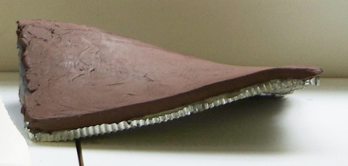
+ 063
Fig. 3.01 | Catalan Rasilla. Traditional Brick
Fig. 3.02 | Honeycomb Aluminum Mesh. Reinforcement
Fig. 3.03 | Honeycomb Composite. EX- Honeycomb Aluminium Mesh + Cement + Ceramics
3.2.1 Parametric Moulding System | Prototype 01
A. Aim
In this first experiment the aim is to explore the potential development of a parametric moulding system in order to introduce variation in the fabrication process. The fabrication of a parametric brick will be explored using plaster and applying two simple logics: Twist and Bend (Fig.3.05).
B. Experiment
- The first prototype for the parametric moulding system is built using wood for the structure and a latex sheet for the flexible moulding bed (Fig.3.04). The structure enables to twist and bend the latex sheet and, therefore, to test different geometries.
- The material used for the brick fabrication is plaster and it is poured once the form expected is fixed in the mould (Fig.3.06). Several configurations are tested with this technique obtaining a family of bricks (Fig.3.07)
C. Conclusion
By the application and combination of two simple geometric transformations ( twist and bend ) we achieve an interesting tool in order to introduce variation in the fabrication process. Nevertheless, the use of plaster is not suitable for construction since it is an extremely brittle. Moreover the latex bed is highly deformable under the material weight.
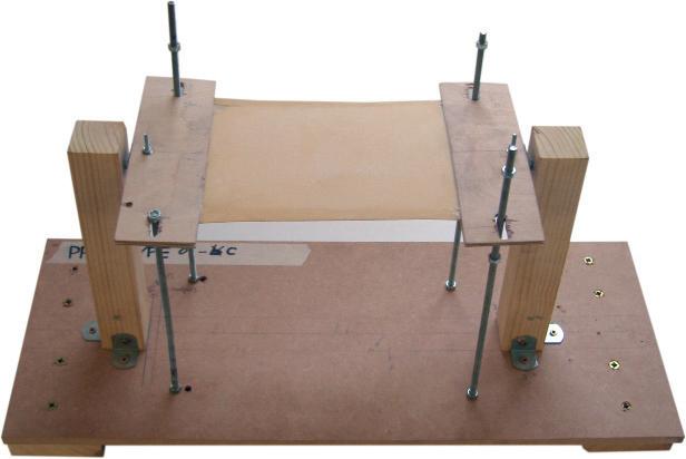
3. Experiments | 3.2 Experiment 01
Cellular Reinforced Ceramics | Juanjo G. Castellon
Fig. 3.04 | Parametric Moulding. Prototype 01. Description
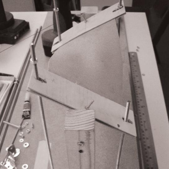
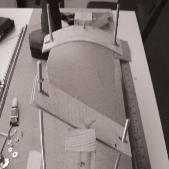

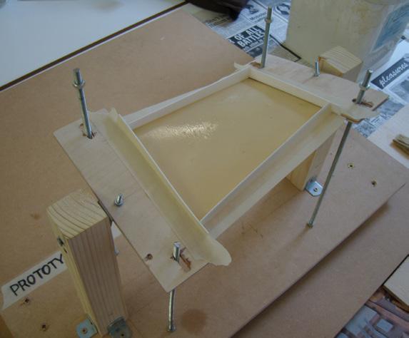
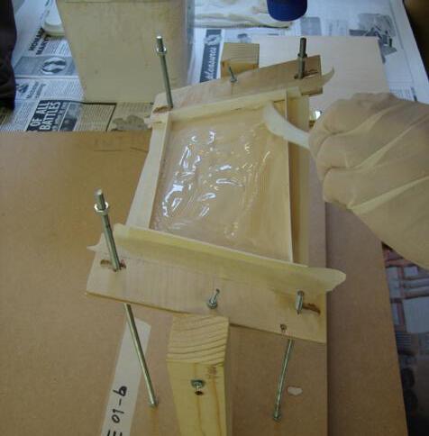

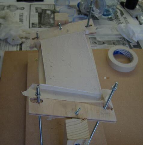 Fig. 3.05 | Parametric Moulding System. Configurations by twisting and bending
Fig. 3.06 | Parametric Moulding System. Test Sequence.
Fig. 3.07 | Parametric Brick. Final Plaster production
Configuration 01 | Twisting Configuration 02 | Bending Step 1 Prepare the latex bed including frame and twisted geometry Step 2 Pour plaster on top of the latex bed Step 4 Wait until plaster gets dried Step 3 Fill the mould to achieve the final thickness 065 1 2 3 4 Lenght Parameter Height
Fig. 3.08 | Parametric Moulding System. Parameters and Geometry
3.2.2 Material System: Honeycomb & Cement Composite
A. Aim
In the second experiment, the aim is to explore a composite material system in order to improve the structural behavior of the traditional brick. The main concept relies on the combination of cement with a metal reinforcement that assumes the tension stresses and reduces the brittle behavior observed in the plaster tests.
B. Experiment
- The aluminium honeycomb mesh is the material selected as reinforcement for the composite panel. It is light and flexible and commonly used as core reinforcement in sandwich panels. The honeycomb panel dimension is A4 , 10mm thick and 6mm cell size.
- A first layer of fine cement mixture is poured in a plexiglass mould (Fig. 3.12), then the honeycomb mesh is attached to the mould and a second layer of cement is poured filling the cells (Fig.3.09).
- The same test is repeated adding a glass fiber sheet between the honeycomb panel (Fig.3.11) and the final layer of cement.
C. Conclusion
The composite material explored by the combination of cement and honeycomb mesh reduces significantly the brittle behavior observed in the plaster test. In addition, the honeycomb aluminum mesh improves the stiffness and the structural potential of the panel. On the other hand, the fine cement is not suitable for construction. Finally, the addition of glass fibers hinders the right connection between cement and mesh.
Cellular Reinforced Ceramics | Juanjo G. Castellon 3. Experiments | 3.2 Experiment 01
Fig. 3.09 | Composite Panel. Honeycomb + Cement. Detailed Section


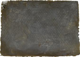

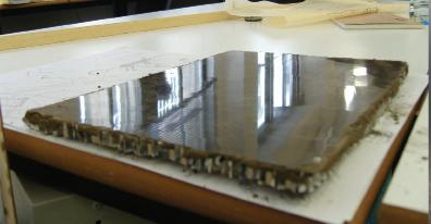
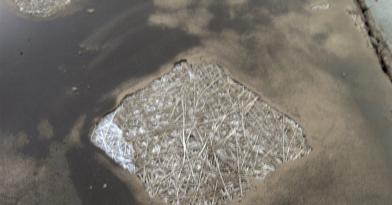 Fig. 3.13 | Flat Panel. Final pice with glossy finishing
Fig. 3.10 | Test 01. Flat Panel. Honeycomb + Fine Cement
210
Fig. 3.11 | Test 01. Flat Panel. Honeycomb + Glass Fibers Fig. 3.12 | Flat Panel. Production Sequence
297 mm
mm
Fig. 3.14 | Flat Panel. Glassfibers test
Step 1 Prepare the Plexiglas moulding bed
Step 1 Prepare the Plexiglas moulding bed
Step 2 Pour the first layer of cement mixture
Step 2 Pour the first layer of cement mixture
Step 3 Spread the mixture along the surface
Step 3 Add Glass-fibers layer to the mixture
Step 4 Attach the honeycomb aluminium panel
Step 4 Attach the honeycomb aluminium panel
Step 5 Pour second layer of cement mixture filling in the cells
067
Step 5 Pour second layer of cement mixture filling in the cells
3.2.3 Parametric Moulding System | Prototype 02
A. Aim
In this third phase of the experiment, the aim is to combine the parametric moulding system explored in the first experiment (prototype 01) with the material composite explored in the second one. In order to do that, some improvements will be done both to the parametric moulding system and to the material system.
B. Experiment
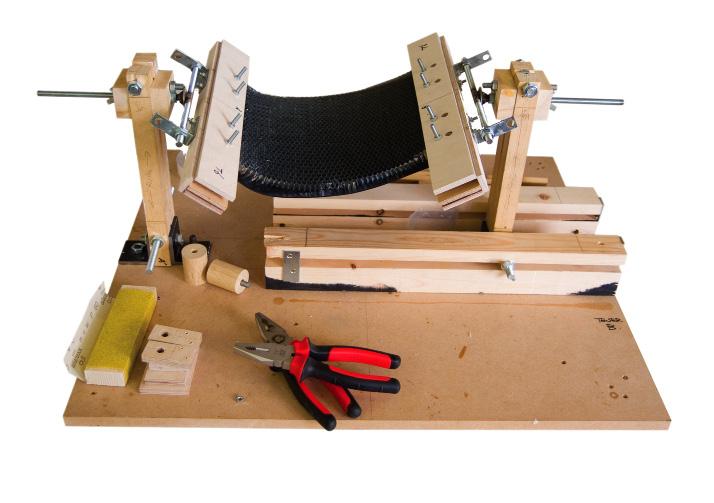
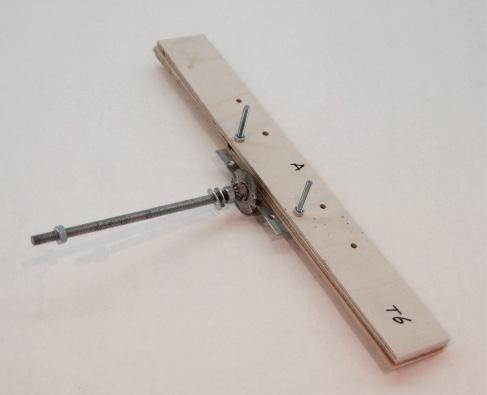
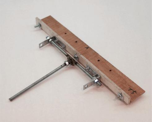
- A new parametric moulding system is built (Fig.3.15) incorporating some improvements to the previous one. Firstly, the latex sheet is replaced by a rubber sheet to add more resistance against the self-weight of the mixture and, at the same time, keeping certain degree of flexibility to the system. Secondly, two mechanical arms are designed to hold the rubber sheet and the honeycomb mesh. Finally, the fine cement is replaced by Extra-Rapid Cement.
- The production process is similar to the one developed in the first experiment. Form is produced by controlling twisting and/or bending parameters (Fig.3.17). Then the honeycomb panel is attached to the rubber sheet and the cement is poured on top of it.
C. Conclusion
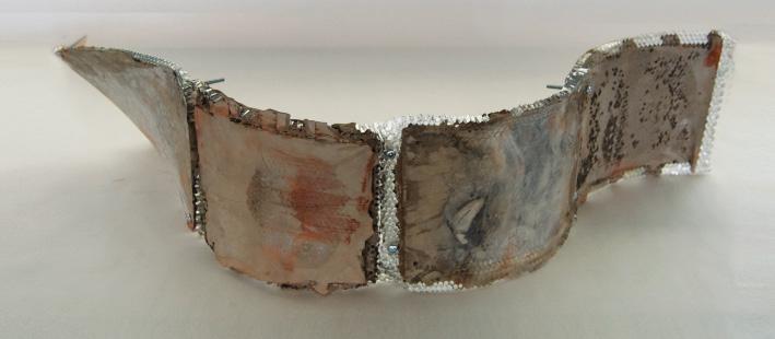
This new moulding prototype enables to fabricate three-dimensional honeycomb composite panels (Fig.3.16). Furthermore, the honeycomb panel is now explored as reinforcement, but also as flexible formwork. Consequently, the honeycomb mesh becomes form and structure. On the other hand, the rubber sheet is not flexible enough and doesn’t match with the honeycomb geometrical behavior.
Fig. 3.15 | Parametric Moulding System. Prototype 02. Cellular Reinforced Ceramics | Juanjo G. Castellon
3. Experiments | 3.2 Experiment 01
(Adjusting Length)


 Step 1 Prepare the rubber bed
Mechanical arm for Twisting
Mechanical arm for Bending
Step 2
Attach the honeycomb to rubber layer
Step 2 Attach the honeycomb to rubber layer
Step 3
Pour Cement
Step 3 Pour Cement
Step 4 Wait until hardening
Step 4 Wait until hardening
Fig. 3.16 | Parametric Moulding System. Assembly Test of 4 panels
Step 1 Prepare the rubber bed
Step 1 Prepare the rubber bed
Mechanical arm for Twisting
Mechanical arm for Bending
Step 2
Attach the honeycomb to rubber layer
Step 2 Attach the honeycomb to rubber layer
Step 3
Pour Cement
Step 3 Pour Cement
Step 4 Wait until hardening
Step 4 Wait until hardening
Fig. 3.16 | Parametric Moulding System. Assembly Test of 4 panels
069
Fig. 3.17 | Parametric Moulding System. Prototype 02. Production Sequence
3.2.4 Material System | Honeycomb & Ceramics Composite
A. Aim
The aim of this experiment is to incorporate ceramics in the composite material.
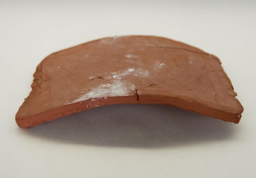
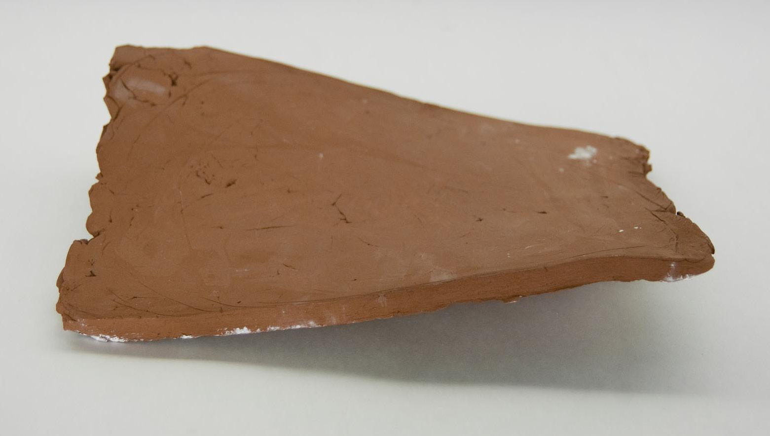
B. Experiment
- The three-dimensional panels produced in the previous experiment perform as formwork for the ceramic layer.
- A mixture of terracotta clay is compacted and applied on top of the three-dimensional panel-formwork adopting the precise form (Fig.3.21). The piece is then fired in a kiln (Fig.2.18) and attached with cement to the honeycomb panel composite forming a multilayered panel (Fig.3.20)
C. Conclusion
One potential application of the system is to add a ceramic skin in order to control the finishing of the panel and take benefit of its material properties. Thus, the piece generated with the parametric moulding system can be used as formwork for the ceramic piece. On the other hand, the shrinkage produced by the firing process, has to be taken into account and the ceramic layer increases the weight of the panel.
Cellular
|
3. Experiments | 3.2 Experiment 01
Fig. 3.18 | Final Ceramic Pieces. Twisted and Bended
Reinforced Ceramics
Juanjo G. Castellon
Fig. 3.19 | Composite Panel. Honeycomb + Cement. Detailed Section
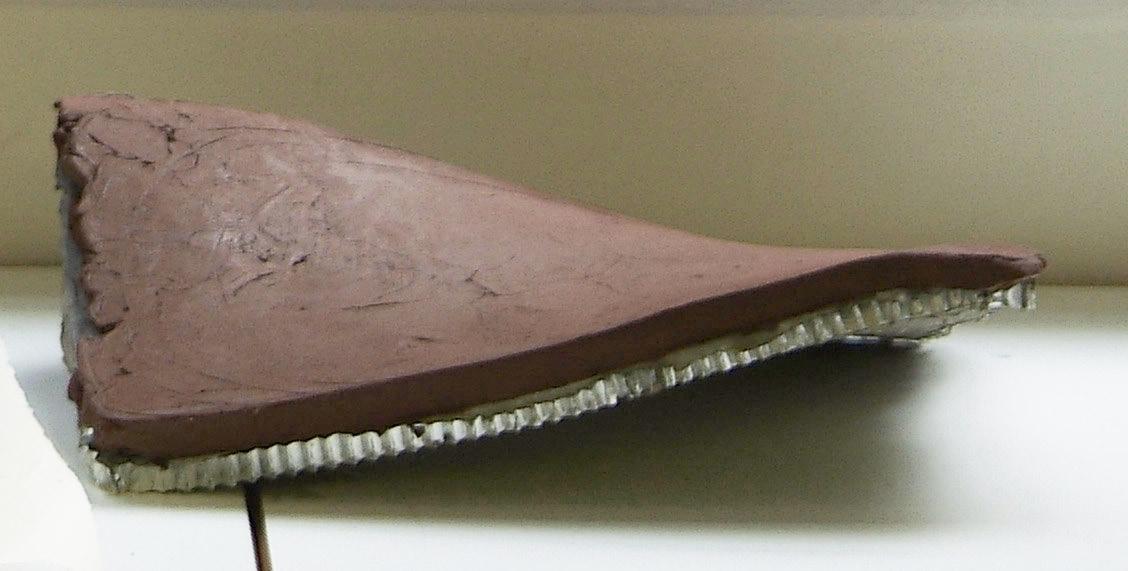
 Fig. 3.20 | Multi-layered system Ceramic Skin.
071
Fig. 3.21 | Final Panel honeycomb + ceramics composite
3.2.5 Parametric Moulding System | Prototype 03
A. Aim
The aim of this experiment is to develop the final prototype for the parametric moulding system adding the improvements required
B. Experiment
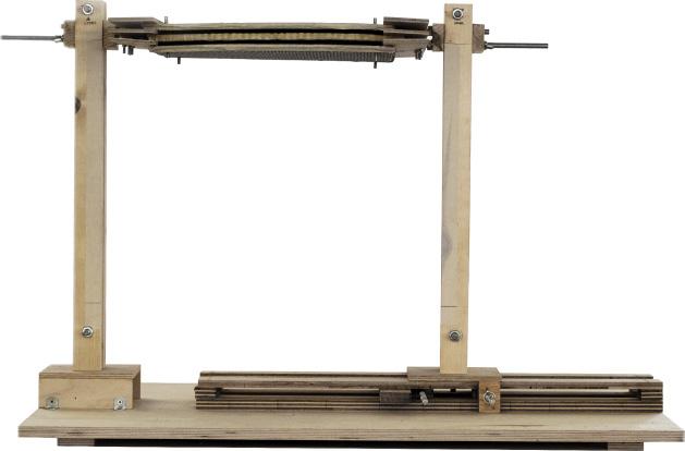
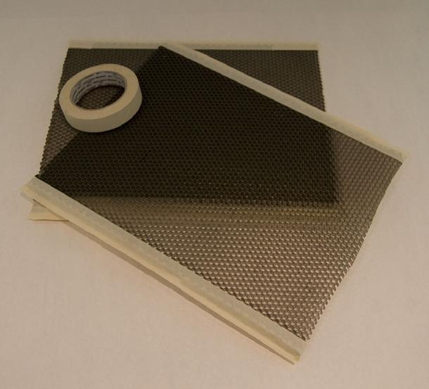
- From the experience achieved in previous tests, the rubber sheet is replaced by a honeycomb aluminium panel wrapped with a latex sheet (Fig.3.23). Therefore, the panel is now, at the same time, moulding bed, panel reinforcement and system’s formwork taking the maximum benefit of the material properties.
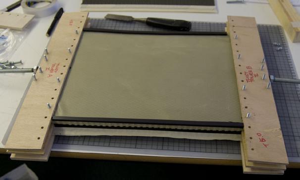
- The moulding system is refined and scaled up to fabricate A3 sized panels (Fig.3.22). In addition, a three layer system is developed (Fig.3.25) in order to produce two panels at once and inserting the moulding bed in between.
- The production sequence is similar to the ones previously described. The form, twisted or bended (Fig.3.24), is generated with the flexible moulding system. The fast-setting cement is poured (Fig.3.26) and, once it starts hardening, the mould is flipped over and the cement is poured again.
C. Conclusion
This final prototype is highly successful. The final piece produced is strong, resistant and well finished. The honeycomb composite proves to be, potentially, a good material for architectural applications. Finally, the parametric moulding system enables a fabrication process that incorporates variation in the fabrication process and efficiency in the material system. In further developments, the assembly logics would be a key issue. The main aim now is to link the fabrication process with digital and parametric tools.
350mm (vertical adjustment) 400mm
(horizontal adjustment)
Fig. 3.22 | Parametric Moulding System. Prototype 03
Cellular
Fig. 3.23 | Moulding Bed preparation
Reinforced Ceramics | Juanjo G. Castellon
3. Experiments | 3.2 Experiment 01
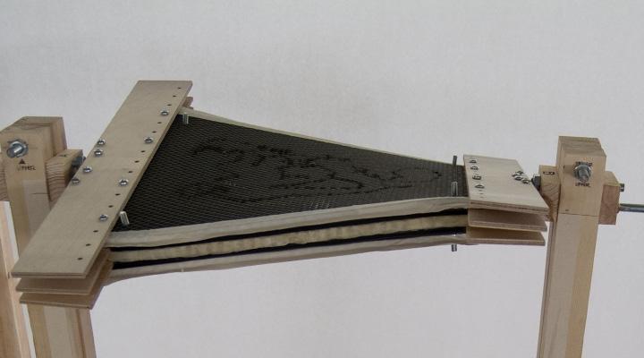
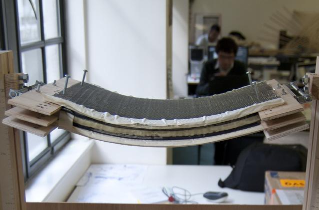
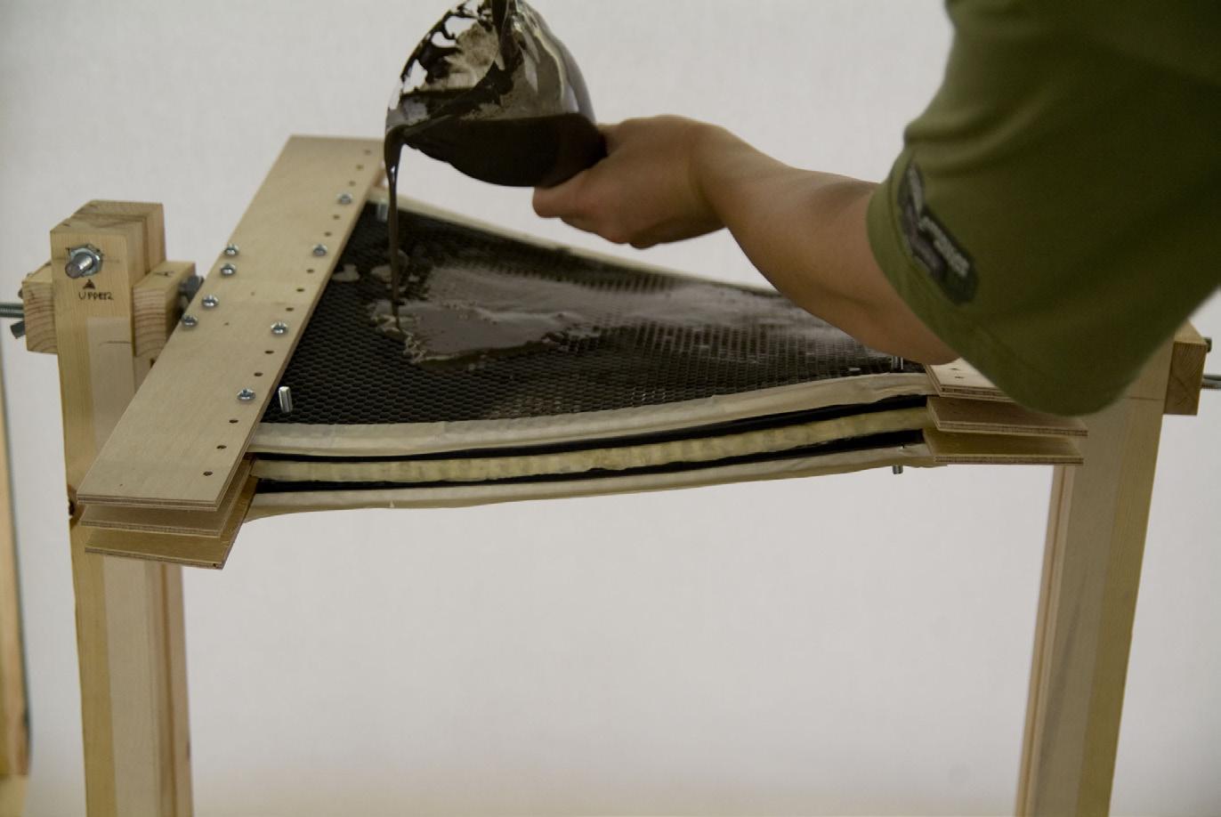
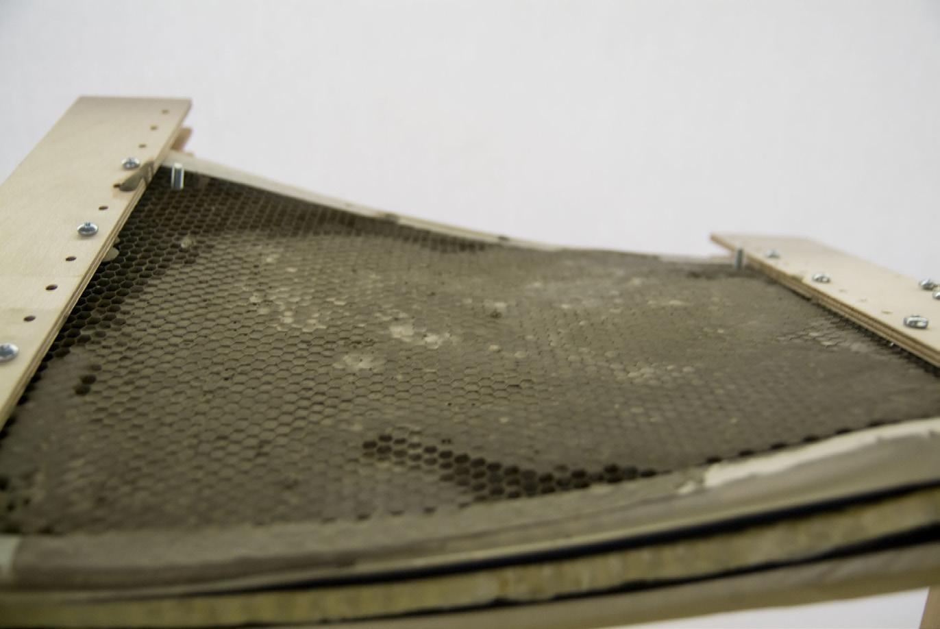
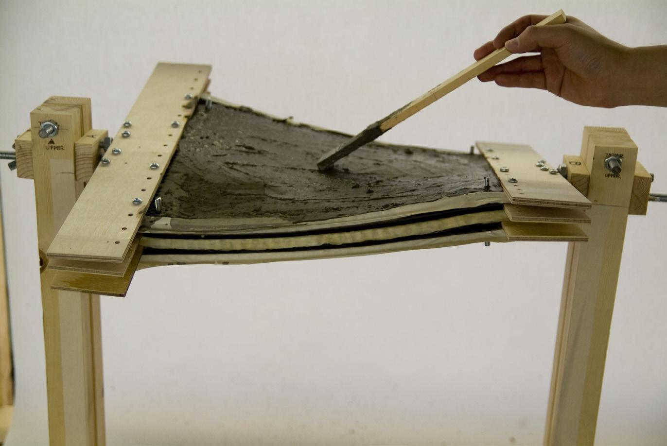
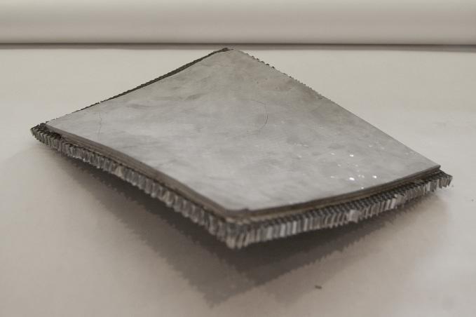 Fig. 3.26 | Parametric Moulding System. Production Sequence
Fig. 3.27 | Final Piece. Honeycomb + Cement
Fig. 3.24 | Twisted and Bended Configuration
073 3 4 1 2
Fig. 3.25 | Parametric Moulding. Multi-layered System. Detail
3.2.6 Parametric Model | Generative Process
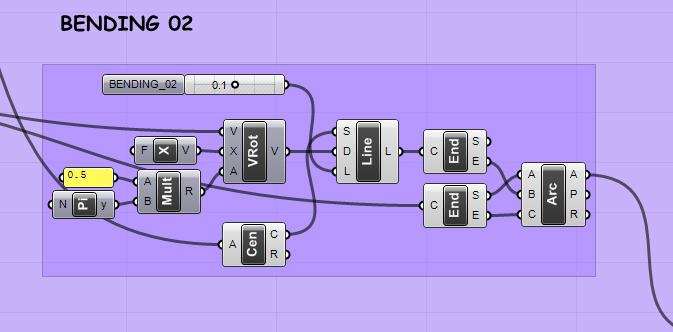
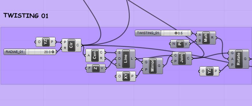
After the set of physical experiments previously done, a digital-parametric model is developed. This model takes into account the same parameters that the ones applied during the fabrication process. Basically, the angle of twisting and the panel curvature (Fig.2.28) are the two main parameters that control the panel geometry. Consequently, the form of the panel can be precisely defined and it is possible to deploy, digitally, the potential of the system.
The digital model makes possible a generative process that explores the potential assembly of several three-dimensional panels (Fig.3.30). The main aim is to link the digital model with the physical model in order to enable an innovative fabrication process based in the combination of analog and digital processes.
Finally, a potential structural application of the system is proposed. This application is based in the fabrication of a sandwich structure (Fig.3.31) that performs as lost formwork. The concrete can be poured in between the formwork foming, eventually, a composite structural system.
Lenght
Fig. 3.28 | Parametric Model. Logics and Geometry
Config. 01 | Twist
Cellular
|
G.
3. Experiments | 3.2 Experiment 01
Config. 02 | Bend
Reinforced Ceramics
Juanjo
Castellon
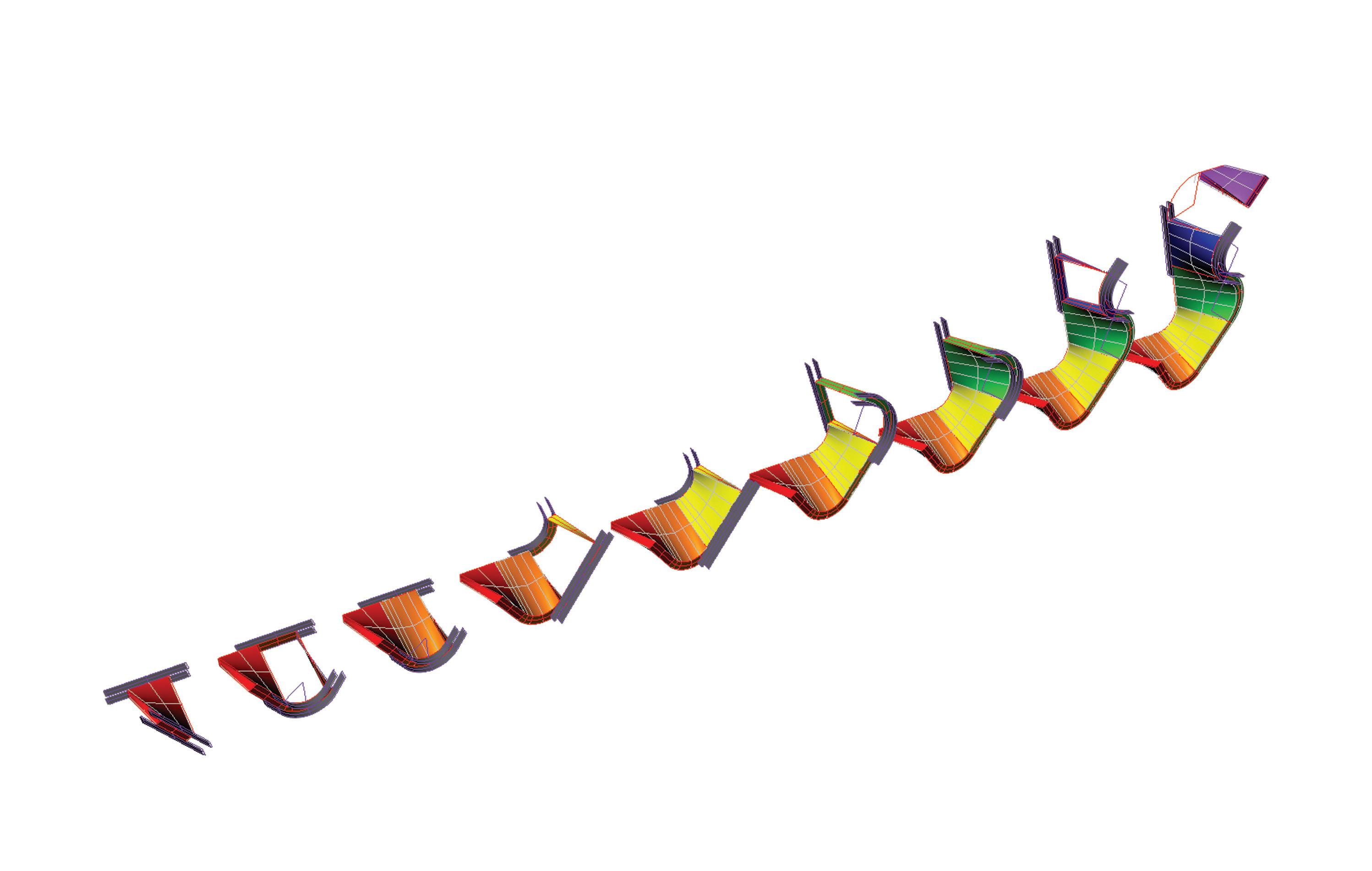
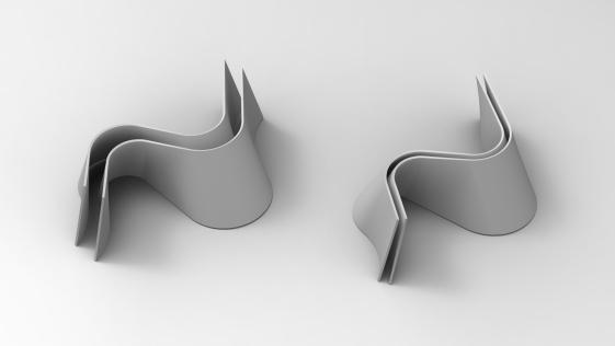
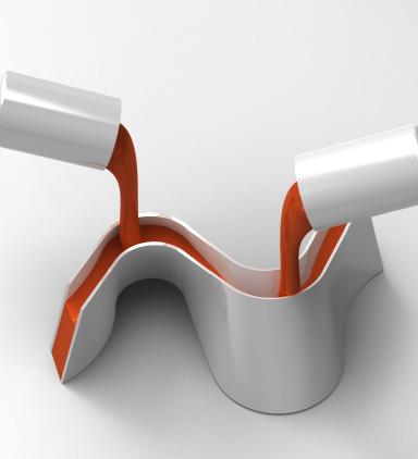

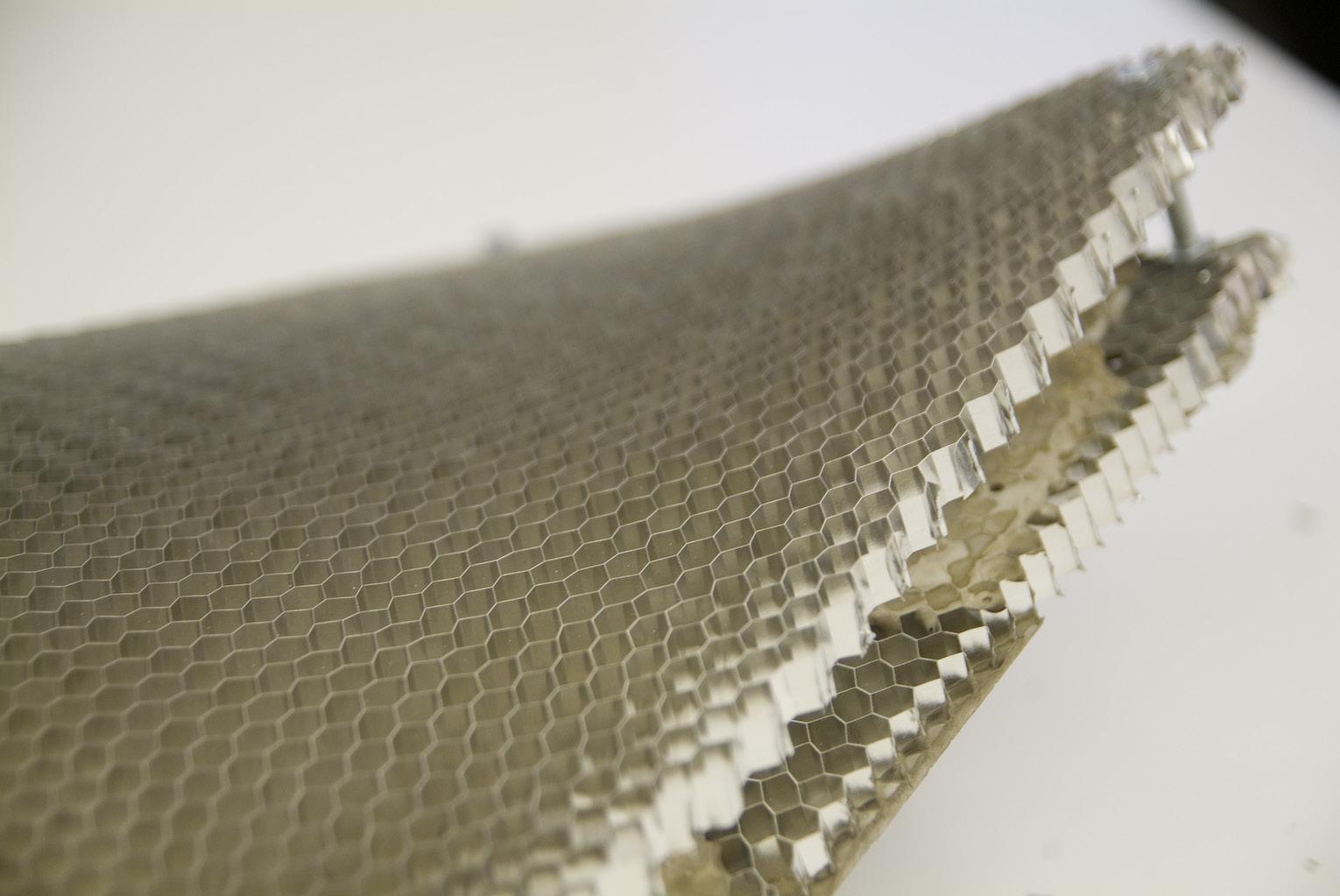 Fig. 3.32 | Possible configuration as a lost Formwork
Fig. 3.33 | System used as a lost formwork. Pouring Concrete
Fig. 3.31 | Preparation of a Sandwich panel System.
075
Fig. 3.30 | Generative Process. Parametric Assembly
3.2.7 Parametric Model | Assembly Logics
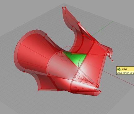
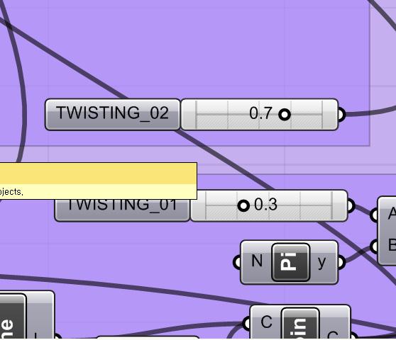
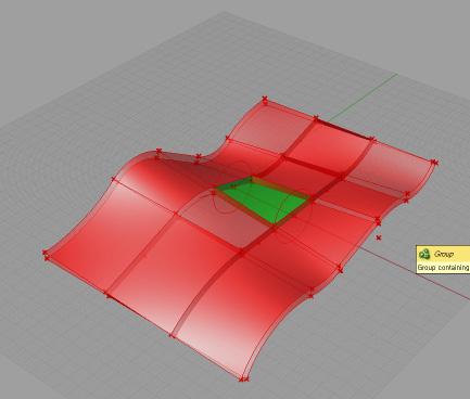
Following the digital experiments, a second parametric model is developed. This time the main aim is to explore the tangency logics in order to build smooth ruled surfaces (Fig.3.39). In this parametric model the global form depends on the component geometry. By changing the geometry of one of the panels, the rest of the panels adapt to the new configuration following tangency logics.
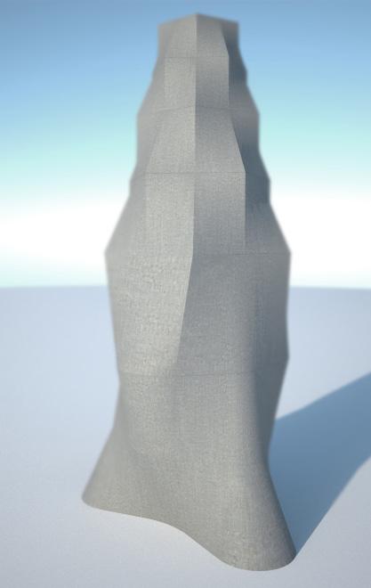
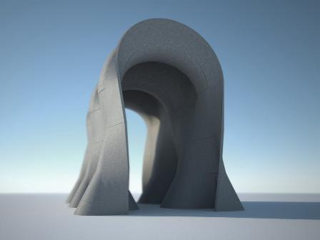
On the other hand, some formal studies are developed trying to incorporate structural principles in the parametric model linking form and structure (Fig.3.34). Consequently, some geometrical principles are applied in order to assembly the panels and configuring structural arrangements.
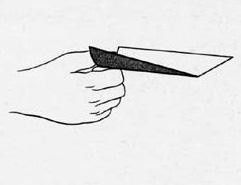
The first geometrical study is developed to build a dome configuration (Fig.3.37,3.35) and the second one is developed to build a vaulted structure (Fig.3.38,3.36)
 Fig. 3.38 | Geometrical Studies. Sequence of Generation. Vaults
Fig. 3.37 | Geometrical Studies. Sequence of Generation. Dome
Fig. 3.35 | Structural Application. Dome
Fig. 3.34 | Double Curved Surface. Stiffness Principle
Cellular Reinforced
|
G.
3. Experiments | 3.2 Experiment 01
Fig. 3.36 | Structural Application. Vaults
Ceramics
Juanjo
Castellon



077
Fig. 3.39 | Parametric Model. Configurations.
3.2.8 Parametric Model | Panelization System
The last digital exploration in this set of experiments is focused in the panelization system. The aim is to use the minimum amount of panels in the construction process. In order to achieve that, a deep geometrical understanding is required and some experiments are deployed.
The first digital experiment is based in the exploration of the relationship between the amount of panels and the potential forms that can be generated with them (Fig.3.40).
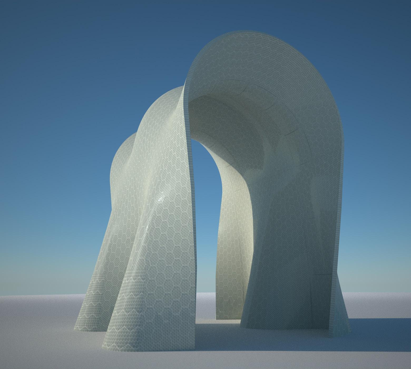
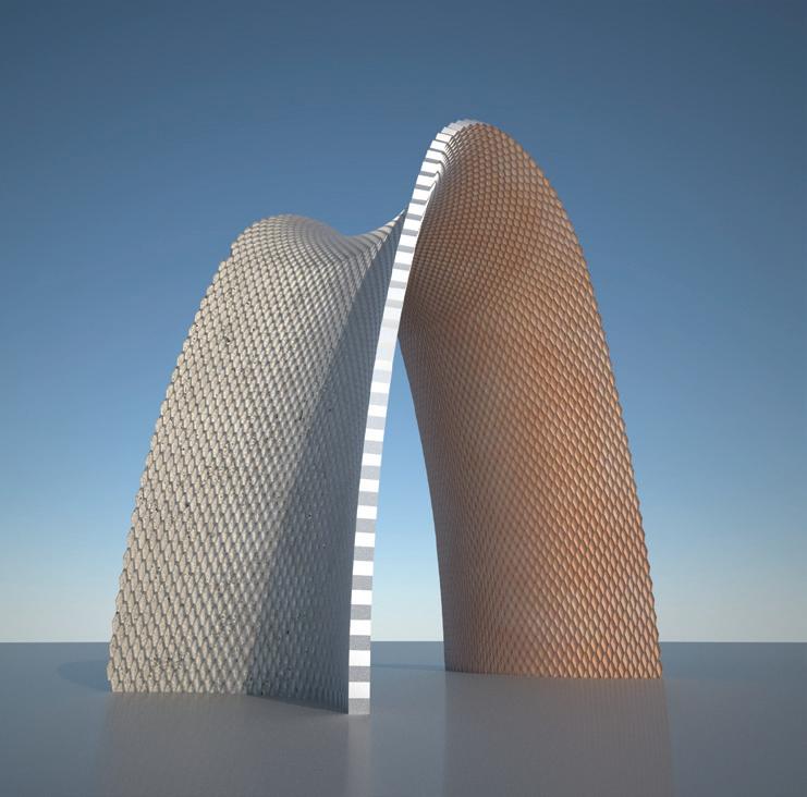
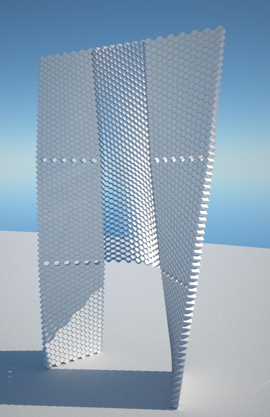
Secondly, this logic is applied in the generation of a vaulted space (Fig.3.45) testing the minimum amount of panels needed for its construction. Instead of designing the global form and making the panels “a posteriori”, this process aims to control the panel geometry as a design tool to generate the final form (Fig.3.41).
On the other hand, the geometry of the honeycomb structure shows a potential solution for solving the joint between the panels (Fig.3.44).
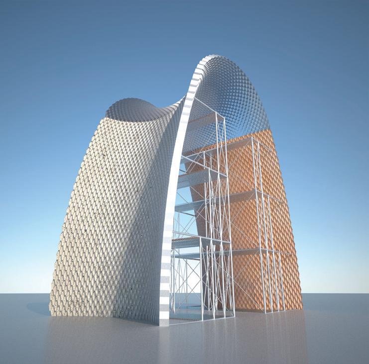
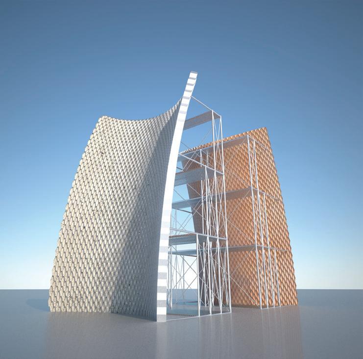
Finally, the construction process is explored (Fig.3.46), proposing a potential construction sequence and blowing up the scale of the system by splitting the system in two processes: the honeycomb metal mesh (tension structure) and the ceramic pieces (compression structure).
Cellular Reinforced Ceramics |
G.
3. Experiments | 3.2 Experiment 01
Juanjo
Castellon
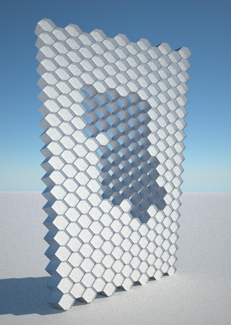
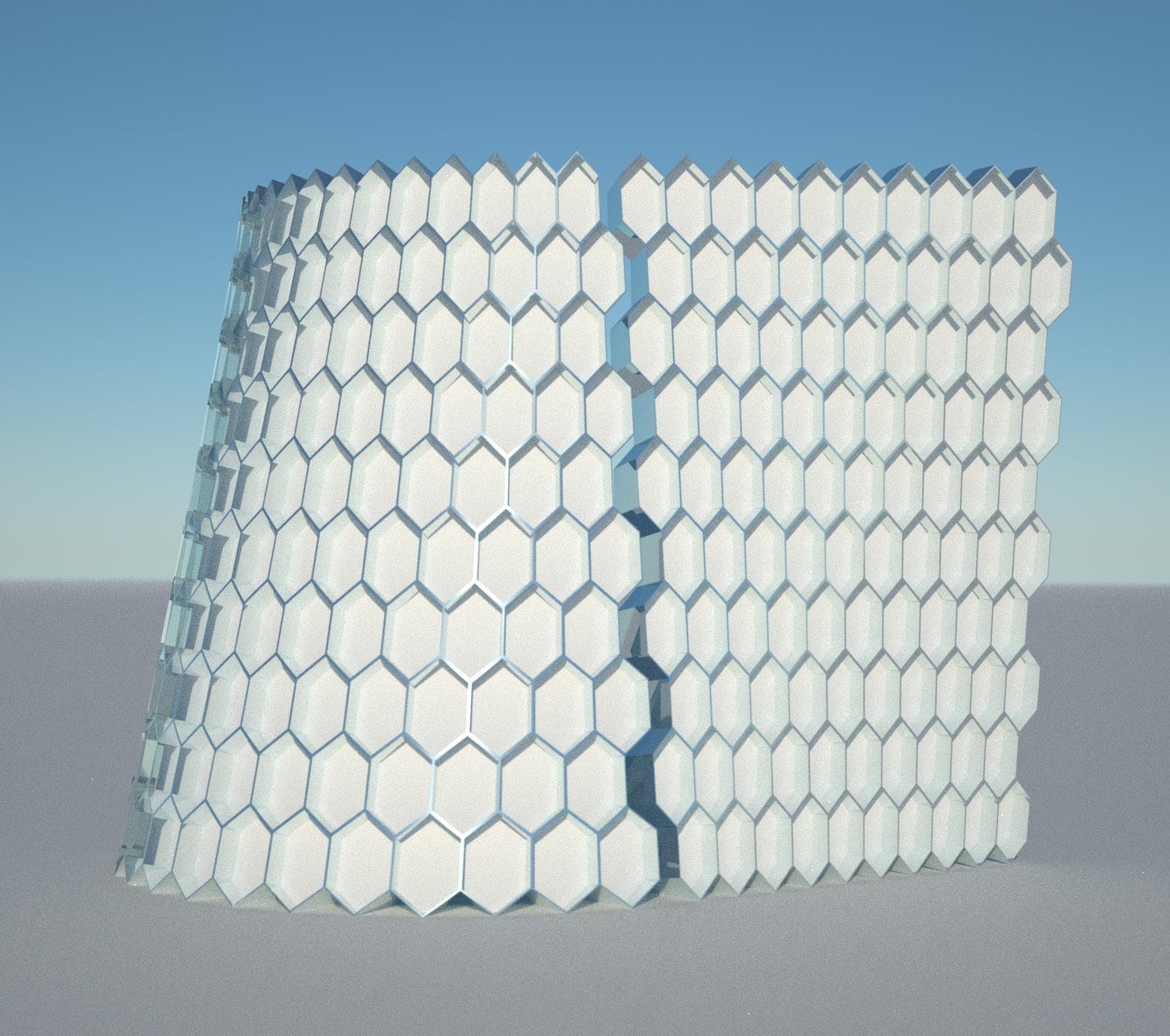
Fig. 3.40 | Configurations with a limited amount of components
Fig. 3.41 | Vaulting System. Visualization of a particular configuration

1 2 2 3 3 4 4 1 1 1 1’ 1’ 1’ 1’ 1 2 2 2 3 3 3 4 4 4 7 7 5 5 5 5 6 6 6 6 6’ 6’ 6’ 6’ 6’ 6’ 1 1 1 1 1 1’ 1’ WALL SYSTEM SYMMETRY VAULT SYSTEM SINUSOID VAULT SYSTEM ( 2
)
3:
STEP
079
modules
STEP 1: Metal Mesh + Scafolding STEP
2:
Ceramic bricks + ConcreteS TEP
Top Vault Mesh
4:
Top Vault bricks + concrete
Fig. 3.42 | Structural Assembly. 4 pieces
Fig. 3.45 | Structural Applications of the System. Minimum amount of components
Fig. 3.46 | Potential Construction on site
Fig. 3.43 | Transparency Test
Fig. 3.44 | Assembly Logics. Joint between two panels
3.3 Experiment 02
Cellular Reinforced Ceramics
3.3.1 Aluminium Honeycomb | Deformation behaviour
3.3.2 Material System | NEX Honeycomb Mesh + Ceramic Bricks
3.3.3 Parametric Model | Geometrical Logics
3.3.4 CAD-CAM & CRAFTS | Non-Uniform Extrusion
3. Experiments | 3.3 Experiment 02
Cellular Reinforced Ceramics | Juanjo G. Castellon

+ 081
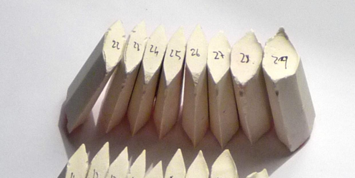
Fig. 3.47 | COMPRESSION ELEMENT. Parametric Bricks
Fig. 3.49 | Physical Model
Fig. 3.48 | TENSION ELEMENT. NEX Aluminium Honeycomb.
STRETCHED
3.3.1 Aluminium Honeycomb | Deformation Behaviour
All the previous experiments were developed working with a standard honeycomb panel and applying twisting and bending transformations on it. This is a simplification of the real behaviour of the honeycomb. Consequently, a deeper understanding of the honeycomb panel behaviour is required. A honeycomb structure produces very specific deformations. The global form in a honeycomb panel depends on the cell deformation.
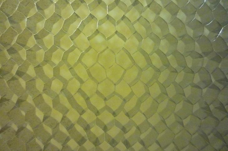
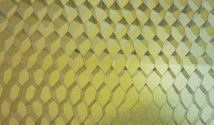
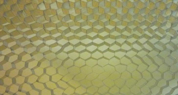
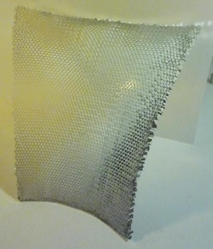


CURVED PANEL: Y axis
PANEL: Y rotation STRETCHED PANEL : anisotropic deformation
The standard panel provided by the supplier company is a homogeneous panel with a specific cell size (Fig.3.50), in other words, the panel is stretched with an isotropic deformation.
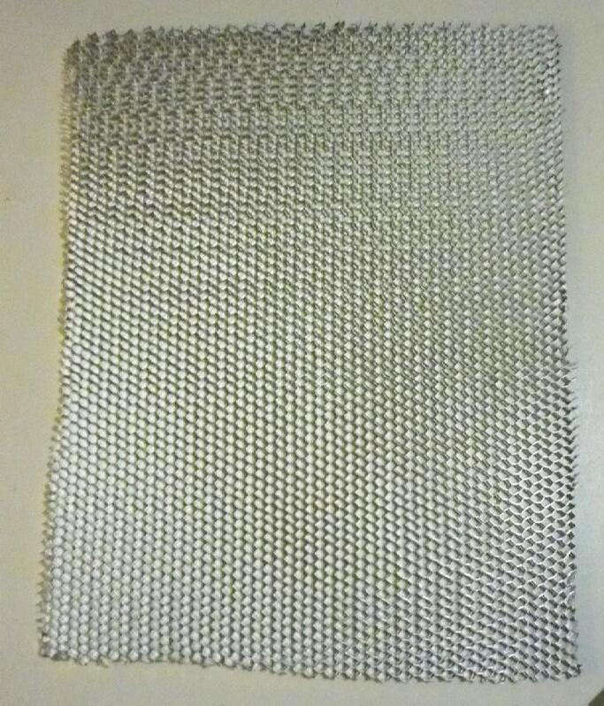
Nevertheless, if the panel is stretched with an anisotropic deformation Fig.3.51), the global form has a completely different geometrical behaviour. Therefore, by modifying the cell geometry, it is possible to control the panel curvature to form a double-curved surface.
Consequently, a series of digital experiments, using structural analysis software, were developed in order to understand the relationship between the cell deformation and the natural form produced by it (Fig.3.52). The curvature of the panel depends on the cell size and geometry.
STRETCHED UNIT
STRETCHED PANEL : isotropic deformation
STRETCHED PANEL: X direction STRETCHED PANEL: X deformation diagram
STRETCHED PANEL: Y + X direction STRETCHED PANEL: YX deformation
X X X Y Y Y X >Y deformation Y > Z deformation X = Y deformation
CURVED
STRETCHED STRETCHED
X X Y Y Y X >Y deformation Y > Z deformation X = Y deformation
PANEL : isotropic deformation
CURVED
PANEL: STRETCHED PANEL : anisotropic deformation
Fig. 3.50 | Stretched Panel. Isotropic Deformation
Fig. 3.51 | Stretched Panel. Anisotropic Deformation
3. Experiments | 3.3 Experiment 02
Cellular Reinforced Ceramics | Juanjo G. Castellon
PRE-STRETCHED UNIT
STRETCHED UNIT
STRETCHED PANEL: X direction
STRETCHED PANEL: X deformation diagram
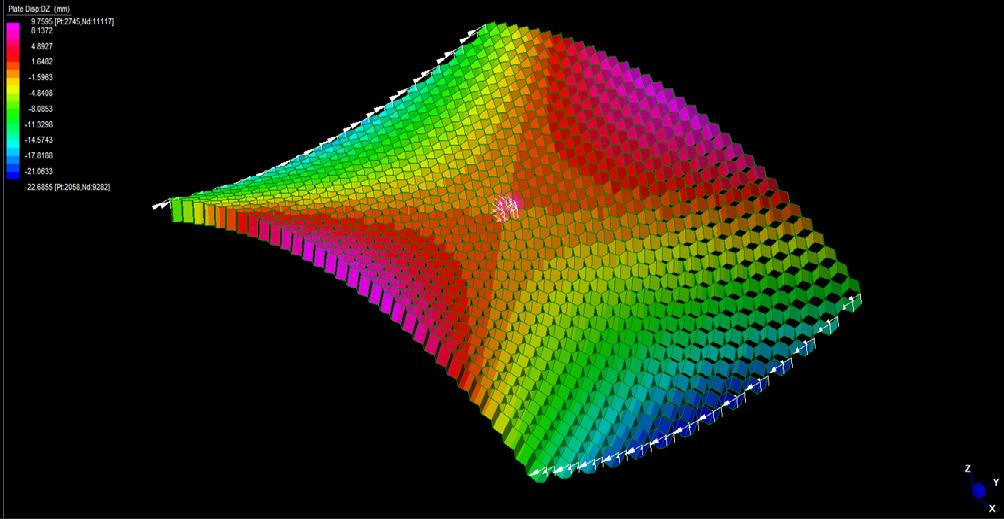
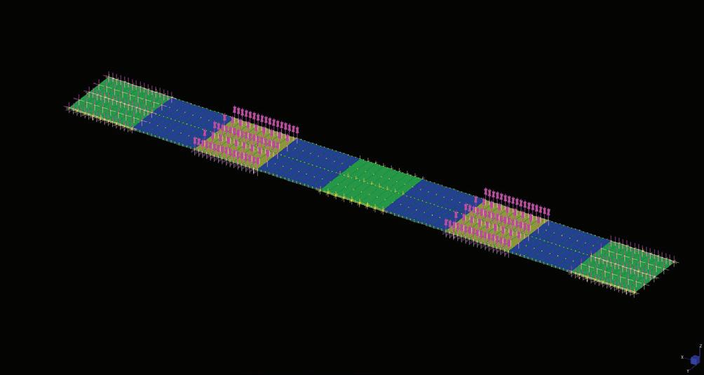
STRETCHED PANEL: Y + X direction
STRETCHED PANEL: YX deformation
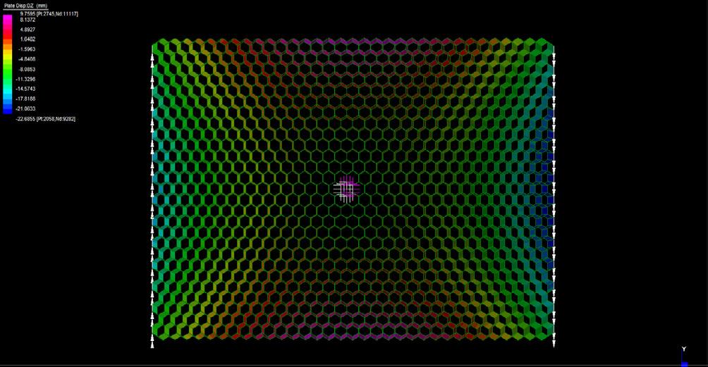
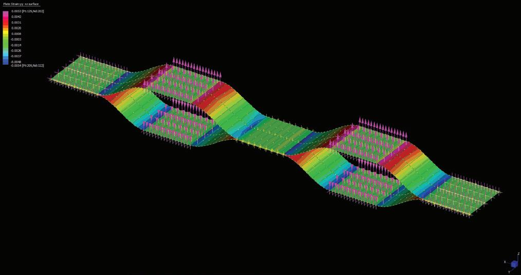
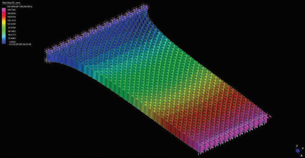
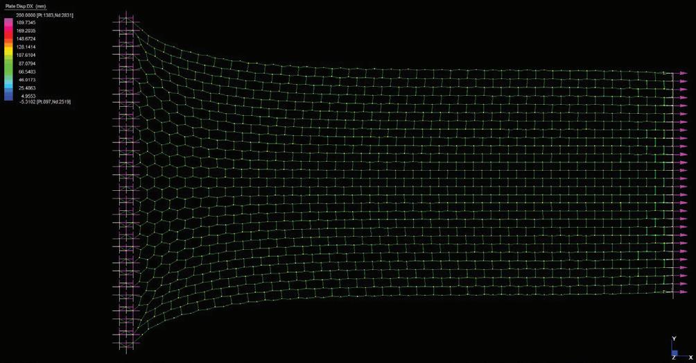
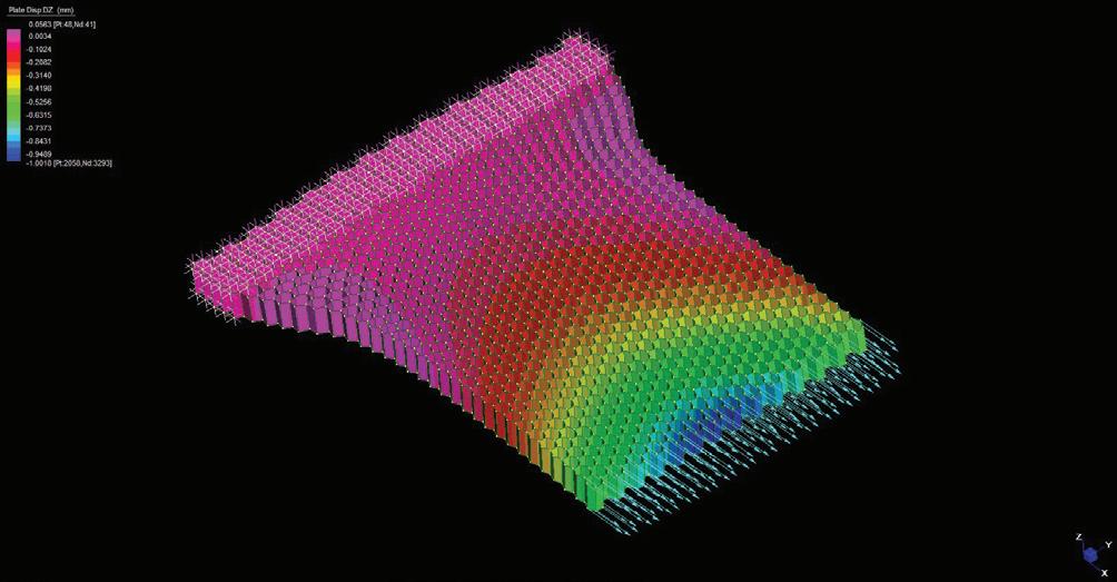
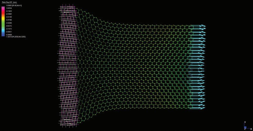
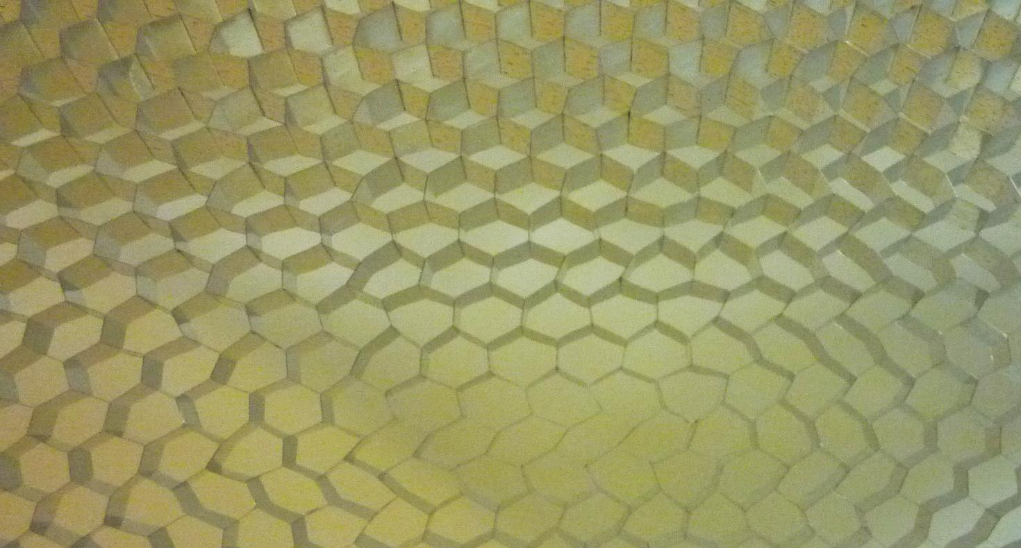
CURVED PANEL: Y axis
CURVED PANEL: Y rotation
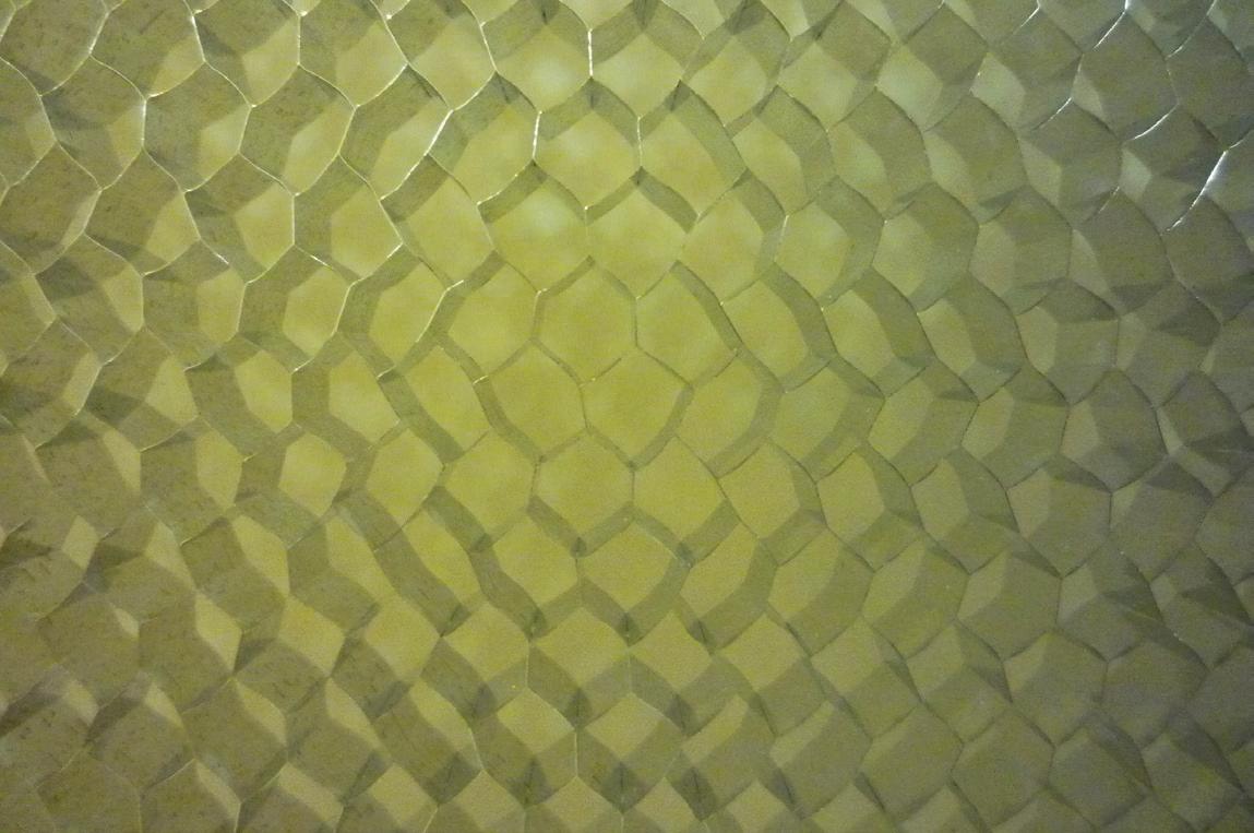
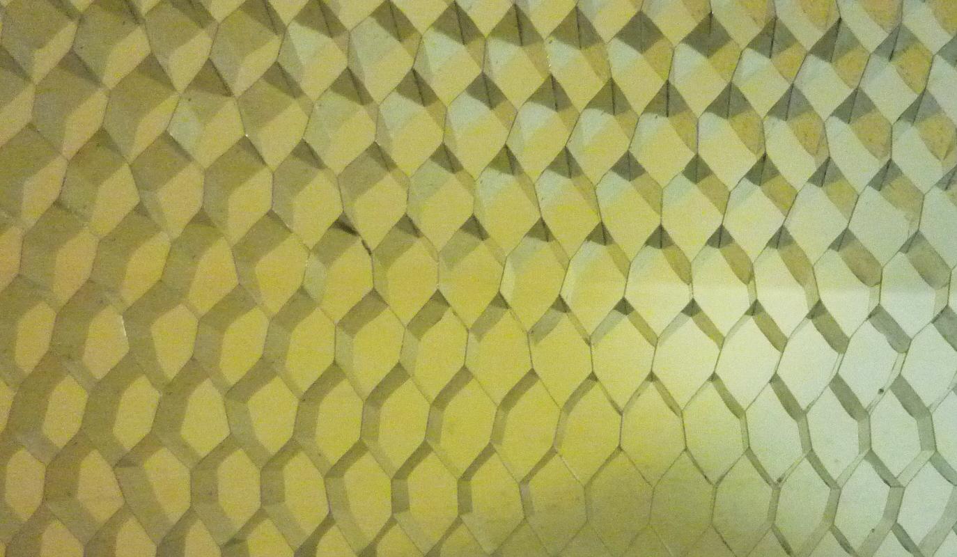
X X X Y Y Y X >Y deformation Y > Z deformation X = Y deformation
083
Fig. 3.52 | Honeycomb structures Deformation Studies
3.3.2 Material System | NEX Honeycomb Mesh + Ceramic Bricks
A. Aim
From the analysis of the honeycomb deformation behaviour, we can conclude that there is a direct relationship between the cell geometry and the global form of the system. From this conclusion, one question arises: Is it possible to use this logic as a design tool?
B. Experiment
Keeping this question in mind the following experiment was developed:
The honeycomb expanded panel used in previous experiments ( 6mm cell size and A3 format ) is replaced by a non-expanded slice (19mm cell size in various formats). The reason of this shift is to take advantage of the great flexibility of the non-expanded honeycomb (Fig.3.54) and to explore the potential to develop our material system in a bigger scale.
The main strategy relies on splitting our material system in two main elements:
1. NEX Aluminum Honeycomb Mesh (19 mm cell size and 40 cm depth). The panel dimensions can be up to 1800x4500 mm. This flexible mesh performs as reinforcement, flexible formwork and structural element under tensile stresses.
2. Ceramic Brick. Is the element that performs under compression stresses and defines the cells deformation and, consequently, the global form of the system. It can be generated by a parametric control of the brick geometry and its proper assembly into the mesh.
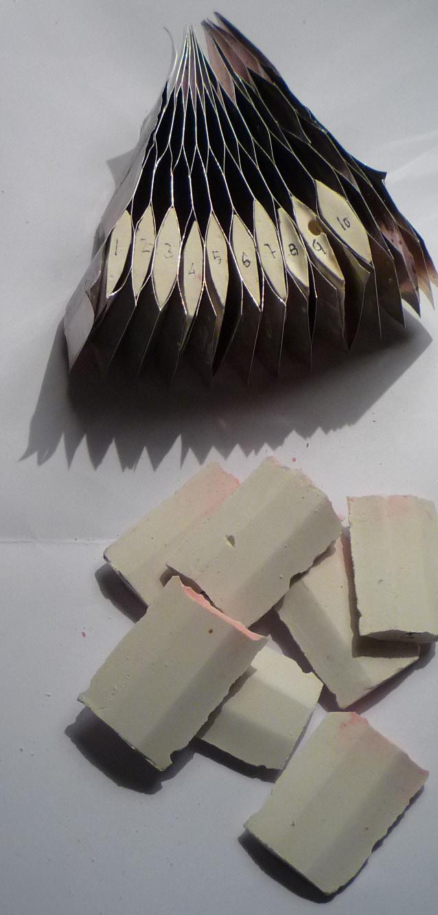
C. Conclusion
Therefore, our new material system (Fig.3.53) is a hybrid technique that sets out an interesting process that combines material properties, geometry, fabrication process and structural behavior (Fig3.55).
3. Experiments | 3.3 Experiment 02
Cellular Reinforced Ceramics | Juanjo G. Castellon
Fig. 3.53 | Reinforced Celullar Ceramics. NEX Honeycomb Mesh + Plaster Bricks
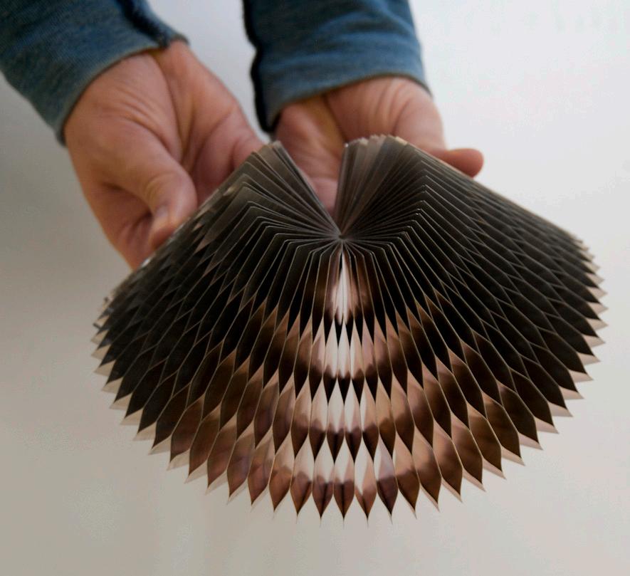
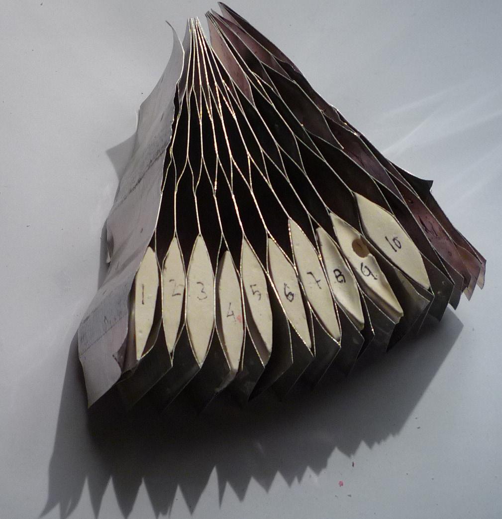
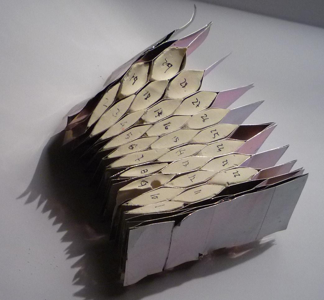
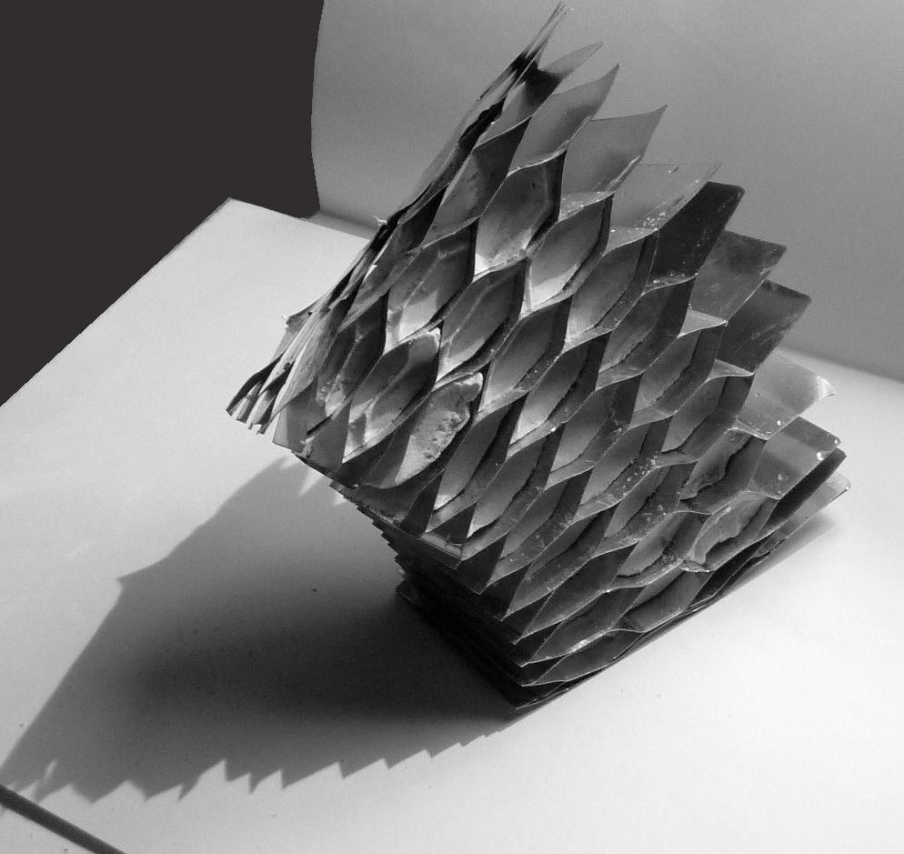
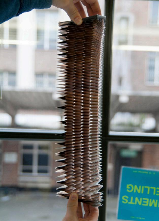
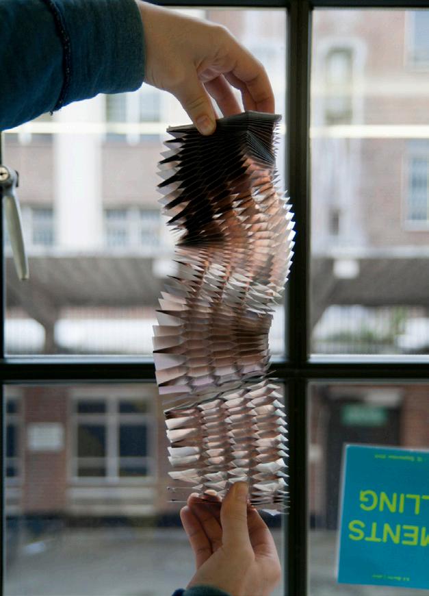
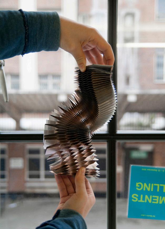
085
Fig. 3.55 | Reinforced Celullar Ceramics. Material System. NEX honeycomb + Plaster Bricks
Fig. 3.54 | NON-EXPANDED HONEYCOM B. Exploration of its geometrical behavior.
3.3.3 Parametric Model | Geometrical Logics
A. Aim
Next step in the research is to explore the geometrical potential of the system. In order to do that, a new parametric model is developed. With this model the interaction between cell geometry and global form can be tested. In addition, this model will enable a first approach regarding assembly logics.
B. Experiment
Two main geometrical principles are tested:
1. It is possible to generate cylindrical geometries by applying the same brick in all the mesh (Fig.3.58). Therefore, it is possible to control the cylindrical radius by changing the brick geometry or, in other words, 1 brick defines 1 curvature (Fig.3.56).
2. Following this logic, it is possible to obtain conical forms changing the brick geometry on each mesh level (Fig.3.59). Consequently, there is a direct relationship between brick geometry and global curvature (Fig.3.57).
With these two basic geometrical logics it is possible to test several assemblies either using cylindrical (Fig.3.60) or conical configurations or combining both (Fig.3.61)
C. Conclusion
Concluding, we can establish a criterion that relates brick geometry and global form curvature. With this simple logic and using parametric tools, it is possible to explore different formal configurations that evolve in space. In addition, those evolving configurations can be developed by the combination of two simple logics: cylindrical and conical geometries.
R1 R2 R3 R4 GENERATIVE PROCES: Geometry Rules PANEL 01 PANEL 02 PANEL 03 PANEL 04 R1 R1 R2 R2 R3 R3 R4 R4 PANEL 01 PANEL 02 PANEL 03 PANEL 04
Cellular Reinforced Ceramics |
G.
3. Experiments | 3.3 Experiment 02
Juanjo
Castellon
Fig. 3.57 | Conical arrangements
Fig. 3.56 | Cylindrical arrangements.

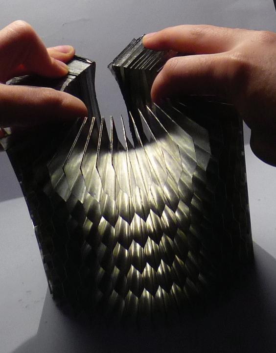
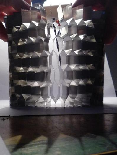
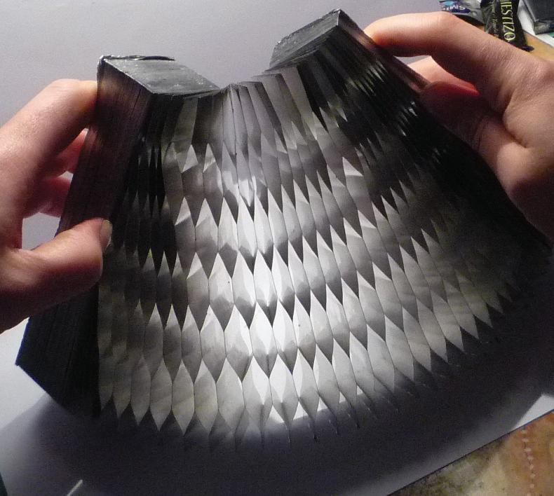
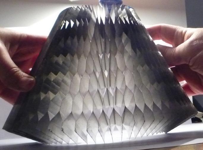
N
Q : Quantity of bricks R1 : Upper Radiae R2 : Lower Radiae D : Panel Depth H : Panel Heigth R1 = R2 N : 1 Q : 36 R1 H D R2 1 N
Q :
bricks R1 : Upper Radiae R2 : Lower Radiae D : Panel Depth H : Panel Heigth R1 = R2 N : 5 Q : 36 1 2 3 4 5 R1 R2 H D R1 R2 R3 R4 PANEL 03 PANEL 03 PANEL 04 PANEL 04 PANEL 01 PANEL 02 PANEL 04 PANEL 04 087
: Number of different Bricks
: Number of different Bricks
Quantity of
Fig. 3.58 | Cellular Reinforced Ceramics. Geometrical Principles. Cylindrical Configuration
Fig. 3.59 | Cellular Reinforced Ceramics. Geometrical Principles. Conical Configuration
Fig. 3.60 | Generative Process. Assembly of Cylindrical Configurations
Fig. 3.61 | Generative Process. Assembly of Cylindrical and Conical Configurations
3.3.4 CAD-CAM & CRAFTS | Non-Uniform Extrusion
This chapter regards the fabrication processes that can be, potentially, enabled by the system. The aim is to activate a CAD-CAM & CRAFTS process that involves contemporary and traditional fabrication techniques.
In order to activate this hybrid process, two main industrial processes have to be taken into account: the production of the NEX aluminium Honeycomb Mesh and the production of the Parametric Ceramic Brick (Fig.3.64).
The fabrication of the NEX Honeycomb Mesh is, as described in chapter 2.2.3, a highly standardized process. The experiments have been developed using a 19mm size cell. Consequently, next step of the process would be to scale up the honeycomb mesh 10 times in order to obtain a 190mm size cell. This part of the research has, necessarily, to be done in collaboration with the real industry. The foil thickness needed would be tested and the implications of the mesh production at this scale.
On the other hand, the Parametric Brick fabrication can be developed implementing traditional tools, existing in a conventional ceramic workshop, with contemporary tools. In order to do that, a parallel research process is being currently developed in collaboration with Toni Cumella in Barcelona.
The main goal of this research is to apply a non-standard extrusion in the production of the bricks (Fig. 3.66). This research will be developed using parametric tools in combination with traditional fabrication tools. With this technique, it would be possible to introduce variation in the fabrication process and, therefore, explore the architectural potential of the system. One important aspect to be developed is the performative design of the system. Thus, the Parametric Brick system could react to environmental, structural or spatial requirements (Fig.3.65).
The most challenging part of the research is the hybrid process involving CAD-CAM&CRAFTS techniques and the extremely interesting interaction between two radically different materials considering its structural, aesthetics, performative and technical properties. This difference creates a very intriguing hybrid system (Fig.3.62,3.63) which will be explored in an architectural scale in the following phase of the research.
Cellular
3. Experiments | 3.3 Experiment 02
Reinforced Ceramics | Juanjo G. Castellon


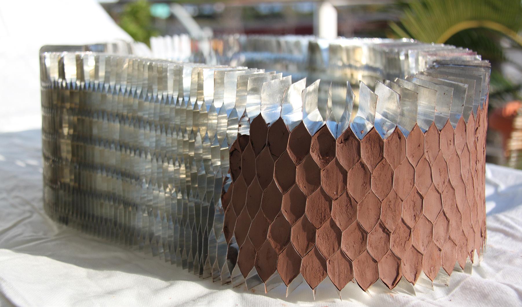
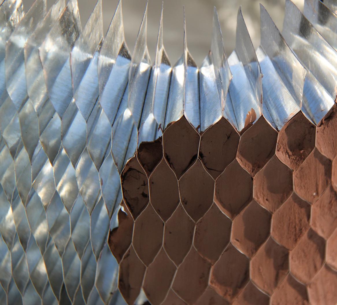
089
Fig. 3.62 | Material System. Physical Test
Fig. 3.64 | NON UNIFORM EXTRUSION. Mesh + Parametric Bricks
Fig. 3.66 | NON UNIFORM EXTRUSION. Conffigurations
Fig. 3.63| Material System. Physical Test
Fig. 3.65 | NON UNIFORM EXTRUSION. Performative and Responsive Application
3.4 Evaluation & Summary
From the experiments developed some conclusions arise:
• The composite material explored by the combination of aluminum honeycomb mesh and cement has been successfully tested. Both the structural and geometrical properties have a potential application in architecture.
• In addition, the parametric molding system developed introduces variation in the fabrication process and takes advantage of the structural and geometrical properties of the honeycomb aluminum mesh.
• Otherwise, the scale of the first prototype panel leads to a construction process based on panelization and, in that case, a specific analysis regarding joints and assembly would be required.
• On the other hand, once understood the material system in a bigger scale, the relationship between cell geometry and global form becomes the main parameter for the second set of experiments.
• Blowing up the scale, the material system evolves towards an interaction between a flexible mesh, under tensional stress and a parametric brick under compression stress.
• Therefore, the fabrication system evolves towards a combination of analog and digital techniques. This hybrid technique challenges further developments regarding CAD-CAM & CRAFTS processes.
• This system and the geometrical principles explored using digital tools enable the following phase of research. It will be focused in the architectural application of the system
Cellular Reinforced Ceramics | Juanjo G. Castellon 3. Experiments | 3.4 Evaluation & Summary
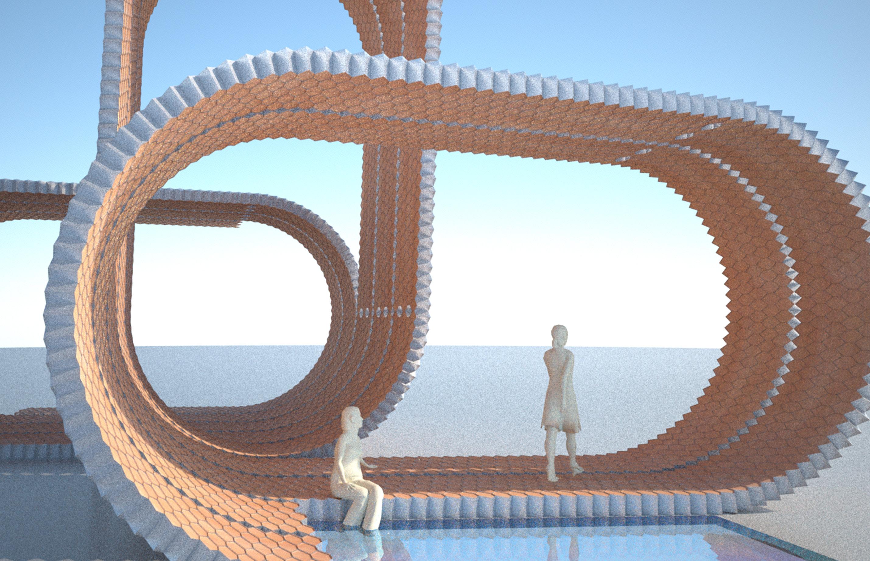
091
Fig. 3.66 | Cellular Reinforced Ceramics. Architectual Proposal
4. Design Development
093
4.1 Introduction
4.2 Digital Model 01. Combinatorial Assembly
4.3 Digital Model 02. The Loop
4.4 Digital Model 03. Double - Layered Loop
4.5 Digital Model 04. Catenary Loop
4.1 Introduction
The experiments developed lead us to the next step of the research. This chapter is focused in the design development of the proposed system. The main aim at this stage of the project is to understand the system in full scale and to deploy its spatial and structural potential enabling its application in the architectural realm.
In order to do that, a parametric model will be developed in several stages, incorporating progressively all the parameters aimed to control and apply architecturally.
As a result of the following exploration, the design groundwork will be ready for a specific proposal in a specific context.
4. Design Development | 4.1 Introduction Cellular
Reinforced Ceramics | Juanjo G. Castellon
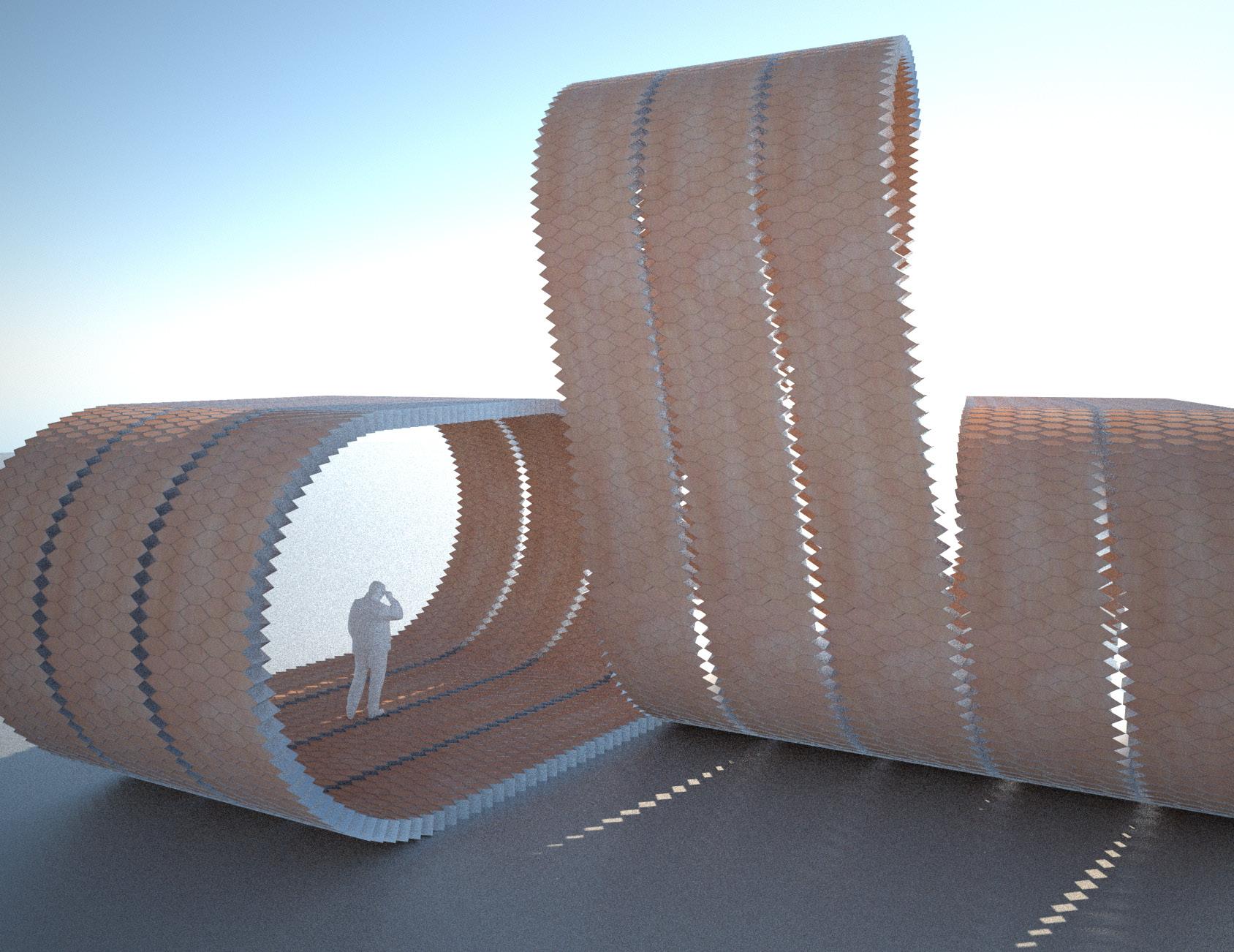
095
Fig. 4.01 | Cellular Reinforced Ceramics. Design Development.
4.2 Digital Model 01 | Combinatorial Assembly
A. Aim
With regards of design principles, the main goal is to achieve spatial richness and variation using a limited amount of components. It was proved in previous experiments that it is possible to produce variation and complexity by the combination of simple cylindrical and conical geometries. Therefore, this first digital model explores a combinatorial system using a limited amount of components.
B. Development
This geometrical exercise starts with the definition of 4 basic configurations (Fig.4.03). These configurations are generated with 2 different radii (R1 and R2). Configurations 01 and 02 are generated at XY plan, and configurations 03 and 04 are generated at YZ plan. Therefore, configurations 05, 06, 07 and 08 are generated by the combination of the 4 basic geometries. Consequently the system is based in 8 permutations that enable infinite configurations in space (Fig.4.02).
C. Conclusion
Complex forms can emerge from simple rules. From this point of view, a clear understanding of the geometrical principles enables a consistent and efficient construction process. This fact doesn’t mean that complex forms cannot be achieved. Complex forms and simple rules are compatible concepts. On the other hand, geometrical principles don’t directly produce architecture. Actually, in this case (Fig.4.04), a geometrical strategy has been developed but there is no control of the spatial and structural aspects.
4. Design Development | 4.2 Digital Model 01
Cellular Reinforced Ceramics | Juanjo G. Castellon
Fig. 4.02 | Combinatorial Assembly. Particular case
PANEL 04
PANEL 03
PANEL 07
PANEL 08
PANEL 06
PANEL 01
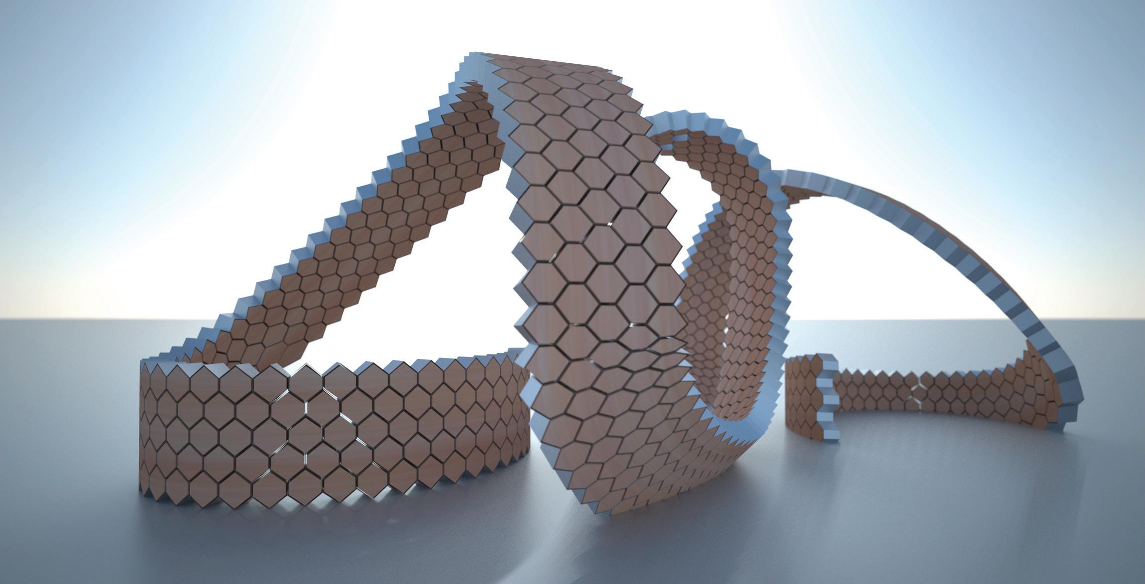
PANEL 02
PANEL 05
R1 R1 R1 R1 R1 R1 R2 R2 R2 R2 R2 R2 XY: R1 CONFIG 01 CONFIG 02 CONFIG 05 : 01+03 CONFIG 06 : 02+03 XYZ: R1 R1 XYZ: R2 R1 XY: R2 CONFIG 07 : 01+04 CONFIG 08 : 02+04 CONFIG 03 CONFIG 04 XYZ: R1 R2 XYZ: R2 R2 YZ: R1 YZ: R2
097
Fig. 4.03 | Combinatorial Assembly. Basic Configurations proposed.
Fig. 4.04 | Combinatorial Assembly. Limited Amount of variations. N=4. 8 Permutations
4.3 Digital Model 02 | The Loop
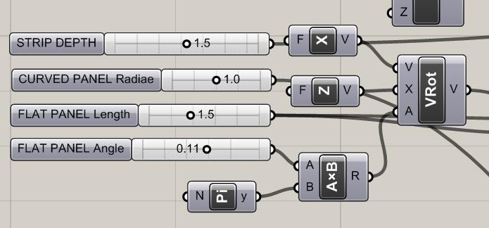
A. Aim
In this second test, the aim is to test the system in terms of architectural requirements. Therefore, the system has to be organized following spatial and structural logics.
B. Development
The combinatorial logic is applied and reduced here to two single configurations: one curved and one flat (Fig.4.06). A digital model is developed to control their geometrical parameters (Fig.4.05).
The configurations generated are combined following a loop arrangement in order to define a space. The result is a parametric continuous surface that becomes floor, wall and roof (Fig.4.07). Consequently, we can use Cellular Reinforced Ceramics to solve all the spatial and technical requirements of the project.
C. Conclusion
The digital model developed at this stage enables to test and evaluate spatial, structural and technical properties of the system at full scale (Fig.4.08,4.09). Assembly logics and structural inputs have to be incorporated to the model.
R1
Cellular Reinforced Ceramics | Juanjo G. Castellon
Fig. 4.06 | Generative Process Basic configurations
Fig. 4.07 | Generative Process. Parametric Model Sequence
4. Design Development | 4.2 Digital Model 02
Fig. 4.05 | Parametric Model. Parameters
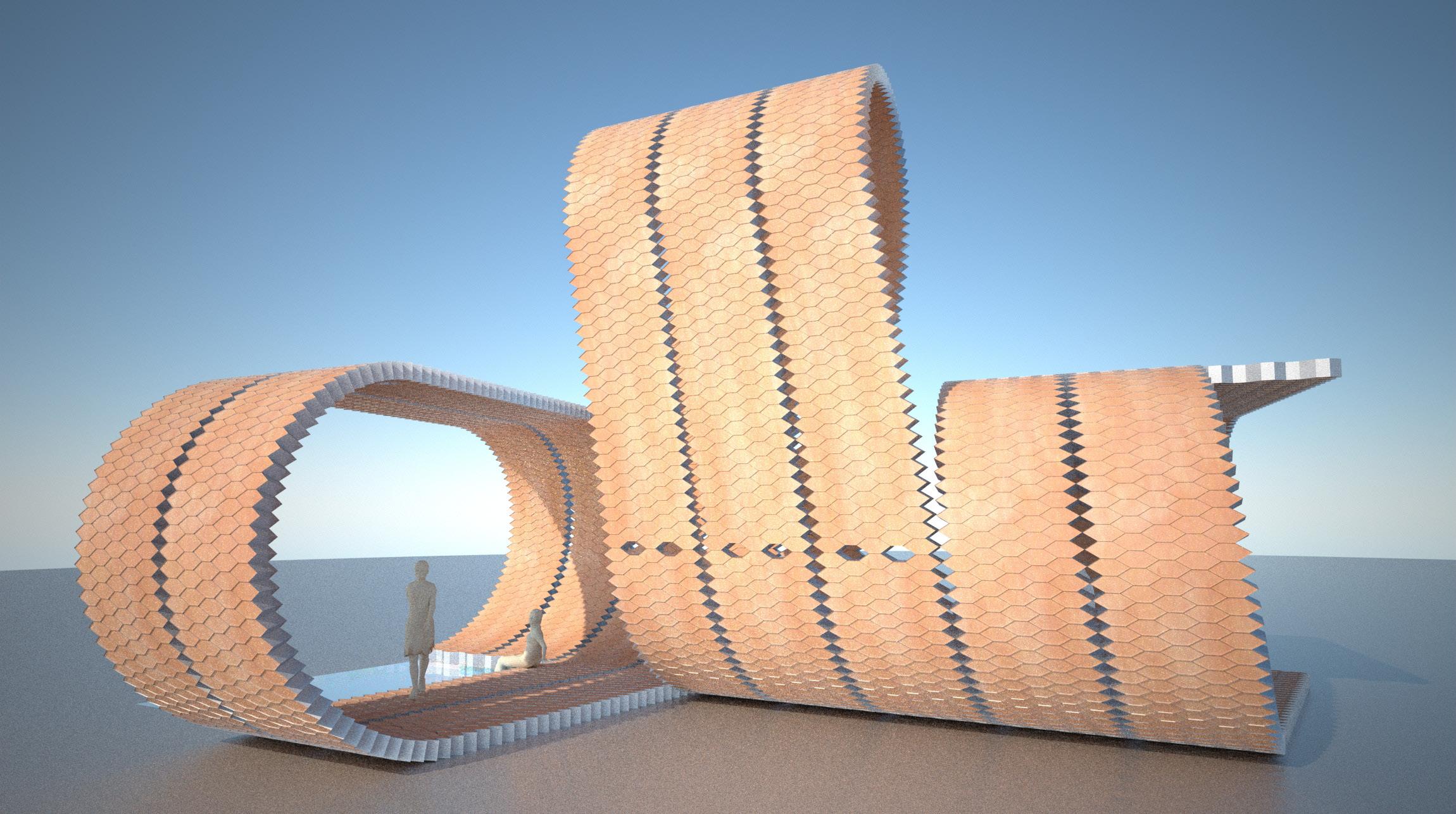
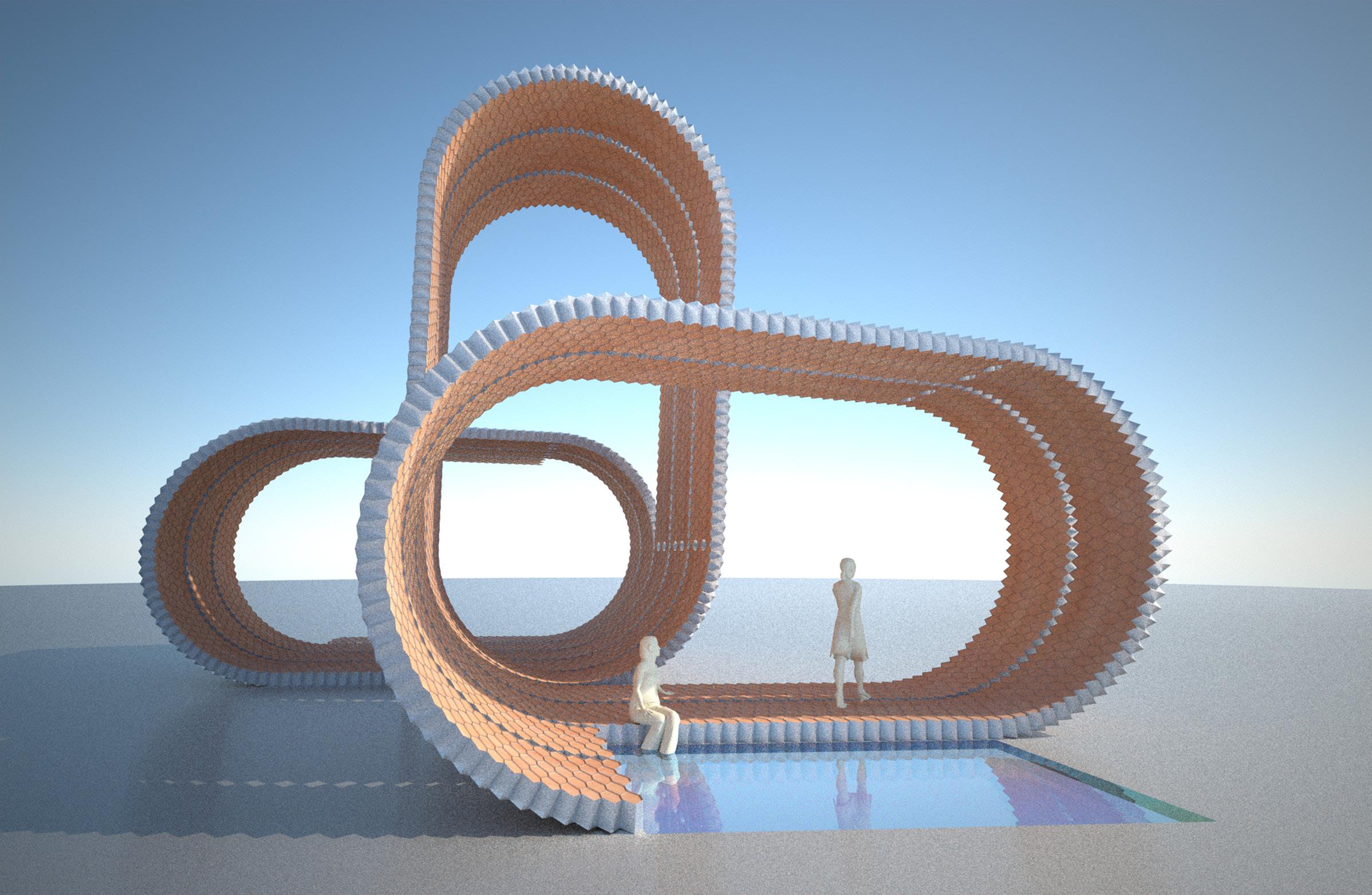
099
Fig. 4.08 | Architectural Proposal Loop. Side View
Fig. 4.09 | Architectural Proposal Loop. Front View
4.4 Digital Model 03 | Double Layered Loop
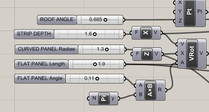
A. Aim
At this stage of the design process, the aim is to explore a technical and architectural proposal to solve the assembly logics of the Loop system.
B. Development
Based on the Cohesive Construction theories developed by Rafael Guastavino, a double-layered system (Fig.4.12,4.13) is proposed as assembly technique. Those two layers are overlapped and laid using cement. By staggering the bricks joints, the system increases, potentially, its resistance and cohesion following the principles applied in the traditional Catalan vault technique by Guastavino.
C. Conclusion
The solution proposed (Fig.4.14,4.15) explores an assembly technique that improves, potentially, the structural behaviour of the system. On the other hand, this solution increases the amount of material required and its behaviour cannot be tested with software tools since it is a technique based on practice and without theoretical background nor data.
Cellular Reinforced Ceramics |
G.
4. Design Development | 4.2 Digital Model 03
Juanjo
Castellon
Fig. 4.10 | Parametric Model. Parameters
Fig. 4.13 | Double-Layered Loop. Elevation
Fig. 4.11 | Parametric Model. Configurations
Fig. 4.12 | Architectural Proposal Double-Layered Loop

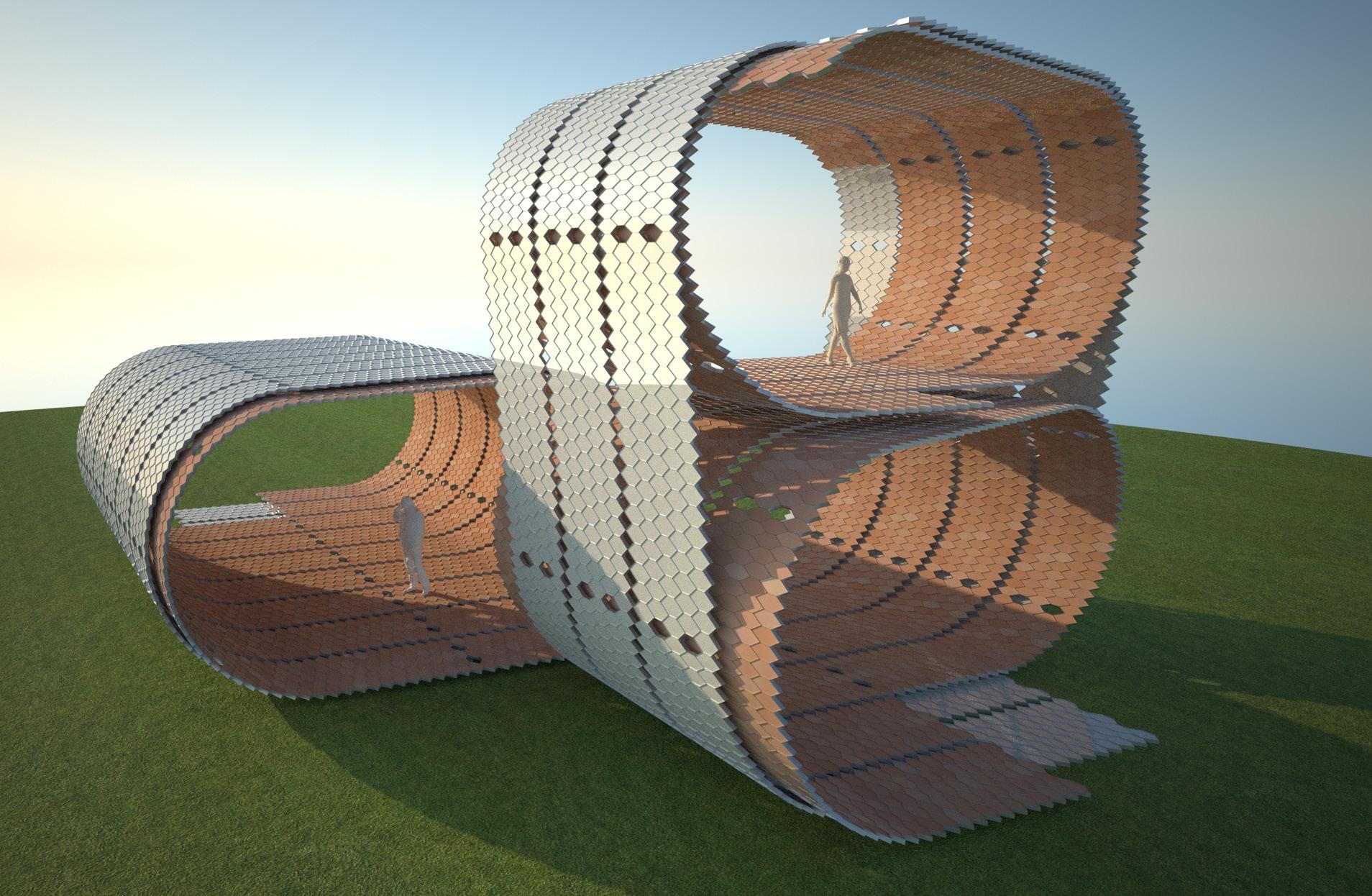
101
Fig. 4.14 | Architectural Proposal Double Layered Loop
Fig. 4.15 | Architectural Proposal Loop. Front View
4.5 Digital Model 04 | Catenary Loop
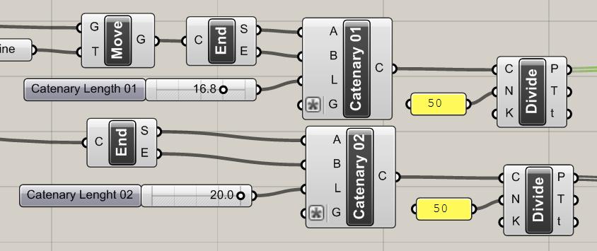
A. Aim
In this last stage of the design development, the digital model will be implemented to incorporate structural principles to the architectural form.
B. Development
Following the principles applied by the Uruguayan engineer Eladio Dieste, the architectural form incorporates catenary sections (Fig.4.18,4.19) in order to optimize its structural behavior. Form and structure become, in that way, interrelated concepts. The digital model is implemented with parameters that control the length and morphology of the catenary sections (Fig.4.16). Therefore, the loop is able to adapt its form according to environmental, spatial and structural criteria (Fig.4.20,4.21).
C. Conclusion
The final parametric model incorporates all the requirements needed for the final design proposal. Next step will be to allocate the system in a specific context deploying all its architectural potential.
SURFACE 01 SURFACE 02 R1 R1 R3 R3 R2 R1 R1 R2 H Cellular Reinforced Ceramics | Juanjo G. Castellon 4. Design Development | 4.2 Digital Model 04
Fig. 4.16 | Parametric Model. Parameters
Fig. 4.17 | Parametric Model. Configurations
Fig. 4.18 | Caterany Sections. Principle and simplyfication
Fig. 4.19 | Catenary Structure. Geometric definition
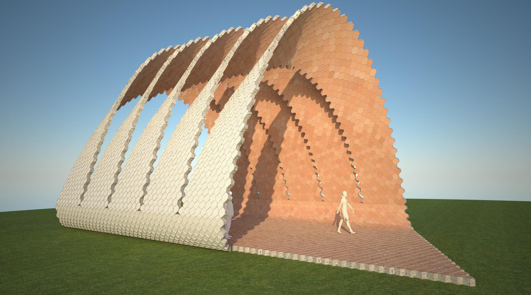
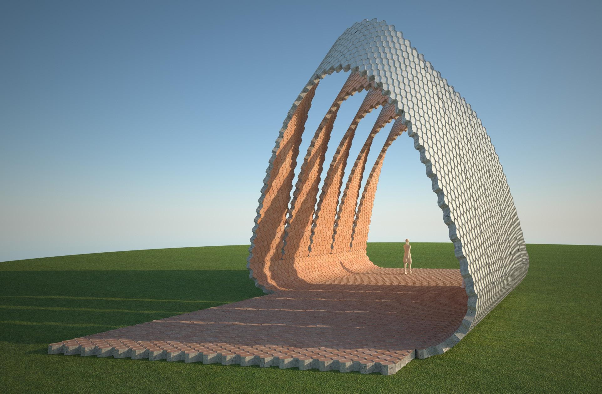
103
Fig. 4.20 | Architectural Proposal Catenary Loop
Fig. 4.21 | Architectural Proposal Catenary Loop
5. Design Proposal
105
5.1 Description 5.2 Site 5.3 Context 5.4 Proposal 5.4.1 Programme and Urban behaviour 5.4.2 Environmental behaviour 5.4.3 Conclusion
5.1 Description
Located in Granada ( Spain ), The Alhambra is considered one of the most impressive examples of Moorish architecture in the world. Its construction dates from 11th to 15th century and was included on 1984 at the World Heritage List. On top of a hill and surrounded by woods (Fig.5.03), the access to the Alhambra presents a particular relevance.

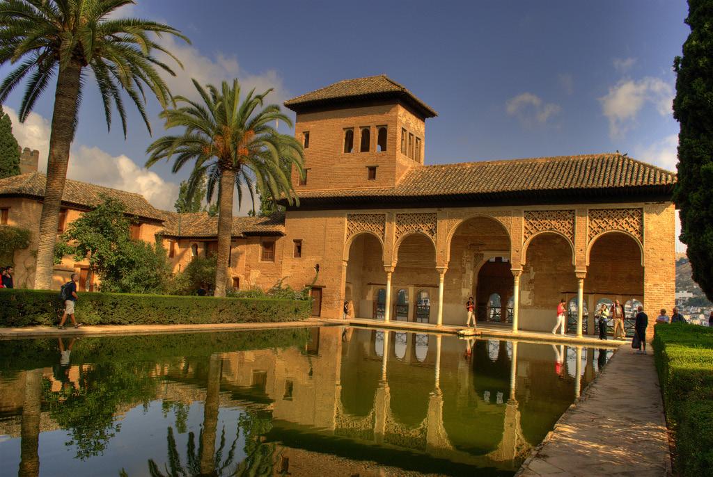
The aim of the project is to reorganize the entrance/exit area to the Alhambra by building a new entrance pavilion that would replace the existing one in order to incorporate an exhibition space, a bookshop, a store and the main entrance hall.
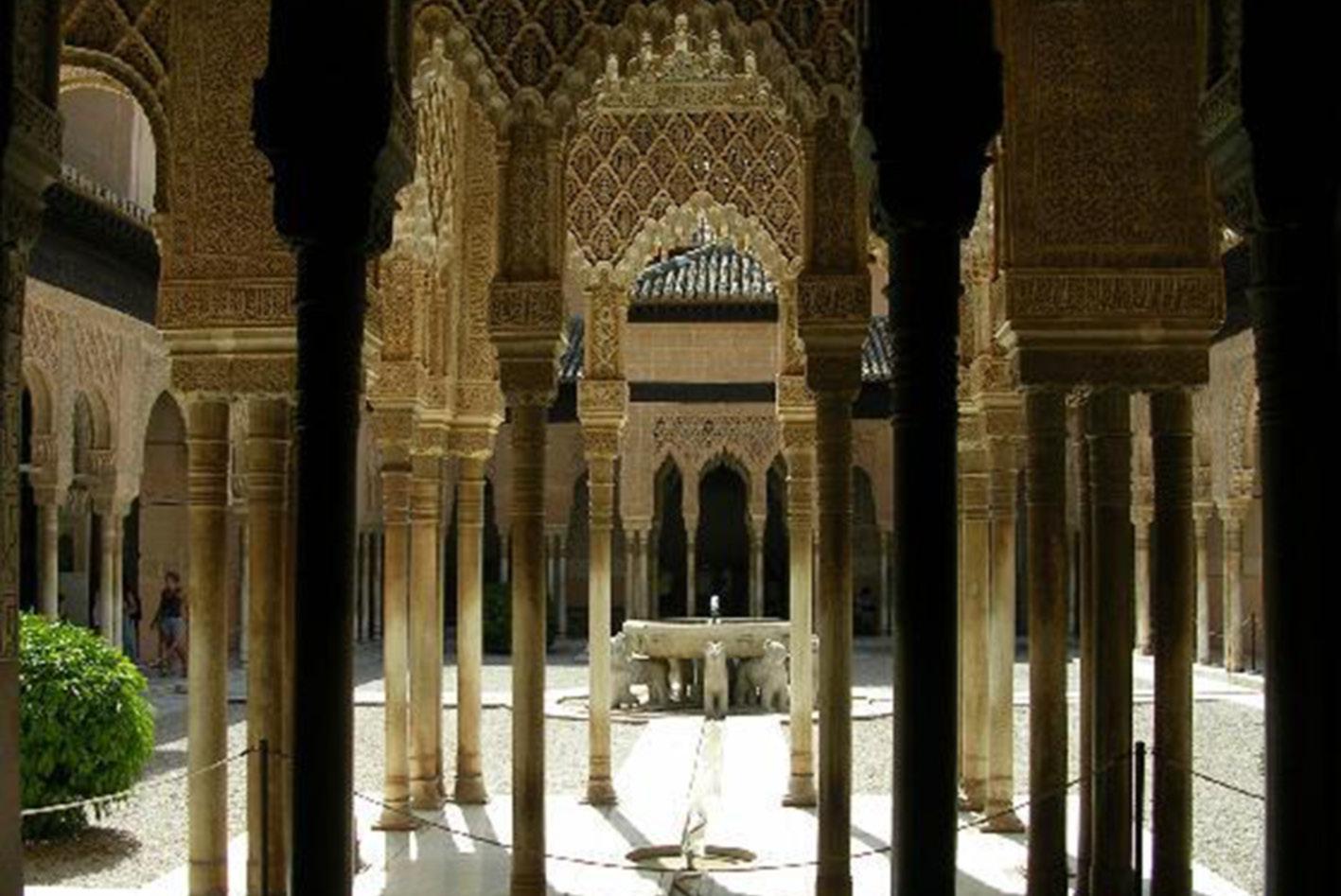

The project will also take into account the surrounding area and the public space enhancing outdoor activities and social interaction.
AREA OF PERFORMACE AREA OF INFLUENCE SITE BOUNDARIES


5. Design Proposal | 5.1 Description
Cellular Reinforced Ceramics | Juanjo G. Castellon
Fig. 5.01 | The Alhambra. The Lions Courtyard
Fig. 5.03 | The Alhambra. Paronamic View
Fig. 5.02 | The Alhambra. The Partal Palace

107
Fig. 5.04
| Photoplan of the Alhambra
5.2 Site
Due to the orography that surrounds the Alhambra, the arrival from the city center is only possible by car or bus. There is a single road connecting the city center with the Alhambra and this road ends on the site selected for the project.

The site is almost flat and surrounded by lush vegetation. Granada has continental climate with high fluctuations of temperature along the year with cold winters and extremely hot and dry summers. Therefore, the existing vegetation is important in order to regulate the sudden changes in temperature and to shade the site during summertime.


Cellular
1 3 2
Reinforced Ceramics | Juanjo G. Castellon
Fig. 5.05 | The Alhambra. Access area. View 1
Fig. 5.06 | The Alhambra. Access area. View 2
5. Design Proposal | 5.2 Site
Fig. 5.07 | The Alhambra. Access area. View 3
109
5.3 Context
The existing urban context, is evaluated by the analysis of 3 main elements: roads network, pedestrian network and existing vegetation.
Roads Network (Fig.5.08):
The access to the Alhambra area takes place at the site’s perimeter by car or by bus. Coming by bus, the visitor gets off at the bus stop and, in case of arriving by car, two car parks are available at the site’s perimeter.
Existing Vegetation (Fig. 5.09):
Allocated in a second perimeter, the existing vegetation performs as a green barrier between the vehicular traffic and the public plaza. This green space protects the site from noise and wind and provides shading and thermal control during summertime.
Pedestrian Network (Fig.5.10):
Consequently, visitor’s promenade towards the access area starts either from the car park or from the bus stop. The pedestrian promenade continues through several paths across the vegetation and visitors finally arrive to the public plaza and to the existing access building to the Alhambra.
Cellular Reinforced
Ceramics | Juanjo G. Castellon
Fig. 5.08 | Diagram. Existing Roads Network
5. Design Proposal | 5.3 Context
Fig. 5.10 | Diagram. Existing Pedestrian Network Fig. 5.09 | Diagram. Existing Vegetation
111
Fig. 5.11 | The Alhambra. Diagram of existing elements
ACCESS
TO ALHAMBRA EXISTING BUILDING
PLAZA
CAR PARK AREA
CAR PARK AREA
BUS STOP
ROAD TO CITY CENTER
5.4.1 Proposal | Urban and Programmatic behaviour.
Taking into account the existing context, some conclusions arise:
- The situation of the existing roads and vehicular traffic at the site’s perimeter avoids an interaction between cars and people and, therefore, generates suitable conditions for social interaction.
- The green belt around the site is a natural barrier that protects it from the car traffic. In addition, and taking into account the climate conditions in Granada, the existing vegetation is needed to provide thermal control and shading during summertime. Furthermore, this green belt filters views and circulation to the public plaza.
- Visitors promenade is interesting and well-connected from the car park to the plaza. On the other hand, the existing building is isolated and not integrated in the pedestrian network.
Consequently, the proposal is based in the application of the Catenary Loop’s System for this specific site and context. The main concept is to generate a building that performs both in terms of programmatic requirements as well as a urban element.
The system evolves in space generating four pavilions that solve the programmatic requirements (Fg.5.12). At the same time, these pavilions perform as urban infrastructure connecting the existing pedestrian network with the actual access to the Alhambra (Fig.5.13).
5. Design Proposal | 5.4 Proposal 1 2 3 4 25m 10 0 Cellular
|
Reinforced Ceramics
Juanjo G. Castellon
Fig. 5.12 | Proposal. Program: 1. Exhibitions, 2. Tickets, 3. Entrance Hall, 4. Bookshop and Store
113
TO
EXISTING BUILDING
ACCESS
ALHAMBRA
PLAZA
CAR PARK AREA
CAR PARK AREA
BUS STOP
ROAD TO CITY CENTER
Fig. 5.13 | Proposal. Diagramatic plan
5.4.2 Proposal | Environmental behaviour
In order to achieve the final form, the parametric model developed to design the Catenary Loops is adapted to specific environmental requirements. In other words, the Loop’s geometry reacts to the environment according with the sun orientation on each pavilion.
Pavilion 01 (Fig.5.17)
This pavilion has his main façade facing South-East orientation. The loop is closed towards south orientation and opens towards north. Northern orientation is very suitable for an exhibition space and provides a clear and diffuse light avoiding direct radiation.
Pavilion 02 & 03 (Fig.5.16) and Pavilion 04 (Fig.5.15)
These pavilions have their main façade facing South-West orientation. Both, south and west orientations can increase significantly the radiation level. Consequently, the loops are closed towards south and west orientation and open towards east .This orientation provides mild light during the morning.
Cellular Reinforced Ceramics | Juanjo G. Castellon 1 2 3 4 25m 10 0
5. Design Proposal | 5.4 Proposal
Fig. 5.14 | Proposal. Diagram of Pavilions distribution
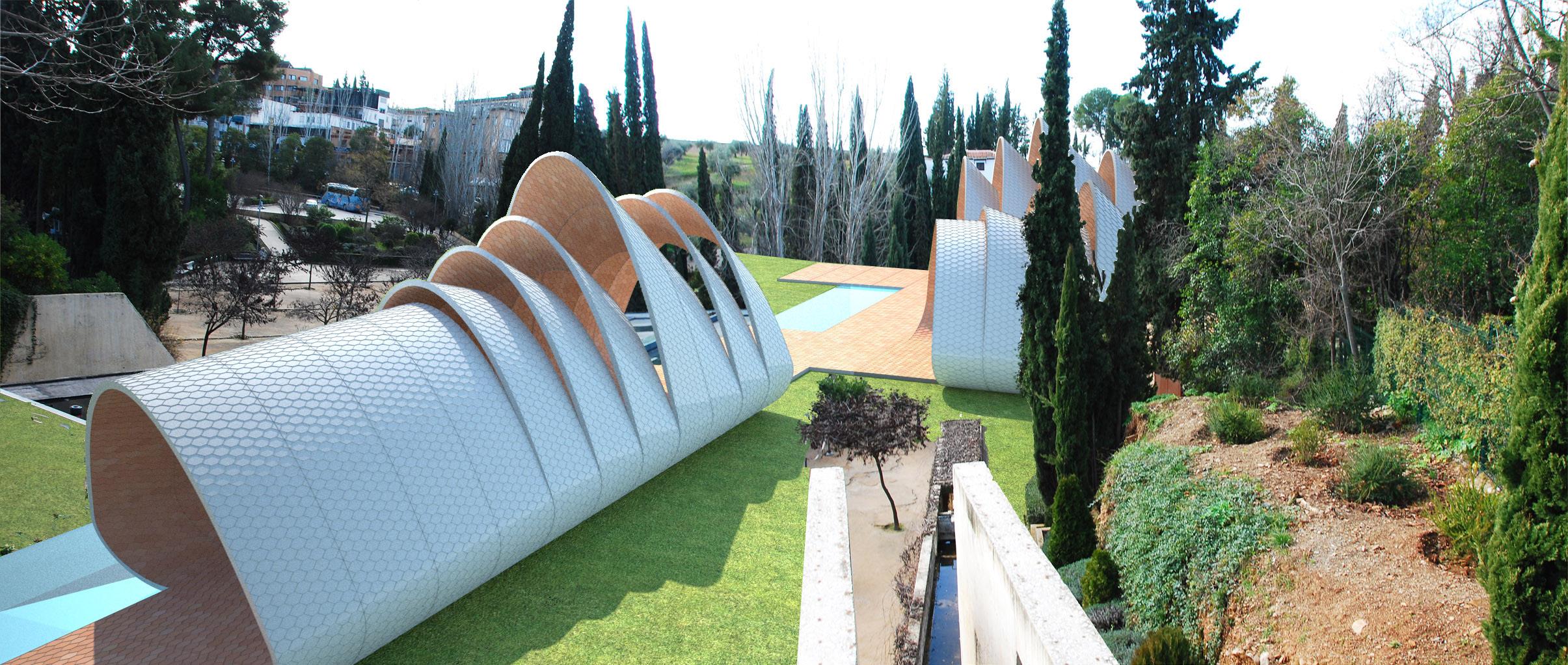
117 2 3 4
Fig. 5.18 | Proposal. View from the car park
Fig. 5.15 | Proposal. Pavilion 4
Fig. 5.16 | Proposal. Pavilions 2 and 3
1
Fig. 5.17 | Proposal. Pavilion 1
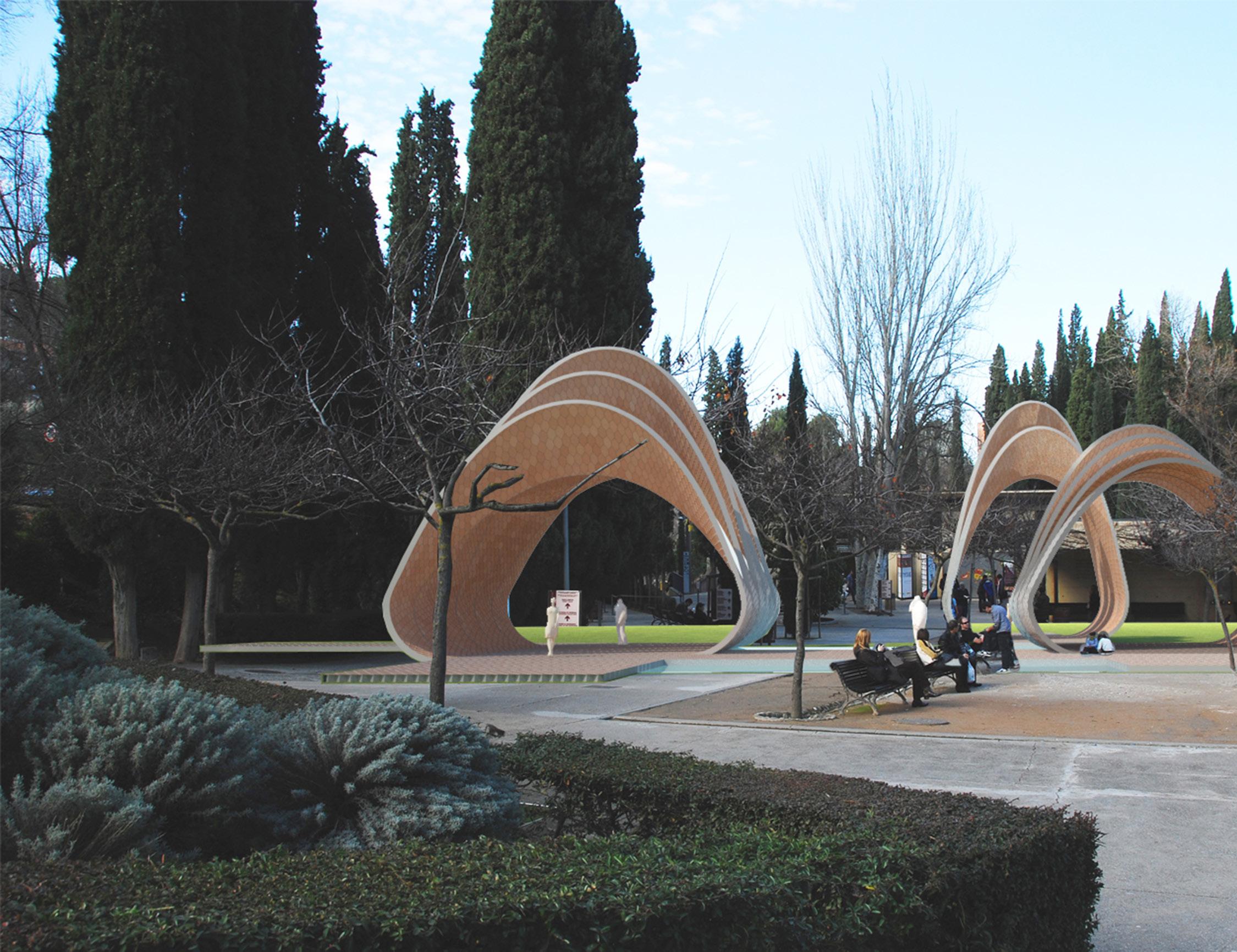
5. Design Proposal | 5.4 Proposal
Cellular Reinforced Ceramics | Juanjo G. Castellon
Fig. 5.19 | Proposal. Main access from the bus stop

115
5.4.3 Proposal | Conclusion
This design proposal deploys the spatial qualities of Cellular Reinforced Ceramics in a specific site and context. It is possible now to understand the potential of this construction and material system at full scale projects.
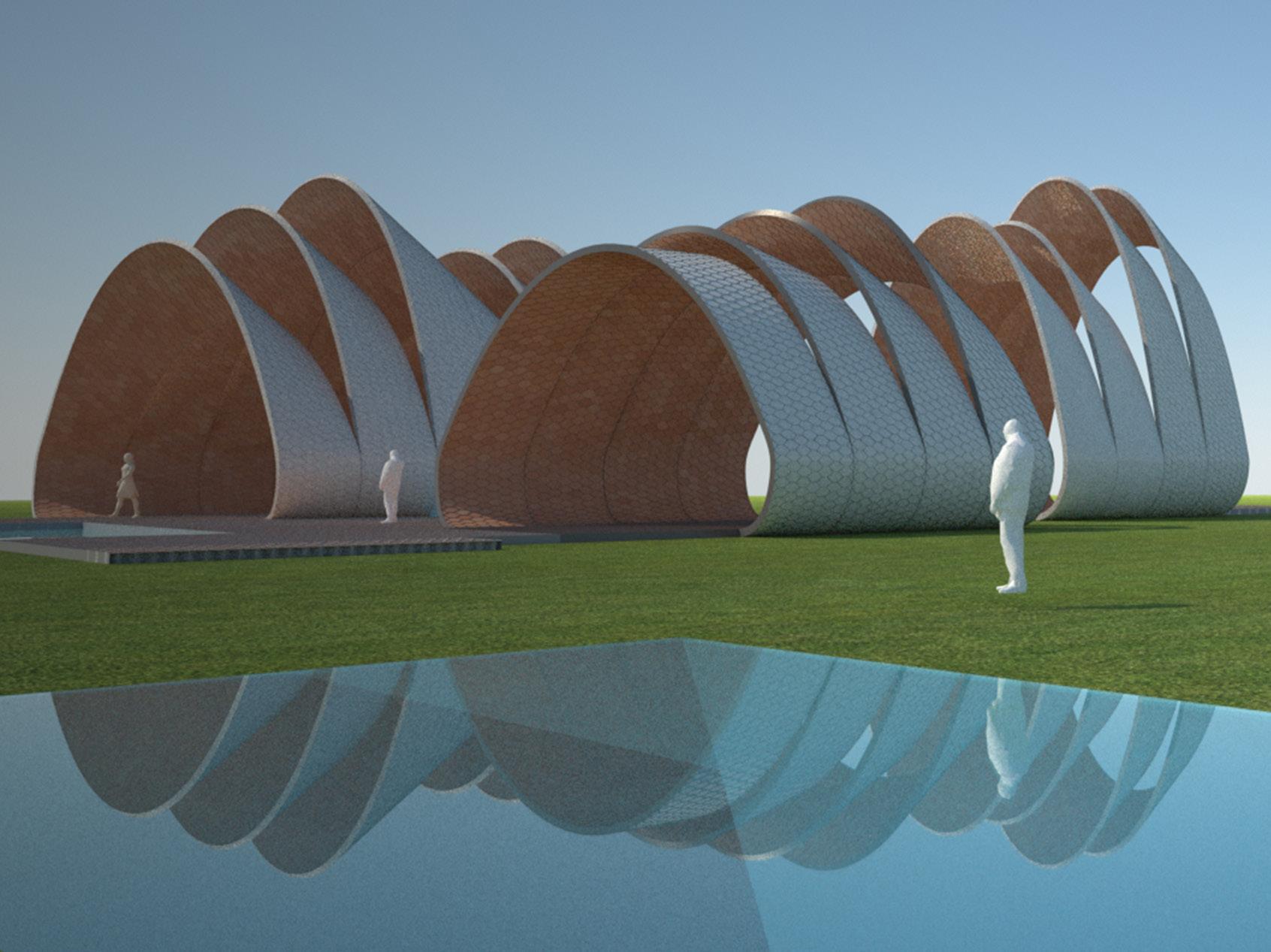
Although several technical questions are still open, a solid ground has been stated and further developments will be done in collaboration with industry and fabricators.
If you want to build Architecture, just dream it. If you want to dream Architecture, just build it. However, you will always find it between the past and the future.
5. Design Proposal | 5.4 Proposal
Cellular Reinforced Ceramics | Juanjo G. Castellon
Fig. 5.20 | Proposal. General view
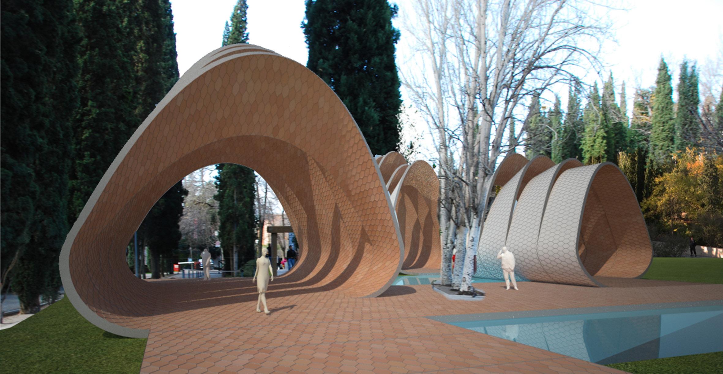
119
Fig. 5.22 | Proposal. East Elevation
Fig. 5.21 | Proposal. South Elevation
Fig. 5.23 | Proposal. Access View
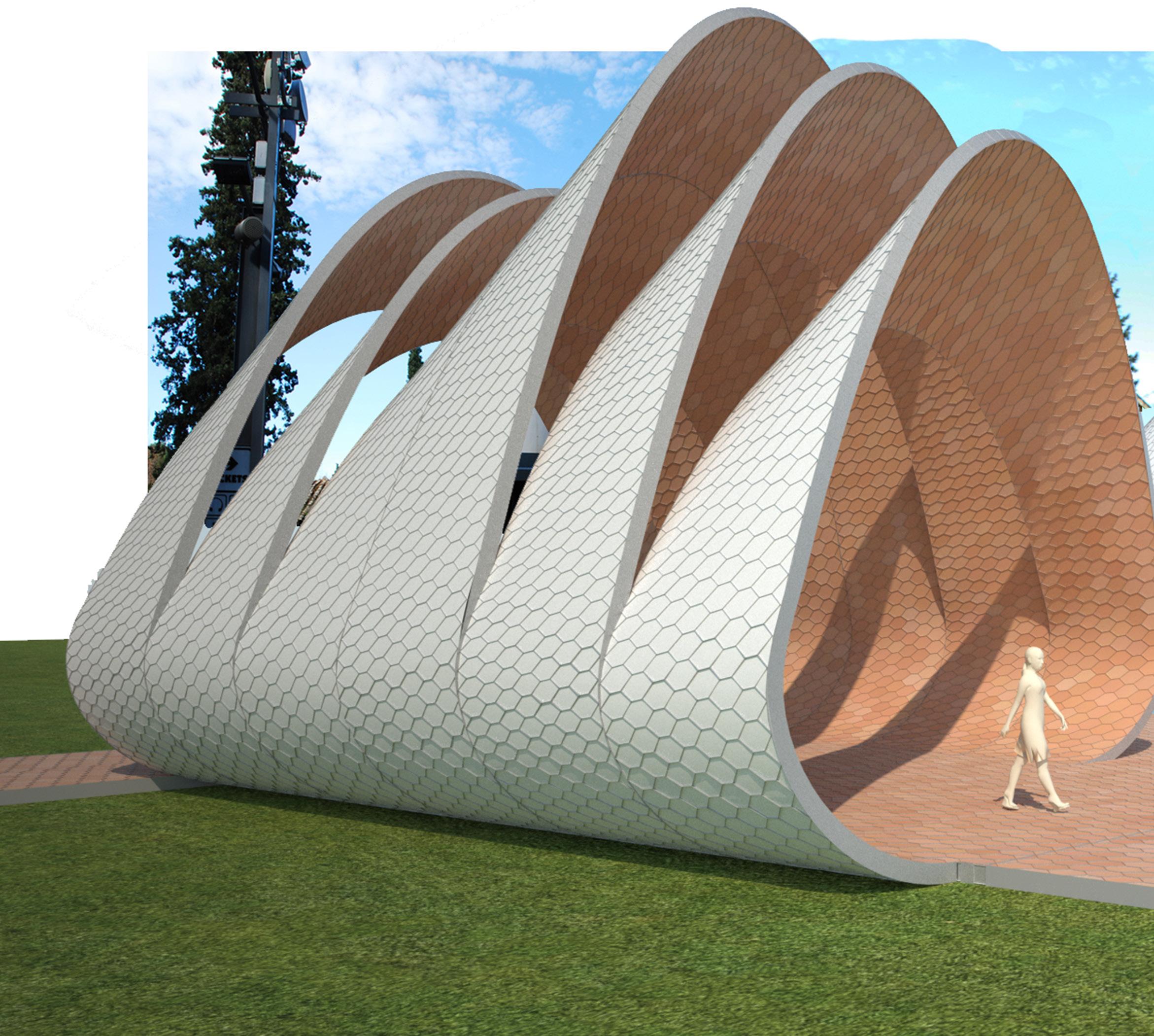
5. Design Proposal | 5.4 Proposal
Cellular Reinforced Ceramics | Juanjo G. Castellon
Fig. 5.24 | Proposal. General View
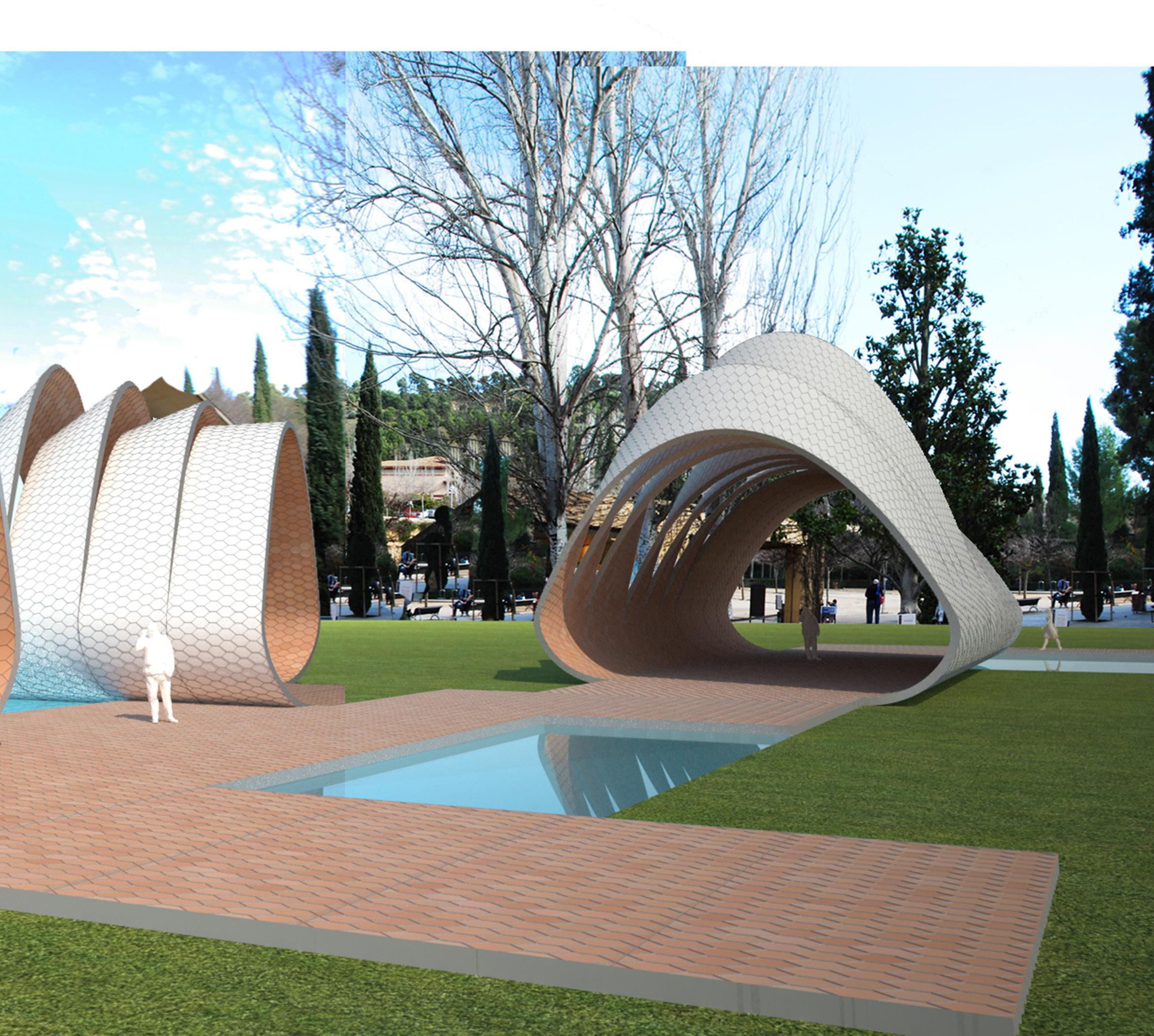
121
6. Conclusions & Further Development
CONCLUSIONS:
* New parametrics tools represent an oppotunity to review traditional techniques by adding variation and implementing industrial tools with contemporary technologies.
* The combination of ceramics, cement and honeycomb metal mesh reinforcement could, potentially ,open new structural and architectural applications.
* Complexity in a fabrication process is directly related with the geometrical rules that define an architectural form. Complex doesn’t mean smart.
FURTHER DEVELOPMENTS:
* Currently in collaboration with Toni Cumella (catalan ceramics manufacture ) in the development of a non uniform extrusion process .
* Currently in collaboration with Escofet in the development of honeycomb reinforced panels ( concrete + aluminum honeycomb mesh ).
* Potential application of the system using cardboard honeycomb panels as a moulding system that can disappear during the firing process.
6. Conclusions & Further Developments
Cellular Reinforced Ceramics | Juanjo G. Castellon
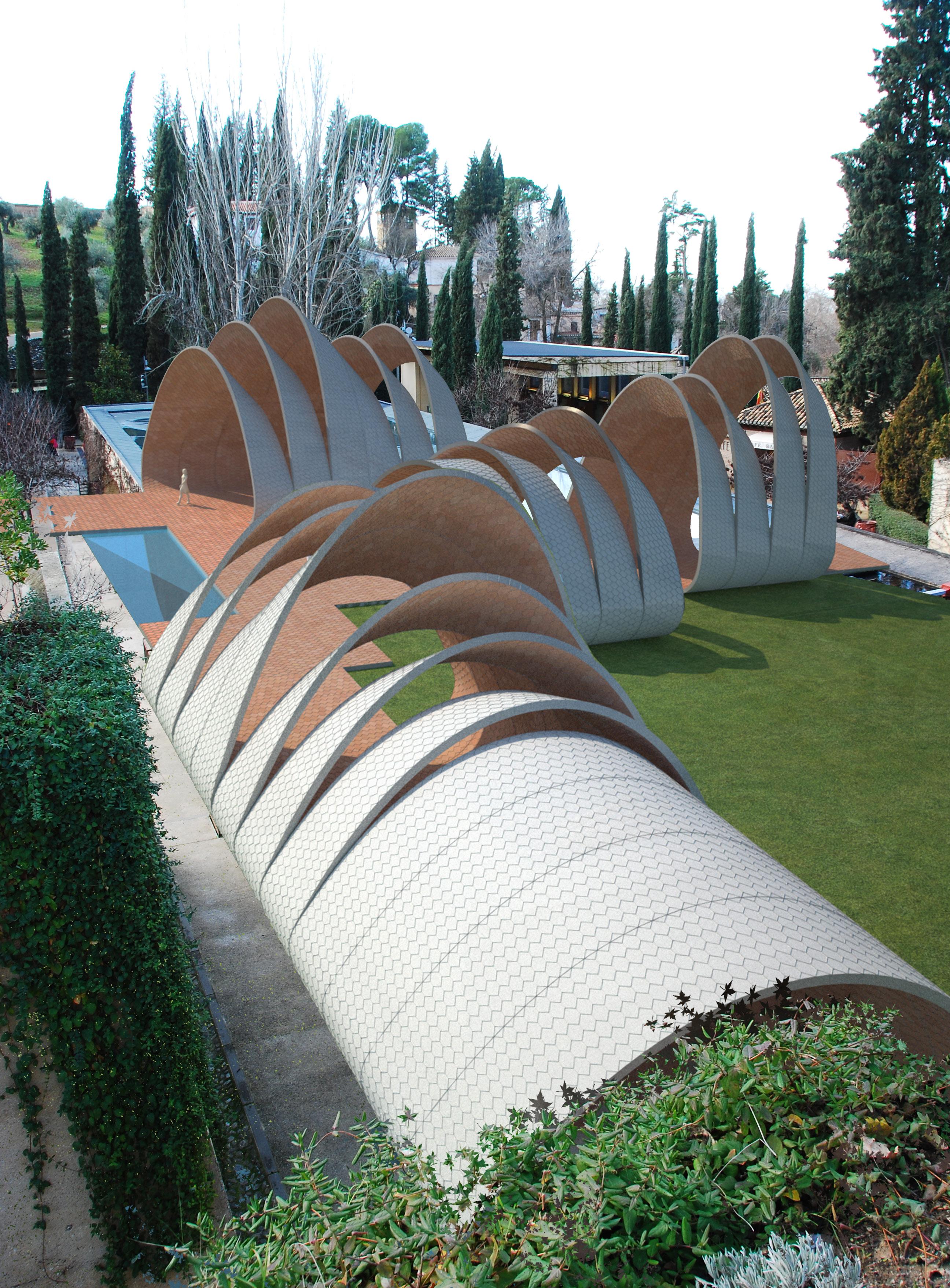
123
Fig. 5.25
| Proposal. Aereal View
Credits
125
Credits | Images Cellular
Reinforced Ceramics | Juanjo G. Castellon
Fig. 1.01 | La Sagrada Familia | © CJ Walsh
Fig. 1.02 | La Sagrada Familia | © CJ Walsh
Fig. 1.04 | The Programmed Wall | © Gramazio & Kohler
Fig. 1.07 | Port Warehouse | Flickr © Juanitta
Fig. 1.08 | © Image from article: Luis Moya and the tile vaults in post-war Spain_ Josep M Adell
Fig. 1.09 | © Image From document: Advaced Geometry, Rudimentary Construction. Michael H. Ramage
Fig. 1.10 | © Image from article: Luis Moya and the tile vaults in post-war Spain_ Josep M Adell
Fig. 1.11 | La Ricarda | Flickr © Xikki
Fig. 1.12 | Aymerich, Amat i Jover Textile Mill | © Xabier de Jaureguiberry
Fig. 1.13 | © Image from article: Luis Moya and the tile vaults in post-war Spain_ Josep M Adell
Fig. 1.14 | Aymerich, Amat i Jover Textile Mill | © Xabier de Jaureguiberry
Fig. 1.15 | City Hall Station | © Ryan Budhu
Fig. 1.16 | © Image from Thesis: Rafael Guastavino and the Boston Public Library _ Lisa J. Mroszczyk
Fig. 1.17 | © Avery Architectural and Fine Arts Library
Fig. 1.18 | © Image from article: The Guastavinos and tile vaults in North America_ John Ochsendorf
Fig. 1.19 | Ellis Island | Flickr © Vogelium
Fig. 1.20 | © Image from magazine: Revista de Obras Publicas 3422
Fig. 1.21 | © Boston Public Library
Fig. 1.22 | © Boston Public Library
Fig. 1.23 - 1.29 | © Image from website: www.pinecalyx.co.uk
Fig. 1.30 | © Image from article: On the shape of Cables, Arches, Vaults and Thin Shells. Mark Schenk
Fig. 1.31 - 1.34 | © Image from article: Ceramica Armada.Baldassari/Cueto
Fig. 1.35 | © Image from book: Innovation in structural art. Standford Anderson
Fig. 1.36 | © Image from article: Form, Force and Structure
Fig. 1.37 | © Image from website: www.avab.free.fr
Fig. 1.38 | Port Warehouse | Flickr © Ekainj
Fig. 1.39 - 1.43 | © DesignToProduction
Fig. 1.44 | © Rolex Learning Center
Fig. 1.45 | Rolex Learning Center | © École polytechnique fédérale de Lausanne
Fig. 1.46 | Rolex Learning Center | Flickr © Tim Tom
Fig. 2.01 | © Image from book: Patent Constructions: New architecture made in Catalonia. Ed. ACTAR
Fig. 2.03 | © Image from Fernandez, John (2006), Material Architecture, Architectural Press
Fig. 2.10 - 2.15 | © Image from article: Innovación en el uso de la cerámica en arquitectura. Vicente Sarrablo.
Fig. 2.16 | © Image from book : Cellular Solids.Gibson, Lorna J. and Michael F. Ashby,
Fig. 2.18 | © Diagram from catalogue: Alucoat-Conversion
Fig. 2.19 | © Diagram from catalogue: Alucoat-Conversion
Fig. 2.21 | © Image from book: Made Of. New Materials Sourcebook for Architecture and Design. Ed. Gestalten. 2010
Fig. 2.22 - 2.24 | © Image from website: http://another29.exblog.jp/
Fig. 2.25 - 2.27 | © Image from book: Made Of. New Materials Sourcebook for Architecture and Design. Ed. Gestalten. 2010
Fig. 2.48 | © Image from website: www.dezeen.com
Fig. 2.48 | The Programmed Wall | © Gramazio & Kohler
Fig. 2.49 | Radiolaria Pavilion | © Image from website: www.blueprintmagazine.co.uk
Fig. 2.50 - 2.52 | Villa Nurbs | © Image from website: www.ruiz-geli.com
Fig. 2.53 - 2.54 | © Image from book: Patent Constructions: New architecture made in Catalonia. Ed. ACTAR
Fig. 2.58 | The Programmed Wall | © Gramazio & Kohler
Fig. 5.01 | The Programmed Wall | © Gramazio & Kohler
Fig. 5.02 | The Alhambra | Flickr © Cesar Atanes
Fig. 5.03 | The Alhambra | from website: www.webshots.com © Otterenespana
Fig. 5.04 - 5.07 | The Alhambra | © Patronato de Alhambra y Generalife
All the rest of the images and diagrams belong to the authors:
© Juanjo G. Castellon
© Baek - Ki Kim
127
Bibliography
Cellular Reinforced Ceramics | Juanjo G. Castellon
Bibliography
129
Bibliography | Books
Cellular
Reinforced Ceramics | Juanjo G. Castellon
Books
Addington, Michelle / Schodek, Daniel L. (2004) Smart Materials and Technologies in Architecture, Architectural Press, UK
Aldinger, F. / Baumard, J.G. (2001) Advanced Ceramic Materials: Basic Research Viewpoint, Max-Planck-Institut fÜr Metallforschung
Anderson,S. (2004) Eladio Dieste, Innovation in Structural Art [Hardcover]. Princeton Architectural Press, New York
Bitzer, Tom, (1997) Honeycomb Technologies: Materials, Design, Manufacturing, Applications and Testing, Chapman & Hall, London
Balmond, Cecil (2007) Informal, Prestel, Germany
Balmond, Cecil (2008) Number 9: The Search for the Sigma Code, Prestel, Germany
Balmond, Cecil (2007) Element, Prestel, Germany
Bechthold, M. (2008): Innovative Surface Structures: Technologies and Applications, Routledge
Brownell, Blaine (2006) Transmaterial: A Catalog of Materials That Redefine Our Physical Environment, Princeton Architectural Press.
Burry, J. & Burry, M. (2010). The New Mathematics of Architecture , Thames & Hudson
Cohen, J.L. / Moeller, M. (2006). Liquid Stone: New Architecture in Concrete [Hardcover], Princeton Architectural Press
Corser, R.(2010). Fabricating Architecture, Princeton Architectural Press
Ferré, A. / Devesa, R. / Salazar J. (2007) Patent Constructions: New Architecture Made in Catalonia, ACTAR
Ferré, A. / Sakamoto,T. (2008). From Control to Design. ACTAR
Fernandez, J. (2006), Material Architecture, Architectural Press
Gibson, L. J. / Ashby, M. Cellular Solids; Structure and Properties-Second Edition, 2001, Cambridge University Press
Giralt-Miracle, D. (2002). Gaudí: La busqueda de la forma. Lunwerg Ed.
Gonzalez Blanco,F. (2007). Miguel Fisac, Huesos varios [Perfect Paperback]. Ed. COAM
Gramazio & Kohler. (2008). Digital Materiality in Architecture , Lars Müller Publishers
Hagan, S. (2008) Digitalia: architecture and the digital, the environmental and the avant-garde, Routledge
Hensel, M. & Menges, A.(2007). Morpho-Ecologies: Towards Heterogeneous Space In Architecture Design, AA Publication
Iwamoto, L. (2009). Digital Fabrications. Architectural and Material Techniques , Princeton Architectural Press
Kolarevic, B. (2003). Architecture in the digital age: design and manufacturing, Spoon Press, New York
Kolarevic, B. & Malkawi,A. M. (2005). Performative Architecture: Beyond Instrumentality, Routledge, New York
Liu, Y.-T., Lim, C.-K. (2009). New Tectonics - Towards a New Theory of Digital Architecture, Birkhäuser, 2009
Moussavi, F. & Kubo, M. (2006) The Function of Ornament, Actar
Moussavi, F. (2009). The Function of Form, Actar
Picon, A. (2010). Digital Culture in Architecture: An Introduction for the Design Profession, Birkhäuser
Pottmann, H. - Asperl, A.-Hofer, M & Kilian, A. (2007). Architectural Geometry , Bentley Institute Press
Ochsendorf, J. (2010). Guastavino Vaulting: The Art of Structural Tile. Princeton Architectural Press
Ortega, Ll. (2009): La digitalización toma el mando, Ed. GG
Thomas ,K.Ll (2007) Material Matters: Architecture and Material Practice [Paperback]. Routledge
Thompson, D. (1992) On Growth and Form, Cambridge University Press
Thomson, R. (2007). Manufacturing Processes For Design Professionals , Thames & Hudson
Rajchman, J. / Virilio, P. (1998) Construction, The MIT Press, US
Reiser, J. (2006). Atlas of Novel Tectonics, Princeton Architectural Press
Sauer, C. (2010). Made Of… New Materials Sourcebook for Architecture and Design, Gestalten
Spuybroek, L. (2009). The Architecture of Variation, Thames & Hudson
Stattman, N. (2003) Ultra light-Super strong A new generations of design materials, Birkhauser, CH
Terzidis, K. (2006). Algorithmic Architecture, Architectural Press
Villa-Real, A. (1993). La Alhambra y el Generalife. Miguel Sanchez
Woodbury, R. (2010): Elements of Parametric Design, Routledge
131
Bibliography | Articles & Websites
Cellular Reinforced Ceramics | Juanjo G. Castellon
Articles
Abrahams, T. The World’s First Printed Building .Blueprint Magazine .March .2010
Bassegoda, B. “Bóvedas Tabicadas” . Curso Superior de Materiales Cerámicos. Consejo Superior de Investigaciones Científicas. 1952
Celento, D.Harrow, D. CeramiSKIN Digital Possibilities for Ceramic Cladding Systems. ACADIA 08. 2008
Collins, George R. “The Transfer of Thin Masonry Vaulting from Spain to America”. American Society of Architectural Journal 1968 Oct., v. 27, n. 3, p. 176-201.
Guastavino, R. Essay on the theory and history of cohesive construction. Ticknor.1893
Huerta, S. La construcción tabicada y la teoráa cohesiva de Rafael Guastavino. Cedex.2006.
Kohler, M. The Robot and the Architect are Friends .Icon Magazine .July .2010
Lefteri, Chris. Ceramics: Material for inspirational design. Rotovision.2003
Lundgren, H. Cylindrical Shells. Vol.1 of Cylindrical Roofs .Danish Technical Press . Copenhagen. 1949.
Mroszczyk, L. J. Rafael Guastavino and the Boston Public Library. Massachusetts Institute of Technology.June 2004
Ochsendorf, J. The Guastavinos and tile vaults in North America. Informes de la Construccion. Vol 56. N496. March-April 2005
Ramage, M. H. Building a Catalan vault. 2004
Sarrablo, V. Innovación en el uso de la ceramic en arquitectura. El Tejido Cerámico Estructural. Lourenço (eds.). 2007
Shenk, M. On the shape of Cables, Arches, Vaults and Thin Shells. 2009
Theodossopoulos,D. Sinha ,B.P. A study on the free-standing masonry vaults of Eladio Dieste. 2007
Websites
http://www.designtoproduction.com
http://www.gramaziokohler.com/
http://www.ruiz-geli.com/
http://www.pinescalyx.co.uk
http://www.stageone.co.uk/_content/composites_hub_page.php
http://robotsinarchitecture.blogspot.com/
http://www.buildfreeform.com/
http://www.d-shape.com/index.htm
http://www.block.arch.ethz.ch/index.php?pageID=22&filter=8
http://eat-a-bug.blogspot.com/
http://matsysdesign.com/
http://www.dfab.arch.ethz.ch/web/e/forschung/135.html
http://www.ceramicaserra.com/
http://www.cumella.cat/home.htm
http://www.escofet.com/
http://www.ceracasa.com/
http://www.spaintiles.info/eng/ascer/historia.asp
http://www.cricursa.com/segur/index.aspx
http://www.ductal-lafarge.com/wps/portal/ductal
http://www.alucoat-conversion.com/
http://www.trbls.com/bonding.htm
http://www.corecomposites.com/
http://www.plascore.com/product-honeycomb-cores.htm
http://www.lmii.com/carttwo/thirdproducts.asp?NameProdHeader=+Nomex
http://www.professionalplastics.com/Nomex_Honeycomb
http://web.mit.edu/course/3/3.91/www/slides/cunniff.pdf : M5 Hyperfibre Akzo Nobel
133
Acknowledgements Cellular
Reinforced Ceramics | Juanjo G. Castellon
Acknowledgements
I would like to acknowledge …
… Michael Weinstock his warm support and guidance during the whole process.
… Toni Kotnik his open-minded and playful attitude and his personal engagement with the project.
… George Jeronimidis his wise advice and time spent with me in front of the computer.
… Toni Cumella and Jordi Serra their generosity for sharing with me their amazing knowledge and experience on ceramics
… Luis Caro (Alucoid) for sponsoring the project providing lots of material and motivation.
… Enric Pericas ( Escofet ), Vicente Sarrablo (UIC) and Ana Martinez (ASCER) for their valuable advice and contribution.
… My colleague Baek-Ki Kim and the rest of my EmTech mates for their respect and friendship.
… my sponsor “La Caixa” their confidence in my dreams.
… my family because they built me.
135


110211 March Dissertat on indd 136 110211_March Dissertation.indd 136 2/12/2011 2:44:39 AM 2:44:39


 Fig. 1.00 | Proposed Vaulting System in “La Alhambra”. Granada. Spain.


 Fig. 1.23 | Wooden formers attached to the central pole
Fig. 1.24 | Fist layer setting
Fig. 1.26 | Third layer of tiles at 90º
Fig. 1.25 | Second layer arranged in 45º pattern
Fig. 1.27 | Interior view


 Fig. 3.05 | Parametric Moulding System. Configurations by twisting and bending
Fig. 3.06 | Parametric Moulding System. Test Sequence.
Fig. 3.07 | Parametric Brick. Final Plaster production


 Fig. 3.13 | Flat Panel. Final pice with glossy finishing
Fig. 3.10 | Test 01. Flat Panel. Honeycomb + Fine Cement


 Step 1 Prepare the rubber bed
Mechanical arm for Twisting
Mechanical arm for Bending
Step 2
Attach the honeycomb to rubber layer
Step 2 Attach the honeycomb to rubber layer
Step 3
Pour Cement
Step 3 Pour Cement
Step 4 Wait until hardening
Step 4 Wait until hardening
Fig. 3.16 | Parametric Moulding System. Assembly Test of 4 panels
Step 1 Prepare the rubber bed
Step 1 Prepare the rubber bed
Mechanical arm for Twisting
Mechanical arm for Bending
Step 2
Attach the honeycomb to rubber layer
Step 2 Attach the honeycomb to rubber layer
Step 3
Pour Cement
Step 3 Pour Cement
Step 4 Wait until hardening
Step 4 Wait until hardening
Fig. 3.16 | Parametric Moulding System. Assembly Test of 4 panels


 Fig. 3.20 | Multi-layered system Ceramic Skin.


 Fig. 3.26 | Parametric Moulding System. Production Sequence
Fig. 3.27 | Final Piece. Honeycomb + Cement
Fig. 3.24 | Twisted and Bended Configuration


 Fig. 3.32 | Possible configuration as a lost Formwork
Fig. 3.33 | System used as a lost formwork. Pouring Concrete
Fig. 3.31 | Preparation of a Sandwich panel System.


 Fig. 3.38 | Geometrical Studies. Sequence of Generation. Vaults
Fig. 3.37 | Geometrical Studies. Sequence of Generation. Dome
Fig. 3.35 | Structural Application. Dome
Fig. 3.34 | Double Curved Surface. Stiffness Principle


