A rtic r ecalibration
Resource driven fabrication system for the Artic in the near future [<2050]
Emergent Technologies and Design 2016 - 2018

M.Arch Candidates
Mithuna Murugesh | Elena Shilova
Director Michael Weinstock
Emeritus Professor Dr. George Jeronimidis
Studio Master Elif Erdine
Studio Tutors Antiopi Koronaki Alican Sungur Lidia Badarnah
A rtic r ecalibration
Resource driven fabrication system for the Artic in the near future [<2050]
Architectural Association School of Architecture
Master of Architecture, Emergent Technologies and Design 2017-2018
Architectural Association, 2018 36 Bedford Square, London WC1B 3ES
Architectural Association (Inc), Registered charity No 311083 Company limited by guarantee. Registered in England No 171402
M.Arch candidates: Mithuna Murugesh Elena Shilova

ii i Architectural Association Arctic Recalibration
Architectural Association School of Architecture
Graduate School Program
Coversheet for submission 2016-2018
Programme Emergent Technologies and Design
Term Dissertation
Student Name(s) : Mithuna Murugesh, Elena Shilova
Submission Title Arctic Recalibration
Title Emergent Technologies and Design Course
Tutor Michael Weinstock, George Jeronimidis
Submission Date 12.01.’18
Declaration :
“I certify that this piece of work is entirely my/our own and that any quotation or paraphrase from published or unpublished work of others is dully acknowledged.”
Signature of Student(s)
Mithuna Murugesh Elena Shilova
iv iii Architectural Association Arctic Recalibration
”Fall seven times, stand up eight.”- Japanese Proverb
I would first like to thank my thesis advisor Michael Weinstock, Director of the Emergent Technologies and Design program of the Architectural Association school of Architecture. The door to your office was always open whenever I ran into a trouble spot or had a question about my research or writing.
To George Jeronimidis, your feedback and always helpful advice and attitude are always appreciated. Your helpfulness will not be forgotten and I am very grateful for your positive influence at the AA.
I would also like to show gratitude to my tutors, including Elif Erdine, Evan Greenberg, Antiopi Koronaki, Alican Sungur and Lidia Badarnah for their insightful comments and encouragement, but also for the hard question which incented me to widen my research from various perspectives. I would also like to thank Mohammed Makki who’s input was highly valued. A special thanks to Angel Lara Moreira who’s ‘can do’ attitude was always a positive reinforcement.
I would like to sincerely thank and show my gratitude to my family for always believing in me, and for the continuously support to help me to pursue my ambitions. Special thanks to my mother for the unwavering encouragement and support through out.
I thank my fellow teammate, Elena Shilova, for the stimulating discussions, her thirst for knowledge and for the sleepless nights when working together without whom this research would be incomplete.
-Mithuna Murugesh
“In the middle of every difficulty lies opportunity” -Albert Einstein
I would like to express my sincere appreciation to my advisor, Michael Weinstock, for his impregnable belief in this project, as well as knowledge and guidance, both professional and personal. His sincere love and passion for architecture was contagious, encouraging us to challenge ourselves, be ambitious, adventurous and push our boundaries.
I also want to express my deep gratitude to prof. George Jeronimidis, whose expertise and patience supported this project at every step of its winding path. I am thankful to Elif Erdine, Evan Greenberg, Manja Van de Worp, Lidia Badarnah, Antiopi Koronaki and Alican Sungur for their highly professional attitude and for the warm, friendly atmosphere they created at Emergent Technologies and Design. Lastly, I would like to acknowledge the contribution AA staff, and Angel Lara-Moreira in particular for his help and good advice.
I would like to sincerely thank my beloved family, who always supported and believed in me, providing me this opportunity in the first place. I would like to express my gratitude and admiration to all of my colleagues in EmTech and in the AA, whose kaleidoscope of cultures, passions and characters inspired me along all the journey.
Last, but not the least, I would like to thank my amazing teammate, Mithuna Murugesh, whose unbelievable dedication, attitude and professionalism was an example for me and a powerful driver in the completion of this project.
-Elena Shilova
vi v Architectural Association Arctic Recalibration
Materials are not inert receptacles for a form imposed from the outside, but active participants in the genesis of form.
Neri Oxman MIT Media Lab
viii vii Architectural Association Arctic Recalibration
Arctic Recalibration is an investigation of resource-driven settlement strategies in Arctic environments. Traditional construction materials are scarce in the northern latitudes, and extreme environmental challenges to construction are notoriously common to the Arctic. As such, the majority of the built mass consists of imported panellised assemblies that borrow from modular military buildings or housing types better suited to lower latitudes. In light of global warming and economic interest in the Arctic, this project reconsiders current models of construction and importation.
Firstly, a material system fabrication system and building type was developed to address locally sourced materials. This material strategy has been explored at a variety of scales ranging from material properties to environmentally driven building arrangements. The aim of the investigation is the development of sustainable settlement types for pioneering what is often perceived to be the Earth’s final frontier.
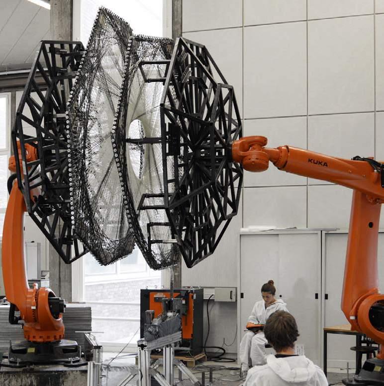
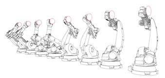
The work is contextualised in the Seward peninsula in Alaska, the site of abundant thermokarst drained lake basins as a part of a relocation strategy for local peoples. In response to the lack of conventional construction materials, this project has been developed to capitalise on a potentially abundant resource in the Arctic: peat, which, conveniently, also has positive thermal properties. Peat can easily be prepared for use in a one year period the proposed system. Contemporary construction techniques in the Arctic are slow [limited to the summer period], labor-intensive, dangerous, expensive, and constrained to primarily rectilinear forms, often resulting in homogenous structures built using materials sourced from centralized factories that are not contextualised to site. To begin to address these issues, we present the proposed fabrication system, an automated construction system capable of customized on-site fabrication of architectural-scale structures using real-time environmental data for process control. The system consists of a multi robot, composed six axis robotic arms carried on a tracked mobile platform.
With this model as a proposed building type, various environmental, topological and strategic relationships have been used to develop a design model for autonomous building clusters.
The aim of this multi-scale investigation of a local [low technology] material strategy in conjunction with robotic fabrication [high technology] is to investigate the possibility of pioneering the New North in a way that is economically efficient and environmentally meaningful in the near future [< 2050].
x ix Architectural Association Arctic Recalibration a bstract
1. Introduction
xii xi Architectural Association Arctic Recalibration the arctic ..........................................................................................14 the new north ..........................................................................................16 inhabitating the arctic ..........................................................................................18
THE ARCTIC
Identifying the environmental, economical and social driver that will define the future of northern development
INTRODUCTION :
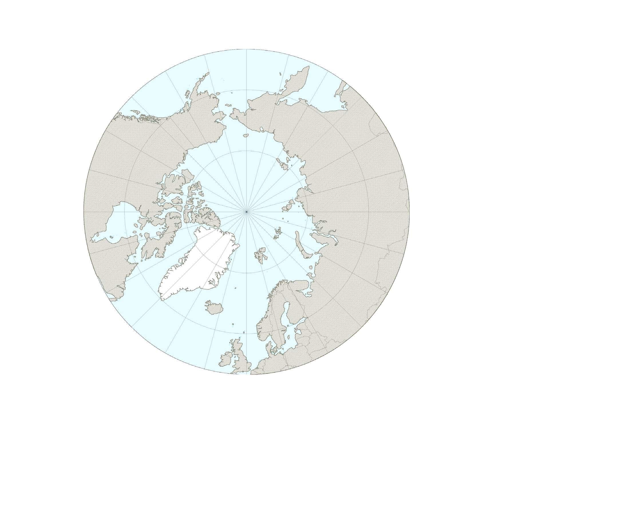
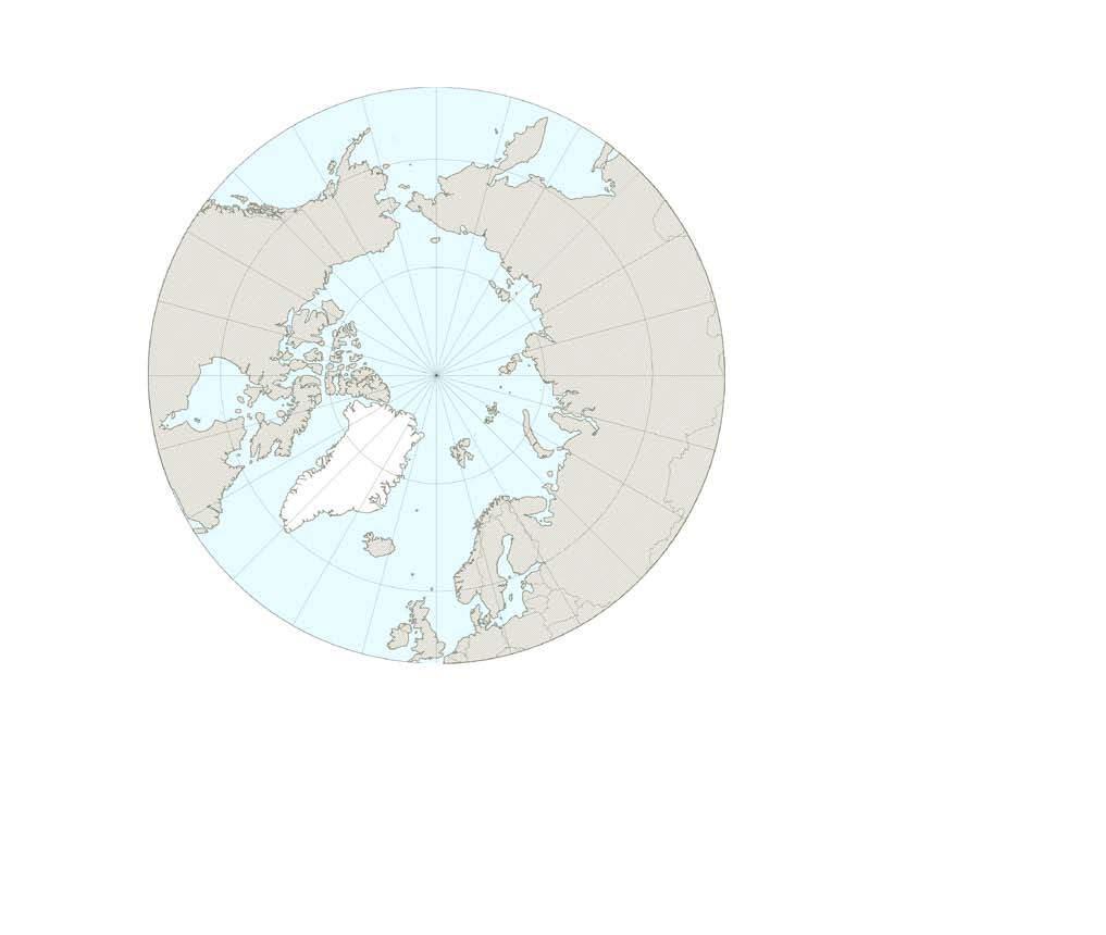
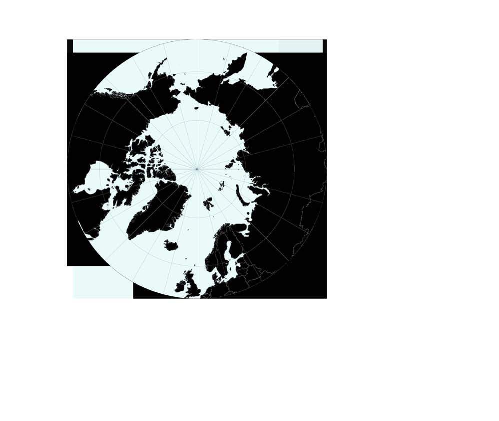
The region surrounding the North Pole consists of a large ocean surrounded by land. This ocean, called the Arctic Ocean, is like no other ocean on Earth; and because of its special location and climate, the lands that surround it are unique.
Most commonly, scientists define the Arctic as the region above the arctic circle, an imaginary line that circles the globe at approximately 66° 34’ N [dashed grey circle in the image at left]. Another definition of the Arctic is the region above the tree line [marked in green]. Arctic tundra is found across northern Alaska, Canada, and Siberia. This biome has long cold winters and short cool summers resulting in a complex and highly dynamic scenario of chemical and physical phenomena, including rapid cycles of freezing and thawing, evapouration and precipitation. The Arctic tundra has low precipitation [less than 10 inches per year] and dry winds with almost permanent ice and snow conditions. These conditions make the Arctic tundra a desert-like climate

The average Arctic winter temperature is -30° F [-34°C], while the average Arctic summer temperature is 37-54° F [3-12° C]. In general, Arctic winters are long and cold while summers are short and cool. The Arctic’s inhospitable weather and other environmental challenges have limited human activity and settlement.
One unique characteristic of the Arctic tundra is permafrost-ground that is permanently frozen. Because the permafrost has no cracks or pores, nothing can penetrate it, neither plant roots nor water and it remains at a constant 0 degree celcius. However with the onset of global warming the arctic is one of the most rapidly changing environment.
S W E D E N F I N L A N D N O R W A Y UNITEDSTATES CANADA IC E L A N D GREE N L A N D RUSSIA 66 33N 2 00 PRO ECT ON P R E S E N T C E E X T END 10 C DEGREE ISOTERM 0 C J U L Y ISOTERM TREELINE xiv xiii Architectural Association Arctic Recalibration
NSIDC
National Snow and Ice Data Center
THE NEW NORTH
Identifying the environmental, economical and social driver that will define the future of northern development
DRIVERS OF DEVELOPMENT IN THE ARCTIC
The four major global forces influencing development in the New North can be identified in: the increase in global population and migr tion, the growing demand for natural resources, globalisation and climate change . Mineral resources [oil, gas, and mining], fisheries, shipping, and tourism the four main sectors for development. 2
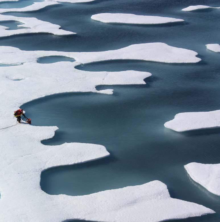
Climate change is drastically changing the geography of the Arctic and its ecosystems. As sea ice thins and snow cover reduces, the Arctic absorbs more heat and reflects less light . Summers arrive earlier in the year and last longer. Younger ice breaks with less effort, making more of the Arctic navigable without icebreakers. Existing infrastructure built on permafrost will have issues to maintain. Winter roads, which many communities such as Tiksi, Russia, depend on for access to the outside world, have seen their seasons decline from over 200 days in the 1970s to 100 day 2.
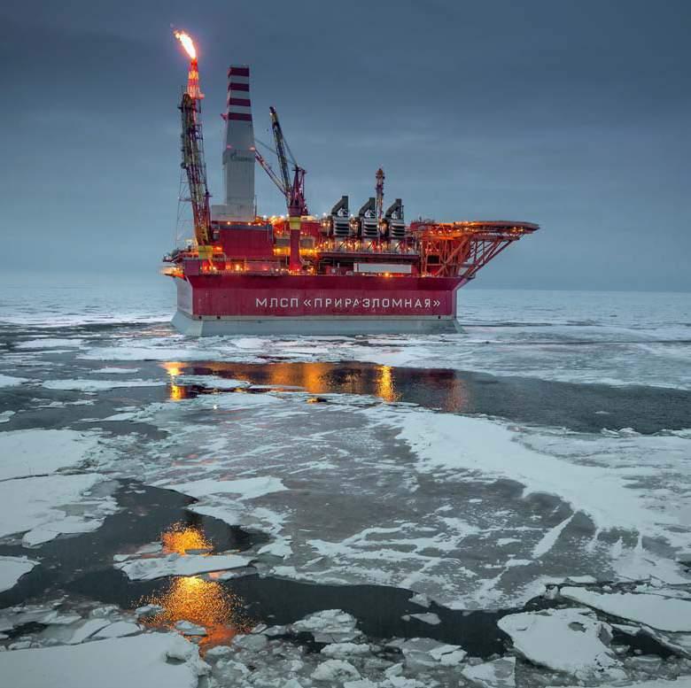
Amidst this uncertainty, there is also economic opportunity. The Arctic Ocean has seen increased use in transport recent years. The Arctic shipping industry is currently a point-to—point operation but a diminishing of these barriers makes a trans- Arctic shipping route possible. And while new oil, gas, mineral reserves and construction materials are constantly being discovered, an increase in labour demand and economical opponunities is predicted to attract an increasing number of people in the years to come
O V Y R E N G O Y M K D 100,000 50,000 20,000 400,000 200,000 NSIDC , National Snow and Ice Data Center xvi xv Architectural Association Arctic Recalibration
INHABITING THE ARCTIC
Current design response the the climatic challenges and the role of responsive architectural designs
Any human intervention has an immediate and measurable effect on urbanisation and the soil tectonics below it. Thawing of permafrost causes unstable ground for the buildings and infrastructure supported on it. This serves as a precondition for architectural systems that demonstrate adaptability to site variability in the Arctic context. Thawing of permafrost not only causes unstable ground for established ecosystems, buildings and infrastructure but also releases methane (CH4) and carbon dioxide (CO2), due to the huge amount organic matter stored in the frozen soil, with heavy consequences on the environment.
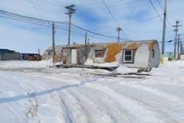
Since the creation of permanent settlements in the 1950’s, these communities have been lacking of adequate buildings and infrastructure . Due to the inaccessibility of most Arctic communities, and a lack of building materials sourced locally, most buildings are designed to incorporate transportable components with low manufacturing costs, often yielding energy inefficiencies. Given the military and scientific nature of most of the buildings around which the first settlements were created, it is not uncommon to see houses in the shape of quonsets or hangars 5 This universal type of architecture based on economy rather than local climatic factors has produced buildings that for almost any function, from civic to residential, are usually rectilinear prefabricated envelopes, often called ‘matchbox’ houses for their lack of geometrical variation 6
With the dynamics of the future growth of northern settlements being unknown, there is an opportunity for a new paradigm in arctic architecture to be developed in response to the need for more regional designs
‘New North’ scenario Existing settlement strategy Discovery of reserves of resources Less extreme projected climate Potentially accessable routes Poor soil conditions for settlements due to climate change Poor living conditions Short periods of stay Increase in demand Migration of existing settlements Construction/housing materials Energy Transport infrastructure Migration from coastlines due to erosion and flooding into inland hotspots Integrated Strategy for Arctic Habitation xviii xvii Architectural Association Arctic Recalibration
CURRENT DESIGN RESPONSE TO THE CLIMATE CHALLENGES :
xx xix Architectural Association Arctic Recalibration
overview .........................................................................22 global warming in the arctic .........................................................................24 thermokarst DraineD lake basin .........................................................................30 Potenrial materials .........................................................................32 site selection .........................................................................34 PreDicteD PoPulation influx .........................................................................38 logistics .........................................................................42 arctic architecture .........................................................................50 arctic automation .........................................................................56 conclusions .........................................................................58
ii . D omain
OVERVIEW
Whoever wants to survive the extremes of the Arctic environment needs to adapt to it. During the centuries of Arctic occupation, humans, from the Thule to their Inuit descendants, have found different ways of responding to such challenges . Whether it is the materials they adopted for their dwellings, the strategic positioning and orientation of their settlements, or the seasonal migrations in search for food sources and milder climates.
The following sections explain what the potential change in climate is estimated and its effect and on the arctic, and how an originally dynamic and adaptive response approach has led way to a standardised, rapid and cost-effective one. The opportunity and limitations of the potential change in the arctic, on both the landscape and that of dwellings will be analysed in order to lay out the framework for what is intended to be a methodical approach encompassing several scales to improve construction in the North.
The scenario taken into consideration is that of Alaska. Although many of the challenges and indeed their possible responses can be valid for different Arctic contexts around the world such as the Siberian tundra and the Icelandic and Scandinavian regions, this area was chosen for the wide availability of data and information as well as the unique high frequency “Thermokarst basins” issue explained in depth in the following sections.
xxii xxi Architectural Association Arctic Recalibration
‘CONTINUOUS ADAPTING IS THE ARCTIC WAY OF LIFE’ :
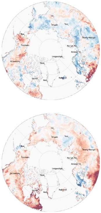
The Arctic is warming at a rate of almost twice the global average.
This sample image shows near- surface air temperature for October 1980.
NEAR SURFACE AIR TEMPERATURE
Surface air temperature change mapped in the Arctic
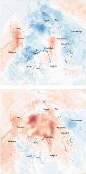
This sample image shows near- surface air temperature for October 2015.
A IR TEMPERATURE INCREASE IN RECENT YEARS :
The maps show how air temperatures in the Arctic compare to averages from 1979 to 2015 . On the map, areas with higher than average temperatures for the selected month [Selected month being October onset of winter] and year are indicated in oranges and reds [positive anomalies], and areas with lower than average temperatures are shown in blues [negative anomalies]. The map of anomalies helps show where temperature change is strongest. These are temperatures two meters above the surface, similar to the temperatures given in weather reports and forecasts.
An interesting aspect of Arctic change seen in the temperature maps is the phenomenon of “Arctic amplification.” This refers to the outsized warming of the Arctic relative to the rest of the globe. While a number of mechanisms contribute to Arctic amplification, the loss of Arctic sea ice cover plays a dominant role. Basically, because there is so much more dark, open water than was the case even a decade ago, the ocean gains much more heat in summer than it used to. This in turn means that more heat is released back to the atmosphere in autumn as sunlight wanes. This warming climate allows for a milder climate resulting in an influx in population willing to settle in these areas which would previously not be the case.
xxiv xxiii Architectural Association Arctic Recalibration
SOIL NON FROZEN ANOMALIES
Non-frozen soil change in the Arctic mapped
INCREASE IN NON FROZEN SOIL :
The map shows how the number of days in each year the soil surface is unfrozen compares to the average for the period 1979 to 2015 . On the map, areas where soil surfaces are unfrozen for more days than normal are shown by reds [positive anomalies]. Areas where soil surfaces are unfrozen for fewer days than normal are shown by blues[negative anomalies]3 The map of anomalies helps to show where changes the number of days with unfrozen soil are the strongest.
Much of Alaska and eastern Siberia exhibit increases in the non-frozen period in most years since 2005. However, central Siberia and northern Canada show more variability.
With an increase in unfrozen soil in the recent years, materials that were never before available in the arctic are now appearing. Materials such as peat, sand and potentially trees, due to the ability to now grow more than shrubs, are potential materials that could be used in the Arctic for construction purposes.
xxvi xxv Architectural Association Arctic Recalibration
This sample image shows soil non-frozen anomalies for October 1980.
This sample image shows soil non-frozen anomalies for October 2015.
SNOW COVER DURATION
Snow cover anomolies mapped in the Arctic
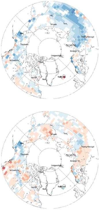
CHANGE IN SNOW COVER DURATION :
The maps show how Northern Hemisphere snow cover for different years and months compares to averages for the period 1980 to 2015 9 The maps show snow cover duration, expressed as the number of days a grid cell is snow covered for each month for each year. On the maps, areas with longer than average snow cover duration are indicated in blue [positive anomalies]. Areas with shorter than average snow cover duration are indicated in red [negative anomalies]4 The maps of anomalies help show where changes in snow cover are strongest.
The maps show spatial patterns of anomalies of snow cover duration. There are no large anomalies in Arctic latitudes in winter months. Much of the Arctic at this time is so cold that precipitation is nearly always in the form of snow, and the snow, once fallen, rarely melts. Large anomalies in snow cover start to appear in the Arctic after May. Negative anomalies are prevalent over Alaska and Siberia after about 2005. In September and October, both positive and negative anomalies can be seen. An increase in the number of days with snow cover might indicate an increase in the frequency of early autumn snow events, which are related to a decrease of winter months leading to milder climate.
xxviii xxvii Architectural Association Arctic Recalibration
This image shows snow cover duration for October 1980.
This image shows snow cover duration for October 2015.
thermokarst D raine D basins
An overview of the formation of thermokarst drained lake basins
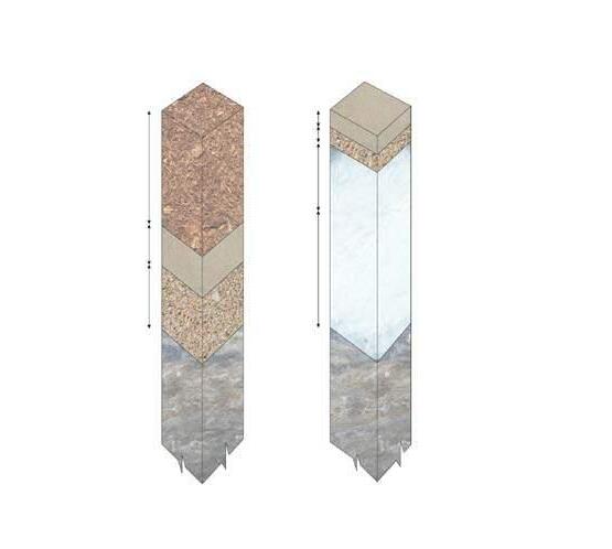
THERMOKARST DRAINED LAKE BASINS : Due to global warming with an increase in temperature in the arctic thawing of permafrost is now a common occurrence 10 The thawing of permafrost creates thermokarst topography, an uneven surface that contains mounds, sinkholes, tunnels, caverns, and steep-walled ravines caused by melting of ground ice.
Thawed depressions filled with water (thaw lakes, thermokarst lakes, cave-in lakes) are widespread in permafrost areas, especially in those underlain with perennially frozen silt. Locally, deep thermokarst pits 6 metres deep and 9 metres across may form as ground ice melts. Some of these lakes drain away leaving behind large amounts of peat and sand. These two materials are explored as building materials.
Thermokarst lakes are an interesting phenomenon, who’s frequency of occurence is increasing with a rise in temperature due to global warming in the current scenario. Within the 30 year scenario there is an increase in the frequency of the next stage of thermokarst lakes, i.e. drained thermokarst lake basins 11 These basins leave behind materials that were previoudly unavailable in the arctic region.
Initial stage (pre-thawing)
Thermokarst lake inception (ice-rich permafrost thawing)
ice wedge
peat
water
ice-rich permafrost
Mature stage (maximum lake depth)
Drained stage (no water in the basin)
Thermokarst drained lake formation
xxx xxix Architectural Association Arctic Recalibration
P otential materials
Site selection
OVERVIEW :
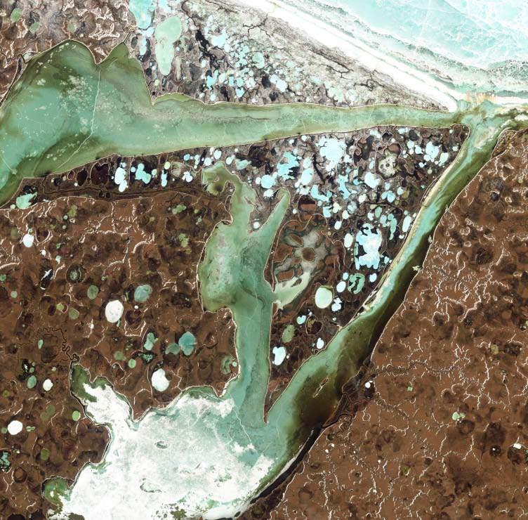
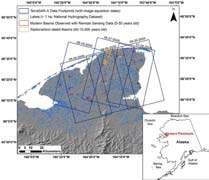
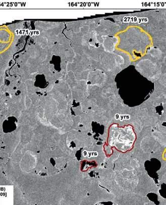
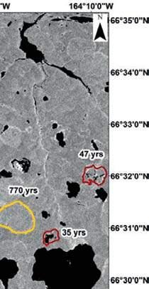
Drained lake basins are widespread in Arctic lowlands affected by thermokarst and, in tundra areas, the topography of these basins typically constitutes a wet, depressed margin surrounding a slightly elevated, better drained centre. This low grade geomorphological feature is widespread in Arctic lowlands (see satellite images to the right), yet the genesis of this topography is poorly understood.
The seward peninsula in Alaska has a high frequency of existing thermokarst lakes which in the 30 year scenario many would become drained thermokarst lake basins due to their old age. Climate in the Sweard peninsula is characterized by long cold winters and short growing seasons [May to September]. The mean annual air temperature of the region is −6.1 °C, and the mean annual precipitation is 255 mm, with roughly 125 mm falling in the form of snow based on historical summaries for the period 1971–2000 recorded at Barrow, Alaska which is located 60 km to the northeast, but has a similar mainland position as the northern Seward Peninsula.
xxxii xxxi Architectural Association Arctic Recalibration
Basin Out- Out0 1000 600 800 400 200 Sandy Basin Volumetric water 12 10 8 80 20 40 60 2 100
Sphagnum peat Fine sand Bedrock Gravel sand
sewar D P eninsula , alaska
Site selection
OVERVIEW :
Drained lake basins are widespread in Arctic lowlands affected by thermokarst and, in tundra areas, the topography of these basins typically constitutes a wet, depressed margin surrounding a slightly elevated, better drained centre. This low grade geomorphological feature is widespread in Arctic lowlands (see satellite images to the right), yet the genesis of this topography is poorly understood.
The seward peninsula in Alaska has a high frequency of existing thermokarst lakes which in the 30 year scenario many would become drained thermokarst lake basins due to their old age. Climate in the Sweard peninsula is characterized by long cold winters and short growing seasons [May to September]. The mean annual air temperature of the region is −6.1 °C, and the mean annual precipitation is 255 mm, with roughly 125 mm falling in the form of snow based on historical summaries for the period 1971–2000 recorded at Barrow, Alaska which is located 60 km to the northeast, but has a similar mainland position as the northern Seward Peninsula 12

Digital Elevation Model (DEM) base map of the Seward Peninsula showing the location of lakes (>1 ha) mapped the DTLBs that drained (>90% of surface area loss) 0–50 years ago
xxxiv xxxiii Architectural Association Arctic Recalibration
Number of lakes, thousands Latitiude, N 73 71 69 67 65 63 0 80 20 40 60 61 Surface area, thousands Latitiude, N 71 69 67 65 63 0 80 20 40 60 61
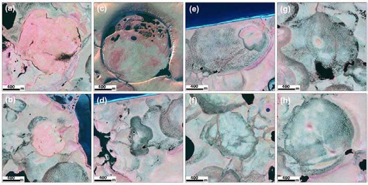
DTLB of different age classes located in the northern Seward Peninsula (Modern: (a) 9 yrs old, (b) 29 yrs old; Young: (c) 403 ± 55 cal·yr·BP, (d) 294 ± 15 cal·yr·BP; Medium: (e) 1471 ± 60 cal·yr·BP, (f) 770 ± 35 cal·yr·BP; Old: (g) 2719 ± 40 cal·yr·BP, (h) 2567
xxxvi xxxv Architectural Association Arctic Recalibration
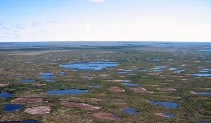
basins and new DTLB and old DTLB
Landscape at the Seward peninsula - varying lake
NEAR TERM (<2050) P HANGE IN THE ARCTIC
An overview of population change due to climate change in the Arctic
OVERVIEW OF POPULATION GROWTH IN ARCTIC
The population of the Arctic remained about the same in 2010 as in 2000, through a combination of growing and declining Arctic regions balancing each other out 13 Indicating that while the overall population remained around the same, the population per area changed drastically due to erosion and flooding of coastlines of the arctic with population influx into certain areas of the Arctic that are now safe to inhabit.
Among Arctic regions, Alaska’s population increased at a faster rate than the U.S. average 14. The regions of the Canadian Arctic also increased at a faster rate than Canada as a whole. Population growth in Iceland was 14 percent, similar to the North American Arctic. In all Arctic regions of Fennoscandia, population growth in the northern or Arctic regions was considerably less than the countries as a whole. The population of the Russian Arctic declined by 6%,, much less than the decline during the 1990s, but twice that of the Russian Federation rate. Growth in the oil and gas producing regions Nenets & Yamal-Nenets Okrugs] was outweighed by decline in all other Arctic regions of Russia.
The main factor driving trends in population change in the Artic is migration. The major trend in most Arctic regions is migration losses to the southern regions of their respective countries and migration gains from abroad 15 Nearly all of the Arctic regions are experiencing considerable international migration of people seeking work in resource extraction and the service sectors. These migration flows are having a considerable impact on the social composition of the Arctic regions.
xxxviii Arctic Recalibration
ooding and erosion at the coast POPULATION Migration from global regions due to milder climates and new potential resources NEED FOR NEW SETTLEMENTS CURRENT PREDICTED S W E D E N F I N L A N D N O R W A Y UNITEDSTATES CANADA IC E L A N D GREE N L A N D RUSSIA 66 33N 100 ROJ CT ON P R E N T C E X T END C DEGREE ISOTERM 10 C J U L Y ISOTERM TREEL NE Current treeline Projected treeline >1 No change <1 40,000 10,000 1000
arctic econom Y
An overview of the current and potential economy of the arctic which causes population influx
HIGH POTENTIAL :
Alaska GDP was 0.9% of the GDP of Arctic nations (Canada, Denmark, Finland, Iceland, Norway, Russia, Sweden, US) 16
Measured by real GDP the Arctic economy grew over 31% between 2000 and 2009, faster than the rate of growth for the Arctic nations (2.1%). GDP grew much faster than population in the Arctic, which meant real per capita GDP grew 30%, more than twice the rate of per capita GDP growth for the Arctic nations as a whole and approximately 10% more than growth of per capita GDP for the world economy.
Arctic nations are currently optimistic about the prospects for Arctic resource development. Various resource development projects are proposed for Greenland, Nunavut, Russian and Alaskan arctic seas.
Optimism about the future of the arctic economy is based on 3 observations:
NATURAL
RESOURCES EASE
The Arctic is a storehouse of natural resources, holding almost 22% of the world’s undiscovered conventional oil and gas.
Global warming in the Arctic will likely allow ice free travel in arctic seas and lower the cost of access to and development of the Arctic’s resources, while access by sea will lower cost delivery of supplies and of shipment of the resources to markets.
xl xxxix Architectural Association Arctic Recalibration
OF ACCESS
The potential for accessing resources has increased with the current rapid rise in commodity prices. Increasing demand from emerging nations is driving prices increases of commodities, most of which have risen sharply since 2001. :
: DEMAND
Oil drilling in Alaska
LOGISTICS
Evaluation of the modes of transport and limitations of construction in the Actic region
BY LAND
Terrestrial transportation happens prevalently by truck on paved or more commonly gravel-surfaced roads. For just a few months during the winter freeze up, ice bridges are formed and what are called ‘ice-roads’ which allow circulation of heavy goods vehicles (HGV’s) can function as the only way to reach certain settlements by land.
MAIN USE- Large tanks, medium sized crates, barrels and oversized shipments.
BY SEA
Marine transportation is rapidly expanding as it is becoming easier to sail the Arctic Ocean as perennial icestarts retreating. Since port facilities and wharf in arctic destinations are almost non existent, shipments loaded on container ships are usually unloaded onto landing barges which can run up onto the beaches.
MAIN USE- Large crates
RESOURCE TRANSPORT
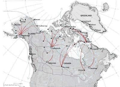
Due to the lack of local suppliers, building material, including steel, wood and concrete must be imported. In some communities even gravel or coarse aggregates for foundation backfill is scarce. Construction equipment might also not be readily available and forklifts and cranes- when required- might have to travel a long way to reach the site. It has been estimated that marshalling and shipping charges for transporting material to the Arctic may take up to 20% of the total cost of construction17. Transporting material on site in the Arctic usually takes place in three ways: by truck, ship or air cargo. It is important to point out that the availability and cost of these modes of transport highly depend on the location of the settlement and the time of the year.
BY AIR
Due to its high costs, aerial transportation is more commonly reserved to high priority or perishable goods such as medicines or the movement of people. Almost every major arctic settlement is provided with short landing strips for small charter planes to land.
MAIN USE- Perishable goods, medicines.
xlii xli Architectural Association Arctic Recalibration
ARCTIC CONSTRUCTION
Analysis of past and present building types with specific focus on Alaska.
PERMANENT ARCHITECTURE IN ALASKA :
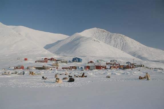
Government post-WWII housing typologies have created a template for arctic shelters which is in use still today. Development of Alaskan Arctic did not start until the 1950’s when the government started using the small ports and whaling stations built in the early twentieth century as a basis to form communities for indigenous people 18
Permanent settlement was encouraged by providing health care, education and social amenities to the lnuit. Installing permanent architecture in these zones can be seen as a Canadian and American attempt to assert arctic sovereignty during the Cold War when the arctic started having greater strategic importance19 The resulting architectural designs are the proof of this fact, as they appear more “frontier” designs than family houses.
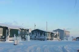
xliv xliii Architectural Association Arctic Recalibration Aerial view of the settlement of Inuvik
CONTEMPORARY ARCTHITECTURE
Current building forms, methods and materials
TYPE A
Irregular body, roof pitch >30
EXISTING DWELLING
Despite promoting the new notions of comfort and durability, the housing stock provided by the Canadian government in the last five decades completely disregards the traditional Inuit lifestyle and the cultural and sustainable intelligence of their existing dwellings. ln fact, the local model of dwelling, articulated around a common living room and several individual sleeping quarters, often took the form of an hermetic container. Several Canadian anthropologists, like Peter Dawson in 2002 19 recorded how the activities of Inuit families [e.g. food preparation, crafting, storage, etc.] were often ill-accommodated by the spatial configuration of the new homes.
MATERIAL
These so called ‘Euro—Canadian’ dwelling types applied the post-war modernist ideal of regularity to ‘universalise’ the design process and cut down design and fabrication costs. The result is the choice of aluminium as primary structural and exterior surface material, as is was inexpensive to import it from the southern regions. The poor thermal insulation of such material, and its rapid deterioration in the arctic environment however often caused expensive maintenance.
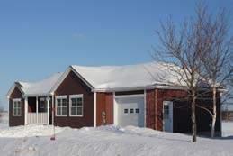
TYPE B
Straight body, roof pitch >30
TYPE C
Other [quonsets]
xlvi xlv Architectural Association Arctic Recalibration
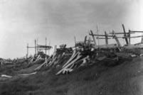
VERNACULAR ARCTHITECTURE
vernacular building forms, methods and materials
MATERIAL
Historic evidence suggests that Arctic indigenous architecture often featured semisubterranean house floors, passageways, cold-trap tunnels, raised sleeping platforms and a variety of construction materials that differed according to seasonal needs and availability. In the generally treeless tundra environment they commonly used materials such as sod, turf and animal skins as a building envelope, and driftwood, whalebones, caribou antlers and even narwhal tusks for the main structure.


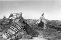


SEASONAL SHIFT
A crucial element of the Inuit settlement pattern is its seasonal shift between concentration in winter and dispersion in summer 20 This major demographic shift is heavily coupled with the surrounding life: summer was the season for exploring, and kayak hunting; while winter was a time for visiting, storytelling, ritual ceremonies and regenerating the cooperation vital to the
xlviii xlvii Architectural Association Arctic Recalibration
1-4 InhabitantsConstruction materia- Ice blocks
1-4 InhabitantsConstruction materia- Driftwood,
IGLU
6-8 InhabitantsConstruction materia- Sod, rocks
NAPAQTAQ IGLUYUARVK
1-4 InhabitantsConstruction materia- Saplings
4-6 InhabitantsConstruction materia- Sealskin
4-6 InhabitantsConstruction materia- Bones
TUPIQ ARCHED TUPIQ
WINTER DWELLINGS SUMMER DWELLINGS QUALURVIK
AUTOMATED CONSTRUCTION
Introduction to robotic construction processes
INTRODUCTION
Construction shapes our modern world. With global annual output in excess of $8.5 trillion, construction is an integral part of the global economy’s backbone, yet it relies on traditional fabrication technologies that are dangerous, slow, and energy-intensive. Common labor-intensive processes including bricklaying, wood framing, and concrete casting have, for decades of design construction, put workers at risk. The International Labour Organization estimated in 2005 that more than 50,000 people die globally in the construction industry per year, accounting for 17% of workplace accident fatalities 21
To improve safety, speed, and quality and to facilitate complex integrative fabrication operations, other manufacturing sectors such as automotive and consumer electronics have adopted the use of automated fabrication. Automated construction systems promise to yield similar benefits to the construction industry and, moreover, make newer digital fabrication techniques available at large scale. In combination with layer-based and freeform additive manufacturing techniques, automated construction systems could produce geometries that would be economically, if not physically, impossible to realize with conventional construction techniques. Structures produced by automated construction systems could be adapted on the fly to site-specific environmental conditions and constraints, using data collected in real time during fabrication. This capacity for data collection could also support more direct, detailed quantification of the building process, generating valuable data sets and describing a structure’s construction in high detail. Last, automated construction systems that could operate autonomously would find ideal applications performing construction tasks in inhospitable [such as after natural disasters] or extreme [such as Arctic] environments.
xlix Architectural Association Arctic Recalibration
ROBOTIC FABRICATION
Parameters in robotic fabrication
ROBOTIC FABRICATION
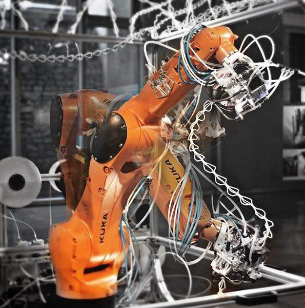
Robotic design and fabrication technology have brought a big impact in architectural design as well as in construction process in terms of new material exploration, high resolution production, and automation. The ability to be applied with different tools and tasks such as extrusion, brick layering, filament winding etc. opens up a wide range of fabrication possibilities and a new novel of techniques.
It’s ease of construction and shortening of construction time is a huge asset to the harsh conditions of the Arctic.
POTENTIAL FOR DESIGN :
Recent researches in these fields offer the opportunity towards digital fabrication in scale of construction. Furthermore, such construction of large scale systems push the researcher and architect to transform design traditions to a more complex, yet more detailed resolution output.
Some main variables of this fabrication technique are:
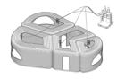
a) The robot
b) The end effector
c) Robotic movements and
d) Collaboration
lii li Architectural Association Arctic Recalibration
PARAMETERS OF ROBOTIC FABRICATION
The systems that define the robotic fabrication process
ROBOTIC PLATFORM
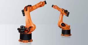
There are robots capable of doing various tasks or specific fabrication approaches, such as additive fabrication, subtractive fabrication, assembly, layering, stitching etc. depending on the needs. Robots can also be classified into two types based on their mobility which are in place robots or movable robots.
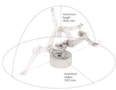
However, the most used robots in researches and some architectural practices are the six axis robotic arms. Their capability to be equipped with almost any tool implies that this robot can almost do anything if programmed to.
CONTROL SYSTEMS
The control system is designed to get the high accuracy in robotic fabrication process. Some parameters such as speed, gripper size, curing time, and material friction are the main factors that can affect the output especially in an continuous system.
In such an advanced fabrication systems, integrating sensor devices can be used to enable a real-time and even in-situ fabrication process. A multi robotic system for a continuous system would be ideal.
MULTI-ROBOTICS
Multi-robotic fabrication methods can improve significantly the potential of robotic fabrication in architecture and construction techniques through an integration of assembly task in higher complex fabrications.
There are several challenges facing these methods when multi robotic works are used for building complex constructions. An example is the robot path and the necessity for collision avoidance. In the end, these challenges will become robot constraints when it is combined with the working area of a robot and its kinematic behaviour.
liv liii Architectural Association Arctic Recalibration
on site | off site construction
The pros and cons of automated onsite and offsite construction are discussed
OVERVIEW :
The design of buildings is strongly linked to the environmental conditions of their sites. Ground stability, the presence of extreme winds, or other environmental and social factors will determine the construction techniques and materials that are necessary to build safe, usable structures. These, in turn, dictate the capabilities required of the construction system itself.
The first point of classification is thus systems that manufacture prefabricated components in an off-site factory environment, systems that perform fabrication tasks directly on site, and systems that perform a combination of both. Prefabrication has been widely used in the construction industry, with a major example being the prefabricated aluminium flat packs outsourced to the Arctic 21
However, this prefabrication is limited by a range of costs and constraints associated with transportation and assembly and by poor customizability of structures, which can pose particular challenges when information about build sites is limited or inaccurate. Raw materials need to be transported to a centralized factory, processed, and then shipped to the site. For large structures, such as buildings and civil infrastructure, transportation can be constraining due to volumetric limitations and the absence of roads [both relevant to the conditions of the Arctic]. For structures being built in remote or extreme locations, sufficient information about the environment can be challenging to obtain and hence affect the ability to plan a structure.
Therefore autonomous on-site construction can offer improved worker safety, improved process control and quantification, and last-minute adaptability to local conditions. Although prefabrication is a convenient stepping stone for the field, on-site fabrication will rapidly displace it as automated construction systems take a
PiP wall section, with milled portion to geometric accuracy milled offsite and then assembled
lvi lv Architectural Association Arctic Recalibration
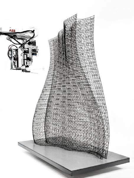
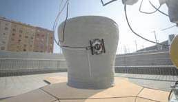
Architectural-scale hemiellipsoidal 3D printed on site
research project by Gramazio
Kohler Research at ETH Zurich
titled ‘Mesh Mould’
static or mobile s Y stems
A historical over of static or mobile robot systems
OVERVIEW :
Historically, most of the automated construction systems explored have been functionally static, either because they are too large and unwieldy to safely move even if they operate on site or because they are intended to operate as prefabrication systems in factory conditions, as with most gantry-style systems 21. Static systems generally benefit from simpler construction, design, and operation.
The most common static platforms are gantry-style systems, which generally have 3 degrees of freedom (DOFs) and are unable to handle complex geometries and overhangs. Even small arms mounted on gantry systems rapidly encounter issues with collision with the structure when attempting to fabricate overhang-like structures. Static systems also require assistance from either a human-operated device or another autonomous system for transportation to and set up at a work site.
MOBILE SYSTEMS :
More recent work has begun to explore mobile platforms for construction. Mobility rapidly becomes imperative as researchers seek to develop systems with much larger build volumes, to enable fully autonomous on-site fabrication, and to effectively deploy automated construction systems in swarm configurations.
Mobile systems can be classified as terrestrial or aerial. Terrestrial systems remain on the ground and primarily increase lateral work volumes. Aerial drone-based systems provide theoretically unlimited work volume across all dimensions and tremendous operational flexibility. However, they are typically restricted to assembly tasks and also suffer from major constraints associated with flight, such as high energy costs, limited load capacity, fabrication time limitations due to battery/fuel consumption, complex control requirements, and substantial hazard associated with system failure. Environmental factors, such as wind, rain, and wildlife, are also important challenges. Thus, terrestrial systems can provide increased work volumes and swarm capabilities without incurring heavy costs on complexity of the system itself.
lviii lvii Architectural Association Arctic Recalibration
A SSEMBLY L OGIC
The assembly logics that the proposed construction system must consider
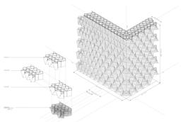
D iscrete a ssembl Y l ogic :


A discrete system is a system with a countable number of states. A discrete assembly logic is divided into two steps. The first step is the fabrication of discrete elements bricks, panels, frames, etc. which can all be identical, composed by family variations, or all unique and can be fabricated either off site or on site. Identical elements are better suited for bottom-up approaches since they are less restrictive. The second step consists of the on-site assembly of the elements.
The main limitation of employing a discrete assembly logic for a robotic construction method is the added complexity gained by separating fabrication and assembly, although in some cases the assembly process can become relativey simple since it consists only on the correct positioning of prefabricated elements.
n on -D iscrete a ssembl Y l ogic
A non-discrete [continuous system] is one in which the state variables change continuously over time. Non-discrete assembly logics are those in which fabrication and assembly are replaced by a single material deposition process. Although the process might be considerably more complex than the assembly of pre-made elements, by eliminating the fabrication process it becomes considerably easier to intergrate the entire construction process into an automated system.

The devices used for non-discrete assembly strategies should be designed specifically for the selected material and deposition strategy.
lx lix Architectural Association Arctic Recalibration
Discrete sYstem TerraPerforma - 3D Printed Performative Wall
sYstem Mnibuilders
robotic continuous system
Assembly Logic Assembly Logic Assembly Logic
non-Discrete
multi
C ONCLUSIONS
PEAT AS A MATERIAL FOR CONSTRUCTION :
Understanding the nature, availability, value and properties of peat in the drained thermokarst lakes and taking into consideration the material(soil) precedents, where forms of soil is used as a material for construction and research at various scales, using various techniques inspires the selection of this material for further research. The aim is to understand the innate properties of the material and use it advantageously for construction in arctic regions.
PROTOTYPYING TECHNIQUE
Analysing the various methods of construction and research using peat as a building material, the methods can be simply classified into Rapid prototyping techniques and Slow Prototyping techniques. Considering the local climatic conditions and material properties; a preference is placed towards slow prototyping formation techniques with a rapid assembly logic. The aim is to select suitable prototyping techniques based on the properties of the material determined through physical experiments and possibly integrate various techniques to form an architectural system that responds to external factors.
SITE SELECTION :
An area of approximately 3,800 km2 on the northern Seward Peninsula, Alaska [66.5°N, 164.5°W] is selected as the site. The study area is situated in an ice-rich permafrost region and is largely covered by thermokarst-affected terrain with a large number of thermokarst lakes and DTLBs and erosional remnants of uplands. The northern Seward Peninsula is identified as one of the major lake districts of Alaska, where 7% of the 6,418 km2 coastal lowland area is covered with lakes larger than 1 hectare. Thermokarst lakes in the lowland plain of the region mainly formed as a result of permafrost degradation due to warming throughout the Holocene
Currently, the mean annual ground temperature is recorded as −3 °C . This allows for current formation of permafrost following drainage of thermokarst lakes in the region . The depth of permafrost exceeds 90 M and the active layer is 0.3–0.6 M thick The permafrost thickness very likely varies due to the distribution and thermal impact of thermokarst lakes however, is confirmed to be abundant currently and only grow in its availibility with increasing temperatures.
FURTHER RESEARCH :
Further research aims on understanding in depth the properties and performance of the material in various states. This is aimed to be done through rigorous physical experiments through which the properties of the material may be determined and digitized for further computational processes. Various prototyping techniques will be investigated and weighed based on the advantages they offer both to the site and to the material while pushing towards innovative construction strategies.
lxii lxi Architectural Association Arctic Recalibration
iii . m aterial s Y stem
lxiv lxiii Architectural Association Arctic Recalibration
material science ...........................................................................65 case stuDies ...........................................................................68 binDer exPeriment ...........................................................................77 comPaction exPeriment ...........................................................................79 volume reDuction exPeriment ...........................................................................81 surface area exPeriment ...........................................................................83 freezing exPeriment ..........................................................................85 water resistance ...........................................................................87 self insulating material ..........................................................................89 material comParison ...........................................................................91
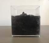
Physical and chemical properties of peat
Sphagnum Peat, is dead fibrous material that forms when mosses and other living material decompose in peat.
MATERIAL PROPERTIES
Peat is a type of soft soil composed of high contents of fibrous organic matters and is produced by the partial decomposition and disintegration of mosses, sedges, trees, and other plants that grow in marshes and other wet place in the condition of lack of oxygen.
Peat also contains high organic content, often more than 75%. The organic contents present in peat are the remains of partially decomposed and disintegrated plant. These take place in conditions where the rate of accumulation is more than the rate of decay. Peat is accumulated if the rate of decay is slower than the rate of addition 22
It accumulates whenever the conditions are suitable, that is, in areas where there is the ground is fully undrained, irrespective of latitude or attitude. Generally, the deposit is found in thick layers on limited areas. However, due to climate change and the creation of DTLB peat is found in abundance as the top soil. Since the main component is organic matter, peat is very spongy and highly compressible in characteristic (Roy, 2004
lxvi lxv Architectural Association Arctic Recalibration
m aterial s cience
C,H,O,N,S Dark brown 0.61 um 1121 kg/m3 5.5 ph 37 % 12% 0.4-1.2 Material Element composition Colour Particle size Density Acidity Water Holding Capacity Air Capacity Friction
P eat c om P ressibilit Y f actors
The dominant factors controlling the compressibility characteristics of peat
FIBRE CONTENT
INITIAL PERMEABILITY

NATURAL WATER CONTENT
VOID RATIO
NATURAL ARRANGEMENT OF SOIL PARTICLES

The percentage of organic matter in peat [sphagnum moss peat] is 70 - 95%
600 barrier
12 - 50% .This water is available in the form of free water molecules.
0.5 - 25 %
Non alligned fibres distributed uniformly
lxviii lxvii Architectural Association Arctic Recalibration
PEAT [LOAM] SILT LOAM SILTY CLAY SANDY CLAY LOAMY SAND SAND SANDY LOAM SANDY CLAY LOAM CLAY SILTY CLAY LOAM CLAY LOAM CLAY% SILT% SAND %
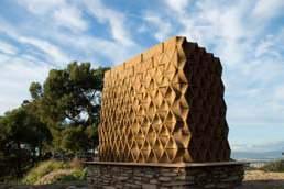
r icola k räuterzentrum
Rammed earth block construction
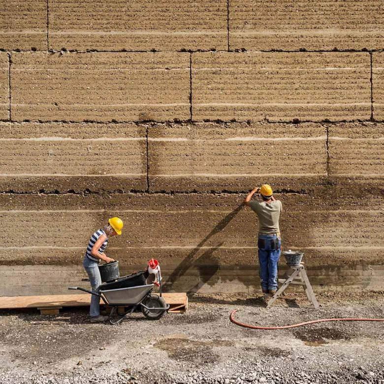
OVERVIEW TECHNIQUE
Architects: Herzog & de Meuron
Location: Laufen, Switzerland
Year: 2014
Time of construction: 18 month
Size: 50x50 meters
Cost - unknown
The prefabricated earth elements are manufactured in a nearby factory out of ingredients extracted from local quarries and mines. Clay, marl and material excavated on site are mixed and compacted in a formwork and then layered in blocks to build the walls. To arrest erosion caused by wind and rain, a trass mortar achieved mixing volcanic tuff (trass) with lime, is compacted every 8 layers of earth directly in the formwork.
ADVANTAGES
-Locally sourced earch from the construction site
-Earth based mortar composition
-Large-scale blocks
-Short-time walls assembly
DISADVANTAGES
-Human labour compaction - additional time
-Logistics: Blocks are prefabricated on a factory 10 km from a site
-Heavy blocks are lifted by the heavy machinery
-Framework is required for the blocks fabrication
-Steel framework as a building framework
lxx lxix Architectural Association Arctic Recalibration
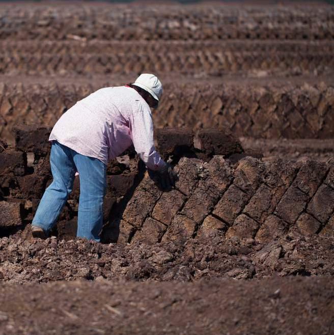
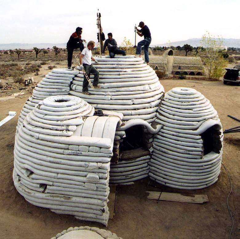
Earth tube construction
OVERVIEW
Architects: Nader Khalili
Location: Canada, Mexico, Brazil, Belize, Costa Rica, Chile, Iran, India, Siberia, Mali, and Thailand, U.S.
Year: 1995-present
Time of construction: 1-30 days
Size: D up to 10 m, h up to 6 meters, S up to 2,000 sq. ft
Cost - unknown
TECHNIQUE
Long or short sandbags are filled with moistened earth and arranged in layers or long coils. Strands of barbed wire are placed between each layer of sandbag to act as both mortar and reinforcement. Stabilizers such as cement, lime, or asphalt emulsion may be added. The SuperAdobe building system can be used for structural arches, domes and vaults, or conventional rectilinear shapes.
ADVANTAGES
-No mortar
-Continuous discrete process
-Short-time construction
-No need to lift heavy blocks
-No framework
-Additional tensile strength due to barbed wire
DISADVANTAGES
-Human labour required
-Polyethilene bags are required
-Spatial limitations to small compression-only structures
lxxii lxxi Architectural Association Arctic Recalibration
s u P era D obe
e D en P roject
Layered rammed earth construction
OVERVIEW
Architects: Grimshaw Architects
earth construction: Rammed Earth Consulting
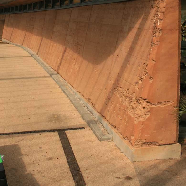
Location: Cornwall, England.
Year: 2001
Time of construction: 8 weeks
Size: 2 walls 45 meters each
Cost: £70 per metre square
TECHNIQUE ADVANTAGES
The walls are built from a 3m deep subsoil - well graded material with clay, sand and stones in the mix, .extracted by the main contractor as part of their landscaping works. It is rolled into a ‘bund’, a pile of soil which was tracked over by a digger to seal the top surface. The formwork is the old ‘acrow’ type, from 15mm ply. In all about 270 tonnes of soil are used, placed into the formwork in 150mm deep fills and rammed. Clay plaster is used as a mortar.
-Showed resistance to flash flood
-Short period of construction
-No framework
DISADVANTAGES
-labor-intensive compaction
-Complex geometries not possible
lxxiv lxxiii Architectural Association Arctic Recalibration
lxxvi lxxv Architectural Association Arctic Recalibration
Physical material tests conducted to analyse material potentials
a DD itives
Introduction to the additives proposed, the types and the selection criteria of the additives
OVERVIEW
Peat requires a binder to hold the particles together and solidify the result to retain structural integrity. By definition, a binder is any material or substance that holds or draws other materials together to form a cohesive whole mechanically, chemically, or as an adhesive. A binder may be interchangeably used with adhesives, cements or glues and resists separation with the base material in use.
MECHANISM OF BINDERS
For a binder to perform efficiently and effectively with sphagnum peat, it is required to possess certain properties. It must be mixable, it should be able to harden either naturally or through induced processes and it must be able to transfer loads Adhesion, the connection between the binder and the base material may occur either mechanically or chemically. The strength achieved through adhesion depends on several factors including the means through which it occurs. In some cases, an actual chemical bond occurs between adhesive and substrate. In others, electrostatic forces, as in static electricity, hold the substances together. A third mechanism involves the van der Waals forces that develop between molecules. A fourth means involves the moisture-aided diffusion of the binder into the substrate, followed by hardening.
TYPES OF BINDERS :
Binders can be classified into two distinct types – Natural or Synthetic
Natural binders are produced from organic sources such as resins from tree barks, starches from vegetables or protein based glues form animals. They are natural polymeric materials and are often referred to as bio-adhesives. They are of commercial interest and tend to be bio-compatible
Synthetic binders are based on polymers such as plastics, elastomers and thermosets. Some of the commonly used commercial synthetic binders are epoxy, polyurethane and acrylic polymers. Though proven to be very effective they have a limited shelf life when compared to natural binders and may have reduced performance through prolonged storage.
SELECTION CRITERIA OF BINDERS :
The binder to be used in creating a stable material for construction need to based on certain selection criteria. As Peat is the base material used in this research, an appropriate binder that works well with its particles is to be used.
The selection will be based on Drying time, Compressive strength, Dimension after compaction, Sustainability, Recyclability or reusability, Strength achievable and properties imparted to the material as a whole.
FIRE RETARDANT ADDITIVE :
Peat inherently is a highly flammable material. Peat is partially decomposed plant matter formed in wetlands that can be harvested as fuel. It can be the first step in the formation of coal, a process that takes millions of years and is therefore, used as fuel in many parts fo the world.
To prevent peat from being inflammable a fire retardant is added to the mixture in a powder form [not in liquid form to prevent the increase of volume of liquid in the peat which could potentially absorb the proposed binders]
Phos-Chek fire retardants are manufactured as dry powders. Some of the main components of Phos-Chek retardants include ammonium polyphosphate, diammonium phosphate, diammonium sulfate, monoammonium phosphate, attapulgus clay, guar gum. The phosphate and sulfate salts act as fire retardants and prevent combustion of cellulosic materials which is highly available in peat.
lxxviii lxxvii Architectural Association Arctic Recalibration
Free water molecules
Material Peat Binder Fire retardant
bin D er | ex P eriment i
Experiment to test suitable binder for the base material
APPARATUS
Peat+Additive+water mix
4-sided formwork.
Cap with the size of the hole in the formwork
Weights
TECHNIQUE STEPS
1. Mixing the composite: peat+additive+water.
2. Placing the mix into the 4-sided formwork
3. Compacting the mix from the top with the force
4. Removing the weight and waiting for the brick to dry.
INITIAL PARAMETERS
Size: 70x200x50 mm
Volume: 700000 mm
Force applied 30 kg with step of 2 kg;
OBJECTIVE :
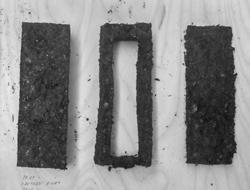
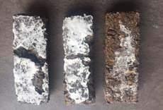
the first physical experiments conducted was a simple compaction experiment, where the material is brought together to a homogenous mix and compacted using moulds and left to dry yielding bricks which are then examined for further studies and research.
As preliminary investigation, a series of different naturally and synthetically ocurring binbers combined with peat have been tested. The drying time, change in volume, color compressive shear strength, weight are used to rank the series. The aim of the experiment is to understand the results that different compositions of peat, additive, water combined with certain drying time and temperature can provide.
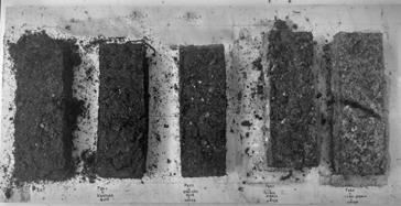
ConC Peat + xanthan gum
lusions Peat + Potato starch + Water
I. The block without binder does not perform structurally
Peat + xanthan gum + Water
Peat + corn starch + Water
II. Best type of binder is xanthan gum in composition without water, which performs better in regards to both hardening time and compression strength.
III. Potato starch sample has the least amount of compressive strength and can not be considered as an approppriate option.
lxxx lxxix Architectural Association Arctic Recalibration Step 1-2 Step 3 Step 4
Xanthan gum,a powerful thickening agent, that is also used as a stabilizer to prevent ingredients from separating is the binder selected for further experiments as it was found to have the highest compressive strength, lowest drying time and it not require additional water as it combined with the existing free water molecules in the peat thus, utilising less resources [additional water] keeping with objective of resource autonomy. Peat
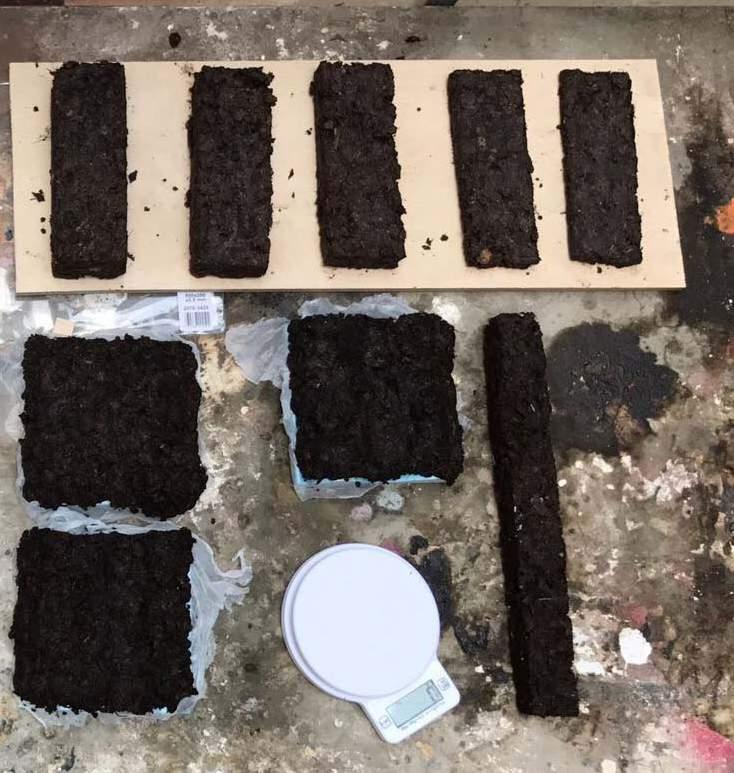
com Paction | ex P eriment ii
Experiment to test compaction methods
OBJECTIVE
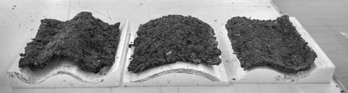
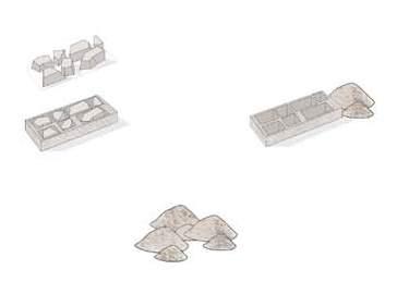
The fundamental mechanical property characterization of peat is in its compressive strength which develops once the material is compacted. Aiming to understand the material properties, two methods of compaction- ‘one step compaction’ and ‘layered compaction’ is tested.
One step compaction - peat is placed in the mold and compacted at the end once. Layered compaction - peat is placed in multiple layers with each placement intercepted with a compaction step.
A classical experiment in mechanics is performed on material samples of varying compacted methods to decide the method utilised during fabrication.
OBSERVATION
I. Compacting layer by layer drastically increases the compressive strength of the unit.
II. However, layer by layer compacting increases the time of fabrication.
III. Layer by layer compaction has an increased drying time when compared to one step compaction.
CONCLUSION
Layer by layer compaction is the selected method of compaction for the units. The compressive strength of the layered compaction for this specific dimension is 1.19 MPa. This experiment further reinforced the logic to be used during the construction process.
one step compaction layer by layer compaction one step compaction layer by layer compaction
-Compaction methods proposed
- Image of comapction proposed
- Table of properties of two proposed compaction methods
lxxxii lxxxi Architectural Association Arctic Recalibration
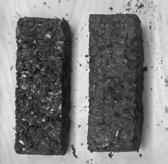
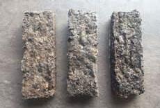
VOLUME REDUCTION | ex P eriment iii
Experiment to test amount of material that would create an optimum block
5 cm height block
V
5 cm height frame
V1 = V/2
OBJECTIVE
The aim of this experiment is to analyse and quantify the compressive strengths of material samples to understand the different types of geometries possible; hollow, thin shells or thick blocks.
OBSERVATION
I.Extraction of the material from the middle of the component drastically decrease the compressive strength. In fact, this “frame” component does not perform structurally.
II. Decreased thickness of the unit decrease the hardening time,but potentially increase the assembly and construction time.
CONCLUSION
The usage of hollow blocks and thin sections of modules is rejected due to the observed low compressive strength. A module with high thickness will have to be produced.
2.5 cm height block
V1 = V/2
5 cm height block V
5 cm height frame
V1 = V/2
2.5 cm height block
V1 = V/2
-Geometries tested
- Image of tested geometries
- Table of properties of various volumes and geometries
lxxxiv lxxxiii Architectural Association Arctic Recalibration
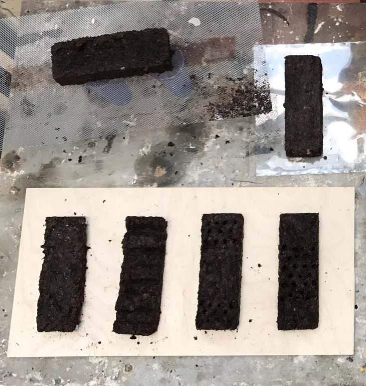
SURFACE ARE| ex P eriment iii
Geometry
oBJECTiVE : The objective is to find the relation between increasing the surface area while keeping volume constant to the drying time of these units.
A simple set up is designed for performing multiple experiments with precision. It consists of two panels joined parallelly to each other, one acting as a base and the other acting as the ‘compactor’ over which a weight is placed and then the drying time is recorded.
oBsERVATion :
I. The geometry of the component keeps changing while drying due to unequal water loss on the surface
II. Precision of the dried components is low, which can potentially have an impact to the stability of the final unit-composed geometry.
ConClusion :
I. Sine shape performs in the bast way, decreasing drying time by 30%.
II. Thickness of the component needs to be increased as this dimension [5 MM] easily deflects.
III. Decrease of a thickness increases the compressive strength, however increases the construction time.
A definite relation between drying time and surface area can not be conlusively drawn from this experiment due to varying results. While this experiment provided preliminary insights into the relation between uniform surfaces and drying time the potential idea of utilising ruled blocks that are molded into form is rejected due to the low precision of the material once hardened.
lxxxvi lxxxv Architectural Association Arctic Recalibration foam framework P vc firm P eat mix P vc firm foam framework 3 cm 3 cm 3 cm 15 cm 15 cm s ine c - sha P e w ave sha P e P lane
alteration to increase the surface area
c - sha P e s ine sha P e w awe sha P e
freeze & thaw c Y cle | EXPERIMENT IV
Geometry alteration to increase the surface area
+ Xanthan gum
+ Xanthan gum + water
OBJECTIVE
Peat + Salt + water
SET UP Three samples are tested
- Peat + Xanthan gum
Peat + Xanthan gum
+ Xanthan gum + water
Peat + Salt + water
OBSERVATIONS :
F reezing time :
P eat + X anthan gum - 4 hours
P eat + water + X anthan gum - 14 hours
P at + salt + water - more then 72 hours
i The sample with xanthan gum froze in 4 hours, the sample with xanthan gum and additional water froze in 14 hours while the sample with salt and water took over 72 hours to freeze.
ii. Salt addition to the mixture drastically increases the freezing time and/or the freezing temperature.
III. The sample without additional water freezes the fastest, and during the thawing creates less amount of cracks in a unit.
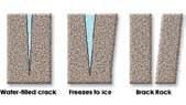
IV. The unit resists the freezing cycle regardless the mixture. However, the unit expands during the freezing causing a change in dimension.
V. The compression strength after freezing increases marginally.
CONCLUSION :
The results of the sample indicate that there is a change in dimension of the unit once frozen of %. There is a negligible increase in the compressive strength of samples once frozen and therefore the original compressive strength measured is taken into account for further experiments.
- Peat + Xanthan gum + water
- Peat + Salt + water [The presence of salt makes it harder for water molecules to bond to the ice structure, because ice naturally repels salt molecules]
The samples are placed in a freezing environment of a consistent - 17 ° c which is comparable the average temperatures during an Alaska winter.
lxxxviii lxxxvii Architectural Association Arctic Recalibration -17 ° c
0 ° c
Peat
Peat
Peat
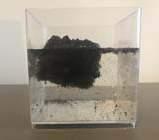
water resistance | EXPERIMENT V
Understand water resistance of a dry sample
resource reusabilit Y
Reusability of the material
OBJECTIVE :
The aim of this experiment is to understand the behaviour of water absorption a completely dry sample as the proposed site has heavy precipitation in the form of snow.
OBSERVATION : It is observed that the material does not easily absorb the water once completely dry. After 6 hours there is minial dissolving of the external surface of the material with the water. After 24 hours the sample shows slight signs of dissolving however, the top surface which is not submerged by water remains completely dry. Post 48 hours along with the aid of manually crushing the sample into small particles water begins to be absorbed by the sample and requires constant stirring to fully break down and absorb the water.
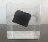
CONCLUSION : While the material shows a strong resistance to water when completely dry it is not water proof. Therefore, a water proof coating will potentially be required. This experiment reinforces the idea that the material is potentially reusable and further pushes the concept of material autonomy.
RESOURCE AUTONOMY :
The dearth of resources and the demand to reduce environmental impacts both in the procurement and processing of materials and products in construction places great significance on the construction method in this remote site. This requires appreciable improvements in resource efficiency. Resource efficiency means using the Earth’s limited resources in a sustainable manner while minimizing impacts on the environment.
In this research, the material developed is mainly peat naturally occurring and derived from nature providing alternate methods of building and living. This material further has a high potential of being reused or recycled. The set material can be pulverized [as discussed in the ‘water resistance’ experiment] and mixed with determined quantities of water to produce the initial form of the material which is used to create compacted units.
The re-use of the material involves little processing and offers greater value than recycling as there are no additional tools or environmental impacts here associated with reprocessing. Therefore allowing to create more with less.
xc lxxxix Architectural Association Arctic Recalibration 6 Hours 24 Hours 48 Hours + crushing sample
Material mix
Pulverised unused material Panels created
self insulating
Understand of the inherent insulating nature of peat and its potentials in the Arctic
HEAT TRANSFER :
Thermal conductivity is a measure of resistance to heat flow through a given thickness of material. The principles of heat transfer help to understand how insulation works. Heat flows from warm to colder surfaces until the temperature of both is equal.
C ONDUCTION
Conduction is the direct transfer of heat between adjoining molecules. A warmer molecule transfers some of its energy to colder neighbours. A good example is when one sits down on a cold metal chair, one can feel the cold from the chair as heat from the warmer body is quickly transferred by conduction to the chair.
C ONVECTION
Convection is the transfer of heat through liquids and gases. An example is warm air rising from a hot surface and being replaced by cooler and denser air that sinks. Heat is carried away from the surface by the warm air.
Peat has been studied in its natural and artificial forms to understand its potential as a self insulating material.
R (Thermal conductivity) 0.33 W/m °C
PEAT IN NATURE :
Peat is inherently an insulating material. In nature when found in areas with snow as precipitation it works as a great insular to keep the ecosystem going. The peat which exists in the permafrost layer in the Artic protects plant life by freezing in extreme cold conditions, this causes the plants to freeze too. Once, the weather warms the peat thaws out and the plants in the permafrost also thaw out. Peat in nature in inherently self insulating.
CURRENT INSULATING
USES :
Peat is traditional insulating materials used in log construction. Peat fibres are lightweight, porous and mostly hollow, which gives them a good natural heat insulation capacity.
Combined with the modern manufacturing techniques used to produce insulating materials, peat fibre can be refined into easy-to-handle insulating sheets whose dimensions match construction standards. They do not cause itching during installation and they do not sag.
It is not uncommon to discover old peat-insulated wood roofs and base floors in good condition during building renovations. With peat preventing the growth of bacteria and fungi, the wood structures remain healthy from one decade to the next as long as they have not been exposed to rainwater or capillary water. Peat fibre is hydrophobic, which makes the insulating material breathable and quick-drying.
CONCLUSION :
The utilisation of peat allows for increased energy efficiency as the material itself is inherently insulating against the harsh climatic conditions. Utilising peat leads to securing energy efficiency.
xcii xci Architectural Association Arctic Recalibration
MATERIAL COMPARISON
Comparison of the compacted peat created to other commonly used building materials

xciv xciii Architectural Association Arctic Recalibration Bricks hard Granite Limestone Portland concrete month Sandstone Slate Peat + Xanthan gum 10 20 30 40 50 60 70 80 90 100 110 120 130 0 Granite Limestone Sandstone Slate Peat + Xanthan gum 0.5 1.0 1.5 2.0 2.5 3.0 3.5 4.0 4.5 5.0 5.5 6.0 6.5 0 Bricks light Bricks common Portland concrete year Bricks hard Portland concrete 1 month Bricks light Bricks common Portland concrete year Bricks hard Granite Limestone Portland concrete month Sandstone Slate Peat + Xanthan gum 10 20 30 40 50 60 70 80 90 100 110 120 130 0 Granite Limestone Sandstone Slate Peat + Xanthan gum 0.5 1.0 1.5 2.0 2.5 3.0 3.5 4.0 4.5 5.0 5.5 6.0 6.5 0 Bricks light Bricks common Portland concrete year Bricks hard Portland concrete month Bricks light Bricks common Portland concrete year Bricks hard Granite Limestone Portland concrete 1 month Sandstone Slate Peat + Xanthan gum 10 20 30 40 50 60 70 0 Bricks light Bricks common Portland concrete year Compressive strength comparison Tensile strength comparison Elastic Modulus comparison N/mm N/mm GPa
xcvi xcv Architectural Association Arctic Recalibration iv. m etho D s overview ........................................................................................97 Data collection .........................................................................................99 Design methoDs .......................................................................................101 Design analYsis ......................................................................................103
Integrating several design strategies in the design process
oVERViEW
As part of the process of exploring the nature and uses of peat as a sustainable building material, this chapter illustrates in detail the methodologies and tools used for research, system exploration and for the design process. The methods defined in this chapter are described in three categories; Data Collection, Design exploration, Analysis and Evolutionary processes. The categories described in this chapter provide a sequence of work flow. Furthermore, each technique is described so as to provide specific knowledge and reasoning for its selection and its contribution to the system exploration. Each method provides precedence to the following method employed and are interdependent.
The complex system in this project require the integration of several design and analysis tools at various scales and stages of work. Early physical experiments with the material system were carried out in the design studio which informed the design process of compaction prototypes. From there on digital simulations at at various scales provide information feedback loops and workflows within Grasshopper.
Models were produced at various scales to verify various assumptions about resource driven settlements in the Alaskan Arctic. Data mining techniques were elaborated to sample information published by the NASA Carbon Cycle Observatory to quantitatively evaluate potential available resources within the Arctic in the 30 year timeline within the Seward Peninsula of Alaska. Thermokarst drained basins were simulated to understand the viability of sustainably extracting peat for use in the proposed building type. As such data was sampled from various experiments from 1994 to 2015, to make statistical models of thermokarst drained basins within the site based on the basins age.
This chapter provides also an overview of the processes and explorations described and implemented in the chapters to follow
MATERIAL SITE
- Population in ux
PHYSICAL EXPERIMENTS
- Binding additives
- Compaction method
ROBOTIC FABRICATION
SOLAR ANALYSIS
EVOLUTIONARY PROCESS
MATERIAL RESEARCH
Material research: properties
Case studies
Physical Experiments: extrusion compaction
- Frequency of drained lakes
- Soli uction
- Thermokast depression
- Freezing and thawing
- Increased surface area
GEOMETRY EXPLORATION
- tolerance introduction
SYSTEM EXPLORATION
- discrete/nondiscrete system
STRUCTURAL EXPERIMENTS
- Karamba/Kangaroo analysis
- Kuka prc Pick and place toolpath
- Ladybug plug in SHADOW ANALYSIS
- Ladybug plugin
STRUCTURAL ANALYSIS
- Karamba
PERMAFROST THAWING
- Grasshopper
- Genetic algorithm (GA)
DATA COLLECTION DESIGN EXPLORATION DESIGN EXPLORATION xcviii xcvii Architectural Association Arctic Recalibration
o
verview
Data collection
Understanding the properties of the material and the context of the site
PHYSICAL EXPERIMENTS
Slow and rapid prototyping experiments were used to understand the capacity and the possibility technique of the material. Additive experiments were used to identify the most suitable binder for the peat mixture. In parallel, various drying as well as compacting techniques were used to explore the limit of the material. Therefore, the results were calculated providing sufficient data for digitizing the material.
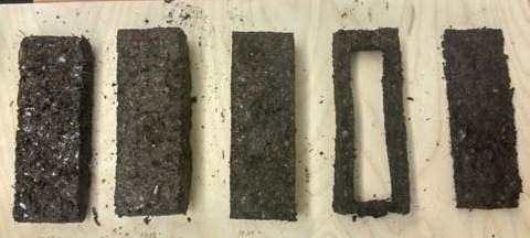
Sampling of population data from governmental organisations and national arctic data centres for ice and snow to estimate current and potential demographic trends. The information published by the National Snow and Ice Data report was used to identify trends in the populations of settlements in the northern peninsulas of Alaska over time.
Sampling of mapped data of thermokarst lakes and drained thermokarst drained basins (DTLBs) from NASA Carbon Cycle Observatory mapped onto co-ordinates. A digital model of the Seward Peninsula of Alaska was developed, in which statistical information of thermokarst lakes of varying ages from NASA Carbon Cycle Observatory were overlayed.
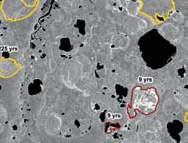
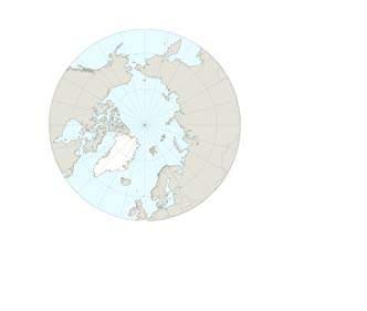
Y UN S N GR D RUS A c xcix Architectural Association Arctic Recalibration
CENSUS DATA SAMPLING : MAPPED DATA SAMPLING
D esign metho D s
Understanding the design potentials and limitations through software
ROBOTIC FABRICATION
KUKA|prc allows the generation of KUKA Robot Language code directly out of Grasshopper, along with a kinematic simulation of the robot which simulates the automated fabrication process with precision.
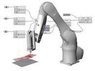
LOCAL GEOMETRY FINDING
RHINOVAULT
Using reciprocal diagrams, RhinoVAULT provides an intuitive, fast funicular form-finding method, adopting the same advantages of techniques such as Graphic Statics, but offering a viable extension to fully three-dimensional problems. The goal is to share key aspects of research in a comprehensible and transparent setup to create beautiful shapes but also an understanding of the underlying structural principles.
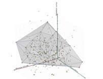
EVOLUTIONARY PROCESS :
Multi-criteria optimisation is used to combine different evaluation parameters into the design of a structure. When two contradicting parameters are evaluated (e.g. the span versus the deflection of an arch), a range of solutions is produced. The advantage of using this evaluation method is that no single best solutionis ever produced, leaving the designer with the opportunity decide which solution out of the found range he sees more fi t.
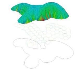
cii ci Architectural Association Arctic Recalibration
KUKA PRC/ROBOTS
OCTOPUS PLUG-IN
D esign anal Y sis

Analysing the environmental conditions to optimise the design
STRUCTURAL EFFICIENCY
KARAMBA
Karamba is a parametric structural engineering tool which provides analysis of spatial trusses, frames and shells. This makes it easy to combine parametricized geometric models, finite elements calculations and optimized algorithms. It is used to calculate structural displacements and principal stresses in the global geometry.
FINITE ELEMENT ANALYSIS
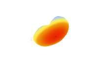
: LADYBUG
Strand7 is a general-purpose finite element analysis system designed specifically for Windows. It is used for the static, dynamic and heat transfer analysis of structures and comprises pre-processing, post-processing and solver functionality in a single application. The state-ofthe-art interface offers a consistent environment for the creation and analysis of finite element models and the extraction and interpretation of results.
SOLAR ACCESS ANALYSIS
:
As in analysis carried out on a building scale using solar access analysis, the same tools can be used to calculate incident solar radiation on a surface of a proposed building type. The aim of using this tool is to maximise the precious solar gains in the Arctic environment.
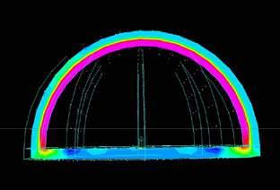
civ ciii Architectural Association Arctic Recalibration
STRAND 7
cvi cv Architectural Association Arctic Recalibration v. research D evelo P ment Design ambition ...............................................................................107 environmental conDitions ...............................................................................112 solar gain ...............................................................................117 structural analYsis ...............................................................................119 heat transfer analYsis ...............................................................................121 robot morPhosPace ...............................................................................125 robotic rail ProPosal ...............................................................................158 enD effector Design ...............................................................................162 staging Process ...............................................................................166
DESIGN AMBITION
Current design response the the climatic challenges and the role of responsive architectural designs
MATERIAL
DESIGN AMBITION
The ambition is to employ a design process that integrates the material developed, the fabrication processes, environment, structure and the resulting architecture. This is aimed to be achieved by understanding the materials performance, the assmebly techniques required and the robotic constraints to derive a suitable structural logic that responds to environmental factors generating a novel architectural typology. Each factor contributes significantly to the overall process and the result of the process is the interaction of these distinct factors.
Due to the highly interconnected data at all micro, meso and macro scales and feedbacks loop present in this research a linear narrative is not possible thus, certain topics are referenced back and forth with their chapter names and page numbers.
RESOURCE DRIVEN SETTLEMENT STRATEGIES
The logistical challenges of importing goods from the southern latitudes to the few and-far-between settlements of Alaska drives not only their high cost of construction but a higher cost of living in dweelings that do not live up to the required standard of living in such harsh climates. This section seeks to investigate the extent to which this may be alleviated by capitalizing on local resources as much as possible.
The proposed material system is defined by peat, and focuses on the utilisation of robots to construct and the resulting constrains its form [local scale] and settlement pattern [global scale] . As described in previous sections, peat is readily abundant, renewable, inexpensive and insulating. Although the robots must likely be imported, it is a one time investment which will continue to service the site for years to come and therefore pay off its inital cost invesment in the long term leading to safe construction processes and apt housing for the site
In terms of the design at the global scale [settlement design], the primary constraint is therefore constraints of the robot in addition to the hostile environmental conditions.
ARCHITECTURE
1. Site
2.Programs
3.Requirements
1. System (discrete or non-discrete)
2.Compaction method
3. Geometry
4.Con gurations
ENVIRONMENT
FACTORS
1. Solar analysis
2.Wind analysis
3.Snow analysis
4.Permafrost analysis
5.Thermokarst landscape analysis
STRUCTURE
1. Compressive strength
2.Tensile strength (low)
3.Self supporting
1.Robotic placement moveable/stationary
4. Load path
cviii cvii Architectural Association Arctic Recalibration
DESIGN PROCESS
INTEGRATED
FABRICATION
FORM MATERIAL PERFORMANCE STRUCTURAL LOGIC PERFORMANCE APPLICATION SCENARIO NEW SETTLEMENT ROBOTIC CONTRAINT
Architectural Design
Architectural Design
MATERIAL FABRICATION FABRICATION
MATERIAL FABRICATION FABRICATION
FABRICATION STRUCTURE ARCHITECTURE
FABRICATION STRUCTURE ARCHITECTURE
1.Additive (binder)
2. Hardening time
3.Impact of freezing and thawing
1. Compaction load
2.Compaction method
3. Increased surface area
1.Additive (binder)
2. Hardening time
1. System (discrete or non-discrete)
2.Compaction method
3. Geometry
3.Impact of freezing and thawing
1. Compaction load
STRUCTURE
1. Compressive strength
2.Tensile strength (low)
3.Self supporting
4. Load path
2.Compaction method
1.Robotic placement moveable/stationary
3. Increased surface area
EXTERNAL FACTORS
1. Solar analysis
2.Wind analysis
3.Snow analysis
4.Permafrost analysis
5.Thermokarst landscape analysis
1. Con gurations
2.Variations
1. System (discrete or non-discrete)
2.Compaction method
3. Geometry
1. Site
2.Programs
1.Robotic placement moveable/stationary
3.Requirements
1. Con gurations
2.Variations
1. Site
2.Programs
3.Requirements
STRUCTURE
1. Compressive strength
2.Tensile strength (low)
3.Self supporting
4. Load path
EXTERNAL FACTORS
1. Solar analysis
2.Wind analysis
3.Snow analysis
4.Permafrost analysis
5.Thermokarst landscape analysis
PROCESS FLOW
The research process is divided into three scales micro, meso and macro each focusing on material, fabrication and structure which cumulatively contributes to the architectural design.
cx cix Architectural Association Arctic Recalibration
Micro
Macro scale Meso scale
scale
Meso
Micro
Macro scale
scale
scale
ENVIRONMENT CONDITIONS
An overview of the existing site conditions in Barrow, Alaska
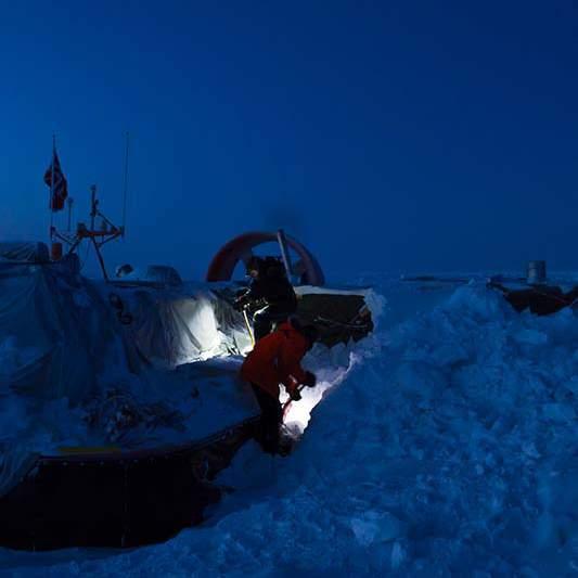
TEMPERATURE ANALYSIS :
The environemental conditions in the Arctic play a large role in terms of the housing types developed. Many daunting factors such as the site’s hostile climate, it’s winter months of complete darkness and low amount of solar radiaiton during the summer months are important factors to take into consideration while design structure for the site, however for housing structures these factors are doubly important. Various environment aspects of the Seward Peninsula are analysed in detail which informs design decisions taken at the later stage of the architecture proposal.
The environmental conditions of the selected patch within the Seward Peninsula region are analyzed using weather data 23. Temperature graphs are generated by “Mateonorm” software which provides irradiation data and other weather data for the site and shading graphs are generated by “Climate consultant” a graphic based computer program that helps understand the local climate. The environmental conditions are studied and suggestions for design are derived through understanding the needs.
cxii cxi Architectural Association Arctic Recalibration
Alaskan locals conduction everyday activites during winter months in the presence of no sun.
TEMPERATURE ANALYSIS
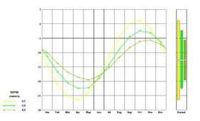
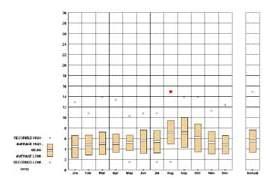
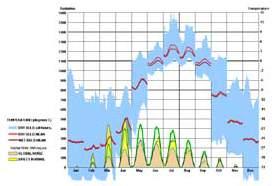
The temperature graphs show that the site- Seward Peninsula, Alaska has year round extreme cold conditions, with winter months having temperature ranging from -40 C to -9 C while the summer months go up to a maximimum of 13 C. A valuable observation must be noted that only 4 months of the year have temperutes rising above 0 C.
The dry-bulb temperature is the temperature of air measured by a thermometer freely exposed to the air but shielded from radiation and moisture. DBT is the temperature that is usually thought of as air temperature, and it is the true thermodynamic temperature.
WIND SPEED CHART
The wind direction onsite shifts between north east and north west. The wind speends recorded in the year 2016 ranged from 10 ms -1 to a maximum of 14 ms -1.
SOLAR ANALYSIS
The 3D solar analysis indicates extreme low amount of solar radiation. The winter months of the site have little to no sunlight, with 2 months in the winter having continuous days of darkness. The 2 summer months have a longer duration of sun however the amount of radiation is still incredibly low,
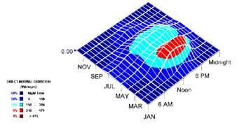
GROUND TEMPERATURE
Because the material selected for construction is peat, the ground conditions must also be analysed to determine the months that are apt to harvest peat along with the months that have suitable ground conditions during which to build. The months of September have the highest temperatures while the month of April has the lowest temperatures, therefore the months around April are selected to construct on site due to a hardened terrain for the robotic rails and dwellings to be placed on.
cxiv cxiii Architectural Association Arctic Recalibration
conclusions
Design suggestion based on environment factors
D esign Parameters
Overview of constraints within design to take into account
DESIGN CONSTRAINTS
1.Compression structure 2. Insulating 3. Robotic reach
DESIGN SUGGESTIONS
BASED ON ANALYSIS :
- For passive solar heating face most of the larger facades to south to maximize winter sun exposure.
-Keep the structure small (appropriate ratio), because excessive floor area wastes heating energy that accumulates over time.
-Extra insulation ( thicker layers of insulation) will increase occupant comfort by keeping indoor temperatures uniform.
-Traditional passive homes in cool overcast climates used low mass tightly sealed, well insulated construction to provide rapid heat buildup.
-Locate storage areas on the side of the building facing the coldest wind to help insulate
-Carefully seal building to minimize infiltration and eliminate drafts, especially in windy sites (house wrap, weather stripping, tight windows)
DESIGN CONSTRAINTS : The data gathered from the material studies and robotic research creates design contraints that have to be addressed while designing the dwelling units.
- Due to the nature of the material a compression structure must be created.
-The hostile conditions of the Artic require an insulating dwelling structure.
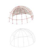
-Due to the compression structure the robot must build from the outer surface only.
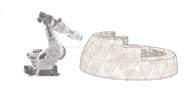
cxvi cxv Architectural Association Arctic Recalibration
SOLAR GAIN
An experiment to understand building geometry in relation to solar gain

OBJECTIVE :
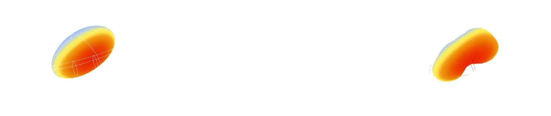
The test geometry is analyzed using Ladybug, a grasshopper plugin developed by Mostapha Roudsari, to quantify the amount of radiation directly affecting the surface during a time period at specific intervals. A sun path is generated using the input from the specified site location which is the Seward peninsula. The analysis of the solar radiation shows that the faces on the top of the geometry and the faces on the southern side of the geometry receive radiation for the longest hours and is denoted by the red colour on the radiation chart. This provides some suggestion on the required orientation of the structure on site.
It was seen that aggregated buildings are an efficient way to provide dwelling space for a population while signi fi cantly decreasing shadows and heat losses. Building orientation was revealed to be an important factor in environmental performance. As an exploration of the orientation of the aggregated buildings, this experiment aims to relate the orientation of the housing structures to the solar vector such that a predetermined geometry was then further utilised to create a settlement cluster pattern.
SET UP :
Through a series of small geometrical explorations evaluated with Barrow weather data, it was determined that the curved geometry is the better solution. This particular geometry/orientation achieves the most total radiation, as well as the most sunlight hours due the curvature increasing the surface area which recieves sunlight.
UNDULATING SURFACE :
A simple demonstration illustrates the role of surface variation in increasing total solar radiation on the proposed type. This demonstrates that an undulated geometry is particularly useful for linear structures in the Arctic environment with regards to solar gains.
cxviii cxvii Architectural Association Arctic Recalibration
N S S
SURFACE :
SURFACE
REGULAR
BENDING
Shallow dome
H = 2500 mm
D = 7000 mm
Thickness of the shell is 450 mm
Mass = 535 563 kg
structural anal Y sis
Finding the most suitable dome cross-section
Semi-spherical dome
H = 5000 mm
D = 5000 mm
Thickness of the shell is 450 mm
Mass = 530 385 kg
Catenary arch
H = 6000 mm
D = 4500 mm
Thickness of the shell is 450 mm


Mass = 476 887 kg
OBJECTIVE SETUP
Karamba structural analysis is conducted in order to define the optimal height-span ratio in the dome structures. Gravity, snow and wind load are applied as deforming forces. Utilisation and deflection parameters were evaluated.
3 different types of domes were tested:
Shallow dome - H/D ratio 0.35

Semi-spherical done - H/D ratio 1


Catenary dome - H/D ratio 1.33


Thickness for all the tested dome is 450 mm accordingly.
Peat properties used: Density = 1121 kg/m 3

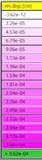
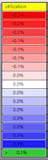
Several forces are applied:
1. Gravity - accordingly to the mass uniformly to all the dome
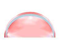
2. Snow load - 0.7 KN/m 2 applied on the upper third of the dome the in negative z direction
3. Wind load - 1.1 KN/m 2 applied accordingly to the wind direction from Nowth-East and North-West side of the structure.
OBSERVATIONS
According to the analysis, the shallow dome structure shows the worst result among the 3. It has 1.5 more deflection then semi-spherical sample and twice more deflection then the catenary arch one. The utilisation higher up to 8 times compare to the other dome shapes.
On the other hand, the catenary arch sample shows the least amount of deflection and the least utilisation (twice time less compare to semi-spherical dome.
CONCLUSION
The catenary arch is the optimum shape for minimisation of the structural deflection and is therefore taken further into this research.
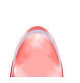
cxx cxix Architectural Association Arctic Recalibration
heat transfer anal Y sis | stran D
Insulating capacities of different shell thickness’s.
OVERVIEW :
Heat transfer analysis is important for understanding the internal micro climate of the proposed housing units. The simulations perform examples of analysis of heat loss from proposed housing units in the Arctic environmental conditions. Steady State and Transient analysis are performed. Steady State analysis is operating with constant set boundary conditions (temperature outside, temperature inside and heat sources) and gives one solution in the equilibrium between them. Transient heat analysis, on the other hand, works with the temperature change throughout the defined time limits and shows the dynamic change in thermal performance.
SETUP :
Several properties of peat are utilised:
R (Thermal conductivity) - 0.33 W/m °C
Thermal conductivity is a measure of resistance to heat flow through a given thickness of material
Cp (Specific Heat) 800 kJ/kg °C
Specific heat is the amount of heat needed to raise the temperature of one kilogram of mass by 1 °C
ρ (Density) - 1121 kg/m
Insulation is a crucial parameter, which is needed to be taken into consideration during design process in an Arctic environment.
The outside temperature is the winter one in Alaska, within the range of -10 to -30 °C for the Transient, and -10 °C for Steady State analysis.
The shell after strand analysis with applied boundary conditions.
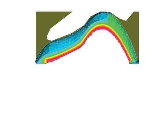
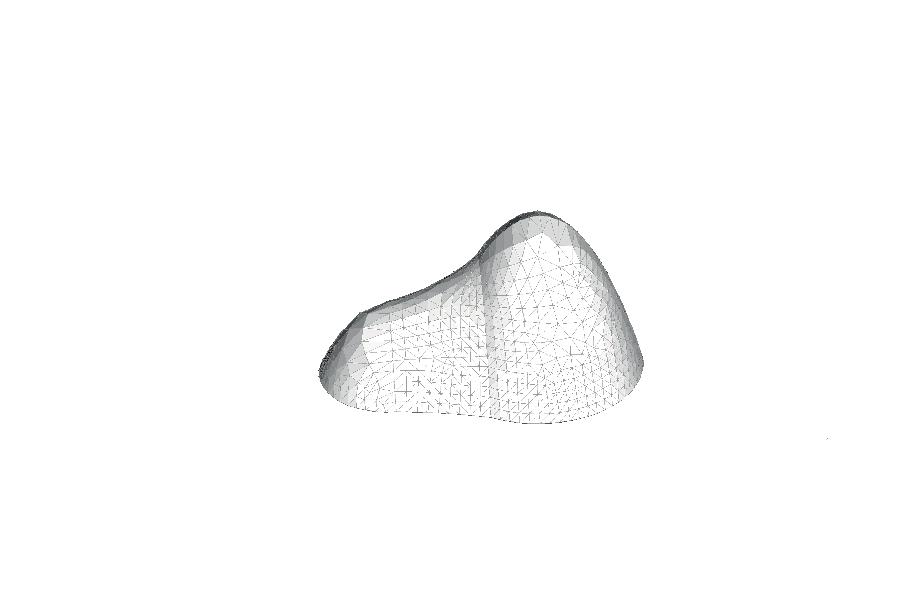
Peat shell before analysis
Peat base
Scheme of analysed structure with applied climatic boundary conditions
cxxii cxxi Architectural Association Arctic Recalibration
floor base | ex P eriment i
Experiments with two different bases
EXPERIMENT 1 :
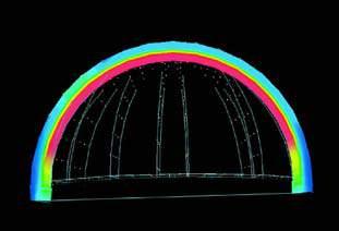
Peat shell with uniformed thickness of 300 mm and no base is studied.
EXPERIMENT
:
A peat shell with the same thickness [300 mm] is analysied, in this case a 400 mm peat base is added for insulation of the bottom edge of the shell.
:
Heat loss in the bottom edge of the shell is observed [areas of higher temperature on the external surface]. It is clear that the largest heat loss occurs at the bottom edges of the shell due to the lack of continuity of the peat material. The biggest range of the temperature difference on the outer surface is 12 °C.
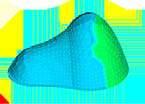

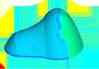
Heat loss along the bottom edges of the shell are completely eliminated. The biggest range of the temperature difference on the outer surface is 5 ° C. From this experiment it is clear that the dwellings require a base of the same material [peat and xanthan gum] in order to prevent heat loss and create a suitable internal living condition.
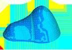
cxxiv cxxiii Architectural Association Arctic Recalibration
300 mm heat loss in the
SETUP : OBSERVATIONS
Thermal performance at -35° Thermal performance at -10° (°C): +20 °C -30 °C
Cross-section
connection to the ground
400 mm base SETUP OBSERVATIONS Thermal performance at -35° Thermal performance at -10° (°C): +20 °C -30 °C
2
300 mm
Cross-section
heating | ex P eriment ii
Experiments to define type of heating required for suitable indoor living conditions
Underfloor heating
OBJECTIVE :
As in the previous experiment the inclusion of a base improves the heat loss in the material. Next, an experiment is condicted to analyse an appropriate method of heating to propose for the housing dwellings to protect the inhabitants from the hostile climatic conditions of the Seward peninsule where the maximum temperature recorded in 2016 was 14 C and the winter temperature range is between -9 C and -40 C.
OBSERVATIONS :
The following options were tested

- Stove: while it is the most cost efficient option, Strand analysis indicated that the heat only collected in the middle of the shell.
-Radiators along walls: The heat distribution is only along the walls leaving the central areas of the shell unheated.
- Underfloor heating: provides equal heating to the entire structure leaving no part of the indoors unheated.
It is noted in the table [on the adjacent page] the range of temperature indicated between red and pink provide the maximum thermal confort to humans. As observed in the image alongside the interior of the shell is denoted in ranges of pink and red [from 16 C and above] indicating the indoors are at an optimum level of thermal comfort while the oter surface of the same shell is represented in blue indicating that there is no thermal loss that occurs.
PROPOSED HEATING SYSTEM :
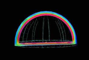
A simple demonstration illustrates the role of underfloor heating in increasing total thermal comfort in the proposed type. The method of using an underfloor heating proved to be the appropriate method of heating in the hostile climate. Underfloor heating is a form of central heating and cooling which achieves indoor climate control for thermal comfort using conduction, radiation and convection. It is the most effective and economic method of heating considering the climatic cinditions.
t (°C): +20 °C -30 °C
( °C): +20 °C - 30 °
Interior thermal comfort range
interior thermal comfort range from 16 C
exterior surface is cold - no heat loss
Exterior surface cold No heat loss
interior surface is hot - heat is kept underfloor heating
Interior surface warm Heat contained
Underfloor heating
Underfloor heating analysis for housing units
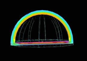
cxxvi cxxv Architectural Association Arctic Recalibration
KUKA KR 30-60 Morphospace diagram - Elevation
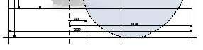
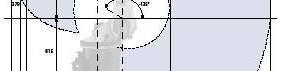

micro scale | robot mor P hos Pace
Micro scale robot proposed to be used
OVERVIEW
When using robots for fabrication, it is necessary to understand the robot morphospace. It may be simply described as the robotically fabricable space. Understanding the kinematics of robot fabrication provides a range of applications that can help develop novel construction techniques beneficial to architectural design.
The increased potential in the morphological differentiation of building elements in relation to the machine constraints can be described as a machinic morphospace in reference to theoretical morphospaces in biology 24. This methodology allows conceptualizing the design space of theoretically possible fabrication methods given the parameters of a specific machine configuration.

Therefore, before further investigation into the material and possible construction methods, the robot morphospace is thoroughly studied to help further the design process. The multi-axis robotic arm used for physical experiments is the KUKA KR 60 whose morphospace is described with the illustration. However, due to the hostile climatic conditions onsite the robot proposed is the KUKA ARCTIC QUANTEC KR 240. The difference between both the robots are studied and clearly understood.
Further, the morphospace and the kinematics of the robotic arm are visualized using the KUKA-Prc parametric robot control plug-in for Grasshopper in Rhino whose feedback allows for quick transition from the programming environment to the robot for fabrication.
cxxviii cxxvii Architectural Association Arctic Recalibration Max. reach Payload Axis Footprint 3000 240 kg 6 650 x 800
ROBOT PROPOSED ON SITE KUKA KR ARCTIC QUANTEC
While physical tests are carried out using the KUKA KR 60. Due to the extreme negative temperatures on site (maximum -40 C) the KUKA KR 60 would not be able to function, thus the KUKA KR ARCTIC QUANTEC is proposed as it can work in extreme negative temperatures.
The KR QUANTEC PA can perform palletizing tasks quickly and precisely even in ice-cold temperatures 25. Thanks to the Arctic design, it needs no protective suit. Its immunity to temperatures well below zero makes it a palletizing professional in this sector. The KR QUANTEC PA Arctic can even work with the utmost precision at minus 50 degrees Celsius. Its great reach allows for short cycle times and high flexibility when stacking and setting down items in a frosty environment.
The KR QUANTEC PA arctic is not a special solution from KUKA. Instead, it is a cold-resistant adaptation of the service-proven standard palletizing robot from the KR QUANTEC series. With a reach of 3,195 mm, the palletizing robot is characterized by short cycle times, high flexibility and extreme precision in stacking and setting down. The robot is available in three payload variants: 120, 180 and 240 kg. The payload selected for this proposal is 240 kgs.
Since it does not require a specially designed protective suit for cold environments, the user saves on costs. Furthermore, no downtime is required for exchange work, no special heating is needed in the robot arm and the large work envelope is not restricted by additional wrapping.
cxxx cxxix Architectural Association Arctic Recalibration KUKA ARCTIC QUANTEC Morphospace diagramElevation 677 2832 2845 3195 2845 1350 -40 -5 1220 +155 All dimensions in MM Max. reach Payload Axis Footprint 3195 240 kg 4 800 x 800
efficient tool Path D esign
Importance of an efficient toolpath design
OVERVIEW
The integration of multi-functional kinematic machines into creative processes allows a designer a high degree of customization enabling innovative design. Designing an efficient tool path is pivotal in Robotic Fabrication processes. This tool-path design has a direct impact on construction time, machine time and the amount of material used.
It is therefore not so much a workflow that realizes a finished 3D data, rather a process that has to be implemented at early stages of design by the designer. In return, it gives the designer the ability to move past the predefined strategies of CAD-CAM (Computer Aided Design / Manufacturing). This is achieved by carefully considering and implementing the properties of tools the machines in addition to the properties of the material in use.
The aim of this research on robotic tool-paths is to help understand and utilize the special properties of tool-paths to create complex geometries with structural integrity, minimum machine-time and wasted material through parametric programming strategies using a multi axis (6 axis) robot arm. This exploration is conducted at every scale (micro, meso, macro) such that an efficient toolpath is designed.
The design decisions taken involves the ‘pick and place’ method of a commpression based structures using a multi-axis robotic arm. When critically evaluating this material system, inintial problems with regard to fabrication and structure are predicted.
-Tool-Path discontinuity (inefficient)
- Formation of tension members (not suitable for the material developed)
- Singularities (Collision in fabrication)
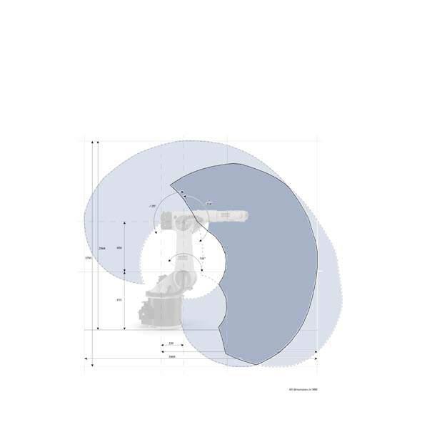
cxxxii cxxxi Architectural Association Arctic Recalibration
Overlap of robotic reach between KUKA 30-60 and KUKA
ACTIC QUANTEC
AIM
meso P hos
Exploring construction strategies at the meso scale
Multiple
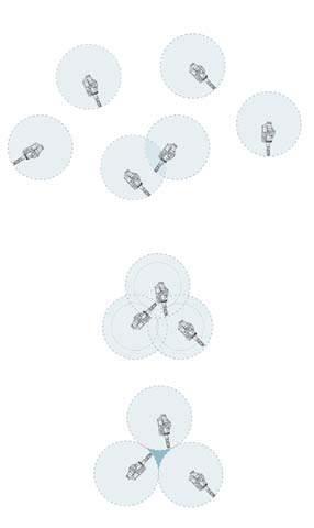
EXPLORING STATIONARY ROBOTS
As robotic arms are proposed for the construction process, defining a system becomes crucial to the workflow. The robot kinematics and the robot reach
As seen in the above figures the use of stationary robots pose several limitations. Firstly, it requires careful placement. The robots must be placed such
This requires the overlapping of the robot workspaces. Consequentially increasing the number of robot required for a specific area to a large extent.
EXPLORING MOVABLE ROBOTS
Movable robots are also explored to create an efficient system. A system is proposed which includes a rail path, thus while the number of robots utilsed is maintaining, the meso scale morphospace is drastically increased. These robotic arms are guided by a rail system increasing its reach, simplifying the workflow and reducing the number of collaborating robots in construction thereby also easing the computational process.
The maximum height reachable by a robotic arm is 3.2m; this limits also the possible spatial morphologies.
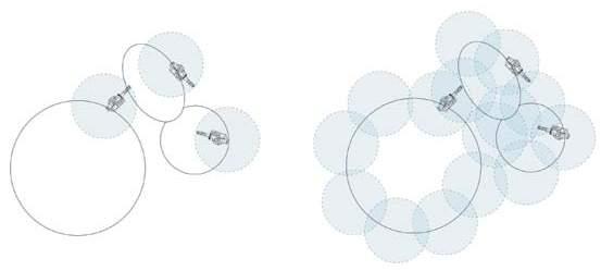
cxxxiv cxxxiii Architectural Association Arctic Recalibration
Stationary Robots inaccesable spaces created Overlapped Robots morphospace : Reduced working area
stationary robots not feasable due to large scale of settlement
robotic s Y stem P ro P osal
Strategies for the placement of the robots on site
CONSTRUCTION
The robot proposed to be used for the construction process is a KUKA ARCTIC QUANTEC KR240. The reach of the robot is a diameter of 6.4m. As discussed previously, we see that the robotic arms have to be placed such that their workspaces overlap to avoid inaccessible spaces. The placement of stationary robots on site increases the number of robots required on site enormously therefore alternate strategies must be presented. A limited number of robots required on site. There are several approaches to this. The approache proposed is:
a) Moveable robots on an external rail system (as structures are in compression the placement of aggregates must be externally)
These robotic arms are guided by a rail system increasing its reach, simplifying the workflow and reducing the number of collaborating robots in construction thereby also easing the computational process. The maximum height reachable by a robotic arm is 3.2m; this limits also the possible spatial morphologies. This limitation is addressed by mounting the robotic arm on scissor lifts. The working of this system is illustrated in the figure alongside.
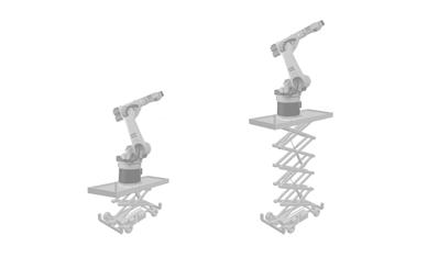
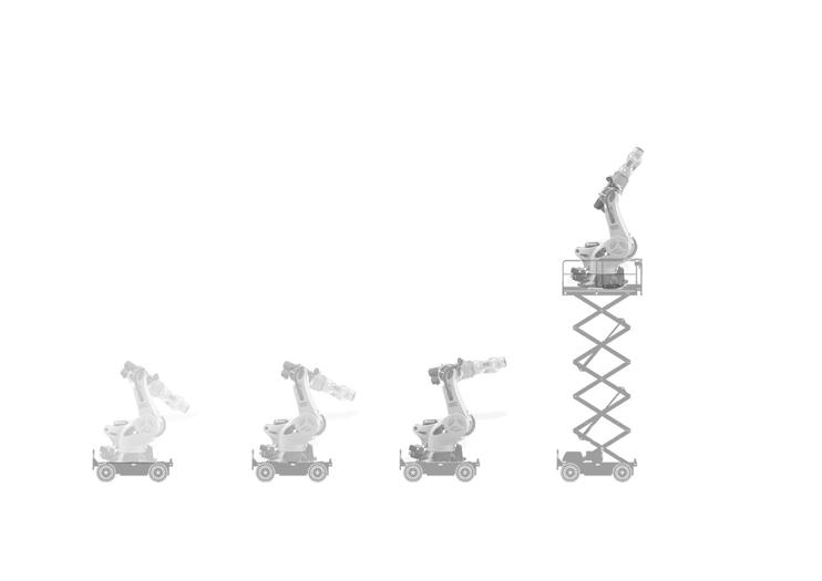
The approaches is critically analyzed. It is observed that the approach in which an external rail system is proposed pose several advantages but increases significantly the construction time. This system is also limited to the rail system; the degree of curvature of the rail is limited therefore limiting possible morphologies.
The system also proposes the use of moveable robots on scissor lifts with rails arranged in a fashion taking into consideration the requirement of of the settlement pattern and overlapping workspaces. This arrangement helps encompass significantly larger areas with controlled number of robots decreasing the construction time when compared to the previous approach of numerous stationary robots. Weighing the advantage and disadvantages of this strategies, the advantages and limitations are adopted into the further design process of the settlement.
cxxxvi cxxxv Architectural Association Arctic Recalibration
LOGICRAIL SYSTEM Kuka Arctic Robot vertical scissor lift rail system 3000 3000 Increased horizontal movement Increased vertical movement Working of proposed rail system
micro scale | en D effector D esign
End effector designed proposal
END EFFECTOR DESIGN AND DEVELOPMENT
Understanding the behavior of the material developed and the process required for the solidification of the material preliminary experiments were conducted as stated previously using a simple set up.
Taking further this research, physical experiments were aimed to be achieved using a KUKA multi axis robotic arm. A suitable end effector [tool head] had to be designed and developed for physical tests. On site the complete end effector system remains the same except for the flanges which have would have changes in its dimension for a 1:1 scale system.
The process of picking amd placing the modules has to be automated integrating its functions into a tool head. This automation process brought in several parameters that had to be taken into consideration. The end effector had to be well designed and oriented to fit the robot arm flange.
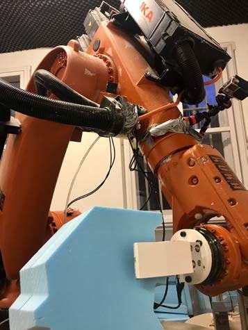
The design of the end effector can be divided into 3 parts which fit together to perform the required task.
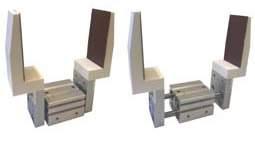
The 3 parts are:
I) Flanges
II) Pneumatic gripper
III) Flange connector
cxxxviii cxxxvii Architectural Association Arctic Recalibration
Closed position Open position
Image of the proposed end effector along with its open and closed positions
Three main parts of the end effector clearly defined
I. FLANGES
The flanges are the part of the end effector that is mainly responsible for the picking of the panels. While various flanges are available on the market, a custom flange set was 3D printed to integrate all the necessary requirements of the proposed toolpath deisgn. The flanges proposed is a two-jaw shortstroke parallel flange.
II. PNEUMATIC GRIPPER
The pneumatic gripper is the piece that connects the gripper set up to the flange plate of the multi axis robotic arm. The flange acts as the point of connection between the robot arm and the tasks to be accomplished. In the case of the pneumatic gripper, the gripping force can be infinitely adjusted up to the limit of 140 newtons on the ready-to-connect controller supplied The orientation of the robot is based on this connection making it pivotal to the assembly process.
III. FLANGE CONNECTOR
The flange connector is the piece that connects the gripper set up to the flange plate of the multi axis robotic arm. The flange acts as the point of connection between the robot arm and the tasks to be accomplished. The orientation of the robot is based on this connection making it pivotal to the printing process.
A flange connector is an existing default flange for this end effector. The parts were then 3D printed for higher accuracy and flexibility in design. The connector consists of base plates to which a joint is designed to make the complete end effector shorter for precision in the proposed toolpath design.
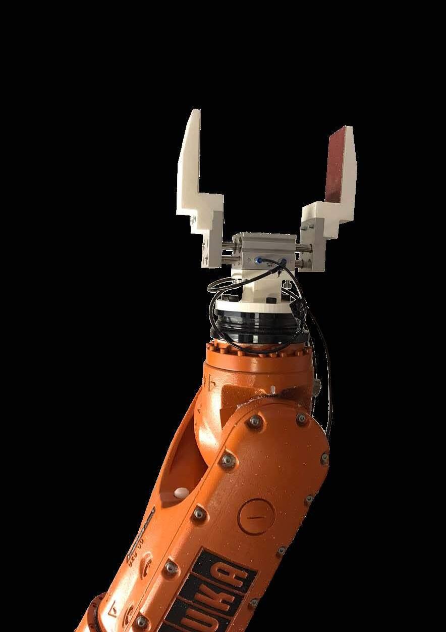
cxl Arctic Recalibration
en D effector D esign
End effector designed iterations tested
AIM :
The main aim of the gripper is to accommodate panels with various dimensions and grip the panel perpendicular to the planes. Since all the panels have different sizes and angles of side surfaces this becomes a challenging task. However, the two largest sides of all the panels are parallel, flat, and are located at the same distance in all the panels [due to a constant thickness]. As far as the pneumatic gripper construction requires two surfaces parallel to each other as if the surfaces are not parallel the gripper will not close properly and/or will cause a change in the gripping position [the flanges, trying to shut properly will rotate the panel and thus damage its surface]. Therefore using the two largest flat surfaces of the panel [representing inner and outer surface of the shell] is the optimum solution.

During this process it was brought to notice that the system has two contradicting aims:
-increase the strength of the grip and
-decrease the length of the total system.
Extension of the 6 th axis increases the lever arm, therefore making the panels harder to lift as well as harder to manipulate in complex rotations. However minimising rotations means minimising risk of collisions and singularities. These two factors are kept in mind while designing the end effector.
ITERATION II
FAILED ATTEMPT
In the second attempt, the gripper is designed with longer flanges [100 MM], and the gripping distance is set to 145 MM which is 5 MM less than the panel’s dimension [15 MM] with the aim that the reduced dimension will help increase the friction and keep the panels in place when being picked and placed into position.
However it is observed during tests that in the places of contact of different materials with different densities: plastic [flanges] and metal [actuator] the plastic flanges begin to crack due to excessive pressure at these points. The use of a smaller gripping dimension [145 MM] also adds to the cracking of the plastic flanges along the edge.
The dimensions of this gripper are too small. The flanges arent long enough to grip the panels. A serrated surface is proposed in order to increase the friction between the panels [experiment material - foam] and the flanges however this attempt is unsuccesful.
ITERATION III
SUCCESSFULL ATTEMPT
In the final attempt; the gripping dimension is set at 150MM [exact dimension of panels], the plastic flanges are made thicker and 3D printer with a denser in-fill, also the contacting surfaces of the flange are lined with a low density sand paper [Grit 50] in order to increase friction.
During the conducted physical tests, this end effector is successful in picking and placing the panels with no alterations required. While the friction of the foam selected for physical experiments and the finished peat product is comparible[similar] for the end effector design onsite the dimensions of the flanges would have to be altered and exploration must be conducted into
cxlii Arctic Recalibration
100 mm 70 mm 5 mm 20 mm
FAILED ATTEMPT 100 mm 20 mm 100 mm 40 mm 70 mm 5 mm 100 mm 5 mm 20 mm 40 mm
ITERATION I :
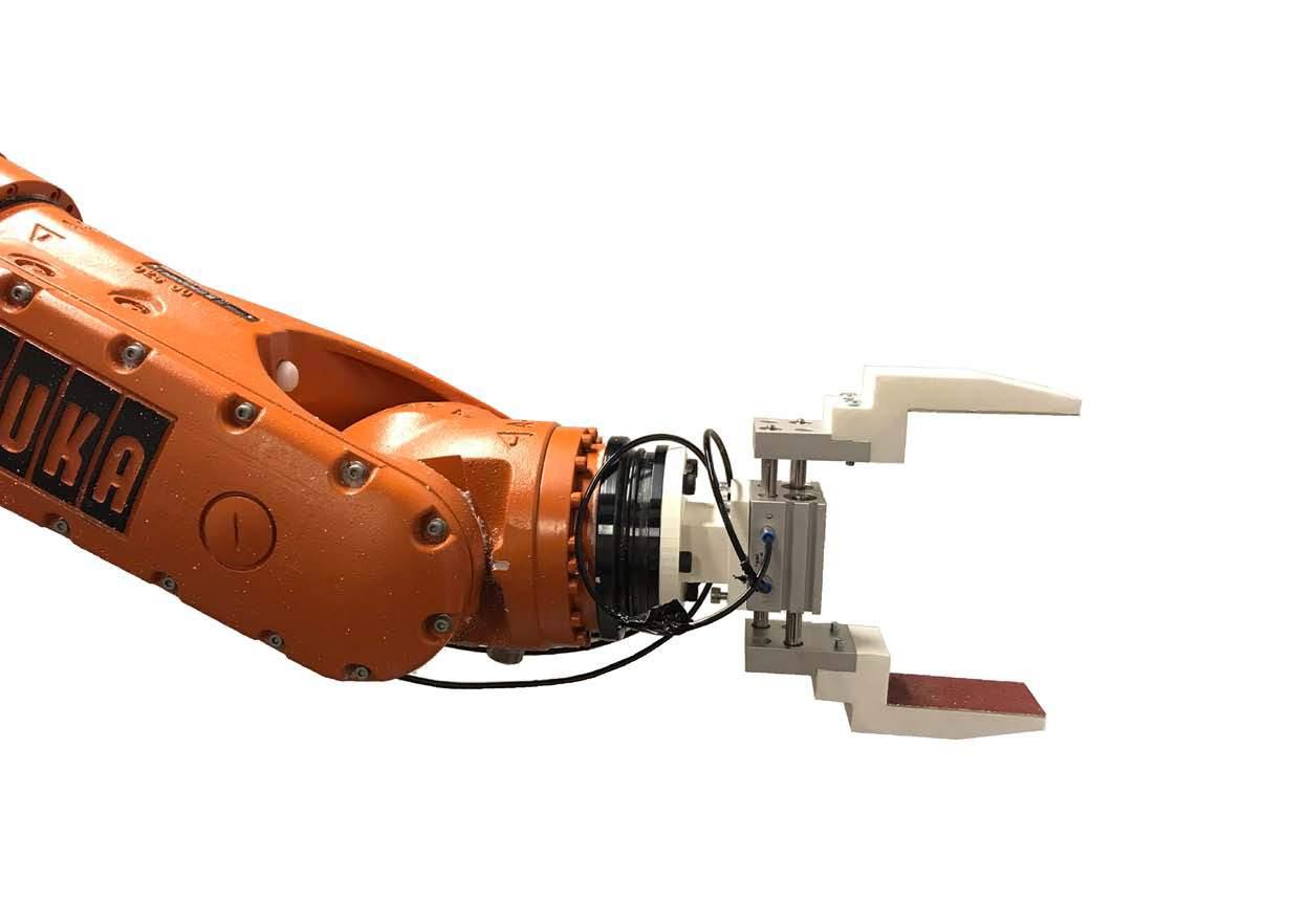
cxliv cxliii Architectural Association Arctic Recalibration
End-effector fitted onto a robotic arm.
Kuka KR60
Pneumatic gripper
Flange connector
Flanges
Sandpaper [Grit 50]
Stages of constructionCombining Rapid and Slow prototyping techniques.
staging P rocess
Staging of the construction process
1. System (discrete or non-discrete)
2.Compaction method
3. Geometry
4.Con gurations
SLOW PROTOTYPING
STAGE 01
MODULE
PRODUCTION
-Peat Compaction
-Module cutting
PARAMETERS
-Peat thawing rate
-Multi layered compaction time
-Curing time
STAGE I :
As two disparate processes are used in this research to form the architecture the staging logic becomes cardinal. The construction process is divided into two main stages;
RAPID PROTOTYPING
STAGE 02
AGGREGATION
-’Pick and place’ system
PARAMETERS
-complexity of placement position
-time taken for robot to assemble aggregates
STAGE II :
Stage I involves the module production of panel production. This involves the slow prototyping process of compacting sheets of peat and also cutting the various panels of peat once completely dried and having it ready for the assembly process [stage II]. This stage must take place during the summer months as it involves preliminary preparation that require the sun. The peat needs to thaw for free water molecules to be released so that the binder [xanthan gum] can bind with the peat. It must then be compacted and left for hardening over a long period of time [estimated 5 months from physical tests]when the sun is out to expedite the process of drying of peat and thus the hardening of peat. The panels can then be cut from sheets and kept ready for assembly.
Stage II involves the assembly of panels where the building envelope is created. This process is a fast prototyping system as it involves automated assembly using robots. This stage is proposed to occur during the winter months when the permafrost is frozen and thus the terrain is hardened allowing for ease of construction of the robotic rails which is the main aspect of the proposed fabrication system.
cxlvi cxlv Architectural Association Arctic Recalibration
Steps involved in the construction of Peat Harvested system in relation to seasonality
seasonalit Y | macro scale
Land transformations and material extraction and assembly sequences explained in detail with respect to seasonal factors
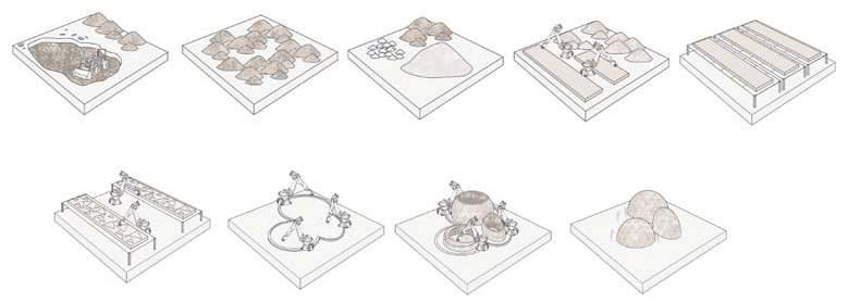
SPRING :
Once, temperature begin to rise in this period peat harvesting takes place. The peat needs to be placed for a small period of time to thaw, so that the free water molecules can thaw and then be combined with the binder to form the proposed mixture. This period is perfect for the thawing to take place as the site has a milder climate and the temperature only keep rising.
SUMMER :
During the summer temperature are at their highest point this has to be exploited and the peat plates are left to dry during this season. It is the only few months when the sun can compensate for the low temperature and help the drying and consequent hardening of peat pieces before they can be cut.
AUTUMN :
Because of the measured long period of time taken for peat to dry [see ‘Material Properties’ chapter] the first month of this season is required for the final drying stage of peat panels. In this transition period, the panels can be cut using the CNC machine as it has no link to the environment conditions. This process is a rapid process and requires only few days.
WINTER :
Once, the ground hardens up, the robotic rails can be set up. Previously, with existing construction methods, manual fabrication during this period a little to no sunlight and harsh temperatures would be impossible. However, due to the proposed automatic robotic construction system the long winter months can be utilised in an efficient manner to construct the dwelling units.
cxlviii cxlvii Architectural Association Arctic Recalibration -15 °c -26 °c -27 °c -19 °c -9 °c -1 °c 5 °c 3°c -2 °c -12 °c -21 °c -24 °c 6 9 12 15 18 20 21 18 13 10 7 5 January February March April May June July August September October November December peat harvesting peat thawing cut modules lay robot tracks peat + xanthan gum mixture layered compaction dry (on mesh) ‘pick and place’
construction
P ro D uction | micro scale

Staging of the construction process
STAGE I
In the first stage, the layered compaction takes place as an iterative process. Once the thickness of 300MM is reached the frames and partial base is removed and left to dry. The base is partially removed as previous tests [See ‘Material properties’ chapter] prove that when a base is left while the drying process takes place, the surfaces exposed to air dry faster and begin to shrink slightly this leads to the samples being curved.
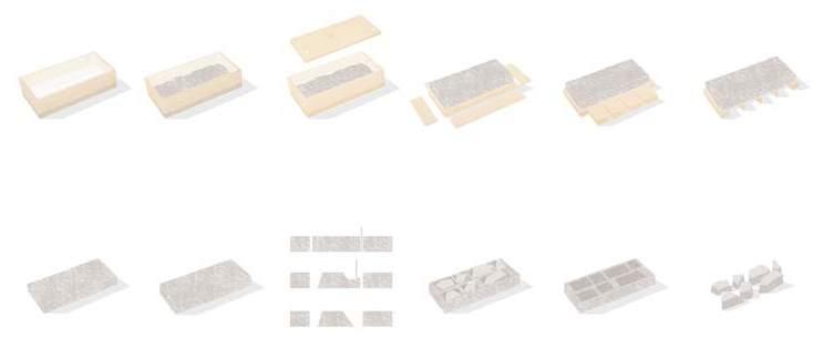

STAGE II
Once the peat plate is dried, it is set into a CNC [Computer numerical ontro ]milling system. Since, all the panels have angled edges, the router bit cannot penetrate at a 90 degree and cut through. Instead, the bounding box of the panel is first cut at 90 degrees, then the router bit subtractive prototyping process of reverse contour grafting layer by layer till the required angle is complete. The unused material can then be crushed and used once again in the compaction process thus allowing no resource to be wasted keeping in the concept of material autonomy.
STAGE III
At the assembly stage, an end effector is custom designed for the panels. An automatic feeder system is proposed to reduce the compliactions due to variations in geometry of panels so that the system is precise and efficient. A robotic ‘pcik and place’ sequence is defined and the assembly process can take place.
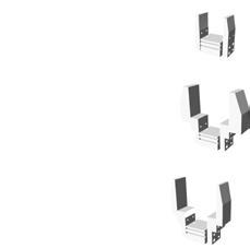
cl cxlix Architectural Association Arctic Recalibration
Panels marked
Set up
Compaction Cutting Assembly Compaction Cutting Assembly
Compaction
Automatic feeder
CNC milling Reverse contour grafting Panels extracted from sheet
Robotic pick and place assembly
Unused material re-used Panels
The local scale peat panel production is described
Precise anglular joint clearly seen in this image after CNC of the proposed material
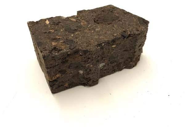
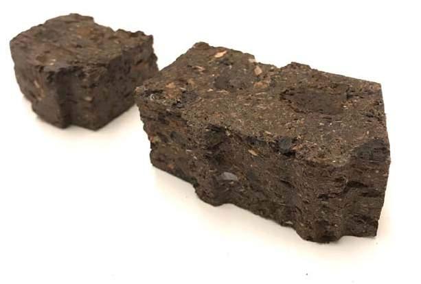
clii cli Architectural Association Arctic Recalibration
Several scaled mock-up voissuours tested
vi . D esign D evelo P ment
cliv cliii Architectural Association Arctic Recalibration
architectural ProPosal .............................................................................156 Program requirement ..............................................................................160 clustering Pattern ............................................................................165 msc conclusion ............................................................................181 segmenteD shell Design ...........................................................................185 stereotomY ............................................................................190 ‘Pick & Place’ construction ..........................................................................216 assemblY sequence ...........................................................................224 evaluation ...........................................................................233
architectural P ro P osal


Architecture design process
OVERVIEW :


Understanding the characteristics of Arctic region in the near future and the properties and advantages of peat as building material, a housing community is proposed. This architectural proposal is built to house the current locals, who live in less than ideal flat packs 26, the locally migrating popualtion due to coastal shifts and the imminent international population influx predicted due to climate change 27
There is a huge need for housing units and the current poorly made housing systems are not adapted to the local ever changing climate. Similarly, in accordance to the user types, a housing community is proposed, where the material which will potentially be abundantly available on site, peat, is celebrated and used for innovation, design, developed over a period of time. Here the material is locally sourced and harvested and used for the construction of permanent and adaptable housing spaces.
Due to the highly interconnected data at all scales and feedbacks loop present in this research certain topics are referenced back and forth with their chapter names and page numbers.


clvi clv Architectural Association Arctic Recalibration SITE Peat NEW SETTLEMENT PROPOSAL USER TYPE PROGRAM Seward Peninsula Material Fabrication Architecture Site Housing Locals Population In ux Community in Near Future <2050 Relation ship between Material, Site , Programs and the User Types.
housing requirements
An overview of the strategies aimed to be utilised in the following chapter
BUILDING MORPHOLOGIES AGGREGATIONS
Having developed settlement needs, the proposed building types will be elaborated in the following pages before being tested as environmentally driven building clusters. The types developed, their sizes, and relative quantities per resident have been adapted from functional studies of Arctic natives
The spans and heights are kept within the ranges outlined in the Research Development Chapter. The proposed material system is expressed as linear aggregations that can be built as multiple units within an aggregation. Connected buildings appear in many traditional design patterns of northern societies.
The advantages of these structures are in the creation of windbreaks from the cold Arctic winds and the prevention of heat losses.
SETTLEMENT AGGREAGTION :
Such linear aggregations can be assembled to effectively create a windbreak for thermal comfort, as much as creating increased interaction amongst inhabitants. It is also a way to distribute residential units with regards to a desired local density.
FUNCTIONAL ZONING :
To make use of the thermal capacity of a peat assembly, functional zoning in these spaces is achieved by varying arch spans to create dome-like volumes in the overall assembly. As these regions behave as heat sinks, the location of these zones predetermines the location of a central heat source and therefore common areas.
clviii clvii Architectural Association Arctic Recalibration
P rogram requirement
Strategies for the programtic requirements
PROGRAM ANALYSIS
The housing units must be provided with public, semi public and private space. The public areas include the common areas, transition areas and entrances. The semi public areas constitue the storage areas and certain domestic spaces. While the private spaces include the sleeping quarters and certain domestic spaces. Each of these spaces encompass a unit of varying radius, height and ground level depending on the spatial requirements and their degree of privacy with relation to the robotic arm limits.
The heights of the units range from a maximum of 6M to a minimum of 2.1M while the maximum radius of a units is lmited to 5.4M. The heights are alloted based on degree of privacy, for example the common space has a heigh of 6M while the storage area has a height of 2.1M.
The degree of privacy also determines the amount of sunlight entering the space, be it direct or diffused. Different spatial experiences are provided to each type of space.
clx clix Architectural Association Arctic Recalibration
Height Degree of privacy Solar exposure Wind exposure Natural Light High Low Common space Domestic spaces Entrance area Storage space Sleeping spaces Public Private Common space Domestic spaces Entrance area Storage space Sleeping spaces Common space Domestic spaces Entrance area Storage space Sleeping spaces High Low Common space Domestic spaces Entrance area Storage space Sleeping spaces Common space Domestic spaces Entrance area Storage space Sleeping spaces High Low High Low Radius of unit program type program type Orientation Location Orientation Location Size of openings Number of openings Transition space Transition space Transition space Transition space Transition space Common space 50 sq.m Entrance area Storage space Sleeping spaces 36 sq.m Transition space Domestic spaces
involved in
Parameteres
functional zoning of spaces
zoning within P rimitve
Proposed programmatic distribution
Sleeping space
Common space
Domestic space
Storage space
prototypical arctic home : Building Size: 160 m2 average: ranging from 45m to 270m 2
Existing Proposed
- Outsourced material

-Prefab houses
-Poor thermal insulation
parameters :
Dome Length: 9m
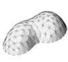

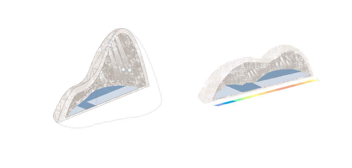
Maximum Dome Count: 4
- Locally sourced material
-Adapted to climate
-Thermal insulation
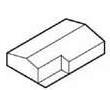
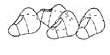


heat zones
1 unit/2 BR
3 unit/6 BR
2 unit/4 BR
4 unit/8 BR
clxii clxi Architectural Association Arctic Recalibration
robotic tool Path as a D esign D river
Integration of robotic fabrication constraints as design opportunities.
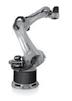
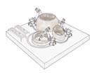
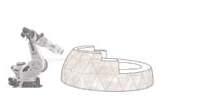
OVERVIEW :
The integration of the robotic toolpath is conducted on a various scales. As was observed previously, the morphology heavily relies on the limitations of the robotic morphospase. Instead of using the robot as a builduing tool it is proposed to use it as a design driver by integrating roboric constrains into the design process.
MACRO SCALE :
At the global scale in relation to the toolpath; the main parameter to evaluate is the assembly’s time factor. It is influenced by both efficiency of the robotic rails placement and actual microscale toolpath continuity.
MESO SCALE :
Due the the proposed material system being able to work best in compression a compression based structure is proposed. To assemble this compression based shells the robots must always be placed outside the unit therefore after taking into account the proposed robots morphospace, bounderies the generated units are created due to morphospaces limitiations.
MICRO SCALE :
In terms of the micro scale toolpath the rotation of the axis is the main parameter taken into consideration. Singularities and discontinuities have to be avoided during the construction process.

clxiv clxiii Architectural Association Arctic Recalibration
MACRO SCALE MACRO SCALE MACRO SCALE MICRO MICRO SCALE Placement from outside Time taken of path followed MACRO SCALE MACRO SCALE MACRO SCALE MICRO MICRO SCALE Placement from outside Robotic reach Time taken of path followed MACRO SCALE MACRO SCALE MACRO SCALE MICRO SCALE MICRO SCALE Placement from outside Robotic reach 4 Axis Time taken of path followed MACRO SCALE MACRO SCALE MACRO SCALE MICRO SCALE MICRO SCALE Placement from outside Robotic reach 4 Axis Time taken of path followed
Integration of robotic fabrication constraints as design opportunities.
clustering Pattern | genetic algorithm
A genetic algorithm to demostrate the relationship between building aggregations, spacing and fabrication constraints
OBJECTIVE
CONSTRAINTS :
The premise of this experiment is to understand viable densities in an urban cluster with a residential program in relation to the environmant contraints and proposed fabrication system constraints.
As discussed earlier (“Function zoning” on p. I23), the proposed dwelling type can be aggregated to house anywhere between 2 to 12 people. The importance of this design decision is that 44 inhabitants can be housed in 4 larger structures or 22 smaller units, and anywhere in between. While larger aggregations can accommodate more inhabitants more compactly inside a building.
The clustering experiement is conducted on a meso scale. It incorporates robotic rails placement and robotic morphospase constrains. The robotic morphospase creates constrains on the width and length of the primitive, to a meximum of 5 metres width due to the robotic reach of the proposed robot [the use of a different robot would alter the dimension constraints of the dwelling] hovewer, does not restrict the height due to using the scissors lift system. However the material properties contraint the height of the structures to 4-5 metres due to the structural capacity of the selected material [peat with xanthan gum].
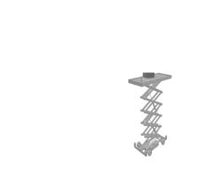
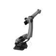
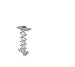
In these residential clusters, due to the importance of solar radiation and challenge of designing with low sun angles, buildings should be arranged to reduce shading on the successive dwellings, while a contradicting criteria is the reduction of distance between buildings due to wind exposure.
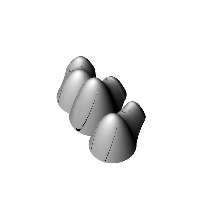
clxvi clxv Architectural Association Arctic Recalibration
INDEPENDANT
3195 6 0 0 0 >800
VARIABLES
intersecting robotic morphospace
Robotic rail formation in the compound housing unit
Various genes set during the clustering algorithm
gene P ool
Variable parameters of the primitive
OVERVIEW
Gene pool is the range of parameters, which are alterated in the Genetic algorithm. Set of local and global genes were applied, which influence both position of the primitive in the resulting morphology.
GENE POOL
INDIVIDUAL GENES
GENE 1:
Distance between 1 and 2 domes


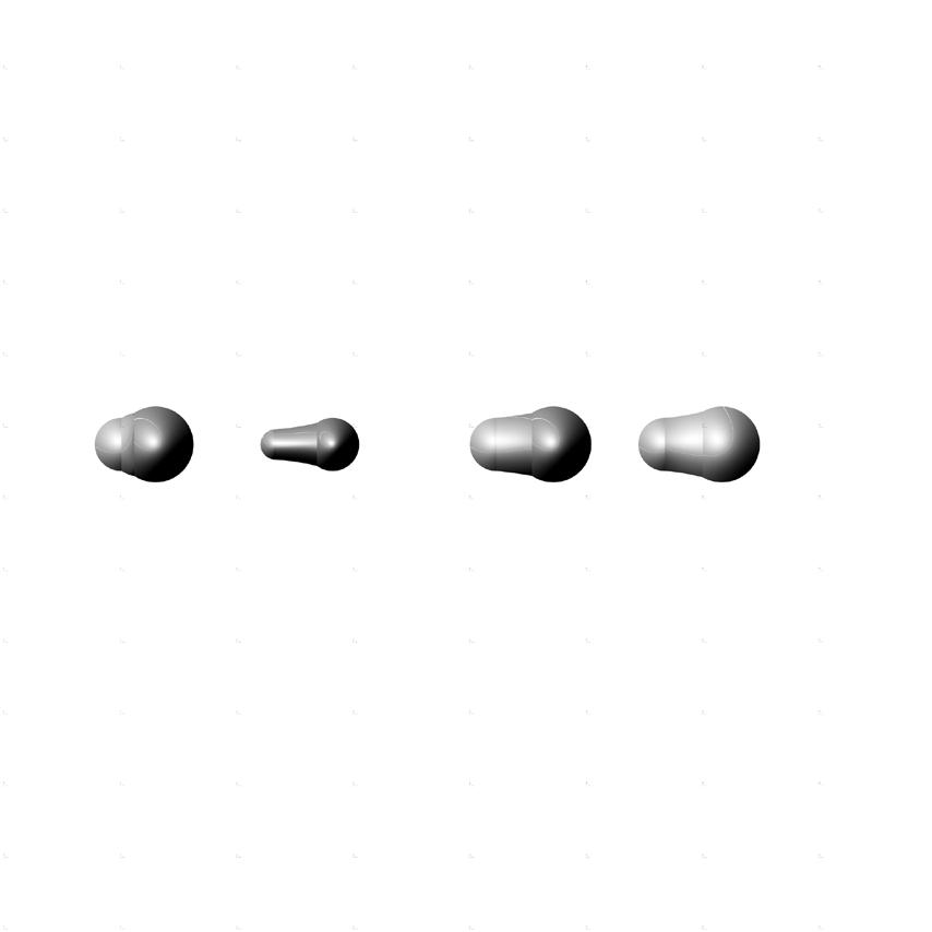

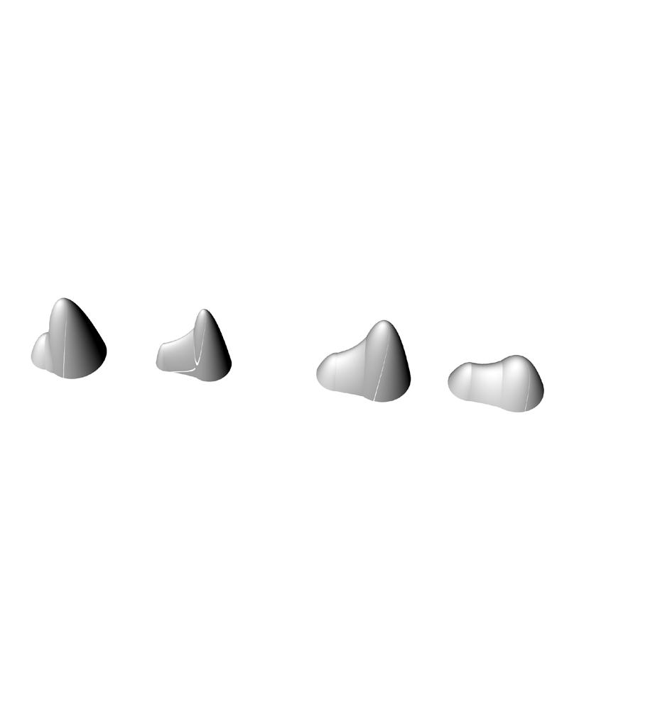


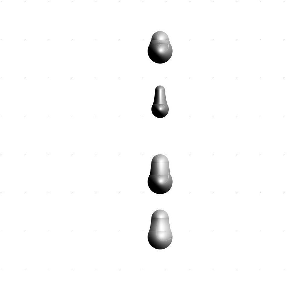


Range - 3.5 -5 m
GENE 2
Radius of 1 and 2 domes
Range (1) - 2 3.5 m
Range (2) - 4 - 5 m
GENE 3
Height of 1 and 2 domes
Range (1) 3.5 - 5 m
Range (2) - 4.5 - 6 m
GROUP GENES
GENE 4
Rotation
Range from -30 to +30 degrees
GENE 5 x y movement
Range from -6 to +6 meters
clxviii Arctic Recalibration
1
2 GENE 3 GENE 4 GENE 5
GENE
GENE
robotic rails
Calculation accordingly to the robotic reach
OVERVIEW :
Once more than two units are combined together, the unaccessible space in the middle of the unit appears. The position of the centres if defined by the accessibility for the robot. In order to avoid it, 2 types of morphological modifications were implemented:

- xy movement of the lateral primitives
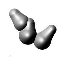
- rotation of the lateral primitives until the point where all the points are accessible for the robot.
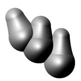
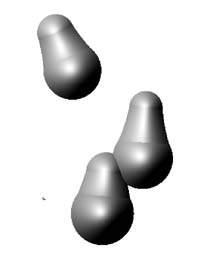
clxx clxix Architectural Association Arctic Recalibration
Unreachable area Solution 1. Moving composing primitives in xy directions
Solution 1. Rotation of composing primitives in xy plane
Variation of robotic reach in relation to the robots toolpath
Fitness criteria described
MAXIMIISE SOLAR EXPOSURE
- exposed areas
- non exposed areas
MINIMISE WIND EXPOSURE
- exposed areas
- non exposed areas
fitness criteria
Fitness criteria for clustering pattern is defined
As was observed previously, the architectural proposal in Arctic area heavily relies on the environmental conditions. Parameters of the housing units, therefore, are informing their morphology and derives the criteria to meet.
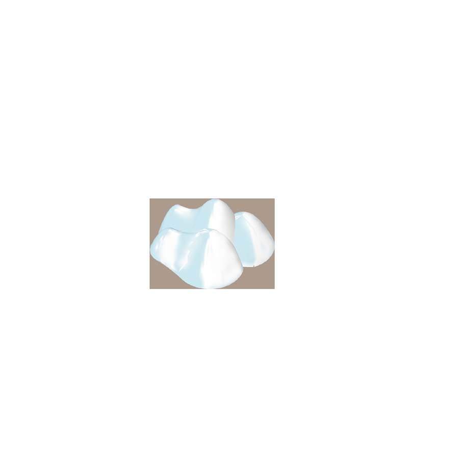
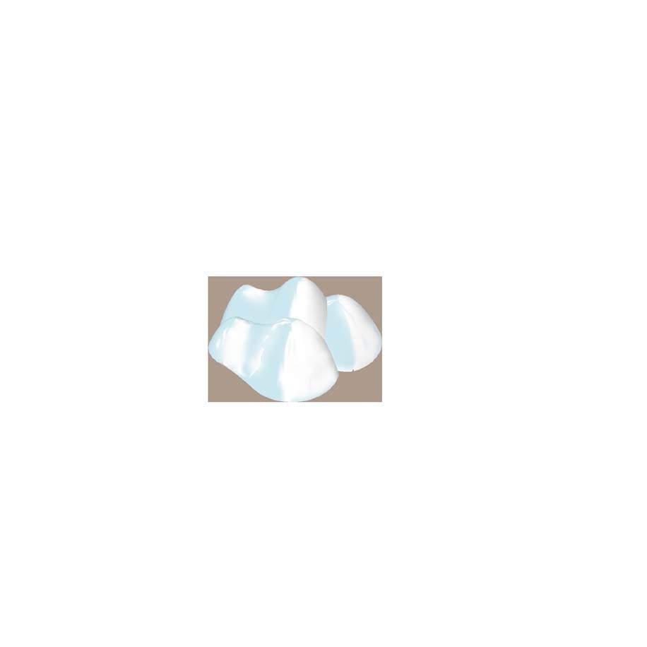
Using Octopus as a tool for multi criteria optimisation allows for multiple conflicting criteria. Although the environmental conditions and fabrication process have different layers of complexity, in the global scale Genetic Algorithm 3 fitness criteria were defined:
Sun rays angle is 35° to the horison. All the morphologie’s survaces are divided into faces. Each face is evaluated in relation to the multiple sun vectors. The total amount of exposed faces is calculated. The more exposed faces the individual has, more fit it is. Therefore, the fittest individual for this criteria is expected to have detached primitives, placed along west-east direction.
Prevailing wind direction in Seward Peninsula area is North-East and NorthWest. Generated morphologie’s survaces are divided into faces. Each face is evaluated in relation to the multiple wind vectors. The less exposed faces the individual has, more fit it is. Therefore, the fittest individual for this criteria is expected to have primitives, compound into one morphology, placed along north-south direction with inclination up to 30 °
MINIMISE LENGTH OF TOOLPATH :


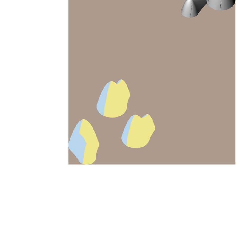
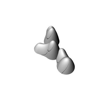

- rails
The robotic rail is closed uneven outline outside the compound interconnected housing unit due to the fact, that all the panels should be placed from outside of the structure. The aim is to minimise the length of the robotic rail in such a way, so all the point on the constructed morphology are accesable by the robot. Therefore, the fittest individual for this criteria is expected to have primitives, connected into the chane-like linear structure with no more then 2 primitives connected by the longer side to avoid the rarge span of the compound morphology.
clxxii Arctic Recalibration
EXPOSURE
EXPOSURE
PATH LENGTH
OVERVIEW SOLAR
WIND
ROBOTIC
Generation 100 phenotype 03 of dispersed settlement pattern
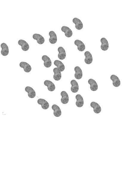
D is P erse D Pattern | genetic algorithm i
Dispersed clustering type evolutionary algorithm explored
Solar Exposure [m 2 59820
Wind exposure [m 47253
Tool-Path Length [m] 475
OVERVIEW
DISPERSED SETTLEMENT PATTERN
The algorithm is created in such a way, in which the threshold of the position of the primitives is limited, and they have no ability to intersect with each other.
The angle of rotation is not restricted, but the primitives are aligned along north-south direction to the wind direction ad wind exposure minimisation.
The optimal [best of all three fiteness criteria] individual from generation 100 is selected.
I NDIVIDUAL S PROPERTIES
The fitness criteria values are recorded for later comparison between the three settlement pattern options to select the optimum option.
Solar exposure: 59820 m 2
Wind exposure: 47253 m
Rails length: 475 m
Approx. inhabitants: 100 people
clxxiv clxxiii Architectural Association Arctic Recalibration
Generation 100 phenotype 39 of nucleated
nucleate D Pattern | genetic algorithm ii
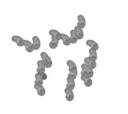
Nucleated clustering evolutionary algorithm explored
G 100.39. Nucleated settlement pattern
Solar Exposure [m 2 ] 40830
Wind exposure [m 2 39562
Tool-Path Length [m] 322
OVERVIEW
NUCLEATED SETTLEMENT PATTERN
The algorithm is created in such a way, in which the threshold of the position of the primitives is limited, and they are forced to combine into agglomerates of units 2-6 primitives in each
The angle of rotation is not restricted, but the primitives are aligned along north-south direction to the wind direction ad wind exposure minimisation. In order to meet the robotic accesibility parameter the primitives are aggregating into chain structures in the longitudinal direction.
I NDIVIDUAL S PROPERTIES
The fitness criteria values are recorded for later comparison between the three settlement pattern options to select the optimum option.
Solar exposure: 40830 m 2
Wind exposure: 39562 m 2
Rails length: 322 m
Approx. inhabitants: 75 people
clxxvi clxxv Architectural Association Arctic Recalibration
G 100.25. Intermediate settlement pattern
Solar Exposure [m 2 ] 51649
Wind exposure [m ] 42884
Tool-Path Length [m] 422 Generation 100 phenotype 25 of intermediate settlement pattern
interme D iate Pattern | genetic algorithm iii
Intermediate clustering evolutionary algorithm explored
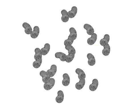
OVERVIEW
INTERMEDIATE SETTLEMENT PATTERN
The algorithm is created in such a way, in which the threshold of the position of the primitives is the combination of Genetic Algoritm 1 and 2.
The angle of rotation is not restricted, but the primitives are aligned along north-south direction to the wind direction ad wind exposure minimisation. In order to meet the robotic accesibility parameter the primitives are aggregating into chain structures in the longitudinal direction compound of 2-4 primitives.
I NDIVIDUAL S PROPERTIES
The fitness criteria values are recorded for later comparison between the three settlement pattern options to select the optimum option.
Solar exposure: 51649 m
Wind exposure: 42884 m 2
Rails length: 422 m
Approx. inhabitants: 93 people
clxxviii clxxvii Architectural Association Arctic Recalibration
conclusion
Evaluation of design and research advancements in the global clustering pattern
SETTLEMENT CLUSTERING TYPE SELECTION
Observing the results it is clear, that the compacted settlement achieves the smallest wind exposure, but smallest solar exposure as well. While the dispersed pattern shows the most solar exposure it also has the most wind exposure. Therefore, the intermediate clustering pattern is selected to explore further as it has a large amount of solar exposure while maintaining a lower amount of wind exposure when compared to the other options. Moreover, there is a larger possibility of spatial variations and thus shows more architectural potential.
SOLAR EXPOSURE :
The sun is a precious resource, as it is the primary source of thermal gain and both the building envelopes and the outdoor surface should bene fi t as much as possible from it. Although solar access to open ground conditions in relation to building clusters has not yet been evaluated, this would be a signi fi cant advancement.
WIND EXPOSURE :
The wind in the Arctic proves to be a harsh climatic factor that needs to be taken into consideration while designing a settlement pattern. A clustering pattern has been selected such that the surfaces exposed to the harsh wind conditions is at a minimum while still having a sufficient spacing between them to gain solar energy.
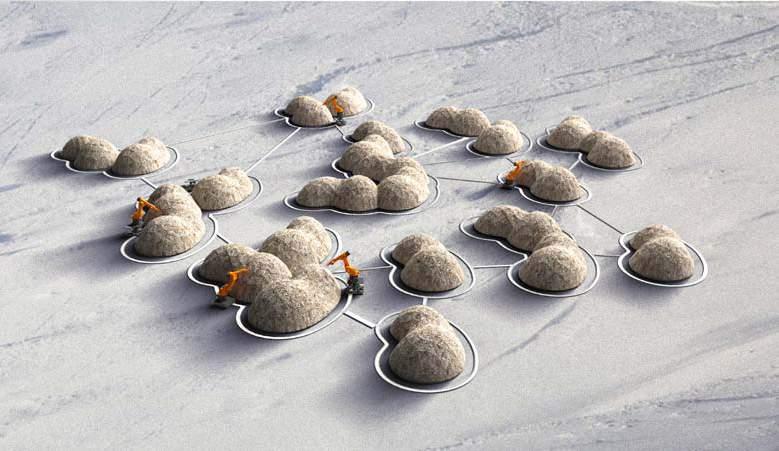
ROBOTIC RAILS :
The robotic rails defined are the shortest distances between successive agglomerates thus prividing an efficient toolpath such that there would be no waste of energy or time during the construction process.
Once the topological relationships described in the ‘Robotic rails’ have been developed, the next design development consists of interpreting and designing these networks as pedestrian circulation once the construction process is complete and there is no further need for the robotic rails.
DENSITY EVAULATION
As residential density has been redefined not by the amount of single family homes but by the agglomeration of various dwellings, it would be useful to quantify the advantages or disadvantages of this method of achieving density in an Arctic context.
PEDESTRIAN COMFORT
While high wind speeds notably increase the chill factor and decrease the level of thermal comfort in a space, the snow that they can carry can also block or impede the access to buildings, further decreasing the appeal that an outdoor space might have for any activity. As such, a part of relevant network strategy should incorporate the strategic allocation of snow fences and windbreaks that will provide thermal comfort and year-round use of the pathways that connect them.
clxxx clxxix Architectural Association Arctic Recalibration
Selected nucleated clustering pattern
LIMITATIONS
material s Y stem evaluation
Potential and limitations of the material system developed during the MSc. Phase
OVERVIEW :
Due the the highly interconnected data and feedback loops from micro, meso and macro scale a linear narrative is not possible thus, the MSc conclusions are discussed at this point [after completing ‘Research Development’ chapter] after all information regarding the system has been clearly defined.
The initial ambition of creating a structurally sound material system using locally sourced and harvested peat in the Arctic has been accomplished, with further detailed research required. Employing the structural properties of peat once compressed. Other innate properties of the material (insulating,) have been used to create unique environments and varied spatial qualities. The advantages and limitations of the developed material system are discussed below.
POTENTIAL MATERIAL SYSTEM :
Firstly, the created building material consists of environmentally conscious and economic raw materials. Peat, the principal raw material, which forms the bulk of the system is a potentially abundant resource. It is also locally harvested thereby reducing transportation and construction costs.
The structural properties of the material are determined through physical tests. The compressive and tensile strength of the material are determined to be 5.44N/mm2 and 1.98N/mm2 respectively and can be compared to best quality brickwork. This provides a possibility for varied structural configurations. Additionally, the combination of divergent prototyping techniques for construction provides a platform for the material to take on a productive and proactive role by using its inherent properties (self-insulating and water resistant).
POTENTIAL INTEGRATED SYSTEM :
The developed material system holds a strong relationship between its site and structure. The environmental factors such as extremely low temperatures drive the development and growth of the material system in terms of insulation and also in the geometry through form finding.
Since extemely cheap, locally sourced and harvested peat is used for construction, the reliance on outsourced construction products and expensive materials are significantly minimized.
DESIGN PROCESS
1. Form nding
Physical material tests prove that the material developed works effectively in compression and considerably less in tension, therefore, compression based systems are resorted to to decrease low yielding in form finding processes.
Since robotic arms are proposed for fabrication, morphologies are confined to the buildable volume and reach of the specific robotic arm. Furthermore, in design, several assumptions of robotic fabrication were made. The robot kinematics and toolpath to be followed were precisely considered at the design stage.
Additionally, variations in positions and orientations of the structure are employed to tackle environmental factors making it computationally ardu -
SUMMARY MATERIAL SYSTEM
MATERIAL SITE
Locally abundant resource
Climatically suitable [insulating]
Reduced transportation cost
MATERIAL - STRUCTURAL PERFORMANCE
Compression
Tension
MATERIAL FABRICATION TECHNIQUE
Compaction
- layered compaction
- overall compaction
Extrusion
Digitization of material
clxxxii clxxxi Architectural Association Arctic Recalibration
settlement s Y stem evaluation
Potential and limitations of the architectural proposal developed during the MSc. Phase
Environmental resistance
Loading capacity
OVERVIEW :
The use of this proposed material system promises to reduce a reliance on the import of standard construction products decreasing the dependence of Arctic settlements on expensive foreign materials. While incorporating environmental notions into the clustering principles of the settlement can yield more comfortable living environments mainly in the interior (in the dwellings) and further reduce energy demands. The exterior (in the public spaces) is not addressed in this research.
SETTLEMENT PATTERN :
Strategies for a global settlement pattern are aimed at maximising the role of the sun as a resource for winter heat, minimising wind exposure, reducing the toolpath length and reducing material usage. A signi fi cant advancement was made in relating an undulated building geometry to increased solar radiation, which allows a more northerly orientation and therefore reduced building shadows. This geometry was used as the base geometry from which the overall settlement was developed.
RESOURCE AUTONOMY :
The role of resource autonomy is a major driver for the system as developed so far. The use of locally abundant material [low-technology] diminishes the role of imported materials in construction. The integration of a low tech resource with a high tech fabrication system allows for the continued construction of dwellings over a transformative settlement thus, diminishing the role of imported materials on site.
RAIL SYSTEM TOOLPATH INFORMING MORPHOLOGY
MATERIAL PROPERTIES


compactability freezing-thaw cycles insulating

ENVIRONMENTAL PERFORMANCE
STRUCTURAL PERFORMANCE PROGRAMS STRUCTURE
SUSTAINABILITY
POSSIBLE STRUCTURE compression only dome shape arch cross-section

CONSTRUCTION LOGIC component based placement from outside only
ROBOTIC TOOLPATH SIMULATION


robotic reach to all the points on the surface singularities avoidance time factor GA MULTICRITERIAL OPTIISATION


environmental factors integration
ARCHITECTURAL PROPOSAL
clxxxiv clxxxiii Architectural Association Arctic Recalibration
KUKA ARCTIC QANTEC
MICRO SCALE 4
toolpath
component
MACRO SCALE
rail system robotic reach intersecting robotic MACRO SCALE MACRO SCALE MACRO SCALE MICRO SCALE MICRO SCALE Placement from outside Robotic reach 4 Axis Time taken of path followed MACRO SCALE MACRO SCALE MACRO SCALE MICRO SCALE MICRO SCALE Placement from outside Robotic reach 4 Axis Time taken of path followed
axis
simulation
design
settlement clustering
functional zoning of combine D units
Zoning developed for combined units of dwellings
OVERVIEW
3.
2.
Once dwellings are combined into more than one the functional distribution needs to be altered as well. Parameteres such as hieght gradient and thermal conditions are analysed. It is found that the functional zoning follows a similar pattern to zoning in a single unit[see ‘Functional Zoning’ chapter] wher less habited spaces are placed towards the wind bearing side while the main habitable spaces such as common and sleeping spaces are pushed towards the back. While this stage is defined only in terms of zoning and not defined in detailed it provides enough information to inform the successive design detailing. Further exploration is required.
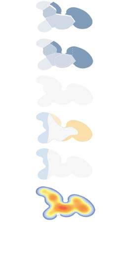
Spatial zoning
Geometric spatial differentiation seams

Summer period
22 hours sunlight
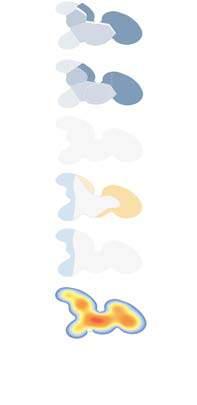
Levels based on zoning 4 unit/8 BR
Exploded axonometric of parameters that define functional zoning
clxxxvi clxxxv Architectural Association Arctic Recalibration
Storage space Common space Domestic space Sleeping space Reduced
Constant heating Storage space Common space Domestic space Sleeping space <1.5M 1.5 - 2.1 M >2.1 M Storage space Common space Domestic space Sleeping space Storage space HEIGHT GRADIENT THERMAL CONDITIONS [SUMMER] THERMAL CONDITIONS [WINTER] ACTIVITIES -Sleeping space -Common space -Storage space -Domestic space 1. Height gradient 2. Thermal mapping 3. Geometrical spatial di erentiation SPATIAL MAPPING FUNCTION ZONING
Reduced heating Constant heating Increased heating
heating
Reduced
Storage space Common space Domestic space Sleeping space Reduced
Storage space Common space Domestic space Sleeping space <1.5M 1.5 - 2.1 M >2.1 M Storage space Common space Domestic space Sleeping space Storage space HEIGHT GRADIENT THERMAL CONDITIONS [SUMMER] THERMAL CONDITIONS [WINTER] ACTIVITIES -Sleeping space -Common space -Storage space -Domestic space
heating Constant heating Increased heating
heating Constant heating
1. Height gradient
Thermal mapping
Geometrical spatial di erentiation SPATIAL MAPPING FUNCTION ZONING
segmente D shells
Preference of segmented shells over continuous shells
Pattern | force flow
Geometric properties of segmental plate shells
OVERVIEW :
To implement the complex geometries the use of a segmented shell system is proposed. Shell structures are structurally efficient, because out of plane forces are transformed into membrane forces. However, continuous shell structures are rarely built today, due to high manufacturing costs.
Segmental plate shells, composed of prefabricated planar panels, might offer an interesting alternative. Unlike single layer grid shells, which usually need bending-stiff joints to stabilize the structure, segmental plate shells could generate local bending stiffness without the help of a bending-stiff joint. When three plates meet at one point and are hinged along the intersection lines, each plate is constrained by the other two; they cannot have relative movements anymore. This property helps segmental plate shells to generate a relative simple connectivity, which makes this type of structures more competitive.
The pattern of segmental plates affects the force transfer also in the shell. Since the material is not continuous at joints, forces will be redirected when they pass through the connections. The joint stiffness affects the force transfer as well, because stiffer connections attract higher forces. The geometric pattern and the joint stiffness thus jointly determine where and how the internal forces will be transferred in segmental plate shells.
FORCE TRANSFER :
The pattern of segmental plates will affect the force transfer in shell structures. It defines the locations of all connections, which are the weak points in the structure. Because the material is not continuous at connections, forces will be redirected when they pass through the connections. Besides, the joint stiffness also affects the force path largely, because when the joints are stiffer, larger forces will be attracted to flow through. The geometric pattern and the joint stiffness thus determine where and how the internal forces are transferred in segmental plate shells.
The following example is studied (based on Proceedings of the International Association for Shell and Spatial Structures (IASS) Symposium 2015, AmsterdamFuture Visions).
Four FE-models were built to investigate the phenomenon mentioned above. Each model is applied with a downward force on the top to observe how the force is transferred in the segmental elements. The joint stiffness of the models is set such that the contact mechanism of the finger joint connection is considered, which means joint stiffness in the local y-direction is much larger than the remaining two directions.
clxxxviii clxxxvii Architectural Association Arctic Recalibration
Flow diagram of the design, structural analysis and materialisation phases of discrete, free-form stone vaults showing the interdependencies with relevant constraints
D igital D esign an D materialisation
This section describes the sequential, but interrelated steps of the digital chain from form finding to materialisation
OVERVIEW
A key aspect is to define and develop a suitable and coordinated design and fabrication set-up for the production of the hundreds of individual voussoirs that need to be processed for a single vault design. Owing to the three dimensional shape of the separate blocks and the geometrically complex fabrication constraints, the challenge is to coordinate the design of the individual voussoirs, in accordance with the technical machine set-up. Furthermore, the right balance needs to be found between form finding and fabrication constraints, in order to produce free-form stone vaults efficiently
The figure on the adjacent page shows the steps of the process and their interdependencies 28. The steps are categorised in three main phases: design process, analysis process and materialisation process.
The first phase of the digital chain is the design process, which consists of three steps. The defining structural properties for the proposed material, are its low tensile and high compressive strength. Because of this, to span space in unreinforced masonry, the use of funicular form, acting purely in compression, is mandatory to ensure structural stability. Therefore, in the first step, an appropriate funicular form is determined [by using a RhinoVault plugin for Grasshopper].
In the second step, based on the results of the funicular form finding, a possible tessellation geometry is generated that defines the cutting strategy of the vault. This is an automated process, informed by structural and fabrication-related data, which is influenced or guided by the designer.
In the third step of the design process, the tessellation pattern is used to generate the voussoir geometry considering structural as well as fabrication and assembly constraints.
cxc clxxxix Architectural Association Arctic Recalibration DESIGN PROCESS 1. Form nding 2. Tesselation 3. Voussoir geometry ANALYSIS PROCESS DESIGN PROCESS 1. Fabrication 2. Installation CONSTRAINTS 1. Architecture and tectonics 2. Structure 3. Fabrication and installation Pattern Shape and structural form Local thickness Alignment to force ow Fabrication Requirements Planar cuts Single curved cuts Ruled cuts Double curved cuts Rough cuts High precision cuts Limits of axis Motion control Block dimensions Architectural and techtonic requirements Structural requirements INTERDEPENDANT CONSTRAINTS w DESIGN PROCESS 1. Form nding 2. Tesselation 3. Voussoir geometry ANALYSIS PROCESS DESIGN PROCESS 1. Fabrication 2. Installation CONSTRAINTS 1. Architecture and tectonics 2. Structure 3. Fabrication and installation Pattern Shape and structural form Local thickness Alignment to force ow Fabrication Requirements Planar cuts Single curved cuts Ruled cuts Double curved cuts Rough cuts High precision cuts Limits of axis Motion control Block dimensions Architectural and techtonic requirements Structural requirements INTERDEPENDANT CONSTRAINTS u
Software
1. Structurally sound compression
com P ression structure | rhinovault
Manual
This section describes the sequential, but interrelated steps of the digital chain from form finding to materialisation
1. Di erentiation
RHINOVAULT
Software
1. Structurally sound compression
Manual
1. Di erentiation
Inputs
1. Outline
2. Spatial relationship
3. Max height
OBJECTIVE
INPUTS
Inputs
1. Outline
2. Spatial relationship
3. Max height
The Rhinoceros Plug-In RhinoVAULT emerged from research on structural form finding using the Thrust Network Analysis (TNA) approach to intuitively create and explore compression-only structures. Using reciprocal diagrams, RhinoVAULT provides an intuitive, fast funicular form-finding method, adopting the same advantages of techniques such as Graphic Statics, but offering a viable extension to fully three-dimensional problems. The key aspects of the research is a comprehensible and transparent setup to create beautiful shapes but also to give an understanding of the underlying structural principles.
Due to the properties of the proposed material, compression based systems prefered, a compression only structure must be created. The aim of this experiment is to manipulate force lines to achieve the required geometry.
outline [base] of the shell [A dwelling type is selected from ‘intermediate clusting pattern’ on page 140 as a base input], spatial relationships thought program distribution andmaximum height accordingly to wind forces [5 m] in the highest outer shell point. Reference ‘Rhinovault’ psuedocode in ‘Appendix’ chapter.
A compression only structure is created with spatial variations that are controlled by the designer. The structure created has domed like variations to introduce spatial variation and form thermal sinks.
RhinoVAULT process followed to create a compression only strcuture
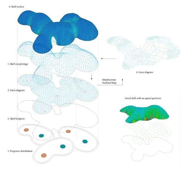
cxcii cxci Architectural Association Arctic Recalibration
OUTPUT
RhinoVAULT process followed to create a compression only strcuture
conclusion
This section describes the sequential, but interrelated steps of the digital chain from form finding to materialisation
Compression only structure Displacement in structure
CONCLUSIONS
Input geometry
Output geometry
A comparitive analysis is done of the input surface and the output surface [seen above]. While the basic geometry is kept intact due to alterations of force lines to create a funicular structure there is a slight change in the geometry of the shell.
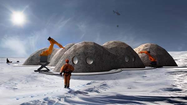
In the image seen alongside it is clear that a complete compression only structure is created.
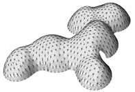
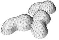
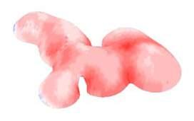
cxciv cxciii Architectural Association Arctic Recalibration
tesselation
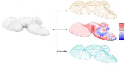
This section describes the sequential, but interrelated steps of the digital chain from form finding to materialisation
OVERVIEW
A key aspect is to define and develop a suitable and coordinated design and fabrication set-up for the production of the hundreds of individual voussoirs that need to be processed for a single vault design. Owing to the three dimensional shape of the separate blocks and the geometrically complex fabrication constraints, the challenge is to coordinate the design of the individual voussoirs, in accordance with the technical machine set-up. Furthermore, the right balance needs to be found between form finding and fabrication constraints, in order to produce free-form stone vaults efficiently
The figure on the adjacent page shows the steps of the process and their interdependencies. The steps are categorised in three main phases: design process, analysis process and materialisation process.
The first phase of the digital chain is the design process, which consists of three steps. The defining structural properties for the proposed material, are its low tensile and high compressive strength. Because of this, to span space in unreinforced masonry, the use of funicular form, acting purely in compression, is mandatory to ensure structural stability. Therefore, in the first step, an appropriate funicular form is determined [by using a RhinoVault plugin for Grasshopper].
In the second step, based on the results of the funicular form finding, a possible tessellation geometry is generated that defines the cutting strategy of the vault. This is an automated process, informed by structural and fabrication-related data, which is influenced or guided by the designer.
In the third step of the design process, the tessellation pattern is used to generate the voussoir geometry considering structural as well as fabrication and assembly constraints.
Selected patch marked in red
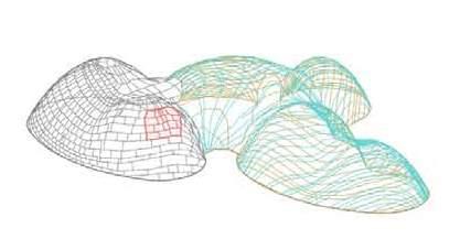
cxcvi cxcv Architectural Association Arctic Recalibration
UV tesselation line form finding experiment
materialization
This section describes the creation of planar panels from doubly surved surfaces
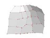
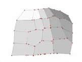
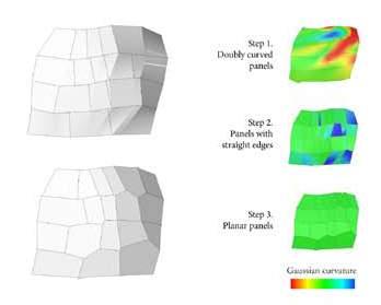
OBJECTIVE :
Individual voussoirs are generated from the tessellation, however these voussoirs are doubly curved. Due to properties of the proposed material [compaction] and the production of material being possible only in flat sheets the proudction of double curved panels is impossible. Therefore, the doubly curved panels need to be converted to planar panels. This step is computationally heavy and requires a sufficient amount of additional manual alterations. To ease this process a custom python script should be explored.
Rebuild the lines of each edge of doubly-curved panel from curves to straight lines. The panel morhps into being singly-curved or remains double curved with less curvature degree.
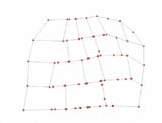
STEP II :
STEP I : Apply the planarization algorithm to the resulting panels. Algorithm: Move points on the surface until planarity reached. Conclusion – this planarization algorithm works, but increase the complexity of the system.
CONCLUSION :
While the planarization algorithm works, the complexity of the system is greatly increased. Applying this planarisation algorithm to the double curvature panels creates a considerable change in panels geometry howerver care is taken into maintaining the resolution of the overall structure.
Doubly curved panels to planar panels [curvature analysis]
Morphing
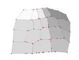
of planar surfaces
cxcviii cxcvii Architectural Association Arctic Recalibration
RhinoVAULT process followed to create a compression only strcuture


conclusion
An overview of the previosuly discussed systems

CONCLUSION
The digital design and materialisation chain for the development of this structure, allowing innovative architectural applications for a traditional material, has been discussed. The interdependent constraints, in particular structural and fabrication requirements, have been discussed and associated with basic geometric constraints. Optimisation algorithms that deal with these constraints have been developed. The techniques for tessellation and for generation and optimisation of vousoirs have been integrated in the TNA-based form-finding tool RhinoVault. The result shows the efficient combination and integration of construction material and structural form.
Future research will focus on the optimisation techniques in the design process. In particular, the tessellation and planarisation strategies need to be investigated further, allowing for fewer dependencies on such a computaationally heavy procedure to better incorporate architectural considerations. Another challenge and additional focus of research further is the assembly logic by identifying geometrically feasible and structurally stable construction sequences during incomplete phases of free-form vaults, which goes along with the further investigation of advanced structural analysis and efficient formwork systems which would be the next stage.
cc cxcix Architectural Association Arctic Recalibration Input surface Control diagram Compression only surface Final surface FORM-FINDING Tesselation Stereotomoy II MATERIALIZATION Fabrication III REALIZATION Rapid prototyping 42
stereotom Y
An overview of the joinery system proposed
interlocking ex P loration
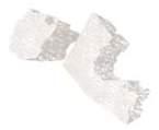

An overview of the joinery system proposed
INTERLOCKING PANELS :
The lack of materials onsite and the rejection of expensive and inneficient outsourcing of resources has been a key driver in this research. While analysing the fabrication system proposed the use of mortar was rejected simply due to lack of resources. This chapter explores the geometries required for a dry masonry system.
Physical tests were conducted and it is understood that the panels collapse due to the lack of interlocking [requires more friction forces]
The directions of voussoir collapsing are-

-Horizontal sliding towards the centre of the shell due to gravity forces
-Vertical flipping inwards once again, due to gravity forces
To prevent these two methods of the system failing a stereotomy exploration is conducted by analysing various vertical and horizontal joinery systems.
ITERATION I :
MULTIPLE TEETH
It is found that the number of perpendicular teeth are excessive creating complications in the assembly process. Also, the presence of angular teeth at the corners of the panels does not allow for ease of construction.
ITERATION II :
TRAPEZOIDAL SINGLE TOOTH
The geometry eveolved to one tooth per side with a trapezoid geometry instead of rectangular making it easier to slide into position. It drastically reduced the complexity, however the vertical interlocking doesn’t lock vous soirs in all the directions and the panels slide out.
ITERATION III :
HORIZONTAL TAPERED JOINT
A horizontal only tapered joint is proposed. It is observed that the panels slide in the horizontal axis, inside towards the centre of the shell and also [in the vertical direction] flip inwards. The occurences of these failures increase
ccii cci Architectural Association Arctic Recalibration
REJECTED
REJECTED
P ro P ose D stereotom Y
An overview of proposed geometry of the voussoir with the integrated interlocking
ITERATION IV :
TAPERED HORIZONTAL JOINT

The horizontal interlocking tooth is tapered along the internal side of the panel to prevent the panel from sliding horizontally inwards. If there is an attempt to slide inwards, the tapered joint will prevent this movement and the panel will not be able to and will stay in position.

ANGLED VERTICAL JOINT
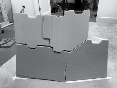
The vertical joint is designed in such a manner to prevent vertical flipping. The side interlocking is redesigned in order to relate to the robotic pick and place toolpath. An angled plane is placed along the vertical sides of the panels, it is tilted against the direction of flipping.
The interlocking system is designed to fulfil two contradicting criterias –No friction while robot is placing the voussoir in order to not damage the previously constructed part of the structure, while also maximising friction once the panel is placed to prevent movement.
cciv cciii Architectural Association Arctic Recalibration
[ ANGLED VERTICAL JOINT, TAPERED HORIZONTAL JOINT ]
Horizontal Joint Gravity Vertical Joint
The tapered joint explained in detail
An image of the assembled stereotomy proposed
OBJECTIVE
friction forces
An overview of the friction forces in the proposed panels
FRICTION FORCE :
Friction betwen the panels is a key aspect of this system. Therefore, the friction forces are clearly analysed to understand its implications on the fabrication system proposed.
The friction force is the force exerted by a surface when an object moves across it - or makes an effort to move across it.
The frictional force can be expressed as:
Ff = μ N where
Ff = frictional force (N, lb)
μ = static (μs) or kinetic (μk) frictional coefficient
N = normal force (N, lb)
There are at least two types of friction forces -Kinetic (sliding) friction force- when an object moves -Static friction force - when an object makes an effort to move
In the calculations the static friction force is used as far as there is no movement in the block on the lower row. For an object pulled or pushed horizontally the normal force[N] is simply the gravity force or weight:
N = Fg
Fg = gravity force - or weight (N, lb)
m = mass of object (kg, slugs)
g = acceleration of gravity (9.81 m/s2)
The friction force can be modified to
Ff = μ m g
The calculation is made to determine the equilibrium position with the maximum angle possible until sliding of the block.
CALCULATION :
In equilibrium all the forces are balanced, therefore:
On x axis of local block’s coordinate system:
m*g*sinθ - Ff = 0 , where Ff = µ*m*g
On y axis of local block’s coordinate system:
m*g*cosθ – Fn= 0, where Fn = µ*N*cosθ, N=m*g
m*g*sinθ - µ*m*g = m*g*cosθ - µ*m*g*cosθ /dividing by mg
sinθ - µ = cosθ - µcosθ
cos2θ + sin2θ = 1, therefore cosθ = √1-sin2 θ
sinθ = cosθ - µ - µ*cosθ
sinθ = √1-sin2 θ µ - µ*√1-sin2 θ
sin2θ = 1- sin2 θ - µ2 - µ - µ*sin2 θ
sin2θ *(2+ µ) = 1-- µ2 - µ
sin
θ = √1-- µ2 - µ/(2+ µ)
θ = arcsin √(1-- µ2 - µ/(2+ µ))
θ = arcsin √(1-0.62 – 0.6/(2+0.6))
θ = arcsin√0.41
θ = arcsin0.64
θ = 39.79
CONCLUSION :
Therefore, the last angle of self-supporting part of the dome without caffolding is 90° - 39.79° = 50.21. All the parts of the dome with the external surface increment more than this must to be cut and assembled on the ground [as explained in ‘Assembly Phasing’ chapter].
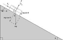
ccvi ccv Architectural Association Arctic Recalibration
‘P
ick an D P lace ’ s Y stem
Defining the orientation of placing the panels to be picked
PANEL PLACEMENT FOR ‘PICK’ SEQUENCE:
Robotic pick and place automation speeds up the process of picking parts up and placing them in new and different locations, increasing production rates 29 With many end-of-arm-tooling options available, pick and place robots can be customized to fit specific production requirements. Moving large, small, heavy, or hard-to-handle products can be an easy task to automate in the factory line.
Consistency is also a benefit of using a pick and place system. The robots can be easily programmed and tooled to provide multiple applications if required. An increase in output with a pick and place robot system offer long-term savings to construction processes. With the advancements in technology and affordability of robots, more pick and place robotic cells are being installed for automation applications.
This ‘pick and place’ system is utilised in the proposed fabrication sequence.
LOCAL SEQUENCE:
A patch is selected from the total structure to analyse and perform physical tests to prove the ‘pick and place’ fabrication system. The toolpath followed at the local scale is a simplistic one following one direction,constructed row by row from bottom to top such that each panel is half locked by two sides and has two free sides also. However, once the successive panel is placed, the previous panel is fully locked thus creating a rigid compression only structure.
CHALLENGES ADDRESSED:
As with all robotic fabrication, the system must be clearly defined and requires a one time customisation set up before the process can then be performed continuosly and aacurately. The main challenges of fabrication system that are addressed at the micro scale are:
-Positioning the panels for the gripper to pick them up
-How to grip the panel securely and transfer it
-Placing the panels in required positions in the right orientation
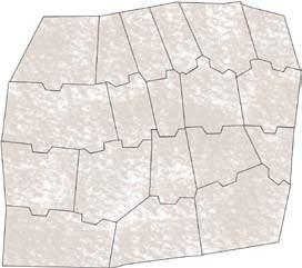
ccviii ccvii Architectural Association Arctic Recalibration
1 2 3 5 6 7 11 9 10 12 13 14 15 1 8 4 8 16 17 Local sequence
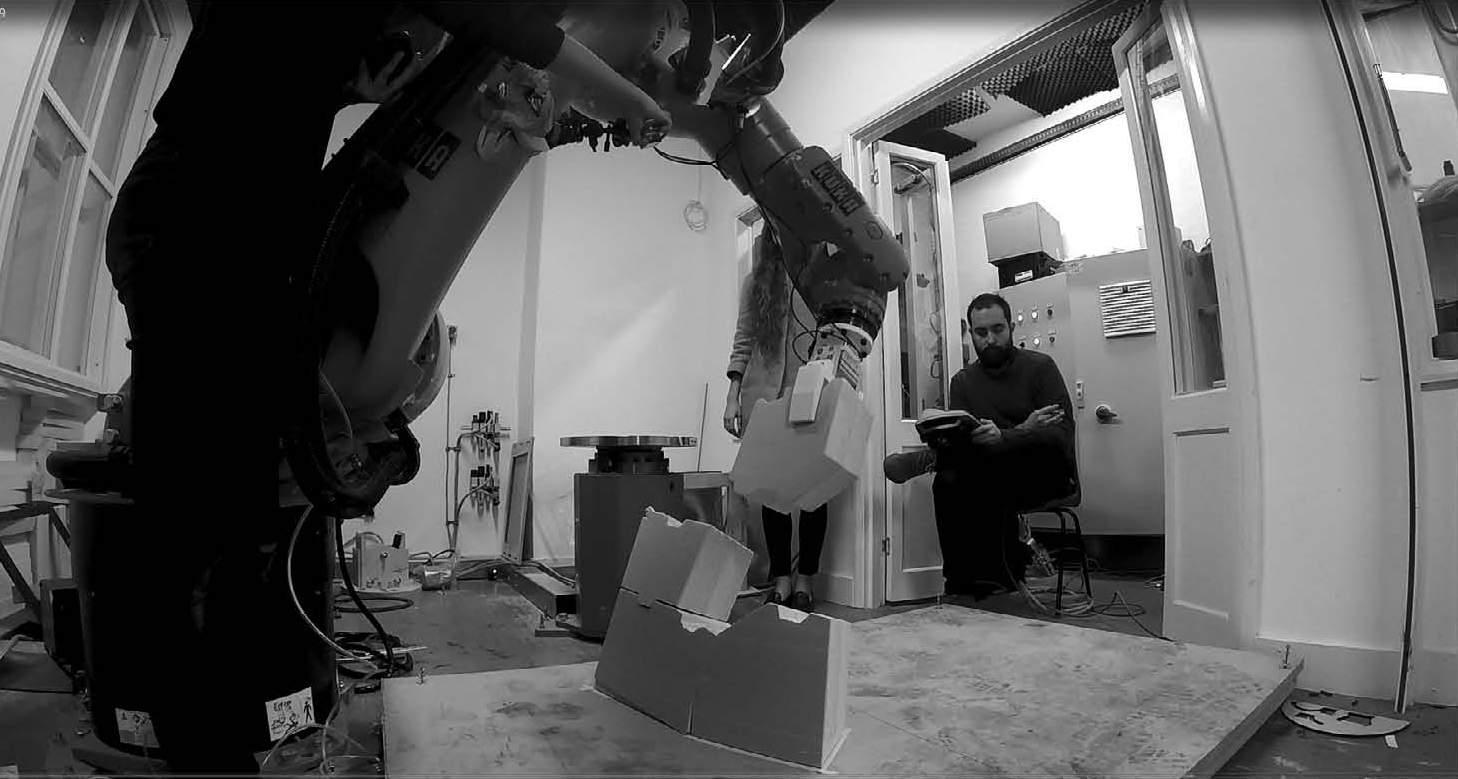
ccx ccix Architectural Association Arctic Recalibration
‘P ick ’ tool Path D evelo P ment
Defining the orientation of placing the panels to be picked
gri PP er P osition
Defining the picking process of panels in relation to the custom gripper
GRIPPER RELATION TO PANELS:
To accommodate dimensions for changing size and gripping perpendicular plane for the panels –
PANEL PLACEMENT FOR ‘PICK’ SEQUENCE:
The objective at this stage is to place panels with variations in dimensions with accuracy, so they don’t fall during the ‘pick’ process.
The proposed automated feeder system requires guides to place the panel preciselyas there is a great variation in dimensions of all the panels. However the two largest surfaces of the panels are parallel to each other. Therefore, the feeder is tranfers blocks in a conveyer belt with edges that are tailored to the thickness of the panels. Therefore, the supporting guides of the panels are the side edges and the starting edge of the panel is perpedicular to the surface.
However, the side of the panel to be placed on needs to be determined. This is done by calculation of the centre of gravity of each panel as well as area of each side surface. The surface with biggest area, which is not outside of the projection of centre of gravity once the panel is placed on it, is selected as a bottom surface. The gripper position adapts accordingly.
Due to the planaraization of units none of the angles in the panels is 90 degree. There is great variation within the panels with all of them measuring different sizes and different angles of the side surfaces. However, the two main parallel pargest sides of the panels are parallel, flat, and are located at the same distance in all the panels [due to equal thickness]. This is used as a benefit for the system; to utilise only one universal gripper design for all the panels.
One gripper design without the requirement to adjust flanges proves to be a simpler, more efficient and mobile [as there is no need for the end effector to be replaced during construction] design. As far as the pneumatic gripper construction requires 2 surfaces parallel to each other. If the surfaces are not parallel, the gripper will not close properly and/or will cause the change in the ‘pick’ position because the flanges while attempting to close properly will rotate the panel slightly and damage its surface or also potentially create a deviation. Therefore using two largest flat surfaces of the panel [representing inner and outer surface of the shell] is the only appropriate method of picking the unit for construction.
In this case, the base point of the gripper [the tip that is predetermined and set up] constantly changes in order to pick up different panels. The 6 th axis of the robot, therefore, is no longer parallel to the side surface, only the flanges are parallel to the panel. This ‘pick’ orientation is presented in the image presented on the next page.
ccxii ccxi Architectural Association Arctic Recalibration
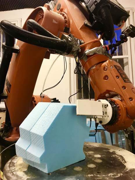
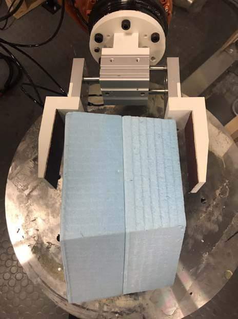
ccxiv ccxiii Architectural Association Arctic Recalibration
Aggregation of planar units using multi axis robotic arm
Orientation relation of gripper to the panels are paralel
‘P lace ’ tool Path D evelo P ment
Robotic simulation of the ‘pick and place’ sequence as proof of concept
KUKA TOOLPATH DEVELOPMENT
:
There are 2 types of manipulating the robot in KUKA PRC software –
- Automatically by defining the position of the end-effector tip surface or
- Manually by defining the rotation for each axis independantly 30
The selection between methods depends on the goal which is needed to be achieved. Therefore, for the start and end position of pick and place the angles for the each axis’ are defined. This position is standard for all the pick and place iterations and prevents singularities. It is also used for maintaining the robot by putting additional rotations if needed. It is set in relation to the robotic morpshospace in general, possible obstacles during construction and the dimensions of the robot
The toolpath, on the other hand, requires custom, tailored to each block movement. Therefore, is the compiled of the sequence planes, where the origin defines the position of the gripper and the orientation defines the same aspect of the gripper accordingly. KUKA PRC software adjusts the position of all 6 axis in such a way, so the end-effector is positioned properly automatically. See ‘Appendix’ chapter for psuedocode of ‘pick’ point, ‘place’ point derivation and robotic sequence simulation.
DEFINED PARAMETERS :
There are several parameters which needs to be defined for the robotic algorithm:
- Start/end position – equal positions
1 st axis - pi/4
2 nd axis pi/2
3 rd axis - 0
4 th axis - 0
5 th axis -pi/2
6 th axis - 0
-Pick Plane : it is a plane which is the starting orientation
-Safe point : additional toolpath point to prevent robot from crushing into existing constructed part of structure
-Safe Plane : safe point with specific given orientation
-Gripper positions : open/closed – commands to pneumatic gripper actuator
-Waiting time : time before/after picking/placing to ensure the accuracy of movement and panel incretion.
ccxvi ccxv Architectural Association Arctic Recalibration
micro ‘P lace ’ tool Path
Robotic simulation of the ‘pick and place’ sequence as proof of concept
MICRO SCALE PLACEMENT :
This steps involves contradicting criteria where minimum friction is required so that the panels can be placed perfectl into position however, for the panel to stay in position friction is required [in addition to the horizontal and vertical joinery developed] The only solution is to develop a toolpath that would allow the panels to fit perfectly into position with zero tolerance.
The main challenge in placing the panel is to avoid friction. Therefore, the direction of the movement of the panel is always parallel to the previous side panel. The 3d position of the panel, however, is derived by the panel itself due to the fact that it needs to be parallel to the gripper flange’s surface.
Angled vertical joint | Tapered horizontal joint
Orientation of panel to be placed in relation to previous panels already in position
ccxviii ccxvii Architectural Association Arctic Recalibration
GoPro view ‘Pick and place’ sequence [Proof of concept]
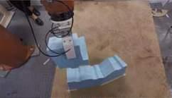
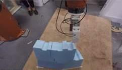
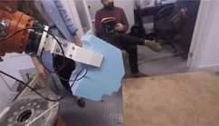
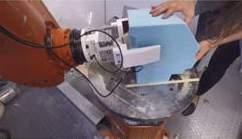

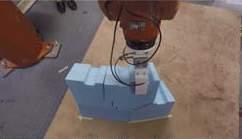
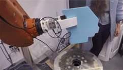
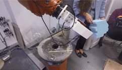
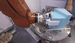
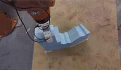
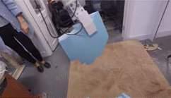
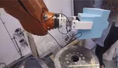
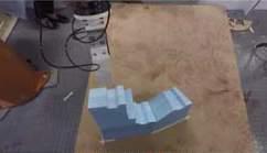
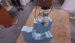
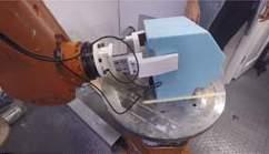
ccxx ccxix Architectural Association Arctic Recalibration 01 05 09 13 02 06 10 14 03 07 11 15 04 08 12 16
Overall view ‘Pick and place’ sequence [Proof of concept]
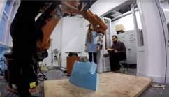
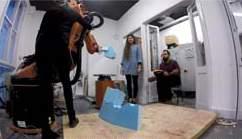
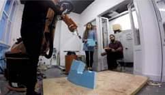
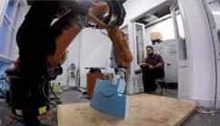
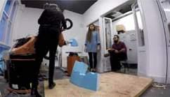
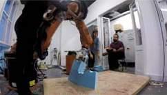
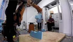
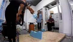
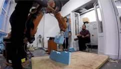
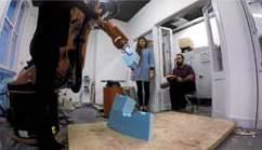
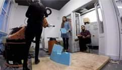
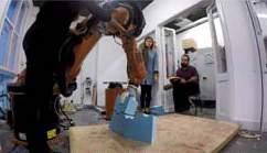
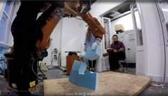
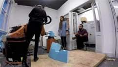
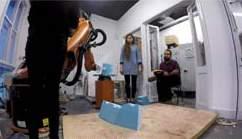
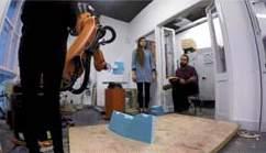
ccxxii ccxxi Architectural Association Arctic Recalibration 01 05 09 13 02 06 10 14 03 07 11 15 04 08 12 16
conclusion
Robotic simulation of the ‘pick and place’ sequence as proof of concept
PHYSICAL EXPERIMENTS –PROBLEMS FACED :
Though the physical experiments were successful assemblying the material along the designed tool-paths several issues were faced at the initial stages of the experiment. These issues faced during the fabrication process can be broadly classified into:
a) Picking position
b) Limitations of the [physical experiment] Material
A) PICKING PLACEMENT POSITION :
While an automatic feeder is proposed for onsite construction during the physical experiments manual placement of the panels is required. The exact orientation of panels is extremely important as it has a consequence on the placing of the panel and finally the overall structure. The positions for placement of panels thus had to be manually calculated and placed after a few iterations of trial and error which proved to be difficult. However, due to the proposed system of the automatic feeder this problem will not be faced during onsite construction.
B) LIMITATIONS OF [EXPERIMENT] MATERIAL :
The foam is extremely light when compared to the proposed material [peat] and sensitive to the slightest pressure variations caused calibrated speed of the robotic arm. Due to the foams light weight there was difficulty in the panels staying in position as the centre of gravity did keep the panels in place at all times after being placed.
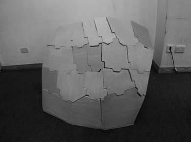
However, the weight of peat is much higher than the foam and thus it is concluded that this problem will not be faced on site due to the centre of gravity falling within the previous panels when the assembly is conducted in peat.
CONCLUSION
The overall selected patch is succesfully assembled. The patch shows double curvature. This experiment is as proof of concept of the ‘pick and place’ assembly technique utilising the panels.
ccxxiv ccxxiii Architectural Association Arctic Recalibration
stages of construction
An overview of the stages of construction in the design process
STAGES OF CONSTRUCTION :
The design proposal includes a 5 stage contstruction process, from the creation of peat harvesting basins to the construction of rail systems followed by the aggregation of the panels of the the settlement.
The rails of the robot in certain area that show potential for growth are proposed to be retained on site for future use as pedestrian pathways.
The figure alongside illustrates the stages of construction and figure illustrates the construction process showing in layers the sequence in which construction process is proposed to take place.
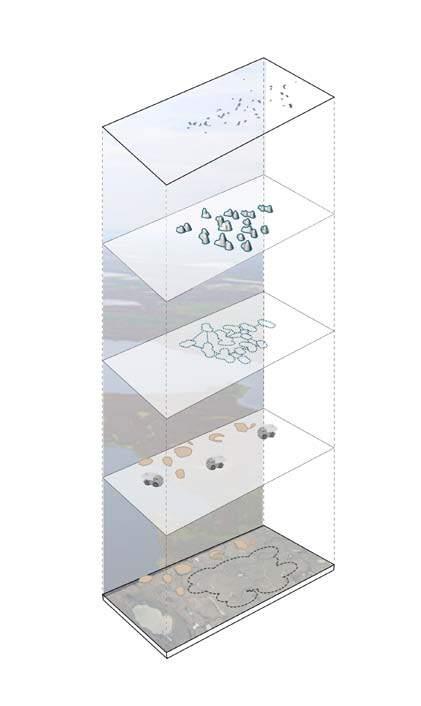
PHASING - FABRICATION PROCESS :
As multiple robots collaborate to fabricate the structure, it becomes necessary to phase the fabrication process. This process of phasing also allows for structurally sound fabrication.
The basic subdivisioning for the phasing of the structure is illustrated in the figure [on the next page], this allows for organized work flow, constructing bottom up providing intervals for the robots to assemble the successive structures as required. The tolerance seams structures are assembled in a layer by layer manner and joined after the fabrication of the unit structure it supports. This process is illustrated in the figure on the next page.
The rails system as discussed earlier determines the positioning of the robot and the number of robots invoved in the fabrication of a unit. Futhermore, the positions of the robots determine the role the robot will perform, be it a unit, tolerance seam or keystone caps.
ccxxvi ccxxv Architectural Association Arctic Recalibration
Terrain selection Peat harvesting Robotic toolpath sequence Structures assembled Exploded view of the assembly structure
freemason assembl Y
An overview of the various assembly methods studied
COMPRESSION STRUCTURE CONSTRUCTION :
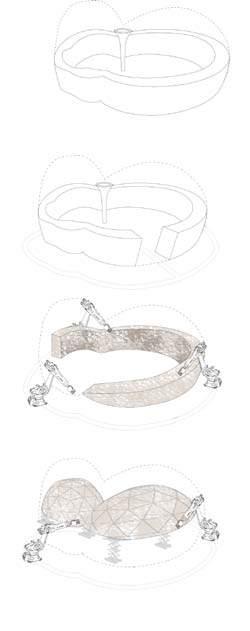
For compression based structures to be fabricated in most cases there is a need for temporary scaffolding to be constructed, over which the structures are built 31 However, this stage proved to be a challenging aspect in this research. The proposed structure is a compression only structure and therefore to be fabricated would generally require a temporary scaffolding. Most scaffolding over the world utilises steel frameworks or even low cost timber.
However, due to the remote location of our sites and its harsh conditions utilising foreign scaffolding was rejected. This was mainly due to -
- Lack of resources onsite
In keeping with the concept of material autonomy and local resources, outsourcing scaffolding is a contradicting proposal. The proposal of essentially constructing a base dome geometry over which the proposed panels would fit in would mean double the resources, in terms of money, time and material and is a contradicting proposal to the ambition of this project.
Therefore, various methods were analysed to create a freemason construction system.
PROPOSED SYSTEMS :
The use of the following system was analysed -
- Timber scaffolding : Site above treeline, no resources
- Slope construction : Panel variatioin would not work with this method
- Elevated construction : Peat members too heavy for this system
- Structural peat components : Waste of precious resources
- Ice as a scaffolding : not precise for complex geometry
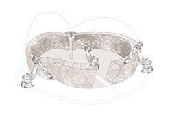
- Inflatables as scaffolding : not precise for complex geometry
- Freemason : Potential further explored
Phasing of the construction sequence in such a way that freemason construction could be utilised is explored futher.
gradual slope construction
gradual lift construction
secondary support construction
ccxxviii ccxxvii Architectural Association Arctic Recalibration
phase
Phasing of the fabrication process of the global geometry
stages of construction
An overview of the stages of construction in the design process
TOLERANCE DEVIATION :
The proposed system is a high precision system with no integrated tolerance in the geometry or toolpath proposed itself. However, during the production and fabrication process there is the possibility of minor errors due to tolerances of the machines [CNC machine, Kuka KR 60] itself. CNC machines have a tolerances of 5 MM while Kuka Robots have a tolerance of 20 MM. This slight deviation due to machine tolerances could build up and create a larger deviation in the final product. The construction process aims to mitigate the potential deviation that could occur.
TOLERANCE MITIGATION : As multiple robots collaborate to fabricate the structure, it becomes necessary to phase the fabrication process. This process of phasing also allows for structurally sound fabrication by mitigating tolerances during the construction process.
The construction phasing is divided into -
- Units
- Seam units
- Keystone cap units
As seen in the image alongside, the main units are constructed two at a time with successive units being constructed simultaneously. Once, a specific height is reached, which is predetermined from increment analysis done previosuly, the connecting tolerance seam is then constructed taking into account any deviations that have built up in either enuts due to machine tolerances, thus, mitigating the deviation at this step. This iterative process is followed , following a sequential path indicated in the diagram alongside, such that any minor or major deviation is mitigated at every step of the unit construction thus, resulting in a precisely fabricated geometry.
Once, the entire structure is constructed to a predetermined height, the final stage is the construction of keystone caps. These keystone caps mumst be constructed separately and then placed in their specific positions.
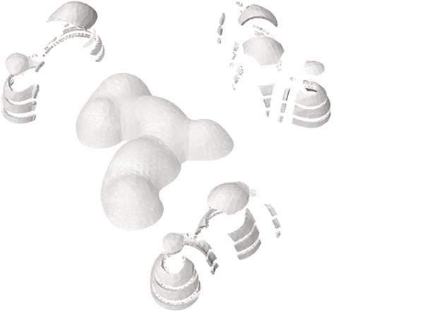
ccxxx ccxxix Architectural Association Arctic Recalibration
Global sequence successive units
seam keystone cap
ke Y stone ca P construction
An overview of the stages of construction in the design process
KEYSTONE CAP CONSTRUCTION :
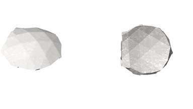
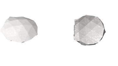
The keystone caps are constructed in several parts. A rough mound of unused peat is placed as a temporary support on the ground. The caps are divided into symmetrical arches. The arch 1 is first constructed over the mound of peat, followed by the two parts of arch 2 simultaneously which connects to arch 1. Following that parts 3 are constructed and finally part 4. The cap unit is held together with the help of cables to maintain its position as it is lifted off the ground and placed as keystones pieces into the existing construction. The cables are then removed. These keystone cap units act in a similar manner to keystones in arches, putting pressure into the existing structure and keeping the whole structure in complete construction.
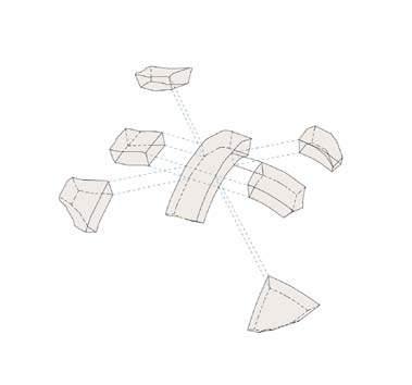
ccxxxii ccxxxi Architectural Association Arctic Recalibration
1 2 2 3 3 4 4 1 2 2 3 3 4 4
Cable [Kept in position during assembly process]
Keystone cap sequence : symmetrical arches
The placement of the keystone cap unit is the last stage of construction.
evaluation
Evaluation of system against existing construction systems
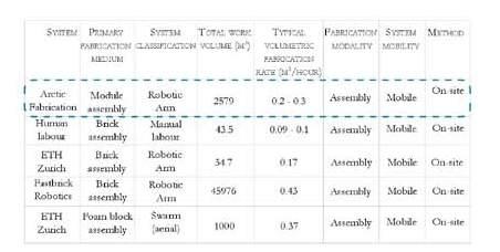
C OMPARISONS WITH EXISTING CONSTRUCTION METHODS
Leveraging digital manufacturing techniques to create buildings enables novel structural designs, improved structural performance, and greater construction efficiency. Use of the proposed techniques would change the cost structure of buildings to be based on total raw material cost, rather than on geometric complexity. Automation of the construction process also simplifies logistics, reduces construction time, and decreases labor costs. Having a correct time prediction is also very useful for planning purposes and ensuring that a project finishes on time. Last, robotic construction would decrease the number of injuries and deaths in the construction industry by reducing human exposure to many of the dangerous and laborious tasks involved in constructing in the Arctic’s hostile conditions.
As an example, a preliminary financial analysis was conducted to compare the proposed fabrication system with traditional construction methods for an average-sized one-story structure 32 Estimates from construction workers were used to calculate costs for pre fabricated aluminium construction, and included human labor for the construction system. For the purpose of the estimate, finishing costs and interior walls were not considered for all techniques, and the added long-term financial benefit of the thermal insulation for energy savings was not considered. This analysis shows that the cost of the proposed system would be 27% less expensive than traditional pre fabricated methods. While the initial invesment of robots would be high, due to their continuous over time the investment would gradually pay off. Most of these cost savings come from labor costs, but transportation volume costs (defined as the volume required to transport construction materials to the worksite) are also substantially smaller to none for the proposed system. These estimates strongly support the fiscal feasibility for the proposed material and fabrication technique, showing that it will not only save time and increase safety but also lower costs for a better more adapted cuilding structure.
C OMPARISONS WITH EXISTING AUTOMATED CONSTRUCTION RESEARCH :
An important lens for evaluating the contributions of this research is in the context of other large-scale automated construction systems that exist today. However, the diversity of automated construction systems in development today makes it challenging to find a common set of metrics for intersystem comparison. In addition to variations in system size and intended task, automated construction systems have been designed to leverage a huge range of fabrication processes, which are frequently difficult to compare.
In light of these challenges, a basic analysis using two metrics that can provide some insight into the relative performance of different automated construction systems and that can be easily estimated if exact values have not been published for a given system are proposed. The first metric is the total work volume that the system can reasonably reach during a fabrication operation. This estimates the scale of the structures that a given system can produce. The second metric is the typical maximum volumetric fabrication rate a system can achieve with its default fabrication process. This provides a measure of how rapidly a given system can produce structures. Together, these two metrics give a rough sense of a system’s overall performance in executing automated construction tasks 33
these metrics for a selection of automated construction systems that either are in active development or have been developed within the past 5 years
ccxxxiv ccxxxiii Architectural Association Arctic Recalibration
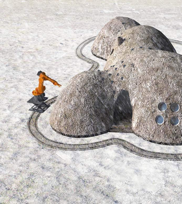

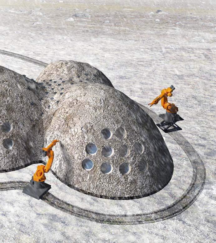
ccxxxvi ccxxxv Architectural Association Arctic Recalibration
Render - showing the fabrication process and the collaborative working of the robots.
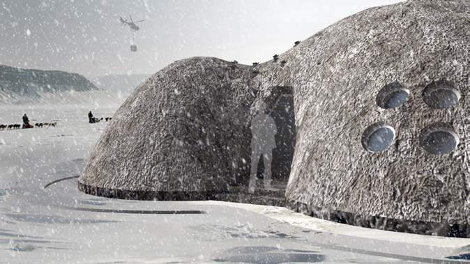
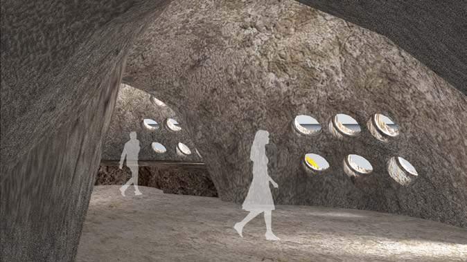
ccxxxviii ccxxxvii Architectural Association Arctic Recalibration
Render - Exterior Viewshowing the relation between structure scale and human scale
Render - Interior view - showing the variation in space derived through sectional variation
vii . architectural P ro P osal
ccxl ccxxxix Architectural Association Arctic Recalibration
introDuction ......................................................................................241 assemblY sequence .....................................................................................243 sYstem Details .....................................................................................245 sectional variation ....................................................................................247 centraliseD Distribution ....................................................................................249 energY ....................................................................................253 sequential occuPation .....................................................................................257
intro D uction
This section illustrates assembly details and relevant variations of the proposed building type
OVERVIEW
The relevant system details demonstrate the association of various components in the proposed material system. It is important to note that a wide range of other possibilities for material speci fi cations might be pursued as the system is open to all sorts of alterations depending on context speci fi c availability.
Variations of the dwelling type are discussed. Strategies are elaborated for volumetric differentiation; through sectional variations. These have begun to indicate possibilities of designing for interior partitions and thermal zones.
One housing unit is illustrated in detail to define the erection sequence.
The notion of a centralised utility conduit has been elaborated further to illustrate how it can be designed within a pedestrian network at the scale of the settlement, using many of the guide parameters discussed so far. This ensures year-round pedestrian access while also expediting maintenance of utilities.
Finally, a comprehensive settlement design is described in steps. Considerations of time, an important factor in sequential occupation, are demonstrated as a time-based transformation between peat harvesting and a construction sequence.
ccxlii ccxli Architectural Association Arctic Recalibration
assembl Y sequence
The erection sequence of one unit is defined
I. RING FOUNDATION :
First, a ring foundation is cast along the edge of the structures geometry. As, the forces mainly flow along the wall and into the ground a ring foundation is deemed sufficient.
II. CONCRETE SUBFLOOR
III. UNDERFLOOR HEATING
IV. WATERPROOF LAYER
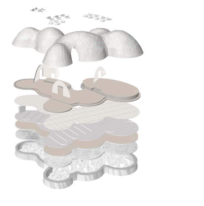
V. PEAT LEVELS :
VI. LIGHTWEIGHT WALL :
The second step is to create a concrete subfloor so that there is an equal distribution of forces and no diffrential settlement occurs.
Next an underfloor heating system is set up based on experiments previously conducted utilising ‘Strand’ analysis
A water proof layer is then placed over the underfloor heating system to act as a buffer between the heating system and the peat floors.
Peat levels are then created using dried large scaled peat plates.
Lightweight acoustic wall panels are proposed, that can be placed based on the users discretion to increase privacy within the sleeping units wherever required.
VII. PEAT SHELL :
The peat segmented shell is then assembled according the the logic previously explained in Global assembly strategy’ on pg 118.
VIII. SNOW CATCHER
Snow catchers are placed last along the seams of the structure where snow is bound to accumulate. Snow catchers are placed to increase the collection of snow till the required amount such that the snow acts as additional insula -
Snow catcher
Waterproof membrane
Windows
Peat segmented shell
Lightweight walls
Peat levels
Waterproof layer
Underfloor heating system
Compacted peat layer
Concrete subfloor
Stones
Ring foundation
Exploded axometric detail of housing a housing unit
ccxliv ccxliii Architectural Association Arctic Recalibration
s Y stem D etails
Detailed drawings and explanations of material requirements for details of proposed structure
WINDOW DETAIL
1. Screws
2. Aluminium clamps
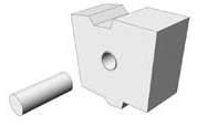
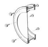
3. Window transom
4. Steel window frame
5. Double glazing
The windows are all of uniform dimension, and are fitted into panels before the assembly process begins.
AIR VENT
1. Radius = 0.1M
2. Waterproof layer
3. Removable peat component
4. Peat panel
A hole for ventilation, 0.1 m in radius, is made in the sides of the main chamber and it is pierced only when stale air has to be released. 87
1 2 3
SNOW GUARD BRACKET
1. Screws
2. Leverage point
3. Flexible polycarbonate angle bracket
Snow guards are installed in multiples along the seams of the structure. Since the seams are pronce to collect snow, snow guards are placed to expedite the process of snow collection such that enough snow accumulates so that it can act as further insulation.
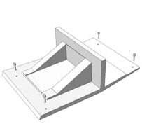
ccxlvi ccxlv Architectural Association Arctic Recalibration
1 2
3 4 5
1
3 4
2
RESIDENTIAL TYPE
Section AA’
sectional variations
Integrated strategies for network design
RESIDENTIAL TYPES
Spatial variation is created through sectional variation by creating seams in the structure that create the allusion of separate domes within one unit. Spatial diffrentiation is further increased by the creation of levels in different spaces. With common spaces raised by 0.2M and sleeping spaces raised by 0.7M above the floor height based on native housing patterns.
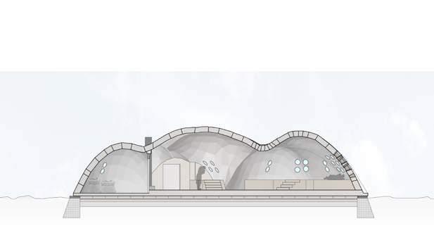
Variation of the proposed type might be integrated into the open use of the house, particularly incorporating the parking and storage of snowmobiles, ATVs, boats, hunting equipment, and winter gear.
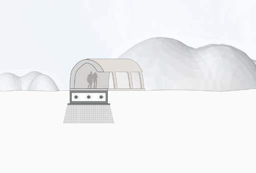
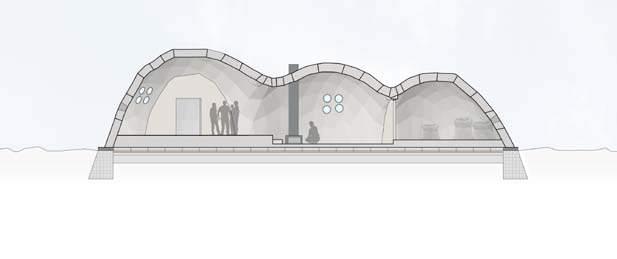
COMERCIAL TYPEPROTECTED WALKWAYS
One common danger of arctic environments is the presence of “black ice,” a thin coating of glazed ice on a surface. As not always immediately visible, icy pedestrian paths pose a great danger as the frequent cause of slips and trips. One way to prevent an icy surface from forming and keep pedestrians safe is the use of covered walkway.
RESIDENTIAL TYPE
Section BB’
COMMERCIAL TYPE
Section CC’
ccxlviii ccxlvii Architectural Association Arctic Recalibration
Storage space Common space Sleeping space Storage space Common space Domestic space [kitchen]
centralise D resource D istribution
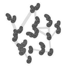
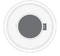
Integrated strategies for network design
NETWORK DESIGN OPPURTUNITIES
Centralised networks, often refered to as “utilidors” in the Arctic, are enclosed utility conduits that protect essential utilities such as water and sewage from permafrost and the extreme environment. Reinventing these functions within a pedestrian network ensures their accessibility for ease of maintenance circulation.
They are not normally used to carry wiring for electric, telephone and television service, which are usually suspended from poles.
DESIGN Utility tunnels ‘utilidors’ are common in very cold climates where direct burial below the frost line is not feasible (such as in Alaska, where the frost line is often more than 5.5 m below the surface, which is frozen year round).
Once the robotic rail path base is defined in the “Rail Path detail” on p. I27 have been developed, the next design development consists of interpreting and designing these networks as pedestrian circulation.
ARCTIC PIPE
Metal jacket
H/D Polyurethane
PVC/HDPE carrier
Control censor
Pipe Insulation
Temperature limit censor conduit heating cable
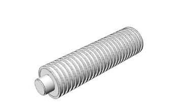
ccl ccxlix Architectural Association Arctic Recalibration
Robotic rails converted to pedestrian pathways
UTILIDOR AS WALKWAYS

The incorporation of a thin [100MM] vaulted peat system creates a series of “snow fences” which has two functions which ensure year-round functionality.
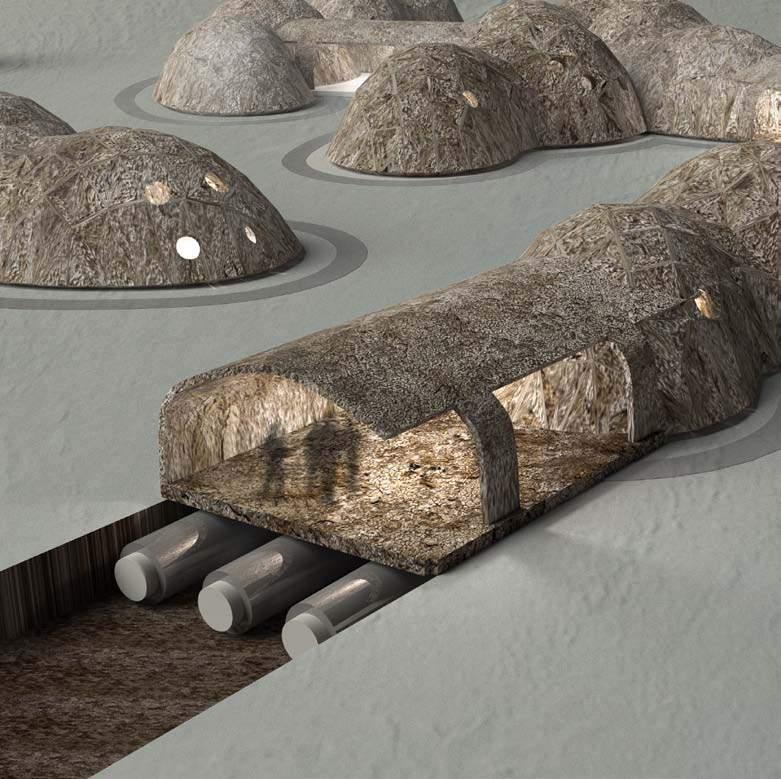
Firstly, the partial cladding of the surface oriented to prevailing winds protects the path from the accumulation of snow. This is easily achieved with thin peat plates assembled in the correct orientation. Secondly, the inclusion of a lighting system ensures safe use during the 22 hour dark winter months.

Water delivery
collection Electricty/Gas Snow/wind fence Light post Wind direction cclii ccli Architectural Association Arctic Recalibration
Sewage
Utilidor as walkway
energ Y resources
Potential energy harvesting methods
WIND ENERGY : Arctic methane release is the release of methane from seas and soils in permafrost regions of the Arctic. While a long-term natural process, it is exacerbated by global warming. This results in a positive feedback effect, as methane is itself a powerful greenhouse gas.
Sustainable energy is a dif fi cult subject in the Arctic. The region is facing economic opportunity with resource extraction as its coal and oil sources are becoming easier to exploit with climate change. In terms of renewable energy, solar energy is also quite challenging- the Arctic Circle de fi nes the portion of the Earth in which the sun does not set for 24 consecutive hours at least once, and does not rise for at least 24 consecutive hours.
The high winds in the Arctic, however, are quite promising. Wind power in Alaska has the potential to provide all of the electricity used in the U.S. state of Alaska. The incorporation of wind harvesting units is deemed worthy of further exploration for Arctic settlements.
Methane is released from Arctic soils not only in the short summer period but also during the bitterly cold winters. It seeps naturally from the soil over the course of the year, but climate change can warm the soil enough to release more methane from organic matter that is currently stable in the permafrost. The harvested peat sites [thermokarst drained lake basins] provides a large potential for methane harvesting and is worthy of further exploration.
ccliv ccliii Architectural Association Arctic Recalibration
METHANE HARVESTING :
sequential occu Pation
Integrated strategies for network design
SEQUENCE
The following images illustrate the sequential occupation and construction of various components at the scale of the autonomous cluster based on the defining parameter; the weather cycle in the Arctic. This entire ‘assembly’ stage can succesfully only be carried out during the winter months of the Arctic.
SITE PREPARATION : FOUNDATIONSHOUSING UNIT & ROBOTIC RAIL :
HOUSING UNITS COMPLETION INFRASTRUCTURE :
The first step is the levelling of the terrain. This step can take place only during the winter months when the permafrost is forzen and thus ground conditions are accurate for onsite assembly process.
The foundations of the robotic rail path must be laid out first, to support the weight of the robots on the rails.
As the foundations are complete the robots are set up and carry out the construction of all the housing units following the sequence of ‘global construction’ previously defined.
Once the overall assembly of the housing units is complete; the robotic rails are disassembled and the pedestrian pathways are constructed.
cclvi cclv Architectural Association Arctic Recalibration
cclviii cclvii Architectural Association Arctic Recalibration viii . conclusion conclusion .........................................................................................10
material an D fabrication s Y stem
The potentials and limitations of the project interms of the material and fabrication syystem developed
OVERVIEW
The proposed system proves to be an appropriate building strategy for the complex Arctic environment. The use of sphagnum peat as a building material promises to address challenges of material scarcity, reconfigurability,and thermal performance. Under the assumption that there is rising economic and strategic interest in pioneering the Arctic, it may well respond to a housing de fi cit and future demands within a sustainable framework that is environmentally responsible and resource-efficient throughout a settlement’s life-cycle from siting and construction, to modification and deconstruction.
The building types developed differ significantly from the current Arctic alumnium prefabricated flat packs. The dome-like geometrical variations that resulted from the requirement of increased solar radiation has the effect of creating heat zones in the interior. When compared to traditional uses of Arctic homes, this approach is more suited to the way the northern societies of Alaska occupy their homes where fewer and larger common spaces are preferred over a larger number of smaller private spaces x Given the role of flat peat panels in the designed assembly sequence, the range of morphological variation is limited to planarised segmented shell assemblies.
The research approach described represents not only a systematic methodology and fabrication process, but also pushes the boundaries toward a new type of architectural frontier. An integrated computational design process embedded in the synthesis of material, form, and performance allows derivation of a complex structure which is capable of eventually accomodate a unique architectural typologies. These would be materially efficient and would result in a reduction of fabrication time.
In order to achieve these goals, a strong coupling is required between material properties, robotic fabrication constraints and digital design models.
MATERIAL SYSTEM :
The material has been explored deeply through the slow [compacting] prototyping experiments. Through these experiments, we were able to assess and record the limits of the material under various conditions. The results obtained were used as a baseline to provide data for digitizing the material. Over the course of the experiments, we faced several challenges in terms of controlling the drying process due to its sensitivity to the environmental conditions.
Furthermore, the data collected ensures a more comprehensive control over the material and allows for new approaches that can be explored on a micro, meso, and macro scale.
There are also low transport and construction costs of peat as an abundant, renewable and inexpensive resource. It accounts for 100% of the building’s total mass and can be locally harvested at very low costs.
FABRICATION SYSTEM :
As we were able to integrate the robotic constraints and material system into a design process, a specific compression based fabrication is achieved. As a result, it provided multiple options in terms of tool path exploration and form finding process. A high precision based fabrication system is developed which can be easily achieved due to the highly precise peat panels created and the high-technology robots used for construction.
Further exploration is required into the automatic feeder.
Built up mahine tolerances could potentially create a deviation in the last ‘keystone’ panel placed. A feedback data loop needs to be considered in order to address this. By integrating a feedback loop with a sensor to analyze the actual deformation, a real time analysis in terms of the last panel dimension and toolpath can be achieved.
cclx cclix Architectural Association Arctic Recalibration
COMPUTATION PROCESS
Through the examination of the computational process, a complex architectural output was achieved. While integration of a compression only structure [Rhinovault] and planarisation helps simplify the overall physical fabrication process, it created an extremely computationally heavy system. Due to the highly interconnected data from micro, meso, to macro scales, the resulting output required increased computation time, the process becoming computationally expensive.
For further exploration of this concept, a custom Python script would be ideal to streamline this process and address the complexity of the panelisation in conjunction with the doubly curved structures. In addition, robotic simulation and a feedback loop connected to an appropriate monitoring system would be capable of mitigating potential fabrication errors.
conclusion
Arctic Recalibration; developing a method of construction to adapt to the changing physical and economic landscape of the Arctic
ARCTIC RECALIBRATION
Climate change is faster and more severe in the Arctic than in most of the rest of the world. The Arctic is warming at a rate of almost twice the global average, resulting increasing strategic and economic interest in the Arctic will inevitably cause an increase in the population living in the arctic mainlands. While local existing settlements are being forced to move inland and new internatioinal urban agglomerations are predicted to form, this project proposes a system that responds to the formation of these clusters with the ever-changing context of the Arctic due to global warming within the near future (<2050).
In order to make this proposed strategy more than just an utopic vision, great care was taken to drive the concept of resource autonomy with an integrated low-technology material but high technology automatic fabrication, building and settlement type. Early material experiments were carried out as physical prototypes during the stage of this work. These were abstracted digitally for exploration and evaluation across various scales from individual panels, patch assembly, building types, building arrangements, and ultimately as the automated construction of the housing units.
The work has been contextualised speci fi cally in the town of Barrow of Alaska for the abundance of information available, but the ideas embedded are intended to be easily replicated and readjusted throughout the fast changing Alaska mainlands.
An Arctic Recalibration is a holistic approach to building at high latitudes. An experiment to combine several different elements in the buildings, settlements and landscape, to form a new type of low-technology material with a high-technology robotic assembly system to create a new climatically adapted material and fabrication system.
cclxii cclxi Architectural Association Arctic Recalibration
cclxiv cclxiii Architectural Association Arctic Recalibration ix . a PP en D ix PsueDocoDes ............................................................................................265
Create a grid of (n) points with the x and y distance 12 m, where n is the number of initial primitives.
Move the base pints in xy direction ununiformly (Gene 4)
Move the points on the specific distance (Gene 1) in the positive y direction with increment +-35° (Gene 5)
Apply the radius (Gene 3) and height (Gene 2) to the domes with the centre in the created points.
Create the transitional spaces between the domes.
Find the projection of the longitudinal and transversal projections of the primitives.
Draw the outline of the base of the primitive from the points on a distance of the robotic reach from the longitudional and transversal projections.
Create a closed polyline from combining the each primitive outlines.
Calculate the distance between morphology surface points and the polyline (the rail)
If the distance for at least one point is less than the robotic reach then:
a. Rotate the lateral primitives until the points are accessible or move the lateral primitives in xy direction (specific gene) until every distance is less then the robotic reach
b. Else: End
Input the output of the shell
Create the triangulated form diagram
Create the dual force diagram
Create the equilibrium shell position with the given height constraint with equal forces
Loop start – Move the control points of the force diagram
Modify the equilibrium shell in real time
Is the desired morphological differentiation achieved?
No: repeat steps (5-7)
Yes? End Loop
Offset the shell with the given shell thickness
cclxvi cclxv Architectural Association Arctic Recalibration
i ii iii iv v vi Global settlement Pattern P s e u d o c o d e vii viii ix x xi
i ii iii iv v vi RhinoVault P s e u d o c o d e vii viii
UV Tesselation Lines
Select a mesh.
Create a bounding box and select its bottom surface
Copy the surface with the equal distance – panels height
Intersect mesh with the surfaces to create isocurves.
Extract control points of isocurves.
Calculate the utilisation values with given wind and gravity forces
Assign the utilisation value to each control point of the isocurves accordingly to the position on the surface
Move the points in z direction accordingly to the utilisation value within a defined domain: if utilisation is high move up, if low, move down.
Project control points back onto the mesh
Create modified isocurves out of moved control points.
Analyse force flow on the mesh and extract force lines.
Measure the distance between the lines
Start loop. If the distance is smaller than half of allowed width of the block: cull the line
Else: End loop
UV Tesselation Lines
Intersect resulting forcelines with new isocurves.
Measure the distance between the points
Start loop. If the distance is smaller than half of allowed width of the block: cull the line
Else: End loop
Connect remaining intersection points into closed polyline horizontal cutting lines.
From remaining intersection points draw a perpendicular to the next upper isocurve
Cull each even line on the even isocurves and uneven line on uneven ones to create staggering.
Project staggered lines and horizontal cutting lines back to the mesh to create tessellation lines
Cut the mesh with the lines to create separated panels.
cclxviii cclxvii Architectural Association Arctic Recalibration
i iii iv v v vi
P s e u d o c o d e vii viii ix x xi xii xiii ii
xiv xv xvi xvii xviii xix
P s e u d o c o d e xx xxi xxii
Planarisation : Phase I
Divide doubly curved patch into doubly curved panels with tessellation lines
Select doubly curved panels
Extract panels boundaries
Explode boundaries
Extract corner points of the boundaries
Rebuild panel boundaries out of straight lines into closed polylines
Planarisation : Phase II
Select corner points of the boundaries and then select initial doubly curved patch
Define equilibrium coplanar position for the corner points of the panels
(Start loop) While moving points towards equilibrium coplanar position keep the points on the initial doubly curved surface (project back on it)
If coplanarity of the points is not achieved ---- repeat
If coplanarity of the points is achieved ---- (end the loop)
Connect new corner points into closed polylines
Create surfaces out of the polyline boundaries (outer surfaces)
Planarisation Phase III
Offset surfaces in their normal direction towards internal side of the patch to create inner surfaces.
Split inner surfaces by intersecting with their neighbours resulting in new inner surfaces.
Define centre of new split inner surfaces
Define centre of the outer surfaces
Select the inner surfaces whose centre points are the closest to the centre of their corresponding outer surfaces.
Loft outer and inner surface boundaries to get sides of the voussoir.
Join inner, outer and side surfaces of each panel into resulting closed Breps.
cclxx cclxix Architectural Association Arctic Recalibration
i ii iii iv v vi
P s e u d o c o d e
viii ix x xiii xi xii
P s e u d o c o d e xiii
xiv xv xix xvi xvii xviii
P s e u d o c o d e xx
Select the voussoirs.
Horizontal interlocking:
Deconstruct voussoirs into surfaces
Define corner points of the surfaces
Calculate average z value of all points for each surface. Surface with highest z value is the top surface of the voussoir, while surface with lowest z value is the bottom surface of the voussoir.
Top surfaces: female interlocking:
Intersect top surfaces with the outer surfaces of the voussoirs to form lines.
Select centre points of the lines and offset them in both directions along the lines keeping half of interlocking element width value.
Offset the lines on outer surfaces by depth of interlocking joint in the direction of the panel centre.
Select centre points on the offset lines and offset them in both directions along the lines keeping one third of interlocking element width value.
Connect the resulting four points on the outer surfaces into closed polyline trapezoids.
Move the trapezoid’s hypotenuses by one fourth of the interlocking element width towards the centre of trapezoid to create tapering.
Loft two resulting trapezoids and cap the surfaces to create interlocking elements
Detach surfaces of intersection between voussoirs and the interlocking elements.
Lower surfaces: male interlocking:
Intersect bottom surfaces with the outer surfaces of the voussoirs to form lines.
Select centre points of the lines and offset them in both directions along the lines keeping half of interlocking element width value.
Offset the lines on outer surfaces by depth of interlocking joint in the opposite direction of the panel centre.
Select centre points on the offset lines and offset them in both directions along the lines keeping one third of interlocking element width value.
Connect the resulting four points on the outer surfaces into closed polyline trapezoids.
Repeat steps (6-10) for the inner surfaces
Move the trapezoid’s hypotenuses by one fourth of the interlocking element width towards the centre of trapezoid to create tapering.
Loft two resulting trapezoids and cap the surfaces to create interlocking elements
Apply custom scaling value as a tolerance if needed
Attach interlocking elements to voussoirs.
Side interlocking:
Intersect left surfaces with the outer surfaces of the voussoirs to form lines.
cclxxii cclxxi Architectural Association Arctic Recalibration
i ii iii iv v vi Stereotomy P s e u d o c o d e vii viii ix x xi xii xiii xiv
xv xvi xvii xviii xix Stereotomy P s e u d o c o d e xx xxi xxii xxiii xxiv xxv xxvi xxvii
e u d o c o d e
Offset the lower end points up by the interlocking distance height.
Move these points perpendicular to the lines by the interlocking distance width.
Draw lines perpendicular to this to the ends of the outer surfaces.
Intersect left surfaces with the inner surfaces to form lines.
Repeat the steps (26-27), moving upper end points down by the interlocking distance height.
Connect resulting interlocking outlines by lofting and cap it to create the interlocking elements
Detach surfaces of intersection between voussoirs and the interlocking elements.
Connect the interlocking elements with the surfaces
Intersect right side surfaces with the outer surfaces of the voussoirs to form lines.
Repeat steps (26-31)
Attach interlocking elements to voussoirs.
create a grid of (n) points with the x and y distance 12 m, where n is the number of initial primitives
Move the base pints in xy direction ununiformly (Gene 4)
Move the points on the specific distance (Gene 1) in the positive y direction with increment +-35° (Gene 5)
Apply the radius (Gene 3) and height (Gene 2) to the domes with the centre in the created points.
Create the transitional spaces between the domes.
Find the projection of the longitudinal and transversal projections of the primitives.
Draw the outline of the base of the primitive from the points on a distance of the robotic reach from the longitudional and transversal projections.
Create a closed polyline from combining the each primitive outlines.
Calculate the distance between morphology suface points and the polyline (the rail)
If the distance for at least one point is less then the robotic reath then:
a. Rotate the lateral primitives until the points are acceseble or move the lateral primitives in xy direction (specific gene) until every distance is less then the roboric reach
b. Else: End
cclxxiv cclxxiii Architectural Association Arctic Recalibration
xxviii xxix xxx xxxi v vi Stereotomy P
viii ix x xi
s
i ii iii iv v vi Robotic rails P s e u d o c o d e vii vii vii vii
i ii iii
Pick: Define any line and point of the feeding table.
Define bottom the surface to be placed on.
Select the side for the robot to pick the panel with the adjacent side surface of the block towards the robot.
iv
Intersect this surfaces to form the line. This line is the alignment line of the block. The end of this line, which is the most remote to the gripper is the alignment point.
Align panel’s line and point with the line and point on the feeding table while positioning the block. This is the pick position of the block.
Select the side of the block to be picked by robot – the one whose centre is the closest to it.
vii viii
Draw a surface perpendicular to the outer surface of the block from the outline of this side – grip surface.
ix
Place:
Define Save point 1 – offset the gripping point in the grip surface in positive z direction by 0.3m.
x xi xii xiii
P s e u d o c o d e xvi xvii xviii xiv
Adjust the gripping plane of the origin – this is Safe plane 1
Define the desired position of the block in resulting structure.
Reorient the grip surface position accordingly to the new position of the block – this is “place” plane
Define the previous neighbouring block.
Select the surface of contact between this 2 blocks and find its centre.
Select the outer line of the surface’s boundary – this is the placing direction.
Offset the “place” gripper position plane in placing direction with positive z value by 0.6. This is Safe Plane 2
Offset the “place” gripper position plane in placing direction with positive z value by 0.3. This is Safe Plane 3
cclxxvi cclxxv Architectural Association Arctic Recalibration
Define the centre point of this surface – this is the reference point for the centre of the gripper – pick gripper position. v vi
Robotic ‘Pick and Place’
P s e u d o c o d e
xv
After the block is picked by the robot, reorient the gripper sequentially to pick plane, Safe plane 1, Safe plane 2, Safe plane 3 and place plane with the block in it.
Robotic
‘Pick and Place’
Robotic Simulation P s e u d o c o d e
Initial position – 1 st axis - pi/4, 2 nd axis pi/2, third axis 0, 0,-pi/2,0. Gripper opened.
Transfer to Safe point 1
Transfer to Pick position.
Wait Close the gripper
Transfer to Safe point 1
Transfer to Safe point 2, reorient the block accordingly to Safe plane 2
Transfer to Safe plane 3
Transfer to Place Point Wait Open the gripper.
Transfer to Safe plane 3
Transfer to Safe point 2
cclxxviii cclxxvii Architectural Association Arctic Recalibration
i ii iv v vi viii
ix xi xii vii iii x xiii
cclxxx cclxxix Architectural Association Arctic Recalibration x . references Design ambition ......................................................................................281
references
INTRODUCTION
1. The prevalence of challenging behaviors: a total population study. Emerson E1, Kiernan C, Alborz A, Reeves D, Mason H, Swarbrick R, Mason L, Hatton C.
2. The prevalence of challenging behaviors: a total population study. Emerson E1, Kiernan C, Alborz A, Reeves D, Mason H, Swarbrick R, Mason L, Hatton C.
3. Bone Weathering in a Periglacial Environment: The Tayara Site (KbFk-7), Qikirtaq Island, Nunavik (Canada) Dominique Todisco and Hervé Monchot
4. Robinson, D.A. and A. Frei. 2000. Seasonal variability of Northern Hemisphere snow extent using visible satellite data. Professional Geographer
5. Construction Intelligence Center, Global Construction Outlook 2020 (Construction Intelligence Center, 2015)
6.International Association for Automation and Robotics in Construction, Robots and Automated Machines in Construction (International Association for Automation and Robotics in Construction, 1998).
7. S. Lim, R. A. Buswell, T. T. Le, S. A. Austin, A. G. F. Gibb, T. Thorpe, Developments in constructionscale additive manufacturing processes. Autom. Constr. 21, 262–268 (2012).
DOMAIN
8..MEASUREs Global Record of Daily Landscape Freeze/Thaw Status. Version 2. Boulder, Colorado USA: NASA DAAC at the National Snow and Ice Data Center.
9. The prevalence of challenging behaviors: a total population study. Emerson E1, Kiernan C, Alborz A, Reeves D, Mason H, Swarbrick R, Mason L, Hatton C.
10. Bone Weathering in a Periglacial Environment: The Tayara Site (KbFk-7), Qikirtaq Island, Nunavik (Canada)
Dominique Todisco and Hervé Monchot
11. Artcic Synthesis, Architecture Association School of Architecture, Alican Sungur & Francis McClosky
12. Construction Intelligence Center, Global Construction Outlook 2020 (Construction Intelligence Center, 2015)
13.International Association for Automation and Robotics in Construction, Robots and Automated Machines in Construction (International Association for Automation and Robotics in Construction, 1998).
14. Lim, R. A. Buswell, T. T. Le, S. A. Austin, A. G. F. Gibb, T. Thorpe, Developments in construction-scale additive manufacturing processes. Autom. Constr. 21, 262–268 (2012).
RESEARCH DEVELOPMENT
15. The prevalence of challenging behaviors: a total population study.
Emerson E1, Kiernan C, Alborz A, Reeves D, Mason H, Swarbrick R, Mason L, Hatton C.
16. The prevalence of challenging behaviors: a total population study. Emerson E1, Kiernan C, Alborz A, Reeves D, Mason H, Swarbrick R, Mason L, Hatton C.
17. Bone Weathering in a Periglacial Environment: The Tayara Site (KbFk-7), Qikirtaq Island, Nunavik (Canada)
Dominique Todisco and Hervé Monchot
18. McNeel, R., RhinoPythonTM: Scripting language in Rhinoceros®, scripting language, 2013. http:// python.rhino3d.com/
19. Construction Intelligence Center, Global Construction Outlook 2020 (Construction Intelligence Center, 2015)
20.Rethinking structural masonry: unreinforced, stone-cut shells & 1 Matthias Rippmann Dipl-Ing PhD candidate, Institute of Technology in Architecture, ETH Zurich, Switzerland & 2 Philippe Block MSc, SMArchS, PhD
21. S. Optimising Stone-Cutting Strategies for Freeform Masonry Vaults Matthias Rippmann1, John Curry2, David Escobedo3, Philippe Block4
DESIGN DEVELOPMENT
22. Davis L, Rippmann M, Pawlofsky T and Block P (2012) Innovative funicular tile vaulting: A prototype in Switzerland. The Structural Engineer 90(11): 46–56.
23. Fallacara G (2006) Digital stereotomy and topological transformations. Proceedings of the 2nd International Congress on Construction History, Cambridge, UK.
24. S. Keating, N. Oxman, Compound fabrication: A multi-functional robotic platform for digital design and fabrication. Robot. Comput. Integr. Manuf. 29, 439–448 (2013
cclxxxii cclxxxi Architectural Association Arctic Recalibration
25. M. Giftthaler, T. Sandy, K. Dörfler, I. Brooks, M. Buckingham, G. Rey, M. Kohler, F. Gramazio, J. Buchli, Mobile robotic fabrication at 1:1 scale: The in situ fabricator. arXiv:1701.03573 (2017).
26. Salt, Architecture Association School of Architecture, Sharon Ann Phillip & Zaqi Fathis
27. Kaczynski MP, McGee W and Pigram DA (2011) Robotically fabricated thin-shell vaulting: A methodology for the integration of multi-axis fabrication processes with algorithmic form-finding techniques. Proceedings of the 31st Annual Conference of the ACADIA, Calgary, Canada, pp. 114–121.
28. Wendland D (2009) Experimental construction of a free-form shell structure in masonry. International Journal of Space Structures 24
DESIGN PROPOSAL
29. The prevalence of challenging behaviors: a total population study. Emerson E1, Kiernan C, Alborz A, Reeves D, Mason H, Swarbrick R, Mason L, Hatton C.
30. The prevalence of challenging behaviors: a total population study. Emerson E1, Kiernan C, Alborz A, Reeves D, Mason H, Swarbrick R, Mason L, Hatton C.
31. Bone Weathering in a Periglacial Environment: The Tayara Site (KbFk-7), Qikirtaq Island, Nunavik (Canada) Dominique Todisco and Hervé Monchot
32. Albu-Schäffer A, Haddadin S, Ott C, Stemmer A, Wimböck C, Hirzinger G (2007) The DLR lightweight robot: design and control concepts for robots in human environments. Ind Rob: Int J 34(5):376–385
33. Construction Intelligence Center, Global Construction Outlook 2020 (Construction Intelligence Center, 2015)
cclxxxiv cclxxxiii Architectural Association Arctic Recalibration
The individual contributions to this thesis are established in the tables alongside INDIVIDUAL CONTRIBUTIONS :

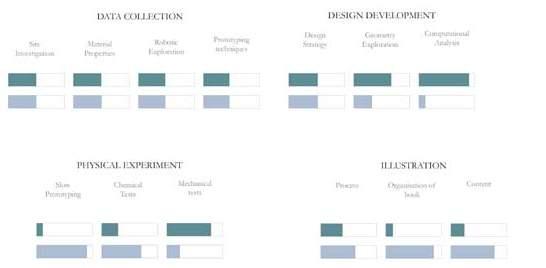
cclxxxvi cclxxxv Architectural Association Arctic Recalibration contribution
Elena Shilova Mithuna Murugesh

cclxxxvii Architectural Association
