Architectural Association | School of architecture | Graduate Programme
DISSERTATION SUBMISSION
Emergent Techonologies and Design program
COVERSHEET FOR COURSE SUBMISSIONS 2009 / 2010
PROGRAMME: Master of Science, Emergent Technologies and Design
COURSE: Emergent Technologies and Design
TUTORS: Michael Weinstock, George Jeronimides
STUDENT NAME(S): BAEK KI KIM
SUBMISSION TITLE: Cellular Composite System for Freeform Fabrication SUBMISSION DATE: 15 October 2010
DECLARATION:
“ I certify that this piece of work is entirely my own and that any quotation or paraphrase from the published or unpublished work of others is duly acknowledged.”
Signature of Student(s):
editorialfinal.indd 1 15/10/2010 08:42
editorialfinal.indd 2 15/10/2010 08:42
Cellular Composite System
for Freeform Fabrication
BAEK KI KIM | MSc
Emergent Technologies
|
Architectural Association School of Architecture editorialfinal.indd 3 15/10/2010 08:42
JUANJO GONZALEZ CASTELLON | MArch
and Design
2009/2010
Contents
editorialfinal.indd 4 15/10/2010 08:42
1. Domain | 008
2. Methods | 028
3. Experiment | 060
4. Design Development | 082
5. Design Proposal | 094
6. Conclusion & Further Development | 110 Image & Diagram Credits | 116 Bibliography | 120 Acknowledgement
Abstract
editorialfinal.indd 5 15/10/2010 08:42
Abstract
This proposal is focused in the development and fabrication of free-form geometries by using a finite number of components. In order to archive that, we will aim our project at 2 main areas of research:
A. The development of a material system that investigates efficient and effective ways to produce, fabricate and assemble three dimensional tiles.
B. The exploration of a geometrical and computational system capable to generate double curved surfaces by the manipulation and variation of a limited amount of components.
editorialfinal.indd 6 15/10/2010 08:42
editorialfinal.indd 7 15/10/2010 08:42
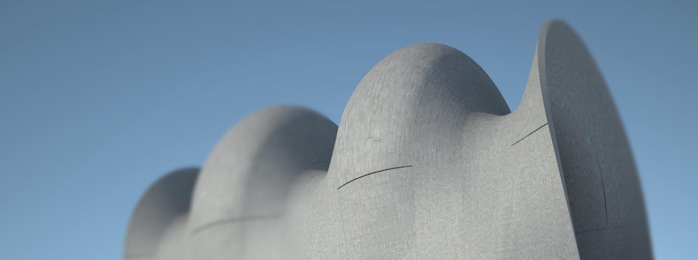
Fig. 1.00 | The Complex vaulting system as the structural arch-system.
1. Domain
editorialfinal.indd 8 15/10/2010 08:42
1.4 Parametric Fabrication 1.5 Summary
1.1 Introduction 1.2 Ceramics
1.3 Vernacular Brick Construction
1.3.1 Catalan Vault
1.3.2 Cohesive Construction System | Rafael Guastavino
1.3.3 Gaussian Vault | Eladio Dieste
009 editorialfinal.indd 9 15/10/2010 08:42
1.1 Introduction
The use and application of free-form geometries has been a constant aspiration in the history of architecture. Nowadays, due to the appearance and development of powerful parametric tools and technologies, this aspiration has become reality. The amazing potential of these tools allows architects to produce and fabricate almost any imaginable form. However, this capability to easily produce and generate complex forms is directly related, in some cases, to a lack of understanding of the geometrical principles behind it. The designer doesn’t need to understand a form to produce it and, consequently, an enormous effort has to be made “a posteriori” in order to make these forms buildable and economically feasible.
On the other hand, there are many precedents in the history of architecture demonstrating that it is possible to build complex and interesting architecture by applying simple logics and smart techniques. Buildings such as La Sagrada Familia designed by Antoni Gaudí or La Atlántida Church by Eladio Dieste are good examples of this. Both buildings were designed and built without computers but with clear geometrical rules and understanding. In addition, both masterpieces were built in collaboration with very skilled manpower and experienced fabricators.
Nowadays, there is a wide field to explore in order to find new methods of design where contemporary parametric tools are part of the design process. In this search, geometry logics and principles can be applied to minimize or even avoid any translation between design and fabrication processes. The aim of this research is to develop a form finding process by the use and application of simple geometrical rules in order to achieve double curved surfaces from a finite number of components. Starting from a simple brick and studying some specific techniques from traditional Catalan architecture, some experiments will be developed in order to improve its performance by using contemporary tools and techniques.
1. Domain | 1.1 Introduction Cellular Composite System | Baek Ki Kim, Juanjo G. Castellon editorialfinal.indd 10 15/10/2010 08:42
011
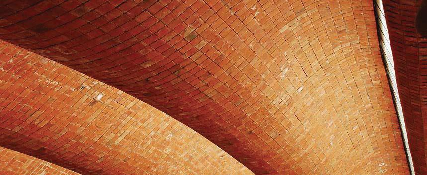
Fig. 1.01 | Port Warehouse.Montevideo. 1977-1979 , Eladio Dieste
Fig. 1.02
editorialfinal.indd 11 15/10/2010 08:42
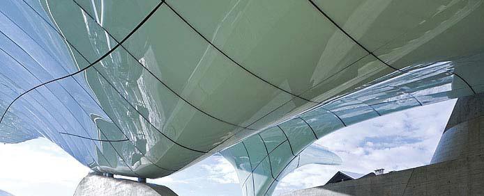
| Nordpark Cable Railway. 2007. Innsbruck, Austria. Zaha Hadid Architects
1.2 Why Ceramics ?
The traditional and colloquial definition of ceramics is simply “fired clay”. However, its etymology comes from the Greek word Кεραμкόϲι(keramikos), meaning, “made of clay”. Ceramic may be used as an adjective describing a material or production process; or as a singular noun, or as a plural noun, ceramics. There is some simplicity and humbleness inherent in ceramic materials. All the raw materials to make ceramics come from the earth (clay) and they just need water and heat to obtain a high quality product. Consequently, ceramic tiles and bricks are highly sustainable materials. Furthermore, ceramics is a local material available in all cultures with a strong connection with the earth and man’s evolution. Its production has been strongly linked to man’s development throughout history improving his living and environmental conditions. Thus, ceramics technology is a good example of man’s progress throughout the ages and witness of his technological evolution1. Even today, ceramics are cutting edge materials in terms of research and new applications.
Regarding its technical properties, the process of firing ceramics confers it not able physical and mechanical properties. Ceramics are hard, they have an excellent compression strength, a high melting point and a good resistance to chemicals2. Moreover, they are waterproof and thermally very efficient when it fired at high temperature and the cost and manufacture of ceramics is sensibly lower than other industries. All these properties make ceramic material very suitable for architecture. In addition, ceramic material is excellent in terms of plasticity, allowing any kind of forms including double curved, and an infinite range of colours and finishing can be applied by glazing techniques and the addition of pigments. With regards to sustainability and environmental factors, ceramics may be produced locally and contain lower embodied energy than many alternative sheathing materials3
On the other hand, it performs poorly under tensile strength, requires firing under high temperatures in order to make it waterproof and, finally, its form depends on a mould. Consequently, the mould-making process is an extremely key factor in this research since the aim is to design and fabricate free-form surfaces. Mould-making can be expensive and time consuming, particularly, when the aim is to produce variation in opposition to the classic flat piece standard repetition.
1. Domain | 1.2 Materiality Cellular Composite System | Baek Ki Kim, Juanjo G. Castellon editorialfinal.indd 12 15/10/2010 08:42
013
editorialfinal.indd 13 15/10/2010 08:42
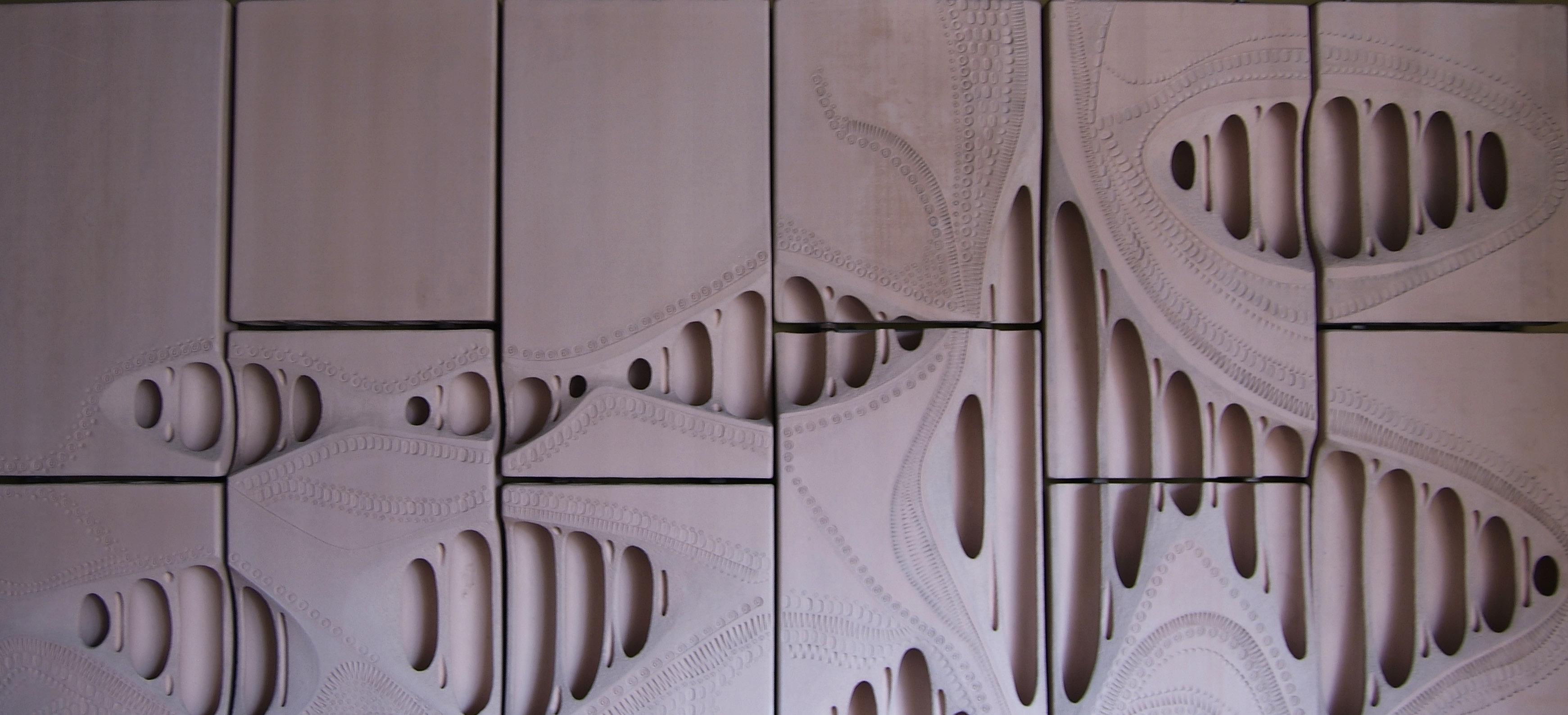
Fig. 1.03 | Toni Cumella. Hand-ground Ceramic Patterns
1.3 Vernacular Brick Construction
1.3.1 Catalan Vault
1.3.2 Cohesive Construction System | Rafael Guastavino
1. Domain | 1.3 Vernacular Brick Construction Cellular Composite System |
editorialfinal.indd 14 15/10/2010 08:42
1.3.3 Gaussian Vault | Eladio Dieste
Baek Ki Kim, Juanjo G. Castellon
015
editorialfinal.indd 15 15/10/2010 08:42
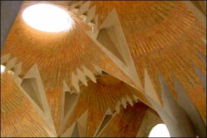
Fig. 1.04 | La Sagrada Familia
1.3.1 Catalan Vault
The Mediterranean tradition of construction is based on the use and application of handmade and humble materials such as ceramics. The brick is an ancient fabrication system, designed and produced in order to build by the addition and specific arrangement of a simple component. A brick is based on a fabrication process where shape and composition are controlled by an industrial process.
Although the first durable constructions were built with stone, brick construction is the first industrial process that is component based. Its constructive logic is based on its prismatic geometry and its combination with mortar for assembly. Brick usage dates from around 10,000 years ago, probably from Mesopotamia and this appearance is a consequence of the lack of stone and wood. Many masonry techniques were developed from the Romans and expanded along the Mediterranean for centuries.
One of these ancient masonry techniques is the Catalan vaulting system4. Although its origin is from different countries along the Mediterranean, Catalonia in Spain was the place where this technique achieved the highest level of quality and refinement.
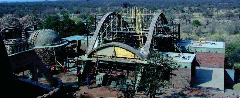
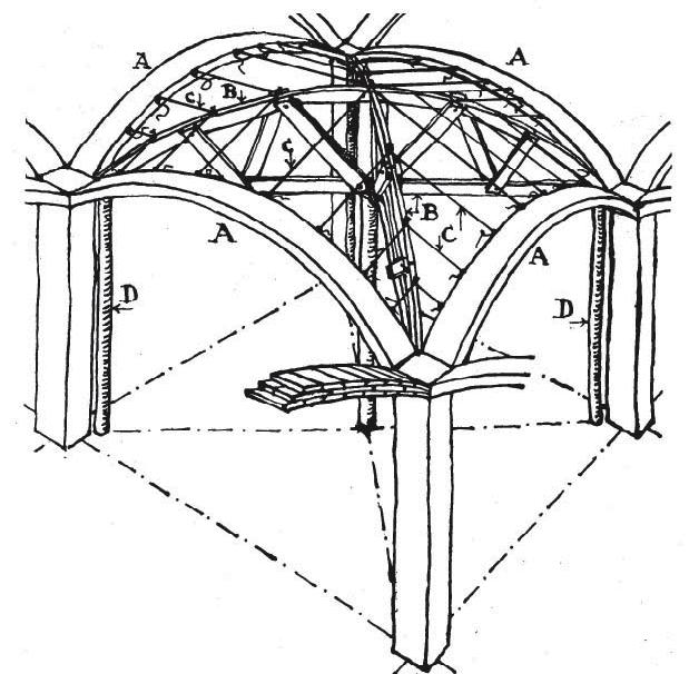
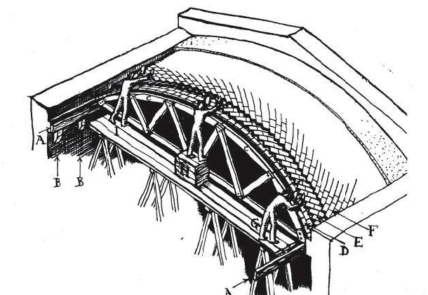
The Catalan vaulting technique relies on fast setting mortar for construction and structural form for stress5. It is based on an specific arrangement of thin bricks (Fig. 1.06) called rasillas6. A rasilla is a simple brick, thinner than the standard one (24 x 11,5 x 2,5 cm). This technique can be applied in the construction of different vaults typologies such as groined vaults (Fig. 1.08) or cylindrical vaults (Fig. 01.09). One of the main advantages of a Catalan vault is that it can be built without formwork assembling the planar bricks in several layers. The first one is assembled using fast-setting plaster and the rest with cement mortar (slower setting but more resistant). Previously, the planar bricks were used by the Romans as a lost formwork for concrete. Furthermore, a Catalan vault is an economic construction system and it has a very efficient structural performance covering large spans.
1. Domain | 1.3 Vernacular Brick Construction Cellular Composite System | Baek Ki Kim, Juanjo G. Castellon editorialfinal.indd 16 15/10/2010 08:42

017
Fig. 1.05 | Construction of a groin vault using catalan vault technique. South Africa. Michael H. Ramage
Fig. 1.06 | Comparison of stone (A) and rasilla (B) bond system
Fig. 1.08 | Preparation for a groin vault construction
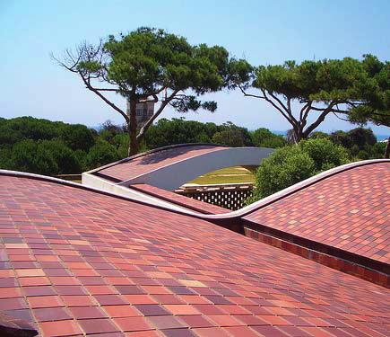
Fig. 1.07 | La Ricarda House. Barcelona. Antoni Bonet
editorialfinal.indd 17 15/10/2010 08:42
Fig. 1.09 | Cylindrical Vault construction with slidding truss
Case Study: Pines Calyx (MIT)
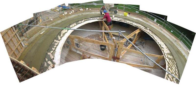
Researchers from the Massachusetts Institute of Technology (MIT) studied the Catalan vault system and applied it in the design and construction of the vaulting at the Pines Calyx, Kent. The following study case describes the steps for a Catalan vault construction applied to this particular project7.
‘Timbrel’ or ‘Guastavino’ tile vaulting creates an arched ceiling in a building, which is capable of supporting very heavy loads even during a severe fi re. Other advantages to this method are that it is extremely economical, quick to build (domes the size of St. Paul’s Cathedral can be built in a few months without needing false work or a wooden structure to support them during construction), and it is environmentally sound, as it can use locally-sourced materials and a minimal amount of concrete. The method of construction has been used in various parts of the Mediterranean and dates back more than 600 years. Between the 1870s and 1930s, through Rafael Guastavino, the method was successfully used within many large buildings on the Eastern seaboard of the USA. Today, only a few craftsmen are practicing this method of vaulting – mostly in Spain. The ‘Timbrel’8 technique involves using tile, laid on edge and built up in layers to produce the necessary structural thickness. In this case three layers of tile were used, with a waterproof cement screed covering the extrados acting as a fourth layer. All the tiles used are approximately 300 x 150 x 20mm. Each layer must be built in concentric rings and each ring must be completed before beginning the next. Firstly there are wooden formers attached to the central pole. The shape that this first layer has to achieve is shown by 2 types of formwork. The first layer is fixed using plaster to hold the tiles in place (Fig. 1.10). Radiating out from the central pole are springing lines at regular intervals around the circumference. In between each of the formers, a cintrel9 is used. Heavier grog tile is used for the 2nd and 3rd layers. Both these layers are fixed using cement mortar and are fixed directly on top of the first layer. Each layer is built using a different bond. The first layer uses stretcher bond, the second has the tiles laid at a 45° angle and the third uses soldier bond. The finished roof is extremely strong and can take the loads of the overlying layers of insulation, earth and turf without any stresses to the structure10
1. Domain | 1.3 Vernacular Brick Construction Cellular Composite System | Baek Ki Kim,
Castellon
Juanjo G.
editorialfinal.indd 18 15/10/2010 08:42
Fig.
012 | Top view of the vault
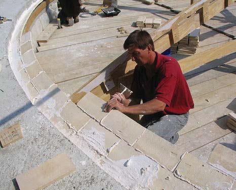
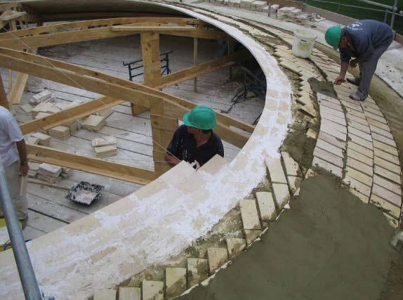
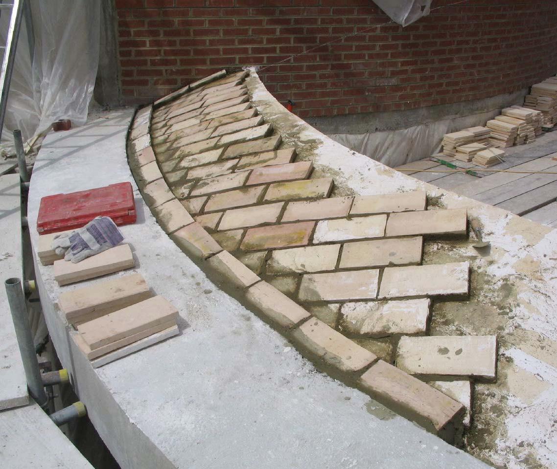
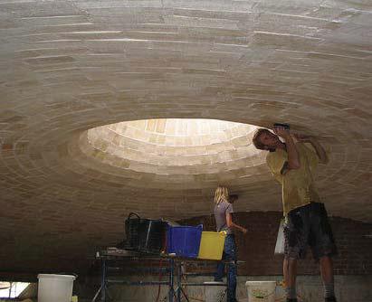
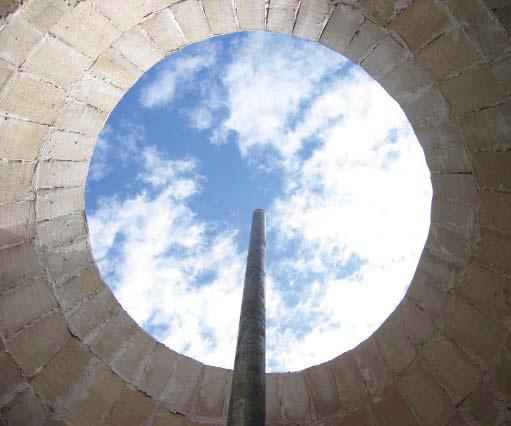 Fig. 1.10 | Fist layer setting
Fig. 1.13 | Third layer of tiles at 90º
Fig. 1.11 | Second layer arranged in 45º pattern
Fig. 1.14 | Interior view
019 editorialfinal.indd 19 15/10/2010 08:42
Fig. 1.15 | Final form. View of the opening
1.3.2 Cohesive Construction System | Rafael Guastavino
The Spanish architect Rafael Guastavino Moreno (1842-1908) built and improved the Catalan vault technique in over 1,000 buildings in the United States creating his own system called “cohesive construction”. His work is an example of how traditional techniques can be explored and evolved11.
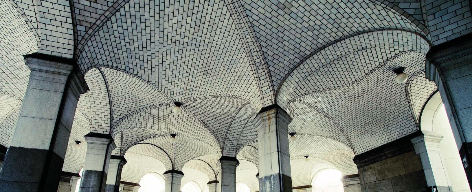
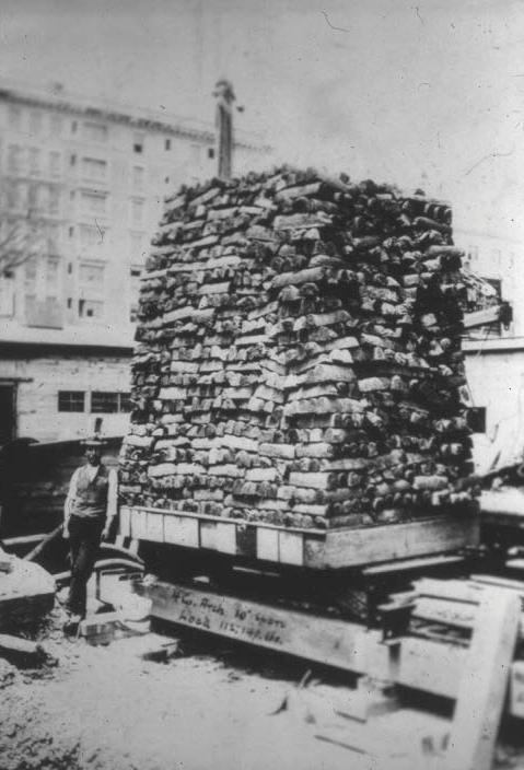
Guastavino started as an architect in Barcelona applying his vaulting system in buildings such as Batlló Brothers Factory in 1869 and Vilassar Theater in 1880. In1881 he moved to the United States to develop his technique. One of the main reasons of this move was the greater supply of Portland cement, which led to one of his major improvements on traditional timbrel vault construction. In 1889, Guastavino built his first big work, the Boston Library (Fig. 1.18). The fame and prestige obtained from this enabled him to found his own company Guastavino Fireproof Construction Co. The main reason of the success achieved by Guastavino’s vaulting system, apart from its amazing structural performance (Fig. 1.18), was its notable resistance against fire.
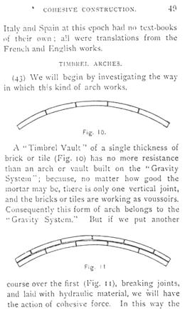
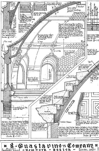
Guastavino built all sorts of vault typologies: cylindrical, groin, neo-gothic and spherical vaults. Provably, this last typology was the most used by Guastavino and the most acknowledged. One of the greatest examples was Saint John’s Divine Cathedral saving a 30 meters span. Finally, there were a set of vaults that cannot be classified in any typology and that were just buildable due to the talent and skills of Guastavino and his team. One of these special cases is City Hall station (Fig. 1.16). In 1892, Guastavino published his Essay on the Theory and History of Cohesive Construction12. In this paper, Guastavino describes cohesive construction as a method of building that relies on the adhesion of materials as opposed to the friction of the more commonly used gravity system. Mechanical construction or by gravity is based on the resistance of any solid to gravity when counteracted by another solid. Cohesive construction is based on the cohesive properties between different materials. Vaults of cohesive construction are composed of several layers of tile and mortar and can be characterized by their thinness, strength and non-combustible properties. His illustrations clearly show that in a vault of single thickness with only one vertical joint, it is gravity alone that keeps the elements in place. According to Guastavino, adding a second layer with breaking joints and mortar significantly decreases the weight of a similar vault and provides greater load capacity due to the cohesion of the materials (Fig. 1.19). Cohesive construction, in its most common form, the timbrel vault, uses little or no steel. It can usually be constructed using little or no centring as the masonry is self-supporting. This, combined with the use of quick-setting mortar, greatly reduces the time and cost of construction compared to conventional masonry vaulting. The tiles and mortar form a homogeneous structure, infallible even to accidental penetrations13.
1. Domain | 1.3 Vernacular Brick Construction Cellular
Composite System | Baek Ki Kim, Juanjo G. Castellon
editorialfinal.indd 20 15/10/2010 08:42
Fig. 1.15 | Timbrel arches, from “Essay on the Theory and History of Cohesive Construction”.

021
Fig. 1.16 | City Hall Station. 1900. New York. Rafael Guastavino
Fig. 1.17 | Guastavino vaulting system. Section
Fig. 1.18 | Boston library. Construction process
editorialfinal.indd 21 15/10/2010 08:42
Fig. 1.19 | Guastavino Vault. Loading test
1.3.3 Gaussian Vault | Eladio Dieste
“The resistant virtues of the structures that we seek depend on their form; it is through their form that they are stable, not because of the awkward accumulation of material. There is nothing more noble and elegant from and intellectual viewpoint that this: to resist through form.” Eladio Dieste
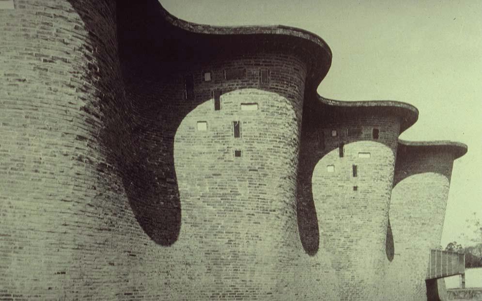
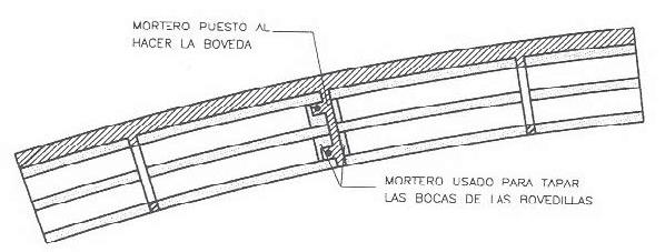
Eladio Dieste (1917-2000) was a Uruguayan engineer that built from 1945 to 1975 a set of buildings based on his invention of “reinforced ceramic construction”14. This hybrid technique developed by Dieste, combines a simple traditional brick technique with metal reinforcement. This combination confers to the system the ductility and mechanical capacity of reinforced concrete and compensates the lack of tensile strength of masonry. Dieste employed, in the construction of his vaults system, hollow bricks from 8 to 12 cm thickness arranged in a grid. Consequently, the only way to place reinforcements was to insert metal bars between the joints following the isostatic lines (Fig. 1.20). This process was difficult and time consuming.
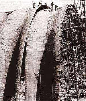
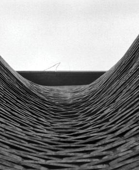
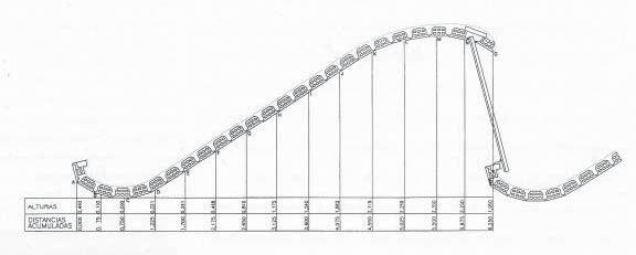
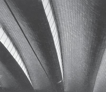
On the other hand, Dieste’s vaults were able to save up to 50 meters span without columns. Eladio Dieste’s reinforced brickwork vaults can be divided two main typologies: the freestanding barrel vault and the Gaussian vault. The first type encompasses single-curvature shells whose direct follows a catenaries curve. The second type, the Gaussian vault, is a double-curved thin-walled shell that is designed to be resistant to buckling (Fig. 1.21). What makes Eladio Dieste’s vaults especially fascinating is that they consist of a single layer of brickwork (Fig. 1.24), creating beautiful large-span shells15. The method applied for Dieste to analyze the structural behavior of his “ceramic shells” was the same employed for the calculation of cylindrical concrete shells. The Lundgren method, also known as “beam theory”, assumes the whole shell performs as a great beam whose cross section is the arch defined by the laminar profile selected16. The conglomerate of brick, cement and steel is more heterogeneous than ferroconcrete. The tensile stresses are absorbed by the steel while the compression stress goes to the brick and mortar compound. Dieste’s solution was focused in the behavior of the vaults in both the longitudinal direction and the cross sections (which consisted of either catenaries profiles or double curvature segments). Reinforced brickwork played a fundamental role in the success of his structures, reducing the need for continuous scaffolding, permitting a higher standardization and control during execution, optimizing the use of the local skills and materials and, finally, combining structural efficiency with economy17.

1. Domain | 1.3 Vernacular Brick Construction
Cellular Composite System | Baek Ki Kim, Juanjo G. Castellon
Fig. 1.20 | Reinforced Ceramics System. Detail
editorialfinal.indd 22 15/10/2010 08:42
Fig. 1.21 | Gaussian Vault. Construction Process
023
Fig. 1.24 | Gaussian Vault. Section and Detail.
Fig. 1.22 | Church of Atlantida. 1958. Uruguay. Eladio Dieste
Fig. 1.25 | Gaussian Vault. Interior View.
editorialfinal.indd 23 15/10/2010 08:43
Fig. 1.23 | Church of Atlantida. Detail
1.4 Parametric Fabrication
The fast development of parametric tools and the evolution of new fabrication techniques have dramatically changed construction processes. In opposition to traditional construction techniques where technologies and resources were limited, there is now an enormous workflow of information between design and fabrication processes. Free forms and complex forms can be easily designed with parametric tools and this complexity has to be transformed and translated in order to become buildable and economically feasible. Consequently, a new professional profile is emerging in this process, a sort of translator between architects and constructors who receives a complex design and deals with its geometry principles and material properties to make it feasible.
What follows is an example of the tasks and responsibilities of one of these emerging companies:
A. CONSULTATION: Our involvement begins with the client’s initial concept development, offering appropriate advice and keeping them informed of the various possibilities and constraints of the project. We can also outline practical limitations such as scale, cost, material selection or finishes.
B. INTERPRETATION AND PROTOTYPING: After receiving the client’s 3D model, usually in Rhino 3D, we conduct a preliminary structural analysis in order to derive component sizes and shapes. From this, we can identify the appropriate manufacturing methods and form of tooling.
C. ANALYSIS: An analysis of the overall structure is then carried out. We look at the performance requirements of the design and identify component types in order to formulate the detailed structural engineering and design of the laminate.
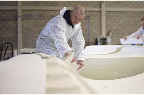
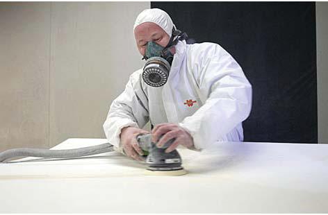
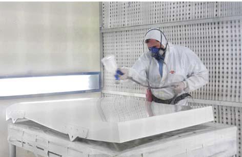
D. PRODUCTION: Once the 3D model has been converted into files, these are used to drive our 3 and 5 axis CNC machines to make the moulds. Each FRP element is then laid-up into these moulds using the appropriate process in accordance with our quality control procedures.
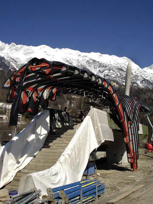
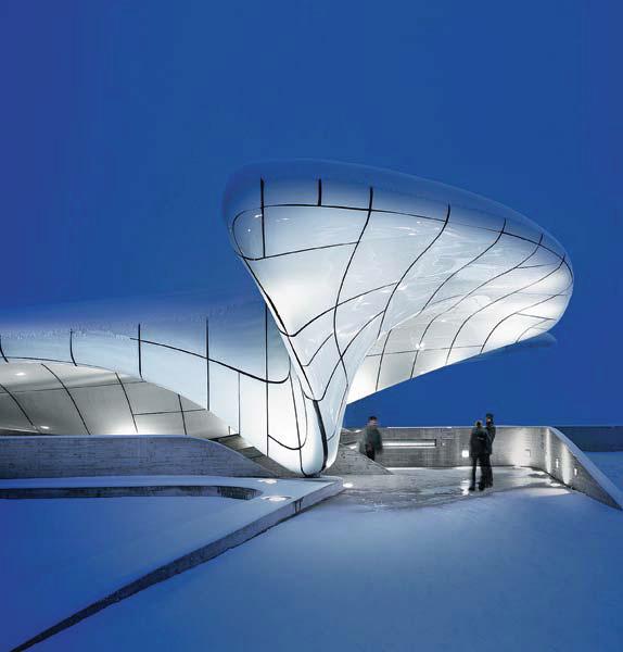
E. DELIVERY & INSTALLATION: At this stage our involvement can operate on many levels, from providing our specialist team to meet all delivery and installation requirements, to perhaps acting purely as a supplier, providing the relevant advice to another contractor18. Projects such as Hungerburg Funicular Station (Fig. 1.29, 1.30) were built following this model process.
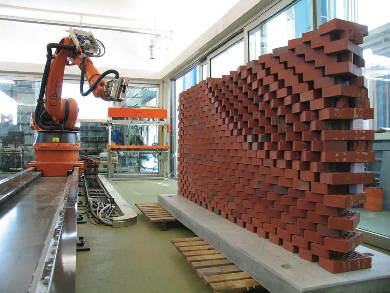
On the other hand, architects such as Gramazio & Kohler (Fig. 1.31) are developing design strategies where design and parametric fabrication merge in one process. They work starting with a simple brick component and a robot deals with complex fabrication. In this case, there is no need of a translator and parametric tools become architectural tools and not production tools.
1. Domain | 1.4 Parametric Fabrication Cellular Composite System | Baek Ki Kim,
G. Castellon
Juanjo
Fig. 1.28 | Free-Form Panels. Stageone. Finishing
Fig. 1.27 | Free-Form Panels. Stageone. Hand-ground smoothen surface
editorialfinal.indd 24 15/10/2010 08:43
Fig. 1.26 | Free-Form Panels. Stageone. Molding production.
025
Fig. 1.29 | Hungerburg Funicular Station. Substructure.
Fig. 1.30 | Hungerburg Funicular Station .2007. Innsbruck. Zaha Hadid
editorialfinal.indd 25 15/10/2010 08:43
Fig. 1.31 | The Programmed Wall. 2007. Gramazio & Kohler. Robotic Assembly
1.5 Summary
A. Ceramic materials are excellent materials with outstanding properties for architectural applications. They have been used throughout centuries and even now are key materials in the development of new composites. On the other hand, ceramics perform poorly under tensile strength and require firing.
B. Traditional masonry techniques such as the Catalan vault were based on a clear understanding of ceramic brick logic and its structural applications.
C. Rafael Guastavino evolved this traditional technique by applying his “cohesive construction” principles. With this technique based in the adhesion of different material layers in a precise geometry and arrangement he was able to build all sorts of vaults in a very efficient and aesthetic manner.
D. Eladio Dieste evolved the vault system adding metal reinforcements and using form to improve its structural behaviour. Furthermore, he was able to build his double-curved Gaussian vaults achieving an elegant and beautiful result.
E. These traditional techniques became obsolete due to the lack of qualified manpower and the appearance of reinforced concrete.
F. New parametric tools allow architectural designs to challenge new formal experimentations and fabrication techniques. On the other hand, the large amount of data and workflow generates, often, a gap between design and production.
G. Some architects are trying to eliminate this gap merging parametric design and fabrication in a single process.
1. Domain | 1.5 Summary Cellular Composite System | Baek Ki Kim, Juanjo G. Castellon editorialfinal.indd 26 15/10/2010 08:43
From these points some questions arise:
1. What kind of transformations could we apply to the traditional brick in order to improve its mechanical and geometrical properties?
2. Is it possible to produce a composite material that combines the benefits of ceramics with reinforced concrete ones?
3. How can we reduce complexity in the fabrication process in order to build free form architecture with contemporary tools?
4. Is it possible to adapt cohesive construction traditional techniques in a free-form tiling and structural system?
027 editorialfinal.indd 27 15/10/2010 08:43
2. Method
editorialfinal.indd 28 15/10/2010 08:43
2.1 Introduction
2.2 Advanced Fabrication
2.2.1 Combination of Digital and Traditional Fabrication
2.2.2 Robotic Fabrication 2.3 Material
2.3.1 Ceramics
2.3.2 Concrete
2.3.3 Honeycomb
2.4 Production Technique
2.4.1 Physical Production Technique
2.4.2 Digital Production Technique
2.5 Evaluation & Methodological Scheme
029 editorialfinal.indd 29 15/10/2010 08:43
2.1 Introduction
The relationship between design and fabrication is the key topic in the new paradigm of contemporary architecture. The appearance of hierarchical generative tools such as Grasshopper, Generative Components or VbScript, opens up a new field for an architecture that incorporates evolution, variation and adaptation in response to environmental, structural and spatial aspects. In addition, this new approach to architecture has to face factors such as feasibility and costs in order to facilitate the fabrication process.
Following the first stage of research (see the 1. Domain chapter), an accurate description of some fabrication and industrial manufacturing processes will be described following a research trip to Barcelona and Valencia to visit a fabricator network made up of several professionals and companies that work with ceramics and concrete in different scales and philosophies.
This chapter will focus on the development of contemporary uses and applications of digital and physical fabrication with its material usages and processes.
2. Method | 2.1 Introduction Cellular Composite System | Baek Ki Kim,
editorialfinal.indd 30 15/10/2010 08:43
Juanjo G. Castellon
editorialfinal.indd 31 15/10/2010 08:43
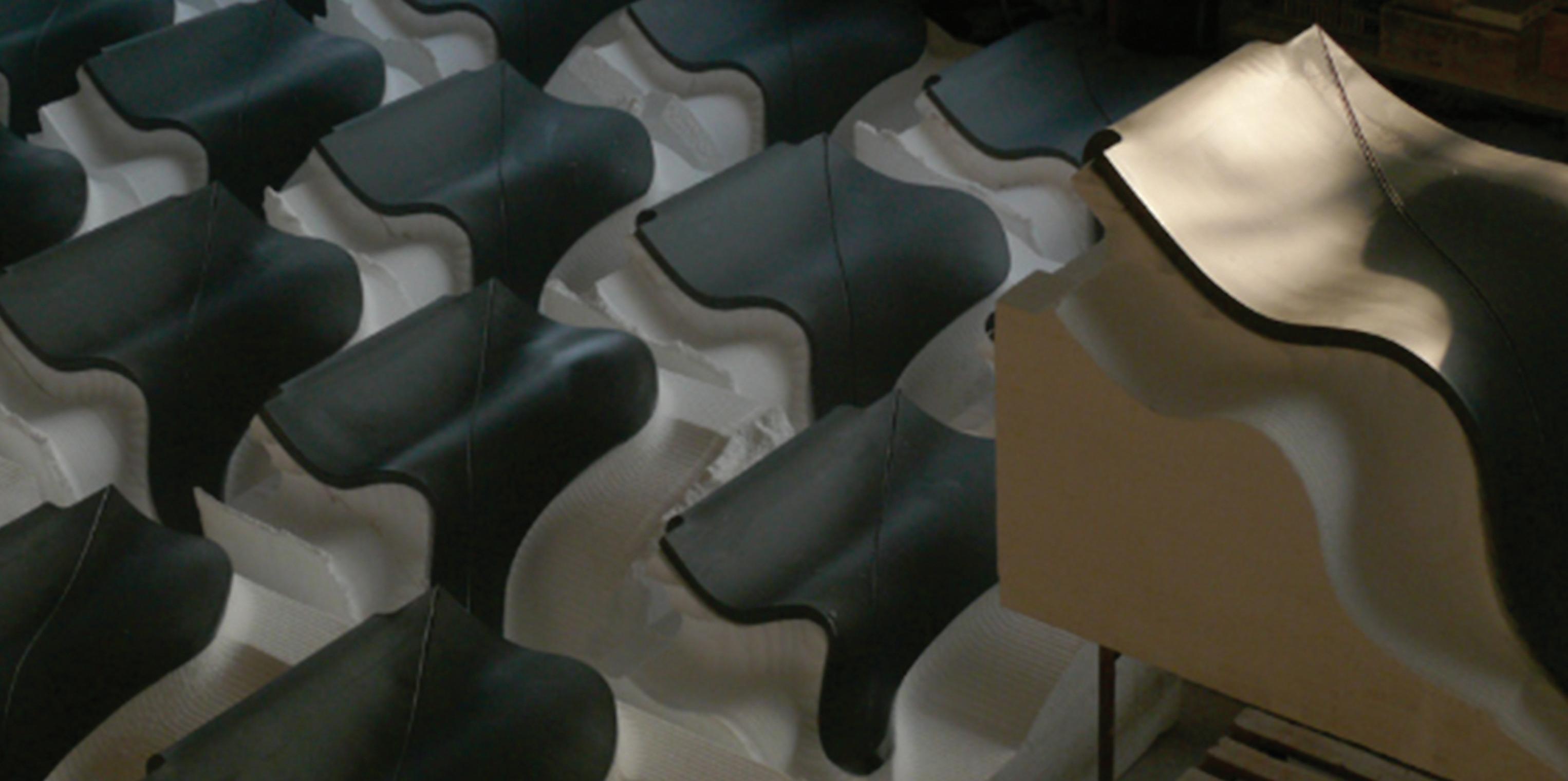
Fig. 2.01 | Ceramic Skins are forming on the mould (Ceràmica Cumella)
2.2 Advanced Fabrication
2.2.1
Combination of Digital and Traditional Fabrication
2. Method | 2.2 Advanced Fabrication Cellular Composite System | Baek Ki
G.
editorialfinal.indd 32 15/10/2010 08:43
2.2.2 Robotic Fabrication
Kim, Juanjo
Castellon
033
editorialfinal.indd 33 15/10/2010 08:43
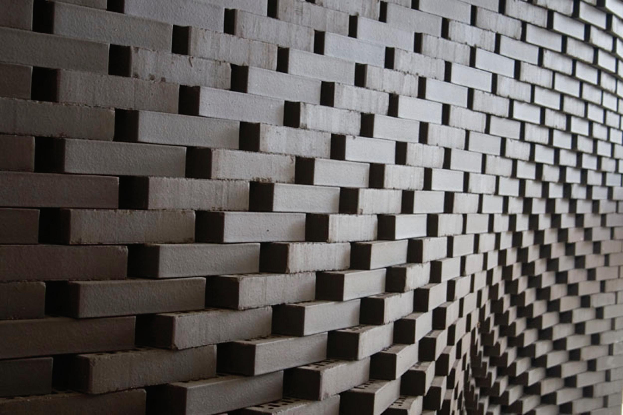
Fig. 2.02 | The brick wall façade by the R-O-B mobile fabrication unit (Gramazio&Kohler)
2.2.1 Combination of Digital and Traditional Fabrication
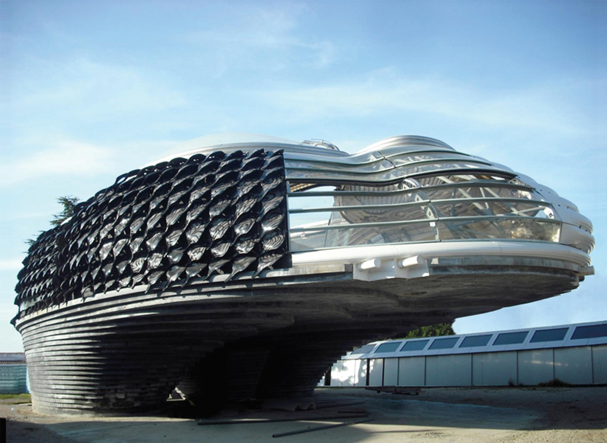
A. Ceramic Skin production (Case study of the Villa Nurbs project by Cloud9)
The fabrication process developed for the design of the façade system of the Villa Nurbs5, project designed by Cloud9 architects, will be analyzed as a study case. As a consequence of this visit, a realistic perspective of the possibilities and limitations of the industrial processes will lead the study of a new parametric fabrication system.
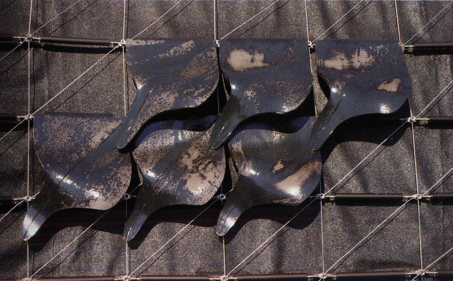
The Ceramic skin presents a new perspective in the architecture field for the definition of façades. A network of tensioned-cables fixed to the sub structure of the building hold those ceramic units up. In addition, they form the external layer of the building fa ade. Frederic Amat the painter works on every each one of the ceramic units.
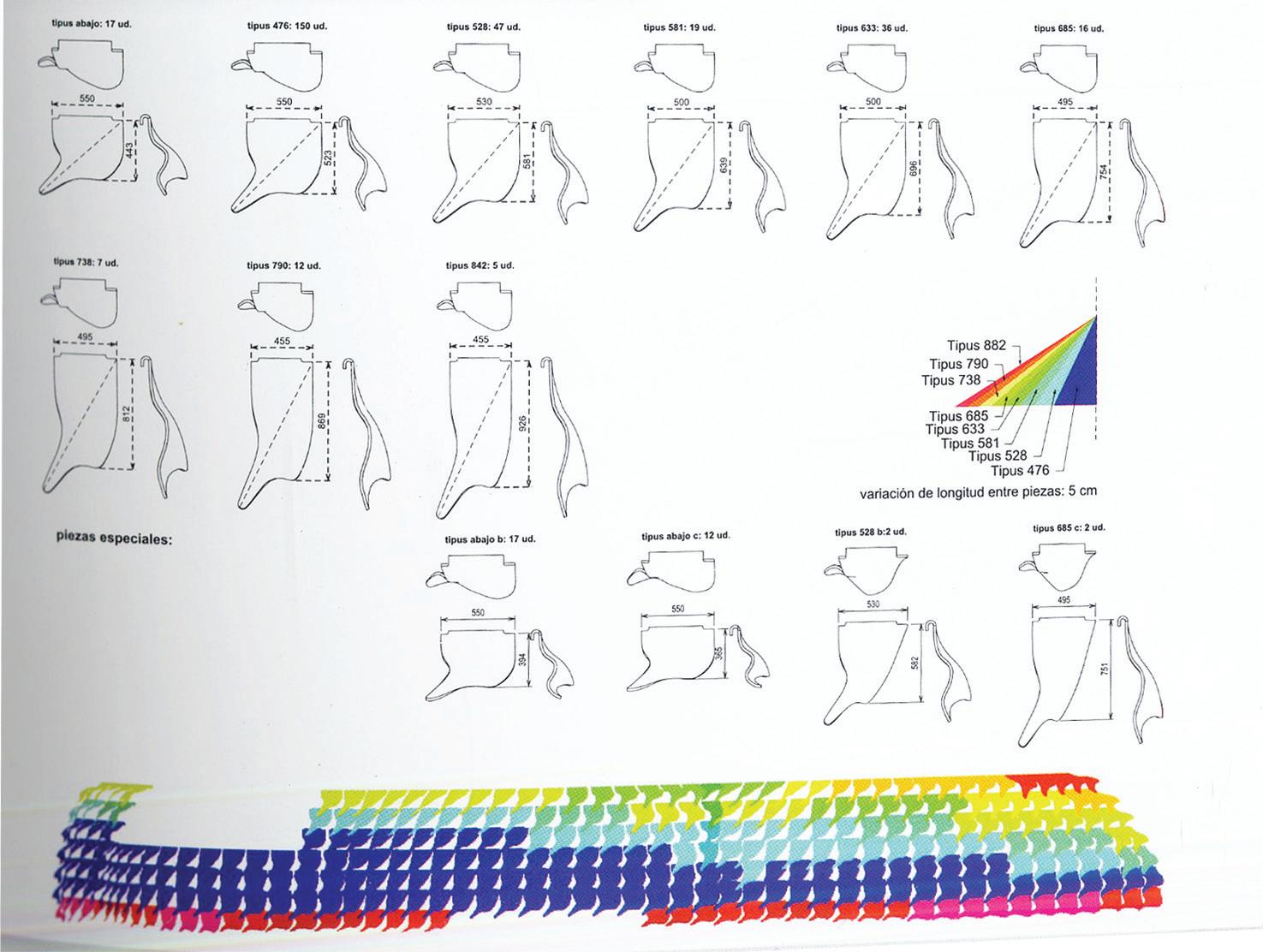
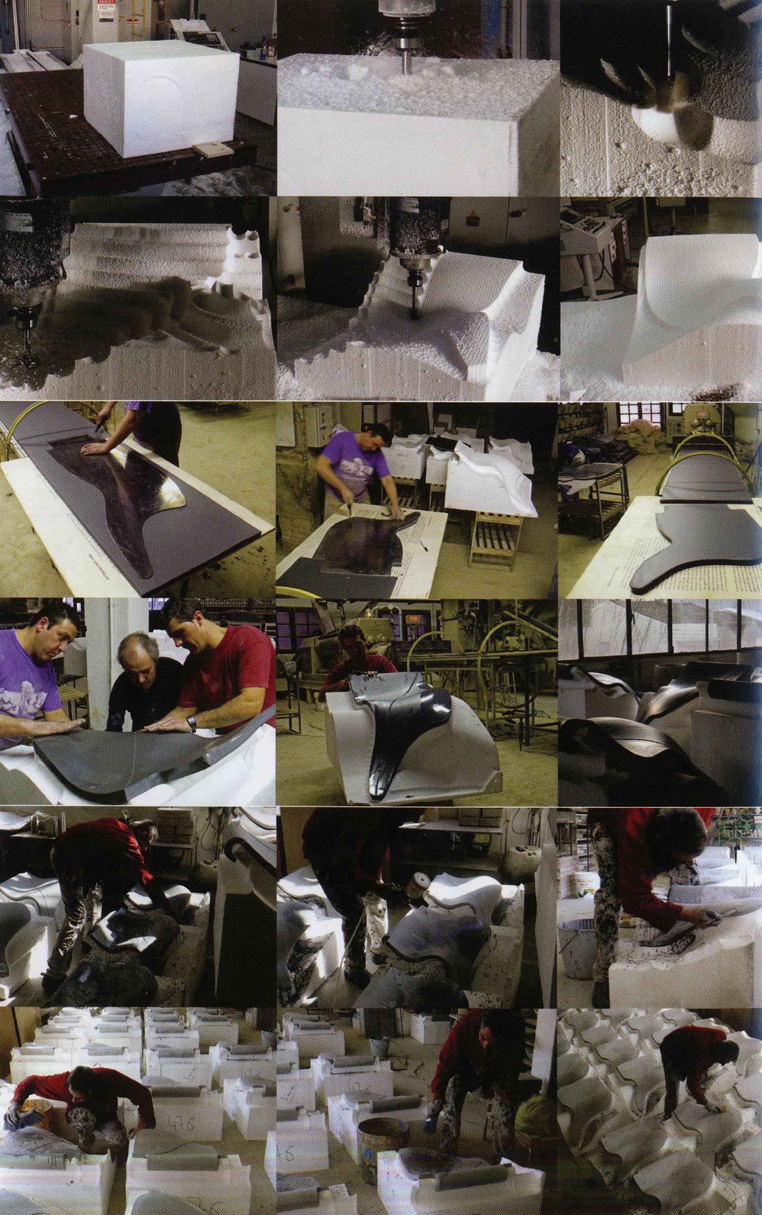
The unit’s geometries are developed on a three-dimensional digital model that is produced by CNCmilled wood and foam mould. Those digital fabrication process connect between CAD software and CAM machine software that can fabricate for the moulds. The interaction among design software, manufacturing software and machinery make the possibility of physical production. Also, it shows to combine a traditional hand-craft fabrication with digital technologies.
2. Method | 2.2 Advanced Fabrication
Cellular
Composite System | Baek Ki Kim, Juanjo G. Castellon
editorialfinal.indd 34 15/10/2010 08:43
Fig. 2.03 | The Villa Nurbs by Cloud9
Project Overview
Architect | Eric Ruiz-Geli, Cloud9
Ceramics | Ceràmica Cumella, S.L., Frederic Amat
Cable and Fixture | Industrias BEC S.A
Impermeability EPDM | Roura i Pujol S. L
035
Fig. 2.04 (above) | The assembly of ceramic skins on the facade.
Fig. 2.05 (above) | The optimised geometries of ceramic skins by CAD/CAM.
editorialfinal.indd 35 15/10/2010 08:43
Fig. 2.06 | The sequence of ceramic skins fabrication. (Ceràmica Cumella)
B. Extrusion-based ceramic production (Ceràmica Cumella)
STEP 1. Materials
The first step in the process is to find the right ingredients for the clay. This decision is based on a continuous test of different combinations of additives, minerals and pigments (Fig. 2.07), and furthermore on a wide experience accumulated over years. The Ceramica Cumella have a laboratory where they test different combinations to achieve different clay mixtures.
STEP 2. Mixture
Once we have the right ingredients that will provide the colour and consistency to the ceramic piece, we start the process in the machine combining our additives and pigments with water. It is very important to keep a constant mixture by controlling the exact amount of water and additives (Fig. 2.08, 2.09). The mixture then is blended in a tank (Fig. 2.10).
STEP 3. Moulding
A key part of the extrusion process is the moulding geometry. In this case we need a very simple moulding. Basically, what we need is the profile of the mould. It is built in steel and attached by bolts to the extrusion machine (Fig. 2.12). It is important to mention that obviously the mould is one of the most expensive elements in the process so the more variation you want, the more expensive the process. For extruding the clay across the sectional moulding there are two parameters that have to remain constant all the time: pressure and temperature (Fig. 2.13). These two inputs are digitally controlled and guarantee a homogeneous finish in all the pieces.
STEP 4. Mechanization
Finally, you have a continuous and homogeneous section of clay that you have to cut according to the depth that you want to give to the ceramic component. You can, for instance, cut it at a specific angle (Fig. 2.17). If the final piece is correct in terms of geometry and quality, then manually some final work can be done on the piece specially for the preparation of the joinery system (Fig. 2.16). If the final piece has some defect in fabrication then you can compile (Fig. 2.18) and recycle these pieces putting them back in the mixture tank. Consequently, there is no wasted material in the process so, in this sense, it is a very sustainable one.
STEP 5. Kiln and Dryer
STEP 5. Kiln and Dryer
The pieces are stored and ready to go to the kiln (Fig. 2.19). The process of firing the pieces takes time. Stoneware elements need temperatures from 1,250 to 1,300 ºC and about 5 hours of heating. So it is important to find a way to avoid stopping the process. In order to do that, one crane raises the kiln (Fig. 2.20) and moves it to the next set of pieces in order to speed up the sequence of firing When you heat the pieces you have to take into account that there will be some retraction on the pieces as a result of the temperature change. Then you have to leave the pieces to cool down and then move them to the drying machine (Fig. 2.18) where the aim is to extract all the moisture from the pieces.
STEP 6. Glazing
Finally, the pieces are ready for the glazing process (Fig. 2.21). You can use a wide palette of colours for the glazing (Fig. 2.22) and you have to again heat the pieces to achieve the final finish. The piece is now ready to go (Fig. 2.23).
CONCLUSIONS:
Some conclusions arise from understanding the extrusion process:
A. Firstly, it is an extremely important process in order to achieve a good quality final piece and that the correct choice of the mixture “ingredients” is very key in the process and you cannot make this choice without a wide understanding and experience testing different combinations and possibilities to control the consistency and colour of the final piece.
B. In terms of geometry, two conditions have to be taken into account. On the one hand we have the limitation of the directionality of extrusion. The consequence of this is that it is difficult to think about curved surfaces without combining extrusion with another process. On the other hand, we have to take into consideration reasonable shrinkage due to heating of the piece.
One last thought regarding the whole process is the need of handcraft in almost all the steps in the process. The extrusion machine fabricates the piece but the final quality in performance and aesthetics relies in human criteria and experience. Actually, in my opinion, the singularity and quality that differentiates The Cumella’s work from the rest of the fabricators is his talent, his experience and his team.
2. Method | 2.2 Advanced Fabrication Cellular Composite System | Baek Ki Kim, Juanjo G. Castellon editorialfinal.indd 36 15/10/2010 08:43


037
Fig. 2.07 - 2.23 | The Sequence of Extrusion-based ceramic production
STEP 1. Materials
STEP 2. Mixture
STEP 5. Drying & Firing
STEP 3. Moulding
STEP 5. Drying & Firing
STEP 4. Mechanisation
2.07 2.08 2.09 2.10 2.11 2.12 2.13 2.14 2.15 2.16 2.17 2.23 2.18 2.19 2.20 2.21 2.22 editorialfinal.indd 37 15/10/2010 08:43
STEP 6. Glazing
C. Adhension-based ceramic casting production (Ceràmica Cumella)
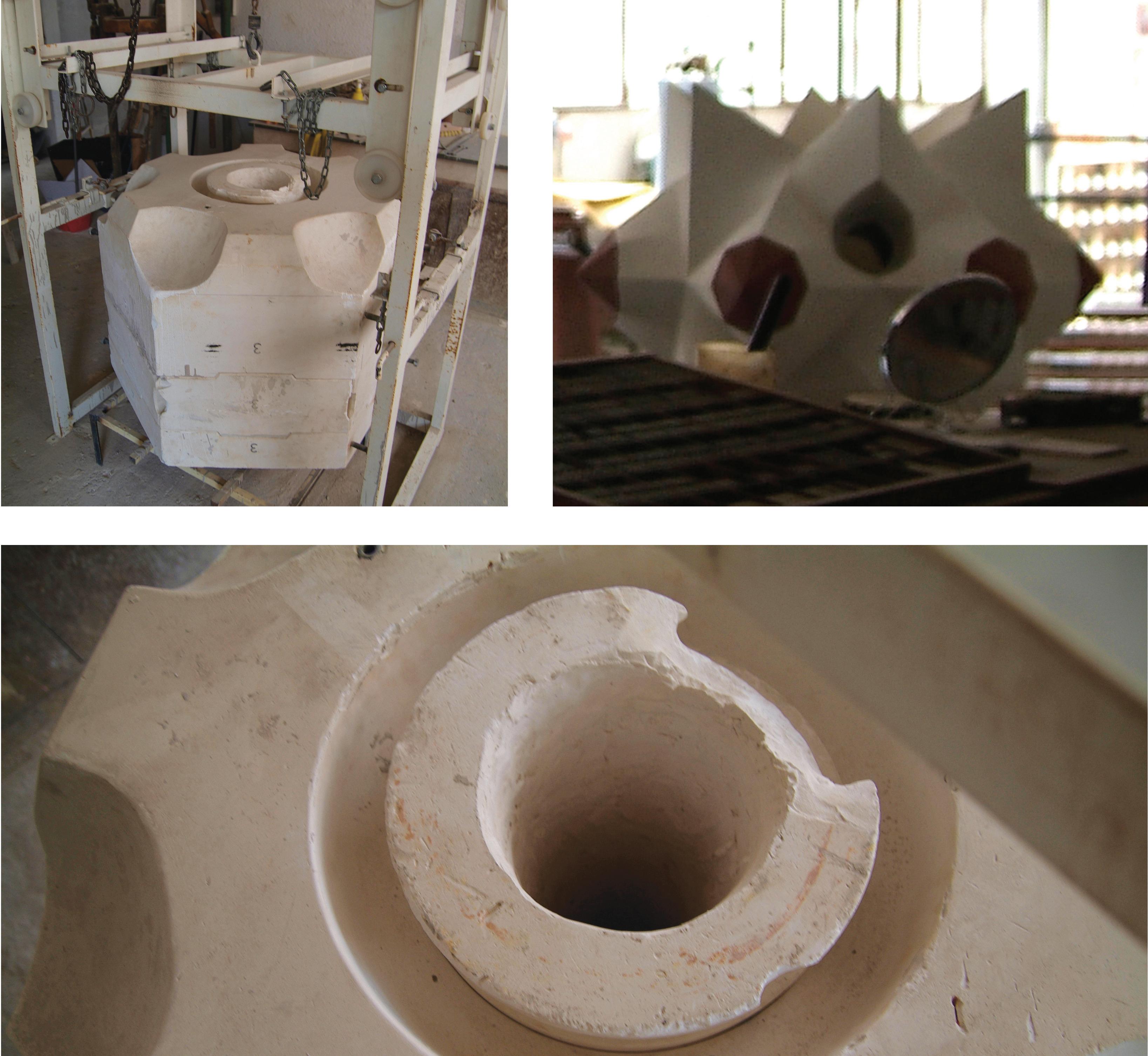
The second fabrication process used by the Cumella is adhesion and they use this technique when the have to fabricate pieces with high three-dimensional complexity. For example, they have used this process for the production of some special pieces in La Sagrada Familia (Fig. 2.25).
This process requires the fabrication of a complex mould and its production is expensive and slow.
This process will be described in the following steps:
STEP 1. Material
The first step in the process is common with the extrusion process and the aim is to find the right ingredients for the clay. This decision is based on a continuous test of different combinations of additives, minerals and pigments and furthermore in a wide experience accumulated along years. They have a laboratory where they test different combinations to achieve different clay mixtures.
STEP 2. Moulding
For this sort of process the moulding fabrication is the most important part. Firstly, because the geometry is completely controlled and defined by the mould and secondly because, depending on the complexity of the piece and its scale, the mould cost can be really high. It means that the piece’s production is quite limited and each piece requires a large amount of work and dedication. In this specific project (a piece for La Sagrada Familia) due to the piece’s complexity, the mould was split into several pieces (Fig. 2.24) and each piece requires another mould for its fabrication. This master mould is usually made of wood or steel, depending on the quality, finish and precision needed. In our case we need about 3 pieces. These pieces are cast independently in stoneware and become the negative mould of our final piece. These moulds made in pieces have to assemble perfectly.
STEP 3. Pouring
The mould has to have a hole to pour the mixture and to extract the remaining mixture once we achieve the thickness that we want for our final piece (Fig. 2.26).
When you pour the mixture, it is liquid, you have to fill all the mould and wait. Then starts the process of hardening, the more time you wait, the thicker the surface.
Once the desired thickness is achieved, the next step is to empty the mould, extracting the remaining mixture and then disassemble all the mould pieces releasing the final piece that is now ready to be heated in the kiln.
The rest of the process (heating, drying and glazing) is exactly the same as the one used in extrusion.
CONCLUSIONS:
Some conclusions arise from the understanding of the adhesion process:
A. Due to the time required for each piece in the process, this technique is not suitable for a construction system if you want to achieve variation and it only makes sense for some special pieces or a standard repetition system.
B. The moulding fabrication is even more complex and important that the final piece and to afford its production cost you would need many pieces.
2. Method | 2.2 Advanced Fabrication Cellular Composite System | Baek Ki Kim, Juanjo G. Castellon editorialfinal.indd 38 15/10/2010 08:43
039
Fig. 2.24 - 2.26 | Casting Mould and Produce pieces of the adhension process for La Sagrada Familia
2.24
2.25
editorialfinal.indd 39 15/10/2010 08:43
2.26
2.2.2 Robotic Fabrication
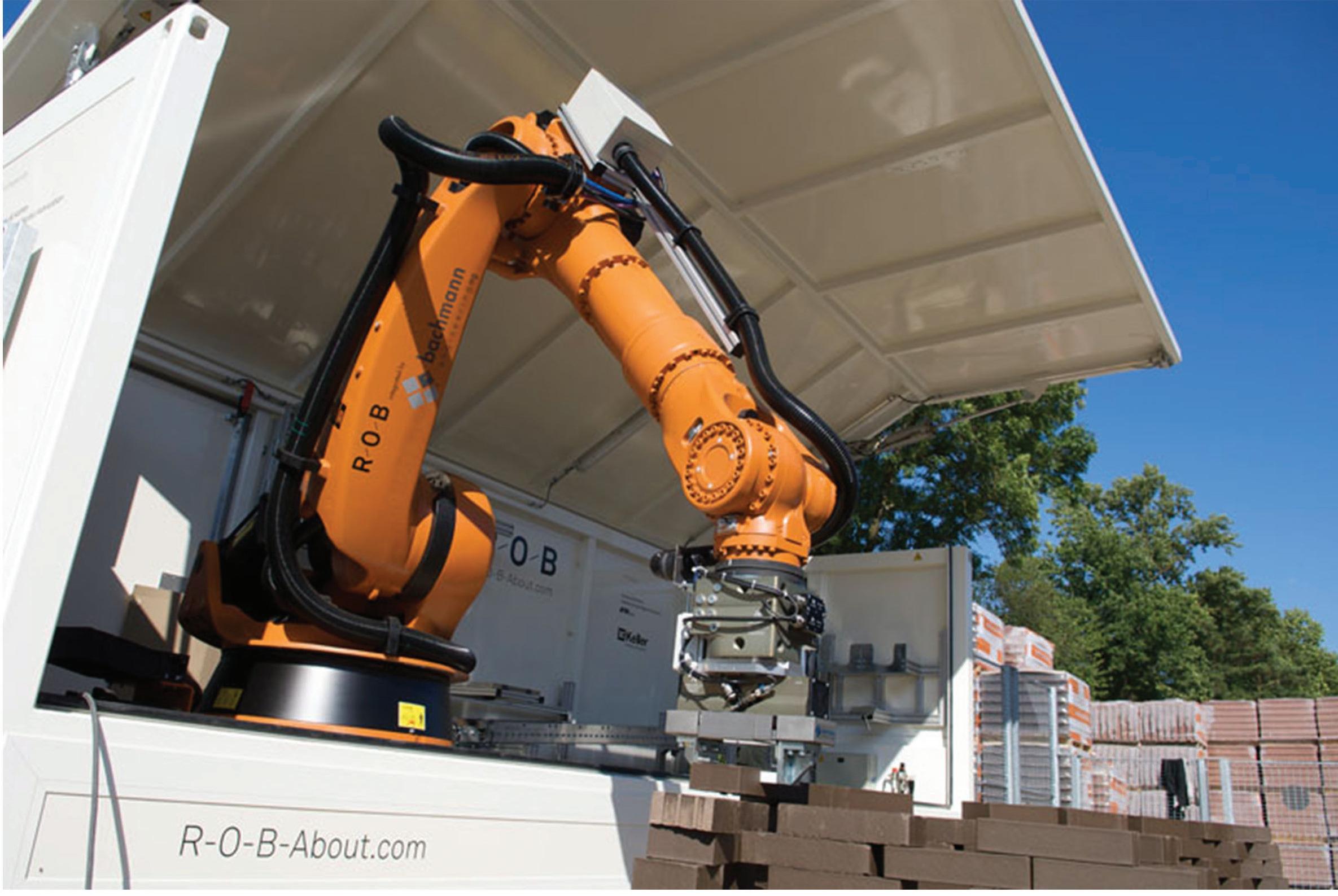
The R-O-B project extends the existed-prefabrication process of construction. It has been developed over the past 3 years by Gramazio & Kohler into a full-scale digital fabrication in architecture using industrial robot arms.
Housed in a modified freight container, the R-O-B mobile fabrication unit can be used anywhere in the world. It combines the advantages of prefabrication – precision and consistent high quality – with the advantages of short transport routes and just-in-time production on the building site. Furthermore, the mobile fabrication unit is not restricted to a predefined manufacturing process or a particular building material. Making use of computer methodologies in the design and fabrication process allows for manufacturing building elements with highly specific forms, which could not be build manually.(Gramazio&Kohler,2007,2008)
For many years, architects have relied on digital manufacturing processes such as CNC milling or 3D printing as tools for formal research at model-scale. Interestingly, the project explores the potential of mobile digital fabrication techniques that can fabricate at 1:1 scale on site.
Project Overview
Client: Keller AG Ziegeleien, Pfungen
Collaborators: Michael Lyrenmann (project leader), Tobias Bonwetsch, Ralph Bärtschi
Selected experts: Viola Zimmermann (cooperate)
2. Method | 2.2 Advanced Fabrication
Cellular Composite System | Baek Ki Kim, Juanjo G. Castellon
Fig. 2.27 | The robotic arm of mobile fabrication unit (Gramazio & Kohler)
editorialfinal.indd 40 15/10/2010 08:43
The geometry of walls are generated by 3D scripted-model and optimised for fabrication
The fabrication unit is transported and set on the site
The robotic arm assembled brick units based on generated parameters / The part of assembled pieces are moved to exact position in the space.

041
Fig. 2.28 (right)
Fig. 2.29 (right)
Fig. 2.30 (right)
leader), editorialfinal.indd 41 15/10/2010 08:43
2.3 Material
2.3.1 Ceramics
2.3.2 Concrete
2. Method | 2.3 Material
editorialfinal.indd 42 15/10/2010 08:43
2.3.3 Honeycomb
Cellular Composite System | Baek Ki Kim,
Juanjo G. Castellon
The relationship between architecture and materials had been fairly straightforward until the Industrial Revolution. Materials were chosen either pragmatically – for their utility and availability – or they were chosen formally – for their appearance and ornamental qualities. Furthermore, materials were not standardised, so builders and architects were forced to rely on an extrinsic understanding of their properties and performance. In essence, knowledge of materials was gained through experience and observation.
The role of materials changed dramatically with the advent of the Industrial Revolution. Rather than depending on an intuitive and empirical understanding of material properties and performance, architects began to be confronted with engineered materials. In this section, we focus on some of the selected conventional and advanced materials that are generally using in traditional and contemporary industries, such as the aeronautic industry, to find the possibilities of materiality.
043
editorialfinal.indd 43 15/10/2010 08:43
2.3.1 Ceramics
Ceramics is classified as non-metallic materials that are made by firing. They are hard and brittle materials that have been used for millennia in the production of ornamental and functional objects.
Types of Ceramic
There are two main groups of ceramics: clay-based and high performance ceramics. Clay-based ceramics are those associated with pottery and include earthenware, stoneware and porcelain. They are fine-grained materials made up of clay minerals (aluminium silicate), quartz and rock fragments. Historically, the quality of ingredients differed according to location. Today, clay is purchased from manufacturers that produce raw materials in accordance with guidelines.
High performance ceramics have fewer impurities than clay-based ceramics and superior properties. They are resistant to high temperatures, most chemicals and corrosion, and outperform metals in many demanding applications. However, like clay-based ceramics they are hard and brittle, and their porous structure has a high compression strength but low tensile strength, which typically falls between metal and plastic.
2. Method | 2.3 Material Cellular Composite System | Baek Ki Kim, Juanjo G. Castellon editorialfinal.indd 44 15/10/2010 08:43
045
Fig.2.31 | Systematic classification of ceramic materials
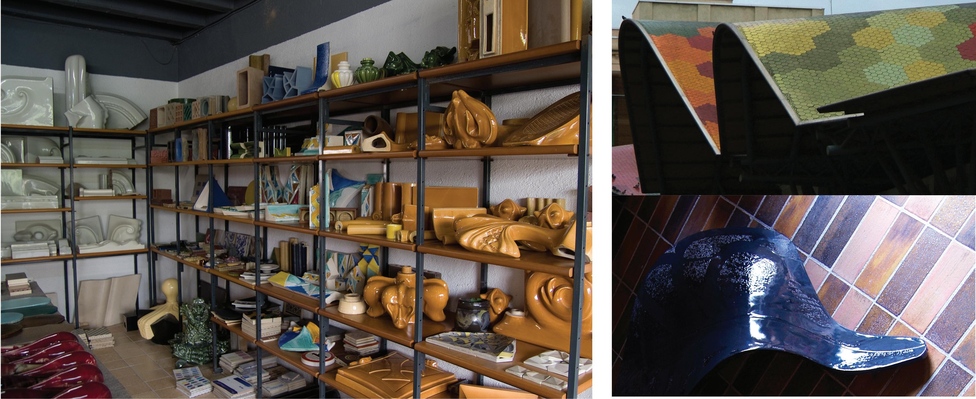
Fig. 2.32 | Samples of Ceramic pieces in Ceràmica Cumella
editorialfinal.indd 45 15/10/2010 08:43
Fig. 2.33 | Santa Catarina Market’s Ceramics roof tile by Enric Miralles (above) Sample of the ceramic skin for Villa Nurbs by Cloud9 (below)
2.3.2 Concrete
Concrete is a construction material composed of cement, which is generally called Portland cement and other cementitious materials such as fly ash and slag cement, aggregate (generally a coarse aggregate made of gravels or crushed rocks such as limestone, or granite, plus a fine aggregate such as sand), water, and chemical admixtures.
Concrete is mixed with water and additives due to a chemical process known as hydration. The water reacts with the cement that glues with the other elements, finally forming a stone-like solid and hard material.
In this research, we looked into two sorts of advanced concrete materials such as Rapid-setting cement and Fibre Reinforced Concrete (Ductal®).
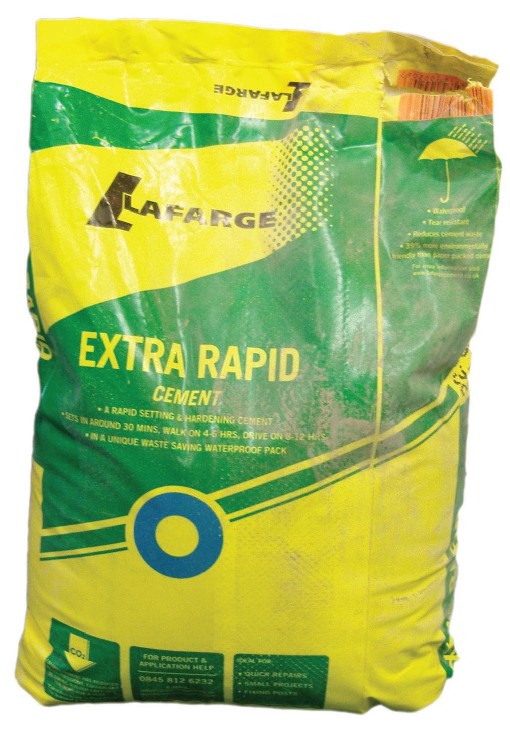
Extra Rapid Cement (Larfarge)
A Portland cement containing calcium aluminate to give rapid hardening and setting properties:
• for repair and maintenance where rapid hardening is required, eg, fence posts, setting manholes, repairs to paths and steps.
• suitable for concrete, mortar, rendering and floor screeds.
• takes foot traffic in 4-6 hours and vehicular traffic in 8-12 hours.
Properties
• Portland cement based.
• Contains calcium aluminate to give rapid setting and rapid hardening properties.
• Sets soon after placing and gains strength rapidly to allow normal services to be brought back into operation in a working day.
• Similar final strength to Mastercrete Original.
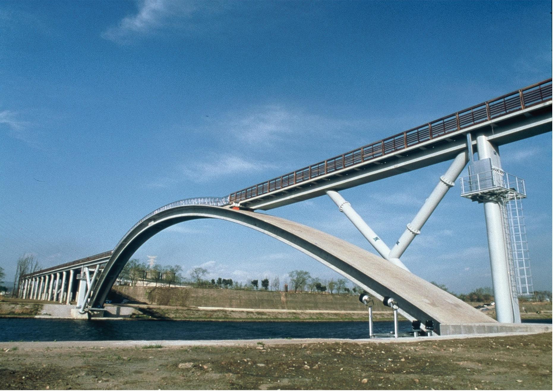
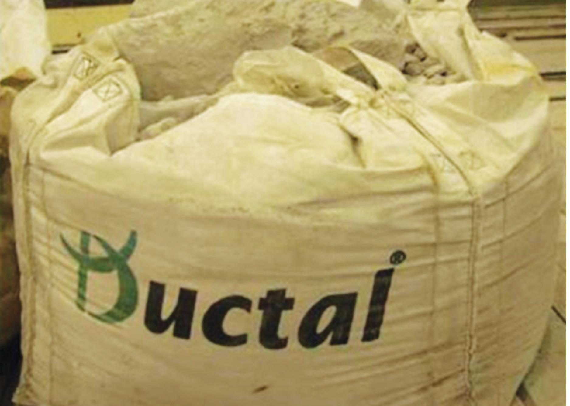
Ductal® (Larfarge): Fibre Reinforced Concrete
Ductal® is an ultra-high performance cement based composite material with metallic or organic fibers. It is mouldable in the form of drycast, fluid or self-placing with properties adaptable to the demands of each application.
“Flexible concrete that is up to 10 times stronger than regular concrete mixtures? Ductal concrete is a high-performance construction material by Lafarge that may create new possibilities for the world of decorative concrete.” (Michael Chusid)
• Ductal® -FM contains metallic fibers and is suitable for structural civil engineering applications such as load-bearing structures.
• Ductal® -AF is a variation of Ductal®-FM that includes the same mechanical properties and, incorporates excellent standardized fireresistance behavior.
• Ductal® -FO contains organic fibers and is suitable for architectural applications such as wall panels, furniture, canopies, etc.
2. Method | 2.3 Material Cellular Composite System | Baek Ki
Kim, Juanjo G. Castellon
editorialfinal.indd 46 15/10/2010 08:43
Fig. 2.34 | Material Performances of Larfarge’s Ductal® cement
047
Fig. 2.37 | Larfarge’s Ductal® cement
Fig. 2.35 | The Peace Bridge in Seoul, Korea construct by Ductal®
editorialfinal.indd 47 15/10/2010 08:43
Fig. 2.36 | Larfarge’s Extra Rapid Cement

2.3.3 Honeycomb
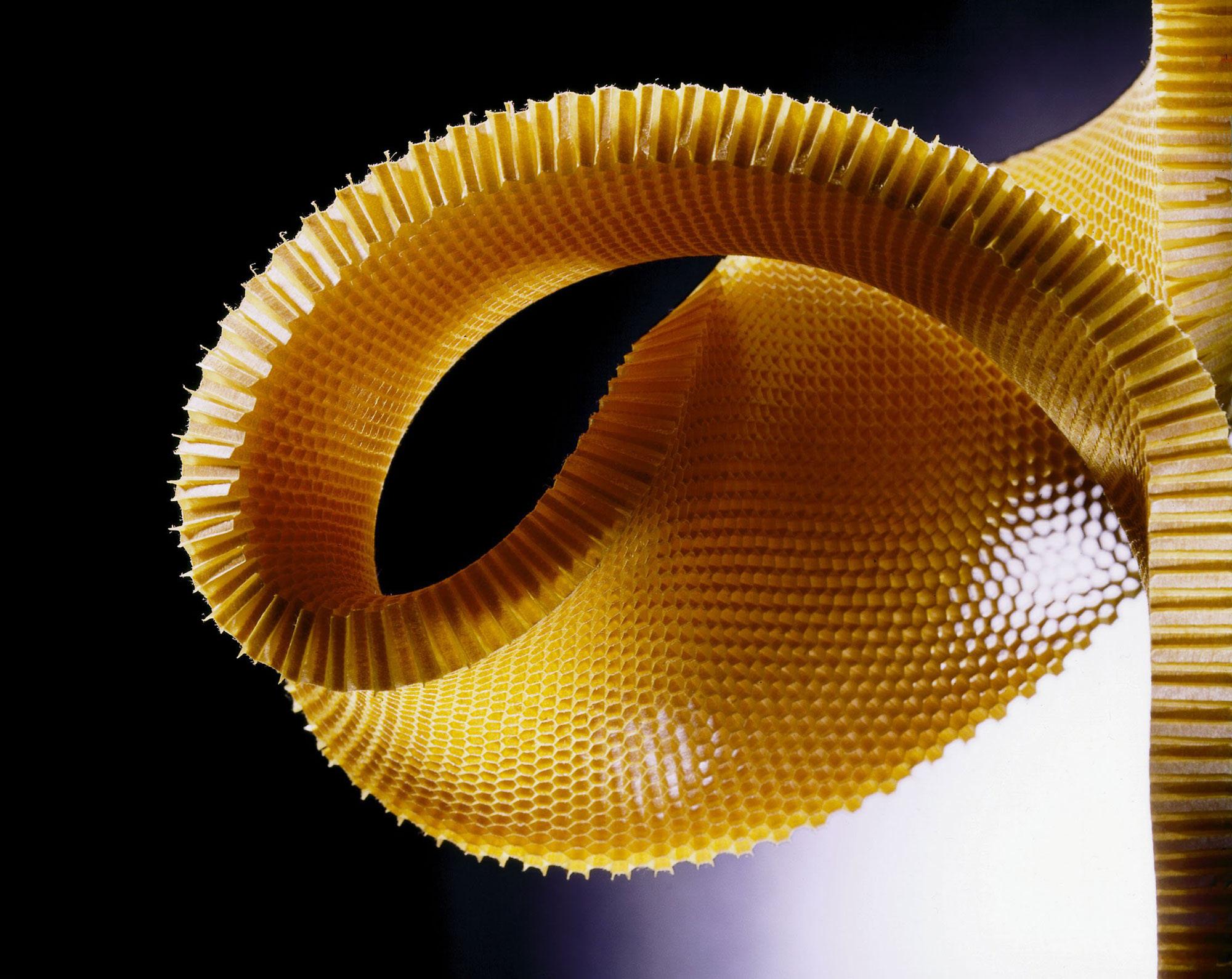
The Honeycomb is an aggregate of hexagonal cells that is mainly used in structural elements. It is a kind of cellular solid made of an interconnected-network of solid walls, which create the edges and surfaces of cells.
Three general structures are shown in Fig. 2.38. The simplest (Fig. 2.38 (a)) is a two-dimensional array of polygons, which pack to fill a plane area like the hexagonal cells of the bee; and for this reason we call such two-dimensional cellular materials honeycombs. More commonly, the cells are polyhedra, which pack in three dimensions to fill space; we can see such three-dimensional cellular materials in foams. If the solid of which the foam is made is contained in the cell edges only (so that the cells connect through open faces), the foam is said to be open-celled (Fig. 2.38 (b)). If the faces are solid too, so that each cell is sealed off from its neighbours, it is said to be closed-celled (Fig. 2.38 (c)); and of course, some foams are partly open and partly closed. The geometry and characterisation of cells is an interesting subject in its own right, and one which has led to ingenious analysis. (Gibson, Ashby, 2001)
The interesting materiality of honeycomb is that it is flexible and has a range of both synclastic and anticlastic bending abilities (figure 32). This is useful for the fabrication of elements, for example planes and cars, which have curved shapes and surface. The most general way to produce those curvatures in the honeycomb is to use a vacuum bag moulding process where a curved mould is used in combination with a surface-laminating process. The honeycomb is made into a suitable shape by the vacuum mould and then held in place until the surfaces are attached to the honeycomb. Despite its limitation of curvature, it can be increased by altering the honeycomb cell size and thickness.
2.
| 2.3 Material
Method
Cellular Composite System | Baek Ki Kim, Juanjo G. Castellon
editorialfinal.indd 48 15/10/2010 08:43
Fig. 2.38 | Examples of cellular solids: (a) a two-dimensional honeycomb: (b) a three-dimensional foam with open cells: (c) a three-dimensional foam with closed cells. (Adapted from Gibson, Lorna J. and Michael F. Ashby, 2001)

049
Fig. 2.39 | Anticlastic bending in honeycomb sheet
editorialfinal.indd 49 15/10/2010 08:43
Fig. 2.40 | DuPont™ Nomex® Honeycomb
2.4
Production Technique
2.4.1 Physical production technique
2.4.2 Digital production technique
2. Method | 2.4 Production Technique
editorialfinal.indd 50 15/10/2010 08:43
Cellular Composite System | Baek Ki Kim, Juanjo G. Castellon
051 editorialfinal.indd 51 15/10/2010 08:43
2.4.1 Physical Production Technique
A .Composite technique
In terms of composite materials (generally called the composites), it is engineered or naturally occurring materials from more than two materials with totally different material properties that keep on the separation and distinct in the macro or micro scale within the completed structure. (Fig. 2.41)
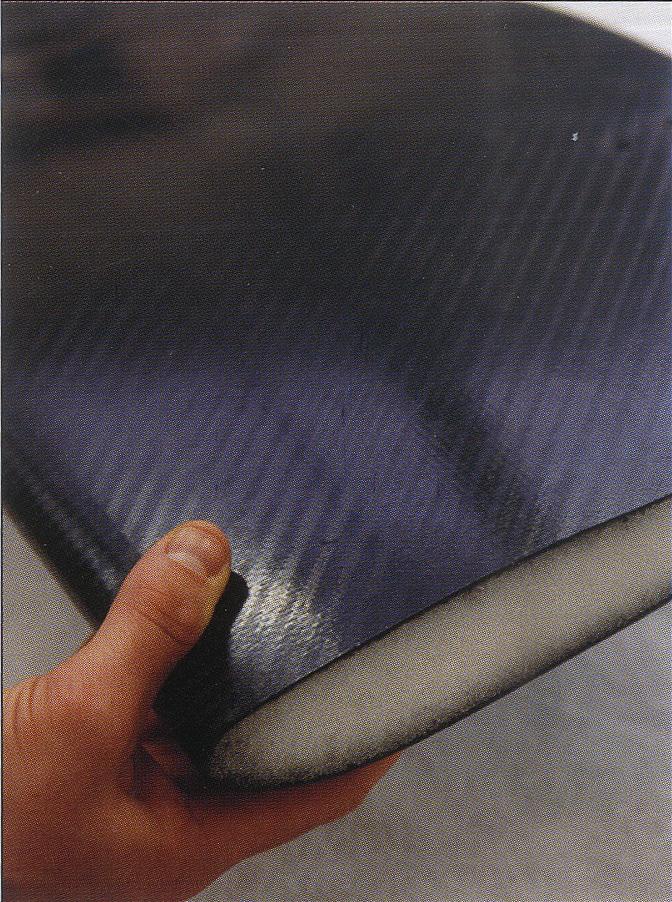
It is general issue that inventions of engineering often find in modern composites. These unusual materials marked the beginning of a new era in materials development and assembly engineering for high performance circumstance. For example, Polymer and ceramic composites were the first high performance fibre reinforced materials and were born from the needs of an industry (the aeronautical industry of the mid 20th century) that required the greatest strengths under strict weight limitations(Fig. 2.42, 2.49)
Since the reinforcement material is one of the most important issues in the strengthening mechanism of a composite, According to the characteristics of the reinforcement, it is suitable to classify composites. The following three categories are frequently used. (Fig. 2.46, 2.47, 2.48)
1. Fibre Reinforced – In this category of composites, the fibre is the primary load-bearing component.
2. Dispersion Strengthened – In this category, the matrix is the main load-bearing component.
3. Particle Reinforced – In this category, the load is shared by the matrix and the particles.
Composite construction can divide into two primary forms: micro-composite and a macro-composite. Referentially, a scale of composites is questions that the difference between micro and macro scale.
Micro-composite: The combination of materials to form a rigid and effectively monolithic matrix, such as glass reinforced plastic or carbon fibre resin construction. (Fig. 2.44)
Macro-composite: The bonding or mechanical fixing of dissimilar materials into a layered assembly where the materials remain identifiable in the final component. (Fig. 2.45)
Especially, the advantages of micro-composites are:
- Lightweight components with a high strength-to-weight ratio
- components that are very strong and stiff
- ability to orientate fibres with the direction of principle stress and thus achieve high structural efficiency
- excellent corrosion resistance
- high resistance to impact damage (dependant on fibre selection)
- effectively zero thermal expansion, if required
- excellent fatigue characteristics
- mouldability: complex shapes can be readily made
- affordable one-off, prototype, or short production runs
- press moulding and resin transfer moulding are medium to high volume processes.
2. Method | 2.4 Production Technique
Cellular
Composite System | Baek Ki Kim, Juanjo G. Castellon
editorialfinal.indd 52 15/10/2010 08:43
Fig. 2.41 | General makeup of composite materials intended for high performance strength or stiffness application
053
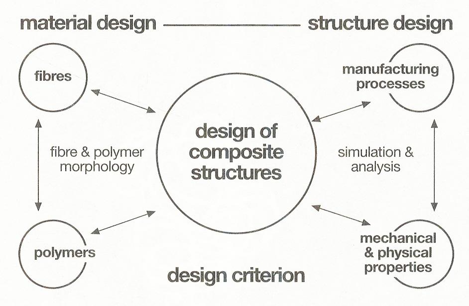
Fig. 2.43 | Design of composite structure includes the design of material and its local variations as well as the manufacturing process. (Adopted from Flying Lightness, 2007)
Fig. 2.42 | Classification of Composite materials
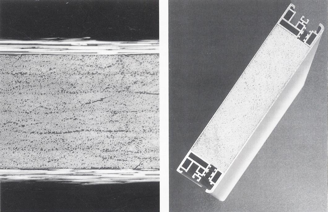
Fig. 083 | Cross-section of a composite metal and extruded polystylene panel (image courtesy of Corus)
Fig. 2.44 | Cross-section of 1mm thick carbon fibre composite, magnified 80 times. (image courtesy of Dr. Paul Smith)
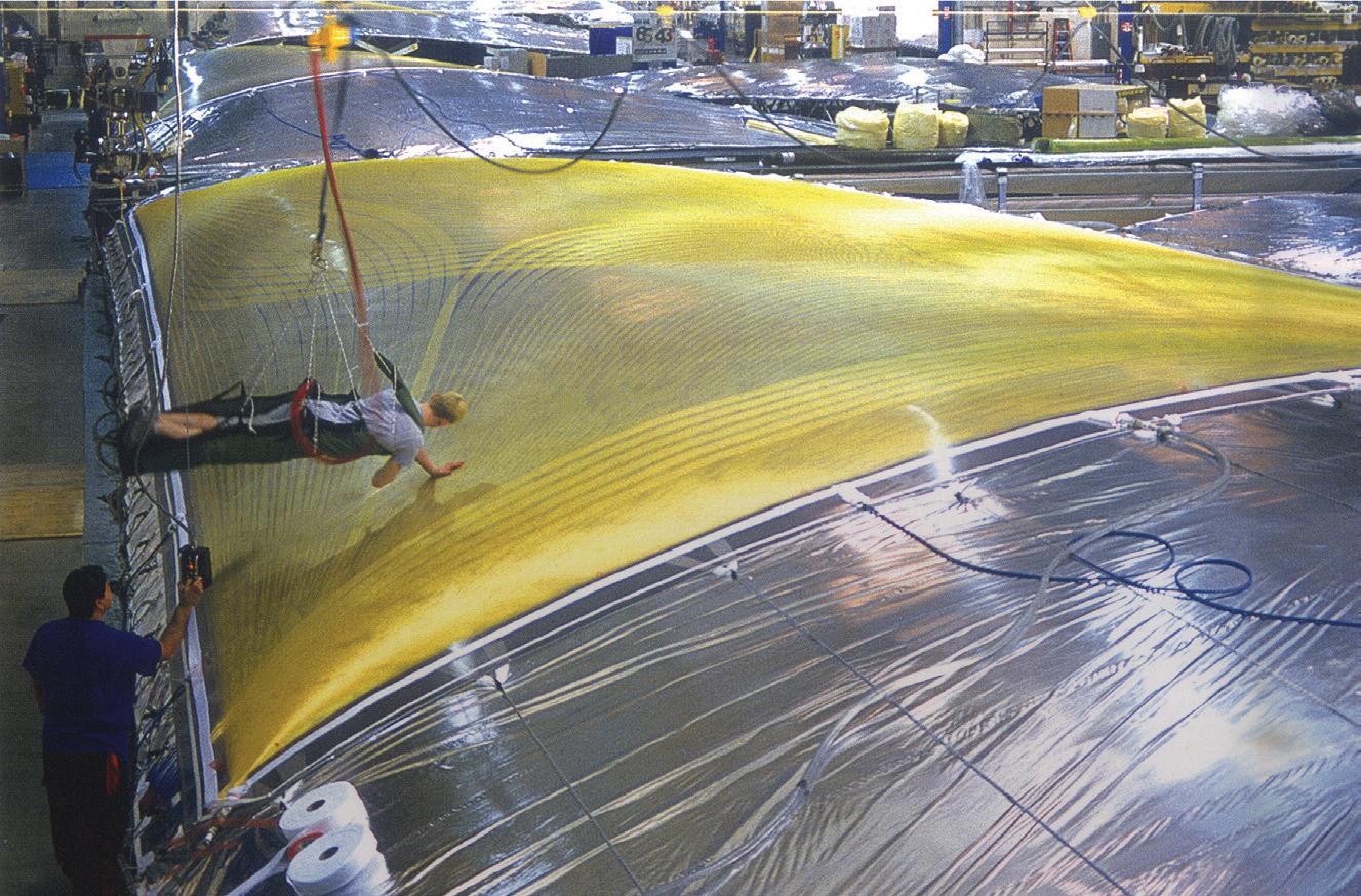
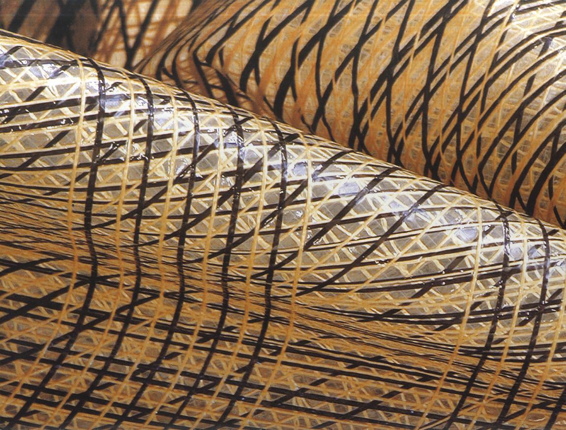
Fig. 2.45 | Aramid fibre sail on the mould table being inspected (North Sails) Fig. 2.46 | 3DLTM Sails, Moulded composite continuous carbon and aramid fibre laid in a pattern anticipating loads path laminated sheets of Mylar®
editorialfinal.indd 53 15/10/2010 08:43
Fig. 2.47 | Aerodynamic racing car spoiler is made by CNC machining PUR foam and incasing it in carbon fibre reinforced epoxy resin
B. Moulding technique
Moulding is the process and techniques of manufacturing through forming flexible raw materials using rigid frameworks or models that are usually called a pattern. It is basically used for more than two pieces of cloned objects.
In the section, we review several characteristic techniques that link our aimed-materials and other techniques such as ceramics, concrete and composites.
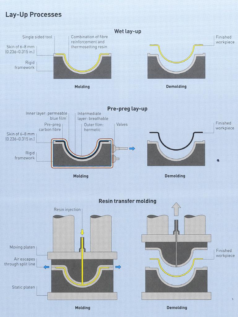
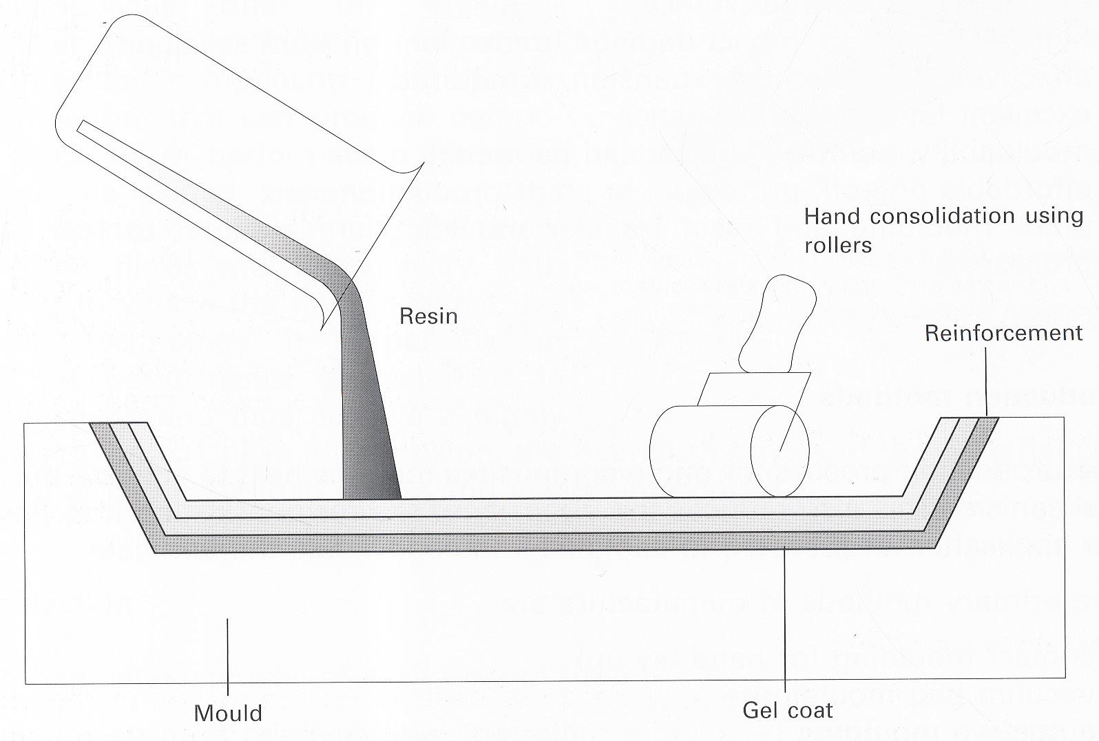
a. Contact Moulding (Fig. 2.49, 2.50)
The process of contact moulding sees the reinforcing material laid into a mould and the resin applied by brush or roller. Successive layers are built up as required, with each layer being consolidated to minimise air entrapment by rolling. Moulds are typically made of timber or fibre-reinforced plastic (FRP), and prior to the application of the reinforcing material, the mould is waxed and a release agent applied. At this stage, a gel coat is often applied; gel coats are thixotropic resins that will adhere to near vertical surfaces. The surface in contact with the mould is a high quality visual surface and can incorporate texture from the mould tool. There is effectively no limit to the size of component that can be produced. As with all moulded products it is essential to design the component so that it will be released from the former. A minimum mould angle of 1° is typical. However, 90° sides can be produced. An FRP lay-up will shrink as it cures by 0.1-0.4%, which needs to be allowed for in the mould design but aids release.
Pros and Cons:
- Smaller capital investment and can be found widespread application
- Difficulty to control the thickness
- Needs a highly skill process with manpower and relatively slow to make
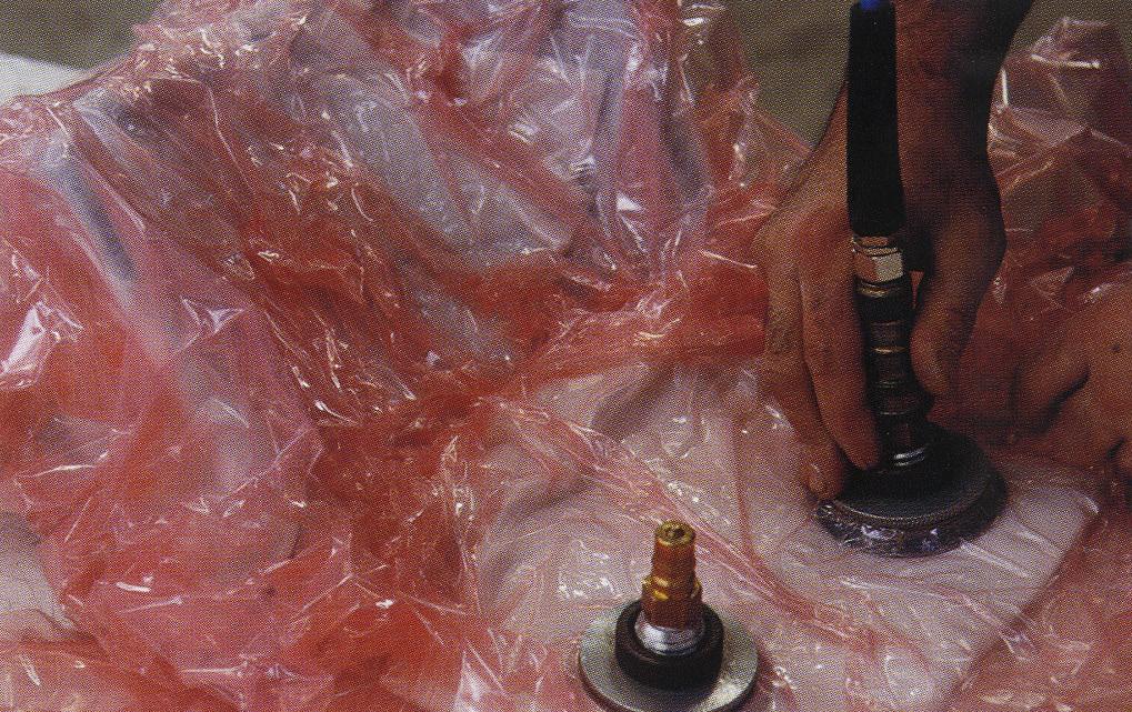
b. Vacuum bag moulding (Fig. 2.51, 2.52)
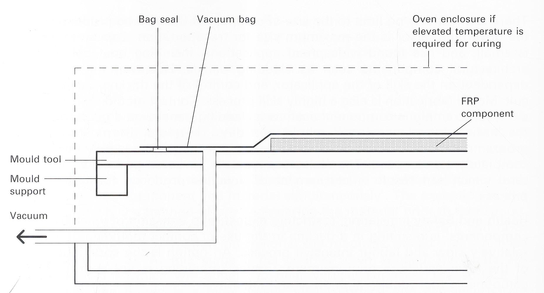
A vacuum is formed under a sealed bag applying an even pressure to the prepreg lay-up in the mould. The pressure is up to 1 atmosphere, 14 psi (1kg/cm2), and the assembly is then heated in an oven to between 60 and 180°C depending on the resin selected. The high quality visual surface is against the mould whereas the bag side is less precise. Unlike metal-faced composite panels, and for small to medium sized components, the bag is actually a moulded sheet of silicone, which itself can be formed for specific components.
Pros and Cons:
- Appropriate for components of complex forms with double curvature
- Can be used for large components
- The Cost of mould is low
- The highest structural integrity higher pressures are required
c. Resin transfer Moulding (Fig. 2.53)
Dry performed reinforcement, and core material when required, is placed in the lower half of a match tool. The tools are closed and clamped, and catalysed resin is injected under pressure. As the matched tool is subject to only 2-3 bar, tools can be made of FRP, metal-lined FRP, and aluminium. Typically, resin transfer moulding (RTM) is cost effective for the production of over 100 components, and for components up to 6,000 mm long. Components of close tolerance, which do not need machining, are produced with a good cycle time for example, a 5m component can be produced in 25 min including a gel coat stage. RTM has the advantage of being closed during the consolidation and curing process, thus emission of volatile organic compounds is minimised.
2. Method | 2.4 Production Technique Cellular Composite System | Baek Ki Kim, Juanjo G. Castellon editorialfinal.indd 54 15/10/2010 08:43

055
Fig. 2.50 | Contact moulding a polymer composite, also known as ‘hand lay-up’
Fig. 2.52 | Vacuum bag moulding a polymer composite
Fig. 2.53 | Resin transfer moulding (RTM) a polymer composite
Fig. 2.51 | Vacuum bag wrapped on the mould that preparing to vacuum
editorialfinal.indd 55 15/10/2010 08:43
Fig. 2.49 | Process of the Lay-up
2.4.2 Digital Production Technique
Computer Numeric Control (CNC)
The Computer Numeric Control technique is under the term a subtractive manufacturing technology is that machines are using high-speed spindles and relatively machine-able aluminium alloys to produce quick turnarounds for tooling and functional elements. It has also advanced to a point that it is current a complementary and sometimes opposed to alternative to additive manufacturing.
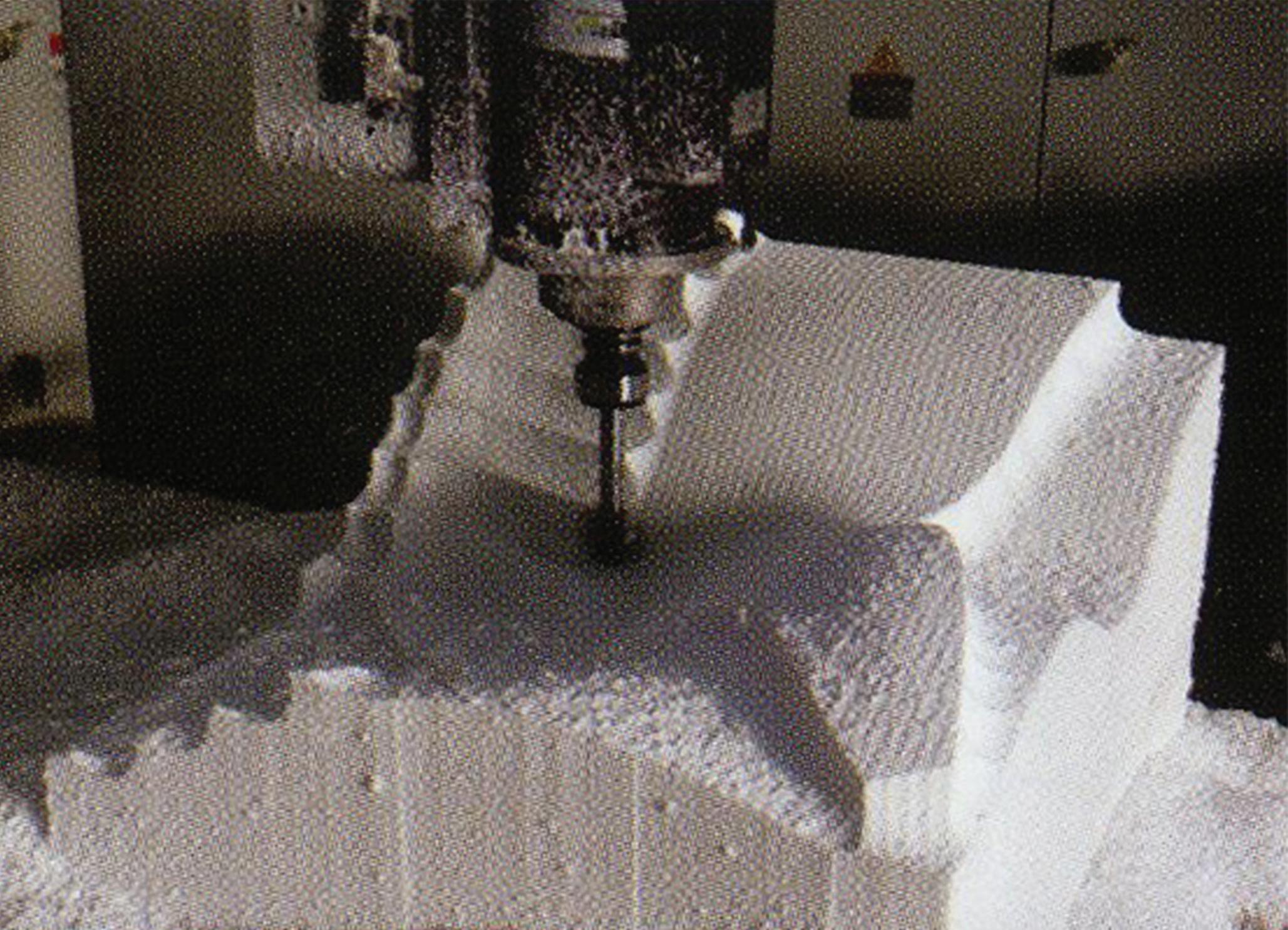
There is main methods that are three- or five-axis milling machine, Computer Numeric Control (CNC) cutting-plasma, laser or water jet. Especially, we were looked into a five-axis CNC milling technique as an advanced technique.
- Five-axis CNC milling
The five-axis CNC milling technique is basically using a CNC machine has capabilities of movement about five different axis simultaneously. Generally, CNC manufacture had 3-axial movement (X, Y, Z axis) with Z axis being parallel to the tool point through a computer numerical controlled method by CAD/CAM data. Further, the five-axis milling machine has the other two axis are reperesents the rotation of the cutting tool installed into the centre of spindle.
The advantage of five-axis milling is the capability of machines to complex geometrical forms in a initial set-up. It decrease the time for setup and increase productivity. Through reducing the time of machine’s setup, time and errors are decreased. In addition, it is allowed along X,Y axis since simultaneous movement that can be used shorter and more rigid tools.
2. Method | 2.4 Production Technique Cellular Composite System | Baek Ki Kim, Juanjo G. Castellon editorialfinal.indd 56 15/10/2010 08:43

057
Fig. 2.54 | The tooling process for the Ceramic Skin by Cloud9’s Villa Nurbs project
editorialfinal.indd 57 15/10/2010 08:43
Fig. 2.57 | CNC machining process
2.5 Evaluation & Methodological Scheme
The researches of methods are given methodological outcomes that can be combined together with traditional methods and digital methods in terms of the fabrication process.
It will be developed through schematic experiments with an active material with its dynamic production techniques and logics of assembly for pre-construction. Furthermore, four categorised concepts: the algorithmic control, the component, its production logics and its assembly logics will be developed to synchronise between the digital process and the physical process. (Fig. 2.53)
A. Algorithmic control
In the centre of methodology, the algorithm can control each geometry of the component, generated parameters for production and given tactics for assembly of the component through a global form.
B. Component:
The system will basically be composed with a core material and several matrix materials such as ceramics and concrete in terms of structural composites. In parallel, the elements of the system can be generated by defined parameters at a micro scale.
C. Production Logics:
The production logics will be reflected in our hierarchical logics based on parameters in terms of panelisation. Also, it will provide a strategy for feasible production concepts that have a deep understanding about conventional manufacturing techniques and its benefits with its development as an advanced production system.
D. Assembly Logics:
The assembly logics will be linked to notions of construction with its connection logics. Therefore, it will interconnect with above Component and Production Logics and form as a bridge. In addition, it will be the propose of a strategy of construction methods as a macro scale.
2. Method | 2.5 Evaluation & Methodological Scheme Cellular Composite System | Baek Ki Kim, Juanjo
Castellon editorialfinal.indd 58 15/10/2010 08:43
G.
059
editorialfinal.indd 59 15/10/2010 08:43
Fig. 2.57 | Diagram of methodological scheme in three system
3. Experiment
editorialfinal.indd 60 15/10/2010 08:43
3.1 Introduction
3.2 Material Composite Test
3.2.1 Flat Panel Composites
3.2.2 Mechanisms of Honeycomb
3.2.3 Curved Panel Composites
3.3 Definition of Parameter & Logics
3.3.1 Geometric Parameter
3.3.2 Production Logics
3.4 Evaluation & Summary
061 editorialfinal.indd 61 15/10/2010 08:43
3.1 Introduction
This chapter will show experiments that compromise traditional, contemporary and advanced scale of fabrication in the fundamental research. As a result, it has schemes of two key experiments, which are composite material system and its dynamic production logics by the algorithmic control methods.
The experiment is mainly composed of two steps: a material composite test and definitions of geometrical parameters and production logics. In the material composite test, it will test a materiality with composite techniques that use honeycomb as a core material and cement or concrete as a matrix material. It could be used as a structural component for a building envelope. In addition, the research will attempt to define a geometrical parameter that can be generated as a form of basic components by its algorithmic logics such as a tangency rule. Beyond those, the schematic moulding prototype can be produced by generated parameters through algorithmic logics.
3. Experiment | 3.1 Introduction Cellular Composite System | Baek Ki
editorialfinal.indd 62 15/10/2010 08:43
Kim, Juanjo G. Castellon
063
editorialfinal.indd 63 15/10/2010 08:43
Fig. 3.01 | The diagram of Area of experiment in this chapter
3.2
Material Composite Test
3.2.1 Flat Panel Composite
3.2.2 Mechanisms of Honeycomb
3.2.3 Curved Panel Composites
3. Experiment | 3.2 Material Composite Test Cellular Composite System | Baek Ki Kim,
G. Castellon editorialfinal.indd 64 15/10/2010 08:43
Juanjo
065
editorialfinal.indd 65 15/10/2010 08:43
Fig. 3.02 | Tactical diagram for material composite test.
3.2.1 Flat Panel Composites
A. Aims
Combining two or more materials is a frequent technique for developing performances of a specific purpose. Basically, it will demonstrate the cement-filled honeycomb structure. In terms of composite techniques, this research tests two techniques with a flat honeycomb panel and several matrix materials for finding an appropriate combination of materials.
B. Composite experiment
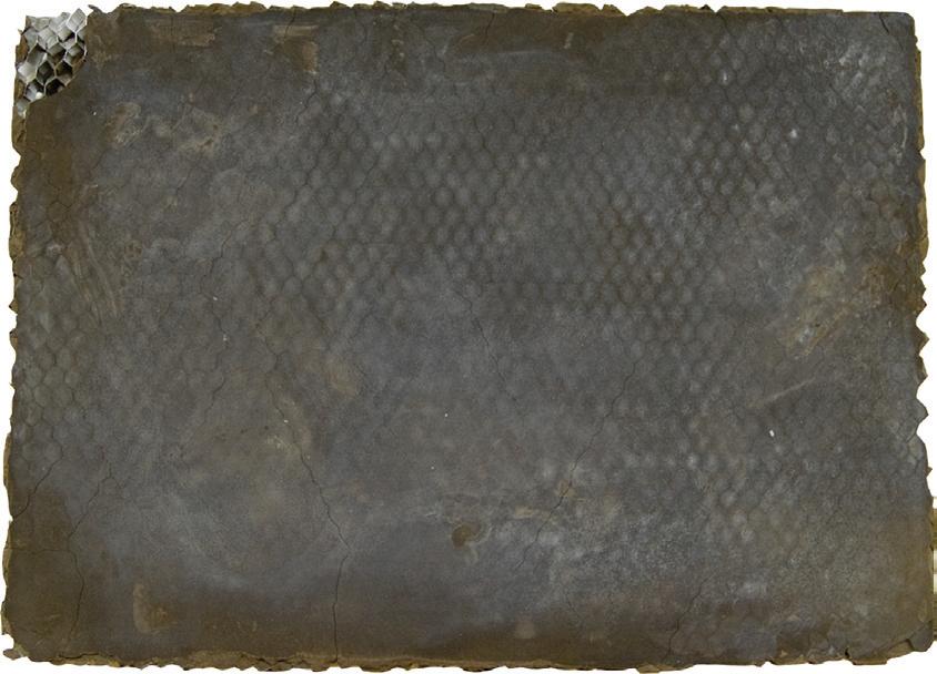
a. Experiment 01 (Fig. 3.03)
- Aluminium based Honeycomb panel (A4 sized rectangular x 10mm thick x 6mm sized cell)
- Fine art cement powder
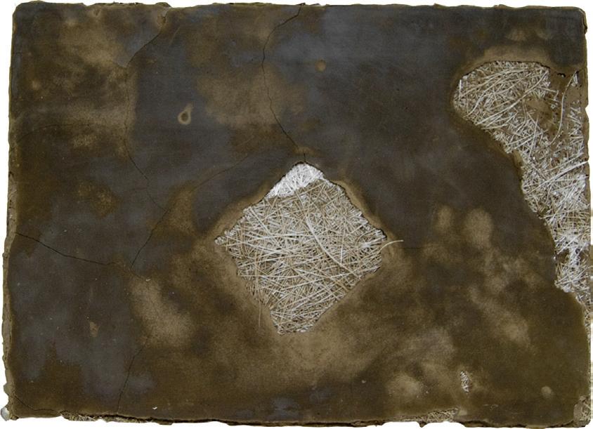
b. Experiment 02 (Fig. 3.04)
- Aluminium based Honeycomb panel (A4 sized rectangular x 10mm thick x 6mm sized cell)
- Fine art cement powder
- Glass Fibre sheet
3. Experiment | 3.2 Material Composite Test
Cellular Composite System | Baek Ki Kim, Juanjo G. Castellon editorialfinal.indd 66 15/10/2010 08:43
Fig. 3.07 | Diagram of the Cement-filled honeycomb composite.


067
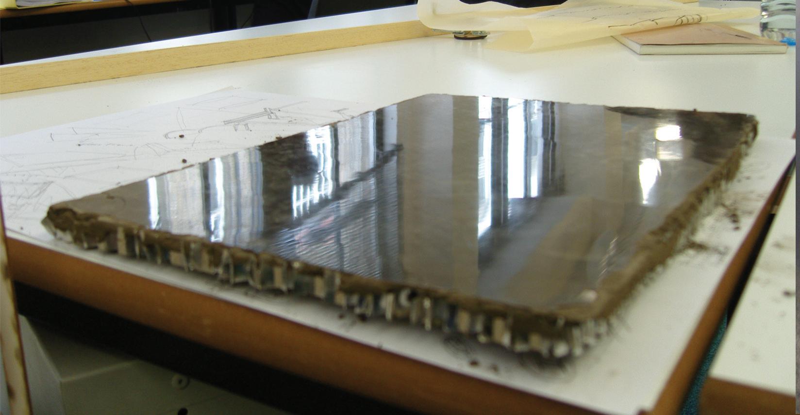
Fig. 3.05 | Glossy effect surface by a Plexiglas-surfaced moulding bed
297 mm 210 mm
Fig. 3.03 | The sequence of flat panel composite (Honeycomb + Fine Art Cement)
Fig. 3.04 | The sequence of flat panel composite (Honeycomb + Glass Fibre Sheet +Fine Art Cement)
Step 1 Prepare the Plexiglas-installed moulding bed Step 1 Prepare the Plexiglas-installed moulding bed Step 2 Pour the cement mixture on the bed for the first layer Step 2 Pour the cement mixture on the bed for the first layer Step 3 Spread the mixture for flatten Step 3 Attach the glassfibre sheet Step 4 Attach the honeycomb panel Step 4 Attach the honeycomb panel Step 5 Pour the cement mixture by filled in cells Step 5 Pour the cement mixture by filled in cells editorialfinal.indd 67 15/10/2010 08:43
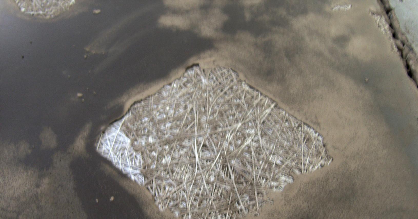
Fig. 3.06 | Glassfibre-reinforced panel has broken-surface problems
3.2.1 Flat Panel Composites
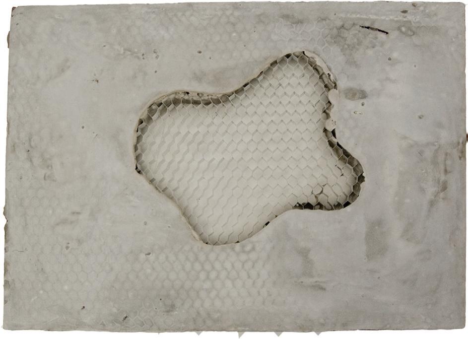
C. Application experiment (Fig. 3.09)
- Alucoat’s Aluminium based Honeycomb panel (A4 sized rectangular x 10mm thick x 6mm sized cell)
- Larfarge’s Extra Rapid cement
- Polyester Resin with hardener
D. Conclusion
To sum up, the composite technique applied to the aim found the appropriate combination of materials, a honeycomb with cement mixture. On the other hand, the matrix materials sometimes require reinforcement (such as fibre-reinforced concrete) and the composite material does not chemically react with each material (aluminium honeycomb and cement). In addition, it is already filled by the matrix and could lose elastic behaviours. Hence, a sequence of matrix filling should be done after the generation of each panel. Although it is just a cement-filled honeycomb panel, the cement can also be worked as a formwork with honeycombs.
3. Experiment | 3.2 Material Composite Test Cellular Composite System | Baek Ki Kim, Juanjo G. Castellon
editorialfinal.indd 68 15/10/2010 08:43
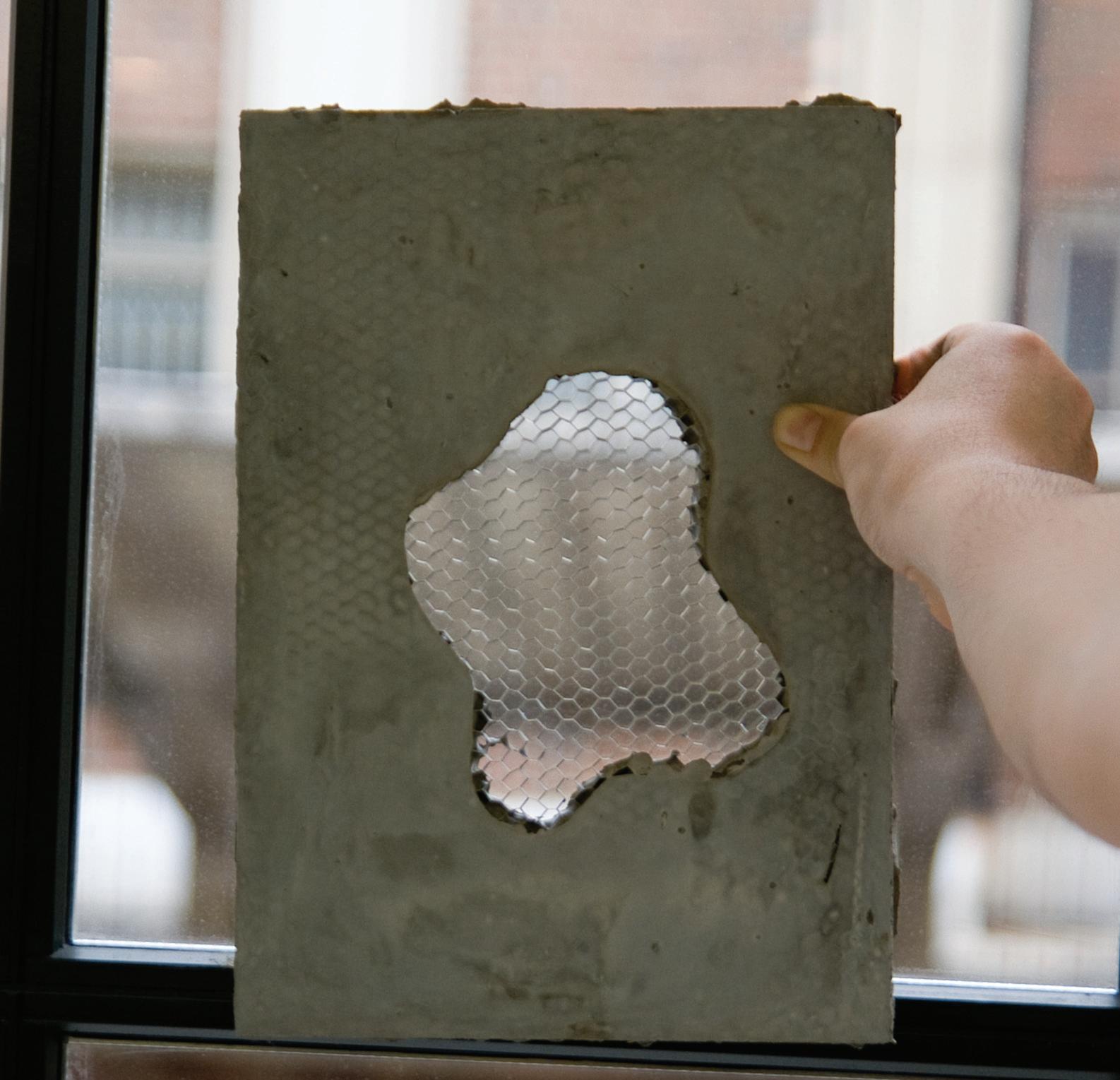
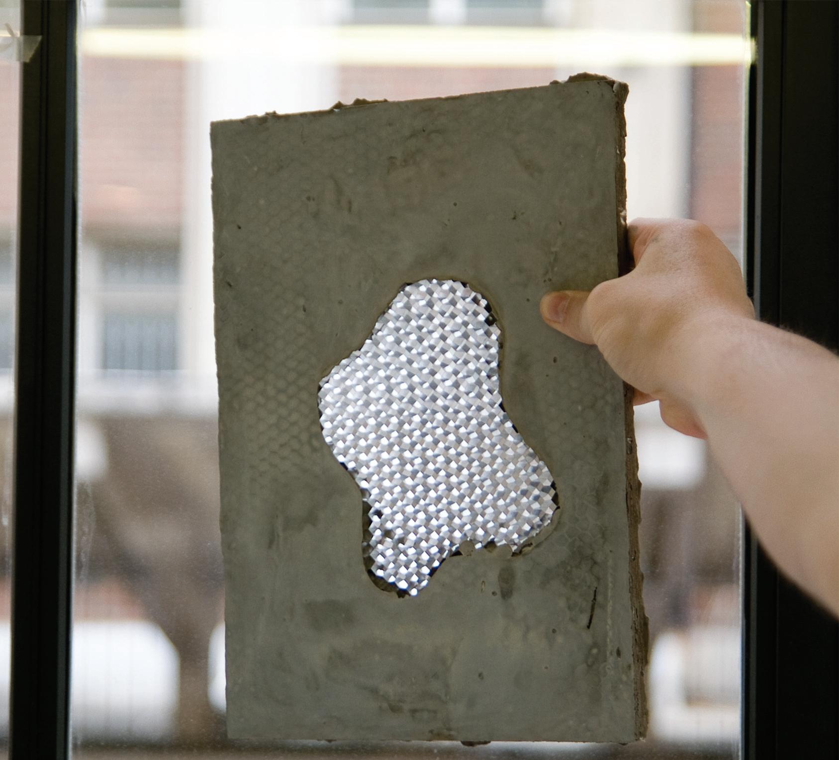

Step 1
Prepare the Plexiglas-installed moulding bed
Step 2
Coating oil-based detacher on the moulding bed’s surface
Step 3
Gradually Pour polyester resin that mixed with hardener.
The ratio of mixture: 10 : 1 Resin : Hardener
Step 4
Dry and harden during 10 hours
069
Fig. 3.07 | Void opening test (Ventilation)
Fig. 3.09 | The sequence of opening test
Fig. 3.08 | Resin-filled opening (Window)
editorialfinal.indd 69 15/10/2010 08:43
3.2.2 Mechanisms of Honeycomb (Deformation)
A. Aims
A honeycomb panel material is a qualified structural material in the engineering field. Especially, it has solid structural capabilities like that under compression, but it is extremely lightweight. However, the project finds more flexible possibilities of its deformation, in particular, under a tensile stress beyond just the flattened status of its geometries.
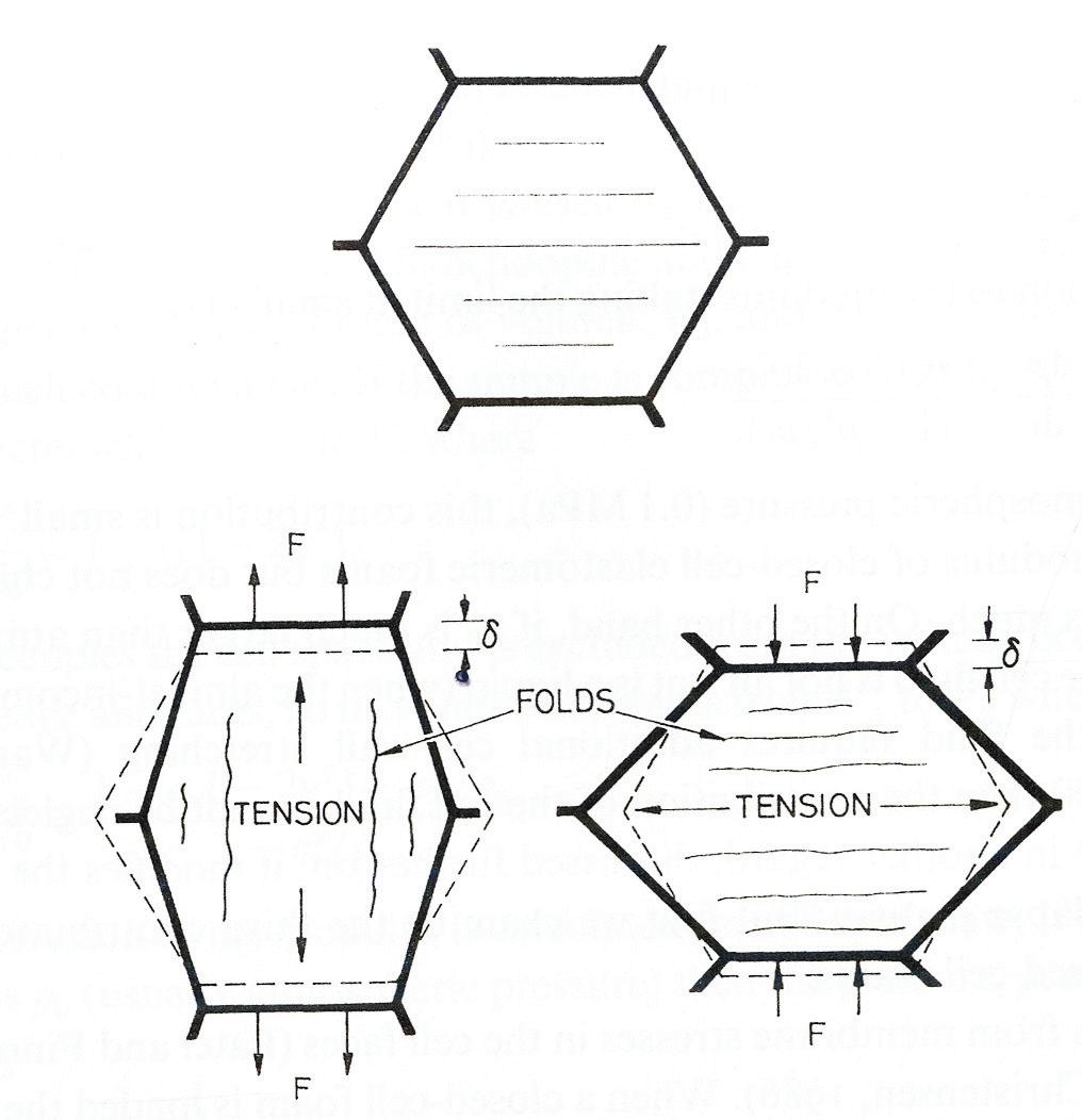
B. Fundamental tensile behaviours of honeycomb (Fig. 3.12)
When a closed-cell foam is loaded, the bending of the cell edges causes the cell faces to stretch (Fig. 3.12). The stretch direction when the loading is compressive is at 90 degrees to that when the loading is tensile, but the magnitude is similar in both cases. It is calculated as follows. The force, F causes the cell edge to deflect by σ (Fig. 3.12). The structure is linearly elastic, so work ½ Fσ, is done against the restoring force caused by the cell edge bending and face stretching. The first of these is proportional to ½ Sσ2 where S is the stiffness of the cell edge (S∝EsI/l3). The second is proportional to ½ Es∉Vf where ∉ is the strain caused by the stretching of a cell face, and Vf the volume of the solid in a cell face (∉∝σ/l and Vf∝l2tf, where, temporarily, we distinguish the thickness of the edges, te form that of the faces, tf).
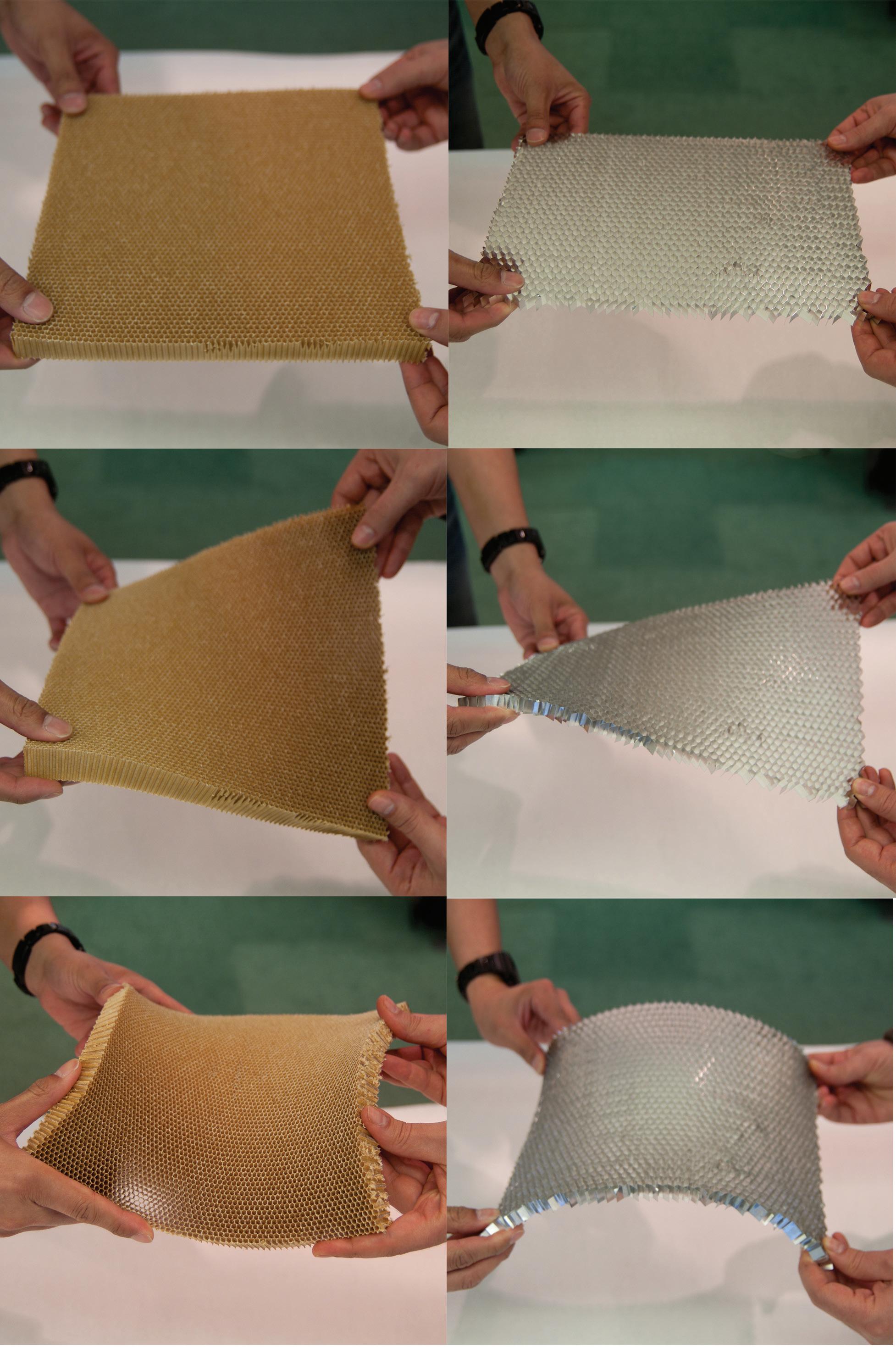
C. Physical experiment of honeycomb deformation
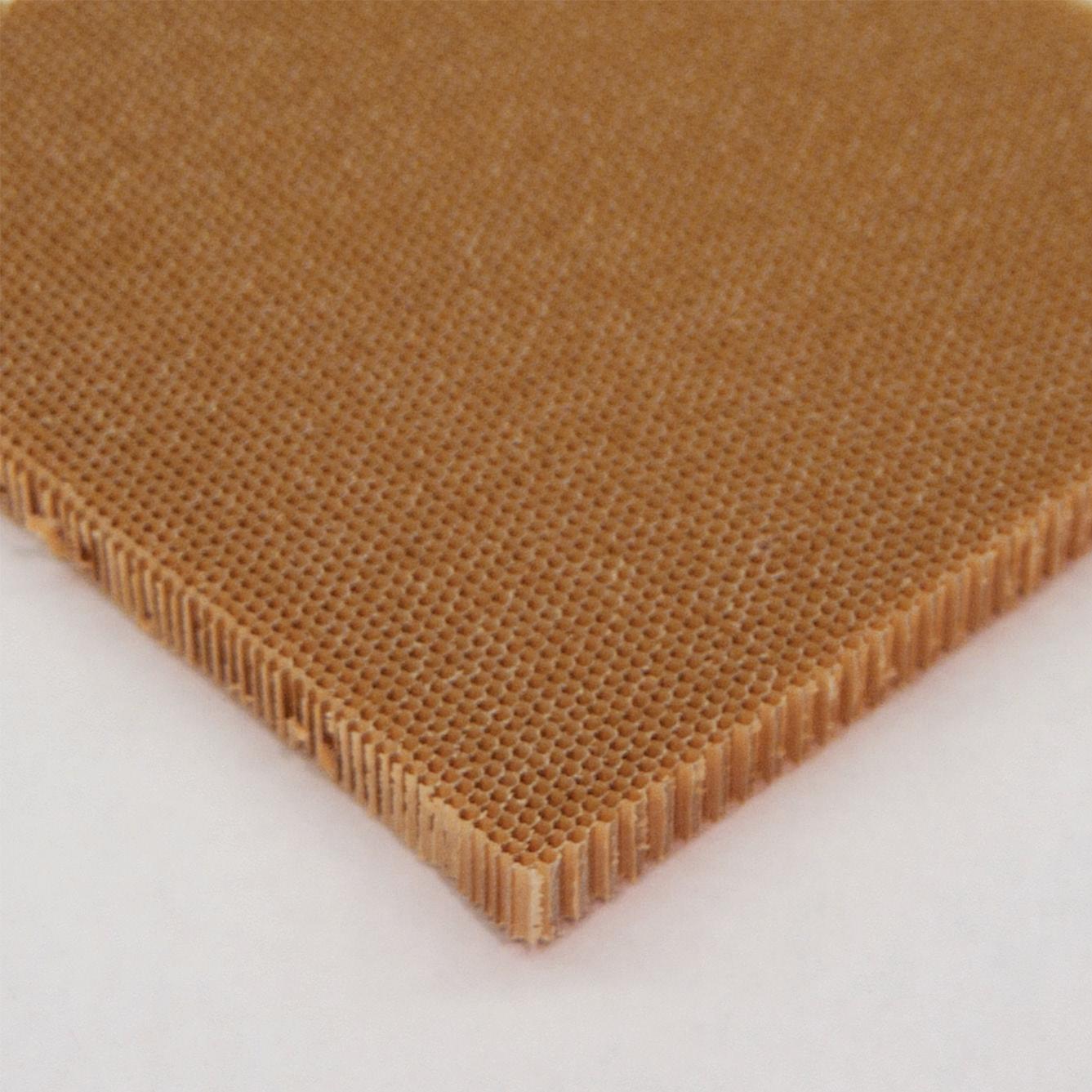
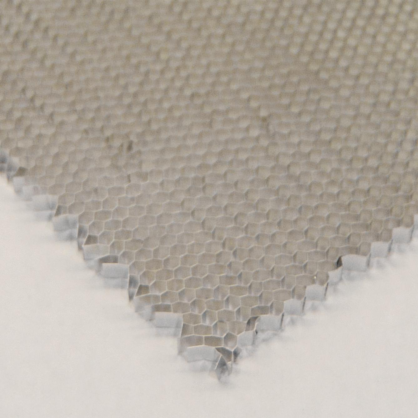
The physical experiment uses two characteristic honeycomb materials: an Aramid fibre (Nomex®)-based panel and an aluminium-based panel. It has elastic behaviours of deformation, but slightly different results following its typical materiality.
C.1 Aramid fibre-based honeycomb (200mm square x 20mm thick x 2mm sized cell)
- Makes surface quality smooth
- Very flexible materiality, but quite stable movement
- Easy to tear like paper and good to burn.
- Higher cost of material
C.2 Aluminium-based honeycomb (A4 sized rectangular x 10mm thick x 6mm sized cell)
- Has a limited value of deformation
- More rigid than aramid fibre-based honeycomb
- Medium cost of material
D. Conclusion
Overall, the honeycomb has the potential of elastic behaviours with its mechanisms of material. Especially, the anticlastic deformation in bending test shows an interesting point for establishing principles of geometry generation. However, the aramid fibrebased material is easy to tear like paper and an aluminium-based material is quite rigid for deforming, on the other hand it could become a suitable material for development.
3. Experiment | 3.2 Material Composite Test
Fig. 3.10 | Aramid Fibre (Nomex®) based Honeycomb
Fig. 3.11 | Aluminium based Honeycomb
Fig. 3.12 | Stretching the faces of a closed-cell foam in compression and tension. (Adopted from Cellular Solid, 2001)
Cellular Composite System | Baek Ki Kim, Juanjo G. Castellon
editorialfinal.indd 70 15/10/2010 08:43
071
editorialfinal.indd 71 15/10/2010 08:43
Fig. 3.13 | General deformation test of honeycomb panels left column: Aramid Fibre based honeycomb right coloumn: Aluminium based honeycomb Stretching Twisting Bending
3.2.3 Curved Panel Composite
A. Aims
The experiment of curved panel composite is applied the composite techniques (Cement-filled honeycomb Fig. 3.07) to curved geometries of the honeycomb panel based on the flat panel composite experiment. (see the 3.2.1 Flat panel composite) In terms of composite techniques, the experiment is tested the techniques that use a curved honeycomb panel, generated by the moulding tool with several matrix materials for finding an appropriate combination of materials. (see chapter 4. Design Development)
B. Composite experiment (related to chapter 4. Design Development)
- Aluminium based Honeycomb panel (A4 sized rectangular x 10mm thick x 6mm sized cell)
- Larfarge’s Extra Rapid Cement
C. Conclusion
Overall, the composite experiment shows some potential issues. Especially, relate to logics of assembly with connection techniques under a feasible construction system. Also, how the component can join together more cohesively such as inherited the techniques as cohesive construction.
3. Experiment | 3.2 Material Composite Test Cellular Composite System | Baek Ki Kim,
Juanjo G. Castellon
editorialfinal.indd 72 15/10/2010 08:43
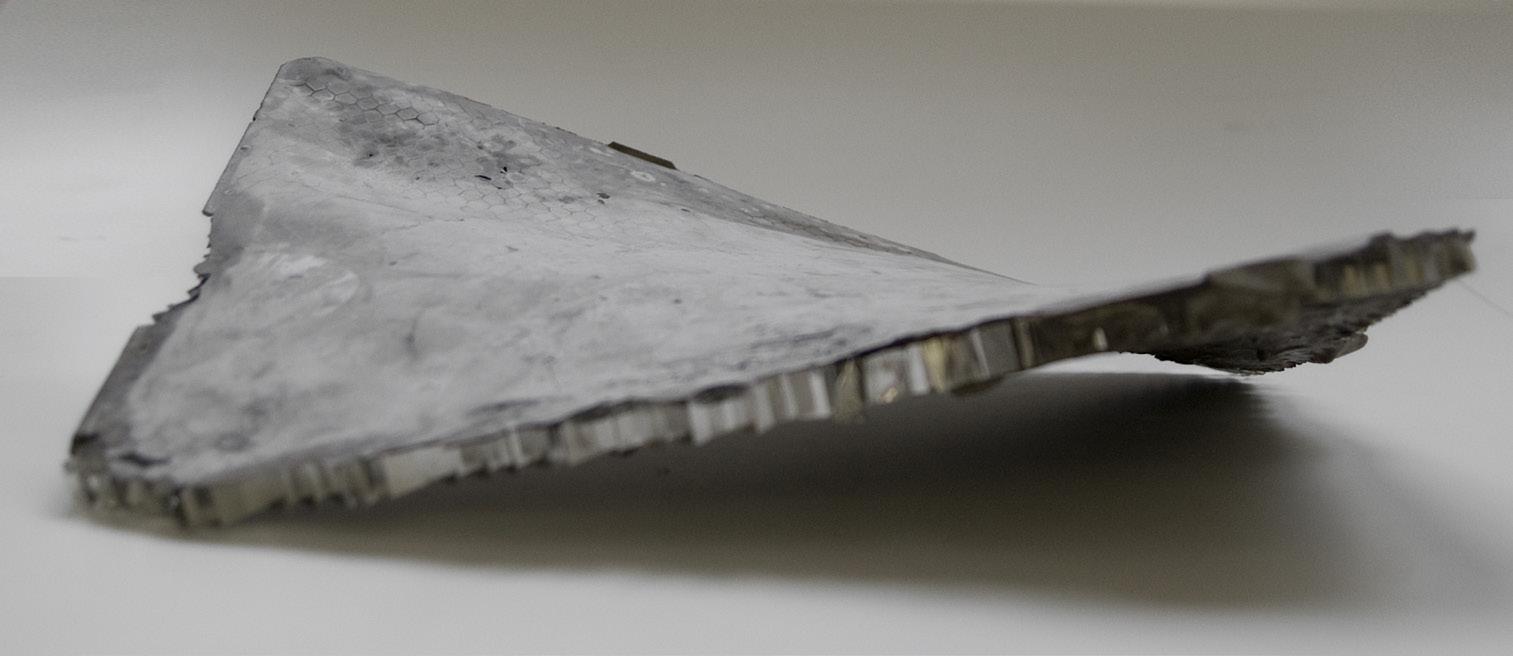
Fig. 3.07 (same as previous) | Diagram of the Cement-filled honeycomb composite.


073
Fig. 3.16 | The pre-assembled composite panel in assembly experiment
Fig. 3.14 | The produced first prototype component of curved panel composite.
Fig. 3.15
editorialfinal.indd 73 15/10/2010 08:43
| The magnified view of the panel. ( an issue of quality controls of it surface)
3.3 Definition of Parameters & Logics
3.3.1 Geometric Parameter
3.3.2 Production Logics
3. Experiment | 3.3 Definition of Parameters & Logics Cellular Composite System | Baek Ki Kim, Juanjo G. Castellon editorialfinal.indd 74 15/10/2010 08:43
3,17 | Tactical diagram for relationship with parameters and logics.
075
editorialfinal.indd 75 15/10/2010 08:43
Fig.
3.3.1 Geometric Parameter
A. Aims
This experiment will explore to define parametric logics for generation of geometric component that can be formed a global form from elemental geometry. It has two categories of linked-development: geometric parameters and a physical mechanic tool that can be synchronised between digital and physical operations.
B. The parameter (Fig. 3.18, 3.19)
The geometric parameters are divided into two main-categories: twisting and bending in surface deformation. It can be generated by a numeric control process. The basic set of the surface-plane has several controllable points: pivot, four nodes each edges, midpoints of two shorter-length sides. The values of each point can generate the geometries of a component. Thus, it can sort out the different configurations for a generation of components as well as link apparently unlinked components by its geometric definition beyond only a visual appearance.
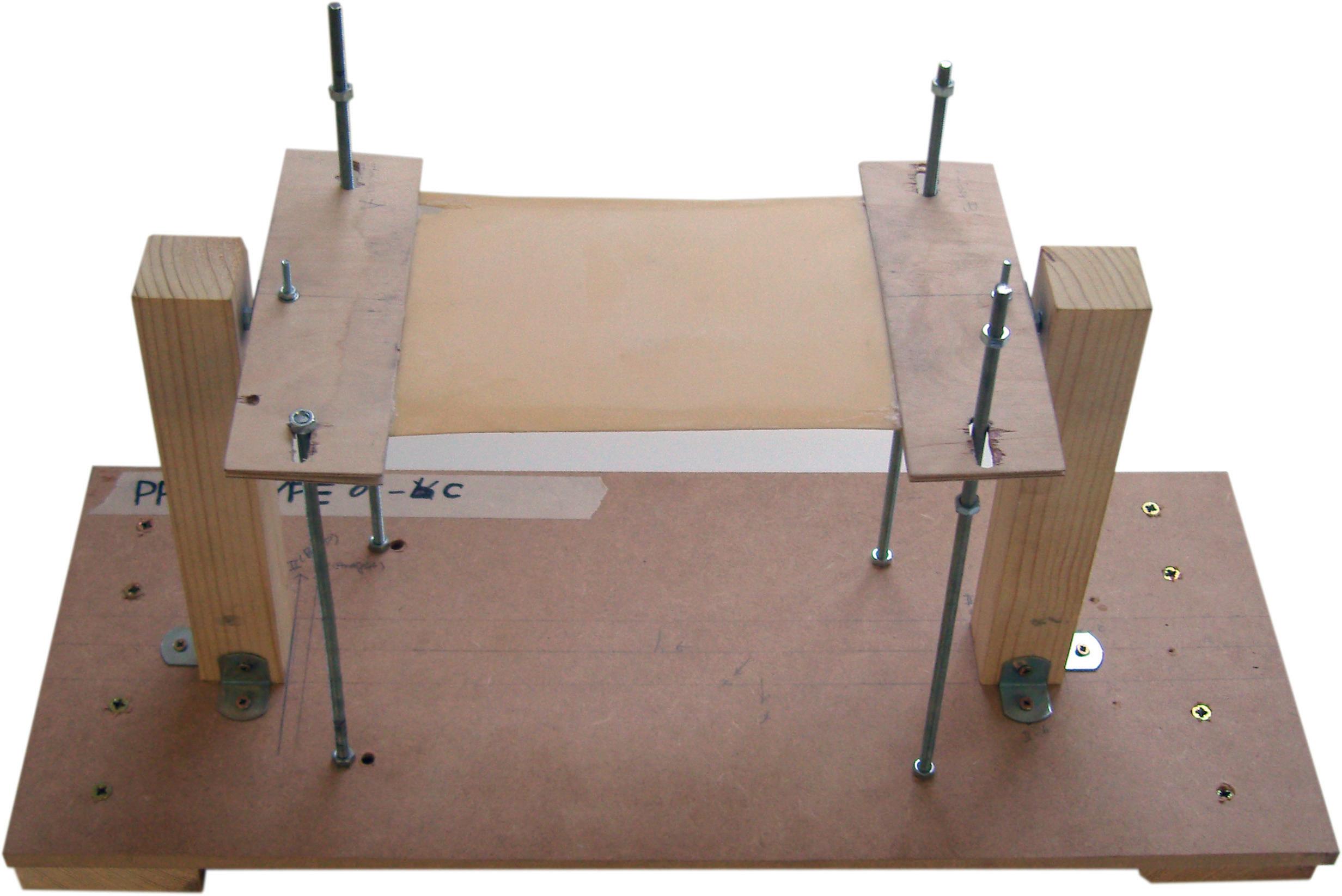
C. The physical mechanic tool; Prototype tool 01 (Fig. 3.20)
The physical mechanic tool can be operated by a generated parameter (numeric values). It has mechanical controllable points, which exactly translate from the geometric parameters with numeric values to physical mechanical movements. In addition, it will connect to production logics with its moulding techniques.
D. Evaluation (Summary)
The experiments set the starting point of the define logics for the geometric parameter. However, the initial schematic definition requires more feasible developments.
3.
3.3 Definition of Parameters & Logics
Experiment |
Fig. 3.18 | Defined fundamental parameters
Config. 01 | Neutral
Twist
Config. 02
|
| Bend Cellular Composite System | Baek Ki Kim, Juanjo G. Castellon editorialfinal.indd 76 15/10/2010 08:43
Config. 03
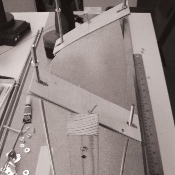
Mechanical behaviour 01 | Twist
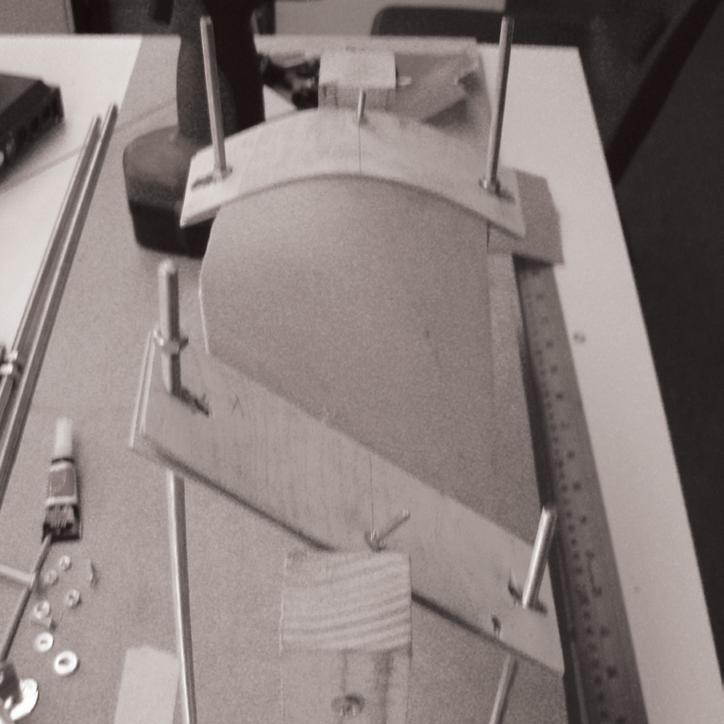
Mechanical behaviour 02 | Bend
077
Fig. 3.19 | Defined mechanical behaviours for the physical moulding tool
Fig. 3.20 | The schematic prototype of moulding system (Prototype 01)
editorialfinal.indd 77 15/10/2010 08:43
3.3.2 Production Logics
A. Aims
The production logics are set as sequences and produced elemental components that are based on defined geometric parameters. The main aims of the experiment are evaluated in real physical aspects for testing feasibility of production and finding problems in geometric parameters.
B. Material usage
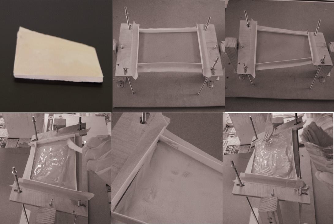
For the production, Larfarge’s plaster is used for the main moulding material. It has 4:3 ratios of the plaster powder and pure water mixture for making viscosity materiality before drying. Polyethylene sheets are used for the moulding enclosure that can be elastically deformed.
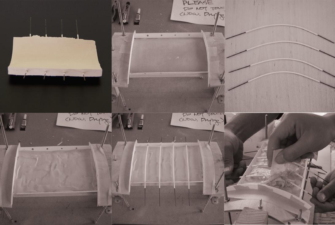
For the piece with a connection, 0.5mm-thick steel wire with 0.7mm-holed plastic pipe for embedded rebar test was used.
C. The sequence of production
There are two types of production: Twisted parameter (Fig. 3.22) and Bended parameter with rebar (Fig. 3.23). Furthermore, the experiment produced morphological sets of components by generated parameters (Fig. 3.21).
D. Evaluation (Summary)
As a consequence, the experiment can achieve a practical relationship with parameter and production logics. On the other hand, it needs to develop geometric parameters for the honeycomb panel as the proper core material, and also needs to use cement or concrete as the proper matrix material. Because the plaster is just provisional testing material that can quickly produce pieces.
3. Experiment | 3.3 Definition of Parameters & Logics Cellular Composite System | Baek Ki Kim, Juanjo G. Castellon
editorialfinal.indd 78 15/10/2010 08:44
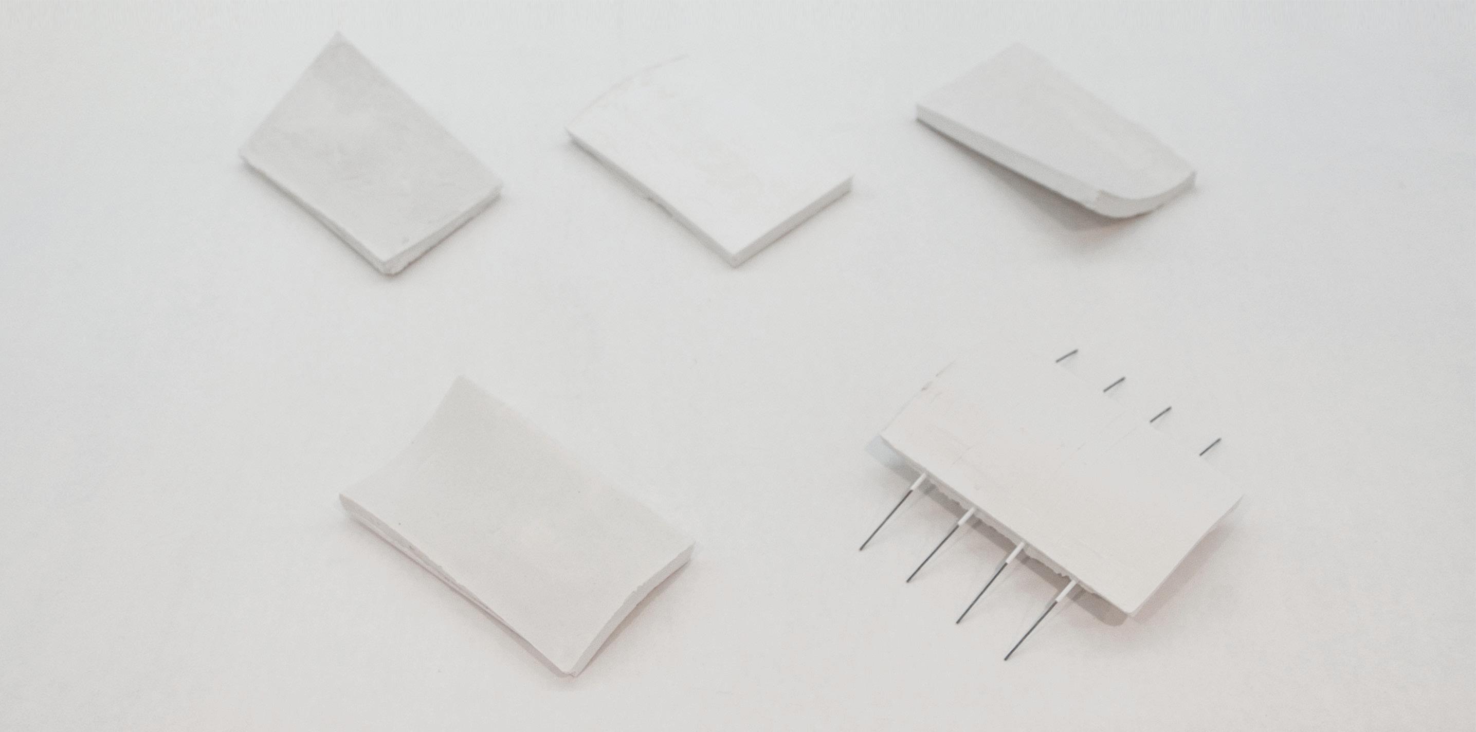
| Morphological sets of produced plaster component by generated parameters
Step a Produced twisted plaster component
Step b Set the enclosures
Step c Set the tool for the component geometry (Twist)
d Pour the plaster mixtrue for the first layer Step d Pour the plaster mixtrue for the first layer
Step e Dry the first layer for holding a base form
a Produced twisted plaster component
Step b Set the enclosures
Step e Dry the first layer for holding a base form
Step c Set the tool for the component geometry (Twist) Step f Fill the plaster mixtrue for final piece Step f Fill the plaster mixtrue for final piece
| The sequence of production
079
Fig. 3.21
Fig. 3.22 | The sequence of production (Twist)
Step
Fig. 3.23
(Bend + Rebar)
Step
a b c d e d a b c d e d editorialfinal.indd 79 15/10/2010 08:44
3.4 Evaluation & Summary
Through the experiments, several potential issues were found for development:
- Potential issues in the experiments:
1. Geometric parameters need to be reconsidered for matching aluminium honeycombs behaviours, in particular the bending parameter for honeycomb’s anticlastic behaviour.
2. The mechanical behaviours of the physical tool (Prototype tool 01) need to be developed for larger scale fabrication.
3. An assembly logics need to be defined in a feasible way.
Thus, the geometric parameter and production logics are achieved as part of the methods and it can be diagrammatised with those three main categories: the component, production logics and assembly logics with several production and connection techniques for design strategies (Fig. 3.24).
3. Experiment | 3.3 Definition of Parameters & Logics Cellular Composite System | Baek Ki
editorialfinal.indd 80 15/10/2010 08:44
Kim, Juanjo G. Castellon
081
editorialfinal.indd 81 15/10/2010 08:44
Fig. 3.24 | Three categories of generated component and logics with its related subjects.
4. Design Development
editorialfinal.indd 82 15/10/2010 08:44
4.1 Introduction
4.2 Geometric Parameters for the Component
4.3 Production Logics
4.4 Assembly Logics
4.5 Evaluation & Summary
083 editorialfinal.indd 83 15/10/2010 08:44
4.1 Introduction
This chapter will show the developments of the systems with regards to the potential issues in the previous chapter.
In detail, the potential issue of parameters and logics will be discussed under re-defined algorithms with generative software (e.g., Grasshopper), and the properties and performance of honeycomb panels will be analyzed in order to use them, both, as a three-dimensional dynamic moulding element and as reinforcement for our composite material system. In addition, the material system will be produced through developed production logics with a practical productive physical mechanic tool. In terms of assembly logics, the connection techniques achieve practical logics that can make solid structural performances as pre-assembled partial building envelop.
The diagram (Fig. 4.01) shows the design strategies of research that has three main top hierarchical systems: the Material system as the component, the Manufacturing system as the production logics and the Construction system as the assembly logics. The logics of each of these are closely connected and can affect each other.
4. Design Development | 4.1 Introduction Cellular Composite System | Baek Ki Kim, Juanjo G. Castellon editorialfinal.indd 84 15/10/2010 08:44
085
editorialfinal.indd 85 15/10/2010 08:44
Fig. 4.01 | Design Strategies of the systems
4.2 Geometric Parameter for the Component
4.2.1 Re-definition of Geoemtric Parameter
This development evolves geometric parameters based on initially defined parameters for selected core material (10mm thick, 6mm sized cell and 210mm by 297mm sized rectangular aluminium-based honeycomb panel).
The main development of the parameter is a shift in bending orientation. Referentially, the previous potential issue was that shorter length of edge, which is not enough to deform the honeycomb panel, the selected core material. This is because it is not only the edge length of honeycombs, but also the mechanical parameters of the physical mechanic tool that could have multiple mechanical behaviours in a single part, hence the part will not be accurate in control. (Fig. 4.02)
4.2.2
Ruled Surface
- The tangency rule
The development deepens a generative algorithm in terms of a tangency rule for a ruled surface. For continuous curvature, each component’s curvatures are kept tangent together, next to the continued curvature of the component (Fig. 4.02). Therefore, while one of the curvatures will be deformed, the other links every component that can be deformed respectively under the rule (Fig. 4.03). It is scripted through generative software such as Grasshopper with Rhino3D
4. Design Development | 4.2 Geometric Parameter for the Component
Cellular Composite System | Baek Ki Kim, Juanjo G. Castellon
Fig. 4.02 | Re - Defined fundamental parameters
Config. 01 | Twist
editorialfinal.indd 86 15/10/2010 08:44
Config. 02 | Bend
Fig. 4.03 (above) | The concept of tangency rules
Fig. 4.04 - 4.10 (right, below) | Digital parametric geometry generation (Grasshopper)
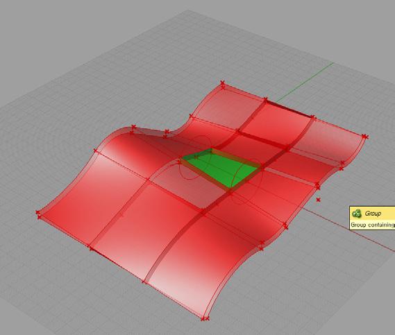
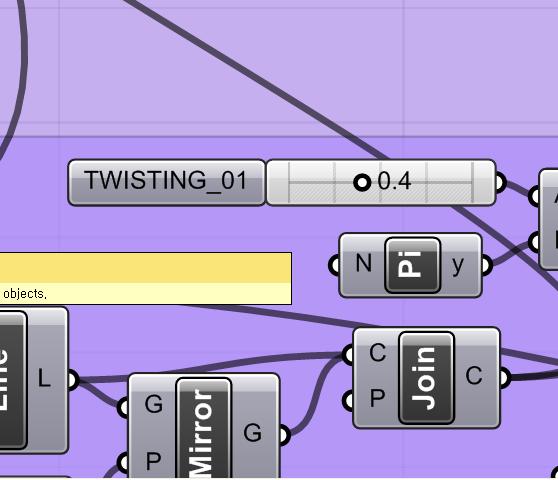
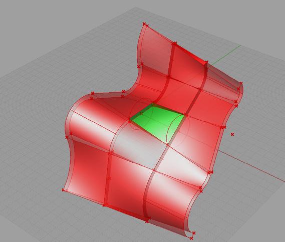
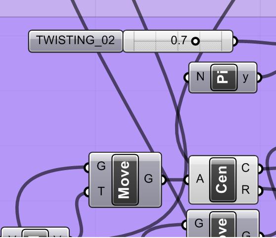
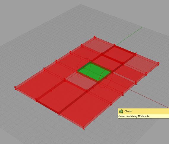
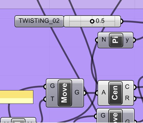
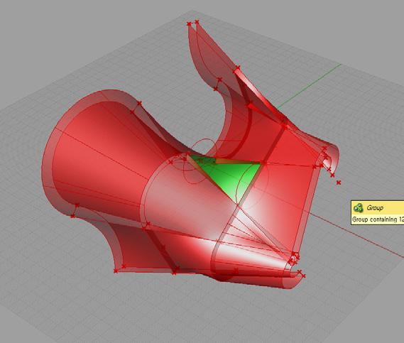

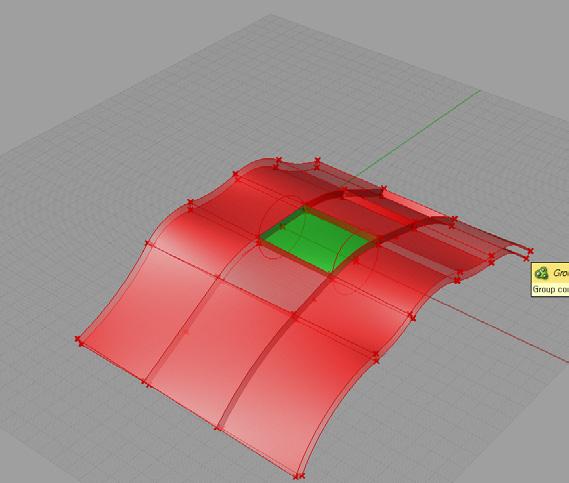
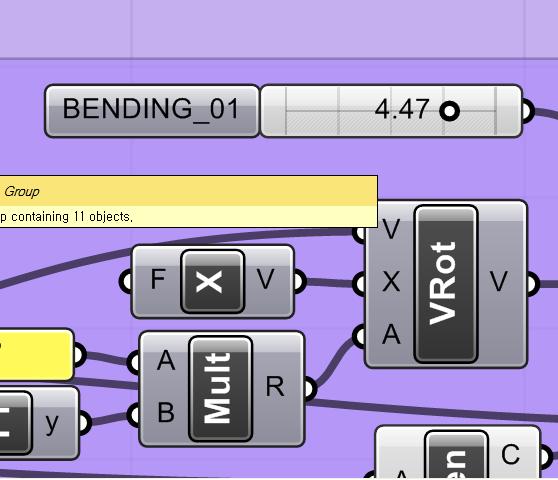

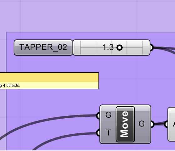

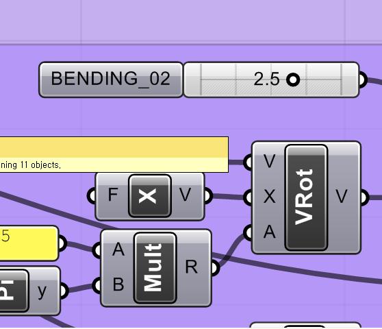
087
Fig. 4.05 | Twisting A side
Fig. 4.06 | Bending A side
Fig. 4.04 | Twisting both side
Fig. 4.07 | Twisting B side
Fig. 4.08 | Tapper
Fig. 4.09 | Neutral
editorialfinal.indd 87 15/10/2010 08:44
Fig. 4.10 | Bending B side
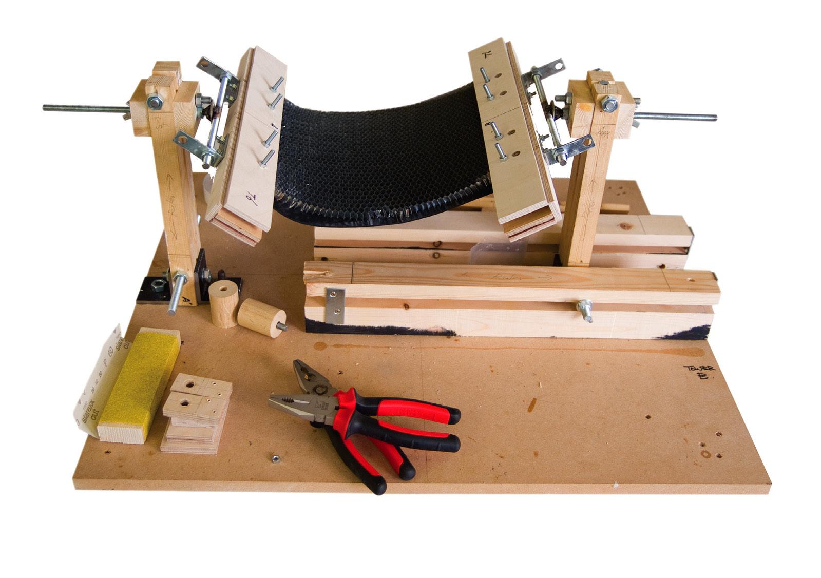
4.3 Production Logics
The production logics evolved through re-defined parameters with the second generation of a physical moulding tool (Fig. 00). It basically had two mechanical arms for generating two parameters (twisting and bending). The tool can produce a material system that uses a cement-filled honeycomb composite as the principle of production. In addition, terracotta clay makes a panel for finishing material on the topside. Interestingly, the honeycomb composite components can be worked as a formwork of ceramics.
A. Selected materials for production
- Matrix materials: Larfarge’s Extra Rapid cement
- Ceramics panel: Terracotta clay
- Core material: Alucoat’s aluminium-based honeycomb panel (10mm thick, 6mm sized cell and 210mm by 297mm sized rectangular)
B. The physical moulding tool (Fig. 4.11)
The physical moulding tool is developed through previous schematic model (see the 3. Experiment) with re-defined parameters and logics. It has several mechanical behaviours for moulding components with honeycomb panel as a core material of composites.
- Mechanical Arm (Twister and Bender)
In this stage, the tool needs two mechanical behaviours that are twisting parameter and bending parameter. So, it has two separated functions of mechanical devices that are a Twister and a Bender.
C. The sequence of production (Fig. 00)
- Component
The sequence of component production is composed with the moulding tool.
- Ceramics panel
The sequence of ceramics (Terracotta) production is composed with the produced composite panels as a formwork. It has two critical aspects in terms of deformation behaviours of the drying clay. Briefly, the deformations of dried clay have 15% difference between a single-formwork and a dual-formwork. The single-formwork has a deformation, which is slightly (15%) lift-up each two edges. (Fig. 4.12)
4. Design Development | 4.3 Production Logics
Cellular Composite System | Baek Ki
editorialfinal.indd 88 15/10/2010 08:44
Fig. 4.11 | The physical parametric moulding tool (Prototype 02)
Kim, Juanjo G. Castellon
Fig. 4.12 (above) | The deformation behaviours of clay in the formwork
Fig. 4,13 (right) | The sequences of terracotta production
Fig. 4.14 (below two) | The sequences of composite panel production

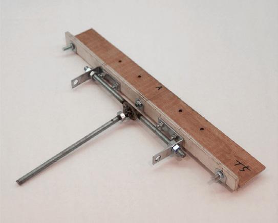
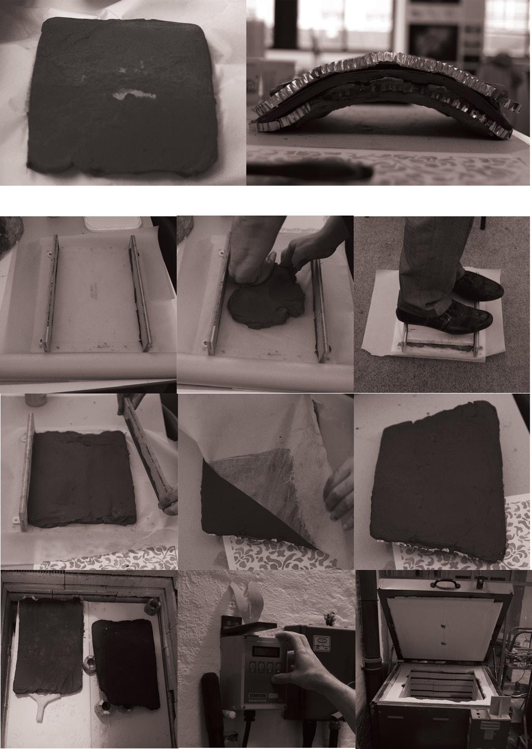


089
Step 1
Prepare the Plexiglas-installed moulding bed The mechanical arm for Twisting
the
Step 1 Prepare
Plexiglas-installed moulding bed
The mechanical arm for Bending
Step 2 Pour the cement mixture on the bed for the first layer
Step 2 Pour the cement mixture on the bed for the first layer
Step 3 Spread the mixture for flatten
Step 3 Spread the mixture for flatten
Step 4
Attach the honeycomb panel
Step 4
editorialfinal.indd 89 15/10/2010 08:44
Attach the honeycomb panel
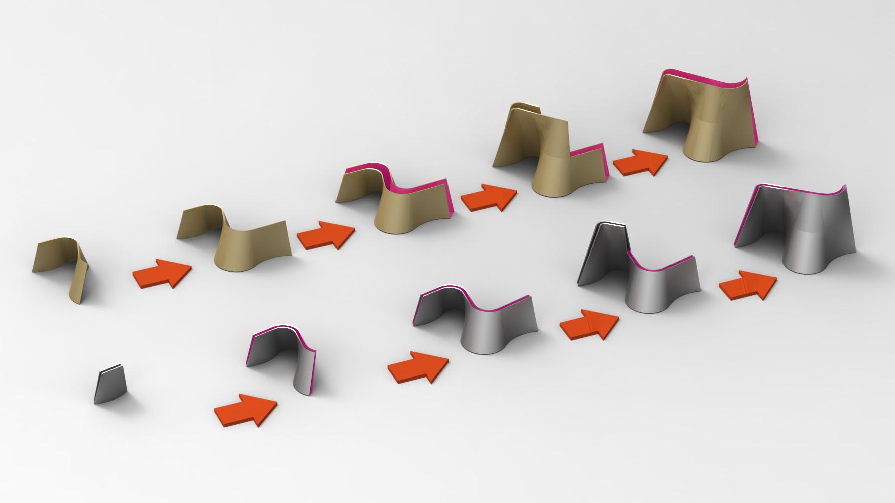
4.4 Assembly Logics
The assembly logics are developed with four pieces of produced prototype. These are connected through bolting mechanisms that are composed of general bolts and nuts. A provisional joint holds the positions of each piece in the right sequence. The linked pieces of double-layered, in between, reinforced concretes are poured into the gap (minimum 40 mm) so that it can be worked as a stable structural system.
- Assembly and construction
There are two slightly different ways of assembly.
a. Single panel assembly
The single-layered panel assembly connects each single composite panel with others by bolts. It can be composed with a single-lined flow of surface. Then, the sequences are iterated behind the first layer. After that, the two independent layers are adhered by reinforced concrete in a 150mm-gap area. Following that, it can be iterated in the same sequences.
b. Double-layered panel assembly
The double-layered panel assembly connects each single composite panel with bolts that are screwed on each side. Then, the connected double-layered panels are linked together with provisional four-side clips on a first row. The 80mm-gaps in between the double-layered panel are filled with reinforced concrete.
4. Design Development | 4.4 Assembly Logics
Cellular Composite System | Baek Ki Kim, Juanjo G. Castellon
Fig. 4.15 | The sequence of assembly and construction in two ways.
b. Double-layered panel assembly
Step 01. Connect panels in double-layered.
Step 01. Connect a single panel to next panel.
Step 02. Link the double-layered panel that make a flow of surface.
Step 02. Make a flow of surface.
Step 03. Pour a reinforced concrete in between the gap.
Step 03. Pour a reinforced concrete in between the gap.
Step 04. Iterate that sequence on the next level.
Step 04. Iterate that sequence on the next level.
editorialfinal.indd 90 15/10/2010 08:44
a. Single-layered panel assembly
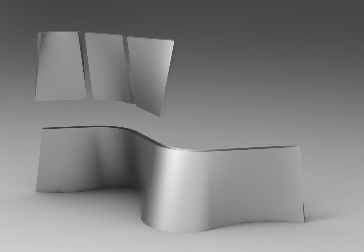
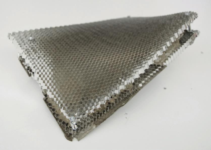
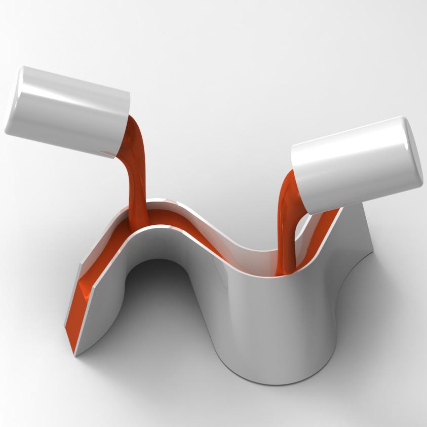
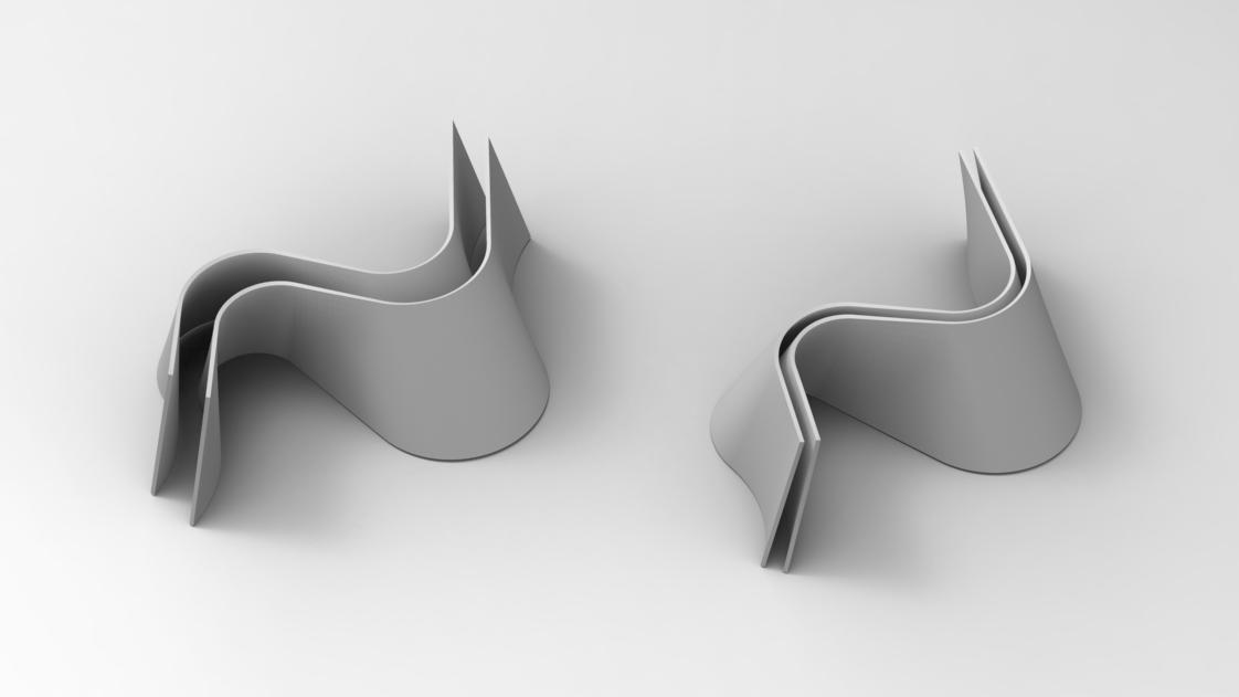
091
Fig. 4.17 | The clip system for assembly / (inside) The clip unit
Fig. 4.16 | The clipping system
Fig. 4.20 | The dimensions of gaps for each layered panel assembly
Fig. 4.19 | The concept diagram for pour the reinforced concrete in between the gap.
Fig. 4.18 | The pre-assembled double-layered composite panel.
b. Double-layered panel assembly
editorialfinal.indd 91 15/10/2010 08:44
a. Single-layered panel assembly
4.5 Evaluation & Summary
The development is materialised with evolved parameters and logics under the three main categories (the material system, the manufacturing system and the construction system) in the design strategies. The material system is not only decided or affected by a final building envelop, but it can also be worked as a structural element. However, it still has some potential issues for the next system development.
- Potential issues in the design development:
A. Material System
1. The system needs to embed joints to connect with other components.
2. The system requires margins around the four sides of the honeycomb panel allow each area of connection to work with each component.
3. The size of the core materials (Honeycomb) needs to be large to generate cleaner and smoother quality of surfaces.
B. Manufacturing System
1. The moulding bed (0.5mm thick rubber sheet) needs to be more elastic but it has stronger materials that fix extra deformation by materials weight.
2. The temporary clips joining the core material (Honeycomb) and the moulding bed require practical mechanisms for alteration as a moulding enclosure.
3. The two types of moulding arms need to hold more layers for producing double-layered components at once that link to the construction system.
4. The moulding machinery needs to increase the scale of capability for larger panels.
C. Construction System
1. The assembly logics need to be develop thinner ways to assemble for a lightweight structural performance.
2. With embedded joints, the connection needs extra reinforcement (e.g.. metal meshes).
4. Design Development | 4.5 Evaluation & Summary Cellular Composite System | Baek Ki Kim,
editorialfinal.indd 92 15/10/2010 08:44
Juanjo G. Castellon
093 editorialfinal.indd 93 15/10/2010 08:44
5. Design Proposal
editorialfinal.indd 94 15/10/2010 08:44
5.1 Introduction
5.2 Material System with Manufacturing System
5.2.1 Parameter with manufacturing the material system
5.2.2 Material System
5.3 Global form with Construction System
5.3.1 Construction System
5.3.2 Configuration of Global form
095 editorialfinal.indd 95 15/10/2010 08:44
5.1 Introduction
This chapter will proposes designed-systems that show strategies about a material system can be generated by manufacturing system and construction system can be embodied global form under the algorithmic controls. (Fig. 5.01) Those are close to interconnect in terms of bottom as micro to top as macro scale of fabrication.
Toward potential possibilities of performance-oriented architectural applications, it can be altered traditional and contemporary architecture in terms of advanced fabrication. (e.g. the Catalan Vaulting and the Funicular railway station; see chapter 1. Domain and 2, Method)
5. Design Proposal | 5.1 Introduction Cellular
| Baek Ki
editorialfinal.indd 96 15/10/2010 08:44
Composite System
Kim, Juanjo G. Castellon
097
editorialfinal.indd 97 15/10/2010 08:44
Fig. 5.01 | Design Strategies of the systems
5.2 Material System with Manufacturing System
5.2.1 Parameter with manufacturing the material system
5.2.2 Material System
5. Design Proposal | 5.2 Material System with Manufacturing System Cellular Composite System | Baek Ki Kim, Juanjo G. Castellon
editorialfinal.indd 98 15/10/2010 08:44
099
editorialfinal.indd 99 15/10/2010 08:44
Fig. 5.02 | The diagram of strategies for Material System
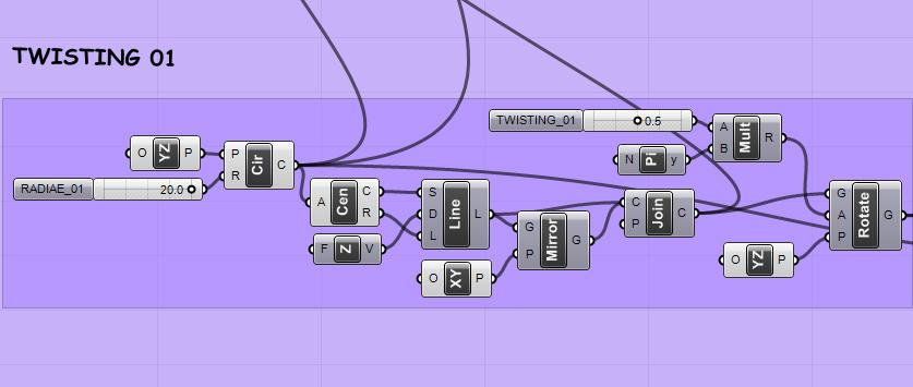
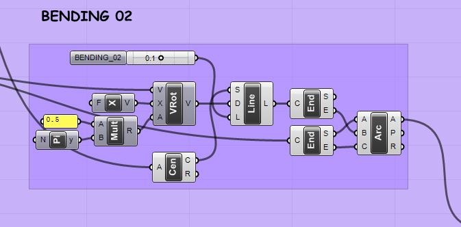
5.2.1 Parameter with manufacturing the material system
In terms of algorithmic control, the parameters have two main sets (Fig. 5.00): twist and bend for control geometries of the material system. It can generate geometries of component by their values. Furthermore, the parametric value applies to the manufacturing system that is basically produced components through their mechanical behaviours with dynamic moulding techniques. (Fig. 5.00)
Config. 01 | Twist
Config. 02 | Bend
5.
| 5.2 Material System with Manufacturing System
Design Proposal
Cellular Composite System | Baek Ki Kim, Juanjo G. Castellon
Fig. 5.03 (above) | The fundamental principles of parameters.
editorialfinal.indd 100 15/10/2010 08:44
Fig. 5.04 (below) | The code set of algorithmic control for par. twist and par. bend. (Grasshopper and Rhino 3D)
400mm (ranges of adjustment)

350mm (ranges of
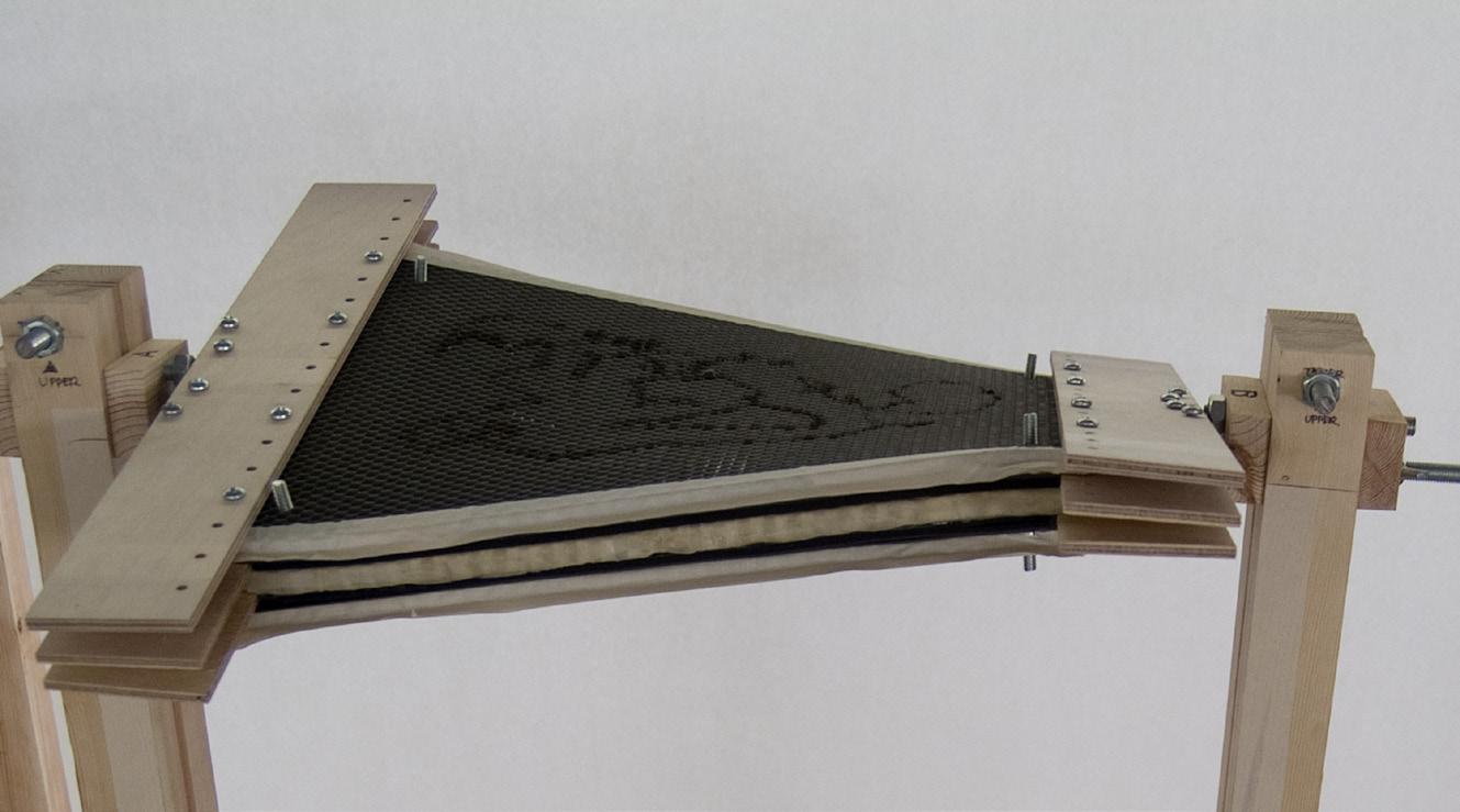
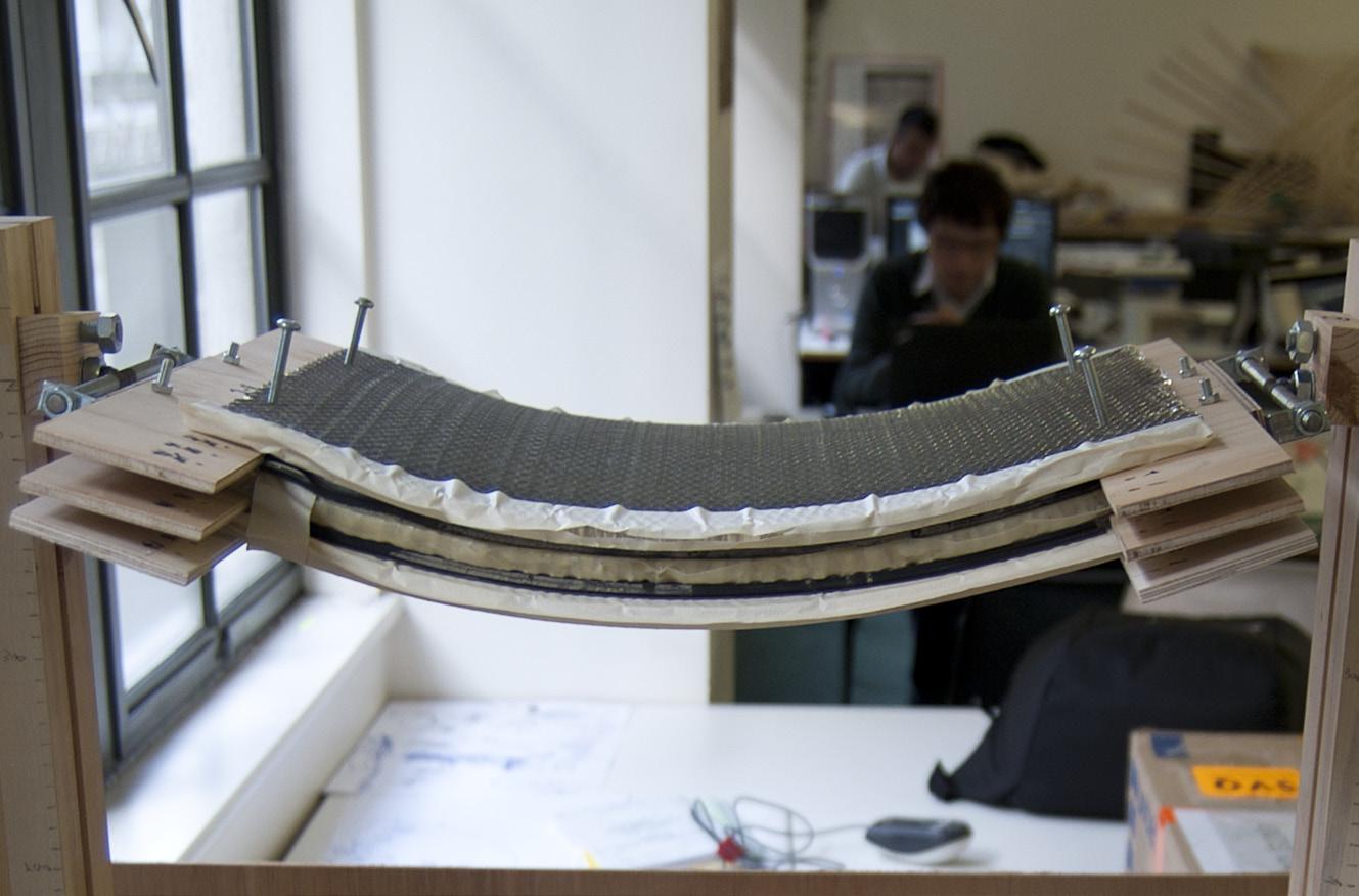

5.09 | The digitally generated-configuration of component geometries for achieve continuity of surface.
101
Fig.
Fig. 5.05 (above) | The physical moulding tool (Prototype 03).
Fig. 5.06 (below) | The concept of set the tool with honeycomb core.
Fig. 5.07 (above) | The set of configuration for par. twist.
Fig. 5.08 (below) | The set of configuration for par. bend.
height)
editorialfinal.indd 101 15/10/2010 08:44
5.2.2 Material System
The material system is made up with a honeycomb composite panel with embedded connectors and ceramic a panel. The composite panel is produced through the dynamic moulding system that can set with values of the parameter.
Especially, the hypothesis of material behaviours in the system, it can be worked as a structural element that the honeycomb as core material makes elastic behaviours for generates geometries as a formwork. And, the cement material as matrix material froze the generated-honeycomb geometries with the cement-filled technique.
5. Design Proposal | 5.2 Material System with Manufacturing System Cellular
| Baek Ki
Composite System
Kim, Juanjo G. Castellon
editorialfinal.indd 102 15/10/2010 08:44
Fig. 5.10 | The composition of material system (Cement-filled honeycomb composite panel + Ceramic Skin unit)

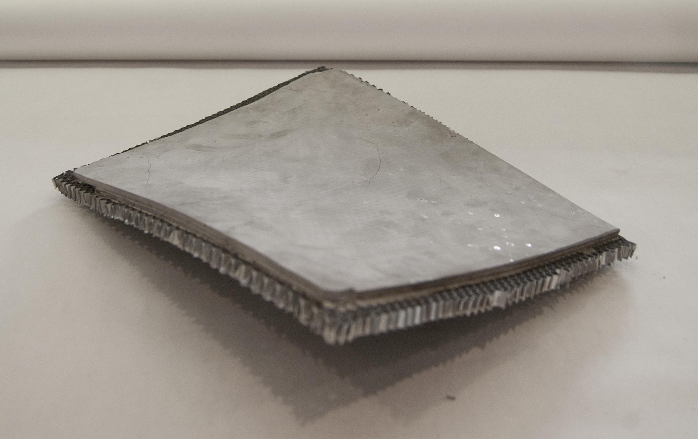
103
Fig. 5.11 | The concept of material System with Ceramic skin units.
editorialfinal.indd 103 15/10/2010 08:44
Fig. 5.12 | The produced honeycomb composite material system.
5.3 Global form with Construction System
5.3.1 Construction System
5.3.2 Configuration of Global form
5. Design Proposal | 5.3 Global form with Construction System Cellular Composite System | Baek Ki Kim, Juanjo G. Castellon editorialfinal.indd 104 15/10/2010 08:44
105
editorialfinal.indd 105 15/10/2010 08:44
Fig. 5.13 | The diagram of strategies for Global form with Construction System
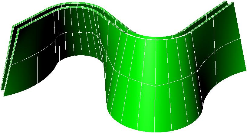
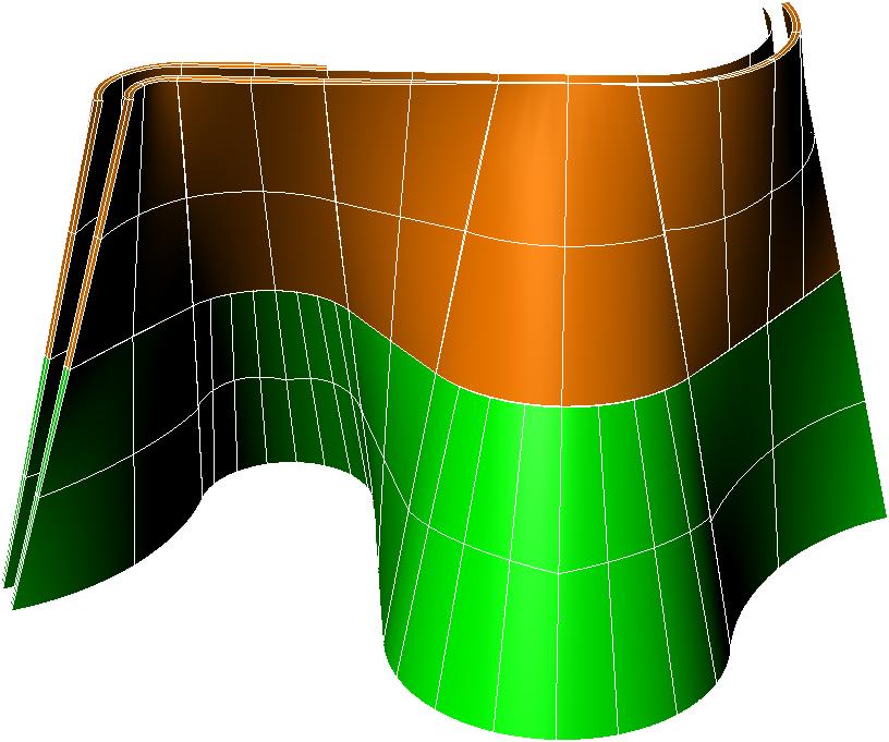
Assembly
Construction sequence
5.3.1 Construction System
Fundamentally, the construction system is started from margins and connector point in the material system. Those two elemental parts imply two ways of assembly strategy: a parametric vaulting system and three-dimension tiles system.
The construction system¬ inspired from Catalan Vault and Gaussian Vault that construct a structure cohesively. In addition, the system attempts to inherit principles of those two vaulting methods, in terms of “cohesive construction”.
The main principle of fabrication is that the component (material system) is overlapped with every next piece with fastsetting mortar (cement), when it has assembled. Every each margins (10mm) on the component became a designatedguide for alignment.
5. Design Proposal | 5.3 Global form with Construction System
Cellular Composite System | Baek Ki Kim, Juanjo G. Castellon
Fig. 5.14 | The simplified-construction sequence and assembly logics.
logics
editorialfinal.indd 106 15/10/2010 08:44
5.15 | The sequence and combination for an arch type of structure.
Cluster of component
5.16 | The sequence and combination for a dome type of structure.
Build up levels by the cluster
107
Fig.
Fig.
Cluster A
Cluster B
Combination A
editorialfinal.indd 107 15/10/2010 08:44
Combination A’
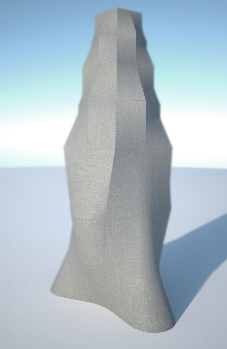
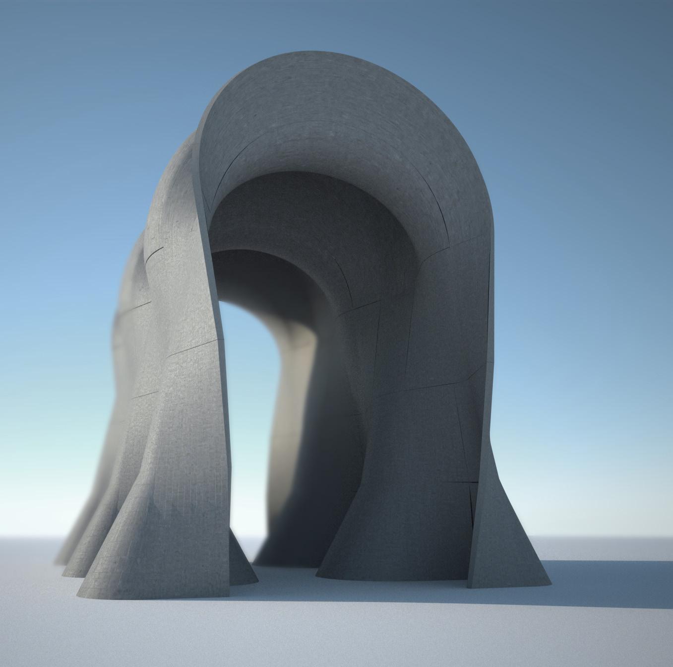
5.3.2 Configuration of Global form
Regarding the design proposal, the main aim is to develop an architectural application with a potential structural behaviour.
In order to achieve that, some of the principles analyzed will be applied. In one hand, from the Gaussian vault principles, form will be used to reduce buckling. On the other hand, the double-curve tile system is assembled using cohesive construction logics.
5.
Proposal | 5.3 Global form with
Design
Construction System
Cellular Composite System | Baek Ki Kim, Juanjo G. Castellon
Fig. 5.17 | The dome type of structure
editorialfinal.indd 108 15/10/2010 08:44
Fig. 5.18 | The arch type of structure

Hypothesis A. relies on the design of a parametric vaulting system.
Firstly, with a limited amount of three-dimensional tiles, it is possible to build an arch system. Its construction is based in a three-layered tile system that is assembled breaking the joints continuity. Secondly, the structural arch-like system can be combined to generate a more complex vaulting system.
Since it is possible to generate different configurations according with our parametric model, it is possible to design and test different vault configurations.
Hypothesis B. is to build domes with the 3D tiles system.
Just by applying some geometrical logics, it is possible to generate domes by symmetries and rotations of a simple twisted panel.
Summarizing, once the material system has been successfully tested, it is possible to apply cohesive principles to generate more complex forms by the addition and assembly of a limited amount of tiles.
This assembly has potential structural behavior and can be applied for the design and construction of parametric vaults and domes.
109
editorialfinal.indd 109 15/10/2010 08:44
Fig. 5.19 | The arch type of structure
6. Conclusion & Further Development
editorialfinal.indd 110 15/10/2010 08:44
6.1 Conclusion
6.2 Further Development
111 editorialfinal.indd 111 15/10/2010 08:44
6.1 Conclusion
It is not possible to ask a composite component ‘what it wants to be’ as Louis Kahn might have done; there are perhaps too many variables and only the beginnings of an established approach. However, this should encourage exploration of this material, particularly as the cost factors continue to fall.
We strongly believe that this project would give more freedom for architecture toward seamless structural performances like ‘Dynamic Aesthetics” as Jean Prouve.
1. The use of honeycomb as a formwork allows the exploration and fabrication of double-curved surfaces with simple tools and avoids the need of producing complex moulds since the mold is part of the final piece.
2. The application and understanding of geometry logics “a priori” from the design of a single piece until the assembly of the final building makes the fabrication process more efficient and avoids the dependency of optimization processes “a posteriori”
3. The honeycomb structures have their own geometry logic (according with their material, cell size and panel thickness) and produce specific deformations that you have to take into account in order to generate our material system.
4. The combination of cement and aluminum honeycomb panel, as reinforcement, produces an efficient material system, even more, when you use the panel geometry to improve stiffness and avoid buckling.
5. The application of the traditional construction system based on the Catalan vault has some problems in its application in double curved surfaces.
6. Conclusion & Further Development | 6.1 Conclusion Cellular Composite System | Baek Ki Kim, Juanjo G. Castellon editorialfinal.indd 112 15/10/2010 08:44
113 editorialfinal.indd 113 15/10/2010 08:44
6.2 Further Development
1. Some cracks are produced in our pieces. The use of fiber reinforced cement such as Ductal® potentially could solve this problem and improve the finishing appearance.
2. A further development for our parametric moulding system could include a synchronisation between the physical prototype and the algorithmic tools by using it as an external device in our computer (working as a “fabrication plotter” ).
3. A deeper analysis of the structural performance of this cohesive assembly logic will be developed to test its potential application in architecture.
4. The research have to develop a joint system in order to achieve structural continuity in our structural system.
5. The reearch could not develop the assembly of several pieces but it needs to use the component as a lost formwork for the construction system, by pouring cement or spraying polyurethane.
6. Conclusion & Further Development | 6.2 Further Development Cellular Composite System | Baek Ki Kim,
G. Castellon editorialfinal.indd 114 15/10/2010 08:44
Juanjo
115
editorialfinal.indd 115 15/10/2010 08:44
Fig. 6.01 | The diagram of further development
Image & Diagram Credits
editorialfinal.indd 116 15/10/2010 08:44
117 editorialfinal.indd 117 15/10/2010 08:44
Fig 1.01. Port Warehouse.Montevideo. 1977-1979 _ Flickr © Juanitta
Fig 1.02. Nordpark Cable Railway.2007. Innsbruck, Austria _ © Iwan Baan
Fig 1.03. Ceramic Patterns.2010. Barcelona _ © Baek-Ki Kim
Fig 1.05. © Image From document: Advaced Geometry, Rudimentary Construction. Michael H. Ramage
Fig 1.06. © Image from: Luis Moya and the tile vaults in post-war Spain_ Josep M Adell
Fig 1.07. La Ricarda.Antoni Bonet _ Flickr © Xikki
Fig 1.08. © Image from article: Luis Moya and the tile vaults in post-war Spain_ Josep M Adell
Fig 1.09. © Image from article: Luis Moya and the tile vaults in post-war Spain_ Josep M Adell
Fig 1.10. © Image from website: www.pinecalyx.co.uk
Fig 1.11. © Image from website: www.pinecalyx.co.uk
Fig 1.12. © Image from website: www.pinecalyx.co.uk
Fig 1.13. © Image from website: www.pinecalyx.co.uk
Fig 1.14. © Image from website: www.pinecalyx.co.uk
Fig 1.15. © Image from website: www.pinecalyx.co.uk
Fig 1.15 (check). © Image from Thesis: Rafael Guastavino and the Boston Public Library _ Lisa J. Mroszczyk
Fig 1.16. City Hall Station _ © Ryan Budhu
Fig 1.17. © Image from magazine: Revista de Obras Publicas 3422
Fig 1.18. © Image from article: The Guastavinos and tile vaults in North America_ John Ochsendorf
Fig 1.19. © Image from article: The Guastavinos and tile vaults in North America_ John Ochsendorf
Fig 1.20. © Image from article: Eladio Dieste and Structural Brick in Uruguay_ Antonio J. Mas Guindal
Fig 1.21. © Image from article: A study on the free-standing masonry vaults of Eladio Dieste _ D.Theodossopoulos, B.P. Sinha
Fig 1.22. © Image from website: www.columbia.edu
Fig 1.23. Atlantida Church. Eladio Dieste © Samuel Smith
Fig 1.24. © Image from article: Eladio Dieste and Structural Brick in Uruguay_ Antonio J. Mas Guindal
Fig 1.25. © Image from article: Eladio Dieste and Structural Brick in Uruguay_ Antonio J. Mas Guindal
Fig 1.26. © Image from website: www.stageone.co.uk
Fig 1.27. © Image from website: www.stageone.co.uk
Fig 1.28. © Image from website: www.stageone.co.uk
Fig 1.29. © Image from website: www.designtoproduction.ch
Fig 1.30. © Image from website: www.designtoproduction.ch
Fig 1.31. The programmed wall_ Gramazio & Kohler © Image from website: www.dfab.arch.ethz.ch
Image & Diagram Credits Cellular Composite System | Baek Ki Kim, Juanjo G. Castellon editorialfinal.indd 118 15/10/2010 08:44
Fig. 2.01 © Images from ceramica cumella
Fig. 2.02 Gramazio & Kohler © Image from website: www.dfab.arch.ethz.ch
Fig. 2.03 – 2/06, 2.54 Images from Ferre, Albert, Devesa Ricardo, Salazar Jamie (2007) Patent Constructions: New Architecture Made in Catalonia, CTAR, Institut Ramon Llull, Deutsches Architekturmuseum
Fig. 2.07-2.23 Process images, © Baek-Ki Kim
Fig. 2.24-2.26 Process images, © Baek-Ki Kim
Fig. 2.27-2.30 Gramazio & Kohler © Image from website: www.dfab.arch.ethz.ch
Fig. 2.31 diagram from Fernandez, John (2006), Material Architecture, Architectural Press
Fig. 2.32-2.33 Ceramica Cumella workshop, © Baek-Ki Kim
Fig. 2.34, 2.37 chart and images from website: http://www.lafargenorthamerica.com/wps/portal/lna/products/datasheet?WCM_ PORTLET=3_0_FM&WCM_GLOBAL_CONTEXT=/wps/wcm/connect/LNA/Products/Other/Ductal/Product_Ductal/Product_Ductal
Fig. 2.36 Cement product, © Baek-Ki Kim
Fig. 2.38, 3.12 adopted from Gibson, Lorna J. and Michael F. Ashby, Cellular Solids; Structure and Properties-Second Edition, 2001, Cambridge University Press
Fig.2.39
Fig.2.40 Nomex Honeycomb, http://multivu.prnewswire.com/mnr/dupont/27300/
Fig. 2.41, 2.42, 2.44,2.44-1, 2.50, 2.52, 2.53 diagram from Stacey, Michael (2001), Component Design, Architectural Press
Fig. 2.45, 2.46, 2.47 images from McQuaid, Matilda (2005) Extreme Textiles: Designing for High Performance, Princeton Architectural Press
Fig. 2.49, 2.51, 2.57 images from Thompson, Rob (2000) Manufacturing Processes for Design Professionals, Thames&Hudson, UK
Fig. 2.57-3.06, 3.10-3.11, 3.13 © Baek-Ki Kim
Fig. 3.14 – 6.01 © Baek-Ki Kim
119 editorialfinal.indd 119 15/10/2010 08:44
Bibliography
editorialfinal.indd 120 15/10/2010 08:44
121 editorialfinal.indd 121 15/10/2010 08:44
- Book
1 ASCER. The Spanish ceramic tiles industry. Cevisama 2009
2 Lefteri, Chris. Ceramics: Material for inspirational design. Rotovision.2003
3 Celento, David.Harrow, Del. CeramiSKIN Digital Possibilities for Ceramic Cladding Systems. ACADIA 08
4 Collins, George R. “The Transfer of Thin Masonry Vaulting from Spain to America.”, American Society of Architectural Historians Journal 1968 Oct., v. 27, n. 3, p. 176-201.
5 Ramage, Michael H. Building a Catalan vault. 2004
6 “Hollow brick, thiner than the standard one, used to build vaults and other masonry works”. Diccionario de la Real Academia de la Lengua Española
7 The text is extracted from Pines Calyx project website, www.pinescalyx.co.uk
10 Ramage, Michael H. Building a Catalan vault. 2004
11 Ochsendorf, John. The Guastavinos and tile vaults in North America. Informes de la Construccion. Vol 56. N496. March-April 2005
12 Guastavino, Rafael. Essay on the theory and history of cohesive construction. Ticknor.1893
13 Mroszczyk, Lisa J. Rafael Guastavino and the Boston Public Library. Massachusetts Institute of Technology.June 2004
14 Anderson, S. Eladio Dieste, Innovation in Structural Art. Princeton Architectural Press. New York. 2004
15 Shenk, Mark. On the shape of Cables, Arches, Vaults and Thin Shells. 2009
16 Lundgren, H .Cylindrical Shells. Vol.1 of Cylindrical Roofs .Danish Technical Press Copenhagen. 1949.
17 Theodossopoulos ,D. Sinha ,B.P. A study on the free-standing masonry vaults of Eladio Dieste. 2007
Addington, Michelle / Schodek, Daniel L. (2004) Smart Materials and Technologies in Architecture, Architectural Press, UK
Addis, Bill (2007) Building: 3,000 Years of Design, Engineering and Construction, Phaidon Press Ltd, UK
Aldinger, F. and Baumard, J.G. (2001) Advanced Ceramic Materials: Basic Research Viewpoint, Max-Planck-Institut fÜr Metallforschung Stuttgart, pp26-31
Bibliography Cellular Composite System | Baek Ki Kim, Juanjo G. Castellon editorialfinal.indd 122 15/10/2010 08:44
Bitzer, Tom, (1997) Honeycomb Technologies: Materials, Design, Manufacturing, Applications and Testing, Chapman & Hall, London
Balmond, Cecil (2007) Informal, Prestel, Germany
Balmond, Cecil (2008) Number 9: The Search for the Sigma Code, Prestel, Germany
Balmond, Cecil (2007) Element, Prestel, Germany
Blanciak, Francois (2008) Siteless, The MIT Press, US
Brownell, Blaine (2006) Transmaterial: A Catalog of Materials That Redefine Our Physical Environment, Princeton Architectural Press; annotated edition, US
Booker, Adrian (2005) Lightness: The Inevitable Renaissance of Minimum Energy Structures, 010 Uitgeverij, NL
Crandall, BC (1996) Nanotechnology: Molecular Speculations on Global Abundance, The MIT Press, US
Ferre, Albert, Devesa Ricardo, Salazar Jamie (2007) Patent Constructions: New Architecture Made in Catalonia, CTAR, Institut Ramon Llull, Deutsches Architekturmuseum
Fernandez, John (2006), Material Architecture, Architectural Press
Gibson, Lorna J. and Michael F. Ashby, Cellular Solids; Structure and Properties-Second Edition, 2001, Cambridge University Press
Hensel, Michael, Menges, Achim, Weinstock, Michael (2010) Emergent Technologies and Design: Towards a Biological Paradigm for Architecture, Routledge, UK
Hudson, Jennifer (2008) Process; 50 product designs from concept to manufacture, Laurence King Publishing Ltd., UK, pp 108-111
Thompson, Rob (2000) Manufacturing Processes for Design Professionals, Thames&Hudson, UK
Thompson, Wentworth D’Arcy (1992) On Growth and Form, Cambridge University Press
Johnson, Steven (2002) Emergence: The Connected Lives of Ants, Brains, Cities and Software, Penguin Books Ltd., UK
Koza R. John (1992) Genetic Programming: On the Programming of Computers by Means of Natural Selection (Complex Adaptive Systems), The MIT Press, US
Koza R. John (1994) Genetic Programming II: Automatic Discovery of Reusable Programs (Complex Adaptive Systems), The MIT Press, US
123 editorialfinal.indd 123 15/10/2010 08:44
Koza R. John, Forrest H. Bennett III David Andre Martin A. Keane (1999) Genetic Programming III: Darwinian Invention and Problem Solving, Morgan Kaufmann, US
Rajchman, John Virilio, Paul (1998) Construction, The MIT Press, US
Ritter, Axel (2006) Smart Materials in Architecture, Interior Architecture and Design: Types, Products, Architecture, Birkhauser Verlag AG, Germany
Wolfram, Stephen (2002) A New Kind of Science, Wolfram Media, Canada
Gary William Flake (2000) The Computational Beauty of Nature: Computer Explorations of Fractals, Chaos, Complex Systems, and Adaptation, The MIT Press, US
Seguin, Patrick, Jousse, Phillipe (2000) Jean Prouvé, Gallery Patrick Segin, FR
Stacey, Michael (2001), Component Design, Architectural Press
Stattman, Nicola (2003) Ultra light-Super strong A new generations of design materials, Birkhauser, CH
McQuaid, Matilda (2005) Extreme Textiles: Designing for High Performance, Princeton Architectural Press
- Websites
http://web.mit.edu/course/3/3.91/www/slides/cunniff.pdf : M5 Hyperfibre Akzo Nobel
http://www.gramaziokohler.com/
http://www.dfab.arch.ethz.ch/web/e/forschung/135.html
http://www.ductal-lafarge.com/wps/portal/ductal
http://www.alucoat-conversion.com/
http://www.trbls.com/bonding.htm
http://www.design.philips.com/philips/sites/philipsdesign/about/design/designportfolio/design_futures/fractal. page
http://live.philips.com/index.php/nl_nl/video/off-the-grid-habitat-2020-vision/16713202001
http://www.design.philips.com/philips/sites/philipsdesign/probes/downloads/sustainable_habitat.page : image downloads
Bibliography Cellular Composite System | Baek Ki Kim, Juanjo G. Castellon editorialfinal.indd 124 15/10/2010 08:44
http://www.corecomposites.com/
http://www.core.form-ula.com/2008/04/08/systemicprocess/
http://www.plascore.com/product-honeycomb-cores.htm
http://www.lmii.com/carttwo/thirdproducts.asp?NameProdHeader=+Nomex
http://www.professionalplastics.com/Nomex_Honeycomb
http://www.favonius.com/soaring/foams/foams.htm
125 editorialfinal.indd 125 15/10/2010 08:44
Acknowledgement
editorialfinal.indd 126 15/10/2010 08:44
First and foremost, I would like to thank to my supervisor of this project, MIKE Weinstock and Dr. George Jeronimidis for the invaluable guidance and advice with encouragement. They inspired me greatly to work in this project. Their willingness to motivate me contributed tremendously to my project. I also would like to thank them for showing me some example that related to the topic of our project.
In addition, I would like to thank the ALUCOAT CONVERSIÓN in Spain and Technical Resin Bonders in the UK as sponsors for providing me with a good resources and materials (Honeycomb panels) to complete this project. Also, I would appreciate Ceramica Cumella, Escofet, Dr. Vicente Sarrablo, ASCER, UIC, Jordi Serra, Cricursa and Ceracasa for showing useful information about Crafts, Industrial and Academic insight for the project. It gave me an opportunity to research and learn about the ceramics and concrete in terms of fabrication during my research trip in Catalonian region, Spain.
Finally, an honorable mention goes to my family, Mr. Juanjo as the great partner and my Emtech colleagues for their understandings and supports on me in completing this project. Without helps of the especial that mentioned above, I would face many difficulties while doing this project.
127
editorialfinal.indd 127 15/10/2010 08:44
© 2009 / 2010
BAEK KI KIM
All Rights Reserved.
editorialfinal.indd 128 15/10/2010 08:44


 Fig. 1.10 | Fist layer setting
Fig. 1.13 | Third layer of tiles at 90º
Fig. 1.11 | Second layer arranged in 45º pattern
Fig. 1.14 | Interior view


