 Kais Al-Rawi
Koerner
Kais Al-Rawi
Koerner
MASTER OF SCIENCE DISSERTATION
EMERGENT TECHNOLOGIES AND DESIGN
ARCHITECTURAL ASSOCIATION
SCHOOL OF ARCHITECTURE
LONDON - UNITED KINGDOM
SEPTEMBER 2012

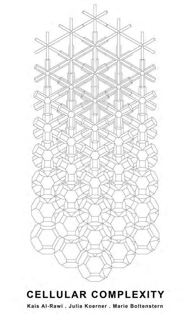
CELLULAR COMPLEXITY BY
.
. Julia
Marie Boltenstern www.cellular-complexity.blogspot.com
ARCHITECTURAL ASSOCIATION SCHOOL OF ARCHITECTURE
GRADUATE SCHOOL PROGRAMMES COVERSHEET FOR SUBMISSION 2011-2012
Programme: Emergent Technologies and Design 2012
Term: 4th
STUDENT NAMES: Kais Al-Rawi, Julia Koerner, Marie Boltenstern
SUBMISSION TITLE: CELLULAR COMPLEXITY
COURSE TITLE: DISSERTATION MSc
COURSE TUTOR : Michael Weinstock, George Jeronimidis, Evan Greenberg, Mehran Gharleghi
SUBMISSION DATE: 14/09/2012
DECLARATION:
“I certify that this piece of work is entirely my/our own and that any quotation or paraphrase from the published or unpublished work of others is duly acknowledged.”
Signature of Students:


CELLULAR COMPLEXITY 7
Kais Al-Rawi
Julia Koerner
Marie Boltenstern
ACKNOWLEDGEMENTS
ABSTRACT
INTRODUCTION
CELLULAR SYSTEMS
PROPERTIES OF CELLULAR SYSTEMS
NATURAL CELLULAR SYSTEMS
IMAGING NATURAL CELLULAR SYSTEMS
INTERNAL STRUCTURE ANALYSIS
GEOMETRY OF NATURAL CELLULAR SYSTEMS
CLOSEST PACKING STRUCTURES
CELLULAR SYSTEMS IN ARCHITECTURE
OVERVIEW
GEOMETRICAL DEVELOPMENTS
GRADIENT EXPLORATION
KELVIN PACKING STRUCTURE
TETRAHEDRON PACKING STRUCTURES
TRUNCATED CUBE - OCTAHEDRON STRUCTURE
SUBDIVISION
FINITE ELEMENT ANALYSIS
OVERVIEW
FABRICATION
ADDITIVE MANUFACTURING
SHEET MATERIAL PRODUCTION
CASTING CELL
CASTING PANEL
JOINTS AND TUBES
JOINTS, STRUTS AND PLATES
EVALUATION: FABRICATION METHODS CASE
HYBRID FABRICATION METHODS OVERVIEW
8
CONTENTS
STUDIES
1.0 1.1 1.2 1.3 1.4 1.5 1.6 1.7 1.8 2.0 2.1 2.2 2.3 2.4 2.5 2.6 2.7 3.0 3.1 3.2 3.3 3.4 3.5 3.6 3.7 3.8 3.9 3.10 11 13 15 16 17 20 24 30 34 35 36 41 44 46 48 56 58 60 64 67 68 70 72 74 76 78 80 82 88 92 95
THE SYSTEM
POROSITY GRADIENT
CELL POROSITY CATALOGUE
FINITE ELEMENT ANALYSIS
PARAMETRIC DESIGN TOOL
TYPOLOGY STUDIES
FABRICATION EFFICIENCY
OVERVIEW
ARCHITECTURAL APPLICATION
TYPOLOGICAL CASE STUDY
APPLICATION: COMPETITION
PROGRAMMATIC REQUIREMENTS
SITE
OVERVIEW
JURY COMMENTS
CELLULAR COMPLEXITY 9 97 98 100 102 108 109 114 118 121 122 126 132 133 136 138 140 141 142 147 149 151 156 160 162 164 166 168 172 174 176 178 183
DATA
PROGRAM ALLOCATION SITE INTEGRATION COMPETITION ENTRY OVERVIEW SYSTEM DEVELOPMENT PROGRAM-STRUCTURE
ENVIRONMENTAL
FACADE DAY
STRUCTURAL
ANALYSIS PROGRAM
CATALOGUE STRUCTURE-SPAN VARIATION
TYPOLOGIES
ANALYSIS
LIGHTING ANALYSIS
DEVELOPMENT SYSTEM ARCHITECTURAL APPLICATION GRADIENT CONDITIONS FURTHER POTENTIALS
CONCLUSION SELECTED BIBLIOGRAPHY APPENDIX 4.0 4.1 4.2 4.3 4.4 4.5 4.6 4.7 5.0 5.1 5.2 5.3 5.4 5.5 5.6 5.7 5.8 5.9 5.10 5.0 5.1 5.2 5.3 5.4 5.5 5.6 5.7
5.8
10
ACKNOWLEDGMENTS
We thank with the deepest gratitude, the contributors to this research.
First we would like to thank our families and friends for supporting us throughout this postgraduate course.
Especially Mr. and Mrs. Koerner for providing us with natural cellular artefacts for CT scanning. Therefore, we would like to also thank Dr. Marc Pelling for referring us to Shirley Featherstone from St Mary’s Hospital. She was so kind to provide us with CT scanning facilities for digital analysis of these natural cellular artefacts.
Furthermore we would like to thank Studio 1PLUS2D and Andreas Koerner for 3D printing test geometries on their in-house additive manufacturing machines. For further introduction into fabrication methods we would like to thank Trystrem Smith from the model making workshop at AA. Lastly Jack Chandy Francis for his support on the Solar Analysis for the Suckerpunch Competition.
Finally we would also like to thank the EmTech faculty: Michael Weinstock, George Jeronimidis, Evan Greenberg and Mehran Gharleghi for their support and guidance throughout the entire dissertation.
CELLULAR COMPLEXITY 11
12
ABSTRACT
Keywords: INTEGRATED FACADE, CELLULAR STRUCTURE, POROSITY, INTRICACY, SPATIAL HIERARCHY, DIFFERENTIATION
This research investigates the potential of porous and cellular systems within an architectural context. The current application of such systems within architecture is limited to the abstraction of basic structure and aesthetics; often overlooking their efficient structural capabilities and passive performative qualities. The aim is to assimilate these qualities into a single architectural façade system which responds to given programmatic and environmental conditions. Conventional façades consist of several separate sub-systems, contradictory to how nature integrates material, form and structure. The ambition is to achieve a material efficient system with spatial and structural properties. The digital fabrication of this system considers additive manufacturing, allowing for material efficient production of double-curved geometries within a differentiated component based system. The question becomes which properties of cellular systems are appropriate at each of these levels and which degree of scaling is possible without compromising the effectiveness.
Diese Dissertation widmet sich der Erforschung von zellulären und porösen Strukturen und deren Potenzial in der Anwendung im Bereich der Architektur. Die gegenwärtige Anwendung solcher Strukturen innerhalb der Architektur beschränkt sich auf Grundschema von Konstruktion und Ästhetik; deren Potenzial für effiziente Tragwerkskonstruktionen und Statik, sowie deren thermische und akustische Eigenschaften werden dabei oft vernachlässigt. Ziel ist es, diese Qualitäten in ein einziges singuläres System zu integrieren, welches sich dynamisch den gegebenen Umweltbedingungen anpasst und dieses System durch den Entwurf einer dreidimensionalen, tragenden Fassaden-Struktur zu manifestieren. Im Gegensatz zu konventionellen Fassaden, die sich üblicherweise aus verschiedenen Bausubstanzen und Schichten zusammensetzen, vereinen natürliche Strukturen Material, Form und Tragwerk. Dies bildet den Ausgangspunkt der Entwicklung eines materialeffizienten, dreidimensionalen Tragwerksystems mit räumlichen sowie bautechnischen Eigenschaften. Durch Entwicklung mathematischer Algorithmen mittels spezieller 3D Software werden jene Strukturen digital beschrieben. Fortschreitende Technologien wie 3D-Druckverfahren und numerische Fertigungsmethoden ermöglichen die präzise Herstellung komplexer Geometrie innerhalb eines solchen modularen Systems. Es stellt sich die Frage welche Eigenschaften zellulärer und poröser Systeme, in welchem Bereich des Entwurfes, eine Anwendung finden und inwieweit jene skalierbar sind ohne die Effizienz des Systems einzuschränken.
This research investigates the potential of porous and cellular systems within an architectural context.
The current application of such systems within architecture is limited to the abstraction of basic structure and aesthetics; often overlooking their efficient
CELLULAR COMPLEXITY 13
ي ثحبلا اذه قرطت و ةيعيبطلا ةمضنلاا ىلا ةمظنا صخلااب ددع نمض تاماسملا و ايلاخلا ا تايوتنسلا ننم ، دن ي ثنحبلا حرلن لا ةنيهانتملا انيلاخلا امنمت نتلاو ةمنضنلاا ذنه صئا خ يظوتل ةيلا ثادحتسا نف قاينس رانمعملا يمن تلا لاقنيبطت ل لانحلا ذن لاانمظن ة رانمعملا يمن ت نف رن تقي ىنلع دنيرجت انكي لا ساسلأا، ىلا ةفاضاضعب حاونلا اامها تي اممت تلا ةمظنلاا ذ ل ةيرطفلا تاردقلا لا ةينبلا اكيه ف ةءافك ببناج ننم اددع لاتاردنق لاةنلاعف د لا وه جمد ذه تاف لا ةلاعفلا ف اظن رامعم دحاو ، عم اماعتلا ىلع رداق لاورظ لاةيئيب و ف ةيج نملا ح نابملانا تا جاولا ةنيديلقتلا نونكتت نم ةدع تاقبطةل فنم و ددع وحت ا ةمظنلاا نم ،ةيعرفلا أدبملا اذه ضراعتي عم طمن ةعيبطلا ب جمد اكملاةينبلاو ةداملا ف ا د ل وه قنيقحت انظن رانمعم ااعف ذ و و و ةداملا ف ةءافك تقولا سفنب عتمتي ب صئا خ ةيلكيه و ةدوج حور ناكملا نظن ثنحب تني ونس لا عينن ت و ةنةيدحلا ءاننبلا و صنخلاا نف و ظن كلذ و نيهاجتاب سيوقت تاذ ااكما عين ت ف ا تيناكملا ارظن ةيقبطلا ةفاضلاا ايجولنكت دختست تلا عين تلا عم بنكرم انظن يدنقت ةنيناكما و داوملانب ةءافك انننوكملا ننف تارننيلتم ةدننع ىننلع وننتحي حت بنن ي االننسلا .دننم ا ىننلا يننجحت و ادختننسا نننكمي صئانن خ ةننمظنلأا ةننيولخلا ةبننسانملا ننف اننك .وتننسم نننم ذننه يوتسملاتا ، لا ثيح .دم يجحتلا ةجرد سمت حةيلاعفلا ذه
14
INTRODUCTION
Within the field of Architecture and Engineering, the application of cellular materials such as ceramics, polymers and foam metals are about to open up a new range of performance and material potentials. The abstraction of permeable and ductile structures has been applied at an architectural scale in projects such as the Aquatics Center by PTW architects. While most projects integrate the aesthetics and basic structure of such cellular systems, the potentials of structural, environmental and spatial integration has yet to be developed. At smaller scales, the use and development of porous materials is within a more complex level. For example, in the medical field porous resin tissues can be reproduced and designed according to certain needs very accurately already. Porous structures also act as passive environmental modulators, capable of regulating temperature and humidity through absorbing and transporting heat energy and moisture. Additionally they provide lightweight and material efficient structural capabilities. Mathematical and geometrical studies of porous systems will lead to the design of an integrated façade system. As in biological systems where there is no distinction between structure and material, the facade system will intricately operate on structural, spatial and performative levels. The question becomes which properties of cellular systems are appropriate at each of these levels and which degree of scaling is possible without compromising the effectiveness.
Current means of researching natural cellular systems include biomimetic strategies that investigate the integration of form, material and structure. In medicine, 3D tomographic imaging is used as a method of analysing porous mediums. Existing computational strategies for the geometrical modelling of packing organisations refer to mathematical logics of Plateau laws and Weaire-Phelan structure. Cellular structures occur in nature at various scales such as Sponges, Corals and Bones which will be analysed through 3D scanning, fluid dynamic analysis and structural simulations. The material properties that become relevant within the analysis of varying porous structures include absorption, thermal energy transfer and structural strength. This will be tested on physical models with specific fabrication methods such as 3d printing polymer, laser sintering, casting and investigation into composite materials. Evolutionary computation allows the generation of multiple formal variations that are constantly evaluated against pre-determined criteria. Evaluation criteria will include spatial and structural properties such as material efficiency against usable area, in addition to functional criteria such as environmental responsiveness.
Façade systems typically consist of several separate subsystems and layers, dealing with each building floor as an isolated entity where flows are transferred only between one level and another. Similar to how nature integrates multiple functions within a material, this research aims to assimilate the structural, material and performative properties of cellular systems into a single façade system. The design will respond to given environmental conditions, such as wind, rain and sun. The system will initially be designed for northern temperate climate; yet adaptable to various locations through modifications and variations within a further study. The system will be responsive in a dynamic way, yet non-mechanic. The application of the façade system will suit an architectural scale that includes medium scale buildings. The current development of large-scale additive manufacturing becomes of particular interest within digital fabrication. This allows for material efficient production of double curved geometries within a unit-based system that allows for unique variation within each unit; while operating as a coherent system at the global scale. The organization of the material and geometry that informs the design will generate functional intermediate spatial conditions as part of the dynamic response to environmental conditions, coupled to the material efficient structure.
CELLULAR COMPLEXITY 15
CELLULAR SYSTEMS
Cellular Systems are low density solids that exist in both natural and manufactured forms; this includes common materials such as wood, cork, corals and sponges.
They are a network of interconnected plates or struts which are respectively the faces or edges of the cells 1 The two main types of cellular solids are two-dimensional and three-dimensional cellular solids, also known as honeycombs and foams. Three-dimensional cellular solids can be further classified to have either open-cells or closed-cells; the first is made up of struts, and the second plates. Open-cell foams have interconnected voids and are constrained by the cell edges, whereas closed-cell foams have sealed cells which are enclosed by plates.
This chapter investigates cellular solids, their characteristics and properties, in addition to a range of natural cellular systems and their underlying geometrical principles and the current architectural application of such systems.
CELLULAR COMPLEXITY 17
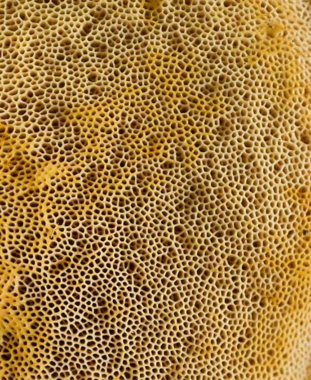
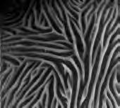
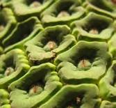
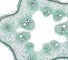
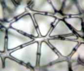
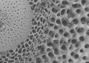
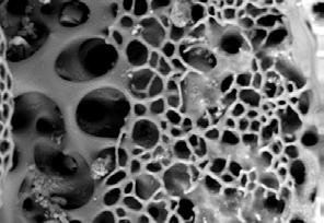
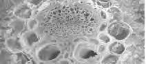
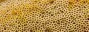
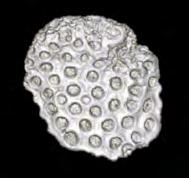
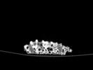
Left: Fig 1.1 The underside of the boletus mushroom consists of a system of closest packed tubules
The most important characteristic and feature in any cellular system is porosity. The porosity is a measure of the amount of solid to void volume, the higher the porosity, the less material per volume the system contains.
The cell shape and morphology is an important characteristic of any cellular system, often considered more significant than the cell size. For example, the elongation or flattening of a cell can create directionality and anisotropy.
Two-Dimensional cellular systems which are known as honeycombs can have regular geometries including triangular, square and hexagonal; random geometries with varying cell sizes and edges also exist, particularly in natural systems.
Three-Dimensional cellular systems, also known as foams may have mathematical space-packing geometries such as Plateau’s rhombic dodecahedron and Kelvin’s tetrakaidecahedron which was thought to be the most efficient in terms of minimal surface area per unit volume. Weaire and Phelan identified an even more efficient structure using computational software. Their geometry is made of six 14-sided cells with two pentagonal dodecahedra; of which all have equal volumes. Natural foams typically have geometries similar to space-packing geometries which only pack properly in a distorted manner; a dominant force in their formation is surface tension 2
In general, the morphology of natural cellular systems contains random elements which generate geometries that are a distortion from the mathematical models. This is typically due to external environmental forces interfering with the formation. The mathematical models remain to be as more efficient and ideal structures which are found in manufactured cellular systems.
The relevant characteristics in honeycombs include: density, edge connectivity, edges per cell, symmetry, edge thickness, largest and small cell dimension, characterizing angle and any exceptionally large cells or broken walls 3 . In foams, of importance are: open or closed cells, edge connectivity, face connectivity, number of faces per cell, face and cell edge thickness, principle cell dimensions and dispersion of cells 4
THE PROPERTIES OF CELLULAR SYSTEMS
Foams can exhibit a range of unique features including structural, thermal and acoustic properties. Cellular geometries which use efficient mathematical space-packing geometries reduce the amount of material required within the structural system. Furthermore, cellular systems can provide exceptionally low thermal conductivity and an ability to absorb sound 5 , providing thermal and acoustic insulation.
STRUCTURAL
The mathematical models such as Kelvin’s or Weaire Phelan are able to provide the least amount of surface area within a given volume, providing an efficient structure. The structural behaviour of cellular systems is mostly determined by the material behaviour and the manner in which they fail. The use of non-regular geometries can decrease the strength of the cellular system by roughly 25% in comparison to idealized geometries 6 . Additionally, any missing cells walls can sharply decrease young’s modulus and the compressive stress 7
18
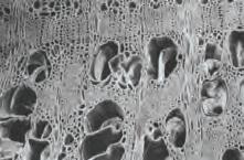
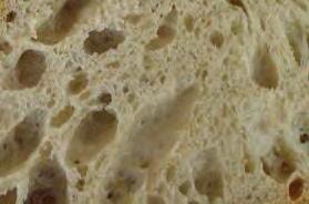
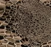
Fig. 1.2 Cellular structure of wood
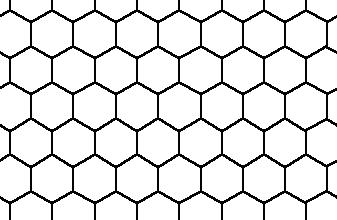
Fig. 1.4 Hexagonal honeycomb
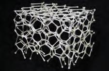
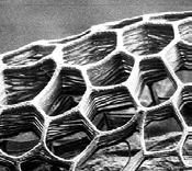
Fig. 1.6 Weaire-Phelan structure
Fig. 1.3 Cellular structure of bread
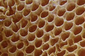
Fig. 1.5 Natural honeycomb
Fig. 1.7 Natural Bubbles
THE MORPHOLOGY OF CELLULAR SYSTEMS
CELLULAR SYSTEMS
THE PROPERTIES OF CELLULAR SYSTEMS
CELLULAR SYSTEMS
deformations with forces: in-plane and out of plane deformations:
shear deflection - bending and rotation elastic buckling - elastomers plastic collapse - metals
- material (and properties: modulus, etc.
- arrangement of cells and structure:
geometry (optimized or variable/random) cell properties (size, thickness, etc.)
THERMAL
very low thermal conductivity in foams: this requires:
-small cell size
-high porosity
thermal acoustic
good in absorbing sound (that comes from within the same room/space)
-porous materials absorb sound and convert it to heat (negligible)
-surfaces need to be open and not sealed
The most common use of foams is thermal insulation, closed-cell foams in particular display one of the lowest thermal conductivity. There are several factors that limit heat flow in foams, these include the low volume fraction of the solid phase. In addition, the small cell size reduces both convection and radiation though absorption and reflection at cell walls; and low conductivity of the gas within the cells8
The thermal conductivity has four main contributors: the conduction through the solid, the conduction through the gas, the convection within the cells, and the radiation through cell walls and across the voids 9. The biggest contributor of the four is the conduction through the gas. What is fascinating within the thermal properties is that the density of the material in the solid has small minimal contribution towards the thermal conductivity. This means that the geometry of the system becomes more important than the actual material it is made of. However this is only true at a certain scale, at larger scales the density does contribute towards the performance. The larger the cell size becomes the larger the heat transfer, as convection starts to take effect as one of the four contributors.
For each given insulation problem, there is an optimum foam density and cell size for the best thermal insulation. For example, the insulation needed for a coffee cup is different from that of a cavity wall. The main factors which determine the optimum requirements include the temperature difference across the insulation and the thickness of the insulation10
ACOUSTICAL
Cellular solids exhibit acoustic properties which hold potential for sound management in buildings. The main mechanisms of sound management are absorption, insolation and isolation. Cellular systems are able to absorb sound waves and convert them to heat; they are considered good absorbers and bad insulators11. The absorption mechanism is useful for absorbing sound that is generated from the same space, avoiding disturbance to the outside. Materials that are porous and high flexible like low-density polymeric and ceramic foams are particularly useful due to their intrinsic damping and wave propogation12. The geometry of open-celled foams are particularly useful due to the connectivity of cells, the sound is able to travel and dissipate throughout the cells13
- for optimization at scale thickness of cellular system temperature difference across
- cell size
- porosity
- material
- gas in pores
- porosity
- open cell not closed cell -material
CELLULAR COMPLEXITY 19
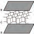
Fig. 1.8 Honeycomb sandwich panel for structural purposes
Fig. 1.9 Weaire-Phelan structure used in Beijing Aquatic Centre
Fig. 1.10 Cellular organization in thermal insulation sheets
parameters properties subset structure geometry environment
Fig. 1.11 Cellular organization in acoustic tiles
structural
cell shape cell packing porosity density
material site data
thickness
temperatures
NATURAL CELLULAR SYSTEMS
In almost every natural substance cellular structures can be found when looking at the right level of magnification 14
Cellular structures in nature occur in a large number of outcomes and variations. They exist as patterns, reliefs, extrusions and also mostly common in three dimensional geometries. What they have in common is that they all affiliate to a certain kind of closest packing geometry, which is the most viable arrangement of cells to fill up a volume.
The system of a specific natural structure is based on a clear logic which results in an infinite number of different outcomes in different artefacts through reaction and optimization towards outer impacts. Through variation in the size of components and the porosity gradients at different levels; the system can address structural and environmental parameters. The cells in this case can be open or closed and regular or irregular.
These parameters are further tackled at various hierarchies of scales within the same structure. Therefore it can be stated that natural systems operate on both, a micro level and on a macro level with the same geometrical logic. In nature there is no distinction between structure, form and material 15. The fact that natural materials are limited to only four different substances - cellulose, collagen, chitin and silk - proves that not simply the material, but moreover the geometrical arrangement of cells plays the biggest role in terms of their efficient structure 16
The strength and ductility is intimately tied to the highest efficiency in distribution of material and structure 17. They make the structure of natural cellular systems of special interest for this research. What natural systems have in common and what makes them so appealing is that the simple logic behind their structure stays the same, while according to given environmental conditions and changes over time, the outcome of them is extremely wide ranging and differentiated. With a minimum of rule sets, a maximum of diverse outcomes can be created18.. The various scales of cell sizes, cell porosities and cell arrangements and shapes are used to address specific conditions that a plant or animal needs to adapt to. Therefore the component-based geometries allow for variation and adaptation towards the required efficiency through differentiation.
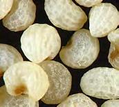
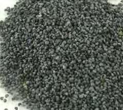
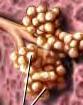
In the example of the Poppy Seeds as shown in Fig.1.17, the cellular arrangement is caused by surface tension 19. Due to a loss of moisture, the outer shell collapses onto the inner shell. The surface tension forces are similar to such that occur in soap bubble formations. Through this a minimal surface condition is created, which means most efficient relation of surface area to volume.
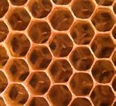
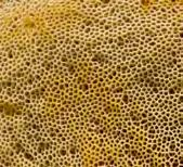
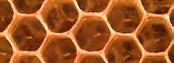
The efficiency of those structures can be illustrated by the example of the bee honeycomb shown in Fig 1.25. In this hexagonal packing arrangement, the greatest amount of honey is combined with an efficient minimum material use for the structure of the cell walls, therefore it requires the least energy from the bees to build up the cells 20
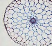
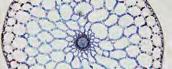
Most of the examples in the 2D extruded natural cellular structures are roots or stems which need to resist forces and bend in one direction as their overall morphology is elongated and extremely defined through directionality. The arrangement and change of size of cells allows for perfect adaptation to such extreme conditions through variation in section 21
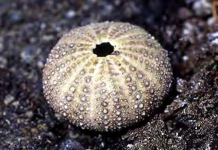
Of special interest in this research are certainly the three dimensional cellular systems and how those structures react to and deal with environmental influences as the goal is to abstract those structures in order to create an architectural system which responds to given environmental conditions. For this purpose some of the structures were chosen to be examined further such as the sea urchin and the coral as they show a wide variety in porosity ranges as well as cell shapes and arrangements.

20
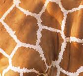
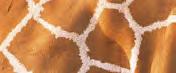
Fig. 1.12 Girraffe Pattern
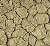
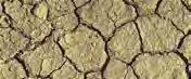
Fig. 1.13 Earth Cracking
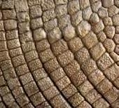
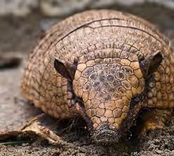
Fig. 1.14a,b Amardillo Skin
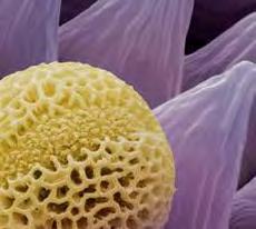
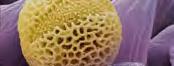
Fig. 1.16a,b Pollen grain
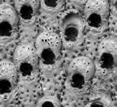
Fig. 1.15a,b Pentapora closeup
Fig. 1.17a,b Poppy Seeds
2D - PATTERN / RELIEF
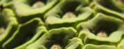
Fig. 1.6a,b Philodendron
CELLULAR SYSTEMS


CELLULAR COMPLEXITY 21
Fig. 1.20a,b Maple Root
Fig. 1.23a,b Cucurbit Root
Fig. 1.21a,b Quercus Alba Root
Fig. 1.22a,b Reed
Fig. 1.24a,b Mare’s Tail
2D - EXTRUDED
Fig. 1.19a,b Redwood Root
Fig. 1.19 Boa Skin
Fig. 1.25 Honeycombs
Fig. 1.27a,b White dead nettle Stem
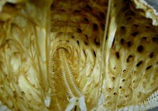
Fig. 1.28a,b Boletus Mushroom
Fig. 1.29a,b Prairie Plant
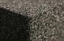
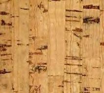
Fig. 1.30a,b Cork
2D - LAYERED
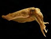
Fig. 1.31 Sepia
Fig. 1.26a,b Juncus
3D SPATIAL
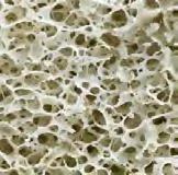
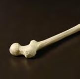
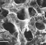
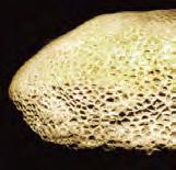
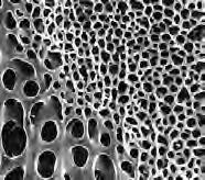
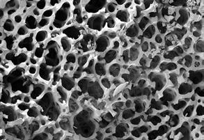
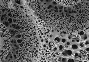
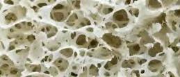
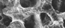
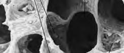
Fig. 1.32a,b Human Bone
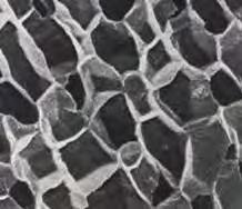
Fig. 1.33a,b Coral
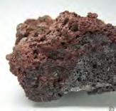
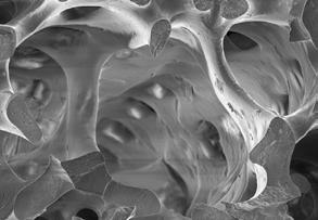
Fig. 1.35a,b Magma Vesicles
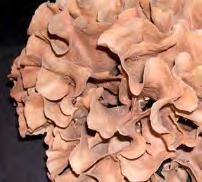
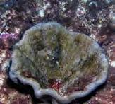
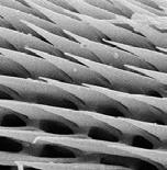
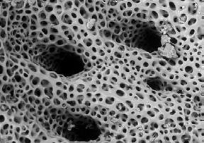
Fig. 1.36a,bSpongia Agaricina
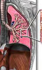
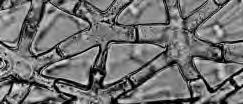
Fig. 1.37a,b Alveoli Human Lung
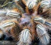
Fig. 1.38a,b Tarantula Leg
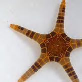
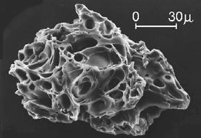
MULTITUDE OF SCALES
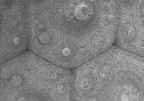
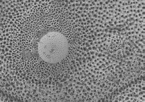
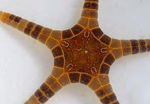
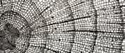
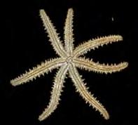
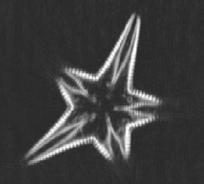
Figures 1.39 - 1.41 which show a sea urchin, a sea urchin spine and a starfish at several levels of magnification were chosen to be examined in further detail, as their structures show a wide range of porosity scales within one single structure. Furthermore, geometrically they grow from an open to closed celled structure in a smooth gradient transition. In this example it becomes clear how natural systems operate with spacepacking structures at various hierarchies.
Within the same natural structure, similar geometries appear at various, utterly different scales. At each scale, the specific structure addresses certain properties the natural substance has to fulfil.
The diagram on the right relates - in a first step - a number of the examined natural structures to properties which are in a later stage important for the development of an architectural system. It illustrates the potentials of the different 2D and 3D structures in terms of structural, thermal, acoustic and other environmental performances. It shows that the different systems are built up to address various impacts which are relevant in their environment by their structures. The structures in return are built up by environmental processes which lead the growth, appearance and performance of the structures.
22
300um 100um 50um 2um 10um 100um 1000um = 1mm 1mm 100um 300um
Fig. 1.41a,b Iconaster Longimanus
Fig. 1.40a,b Sea Urchin Spine
Fig. 1.39a,b Sea Urchin
CELLULAR SYSTEMS
1D RELIEF

2D - EXTRUSION
2D - LAYERED

3D - SPATIAL

GIRRAFFE PATTERN
EARTH CRACKING
POPPY SEEDS
PHILODENDRON
MARE’S TAIL
REDWOOD ROOT REED
HONEYCOMBS
BOLETUS MUSHROOM
POLLEN GRAIN
CORK
SEPIA
SOAP BUBBLES
HUMAN BONE
CORAL
SPONGIA AGARICINA
JUNCUS
ALVEOLI LUNG
GEOMETRY
all these geometries are based on closest packing
MINIMAL SURFACE
CLOSED - CELLED
PROPERTIES
DIRECTIONAL
STRUCTURAL
UNIVERSAL
STRUCTURAL THERMAL
ACOUSTIC
SPATIAL VISUAL FILTRATION
VENTILATION
CELLULAR COMPLEXITY 23
Following our interest in natural artefacts and thier cellular organization, a method of analysing and investigating these systems was required. Typically, architects and designers utilize 3D-scanning sonar devices to obtain a three-dimensinonal computer model of complex objects or natural artefacts. However there are several technical limitations within 3D-scanning and the results only provide an exterior morphological view or reconstruction of the scanned object. What we were rather interested in was the interior structure of the object and the organization of cells, their variation and the reason behind these variations. Furthermore, the interest was in relating natural models which contain aspects of redundancy and randomness for variation within the morphology, to the mathematical geometrical models and comparing aspects of each.
The field of Radiology within the medical discipline is considered to be one of the most advanced in terms of imaging and tomography. Computed Tomography scans also known as CT were developed to produce sectional images through a body or organism for diagnosis purposes. The technology uses X-ray images within a single axis of rotation to image slices which can be reconstructed to three-dimensional images.
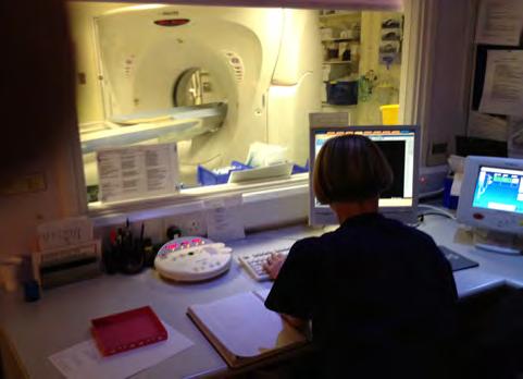
For our research purposes and investigation of natural cellular systems we undertook a number of computed tomography scans for various natural artefacts. The CT scans were done at the Imaging Department in St. Mary’s Hospital, London. Senior Radiographer: Shirley Featherstone
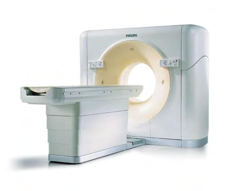
The equipment at the facility is a Philips Brilliance 64 and 256-slice scanner. The scans provide slices at an interval of 0.4mm in two directions, coronal and transverse. The digital resolution of the slices are at 500x500 pixels. The format of these slices are DICOM which is the common format within the medical Industry. The images are monochrome and based on an Xray where the image is entirely about the contrast received from the scan.
For our research purposes and investigation of natural cellular systems we undertook a number of computed tomography scans for various natural artefacts. The CT scans were done at the Imaging Department in St. Mary’s Hospital, London. Senior Radiographer: Shirley Featherstone
The equipment at the facility is a Philips Brilliance 64 and 256-slice scanner. The scans provide slices at an interval of 0.4mm in two directions, coronal and transverse. The digital resolution of the slices are at 500x500 pixels. The format of these slices are DICOM which is the common format within the medical Industry. The images are monochrome and based on an X-ray where the image is entirely about the contrast received from the scan.
Throughout the analysis and use of the DICOM slices, multiple softwares were used for both viewing the images and reconstructing the slices to a three-dimensional model. For viewing purposes MicroDicom and Agnosco Dicom Viewer and RadiAnt DICOM viewer. For the reconstruction of the slices to obtain a geometrical 3D model, InVesalius 3.0 was utilized.
http://www.uchospitals.edu/images/cms/uch_008020.jpg
24
Fig. . Philips Brilliance CT-Scanner
CT-scan in progress at NHS Imperial - St Mary’s Hospital
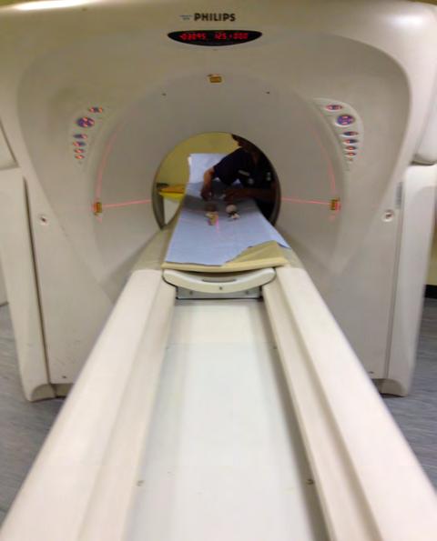
Objects on CT scanner Bed ready for scan
IMAGING NATURAL CELLULAR SYSTEMS CELLULAR SYSTEMS
NATURAL ARTEFACTS
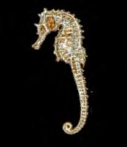
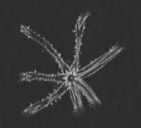
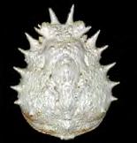
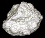
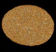
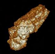
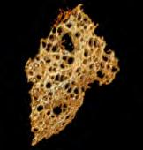
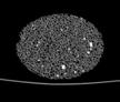
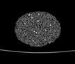
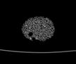
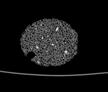
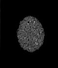
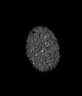
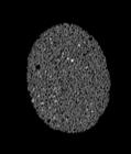
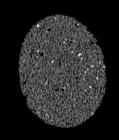
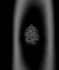
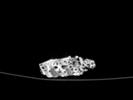
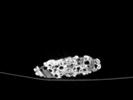
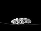
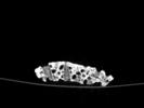
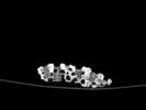
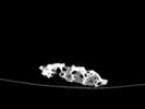
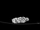
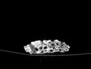
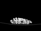
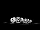
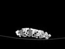
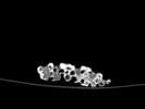
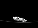
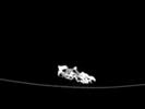
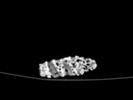
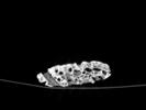
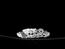
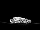
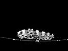
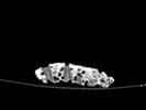
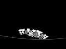
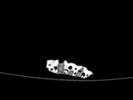
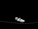
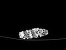
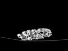
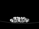
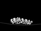
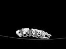
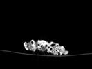
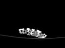
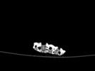
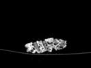
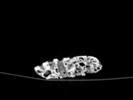
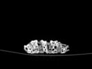
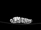
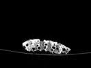
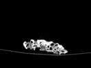
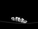
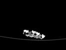
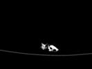
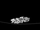
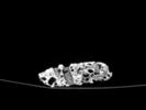
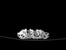
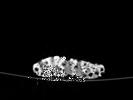
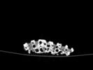
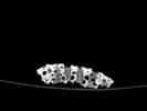
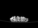
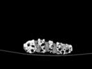
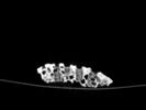
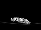
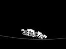
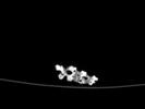
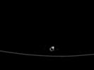
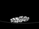
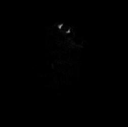
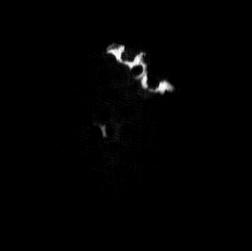
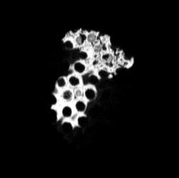
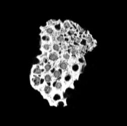
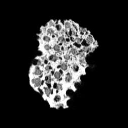
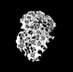
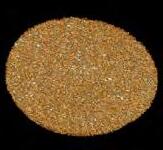
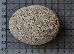
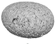
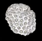
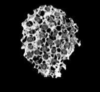
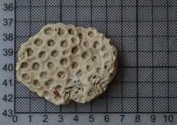
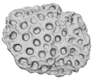
During the arrangements for the Computed Tomography scans, we prepared a range of natural artefacts which could be analysed to provide potential knowledge of natural cellular systems and the variety within them. The objects scanned included: corals, tree bark, sea horse, sea stars, lava stone, pumice stone, cork and spider crab. The size of most objects was small and did not exceed 100mm in length.
The resolution of the slices obtained from the scan is sufficient to provide an observation towards the structure that would be visible by human eye if the object is sliced. The slices however were not at a resolution where microscopic structures or features could be examined.
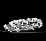
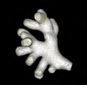
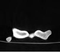
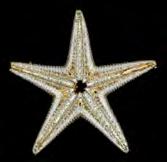
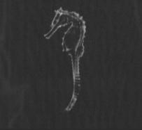
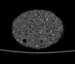
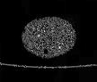
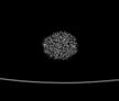
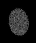
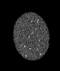
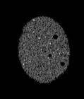
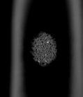
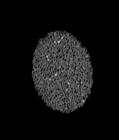
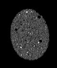
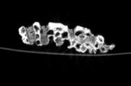
Therefore, the resolution of the performed CT-scan was ideal for certain objects, and for other less relevant for our analysis purposes. This depends on the scale of cells or pores in relation to the object. Shown below, are images taken by the scanner of each object scanned, in addition to a selected slice which shows the object most clearly.
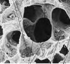
The two objects that were of main interest were the coral and pumice stone, this is due to the clarity of the structure within the given slice resolution where the cells can be observed throughout the slices. These two were taken for further investigation, specifically in terms of the variations they hold within the different cells.
CELLULAR COMPLEXITY 25
TREE BARK
SEA STAR
CORAL
LAVA STONE
SPIDER CRAB
SEAHORSE
CORK
PUMICE STONE
CORAL
SEA STAR
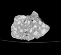
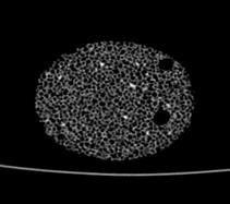
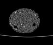
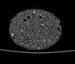
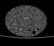
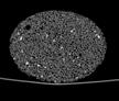
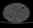
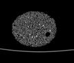
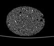
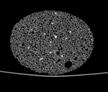
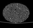
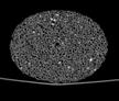
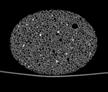
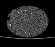
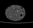
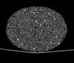
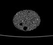
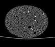
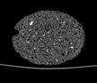
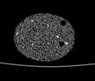
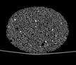
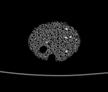
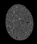
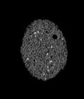
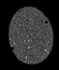
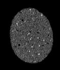
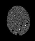
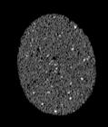
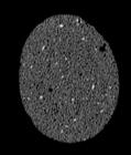
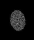
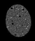
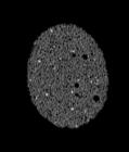
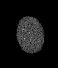
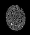
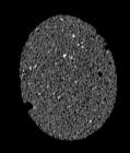
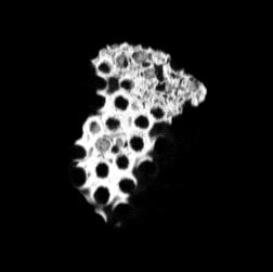
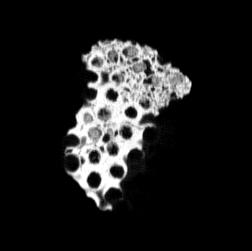
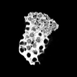
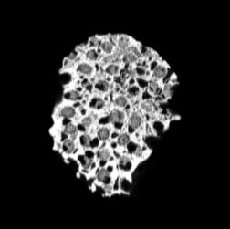
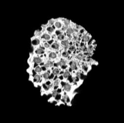
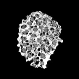
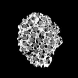
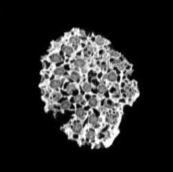
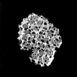
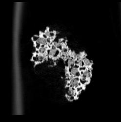
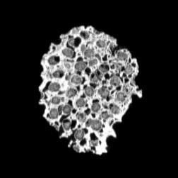
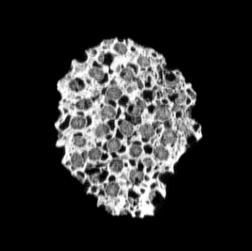
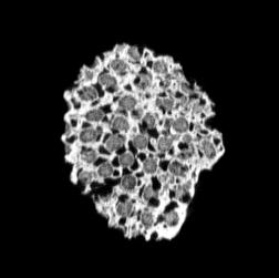
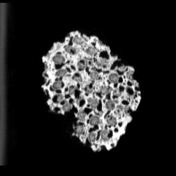
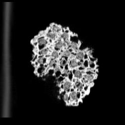
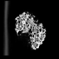
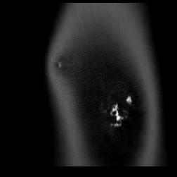
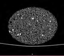
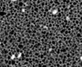
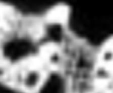
The following images are the slices obtained from the CT scanner which are taken at 0.4mm intervals, with a total of 200 slices. These slices are taken in a coronal direction, cutting through the object sectionally in a vertical plane with the scanner bed shown at the bottom of each slice. The slices presented on this page are half of the complete set, and are therefore at an interval of 0.8mm.
The slices exhibit various qualities of the object, where it is evident that cells have a relatively similar size. The three-dimensional structure appears to be that of a closed-cell cellular system.
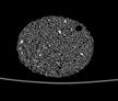
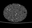
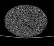
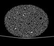
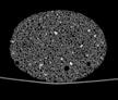
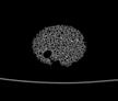
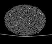
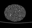
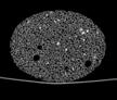
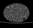
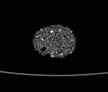
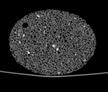
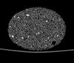
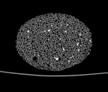
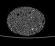
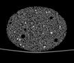
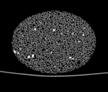
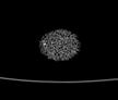
In the areas where the cells meet the exterior of the object, the cells become open to the exterior and have similarities with open-celled systems. There are specific cells throughout the object which are exceptionally larger. Furthermore there are parts of the objects with dense and closed cells.


26
CS- 0.08 CS- 0.88 CS- 1.68 CS- 2.48 CS- 3.28 CS- 4.08 CS- 4.88 CS- 5.68 CS- 6.48 CS- 7.28 CS- 0.16 CS- 0.96 CS- 1.76 CS- 2.56 CS- 3.36 CS- 4.16 CS- 4.96 CS- 5.76 CS- 6.56 CS- 7.36 CS- 0.24 CS- 1.04 CS- 1.84 CS- 2.64 CS- 3.44 CS- 4.24 CS- 5.04 CS- 5.84 CS- 6.64 CS- 7.44 CS- 0.32 CS- 1.12 CS- 1.92 CS- 2.72 CS- 3.52 CS-4.32 CS- 5.12 CS- 5.92 CS- 6.72 CS- 7.52 CS- 0.40 CS- 1.20 CS- 2.00 CS- 2.80 CS- 3.60 CS- 4.40 CS- 5.20 CS- 6.00 CS- 6.80 CS- 7.60 CS- 0.48 CS- 1.28 CS-2.08 CS- 2.88 CS- 3.68 CS- 4.48 CS- 5.28 CS- 6.08 CS- 6.88 CS- 7.68 CS- 0.56 CS- 1.36 CS- 2.16 CS- 2.96 CS- 3.76 CS- 4.56 CS- 5.36 CS- 6.16 CS- 6.96 CS- 7.76 CS- 0.64 CS- 1.44 CS- 2.24 CS- 3.04 CS- 3.84 CS- 4.64 CS- 5.44 CS- 6.25 CS- 7.04 CS- 7.84 CS- 0.72 CS- 1.52 CS- 2.32 CS- 3.12 CS- 3.92 CS- 4.72 CS- 5.52 CS- 6.32 CS- 7.12 CS- 7.92 CS- 0.80 CS- 1.60 CS- 2.40 CS- 3.20 CS- 4.00 CS- 4.80 CS- 5.60 CS- 6.40 CS- 7.20 CS- 8.00
CELLULAR SYSTEMS
PUMICE STONE: CORONAL SLICES
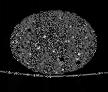
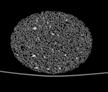
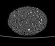
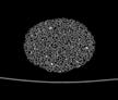
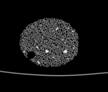
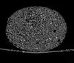
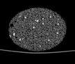
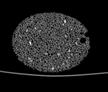
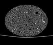
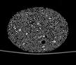
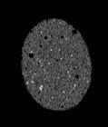
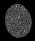
PUMICE STONE: TRANSVERSE SLICES
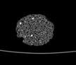
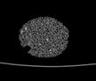
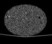
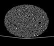
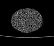
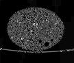
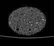
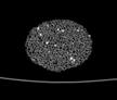
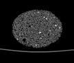
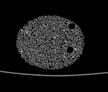
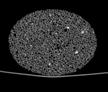
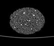
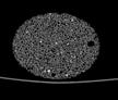
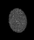
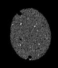
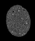
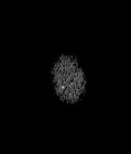
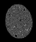
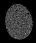
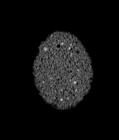
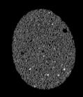
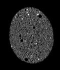
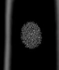
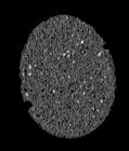
The following images are the slices obtained from the CT scanner which are taken at 0.4mm intervals, with a total of 67 slices, of which 63 are presented. These slices are taken in a transverse direction, cutting through the object sectionally in a horizontal plane.
The transverse slices of the object demonstrate that the organization of cells is similar in both directions: coronal and transverse. There is no elongation which provides the structure with anisotropy. The same characteristics which were noticed in the coronal slices appear again in the transverse slices.


CELLULAR COMPLEXITY 27
TS- 0.08 TS- 0.12 TS- 0.88 TS- 0.92 TS- 1.68 TS- 1.72 TS- 2.48 TS- 2.52 TS- 0.16 TS- 0.20 TS- 0.96 TS- 1.00 TS- 1.76 TS- 1.80 TS- 2.56 TS- 2.60 TS- 0.24 TS- 0.28 TS- 1.04 TS- 1.08 TS- 1.84 TS- 1.88 TS- 2.64 TS- 2.68 TS- 0.32 TS- 0.36 TS- 1.12 TS- 1.16 TS- 1.92 TS- 1.96 TS- 2.72 TS- 2.76 TS- 0.40 TS- 1.20 TS- 2.00 TS- 2.80 TS- 0.48 TS- 0.52 TS- 1.28 TS- 1.28 TS-2.08 TS-2.12 TS- 0.56 TS- 0.60 TS- 1.36 TS- 1.36 TS- 2.16 TS- 2.20 TS- 0.64 TS- 0.68 TS- 1.44 TS- 1.44 TS- 2.24 TS- 2.28 TS- 0.72 TS- 0.76 CS- 1.52 CS- 1.52 TS- 2.32 TS- 2.36 TS- 0.8 CS- 1.60 TS- 2.40
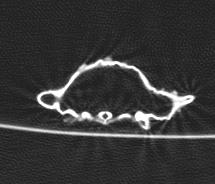
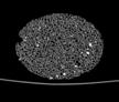
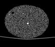
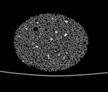
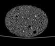
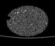
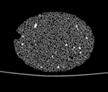
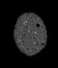
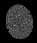
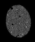
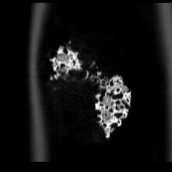
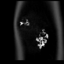
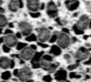
CORAL: CORONAL SLICES
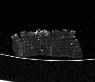
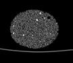
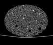
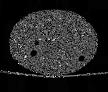
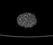
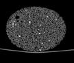
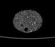
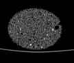
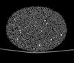
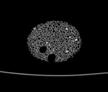
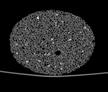
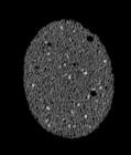
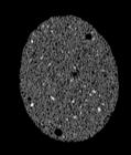
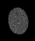
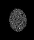
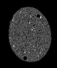
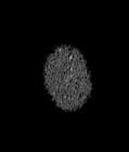
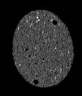
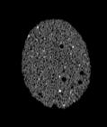
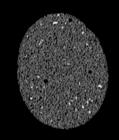
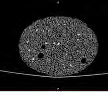
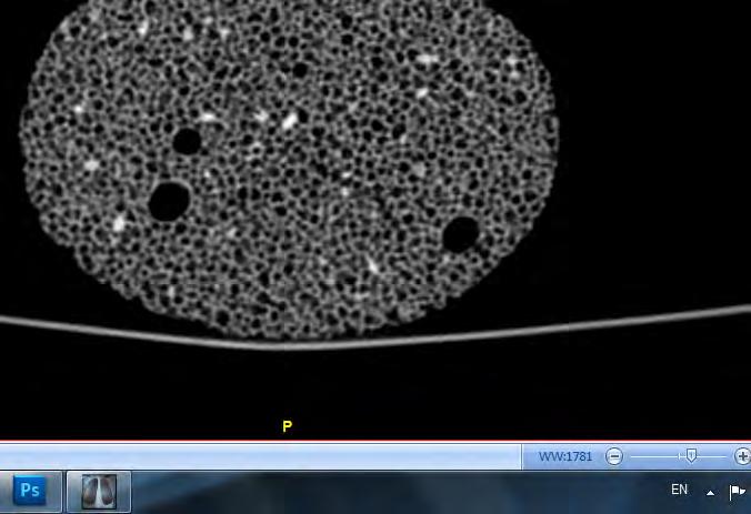
The following images are the slices obtained from the CT scanner which are taken at 0.4mm intervals, with a total of 162 slices. These slices are taken in a coronal direction, cutting through the object sectionally in a vertical plane with the scanner bed shown at the bottom of each slice. 80 slices are presented on this page are half of the complete set, and are therefore at an approximate interval of 0.8mm.


The slices exhibit various qualities of the object, it is evident that there is a range of cell sizes which is variable throughout the object. There are also a number of larger cells that pass through the object sectionally. In some cases there are intersections between the various cells. The cells generally posses the qualities of closed-cell systems, where they intersect they are somewhat similar to open-cell systems.


28 CS- 0.08 CS- 0.88 CS- 1.68 CS- 2.48 CS- 3.28 CS- 4.08 CS- 4.88 CS- 5.68 CS- 0.16 CS- 0.96 CS- 1.76 CS- 2.56 CS- 3.36 CS- 4.16 CS- 4.96 CS- 5.76 CS- 0.24 CS- 1.04 CS- 1.84 CS- 2.64 CS- 3.44 CS- 4.24 CS- 5.04 CS- 5.84 CS- 0.32 CS- 1.12 CS- 1.92 CS- 2.72 CS- 3.52 CS-4.32 CS- 5.12 CS- 5.92 CS- 0.40 CS- 1.20 CS- 2.00 CS- 2.80 CS- 3.60 CS- 4.40
5.20 CS- 6.00 CS- 0.48 CS- 1.28 CS-2.08 CS- 2.88 CS- 3.68 CS- 4.48 CS- 5.28 CS- 6.08 CS- 0.56 CS- 1.36 CS- 2.16 CS- 2.96 CS- 3.76 CS- 4.56 CS- 5.36 CS- 6.16 CS- 0.64 CS- 1.44 CS- 2.24 CS- 3.04 CS- 3.84 CS- 4.64 CS- 5.44 CS- 6.25 CS- 0.72 CS- 1.52 CS- 2.32 CS- 3.12 CS- 3.92 CS- 4.72 CS- 5.52 CS- 6.32 CS- 0.80 CS- 1.60 CS- 2.40 CS- 3.20 CS- 4.00 CS- 4.80 CS- 5.60 CS- 6.40
CS-
CELLULAR SYSTEMS
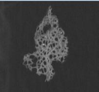
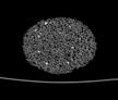
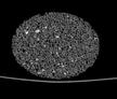
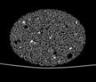
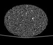
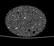
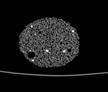
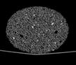
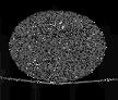
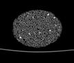
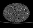
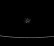
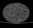
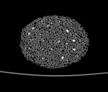
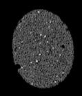
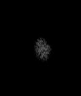
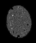
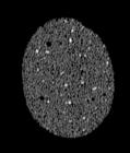
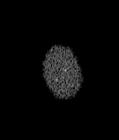
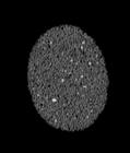
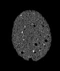
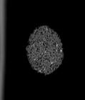
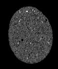
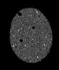
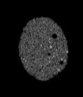
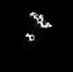
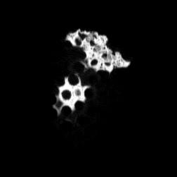
The following images are the slices obtained from the CT scanner which are taken at 0.4mm intervals, with a total of 30 slices. These slices are taken in a transverse direction, cutting through the object sectionally in a horizontal plane.
The transverse slices exhibit qualities that are very different from those of the coronal slices. The cell size appears to be very similar throughout these slices. Based on the coronal slices, these are elongated cells which pass through the object, this elongation suggest qualities such as anisotropy which may provide additional strength in the vertical direction.
Although the coronal slices show these elongated cells passing through the entire object, they are not completely open and you cannot see through the object. This is likely due to their intersection with other cells and solid parts, alongside the angle they run through the object.
CELLULAR COMPLEXITY 29 TS- 0.08 TS- 0.12 TS- 0.88 TS- 0.92 TS- 0.16 TS- 0.20 TS- 0.96 TS- 1.00 TS- 0.24 TS- 0.28 TS- 1.04
1.08 TS- 0.32 TS- 0.32 TS- 0.36 TS- 1.12 TS- 1.16 TS- 0.40 TS- 1.20 TS- 1.24 TS- 1.28 TS- 0.48 TS- 0.52 TS- 0.56 TS- 0.60 TS- 0.64 TS- 0.68 TS- 0.72 TS- 0.76 TS- 0.8
TS-
CORAL: TRANSVERSE SLICES
INTERNAL STRUCTURE ANALYSIS
Further geometrical and structural analysis of the objects was undertaken. For each object, a specific slice was selected in each direction, and at a finer scale the cells where identified, in addition to any distinct features. The centre points of all identified cells were marked as a point-grid. Furthermore, the point grid was used to generate two-dimensional voronoi cells.
In the pumice stone, the cells are diagrammed where the degree of size variation is shown, some larger cells do exist, and areas with dense material are also marked. The voronoi generates mathematical cells which are similar to the morphological cells. However, as shown in the coronal slice, when there is significantly larger cells than the rest of the cells, the variation is not as evident within the voronoi cells.
TRANSVERSE ANALYSIS
CORONAL ANALYSIS
of
30
PUMICE STONE
75 x 57 x 43 mm
Reconstruction of slices into 3D Model selected slice for analysis
close-up
the selceted slice
overlaying of cells
location of cells within slice
point-grid based on cell centres
2D-voronoi from point-grid
CELLULAR SYSTEMS
INTERNAL STRUCTURE ANALYSIS
Similarly the geometrical and structural analysis was undertaken for the coral to provide a comparison. In the coral, the cells hold a larger degree of variation and complexity. Within the coronal slice, an irregular distribution of cells and variety of cell sizes is evident. In the transverse slice, the distribution follows a more regular pattern with similar cell sizes. The voronoi generated based on the cells point-grid does not illustrate strong similarity with the slice, as in the case of the pumice stone.
TRANSVERSE ANALYSIS
close-up of the selceted slice
CORONAL ANALYSIS
of cells
point-grid based on cell centres
CELLULAR COMPLEXITY 31
CORAL
62 x 48 x 14 mm
Reconstruction of slices into 3D Model
selected slice for analysis
overlaying
location of cells within slice
2D-voronoi from point-grid
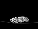
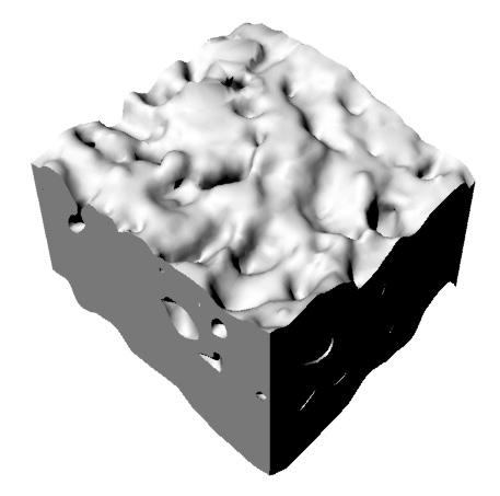
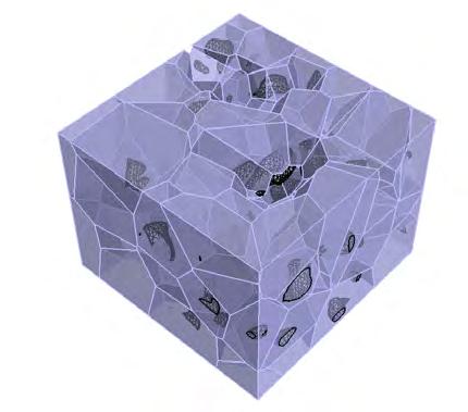
As further analysis in three-dimensions, the slices that were obtained from the Computed Tomography scans in DICOM format can be reconstructed from two-dimensions to create a three-dimensional model. Since the distance between slices is 0.4mm, the resolution of the 3D model is high.
The slices of the coral were reconstructed using InVesalius 3.0, which created a 3D STL format file which is typically used for stereo lithography. This is a format which can be used to 3D print the coral in different materials.
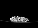
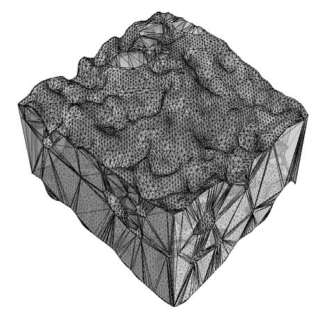
A block of 20mm x 20mm was selected in plan, for further analysis. The block was extracted through boolean operations, and a mesh was obtained digitally from the STL file.

32
Reconstruction of CT slices to produce STL digital model of the scanned coral
20mm x 20mm x ~14mm section block of the scanned coral is extracted for analysis
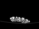
A digital mesh is produced from the Three-Dimensional Geometry of the chosen block
OBJECT RECONSTRUCTION DIGITALLY CELLULAR SYSTEMS
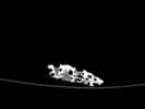
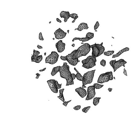
Furthermore, the obtained mesh is porous due to the structure of the coral, and there are therefore voids within it. These voids were extracted digitally and separate meshes were created for each void. The voids represent the cell boundaries, where the coral is the solid that surrounds it.
Through the use of GrassHopper, we were able to generate a 3D-voronoi structure from these surfaces. This provided us with
a mathematical structure that is based on surfaces from the morphological structure. What is evident in this analysis is the aspect of redundancy in the morphological coral, and the effect of environmental factors (mainly water) in changing its morphology.
CELLULAR COMPLEXITY 33
The voids or cell cavities within the mesh are extracted as a separate digital mesh
A Three-Dimensional Voronoi is generated in grasshopper using the mesh of the cell cavities / voids
A mathematical reconstruction of the coral based on the voids of the morphological model
OF OBJECT
MATHEMATICAL RECONSTRUCTION
GEOMETRY OF CELLULAR SYSTEMS
Most cellular structures affiliate to a certain kind of closest packing geometry. Closest packing is the most efficient arrangement of regular or irregular cells.
The geometrical principles that lie behind cellular structures are based on closest packing or space filling geometries 22. The closest packing arrangement is the most effective arrangement of regular or irregular cells, which means that the single components are arranged in a manner which leaves the least possible void space between the cells. Therefore this arrangement positions the cells in the principle of least use of energy in the end - configuration, as well as the least amount of used material for an arrangement of certain cells.
As shown in the diagrams below to the right, space filling occurs in geometries of regular and irregular cells. The closest packing is called ‘space packing’ when it fills up a whole volume without leaving any void. The principle of space packing is the basis for almost every occurring structure in cellular systems. It exists in 2D as well as in 3D. Fig. 1.42 and 1.43 show the difference between an open and a closed cellpacking. Different structures use either open or closed cells, depending on the properties tackled. Other structures combine structures of both open and closed cells.
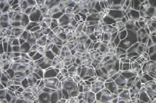
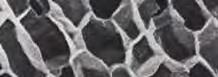
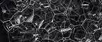
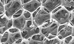
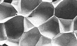
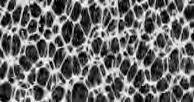
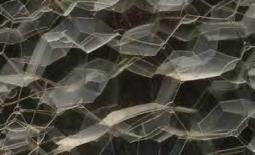
Fig. 1.44 and Fig. 1.45 show an aluminium alloy structure next to soap bubbles. The pictures demonstrate that similar cell arrangements can occur in wildly different substances and are then hardly distinguishable in morphology when displayed 23. This proves that closest packing structures are built up regardless of scale and material, simply the geometry counts in the effectiveness of such structures.
As in the same substance as well as in different systems, the same packing structure can occur at utterly different scales, it can be stated that closest packing structures operate regardless of scales 24. Simply, the arrangement of cells is most important, not the scale or the material of cells. What counts is the number of cells and their efficient arrangement in relation to required properties. This gives the opportunity of having hierarchical structures with which their cellular systems address different extrinsic and intrinsic forces 25. The investigation of transitions in these scales, their geometrical arrangement and the resulting performance lies in the main focus of our research.
THE DUAL NETWORK
By connecting the centres of all neighbouring cells, the dual network of a cell arrangement is created. As visually displayed in the diagrams on the right, the dual network results in a triangulated structure, which again emphasizes the high efficiency of the closest packing arrangement - it is proven that the triangle is the only form that is stable by the nature by its geometry 26. When hinging the edges of a triangle, it will still remain in position. This is why closest packing structures can be considered highly effective in structural terms. Through the Dualnetwork, the Dual-geometry is created, this is valid in 2D structures, in which the Dual Polygon is created and for 3D structures, in which the Dual 3D-Polyhedra results.
TRANSITIONS OF POROSITIES
Within cellular systems, porosity occurs in a variety different ways. The transition from different states of porosities within single packing structures is of special interest. In cellular systems, porosity occurs geometrically by either subtracting an offset of the cell itself or by subtracting an offset of the respective dual-cell. Different scales of this offset lead to various porosity percentages. When these numbers change gradually from one cell to its neighbouring cells, a smooth transition can be found. In both, the Cell as well as the Dual-cell offset, the structural efficiency is still guaranteed, as the principal geometrical arrangement was not changed.
34 Cell offset POROSITY Dual-cell Offset
Fig. 1.42 Open Celled Structure
Fig. 1.44 Metal foam
Fig. 1.45 Soap Bubbles
Fig. 1.43 Closed Celled Structure
Space Packing Structure - Hexagons
Space Packing Structure - Irregular Cells
Space FIlling Structure - Circles
STRUCTURES AND DUAL-NETWORK
Dual Network Closest Packed Circles
Dual Network Closest Packed Hexagons
CELLULAR SYSTEMS
Dual Network Irregular Cells
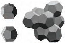
CLOSEST PACKING 3D STRUCTURES
Three dimensional space-packing structures have similar properties as the two dimensional arrangements discussed before. In the following space-packing examples, the structures consist of equal, regular or semi-regular Polyhedra.
When filling a space with equal spheres as shown below, the filled space is not fully occupied by the packed spheres - concave voids are left. This means that the sphere, which as a single object has the smallest surface area in relation to volume and is therefore highly efficient, is in an array not as efficient any more. To eliminate the concave void spaces, the spheres can be swollen to the rhombic dodecahedron, which still is not the most efficient structure 27
One of the most efficient structures is the truncated octahedron which can be packed in the Kelvin packing mechanism. The octahedron packing is resultant of constructing the dual Polyhedra of Sphere packing. Spheres can be packed to a stable condition as they tend to array in triangular manner - opposing to the cube, which will always be in an unstable condition when packed. This can be improved by truncating the cube and adding a second Prism - the Octahedron and combining the two Polyhedra in an efficient packing structure.
SPHERE SPACE FILLING leaves concave voids
CUBE PACKING unstable condition
RHOMBIC DODECAHEDRON swollen spheres
TRUNCATED CUBE + OCTAHEDRON +
OCTAHEDRON PACKING Sphere Dual Polyhedron
TRUNCATED OCTAHEDRON Kelvin Paking
CELLULAR COMPLEXITY 35
CELLULAR GEOMETRIES IN ARCHITECTURE
THE NATIONAL AQUATIC CENTRE BEJING, PTW (AUSTRALIA) AND ARUP (UK)
Following our investigation into various packing geometries, we wanted to investigate the current use of such geometries within an architectural context. The best known example to utilize cellular geometries and efficient structural geometries in architecture is the Water Cube, known as The National Aquatic Centre.
The case study of the Aquatic Centre in Beijing exhibits the use of cellular systems for structural performance and an integrated building envelope. The design of the structure and building is based on the Weaire-Phelan structure which consists of twelve and fourteen sided polyhedrons. This structure is considered to be the most efficient space-packing geometry in terms of surface area to volume.
The Kelvin structure from 1887 was considered to be the most efficient space-packing structure, it uses a single geometrical shape that is repetitive throughout the structure. In 1993, Denis Weaire and Robert Phelan used computer simulations for foams, and were able to discover a structure that is more efficient than Kelvins. It uses two different polyhedra, one is an irregular dodecahedron (12 sided) and another that is tetrakaidecahedron (14 sided). The two have equal volumes, and pack together to create this structure. The surface area is 0.3% less than Kelvin’s structures. Until today it remains the most efficient packing geometry.
The structural system had to respond to seismic conditions on site and the large span structural requirements of the program. The combination of geometrical non-directional space frame structure and the lightweight pneumatic ETFE facade skin system made it possible to reduce gravity loads and lateral loads. The large dimensions in depth of the walls and roof provide the possibility of a large spanning structure with high interior ceilings. Further the three dimensional orthotropic load-bearing structure is an extremely efficient form of construction that requires roughly 30% less steel than a column-and-beam system on a span of hundred meters and height of seven meters.
The ETFE pockets act as a protecting cover for the structure from the corrosive properties of the pool water and the polluted air of Beijing. As well the facade acts as a mediating climate control system within the interior spaces of the building. Geometries from nature which have such performative aspects have been an inspiration to the PTW’s team.
The design process of the building involved the generation of a closed packing system of such cells, which were then rotated and chopped into a square global form. The resulting structure has the ability to span over large distances without supporting columns while at the same time evoking the effect of randomness and complexity. The system is generated out of fifteen different cells in the elevation walls and seven different cells in the ceiling. Because of the combination of the cells in different ways each laser-cut ETFE sheet is different and unique. The cells are generated out of three different nodes and four different members. An additional face structure was added at the edges to finalise the rectangular box section to complete the structure.
The repetition and rotation of cells is an efficient way to achieve high complexity within the system and to overcome the problem of too many different pieces. The mathematical geometries of closed packing cellular systems allowed for high structural properties which enable spanning large distances. The analysis of the three dimensional structural facade system is a case study for the integration of structure into the envelope. However in this project there is no variation in cellular organization and porosity to address different conditions; an aspect we aim to tackle throughout our research.
36
The Kelvin Structure
The Weaire Phelan Structure
CELLULAR SYSTEMS
THE NATIONAL AQUATIC CENTRE BEJING, PTW (AUSTRALIA) AND ARUP (UK)
Cellular Organization within the Structure - Elevation
The 15 repetitive cells throughout the vertical elements of the building are highlighted - walls
There are 7 repetitive cells for the horizontal roof elements of the building
Three-Dimensionality of the Cellular Facade - Section
Fig. 1.46 - The large span of 160m is illustrated above, where the facade also becomes thick in its depth, reaching about eight meters for the roof, and almost four meters in the thin parts of the walls
CELLULAR COMPLEXITY 37
1. 3. 2. 4. 5. 6. 7. 9. 10. 11. 12. 13. 14. 15. 30.00 m 7.60 m 177.00 m 160.00 m 3.70 m
CASE STUDY: TYPICAL DOUBLE SKIN FACADE
THE TELUS HEADQUARTERS (WILLIAM FERRELL BUILDING), VANCOUVER PETER BUSBY AND ASSOCIATES, 2001
The general concept of a double-skin facade is the idea of two layers with a cavity in between. The first skin acts as a rain screen, protecting from environmental conditions, often not fully sealed. The intermediate buffer zone allows for increased thermal and acoustic insulation. Whereas the second skin encloses the enterior spaces, often with operable windows to the controlled buffer zone.
In the facade of the Telus Headquarters in Vancouver this concept is applied, and hereby illustrated. Its double skin facade system is based on the same multi-layer principle, a combination of external layer, intermediate space and inner layer. Within the external layer there are openings which allow for ventilation. The air exchange in the intermediate layer is activated by the solar induced thermal buoyancy and different wind effects.
The intermediate layer which is the buffer zone is controlled by dampers on the top and fans on the bottom of the cavity to ensure a good airflow within both layers. In summer the exterior windows are open and let the air inside the cavity, it heats up and rises to the top of the cavity and exits through the dampers, while the interior windows stay closed to keep the heat outside of the spaces. In winter the dampers are closed and the fan is turned off as well the exterior and interior windows stay closed. This provides a thermal buffer zone which prevents the cold air from outside to enter the building. Both conditions for Summer and Winter are illustrated, showing the variation in performance within a singular system.
The concept of double skin facades is able to address multiple parameters including thermal, acoustic and visual. However most double skin facades are uniform in their appearance and do not have variation. This suggests that it is a solution that does not change with different changes in the building, including program. Furthermore this system adds complexity and layers, separating the facade into different parts that do not operate within a heirarchy.
38
26° 26° 26° 26° 27° 27° 27° SUMMER exterior windows opened 26° interior windows closed 24° dampers open fan on WINTER exterior windows closed -7° interior windows closed 24° dampers closed fan off 6° 6° 6° 7° 7° 7° 7° CELLULAR SYSTEMS Fig. 1.47 - Facade performance in summer and winter
CASE STUDY: THREE-DIMENSIONAL FACADE
THE NATIONAL AQUATIC CENTRE BEJING, PTW (AUSTRALIA) AND ARUP (UK)
In comparison to the double skin facade, the Aquatic Centre has a three dimensional facade that is integrated within structural system. The combination of two layers of ETFE pockets with cavities in between the cells that are used for the structural system provide a performative similar to that double skin facade.
It is designed for different seasonal conditions. In summer, when external weather conditions are hot and humid, the internal layer is sealed. Through an opening on the bottom edge air, cooled by passing over water around the building perimeter, enters the cavity between both layers and heats up, rises and is exhausted by roof vents.
Both layers are sealed during the winter months to minimise heat loss and in order to maximise the thermal performance of the envelope. Further the thermal mass of the water and concrete inside the building capture the heat collected during the day and release it in the evenings.
The main difference between the three-dimensional cellular facade and the double skin facade is the integration within structure. The double skin facade acts as a separate layer and system to that of the buildings structure and is independent of it.
The potential that the three-dimensional facade unveils is the ability to use the spaces created within the cells for programmatic conditions. At the moment, the facade can be entered into spatially only for maintenance purposes and remains inaccessible to the building users.
This case study however still disregards variation in the major parameter of cellular systems - porosity. There is a potential to reduce or increase porosity, in response to program, light, structure and other factors. The variation becomes particularly weak in this case when considering transitions and cases between the facade and roof.
CELLULAR COMPLEXITY 39 cool air drawn in over outside water for ventilation controls daylight to areas that do not have glare ETFE switched on or off ETFE transparent to acoustic low frequency, internal skin absorbs high frequency diffuse indirect light through ETFE switched to ‘OFF’ position hot cavity air vented to outside SUMMER maximising passive solar gain into pool, solar heat gain is higher then heat loss thermal mass of structure and water absorbs the heat double skin facade acts like a highly insulated greenhouse WINTER maintainance platform for easy access to lights and services Lights in cavity act as indirectly heating of internal space 36° 30° 28° 28° 45°
Fig. 1.48 - Facade performance in summer
and winter
40 CELLULAR SYSTEMS
CELLULAR SYSTEMS overview
Throughout this research phase of the project, the general characteristics of cellular systems were investigated. A range of properties were discovered including efficient structural capabilities, low thermal conductivity and good acoustic insulation. These properties however exist at different scales and have a range of parameters affecting them. The parameters can be generally classified to material, geometry and environment.
Of particular interest within the research were natural cellular systems and their geometrical transitions and gradients. Imaging technology from the medical radiology discipline was used to analyse natural artefacts through computed tomography scans. The slices obtained were analysed for their organization and relation to mathematical models. An aspect of redundancy was noticed in most natural systems, their formations are also part of emergent form-finding methods which rely on metabolic processes and environmental factors.
There is however an underlying principle between all cellular systems, and this is the closest-packing arrangement. This creates triangulation which results in structural properties, and an efficient use of material.
Furthermore, the current use of cellular systems in architecture was investigated through a case study which is compared to conventional systems. In general, the current use of cellular systems does not exploit their opportunity in creating variation through porosity. This variation could address different conditions within a building, and not addressing the entire building through one repetitive solution.
Additionally, the cellular systems provide potential for three-dimensional spatial qualities, while maintaining a unified system that integrates multiple performative aspects; where there are no layers and separation between various elements.
CELLULAR COMPLEXITY 41
image references references
1 - p.2, Gibson, L. J., & Ashby, M. F. (1997). Cellular solids (Second ed.). Cambridge: Cambridge university press.
2 - p.30, Ibid
3 - p.45, Ibid
4 - p.47, Ibid
5 - p.283, Ibid
6 - p.133, Ibid
7 - Ibid
8 - p.285, Ibid
9 - p.289, Ibid
10 - p.293, Ibid
11 - p.303, Ibid
12 - p.307, Ibid
13 - p.309, Ibid
14 - p. 11, Pearce, P. (1990). Structure in nature is a strategy for design. Cambridge: MIT Press. (Original work published 1978)
15 - p. 92, Jeronimidis, G. (2004). Biodynamics. Emergence: morphgenetic design strategies, London: Wiley-Academy.
16 - Ibid
17 - p. 34, Weinstock, M. (2006). Self-Organisation and Material Constructions. Techniques and technologies in morphogenetic design, London: Wiley-Academy.
18 - p. xiii, Pearce, P. (1990). Structure in nature is a strategy for design. Cambridge: MIT Press. (Original work published 1978)
19 - p. 16, Ibid
20 - p. 10, Ibid
21 - p. 33,34, Weinstock, M. (2006). Self-Organisation and Material Constructions. Techniques and technologies in morphogenetic design, London: Wiley-Academy.
22 - p. 11, Pearce, P. (1990). Structure in nature is a strategy for design. Cambridge: MIT Press. (Original work published 1978)
23 - p. 14, Ibid
24 - p. 9, Ibid
25 - p. 11, Ibid
26 - p. 3, Ibid
27 - p. 5, Ibid
Fig. 1.1 http://3.bp.blogspot.com/-zhvYMSqPP3E/T7y1QRjSLxI/ AAAAAAAAAKM/0CFLSacXWPs/s1600/mushroom.jpg
Fig. 1.2 http://www.engr.wisc.edu/alumni/perspective/06.4/Photo_ p8_1.jpg
Fig. 1.3 http://i567.photobucket.com/albums/ss116/shiaopinghu/ c20crumbcloseupusethisone.jpg
Fig. 1.4 http://w3.antd.nist.gov/wctg/netanal/honeycomb.gif
Fig. 1.5 http://fr.wikipedia.org/wiki/Fichier:Honey_comb.jpg
Fig. 1.6 http://www.structuremag.org/images/0908-f2-8.gif
Fig. 1.7 http://samjshah.files.wordpress.com/2008/08/rd_love_bubbles.jpg
Fig. 1.8 http://en.wikipedia.org/wiki/File:CompositeSandwich.png
Fig. 1.9 http://www.designbuild-network.com/projects/watercube/ images/10-watercube.jpg
Fig. 1.10 http://www.jetsongreen.com/images/old/6a00d8341c67ce53e f0133f6454521970b-500wi.jpg
Fig. 1.11 http://farm5.static.flickr.com/4019/4636848809_e3d6195efb. jpg
Fig 1.12 http://www.jameswarwick.co.uk/do/ecco/view_item?listid=2&li stcatid=43&listitemid=1182&ind=21&page=1
Fig 1.13 http://www.newscientist.com/gallery/mars-cracks-driedlakes/2
Fig 1.14a http://www.flickr.com/photos/jrosenk/6848040787/
Fig 1.14b http://www.maya-culture.de/category/flora-fauna/page/6/ Fig 1.15a http://neogenebryozoans.myspecies.info/category/bryozoa/ bryozoa/gymnolaemata/cheilostomata/ascophora/bitectiporidae/pentapora
Fig 1.15b http://www.nhm.ac.uk/research-curation/staff-directory/ zoology/m-spencer-jones/index.html
Fig 1.16a http://www.ucmp.berkeley.edu/esem/pollen.gif
Fig 1.16b http://cache.zazna.com/selection/Qfb0lSFVmJ,proxy.html
Fig 1.17a http://en.wikipedia.org/wiki/File:Poppy-seeds.jpg
Fig 1.17b http://purpleopurple.com/health-benefits/poppy-seeds.html
Fig 1.18a http://www.panoramio.com/photo/5489858
Fig 1.18b http://owlsmall.info/59-philodendron-silk-plant-real-touch.php
Fig 1.19a http://mfareview.wordpress.com/2011/12/16/architecturalcyborgs-nanotechnology-and-the-potential-for-living-architecture/
Fig 1.19b http://magickcanoe.com/blog/2006/11/27/in-the-redwoodspart-four/
Fig 1.20a http://botweb.uwsp.edu/anatomy/images/dicotwood/pages/ SEM0222.htm
Fig 1.20b http://www.stockphotopro.com/photo_of/root/A841K2/silver_maple_Tree_roots
Fig 1.21a http://www.probelog.com/2007/07/quercus-alba-wood.htm
Fig 1.21b http://rowva-jh-hist.wikispaces.com/Megan+and+HannahSymbols
42
CELLULAR SYSTEMS
Fig 1.22a http://www.probelog.com/span/
Fig 1.22b http://www.public-domain-image.com/plants/flowers/slides/ high-reed-grass.html
Fig 1.23a http://www.metisllc.com/store/index.php?main_ page=product_info&products_id=3
Fig 1.23b http://www.omafra.gov.on.ca/IPM/english/cucurbits/index.html
Fig 1.24a http://www.corbisimages.com/stock-photo/rights-managed/ DK011811/crosssection-of-a-mares-tail-plant-stem
Fig 1.24b http://www.wetlandplants.co.uk/acatalog/info_hipvul.html
Fig 1.25 http://www.wisdomportal.com/Haikus/Number6inNature.html
Fig 1.26a http://botany.cz/en/plant-tissues/
Fig 1.26b http://www.naturalmedicinalherbs.net/herbs/j/juncuseffusus=soft-rush.php
Fig 1.27a http://www.sciencephoto.com/media/28835/view
Fig 1.27b http://commonground08.wordpress.com/2010/08/03/plant-ofthe-week-white-dead-nettle/
Fig 1.28a http://3.bp.blogspot.com/-zhvYMSqPP3E/T7y1QRjSLxI/ AAAAAAAAAKM/0CFLSacXWPs/s1600/mushroom.jpg
Fig 1.28b http://www.slowmotiondoomsday.com/boletus.html
Fig 1.29a http://www.probelog.com/2007/07/prairie-plant.htm
Fig 1.29b http://www.thebattery.org/plants/plantview.php?id=241
Fig 1.30a http://maceracio.blog.hu/2012/05/29/hogy_is_van_ez_ palackzaras_1
Fig 1.30b http://www.furniturehomedesign.com/category/flooring/ Fig 1.31a http://www.probelog.com/span/
Fig 1.31b http://digital-photography-school.com/discover-seven-waysto-create-sepia-images-in-photoshop
Fig 1.32a http://futurismic.com/2008/12/16/we-can-rebuild-you-injectable-artificial-bone-paste-developed/
Fig 1.32b http://larrytanner.blogspot.co.uk/2012_05_01_archive.html
Fig 1.33a http://larrytanner.blogspot.co.uk/2012_05_01_archive.html
Fig 1.33b http://www.ammonite.free-online.co.uk/brcoral.htm
Fig 1.34a http://www.nhm.ac.uk/research-curation/research/projects/ echinoid-directory/intro/stereom.html
Fig 1.34b http://tidechaser.blogspot.co.uk/2012/03/sea-stars-classasteroidea-of-singapore.html
Fig 1.35a http://www.probelog.com/
Fig 1.35b http://geology.com/rocks/scoria.shtml
Fig 1.36a http://www.probelog.com/
Fig 1.36b http://www.asturnatura.com/especie/spongia-agaricina.html
Fig 1.37a http://www.britannica.com/EBchecked/media/3362/Scanningelectron-micrograph-of-the-adult-human-lung-showing-alveolar
Fig 1.37b http://www.umm.edu/patiented/articles/normal_lungs_alveoli_000413.htm
Fig 1.38a http://www.flickr.com/photos/pixelprobe/3122457509/
Fig 1.38a http://www.flickr.com/photos/pixelprobe/3122457509/
Fig 1.38b http://www.wallpaper-gratis.eu/tier/natur/tier10.php
Fig.1.39a http://eveningswithpeter.blogspot.co.uk/2011/08/tonightsmenu-saffron-risotto-with-sea.html
Fig 1.39b http://www.probelog.com/
Fig.1.40a http://echinoblog.blogspot.co.uk/2010_05_01_archive.html
Fig 1.40b http://www.probelog.com/
Fig 1.41a http://tidechaser.blogspot.co.uk/2012/03/sea-stars-classasteroidea-of-singapore.html
Fig 1.41b http://www.probelog.com/
Fig. 1.42 http://greencomplianceplus.markenglisharchitects.com/ technical/insulation/qii-hers-credit-now-allows-open-cell-spray-foam/ Fig. 1.43 http://greencomplianceplus.markenglisharchitects.com/ technical/insulation/qii-hers-credit-now-allows-open-cell-spray-foam/ Fig. 1.44 http://archive.nrc-cnrc.gc.ca/eng/ibp/irc/cbd/buildingdigest-166.html
Fig. 1.45 http://chemistry.about.com/od/bubbles/ig/Bubble-Photos/ Soap-Bubble-Foam.htm
Fig. 1.46 http://moreaedesign.wordpress.com/category/ uncategorized/page/2/
Fig. 1.47 http://myweb.wit.edu/viridis/green_site/projects/2_ processes/envelope/1_double-skins/6_case%20studies/case%20 studies.html
Fig. 1.48 http://fabricarchitecturemag.com/articles/0508_f2_ watercube.html
CELLULAR COMPLEXITY 43
GEOMETRICAL DEVELOPMENT
Following our research into cellular systems, and developing an understanding towards the underlying geometrical principles behind these systems, we commenced explorations within the geometrical realm of cellular systems.
The ambition of our geometrical development was to create variation in porosity within cell-based geometries. The creation of these geometries was be based on the closest-packing principles investigated earlier. Furthermore, the use of network offsets, and dual networks guided the process towards creating a gradient in porosity by gradually adjusting the offset of the network, or dual-network.
The geometrical development occurs in both 2D and later 3D. A variety of efficient space-packing structures were chosen for development. This section displays the various opportunities to develop a gradient of porosity, which would address various properties throughout the application of the system.
CELLULAR COMPLEXITY 45
As an initial step towards the development of a cellular system and its geometry, several explorations were undertaken in two dimensions where there is a possibility to develop a porosity gradient. The first two explorations examine the possibility of use of an offset network on either a triangular or hexagonal tessellations in two-dimensions. The amount of offset would determine the porosity; where the application of the offset amount through intervals would create a gradient.
TRIANGULAR TESSELLATION OFFSET NETWORK
Throughout the process, the centre point of each tessellation is taken, and the tessellation is scaled down by an interval factor, towards this centre point. The offset tessellation is then subtracted from the original to create a void which generates the porosity. The process is illustrated below.
HEXAGONAL TESSELLATION OFFSET NETWORK
Triangular Tessellation Pattern
Hexagonal Tessellation Pattern
Tessellation centre points
Tessellation centre points
Tessellation offset from centre points
Tessellation offset from centre points
46
Generated Gradient
Generated Gradient
GRADIENT
TWO-DIMENSIONS GEOMETRICAL DEVELOPMENT
DEVELOPMENT:
GRADIENT DEVELOPMENT: TWO-DIMENSIONS
As a further development of the two-dimensional gradient, a dualoffset network is tested. The dual network is generated by connected the centre points of multiple tessellations. In the case of a triangular tessellation, connecting each six triangles will generate a hexagon. For the hexagonal tessellation connecting each three hexagons will generate a triangle. The offset is then applied on the dual geometry and not the original tessellation. This allows for alternation between geometries where a triangular tessellation grid can have porosity through hexagonal voids and vice versa.
TRIANGULAR TESSELLATION DUAL-OFFSET NETWORK
HEXAGONAL TESSELLATION DUAL-OFFSET NETWORK
CELLULAR COMPLEXITY 47
Triangular Tessellation Pattern
Hexagonal Tessellation Pattern
Tessellation centre points
Tessellation centre points
Connection of centre points for dual-network
of tessellation
Generated Gradient Generated Gradient
Connection of centre points for dual-network Offset
dual-network Offset of tessellation dual-network
KELVIN PACKING STRUCTURE
DUAL GEOMETRY OFFSET
The principles applied in two-dimensions are now tested in threedimensional geometries. The basis for the first developed porous structure is the Kelvin packing structure. The primitive cell is a Truncated Octahedron. By connecting the centers of each cell, the Dual-Polyhedron is created, in this case the Rhombic Dodecahedron. This Dual Polyhedron is then partitioned into Tetrahedra, which are offset in gradually increased values throughout the structure. By subtracting these Dual-Polyhedra from the initial cells, desired Porosities are created in the single cells and in the overall structure. To achieve an even higher range of porosity the cell is then offset and also subtracted from a certain point in the structure. Through the principle investigated earlier on the structural quality of a Dual-Network, the structural efficiency is still guaranteed, even with the porous cells.
48
INITIAL CELLS DUAL OFFSET DUAL SUBTRACTED OFFSET CELLS RESULTING POROUS STRUCTURE
GEOMETRICAL DEVELOPMENT
TRUNCATED OCTAHEDRON KELVIN PACKING
DUAL SYSTEM OFFSET
In this structure, the Kelvin packing is again the basis for the geometrical development. The centres of the packed Truncated Octahedrons are connected in order to create the Dual-Network. This Network is then extruded with offsets of the cell walls. Throughout the structure, the Extrusion-Offset Number increases, therefore the thickness of the generated Dual-structure increases. By subtracting this Dual-Structure from the initial cells, a Porosity gradient is created throughout the system.
50
KELVIN PACKING STRUCTURE
INITIAL CELLS DUAL EXTRUDED DUAL IN CELLS DUAL SUBTRACTED RESULTING POROUS STRUCTURE
GEOMETRICAL DEVELOPMENT
TRUNCATED OCTAHEDRON KELVIN PACKING
DUAL SYSTEM AS STRUCTURE
In this structure, the same principle as in the previous example is applied - The Dual-Network of the Kelvin Packing System is generated and offsets of the cell walls are extruded along it in various thicknesses. In this case, the Dual-Structure is not subtracted from the initial cells, it is used as a structure on its own. What is particularly interesting in this structure, in relation to the former two is the change in cell size. Previously the cell size remained the same due to the base primitive. In this case the cell becomes smaller due to the change in the network offset size. This is the first attempt to create a gradient in porosity, and change in cell size.
INITIAL CELLS DUAL EXTRUDED RESULTING POROUS STRUCTURE
52
KELVIN PACKING STRUCTURE
GEOMETRICAL DEVELOPMENT
TRUNCATED OCTAHEDRON KELVIN PACKING
KELVIN PACKING STRUCTURE: NETWORK OFFSET POROSITY GRADIENT
As a further analysis of the porosity gradient. The amount of cell offset is documented, in relation to the porosity of the cell. This investigates the relationship between the geometrical changes and porosity changes. Furthermore, by creating a graph of this relationship, it is possible to determine the amount of offset needed to create a specific porosity. Generally, cellular systems which are porous have a porosity on average around 30%, in this geometry and offset network, the focus range would be between 0.1 to 0.5 - 40%-90% porosity, as outlined below.
Far Left: offset - porosity data Left: Network Offset Geometry Below: offset - porosity graph
54 Geometry NETWORK OFFSET DUAL-NETWORK OFFSET Offset 0 0.8 0.9 0.7 0.5 0.6 0.4 0.2 0.3 0 0.921 0.978 0.833 0.602 0.724 0.474 0.232 0.10.134 0.5 0.4 0.992 0.973 0.999 0.875 0.936 0.784 0.10.271 0.348 0.2 0.3 0.488 0.657 Porosity OffsetPorosity 0 0.2 0.4 0.6 0.8 1 1.2 00.20.40.60.81 0 0.2 0.4 0.6 0.8 1 1.2 00.20.40.60.81 DUAL-NETWORK
0 0.921 0.978 0.833 0.724 0 0.8 0.9 0.7 0.6 0 0.992 0.973 0.999 0.936 Porosity Geometry OffsetPorosity 0 0.2 0.4 0.6 0.8 1 1.2 00.20.40.60.81 network offset
OFFSET
GEOMETRICAL DEVELOPMENT
KELVIN PACKING STRUCTURE: DUAL-NETWORK OFFSET POROSITY GRADIENT
The same analysis is undertaken for the dual-network offset. In this case the relationship is not as linear but becomes sharper as the offset increases, due to the geometry. In this case the offset focus range would be only between 0.1 and 0.3 in relation to 0.1 and 0.5 in the network offset structure. This establishes the fact that the type of network and geometry creates variable changes in porosity within a given offset.
Far Left: offset - porosity data Left: Dual-Network Offset Geometry Below: offset - porosity graph
CELLULAR COMPLEXITY 55 DUAL-NETWORK OFFSET Offset 0.8 0.9 0.7 0.5 0.6 0.4 0.2 0.3 0 0.921 0.978 0.833 0.602 0.724 0.474 0.232 0.10.134 0 0.8 0.9 0.7 0.5 0.6 0.4 0 0.992 0.973 0.999 0.875 0.936 0.784 0.10.271 0.348 0.2 0.3 0.488 0.657 Porosity Geometry OffsetPorosity 0 0.2 0.4 0.6 0.8 1 1.2 00.20.40.60.81 1.2 00.20.40.60.81 network offset dual network offset DUAL-NETWORK OFFSET Offset 0 0.921 0.978 0.833 0.602 0.724 0.474 0.232 0.10.134 0 0.8 0.9 0.7 0.5 0.6 0.4 0 0.992 0.973 0.999 0.875 0.936 0.784 0.10.271 0.348 0.2 0.3 0.488 0.657 Porosity Geometry OffsetPorosity 0 0.2 0.4 0.6 0.8 1 1.2 00.20.40.60.81 00.20.40.60.81 network offset dual network offset
OCTAHEDRON PACKING STRUCTURE
Further geometrical development was continued towards different spacepacking structures from the Kelvin. This structure consists of closest packed octahedrons which are oriented in three different directions in order to fill up a volume without leaving any voids. By connecting the centre of each Octahedron with the centres of all its neighbouring cells, the Dual Polyhedra of the Octahedron Packing structure are created. In this case the Dual structure consists of two different Polyhedra - The Truncated cube combined with the Octahedron itself. By scaling the Dual Polyhedra in their centres gradually throughout the structure, a porosity gradient is generated.
56
INITIAL CELLS DUAL OFFSET DUAL SUBTRACTED RESULTING POROUS STRUCTURE GEOMETRICAL DEVELOPMENT
OCTRAHEDRON OCTRAHEDRON PACKING
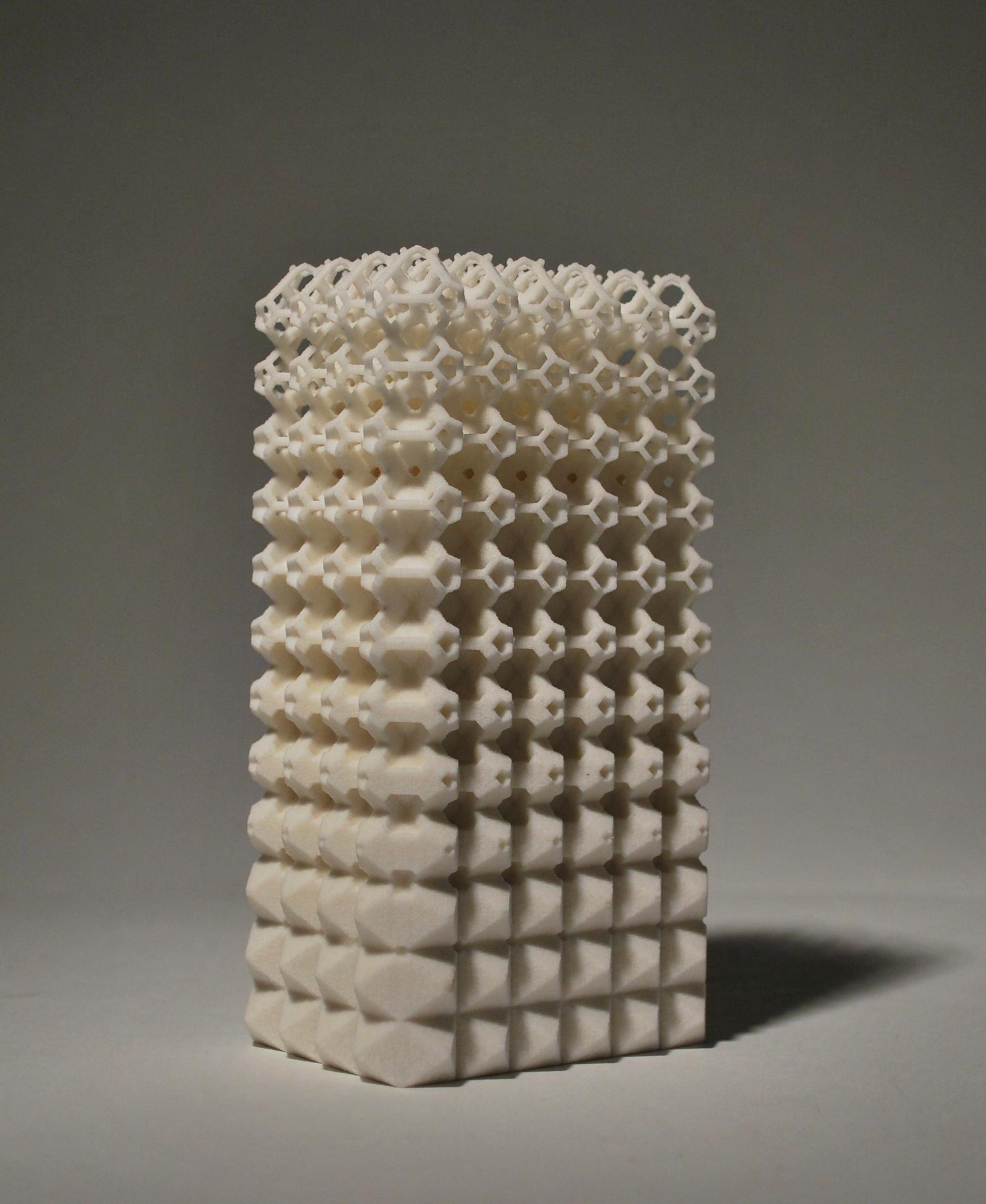
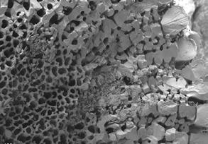
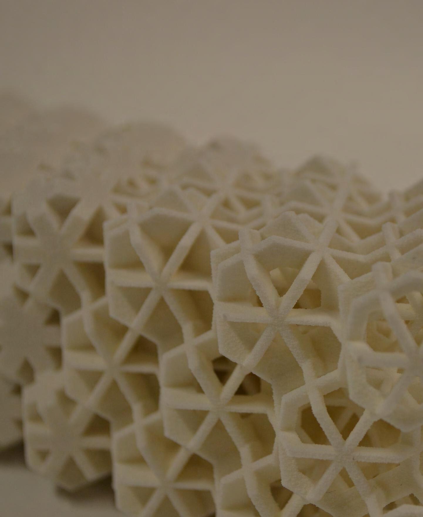
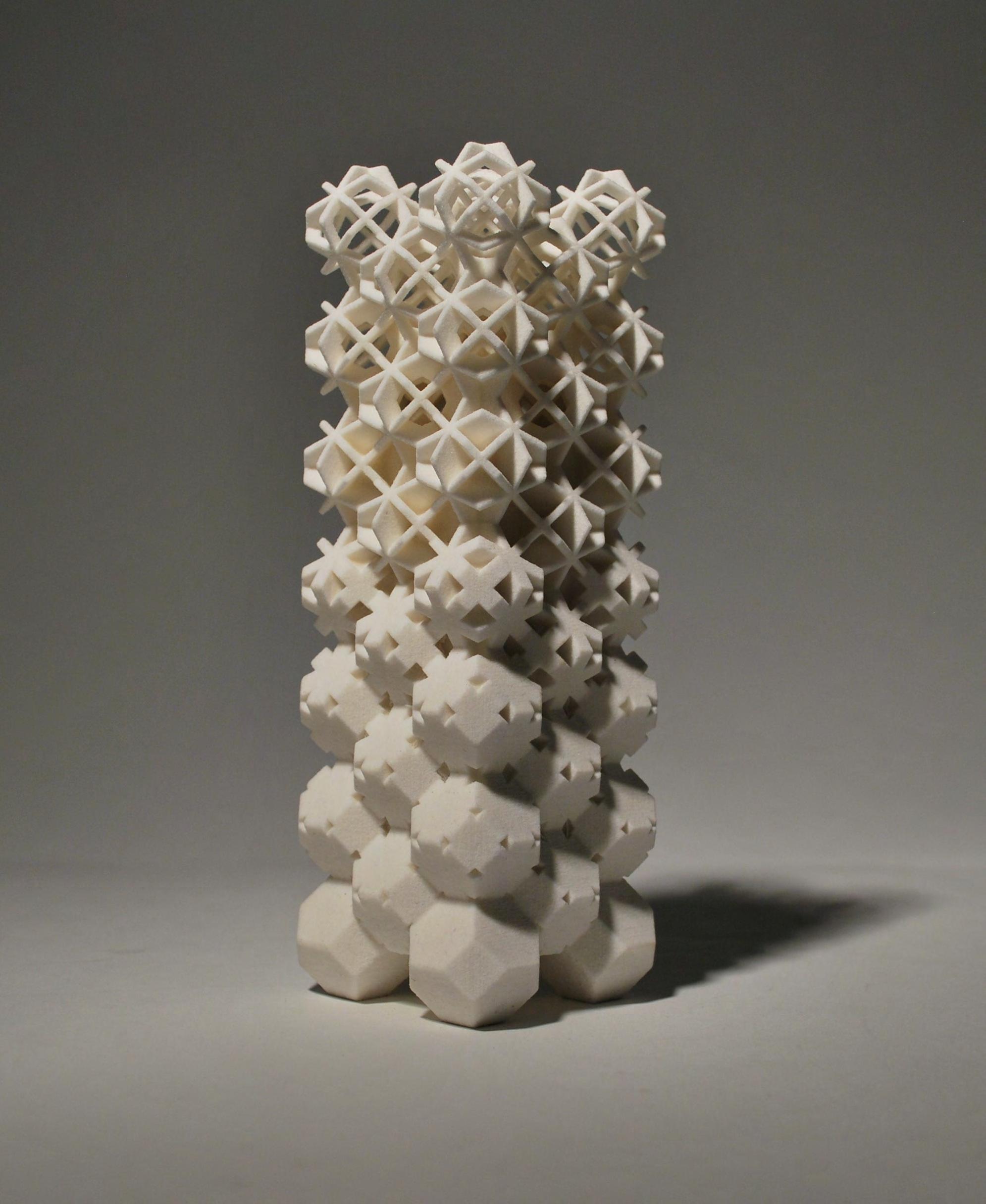
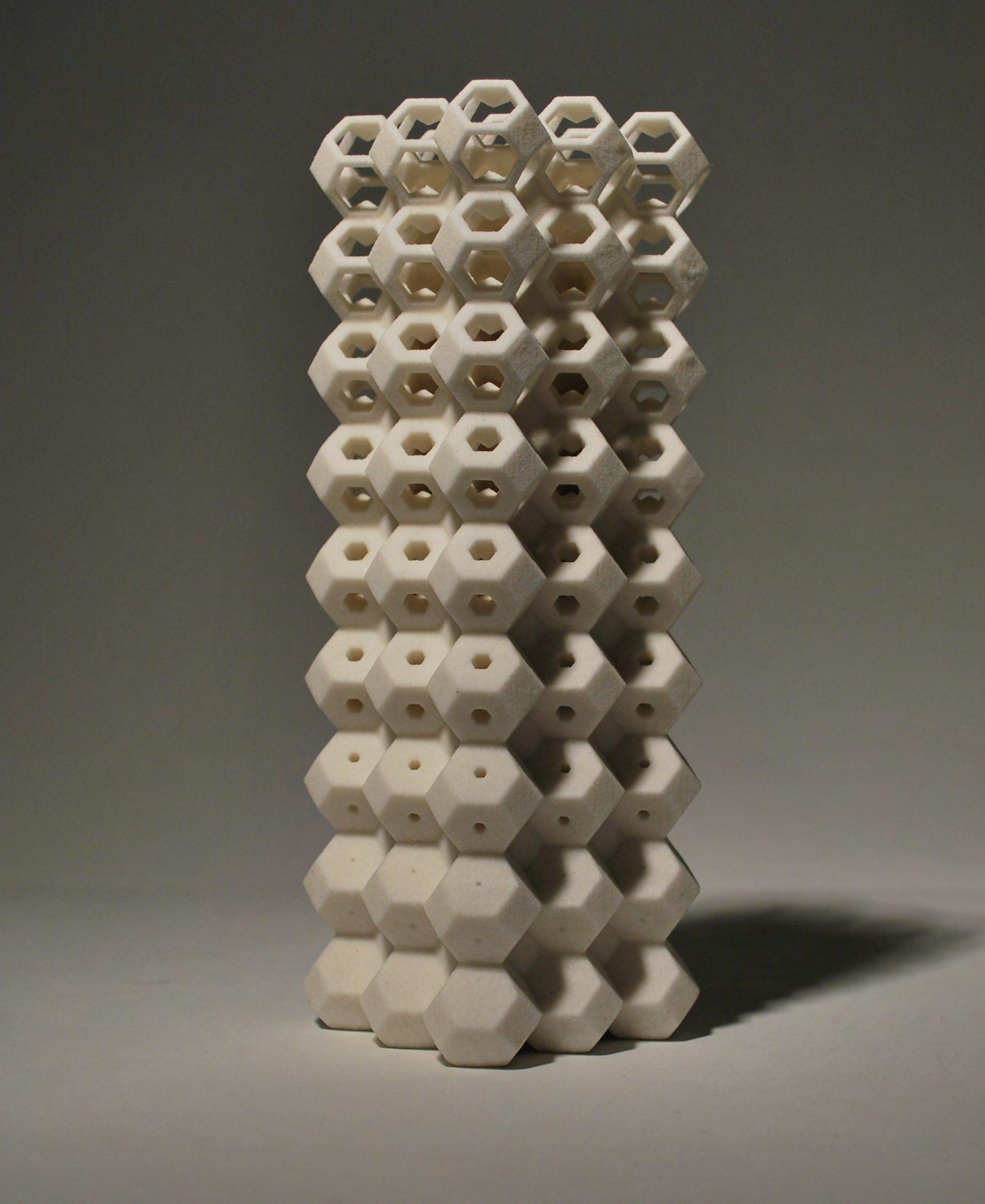
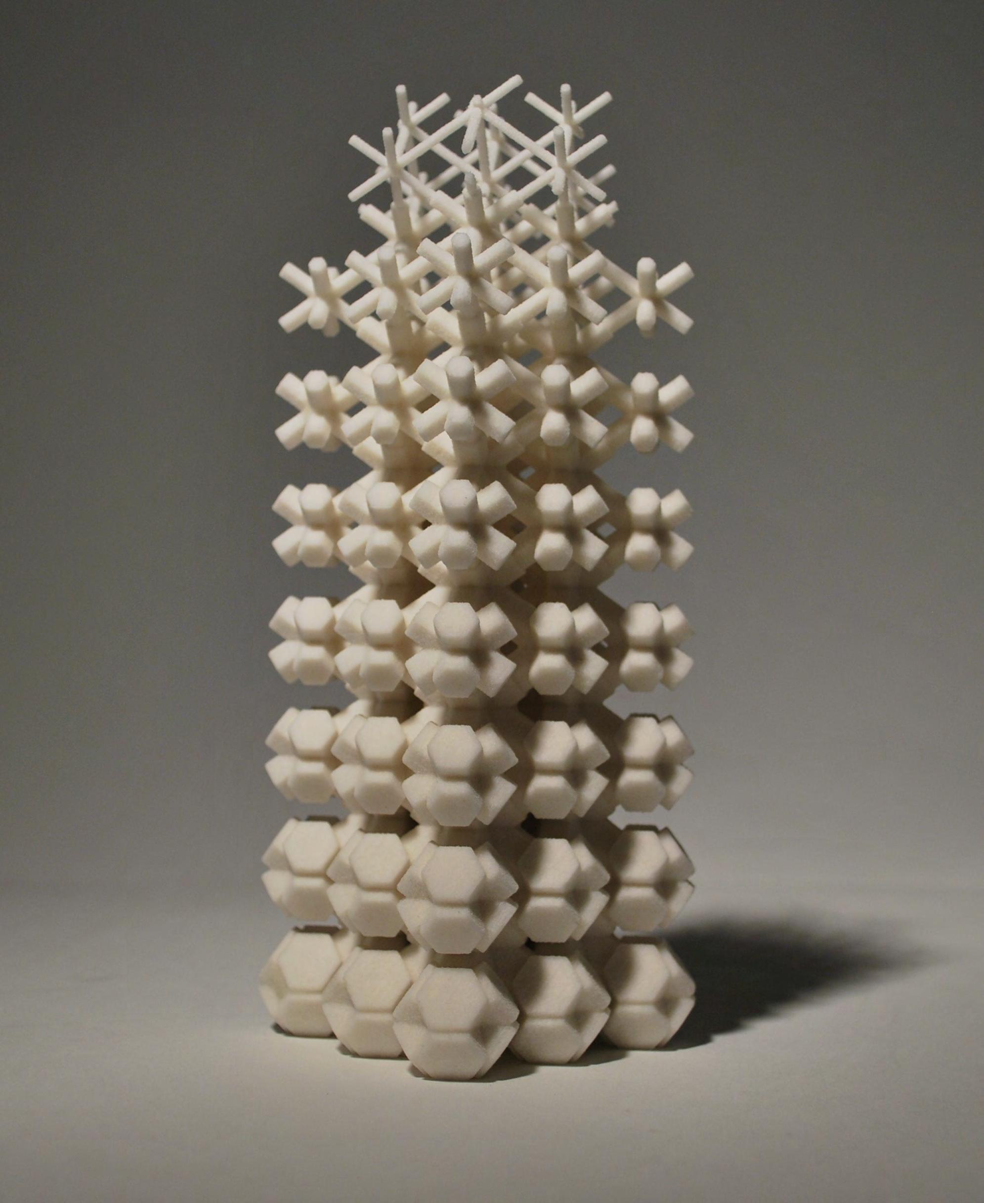
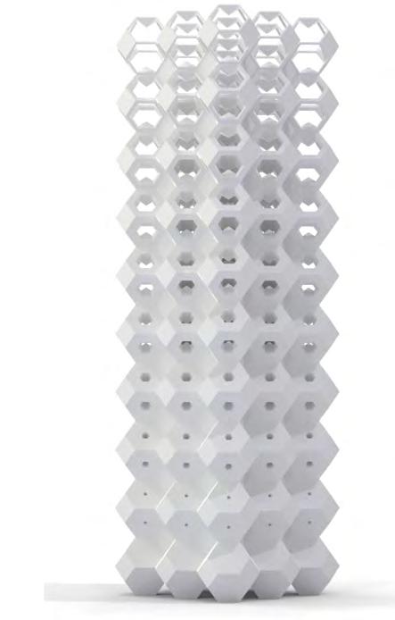
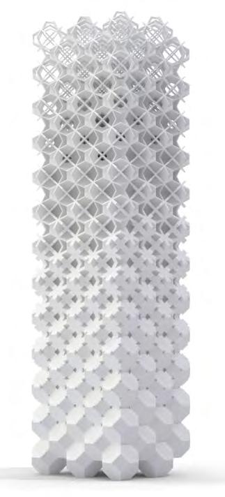
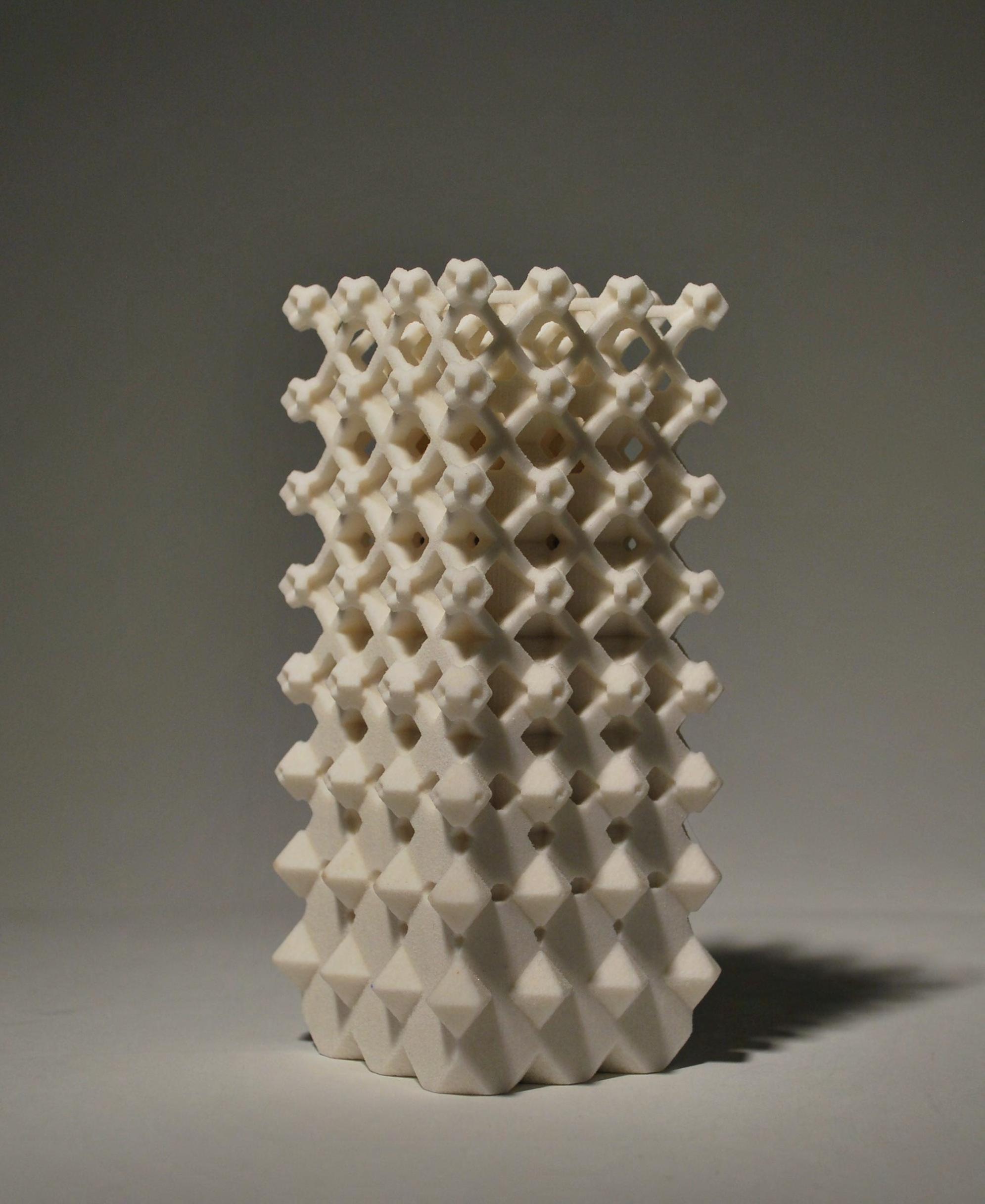
TRUNCATED CUBE - OCTAHEDRON STRUCTURE
This structure is built up out of two different Polyhedra - The Truncated Cube and the Octahedron. The Dual-Polyhedron of this structure is the Octahedron. It is, like in the previous geometries generated by connecting the centres of the original cells. The Dual-Polyhedra are then gradually scaled throughout the structure in order to achieve the desired porosity gradient. The Dual Polyhedron is then subtracted from both, the Truncated Cube and the Octahedron.
The interesting aspect in this specific geometry is the transition not only in porosity, but in cell type, where it changes from closed cells with plates towards open cells with struts.
TRUNCATED CUBE - OCTAHEDRON PACKING
58 +
INITIAL CELLS DUAL OFFSET DUAL SUBTRACTED RESULTING POROUS STRUCTURE GEOMETRICAL DEVELOPMENT
Not only gradient in cell porosity, but also gradient in cell size is and important factor when looking into the structure of cellular systems.

Subdivision was investigated as a strategy of variation in cell size, where it is possible to subdivide a large cell into a number of smaller identical cells. In the first example shown below, a simple subdivision of the initial cell is shown. The initial cell, the Rhombic Dodecahedron can be subdivided into smaller cells, which are in fact just equal to the scaled initial cell. In this system, several sizes of cells can be combined in one single, continuous system in order to address various required properties.
SUBDIVISION OF THE RHOMBIC DODECAHEDRON
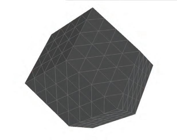
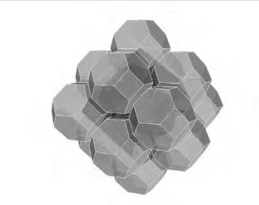
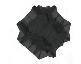
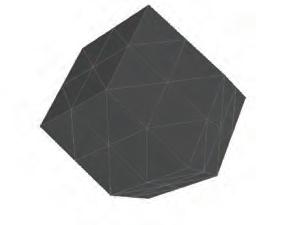
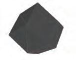
Below, the initial Truncated Octahedron cell is shown, and its Dual Structure Polyhedron, the Rhombic Dodecahedron. In this example, cell porosity is created by subtraction of the offset Dual structure on the initial cell. The same operation is executed on the Dual-cell itself. The new, porous Dual-cell can then be placed in the initial cell, where it was taken out before.
This operation can possibly be repeated in a desired amount of iterations with the desired amount of porosity at each level. Therefore hierarchies in cell size as well as in porosity are created within one single, controlled system.
TRUNCATED OCTAHEDRON DUAL OFFSET VARIATION IN CELL
SIZE
GENERATION OF DUAL NETWORK AND POLYHEDRON
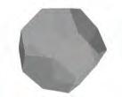
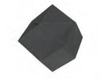
TRUNCATED OCTAHEDRON RHOMBIC DODECAHEDRON
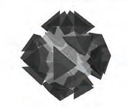
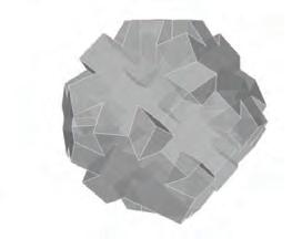
60
VARIATION IN CELL SIZE THROUGH SUBDIVISION
TETRAHEDRON DUALDUAL GEOMETRICAL DEVELOPMENT 0.9 SUBDIVISION TETRAHEDRON
TETRAHEDRON
TETRAHEDRON
TRUNCATED OCTAHEDRON
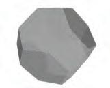
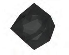
DUAL OFFSET
DUAL OFFSET
RHOMBIC DODECAHEDRON DUAL SCALE DUAL SUBTRACTION
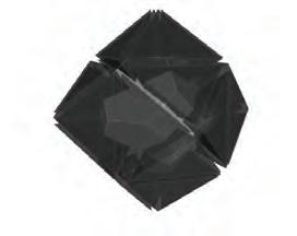
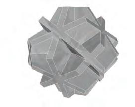
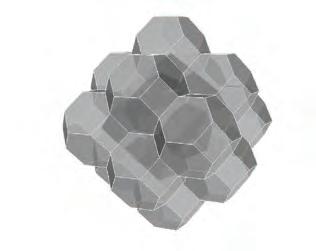
TRUNCATED OCTAHEDRON
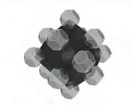
SCALE DUAL SUBTRACTION
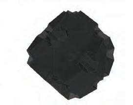
COMBINATION OF POROUS INITIAL AND POROUS DUAL
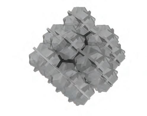
CELLULAR COMPLEXITY 61 DUAL
SUBDIVISION
TETRAHEDRON 0.5 0.9 0.5 0.9
0.5 0.9 SUBDIVISION
TETRAHEDRON 0.5 0.9 0.5 0.9
0.5 0.9 DUAL
DUAL
SPACE-PACKING STRUCTURES: POROSITY GRADIENT
The results of the geometrical development of a porosity gradient through space-packing structures are presented below. Three variations were produced for the kelvin structure which utilizes the same cell primitive repetitively. The various offset networks create the change in geometry and porosity. Furthermore a tetrahedron packing is also investigated, in addition to a two-primitive packing strategy with truncated cubes and octahedrons. Overall, there are various ways to develop the gradient geometrically. Further investigation and comparison of these structures is required for their evaluation.
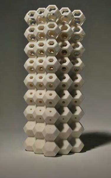
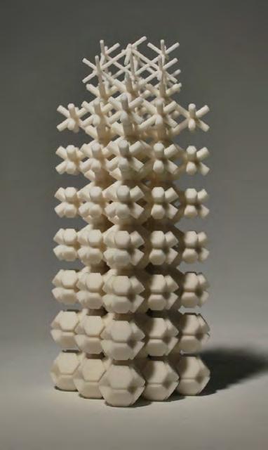
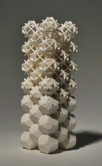
62
KELVIN PACKING - DUAL
KELVIN PACKING CELL OFFSET
KELVIN PACKING DUAL OFFSET
GEOMETRICAL DEVELOPMENT
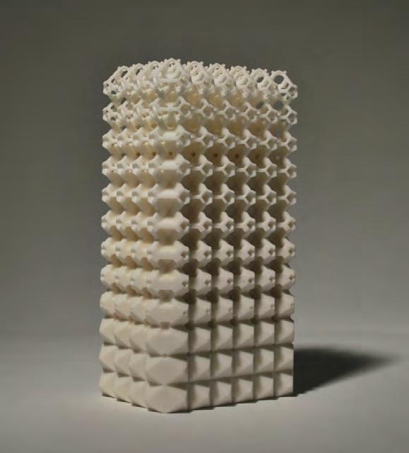
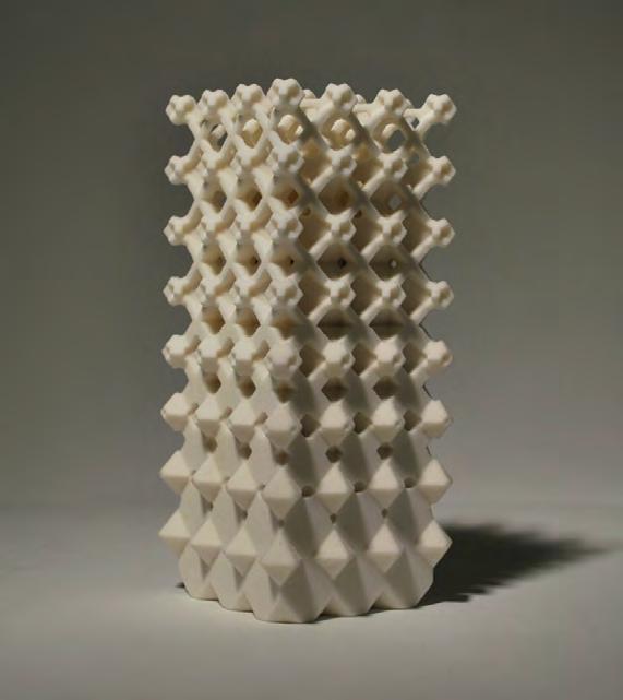
CELLULAR COMPLEXITY 63
TETRAHEDRON PACKING DUAL OFFSET
TRUNCATED CUBE - OCTAHEDRON DUAL OFFSET
The structural efficiency of the examined space-packing geometries was tested in a Finite Element Analysis in Strand7. In the first test, the different geometries were compared to each other by abstracting them to their basic shape. In each case the structure consists of eight cells which fill up a volume of 5 x 5 x 5 meters. The overall material volume used for each structure is 1.5m³ and each structure is vertically loaded with 10kN. This setup makes the tests a pure comparison of the geometries, therefore it is material independent - the material used in this case is stainless steel. The structures were compared in both, mean stress and displacement in load direction. Due to the small number of
TEST 01
DISPLACEMENT
biggest displacement: 3.21 mm
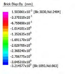
cells used, this serves as a first overview to give a feeling of the relation of all the structures.
The results show that the Truncated Cube - Octahedron structure is the structurally most effective in this setup. The Kelvin-Dual is structurally not strong because of the small number of cells, this causes the cells on the edges to perform weak in displacement and stress. The structural performance of the Kelvin Structure is comparable to the Truncated Cube - Octahedron.
STRESS
biggest stress: 3.3 MPa average stress: 2.9 MPa
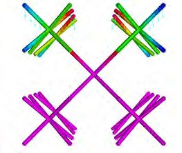
biggest displacement: 0.39 mm
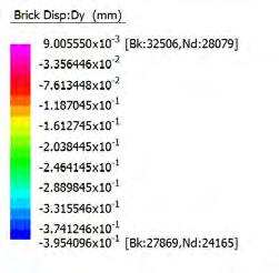
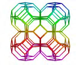
biggest displacement: 0.03mm
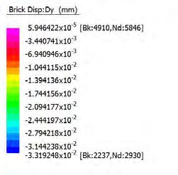
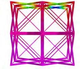
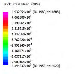
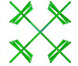
biggest stress: 2.8MPa average stress: 0.007MPa
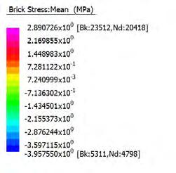
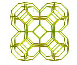
biggest stress: 0.27MPa average stress: 0.045MPa
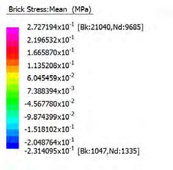
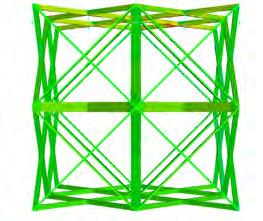
64
FINITE ELEMENT ANALYSIS
Kelvin - Dual
Kelvin - Packing
Truncated Cube/ Octahedron-Packing
GEOMETRICAL DEVELOPMENT
In a continuation of this Analysis, the Kelvin-Dual was chosen to test the effect of increasing the number of cells for structural efficiency. Again, the overall material volume, the overall filled up dimension and the applied load remain the same - only the number of cells changes. The results of the second test show clearly, that the structural performance can be significantly improved by increasing the cell number. By filling up the volume with cells which are one third in size compared to the initial cell, which means that the number of layers is tripled.
TEST 02
8 CELLS
5 m 5 m 10 kN
43 CELLS
5 m 5 m 10 kN
250 CELLS
5 m 5 m 10 kN
DISPLACEMENT
biggest displacement: 3.21 mm
The structural efficiency of the what was considered the weakest structure in test 01 becomes now comparable with the most effective structure, the Truncated Cube - Octahedron Structure. Also, when looking at the third case in test 02, the results show that not only the number of cells, but also the cell arrangement plays a very important role. The top right row in the shown tests is much weaker that the top left row, caused by the fact that it only connects to one underlying row.
STRESS
biggest stress: 3.3 MPa average stress: 2.9 MPa
biggest displacement: 1.8 mm
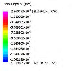
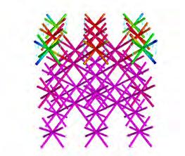
biggest displacement: 0.9 mm
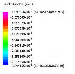
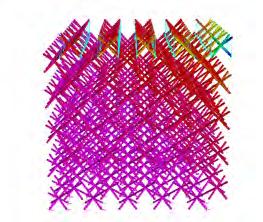
biggest stress: 3.5 MPa average stress: 0.9 MPa
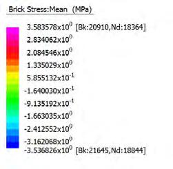
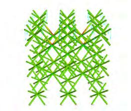
biggest stress: 3.4 MPa average stress: 0.5 MPa
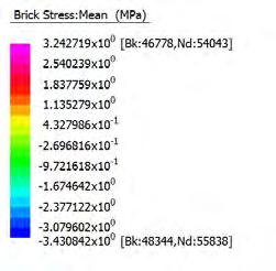
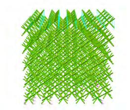
CELLULAR COMPLEXITY 65
66 GEOMETRICAL DEVELOPMENT
GEOMETRICAL DEVELOPMENT
overview
Based on the studies on geometrical and structural principles of cellular systems, several 2D and 3D structures, containing a controlled porosity gradient were developed. In both, 2D and 3D a chosen closest packing structure made of one or more regular or semi-regular cells was the basis. By connecting the centres of neighbouring cells, the Dual-Network of the initial structure was generated. Different further operations were carried out with the generated DualPolygons and Dual-Polyhedra in order to create porosity throughout the structure.
The results of the porosity evaluation demonstrate that in different structures, the same scale factors can create different porosity percentages. This suggests that, for developing a system of desired porosity with different structures, different geometrical and offset-network factors have to be taken into account. However through cataloguing, a controlled system of porosity generation can be developed.
The porosity in the system is generated in a gradient, in constant fields as well as random distributions. Because of the fact that the whole porosity is based on either the initial network itself or the relating DualStructure, it is assumed that the structural performance and efficiency is still guaranteed within the system.
Further, initial theoretical steps investigated a method to develop not only a change in Porosity within the system, but also a change in cell size through various subdivision strategies.
The studied and developed structures set the foundation for the architectural system by making use of these different porosity gradients which can be created in a controlled way in order to address the required properties. These structures were tested through Finite Element Analysis for a comparative evaluation of the geometries, throughout these tests several an understanding was developed towards their structural capabilities and particularly with variation in aggregations.
However, the structures, base geometries and networks require further investigation for application, viability and performance within an real scale architectural system.
CELLULAR COMPLEXITY 67
FABRICATION
Following our research towards the geometrical development of cellular systems, and in particular the creation of a gradient in space-packing structures; the interest lies in the viability and fabrication of these structures.
Most of the structures contain complex geometrical transitions, hollow sections and continuous elements. Therefore, a range of fabrication methods are examined and evaluated. These methods are evaluated based on their applicability towards a real-scale architectural application.
While first fabrication tests utilize advanced additive manufacturing technologies and their ability to produce almost highly complex geometries. The further tests include more conventional fabrication methods due to the range of limitations within additive manufacturing.
The tests also consider hybrid methods combining different means of fabrication. Due to our developed interest in this realm, a range of case studies are investigated, particularly for real-scale fabrication viability and application.
CELLULAR COMPLEXITY 69
ADDITIVE MANUFACTURING
FABRICATION METHODS
ADDITIVE MANUFACTURING OF GEOMETRY
This fabrication tool is able to build up the geometrical system layer by layer by the means of a 3D-printer. The geometrical system which was 3D printed is shown in the drawing on the right. The layers of the intervals the printer goes through for the additive process is illustrated below. This method was used to produce presentation models of selected geometries, any complex geometry can be 3D printed as long as it is generated as a solid and contains minimum thickness above 1mm.
This fabrication tool is able to build up the geometrical system layer by layer (additive manufacturing) by the means of a 3Dprinter. The geometrical system which was 3D printed is shown in the drawing on the right. The layers of the intervals the printer goes through for the additive process is illustrated below. This method was used to produce presentation models of selected geometries, any complex geometry can be 3D printed as long as it is generated as a solid and contains minimum thickness of 1mm.
Layers of Geometrical System processed by 3D-printer
70
00.00 00.50 01.00 01.50 02.50 03.50 02.00 03.00 04.00 04.50 05.00 05.50 06.50 07.50 06.00 07.00 08.00 08.50 09.00 09.50 10.50 11.50 10.00 11.00 12.00 12.50 13.00 13.50 14.50 15.50 14.00 15.00 16.00 16.50 17.00 17.50 18.50 19.50 18.00 19.00
FABRICATION
3D-PRINTING TECHNOLOGY
The models were 3D printed in the digital prototyping lab at AA (DPL). The equipment used is a ZCORP 310 plus rapid prototyping machine which has a maximum build size 203x254x203 mm. The machine uses an additive process of layers of gypsum-based powder and glue. These five models were produced in one printing box and took about 24 hours to print. The machines need to be manually prepared and cleaned and the models need a manual processes of extracting and de powdering which took about two hours.
After taking the models out of the machine they need to be infiltrated to achieve strength and durability. This technology features highly
complex configurations such as these geometries, which would have not been able to print with any other 3D printing technology in such short time. As plastic printers for example take much more time as well as support material and this causes very long production times.
The photographs display the initial 3D printed cellular systems of the following selected geometries:
Fig. 3.1 Kelvin Dual Network, Fig. 3.2 Kelvin Dual Offset
Fig. 3.3 Tetrahedron Dual Offset, Fig. 3.4 Kelvin and Cell Offset
Fig. 3.5 Truncated Cube Octahedron Dual Offset
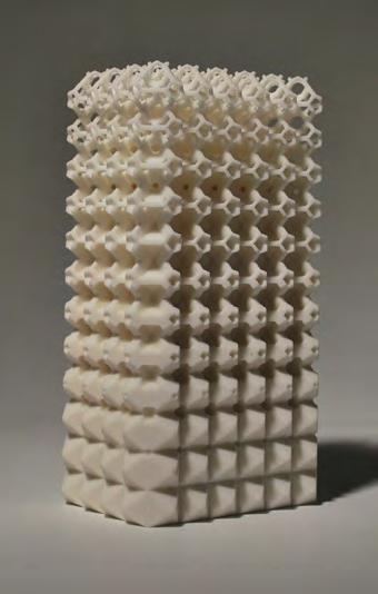
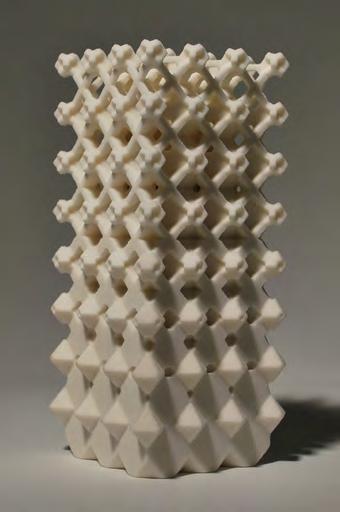
CELLULAR COMPLEXITY 71
Fig. 3.1
Fig. 3.4
Fig. 3.2
Fig. 3.5
Fig. 3.3
FABRICATION METHODS
SHEET MATERIAL PRODUCTION OF SINGLE CELL
SHEET PRODUCTION OF INDIVIDUAL CELL
This fabrication method attempts to produce the cell through sheet material, using a laser-cutter. Cells with various porosities have different nets for assembly. The resultant system contains a large number of joints between cut elements, which becomes more complex as the porosity increases.
This fabrication method attempts to produce the cell through sheet material, using a laser-cutter. Cells with various porosities have different nets for assembly. The resultant system contains a large number of joints between cut elements, which becomes more complex as the porosity increases. The chosen cell geometry is shown to the right, in addition to an overall global aggregation.
Diagrams: Right: Individual Cell ; Far Right: Geometrical System
72
cell geometry with varying porosity net of cell geometry for laser-cutting exploded axonometric of assembly
FABRICATION
LASER-CUTTING FABRICATION
This method was used to investigate into the fabrication of single cells of a cellular system within a larger scale . For the fabrication the laser cutter at the DPL at AA was used for cutting cardboard sheet material (1mm thickness) . The diagrams Fig. 3.6-3.8 display the gradient thickness change throughout the cellular system . The thick line is the cutting edge and the thin lines are the scored lines for folding. Each drawing is the cutting and folding line of one individual cell. For further investigation one would need to think of connection methods of these single cells. Because there were too many pieces this model was not finished.
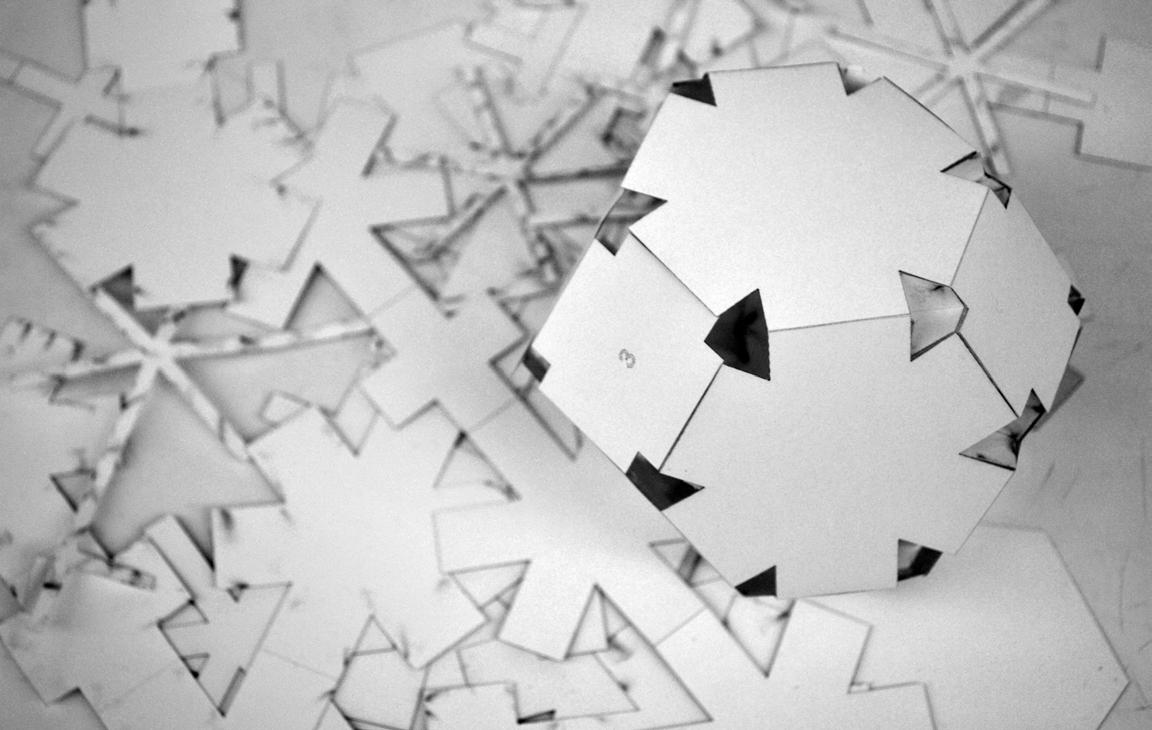
CELLULAR COMPLEXITY 73
Fig. 3.6
Fig. 3.7
Fig. 3.8
CASTING CELLS INDIVIDUALLY
FABRICATION METHODS
CASTING OF INDIVIDUAL CELL
This fabrication method attempts to produce the cell through casting in a multi-part mould. The mould consists of a base and six removable sides with a vacuum form of the CNC-milled voids of the cell’s geomtery. The vacuum forms of the voids within the cell would assemble toghether within a bounding box that fixes them toghether for casting.
This fabrication method attempts to produce the cell through casting in a multi-part mould. The mould consists of a base and six removable sides with a vacuum form of the CNC-machined voids of the cell’s geometry. The vacuum forms of the voids within the cell would assemble together within a bounding box that fixes them together for casting. The chosen cell geometry is shown to the right, in addition to an overall global aggregation.
Diagrams: Right: Individual Cell ; Far Right: Geometrical System
mould bounding box Laser-cut MDF or Perspex
74
cell geometry positive cell interior voids mould for positive step001 step002 step003
closed exterior net
assembling voids assembled sides to void
high
form of assembled MDF and high density
plaster
exploded axonometric
cell
seperated
CNC-milled MDF CNC-milled
density foam Vacuum
foam complete mould with box
FABRICATION
As illustrated and described on the left side, this fabrication method investigated into the possibility of casting an individual cell. The mould was separated into multiple pieces and the elements were computerized numerical controlled (CNC) machined out of polyurethane block material (Fig. 3.12). This hard foam provides high precision in geometry and detail level. As it is a very hard and strong material it can be used for vacuum forming technology. The elements were vacuum formed using plastic sheet material.
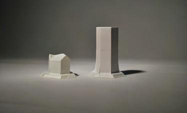
Due to the interior elements sharp straight angles (90 degrees) it was impossible to take the elements out of the sheets once they were vacuum formed (Fig. 3.9) The plates for the surrounding mould frame were CNC machined out of medium-density fibreboard (MDF). Unfortunately it was not possible to machine them with a small sized milling bit, for that reason the edges had incorrect angles and did not fit well together. Due to those facts this model stayed incomplete.
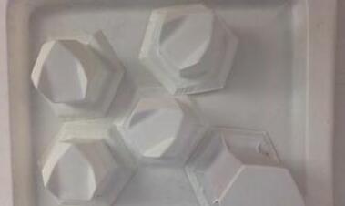
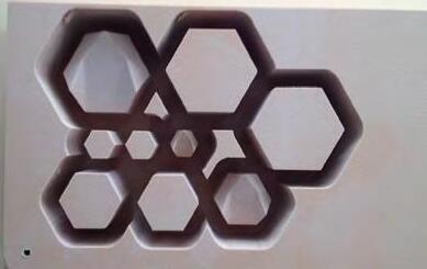
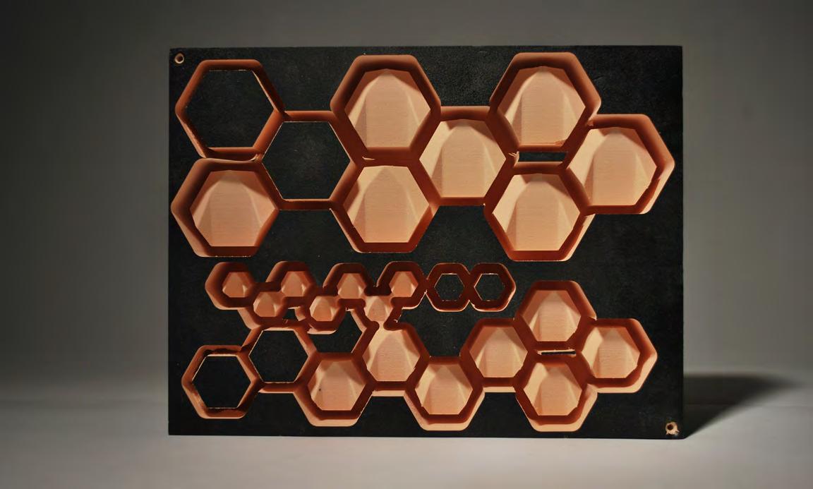
CELLULAR COMPLEXITY 75
Fig. 3.12
Fig. 3.9
Fig. 3.10
Fig. 3.11
MULTI-PART MOULD FOR SINGLE CELL CASTING
FABRICATION METHODS
FABRICATION METHODS
PANEL-BASED CASTING OF CELLS
PANEL CASTING OF CELLULAR SYSTEM
PANEL CASTING OF CELLULAR SYSTEM
This fabrication method attempts to produce the global geometrical system through casting panels which contains a portion of multiple cells. The mould would be CNC-machined and plaster-cast to achieve the panel (with possibility of vacuum forming the mould). The panels would assemble face to face with intermediate individual cells in between which are cast using the same method.
Diagrams: Right: Individual Cell ; Far Right: Geometrical System
This fabrication method attempts to produce the global geometrical system through casting panels which contains a portion of multiple cells. The mould would be CNC-machined and plaster-cast to achieve the panel (with possibility of vacuum forming the mould). The panels would assemble face to face with intermediate individual cells in between which are cast using the same method. The chosen cell geometry is shown to the right, in addition to an overall global aggregation.
CNC-machine mould and plaster cast
76
two-part mould plaster casting unit a unit
1x unit a 1x unit b 2x unit a 2x unit a 18x unit b plaster plaster
b
module assembly
panel panel system assembly step001 step002 step003
CNC-machine
mould and plaster cast modules
to
two-part
plaster casting unit a unit b 1x unit a 1x unit b 2x unit a 2x unit a 18x unit b plaster plaster
mould
module assembly to panel panel system assembly step001 step002 step003
modules
FABRICATION
This method was used to generate the cellular system not by single cells , but rather translating the cellular system into panels. Those panels would inherit one side / half of a multiple cellular network. This method was developed to overcome connection details in previously tested single cell fabrication methods. The Panels were machined with CNC out of polyurethane block material. These panels fit together very precisely and leave a gap on one side of the box to infill the plaster for casting.
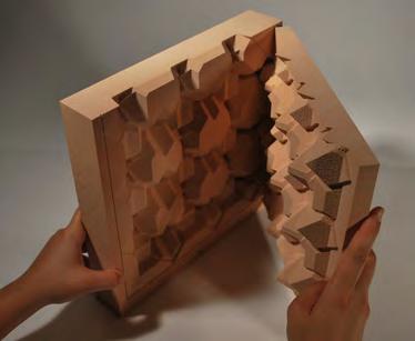

Prior to applying plaster into the mould, the panels need to be sealed due to the porous nature of the foam block. A sealing wax was used to seal the foam. This was done in three layers with manual polishing treatment in-between. A test cast was done on one small panel which unfortunately still locked the plaster in. this proofed that we would have not been able to take the plaster out of the mould after casting due to the tolerances in the angles. Instead it would have been more efficient to CNC the positive panel and use the method of silicon mould; a method for further investigation.
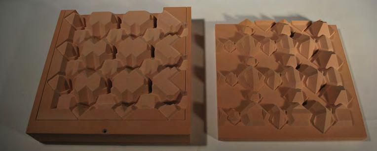
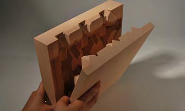
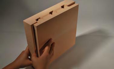
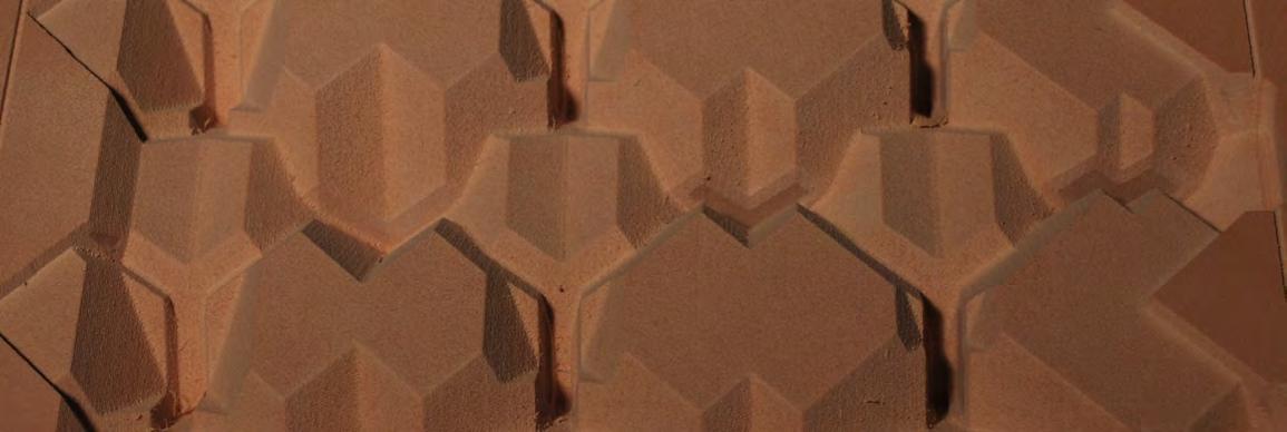
CELLULAR COMPLEXITY 77
Fig. 3.13
Fig 3.17
Fig. 3.14
Fig. 3.15
Fig. 3.16
CNC-MACHINED CASTING PANELS
FABRICATION METHODS
CAST JOINT AND TUBE SYSTEM
This fabrication method combines the use of custom made components at connection nodes, and readily available elements in between - tubes. The custom joint is first additively manufactured through 3D-printing, a silicone mould is created from the print. This silicone mould is then used to mass-produce the joint in various materials. The chosen cell geometry is shown to the right, in addition to an overall global aggregation.
This fabrication method combines the use of custom made components at connection nodes, and readily available elements in between - tubes. The custom joint is first additively manufactured through 3D-printing, a silicone mould is created from the print. This silicone mould is then used to mass-produce the joint in various materials.
Diagrams: Right: Individual Cell ; Far Right: Geometrical System
tubes + joints
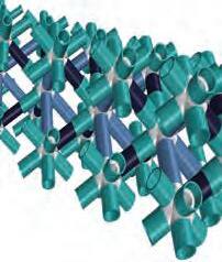
assembly of joints and tubes in various sizes
step001
3D-print required joint sizes
78
cast silicone to 3D-print joint in box
retrieve 2-part silicone mould
plaster cast joint step002
step003 step004 plaster
mmsmallx28mediumx4largex4 4mm223744 6mm203440 8mm193138 10mm172834 12mm162632 14mm142228 16mm132026 18mm111722 20mm101520 tubes cut in 3 different lengths
FABRICATION
CELL AGGREGATIONS THROUGH JOINTS+STRUTS
CAST JOINTS AND TUBES SYSTEM
The following diagrams Fig. 3.18-3.20 illustrate the combination of the tube and joint system. These were used as visualisation methods to see the results of a rectangular cellular system inheriting a gradient in thickness by varying tubes and joints sizes. The joints were 3D-printed at AA DPL lab and the plastic tubes were cut in the AA model workshop. The fabrication and cutting of the elements was more labour intensive then the actual assembly of the pieces.
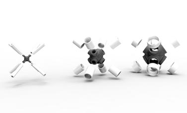
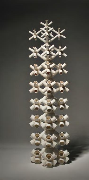
For connecting and fixing the system together, glue was used as some intolerances appeared between tubes and joints and therefore had to manually adjusted. Overall the fabrication method revealed stiffness and durability throughout the whole system and was in fact the fastest, simplest and cost efficient fabrication method.
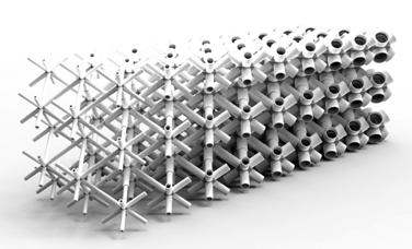
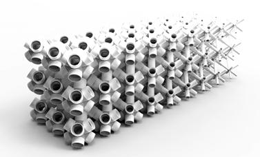
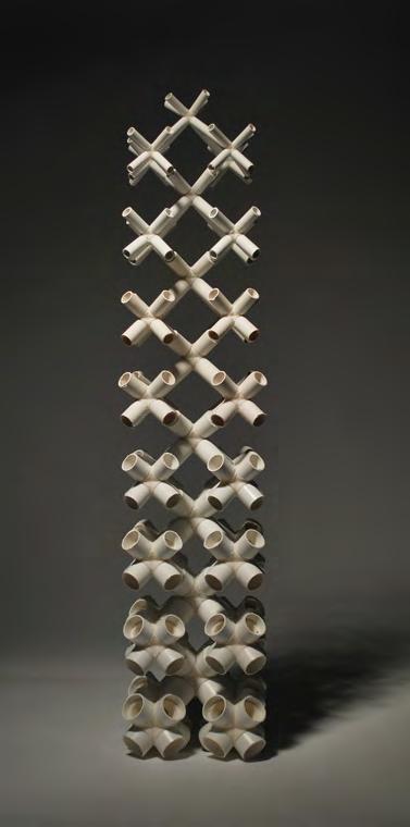
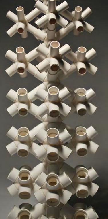
CELLULAR COMPLEXITY 79
Fig. 3.18
Fig. 3.21
Fig. 3.19
Fig. 3.22
Fig. 3.20
Fig. 3.23
TEST JOINTS - 3D PRINTING
As the initial starting point we decided to fabricate the joints with additive manufacturing method. First tests were done with the AA DPL 3D Printer, which is a Powder Printer and the final geometry printed is very fragile and not very strong in its structural properties (Fig. 3.33). Thus we undertook another experiment with the in-house 3D Printer UltiMAKER which is able to 3D print in Plastic and the final object is very strong and durable (Fig 3.24-3.26). To evaluate the detail level in comparison with the powder printer the machines are not able to achieve the same detail level as the AA DPL Printer does.
Further tests were done with the Printer of “1PLU2D” where the machines achieved a similar detail level with the high resolution printing method (Fig. 3.27-3.29). Only at the points where angles reach over 135 degrees the printer had issues with printing the cantilevering geometry perfect. Thus we decided to not go ahead with these machines for the fabrication method for the Joints, but rather use the 3D printer at the AA DPL lab and investigate into casting methods (Fig. 3.33).
3D PRINT TEST BY ANDREAS KOERNER [ULTIMAKER]
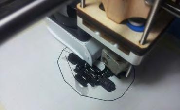
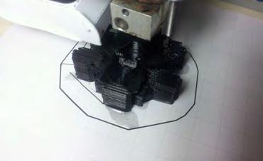
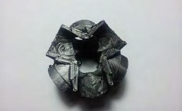
3D PRINT TEST BY STUDIO INTEGRATE / 1PLUS 2D
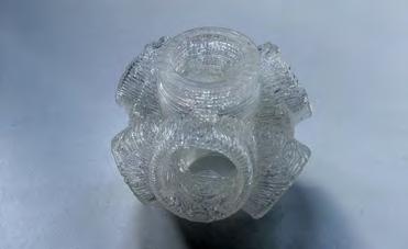
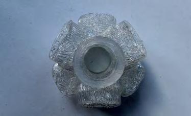
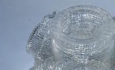
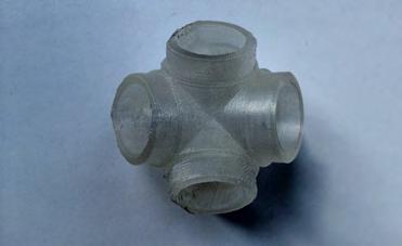
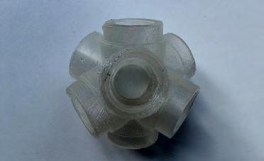
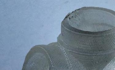
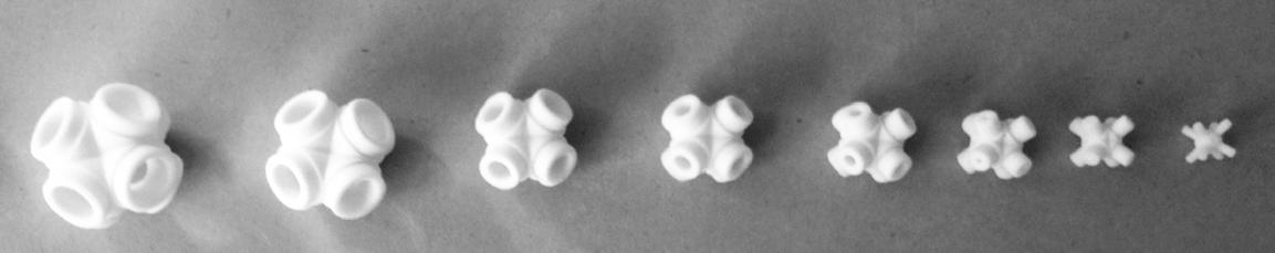
80
3D PRINT TEST AT AA DPL LAB
Fig. 3.24
Fig. 3.27
Fig. 3.30
Fig. 3.33
Fig. 3.25
Fig. 3.28
Fig. 3.31
Fig. 3.26
Fig. 3.29
Fig. 3.32
FABRICATION
For the Replication of joint, with plaster casting method, one joint 5x5 centimetres was 3D printed using the AA DPL Powder Printer. The joint was printed with closed ends but hollow inside in order to keep the weight and price low. Because the powder 3D prints are not permeable to water and other liquids the pores of the surface had to be sealed with a waterproof plastic seal (Fig. 3.34). The sealing liquid had to be applied with a brush in three thin layers with 30 minutes waiting time inbetween. Once the surface was fully sealed and dry the joint was glued with super glue into a prepared perspex box.

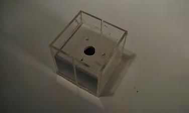
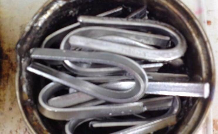
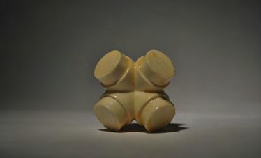
1 Litre of Silicon was used to produce a silicon mould around the 3D printed joint (Fig. 3.35). Once the silicon had dried, the cube was cut half open and the joint was taken out. In total 5 plaster joints and one low melt alloy joint were produced with this negative mould. The precision of the replicates surface detail increased throughout the process and because of low waiting time and fast production this was the method we continued investigating further.
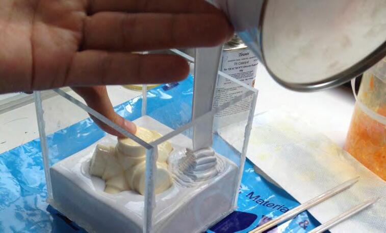
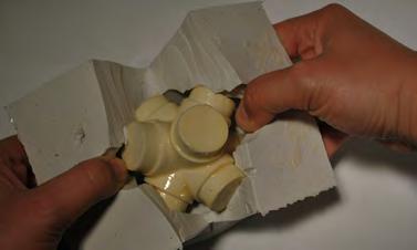
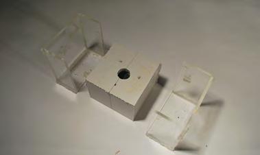
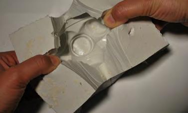
CELLULAR COMPLEXITY 81
Fig. 3.34
Fig. 3.37
Fig. 3.40
Fig. 3.43
Fig. 3.35
Fig. 3.38
Fig. 3.41
Fig. 3.44
Fig. 3.36
Fig. 3.39
Fig. 3.42
Fig. 3.45
CUSTOM SILICONE MOULD FOR JOINTS
The fabrication method combines the use of custom made joints and pre fabricated plates and struts. According to the level of variation and irregularity within the fabricated part, the joints are either 3D printed or cast. Depending on the quantity of each type an evaluation of feasibility of each method has to be decided. In the model, plate thicknesses stay the same throughout the change of porosity.
As the initial starting point we decided to fabricate the joints with additive manufacturing method. First tests were done with the AA DPL 3D Printer, which is a Powder Printer and the final geometry printed is very fragile and not very strong in its structural properties (Fig. 3.33). Thus we undertook another experiment with the in-house 3D Printer UltiMAKER which is able to 3D print in Plastic and the final object is very strong and durable (Fig 3.24-3.26). To evaluate the detail level in comparison with the powder printer the machines are not able to achieve the same detail level as the AA DPL Printer does.
82
joint 01 joint 02 joint 03 joint 04 plates 01 plates 02 struts 03 struts 04
Cast - 3D Print Joints / Plates and Struts
FABRICATION METHODS
WITH PLATES AND STRUTS FABRICATION
CUSTOM JOINTS
Study structure containing closed and open cells, plates and struts respectively
CELLULAR COMPLEXITY 83
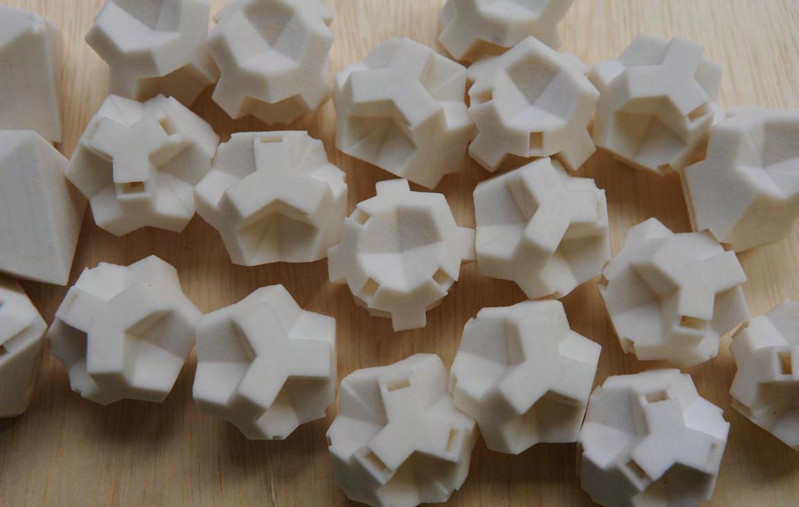
Since a 3D printer was used, we were able to customize each joint for the condition it was at (corner, edge, etc.)
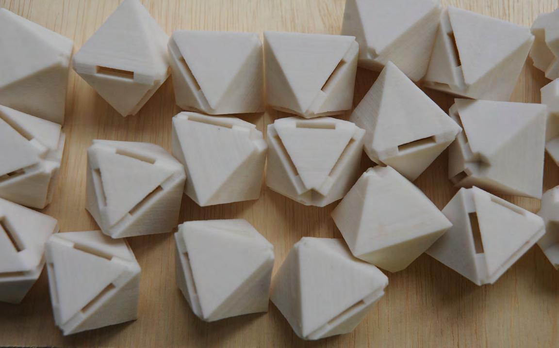
84 FABRICATION
Joints for connection with plates, in comparison to joints shown above - customizing for a material gradient and continuity of elements
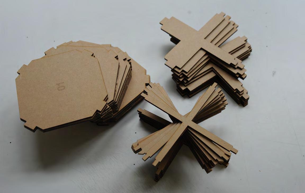
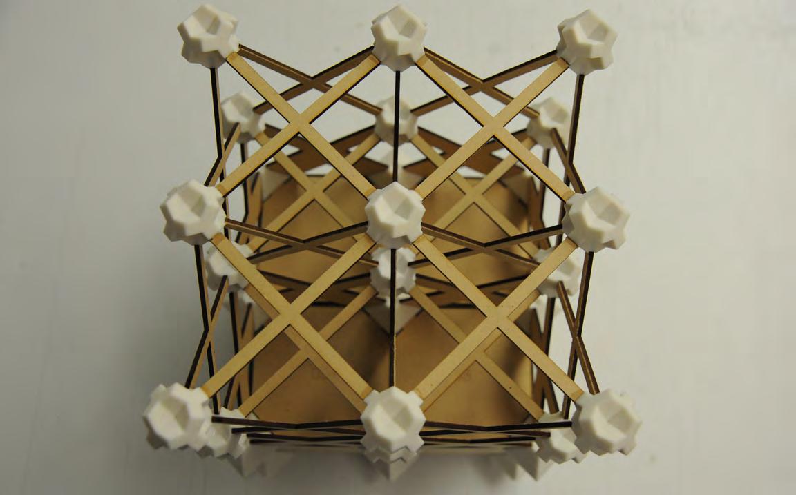
CELLULAR COMPLEXITY 85
The laser-cut plates and struts elements - the point where they fit into the joint is unified, therefore it is possible to mass-produce the joints
Top Perspective view of the fabricated model, combining 3D printed joints, laser-cut struts and plates.
EVALUATION: FABRICATION TESTS
In general, the fabrication methods investigated were to consider alternatives to 3D-printing which are viable for producing complex geometry. The intention is to compare fabrication methods for feasibility and efficiency for an architectural scale system. For the tests, the machinery and materials have set the initial constraints. The resulting models were compared in terms of production time, cost and effectiveness and the already common methods such as investment casting or lasercut sheet material are set into a relation to the additive manufacturing process.
GEOMETRICAL SYSTEM
Systems 01 and 02 are methods which combine customized joints with standardized plates and struts elements. The joint can be either cast or 3D-printed, depending on what is most economical and efficient at a given case. For systems 04 and 05, entire individual cells were produced as separate units, first mentioned through a CNC-milled mould, and in the second one through laser-cut sheet material which were then connected through countless joints. System 03 also requires several joints between panels, layering the method and increasing its complexity.
METHOD
MODEL
COST
3D printing structure additive manufacturing
Joints and Tube SystemJoints and Tube System
3D printing joints Casting joints
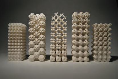
TIME (machine h / man h)
SIZE
ADVANTAGES
DISADVANTAGES
POSSIBLE REAL
SCAL MATERIAL
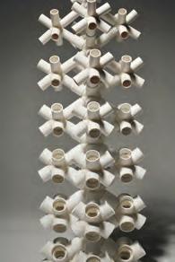
Joints - Struts and Plates 3D printing joints
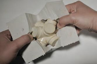
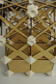
medium cost any geometry possible low machine hours high detail / precision 3D printed joints - variation of angles
3D printed concrete contour-crafting steel tubes bound to available tube dimensions closed cells are not achieved high cost high machine hours scale limited to machine
3D printed/cast joint
production of open and closed cells possiblle wide variety of scales
assembly is difficult
3D printed/cast joint steel/wood/glass panels
86
KELVIN DUAL TRUNCATED CUBE OCTAHEDRON
200 x 200 x 500 70 x 70 x 180 70 x 70 x 70 10h / 15h 30h - 50h / 1h 10h / 15h 350 x 350 x 450 10h / 15h
£ 75.00 £ 45.00 £ 48.00
system 01 system 02 system 01 system 02 system 03 system 04 system 05
FABRICATION
The advantage in methods 01 and 02 are their hybrid approach, where joints are minimized yet complex and fabricated through advanced methods. The larger elements become standardized sheet material or extruded profiles which are cut through traditional methods. These hybrid fabrication methods become of particular interest are therefore require further investigations through real-scale case studies.
The tests developed our perspective towards looking at additive
manufacturing, not as a way to produce the whole system, but rather as an opportunity for producing only complex parts or joints of the system which allow for the use of standardised elements within a highly complex Three-Dimensional system. The experiments showed that the 3D print process is viable and efficient from a point where each part/ joint is different from the others. If elements are complex but repeated, casting with accurate moulds becomes a more efficient strategy.
Sheet material Individual Cell
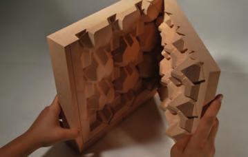
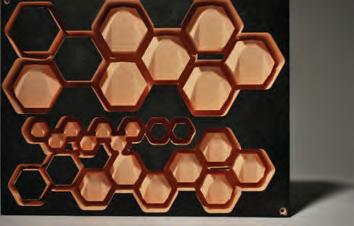
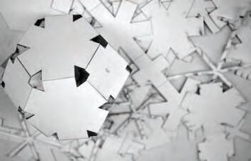
difficult to release piece from mould lots of screws £ 50.00
pre-cast concrete medium cost low machine hours like tilt up construction
and assembly of mould
2h machine / 30h man
100 x 100 x 900 mm
about 300 joints within the system assembly labour intensive
wooden plates steel plates low cost low machine hours £ 9.00
CELLULAR COMPLEXITY 87
OCTAHEDRON KELVIN
KELVIN
Casting panelized part of system
400 x 400 x 400 mm
10h machine
preparation
low
low
£
Casting Individual Cell 100 x 100 x100 mm 5h machine / 15h man pre-cast concrete
cost - 1 mould
machine hours
30.00 system 04 system 03 system 05
CASE STUDY: WELDED STEEL JOINTS
THE NATIONAL AQUATIC CENTRE BEIJING, PTW (AUSTRALIA) AND ARUP (UK)
Due to our interest in the development of joints for the system, we investigated a number of case-studies for their use of joints within complex systems at an architectural scale. These include the Aquatic Centre by PTW, The Quantom Cloud by Antony Gormley and the EmTech canopy at the Architectural Association in London.
The first case study is the Aquatic Centre in Beijing. The structure consists of 22 000 steel tubes which are connected through 12 000 joints. Within this space frame are simple circular tubes which are welded to spherical nodes manually on site. All members are framed into the nodes, creating a perfect structure for seismically active areas, such as Beijing..
The only way to solve this highly complex construction was to use Rapid Prototyping machinery which is usually used in the Automobile Industry. The structure was developed with a software, created by Arup specifically for this project, which allowed for highly complex analysis and optimization. In this way specific sizes, shapes, profiles and weights could be assigned to each of the tubes individually by testing the whole space frame in various conditions. The collected data was transformed into a 3D model from which all necessary structural drawings could be extracted. This digitally driven, automated planning process ensured precision, accuracy and high time efficiency which enabled the team to produce detailed plans for an optimized structure in less than one week.
3
DIFFERENT
TYPES OF STRUCTURAL JOINTS
88 FABRICATION
CASE
STUDY: INVESTMENT CASTING - JOINTS
THE QUANTUM CLOUD, LONDON
ANTHONY GORMLEY AND LUSAS (STRUCTURAL ENGINEERING)
The structure of the 30m high x 16m x 10m oval cloud sculpture was generated by a custom fractal growth software and consists of 1.5m long, randomly oriented steel sections. The centre forms the structural core and visually appears as a human body which diffuses towards the edges.
In total are 325 tetrahedral steel units, each made of four hollow steel sections that are welded together. The Neighbouring units are connected through individually investment cast joints and are initially connected with steel pins which are removed after the joints are welded together.
The investment casting uses a wax positive of the joint (the investment) to create a mould, where this wax is then melted to obtain the mould and cast repetitive elements in it. The specifically developed software for this project automatically generates files which were the basis for the SolidWorks software in which the 3D fabrication documents were created.
CONNECTION NODES: CAST JOINT, TETRAHEDRAL PART AND SYSTEM OF WELDED METAL PROFILES
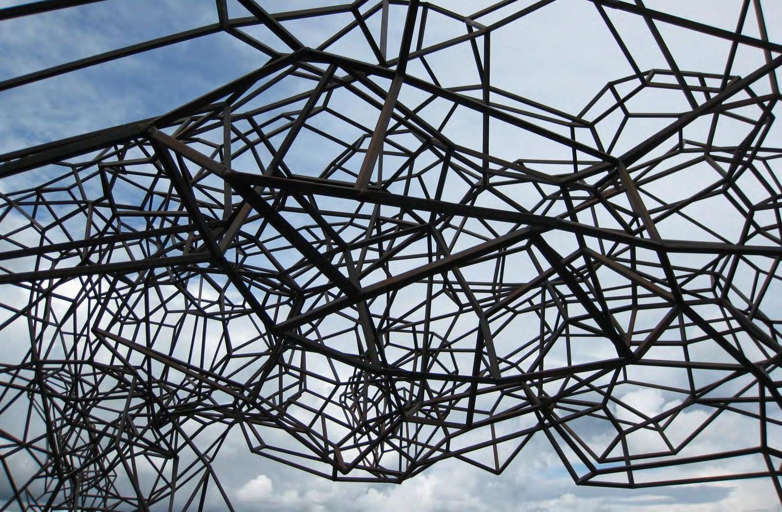
GEOMETRICAL DEVELOPMENT
Fig. 3.46 - Quantam Cloud by Antony Gormley, London
CASE STUDY: CUSTOM 3D-PRINTED JOINTS
DOUBLY CURVED CANOPY SCREEN, LONDON ARCHITECTURAL ASSOCIATION, EMTECH STUDENTS, 2012
This case study focuses on the importance of joints within differentiated structural systems, as well as various methods of how to feasibly create and manufacture those. In general the combination of small customized elements with larger, standardized elements can be considered as an efficient fabrication strategy. When looking deeper into complex structures it becomes clear that the current challenge is to utilize digital fabrication where it becomes effective and necessary.
The EmTech canopy is a project we were involved in that combined both customized and standardized elements to achieve a double curvature in geometry. We revisited this project as a precedent for this research. The double curvature of the canopy is induced by the customized 3D Printed joints which therefore form the key elements in this project.
THE
STANDARDIZED
WOOD ELEMENTS FOR EACH TIER OF THE CANOPY
They were digitally developed, allowing the joints to be accurately placed into the simple straight timber struts within the desired curved position.
The connection between the wood struts was critical due to the double-miter joint, which has the wood angled in two directions. These different angles are illustrated below for the different tiers/levels of the canopy. Due to the sharp angle between the wood struts, mechanical connections such as bolts were not possible due to limited length and the inability to accurately predrill or place bolts at the repetitive corner conditions.
90 FABRICATION
01 426.8 426.8 416.2 416.2 40.4° 49.6° 40.4° 49.6° 50.0° 40.3° 40.3° 50.0° 85.5°85.5° 85.5° 85.5° 85.5° 85.5° 85.5° 85.5° TIER 02 426.8 426.8 416.2 416.2 40.8° 48.9° 40.8° 48.9° 49.8° 40.8° 40.8° 49.8° 85.5°85.5° 85.5° 85.5° 85.5° 85.5° 85.5° 85.5°
04 42.8° 426.8 426.8 416.2 416.2 46.6° 42.8° 46.6° 48.1° 42.8° 42.8° 48.1° 85.6°85.6° 85.6° 85.6° 85.7° 85.6° 85.6° 85.7° TIER 03 426.8 426.8 416.2 416.2 41.6° 47.9° 41.6° 47.9° 49.1° 41.6° 41.6° 49.1° 85.6°85.5° 85.6° 85.5° 85.6° 85.6° 85.6° 85.6°
TIER
TIER
Although the sophistication of this project lies in the joints, the struts as well have to be individually developed and cut in various angles in order to meet the precision in detail of the overall appearance. The struts could be cut with a simple table saw with the help of specifically designed guiding boxes. Each frame consists of 4 differently cut timber struts and 3 different joints. Each row of the installation is made of the same type of frame.
When considering this method for an architectural scale, properties of the materials available for the additive manufacturing process have to be tested against durability in outdoors space. Hence more and more materials are being developed for the 3D printing process, therefore it could be considered as a viable method.
GLOBAL GEOMETRY OF THE CANOPY, CUSTOM JOINTS ILLUSTRATED
CELLULAR COMPLEXITY 91
01 02 02 02 03 04 03 01 01 01 01-bottom 01-side 01-top 02-bottom 02-side 02-top 03-bottom 03-side 03-top 04-bottom 04-side 04-top
The chosen fabricated method utilizes the geometry of the truncated cubes and octahedrons, where the truncated cube becomes the joint; and the octahedron is divided into several plates or struts based on the offset network.
The space-packing concept of this geometry utilizes the truncated cube to fill the voids in the octahedron, completing its structural spacepacking capabilities. Therefore, in this case the joints are well suited for this purpose.
The advantage of this system is the ability to create a transition or gradient not only in the porosity, but also in the type of cell, by switching from plates to struts, the system changes from closes cells to open cells.
NON-STANDARDIZED ELEMENTS
At an architectural scale application, it would consist of non-standardized elements which are customized, and standardized elements which are typically available. The joint is the customized element and would be produced through casting or additive manufacturing methods, where a variety of structural materials are available within this method including metals.
As for the standardized elements, a range of sheet materials are available, ranging from transparent glass, to opaque metals and wood. Furthermore, for the areas where struts are needed, wood, metal and acrylic profiles are abundant, and would be used based on the performative aspects of the specified area. Furthermore, extruded profiles could be readily customized in aluminium and other materials for the strut elements.
STANDARDIZED ELEMENTS
MACHINING
ADDITIVE MANUFACTURING MOULD PRODUCTION CASTING
PROFILES
STRUTS
92
HYBRID FABRICATION METHOD
DEVELOPED
SHEETMATERIAL
LIQUID MATERIAL
JOINTS PLATES
GLASS
WOOD
METAL
CAST METAL WOOD METAL
3D PRINTED METAL
ACRYLIC
LASERCUTTING WATER-JET
FABRICATION
PLATES AND STRUTS MODEL
VARIATION IN POROSITY AND CELL TYPE: CUSTOMIZED JOINTS, STANDARDIZED PLATES AND STRUTS
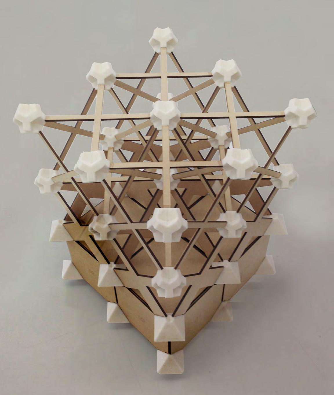
image references
Fig. 3.1 to 3.45 - Taken or Created by Cellular Complexity authors: Kais Al-Rawi, Julia Koerner or Marie Boltenstern.
Fig. 3.46 - http://2.bp.blogspot.com/-JIn1nVF-jmc/TjU v8PEqMUI/AAAAAAAAB4w/8wXdDjk0jUc/ s1600/19+Firmament+-+Antony+Gormley.JPG
94 FABRICATION
FABRICATION overview
The variety of tested methods contributed towards an understanding of the fabrication of complex geometrical systems, revealing limitations and opportunities concerning materiality and possible scaling of the structure. The fabrication explorations on a model scale included techniques which could be eventually scaled up to an architectural scale.
Throughout the experiments it became clear that the sophistication of such a complex systems lies in the joint, if the structural efficiency of the packing structure is to remain. This encouraged the decision of developing a combination of customized joints with planar standardized plate and strut elements. Another reason for choosing a plates and struts system is that it allows for the required combination of open and closed cells, while allowing for porosity changes.
This chosen method allows for the integration of plates, including a variation of opaque and translucent plates, which means that the integration of glass plates could be possible within the architectural system. Further, the shape of the plates and struts can change gradually, so there can be a porosity gradient throughout the system. The available digital fabrication methods, including laser-cutting and water-jet cutting allow for precise cutting of plates in the desired degree of porosity.
The joints can be precisely produced in any desired geometry, thus combining complex angles, through the use of additive manufacturing for making the mould or for producing the joint itself with 3D printing. A study of the number of repetitive joints would be required to determine the feasibility of printing in relation to casting. From an economical point of view, this means that 3D printing is more efficient for joints which occur in a small amount only and from a certain amount onwards, it is viable to produce a mould - but here again it has to be taken into consideration that a mould is only usable a limited number of times.
As a result, the decision is to further develop the system based on the truncated cube and octahedron geometry, with a combination of custom joints, and standard plates and struts. The potential of this geometry and its development architecturally and performatively is to be investigated.
CELLULAR COMPLEXITY 95
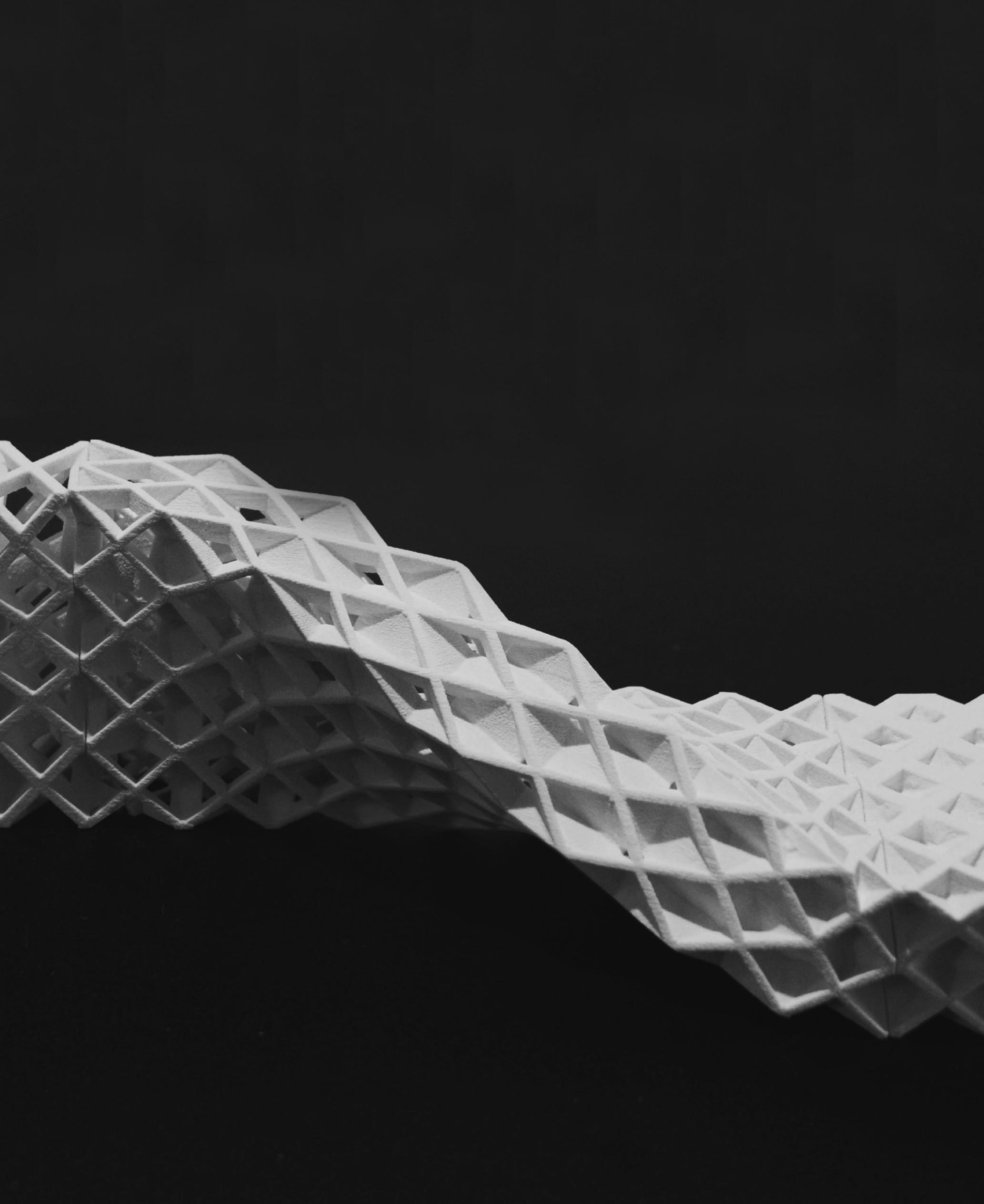
THE SYSTEM
In the previous section, fabrication methods were investigated and evaluated. The results determined that a hybrid fabrication method is best suited for the architectural application of this system. Based on this fabrication method, there are certain limits implied on the system, this includes the planar property of standardized elements within the system. In terms of scale, the abundance of sheet material and profiles in various sizes facilitate the scaling of elements.
Therefrom this section investigates the computational development of this system on the digital platform, in order to define the parameters behind the geometry and the opportunities and limitations they imply. The system will be generated through an algorithm where we as designers have control of the various parameters affecting the porosity and scale of the system. Furthermore, the structural effects with these changing parameters are tested to investigate efficient structural strategies.
The computational application provides further potential in the application of geometry. Due to the surface-based algorithmic approach, the system can be tested on planar, single curved and double curved surfaces. The architectural potential of this approach is investigated through typologies, which are then tied back to the fabrication research in order to understand what effects will these morphological changes imply on fabrication.
CELLULAR COMPLEXITY 97
Within the system, several possibilities of how to control the required porosity gradients were developed. One of the gradients is the material gradient which creates variation in the size of the opening and the strut thickness - it defines how much material is used in single cells. For the opening size, the cell is offset in its centre to a certain scale-number and then subtracted from the initial cell. A bigger opening means more porosity when keeping the other factors the same. When changing the strut thickness, material is added or subtracted on the outer parts of the cell; where the porosity can be reduced by increasing the strut thickness.
The geometrical gradient deals with cell size, number of cells and the shape of the cell. Increasing the cell size and keeping the used material the same, means a higher degree of porosity for the single cell. Increasing the number of cells while keeping the overall volume of the structure the same means lower porosity. Adding layers of cells has an effect on the porosity when the dimensional layering axis is not directly perpendicular to the orthogonal system. The shape and proportion of each cells can be changed, to address morphological or structural requirements which are concerned with directionality.
The surface-based programming of this method within the surface co-ordinates allows for the use of planar, single curved and also double curved surfaces. This allows for the production of double curved geometries in a global scale, which are fabricated through linear and planar elements.
All the developed tools for varying porosity can be used for smooth transitions throughout the system. This includes: changing cell size, number of layers, adding or reducing material, as well as changing the shape of the cell. What changes however is the structural performance of the cells when changing those factors. The ability of getting a very specific porosity through different parameters unviels a range of possibilities of how to deal with controversial requirements on structural, day lighting and visual needs without heavily compromising on the qualities of each. The cell is able to change its shape according to local requirements, such as programmatic needs and according to global requirements which is an adaptation the overall global form.
The performative aspects including structure and day lighting require testing through analysis software workbenches. The results from these tests, and possible tests of site conditions will define the precise application of the system architecturally.
MATERIAL GRADIENT
OPENING SIZE
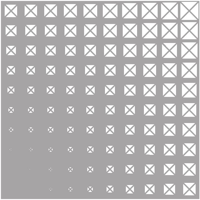
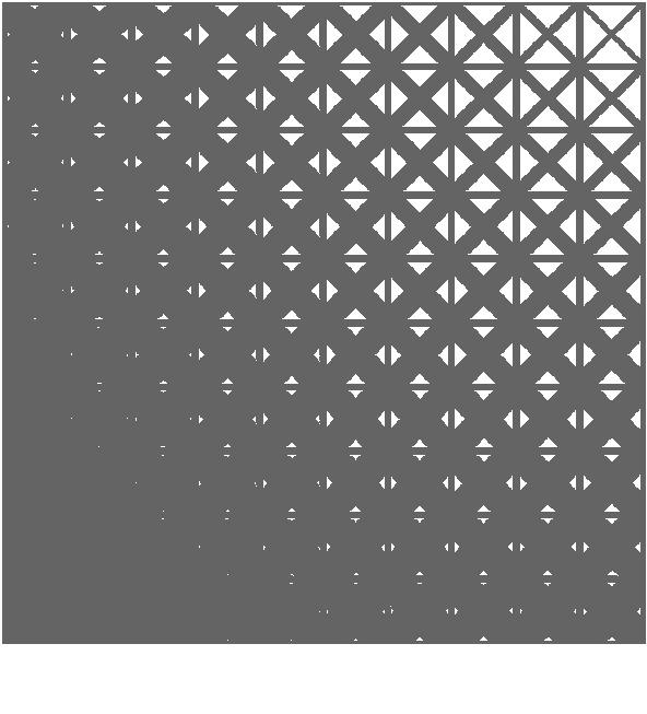
98
STRUT THICKNESS
POROSITY GRADIENTS
0.0 1.0 1.0 0.0 1.0 1.0 0.5 0.5 0.0 0.0 THE SYSTEM
GEOMETRICAL GRADIENT
CELL SIZE
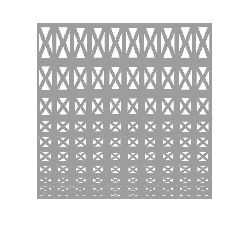
CELL SHAPE based on local requirement
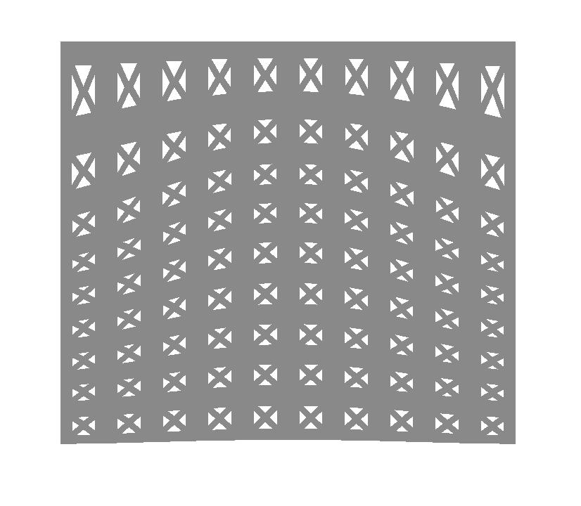
NUMBER OF CELLS
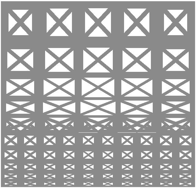
CELL SHAPE based on global requirement
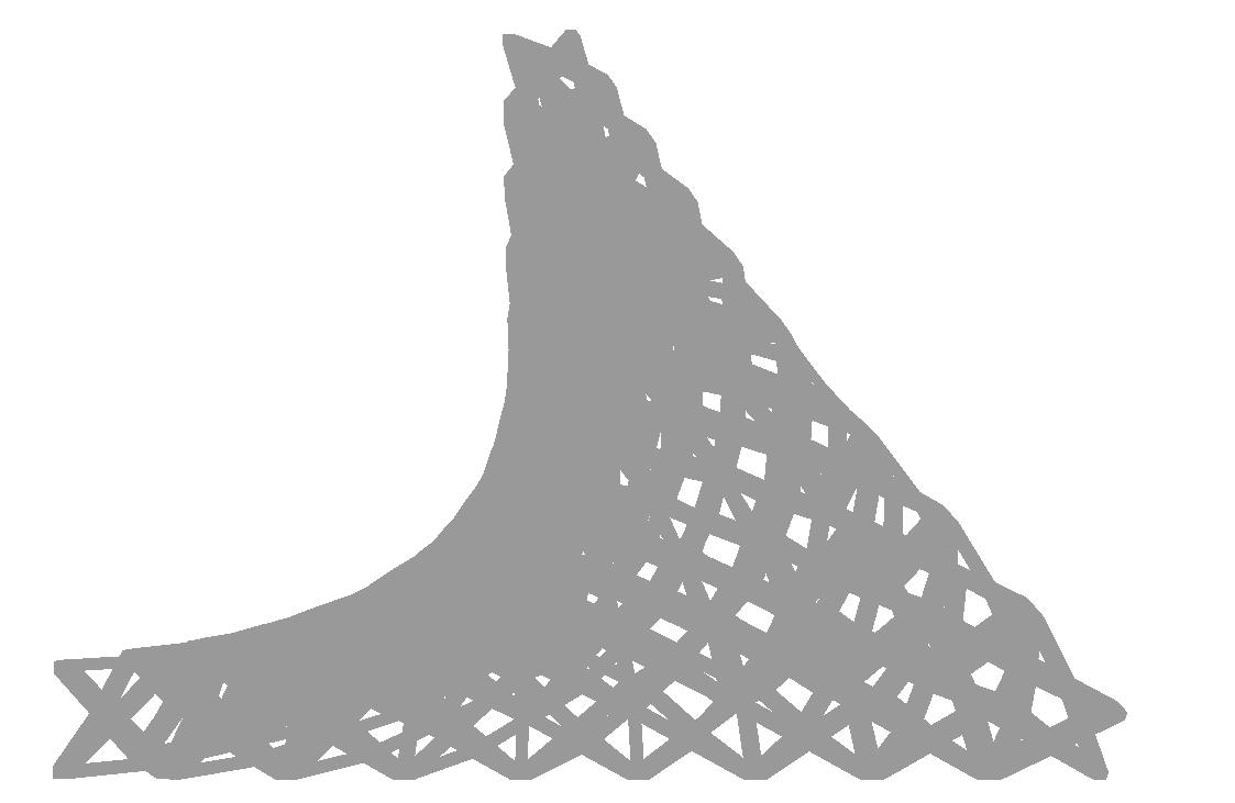
CELLULAR COMPLEXITY 99
1.0 1.0 2.0 0.5 0.0
POROSITY RANGE: CATALOGUE
The two main parameters that are affecting the porosity of the system in a planar application are the Strut Thickness and the Openings. The effect these two parameters create are catalogued below for single cells. For this purpose, the cells catalogued have a maximum porosity of about 50%. The cells within higher range porosity are left out. This is due to the nature of porous systems and their characteristic of having about 30% porosity or lower.
The ratio of solid to void is displayed at the four extremes presented, Thick and Closed, Thick and Open, Thin and Closed & Thin and Open. The porosity is also displayed at these four extremes within the catalogue, the porosity ranges from 48.44% to 99.73%, this means that only 51.56% and 0.27% material volume is used within the overall cell volume, respectively.
POROSITY RANGE SINGLE CELL 5 x 5m
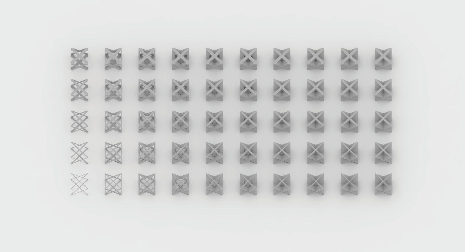
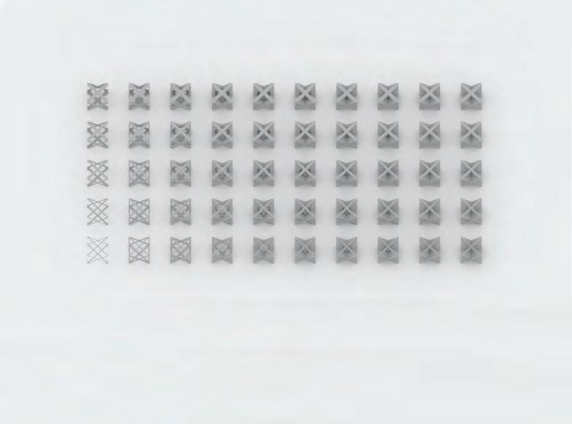
100
THE SYSTEM
0.0027 (99.73%) 0.0123 (87.7%) 0.1231 (87.69%) 0.5156 (48.44%) OPENINGS STRUT THICKNESS
Similarly, the porosity is catalogued however in this case for an aggregation of 8 cells in two levels each containing two by two cells. In this case the porosity and ratia are exactly the same as those of the single cell. This is due to fact that the cells in the aggregation are identical to those shown individually. Since porosity is a ratio, the ratio will remain the same because both parameters of volume will increase at the same rate.
However if the aggregation contains cells that are not arranged in a planar manner, or not space-packed, or contain certain elongation or deformation in any direction, the porosity will then become different.
POROSITY RANGE 8 CELLS 5 x 5m
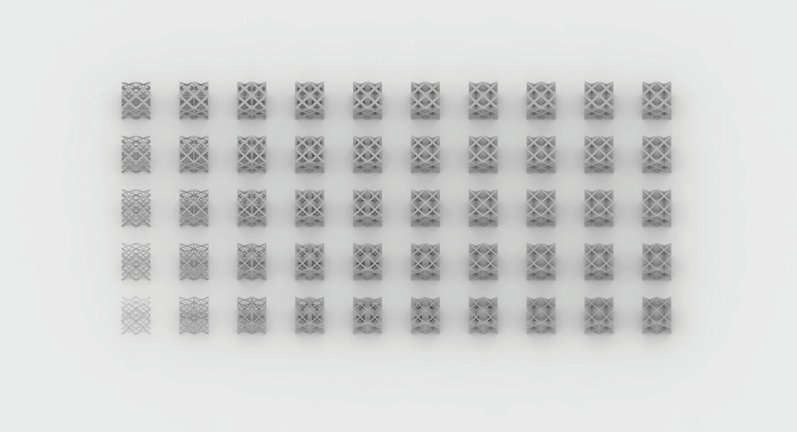
CELLULAR COMPLEXITY 101
0.0027 (99.73%) 0.0123 (87.7%)
0.1231 (87.69%)
0.5156
(48.44%)
THICKNESS
OPENINGS STRUT
Finite Element Analysis software was used to examine the effect of changing the various gradients on the structural efficiency. In test 01, the effect of the geometrical gradient was tested by filling up a Volume with first one big cell and then eight smaller cells while keeping the material and overall volume the same. Through that, the size of the cell decreases and the number of layers increases. As mentioned in earlier results within the Geometrical Development chapter, by increasing the number of cells and layers, and keeping the same material and overall volume, the structural performance can be increased - in this case the displacement can be reduced up to 50% and the mean stress up to 70%.
In the following test 02, the changes in the material gradient were analysed. Various combinations of different strut thicknesses and openings were tested in comparison. Economically speaking, the example which has a small strut thickness and a small opening is the
TEST 01 - GEOMETRICAL GRADIENT
DISPLACEMENT (Y)
most efficient one as it has a high structural performance while keeping the used material to an efficient minimum. The stronger the cell has to be, the smaller the opening and the larger the strut thickness should be. Through the efficient arrangement of material in the closest-packing system, the material volume can be kept low, even in areas which require a high structural efficiency.
The test results serve as a basis on understanding the effect of parameters which becomes particularly useful when combining structural and visual requirements. Often, controversial properties such as high structural performance and high porosity have to be combined within the structure, therefore the balance of the various gradients have to be studied in detail in order to maintain the structural capabilities of the cell aggregations.
STRESS (MEAN)
Material Volume: 1.5m³
Dimension: 5 x 5 x 5 m
biggest displacement: 0.07 mm
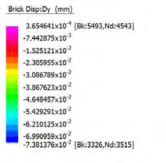
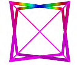
biggest stress: 2.5 MPa
average stress: 0.16 MPa
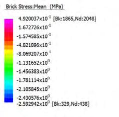
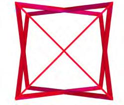
biggest displacement: 0.03mm
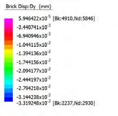
biggest stress: 0.27MPa
average stress: 0.045MPa
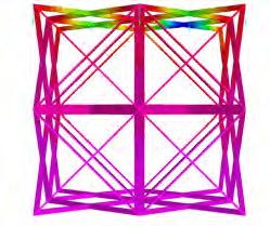
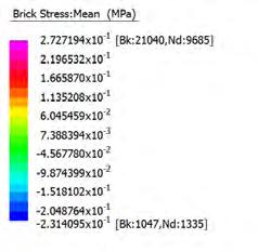
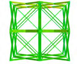
102 FINITE ELEMENT ANALYSIS
THE SYSTEM
SINGLE CELL
8 CELLS
5 m 5 m 10 kN 5 m 5 m 10 kN
LARGE OPENING - SMALL STRUT THICKNESS
biggest displacement: 0.001 mm
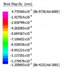
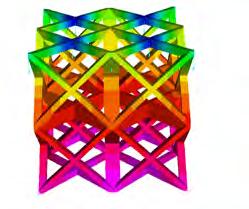
LARGE OPENING - LARGE STRUT THICKNESS
biggest displacement: 0.0004 mm
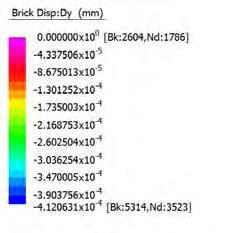
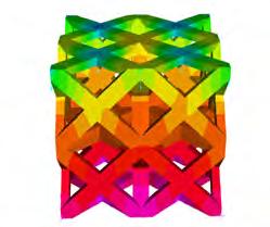
SMALL OPENING - SMALL STRUT THICKNESS
biggest displacement: 0.0006 mm
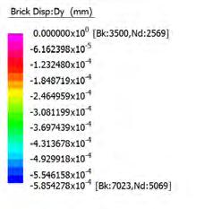
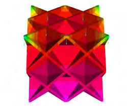
SMALL OPENING - LARGE STRUT THICKNESS
biggest displacement: 0.0002 mm
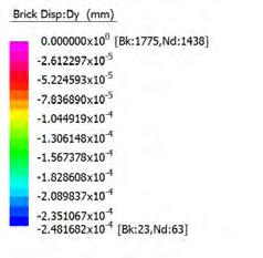
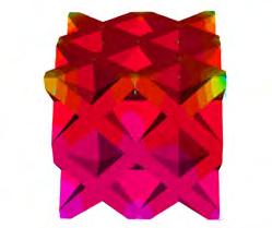
biggest stress: 0.02 MPa average stress: 0.005 MPa
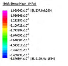
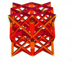
biggest stress: 0.03 MPa average stress: 0.0004 MPa
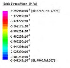
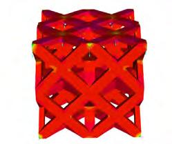
biggest stress: 0.004 MPa average stress: 0.01 MPa
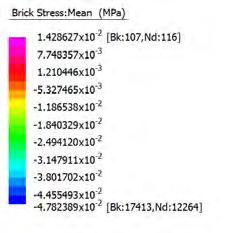
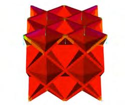
biggest stress: 0.02 MPa average stress: 0.002 MPa
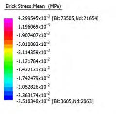
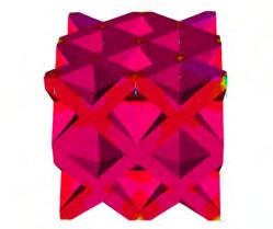
CELLULAR COMPLEXITY 103
02 - MATERIAL GRADIENT DISPLACEMENT (Y)
TEST
STRESS (MEAN)
A structural analysis was carried out to test the effect of various gradients on cells in an aggregation. The test results provided a basic understanding of which gradient-aggregations are structurally efficient and used for certain requirements in the design process. Each case was tested in terms of displacement (x,y,z) and mean stress. For each example, 5 cells were stacked in an overall dimension of 1 x 1 x 5 meters and loaded with 10kN. The overall material volume was 0.6m² in every aggregation, this guaranteed that the test results were comparable. In each of the three tests, first an aggregation which included variation in the geometrical gradient - a change in cell size - was set out. In the next step, to each of these initial test aggregations, a material gradient was added - first a change in opening, then a change in strut thickness, again in both directions.
For tests which involve a geometrical gradient, the results displayed that arge cells on the bottom and small cells on the top (close to the load) have the most efficient aggregation. In this formation, the displacement could be reduced by 50% and the stress which was now almost even throughout the structure could be reduced by almost 70% compared to the example without any material gradient. This effectiveness could be increased by adding material gradients to the structure. The strongest aggregation is the one with a large strut thickness on the bottom, growing smaller to the top - in this aggregation, the stress is almost evenly distributed throughout the structure. When considering material efficiency in the evaluation, the aggregation which operates with opening gradient is the most effective one. In the following pages, the results will be discussed in more detail. MATERIAL GRADIENT
104 FINITE ELEMENT ANALYSIS SETUP
OPENING
TEST 01 TEST 02 TEST 03 none large - small large - small large - small large - small large - small large - small large - small small - large small - large small - large small - large small - large small - large small - large MATERIAL GRADIENT STRUT THICKNESS THE SYSTEM
GEOMETRICAL GRADIENT
In this first test, no geometrical gradient was applied, which means all aggregated cells are the same size. The results of this tests show, that adding material - no matter if through the openings gradient or the struts thickness gradient ,and if on bottom or top, the structural performance of the aggregation can be improved. The largest effect is achieved when adding more strut-thickness on the bottom rather than on the top.
POROSITY GRADIENT
biggest displacement: average displacement: 0.015 mm 0.0008 mm
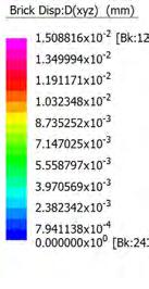
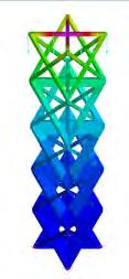
biggest displacement: average displacement: 0.008 mm 0.006 mm
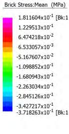
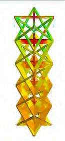
GEOMETRICAL GRADIENT
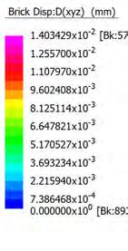
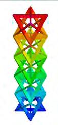
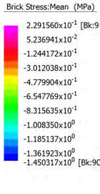
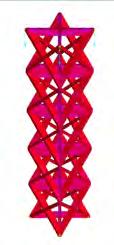
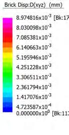
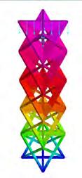
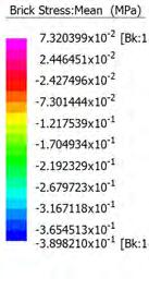
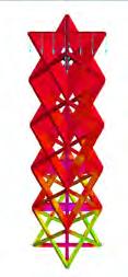
THICKNESS GRADIENT
biggest displacement: average displacement: 0.003 mm 0.0001 mm
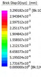
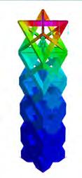
biggest displacement: average displacement: 0.003 mm 0.002 mm
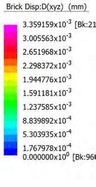
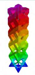
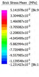
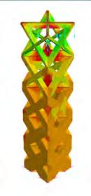
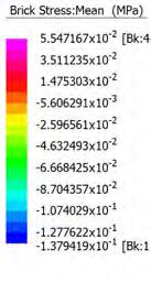
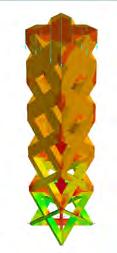
CELLULAR COMPLEXITY 105 FINITE ELEMENT ANALYSIS TEST 01
biggest displacement: average displacement: 0.014 mm 0.006 mm 0.2 MPa 1.2 MPa biggest stress: average stress:
0.02 MPa 0.12 MPa biggest stress: average stress: 0.05 MPa 0.06 MPa biggest stress: average stress: 0.07 MPa 0.005 MPa biggest stress: average stress: 0.01 MPa 0.003 MPa biggest stress: average stress:
In the second test, the gradient which involved large cells on the bottom and small cells on the top. As discussed earlier, this produced the most efficient arrangement of cells in terms of displacement and mean stress. What this test displayed is that the most effective arrangement was the one with a material gradient as in this example, which on the bottom has a large strut thickness to take all the loads and on the top has a small opening in order to resist the directly applied loads better.
POROSITY GRADIENT
biggest displacement: average displacement: 0.013 mm 0.0008 mm
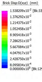
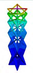
biggest displacement: average displacement: 0.009 mm 0.006 mm
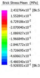
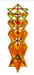
GEOMETRICAL GRADIENT
biggest displacement: average displacement: 0.009 mm 0.004 mm
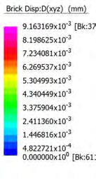
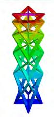
MPa 0.04 MPa biggest stress: average stress:
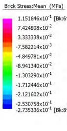
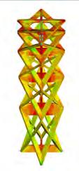
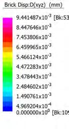
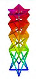
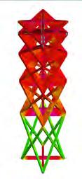
THICKNESS GRADIENT
biggest displacement: average displacement: 0.07 mm 0.0004mm
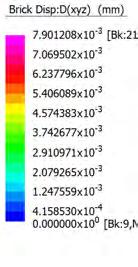
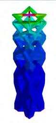
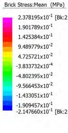
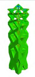
biggest displacement: average displacement: 0.004 mm 0.002 mm
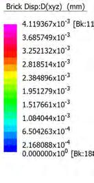
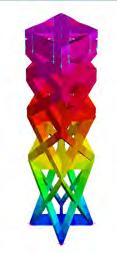
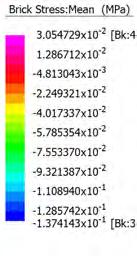
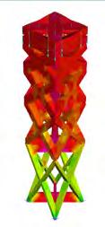
106 THE SYSTEM
0.05
0.1 MPa 0.02 MPa biggest stress: average stress: 0.06 MPa 0.02 MPa biggest stress: average stress: 0.07 MPa 0.004 MPa biggest stress: average stress: 0.04 MPa 0.0003 MPa biggest stress: average stress:
FINITE
ELEMENT ANALYSIS TEST 02
FINITE ELEMENT ANALYSIS TEST 03
In test 03, the geometrical gradient grows from small cells on the bottom to big cells on the top. This arrangement showed an improvement in comparison to test 01 which had no geometrical gradient at all and is comparable in effectiveness to the previous test. In this example, the biggest cell is on the top and therefore directly takes all the loads, the material-efficient aggregation which includes change of opening size was the most efficient one. In general it can be stated, that in reducing the opening size, a material efficient as well as structurally efficient aggregation can be formed.
POROSITY GRADIENT
biggest displacement: average displacement: 0.01 mm 0.0007 mm
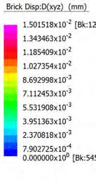
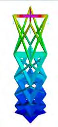
biggest displacement: average displacement: 0.012 mm 0.008 mm

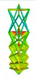
GEOMETRICAL GRADIENT
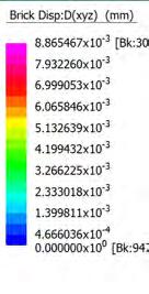
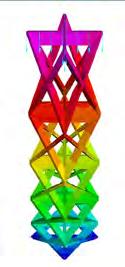
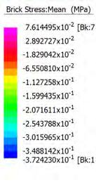
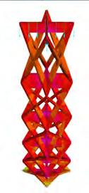
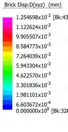
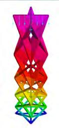
THICKNESS GRADIENT
biggest displacement: average displacement: 0.003 mm 0.0002 mm
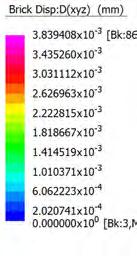
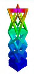
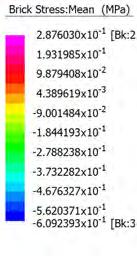
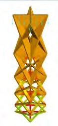
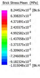
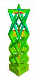
biggest displacement: average displacement: 0.004 mm 0.003 mm
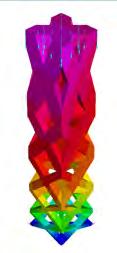

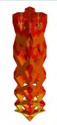
CELLULAR COMPLEXITY 107 biggest
0.07 MPa
MPa biggest
displacement: average displacement: 0.008 mm 0.004 mm
0.03
stress: average stress:
0.09 MPa 0.004 MPa biggest stress: average stress: 0.07 MPa 0.006 MPa biggest stress: average stress: 0.1 MPa 0.02 MPa biggest stress: average stress: 0.04 MPa 0.01 MPa biggest stress: average stress:
PARAMETRIC DESIGN TOOL
In a first typological study, the developed tools to create porosity gradients were tested on different examples of transitions from horizontal to vertical surfaces.
Digitally, the developed system is applied on generated surfaces, which define the global shape of the design. Through manipulation of the iso-curves on the surfaces, the cell shape and size can be varied to the desired amount. The examples below, TYPE A, TYPE B and TYPE C show various preparations of surfaces in order to achieve different conditions, which will be presented in the next pages. While the size variation is controlled by the input surface, the material gradient is controlled through the algorithm.
The balance between the geometrical and material gradient, and number of cells layers would be driven by performance and fabrication cost within an actual design development phase. These typologies demonstrate the possibility of producing highly complex configurations and transitions which include double-curvature and twisting.
In the example of TYPE A, the surfaces are prepared from a regular, horizontal surface where no change in cell size and shape will take place to a transition surface in which the cells are shaped by the global form of the surface to the vertical surface, in which the cells are shaped by a local change in order to generate a differentiated wall.
In example TYPE B, the horizontal surface is shaped with the goal to create a gradually increasing opening for a possible open roof structure, the transition surface again will shape the cells and the vertical surface is regular and will have variation through changes in the material gradient.
In example TYPE C, the horizontal and the transition surface will have porosity differentiation through the material gradient, whereas the vertical surface’s cells will gradually change in size, controlled by the iso-curves of the surface.
SURFACE AND ISO-CURVES
A
CELL GRID
108
TYPE
TYPE A
TYPE B
TYPE B
TYPE C
THE SYSTEM
TYPE C
TYPOLOGY STUDY - TYPE A
TYPE A is a typology of a spatial conditions where a roof changes into a facade. The parameters for the roof are set to have closed cells in order to have a walkable surface. Throughout the middle transition surface the cellular system increases the porosity level to achieve an open cellular system for the facade. This typology displays the possibility of various gradients within one system. Further it shows gradients from regularity to irregularity within one system.
POROSITY GRADIENT TRANSITION VERTICAL TO HORIZONTAL
POROSITY GRADIENT TRANSITION VERTICAL TO HORIZONTAL
base surface and isocurves
base surface and isocurves
grid on surface
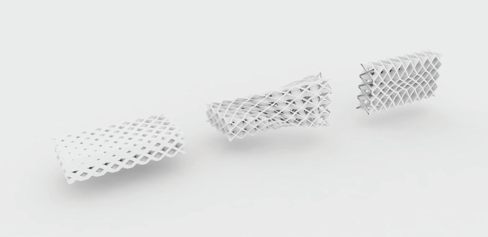
SIDE VIEW
GRADIENT IN PLATE THICKNESS
GRADIENT IN PLATE THICKNESS
grid on surface
GRADIENT IN CELL SIZE
GRADIENT IN CELL SIZE
GRADIENT IN OPENINGS
GRADIENT IN OPENINGS
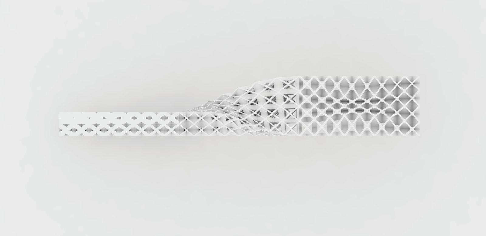
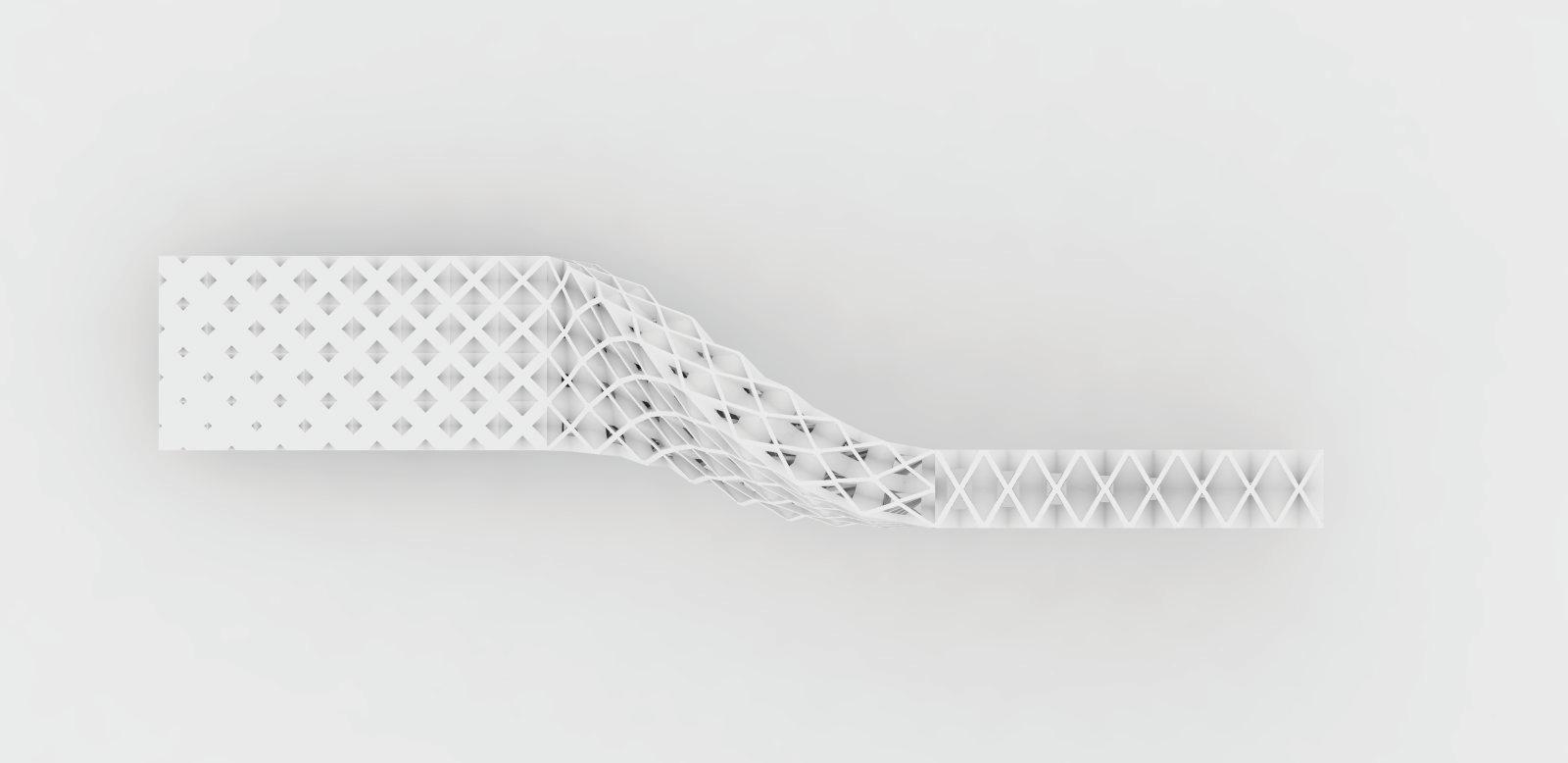 TOP VIEW
SIDE VIEW
TOP VIEW
TOP VIEW
SIDE VIEW
TOP VIEW
TYPOLOGY STUDY - TYPE B
In TYPE B the parameters for the roof are set to have open and large cells in order to have light transmitting ceiling. Throughout the middle transition surface the porosity level stays the same though the regularity of cell size is given. Throughout the third surface the cells get less porous do work as enclosed facade system. This typology displays gradients varying regularity to irregularity within one system as well cell size differentiation.
POROSITY GRADIENT TRANSITION VERTICAL TO HORIZONTAL
POROSITY GRADIENT TRANSITION VERTICAL TO HORIZONTAL
base surface and isocurves
base surface and isocurves
grid on surface
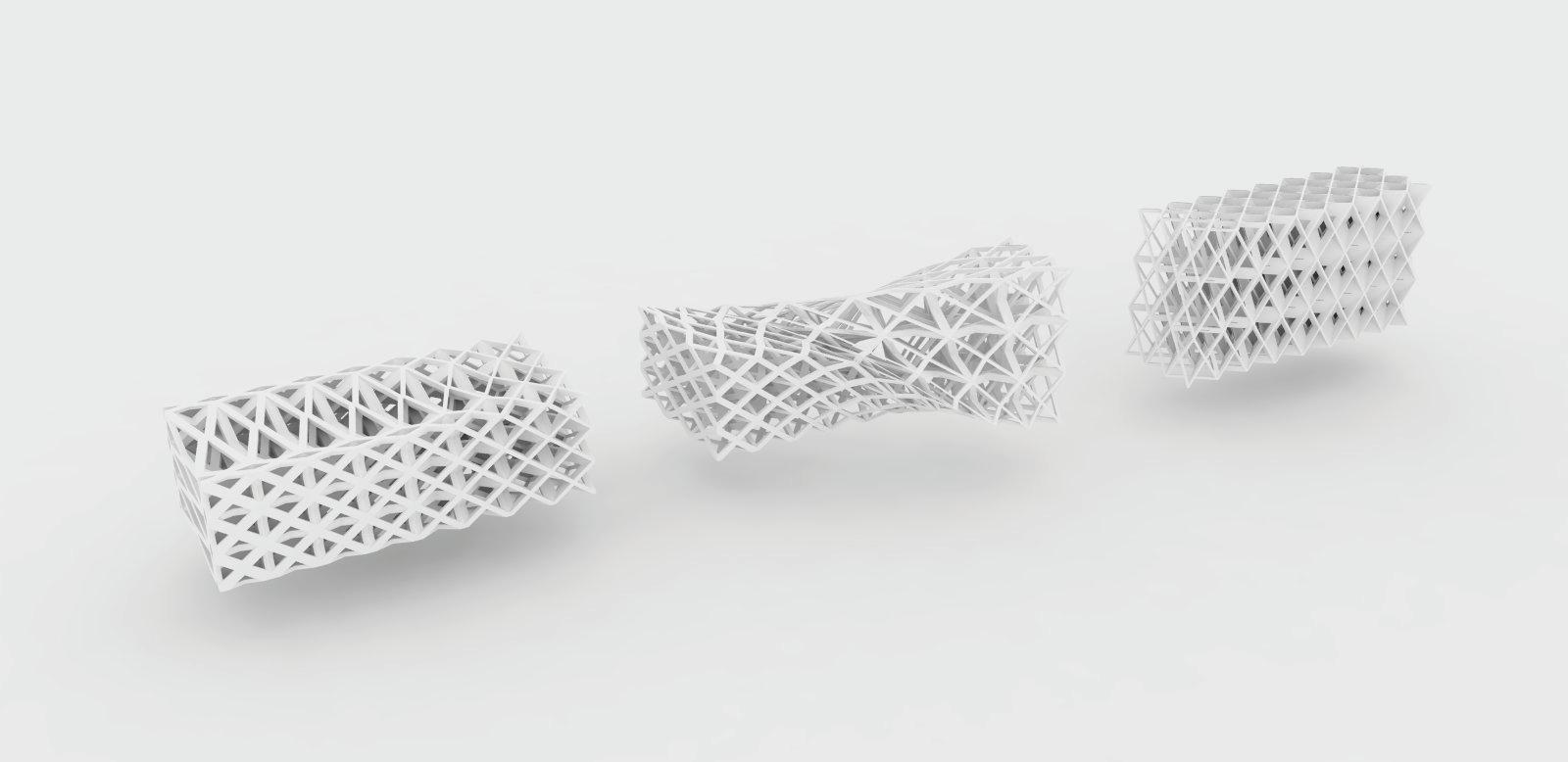
grid on surface
GRADIENT IN STRUT THICKNESS
GRADIENT IN STRUT THICKNESS
GRADIENT IN OPENINGS
GRADIENT IN OPENINGS
GRADIENT IN CELL SIZE
GRADIENT IN CELL SIZE
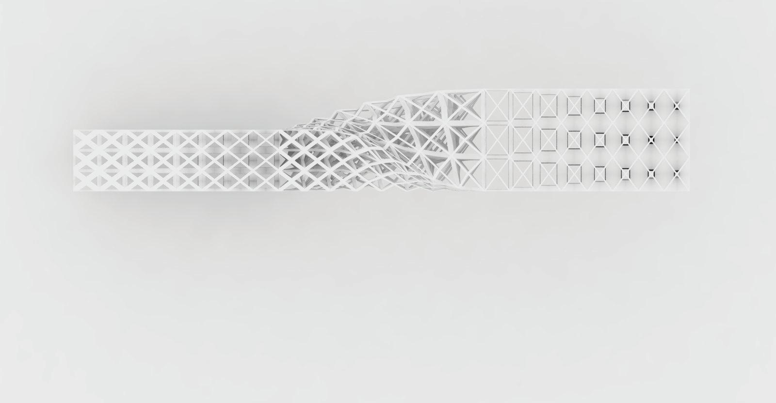
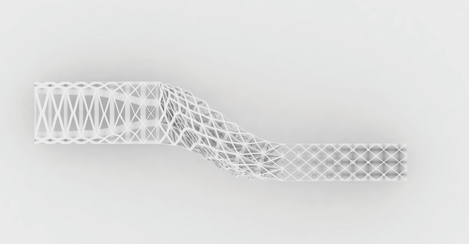 SIDE VIEW
TOP VIEW
SIDE VIEW
TOP VIEW
SIDE VIEW
TOP VIEW
SIDE VIEW
TOP VIEW
THE SYSTEM
TYPOLOGY STUDY - TYPE C
In TYPE C the parameters for the roof are set to have regular and open cells in order to have a light transmitting roof structure. Throughout the middle transition surface the cellular system decreases the porosity level to achieve enclosed cellular system for the facade. What is displayed in this typology is a thickness change in struts and that an enclosed cellular facade system can be achieved either this way or by altering the value of inside boolean geometry - which is the opening size.
POROSITY GRADIENT TRANSITION VERTICAL TO HORIZONTAL
GRADIENT IN STRUT THICKNESS
base surface and isocurves
base surface and isocurves grid on surface
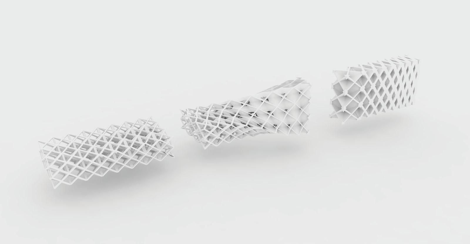
GRADIENT IN PLATE THICKNESS
GRADIENT IN OPENINGS
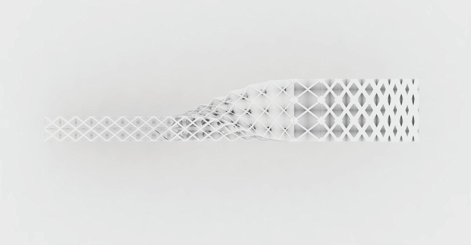
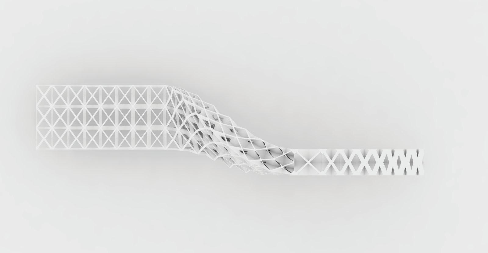 SIDE VIEW
TOP VIEW
SIDE VIEW
TOP VIEW
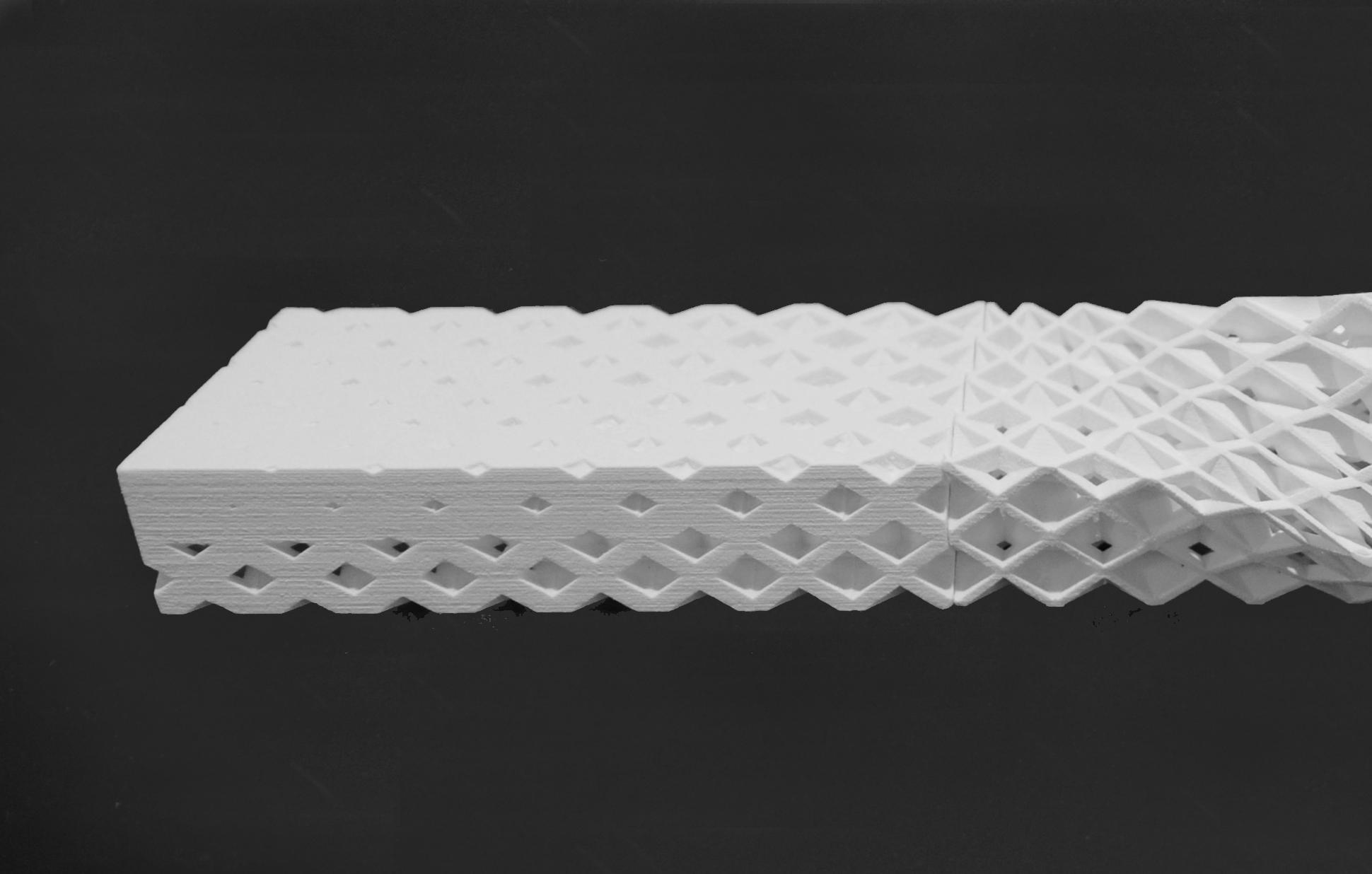
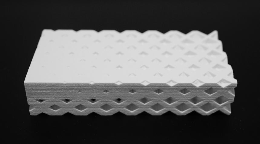
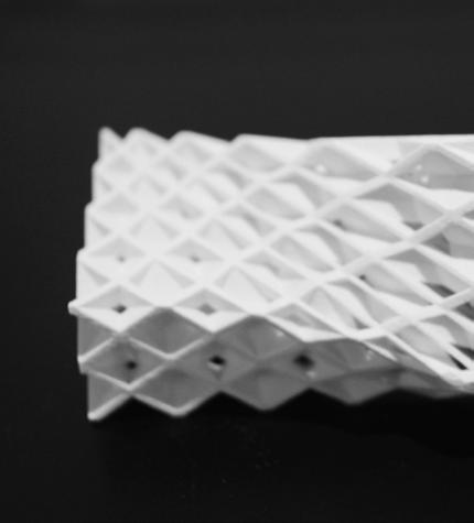
112
3D PRINTED STUDY MODEL OF TYPOLOGY - TYPE A
ROOF PATCH
THE SYSTEM
TRANSITION PATCH
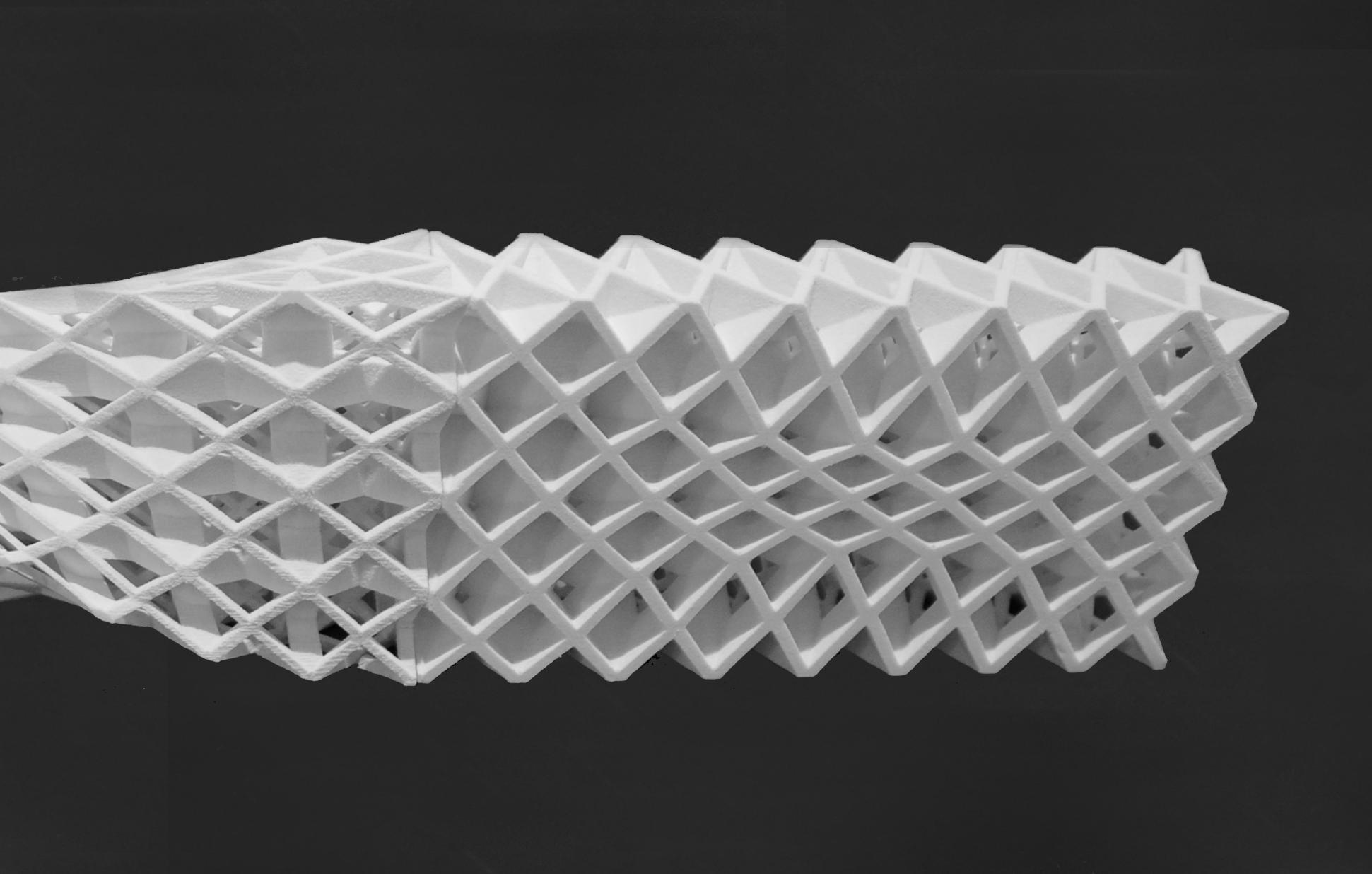
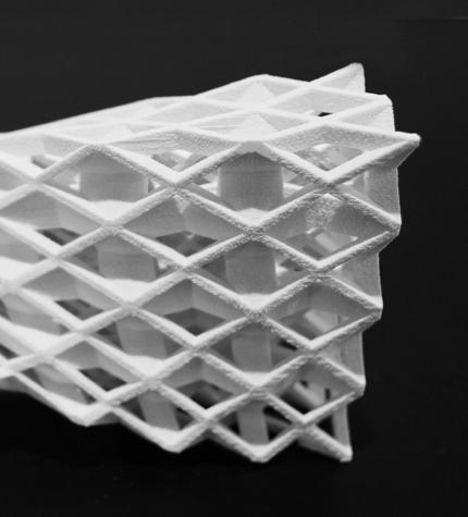
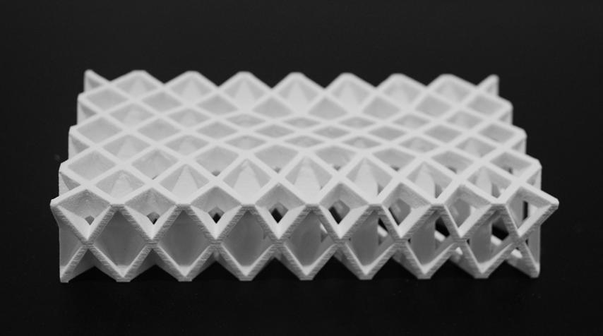
CELLULAR COMPLEXITY 113
FACADE PATCH
The typologies generated earlier were analysed for the viability in terms of the relation of additive manufactured joints to cast joints. Five patches from the typologies, with varying geometrical and material gradients were compared. The physical possibility and economic feasibility of fabrication was taken into account and lead to an understanding of the amount of additive manufactured joints, moulds and cast joints.
The first two patches contained a material gradient only. The difference in joint size adaptability was compared. In both examples the strut thickness increases throughout the system. In the first patch the joint
size followed the material thickness while in the second patch the joint size did not follow the material thickness. This resulted in a reduction of additive manufactured joints followed by a reduction in moulds, while the number of cast joints per mould increased. Dependant on the manufacturing method, the mould the feasibility and number of cast joints from one mould would affect the decision of chosing one method over the other.
MATERIAL CHANGE IN STRUT THICKNESS
JOINT SIZE FOLLOWS MATERIAL THICKNESS
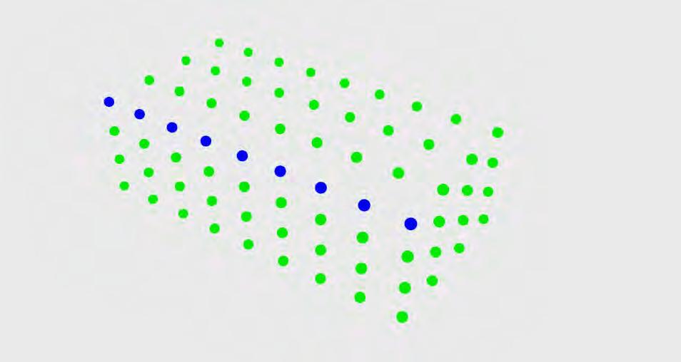
MATERIAL CHANGE IN STRUT THICKNESS JOINT SIZE DOES NOT FOLLOW MATERIAL THICKNESS
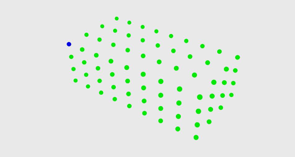
114 THE SYSTEM
PATCH 1
9 3D PRINTED JOINTS 9 MOULDS 15 JOINTS PER MOULD 135 CAST JOINTS 144 JOINTS IN TOTAL 72 CELLS 1 3D PRINTED JOINT 1 MOULD 143 JOINTS PER MOULD 143 CAST JOINTS 144 JOINTS IN TOTAL
72 CELLS
PATCH 2
JOINTS FABRICATION EFFICIENCY
The third and the fourth patches contained both a material and a geometrical gradient. The difference between a regular and an irregular system is compared. The cell size change allowed the system to include variation. The number of additive manufactured joints for the moulds to cast joints has increased in comparison to the second patch. In these examples the joint size did not follow material thickness, thus the change in number was not taken into account within this examples. This comparison investigated the constraints of physical possibility and feasibility of irregularity throughout the system.
The main difference in the patches compared is the opportunity that joints would be additively manufactured for the fabrication of moulds as well as for joint variation in the system, by means of incorporating a parametric change to produce each joint slightly different from the other.
GEOMETRY CHANGE IN CELL SIZE

GEOMETRY CHANGE IN CELL SIZE JOINT SIZE DOES NOT FOLLOW MATERIAL THICKNESS
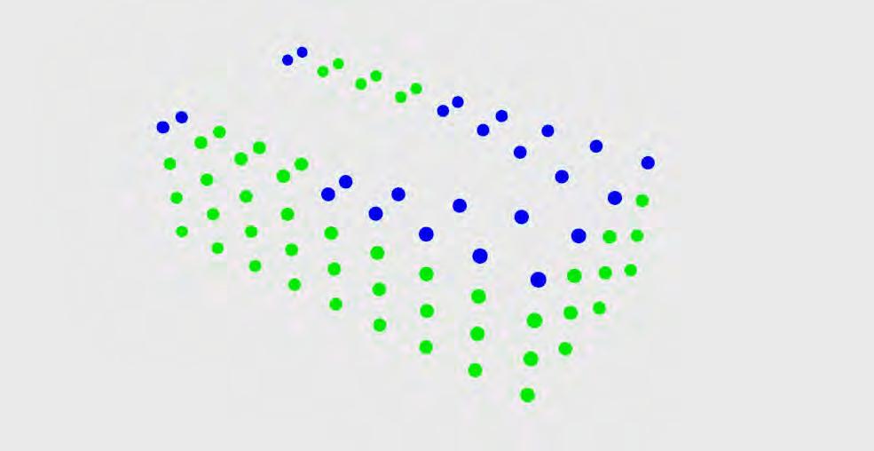
SIZE DOES NOT FOLLOW MATERIAL THICKNESS
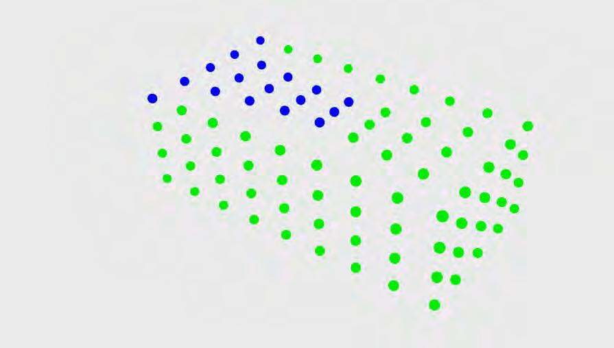
CELLULAR COMPLEXITY 115
PATCH 3
PATCH 4
72 CELLS 24 3D PRINTED JOINTS 24 MOULDS 3 / 15 JOINTS PER MOULD 84 CAST JOINTS 144 JOINTS IN TOTAL 96 CELLS 17 3D PRINTED JOINTS 17 MOULDS 7 / 36 JOINTS PER MOULD 163 CAST JOINTS 180 JOINTS IN TOTAL
JOINT
This patch was analysed as a transition patch between a horizontal and a vertical surface. Because of the radical change within the geometry almost every single joint was categorised as an additive manufactured joint. This sets a discussion for the feasibility of such a radical change in geometry within the system in relation to the physical possibility of fabrication. The typology revealed that the system can achieve curvature and has no geometric constraints or physical constraints, however the feasibility of fabricating the system in such geometry would be questionable.
MATERIAL CHANGE IN STRUT THICKNESS
JOINT SIZE FOLLOWS MATERIAL THICKNESS
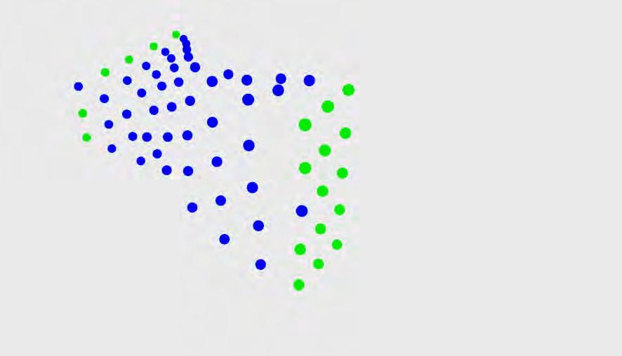
116 THE SYSTEM
PATCH 5
72
108 3D PRINTED JOINTS 2 MOULDS 14 JOINTS PER MOULD 28 CAST JOINTS 136 JOINTS IN TOTAL
CELLS
JOINTS FABRICATION
EFFICIENCY
The evaluation of this analyses reveals that in order to receive comparable results the number of cells need to be the same. This includes that the number of layers and rows in all patches can change as long as the number of cells stays the same. Those patches are made of three vertical and three horizontal layers and nine rows of cells. In this case this was the minimum amount of cells required to achieve an acceptable gradient.
Once the variation in geometry requires symmetry, one additional row of cells needs to be added such as in a patch four. The required symmetry results of a gradient variation which is mirrored. This has of course an effect on the final numbers of joints.
EVALUATION TABLE
PATCHES

In terms of varying the joint size with material thickness, it is more efficient to maintain the joint size the same and develop it to a high level of detail, reducing complexity. Furthermore, the spatial effect of the joint would be unified and adaptable within spaces, where no substantially larger joints appear within a space.
JOINT SIZE
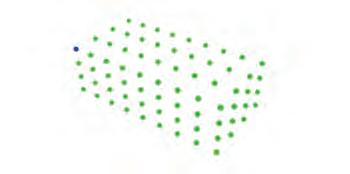


CELLULAR COMPLEXITY 117
NO VARIATION NO VARIATION VARIATION VARIATION VARIATION GEOMETRY AMOUNT SPECIFICS FOLLOWS STRUT THICKNESS DOES NOT FOLLOW STRUT THICKNESS DOES NOT FOLLOW STRUT THICKNESS DOES NOT FOLLOW STRUT THICKNESS DOES NOT FOLLOW STRUT THICKNESS
OVERVIEW OF JOINT VARIATION
PATCH 1 CHANGE CHANGE CHANGE CHANGE CHANGE PATCH 2 PATCH 3 PATCH 4 PATCH 5 STRUT THICKNESS 9 1 24 17 108 3D PRINTED JOINTS 15 143 3 / 15 7 / 36 14 JOINTS PER MOULD 9 1 24 17 2 MOULDS 72 72 72 95 72 CELLS 144 144 144 180 136 JOINTS IN TOTAL 135 143 84 163 28 CAST JOINTS
118 THE SYSTEM
THE SYSTEM overview
Throughout the progression of the system development phase, the opportunities and limits of the digital design tools were explored and tested on specific examples. The ability to vary porosity became tied to a number of controlled parameters within the algorithm. This allow for a wide range of variations and combinations of how to meet potential performative aspects within the system and its architectural application. We further developed an understanding of a material gradient and a geometrical gradient.
In the realm of a material gradient the challenge becomes, how to combine the various gradients and the question comes up of where to use which tool in which intensity and what is the best way of how to generate a certain desired porosity in the most efficient way. The main ambition when actually applying the generated system and porosity levels is to always maintain a controlled and smooth porosity gradient in all directions. The parameters affecting structure have already been defined through a number of Finite Element Analysis tests.
Within the geometrical gradient, the algorithmic approach allowed for the application of the system on complex surfaces. This was further tested through a range of typologies which include architectural transitions. These complex transitions were analysed geometrically and performatively.
The feasability and fabrication of these typologies was revisited. The fabrication method developed earlier allows for various ways of how to realize the generated typologies. The customized joints can either follow the strut thickness in size or stay the same size. Based on the frequency they occur throughout the structure. Certain cases require identical joints everywhere, others require several joints which are repeated, and finally cases that require customized joints at each node.
Therefore, it is important to consider the amount of joints, and the production limit of moulds, where an opportunity is already given to create variation. This sets an initial limitation to the development of geometrical gradients and the amount they recur at.
These defining parameters of the system, their opportunities and constraints have set a foundation for the systems development, the next phase will examine its application at an architecture scale.
CELLULAR COMPLEXITY 119
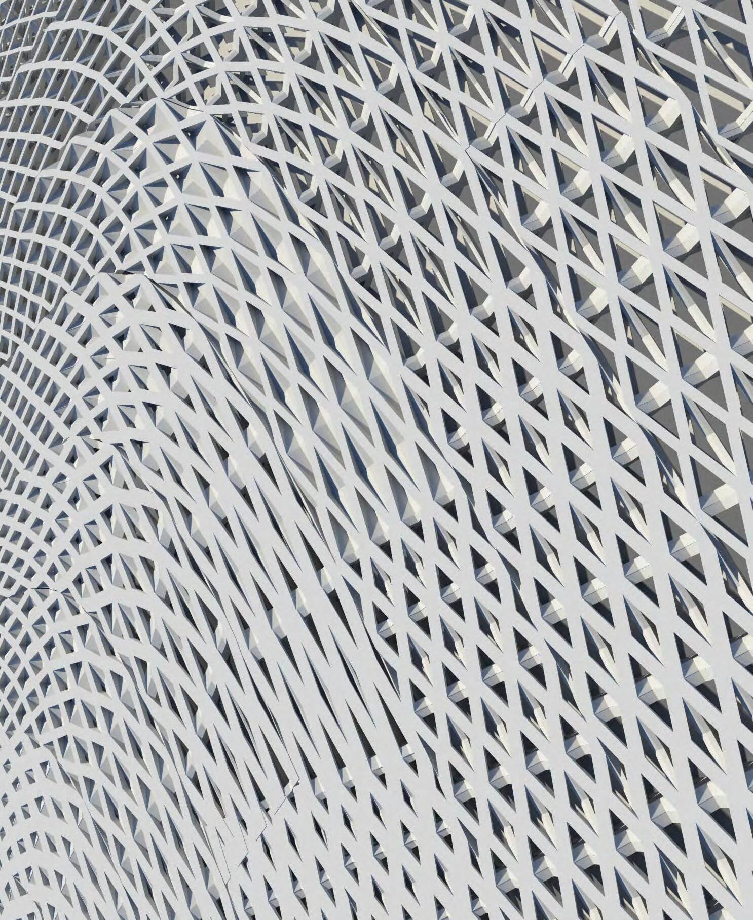
ARCHITECTURAL APPLICATION
Throughout the previous section, the system was investigated in further detail and the defining parameters for its application were established. This section will examine the application of the system at an architectural scale.
For the architectural application, we became particularly interested in the tower typology and the diverse programmatic uses involved in this type. The current state-of-the-art architecture in tower design creates limited variation within towers to address architectural and programmatic conditions. A case study is investigated for this purpose, and its relation to our system.
The case study leads us to selecting a site and range of programs to commence the application process. Throughout our research we investigated architectural competitions and selected the suckerPUNCH international competition which involves the design of a convention, hotel and casino in Hudson Yards, New York.
The application of the system at this scale provided us with case study on how the system operates at a large scale and the opportunities and limitations which become apparent.
CELLULAR COMPLEXITY 121
TYPOLOGICAL CASE STUDY
THE SHARD, LONDON RENZO PIANO BUILDING WORKSHOP
Throughout the dissertation, several typologies were considered for the architectural application of the system, of most interest was the tower typology. The large-scale of this typology and the lack of architectural systems which are able to address variation at this scale encouraged us to consider it for the dissertation.
The system would be able to address diverse programmatic changes, which would require continuous changes within the facade and the structural system. Throughout our system, they would be closely integrated.
DISTINCT URBAN / ARCHITECTURAL CONDITION
Mixed-Use Tower:
- OFFICES - HOTEL - RESIDENCES
Public Transportation
- BUS STATION
-
-
INVESTIGATE VARIATION IN
Our choice of The Shard as a case study is due to its distinct urban condition which combines numerous programmatic functions in a high density node. As part of our research, we intend to examine the variation in the architecture of The Shard in terms of its facade and overall structure and how they vary with the urban and programmatic conditions. The levels below and at ground combine multiple transportation nodes. The tower itself includes offices at the lower levels, a hotel and restaurants at mid levels, residences and an observatory at the upper levels of the tower.
STRUCTURE FACADE
122
underground jubilee line underground northern line bus station railway station offices offices hotel residences mixed use tower offices underground and railway station bus station
RAILWAY
STATION
UNDERGROUND:
NORTHERN LINE
JUBILEE
ARCHITECTURAL APPLICATION
-
-
LINE
THE STRUCTURE
The structure of skyscrapers typically depends on two main loads:
-Dead and Live Loads: These are the loads from the structure of the building and its furnishings and occupants, the direction of this load is the gravities direction, they increase at lower floors of the building.
-Lateral Loads: These are loads due to environmental elements such as wind. The direction of these loads is perpendicular to gravity and increases at the higher floors of the building.
The design of The Shard demonstrates a degree of variation that responds to the structural loads outlined. In terms of Dead and Live Loads, the core area of the structure decreases as the structure becomes higher and reaches its peak, with changing intervals as programs change. Although cores are typically used to resist lateral loads, the decrease in core size does optimize the structure for both efficiency in material and space. As for lateral loads, the tapered design of the building reacts to the lateral loads. The smaller the floor plate of the building, the less lateral wind loads it needs to resist.
DECREASE IN DEAD AND LIVE LOADS WITHIN THE STRUCTURE LESS STRUCTURE IS REQUIRED AT THE TOP
INCREASE IN LATERAL WIND LOADS
SMALLER FLOOR PLATE PROVIDES MORE STABLE STRUCTURE
Conventional Typical Plan Tower
(ESTIMATED FROM REFERENCE 1)
Tapered Plan Tower eg. The Shard
(ESTIMATED FROM REFERENCE 1)
CELLULAR COMPLEXITY 123
2-28 100% RESTAURANTS 31-33 34-52 53-65 68-72 LEVELS LEVELS LEVELS LEVELS LEVELS HOTEL OFFICES 53.9% 29.5% 5.2% CORE AREA
ELEVATION SHEAR MOMENT DEFLECTION ELEVATION SHEAR MOMENT DEFLECTION CORE AREA CORE AREA CORE AREA RESIDENCES OBSERVATORY
THE FACADE
The design of the building consists of eight shards of glass leaning towards each other. The entire facade is a ventilated double skin facade. The system is consistent throughout the structure and does not vary between the different programmatic and urban conditions. The two skins with a cavity in between provide enhanced thermal performance, and contain a shading element in the cavity to reduce heat gain from sunlight. The ventilation aspect of the facade was designed to operate at several levels. First, ventilation within the same floor for cooling during summer, where cold air enters from the outside to the cavity, into the spaces at low points. Warm air escape at high points of the space through stack effect to higher points in the cavity, further to the outside.
The second performative ventilation level is to have openings closed between the cavity and exterior. During winter, excess heat from office spaces can rise through the stack effect within the cavity towards the residential and hotel floors where it is needed. If excess heat exists within all floors, heat will rise towards the top of the building and exit the cavity. These ventilation strategies were part of the original design scheme, however during construction the facade was changed to become a non ventilated double skin facade.
ORIGINAL SCHEME:
Ventilation within same floor


RESIDENCES

- Cold air into building through cross ventilation through low openings in the facade at each floor.
Ventilation through building
- Warm air out of the building through stack effect and higher openings in the facade at each floor. Excess Heat form Office floors: Cross-Ventilation within the same floor or space:


OFFICES
- Through stack effect rises to Hotel and Residential floors where heat is needed.
- Rise of heat from all floors towards the top of the tower.
124
Fig. 5.2
Fig. 5.3
Fig. 5.1
Double Skin Facade Section with Roller Blinds
HOTEL
ARCHITECTURAL APPLICATION
The Shard presents an urban condition that integrates multiple distinct programmatic functions. The variation in structure attempts to achieve an efficient structure through a continuously decreasing floor plate towards higher floors, and decreasing core size with programmatic changes. The facade and ventilation systems are consistent throughout the structure with no variation; however attempts to address different programs ventilation in one system by stack effect. The various elements within the design are treated as separated performative elements and layers and not part of an integrated system that is inherent to the design.
In terms of application within the context of the dissertation, the structural analysis suggest the use of more porous cells at the higher parts of the building. This is due to their material efficiency and lower structural needs, in addition the porosity allows wind to pass through where lateral loads are high. Furthermore, the use of low porosity cells at lower parts of the building where higher structural capacities are needed and lower wind loads are present. In general, the Shard does contain variation however does not attempt to create variation with specific programs and orientations.
URBAN / ARCHITECTURAL CONDITION
MIXED-USE TOWER:
- OFFICES - HOTEL - RESIDENCES
TRANSPORTATION:
- BUS STATION
- RAILWAY STATION - UNDERGROUND:
- NORTHERN LINE - JUBILEE LINE
STRUCTURE
VARIATION ACROSS BUILDING
RESPONDING TO CONDITION
CORE
STRUCTURE
LEVEL 68-72
5% AREA
LEVEL 53-67
30% AREA
LEVEL 34-52
54% AREA
LEVEL 2-33
100% AREA
FLOOR PLATES
LEVEL 2:
100% AREA
LEVEL 40:
~50% AREA
LEVEL 72:
~11% AREA
DECREASE IN DEAD AND LIVE LOADS AT HIGHER FLOORS
APPLICATION IN CELLULAR CONTEXT
USE OF:
HIGH POROSITY CELLS AT HIGHER FLOORS allow wind to pass through and not apply lateral forces onto the building
LOW POROSITY CELLS NEAR BASE OF BUILDING higher structural capacity cells at lower parts of the building
DECREASE IN WIND LATERAL LOADS WITH SMALLER FLOOR-PLATES
FACADE/ VENTILATION
DOUBLE SKIN FACADE
NON-CHANGING THROUGHOUT BUILDING
features throughout:
-openings to exterior at each level in both low and high points
-opening at the top of building at facade cavity
-roller blinds in facade cavity
-STACK EFFECT for excess heat
-SOLAR GAIN
-VENTILATION
-NATURAL DAY LIGHTING
STACK EFFECT:
CONTINUOUS VERTICAL VOIDS IN STRUCTURE transfer excess heat between programmes
VOIDS BETWEEN CAVITY AND INSIDE AND OUTSIDE transfer heat outside of the building cross ventilation
CELLULAR COMPLEXITY 125
STUDY SYNTHESIS
CASE
SUCKERPUNCH COMPETITION / www.suckerpunchdaily.com
Subsequent to our research into the tower typology, which investigated the case study of an existing tower in London, we investigated possible opportunities for application. We selected to define our application through an architectural ideas competition, this would define a site and range of programmatic uses for our system.
This would provide us with a case study for application and allow us to develop the project further based on our findings. The competition brief and requirements are shown below and on the page to the left, including jury members.
New York City Casino/Convention Center
The interest in the tower typology lead us to the context of Manhattan in New York, where we found the suckerPUNCH architectural competition for a casino, hotel and convention centre in Hudson Yards, Manhattan. This competition was well suited to our system due to its involvement in a large urban site, and the requirements of a diverse range of programs. Furthermore, the time line of the competition was well suited to our dissertation, where the submission of our entry would be more than a month prior to the completion of the dissertation.
Recently, New York’s state government has been trying to legalize non-Indian casinos throughout the state. Current proposals are asking for the construction of seven “Vegas”-sized casinos throughout New York. Although lawmakers have pushed to keep the casinos out of New York City, this ideas competition aims to investigate what a casino would do to New York City and, likewise, what New York City would do to a casino. The New York casinos are being pitched by their supporters as “regional revitalization” tools. Although Manhattan is arguably in no need of revitalization, it does have one clear zone that could use rethinking—Hudson Yards and the area around its neighbouring convention centre. The existing Jacob Javits Centre remains an isolated structure surrounded by a no-man’s-land of parking and train tracks. Cut off from restaurants, hotels, and entertainment, it is hardly an inviting location for a large convention, nor does it allow for or engender connection to the city at-large. You might as well have your convention in Secaucus. There is talk of relocating the Centre to Queens, to be sited next to the recently opened “racino” at Aqueduct Racetrack—a major financial success thus far, and example of the excitement people in the five boroughs have for gambling. The proposed convention centre would be the largest in the United States. This competition asks entrants to leave the convention centre at its current location on Manhattan’s West Side, but replace it and add a hotel and casino to the complex.
COMPETITION BRIEF BY SUCKERPUNCH:
Entrants are asked to rethink this zone so as to create a dynamic destination in the city for tourists, residents, and convention-goers alike. At the same time, the complex should become a draw for non convention-goers.

COMPETITION OUTLINES:
CELLULAR COMPLEXITY
ENTRY WAS AWARDED SECOND PLACE
If a Vegas-style themed casino clearly wouldn’t work in New York City, then what would bring New Yorkers out to gamble? Is it a family focused zone for tourists or an adults-only retreat? The proposed building should incorporate state-of-the-art facilities for both modern gambling and high- tech conventions. The convention centre should be unique while remaining flexible, and the casino should shake off both cheesy Vegas aesthetics and the dry desperation of Atlantic City to strive for something architecturally rich and complex—while simultaneously entertaining. The complex should also find a way to reconnect to Manhattan’s nearby entertainment districts. Madison Square Garden, Times Square, and the High Line seem cut off, despite their proximity. This complex should aim to recharge its surroundings in the same way the High Line did the Meatpacking District, bringing in pedestrians and cleaning up the area. On the western, waters edge of Manhattan, the site also includes a large pier that can be used for a portion of the program or turned into outdoor parks and recreation areas. The site includes the land the current convention centre lies on, the space over the West Side Yard train yard, and the aforementioned waterfront pier. The West Side Yard was designed to accommodate an overbuild in its air rights, and space was left between the tracks for columns to support a platform above the tracks. The history of proposals for the very same site includes the ongoing Hudson Yards Redevelopment and the IFCCA “Competition for Manhattan’s West Side.” (COMPETITION BRIEF BY SUCKERPUNCH)
This is an open, international ideas competition hosted by suckerPUNCH to generate progressive contemporary designs. There are no plans for the Casino/Convention Center to be built at this time. The site is not owned by or affiliated with suckerPUNCH.
///jury/AWARDS
kutan AYATA (YOUNG & AYATA)
ezio BLASETTI (Ahylo Studio)
david ERDMAN (davidclovers)
marc FORNES (THEVERYMANY)
Recently, New York’s state government has been trying to legalize nonIndian casinos throughout the state. Current proposals are asking for the construction of seven “Vegas”-sized casinos throughout New York. Although lawmakers have pushed to keep the casinos out of New York City, this ideas competition aims to investigate what a casino would do to New York City and, likewise, what New York City would do to a casino. The New York casinos are being pitched by their supporters as “regional revitalization” tools. Although Manhattan is arguably in no need of revitalization, it does have one clear zone that could use rethinking—Hudson Yards and the area around its neighbouring convention centre. The existing Jacob Javits Centre remains an isolated structure surrounded by a no-man’s-land of parking and train tracks.
ferda KOLATAN (su11 Architecture & Design)
craig SCOTT (IwamotoScott Architecture)
marcelo SPINA (P-A-T-T-E-R-N-S)
mike SZIVOS (SOFTlab)
abigail COOVER (hume coover studio, suckerPUNCH)
nathan HUME (hume coover studio, suckerPUNCH)
entertaining. The complex should also find a way to reconnect to Manhattan’s nearby entertainment districts. Madison Square Garden, Times Square, and the High Line seem cut off, despite their proximity. This complex should aim to recharge its surroundings in the same way the High Line did the Meatpacking District, bringing in pedestrians and cleaning up the area. On the western, waters edge of Manhattan, the site also includes a large pier that can be used for a portion of the program or turned into outdoor parks and recreation areas.
The site includes the land the current convention centre lies on, the space over the West Side Yard train yard, and the aforementioned waterfront pier. The West Side Yard was designed to accommodate an overbuild in its air rights, and space was left between the tracks for columns to support a platform above the tracks. The history of proposals for the very same site includes the ongoing Hudson Yards Redevelopment and the IFCCA “Competition for Manhattan’s West Side.”
$2500 in prizes will be awarded and the winning designs will be published on suckerPUNCH.
///entryREQUIREMENTS
Cut off from restaurants, hotels, and entertainment, it is hardly an inviting location for a large convention, nor does it allow for or engender connection to the city at-large. You might as well have your convention in Secaucus. There is talk of relocating the Centre to Queens, to be sited next to the recently opened “racino” at Aqueduct Racetrack—a major financial success thus far, and example of the excitement people in the five boroughs have for gambling. The proposed convention centre would be the largest in the United States. This competition asks entrants to leave the convention centre at its current location on Manhattan’s West Side, but replace it and add a hotel and casino to the complex.
This is an open ideas competition. entrants will be required to digitally submit two [2] boards at 18” high x 24”wide and 150dpi in tiff format with the provided 5 digit code in a 1”x1” square in the lower right hand corner of each board. Image requirements are as follows:
PLANS
This is an open, international ideas competition hosted by suckerPUNCH to generate progressive contemporary designs. There are no plans for the Casino/Convention Center to be built at this time. The site is not owned by or affiliated with suckerPUNCH.
THE JURY
all necessary site and floor plans to describe the project including at minimum a ground level plan describing the form, integration of program, and relationship to the site
*scale is at the discretion of the entrant SECTIONS
Entrants are asked to rethink this zone so as to create a dynamic destination in the city for tourists, residents, and convention-goers alike. At the same time, the complex should become a draw for non convention-goers.
one [1] north/south section
one [1] east/west section
*scale is at the discretion of the entrant RENDERINGS
one [1] aerial view
one [1] street level view
one [1] interior view
kutan AYATA (YOUNG & AYATA)
ezio BLASETTI (Ahylo Studio)
david ERDMAN (davidclovers)
marc FORNES (THEVERYMANY)
ferda KOLATAN (su11 Architecture & Design)
craig SCOTT (IwamotoScott Architecture)
*one rendering best describing the formal and atmospheric intent of the project must be rendered at 10” high x 13” wide and 150dpi in tiff format. This image is to be included on the boards as one of the above views.
If a Vegas-style themed casino clearly wouldn’t work in New York City, then what would bring New Yorkers out to gamble? Is it a family focused zone for tourists or an adults-only retreat? The proposed building should incorporate state-of-the-art facilities for both modern gambling and high- tech conventions. The convention centre should be unique while remaining flexible, and the casino should shake off both cheesy Vegas aesthetics and the dry desperation of Atlantic City to strive for something architecturally rich and complex—while simultaneously
///competitionSCHEDULE
on suckerPUNCH
marcelo SPINA (P-A-T-T-E-R-N-S)
mike SZIVOS (SOFTlab)
abigail COOVER (hume coover studio, suckerPUNCH)
nathan HUME (hume coover studio, suckerPUNCH)
126 ARCHITECTURAL APPLICATION
April 2012 competition launch 11 June 2012 deadline for questions 18 June 2012 answers to questions will be posted
ARCHITECTURAL APPLICATION
27
and the area around its neighbouring convention centre. The existing Jacob Javits Centre remains an isolated structure surrounded by a no-man’s-land of parking and train tracks. Cut off from restaurants, hotels, and entertainment, it is hardly an inviting location for a large convention, nor does it allow for or engender connection to the city at-large. You might as well have your convention in Secaucus. There is talk of relocating the Centre to Queens, to be sited next to the recently opened “racino” at Aqueduct Racetrack—a major financial success thus far, and example of the excitement people in the five boroughs have for gambling. The proposed convention centre would be the largest in the United States. This competition asks entrants to leave the convention centre at its current location on Manhattan’s West Side, but replace it and add a hotel and casino to the complex. Entrants are asked to rethink this zone so as to create a dynamic destination in the city for tourists, residents, and convention-goers alike. At the same time, the complex should become a draw for non convention-goers.
///entryREQUIREMENTS
proposed convention centre would be the largest in the United States. This competition asks entrants to leave the convention centre at its current location on Manhattan’s West Side, but replace it and add a hotel and casino to the complex. Entrants are asked to rethink this zone so as to create a dynamic destination in the city for tourists, residents, and convention-goers alike. At the same time, the complex should become a draw for non convention-goers.
This is an open ideas competition. entrants will be required to digitally submit two [2] boards at 18” high x 24”wide and 150dpi in tiff format with the provided 5 digit code in a 1”x1” square in the lower right hand corner of each board. Image requirements are as follows:
PLANS
COMPETITION OUTLINES:
Recently, New York’s state government has been trying to legalize non-Indian casinos throughout the state. Current proposals are asking for the construction of seven “Vegas”-sized casinos throughout New York. Although lawmakers have pushed to keep the casinos out of New York City, this ideas competition aims to investigate what a casino would do to New York City and, likewise, what New York City would do to a casino. The New York casinos are being pitched by their supporters as “regional revitalization” tools. Although Manhattan is arguably in no need of revitalization, it does have one clear zone that could use rethinking—Hudson Yards and the area around its neighbouring convention centre. The existing Jacob Javits Centre remains an isolated structure surrounded by a no-man’s-land of parking and train tracks. Cut off from restaurants, hotels, and entertainment, it is hardly an inviting location for a large convention, nor does it allow for or engender connection to the city at-large. You might as well have your convention in Secaucus. There is talk of relocating the Centre to Queens, to be sited next to the recently opened “racino” at Aqueduct Racetrack—a major financial success thus far, and example of the excitement people in the five boroughs have for gambling. The proposed convention centre would be the largest in the United States. This competition asks entrants to leave the convention centre at its current location on Manhattan’s West Side, but replace it and add a hotel and casino to the complex. Entrants are asked to rethink this zone so as to create a dynamic destination in the city for tourists, residents, and convention-goers alike. At the same time, the complex should become a draw for non convention-goers.
all necessary site and floor plans to describe the project including at minimum a ground level plan describing the form, integration of program, and relationship to the site
*scale is at the discretion of the entrant SECTIONS
This is an open, international ideas competition hosted by suckerPUNCH to generate progressive contemporary designs. There are no plans for the Casino/Convention Center to be built at this time. The site is not owned by or affiliated with suckerPUNCH.
one [1] north/south section
one [1] east/west section
COMPETITION OUTLINES:
*scale is at the discretion of the entrant RENDERINGS
one [1] aerial view
///jury/AWARDS
one [1] street level view
This is an open, international ideas competition hosted by suckerPUNCH to generate progressive contemporary designs. There are no plans for the Casino/Convention Center to be built at this time. The site is not owned by or affiliated with suckerPUNCH.
one [1] interior view
kutan AYATA (YOUNG & AYATA)
ezio BLASETTI (Ahylo Studio)
david ERDMAN (davidclovers)
COMPETITION OUTLINES:
marc FORNES (THEVERYMANY)
*one rendering best describing the formal and atmospheric intent of the project must be rendered at 10” high x 13” wide and 150dpi in tiff format. This image is to be included on the boards as one of the above views.
ferda KOLATAN (su11 Architecture & Design)
///jury/AWARDS
craig SCOTT (IwamotoScott Architecture)
marcelo SPINA (P-A-T-T-E-R-N-S)
kutan AYATA (YOUNG & AYATA)
///competitionSCHEDULE
mike SZIVOS (SOFTlab)
ezio BLASETTI (Ahylo Studio)
This is an open, international ideas competition hosted by suckerPUNCH to generate progressive contemporary designs. There are no plans for the Casino/Convention Center to be built at this time. The site is not owned by or affiliated with suckerPUNCH.
abigail COOVER (hume coover studio, suckerPUNCH)
david ERDMAN (davidclovers)
nathan HUME (hume coover studio, suckerPUNCH)
27 April 2012 competition launch
marc FORNES (THEVERYMANY)
11 June 2012 deadline for questions
ferda KOLATAN (su11 Architecture & Design)
$2500 in prizes will be awarded and the winning designs will be published on suckerPUNCH.
craig SCOTT (IwamotoScott Architecture)
18 June 2012 answers to questions will be posted on suckerPUNCH
///jury/AWARDS
25 June 2012 early registration deadline
marcelo SPINA (P-A-T-T-E-R-N-S)
mike SZIVOS (SOFTlab)
13 August 2012 project submission deadline
abigail COOVER (hume coover studio, suckerPUNCH)
kutan AYATA (YOUNG & AYATA)
3 September 2012 winners will be posted on suckerPUNCH
nathan HUME (hume coover studio, suckerPUNCH)
ezio BLASETTI (Ahylo Studio)
///entryREQUIREMENTS
david ERDMAN (davidclovers)
///awards
marc FORNES (THEVERYMANY)
$2500 in prizes will be awarded and the winning designs will be published on suckerPUNCH.
ferda KOLATAN (su11 Architecture & Design)
craig SCOTT (IwamotoScott Architecture)
This is an open ideas competition. entrants will be required to digitally submit two [2] boards at 18” high x 24”wide and 150dpi in tiff format with the provided 5 digit code in a 1”x1” square in the lower right hand corner of each board. Image requirements are as follows:
marcelo SPINA (P-A-T-T-E-R-N-S)
$2500 in prizes will be awarded and the winning designs will be published on suckerPUNCH.
mike SZIVOS (SOFTlab)
PLANS
abigail COOVER (hume coover studio, suckerPUNCH)
///entryREQUIREMENTS
///program
nathan HUME (hume coover studio, suckerPUNCH)
all necessary site and floor plans to describe the project including at minimum a ground level plan describing the form, integration of program, and relationship to the site
*scale is at the discretion of the entrant
Exhibition / Convention Space
SECTIONS
one [1] north/south section
2,000,000 square feet
If a Vegas-style themed casino clearly wouldn’t work in New York City, then what would bring New Yorkers out to gamble? Is it a family focused zone for tourists or an adults-only retreat?
entertainment districts. Madison Square Garden, Times Square, and the High Line seem cut off, despite their proximity. This complex should aim to recharge its surroundings in the same way the High Line did the Meatpacking District, bringing in pedestrians and cleaning up the area. On the western, waters edge of Manhattan, the site also includes a large pier that can be used for a portion of the program or turned into outdoor parks and recreation areas. The site includes the land the current convention centre lies on, the space over the West Side Yard train yard, and the aforementioned waterfront pier. The West Side Yard was designed to accommodate an overbuild in its air rights, and space was left between the tracks for columns to support a platform above the tracks. The history of proposals for the very same site includes the ongoing Hudson Yards Redevelopment and the IFCCA “Competition for Manhattan’s West
The proposed building should incorporate state-of-the-art facilities for both modern gambling and high- tech conventions. The convention centre should be unique while remaining flexible, and the casino should shake off both cheesy Vegas aesthetics and the dry desperation of Atlantic City to strive for something architecturally rich and complex—while simultaneously entertaining. The complex should also find a way to reconnect to Manhattan’s nearby entertainment districts. Madison Square Garden, Times Square, and the High Line seem cut off, despite their proximity. This complex should aim to recharge its surroundings in the same way the High Line did the Meatpacking District, bringing in pedestrians and cleaning up the area. On the western, waters edge of Manhattan, the site also includes a large pier that can be used for a portion of the program or turned into outdoor parks and recreation areas. The site includes the land the current convention centre lies on, the space over the West Side Yard train yard, and the aforementioned waterfront pier. The West Side Yard was designed to accommodate an overbuild in its air rights, and space was left between the tracks for columns to support a platform above the tracks. The history of proposals for the very same site includes the ongoing Hudson Yards Redevelopment and the IFCCA “Competition for Manhattan’s West
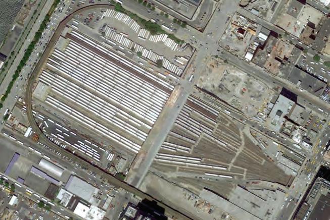
$2500 in prizes will be awarded and the winning designs will be published on suckerPUNCH.
one [1] east/west section
This is an open ideas competition. entrants will be required to digitally submit two [2] boards at 18” high x 24”wide and 150dpi in tiff format with the provided 5 digit code in a 1”x1” square in the lower right hand corner of each board. Image requirements are as follows: PLANS
*scale is at the discretion of the entrant
RENDERINGS
Meeting Room Square Footage
200,000 square feet / 50 rooms
///entryREQUIREMENTS
one [1] aerial view
one [1] street level view
all necessary site and floor plans to describe the project including at minimum a ground level plan describing the form, integration of program, and relationship to the site *scale is at the discretion of the entrant SECTIONS
Ballroom
one [1] interior view
one [1] north/south section
30,000 square feet
one [1] east/west section
This is an open ideas competition. entrants will be required to digitally submit two [2] boards at 18” high x 24”wide and 150dpi in tiff format with the provided 5 digit code in a 1”x1” square in the lower right hand corner of each board. Image requirements are as follows:
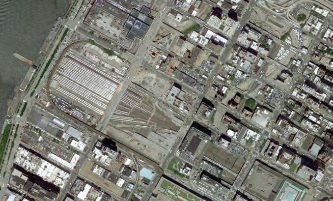
*one rendering best describing the formal and atmospheric intent of the project must be rendered at 10” high x 13” wide and 150dpi in tiff format. This image is to be included on the boards as one of the above views.
PLANS
Hotel 4000 suites
*scale is at the discretion of the entrant RENDERINGS
one [1] aerial view
one [1] street level view
all necessary site and floor plans to describe the project including at minimum a ground level plan describing the form, integration of program, and relationship to the site
one [1] interior view
*scale is at the discretion of the entrant SECTIONS
Theater 1500 seats
one [1] north/south section
///competitionSCHEDULE
one [1] east/west section
*one rendering best describing the formal and atmospheric intent of the project must be rendered at 10” high x 13” wide and 150dpi in tiff format. This image is to be included on the boards as one of the above views.
Lecture Hall 200 seats
27 April 2012 competition launch
*scale is at the discretion of the entrant RENDERINGS
11 June 2012 deadline for questions
one [1] aerial view
Cafeteria / Restaurant / Lounge / Retail
18 June 2012 answers to questions will be posted on suckerPUNCH
one [1] street level view
25 June 2012 early registration deadline
60,000 square feet or 20 restaurants and 70 shops
one [1] interior view
13 August 2012 project submission deadline
///competitionSCHEDULE
Entertainment Area
3 September 2012 winners will be posted over the course of the week on suckerPUNCH
*one rendering best describing the formal and atmospheric intent of the project must be rendered at 10” high x 13” wide and 150dpi in tiff format. This image is to be included on the boards as one of the above views.
27 April 2012 competition launch
40,000 square feet or 4 clubs and 1 large showroom
11 June 2012 deadline for questions
Gambling floor
18 June 2012 answers to questions will be posted on suckerPUNCH
120,000 square feet
25 June 2012 early registration deadline
13 August 2012 project submission deadline
3 September 2012 winners will be posted over the course of the week on suckerPUNCH
Operational Facilities
///competitionSCHEDULE
200,000 square feet
27 April 2012 competition launch
Loading Docks
11 June 2012 deadline for questions
50 truck bays
18 June 2012 answers to questions will be posted on suckerPUNCH
25 June 2012 early registration deadline
13 August 2012 project submission deadline
3 September 2012 winners will be posted over the course of the week on suckerPUNCH
Service, Circulation and Support programs as required. This program is meant to be open and flexible. It should be used as a guideline but changes can be made at the discretion of each entrant.
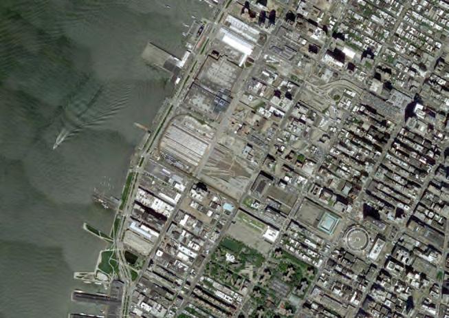
CELLULAR COMPLEXITY 127
Above and Below: Site Aerial Images from Google Earth
thus far, and example of the excitement people in the five boroughs have for gambling. The
Yard was designed to
train yard, and the aforementioned waterfront pier. The West Side
accommodate an overbuild in its air rights, and space was left between the tracks for columns to support a platform above the tracks. The history of proposals for the very same site includes the ongoing Hudson Yards Redevelopment and the IFCCA “Competition for Manhattan’s West Side.” (COMPETITION BRIEF BY SUCKERPUNCH)
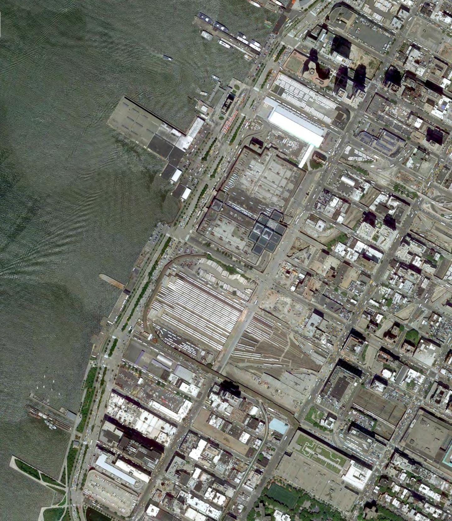
128 ARCHITECTURAL APPLICATION
Site Aerial Image from Google Earth
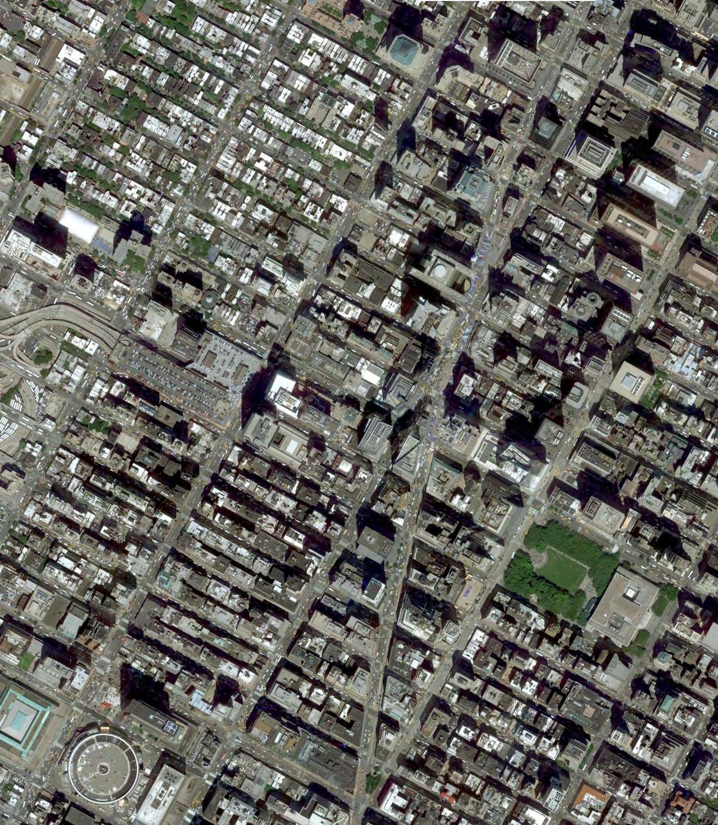
CELLULAR COMPLEXITY 129
The Site is located between 10th -12th Avenue and 30-39th Street. The Pier, the Convention Centre site and the site between the Convention Centre and the Hudson yards are built areas. While the Hudson Yards consist mainly of train tracks and stored trains. On the west side of the overall site there is 12th Avenue, highly used traffic connection between north and south of Manhattan’s West side.
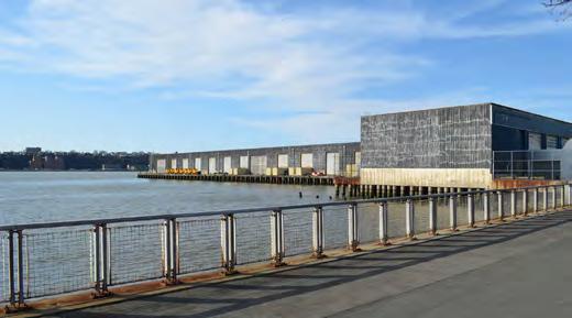
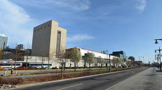
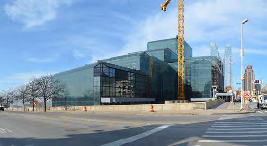
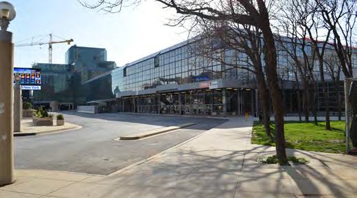
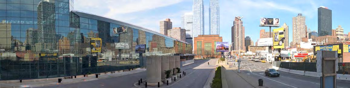
130 ARCHITECTURAL APPLICATION
COMPETITION SITE PANORAMAS 1 1 VIEW TOWARDS THE PIER 212th AVENUE LOOKING SOUTH EXISTING CONVENTION CENTRE EXISTING CONVENTION CENTRE 11th AVENUE LOOKING NORTH 12th AVENUE LOOKING NORTH 12th AVENUE & west 34th STREET 12th AVENUE & west 33th STREET 10th AVENUE & west 30th STREET 10th AVENUE & west 34th STREET 3 4 5 6 7 8 9 10 2 3 4 5 6 8 9 10 7
VIEW TOWARDS THE PIER 212th AVENUE LOOKING SOUTH EXISTING CONVENTION CENTRE EXISTING CONVENTION CENTRE 11th AVENUE LOOKING NORTH 12th AVENUE LOOKING NORTH 12th AVENUE & west 34th STREET 12th AVENUE & west 33th STREET 10th AVENUE & west 30th STREET 10th AVENUE & west 34th STREET 3 4 5 6 7 8 9 10 3 10
Images from Google Street View
1
1 3 5 2 4
CELLULAR COMPLEXITY 131 6 7 8 9 10
PROGRAMMATIC REQUIREMENTS
SUCKERPUNCH COMPETITION GUIDELINE:
The Site is in total 262 569 square meters and the total area of program is 258 463 square meters. The program consists of a huge exhibition space and an even larger Hotel area. These two programs make up the biggest area of the building. Further there are several medium scale programs meeting rooms, operation facilities, the casino and the loading docks. Finally there are several individual programs such as Cafés and restaurants, entertainment area, ballroom, theatre and lecture hall. Twenty percent of the total program area is set out for circulation and support programs. The program mainly consists of a combination of residential and commercial facilities as well as entertainment program.
The site includes the land the current convention centre lies on, the space over the West Side Yard train yard, and the aforementioned waterfront pier. The West Side Yard was designed to accommodate an overbuild in its air rights, and space was left between the tracks for columns to support a platform above the tracks. The history of proposals for the very same site includes the ongoing Hudson Yards Redevelopment and the IFCCA “Competition for Manhattan’s West Side.”
SITE SPECIFICS AND SITUATION
The Site is situated on the west side of Manhattan Mid Town close to the River edge. It is
connected to the City Centre through public and private transport. The
area is divided into five pieces of land which are possible building zones. The land is disconnected through main and side streets. Above the Train yards the building area starts on top of the
the
is
Site Areas in Square Meters:
Train yards right: 57 800 sqm
Train yards left: 58 124 sqm
Lower convention: 18 090 sqm
Convention centre: 79 247 sqm
Pier: 19 223 sqm
TOTAL: 262 569 sqm


132 N
Hotel 400 000 sqm / 4000 suites Exhibition / Convention Space 185 806 sqm Meeting Rooms 18581 sqm / 50 rooms Operational Facilities 18581 sqm Gambling floor 11148 sqm Loading Docks 10000 sqm / 50 truck bays Cafeteria / Restaurant / Lounge / Retail 5574 sqm / 20 restaurants / 70 shops Entertainment Area 40,000 square feet or 4 clubs and 1 large showroom = 12192 sqm = 5x (50 m x 50 m) Ballroom 30,000 square feet = 9144 square meters = 95.6 m x 95.6 m Theater 1500 seats ~ 2000 sqm = 45 m x 45 m Lecture Hall 200 seats ~ 270 sqm = 16.3 m x 16.3 m 20% service / circulation / support programs N
existing
Hotel 400 000 sqm / 4000 suites Exhibition / Convention Space 185 806 sqm Meeting Rooms 18581 sqm / 50 rooms Operational Facilities 18581 sqm Gambling floor 11148 sqm Loading Docks 10000 sqm / 50 truck bays Cafeteria / Restaurant / Lounge / Retail 5574 sqm / 20 restaurants / 70 shops Entertainment Area 40,000 square feet or 4 clubs and 1 large showroom = 12192 sqm = 5x (50 m x 50 m) Ballroom 30,000 square feet = 9144 square meters = 95.6 m x 95.6 m Theater 1500 seats ~ 2000 sqm = 45 m x 45 m Lecture Hall 200 seats ~ 270 sqm = 16.3 m x 16.3 m 20% service / circulation / support programs ///SITE Train yards right: 57 800 sqm Train yards left: 58 124 sqm Btw yards /convention: 18 090 sqm Convention centre: 79 247 sqm Pier: 19 223 sqm TOTAL: 262 569 sqm 350.00m BUILDING - TYPOLOGY - PROGRAM PROGRAM PROGRAM RELATION: The Site is in total 262 569 square meters and the total area of program is 258 463 square meters. The program consists of a huge exhibition space and an even larger Hotel area. These two programs make up the biggest area of the building. Further there are several medium scale programs meeting rooms, operation facilities, the casino and the loading docks. Finally there are several individual programs such as Cafés and restaurants, entertainment area, ballroom, theatre and lecture hall. Twenty percent of the total program area is set out for circulation and support programs. The program mainly consists of a combination of residential and commercial facilities as well as entertainment program. Btwyards/convention Trainyardsleft Trainyardsright Conventioncentre Pier pier conventioncentre lowerconvention trainyardsleft trainyardsright ARCHITECTURAL APPLICATION
well
whole
train tracks while on
convention centre’s Site building below zero level
possible. ///PROGRAM:
AND GREEN ZONES
The Hudson Yards is a good accessible site within Manhattan's west side shore. It has good public transport connections on a macro scale as well on the micro scale, such as the connection to the Metro North, LIRR, Amtrakt Transit and subway system of Lower Manhattan. Currently there are about 1300 parking spaces on site and walking distance to Penn train station and closest ferry port is less then five minutes and the main airports of New York City are within a 16 miles radius. Because the Lincoln Tunnel entrance is close to the site there is immediate access to the West Side Highway. An extension of the subway line Nr.7 is planned with a local subway stop next to the existing convention centre; completion is planned for December 2013. Furthermore Bus service with bus stops close to existing convention centre provides additional potentials from the public transportation system. Near the pier there are multiple Helicopter platforms.
The site provides easy access throughout all transportation services, public and private, and leaves space for further developments such as a new water taxi stop on the pier.
The Hudson Yards is a good accessible site within Manhattan’s west side shore. It has good public transport connections, such as the connection to the Metro North, LIRR, Amtrakt Transit and subway system of Lower Manhattan. Currently there are about 1300 parking spaces on site and walking distance to Penn train station, the closest ferry port is less than five minutes and the main airports of New York City are within a 16 miles radius. Because the Lincoln Tunnel entrance is close to the site there is immediate access to the West Side Highway. An extension of the subway line Nr.7 is planned with a local subway stop next to the existing convention centre; completion is planned for December 2013. Furthermore Bus service with stops close to existing convention centre provides additional public transport. Close to the pier there are multiple Helicopter platforms.
The site provides easy access throughout all transportation services, public and private, and leaves space for further developments such as a new water taxi stop on the pier.
Further benefits of the site are the location close to the current end of the New York City High line Project. There is an extension planned to reach over the left side of the Hudson Yards. This rises the possibility to extend the High line even further in the direction of the Times Square, to state a connectivity between the districts. The shoreline next to the main street is part of the existing Hudson park side of West Manhattan. This park area could be extended on the pier and connected to the High line extension.
Further benefits of the site are the location close to the current end of the New York City High line Project. There is an extension planned to reach over the left side of the Hudson Yards. This rises the possibility to extend the High line even further in the direction of the Times Square, to state a connectivity between the districts. The shoreline next to the main street is part of the existing Hudson park side of West Manhattan. This park area could be extended on the pier and connected to the High line extension.
CELLULAR COMPLEXITY 133 N N N N
Building area
Streets Public Traffic TRANSPORTATION
Green Zones
INFRASTRUCTURE
lowerconvention Trainyardsleft Trainyardsright Conventioncentre Pier lowerconvention Trainyardsleft Trainyardsright Conventioncentre Pier lowerconvention Trainyardsleft 30thStreet 33rdStreet 30thStreet 35thStreet 36thStreet 37thStreet 38thStreet 39thStreet 40thStreet 41stStreet 39thStreet 40thStreet 41stStreet 29thStreet 30thStreet 29thStreet 12th Avenue 12th Avenue 11th Avenue 11th Avenue 10th Avenue 10th Avenue Trainyardsright Conventioncentre Pier lowerconvention Trainyardsleft Trainyardsright Conventioncentre Pier subway stops centre of public transport subway Line 7 (completed by 2013) bus line bus stops helicopter platforms ferry port existing green zone and planned high line suggested green zone extension connection to TIMES SQUARE high line main streets secondary streets Lincoln tunnel SITE ANALYSIS
INFRASTRUCTURE
TRANSPORTATION
TRANSPORTATION NODES
The main transportation nodes that exist around the site are:
The main transportation nodes that exist around the site are:
Bus Lines: M11 running north-south, M42, M50 and M34-SBS running towards east river.
Bus Lines: M11 running north-south, M42, M50 and M34-SBS running towards east river.
Subway Lines: 7, A, C and E connecting to Brooklyn, Queens and Bronx.
Subway Lines: 7, A, C and E connecting to Brooklyn, Queens and Bronx.
Pennsylvania Rail Station with services on more than 18 lines. Ferry running to seven different destinations in Union and Jersey City.
For each mean of transportation, a relevant walking distance radius was assigned which would determine the connectivity of each site. For Bus Lines, a radius of 150m equivalent to 2 minute walk was set. For subway, ferry and rail, distances of 250m, 600m and 800m were set respectively.
For each mean of transportation, a relevant walking distance radius was assigned which would determine the connectivity of each site. For Bus Lines, a radius of 150m equivalent to 2 minute walk was set. For subway, ferry and rail, distances of 250m, 600m and 800m were set respectively.
Pennsylvania Rail Station with services on more than 18 lines. Ferry running to seven different destinations in Union and Jersey City.
134 F E YRR m006 gniklaW suidaR
Radius PENNSTATION 800m Walking Radius BUS150m WalkingRad i u s
SUBWAY250mWalking
Bus Stops - 2 minute walking radius (150m) Subway - 3 minute walking radius (250m) Rail Station - 10 minute walking radius (800m) Ferry - 6 minute walking radius (600m)
ARCHITECTURAL APPLICATION
ALLOCATION
The data for the allocation of programs was based on the transportation nodes and water proximity. Each program was evaluated for its need to be near specific transportation nodes, based on the relevance of the mode of transportation to the programs functional usage. Similarly the importance of the water proximity to each program was evaluated. The evaluations for each program were recorded and input to our data spreadsheets which are part of an overall program characteristics catalogue.
The data for the allocation of programs was based on the transportation nodes and water proximity. Each program was evaluated for its need to be near specific transportation nodes, based on the relevance of the mode of transport to the programs functional usage. Similarly the importance of the water proximity to each program was evaluated. The evaluations for each program were recorded and input to our data spreadsheets which are part of an overall program characteristics catalogue.
For each site, an evaluation was set based on the analysed transportation nodes and their proximity to each of the 5 different sites. Similarly the water proximity was evaluated for each site.
For each site, an evaluation was set based on the analysed transportation nodes and their proximity to each of the 5 different sites. Similarly the water proximity was evaluated for each site.
The evaluations of each program and each site were compared where the programs that have similar evaluation to a site were assigned to that site. Some programs are assigned with a choice of more than one site. This sets the initial constraint on programs distribution on site.
The evaluations of each program and each site were compared where the programs that have similar evaluation to a site were assigned to that site. Some programs are assigned with a choice of more than one site. This sets the initial constraint on programs distribution on site.
The developed architectural system exhibits potential were multiple programs are stacked together in tower conditions. Therefore, most programs would be located in one position on site. The area which is found to be most connected would suit the most amount of programs. The site in between the West Rail Yards and the current Javits Centre display a high degree of connectivity; rendering it suitable for multiple programs.
The developed architectural system exhibits potential were multiple programs are stacked together in the studied tower typology. Therefore, most programs would be located in one position on site. The area which is found to be most connected and would suit the most amount of programs. The site in between the West Rail Yards and the current Javits Centre display a high degree of connectivity; rendering it suitable for multiple programs.
CELLULAR COMPLEXITY 135 YRREF 006 m W a l k i n g R a d ius SUBWAY250m
NEP N S T A T I O N 8 0 0m Wa l king Radius BUS150m Walking Radius subway stops bus stops ferry port
Walking Radius
PROGRAM
TRANSPORTATION AND WATER PROXIMITY No. BUSSUBWAYFERRYTRAINWATER 1 22202 2 22112 3 21021 4 11112 5 10202 1 2 3 4 5 PROGRAM SITE - PROGRAM EVALUATION PIER CONVENTION, CLUBS HOTEL, MEETING ROOMS, CLUBS,SHOPS, THEATRE SHOWROOM, LECTURE HALL GAMBLING, HOTEL, RESTAURANTS, BALLROOM SHOPS, RESTAURANTS SITE CONVENTION LOW CONVENTION RAIL EAST RAIL WEST RAIL WEST RAIL EAST PIER SITE CONVENTION LOW CONVENTION noPROGRAM OVERALL AREA m2 TYPE BusMetroFerryRail water proximity 0-20-20-20-20-2 1Hotel 400000Hotel suites 01122 High gallery Exhibition1 Exhibition2 3Meeting Rooms 18581Meeting rooms22110 4Operational Facilities18581variable NNNNN 5Gambling Floor 11148Gambling Area11111 6Loading Docks 10000Loading Bays NNNNN Shops 11002 Restaurants 22100 Clubs 22001 Large showroom22011 9Ballroom 2787Ballroom 11010 10Theatre 2000Theatre 22111 11Lecture Hall 270Lecture Hall 11010 PROGRAM SITE - LOCATION 0 - not important 1 - somewhat important 2 - very important 22221 PROGRAM 8Entertainment Area 3716 2Exhibition / Convention185806 7 Cafeteria/ Restaurant/ Retail / Lounge 5574 Above: Evaluation of sites in terms of transportation and water proximity Left: Evaluation of programs in terms of transportation and water proximity Below: Approximate matching choices between programs and site PROGRAM
ALLOCATION
A programme catalogue was created in order to document the characteristics of each program and any criteria it holds that informs part of the system or the architecture. The programs are listed with the areas, type and unit size. For each programme ranges are set for its desired dimensions based on the type of use. Furthermore a height range for the program is also documented. In terms of allocation within the building, ranges are also set for minimum and maximum floor locations; alongside the number of floors.
A programme catalogue was created in order to document the characteristics of each program and any criteria it holds that informs part of the system or the architecture. The programs are listed with the areas, type and unit size. For each programme ranges are set for its desired dimensions based on the type of use. Furthermore a height range for the program is also documented. In terms of allocation within the building, ranges are also set for minimum and maximum floor locations; alongside the number of floors.
The programme data catalogue was created in order to document the characteristics of each program and any criteria it holds that informs part of the system or the architecture. The programs are listed with the areas, type and unit size. For each programme ranges are set for its desired dimensions based on the type of use. Furthermore a height range for the program is also documented. In terms of allocation within the building, ranges are also set for minimum and maximum floor locations; alongside the number of floors.
Another section of the catalogue documents the relation towards means of transport and the desire of the programme to be located near a specific transportation node, which could contribute positively to the use of the programme.
There are also characteristics that directly relate to the system such as structure, lighting and enclosure. For each of these characteristics the relevant information is documented including span widths, and natural lighting needs.
Another section of the catalogue documents the relation towards means of transport and the desire of the programme to be located near a specific transportation node, which could contribute positively to the use of the programme.
There are also characteristics that directly relate to the system such as structure, lighting and enclosure. For each of these characteristics the relevant information is documented.
There are also characteristics that directly relate to the system such as structure, lighting and enclosure. For each of these characteristics the relevant information is documented.
136
PROGRAM CATALOGUE PROGRAM PROGRAM noPROGRAM OVERALL AREA m2 PROGRAM AMOUNT TYPE AVG UNIT SIZE minminminmax mmmm 1Hotel 400000 4000hotel suites 100203234 40000m2 high gallery4000030402025 92903m2 exhibition1929035060710 92903m2 exhibition29290350601015 3Meeting Rooms 18581 50meeting rooms371.6210018034 4Operational Facilities 18581 variablevariablevariableNN34 5Gambling Floor 11148 1Gambling Area111485575810 6Loading Docks 10000 50Loading Bays 200485258 20restuarants 139.3571045 70shops 39.814286161845 4clubs 464.51822810 1large showroom18584560815 9Ballroom 2787 1Ballroom 278730401012 10Theatre 2000 1Theatre 200040481822 11Lecture Hall 270 1Lecture Hall 270121546 8 Entertainment Area 3716 0.5 7 Cafeteria/ Restaurant/ Retail / Lounge 55740.5 WidthFloor Height 2Exhibition / Convention 185806 PROGRAM AREA m2 262569 1train yards right 57800 2train yards left 58124 3between yards and convention 18090 4convention centre 79247 5pier 19223 ENTIRE SITE Based on the programmes relations to nodes in relation to these nodes. The outputs of both be in which site. This provides a reference for programme also considered a factor that can contribute towards PROGRAM CATALOGUE SITE - PROGRAM minmax minmax0-20-20-20-20-20 floorfloor levellevel 9max 408001122 18 11 38 11 13 11 36 1222110 minmax minmaxNNNNN -12 1111111 -11 11NNNNN 1max 4611002 12 2322100 minmax 2422001 12 1122011 min3 1111010 min5 1322111 36 1111010 PROGRA M Level allocation Number of Floors/Levels No. BUSSUBWAYFERRYTRAINWATER 1 22202 2 22112 3 21021 4 11112 5 10202 RAIL WEST PIER RAIL EAST SITE - PROGRAM SITE CONVENTION LOW CONVENTION 1 2 3 4 5 RAIL EAST RAIL WESTGAMBLING, PIER CONVENTION LOW CONVENTIONHOTEL, SITE
PROGRAM CATALOGUE PROGRAM PROGRAM noPROGRAM OVERALL AREA m2 PROGRAM AMOUNT TYPE AVG UNIT SIZE minminminmax mmmm 1Hotel 400000 4000hotel suites 100203234 40000m2 high gallery4000030402025 92903m2 exhibition1929035060710 92903m2 exhibition29290350601015 3Meeting Rooms 18581 50meeting rooms371.6210018034 4Operational Facilities 18581 variablevariablevariableNN34 5Gambling Floor 11148 1Gambling Area111485575810 6Loading Docks 10000 50Loading Bays 200485258 20restuarants 139.3571045 70shops 39.814286161845 4clubs 464.51822810 1large showroom18584560815 9Ballroom 2787 1Ballroom 278730401012 10Theatre 2000 1Theatre 200040481822 11Lecture Hall 270 1Lecture Hall 270121546 8 Entertainment Area 3716 0.5 7 Cafeteria/ Restaurant/ Retail / Lounge 55740.5
2 Exhibition / Convention 185806 PROGRAM AREA m2 262569 1train yards right 57800 2train yards left 58124 3between yards
convention
centre 79247
WidthFloor Height
and
18090 4convention
ENTIRE SITE PROGRAM DATA CATALOGUE
5pier 19223
ARCHITECTURAL APPLICATION
Based on the programmes relations to nodes of transportation, the sites were also evaluated in relation to these nodes. The outputs of both evaluations inform which programs are likely to be in which site. This provides a reference for programme allocation. The proximity to water is also considered a factor that can contribute towards the allocation of a programme.
CELLULAR COMPLEXITY 137 PROGRAM
PROGRAM CATALOGUE SITE - PROGRAM BusMetroFerryRail water proximity columns in space? min Area with open span Span WidthLighting ReqEnclosure minmax minmax0-20-20-20-20-20 or 1avg m2avg m0 - 2 0 - 2 floorfloor levellevel 0 - none 1- yes m2 m 0 - no light 1 -some light 2 -lots of light 0 -fully enclosed 1 -some enclosed 2 -open air space 9max 408001122 0 40 5 2 2 18 11 04000035 2 1 38 11 09290355 1 2 13 11 09290355 0 2 36 1222110 0 371 8 1 2 minmax minmaxNNNNN N N N N N -12 1111111 01114860 0 1 -11 11NNNNN 01600 8 N 1 1max 4611002 0 1408.5 2 1 12 2322100 0 40 4 1 1 minmax 2422001 0 465 20 0 1 12 1122011 0185835 2 1 min3 1111010 0914435 0 2 min5 1322111 0200045 0 2 36 1111010 0 27013.5 1 2 SPACE QUALITIES PROGRA M 2221 Level allocation Number of Floors/Levels 0 - not important 1 - somewhat important 2 - very important 2 PROGRAM SITE - LOCATION STRUCTURE No. BUSSUBWAYFERRYTRAINWATER 1 22202 2 22112 3 21021 4 11112 5 10202 RAIL WEST PIER RAIL EAST SITE - PROGRAM EVALUATION SITE CONVENTION LOW CONVENTION 1 2 3 4 5 RAIL EAST SHOWROOM, LECTURE HALL RAIL WESTGAMBLING, HOTEL, RESTAURANTS, BALLROOM PIER SHOPS, RESTAURANTS PROGRAM CONVENTION CONVENTION, CLUBS LOW CONVENTIONHOTEL, MEETING ROOMS, CLUBS,SHOPS, THEATRE SITE
transportation,
in which site. This provides a reference for programme allocation. The proximity to water is also considered a factor that can contribute towards the allocation of a programme. PROGRAM CATALOGUE SITE - PROGRAM BusMetroFerryRail water proximity columns in space? min Area with open span Span WidthLighting ReqEnclosure minmaxminmax0-20-20-20-20-20 or 1avg m2avg m0 - 2 0 - 2 floorfloorlevellevel 0 - none 1- yes m2 m 0 - no light 1 -some light 2 -lots of light 0 -fully enclosed 1 -some enclosed 2 -open air space 9max408001122 0 40 5 2 2 1811 04000035 2 1 3811 09290355 1 2 1311 09290355 0 2 361222110 0 371 8 1 2 minmaxminmaxNNNNN N N N N N -121111111 01114860 0 1 -1111NNNNN 01600 8 N 1 1max4611002 0 1408.5 2 1 122322100 0 40 4 1 1 minmax2422001 0 465 20 0 1 121122011 0185835 2 1 min31111010 0914435 0 2 min51322111 0200045 0 2 361111010 0 27013.5 1 2 SPACE QUALITIES PROGRA M 2221 Level allocation Number of Floors/Levels 0 - not important 1 - somewhat important 2 - very important 2 PROGRAM SITE - LOCATION STRUCTURE No. BUSSUBWAYFERRYTRAINWATER 1 22202 2 22112 3 21021 4 11112 5 10202 RAIL WEST PIER RAIL EAST SITE - PROGRAM EVALUATION SITE CONVENTION LOW CONVENTION 1 2 3 4 5 RAIL EAST SHOWROOM, LECTURE HALL RAIL WESTGAMBLING, HOTEL, RESTAURANTS, BALLROOM PIER SHOPS, RESTAURANTS PROGRAM CONVENTION CONVENTION, CLUBS LOW CONVENTIONHOTEL, MEETING ROOMS, CLUBS,SHOPS, THEATRE SITE
Based on the programmes relations to nodes of
the sites were also evaluated in relation to these nodes. The outputs of both evaluations inform which programs are likely to be
STRUCTURE - PROGRAM SPAN VARIATION
PROGRAM SPAN VARIATION
The various conditions presented set general consideration for the sizing and type of elements - the cells within the system. Each of the conditions becomes relevant at a specific part of the building. For example, the base of the building can have a situation similar to the second condition with large spans at public areas at the lower parts, repetitive spans and programs can occur above this portion where short spans continue. These short spans can then become larger at the top of the building where dead and live loads are low; similar the third condition. STRUCTURE
Through the use of simple structural logics, a set of conditions where generated where various conditions relating to program spans can be comparatively analysed and evaluated. The aim is to investigate the variations that occur within structural members due to programmatic variations which affect the spans. The first condition explores identical spans over repetitive floors, the second condition examines spans that are decreasing with building height, the third is the opposite where the span increases with building height. The final two cases explore either short spans over a long span, or a long span over short spans.
Through the use of simple structural logics, a set of conditions where generated where various conditions relating to program spans can be comparatively analysed and evaluated. The aim is to investigate the variations that occur within structural members due to programmatic variations which affect the spans. The first condition explores identical spans over repetitive floors, the second condition examines spans that are decreasing with building height, the third is the opposite where the span increases with building height. The final two cases explore either short spans over a long span, or a long span over short spans.
The various conditions presented set general consideration for the sizing and type of elements - the cells within the system. Additionally the allocation of program within the vertical axis of the building. Each of the conditions becomes relevant at a specific part of the building. For example, the base of the building can have a situation similar to the second condition with large spans at public areas at the lower parts, repetitive spans and programs can occur above this portion where short spans continue. These short spans can then become larger at the top of the building where dead and live loads are low; similar the third condition.
vertical members (columns): slight size decrease with height
horizontal members (beams): slight size decrease with height
vertical members (columns): size decrease with height
horizontal members (beams): size decrease with height
vertical members (columns): size can be relatively the same horizontal members (beams): size can be relatively the same
vertical members (columns): size decrease with height
horizontal members (beams): size decrease with height
vertical members (columns): size increase with height
horizontal members (beams): size relatively the same
138
SPAN VARIATION VERTICAL LOADS VERTICAL & HORIZONTAL LOADS LOADS CELL POROSITY
ARCHITECTURAL APPLICATION
STRUCTURE
STRUCTURE - PROGRAM IN TOWER
PROGRAM-SYSTEM DEVELOPMENT
Based on the previous structural study, the conditions were allocated in the relevant positions within an overall tower context. The tower starts with a low span structural transition to handle the loads from the large span public areas. This large span breaks down gradually into smaller spans to reach an area where the spans are repetitive. At the topmost parts, there is an opportunity to increase the spans and benefit from specific programmatic conditions.
Based on the previous structural study, the conditions were placed in the relevant positions within an overall tower context. The tower starts with a low span structural transition to handle the loads from the large span public areas. This large span breaks down gradually into smaller spans to reach an area where the spans are repetitive. At the topmost parts, there is an opportunity to increase the spans and benefit from specific programmatic conditions. This distribution is considered to display the opportunities within gradients and the efficient use of a cellular system due to the ability to vary the cells gradually and create an efficient structure through a gradient.
This distribution is considered to display the opportunities within gradients and the efficient use of a cellular system due to the ability to vary the cells gradually and create an efficient structure through a gradient.
VARIATION
STRUCTURE
LONG SPANS
LOW DEAD AND LIVE LOADS
HIGH LATERAL LOADS
SHORT SPANS
MID RANGE DEAD AND LIVE LOADS
MID RANGE LATERAL LOADS
STRUCTURAL OUTLINE
LONG SPANS
HIGH RANGE DEAD AND LIVE LOADS
LOW RANGE
LATERAL LOADS
SHORT SPANS
VERY HIGH DEAD AND LIVE LOADS
LOW RANGE
LATERAL LOADS
The spatial qualities of the resultant spaces are evaluated where they can be related to the programmatic spaces and address their requirements. For example, the lower public exhibition spaces need a heavy structure due to the location and loads, therefore do not have gain natural light, yet still have possibility to be semi-enclosed. The topmost spaces have low loads and can benefit from natural light and views in programs such as restaurants and events spaces. Similarly other programs fall within this overall gradient of the tower.
The spatial qualities of the resultant spaces are evaluated where they can be related to the programmatic spaces and address their requirements. For example, the lower public exhibition spaces need a heavy structure due to the location and loads, therefore do not have gain natural light, yet still have possibility to be semi-enclosed. The topmost spaces have low loads and can benefit from natural light and views in programs such as restaurants and events spaces. Similarly other programs fall within this overall gradient of the tower.
SPATIAL QUALITIES
SUITABLE PROGRAMS
PRIVATE GAMBLING / EVENTS
RESTAURANTS
LARGE SUITES
STRUCTURE EXISTING
HOTEL SUITES
MEETING ROOMS
GAMBLING
CONVENTION BALLROOM / THEATRE
CELLULAR COMPLEXITY 139
TRAINS
TRANSITION
MEDIUM LIGHT NO REQUIRED NATURAL LIGHT LOW TO MID NATURAL LIGHT HIGH NATURAL LIGHT OPEN SEMI-ENCLOSED ENCLOSED LIGHT ENCLOSURE
The strategy taken to develop the tower combines characteristics of the programs, their relation to the site, with characteristics of the overall system and how it works on an urban and architectural scale. The intent is to illustrate the performance of the system in addressing variable architectural and programmatic conditions. The variation within the system would occur through gradients for structure and light requirements, with variations for additional environmental criteria such as rain and wind. The programmatic spaces were arranged with the idea of a tower and podium, where the podium contains exhibition and convention spaces alongside services with variation at a large scale which is based on macro-scale variations for urban design elements concerning structure, enclosure and light.
The regular span spaces are in the central part of the building and would still have a variation even though spans are repetitive, there is variation due to changing dead, live and lateral loads across the height of the building. The larger spans are either located at the top or bottom of the structure, at the bottom a heavy and solid structure with low natural light conditions exists. Whereas the top spaces have a light structure that is deep allowing for good views and natural light.
The exploded axonometric illustrates the assemblage of programs within the tower and how the spaces are arranged to achieve a gradient of structure, yet correspond to the lighting conditions within the spaces.
Private Gambling / Events Space
Entertainment: Restaurants and Clubs
Large Hotel Suites
Hotel Suites
Meeting Rooms
Hotel Amenities & Entertainment
Ballroom
Hotel Lobby & Entrance
Theatre
Gambling Floor / Casino
Showroom
Convention Centre Halls
Shops
Operational Facilities
Structural Transition
Loading Docks
High Line Park
Gallery
Site Boundaries
140 PROGRAM ALLOCATION
ARCHITECTURAL APPLICATION Programmatic Exploded Axonometric
PROGRAM ALLOCATION
SITE INTEGRATION
The tower which houses most programs is allocated on the area of the site with the best connection to the transportation nodes. However the current condition of the site and its interaction with the rest of Manhattan is considered weak. As part of our proposal the extension of the High Line Park is integrated into the building. This would begin from the gallery adjacent to the convention halls and ending at street-level where the shops and showroom area. The intent is to establish a link diagonally from this point towards Times Square.
The tower which houses most programs is allocated on the area of the site with the best connection to the transportation nodes. However the current condition of the site and its interaction with the rest of Manhattan is considered weak. As part of our proposal the extension of the High Line Park is integrated into the building. This would begin from the gallery adjacent to the convention halls and ending at street-level where the shops and showroom area. The intent is to establish a link diagonally from this point towards Times Square.
The integration of the High Line opens opportunities for direct connection between the convention spaces, the tower and the public realm. The Gallery itself in which the High Line would run through becomes an extension of the exhibition and convention spaces, creating a public exhibition space. This type of space would have semi-enclosure to environmental conditions, yet variations for light and structure.
The integration of the High Line opens opportunities for direct connection between the convention spaces, the tower and the public realm. The Gallery itself in which the High Line would run through becomes an extension of the exhibition and convention spaces, creating a public exhibition space. This type of space would have semi-enclosure to environmental conditions, yet variations for light and structure.
The morphology of the tower is kept simple to integrate within orthogonal planning grid of Manhattan. The complexity within the architecture would emerge as part of the variations and gradients that correspond to the various programmatic conditions and shifts in program, structure and enclosure.
As a research investigation into the application of the system and its potentials, the morphology of the tower is kept simple and is able to integrate within orthogonal planning grid of Manhattan. The complexity within the architecture would emerge as part of the variations and gradients that correspond to the various programmatic conditions and shifts in program, structure and enclosure.
Site characteristics and data will inform various aspects within the application of the system, this includes performative aspects such as natural light, based on latitude and orientation. Structural criteria including site specific lateral loads, and wind data for ventilation orientations and strengths.
Site characteristics and data will inform various aspects within the application of the system, this includes performative aspects such as natural light, based on latitude and orientation. Structural criteria including site specific lateral loads, and wind data for ventilation orientations and strengths.
As a case study, we tested the system application for the competition entry which is shown in the next pages.
CELLULAR COMPLEXITY 141
Programmatic Layouts on Site
SITE INTEGRATION
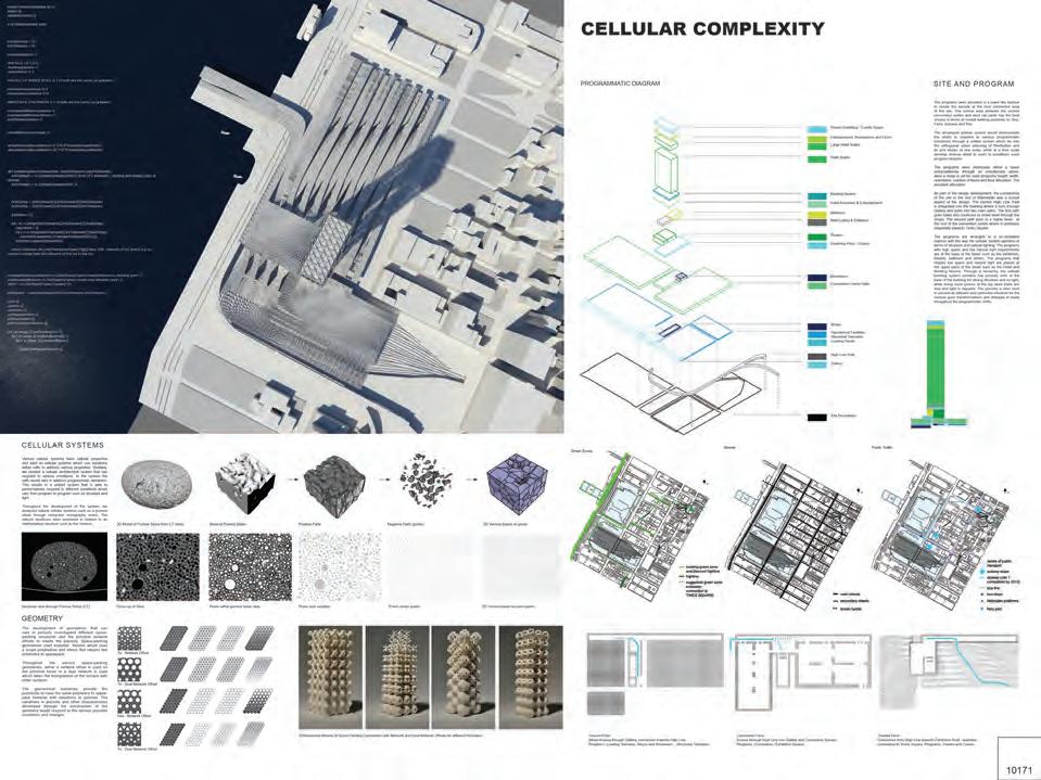
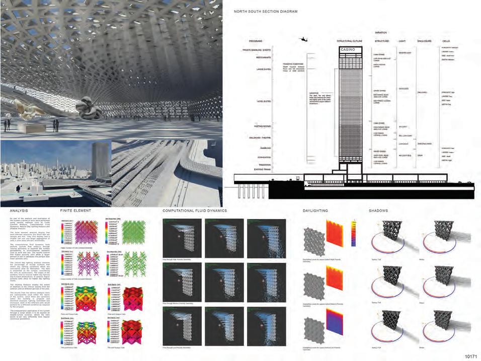
142 ARCHITECTURAL APPLICATION
COMPETITION ENTRY BOARDS 13TH AUGUST 2012
SUCKERPUNCH
BOARD ONE
BOARD TWO
Descriptive text of project, from competition boards:
The programs were allocated in a tower-like fashion to create the density at the best connected area of the site. The central area between the current convention centre and west rail yards has the best access in terms of overall walking proximity to: Bus, Ferry, Subway and Rail. The developed cellular system would demonstrate the ability to respond to various programmatic conditions through a unified system which fits into the orthogonal urban planning of Manhattan and its grid blocks at one scale, while at a finer scale develop diverse detail to react to conditions each program requires. The programs were distributed within a tower computationaly through an evolutionary solver, were a range is set for each programs height, width, orientation, number of floors and floor allocation. The resultant allocation. As part of the design development, the connectivity of the site to the rest of Manhattan was a crucial aspect of the design.
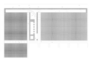
The current High Line Park is integrated into the building where it runs through Gallery and splits into two main paths. The first path goes lower and continues to street level through the shops. The second path goes to a higher level - at the roof of the convention centre where it continues diagonally towards Times Square. The programs are arranged in a co-ordinated manner with the way the cellular system operates in terms of structure and natural lighting. The programs with high spans and low natural light requirements are at the base of the tower such as the exhibition, theatre, ballroom and others. The programs that require low spans and natural light are placed at the upper parts of the tower such as the Hotel and Meeting Rooms. Through a hierarchy, the cellular building system contains low porosity cells at the base of the building for strong structure and no light, while being more porous at the top were loads are less and light is required. The porosity is also used to provide an efficient and optimized structure for the various span transformations and changes in loads throughout the programmatic shifts.
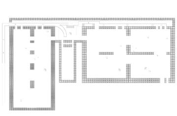
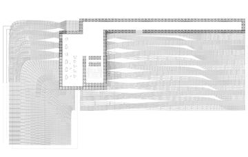
CELLULAR COMPLEXITY 143 STRUCTURAL OUTLINE VARIATION CELLS STRUCTURE LONG SPANS LOW DEAD AND LIVE LOADS HIGH LATERAL LOADS SHORT SPANS MID RANGE DEAD AND LIVE LOADS MID RANGE LATERAL LOADS LONG SPANS HIGH RANGE DEAD AND LIVE LOADS LOW RANGE LATERAL LOADS SHORT SPANS VERY HIGH DEAD AND LIVE LOADS LOW RANGE LATERAL LOADS POROSITY: mid-high LAYERS: many SIZE: small-mid DEPTH: Medium POROSITY: high LAYERS: few SIZE: large DEPTH: low POROSITY: low LAYERS: many SIZE: small DEPTH: high MEDIUM LIGHT HIGH LIGHT NO LIGHT REQ OPEN SEMI-ENCLOSED ENCLOSED LOW LIGHT NO LOW LIGHT NO LIGHT LIGHT ENCLOSURE PROGRAMS EXISTING TRAINS TRANSITION CONVENTION BALLROOM THEATRE GAMBLING MEETING ROOMS HOTEL SUITES LARGE SUITES RESTUARANTS PRIVATE GAMBLING / EVENTS VARIATION TRANSFER CONDITIONS Depth required between floors and not necessarly heavy or solid structure The dead, live and lateral loads vary between the lower and higher parts of the tower and therefore require different thicknesses.
SUCKERPUNCH COMPETITION ENTRY BOARDS 13TH AUGUST 2012
Convention
Convention Spaces. Programs: Convention
Connection
High
FLOOR PLANS
CASINO
Ground Floor: Street Access through Gallery, connection towards High Line Programs: Loading, Services, Shops and Showroom - Structural Transition
Floor: Access through High Line into Gallery and
/ Exhibition Spaces Theatre Floor:
from
Line towards Exhibition Roof - walkable connection to Times Square. Programs: Theatre and Casino
SECTION N/S
CASINO
SUCKERPUNCH COMPETITION ENTRY BOARDS 13TH AUGUST 2012
AREAL VIEW
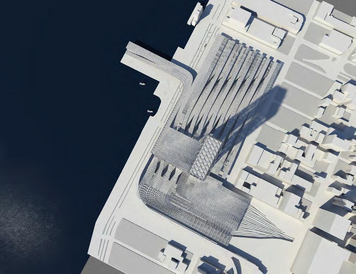
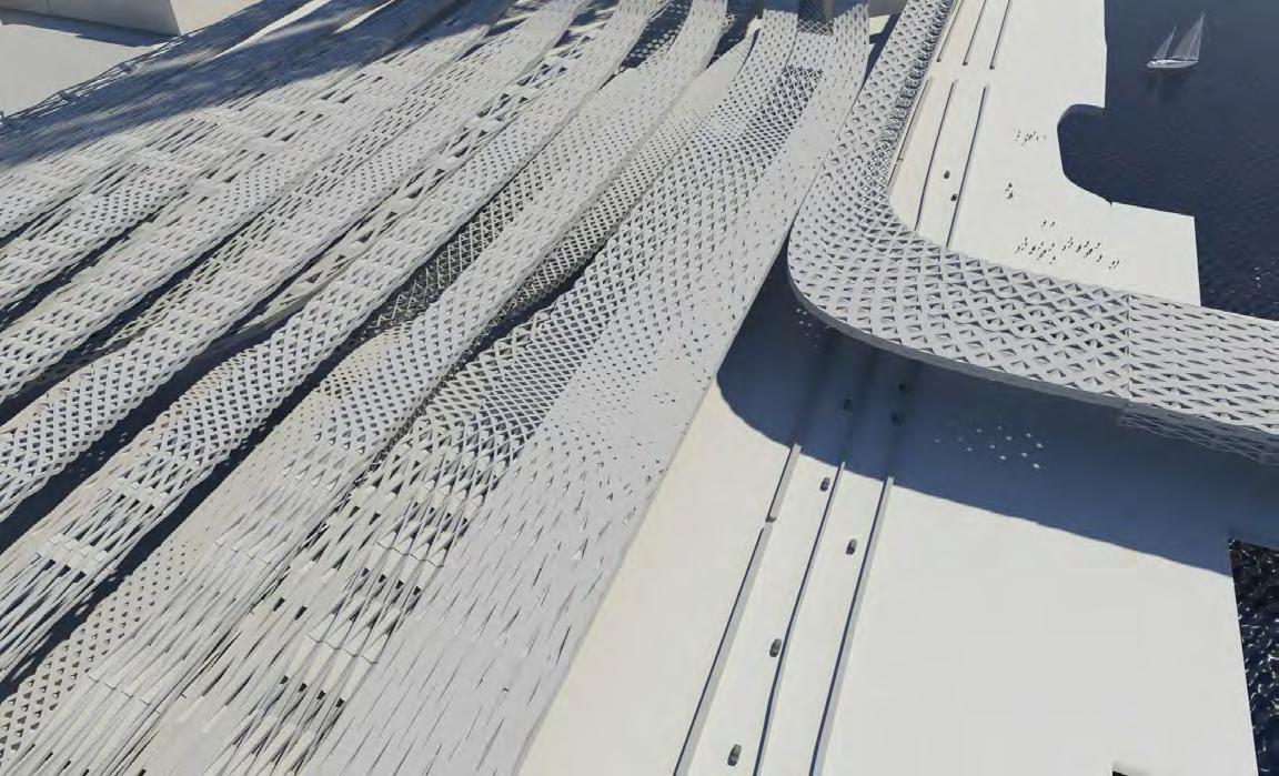
144 ARCHITECTURAL APPLICATION
12TH AVENUE BIRDS EYE PERSPECTIVE
SUCKERPUNCH COMPETITION ENTRY BOARDS 13TH AUGUST 2012
PERSPECTIVE VIEW TOWARDS MIDTOWN
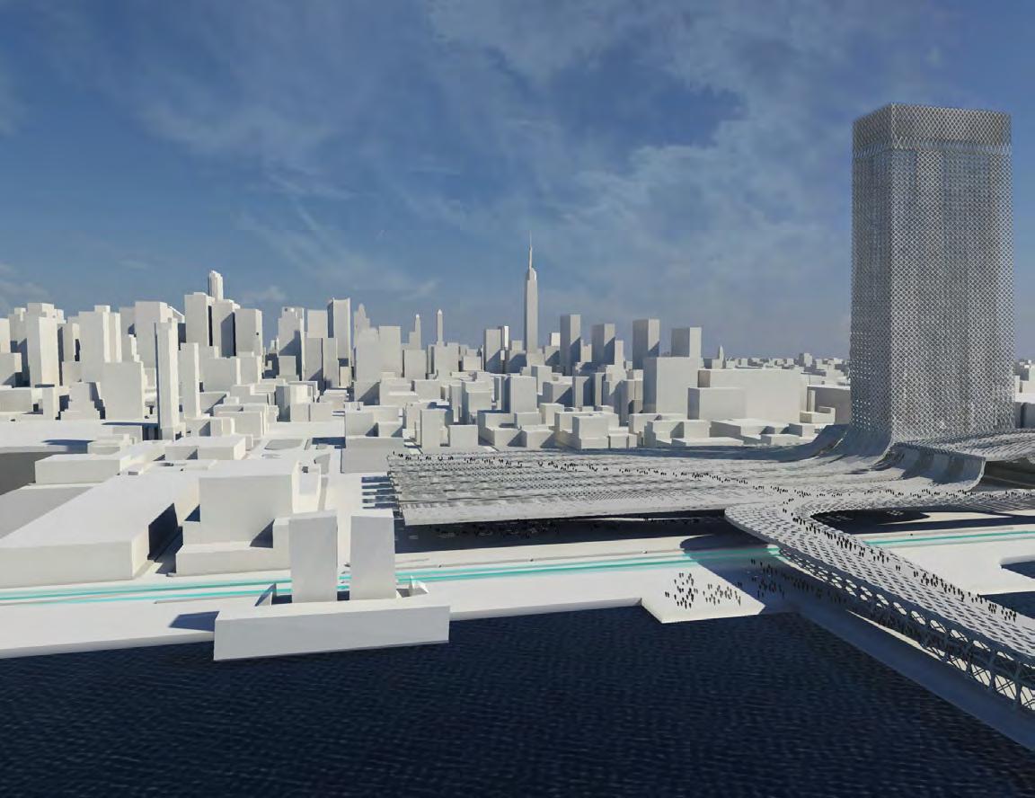
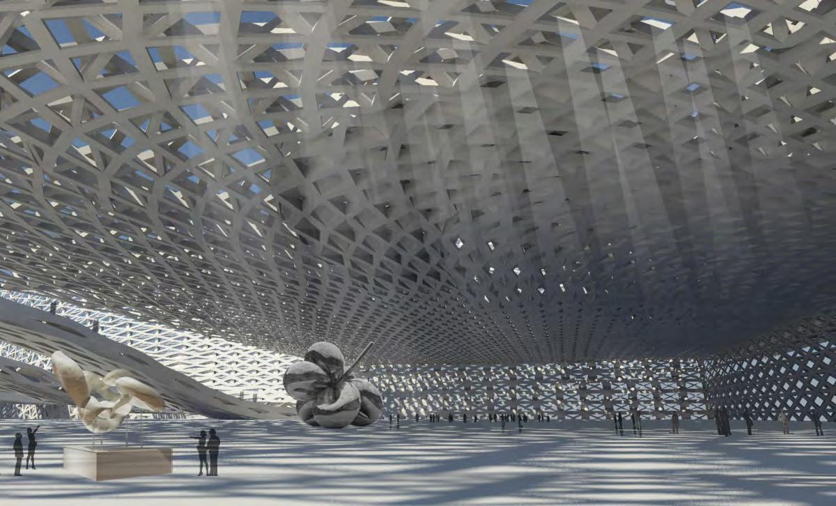
CELLULAR COMPLEXITY 145
INTERIOR PERSPECTIVE OF EXHIBITION SPACE
references
1 - The web-based Java App by UOregeon was used to diagrammatically estimate the effects of basic building morphology on structure loads. http://darkwing.uoregon.edu/~struct/courseware/461/461_lectures/461_ lecture18/461_lecture18.html
image references
Diagrams and Images not referenced were taken or created by Cellular Complexity authors: Kais Al-Rawi, Julia Koerner or Marie Boltenstern.
Fig. 5.1 - http://highrise.bk.tudelft.nl/pdf/Shard_London_Bridge_web.pdf
Fig. 5.2 - Ibid
Fig. 5.3 - Ibid (minor editing was done to the diagrams)
146
ARCHITECTURAL APPLICATION
ARCHITECTURAL APPLICATION
overview
Throughout the architectural application process, the scope was defined through typological case studies concluding with the decision of developing a tower application. The site and program were defined through a international ideas competition.
The approach towards the application involved comprehensive site analysis towards the architectural requirements to be able to develop a successful entry. The goal was to be able to test the system on a tower application and develop understanding of the application of the system.
The central aspect to applying the system was the allocation of programs. This process was based on studying basic structural typologies and the effect of changing program spans on structural members. Based on this study, the assemblage of programs was defined, in conjunction with their natural lighting requirements.
The cellular complexity entry was awarded second place and gained recognition from an international jury of architects and designers. In terms of our research, the competition has become a case study for the application of the system. The initial concern that developed throughout the application is the matter of scale.
Since the tower extends over more than 70 floorsabout 200 meters in height, the cell size becomes critical factor. When the cells become over a few meters height, they require deformation in the horizontal axis to avoid over-thickening the facade.
Furthermore, the development of a gradient over the height of the building became particularly challenging and requires additional investigation. The further development would require investigation into structural gradient typologies at a local and global scale, and the parameters that may influence this gradient.
CELLULAR COMPLEXITY 147
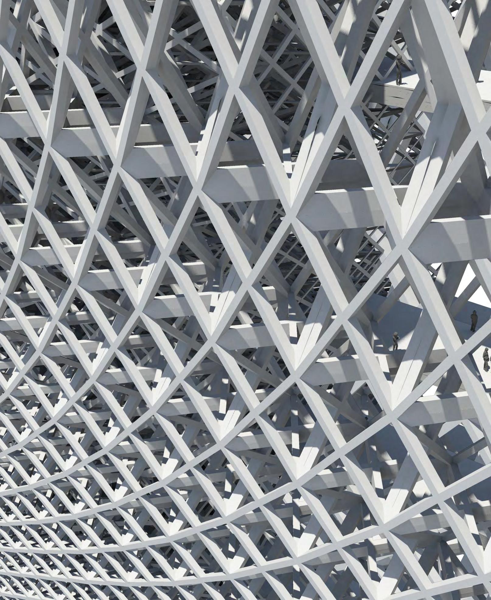
SYSTEM DEVELOPMENT
Throughout the previous section, the system was investigated in further detail and the defining parameters for its application were established. This section will examine the application of the system at an architectural scale.
For the architectural application, we became particularly interested in the tower typology and the diverse programmatic uses involved in this type. The current state-of-the-art architecture in tower design creates limited variation within towers to address architectural and programmatic conditions. A case study is investigated for this purpose, and its relation to our system.
The case study leads us to selecting a site and range of programs to commence the application process. Throughout our research we investigated architectural competitions and selected the suckerPUNCH international competition which involves the design of a convention, hotel and casino in Hudson Yards, New York.
The application of the system at this scale provided us with case study on how the system operates at a large scale and the opportunities and limitations which become apparent.
CELLULAR COMPLEXITY 149
PROGRAM AND STRUCTURE
PROGRAM AND STRUCTURE
PROGRAM AND STRUCTURE
The diagrams below illustrate through section the diverse range of programs that are included within the tower, the uses range from public and semi-public exhibition and convention spaces, towards entertainment facilities including theatre, ballroom and casino above the public areas, and within the top part the private hotel rooms and restaurant facilities in addition to a private events space at the topmost floor.
The diagrams below illustrate through section the diverse range of programs that are included within the tower, the uses range from public and semi-public exhibition and convention spaces, towards entertainment facilities including theatre, ballroom and casino above the public areas, and within the top part the private hotel rooms and restaurant facilities in addition to a private events space at the topmost floor.
The diagrams below illustrate in section the diverse range of programs that are included within the tower, the uses range from public and semipublic exhibition and convention spaces, to entertainment facilities including theatre, ballroom and casino, directly above the public. The tower combines private hotel rooms and restaurant facilities in addition to a gambling and events space at the topmost floor.
The spaces are not only arranged in the manner of public, semi-public and private but are also based on how the architectural system operates which is based on structure, where the structure also provides qualities which are related to natural lighting due to the cells geometrical qualities when high porosities appear. The second diagram illustrates the variation within spans involved for the allocated programs. Note that the spans run throughout the tower in a gradient manner with no direct shifts.
The spaces are not only arranged in the manner of public, semi-public and private but are also based on how the architectural system operates which is based on structure, where the structure also provides qualities which are related to natural lighting due to the cells geometrical qualities when high porosities appear. The second diagram illustrates the variation within spans involved for the allocated programs. Note that the spans run throughout the tower in a gradient manner with no direct shifts.
Program Variation
Private Gambling / Events Space Entertainment: Restaurants and Clubs
Structural Variation
The spaces are based on how the architectural system operates, where the structure also provides qualities which are related to natural lighting due to the cells geometrical qualities when high porosities appear. The second diagram illustrates the variation within spans involved for the allocated programs. Note that the spans run throughout the tower in a gradient manner with no sudden and direct shifts.
150
SITE PROGRAMS
Large
span ~ 45m span ~ 30m span ~ 15m span ~ 5m span ~ 7m span ~ 4m span ~ 75m span ~ 45m span ~ 15m span ~ 10m Meeting Rooms Hotel Amenities & Entertainment Ballroom Theatre Gallery Gambling Floor / Casino Convention Centre Halls Operational Facilities, Loading Docks Structural Transition Shops West Rail Yards
Hotel Suites Hotel Suites
SITE PROGRAMS
Private Gambling
Events Space Entertainment: Restaurants and Clubs Large Hotel Suites Hotel Suites span ~ 45m span ~ 30m span ~
span ~ 5m span ~ 7m span ~ 4m span ~ 75m span ~ 45m span ~ 15m span ~ 10m Meeting Rooms Hotel Amenities & Entertainment Ballroom
Gallery Gambling Floor / Casino Convention Centre Halls Operational Facilities,
Structural Transition Shops West Rail Yards
/
15m
Theatre
Loading Docks
SYSTEM DEVELOPMENT
STRUCTURE
PROGRAMMATIC STRUCTURAL TYPOLOGIES
STRUCTURE WITHIN BUILDING
The further development of the system involved a range of programmatic structural typologies, where specific parts of the tower are chosen and investigated at a local scale. These typologies set a comparative geometrical and architectural
The structural conditions vary throughout the building, at the base the dead and live loads are very high, at the top the lateral loads are high. In general the base of the tower requires the most structure. The transformations in spans occur in a gradient manner where there are multiple transfer conditions which occur gradually.
The large public and semi-public spaces within the lower parts of the tower require a heavy and dense structure to allow for the large spans and at the same time transfer the dead loads from above towards the ground. The large span spaces at the top of the tower do not require such a heavy structure as they are mostly resisting lateral forces which are perpendicular to the low dead and live loads.
The two main conditions in which variations occur are either the transfer conditions where there is a change from one span to another or a condition of variation where there is a repetitive span over a large number of floors.
The transfer conditions are where loads from one span and set of columns need to be transferred to another. This situation typically requires a transfer beam which is deep, the depth provides the ability to transfer the loads from one area to another. Such conditions are outlined below with increased depth for this condition. The cellular system becomes of particular use to the ability to use low porosity cells which provide depth with low amount of material.
When a span occurs repetitively over multiple floors, a variation would still occur because the loads on the first few of these floors is not the same as the last few. There would be a change in dead, live and lateral loads which suggest change throughout the structure through slight variation. In this case, the porosity of the cellular system can be varied to address any variations within the structure at both local and global scales.
STRUCTURAL TYPOLOGIES
CELLULAR COMPLEXITY 151
PROGRAM-STRUCTURAL TYPOLOGY: THEATRE
The theatre is located in the top portion of the tower, above the restuarants and hotel suites. It has a long span, and high floor height. The typology used to address this programmatic condition is presented, it aims to satisfy both the structural requirements and the lighting conditions; in a manner which works with the system and its gradients which attempt to efficiently create spatial conditions.
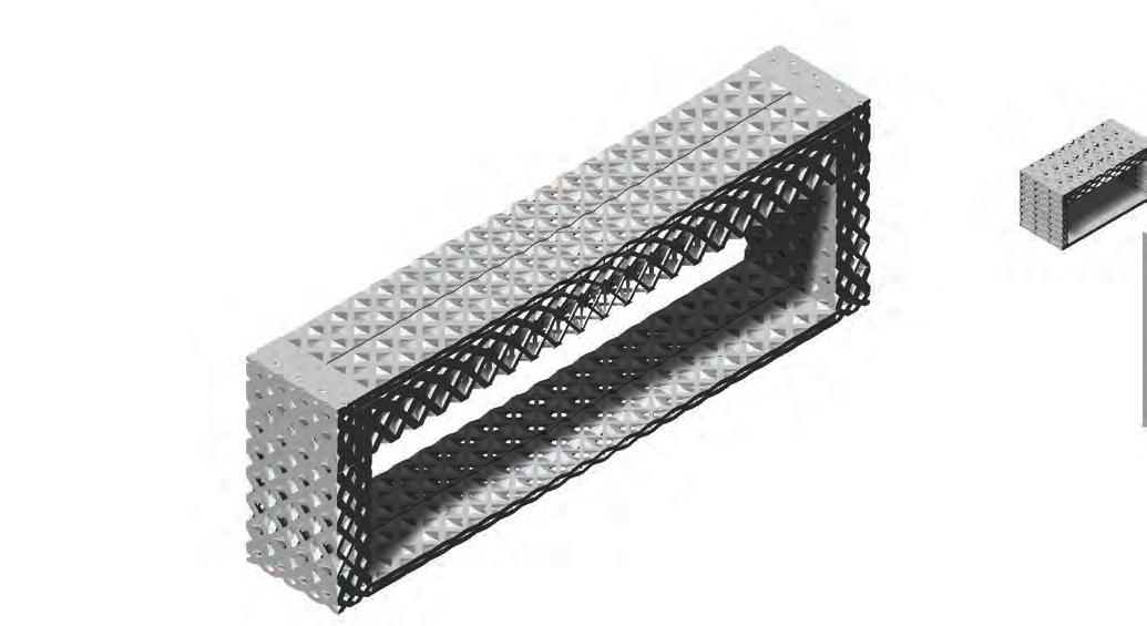
PROGRAMSPAN WIDTH HEIGHTLOCATIONPROGRAM ABOVE PROGRAM BELOW
Convention45m15mTower Top RestaurantsOpen
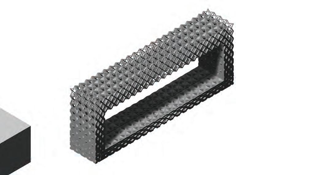
CONDITIONS
Span:
- high span, no transfer condition from above, transfer condition to spaces below
Location:
- dead loads only from self weight, low live loads. - high lateral loads with direction at walls, perpendicular to gravity.
Program:
- the private events and gambling space requires views towards the outside due to its location on a high floor.
- ground surface can be resurfaced or staged for particular activities
structural condition example
RESULTANT
ORGANIZATION
Vertical Members:
The vertical members require multiple layers to achieve structural rigidity, furthermore several cells for the possibility of a gradient. The cells start very dense to allow for transfer of loads towards the ground members, however gradients towards very porous cells to allow for views, particularly within the outer layer. Near the corner where the ceiling and wall members meet, medium porosity cells are used to resist loads.
Horizontal Ground Members:
The horizontal ground members are made up of two layers which are dense to allow for the transfer of loads towards the members within the floor below.
Horizontal Ceiling Members:
The horizontal ceiling members are made up of two layers for additional strength, however both layers are of very porous to allow for views to the outside. They become less porous towards the edges due to higher loads and connection to vertical members.
The cell size is approximately 2 meters in this condition.
152
SYSTEM DEVELOPMENT
PROGRAM-STRUCTURAL TYPOLOGY: CASINO
The theatre is located in the lower portion of the tower, between the convention centre and the entertainment floor. It has a long span, and high floor height. The typology used to address this programmatic condition is presented, it aims to satisfy both the structural requirements and the lighting conditions; in a manner which works with the system and its gradients which attempt to efficiently create spatial conditions.
PROGRAM
SPAN WIDTH HEIGHTLOCATIONPROGRAM ABOVE PROGRAM BELOW
Theatre35m15mTower Low Entertainment Convention
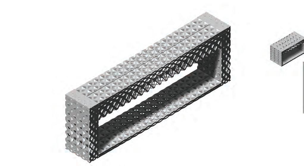
CONDITIONS
Span:
- high span, requires distribution of all loads above to only two parts, due to theatre above the transfer condition is not big and loads are already running through.
Location:
- very high dead and live loads from all floors above, transfer of loads from above, full structural transition under this floor to handle these loads towards the ground.
- low lateral loads.
Program:
- the theatre does not require natural lighting and will depend mainly on artificial lighting which is specified by the performance.
- at certain areas high floor height may be desirable.
- floors need not to be flat, resurfacing or platforms would be used, therefore surface permeability is not a concern.
structural condition example
RESULTANT ORGANIZATION
Vertical Members:
The vertical members require multiple layers to achieve structural rigidity, furthermore several cells for the possibility of a gradient. The gradient occurs vertically and horizontally.
-vertically cells become denser near the connection to the ceiling members.
-horizontally the cells become less dense towards the exterior as the they are away from the integral structural members
Horizontal Ground Members:
The horizontal ground members are placed in one layer which is relatively dense, with slight variation where the cells are less dense towards the centre due to less loads transferred from the centre.
Horizontal Ceiling Members:
The horizontal ceiling members are made up three layers due to the transfer condition occurring where the space above have a different span and need to transfer loads to the condition within this floor. The first layer provides a slab condition for the upper spaces, the second and third layer facilitate the transfer of loads. Very porous cells are used towards the centre due to the need of a depth more than strength as a path for loads. Near the edges where the horizontal members meet the vertical members the cells are dense and are less porous.
The cell size is approximately 2 meters in this condition.
CELLULAR COMPLEXITY 153
PROGRAM-STRUCTURAL TYPOLOGY: MEETING
The meeting rooms are located in the middle portion of the tower, between the Entertainment floors and hotel suites, and consist of 2 floors. It has a medium span, and low floor height. The typology used to address this programmatic condition is presented, it aims to satisfy both the structural requirements and the lighting conditions; in a manner which works with the system and its gradients which attempt to efficiently create spatial conditions.
PROGRAMSPAN WIDTH HEIGHTLOCATIONPROGRAM ABOVE PROGRAM BELOW
Meeting Rooms10m4mTower Mid HotelMeeting
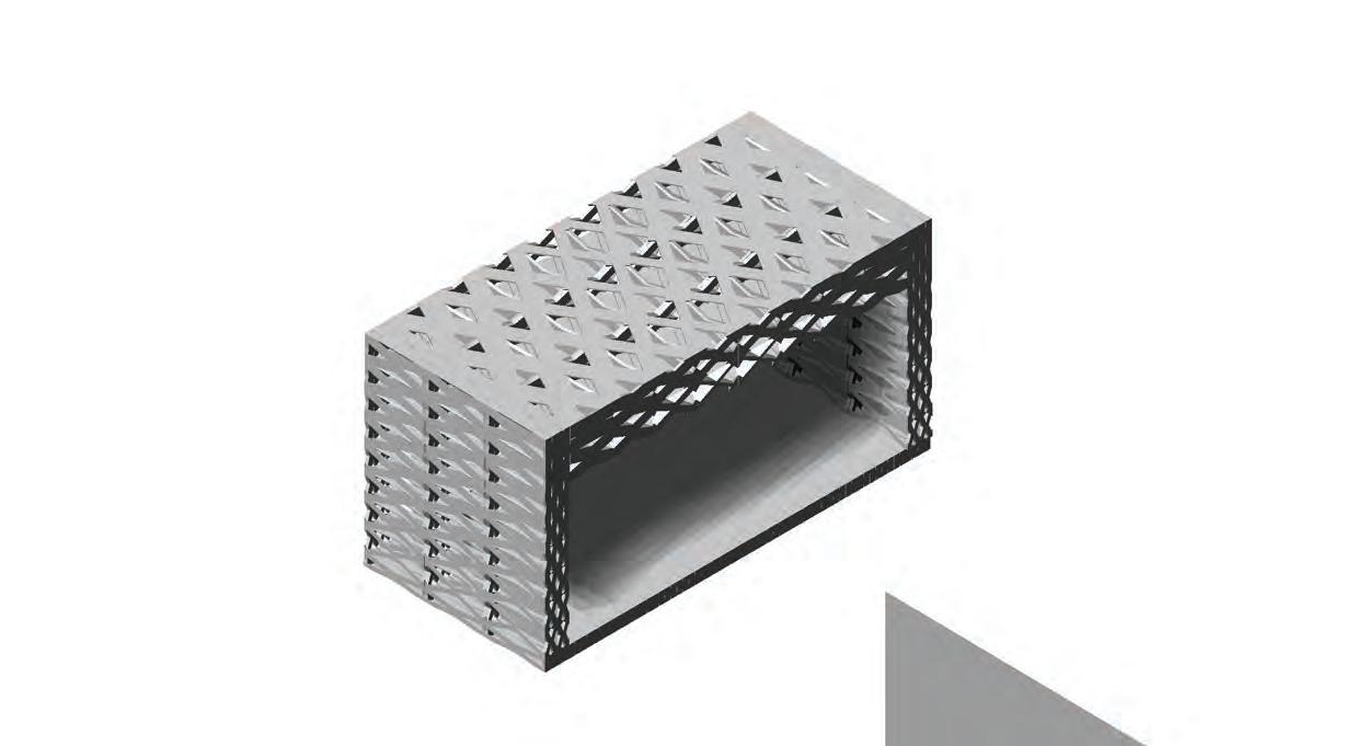
CONDITIONS
Span:
- short to medium span, between hotel and amenities, theatre and ballroom. Transfer condition to hotel above.
Location:
- high dead and live loads from all floors above
- low lateral loads
Program:
- natural light requirements are not important, no or low natural light is acceptable.
- low floor height and flat floors are required.
structural condition example
RESULTANT ORGANIZATION
Vertical Members:
The vertical members consist of two layers to achieve structural rigidity, these layers are enclosed to provide seperation between spaces. The members start with more porous and end with less porous cells near the connection with the transfer condition. The gradient is very slight and targets material efficiency.
Horizontal Ground Members:
The horizontal ground members are made up a single layer which is dense and allows for walkability.
Horizontal Ceiling Members:
The horizontal ceiling members are made up of two layers for additional strength. They become less porous towards the edges due to higher loads and connection to vertical members.
The cell size is approximately 1 meter in this condition.
154
SYSTEM DEVELOPMENT
PROGRAM-STRUCTURAL TYPOLOGY: HOTEL
The hotel suites is located in the middle portion of the tower, between the meeting rooms and top restuarants / entertainment floors. It has a short span, and low floor height. The typology used to address this programmatic condition is presented, it aims to satisfy both the structural requirements and the lighting conditions; in a manner which works with the system and its gradients which attempt to efficiently create spatial conditions.
CONDITIONS
Span:
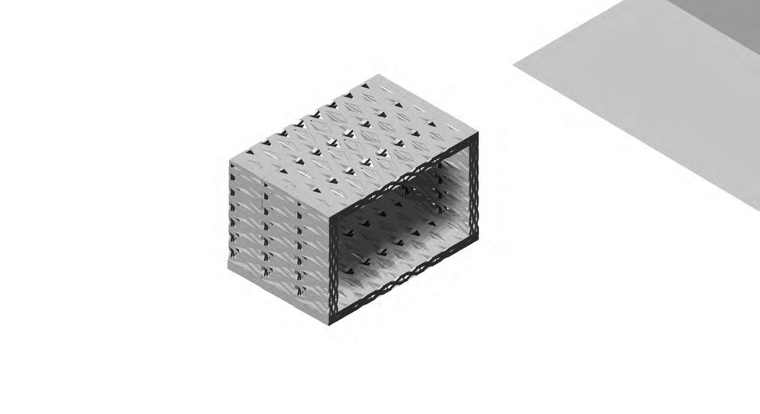
- short span, repetitive throughout the tower for hotel rooms.
Location:
- high dead and live loads from all floors above - low to medium lateral loads
Program:
- natural light requirements are important, medium to high natural lighting conditions are necessary.
- low floor height and flat floors are required.
structural condition example
The vertical members consist of two layers to achieve structural rigidity, these layers are enclosed to provide seperation between spaces. The members start with more porous and end with less porous cells near the connection with the transfer condition. The gradient is very slight and targets material efficiency.
Horizontal Ground Members:
The horizontal ground members are made up a single layer which is dense and allows for walkability.
Horizontal Ceiling Members:
The horizontal ceiling members are made up of two layers for additional strength. They become less porous towards the edges due to higher loads and connection to vertical members.
The cell size is approximately 1 meter in this condition.
CELLULAR COMPLEXITY 155
PROGRAMSPAN WIDTH HEIGHTLOCATIONPROGRAM ABOVE PROGRAM BELOW
SITE: ENVIRONMENTAL ANALYSIS
SOLAR EXPOSURE ANALYSIS
The secondary parameters towards applying the system architecturally is day lighting. The diverse programmatic requirements require variable lighting conditions and therefore analysis would be required on how to achieve these conditions.
In this test it is evident that the roof surfaces achieve the most solar exposure, followed by southern surfaces, while north surfaces obtain the least. This study provides an initial input towards the design of openings within the system, and how they could vary to achieve the desired amount of day light at each program. SOLAR EXPOSURE ANALYSIS
The first analysis is a solar exposure analysis of the site, where the overall massing of the building is placed on site, and the percentage of light on the surfaces is examined.
The case study of the Aquatic Centre in Beijing was chosen for its structural performance and building envelope. The structural system had to respond to the seismic conditions on site as well large span structural properties. The combination of geometrical non directional space frame structure and lightweight pneumatic ETFE facade skin system made it possible to reduce gravity loads and lateral loads. The large dimensions in depth of the walls and roof provide the possibility of a large spanning structure and high interior ceilings. Further the three dimensional orthotropic loading bearing structure is an extremely efficient form of construction that requires roughly 30% less steel than a column-and-beam system on a span of hundred meters and height of seven meters.
The ETFE pockets act as a protecting cover for the structure from the corrosive properties of the pool water and the polluted air of Beijing as well the facade acts as a mediating climate control system within the interior spaces of the building. Geometries from nature which have such performative aspects have been an inspiration to the PTW’s team.
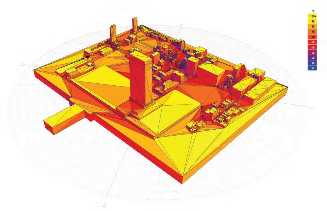
SOLAR EXPOSURE ANALYSIS
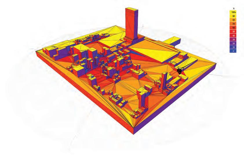
156
SYSTEM DEVELOPMENT
SHADOW RANGE ANALYSIS
SHADOW RANGE ANALYSIS
Furthermore, a shadow range analysis was performed for 4 different times of the year. The aim of this test is to investigate the parts of the building that are self shaded by the building itself at different times of the year. This can become a further input towards creating variation within a program or single surface, where one part is more shaded than the other, creating a further gradient within the system.
The facade of the Telus Headquarters in Vancouver is used to diagram the current state of double skin facade design. The double skin facade system is based on a multilayer principle, a combination of external layer, intermediate space and inner layer. Different layers contribute to different performative aspects, such as the external layer protects against weather and improves the acoustic insulation against external noise. Within the external layer there are openings which allow for ventilation. The air exchange in the intermediate layer is activated by the solar induced thermal buoyancy and different wind effects.
The intermediate layer is controlled by dampers on the top and fans on the bottom of the cavity to ensure a good airflow within both layers. In summer the exterior windows are open and let the air inside the cavity, it heats up and rises to the top of the cavity and exits through the dampers, while the interior windows stay closed to keep the heat outside of the spaces. In winter the dampers are closed and the fan is turned off as well the exterior and interior windows stay closed. This provides a thermal buffer zone which prevents the cold air from outside to enter the building.
As the results show, the roof of the convention centre becomes shaded through different parts of the year, the extent of this shading is also variable, therefore the seasonality and use of program can be utilized within the design criteria.
In comparison to the double skin facade the Aquatic Centre has a three dimensional facade with integrated structural system. The combination of two layers of ETFE pockets with in-between cavities used for the structural system acts performative similar to the double skin facade. It is designed for different seasonal conditions. In summer, when external weather conditions are hot and humid, the internal layer is sealed. Through an opening on the bottom edge air, cooled by passing over water around the building perimeter, enters the cavity between both layers and heats up, rises and is exhausted by roof vents. Both layers are sealed during the winter months to minimise heat loss and in order to maximise the thermal performance of the envelope. Further the thermal mass of the water and concrete inside the building capture the heat collected during the day and release it in the evenings.
The three dimensional structural envelope is inaccessible, though can be entered for maintenance reasons. There is no geometrical differentiation between roof and wall within the whole system.
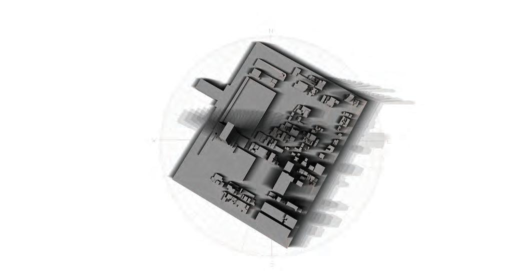
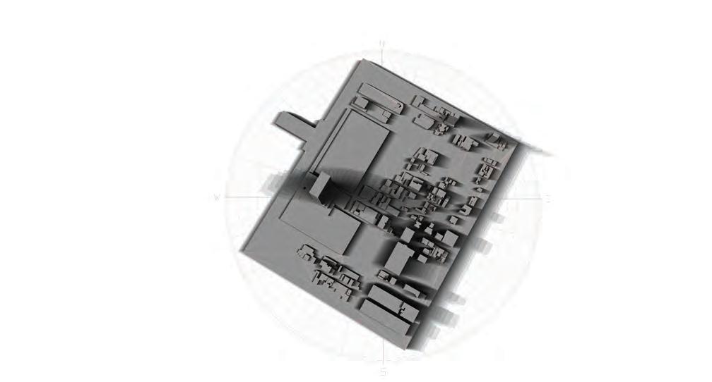
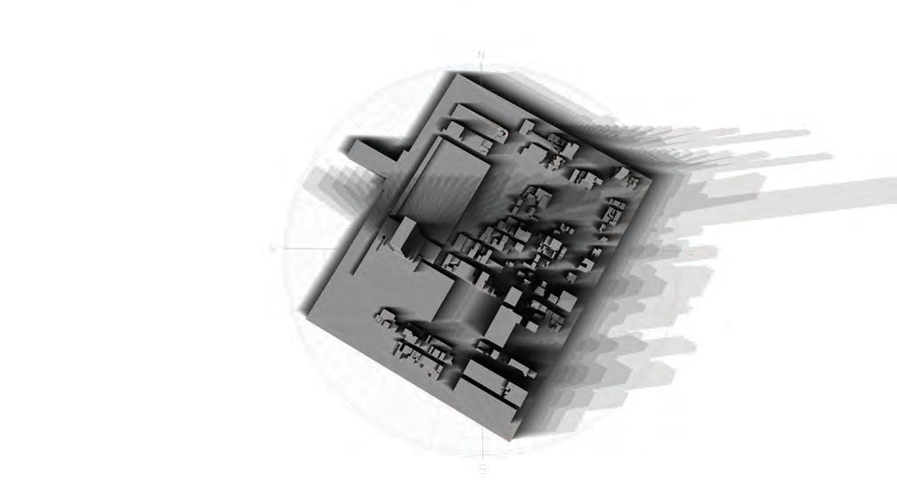
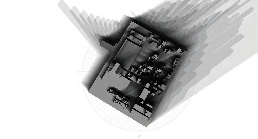
CELLULAR COMPLEXITY 157
SPRING EQUINOX - 21 MARCH FALL EQUINOX - 21 SEPTEMBER
SUMMER SOLSTICE - 21 JUNE
WINTER SOLSTICE - 21 DECEMBER
SITE: ENVIRONMENTAL ANALYSIS
SOLAR EXPOSURE ANALYSIS
In a further step, a solar radiation analysis was performed, this analysis provides the solar intensity based on direct solar radiation and diffused solar radiation. The direct solar radiation displays the intensity of light on surfaces due to direct sunlight hitting the surface. The diffused solar radiation displays the intensity achieved through radiation, the measure is also related to heat, since this is transferred through radiation the values become higher than that of direct radiation.
The case study of the Aquatic Centre in Beijing was chosen for its structural performance and building envelope. The structural system had to respond to the seismic conditions on site as well large span structural properties. The combination of geometrical non directional space frame structure and lightweight pneumatic ETFE facade skin system made it possible to reduce gravity loads and lateral loads. The large dimensions in depth of the walls and roof provide the possibility of a large spanning structure and high interior ceilings. Further the three dimensional orthotropic loading bearing structure is an extremely efficient form of construction that requires roughly 30% less steel than a column-and-beam system on a span of hundred meters and height of seven meters.
The ETFE pockets act as a protecting cover for the structure from the corrosive properties of the pool water and the polluted air of Beijing as well the facade acts as a mediating climate control system within the interior spaces of the building. Geometries from nature which have such performative aspects have been an inspiration to the PTW’s team.
The analysis shows that there is an intensity on all surfaces including the North Facades. This use of this analysis within the design would require further study on the albedo of surfaces and heat gain within the building.
The case study of the Aquatic Centre in Beijing was chosen for its structural performance and building envelope. The structural system had to respond to the seismic conditions on site as well large span structural properties. The combination of geometrical non directional space frame structure and lightweight pneumatic ETFE facade skin system made it possible to reduce gravity loads and lateral loads. The large dimensions in depth of the walls and roof provide the possibility of a large spanning structure and high interior ceilings. Further the three dimensional orthotropic loading bearing structure is an extremely efficient form of construction that requires roughly 30% less steel than a column-and-beam system on a span of hundred meters and height of seven meters.
The ETFE pockets act as a protecting cover for the structure from the corrosive properties of the pool water and the polluted air of Beijing as well the facade acts as a mediating climate control system within the interior spaces of the building. Geometries from nature which have such performative aspects have been an inspiration to the PTW’s team.
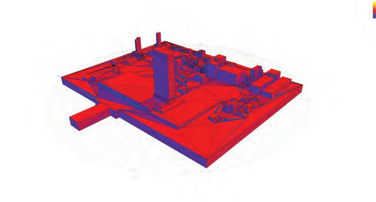
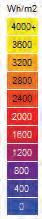
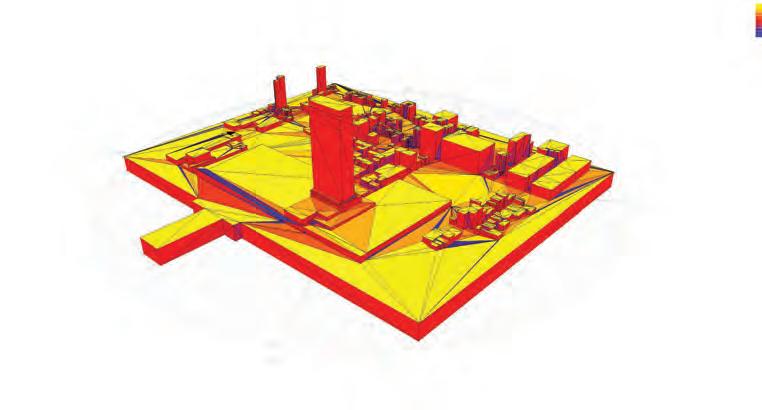
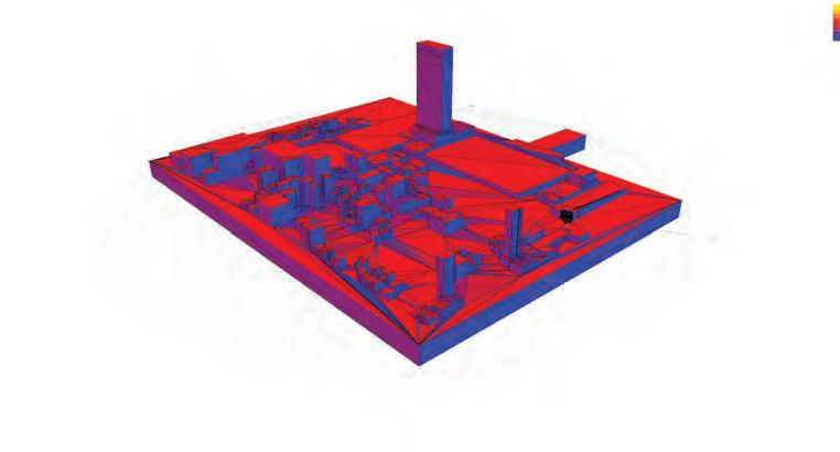
158
Solar Radiation / Daily Values
Solar Radiation / Daily Values
Direct
Diffused
RADIATION
SYSTEM DEVELOPMENT
SOLAR
ANALYSIS
The facade of the Telus Headquarters in Vancouver is used to diagram the current state of double skin facade design. The double skin facade system is based on a multilayer principle, a combination of external layer, intermediate space and inner layer. Different layers contribute to different performative aspects, such as the external layer protects against weather and improves the acoustic insulation against external noise. Within the external layer there are openings which allow for ventilation. The air exchange in the intermediate layer is activated by the solar induced thermal buoyancy and different wind effects.
The average solar radiation, which is based on both diffused and direct is displayed below. The average results of this analysis are somewhat similar to those of the solar exposure analysis. In both cases, the production of a detailed mesh for the required program surfaces may enhance the resolution of the analysis and provide results which are applicable at local and specific scales. However in this case, the resolution is sufficient due to the lack of external factors affecting the overall exposure; only self-shading becomes a factor and this is investigated in detail separately
The intermediate layer is controlled by dampers on the top and fans on the bottom of the cavity to ensure a good airflow within both layers. In summer the exterior windows are open and let the air inside the cavity, it heats up and rises to the top of the cavity and exits through the dampers, while the interior windows stay closed to keep the heat outside of the spaces. In winter the dampers are closed and the fan is turned off as well the exterior and interior windows stay closed. This provides a thermal buffer zone which prevents the cold air from outside to enter the building.
In comparison to the double skin facade the Aquatic Centre has a three dimensional facade with integrated structural system. The combination of two layers of ETFE pockets with in-between cavities used for the structural system acts performative similar to the double skin facade. It is designed for different seasonal conditions. In summer, when external weather conditions are hot and humid, the internal layer is sealed. Through an opening on the bottom edge air, cooled by passing over water around the building perimeter, enters the cavity between both layers and heats up, rises and is exhausted by roof vents.
Both layers are sealed during the winter months to minimise heat loss and in order to maximise the thermal performance of the envelope. Further the thermal mass of the water and concrete inside the building capture the heat collected during the day and release it in the evenings.
The three dimensional structural envelope is inaccessible, though can be entered for maintenance reasons. There is no geometrical differentiation between roof and wall within the whole system.
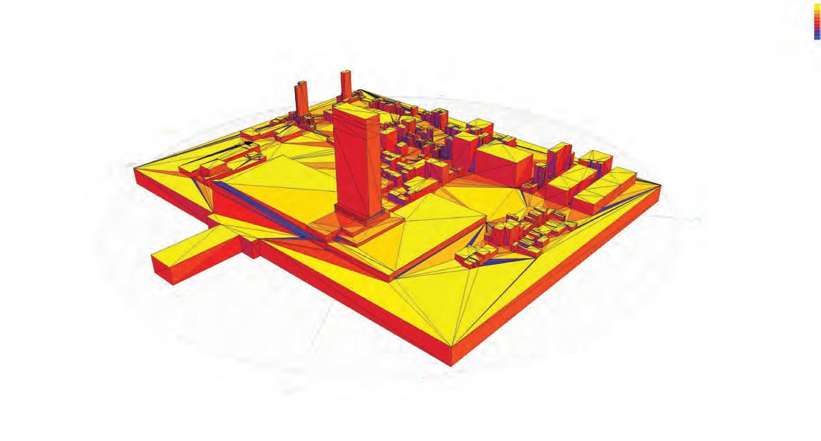
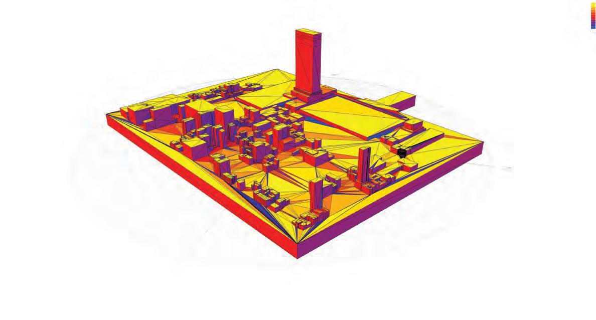
CELLULAR COMPLEXITY 159
SHADOW RANGE ANALYSIS
Average Solar Radiation / Daily Values
SOLAR RADIATION ANALYSIS
DAY LIGHTING ANALYSIS
DAY LIGHTING ANALYSIS
As part of the geometrical analysis a series of day light tests were executed to investigate the effect of different porosities and orientation. Throughout the tests three different porosities were chosen, for each porosity the test was carried out with the geometry once facing south and once 45 degrees rotated from south. The tests evaluate the amount of daylight hitting a surface behind the geometries.
As part of the geometrical analysis a series of day light tests were executed to investigate the effect of different porosities and orientation. Throughout the tests three different porosities were chosen, for each porosity the test was carried out with the geometry once facing south and once 45 degrees rotated from south. The tests evaluate the amount of daylight hitting a surface behind the geometries.
The day lighting analysis sets a value for illuminance based on the location. For New York City a value of 6500 lux is set. To set this value within a comparative context, 0.27 lux is estimated as the illuminance at a clear sky with full moon, and daylight between 5,000 - 25,000 lux, while direct sunlight is estimated as 30,000 - 100,000 lux. The results illustrate that the three tested models obtain reasonable day lighting values, cells with higher porosity do achieve a percentage of area satisfying the day light criteria.
In continuation of the environmental analysis for daylighting, an analysis of the system was undertaken to be paired with the analysis of the site. A series of day light tests were executed to investigate the effect of different porosities and orientation. Throughout the tests three different porosities were chosen, for each porosity the test was carried out with the geometry once facing south and once 45 degrees rotated from south. The tests evaluate the amount of daylight hitting a surface behind the geometries.
The day lighting analysis sets a value for illuminance based on the location. For New York City a value of 6500 lux is set. To set this value within a comparative context, 0.27 lux is estimated as the illuminance at a clear sky with full moon, and daylight between 5,000 - 25,000 lux, while direct sunlight is estimated as 30,000 - 100,000 lux. The results illustrate that the three tested models obtain reasonable day lighting values, cells with higher porosity do achieve a percentage of area satisfying the day light criteria.
Daylight Factor : 50 - 100%
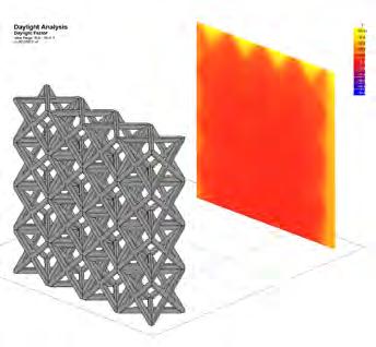
45.degree orientation
Daylight Factor : 50 - 100% Cell Aggregation prototype 01- Porosity : 0.14
orientation
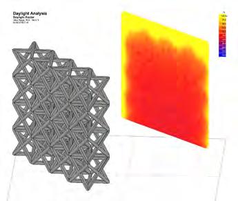
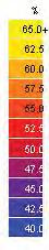
Note : All analysis based on recorded exterior Lux value in New York City - 6500 Lux. Daylight factor mapped on analysis grid in percentage (%) in comparison to the exterior daylight. Results indicate that all daylight factors are within desirable limits.
Note : All analysis based on recorded exterior Lux value in New York City - 6500 Lux. Daylight factor mapped on analysis grid in percentage (%) in comparison to the exterior daylight. Results indicate that all daylight factors are within desirable limits.
The day lighting analysis sets a value for illuminance based on the location. For New York City a value of 6500 lux is set. To set this value within a comparative context, 0.27 lux is estimated as the illuminance at a clear sky with full moon, and daylight between 5,000 - 25,000 lux, while direct sunlight is estimated as 30,000 - 100,000 lux. The results illustrate that the three tested models obtain reasonable day lighting values, cells with higher porosity do achieve a percentage of area satisfying the day light criteria.
Daylight factor mapped on an analysis grid.
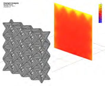
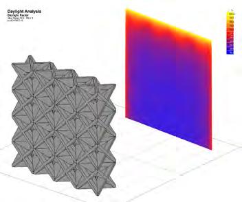
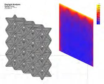
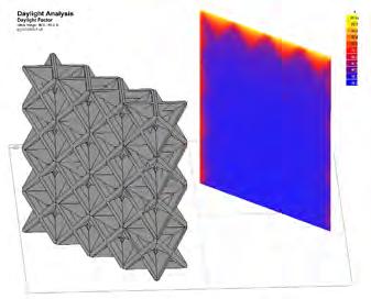
160
Aggregation prototype 02- Porosity : 0.23
Aggregation prototype 03- Porosity : 0.32
Aggregation prototype 01- Porosity : 0.14 Cell Aggregation prototype 02- Porosity : 0.23 Cell Aggregation prototype 03- Porosity : 0.32 N N
Cell
Cell
Cell
Daylight Factor : 50 - 100%
45.degree
Daylight Factor : 50 - 100% Cell Aggregation prototype 01- Porosity : 0.14
Daylight factor mapped on an analysis grid.
Cell Aggregation prototype 02- Porosity : 0.23
Cell Aggregation prototype 03- Porosity : 0.32
0.14
Aggregation prototype 02- Porosity : 0.23
Aggregation prototype 03- Porosity : 0.32 N N
Cell Aggregation prototype 01- Porosity :
Cell
Cell
ANALYSIS SYSTEM DEVELOPMENT
FACADE DAY LIGHTING
DAY LIGHTING ANALYSIS
DAY LIGHTING ANALYSIS
As part of the geometrical analysis a series of day light tests were executed to investigate the effect of different porosities and orientation. Throughout the tests three different porosities were chosen, for each porosity the test was carried out with the geometry once facing south and once 45 degrees rotated from south. The tests evaluate the amount of daylight hitting a surface behind the geometries.
As part of the geometrical analysis a series of day light tests were executed to investigate the effect of different porosities and orientation. Throughout the tests three different porosities were chosen, for each porosity the test was carried out with the geometry once facing south and once 45 degrees rotated from south. The tests evaluate the amount of daylight hitting a surface behind the geometries.
The tests were further continued by analysing the effect of layering a specific patch multiple times. The results obtained were also quite predictable, where the increase in layers resulting in a decrease in day lighting. However the degree of this decrease is not substantial when comparing patches such as those with very high porosity. The factor that should be kept in mind that the amount of day lighting increases with the opening size of the cells, therefore a low porosity cell can still be used for structural purposes and satisfy light requirements if it has a suitable opening size.
The day lighting analysis sets a value for illuminance based on the location. For New York City a value of 6500 lux is set. To set this value within a comparative context, 0.27 lux is estimated as the illuminance at a clear sky with full moon, and daylight between 5,000 - 25,000 lux, while direct sunlight is estimated as 30,000 - 100,000 lux. The results illustrate that the three tested models obtain reasonable day lighting values, cells with higher porosity do achieve a percentage of area satisfying the day light criteria.
The day lighting analysis sets a value for illuminance based on the location. For New York City a value of 6500 lux is set. To set this value within a comparative context, 0.27 lux is estimated as the illuminance at a clear sky with full moon, and daylight between 5,000 - 25,000 lux, while direct sunlight is estimated as 30,000 - 100,000 lux. The results illustrate that the three tested models obtain reasonable day lighting values, cells with higher porosity do achieve a percentage of area satisfying the day light criteria.
Factor : 50 - 100%
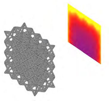
45.degree orientation
Daylight Factor : 50 - 100%
Note : All analysis based on recorded exterior Lux value in New York City - 6500 Lux. Daylight factor mapped on analysis grid in percentage (%) in comparison to the exterior daylight. Results indicate that all daylight factors are within desirable limits.
Note : All analysis based on recorded exterior Lux value in New York City - 6500 Lux. Daylight factor mapped on analysis grid in percentage (%) in comparison to the exterior daylight. Results indicate that all daylight factors are within desirable limits.
The effect on orientation is not significant and was not tested in the second patch. The reason behind this is that due to the rotation of the sun throughout the day, the total amount of day light will not be affected if the cell is slightly tilted, since the spaces will still gain day light when the sun is at a slightly different angle.
However, the accuracy and resolution of the Ecotect software was not very high, in some cases the results were conflicting and some adjustments were required.
Daylight factor mapped on an analysis grid.
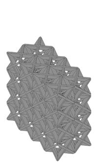
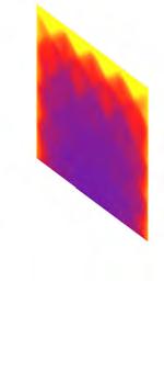
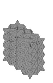
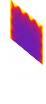
CELLULAR COMPLEXITY 161
Daylight
prototype 02- Porosity : 0.23
Aggregation prototype 03- Porosity : 0.32
Aggregation prototype 01- Porosity : 0.14 Cell Aggregation prototype 02- Porosity : 0.23 Cell Aggregation prototype 03- Porosity : 0.32 N
Cell
Aggregation
Cell
Cell
Daylight
: 50 - 100%
Factor
45.degree orientation Daylight Factor : 50 - 100% Cell Aggregation prototype 01- Porosity : 0.14
Daylight factor mapped on an analysis grid.
Cell Aggregation prototype 02- Porosity : 0.23
Cell Aggregation prototype 03- Porosity : 0.32
Cell Aggregation prototype 01- Porosity : 0.14
02- Porosity : 0.23 Cell Aggregation prototype 03- Porosity : 0.32 N
Cell Aggregation prototype
STRUCTURAL DEVELOPMENT
In parallel to the lighting analysis, the structure was investigated in further detail. Based on the allocated programs and morphology, a range of structural conditions was developed. These conditions are divided into transfer conditions and gradient conditions. In reality both conditions contain porosity gradients, the difference is in intensity and scale.
Four different transfer conditions were devised, the variation between them is the span length and ratio between the two transfers. For the gradient conditions they can exist in a local area or in a global form. The local gradient attempts to address programmatic conditions or to create efficient use of material. The global gradient connects multiple gradients within the structure.
STRUCTURAL CONDITION
Transfer Type A
Transfer Type B
Transfer Type C
CHARACTERISTICS
-Transfer between two spans -One span Above 20m -Transfer Ratio above 2
-Transfer between two spans -One span Above 20m -Transfer Ratio below 2
-Transfer between two spans -Spans Below 20m -Transfer Ratio above 2
DESCRIPTION
This condition occurs where there is transfer between a large span and a span that is atleast 2 times smaller.
This condition occurs where there is transfer between a large span and a span that is similar.
This condition occurs where there is transfer between a regular span and a span that is atleast 2 times smaller.
CELLULAR ORGANIZATION
~3m to ~6m ~4m to ~8m
~1m to ~3m
Gradient Global Transfer Type D
-Transfer between two spans -Spans Below 20m -Transfer Ratio below 2
Gradient Local
Gradient required within program floor for view or local structural optimization
Gradient across multipe floors for optimization with global structural loads
LOADS: LATERAL DEAD FORCE: DIRECTION CELL
This condition occurs where there is transfer between a regular span and a span that is similar
This condition is where a gradient is needed as part of the program requirement and/or its structure, typically occurs at roof conditions
This condition is where a gradient is needed across multiple floors of similar span for structural optimization
Program Floor Height ~0.5m to ~2m
Program Total Levels Height
-deep structure -dense at corners -dense at the top -very porous near bottom -multi-layered -shallow structure -dense at corners -dense both at the top and bottom -multi-layered case specific -elongated cells near bottom, -constained cells at top
162
GRADIENT SCALE estimate
High LowHorizontal Horizontal & Vertical Vertical Mid Mid Low High SYSTEM DEVELOPMENT
STRUCTURAL CONDITIONS
The devised conditions are displayed on different locations of the building as shown in the section below. Transfer conditions occur whenever there is a change in span; the type becomes dependant on the span change. Local Gradients are outlined in locations such as the top floor casino and the roof of the convention centre. This is where detail is required for lighting, view or roof walkability.
~ 45m
~ 30m
~ 15m
Local Gradient
Transfer Type B
Transfer Type D
Transfer Type C
Global Gradient
Dead & Live
~ 5m
~ 15m ~ 10m
~ 75m ~ 45m
~ 7m ~ 4m
Transfer Type D
Transfer Type D
Transfer Type A
Local Gradient
Transfer Type A
Dead & Live
Dead & Live
CELLULAR COMPLEXITY 163
Low Lateral High
Medium Lateral Medium
High Lateral Low
SYSTEM ARCHITECTURAL APPLICATION
As a further study, a segment of the building was selected where the system is applied in finer detail illustrating various gradients and variations within the facade to address different properties. This segment includes a North-West Corner which contains convention halls, a theatre, hotel amenities, restuarants, meeting rooms and hotel suites.
The conditions are outlined besides each program, and the type of gradient or transfer condition is defined. Furthermore, the lighting conditions of the program are also defined, some data refers back to the initial program data catalogue. This gives firsthand information towards the application of the algorithm and the intensity and scale of gradient for each program surface.
STRUCTURAL CONDITIONS LIGHT CONDITIONS
Global Gradient
meeting rooms hotel suites
entertainment / amenities
Transfer Type D
Transfer Type D
Transfer Type A
Natural Light
exhibition / convention centre
Transfer Type B
Natural Light
Requirement No Requirement Medium Natural Light
164
theatre
SYSTEM DEVELOPMENT
Low
No
High
FACADE DAY LIGHTING ANALYSIS
An initial patch was developed for each of the programs, where the cell size corresponds to the requirements of this program structurally, visually and for day lighting. Furthermore, two additional patches are generated to examine the effect of a north or south oriented facade. The north facade receives less day light and would therefore allow for bigger openings, and the south facade would have smaller openings to avoid solar heat gain.
A schematic 3D section was generated based on these programs to display the assemblage of programs and the cellular arrangement and variation within the various programs and transfer conditions, within an overall gradient.
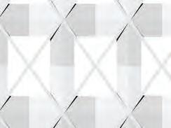
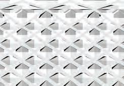
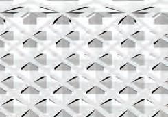
MEETING
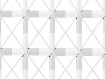
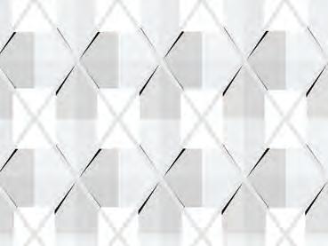
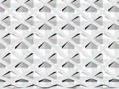
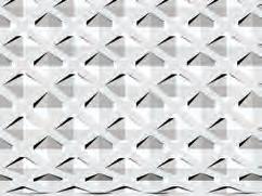
ENTERTAINMENT THEATRE
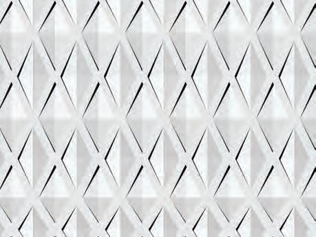
CONVENTION
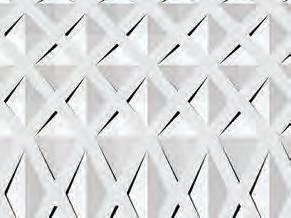
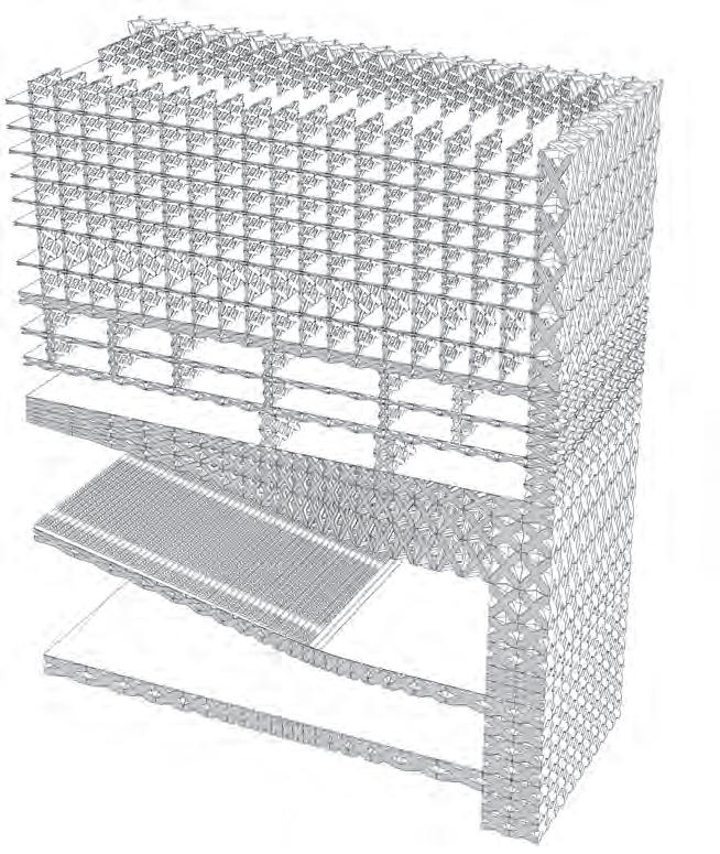
CELLULAR COMPLEXITY 165 east - west north HOTEL
WEST FACADE NORTH FACADE
SCHEMATIC 3D SECTION
HOTEL north HOTEL
HOTEL
THEATRE CONVENTION
The 3D section below alongside the corner perspective display the allocation of programs within the building, and the way the cells adapt to address each program differently. What is important is that a global gradient is still maintained in the system, and there are smooth transitions from one part to another. The architectural and spatial potential of this system are to be investigated further.
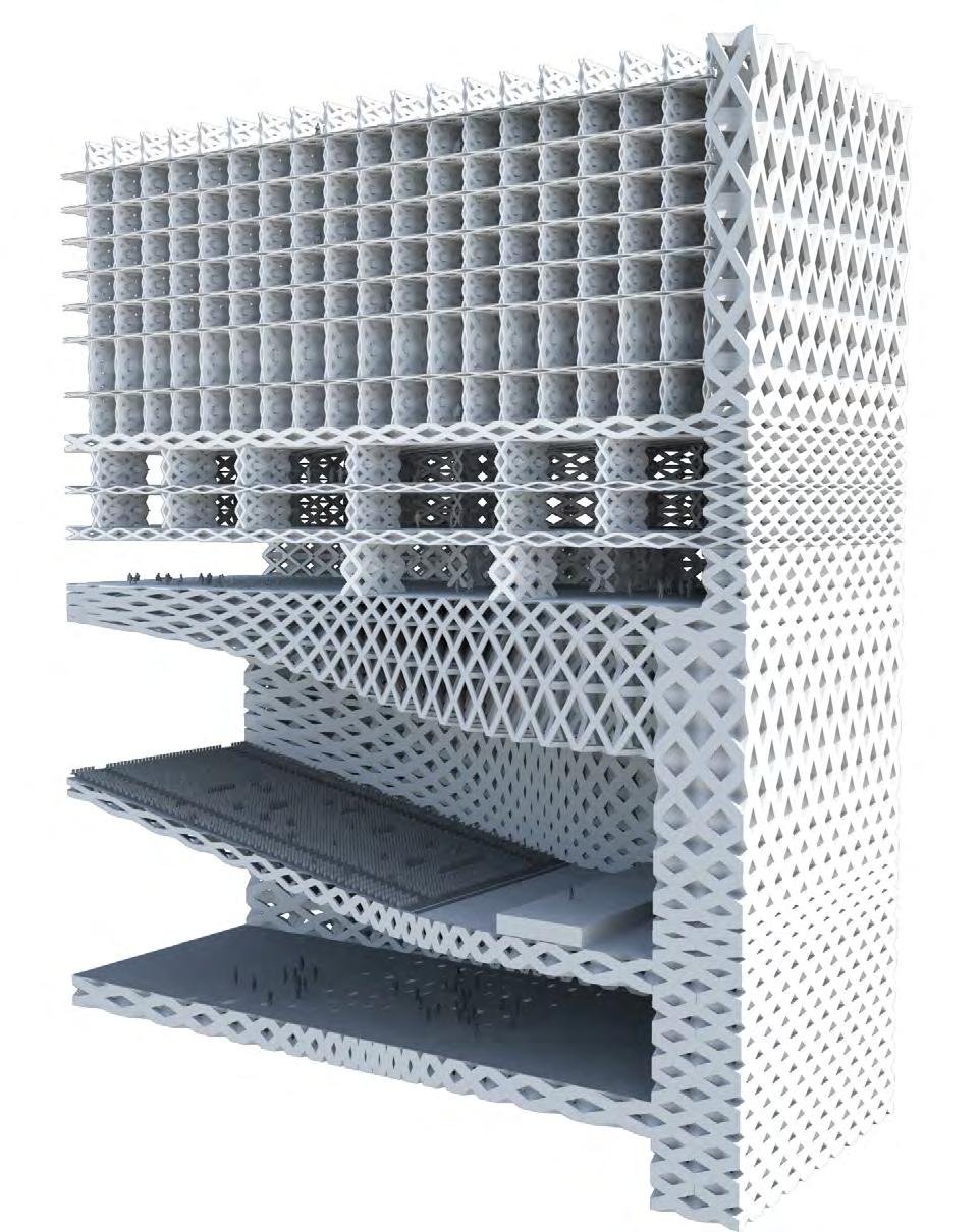
166 GRADIENT CONDITIONS
SYSTEM DEVELOPMENT
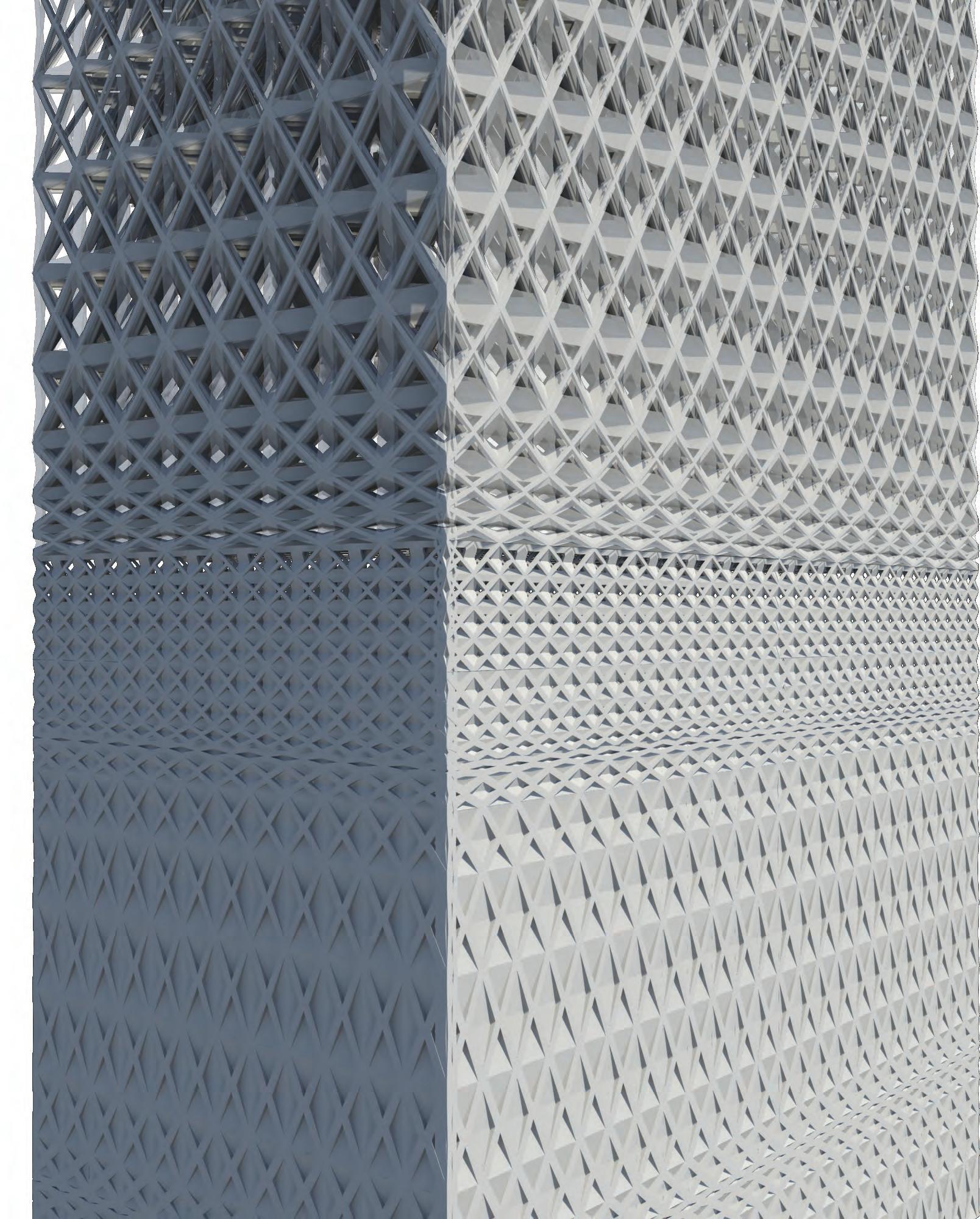
CELLULAR COMPLEXITY 167
The developed system displayed various potential within the systematic and performative sides of architecture, where there are further potentials spatially and architecturally. Several spatial typologies were produced to examine some of these potentials
The earlier study of how to integrate the facade and the program to make the façade inhabitable tests how the interaction of façade and program could work. This was carried out by changes in cell size and porosity according to specific programs, the result however was somewhat conventional. In the following typologies a number of conditions are investigated. The integration of accessible cells and the creation of intricate spaces are part of the possibilities of making the façade inhabitable in certain desired areas.
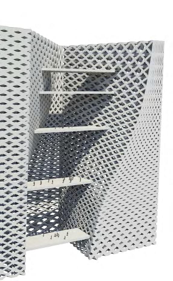
Terraced spaces can be created on the inside and on the outside of the building. In this case the aspect that requires further resolution ishas the transition from the floor plates to the façade. The aim should be not to simply use conventional floor plates but to integrate them in the cellular arrangement. The typologies allow for an adaption in the design process to spatial programs and their influences. The innovative aspect in this study, in comparison to the earlier developed example is the integration of a continuous - rather than an abrupt, pixelated change in thickness of layers.
The first spatial typology investigates the involvement of not only a gradient in cells, but also a spatial gradient. Therefore the spaces would be designed in a similar manner to the system, for its inputs.
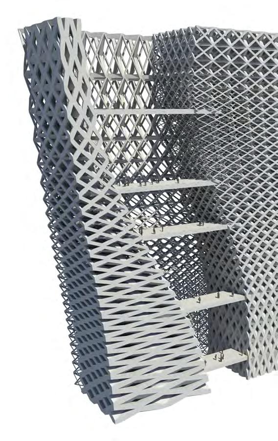
168 INHABITABLE COURTYARD CONDITIONS
GRADIENT
FURTHER POTENTIALS OF THE SYSTEM
SPATIAL
IN ADDITION TO CELLULAR GRADIENT
SYSTEM DEVELOPMENT
Furthermore, the second typology investigates the creation of light well or courtyard condition which is inhabitable, the potential is to generate this condition through substantially larger cells where this condition becomes part of the inhabitable cellular system. The design of this courtyard can be optimized to the natural lighting conditions of the site it is located in.
The third typology considers branching of the cellular system, and the possibility of inhabiting spaces in between the branching of the system. The interest would lie in investigating branching logics and their efficiency towards structural parameters. In this case it is a downside branching that is illustrated, the opposite can also hold potential.
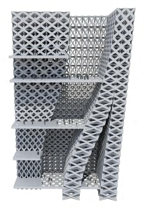
Finally, the last condition visualizes the effect of creating a direct change in program towards a courtyard condition, this is where the aspect of building up redundancies and additional material becomes of interest, returning to the natural cellular systems. This may include form-finding methods which utilize environmental criteria to generate a morphology.
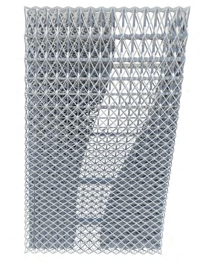
CELLULAR COMPLEXITY 169 FACADE VARIATION WITH SPATIAL VARIATION
FACADE CONDITIONS
INHABITABLE
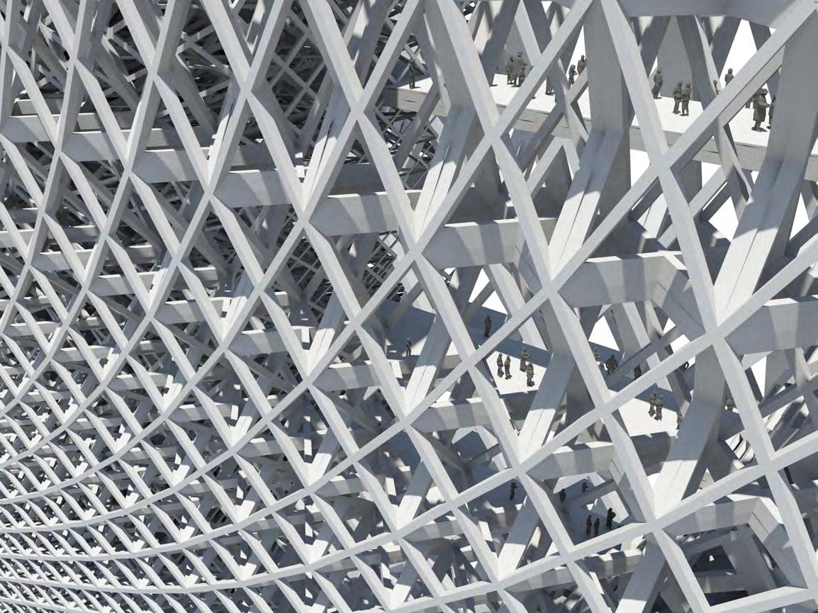
170 INHABITABLE FACADE GRADIENT SYSTEM DEVELOPMENT
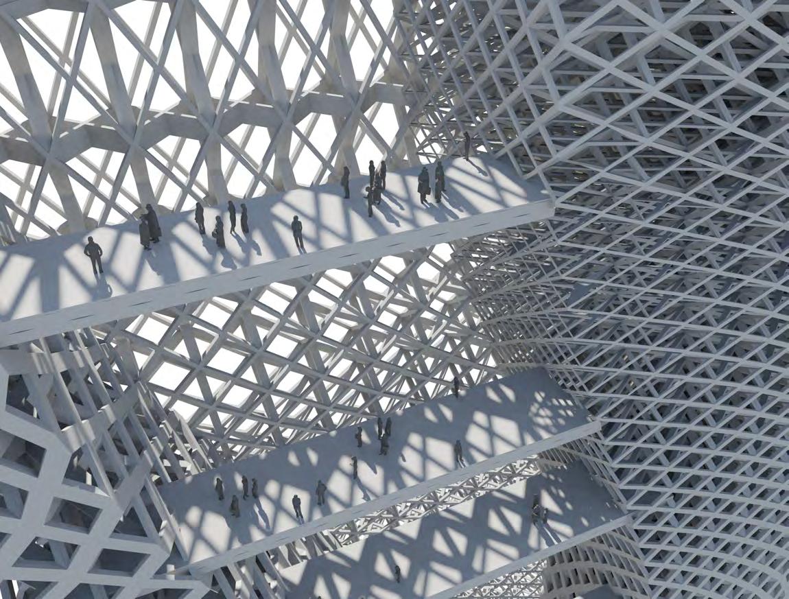
CELLULAR COMPLEXITY 171 FACADE COURTYARD CONDITION
172 SYSTEM DEVELOPMENT
overview SYSTEM DEVELOPMENT
The system development phase investigated performative aspects in higher details, the strategy was to set out a number of conditions for each performative property. Structurally, a range of conditions were defined, and for day lighting a number of levels where also defined.
This process was further continued by utilizing environmental analysis software to obtain analysis data that is specific to the building and site, and furthermore to the system. This allowed us to link the system, to the proposed architecture at the given site.
At this stage, the application of the system was limited to a segment of the building, allowing us to develop a more refined resolution. The system was developed through program patches, where these patches directly corresponded to the specific program needs. The challenge was then to create a gradient between those patches. The parametric design tool and its use of direct numerical parameters aided this process. We were able to generate specific iso-curves for gradients on the surfaces. Furthermore, we can input the gradient ranges and therefore they become interlinked from one program to another. The ending gradient of one program becomes the starting gradient of another.
Throughout this process we developed a North-West corner of the building which demonstrated the abilities of the system in responding to specific program, creating a gradient and being structurally coherent throughout. This was illustrated in patches, threedimensional sections and corner perspectives.
However, throughout the application it was evident that the architectural and spatial potential of this system is very valuable, therefore we examined these aspects in a typological study. This study investigated a number of spatial conditions which were initially independent of performative aspects. However, at further investigation of such conditions there are several opportunities to inherit them within the system. Most conditions refer to aspects within natural systems and their development of redundancy and excess material, which is still effective and not redundant in many situations.
CELLULAR COMPLEXITY 173
JURY COMMENTS
The research was presented at the Architectural Association in London to an international jury which included: The jury was held on the 20th of August 2012 at the Main Lecture Hall, 36 Bedford Square.
Francis Aish, Foster + Partners
Selim Bayer, Flat C
Jeroen Janssen, AKT II
Tom Lea, Amanda Levete Architects
Wolf Mangelsdorf, Buro Happold
Theo Spyropoulos, AA DRL
Jordi Truco, ELISAVA / HYBRIDa
In addition to the EmTech Faculty:
Michael Weinstock
George Jeronimidis
Evan Greenberg
Mehran Gharleghi
Furthermore, the competition entry for the suckerPUNCH competition, was reviewed by a panel of international jury members which included:
The jury reviewed the entry which was submitted on the 13th of August 2012, an earlier stage of the research.
Kutan Ayata, YOUNG & AYATA
Ezio Blasetti, Ahylo Studio
David Erdman, davidclovers
Marc Fornes, THEVERYMANY
Ferda Kolatan, su11 Architecture & Design
Craig Scott, IwamotoScott Architecture
Marcelo Spina, P-A-T-T-E-R-N-S
Mike Szivos, SOFTlab
Abigail Coover, hume coover studio, suckerPUNCH
Nathan Hume, hume coover studio, suckerPUNCH
The suckerPUNCH jury awarded the Cellular Complexity competition entry Second Place.
174 ARCHITECTURAL APPLICATION
Several topics set the discussion for the EmTech jury, this included the referencing of natural systems and the way in which they operate with material redundancies. The jury suggested a comparison of cost-efficiency between conventional building systems and what is being proposed by this research. Furthermore, the morphology within the architectural application was discussed, where the jury pointed out the potentials within the system of creating inhabitable cellular spaces and their continuation. This may include the inclusion of curved spaces within the system as part of both the potential and research into cellular systems. As part of our research we investigated the performative and definitive aspects of the system. The exploration of such spatial and architectural qualities are part of the intention and further development.
As for the suckerPUNCH competition. Feedback was received from two of the jury members as follows:
Craig Scott (IwamotoScott Architecture): The underlying ideas regarding a responsive, scripted structural porosity are compelling, and the site strategy seems promising. Yet, the tower’s overly boxy form and the lack of specificity of the casino interior seem like missed opportunities. Curiously, the spacemaking potential of the designer’s “3-D sphere packing” and “3D voronoi based on pores” is not very present other than as a gradated space frame of sorts—particularly not as a habitable condition, at least not as it is currently rendered and drawn in section.
Marcelo Spina (P-A-T-T-E-R-N-S): This is a very interesting project at the level of the research that it presents. The approach at the problem of packing and cellular partition is very rigorous and deserves to be mentioned. However, given the manifest cellular interest on the part of the authors, the overall deployment of the project falls very much within the morphodynamic “flow”like genre, one which this site has seen before in excellent projects such as West Side Convergence by Reiser+Umemoto. It seems that if the research is pursued seriously, not only at the level of research but also in its architectural design application, one would have to seriously consider issues of scale of components in relation to size of the whole, apses of multi directionality very much found in any cellular system, and the reduction of linear flow as the main feature of the project.
CELLULAR COMPLEXITY 175
CONCLUSION
This research first initiated through an interest in the coherence of natural systems, where cellular systems were found to be particularly interesting due to their efficient abilities in addressing a variety of performative properties, by integrating morphology with material and structure. The crucial aspect in cellular systems is their occurrence within a wide range of scales. This fact implies that such systems are able to adapt and perform within multiple scales and purposes. Therefore, the scalability of cellular systems and their geometries was viable within an architectural scale. The natural systems informed the research with the underlying principle of cellular geometries, from which two-dimensional and three-dimensional space-packing geometries were developed for an architectural application. The aspect of most interest within these systems was the ability to create variation and changes in porosity. Eventually, the gradient condition where porosity changes gradually became a focus within the application and was investigated programmatically for an architectural context.
Throughout the development of the research and architectural application, the emergent technologies in design, analysis and fabrication were of particular use and influence towards the project. In terms of design, the parametric computational methods allowed for the underlying set-up of the system and the introduction of a range of variables to control different parts of the system using algorithms; this would otherwise be unachievable through traditional methods given the current level of control. As the process progressed, the algorithms and digital models became particularly heavy due to the large amount of data. Given this data dilemma, the integration of analysis workbenches within the process was computationally impossible. Therefore, the analysis methods were used to generate comparative guidelines which inform the algorithmic parameters. These included testing site conditions, or a range of developed patches
which lead to assumptions on the performance of the system. In order to develop an accurate use of these analysis tools, comprehensive cataloguing and documentation would be required to precisely address performative properties. This would create an endless loop-hole for optimization and testing, in this context we limited our tests to extreme and median variations of the system. The aspect that is even more challenging within the analysis tools is the design for combinatory performance aspects, where more than one criteria is to be satisfied. The current approach to such challenges involves evolutionary computation, where multiple iterations are generated and evaluated for fitness in a number of criteria. This vwas an option within the system, though given the computational load of the geometries and algorithm, it would be particularly intensive.
The emergent digital fabrication methods including additive manufacturing were considered within the fabrication of the complex geometries. Due to the limitations in scale and costs, these technologies were found to be best combined with traditional fabrication methods. This involved the development of a hybrid fabrication method includes the use of customized joints and standardized elements. This involves complex 3D printed or cast joints in combination with planar struts and plate elements. The intent is to utilize the advanced technology where it is required within the system. Furthermore, materials which include structural composites and highly insulating translucent panels become of interest for further investigation. In parallel to the fabrication development, the systems geometrical development was in process, the results from the system were constantly evaluated with the given fabrication methods for viability. The synthesis was to develop the system while maintaining a viable ratio of customized joints to standardized joints. In a large scale application, the quantity of joints allow for the development of multiple variations at the same efficiency and feasibility of a single variable. These
176
limitations are particularly tied to the scale of the project, if the system was developed on a pavilion scale, both analysis and fabrication technologies would offer further opportunities within the design and procurement of the system.
The choice of the tower typology allowed for an architectural application at a large scale. This unveiled the opportunity of developing hierarchy within the system through the developed gradients. This means that the tower is to operate at an urban scale through a global gradient, and at a programmatic scale through a local gradient; the challenge was to integrate these two together. The application of the system was tested architecturally on a portion of the tower. The intent was to examine the system on a given site and program, therefore these two parameters heavily influenced the architecture and system design. However, as a research application these parameters were conservatively manifested into a basic form, to test the potentials of the system in variation. The overall cell distribution resulted in a dense structure. Although the system targets material efficiency in structure, and the use of material where it is most required; the current optimization is based on structural assumptions from comparitive geometrical tests. Therefore, precise optimization simulations would be required to determine the redundancies within a refined material and structural strategy.
In terms of architectural design, the detailed development of the tower-core and circulation is an aspect to be further developed. The technical and mechanical aspects have potential for integration within the system. This includes the unavoidable cores, not due to structure, but also circulation and mechanical transport of water and waste. The opportunity may develop through transition mechanical spaces which work within the gradient to shift between programs, and operate the tower.
Although the system was exploited at the level of the cell in the overall design, there are architectural and spatial qualities to be revealed. The potential of a smooth gradient would result in higher structural performance, thus helps to loosen the very dense aggregation of cells. Furthermore it creates spaces which are of high architectural and spatial quality. A higher variation in cell size could allow inhabitability of the facade which in a further step makes the dense aggregation of cells justifiable. It is also a step away from the current rectilinear appearance of the building if the mentioned smooth transitions in cell size are considered. Furthermore, a spatial gradient is an aspect for future development of the programmatic arrangements, where the program itself also operates in a gradient.
In Conclusion, this research develops an architectural system which ¬utilizes efficient geometries and develops variation through a cellular system to address a multitude of properties in different programmatic and environmental site conditions. The research further utilizes emergent technologies in design, analysis and fabrication. The abstraction of underlying principles from natural systems has driven the coherence of the system and its hierarchy in addressing properties at different scales. The further development of this research and system would refer back to these natural systems and their potential to develop spatial and architectural qualities alongside the performative qualities currently displayed. This aspect would examine the concepts of redundancy and material build-up in relation to spaces and the development of a spatial gradient within the inputs for the system.
CELLULAR COMPLEXITY 177
SELECTED BIBLIOGRAPHY
books
Addington, M., & Schodek, D. L. (2005). Smart materials and new technologies for the architecture and design professions. Oxford: Architectural.
Carroll, S. B. (2005). Endless forms most beautiful: the new science of evo devo and the making of the animal kingdom. New York: Norton.
Jeronimidis, G. (2004). Biodynamics. Emergence: morphgenetic design strategies, London: Wiley-Academy.
Knaack, U., & Klein, T. (2008). Façades. Rotterdam: 010 Publishers.
Gibson, L. J., & Ashby, M. F. (1997). Cellular solids (Second ed.). Cambridge: Cambridge university press.
Hausladen, G., & Saldanha, M. d. (2007). Climate skin: concepts for building skins that can do more with less energy. Basel: Birkhäuser
Hensel, M., Menges, A., & Weinstock, M. (2010). Emergent technologies and design. Oxon, [U.K.: Routledge.
McQuaid, M., & Beesley, P. (2005). Extreme textiles: designing for high performance. New York: Smithsonian Cooper-Hewitt, National Design Museum
Pawlyn, M. (2011). Biomimicry in architecture. London, UK: Riba Publishing
Pearce, P. (1990). Structure in nature is a strategy for design. Cambridge: MIT Press. (Original work published 1978)
Reiser, J., & Umemoto, N. (2006). Atlas of novel tectonics. New York: Princeton Architectural Press.
Weinstock, M. (2006). Self-Organisation and Material Constructions. Techniques and technologies in morphogenetic design, London: Wiley-Academy.
presentations
Cox, S. Solid Cellular Materials. University of Wales Aberystwyth.
Ju, J. Research Vision: Smart Cellular Materials, I )Energy Efficient Design, ii) Energy Harvesting Structures . Clemson University, Cedar - Clemson Engineering Design Applications and Research.
Rosa, M. E. (2007). Cellular Materials: Structure and Properties. ICEMS-Instituto de Ciência e Engenharia de Materiais e Superfícies, Departamento de Engenharia de Materiais, Instituto Superior Técnico, Universidade Técnica de Lisboa.
Strauß, H. Additive Manufacturing in architecture and building construction. xx: TU Delft, Facade Research Group, Hochschule Ostwestfalen-Lippe, University of Applied Science.
dissertations
Ajdari, A. (2008). Mechanical behavior of cellular structures: a finite. Boston: IRis Notheastern University, Department of Mechanical and Industrial Engineering.
Satira, R. (2010). Cellular Solid Morphologies, Inhabitable Cellular Structure. London, Architectural Association: Emergent Technologies and Design
Tenu, V. (2009). Minimal surfaces as self organizing systems - A particle spring system simulation for generating triply. London: Bartlett School of Graduate Studies.
178
SELECTED BIBLIOGRAPHY
Colding, T. H., & Minicozzi, W. P. (2005). Shapes of embedded minimal surfaces. Cambridge: Department of Mathematics, Massachusetts Institute of Technology.
Ehrlich, H., & Worch, H. (2007). Sponges as natural composites: from biomimetic. Dresden: Max Bergmann Center of Biomaterials, Institute of Materials Science.
Ghantous, S., & Mituryayeva, Y., The use of lightweight plastics and the Beijing National Aquatics Centre. Ethylene Tetraflouretrhylene
Gonchar, J. (2008). Inside Beijing’s Big Box of Blue Bubbles. Mc Graw Hill Construction, Continuing Education
Loi, S. U., & Szeto, T. (2010). Project No. 1 Thematic Analysis of Current Building Design Techniques and Technologies. Steel
Markillie, P. (21 April 2012). A third industrial revolution. The Economist.
Nielsen, L. F. (1993). Strength of porous materials. Course 6108: Porous Building Materials.
Kishimoto, S. (2008). Closed cellular materials for smart materials. Sengen: International Conference on Experimental Mechanics 2008,.
Kowalczyk, S. W., Blosser, T. R., & Dekker, C. Biomimetic nanopores: learning from. Delft: Kavli Institute of Nanoscience, Delft University of Technology.
Lim, S., Buswell, R. A., Le, T. T., Austin, S. A., Gibb, A. G., & Thorpe, T. Developments in construction-scale additive manufacturing. Loughborough : Loughborough University.
Lee, Y., Lee, B., Jeon, I., & Kang, K. (2007). Wire-woven bulk Kagome truss cores. School of Mechanical Systems Engineering, Chonnam National University,Yongbong-dong: Science Direct.
Öchsner, A., Fiedler, T., & Augustin, C. Metallic hollow sphere structures - multifunctional materials for lightweight applications
Plucknett, K., & Lilley, B. (2012). The art of engineering nothing (or what we can do to ‘design’ porous ceramics) .
Reay, S. D., & Withell, A. (2011). How Can Rapid Product Development Support Sustainable Product. Auckland: Product + Design, School of Art + Design.
Schoen, A. H. (1970). Infinite Periodic Minimal Surfaces without Self-Intersections. Cambridge: NASA Technical Note.
Seepersad, C. C., McDowell, D. L., Mistree, F. F., & Allen, J. K. (0). Multifunctional Topologydesign of cellular material.
Stampf, J., Fouad, H., Seidler, S., Liska, R., Schwager, F., Woesz, A., et al. (2004). Fabrication and moulding of cellular materials by. Potsdam: Max Planck Institute of Colloids and Interfaces.
Strauss, H. (0). Rapid Prototyping Technologies for Facades. Delft: Delft University of Technology.
Stampfl, J., Wöß, A., Fratzl, P., & Seidler, S. (2002). Rapid prototyping of ceramic and polymeric cellular materials. Vienna: IFMBE Proceedings.
Tekoglu, C., & Onck, P. R. (2005). Size effects in the mechanical behavior of cellular. Groningen: Journal of materials science.
Wadley, H. N. (2006). Multifunctional periodic cellular metals. xx: Philosophical Transactions of the royal society.
Williams, C., & Rosen, D. (0). Manufacturing cellular materials via three-dimensional printing of spraydried. Atlanta: Georgia Institute of Technology
CELLULAR COMPLEXITY 179
articles
Algorithms in nature drive architecture research, parametric designs - YouTube. (n.d.). YouTube - Broadcast Yourself.. Retrieved April 29, 2012, from http://www.youtube.com/watch?v=Yn_Xarm6Rj8
American Cement Building – Los Angeles - Retrieved May 7, 2012, from http://populuxebooks.com/blog/index.php/american_cement_ building_los_angelesAmerican Cement Building – Los Angeles
Biodegradable synthetic resin replaces vital body parts. (n.d.). Phys. Org - Science News, Technology, Physics, Nanotechnology, Space Science, Earth Science, Medicine. Retrieved May 2, 2012, from http://phys.org/news163773414.html
Bios-Fin system = Algae Biofiltration to Biofuel Building Facade System - Retrieved May 1, 2012, from http://biosarch.wordpress. com
Ceramic Samba by Tyler Hopf, Michael Villardi and Sarah Murray - Retrieved June 25, 2012, from http://futuresplus.net/2012/03/22/ ceramic-samba-tyler-hopf-michael-villardi-and-sarah-murray
Component facade fabrication process by Toni Cumella of CLOUD 9 Barcelona – - Retrieved May 26 2012, from http://ma-s-lab.blogspot. co.uk/2010/11/workshop-starts-on-assumption-that.html
Conventional and novel processing methods for cellular ceramics – article - Retrieved May 24, 2012, from http://rsta. royalsocietypublishing.org/content/364/1838/109.full
Contour Crafting – Print your dream house - Retrieved July 9, 2012, from http://www.yankodesign.com/2012/04/20/print-your-dream-house/
D- Shape – large scale additive manufacturing by Enrico DiniRetrieved July 9, 2012, from http://www.constructionshows.com/3d-printing-revolutionaries-reachfor-the-stars/
Dezeen Screen: The Solar Sinter by Markus Kayser - Dezeen. (n.d.). Dezeen - architecture and design magazine. Retrieved April 29, 2012, from http://www.dezeen.com/2011/06/30/dezeen-screenthe-solar-sinter-by-markus-kayser/
“Endless” Chair 3D printed: Robotic Arm and Recycled materials3D Printing - 3D Printing Video Player :: ENGINEERING.com. (n.d.). ENGINEERING.com | The Engineer’s Ultimate Resource Tool. Retrieved April 29, 2012, from http://www.engineering.com/3DPrinti ng/3DPrintingVideoPlayer/VideoId/2887/Endless-Chair-3D-PrintedRobotic-Arm-And-Recycled-Materials.aspx
Erwin Hauer – 3 dimensional cast ed facade systems - Retrieved April 30, 2012, from www.erwinhauer.com
Evolute - Scientific Publications. (n.d.). Evolute. Retrieved April 30, 2012, from http://www.evolute.at/technology/scientific-publications. html
ezioblasetti.net. (n.d.). ezioblasetti.net. Retrieved April 19, 2012, from http://portfolio.ezioblasetti.net/
Fibrous tower by kokkugia - Retrieved September 3, 2012, from http://www.designboom.com/weblog/cat/9/view/9257/kokkugiafibrous-tower.html
Future Architecture. (n.d.). Future Architecture. Retrieved April 30, 2012, from http://www.futurearchitecture.eu/
Future Architecture. (n.d.). Future Architecture. Retrieved April 30, 2012, from http://www.futurearchitecture.eu/
Graphene Nanopatelets - Retrieved May 7, 2012, from http://www.grafen.com.tr/products_nano.html
Green Cast by Kengo Kuma and Associates – small building in Odawara – Japan - Retrieved June 25 2012, from http://www. contemporist.com/2012/06/14/green-cast-by-kengo-kuma-andassociates/
hawktraining - concrete facade of the Stadthalle in Chemnitz,.... (n.d.). hawktraining. Retrieved April 29, 2012, from http:// hawktrainer.tumblr.com/post/16637611579/concrete-facade-of-thestadthalle-in-chemnitz
HygroScope – Centre Pompidou Paris « Biomimetic Architecture. (n.d.). Biomimetic Architecture. Retrieved April 29, 2012, from http://www.biomimetic-architecture.com/2012/hygroscope-centrepompidou-paris/
Jenn 3D – Polyhedra Simulation Software - Retrieved May 7, 2012, from http://www.math.cmu.edu/~fho/jenn/#download
Large Scale casting for wind turbines – microscopic photo platform - Retrieved June 25, 2012, from http://www.windgreenergy.com/ product_info.asp?pid=15
Joris Laarmann Lab bone chair - Retrieved May 1, 2012, from http:// www.jorislaarman.com/
Mathias Bentsson – cellular chair - Retrieved May 1, 2012, from www.designboom.com/weblog/cat/8/view/13846/mathias-bengtssoncellular-chair.html
Mikro Forum – microscopic photo platform - Retrieved May 26 2012, fromhttp://www.mikroskopie-forum.de/
moh architects | selected projects. (n.d.). moh architects | home. Retrieved May 1, 2012, from http://www.moh-architecture.com/ projects_p009.htm
Noodle Block Cube – lasercut and heatformed rubber by Lauren Moriarty – article - Retrieved May 7, 2012, from http://www. laurenmoriarty.co.uk/
O-14 Tower by Reiser + Umemoto - Retrieved September 3, 2012, from http://www.contemporist.com/2011/03/10/o-14-tower-by-reiserumemoto/
photostream by Studio Jonas Coersmeier - Retrieved May 26, 2012, from http://www.flickr.com/photos/pixelprobe/
Plucknett, K., Lilley, B., & 2012, 1. M. (n.d.). SMART GEOMETRY ARTICLES. sgHome. Retrieved May 2, 2012, from http:// smartgeometry.org/index.php?option=com_content&view=article&id =144&Itemid
180 web
SELECTED BIBLIOGRAPHY
Porous screen wall by Rem Koolhas – Prada Store Los AngelesRetrieved May 1, 2012, from www.designboom.com/weblog/cat/8/ view/13846/mathias-bengtsson-cellular-chair.html
Prototyping. (n.d.). Prototyping. Retrieved April 30, 2012, from http:// prototyping.materialise.com/
Printing 3D components – January 12th 2012 – article - Retrieved May 7, 2012, from http://3dprintinginaec.blogspot.co.uk/2012/01/ printing-3d-building-components.html
Quantum Cloud by Anthony Gormley - Retrieved July 9, 2012, from http://www.lusas.com/case/civil/gormley.html
ReubenMiller : Early Modern Concrete Facades - Beautiful. (n.d.). ReubenMiller . Retrieved April 29, 2012, from http://reubenmiller. typepad.com/my_weblog/2007/12/early-modern-co.html
Soap Foam Cahir - video- Retrieved May 7, 2012, from http://vimeo.com/7261475
Shenzhen International Airport under construction - Massimiliano + Doriana Fuksa | Simbiosis News. (n.d.). Simbiosis News | Architecture, Design and Vanguard. Retrieved April 30, 2012, from http://simbiosisgroup.net/27870/shenzhen-airport-underconstruction-massimiliano-doriana-fuksa
WertelOberfell. WertelOberfell. Retrieved April 30, 2012, from www. platform-net.com
Ted Talk in Salzburg by Siavash Mahdavi - State of the Art in 3D printing - video Retrieved May 7, 2012, from http://www.youtube.com/ watch?v=MU3W-RrJDT4
Titanium Foam. (n.d.). x. Retrieved May 2, 2012, from medgadget. com/2010/09/titanium_foam_as
3dma_rock Primer. Stony Brook University - Department of Applied Mathematics & Statistics. Retrieved May 2, 2012, from http://www. ams.sunysb.edu/~lindquis/3dma/
Sea Urchin Blog - Retrieved May 26 2012, from http://echinoblog. blogspot.co.uk/2010_05_01_archive.html
Structure-property relationships of a biological mesocrystal in the adult sea urchin spine, J. Seto, Y. Ma, S. Davis, F. Meldrum, A. Gourrier, Y.-Y. Kime, U. Schilde, M. Sztucki, M. Burghammer, S. Maltsev, C. Jäger, and H. Cölfen, PNAS 109, 3699–3704 (2012). - Retrieved May 26 2012, from http://www.pnas.org/ content/109/10/3699
systemicprocess + responsive skin by David Jaubert- Retrieved April 30, 2012, from http://www.core.form-ula.com/2008/04/08/systemicprocess/ and http://davidjaubert.com/projects/porous-wall/
Voronoi relaxation study - Retrieved May 7, 2012, from http:// livecomponents-ny.com/
CELLULAR COMPLEXITY 181
182
APPENDIX
This appendix includes various parts of the research which are not presented earlier. This includes the computational algorithms used to generate the system with further explanation on how they operate. Additionally a number of photographs of the 3D printed geometries have been included
Furthermore, the appendix includes research which contributed towards the development of the research however did not become particularly relevant within the overall scheme presentation.
CELLULAR COMPLEXITY 183
Opposing to conventional facades, which consist of different layers to address various properties, the suggested system inherits the required structural and performative aspects within one single system. Instead of having several separate sub-systems, one intricate system, adaptable to given environmental conditions, in the design and planning phase is developed.
The studied properties of cellular systems were analyzed and in a further step related to the properties a façade has to address. This helped to understand how a structure in a cellular system looks like in order to address a certain property and how this can be abstracted for a façade system.
The properties which have to be addressed in the development of the façade include structure, insulation, ventilation, weather and climate protection, visual aspects as sunlight while respecting the difference between summer and winter. Often, requirements of façade systems are contractive - Enclosure and insulation has to be guaranteed but at the same time lots of light has to enter the building. A proper insulation glazing can improve the façade performance in this aspect significantly. Also, the layer thickness is an important factor as insulation is not linearly proportional to the layer thickness. Another important factor is the solar control which often contradicts with the light requirements. Further, a decision has to be take if the user has access to the system and control ventilation1. The structural building skin is an alternative suggestion to the internal building core1
The process of how to design the façade by use of the cellular system was developed. There are certain properties which are developed for the whole building - such as structure and visual aspects- and properties which are addressed on a smaller scale including ventilation and insulation. For each property a range of cell scales and porosities is defined.
INSTEAD OF DIFFERENT LAYERS OF SEPERATE SYSTEMS
REQUIRED PROPERTIES INHERITED IN ONE SINGLE SYSTEM
PROPERTIES
PROPERTIES
CELLULAR SYSTEMS
CELLULAR SYSTEMS
structural
structural
2D + 3D structures
2D + 3D structures
deformations with forces: in-plane: shear deflection - bending and rotation out-of plane forces: generally extension or compression
deformations with forces: in-plane: shear deflection - bending and rotation out-of plane forces: generally extension or compression
thermal
low thermal conductivity in foams requires:
-small cell size
-high porosity
low thermal conductivity in foams requires:
-small cell size
-high porosity
-low convection and conduction properties of material and gas used
acoustic
-low convection and conduction properties of material and gas used
thermal acoustic
sound absorbing (that comes within the same room/space) -porous materials absorb sound and convert it to heat (negligable)
sound absorbing (that comes from within the same room/space)
-porous materials absorb sound and convert it to heat (negligable)
-must be open celled -must be open celled
-must be open celled
-must be open celled

PARAMTERS
PARAMTERS
- arrangement of cells and structure: geometry (optimized or variable/random) cell properties (size, thickness, etc.)
- arrangement of cells and structure: geometry (optimized or variable/random) cell properties (size, thickness, etc.)
- material (and properties: modulus, etc.)
- for optimization at scale thickness of cellular system temperature difference across
- for optimization at scale thickness of cellular system temperature difference across
- cell size - porosity
FACADE PROPERTIES
STRUCTURAL THERMAL
STRUCTURE
- material (and properties: modulus, etc.) cell shape cell packing porosity density thickness material
material - gas in pores
- cell size - porosity - material - gas in pores
- porosity
porosity - open cell not closed cell
- open cell not closed cell
cell shape cell packing porosity density thickness material
ENVIRONMENT
site data temperatures
site data temperatures
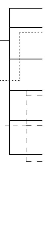
184
FACADE PROPERTIES
+ +
ACOUSTIC VISUAL ENVIRONMENTAL SPATIAL STRUCTURE
PROPERTIES
ENVIRONMENT FACADE
STRUCTURAL THERMAL ACOUSTIC VISUAL ENVIRONMENTAL SPATIAL
-
-
APPENDIX
1- Hausladen, G., & Saldanha, M. d. (2007). Climate skin: concepts for building skins that can do more with less energy. Basel: Birkhäuser
INPUTS
SITE INFO:
INPUTS
-Latitude(sun) -Wind data(wind) -Site Outline (perimeter) -Surrounding Buildings
SITE INFO:
-Latitude(sun) -Wind data(wind) -Site Outline (perimeter) -Surrounding Buildings
TYPOLOGY: -Height -Programmes -Spatial Facade Areas -Structure
TYPOLOGY: -Height -Programmes -Spatial Facade Areas -Structure
PROPOSED PROCESS STEPS
PROPOSED PROCESS STEPS
Inputs:
STEP001
-Site Data
ATTRACTORS: -Light -Ventilation -Visual -Loads/Structure
ATTRACTORS: -Light -Ventilation -Visual -Loads/Structure
/ validate
Inputs:
Inputs:
POSSIBLE OUTPUTS VARIATION
BUILDING: -Programme Plan -Building Morphology -Floor Heights
POSSIBLE OUTPUTS VARIATION
BUILDING: -Programme Plan -Building Morphology -Floor Heights
FACADE: -Voids in Facade/Spatial -Lattice Size -Gradients
FACADE: -Voids in Facade/Spatial -Lattice Size -Gradients
CELLS: -Cell Size -Cell Geometry -Cell Porosity
CELLS: -Cell Size -Cell Geometry -Cell Porosity
Inputs:
OVERALL LATTICE
-Building Programmes -Spatial Facade Areas
Inputs:
Outputs:
-Site Data
-Overall Lattice -Structural Loads Gradient; resulting in subdivision
Inputs:
Outputs:
-Orientation, and surroundings -Site Latitude -Overall Lattice and Structure
Inputs:
Outputs:
-Orientation, and surroundings -Site Wind Data, wind paths -Overall Lattice and Structure
Inputs:
Outputs:
ETC. STEP004 tertiary parameters
Inputs:
-Overall Building Lattice based on programme, with spatial facade areas.
-Building Programmes -Spatial Facade Areas
Outputs:
-Overall Lattice -Structural Loads Gradient; resulting in subdivision
Outputs:
-Overall Building Lattice based on programme, with spatial facade areas.
plan sections generated based on programme (multiple iterations)
VOID SIZE vs CELL SIZE
plan sections generated based on programme
VOID SIZE vs CELL SIZE
-Lattice Subdivision -Primary Cell Layout: size based on subdvision porosity based on loads -Primary Hierarchy based on structural loads (optimal iteration)
-Lattice Subdivision -Primary Cell Layout: size based on subdvision porosity based on loads -Primary Hierarchy based on structural loads
void within system: rooms - structural open space visual open parts continuous voids for ventilation guidance insulation voids (membrane possibility) cell within
lattice
space visual open parts continuous voids for ventilation guidance insulation voids (membrane possibility) cell within system: varies within defined lattice
(multiple iterations)
(optimal iteration)
-Orientation, and surroundings -Site Latitude -Overall Lattice and Structure
Outputs:
-Developed Lattice with: variable thickness porosity (multiple iterations)
-Developed Lattice with: variable thickness porosity
Combinatorial Optimization?
(multiple iterations)
Combinatorial Optimization?
-Orientation, and surroundings -Site Wind Data, wind paths -Overall Lattice and Structure
Outputs:
-Developed Lattice with : variable thickness variable porosity (multiple iterations)
-Developed Lattice with : variable thickness variable porosity (multiple iterations)
Outputs:
CELLULAR COMPLEXITY 185 OVERALL
ENTIRE BUILDING PART OF FACADE STRUCTURE structural loads increase wind loads increase control of porosity through acquired site data vectors according to sun movement more sun required: increase of cell porosity increase of cell size decrease of system thickness no need of change of cell size or porosity along defined path create continuous path of porous cells to ventilate continuous aggregation of cells which fulfil desired insulation properties porosity increase density increase global solution: increase thickness of overall system change of cell size increase cell density local solution: change of porosity % increase cell wall thickness global solution: change of cell size local solution: change of porosity % at individual cells SUN / LIGHT / VISUALWIND & VENTILATIONINSULATION inside outside inside outside inside outside
LATTICE
varies
defined
system:
within
OVERALL
HEIRARCHY level i HEIRARCHY level ii HEIRARCHY level iii
LATTICE STEP001
STRUCTURE STEP002 re-evaluate / validate SUN / LIGHT / VISUAL STEP003a WIND & VENTILATION STEP003b INSULATION, ETC. STEP004
OVERALL LATTICE ENTIRE BUILDING PART OF FACADE STRUCTURE structural loads increase wind loads increase control of porosity through acquired site data vectors according to sun movement more sun required: increase of cell porosity increase of cell size decrease of system thickness no need of change of cell size or porosity along defined path create continuous path of porous cells to ventilate continuous aggregation of cells which fulfil desired insulation properties porosity increase density increase global solution: increase thickness of overall system change of cell size increase cell density local solution: change of porosity % increase cell wall thickness global solution: change of cell size local solution: change of porosity % at individual cells SUN / LIGHT / VISUALWIND & VENTILATIONINSULATION inside outside inside outside inside outside
Inputs: Outputs:
tertiary parameters
void
rooms
structural open
within system:
-
FACADE DESIGN PROCESS
HEIRARCHY level i HEIRARCHY level ii HEIRARCHY level iii
SUN
STEP003a WIND
STEP003b INSULATION,
STRUCTURE STEP002 re-evaluate
/ LIGHT / VISUAL
& VENTILATION
SCALE RANGE OF CELLULAR SYSTEM RELATED TO FACADE PROPERTIES
PATCH OF 300.00 X 150.00 CM
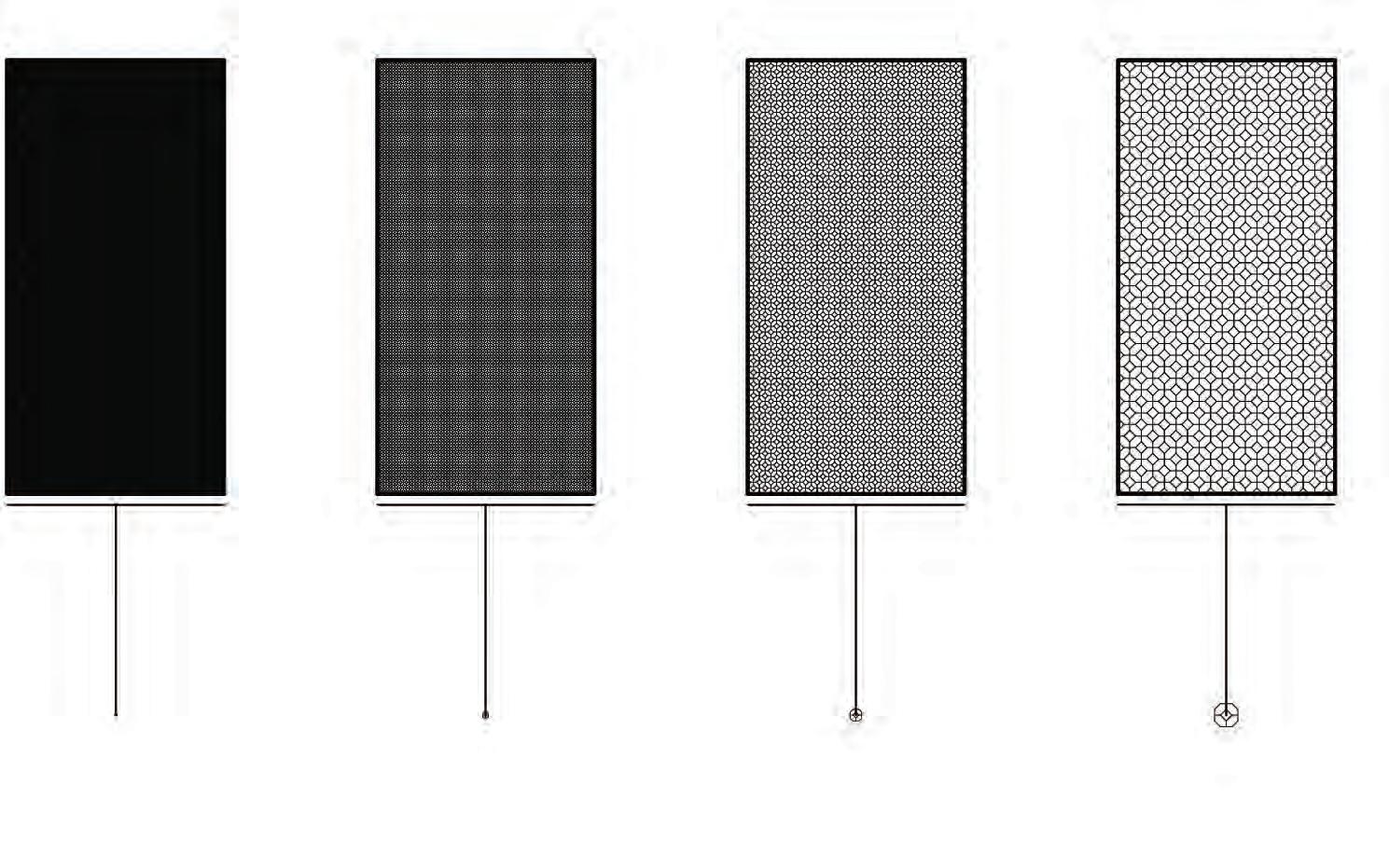
THERMAL
ACOUSTIC - insolation - LARGE SCALE: GEOMETRY CONTROLLED
VISUAL - POROSITY LOW 0.2 / POROSITY HIGH 0.9
VENTILATION - increases with porosity
STRUCTURAL - Material Scale Limitations apply
SPATIAL
186 2.00 cm
4.00 cm 8.00 cm 16.00 cm
INITIAL SCALE STUDY OF CELL SIZE
APPENDIX
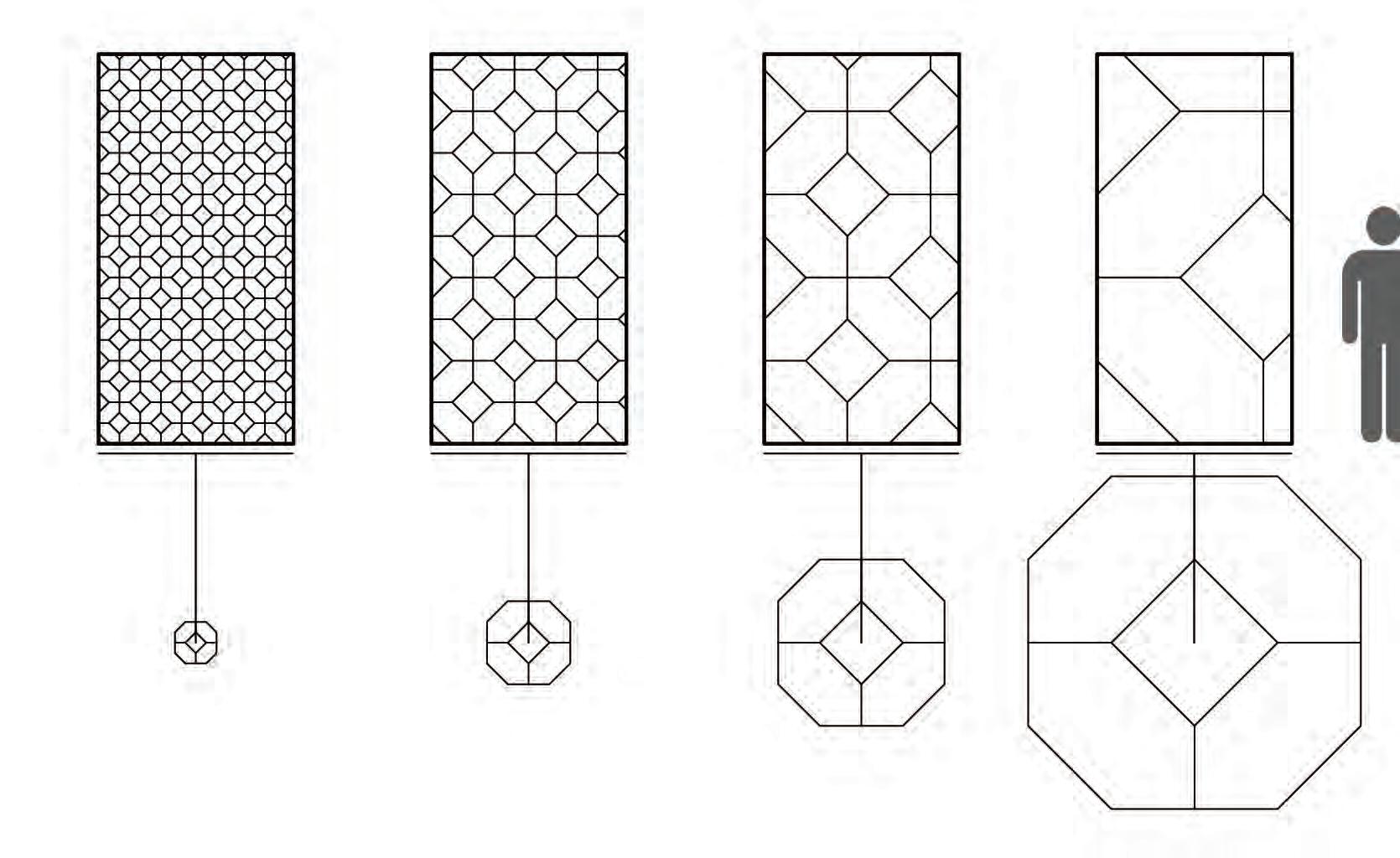
CELLULAR COMPLEXITY 187 32.00 cm 64.00 cm 128.00 cm 256.00 cm
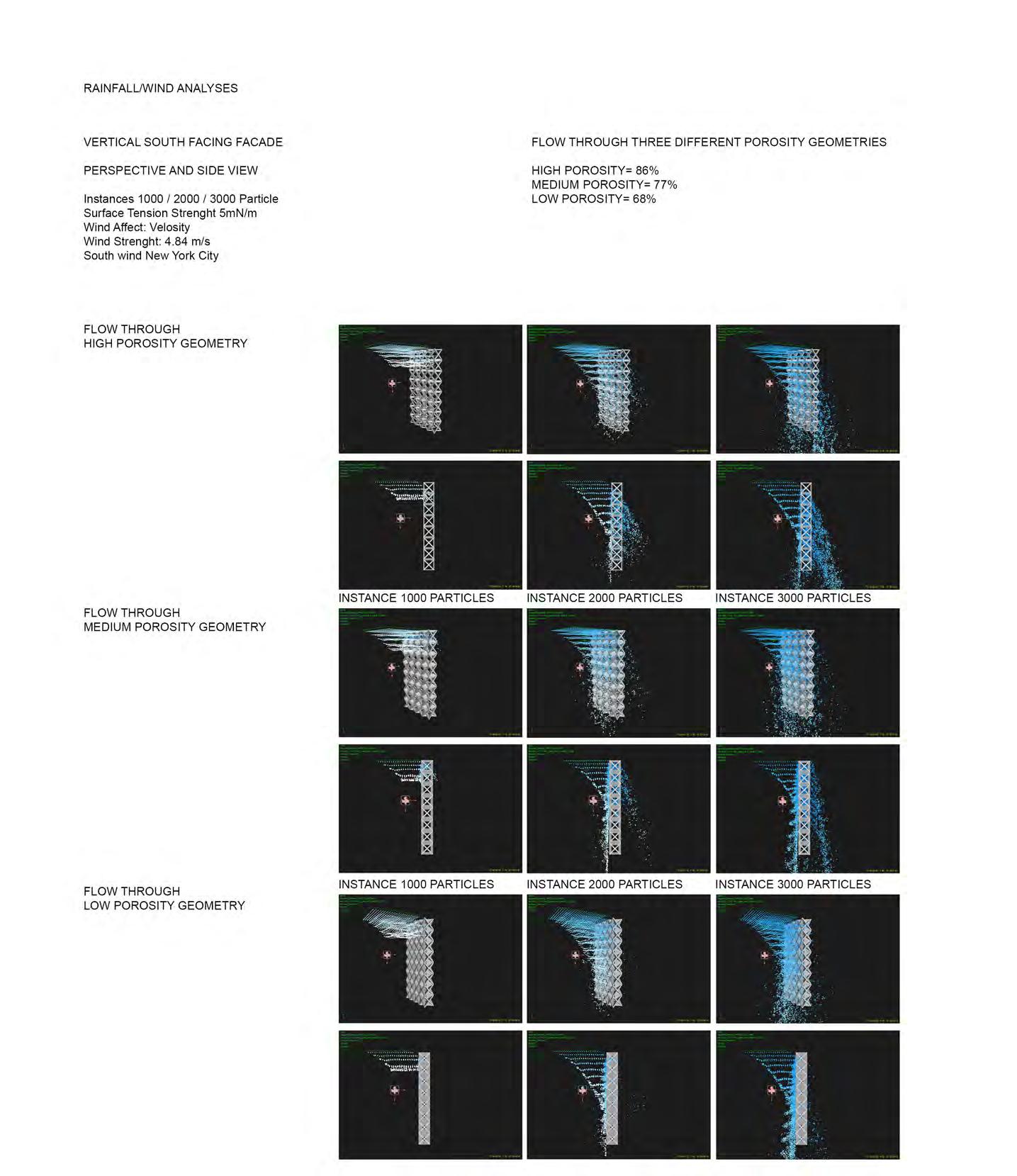
188 APPENDIX
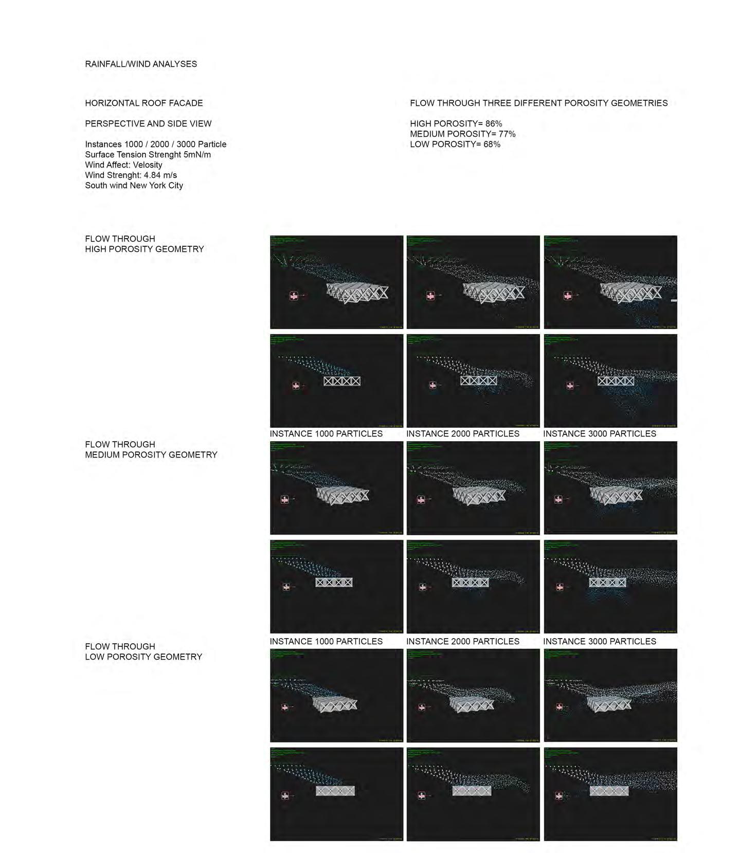
CELLULAR COMPLEXITY 189
COMPUTATIONAL
FORCE WIND
inlet: velocity 10ms-1 outlet: pressure 1Pa
DIRECTION WIND INLET
CELL GEOMETRY
hexagonal tesselation dual-network offset tetra decahedron offset porosity
cell size : 500x500mm
hexagonal tesselation offset tetra decahedron offset porosity
0.20.232
cell size : 500x500mm
hexagonal tesselation dual-network offset tetra decahedron offset porosity
cell size : 500x500mm
hexagonal tesselation offset tetra decahedron offset porosity
0.20.232
cell size : 500x500mm
190
FLUID
DYNAMICS
45’ 0’
0.234
0.234
APPENDIX
CONTOUR PRESSURE
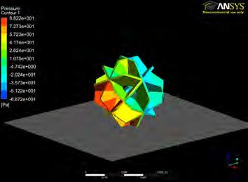
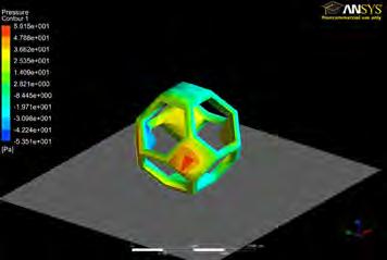
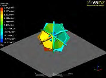
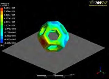
STREAMLINE FLOW CORONAL SECTION
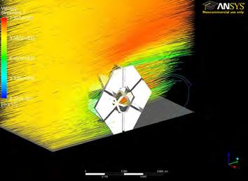
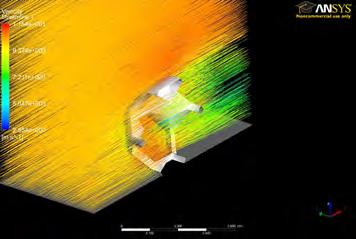
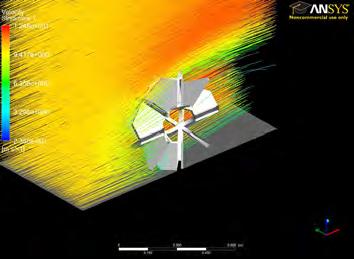
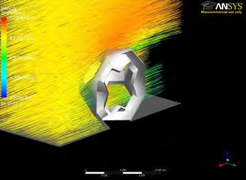
STREAMLINE FLOW TRANSVERSE SECTION
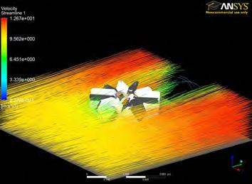
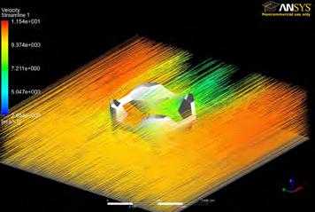
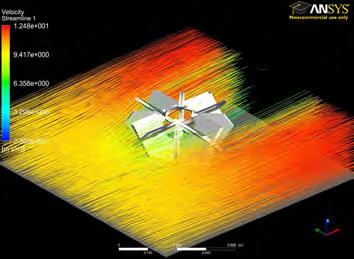
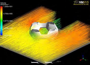
CELLULAR COMPLEXITY 191
COMPUTATIONAL FLUID DYNAMICS
FORCE WIND CELL GEOMETRY
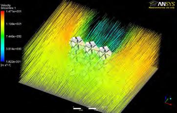
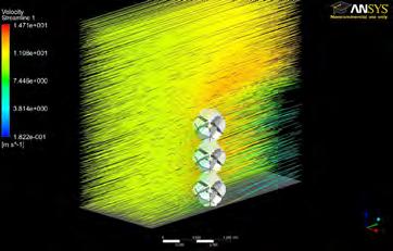
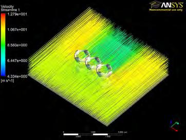
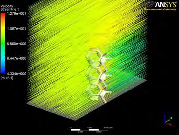
192
CELL ORGANIZATION STREAMLINE FLOW CORONAL and TRANSVERSE SECTION inlet: velocity 10ms-1 outlet: pressure 1Pa hexagonal tesselation dual-network offset tetra decahedron offset porosity 0.234 cell size : 500x500mm 3x3x1 3x3x1 inlet: velocity 10ms-1 outlet: pressure 1Pa hexagonal tesselation offset tetra decahedron offset porosity cell size : 500x500mm 0.20.232
APPENDIX
SHADOW DIAGRAMS
Cell Aggregation prototype 01- Porosity : 86%
JANUARY 21st 3pm
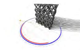
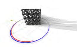
Cell Aggregation prototype 02- Porosity : 77%
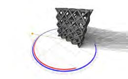
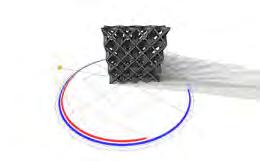
Cell Aggregation prototype 03- Porosity :68%
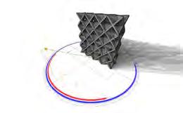
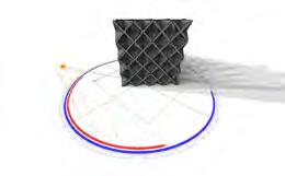
APRIL 21st 3pm
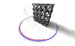
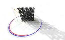
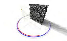
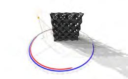
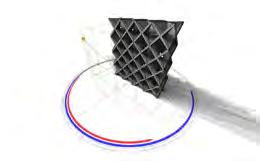
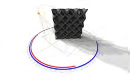
JULY 21st 3pm
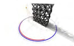
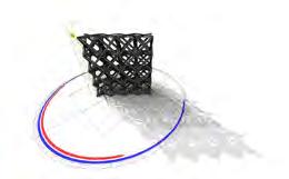
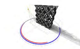
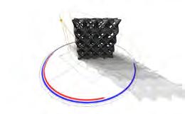
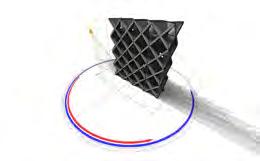
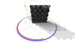
CELLULAR COMPLEXITY 193
N N N
SHADOW ANALYSIS
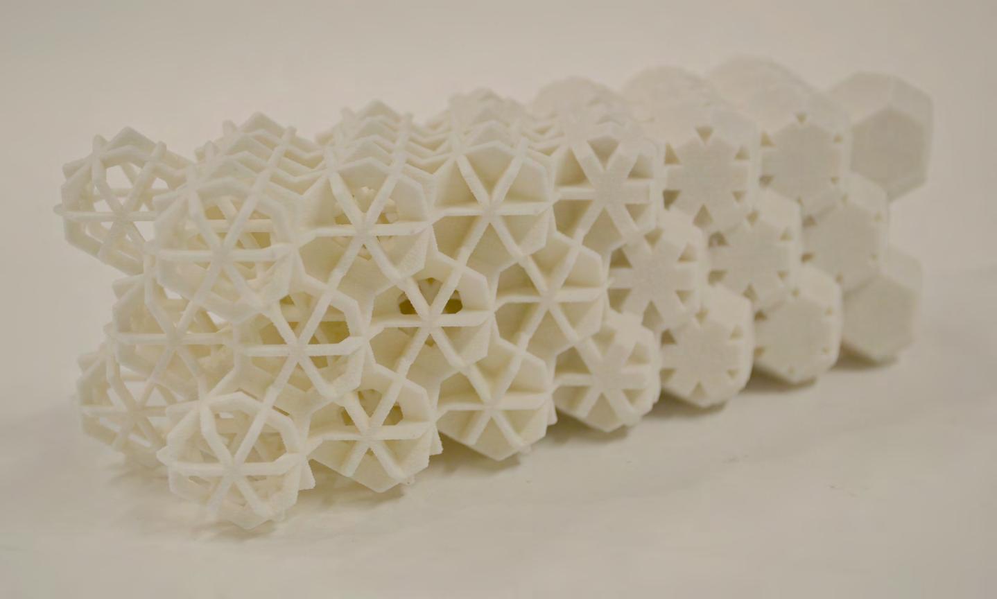
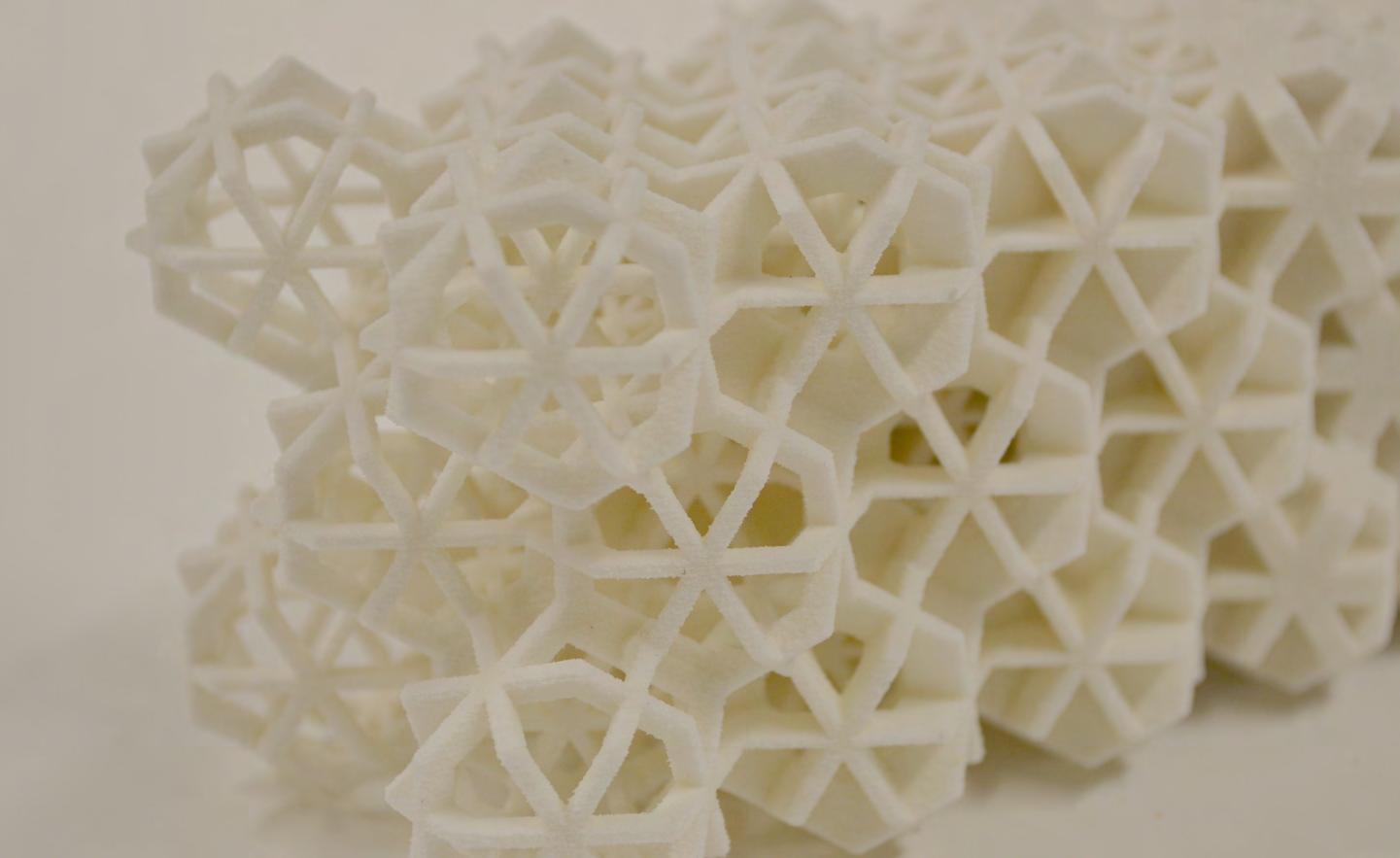
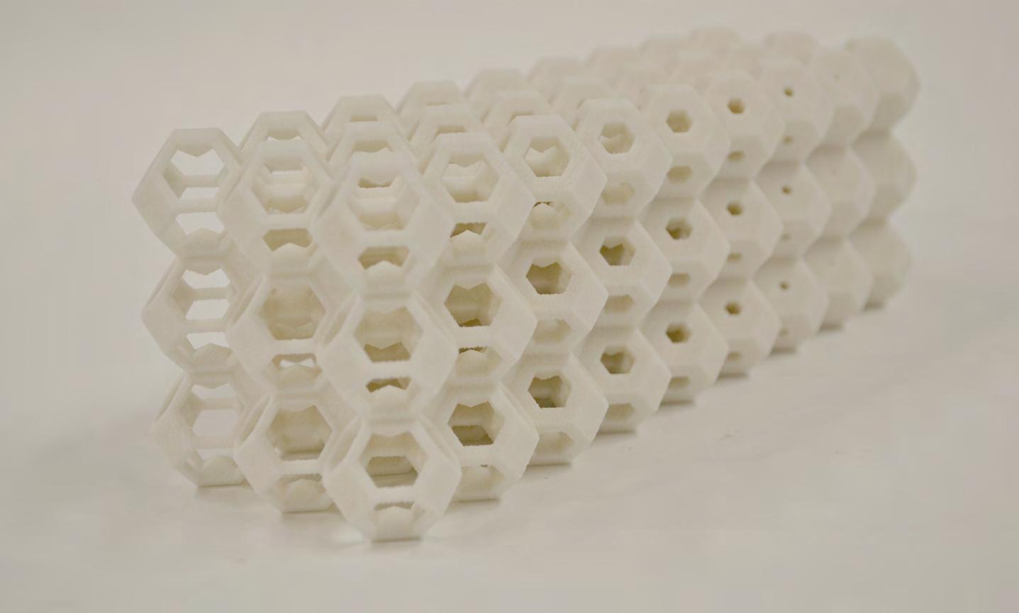
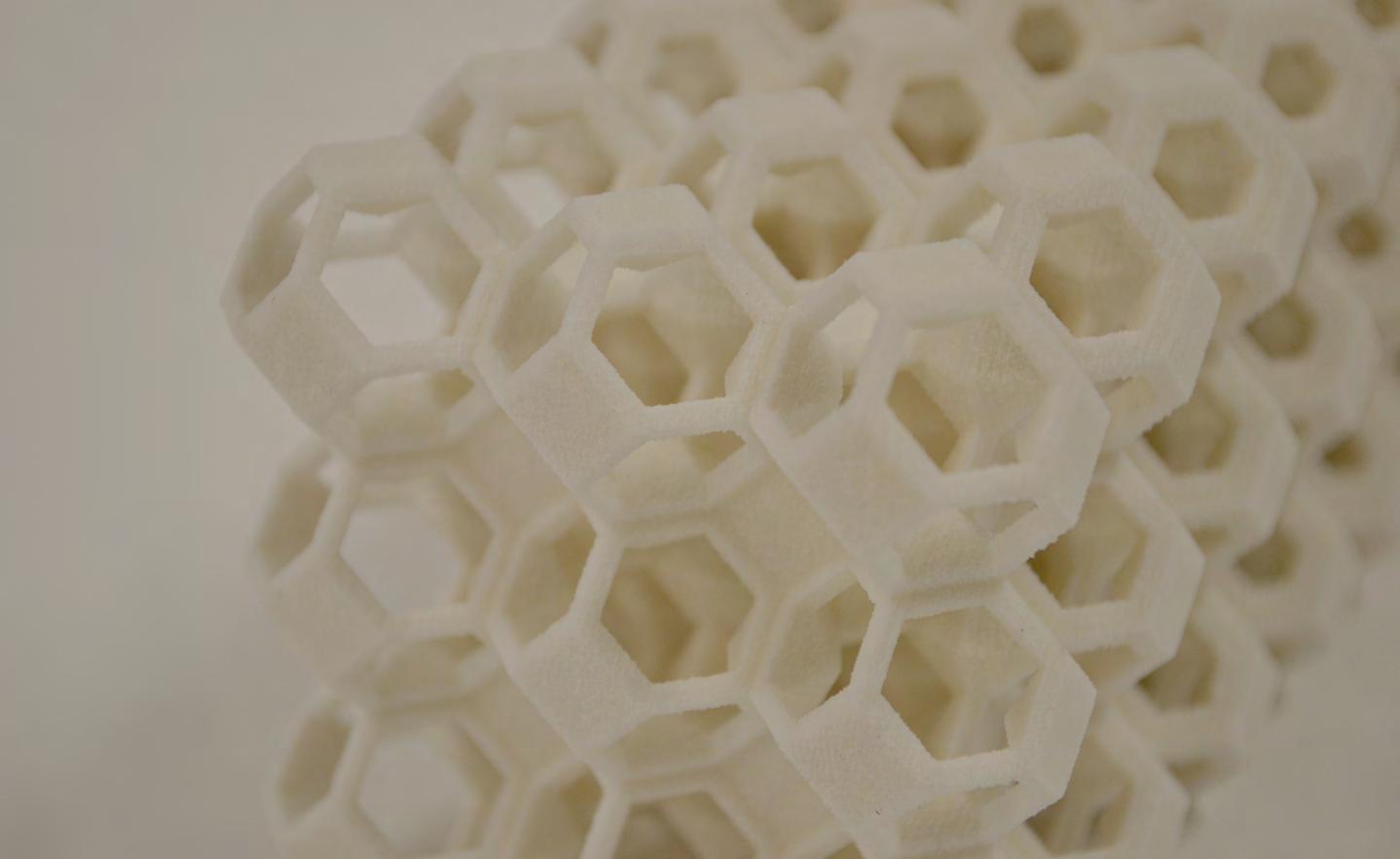
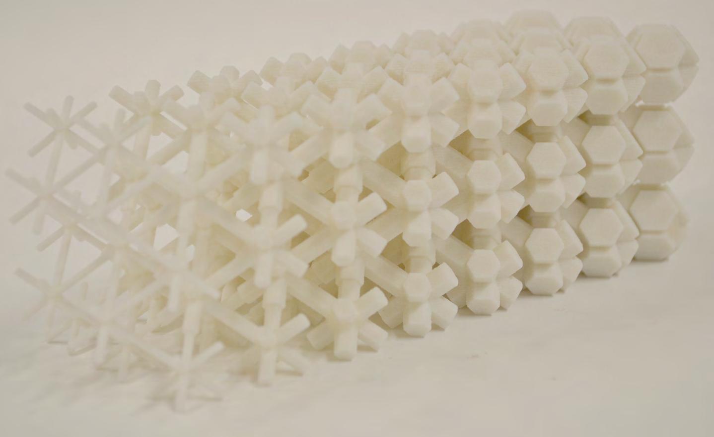
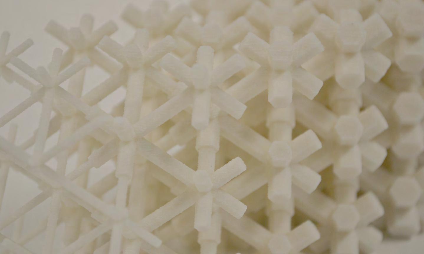
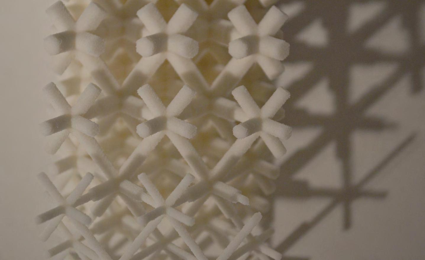
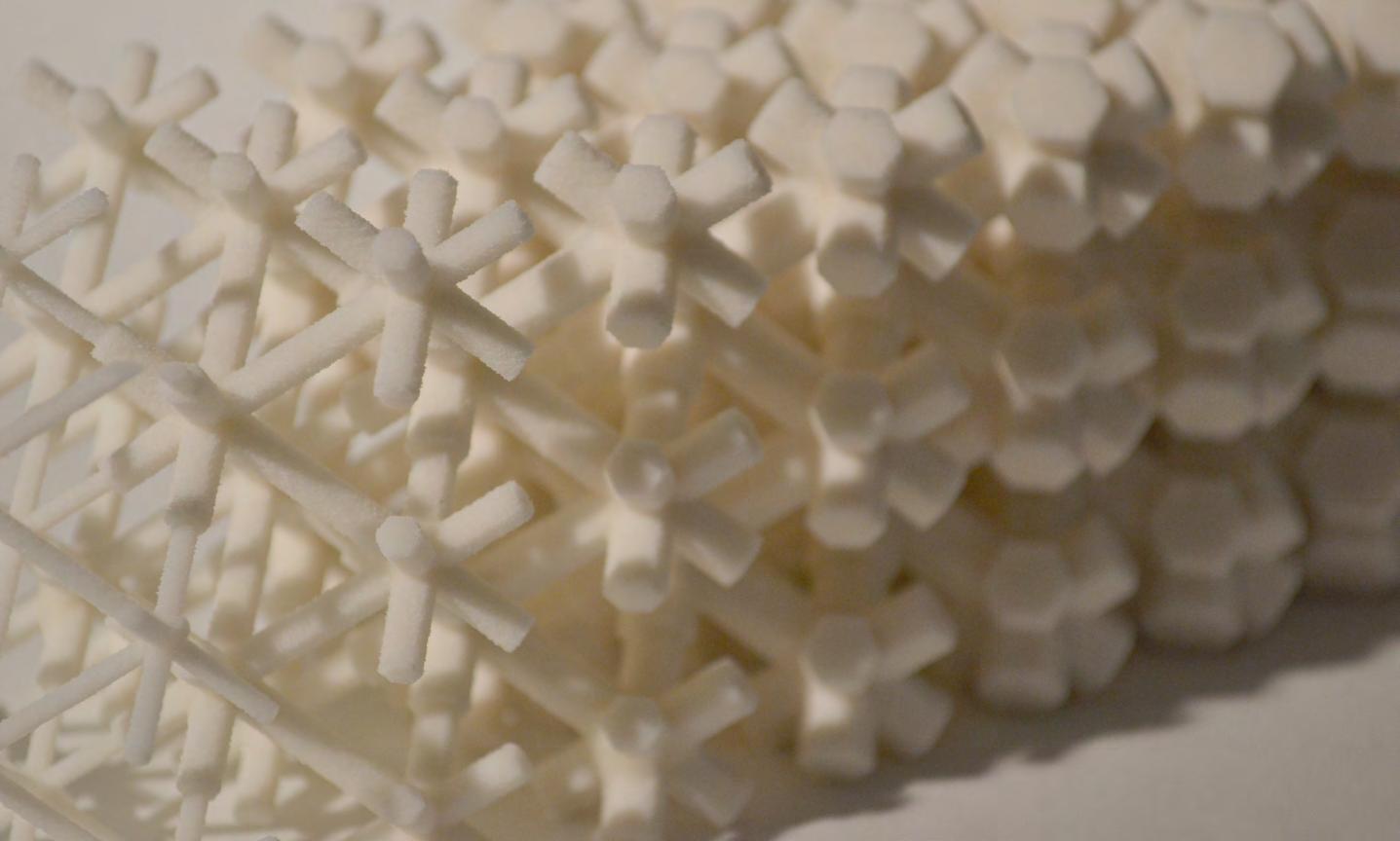
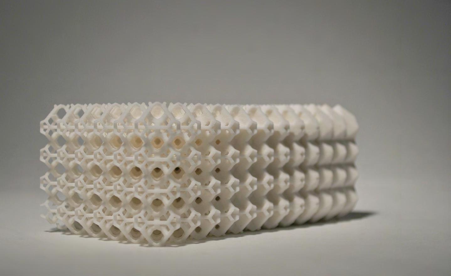
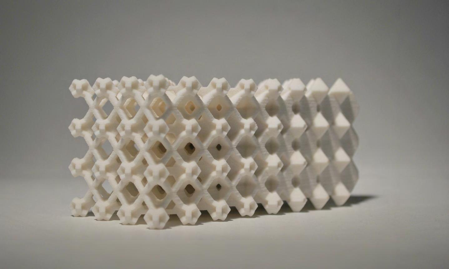
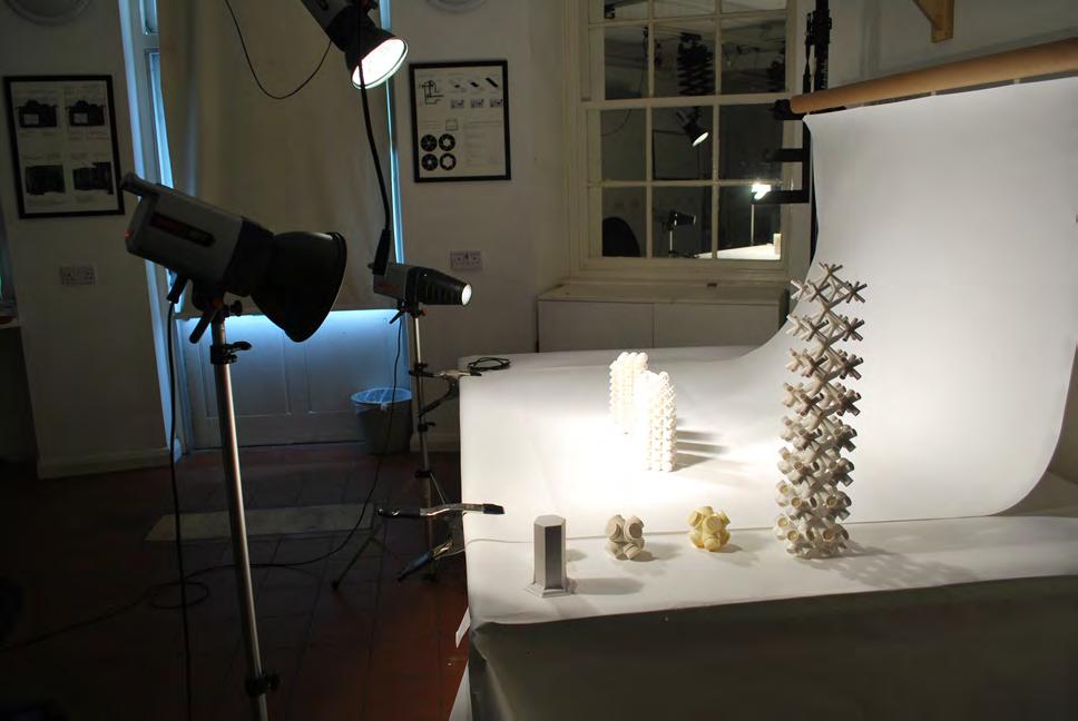
CELLULAR COMPLEXITY 199
Photo Studio AA
Photo Studio AA
A script was developed which builds up the cell according to an input surface. The surface can be planar, curved or doubly curved. The geometry of the cells develops along the surface and consists of planar parts only, even if the surface is curved. The points for each cell are defined by dividing the surface in a desired number of points in both, u and v direction. In each of those points, the surface normal is found in order to create the height of the cell. This height is added several times in an amount which is defined by the number of layers of the system. Through these basic points, each cell is built up by first creating the bounding box of the cell. The geometries which define the strut thickness and the opening are then booleaned out of this basic box in a defined range of scales towards an attractorpoint for each. This range is always a value between 0 and 1 as the distances to the attractor points are remapped. For each gradient, a minimum and a maximum value is entered, so the gradient is then generated between those numbers.
import rhinoscriptsyntax as rs points=[] pointsforcenter=[]
rs.EnableRedraw(False)
import rhinoscriptsyntax as rs points=[] pointsforcenter=[] rs.EnableRedraw(False)
intUdivisions =3
intVdivisions =35
numberoflayers=7
#HEIGHT OF CELL:
intUdivisions =3 intVdivisions =35
#cellheightfactor=1 vectorfactor=2
numberoflayers=7
#SCALE OF INSIDE BOOL 0-1 (if both are the same, no gradient)
#HEIGHT OF CELL:
mininsidescalefactor=0.4 maxinsidescalefactor=0.9
#cellheightfactor=1
vectorfactor=2
If the minimum and the maximum value are the same number, there is no gradient. In the corners of each cell, the joint is built up, following an average size of the defined strut thickness. The basic surface is modeled and the attractor are points set in Rhino. By editing the control lines of the surface, the shape and the size of the later built up cells can be defined. Variable values such as number of divisions in u and v direction - which define the number of cells in each layer - and the number of layers, which multiplies the number of before generated cells in the third direction are entered before running the script. Also, the minimum and maximum factor for strut thickness and opening gradient as well as the height of each layer is defined by the user. After entering those values, the script runs and builds up the structure. Often, a large number of data is created and in extremely twisting surfaces it can happen that some cells cannot be built up any more.
ENTER VALUES FOR VARIABLES
number of cells (defined by U+V divisions of surface)
number of layers
thickness of layers
range of opening gradient (0-closed,1-open)
#MATERIAL THICKNESS 0-1 (if both are the same, no gradient)
#SCALE OF INSIDE BOOL 0-1 (if both are the same, no gradient)
minmaterialthicknessfactor=0 maxmaterialthicknessfactor=0.3
mininsidescalefactor=0.4 maxinsidescalefactor=0.9
#MATERIAL THICKNESS 0-1 (if both are the same, no gradient)
jointthicknessfactor=1
minmaterialthicknessfactor=0
maxmaterialthicknessfactor=0.3
jointthicknessfactor=1
overallthicknesschange=0
actualmininsidescalefactor=(0.1+9.8*mininsidescalefactor) actualmaxinsidescalefactor=(0.1+9.8*maxinsidescalefactor)
overallthicknesschange=0
actualmininsidescalefactor=(0.1+9.8*mininsidescalefactor)
actualmaxinsidescalefactor=(0.1+9.8*maxinsidescalefactor)
def samplesurface(cubesurface, cubeUdivisions,cubeVdivisions): listUdomain = rs.SurfaceDomain(strSrf,0) # list of 2 elements - starting and ending point of domain listVdomain = rs.SurfaceDomain(strSrf,1)
def samplesurface(cubesurface, cubeUdivisions,cubeVdivisions): listUdomain = rs.SurfaceDomain(strSrf,0) # list of 2 elements - starting and ending point of domain listVdomain = rs.SurfaceDomain(strSrf,1)
floatUstep = (listUdomain[1]-listUdomain[0])/intUdivisions floatVstep = (listVdomain[1]-listVdomain[0])/intVdivisions
listofrows = []
floatUstep = (listUdomain[1]-listUdomain[0])/intUdivisions floatVstep = (listVdomain[1]-listVdomain[0])/intVdivisions
for i in rs.frange(listUdomain[0],listUdomain[1],floatUstep): columnlist = [] for j in rs.frange(listVdomain[0],listVdomain[1],floatVstep): columnlist.append(rs.EvaluateSurface(strSrf,i,j)) listofrows.append(columnlist)
range of strut thickness gradient (0-closed,1-open)
SAMPLE SURFACE
divide surface in u and v points in the before entered number of points
return listofrows #rs.AddPoints(listofrows[10][0]) take 10th element of list, which is a list - second number:take first element of this list in the list
listofrows = [] for i in rs.frange(listUdomain[0],listUdomain[1],floatUstep): columnlist = [] for j in rs.frange(listVdomain[0],listVdomain[1],floatVstep): columnlist.append(rs.EvaluateSurface(strSrf,i,j)) listofrows.append(columnlist)
return listofrows #rs.AddPoints(listofrows[10][0]) take 10th element of list, which is a list - second number:take first element of this list in the list
materialthicknessattractors=rs.GetObjects('select materialthickness attractor point',1) insidescaleattractors=rs.GetObjects('select inside bool attractor point',1) strSrf = rs.GetObject("select surface",8)
listofpoints = samplesurface(strSrf,intUdivisions,intVdivisions)
materialthicknessattractors=rs.GetObjects('select materialthickness attractor point',1)
insidescaleattractors=rs.GetObjects('select inside bool attractor point',1)
SELECT ATTRACTORPOINTS AND SURFACE
strSrf = rs.GetObject("select surface",8)
listofpoints = samplesurface(strSrf,intUdivisions,intVdivisions)
cells=[]
cells=[] zpoints=[] centroids=[] surfacepointslist=[] jointsurfacelist=[] listofsurfacecenterlists=[]
200
#------------------------------------------------------------------------------------------------------------------------------------------#---------------------- CHANGE CHANGE CHANGE CHANGE CHANGE CHANGE CHANGE CHANGE CHANGE CHANGE ------------------------#-------------------------------------------------------------------------------------------------------------------------------------------
#------------------------------------------------------------------------------------------------------------------------------------------#------------------------------------------------------------------------------------------------------------------------------------------#-------------------------------------------------------------------------------------------------------------------------------------------
RHINO PYTHON SCRIPT OF STRUCTURE
#-----------------------------------------------------------------------------------------------------------------------------#---------------------- CHANGE CHANGE CHANGE CHANGE CHANGE CHANGE CHANGE CHANGE CHANGE CHANGE ------------------------#-------------------------------------------------------------------------------------------------------------------------------------------
#------------------------------------------------------------------------------------------------------------------------------------------#-----------------------------------------------------------------------------------------------------------------------------#-------------------------------------------------------------------------------------------------------------------------------------------
APPENDIX
element
materialthicknessattractors=rs.GetObjects('select materialthickness attractor point',1) insidescaleattractors=rs.GetObjects('select inside bool attractor point',1)
strSrf = rs.GetObject("select surface",8)
listofpoints = samplesurface(strSrf,intUdivisions,intVdivisions)
cells=[] zpoints=[] centroids=[] surfacepointslist=[] jointsurfacelist=[] listofsurfacecenterlists=[] for i in range (0,len(listofpoints)-1): for j in range (0,len(listofpoints[i])-1): for k in range (0,numberoflayers): pyramidcentroidnormals=[] verybottompointlist=[listofpoints[i][j],listofpoints[i+1][j],listofpoints[i+1][j+1],listofpoints[i][j+1]] normalunilist=[] startlist=[] endlist=[] edgelist=[]
surfacepoints=[]
#vectorfactor=rs.Distance(listofpoints[0][0],listofpoints[1][0])
materialmax=(vectorfactor/2.1)
materialmin=vectorfactor/25
actualminmaterialthickness=(materialmin+(materialmax-materialmin)*minmaterialthicknessfactor)
actualmaxmaterialthickness=(materialmin+(materialmax-materialmin)*maxmaterialthicknessfactor)
#jointthickness=((materialmin+(materialmaxmaterialmin)*(minmaterialthicknessfactor+maxmaterialthicknessfactor)/2))*jointthicknessfactor
jointthickness=actualminmaterialthickness*jointthicknessfactor
for h in range (0,len(verybottompointlist)):
closest=rs.SurfaceClosestPoint(strSrf,verybottompointlist[h])
normaldir=rs.SurfaceNormal(strSrf,closest)
normaluni=rs.VectorUnitize(normaldir)
DEFINE LISTS AND LOOP for accessing all points for each cell in u,v and z direction
CONVERT NUMBERS TO FACTOR
NORMALS IN Z DIRECTION
#normalscale=rs.VectorScale(normaluni,cellheightfactor*vectorfactor*numberoflayers*(1+i*overallthicknesschange))
normalscale=rs.VectorScale(normaluni,vectorfactor*numberoflayers*(1+i*overallthicknesschange))
normal=rs.VectorAdd(verybottompointlist[h],normalscale)
#verytoppoint=rs.AddPoint(normal) edge=rs.AddLine(verybottompointlist[h],normal) edgelist.append(edge)
zpoints01=rs.DivideCurve(edgelist[0],numberoflayers)
zpoints02=rs.DivideCurve(edgelist[1],numberoflayers)
zpoints03=rs.DivideCurve(edgelist[2],numberoflayers) zpoints04=rs.DivideCurve(edgelist[3],numberoflayers) zpoints.extend(zpoints01)
rs.DeleteObjects([edgelist[0],edgelist[1],edgelist[2],edgelist[3]])
start01=rs.AddPoint(zpoints01[k])
end01=rs.AddPoint(zpoints01[k+1]) smallnormaldir01=rs.VectorCreate(end01,start01) smallnormaluni01=rs.VectorUnitize(smallnormaldir01) pyramidnormal01=rs.VectorScale(smallnormaluni01,jointthickness)
start02=rs.AddPoint(zpoints02[k])
end02=rs.AddPoint(zpoints02[k+1]) smallnormaldir02=rs.VectorCreate(end02,start02) smallnormaluni02=rs.VectorUnitize(smallnormaldir02) pyramidnormal02=rs.VectorScale(smallnormaluni02,jointthickness)
start03=rs.AddPoint(zpoints03[k]) end03=rs.AddPoint(zpoints03[k+1]) smallnormaldir03=rs.VectorCreate(end03,start03) smallnormaluni03=rs.VectorUnitize(smallnormaldir03) pyramidnormal03=rs.VectorScale(smallnormaluni03,jointthickness)
start04=rs.AddPoint(zpoints04[k]) end04=rs.AddPoint(zpoints04[k+1]) smallnormaldir04=rs.VectorCreate(end04,start04) smallnormaluni04=rs.VectorUnitize(smallnormaldir04) pyramidnormal04=rs.VectorScale(smallnormaluni04,jointthickness)
bottompointlist=[start01,start02,start03,start04] toppointlist=[end01,end02,end03,end04]
normalunilist=[smallnormaluni01,smallnormaluni02,smallnormaluni03,smallnormaluni04] pyramidcentroidnormals=[pyramidnormal01,pyramidnormal02,pyramidnormal03,pyramidnormal04]
srfnormal01scale=rs.VectorScale(normalunilist[0],vectorfactor) srfnormal02scale=rs.VectorScale(normalunilist[1],vectorfactor) srfnormal03scale=rs.VectorScale(normalunilist[2],vectorfactor) srfnormal04scale=rs.VectorScale(normalunilist[3],vectorfactor)
srfnormal01=rs.VectorAdd(bottompointlist[0],srfnormal01scale) srfnormal02=rs.VectorAdd(bottompointlist[1],srfnormal02scale) srfnormal03=rs.VectorAdd(bottompointlist[2],srfnormal03scale) srfnormal04=rs.VectorAdd(bottompointlist[3],srfnormal04scale)
#SURFACE POINTS - 6 CUBE SURFACES
surface01points=[bottompointlist[0],bottompointlist[1],toppointlist[1],toppointlist[0]] surface02points=[bottompointlist[1],bottompointlist[2],toppointlist[2],toppointlist[1]] surface03points=[bottompointlist[2],bottompointlist[3],toppointlist[3],toppointlist[2]] surface04points=[bottompointlist[3],bottompointlist[0],toppointlist[0],toppointlist[3]] surface05points=[bottompointlist[0],bottompointlist[1],bottompointlist[2],bottompointlist[3]] surface06points=[toppointlist[2],toppointlist[3],toppointlist[0],toppointlist[1]] surfacepoints=[surface01points,surface02points,surface03points,surface04points,surface05points,surface06points] surfacepointslist.append(surfacepoints) surfacecenterlist=[] quadsurfacelist=[]
#create quadsurfaces quadsurfaceface01part01=rs.AddSrfPt([surfacepoints[0][1],surfacepoints[0][2],surfacepoints[0][3]]) quadsurfaceface01part02=rs.AddSrfPt([surfacepoints[0][3],surfacepoints[0][0],surfacepoints[0][1]]) quadsurfaceface01=rs.JoinSurfaces([quadsurfaceface01part01,quadsurfaceface01part02],delete_input=True) quadsurfacecenterdirection=rs.VectorCreate(surfacepoints[0][1],surfacepoints[0][3]) quadsurfacecenterscale=rs.VectorScale(quadsurfacecenterdirection,0.5)
GENERATE ALL POINTS OF CELL BOUNDING BOX
GENERATE ALL NECESSARY VECTORS
LIST ALL POINTS FOR EACH FACE OF CELL BOUNDING BOX
CELLULAR COMPLEXITY 201
of this list in the list
#quadsurfacecenter=rs.SurfaceAreaCentroid(quadsurface) quadsurfacecenter=rs.AddPoint(quadsurfacecenter) surfacecenterlist.append(quadsurfacecenter) quadsurfaceface02part01=rs.AddSrfPt([surfacepoints[1][1],surfacepoints[1][2],surfacepoints[1][3]]) quadsurfaceface02part02=rs.AddSrfPt([surfacepoints[1][3],surfacepoints[1][0],surfacepoints[1][1]]) quadsurfaceface02=rs.JoinSurfaces([quadsurfaceface02part01,quadsurfaceface02part02],delete_input=True) quadsurfacelist.append(quadsurfaceface01) quadsurfacelist.append(quadsurfaceface02) quadsurfacecenterdirection=rs.VectorCreate(surfacepoints[1][1],surfacepoints[1][3]) quadsurfacecenterscale=rs.VectorScale(quadsurfacecenterdirection,0.5) quadsurfacecenter=rs.VectorAdd(surfacepoints[1][3],quadsurfacecenterscale) #quadsurfacecenter=rs.SurfaceAreaCentroid(quadsurface) quadsurfacecenter=rs.AddPoint(quadsurfacecenter) surfacecenterlist.append(quadsurfacecenter) for a in range (2, len(surfacepoints)): quadsurfacepart01=rs.AddSrfPt([surfacepoints[a][0],surfacepoints[a][1],surfacepoints[a][2]]) quadsurfacepart02=rs.AddSrfPt([surfacepoints[a][2],surfacepoints[a][3],surfacepoints[a][0]]) quadsurface=rs.JoinSurfaces([quadsurfacepart01,quadsurfacepart02],delete_input=True) quadsurfacelist.append(quadsurface) #create surface centers quadsurfacecenterdirection=rs.VectorCreate(surfacepoints[a][0],surfacepoints[a][2]) quadsurfacecenterscale=rs.VectorScale(quadsurfacecenterdirection,0.5) quadsurfacecenter=rs.VectorAdd(surfacepoints[a][2],quadsurfacecenterscale) #quadsurfacecenter=rs.SurfaceAreaCentroid(quadsurface) quadsurfacecenter=rs.AddPoint(quadsurfacecenter) surfacecenterlist.append(quadsurfacecenter) listofsurfacecenterlists.append(surfacecenterlist)
#join quadsurfaces
jointsrf01=rs.JoinSurfaces(quadsurfacelist,delete_input=True) jointsurfacelist.append(jointsrf01)
#---------------------------- CENTROID ------------------------centroid_L01=rs.SurfaceVolumeCentroid(jointsrf01) #rs.AddPoint(centroid_L01[0]) centroids.append(centroid_L01[0])
#VECTOR 01 bottom 1-2
vector01=rs.VectorCreate(bottompointlist[0],bottompointlist[1])
vector01uni=rs.VectorUnitize(vector01) vector01=rs.VectorScale(vector01uni,jointthickness)
#PYRAMID LAYER 01 - VECTOR 02
vector02=rs.VectorCreate(bottompointlist[1],bottompointlist[2])
vector02uni=rs.VectorUnitize(vector02) vector02=rs.VectorScale(vector02uni,jointthickness)
#PYRAMID LAYER 01 - VECTOR 03
vector03=rs.VectorCreate(bottompointlist[2],bottompointlist[3])
vector03uni=rs.VectorUnitize(vector03)
vector03=rs.VectorScale(vector03uni,jointthickness)
#PYRAMID LAYER 01 - VECTOR 04
vector04=rs.VectorCreate(bottompointlist[3],bottompointlist[0])
vector04uni=rs.VectorUnitize(vector04)
vector04=rs.VectorScale(vector04uni,jointthickness)
#PYRAMID LAYER 01 - VECTOR 01A
vector01A=rs.VectorCreate(toppointlist[0],toppointlist[1])
vector01Auni=rs.VectorUnitize(vector01A) vector01A=rs.VectorScale(vector01Auni,jointthickness)
#PYRAMID LAYER 01 - VECTOR 02A
vector02A=rs.VectorCreate(toppointlist[1],toppointlist[2])
vector02Auni=rs.VectorUnitize(vector02A) vector02A=rs.VectorScale(vector02Auni,jointthickness)
#PYRAMID LAYER 01 - VECTOR 03A
vector03A=rs.VectorCreate(toppointlist[2],toppointlist[3])
vector03Auni=rs.VectorUnitize(vector03A)
vector03A=rs.VectorScale(vector03Auni,jointthickness)
#PYRAMID LAYER 01 - VECTOR 04A
vector04A=rs.VectorCreate(toppointlist[3],toppointlist[0])
vector04Auni=rs.VectorUnitize(vector04A) vector04A=rs.VectorScale(vector04Auni,jointthickness)
booleanlist02=[]
#PYRAMID LAYER 01 CORNER 01 #TOP-01
pyramidtop01=rs.VectorAdd(bottompointlist[0],pyramidcentroidnormals[0]) #pyramidtop01=rs.AddPoint(pyramidtop01)
#VECTOR L01-C01-01
vector01_01=rs.VectorAdd(bottompointlist[0],vector01*-1) #rs.AddPoint(vector01_01) #VECTOR L01-C01-02
vector01_02=rs.VectorAdd(bottompointlist[0],vector04)
#rs.AddPoint(vector01_02)
#SURFACE
curve01_01=rs.AddInterpCurve([bottompointlist[0],vector01_01,vector01_02,bottompointlist[0]],1) srf01_01=rs.ExtrudeCurvePoint(curve01_01,pyramidtop01) srf01_02=rs.AddSrfPt([bottompointlist[0],vector01_01,vector01_02]) jointsrfpyramid01=rs.JoinSurfaces([srf01_01,srf01_02],delete_input=True)
scalepoint01=rs.SurfaceVolumeCentroid(jointsrfpyramid01) jointsrfpyramid01scaled=rs.ScaleObject(jointsrfpyramid01,scalepoint01[0],[1.1,1.1,1.1],copy=True) booleanlist02.append(jointsrfpyramid01scaled)
#BOTTOM-01
pyramidbottom01A=rs.VectorAdd(toppointlist[0],pyramidcentroidnormals[0]*-1) #pyramidbottom01=rs.AddPoint(pyramidbottom01)
#VECTOR L01-C01-01
vector01A_01=rs.VectorAdd(toppointlist[0],vector01A*-1)
#rs.AddPoint(vector01_01) #VECTOR L01-C01-02
vector01A_02=rs.VectorAdd(toppointlist[0],vector04A)
CREATE CELL BOUNDING BOX SURFACES
CREATE CENTROID OF BOUNDING BOX
VECTORS FOR JOINTS
SURFACES FOR JOINTS
202
#
---------------------------------------------# #------------------------------------------------------------------------------------------------------------------------------# #------------------------------------------------------------------------------------------------------------------------------#
# #----------------------------------------- JOINTS JOINTS JOINTS JOINTS
APPENDIX
#SURFACE
curve01_01=rs.AddInterpCurve([bottompointlist[0],vector01_01,vector01_02,bottompointlist[0]],1)
srf01_01=rs.ExtrudeCurvePoint(curve01_01,pyramidtop01)
srf01_02=rs.AddSrfPt([bottompointlist[0],vector01_01,vector01_02])
jointsrfpyramid01=rs.JoinSurfaces([srf01_01,srf01_02],delete_input=True)
scalepoint01=rs.SurfaceVolumeCentroid(jointsrfpyramid01)
jointsrfpyramid01scaled=rs.ScaleObject(jointsrfpyramid01,scalepoint01[0],[1.1,1.1,1.1],copy=True) booleanlist02.append(jointsrfpyramid01scaled)
#BOTTOM-01
pyramidbottom01A=rs.VectorAdd(toppointlist[0],pyramidcentroidnormals[0]*-1)
#pyramidbottom01=rs.AddPoint(pyramidbottom01)
#VECTOR L01-C01-01
vector01A_01=rs.VectorAdd(toppointlist[0],vector01A*-1)
#rs.AddPoint(vector01_01)
#VECTOR L01-C01-02
vector01A_02=rs.VectorAdd(toppointlist[0],vector04A)
#rs.AddPoint(vector01_02)
#SURFACE
curve01A_01=rs.AddInterpCurve([toppointlist[0],vector01A_01,vector01A_02,toppointlist[0]],1)
srf01A_01=rs.ExtrudeCurvePoint(curve01A_01,pyramidbottom01A)
srf01A_02=rs.AddSrfPt([toppointlist[0],vector01A_01,vector01A_02]) jointsrfpyramid01A=rs.JoinSurfaces([srf01A_01,srf01A_02],delete_input=True)
scalepoint01A=rs.SurfaceVolumeCentroid(jointsrfpyramid01A)
jointsrfpyramid01Ascaled=rs.ScaleObject(jointsrfpyramid01A,scalepoint01A[0],[1.1,1.1,1.1],copy=True) booleanlist02.append(jointsrfpyramid01Ascaled)
#PYRAMID LAYER 01 CORNER 02
#TOP
pyramidtop02=rs.VectorAdd(bottompointlist[1],pyramidcentroidnormals[1])
#pyramidtop02=rs.AddPoint(pyramidtop02)
#VECTOR L01-C02-01
vector02_01=rs.VectorAdd(bottompointlist[1],vector01)
#rs.AddPoint(vector02_01)
#VECTOR L01-C02-02
vector02_02=rs.VectorAdd(bottompointlist[1],vector02*-1)
#rs.AddPoint(vector02_02)
curve02_01=rs.AddInterpCurve([bottompointlist[1],vector02_01,vector02_02,bottompointlist[1]],1)
srf02_01=rs.ExtrudeCurvePoint(curve02_01,pyramidtop02)
srf02_02=rs.AddSrfPt([bottompointlist[1],vector02_01,vector02_02]) jointsrfpyramid02=rs.JoinSurfaces([srf02_01,srf02_02],delete_input=True) scalepoint02=rs.SurfaceVolumeCentroid(jointsrfpyramid02)
jointsrfpyramid02scaled=rs.ScaleObject(jointsrfpyramid02,scalepoint02[0],[1.1,1.1,1.1],copy=True) booleanlist02.append(jointsrfpyramid02scaled)
#BOTTOM-02
pyramidbottom02A=rs.VectorAdd(toppointlist[1],pyramidcentroidnormals[1]*-1) #pyramidbottom02=rs.AddPoint(pyramidbottom02)
#VECTOR L01-C02-01
vector02A_01=rs.VectorAdd(toppointlist[1],vector01A)
#rs.AddPoint(vector02_01)
#VECTOR L01-C02-02
vector02A_02=rs.VectorAdd(toppointlist[1],vector02A*-1)
#rs.AddPoint(vector02_02)
curve02A_01=rs.AddInterpCurve([toppointlist[1],vector02A_01,vector02A_02,toppointlist[1]],1) srf02A_01=rs.ExtrudeCurvePoint(curve02A_01,pyramidbottom02A)
srf02A_02=rs.AddSrfPt([toppointlist[1],vector02A_01,vector02A_02])
jointsrfpyramid02A=rs.JoinSurfaces([srf02A_01,srf02A_02],delete_input=True)
scalepoint02A=rs.SurfaceVolumeCentroid(jointsrfpyramid02A) jointsrfpyramid02Ascaled=rs.ScaleObject(jointsrfpyramid02A,scalepoint02A[0],[1.1,1.1,1.1],copy=True) booleanlist02.append(jointsrfpyramid02Ascaled)
#PYRAMID LAYER 01 CORNER 03
#TOP
pyramidtop03=rs.VectorAdd(bottompointlist[2],pyramidcentroidnormals[2]) #pyramidtop03=rs.AddPoint(pyramidtop03)
#VECTOR L01-C03-01
vector03_01=rs.VectorAdd(bottompointlist[2],vector02)
#rs.AddPoint(vector03_01)
#VECTOR L01-C03-02
vector03_02=rs.VectorAdd(bottompointlist[2],vector03*-1)
#rs.AddPoint(vector03_02)
curve03_01=rs.AddInterpCurve([bottompointlist[2],vector03_01,vector03_02,bottompointlist[2]],1) srf03_01=rs.ExtrudeCurvePoint(curve03_01,pyramidtop03)
srf03_02=rs.AddSrfPt([bottompointlist[2],vector03_01,vector03_02]) jointsrfpyramid03=rs.JoinSurfaces([srf03_01,srf03_02],delete_input=True) scalepoint03=rs.SurfaceVolumeCentroid(jointsrfpyramid03) jointsrfpyramid03scaled=rs.ScaleObject(jointsrfpyramid03,scalepoint03[0],[1.1,1.1,1.1],copy=True) booleanlist02.append(jointsrfpyramid03scaled)
#BOTTOM pyramidbottom03A=rs.VectorAdd(toppointlist[2],pyramidcentroidnormals[2]*-1) #pyramidbottom03=rs.AddPoint(pyramidbottom03)
#VECTOR L01-C03-01
vector03A_01=rs.VectorAdd(toppointlist[2],vector02A)
#rs.AddPoint(vector03_01) #VECTOR L01-C03-02
vector03A_02=rs.VectorAdd(toppointlist[2],vector03A*-1)
#rs.AddPoint(vector03_02)
curve03A_01=rs.AddInterpCurve([toppointlist[2],vector03A_01,vector03A_02,toppointlist[2]],1)
srf03A_01=rs.ExtrudeCurvePoint(curve03A_01,pyramidbottom03A)
srf03A_02=rs.AddSrfPt([toppointlist[2],vector03A_01,vector03A_02]) jointsrfpyramid03A=rs.JoinSurfaces([srf03A_01,srf03A_02],delete_input=True) scalepoint03A=rs.SurfaceVolumeCentroid(jointsrfpyramid03A) jointsrfpyramid03Ascaled=rs.ScaleObject(jointsrfpyramid03A,scalepoint03A[0],[1.1,1.1,1.1],copy=True) booleanlist02.append(jointsrfpyramid03Ascaled)
#PYRAMID LAYER 01 CORNER 04
#TOP
pyramidtop04=rs.VectorAdd(bottompointlist[3],pyramidcentroidnormals[3]) #pyramidtop04=rs.AddPoint(pyramidtop04)
#VECTOR L01-C04-01
vector04_01=rs.VectorAdd(bottompointlist[3],vector03)
#rs.AddPoint(vector04_01)
#VECTOR L01-C04-02
vector04_02=rs.VectorAdd(bottompointlist[3],vector04*-1)
#rs.AddPoint(vector04_02)
curve04_01=rs.AddInterpCurve([bottompointlist[3],vector04_01,vector04_02,bottompointlist[3]],1)
srf04_01=rs.ExtrudeCurvePoint(curve04_01,pyramidtop04)
srf04_02=rs.AddSrfPt([bottompointlist[3],vector04_01,vector04_02]) jointsrfpyramid04=rs.JoinSurfaces([srf04_01,srf04_02],delete_input=True) scalepoint04=rs.SurfaceVolumeCentroid(jointsrfpyramid04) jointsrfpyramid04scaled=rs.ScaleObject(jointsrfpyramid04,scalepoint04[0],[1.1,1.1,1.1],copy=True) booleanlist02.append(jointsrfpyramid04scaled)
#BOTTOM
pyramidbottom04A=rs.VectorAdd(toppointlist[3],pyramidcentroidnormals[3]*-1)
#pyramidbottom04=rs.AddPoint(pyramidbottom04)
#VECTOR L01-C04-01
vector04A_01=rs.VectorAdd(toppointlist[3],vector03A)
#rs.AddPoint(vector04_01)
#VECTOR L01-C04-02
vector04A_02=rs.VectorAdd(toppointlist[3],vector04A*-1)
SURFACES FOR JOINTS (OCTAHEDRONS) IN EVERY CORNER
CELLULAR COMPLEXITY 203
DUAL GEOMETRY WHICH IS THEN SUBTRACTED FROM THE STRUCTURE INTO LEAVE THE STRUT THICKNESS IN THE DESIRED SCALE
print len(centroids)
cells=[]
allmaterialthicknessdistances=[]
allinsidescaledistances=[]
insidescaledistances=[]
materialthicknessdistances=[]
for g in range (0,len(centroids)):
for a in range(0,len(insidescaleattractors)): insidescaledistancehelp=rs.Distance(centroids[g],insidescaleattractors[a])
#insidescaledistances.append(insidescaledistancehelp)
#insidescaledistance=sum(insidescaledistances)
allinsidescaledistances.append(insidescaledistancehelp) print allinsidescaledistances
for b in range(0,len(materialthicknessattractors)):
materialthicknessdistancehelp=rs.Distance(centroids[g],materialthicknessattractors[b])
#materialthicknessdistances.append(materialthicknessdistancehelp)
#materialthicknessdistance=sum(materialthicknessdistances) allmaterialthicknessdistances.append(materialthicknessdistancehelp) print allmaterialthicknessdistances
mininsidescaledistance=min(allinsidescaledistances) maxinsidescaledistance=max(allinsidescaledistances)
minmaterialthicknessdistance=min(allmaterialthicknessdistances) maxmaterialthicknessdistance=max(allmaterialthicknessdistances)
mhigh1=maxmaterialthicknessdistance mlow2=actualminmaterialthickness mhigh2=actualmaxmaterialthickness mvalue=allmaterialthicknessdistances
ilow1=mininsidescaledistance ihigh1=maxinsidescaledistance ilow2=actualmininsidescalefactor ihigh2=actualmaxinsidescalefactor ivalue=allinsidescaledistances
insidescalelist=[] materialthicknesslist=[]
mlow1=minmaterialthicknessdistance
for s in range (0,len(allinsidescaledistances)): insidescale=ilow2+(allinsidescaledistances[s]-ilow1)*(ihigh2-ilow2)/(ihigh1-ilow1)
materialthickness=mlow2+(allmaterialthicknessdistances[s]-mlow1)*(mhigh2-mlow2)/(mhigh1-mlow1) insidescalelist.append(insidescale) materialthicknesslist.append(materialthickness)
print materialthicknesslist print insidescalelist
for y in range(0,len(centroids)): listofsurfacecentersmoved=[] listofcentroidvectors=[] listofmovepointlistquad=[] listofmovepointlistquadA=[]
for e in range (0,len(surfacepoints)): #create vector between 4 points of each face movevectordirection01=rs.VectorCreate(surfacepointslist[y][e][1],surfacepointslist[y][e][0]) movevectordirection02=rs.VectorCreate(surfacepointslist[y][e][2],surfacepointslist[y][e][1]) movevectordirection03=rs.VectorCreate(surfacepointslist[y][e][3],surfacepointslist[y][e][2]) movevectordirection04=rs.VectorCreate(surfacepointslist[y][e][0],surfacepointslist[y][e][3]) movevectordirection=[movevectordirection01,movevectordirection02,movevectordirection03,movevectordirection04] movevectorscale=[] for d in range (0,len(movevectordirection)): movevectoruni=rs.VectorUnitize(movevectordirection[d]) movevectorscales=rs.VectorScale(movevectoruni,materialthicknesslist[y]) movevectorscale.append(movevectorscales)
#vectors for points of dual on surface edges movevector01=rs.VectorAdd(surfacepointslist[y][e][0],movevectorscale[0]) movepoint01=rs.AddPoint(movevector01) movevector02=rs.VectorAdd(surfacepointslist[y][e][1],movevectorscale[1]) movepoint02=rs.AddPoint(movevector02) movevector03=rs.VectorAdd(surfacepointslist[y][e][2],movevectorscale[2]) movepoint03=rs.AddPoint(movevector03) movevector04=rs.VectorAdd(surfacepointslist[y][e][3],movevectorscale[3]) movepoint04=rs.AddPoint(movevector04) movevector01A=rs.VectorAdd(surfacepointslist[y][e][1],movevectorscale[0]*-1) movepoint01A=rs.AddPoint(movevector01A) movevector02A=rs.VectorAdd(surfacepointslist[y][e][2],movevectorscale[1]*-1) movepoint02A=rs.AddPoint(movevector02A) movevector03A=rs.VectorAdd(surfacepointslist[y][e][3],movevectorscale[2]*-1) movepoint03A=rs.AddPoint(movevector03A) movevector04A=rs.VectorAdd(surfacepointslist[y][e][0],movevectorscale[3]*-1) movepoint04A=rs.AddPoint(movevector04A) movepointlistquad=[movepoint01,movepoint02,movepoint03,movepoint04] movepointlistquadA=[movepoint01A,movepoint02A,movepoint03A,movepoint04A]
#edgemidpoints
edgemidpointline01=rs.AddLine(surfacepointslist[y][e][1],surfacepointslist[y][e][0]) edgemidpointline02=rs.AddLine(surfacepointslist[y][e][2],surfacepointslist[y][e][1]) edgemidpointline03=rs.AddLine(surfacepointslist[y][e][3],surfacepointslist[y][e][2]) edgemidpointline04=rs.AddLine(surfacepointslist[y][e][0],surfacepointslist[y][e][3]) edgemidpointlinelist=[edgemidpointline01,edgemidpointline02,edgemidpointline03,edgemidpointline04]
surfacecentervectors=[]
centroidvectors=[] surfacecentersmoved=[] for f in range (0, len(edgemidpointlinelist)): #create edgemidpoints of 4 edges of each quadsurface edgemidpointlist=rs.DivideCurve(edgemidpointlinelist[f],2)
edgemidpoint=edgemidpointlist[1]
204 -------------#------------------------------------------------------------------------------------------------------------------------------#------------------------------------------------------------------------------------------------------------------------------#------------------------------------------------------------------------------------------------------------------------------#------------------------------ GRADIENT GRADIENT GRADIENT GRADIENT ---------------------------------------------
APPENDIX
#edgemidpoints
edgemidpointline01=rs.AddLine(surfacepointslist[y][e][1],surfacepointslist[y][e][0])
edgemidpointline02=rs.AddLine(surfacepointslist[y][e][2],surfacepointslist[y][e][1])
edgemidpointline03=rs.AddLine(surfacepointslist[y][e][3],surfacepointslist[y][e][2])
edgemidpointline04=rs.AddLine(surfacepointslist[y][e][0],surfacepointslist[y][e][3])
edgemidpointlinelist=[edgemidpointline01,edgemidpointline02,edgemidpointline03,edgemidpointline04]
surfacecentervectors=[] centroidvectors=[] surfacecentersmoved=[]
for f in range (0, len(edgemidpointlinelist)):
#create edgemidpoints of 4 edges of each quadsurface
edgemidpointlist=rs.DivideCurve(edgemidpointlinelist[f],2) edgemidpoint=edgemidpointlist[1]
centroidvectordirection=rs.VectorCreate(edgemidpoint,centroids[y]) centroidvectoruni=rs.VectorUnitize(centroidvectordirection) centroidvectorscale=rs.VectorScale(centroidvectoruni,materialthicknesslist[y]) centroidvector=rs.VectorAdd(centroids[y],centroidvectorscale) centroidvectorpoint=rs.AddPoint(centroidvector) centroidvectors.append(centroidvectorpoint) #surfacecentervector surfacecentervectordirection=rs.VectorCreate(edgemidpoint,listofsurfacecenterlists[y][e]) surfacecentervectoruni=rs.VectorUnitize(surfacecentervectordirection) surfacecentervectorscale=rs.VectorScale(surfacecentervectoruni,materialthicknesslist[y]) surfacecentervector=rs.VectorAdd(listofsurfacecenterlists[y][e],surfacecentervectorscale) surfacecentersmoved.append(rs.AddPoint(surfacecentervector)) listofsurfacecentersmoved.append(surfacecentersmoved) listofcentroidvectors.append(centroidvectors) listofmovepointlistquad.append(movepointlistquad) listofmovepointlistquadA.append(movepointlistquadA)
booleanlist=[]
A_00=rs.AddSrfPt([listofmovepointlistquad[0][0],listofmovepointlistquadA[0][0],listofsurfacecentersmoved[0][0]])
A_01=rs.AddSrfPt([listofmovepointlistquad[0][0],listofmovepointlistquadA[0][0],listofsurfacecentersmoved[4][0]])
A_02=rs.AddSrfPt([listofmovepointlistquad[0][0],listofsurfacecentersmoved[4][0],listofcentroidvectors[0][0]])
A_03=rs.AddSrfPt([listofmovepointlistquadA[0][0],listofsurfacecentersmoved[4][0],listofcentroidvectors[0][0]])
A_04=rs.AddSrfPt([listofsurfacecentersmoved[0][0],listofcentroidvectors[0][0],listofmovepointlistquad[0][0]])
A_05=rs.AddSrfPt([listofsurfacecentersmoved[0][0],listofcentroidvectors[0][0],listofmovepointlistquadA[0][0]]) porosA=rs.JoinSurfaces([A_00,A_01,A_02,A_03,A_04,A_05],delete_input=True)
DUAL GEOMETRY WHICH IS THEN SUBTRACTED FROM THE STRUCTURE INTO LEAVE THE STRUT THICKNESS IN THE DESIRED SCALE
A1_00=rs.AddSrfPt([listofmovepointlistquad[0][2],listofmovepointlistquadA[0][2],listofsurfacecentersmoved[0][2]])
A1_01=rs.AddSrfPt([listofmovepointlistquad[0][2],listofmovepointlistquadA[0][2],listofsurfacecentersmoved[5][2]])
A1_02=rs.AddSrfPt([listofmovepointlistquad[0][2],listofsurfacecentersmoved[5][2],listofcentroidvectors[0][2]])
A1_03=rs.AddSrfPt([listofmovepointlistquadA[0][2],listofsurfacecentersmoved[5][2],listofcentroidvectors[0][2]])
A1_04=rs.AddSrfPt([listofsurfacecentersmoved[0][2],listofcentroidvectors[0][2],listofmovepointlistquad[0][2]])
A1_05=rs.AddSrfPt([listofsurfacecentersmoved[0][2],listofcentroidvectors[0][2],listofmovepointlistquadA[0][2]]) porosA1=rs.JoinSurfaces([A1_00,A1_01,A1_02,A1_03,A1_04,A1_05],delete_input=True)
B_00=rs.AddSrfPt([listofmovepointlistquad[1][0],listofmovepointlistquadA[1][0],listofsurfacecentersmoved[1][0]])
B_01=rs.AddSrfPt([listofmovepointlistquad[1][0],listofmovepointlistquadA[1][0],listofsurfacecentersmoved[4][1]])
B_02=rs.AddSrfPt([listofmovepointlistquad[1][0],listofsurfacecentersmoved[4][1],listofcentroidvectors[1][0]])
B_03=rs.AddSrfPt([listofmovepointlistquadA[1][0],listofsurfacecentersmoved[4][1],listofcentroidvectors[1][0]])
B_04=rs.AddSrfPt([listofsurfacecentersmoved[1][0],listofcentroidvectors[1][0],listofmovepointlistquad[1][0]])
B_05=rs.AddSrfPt([listofsurfacecentersmoved[1][0],listofcentroidvectors[1][0],listofmovepointlistquadA[1][0]]) porosB=rs.JoinSurfaces([B_00,B_01,B_02,B_03,B_04,B_05],delete_input=True)
B1_00=rs.AddSrfPt([listofmovepointlistquad[1][2],listofmovepointlistquadA[1][2],listofsurfacecentersmoved[1][2]])
B1_01=rs.AddSrfPt([listofmovepointlistquad[1][2],listofmovepointlistquadA[1][2],listofsurfacecentersmoved[5][3]])
B1_02=rs.AddSrfPt([listofmovepointlistquad[1][2],listofsurfacecentersmoved[5][3],listofcentroidvectors[1][2]])
B1_03=rs.AddSrfPt([listofmovepointlistquadA[1][2],listofsurfacecentersmoved[5][3],listofcentroidvectors[1][2]])
B1_04=rs.AddSrfPt([listofsurfacecentersmoved[1][2],listofcentroidvectors[1][2],listofmovepointlistquad[1][2]])
B1_05=rs.AddSrfPt([listofsurfacecentersmoved[1][2],listofcentroidvectors[1][2],listofmovepointlistquadA[1][2]]) porosB1=rs.JoinSurfaces([B1_00,B1_01,B1_02,B1_03,B1_04,B1_05],delete_input=True)
C_00=rs.AddSrfPt([listofmovepointlistquad[2][0],listofmovepointlistquadA[2][0],listofsurfacecentersmoved[2][0]])
C_01=rs.AddSrfPt([listofmovepointlistquad[2][0],listofmovepointlistquadA[2][0],listofsurfacecentersmoved[4][2]])
C_02=rs.AddSrfPt([listofmovepointlistquad[2][0],listofsurfacecentersmoved[4][2],listofcentroidvectors[2][0]])
C_03=rs.AddSrfPt([listofmovepointlistquadA[2][0],listofsurfacecentersmoved[4][2],listofcentroidvectors[2][0]])
C_04=rs.AddSrfPt([listofsurfacecentersmoved[2][0],listofcentroidvectors[2][0],listofmovepointlistquad[2][0]])
C_05=rs.AddSrfPt([listofsurfacecentersmoved[2][0],listofcentroidvectors[2][0],listofmovepointlistquadA[2][0]]) porosC=rs.JoinSurfaces([C_00,C_01,C_02,C_03,C_04,C_05],delete_input=True)
C1_00=rs.AddSrfPt([listofmovepointlistquad[2][2],listofmovepointlistquadA[2][2],listofsurfacecentersmoved[2][2]])
C1_01=rs.AddSrfPt([listofmovepointlistquad[2][2],listofmovepointlistquadA[2][2],listofsurfacecentersmoved[5][0]])
C1_02=rs.AddSrfPt([listofmovepointlistquad[2][2],listofsurfacecentersmoved[5][0],listofcentroidvectors[2][2]])
C1_03=rs.AddSrfPt([listofmovepointlistquadA[2][2],listofsurfacecentersmoved[5][0],listofcentroidvectors[2][2]])
C1_04=rs.AddSrfPt([listofsurfacecentersmoved[2][2],listofcentroidvectors[2][2],listofmovepointlistquad[2][2]])
C1_05=rs.AddSrfPt([listofsurfacecentersmoved[2][2],listofcentroidvectors[2][2],listofmovepointlistquadA[2][2]]) porosC1=rs.JoinSurfaces([C1_00,C1_01,C1_02,C1_03,C1_04,C1_05],delete_input=True)
D_00=rs.AddSrfPt([listofmovepointlistquad[3][0],listofmovepointlistquadA[3][0],listofsurfacecentersmoved[3][0]])
D_01=rs.AddSrfPt([listofmovepointlistquad[3][0],listofmovepointlistquadA[3][0],listofsurfacecentersmoved[4][3]])
originalobject=rs.ScaleObject(jointsurfacelist[y],centroids[y],[0.8,0.8,0.8])
D_02=rs.AddSrfPt([listofmovepointlistquad[3][0],listofsurfacecentersmoved[4][3],listofcentroidvectors[3][0]])
originalobjectcopy=rs.CopyObject(originalobject)
D_03=rs.AddSrfPt([listofmovepointlistquadA[3][0],listofsurfacecentersmoved[4][3],listofcentroidvectors[3][0]])
D_04=rs.AddSrfPt([listofsurfacecentersmoved[3][0],listofcentroidvectors[3][0],listofmovepointlistquad[3][0]])
D_05=rs.AddSrfPt([listofsurfacecentersmoved[3][0],listofcentroidvectors[3][0],listofmovepointlistquadA[3][0]]) porosD=rs.JoinSurfaces([D_00,D_01,D_02,D_03,D_04,D_05],delete_input=True)
SCALE CELL BOUNDING BOX WHICH IS THEN SUBTRACTED TO ACHIEVE THE DESIRED SIZE OF THE OPENING
originalobject2=rs.ScaleObject(originalobjectcopy,centroids[y],[insidescalelist[y]/10,insidescalelist[y]/10,insidescalelist[y]/10] )
D1_00=rs.AddSrfPt([listofmovepointlistquad[3][2],listofmovepointlistquadA[3][2],listofsurfacecentersmoved[3][2]])
D1_01=rs.AddSrfPt([listofmovepointlistquad[3][2],listofmovepointlistquadA[3][2],listofsurfacecentersmoved[5][1]])
D1_02=rs.AddSrfPt([listofmovepointlistquad[3][2],listofsurfacecentersmoved[5][1],listofcentroidvectors[3][2]])
D1_03=rs.AddSrfPt([listofmovepointlistquadA[3][2],listofsurfacecentersmoved[5][1],listofcentroidvectors[3][2]])
booleanlist.append(originalobject2)
D1_04=rs.AddSrfPt([listofsurfacecentersmoved[3][2],listofcentroidvectors[3][2],listofmovepointlistquad[3][2]])
bool=rs.BooleanDifference(originalobject,booleanlist)
D1_05=rs.AddSrfPt([listofsurfacecentersmoved[3][2],listofcentroidvectors[3][2],listofmovepointlistquadA[3][2]]) porosD1=rs.JoinSurfaces([D1_00,D1_01,D1_02,D1_03,D1_04,D1_05],delete_input=True)
bool2=rs.ScaleObject(bool,centroids[y],[1.26,1.26,1.26]) cells.append(bool2)
E_00=rs.AddSrfPt([listofmovepointlistquad[0][3],listofmovepointlistquadA[0][3],listofsurfacecentersmoved[0][3]])
E_01=rs.AddSrfPt([listofmovepointlistquad[0][3],listofmovepointlistquadA[0][3],listofsurfacecentersmoved[3][1]])
E_02=rs.AddSrfPt([listofmovepointlistquad[0][3],listofsurfacecentersmoved[3][1],listofcentroidvectors[0][3]])
rs.BooleanUnion(cells)
E_03=rs.AddSrfPt([listofmovepointlistquadA[0][3],listofsurfacecentersmoved[3][1],listofcentroidvectors[0][3]])
E_04=rs.AddSrfPt([listofmovepointlistquad[0][3],listofsurfacecentersmoved[0][3],listofcentroidvectors[0][3]])
E_05=rs.AddSrfPt([listofmovepointlistquadA[0][3],listofsurfacecentersmoved[0][3],listofcentroidvectors[0][3]]) porosE=rs.JoinSurfaces([E_00,E_01,E_02,E_03,E_04,E_05],delete_input=True)
F_00=rs.AddSrfPt([listofmovepointlistquad[0][1],listofmovepointlistquadA[0][1],listofsurfacecentersmoved[0][1]])
F_01=rs.AddSrfPt([listofmovepointlistquad[0][1],listofmovepointlistquadA[0][1],listofsurfacecentersmoved[1][3]])
F_02=rs.AddSrfPt([listofmovepointlistquad[0][1],listofsurfacecentersmoved[1][3],listofcentroidvectors[0][1]])
F_03=rs.AddSrfPt([listofmovepointlistquadA[0][1],listofsurfacecentersmoved[1][3],listofcentroidvectors[0][1]])
F_04=rs.AddSrfPt([listofmovepointlistquad[0][1],listofsurfacecentersmoved[0][1],listofcentroidvectors[0][1]])
F_05=rs.AddSrfPt([listofmovepointlistquadA[0][1],listofsurfacecentersmoved[0][1],listofcentroidvectors[0][1]])
CELLULAR COMPLEXITY 205
RHINO PYTHON SCRIPT - GENERATED SYSTEM
import rhinoscriptsyntax as rs rs.EnableRedraw(False)
def draw_primitive(basepoint,porosity,scale,grid,amount_x,amount_y,amount_z):
vector = rs.VectorCreate(basepoint,[0,0,0])
###INDEX###
#A1 - BOTTOM SQUARE
#A2 - TOP SQUARE
#A3 - BOTTOM LEFT SQUARE
#A4 - TOP RIGHT SQUARE
#A5 - BOTTOM RIGHT SQUARE
#A6 - TOP LEFT SQUARE
b = 1/6*scale
dcp = 0.33*scale
###SQUARE BOTTOM#1#
a1_LL = rs.AddPoint([2*b,2*b,0])
a1_LR = rs.AddPoint([4*b,2*b,0])
a1_UL = rs.AddPoint([2*b,4*b,0])
a1_UR = rs.AddPoint([4*b,4*b,0])
a1 = rs.AddSrfPt([a1_LL,a1_UL,a1_UR,a1_LR])
###SQUARE TOP#2#
a2_LL = rs.AddPoint([2*b,2*b,5.65*b])
a2_LR = rs.AddPoint([4*b,2*b,5.65*b])
a2_UL = rs.AddPoint([2*b,4*b,5.65*b])
a2_UR = rs.AddPoint([4*b,4*b,5.65*b])
a2 = rs.AddSrfPt([a2_LL,a2_UL,a2_UR,a2_LR])
###SQUARE BOTTOM LEFT#3#
a3_L = rs.AddPoint([1*b,1*b,1.42*b])
a3_U = rs.AddPoint([1*b,1*b,4.24*b])
a3_MR= rs.AddPoint([2*b,0*b,2.82*b])
a3_ML= rs.AddPoint([0*b,2*b,2.82*b])
a3 = rs.AddSrfPt([a3_L,a3_MR,a3_U,a3_ML])
###SQUARE TOP RIGHT#4#
a4_L = rs.AddPoint([5*b,5*b,1.42*b])
a4_U = rs.AddPoint([5*b,5*b,4.24*b])
a4_MR= rs.AddPoint([4*b,6*b,2.82*b])
a4_ML= rs.AddPoint([6*b,4*b,2.82*b])
a4 = rs.AddSrfPt([a4_L,a4_MR,a4_U,a4_ML])
###SQUARE BOTTOM RIGHT#5#
a5_L = rs.AddPoint([5*b,1*b,1.42*b])
a5_U = rs.AddPoint([5*b,1*b,4.24*b])
a5_MR= rs.AddPoint([6*b,2*b,2.82*b])
a5_ML= rs.AddPoint([4*b,0*b,2.82*b])
a5 = rs.AddSrfPt([a5_L,a5_MR,a5_U,a5_ML])
###SQUARE TOP LEFT#6#
a6_L= rs.AddPoint([1*b,5*b,1.42*b])
a6_U= rs.AddPoint([1*b,5*b,4.24*b])
a6_MR=rs.AddPoint([0*b,4*b,2.82*b])
a6_ML=rs.AddPoint([2*b,6*b,2.82*b])
a6 = rs.AddSrfPt([a6_L,a6_MR,a6_U,a6_ML])
HEX1a= rs.AddSrfPt([a1_LL,a1_LR,a5_L,a3_L])
HEX1b= rs.AddSrfPt([a5_L,a3_L,a3_MR,a5_ML])
HEX2a= rs.AddSrfPt([a1_LL,a1_UL,a6_L,a3_L])
HEX2b= rs.AddSrfPt([a6_L,a3_L,a3_ML,a6_MR])
HEX3a= rs.AddSrfPt([a1_UL,a1_UR,a4_L,a6_L])
HEX3b= rs.AddSrfPt([a4_L,a6_L,a6_ML,a4_MR])
HEX4a= rs.AddSrfPt([a1_UR,a1_LR,a5_L,a4_L])
HEX4b= rs.AddSrfPt([a5_L,a4_L,a4_ML,a5_MR])
HEX5a= rs.AddSrfPt([a2_LL,a2_LR,a5_U,a3_U])
HEX5b= rs.AddSrfPt([a5_U,a3_U,a3_MR,a5_ML])
HEX6a= rs.AddSrfPt([a2_LL,a2_UL,a6_U,a3_U])
HEX6b= rs.AddSrfPt([a6_U,a3_U,a3_ML,a6_MR])
HEX7a= rs.AddSrfPt([a2_UL,a2_UR,a4_U,a6_U])
HEX7b= rs.AddSrfPt([a4_U,a6_U,a6_ML,a4_MR])
HEX8a= rs.AddSrfPt([a2_UR,a2_LR,a5_U,a4_U])
HEX8b= rs.AddSrfPt([a5_U,a4_U,a4_ML,a5_MR])
##########################################
## HEXAGONS ############################## ## HEXn = surface ######################## ## HEXncp = centerpoint ################## ## HEXnpl = outline/polyline ############# ## HEXn = surface normal ################# ########################################## ## HEX1 ## LOW FRONT ##################### ## HEX2 ## LOW LEFT ###################### ## HEX3 ## LOW BACK ###################### ## HEX4 ## LOW RIGHT ##################### ## HEX5 ## HIGH FRONT #################### ## HEX6 ## HIGH LEFT #####################
## HEX7 ## HIGH BACK #####################
## HEX8 ## HIGH RIGHT #################### ##########################################
HEX1 = rs.JoinSurfaces([HEX1a,HEX1b],True)
HEX1pl=rs.DuplicateSurfaceBorder(HEX1)
rs.DeleteObject(HEX1)
HEX1 = rs.AddPlanarSrf(HEX1pl)
HEX1cp0= rs.SurfaceAreaCentroid(HEX1)
HEX1cp = HEX1cp0[0]
HEX1n = rs.SurfaceNormal(HEX1,HEX1cp)
if porosity == 0: HEX_1 = HEX1
else: opl_1 = rs.OffsetCurve(HEX1pl,HEX1cp,porosity*dcp)
#HEX_1 = rs.AddLoftSrf([HEX1pl,opl_1])
#rs.DeleteObject(HEX1)
HEX2 = rs.JoinSurfaces([HEX2a,HEX2b],True)
HEX2pl=rs.DuplicateSurfaceBorder(HEX2)
rs.DeleteObject(HEX2)
HEX2 = rs.AddPlanarSrf(HEX2pl)
HEX2cp0= rs.SurfaceAreaCentroid(HEX2)
HEX2cp = HEX2cp0[0]
HEX2n = rs.SurfaceNormal(HEX2,HEX2cp)
if porosity == 0: HEX_2 = HEX2
else: opl_2 = rs.OffsetCurve(HEX2pl,HEX2cp,porosity*dcp)
#HEX_2 = rs.AddLoftSrf([HEX2pl,opl_2])
#rs.DeleteObject(HEX2)
HEX3 = rs.JoinSurfaces([HEX3a,HEX3b],True)
HEX3pl=rs.DuplicateSurfaceBorder(HEX3)
rs.DeleteObject(HEX3)
HEX3 = rs.AddPlanarSrf(HEX3pl)
HEX3cp0= rs.SurfaceAreaCentroid(HEX3)
HEX3cp = HEX3cp0[0]
HEX3n = rs.SurfaceNormal(HEX3,HEX3cp)
if porosity == 0: HEX_3 = HEX3
else: opl_3 = rs.OffsetCurve(HEX3pl,HEX3cp,porosity*dcp)
#HEX_3 = rs.AddLoftSrf([HEX3pl,opl_3])
#rs.DeleteObject(HEX3)
HEX4 = rs.JoinSurfaces([HEX4a,HEX4b],True)
HEX4pl=rs.DuplicateSurfaceBorder(HEX4)
rs.DeleteObject(HEX4)
HEX4 = rs.AddPlanarSrf(HEX4pl)
HEX4cp0= rs.SurfaceAreaCentroid(HEX4)
HEX4cp = HEX4cp0[0]
HEX4n = rs.SurfaceNormal(HEX4,HEX4cp)
if porosity == 0: HEX_4 = HEX4
else: opl_4 = rs.OffsetCurve(HEX4pl,HEX4cp,porosity*dcp)
#HEX_4 = rs.AddLoftSrf([HEX4pl,opl_4])
#rs.DeleteObject(HEX4)
HEX5 = rs.JoinSurfaces([HEX5a,HEX5b],True)
HEX5pl=rs.DuplicateSurfaceBorder(HEX5) rs.DeleteObject(HEX5)
HEX5 = rs.AddPlanarSrf(HEX5pl)
HEX5cp0= rs.SurfaceAreaCentroid(HEX5)
HEX5cp = HEX5cp0[0]
HEX5n = rs.SurfaceNormal(HEX5,HEX5cp)
if porosity == 0: HEX_5 = HEX5 else: opl_5 = rs.OffsetCurve(HEX5pl,HEX5cp,porosity*dcp)
#HEX_5 = rs.AddLoftSrf([HEX5pl,opl_5])
#rs.DeleteObject(HEX5)
HEX6 = rs.JoinSurfaces([HEX6a,HEX6b],True)
HEX6pl=rs.DuplicateSurfaceBorder(HEX6)
rs.DeleteObject(HEX6)
HEX6 = rs.AddPlanarSrf(HEX6pl)
HEX6cp0= rs.SurfaceAreaCentroid(HEX6)
HEX6cp = HEX6cp0[0]
HEX6n = rs.SurfaceNormal(HEX6,HEX6cp)
if porosity == 0: HEX_6 = HEX6 else: opl_6 = rs.OffsetCurve(HEX6pl,HEX6cp,porosity*dcp)
#HEX_6 = rs.AddLoftSrf([HEX6pl,opl_6])
#rs.DeleteObject(HEX6)
HEX7 = rs.JoinSurfaces([HEX7a,HEX7b],True)
HEX7pl=rs.DuplicateSurfaceBorder(HEX7)
rs.DeleteObject(HEX7)
HEX7 = rs.AddPlanarSrf(HEX7pl)
HEX7cp0= rs.SurfaceAreaCentroid(HEX7)
HEX7cp = HEX7cp0[0]
HEX7n = rs.SurfaceNormal(HEX7,HEX7cp)
if porosity == 0: HEX_7 = HEX7
else: opl_7 = rs.OffsetCurve(HEX7pl,HEX7cp,porosity*dcp)
#HEX_7 = rs.AddLoftSrf([HEX7pl,opl_7]) #rs.DeleteObject(HEX7)
206
###########################################
APPENDIX
HEX8 = rs.JoinSurfaces([HEX8a,HEX8b],True)
HEX8pl=rs.DuplicateSurfaceBorder(HEX8)
rs.DeleteObject(HEX8)
HEX8 = rs.AddPlanarSrf(HEX8pl)
HEX8cp0= rs.SurfaceAreaCentroid(HEX8)
HEX8cp = HEX8cp0[0]
HEX8n = rs.SurfaceNormal(HEX8,HEX8cp)
if porosity == 0: HEX_8 = HEX8
else:
opl_8 = rs.OffsetCurve(HEX8pl,HEX8cp,porosity*dcp)
#HEX_8 = rs.AddLoftSrf([HEX8pl,opl_8])
#rs.DeleteObject(HEX8)
HEXS = rs.JoinSurfaces([HEX1,HEX2,HEX3,HEX4,HEX5, HEX6,HEX7,HEX8,a1,a2,a3,a4,a5,a6])
#### INNER TUBES ####
##TUBE1 1&7
#rs.ReverseCurve(opl_1)
#rs.CurveSeam(opl_7,(rs.CurveClosestPoint(opl_7,(rs.CurveStartPoint(opl_1)))))
#TUBE1 = rs.AddLoftSrf([opl_7,opl_1])
#TUBE_1=rs.CapPlanarHoles(TUBE1)
#T1 = rs.AddPlanarSrf(opl_1)
#T7 = rs.AddPlanarSrf(opl_7)
##TUBE2 2&8
#rs.CurveSeam(opl_8,(rs.CurveClosestPoint(opl_8,(rs.CurveStartPoint(opl_2)))))
#TUBE2 = rs.AddLoftSrf([opl_2,opl_8])
#TUBE_2= rs.CapPlanarHoles(TUBE2)
#T2 = rs.AddPlanarSrf(opl_2)
#T8 = rs.AddPlanarSrf(opl_8)
#TUBE3 3&5
rs.ReverseCurve(opl_3)
rs.CurveSeam(opl_5,(rs.CurveClosestPoint(opl_5,(rs.CurveStartPoint(opl_3)))))
TUBE3 = rs.AddLoftSrf([opl_3,opl_5])
rs.CapPlanarHoles(TUBE3)
#T3 = rs.AddPlanarSrf(opl_3)
#T5 = rs.AddPlanarSrf(opl_5)
TUBE3cnt= rs.SurfaceVolumeCentroid(TUBE3)
TUBE4=rs.RotateObject(TUBE3,TUBE3cnt[0],90,[0,0,1],True)
TUBE1=rs.RotateObject(TUBE3,TUBE3cnt[0],180,[0,0,1],True)
TUBE2=rs.RotateObject(TUBE3,TUBE3cnt[0],270,[0,0,1],True)
#T1_2 = rs.BooleanUnion([TUBE1,TUBE2])
#T3_4 = rs.BooleanUnion([TUBE3,TUBE4])
#HEXS1 = rs.BooleanDifference(HEXS,T1_2)
#HEXS2 = rs.BooleanDifference(HEXS,T3_4)
##TUBE4 4&6
#rs.CurveSeam(opl_6,(rs.CurveClosestPoint(opl_6,(rs.CurveStartPoint(opl_4)))))
#TUBE4 = rs.AddLoftSrf([opl_4,opl_6])
#TUBE_4= rs.CapPlanarHoles(TUBE4)
#T4 = rs.AddPlanarSrf(opl_4)
#T6 = rs.AddPlanarSrf(opl_6)
#PRIMITIVE1 = rs.JoinSurfaces([HEX1,HEX2,HEX3,HEX4,HEX5,HEX6,HEX7,HEX8,a1,a2,a3,a4,a5,a6],True)
############################################################################
########################## PRIMITIVE #######################################
############################################################################
PRIMITIVE1 = rs.JoinSurfaces([HEX1,HEX2,HEX3,HEX4,HEX5,HEX6,HEX7,HEX8,a1,a2,a3,a4,a5,a6],True)
###SPACE PACKING VECTORS###
x_space_vector = rs.VectorCreate(a5_MR,a1_LL)
#x_space_vector1b = rs.VectorCreate(a5_MR,a2_LL)
y_space_vector = rs.VectorCreate(a6_ML,a1_LL)
###DISTANCE###
dist = (rs.Distance(a3_ML,a5_MR)+rs.Distance(a3_MR,a5_ML))
PRIMITIVE0 = rs.ScaleObject(PRIMITIVE1,[0,0,0],[scale,scale,scale])
rs.DeleteObjects([a1_LL,a1_UL,a1_UR,a1_LR,a2_LL,a2_UL,a2_UR,a2_LR,a3_L,a3_MR,a3_U,a3_ML,a4_L, a4_MR,a4_U,a4_ML,a5_L,a5_MR,a5_U,a5_ML,a6_L,a6_MR,a6_U,a6_ML])
PRIMITIVE = rs.MoveObject(PRIMITIVE0, vector)
CELLULAR COMPLEXITY 207
x_primitives = []
for i in range(0,amount_x): vect_x = [dist*(i+1),0,0]
x_primitives.append(rs.CopyObjects(blocks4, vect_x))
x_primitives.append(blocks4)
listx = len(x_primitives)
s_block_y1 = rs.CopyObjects(x_primitives[0],y_space_vector)
s_block_y2 = rs.CopyObjects(x_primitives[1],y_space_vector)
s_block_y1.append(rs.CopyObject(s_block_x,y_space_vector))
s_block_y1.append(rs.CopyObject(PRIMITIVE,y_space_vector))
y_primitives = [] for j in range(0,amount_y): for k in range(0,listx): vect_y = [0,dist*(j+1),0] y_primitives.append(rs.CopyObjects(x_primitives[k],vect_y))
listy = len(y_primitives)
z_primtives = [] for a in range(0,amount_z): vect_z = [0,0,0.94*(a+1)] for b in range(0,listx): z_primtives.append(rs.CopyObjects(x_primitives[b],vect_z)) for c in range(0,listy): z_primtives.append(rs.CopyObjects(y_primitives[c],vect_z))
# primitives_x = []
# for i in range(0,amount_x): # vect = rs.VectorScale(x_space_vector,i+1) # rs.CopyObject(PRIMITIVE,vect)
##draw_primitive(base point, porosity offset,scale(bounding box),grid(0or1), amount x, amount y, amount z) ##
draw_primitive([0,0,0],0.25,1,0,3,3,3)
208
APPENDIX
CELLULAR COMPLEXITY 209
