expandable surface system
geometrically pre-controlled structural plywood surfaces
>>Em E rg E nt tE chnologi E s and dE sign msc d iss E rtation proj E ct 2010-2011
>>jacob bE k, i gnacio m artí, pablo Zamorano

geometrically pre-controlled structural plywood surfaces

>>Em E rg E nt tE chnologi E s and dE sign msc d iss E rtation proj E ct 2010-2011
>>jacob bE k, i gnacio m artí, pablo Zamorano
geometrically pre-controlled structural ply W ood surfaces
>>e mergent t echnologies and d esign msc d issertation project 2010-2011 >>expandablesurfacesystem.blogspot.com
>>msc . candidates:
jacob bek, ignacio martí, pablo Zamorano
>>tutors:
michael Weinstock, director emergent technologies and design
dr. george jeronimidis, director emergent technologies and design
dr. toni Kotnik, christina doumpioti, evan greenberg, suryansh chandra
architectural association school of architecture graduate school programmes
coVersheet for submission 2010-2011
programme: emergent technologies & design
term: spring/summer term
student name(s): jacob bek (msc), ignacio martí (msc), and pablo Zamorano (msc)
submission title: expandable surface system
course tutor: mike Weinstock
course title: master of science dissertation
submission date: 16.09.2011
declaration:
“i certify that this piece of work is entirely my/our own and that any quotation or paraphrase from the published or unpublished work of others is duly acknowledged.”
signature of student(s):
jacob bek ignacio martí
pablo Zamorano
date: 16.09.2011
to our families
abstract design to fabrication
introduction
why mathemat ics, geometry, and cuts?
01. domain
how to achieve structural complex geometries through cutt ing patterns in sheet material?
understanding of mathematical, and digital surfaces
01.1>techniques
plywood surface explorations, charles and ray eames
mult ihalle, frei otto
01.2>materials
deployable metal mesh systems
01.3>material+technique
morphogenic genome, dr. haresh lalvani
vector wall, reiser + umemoto rur architecture digitally and physically controlled surfaces
01.4> project ambitions
design to fabrication
02. method
experiments setup based on materials, structural performance, fabrication, and computation
03. research deVelopment from paper to a 1 to 1 mock-up
03.1>geometry logics
patterns, materials, and computation
exp.01 > external forces, system control tests
exp.02 > first scaled plywood physical test
exp.03 > pattern experiments
03.2>computation logics
pattern evolution to control variation
pattern evolution and rationalization
mathemat ics of deformations
03.3>material logics
exp.04 >1 to 1 mock-up set
exp.04 > failures and achievements
exp.05 > panels connection exp.04-05 > conclusions
03.4>structural analysis
strand 7 displacement test
03.5>computational logic
material based pattern algorithm digital form finding algorithm
03.6>chapter summary
04. design deVelopment
material based experimentat ion>>the case of the self supported wall
04.1>geometry
curvature studies
wall panels and corner condition
panels and stability
scheme to fabricate pattern analysis
04.2>fabrication logics
assembly logic
04.3>computat ion logics
material based panel deformation engine
surface approximation algorithm surface approximation algorithm sequence
04.4>fabrication
fabrication process panels formation connect ion joints
04.5>final installation
final pictures and light qualities
04.6>wall system conclusions
system success and areas to further investigate
05. design proposal
indoor pavilion and exhibition stand
05.1>pavilion method
morphogenetic setup based on materials, structural performance, fabrication, and computation
05.2>geometry logic
curvature, material and patterns
05.3>structure logic
structural implementation in the system
double layer = geometry based system
double layer system mock-up
single layer = integrated material property based system
05.4>material explorations
edge condit ion experiment
05.5>single layer panel system
material geometry and fabrication
05.6>materialised pattern towards doubly curved plywood sheets
05.7>structure logic
approximation of the material bending stiffness
05.8>material system
currently, built architectural structures and material systems rely heavily on an assembly of varying, and often opposing, systems to solve issues of performance, geometry, and structure at different scales. adversely, performance emerges in nature from a complex hierarchy between materials and structure. our aim is to design a material system based closer to the biological model. this model will seamlessly link form, structure, and material intelligence while informing global morphology within a geometric rule base. this process will always be closely connected to a hybrid between design processes and fabrication. We will study the relationship between embedded physical material properties and localized geometric manipulations in order to create a morphogenetic material system tested at two scales of architectural application - a self-supporting wall system and a small scale enclosure.
Key words:
the key area of investigation in this dissertation attempts to forward the discourse of digital surfaces as a design tool in architecture to fabrication. this study of surfaces is a direct function of the aim to link design, structure, geometry, and materials into an integrated architectural system of design and fabrication.
for this task it is essential to understand why architects and designers have become dependent on working with surfaces and why there is such a disconnect between the design tool and fabrication. before discussing surfaces and contemporary digital design tools, it is useful to understand the geometric principles of surfaces and therefore the mathematics behind the geometry.
in the simplest terms, a common understanding
is, “mathematics is the study of numbers.” While this assessment is absolutely valid, sometime around 500 b c. to 300 a d. the greeks introduced the notion of geometry to the discourse. this addition essentially extended the definition to, “the study of numbers and shapes.” While taking some liberty in this assessment, the study of geometry and mathematics are very similar areas of investigation with different modes of representation - ie. shapes and numbers.
With this brief background, when a designer boots up their 3-d modelling software and models a simple plane or complex sur-
face the same series of functions are applied. the curves, lofts, and surfaces are just visual representations of geometry which can be described by numbers and functions. so as you easily move nodes of a surface or curve, your computer is computing and saving numbers, and your screen is translating that into pixels.
our tools for design have become so disconnected from our tools for fabrication. entire specializations, schools, and industries have emerged in the last decade to translate digital surface designs into realizable built structures. most of this discipline rely on multiple overlapping systems of supplemental structures and mechanics just to support the simplified and rationalized representations of a digital surface. our aim to develop a design tool, directly related to material and fabrication, that will allow us to translate surfaces, structure, and geometry into one architectural system.
one of the difficulties working with digital surfaces is their ability to be manipulated, stretched, and extended to no end. there is no physical material that acts in a similar way. one technique that has been used historically to expand the limits of materials are scores and cuts. by making simple localized cuts or scores, one can curve, shape, and stretch standard materials past the limit of their standard properties. We aim to build on these investigations.
ho W to achie V e structural complex geometries through cutting patterns in s heet m aterial?
as we began to invest igate and develop the notion of the expandable surface system it became crucial to research and understand two key areas of study. first, we needed to better understand the fundamental geometries, logic, and structure of surfaces. second, we sought to examine contemporary methods of fabrication, precedent surface structures, and materials.
While the notion of the mathematical surface is not new, as architects, it is a relatively new phenomenon to work with true mathematical surfaces as a design tool leading to fabrication. true one could argue that gaudi’s catenaries and buckminster fuller’s space frames were explorations in surface structures, but in only the last decade have surfaces become a leading design tool with the advent of digital tools mainly utilizing b-spline, bezier, or nurbs surfaces. now with such ease and a few clicks of a mouse, the designer can generate a surface digitally that is
impossible to seamlessly reproduce physically. consequently, we spend countless hours rationalizing geometries in an attempt to mimic mathematical surfaces. We believe that this approach is somewhat backward. how can we link geometry, structure, and fabrication through a better understanding of design as a tool?
before beginning system design, the domain sets out to examine a brief understanding of digital and mathematical surfaces, general geometry and structural logics, and current material and design practices.
u nderstanding of mathematical and digital surfaces
as a general notion mathematical surfaces are a theoretical concept. surfaces have no thickness, material properties, nor reactions to outside forces. they exist within a vacuum of three dimensional space. digital surfaces can be stretched and manipulated to near infinity. in a sense surfaces have no physical restrictions. it may seem obvious, but due to these reasons surfaces are near impossible to directly translate and reproduce in reality.
W hat properties of surfaces ma K e them so difficult to produce physically?
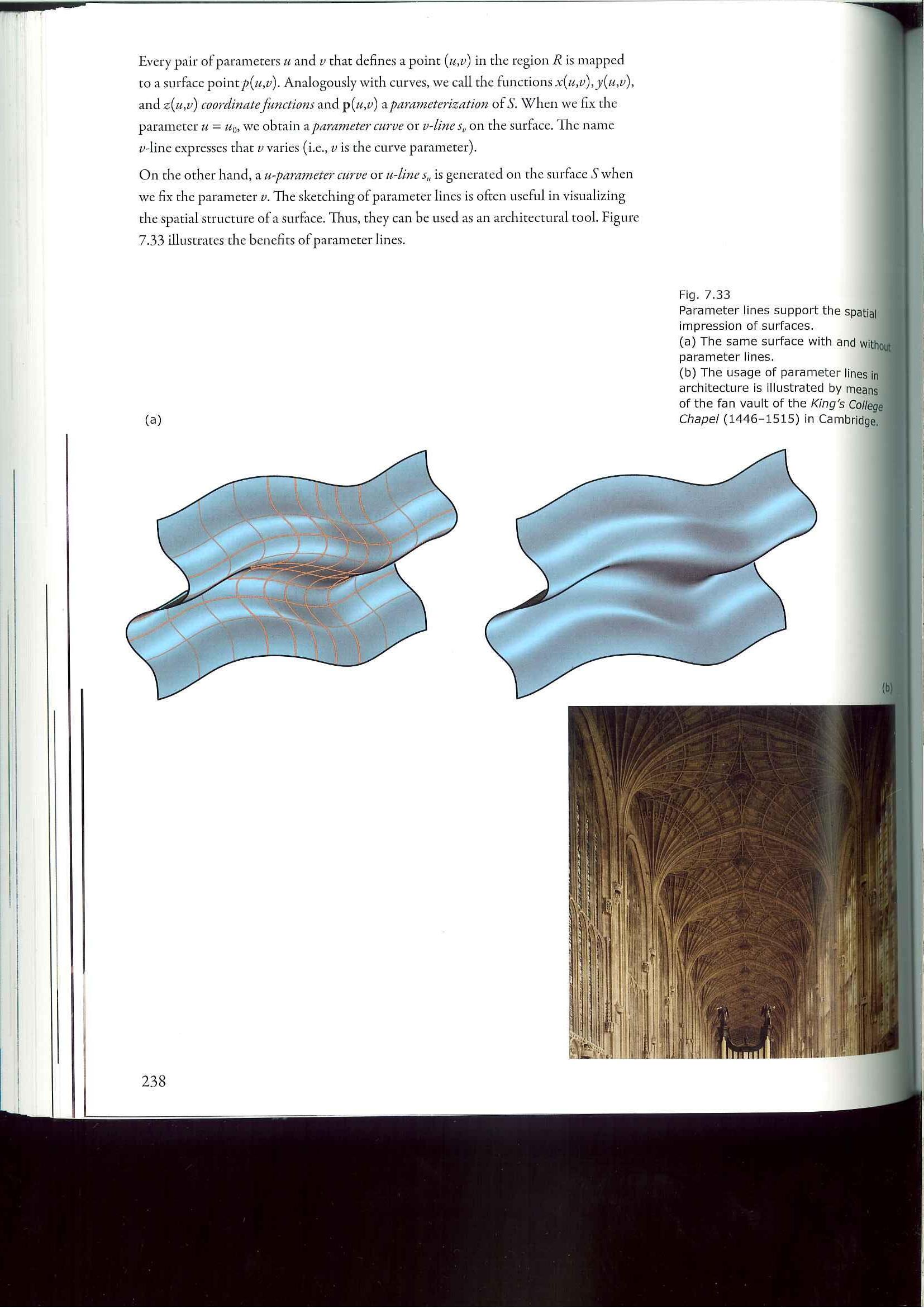
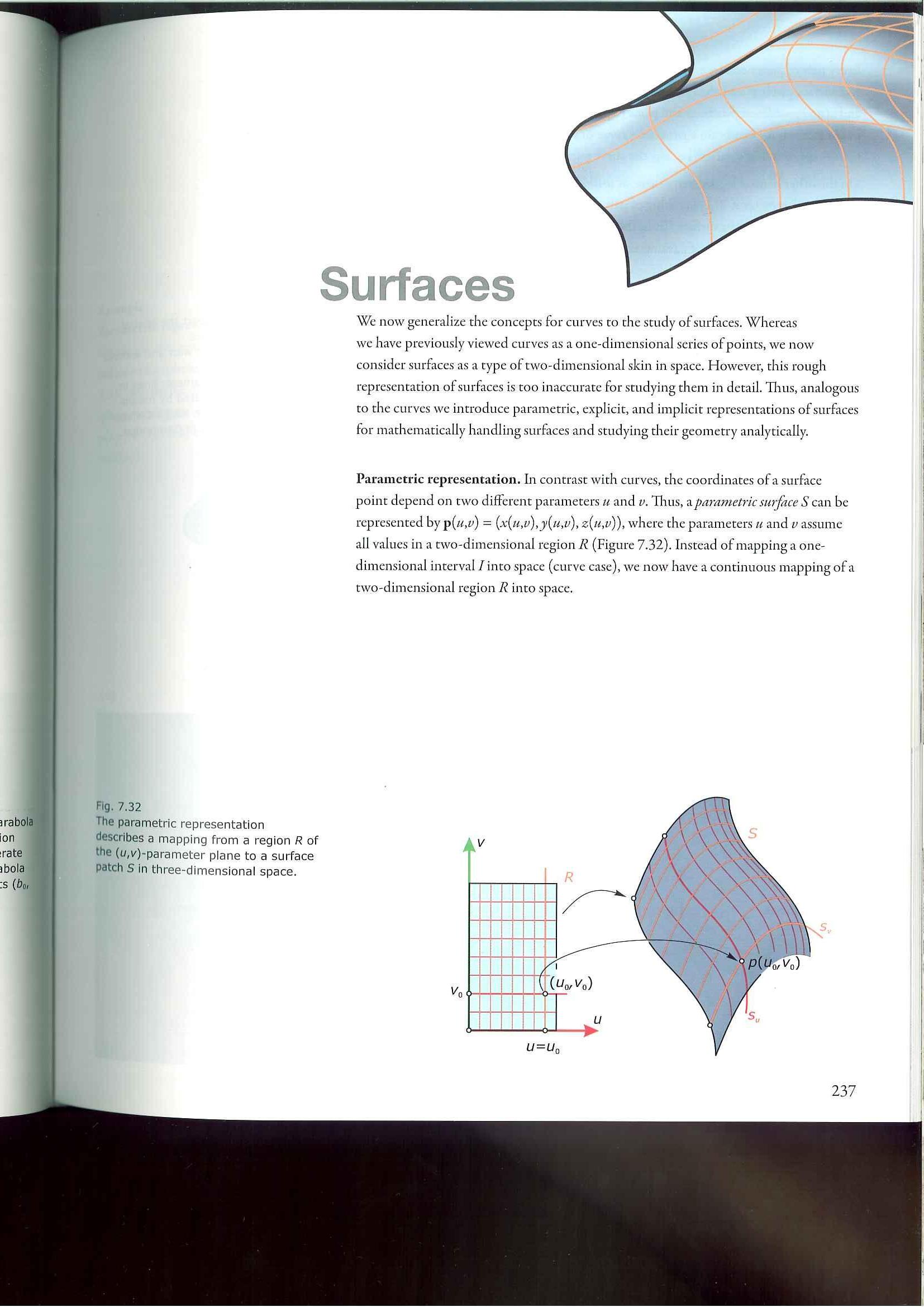
While many types and techniques exist to produce surfaces digitally, the basic principals are the same. surfaces are described and represented by u, V mapping. u and V are letters assigned to the two directions of contours on a surface. they are merely a method to describe a surface in 3 dimensions in a 2 dimensional projection. each point or coordinate on a surface can be identified by the intersection between two u, V curves.
as far as global surface geometry is concerned, two main areas to focus and understand are the notion of synclastic and anticlastic geometries. an understanding of these concepts is key to the geometry, fabrication, and structural stability of a surface system. simply stated a synclastic surface contains all curvature curving in the same direction, such as a sphere. mathematically, a synclastic surface has a positive gaussian curvature at all points. an anticlastic surface contains curvature in opposing directions, such as a saddle. in contrast to a synclastic surface, the gaussian curvature is negative at all points.
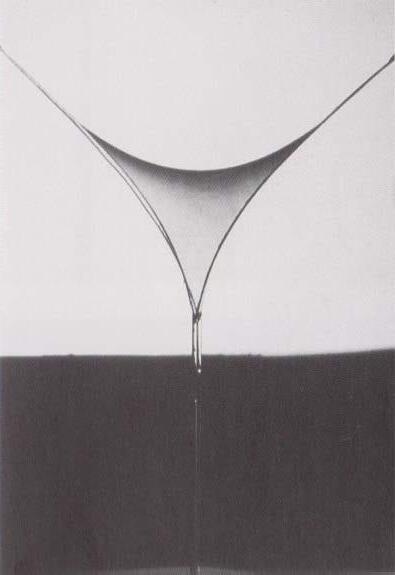
the development of a technique utilising anitclastic curvature will be key in the overall stability and stiffness of the system.
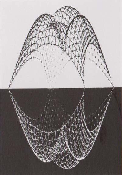 03. “suspended nets as model for grid shells” frei otto
01. “drawing for multihalle” frei otto
02. “soap film between threads” frei otto
charles and ray eames were pioneers and masters in manipulat ing material properties, primary in wood. they utilized a technique of laminating multiple sheets of thin wood veneers over a formwork. With an adhesive, each layer was bonded together holding the final curvature and shape. this technique is a great example of using and pushing the boundaries of a specific material’s inherent properties beyond the standard uses. these experiments not only push the geometries possible of the material, but increase structural performance, properties, and test new modes of fabrication.
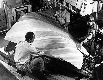
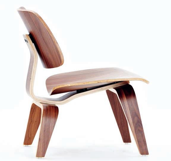
to be crit ical of the process, the downside to this process is its reliance on a secondary formwork. each new geometry or panel requires creating a custom formwork. this does not pose a problem to an industrial design process when a product is mass produced, but is a major disadvantage as a customized architectural design tool and method of fabrication.
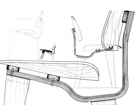
p ly W ood surface explorations, c harles and ray e ames1 the eames checking the fabrication process of their folding screen fsW-10. 1946 2 lounge chair. 1946. charles and ray eames. produced by herman miller. eames forming plywood sheet over formwork eames chair made from formed plywood 01.
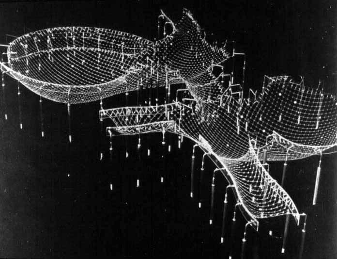
frei otto’s multihalle in mannheim, germany is one of the best historical examples of a translation of a surface design to a buildable structure. otto rationalized the structure into a space frame consisting of two interlocking layers of wood framing in opposing directions. these layers mirror typical u,V parameters used to describe a typical three dimensional digital surface. the resulting roof structure feels extremely light and is relatively thin in comparison to a typical large span roof section. a final roofing membrane is applied over the framing.
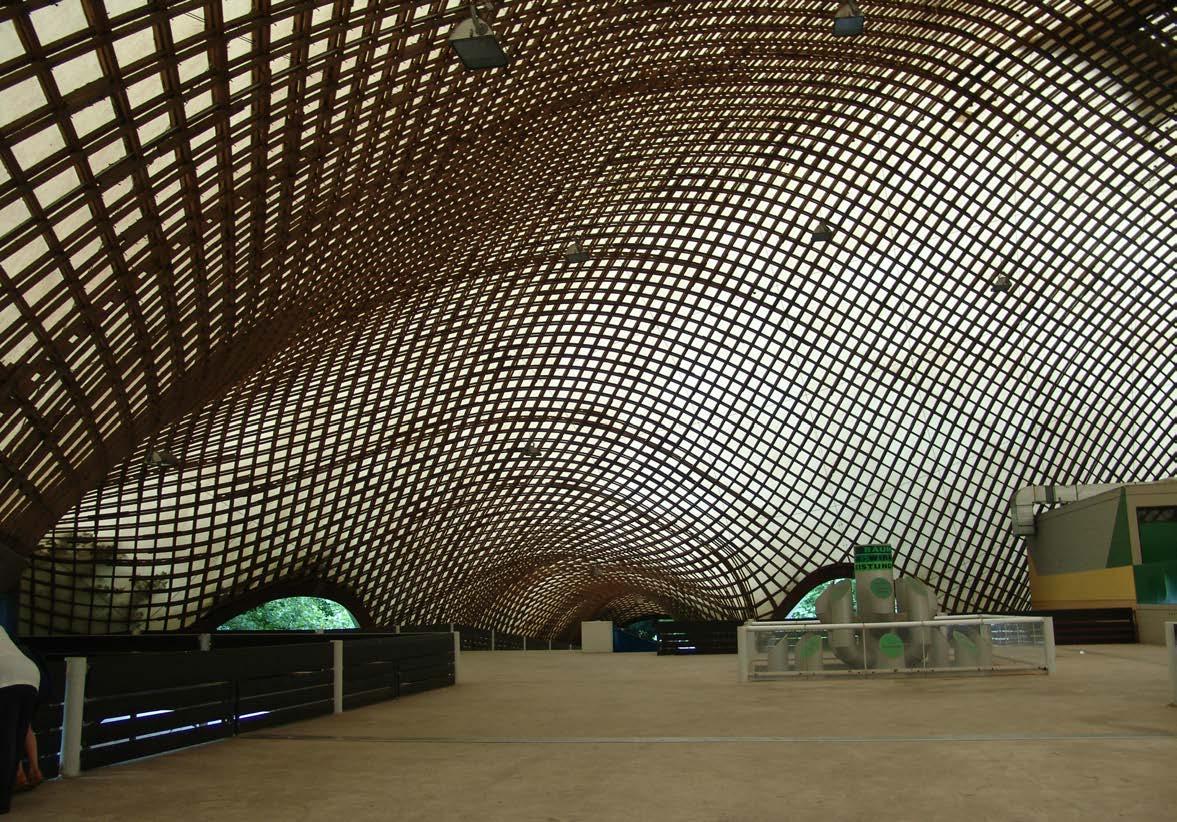
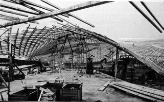
While simulating the properties of a surface, multihalle utilizes a stick framing system.
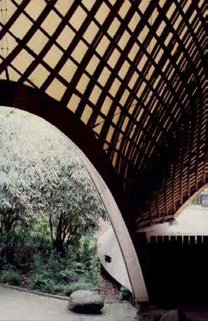
surface simulated by assembly of individual stick framing members in space frame.
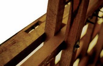
m ultihalle, m annheim, g ermany, f rei ottoroof structure foundation detail construction process timber detail of overlapping members view of multihalle 03. 04. 05.
expandable metal mesh is a standard off the shelf industrial product used in many commercial and architectural applications. While many varieties of the product are available, the general principle of the product is the same. large sheet material, typically steel or aluminium, are cut with a series of regular patterns. these sheets are then stretched with great force typically creating flat thickened plates. the product utilizes one main material property, metal’s stiffness at the point of plastic deformation. once a section of a metal alloy is bent or expanded it typically will hold its new form with much stiffness. on the alternative side, the properties of the material do not allow for much elastic behaviour. essentially this means the material will not return to its base shape or configuration. this is why expanded meshes are primarily made from metals.
While this system is very efficient in terms of material waste, ease of construction, and cost; expandable metal meshes do not maintain structural properties (beyond the base material), achieve complex geometric configurations, or allow for patterns. the system works based solely on its material properties. it requires a secondary fixing and structural system and therefore is primarily used as a screening or facade system.
2 photo: gerald holubowicz/polaris 3 http://personal.telefonica.terra.es/web/mallasmam/deploye.htmexpanded metal mesh fixed due to material’s property of plastic behaviour.


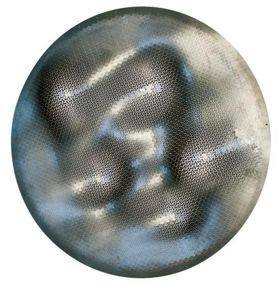
dr. haresh lalvani’s work encompasses morphological, structural, and design advances. much of his work explores surface structures as a “morphogenic genome.” he investigates how similar geometric rules, principals, and methods of fabrication can create different surface morphologies. dr. lavani typically works with metal sheet material to create a series of geometric surfaces formed on natural forces. unique to dr. lavani’s system, the self weight and natural forces form the unanticipated final geometry of the hung panels.
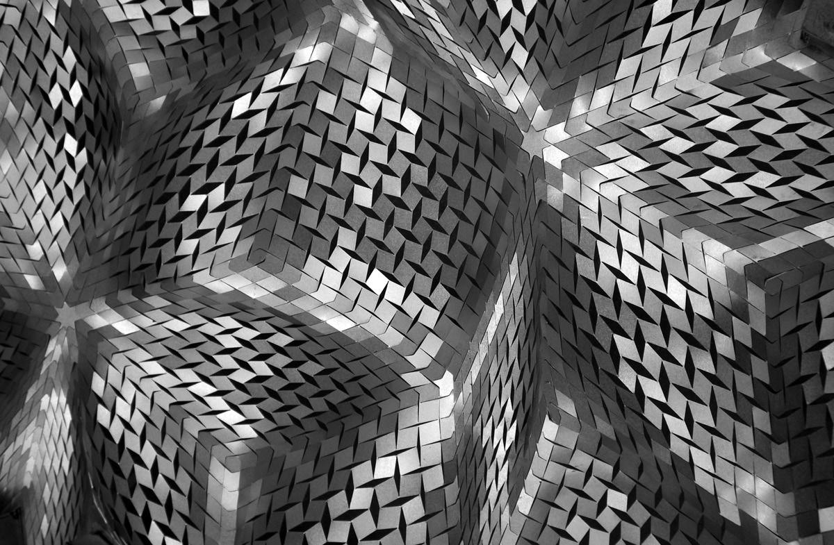
the rule base is set into the material, while the end form is generated naturally. While a very compelling exercise, we would like to further this research to develop a design tool in which we can control and design with the rule base. how can the embedded logic then transform back into the digital and inform a method of design?
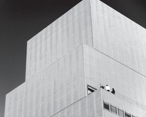
1 xurf project from the 2point5d+ exhibition at de castellane gallery, brooklyn, new york in february 2008 2 Zig Zag xurf (detail). 2008. photo courtesy of de castellane gallery detail of morphogenic genome experimentin reiser + umemoto, rur architecture pc’s Vector Wall installation at the museum of modern art, new york, ny, explores expandable perforated sheets. the aim of the project seeks to explore the variability of a repeated module using off the shelf material. the panels are made by laser cut 4x8 feet steel sheets. in response to the project, the Vector Wall successfully manages to establish variability in surface geometry and mitigating light.
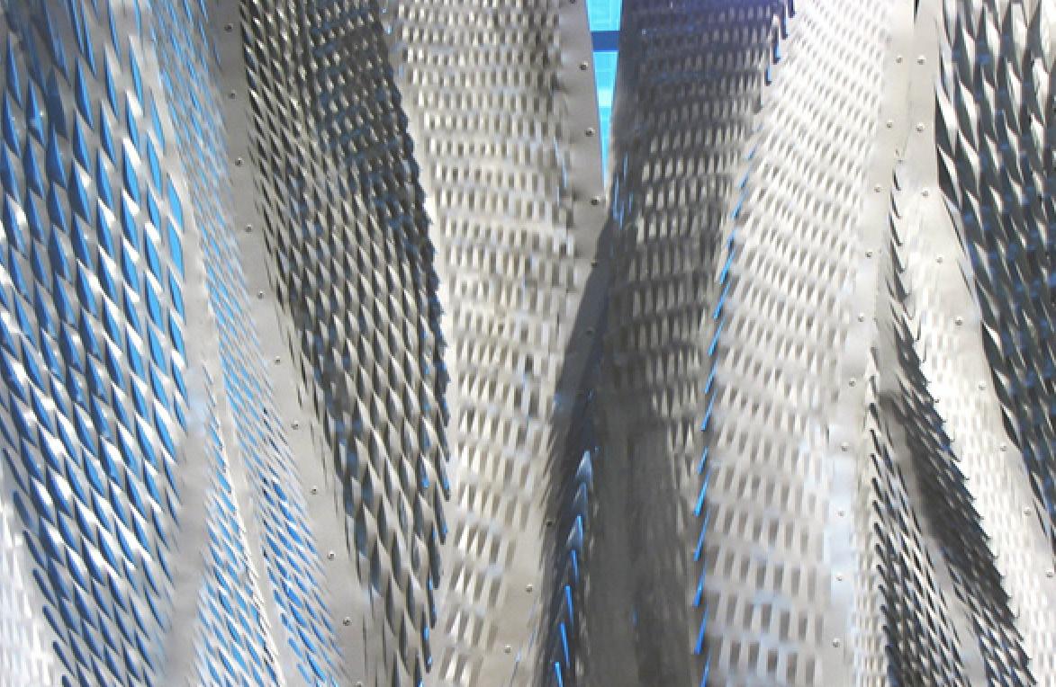
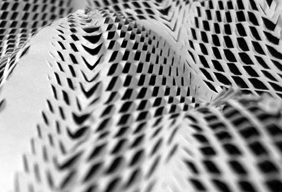
the geometry itself does not directly link to a structural logic and stability inherent to the system. the final configuration is partly a result of a rule base set into the cut patters, but the global geometry is more of a product of applying large external forces to the system.
installation based on cut patterns and global imposed forces to achieve surface geometry.Vector Wall, n e W yor K r eiser + u memoto Vector Wall, study model Vector Wall, flattened pattern drawing
digitally and physically controlled surfaces
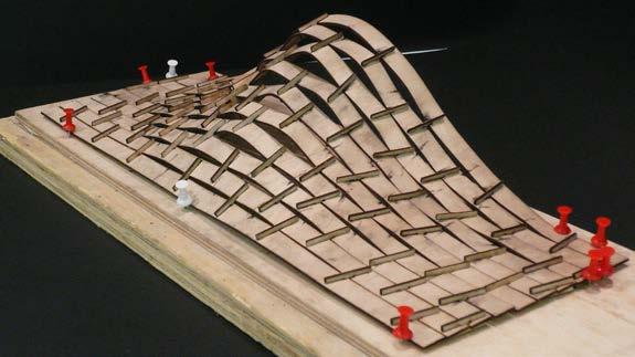
Our first step at proving this hypothesis was recreating and fabricating a physical While not as refined as the digital, the physical model did respond extremely well rendering.
Our first step at proving this hypothesis was recreating and fabricating a physical model from the output of the digital system. While not as refined as the digital, the physical model did respond extremely well and resulting global form mirrored the digital rendering.
the starting point for the Expandable Surface System research will be built off a previous analysis of expandable surfaces in the emtech, core studio i
in these experiments we continuously ran corresponding digital and physical explorations. the analysis into the digital system was continually developed and refined as we better understood the physical behaviour of material system.
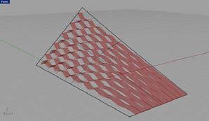
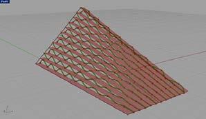
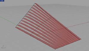
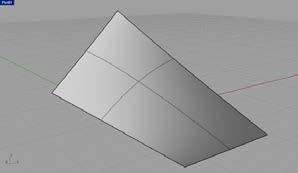
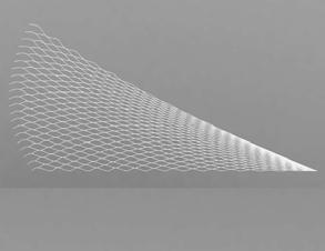
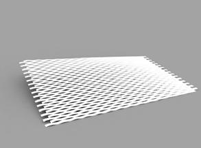
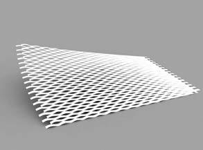
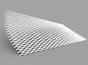
simply described, the definition is setup as follows: as an input, a simple rhino nurbs surface is brought into the parametric environment. this surface is then subdivided into a series of horizontal lines at any given spacing. a vector perpendicular to the surface normal extrudes the subdividing lines. the far edge of this newly extruded surface is then subdivided with a series of points at varying intervals. every other point is connected with an interpolation curve creating the wave-like pattern. lastly, this final curve is extruded once more back (in the opposite direction of the previous vector) until it reaches the surface.
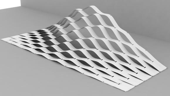
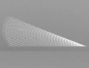
the result of this digital system, while having very similar visual characteristics, reacted interestingly different to the initial physical tests. firstly, the digital model created a uniform gradient of increased openings of the cells. While creating a global desired properties, we were unable to control a localized area of openings if required by program or climatic conditions.
the second difference from the physical system lies in the fact that we were unable to restrain the dimensions of the digital input surface. With a simple piece of paper you are unable to stretch the material; which essentially means the material maintains a constant surface area. there is no such restriction in a digital surface. so essentially each individual resulting strip from the digital system was a different length and each joining point between adjacent strips was staggered.


project developed in collaboration with cesar martínez.

as we betan input, a series of hori-
Grasshopper
having very similar visual characteristics, reacted interestingly different to the initial created a uniform gradient of increased openings of the cells. While creating a global control a localized area of openings if required by program or climatic conditions. The system lies in the fact that we were unable to restrain the dimensions of the digital input you are unable to stretch the material; which essentially means the material maintains such restriction in a digital surface. So essentially each individual resulting strip from the and each joining point between adjacent strips was staggered.
Step _ 01 _ Input Surface
Step _ 02 _ Horizontal Lines
Step _ 03 _ Interpolation Curve
Step _ 04 _ Final Strip Extrusion
In parallel to running the physical experiments, we continuously ran corresponding digital explorations. This analysis into the digital system was continually develop into a parametric Grasshopper definition which became increasingly refined as we better understood the physical behaviour of material system. Simply described, the definition is setup as follows. As an input, a simple Rhino nurbs surface is brought into the parametric environment. This surface is then subdivided into a series of horizontal lines at any given spacing. A vector perpendicular to the surface normal extrudes the subdividing lines. The far edge of this newly extruded surface is then subdivided with a series of points at varying intervals. Every other point is connected with an interpolation curve creating the wave-like pattern. Lastly, this final curve is extruded once more back (in the opposite direction of the previous vector) until it reaches the surface.
Extrusion
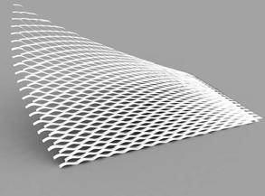
Deformation _ 02
The far edge connected the opposite to the initial creating a global conditions. The digital input material maintains strip from the
Step _ 01 _ Input Surface
Global Deformation _ 03
Step _ 02 _ Horizontal Lines
Global Deformation _ 04
Step _ 03 _ Interpolation Curve
Grasshopper Definition
Step _ 04 _ Final Strip Extrusion
The result of this digital system, while having very similar visual characteristics, reacted interestingly different to the initial physical tests. Firstly, the digital model created a uniform gradient of increased openings of the cells. While creating a global desired properties, we were unable to control a localized area of openings if required by program or climatic conditions. The second difference from the physical system lies in the fact that we were unable to restrain the dimensions of the digital input surface. With a simple piece of paper you are unable to stretch the material; which essentially means the material maintains a constant surface area. There is no such restriction in a digital surface. So essentially each individual resulting strip from the digital system was a different length and each joining point between adjacent strips was staggered.
In parallel to running the physical experiments, we continuously ran corresponding digital explorations. This analysis into the digital system was continually develop into a parametric Grasshopper definition which became increasingly refined as we better understood the physical behaviour of material system. Simply described, the definition is setup as follows. As an input, a simple Rhino nurbs surface is brought into the parametric environment. This surface is then subdivided into a series of horizontal lines at any given spacing. A vector perpendicular to the surface normal extrudes the subdividing lines. The far edge of this newly extruded surface is then subdivided with a series of points at varying intervals. Every other point is connected with an interpolation curve creating the wave-like pattern. Lastly, this final curve is extruded once more back (in the opposite direction of the previous vector) until it reaches the surface.
In parallel to running the physical experiments, we continuously ran corresponding digital explorations. This analysis into the digital system was continually develop into a parametric Grasshopper definition which became increasingly refined as we better understood the physical behaviour of material system. Simply described, the definition is setup as follows. As an input, a simple Rhino nurbs surface is brought into the parametric environment. This surface is then subdivided into a series of horizontal lines at any given spacing. A vector perpendicular to the surface normal extrudes the subdividing lines. The far edge of this newly extruded surface is then subdivided with a series of points at varying intervals. Every other point is connected with an interpolation curve creating the wave-like pattern. Lastly, this final curve is extruded once more back (in the opposite direction of the previous vector) until it reaches the surface.
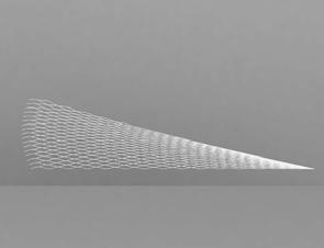
Strip Length Extension
The result of this digital system, while having very similar visual characteristics, reacted interestingly different to the initial physical tests. Firstly, the digital model created a uniform gradient of increased openings of the cells. While creating a global desired properties, we were unable to control a localized area of openings if required by program or climatic conditions. The second difference from the physical system lies in the fact that we were unable to restrain the dimensions of the digital input surface. With a simple piece of paper you are unable to stretch the material; which essentially means the material maintains a constant surface area. There is no such restriction in a digital surface. So essentially each individual resulting strip from the digital system was a different length and each joining point between adjacent strips was staggered.
Global Deformation _ 01
Global Deformation _ 02
Global Deformation _ 03
Global Deformation _ 04
Deformation Elevation _ 02
Global Deformation Elevation _ 03
Global Deformation Elevation _ 04
Step _ 01 _ Input Surface
Deformation Diagram _ 02
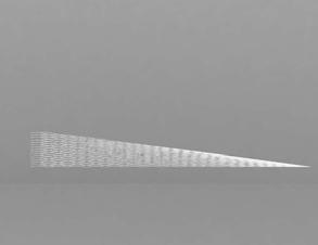
Global Deformation Diagram _ 03
Global Deformation Elevation _ 01
Global Deformation _ 01
Step _ 02 _ Horizontal Lines
Global Deformation Diagram _ 04
Global Deformation Elevation _ 02
Global Deformation _ 02
Step _ 03 _ Interpolation Curve
Global Deformation Elevation _ 03
Global Deformation _ 03
Step _ 04 _ Final Strip Extrusion
Global Deformation Elevation _ 04
Strip Length Extension
Elevation _ 04
Diagram _ 04
Emergent Technologies & Design Core Studio One 2010
Global Deformation _ 04
Expandable
Global Deformation Diagram _ 01
Global Deformation Diagram _ 02
Global Deformation Diagram _ 03
The result of this digital system, while having very similar visual characteristics, reacted interestingly different to the initial physical tests. Firstly, the digital model created a uniform gradient of increased openings of the cells. While creating a global desired properties, we were unable to control a localized area of openings if required by program or climatic conditions. The second difference from the physical system lies in the fact that we were unable to restrain the dimensions of the digital input surface. With a simple piece of paper you are unable to stretch the material; which essentially means the material maintains a constant surface area. There is no such restriction in a digital surface. So essentially each individual resulting strip from the digital system was a different length and each joining point between adjacent strips was staggered.
The result of this digital system, while having very similar visual characteristics, reacted interestingly different to the initial physical tests. Firstly, the digital model created a uniform gradient of increased openings of the cells. While creating a global desired properties, we were unable to control a localized area of openings if required by program or climatic conditions. The second difference from the physical system lies in the fact that we were unable to restrain the dimensions of the digital input surface. With a simple piece of paper you are unable to stretch the material; which essentially means the material maintains a constant surface area. There is no such restriction in a digital surface. So essentially each individual resulting strip from the digital system was a different length and each joining point between adjacent strips was staggered.
Global Deformation Elevation _ 01
Global Deformation Elevation _ 02
Emergent Technologies & Design Core Studio One 2010
Global Deformation _ 01
Global Deformation _ 02
Global Deformation Elevation _ 03
Strip Length Extension Diagram
Zamorano
Global Deformation _ 03
Global Deformation Diagram _ 04
Global Deformation Elevation _ 04
Emergent Core
Global Deformation _ 04
Global Deformation Diagram _ 01
Global Deformation _ 01
Global Deformation _ 02
Global Deformation Diagram _ 02
Global Deformation Elevation _ 01
Global Deformation Elevation _ 01
Global Deformation Diagram _ 01
Global Deformation Elevation _ 02
Global Deformation Elevation _ 02
Global Deformation _ 03
Global Deformation Diagram _ 03
Expandable Surface System 8
Global Deformation _ 04
Global Deformation Diagram _ 04
Global Deformation Elevation _ 03
Global Deformation Elevation _ 03
Global Deformation Elevation _ 04
Global Deformation Elevation _ 04
Global Deformation Diagram _ 02
Global Deformation Diagram _ 03
Global Deformation Diagram _ 04
our aim is to design a self-synergistic material system that can create a dialogue and responsiveness between a design method and structure, to intern, interact and impact global morphology within a geometric rule base. the material system, controlled at the local material level, aspires to adjust and inform many formal variations and complex geometries. the reciprocal relationship between the cellular level and the larger field will be key.
We will explore different natural materials and methods of pushing the physical boundaries of these materials. it is integral to our process to always think and test at full scale. We will develop a simple repetitive method of fabrication utilizing a constant size and type of raw material, which will then change for differentiation. in order to accomplish this, we will research and test matter at the low level in the simple form of cuts, bends, expansion, contraction, and folding. at a higher level of hierarchy, we will explore a number of passive materials in terms of form, structure, and geometry.
Within the domain of current material and architectural explorations, many recent projects have investigated high level material science means of producing new performative materials or computational principals to mimic material phenomenons. the research will place itself between these two methods. We will work parallel at the two levels of hierarchy previously described. using a biological model of growth, a series of repetitive flexible elements will act in the field, finding a natural state of equilibrium as a culmination of material behaviour and natural forces.
our ambition is to respond to this phenomenon by investigating
and imbedding more intelligence into the synergy between material logic, form, structure, and geometry. natural systems do not act solely upon one of these elements alone. this coaction allows the system to respond to a change in its growth or environment at different scales. our aspiration is to study the relation between a hybrid of passive material structures and local manipulations to create an emergent material system that reacts to geometry and structural changes along its surface.
We will test and quantify the system’s architectural performance at different scales - one at the scale of a small inhabitable pavilion, and two in the fabrication of a full scale supporting wall system.
in the realization of this system, we hope to ascertain that a single low technology material system, acting at different scales, can perform as a passive, yet responsive, material architecture.

02.method
experiments setup based on materials, structural performance, fabrication, and computation
our method and approach to explore the notions of surface, material, and fabrication aim to maintain a constant connection between geometric logic, digital tests, material properties and fabrication.
the work flow to achieve this task cannot be linear. a constant dialogue between physical experiments, and their assessments, must inform the rationale and logic of digital tests and geometric analysis - and vice-versa. our initial experimentation will be focused on geometry and patterns. how can one develop a systematic way to generate complex two dimensional cut patterns and evaluate their three dimensional formal characteristics? then, how can a quick physical experiment or paper model be translated and compared to a digital test?
as the base primary mode of experimentation, we will generate 2d digital cut patterns and inscribe the lines onto paper via laser cutting technologies. once assessing these models, we will adjust the next iteration accordingly. the experiments will be evaluated based on scale, surface flexibility, cut size, light mitigation, overall geometry, structural stability, and ease of fabrication to begin with. at first we will experiment with regular constant patterns. We aim to then develop methods to parametrically generate and adjust the patterns. in later stages the physical and digital experiments may split and run on parallel paths informing each other at key points. once an understanding of the geometry is established, we will increase the scale and material.
as our aim is to not only develop a design tool, but a fabrication technique, it is important to understand both material and construction limits at one to one. While the logic of systems may scale, materials, in particular wood and fibrous materials, do not. as the paper studies lead to scaled material models the logic of the system and understanding of the geometric principals will need to be reassessed.
in addition to localized material tests, it is also crucial to not loose sight of global design studies and an understanding of overall geometric and structural principals for the success of the system. part one of the exploration will focus on the development of a single layer self-supporting wall system. part two will focus on furthering the logic of this development into a small scale span enclosure. these two milestones in the project aim to test different qualities of the system. the assumption is that one method will not directly translate between the different design criteria.
how can adjustments be made to a single tool and system to accommodate varying and changing design goals?
experiments setup based on materials, structural performance, fabrication and computation
design de V elopment experiments research
research de V elopment
material material tests global and local forces fabrication tests
geometry computation
pattern studies
material and
case study: self supported Wall system
parameteriZation studies computational form finding studies
e V al uation
structure
fea tests in strand 7 physical mocK-ups
geometry
curVes, surfaces and form finding experiments
computation
form finding algorithms deVelopment parametric modeling panelising experiments complex geometry control
fabrication
reduction of Waste pre-set process transportation strategies
deployable system digital and physical coordination
full scale surface fabrication test
research proposal
materialized
structure
fea tests
case study: paV ilion selfsupported Wall
bending stiffness ratio
physical mocK-ups single and double layer structure tests
geometry
complex geometries rationaliZation edge and shape relations
computation
surface approximation algorithm edge condition algorithm
fabrication
future de V elo p ments
paV ilion
full deployable test: local fabrication standard panel system no moulds or formWorK details and connections deVelopment shipping and assembly abroad
e V al uation
e V al uation e V al uation
the first stage of research development focuses on an explorat ion and understanding of the geometry and solidifying the logic of the system. then, these steps will lead to a select material and a full scale mock-up. the initial studies will spring from the domain research on surfaces, materials, and precedent works.
the first investigations focused on pure geometric explorations and pattern play. the aim was to establish the base rule set and limitations of the technique. What benefits could incisions into a surface material provide? how can the material properties go beyond the prevailing boundaries and applications? What parameters are in play and how can we adjust, control, and see affects of these parameters? lastly, what criteria needs to be studied and how do we quantify and measure the results?
advancing from these tests and results, a step will be made to a material selection and one-to-one scaled mock-up. What material properties are not only appropriate and suited for the perfor-
mance of the system, but what material will be an active participant in the system? how can the feedback, inherent properties, tension, and response of a material add to the life and design of system? With the jump in scale a reassessment of the logic, performance, and mode of evaluation will need to be made.
as the first design studies are made, many questions arise how to guide the development of they system. it is key to maintain a system of annotation and evaluation across both digital and physical platforms.
The material system’s exploration began with a series of experiments consisting of applying a pattern of cuts to a paper sheet and then acting on its surface. Different patterns were explored. Rules to compare and analyze the behaviour of each pattern were established. The parameters to control the pattern definition were the length of the cut, the gap between cuts, the distance between rows, and the geometric relation between them. It was soon discovered that the proportion between these parameters were crucial to make the pattern performative. The chosen criteria were as follows: the successful patterns were able to be stretched or expanded homogenously, that is to say if applying a global or local deformation, the pattern was to be modified only by these external forces.
initial stable cut patterns tested 01.
the material system exploration began with a series of experiments consist ing of applying a pattern of cuts to a paper sheet and then acting on its surface. different patterns were explored. rules to compare and analyse the behaviour of each pattern were established.
the parameters to control the pattern definition were the length of the cut, the gap between cuts, the distance between rows, and the geometric relation between them. it was soon discovered that the proportion between these parameters were crucial to make the pattern performative.
Emergent Technologies & Design Core Studio One 2010
generative irregular digital cut patterns 02.
once an understanding of the base relationships within the cut pattern system was established, testing irregular spacings and patterns was a sequential step. a digital parametric tool was developed to efficiently test irregular patterns. the base principle of this tool was to interpolate offset lines between two curves. these lines were then divided to create the alternating cut pattern.
this tool proved to be quite useful to quickly test complex patterns digitally and produce study models. it became difficult to
control the spacing between cuts, as the lines were always varying sequentially from cut to cut. this rendered some areas of the surface unable to open due to a spacing that was too wide. also areas where the pattern was too condensed, the system failed under material distress.
the physical results of this test can be seen in the experiments in the following pages.
cut length: 20 mm
gap between cuts: 5mm distance between rows: 2.5mm
the results showed that parallel patterns were more suitable for the project requirements. While radial or tangent patterns didn’t distribute the forces linearly, thus making the paper surface crumple. at the same t ime, parallel patterns made the paper strips twist and to change their orientation. this property became very valuable when applied to a bigger surface as
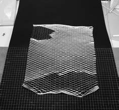
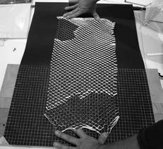
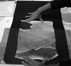
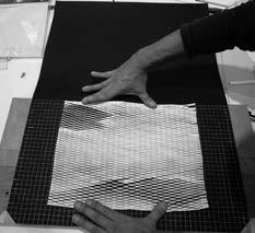
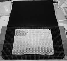
it generated a very interesting range of openings and shadows.
the control tests parallel pattern contains the following proportions:
a) the length of the cut was 20 mm
b) the gap between cuts was 5 mm
c) the distance between rows was 2.5 mm
regular pattern chosen for system control tests with external forces in expansion and compression.
control test compression, diagram examining the relation between height and width
control test compression, physical test without cell opening - global external forces applied
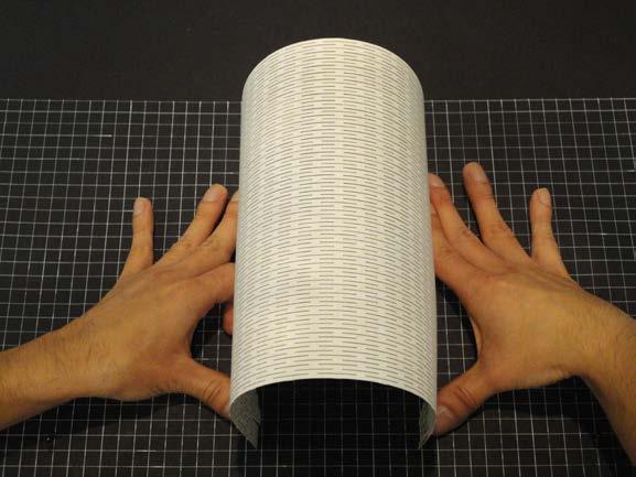
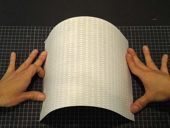
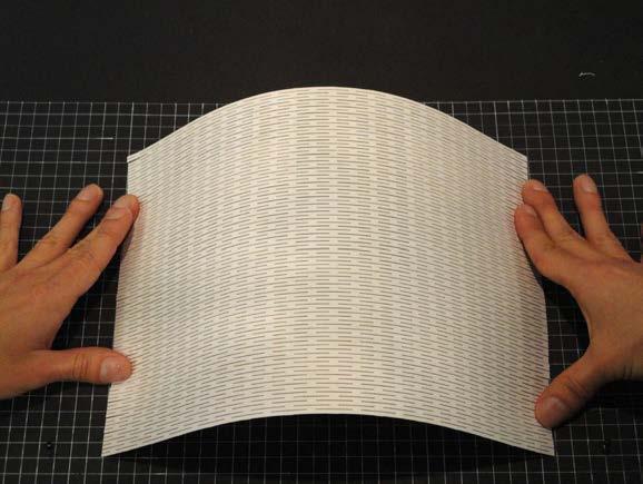
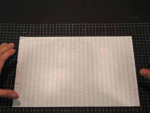 05.
05.
exp.02 > first scaled ply W ood physical test
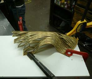
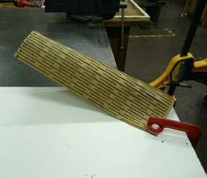
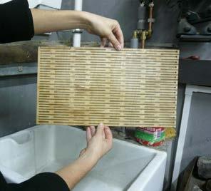
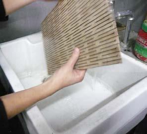
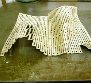
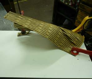
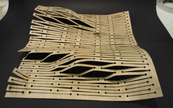
exp.02 was carried on with a different material. a 1.5 mm birch ply was used to analyse the behaviour of the chosen pattern. as the material was thicker, the pattern was scaled proportionally. it was then applied both to local and global deformations.
In later developments, the same experiments were carried on with a different material. A 1.5 mm birch ply was used to analyze the behaviour of the chosen pattern. As the material was thicker, the pattern was scaled proportionally. It was then applied both local and global deformations. The results were that the scaled pattern had less differentiation and also the wood didn´t resist the tension and compression in the same way as the paper. It broke at some points. On the other hand, the wood worked better structurally, generating a stiffer surface.
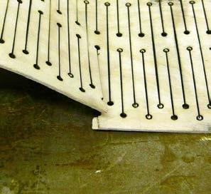
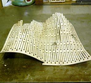
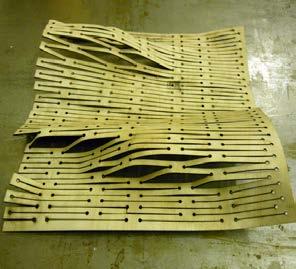
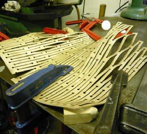
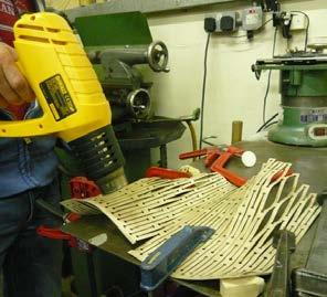
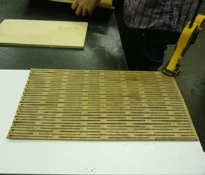
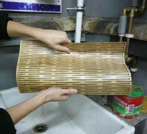
the results were that the scaled pattern had less differentiation and also the wood didn’t resist the tension and compression in the same way as the paper. it broke at some points. on the other hand, the wood worked better structurally, generating a stiffer surface due to material properties. plywood material tested for local and global deformations.
different material. A 1.5 mm birch ply was used to anapattern was scaled proportionally. It was then appattern had less differentiation and also the wood broke at some points. On the other hand, the wood
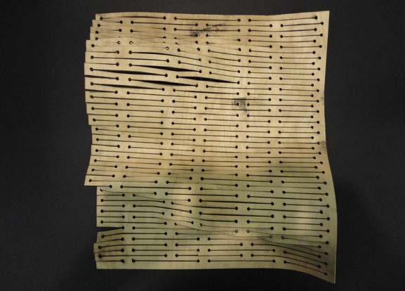
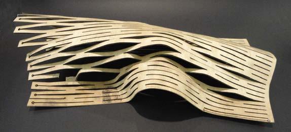
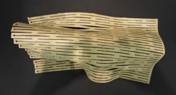
the research phase included the study of different cut patterns. to test and evaluate their performance an experiment was set up. the objective of it was to test how the cut pattern affected. first, the capacity to expand the sheet was tested, and second, the surface morphology.
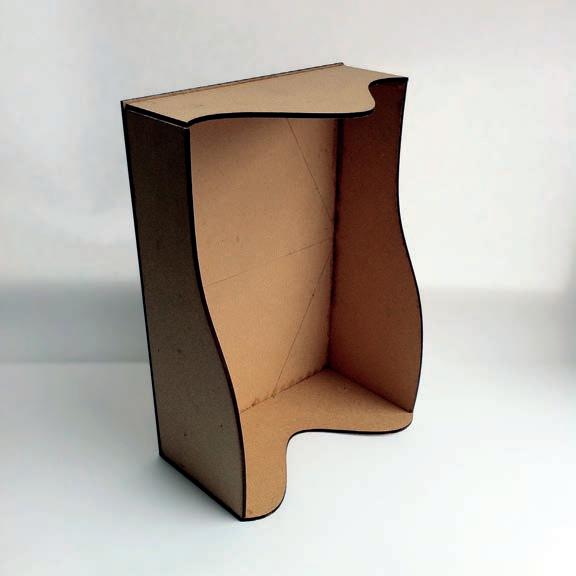
to carry out the experiment, 5 paper sheets of 297 mm x 210 mm were lasercut with different patterns and a mdf doubly curved formwork was made. the sheets were to adapt to the formwork by matching the edges. the criteria to evaluate the performance of every pattern was the amount of expansion in centimetres and the adaptability to the given shape of the formwork. the fittest individuals were the most expandable and the most adaptable.
cut pattern number 2 was not able to expand and was discarded. patterns 4 and 5 were able to expand, but the irregularity and curvature of the cuts made it impossible to adapt them to the formwork. they were discarded as well.
the cut pattern number 1 and number 3 expanded easily and homogeneously. at the same t ime, both adapted well to the shape of the mould.
since both patterns were equally suitable, a second experiment was set up. this experiment consisted of loading both surfaces with the same weight and check visually for the deflections.
pattern number 1 resisted less load than pattern number 3 and it was chosen to further develop.
measures: 297 x 210mm
weight: 17.8 grams
thickness: 0.5mm
density: 0.5974 gr/m3
paperweight: 300gr/m3
exp.03.1
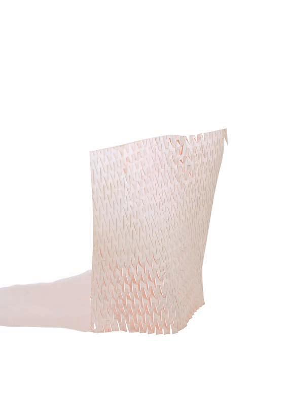
pattern 01
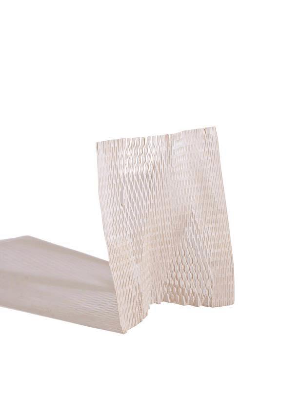
measures: 297 x 210 mm weight: 16.6 grams original weight: 17.8 grams weight loss: 6.74% number of cuts: 816
description: parallel cuts of 20 mm with alternating columns. the distance between rows was 5mm and between columns 3mm.
performance: the pattern was easily expandable and adaptable to the formwork’s shape.
exp.03.2
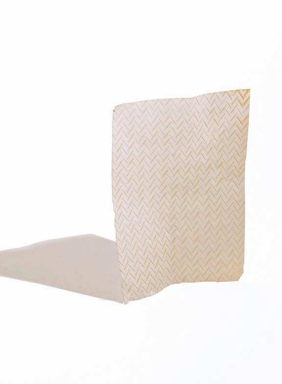
pattern 2
measures: 297 x 210 mm
weight: 17.4 grams
original weight: 17.8 grams
weight loss: 2.25% number of cuts: 587
description: intersecting pattern at 70 º made of 15 mm long cuts. the distance between rows is 7.5mm and the distance between columns is 9mm
performance: the pattern could not expand.
exp.03.3
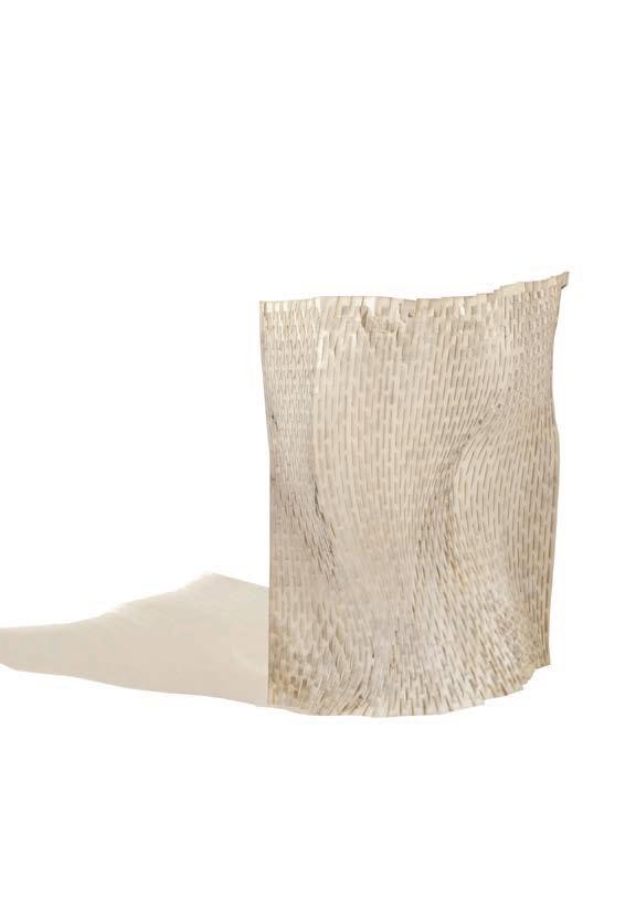
pattern 3
measures: 297 x 210 mm
weight: 17 grams
original weight: 17.8 grams weight loss: 4.49% number of cuts: 558
description: parallel and oblique pattern at 22.5 º pattern made of 25.5 mm long cuts. the distance between rows is 10mm and the distance between columns is 25mm
performance: the pattern was easily expandable and adaptable to the formwork’s shape. this was the fittest pattern.
exp.03.4
pattern 4
measures: 297 x 210 mm
weight: 16 grams
original weight: 17.8 grams weight loss: 10.1%
number of cuts: 1741
description: segmented
curved pattern made of mean curves between 4 guide curves. average cut length 16.8 mm.
performance: the pattern was easily expandable but not adaptable to the formwork’s shape.
exp.03.5
pattern 5
measures: 297 x 210 mm
weight: 16.4 grams
original weight: 17.8 grams weight loss: 7.86% number of cuts: 985
description: segmented
curved pattern made of mean curves between 2 guide curves. average cut length 16.4 mm.
performance: the pattern was easily expandable but not adaptable to the formwork’s shape.
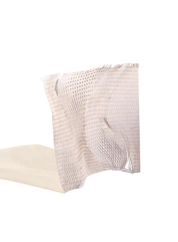
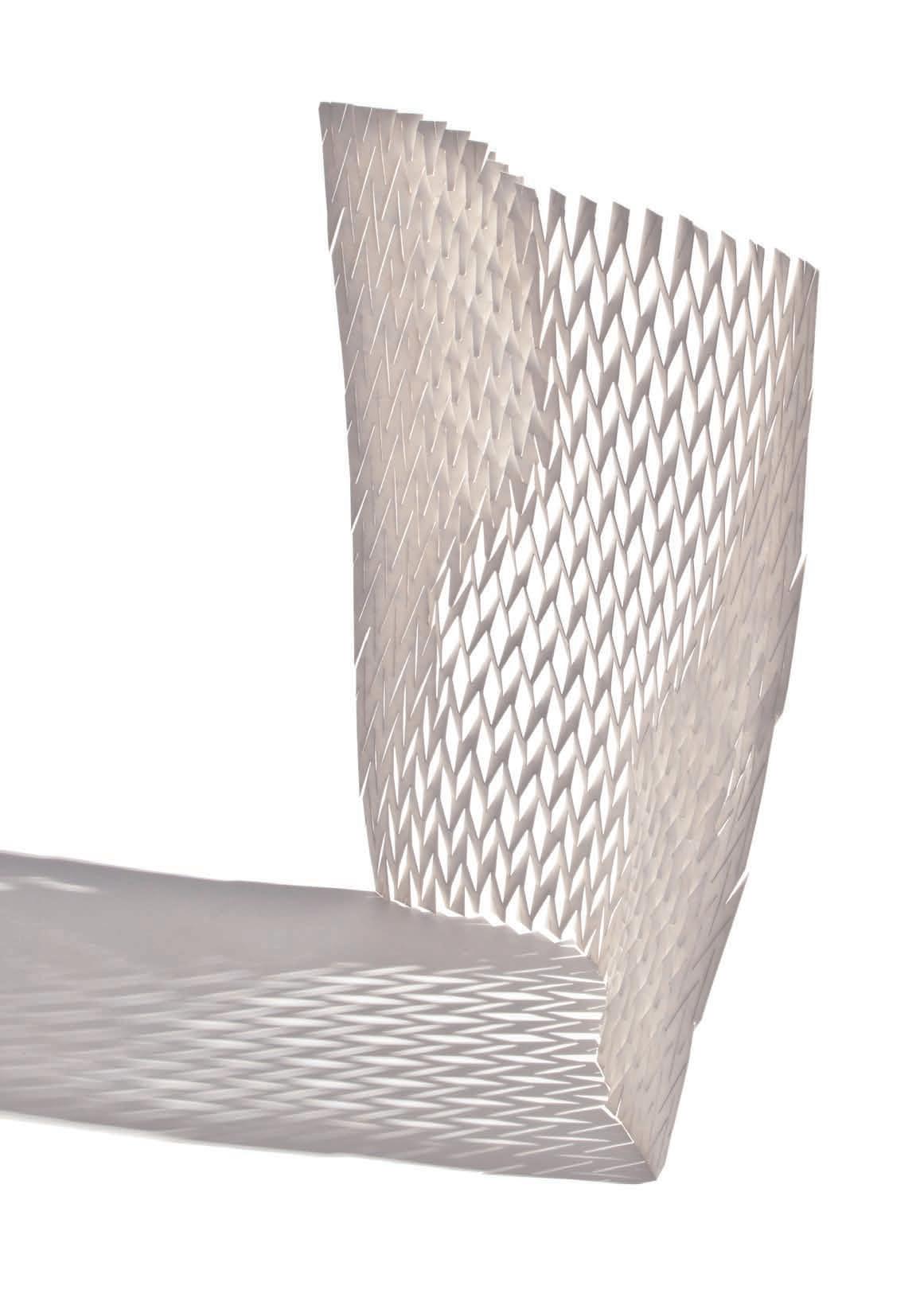
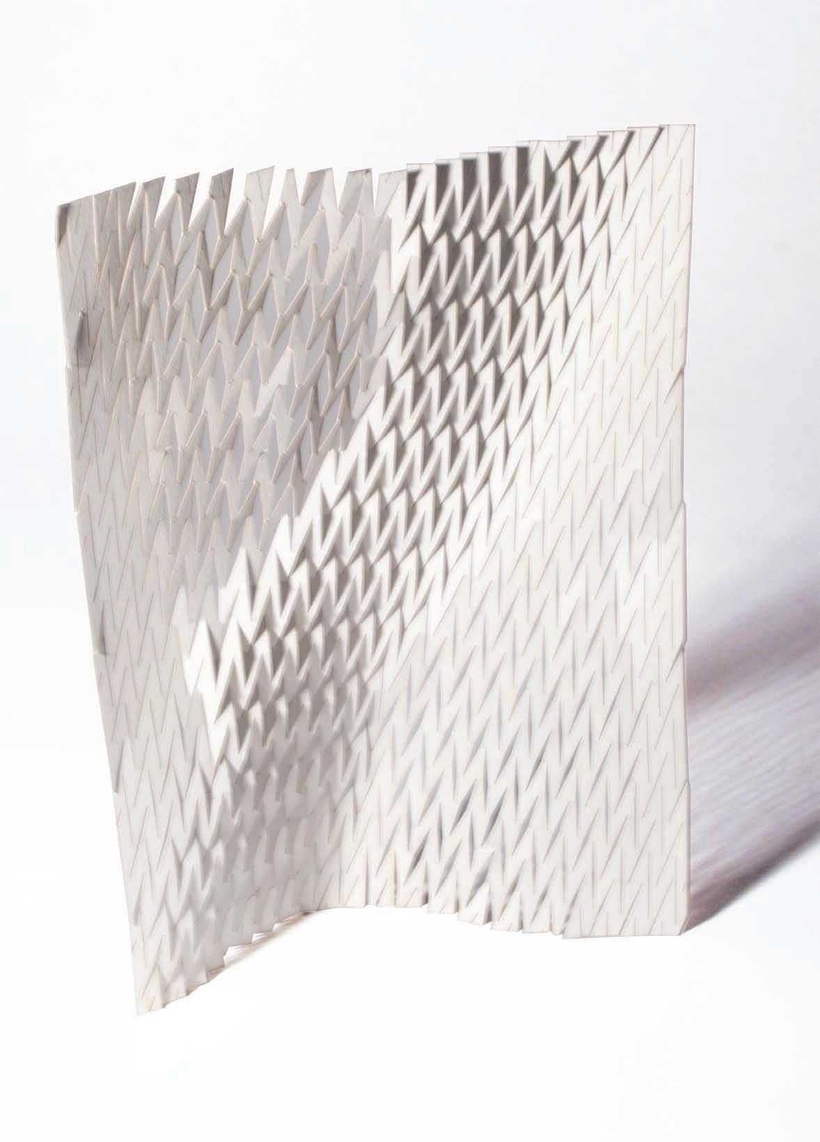
in an attempt to better control the pattern generations, while maintaining variat ion in the system, we developed a tool to control these variations in the two-dimensional patterns.
two curves are used as boundary inputs. in the first iteration of the tool, a single curve was used to control the parameter of variation. the curve was analysed for value translated to a rotation angle of the cut and the location on the panel. using a symmetrical gradual input curve, a gradient from regular parallel cuts, to opposing cuts, back to a parallel cut pattern is produced. as the input curve changes in amplitude or shape, then pattern will adjust accordingly.
the limitation in this tool lies in the fact that each column of cuts is exactly the same. Variation only occurs in one direction.
the second iteration of this tool further developed the controlling input and parameters. to achieve a varying cut pattern in both vertical and horizontal directions, a three-dimensional surface was analysed in a similar manner as the two-dimensional curve previously.
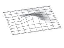
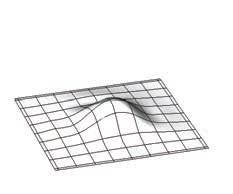
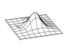
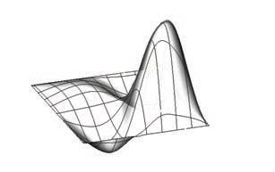
the surface is analysed in three dimensions - x, y, and Z. the value is assigned to each grid point on the surface. the x, y coordinates translate to the location of an individual cut in the twodimensional output pattern. the Z coordinate assigns an angle of rotation to each cut, creating variation in two directions.
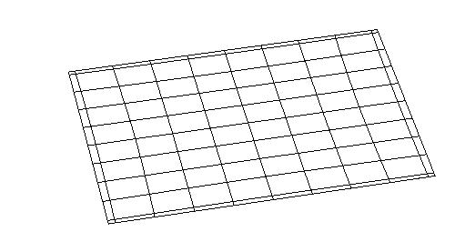
original patternstep 1 step 2 step 3 step 4 step 5
offset pattern evolution 01.
after exploring and experimenting with different cut patterns, the fittest one was further developed and rationalized. the original parallel pattern with the best expansion performance was used as a starting point. then a sequence of geometrical rules was applied to systematize the pattern. the objective was to generate a design tool capable to apply the pattern to any size and sheet proportion being the input a surface boundary and the output the pattern itself.
the first step was to understand the pattern as a component based-like surface where every component framed every cut. then the cuts of odd columns were rotated 7.13o counter clockwise so the distance between the upper end point of every cut and the component’s frame was 1.25 cm.
the second step was to repeat the process with the even columns but to the opposite direction.
the third step was to rotate the whole field so the even columns were perpendicular to the universal x axis.
the fourth step was to scale the whole field by 50% so the length of every cut grew from 20 mm to 30 mm.
the fifth and final step was to move the cuts from the even columns so that the lower end point matched the lower left corner of the components’ frame. by doing that, the middle point of the even columns cuts’ was equidistant to the upper points of the previous and next column cuts.
this was the last step before setting the parameters of the pattern with a grasshopper definition. this enabled the cuts’ of every other column to rotate from their middle point to match the diagonal of the entire sheet.
1 original pattern
offset pattern evolution, in detail
the pattern is rotated to change the direction of the deformation based on the previous analysis a base pattern was set
rotation parameter 01
input boundary curves pattern density
alternate row offset control parameter curve input
rotation parameter 02
definition to parametrically generate efficient patterns between two boundary input curves
 02.
03.
04.
step
step 2 step 3 step 4 step 5
input surface
constrained dimensioned surface
extracted isocurve centreline
centre line of base cut pattern
centre line of rotated cut pattern
following the pattern logics previously developed, the first digital experiment to reproduce the physical system was a predominately “top down” approach.
using a free form surface as an input, a constrained surface was reproduced based on sheet dimension and material restrictions. next, the isocurves were extracted from the contained surface and a series of division points were applied on to the curves. two sets of points were applied at two different intervals. the two interval points were then connected to create the base cut patterns on the surface. an algorithm then created the cut openings and rebuilt the final surface with each open cut. in this instance, each cut was open to an equal amount.
While this technique was a significant step to visualizing the system, it did not assist in a finding or insight into the logic and
opening based on tangent angle of base surface
top down pattern generation on surface approach failed to develop as a suitable generative design tool.
further understanding of the system. it was difficult to assess the geometrical relationships at both local and global scales. this step did lead us to find a more suitable design tool based on material and geometric properties, as opposed just a representational tool.
basic geometric component diagram
to create the computational system, 4 basic components were defined within the system to be repeated an inverted according to the geometry needed
seed unit
fixed angle surface with components 01.
02. 03.
input surface translates to fixed angles applied to pattern generation
Incremental Angle Gradient Surface
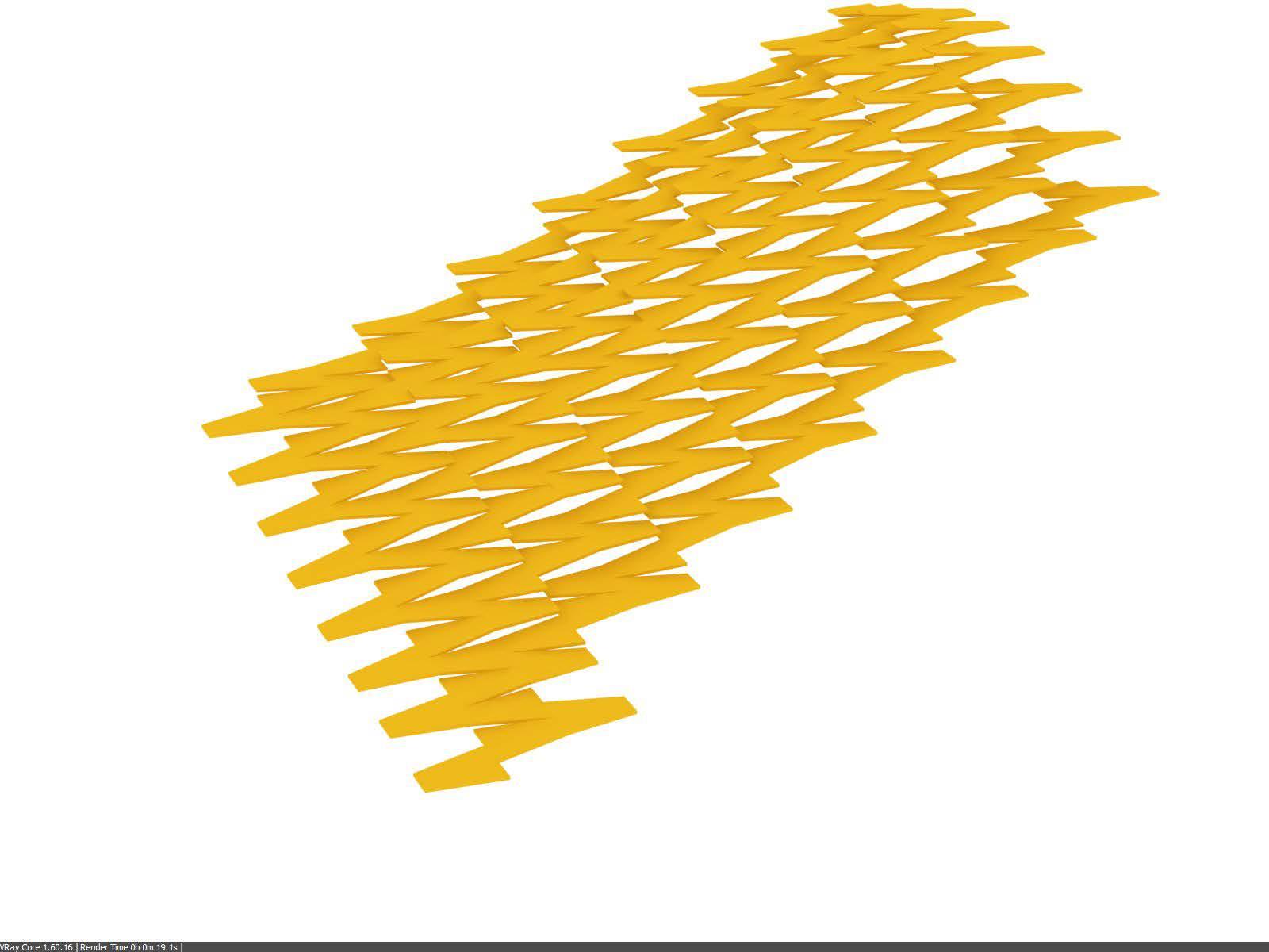

incremental angle surface, elevation
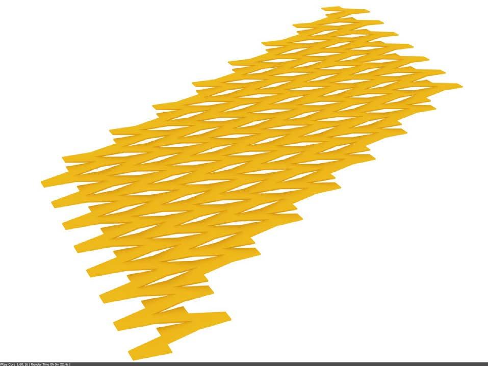

input guide surface
fixed angle surface, elevation
Guide Surface Fixed Angle Surface Fixed Angle Elevation
point of system failure
Incremental Angle Elevation
Incremental Angle Elevation
the next iteration of digital experiments was built out of much more of a “bottom up” approach.
Guide Surface Fixed Angle Surface Fixed Angle Elevation
this test broke down the overall local logic of the surface system into a series of planar components. a single unit was placed into the field with an additive recursive process. the unit was then copied, flipped, or mirrored to align with the previously placed unit. as each unit is placed, it is set to a specific rotation angle. Variation in the system comes as this rotation angle changes incrementally.
based on pure geometry, this system works quite well. geometrically this technique, with all rotation angles set the same, the system is quite successful. this technique begins to fail when an
incremental rotation angle input is changed. as clearly seen in the incremental example above, the units are misaligned.
the pure geometric approach failed when adjust ing component angle, concluding that the material system is not acting as pure geometry.
as a consequence of this study, we concluded that the material system was not based on pure geometry. additional material properties and tolerances are acting on the system allowing for the varying openings. this tolerance will need to be translated and added to the digital system.
please refer to page 178 for technical details on this experiment.
input guide surface
input surface translates to changing angles applied to pattern generation


Second Generation
Guide Vector
First Generation
Rotation Angle Input
Second Generation
second generation
Guide Vector
guide vector
First Generation
first generation
Rotation Angle Input
Seed
rotation angle, input translated from guide surface seed unit
the first set of mock-up experiments were set for testing the digital achievements on plywood
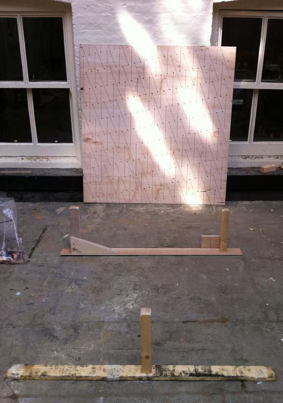
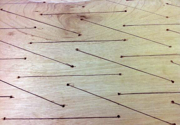
the basic goals for the experiments were to test:
>edge deformations
>spacers
>fibre orientation
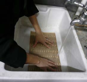
>Wood reaction to soaking and forming
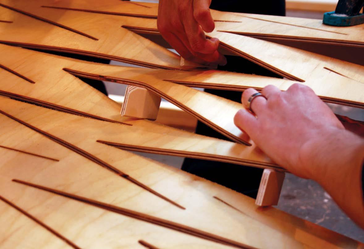
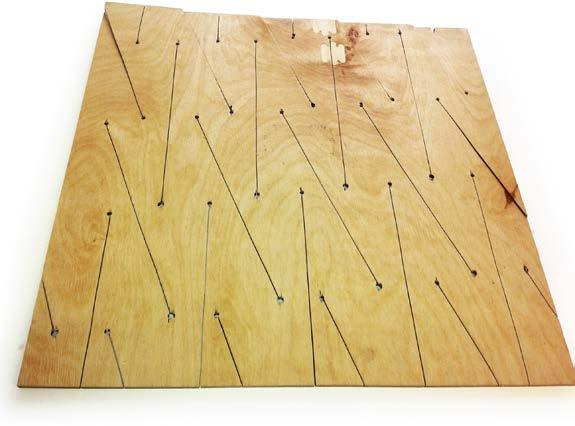
the process followed to achieve this was: the pattern generated from the algorithm was projected into the sheet, traced (01) and then cut with jigsaw in the shop (02). this process would be omitted in later experiments by the use of g-code and cnc milling.
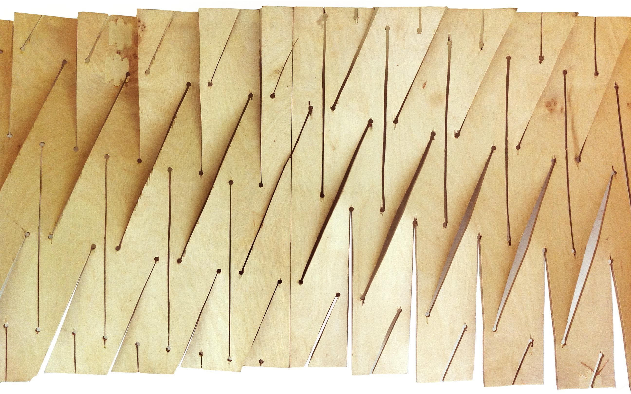
once the pattern was cut, the sheet was laid on the formwork (04) and soaked for 30 minutes (05). as the surface was bent the edges shrank, decreasing the base rectangle (06).
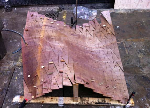
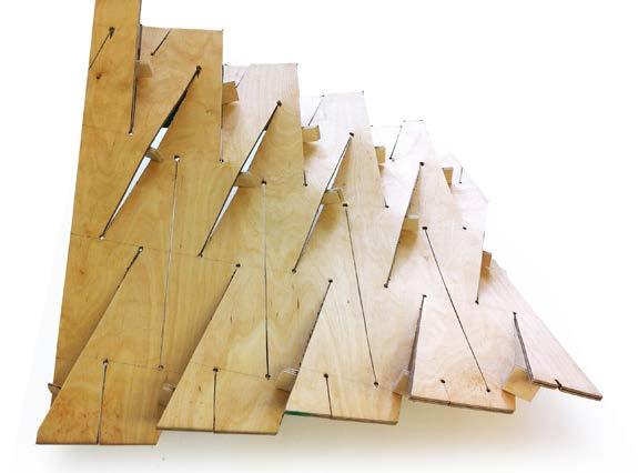
after this, the spacers were placed from the edges towards the centre (07). as the spacers were added, the edge length began to expand getting closer to the base rectangle. also when the third line of spacers were inserted, the height between the cuts on the edge increased (08).
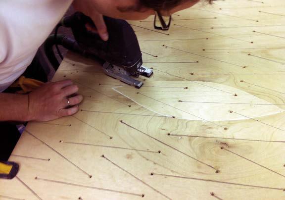
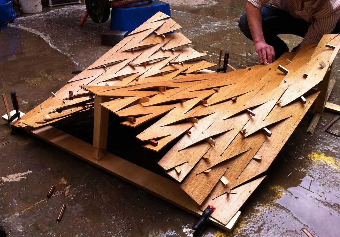
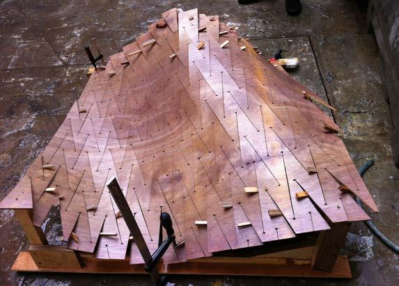
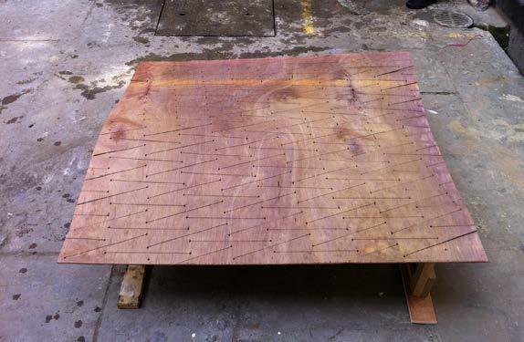
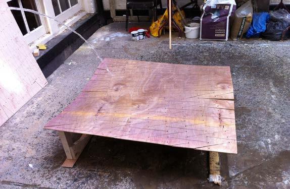
 fabrication process, flat panel
fabrication process, inserting spacers
fabrication process, final mock-up
fabrication process, inserting spacers
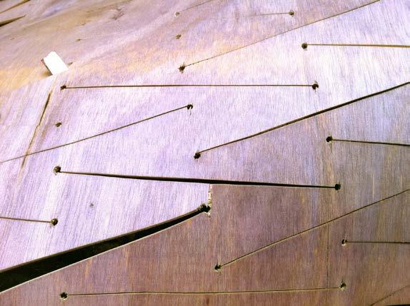
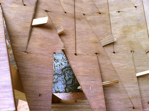
most unanticipated material failures were connected to fibre orientat ion. When cut opening and rotation was forced, opposite to the orientation of the fibres, the material was more likely to fail than when the cuts were oriented parallel to the fibres.
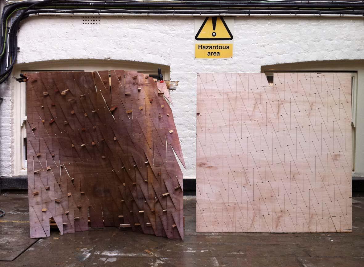
 Fibre orientation
fibre orientation
fabrication results, material failure due to fibre orientation
fabrication results, self supporting stable formed panel in comparison to panel before forming process
06. test patch, assembly and joining connection test edge to edge condition
this connection presented limited tolerance. hence, it required a high precision on the panel finish and in the pattern layout for each panel.
two possibilit ies are deducted:
a- digital fabrication tool developed to predict material deformations and match pattern accordingly.
b- possible overlapping joint.
exp.04 + exp 05> conclusions
fibre orientation on panel evaluation
material: 5 mm grade e 3 layer plywood (0.6- 3.8- 0.6 mm) panel: 124 x 118 cm
how does the fibre orientation affect the curvature of the panel? it reduces “h” by a 52%
52% decrease in overall surface deformation with fibres oriented parallel to cuts
edge deformation evaluation
material: 6 mm grade b 5 layer plywood (1.2 mm)
how to calculate the deformation on the edge condition due to surface forming? by the following geometrical procedure
edge condition needs to be altered to accommodate surface curvature and forming process
spacers vs soaking evaluation
material: 5 mm grade e 3 layer plywood (0.6- 3.8- 0.6 mm) panel: 124 x 118 cm
how does soaking the panel affect its curvature? it increases “h” by a 47%
47% increase in overall surface deformation with soaking
opening reduction evaluation
material: 6 mm grade e 3 layer plywood (0.6- 3.8- 0.6 mm)
how much do the openings decrease after removing the spacers? they decrease by a 16% (from 35 mm to 30 mm)
16% opening reduction after spacer removal
formed panel by structural analysis, perspective view
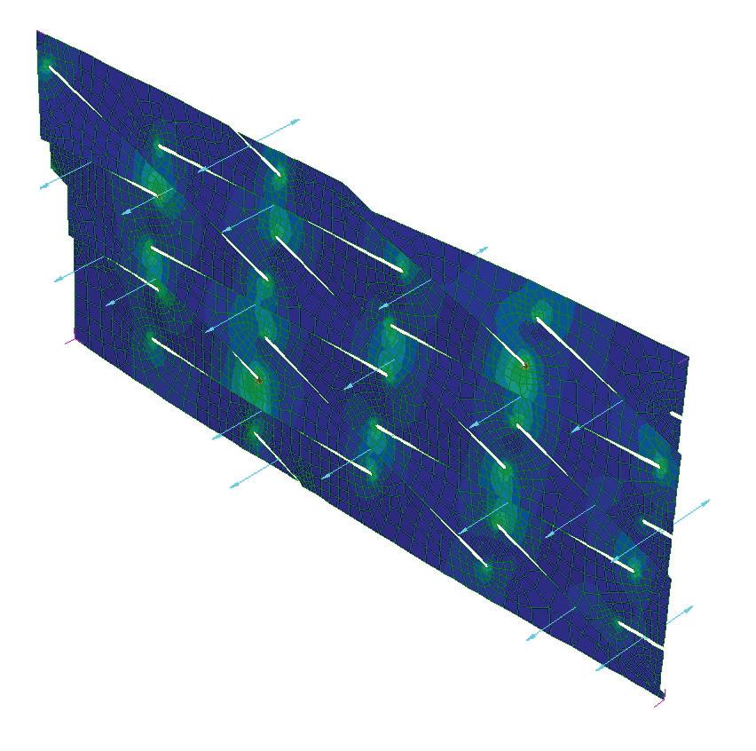
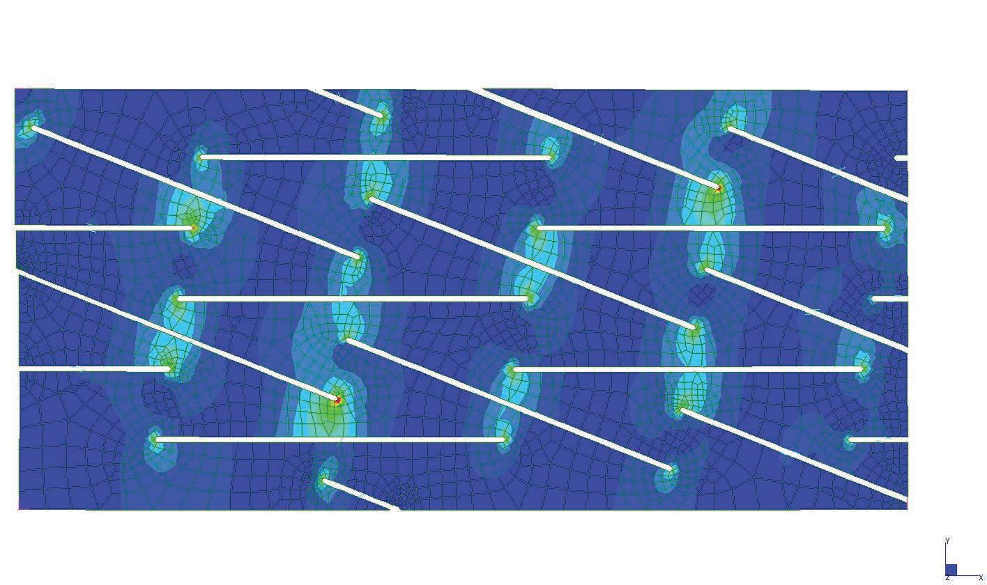
based on the physical tests, a rectangular patch was modeled and tested in strand 7.
the aim of the experiment was to compare the deformations achieved from the physical tests and also to compare the required force to open the cuts and its consecutive stress.
the original rectangular surface was 770mm x 360mm with cuts of 300mm.
the applied force to open each cut was 10Kg. the forces were applied on the centre of the edge of each side of the cut facing opposite directions. this created an opening and rotation of each cut.
formed panel by structural analysis, plan view
base parameters to control cuts and surface deformation
formed panel by structural analysis, elevations
once the calculation was done, the deformed model was exported to rhinoceros, measured and compared to the physical mock-up.
the results were convincingly close to the physical tests. hence this model was set to be developed as an algorithm to create complex geometries.
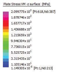
points of maximum stress
sections through the material, revealing ratio between material rotations and openings
based on the material studies and digital tests in strand 7 we set the geometric parameters for the development of the system.
after a detailed study of the results of the structural model, a series of geometric relationships were observed. in a additive process, each cut is successively added to the next with just two parameters. first, a value is given for size of opening height given to the system and therefore this value equals the height of spacer. second, a rotation value is established to simulate the material behaviour and tolerance.
the surface deformations are based on spacer size and the angle of rotation created by the material behaviour and tolerances.
With a base approach to the single section established (diagram 02), a method to repeat these sections in the field was needed.
in addition to reproducing the patterns, every other section needed to provide an alternating pattern with varying cut size openings. an additional curvature was derived to bring the two elements together.
these pure geometric relationships will allow the system to be further developed on the digital front, and implore a better logic and implementation of the material behaviour.
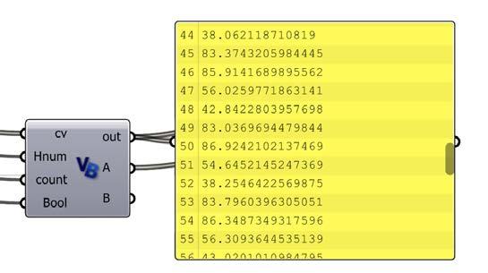
list of spacer sizes generated by algorithm
algorithm generates sectioning pattern
sections are analysed for spacer size
algorithm devised to translate geometric material findings digitally
as a step to implement ing the section, angle, and spacer logic previously studied, and algorithm was generated to simulate the material and geometric properties on a given geometry.
the script analysed the surface geometry, extracted isocurves at a given interval, then generated a custom rationalized section for each curve. this section in turn informs the cut interval and spacer size.
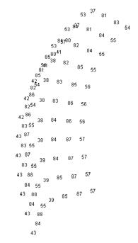
With the increase in cut interval, spacer sizes are reduced. hence, denser cut patterns generate smaller openings.
please refer to page 180 for technical details on this experiment.
section depicting algorithm logic, numbers display height of spacers in millimetres


as further analysis was undergone into the physical and geometric proprieties, as well as the structural analysis, an algorithm was setup to better approximate these finding digitally.
for the first time, this experiment truly creates a tool for form finding.
using the logic and geometric principles developed from the previous sectioning step technique, the script attempts to recreate this phenomenon. in a cartesian grid arrangement, the sections are reproduced with two values given. these parameter values define two required inputs - the height of the cut opening and the direction of that opening.
the difficulty in this system is the source of these values. the values are obtained from numbers and text manually inputted into a spreadsheet. the data from the spreadsheet is then sent,
crossing platforms, to the parametric definition and algorithm as inputs. the result is the surface patterns seen above. in order to change the surface geometry, one must edit the characters in the spreadsheet.
While this makes for a fairly limited workflow, the tool is truly form finding. the rule base is set, parameter inputs given, and the formal geometry is generated, analysed, and evaluated.
please refer to page 176 for technical details on this experiment.
truetruetruetruetruetruefalsefalsefalsefalsefalsefalse truetruetruetruetruetruefalsefalsefalsefalsefalsefalse truetruetruetruetruetruefalsefalsefalsefalsefalsefalse truetruetruetruetruetruefalsefalsefalsefalsefalsefalse falsefalsefalsefalsefalsefalsetruetruetruetruetruetrue falsefalsefalsefalsefalsefalsetruetruetruetruetruetrue falsefalsefalsefalsefalsefalsetruetruetruetruetruetrue falsefalsefalsefalsefalsefalsetruetruetruetruetruetrue
1.
While the paper experiments were quite intuitive and exploratory at first, a few basic parameters became clear very quickly. simple relationships between cut length, spacing, and adjacent cut overlaps resonated.
2.
as we simplified the patterns to better control and represent the parameters in play, we determined that opposing the directions of every other incision gave stiffness, stability, and control over system.
3.
by introducing the spacer technique as a local operation, an increased command and control over the geometries was offered.
4.
the spacer detail eliminated the requirement for customisable formwork for each new surface configuration.
5.
many outside forces and material feedback were acting on the physical systems that were near impossible to understand and reproduce purely with mathematic and geometric means.
6.
through a structural analysis of a small surface patch, a basic recurring geometric pattern was discovered. this discovery lead to a recursive logic of adding cuts and openings based on the analysis of a global surface form.
While the initial experiments ranged in success, the evaluations lead to the goal of a full scale mock-up and material selection of 6.5mm birch plywood.
the aim of the geometric tests was to develop a simple logic and understanding of the technique and system. they proved to be very successful in this regard. While the paper experiments were quite intuitive and exploratory at first, a few basic parameters became clear very quickly. simple relationships between cut length, spacing, and adjacent cut overlaps resonated. as we developed a fairly fluid process of generating patterns digitally and physical model making, the evaluation of these tests became the challenging part. What quantifiable data could be extracted? there was an obvious visual seduction in the patterns and the light qualities they provided. steps were taken to better understand the global curvature and geometric logic of the surfaces. dense regular cut patterns provided most flexibility and expansion in the forming process. it was useful to have this flexibility to form find a stable geometric configuration at first, but too much flexibility limited the stiffness of the surfaces. additionally, the free form patterns posed some difficulty in scaling up material and size. as we simplified the patterns to better control and represent the parameters in play, we determined that opposing the direction of every other incision gave stiffness, stability, and control over system.
the main obstacle in controlling the system and taking steps to the one to one mock up was devising a method to change the way we operated on the surfaces. in the simple paper models, an external global force was imposed (ie stretching the surface by hand) easily. this technique provided a uniform distribution of openings, but was simply unrealistic at a larger scale. in addition to the reality of not being to globally stretch a large sheet of
plywood, we were searching for a method to better control how we acted on the material. by introducing the spacer technique as a local operation, an increased command and control over the geometries was offered. this was also the first step to eliminating the requirement for customisable formwork for each new surface configuration.
While the physical experiments made fast leaps into foreseeing futures of the system, the underlying principles and geometric logic were not as simply understood. many outside forces and material feedback were acting on the physical systems that were near impossible to understand and reproduce purely with mathematic and geometric means. the earlier discussion on the limitations of digital surfaces built on these difficulties. We experimented with many approaches both “bottom up” and “top down.” by utilizing an additive process of breaking the surface down into individual component units, then attempting to rebuild the surface one unit on the next, was main concept of the “bottom up” approach. in opposition to this approach, we tried a number of techniques of analysing a global form, and determining the cut pattern and size of cell opening. both approaches offered benefits in terms of inputs, but posed limitations in the overall success of the resultant surface.
the most successful of the techniques, and consequently the approach we chose to continue to develop, was neither “top down” or “bottom up.” through a structural analysis of a small patch of a surface, in which local forces were applied at each cut, a basic recurring geometric pattern was discovered. this discovery lead to a recursive logic of adding cuts and openings based on the analysis of a global surface form, a technique we aim to further develop.
material based experimentation>>the case of the self supported Wall
as part of the aa end of the year exhibition, the emergent technologies and design program asked our team to develop a self supported wall to create a space for the exhibition and to serve as a backdrop for the panels showing the projects from the programme. this opportunity was embraced to test and develop the system towards its first built stage.
along the ambitions of the abstract, the first scaled experiment of the expandable surface system is an exploration, design, and fabrication of a self-supported wall system. as the system has been defined in terms of parameters, inputs, material, a notion of scale limitations, and method of fabrication many steps still need to be taken to a successful fabrication of the wall system.
What lessons were successful from the previous experiments to carry to the wall system?
as a baseline, with the main local parameters established, a simple brief was devised to efficiently proceed in the wall and system design. at first a scale would need to be established. how big would the wall system need to be? What environmental and programmatic requirements would need to be accommodated? What are the material and fabrication limitations? how can the self-supported wall experiment grow and be extended into future systems?
one key issue that will need to be addressed in the full scale installation is the notion of panelisation and joints. as the system is currently defined, these questions are not yet considered. the main assumption is that the continuity of surface and structure will not perform as fluidly with the requirement to move to a panelised system. both physical tests and digital coordination will need to be built into the system to address the issue. the topic of panelisation and joining will be the focal point of this portion of the research.
along with panelising the system, the current insight into possible global geometries, structure, and stability will need to be reexamined. the primary criteria in regards to structure are simply the requirement that the wall system must be self-supporting and safely. no outside vertical loads will be provided for and only minimal horizontal forces (i.e. a visitor physically pushing the wall) would the wall need to resist.
the main goal of this test is a proof of concept. can the base research system be developed and translated into a method of design, coordination, fabrication, and installation effectively? if so, what notions of material and fabrication will then be reinvested into the design and refinement of the system?
h
sp ep 01.
as the first stage for this process, the geometry logics for creating the surfaces are studied. the main goal here is to determine the parameters to control geometry growth, always thinking in regards to the structural possibilities and the material constraints.
based on the first mock-up experiments, material reactions and deformations, a catalogue of possible curves was developed studying 3 basic parameters:
01> deformation of curve: the point of deformation for each curve was limited to 1 (h).
02> length of curve: length (l) was set to 120cm (base of a standard plywood panel)
03> point of connection: a connection for consecutive curves is restrict to 3 points, start point (st), midpoint (me) and endpoint (ep) of each curve.
the catalogue was used to study parametric growth for different schemes and to understand how complex geometries could be achieved by controlling just a few number of parameters.
one panel two panels, same curvature, opposite direction
two panels, same curvatures, same direction
one panel, possible combination of curvature
curve deformations catalogue >>possible curvatures and connection between curves.
h= height of deformation curve deformations catalogue >>overlapped curvatures.
number of panels:5,5
equal size panels:5
half size panels:1
number of panels:5,5
equal size panels:2
half size panels:7
number of panels:8
equal panels:4
custom size:4
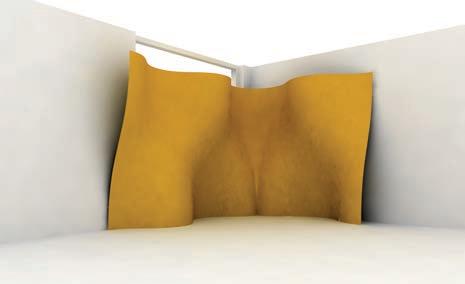
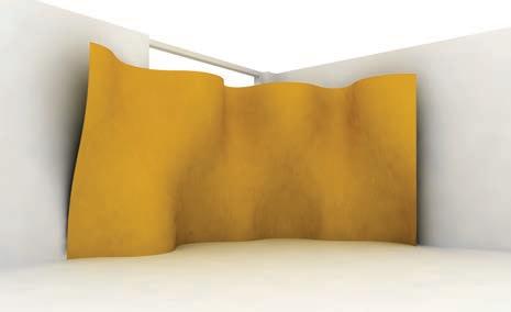
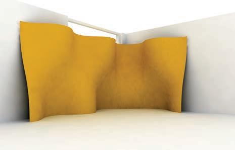
the base geometry for the wall was set as an l shape to create a more suitable condition for the panels to be exhibited and to perform with the light coming from the existing window.
following the curvature catalogue several schemes where tested to generate different morphologies with the minimum of different panels and connections.
to ensure structural stability, opposite curvatures in top and bottom of the wall were always maintained.
to achieve a seamless surface feeling, several iterations were carried out to optimise the number of panels and to reach a corner condition without kinks.
as the last iteration for this process, the panels themselves were re-designed to be easily fabricated and to have always a straight edge to be connected to the consecutive panel.
number of panels:6
full size panels:4
half size panels:4
number of panels:6,5
equal size panels:6
half size panels:1
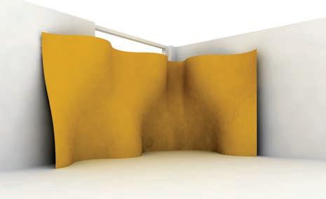
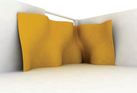
>matches geometry hard to connect
>matches same geometry easy to connect
panel type option 01 panel type option 02The panels share the same dimension though the pattern is unic to each piece to match in sequence.
Basedonthe3,5cm spacer,everypanel achievesthesame deformationinoposite direction.
based on 3.5cm spacer, every panel achieves the same deformation in opposite direction
Thepanelsaredesigned toachievestructural equilibriumwhencoupled toduplicatethedeformationachievedbyeachof them.
the panels are designed to achieve structural equilibrium when coupled to duplicate the deformation achieved by each other
the wall was panelised as a collaborative system. one panel would never stand by itself, it needs the next panel, with opposed curvature. this change in the curve direction increased the depth of the wall base, making the wall to stand. also, the lower flaps of the panels were pushing the panels together and increasing the stability. the “l” shape of the wall was also contributing to overall stability of the system.
the friction between the base of the wall and the floor rendered the system to be self supporting. there was no need for external fixings to the site.
since the pattern was applied to the whole screenwall there was a continuity in the texture of the wall, making it to appear as a continuous surface. at a distance of 1.5 meters one could not perceive the vertical joints between the panels. applying the pattern following the global surface of the screenwall was an early decision and it was taken to avoid the image of a wall made of
equal repeated panels. this technique also to distributes more evenly the self weight of the wall. in the end, we noticed that by maintaining this pattern the surface curvature was shifting from left to right - following the same angle of the cut pattern.
another interesting fact was that the wall system was very flexible in terms of its morphology. once the exhibition was finished and the rest of the elements of the exhibition (the table, boards and cables used to display the works) were removed, we started moving the connected panels around to change the overall shape and the system proved to be very adaptable. it tended to find by itself the right shape to accommodate the global forces that were applied. due to the lightness of the system, the whole process was carried out by two people.
it was a form finding process were the embedded forces of the system balanced the external forces applied onto it.
corner condition, custom corner panel not needed final plan layout with exhibition boards
number of panels:6,5 equal size panels:6 half size panels:1
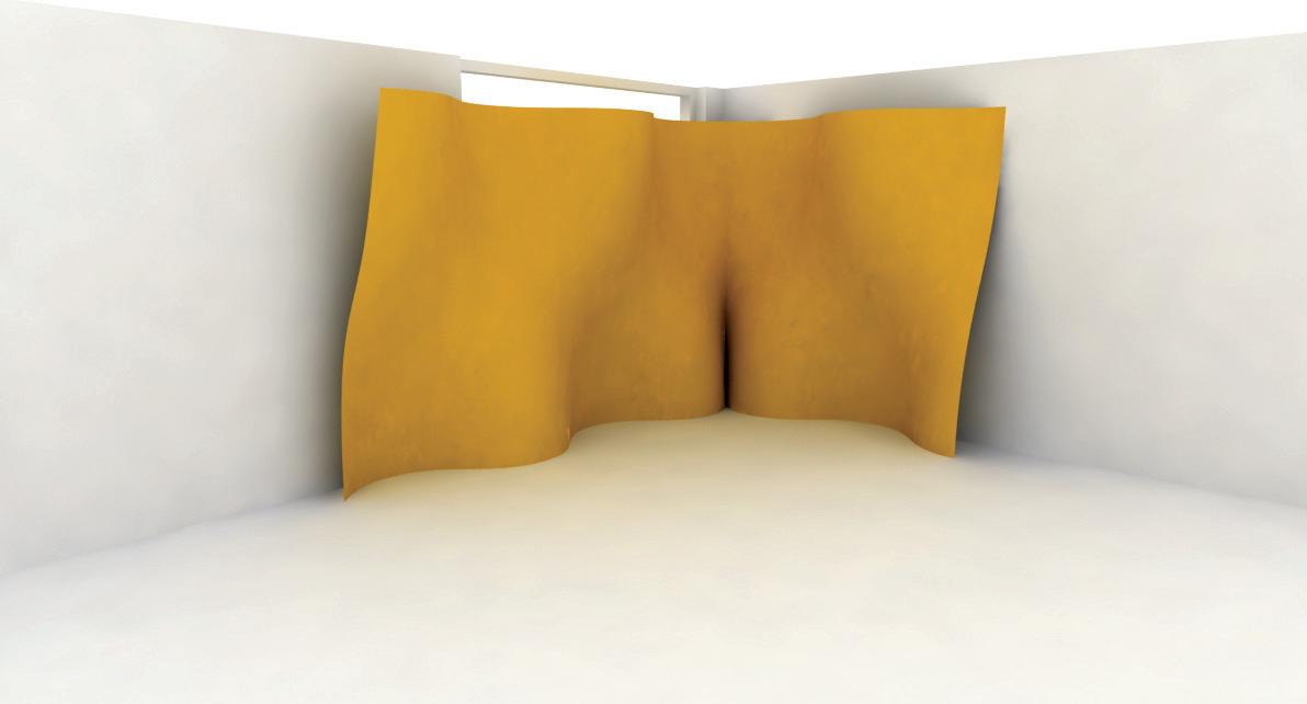
the wall served as a background to display the printed exhibit ion boards. the boards were hung using cables, iron angles, and turnbuckles. the models were displayed on a cantilevered table made of a steel structure and 18 mm birch plywood painted tabletop. the entirety of the emergent technologies and design team was involved in the construction of the exhibition space.
the working team was organized in four teams - table fabrication, exhibition boards graphic design, installation team, and the final group constructing and assembling case study wall system.
as the space was situated on a corner condition, the wall system was required to cover both walls and create an “l” shape configuration. the table was placed at the projection of both ends of the screenwall.
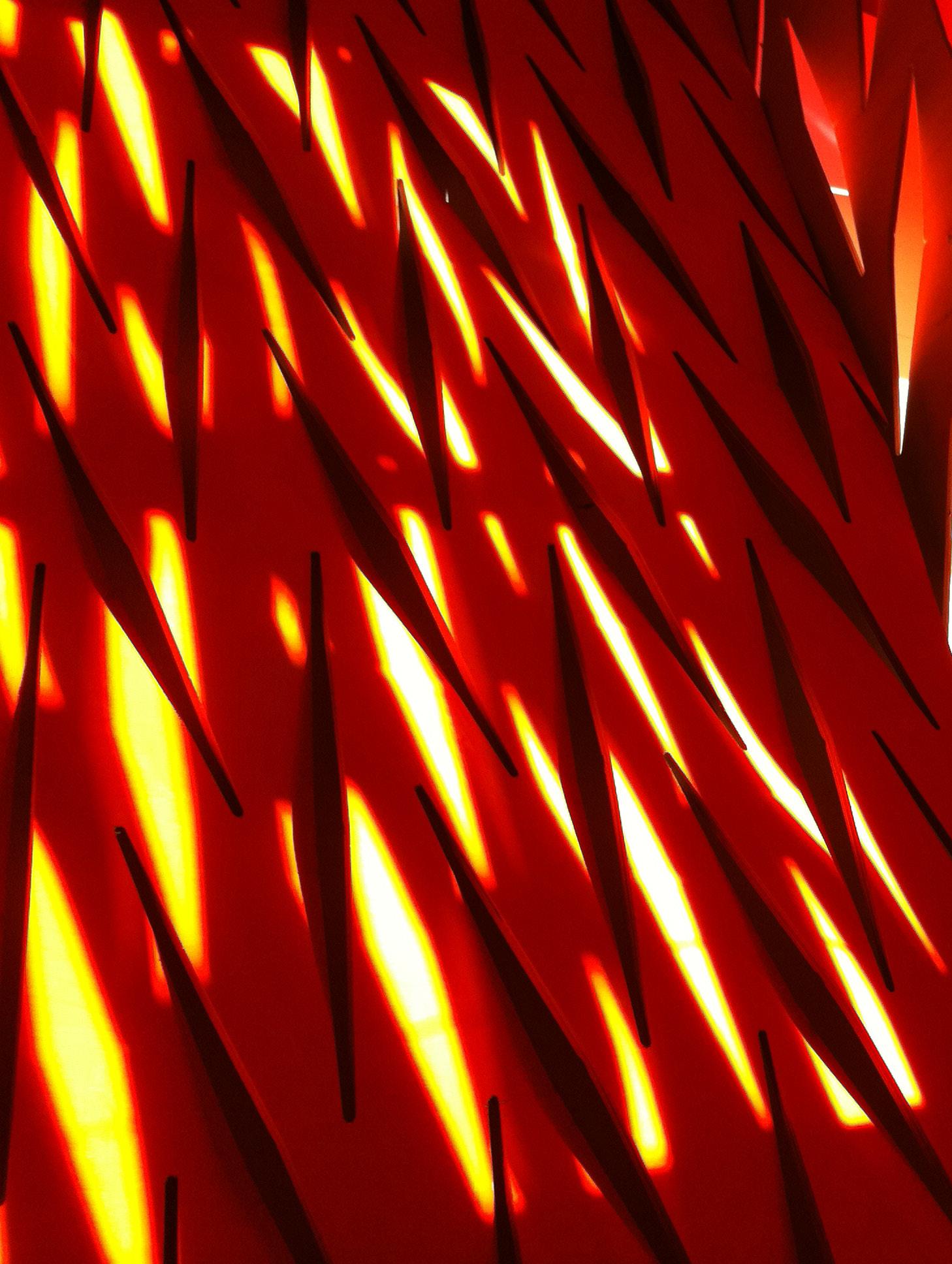
there was a set of east facing windows oriented on one of the two walls. Knowing that we would need to mitigate this natural light into the space for the success of the exhibition, we wanted not only to incorporate the requirement, but exploit these lighting conditions as well. the screenwall modulated the light coming through the window, and to increase this effect, the back of the wall was painted with a water based fluorescent orange paint. this effect produced a very expressive glow. many did not believe that there was no artificial coloured light behind the walls. this effect rendered the neighbouring walls and entire corner of the room to glow.
to the development of the final wall system case study, a series of studies to resolve the final panel size, cut pattern, and geometry were examined.
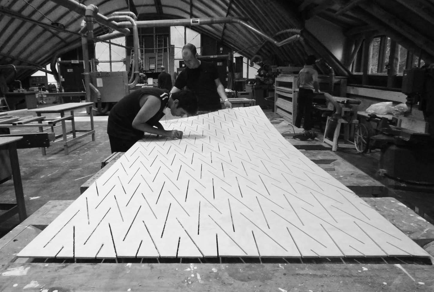
in an attempt to achieve the most minimal amount of material waste possible, the panel size was mainly dictated by the largest stock sheet available. the final panel size was 1220mm x 3050mm. While this sheet material is available off the shelf, the current industry standard is 1200mm x 2440mm and most industry means of fabrication rely on these dimensions. as the panels were larger than cnc fabrication means, the panels were sent through the machine twice per panel. While this increased the complexity of coordination, the required height of the panels was achieved with one stock material.
the final cut pattern was selected based on the analysis of a few parameters and ratios. these parameters were selected and tested primarily in one-to-one material tests. an extrapolation was made to determine the minimum spacing or interval between cuts, cut length, and minimum material area allowance.
the angle of the alternating cut pattern was determined to achieve both panel and global geometry. in order to achieve maximum surface curvature, while maintaining stiffness and structural stability, the pattern was optimised across the surface.
in an attempt to maintain global surface geometric continuity, the pattern was laid out across the entire length of the wall then sectioned for panel dimensions. this technique also allowed for the cut pattern to match at the joint condition.
The panels share dimension though is unic to each match in sequence.
the panels share the same dimensions, though the pattern is unique to each piece to match in sequence
after some quick experiments, we realised that the connection between the panels should be along a straight edge. that lead us to the assembly logic for the wall.
all the panels are cut to the same dimensions, but the pattern and direction of forming was different.
there was six equal panels and one half width panels to tightly fit in the site condition.
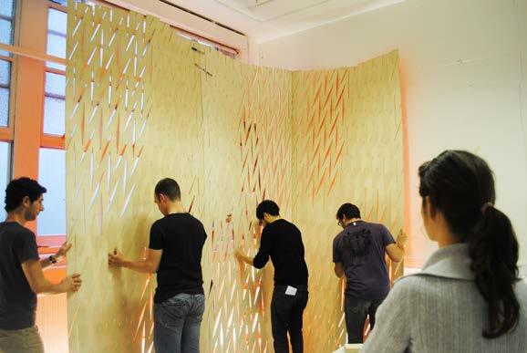
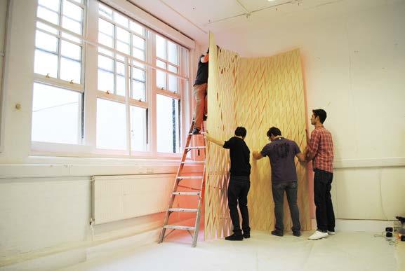
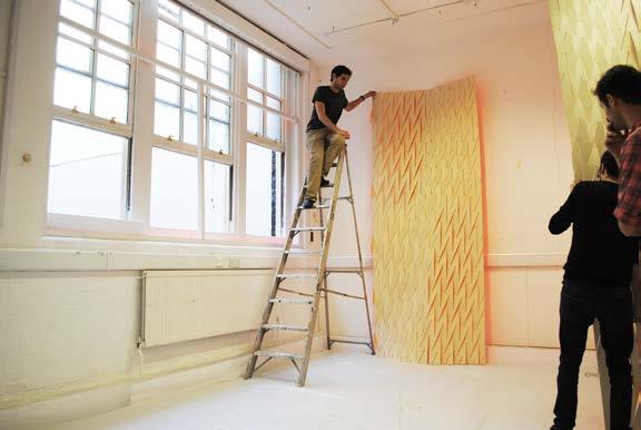
the first two panels to be connected were the inside corner ones. this allowed us to grow in two directions simultaneously. by having the corner assembled first, the wall was standing by itself so it was easy to continue assembly. all panels were joined standing upright and vertical. there were two construction groups. one team fixing the connections from behind the wall and the other in the front applying force and stabilising the system and aligning the panels.
The panels share the same dimension though the pattern is unic to each piece to match in sequence.
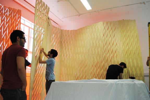
Basedonthe3,5cm spacer,everypanel achievesthesame deformationinoposite direction.
Thepanelsaredesigned equilibriumwhencoupled toduplicatethedeformationachievedbyeachof
material based panel deformation engine
01. original panel without curvature
W: 120cm
l: 240cm
h: 0.0cm
using the data extracted from the physical tests, a panel deformat ion definition was developed.
the basic parameters to control are the base length of each side of the panel, the height of deformation for each edge, and the direction for each deformation vector.
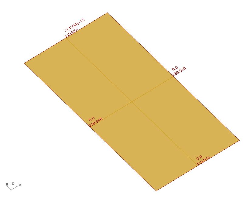
the definition will calculate the deformation for the panel, while taking into account the wood deformation properties and the system expansion properties.
even though the algorithm wouldn’t generate the pattern at this point, it would give the right length for the edge as the pattern would have been there.
parametric definition control, the user can control the deformation height of each panel edge and the direction of it
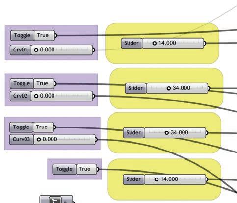
the concept of this definition was to enable surface adjustments within the constraints of available material sizes, physical material properties, and cut system requirements.
W: 116cm
l: 240cm
h: 7.5cm
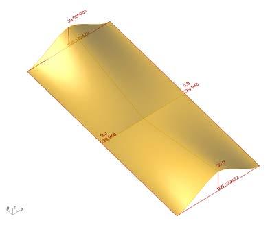
W: 105cm,105cm
l: 240cm
h: 30cm
W: 107cm,105cm
l: 232cm,210cm
h: 25cm,60cm,30cm,15cm
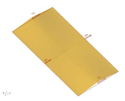
since the algorithm was panel based, the two axis of deformat ion would always be present. this was important to compare with the physical tests and specially for possible kinks.
the next step for the digital development was to take this research to a surface-to-pattern algorithm.
W: 105cm
l: 240cm
h: 30cm
W: 106cm,105cm
l: 240cm,225cm
h: 27.9cm,30cm,30cm
W: 106cm,105cm
l: 240cm,225cm
h: 27.9cm,30cm,30cm
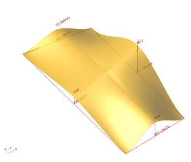
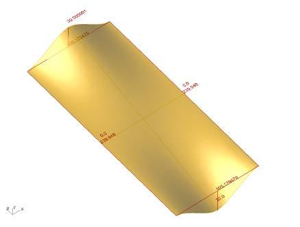
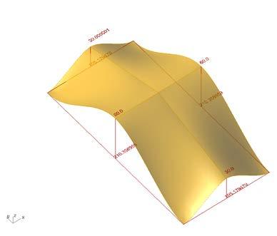
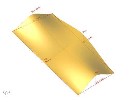 02. position two
04. position four
06. position six
03. position three
05. position five
07. position seven
01. output surface with opened cuts (last step of sequence)
after an understanding of panel sizes and material limitations were established, a system was needed to generate the overall surface with the previously analysed pattern and geometric logics. this system would also need to provide the fabrication process with the required size spacers to achieve the desired form.
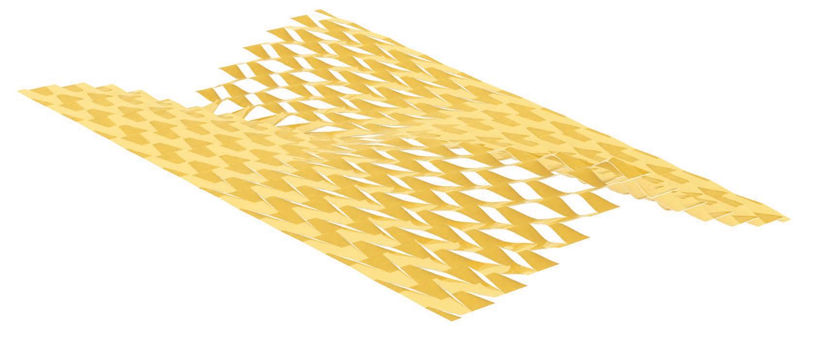
to achieve this task, an algorithm was developed to work both from the side of design intent and from the bottom logic of the material and cut mathematics.
12345678910111213
a freeform, or geometrically controlled, surface is analysed as a design intent input. a number of parameters are abstracted from this surface. first, a base plane is placed to compare if the surface is up or down. a series of a grid points are placed on the plane and projected, in the positive or negative Z direction, to the input surface. the projected points and the base points are connected with a vertical line. the lengths of these lines then remapped to a range of spacer sizes allowed by material properties. this spacer range was from 0 (no spacer) to 80mm at the edge condition.
With this table of values, the programming of the overall surface is embedded. these values are then input into each cut of the surface to generative the final patterned surface.
please refer to page 184-187 for technical details on this experiment.
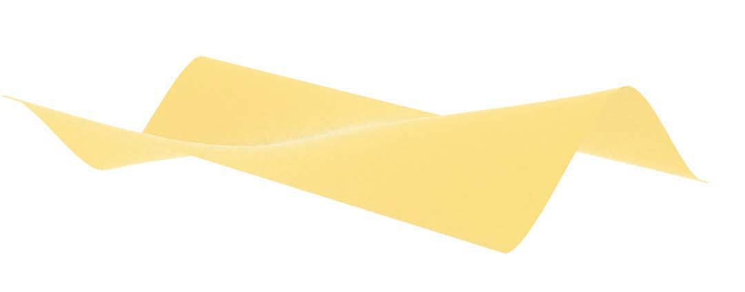

spacer sizes are sent to directly inform panel fabrication
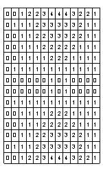
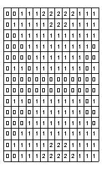
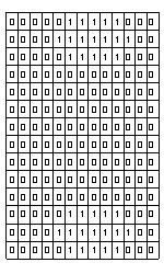
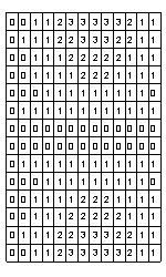
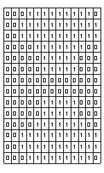
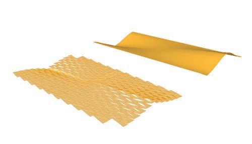
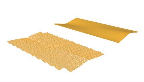
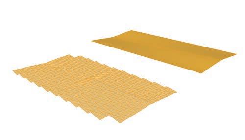
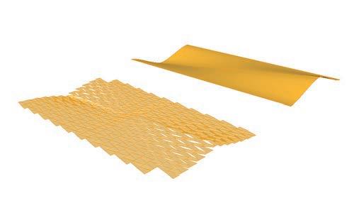
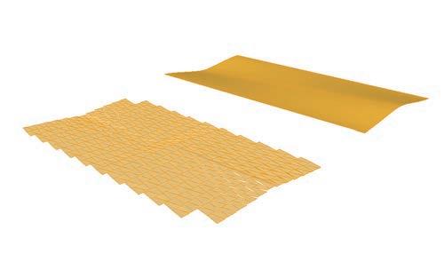
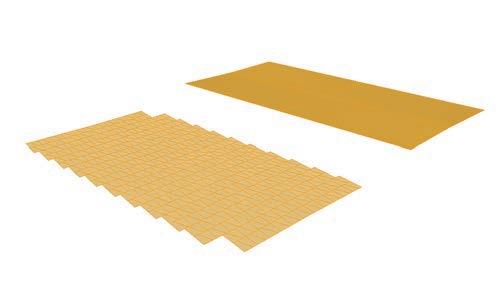
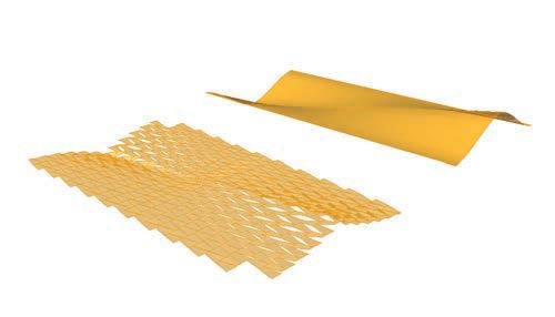
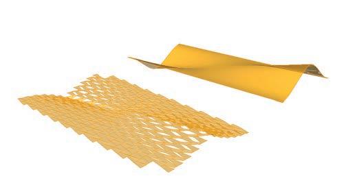
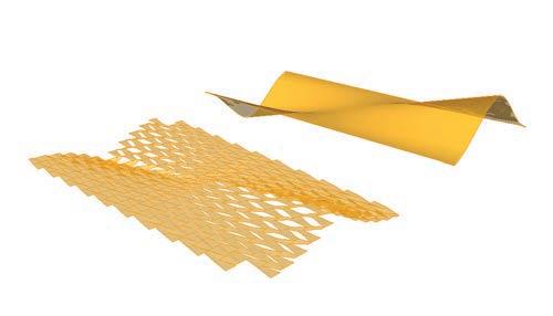
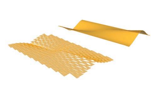
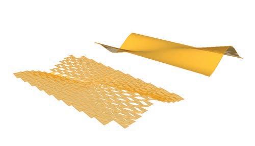
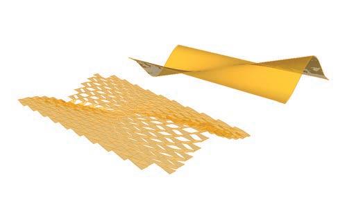
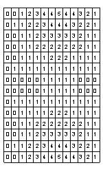
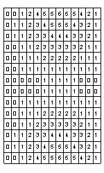
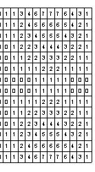
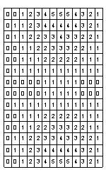
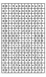
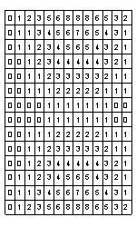
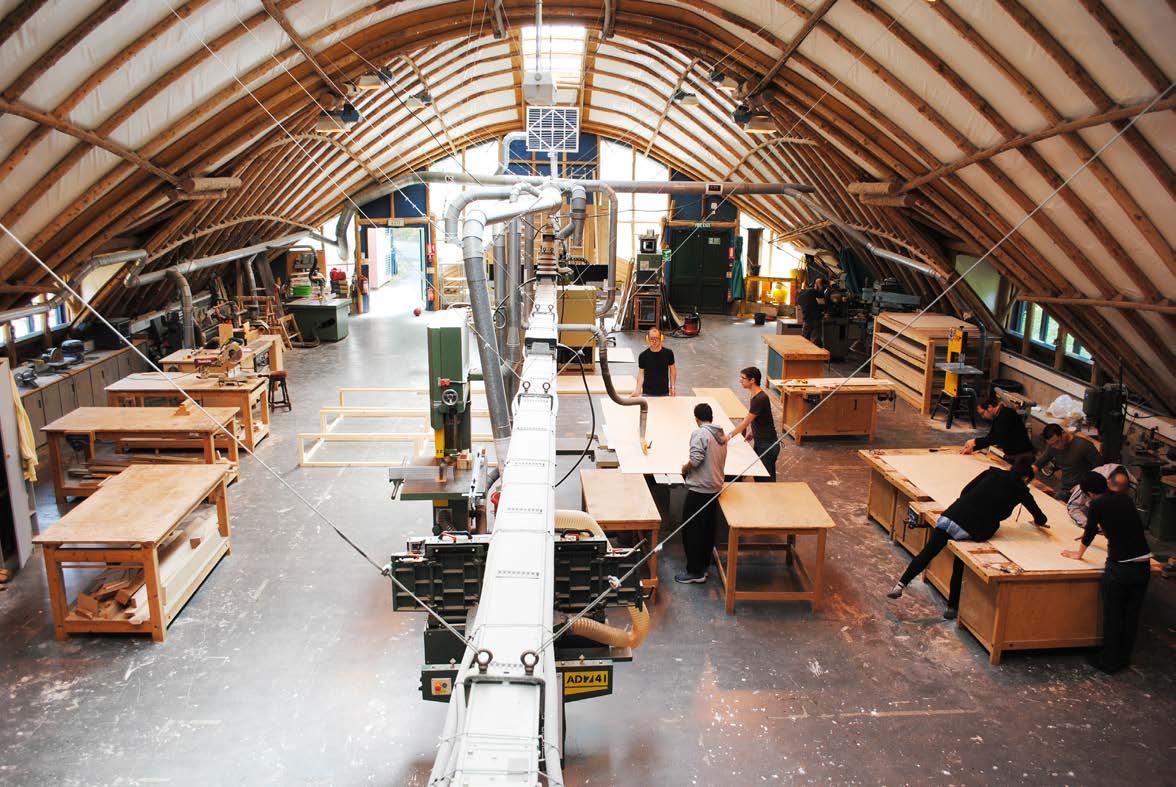
the fabrication sequence occurred in main three steps in three different locations. the first step was carried on in the studio. there, all the digital files to cnc the sheets were prepared, the plywood sheets and other materials were bought, and the schedules were planned. the panels were shipped directly from a local supplier to the aa Workshop at hooke park, dorset.
the second step occurred at hooke park.
a fabrication team of 9 people spent 3 days there to complete the following tasks. first, the sheets were trimmed to panels size. second, the cnc machine was setup and the cutting files from rhino were translated to g-code - the code that the machine used to read the files. then, the sheets were cut at a rhythm of 26 minutes each. to ensure that the machine vacuumed the sheet, a thin layer of 1mm was left in every cut.
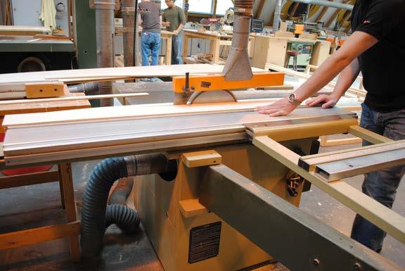
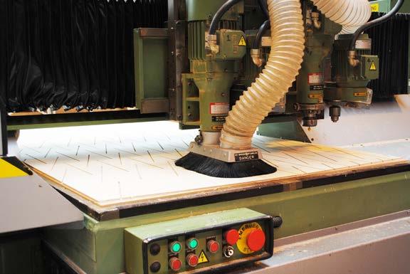
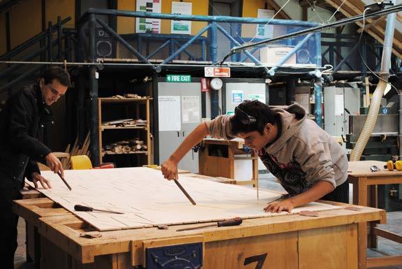
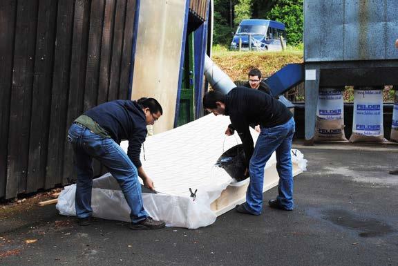
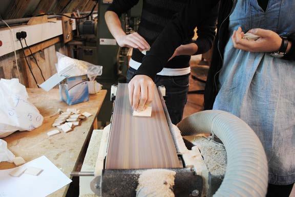
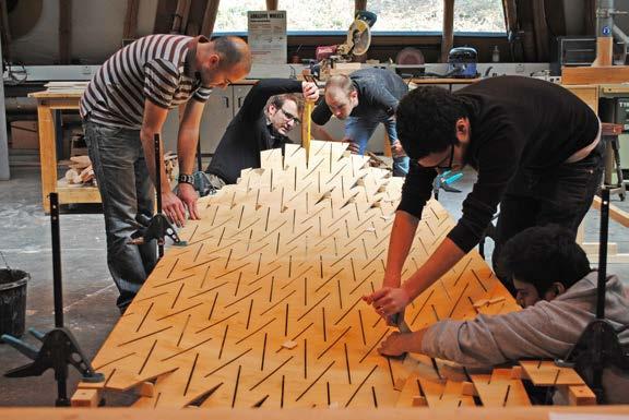
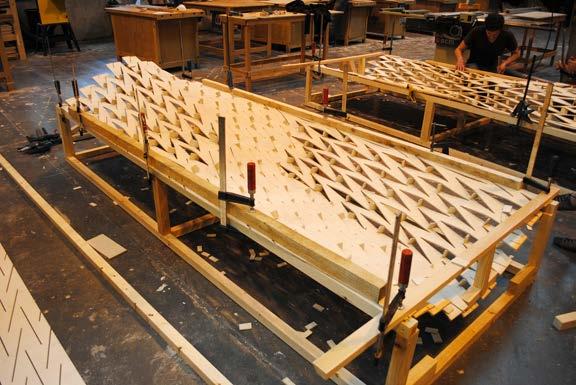
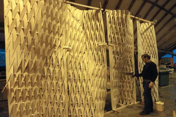 01. sheet trimming
02. cnc milling
03. sanding
04. soaking
05. spacer sanding
06. forming
07. drying
08. testing
panels formation
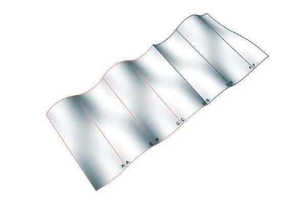
the forming process was done using two basic steps, opening the cuts and placing the spacers. a crowbar was used for opening and a 3cm wide wooden spacer would keep the cut open until dried.
each panel required 26 minutes of cnc machining, 90 minutes of soaking, 30 minutes of forming, and 60 minutes of drying.
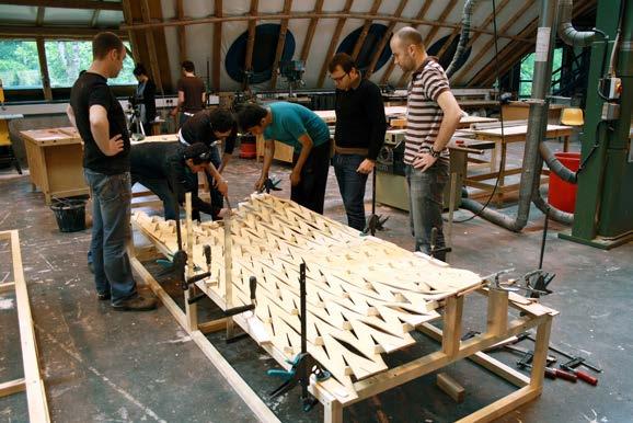
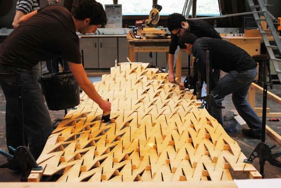
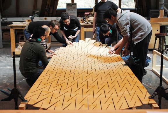
even though all panels had the same basic geometry and panel dimensions, the panel pattern was different for each piece and the deformation were alternating to opposing directions every other panel. this required a big effort in coordination, and therefore before and after each panel was started, the position and pattern was checked. an assembly map was used to help on this process.
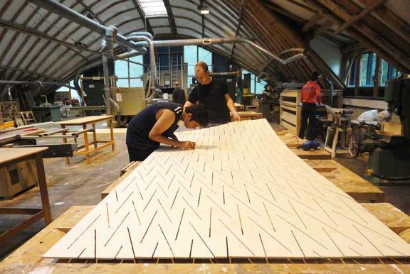 02. sequence of panel forming and opening of cuts
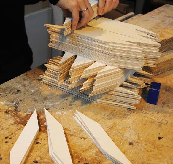
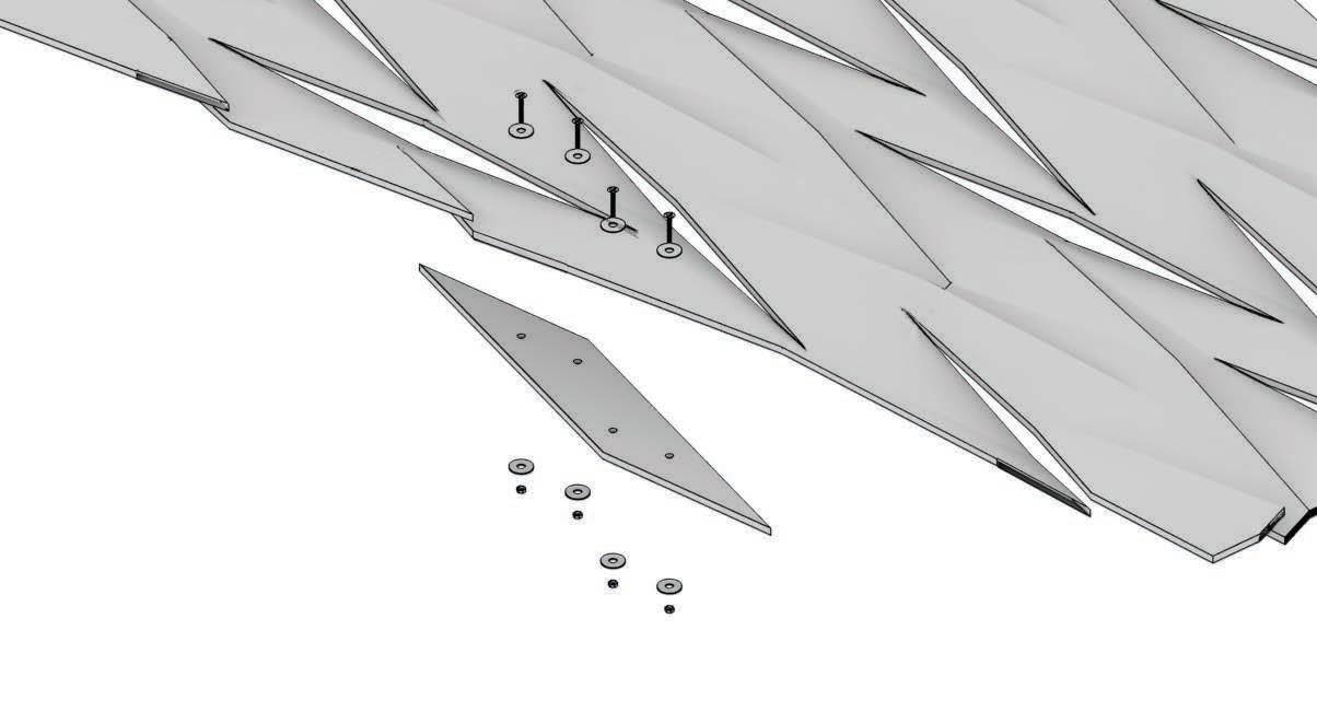
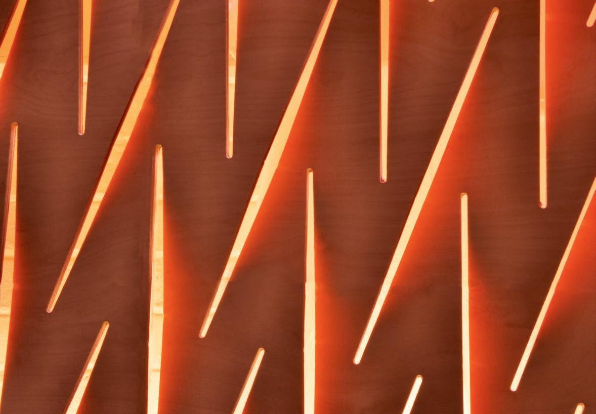
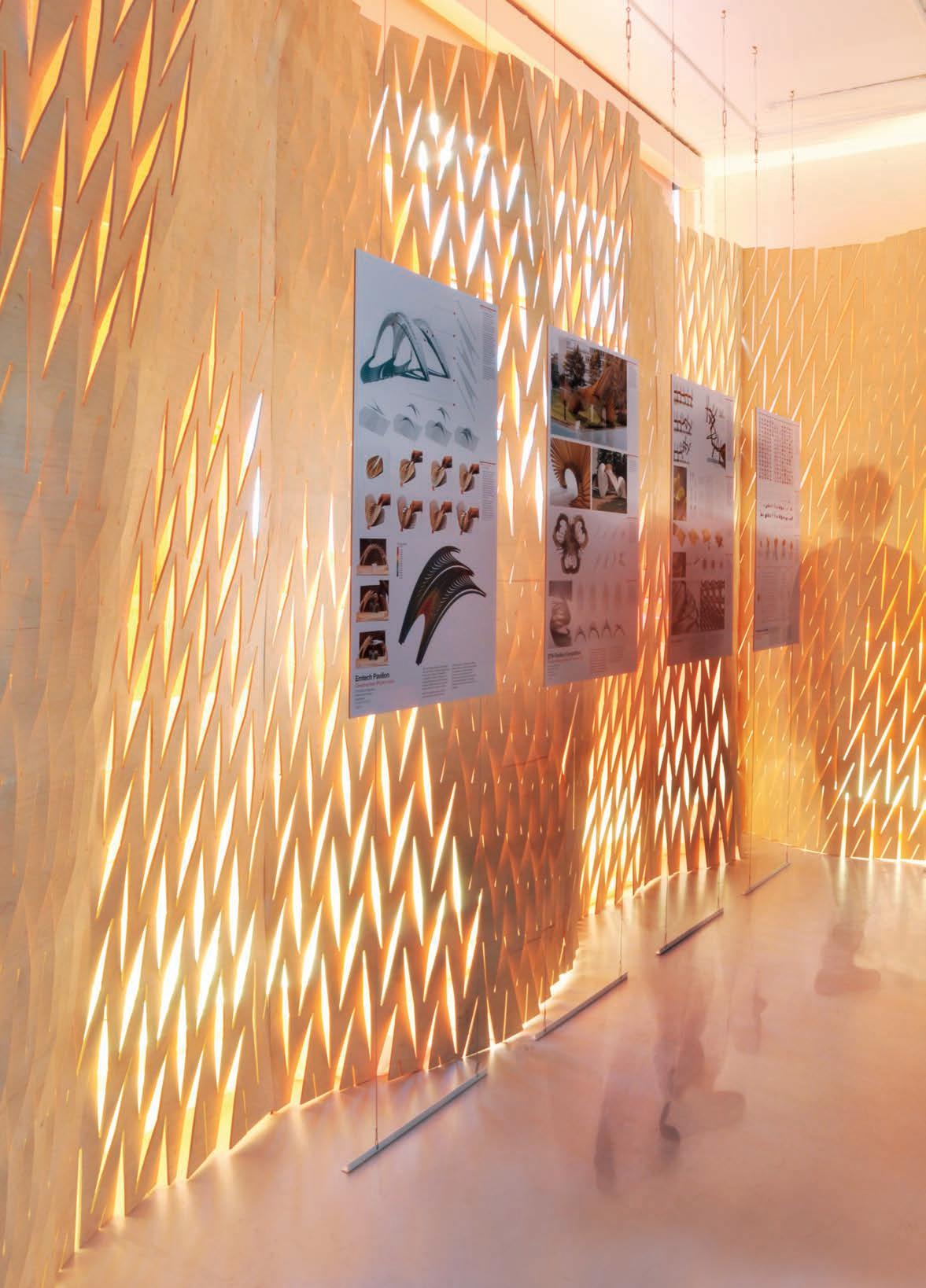 02. panels at the emtech exhibition
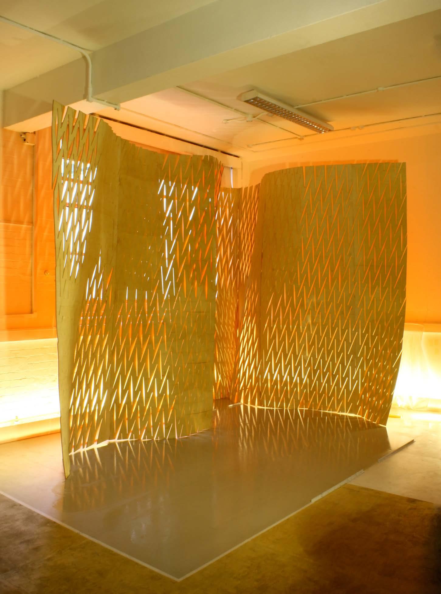
02. shadows, lights, and colour performing through cut pattern expandable surface system 97
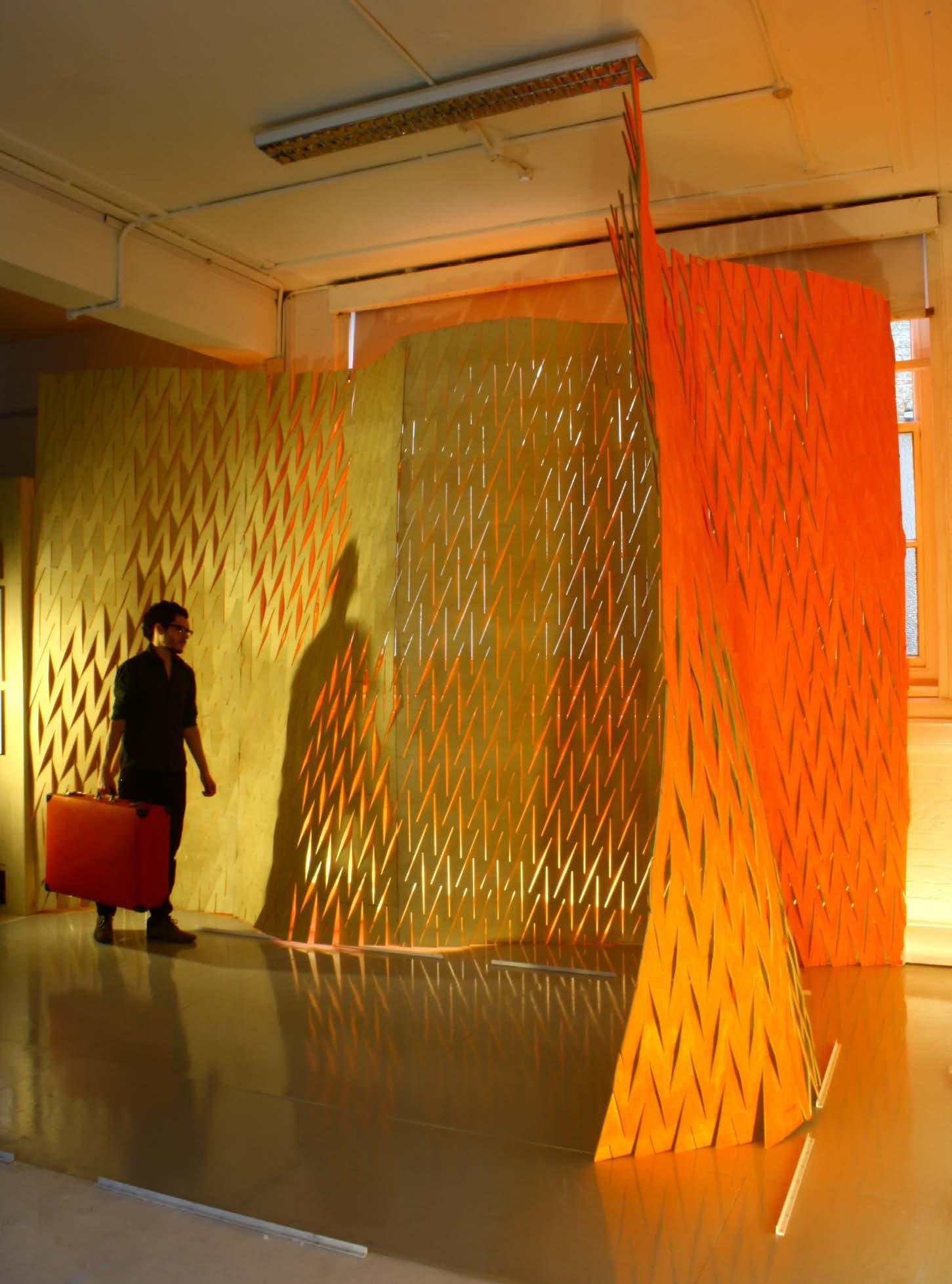
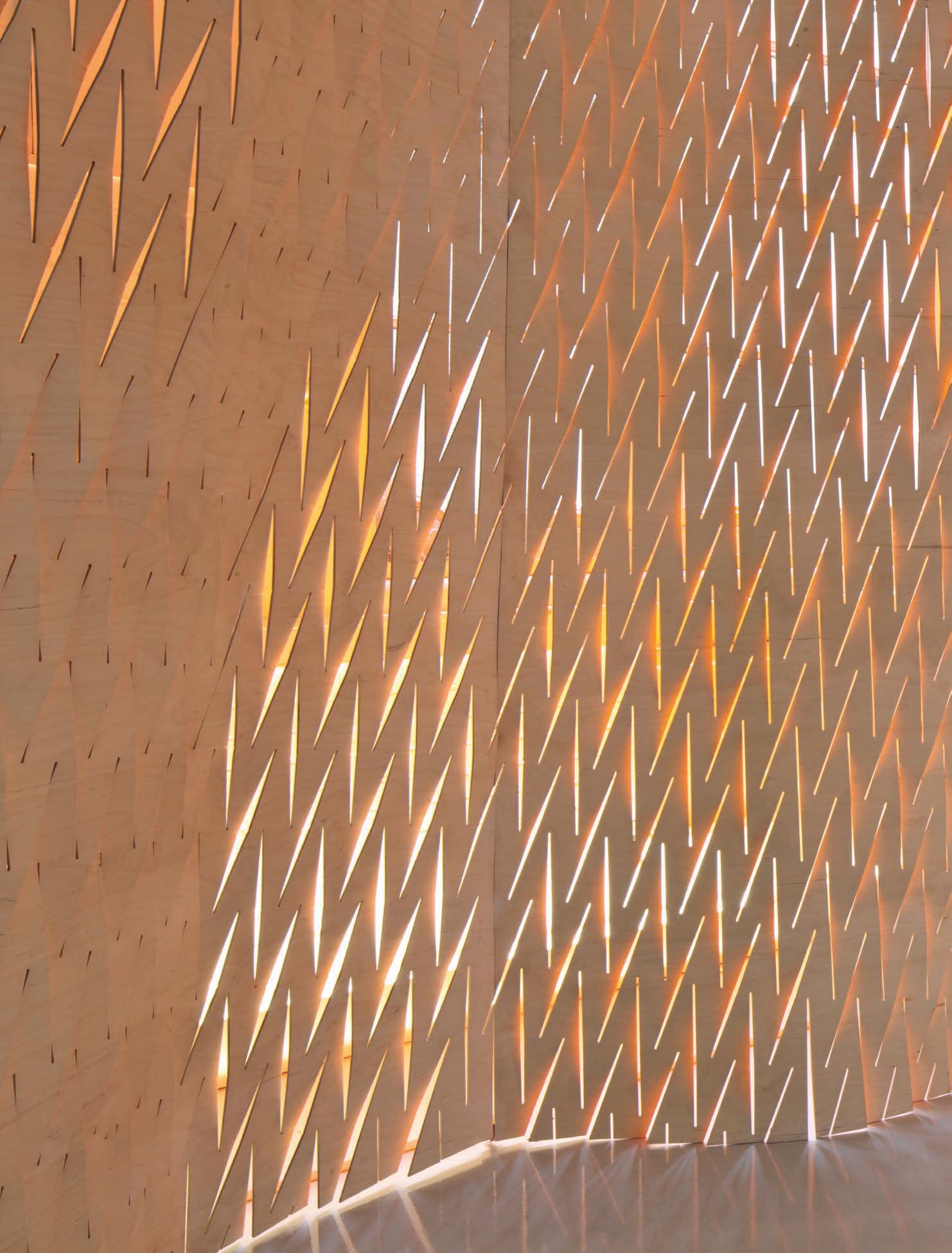
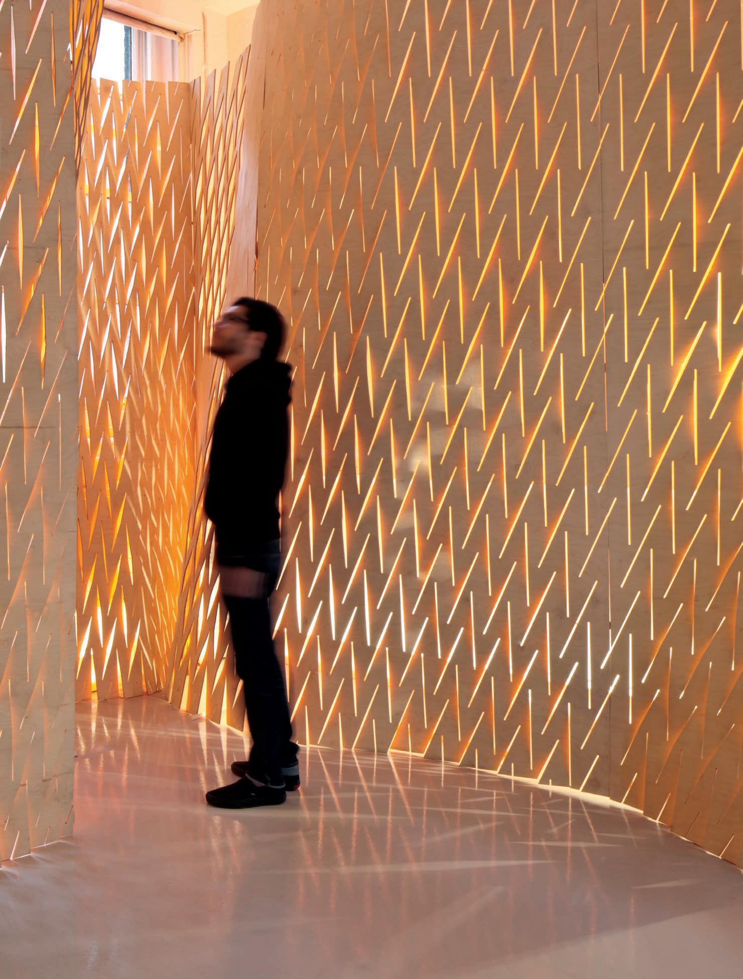
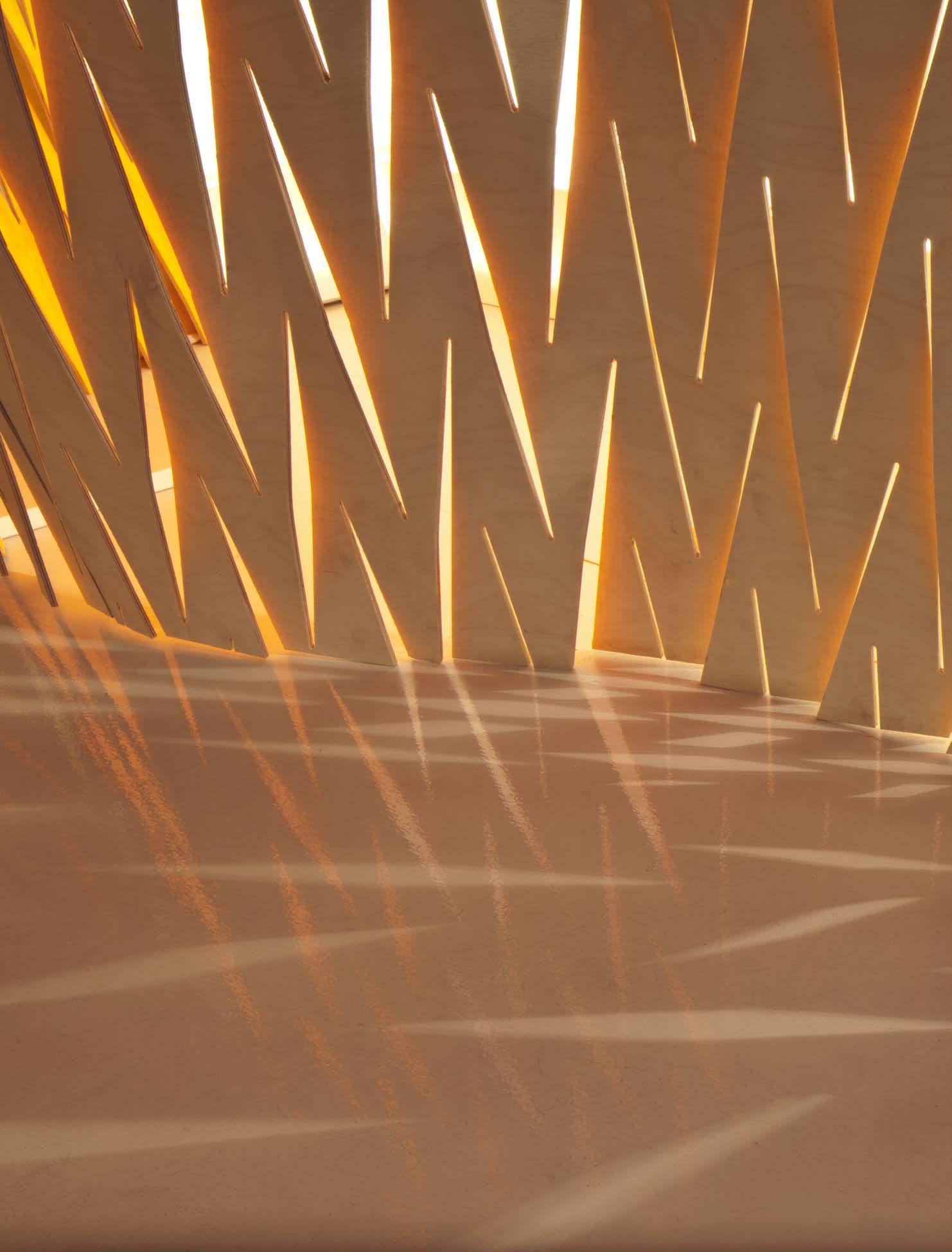
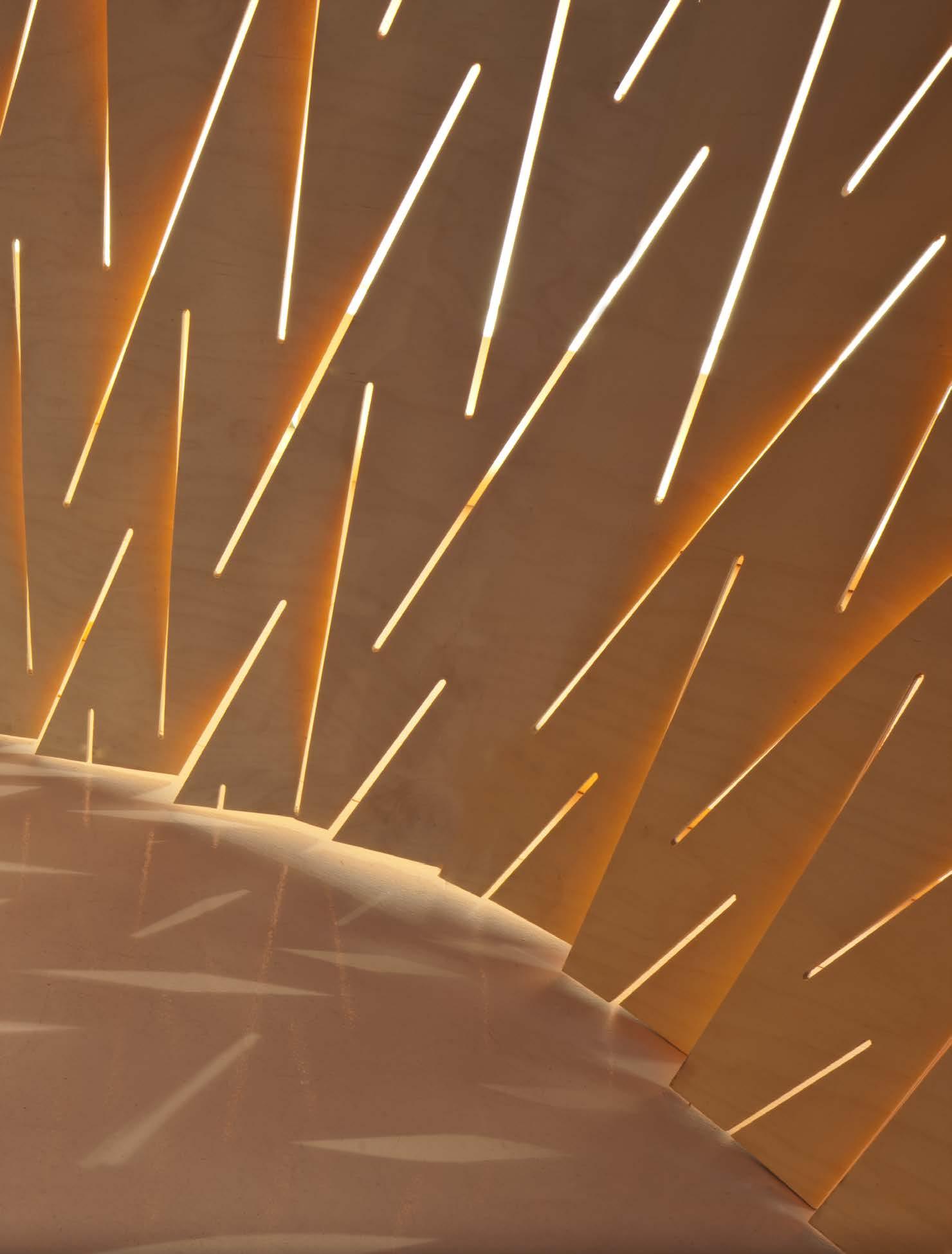
system s uccess and areas to further in V estigate
01. relationship between cut length and opening height - ie. more cuts, small openings
1.
based on general concepts of surface structures, double curvature would be required in the surface to achieve stiffness in the system.
2. the final geometry used alternating adjacent panels containing opposing single curvatures to simulate the effect of a doubly curved surface.
3.
the use of a seemingly repetitive panel type also had significant advantages in deployment and transportation. panels could be formed, then packed safely and efficiently, to be shipped on site.
4.
from the material’s dimensional limitations and physical properties, an approach was developed to predict overall global surface deformation digitally.
5.
essentially the digital tool moderates between a top down design in the form of a surface and the geometric logic of the material and principal cut system.
6. as the panels were formed the edge boundary condition became distorted posing problems in the edge-to-edge joining detail.
7. the shear flexibility of the material and system allowed for minor geometric and construction adjustments throughout fabrication.
in conclusion and response to the assumptions and quest ions raised in the initial aim of the self-supporting wall system experiment, the system provided quite satisfactory. While many concerns came to light, and adjustments made for, the general principles of the base system provided well for the installation and proof of concept.
the main area in which the system advanced throughout the experiment was primarily in the approach to understand principles of global geometry and constraints of the material. the discussion of double curvature in the surface became one of great importance. based on general concepts of surface structures, double curvature would be required in the surface to achieve stiffness in the system. While the final panel geometry was designed digitally to contain double curvature, the fabricated panels did not achieve the same refinement in the surface. this material consequence fed into the final design and panelisation of the wall system. the final geometry used alternating adjacent panels containing opposing single curvatures to simulate the effect of a doubly curved surface. in simpler terms, this small design ploy gave the appearance of a complex geometry. each panel is not stable alone, but increased stability arrives with the addition of panels. two panels work together in structural equilibrium. the use of a seemingly repetitive panel type also had significant advantages in deployment and transportation. panels could be formed, then packed safely and efficiently, to be shipped onsite.
leading up to the fabrication, significant hurdles were taking in understanding and utilizing digital tools. after an assessment of the digital experiments and methods, a workflow was developed from the material analysis. from the material’s dimensional limitations and physical properties an approach was developed to predict overall global surface deformation. the local level physical tests and structural fea models lead to an understanding of the cut geometry. With these two pieces in place, nei-
ther a purely “bottom up” or “top down” approach was utilized to translate the material system. global restrained surfaces are input as design intent, while a recursive logic of repeating geometric units rebuild the surface to serve as an adaptation of the incision logic. essentially the tool moderates between a top down design in the form of a surface and the geometric logic of the material and principal cut system. this became a critical step in the establishment of a true design to fabrication tool.
as previously mentioned, many new unforeseen outcomes and complications were discovered in the design and fabrication of the wall system. as a result the system would need to be refined and furthered to incorporate these issues. one crucial area of difficulty was a consequence of, and first discovered in, the assembly detail of the wall system. as the panels were formed the edge boundary condition became distorted posing problems in the edge-to-edge joining detail. at the scale of the wall system adjustments were able to be made to join the panels, but considerable consideration would need to be invested into adding tolerance into the detail. additionally, later developments would need to allow for joining all four edges and not just two.
the overall geometry and precision of the final fabricated wall was surprisingly similar to the design intent. the shear flexibility of the material and system allowed for minor geometric and construction adjustments throughout fabrication. as the installat ion was observed and measured repeatedly over the course of the three week exhibition, two interesting findings were discovered. While the individual cut openings reduced in size marginally, the overall geometry and curvature of the system increased with self weight and natural creep properties of the plywood.
the concluding experiment and step in the experiment of the expandable surface system lead to the full scale design and construction of an inhabitable pavilion. this phase aims to test the next iterations of the system and the increasing demands of additional design criteria. Key areas of study will lay in the investigation of a refined panelisation system, added geometric requirements, structural integrity, and safety factors.
evolving from the results of the fabrication of the self-supporting wall system, it will be essential to test and develop an approach to achieve double curvature in a single panel. design intent aside, the notion of enclose requires both vertical gravity loads as well as horizontal spans to be provided for. this reason alone will require a non-homogeneous cut pattern allowing for vertical resistance, while allowing for rotation or bending to permit a reasonable horizontal span for inhabitation. how can straight cuts allow for bending in two directions? how will base material properties assist or inhibit the double curvature? how can a four sided edge condition be geometrically calculated to match adjacencies with complex curvature? this base set of questions will be considered when testing panel and global surface geometry.
in addition to a progression and enhancement of the system design, the enclose aims to test some larger questions of site and program. some obvious requirements will respond to the user as well as the constructor. multiple panels will need to be assembled to allow for the comfort and scale inhabitant. the scale of
these panels will need to be suitable for fabrication and assembly; ideally being manageable for one person. While the experimental structure will be constructed in an interior environment, the ambitions of the proposal aim to project futures into exterior applications. how can the patterns be designed around and mitigate solar cycles and climatic conditions? What is the system of feedback and response of the material system to the added design inputs?
the enclosure would be placed as its first location in cologne inside an exhibition centre. this would require full coordination for in-house design, local fabrication, shipping and transportation and finally assembly and disassembly of the structure.
all iterations would be run with 6.5mm grade b-bb birch plywood.
morphogenetic setup based on materials, structural performance, fabrication, and computation
f ormal i ntent (s urface g eometry)
c ut pattern to g enerate c urVature
f irst panelisation based on m aterial c onstraints and structural p erformance
d etermine if panel g eometry is achie Vable Within m aterial c onstraints
e dge pattern a djusted
f or j oint d etail
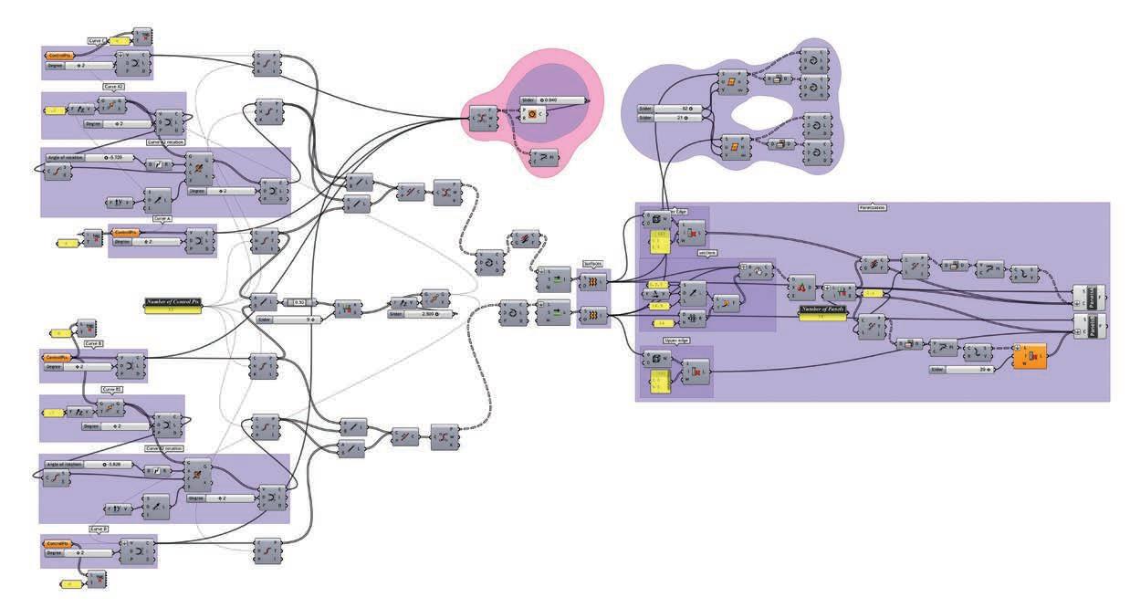
once the parametric engine was ready to run, the points where placed in the space according to two basic conditions, programme and structure.
the program required a 16m2 of enclosed meeting area and 80m2 of open area towards the back of the site.

for structural performance, the base points for the enclosure would describe an arch and towards the back they would describe opposite curvature to create a sequence of self supported walls.
as the basic geometry is defined, the first pattern iteration is run defining number of cuts, spacer size and its distribution.
it is important to emphasise the flexibility that the pattern provides and its capacity to match the input surface.
the emergent pattern can be seen as a field of self-similar components as described in research development chapter. matter and geometry are working together.
likewise, the light qualities can be expected to be similar to the ones presented on the exhibition wall.
even though the algorithms are set from the material properties at this moment, the structural logic is not evaluated yet. hence a fea process is started to determinate the feasibility of the scheme.
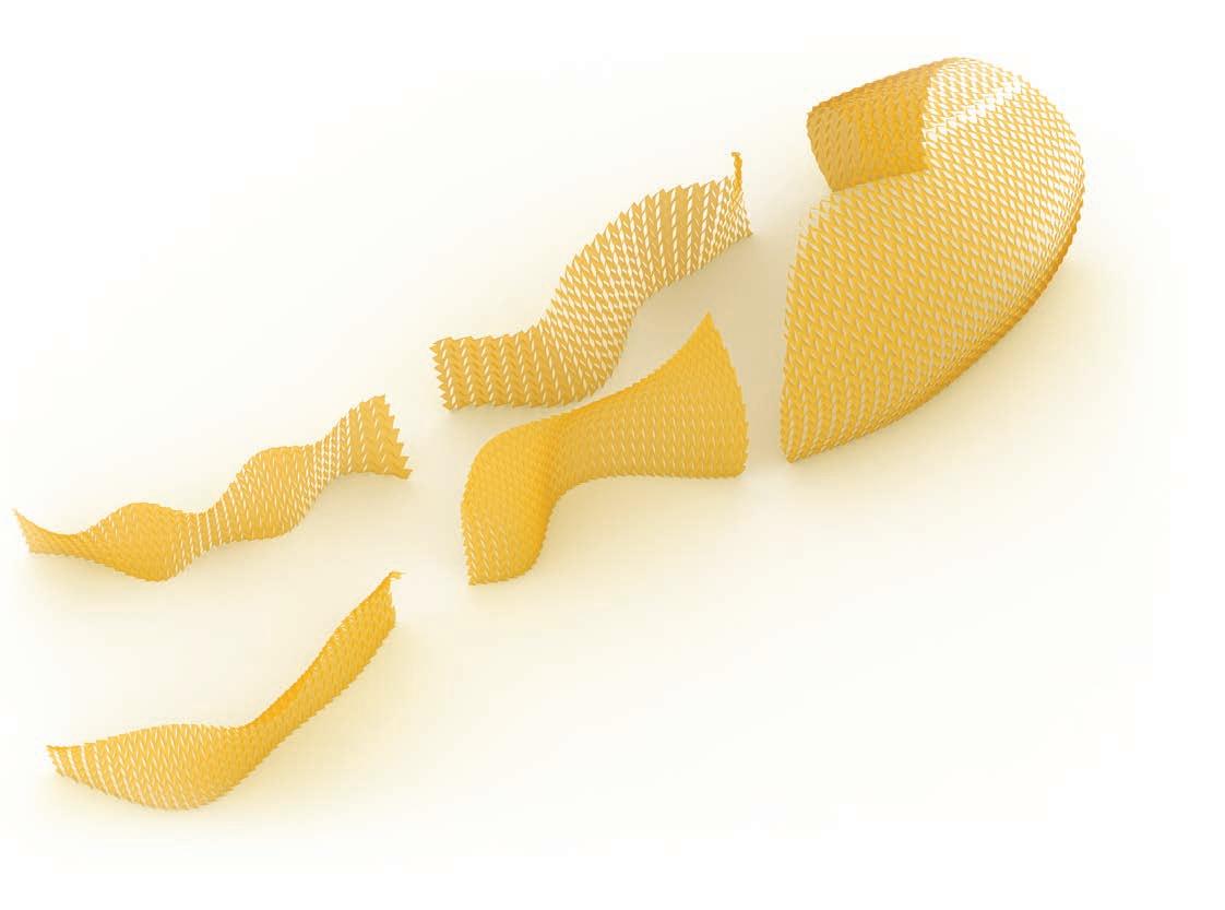
01. first single layer strand test
the main goal for this stage of the project was to fully integrate a coherent structural logic into our material system and to explore the full potential that the material and the cut pattern could give us.
therefore, we set a series of new experiments to test our geometry in different ways and compare the possibilities and limitation of the system.
in the first iteration in strand 7, the model generated in rhino was exported as mesh and tested to self-weight. the results showed severe displacement for the enclosed portion of the pavilion.
the structural failure of the model brought two different approaches to further develop the system. one possibility was to keep the geometry and the pattern as it was; and to reinforce the model with a double layer structural surface. the second possibility was to modify the geometry and further explore a single layer scheme.
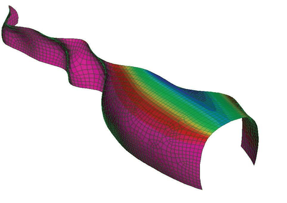
how does a single layer system preform in comparison to a double layer system? is a double layer system required?
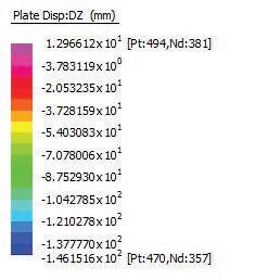
a double layer structure could give us enough freedom to play with geometry and to keep the concept for an expandable surface just by the use of cuts. nevertheless, the amount of material is doubled and it would require external elements to tension the surface.
to test this hypothesis a one-to-two mock-up was tested using three patches of 6.5 mm birch plywood and 30cm spacers to be placed in-between the sheets.
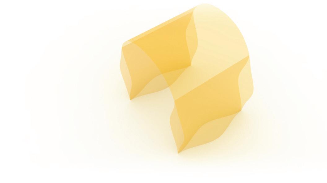
the physical experiment started with just one layer to compare the behaviour with the strand result and, as expected, it failed. as we integrated the second layer the structural performance improved.
lateral loads and self-weight were well taken by the structure. nevertheless, external vertical loads remained not performing satisfactory.
one of the most important points on this experiment was the fact that the overall shape was achieved by the self-weight and the flexibility of bending was provided by the homogeneous pattern. the sheets were laid flat and then pushed up in compression to reach the final form.
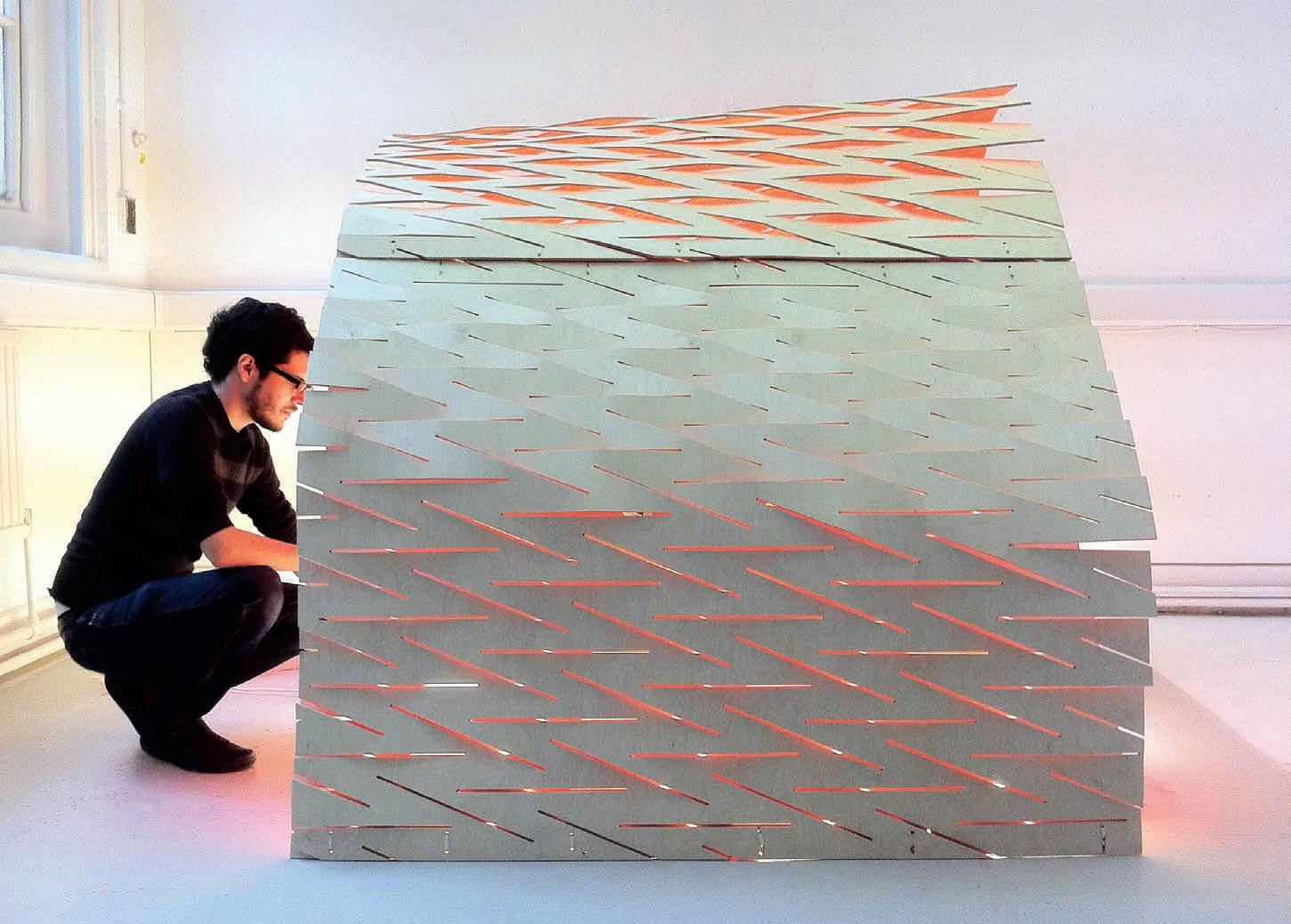
this is key for further development of the system.
pattern here is understood as an intensive field that expands the material capacities, but doesn’t prescribe a specific form.
likewise, its structural behaviour is based on the final geometry and is not integrated as part of the pattern system, nor in the material logic.
as a fabrication integrated system, we thought doubling the amount of material, should be avoided.
to avoid the excess material and fabrication time in the double layer approach, how can we predefine a shape through a single layer system?
how can we fully integrate structural performance into the system?
to further explore these questions, a single layer would be explored.
01. double layer mock-up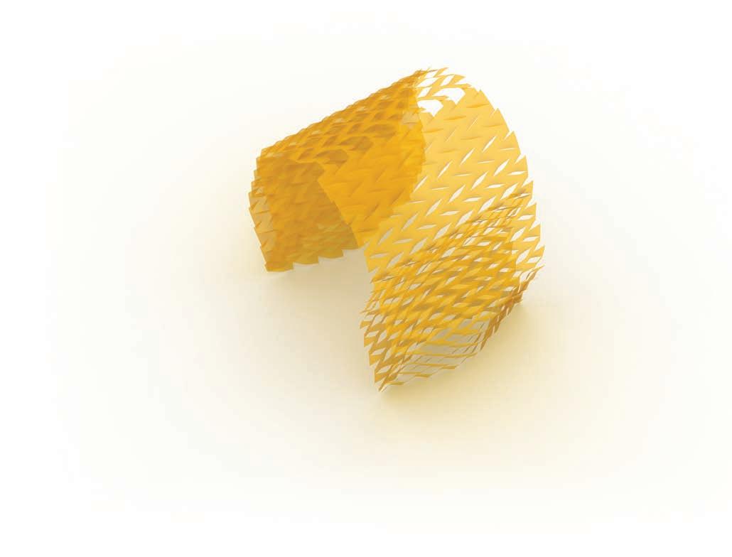
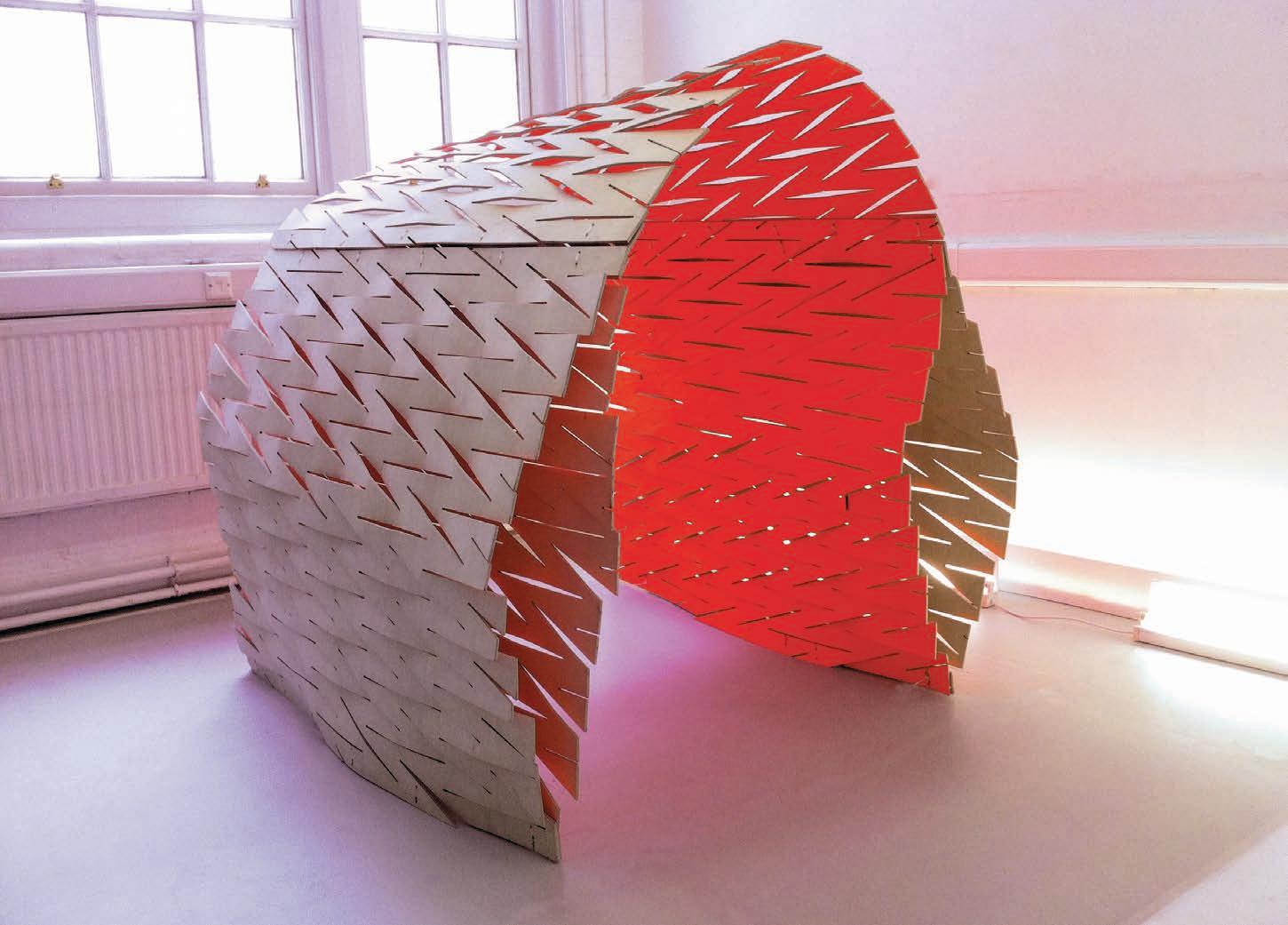 02. hidden line from the digital model
03. perspective rendering from the digital model
single layer = i ntegrated material property based system
after evaluating the performance of the first single layer structure, a corrugated option was explored. the parametric model was refined and changed to the new configuration.
it was decided that the model generated would be divided in two parts, enclosure and walls. even though the first intention was to reach a complete continuous surface, the logic of the program and design goals, and limits of fabrication methods, informed the analysis and physical tests would work more efficiently in a subdivided manner.
01. base single layer surfaceto check the structural performance of the different iterations we ran several finite element analysis in strand 7. the material properties we used to run the analysis were of the continuous birch 6.5mm plywood sheet. We knew that the plywood with cuts was going to be more flexible than the continuous one, so we considered the results just an optimum scenario.
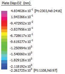
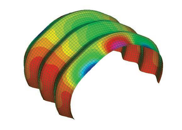
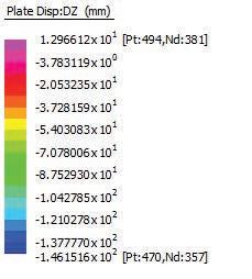
the load test were run under the self-weight of the surface. We restrained the displacement of the ground nodes and allowed their rotation in y direction and restrained it in x and Z.
in the first analysis we had deflections of 14 cm in a 4.2 meter span, so we decided to change the morphology of the enclosure to increase the structural behaviour.
by corrugating and applying double curvature to the surface of the pavilion, we drastically reduced the deflection of the surface to less than 1 mm. We were concerned though about two things: how the cut pattern would reduce the structural performance of the plywood and how to achieve a doubly-curved surface out of applying simple cuts to the sheets?
so we started to explore different cut patterns that would lead us towards doubly-curved panels.
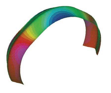
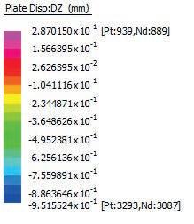
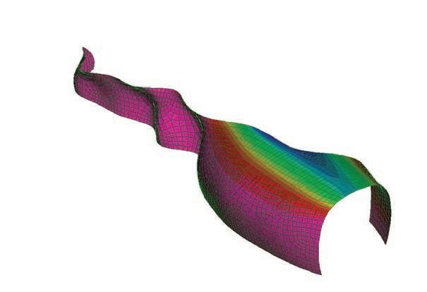
the main lesson during the design process of the plywood screenwall, was to understand the relation between the edges of the panel and the curvature. by transforming the flat edges of the sheet, curvature was obtained thus stability was achieved.
on the search towards doubly curved panels, and based on the above stated principle, it was thought that there might be the possibility to achieve doubly curved panels by cutting and bending the four edges of the panel. to verify this hypothesis, an experiment on the edge condition was set up.
the objectives of the experiment were: to achieve a double curved panel, analyse its stiffness, and understand the relation between the angle of the cuts and the grain direction.
to proceed with the experiment, a panel of 6.5 mm birch plywood was cut into a square of 60 cm side. every side was divided into 10 equal parts of 6 cm each and then a line was drawn from every point to the area centroid of the square. then only the first 20 cm of the every line was jigsawed. after that, the cuts were opened using spacers of the same size that were aligned to the edge of every flap. this was done to guarantee that all the distances and forces were equal.
process of morphing the panel by opening sequentially every side of the surface with 2cm height spacers.
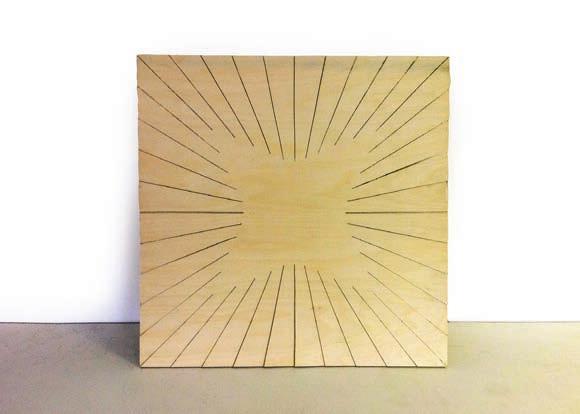
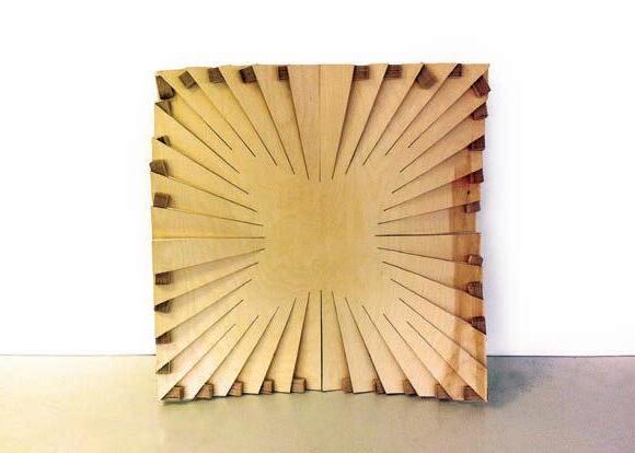
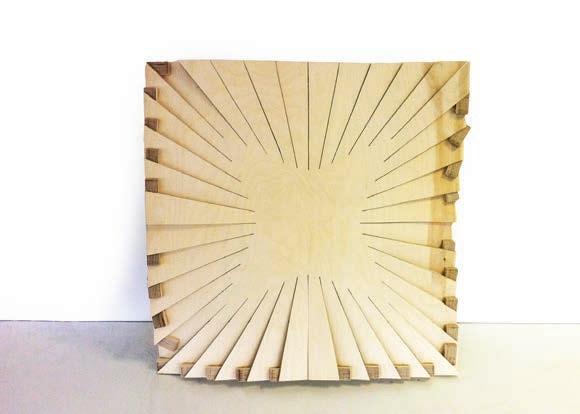
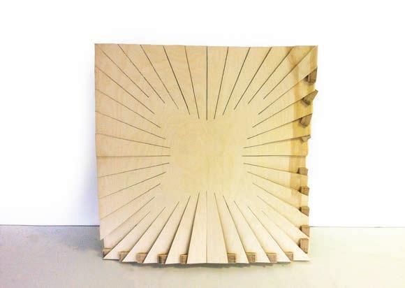
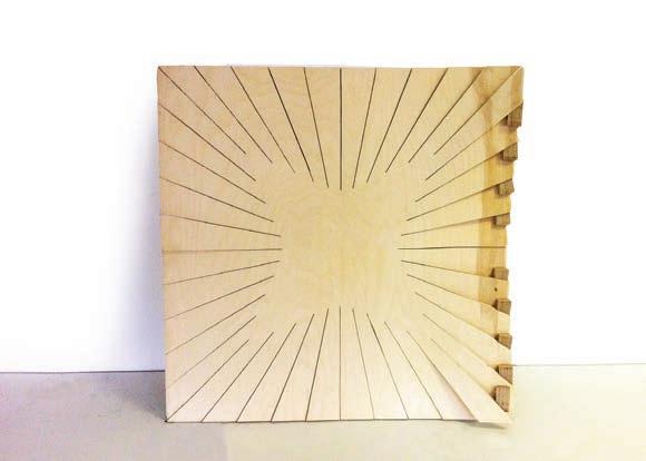
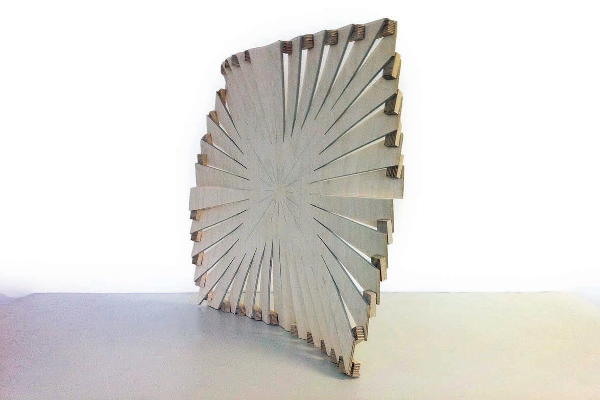
since only the edge was curved, the panel was not actually achieving a doubly curved surface. there was a completely flat area in the centre of the panel. it was understood that the cut pattern should be applied all over the sheet surface, generating smooth transitions between the different directions of the curves.
two of these squares were cut in order to study the possibilities of panelization of the material system. as it happened with the screenwall, the curvature modified the edges; so there was no continuity between the two. this was a key issue in the design of the system, as it will be seen in the next experiments.
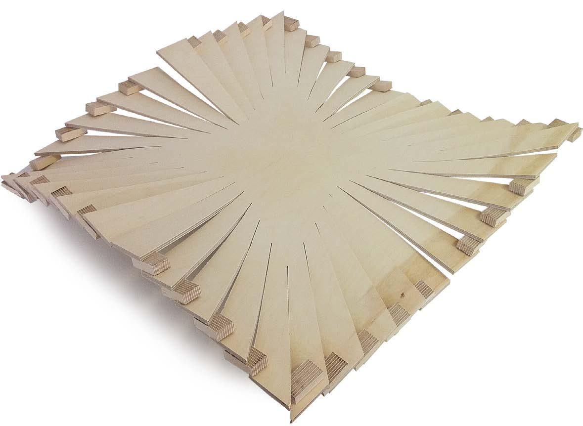
the following pictures show some of the problems found in the experiment. due to the concentric geometry of the cuts the distances between them varied, being some of them too narrow. in addition, the forces were accumulated on the two central flaps, which happened to be the narrowest. When the force increased and the cut aligned with the grain direction, the flaps collapsed. When it happened aligned at 90º with the grain direction, there was some cracking but no breaking. in the rest of the connections there was no visible problems.
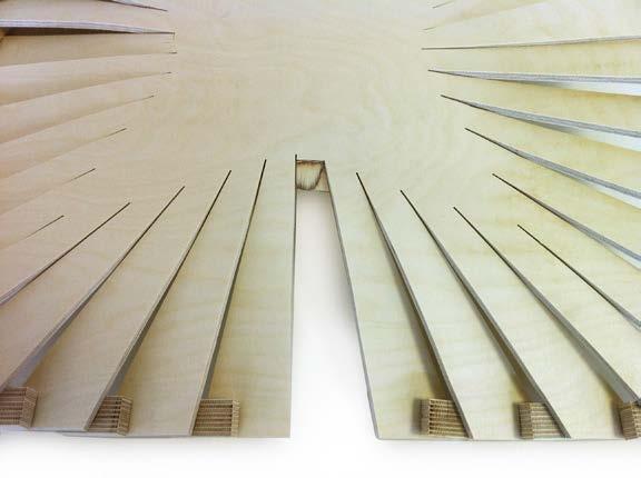
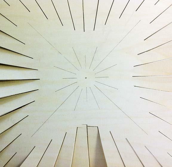
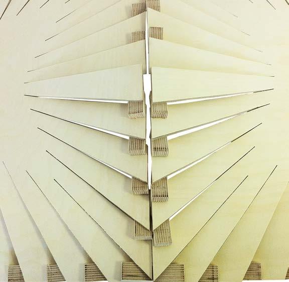
another conclusion was that the concentric cut pattern was causing considerable rotation on the flaps. this rotation was reducing the amount of curvature on the edge as the following diagram exemplifies.
04. expected deformation after the spacers
05. real deformation after the spacers
07. material failure at the narrowest part of the flap
09. material failure follows the grain direction
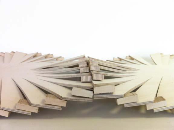 06. detail of two panels together
08. deformation in edge condition due to panel geometry
non-symmetrical displacement due to grain direction
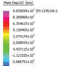


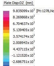
to better understand what was happening inside the fibres of the wood, a digital model of the edge condition test was generated and later analysed with strand7 finite element analysis.
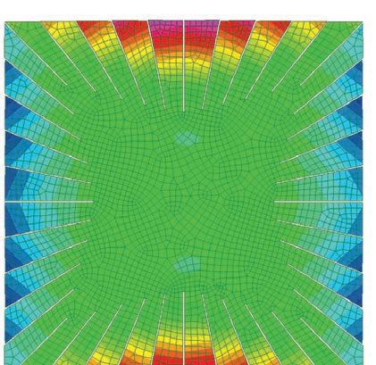


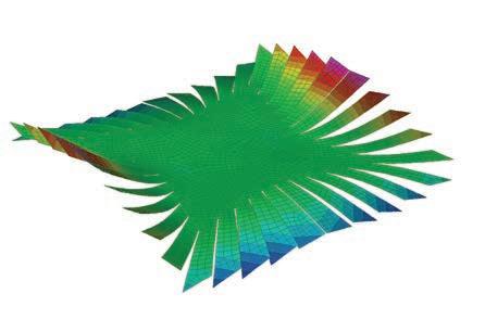
We also wanted to know the amount of force that every spacer was applying to its neighbouring flap for later iterations.
to deform the panel in a similar way than the physical material, we restrained the internal nodes on the end of the cuts and applied forces on the outer nodes of the flaps in Z and -Z direction, with an arithmetic progression, so the force acting on one flap

was the addition of the previous ones. once the model was set up, we applied an initial low load and checked the displacement it was causing, then we scaled the forces to match the displacement obtained in the physical model.
as it can be seen in the following analysis, the higher stresses values in the fea model mirrors the points of failure in the physical model.
plate stress analysis displays areas where material failure are most likely to occur.
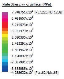
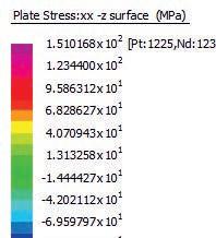
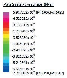
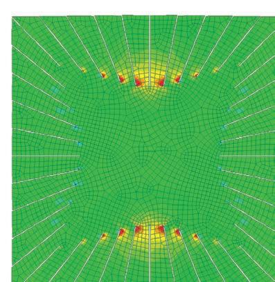
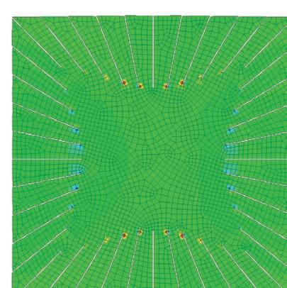
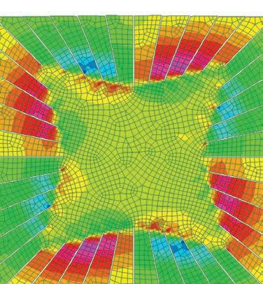
one of the interesting points that we couldn’t assess is the overall point of material failure at high loads in compression to physical tests.
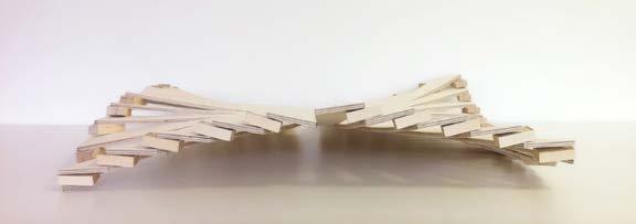 07. fea analysis, plate stress y-y
08. fea analysis, plate stress x-y
05. physical test, elevation
06. fea analysis, plate stress x-x
based on the panel and edge condition experiments, it was decided to further explore a digital and physical form-finding process to achieve a specific geometry. in this case, we tested the panels from the last structural iteration.
the parametric definition described at the beginning of this chapter was re-run to get every panel for the new geometry. the enclosure was down to a sequence of three consecutive arches, each of them composed by two pairs of equal panels.
the main goal on the following series of studies was to achieve a doubly curved panel based on a specific panel edge and interior pattern field.
02. as an assumption to test for future developments changing the direction of the cut pattern, the curvature of the panel can be changed
 01. original pattern to surface intent
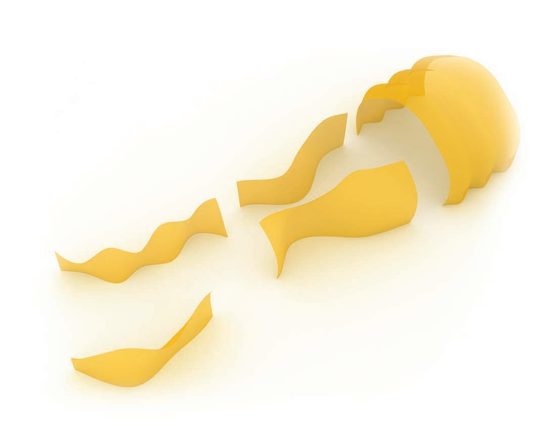
01. iterations of scaled panel tests
after the first experiments on the edge condition of the sheet, six iterations of 1 to 5 models were fabricated and evaluated. the fitness criteria for evaluation was curvature and stiffness. the fittest were the panel with a balance between both. the method for evaluation was first measuring the curvature under self weight; then fixing one end and applying a small load on the free end. then measuring again the deformations under load.
the first three iterations were fabricated simultaneously and evaluated. then, every iteration was fabricated upon the discoveries from the previous ones.
all the patterns were parametrically defined with grasshopper. the definition used as an input a given doubly curved surface and gave a pattern as an output.
original sheet measures: 450x225 mm Weight: 103 grams thicknes: 1.5mm density: 0.5960 gr/cm3 description: birch plywood with three layers. the direction of the grain is along the short axis.
iteration 1
measures: 480 x 240mm
description: vertical and horizontal parallel patterns arranged at 90 degrees, runing parallel to the sheet edges. the vertical pattern was going all the way through from top to bottom. the curvature obtained in the vertical axis was not enough.
iteration 2
measures: 480 x 240mm
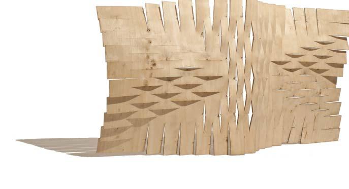
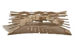

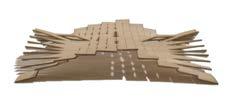

description: vertical and horizontal parallel patterns arranged at 90 degrees, runing parallel to the sheet edges. in this iteration, the horizontal pattern went from left to right. We increased the curvature but decreased dramatically the stifness of the panel.
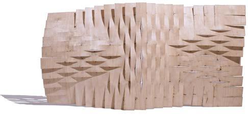
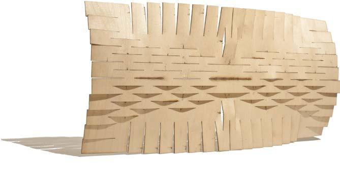
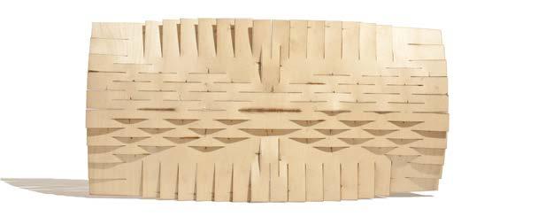

iteration 3
measures: 480 x 240mm description: vertical parallel pattern and concentric pattern along the edges. the concentric pattern made the flaps to rotate and actually there was no bending on the vertical axis. for that reason, the panel was very stiff.
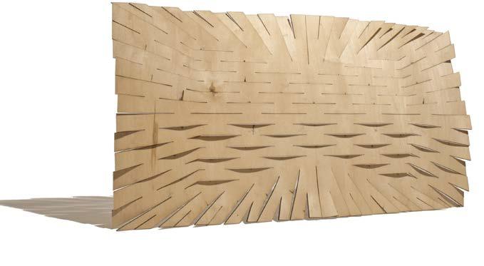
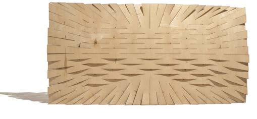
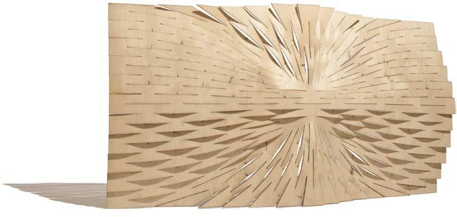

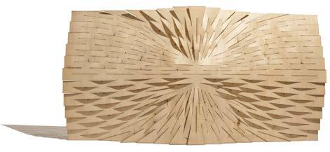
iteration 4
measures: 480 x 240mm description: in this iteration, there was an acceptable relation between curvature and stifness but the pattern was too dense in the central area. We were weakening the material in excess.

iteration 5
measures: 480 x 240mm description: we reduced the number of cuts in the central area and the performance was very similar to the previous iteration but there was a weird behaviour in some of the vertical flaps as they were rotating in excess.
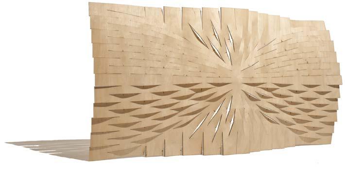

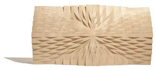
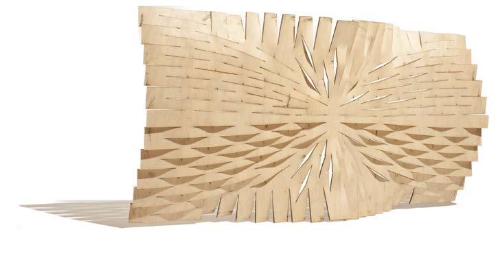

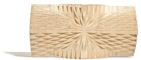
iteration 6
measures: 480 x 240mm description: this a refinement of the previous iteration. We changed the relation between the outer cuts and central cuts to avoid rotation in some flaps. this was the fittest iteration and starting point for the next sequence of structural analysis.

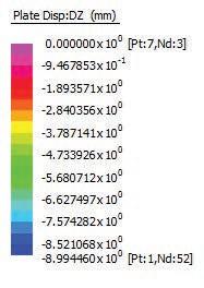
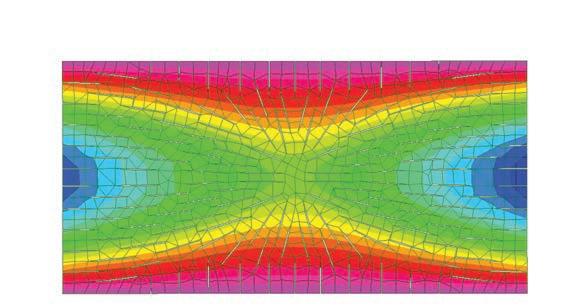
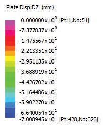
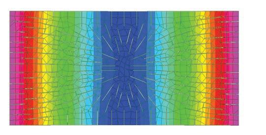
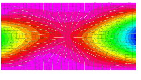
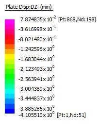
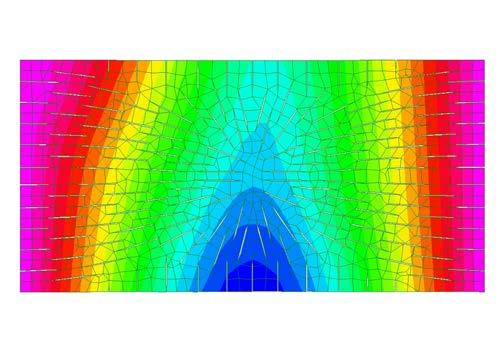
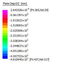 01. load test x axis, panel with unopened cuts
03. load test x axis, panel with opened cuts
02. load test y axis, panel with unopened cuts

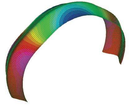
finally, the process was repeated with a model of the sheet with the cuts opened this model was done with strand fea applying loads in z and –z direction on every cut except the ones on the edge. the resultant deformed model was then exported as the sheet to be used for the next load test.
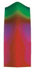
the maximum displacement along the long axis was 4.105510 mm and along the short axis 48.10945 mm.
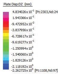
solving the same equations as before, we could find the new values for the young modulus of the sheet with open cuts. young’s modulus e1=10488.45 mpa young’s modulus e2=2394.74 mpa
by opening the cuts the system improved its stiffness by 10.9%. it was possible to bend the plywood by only decreasing its stiffnes by 6.7%
the conclusions of the experiment are numerical. the young modulus of the sheet with open cuts is 10.9% higher than the panel with the unopen pattern.the obtained values were used for the structural analysis of the enclosure.
continuous material without cuts (can not be achieved with sheet material)
base young’s modulus value for birch plywood
material with unopen cuts
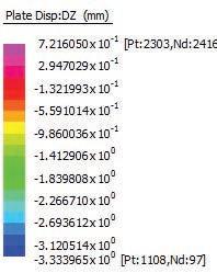
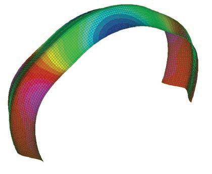
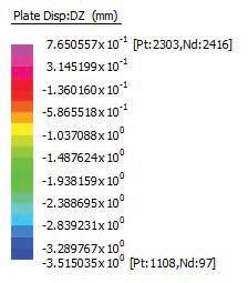
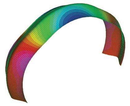
material with open cuts
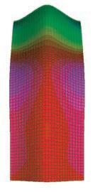

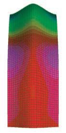

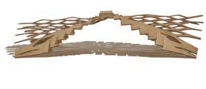
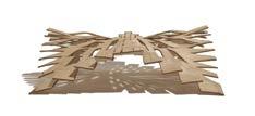
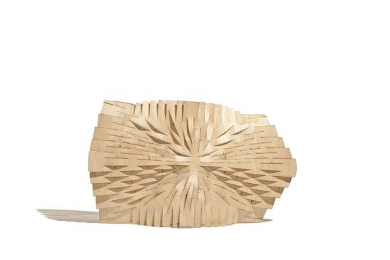
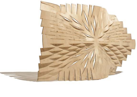
based on the final algorithm a pattern is generated to provide self-similar cuts adapted to create the geometry needed, always constrained by the panel. also each panel has the edge modified to match the specific geometry and once acting with the infield pattern as a whole is re-evaluated to get the needed geometry.
each flap of the panel is evaluated to determinate connection with another panel and a connection cut is added to joint with the subsequent sheet. two main connect ions are set to be added: an overlapped connection for the consecutive piece on the vertical axis and edge to edge connection for the consecutive one on the horizontal axis.
after several iterations two different panels are generated to create the full arch.
the emergent pattern infield for each panel never reached a symmetrical outcome though it always matched the connection with the same panel.
the possibilities at this point were countless but we moved forward to fabricate and keep the system open for future iterations.
panel a panel b 02. last iteration mock-up, translated to the digital model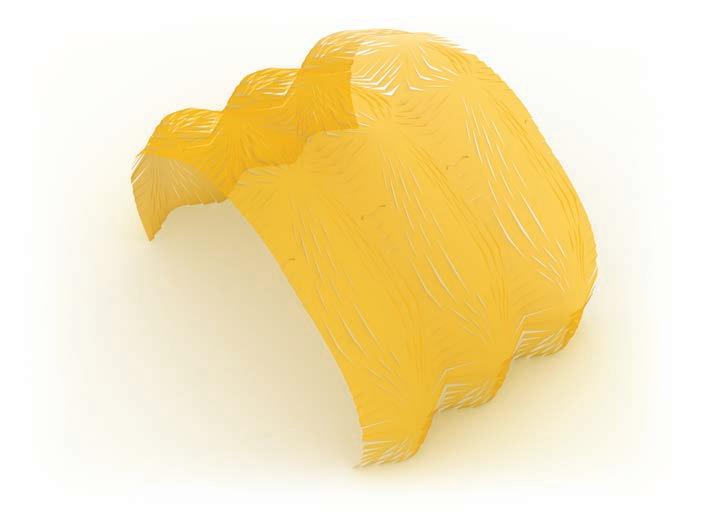
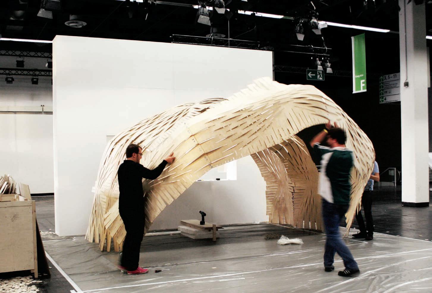
design and fabricaiton
london, uK
information
material
cologne, germany
assembly #1
material
g-code
woolwich, london
cnc milling
no. of panels: 23
m2: 66.24
time per panel: 32 min.
total time: 736 min.
no. of people: 01
man hours: 12.2
barcelona, spain
assembly #2
barcelona, spain reassembly
no. of people: 4
time: 8 hours
man hours: 32
shipping
no. of crates: 4
m3: 9.5
time: 14 hours
no. of people: 1
man hours: 14
stoke newington, london
forming
no. of people: 03
soaking time per panel: 1.5 hours (2 panels at a time)
forming time per panel: 21 min.
total time: 25.3 hours
man hours: 75.9
total man hours: 176.1
shipping no. of crates: 4
m3: 9.5
time: 10 hours
no. of people: 1
man hours: 10
cologne, germany assembly
no. of people: 4
time: 8 hours
man hours: 32

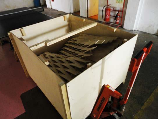
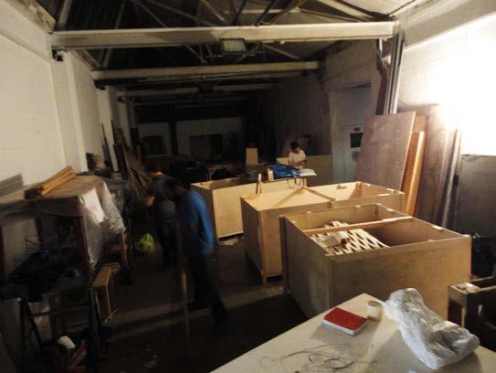
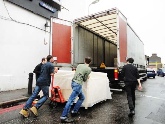
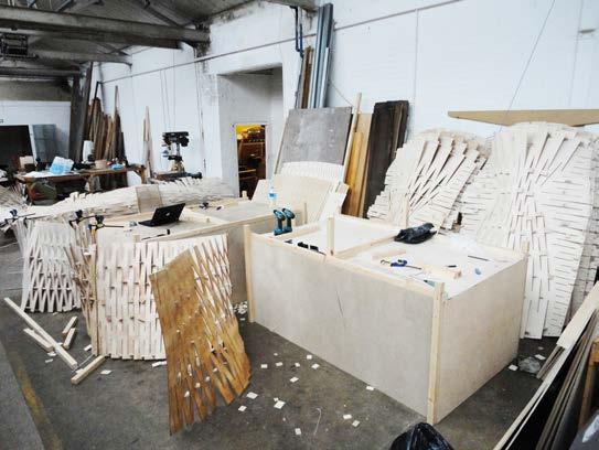
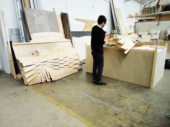
panels production
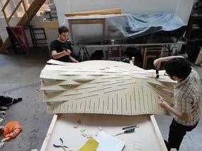
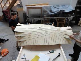
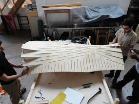
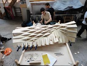
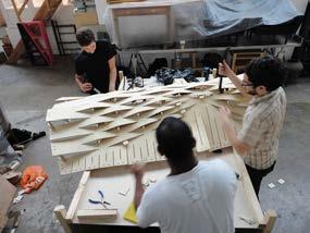
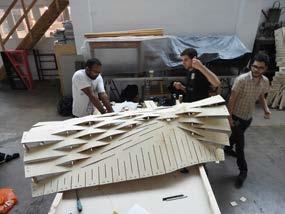
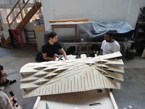
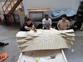
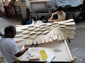
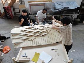
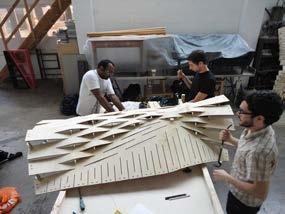
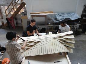
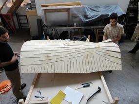
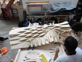
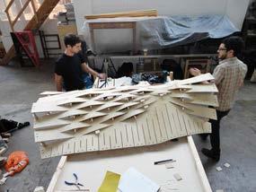
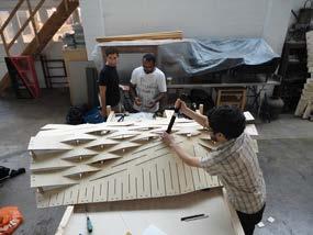
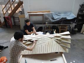
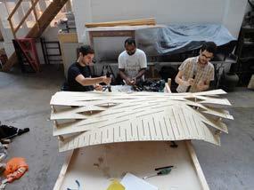
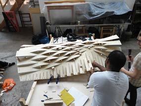
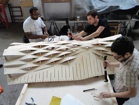
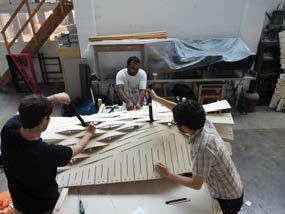
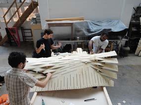
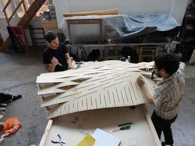
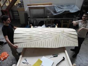
location: stoke newington, london, u.K.
forming time: 21 min.
team: 3 people
tools: 2 crowbars, 6 clamps
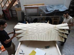
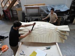
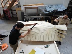
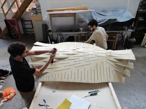
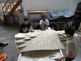
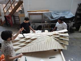
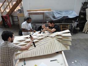
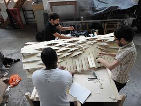
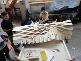
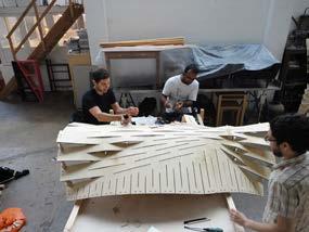
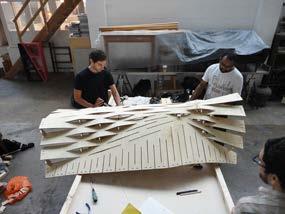
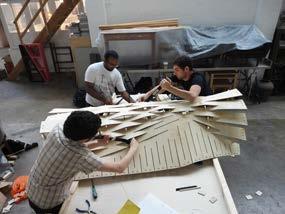
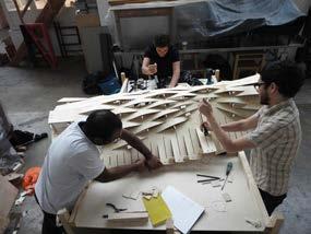
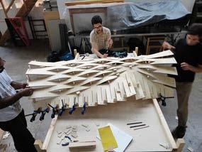
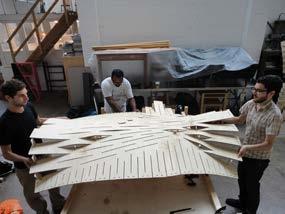
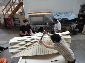
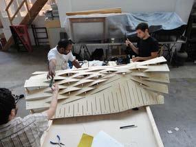
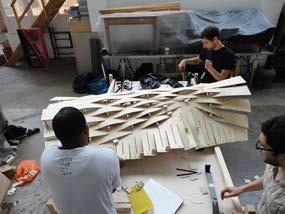
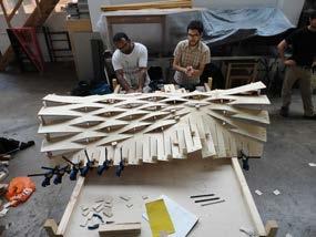
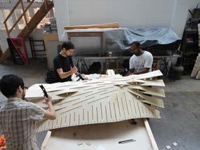
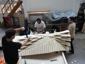
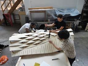
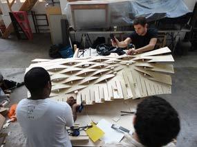
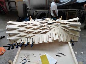
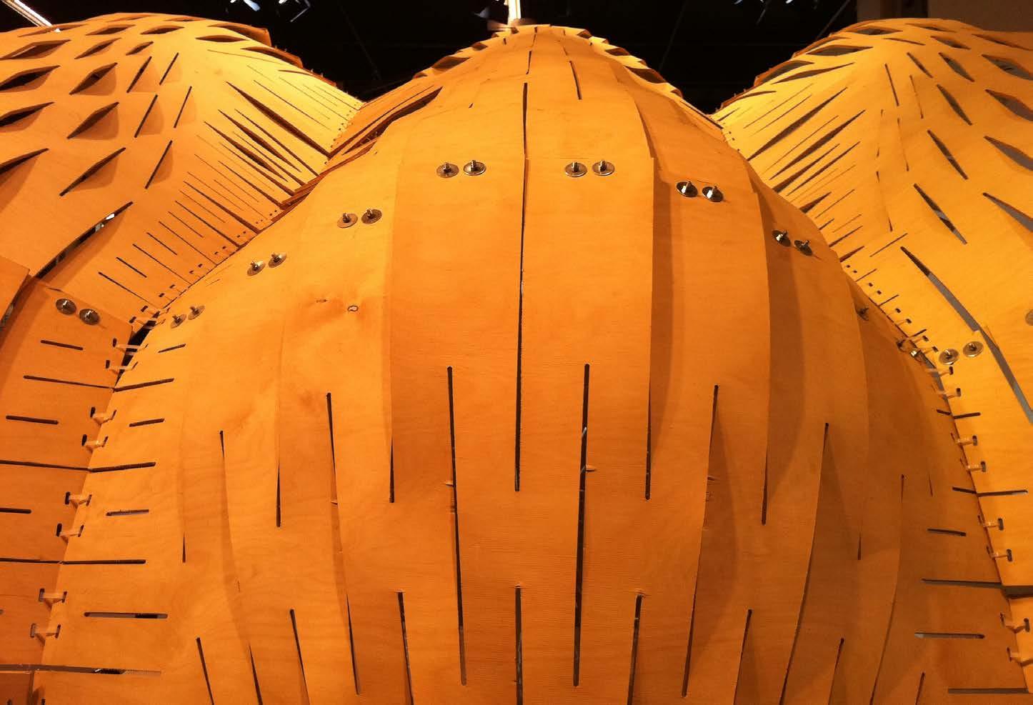
6.5 mm plywood
4 mm steel bolt
4 mm steel bolt
4 mm steel bolt
steel l plate to wooden base to wooden base to wooden base
25 mm washer
25 mm washer
25 mm washer
4 mm steel bolt
4 mm steel bolt
4 mm steel bolt
25 mm washer
25 mm washer
25 mm washer
4 mm knot
4 mm knot
4 mm knot
floor anchorage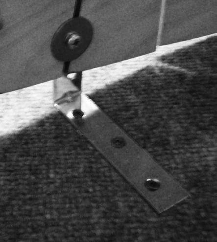
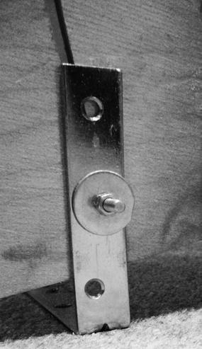
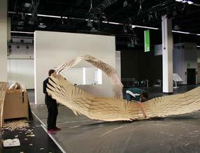
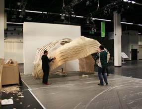
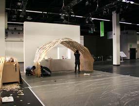
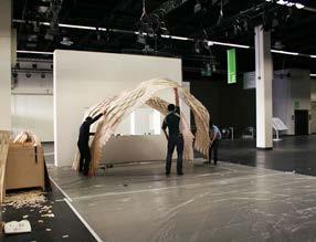
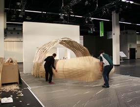
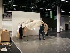
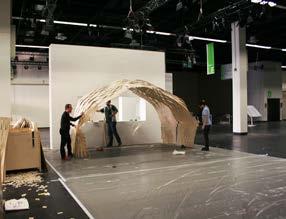
location: cologne, germany assembly time: 480 minutes team: 4 people
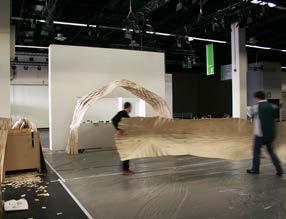
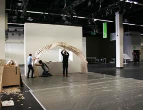
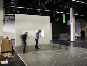
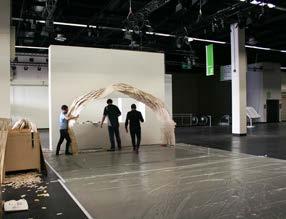
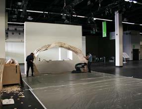
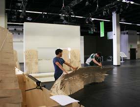
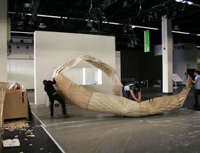
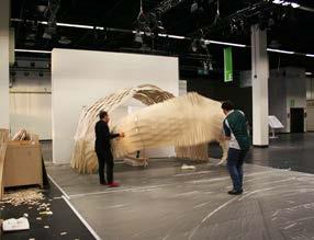
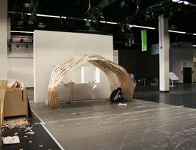
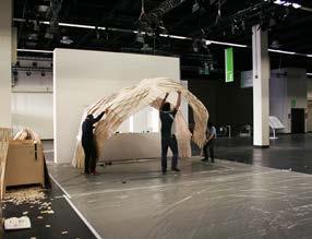
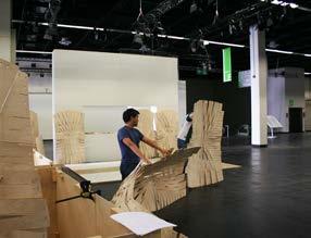
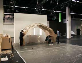
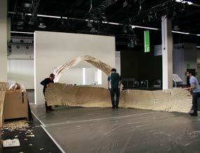
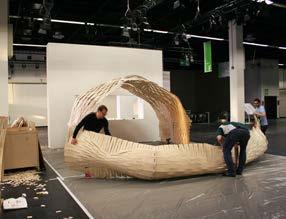
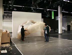
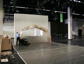
tools: 1 screwdriver, bolts, washers and knots
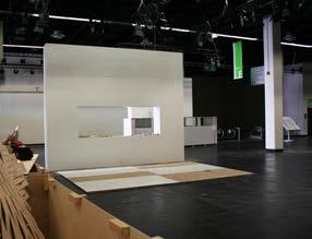
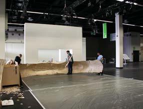
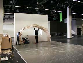
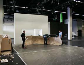
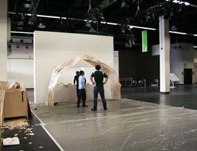
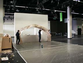
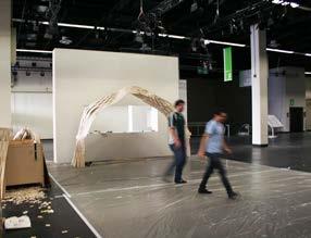
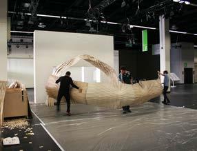
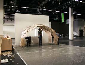
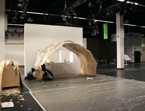
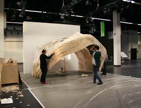
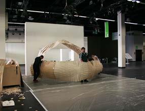
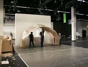
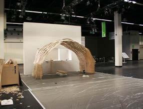
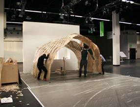
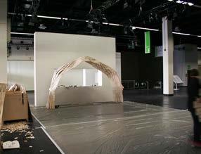
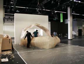
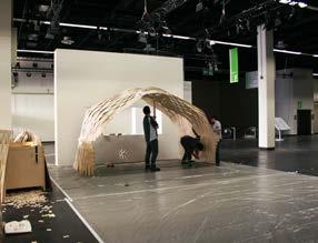
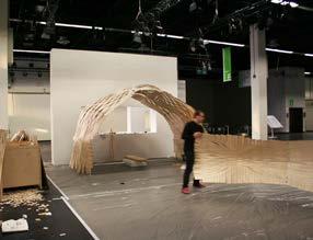
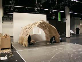
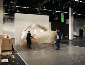
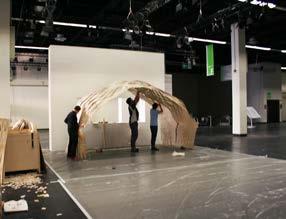
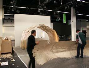
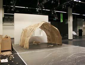
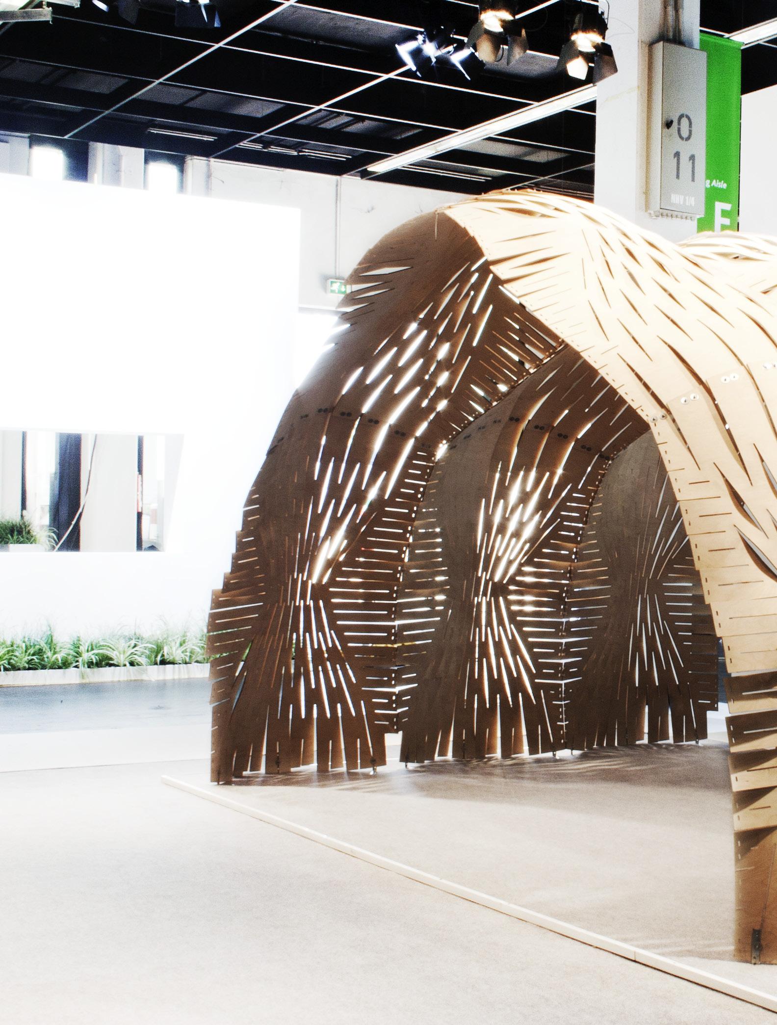
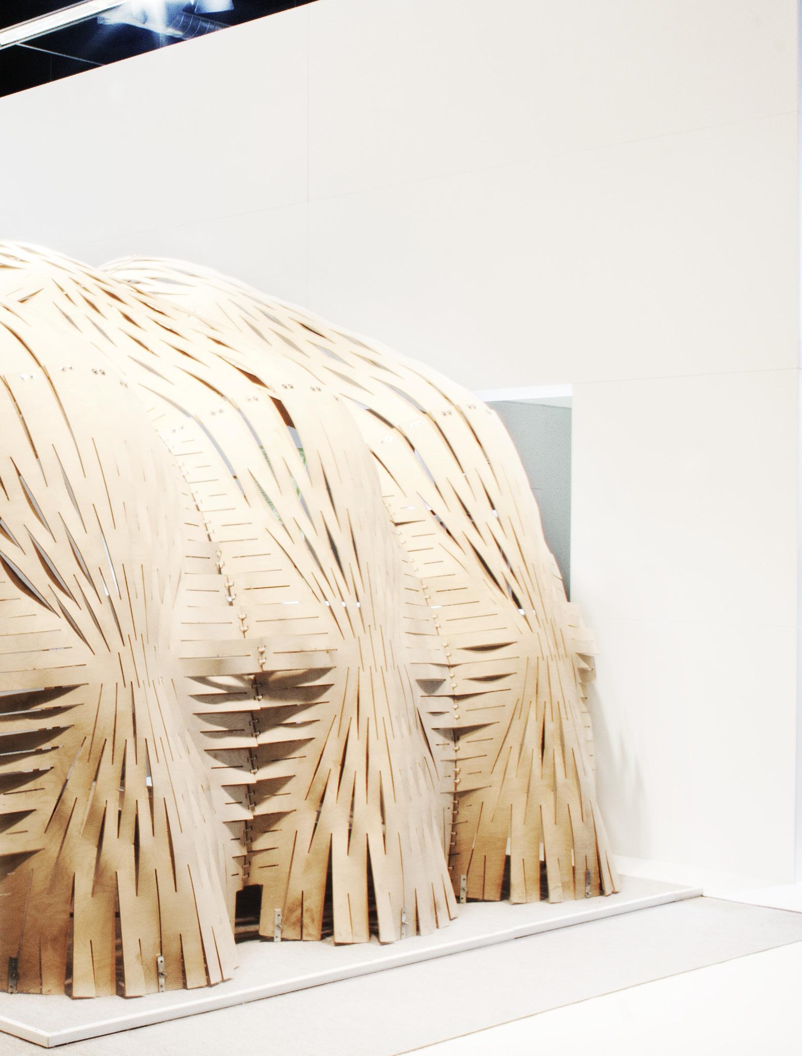
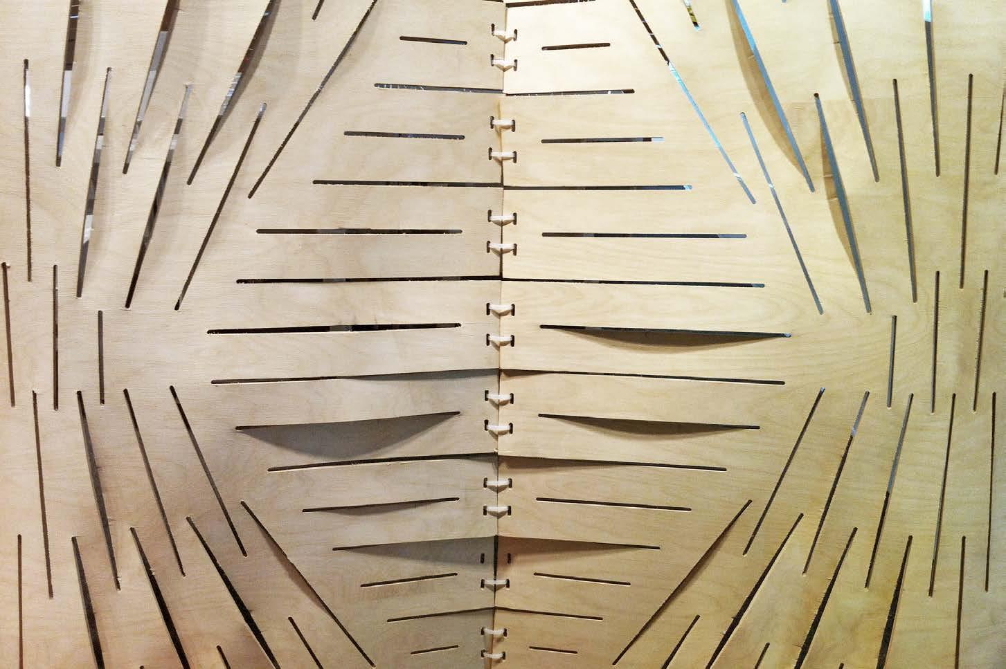
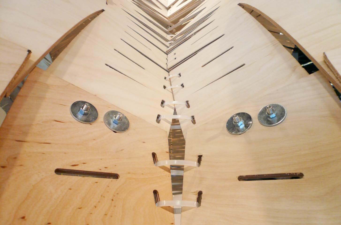
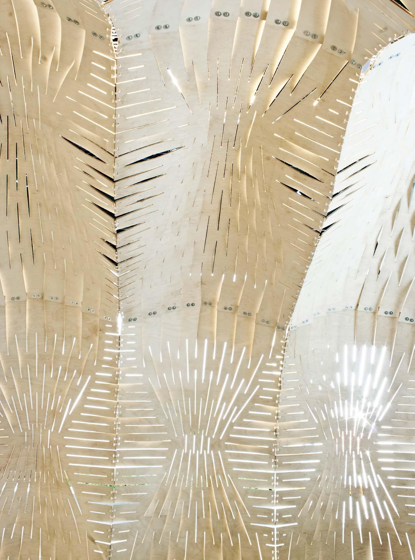

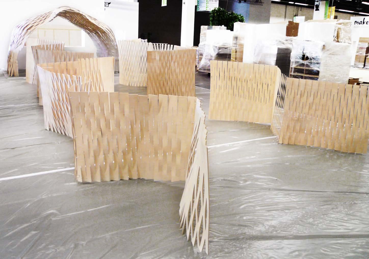
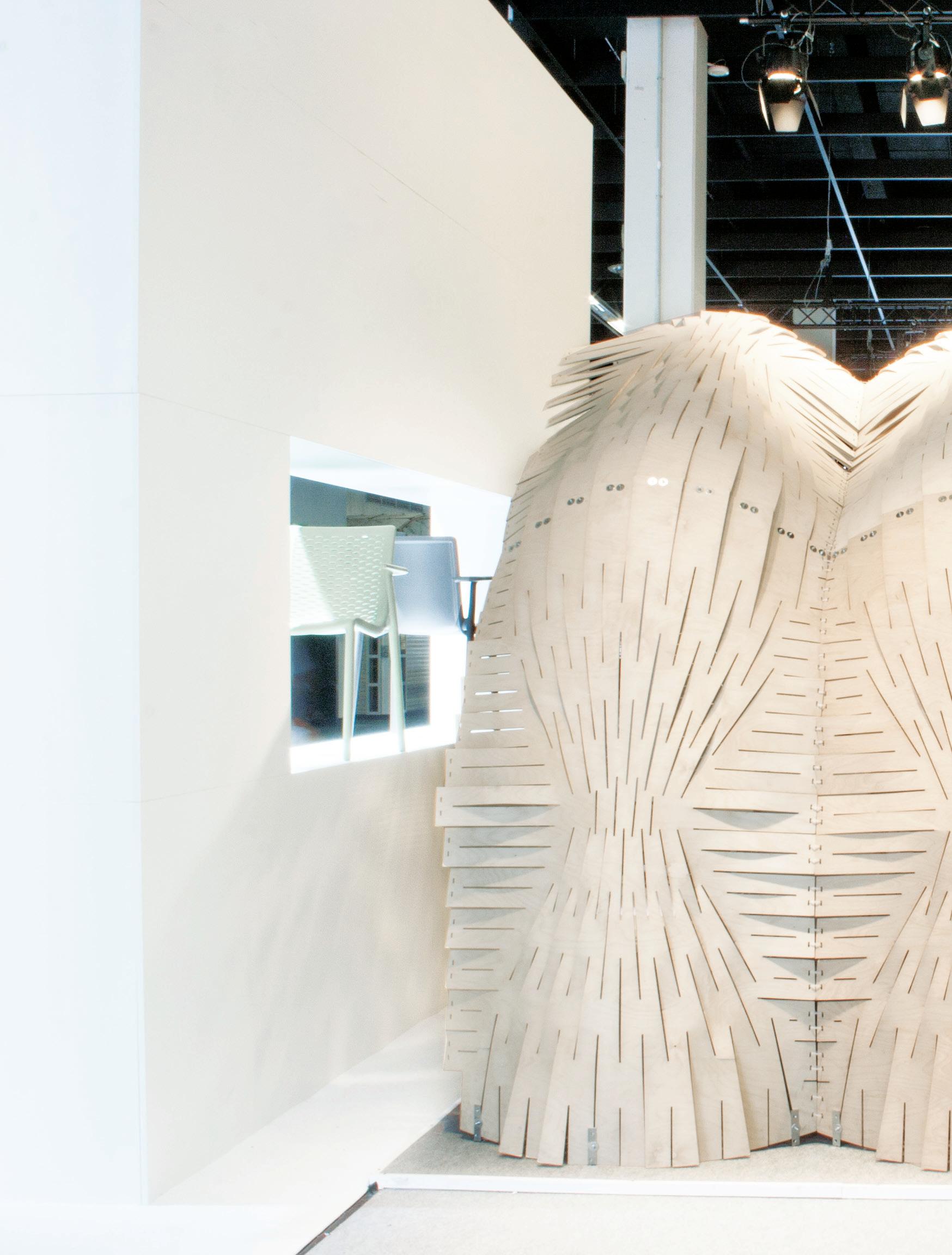
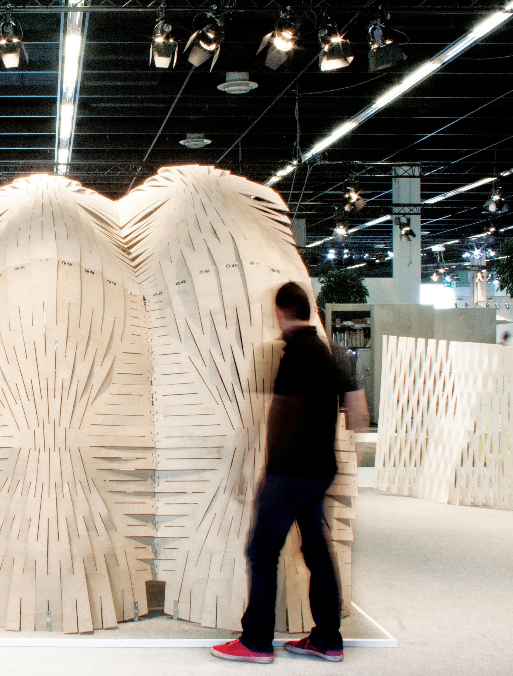
1.
the enclosure addresses issues of material, geometry, and structure. the system took steps to question inhabitation, fenestration, mitigation of light and climate, as well as general architectural and aesthetic qualities.
2.
Was double curvature achieved at the panel level?
as the gradating cuts technique was refined, we concluded that each panel contained areas of single curvature with adjacent zones maintaining an opposing curvature.
3.
the curvature deepened at the ground condition giving stiffness to the points of anchorage. two adjacent panels were assembled and the joining geometry created an extremely rigid rib-like condition integrated within the surface.
4.
the flexibility of the system and pavilion lead to its success. the final form was a combination of the global forces acting on the system along with the embedded logic of the cut patterning.
after consideration of the initial aims and strategies of the pavilion and enclosure, many significant steps were taken in the advancement of the material system to a true architectural system. not only did the pavilion address issues of material, geometry, and structure; the system took steps to question inhabitation, fenestration, mitigation of light and climate, as well as general architectural and aesthetic qualities.
in regards to the key task in the development of the system, a large portion of the efforts was in the prototyping and testing a progression of cut patterns to test and achieve double curvature in a single panel. this task was essential for the development of the enclosure due to the requirement to both span and resist loads horizontally and vertically. the basic approach was to derive a method of gradating between perpendicular cuts - vertical to horizontal then retuning to horizontal. this technique did seem to work however there was always a balance or back and forth between a dominant flexibility in the vertical vs horizontal orientation. as the gradating cuts technique was refined, we concluded that each panel contained areas of single curvature with adjacent zones maintaining an opposing curvature. this phenomena gave both control flexibility as well as stiffness to an individual panel. the material and system principles gave the stability and appearance of complex curvature, while the approximation of double curvature.
as a structure the final installation was quite stiff. as opposed to relying on shear surface geometry to create structural stability, the method of joining the panels became key to generate an
integrated structural ribbing system. each panel was designed with a slight curvature in the horizontal axis. this achieved two main criteria for the structure. one, the curvature deepened at the ground condition giving stiffness to the points of anchorage. second, as two adjacent panels were assembled the geometry created by the joining edge created an extremely rigid rib-like condition integrated within the surface. the overall design also utilized a corrugated geometry. all these elements acting together lead to the success of the cohesive system. all elements were designed into one seemingly simple system.
to be crit ical of the process and the final installation, the system performed very well in terms of flexibility. this flexibility in turn lead to the realization of the pavilion, however the final global form was a combination of the global forces acting in the anchoring detail, method of panelisation, assembly tolerances, and the cut patterns. many more forces are acting in addition to the embedded logic of the material properties and cut patterning system.
in response to the overall aspirations and goals of the initial project abstract, the principal logic behind the expandable surface system served as a very successful platform to study and question issues of material, integration of architectural systems, and methods of construction.
the primary benefits of the proposal are established against how this system performs beyond standard architectural practices. Where can we place the work and advance an architectural discourse?
as established in the abstract, the main goal of the system was to derive a design tool and methodology to address the issue of achieving complex curvatures out of enhanced integration between design, material, and fabrication logics. in this regard, the expandable surface system became quite successful in testing these criteria.
as we will attempt to separate and examine each success and limitation of the system against standard practices, it is very difficult to discuss one aspect of the system alone. all elements of the expandable surface system are integrated and act as one procedure, methodology, structure, composition, and design to production system. each benefit or limitation is seamlessly dependent on all other elements. We will evaluate the elements of the system follows:
1. geometry and structure
2. material and cut patterns
3. feasibility and fabrication
4. a tool of design to production
as we assess the results and findings in the expandable surface system research, we propose an outline and areas of focused speculation into future developments in the system.
We envision the most productive areas of further research in to the following categories:
1. exterior application, climatic inputs, and control.
2. conjecture into system deployment strategies.
3. expand on the principles of the design and working process as a generative tool.
summary of method and form finding assessment
geometry constraints
point based input parametrically controlled geometry
matter constraints
Young’s modulus
self supported Wall opposed curvatures, single layer structure
geometry based model
E1=10488.45 MPa
E2=2394.74 MPa
E3=500 MPa
structurally improVed model
double layer geometrical structure improvement
double layer enclosure geometrical structure improvement with double amount of material
intensiVe field regular pattern infield with different size for each spacer
matter+fabrication panelised pattern infield, two size spacers and single layer self supported structure
fabrication
low-tech deployable driven panels
surface based system pattern approximation for each panel based on a surface geometry
panelised form finding bottom up fabrication experiment
desirable process with undesirable morphological result
expandable surface system 161
exterior application, climatic inputs, and sun and wind control.
as the parameters of the system and the material are well defined, additional design inputs could lead to interesting futures of the system. the majority of the logic designed into the cut patterns and material system were related to geometry and structure. the control and analysis of lighting conditions and solar mitigation was an optimistic assessment of found conditions.
the system currently intuitively or passively suited these conditions.
as a platform for future system design, we would like in investigate how these conditions can be an active input into the design process, origination, scaling, and patterning of the principle cut system. how would the requirements of the geometric structural system inputs interface the increased influence of lighting conditions.
works predominantly under self-weight and gravity loads. With wind loading, the system would have to resist both axial and lateral asymmetrical loads. how would this affect the global system and form. in addition, an area of interest would be how the local paths of air would flow through the individual cuts at a smaller scale.
in addition to exterior climate constraints, how would the physical material and system principals need to be adjusted technically to accommodate exterior weathering? experimentation into how the system and material creep would react in the exterior elements would need to be investigated. With these steps we could speculate into more permanent applications of the system.
in addition to solar inputs, the next main external condition that would need to be addressed would be wind. the current system
With future inputs of sun, wind, and precipitation mitigation, the cut patterns would need to be adjusted - in turn affecting geometry and global morphologies.
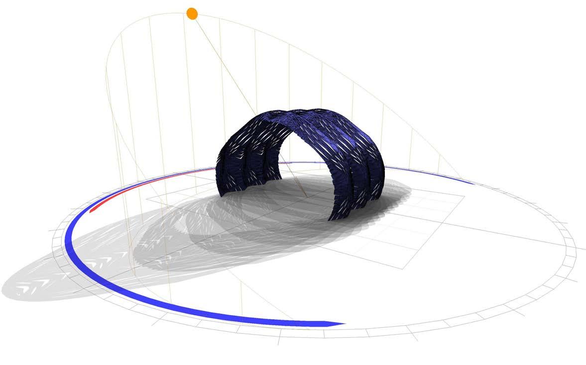
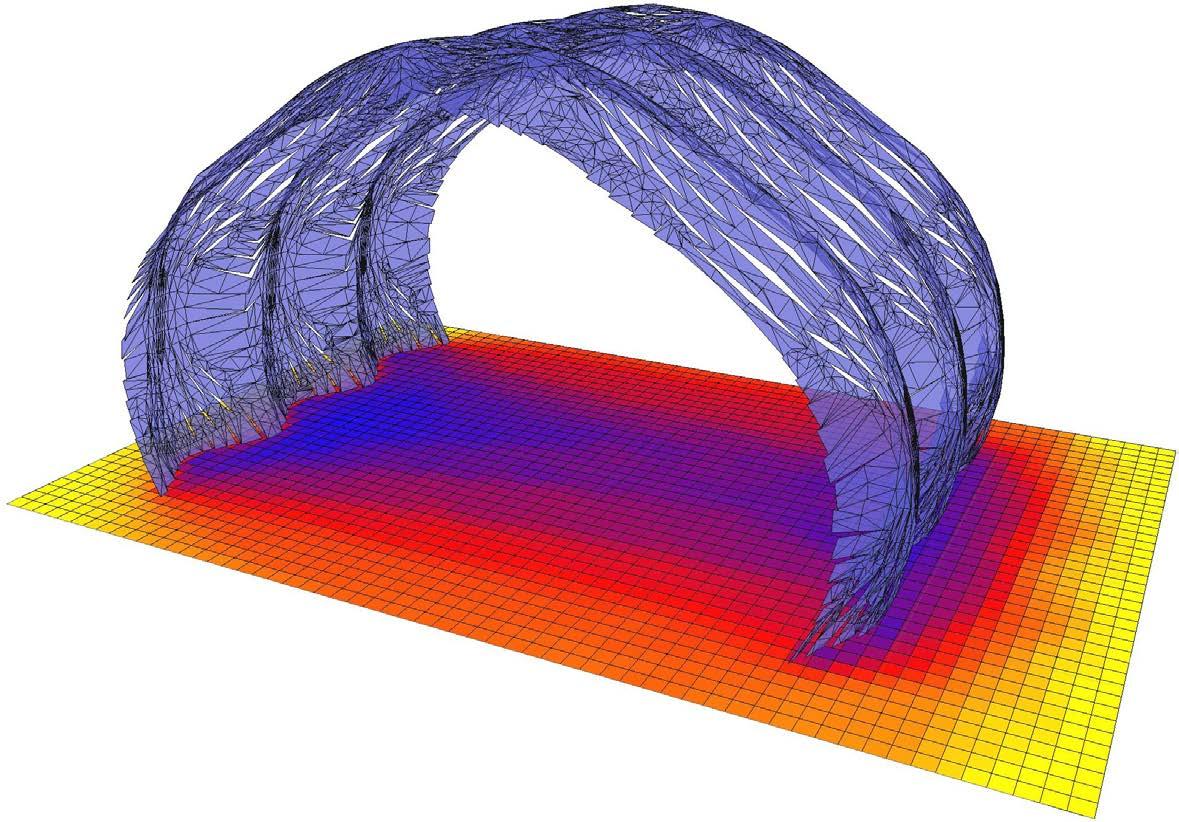
deployment strategies
thinking about larger scale applications of the system, there is an interest in the deployability of not only the physical system, but information as well. the shear simplicity of the system at the fabrication and assembly level, renders it extremely straightforward to convey to constructors in any language or at any skill level. the embedded in the logic and inherent ease of adaptability at the design and material level, within one simple means of fabrication, opens up many opportunities for rapid deployment.
ricated centrally, flat packed, and shipped very efficiently. then using local labor, the panels can formed and assembled onsite.
the concluding notion of deployability, is one of information. When the cut files are translated into g-code, the language readable by cnc machines, they contain only very simple text. this digital document is of minimal size and can be emailed anywhere on the globe in a matter of seconds. this simple document contains all material, structural, geometric, formal design, and modes of fabrication information embedded directly into file. all logic and information for system production are enclosed in one text file.
the obvious centralized approach is designing, fabricating, forming, and shipping the panels for assembly. this is predominately the current approach. the next aspect of the system that yields to deployment is the efficiency of the system. panels can be fab-
this discourse opens up an interesting conversation in regards to what portions of the system are actually deployed.data shipping material shipping
1 2 3
information shipping text data (g-code) sent to a cnc machine to be cut on plywood surfaces. medium: e-mail
panels are cut, formed and assembled on the final destination city.
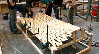
flat, cut panel shipping flat panels with cuts sent to a shop to be formed. medium: ground or air mail
panels are cut anywere else, but formed and assembled on the final destination.
formed panel formed panels sent to the final assembly destination medium: ground or air mail
panels are cut and formed anywere else, and just assembled on the final destination.
panel-01-a.gCdeWhen making projections into the future logics for possible system deployment, it is important to consider local resources along with local fabrication abilities.
as opposed to physical shipping of matter, the transfer of information is extremely efficient and virtually free, both economically and in terms of energy waste. for this reason the most efficient means of deployment relies on the availability of local resources and means of fabrication. the development of a deployment would need to take this into account.
portions of the world with minimal means of local materials, north africa or the middle east for example, would need to rely on neighbouring markets and material sources. this task would involve more time, cost, and energy in transportation and coordination. other areas with high means of material production could simply be sent a g-code file via email, which contains all in formation and system logic required to fabricate the system.
the structural success and interest in this system is unequivocally linked to the principles of surface geometry at two scales - the panel level and the global form. the primary benefit of this approach in comparison standard practice is the constant reliance and dialogue between the aspects acting in one system. there is no distinction between structure and skin, and therefore no requirement for secondary or tertiary systems to interface between the two. the seduction and interest in complex surface geometry is no longer a design aesthetic built on top of a many supporting systems, it is a fundamental aspect of the architecture. in addition to formal characteristics, all scales of geometry act to the success and stability of the overall global form. the principle structure would fail without all portions of the surface geometry in place.
at the panel level, geometry became equally as important in the design process. the development from the wall system to enclosure posed different questions on how the surface system can react and accommodate to different physical forces and design criteria. With respect to the wall panelisation each panel resisted vertical loads independently, but relied on each other for overall bending, buckling, and turning moments allowing the system to be self-supporting. alone each panel contained no stability to stand alone. as the system developed, the geometry of each local panel not only became more complex, but the forces acting on it increased as well. the drive to double curvature in order to achieve enclose, as opposed to a post and lentil system, implied that there had to be a hierarchy of panels and therefore geometry. While all panels act together, the supporting geometry to anchor the system at the ground condition are not suitable for spanning. in addition to structural requirements, the geometry of the varying panels were also a product of the user, scale, and program.
While addressing the design and structural requirements of a pavilion the system works quite well, however there will be an obvious limitation with a significant increase in scale. the current point of development in the system was designed with the intent of a small scale enclosure. the principles of the system would have been approached differently and could not simply be scaled. depending on the instance and change in program, brief, and structural requirements; the system would need to be adjusted and refined both on a material level and possibly a principal logic.
material and cut patterns
the logic, patterning, and scale of the cut system was directly connected to the selection and research into six millimeter birch plywood. the design and logic of the system would have varied with different material constraints. the investigation is directly coupled in a dialogue with the specific standard stock sheet material.
the cut system provided for nearly all aspects of the system. the one simple technique gave the material the ability to move beyond its natural properties and limitations. it gave flexibility in specific areas and stiffness in others. the incisions lead to the control over the overall geometry at a local level, which in turn bred a structural logic. their development controls and exploits lighting conditions and climate. the cuts also directly lead to a simplified low-tech means of fabrication, joining, and an assembly logic. it is also important to recognize the significance of the cut technique, and while less quantifiable, assess its sheer aesthetic and architectural qualities. this was equally important to the interest and success of the system.
the patterning of these cuts is once again closely connected to material and geometry. apparent decisions were made to allow for global form and panel curvature, while less evident considerations were taken for material tolerances, physical logistical, and assembly constraints. all these decisions were made at the pattern level. in addition to the requirements of the pattern to accommodate these aspects of the design, the patterning was also a direct result of fenestration, design aspirations, and an approach to the mitigation of light and potentially climatic conditions. an investigation into the pattern transition to the panel edge and ground condition also became essential to the success of the system. in these cases the requirements of detailing and anchoring determined the pattern logic which in turn directly impacted the global geometry and form.
While the material and cut patterns did manage to respond in addressing the abstract, they did provide some limitations and added difficulties to the system. as an approach the system did restrict the extreme curvature. Within the principles of the system, increased density in the pattern would achieve tighter curvature. however, there was a limitation to this hypothesis. With increased pattern density, overall stiffness and scale of cell openings were diminished. do to this consideration, the patterning system allowed for a limited radii of curvature. in addition to a restriction in local curvature, the overall global forms were always restricted to opposing or oscillating forms of curvature. this was a limitation in the fact that a single cut could only open in two directions and the overall stability of the system relied on an equilibrium of opposing curvatures.
lastly, pushing the boundaries of a natural fibrous material has its restrictions. the technique of soaking and forming the panels was equally contingent on the individual sheet of material. no two sheets of natural material behave exactly the same way. also the phenomena of creep plays into the effectiveness of using the system as a permanent structure. overtime the cut openings will close slightly and overall curvature and geometry may change.
feasibility and fabrication
the mode of fabrication and material constraints are a direct factor into the design and success of the system. in this regard, the project differs most from standard architectural practice. instead of the typical process of design, then forced rationalization of the scheme for material and fabrication limitations, then reassessing design considerations and so on; this system began with these concerns from the start. not only did these rules build the foundation for the logic of the system, but they ensure that a particular design or complex surface intent outputted from the system can be constructed efficiently, safely, within the means of the material, and with extremely minimal material waste.
from the research of the domain, one key goal of the system was to be fabricated independently and not rely on a customizable formwork for each surface geometry. the development of the cut pattern and varying spacer system was directly related to achieving this goal. by the simple low-tech method of imposing local forces at different levels, i.e. different spacer sizes, into the material the formwork is eliminated. to all intents and purposes, the variation in surface geometry is limitless; while the technique, logic, material, and simple mode of fabrication remain the same. this is the fundamental advancement in the systemdirectly connecting the design and tool of construction.
being critical of the fabrication process, the practice is quite crude and labor intensive. for lager scale applications of varying geometries, the system currently relies on the use of large format cnc technologies. While these machines are relatively common, they do have dimensional restrictions more restricting than material sourcing. there is also a marginal cost associated with the use of this technology. While the spacer placement process is quite tedious, the simplicity of it allows the process to easily be explained to the fabricator both verbally and in drawing form. these aspects do allow for an efficient means of deployment. panels can be produced offsite, transported flat very effectively, and formed onsite with little explanation, energy resources, complex tools, or complex means and understanding of construction.
a tool of design to production
all else aside, the true effectiveness of the expandable surface system is determined as a system and tool of design to production, not an isolated design exercise. can the principles of the system be taken to other design problems and be utilized effectively?
it would be hard to argue that the system can be applied to any design problem at any scale, but within the boundaries set out by the project brief the approach is absolutely viable to be used to address other design constrains and programmatic questions. the futures of the system are dependent on how one tackles new design problems and applications.
throughout the process different decisions were taken to reinforce both the digital design tools and physical fabrication experiments most effectively to bring them together. the basis for the digital tools was always physical evaluation, but many aspects of the fabrication and method of working with the material were a direct result of a finding in the digital system. With many approaches to the digital model, the final form of the tool aims to balance a “top down” design intent with a “bottom up” logic of the cut patterns and material behaviour. from the input of a complex surface design intent, the tool will create a rationalized version of the design according to the logics of the “expandable surface system.” first the arrangement of the cut pattern will be applied. then, based on an analysis of the original surface, the tool will inform the size and direction of each cut opening. this data, spacer size and direction, is then send to a text table which can be used by the fabricator as a mapping and instruction for construction. the reformed 3-d digital model, with cuts and opening, is then flattened and the cut files can be sent directly to the cnc machine.
the two full scale test cases of the expandable surface system, the wall system and the small scale enclosure, are a direct result of working methods, tools, and fabrication methods as previous described. all elements of the digital design to production tool are in place and working. in future developments the synergy between the tools could be a very productive system expansion. in a linear process the tools combined can evolve an architectural design from a complex digital global surface; to a panelised system based on standard material sizes and constrains - to the cut patterns applied to each panel with corresponding openings - to flat cnc cut files - to a mapping of spacer sizes and locations for fabrication. the ambition in an idealized version of this process would be recursive. this process would be iterated through a number of generations, each time creating a feedback loop to refine the penalization, cut patterns, and openings. these refinements would become a product of pressures of structural and geometric efficiencies, imposed environmental forces, and fabrication and assembly proficiencies.
as a platform for further developments, this technique aims to truly push the discourse of complex surface structures to a mode of fabrication and assembly.
addington, michelle, and daniel l schodek. smart materials and technologies: for the architecture and design professions. oxford: architectural, 2005. print.
ball, philip. nature’s patterns: a tapestry in three parts. oxford: oxford up, 2009. print.
balmond, cecil, jannuzzi smith, and christian brensing. informal. munich: prestel, 2002. print.
burry, jane, and mark burry. the new mathematics of architecture. london: thames & hudson, 2010. print.
carroll, sean b endless forms most beautiful: the new science of evo devo and the making of the animal Kingdom. new york: norton, 2005. print.
devlin, Keith j., Keith j devlin, and Keith j devlin. mathematics: the science of patterns: the search for order in life, mind, and the universe. new york: scientific american library, 1997. print
hensel, michael, achim menges, and michael Weinstock. emergent technologies and design: towards a biological paradigm for architecture. oxon england: routledge, 2010. print.
iwamoto, lisa. digital fabrications: architectural and material techniques new york: princeton architectural, 2009. print.
johnson, steven. emergence: the connected lives of ants, brains, cities, and software. new york: scribner, 2001. print.
Kolarevic, branko. architecture in the digital age: design and manufacturing. new york, ny: spon, 2003. print.
otto, frei, bodo rasch, and sabine schanz. frei otto, bodo rasch: finding form: towards an architecture of the minimal. fellbach: edition axel menges, 2001. print.
pell, ben, andreas hild, sam jacob, and alejandro Zaera-polo. the articulate surface: ornament and technology in contemporary architecture. basel: birkhäuser, 2010. print.
pottmann, helmut, and daril bentley. architectural geometry. exton, pa: bentley institute, 2007. print.
reiser, jesse, and nanako umemoto. atlas of novel tectonics new york: princeton architectural, 2006. print.
thompson, d’arcy Wentworth, and john tyler bonner. on growth and form. cambridge: cambridge up, 1961. print.
Weinstock, michael. the architecture of emergence: the evolution of form in nature and civilisation. chichester: Wiley, 2010. print.
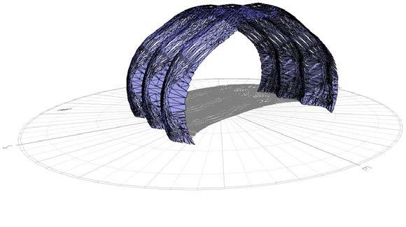
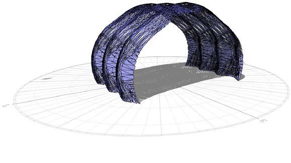
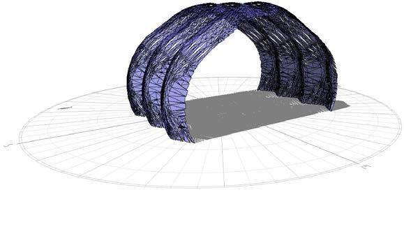
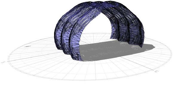
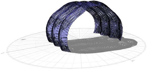
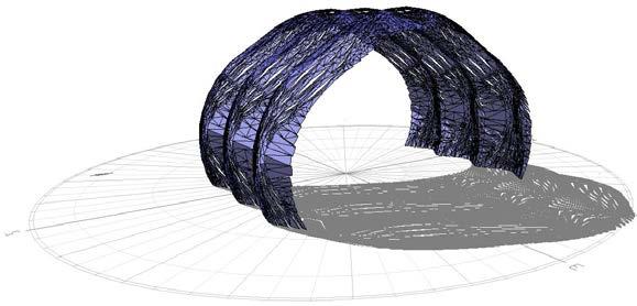
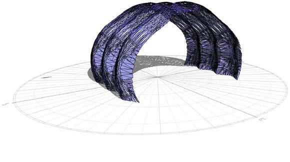
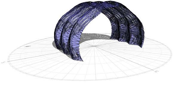
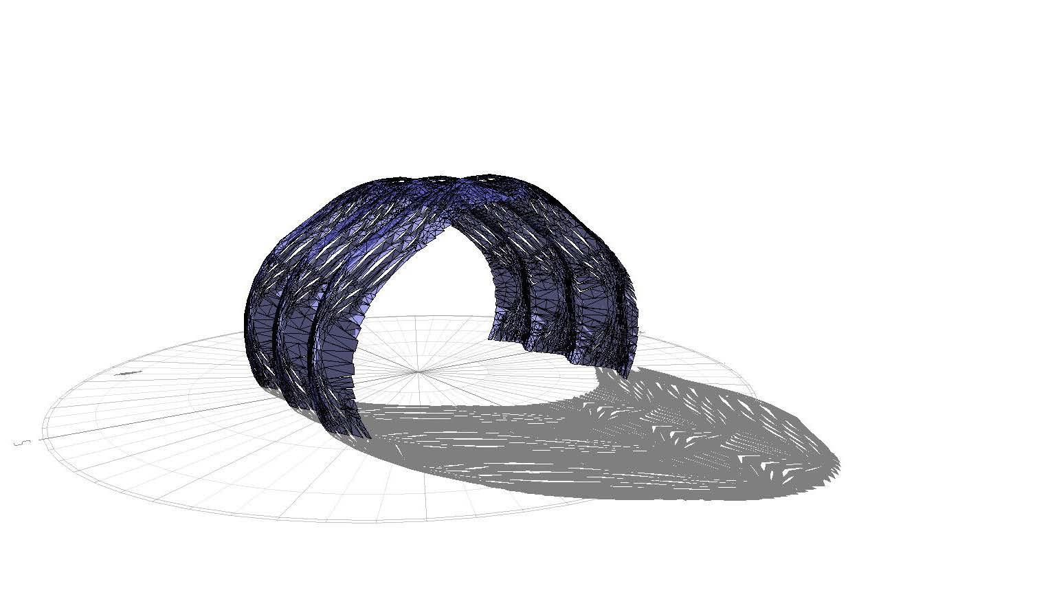
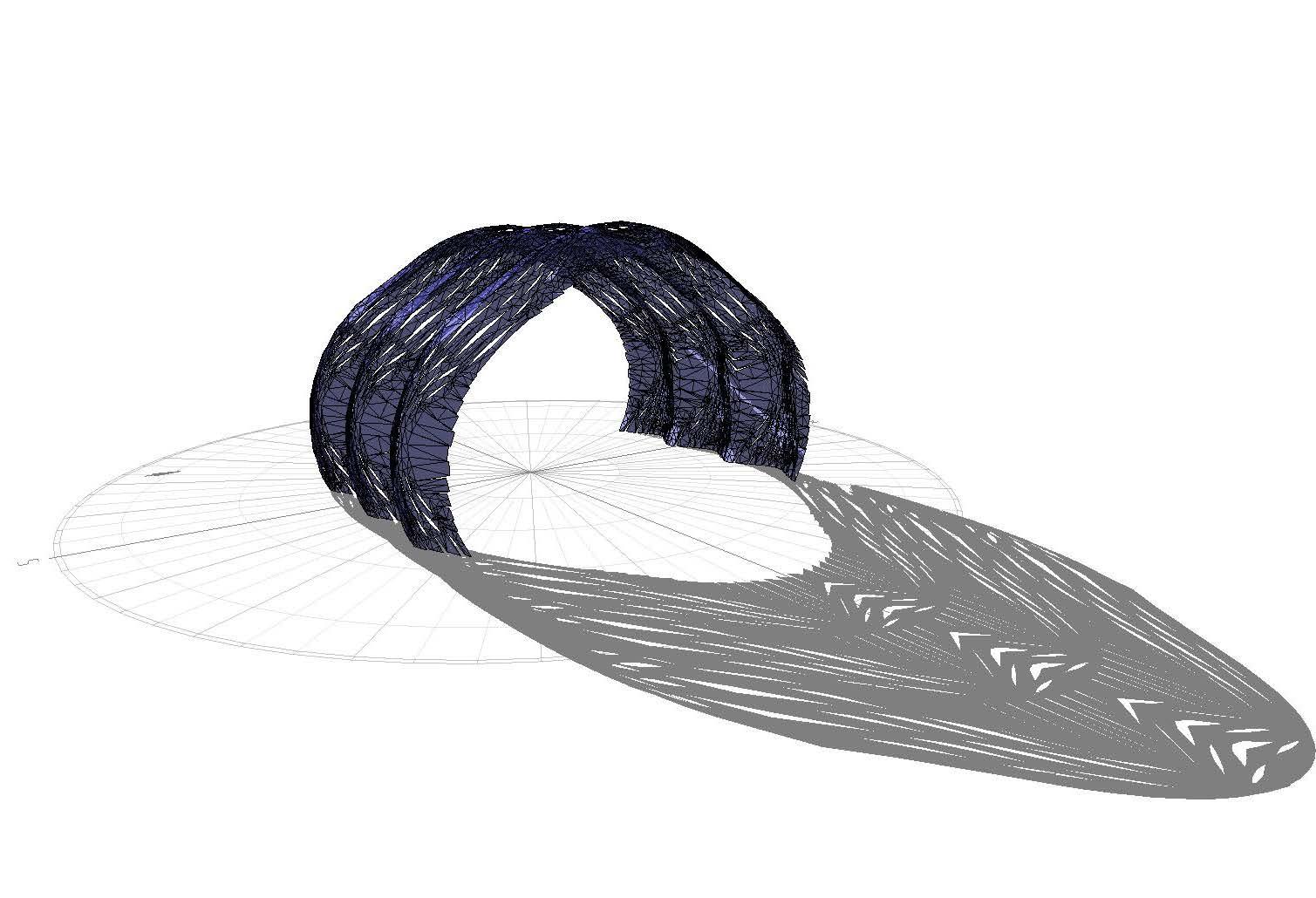
private sub runscript(byVal seedpt as point3d, byVal Z as datatree(of double), byVal x1 as double, byVal x2 as double, byVal ang as double, byVal rows as double, byVal cols as double, byVal offsl as object, byVal offsa as object, byVal updn as datatree(of boolean), byref a as object, byref b as object, byref c as object, byref d as object)
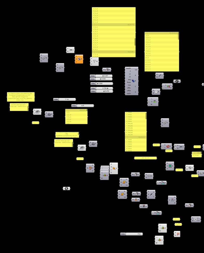
dim ptlist as new list(of point3d)
dim veclist as new list(of Vector3d)
dim stpt as new point3d(seedpt)
dim vecta as new vector3d(plane.Worldxy.yaxis)
vecta.unitize
vecta = vecta * offsl
vecta.rotate(-offsa, plane.Worldxy.Zaxis)
dim stpt2 as new point3d(vecta)
dim cvlist as new list(of curve)
dim edgeVect as new Vector3d(plane.Worldxyyaxis)
edgevect.rotate(-ang / 4, plane.Worldxy.Zaxis)
dim ptlist1 as new list(of point3d)
dim ptlist2 as new list(of point3d)
dim ptlist3 as new list(of point3d)
dim ptlist4 as new list(of point3d)
for i as int32 = 0 to rows - 1
edgevect.unitize
dim edgeln as new line(stpt, edgevect, 20)
stpt = edgeln.pointat(0)
dim temppt1 as new point3d
dim temppt2 as new point3d
dim temppt3 as new point3d
dim temppt4 as new point3d
for j as int32 = 0 to cols - 1
dim vect1 as new Vector3d(plane.Worldxy.zaxis)
dim ln1 as new line
if updn.branch(i).item(j) = false then
ln1 = new line(stpt, vect1, Z.branch(i).item(j)) else
ln1 = new line(stpt, vect1, -Z.branch(i).item(j)) end if
print(Z.branch(i).item(j))
dim pt1 as new point3d(ln1.pointat(1))
dim vect2 as new Vector3d(plane.Worldxy.xaxis)
vect2.rotate(ang, plane.Worldxy.Zaxis)
vect2.unitize
vect2 = pt1 + (vect2 * x1)
dim pt2 as new point3d(vect2)
dim vect3 as new Vector3d(plane.Worldxy.xaxis)
vect3.rotate(ang, plane.Worldxy.Zaxis)
vect3.unitize
vect3 = pt2 + (vect3 * x2)
dim pt4 as new point3d(vect3)
dim vect4 as new vector3d(plane.Worldxy.xaxis)
vect4.rotate(ang, plane.Worldxy.Zaxis)
vect4.unitize
vect4 = pt4 - (vect4 * x1)
dim pt3 as new point3d(vect4)
ptlist.add(pt1) ptlist.add(pt2) ptlist.add(pt3) ptlist.add(pt4)
if i = 2 then
dim cut1 as new line(pt2, temppt4) cvlist.add(cut1.tonurbscurve) end if
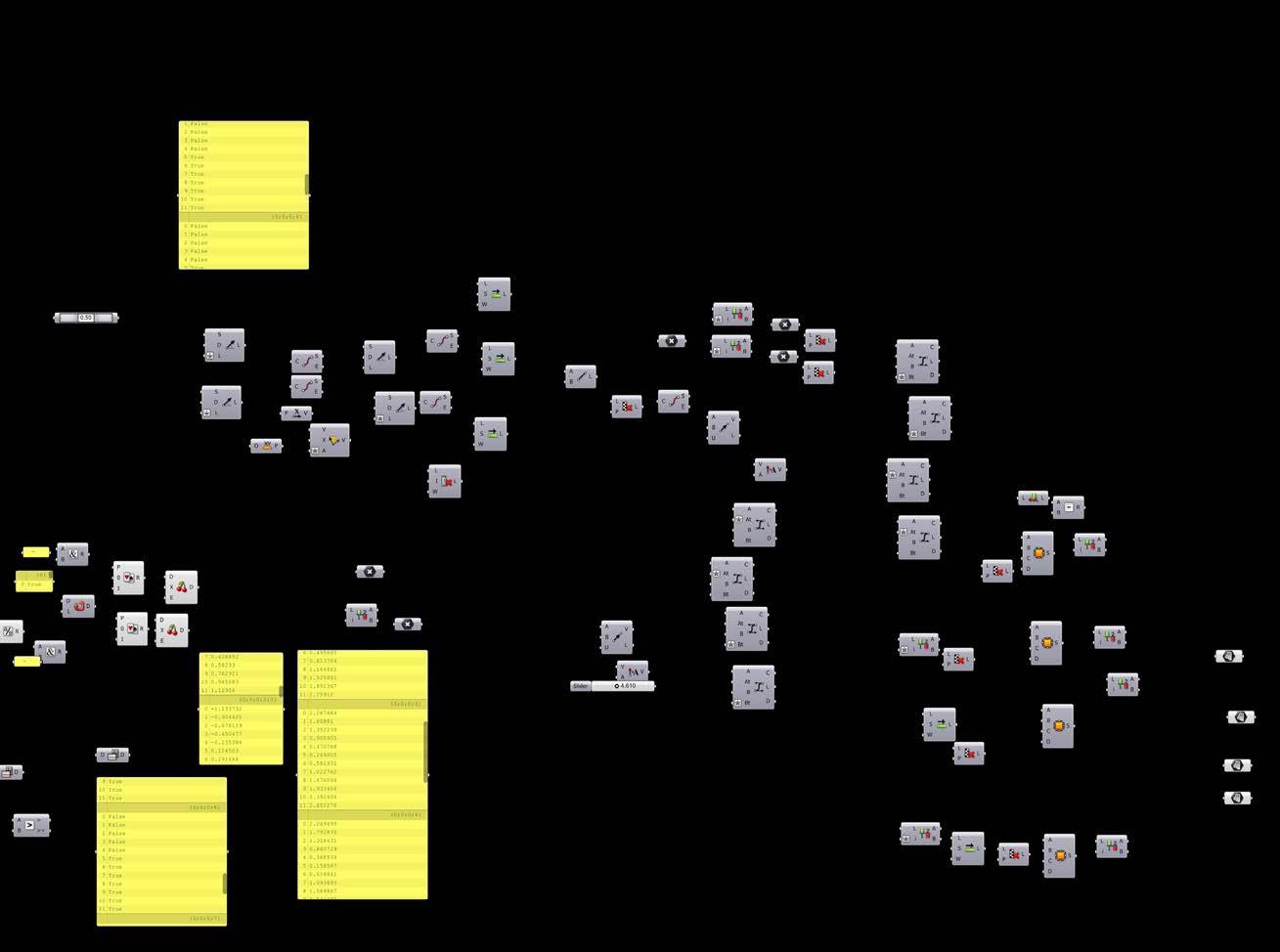
temppt1 = pt1
temppt2 = pt2
temppt3 = pt3
temppt4 = pt4
ptlist1.add(pt1)
ptlist2.add(pt2) ptlist3.add(pt3) ptlist4.add(pt4) next
stpt = edgeln.pointat(1) + edgevect next
a = ptlist1
b = ptlist2
c = ptlist3
d = ptlist4
end sub
end class
rotate on plane script
private sub runscript(byVal stpt as point3d, byVal ang as datatree(of double), byVal l1 as object, byVal l2 as object, byVal gen as double, byVal gen1 as object, byVal updn as datatree(of double), byref a as object, byref b as object, byref c as object)
dim lnlist as new list(of line)
dim surflist as new list(of list(of brep))
dim ropl as new plane(stpt, plane.WorldyZ.Zaxis)
dim roVect as new Vector3d(plane.Worldxyyaxis)
roVect.rotate(ang branch(0).item(0), plane.WorldyZ.Zaxis)
dim ln1 as new line(stpt, plane.Worldxy xaxis, -l2)
dim ln2 as new line(ln1.pointat(1), rovect, l1)
dim ln3 as new line(ln2.pointat(1), plane.Worldxy xaxis, -l2)
dim templn as new line(ln2.pointat(1), rovect, l1)
dim ln4 as new line(ln3.pointat(1), templn pointat(1))
dim ln5 as new line(ln4.pointat(1), plane.Worldxy xaxis, l2)
dim ln6 as new line(ln5.pointat(1), rovect, -l1)
dim ln7 as new line(ln6.pointat(1), plane.Worldxy xaxis, l2)
dim ln8 as new line(ln7.pointat(1), ln1.pointat(0))
dim b1 as brep = brep.createfromcornerpoints(ln1.pointat(0), ln1.pointat(1), ln2.pointat(1), ln7 pointat(1), .01)
dim b2 as brep = brep.createfromcornerpoints(ln3.pointat(1), ln4.pointat(1), ln5.pointat(1), ln6.pointat(1), .01)
‘surflist.add(b1)
‘surflist.add(b2)
roVect.rotate(-ang branch(0).item(0) * 2, plane.WorldyZ.Zaxis)
dim ln7a as new line(ln5.pointat(1), plane.Worldxy xaxis, -l2)
dim ln6a as new line(ln7a.pointat(0), rovect, l1)
dim ln5a as new line(ln6a.pointat(1), plane.Worldxy xaxis, -l2)
dim templna as new line(ln7a.pointat(0), plane.Worldxy xaxis, -ln8.pointat(0).distanceto(ln3.pointat(1)))
dim ln3a as new line(templna.pointat(1), plane.Worldxy xaxis, l2)
dim ln4a as new line(ln3a.pointat(1), ln5a.pointat(1))
dim ln2a as new line(ln3a.pointat(0), rovect, -l1)
dim ln1a as new line(ln2a.pointat(1), plane.Worldxy xaxis, l2)
dim b1a as brep = brep.createfromcornerpoints(ln1a.pointat(1), ln1a.pointat(0), ln2a.pointat(0), ln7a.pointat(1), .01)
dim b2a as brep = brep.createfromcornerpoints(ln3a.pointat(1), ln4a.pointat(1), ln5a.pointat(0), ln6a.pointat(0), .01)
‘ surflist.add(b1a)
‘surflist.add(b2a)
stpt = ln1a.pointat(1)
dim Vecaptlist as new list(of point3d)
dim Vecbptlist as new list(of point3d)
for i as int32 = 0 to ang branchcount - 1
dim blist as new list(of brep)
if updn.branch(0).item(i) = 1 then roVect.rotate(ang branch(0).item(i) * 2, plane.WorldyZ.Zaxis) else roVect.rotate(-ang branch(0).item(i) * 2, plane.WorldyZ.Zaxis) end if
dim ln7b as new line(stpt, plane.Worldxy xaxis, -l2)
dim ln6b as new line(ln7b.pointat(1), rovect, l1)
dim ln5b as new line(ln6b.pointat(1), plane.Worldxy xaxis, -l2)
dim templnb as new line(ln7b.pointat(0), plane.Worldxy xaxis, -ln8.pointat(0).distanceto(ln3.pointat(1)))
dim ln4b as new line(ln5b.pointat(1), templnb pointat(1))
dim ln3b as new line(ln4b.pointat(1), plane.Worldxy xaxis, l2)
dim ln2b as new line(ln3b.pointat(1), rovect, -l1)
dim ln1b as new line(ln2b.pointat(1), plane.Worldxy xaxis, l2)
dim b1b as brep = brep.createfromcornerpoints(ln1b.pointat(1), ln1b pointat(0), ln2b pointat(0), ln7b pointat(0), .01)
dim b2b as brep = brep.createfromcornerpoints(ln3b.pointat(0), ln4b pointat(0), ln5b pointat(0), ln6b pointat(0), .01)
blist.add(b1b)
blist.add(b2b)
codes and definitions 178 appendices
if updn.branch(0).item(i) = 1 then roVect.rotate(-ang branch(0).item(i) * 2, plane.WorldyZ.Zaxis) else roVect.rotate(ang branch(0).item(i) * 2, plane.WorldyZ.Zaxis) end if
dim ln7ab as new line(ln5b.pointat(0), plane.Worldxy xaxis, -l2)
dim ln6ab as new line(ln7ab.pointat(0), rovect, l1)
dim ln5ab as new line(ln6ab.pointat(1), plane.Worldxy xaxis, -l2)
dim templnab as new line(ln7ab.pointat(0), plane.Worldxy xaxis, -ln8.pointat(0).distanceto(ln3.pointat(1)))
dim ln3ab as new line(templnab.pointat(1), plane.Worldxy xaxis, l2)
dim ln4ab as new line(ln3ab.pointat(1), ln5ab pointat(1))
dim ln2ab as new line(ln3ab.pointat(0), rovect, -l1)
dim ln1ab as new line(ln2ab.pointat(1), plane.Worldxy xaxis, l2)
dim b1ab as brep = brep.createfromcornerpoints(ln1ab.pointat(1), ln1ab pointat(0), ln2ab pointat(0), ln7ab pointat(1), .01)
dim b2ab as brep = brep.createfromcornerpoints(ln3ab.pointat(1), ln4ab pointat(1), ln5ab pointat(0), ln6ab pointat(0), .01)
blist.add(b1ab)
blist.add(b2ab)
stpt = ln3ab.pointat(1)
dim ilist as new list(of brep) for j as int32 = 0 to ang branch(i).count - 1 if updn.branch(i).item(j) = 1 then roVect.rotate(ang branch(i).item(j) * 2, plane.WorldyZ.Zaxis) else roVect.rotate(-ang branch(i).item(j) * 2, plane.WorldyZ.Zaxis) end if
dim ln1c as new line(stpt, plane.Worldxy xaxis, -l2)
dim ln2c as new line(ln1c.pointat(1), rovect, l1)
dim ln3c as new line(ln2c.pointat(1), plane.Worldxy xaxis, -l2)
dim templnc as new line(ln2c.pointat(1), rovect, l1)
dim ln4c as new line(ln3c.pointat(1), templnc.pointat(1))
dim ln5c as new line(ln4c.pointat(1), plane.Worldxy xaxis, l2)
dim ln6c as new line(ln5c.pointat(1), rovect, -l1)
dim ln7c as new line(ln6c.pointat(1), plane.Worldxy xaxis, l2)
dim ln8c as new line(ln7c.pointat(1), ln1c.pointat(0))
dim b1c as brep = brep.createfromcornerpoints(ln1c.pointat(0), ln1c.pointat(1), ln2c.pointat(1), ln7c.pointat(1), .01)
dim b2c as brep = brep.createfromcornerpoints(ln3c.pointat(1), ln4c.pointat(1), ln5c.pointat(1), ln6c.pointat(1), .01) ilist.add(b1c) ilist.add(b2c)
if updn.branch(i).item(j) = 1 then roVect.rotate(-ang branch(i).item(j) * 2, plane.WorldyZ.Zaxis) else roVect.rotate(ang branch(i).item(j) * 2, plane.WorldyZ.Zaxis) end if
dim ln7ad as new line(ln5c.pointat(1), plane.Worldxy xaxis, -l2)
dim ln6ad as new line(ln7ad.pointat(0), rovect, l1)
dim ln5ad as new line(ln6ad.pointat(1), plane.Worldxy xaxis, -l2) dim templnad as new line(ln7ad.pointat(0), plane.Worldxy xaxis, -ln8.pointat(0).distanceto(ln3.pointat(1))) dim ln3ad as new line(templnad.pointat(1), plane.Worldxy xaxis, l2) dim ln4ad as new line(ln3ad.pointat(1), ln5ad pointat(1)) dim ln2ad as new line(ln3ad.pointat(0), rovect, -l1)
dim ln1ad as new line(ln2ad.pointat(1), plane.Worldxy xaxis, l2)
dim b1ad as brep = brep.createfromcornerpoints(ln1ad.pointat(1), ln1ad pointat(0), ln2ad pointat(0), ln7ad pointat(1), .01)
dim b2ad as brep = brep.createfromcornerpoints(ln3ad.pointat(1), ln4ad pointat(1), ln5ad pointat(0), ln6ad pointat(0), .01)
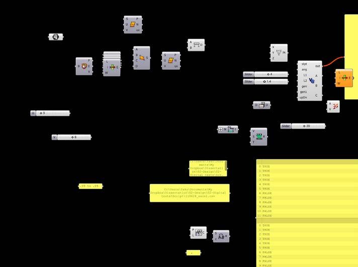
ilist.add(b1ad)
ilist.add(b2ad)
Vecaptlist.add(ln2ad.pointat(0)) Vecaptlist.add(ln5ad.pointat(0))
stpt = ln3ad pointat(1) next surflist.add(ilist)
stpt = ln1ab.pointat(1) next
for i as int32 = 0 to surflist.count - 1 if i > 1 then
dim trans1 as transform = transform.translation(vectlist.item(0)) if vectlist.item(i).length > 0.01 then surflist.item(i).transform(trans1) end if end if next
dim outlist as new list(of brep)
for i as int32 = 0 to ang branchcount - 1
for j as int32 = 0 to ang branch(i).count - 1
outlist.add(surflist.item(i).item(j))
next next a = outlist
end sub end class
private sub runscript(byVal cv as list(of curve), byVal hnum as double, byVal count as object, byVal bool as boolean, byref a as object, byref b as object)
dim lnoutlist as new list(of line) ‘ cv.reverse if bool = true then hnum = -hnum end if
‘for each cV1 as curve in cv for j as int32 = 0 to cv count - 1 dim newhnum as new double newhnum = hnum
dim newcv as curve newcv = cv.item(j)
newcv.domain = new interval(0, 1) dim templn as new line(newcv.pointat(0), newcv.pointat(1))
dim vect as new vector3d(templn.pointat(.5) - newcv pointat(.5))
dim stpt as new point3d(newcv.pointat(0))
dim cvpt as new list(of point3d) cvpt.add(newcv.pointat(0)) cvpt.add(newcv.pointat(.5)) cvpt.add(newcv.pointat(1)) cvpt.add(newcv.pointat(0))
dim closecv as curve = curve.createinterpolatedcurve(cvpt, 3)
dim pltemp as new plane(stpt, vect)
dim templn1 as new line(stpt, pltemp.yaxis, 1) dim testpt as new point3d(templn1.pointat(1))
b = pltemp yaxis
if closecv.contains(testpt) = pointcontainment.outside then newhnum = -newhnum
end if for i as int32 = 0 to count - 1
dim pl as new plane(stpt, vect) dim hVect as new vector3d(pl.yaxis)
dim hline as new line(stpt, hvect, newhnum) pl.rotate(math.pi / 2, pl.xaxis)
pl.translate(new Vector3d(hline.pointat(1) - hline pointat(0)))
dim int as rhino.geometry.intersect.curveintersections = rhino.geometry.intersect.intersection.curveplane(newcv, pl, .0011)
dim interpt as new point3d(newcv.pointat(int(0).parametera))
dim vln as new line(hline.pointat(1), interpt)
lnoutlist.add(vln) lnoutlist.add(hline) print(Vln.length.tostring)
stpt = interpt next next
a = lnoutlist
‘b = upln
end sub
end class
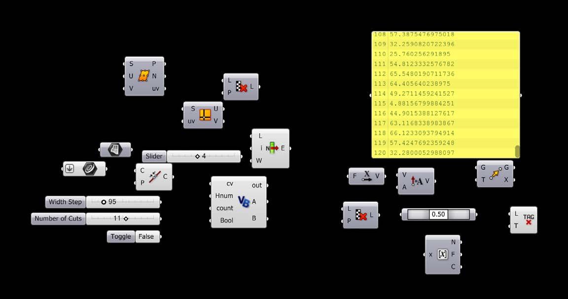
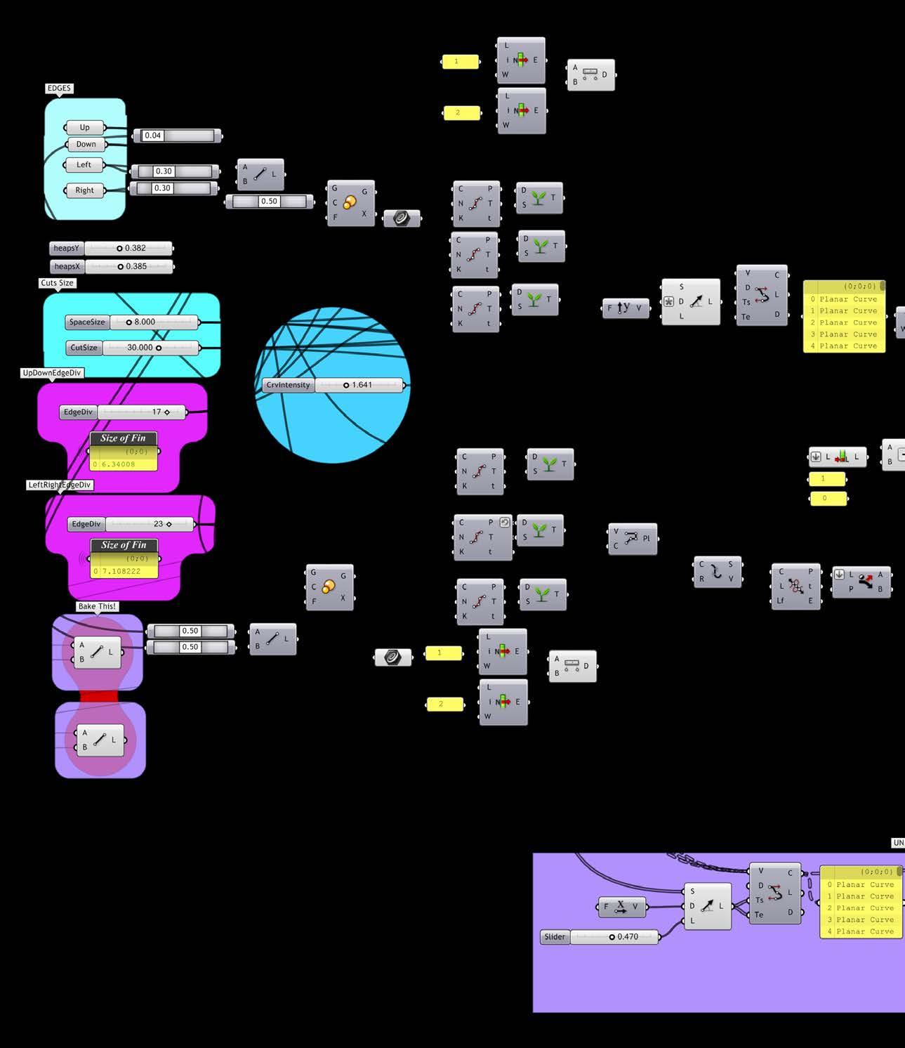
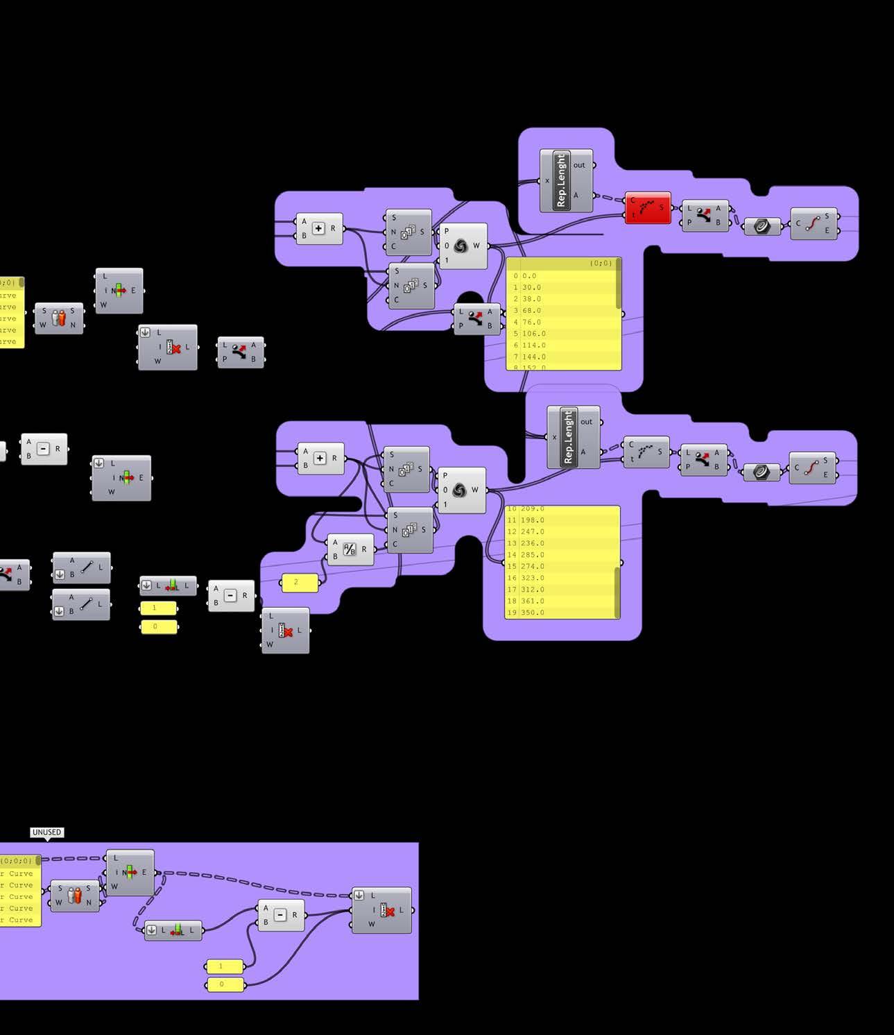
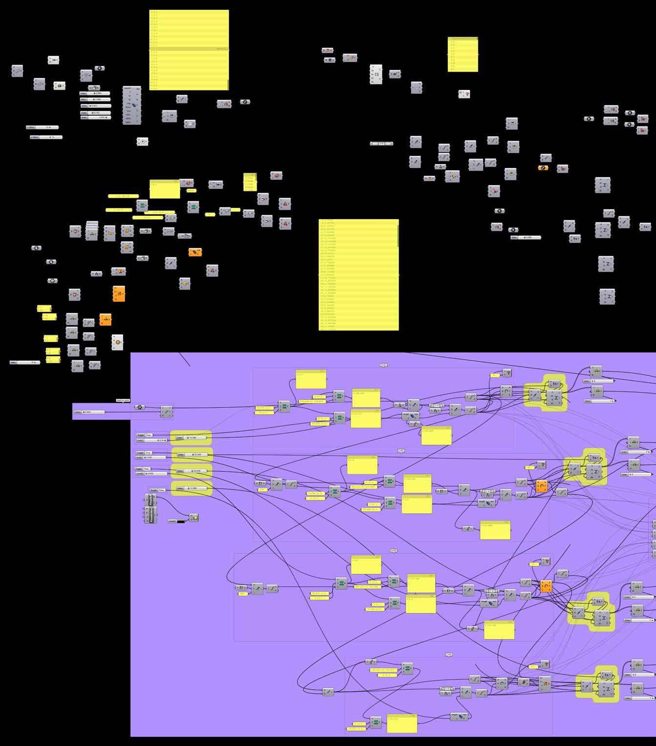
private sub runscript(byVal seedpt as point3d, byVal Z as datatree(of double), byVal x1 as double, byVal x2 as double, byVal ang as double, byVal rows as double, byVal cols as double, byVal offsl as object, byVal offsa as object, byVal updn as datatree(of boolean), byref a as object, byref b as object, byref c as object, byref d as object, byref e as object, byref f as object)
dim ptlist as new list(of point3d)
dim veclist as new list(of Vector3d)
dim stpt as new point3d(seedpt)
dim boutlist as new list(of boolean)
dim Zoutlist as new list(of double)
dim vecta as new vector3d(plane.Worldxy.yaxis)
vecta.unitize
vecta = vecta * offsl
vecta.rotate(-offsa, plane.Worldxy.Zaxis)
dim stpt2 as new point3d(vecta)
dim cvlist as new list(of curve)
dim edgeVect as new Vector3d(plane.Worldxyyaxis)
edgevect.rotate(-ang / 4, plane.Worldxy.Zaxis)
dim ptlist1 as new list(of point3d)
dim ptlist2 as new list(of point3d)
dim ptlist3 as new list(of point3d)
dim ptlist4 as new list(of point3d)
for i as int32 = 0 to rows - 1
edgevect.unitize
dim edgeln as new line(stpt, edgevect, 20)
stpt = edgeln.pointat(0)
dim temppt1 as new point3d
dim temppt2 as new point3d
dim temppt3 as new point3d
dim temppt4 as new point3d
dim vect1 as new Vector3d(plane.Worldxy.zaxis)
if updn.branch(i).item(0) = false then
vect1.reverse end if
dim lastZpt as new point3d(0, 0, 0)
for j as int32 = 0 to cols - 1
dim ln1 as new line
if j = updn.branchcount / 2 then vect1.reverse end if
if updn.branch(i).item(j) = true then
ln1 = new line(stpt, vect1, -Z.branch(i).item(j)) ‘ boutlist.add(true) else ln1 = new line(stpt, vect1, Z.branch(i).item(j)) end if
lastZpt = new point3d(ln1.pointat(1))
if stpt.Z > lastZpt.Z then boutlist.add(true) else boutlist.add(false) end if
Zoutlist.add(ln1.length)
print(Z.branch(i).item(j).tostring)
dim pt1 as new point3d(ln1.pointat(1))
dim vect2 as new Vector3d(plane.Worldxy.xaxis) vect2.rotate(ang, plane.Worldxy.Zaxis)
vect2.unitize
vect2 = pt1 + (vect2 * x1)
dim pt2 as new point3d(vect2)
dim vect3 as new Vector3d(plane.Worldxy.xaxis) vect3.rotate(ang, plane.Worldxy.Zaxis)
vect3.unitize
vect3 = pt2 + (vect3 * x2)
dim pt4 as new point3d(vect3)
dim vect4 as new vector3d(plane.Worldxy.xaxis) vect4.rotate(ang, plane.Worldxy.Zaxis)
vect4.unitize
vect4 = pt4 - (vect4 * x1)
dim pt3 as new point3d(vect4)
ptlist.add(pt1) ptlist.add(pt2) ptlist.add(pt3) ptlist.add(pt4)
if i = 2 then
dim cut1 as new line(pt2, temppt4) cvlist.add(cut1.tonurbscurve)
end if
temppt1 = pt1
‘
temppt2 = pt2 temppt3 = pt3 temppt4 = pt4
ptlist1.add(pt1)
ptlist2.add(pt2)
ptlist3.add(pt3)
ptlist4.add(pt4)
‘ dim vecta1 as new Vector3d(plane.Worldxy.zaxis)
‘ dim lna1 as new line(stpt2, vecta1, Z.item(i))
‘ dim pta1 as new point3d(lna1.pointat(1))
‘
‘ dim vecta2 as new Vector3d(plane.Worldxy.xaxis)
‘ vecta2.rotate(ang, plane.Worldxy.Zaxis)
‘ vecta2.unitize
‘ vecta2 = pta1 + (vecta2 * x1)
‘ dim pta2 as new point3d(vecta2)
‘ vecta3.rotate(ang, plane.Worldxy.Zaxis)
‘ vecta3.unitize
‘ vecta3 = pta2 + (vecta3 * x2)
‘ ‘ dim pta4 as new point3d(vecta3)
‘ dim vecta4 as new vector3d(plane.Worldxy.xaxis)
‘ vecta4.rotate(ang, plane.Worldxy.Zaxis)
‘ vecta4.unitize
‘ vecta4 = pta4 - (vecta4 * x1)
‘ ‘ dim pta3 as new point3d(vecta4)
‘ ‘ ptlist.add(pta1)
‘ ptlist.add(pta2)
‘ ptlist.add(pta3)
‘ ptlist.add(pta4)
‘_______________________________________________________
‘ dim contVect as new Vector3d(pta4 - pt2)
‘ contvect.unitize
‘ contvect = contvect * .2
‘ dim contpt1 as new point3d
‘ dim contpt2 as new point3d
‘ contpt1 = pta4 - contvect
‘ contpt2 = pta4 - contvect
‘ dim cvptlist as new list(of point3d)
‘ cvptlist.add(pt2)
‘ cvptlist.add(contpt1)
‘ cvptlist.add(contpt2)
‘ cvptlist.add(pta4)
‘
‘ dim cv1 as curve = curve.createcontrolpointcurve(cv ptlist, 3)
‘ ‘ cvlist.add(cv1)
stpt = pt4
‘ stpt2 = pta4
next
stpt = edgeln.pointat(1) + edgevect next
a = ptlist1
b = ptlist2
c = ptlist3
d = ptlist4
e = zoutlist
f = boutlist
end sub
end class
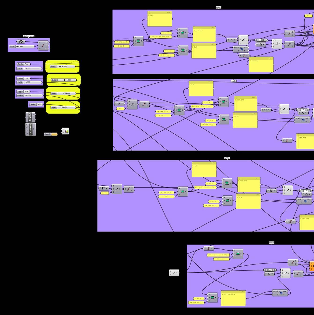
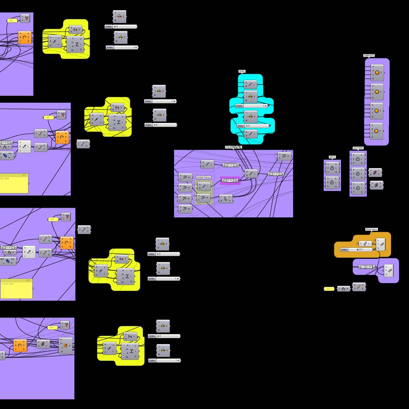
a;pycam-meta-data:
filename: c:\users\yaKo\documents\my dropbox\ dissertation\09emtech exhibition Wall\fab\dxf\panel01-a.dxf
;pycam-meta-data:
timestamp: 2011-09-19 14:38:18.017000
;pycam-meta-data:
Version: 0.5.1.1
;estimated machine time: 26 minutes
g40 (disable tool radius compensation)
g49 (disable tool length compensation)
g80 (cancel modal motion)
g54 (select coordinate system 1)
g90 (disable incremental moVes)
g21 (metric)
g61 (exact path mode)
f200.00000
s1000.00000
;pycam toolpath settings: start
;[bounds]
;maxZ = 0.0
;maxx = 1749.98277426
;maxy = 1845.55713951
;minx = -369.791803791
;miny = -166.41428541
;minZ = 0.0
; ;[tool]
;torus_radius = 0.25
;speed = 1000.0
;shape = cylindricalcutter
;tool_radius = 1.5
;feedrate = 200.0
; ;[process]
;generator = engraVecutter
;pocKeting_type = none
;engraVe_offset = 0.0
;milling_style = conVentional
;path_direction = x
;step_doWn = 3.0
;postprocessor = simplecutter
;material_alloWance = 0.0
;
;pycam toolpath settings: end
t1 m6
g0 Z25.0000
m3 (start spindle)
g04 p3 (Wait for 3 seconds)
x-126.6161 y1467.3373
g1 Z0.0000
x-124.9633 y1467.5001
x-123.3740 y1467.9822
x-121.9092 y1468.7651
x-120.6254 y1469.8188
x-119.5717 y1471.1026
x-118.7888 y1472.5673
x-118.3067 y1474.1567
x-118.1439 y1475.8095
y1492.7540
x-168.9773
g0 Z25.0000
x-147.7967 y1561.9440
g1 Z0.0000
y1525.2306
g0 Z25.0000
x-92.7273 y1679.1429
g1 Z0.0000
x-168.9773 y1645.2540
g0 Z25.0000
x-118.1439 y1619.8373
g1 Z0.0000
y1594.4206
g0 Z25.0000
x-92.7273
g1 Z0.0000
y1598.6567
x-92.9714 y1601.1360
x-93.6946 y1603.5200
x-94.8690 y1605.7171
x-96.4494 y1607.6429
x-98.3752 y1609.2233
x-100.5723 y1610.3977
x-102.9563 y1611.1209
x-105.4356 y1611.3651
x-168.9773
x-144.5280 y1408.6589
x-145.7023 y1410.8560
x-147.2828 y1412.7818
x-149.2086 y1414.3622
x-151.4057 y1415.5366
x-153.7896 y1416.2598
x-156.2689 y1416.5040
x-158.7482 y1416.2598
x-161.1322 y1415.5366
x-163.3293 y1414.3622
x-165.2551 y1412.7818
x-166.8355 y1410.8560
x-168.0099 y1408.6589
x-168.7331 y1406.2749
x-168.9773 y1403.7956
y1382.6151
x-130.8523
x-128.3730 y1382.8593
x-125.9890 y1383.5824
x-123.7919 y1384.7568
x-121.8661 y1386.3373
x-168.9773 y1348.7262
g0 Z25.0000
x-164.7411 y1314.8373
g1 Z0.0000
x-168.9773
x-194.3939 y1323.3095
g0 Z25.0000
x-135.0884 y1314.8373
g1 Z0.0000
x-139.3245
g0 Z25.0000
x-109.6717 y1289.4206
g1 Z0.0000
x-92.7273 y1272.4762
x-168.9773
g0 Z25.0000
x-143.5606 y1213.1706
g1 Z0.0000
y1234.3512
x-143.8048 y1236.8305
x-144.5280 y1239.2145
g1 Z0.0000
x-92.7273 y1543.5873
x-168.9773 y1518.1706
g0 Z25.0000
g1 Z0.0000 x-118.1439
g0 Z25.0000
x-96.9634
g1 Z0.0000
x-92.7273
g0 Z25.0000
x-143.5606 y1382.6151
g1 Z0.0000
y1403.7956
x-143.8048 y1406.2749
x-120.2857 y1388.2630
x-119.1113 y1390.4601
x-118.3881 y1392.8441
x-118.1439 y1395.3234
y1412.2679
g0 Z25.0000
x-92.7273 y1357.1984
g1 Z0.0000
x-160.5050
x-162.1579 y1357.0356
x-163.7472 y1356.5535
x-165.2119 y1355.7706
x-166.4958 y1354.7170
x-167.5494 y1353.4331
x-168.3323 y1351.9684
x-168.8145 y1350.3790
x-145.7023 y1241.4116
x-147.2828 y1243.3373
x-149.2086 y1244.9178
x-151.4057 y1246.0922
x-153.7896 y1246.8153
x-156.2689 y1247.0595
x-158.7482 y1246.8153
x-161.1322 y1246.0922
x-163.3293 y1244.9178
x-165.2551 y1243.3373
x-166.8355 y1241.4116
x-168.0099 y1239.2145
x-168.7331 y1236.8305
x-168.9773 y1234.3512
y1213.1706
x-130.8523
8.3>
fabrication
x-128.3730 y1213.4148
x-125.9890 y1214.1380
x-123.7919 y1215.3124
x-121.8661 y1216.8928
x-120.2857 y1218.8186
x-119.1113 y1221.0157
x-118.3881 y1223.3997
x-118.1439 y1225.8790 y1242.8234
g0 Z25.0000
x27.1188 y1180.6525
g1 Z0.0000 x144.5849 y1133.6660
g0 Z25.0000 x135.4151 y1062.3340
g1 Z0.0000
x414.5849 y950.6660
g0 Z25.0000
x280.0000 y1037.0000
g1 Z0.0000 x580.0000
g0 Z25.0000
x445.4151 y1123.3340
g1 Z0.0000
x724.5849 y1011.6660
g0 Z25.0000
x425.4151 y1001.3340
g1 Z0.0000
x704.5849 y889.6660
g0 Z25.0000
x570.0000 y976.0000
g1 Z0.0000
x870.0000
g0 Z25.0000
x715.4151 y940.3340
g1 Z0.0000
x994.5849 y828.6660
g0 Z25.0000
x860.0000 y915.0000
g1 Z0.0000
x1160.0000
g0 Z25.0000
x1025.4151 y1001.3340
g1 Z0.0000
x1304.5849 y889.6660
g0 Z25.0000
x1005.4151 y879.3340
g1 Z0.0000
x1284.5849 y767.6660
g0 Z25.0000
x1150.0000 y854.0000
g1 Z0.0000
x1450.0000
g0 Z25.0000
x1170.0000 y976.0000
g1 Z0.0000
x1470.0000
g0 Z25.0000
x1574.5849 y1220.0000
g1 Z0.0000
y-0.0000
g0 Z25.0000
x1215.4151 y330.3340
g1 Z0.0000
x1494.5849 y218.6660
g0 Z25.0000
x1090.0000 y488.0000
g1 Z0.0000
x1390.0000
g0 Z25.0000
x1255.4151 y574.3340
g1 Z0.0000
x1534.5849 y462.6660
g0 Z25.0000
x1110.0000 y610.0000
g1 Z0.0000
x1410.0000
g0 Z25.0000
x1130.0000 y732.0000
g1 Z0.0000
x1430.0000
g0 Z25.0000
x880.0000 y1037.0000
g1 Z0.0000
x1180.0000
g0 Z25.0000
x1045.4151 y1123.3340
g1 Z0.0000
x1324.5849 y1011.6660
g0 Z25.0000
x1190.0000 y1098.0000
g1 Z0.0000
x1490.0000
g0 Z25.0000
x1574.5849 y1220.0000
g1 Z0.0000
x0.0000
y-0.0000
x1574.5849
g0 Z25.0000
x1465.4151 y25.3340
g1 Z0.0000
x1528.7500 y-0.0000
g0 Z25.0000
x1175.4151 y86.3340
g1 Z0.0000
x1391.2500 y-0.0000
g0 Z25.0000
x1050.0000 y244.0000
g1 Z0.0000
x1350.0000
g0 Z25.0000
x1070.0000 y366.0000
g1 Z0.0000
x1370.0000
g0 Z25.0000
x1235.4151 y452.3340
g1 Z0.0000
x1514.5849 y340.6660
g0 Z25.0000
x780.0000 y427.0000
g1 Z0.0000
x1080.0000
g0 Z25.0000
x635.4151 y452.3340
g1 Z0.0000
x914.5849 y340.6660
g0 Z25.0000
x470.0000 y366.0000
g1 Z0.0000
x770.0000
g0 Z25.0000
x615.4151 y330.3340
g1 Z0.0000
x894.5849 y218.6660
g0 Z25.0000
x160.0000 y305.0000
g1 Z0.0000
x460.0000
g0 Z25.0000
x305.4151 y269.3340
g1 Z0.0000
x584.5849 y157.6660
g0 Z25.0000
x285.4151 y147.3340
g1 Z0.0000
x564.5849 y35.6660
g0 Z25.0000
x430.0000 y122.0000
g1 Z0.0000
x730.0000
g0 Z25.0000
x575.4151 y86.3340
g1 Z0.0000
x791.2500 y-0.0000
g0 Z25.0000
x720.0000 y61.0000
g1 Z0.0000
x1020.0000
g0 Z25.0000
x865.4151 y25.3340
g1 Z0.0000
x928.7500 y-0.0000
g0 Z25.0000
x0.0000 y122.0000
g1 Z0.0000
x130.0000
g0 Z25.0000
x0.0000 y244.0000
g1 Z0.0000
x150.0000
g0 Z25.0000
x15.4151 y330.3340
g1 Z0.0000
x294.5849 y218.6660
g0 Z25.0000
x140.0000 y183.0000
g1 Z0.0000
x440.0000
g0 Z25.0000
x0.0000 y206.5000
g1 Z0.0000
x274.5849 y96.6660
g0 Z25.0000
x120.0000 y61.0000
g1 Z0.0000
x420.0000
expandable surface system 197
g-code for half panel - continued
g0 Z25.0000
x265.4151 y25.3340
g1 Z0.0000
x328.7500 y-0.0000
g0 Z25.0000
x27.8822
g1 Z0.0000
x27.5691 y24.1067
x26.6842 y50.8496
x23.5256 y111.5862
x13.9411 y257.4608
x4.3566 y427.1051
x1.1981 y517.5536
x0.0000 y610.0000
x210.0000
g0 Z25.0000
x0.0000 y732.0000
g1 Z0.0000
x230.0000
g0 Z25.0000
x95.4151 y818.3340
g1 Z0.0000
x374.5849 y706.6660
g0 Z25.0000
x220.0000 y671.0000
g1 Z0.0000
x520.0000
g0 Z25.0000
x385.4151 y757.3340
g1 Z0.0000
x664.5849 y645.6660
g0 Z25.0000
x365.4151 y635.3340
g1 Z0.0000
x644.5849 y523.6660
g0 Z25.0000
x510.0000 y610.0000
g1 Z0.0000
x810.0000
g0 Z25.0000
x530.0000 y732.0000
g1 Z0.0000
x830.0000
g0 Z25.0000
x675.4151 y696.3340
g1 Z0.0000
x954.5849 y584.6660
g0 Z25.0000
x655.4151 y574.3340
g1 Z0.0000
x934.5849 y462.6660
g0 Z25.0000
x800.0000 y549.0000
g1 Z0.0000 x1100.0000
g0 Z25.0000
x820.0000 y671.0000
g1 Z0.0000
x1120.0000
g0 Z25.0000
x260.0000 y915.0000
g1 Z0.0000 x560.0000
g0 Z25.0000
x27.8822 y1220.0000
g1 Z0.0000
x27.5691 y1195.8933
x26.6842 y1169.1504
x23.5256 y1108.4138
x13.9411 y962.5392
x4.3566 y792.8949
x1.1981 y702.4464
x0.0000 y610.0000
g0 Z25.0000 y671.5000
g1 Z0.0000
x64.5849 y645.6660
y1220.0000 g1
y1133.6660 g0
y1098.0000
x540.0000
g0 Z25.0000
x405.4151 y879.3340
g1 Z0.0000
x684.5849 y767.6660
g0 Z25.0000
x550.0000 y854.0000
g1 Z0.0000
x850.0000
g0 Z25.0000
x695.4151 y818.3340
g1 Z0.0000
x974.5849 y706.6660
g0 Z25.0000
x840.0000 y793.0000
g1 Z0.0000
x1140.0000
y1072.6660
y1159.0000
g0 Z25.0000
x1128.7500 y1220.0000
g1 Z0.0000
x1344.5849 y1133.6660
g0 Z25.0000
x735.4151 y1062.3340
g1 Z0.0000
x1014.5849 y950.6660
g0 Z25.0000
x115.4151 y940.3340
g1 Z0.0000
x394.5849 y828.6660
g0 Z25.0000
x240.0000 y793.0000
g1 Z0.0000
g0 Z25.0000
x985.4151 y757.3340
g1 Z0.0000
x1264.5849 y645.6660
g0 Z25.0000
x965.4151 y635.3340
g1 Z0.0000
x1244.5849 y523.6660
g0 Z25.0000
x945.4151 y513.3340
g1 Z0.0000
x1224.5849 y401.6660
g0 Z25.0000
x925.4151 y391.3340
g1 Z0.0000
x1204.5849 y279.6660
g0 Z25.0000
x760.0000 y305.0000
g1 Z0.0000
y488.0000
g0 Z25.0000
y549.0000
g0 Z25.0000
y574.3340 g1 Z0.0000 x334.5849 y462.6660 g0 Z25.0000
y541.5000 g1 Z0.0000 x44.5849 y523.6660 g0 Z25.0000 x0.0000 y488.0000 g1 Z0.0000
g0 Z25.0000 x0.0000 y411.5000 g1 Z0.0000 x24.5849 y401.6660
g0 Z25.0000
x0.0000 y366.0000
g1 Z0.0000 x170.0000
g0 Z25.0000
x35.4151 y452.3340
g1 Z0.0000
x314.5849 y340.6660
g0 Z25.0000
x180.0000 y427.0000
g1 Z0.0000
x480.0000
g0 Z25.0000 x345.4151 y513.3340
g1 Z0.0000
x624.5849 y401.6660
g0 Z25.0000
x325.4151 y391.3340
g1 Z0.0000
x604.5849 y279.6660
g0 Z25.0000
x450.0000 y244.0000
g1 Z0.0000 x750.0000
g0 Z25.0000
x595.4151 y208.3340
g1 Z0.0000
x874.5849 y96.6660
g0 Z25.0000
x740.0000 y183.0000
g1 Z0.0000
x1040.0000
g0 Z25.0000
x905.4151 y269.3340
g1 Z0.0000
x1184.5849 y157.6660
g0 Z25.0000
x885.4151 y147.3340
g1 Z0.0000
x1164.5849 y35.6660
g0 Z25.0000
x1030.0000 y122.0000
g1 Z0.0000
x1330.0000
g0 Z25.0000
x1195.4151 y208.3340
g1 Z0.0000
x1474.5849 y96.6660
m5 (stop spindle)
g04 p3 (Wait for 3 seconds)
g0 Z25.0000
m2 (end program)
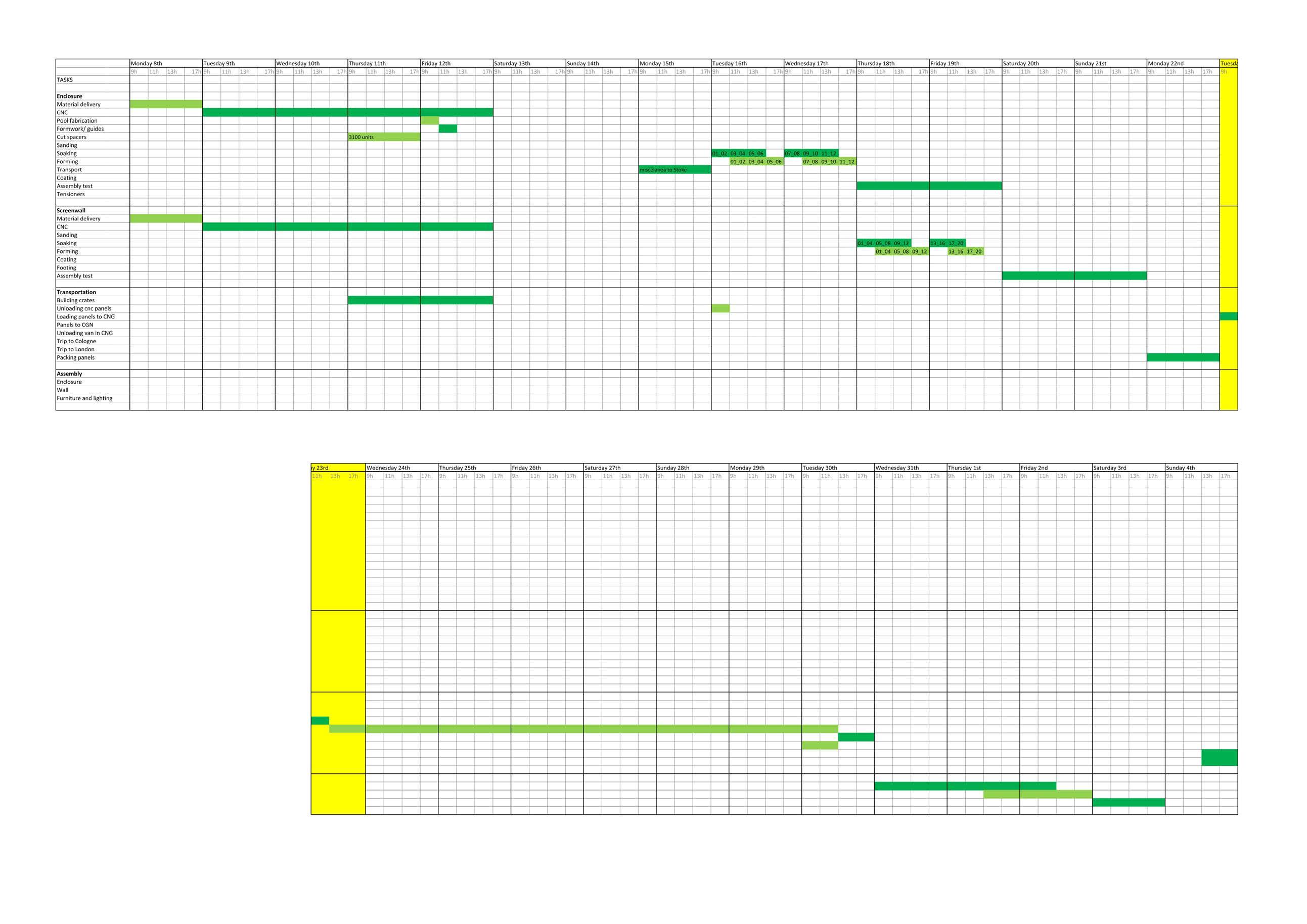


exhibition Wall fab-team
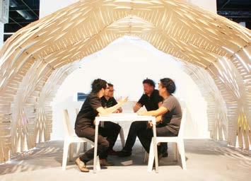
hooKe parK
jacob beK, nacho martí, pablo Zamorano, cesar martineZ, gabriel iVorra morell, yasaman mousaVi, sebastian partoWidjojo, shanKy jain, jeroen janssen, nico martí

enclosure fab-team
london fabrication
jacob beK, nacho martí, pablo Zamorano, jacK chandi
cologne assembly
nacho martí, pablo Zamorano, iVan ucros, sherWood Wang
photo credits
henrietta Williams
shanKy jain
camila rocK de luigi