

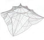
i Cover : An experiment conducted using a dynamic mesh relaxation algorithm (Authors’ Work)
COVERSHEET FOR SUBMISSION 2011-2012
PROGRAMME: Emergent Technologies and Design (EmTech)
TERM: Winter 2012
STUDENT NAME(S): Riyad J. Al Joucka, Jack C. Francis
SUBMISSION TITLE HYBIOS: HYbrid BIO-Structures
COURSE TUTOR Michael Weinstock , George Jeronimidis
COURSE TITLE Dissertation SUBMISSION DATE: 3rd February 2012

DECLARATION:
“I certify that this piece of work is entirely my/our own and that any quotation or paraphrase from the published or unpublished work of others is duly acknowledged.”
Signature of Student(s):
Date: 3.2.2012
HYBIOS_HYbrid BIOStructures explores the possibility of using innovative construction logistics that are the result of hybridization of materials and methods. The research mainly attempts to explore the potential of coupling free form tensile structure fabrication and compression-only shell construction methods, to simplify the building process of complex doublycurved concrete forms.
These forms are valued for the potential of creating interesting differentiated spatial qualities, obscuring the transition between structural and spatial elements resulting in a more coherent overall geometry.
For an online journal, Please visit: www.hybios.blogspot.com
To our parents, families and friends, without you we wouldn’t have made it this far.
Our deepest appreciation goes to all those who believed in the potential of the work presented, and its implementation in the professional practice of architecture.
We are immensely grateful to the Architectural Association as an institution that encourages free thought and excellence, in the pursue of knowledge in contemporary approaches and technologies in architecture. These incentives have provided a working environment that encourages self-development and has influenced our progression as academics and professionals immensely during a short period of time.
We are indebted to our Directors Michael Weinstock and George Jeronimidis for their ever so helpful guidance, and expansive knowledge of the topics relevant to the realm of research within this paper. To our visiting tutors Wolf Mangelsdorf (Buro Happold), Suryansh Chandra (Zaha Hadid Architects), Christina Doumpioti and Evan Greenberg, who were of great support with their continuous feedback and genuine interest in the subject. Sometimes even offering hours of their time to clarify doubts and explain new techniques and methods of working.
Acknowledgments go to our colleagues at Emtech who had never hesitated to offer their support in pursuing our endeavours. To Nicolas Leguina who have assisted immensely with computing problems. Julia Kroener, Jeroen Janssen, Sebastian Partowidjojo, Thanks for spending hours of your time away from your busy schedules out of concern to help us with continuing our work.
Special thanks to our material suppliers who, quite generously, offered their valuable contributions of new technologies and materials to be tested within our research. The companies who have sponsored us with their cutting edge products have helped push this research towards its materialization. Thanks to Andrew Ridout of Elasto-Plastic Concrete (Europe) for providing us with supplies of BarChip Fibres. To Simon Pearson, Managing Director of Jesmonite ltd. who offered their products without compensation, for the sake of testing these within our research. To Phillip Greer, Design Engineer at Concrete Canvas, for supplying this very promising material.
To the Emergent Technologies and Design program, which has been a great experience and an eye opener to pragmatic and logical thinking within the realm of innovation and advanced methods.
We dedicate this body of work as a knowledge base for continuing the research done on complex geometry construction with concrete.
JACK CHANDY FRANCIS
JANUARY 2012
CHAPTER 01/ DOMAIN
1.00 WHY RESEARCH IN MATERIAL SYSTEMS?------------------P.1
1.10|CASE STUDY / TYPICAL CONCRETE CONSTRUCTION---------P.3
1.11|MATERIAL SYSTEM RESEARCH AND INNOVATIONS-----------P.5
1.20|HOW CAN WE ACHIEVE COHERENCE-----------------------P.7
1.30|DIGITAL FORM FINDING AS A DESIGN STRATEGY ---------P.9
1.40|FORMFINDING/ PHYSICAL EXPERIMENTS-----------------P.11
1.50|FORM FINDING AS A DESIGN STRATEGY-----------------P.13
1.70|CASE STUDY/ MARK WEST+THE CAST TEAM---------------P.15
1.60|EXPERIMENTAL PAVILIONS AS TOOLS FOR TESTING-------P.18
1.80|RESEARCH/BarChip FIBRE----------------------------P.21
1.81|RESEARCH/SHOTCRETE--------------------------------P.23
1.82|RESEARCH/CONCRETE CANVAS--------------------------P.24
1.83|RESEARCH/JESMONITE--------------------------------P.25
CHAPTER 02/ METHODS
2.00|EXPERIMENT1.0+1.1/ CONTROLLING MATERIAL BEHAVIOUR-P.27
2.10|EXPERIMENT1.1/MANIPULATING MATERIAL BEHAVIOUR-----P.29
2.20|EXPERIMENT1.3+1.4/C0NTROLLING FORMFINDING PROCESS-P.30
2.30|EXPERIMENT 1.1-1.4/ RESULT ANALYSIS---------------P.31
2.31|EXPERIMENT 1.1-1.4/ RESULT ANALYSIS---------------P.32
2.40|DIGITAL EXPERIMENTS-------------------------------P.33
2.41|RHINO MEMBRANE FOR FREE-FORM FORM FINDING---------P.34
2.50|DIGITAL SIMULATION--------------------------------P.35
2.60|OPERATING IN FEEDBACK LOOPS+ALTERNATING METHODS---P.37
PROJECTIONS TO PROCEED FORWARD-------------------------P.38
3.00|ANA_HYBIOS 2.0/ FORM GENERATION PROCESS-----------P.41
3.10|ANA_HYBIOS 2.0/ METHOD CHOREOGRAPHY---------------P.44
3.12|MATERIAL EXPERIMENT/HYBIOS MUTANT-----------------P.45
3.20|DIGITAL SIMULATION OF CONSTRUCTION LOGISTICS--- --P.47
3.30|ANA_HYBIOS 2.1/ METHOD CHOREOGRAPHY---------------P.49
3.31|ANALOGUE PROTOTYPE ANA_HYBIOS 2.1/FORM GENERATION-P.51
3.40|ANA_HYBIOS 2.0 + 2.1 / PROSPECT ANALYSIS----------P.55
3.41|ANA_HYBIOS 2.0 & 2.1/SPATIAL+STRUCTURAL ELEMENTS--P.57
3.50|DIGITAL STRATEGIES/ SIMULATION OF NEW ELEMENTS----P.59
3.51|DIGITAL STRATEGIES/ SIMULATION TO ANALOGUE--------P.61
3.60|ANALOGUE PROTOTYPE ANA_HYBIOS 3.0/FORM GENERATION-P.63
3.70|RESEARCHED MATERIALS/ WALL ASSEMBLY PROPOSAL-------P71
3.71|ADVANTAGES + DRAWBACKS OF MATERIALS TESTED--------P.73
3.72|MEASUREMENTS + READINGS/ ELASTICITY & STIFFNESS---P.75
3.80|CONCRETE CANVAS ELASTICITY AND STIFFNESS TEST-----P.77
3.81|CONCRETE CANVAS TEST/ HYDRATING CONCRETE CANVAS---P.79
3.90|HYBIOS 3.1- FORCES ON 3 MEMBRANE LAYERS-----------P.81
3.91|ANALOGUE PROTOTYPE ANA_HYBIOS 3.1-----------------P.83
3.92|ANALOGUE PROTOTYPE HYBIOS 3.1 METHOD CHOREOGRAPHY-P.86
4.01|PROTOHYBIOS CC 2.0 / CONCRETE CANVAS SHELL--------P.89
4.02|PROTOHYBIOS CC 2.0 / CONCRETE CANVAS SHELL METHOD-P.91
4.10|PROTOHYBIOS CC 2.0 / CONCRETE CANVAS SHELL METHOD-P.93
4.20|TESTING CONCRETE TROWELLING-----------------------P.95
4.30|ANALOGUE PROTOTYPE ANA_HYBIOS 3.1/FORM GENERATION-P.97
4.40|FINITE ELEMENT------------------------------------P.99
4.50|CONCRETE SLAB TESTING----------------------------P.101
4.51|CONCRETE SLAB REINFORCEMENT----------------------P.102
4.52|DEFLECTION TESTS/CONCRETE REINFORCEMENT----------P.103
4.53|DEFLECTION TESTS/CONCRETE REINFORCEMENT----------P.104
4.54|DEFLECTION TEST/CONCRETE REINFORCEMENT-----------P.105
4.56|DEFLECTION TESTS/RESULTS-------------------------P.109
4.70|MODELLING CONSTRUCTION LOGISTICS-----------------P.110
4.60|TESTING MESH AS A FORMING AND REINFORCING AGENT--P.115
4.61|MESH FORMING METHODS-----------------------------P.117
4.71|DISASSEMBLING THE CONSTRUCTION SCAFFOLDING-------P.119
4.80|JESMONITE ON FABRIC FOR FORMING------------------P.123
4.90|FINAL WALL ASSEMBLY------------------------------P.125
5.00|THE NEED FOR DEVELOPMENT IN CONCRETE INDUSTRY----P.130
5.10|CURRENT PROJECT: TAICHUNG OPERA HOUSE------------P.132
5.20|DIGITAL PROCESSES FLOWCHART----------------------P.134
5.21|QUANTIFYING THE GEOMETRY OF ELEMENTS-------------P.136
5.30|HEIGHT TO AREA RATIOS: PERCEPTUAL THRESHOLDS-----P.138
5.40|OPENING SIZE/COMPARISON TO A CONVENTIONAL SPACE--P.140
5.41|INTRODUCTION OF PROGRAM + PROPORTIONS------------P.142
5.50|LIGHT MODULATION WITHIN CONICAL FORMS------------P.144
5.61|DigiHYBIOS1.1+1.2TESTING CHANGES ON THE EXTERIOR-P.148
5.70|MODULATION STRATEGY/ STACK EFFECT----------------P.150
5.72|MODULATION STRATEGY/ANALYSIS ON EXTERIOR---------P.152
5.80|DigiHYBIOS2.0/LIGHTING EFFECTS ON EXTERIOR-------P.154
5.81|DigiHYBIOS2.1/FEA ANALYSIS OF THE RESULTANT------P.155
5.90|DigiHYBIOS 2.1/EMERGING SPATIAL CONDITION--------P.158
6.10|CHOOSING THE CLIMATIC REGION---------------------P.166
6.20|OBSERVING THE SOCIO-ECONOMIC MICRO ENVIRONMENT---P.168
6.30|PROCESSING A PROGRAM GENERIC TO THE SYSTEM-------P.70
6.40|GENERATING PRAGMATIC CONNECTIONS-----------------P.172
6.50|ORIENTING FOR MODULATION-------------------------P.174
6.60|RUNNING THE ALGORITHM----------------------------P.176
6.70|DETAILS/ OPENING ENCLOSURES----------------------P.178
6.71|DETAILS/ SEATING PODS----------------------------P.180
6.80|FILE TO FACTORY PROCEDURES-----------------------P.182
6.90|GENERATED ITERATION/ PROGRAMMATIC PLAN-----------P.184
6.91|GENERATED ITERATION/ PROGRAMMATIC SECTION--------P.186
7.10|COHERENCE IN THE SUM OF PARTS--------------------P.204
7.21|CONSTRUCTION LOGISTICS/--------------------------P.206 GROUND FORMING
7.22|CONSTRUCTION LOGISTICS/--------------------------P.208 FABRIC MEMBRANE TENSIONING
7.23|CONSTRUCTION LOGISTICS/--------------------------P.210 FABRIC RE-INFORCEMENT
7.24|CONSTRUCTION LOGISTICS---------------------------P214 SHOT-CRETE APPLICATION
The fluidity of concrete as a material, coupled with the flexible workability of its forming process, has lead to innovations in architectural design throughout history. The aim of this dissertation is to go beyond current practices of using concrete in the built environment to enable the construction of complex geometries analogous to the coherence of structures found in nature. State of the art materials related to concrete construction, and cutting edge computer simulations are utilized in the research, creating a constant feedback loop between qualitative analogue prototypes and information-rich computer models.
Many attempts have been made by previous scholars to generate architectural forms that mimic structures found in biological systems. Only few works have portrayed that the form finding methods utilized at the beginning of the design process have been carried through with enough rigor to the construction phase.
Experiments done in casting concrete have been mainly focused on producing modular units that, when aggregated, achieve an envisioned spatial quality. The development of these processes has been restricted to a form work that is confined within the boundaries of an orthogonal frame, hence limiting the generation of inventive spatial qualities. The study at hand proposes a solution that offers a higher degree of flexibility within the design process.
Our research is aimed towards the generation of novel spatial and architectural elements of an architectural enclosure using innovative fabrication systems pertaining to the structural domains of tensile membranes and concrete construction.
The work is focused on experimenting with the notion of coupling digital and analogue form finding methods with construction aware thinking to generate innovative processes of constructing novel tectonics and spatial qualities.
The development of material systems has always been a primary driver for the ambitious search of novelty in formal explorations in architectural design. Concrete has been a specifically interesting material to develop, due to its fluid and flexible nature. The processes made available by current building construction advancements gave rise to a whole new range of possibilities for using concrete as a building material. However, most of the methods previously experimented with have many restraints, especially with creating ecologically feasible geometrically elaborate tectonics.
Developments in digital design enabled architects and designers to envision complex geometries that could be tested for spatial and structural qualities at the design phase.
The aim of the material exploration is to create a base of knowledge on the different properties that concrete could inherit when used in different constructions processes, and when paired with different constituents and composites. The material experiments are set as means to produce articulate spaces composed of coherent building components, that have the transitional qualities of anatomical structures found in nature.
The informal complexity of structures found in nature is derived from simple processes and starting elements. These methods are seen as an inspiration to create simple means of construction that could be carried out by translating a set of instructions to forces that could generate a shape change on the material. Complex spatial qualities and structural elements are hence seen as a resultant of these simple procedures and inexpensive materials.
Material science is an ever-growing field. The advancements made in this field have opened possibilities for architects and designers to construct computer generated designs that have been rendered impossible to realize previously. Exciting new products such as Concrete Canvas (CC) has opened a whole new range of possibilities of imagining spatial qualities.
Additionally, Spray-on concrete (Shotcrete) is widely used in the construction industry today as means to avoid form work and increase efficiency. Pneumatic projection at high velocity onto a surfaces allows compaction and high compressive strength. Additives, admixtures, fibres, curing agents and reinforcement enhance the strength and workability of Shotcrete.
Form finding has been used as a modelling tool to structurally optimise formal explorations at the design phase. Many architects and scholars have experimented with translating the methods and geometries generated by form finding at the design stage, to constructed edifices at full scale. Most of these experiments have failed, mainly because the material behaviour does not scale up with the geometry.
Digital form-finding simulations aid in numerically-quantifying the form finding processes, while embedding material behaviour to output accurate formal results and structural analysis of the forms produced. Enhancing the generation at the design phase, saving time and effort while prototyping. Today’s generation of architects and engineers are armed with an arsenal of quantitative digital tools, that approximate, accurately, the numerical properties of spatial qualities derived from form-found analogue prototypes.
The studies done in the material exploration stage within this book revolve mainly on creating a feedback loop between computer simulated forms and geometries, and analogue prototypes.
These models mainly test the potential of hybridizing tensile membranes coupled with compression handling materials, to eliminate the need for building the substructure required to support tensile tent enclosures. In this case, the ‘substructure’ is envisioned as a form work that could be re-used to cast a different part of the edifice. These membranes are hardened with compression handling materials that help in keeping these enclosures in equilibrium, and creating a skin that modulates the conditions of their interiors.
Quality-rich prototypes help in progressing the ideas of the construction methods, and the spaces generated when these methods are carried out. While quantity-rich computer simulation is constantly updated to provide more accurate information, reinforced with data from the material behaviour and the structural capacity of the geometries produced.
Architecturally, the building method of the study lies in creating spatial fluidity. Transition between traditional architectural elements in contemporary architecture such as the column, arch and wall is envisioned to be of a smooth variation to create a fluid movement within the spaces. The force load distribution will then be optimised to ensure these elements are in an equilibrium state. Program and circulation are also seen as input parameters for the generation process, adding an element of pragmatism to the generated structures, along with immediate environmental conditions as a driver for ecological building models.
Ottawa/Canada
London/ UK
Kerala/India
Amman/JordanAnalogue Form Finding
Digital Form Finding Computation
To further explain the purpose of our exploration in the course of this research, it might help to introduce our backgrounds. The authors of the research at hand, Riyad Al- Joucka and Jack Chandy Francis, are two architects from two cities in different parts of the world, both rich in history and culture.
Riyad Al- Joucka is from Amman, the capital city of Jordan. He attended his undergraduate studies in Carleton University in Ottawa/Canada where he graduated with distinction in 2009. He worked in Amman for the following year, and attempted designing for machine-based fabrication, using simple digital and mechanical tools, to simplify the complexity of creating novel architectonics within the limitations of his region.
Jack Chandy Francis is an Indian architect. He is based in town of Kerala in the South of India. Francis graduated with distinction from the Sathyabama University, Chennai. He worked for several years with InForm Architects, Bangalore, India under architects Kiran Venkatesh on projects ranging in budget and scale. His training revolved mainly on managing construction sites, where he gained expertise in working with construction processes and materials at a very close range. Francis is particularly interested in material science, and its role in improving simple construction logistics.
Observing the construction industry in Jordan and India, reveals how the industry is based on outdated methods that have been long followed by architects, contractors and builders. Third world countries have often been known, as a place where labour is cheap, and widely available, while high precision and expertise is expensive.
Our original drive of pursuing a dissertation on Material Systems at the Emergent Technologies and Design programme at the Architectural Association School of Architecture in London was to bring back our findings to our countries, to benefit these countries, by attempting to inject the avant-garde technologies of architectural design and construction in the fabric of our cities. Such objectives, however, have to be met using simple procedures to be applied in third world countries. Complexity, has to emerge merely as a result of these procedures and their assemblies.
Due to the complications of contemporary architectural expression and technological limitations in these countries, novelty is unusual and contractors habitually dismiss design solution that step beyond the confines of the mundane. This resulted in the increasingly pitiful scene of the young local architects ambition of novelty staying within the boundaries of drafting boards and computer screens. The overall result is a monotonous fabric of modern cities that speak nothing of their inhabitants’ culture or ambition. Cities that are constructed with outdated methods that are often excessive and unsustainable.
Consistently throughout our research, we felt the genuine interest from different individuals within the coverage of our connected network, in the problem we are trying to solve. The help of young professionals of different backgrounds helped us especially with bridging the gap between design and construction.
Construction Logistics
Material Science Analysis
Jack Chandy

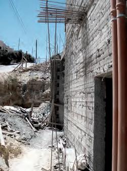
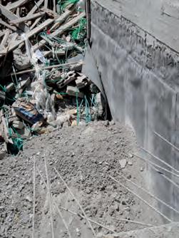
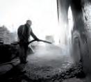
A site visit to a small-scale construction site was carried out in Salt/Jordan in the Middle East. The visit was an eye opener to the typical construction practices concerning concrete, which are carried out in third world countries. Although the construction methods observed were neither cost effective nor efficient, these methods are the norm in countries in the region.
GENERAL DATA
BUILDING TYPE/ Residential Villa
LOCATION/ Salt / Jordan
NUMBER OF SKILLED LABOURERS/ 20
CONSTRUCTION TIME/ 1 Year 8 Months
REMAINING CONSTRUCTION TIME: 1 Year 2 Months
ESTIMATED COST OF STRUCTURE: 1.145 Million GBP
TOTAL AREA OF STRUCTURE: 2100 M2
MATERIALS

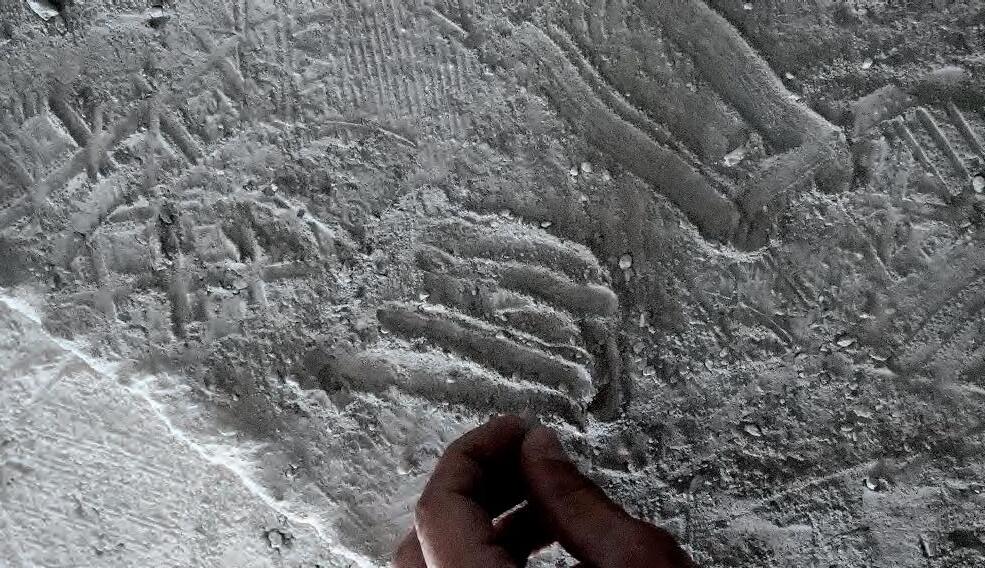

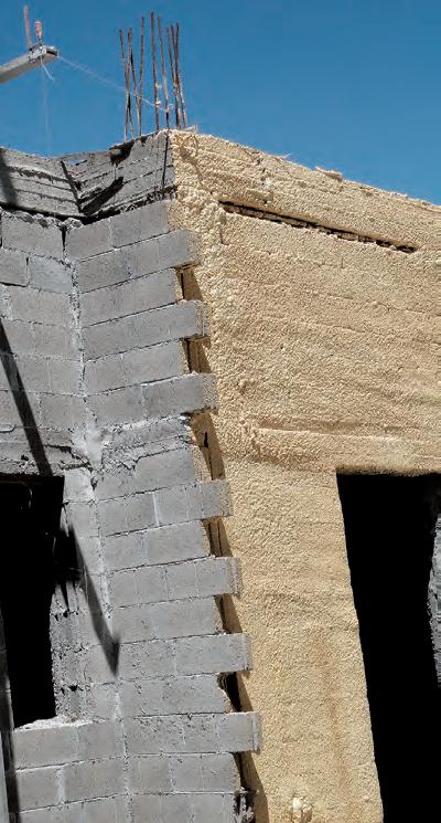
The constructed structure used higher than average material qualities. The following wall section shows an exterior wall, with a thickness that is more than 60 mm. The wall section is not of a typical wall within the structure, but the thickness is shockingly and unnecessarily massive. Excessive use of material is observed, mainly to safely optimise structure and to achieve higher R-values.
Concrete block/ casting / Finishing
Polyurethane sprayon insulation
Concrete Block
Butterfly Joint
Painted-on Waterproof Backing
Stone Cladding
Air Gap
Air Gap

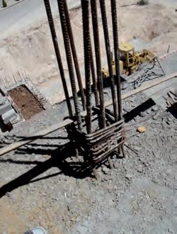
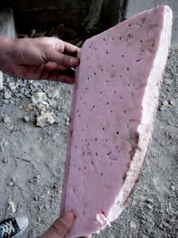
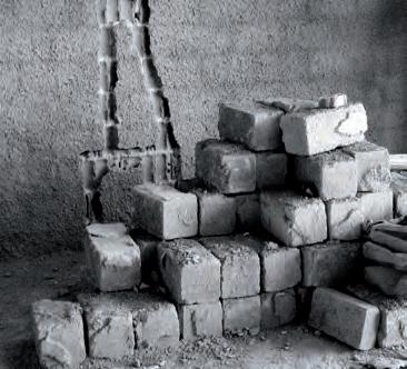
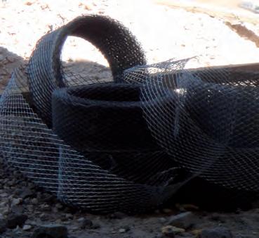
Although skilled workers are often experienced with these methods, and can perform most of these rather quickly, innovation sometimes comes to play when less conventional forms have to be constructed, such as curved walls. Tools and methods are then customized to specific building problems faced on site. In general, it was noted that construction time lines are often halted with mistakes, injuries and malpractice.
Wooden concrete form work is used to cast the concrete structure. The form work is generally re-used, but most of the wood used for casting deteriorates due to malpractice and weathering. The method produces and inevitable amount of waste, even when the wood is reused to a certain extent.
The case study is recorded as a counter thesis for the construction method presented in the thesis at hand. Proving that most of these problems can be solved with the presented method, even though labourers have to be trained to master new techniques.
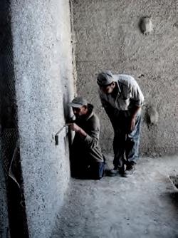
a- Levelling walls using a straight edge and marks made within the concrete.
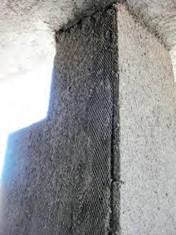
b- Mesh strip applied where ever two different overlapping materials are used.
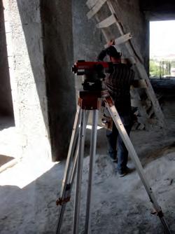
c- Auto Level used to read levelling values to achieve higher accuracy.
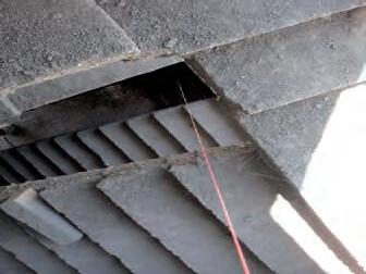
d- Thread used for achieving a consistent straight line through floors.
e- A steel tool custom developed to achieve consistent curved plastering.


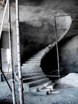
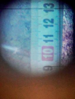
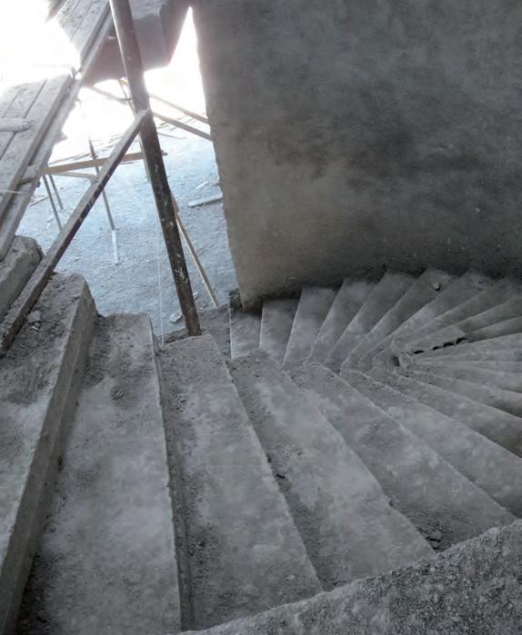
Observing the traditional practice in the Middle East raises the question of what affordable materials are used in the industry to achieve a higher standard of less consuming processes. Materials and processes are constantly under development and looking into some of the relevant current projects under research helps formulate a new construction method under these conditions.
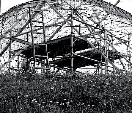
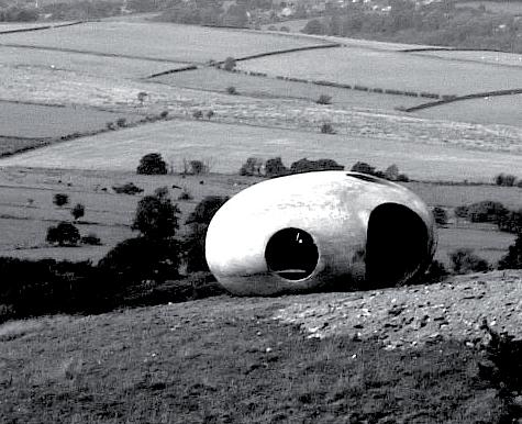
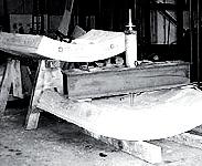
The Atom is one of three community sculptures placed atop three hills in north east Lancashire. It was designed by Peter Meacock with Katarina Novomestska and Architects (WCW) in 2007. It is a viewing shelter with the holes strategically placed to get the best view of the surroundings. The method of fabrication used in the process is very interesting. The form is replicated in reinforcement and concrete is sprayed onto it. There is no form work and thus a huge amount of labour has been cut down. This could be a possible solution in moving towards our goal of removing form work in concrete structures.
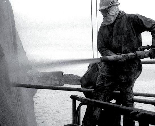
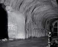
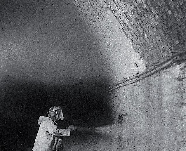
BarChip Fibres are manufactured from high tensile strength modified poly olefin and is similar to steel re bar in having embossing to improve the bond between cement and aggregates. They can be batched with concrete and sprayed on to surfaces. The physical properties of BarChip fibre match that of steel except for the fact that it is a short fibre. The material does not oxidise in any conditions that cause rust in steel and thus is safer. BarChip fibre reinforced concrete is currently being used in precast panels, tunnel reinforcements and plenty of other applications as a replacement to steel reinforcement, due to its capacity to withstand constant humidity The images show few applications of BarChip fibre. This material will be studied in detailed for it structural properties and ease of handling during the material experimental stage.
The images describe the deployment of the concrete canvas shelter, which is 54 sq.m in area in less than 24 hours. The complete shelter is packed and brought on site in a bag. Air is filled into a bag inside the kit using a compressor and this deploys the form. The fabric is hydrated and the concrete hardens in less than 24 hours. This material makes the concrete construction process much easier and reduces the labour by a great extent. Experiments have to be conducted to understand the material in detail and to evaluate its relevance in the dissertation.
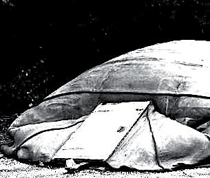
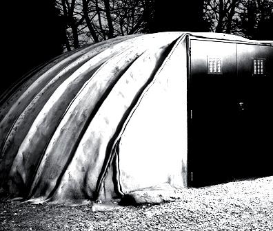
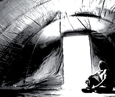
“The house was a room, which though shielded from nature, was characterized by the natural conditions…the modern house has almost completely lost this relationship with its environment. (Frei Otto-IL23 P 125)
The example of a construction site of a villa seen in Salt, posts an alarming threat of the shadows of modern architecture’s influence on its surroundings. The example shows one of many examples of artificial environments, which neglect the cultural and ecological value of immediate surroundings. Such buildings are fuelled by the excessiveness, even in scarce conditions.
Humans have an undeniable effect on their surroundings and environment. Ever since man started affecting his environment with man-made inanimate objects, He has been eager to improve the technologies involved in creating these objects. (Frei OttoIL23 P 125)
Such technologies are often related to limitations, especially within the realm of scientific advancement. The desire for advancing the tools and processes used to re-evaluate the processes involved in the construction industry hence becomes relevant, and inseparably entwined with the overall ambition.
According to Frei Otto, technology is part of nature, in the sense that natural limitations and the laws of physics, all affect technological systems. To derive to a more natural building method that is truthful to the ecological building of the future, one must turn to nature. The search for innovation in the architectural design domain has often lead to nature as a reference for in its minimal is tic distribution of energy and matter. Modernism as characterized by the Miesian ideology, generally allowed for the simplification of building system, while neglecting material behaviour. Where geometry informs matter, forcing it to ‘form’.
“When freed from such essentializing conceptions, matter has its own capacity for self-organization.”
(Reiser+Umemoto- Atlas of Novel Tectonics P.89)
Hybridization of structural elements and systems can be found in many examples of natural formations. Architects now can deploy current technologies in design and fabrication to derive to ecological building methods. (Reiser+Umemoto- Atlas of Novel Tectonics P.51)
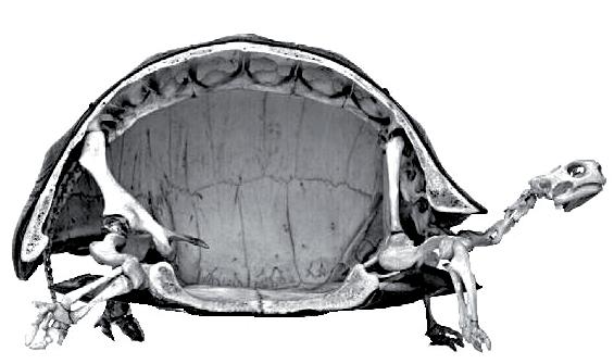
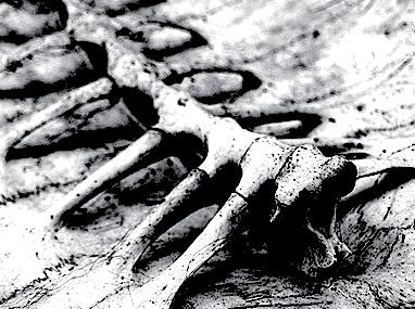
In order to reach coherence, we pursued consistent methods to reach our main ambitions. Starting from observing historical precedents to Anatomical Analogy in Architecture Man-made environments have always strived to achieve optimization in performance, time and effort to overcome physical restraints. Hybridization of structural elements and systems can be found in many examples of natural formations. Where matter is ‘self-organized’ to achieve optimal form.
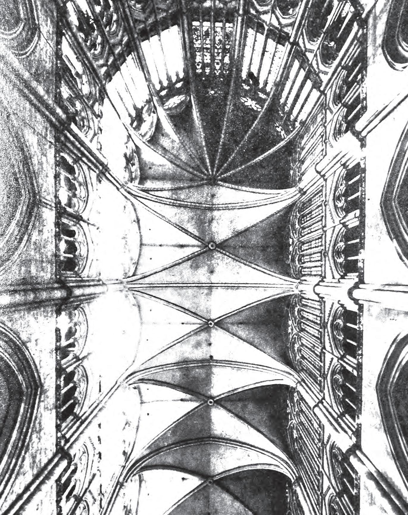
The ribbed vault of Gothic cathedrals approaches the single system ideology, where elements correspond to force patterns, and aesthetic elements have functional values all their own. Philip Steadman speaks of the ‘Anatomical Analogy’ in design by giving the example of Gothic Rationalism architectural style.
Observing biological forms such as the interior structure of a turtle shell reveals how the shell itself is partially a surface-based (shell) exoskeleton and partially a frame-based (non-shell) endoskeleton. The smooth gradient between radically different types of structural systems offers possibilities for new architectural hybrids, which can respond to a wider range of force patterns and facilitate the generation of single-system spaces.
The research attempts to take the anatomical analogy of the turtle shell as a preliminary driver for our themes and ambitions. Looking at the turtle shell as a geometric organisational scheme of materials that optimise to transfer forces. Leaving material choice and methods of forming for exploration, as the main interest point.
We propose, as an alternative to current excessive modernist practices of construction in our countries, a building model that relies on simplistic systems of organization as found in nature, a system that generates complexity by following simple procedures.
We propose set of construction logistics, or codes, where coherence is the resultant of a smooth transition between building elements. These qualities can be achieved by choosing scale-wise materials and a simple code of methods, within the laws of physics and immediate restrains, to achieve natural qualities in the built environment.
Hybridization of structural elements and systems can be found in many examples of natural formations. Architects now can deploy current technologies in design and fabrication to derive to ecological building methods.
As explained previously, common practices in design and construction of buildings have many flaws that could be avoided. The argument stays bound to methods carried out on a small building scale, in a less-developed region in the world. However, the aim of this research architecturally, is to aspire to an iconic cultural building of a larger scale.
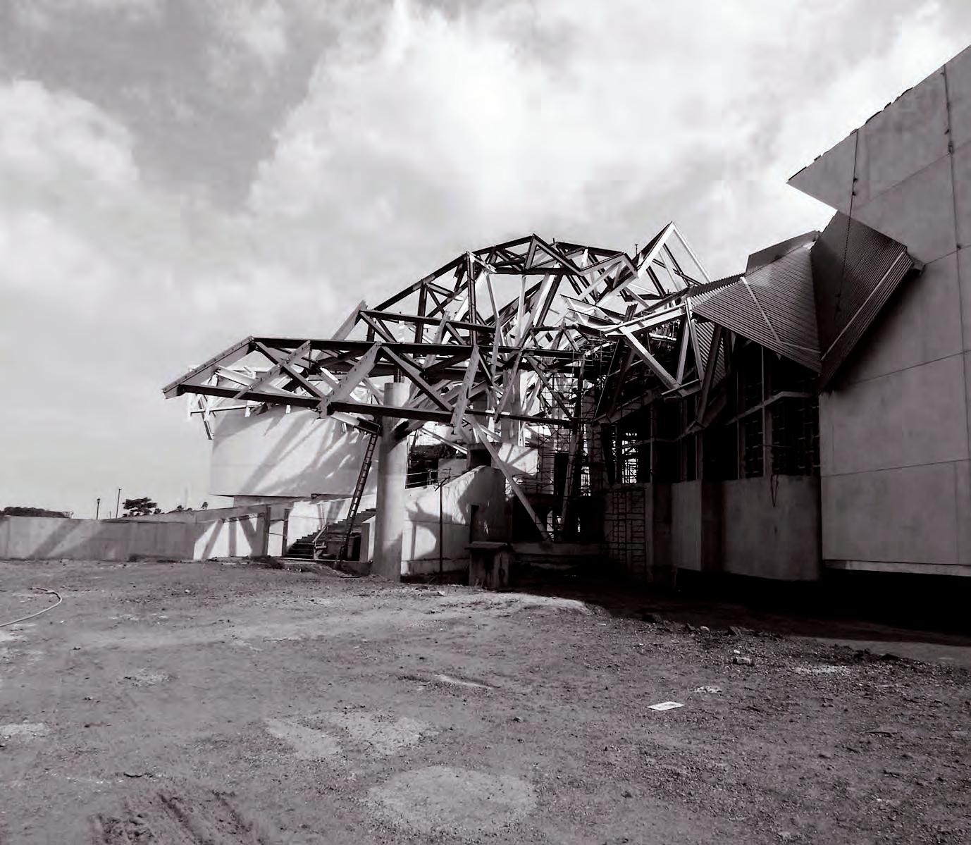
The argument can also be made on observing the novel structural solutions in these buildings that result in awe-inspiring spatial environments, where construction was carried out in cutting-edge standards using the latest of the technologies of their time. The spaces generated for these buildings usually seek for originality in formal expression, due to the larger budget and the cultural importance of these buildings. We recall the Natural History Museum building in Panama by Frank Ghery, Where structure is shaped by adding material to optimise for geometrical and formal expression. The materials are piled up in this case and excessiveness is show cased as an expressive statement.
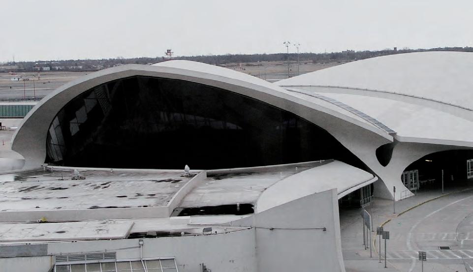
A less recent precedent is the Terminal 5 building by Eero Saranien for the JFK airport in New York. The building utilizes a concrete shell building system, a similar material system that the research at hand is examining. The concrete shell system examined in Terminal 5 is special in the sense that such a structural system was revolutionary at the time of its completion in 1962. The revolutionary structural system resulted in an unprecedented spatial condition, where coherence of the structural elements is the generator of that condition.
However, a more sustained practice could be explored for constructing such structures, especially resolving the difficulty of creating the form work and The excessiveness of material use to achieve structural stability. The material system to be explored has to solve these problems at such a scale, to optimise material use for structural stability, which results in spatial innovation. Aided by current material and design technologies, we aim to solve these problems using current materials and methods.
To use computer simulation to its full capacity, these simulations should be used to model physical properties to create optimal forms. Most practices use computers to simulate spatial qualities, where eventually materials are used in an excessive manner in the construction phase to create structural stability while achieving these forms.
B.Sc.,M.Sc.inEngineeringSciences–Architecture VrijeUniversiteitBrussel,2003
S.M.Arch.S.inDesignandComputation/BuildingTechnology MassachusettsInstituteofTechnology,2005
SubmittedtotheDepartmentofArchitecture inPartialFulfillmentoftheRequirementsfortheDegreeof
DoctorofPhilosophyinArchitecture:BuildingTechnology atthe
June2009
c 2009MassachusettsInstituteofTechnology. Allrightsreserved.
SignatureofAuthor:
Certifiedby:
Acceptedby:
In order to proceed with digitally analysing analogue form finding productively, we looked at previous research done on digital form finding as a method for verification of analogue prototypes.
Philippe Block explains that methods of form finding lead to optimal and often simple methods of construction, where materials can be calculated at the correct scale to observe their behaviour in certain forms.
To understand how physical forces could be an input data in computer simulation, one could recall the concept of the catenary, where gravity acts on material to distribute its form in a way that makes the material behave as an optimal arch when inverted. The origin of shell structural logic, where an arch is repeated to create vaults which in turn have the potential to achieve more complex and more structurally stable funicular enclosures.
“...Technological and computational developments resulted in an explosion of formal explorations in architectural design, and made it possible to generate new, and complex shapes, regardless of their structural stability.” (Philippe Block- Thrust Network Analysis)
Philippe Block introduces the thrust analysis network as a network of forces calculated using digital tools for the quantification of complex funicular design, where forces are discretely organized around vertices. Block praises the curved nature of funicular brick shells and concrete shells these shapes are optimal for load transfer and the spatial coherence we aspire towards. (Block 2009) It becomes clear after reading Block’s theory on technological advancement in digital analysis of form finding for funicular design. There are many precedents for funicular design. The main aspect, which is missing in all the discussed approaches, is the balance between control and freedom in these methods. (Block 2009)
DepartmentofArchitecture May1,2009
JohnA.Ochsendorf AssociateProfessorofBuildingTechnology ThesisSupervisor
JulianBeinart ProfessorofArchitecture Chairman,DepartmentCommitteeonGraduateStudents“There is a need for interactive three-dimensional equilibrium methods which offer control and flexibility to the designer, and which allow the user to understand the interdependencies of the hard constraints enforced by gravity.” P.40 However, Block’s form finding method relies of vertical forces for a an accurate calculation of arches and domes of funicular shells. It is bound by a structural problem to solve rather than a more spatial one. To enable a more versatile digital form finding method research deploys mesh relaxation to respond to a greater range of force, to approximate spatial analysis primarily and not structural one.
“Pneu (Greek : Pneuma = air) as an all-embracing term for a structural system which can be clearly distinguished from many other systems and which has particular characteristics” Frei Otto.
In the Pneu and Bone , Otto states that one of the most efficient technical structural systems is the pneu. A pneu is a structural system consisting of a ductile envelope which is capable of supporting tensile stress, is internally pressurised and surrounded by a medium. The pneu allows forces to transferred over considerable distances with a minimum use of materials , and extremely wide span structures to be erected.
Pneu is the structural system of the living nature.
“Pneu as a structure used to transfer forces and also as an agent for form generation.”
Whenever parts of such objects solidify and become hard like the carapaces of a single cell organisms(eg: radiolaria) like the wood of plants and the shells and bones of animals (shells of insects, internal skeletons of vertebrates). These components are rigid and take compressive loads. These structures are no longer pneus but retain the shape of the pneus from, the structural pneu system is always preserved in principle. It represents the active and living part, whilst the hardened parts maybe regarded as non living or at least less alive substance which can also have load bearing functions. They evolve as pneus , harden in that shape and become other structures such as structural members, skeletons, or shells or in brief: they become non- pneus in the form of structural members, beams and shells. Maybe its through selection from an infinite number of mutations and environmental factors.
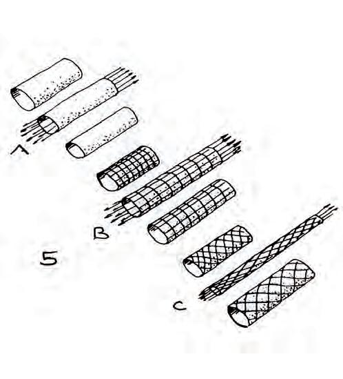
Most objects in living nature can be regarded as three dimensional fibre nets with varying mesh sizes. In most cases however the mesh size in the outer fibres is smaller thus creating high tensile areas of closely spaced fibres which act like fine nets or membranes.
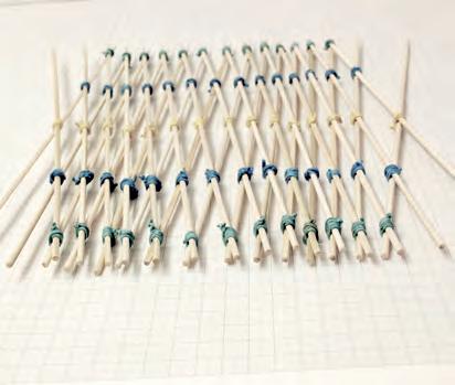
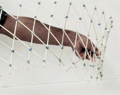
As a first attempt to realize a physical interpretation of a pneu net, the team constructed a lattice of bamboo sticks connected with rubber bands. The lattice system has the flexibility to deform to several surface geometries. However, a more flexible system of materials has to be devised. A system that allows the hardening of the membrane with different compressive materials at different scales. An elastic mesh with a large deformation capacity and high tensile strength has to be used as a Pneu.
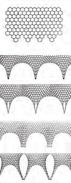
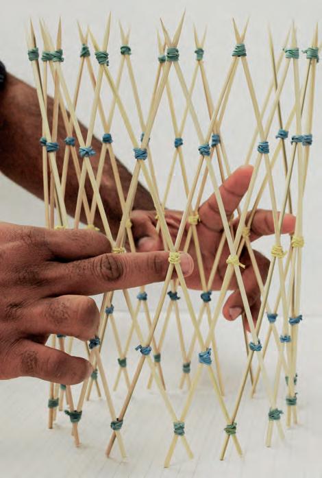

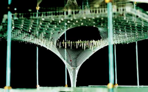
In order for architects and engineers to understand how force flows in shell and membrane structures, many attempts have been done in the past to model the behaviour of materials by applying natural and artificial forces on them. These models could offer an approximate quantification to the force distribution of gravity for example. Natural forces affect materials differently in different scales, however the material’s reactions to these forces could help foresee their geometric structural behaviour in construction.
In a catenary, the force of gravity acts upon the catenary chain, to distribute its links towards a curved geometry, which depends on the distance of the fixed end points. When inverted, the catenary resembled the geometry of an arch in equilibrium. Salmon, George (1879). Higher Plane Curves. Hodges, Foster and Figgis. P. 287-289.
Many architects sought interest in the concept of the catenary, especially Antonio Gaudi, who used the model as a simulation for the construction of some his most impressive neo-gothic cathedrals(Fig 1.40.3). Frei Otto used several different methods for finding optimal forms for the tensioning of net structures such as the ones he did for finding the form of the Stuttgart Station(Fig 1.40.4). In contemporary design, some catenaries were used as an aesthetic feature, such as the one shown of Parades Aleman which was used as sculptural gesture in a building reception hall.
Axel Killian suggests a digital analysis tool to verify funicular shells and structural arches. In his paper entitled “Particle-Spring Systems for Structural Form Finding”, Killian talks about catenaries and hanging chain models as methods to quantify the geometries of load bearing shells and lightweight structures to optimise their shapes for structure.
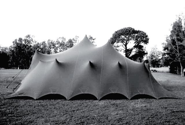
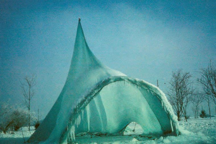
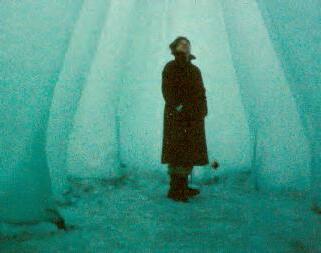

“Tensile membranes attain stiffness if forms allow for membrane stresses to effectively equilibrate the external loads. This requires a double curvature that is anti-clastic in the case of mechanically Stressed membranes.” (Innovative Surface Structures: Technologies and Applications-Martin Betchold)
The iterative shaping process of tensile membranes adds an interesting discussion, especially on the potential of creating smooth spatial transitions with membrane materials. Form finding methods could be thought of as “three dimensional thinking tools’ Martin Betchold, where form could be derived from tensioning membranes to their optimal stiff geometry.
Free form tensile membrane structures are used frequently as an efficient, lightweight option for temporary installation spaces, tents and pavilions. We see benefit in further solidifying theses free form structures once tensile stiffness has been attained, to use them as structural walls, with smooth spatial transitions.
As shown by some experiments by Heinz Isler, some attempts have been done in the past to literally ‘freeze’ tensile membrane structures, to remove the supporting columns underneath. These structures then attain the behaviour of shells, in how load is transferred through their geometries. Compressive materials such as concrete, seem to behave well in compression and could aid in making such enclosures self-structural.
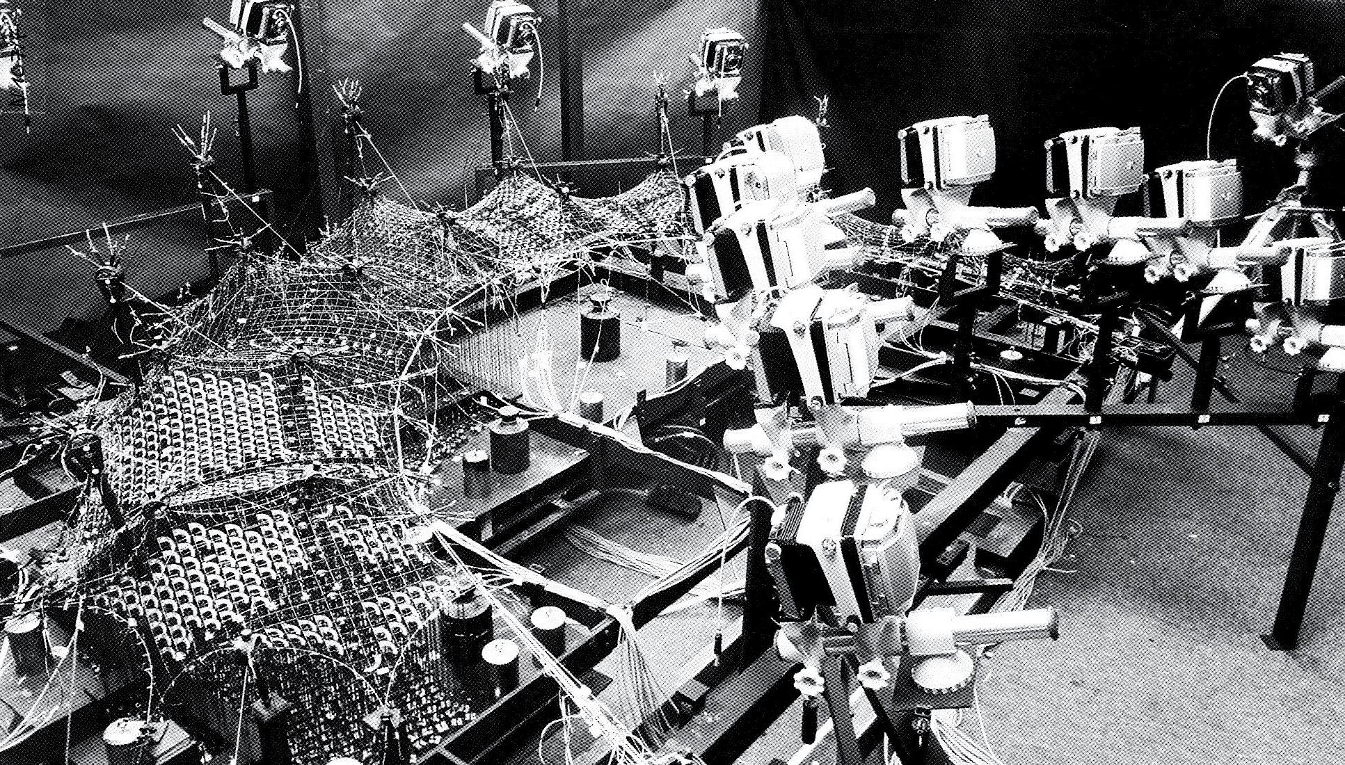
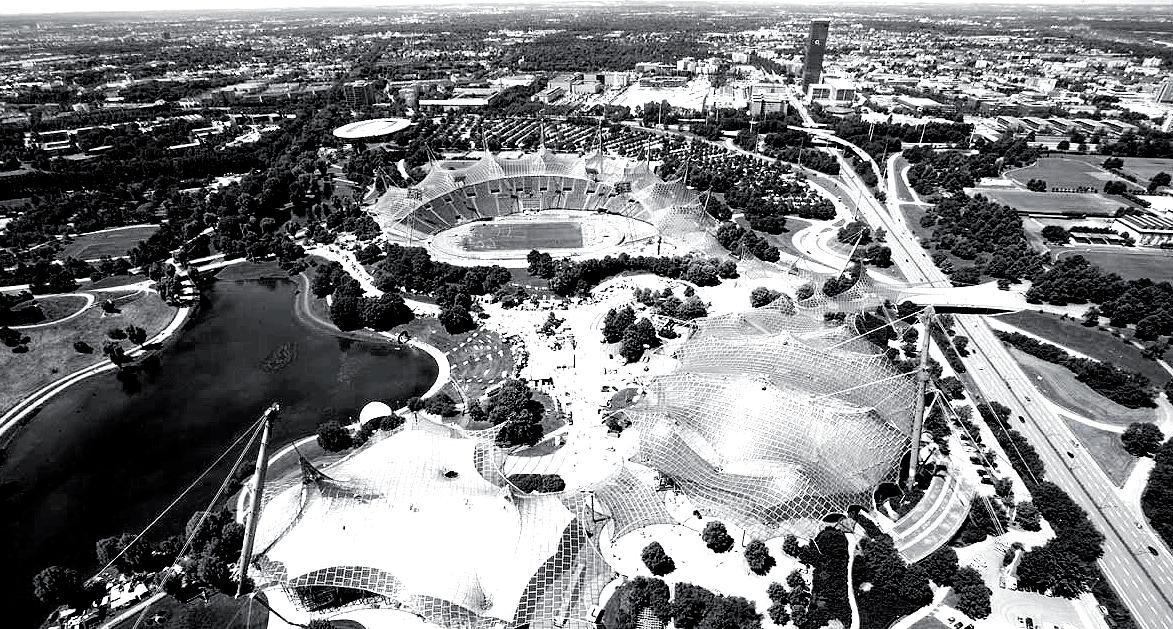
The Olympic roofs project in Munich was completed in 1972. The design test employed by Frei Otto and his Team at the Institute of Lightweight Construction is a fine example of deploying physical models as a strategy of optimization. The model shown was constructed in similar logics and materials that were scaled down to test the tensile membrane for loads. The loads were measured and added to the model, which was photographed using special cameras. Aided with simpler and more accessible methods of analysis that are the result of current technological advancement, architects today can improve on the methods used by Otto and his team.
EXPERIMENTATION AS A DESIGN GENERATOR
As the research progressed, experimentation as a tool for architectural design was explored further. Frei Otto’s form finding methods for finding optimised structural solution, were utilized as a first steps to constructing some of his innovative designs. For example, Otto used his eye cable model as a start for the design and construction of an experimental cable net structure in the University of Stuttgart Vaihingen in 1966. The structure was erected as a test for Otto’s design of the Montreal pavilion, which consists of 460 Sqm of a spatial enclosure. (Finding Form- Frei Otto P. 100)
What is interesting about the experimental pavilion is that the people using it liked the interesting spatial quality that emerged as the result of that condition. The tensile net structure was later clad with an insulating membrane and finished in timber panels. The structure was used later dismantled and used to house the Institute of Light Weight Structures. (Finding Form- Frei Otto P. 102)
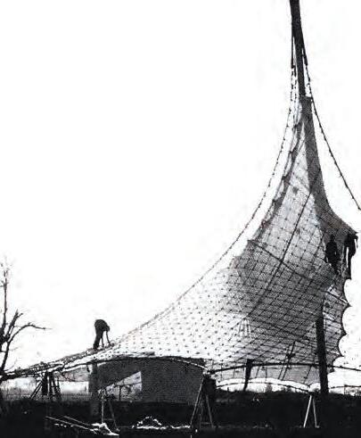
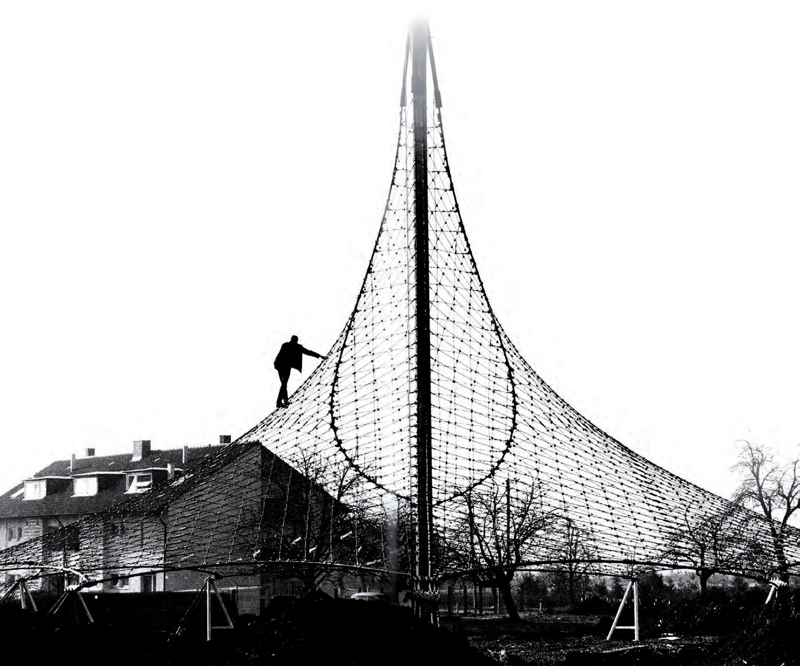
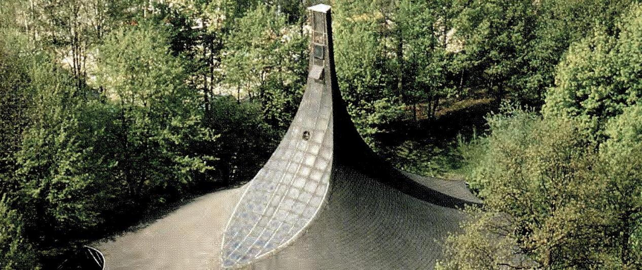
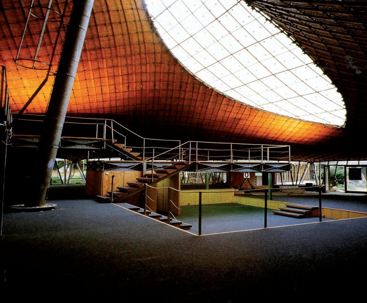
This precedent is brought to the argument to comment on the experimental nature of building structures of that scale as a tool to innovate in architectural design. In this case, the tensile net cable was covered with materials to act as a hermetic enclosure as well. The research aims for a more coherent system, where structural elements, functional parts of the building and the material systems used for cladding are part of a single system.
In the case of Otto’s experiment, the result is defragmented in many ways, due to the subsidiary structural system that holds the membrane up, and the ad-hoc nature of the cladding materials to create a sheltered space. Despite the innovative nature of such experiment regarding the time of its construction, many of the methods used in this example could be enhanced using current technologies and materials.
The result is a spatial solution where the roof is an interesting feature, but the ground level is fairly monotonous and is clearly following a different language formally. Coherence is lacking in the overall spatial quality and fairly standard architectural elements are used within the design.
The main development that we seek as an advancement from the work Otto has done in covering tensile membranes is their conversion to compression concrete shells. In this case, these surfaces gain a structural quality all their own. The giant masts and cables, used to keep the membrane in tension are no longer needed, saving effort time and material in construction. The result we anticipate will be a coherent hybridized system and uninterrupted spatial quality.
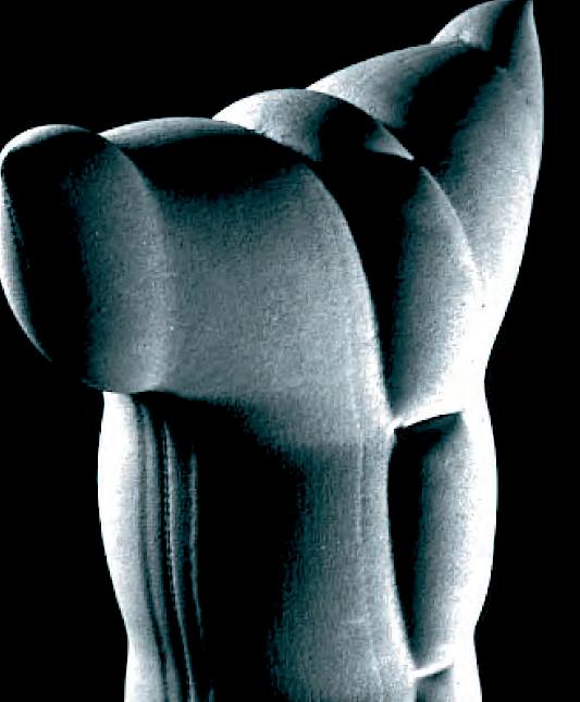
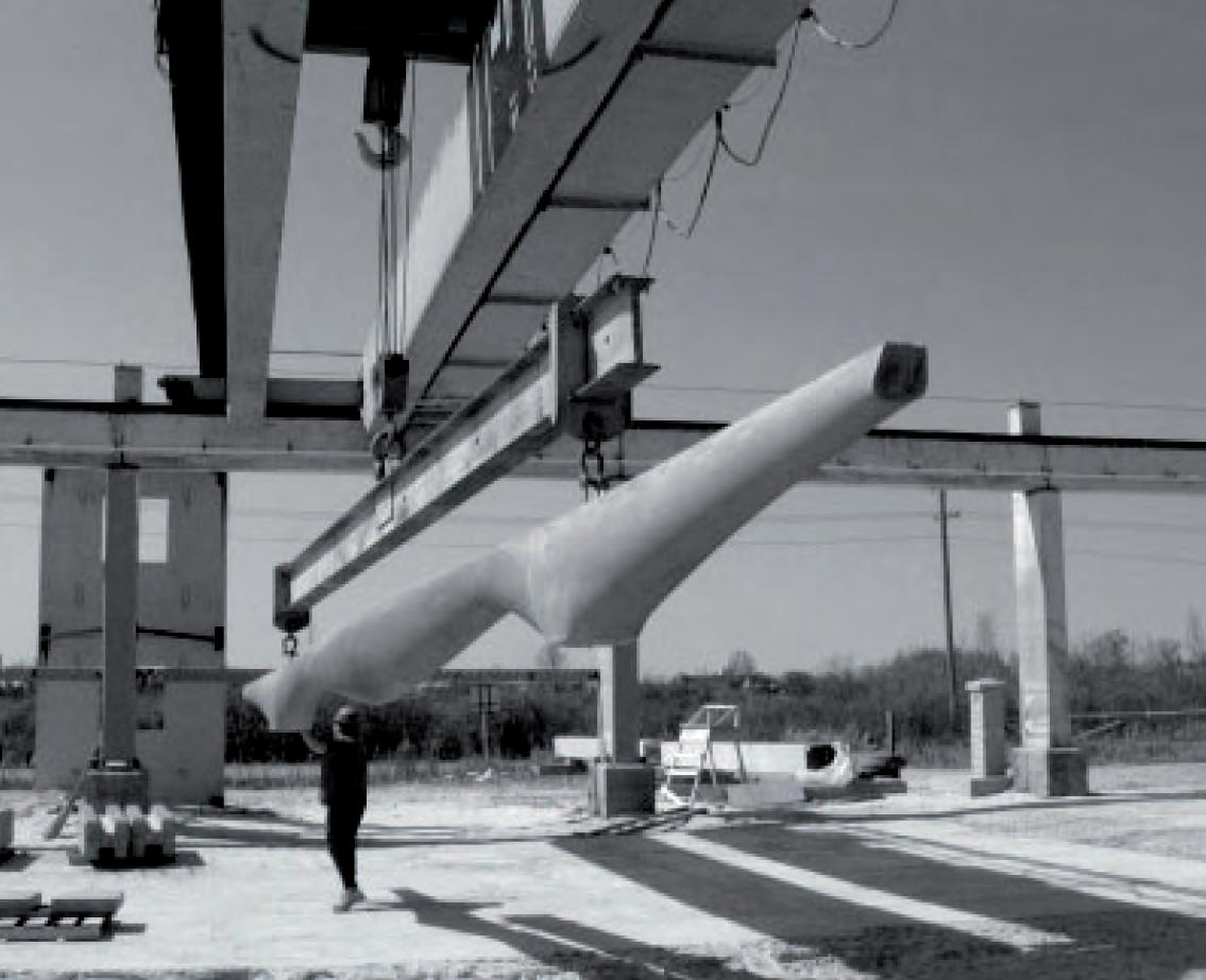
Alan Chandler has carried out several experiments on fabric form work as means to showcase the fluidity of concrete casting with the aid of the C.A.S.T team at the University of Manitoba.
The work done by Chandler gives an insight of the possibilities and limitations of the process. Although the fluidity of concrete is showcased strikingly well in the work done, restraints of the frame that bounds the form work limits the design outcome to merely an aggregation of the created form. This is seen as a limit for achieving the coherent global geometries we pursue.
The difficulty of gaining control over curvatures produced is also a major drawback. Our attempt will aim at overcoming these restraints by the augmentation of the clear transitional moments that separate architectural elements, which assemble a global geometry. The spatial enclosure in this case is envisioned as consistently composed of transitional elements created by imposing previously calculated external forces on the material.
The research showcased in Chandler and Pederschi book entitled ‘Fabric Form work’ shows how the team used analogue and digital methods to create feedback loops in the fabrication process. The team took Gaudi and Isler’s work as a starting point to their exploration in easily creating doubly curved concrete structural elements. Chandler argues the benefits of using such elements in optimal architectural design, especially in terms of their structural capacity.
Mark West writes about the experiments in the AD magazine feature ‘Thinking With Matter’. West argues that the research done by Heinz Isler and Gaudi using form finding analogue prototypes can be improved on with the facilities provided by Digital simulation (Mark West - AD Thinking with Matter P.52). The complications of measuring these prototypes can be avoided by constantly re-evaluating the prototypes and process, using analogue and digital tools, and tested with the proper materials. (Chandler & Pedreschi- Fabric Form work P.2)
Taking the research done by cast into consideration, we intend to set a stepping platform for a more ambitious quest. Our drive for hybridization to achieve optimised coherence in architectural design could be fabricated within the realm of tensile membrane construction and Shotcrete to achieve structurally optimised buildings and spatially differentiated enclosures. We see hybridizing these two methods of construction means to achieve our ambitions. Structural optimization comes from coupling the tensile membrane behaviour and the compressive behaviour of concrete.
DESCRIPTION
BarChip54, a Structural Synthetic Fibre from Elasto-Plastic Concrete’s range of copolymer fibres, evolved from EPC’s “Future Fibre” research and development program. The aim of this program is to develop a range of fibres that achieve the highest performance levels ever seen in structural synthetic fibre reinforcement systems. The latest advances in copolymer technology, engineering design and manufacturing techniques have been incorporated into BarChip54 to deliver a fibre that is unequalled in usability, durability and service performance.
BarChip54 is suitable for use in concrete applications with concrete strengths of 30 MPa or greater.
ADVANTAGES
• Lower cost per Joule fibre
• Weatherproof pallet packaging
• Flexural toughness equal to steel
• Long term durability ~ corrosion free
• Safer and lighter to handle than steel
• Reduced fire damage ~ anti-spilling
• Reduced wear on concrete pumps and hoses
DOSAGE
EPC’s BarChip54 has an effective dosage range of 3 kg to 10 kg per cubic metre. Dosage rates should be elected based on performance requirements. Typical dosage rates for Shotcrete applications in normal ground conditions range from 4 kg to 6 kg per cubic metre.
EPC’s BarChip54 fibre can be pumped through 50 mm rubber hoses without difficulty. Precaution should be akin to ensure the fibres can pass freely through the pump hopper grate.
Ref : http://www.elastoplastic.com/english/products.htm.
Product Data Sheet of BarChip54
Our focus is on complex geometries and thus requires simpler methods of reinforcement than conventional steel re-bars. BarChip fibre holds potential physical properties, which might prove to be useful in coupling it with concrete to form structural surfaces. Fibres are corrosion free making it suitable for any weather especially the tropical and coastal areas. It can be pumped reducing enormous expense on laying out steel bars. The disadvantage of short fibres will have to be overcome by integrating a medium to transfer loads from the 3D matrix into a more directed flow of forces to the receivers. The fibres will also aid in increasing the angle of repose of fluid concrete making it more suitable for sloped surfaces. Lightness of the fibre reduces the total weight of the structure. Fibres reduce or relieve internal forces by blocking microscopic cracks from forming within the concrete. This prevents catastrophic failures in concrete structures in earthquake prone areas.


DESCRIPTION
Data from European Specification for Sprayed Concrete.
Sprayed concrete is a mixture of cement, aggregate and water projected pneumatically from a nozzle into place to produce a dense homogeneous mass. Sprayed concrete normally incorporates admixtures and may also include additions or fibres or a combination of these.
Wet process is a technique in which cement, aggregate and water are batched and mixed together prior to being fed into a purpose-made machine and conveyed through a pipeline to a nozzle where the mixture is pneumatically and continuously projected into place. The mixture normally incorporates admixtures and may also include additions or fibres or a combination of these.
Dry process is a technique in which cement and aggregate are batched, mixed and fed into a purpose made machine wherein the mixture is pressurized, metered into a compressed air stream and conveyed through hoses or pipes to a nozzle where water is introduced as a spray to wet the mixture which is then projected continuously into place. The mixture may also incorporate admixtures or additions or fibres or a combination of these.
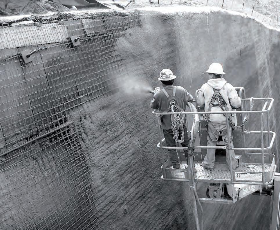
The surface is pre- hydrated with water and kept free of any loose materials. The spraying is started from bottom and continued upwards. This is done to avoid spraying in rebound losses. While spraying the nozzle direction should be maintained 90 degree to the surface. The velocity and spraying distance shall be the optimum for maximum concrete adherence and compaction. The curing of sprayed concrete should be done as any normal concrete curing. The concrete should be protected from frost till it gains strength of at least 5 MPa.
Complex geometries are often difficult to reach for safe laying of concrete. Robotic spraying is a technique, which is being highly used to concrete the inner surface of tunnels where safety issues are critical. The robotic arm would be able to reach complex areas and will do consistent layering of concrete. Spraying is carried out at high velocity and our challenge would be to create a surface, which is able to receive the concrete without forming sags. The concrete also needs reinforcement to keep in place along steep curves where there are chances for it to flow down. BarChip fibre has been described in the previous page, could aid in the process. Workability, spray ability, dosage of accelerator, fibre content, concrete strength are other factors that have to be tested during the next stages.
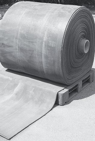
Concrete Canvas (CC), is a flexible, cement impregnated fabric that hardens when hydrated to form a thin, durable, water and if re proof concrete layer. CC allows concrete construction without the need for plant or mixing equipment. Simply position the Canvas and just add water.
CC consists of a 3-dimensional fibre matrix containing a specially formulated dry concrete mix. A PVC backing on one surface of the Canvas ensures the material is completely water proof. The material can be hydrated either by spraying or by being fully immersed in water. Once set, the fibres reinforce the concrete, preventing crack propagation and providing a safe plastic failure mode. CC is available in 3 thicknesses: CC5, CC8 and CC13, which are 5, 8 and 13mm thick respectively.
CC is available in man portable rolls for applications with limited access or where heavy plant equipment is not available. There is no need for mixing or measuring, the concrete is premixed and cannot be over hydrated. It will set underwater and in sea water. Once hydrated, CC remains workable for 2 hours and hardens to 80% strength within 24 hours. Accelerated or retarded formulations can be produced to meet specific customer requirements.
CC is a low mass, low carbon technology which uses up to 95% less material than conventional concrete for many applications. It has minimal impact on the local ecology due to its limited alkaline reserve and very low wash rate. CC has good drape characteristics allowing it to take up the shape of complex surfaces including those with a double curvature. Raw Canvas can be cut or tailored using basic hand tools. The fibre reinforcement prevents cracking, absorbs energy from impacts and provides a stable failure mode. CC is chemically resistant, has good weathering performance and will not degrade in UV. CC has an expected life of over 50 years. The PVC backing on one surface of the Canvas ensures that the material is completely water proof and chemically resistant. CC is fire-safe, does not contribute to the surface spread of flames, has a low level of smoke development and minimal hazardous gas emissions.

Concrete Canvas is a fabric impregnated with cement. This could be a potential material to achieve the geometries we intend to achieve. The tensile strength of the material is negligible though. The material will be tested after initial digital form findings. The fabric needs to be tested for its elasticity. The rubber coating on the back could help keep the structure water proof. The stitching methods would be tested to form larger samples.
Different cutting patterns will have to be tested for larger structures. The method could reduce the enormous time, labour and expense in conventional concrete form work. It would also be a much simpler process to erect a fabric and hydrate it to make it permanent.

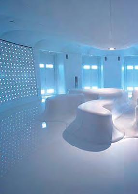
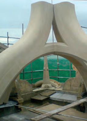
Jesmonite is a versatile range of water-based, solvent free composite materials ideally suited to the creation of decorative mouldings and glass reinforced laminates. These materials have a range of unique properties, which contribute to strength, durability, non-toxicity, and the ability to comply with many of the necessary test requirements of the construction industry, specifically those in regard to fire performance and impact resistance. Jesmonite Composites provide a wide range of material solutions for many industries. The materials have been used extensively in Construction, Theme Environments, Museums, Visitor Centres, Sculpture, and all forms of Mould Making and Moulded Products.
Jesmonite AC730 is a rapid setting acrylic modified cementitious composite. The system is designed for glass reinforced decorative structures, and can also be used for small castings. It is shrinkage compensated material of low permeability and is durable in all conditions of external weathering including water features. The compound has a reduced free-lime content, and is of low alkalinity, leading to major reductions in efflorescence in comparison with ordinary Portland cement systems. The material contains a fine decorative aggregate and powder pigments, carefully controlled to give a consistent decorative surface finish after treatment with a proprietary brick cleaner or acid etch. AC730 is available in six stone finishes; Natural, Bathstone, Yellow Sandstone, White Marble, Portland, and Silver Grey Granite. Jesmonite Limited offers a bespoke matching service to assist Manufacturers, Architects, and Designers to match any colour scheme and surface finish.
Jesmonite Flex liquids represent the ultimate evolution in water resistant, flexible materials for laminating and foam coating. The Flex liquids give laminates made with AC730 powders much greater ductility, and can be used to produce lightweight, durable laminates of between 3mm and 5mm thickness. Mix ratios for maximum flexibility are 3:1 powders to liquids, however it is possible to increase the powders to achieve a variety of mix viscosities suitable for foam coating and spraying using a gravity fed spray gun.
This type of glass reinforcement is tailor made for use with Jesmonite. It is based on the latest quad axial glass reinforcement technology, which makes Jesmonite fibre-glass laminates light and strong and fire resistant. It is constructed like a lace, with continuous glass strands in four axis (quad axial) stitched together using the fireproof material Nomex®. There are very few free filaments, making the glass safe and comfortable to use. It can be accurately cut using scissors or roller cutters, and will conform to even the most complex shapes. This makes it especially suitable to mould making and Jesmonite panel construction.
Specifications
Mix Ratio 5:1 (Powders to Liquids)
Wet Density 1950 kg/m3
Dry Density 1850 kg/m3
Compressive Strength 40 – 45 Mpa (Oven Dry)
Drying Shrinkage 0.1%
Impact Strength 5.0 – 10.1 Mpa
Key Attributes
Improved flexural strength and stability
Excellent Abrasion resistance and impact strength
High Compressive and tensile strength
Rapid curing and high early strength gain
Shrinkage compensated and dimensionally stable
http://www.jesmonite.co.uk/ - AC730 Technical data Sheet. Date Accessed: 21 june 2011
EVALUATION
Our thesis focuses on concrete construction of complex generative components. Studies on fabric form work still impose a lot of restriction on the method. Fixing the fabric in place once the form is achieved is the biggest challenge, if fabric is to be used as reinforcement giving shape in its tensed geometry This is crucial in projecting concrete over the fabric to create a stiff shell and re-use the form work. The flexural strength and stability of AC 730 could be at advantage to the process to avoid sagging of fabric while spraying concrete on it. Tensile strength of AC730 when reinforced with the quad axial glass fibre is very high. It is a water based composite and non-toxic thus improving the quality of work environment. It could also give different interior finishes when acid etched which could eliminate false ceilings. Above all the fact that Jesmonite can be sprayed makes it suite our ambition to do complex surfaces. Our studies on the material informs us that the material is not being used to its full potential. We foresee real potential for the material in the fabrication of emergent elements in the building scale rather than restricting it to columns , pilasters, and decorative components.

Darwanian Analogy
Trial & Error Design
MORPHOLOGICAL DEVELOPMENT
Coherent Transistion Between Exoskeleton/Endoskeleton Turtle Shell Evolutionary Formal Adaptation

Anatomical Analogy +
Single-System Novel Structural

Generation of Optimal Building Design +
Enviromental Opening Differentiation
Structural Force Field Distribution
Spatial Circualtion
Performative Optimization
Differentiated Volumes
Trial & Error in Design = MORPHOLOGICAL DEVELOPMENT
Membrane to Shell Otto’s Pneu & Bone Analogy
Coherent Transistion Between Exoskeleton/Endoskeleton
Structural Elements
Single-System Building as a Whole Entity
Catenary Chain Models
Mesh Deformation
Mesh Relaxation
In order for the research to proceed forward in a cohesive manner, the methods used to proceed forward have to be consistent in their own right. A map of the workflow was extracted from looking at scientific, historical and architectural precedents as a knowledge base can be pushed forth with the aid of current digital tools and material technologies.
As opposed to the top-down hierarchy of the modernist method of developing design, the method proposed works in a bottom-up manner such as systems found in nature (Reiser+Umemoto- P.51). The coherence emerges as the result of nonlinear processes, where simple procedures gradually increase the complexity of the parts to achieve a more complex whole.
The result of these processes is anticipated to be a morphological development of material forms, where complexity increases gradually as a result of rigorous analogue and digital testing. The tools are references used through the course of this nonlinear investigation would ultimately reach maturity with construction-based material logistics.
The result anticipated on the architectural level is a coherent complex spatial condition, where architectural elements would assemble to a complex whole within an unexpected course of events
Programmatic Planning + Single-System Structural Elements
Fig 1.85.1: Diagram showing the domain summary of intentions. Our methods are illustrated as non-linear process of carrying forth research through physical and digital experimentation, where we iterate between both to find an optimal solution for our main intentions.
“A genealogy of emerging matter/ force relationships may be chartered from the simple to the complex. In the simplest case, forces are hidden within the post-and-beam construction are represented. This representation, however, never expands beyond the single member, and it remains semantic, merely a sign of weight.”
(Reiser+Umemoto- Atlas of Novel Tectonics P.91)
FORCE+MATTER=FORM
The need for advancement in simple building assemblies that are ecological becomes an apparent solution to the monotony and excessiveness of current practices of construction. The “Self-Formation” and “Natural Constructions” that Frei Otto pursued in his search for form, is found in nature and could be imitated in the man made environment through analogue and digital processes for form finding in search for optimal architectural design. Nature is a self-sustainable system, and the forms that are the result of natural processes usually perform in an optimal way in their respective environments.
For natural self-formation to be simulated at different scales, materials and the forces acting upon them should be appropriately scaled when such experimentation is carried out.
The methods of experimentation were executed in such a way where issues of feasibility, material behaviour, and spatial differentiation were taken into consideration when these experiments are generated. Material and digital craft are the main drivers of the processes, under the limitations of current technologies and laws of physics.
The results of material experimentation in search for generative architectural design are often open to emergent and unexpected results. With the parameters of material behaviour, force, environmental condition and adaptive tectonic differentiation, the experiments of the research were carried out in an analytical and calculated manner.
Based on the parameters mentioned previously, an analogue form-finding process was deployed. The experiments commenced with the simplest conditions surrounding these parameters. The resultant formal expression of the generated prototypes is merely an outcome of the strengths and failures of its successors, where the complexity of the methods of form finding evolved along the complexity of its resultant geometry.
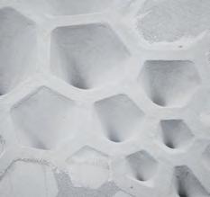
When used at a small scale, plaster, additives and fabric meshes could simulate the behaviour of casting concrete and stretching tensile structures. The experiments used plaster as a compressive material, and cotton fabrics due to their tensile behaviour. The materials are controlled by forces, and parameters as well as additives and composites.
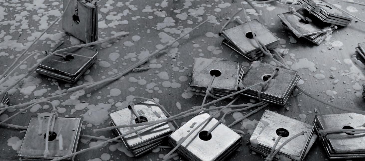
F= W (g) x 9.81
General Aim
To test meshes as tensile materials coupled with compression materials such as plaster to create coherent structural systems. Experimenting with different material qualities and their effect on the overall finish. An attempt towards a smooth gradient of transition between structural elements.
Experiment 1.0
Objectives/
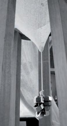
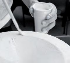
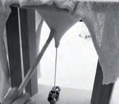
_Testing the general principle of the form finding method.
_Achieving the right mix of material to use with the mesh.
_Using a low-grade, affordable mesh.
_Using bolts as weight, as force acting on the fabric with gravity.
Experiment 1.3

Objectives/
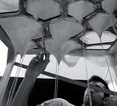
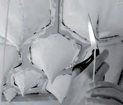
_Differentiating the heights of the formed geometries by adding heavier weights to larger cells, weights get gradually smaller as the cell gets smaller.
_Testing the fine mesh for loads.
_Using less glue (additives)
Experiment 1.1
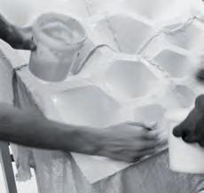
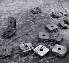
Objectives/
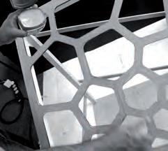
_Using release on the plaster preventing it from sticking.
_Testing multiple sizes of cells using the same weights.
_Testing the forms on a slanted frame form work.
_Adding more glue to achieve a higher degree of flexibility.
Experiment 1.4

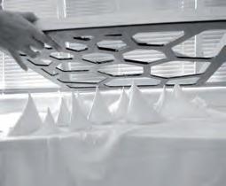
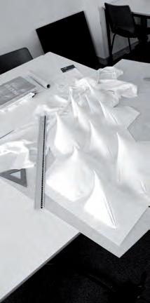
Objectives/
_Attaching heavier weights to smaller cells, weights get gradually heavier as the cell gets smaller.
_Testing creases on multiple cells.
_Using high-grade plaster to bring out the material finish of plaster.
Experiment 1.2
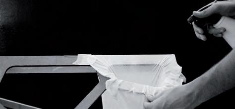

Objectives/
_Improving the fineness of the grade finish by using a higher quality fine mesh.
_Spraying water to improve workability time.
_Testing adding creases to allow buckling, as a ribshell hybrid system.
Experiment 1.5
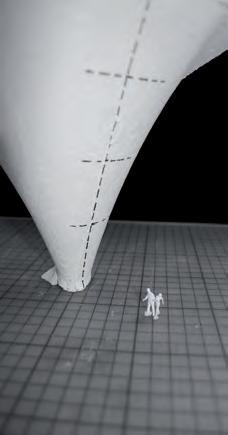
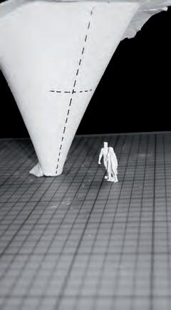
Objectives/
_Testing multiple assembly configurations in relation to scale, by dividing the resultant forms and comparing them to modelling figures of different scales.
_Thinking of formal and material alternatives that would work at a 1:1 scale.
The first three experiments proved as good communicative tools of the behaviour of the materials to be explored. Despite the clunky and underdeveloped nature of these prototypes, the failures of these two experiments were indicative of what should be solved in the next prototype. In Experiment 1.0, the cone created became attached to the wooden form work, making it apparent that a release substance should be used to take the model out of its cast. In Experiment 1.1, where the materials were tested on a large restraining grid, the low-grade quality of the plaster and fabric used, resulted in a more rough finish than what we aimed for.
The main failures of Experiment 1.1 were the seams that were sewed to create a large membrane piece-mainly due to the size limitation of the fabric and the rough finish of the construction grade plaster. What was interesting about that model was that when we added more wood glue to the mix, the surface of the prototype became a lot suppler, due to the elastic quality of the form work, and the manipulative quality that the glue added. The result is a sort of elastic surface that could be manipulated and formed despite the cracking of the plaster.

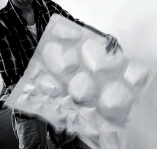
In Experiment 1.2, the main aim was to control and improve the surface finish. Three different cones were tensioned using a high quality cotton fabric mesh, and high quality hard casting sculpting plaster. The fist cone was tested under the same conditions, spraying water on the fabric before painting with plaster. The second and the third cells were tested for creating ribbed corners by creasing the fabric after spraying it with water. The water-sprayed cone allowed for more time and flexibility when casting, as well as further tensioning the fabric, which resulted in a smoother finish.
Experiment 1.3 and 1.4 expanded on the idea of having creases or not, respectively. The over all geometry was freed from the confines of the squared form work by tensioning only the diagonal cells of the grid, once with heavier weights on the larger cells and then reversing the process in Experiment 1.4. The remaining fabric was cut away. The resultant prototypes had an interesting spatial quality underneath the restricted pathways of the grid, which was tested for scale, as a structural column component in Experiment 1.5.
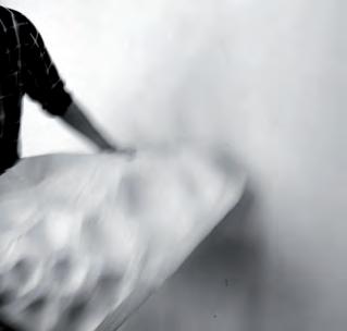
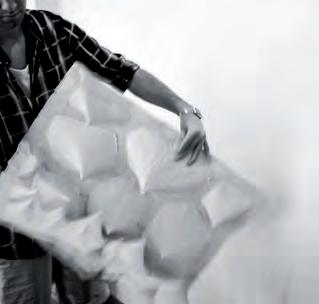
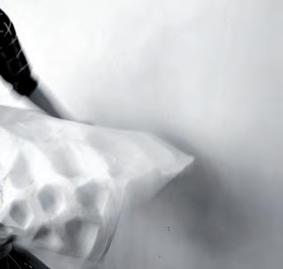

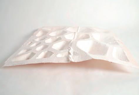
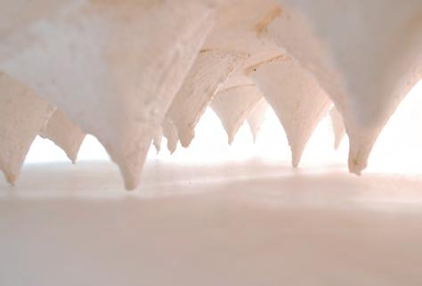
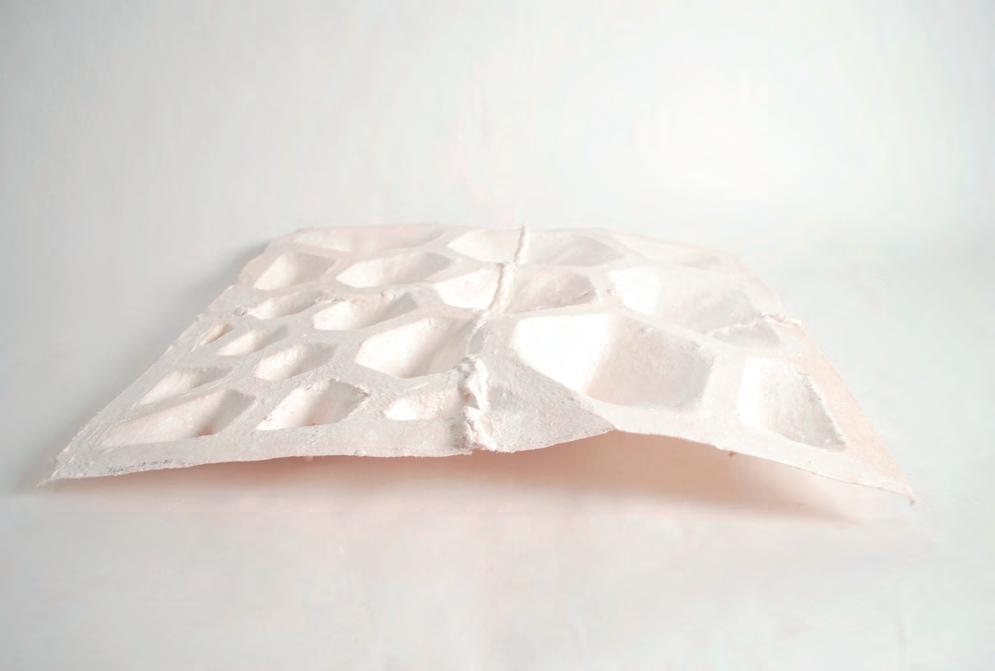
Experiment 1.1 initiated many thoughts about the materials we are using. Many ideas on how to refine the grade finish were the outcome of observing the resultant surfaces. The plaster that was available had was not of a good grade; the fabric used was thick and lacked elasticity. The surface finish resulting was rough but the conical forms were created easily.
Random variation of cell openings and forces affecting the unrestrained area per cell allowed for little differentiation to emerge, but a variation in height when the shell is inverse is noticed due to a change in curvature. The experiment was educational and successful in many ways, the release used on the frame worked successfully and we were able to take the prototype out of the frame to re-use the casting frame in later stages of the exploration.
Advantages
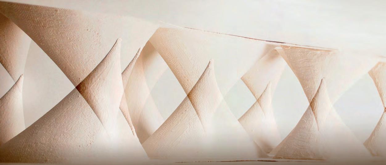
1. Almost endless possibilities for form finding.
2. Relaxed geometry makes the structure very light with minimal material used
3. Process encourages teamwork, inspirational for starting a project.
4. Differentiated spatial qualities achieved.
5. Reduction of Highly complex form work.
Disadvantages
1. Results are dependant on sizes of materials used.
2. Process is highly dependent on the techniques and materials used.
3. Modelling method is hard to translate to building scale.
4. Overall feedback about the geometry but not about the forces necessary to achieve a certain equilibrium.
5. Lack of balance between freedom of form finding and levels of control.
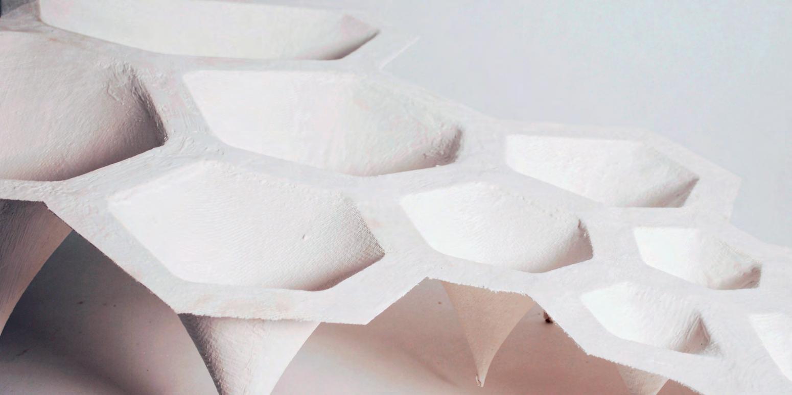
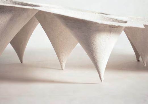
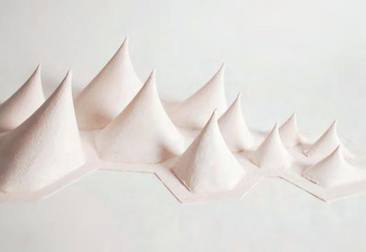


EXPERIMENT 1.3 + 1.4
After refining the material formation process, the analogue modelling method yielded interesting geometries. These geometries were observed and measured, especially for their spatial and structural qualities. It became clear from handling this less flexible, hard casting mix that some areas of the form have different fragility values across the prototype. The model had a cleaner finish and a harder shell, but the curvature and the increased tension in the fabric were observed to have the best performance in resisting cracking. The straight, less tensioned areas restrained by the grid proved a lot more brittle.
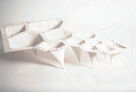
As an initial test of switching the methods of testing between analogue models, and digital analysis was carried out. The need for devising method to analyse these models becomes relevant. For the past few experiments an important parameter was the size of the opening on a restraining grid in comparison to the force exerted on the material, which generated more variation in the resultant geometries.
The resultant conical geometries were analysed for their spatial quality mainly by measuring the resultant geometry length. The results of Experiments 1.3 and 1.4 were comparatively analysed where one prototype used logic of a large force on the smaller cells, and a smaller force on larger cells. The Result showed that the size of the cell has the most effect on the resultant geometry, where larger cells allowed for a greater deformation.
GRAPH 1.0/ COMPARATIVE ANALYSIS OF RESULTANT GEOMETRY OF EXPERIMENT 1.3+1.4
TABLE 1.0/RECORD OF MATERIAL BEHAVIOUR RESULTS
Tools of architectural design are advancing at a fast pace . To communicate our intentions and to evaluate our designs we have be skilled in the precision tools in the industry. These will help conceptualize, analyse and communicate the design to professionals in the industry. Therefore to enhance the design, develop it and to get it into a construction phase there is a demand to use the best software available. Digital tools provide us with precise and quantitative information, which can be translated into effective data for further development.
We planned out our goals and looked at the tools that could aid our process.
1. Rhinoceros 3D is a modelling software which uses NURBS ( Non Uniform Rational B-Splines) and has no limit to complex forms”. It can also handle polygonal meshes will be useful to run dynamic relaxation algorithms. It is also compatible with the latest prototyping machines where we could feed the digital model to generate physical prototypes ( like 3D printers , laser printers, 3D scanners, cnc milling etc ).
2. Grasshopper “For designers who are exploring new shapes using generative algorithms, Grasshopper® is a graphical algorithm editor tightly integrated with Rhino’s 3-D modelling tools. Unlike RhinoScript, Grasshopper requires no knowledge of programming or scripting, but still allows designers to build form generators from the simple to the awe-inspiring.” (Ref : http://www.grasshopper3d.com/). Since we are architects and not experts in scripting grasshopper seems to be the right tool to experiment with algorithms.
3. GeometryGym “Geometry Gym provides tools for Architects and Engineers, streamlining work flow processes for improved productivity and designs. Powerful Parametric and Generative modelling of structure is enabled by utilizing plug-ins for Grasshopper3d and Rhino3d will facilitate embedding the material properties while using dynamic relaxation.
4. Ecotect Analysis: “Autodesk® Ecotect® Analysis sustainable design analysis software is a comprehensive concept-to-detail sustainable building design tool.
With better understanding of the variety of tools at today’s architects’ disposal, the goals and methods could be simulated and tested effectively using the right tools. Geometry gym, Strand7, Oasys will aid in optimization of the forms. Grasshopper can connect to Ecotect analysis and thus the digital model can be analyzed and edited at the same time. Energy analysis, thermal performance, solar radiation, day lighting and shadow and reflections, are few factors that would be analyzed and optimised for the building design.
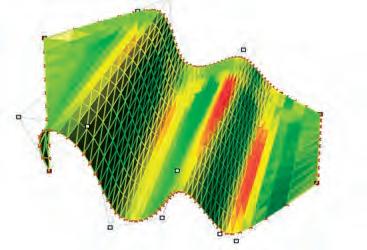
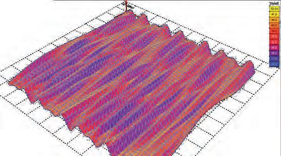
INITIAL DIGITAL FORM FINDING USING RHINO MEMBRANE
Rhino membrane is a convenient dynamic relaxation simulation plug in. It has become popular as a form finding tool since it works with Finite element analysis. It is used in the industry mainly to calculate tensile membrane structures. The results are very close to accurate and thus can be used in real construction. It can be used to relax any preprocessed mesh into a stressed surface in equilibrium and this is exactly the aim of the digital experiments in this research.
The stresses on the weft and warp of the fabric can be read from the colour mappings and thus aids optimization of the forms. Tensile membranes work entirely on tension and compressive forces have to be avoided since they cause wrinkles. Form-finding using rhino membrane helps simulate a form by applying prestress at the nodes. A simple experiment of an eye cable is demonstrated in the following diagram..

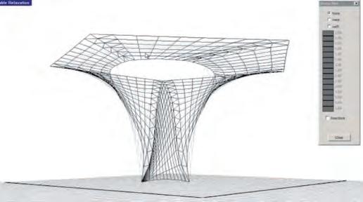
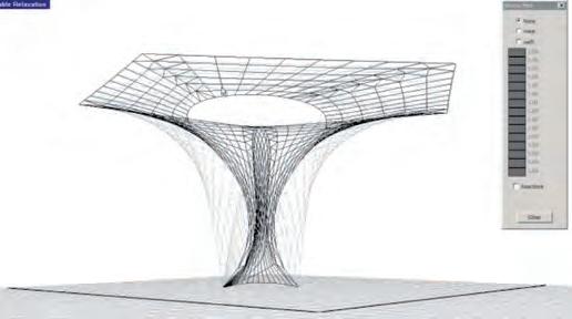
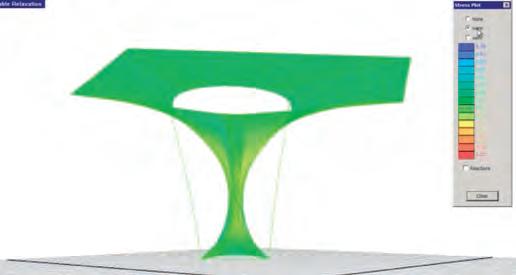
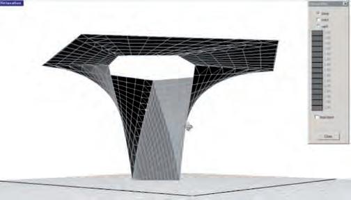


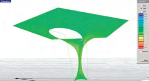
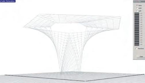
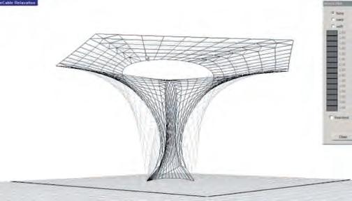
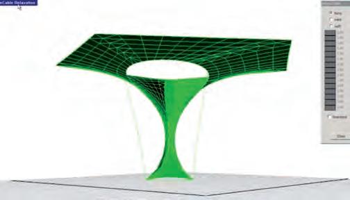
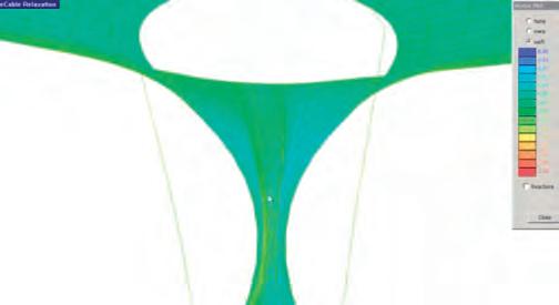
After the initial experiments in fabric and plaster, it was essential to replicate the forms in the digital platform to gather qualitative and quantitative information in a shorter period of time. Digital form finding can be carried out in several methods. Our approach is to initially iterate solutions with the aid of a dynamic relaxation algorithm and then move on to Finite element method to embed the properties of the material. Grasshopper plug-in in Rhino was used for the experiments. Dynamic relaxation is a numerical method used for calculating the forms of cable and free form structures (Killian 2009 P.50), it works with digital meshes that behave in a similar way to the fabric meshes experimented with earlier.
Experiment
As with the physical models a simple experiment was started at first. 2 simple steps were conducted in the experiment
1. Preprocessing of the mesh
2. Relaxation and Analysis
Preprocessing
In this step a mesh was prepared in Rhino with a certain number of nodes. The mesh is plugged into grasshopper and is linked to the mesh relaxation component. This requires restrain points and a prestress for the mesh.
The restrain points are fed into the algorithm. When the points are in space then the points are moved in Rhino mesh. An initial value is fed into the force vector. The algorithm is run with a timer connected to it to visualize the process in real time. The mesh oscillates for a period of time while it finds an equilibrium state. This is the relaxed mesh. The force and restrain points can be altered to analyse architectural spaces and forms.
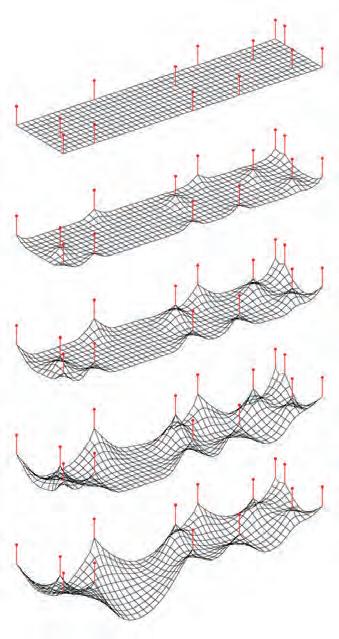
In the first iteration the edge nodes and centre node of the mesh were restrained. A negative force is applied and the simulation is run. The mesh inflates as shown in (Fig 2.50.1). In the second iteration the corner nodes and the centre node is retrained. Thus in each iteration the complexity of the experiment is increased. In the second stage the restrain points are moved in the Z axis and the simulations are run. The results are shown in Generation 2 . In the next stage the restrain points are moved in all the 3 axis’s and 2 layers of mesh is used and the result is Generation 3.
Digital analysis is much more quantitative. Any number of iterations could be done in a very short time frame. The results are quick and the raw data can be translated into useful information for analysis and for further analysis. Only by changing the restrain points and the force applied we can see how the complexity increased. Once the rules are set to generate the spaces several iterations can be carried out and the results can be analysed to rank the fittest generation. Further the geometry can be optimised for better environmental and structural performance
Generation 1 : Increasing the number of constrain points on a single plane.
2.50.1: Initial experiments on dynamic mesh relaxation. Single planar mesh with one restraint point to more complex geometries with multiple layers and restraint points.
Initial experiments in physical experiments clarified the different parameters that drive form finding in fabric. Digital tools were also identified which would help simulate the forms. As a further step in proceeding with the digital and physical analysis the different parameters were listed down. The first parameter was the different weights (forces) that varied the forms. Varying the forces in the nodes resulted in differentiation of the forms and resulted in interesting configurations.
Restrain points was the next parameter to be identified. This played a major role in the form-finding process. Restrain points could vary from simple points to closed curves to pathways. The relation between the numbers of restrains points and the prestress applied is very significant. The cell size, geometry. Are other factors influencing the process.
The type of fabric was the third parameter that was identified. Fabrics behave differently according to the elasticity of the material their strings are made of, the type of weave and the stiffness in their connecting nodes. Few fabrics such as stockinet, fishnet fabric have been tested in the previous experiment. Further experiments will be carried out to quantify precise behaviour of these fabrics.
Once a suitable fabric is identified physical form finding will be carried forth. These experiments will further be simulated digitally to quantify the driving parameters. Materials for real scale construction are of importance in translating the system into a working one. Fabrication techniques for the construction of the material system also have to be devised. Further optimization of the forms according to the material behaviour and environmental pressures will be carried out.
A constant feedback between the above mentioned methods is important to correct and refine the materials and methods. This will be clearly demonstrated in the following chapters. The back and forth loop is explained in the diagram below for a clear definition of the process.
SCALE
OPTIMIZATION
geometrical/enviromental/structural
A feedback loop Flowchart indicating a process of recursive evaluation of different experimentation techniques to carry the research ahead.
Fig 2.60.2 : Preprocessing of the fabric mesh is necessary to generate differentiation in form and space. Applying restraint points and curves at multiple levels to simulate variation are potential ideas towards the next level of experimentation within the system’s formability. The diagram explains simple techniques in achieving these forms.
“The most important requirement for an object that is considered to be beautiful is that it fulfils the purpose for which it is destined, not as if it were a matter of gathering together problems solved individually and assembling them to produce a heterogeneous result, but rather with a tendency toward a unified solution where the material conditions, function, and character of the object are taken care of and synthesized, and once the good solutions are known it is a matter of taking that one which is most fitting to the object as deduced from the need to attend to its function, character, and physical conditions.” (Martinelli 1967, p. 125)
In an effort to challenge the material system that was developed, an increase in the complexity of the forming system was introduced. With the next few HYBIOS (HYBrid BIOStructure) prototypes, the fabric membrane was tensioned through a cubic frame, where the upper and lower sides of the cube had a grid of perforations, where the string used to tension the fabric was tensioned through.
For the second form finding method, we utilized a frame-based system where the sides of the frame are marked with holes on a grid. Two overlapping layers of fabric were used; and the fabric was stretched one layer into the other The geometry of the prototype emerged as a result of manipulating the fabrics exterior morphology. The spatial quality of the interior was discovered as a result of this process.
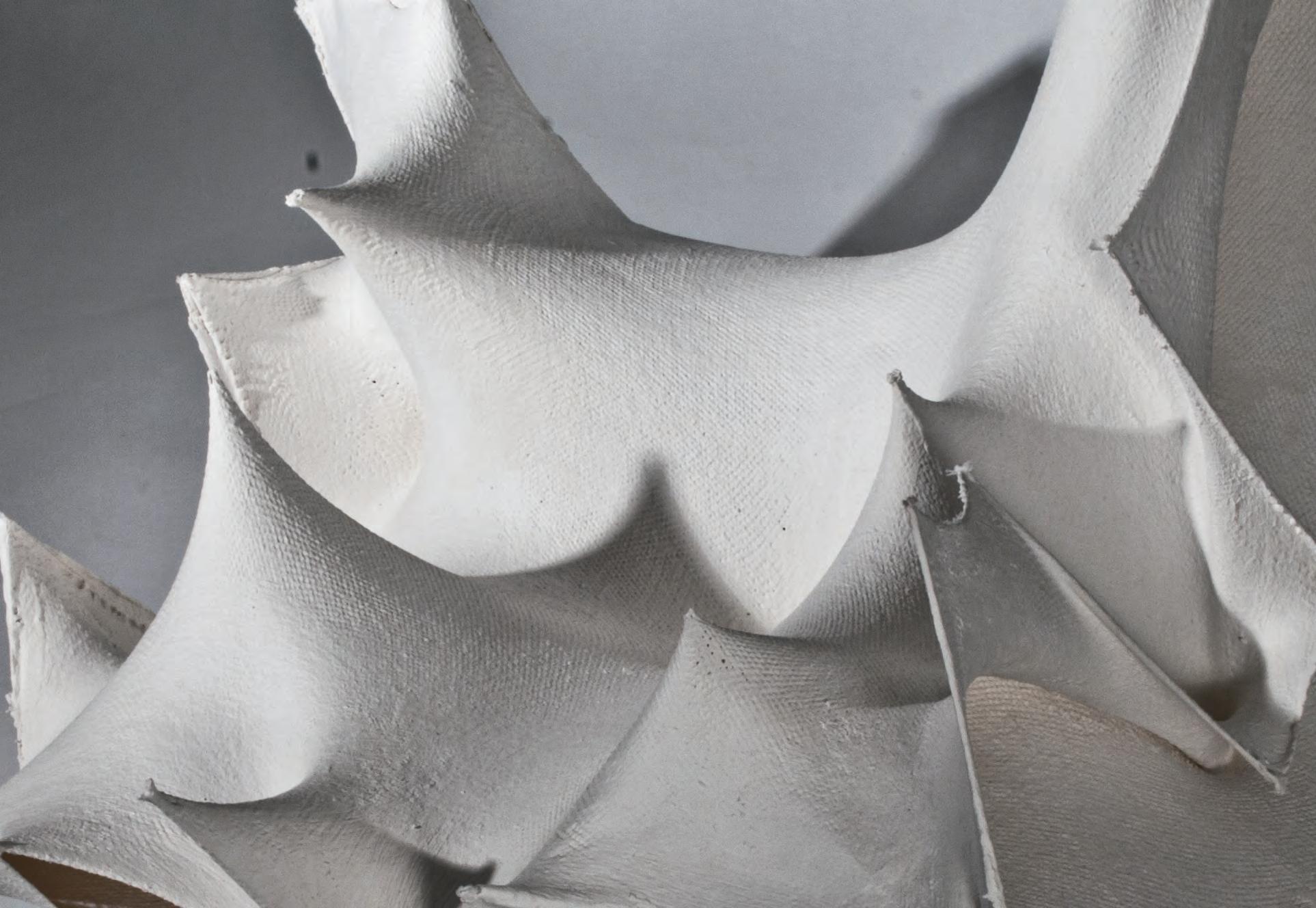
Different methods of stretching were utilized, such as overlapping the nodes, stretching one layer into the other and tying the edges. The fabric was then painted with thin layers of plaster, glue and water consecutively. The strings were cut when the shell has hardened and the resulting HYBIOS 2.0 was sanded and cropped around the edges. As observed in the pervious prototype, the amount of tension in the fabric is very important to achieve crisp forms that are tauter. The fabric was tensioned at several nodes, making sure that it is well tensioned to its maximum capacity.
The process was documented thoroughly and several notes were taken to improve the results of the next experiment. Where the spatial quality of the interior was to become the main focus of exploration. The elements of the resultant form are seen as having potential to create a smooth gradient of transition in the interior spaces. The elements of this single-system were seen as the future solution of structural and programmatic problems in the architectural level.
3.0.2 : The process of Analogue experiment 2.0. Tensioning the mesh on a simple square frame to casting with plaster. The last row demonstrates the process of removing the cast from the frame.

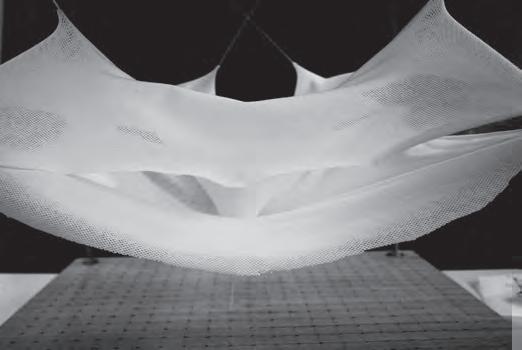

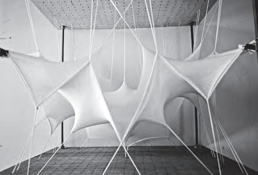
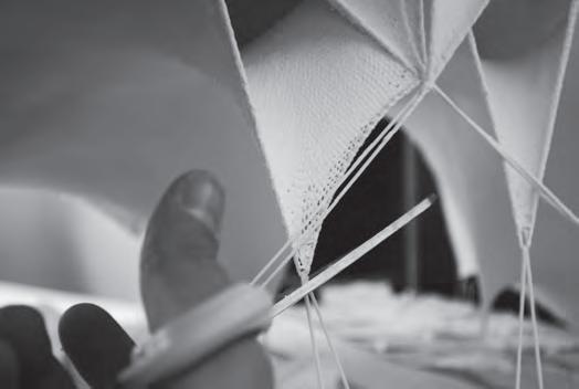
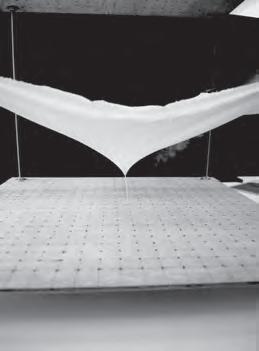
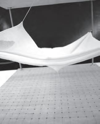
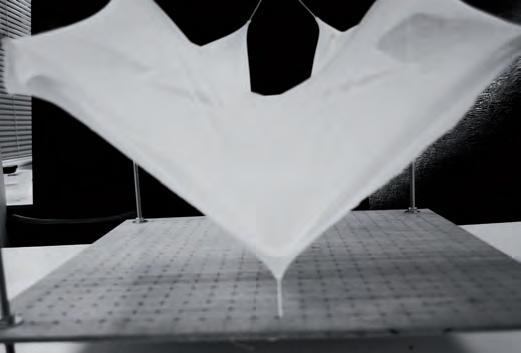
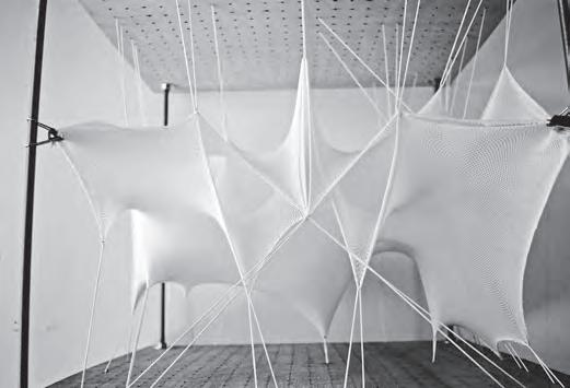
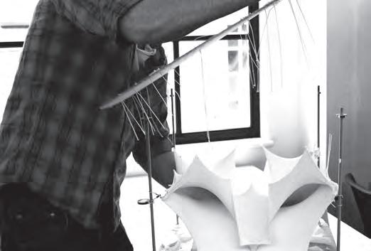
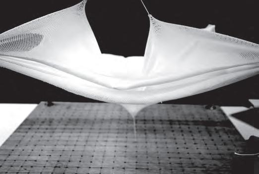
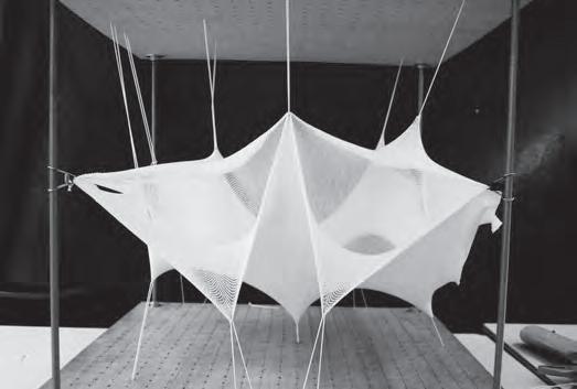
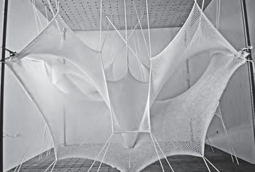
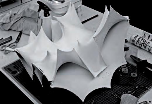 Folding to Create Beams at Edges
Central Node to Corners
Layers on The Same Plane
Tensioning Edges
Folding to Create Beams at Edges
Crossing and Overlapping Nodes
Folding to Create Beams at Edges
Central Node to Corners
Layers on The Same Plane
Tensioning Edges
Folding to Create Beams at Edges
Crossing and Overlapping Nodes
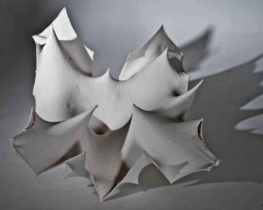
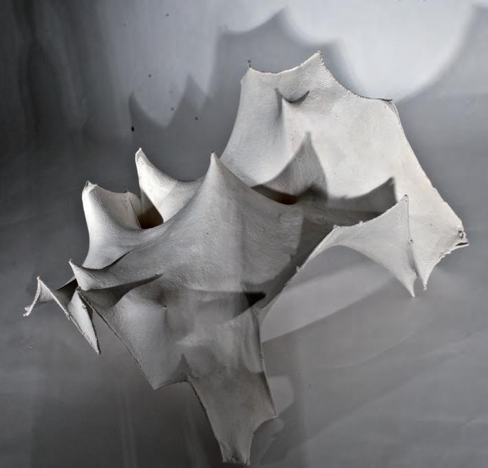

To manipulate the material system randomly by applying forces that tension the fabric, achieving doubly curved surfaces. The complex geometries of these surfaces have a higher structural performance when cast.
The fabric was tensioned at nodes randomly, working on shaping the exterior geometry. The interior morphology emerged from the shaping procedures of the exterior. Arch-like shapes were attempted at the edges.
The fabric was tensioned at nodes randomly, working on shaping the exterior geometry. The interior morphology emerged from the shaping procedures of the exterior. The interior space was not inhabitable, the edges were very weak.

height/350 mm
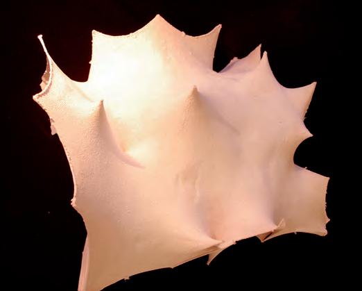
DISCOVERING FORM
A note has to be made on the value of learning by making. Through the course of this research, formal results were the aftermath of processes that increased in complexity, and tackled several anticipated problems. The design strategies following this exploration would be consistent to these processes and informed by material behaviour.
To advance slowly towards complexity, the experiments done each tackled a specific issue. Trial and error is an inevitable part of the process, and lead sometimes to interesting advancement in the generation process. These discoveries were treated as an integral part of the design process, incrementally integrating their benign features in the next design generation, while solving the problems of the previous prototype.
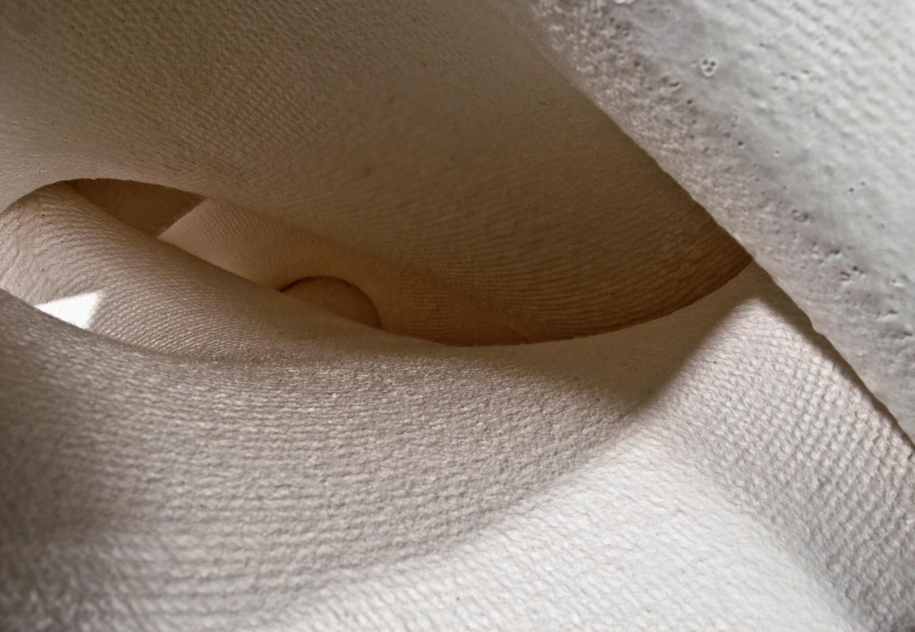
Some of these discoveries are the result of fortunate findings. By treating the material in a certain manner, certain benign features emerge to be adopted by later prototypes. The processes by which we derived to a certain test for the advancement of the material system, often lead to a leap of improvement in the next result.
Of these examples we recall the spatial condition that resulted from the tensioning of HYBIOS 2.0. Where an interesting coherence in the transition was observed and was carried forth and improved on in the next model HYBIOS 2.1. When painting HYBIOS 2.0 some of the parts were not covered properly, resulting in the plaster dispersing on to the treads of the net mesh.
A test was carried out (Fig 3.10.2) where a thin layer of plaster was painted on a piece of fabric stretched between nodes in a bat wing form. On the parts where there was the most tension the plaster dispersed and solidified the threads to create and interesting pixilation of openings that follows the force pattern exerted on the restriction points.
The outcomes of such findings are seen as a method to push the research forward. Several ideas emerged as a result of discovering the pixilation on the material, mainly to differentiate the lighting conditions within the space. The spots of light would add an interesting spatial quality when projected onto the curvilinear spaces. These light and shadow patterns could also be simulated digitally where environmental pressures could be added as a driving parameter.
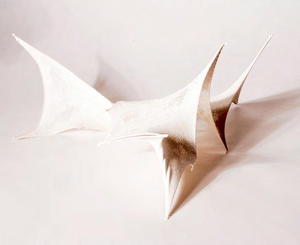
Fig 3.10.2: Possibility of interesting lighting conditions through pixilation. This could also be a possible solution for topological optimization where material is removed from where it is not required.
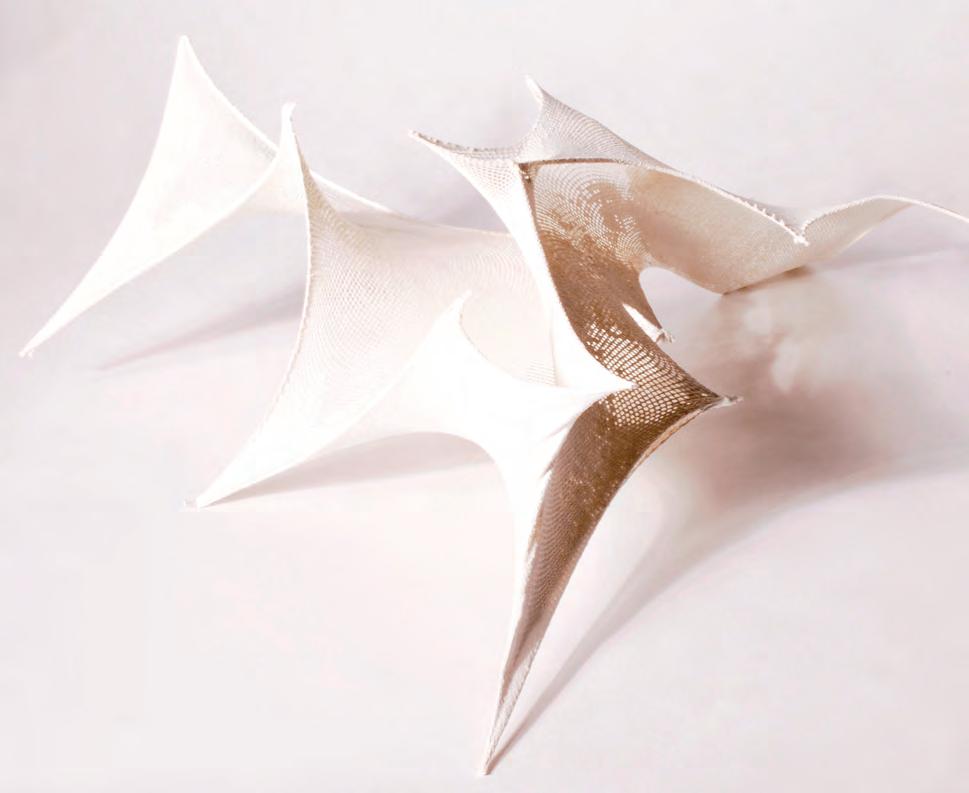
Initial experiments on dynamic relaxation were carried out in rhino membrane and later on in grasshopper using a code written in VB.net. Complexity was improved step by step and so were the spaces. The last chapter explained how the restrain points starting from a single one into multiple points in different levels improved the spatial differentiation inside the mesh. Experiments were conducted to relax one mesh into another and this gave further innovative spaces and possible structural solutions.
The feedback loop diagram in Chapter 2 (Fig 2.60.1) described the importance of moving back and forth between different steps in the whole process. Experiments moved from physical to digital and then to material. It was also essential to start thinking of a initial logic for construction of the material system. The form-finding methods resulted in interesting spatial configurations. The construction process had to be split into phases. A tiling system where standard components assemble to create locally differentiated spaces are simulated in sequence is described in the following diagram.
The system of tiling could work well. But the method proposed here needs to be refined. It would be difficult to build large scaffoldings to prestress the fabric. The previous tests also proved that the force required when using stiff fabrics is enormous. This might not be a practical method. A solution which is simple and inexpensive will be sought out in further steps. Studies on current methods of scaffolding and propping will be conducted to have a better understanding of construction logistics. Another drawback is the lack of material properties in the digital experiments. A Finite Element Analysis (FEA) software that can simulate the properties of the fabric has to be used for material embedded form-finding. These issues will be looked into in the further chapters of the research.
3.20.1: An initial concept for tiling of digitally simulated components. This could be a possible way to fabricate a space on site where components merge into one another after the process.
The objective of the second attempt was to manipulate the geometry from the interior of the form to its exterior. The focus was to hide and reveal while stretching, to make the spaces of the interior more inhabitable. Circular disks were utilized to stretch the fabric into a geometric shape create light-wells to draw light into the interior spaces.
The fabric was painted with thin layers of plaster and glue mix and was sprayed with compressed air at the top to distribute the mix into the strings. The result was a pixelated gradient of transparency along the light-wells creating interesting lighting conditions. A quality observed in the previous test models. The fabric was pulled to be more taut, especially around the points to be sprayed with compressed air.
The spaces generated were pleasant, where coherence is found in the architectural elements and light distribution had an interesting semiotic value. There was a lot to learn from this prototype, the most important note was an insight on how to control spatial and semiotic elements to create spatial differentiation. However, the prototype had a lot of architectural flaws, especially its unawareness to scale, and the uncomfortable steepness of the floor.
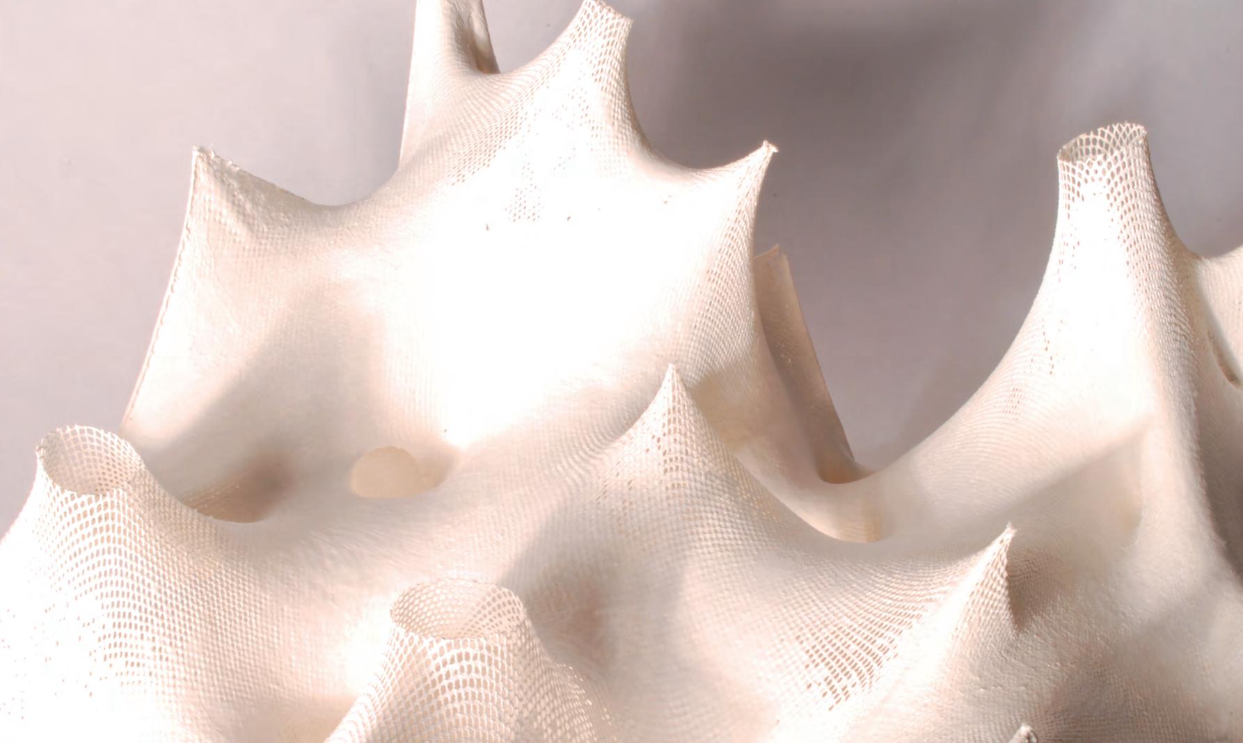
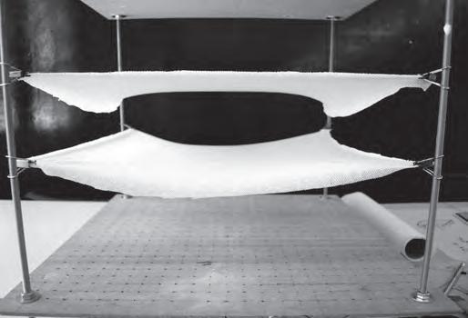
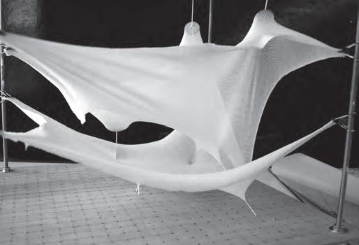
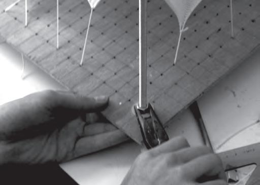
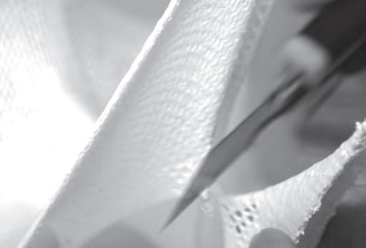
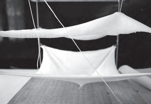
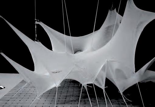
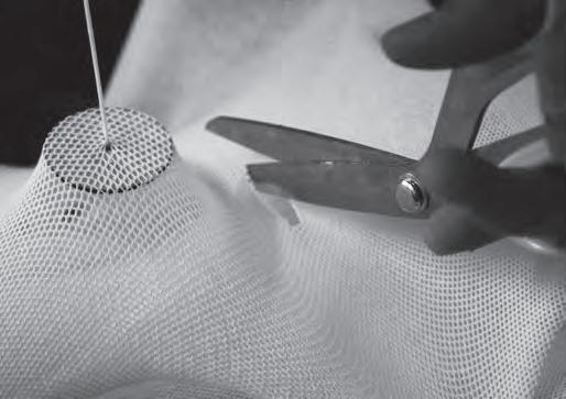
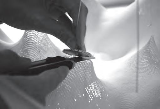
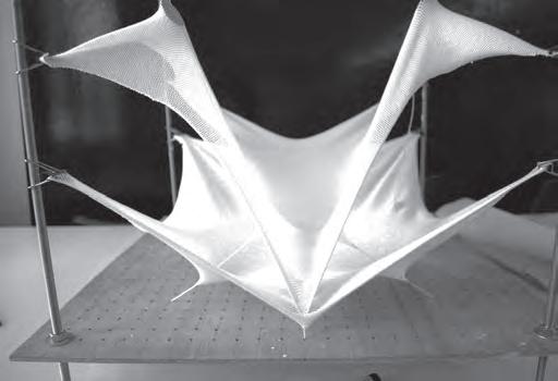

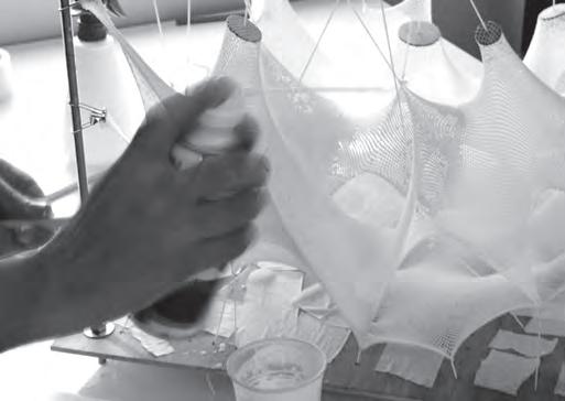

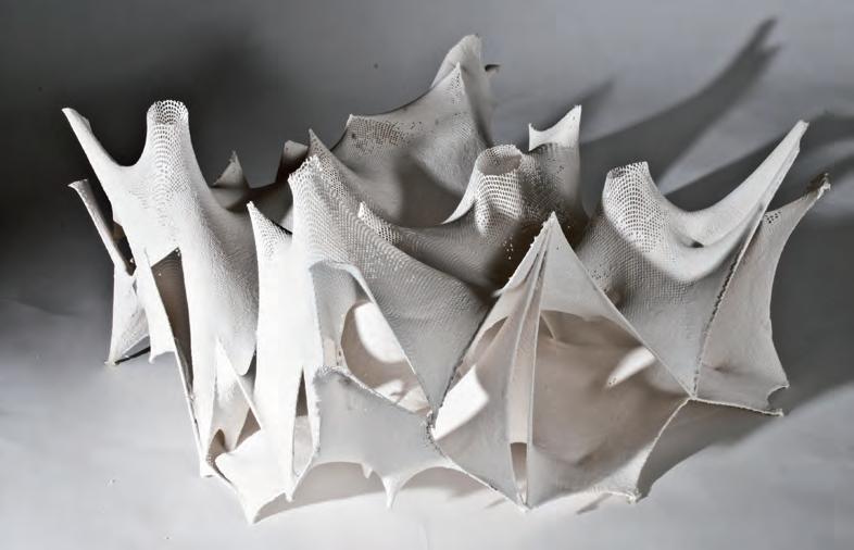

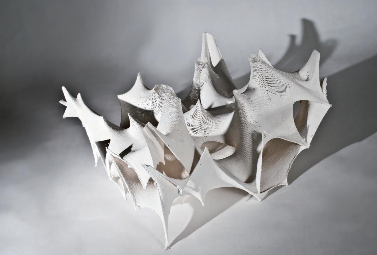
Using the findings and failures of the previous experiment to expand on the use of the forms for structure. A more habitble interior was the main objective of the experiment. Forces where applied to tension the fabric to shape the interior spaces. Methods of bringing the light into the space were attempted.
The fabric was tensioned at nodes randomly, working on shaping the interior geometry of two layers at two separate planes. The exterior tectonics emerged from the shaping procedures of the interior. A gradient of transparency was achieved by painting and spraying compressed air on a freshly painted thin layer of plaster mix. Openings were formed by pulling the material using solid discs, that were cut after the plaster had set.
A pixilation of light rays appeared in the interior by leaving the mesh exposed at the peaks of the eleveated tectonics that were pulled by the forces. The interior morphology emerged from the shaping procedures of the exterior. The number of nodes was excessive and has to be reduced. Adding more nodes at the edges did not solve the edge-buckling problem. Ground is wobbly and uneven.
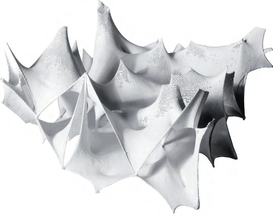
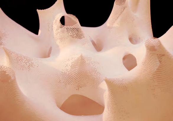
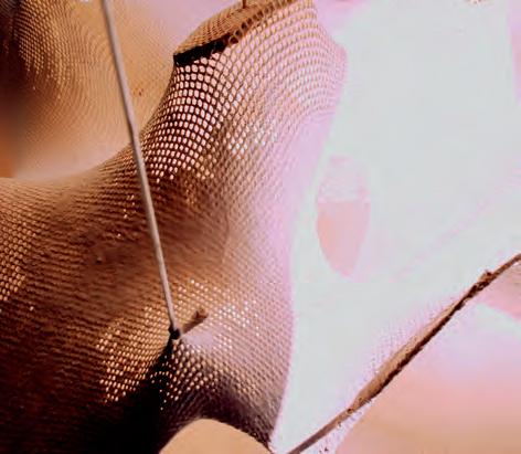
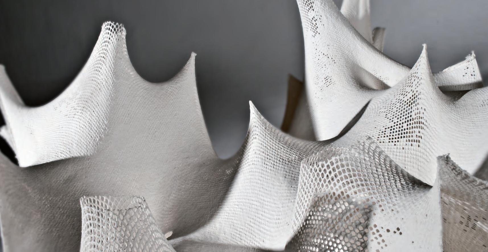
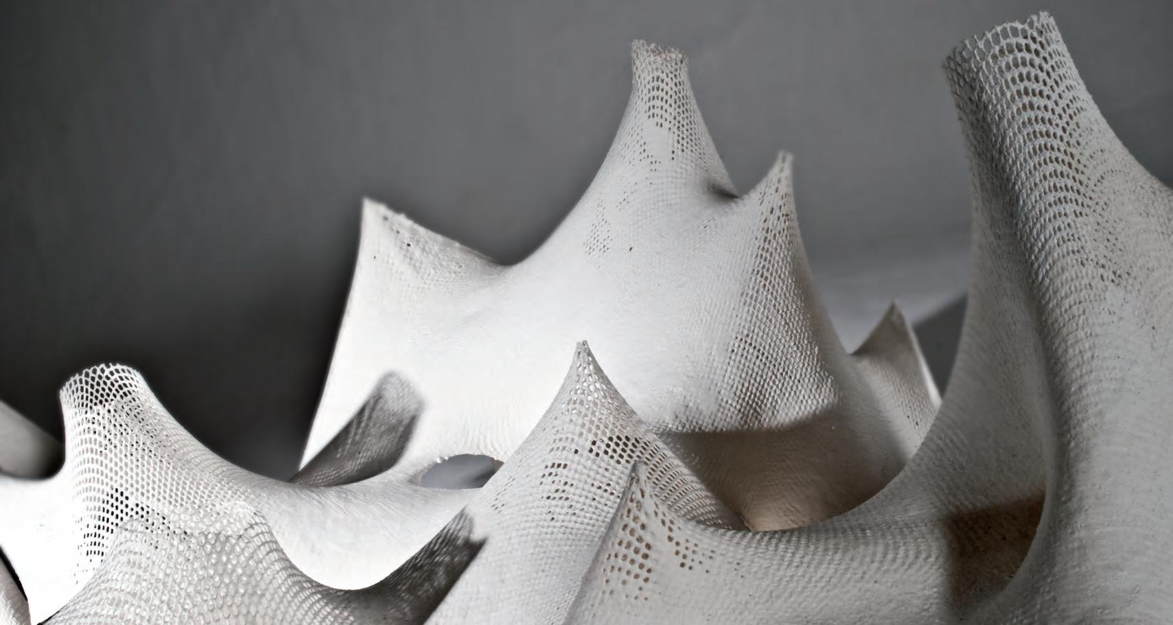
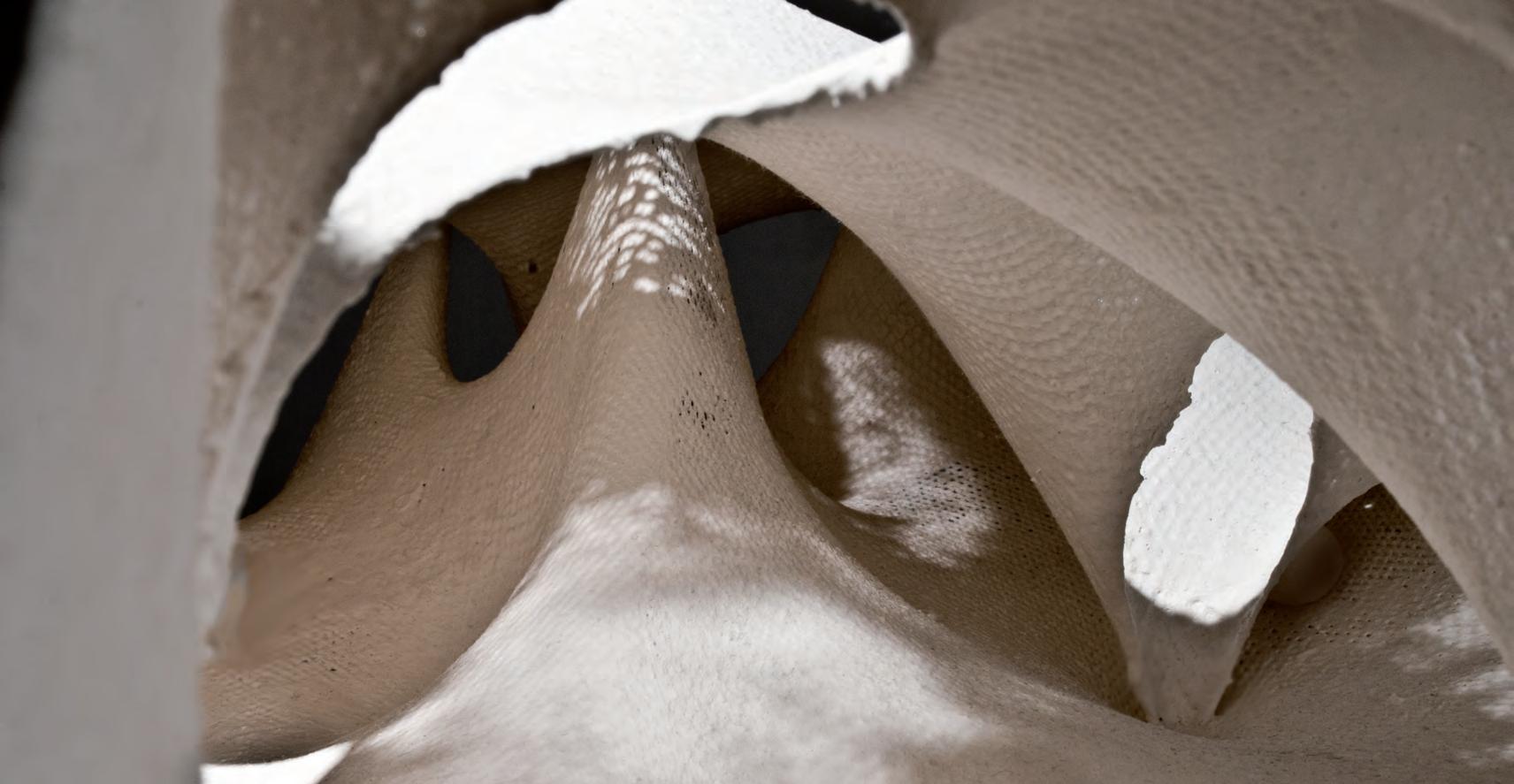
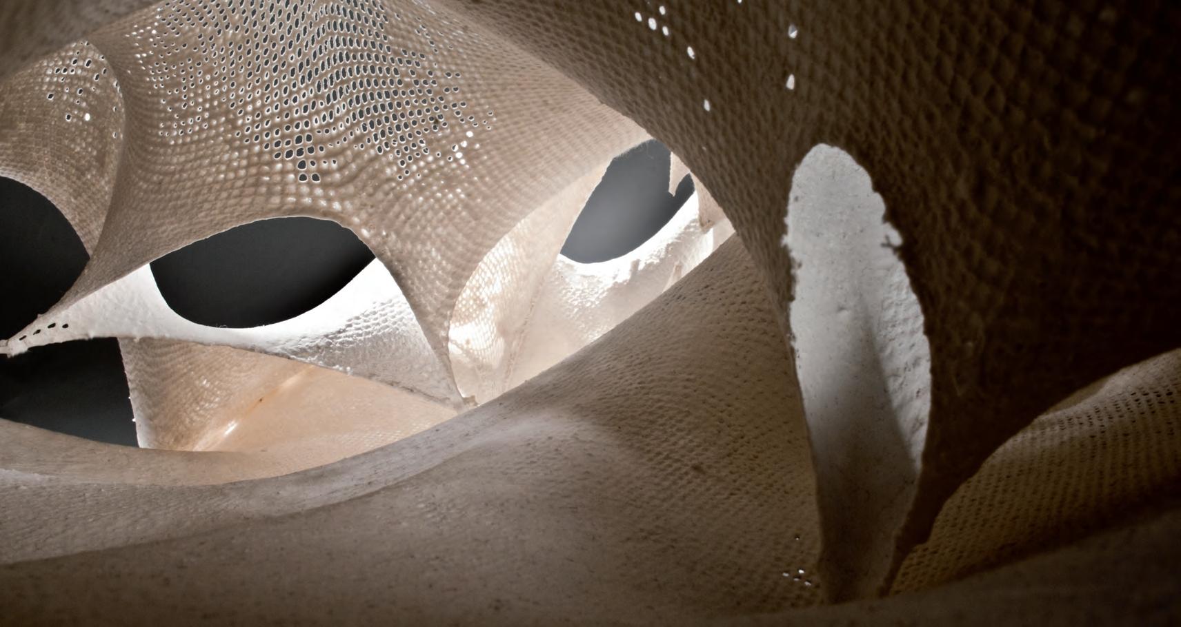
With he benefit of digital models as quantitative simulations acknowledged, the team set to attempt some analogue methods of testing. The aim was not to use the results of this analysis to inform the design, but rather to experiment with ideas that might lead to interesting digital simulations in the next steps.
The first attempt was to photograph the lighting conditions of AnaHybios 2.1, while moving the light in the direction of sunlight from east of the camera to west. The attempt was merely an observation on the differentiation of sunlight brought into the space through the pixelated perforations and the light wells.
The second attempt was to separate the geometry of the model to parts, where these parts could be understood and studied. The curvature of the models was highlighted by the projection of an orthogonal grid generated through Rhino3D.
The resultant images show the curvatures in a clear manner, and showed interesting possibilities for the multi-functional use of the generated geometries. These images however lack in useful data that could be manipulated and used as a design parameter. A good alternative to such method would be isotropic analytical images that analyze curvatures more locally.


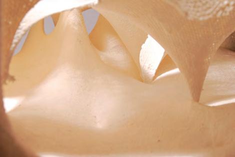
Canopies to shelter entrances
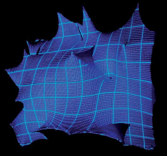
Raising the roof to differentiate heights
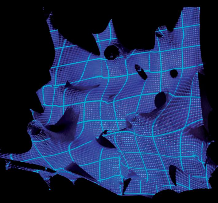
Possible rain water catchment?
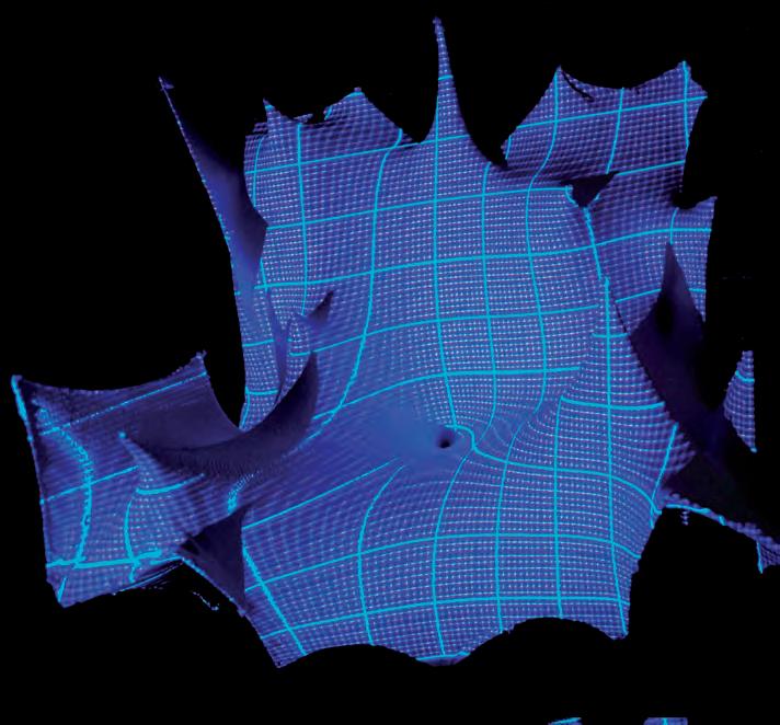
Sudden difference in height creates interesting depressions
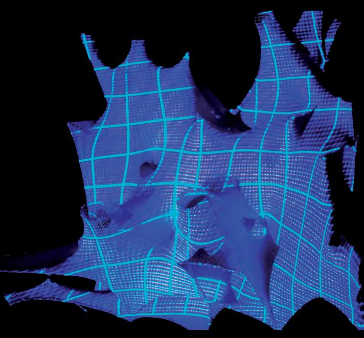
ARCHITECTURAL ELEMENTS
After a number of iterations in the physical and digital interface we started the analysis of the elements. A catalogue to identify the architectural elements that could drive the design is the goal of this evaluation stage. Parts of the physical model are zoomed in to observe the different spatial configurations that have evolved during the experiments.
The first diagram describes a simple roof form. The edges are restrained and the central node is pulled upwards. This results in a tent form. The weft and warp clearly describes the force lines. This also gives us a basic understanding of the structural behaviour of the fabric.
In the second diagram 2 layers of the fabric are pulled, one into another. This increases the stiffness of the elements and also results in forms that resemble structural columns and service cores. They will contribute in transfer of loads from the roofs and floor slabs to the receivers. The spaces inside will perform as service cores, which will accommodate lifts, stairs, ducts for HVAC, electrical, plumbing and fire ducts.
Single Point Restrain/ Tent Forms Overlapping layers of Fabric/ Columns and Service cores
Multiple point restrain/ Openings and Arches
Pulling fabric through another layer/ central coulumns + interesting space
The approach of the design would be as a biological model. Exchange of people light, air, and waste between the building and the exterior will be focused. The third diagram represents a model of a opening derived from the physical model.
More iterations of the element would be generated to overcome the environmental pressures. The gradation in opacity described in diagram 6 aids in creating differential natural lighting inside the spaces. Incisions in topology creates light wells
of Restrain Restrain along a curve to create openings
Evaluation: The element analysis gives us a start on how to catalogue different spatial elements in a building generated from dynamic relaxation driven by differential spatial qualities. Several variations of the elements have to be generated to incorporate them as a driving parameter in the design. This will be looked into in the following experiments.
Openings in Fabric/ Light and ventilation
INTERIOR ELEMENTS 2.0
Opaque to transparent/ variation in natural lighting
Pulling at edge/ Increased Stiffness at edges to resist buckling
Incision in topology : Light Wells
Restrain of nodes at ground/ Structural Columns
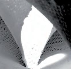
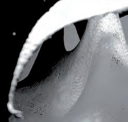
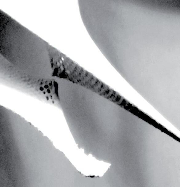
EXTERIOR ELEMENTS 2.1
Single Point Restrain/ Tent Forms

Openings in Fabric/ Light and ventilation
Single Point Restrain/ Tent Forms
EXTERIOR ELEMENTS 2.1
Restrain along a curve to create openings
Overlapping layers of Fabric/ Columns and Service cores
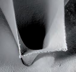
Opaque to transparent/ variation in natural lighting
Overlapping layers of Fabric/ Columns and Service cores
Multiple point restrain/ Openings and Arches

Pulling at edge/ Increased Stiffness at edges to resist buckling
Multiple point restrain/ Openings and Arches
Pulling fabric through another layer/ central coulumns + interesting space
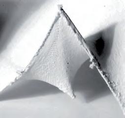
Incision in topology : Light Wells
Pulling fabric through another layer/ central coulumns + interesting space
Restrain of nodes at ground/ Structural Columns
Openings in Fabric/ Light and ventilation
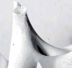
Restrain of nodes at ground/ Structural Columns
Variation in incision/ Manipulation of light in space
Opaque to transparent/ variation in natural lighting

Variation in incision/ Manipulation of light in space
Pulling an incision/ Light Niches
Pulling at edge/ Increased Stiffness at edges to resist buckling
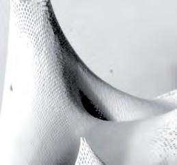
Pulling an incision/ Light Niches
Extraction of interior and exterior elements from the physical model that could be quantified and serve particular functions in the digital model.
Pulling 2 layers of fabric towards each other to tension edges
Incision in topology : Light Wells
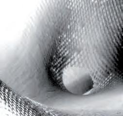
Pulling 2 layers of fabric towards each other to tension edges
“A physical model (as verb) is excellent because, bound as it is in actual reality (AR), it is qualitatively rich: full of dense information about physical forces and strains, construction sequence and detail. It is very difficult, however, to get quantitative information out of this kind of model. Digital models, on the other hand, are excellent because they are rich in quantity: indeed, they are composed of quantities, and this content makes them invaluable in any building culture that must calculate before constructing.”
Mark West/ CASTWe experimented with digital form finding methods, simulating the process of making the analogue prototypes. Different generations were produced, as well as the assembly logistics of the building components
A cellular grid was used to generate a frame for pathways to have a more even floor to walk on. This time, the modelling was done to scale. Points were restricted at the pathway edges to create ramps on the raised platform.
The mesh was relaxed within the grid cells to create blob-like forms by restricting the outlines of the grid. The roof membrane was stretched towards the centre of the cells. The idea is to create a circulation path within the space, where depressions within the grid cells could be used for seating. Although more control was gained over the digital form finding process, there were a lot of restrictions with using the algorithm.
Different architectural elements, such as columns, arches for openings, pathways, ramps and seating depressions were explored. Material behaviour and mesh qualities could not be embedded within the logic of the algorithm. Deforming the mesh was not done in real time either, which was a major restriction. The importance of this digital simulation is to gain more control on the forming process of the prototypes, by following architectural strategies to generate space.
Added floor form work grid
Membrane tensioned towards the centroid of grid cells to make seating area/ lowered platforms
Membrane is restrained by grid to make stable pathway
Tensioning of opening arch to mark entrances.
Membrane tensioned to ground level from raised platform to make ramps
Roof membrane tensioned towards centre of grid cells to make columns
For the next generation of prototypes, the analysis of findings of the previous models was, taken as a starting point. The next prototype adopted the light pixilation and shape tensioning on the roof, but also benefited from the digital simulation to advance from its successor.
HYBIOS 3.0 used a laser cut square grid that was generated for the previous DigiHybios 1.0 Generation. The grid was used to restrain pathways, and generate architectural and structural elements based on the circulation path as suggested by the grid. The floor grid had a central plan. Several pod shapes, to be used as seating areas,were generated by pulling the fabric along random vectors.
A similar logic of design was followed, as tested by the digital simulation. Strategies mainly including extending ramp ways for entrances, covering these with welcoming arches, and dropping down columns to support the roof shell that also create stimulating lighting gestures, all added to the improvement of the design as an inhabitable space.
The idea of the developed form work is that the floor grid could be reused to cast several other HYBIOS. The model was constructed to a scale of 1:50 for a 20m x 20m space. Essentially the point of this experiment is to control the reusable form work to form the structures. The model also was used to carry forth the modelling process to a specific scale, and generated semiotic and structural features to be tested.
The next few pages demonstrate an illustrated documentation of the process of constriction of the next prototype, and a brief analysis of the result. Complexity could be increased, by introducing a second platform and three layers of membrane in the next experiment.
The scale value of the model contributed to the clarification of a placement strategy for elements of different function. The generated prototype allowed for the modelling of an inhabitable space of an improved spatial quality. More control could be added to the placement process, especially when generating space within a measured area. The result of this model could improve the quality of the virtual one, by adding more complexity to it.
pathways for circulation inside the
is resolved through experimenting walkways and ramps on a physical model. The process is similar but the fabric is restrained on a flat grid where pathways are necessary. This grid can be re configured to reuse in different spaces.

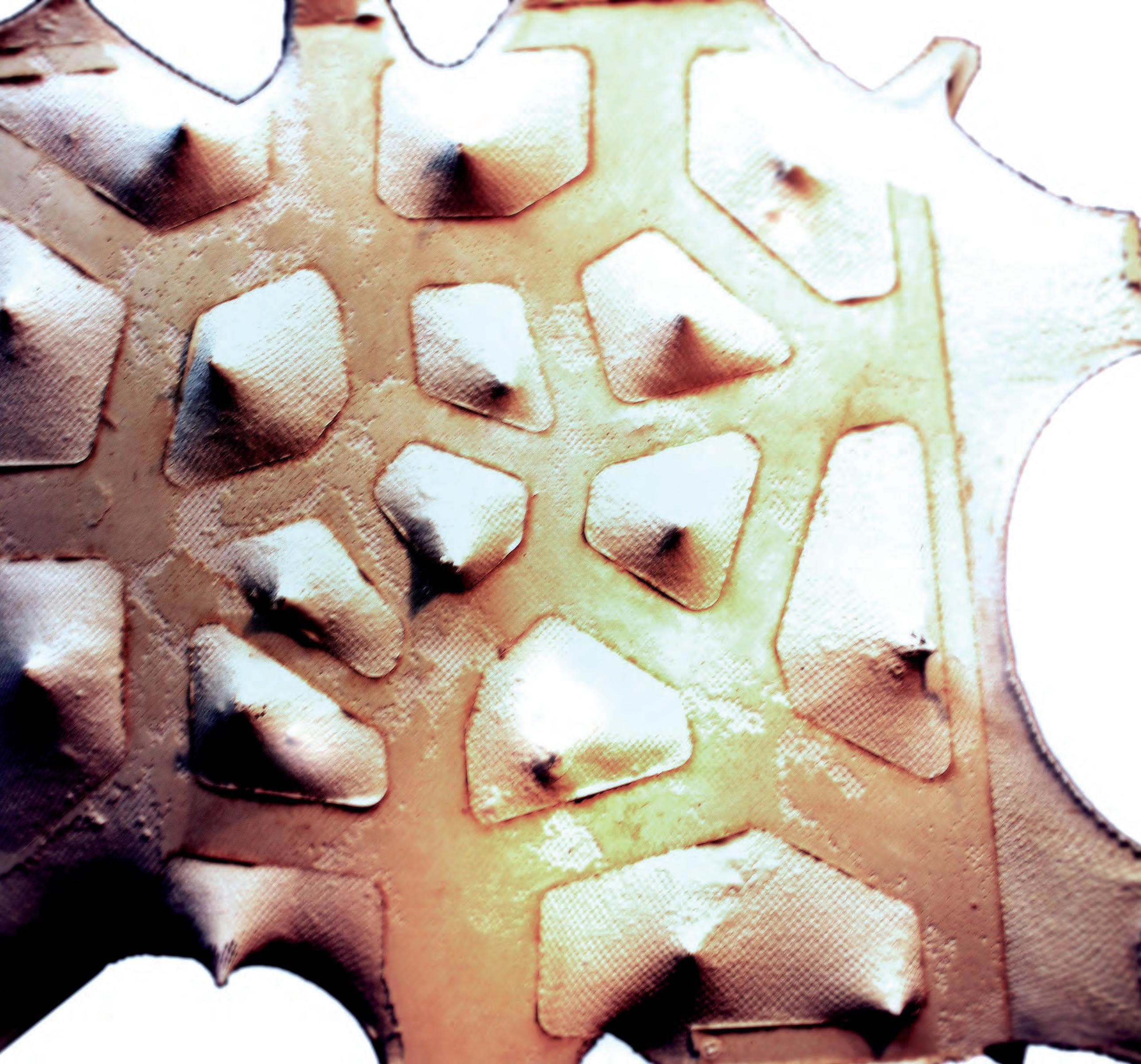
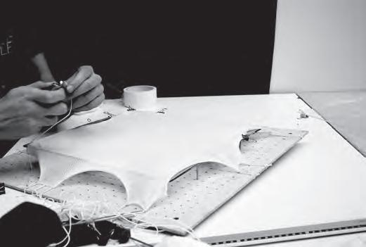
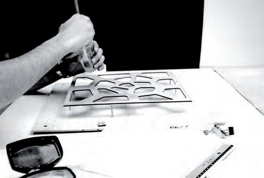
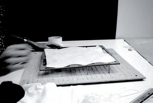
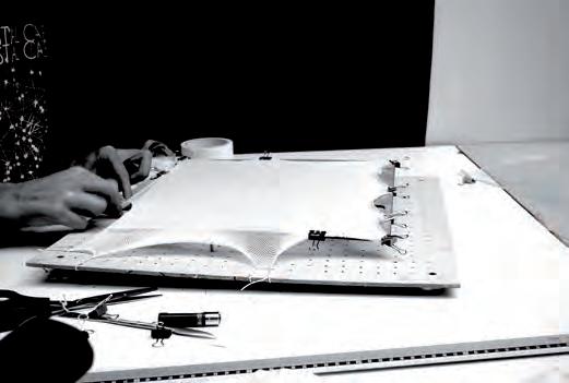

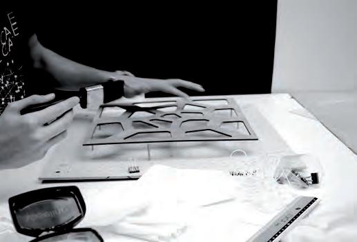
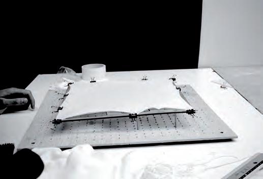
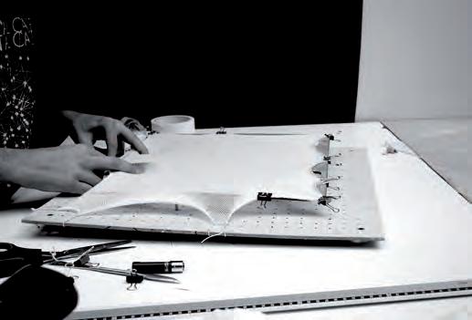

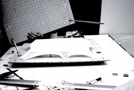
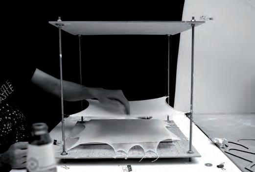
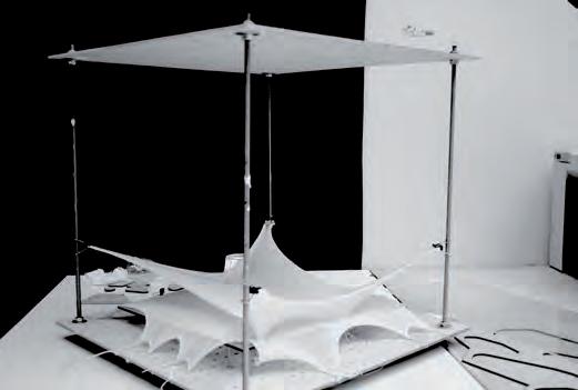
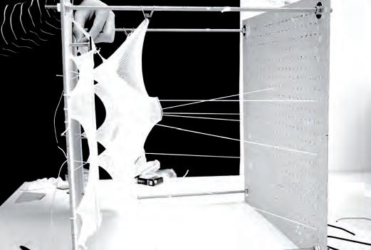
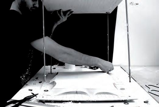

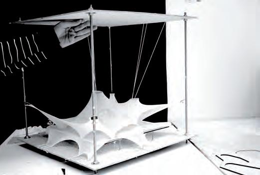

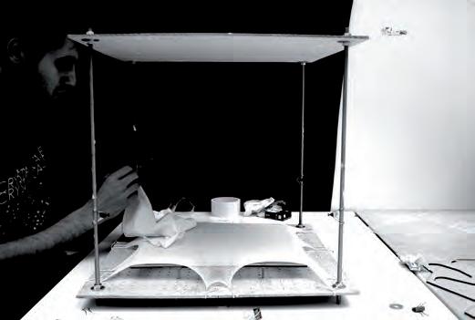

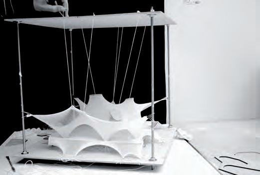
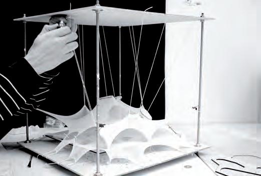
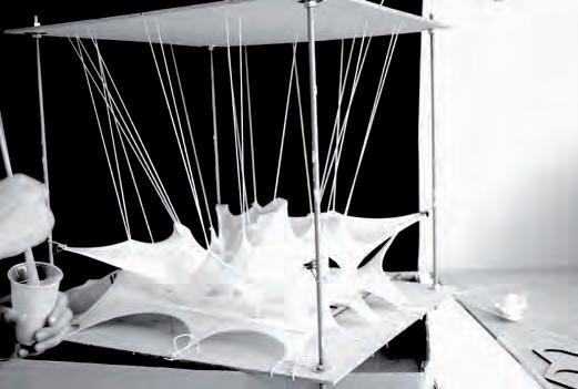
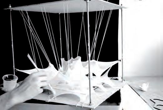
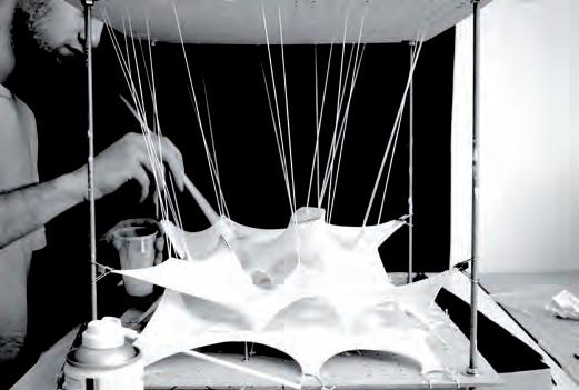
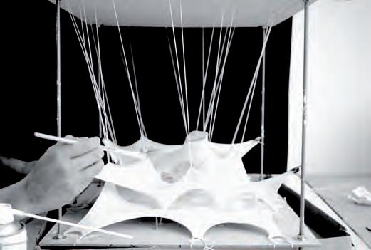

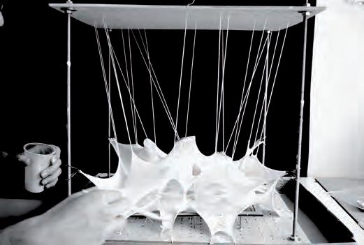
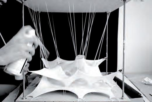
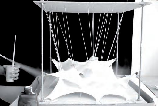
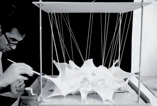
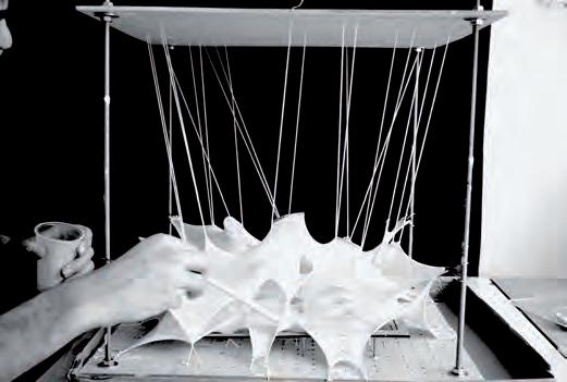
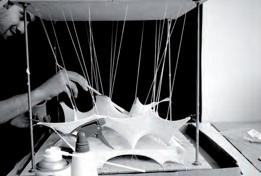
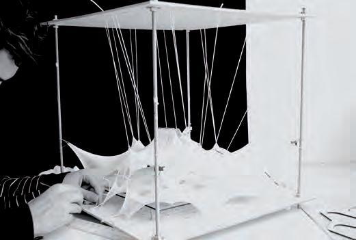
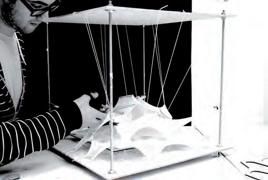
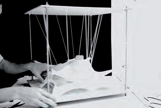
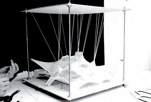

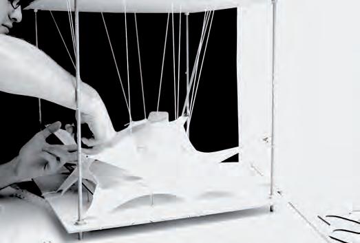
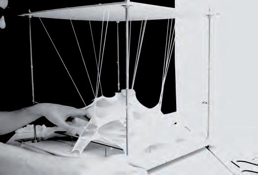
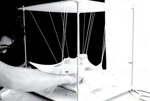

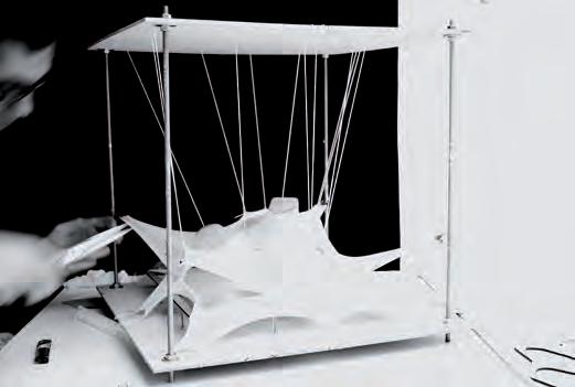
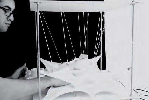

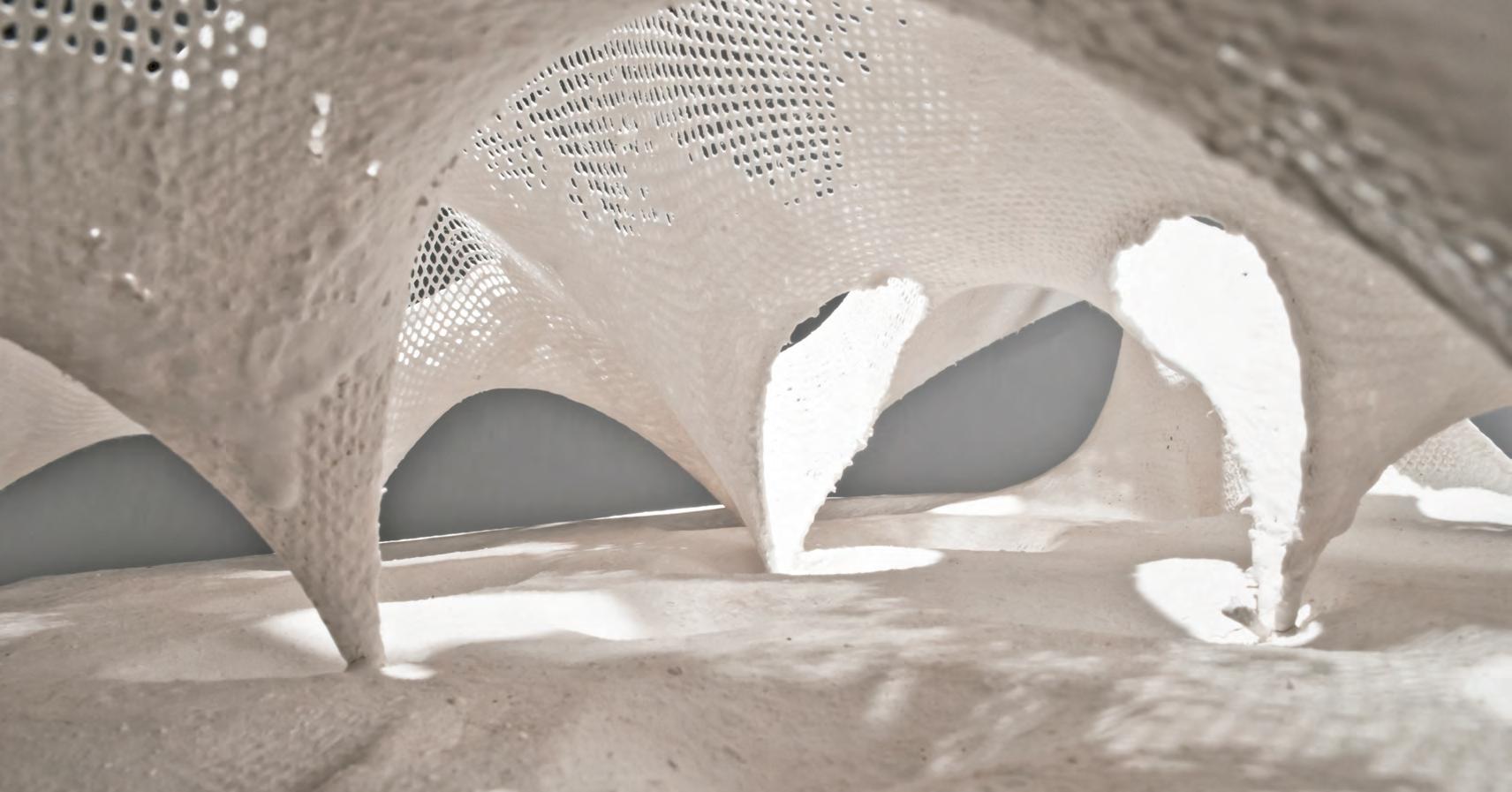

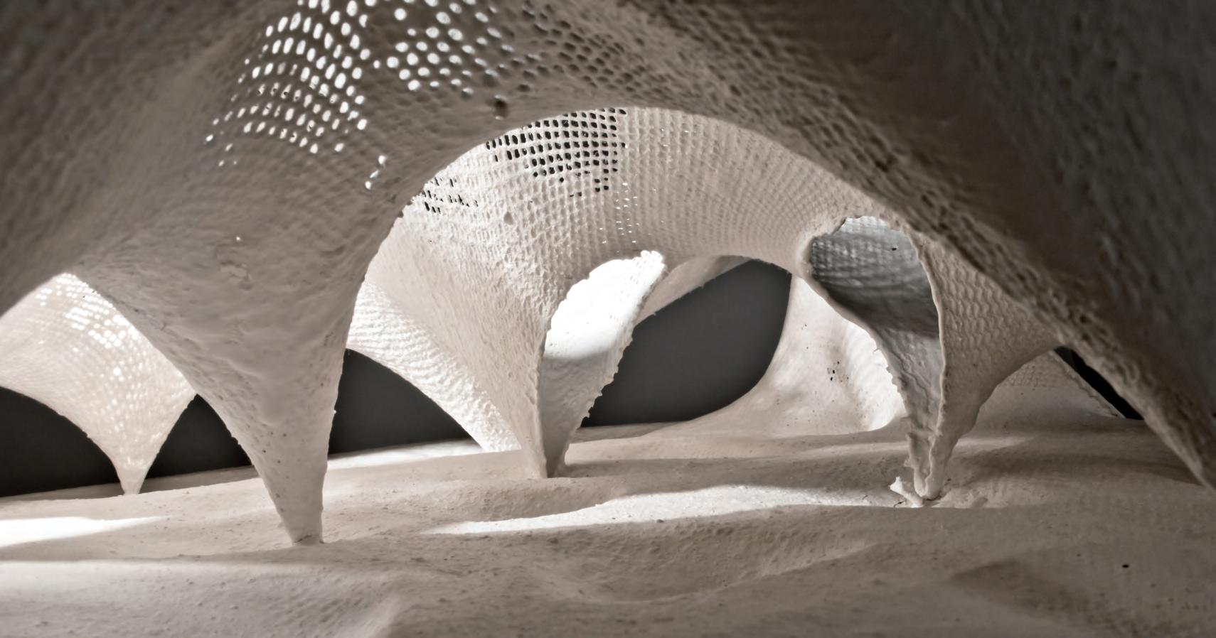

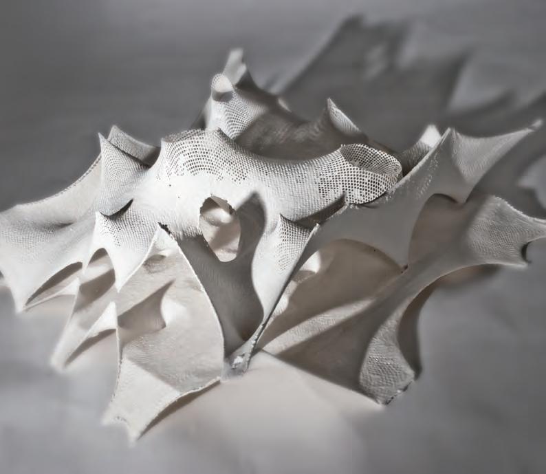
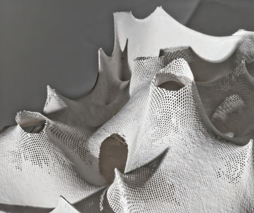
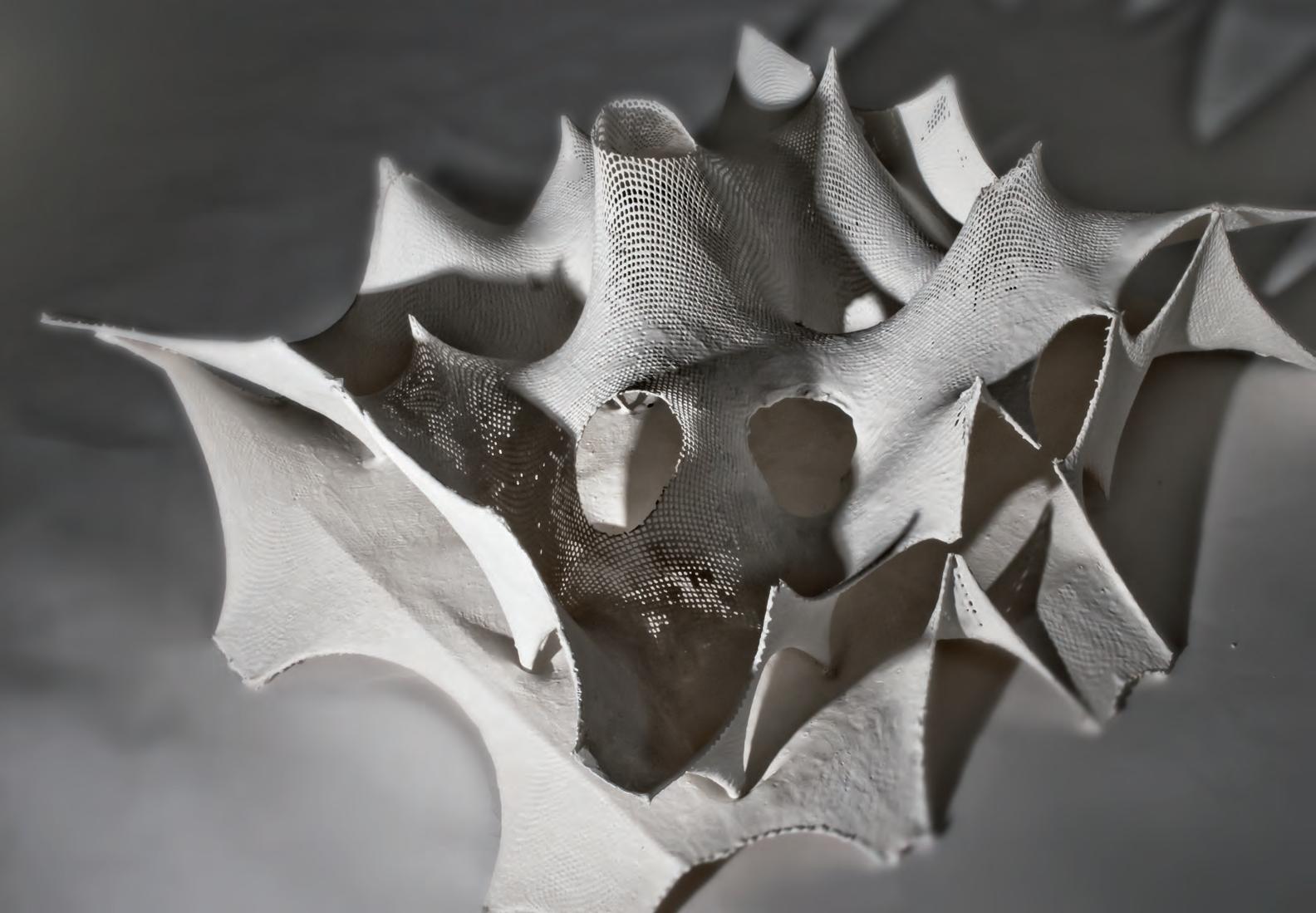
Fig 3.61.1 Analogue model 3.0. Exterior morphologies( Top left), Openings in the geometry for bringing in differential lighting qualities(Top right), Interior heights in proportion to floor areas and the external form(Bottom)
Introducing solutions to solve the main problems of the previous experiment. Scale was kept in mind as the model was constructed. This time the prototype was built to a 1:50 scale. The main ambition of the experiment is to achieve a more habitable prototype spatially, with even pathways to control the circulation rather than wobbly floors. The prototype was also produced after the digital simulation, switching the order to observe the results of the procedure.
The digital simulation was taken as a guideline, but the analogue prototype differed in its forming process. Several different procedures were taken as the analogue prototype was constructed. A cellular floor grid was laser cut as an output from the algorithm that generated the computer simulation. The Procedure was reliant on the floor grid to restrict a more rigid and ordered circulation system. The fabric was pre-tensioned onto the grid, and structural pillars from the second layer were tensioned towards the centers of the cells. Ramp-like edge tensioning was created where the pathways met the edges to allow for a continuity of circulation flow from the exterior to the interior. Arches were formed on top of these entrances within the second layer.
Although more control was gained over the forming process, several problems also were observed. The floor grid did add a more architectural dimension to the space, solving the problems of the un-even ground. The space remained single leveled, which resulted in a more monotonous space than what was aimed for. The release used left an unpleasant yellowish residue. When drawing the pillars towards the cell centers, interesting depressions were created between the pathways that could provide programmatic opportunities such as seating areas. Bringing things to scale helped envisioning the problems that could arise with the construction methods and materials. The analogue prototype yielded substantially different results than the digital one.
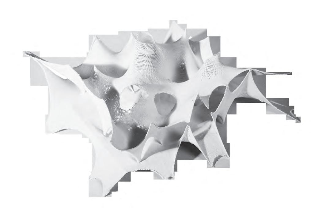
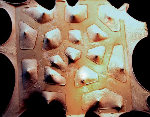
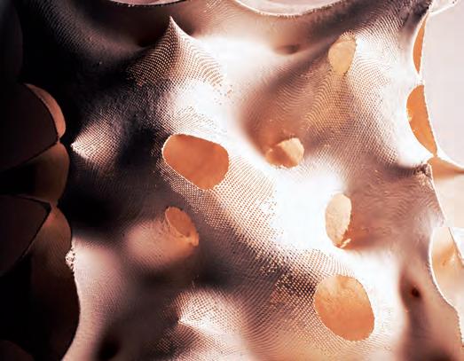

Cutting edge materials, as used by the construction industry, have been discussed in depth in the previous chapter. Prior to experimenting with the real materials a concept layering was proposed by analysing the material behaviour and their physical properties. Concrete cloth seemed to be the apt material for realscale form-finding.
The test charts by the brand described the lack of tensile strength in the material. To overcome this we looked at high strength geo-textiles. These are being increasingly used in the industry for stabilisation of soil in road and construction industry. Coupling concrete cloth and geo-textile seemed to solve the lack of tensile strength.
CONCRETE CLOTH / FORM WORK/
Concrete Cloth (CC) is a flexible cement impregnated fabric that hardens when hydrated, to form a thin durable water and fire proof concrete layer. CC consists of a 3 dimensional fibre matrix containing a specially formulated dry concrete mix. A PVC backing on one surface of the cloth ensures the material is water proof. Hydrophilic fibres on the opposite surface aid hydration by drawing water into the cement.
When water is added the material remains flexible for 2 hours and then sets rapidly. It can be hydrated either by spraying with water or by immersion. Once set, the fibres reinforce the concrete preventing crack propagation and providing a safe plastic failure mode.


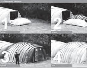
BarChip FIBRE / REINFORCEMENT
BarChip fibres are manufactured from minimum 550 MPa high tensile strength modified poly olefin and similar to steel re bar. The structural fibre range has a contoured surface embossing treatment to maximize bond with a cement matrix.
The base poly olefin is highly resistant to the majority of aggressive agents and will never oxidize when exposed to the conditions which cause steel to rust.
BUTONG / LIGHT WELL PIXILATION
A concrete based material that is translucent, transparent or opaque depending on atmosphere. The material can easily be modelled three-dimensionally. Offering freedom of form to designers of all fields.
Three major finishes are
1. Butong Pattern, 2. Butong Struktur
3. Butong Glazed
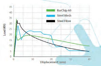
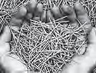

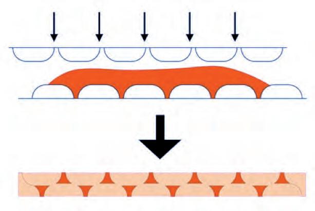
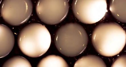
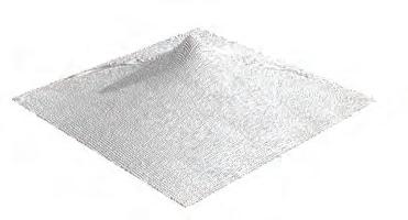
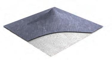
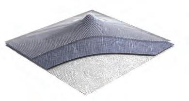

The roughness of the textured material on to which the BarChip re-info red concrete has to be sprayed on would help concrete stay in place while spraying is done. Extensive labour is involved in cutting and placement of steel bars along complex curves. If a mesh could solve this issue it will be a great advancement in the construction of doubly curved concrete structures. Thus the BarChip fibre and mesh reinforcement works together with concrete to form the structural surface. This proposal will be tested on in the further experiments to correct and refine the material layering.
Concrete Cloth is a viable option for a material that forms and creates a base for reinforcement in the proposed wall assembly. More thorough testing has to be done on the material, to test its capacity to shape and reinforce. At the moment options are kept open to create that wall assembly, but these options are still kept open to experimentation, where the best results would lead to a final assembly proposal.
Concrete spraying is proposed for structural surfaces. BarChip reinforcement has been studied in detail in the material studies. A proposal to have BarChip fibre as reinforcement has been conceptualized, to improve the strength of the concrete. The physical properties matched all conventional standards, the only drawback being short fibres. The forces have to be channelled along a fixed path and a steel mesh could solve the issue.
Several physical and digital models have been described in the previous chapter. As a part of developing the material system it came to a phase where testing and evaluating different materials to achieve the forms in real scale had to be carried out. Analysis of the fishnet fabric that was used for the plaster models was the starting point. But lack of stiffness in its elements was the major drawback. It cannot withstand the loads of a structural surface. Then it came to the question of what materials could be used to achieve similar form but has a better tensile capacity and stiffness in its elements. We listed out seven materials to test. They are fishnet fabric , woven cotton , medium scrim , PVC sheets , Welded steel mesh, woven steel mesh and concrete canvas.
Experiment
A 1 m x 1 m x 1 m frame is setup in wood. 4 L- shaped angles are fixed at 4 corners to attach different materials to the frame. 1 meter square samples of each material is prepared. A simple digital scale is used to measure the force during the displacement of the fabric.
Method
The centre point of every sample material is marked and a hook is attached to it (Fig 3.72.1). The digital scale is attached to the hook and the force involved to measure the force at a displacement of every 100 mm is measured. Every sample is tested till it failed. The curvature for each sample is noted.
The detailed evaluation is recorded in the tables listed. We see the different forces that are involved in the stretching of the fabrics and meshes. The curvature varies for each material due to the variation of stiffness in the nodes. Where the stiffness is high the force required for the displacement is really high. The evaluation states that the doubly woven steel mesh works best in the context. But the force required for the displacement is really high. This will result in highly sophisticated machinery to apply the required forces in real scale fabrication.
The interesting observation for the experiment was that the steel mesh could be formed to any required forms and could be used to project concrete over it without using a form work. The prestress involved in stretching the fabric could help in reducing the thickness of the concrete to be applied over it making the structure light weight. In the next steps we will have to test a concrete shell using this technique.
More materials, which require much lesser force for damping into an equilibrium form, and have the necessary stiffness and strength to make the shell structural, will be tested. Is there a method where materials with different properties could be layered to achieve forms with very less force involved but still have high amounts of stiffness in them? Could coupling a tensile structure with a compression material solve the issue? These topics will be tested in the forthcoming experiments.
Fabric Fishnet
Fabric - Woven Cotton
1. Very Elastic.
2. Desired curvature.
3. Easy to handle.
4. Negligible self weight.
1. Easy to handle
2. Economic
3. Low self weight.
Medium Scrim
(PVC)
1. Easy to handle
2. Economic
3. Low self weight.
4. Possibility of layering materials.
1. Very Elastic.
2. Easy to handle.
Concrete Cloth
1. Can take tolerance while stretching.
2. High Stiffness to layer concrete over the fabric.
3. Replacement for form work.
4. Low self weight.
5. Easy to handle.
6. Uniform curing of concrete due to the wetness of the fabric.
7. Higher strength where there is more curvature.
8. Good compressive strength.
1. Force is not scaled proportional with displacement.
2. No stiffness in elements.
3. Cannot take load incase of layering material.
1. Not elastic
2. Force required to deform is very high.
3. Lack of stiffness in elements.
4. Possibility of layering materials is low.
1. Not elastic
2. Force required to deform is very high.
3. Lack of stiffness in elements.
1. Starts to rip when high forces are applied.
1. Force is not scaled proportional with displacement.
2. No stiffness in elements.
4. Difficulty in coupling with concrete.
1. Force is not scaled proportional with displacement.
2. Creasing in Fabric
3. The PVC backing starts ripping beyond 400 mm stretching on a 1000mm x 1000mm sample.
4. Accumulation of water where the fabric is pulled down, during the hydration process. Water drainage on the form needs detailing.
5. Dry mix inside leaks when cuts are made on the fabric resulting in weak areas on the fabric.
6. Low tensile strength.
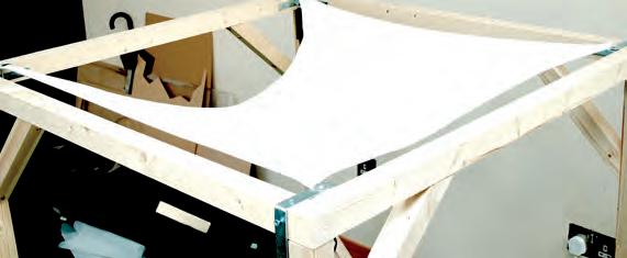
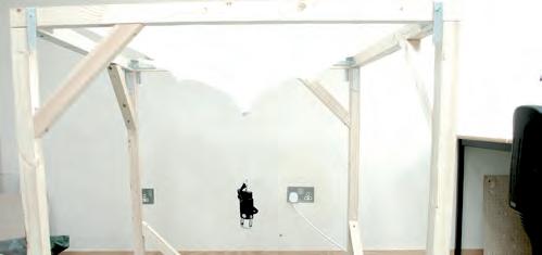

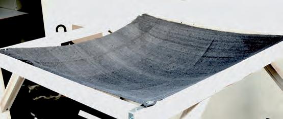
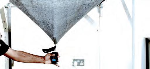


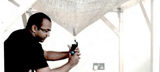
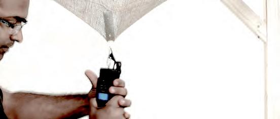
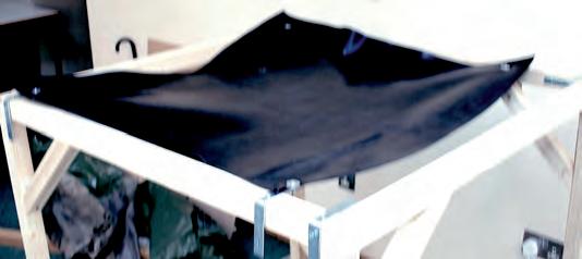
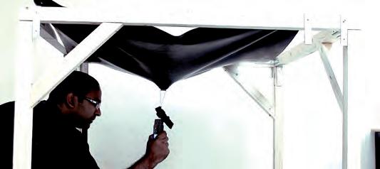
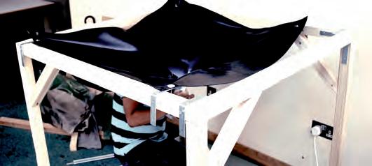
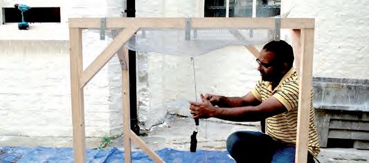
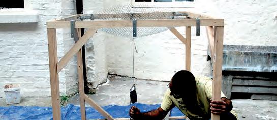

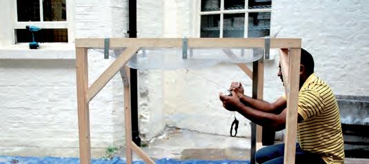
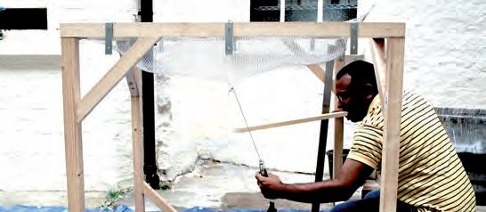
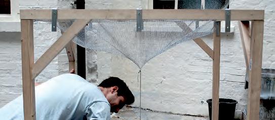
DEVELOPING CONSTRUCTION METHODS
We realised pulling demanded a large amount of force and so the method of pushing the fabric with a prop from inside was tried out. This worked quite well. 2 nodes were pulled and 2 were pushed from inside. The curvature seemed very impressive although the process was little tedious. It was now time to hydrate the material.
The minimum ratio of weight of cloth to water is 1 : 2. The cloth weighed 7 kgs. 14 kgs of water was measured and we started the hydration process. Initially the cloth was sprayed with water to make sure that the powder does not flow off. Second stage was to hydrate the fabric with a small bucket but making sure that the water was spread equally. 14 litres of water went into the process of hydration of the concrete mix inside the fabric.
The 1 m x 1 m concrete cloth was attached to frame at the four corners with nuts and bolts. A small puncture was created exactly at the centre of the square and a simple hook was attached to the fabric. The displacement test was conducted as in the previous experiments. The surprising result was the enormous force that was required to achieve a 400 mm displacement in the fabric. Another observation was that the concrete mix started leaking from the edges where the fabric was cut. But the fabric seemed to stretch quite a bit in tension. The next step was to restrain more nodes displaced from the plane.
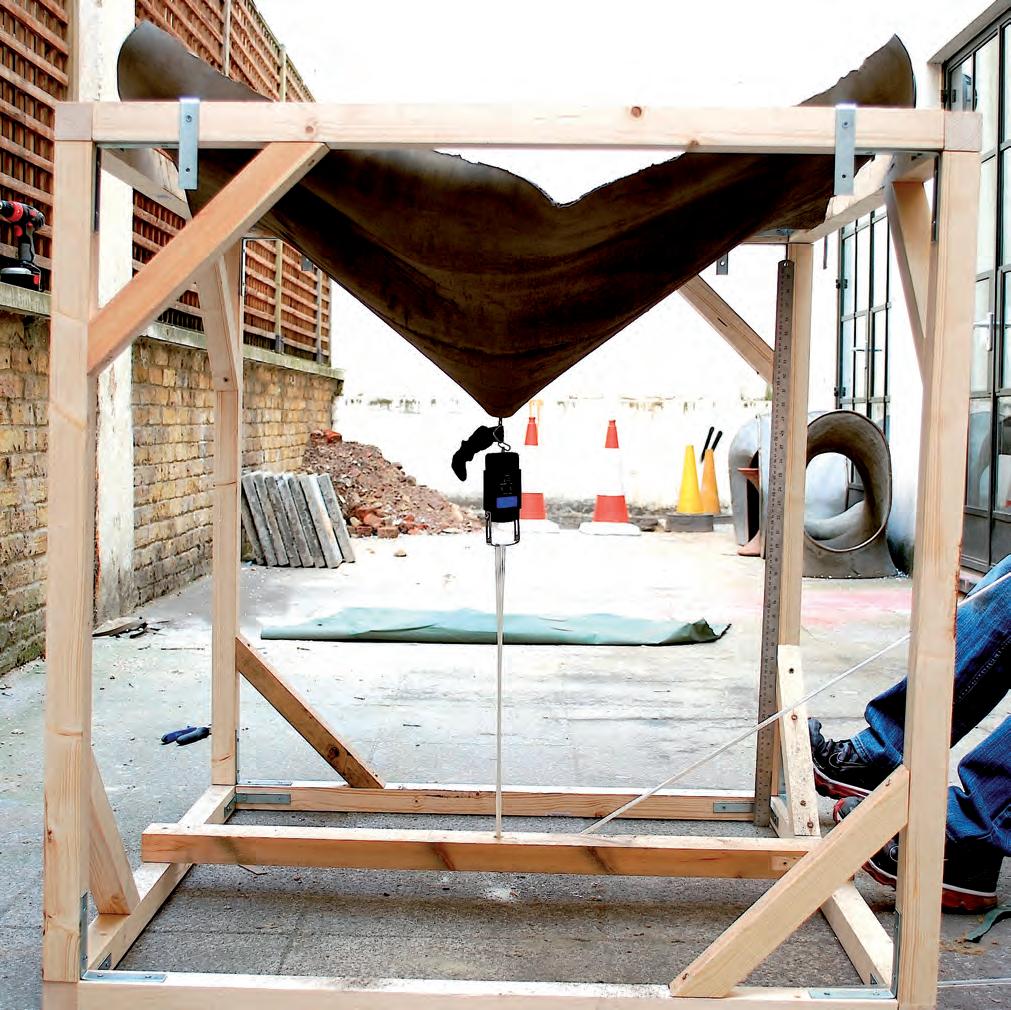
CONCRETE CANVAS HYDRATION
While the digital and physical experiments were being carried out, materials for the 1:1 prototype were acquired. We tested different materials to observe the deformations and stiffness. Concrete canvas seemed to suite the method to form a structural surface. It seemed stretchy and the 3 fibre matrix between the fabric and the PVC backing embedded in the concrete seemed to be very promising.
A 1m x 1m x 1m frame had been fabricated for the displacement tests. We decided to reuse the same frame for testing the concrete cloth. A sample of 1 sq.m. 5mm thick concrete canvas was tested.
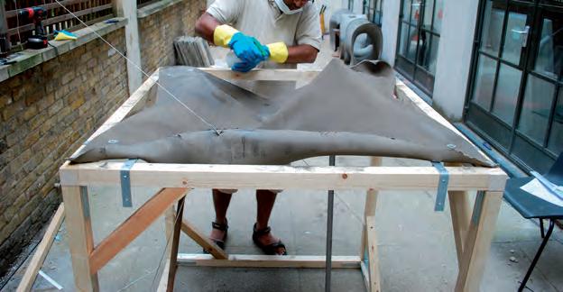
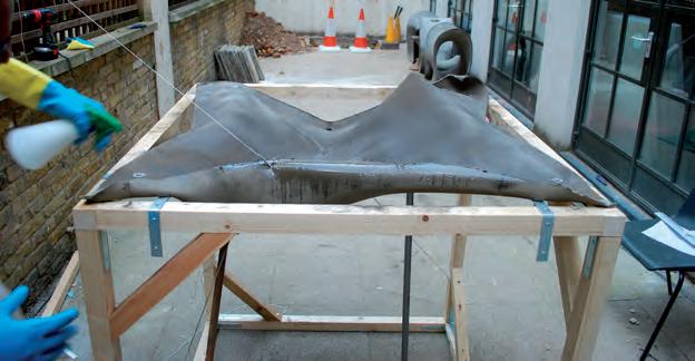
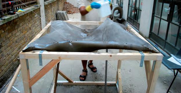

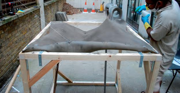

The force applied on the fabric ripped the PVC backing at several areas. This happened because the canvas is not designed to stretch. Creases started appearing at few portions of the stretched fabric. The process of hydration was really simple and this could be done by an unskilled labourer. The workability remained for 2 hours after hydration and the fabric achieved full strength in 24 hours. The result was a concrete shell with high stiffness along the curvatures. The curvature achieved was far from the ones we had achieved on the fishnet fabric. This happened due to the thickness of the material. Layering of materials could solve this issue and this will be resolved in the following experiments.
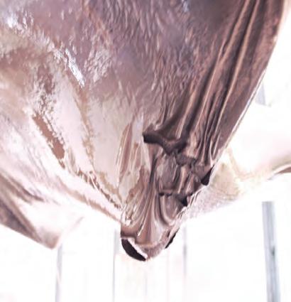
Fig 3.82.1: Resultant forms and material behaviour in the 5 mm concrete canvas test.
PVC backing starts ripping after a certain force applied for deformation(Top left), canvas tensioned before hydration process(Top right), Concrete canvas after hydration and curing(Bottom).
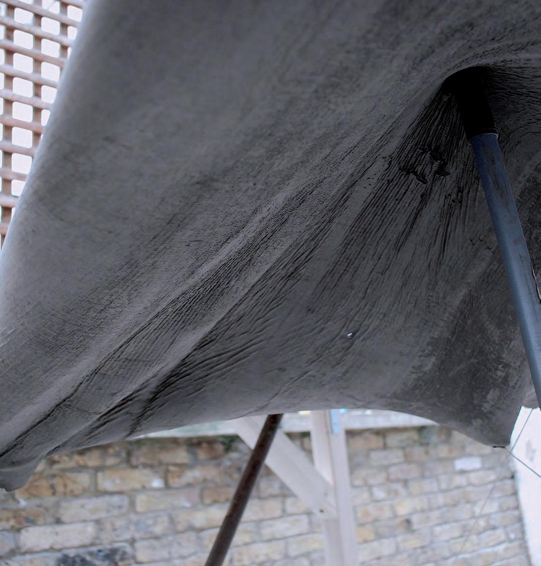
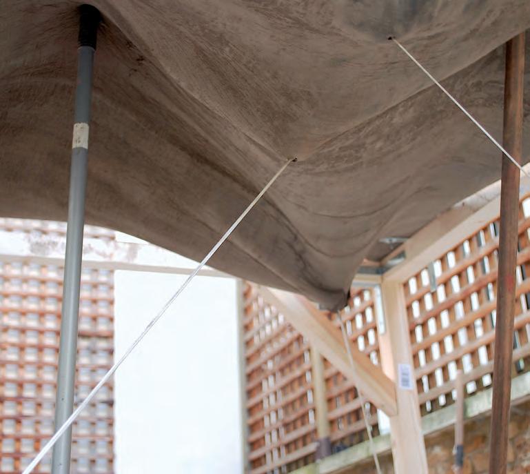
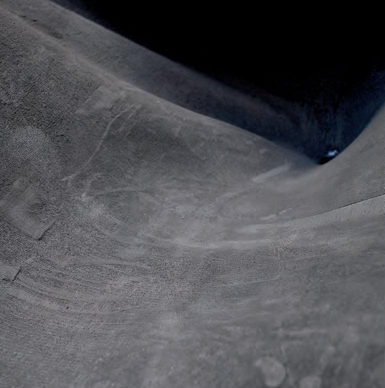
To increase the functionality of the next prototype, more complexity was added to the space by adding a third level. Three layers of the fabric membrane were stretched towards one another this time. The objective of this experiment was to reuse the form work used in the previous one while adding a new restraining grid, this time for the second level. The prototype resulted in a multilevel, spatially differentiated space, where new elements of support came into play.
The new level in HYBIOS 3.1 was supported by tensioning the middle layer of fabric towards the first layer, which had stretched ramps leading towards the circulation paths of the grid. The result was arch-like support members, which where further supported by tensioning the third roof layer into the ground layer through the new mid-level grid. The resultant form had an interesting depression on the tectonic of the roof, and a stiff column with 3 layers of fabric reinforcement stretched to full capacity.
The prototype created was the most successful one to that date. It used the pixilation of light on the membrane, had interesting light wells, a more complex, multi- level space, and more differentiation through its interiors. The model was the best crafted, due to the extensive experience that was already gained by creating previous prototypes. However, there is still more room for improvement in the design generated.
The prototype followed a square plan, which was seen as confining to the tiling of each one of these prototypes. Next steps could include attempting a geometry with more end nodes could be used next to experiment with tiling the pieces in a more variable assembly and more accessibility to each part.
The space formed, although was to a scale of 1:50 again, was a bit too small for accommodating the programs of an iconic building. The space had to be modelled with a different geometry for the grid, with more access points within the autonomy of a larger space. The elements generated to hold the second level up had to evolve to a more stable geometry and a more applicable method of construction.
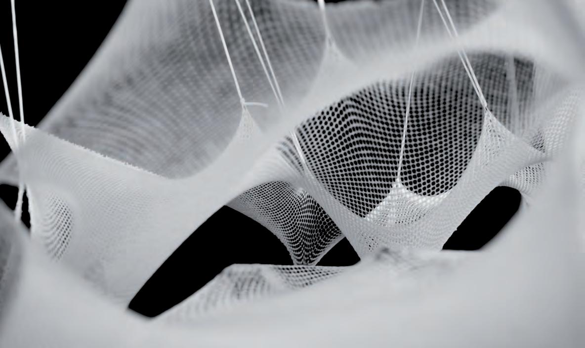
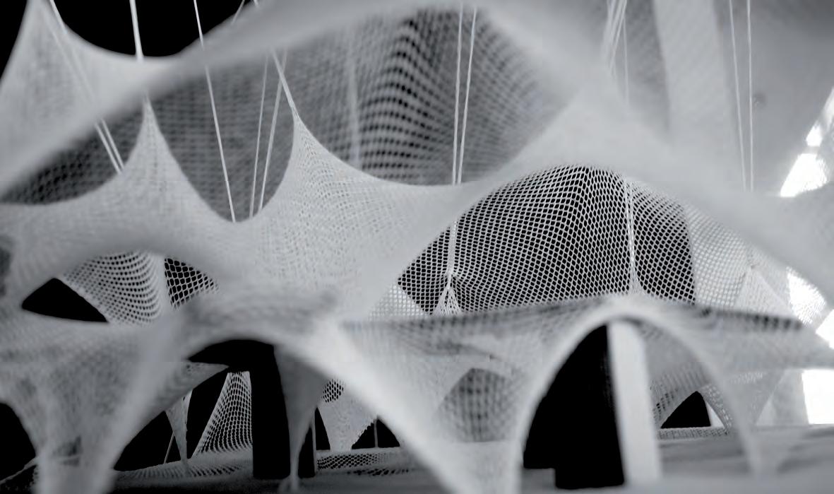

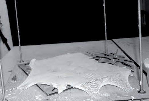
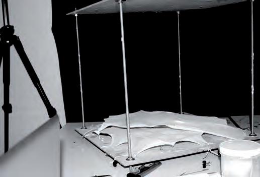
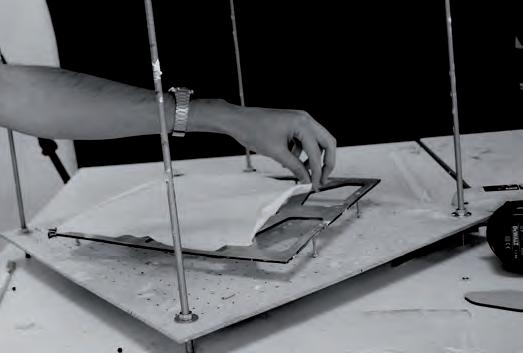
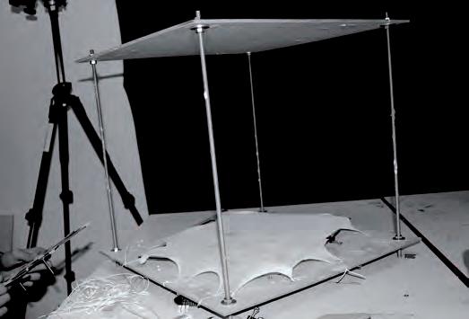
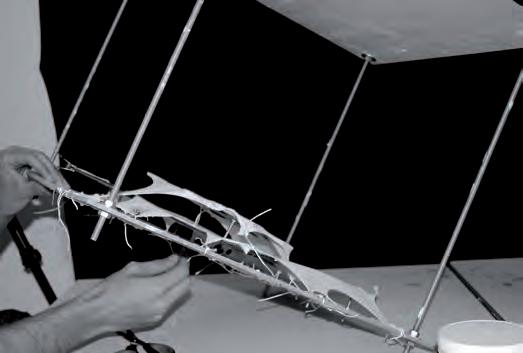
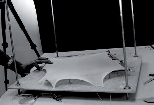

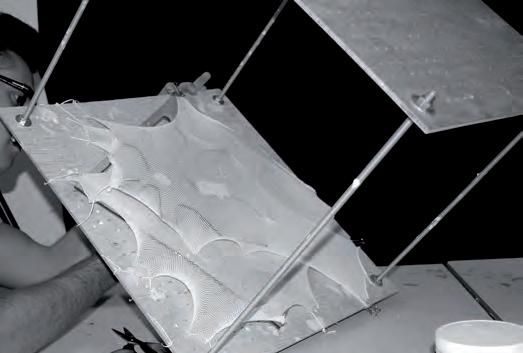
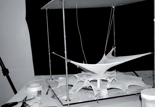
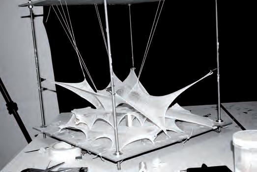
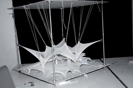
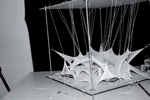
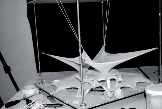
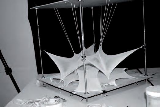
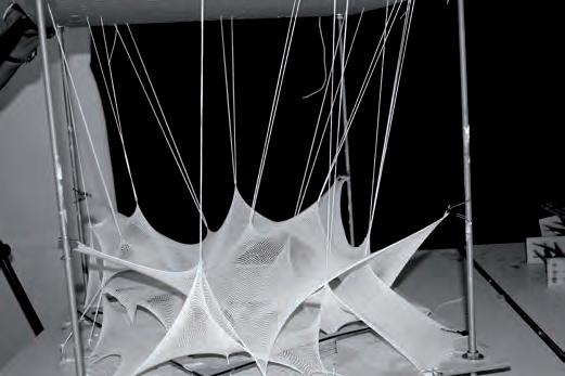
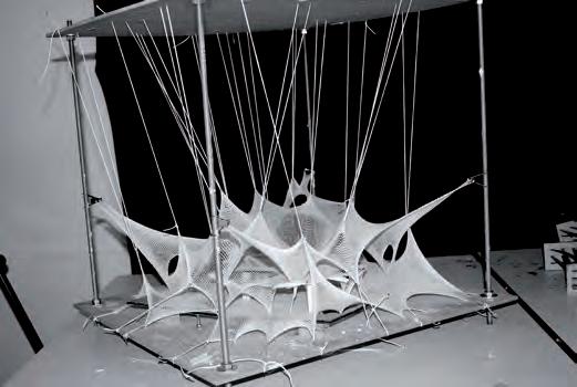
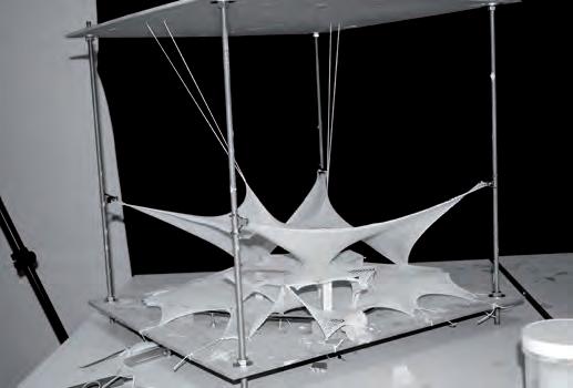
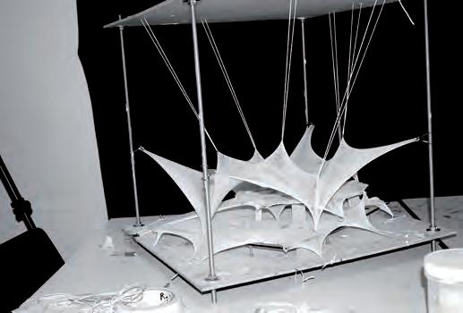
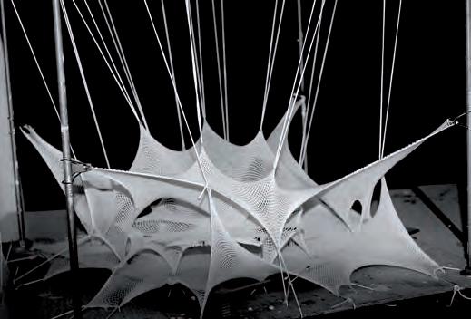
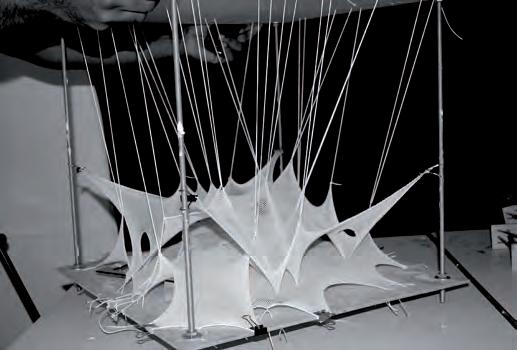
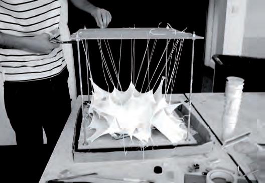
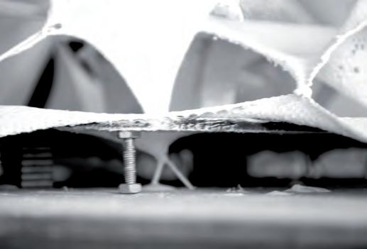
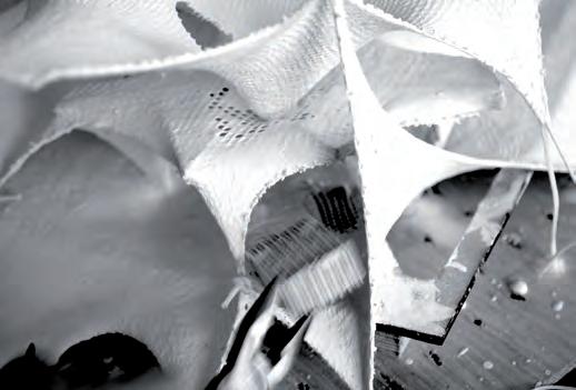
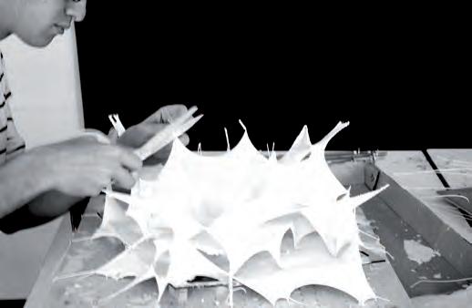
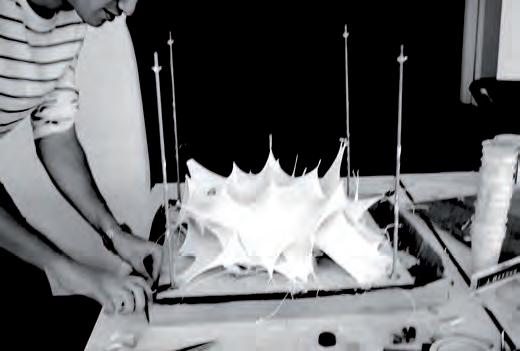
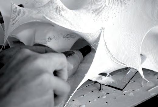
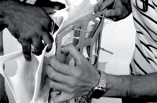
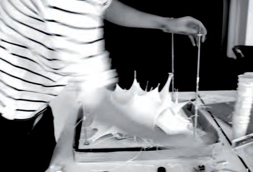


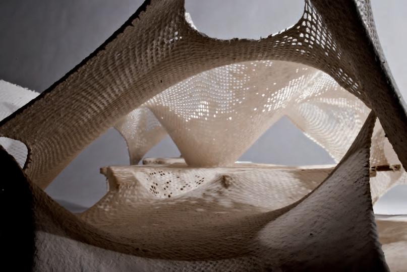
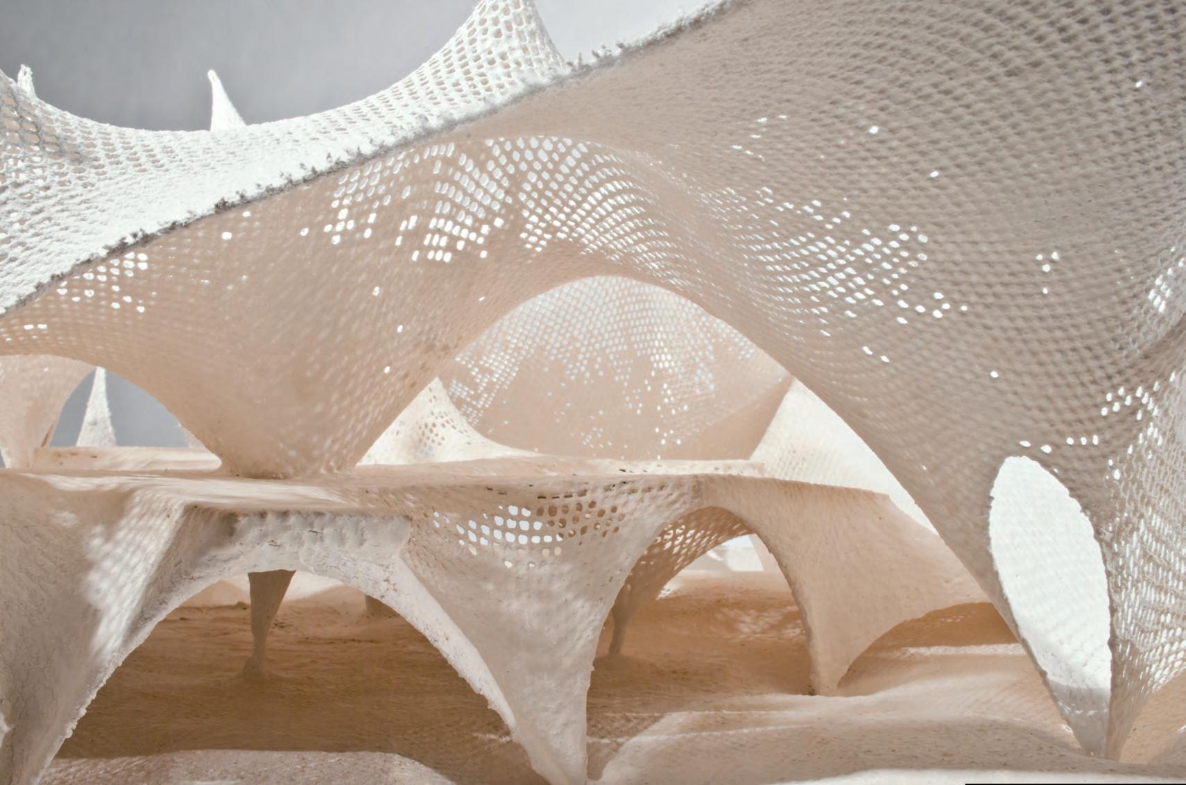
After testing Concrete Canvas for its intrinsic properties, we came to realize many interesting facts about the material’s capacity for shape change. It became apparent that at the building scale, materials have to be handled with applying forces that might be too large to work with within the system devised to form the previous plaster HYBIOS.
For the next few Concrete Canvas tests, we wanted to test the forms that could emerge from manipulating the material using a new system that would ensure an appropriate displacement to follow the geometries of the plaster prototypes.
After carrying out the previous Concrete Canvas test, the tensioning process leaned towards pushing up the material to create protrusions for higher displacements, while pulling down using strings to achieve depressions. The strategy is similar to the logic erecting simple tent enclosures or tensile membrane structures at a larger scale.
A strategy of set rules was followed for the forming the next ProtoHybios CC 2.0. The 5.0 mm thick concrete canvas was cut at a 1000.0 mm square area. The material was laid flat on the ground, while symmetry lines were drawn on the inside of the PVC backing. The diagonal lines marked the center where a main elevation was planned. Lines for cutting holes in the material were set, to test the possibility of introducing openings on the shell.
Cutting concrete canvas was easily done using a utility knife and a straight edge. So was the cutting of the smaller openings. It was noticed that a bit of the cement that is impregnated within the fibers of the canvas seeped, which was alarming, as it could potentially affect the compressive capability of the shell.
The prepared canvas was then anchored using steel bolts on the same cubic frame used for testing the material. The canvas was pushed up using a straight member, and the cut lines were pulled down using string. The canvas was formed symmetrically to test its capacity with lesser variables for the forming process.

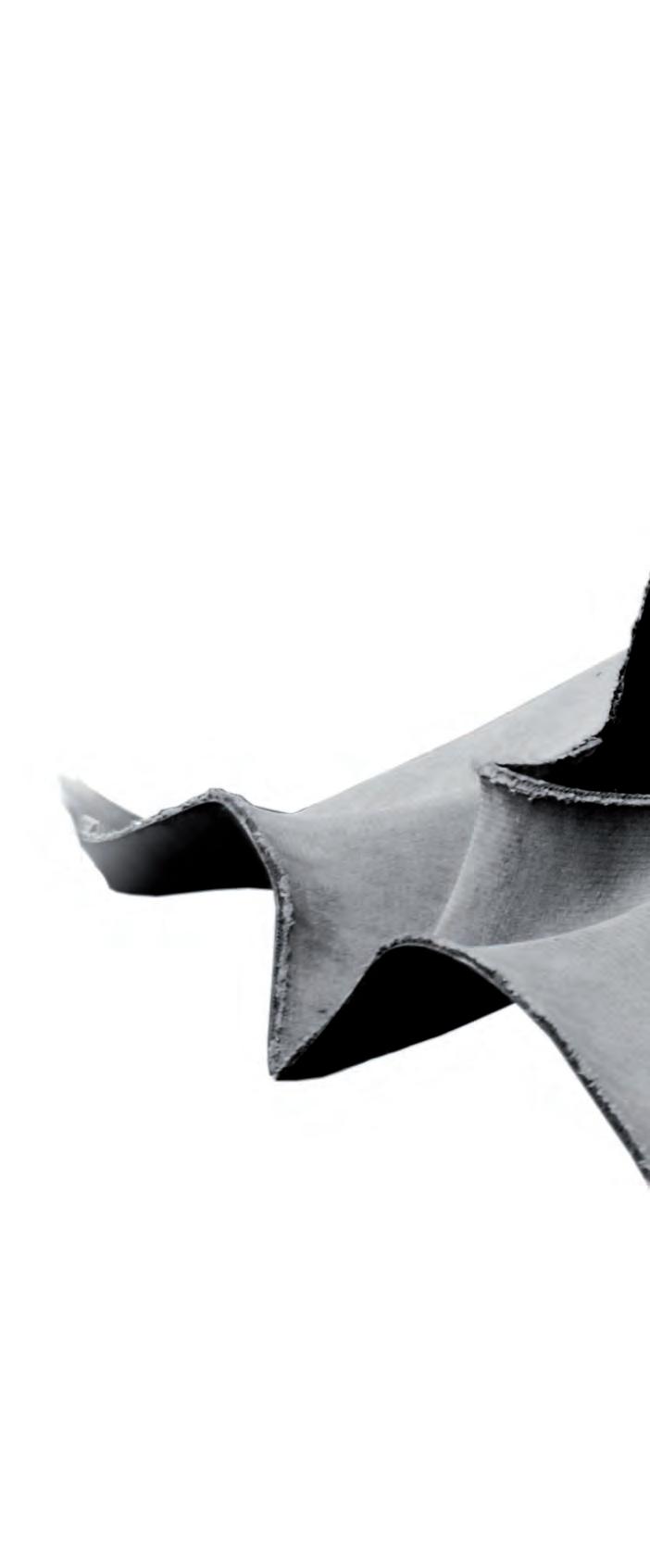
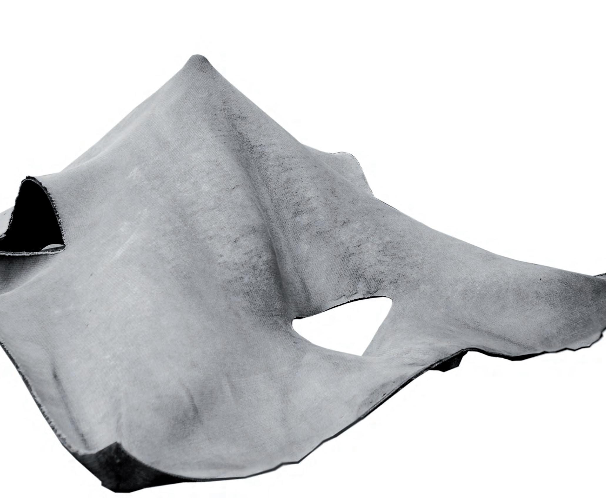
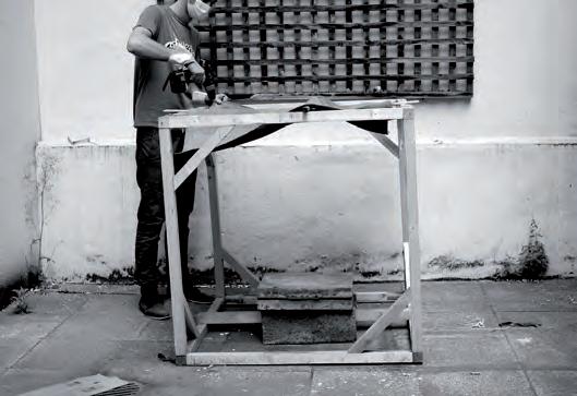
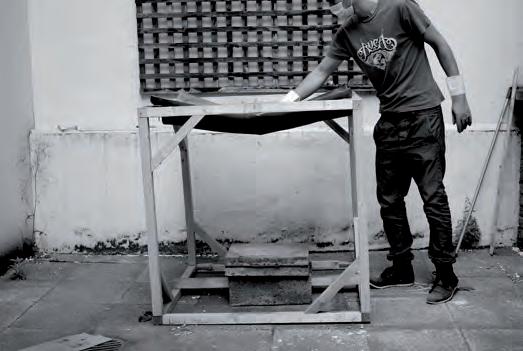
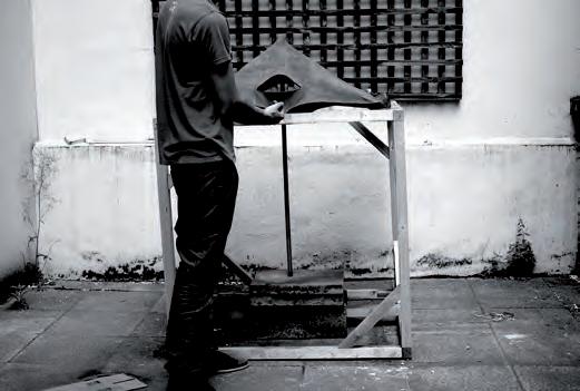
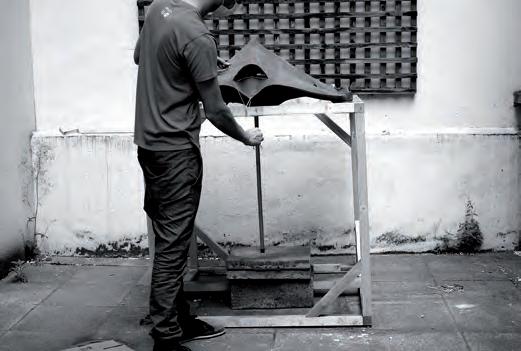
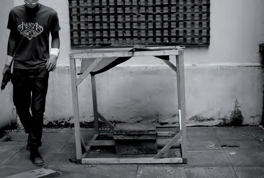
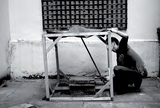
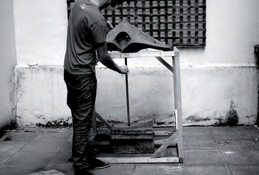
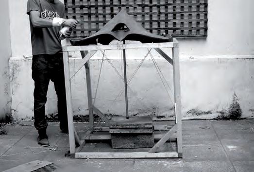
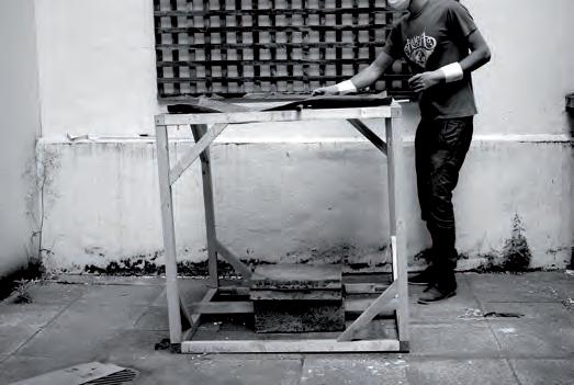
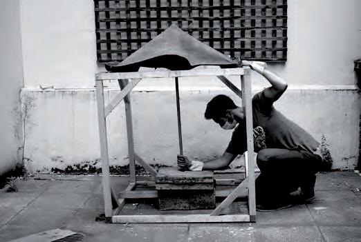
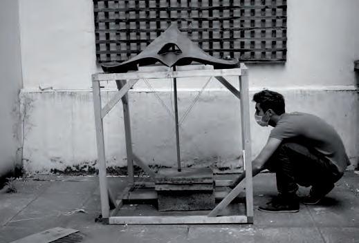
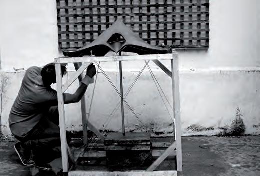
Two of the side openings where tensioned downwards using string, while the other two opened as the result of the tensioning of the whole shell. The variation in the shape of the shell emerged almost entirely as a result of the material acting upon itself and the forces applied to it. What was particularly interesting was the material’s tendency to form bulges that correspond to the openings and the tensioning forces.
These bulges contributed a lot in the forming of the piece and the orientation of the openings, in a symmetrical pattern. It was anticipated that the PVC backing is causing the material to bulge, as noticed by the material tensioning studies done earlier. PVC was tested for its deformation under tensile forces, and similar bulges were formed.


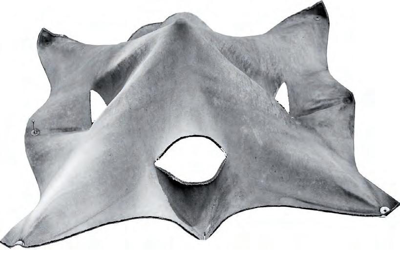
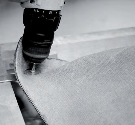
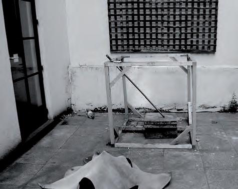
The piece was hydrated thoroughly after, to cover as much of it with water, making sure that all parts are evenly hydrated. It was left to dry and set. When releasing the piece from its cast, it was noticed that the shell was extremely easy to handle, light weight and rigid. The strings were cut, anchoring bolts unscrewed and poles to push removed. The shell was very stiff, especially around the parts where more curvature was achieved by applying more tension during the forming process.
The resultant forms that emerged due to the properties of the material assembly. The outcome was fascinating, especially on how the material has its capacity to self-form, and assemble.
However, the forms created lacked control, and deviated from the original expressive qualities of the plaster models. To further control the shaping process, we decided to form our own material layering strategy as the next research development stage.
Fig 4.02.2: Evaluation of the emergent form in Proto Hybios 2.0.
Fig 4.02.3: Process of removal of cast from the frame in Proto Hybios 2.0.
Concrete cloth was tested for its stretch and hydration process, the result was a shell with high stiffness along curves. Previously the plaster models were refined to create a pathway for circulation, restricting nodes on the pathways was carried out on the concrete canvas to test its capacity for forming in a similar manner.
In this experiment a 0.75m x 0.75m concrete cloth is shaped on a voronoi grid, which was used for the first plaster model. The aim of the experiment was to see if the fabric retains the flat surface after the process and to test the stiffness in these flat areas. The incisions that created light-wells and openings in the plaster model also had to be tested. Cuts were made on the concrete cloth before hydration and the nodes were pulled vertically down. Hydration was carried out and the results were recorded.
The first drawback was that the concrete mix started leaking where the incisions were made. But the restrain along pathways proved to be successful. There was considerable stiffness along the pathways since it was supported by the curved openings. The force applied for pulling the incisions was very high and the method was tedious. The concrete powder started leaking further when the hydration process was carried out. Incisions on concrete canvas are not advisable. If incisions are made they had to be stitched together to close the openings to prevent loss of material. The thickness of concrete canvas makes workability difficult. Layering of materials to form a structural surface will be tested to improve the construction process.
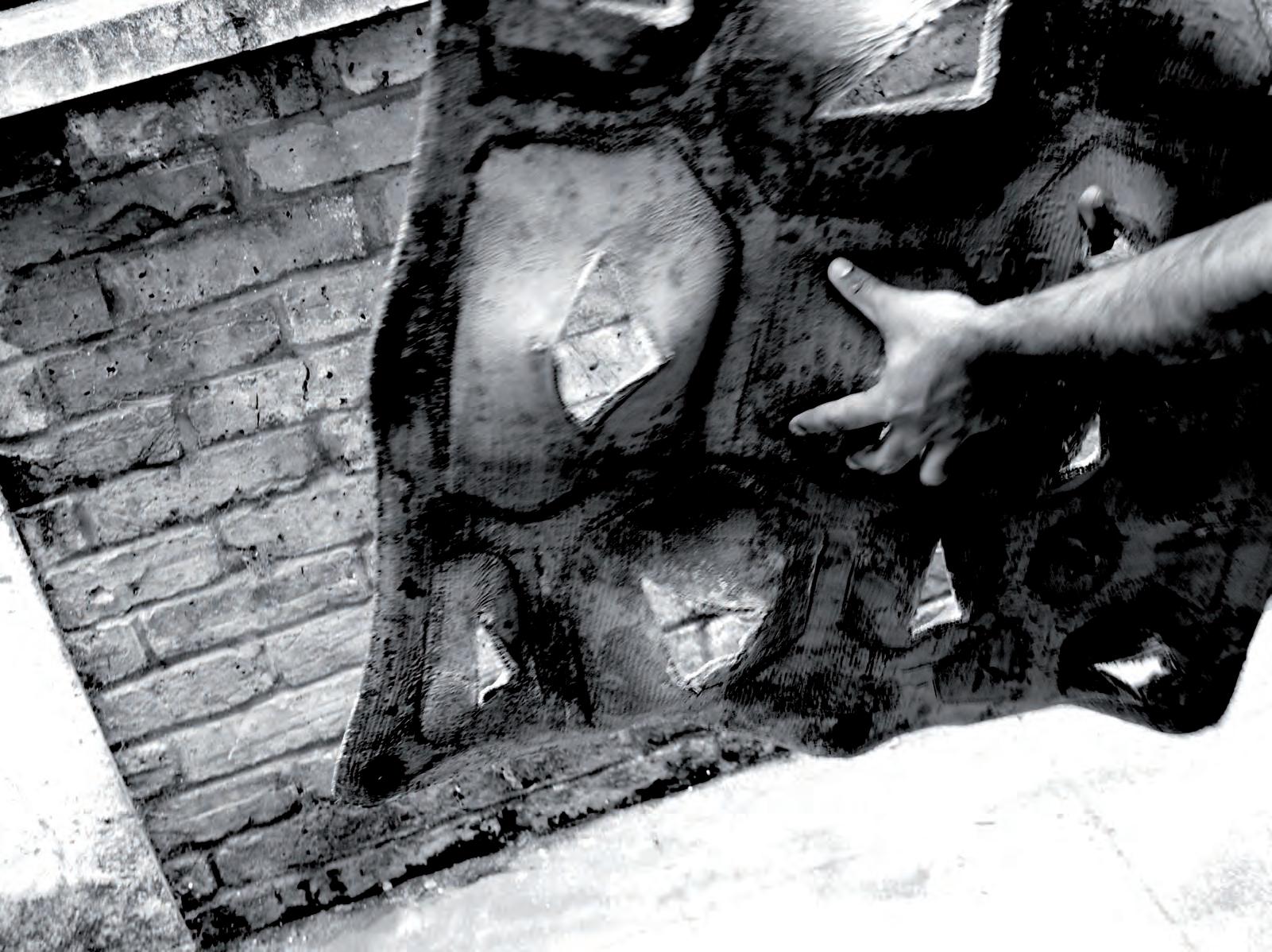
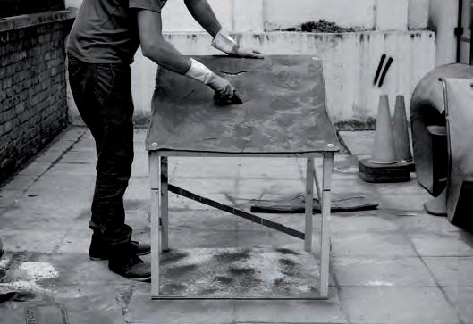
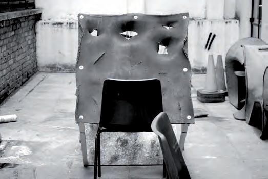

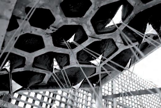
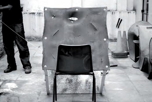
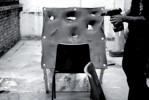

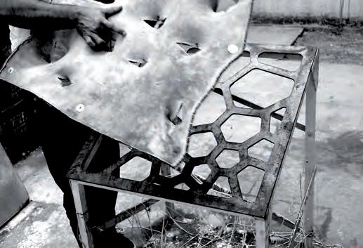
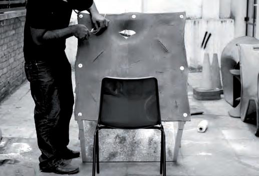
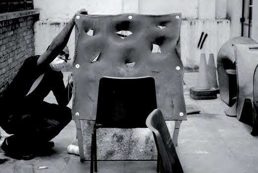

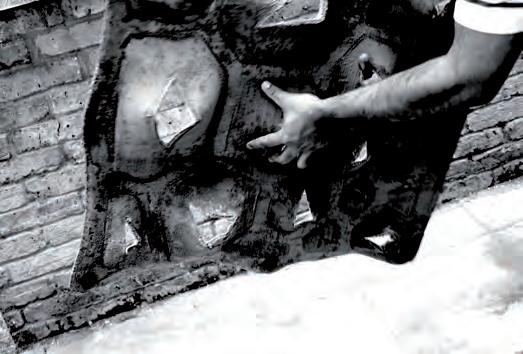
CONCRETE CASTING/ TESTING DIFFERENT REINFORCEMENT FOR SHAPE-FORMING
Data sheets from Concrete canvas reveal that the tensile strength is very weak within the material. This experiment is an attempt to find out the adherence of concrete over concrete canvas. Slabs in 1:1 scale also have to be prepared for testing deflection.
A form work of 0.15 m x 0.04 m x 1 m is prepared in wood for casting concrete. For the first cast a concrete canvas of similar size is prepared and hydrated before layering concrete over it. The processed concrete canvas is placed in the form work and plain concrete in the ratio 1:1.5 (Cement to sand) is layered over it. A similar cast is carried out in the second form work, but with a welded mesh reinforcement in the concrete. This is done so that slab is able to withstand tensile loads. The slabs were left to cure for 21 days to attain full strength.
Evaluation
Concrete casting by trowelling was a simple process. The ratio of water had to be controlled carefully. The concrete canvas adhered well with the concrete mix since both materials were similar in their properties. The composite nature of the Concrete Canvas reinforced with the elasticity of rubber backing and fibrous nature of the fabric that encloses these materials, is anticipated to infuse interesting reinforcement behaviour in the slab. Since reinforced concrete is a composite material there is no standard young’s modulus to analyse the stiffness, the tests were done to derive to an appropriate analysis of these combined properties.
Approximate values have to be calculated using 4-point deflection tests. If the values are within the limits concrete canvas can be used to achieve the geometries in real scale and reinforced concrete can be applied over it to form a structural surface. This would solve our initial proposal of eliminating form work. Experiments to solve the structural surface will be carried out in further chapters.
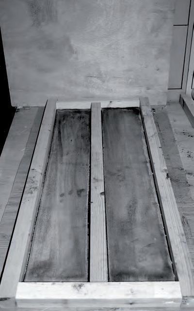

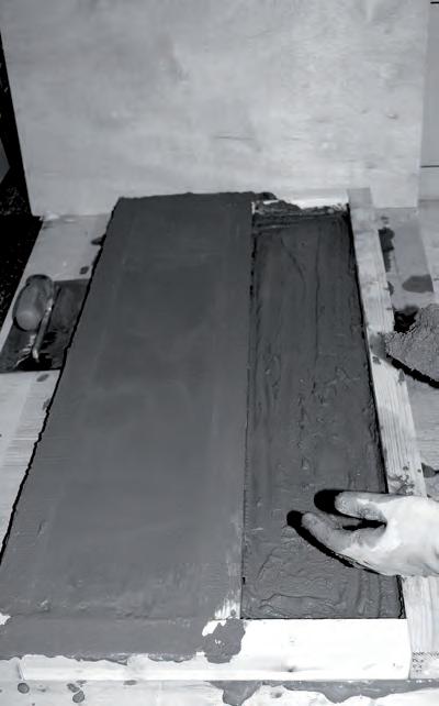
Woven Double Layered Mesh
Advantages:
1. Easy to form
2. Two layers hold concrete in place when sprayed.
3. Helps to eliminate form work.
4. High tensile strength.
5. Prestress on mesh makes the cast stiffer.
Disadvantages:
1. Expensive compared to welded mesh.
2. High force required for stretching.
3. Requirement of sophisticated machinery to hold it in tension during casting.
4. Creasing on mesh beyond certain stretch.
Welded Hexagonal Mesh
Advantages:
1. Inexpensive and easily available.
2. Easy to Form
3. Adds stiffness to the concrete.
4. Helps hold Sprayed concrete.
5. Available in different opening sizes and thickness.
Disadvantages:
1. Low stretching.
2. High force required for stretching.
3. Cells deform before stretching.
4. The welds fail beyond a certain force applied.
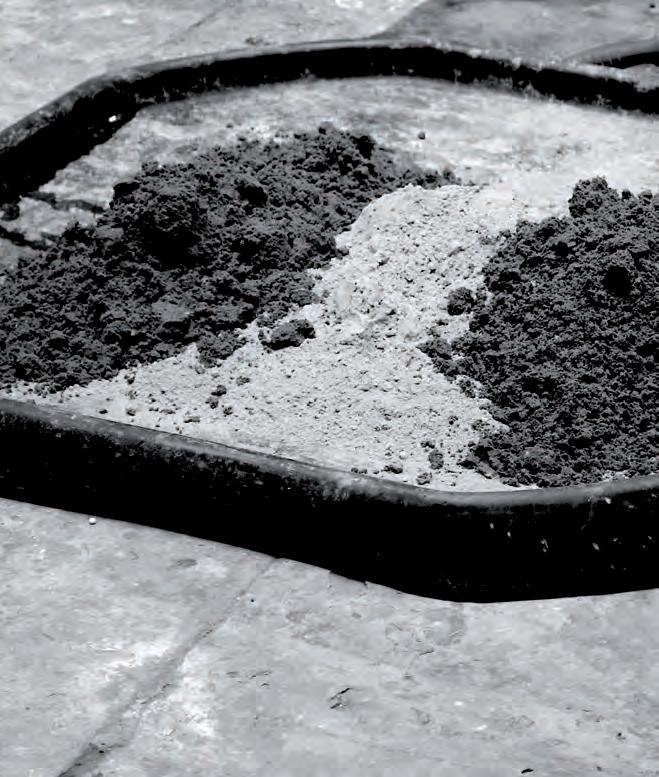
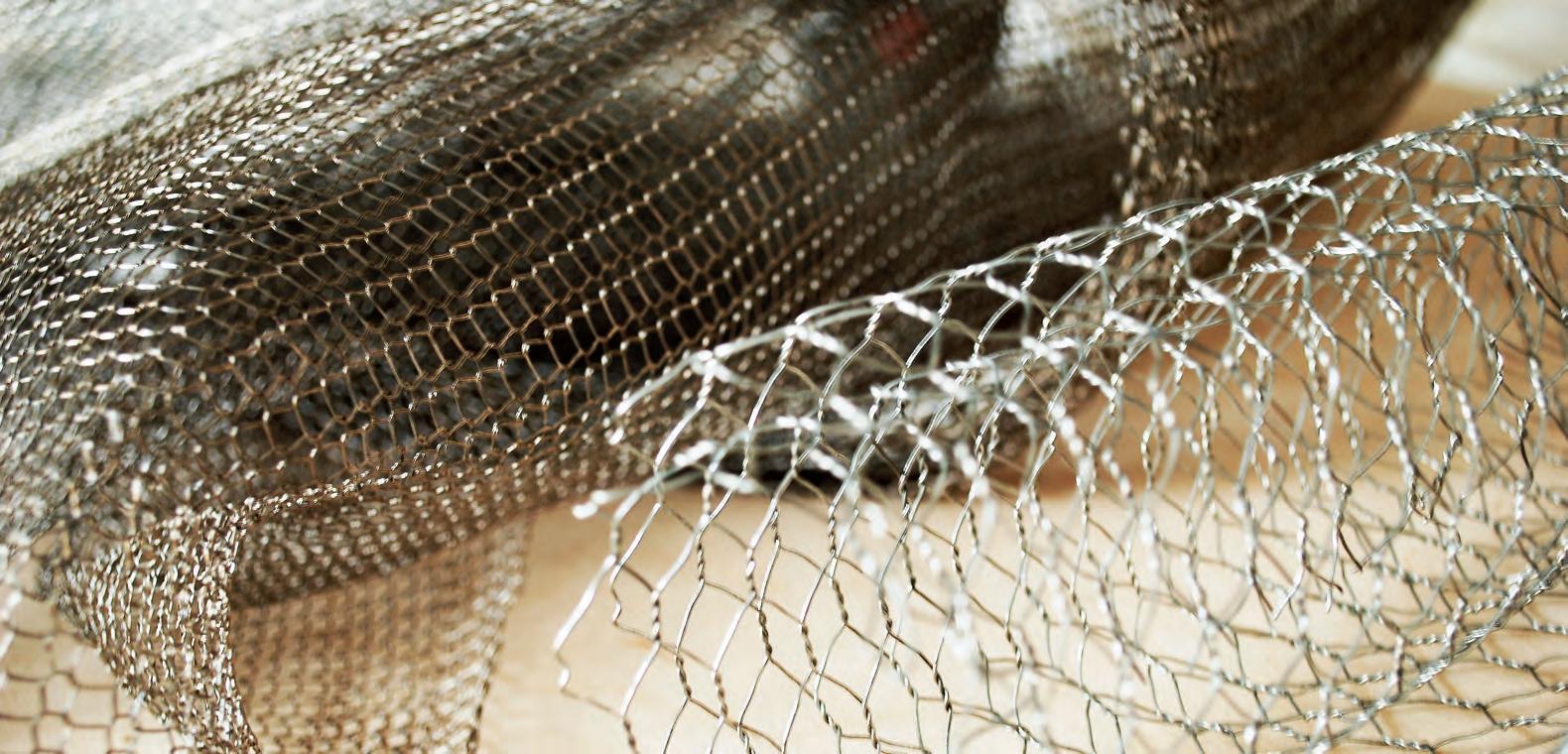 Fig 4.20.2: Testing different grades of concrete and mix.
After several readings and sample casting of concrete were done, it was necessary to carry out tests on the workability of concrete. Workability of concrete is a critical factor to achieve the complex geometry that we have simulated on the digital platform. Appropriate plastering of concrete and achievement of the required strength are the key factors to tackle in the next experiment .
“The advent of new so-called high-performance concrete mixes that are susceptible to small changes in mix proportions has made monitoring workability even more critical”(Eric P. Koehler & David W. Fowler).
The American Concrete Institute (ACI 116R-00, 73) describes workability as “that property of freshly mixed concrete or mortar that determines the ease with which it can be mixed, placed, consolidated, and finished to a homogenous condition.”
“The slump test is the most well-known and widely used test method to characterize the workability of fresh concrete. The inexpensive test, which measures consistency, is used on job sites to determine rapidly whether a concrete batch should be accepted or rejected. The test method is widely standardized throughout the world, including in ASTM C143 in the United States and EN 12350-2 in Europe. The apparatus consists of a mould in the shape of a frustum of a cone with a base diameter of 8 inches, a top diameter of 4 inches, and a height of 12 inches.
The mould is filled with concrete in three layers of equal volume. Each layer is compacted with 25 strokes of a tamping rod. The slump cone mould is lifted vertically upward and the change in height of the concrete is measured. Four types of slumps are commonly encountered, as shown in Figure 3. The only type of slump permissible under ASTM C143 is frequently referred to as the “true” slump, where the concrete remains intact and retains a symmetric shape. A zero slump and a collapsed slump are both outside the range of workability that can be measured with the slump test”.
Reference : Summary of Concrete workability test methods by Eric P. Koehler
University of Texas at Austin, TX and David W. Fowler University of Texas at Austin. Austin, TX. August 2003. P.11
The thesis aims at using high performance concrete, which is reinforced with projectable fibre reinforcement type such as BarChip fibres. We conducted a slope test to clearly understand the difference in levels of workability in 3 different types of concrete. The simplest way to carry out the experiment was to build a small wooden mould attached to a hinge. The diagram represents the setup of the experiment. A protractor is attached to one of the sides to measure the angle of repose. Plain concrete is mixed in the ratio 1:1.5 ( Cement to Aggregate) and 1 part water.
The mix is laid on the mould with normal compaction. The mould is lifted from the free edge to record the maximum angle it can withstand. The concrete flows out at 30 degrees. Looking back at the digital and physical models that were generated we realise that we have steeper curves than 30 degrees. The simplest solution was to add fibre to the concrete. Thus in the second test, BarChip fibre was added to the same mix of concrete @ 7kg/m3. The slope test was repeated and this time the concrete failed at 55 degrees.
The method explained was still not sufficient to test the large deformations of the forms modelled in the prototypes. We realized that addition of a steel mesh inside mould might improve the angle of repose of the concrete. In the 3rd test we laid a layer of doubly woven steel mesh in the mould before we projected the concrete. The result was that the concrete did not flow out from the mould even at an angle of 90 degrees.
Fig 4.30.1: An experimental setup to determine the angle of repose of the concrete when used with different reinforcements.
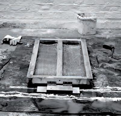
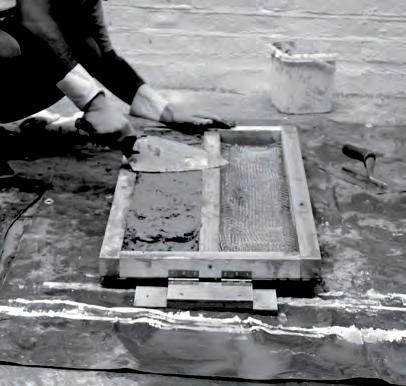
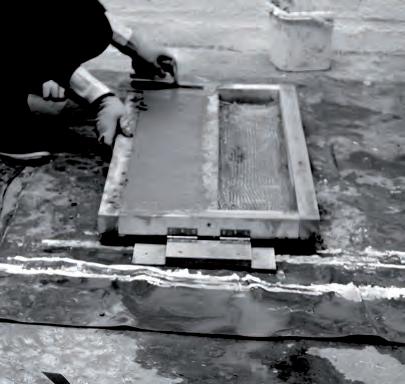
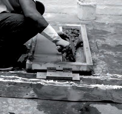
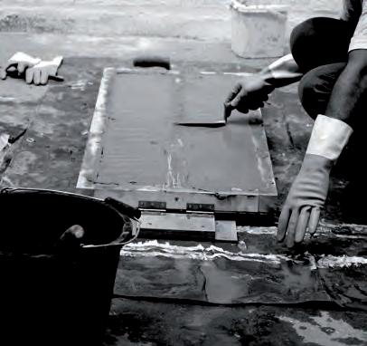
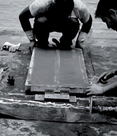

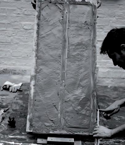
setup and testing different angles at which the concrete would flow away. The mesh proved to be successful in holding up the concrete even at an angle of 90 degree after which it fails.
The structural behaviour of the digitally simulated forms is a key factor for the performance of the material system. Analysis of how the geometry contributes to the behaviour of the forms in described in 3 steps.
1. Preparation of the mesh : A simple element from the digital model was selected to carry forward the analysis. The mesh was rebuilt in Rhino with a fixed number of nodes. It is these nodes which are used as restrain points and for load application in the structural software. It is rebuild in Strand 7 to match the software configurations. The mesh is cleaned and is ready to receive loads.
2. Application of loads : The edges are anchored and load is applied on the nodes using the global pressure settings. The material applied is concrete with steel reinforcement embedded in 2 layers. Reinforcement details and layering is explained in the diagram. Once the mesh was ready the simulation was run.
3. Post-Analysis : After the analysis was done it was important to use the raw data into useful information. We analysed the deformation and stresses on the mesh from the colour mapping and displacement charts. Results show how the geometry contributes to the structure in comparison with a flat slab of similar dimension.
The produced displacement chart shows the most displacement around the part with the most curvature. These parts were noticed to have the most stiffness in the CC ProtoHybios 1.0 & 1.2. We intend to devise a new forming method consisting of similar materials as tested. The capacity of some metal meshes to form, hold concrete and reinforce is seen as a promising development. We intend to test the concrete shell with the methods and materials that became more understandable after the previous experiments.
In the next stages we will look at real time analysis of the overall geometry by linking grasshopper and Oasys ( Structural software ). This will aid in incorporating the fabric properties in the mesh and thus give us true results in the form-finding process. The drawback of the current method is that the fabric properties which were used in form-finding has not been incorporated. But the tests helped us in giving a basic understanding of the material and geometry behaviour
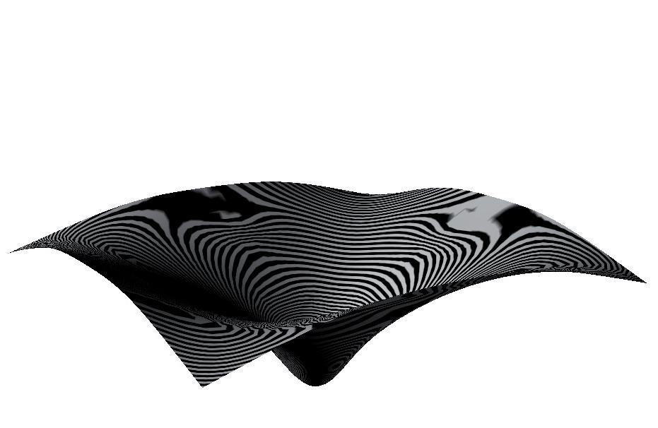
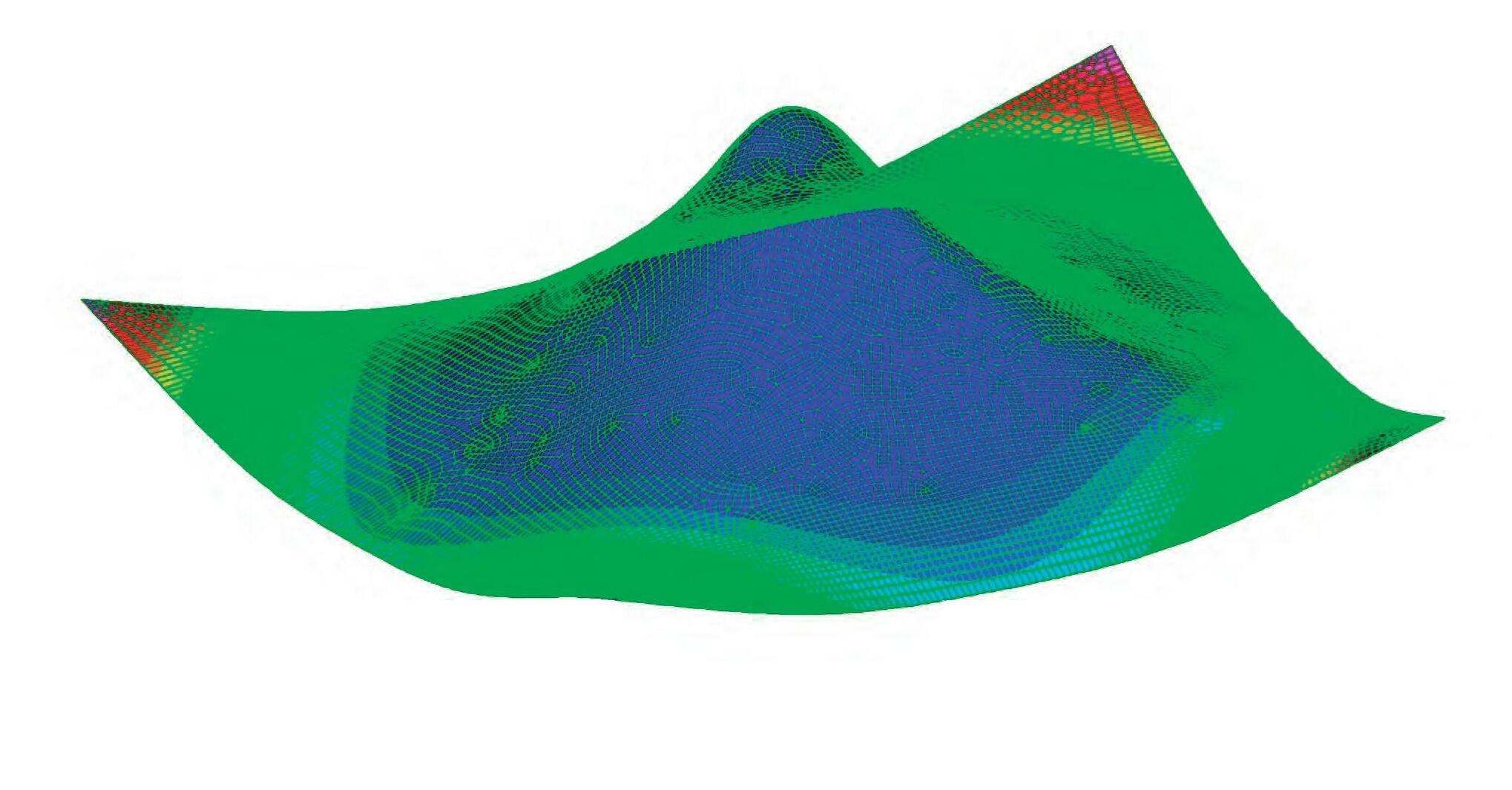
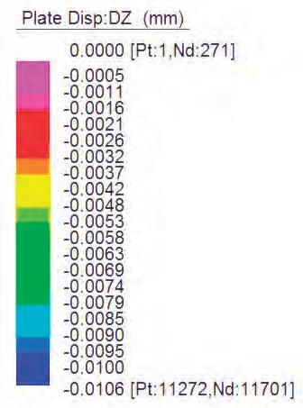

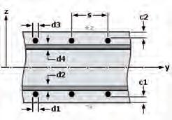
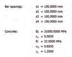
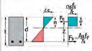
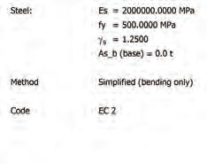
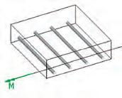
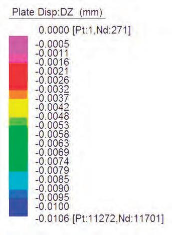
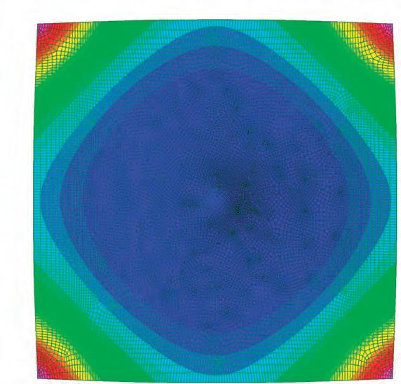
Finite element analysis of a structure provides clarity on deformations and stresses on a certain geometry. Displacement charts and colour mappings are important for the optimization of form. The stiffness of a homogeneous material is determined by its young’s modulus.
Since reinforced concrete is an anisotropic material the young’s modulus of specific finished slabs have to be calculated from 4 point bending experiments. The method of analysis being an analogue one this time, but relies on professional equipment for measuring the effects of loads on different slabs. The main parameter here being force’s effect on the displacement of the slab, which is measured using an analogue Dial Gauge.
Casts are done on the previously prepared moulds to refine the mix ratio of concrete and for improving its strength. Different reinforcements are tested to improve the tensile loading on the slabs. The diagram describes the six different slabs that have been cast for deflection test starting from plain cement concrete to synthetic fibre and metal mesh reinforced concrete. The slabs are kept wet during the entire curing period to attain maximum strength. This also helped in preventing shrinkage cracks on the slab.
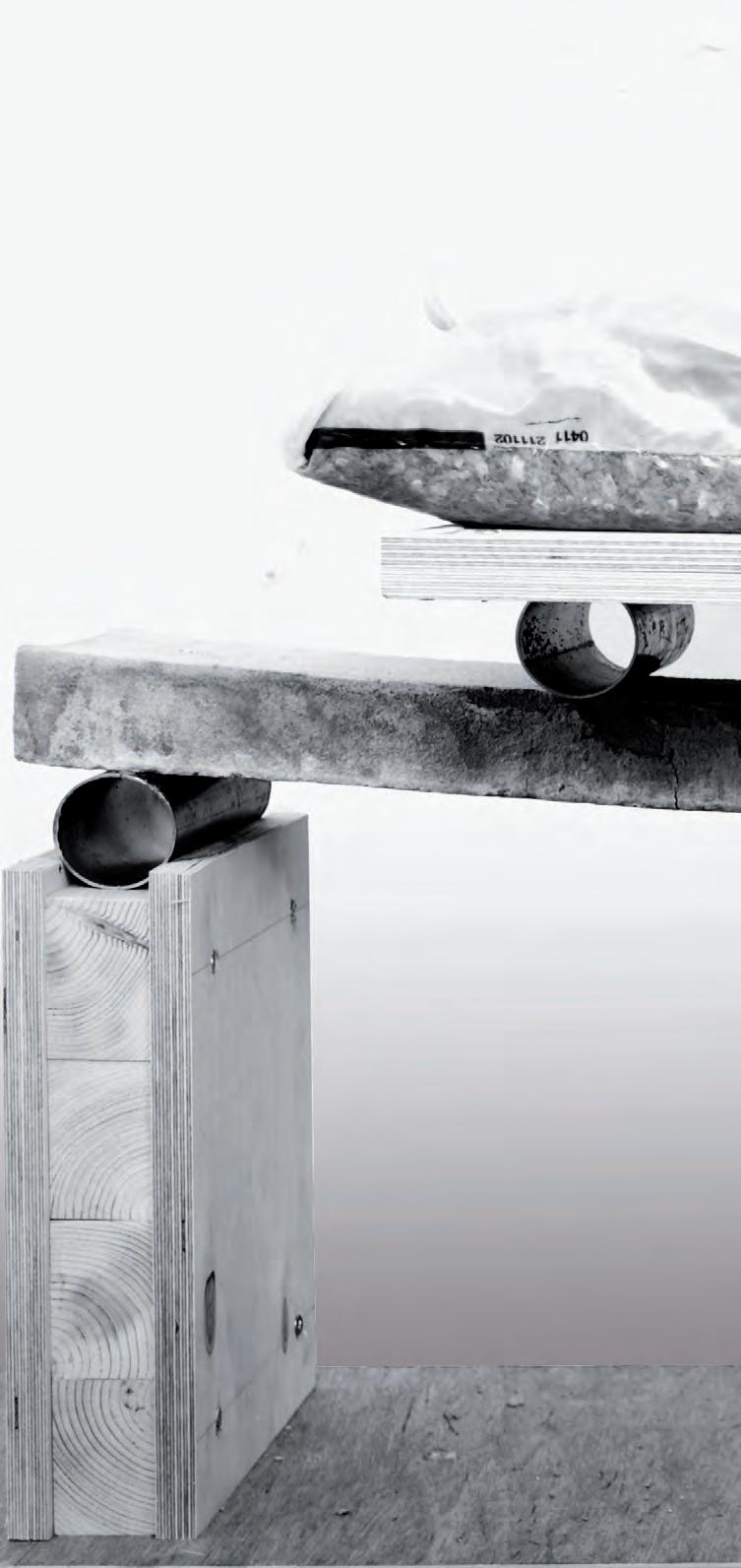
4.50.1: An experimental setup to measure deflection in concrete slabs, which were cast with different grades of concrete and reinforcement. This is a 4-point bending test.
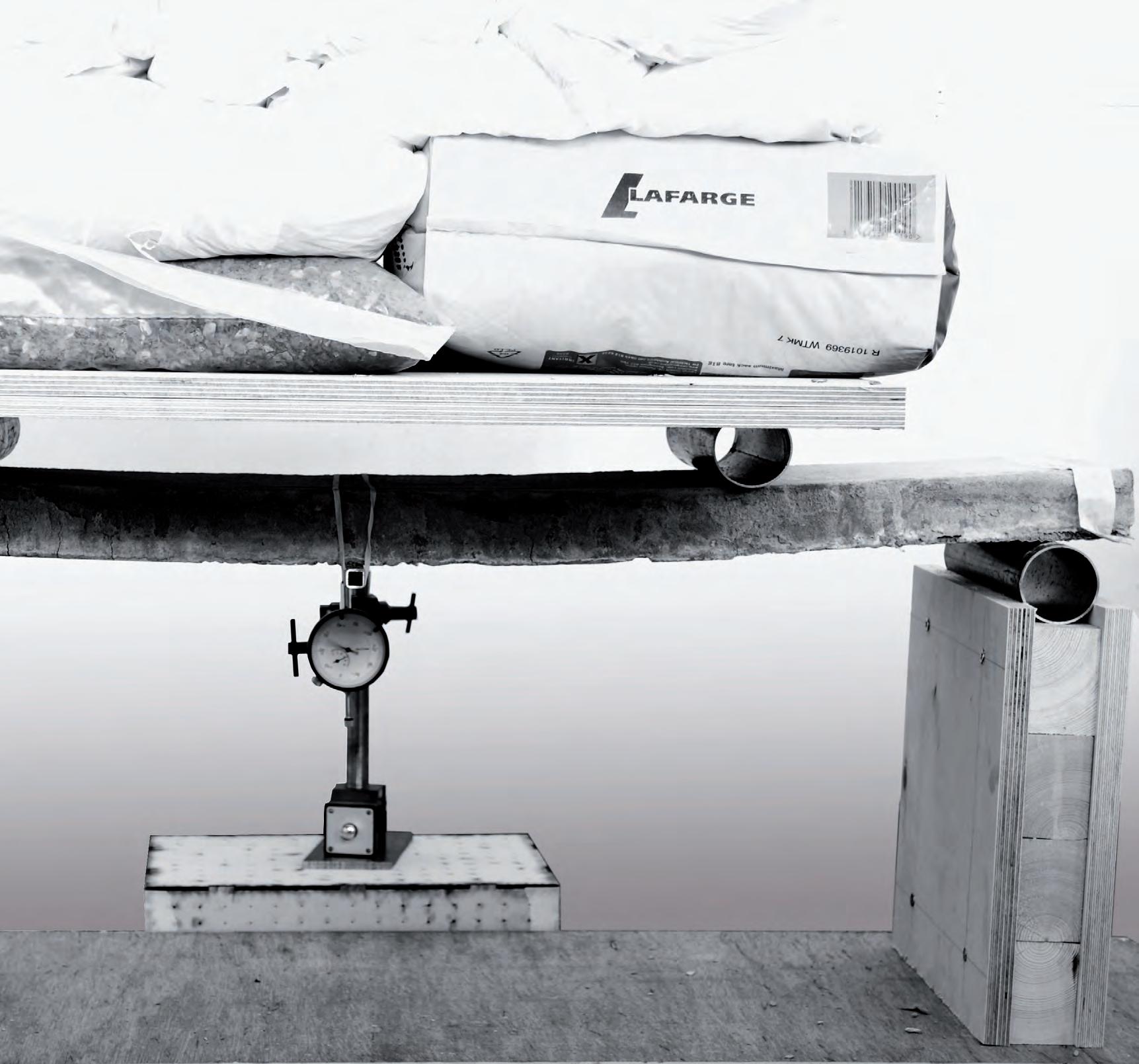
Several slabs were prepared, reinforced with different materials that could be tensioned as a free form surface. The slabs were cast with different concrete mixes of different ratios. After the slabs have cured to a period of time proportionate to the mix of the cast slabs. The slabs were weighed and their reinforcement types were charted.
The point of this exercise was to not only test casting and trowelling methods. Once the slabs were cured, and different mix levels were attempted for mix ability, workability and different affects of different ratios that help achieve stiffness. We aim for a thinner shell of concrete, which has sufficient structural integrity and a minimal mass.
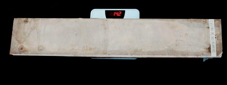
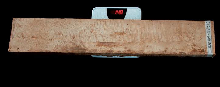
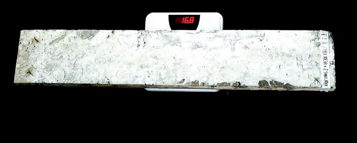
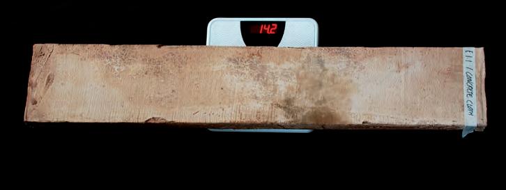
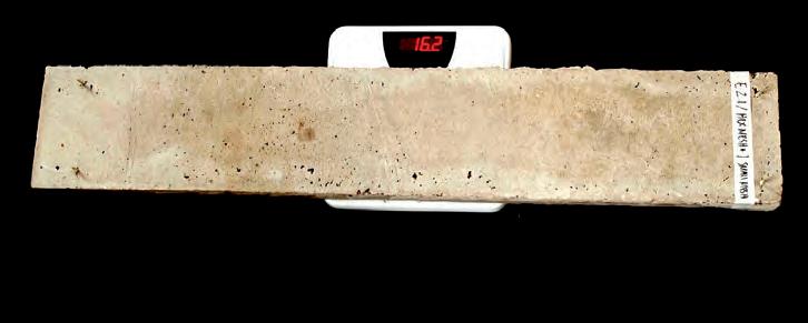
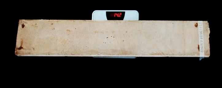
SLAB 00
Slab 00 started with no reinforcement, and a hard casting concrete mix. A series of small weights were incrementally added to the centre of the slab while the dial gauge was reading the deflection measurements in (mm). The slab remained consistently levelled as the deflection measurements were taken. Slab 00 crumbled instantly once the weight of 93 kg was achieved as a load acting on the slab center.
With Slab 1.1 we started by testing the capacity of Concrete Cloth as a reinforcement material. Knowing the material’s capacity to shape by tensioning, the material has to be tested for its reinforcement capacity. Concrete canvas of the smallest thickness (4 mm) was tested as reinforcement, for concrete to be laid on it, once it has been tensioned to shape. A strip of (4 mm) Concrete Canvas was inserted in the concrete cast.
The slab was set up in identical conditions to the other ones, loads being added incrementally as the deflection measurements were taken. The slab took considerably more load than the one with no reinforcement, considering the mix was even softer, with more sand this time. The slab did not completely fail, but cracked and the weight remained on it.
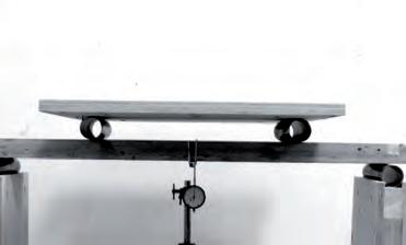
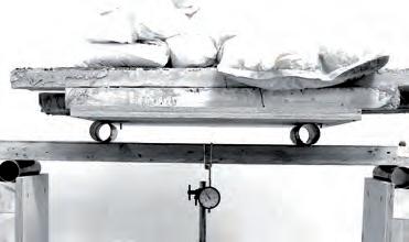
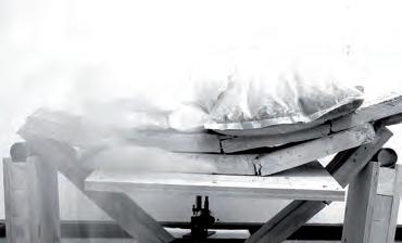
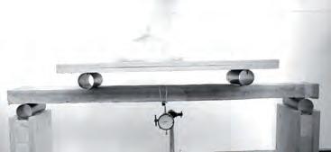
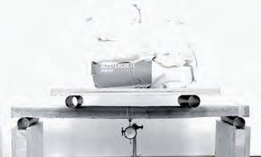
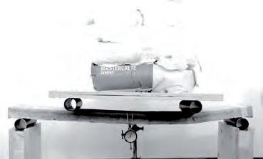
The same ratio of cement to sand was used for the next slab. Slab 1.2 was reinforced with Concrete Canvas of (8 mm) thickness and a hexagonal mesh
As noticed he Concrete cloth clearly adhered to the concrete plastered on it. The fibrous nature of the cloth coupled with the elasticity of the PVC backing, greatly helped reinforcing the slab, bringing attention to the capacity of fibre reinforcement and composites in reinforcing within the wall assembly.
The hexagonal mesh aided in the reinforcement of the slab, to achieve greater structural strength. The slab took the load of an extra 25 kg, as compared to the previous CC (4 mm) reinforced (Slab 2.1). The result was still not satisfactory; a more stiff reinforcement has to be tested.
With the next slab, the importance of the mix ratio of sand to cement had to be tested. More cement was added to the mix this time, resulting in a much harder concrete slab. Although only the hexagonal mesh was used to reinforce the slab, failure occurred when much larger force was applied. The slab this time failed instantly when the load of 141 kg was achieved.
The slab showed no signs of the elasticity of the previous CC reinforced slabs. Once the final weight was added the slab shattered immediately and did not crack. The hardness of the mix and the lack of fibre-based reinforcement contribute to that fact.
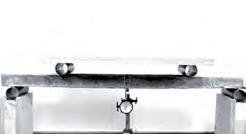
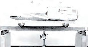

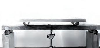
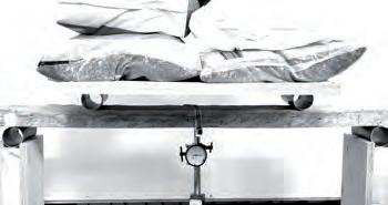
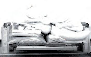
This slab was reinforced with two different meshes, a woven, double layered mesh, and the hexagonal mesh used earlier. The effect anticipated of the way these meshes work together was that the pattern; hardness and layering of these meshes would create a 3 dimensional matrix. Where concrete would adhere to the meshes and penetrate through the reinforcement material and benefit from its shaping and tensile bearing capacity.
The slab was cast with the harder mix of concrete, and it withstood a noticeably larger load. The slab failed at 157 kg of weight added, which proved that metal meshes could be used for reinforcing a thin concrete shell. The meshes have to be tested next for their forming capacity.
For the final slab, we wanted to test a method of reinforcement that is independent of the forming process. This way more options could be open to use different materials of different strengths and a wider of shaping capabilities. The effect of fibre orientation in different composites and constituents has been greatly noticed in the previous materials tested. These fibres add to the strength of the concrete composite wall and allow for greater elasticity in transferring the loads.
Slab 3.0 was tested with BarChip fibre, a material described earlier. BarChip enhanced the loading capacity of a concrete slab with a similar mix but more curing days was tested. This was to ensure that a material could be added to Shotcrete, which can reinforce and have the flexibility to form to any geometry. The slab withstood an enormous load compared to the others, where it failed at a weight of 247, overriding the performance of the previous slab by more than a 150% increase in strength. The fibres allowed for a huge deflection remaining flexible and bowing despite that the concrete mix was very hard, and was let to cure for the longest period of 15 days.
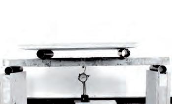
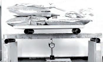
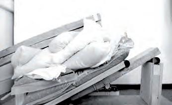
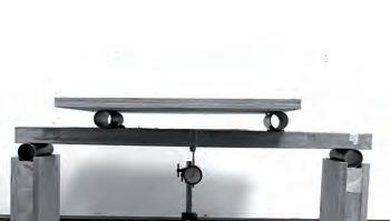
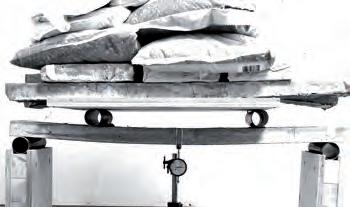
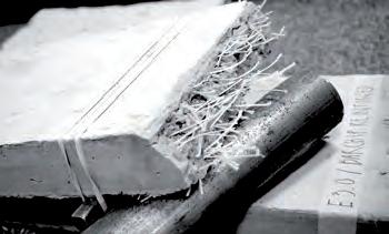
The results of the concrete slab reinforcement gradually increased in structural capacity and flexibility of application. The readings of the deflection displacement (x) as taken by the dial gauge were graphed against the force (y) used to achieve that deflection.
As compared to SLAB 00 which had no reinforcement, SLAB 3.0, which was reinforced with BarChip fibres, recorded a massive increase in structural strength. SLAB 1.1 and SLAB 1.2, which were reinforced with Concrete Canvas, displayed a great deal of flexibility under forces, and achieved the largest deflection.
Slab 3.0 showed a dramatic increase of flexibility and strength. It surpassed the performance of the other slabs in terms of strength. The use of BarChip Fibre to be sprayed on the formed geometries became an apparent development in the process. There are still products that could be tested to stiffen fabrics used for forming tensile structures. Concrete mixed with BarChip can be then sprayed onto the hardened surfaces to create structural enclosures.
BarChip54, a Structural Synthetic Fibre from Elasto-Plastic Concrete’s range of copolymer fibres, evolved from EPC’s “Future Fibre” research and development program. The aim of this program is to develop a range of fibres that achieve the highest performance levels ever seen in structural synthetic fibre reinforcement systems. The latest advances in copolymer technology, engineering design and manufacturing techniques have been incorporated into BarChip54 to deliver a fibre that is unequalled in usability, durability and service performance.
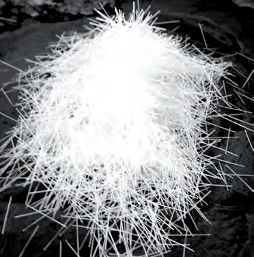
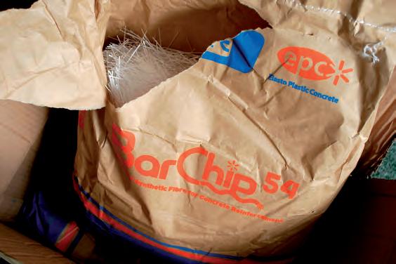
Result overlay of the deflection for the six different slabs which were tested.
Young’s modulus is the measure of stiffness in an isotropic material. In Finite element analysis the young’s modulus has to be fed in, to run the simulation tests. Reinforced concrete is anisotropic. Its behaviour changes with the structure of the material and with the type of loading applied onto it. Therefore separate calculations have to be carried forth for each type of structural slab that has been cast. Four-point bending test has been carried out for all slabs and the deflection has been calculated.
A bar chart has been calculated of the weight at which each slab broke, to compare clearly the results obtained. The slabs show an incremental increase in strength, while Slab 3.0 increased greatly in stiffness and broke at the greatest weight added. Experimental mechanics for fibre reinforced composite materials gave the calculations for the young’ modulus from the deflection tests. The calculations and results are detailed in the following chart.
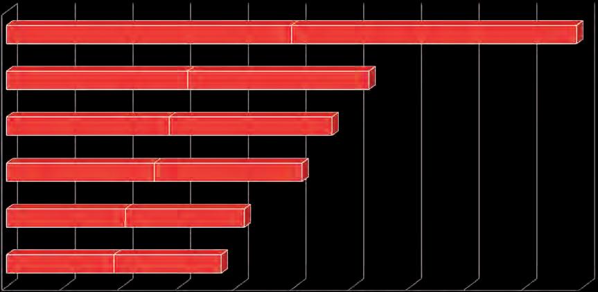
P = Load (Newton)
l = Span (Millimetres)
b = width(Millimetres)
h = Thickness (Millimetres)
= Deflection at centre ( Millimetres)
MODULUS FROM 4 POINT BENDING
S = Correction Factor for shear
E= Pl 64bh 11+8S
P = Load (Newton)
l = Span (Millimetres)
b = width(Millimetres)
h = Thickness (Millimetres)
= Deflection at centre ( Millimetres)
S = Correction Factor for shear
S= 3h E 2l G
= 0.00072 (negligible)
E= P1000 x11
FRACTURE STRESS
STRESS
= P x3l/2bh = P x 0.00625
= P
Source Experimental Mechanics of Fiber Reinforced Composite Materials
Source Experimental Mechanics of Fiber Reinforced Composite Materials
J.M. Whitney, I.M Daniel, R.B Piper
J.M. Whitney, I.M Daniel, R.B Piper
The Society for Experimental Stress Analysis. Brookfield Center, CT,USA © 1982
Fig 4.56.2: Table indicating the slabs, force at which it failed, the deflections and the calculated young’s modulus from the 4 point bending tests.
The Society for Experimental Stress Analysis. Brookfield Center, CT,USA © 1982
Concrete canvas shells have been explained and evaluated in the previous chapter. The lack of tensile strength is the major drawback of concrete cloth. The simplest way to improve the tensile strength is to have a steel mesh inside the concrete. If this could be prestressed it would be of advantage in minimising the thickness of concrete and improving the strength.
This following experiment has 3 main goals :
1. To improve the tensile capacity of concrete shells.
2. Prestress a steel mesh to improve the strength with minimum material
3. Project concrete over the mesh without using form work.
A double-layered woven steel mesh is fixed flat on the 1 metre cube frame, which was built for the stretch tests. Simple techniques of push and pull were performed to achieve the forms similar to our previous experiments. The form-finding process gave the mesh a prestressed overall state. The mesh is laid over a fabric to prevent concrete from falling off the mesh. Steel wires were used to pull the mesh and wooden props to push. The process was very simple but the flat areas on the mesh seemed to lack stiffness. To improve this patches of welded mesh were attached where the mesh lacked curvature. Concrete was prepared in the ratio 1:1.5 (cement :aggregate) with the ratio of water carefully monitored. The mesh was prehydrated and the cement concrete was projected onto it with trowel. This was the first attempt to replicate spraying the mesh with concrete.
The concrete adhered to the mesh by simply trowelling and compacting the pasty mix on to it. The two layers held the concrete from falling off the mesh. Trowelling the materials gave good compaction for the concrete. 20 mm concrete was projected uniformly over the mesh. This process also helped hide the minor seams that were formed during the prestress of the mesh. The shell was kept wet for 28 days to attain full strength. Result was a 20 mm thick high strength concrete shell. The elimination of form work was another big leap in the research. The only drawback of the experiment is the force required to prestress the mesh. Our next experiments will try to overcome this drawback.
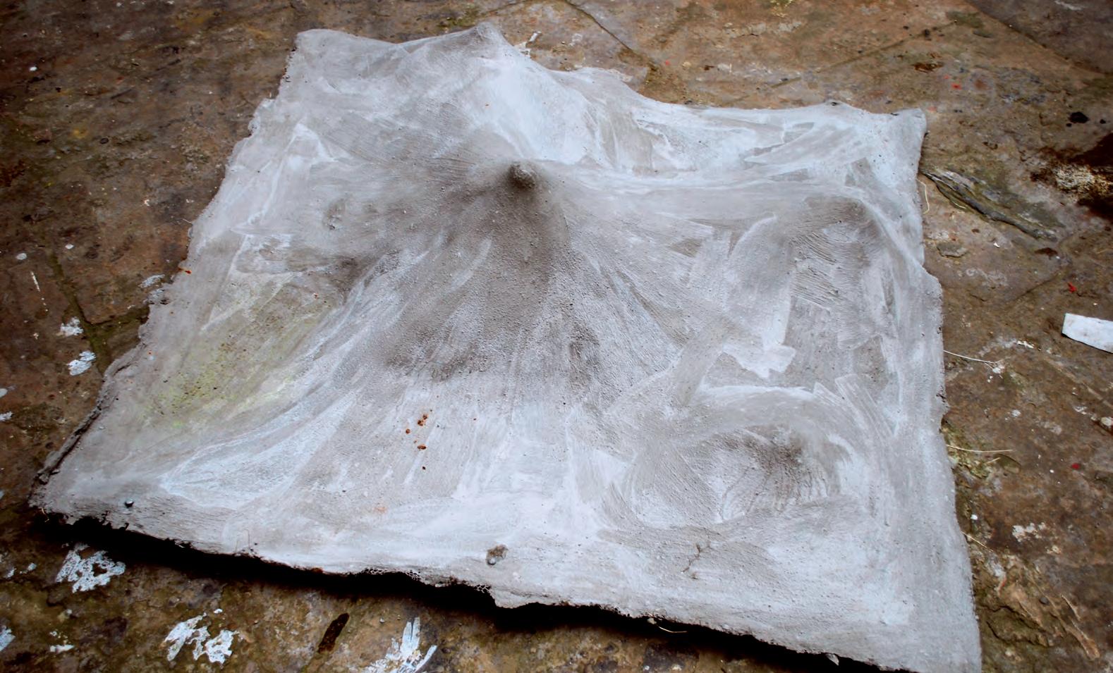 Fig 4.60.1: Result from the test where concrete was projected on to a pre-tensioned mesh. In this case the mesh works as reinforcement and holds the concrete in place. The pretension improved the stiffness and helped reduce the thickness of the slab.
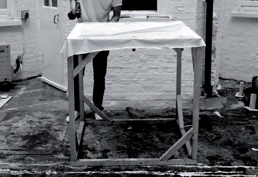
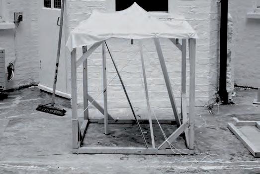
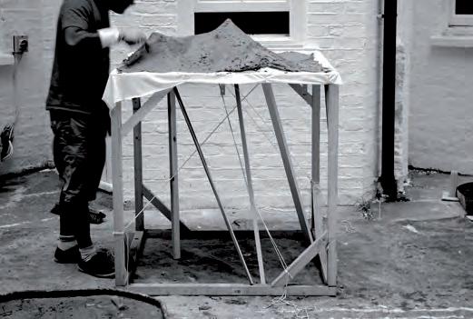
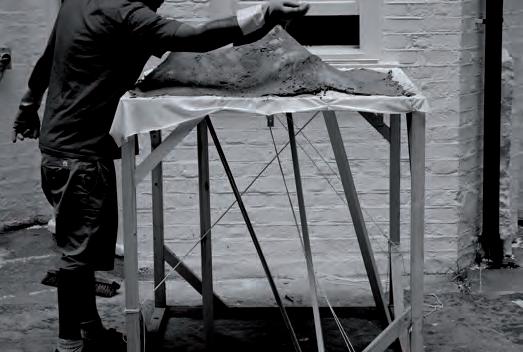

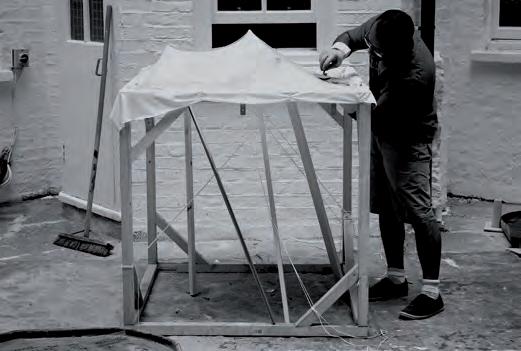
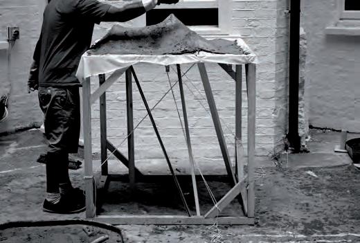
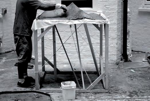

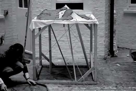
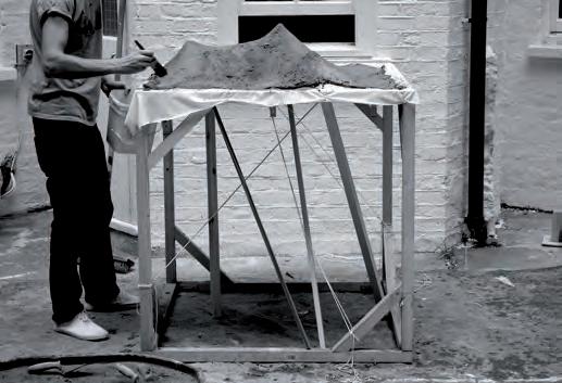
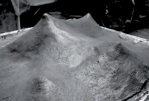
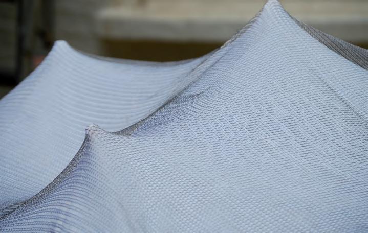
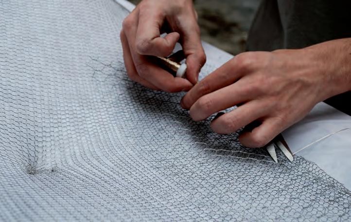
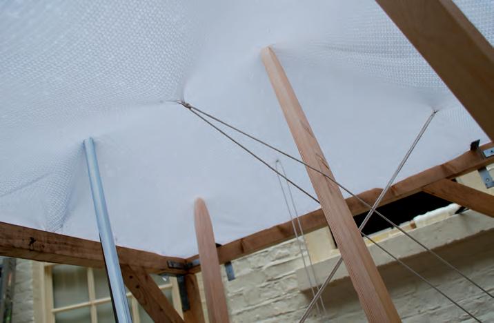
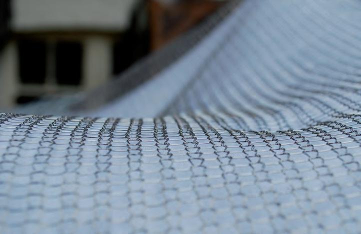

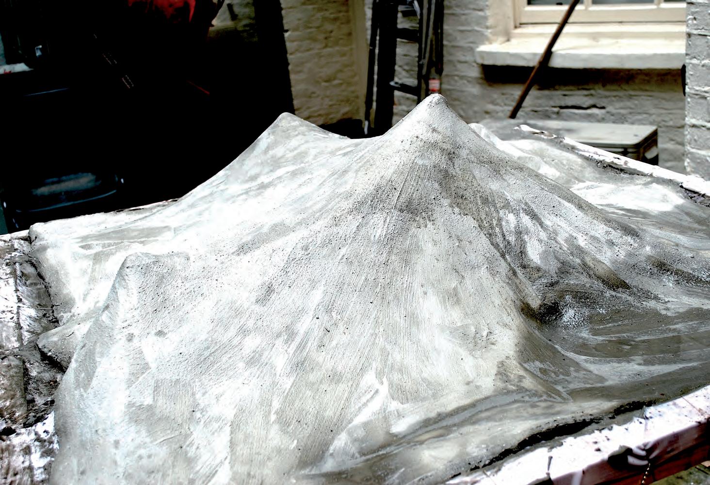
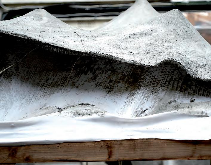
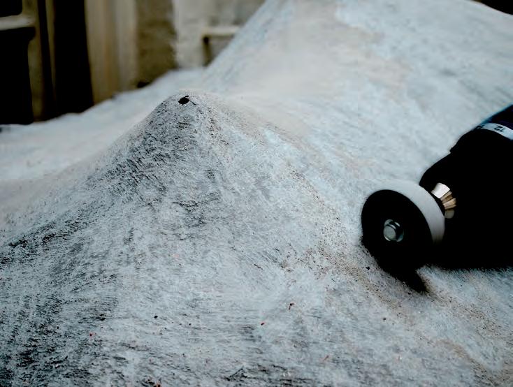
After understanding how the materials at the construction scale could be manipulated, the information gained from the concrete experiments was cross compared to the analogue models to evaluate tho possibility of inventing a construction method within a re-usable system.
It became clear after constructing the building scale material prototypes, that the best way to achieve the required deformations on these materials, and at that scale, is to push the mesh material upwards, and pull downwards, as opposed to pulling at all directions. It was evident that a construction system, similar to the one used to erect tent forms, has to be devised in order to achieve the geometries intended.
This time a hexagonal grid was generated, a tillable geometry with more end points, therefore more possibilities for points of connection. The generation of the Voronoi grid followed a central plan scheme where main branches of the grid started from the end points of the hexagon. The cells of the geometry of the lower level were oriented towards a central plan. The geometry of the upper level corresponded to the lower one, but a pentagon shape was generated for less access ways and sides. Cells of the upper level grid are in parallel to the upper one and are larger in size.
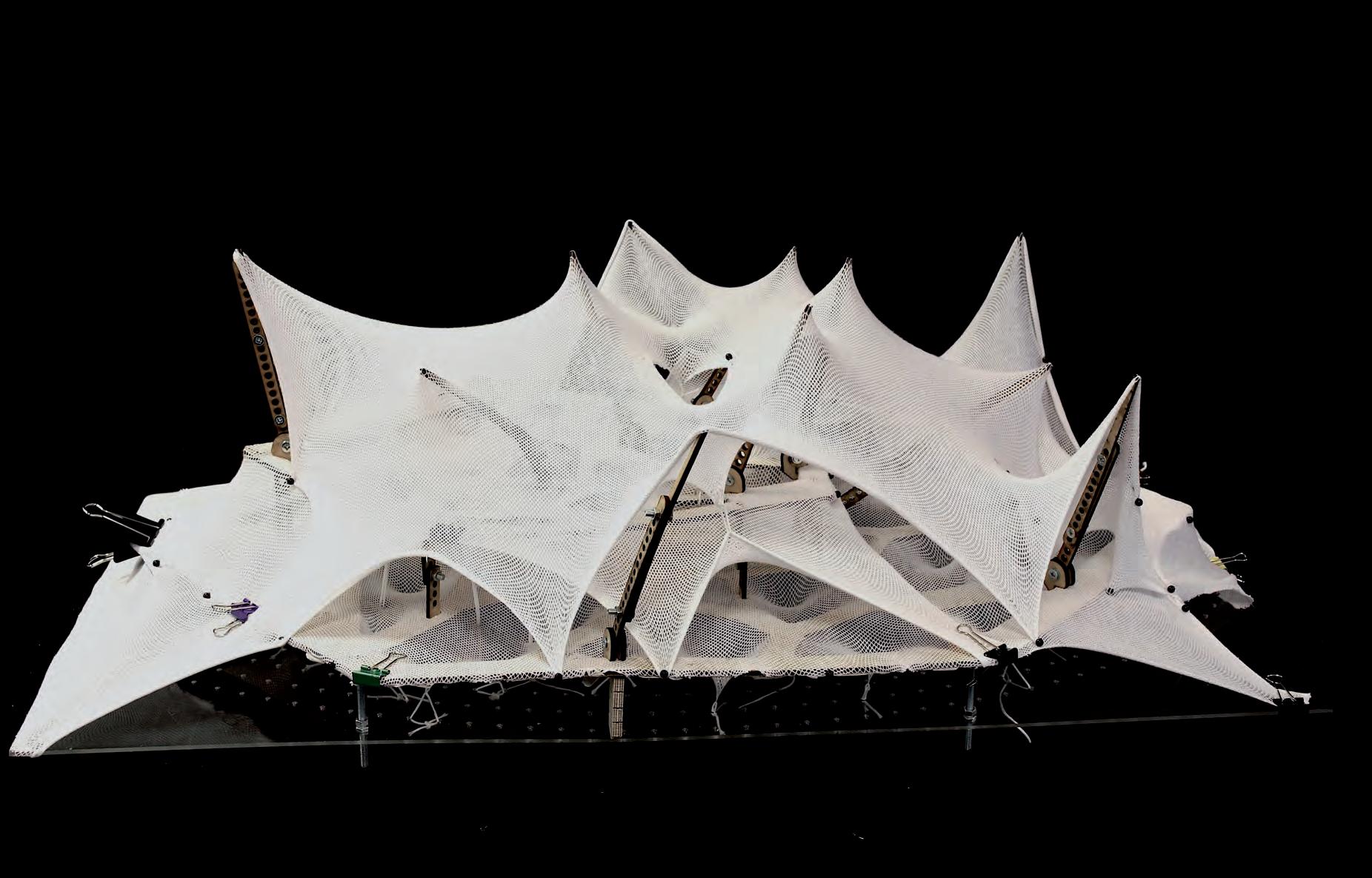
A system of modular components was devised to stretch the geometry of the fabric into an optimised form. The process used an entirely system of form work. Where the pathway restrain grid was overlaid on a sheet of PVC with perforation. The clear PVC enabled an easier stretching of the seating pod elements.
The modular system consisted of modular components, where these components could be assembled to create elements, that are adjustable in length, angle and thickness, to accommodate to the variable heights needed to be modelled, and to be able to withstand different pressure forces applied on them. Themes elements had a clipping system, where the clips worked with the cells of the Voronoi grid, ensuring a ease of removal after the casting has been done. The second level was erected using foldable legs with adjustable heights.
After constructing the previous prototype (HYBIOS 3.1), it became apparent that better means of holding the mass of the second level had to be developed. The members holding the second level looked too weak to hold that mass up, and a better support system had to be established. While experimenting with the cut out pieces, that were the left over pieces of the MDF wood used to cut the grid, an attempt was made to stretch the geometry of a cell towards the parallel lower grid cell to achieve a Catenoid-like surface. The catenoid column in this case being a massive hollow surface, holding the upper level in place. The column could also be filled with concrete, as in the experiments done by Alan Chandler and the CAST team.
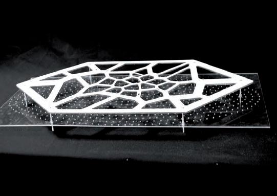
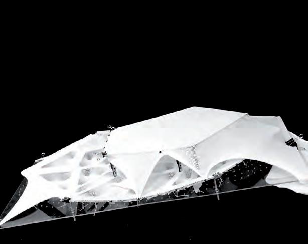
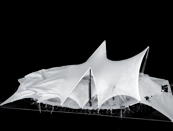
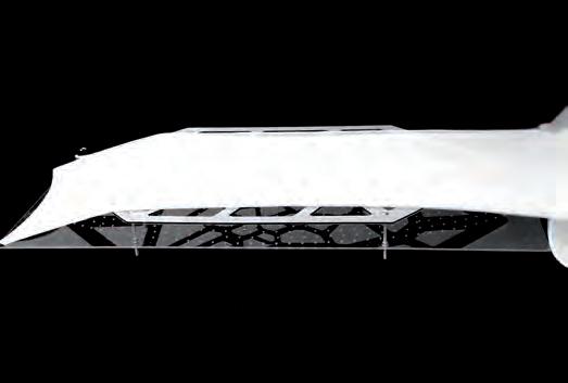
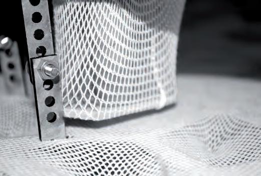

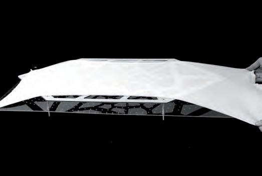
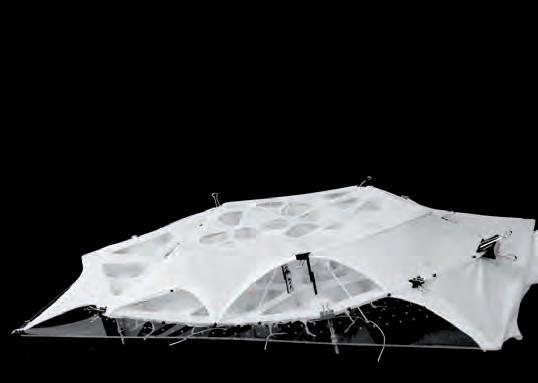
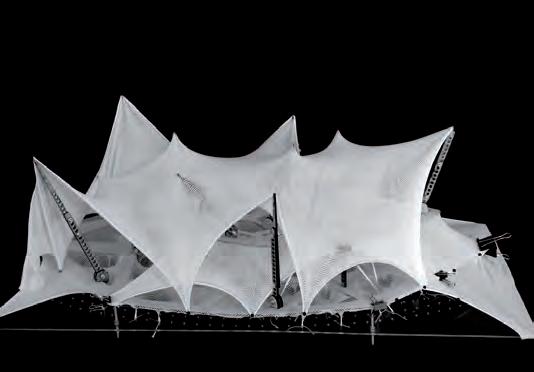
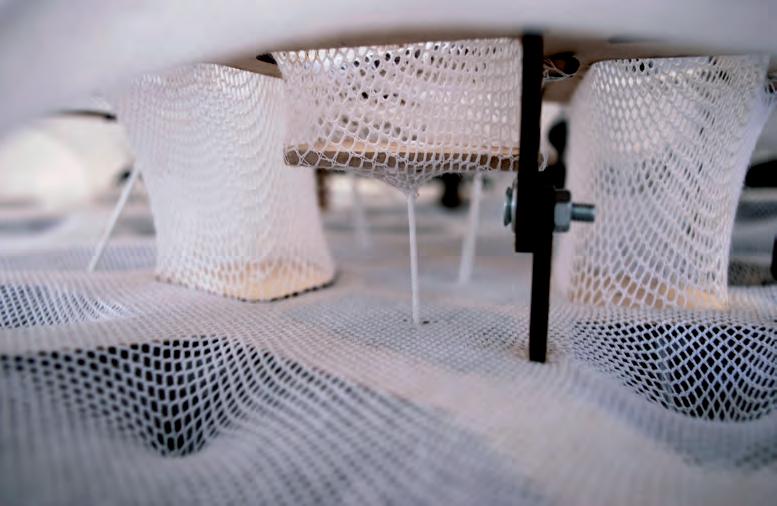
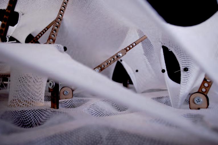
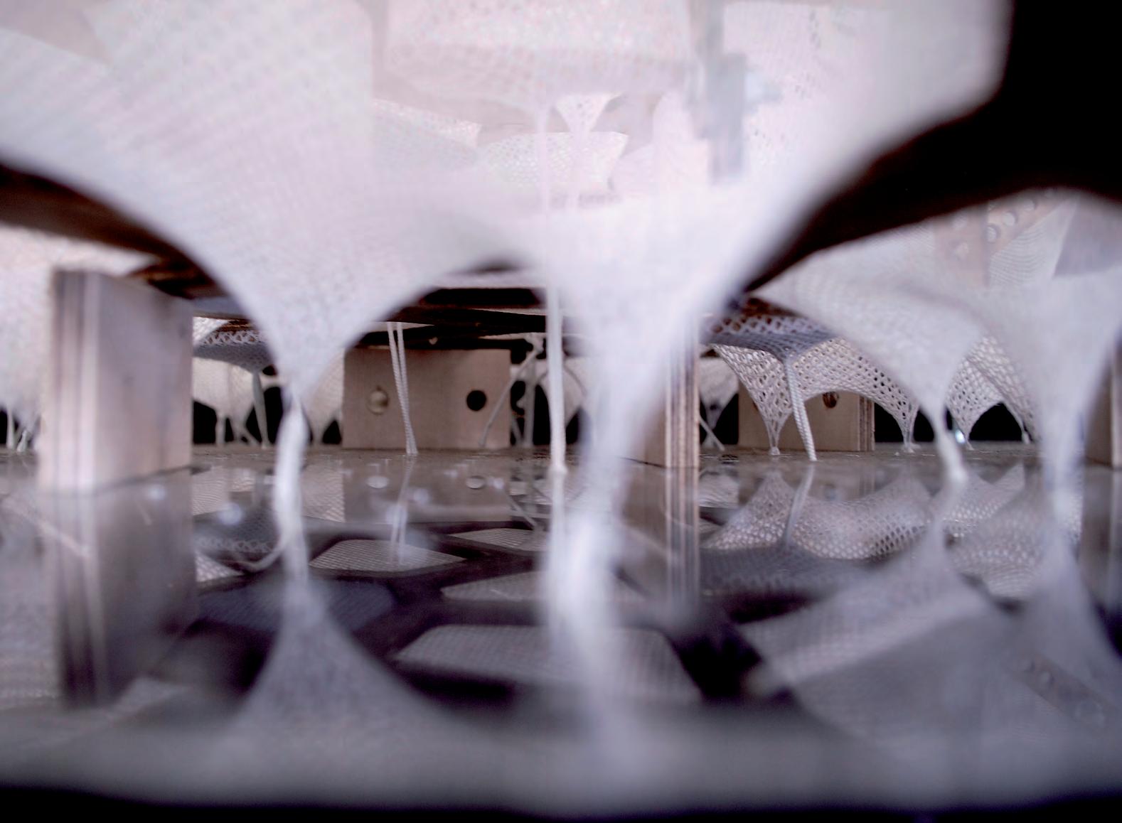

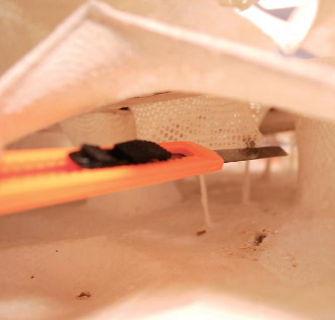
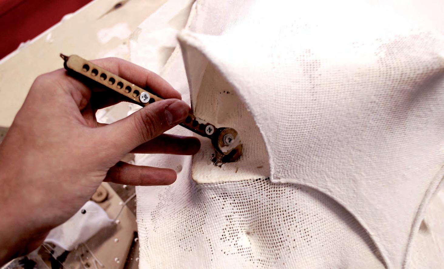

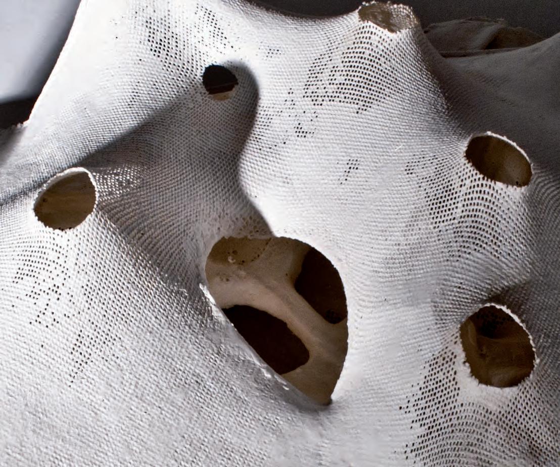
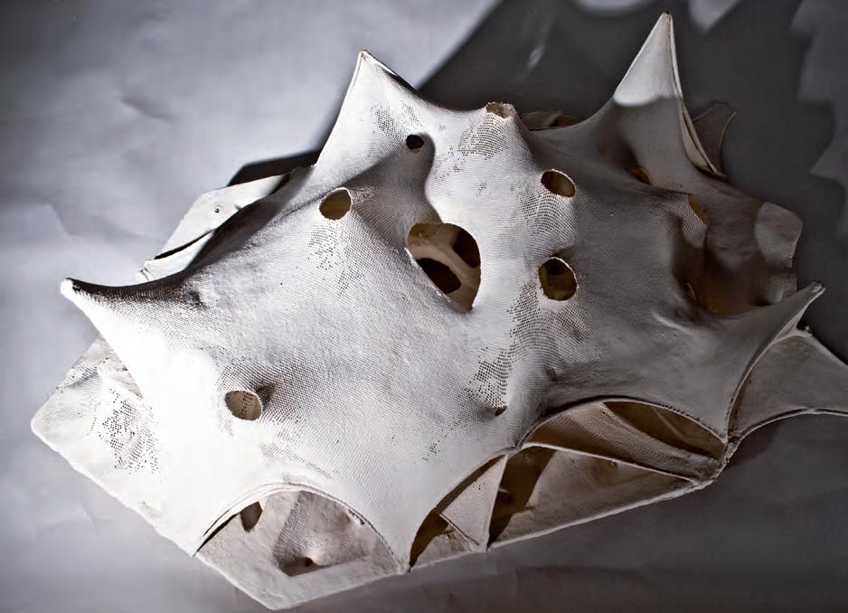
As discussed previously, parametric digital models are flexible to edit, and revaluate according to real scale materials and conditions. To proceed forward with the design strategy, a clear plan of the form generation has to be laid-out. The model must integrate the qualities and behaviour of the materials as they correspond to scale, which, after the experiments we carried out, can be input as numbers and formulas.
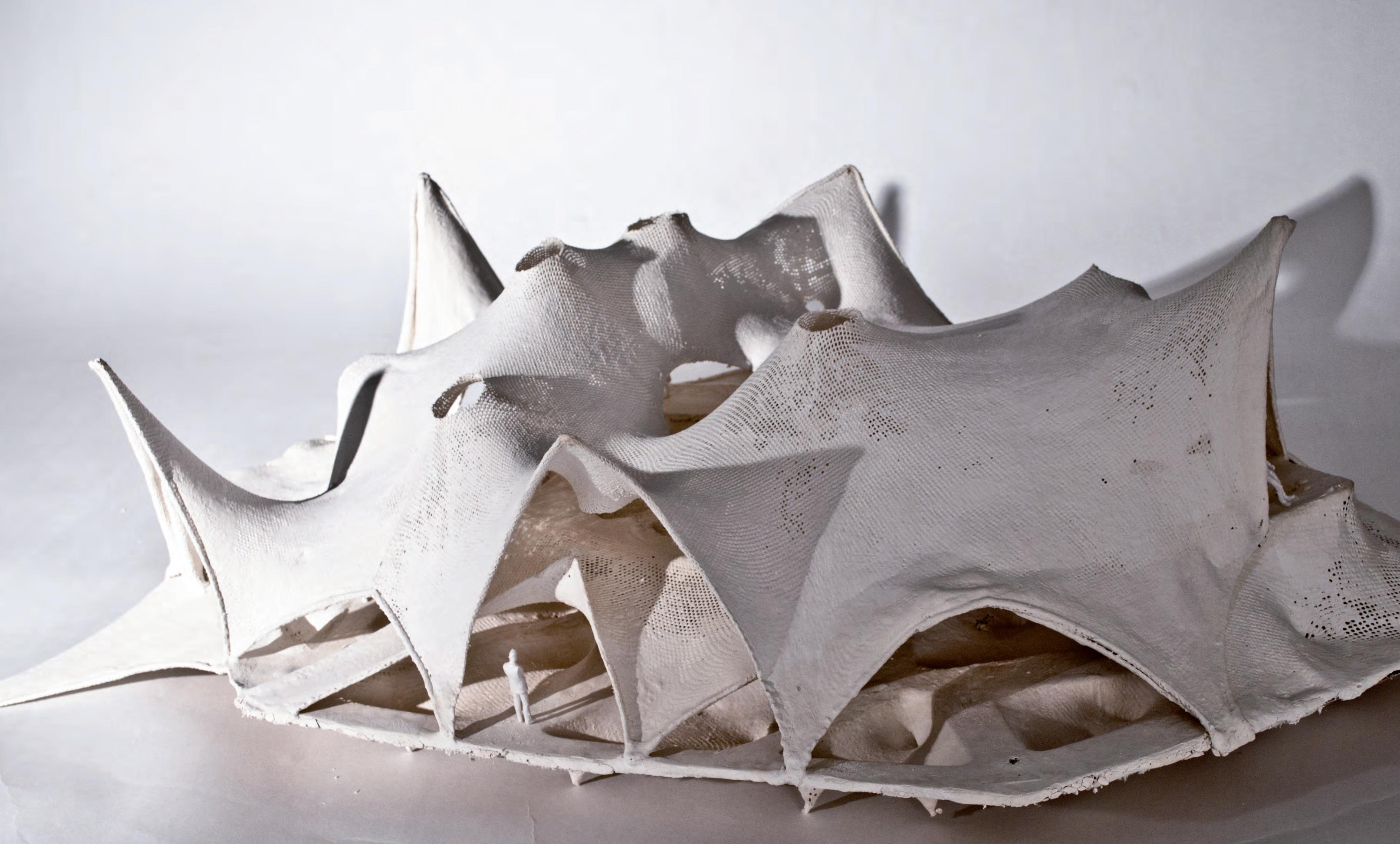
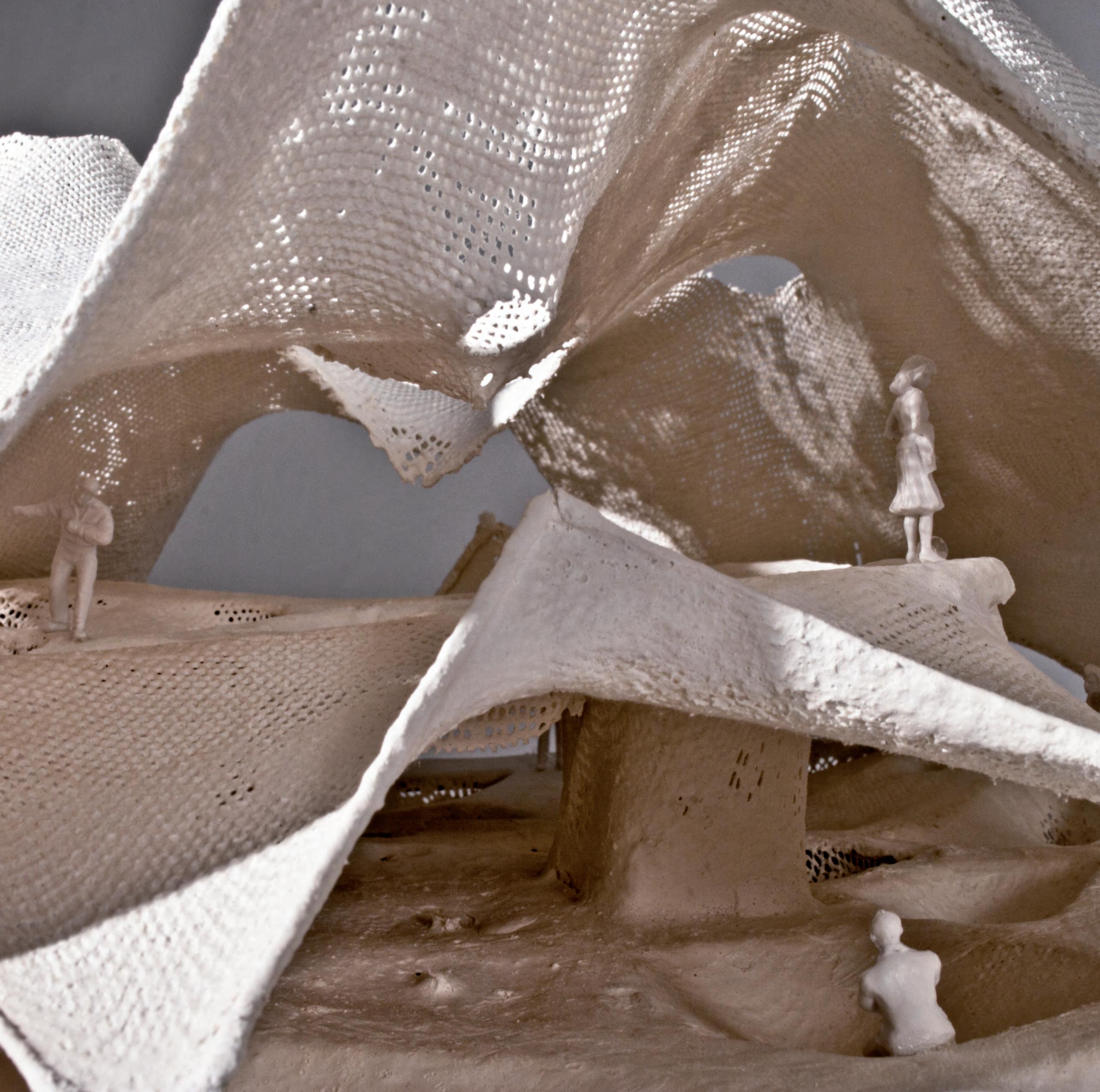
HYBIOS 4.0 is the outcome of modelling a construction system. Observing the material behaviour under the forces and conditions of a new method, the resultant spaces seemed disappointing in the quality of the finish. Despite these facts, there is a lot to be learned from this prototype, especially on how to simulate the construction process at different scales.
Several issues were noted when casting around pieces, especially their movement when the heavier coat of plaster was applied. The resultant finish lacked in quality, mainly due to the added force of the plaster acting on the fabric membrane.
Some of the forms were stretched in an exaggerated manner to enable hand access to model the interior. The pathway system generated was excessive in its expression, and a simpler circulation pathway system had to be devised as it corresponds to the programmatic functions of the building cell.
The overall result is a more complex spatial narrative, the failures in the quality finish and system modelling are due to several reasons, as listed previously. Most of these reasons, nevertheless, are due to limitations when modelling physically at a scale of 1:50. The need for digital simulation of the building design becomes of vital importance.

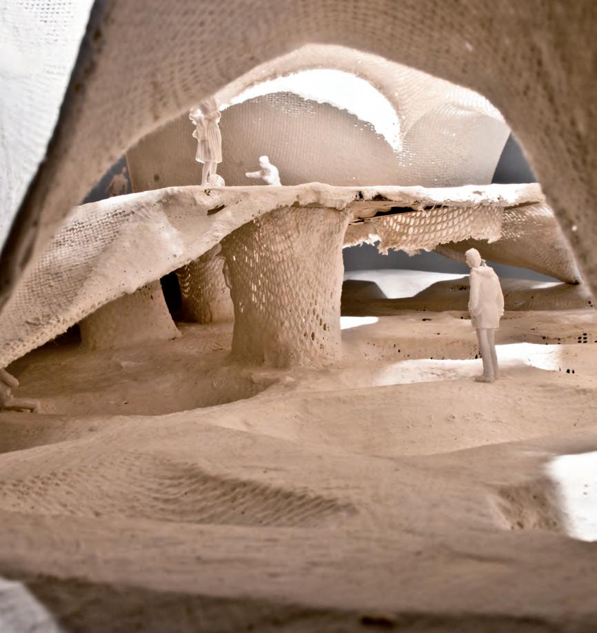
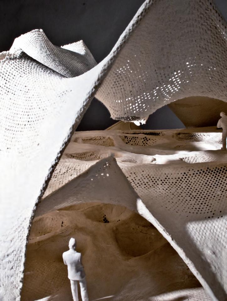
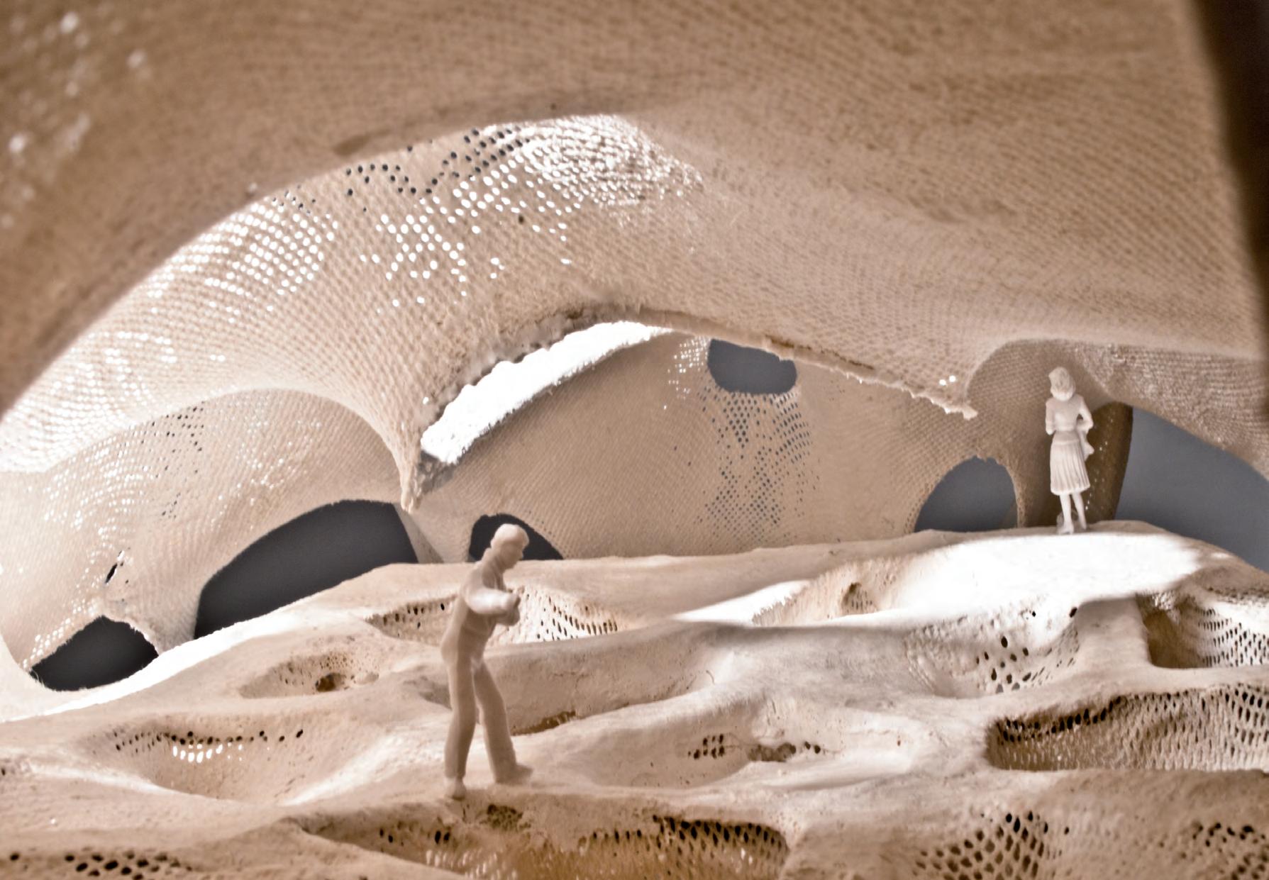
Jesmonite is water based solvent free material. The material has been explained in detail previously in Chapter 2 This experiment describes its contribution of stiffness to the fabric, which has been used to replicate the digital form-finding models. Fabric allows for the most elasticity of geometric deformation, rendering it a great option to provide the form work for the concrete to be layered on.
Process
AC 730 is a cementitious acrylic product. It is resistant to all weather conditions making it suitable for layering concrete over it. This is mixed with AC 730 flex liquids in the ratio 3:1(Powder to liquid) to improve its ductility. The mixing is done with high shear blades attached to a normal drill. The consistent mix is sprayed over the fabric. Quad axial glass fibre is a high strength fibre carefully crafted with filaments in 4 directions. The orientation of the fibres add to the strength of the material. It is also fire proof making it safe for building construction. The Mesh is cut carefully in the pattern of the fabric and laid over it when the first layer of fabric is relatively dry. The mesh sticks on to the wet Jesmonite with ease. Another layer of Jesmonite is sprayed over the mesh and allowed to dry.
Evaluation
The quad axial mesh reinforces the fabric and adds stiffness to it. The stiffness prevents any sag when concrete and reinforcement is layered over it. This solved the major issues with the fabric, which gave us the forms closest to the digital models. It is cement based and will adhere well with concrete preventing differential expansion of 2 layers. The next experiment will demonstrate layering reinforced concrete over the fabric.
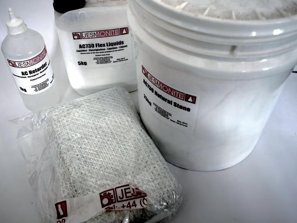

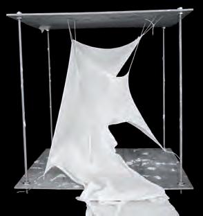
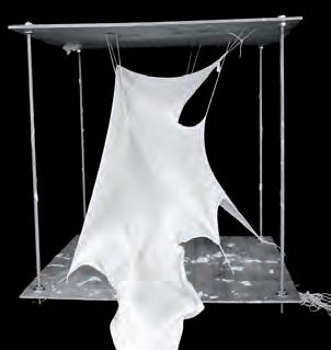
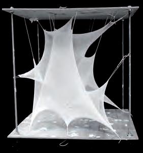
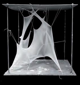
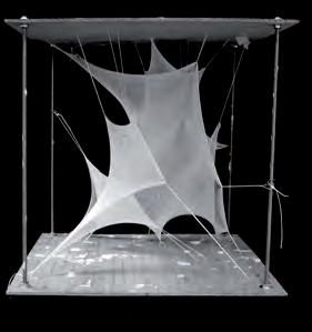
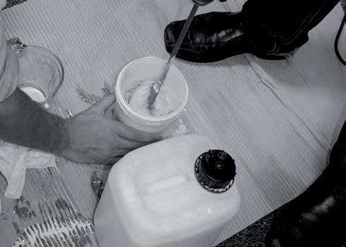
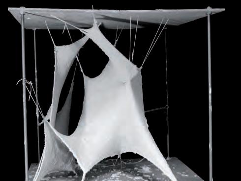
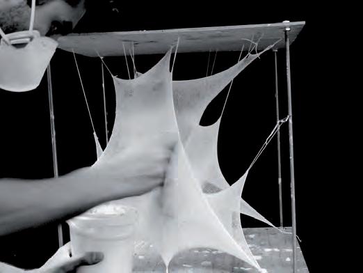
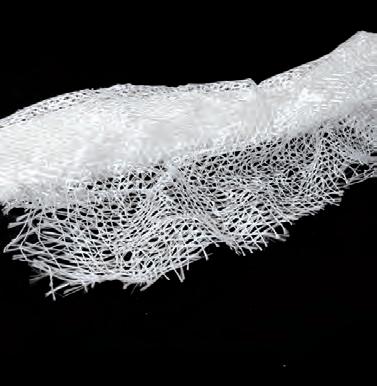
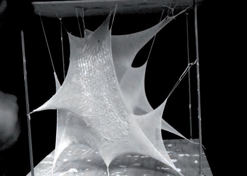
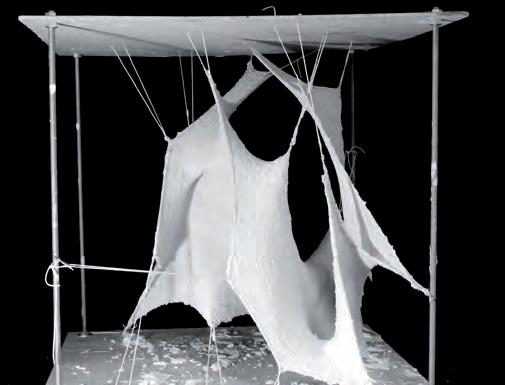

Various experiments have been carried out in the previous chapters on physical and digital form finding. Material tests and construction logistics have also been tested and successful results have been attained. After close evaluation of these experiments clarity was gained on the fact that layering materials to complement different properties would bring out a successful material system, which is a structural hybrid of current construction models.
This proposal demonstrates layering of materials to construct the forms developed through form-finding experiments in real scale. The process is explained in the following steps and the diagram.
1. Fishnet fabric: is a stretchable fabric and was the most successful in replicating the digital models. It is also inexpensive. The greatest drawback of the fabric was the lack of stiffness in its elements. Materials with high stiffness resulted in unsatisfactory forms, which could not be optimised for structure. In the first stage the fabric is restrained at the nodes from the digital model and then prestressed at the edges.
2. Jesmonite: AC730 is a rapid setting acrylic modified cementious composite. AC 730 is layered over the stretched fabric. Quad axial glass fibre is layered over the wet Jesmonite. The glass fibre is coated with another layer of Jesmonite. The layering process is repeated in case of larger spans. Jesmonite adds stiffness to the fabric and the fibre mesh increases the tensile capacity of the structure. The last layer is left in a rough finish to receive concrete over it. Jesmonite helps retain the form of the fabric. Its cementious and fuses with the concrete over it. This process is essential in preventing sags in the fabric otherwise caused due to the weight of the concrete and structural reinforcement. It also provides a platform for construction, which would have been absent in case of fabric alone.
3. BarChip fibre reinforced concrete over doubly-woven steel mesh: BarChip fibre reinforced concrete is sprayed over the fabric form work. A layer of double woven steel mesh in between directs the flow of forces from the 3D matrix of the fibre to the receivers. This also helps hold the concrete in place where the angle of repose of concrete is more than the slope of the surface. Robotic spraying will aid in reaching complex forms with ease. The thickness of concrete can also be kept consistent in this process.
4. Waterproofing and interior finishing: The concrete is left to cure and a layer of waterproofing is done over the surface. The Jesmonite is acid etched from inside to create different interior finishes. The process helps in shift from conventional wooden form work in the construction of static components into a more emergent process of generic forms.
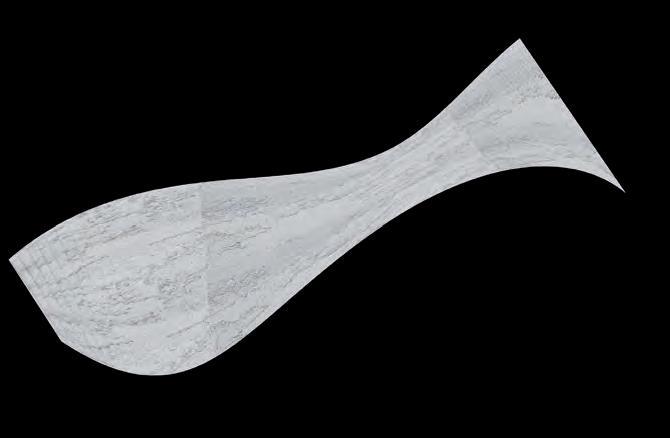

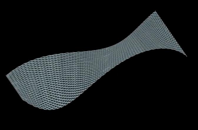

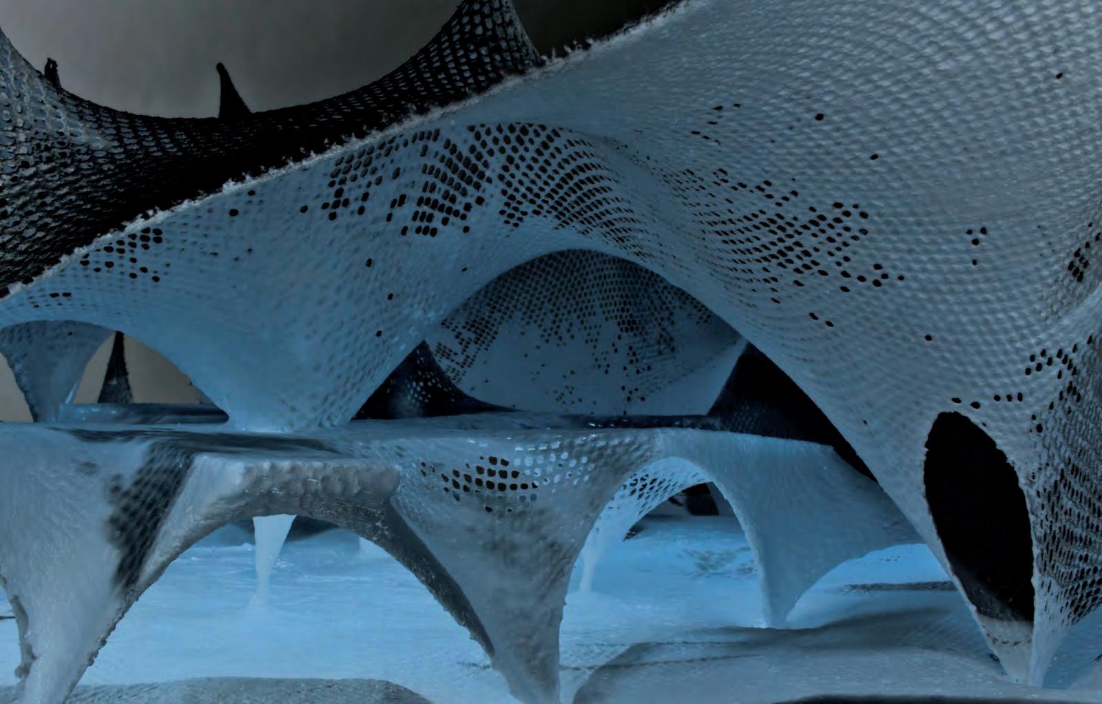
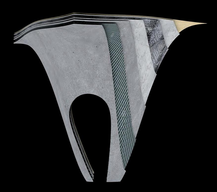
1.Fishnet fabric is stretched to achieve the form.
2.The fabric is layered with 2mm Jesmonite.
3.QuadAxial glass fibre mesh reinforces Jesmonite
4.A second layer of Jesmonite is applied over the glass reinforcement.
5.Barchip fibre reinforced concrete is applied over cured Jesmonite. A layer of steel mesh directs the flow of forces from the concrete to the recievers.It also helps wet concrete in place.
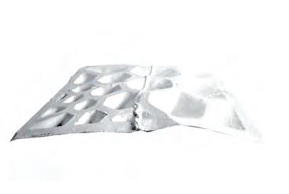


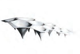
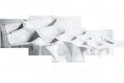
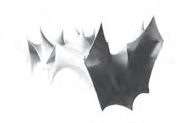
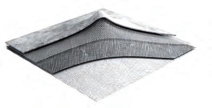
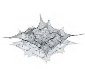
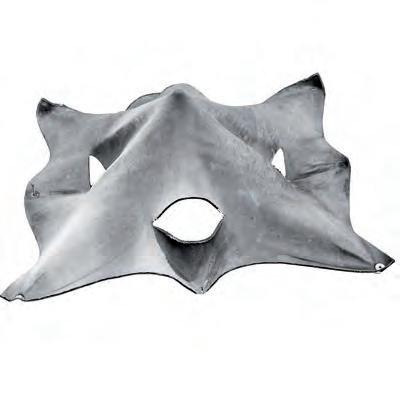

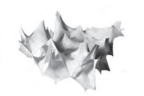
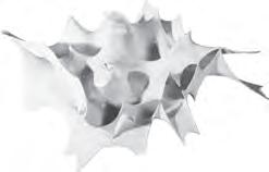

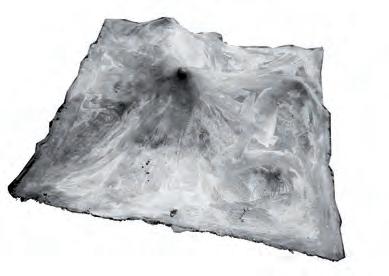
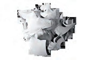
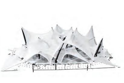
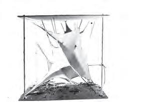
proto- (usu. prot- before a vowel) combining form original; primitive : prototherian | prototype. • first; anterior; relating to a precursor : protomartyr | protozoan.
ORIGIN from Greek prōtos ‘first.’
Driven by a search for a novel construction system using hybridized methods and materials, the research resulted in a set of varied prototypes that evolved in formal and functional complexity. Following simple consecutive changes each time, the prototypes evolved mainly by improving on the qualities of successors. The prototypes were also informed by constant digital validation from the generated simulations.
An interesting analogy between such methods of design and nature could be established as discussed by Phillip Steadman in ‘The Evolution of Designs’. The Darwinian Analogy, looks at evolutionary design as the product of ‘Trial and Error’ where benign features of a certain form, driven by environmental and immediate conditions, are inherited by the next development of that form. Undesirable features tend to fail and are not passed to the next generation of forms. (Philip Steadman-The Evolution of Designs P. 72)
The concept of the ‘Survival of The Fittest’ as Quoted by Herber and Spencer (Philip Steadman-The Evolution of Designs P. 72) ensured a framework of ‘Learning by Doing’ where mistakes done in the previous prototype inform the development of the next one. This enhanced the evolution process of the design where the simple was developed to complex while avoiding complication as much as possible.
Concrete as a building material has been used in a range of casting methods due to the variety of ways of working with the material. An array of application methods in the construction industry has been observed through the course of this research ranging from the traditional practice in third world countries to more up-to-date digital fabrication methods in workshops and research circles.
Disadvantages are noted on both ends of the spectrum. The gains of using certain methods of casting concrete are considered as the key factor of choosing the correct construction logistics. These gains are measured by first calibrating the design outcome. The construction industry is surrounded by a set of restraints, which could influence deriving to logical solution for constructing a certain space within available resources, time constraints and expertise in advanced construction.
Complex geometric solutions that often lead to fluid spatial design are hence burdened by the constraints of place, time and resources. This could potentially lead to the risk of the monopolization of novelty in the built environment due to the lack of precision, know-how and advanced tools in unspecialized environments.
The few architectural masterpieces that have over come the many difficulties of design and construction have often required unreasonable amounts of resources, materials and expertise. The results are spectacular environments, which hide behind ugly and excessive processes of formation. The complication and abundance of these processes, that often are an afterthought of the design process, habitually compromise the initial ideas imagined by the architect by untruthfully forcing materials into the complex geometries conceived earlier.
In order to achieve simplicity and truth in the process of constructing the spatial fluidity that we pursue in the course of this research, the process had to be inverted. The research aims at new construction method where materials assemble to perceived and controlled complex geometries, according to a design system that is the result of a thorough investigation of how these construction materials behave.
The design system generates digital outcomes that are based on limitations and possibilities of the material system investigations presented earlier.
Digital generations can be quantified and tested to take full advantage of the material-hybrid’s possible performativity.
Outdated Process
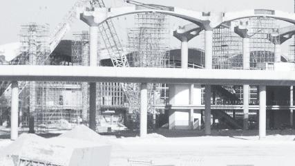
Conventional Space
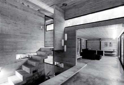
Monotonous Form
Robotic Process
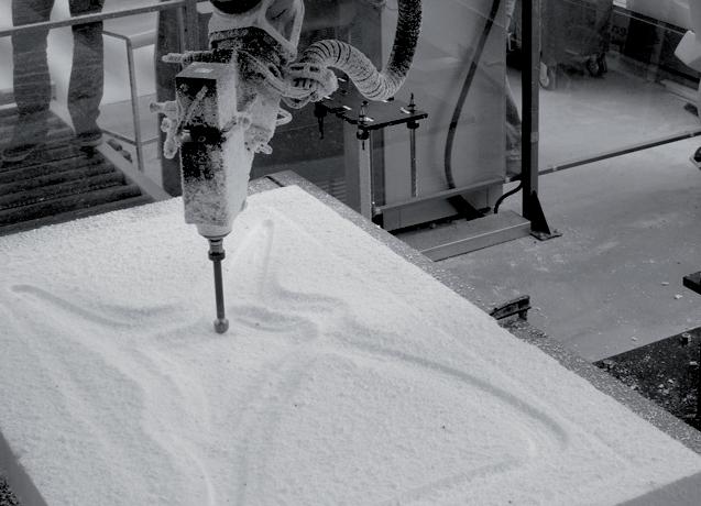
Labour Intensive
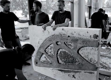
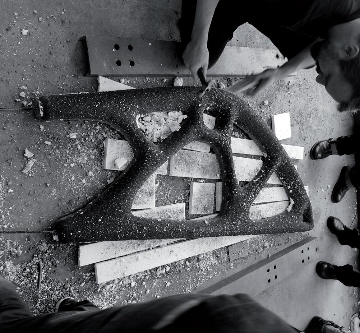
“The architecture I strive for changes Euclidean geometry to a nonlinear geometry which is based on nature, because I feel that humans are losing their sensitivity and vitality in the ubiquitous grid-formed urban and architectonic spaces.” Toyo Ito/Detail Practice: Digital Processes
The Taichung Metropolitan Opera House in Taiwan is a cultural centre, anticipated for completion by 2014. The structure is currently under the construction phase and the work done is of Toyo Ito & Associates Architects in collaboration with Arup Advance technology and Research.
This particular project becomes relevant not only due to its use of current state of the art techniques, but also because of the overlap in the process it shares with the investigations carried out in this thesis. The project proposes a new set of challenges to the engineering, architecture and construction praxis.
The process starts with the concept sketches by Ito, where he imagined an un-interrupted space where the structure is augmented within the flowing smooth geometry of the enclosure that wraps around program spaces. The idea is conceived with mathematical quantification of digital models by modelling the geometry of catenoid shapes, which are relaxed to a minimal surface over-all geometry.
These geometries have spatial and performative values within the building. The digital models are tested and cross-compared with physical prototypes using various modelling methods to reveal their spatial qualities. Large-scale models were tested for acoustic performance while digital models are tested for structural behaviour.
Construction details such as reinforcement bars are calculated within the digital model. The placement, size and shape of reinforcement is designed digitally based on the size of the concrete piece, the curvature it takes and the load that is imposed upon it. The construction is carried out with spraying concrete on the steel reinforcement to achieve a concrete shell.
Although it is exciting to see architects and engineers exploring innovative methods in the industry, it became clear that a lot of the methods used in the Opera’s realization have been looking at things in a fairly traditional manner. The geometries were the result of a design idea, rather the other way around. Materials are forced to confine to that design causing an unavoidable amount of excess in waste, as seen by the immense amount of scaffolding and form work needed to achieve these geometries as a built form.
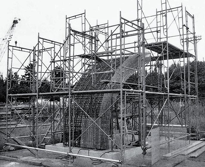
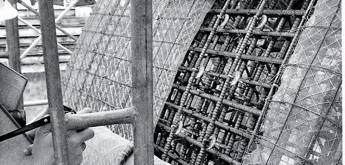
Within Detail Practice: Digital Processes by Moritz Hauschild and Rudiger Karzel, the unconventional process of designing the Opera house is explained thoroughly.
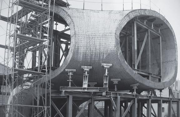
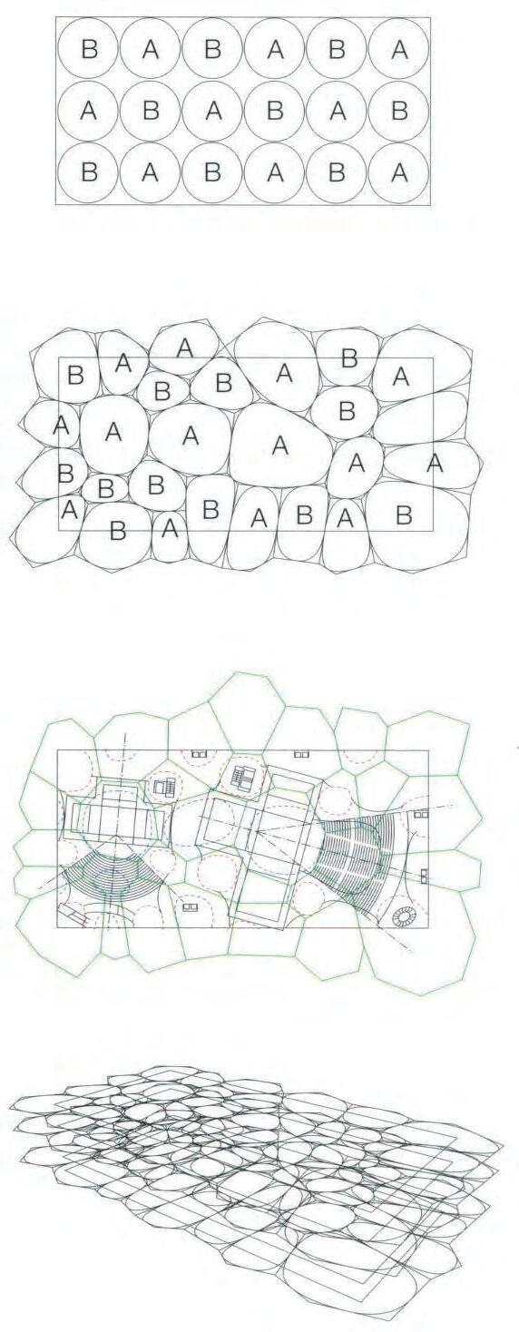

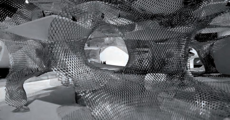

MULTIPLE GENERATIONS
To enable the application of the material system on different sites and conditions, digital models have to be simulated for testing purposes. A digital algorithm that allows for recursion is needed to produce different iterations to constantly re-evaluate the generated outcome. Within the intelligence algorithm, the material behaviour of the system and the possible spatial limitations have to be taken into consideration.
SPATIAL CONSIDERATION
Since fluidity of the transition between static architectural elements is the main objective, the function of these spatial conditions has to be considered in the pseudo code of the design process. The values of areas of space to satisfy certain program are the main initial input.
MATERIAL, FORM, PERFORMANCE
The performative function of the architectural elements to be introduced, as realized by the previous material investigation can be quantified and fine-tuned to modulate the thermal comfort within the interior spaces. This optimization process could also benefit from the recursive nature of the architectural parametric tool.
Our intention is a digital tool where the input is program areas and the outcome is fabric patches that could be materialized using digital fabrication tools. This could aid in bridging the gap between the designer and the construction worker to minimize error in the construction of complex concrete structures, and thus simplifying the process of forming and materializing such buildings.
Re-Organize Base Geometry
Start Voronoi algorithm starting from points as centres INPUT POINT
Are points within containment area for building?
Did the Occupation plot distribute well on unbuilt land?
Did the Occupation plan distribute well on unbuilt land?
Generate pathways for restraint along the cell edges
Are all layers of the base on the same plane?
EDGE POINTS OF OCCUPATION PLOT
INPUT EDGE POINT
LIGHTWELLS Are SOLAR CHIMNEYS facing the right angle
Change Angle of Light Well Force Vector.
Apply forces on mesh to generate.
Map Isoptropic stress analysis chart
Find intersection points that are closes to intersections and to the cropped holes in the mesh
Are touch down points aligned to holes and inters
Orient vectors to acheive a proper Solar Chimney stack effect
Map out light well pixelation following curvature paths
Lay out seam patching strategy following stress paths OUTPUT PATCHING SHAPES FOR TENSIONING
Are Solar Chimney vectors oriented properly
Use EDGE POINTS as restraint points for MESH RELAXATION ALGORITHM
PROCESS
INPUT/OUTPUT EVALUATION
Quantifying geometry is important towards generating precise computational models. Design variables and optimization rules, which determine functional attributes of the system, have to be clearly listed. The set of input parameters extracted will be compiled into an algorithm, which can be tested on different prototypes and site conditions for further evaluation.
Architectural elements that serve different functions are captured from instances on the physical experiments as a first step towards calibration of thresholds in the digital model. The diagram in (Fig 5.21.1) describes the different elements that can be merged to create a fluid coherent space. A sequence from a single cell to a set of cells that could represent certain programs is grouped in (Fig 5.21.2) Larger groups are clustered which will follow a certain logic (for example: circulation pattern). Pathways are introduced for circulation and spatial division.
Grouping of the extracted architectural elements could result in coherent spaces. The spatial and lighting qualities of these elements in different instances have to attempted on small digital prototypes. Introduction of pathways bring in interesting points of intersection between spaces that could turn out to be thresholds of perceptual values. These will be studied in depth in the next experiments.

5.21.2: Concept for grouping programs from a single cell to multiple ones (Top), Introduction of pathways and seating spaces for spatial division (Middle),Intersection of pathways and programs informing interior and exterior touch down points (Bottom).
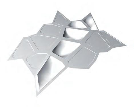
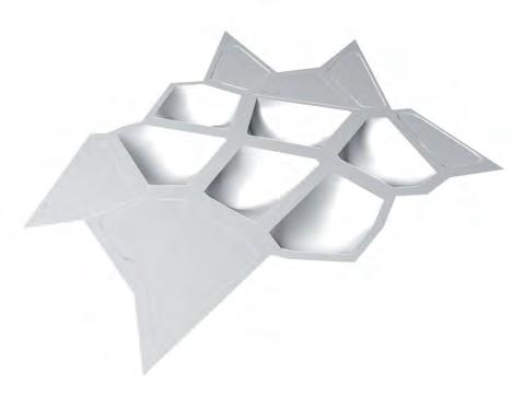

Differentiation of programs through perceptual thresholds aid in eliminating rigid architectural boundaries, those often dictate the use of space in a conventional building. Techniques applied to the extracted elements such as modulation of roof forms, variation of interior planes and introduction of light wells aid in emergence of spaces with differential spatial and lighting qualities. An awareness of the spatial environment by actuating the sensory information will bring in an innovative spatial experience for the visitors. This could be achieved through varied heights, lighting conditions, thermal differences.
The illustration in (Fig 5.30.1:) describes an initial concept for the clustering of the architectural elements that were extracted in the previous step. Differential spatial conditions imply semiotic values to programs. Simple transformations to the elements create varied spatial and lighting experiences. Introduction of light wells in specific instances highlights thresholds of change. These could also enlarge to form courtyards inside the building, which would create interesting spaces that would attempt to fuse the interior and exterior.
Spatial division through innovative features that emerge by the interaction of elements has to be simulated using a dynamic relaxation algorithm. To achieve this the accessible floor spaces, heights and lighting needs of different programs that suite the system have to be studied in detail. Forthcoming chapters will focus on analysis of qualities and limitations of the system with regard to height and light in hypothetical spaces.
Inflicting roof forms to create perceptual thresholds
Differential lighting conditions create gradient thresholds
Modulation of hieght to create spatial differentiation
Modulation of prestress on fabric to create differential seating pods
Variation of floor levels to create performative spaces
Light wells creating perceptual thresholds
Fig 5.30.1: Concept techniques for introduction of perceptual thresholds in the interior spaces. Differentiation created through modulation of roof forms, Floor levels and light wells. These transformations of elements create spaces with differential lighting and spatial qualities.
It became apparent through the earlier experiments that the material system proposed has many limitation. Understanding these limitations enables us to work within the physical boundaries of the anticipated spatial volumes. The system derives its form from the material behaviour. Its form follows the natural force path to find the optimal geometry. Optimal geometry implies minimal use of material, making it efficient and lightweight.
As an initial step the physical properties of an industrial fabric is embedded into the digital mesh. The dynamic relaxation algorithm is written with the fabric properties embedded within its logic so that the final digital model is closest to the real scale construction in terms of the spatial qualities.
A series of experiments are demonstrated in the next few chapters to quantify the accessible floor areas. Once the spatial volumes are catalogued, methods to improve the percentage of usable floor are discussed. The experiments include testing of minimum clearances, variation of openings and maintaining average heights within the spaces and clustering of spaces. Tests are also carried out to perceive the quality of lighting within the system. Techniques to vary the lighting conditions within the interior spaces are also demonstrated with light and shadow simulations.
Optimization of global and local orientation of the forms had to be tested for improving the ventilation in the system. Stack ventilation increases with difference in height between the inlets and outlets. The form is suitable to exhaust hot air, but has to be modulated to better the performance of that feature. Methods to improve buoyancy through creating temperature difference will be dealt with in-depth in the next section of the experiments.
The percentage of accessible floor areas could be improved by several methods. The first step towards improving the area of the habitable space is tested in the diagram through variation of opening sizes. Variation of this opening according to program requirements improves the light and the usable floor space in the interiors. A standard footprint is tested with variation of the light well diameter and the increase in the minimum clearance at the periphery of the spaces is noted. Experiments to demonstrate increase in tip heights and clustering are detailed in the next chapter.
Ventilation shaft
Accessible floor
Ventilation shaft
Accessible floor
Ventilation shaft
Accessible floor
Ventilation shaft
Accessible floor
Ventilation shaft
Accessible floor
A simple relaxed tent is illustrated to observe the difference in volume in the system compared to a cylindrical form. The diagram explains the loss of volume in the system in comparison with a conventional space. The resultant form has an upper conical volume, which is decreasing in diameter towards the tip. This could possibly create a negative pressure, which could be taken advantage of to improve the ventilation inside.
: Conventional space
B : Hybios material system
ELABORATE WHILE WRITING TEXT.
ELABORATE WHILE WRITING TEXT.
Experiment : To evaluate the usable space in the material system.
Experiment : To evaluate the usable space in the material system.
Evaluation : The tent form reduces the usable space drastically.
Evaluation : The tent form reduces the usable space drastically.
Solution : Increase the height. Cluster spaces to increase the average height of spaces. Reduce the number of restrain points on ground.Introduction of multiple light wells in differential heights in the same space.
A : 10m dia 5m High. Usable Space : 100 % Section at 2.20m hieght Section through Hybios B : 10m diameter 5m High. Usable Space : 16 %
Solution : Increase the height. Cluster spaces to increase the average height of spaces. Reduce the number of restrain points on ground.Introduction of multiple light wells in differential heights in the same space.
A : 10m dia 5m High. Usable Space : 100 % Section at 2.20m hieght Section through Hybios B : 10m diameter 5m High. Usable Space : 16 % Accessible Floor Area
Experiment : To evaluate the usable space in the material system.
Evaluation : The tent form reduces the usable area drastically.
Solution :
-Increase the height.
-Cluster spaces to increase the average height of spaces.
-Reduce the number of restrain points on ground.
-Introduction of multiple light wells in differential heights in the same space.
As an effort to comprehend the volumetric capacity of interior spaces within the system, a set of public programs are selected and heights are assigned for fixed areas. The series of drawings in (Fig 5.41.1) describes the percentage of accessible floor area for different programs after increasing the heights. An area to height ratio is developed for public and private spaces within a generic public building.
The ratio derived is helpful in defining the heights of spaces in the algorithm that is to be developed. Experiments to further improve the space have to be carried out. Variation of opening sizes and clustering of roof forms could improve the space. Experiments on these will be carried out next. The upper conical volumes that is a result of modification of height of the spaces could be experimented for the improvement of the ventilation inside the building.
Different programmatic zones require different natural lighting needs within the built enclosure. The need for natural light depends on the type of activity that takes place in a particular space. Since the flexibility of the forms we have investigated as enclosing spaces has wide range of formal adaptation to modulate the interior condition, a strategy for orienting these forms had to be devised. One major alteration parameter is the angle at which these conical forms should be oriented to harvest sunlight into their interior.
The conical forms were tested digitally under a direct light source, and different forming conditions, to visualize the light and shadow cast within their interiors. The first set of digital experiments were to orient the forms at 45 and -45 degree rotation away from the light source, the main intention was to observe the spot of light resulting within the shaded enclosure, and compare it to a perpendicularly oriented form. The intention is to create light spots within each space that correspond in intensity to the lighting needs of that space. From direct intense light to diffused passive lighting.
The potential of creating a pixilation pattern in the light brought in was observed by removing faces of the digital mesh. Two strategies for creating that lighting effect were attempted, by removing the faces closer to the opening or further away from the openings. Light pixilation could be implemented as means to highlight specific instances within the space, as observed in the physical models.
The lighting modulation techniques explored give an insight of their use in the decision making process of the design. According to the lighting need of each enclosure, the openings could determine the amount of lighting needed per square area of coverage, and the orientation could be decided upon based on the adjacency of these enclosures and their pre-determined function. A diagram that illustrates the lighting need, size and adjacency of the placement of program areas illustrates the light emmitance of these enclosures.

5.50.1: Variation in the light and shadow cast in the interior spaces according to inclination of the light wells (Top), Differential lighting conditions cast on the floor due to pixilation on the roof forms(Right), Variation in pixilation on the system creates interesting patterns on the system(Bottom).
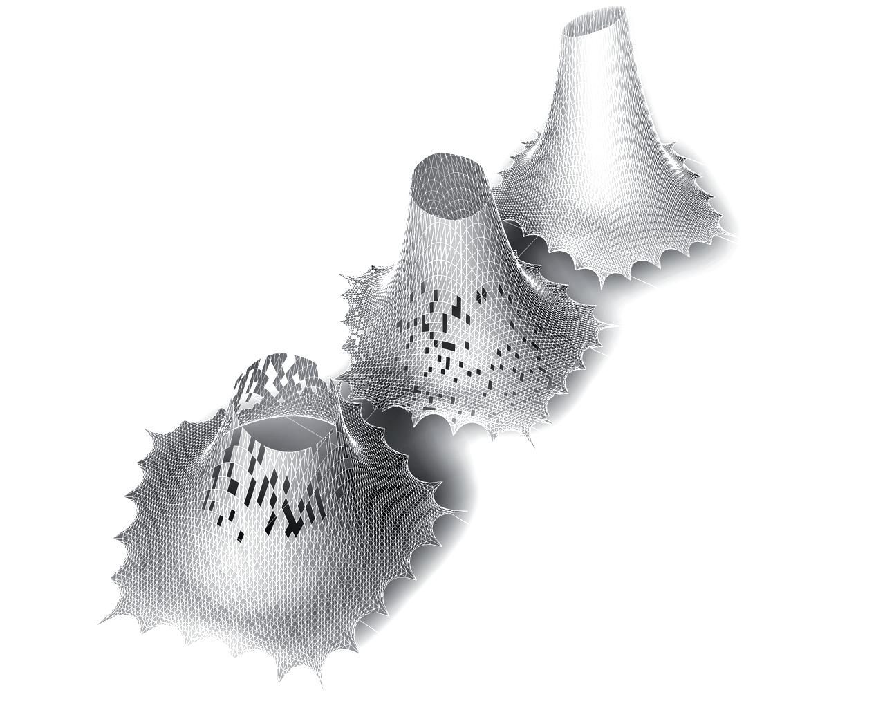
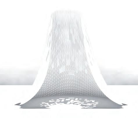
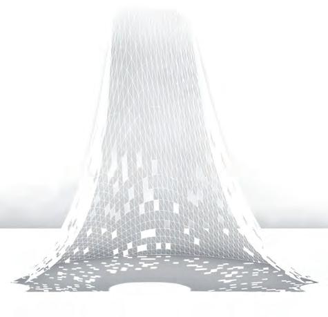
5.50.2: Attenuation of light within programs. This can vary the light levels assigned to different programs.
A single form was extracted to investigate in detail the accessible floor area and lighting inside, simulated through a dynamic relaxation algorithm. An area to height ratio was calculated to assign heights to the public and private spaces. Techniques to improve accessible floor area were discussed before such as variation of opening sizes and clustering. Diagram (Fig 5.51.1) describes the percentage increase in accessible floor area, which occurs during clustering.
The accessible space areas of Space A and Space B, which resemble the program areas investigated earlier have been diagrammed to illustrate their usable spaces. These programs are combined into one and in this case the simulation is done using one single mesh instead of two individual ones. The heights of each program remain unaltered. The section through the prototype elaborates how the accessible floor area is improved. The form changes at the edge where the 2 programs meets and the optimal form results in a increased percentage of usable floor area.
Clustering is an important strategy towards the generation of a complete design when several programs and sub programs are involved. When multiple clustering is generated the percentage of accessible floor area can be increased to that of any conventional building but still holds all the spatial and lighting qualities of the system.
A set of areas ranging in privacy and lighting needs were extracted from the list of programs introduced to the conical forms previously. These programs were packed according to their adjacency needs to create a smaller patch of the proposed overall structure.
The clustering method aids in the creation of smaller digital models for the testing and analysis process. A dynamic relaxation script was written for the purpose of relaxing forms that have many input forming parameters. These parameters include the location of restraint points, the height of the vectors depending on area and function and the size of the opening restrained at the tip of each vector. The same part of the script that culls mesh faces by area size was tested on an initial iteration to envisage the shading quality within the interior.
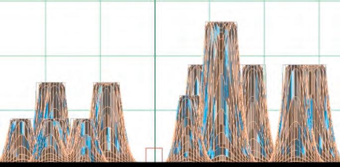
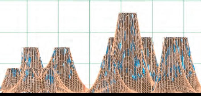
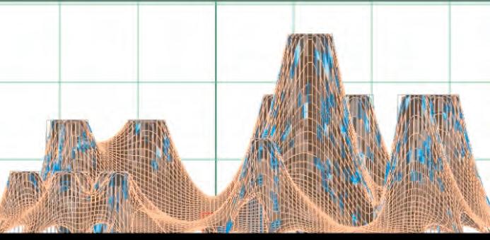
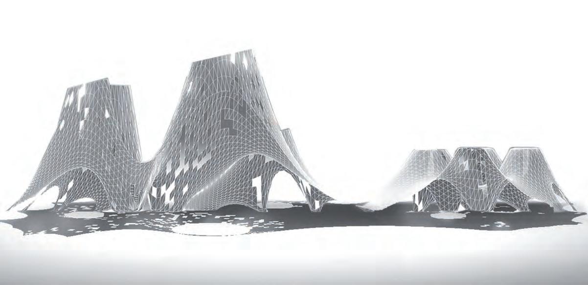
Following the testing of a cluster of programs within an interior, the exterior morphology of the enclosing skin was altered and tested, to be fine-tuned for modulation purposes. Two iterations of the mesh relaxation script were generated, with differentiating characteristics in each.
Circles of areas that have different programmatic functions ranging from public to private make the floor plan of the hypothetical space. The program of these two spaces was kept in the same adjacency order to minimize the amount of change, and enable a clear visible difference in the analysis results. The first digital prototype that was produced followed the proportions of the previous investigations in the ratio of square area of a certain program to its height. The solar chimneys were oriented straight towards the direct light source.
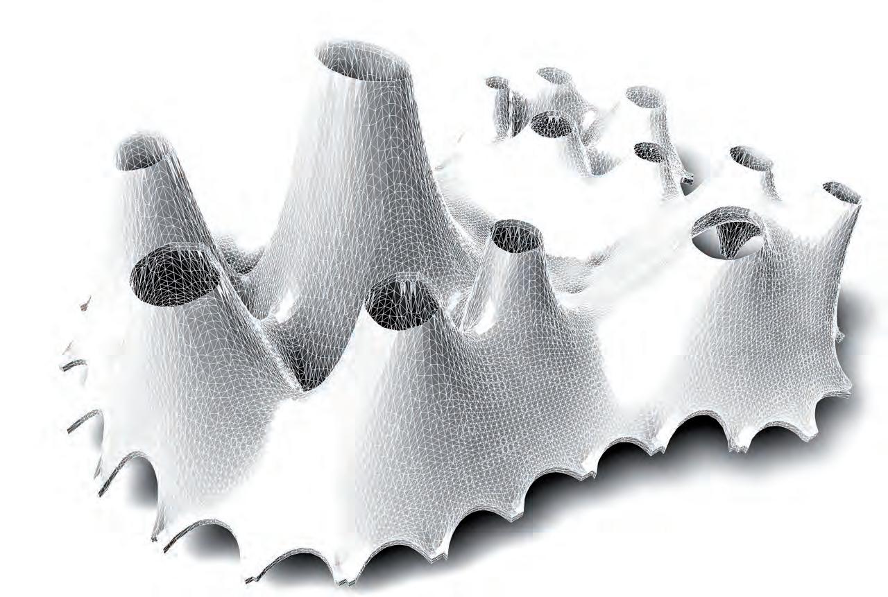
The second Digital prototype had inclined vectors for directing light within the structure. The strategy of tilting the angles of each solar chimney was determined by the program space allocated underneath. The strategy provided further insight on the duality of the strategy for forming these solar chimneys. Further quantification of the emergent forms of these different setting conditions had to be carried out next, under precise and particular environmental conditions.
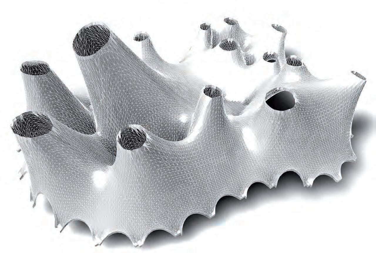
Solar Chimneys have been widely used in hot and dry climates to improve the natural ventilation inside buildings. It is a simple shaft facing the sun’s direct radiation. The shaft surface is heated up by passive solar energy and creates a temperature difference between the interior spaces and the shaft. Convection currents move the warm air into the shaft and remove them through upper apertures. The roof forms in the system is suitable to perform similarly. They are oriented away from the sun thus increasing the solar exposure area. The stack ventilation is dependent on factors such as the solar collector area of the shaft, the height of the shaft and the inlet and outlet air apertures.
Surface heats up due to radiation and pulls up hot air
Windward side Leeward side
Bouyancy increases due to the form of the system.
Surface heats up due to radiation and pulls up hot air
Windward side
trees to cool and filter air near openings
Bouyancy increases due to the form of the system.
Solar chimney
Leeward side
Solar chimney
trees to cool and filter air near openings
Openings at lower levels facing windward direction
Warm air is lighter than cold air and rises and leaves the building interior through the upper openings. The air inside is replaced by the colder air entering through the lower openings.
Openings at lower levels facing windward direction openings
Warm air is lighter than cold air and rises and leaves the building interior through the upper openings. The air inside is replaced by the colder air entering through the lower openings.
Stack ventilation increases with difference in height between the inlets and outlets. The form is suitable to exhaust hot air. Methods to improve buoyancy through creating temperature difference will be dealt with in-depth in the next section of the experiments.
Material system as a solar chimney
Stack pressure is proportional to indoor outdoor temperature difference and to the vertical distance between openings. Airflow increases with temperature difference and vertical distance between openings.
Material system as a solar chimney
Stack pressure is proportional to indoor outdoor temperature difference and to the vertical distance between openings. Airflow increases with temperature difference and vertical distance between openings.
Windward side
Windward side
Ventilation for cooling.Improvement of passive stack inside the system
Ventilation for cooling.Improvement of passive stack inside the system
chimney
Leeward side
Solar chimney
Leeward side
The exposure area of the shaft and height is proportional to the area of the program and the number of users. Thus ventilation rate improves according to the area of the program. This is clearly demonstrated in the solar exposure analysis diagram.
Orienting the forms to the leeward side increases the negative pressure and thus the suction rate from the interior. To understand the inlet and outlet apertures, a computational fluid dynamics analysis of the form is carried out as the next step. Tilting the chimneys also allowed for a larger surface area in the centre allowing for more solar gain. Openings could be introduced around that area to draw more sunlight into the spaces.
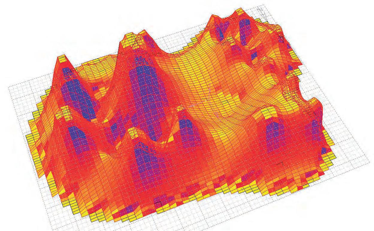

The potential material layering of the geometries created digitally is relatively light in weight. External environmental factors of the climatic regions suitable for the proposed material system include usually high prevailing wind speeds. This potentially could lead to high pressures hitting the lightweight shell skin.
A CFD wind simulation test was carried out with a wind velocity of 35 m/s resembling a moderate to high wind speed directly projected at the digital model’s exterior in the X direction. The procedure was carried out on the straight and tilted models to observe the differences of both. A normal force of Lift was introduced in the Y direction.

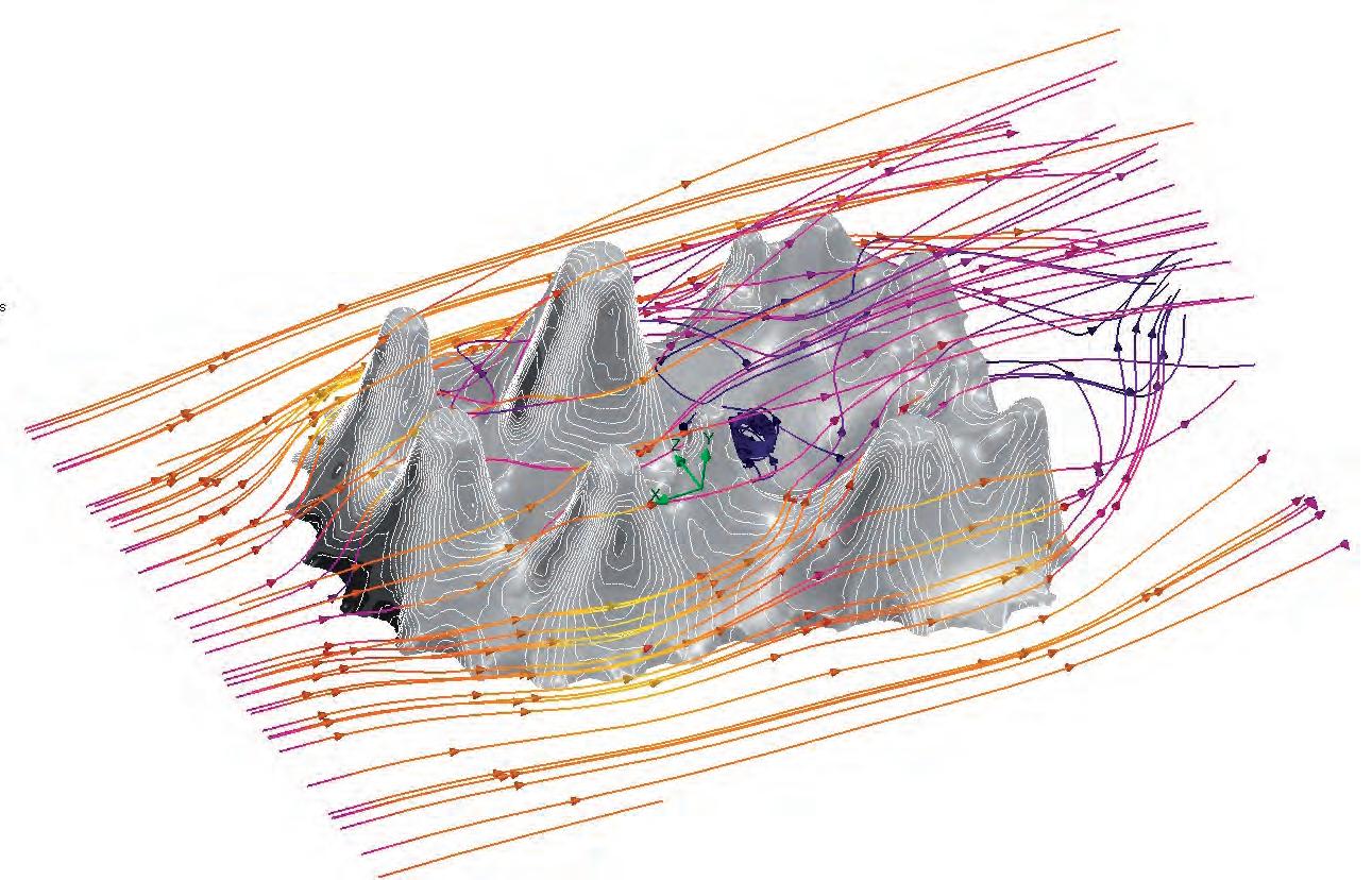
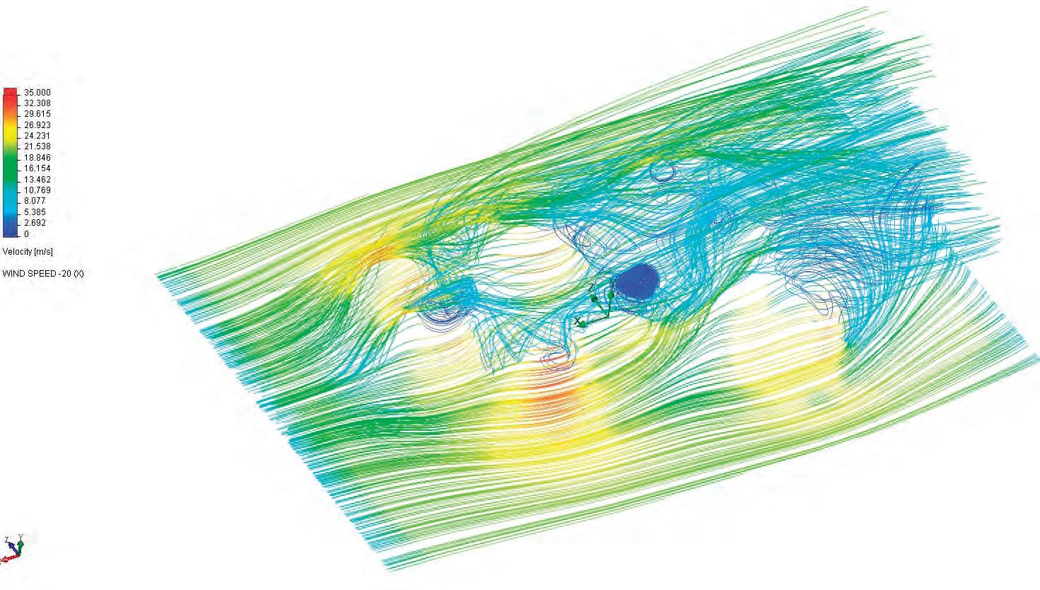
The wind velocity increased around the bulging protrusions of the model. That result corresponded in a higher pressure on the exterior of the prototype in those specific areas. Some stagnation of low velocity air was noted circulating in the recessed area between the highest protrusions of the straight solar chimney model.
In the second prototype with the tilted solar chimneys that stagnation was reduced and a more streamlined exterior wind distribution was noted on the morphology of the model. The Wind was projected opposite to the general direction on to which the main solar chimneys are tilted.
Wind loads acting on the building envelope are part of the dynamic forces that might affect the performance of the structure. These tests are carried out to evaluate the difference between geometries created within the system for evaluation purposes only, and not as an optimization strategy


Direct solar radiation is a major concern in the climatic regions where the system is applicable. The shell structure geometry has to be tested for its shading properties around the exterior and for lighting qualities within the interior. Parametric tools such as Geco, a Plug-in for Grasshopper, could be used in collaboration with Ecotect to generate precise illustrations of environmental analysis of digital models provided as input. The analysis was to be carried out on a digital model that has side openings for enhancing the ventilation and aid in lighting, as well as serve as entrances.
A third digital prototype with tilted solar chimneys was generated for testing the lighting conditions over and under the enclosure shell. The prototype was based on a Voronoi cellular plan where pathways were introduced between the program spaces.
Between the Voronoi cells the touch points are marked within the interior cell boundaries. These are set restrain points, which align with mesh crop circles to restrain a point on their circumference. Restrain points generate a light well where the roof structure touches the ground bringing an opening with light within the interior of the shell after the mesh has been relaxed.
As seen in (Fig 5.80.2), the luminosity analysis of the interior of the prototype with openings has an immense amount of differentiation in its colour mapping, showing a gradient of change of light values across the ground floor. Spots of lighter colour suggest a spot of light cast by one of the openings corresponding. This analysis is used to strategize the placement of openings according to program lighting needs.
Light wells have the function of bringing the roof to the ground, bring light and create a sign marking a perceptual threshold of change between the program areas. Around the perimeter the restrain touch points are spread at the vertices of the voronoi polygon cells. These make window like openings that aid the ventilation within the interior and create entrance and exit archways.
As a strategy of placing the entrances and exits of the building properly, exterior shadow studies had to be carried out to ensure the right decisions are to be made. Setting a light source that simulates the movement of the sun around the model simulated the shadows cast around the building.
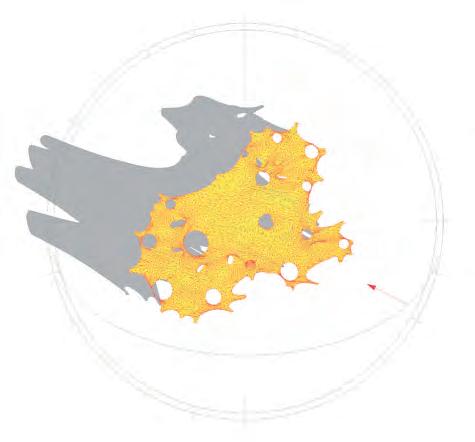
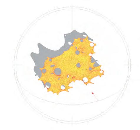
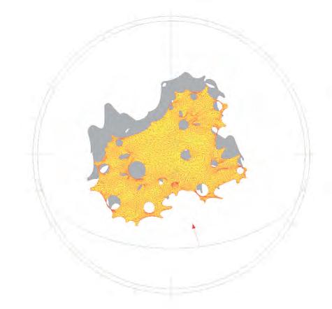
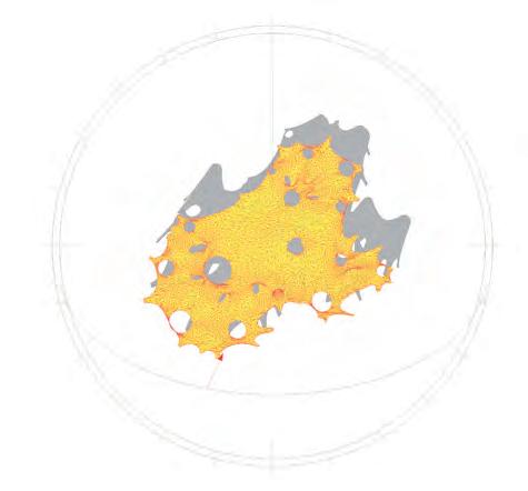
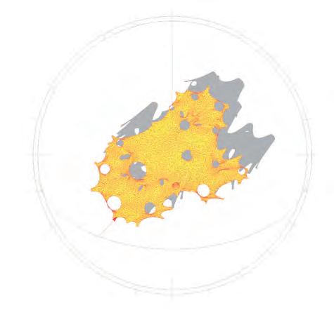
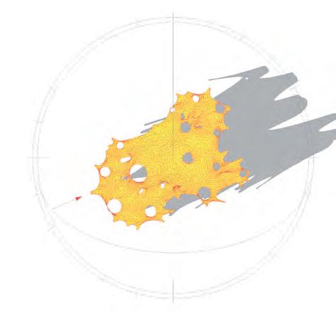
Fig 5.80.2: Lighting analysis of the interior through the upper apertures of the system(Top left), Differential lighting conditions that emerged in the process in the interior(Top right), Prototype which was analysed for interior lighting conditions. The variation of opening were assigned according to program light requirements(Bottom).

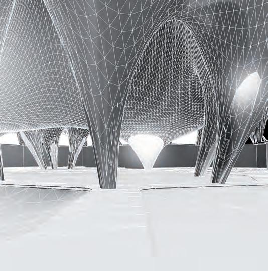
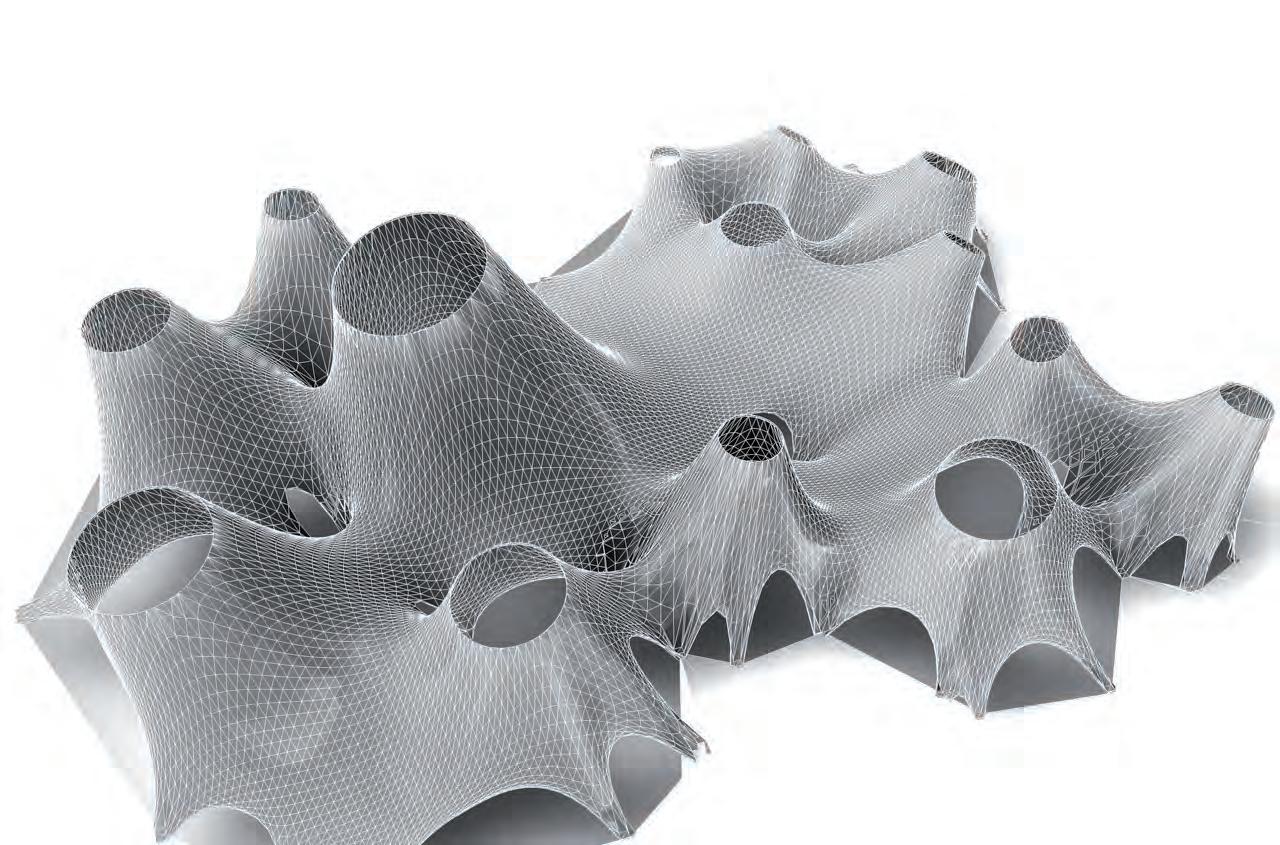
Finite element analysis of the digitally simulated prototypes is important for finding the thinnest shell possible for the structure. Young’s modulus defines the stiffness of a given isotropic material. When it comes to anisotropic materials the stiffness is dependent on various factors such as direction of elements, loading cases, mix ratios etc. Previously in Chapter 4, it has been explained how six different concrete slab tests were conducted and bar-chip fibre reinforced concrete sprayed over a 2 mm steel mesh was finalised as the final structural layer. Since this is a new anisotropic material, deflection tests were conducted to calculate the young’s modulus of the material.
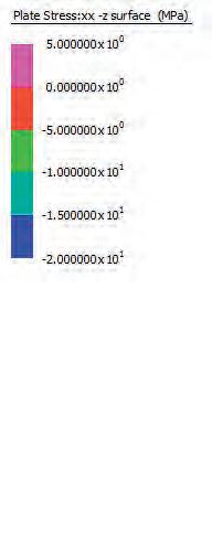
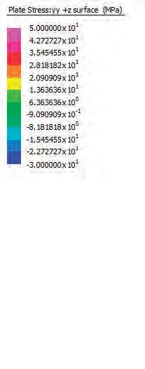
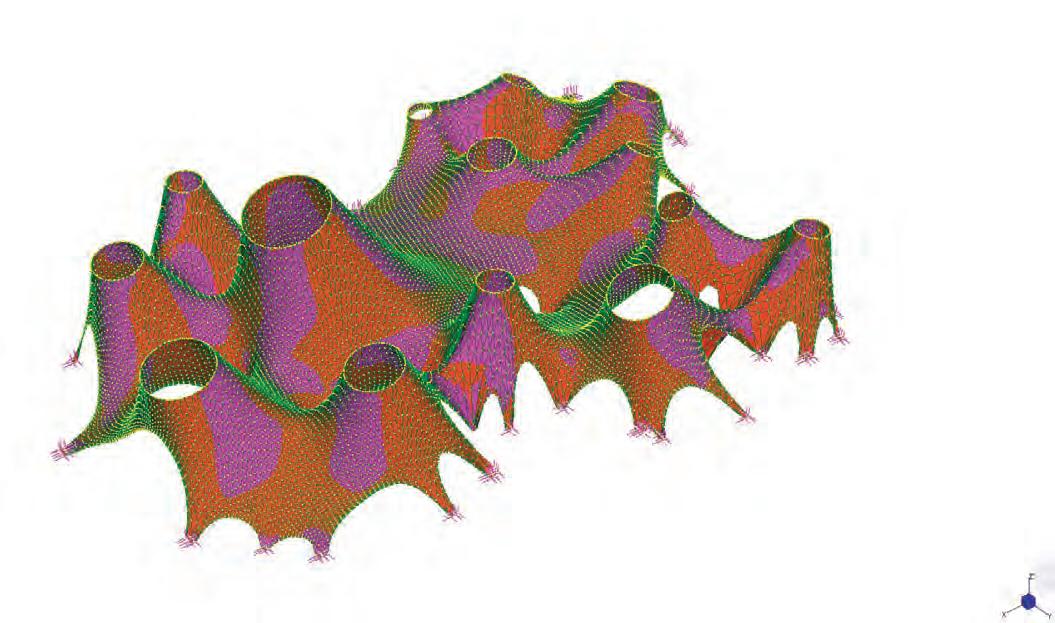
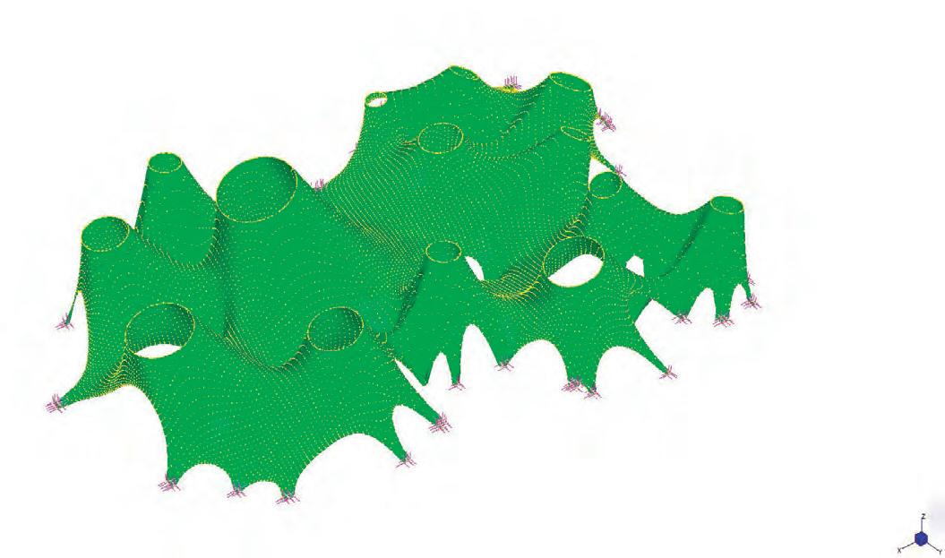
Three basic steps in finite element analysis have been described in Chapter 4. Once the pre-processing is done a slight variation is made in the analysis stage. A custom material is made with physical properties input from the deflection tests carried out. This material is applied to the mesh and analysis is run. Post processing gives the stresses on the shell and the displacement at nodes. The thickness of the slab is increased and the analysis is run till it comes to an equilibrium state. 150 mm thick layer across the entire shell proved to be a stable configuration.
The hybrid shell, which spans 20m at its longest span proved to be stable with the bar chip fibre reinforced concrete with a thickness of 150 mm sprayed over a 2 mm steel mesh. The steel mesh helps redirect the forces from the randomly distributed fibres into horizontal forces. The double curvature along the surfaces contributes in making the shell thinner to a great extent.
The hybrid shell, which spans 20m at its longest span proved to be stable with the bar chip fibre reinforced concrete with a thickness of 150 mm sprayed over a 2 mm steel mesh. The steel mesh helps redirect the forces from the randomly distributed fibres into horizontal forces. The double curvature along the surfaces contributes in making the shell thinner to a great extent.
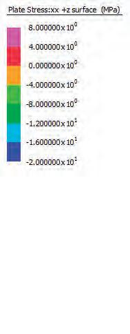
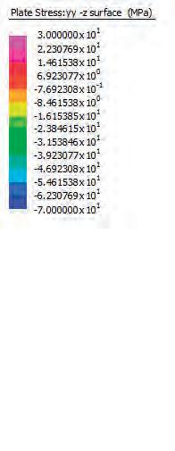
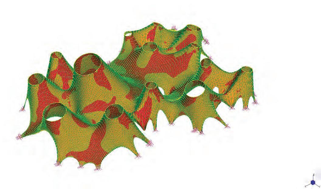
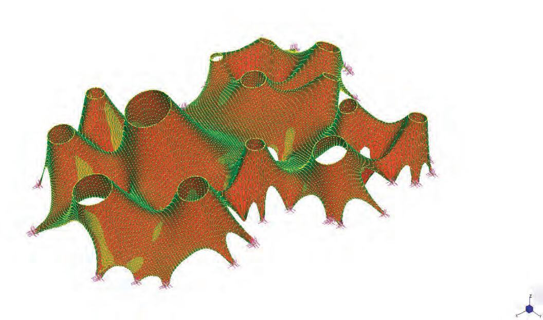
The tests conducted so far have enabled the quantification of many factors that could be considered in the design decision-making process. Modulation techniques in accordance to environmental conditions can now be input as conditions for achieving the output geometry of the built form. The last and most important evaluation that was made was of the condition of the interior floor plates and the organization of the interior spatial formation.
The morphology of the interior was considered more profoundly in the testing of the last digital prototype. The floor plates of the programs are separated by height differences to cause more differentiation between these areas. It became clear that the floor plates have to be shifted underground to allow the edges to be restrained at ground level
Lighting effects were considered in more detail within the making of the last digital prototype. Light from direct to diffuse to dim was introduced into the spaces by varying the opening size. On one of the main light wells, which celebrate a central space, was pixelated to note the effects of adding such element to the space. The opening shape and size follows the voronoi cell underneath and extracts an opening diameter from the information set within the specific cell.
The resulting interior had a higher level of sophistication within this prototype. The conditions that yielded for creating the pleasant fluid space were noted. The pixilation on the light well added more life to the space due to the interesting light it has produced. It also had a semiotic value, directing the eye of the visitor towards important instances such as the perceptual thresholds between programs.
The interior space benefited from more differentiation within its various parts. However, faults and mistakes in the process lead to some unwanted results as well. Shifting the interior planes resulted in a detachment between the roof shell and the ground level. This formal expression counteracts the initial intention of blurring the transitions between these spatial elements.
The strategy creates unwanted edges between the floor plates and causes segregation and interruption in the fluidity of the space. Problems of accessibility of circulation pathways also became evident. More complexity should be added to the algorithm to create a seamless topography on to which the pathways can be mapped. The topography must do by an area to height ratio that corresponds to standard ramp slope percentages to keep circulation flowing at ease.
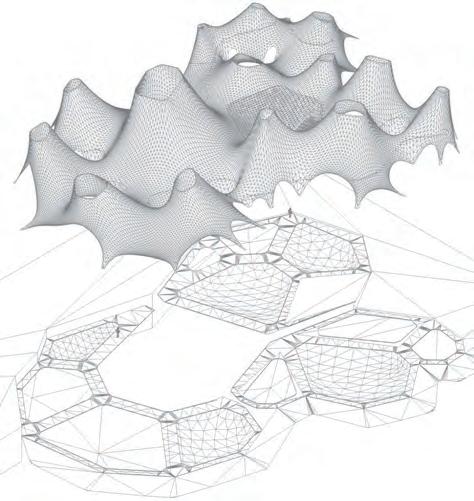
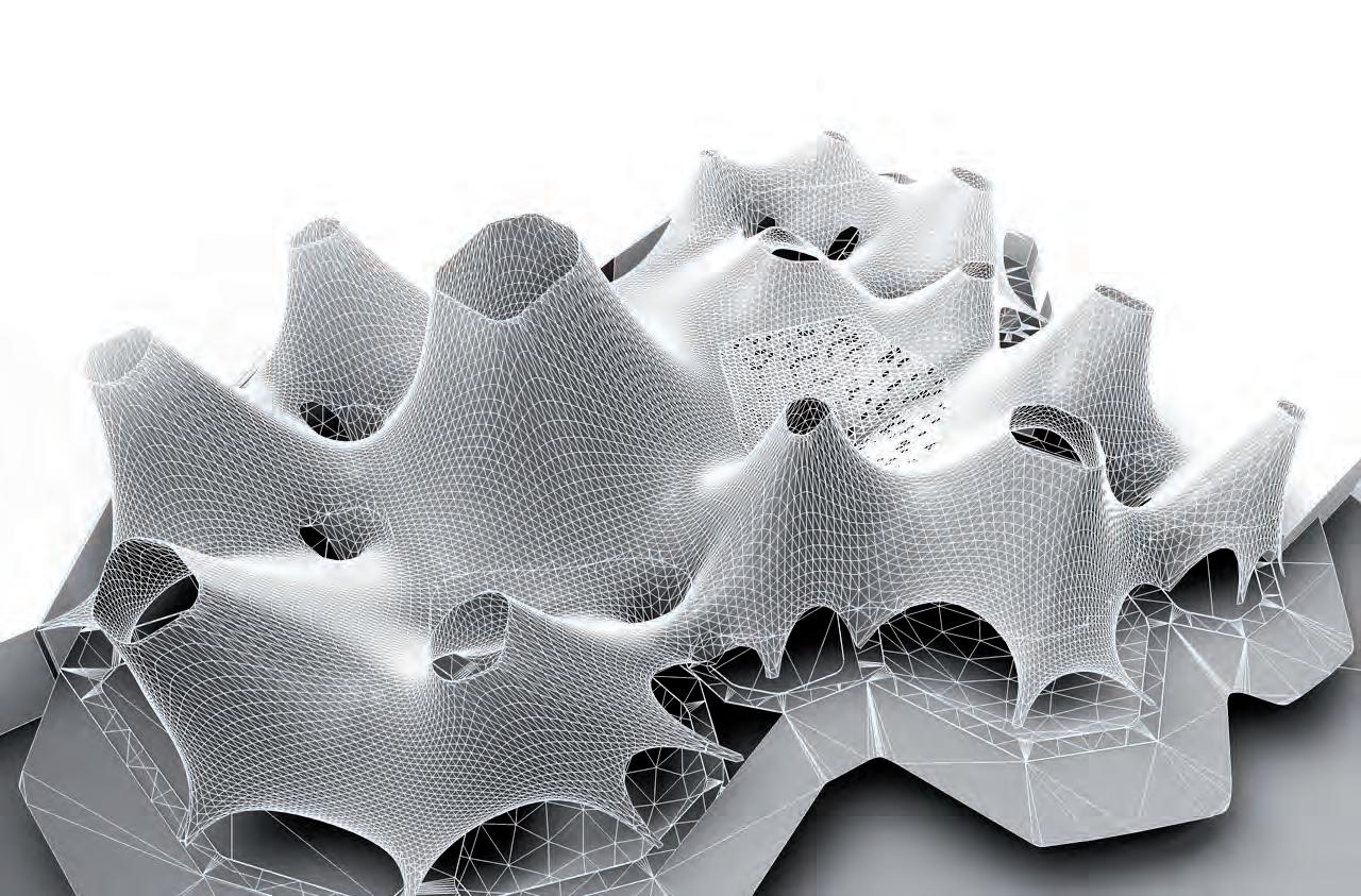
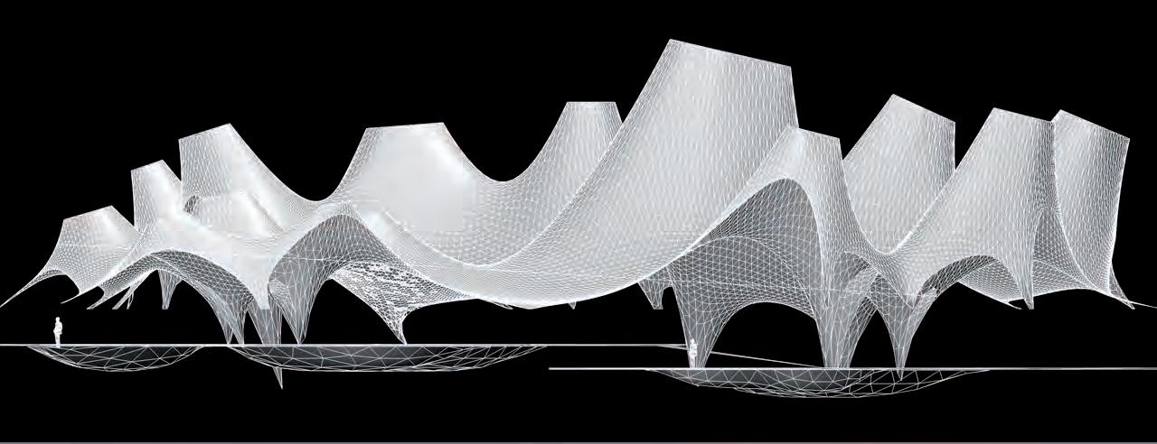
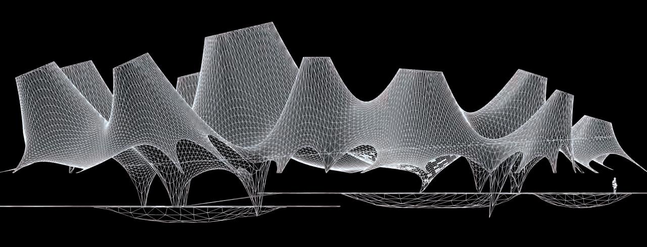
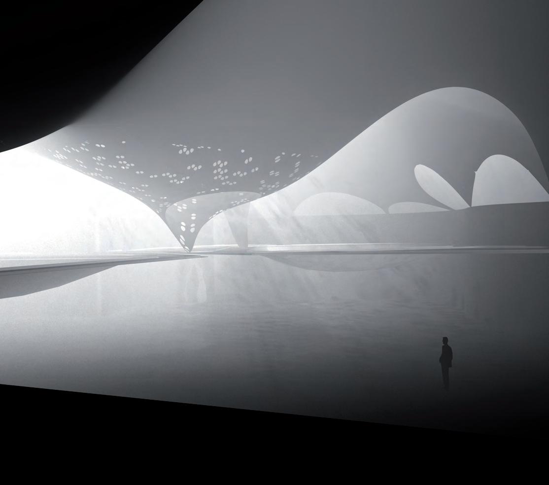

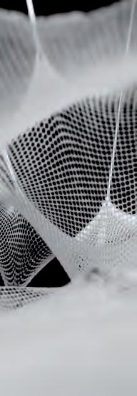
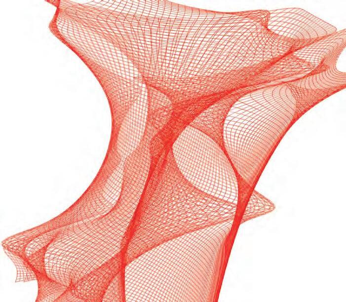
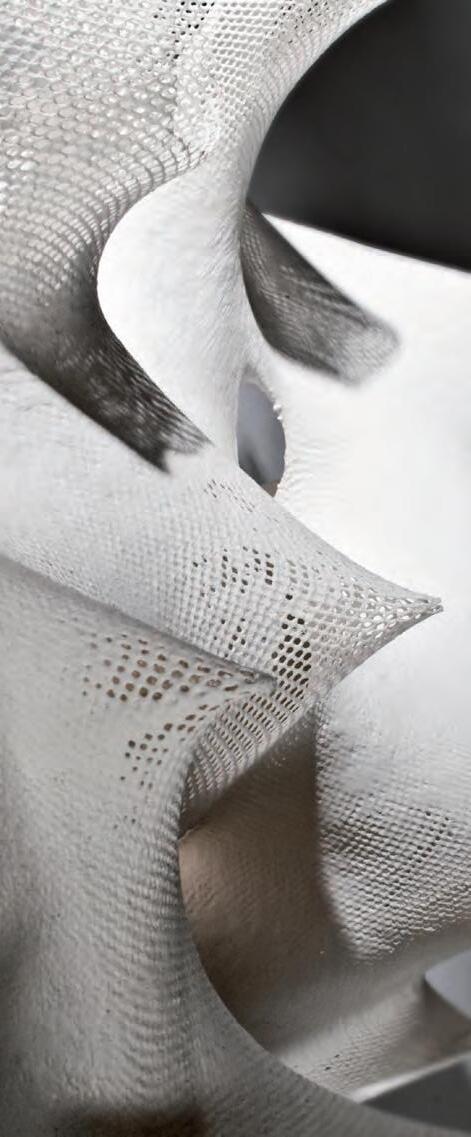
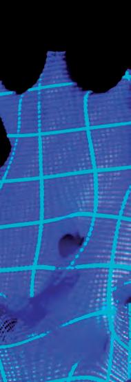

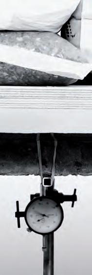
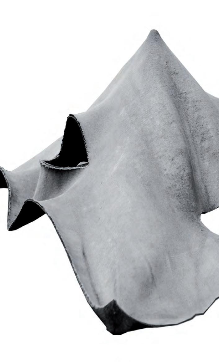
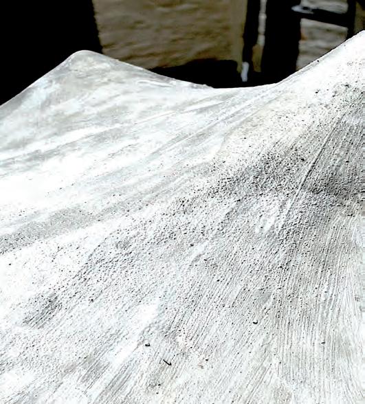
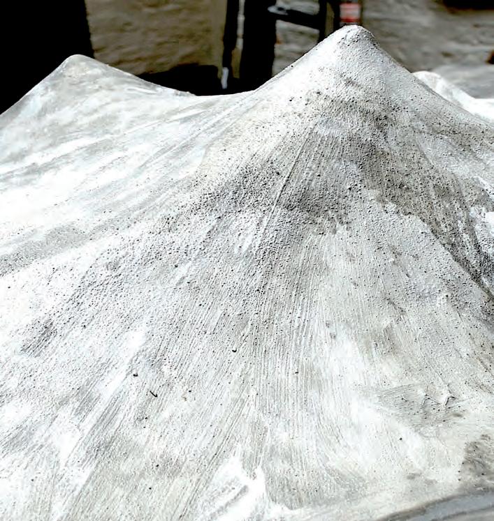
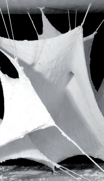
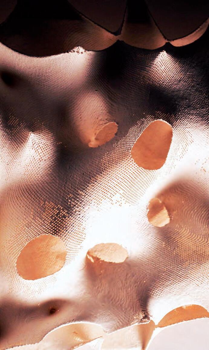
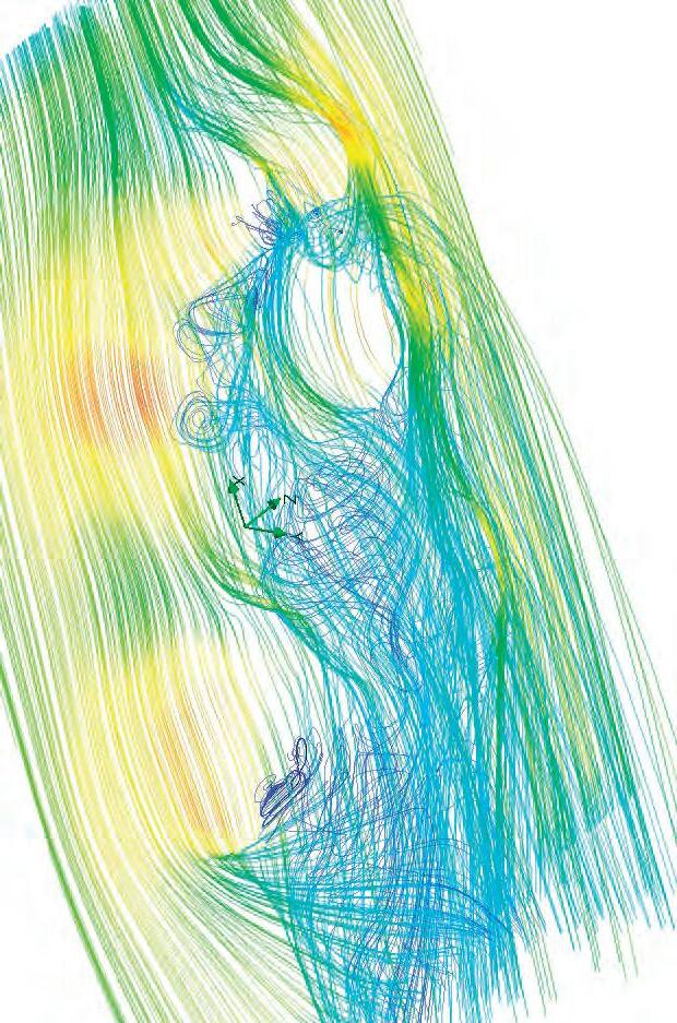
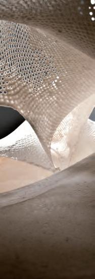
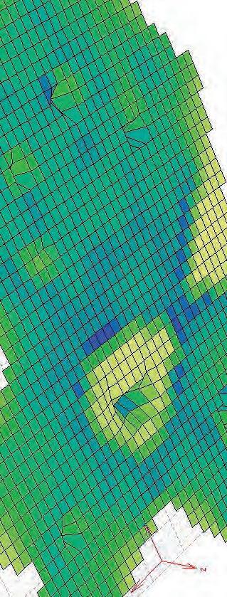
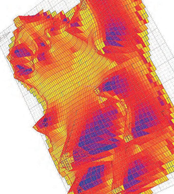
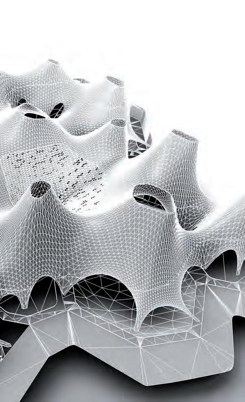
The sequence of experiments carried out previously alternated methods of enumerating the HYBIOS models. These models varied in materials that mimic the behaviour of tensile membranes and compressive casting materials. The free form geometry of these models could only be simulating their formation processes digitally.
The resultant digital models are then further tested according to environmental, spatial and programmatic parameters to enhance their qualities. This process resulted in providing insight on taking design decisions and information on how to optimize, modulate and fine-tune the simulated models.
The next procedures of this exploration aim at compiling the information gathered in the previous stages of modelling and analysis to create a platform for a tooling system that generates a final outcome. The geometry of that outcome should provide a seamless fluid spatial quality as a design proposal. The immediate site conditions are observed in a through manner
The form of the material system makes it suitable for climates with a high cooling load. Such conditions imply that the region has a hot summer and requires low heating during winter. The optimization of forms to improve natural ventilation and maintain an acceptable indoor air quality (IAQ) is the aim of the next environmental analysis experiments. Creating sufficient air changes to cool the indoor air temperature and to maintain the level of required oxygen and dilute the concentration of carbon dioxide will be resolved within the system using passive design strategies.
The prospective cooling capacity of the outdoor air is utilised to bring down the energy demand inside the building. To achieve this the material system is modified to implant qualities of solar chimneys and wind receivers. Openings at lower levels of the building facing the windward side receive dense cold air from outside. The tent forms of the system will face the suns direct heat. The temperature of the upper surfaces increase and pulls up the less dense warm air. The upper openings are oriented towards the leeward side and the negative pressure thus created eliminates the warm air from the interior.
Wind driven ventilation cannot be completely relied on since the direction and pressure of wind are constantly changing. Finer modification of the system through solar exposure analysis and orientation of local openings will be dealt next.
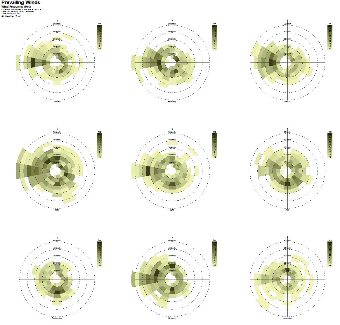
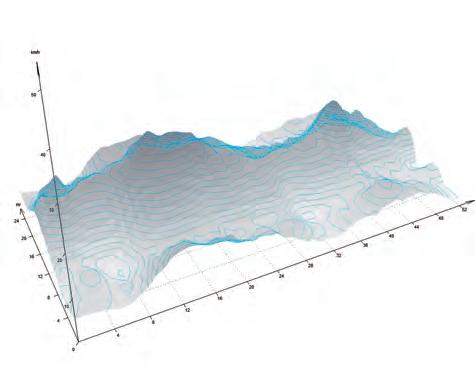

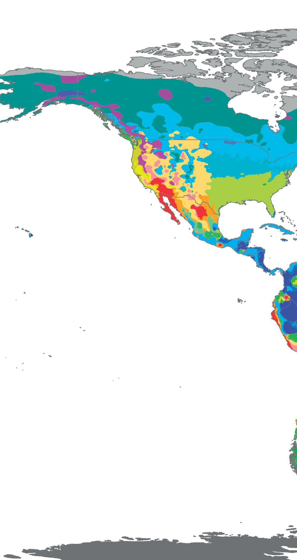
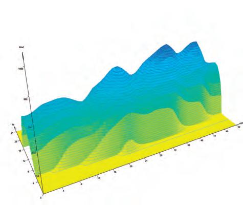

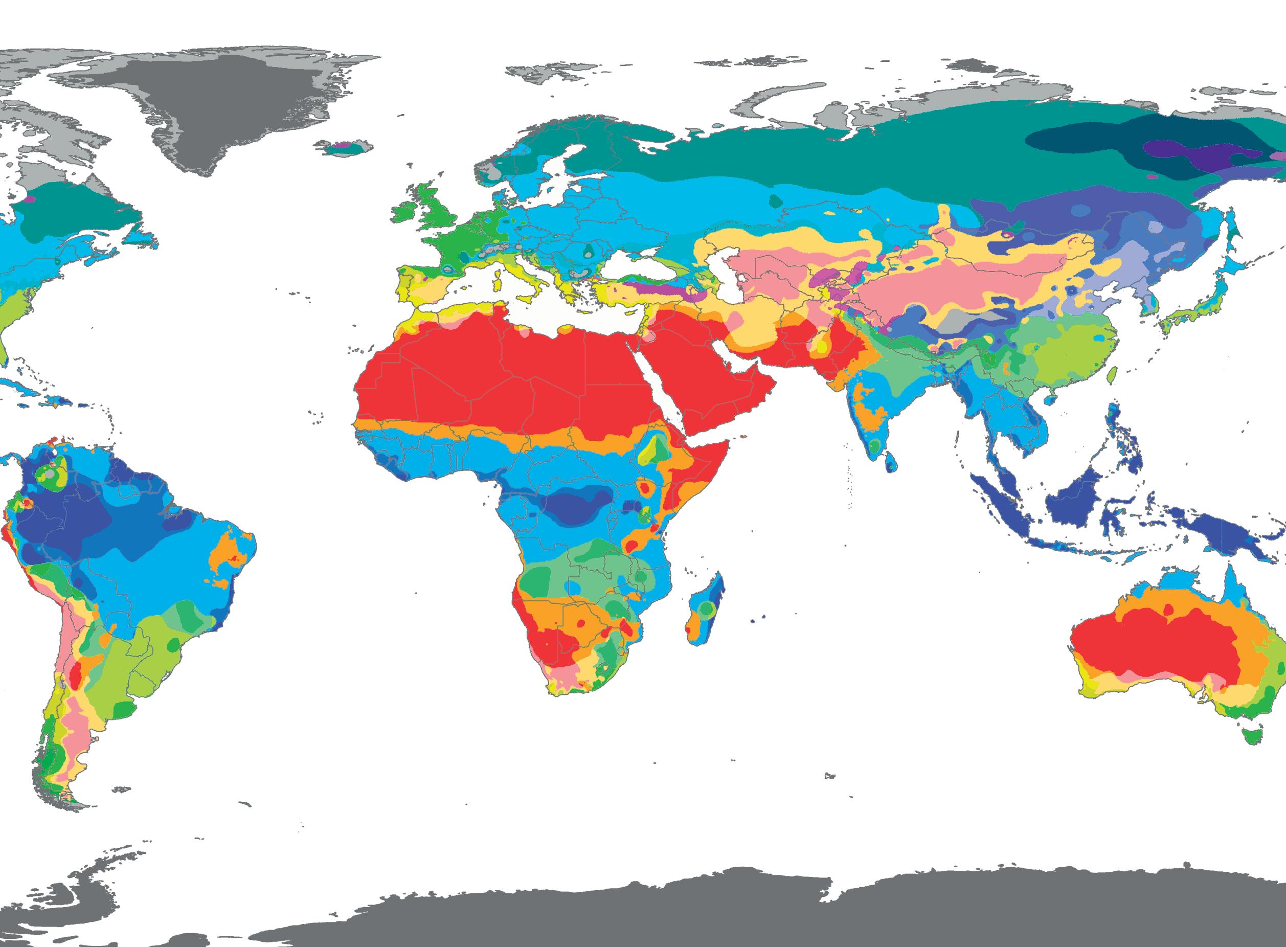
different climatic zones in the world, The red zones indicate a hot arid dry climate which is most suitable for the HYBIOS system.

Zooming in further into a country that is within the climatic regions discussed earlier, a decision was made to speculate further on Jordan as a potential site to run the final iteration design scheme. The concrete construction industry in Jordan has been discussed briefly previously. Concrete is the main available building material due to the region’s abundance of minerals and lack of forestry to produce timber. Amman is a mountainous region, the weather conditions there are hot and dry usually but occasional rainfall and snow occur due to the height of the city’s topography.
Concrete is produced locally and is the main building material generally used there, it is however, still mainly used in a traditional manner, by casting in re-usable timber form work. The current construction techniques adopted in Jordan are mainly due to cheap labour and expensive expertise to handle more complex projects.
Amman is the capital of Jordan; it is the main urban centre and the commercial hub of the country. As a country that relies on services and tourism as a main source of income, several plans of reform have been made to vitalize the economy of the country. City planners have approved many visions of a city centre that is based on commercial projects, as an attempt to attract more tourists to the city. Rarely do these projects get realized, due to their vast budgets. Specialists are advising Jordanian authorities to give up commercial-based project attempts and focus on enhancing cultural aspects of the city.
Northwest of Amman is an area well known for its rich history and connection to the culture of the inhabitants of the capital. Many gallery showrooms for art, independent cinema theatres, artist café’s, bars and restaurant are part of the active cultural life to that city tissue. Notable areas include ‘Al-Rainbow’ Street, a pedestrian strolling boulevard, Paris circle, a meeting place for creative minds in the city and the first circle, one of the oldest upper class neighbourhoods in the city These key areas make for a strong attraction to tourists who are looking to experience the bohemian and authentic spirit of Amman.
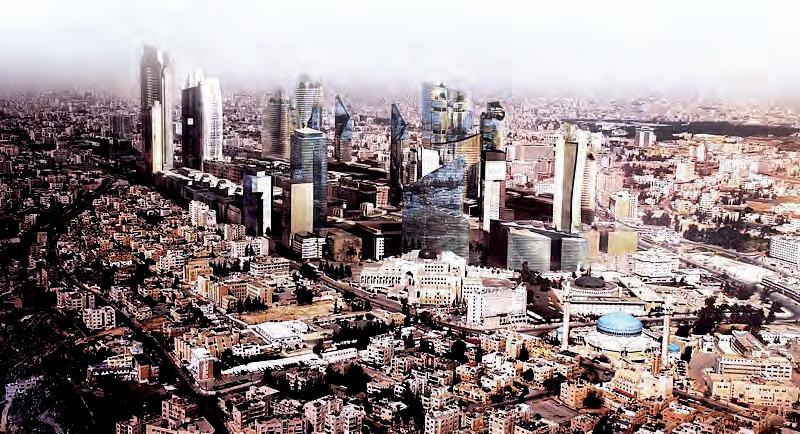
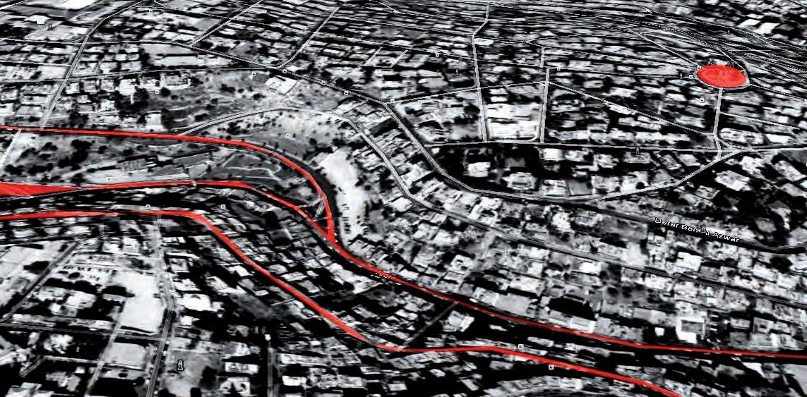

The material exploration carried forth previously allowed us to create forms and spatial differentiation of distinctive qualities. The gradient of change in spatial fluidity, circulation, and light qualities indicated the choosing of a public, celebratory program. Programs generic to the spatial qualities derived earlier in the process were listed, and the ones needed by the main purpose of a Creative Communication Hub were chosen to list the sub programs needed by each main program. The ‘sub programs’ were then listed and packed into the main programmatic zones. The natural lighting needs of such activities differentiate between dark, diffused and well-lit spaces.
The proposed building is a Cultural Centre, a place of intellectual and creative thought exchange and exposition. Sub-programs needed to satisfy such a building’s pragmatic, social and intellectual functions were listed.
Areas needed to achieve such programs are devised to extract height ratios of the enclosing shell’s form. The programs were sorted according to different parameters that give key characteristics of a space that contains each activity. Differentiation could then be made in the quality of the spaces according to these characteristics.
AUDITORIUM
MULTIMEDIA LIBRARY
EXHIBITORY
ANTENNA
LOBBY WORKSTATION LAB
DIGITAL ARCHIVES
ADMIN
EXHIBITORY
Fig 6.30.1: (Top) Packing of programs within main event zones.
Fig 6.30.2: Sorting of programs by identifying the proximity requirements.(Bottom)
AUDITORIUM
PROGRAM BY AREA
AUDITORIUM_480 SQM
MULTIMEDIA LIBRARY_400 SQM
DIGITAL ARCHIVES_325 SQM
EXHIBITORY_350 SQM
LOBBY_250 SQM
WORKSTATION LAB_250 SQM
ANTENNA_200 SQM
ADMIN_160 SQM
LIST PROGRAM BY LIGHTING NEEDS
EXHIBITORY
LIBRARY
LOBBY
LAB
DIGITAL ARCHIVES
AUDITORIUM
LIST PROGRAM BY PERMEABILITY
Fig 6.30.2: The process of sorting programs as per area, lighting and height requisites.
Listing the parameters programmatic needs leads to an inventive solution to bring these programs together in a connection strategy, and indicates ways to formalize the plan of the generated design. The process was listed in a 12 step strategy to generate the design’s digital simulation.
FLOOR PLAN LOGIC
The programs listed previously are plotted as circles with designated areas, which are then clustered based on their adjacency requirements. Intersections between the circles are connected to form a spine that branches out to create the program polygons. Area for each program is calculated according to the number of users. Sorting of programs as per the area, heights and proximity demands is carried forth as discussed in the previous chapter The sorted program is a list of circles of the given areas with an assigned RGB value.
FLOOR PLAN LOGIC
STEP 1 : Input a set of programmes as circles depending on area requirement
STEP 1 : Input a set of programmes as circles depending on area requirement
STEP 2 : Packing the list of circles according to programme adjacencies using RGB values in a bounding box(the site).
STEP 2 : Packing the list of circles according to programme adjacencies using RGB values in a bounding box(the site).
STEP 3 : Generation of Delaunay lines on the packed areas.
STEP 3 : Generation of Delaunay lines on the packed areas.
STEP 4 : Generation of perpendicular lines from intersection of delaunay lines and circles.
STEP 4 : Generation of perpendicular lines from intersection of delaunay lines and circles.
STEP 5 : Closing of open edges with a polygon by intersecting the circumscribed polygon and the lines generated in Step 4
STEP 5 : Closing of open edges with a polygon by intersecting the circumscribed polygon and the lines generated in Step 4
STEP 6 : Rerunning of packing of sub-programs inside the main programmes.
STEP 6 : Rerunning of packing of sub-programs inside the main programmes.
Shifting the floor planes between the circulation pathways, achieves spatial differentiation between designated areas, and produces the digital topographic surface. The pathways are then mapped onto this surface to create a fluid circulation strategy, causing less interruption within the building elements. The programmatic events then take place on flat spots that are on different levels.
STEP 7 : Introduction of pathways for circulation. STEP 8 : Sorting the programmes by lighting requirement.
STEP 9 : Varying floor levels for differentiation of spaces according to height and light requisits.
The series of experiments conducted during the design development stage helped us analyse a set of problems and develop a set of rules that would optimise the system for better performance. The evaluation of the experiments clarify that the system is suitable for a public building in a hot and dry climate. To formalize the rules as a design tool, the set of instructions have to be translated into a design algorithm, which can be fed with a set of program areas and outputs a form, which is coherent, modulates the spatial and lighting conditions and is optimized for immediate environments and structural loads.
This is the input for the 12- step pseudo code that has been developed.
1. Packing of the circles as per adjacency rules within a boundary- The Site.
2. Generation of Delaunay lines for the adjacent circles that are packed.
3. Generation of perpendicular lines from the intersection of delaunay and circles.
4. Closing the open ends with a polygon.
5. Repeating step 1 to 3 for arranging the subprograms within the main programs.
6. Repeating step 1 to 3 within areas where seating pods are assigned.
7. Introduction of pathways, Primary, secondary and tertiary.
8. Evaluating the lighting needs as per the program and site conditions.
9. Shifting of interior planes as per the evaluations
10. Assigning height data for programs from the initial step.
11. Optimization for reducing wind load.
12. Orienting the forms away from sun to improve the solar exposure area.
Step 10: Fixing heights as per programme requirement.
11: Orienting the form towards prevailing wind to reduce wind load on the surface.
Step 12: Orienting the form according to sun path to increase the temperature at the tips to improve the stack effect.
Existing environmental analysis of the given site is to be carried out before step 11 and 12 of the design algorithm. Diagram in (Fig 6.50.1) explains basic understanding of prevailing wind and sun path. Step 11 of the algorithm generates vertical form as per the area to height ratio. This form is analysed in Autodesk Ecotect analysis software for solar exposure of the conical forms as done previously with the digital models.
The forms are oriented to receive maximum direct solar radiation. The heated volumes create the temperature difference between the interior spaces and the upper volumes thus enhancing the stack ventilation as discussed earlier A computational fluid dynamics analysis is also done to find the angle at which the turbulence and wind load is minimum within the system. The analysed angles are applied to the vectors that generate the roof forms and the result is a system with improved performative features.
level 4.0M
Site Area : 23500 Sq.m.
Building Area : 5000 Sq.m.
Plot Coverage : 22 %
SITE PLAN
0.0M
An algorithm has been written to list a set of instructions and controlling parameters of the overall geometry. Most importantly, the extraction of restrain-points from that plan, and the dynamic relaxation script of the roof shell, is needed to result in an overall spatial geometry.
New enhancements have been introduced to the script. The main problem of the last digital iteration was the floor condition and its coherence with the formal language of the roof structure. Starting with the site, a topography that corresponds to the programmatic organization scheme is introduced. The digital surface of the topography is modelled by keeping a ratio of width to height according to ramp standards. Pathways that are also the result of the circle packing and Voronoi generation of the plan are mapped onto the surface of the topography.
Several options for recessing private spaces and creating seating pods can be derived by inputting the plan with code marked colour spots where the devised detail is needed. The system forms the walls of the recessed spaces and relaxed pods according to that image that is the input, by reading through colour information. A different colour for reading each detail is input within the parametric system.
The centres of the polygons of the main program areas are also extracted to mark starting points of the solar chimney vectors. The vectors are tilted towards the leeward wind direction and away from direct solar radiation. Those instructions are carried forth according to environmental pressures of the immediate site and the spatial needs of each program under each solar chimney. The heights of the vectors are the result of the previous extraction of the height to area ratios of the conical form of each program.
What was interesting when working with the digital mesh relaxation algorithm is its capacity to be morphed using similar methods of forming as the physical fabric to achieve similar tensile formations. The mesh is cropped for holes digitally, by removing mesh faces. Restraint points are marked corresponding to these openings to create touchpoint light wells. Restraint points are also marked around the edges to create arch-like openings to bring in light and create entrances. After these conditions are set the mesh relaxation algorithm is started and continues running to find an optimized morphology.
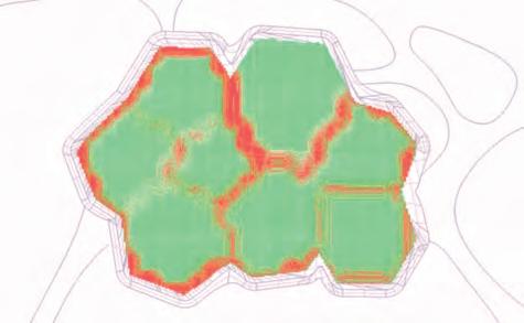
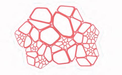
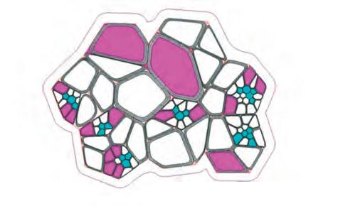
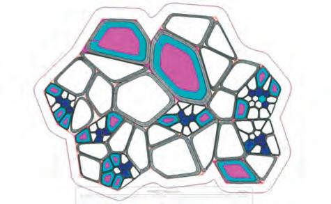
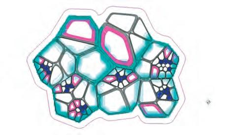


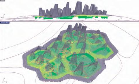

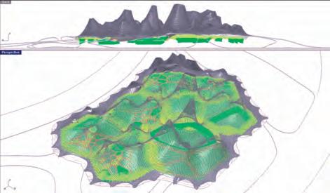
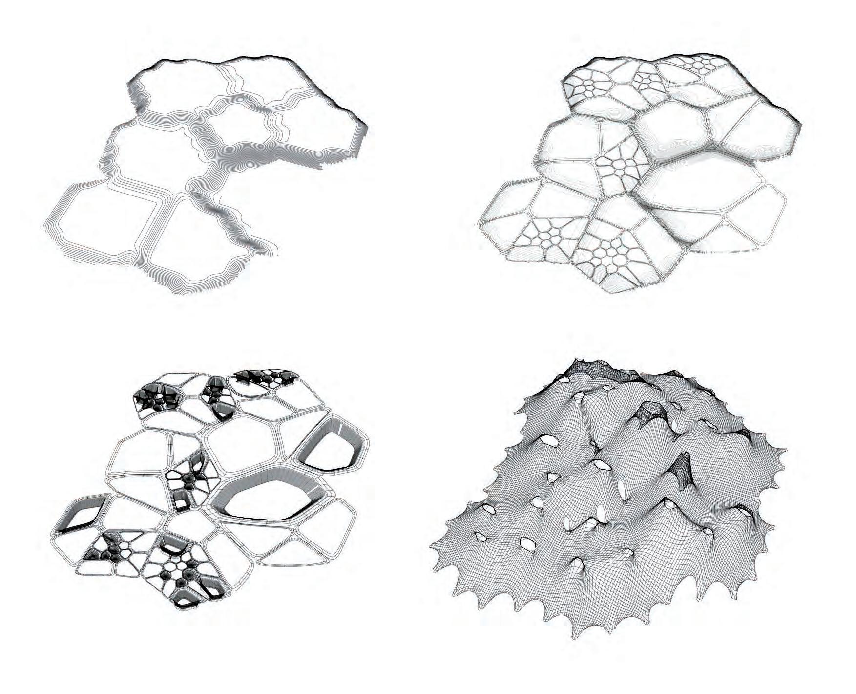


 Fig 6.60.2: Diagrams describing the process of roof generation.
(a)
(b)
(c)
(d)
(e)
Inlet and outlet aperture sizes are important for improvement of stack ventilation. Higher volumes of air exchange can cause discomfort inside the building due to the heavy draught of air. To maintain a comfortable airflow inside the building it is important to have control of the air exchange.
Case studies of similar forms have been found where the building enclosure used vertical glass panels, which do not follow similar language of the system, and completely block down the inlet for ventilation. Louvres along the edge of the structure will help in controlling air, direct sunlight and noise within the space inside.
(Fig 6.70.1) describes a parametrically controlled louvre, which can be rotated to control the amount of opening. The rotation can thus control the amount of light and ventilation inside. Different rotations result in differential percentage of openings. The levels of air, light and noise are harnessed and the louvres follow a similar language of the system
Opening of louvers : Open to closed state. Defining light and wind inlet into the system
Rainwater seepage opening
Rainwater seepage reduction
Experiments have proved how the form aids natural stack ventilation. The upper apertures range from 2 to 5 meter in diameter. This lets in natural daylight and improves the overall spatial and lighting quality inside the space. Protection of the interior spaces from rain cannot be eliminated while improving the spatial experience. Thus a simple concept has been diagrammed as a solution to maintain the natural daylight in the interior spaces but at the same time protect the spaces from rain.
The diagram in (Fig 6.70.2) explains how a simple rotation applied to the form helps total elimination of rainwater seepage into the building. A 10 mm thick tempered glass is used with a hydraulic lift. The skylight is placed in an angle such that even during the rains the water does not seep in. This allows for natural ventilation during all times. The hydraulic lift helps in controlling the volume of air exchange between the interior and exterior.
The aim of letting in natural daylight, controlling the volume of air exchange and protection from rain has been resolved with one solution. The operable roof also helps in complete closure in case artificial air-conditioning is required at some period of the year. The added level of control in the detail of the shell aims in realtime modulation of the space, by its inhabitants.
Rainwater seepage Elimination
HeadRing Beam
Hinge for rotation
10mm toughened glass
Frame for opening to rest
Weather stripping
Rainwater seepage through opening
Rainwater seepage reduction
Rainwater seepage Elimination
The spatial language of a certain zone within the interior is very crucial to communicate the identity of its program. Perceptual thresholds were introduced into the system to bring in a conversation between the user and the space. The user identifies the space from its spatial and lighting conditions. The semiotic value of the space improves the functionality of it to a higher degree. The result is a fluid coherent space with assigned floor heights connected and divided by a central spine and few secondary spines.
Certain programs demand more secluded spaces. These are recessed areas colour mapped on the algorithmic plan. Since the resultant spaces are a deviation from the conventional spaces, a furniture system that maintains the same language and holds all the ergonomics required, had to be introduced.
The concept for the private spaces has been described in the diagram (Fig 6.71.1:). . A ramp connects these spaces from the main circulation paths. Areas that require such spaces have been identified and incorporated in the process of floor formation. These include private offices, server rooms and closed discussion areas. The recess varies from 2 meter to 3 meter according to the area and number of users. The spaces are inserted into the underground and thus eliminate the introduction of physical walls into the coherent space above.
Furniture for seating is another issue that had to be resolved to adhere to the elegance of the emerging spaces. Areas where seating is necessary are identified in the programs and the spatial division is done accordingly, Seating pods are introduced in these spaces. Diagram(Fig 6.71.1:) explains the simulation of a seating pod with ergonomics incorporated into it. The same logic that has been used to simulate the roof is used to generate the furniture to maintain the fluidity of elements.





Fabrication is usually the outcome of a certain design process in the traditional architecture practice. The research presented attempts a synthesis of information between models of different scales and mediums. Bridging the gap between the digital generation and the fabricated full-scale construction is really important in the process of organising, optimizing, and materializing the design. Once the algorithm outputs the restrain heights and touch points on the ground it is important to embed the material behaviour in the script and find the optimal geometry for the system.
For this, GSA Oasys, the structural software developed by Arup is linked to grasshopper where the design is in progress. The final mesh generated by the algorithm is fed into GSA through a plugin, Geometry Gym that dictates the form finding process within grasshopper interface. GSA uses soap film minimal surface calculations to define the optimal form. The Calculations for a completely compression structure is carried out in the FEA analysis tool within GSA. The process is described in the flow chart following.
The result is a mesh which is returned into grasshopper. A cutting pattern is generated for the mesh along the force lines and within the fabrication limits. The cut mesh is unrolled using rhino and send to the factory where the fabric is cut directly from the cutting pattern file. The process is described in (Fig 6.80.1) The cut fabrics are brought to site and assembled in order. This process eliminates all the difficulties of fabrication as it is seen as a part of design. Specialists can improve the cutting pattern generation and thus take the fabrication process to a more advanced level.
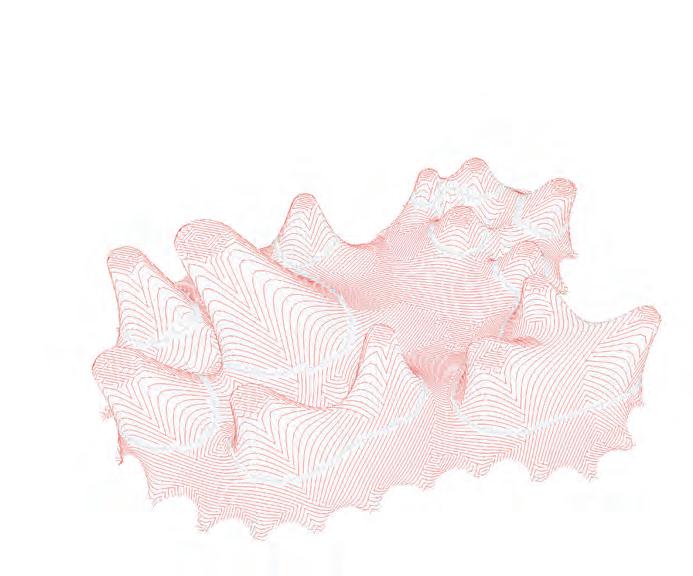
PROCESS START
PREPARE MESH
Mesh Based on aspect ratio
max Angle
minimum edge length
maximum edge length
CREATE FABRIC
LOAD
warp modulus N/m
8.00003e+5
weft modulus N/m
4.00003e+5v Shear Modulus
FABRIC PROPERTY
Poissons ratio 0.45
3.0000e+5
create structural finite elements from mesh
apply node attributes
create settlement load
find closest structural node to the restraining perimeters
RUN FORM FIND CREATE ANALYSIS CASE
FINAL MESH FROM FEA FORM FOUND NODES
Several Optimization techniques were experimented during the design development stage. The sun angle studies gave us the right angle for the forms to be oriented. The CFD studies helped reduce the wind load on the system, and envision the surrounding wind flow. The structural analysis gave a stable form in equilibrium state.
All the analysis were then formalised into one 12step design tool. Design development started with selection of a site and the relevance for the system to be experimented in the particular situation. Environmental studies were carried out and the algorithm was run to generate several iterations. The fittest iteration is selected and detailed out in the Floor plan. The levels demonstrate how programs that require dark spaces are moved underground and spaces requiring more light are moved upwards. Thus a differential lighting condition is created for programs implying interesting moments of perceptual thresholds.
The 3 meter wide central spine is clearly visible. It is one smooth ramp that connects all the different program levels. The secondary pathways are 2 meter wide and subdivide the main programs into micro programs. The presence of tertiary pathways, which provides circulation between seating pods and recessed areas can be seen in the drawing.
The logic of sorting of spaces are also demonstrated. The gallery needs the most lighting and visibility and is placed at the uppermost level. The theatre, which is to be the darkest, receives the lowest level and is recessed into the ground making it dark. The openings are also controlled as per the set of instructions fed into the algorithm. The gallery has the widest opening and the theatre has the smallest opening not only to improve ventilation but also to diffuse and dim direct light.
The recessed areas and the furniture pods discussed in detail in the previous pages are seen in the floor plan. There is fluidity of elements at all scales ranging from the roof forms to the furniture. A 2 meter wide threshold at the periphery blends the exterior and the interior. The anchor points of the system at ground level are outside this 2 meter pathway and thus make the pathway sheltered.
All the spaces are entirely connected by one surface, which is within the accessible slope ratio of 1:12. This makes the building suitable for all but still eliminates the monotony of single level floors. The generated plan is a further fruitful outcome of the research done in this dissertation, successfully achieving differentiation between programs and minimizing segregation between elements.
Administration(+1.60 M)
Recessed Discussion Spaces
Inlets for ventilation
Archive behind
Gallery(+2.80M)
Solar Chimney (Ventilation)
Light Wells (Perceptual threshold)
Retaining Wall around program spaces (Contolling light + privacy)
Workstation(+2.00M)
Multimedia Library behind
Gallery(+2.80M)
Theatre(-0.80M)
Antenna(+1.20M)
Modulation of roof forms for differentiation of spaces
Retaining Wall around program spaces (Contolling light + privacy)
Workstation(+2.00M)
Multimedia Library behind
Seating Pods
Light Wells (Perceptual threshold)
Auditorium Recessed(-2.80M)
Theatre(-0.80M)
Archive behind
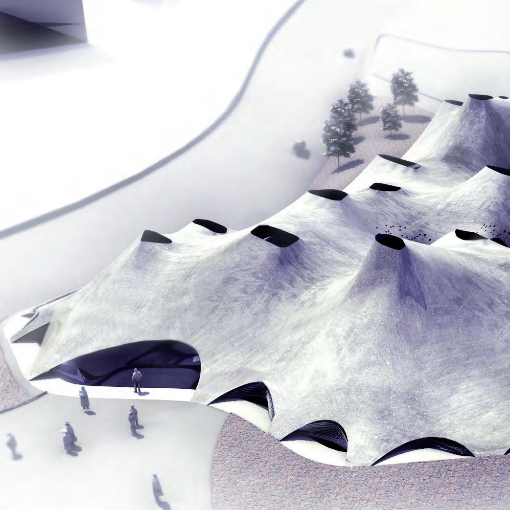
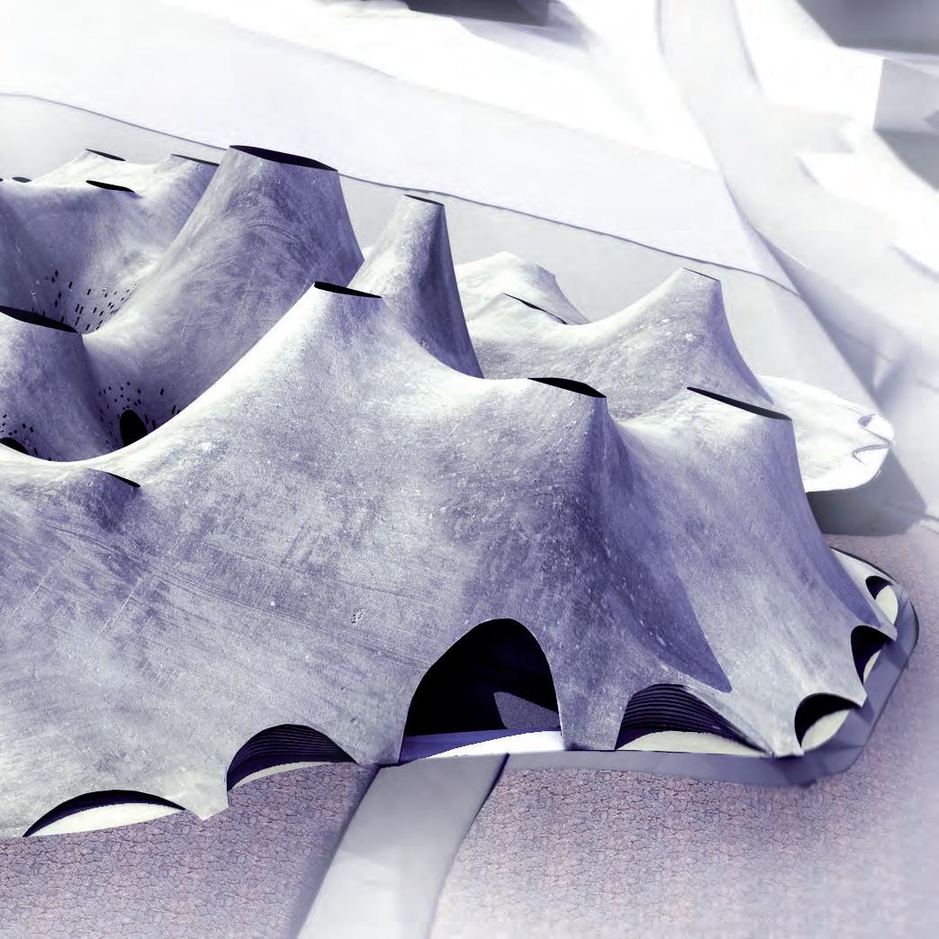
An aerial view of the resultant design. The image indicates the orientation of forms which are optimised for reducing the wind loads and for improving the stack ventilation. The fluidity in the exterior geometry is also visible.
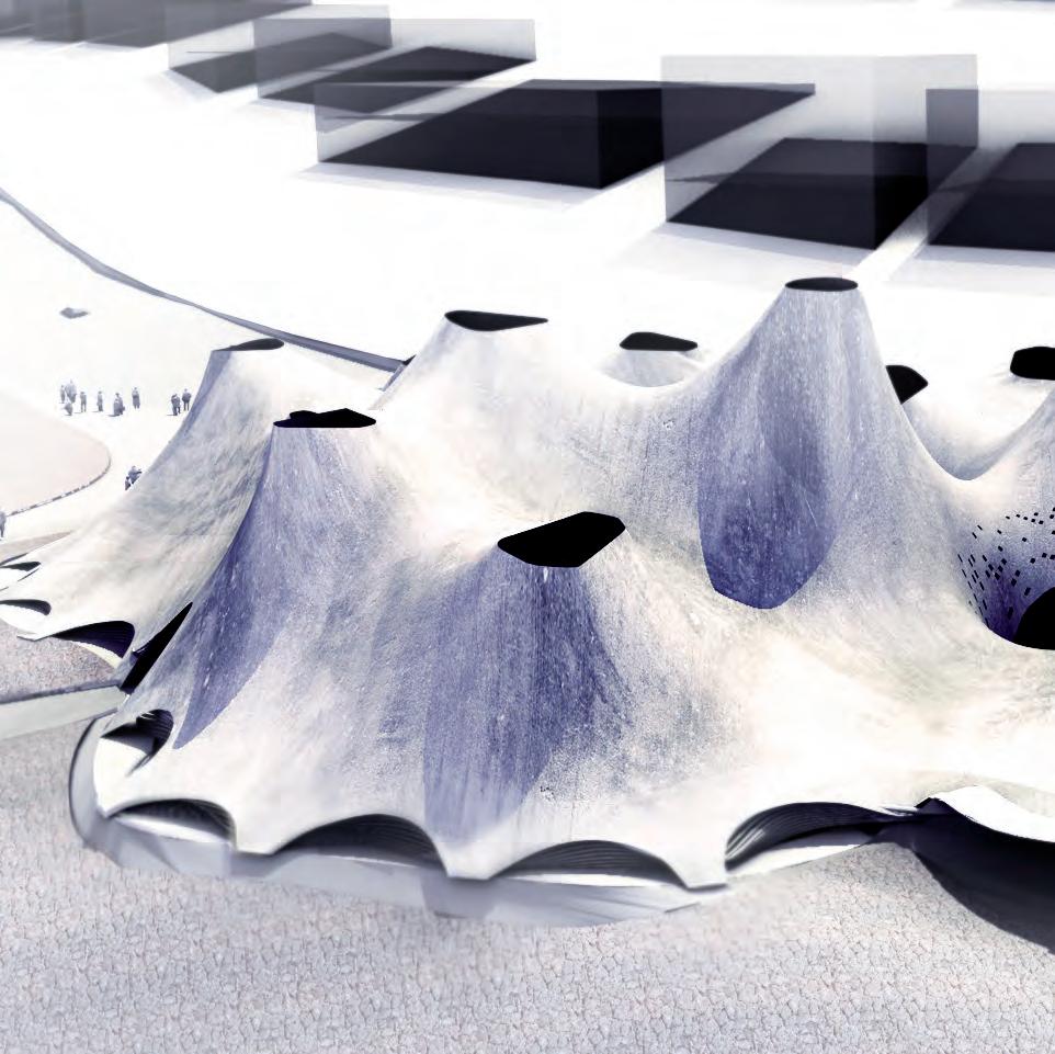
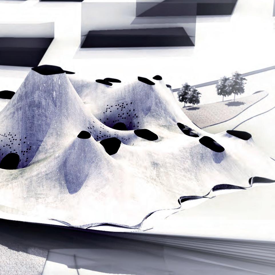
An aerial view indicating the variation of upper aperture sizes, according to the lighting requirements of the specific programs. The pixilation introduced to emphasis the spaces which highlight the intersection of the programs are also visible.
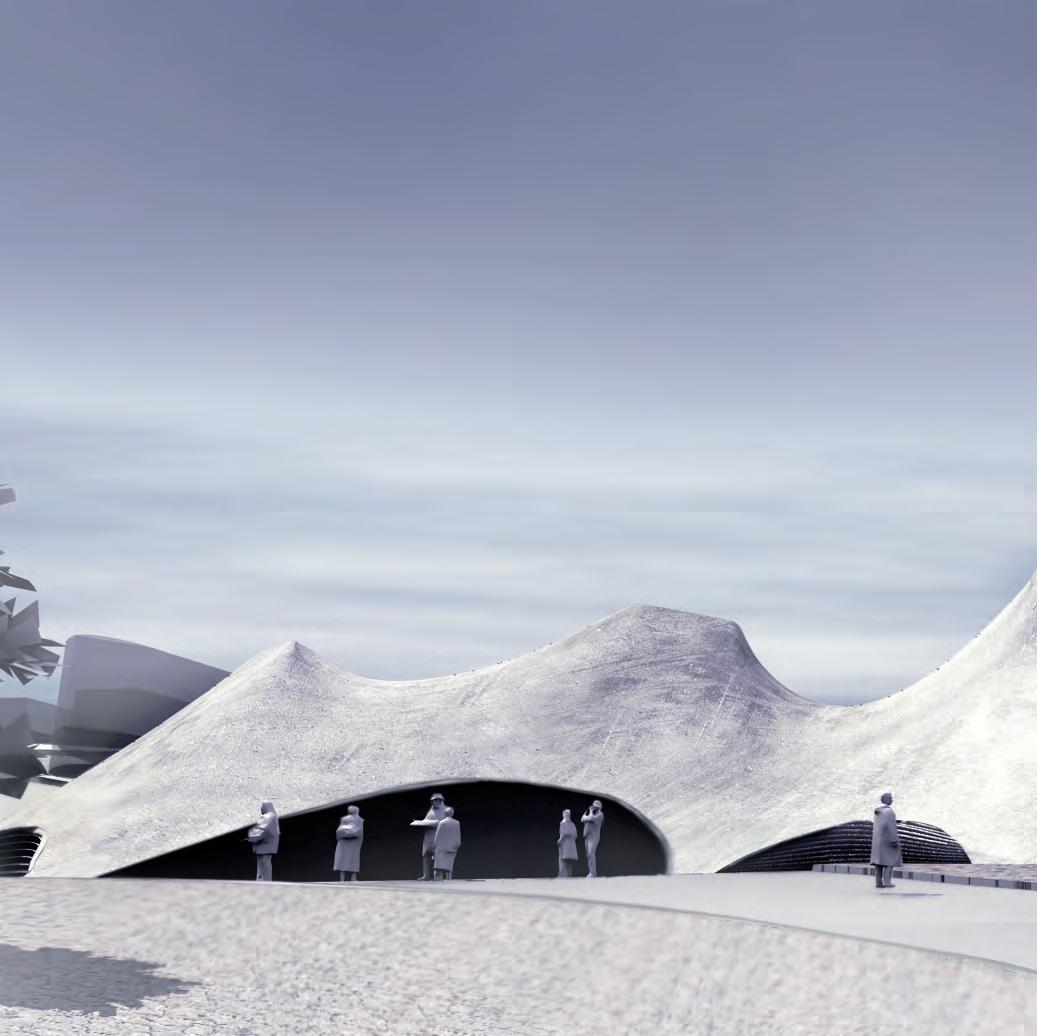
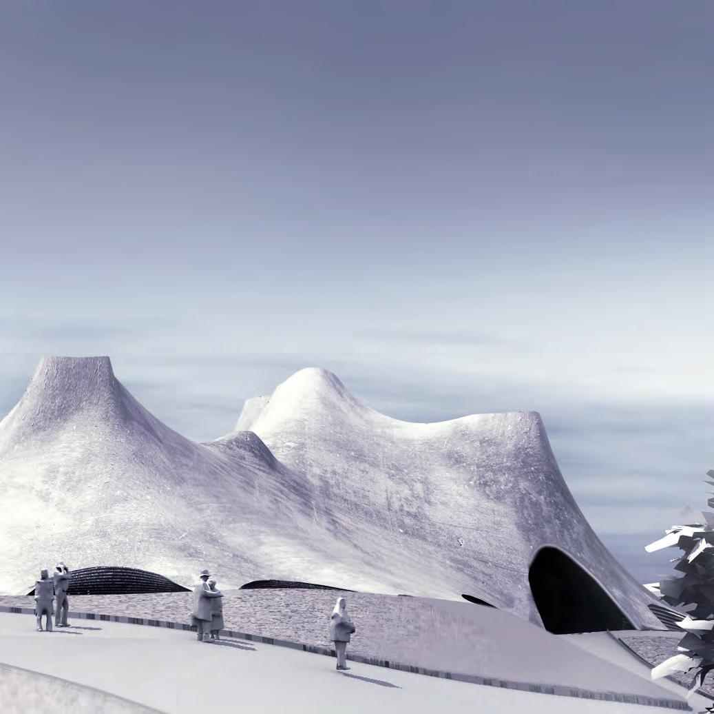
A perspective showing the entrance on the centre. The building takes form according the forces that shaped it and act upon it. It is morphed as an extension of its surroundings and interacts with its immediate environment.
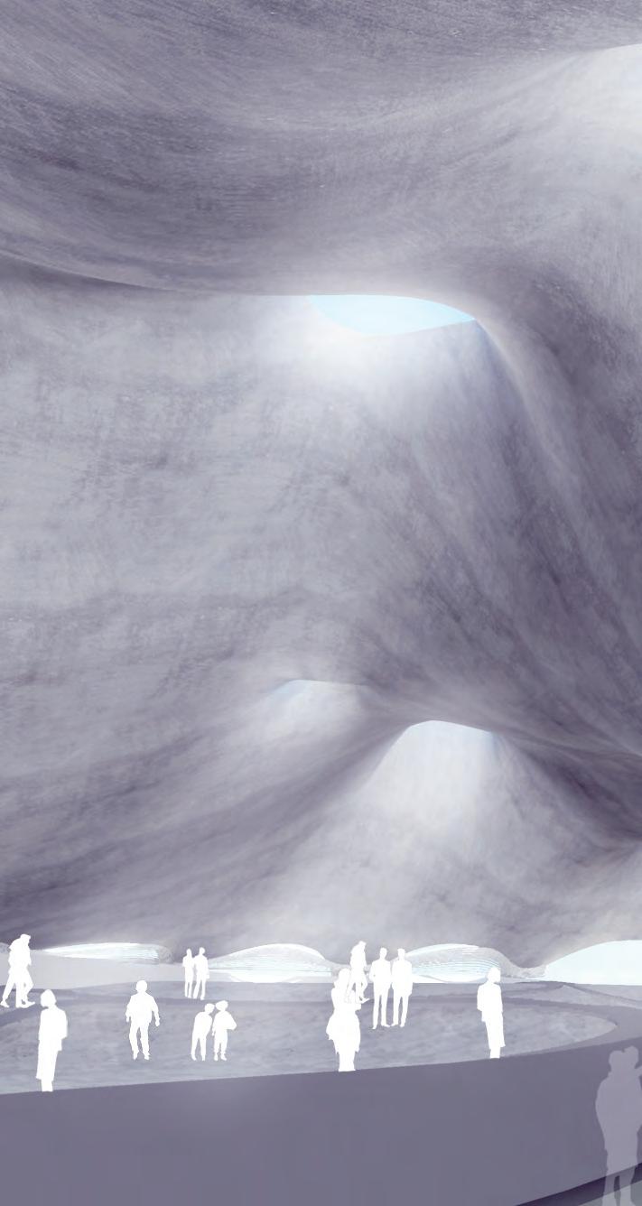
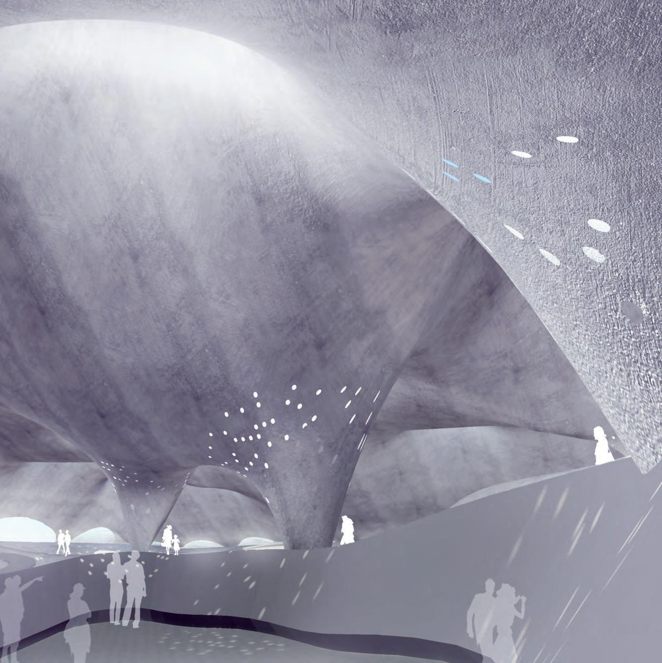


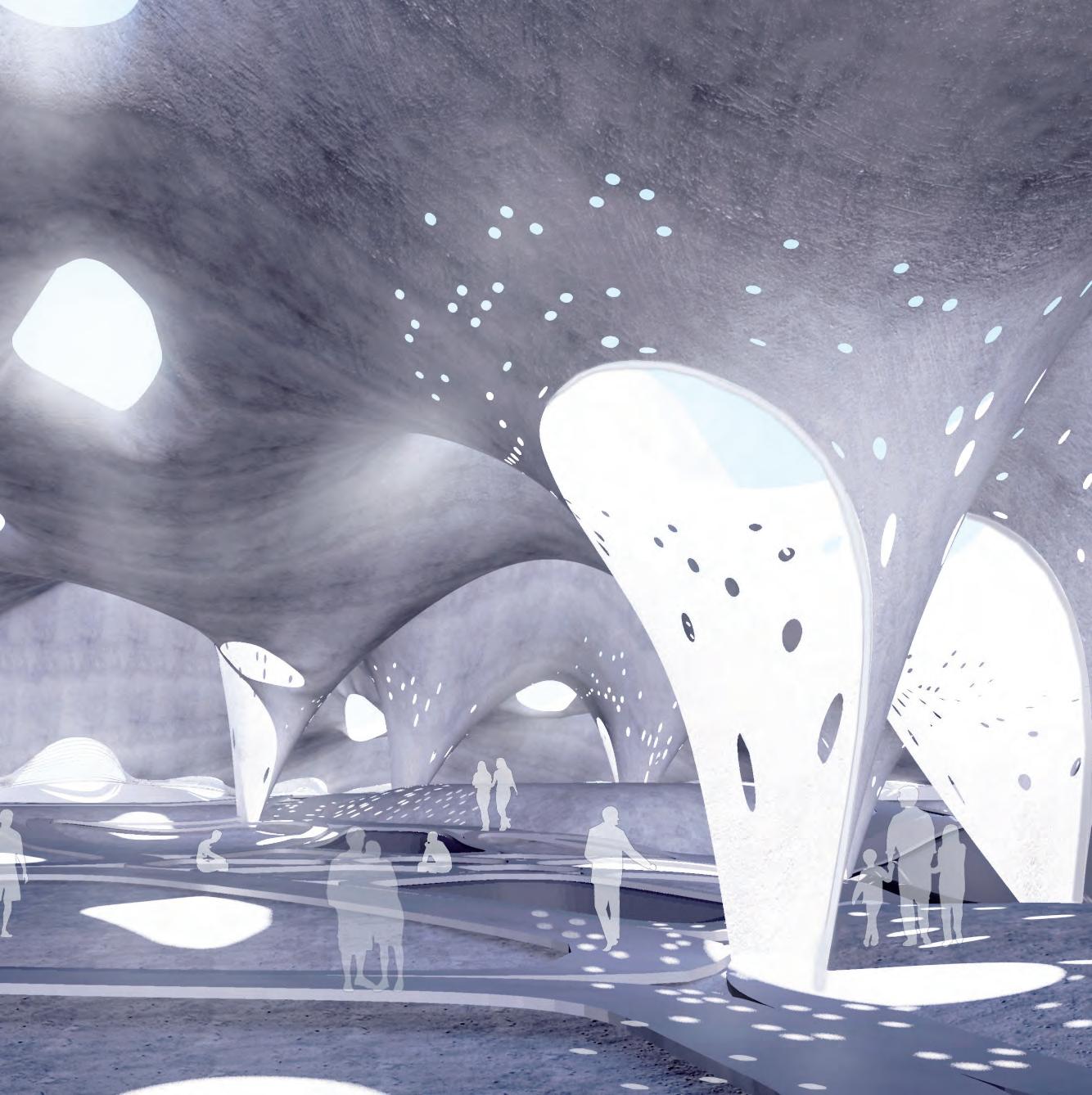
Perceptual thresholds emphasised by light wells at the periphery of the auditorium. The view also reveals difference in heights and lighting between public and private spaces.
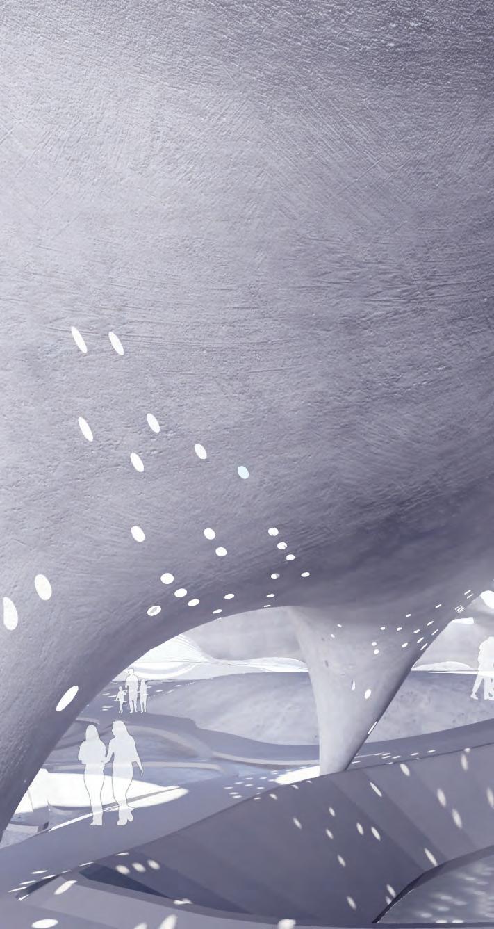

As an outcome of the research presented, an iteration of a full-scale design has been simulated under precise formation and modulation rules to reach a proposal for an ecologic building solution. The resultant geometry is the outcome of a through investigation of the potential of the system to adapt itself to accommodate for different programmatic, performative and spatial needs.
The behaviour of the hybrid material assembly and the possible construction techniques investigated earlier provide a domain of limits to what can be achieved geometrically with such systems. The formation of the shell speaks of these techniques and the process of developing them. The architectural parts are formed in processes have distinct geometries and performance within the overall space.
The strategies that were extracted from the process include the solar chimneys, circular openings, light well touch points, layering for perceptual thresholds and arches by edge restrained points. Each one of these elements contributes to the over-all geometry.
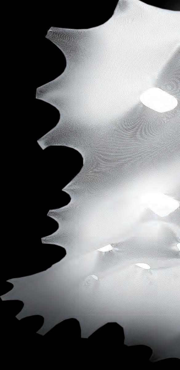
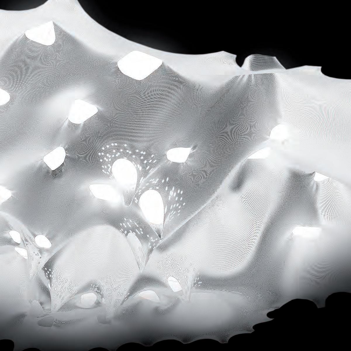
Following through with the design evaluation, the presented series of diagrams explain the construction process through a 4- step summary of the procedures. The geometries of the iteration generated previously, aid in envisioning the construction logistics at full scale. The intention of these illustrations is to provide a simplified outline of the possible set of instructions to carry out the construction procedure.
The process starts by excavating the ground according to dimensions provided by the generated plan. Starting wit the outlines of that plot, the topography levels are achieved by excavating different areas at different rates. Further excavation can be done on the areas where the private recessed sub programs have to be introduced. The outcome is a topography that has differentiation in the levels according to the programmatic zoning rules.
The interior circulation can then be organized according to measurements provided by the computed plan. Program zones are further subdivided by the introduction of Concrete Canvas pathways, which can take shape to the topography. The outcome is a seamless but differentiated ground floor, which is sensitive to the spatial needs of the program. The strategy also highlights the proposed circulation paths between the program zones. The resultant forms can then be finished with concrete to minimize their differences.
BULLDOZER EXCAVATING

CONCRETE CANVAS OVER FORMED GROUND

The ground excavation and plotting allows then for the mapping of restrain points, where the tensile membrane can touch the ground. The plotted points can be extracted from the algorithm and indicate where does the structure need to meet the ground. A detail is to be formulated for keeping the forces of the entire structure under control, by fixing the membrane at ground level and possibly connecting that detail underground at a sufficient level, to keep the forces at equilibrium.
The simulated membrane geometry is to be achieved by sewing the pieces of material together as they assemble to make that form. An approach to patching has been discussed to allow for the minimization of error during the sewing process. The result should resemble the simulated forms, by strategizing the machine-cut patch assembly. This process attempts at minimizing error in the construction phase of the process. More precision is achieved by creating a direct link between the designer’s simulation, and the instructions given to the worker.
As the fabric is assembled in pieces, the over-all tent form begins to take shape. Force is required to bring the fabric to its volumetric form. Spatial enclosures of certain qualities then start to emerge as the result of force induced on the patched fabric membrane. The spaces are formed as the result of tensioning at the side anchor points, a procedure that can be carried through by introducing pulleys at the designated arch-touch points, as implied by the generated plan. Cranes can be used to hold the weight of the entire fabric, as it is being tensioned.
To achieve the conical tent forms, industry standard hydraulic jacks are introduced at the centres of the polygons of the designated program areas. The equipment investigated to raise the fabric upwards should have the capacity to retract its height, to facilitate the movement underneath the structure as its being tensioned, and the removal of this equipment after casting. The possibility of creating specific equipment is a possible solution to tension and retract as well as spray compressive material. Such innovation in the construction procedure departs from standard methods and is relevant to the envisioned material system.
Steel mesh reinforcement
5mm jesmonite reinforced with quadaxial glass fibre
Fabric
Barchip fibre reinforced
Steel mesh reinforcement
5mm jesmonite reinforced with quadaxial glass fibre
Fabric
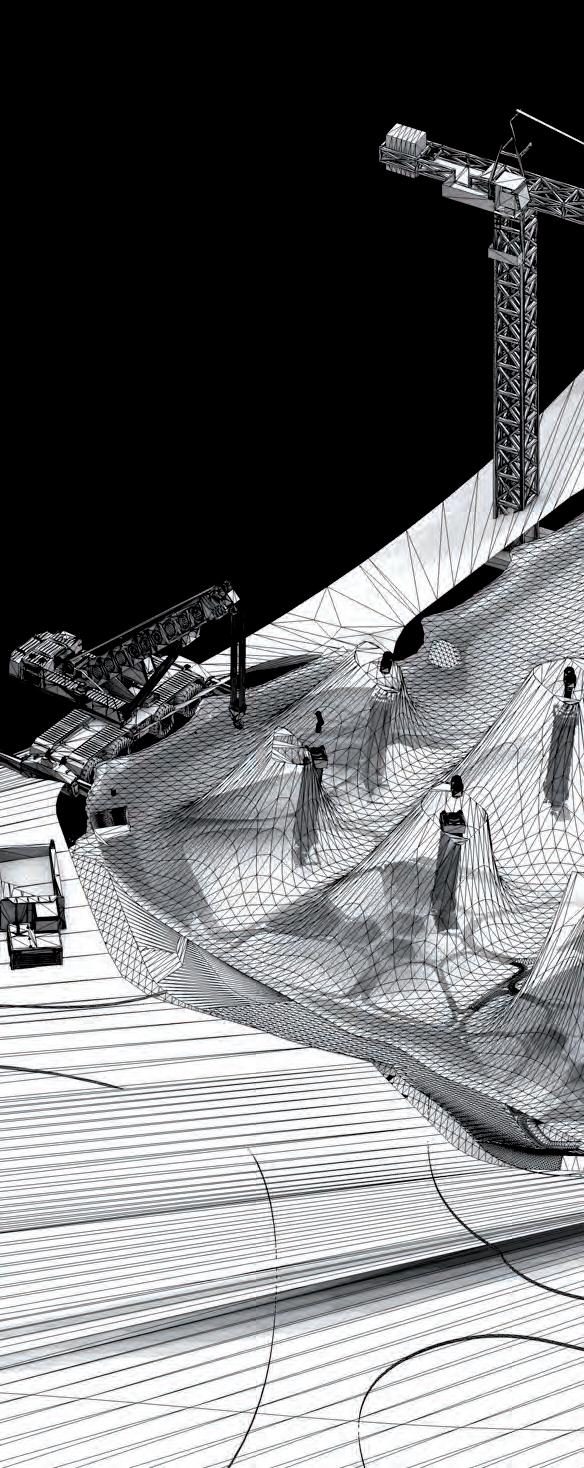
Barchip fibre reinforced
Steel mesh reinforcement
5mm jesmonite reinforced with quadaxial glass fibre
Fabric
CRANES TO HELP LIFT FABRIC
Barchip fibre reinforced
HYDRAULIC JACKS TO LIFT FABRIC UP
Steel mesh reinforcement
5mm jesmonite reinforced with quadaxial glass fibre
Fabric
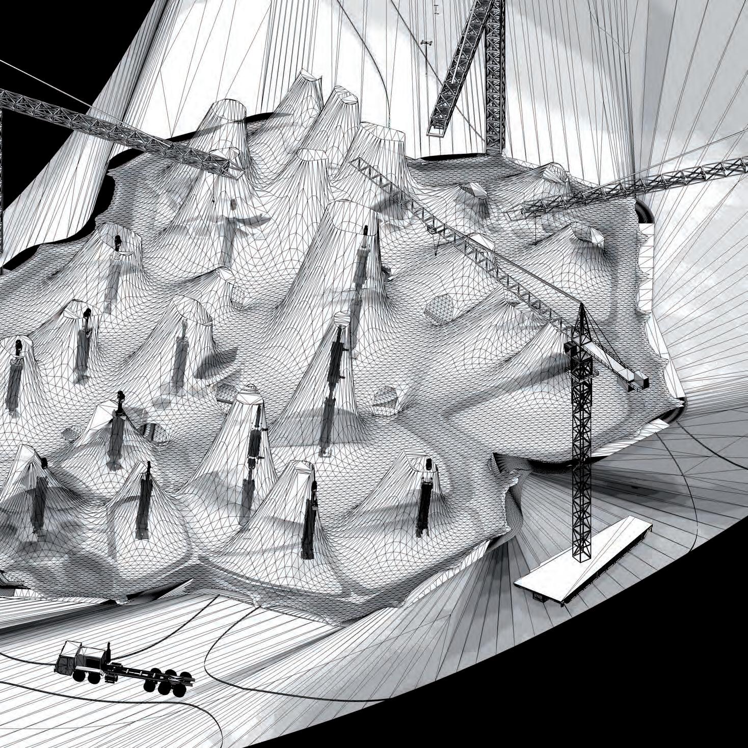
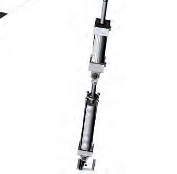
Barchip
The fabric tensioning process ends with the formation of a tensile membrane enclosure, which is dependent on construction equipment for support. As discussed in previous chapters, the material system requires the stiffening of that membrane with compressive material layering, which enables the free form structure to become a structural shell. The layering process is an integral part of reaching the ultimate aim of a coherent systematic approach to spatial forming. The materials researched previously pertain different characteristics, and have to be dealt with in specific techniques to achieve a desirable result.
The potential of these materials forming to construct the over all geometry depends on the characteristics of these materials and their application restraints. The order of layering the materials is an essential construction instruction. The free form geometry is the consequence of a deterministic shaping technique, where the form adapts for performative and spatial needs according to program. Once the form is fully seamed and stretched to the required geometry, the membrane becomes ready to take the load of the layering materials.
Jesmonite has been thoroughly discussed earlier as an available material that could initiate that layering process to achieve equilibrium state in the load distribution when removing the tensile supports. The material proved to work with fabric at a small scale. At the actual building scale, the material can be sprayed on to the free form membrane at separate intervals. Layering of reinforcement can be added to the surface in the form of quad axial glass fibre mesh that adds to the stiffening qualities of the shell at a micro level. Workers can spray Jesmonite at lower levels of the structures, while nozzles from the hydraulic jacks can dispose the material at the tips of the tent forms. The equal distribution of the materials is essential for avoiding having an unstable shell. Patches of extra fibreglass reinforcement and Jesmonite can be added to areas with higher acting loads.
5mm jesmonite
5mm jesmonite reinforced with quadaxial
5mm jesmonite reinforced with quadaxial glass
5mm jesmonite reinforced with quadaxial glass fibre
LIFTS FOR WORKERS MESHING
HYDRAULIC JACKS TO SPRAY JESMONITE

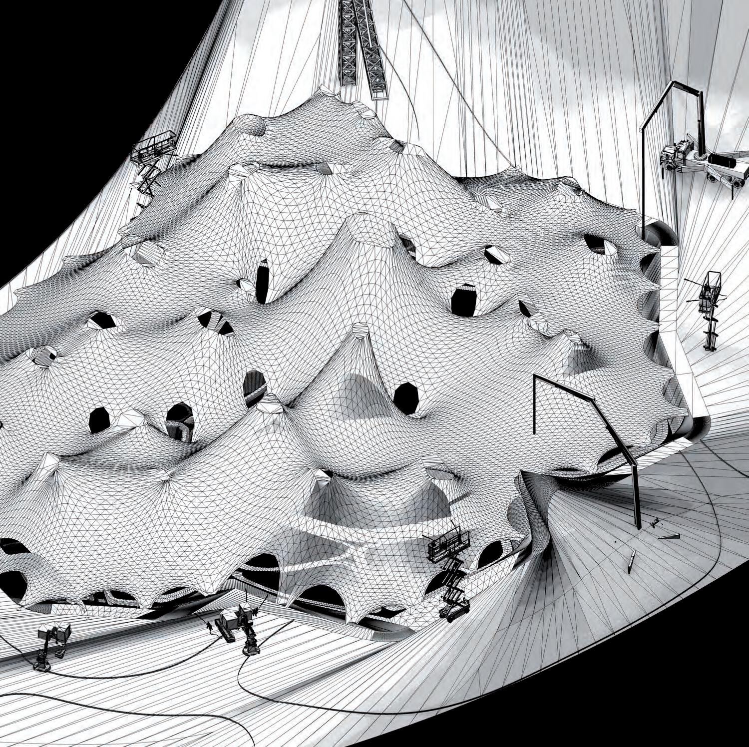
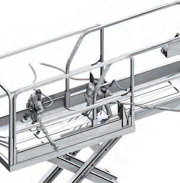
The construction process comes closer to completion by making sure that the roof form is covered with enough thickness of material to guarantee its handling of compressive forces, and aim at distributing these forces almost equally across the free form geometry. The last step of the sequence is to apply shot-crete that is reinforced with barchip fibre onto a steel mesh applied on the hardened Jesmonite and quad axial fibreglass mesh layers.
Barchip fibre reinforced concrete Steel mesh reinforcement
5mm jesmonite reinforced with quadaxial glass fibre
After being let to cure a sufficient time, the Jesmonite and fibreglass mesh layered surface is further reinforced with more layers of materials. A formable steel mesh is then formed that can take shape as the free-form geometries and reinforce the shell further, especially in handling shear forces. The steel mesh is also essential for the Shotcrete to adhere to the free form surface while it is being sprayed.
Barchip fibre reinforced concrete
Steel mesh reinforcement
5mm jesmonite reinforced with quadaxial glass fibre Fabric
Concrete spraying has to happen subsequently at areas where the tensile stresses are highest. This procedure ensures that the structure would not crack with the weight of the concrete on it. The possibility of manufacturing new concrete spraying equipment that covers the free form shell from the tops as workers spray at the bottom is touched upon and becomes relevant at this stage of the construction procedure.
When the entire form has been properly covered, the material layers are left to cure and adhere to each other. The curing time depends on the thicknesses achieved, the mix ratio of the concrete and the weather conditions of the site. Only when the entire mixture is completely set and dry, the hydraulic jacks are retracted and removed.
A note has to be made on some ways that thermal expansion of such a structure can be dealt with. Thermal joints could be introduced between the patch seams of the fabric made of a material that is elastic, and could allow for slight movement to allow the shell to expand and contract. The perforations made at the light wells to allow for light pixilation can be introduced as grommet openings with metal siding that would be trowelled with concrete manually. The surfaces of the interior can also be smoothened by trowelling plaster onto the surface.
Barchip fibre reinforced concrete
Steel mesh reinforcement
5mm jesmonite reinforced with quadaxial glass fibre
Barchip fibre reinforced
Steel mesh reinforcement
5mm jesmonite reinforced with quadaxial glass fibre Fabric

HYDRAULIC JACKS COULD ALSO DISPENSE CONCRETE FROM CENTRE
ROBOTIC ARM SPRAYING CONCRETE BARCHIP FIBRE MIX

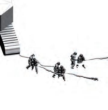
As we near the end of the process examined within this research, a clear layout of the main intentions, the process and the outcome of that process is set out and illustrated. The main intention of this body of work is to reduce the complication that surrounds the construction of fluid concrete spaces. These spaces allow for coherence within the built environment enclosures. Throughout the course of research, a lot of challenges have been met due to the experimental nature of the investigation as a material process. The challenges met have opened doors of perception to steer the interest towards areas of interest that branch out to investigate in detail some aspects that push for the main intention.
Our process of exploration has relied on a nonlinear synthesis between information gathered from models of different scales and mediums. Different weights of emphasis have been placed on parts of the process depending on the gain and relevance of the part under examination. The sequence of progression towards a viable solution to the proposed problem is recursive, and iterates between what these techniques have as results, of data to inform the research.
Complex Euclidian forms are not new in the design of contemporary buildings. Many architects have attempted the creation coherent forms that imitate the organic forms found in nature. As a departure from the rigid orthogonal planning of the human interventions on nature of its different scales; architects, planners and engineers have been adopting these complex geometries to create human built environments that take shape according the forces that act upon them. The immense and exponential advances in digital design, analysis and computation noticed in the recent years have allowed for these projects to become feasible. Advances in material sciences and the building industry have allowed for their construction.
The formation processes of these buildings have not yet reached a level of maturity to rival nature’s simplicity and economy in creating complex materialization. The process of construction is usually an afterthought of the envisioned design, where plenty of materials could be wasted in the process, leading to an un-ecological intervention with nature.
We aimed for the resulting spaces of our work to stay truthful to the ambitions of unifying the building into a single system that handles environmental, pragmatic and structural conditions within its enclosure.
To stay ingenuous to the ambitions within the process, the methods focused on using the least amount of material to achieve these optimized formations. Therefore taking full potential of the advantages of the goals set previously, by achieving complexity while avoiding complication, a method has been investigated to achieve free form spatial enclosures that have a minimal mass and are constructed with innovative simplified methods.
Building materials have shown their capacity to assemble towards geometries, which could be formed by implying forces of different magnitudes. The conceptual idea proposes applying materials to pneu- like tensile membranes to solidify them, and enable their geometries to accommodate for handling a wider range of force fields within a coherent single-system. The sets of information needed to create a scheme of commands to shape the free form geometries into a pragmatic structure were extracted, and constantly refined for creating and analysing models of several scales and mediums.
The experiments carried out on material systems have taken the most weight of importance during the course of investigation. The better understanding of these systems, informs the precise quantification of the free form geometries resulting from a set of instructions. These instructions are introduced essentially to improve on the pragmatic function of the spaces within these forms. Through the course of investigation that was carried out after the material research phase, defining parameters have been introduced to an algorithmic system that is built to produce different iterations of its formations based on different conditions.
The main function of the building was introduced as a result of the qualities noted in the analogue models, where the function suited the form. Programs most befitting to such spaces were introduced to rationalise these forms into a set coverage of area that needs a specific height. The digital models helped with understanding the environmental pressures that could interact with the proposed models and enable the analysis of these models under specific conditions.
Emergent formations produced by the process communicate the forces that act on and create them to suit a specific function, under specific environmental conditions and organizing rules. The unity of the system is resembled in a hybrid of different elements that contribute to making a building, where these elements fuse in a single entity that solves the building requirement.
Scale was introduced early on in the process to elaborate the techniques used to towards a pleasant spatial quality. The architectural value of the project lies in its seeking of economy and truth with the process. The development of research has been done in an inverse manner where the outcome was the result of rigorous experimentation. Radical solutions to the banal and mundane building problems have lead to imaginative spatial environments through rigorous scientific research.
Different factors such as social, cultural, environmental and economic factors of current conditions were investigated as shaping forces of the over all geometry. The research in these domains as it relates to the material system, have been methodically informative in the decision making process to use these parameters in the simulation of a generated outcome. The algorithm was started at a later stage and outlined these factors as shaping parameters of the calculated built form simulation.
The work done has given insight towards continuing the research, to proceed beyond the effort presented here within this document. Certain developments could be done in the future to better realize the potential of the proposed concepts. The research attempted to touch up on most aspects of the procedures that surround the realization of these novel solutions. Emphasis was given on certain more radical procedures, especially on the materials, to test their legibility, and solve in detail their application procedures within the system.
In future research, more exploration is needed on the coherence of the algorithms that simulate the generation of the building. Construction procedures have to be further investigated with experts. Structural optimization and the construction process could be rooted within the single algorithm to attain more complexity within its recursion to produce site and program specific iterations.
Within the constraints of several conditions we present this work as an all-rounded insight into a radical set of procedures as an effort in minimizing the complication that surrounds building doubly curved concrete surfaces. The project has taken an ambitiously large scale to benefit from the large span coverage and efficiency of material disposition provided by the system. The purpose of our investigation is to provide an insight to achieving fundamentally different ideas within the constraints of efficiency, economy and feasibility. The work presented is a platform for further investigation on these procedures.
Reducing Material Waste of the Building Process
Building of Minimal Mass
Differentiated and Articulated, Coherent Spaces That Follow Program
Multiple-input, Iterative Simulation Tools Environmental Response Through Analysis of Emergent Form
1
Cebra-Thomas, Judith, Fraser Tan, Seeta Sistla, Eileen Estes, Gunes Bender, Christine Kim, Paul Riccio, and Scott F. Gilbert. “How the Turtle Forms Its Shell: A Paracrine Hypothesis of Carapace Formation.” Journal of Experimental Zoology Part B: Molecular and Developmental Evolution 304B.6 (2005): 558-69. Print. 1
2 Block, Phillippe. Thrust Network Analysis: Exploring Three Dimensional Equilibrium. (2009). Massachusetts Institute of Technology. Web. 2
3
Steadman, Philip. The Evolution of Designs: Biological Analogy in Architecture and the Applied Arts. London: Routledge, 2008. Print. 3
4 Kilian, Axel. Linking Hanging Chain Models to Fabrication (2009). MIT. Web. 4
5
Bechthold, Martin. “PART 2: Membrane Structures.” Innovative Surface Structures: Technologies and Applications. London: Taylor & Francis, 2007. Print. 5
6 Chilton, John C., and Heinz Isler. Heinz Isler: The Engineer’s Contribution to Contemporary Architecture. London: Telford, 2000. Print.
7 Nerdinger, Winfried, and Frei Otto. Frei Otto, Complete Works: Lightweight Construction Natural Design. Basel: Birkhäuser, 2005. Print. 7
8 Otto, Frei. Pneu Und Knochen = Pneu and Bone. Stuttgart: Inst. F. Leichte Flächentragwerke, 1995. Print. 8
9
Otto, Frei, Sabine Schanz, and Bodo Rasch. Frei Otto, Bodo Rasch: Finding Form : Towards an Architecture of the Minimal : The Werkbund Show Frei Otto, Frei Otto Shows Bodo Rasch : Exhibition at the Villa Stuck, Munich, on the Occasion of the Award of the 1992 Deutscher Werkbund Bayern Prize to Frei Otto Und Bodo Rasch. [Germany]: Axel Menges, 1995. Print. 9
10
Sheil, Bob. Protoarchitecture: Analogue and Digital Hybrids. London: John Wiley, 2008. Print. 10
11
Ingold, T. S., and K. S. Miller. Geotextiles Handbook. London: T. Telford, 1988. Print. 11
12
“Elasto Plastic Concrete Reinforcement Fibres Fibers,Plastic Fibre Reinforcement Barchip Fibres.” Elasto Plastic Concrete Barchip Synthetic Structural Fibres Reinforce Concrete Shotcrete Replace Steel Mesh. EPC:Barchip Fibre. Web. 02 Feb. 2012. <http://www.elastoplastic.com/english/products.htm>. 12
13
“Concrete Canvas Shelters - Rapidly Deployable Hardened Structures.” Concrete Canvas - Rapidly Deployable Infrastructure. Concrete Canvas Ltd: Rapid Concrete Infra Structure. Web. 02 Feb. 2012. <http://www.concretecanvas.co.uk/Concrete_Canvas_Shelters.html>. 13
14
Jesmonite Ltd. Web. <www.Jesmonite. com>. 14
15
Reiser, Jesse, and Nanako Umemoto. Atlas of Novel Tectonics. New York: Princeton Architectural, 2006. Print. 15
16
Domingo, Alberto. “Proceedings of the International Association for Shell and Spatial Structures (IASS) Symposium 2009, Valencia.” Ed. Carlos Lazaro. Evolution and Trends in Design, Analysis and Construction of Shell and Spatial Structures 28 September – 2 October 2009, Universidad Politecnica De Valencia, Spain (2009). Print. 16
19
Kolatan, Ferda, and Jenny E. Sabin. Meander: Variegating Architecture. Exton, PA: Bentley Institute, 2010. Print. 19
20
“Butong Official Website.” ButongCreative Concrete Design. Butong Sweden Ltd. Web. 02 Feb. 2012. <http:// www.butong.se/>. 20
21
Ballim, Y. “Reinforcement Corrosion and the Deflection of RC Beams––an Experimental Critique of Current Test Methods.” Cement and Concrete Composites 25.6 (2003): 625-32. Print. 21
22
“Finite Element Analysis (FEA).” Journal of Equine Veterinary Science 19.5 (1999): 330. Print. 22
23
Hauschild, Moritz, and Rü̈diger Karzel. Digital Processes: Planning, Design, Production. Munich: Institut Fur Internationale, 2011. Print. 23 24
Kolarevic, Branko, and Kevin R. Klinger. Manufacturing Material Effects: Rethinking Design and Making Architecture. New York: Routledge, 2010. 24
25
“Education and Economy in Jordan Reform.” Amman Voice. Web. 02 Feb. 2012. <http://ammanvoice.blogspot. com/2008/02/education-and-economy-injordan-reform.html>. 25
26
“Detailing of Tensile Membranes — Architen Landrell - Tensile Fabric Architecture, Structures and Canopies.” Architen Landrell - Tensile Fabric Architecture, Structures and Canopies. Web. 02 Feb. 2012. <http:// www.architen.com/technical/articles/ another-article>. 26
Uncategorized
Hensel, Michael, Achim Menges, and Michael Weinstock. Emergence: Morphogenetic Design Strategies. Chichester: Wiley-Academy, 2004. Print.
Balmond, Cecil. Informal. Munich: Prestel, 2002. Print.
Carroll, Sean B. Endless Forms Most Beautiful: The New Science of Evo Devo and the Making of the Animal Kingdom. New York: Norton, 2005. Print.
“Concrete Books and Masonry BooksBooks on Concrete, Masonry and Brick Construction and Repair Techniques.” Construction Books, Contractor Books, Building & Electrical Codes, Construction Tools and Test Equipment for Electricians and the Building Trades. Web. 02 Feb. 2012. <http:// www.contractor-books.com/Concrete. htm>.
Page 2:
Fig 1.00.2: Material wastage in the concrete construction industry due to lack of high precision tools and skilled labour in Jordan and India. Image: Riyad-Al- Joucka [ April 2011 ]
Page 3 & 4:
Fig 1.10 : Typical concrete construction practices in Jordan. Image: Riyad-Al- Joucka [ April 2011 ]
Page 6:
Fig 1.11.1: Construction of Atom pavilion without scaffolding and formwork.
Reinforcement formed into the design geometry and laid with steel mesh. (Left)
Spraying concrete over the formed reinforcement.(Middle)
Pavilion after completion.(Right). Images: http://www.geograph.org.uk/ photo/2537488 [ Accessed: May 2011]
Fig 1.11.2: Relevance of synthetic fibres in the current concrete construction industry.
Load tests revealing strength of fibre reinforced concrete similar to steel reinforcement.(Left)
Barchip fibre reinforced concrete being used in spraying tunnels. Ease of combination of concrete and reinforcement.(Middle)
Worker spraying concrete in a tunnel in Bombay, India. Images: http://www.elastoplastic.com/ [ Accessed May 2011]
Fig 1.11.3: Deploying a Concrete Canvas Shelter.
Inflating the air balloon inside the shelter kit(Left)
Hydration of erected shelter(Middle) Interior of the shelter after the canvas is hydrated and cured.(Right). Images: http://www.concretecanvas. co.uk/ [Accessed May 2011]
Page 7:
Fig 1.20.1: Section through a turtle shell. Fusion of exoskeleton and Endoskeleton. http://www.varbak.com/images/turtleskeleton-nb19467.jpg [Accessed May 2011]
Fig 1.20.2: The detail of a turtle carapace where the ribcage, dermal armour and the scutes are fused. Image: http://www. mnpctech.3dpixelnet.com/picture_library/bio-mech.turtle.exoskeleton.jpg [Accessed May 2011]
Page 8:
Fig 1.20.3: Ribbed Vault in a gothic cathedral. http://4.bp.blogspot.com. [ Accessed June 2011]
Page 9:
Fig 1.30.1: Piling up of materials for optimisation of geometry. Panama Museum of Biodiversity( Frank Gehry Assoc 2011) Image: http://www. google.co.uk/imgres?imgurl=http://4. bp.blogspot.com/ [ Accessed Dec 2011].
Fig 1.30.2: Terminal 5.JF Kennedy Airport New York. Example of modernist concrete shell(Eero Saranien 1962) Image: http://en.wikipedia.org/ wiki/Thin-shell_structure [ Accessed Dec 2011].
Page 11:
Fig 1.40.1: Sketches from Pneu and Bone ( IL 35 Frei Otto). AA library [ Accessed June 2011]
Page 11:
Fig 1.40.1: Sketches from Pneu and Bone ( IL 35 Frei Otto). AA library [ Accessed June 2011]
Page 12:
Fig 1.40.3: Hanging chain model of the Colonia Guell by Antonio Gaudi: Form finding to Measure. Image: http://farm4.staticflickr.com /3094/2860405491_2e5504b63f_z.jpg [ Accessed July 2011]
Fig 1.40.4:Frei Otto’s Soap film model for Stuttgart Railway station. Physical form finding to find the optimal geometry. Image: http://techsem.ocular-witness.com/?p=31 [ Accessed June 2011]
Page 13:
Fig 1.50.1: A tensile structure where the form is stabilised by applying the optimal tension to the restrain points and acting vectors. Image: http://www.bedouintentexeter.co.uk/ [ Accessed July 2011]
Fig 1.50.2: A series of experiments by Heinz Eisler where the fabric is allowed to freeze and the structure is inverted into a complete compression shell. Through this process the supporting masts are eliminated once the membrane is frozen. Images: http://safetythird.files. wordpress.com/2011/04/heinz-isler1. jpg [Accessed July 2011]
Page 14:
Fig 1.50.3: A precise physical model of the Olympics stadium in Munich by Frei Otto. The forces and geometry is recorded and scaled up for onsite using cameras that capture the movement of the structure. Image: http:// transformatics.blogspot.com/2007/04/ frei-otto-and-munich-1972-olympic. html [Accessed July 2011]
Fig 1.50.4: The Olympic stadium in Munich after completion. The construction was completely calibrated from the physical model. Image: http://www.sbp.de/en/build/show/7Roof_for_Munich_Olympics_Arena_1972 [ Accessed July 2011]
Page 15 & 16
Fig 1.60.1: The institute of Light weight Structures in the university of Stuttgart.
Fig 1.60.2: The pavilion after it has been clad with wooden planks.
Image: Frei Otto Finding Form 1993, Pg 100-101 [ Accessed June 2011].
Page 17:
Fig 1.70.1,2,3: assortment of experiments using fabric formwork concrete construction at the University of Manitoba.( Mark West CAST 1995) Image: Fabric Formwork. Edited by: Alan Chandler and Remo Pedreschi. December 2007.
Fig 1.70.4: Slab to column detail showing reinforcement(Mark West CAST 1992).
Image: http://www.cast.org/ [ Accessed July 2011].
Page 18:
Fig 1.70.5: A 12 meter fabric-cast beam. Shaping of beam following its natural force path to reduce self weight (Mark West/ Cast 2003).Image: http://www.cast.org/ [ Accessed July 2011].
Page 19:
Fig 1.80.2: Application of Barchip Fibre reinforced concrete on site. Image: http://www.elastoplastic.com/ [ Accessed September 2011]
Page 20:
Fig 1.81.1: Construction workers spraying concrete in a steel reinforcement grid in a dam.
Image: http://www.wtec.org/loyola/ compce/03_07.htm [Accessed January 2012]
Page 21:
Fig 1.92.1: Crossection of a typical Concrete Canvas showing different layers of materials.
Image:http://www.concretecanvas. co.uk/ [ Accessed September 2011].
Page 22:
Fig 1.93.2: Jesmonite used in interior of Hotel Puerta America, Madrid..
Image: http://www.jesmonite.com/ [Accessed September 2011]
Fig 1.93.3 Jesmonite used in Replica Wyatville chimney stacks, Wollaton Hall
Image: http://www.jesmonite.com/ [Accessed September 2011]
Page 71:
Fig 3.70.1: Types of concrete canvas in the industry(Top) Deployment of a concrete canvas shelter.(Bottom)
Image:http://www.concretecanvas. co.uk/ [ Accessed September 2011].
Fig 3.70.2: Load/Displacement graph of Barchip fibre in comparison to steel mesh and steel fibre(Top). Embossing on Barchip fibre to increase the bond between concrete.
Image: http://www.elastoplastic.com/ [ Accessed September 2011]
Fig 3.70.3: Moulding process of Butong(Top). Finished translucent Butong(Bottom)
Image: http://www.butong.eu/ [ Accessed July 2011].
Page 132 & 133:
Fig 5.01.1: Image showing parts of the building and the immense amount of scaffolding and material used.
Fig 5.01.2: Organisation scheme for computing a programmatic and structural acoustically performing shell structure.
Fig 5.01.3: Digital for finding using mesh relaxation to achieve a minimal surface composed of catenoid shapes.
Images: Digital Processes by Moritz Hauschild and Rudiger Karzel, the unconventional process of designing the Taichung Metropolitan Opera house.
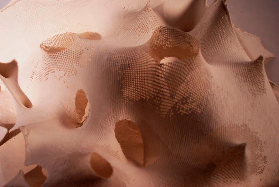
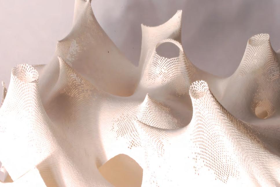
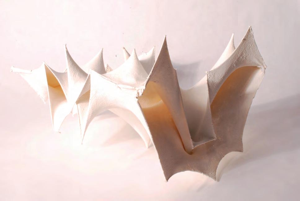
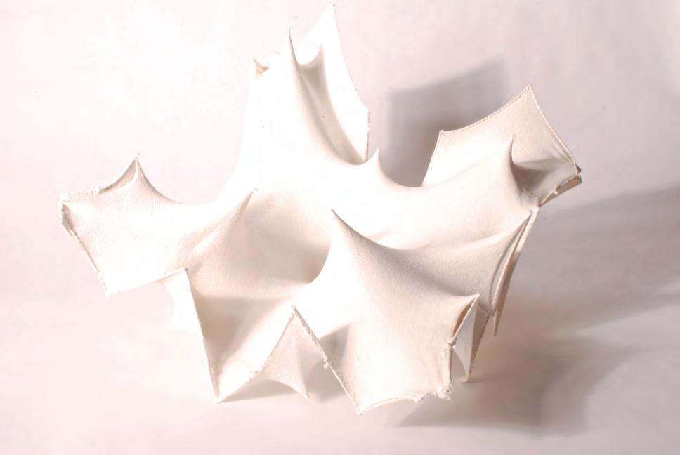
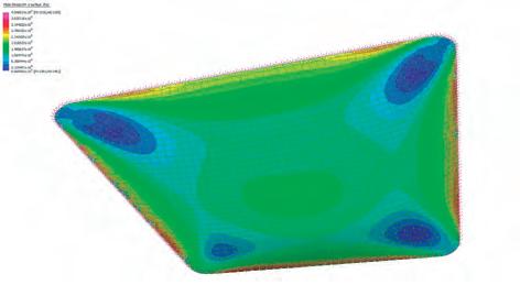
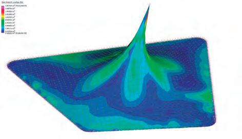
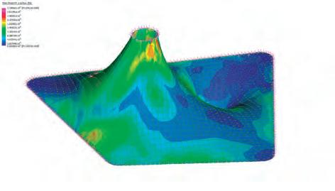
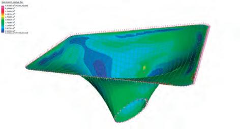
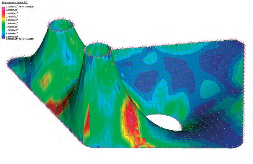
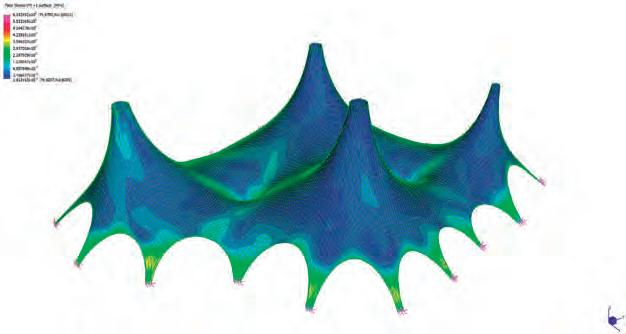


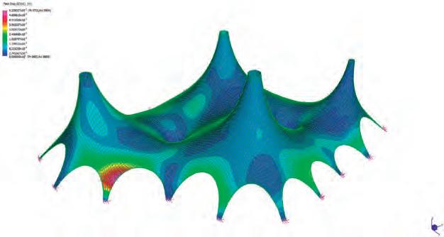


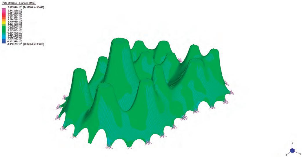
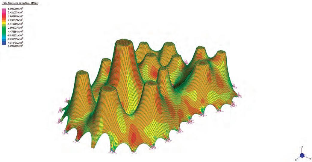
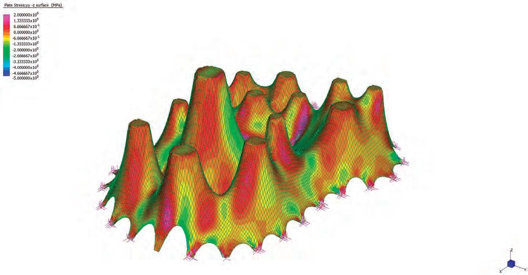
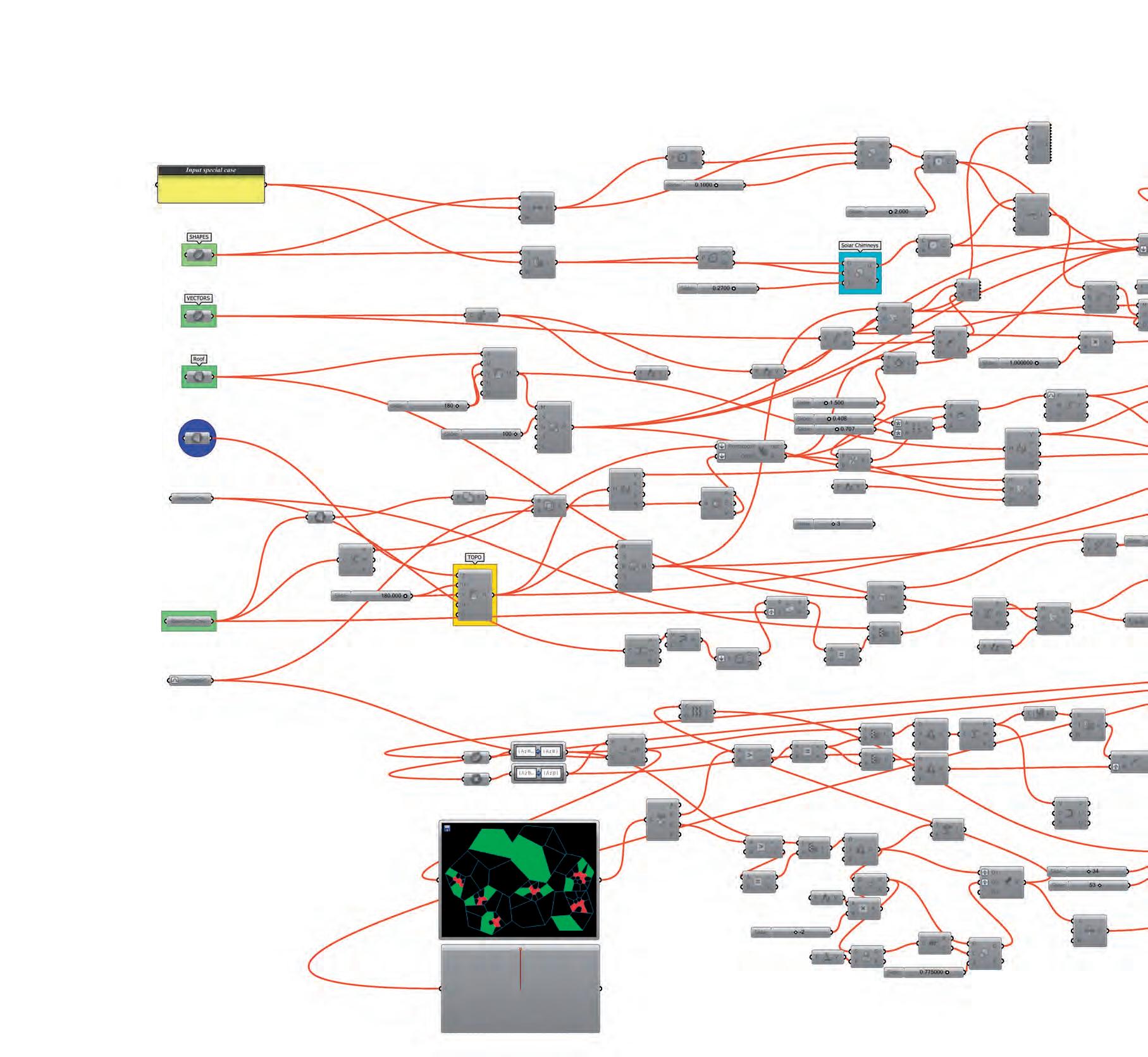
Input Parameters
Zone Mapping Data
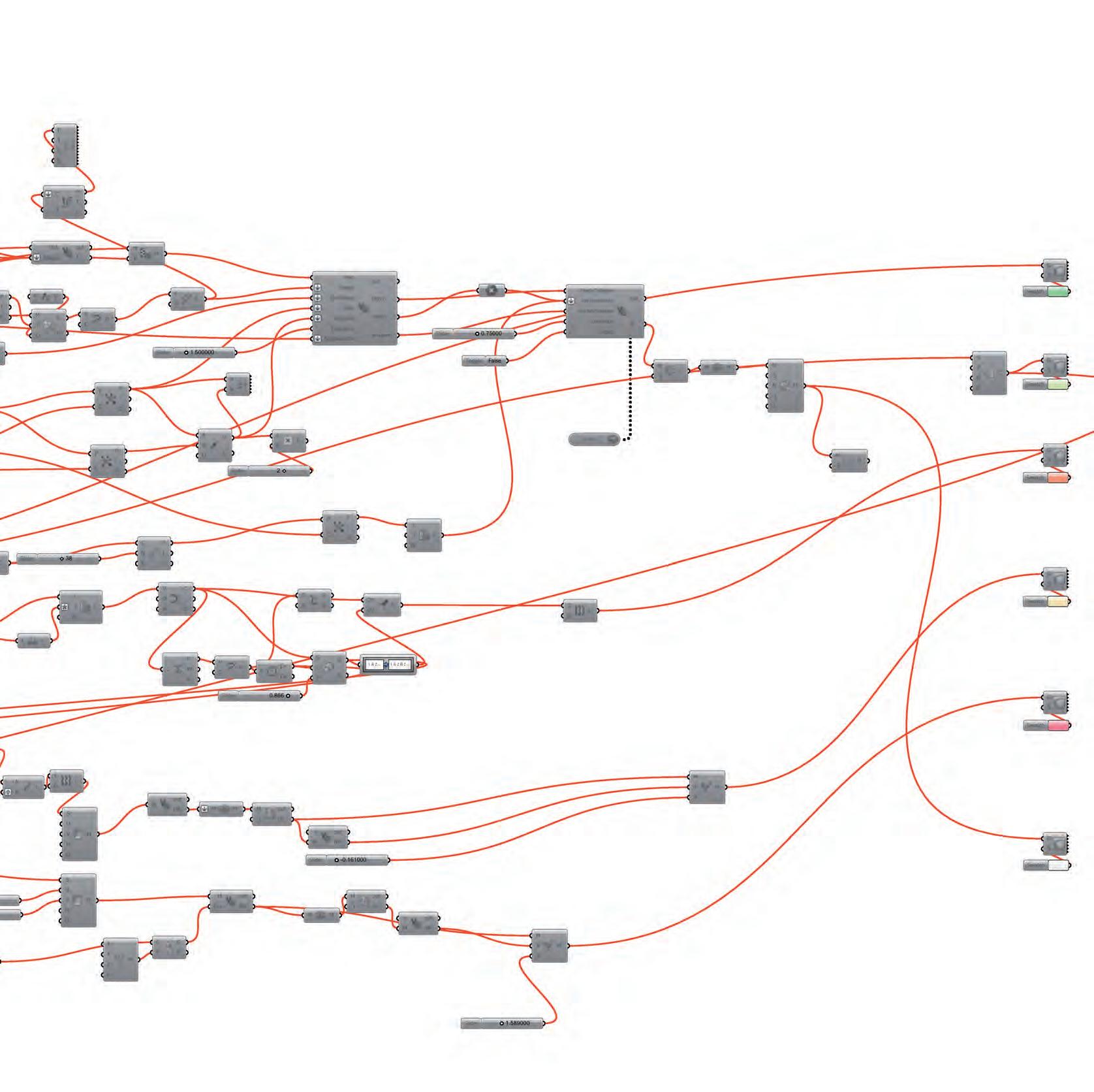
Relaxing Recessed Spaces
C:\Program Files (x86)\Notepad++\change.log
06 February 2012 15:57
PrivateSub RunScript(ByVal Circ As List(OfCircle), ByVal lnlist As List(OfLine), ByRef Output AsObject, ByRef Output2 AsObject, ByRef Output3 AsObject, ByRef Output4 AsObject, ByRef Output5 AsObject)
'1._______________Start of script______Input of program Areas for packing
Dim Circlist AsNew list(Ofcircle)
Dim Circlist2 AsNew list(Ofcircle)
Dim Radlist AsNew list(Of Double)
Dim radlist2 AsNew list(Of Double)
Dim Cptlist AsNew List(OfPoint3d)
Dim Cptlist2 AsNew List(OfPoint3d)
Dim lnlist1 AsNew list(OfLine)
Dim CLintersectlist AsNew List(Ofpoint3d)
Dim NL1list AsNew list(OfLine)
Dim Intptlist AsNew list(Ofpoint3d)
Dim NL1lnlist AsNew List(Ofline)
'2._______________Generating Delaunay Lines_______________________________
For i As int32= 0 To circ.Count - 1
For j As int32 = 0 To circ.Count - 1
If i = j ThenContinueFor
Dim a As Circle = Circ.item(i)
Dim b As circle = Circ.item(j)
Dim Rad AsDouble = a.Radius
Dim Centerpoint As point3d = a.Center
Dim Rad2 AsDouble = b.Radius
Dim centerpoint2 As point3d = b.Center
Dim Dist AsDouble = centerpoint.DistanceTo(centerpoint2)
If math.Abs(dist - Rad - Rad2)< 0.01 Then
Dim ln AsNew Line(centerpoint, centerpoint2)
Dim Test AsBoolean = True
For k As int32 = 0 To lnlist1.count - 1
Dim testln As Line = lnlist1.item(k)
If testln.To = ln.From AndAlso testln.from = ln.To Then test = False 'deletes EndIf Next
'3._________________Setting Conditons________________________________________
If test = TrueThen
Dim LT AsDouble
Dim CT AsDouble
Dim LTP AsNew point3d
Dim CTP AsNew Point3d
Dim CLintersect As intersect.LineCircleIntersection = intersect.Intersection.LineCircle(ln, a, LT, LTP, CT, CTP)
Dim V As vector3d = ln.Direction
V.Rotate(math.PI / 2, vector3d.ZAxis)
Dim NL1 AsNew line(ctp, V, 5) NL1list.add(NL1)
C:\Program Files (x86)\Notepad++\change.log 06 February 2012 15:57
V.Rotate(math.PI, vector3d.ZAxis)
Dim NL2 AsNew line(ctp, V, 5) NL1list.add(NL2) Lintersectlist.add(ctp) lnlist1.add(ln)
EndIf
EndIf Next Next
'4.___Generating Perpendicular Vectors from circle circle intersection____
Dim FLlist AsNew list(Ofline)
For i As int32 = 0 To NL1list.count - 1
Dim NL1 As line = NL1list.item(i)
Dim FLCounter As int32 = 0
For j As int32 = 0 To NL1list.Count - 1
Dim NL2 As line = NL1list.item(j)
If i = j ThenContinueFor
Dim LT1 AsDouble
Dim LT2 AsDouble
Dim LLintersect AsBoolean = intersect.Intersection.LineLine
True)
If LLintersect = TrueThen
Dim intpt As Point3d = NL1.PointAt(LT1)
Dim test AsBoolean = True
For k As int32 = 0 To intptlist.count - 1 If intpt = intptlist.item(k) Then test = False
EndIf Next
If test = TrueThen intptlist.add(intpt)
EndIf
Dim NL1Ln AsNew line(NL1.From, intpt) NL1lnlist.Add(Nl1Ln) FLcounter += 1
EndIf Next
If FLcounter = 0 Then FLlist.add(NL1)
EndIf Next
Dim NL3lnlist AsNew list (Ofline) NL3lnlist.addrange(NL1lnlist)
For i As int32 = 0 To NL1lnlist.count - 1
For j As int32 = 0 To NL1lnlist.Count - 1
If i = j ThenContinueFor
Dim a As line = NL1lnlist.item(i)
Dim b As line = NL1lnlist.item(j)
If a.From = b.From AndAlso vector3d.VectorAngle(a.Direction, b.Direction)< 0.1
C:\Program Files (x86)\Notepad++\change.log 06 February 2012 15:57 Then
If a.Length < b.Length Then NL3lnlist.remove(a) Else
NL3lnlist.remove(b)
EndIf
EndIf Next Next
Dim EPTlist AsNew list(OfPoint3d)
Dim ELNlist AsNew list(Ofline)
For i As int32 = 0 To NL3lnlist.count - 1
For j As int32 = 0 To NL3lnlist.count - 1
Dim a As Line = NL3lnlist.item(i)
Dim b As Line = NL3Lnlist.item(j)
If i = j ThenContinueFor
If a.To = b.To Then
Dim intpt As Point3d = a.To
Dim test AsBoolean = True
For k As int32 = 0 To EPTlist.count - 1
If intpt = EPTlist.item(k) Then test = False
EndIf Next
If test = TrueThen EPTlist.add(intpt)
EndIf
EndIf Next Next
For i As int32 = 0 To EPTlist.count - 2
Dim a As point3d = EPTlist.item(i)
Dim b As point3d = EPTlist.item(i + 1)
Dim Eln AsNew Line(a, b)
NL3lnlist.add(Eln) Next
'5._______________Generating Polygons to close the boundaries_______
Dim NCirclist AsNew list(Ofcircle)
Dim Polygonlist AsNew list(Ofpolyline)
For i As int32 = 0 To circ.Count - 1
Dim a As Circle = Circ.item(i)
Dim Rad AsDouble = a.Radius / math.Cos(math.PI / 6)
Dim Centerpoint As point3d = a.Center
Dim NCirc AsNew circle(Centerpoint, rad) Ncirclist.add(Ncirc)
Dim pts AsNew list(OfPoint3d)
For j As Int32 = 0 To 6 pts.Add(NCirc.PointAt(2.0 * Math.PI *(j / 6))) -3-
C:\Program Files (x86)\Notepad++\change.log 06 February 2012 15:57 Next
Dim polygon AsNew polyline(pts) Polygonlist.add(polygon) Next
Dim intptlistN AsNew list(OfPoint3d)
Dim PLFlist AsNew list (OfPolyline)
For i As int32 = 0 To Polygonlist.count - 1
Dim TPvaluelist AsNew List(Of Double)
Dim CHKline AsNew list(Ofline)
Dim a As Polyline = polygonlist.item(i)
Dim Arln() As Line = a.GetSegments
For l As int32 = 0 To Arln.length - 1
Dim Arlnn As line = Arln(l)
For j As int32 = 0 To FLlist.count - 1
Dim LT AsDouble
Dim CT AsDouble
Dim b As Line = FLlist.item(j)
Dim PLLintersect AsBoolean = intersect.Intersection.lineline(Arlnn, b, LT, CT, .01 , True)
If PLLintersect = TrueThen
Dim intptN As Point3d = Arlnn.PointAt(LT)
Dim test AsBoolean = True
For k As int32 = 0 To intptlistN.count - 1 If intptN = intptlistN.item(k) Then test = False
EndIf Next
If test = TrueThen intptlistN.add(intptN)
Dim TPvalue AsDouble = a.ClosestParameter(intptN)
TPvaluelist.Add(TPvalue)
CHKline.add(b)
EndIf EndIf Next Next
Dim
TPvaluept AsNew list (OfPoint3d)
Dim TPval() AsDouble = TPvaluelist.ToArray
Dim CHKline2() As line = CHKline.toarray array.Sort(TPval, CHKline2)
TPvaluept.add(a.PointAt(TPval(0)))
Dim V As vector3d = CHKline2(0).direction
Dim V2 As Vector3d = a.TangentAt(TPval(0))
If vector3d.VectorAngle(V, V2)< math.PI / 2 Then
For j As int32 = 0 To a.Count - 1
Dim pt As Point3d = a.item(j)
Dim TPvalue AsDouble = a.ClosestParameter(pt)
If TPvalue > TPval(0) AndAlso TPvalue < TPval(1) Then TPvaluept.add(pt)
EndIf Next
C:\Program Files (x86)\Notepad++\change.log
Else
For j As int32 = 0 To a.Count - 2
Dim pt As Point3d = a.item(a.Count - 2 - j)
Dim TPvalue AsDouble = a.ClosestParameter(pt)
If TPvalue < TPval(0) Then TPvaluept.add(pt)
EndIf Next
For j As int32 = 0 To a.Count - 2
Dim pt As Point3d = a.item(a.Count - 2 - j)
Dim TPvalue AsDouble = a.ClosestParameter(pt)
If TPvalue > TPval(1) Then TPvaluept.add(pt)
EndIf Next
EndIf
TPvaluept.add(a.PointAt(TPval(1)))
Dim PLF AsNew Polyline(TPvaluept) PLFlist.add(PLF) Next
Dim FFlist AsNew list(Ofline) For i As int32 = 0 To FLlist.count - 1
Dim a As Line = FLlist.Item(i)
Dim LDB AsNew List(Of Double) For j As int32 = 0 To intptlistN.count - 1
Dim b As Point3d = intptlistN.Item(j)
Dim LTVAL AsDouble = a.ClosestParameter(b)
Dim Propt As Point3d = a.ClosestPoint(b, True)
If b.DistanceTo(propt)< 0.01 Then LDB.Add(LTVAL)
EndIf Next
LDB.sort
LDB.Reverse
Dim pt As Point3d = a.PointAt(LDB.item(0))
Dim Fln AsNew line(a.From, pt) FFlist.add(Fln) Next
'6._____OutputList_______
Output1 = FFlist
Output2 = Polygonlist
Output3 = NL3lnlist
Output4 = intptlistN
Output5 = PLFlist
'7.End of script_generation of closed polygons within a set of packed programs EndSub
06 February 2012 15:57