robotic nomadism
m sc candidates course director studio master studio tutors consultants
Carmen Cristiana Matiz
Heather Brick McMenomy
Michael Weinstock
Dr. Elid Erdine
Dr. Lidia Badarnah
Antiopi Koronaki
Alican Sungur
Dr. George Jeronimidis
Mohammed Makki
[robotic]
n omadism
ARCHITECTURAL ASSOCIATION SCHOOL OF ARCHITECTURE
GRADUATE SCHOOL PROGRAMMES
COVERSHEET FOR SUBMISSION 2017-18
PROGRAMME: Emergent technologies and Design
STUDENT NAME(S): Carmen Cristiana Matiz Heather Brick McMenomy
DISSERTATION TITLE: Robotic Nomadism
COURSE TITLE MA/MSc Dissertation MSc Dissertation
COURSE TUTOR Michael Weinstock
DECLARATION:
“I certify that this piece of work is entirely my/our own and that any quotation or paraphrase from the published or unpublished work of others is duly acknowledged.”
Signature of students
Carmen Cristiana Matiz Heather Brick McMenomy
Date:
acknowledgements
We would like to express sincere gratitude to our Director Michael Weinstock, and our tutors, Dr. Elif Erdine, Antiopi Koronari and Alican Sungur, for their invaluable advice an for their support throughout the project. We would like also to thank Dr, George Jeronimidis and Mohammed Makki for their constructive comments and critiques throughout the course of the program, and Angel Moreira, Alvaro Rodriguez and Henry Cleaver, who supported us throughout the experimentation faze of the project with their fabrication and robotics expertise. Finally, we want to thank our families and friends for their encouragement and congratulate our colleagues, for the invaluable and unforgettable shared experience in the AA.
00. t able of c ontents
01. i ntrod U ction ...........................................10 02. domain ........................................................16 03. material s Y stem ......................................48 04. fabrication ..............................................84 05. com PU tational e XP eriments ..............120 06. desi G n P ro P osal ...................................164 06. o n-site fabrication ..............................161
01.intro
a bstract
Nomadic pastoralism is the most sustainable mode of existence in arid climates, and current housing solutions only utilize the most basic forms of building technology. Incipient desertification lends itself to the expansion of this lifestyle, but current housing proposals in west africa do not accommodate seasonal movement. Furthermore, vernacular african architecture provides a democratization of construction which is not considered. Incorporating additive manufacturing with transportable robots into existing vernacular techniques could catalyze modernization without losing cultural relevance.
Therefore, the focus of this research is to create a material system which can provide dwellings for nomadic pastoralists in sub-saharan Africa using existing construction techniques and additive manufacturing. Vernacular precedents are studied, including actively bent armature tents and earthen construction techniques. The proposed solution is a wattle and daub system, which combines actively bent wooden rods and extruded earth. Studies in gridshell systems and their structural performance under compressive loads are conducted, as well as studies in extrusion techniques and the thermal performance of resultant forms.
The resulting proposal can be assembled on-site, then disassembled and re-created. The rods are transported, and the earth is left behind and re-formed with each erection. As a result, this material system allows dwellings to maintain ephemerality of form.
Robotic Nomadism | iN t R o 012
0.0 i ntroduction
013
t raditionalism
Traditional building methods involve structures that are built and perodically edited by those who inhabit them, allowing for a democratized process of construction. The technology associated with traditionalism is associated with something that is of a time before modern construction techniques. A move towards more contemporary forms tends to leave behind the accessibility of traditional construction techniques; however, this does not have to be the case. Utilizing traditional methods of construction with modern geometry can help disenfranchised people attain more contemporary forms without sacrificing the useful methods of construction and social engagement traditional architecture affords them.
First, it will be beneficial to define what is meant by “traditionalism.” For the purposes of this research, it will be defined as “That which is handed down”1 in that it is a method of building which is inherited from generation to generation through practice, and revised slightly with each generation. Therefore, it is created by those who make do with what is there, rather than importing materials from elsewhere. Because of this, materials can be replaced easily and locally, and buildings can be repaired by people in the community.
Traditionalism exists in contrast with instructionalism, a characteristic of modern architectural design, dissociates the user from the designer and the constructor. With instructionalism, the architect and the creator are separate entities, and the user to design feedback loop that traditionalism allows for is lost. This does not mean that traditional architecture cannot be modern, or that its design must remain the same over centuries.
Maintaining traditional building practices while advancing building technology allows for design revisions, so long as the practice and the ability to alter one’s space is not lost. As Tuan states in her essay on traditionalism, “Perhaps what we seek to retain are not so much particular artifacts and buildings, but rather the skill to reproduce them. If we retain the skill, no human work is irrevocably lost.”2 Skills can be maintained while utilizing computer aided design to achieve more complex geometry. In this way, modernization can be created without losing the sustainability and accessibility of traditionalism.
In a case study of Botswanese housing, the government used federal aid money to build more “modern” homes for semi-nomadic people. Typically, Botwanese women construct homes, and it is considered her property, while all things purchased are within their husband’s domain. Switching from traditionally constructed earthen dwellings to modern dwellings resulted in a loss of control over the home, and a subsequent disruption of an existing gender dynamic The change in housing construction was referred to as the “domestication of women” because it repurposed women’s primary source of economic agency: construction. Even after moving in, many women opted to rent out the modern home, and build themselves traditional dwellings in the backyard. While there was interest in living in a wood framed home, this interest was derived from a desire to be a part of the times, and to incorporate contemporary building techniques. Unfortunately, contemporary building techniques tend to be
synonymous with instructionalism, importing materials, and a western concepts of building and home. The ephemerality, tradition, and a democratization of construction techniques which traditional earthen housing provides is lost in many attempts to appear modern. Therefore, incorporating advanced construction techniques into traditional building methods provides an opportunity to create contemporary designs without losing the benefits and cultural relevancy of traditional architecture.
Robotic Nomadism | iN t R o 014
“Our conception of modernity creates its own self-enclosed canons of traditionality. Traditions identified as the past is a modernist idea. The same holds true for the concept of vernacular as equated with low technology. In a context where the relation between traditional and modern has lost a fixed temporal reference, tradition seen as a settled body of knowledge that can be transferred, uncovered, mastered, and laid claim to is at best reactive and at worst mortuary.”
-Jean-Paul Bourdier
015
016 02. domain
017
mobilit Y in west a F rica 02.01
West Africa is one of the most mobile regions in the world, characterised with 90% intra-regional migratory flows 1
National pastoral mobility
Cross-border pastoral mobility Pastoral zone
Wet season Dry season
Caravan Marketing itineraries Border crossing point Water bodies
10% 43 million livestock in m ali
T ranshumant pastoralist (1 375 489)
Nomadic pastoralist (93 296) Agro-pastoralist (8 342 126)
o F m ali’s gd P is based on P astoralism
018 r obotic n omadism domain
Fig 02.01.01 - Mobility patterns in West Africa in relation to Mali’s position within the territory
Fig 02.01.02 - Statistics related to pastoralism in Mali, Africa
ALGERIA MALI
LIBYA
NIGERIA
Source
1. EU Support to Mobility and Migration within West Africa, Strategic Steering Committee, Factsheet, Brussels, 2015
2. OECD/SWAC, “The African Approach on Migration”, in West African Mobility and Migration Policies of OECD Countries, OECD Publishing, Paris,2008
3. Bendandi B, Venier M, Vulnerability and Resilience in West Africa: Understanding Human Mobility in the Context of Land Degradation, KNOMAD, 2017
4. ECOWAS, CSAO/OECD, Elevage et marché régional au Sahel et en Afrique de l’Ouest. Potentialités et défis, Editions Club du Sahel et de l’Afrique de l’Ouest/OCDE, 2008, 162 p
the necessit Y o F mobilit Y
Long distance movement between complementary agro-economic zones and areas of traditional cross-border movement are deeply rooted in West African history , which has always been characterised by a high degree of human mobility.
Mobility is the most important response by the inhabitants of arid environments in the Saharan and Sub-saharan region to climatic adversity. The climatic conditions in these areas are characterised by instability, irregular rainfall patterns and periods of draughts, having an important influence in the decision-making process that dictates the lifestyle patterns that people adopt. The mobility configuration is also highly diversified, with some countries serving as source, origin and transit routes for migrants2
Contemporary migratory flows arise as a result of environmental factors, but also socio-economic, political and historical-cultural factors which have had serious impacts on intra-regional migration of cross-border workers, mobility of traders and pastoralists.
Land use degradation and desertification is often a key driver of human mobility in the area. Land degradation might lead to increases in migration because of the need to diversify incomes, but it can also cause reduced mobility by eroding the assets and capital required to finance migration . When on-site adaptation is either impossible or undesirable, migration allows people to modify their exposure to climatic stress3. On one hand , temporary and circular labour migration are the most common strategy used throughout history and increasingly in the last decades to cope with increasingly hostile environments, while on the other hand, land abandonment and out-migration can lead to further isolation and marginalization of vulnerable rural populations.
Pastoralism is the main activity in arid and semi-arid regions of West Africa that involves sustainable use of irregular and fragile natural vegetation and scarce water resources, while enforcing growth in local communities.
mali
We chose Mali as the area of our analysis. Due to its climatic instabilities and political issues, Mali has been characterised with high degree of mobility, to such extent that even the sedentary image of farmers in central and south of the country transitioned to a mobile lifestyle. This leads to the increased need for change in the way of thinking about the geographical and political dimension when considering issues related to access to land, land use and conflict in West Africa and beyond, but also inquiries as to how can architecture, as a highly static industry, respond to the increased need of mobility in the area4
While the extreme draught in the previous years affected drastically the number of livestock at a national level, pastoralism is still an important part of the Malian society and an appropriate and sustainable way of lifestyle that responds to the increasingly arid environmental conditions.
019
Pastoral societ Y
“Pastoralism is mobility: mobility is pastoralism” A Borana proverb
Although there is no standard definition of pastoralism, it has often been described as a livelihood in which at least 50% of a household’s food and income is derived from livestock1 In addition, pastoralism is characterised by mobility and, in particular, the seasonal movement of livestock to access grazing resources and water. Pastoralists occupy vast arid and semi-arid zones with very high spatial and temporal variability of rainfall. In these dry areas, the strategic movement of livestock is a rational and productive response to uncertain availability of pasture and water, and includes substantial cross-border movements of animals. Typically, livestock herding produces milk for direct household consumption, as well as offspring for sale, or for exchange for cereals. These are the basic elements of pastoralism which, in general terms, have remained unchanged over hundreds of years. The common perceptions about pastoralist are that they represent a minority who practice an archaic and outdated lifestyle, but even if they often inhabit harsh remote regions, they are fully integrated with a wider global process. Pastoralism across the region not only has diverse forms, but is also robust and highly dynamic, responding to market opportunities and a range of other economic, social and environmental influences over time2
Pastoral mobility plays a critical role in the economic prosperity of Africa’s drylands. Across West Africa, an estimated number of 50 million pastoralist support their families and communities in an industry based solely on livestock, that depend on natural dryland pastures.
In an area where other land use systems are failing in the face of climate change, mobile livestock keeping is producing national and regional economic benefits, determining specific lifestyle patterns. Mobility is a key way for pastoralist to make the best use of water and grazing resources in these dryland areas. Their strategies have evolved through time, being highly efficient and adaptive to the environment.
Pastoralism relies on unique production strategies, with the ability to move being the most crucial. Mobility is an essential component of the herd’s productivity in arid and semi-arid areas. It allows livestock to benefit from fodder resources which vary in quantity and quality in different areas during the year. As new policies and innovative practices for pastoral mobility are beginning to take root in many parts of dryland Africa, it encourages governments to develop informed, progressive policies that reflect the need of modern pastoralist.
Livestock mobility is a modern approach to poverty alleviation and accelerated development. While supporting mobility does not require substantial financial investment, it requires refreshed thinking and a clearer problem understanding. Transhumant livestock farming also contributes to the development of abandoned and isolated areas by ensuring a human presence in areas with significant security issues.
Source
1. Catley A, Scoones I, Lind J(ed.), Pastoralism and Development in Africa: Dynamic change at the margins, Routledge,2013
2.Idem
3. Bendandi B, Venier M, Vulnerability and Resilience in West Africa: Understanding Human Mobility in the Context of Land Degradation, KNOMAD, 2017
020 r obotic n omadism | domain
P astoral mobilit Y

021
Fig 02.01.03 - In an area where other land use systems are failing in the face of climate change, mobile livestock keeping is thriving
agro -P astoralism
Agro-pastoralism is a form of sedentary or semi-trashumant livestock farming that links crop-growing and livestock. Having a wider availability of resources in their surrounding area, or being pressured by socioeconomical factors, pastoralist choose to settle into permanent settlement. While the herd still needs to be mobile, it is of smaller dimensions at the groups are not dependent on them. The grazing areas are generally in the surroundings of the settlement and only designated members of the family follow their movement. It is generally a short-range mobility. Once the settlement prospers and agriculture lands expand, conflicts may arise between the two ways of food production, finding the balance being essential1

P astoral transhumance
Transhumance is an animal production practice characterised by regular seasonal movements between complementary ecological areas. The herds generally leave a disequilibrium environment, where pastures become scarce, and move towards areas with more abundant resources. The movement is mainly cyclical with a set trajectory, primarily a northsouth movement based on the dry and wet season variance. In this context, transhumance in West Africa may be considered as a form of adaptation to these arid environments, making good use of the existent ecological complementarity. While it implies long distance mobility or cross-border mobility, its degree of dependence on sedentary settlements is higher, as only part of the pastoral family follows the herd movement, while others remain sedimentary with a few animals that sustain their life until the herd returns. While their movement may vary, it explored a defined area named in specialised literature as a transhumance shed.2
P astoral nomadism
Pastoral nomadism is the simplest form of pastoralism. It is characterised by continual and unpredictable movements of all members of a family or a group. As the household is primarily dependent on the herd for survival, their movement is controlled by the movement of the livestock. While they pursue the general seasonal movement of transhumance, the length of stay of nomads at one place and the direction of movement a2re solely governed by the availability of water and natural forage. It is common in sparsely populated areas that are not suitable for the cultivation of crops. Nomadic herding is the only food production method adapted to these ecosystems and it is the most extensive land use system.
Source
1. Catley A, Scoones I, Lind J(ed.), Pastoralism and Development in Africa: Dynamic change at the margins, Routledge,2013
2. Alidou S M, Cross-border transhumance corridors in West Africa, CapEX Report, 2016
022 r obotic n omadism | d omain
Fig 02.01.03 - Pastoral transhumant in Mali.
tYP es o F P astoral mobilit Y
While mobility is an essential practice of pastoral society, different degrees of mobility can be identified based on the availability of climatic dependent resources.
Pastoral nomadism P astoral transhumance a gro P astoralism
Self-sufficient
No permanent structures
Locations and timing is determined by the livestock needs.
Cyclical movement
Regular encampments
Cyclical movement, set trajectory
Do not depend on animals
Family remains in permanent settlement
Reduced movement related to fixed settlement
Adaptable to existing conditions
and
023
Temporary camp 1 14 days 3 3 km 4-9 km/day 14-20 km/day 6 months 1+ years Seasonal camp Settlement Short distance travel Long distance travel Hearding loops Temporary camp 1 14 days 3 3 km 4-9 km/day 14-20 km/day 6 months 1+ years Seasonal camp Settlement Short distance travel Long distance travel Hearding loops
Fig 02.01.04 - Pastoral movement types in relation temporary
permanent settlements
Factors determining the degree o F mobilit Y
A delicate balance between environmental, socio-economical and political factors determine the degree of mobility a certain pastoral society adopts as a lifestyle.
Production
The major reason for mobility is to maximise livestock productivity levels. When on the move, pastoralists are not just searching for food for their animals, they are tracking the very best grazing and water sources. High quality nutrients in dry rangelands are short-lived and predictably patchy. In order to exploit them efficiently pastoralists need to move often and quickly
Trade
Livestock need to be bought and sold. The best markets where pastoralists can get good prices for their animals are often far from the best production areas. Trading can be local, national or international depending on the season and what is to be sold or purchased. Often trade involves extensive treks and the safe movement of animals is therefore key.
Survival
Livestock movement becomes absolutely essential to flee drought, disease or conflict. Prompt and often long-range mobility during these times is necessary for the survival of the herds and the pastoralists themselves.
The mobility patterns are not fixed, as a pastoral family or group can transit from semi-transhumant to nomadic due to the availability of resources, or nomadic pastorals can become mainly sedentary due to socio-economic and political pressure determined by land use and land availability.1
Source
024 r obotic n omadism | domain
1. Catley A, Scoones I, Lind J(ed.), Pastoralism and Development in Africa: Dynamic change at the margins, Routledge,2013

025
Fig 02.01.05 - Nomad herd engaged in long distance mobility
variation o F movement
Flexibility is crucial for the pastoral society. Increasing opportunities for mobility
When discussing adaptation to environment of pastoralist in nonequilibrium range ecologies as the Sub-Saharan area, flexibility is one of the key considerations. The high variability and low predictability of spatialtemporal distribution of pastoral resources (water and forage) is the major driving factor.
A pastoral corridor is a strip of land that is reserved for livestock passage to access pasture, water sources or other herd infrastructure suck as livestock markers, vaccination areas or holding areas. Access to water points, grazing areas and resting points are key elements in long distance and cross-border pastoral mobility. It ensures long-distance and cross-border mobility, connecting north and south dispersion zones2. Resting and settling points are chosen according to grazing areas. A grazing area is an area identified and specially reserved for grazing livestock. As it may or may not be developed, it must contain good quality and abundant pasture and be able to receive a large number of animals. The size should take into account not only the quality and quantity of pasture, but also the pasture carrying capacity.2 The annual herd movement is enclosed within an area termed pastoral shed. The movement remains seasonal within this area and a pastoral shed can spread over hundreds of kilometres. Provided enough resources, the pastors tend to remain within the same pastoral shed. On the other hand, the movement within the pastoral shed is flexible. While some parameters display a certain level of regularity, predictability at certain scales, dryland ecology is a continuum between equilibrium and non-equilibrium conditions that coexist within the same system.
To further understand the importance of variation, the figure displays results from a recent study that considered 4 pastoral sheds in Mali.3 Satellite images comparing green up periods and vegetation density on the same dates at subsequent years. The dryland locations where vegetation is available are seen to vary significantly over time, both within and between years.
Pastoralism is by definition flexible and dynamic. Pastoralists mobility responds to changing circumstances, so initiatives need to be equally flexible. This translates in providing formal services as well as building infrastructure aimed at reinforcing pastoral mobility. As paths traditionally change course from one year to the next according to local climatic and social conditions, policies for infrastructure and housing requirements has to be adaptable, having formalised agreements and rights that are not overly prescriptive and rigid.
A hybrid mechanism should be built for long-term management of mobility4, middle way between formal and informal representing the optimal approach for ensuring flexibility, involving the simultaneously the authorities and local pastoral communities.
Translating this to the built environment, temporary housing rights regarding land use can present a way for transitioning from informal housing to a more formalised and controlled building environment.
Sources
1. Jode H de (ed.), Modern and mobile: the future of livestock production in Africa’s drylands, London: IIED, 2009
2. Idem
3. OECD/SWAC, An Atlas of the Sahara-Sahel: Geography, Economics and Security, West African Studies, OECD Publishing, Paris,2014
4. De Haan C., Steinfeld H., Blackburn H., 1999. Elevage et Environnement. A la recherche d’un équilibre. FAO, 115 p.
Robotic Nomadism | iN t R o 026
r etaining F lexibilit Y r easons o F variation
Northern dispersion zone
north- s outh dis P ersion zones variation in vegetation green u P [variable speed of movement] [movement path are determined by available forage resources]
123 days multiple resting points
seasonal camps long distance movement short distance movement 165 days Southern dispersion zone
Pastoral corridor 28 days 44 days
Main harvest
Labor migrants depart
Pastors move southward
Dry season
Early start of pastoral and agricultural lean season Ramadan
Pastoral lean season Agricultural lean season
Land preparation Sowing Migrants return
Pastors return northward
Rainy season
027
Fig 02.01.08 - Mali Agricultural Timeline. Analysis regarding food security.
Fig 02.01.07 - Satellite image analysis of variability in vegetation green up within a pastoral shed at the same date across multiple years
Fig 02.01.06 - North-South dispersion zones. The variability of movement speed within a pastoral shed
Nov Oct 11 Dec Jan Feb Mar Apr May Jun Jul Aug Sept Oct 2
2003 2005 0 20 40 80 km 2003 2005 0 20 40 80 km 2003 2005 0 20 40 80 km
remote construction
Low dependency on permanent settlements applies certain limitations to the construction process and design
building in remote locations
The necessity of building in remote locations imposes certain important constraints on the design process. Modern building techniques imply the use of industrially processed material which is transported to the construction site, together with a skilled team of labourers. When discussing construction in remote locations, this process become extremely difficult as it involves transporting material, tool and human labour across extended distances. Careful planning needs to be done to ensure the success of the project, which has a high demand of resources.
As for the nomadic pastoral community, because the construction process reoccurs every few months, at locations that vary in distance from permanent settlements, the modern formal construction techniques become impossible to use.
New design and assessment criteria need to be developed in order to constrain the design process for achieving optimal solution that respond to the needs of a nomadic community. One of the most important criteria that dominates both design and construction is self-sufficiency because of the possibility of settling in secluded in remote locations is a recurrent condition.
The material systems should allow customization to respond to the changing needs of the community and also to the new conditions that the settling locations provide. It must adapt to the availability of resources and be economical from that point of view.
The construction sequence is entitled to careful planning and timing,
nomadic construction
Nomadic construction adds further limitations as it requires a carefully planned balance between the time needed for construction and the comfort that the design can provide. They require a different perspective when discussing sustainable and economic models of housing. One of the most important quality to be considered is the quality of being self-sufficient.
To clearly define the parameters of development of housing concepts appropriate to a nomadic lifestyle, the following criteria of assessment needs to be considered:
028 r obotic n omadism | domain 02.03
design criteria
Remote settling locations determine the use of resources immediately available on-site.
local
Local construction techniques have evolved to respond to local material and local climate.
The design has to be able to incorporate the needs of each community
assesment criteria
The design must respond to the changing family dynamics and must be easily adaptable to new locations.
The nomad community needs to have be the main decision makes in the design and construction process and be in full control of the tools.
The tools involved in construction need to be easily transportable. If part of the structure travels with the community, weight and dimensions are key factors for design.
As it will be a recurrent process each time the community temporarily settles in a new location, time is an essential factor.
029
Fig 02.03.02 - Criteria considered for assessing design solutions in relation to the needs of a nomadic community
Fig 02.03.01 - Criteria that drive the design process for a nomad comumnity
techniques trans P ortabilit Y construction time F lexibilit Y /ada P tabilit Y local availabilit Y P artici P ator Y design sel F -su FF icienc Y
Numerous methods of surviving in climates with little rainfall have been developed across the centuries, and many of them involved structures whose location never changed. These structures held various forms of permanency and occupation to accommodate the transient nature of existing in extreme environments. Permanent structures existed, but they were not inhabited regularly by the same people year-round. One option was that inhabitants would cycle through, and the structure would act as a hotel to those crossing the desert. Another option for permanent structures was that they would be owned by a single family, but left alone for most of the year as dwellers found alternate sources of water. The third structure, and the most widely used today, are tent structures, which would travel with dwellers and are erected with each new settlement.
The aforementioned architectural solutions to extreme environments offer different degrees of architectural suitability. Customization refers to the ability of users to revise a space to meet their needs. If a structure can be edited throughout its life to accommodate different family sizes, then it is more likely to sustain continued use by the same inhabitants.
Autonomy refers to a housing solution’s ability to be maintained by those inhabiting it. In remote environments, maintenance from those not currently inhabiting the structure can be difficult to obtain. Tools and supplies not available on site are difficult to transport to remote locations, therefore, when structures are not supported by an external government source, they fall to ruin. As a result, housing solutions which don’t offer a high degree of autonomy tend to go into disrepair if they cannot be maintained solely by those inhabiting it.
Thermal refers to the amount of thermal comfort provided by a dwelling solution. Dry, hot environments are difficult to survive in, and material systems which can enclose space and absorb heat during the day are preferable to those which cannot. Having thick, heat-absorbing walls works to the detriment of autonomy and customization because of the long construction times that mud brick structures require, as well as the large amount of workforce needed in an environment with few people Security refers to the amount of protection from crime a building provides. The Sahel region of the Sahara desert is known to have large amounts of crime, and no acess to the protection of a government entity. Architectural solutions can help provide a temporary respute from the threat of theft and violence. Large, earthen structures can block incoming bullets, and enclose courtyard spaces can help prevent unwanted intruders from entering the space.
No singular architectural solution has met all of these needs equally, but stuctures have created differing amounts of suitability by adjusting their levels of occupation and permanance. Large, earthen structures can be inhabited infrequently and respond thermally, and tent structures can be inhabited constantly but do not provide thermal comfort. By adjusting levels of occupation and constructability, hitoric structues have been able to meet some of the requirements of living nomadically in harch environments.
Robotic Nomadism | iN t R o 030
tYP es o F d esert d welling
Permanent Structure, Constant Occupation

Caravanserai were trading posts placed a day’s journey apart along desert trading routes between the 14th and 17th century. They were constructed using mud brick formed from the surrounding soil, with the help of nearby governments. Because of their long construction time and the limited amount of time that travellers would occupy the space, the rooms were not tailored to the user’s needs, and the building required funding from outside sources to be maintained. Because of this, their use fell during the Ottoman Empire.
Programmatically, they served the same role as motels, in that traders who were passing through would stay in the space temporarily before moving on to a new location. Visitors could replenish their water supply, trade goods, and gain a night’s rest with the insurance that their precious cargo would be safe as they slept. To achieve this, the building was shaped like a square doughnut, with exterior walls comprised of sleeping and storage rooms, while the interior courtyard enclosed livestock. This prevented theft from bandits, as well as the possibility of livestock wandering off during the night. They included one guarded entryway, as well as sites of religious worship in the corners of the interior courtyard. Because they served as a site of constant cultural exchange, these sites offered both churches and mosques.
All spaces; however, lacked a sense of specificity to one particular culture in order to achieve suitability for all cultures. Therefore, once their economic purpose faded away, Caravanerai fell into ruin and disrepair. Because their form could not be tailored to meet future needs or provide for indigenous populations, they were no longer used.

031
Customization • a utonomy • t hermal ••• s e C urity •••
c aravanserai
Permanent Structure, Seasonal Occupation
Terraced Wadi were part of a system of desert dwelling which allowed for seasonal occupation of desert homes. Typically in the Negev Desert in Israel, these settlements were created to plant crops on a hill in a way that allowed them to be consistently irrigated without any labour present.
The three types of terraced wadi include a basic terrace, walled terrace, and irrigated terrace. I the basic terrace, water flows down a series of steps, irrigating the crops on top of the terraces. This system can support a small family, but is not suitable for larger settlements. On the walled terrace, each parcel of land is protected by a 2m wall, allowing the area to flood. This allows for larger settlements, but requires more labour to produce, as each wall must be water-tight. In the irrigated terrace, a large body of water is collected using a 3m wall, and redistributed to crops in a different area. This is the most difficult irrigation system to implement of the tree, provides the most amount of water storage, and allows for larger volumes of production as a result.

Made of mud brick, the dwellings adjacent to the wadis provided thermal comfort as needed, along with a degree of specificity and customization that many self-built houses provide. While valuables could not be left on site during seasonal abandonment, these structures provided more security then transportable dwellings, but less than what a walled enclosure of multiple families would provide.
Due to the upkeep of irrigation systems; however, these dwellings also fell into ruin due to a lack of use. While there was a degree of freedom in the design, requiring assistance from a nearby government for its maintenance led to its eventual state of ruin.
Robotic Nomadism | iN t R o 032 1m-2m 3m
Customization •• a utonomy • t hermal •• s e C urity ••
t erraced w adi
Ephemeral Structure, Constant Occupation t
The third and currently utilized method of dwelling in the desert are tent structures. These structures allow for maximum autonomy, as all the materials can be procured on site and carried by its users. They also allow the highest amount of customization, as their form can be varied by erecting the same materials in a different sequence. The Bedouin, for example, are able to create 27 different configurations with the same materials.


Black cloth weaved from goat hair in strips create thermal convection zones within the fabric, allowing for more ventilation than a cloth cover. This does not; however, provide nearly as much thermal comfort as a mud brick structure.
Security is a concern with tent structures, as the typical nomadic tribe must have a person on guard to alert others of a possible security concern. The tents do not provide protection from herding animals, or weapons in the are.
Despite these drawbacks, this is the main type of dwelling utilized by those who inhabit the Sahel area of the Sahara desert because it allows for a high degree of autonomy as well as a high degree of customization. There are many different types of tent structures currently in use by nomadic tribes, three of which will be studied in greater detail in the following chapter.
033
Customization ••• a utonomy ••• t hermal • s e C urity •
ents
tYP
es o F t ent s tructures
t ensile
Tensile structures enclose the most spce with the least amount of material, and are popular in the western region of the Sahara. Central poles are supported in tension by a fabirc layer, which is pinned to the ground. The potential for adding a thermal layer; however, is limited with this style of tent.

Customization •• t hermal • a utonomy ••• s e C urity •

Robotic Nomadism | iN t R o 034
a rmature
Armature tents enclose space with actively bent wooden members. They do not have a central pole, and are therefore more limited in their variety. These are more popular in the western and central Sahara, and Mali.


Customization •••
t hermal •
a utonomy •••
s e C urity •
035
The term self-build defines the practice of creating housing for oneself and can be done through a variety of methods. The self-builder’s involvement in the process of construction can range between doing the actual building work to actually designing and building it. This process can be extended to the scale of the community, having every individual contributing to the construction of the settlement. Many examples throughout history identify self-build communities in which each family had a specific role in the construction process. The role, in some cases, could be inherited across generations.
Self-sufficiency and rapid construction are the two main characteristics that define the nomadic community construction needs for housing, and these can be simultaneously met using self-build strategies.
sel F -building existing methods
The existing methods used by self-builders vary based on the degree of prefabrication that they involve. From the existing range of solutions, we selected the ones that were optimal for rapid and remote construction and could be deployed by nomadic pastoral communities.
Flat-packs are usually shipped to the site and can be rapidly assembled on site. The construction process is time efficient, but all the elements need to be pre-designed and prefabricated using industrial methods. Popular choice among self-builders as its structure can be deployed in a number of days. Lightweight compared to usual constructions, the elements can be voluminous. As it requires prefabrication and needs processed material, it does not represent a favourable solution for the criteria considered.
The kit-of-parts, and more precisely, the solution proposed by Foster and Partners for the Rwanda Drone ports is a balanced solution between prefabrication, predesign and on-site construction. The kit provides geometrically defined formwork and a brick pressing machine. The mud bricks are produced with local material and assembled using the formwork. This solution lacks the needed flexibility for nomadic construction, as the design is limited to the prefabricated formwork.
A third option would be providing design tools and construction tools that ensure that raw local material is used 100% and that the housing design can be customised to address the dynamic needs of the community. An on-site 3d printer can be an example of such construction tool, that can ensure on site fabrication and on-site assembly.
036 r obotic n omadism | domain
sel F- build strategies
F lat- P acks
(providing geometrical defined material )
Off-site fabrication
On site assembly
Open source
local material usage
Wiki house 2011
Wikihouse Foundation

kit o F P arts
( providing formwork )
Off-site fabrication of formwork/ scaffolding
On site assembly and construction

local material usage
Drone port proposal Rwanda
Foster and Partners 2015
tool kit
( providing Tools )
On-site fabrication

On site assembly
local material usage
3D printed house - Milan Design week 2018
Arup/ CLS Architecti
037
Fig 02.03.03 - Self-build techniques
SCALE DURABILITY TRANSPORTABILITY ADAPTABILITY CONSTRUCTION TIME AVAILABILITY SCALE DURABILITY TRANSPORTABILITY ADAPTABILITY CONSTRUCTION TIME AVAILABILITY
DURABILITY
CONSTRUCTION TIME
SCALE
TRANSPORTABILITY ADAPTABILITY
AVAILABILITY
im P ortance o F using local materials
Due to the remote locations that seasonal nomadic settlements require for unrestrained access to forage resources and wide spread range lands, the communities usually lack access to infrastructure. This translates into the impossibility of having constant access to industry processed material or the possibility to transport large quantities of material. Making use of what is available in their proximity ensures not only a sustainable lifestyle, but is, in fact the only way a nomadic community can remain self-sufficient and survive in extreme conditions. Therefore, the use of local materials as a design strategy is critical, as it can allow the degree of independence needed, while also promoting local techniques and craftsmanship, creating a community responsibility towards engaging in participatory design and construction process.
l ocallY available materials in mali
Most commonly available material that is intensely used in construction is loam. Earthen constructions, built using traditional techniques, are currently often not perceived as a modern solution. While loam offers great thermal properties, the construction process requires a long period of time, being used for permanent settlements and being permanently improved and adjusted.
Sand is rarely used in construction as it requires large quantities and an appropriate binder to achieve structural capabilities.
Grasses and leaves are widely used in a bundled form for roofing in permanent settlements and for covering nomadic tents, being weaved into mats. Being lightweight, they can be easily transported.
Wood is not widely available in large quantities required for timber, but local trees provide long branches and roots which are used in formal and informal constructions in rural environments. This represents a sustainable use of local resources at it does not damage the source of raw material.
Stone is only available in selected regions. Rarely used in construction due to the difficulty of processing and transportation.
m aterial suitable to nomadic construction
Considering the needs of nomadic remote construction, wood in form of branches and roots together with vegetable fibres like grasses and leaves seem to be the best solution due to their wide availability and easy transportability. Earth, on the other hand, can provide the needed thermal properties for indoor comfort.
038 r obotic n omadism | domain
l ocallY sourced materials
earth sand grasses wood stone


039
Fig 02.03.04 - Locally sourced materials and their availability across Mali
l ocal a vailabilit Y SCALE DURABILITY TRANSPORTABILITY ADAPTABILITY CONSTRUCTION TIME AVAILABILITY SCALE DURABILITY TRANSPORTABILITY ADAPTABILITY CONSTRUCTION TIME AVAILABILITY SCALE DURABILITY TRANSPORTABILITY ADAPTABILITY CONSTRUCTION TIME AVAILABILITY SCALE DURABILITY TRANSPORTABILITY ADAPTABILITY CONSTRUCTION TIME AVAILABILITY SCALE DURABILITY TRANSPORTABILITY ADAPTABILITY CONSTRUCTION TIME AVAILABILITY
c onstruction as a Practice
n ankani
Construction is not an event, nut a process in the Sahel region of Africa. The three case studies of housing studied in this paper are Nankani, Gabra, and Mugsum. The Nankani alter their housing to accommodate growing families, changing their earthen dwellings with every new birth to accommodate growth. Each person contributes to construction, and metaphors are used comparing the growth of a village to the growth of a living organism.
 g abra
The Gabra are best known for their communal practices of building tents together, as construction is primarily done by women and childern in groups. Passing on of tents is an important aspect of mother-daughter bonding, and complex, actively bent gridshell structures are slowly revised through generations of tradition. this structure does not provide thermal protection from harsh winters, but is available for nomadic societies.

Mugsum huts are created by hand with patterns that minimize erosion and allow for continual repair. Their section is a caterenary arc, which allows for a thin profile. Huts are arranged in a circle to create a boundary, but one hut cannot physically meet with one another. Each structure takes 6-8 months of consistent work to construct. Due to its difficulty, these huts are a dying form of dwellings, and typically done for tourist attractions.

Robotic Nomadism | iN t R o 040
m ug s um

 himba
himba
One of the very few nomadic societies in Africa which utilize earthen construction are the Himba in Namibia. Because the soil is suitable for sculpting, the Himba are able to create a wattle and daub system quickly and easily. They are limited in the forms they can create; however, this is one of the few nomadic housing forms which do respond to thermal comfort.


Robotic Nomadism | iN t R o 042
e xtension F or the c harcoal b urner’s h ut
A contemporary wattle and daub system was created in Chile, in which a wire mesh was used to create a charcoal dome. The wire mesh is reused after the charcoal is created, so the structure can be created elsewhere.


043
Pro P osed m aterial sY stem
c ontem P orar Y w attle & d uab
t extured e arth la Y er
Can add more thermal mass, protecting inhabitants from harsh weather
Flat e arth la Y er
Can be rapidly produced, and creates a heafty shell for additional extrusion
d ate Palm m esh
Readily available, and allows soil to be added to the form between gridshell members
a ctivelY bent gridshell

Easily portable, and uses existing building practices to drive the form of the structure.
The proposed material system incorporates robotic fabrication with a wattle and daub technique, merging traditional building practices with contemporary construction technology. The bottom layer is an actively bent acacia gridshell, similar to the gridshells constructed by the Tuareg and Gabra. This layer encloses large amounts of space with relatively little material, allowing for a light load when the settlement must move again. Joints are tied with leather ties, and poles can be replaced by other acacia trees found on site. Its existing forms; however, will have to be adjusted to accommodate the upper layers. A date palm mesh will then be created between actively bent poles. Date palm is readily available, and the creation of mats from it is an actively practiced fabrication technique. This allows earth to be added on top of the gridshell without having to space acacia tightly enough to hold a soil mixture. This reduces the amount of poles needed in the system, and subsequently, the amount of joints and construction time needed. Above the date palm mesh is a layer of extruded earth which an be constructed quickly. The top flat layer allows the form to be enclosed as a thicker top layer is added over a longer period of time.
Robotic Nomadism | iN t R 044
Although population ratios are consistently in flux, certain parameters were set to help define the scope of this research. The depicted ratios are based on population dynamics of the Gabra nomads, although they are similar to dynamics displayed by Tuareg and Rendille. We will consider that there will be a camel to person ratio of 5:1, meaning that the animal enclosure space far exceeds the human enclosure space, although this can vary based on economic conditions. In addition, we will consider that there is roughly one truck per 20 people. This assumes that even in the smallest groups, there will be at least one transit vehicle. These are typically used to scout out new areas before alerting the rest of the caravan of the next move, and can also be used to carry heavy equipment, such as a robot. The minimum settlement size for a nomadic group is typically 25 people, and can grow to up to 250 people. These groups can change in scale regularly, as more groups join together to form larger settlements throughout the stationary seasons. In the urban scale section, growth and development of groups over time will be discussed in more detail. The lifespan of the structure will be for 3-4 months, between December and March, and June and September. These are the times when nomadic pastoralists settle, and are also the times of year with the most extreme temperatures. These two time periods will have separate camp-site processes, and one would not relate to another. This rebuilting allows for traditional revisions to take place during the building process, so long as changes are then written into the robot’s tool path.
045 s tructure l i F es P an maximum Po P ulation size m inimum Po P ulation s ize Person : t ruck r atio Person : c amel r atio 25 200 25 200 1 person 5 camels 20 people 1 truck 25 people 200 people t arget Program d ec. Jan. Feb. m ar. aP ril m a Y June JulY a ug. s e P o ct. n ov.
t ravels w ith Po P ulation
cell phone with acacia assembly instructions
truck to transport robot robot livestock with acacia sticks

r emains in Place
soil to extrude
In the proposed material system, the only physical addition to the nomadic travel load is a robot. The elastically bent gridshell can be constructed using wood that is currently used for armature tents. The robotic arm can be transported using trucks that are currently avaliable and used. Mobile phones are already avaliable to nomads, and instructions for alternate gridshell assemblies can be downloaded and applied to the sticks in the area. Files for robotic tool paths can be sent digitally through a phone, and implemented through a robot.

In this system, the heaviest load, which is the earthen layer that is applied to the gridshell, is left behind at the end of a 3-4 month settlement period. The wooden poles can be reuses for the next iteration, and also used in different forms if needed.

Robotic Nomadism | iN t R o 046

047
03. material s Y stem
[understanding the material contribution to the system]
048
049
The experiment process for this research melds multiple layers of consideration, combining the acacia and wood mechanical properties with cultural context to make a material proposal.
The preceding chapter highlights how available materials, environmental considerations, and programmatic needs lend themselves into a two-part wattle and daub system, utilizing acacia and extruded earth. From here, mechanical constraints for both materials are considered initially to obtain a first approximation of composition and form. Then, computational and robotic experiments are conducted, revised, and re-conducted until suitable conclusions can be drawn. Within the second round of experiments, cultural considerations are analysed and incorporated into the setup, allowing us to tailor the experiment to ensure they can produce solutions which are suitable for the target program.

Robotic Nomadism | iN t R o 050
e x P eriment Process
Fig 2.02 - Interesting image withrobofromuhfiushfsnkhkztjfzuhgisjgln nsunfusngk
TEST EXTRUSION COMPUTATIONALLY [solar analysis]
IDEAL COMPOSITION IDEAL PROFILE
AVAILABLE MATERIALS [sand, wood, clay]
ENVIRONMENTAL CINSIDERATIONS [thermally responsive]
2 PART SYSTEM [wood & extruded earth]
EXTRUDED EARTH
TEST EXTRUSION MANUALLY [plastic nozels]
PROGRAMMATIC NEEDS [rapid production]
WOODEN GRIDSHELL
TEST GRIDSHELL PATTERNS [kiwi3D]
CULTURAL PRECEDENTS
IDEAL GRIDSHELL PATTERN ARCHITECTURAL BODY PLAN
RUN GENETIC ALGORITHM
SYNTHESIZE OBJECTIVES ANALYZE CONSTRAINTS
CONCLUDING FORMS
TEST EXTRUSION ROBOTICALLY [air compressed extruder]
CONCLUDING PATHWAYS
PROPOSAL
ANALYZE RESULTS REVISE SIMULATION
051
03.01 acacia wood
Species: Acacia Tortilis / Vachellia Tortilis
Common names: Umbrella Thorn, Acacia Thorn
Acacia tortilis is known to tolerate high alkalinity, drought, high temperatures, sandy and stony soils, strongly sloped rooting surfaces, and sand blasting. It occurs from sand dunes to rocky scarps. A tough resistant species, the umbrella thorn grows in areas of annual rainfall as low as 40 mm and dry seasons of 1-12 months1. The wood is heavy and hard, and its strength values are considerably higher than those of oak. It is difficult to split, it is also tough and elastic.
Distribution and description
Acacia tortilis is commonly found in the north, north-west, east and south east of Africa. It is prevalent in the Saharan and Sub-Saharan and Sahelian belt. It reaches heights of between 5 and 20 m in nature. It is fairly slowgrowing and in cultivation reaches a final height of between 3 and 5 m with a spread of 8-13 m. In extremely arid conditions, it may occur as a small, wiry bush. Branches range between 40 mm and 10 mm2
General Uses
One of its uses is sand dune stabilization, for which it is particularly suitable. It is also one of the major dry season fodder trees for the SaharaSahelian belt. The thorny branches are used to erect temporary cages and pens, while the flexible roots and branches are used by African nomad societies to create frameworks of their temporary shelters.
Source
1. http://www.worldagroforestry.org
2.https://hort.purdue.edu/newcrop/duke_energy/Acacia_tortilis.html
052 r obotic n omadism | material s Y stem
m echanical P ro P erties
Property Specific gravity Weight Fibre stress at elastic limit Static bending Modulus of rupture Modulus of elasticity Work to elastic limit 0.66 1164 kg/m3 335 kg/m3 608 kg/cm2 0.133 kg/cm2 0.69 769 kg/m3 461 kg/m3 Impact bending - value of work absorbed 160 kg/cm2 105 kg/cm2 806 kg/cm2 58000 kg/cm2 71900 kg/cm2 0.199 kg/cm2 Green Dry Compression Parallel to grain Perpendicular to grain 344 kg/cm2 416 kg/cm2 90 kg/cm2 70 kg/cm2 Surface hardness Radial Tangential 615 kg/cm2 638 kg/cm2 614 kg/cm2 578 kg/cm2 Shear parallel to grain Radial Tangential 114,2 kg/cm2 160 kg/cm2 133.1 kg/cm2 122 kg/cm2
c haracteristics
[Oak] 86200 kg/cm2 12300 kg/cm2 245 kg/cm2 483 kg/cm2

053
Fig 03.01.01 - Acacia trees in the Sahel region, Africa
methods o F using wooden elements as structure
The aim of this analysis is to identify the optimal method of using wood elements that ensures a fast fabrication and assembly time and corresponds to the available material in a sustainable way.
timber F rame active bending P rebending [using straight elements] [bending straight elements] [using curved elements]
The material has to be industrially processed to achieve appropriate sections
Active bent elastic grid shells can be easily assembled using unprocessed local material
Prebending enable the structure to resist a higher load
F abrication time
m aterial used
a ssemblY time ada P tabilit Y
F abrication time
m aterial used
a ssemblY time
ada P tabilit Y
054 r obotic n omadism | material s Y stem
Fig 03.01.02 - Assessing ways of using wood as structural load bearing elements in construction
a ssemblY time ada P tabilit Y m aterial used
F abrication time
straight elements
Timber frames, also known as post and beam constructions are traditional methods of construction using heavy timbers. Straight elements are statically determined and present less reactions under temporary external load. They perform better in time and are suited for permanent structures. The elements cross section is larger and use ore have to be processed from tree logs to standard dimensions by industrial processes. These types of structures require a higher material volume and mass and are not easily transportable.
active bent elements
Active bending is well known for the low assembly time it requires and its fast erection methods. As it uses only thin and long elements for the fabrication of a structure, branches and root can be used, not compromising the entire tree. This is important to take into consideration, as Acacia trees are heavily used to combat desertification. The main characteristics of acacia wood are its flexibility and durability. This translates into a good structural behaviour during bending. The end design is usually typically a lightweight frame that can be easily disassembled and transported. The fore-mentioned information together with precedents of using active bending as a construction method in several nomadic tribes reinforces the observation that active-bending is a method worth further exploration.
P rebent elements
Prebending has most of the characteristics of active-bending, ensuring a lightweight structure that performs even better under load. The main disadvantage is that it requires constraining the elements in different bend positions prior assembly. It often requires special moulds, increasing wood moisture content and letting it dry in the desired position, which increases the fabrication time exponentially. The assembly becomes more difficult and the design solution less adaptable. Prebending may be a desired solution for special load carrying edge conditions, were the active bent elements cannot perform.
055
active bending
A form defining strategy based on systemized elastic deformation – bending
s tructural behaviour and geometr Y a ctive bending
Bending-active structures are structural systems that include curved beam or shell elements which base their geometry on the elastic deformation from an initially straight or planar configuration.1
The term was initially introduced by J. Knippers 2 to describe structures that base their geometry on the elastic deformation of elemets that were initially straight or planar ( curved beams and surfaces).
It is a form defining strategy based on bending, or in more technical terms, systemized elastic deformation.They can be understood as a subcategory of surface-active structures as they load bearing capabilities include a combination of bending and normal forces, in their final deformed state having the capacity to develop real arch or shell properties.
As grid shells are concerned, this study will focus on the elastically deformation of initially straight elements, more exactly the active bending of beam elements.
From a structural point of view, they can be classified as “constrained statically indeterminate structures”3
Taking into account the material properties, the induced deformation must always remain in the elastic range, making sure that the bending stress applied does not surpass the elastic limit of the material. This ensures that plastic deformations do not ocure and allow the use of linear material analysis methods.
From a geometrical point of view, due to the large deformations of bending-active structures, the calculations generally must be performed geometrically non-linear.
Source
1. Knippers et al 2011: 134
2. Knippers et al 2011: 80
056 r obotic n omadism | material s Y stem
Fig 03.01.03 - Erection process of an active bent gridshell
1 2 3 4 5 6
e lastica curves
Comparative study between geometrical defined curves
com P arison e lastica geometr Y
The geometry of bending focuses its study around a certain type of curve named Elastica.
From the perspective of ease of use and integration in the design process, there are many well known definitions of curves that offer simpler geometric and structural definitions.
An elastica curve is the shape a long, thin flexible rod creates when it is elastically bent. It is geometrically defined as a plane curve that has at all points a curvature that is proportional to the distance to a fixed line, called the directrix1. It is an analytical model.
Understanding the elastica curve is fundamental to understanding the structural behaviour of bent elements and for establishing the appropriate form-finding method in clarifying the design intentions.
Source
1. https://www.mathcurve.com/courbes2d.gb/linteaire/linteaire.shtml
In order to further understand the geometry and structural performance of the elastica curve, a comparison has been set up between it, the catenary curve and the circular curve. Using the same span and height over span ratio, it can clearly eb seen that until a 0.3 height/span ratio, the curve perform approximately similar. Increasing this span, the curves start to achieve very different curvatures along the length of their curve.
From a structural point of view, the elastica situates itself between the catenary, which exhibits minimum displacement under vertical load, and the circular curve .
057
Fig03.01.04 - Geometrical comparison between the elastica, catenary and circular curve
Elastica curve Heigth Span Span Legend Catenary curve Circular curve 4 0.90 0.60 0.30 0.10 0 3 2 1
bending moment
Identifying the bending moment associated with rupture
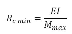
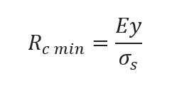
One essential thing to be considered when working with form-active structures achieved through bending, from a structural point of view, is the bending moment, as it is the most important value that can be related to moment of rupture. Given the fact that, as most wood materials, the mechanical properties of acacia reveal a compressive strength far lower that the tensile strength, Euler-Bernoulli beam theory will be used to identify the maximum bending moment associated to compression that an element can undertake while being bent1
This will lead to identifying the range of forms and curvatures available to the designer in the design process, allowing to impose certain limitation of the form finding method.
Initial studies were made on a 600 mm dowel with the cross section of 3mm. Using an iso geometric finite element analysis solver, the element was bent into multiple states. The bending moments associated to the different states of the element were extracted and compared with the maximum allowed bending moment in compression, using a visualization method. As can be observed in the figure, the orange colour marks sections of the element that are under more stress than the material can physically allow. From the 10 states that were achieved computationally, only 4 states can be achieved physically. The experiment was cross checked with physical experiments3
where σ
s - acacia compressive strength
y - distance from centreline to surface ( cross section)
I - second moment of area
M max - maximum moment at rupture
Associated to a chosen cross section of elements, knowing the compressive strength and material elasticity, a maximum bend before rupture can be identified using the resulted bending moment values.


Source
1. https://www.engineeringtoolbox.com/area-moment-inertia-d_1328.html
058 r obotic n omadism | material s Y stem
Same initial length Same cross-section Different curvatures 0.60 m 3 mm Different initial lengths Same cross-section Same curvatures 0.25 m 4.00 m 9 mm Same initial length Different cross-sections Different curvatures 2.00 m 3 mm 40 mm
059
Fig 03.01.07 - Associated geometrical and structural analysis values
Fig 03.01.06 - Physically achievable bend states
Horizontal displacement (m) Horizontal span (m) Vertical displacement (m) Heigth span ratio Maximim bending moment (kNm) Minimum radius of curvature (m) Tangent angle at anchor points (degree) 0.157 0.32 0.212 0,000101 0,000132 0,000157 0,000181 0,000203 0,000225 0,000245 0,000278 0,000312 51.3 0.189 0.45 0.165 65.2 0.209 0.61 0.139 75.9 0.223 0.74 0.121 85.6 0.233 0.96 0.108 94.6 0.238 1.2 0.098 102.9 0.241 1.6 0.09 109.9 0.240 3.4 0.079 120.7 0.234 0.485 0.418 0.339 0.30 0.242 0.19 0.143 0.069 00.07 130.7 1 2 3 4 5 6 7 8 9 10 20% 30% 40% 50% 60% 70% 80% 90% 100% 0.115 0.21 0,000069 0.305 36.1 0.541 10% breaking point 0.6 100% 0 0 0.11 0.15 0.19 0.22 0.21 0.23 0.24 20% 30% 40% 50% 60% 70% 80% 90% 10% 0% 0 0.485 0.418 0.339 0.30 0.242 0.19 0.143 0.069 0.541 Rupture occures before reaching the curvature Curvature not achievable Curvatures achievable within the elastic range of the material behaviour 0.000164 kNm M max 1 2 3 4 5 6 7 8 9 10 1 2 3 4 5 6 7 8 9 10
Fig 03.01.05 - Iso Geometric Finite Element Analysis - Legend includes maximum bending moment as limitation for form finding
moment and curvature relationshi P
In order to describe curvature, the term radius of curvature is used. The radius of curvature R is the reciprocal of the curvature. For a 2D element, like a curve, it represents the radius of a circular arc that has the property of best approximating the curvature at that specific point.2
Numerical analysis
The local radius of curvature of an elastica curve can be calculated knowing the bending moment at a specific point across the bent element using the relation:

is the point at which the value of the bending moment is the highest:
This lead to the observation that the minimum radius of curvature is a property of the curve that not related to the initial length of the bent element, but to the material properties. The minimum radius of curvature is a value that for a certain cross section, remains constant across length variation.
Structural analysis
From this we can understand that the minimum radius of curvature, which defines the point at which the curve present the most accentuated curvature
Using the same element cross section, elements with different lengths were tested in order to understand the relationship between the bending moment and the resulted curvature in the computational environment. FEA analysis revealed a small deviation between the values of the local minimum radius of curvature exhibited at the point of maximum bending moment. This was a result of small variation of the bending moment as the simulation was stopped on load case before the maximum bending moment value.
Robotic Nomadism | iN t R o 060
Same initial length Same cross-section Different curvatures 0.60 m 3 mm Different initial lengths Same cross-section Same curvatures 0.25 m 4.00 m 9 mm Same initial length Different cross-sections Different curvatures 2.00 m 3 mm 40 mm
061
Fig 03.01.09 - Associated geometrical and structural analysis values
Length(m) Horizontal displacement (m) Vertical displacement (m) Heigth span ratio Maximim bending moment (kNm) Minimum radius of curvature (m) Tangent angle at anchor points (degree) 0.472 0.076 0.004127 0.16 0.21 0.28 0.38 0.45 0.55 0.70 0.83 1.13 1.70 2.15 3.50 13.7 0.344 28.07 0.676 0.146 0.004241 0.384 36.5 0.844 0.239 0.0043 0.398 46.02 0.943 0.363 0.004418 0.39 58.43 1.045 0.473 0.004312 0.408 65.22 1.079 0.601 0.004364 0.414 74.09 1.045 0.737 0.004331 0.415 83.65 1.028 0.858 0.00424 0.428 90 0.87 Loadcase 6 10 15 22 26 31 36 39 43 0.989 0.00432 0.420 99.9 1 2 3 4 5 6 7 8 9 10 11 12 13 14 0.50 m 0.75 m 1.00 m 1.25 m 1.50 m 1.75 m 2.00 m 2.25m 2.50 m 0.650 46 1.107 0.00437 0.412 109.9 2.75 m 0.560 47 1.209 0.004228 0.427 114.42 3.00 m 0.372 48 1.304 0.004204 0.430 120.7 3.25 m 0.000154 49 1.370 0.004383 0.4130 130.7 Force (kN) 0.00284 0.00129 0.000755 0.000508 0.000366 0.000283 0.000231 0.000192 0.000169 0.000154 0.000136 0.000125 0.000124 3.50 m 0.241 0.036 0.15 0.004400 0.196 26.07 4 0.25 m 0.011 14 13 12 11 10 9 8 7 6 5 4 3 2 1 0 0.033 0.074 0.143 0.236 0.361 0.599 0.856 0.987 1.366 0.471 0.734 1.205 0 0 0.033 0.074 0.143 0.236 0.361 0.471 0.599 0.734 0.856 0.987 1.104 1.205 1.300 0.004437 kNm 1.366 M max
Fig 03.01.08- FEA Analisys- Minimum radius of curvature in relation to length
m inimum radius o F curvature
The minimum radius of curvature of a certain element cross section can be related to the maximum bending moment, but in the same time it can be calculated using the equation, independent of it:
considering complex structures. In the same time it can be a way of structural optimisation, as the appropriate cross section can be calculated for a desired curvature.
The bending moment can also be numerically calculated if considered necessary in the further form finding procedure.
This translates in the possibility of geometrically finding the minimum radius of curvature that a cross section can perform in relation to mechanical material properties (elastic modulus and compressive strength). This eliminates the initial need of FEA analysis for determining the eligible forms that can be produced physically.
Geometrically constraining the form finding process with a minimum curvature analysis can substantially reduce the analysis time when
The locally available acacia branch and root cross sections have been analysed to determine a minimum radius of curvature data base that can prove useful in the form finding process. The results are cross checked with FEA analysis to exclude errors.
062 r obotic n omadism | material s Y stem
Same initial length Same cross-section Different curvatures 0.60 m 3 mm Different initial lengths Same cross-section Same curvatures 0.25 m 4.00 m 9 mm Same initial length Different cross-sections Different curvatures 2.00 m 3 mm 40 mm
063
Fig 03.01.11 - FEA Analysis- Minimum radius of curvature in relation to cross section
Section diametre (mm) Horizontal displacement- Span (m) Vertical displacement (m) Heigth span ratio Maximim bending moment (kNm) Max moment before rupture (kNm) Minimum radius of curvature (m) Tangent angle at anchor points (degree) 0.373 0.806 0.001315 2.1 0.7 0.45 0.33 0.24 0.18 0.15 0.12 0.12 0.001253 0.284 1.045 0.737 0.004437 0.004331 0.415 1.394 0.631 0.010518 0.010366 0.545 1.589 0.538 0.020543 0.02023 0.679 1.759 0.424 0.048695 0.047482 0.906 1.847 0.343 0.095107 0.090353 1.150 1.889 0.295 0.164345 0.157444 1.357 1.928 0.237 0.260973 0.228435 1.707 1.928 Loadcase 47 36 26 19 12 8 6 4 4 0.237 0.389557 0.389081 1.709 1 2 3 4 5 6 7 8 9 10 6 mm 9 mm 12 mm 15 mm 20 mm 25 mm 30 mm 35 mm 40 mm Force (kN) 114.4 83.6 65.2 53 40.2 31.9 27.1 21.7 21.7 0 0.7830.000164 0.000094 0.236 50/no break 3 mm 130.7 0.0049 0.018 0.0522 0.121 0.366 0.872 1.790 3.284 5.6033 0.00038 1 2 3 4 5 6 7 8 9 10 0 1.92 1.88 1.84 1.75 1.58 1.39 1.04 2.00 0.37 0 0 0.23 0.29 0.34 0.42 0.53 0.73 0.63 0.78 breaking point for each section Same initial length Different cross-sections Different Minimum radius of curvature 2.00 m 3 mm 40 mm 0.80 M ma
Fig 03.01.10- Associated geometrical and structural analysis values
i nitial g ridshell s tudies
Because curves behave differently in an active bent structure than they do in a cantenary simulation, simple hanging chain methods of predicting behaviour would not suffice. Simply creating elastica curves mathematically would also lose accuracy, as the forces of neighbouring elastica curves change its form. Therefore, an initial study on how actively bent gridshells actuate, enclose space, and hold weight was conducted to determine the ideal pattern for gridshell optimisation.
Robotic Nomadism | iN t R o 064
a ctivelY b ent g ridshell
d e F ormed c urve
065 4m 1-3 cm of soil
point c om P ressive l oad a ctuation Force a nchor Point Freedom
until breaking
Breaking Point
t riangulation 1 1 cm soil


• Joints: 89
• Volume: 6.09 m3
• Cum. Length: 119.40 m
t riangulation 2 1 cm soil
• Joints: 4
• Volume: 4.94 m3

• Cum. Length: 85.55 m
Moment Calculation
t riangulation 3 2 cm soil
• Joints: 81


• Volume: 3.88 m3


• Cum. Length: 116.67 m

Robotic Nomadism | iN t R o 066
s tandard q uads 0 cm soil
• Joints: 45
• Volume: 6.62 m3
• Cum. Length: 54.74 m
d iagrid 3 cm soil
• Joints: 81
• Volume: 6.64 m3
• Cum. Length: 66.02 m
The diagrid structure was the most usable pattern in out initial studies because of its ability to hole 3cm of wet soil mixture. However, none of the forms were able to reach a height above 2m without breaking, so alternate methods of enclosing usable space would need to be performed.


s kewed q uads 0 cm soil
• Joints: 47
• Volume: 6.97m3
• Cum. Length: 65.58 m
067
l ocal material: date P alm F iber
lea F lets a vailabilit Y and P ro P erties
Fibrous and soft, the date palm trunk is not suitable as a structural material in construction. Its cellular structure makes flat sawing not a good option, and as a result, palm trunks are never used in the building environment. On the other hand, its leaves and fronds come as a well exploited regenerable resource. Often exploited for woven products, date palm leaves are a commodity due to their fibrous qualities1 .
Usually women into basketry and mats, the date palm leaves are intensely utilised by nomads for weaving their tent mats as they are strong in tension and due not lose their qualities with drying.
Every year under a normal growth rate is average conditions, a date palm produces between 12 and 15 new leaves, and consequently the same number of leaves can be harvested. Considering these quantities over thousand of trees, this can lead to a large available resource.
The leaves can be used in different ways according to the part that is used, but for weaving purposes leaflets are generally used. They can vary in length from 15 to 100 cm, being 1-6 cm wide. On the midrib of each leaf, the number of leaflets varies between 120 and 240.2
They are an accessible resource that does not necessitate intense labour, and can be easily collected and manipulated by hand, not needing additional tools.
Source
1. T. Odeyale and T. Adekunle, “Innovative and sustainable local material in traditional African architecture,” 2008
2. http://www.iranicaonline.org/articles/date-palm
068 r obotic n omadism | material s Y stem
Date palms can be easily found across Mali, especially is the proximity of oases.

069
Fig 03.02.01 - Gabra nomad carrying date palm mats
Two parameters are important to define the mesh properties: orientation and density
Taking into consideration that the material system uses a diagrid configuration, the mesh weaving orientation is discussed in relation to the pole orientation as well as the gravitational pull.
The mesh has two roles as an intermediary layer: it acts as cross bracing for the grid shell, conferring stability and rigidity to the structure, as well as acting as formwork for the following loam layers. The weaving orientation is important for both criteria. For the following layers, the horizontal weaving does not provide enough support.

For both criteria, the bidirectional weaving is the optimal solution as it offers enough strength hold earthen layers, and acts uniformly in both pulling directions, ensuring stability.


The mesh density affects proportionally the fabrication time and material quantity, in relation the strength it adds to the gridshell. The denser the mesh, the more material it requires, which result in a higher fabrication time, but in the same time more strength for crossbracing and a better defined formwork. The aim of this study is to identify a balanced solution between fabrication time and necessary stiffness. A 50% dense weave results in a sufficiently tense mesh as well as improved stability for the poles.
The mesh density has to also respond to the material viscosity and method of application on the mesh. Taking into consideration a viscous paste similar to plaster, the 50% mesh would provide enough support to ensure the continuity of an initial layer, as well as a good behaviour in supporting its weight.
070 r obotic n omadism | material s Y stem
grid bracing laY er su PP ort m aterial used F abrication time grid bracing laY er su PP ort m aterial used F abrication time grid bracing laY er su PP ort m aterial used F abrication time
weaving densit Y weaving orientation d
P
bidirectional weave vertical weave horizontal weave
Fig 03.02.02 - Physical experiments that test the mesh weaving orientation
ate
alm mesh
25 % densit Y
A less dense mesh provides the advantage of being time efficient in relation to the construction process
F abrication time
m aterial used
grid bracing
laY er su PP ort
50% densit Y
A less dense mesh provides the advantage of being time efficient in relation to the construction process
F abrication time
m aterial used
grid bracing
laY er su PP ort
90% densit Y
A less dense mesh provides the advantage of being time efficient in relation to the construction process
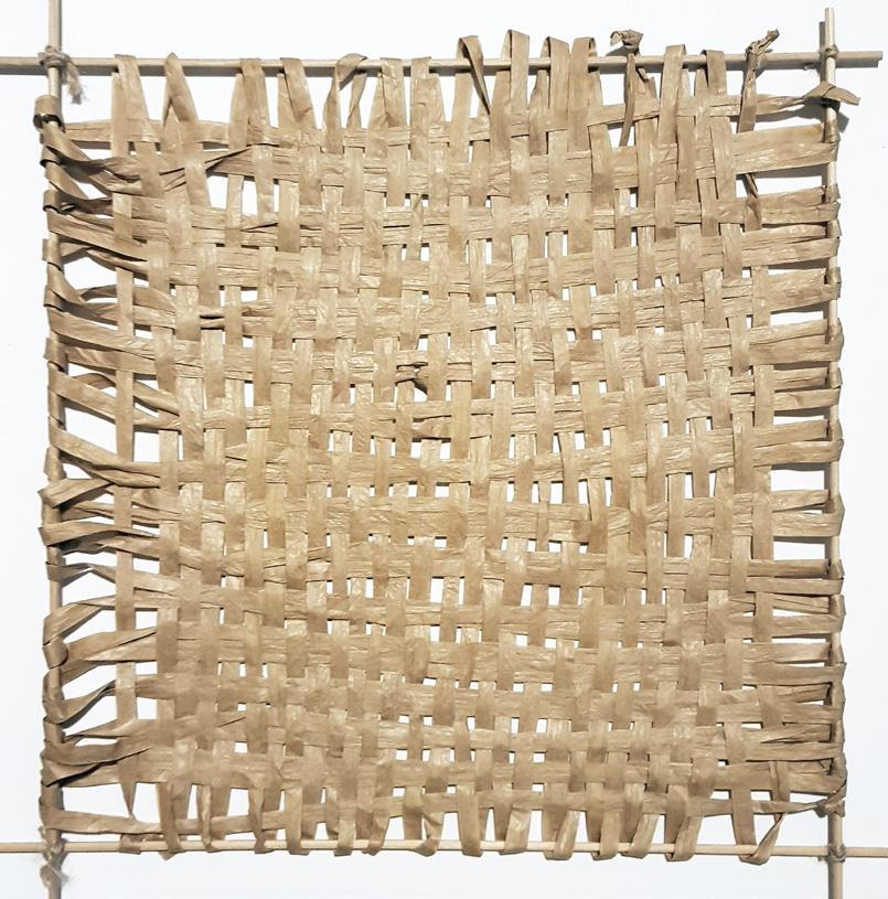


F abrication time
m aterial used
grid bracing
laY er su PP ort
071
Fig 03.02.03 - Material experiments for understanding the behaviour of different mesh densities
l ocal material: s oil
Earth has always been an important part of the material systems used in hot-arid and temperate environments. Even today, a considerable part of the world’s population inhabits earth dwellings1. While the popular perception associates earth constructions with poverty or low social class. It is one of the most sustainable building materials.
In developing countries such as Mali, the percentage rises over 50%, as the high requirements for shelter cannot be fulfilled by industrialised construction materials nor industrialised construction techniques. The high need can be met with the use of local material and do-it-yourself techniques. Earth is an appropriate material in this sense, as it can be easily manipulated with bare hands, without the need of specialised tools are time costly techniques.
Soil is made up of four basic parts: air, water, organic matter and minerals. Generally, the organic matter represents 2-5% of the total soil volume. Water and air can take up to 25 % each, and the remaining part consists of minerals2.

When talking about soil texture, it is relative to the proportion of minerals that it is composed of: sand, silt and clay. Sand are the largest particles and the greater the amount of sand in the mixture, the harder it is to be used in construction as it loses its ability to bound. Silt particles are much smaller than grains of sand but are still largely composed of quartz Clay particles are the smallest component found in soil, have a plate-like shape and contain larger amount of nutrients than sand and silt. Clay gives soil the texture that exhibits plasticity, the sticky feel when moistened and the ability to me made into firm casts that harden when dry.
The type of soil that is widely spread across Mali are entisoils. Entisoils, usually found in very dry or cold locations, are newly formed soils and their main characteristics is that they have little profile development. This means that the soil does not present different layers when analysed in a vertical section. When analysing the composition of entisoils, we can see that it remains constant even after 1 m of depth3. The particles that form the soil texture are uniform distributed. In the context of out study, this translates into an abundant source of building material, readily and easily available, for which little or no effort has to be done for processing, such as sifting and mixing.
Souce
1. Gernot Minke Building with earth, Birkhauser, Basel,2006
2. William Bleam, Clay Mineralogy and Chemistryin Soil and Environmental Chemistry (Second Edition), 2017
3.http://passel.unl.edu - accessed 10.06.2018
072 r obotic n omadism | material s Y stem
Fig 03.03.01 - Soil in Mali - Easily manipulated by hand even at higher depths
e
construction
soil texture and com P
osition
soil in mali
arth
The constant section makes material processing and gathering easier
According to the analysis done in 2 area in central Mali, the physical and chemical soil characteristics at 0 -20cm depth are as following:

Organic matter content 0.2-0.3 %
Clay content 10-20%
Silt content 1-2% Sand content 75-88% 1
These characteristics translate into the following range of possible soil textures: Loamy Sand, Sandy Loam and Sandy clay loam. As the clay percentage can be fairly low, the ability to become plastic when moist is reduced. Another factor to take into account is that the local variaty of sand is generally silica and quartz with a fine grain, which increases its ability to self-adhere
Earth is usually used for walling as its good behaviour in compression(36MPa) and low tensile modulus(1-3MPa)2 . Its structural properties are strongly related to density and clay content. The elasticity modulus usually varies between 1 to 6 MPa.
Due to the fact that local soil is composed of fine sand particles and a low percentage of clay, its structural capacities to carry load are reduced.
Local earth constructions use larger water content to ensure a fine paste and the necessary compactness to achieve higher densities and mostly used for lightly loaded one or two stories buildings.
1. Oxfam America Research Report- Mali Agricultural pilot soil baseline and background research, Dr. Daouda Sidibé, February 2013
2.Gernot Minke Building with earth, Birkhauser, Basel,2006
073
Source
Fig 03.03.02 - 12 types of soil texture - Identifying predominant soil texture in Mali
structural P ro P erties l ocal soil texture soil texture [High percentage of sand] soil texture in Mali > 1m 0 Clay Sandy clay loam Clay loam Loam Silt loam Silt Sandy loam Sand Silty clay Siltyloamclay Loamysand Sandy clay 10 0 90 100 80 70 60 50 40 30 20 10 0 20 30 40 50 60 70 80 90 100 10 0 20 10 10 10 10 10 10 10 10 Sil t percentage Sand percentage Clayp ercentag e Plastic behaviour The available material can vary in plastic behaviour
to clay
variation en tisoil [No layer variation in depth]
Fig 03.03.03 - Vertical section through entisoil - no layer variation
due
percentage
t hermal resistance
[Isolation for decreasing thermal radiation]
The thermal resistance of loam is low compared to other materials. Considering this factor alone, loam does not perform well without additional isolation
t hermal l ag
[Delaying thermal transition ]
Loam is well known for its thermal mass properties. Providing the needed amount of thermal lag delays the temperature build up, compensating its R-value


074 r obotic n omadism | material s Y stem
Fig 03.03.04- Thermal properties important when considering loam as a building material
+time Q 1 Q 2 <Q 1 therma l P ro P erties
therma l P ro P erties
When discussing thermal comfort, the thermal properties of a material, its capacity to attenuate the temperature variation and its performance in relation to heat flow in a building are determined by its conductivity (k-value), its density and the specific heat capacity. A typical k-value for mud bricks of thick loam mixed with cut straw is 0.53 W/mk and a time lag of 9-10 hours(REFERENCE!) In climates with high diurnal temperature variations, the properties of loam are more beneficial in comparison to concrete.
While thermal comfort is interrelated with many factors such as humidity and ventilation, and the thermal dynamics tend to be highly complex. Our study focuses on the following two main properties that characterise loam that solely depend on the outer layer of the construction and in affect directly indoor comfort: Thermal resistance and Thermal Lag
thermal resistance
Thermal resistance is the ability of a material to provide insulation. Low thermal conductivity, as a material property, can provide insulation by reducing the amplitude of thermal variations from the exterior environment, providing a more stable interior environment.
The thermal resistance is described in the building industry by using the R-value. Loam’s R-value is lower than concrete, which implies better performance in relation to its insulation properties. But even wide wall cross sections can not satisfy building regulation requirement alone, solely considering the R-values.
While being the most used, in the case of loam, thermal resistance cannot be considered without considering the added properties that thermal mass provides to interior comfort
thermal lag
Additional to thermal resistance, a high thermal storage capacity results in heat taking a longer span of time to pass through the material thickness. This property is referred to as thermal lag and represents the time delay for heat to be conducted through a material.
It is associated to thermal mass, a relation between specific heat capacity and mass, and it is fundamental when discussion about loam thermal properties as it describes the potential to attenuate high diurnal temperature difference. An element with high thermal mass will also have a high thermal lag.
Loam and building material fabricated with it have low thermal conductivity and a high specific heat capacity which translates in a large time lag and a low heat decrement. It is generally accepted that a minimum time lag of 1012 hours is the appropriate value to balance temperature variation, ensuring a balanced interior environment.
075
Considering the extreme temperatures that in May reach 45oC , with a constant diurnal temperature variation of more than 15oC , the local soil properties were used to determine the appropriate wall thickness necessary for good thermal performance in relation to the local climate.
Numerical calculations were done for different thicknesses ranging from 10cm to 40 cm. From a thermal resistance point of view as well as considering thermal lag, a thickness of 30 cm would be the necessary depth of loam for ensuring the optimal thermal performance. This thickness provides 12h time lag which is needed for hot summer conditions.
A 30 cm wall thickness, on the other hand, is not a desired solution, as the proposed material system does not require the earthen layer to have structural capacity and requires more light-weight options.
construction time
An important thing to consider for nomadic housing is the construction time necessary for erecting an inhabitable structure.
As the material system needs to provide easily deployable solutions, a 30 cm wall thickness is not a solution that be considered, as the more material is used, the more time it required for material collection, mixing and adding it to the structure, as well as more water needs to be engaged into the construction process, a resource that is extremely valuable in the area.
The goal of further investigation will be how to decrease construction time while providing the necessary level of interior comfort.
lo am P ro P erties related to local mali climate mali climate data dr
High material quantities imply additional problems to the construction process. The high density of loam translates into heavy weights, that need to be carried by the elastic grid shell and date palm mesh. Resulting in a need for a higher number of polls and a denser mesh, that increases the construction time exponentially.
A thick material layer of loam with 20% clay composition also requires longer drying times, which result is adding the layers vertically in a delayed sequence, to ensure the necessary level of stability equivalent to the water content. This can delay the construction time with weeks and even months.
Robotic Nomadism | iN t R o 076
45 40 35 30 25 20 15 10 J a n F e b M a r A p r M a y J u n J u l A u g S e p O c t N o v D e c
Y ing time and weight
Fig03.04.05 - Annual temperature variation in Timbuktu, Mali (min-max montly variation, oC)
Fig03.03.06 - Annual sunshine hours in Timbuktu, Mali (hours)
12 10 J a n F e b M a r A p r M a y J u n J u l A u g S e p O c t N o v D e c 8 6 4 2 0 70 60 J a n F e b M a r A p r M a y J u n J u l A u g S e p O c t N o v D e c 50 40 30 20 10 0
Fig03.03.07 - Annual rainfall in Timbuktu, Mali (mm)
loam thermal P er F ormance related to la Y er thickness
Admittance: 2.82 [W/m 2 /K]
Decrement factor: 0.84 [-]
Decrement delay 3.34 [hours]
k value: 56 [kj/ m 2 K ]
Weight 28 [kg]
Admittance: 3.08 [W/m 2 /K]
Decrement factor: 0.41 [-]
Decrement delay 6.27 [hours]
k value: 90 [kj/ m 2 K ]
Weight 70 [kg]


Admittance: 3.06 [W/m 2 /K]
Decrement factor: 0.16 [-]
Decrement delay 12.1 [hours]
k value: 112 [kj/ m 2 K ]
Weight 110 [kg]
[ 10 cm] [ 20 cm] [ 30 cm] [ 40 cm]


Admittance: 3.06 [W/m 2 /K]
Decrement factor: 0.06 [-]
Decrement delay 16.02 [hours]
k value: 112 [kj/ m 2 K ]
Weight 172 [kg]
077
Fig 03.03.08 - Thermal properties of loam for different wall cross sections. 30cm would be an appropriate thickness to assure interior comfort for the Malian climate
Identifying the gridshell areas most exposed to solar radiation in the local climatic conditions
c onditions considered
Solar radiation and solar exposure analysis have been done to determine de least favourable conditions that can occur in the local climate. The values are studied for the amount of daylight exposure that occurs on the hottest day of the year. This day varies across Mali, as for the norther part it occurs in July, for the central part in May-June and for the southern part in April1. For this study the central area was considered.
For each orientation, 3 types of surfaces were explored: a flat surface, a surface that has the minimum radius of curvature that occurs in a 20 mm diameter curved dowel and one respectively for the curvature of a 15 mm bent dowel. Each surface was tilted from 0 to 90 degrees to mimic its possible positions across a gridshell.

Source
1. https://www.climatestotravel.com/climate/mali
surface, the values are uniform across the entire surface, on curved surfaces, due to the variable angle at which the sun hits the surface, solar radiation values are distributed as a gradient. The northern facing side has more solar exposure as radiation and as sunlight hours.
When considering the least favourable conditions, the horizontal flat surface ranks the first, closely followed by the curved surfaces. This condition can only occur on limited areas of a grid shell, the geometry being optimal for minimizing solar exposure. Considering the relation between solar exposure and amount of radiation received, as well as the area they could occupy on a gridshell, the north and south 30 degree tilted surfaces are the least favourable conditions. These conditions occur at the highest points of the gridshell, and they also require the highest thickness of material, making explorations to reduce material usage essential for our study.
078
curvature and orientation 0o 30o 60o 90o South Flat Max curvature 20mm dowel Max curvature 15mm dowel North West 30o 60o 90o 30 60o 90o r obotic n omadism | material s Y stem
- Identifying least favourable possible conditions
079
North West East 30o 60o 90o 30o 60o 90o 30o 60o 90o Solar exposure 0o rotation 0o rotation 0o rotation 0o rotation north facade Orientation Curvature Rotation south facade west facade east facade 0o rotation 30o rotation 60o rotation 90o rotation 30o rotation 60o rotation 90o rotation 100% 50% 0% 1.305 kW Total solar radiation 0o rotation 0o rotation 0o rotation north facade Orientation Curvature Rotation south facade west facade east facade 0o rotation 30o rotation 60o rotation 90o rotation 90o rotation 0% 1.305 kW radiation 0o 30o 60o 90o South Flat Max curvature 20mm dowel Max curvature 15mm dowel North 90o
Fig 03.03.10
methods o F decreasing material usage
The use of air cavities can be similar to using an insulating material. As air has low conductivity, the air trapped between to layers can act as a barrier, limiting or inhibiting heat transfer. As heat transfers across air by conduction, convection and radiation, it is important to take into account the depth of the air gaps proposed.
Air gaps broader than 50 mm can in turn increase the heat transfer coefficient due to the convective heat transfer that occurs in addition to the conductive transfer.
increasing energ Y F low

Thermal lag is directly dependent on the depth of the outer envelope. In order to achieve the equivalent thermal lag to a depth of 30 cm using less material, the energy flow paths, meaning the continuous layer of material that travels form the outside to the inside can be increased in the horizontal plane.
Using this method, the same thermal performance can be reached with reduced vertical cross section dimensions.
Terraperforma is a research project that explores this property to achieve thermal performant walls.
Case study: Terraperforma, IAAC , OTF 2016-2017
For our study, multiple air gaps will be explored for ranging between 10-40 mm, to reduce the material needed to ensure the same thermal performance sel
Heat transfer reduction can be obtained by manipulating the outer layer and the way it interacts with solar radiation. While the amount of solar radiation that reaches the area cannot be reduced, its distribution across the surface can be designed to reduce the effect it has on the interior environment.
Higher levels of radiation can be absorbed at points farther away for the interior of the envelope, and self shade can be incorporated into the design in order to protect the more vulnerable areas of the exterior envelope at peak solar radiation hours.
Cactus species have adapted to hot arid environments by developing selfshading forms.
080
Fig 03.03.11 - Self shading patterns are common in local vernacular architecture
F - shading
P ath air ga P s
r obotic n omadism | material s Y stem

081
The methods proposed for reducing material quantity, while efficient from a thermal behaviour point of view, add extra complexity to the geometry, which if fabricated as a component, would require complicated moulds and add an additional fabrication process to the construction timeline. A different way to achieve such complexity is partitioning the geometry in vertical layers. The sum of all layers would create the necessary wall thickness while being able to more easily develop complex geometries. A layer-by-layer approach allows for a geometrical freedom of envelope design to be realised, the only restriction being that layers need to be selfsupporting during extrusion to avoid collapse.
Increasing the number of layers does add to the construction timeline, but in the same time allows for planned sequencing of deploying the layers, in which the gridshell can become inhabitable from day 01. Starting the layering process with a flat extruded layer that covers the entire span of the wooden structure and date palm mesh can ensure an enclosed secure place for the first night.
Allowing the necessary time for the initial layer to dry (one day) creates a more robust and rigid surface for the additional weight that the second layer brings to the structure.
Successive layers of hardened material eventually defines the final envelope geometry. Each layer adds additional thermal properties to the construction and the number of layers can be decided based on the season and length of stay at that particular place. The final envelope thickness can be realised in the timespan of a week and each layer can be customized to achieve the desired thermal performance, allowing having varied geometry as well as varied layer thicknesses.
Layering and sequencing the layer fabrication process reduces the drying time for each layer and ensure a rigid base for the following layers, limiting the possibility of collapse or major errors. It also permits a high degree of control during the on-site fabrication process, which is essential for nomadic construction as limited time for material deployment and repairs defines the process. Sources
082 la Y ering
l a Y er sequencing
l a Y ering r obotic n omadism | material s Y stem


04. fabrication
[Physical experiments in material behaviour and robotic fabrication]
084
085
extrusion gear mechanism
Extrusion is the process of pushing a material through a desired cross section. It has the advantage to provide a continuous, uniform and controlled material flow. It can be an easy construction technique to deploy material consistently and at higher rates. It can be realised using low tech tools, especially when the material used is loam. As the material is easily manipulated, does not need temperature variations during extrusion, does not cure and can be easily be mixed into a homogenous paste. Different types of extruders exist, having different performance in relation to the material used. The possible solutions are analysed in relation to the needs and limitation of nomadic remote construction.
t YP es o F extruders
Extrusion is characterised by two main factors: the shape of the orifice of the extruder and the underlying mechanism of extrusion. Specialised literature identifies 3 main types of extruders1 based on their mechanism of driving material flow through the nozzle.
screw mechanism
Using an Archimedes screw material is moved within the extruder. While this solution offers the best control over the quantity and flow speed of material extruded, and it does not need powerful motors for rotation, it also necessitates better calibration between the movement of the nozzle and the rotation of the screw. It needs a continuous material input and is more sensible to clogging.
Build using a stepper motor and a piston to push the material through the nozzle, the gear extruder is a balanced solution when considering material flow and extrusion speed.
The extruder cannot be adapted to a continuous material intake system, and the extrusion length depends on the extruder cylinder volume. The permanent need for material refill is a limitation when considering construction time.
The dimensions of the actual extruder are double in comparison to other solutions, as the piston need space to engage in its movement.
Pum P mechanism
The pump mechanism uses the pressure generated by compressed air as the main driver that determines the movement of material.
The extruder is composed of less elements having a simpler assembly process. The elements are also widely available, the only special requirements is to ensure the cylinder is a pressurized environment and that there are means of stopping and controlling the pressure intake.
A disadvantage is that is require a secondary machinery to generate compressed air. Due to its wide availability and easy assembly, our study further explores the pump mechanism.
086 04.01 r obotic n omadism | F abrication
extrusion
Source
1. Gibson I., Rosen D. W. and Stucker B., Additive Manufacturing Technologies, Springer, 2010
gear extruder screw extruder P um P extruder [stepper motor] [stepper motor] [air compressor]
Continous material intake is essential. Requires more calibration and control.


Increased motor power is needed. Extruder has increased size due to piston.
Availability of components, fast prototyping , sufficient pressure.

087
Fig 04.01.01 - Extruder typology based on the underlying mechanism
dimension dimension dimension Protot YP ing time Protot YP ing time Protot YP ing time max P ressure max P ressure max P ressure availabilit Y availabilit Y availabilit Y
SCALE DURABILITY TRANSPORTABILITY ADAPTABILITY CONSTRUCTION TIME AVAILABILITY SCALE DURABILITY TRANSPORTABILITY ADAPTABILITY CONSTRUCTION TIME AVAILABILITY SCALE DURABILITY TRANSPORTABILITY ADAPTABILITY CONSTRUCTION TIME AVAILABILITY
e xtruder design
Air compressor
Pressure regulator + Ball valve
Hose connection
female adapte r
PVC threaded cap
P VC 110mm plain socket
PVC 110 mm tube

P VC 110mm plain socket
Brass reducing bush
Ball valve
material extrusion
Brass reducing bush
Nozzle r=5mm
e xtruder design and assemblY
The extruder design is made entirely by parts that can be acquired in a common plumbing store. Most parts are threaded to reduce the risk of failure in high pressure conditions. A PVC pipe is the container that will hold the material volume. A threaded version of the pipe was not available and pressure rated glue was used for its assembly.
The assembly can be done entirely by hand, without the needs of additional tools and it can be assembled in 15 min.
A ball valve controls the on/of state of material flow using a handle. The nozzle can be easily unscrewed and replaced
088 r obotic n omadism | F abrication
Fig 04.01.02 - Extruder design and parts used for its assembly
Considering the of sand and clay compositions that can be found in the local soils of Mali, we experimented different percentages to determine an adequate mix for extrusion.
Using natural mineral modelling clay and fine sand at different percentages, maintaining the water content constant foe each test, the resulted paste was loaded into a hand extruder and tested for its behaviour. Higher clay percentages resulted in a more plastic behavior of the material flow
Higher sand percentages made the material flow during extrusion brittle and not uniform.
A 20% clay and 80% sand mix will be used for further experiments due to its adequate behaviour.
The past viscosity is sensible when considering water content. Varying the water content by 5 perfect can determine the paste to bee too liquid to sustain its extruded geometry or too viscous to extrude the nozzle. The amount of force needed to push the material through the nozzle increases exponentially with the decrease of water content.
The material becomes hard and bounds in the drying process, but it can be dissolved in placed in water again and the material does not cure.
While this makes the it very easy to be mixed an manipulated by hand, it also can present different paste viscosities within the same mix. This results in an unhomogenous material flow while extruding with the same force applied.
The mix viscosity was determined for achieving the best behaviour considering the following nozzle dimensions:
A round small nozzle ( r=5mm) This nozzle is preferred for testing as it does not require large amounts of material and the experiments can be performed for an 1:1 test.
A round large nozzle ( r=10 mm) - preferred initially for construction purposes


A round textured nozzle - as it presents the possibility of increasing layer self-adhesion and adhesion to formwork
A semi-circle textured nozzle - As it could create the same effect while being material efficient.
089
Fig. 04.01.04 - Types of nozzles explored
Fig04.01.03 - Material mix composition used for physical experiments in fabrication
round r=5mm round r=10mm textured 02 r=10mm textured 02 r=10mm nozzle w ater content m ix com P osition material viscosit Y 12% clay 25% clay 88% Sand 75% Sand 20% CLAY LOCAL MATERIAL DRY MIX 71.5% 1x 4x 2x WATER CONTENT 28.5% EXTRUDABLE MIX 80% SAND SAND CLAY WATER WATER SAND SAND SAND
e xtruder test - hand extrusion
exceeded pressure for existing travel speed
exceeded travel speed for existing pressure optimal speed/pressure balance
1 cm printed grid for measurement

initial extrusion tests
Initial tests have been done connecting the extruder to an air compressor.
The first tests did not use a loaded extruder, as they ensured the safety of its usage under high pressure. The extruder resisted to 10 bar of air pressure, and its possible fail point is where the PVC tube is glued to the connecting piece. Pressure rated glue was used. The extruder presented small air leakage, that does not represent an issue considering the rate of air intake. It actually is a well-received pressure release in case of extruder blockage.
Connecting a fully loaded extruder with the earth mixture to air pressure intake resulted in the following observations:
If the material consistency is too dense in relation to the nozzle, no material will be extruded.
If the pressure is higher than 2 bars, the extruder acts as a loaded gun and
presents a sping-back when extrusion ball-valve is released.
A constant material flow can be obtained using pressures between 0.5 -1.5 bars. The pressure determines the extrusion speed of a certain material viscosity. The extrusion speed needs to be related to the travel speed. Experiments done by hand lacked the consistency of travel speed.
An extrusion length test was done with a fully loaded extruder and a 5 mm radius round nozzle. 13.6 m can be extruded until reaching a critical material level, when the extrusion loses extrusion flow consistency and 14,95 m until the extruder is completely empty. These test also helped in approximating printing speed.
090 r obotic n omadism | F abrication
Fig 04.01.05 - Extrusion length texthand manipulation of extruder
low material level extrusion end extrusion start
critically
testing sa F et Y in relation to P ressure
a chiving material extrusion


a chiving controlled material F low

091
Fig04.01.06 - Testing extruder functionality
a dditive manu F acturing
Architectural Association, Digital Prototyping Lab Robotic Cell

Base CNC milled foam surface curvature equivalent to 15 mm bent dowel
Frame for height adjustment
Air Compressor
092 r obotic n omadism | F abrication 04.02
Fig 04.02.01 - Additive manufacturing experiment setup for thermal layer fabrication study
KUKA KR-60 6 DOF industrial robotic arm
10m Pressure Hose
Robot -Extruder attachment
3d P rinting
Printing techniques can provide very rapid construction times for producing certain geometries that usually require complicated moulds. Another advantage is that no additional cost is associated with customization and geometry complexity.
Considering the layering technique proposed for thermal and material efficiency, alongside the fact that gridshell geometry will be adaptable to family and community dynamics resulting in a range of possible forms, providing a tool for additive manufacturing is an efficient construction strategy for ensuring that the criteria for rapid construction, transportability and flexibility are ensured in remote locations.
An industrial robot is not yet an accessible tool to nomadic communities due to its high cost. High power necessitates a controlled environment and the increased weight making it not easily transportable suggest it no being a viable solution.
On the other hand, a KUKA R-60 being accessible to the Architectural Association students, it is an ideal tool for experimentation and understanding what can be obtained with a certain material in designing a fabrication process. Also, a further understanding of the needed degrees of freedom, the necessary precision, the payload involved and the requirements that a certain fabrication process actually requires can be abstracted from this experiment for developing a simpler, low-tech tool that better responds to the nomadic community remote construction needs.
Using the robotic cell and the KUKA KR-60 available at the AA Digital Prototyping Lab, the following experiment setup has been developed:
An air compressor is connected to a pressure regulator to ensure the adequate control of pressure intake in the system, connected to a ball valve for an on/off control. A pressurised 10 m hose connects the air source to the extruder, which is mounted on the robotic arm using a custom design toolhead attachment. A 50x50x50 cm wooden frame is positioned in front of the robot to ensure easy access of the extruder with minimum movements required. On the frame, a CNC milled foam to the curvature of a 15 mm bent wooden is positioned at a 30 degree tilt to mimic the gridshell geometry.
One student is controlling the air pressure levels and material on/off flow while the second student is controlling the robot movement.
093
ex P eriment setu P
e x P eriment tool - i ndutrial robot
t est 01_ extruder orientation
o bservations
For extrusion each surface design is translated into a tool path. Toolpath design is strongly influenced by the extruder orientation, as each orientation has different limitations. The first experiment tested two extruder orientations: one that follows the normal of the surface and a constant vertical orientation.
TEST 01_A
Orienting the extruder to the surface encountered situations when it was situated horizontally. Due to the extruder design, this favours the creation of air bubbles that determines extrusion failure. This could be overcome by introducing an intermediary piece between the pressurised air and the material, that acts as a piston. While this would decrease the possibility of air bubbles, it would also increase material refill time.
While extrusion could start at any point on the surface, the adherence between surrounding layers is not ensured.

TEST 01_B
The vertical orientation does provide a continuous material flow, until the point where the material levels in the extruder are critically low. The adjacent layers present a strong bound and the extrusion follows closely the surface curvature. The layers must always be deployed from the lower point following the vertical direction to avoid collapse.
As the first experiment failed within the first layers, and future failures are not easily avoidable, while the second test did not fail until low material quantities, further experiments will use a vertical extruder orientation.

094 r obotic n omadism | F abrication
Fig 04.02.02 - Flat layer experiment results with different extruder orientation set ups
The extruder orientation is important for determining the possible fabrication design
extruder oriented to sur F ace extruder oriented verticallY


095
Fig04.02.03 - Experiment calibration for the two orientations considered
extruder oriented to sur F ace
extruder oriented verticallY
Air pressure translates into extrusion speed. The air pressure needs to be calibrated to the printing speed
observations
The air pressure intake for extrusion is highly related to the material consistency. If the pressure is to high, the quantity of material that exits the nozzles increases – resulting in a higher extrusion speed. Having the same layer height, a higher pressure results in the layers changing their section, becoming elongated horizontally. If the extrusion speed exceeds the printing speed, the layer edges start to curl.
A comparative study has been set up, one running at 1 bar pressure and 50 mm/s speed and the other running at 2 bar of pressure and 100 mm/s speed. Both studied were run with the same toolpath and same material quantity. While a higher printing speed is desirable , the test show that more pressure, even if it completes the test faster, the resulted surface extrusion has less height due to the layer compression and more material usage.
As some layer variation can be seen in both tests,in a detail examination of the layers it can be seen that low pressure/low printing speed results in controlled extrusions, which is desirable as the surface continuity and consistency is needed for the following layer adherence.

The height difference from the two experiments makes the decision to continue experiments with a lower pressure and printing speed, the rational way to pursue further experiments to ensure surface consistency and precision of design

096 r obotic n omadism | F abrication
Fig 04.02.04 - Layering detail with different extrusion pressure intake
t est 02_ P ressure and s P eed high P ressure/s P eed extrusion low P ressure/s P eed extrusion
high P ressure/s P eed extrusion
low P ressure/s P eed extrusion
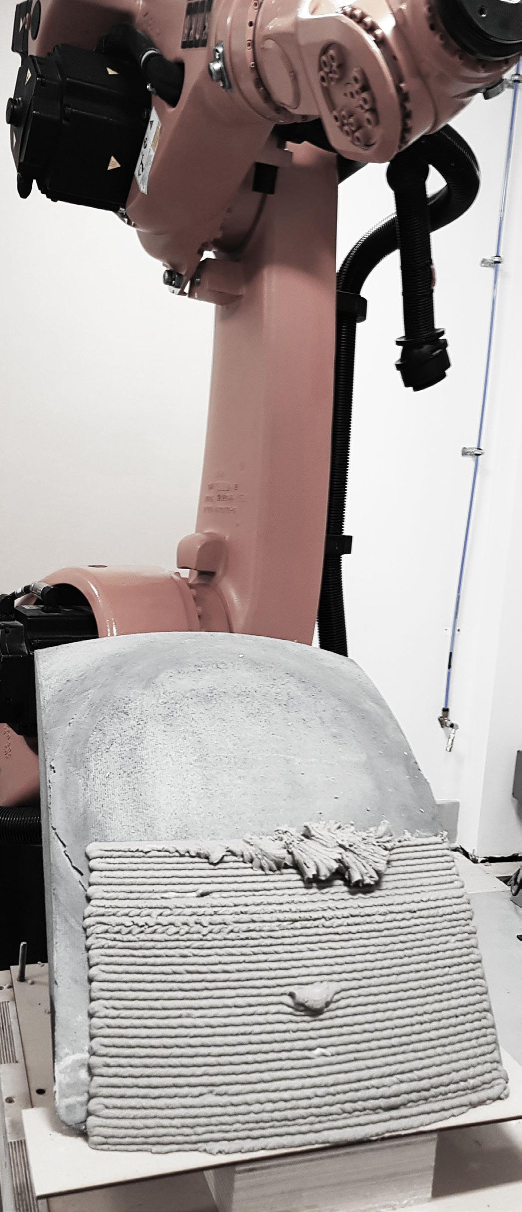

097
Fig04.02.05 - Extrusion speed/pressure variation - same material quantity used
test 03_ calibration and texture
observations
In order to ensure that consistent conclusions can be taken from the experiments, an extended patch should be analysed though different heights and curvatures of the base surface. The volume of the extruder related to the nozzle dimension and material consistency can be translated in tool path length into 20 tool path layers. The ability to stop extrusion prior to losing extrusion flow consistency is important. For each nozzle type, the tool path extent/extruder volume needs to be determined.
Material refill
Material refills take most of the experiment time as the extrusion time is extremely fast. To ensure rapid construction times, a continuous material flow intake system should be developed for on-site fabrication.

Nozzle and texture
The initial assumption is that a textured nozzle would provide a higher surface and layer adhesion, making the extrusion process faster and more relatable.
Running the same test with a round 5 mm radius nozzle we could identify extrusion errors related to material consistency and pressure variation. The chosen pattern elevates the variation, having more impact on the experiment result. The textured nozzle, for the first part of the experiment, the designed pattern was not obvious visually. The last refill, that may have a slightly different pressure/material composition variation, resulted in a better layer adhesion. While the result as a whole was more compressed, resulting in less height, and the surface variation is higher that round nozzle, it still provided a continuous functional layer. The variations did not influence the behaviour of the test as a whole.

098 r obotic n omadism | iF abrication
in relation to material quantity and nozzle
Fig 04.02.06 - Importance of understanding material quantity in relation to tool path length
Calibration
type
t ool P ath length calibration to material quantit Y


099
pressure 0.5-1 bar nozzle
Fig04.02.07 - Textured surface with nozzle variation - comparison
adhesion material
pressure 0.5 bar nozzle r=5mm pressure variation r ound nozzle test textured nozzle test
material refill layer height variation better layer
consistency variation
Experiment investigating material system fabrication issues related to additive manufacturing
observations
A patch test that simulates the proposed material system conditions was fabricated. Four 15mm diameter dowels, tied together 2x2 in perpendicular directions are interwoven with a raffia fibre mesh. The mesh is tied to a boundary frame to ensure the tension achieved in real grid shell continuity conditions. The mesh density is 50%. The frame is tilted 30 degrees to test adherence to frame.

A flat extrusion pattern tool path is adapted for the frame, ensuring an offset from the dowels. The offset considered had exaggerated dimensions, resulting in the layer imprecision along the vertical dowels. Adjusting the offset by 5mm would provide optimal results.
The printing process was not visibly influenced by the underlying mesh. The layers printed on the plain mesh are consistent and present a good behaviour in relation to adherence. The mesh can support the extra weight with limited


displacement considering a 30x30cm gap. Evaluating the backside of the mesh, no spillage or dripping can be seen. The material consistency is properly calibrated to the mesh density, air pressure intake and printing speed.
The experiment result is a success, taking in consideration also the result after drying. The printed layer adds robustness and rigidity to the surface, making it more stable to transport and manipulation, meaning it behaves well in eccentric load conditions.
In an on-site additive manufacturing situation, a depth sensor attached to the extruder nozzle can provide the right precision to adjust the extruder movement to the surface variation determined by the wooden dowels. Even without the proposed sensor, the layer variation is a functional layer that would not determine collapse.
100 r obotic n omadism | F abrication
Fig 04.02.08- 3D printing on dowel and mesh structure - detail study
la Y er detail dowel detail mesh detail
test 04 _ P roo F o F conce P t


101
Fig 04.02.09 - Comparative study between frame behaviour before and after earth layer
d owel and mesh F rame
m aterial s Y stem test
P atterns
Two types of pattern variations are considered in relation to self-shading and air gap creation
P atterns considerd
linear variation [Vertical] [Alternating] [Spiralling]
linear variation
Introducing surface variation is essential for developing an efficient layered thermal enclosure.

Starting from a flat layer tool path, certain points are chosen and moved in the surface direction without considering the vertical component of the vector, resulting is a linear variation pattern.
Linear variations present geometric simplicity, as the variation can be designed directly as linear tool paths. It is efficient if the offset distanced permitted by fabrication is not exceeded. The variation is uniform to the base surface on the decided linear pattern at the decided offset.
Introducing smoother variations tend to be difficult. This result is the first offset kink collapsing if pattern does not start at base layer. It does not mean that the continuity of next layers cannot be assured, but can result
in unplanned variations. Larger deviations from vertical patterns may be difficult and result is failure of the pattern. Horizontal patterned cannot be obtain due to lack of layer support.
Linear variation can produce 3 main types of patterns:
Vertical patterns are the most stable as they have constant vertical support. Alternating vertical patterns have potential when considering self shading, but more potential of fabrication failure. Spiralling linear patterns are the most prone to collapse is spiral inclination exceed layer thickness
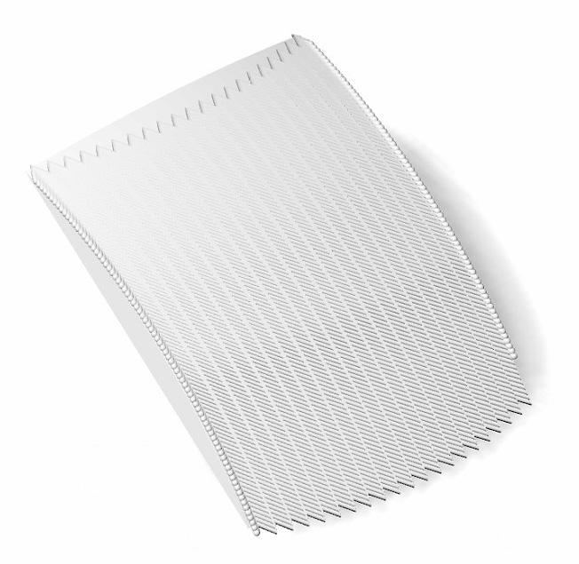

Robotic Nomadism | iN t R o 102 04.03
Fig 04.03.01 - Patterns considered for material experiments in relation to thermal performance
sur F ace variation
Surface variation patterns are designed as a geometrical manipulation of the base surface. The resulted surface is then divided in section lines for developing the extruder tool path.

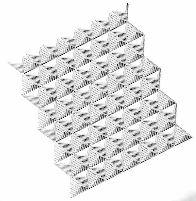
The supposed advantages of surface variation patterns are that the vertical variation can be more easily controlled to achieve a gradual variation. This would allow more complex patterns with the same amount of effort. Achieving a gradual variation would result is less failure.
The patterns explore take into account the potential of creating larger air gaps and varied self-shading patterns.
Two types of variation are considered:
Triangulations, as they can obtain a larger horizontal extrusion span by constructing gradual extending supporting layers.
Surface curvature is explored for achieving air gaps that act as bumps. Curved variations can better adapt to changes is orientation of curved gridshells, ensuring a gradual transition.
103
sur F ace variation [Triangulation] [Curvature]
Fig04.03.02 - Criteria considered for pattern success in relation to thermal comfort improvement
Pattern a nalY sis - criteria considered F or com P arison
Data calculated for the daylight hours within a day under extreme heat conditions
solar r adiation related to

[The amount of radiation is related to distance from interior surface ]
The distance that the thermal energy has to travel to reach the interior surface is calculated as a weighting factor
Providing less hours of sun exposure on surface result in a controlled distribution of solar radiation

shading P ercentage
[Calculating percentage of area shaded within daylight hours ]
104 r obotic n omadism | F abrication
vertical P attern analY sis c riteria considered
Solar radiation related to depth
A surface variation pattern does not reduce the amount of radiation that hits the surface, but it influences the way it is distributed across the surface. The amount of solar radiation received during the daylight hours is calculated I relation to the distance to the base surface, the energy path the thermal energy travels transforms into a desired time lag. The larger the amount of radiation is received on the farthest points from the base surface, the more successful the pattern is
Shading percentage
A shading percentage is calculated as a relation between the total amount of sun hours possible to the amount of sun hours that each point of the surface is actually exposed during the same amount of time.

A vertical pattern receives more amount of solar radiation compared to a flat layer. In the same time, the amount of sun hour exposure is substantially reduced, distributing the solar radiation at the outermost points of the surface. From these considerations, the layer does improve thermal properties.
The offset depth becomes very important in creating gaps and self shading, so a range of offsets should be considered.
105
Fig04.03.03 - Vertical pattern considered for analysis
A dense vertical pattern with an offset of 4 cm is considered as an extreme analysis condition.
vertical P attern
s hading - hourlY variation
Considered as a daily value, the self-shading percentage increased in a desired improvement. When analysing the hourly variation of the selfshading percentage, the conclusions are not as desirable as initially considered.
While self-shading is very efficient during morning and evening sun hours, that is also the time when the solar radiation received by the surface is low due to sun angles. At the same time, at noon when solar radiation peaks, the patterns exposes more surface to solar radiation than a flat pattern, and the percentage of shading is 0%
e FF
Y o F verical P attern
Considering the obtain data about self-shading and solar radiation exposure, the efficiency of the pattern is not remarkable. Further detailed studies should be done to conclude the thermal improvement of this pattern as an external layer.
The vertical layer, while it shows a slight improvement when acting as an exterior layer, can present a substantial thermal improvement when considered as an intermediary layer, as it can efficiently produce air gaps.
While the intermediary layers may be exposed to solar radiation several day during the finalisation of the construction, having self-shading properties and not increasing radiation intake is considered a plus.
v ertical P attern as intermediar Y la Y
er
As an intermediary layer, the vertical pattern has a very efficient behaviour as is responds to both methods of reducing material usage. It introduces air gaps on both sides of the pattern, doubling the number of air gap layers. On the other hand, it also creates longer energy paths to the interior surface due to its diagonal connections and its linear vertical connection with the outer and inner layer.
Different offset distances and densities need to be tested for fabrication limitations to ensure the possibility of its application on a gridshell geometry.
106 r obotic n omadism | F abrication
icienc
vertical P attern


107
[7pm] [7pm] [3pm] [12pm] [12pm] [6pm] [6pm] [9pm] [100%] [50%] [shading %]
Fig 04.03.04 - Hourly shading variation, study for vertical pattern
Investigating material capabilities to related to varied offset distances form the base surfaces
observation
The experiment investigates the material behaviour of the earth mix when the toolpath deviates from the base surface following a vertical pattern. A range of offset distances are tested for fabrication issues to determine a minimum and maximum range of usable offsets. The distances range form 1.8 cm to 4.2 cm, following the orientation direction of the surface while maintaining parallel to the vertical axis. The vertical rows have a 2 cm width and are spaced 4 cm apart.
Both experiments, even thou they has surface issues, did not present issues regarding pattern collapse or layer inconsistency. The offsets under 2.6 cm are not relevant to improving thermal conditions as the surface pattern resulted is not consistent enough to have self-shading properties or sufficient for creating air gaps.
The round nozzle test had considerable layering issues related to pressure and material consistency variation. The issues persisted for several layers, and self-regained the desired pattern as the material extrusion continued in
the vertical direction. It is desirable as it ensures that if issues due appear during the extrusion process, the pattern is not compromised and does not collapse as it can regain order after a few stabilizing layers. The texture layer did achieve a more uniform surface pattern in comparison to the round nozzle test. The textured nozzle is on the other hand highly influenced by the direction of printing, as it can be seen that the offset points do not perfectly overlap vertically, developing a zig-zag pattern. The textured extrusion does have a better layer adhesion and can easily overcome surface errors. On the other hand, it presents less possibilities of creating air gaps due to the variation in overlap. As it is not desirable for improving thermal conditions, it can be used to overcome fabrication errors of previous surfaces to ensure the continuity of the construction process. For both test, a larger offset from the surface is desirable. To ensure the desired air gaps, a larger width needs to be considered when designing the vertical rows to prevent layer self-intersection.


108 r obotic n omadism | F abrication
Fig 04.03.05 - Surface detail - same pattern,offset gradient form left to right. Different nozzles
test 05 _o FF set distance


109
Fig 04.03.06 - Experiment resultsoffset distance variation
vertical P attern variation round nozzle
vertical P attern variation textured nozzle
Fabricating a vertically layered thermal envelope - fabrication process and issues
observations
The layering test aims to prove the possibility of a vertical layering fabrication process realised in stages for developing a thermally efficient envelope. The test consists of two layers added subsequently.
The initial layer is a flat pattern extrusion, as initial layers need to ensure a uniform adherence and bound to the date palm mesh and create a robust and rigid layer to resist the weight of the following layers.

The second layer is a vertical pattern in which the spacing between vertical rows is reduced to a minimal connection to the base surface and allows the width of the rows to be large enough to produce desired air gaps for thermal performance. The minimal connection between layers reduces the area or thermal energy transmission, increasing the energy path.

The initial layer is left to partially dry, in order to maintain its geometry when the additional weight of another layer is added. Taking into consideration the hot arid climate conditions in Mali, the desired drying result should occur in a few hours. When sufficiently dried, the second layer can be deployed following the base one.
Small surface variations due to fabrication issues occurred in layer 01 does not affect substantially layer 02. The two layers adhere well together, even if they are at different moisture contents. The layers successfully act together when robustness and rigidity is concerned. The fabrication method can be easily deployed on site without noticeable fabrication issues or collapse, maintaining the designed thermal qualities.
110 r obotic n omadism | F abrication
Fig 04.03.07 - Layering experimentsurface detail
test 06 _ l a Y ering - P roo F o F conce P t


111
Fig 04.03.08 - Sequence of fabricationlayer 01 and layer 02
vertical P attern variation round nozzle
vertical P attern variation textured nozzle
Surface pattern could provide a better thermal performance, but are more fragile in relation to fabrication issues
solar radiation
Both considered surface variations layer areas present a gradual distribution of solar radiation across the surface, concentrated the received thermal energy on the outermost parts of the pattern.
Under this consideration, introducing surface curvature is a better solution as it allows for creating wider air gaps that increase the energy path and provide insulation. This logic is accentuated when considering the bumps as a geometrical transformation.
Triangulation only introduces small air gaps, but they are evenly distributed across the considered patch.
sel F shading
From a sun hours exposure point of view, the thermal performance of the two patterns differs drastically.
As curvature is only introduced locally, and the offset from the surface is relatively low compared to the area of surface that is displaced, the surface curvature variation does not provide the necessary self shading required.
Triangulation provides the highest amount of self shading as at most times on 50% oth the rows, one face of the small piramids that make the pattern is never exposed to sun , while the others are exposed to radiation only 50 percent of the day
112 r obotic n omadism | F abrication
sur F ace P atterns - thermal analY
sis
Total radiation 2,04 kW

Radiation/depth 0.02 kW/m

Shading 65 % Solar exposure 1-12 h
Total radiation 2,54 kW
Radiation/depth 0.022 kW/m


Shading 15 % Solar exposure 1-12 h


113
[Curvature]
Fig 04.03.09 - Surface pattern thermal capabilities analysis
[Triangulation]
Surface pattern could provide a better thermal performance, but are more fragile in relation to fabrication issues
observations
The base surface for the surface patterns explored is a flat surface tilted at 30 degrees. The base surface was chosen to reduce errors related to curvature. A triangulation patterns and surface curvature pattern are studied to explore the possibility of failure as the toolpath presents a gradual variation prone to collapse.
Both patterns introduce the possibility of creating ventilation gaps for improving indoor comfort.
The triangulation pattern is extruded without visible surface issues. It is a stable pattern that does not have the risk of collapse even when material mix does not exhibit consistency. The layers present a high level of selfadherence. More material needs to be used to cover the same amount of surface, this representing an undesirable feature.
The curvature pattern explored the possibility of creating of wave like variations with larger widths as well as larger air bump as a surface variation . Due to the material viscosity and the distribution of layer weight, the pattern did not maintain its desired geometry, the layers collapsing on the base surface.

An additional observation occurred while the test were drying. The flat surface did not allow enough layer adherence to the base surface, and the layers gradually compressed resulting in an undesirable behaviour. The sliding effect was especially visible for the triangulating pattern as it had more weight on a lower surface area. As a conclusion in this sense, curvature amplifying surface layer adherence, reducing errors and risk of collapse.
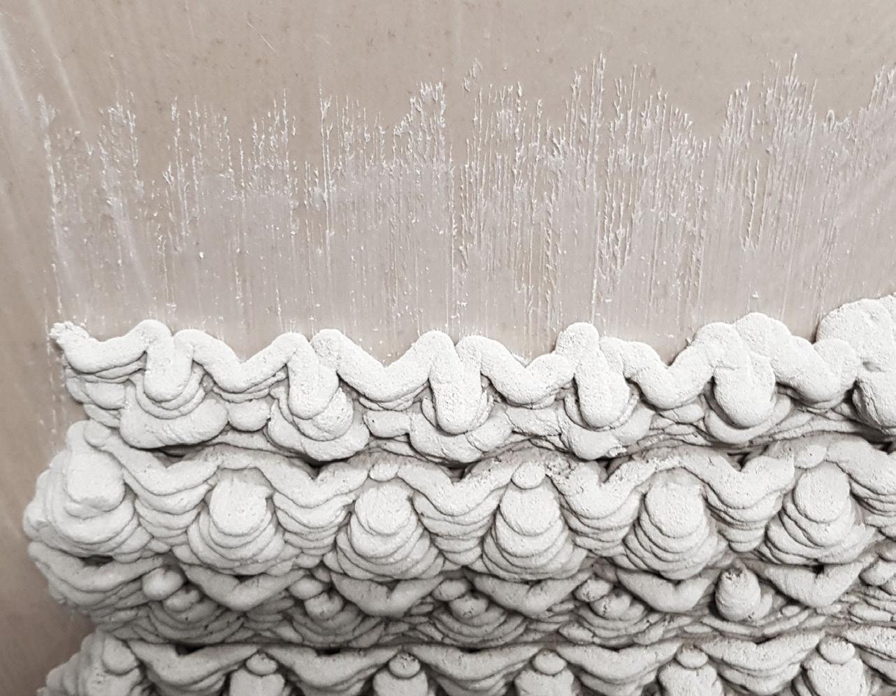
114 r obotic n omadism | F abrication
Fig 04.03.11 - Curved bumps did not maintain desired geometry - layers sagged
Fig 04.03.10 - Material sliding during drying
test 07 _sur F ace P atterns


115
Fig 04.03.12 - While at the moment of fabrication, the triangulation pattern suggested a good behaviour, both patterns failed to perform from a fabrication point of view
s ur F ace triangulation
su r F ace curvature
e FF icient P atterns
From the patterned explored, the three linear patterns had similar and also performant result for the criteria considered in this analysis.
As the data was gathered for an entire day and the analysis is done for the least favourable orientation, at 30 inclination, the patterns may behave differently if placed on the entire global geometry.
A factor that is visually present but has not been taken into account is how much the pattern density affect the results, as the density seen to range from high to low across selected patterns.
alternating vertical P attern
The alternating pattern is an improved version of the vertical pattern. It allows for more shade to be created and provide self-shading for more hours within the day
From the perspective of fabrication, it is prone to layer errors as some layers are not supported horizontally. In the same time, the failure of a vertical row would not affect the entire pattern, making it more resilient to on-site fabrication
s P iralling - inclination over 45 degrees
The spiralling pattern achieves the highest amount of self-shading making it extremely efficient as an outer layer.
It also has the geometrical advantage to be easily adaptable to different orientations and curvatures by varying the inclination of the spiral. The transition between variations can be smooth and a global geometry façade can be easily customized to ensure best thermal performance.
The spiralling pattern has the potential to be highly sensitive to surface variations and easily collapse. A physical fabrication experiment is essential for its consideration.
116 r obotic n omadism | F abrication
eFF icient sel F - shading P
atterns
vertical alternating P attern


s P iralling - inclination under 45 degrees
s P iralling - inclination over 45 degrees
Total radiation 2,33 kW
Radiation/depth 0.030 kW/m
Shading 54.4 %

Solar exposure 1-12 h
Total radiation 2,33 kW
Radiation/depth 0.029 kW/m
Shading 55 % Solar exposure 1-12 h
Total radiation 2,54 kW
Radiation/depth 0.030 kW/m
Shading 55.4% Solar exposure 1-12 h
117
Fig04.03.13 - Pattern tat have similar good performance as an exterior layer condition
test 08 _s P iralling P attern
The spiralling pattern inclination and offset is explored
observations
The spiralling pattern is 3d printed on a flat surface at a 60 degree inclination as increased inclination increases the changes of fabrication tolerances to sum up as the layering advances vertically.
The spiral inclination is 45 degrees and a variation of offset distance from the base surface is explored, ranging from 1.8 cm to 4.2 cm.
Two thirds of the extrusion process due not present any surface tolerances, as the layers adhere to each other as well as to the base surface. The inclination provides sufficient horizontal support as the offset layers overlap more than 50%.
After the last material refill, a height error determines the extrusion process to miss a layer, which influences negatively the entire patch.
As a conclusion, the spiralling pattern can be fabricated efficiently, but is more sensible to errors, which it hardly manages to surpass.
Visually analysing a detailed patch, we can see different degrees of self shading determined by the offset distance. Larger offset distances produce desired amounts of self-shading at the closest points to the underlying surface, realising an efficient distribution of radiation.
The spiralling pattern is the solutions that best performs as an external layer in relation to fabrication and thermal criteria considered in this study
To reduce the probability of failure, the pattern direction can be mirrored after a certain length.

118 r obotic n omadism | F abrication
Fig 04.08.14 - Varied degrees of self shading related to pattern offset distance from base surface


119
e xtrusion develo P ment s P iralling P attern
Fig04.03.15 - Fabrication stages and associated errors
120 05. c om P Utational e XP eriments
121
g enetic a lgorithm s etu P 1
c ombining di FF erent kinds o F bending
While large structures can create usable space with a gridshell made entirely of actively bent crossing members, smaller structures require a combination of actively bent and unbent members to enclose usable space. As seen in the initial gridshell tests, it is not possible to create a gridshell of entirely actively bent acacia wood poles and enclose space above 2.5m without the sticks breaking during its actuation. Indigenous examples of actively bent gridshell structures combine different types of bent and unbent members to enclose an adequate amount of space with the fewest amount of members. In the Gabra tent, a pre-bent beam is created by bending a tree branch while it is still wet, and letting it dry in the sun.. This bent member guides the shape of the gridshell, and makes it possible to tilt the actively
bent gridshell portion 30 degrees away from the ground. The portion on the other end of the pre-bent guiding curve is unbent, and simply used to prop up the gridshell. In this way, more space is enclosed than a structure which is comprised only of actively- bent beams.

In addition to this, the actively bent portion of the gridshell does not form a grid at all points within the gridshell. The areas where the poles cross create a flatter surface than the parts of the poles which are not crossing, meaning that extending the members within the gridshell beyond the area where the poles cross can create a dome-like structure which is raised into the air by the unbent portion.
Unbent nodes; however, do not have the same structural
Robotic Nomadism | iN t R o 122
actively bent pre-bent unbent
capabilities and benefits of an actively bent structure. They do not provide added compressive strength with few poles in the same way as a pure gridshell. Therefore, enclosing adequate space with the minimum amount of poles becomes an conflicting objective, as trade-offs between area and weight are made. In the forthcoming chapter, methods of gridshell optimization through genetic algorithms will be explored, as optimization criteria are applied to structures with a combination of pre-bent, unbent, and actively bent structures are made.

123
The four objectives for gridshell optimization were designed to make a structure which can carry wet soil, be assembled quickly, transported easily, and used. Therefore, minimizing wood poles is an objective set to minimize the amount of material carried from site to site. Joints are associated with construction time, as they are the most time-consuming portion of the erection process. Standing area is maximized in order to make the space usable and comfortable. Minimize breakage refers to the moment calculation near breaking after the weight of soil is applied to the structure.
s tanding a rea c alculation
MINIMIZE WOOD POLES MINIMIZE JOINTS MAXIMIZE STANDING AREA MINIMIZE BREAKAGE MINIMIZE WOOD POLES MINIMIZE JOINTS MAXIMIZE STANDING AREA MINIMIZE BREAKAGE MINIMIZE WOOD POLES MINIMIZE JOINTS MAXIMIZE STANDING AREA MINIMIZE BREAKAGE MINIMIZE WOOD POLES MINIMIZE JOINTS MAXIMIZE STANDING AREA MINIMIZE BREAKAGE POLE SPACING 10-50 CM GUIDE CURVE CHANGE ANCHOR POINT MOVEMENT TiILT GRIDSHELL 0°-45° UNBENT POLE SPACING 10-100 CM RAISE GRIDSHELL MINIMIZE WOOD POLES MINIMIZE JOINTS MAXIMIZE STANDING AREA MINIMIZE BREAKAGE POLE SPACING 10-50 CM GUIDE CURVE CHANGE ANCHOR POINT MOVEMENT ANCHOR POINT REMOVAL RADIUS ADJUSTMENT 2.5 m Robotic Nomadism | iN t R o 124 Creating and calculating objectives g enetic a lgorithm s etu P o b J ectives g enes o b J ective m atrix
c alculating Fitness o b J ectives
w eight aPP lied
The weight applied to the gridshells was simulated using the following equation, applying a Newton force to each node in the gridshell. The thickness of earth applied was 1cm, at a density of 1905 kg/ m3, to mimic the 80% sand soil when wet.
m inimize wood Poles
The length of each pole is calculated and multiplied by its density and cross-sectional area. This amout is added and set to minimize.
m aximize s tanding a rea
Usable space for this experiment setup is defined as all area above 2.5m, so that users can stand within the gridshell.
m imimize m oment
The moment for acacia wood sticks is defined as .016 kNm. This was applied to an structure which had undergone and active bending simulation. Because a small amount of moment stress actually improves a gridshell’s ability to carry weight, not all stress was deemed unwanted. The breaking point of acacia was multiplied by .75, and the node which were above this were included in the moment calculation. The overall sum of these was set to minimize, in order to prevent a structure which is close to breaking from being deemed successful. All simulations were run using k2 Engineering in grasshopper.

Moment Calculation Breaking Point
*
Number of Nodes
Density of Earth
Gravity * Thickness of Earth * Surface Area
125
i nitial ga s tudies & r esults
d ividing into two ga ex P eriments
The first set if genetic algorithm (GA) experiments were set up with a wide range of possible body plans in hopes of a variety of forms emerging. The result; however, was unsatisfactory. Because more formations of gridshell fail than not, over half of the gridshells created with random mutation were not able to actuate, and still passed on their genes.

In response, a filter function was created to negate forms which were not able to actuate, making all their fitness values unsatisfactory.
The first successful GA experiment showed a tendency to create two different types of forms: large and small. Neither were suitable for our purposes, but because there was this tendency, the GA was separated into two: large and small. The small forms could be simple dome structure, mimicking a tent or a hut, and the large forms would be informed by nearby permanent homes.

Robotic Nomadism | iN t R o 126
r emoving t he abilit Y to cull anchor P oints
Based on the initial grisdhell study, we saw that removing anchor points from a gridshell during actuation could improve structural performance. Applied to the GA without a guiding curve; however, resulted in table-like forms which were not able to perform in the two part system. Therefore, the gridshell was set to remain on the inactively bent guiding cure, and the guiding curve would have to be revised to suit the gridshell.


127
ga 1 b od Y Plan
Individuals Per Generation:
Number of Generations: 100 100
Elitism:
Mutation Probability:
Mutation Rate:
0.2 0.2 0.6 0.8
1. initial circle
3. select anchor points
2. adjust curve
+/- 0.5m
4. move anchor points
3-4m
Crossover: Robotic Nomadism | iN t R o 128
Based on lessons learned from initial GAs the starting radis of the gridshell was limited to stay within 3-4, and a guiding curve would emerge from the second actuation. All ends of the gridshell were o remain on the guiding curve in the final actuation, and inactively bent members supported the guiding curve.
0-2m 0°-45°
5. first actuation
8. second actuation
9. add pre-bent & actively bent members
7. add legs
129
6. rotate and raise gridshell
m inimize Joints
Fitness Values Excluding Culled Solutions
Standard Deviation Graph
Th filter method can be seen in the fitness values graph, where failed experiments hit the top of the fitness value chart, skewing the data. Once culled, there was improvement in 3/4 objectives over 100 generations.

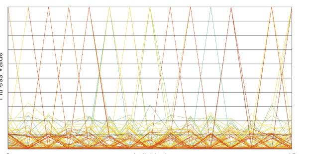


Fitness Values Including Culled Solutions
m inimize Poles
Fitness Values Excluding Culled Solutions
Fitness Values Including Culled Solutions
Standard Deviation Graph
Robotic Nomadism | iN t R o 130
m inimize m oment
Fitness Values Excluding Culled Solutions
Standard Deviation Graph
Because the area was set to a slim margin,, there was little room for improvement in the data, and the filter method skewed the SD graph significantly. The culled list of fitness values does show improvement over time in this arena as well.


Fitness Values Including Culled Solutions
Generation 100
Generation 0
m aximize u sable a rea
Fitness Values Excluding Culled Solutions
Fitness Values Including Culled Solutions
Standard Deviation Graph


131
Parallel c oordinates Plot


Most Repeated Second Most Repeated Third Most Repeated

Robotic Nomadism | iN t R o 132
Generation 0 Generation 100
Fitness c hart
Cluster of failed solutions
Maximize Area:


Minimize Moment Most Fit
Least Fit
c luster a nalY sis
Cluster 3
Cluster 2
Cluster 1
Minimize Joints
Minimize Poles
133


Minimize Joints Minimize Poles Minimize Moment Maximize Area 90-34 60-35 90-39 80-36 93-36 80-28 95-24 92-29 Most Repeated Cluster 1 Cluster 2 Cluster 3 Robotic Nomadism | iN t R o 134
c onclusions
All of the most fit values had a tilted gridshell, and scaled in their anchor points to early half of the original curve. a variety of areas were produced, which would be able to accommodate different needs for different users f the material system.

135
s ocial o rganization in l arger d wellings
h ousing Patterns
Because of this system, large, open floor plans that circular Organization of spacing in Indiginous west African housing

m ulti-FamilY s ettlment
first family courtyard second family courtyard shared family common area
single person’s dwelling shared livestock
Robotic Nomadism | iN t R o 136
m arried FamilY h ousehold
h ousing Patterns
To develop a larger household in the second genetic algorithm, the dwelling pattern above was abstracted into a series of intersecting circles, around which further internal divisions could be made. Each space was given a target area, but the radius of the guiding circle could grow or shrink 2m. This allowed a general form which provides adequate area to be enclosed by the gridshell, as well as offer some degree of freedom for the genetic algorithm to provide unique solutions.
Dimensions of abstracted floor plan, by circle radius:
a bstracted Plan
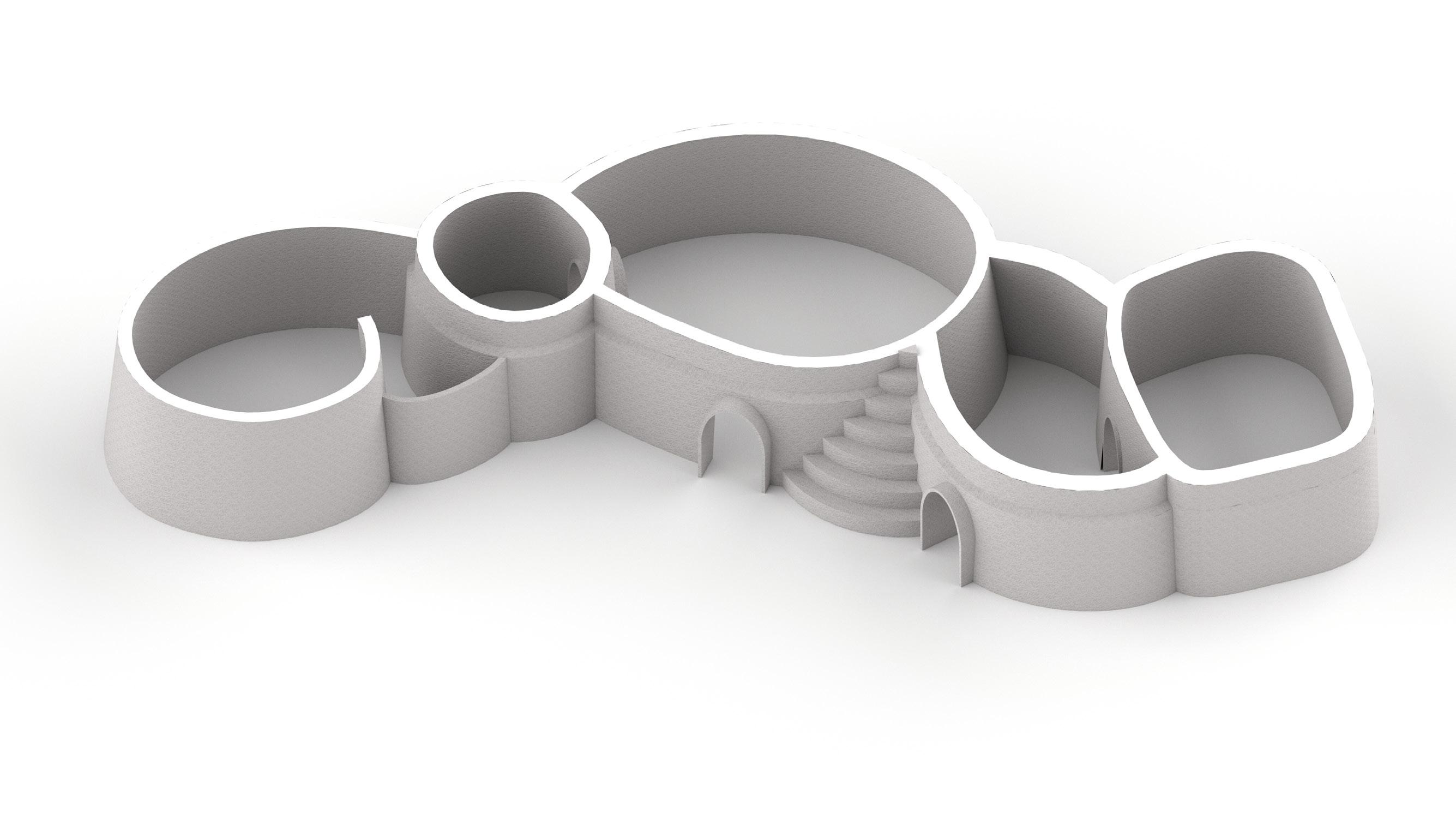
137
1. 3m
2. 2m
3. 4m
4. 3m
5. 2m
1. half open-air kitchen
2. grainery
3. married woman’s sleeping & work area
4. married man’s entry
1 2 3 4 5
5. married man’s sleeping area
Robotic Nomadism |
g enetic a lgorithm 2 s etu P
o b J ectives g enes
o b J ective m atrix
POLE SPACING
10-50 CM
MINIMIZE WOOD POLES
POLE SPACING
10-50 CM
MINIMIZE WOOD POLES MINIMIZE JOINTS
MINIMIZE WOOD POLES
GUIDE CURVE CHANGE
MINIMIZE JOINTS
GUIDE CURVE CHANGE
MAXIMIZE STANDING AREA
MINIMIZE BREAKAGE
MINIMIZE JOINTS
ANCHOR POINT MOVEMENT TiILT GRIDSHELL
0°-45°
MINIMIZE BREAKAGE
RAISE GRIDSHELL
UNBENT POLE SPACING
10-100 CM
MAXIMIZE STANDING AREA
ANCHOR POINT MOVEMENT ANCHOR POINT REMOVAL
Included on initial GA, Removed for the following GA
RADIUS ADJUSTMENT
MINIMIZE BREAKAGE
MAXIMIZE STANDING AREA
iN t R o 138
s ettlement architecture in n aironi

139


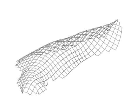


Minimize Joints Minimize Poles Minimize Moment Maximize Area 316-0 357-9 361-2 384-4 294-4 316-2 000 - 0 = Generation - Individual Robotic Nomadism | iN t R o 140 i nitial ga e x P eriments bod Y Plan m ost Fit
s tandard d eviations c onclusions r evisions
While there was success in the results of the second GA, the forms were not suitable for creating dwellings in a wattle and daub system. In the smaller rooms, the gridshell did not rise above 2m even in large forms. Removing anchor points also created large openings, which would require a large flat wall to cover.
Generation 1000
To amend the height issue, legs were added to the large structure in the same way that they were added in the first genetic algorithm. In addition, the anchor point removal feature was also removed, to ensure that resulting forms were enclosing space in a way that would provide thermally responsive shelter.
Generation 0
Minimize Moment Minimize Poles Maximize Area
141
Minimize Joints
Degree of Curvature
Radii Adjust 1-2 m from initial size
Set global curvature
Create Initial Boundary Smooth Boundary
Move Anchor points inward Add Legs
Robotic Nomadism | iN t R o 142
r evised b od Y Plan
Add Poles

Remove short edges, determine initial anchor points
Add inactive bent & unbent members

143
Spaced between 10cm & 50cm
Actuate Legs
Generation 100
o b J ective a nalY sis
m inimize Poles
Standard Deviation Trendline
Standard Deviation Excluding Culled Generations
Mean Values Trendline


Generation 0
Fitness Values Excluding Culled Solutions
Standard Deviation Including Culled Generations


Fewest Poles
Generation 12 - Individual 10
Fitness Values Including Culled Solutions
Robotic Nomadism | iN t R o 144
m inimize Joints
Standard Deviation Trendline
Mean Values Trendline Standard Deviation Excluding Culled Generations


Fitness Values Excluding Culled Solutions
Fitness Values Including Culled Solutions Standard Deviation Including Culled Generations
Fewest Joints Generation 67 - Individual 01

145
Generation 100
o b J ective a nalY sis
m inimize m oment
Generation 0
Standard Deviation Excluding Culled Generations
Fitness Values Excluding Culled Solutions
Standard Deviation Including Culled Generations


l east m oment Force
Generation 46 - Individual 01
Fitness Values Including Culled Solutions
Robotic Nomadism | iN t R o 146
Standard Deviation Trendline Mean Values Trendline
m inimize m oment
Standard Deviation Trendline
Standard Deviation Excluding Culled Generations
Mean Values Trendline


Fitness Values Excluding Culled Solutions
Standard Deviation Including Culled Generations


Fitness Values Including Culled Solutions
m ost usable area Generation 40 - Individual 01
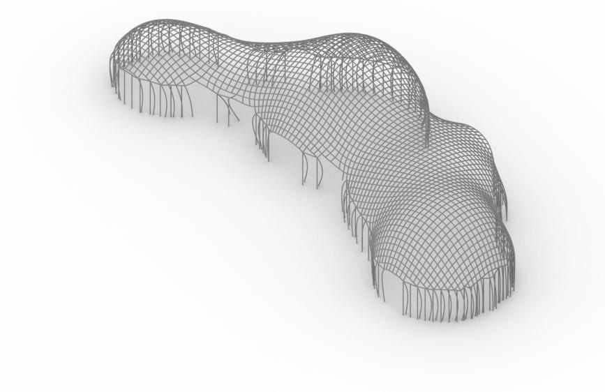
147
Fitness c hart a nalY sis
Results showed patches of areas with favorable usable area rankings,with little variation in the moment fitness. There seemed to be just very fit and medium fit values in area for most of the chart above a cerain threshold of joints and poles.

Fitness c hart
Minimize Moment
Maximize Area:
Least Fit
Most Fit
Minimize Joints
Minimize Poles
Robotic Nomadism | iN t R o 148
Two highly dense clusters formed near the Pareto front, showing similar forms with slightly different pole densities.


149
c luster 1 Generation 96 - Individual 01
c luster 2 Generation 98 - Individual 14
Cluster 1
Cluster 2
c luster a nalY sis
Parallel c oordinates Plot


Generation 100
m ost re P eated Form
Generation 95 - Individual 07
s econd m ost re P eated Form
Generation 80 - Individual 02
Generation 0
Robotic Nomadism | iN t R o 150
gene mean values rank 1


Generation 84 - Individual 08
gene mean values rank 2 Generation 87 - Individual 01
gene mean values rank 3 Generation 65 - Individual 05
151
Breaking Point
Moment Calculation

g eneration 12 - i ndividual 10 - Fewest Poles


g eneration 67 - i ndividual 01 - Fewest Joints
g eneration 46 - i ndividual 01 - l east m oment Force

Robotic Nomadism | iN t R o 152


153 2.5m 2.5m 2.5m
Breaking Point
Moment Calculation
g eneration 40 - i ndividual 01 - m ost area


g eneration 96 - i ndividual 01 - c luster r e P resentative 1
g eneration 98 - i ndividual 14 - c luster r e P resentative 2

Robotic Nomadism | iN t R o 154
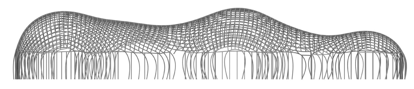


2.5m 2.5m 2.5m 155
Breaking Point
Moment Calculation


g eneration 84 - i ndividual 08 - gene mean values rank 1


g eneration 87 - i ndividual 01 - gene mean values rank 2
g eneration 65 - i ndividual 05 - gene mean values rank 3

Robotic Nomadism | iN t R o 156


2.5m 2.5m 2.5m 157
Breaking Point
Moment Calculation
g eneration 95 - i ndividual 07 - m ost re P eated Form
g eneration 80 - i ndividual 02 - s econd m ost re P eated Form
c onclusions
The repeated forms and the clustered forms in the simulation proved to provide the most usable shapes. A grid density of 30-40 cm was the most favourable, and forms with the least amount of global curvature were consistently repeated.


Robotic Nomadism | iN t R o 158


2.5m 2.5m 159
160 06. desi G n P ro P osal [clarification]
161
Analysing the way the solar vectors reach the global geometry design and how the solar radiation amount is distributed across the surface reveals the complex influence of surface curvature and inclination that elastic gridshell exhibit.
As a general statement, the solar radiation values decrease gradually from the upper part to the foundations, more accentuated curvature created a more accentuated gradient of values.

Curvature and inclination also influence self shading, but their relationship is not as direct.

In order to increase thermal conditions in the global geometry, the gradient of solar radiation must influence the way the selected pattern is applied to the surface.
As solar analysis simulation tools are not always accessible tools to onsite construction, the pattern is applied to the surface using the following parameters: surface curvature, surface inclination and orientation in relation to the sun position.

Robotic Nomadism | iN t R o 162
Fig 2.02 - Solar analysis result of a generic global gridshell geometry
analY sis on
geometr
solar analY sis - global geometr Y F lat la Y er Total radiation 112 kW Shading 41 % Solar exposure 1-12 h
solar
global
Y
sel F -shading la Y er
Total radiation 162 kW
Shading 78 %
Solar exposure 1-12 h
aPP lY ing sel F -shading P attern
The previous study identified the spiralling linear pattern as the most efficient when considering self-shading and solar radiation distribution while being also easily fabricated on-site.
The spiralling pattern also offers the advantage to be highly adaptable having the following parameters that define it: density and spiralling angle.
These parameters can be closely related to surface curvature,inclination and orientation , resulting in a customised self-shading pattern that respond to the gradient distribution of solar radiation and shading across the global geometry of the gridshell.


163
Fig 2.02 - Solar analysis affter aplication of customised self-shading pattern
o n- s ite a ctuation Process
Robotic Nomadism | iN t R o 164

165
s ettlement s cale
Tent arrangements are re-created in the similar formations at different locations, each demonstrating an adherence to social structures. The most elite family is the furthest west, and the rest of the families decrease in social standing as one travels clockwise. Fences constructed of brush enclose the settlement and livestock areas, and tents encircle the livestock area. At any size, the settlement maintains a burning fire in the very centre, which remains lit at all hours. This serves as a central meeting point, and is the place and community area.

In a similar fashion to Nankani social structure, nomadic settlements create a series of nested forms which carry different degrees of privacy. In Nankani housing, the most protected area is the grainery, and each form outside the grainery leads to a more public space. The most protected area in a nomadic settlement is the central fire, followed by livestock, then tents. Even within the camel enclosures, there is a nested form for young camel fowl, so that they are more protected than their stronger elders.
While many resources are communal, there are divisions and family ownership within nomadic caravans which are reflected in their settlement patterns. Each livestock enclosure has an opening which points to the family the livestock belongs to. If one circle grows beyond about 30 tents, a second form is created so that the camp can expand, but the most elite families do not have to resettle.
After a settlement is made, neighbouring clans can join the same settlement, pooling communal resources such as fencing, fire, and labour Camps always grow southeast for the same reason. If a small amount of nomads wish to join the settlement, they may have to set up camp outside of the enclosure until there are sufficient enough numbers to justify resettling the camp. In addition, to maintaining a consistent form, newcomers know where to settle their tents upon arriving.
Robotic Nomadism | iN t R o 166
settlement growth over time
smallest settlement, surrounding livestock as the settlement grows, the encampment expands southeast
a second camel form is created for as the first circle cannot expand further
a third camel enclosure is created to the east of the existing settlement
larger settlement with multiple enclosures
fence, made of dry brush
tent 2-5m in diameter
camel enclosure
camel fowl enclosure
central fire location (naabo)
0 5 10 25 50 100 distance (meters)
N N N N N N 167
07. on-site fabrication
[Fabrication tools and construction scenario]
168
169
r obotic n omadism | on-site F abrication
07.01
existing technologies

SCALE
DURABILITY
TRANSPORTABILITY
ADAPTABILITY
CONSTRUCTION TIME AVAILABILITY
arm-based
SCALE
DURABILITY
TRANSPORTABILITY
ADAPTABILITY
CONSTRUCTION TIME AVAILABILITY

SCALE

DURABILITY
TRANSPORTABILITY
ADAPTABILITY
CONSTRUCTION TIME
AVAILABILITY
170
Fig 07.01.01 - Evaluation of current on site additive manufacturing systems available
on-site additive manu F acturing technolog Y
Tecnalia /IAAC/ 2017 Tower Assembly/ Gramazio &Kohler Research Institute for Dynamic Systems and Control / 2011
Minibuilders /IAAC/ 2014
gantries
s Y stems multi-robotic P lat F orms
current situation
Mostly used in controlled indoor environment
System use adapted off-the-shelf multi-purpose tools
Issues occur on site due to positioning, terrain and calibration tolerances
gantries
Gantries are a low tech on site additive manufacturing system, as they require only 3 linear axis of movement powered by stepper motors and an initial calibration test.
On the other hand, gantries used in construction need an installation footprint larger than the design proposed for construction, resulting in large and heavy equipment that cannot be easily transported due to its volume.
Initial calibration and equipment set up require an extended period of time, and taking into consideration that our material system requires printing on an existent geometry, the calibration becomes a highly difficult process.
arm-based s Y stems
Arm-based systems are intensely explored in academia and in the building environment as construction tool. Most arm-based systems explore the use of industrial robots, which are robust and heavy technology that has a large range of capabilities.
While they are perfect tools for an indoor controller environment, when the need for ease of transportation and mobility during the fabrication process is evoked, the explorations are still not conclusive as a desirable solution that could be integrated into the construction industry has not been developed yet.
Arm-based systems can be easily adapted to different fabrication techniques and present the advantage to be easily packed and shipped to any location, making them an possible solution for remote locations
multi-robotic P lat F orms
Multi-robotic platforms are composed of several robots that collaborate into achieving a designed goal. They have the advantage to be extremely small and light in comparison with other building equipments. They can also adapt to various ranges of design as their strength lies in not being fixed to a certain location.
A multi-robotic platform would ideally be the best fabrication tool considering the need of the nomadic community and the requirements of the material system. On the other hand, the technology is not yet developed, as there are no functional designs that could perform on-site. Most issues are regarding their need of a central system for communication and multiple sensors on each robot as well as a global sensor for location. Considering the layer deployment on an existing surface, an adequate gripping system that could be used for our material system was not identified.
171
d emocratization o F technolog Y
Powerful technology is becoming more and more accessible, providing opportunities of developing new methods for problem-solving
[accessible table top robotic arm] [kits of parts thats self-replicate] [online open source instructions]
Robotic arms are becoming very accessible to the general population
A movement that started with a 3d printer that was shipped as a kit of parts that can fabricate the parts needed for a new printer
Online open source platform for sharing instructions for developing robots
a ccesible robotics

Technology is becoming more and more accessible to the general population. Robotics was a close field that was only dedicated to specialised professionals, but in recent years more and more easily accessible devices and interfaces are being developed.
One example is Eva1, a desktop robotic arm developed by Automata (Mostafa ElSayed and Suryansh Chandra) can be purchased with little resources and encourages small business owners to incorporate automation in their process.

The Reprap movement opened the field of robotics to customization and reproduction , developing a kit of parts for assembling a 3d printer and the same kit of parts could be produced aging with the assembled printer.

The online open source movement encourages sharing and mass improvement of technology, and here an important online platform worth mentioning for the field of robotics is instructables.com . The platform offers a space for people to share detailed step by step instruction and plans that anybody can use to reproduce or to develop their own prototype.
Considering the general direction of the field towards democratization and open access to automation and robotics, our study proposes incorporating robotic fabrication into the construction process as the scenario can be easily implemented even in remote areas of Africa. This could provide improved self-sustainability of nomadic communities, as well as empowering them by creating new opportunities for growth.
Source
1. https://automata.tech/ - Accessed 10.09.2018
2. https://reprap.org/ - accessed 10.09.2018
172 r obotic n omadism | on-site F abrication
07.02
Fig 07.02.01 - Methods that brought technology closer to the general population
nstructables
eva r e P ra P i
industrial robot tool requirements s im P li F ied tool [complex machinery] [for desired task] [efficient tool for considered criteria]
Industrial robots are well known for their multi-purpose design and capabilities
The proposed fabrication process imposes certain specific requirements for the tools capabilities


a dequate tool F or F abrication needs
Using an industrial robot for physical fabrication tests offered a high degree of freedom to the experimentation process. While this is desired in a research environment, it is not necessary optimal for a construction scenario.
A more complex tool means that it needs more resources for its development and fabrication, it can translate into larger weight and robustness, more complicated software and interfaces, higher difficulties in calibration and other factors.
Understanding the requirement that are needed in the proposed process is key to assuring that the tool used is adequate for the process, but also for the users that will engage in controlling it.
Once the requirements that are used in the designed fabrication process are understood, they can be abstracted and compiled for the development of a more simpler tool that responds better to the needs of the user.
By taking into consideration only the needed requirements, a more accesible and efficient tool can be designed
The physical fabrication experiments done with an extruder attached to an industrial robot and powered by an air compressor revealed that the tools we were using were much too powerful for the actual needs of the process: The air pressure needed is maximum 1 bar, pressure that a foot pump or a small tire compressor can provide. The compressor used was capable of 10 bar
The material flow needs to be continuous for time requirements, meaning that the only thing that the robot need to manipulate is a nozzle, without the load of the material, that would be provided externally. The Kuka could carry a 60 kg payload.
Only two types of movement need to be ensures: The nozzle moved in curved horizontal lines along the base surface and vertically when advancing an layer. The nozzle is always oriented vertically. The 6 DOF the industrial robot provides are not needed.

173
Fig 07.02.02- Understanding tool specific requirements for the fabrication process
ing robotics
tool requirements - sim P li FY
robotic tool d esign
The robotic tool is in itself composed of multiple components that respond to the performance needs of the tool.
better layer adhesion
layer height variation
nozzle connected to continuous material flow
material refill
continous material F low
Providing continuous material flow is essential for developing a time efficient process as constantly refilling the extrudes was labour and time intensive.
The easiest and low-tech solution to respond to this problem is looking into cement spraying and mortar spraying devices. They are usually composed of a container that at its bottom has an pressure inlet. As the own weight of the material pushes it down, its is directed using pressure to the nozzle. this permits a continuous refill of the container without stopping the printing process.
The containers is positioned in such a way that, when full, uses the material weight as a stabiliser for an extended forward robotic arm.
The larger the robotic arm, the harder it is to manipulate, being less stable and precise. Also increasing dimensions adds to total weight and volume making it harder to transport.
As the gridshell dimensions need higher working areas, a scissor lift is proposed as a response to that problem.
All the components, together with the robotic arm are placed on a mobile platform, to ensure ease of transport between locations but also between printing positions.

174
07.03 r obotic n omadism | on-site F abrication
P onents
com
li F t mobile P lat F orm
Fig 07.03.01 - Configuration of robotic fabrication tool
scissor
*Industrial robot model is only used for visualization purposes
scissor lift
tool working area and P ositioning


175
Fig 07.03.04 - Mobile platform with scissor lift and material container detail
Fig07.03.03 - Robot positioning. Multiple positions along gridshell
Fig 07.03.02 - Symmetrical material deployment to avoid unwanted displacement
*Industrial robot model is only used for visualization purposes position 01
Mobile platform detail
position 02 position 03
07.04
F abrication sequence
The on-site fabrication process takes place in two stages. In the first stage a secure shelter is established while in the second stage the shelter is transformed into thermally efficient housing.
STRUCTURE
DATE PALM MESH WEAVING THERMAL LAYER 01 EXTRUSION
THERMAL LAYER 02-04 EXTRUSION

MATERIAL GATHERING (BRANCHES + ROOTS)
GRIDSHELL ASSEMBLY
CROSS BRACED STRUCTURE AND FORMWORK
IMPROVED THERMAL COMFORT INHABITABLE STRUCTURE
176 r obotic n omadism | on-site F abrication
Fig 07.04.01sequence
Fig 07.04.02timeline
GRIDSHELL ASSEMBLY
) MESH WEAVING
MATERIAL GATHERING (DATE PALM

177
Fig 07.04.03 - Stage 02 fabrication sequence
Fig 07.04.04 - Stage 02 fabrication timeline
INHABITABLE STRUCTURE
EXTRUSION FINAL DESIGN GRIDSHELL ASSEMBLY STRUCTURE MATERIAL GATHERING (BRANCHES + ROOTS) GRIDSHELL ASSEMBLY MATERIAL GATHERING (DATE PALM ) MESH WEAVING SOIL MIXING ARRIVAL ON SITE 1h 2h 3h 4h 5h 6h 7h 8h 9h 10h 11h SECURE SHELTER THERMAL LAYER DRYING TIME CROSS BRACED STRUCTURE AND FORMWORK THERMAL PERFORMANT ENVELOPE IMPROVED THERMAL COMFORT INHABITABLE STRUCTURE DATE PALM MESH WEAVING THERMAL LAYER 01 EXTRUSION THERMAL LAYER 02-04 EXTRUSION SELF-SHADING LAYER EXTRUSION THERMAL LAYER 03 DRYING TIME THERMAL LAYER 02 DRYING TIME SECURE SHELTER 1 day 2 days 3 days 4 days THERMAL EFFICENT HOUSING SHELF SHADING LAYER DRYING TIME
THERMAL LAYER 01

Robotic Nomadism | iN t R o 178

179
180
181
07. references
182 r obotic n omadism | re F rences
bibliogra P h Y
domain
Traditionalism
1. Alsayyad, Nezar. “Dualities in the Study of Traditional Dwellings and Settlements.” In Dwellings, Settlements, and Tradition. Lanham, Maryland, USA: University Press of America, 1989.
2. Bourdier, Jean-Paul, and Nezar Alsayyad. Dwellings, Settlements, and Tradition. Lanham, Maryland, USA: University Press of America, n.d.
3. Jean-Paul, Bourdier. “Reading Tradition.” In Dwellings, Settlements, and Tradition. Lanham, Maryland, USA: University Press of America, 1989.
4. Larsson, Anita. “Traditional Versus Modern Housing in Botswana -an Analysis of the User’s Persepective.” In Dwellings, Settlements, and Tradition. Lanham, Maryland, USA: University Press of America, 1989.
Mobility is West Africa
1. Alidou S M, “Cross-border transhumance corridors in West Africa”, CapEX Report, 2016
2. Bendandi B, Venier M, “Vulnerability and Resilience in West Africa: Understanding Human Mobility in the Context of Land Degradation”, KNOMAD, 2017
3. Catley A, Scoones I, Lind J(ed.), “ Pastoralism and Development in Africa: Dynamic change at the margins”, Routledge, 2013
4. De Haan C., Steinfeld H., Blackburn H., “ Elevage et Environnement. A la recherche d’un équilibre”. FAO, 1999
5. ECOWAS, CSAO/OECD, “Elevage et marché régional au Sahel et en Afrique de l’Ouest. Potentialités et défis”, Editions Club du Sahel et de l’Afrique de l’Ouest/OCDE, 2008
6. “EU Support to Mobility and Migration within West Africa”, Strategic Steering Committee, Factsheet, Brussels, 2015
7. OECD/SWAC, “An Atlas of the Sahara-Sahel: Geography, Economics and Security”, West African Studies, OECD Publishing, Paris,2014
8. OECD/SWAC, “The African Approach on Migration”, in West African Mobility and Migration Policies of OECD Countries, OECD Publishing, Paris,2008
Remote Construction
1. Jode H de (ed.), Modern and mobile: the future of livestock production in Africa’s drylands, London: IIED, 2009
2. Fosters and Partners, Rwanda Drone Port - data retreive from: https://www.fosterandpartnerscareers.com/ - accessed: 10.09.2018
Dessert dwellings
1. Haiman, M. “Dating the Agricultural Terraces i the Southern Levantine Deserts - The Spatial-Contextual Argument.” Journal of Arid Environments, January 3, 2012.
2. Lotfalikhani, Elahe, and Ahmad Danaeinia. “Typology of Architecture of the Stone Caravansersis Od the Seljuk Period in Qom Province.” International Journal of Applied Arts Studies, April 16, 2017.
Construction as practice
1. Bourdier, Jean-Paul, and Trinh Minh-Ha. Vernacular Architecture of West Africa: A World in Dwelling. Routledge, 2011.
2. Cowan, Gregory. “Nomadology in Architecture: Ephemerality, Movement, and Collaboration.” University of Adelaide, 2002.
3. Eglash, Ronald. African Fractals: Modern Computing and Indigenous Design. New Brunswick, Canada: Rutgers University Press, 2004.
4. Eglash, Ronald. African Fractals: Modern Computing and Indigenous Design. New Brunswick, Canada: Rutgers University Press, 2004.
5. Linzey, Michael. “Speaking To and Talking About: Maori Architecture.” In Dwellings, Settlements, and Tradition. Lanham, Maryland, USA: University Press of America, 1989. Morgan, William. Earth Architecture. Gainesville, FL, USA: University of Florida Press, 2008.
6. Oliver, Paul. “Handed Down Architecture: Tradition and Transmission.” In Dwellings, Settlements, and Tradition. Lanham, Maryland, USA: University Press of America, 1989.
7. Prussin, Labelle. African Nomadic Architecture: Space, Place and Gender. Smithsonian Books, 1997.
183
8. Rapoport, Amos. “On the Attributes of Tradition.” In Dwellings, Settlements, and Tradition. Lanham, Maryland, USA: University Press of America, 1989.
9. Tuan, Yi-Fu. “Traditional: What Does It Mean?” In Dwelling, Settlements, and Tradition. Lanham, Maryland, USA: University Press of America, 1989
m aterial sY stem Acacia
1. Acacia availability in Africa. Data retrived from : https:// hort.purdue.edu/newcrop/duke_energy/Acacia_tortilis.html - accessed on 06.06.2018
2. Acacia mechanical properties.Data retrieved from : http:// www.worldagroforestry.org - accessed : 23.06.2018
3. Elastica curve - mathematical definition . Source: https:// www.mathcurve.com/courbes2d.gb/linteaire/linteaire.shtml - accessed : 20.07.2018
4. Harris, R., Romer, J., Kelly, O., & Johnson, S., “ Design and construction of the Downland Gridshell”. Building Research & Information, 2003
5. Levien, R. , “The Elastica: A Mathematical History”. University of California, Berkeley, 2008
6. Lienhard, Julian. “Bending-Active Structures: Form-Finding Strategies Using Elastic Deformation in Staitc and Kinematic Systems and the Structural Potentials Therein.” University of Sttutgart, 2014.
7. Kelly O.J., Harris R.J.L, Dickson M.G.T and Rowe J.A,. “Construction of the Downland Gridshell”, The Structural Engineer, Vol. 79, No. 17, 2001
8. Kuijvenhoven, M., & Hoogenboom, P. C. J. “Particlespring method for form finding grid shell structures consisting of flexible members”. Journal of the International Association for Shell and Spatial Structure, 2012
9. Moment of inertia- mathematical formulas . Source: https://www. engineeringtoolbox.com/area-moment-inertia-d_1328.htm - accessed : 13.07.2018
10. Simitses, G.J. ,Hodges, D.H. “Fundamentals of structural stability”. Amsterdam, Boston: Elsevier/Butterworth-Heinemann, 2006
Date palm
1. Bourdier, Jean-Paul, and Trinh Minh-Ha. Vernacular Architecture of West Africa: A World in Dwelling. Routledge, 2011.
Earth
1. Bleam W., “Clay Mineralogy and Chemistry, in Soil and Environmental Chemistry “(Second Edition), 2017
2. Entisoil definition and typology. Data retreived from : http://passel.unl.edu/pages/informationmodule. php?idinformationmodule=1130447032&topicorder=4&maxto=16accessed : 14.08.2018
3. Gernot, Mike. Building with Earth. Second. Bazel, Switzerland: Birkhäuser, 2019.
4. Mali weather data. Data retreive from L https://www.timeanddate.com/ weather/mali/timbuktu/climate -accessed: 07.08.2018
5. Morgan, William. Earth Architecture. Gainesville, FL, USA: University of Florida Press, 2008.
6. “Oxfam America Research Report Mali “ Agricultural Pilot Soil Baseline And Background Research Dr. Daouda Sidibé February 2013
7. Rael, Ronald. Earth Architecture. New York, New York: Princeton Architectural Press, 2009
F abrication
1. Koch-Nielsen H., Stay Cool - A design guide for the built environment in hot climats, Earthscan, London, 2002
2. Hegger M., Fuchs M, Energy Manual - Sustainable architecture, Birkhauser, Munich, 2008
3. Thermal data: https://new-learn.info/packages/clear/thermal/buildings/ building_fabric/elements/cavities_and_air_spaces.html
c om P utational ex P eriments
1. Brandt,C, “Callibrated Modelling of Form-Active Structures”, Technical University of Denmark, June 2006
184 r obotic n omadism | re F erences
d esign P ro P osal
1. Prussin, Labelle. African Nomadic Architecture: Space, Place and Gender. Smithsonian Books, 1997.
on-site F abrication
1. Eva:Robot description. Infromation retreived from : https://automata. tech - accessed on 17.09.2018
2. On-line robotics opens source platform: https://www.instructables.com/ -accessed : 12.09.2018
3. Sharif, S and Gentry, TR “Design Cognition Shift from Craftsman to Digital Maker”, Proceedings of CAADRIA 2015, Korea, 2015
4. Shepherd, S and Buchstab, A 2014 ’Kuka robots on-site’,Robotic Fabrication in Architecture, Art and Design 2014, pp. 373-380
5. Stumm, S, Braumann, J, von Hilchen, M and Brell-Cokcan, ’On-Site Robotic Construction Assistance formAssembly Using A-Priori Knowledge and HumanRobot Collaboration’, International Conference on Robotics in Alpe-Adria Danube Region 2016
185
.
