
16 minute read
Implementation of Grid Synchronization Methods on a Real Time Development System
Acta Universitatis Sapientiae Electrical and Mechanical Engineering, 13 (2021) 5267 DOI: 10.2478/auseme-2021-0005
Advertisement
Andor-Attila ZSIGMOND1 , András KELEMEN2
Sapientia-Hungarian University of Transylvania, Cluj-Napoca,
Faculty of Technical and Human Sciences, Târgu Mureş, Department of Electrical Engineering, e-mail: 1zsigmonda@student.ms.sapientia.ro, 2kandras@ms.sapientia.ro
Manuscript received November 10, 2021; revised November 30, 2021
Abstract: The paper presents a study regarding the implementation of two representative grid synchronization methods, intended to be used in the control structure of a three phase switch mode voltage rectifier.
The methods considered are the Synchronous Reference Frame Phase Locked Loop (SRF PLL) and the Double Synchronous Frame Phase Locked Loop (DSRF PLL), respectively. These synchronization methods have been compared on a real time development system type dSpace 1104 from the point of view of their performance in case of an unbalanced mains voltage system. Finally, the influence of the chosen grid synchronization method on the performance of a synchronous reference frame controlled three-phase switch mode voltage rectifier is studied by simulation, and better results are demonstrated to be provided by the use of the DSRF PLL.
Keywords: PWM rectifier, Phase Locked Loop, synchronous reference frame control, grid synchronization.
1. Introduction
The paper deals with the grid synchronization, which is an important task in the control of grid connected switch mode rectifiers [1], [9]. The voltage oriented control of the PWM voltage rectifiers is based on the identification of a reference frame synchronously rotating with the voltage vector of the direct sequence component of the three phase grid voltage system [2]. After the presentation of the operating principle of the SRF PLL and of the DSRF PLL [5], [6], the study compares the performance of these methods under unbalanced grid voltage conditions, in the simulated presence of a large inverse sequence component. Real-time models of the rectifier control structures including the two PLL versions are built using the Real Time Toolbox of Matlab-Simulink,
Implementation of Grid Synchronization Methods on a Real Time Development System 53
and are implemented on a dSpace 1104 type development system [8]. The full rectifier control structure is included to make possible the determination of the minimum program cycle. Practical measurements are made to compare the performance of the PLL structures in these conditions, for the secondary voltage system of a transformer with unbalanced load. Finally, the performance of the PWM rectifier is analyzed by discrete time simulation, using the maximum sampling frequency determined for the real time development system, in the case of the SRF PLL and DSRF PLL synchronization methods, under unbalanced grid conditions.
2. Grid synchronization methods
The goal is the identification of the angular position, magnitude and rotation frequency of the grid voltage vector. Out of the several existing phase locked loop versions [12], designed to perform this task, a well-known initial one is the SRF-PLL [4], [6], [7]. Its operation is based on the orientation of a coordinate system so that one of the grid voltage vector components in this coordinate system is cancelled. Thus, the cancelled component plays the role of the phase error, and the controller that cancels this error operates in this coordinate system, said synchronous, because in steady state it rotates in phase, and with the same frequency with the grid voltage vector. A block diagram is shown in Fig. 1, where ���� is the estimated phase angle in the stationary coordinate system of the space vector assigned to the grid voltage system [����,����,����]�� , [��] is the matrix of the ������/���� Clarke transformation, [��(����)] is the matrix of rotation by ����, while ������ is the feedforward value of the angular frequency.
Figure 1: Block diagram of the SRF-PLL [4]
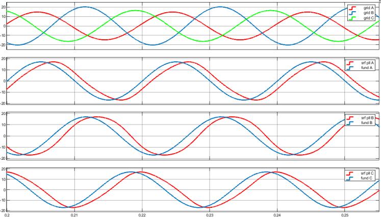
The main drawback of this PLL structure is its poor performance under unbalanced or distorted grid voltage [6], [14]. In this case, the essential task is the identification of the fundamental frequency positive sequence voltage component. The Matlab-Simulink simulation results shown in Fig. 2 illustrate the inaccurate detection of the direct component of a 50 Hz, 3-phase unbalanced
54 A.-A. Zsigmond, and A. Kelemen
voltage system, with components given in Table 1, in case of the controller parameters ���� =13.06, ���� =1451, ��0 =2��40 ������ �� .
Table 1: Components of the voltage system from Figure 2 Component Amplitude[V] Initial phase[deg]
���� + 17 0
���� − 3.4 45
Figure 2: Unbalanced 3-phase grid voltage system (top) and its direct sequence component (blue waveforms on the other axes) vs. the 3-phase system that results using the phase angle detected with SRF-PLL
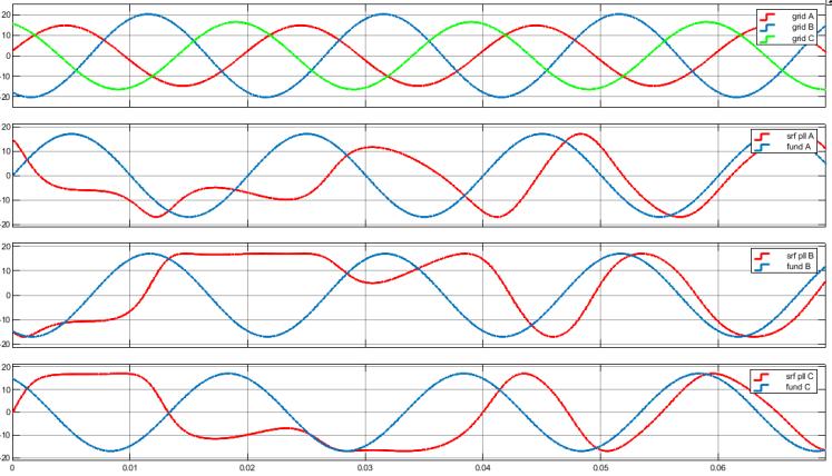
Figure 3: The starting transients of the SRF-PLL in case of unbalanced grid voltage
On the contrary, the Double Synchronous Reference Frame PLL method can successfully separate the direct and inverse components of the unbalanced grid
Implementation of Grid Synchronization Methods on a Real Time Development System 55
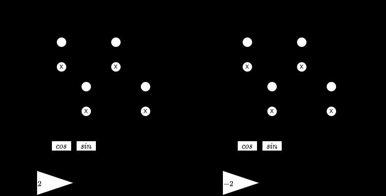
voltage, and can also deal with a distorted voltage system [2], [5]. This is performed by the PLL structure shown in Figure 4, using two synchronous reference frames with direct and inverse rotation senses, respectively. A decoupling network (Figure 5) cancels the double-frequency components that result from the representation of the direct and inverse sequence voltage vectors in the reference frames rotating in the opposite direction. Thus the low-pass filtering tasks of the PLL become easier and the dynamic response becomes better [5].
This structure can even be generalized for the detection of higher order harmonics [5].

Figure 4: The block diagram of the DSRF-PLL [5]
Figure 5: The block diagrams of the positive and negative sequence decoupling cells [5]
The estimated angular positions of the reference frames with (+��) direct and (–��) inverse angular speed are ���� and −����, respectively.
56 A.-A. Zsigmond, and A. Kelemen
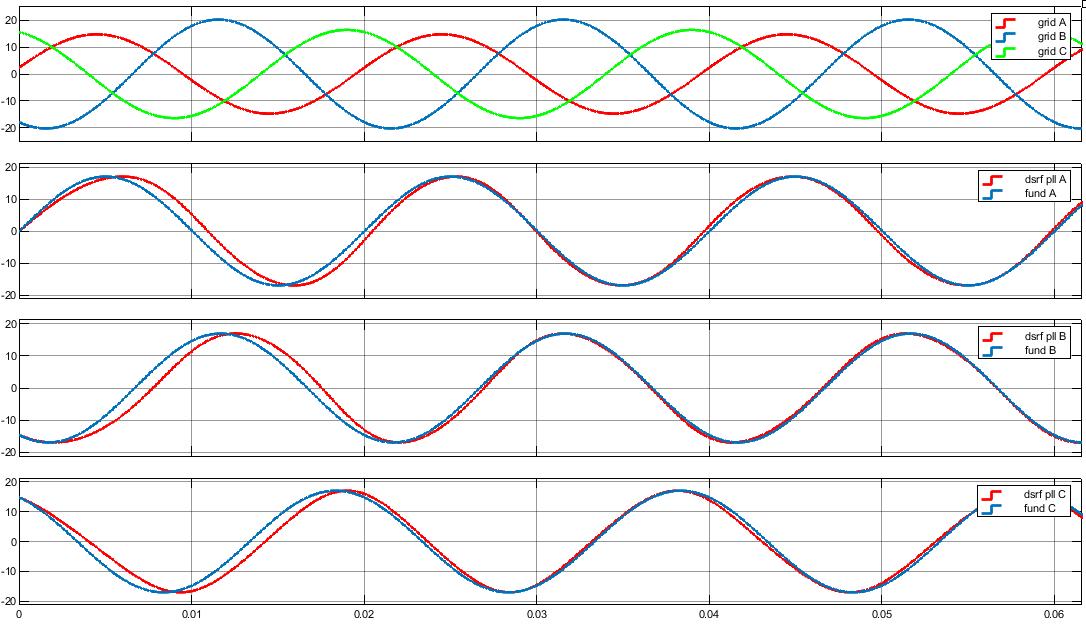
In a similar way to the SRF-PLL case, Figure 6 compares the direct sequence component of the voltage system to the voltage system detected by the DSRF phase locked loop, for the controller parameters ���� =13.06, ���� =1451 The initial value of the angular frequency was ��0 =2��40 ������ �� , while the cutoff angular frequency of the low-pass filters was ���� =222.14

Figure 6: Unbalanced 3-phase grid voltage system (top) and its direct sequence component (blue waveforms on the other axes) vs. the 3-phase system that results using the phase angle detected with DSRF-PLL
Figure 7: The starting transients of the DSRF-PLL in case of unbalanced grid voltage
Implementation of Grid Synchronization Methods on a Real Time Development System 57
The power circuit of the investigated switch mode voltage rectifier is shown in Figure 8.
The control structure is based on the mathematical model (1), developed in the synchronous reference frame [9], [11], [13].
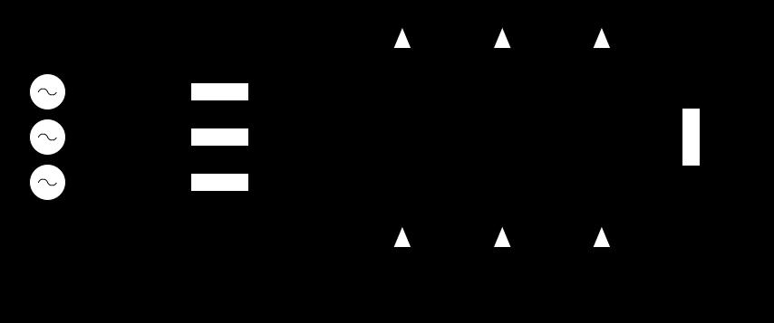
Figure 8: The power circuit of the 3 phase switch mode voltage rectifier [9]
(1)
where ����,u��,id,iq,������,ukq are the d and q components in the synchronous reference frame of the grid phase voltage, grid current, and rectifier bridge input voltage, respectively. ����,�� are the components of the switching vector, defined by the switching states of the upper transistors.
The synchronous coordinate system voltage mode controller synthesizes the rectifier input voltage references using the compensation network from Figure 9 [9]. This structure is based on (1), where
(2)
58 A.-A. Zsigmond, and A. Kelemen
are the outputs of the �� and �� axes current controllers.
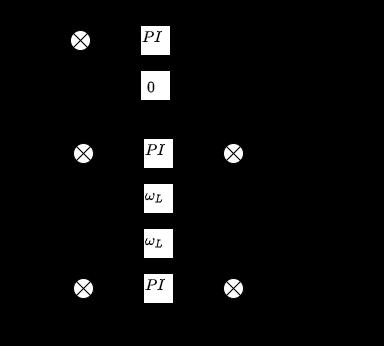
Figure 9: Control system in the synchronous reference frame [9]
The components of the grid current reference in the synchronous reference frame result from the assumption that the rectifier is operated at unity power factor. This means that the reference of the active grid current component ���� ∗ is delivered by the output of the DC-link voltage regulator, and ���� ∗ =0 [15].
In consequence, the block diagram of the voltage controlled rectifier results as shown in Figure 10, where the rectifier input voltages result by space phasor modulation [11], based on the voltage reference components and the actual DClink voltage.
The grid synchronization is performed by one of the above mentioned PLL structures, with significant influence on the performance of the rectifier, as discussed in the following sections.
Implementation of Grid Synchronization Methods on a Real Time Development System 59

Figure 10: The overall control system of the switch mode rectifier with space vector modulated gate signals (SVM)
4. Experimental setup for the PLL assessment
The experimental setup for the analysis of the PLL structures is based on a dSpace DS1104 type real time development system (250 MHz floating point 603 PowerPC processor) [8], with galvanically isolated analog and digital inputs and outputs. The voltage source is the 17 V secondary of a 3-phase transformer, which delivers an unbalanced voltage system when heavily loaded.
One of the goals of this study has been the assessment of the maximum sampling frequency when all functionalities of the control system are implemented in the DS1104 system. The model from Figure 11, is used for the measurement of the execution times that finally limit the sampling frequency.
60 A.-A. Zsigmond, and A. Kelemen
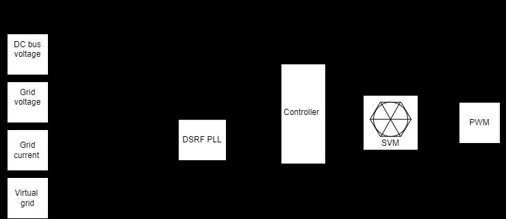
Figure 11: Real time model of the rectifier control system
Figure 12 shows the turnaround time corresponding to the case when all control functions were confined to a single task.

Figure 12: Timer Task 1 turnaround time
It can be observed that the turnaround time is less than 75����, i.e. 75% of the initially set 100���� cycle period maximum, which makes it possible to increase the sampling frequency to 12kHz, corresponding to an 83����, sampling period.
It has to be mentioned that the sampling period can be further decreased by creating a multirate model, which allows for the execution of lower priority, but time consuming tasks in the time available between the processing of highpriority tasks [8].
Implementation of Grid Synchronization Methods on a Real Time Development System 61
The SRF and DSRF PLL synchronization methods have been compared while setting the above established maximum sampling frequency. The controller parameters have been set to the values given in the previous section.
In Figure 13 there are represented on the same time diagrams the balanced grid voltage system and the voltage system identified by the corresponding PLL method. The bottom diagram shows the ���� outputs (representing in fact the phase error) and the angular positions identified by both methods. It can be observed that in case of a balanced grid voltage system, the behavior of both methods is similar. The small overshot in case of the DSRF-PLL is attributable to the controller settings, but the steady-state phase error is zero in both cases.
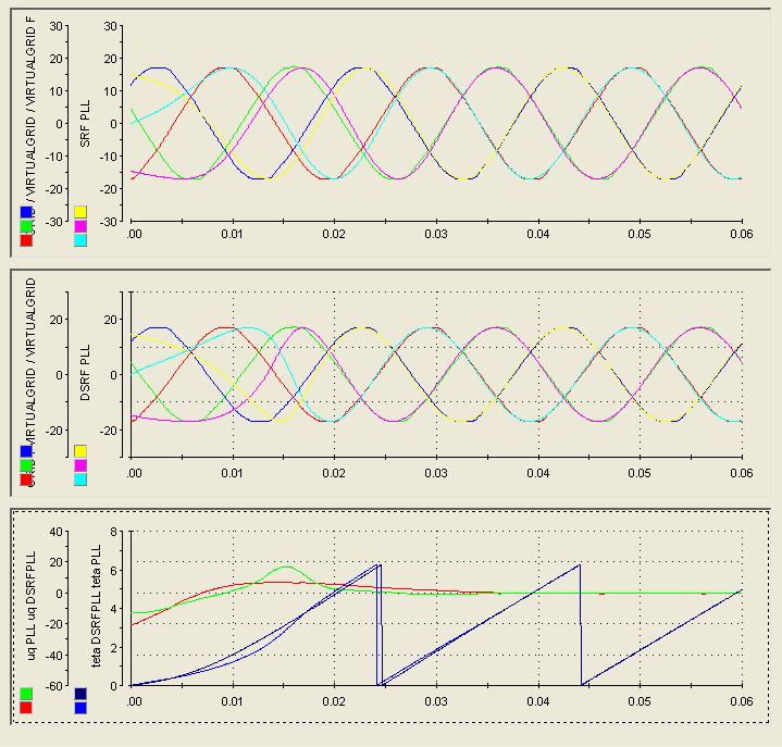
Figure 13: The starting transients while using for grid synchronization the SRF (top) and DSRF PLL (center) methods, in case of balanced grid voltages
Figure 14 presents the results of a start-up in case of an unbalanced grid simulated by the real time development system. In this case the amplitude ratio of the inverse and direct sequence components was 0.5. The steady-state error
62 A.-A. Zsigmond, and A. Kelemen
of the DSRF-PLL method is zero, while the result obtained using the SRF-PLL method is unreliable.
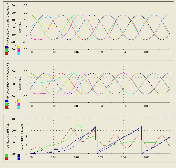
Figure 14: Synchronization in case of a synthetic unbalanced grid. The reference is the direct component of the asymmetrical voltage system. The red curve in the bottom diagram is the phase error in case of the SRF-PLL
An experiment has been performed using the output voltage system of a 3phase 240 VA transformer, and inducing unbalance by an asymmetrical resistive load step (5A step between two phases). Figure 15 shows the behavior of both PLL methods in this practical case. The voltage system is also distorted in this experiment, but, again, the DSRF-PLL proves to be more performant.
Implementation of Grid Synchronization Methods on a Real Time Development System 63

Figure 15: The response of the SRF and DSRF PLL methods to a transformer secondary voltage unbalance induced by an asymmetrical load step at t=0
5. Simulation of the switch mode rectifier with SRF and DSRF PLL synchronization, under unbalanced grid voltage conditions
This chapter compares by Matlab-Simulink simulation the PLL methods applied for the grid synchronization of a switch mode voltage rectifier shown in Figure 10. The discrete time models use the highest possible sampling frequency, established during the experiments for the implementation on the dS1104 real time development system.
The harmonic content of the grid currents is used to compare the performances of the PLL methods under unbalanced grid voltage conditions.
From (1) and (2) it can be observed, that the actual grid currents and voltages directly influence the synthesis of the rectifier voltage reference. On its turn, the rectifier voltages directly influence the grid currents, hence the importance of the correct identification of the direct sequence grid voltage system.
64 A.-A. Zsigmond, and A. Kelemen
The following parameters were set: - The converter components: ���� =5.6����,�� =450����,���� = 32Ω - DC voltage controller parameters: ���� =0.01,���� = 0.1 - Controller of the current component ����: ���� =50,���� =10 - Controller of the current component ����: ���� =50,���� =10 - Grid line voltage direct sequence component: ���� =380��������,f= 50Hz - Grid line voltage inverse sequence component: ���� =0.3���� = 114��������, φ=30°,f=50Hz - SRF-PLL controller: ���� = 0.584,���� = 64.93 - DSRF-PLL controller���� = 0.584,���� = 64.93
Figure 16 shows the unbalanced grid voltage system and the distorted grid currents in case of synchronization using the SRF-PLL method.
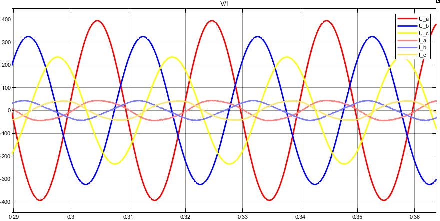
Figure 16: Asymmetrical grid and distorted currents resulting with the SRF-PLL
In Figure 17 it can be observed that significant 3-rd and 5-th order harmonics appear in the grid current due to the fact that the SRF-PLL is not suitable for the direct sequence grid voltage component detection. In this case, the total harmonic distortion of the grid current is higher than 5%
Implementation of Grid Synchronization Methods on a Real Time Development System 65
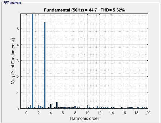
Figure 17: FFT analysis of a grid phase current in case of SRF-PLL synchronization
The result is much better when the DSRF-PLL is applied for synchronization. This is demonstrated in Figure 18 and Figure 19, which show the almost sinusoidal grid currents and their harmonic contents under the same unbalanced grid voltage conditions. In this case the total harmonic distortion is close to 1.7%, and unity power factor operation can be observed as well
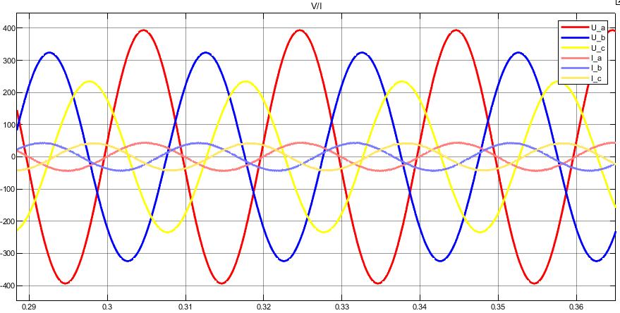
Figure 18: Asymmetrical grid voltage and symmetrical grid current system resulted when using the DSRF-PLL synchronization method
66 A.-A. Zsigmond, and A. Kelemen
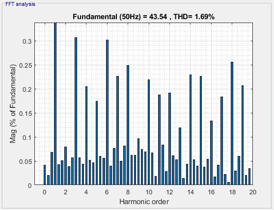
Figure 19: FFT analysis of a phase current in case of DSRF-PLL synchronization
6. Conclusions
In this study, the SRF PLL and DSRF PLL grid synchronization methods, used for the control of grid connected switch mode rectifiers, have been presented and compared. The voltage oriented control structure of the rectifier, that applies these synchronization algorithms, has been implemented on a dSpace 1104 type real time development system, and we found that a 12 kHz sampling frequency could be reached, with further improvement possibility by creating a multirating model.
A discrete time Matlab-Simulink model of the rectifier supplied from an unbalanced grid voltage system was created, which made possible the comparison of the harmonic contents of the grid currents absorbed in case of the two different synchronization methods.
For a ratio of the inverse and direct sequence grid voltage components of 0.4, we found that the total harmonic distortion of the grid currents was 5.62% in case of the application of the SRF PLL, but it decreased to 1.69 % when we applied the DSRF PLL synchronization method.
The harmonic content of the grid currents proves that in the case of an asymmetrical voltage system, the DSRF PLL provides a more performant operation of the rectifier due to its ability to accurately separate the direct and inverse sequence voltage components.
Implementation of Grid Synchronization Methods on a Real Time Development System 67
References
[1] Teodorescu, R., Liserre, M., Rodriguez, P., “Grid Synchronization in Three Phase Power
Converters,” in Grid Converters for Photovoltaic and Wind Power Systems, IEEE, pp.169–204, 2007. [2] Rodriguez, P., Pou, J., Bergas, J., Candela, I., Burgos, R., and Boroyevich, D., “Double
Synchronous Reference Frame PLL for Power Converters Control” , IEEE 36th Power Electronics Specialists Conference, 2005, pp. 1415–1421. [3] Malinowski, M., Kazmierkowski, M. P., Trzynadlowski, A., “Review and Comparative
Study of Control Techniques for Three-phase PWM Rectifiers”, Mathematics and Computers in Simulation, 63, pp. 349–361, 2003. [4] Kulkarni, A., and John, V., “Design of Synchronous Reference Frame Phase‐Locked
Loop with the Presence of DC Offsets in the Input Voltage” , IET Power Electronics, vol. 8, no. 12, pp. 2435–2443, 2015. [5] Rodriguez, P., Pou, J., Bergas, J., Candela, J. I., Burgos, R. P., and Boroyevich, D.,
“Decoupled Double Synchronous Reference Frame PLL for Power Converters Control” , IEEE Transactions on Power Electronics, vol. 22, no. 2, pp. 584–592, 2007. [6] Sevilmiş, F., and Karaca, H., “Performance Analysis of SRF-PLL and DDSRF-PLL
Algorithms for Grid Interactive Inverters,” International Advanced Researches and Engineering Journal, pp. 116–122, 2019. [7] Guo, X. et al., “Phase Locked Loop and Synchronization Methods for Grid- Interfaced
Converters: a Review” , Przegląd Elektrotechniczny, pp. 182–187, 2011. [8] dSPACE GmbH, “Real-Time Interface (RTI and RTI-MP) -Implementation Guide,”
Relase 4.2 –March 2005. [9] Sanjuan, S. L., “Voltage Oriented Control of Three‐Phase Boost PWM Converters” ,
Göteborg, Sweden, Chalmers University of Technology, 2010. [10] Rodriguez, P., Sainz, L. and Bergas, L., “Synchronous Double Reference Frame PLL
Applied to a Unified Power Quality Conditioner”, in Proc. 10th International Conference on Harmonics and Quality of Power, vol. 2, 2002, pp. 614–619. [11] Hartani, K, and Miloud, Y., “Control Strategy for Three Phase Voltage Source PWM
Rectifier Based on the Space Vector Modulation”, Advances in Electrical and Computer Engineering, 2010. [12] Chung, S.-K., “A Phase Tracking System for Three Phase Utility Interface Inverters” , IEEE Transactions on Power Electronics, vol. 15, no. 3, pp. 431-438, May 2000. [13] Rodriguez, J. R., Dixon, J. W., Espinoza, J. R., Pontt, J., and Lezana, P., “PWM
Regenerative Rectifiers: State of the Art” , IEEE Transactions on Industrial Electronics, vol. 52, no. 1, pp. 5–22, Feb. 2005. [14] Sharma, D., Sen, B., and Babu, B. C., “Improved Grid Synchronization Algorithm for
DG System Using DSRF PLL Under Grid Disturbances” , 2012 Students Conference on Engineering and Systems, 2012, pp. 1–6. [15] Akagi, H., Hirokazu, E., Aredes, M, “Instantaneous Power Theory and Applications to
Power Conditioning”, IEEE Press, 2007.


