18 minute read
Kinematic and Dynamic Modeling of the Rotary Harrow
Acta Universitatis Sapientiae Electrical and Mechanical Engineering, 13 (2021) 2538
DOI: 10.2478/auseme-2021-0003
Advertisement
Ferenc TOLVALY-ROSCA1 , JuditPÁSZTOR2 , Zoltán FORGÓ3
Sapientia Hungarian University of Transylvania, Cluj-Napoca, Faculty of Technical and Human Sciences, Târgu Mureş, Department of Mechanical Engineering, e-mail: 1tferi@ms.sapientia.ro, 2pjudit@ms.sapientia.ro, 3zforgo@ms.sapientia.ro
Manuscript received November 15, 2021; revised December 02, 2021.
Abstract: The actual energy situation and the significant energy demand of agricultural production require the exploration and analysis of the general laws of the main processes in the field of energy, which is part of the borderline between the technical sciences and the agricultural sciences. Tillage machines change the physical properties of the soil, but at the same time the mechanical properties of the soil react to the implement. One of the basic works of seedbed preparation is harrowing. In this work we study the kinematics and dynamics of the active rotary harrow implements, taking into account the cutting resistance of the soil. The results obtained with the developed modeling methods, give reliable approximations to the experienced tilling processes.
Keywords: Rotary harrow, kinematics, dynamics, assembly model.
1. Introduction
Tillage is a mechanical intervention, the aim of which is to create favorable soil conditions for the crops to grow. Tillage consists of basic operations and seedbed preparation. The basic operation is the deepest, the seedbed preparation is shallower, but the most demanding intervention.
The purpose of seedbed preparation is rapid germination, which is facilitated by a soil condition in which the circulation of moisture, air and heat is favorable. During seedbed preparation, the top layer of soil is loosened, crushed, levelled and compacted at the depth of sowing. It is necessary to choose a method and a tool by which the conditions of good germination can be realized cost-effectively with little intervention, without damaging the soil structure. Machines that perform these jobs in one run at the same time are common. These machines are usually equipped with active tillage implements, which are driven by the tractor's PTO shaft. One such work machine is the rotary harrow [1], [2].
26 F. Tolvaly-Rosca, J. Pásztor, and Z. Forgó
The rotary harrow is the seedbed preparation work machine. In the course of its work, it shreds the soil. It also stirs up, flattens and mixes vigorously while shreds. The rotary harrow is power-driven, its implements are active, and they are also driven from the power take-off shaft (PTO), during towing. Thus, the power requirement of the traction work is lower, the slip loss during towing is smaller, therefore it can be used even in wetter ground conditions [1], [3].
The main goal of the machine operation is to provide the required seedbed with the lowest possible number of turns and favorable energy consumption [4], [5].
Using a nonlinear mathematical modeling and simulation of the systems [6] [7], the movement trajectories of a work tool can be studied, [1], [3], [8], [9], [10], [11].
Dynamic models can be used to study the dynamic behaviour [12] and the energy demand [13] of a work tool. In the present paper we perform kinematic and dynamic modelling of the rotary harrow teeth.
2. Materials and methods
We perform kinematic and dynamic modeling of the rotary harrow. To do this, we made a simplified assembly model of the rotary harrow, which is used for dynamic modeling. The trajectories of the harrow teeth are generated using mathematical modeling, the forces acting on one harrow tooth are determined, then they are used to make computer simulations for dynamic and energetic studies.
2.1. The simplified assembly model
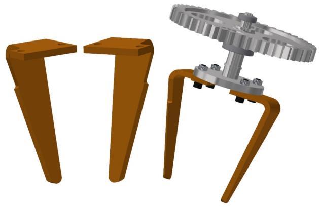
The working tool of the rotary harrow is the tine. Since the rotation direction of the adjacent work units is opposite, two types of tines are used according to each rotation directions (Fig. 1).
Figure 1: The solid models of the tines (left) and a working unit with two tines (right)
Kinematic and Dynamic Modeling of the Rotary Harrow 27
The implements are driven from the power take-off shaft of the power unit, via a deceleration gearbox (Fig. 2). The PTO shaft spindle speed is conventional, 540 rpm. The drive chain is designed so that the rotational movement from the tractor-PTO is transmitted by gears to the vertical axes, so that the adjacent implements rotate in opposite directions.
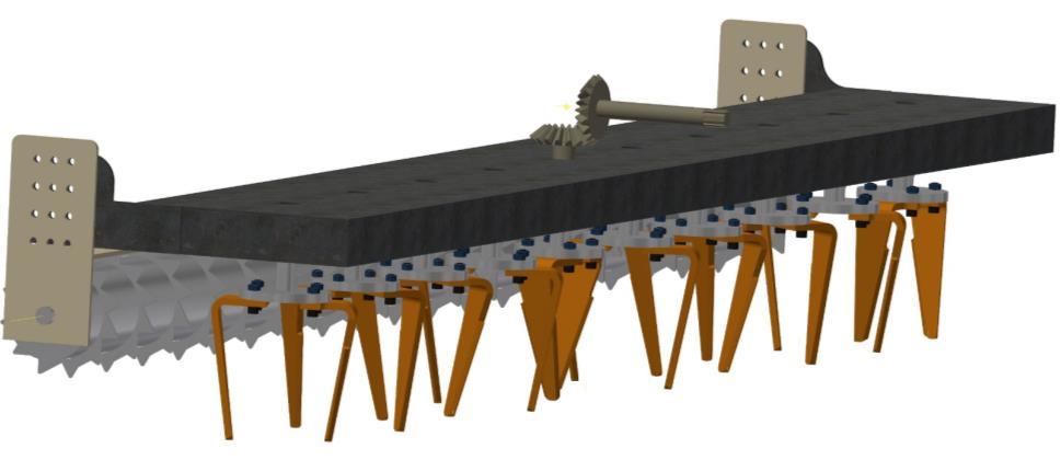
Figure 2: The simplified assembly model of the rotary harrow is based on Amazone KE3001 type machine [14]
The shapes of the harrow tines are extremely various. Most work machine manufacturers reduce fuel consumption and wear by using new,optimized shapes and innovative materials to increase the efficiency of their products [8].
The most commonly used harrow tine is the wide-bladed harrow tine. It can be made in straight or helical, vertical or oblique versions. In this paper we analyze a wide-bladed, oblique harrow tine. The width of the harrow tines increases from the tip to the base, so the cutting edge is able to pull the plant stalks into the soil, hence it has a slight compacting effect in the working depth and avoids any obstacles more easily.
2.2. The kinematic model
The trajectories of the points situated on the tines are important parts of the kinematic models. The trajectories can be used to identify parameters that affect tooth movement and to analyze how they affect the tillage process. The dimensions of soil chips formed during the movement of harrow tines in the soil can also be analyzed [10].
The points noted with ����(������,������,������) and ����(������,������,������), �� =1÷10 represent the tip of the harrow tines. The tines are moved by the combined effect of a rotating and a forward (towing) movement (Fig. 3).
28 F. Tolvaly-Rosca, J. Pásztor, and Z. Forgó
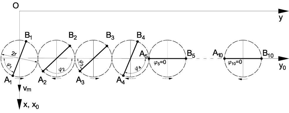
Figure 3: The initial positions of the working units, according to Amazone KE 3001 [14]
The motion equations of the points ����(������,������,������)and����(������,������,������)in the stationary coordinate system °xO° y are given by the following relations:
�������� =����sin((−1)����+����)+������
�������� =2��(��−1)+���� cos((−1)����+����)
�������� =����sin((−1)����+���� +��)+������
�������� =2��(��−1)+���� cos((−1)i��+���� +��) (1)
(2)
�� =���� (3) where: vm is the forward speed of the rotary harrow, [m/s]; ω is the angular velocity of the drive shaft, [rad/s]; a is the working depth [m]; i is the serial number of the implement; φi is the angle between the direction line of the working units and the horizontal line - the initial phase shift, r is the radius of the rolling circle of the gears, rt is the half distance between the tips of the tines from a working unit.
Note: for i = 5 the above relations describe the driving unit; rt depends on the shape of the tine: if 2rt = 2r, the tines are vertical, if 2rt >2r the tines are divergent and if 2rt < 2r the tines are convergent (the tines are tilted).
The initial phase shifts of each working unit φi are given in Table 1:
Table 1: Initial phase shifts for each work unit
φ1 φ2 φ3 φ4 φ5 φ6 φ7 φ8 φ9 φ10
π/3 5π/6 π/6 2π/3 0 2π/3 π/6 5π/6 π/3 0
Kinematic and Dynamic Modeling of the Rotary Harrow 29
According to the motion equations, the trajectories of the tines describe looped cycloids (Fig. 4) [15]. The equations are considered valid and suitable to perform kinematic studies.
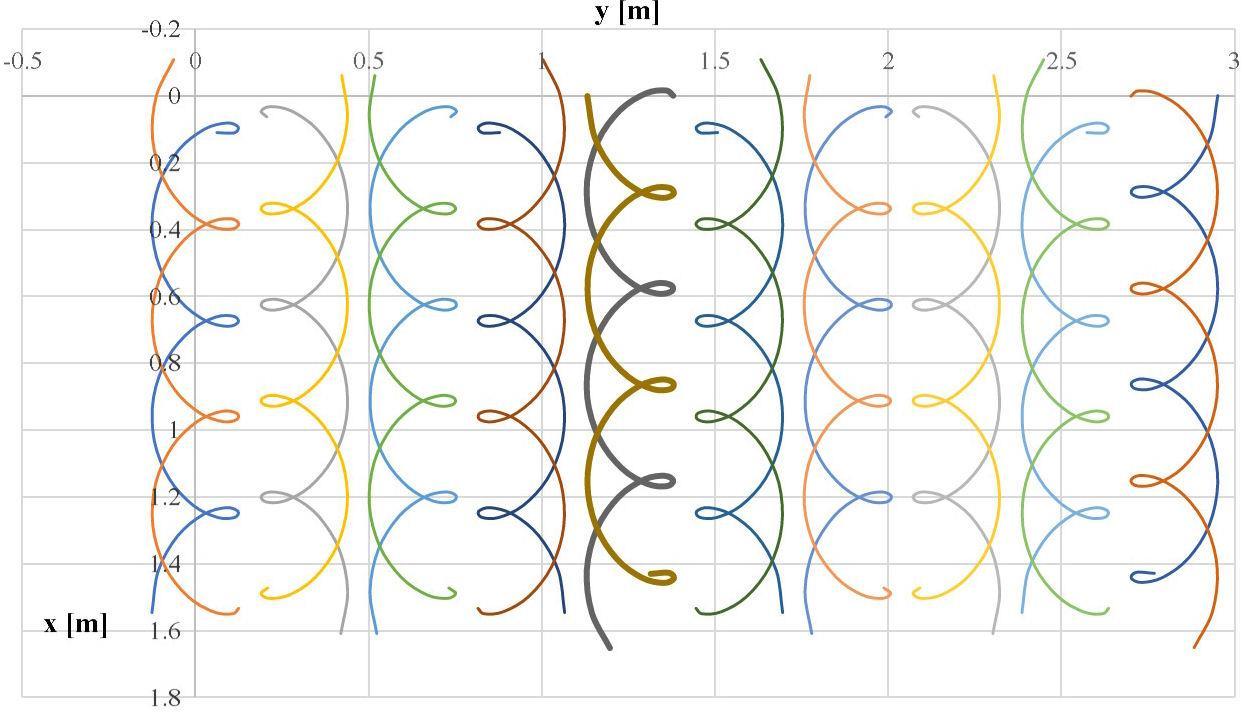
Figure 4: The rotating harrow tine tips trajectories
We examined the effect of changes of the tilt angle of the harrow tines, the towing speed, and the angular velocity on moving trajectories.
The effect of the tilt angle of the harrow tines in the cultivated soil, as a function of the working depth, can be seen in Fig. 5.
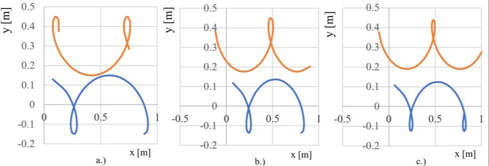
Figure 5: Trajectories described by points in different depths of the tine. a.) top of harrow tine, b.) middle of harrow tine, c.) tip of the harrow tine
30 F. Tolvaly-Rosca, J. Pásztor, and Z. Forgó
Due to the cohesiveness of the teeth, the distance between the sides of the teeth decreases from the surface of the soil to the tip of the teeth. Thus, soil shredding is expected to be more vigorous close to the surface relative to the working depth. Thus, the inclination angle contributes to the proper formation of the seedbed.
The effect of the forward speed on the worked surface can be seen in Fig. 6. As the forward speed increases, the stride of the implement increases, and the cuts become less frequent. As a result, the seedbed becomes clumpier and may require further processing.
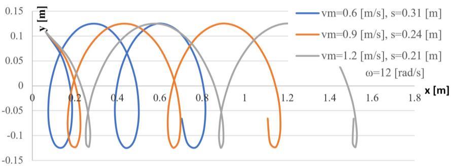
Figure 6: The effect of the towing speed on the trajectory of the tip
In practice as an illustrative indicator, the step of the implement [9], is used to characterize the kinematics of the work process. In the case of a rotary harrow, step s, the distance made during one revolution, can be calculated as follows:
2�� �� ; ��=
���� �� [m/rot] (4)
where: T [s], period of rotating motion and n [rpm] the spindle speed.
It can be concluded, that the pitch of the rotary harrow varies in direct proportion to the forward speed and in inverse proportion to the speed.
The effect of the angular velocity on the worked surface can be seen in Fig. 7. A low angular velocity results in a less machined surface.
Kinematic and Dynamic Modeling of the Rotary Harrow 31
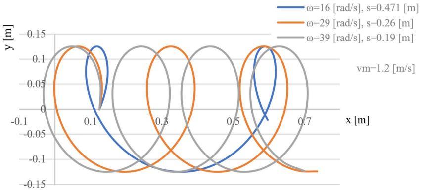
Figure 7: The variation of the tip trajectory for different angular velocities of the working unit The rotary harrow’s kinematic index is given by:
[−] (5)
Recommended values based on operating experience: ��=1.5÷6, [11], [14]. In the investigated cases: ��=1.25÷2.50, �� =1.66÷4.06.
2.3. Dynamic modeling
In this paper, we consider the work of the tines divided into two elementary processes. The tines cut and compress the soil.
According to these processes in Fig. 8, the following forces are considered: - the bit force (Fb); - the friction forces (T1 and T2) - on the sides of the tine; - the normal forces (N1 and N2) - acting on the tine sides; - the compaction forces, Fc.
The forces acting on the tine were calculated based on literature data [16], [17], [18].
Determining the forces and the loads on the implements, which result from a real tillage of the soil, is a complex task, as the stresses already laying in the soil can also influence the soil’s response to tillage forces, and these should be incorporated into the models, [19].
2.3.1. Determination of the Bit Force
The tine is considered a wedge-type blade having a pentagonal cross-section with parallel sides (Fig. 8) [16], [20], [21].
32 F. Tolvaly-Rosca, J. Pásztor, and Z. Forgó
The tine, due to the work of the previous tine, also travels in shreddedloosened-pre-compacted soil, so the deformation zone will be asymmetrical. As a result of the change in the deformation zone, the forces acting on the tool also change. In determining the shear force, it is assumed that the physical properties of the soil are different on both sides of the harrow tooth, so the soil can be considered more compact on one side.
The forces acting on the wedge, in the light of the above, are shown in Fig. 8. The resulting force on the wedge is given by the sum of the normal forces N and the frictional forces T, acting on the wedge. The occasionally concentrated loads (given by stones, roots etc.) acting on the tool edge are not taken into consideration in our model.
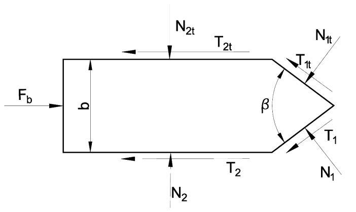
Figure 8: The forces acting in a section of a tine
The bit force acting on the tine can be calculated using the cutting resistance. It derives from normal forces and frictional forces, where:
��1�� =��1����1 [N], ��1 =��1��1 [N] (6)
��1t =������1t =������1t��1 [N], ��1 =����1 =�1��1 [N] (7)
��2t =��2t��2 [N],��2 =��2��2 [N] (8)
��2t =������2t =������2t��2 [N], ��2 =����2k =����2��2 [N] (9)
���� =��1sin
�� 2 +��1cos
�� 2 +��2 +��1��sin
�� 2 +��1��cos
�� 2 +��2�� [N] (10)
where: k1t, k2t, are the specific resistances to worked soil deformation [N/m2]; k1, k2 are the specific resistances to unworked soil deformation [N/m2]; A1 is the active surface of the tine edges [m2]; A2 is the surface of one of the sides of the
Kinematic and Dynamic Modeling of the Rotary Harrow 33
tine in contact with the soil [m2]; μt, μ are the friction coefficients between the soil and the tine; and β is the lip angle of the tine.
During the work the A1 and A2 surface can be considered functions of the working depth a [m], ��1 = ��1(��), ��2 =��2(��).
The k1 and k2 coefficients depend on: the soil deformation – are functions of thickness of the tine, the friction coefficient between the soil and the tine and the soil texture type. According to [12] ��1,��2 =��(��, ,), where b is the harrow tine thickness [m].
The values of the above coefficients are μt = 0.6 and μ = 0.7; k1t = 720883.68 [N/m2], k1 =783930.62 [N/m2], k2t =33692.35 [N/m2], k2 =32128 [N/m2]; = 90° and b = 0.015 m.
2.3.2. Calculating the compaction forces, Fc
The harrow tines shred the soil, while they rotate during the work, compacting the soil in the towing direction. This process, shown in Fig. 9, can be considered a cutting with a variable wide profile (the projection of the width changes according to the rotation angle) [16]. The maximal width of the profile in this case is the length of the side of the tine.
To determine the compaction forces, the physical and mechanical properties of the soil, the geometry of the cutting tool must be considered [22].
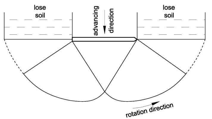
Figure 9: The compaction effect of the tine
To calculate soil resistance, the international literature uses the equation of Reece [18]. Cutting resistance per unit width:
���� =����2���� +�������� +������ℎ������ +�������� [
N
] (11)m
34 F. Tolvaly-Rosca, J. Pásztor, and Z. Forgó
where: a is the working depth [m]; γ is the specific weight of soil [N/m3]; c is the soil cohesion [N/m2]; aadh is the soil adhesion [N/m2]; q surcharge on the soil surface [N/m2]; Nc, Nγ, Na, Nq are dimensionless Reece’s resistance factors.
Reece's resistance factors are function of friction factors (ρ and φ), tool geometry, and deformation zone formation. Values used in the calculation: γ = 1500·9.81=14715 [N/m3]; c = (0.01…0.02) ·104 [N/m2]; aadh = 0 [N/m2]; q = 0 [N/m2]; Reece's resistance factors: Nc = 4.8, Nγ =8.8 (ρ = φ = 35°, α = 90° [16]).
The compaction force acting on a tine changes during its circular motion (Fig.10), and depends on the projected width of the harrow tine:
���� =���� ��cos�� =���� ��cos����[N] (12)
where: l is the median width of the tine (at the half of the working depth a) [m].
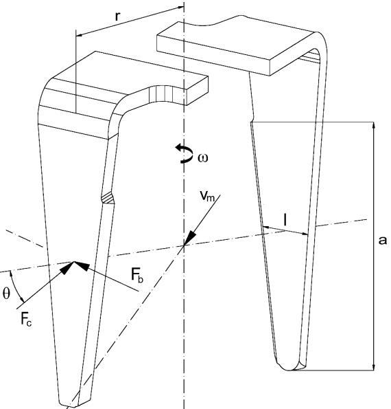
Figure 10: The position of the bit (Fb) and compacting (Fc) loads regarding the tines
2.4. Determining the driving torque
The paper [23] presents a methodology for mechanism simulation in case of agricultural machines, which may be applied at this mechanism also as seen in Fig. 11.
Kinematic and Dynamic Modeling of the Rotary Harrow 35
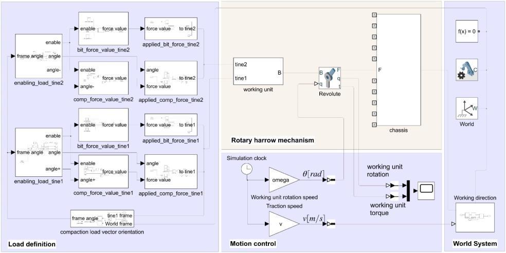
Figure 11: The Matlab Simscape model of the rotary harrow mechanism containing the working loads and kinematic parameters of the working process
The core element of the model is the rotary harrow mechanism area, which was presented already in Fig. 2. Because of model redundancy, the mechanism is simplified: besides the chassis, only one working unit is considered. This will allow a quicker simulation, and further, to obtain the driving torque for the whole rotary harrow machine, the number of the working units must multiply the simulationresult. Overlapping the 10torque variationsthrough time must be done by taking into consideration the initial phase shifts depicted in Table 1.
Next to the Rotary harrow mechanism area, the Motion control allows to run the simulation with the kinematic parameters as v for the traction speed and omega for the working unit rotation speed. To obtain the needed driving torque for the working unit, the loads on the tines must be calculated and applied at the right timing intervals. As above presented (Fig. 10.), two loads were taken into account, whose definitions are provided in equations (10) and (12). The Load definition area from the simulation implements those equations and applies to the tines of the working unit (denoted by tine1 and tine2). The magnitude and the direction of the loads are the same for both of tines, but the applying time interval differs through the simulation. Therefore, to have a more readable simulation model, the loads are calculated and presented separately.
The calculated driving torque for one working unit could be retrieved from the simulation through the graph element inside the Motion control area. Applying the phase shifts between the working units and summing the overall torques, for the parameters v = 1m/s traction speed and omega = 16 rad/s working unit rotation speed, the final simulation result is obtained.
36 F. Tolvaly-Rosca, J. Pásztor, and Z. Forgó
Figure 12: The variation of the driving torque (five cycles depicted)
Fig. 12. presents the torque variation through [2.25 s, 4.25 s] time interval consisting of five cycles. The mean value for the driving torque is 9872.6 Nm, having a cyclic variation in the [9818.5 Nm, 9934.2 Nm] interval.
3. Conclusions
The above defined kinematic equations describe trajectories also found in the literature, so they are suitable for performing theoretical investigations. As they are graphically visualized in a virtual environment, they easily allow to track changes made to various working parameters.
As the towing speed and the implement’s spindle speed majorly affects the quality and the bumpiness of soil work to be performed, it is recommended to carefully choose the values for these parameters.
We can also state that the further development of soil preparation machines is inconceivable without a solid knowledge of the soils and their characteristics. The complex structure and inhomogeneity of soils make it very difficult to describe their general mechanical laws and to select the correct mechanical properties. The main difficulty in modeling a close to reality soil-machine relationship is to build a complex computer model of the soil. While tillage machines change the physical properties of the soil, they also have reactions on the implement. The currently used soil characteristics do not describe correctly the mechanical behavior of soils under all conditions. In the presented modeling process, we performed simplifications that take from the complexity of the tillage processes. The presented work can be used as base for further practical and experimental investigations.
Kinematic and Dynamic Modeling of the Rotary Harrow 37
References
[1] Láng, Z., “A zöldség-, dísznövény- és szaporítóanyag – termesztés berendezései és gépei”, Publisher Mezőgazda, Budapest, 1999. [2] Szendrő, P., “Géptan”, Publisher Mezőgazda, Budapest, 2003. [3] Pásztor, J., Forgó, Z., “Ásógép kinematikája és munkaminőségi mutatóinak vizsgálata növényházban”, Műszaki Szemle, Publisher EMT, Cluj-Napoca, 2009. [4] Birkás, M., Dekemati, I., Kende, Z., Radics, Z., Szemők, A., “A sokszántásos műveléstől a direktvetésig-Előrehaladás a talaj művelésében és védelmében”, Agrokémia és Talajtan, no.67, vol. 2, pp.253268, 2018. [5] Raparelli, T., Pepe, G., Ivanov, A., Eula, G., “Kinematic Analysis of Rotary Harrows”, Journal of Agricultural Engineering; vol. LI:976, pp. 914, 2020. [6] Kovari, A., “Effect of Leakage in Electrohydraulic Servo Systems Based on Complex Nonlinear Mathematical Model and Experimental Results” , Acta Polytechnica Hungarica, vol. 12, no. 3, pp. 129–146, 2015. [7] Sánta, R., Garbai L., Fürstner, I., “Numerical Investigation of the Heat Pump System”, Journal of thermal analysis and calorimetry, vol. 130, no 2, pp. 11331144, 2017. [8] Balsari, P., et al., “Performance Analysis of a Tractor - Power Harrow System Under Different Working Conditions”, Biosystems Engineering, vol. 202, pp. 2841, 2021. [9] Major, T., “Mechanization Development for Soil Tillage at Stumpy Forest Areas”, Theses of doctoral (PhD) dissertation, University of West Hungary, Sopron, 2014, http://doktori.nyme.hu/458/2/ Tezisfuzet_angol_MajorT.pdf. [10] Virág, S., “Effects of Cultivation on Clod Formation os Soils Energetic Relationships in Breakage of Clods”, Theses of doctoral (PhD) dissertation, University of Debrecen, 2005, https://dea.lib.unideb.hu/dea/handle/2437/79555. [11] Naghiu, A., Baraldi, G., Naghiu, L., “Mașini și instalații agricole”, Editura Risopront, ClujNapoca, 2004. [12] Kovari, A., “Influence of Cylinder Leakage on Dynamic Behavior of Electrohydraulic Servo System,” in SISY 2009 - 7th International Symposium on Intelligent Systems and Informatics, 2009, pp. 375379. [13] Sánta, R., “Comparative Analysis of Heat Pump System with IHX using R1234yf and R134a” , Periodica Polytechnica Mechanical Engineering. [14] https://amazone.hu/hu-hu. [15] Máté, M., “Műszaki mechanika – kinematika”, Publisher TMS, Cluj-Napoca, 2010. [16] Sitkei, Gy. “Soil Mechanics Problems of Agricultural Machines”, Publisher Franklin Book Programs, New York, U.S.A., 1976, pp. 2262. [17] Major, T., Csanády, V., “Application of Numerical Analysis for the Design of Rotating Tool”, Hungarian Agricultural Engineering, no. 26/2014, pp. 1619, 2014. [18] Chung, S. O., Sudduth, K. A, “Soil Failure Models for Vertically Operating and Horizontally Operating Strength Sensors”, American Society of Agricultural and Biological Engineers, vol. 49(4), pp.851863, 2006. [19] Rajaram, G. “Mechanical Behavior of an Agricultural Soil” , Retrospective Theses and Dissertations. 9570, Iowa State University, Capstones, 1991. [20] Amantayev, M., Gaifullin. G., Nukeshev, S., “Modelling of the Soil-Two Dimensional Shearing Tine Interaction”, Bulgarian Journal of Agricultural Science, 23, no.5, pp. 882885, 2017. [21] Aluko, O.; Seig, D. A., “An Experimental Investigation of the Characteristics of and Conditions for Brittle Fracture in Two-Dimensional Soil Cutting”, Soil & Tillage Research, vol. 57, no.3, pp.143157, November 2000.
38 F. Tolvaly-Rosca, J. Pásztor, and Z. Forgó
[22] Thakur, T. C., Godwin, R. J., “The Present State of Force Prediction Models for Rotary Powered Tillage Tools”, Journal of Terramechanics, vol. 26, no. 2, pp. 121-138, 1989. [23] Forgó, Z.; Tolvaly-Roșca, F.; Pásztor, J.; Kovari, A., “Energy Consumption Evaluation of Active Tillage Machines Using Dynamic Modelling”, Appl. Sci., no.11, 6240, 2021.


