16 minute read
Peculiarities of the Grinding Process of a Gear Hob Helical Rake Face
Acta Universitatis Sapientiae Electrical and Mechanical Engineering, 13 (2021) 3951
DOI: 10.2478/auseme-2021-0004
Advertisement
Norbert HODGYAI1 , Márton MÁTÉ2, Ferenc TOLVALY-ROȘCA 2 , Mircea Viorel DRĂGOI1
1 Transilvania University of Brașov, Faculty of Technological Engineering and Industrial Management, Department of Manufacturing Engineering, e-mail: hodgyai@ms.sapientia.ro, dragoi.m@unitbv.ro 2 Sapientia Hungarian University of Transylvania, Cluj-Napoca, Faculty of Technical and Human Sciences, Târgu Mureş, Department of Mechanical Engineering, e-mail: mmate@ms.sapientia.ro, tferi@ms.sapientia.ro
Manuscript received November 15, 2021; revised December 05, 2021.
Abstract: This paper presents a study regarding the gear hob’s rake face grinding possibilities and its consequences. A simple theoretical lined surface is considered. The mathematical model of the reciprocate meshing of surfaces was applied. It was proven that the proposed form of the rake face cannot be obtained because an undercut of inacceptable extent occurs. It is also proven and sustained by CAD modeling that using a simplified, flat grinding disk, the undercut is avoided, but the phenomenon of transection appears.
Keywords: gear hob, rake face, grinding wheel, profile error, modeling.
1. Introduction
The gear-hob is one of the most productive cutting tools used in cylindrical gear machining. As well as known, literature contains a very large number of papers dealing with the cutting process, the generating process and the build-up of this very efficient cutting tool.
It can be stated that between the profile correction of the first attempt gearhobs till nowadays high-quality tools spread a long way marked by research and results of a large number of scientists. A large number of papers deal with different profile modifications, the sharp differentiation of roughing, semifinishing and finishing gear-hobs and their profiles [1], [2]. Here it must be remarked that interests are focused on profile modifications targeting the improvement of the tooth dedendum stiffness, extending to the study of the
40 N. Hodgyai, M. Máté, F. Tolvaly-Rosca, and M.V. Drăgoi
realization, involving the profile of the gear hob tooth relief face grinding wheel, its axial profile and also its dressing methods [3], [4].
Other research results cluster near the cutting process. One stream is the study of the influence of the cutting parameters (the chip thickness, the feed, the cutting speed, and cutting depth) on the durability of the gear-hob’s edge. The other stream focuses on the influence of the chip forming process on the thermal phenomenon, with effect on the tool life. Here have to be mentioned the results published in [5], [6], [7].
The real form of the rake face is narrowly discussed. The principle of the correct meshing of this surface is mentioned in a few papers [1], [8].
Despite of this, the present paper is based on the hypothetic presumption that the rake face form has a significant influence of the cutting edge form and thus, on the precision of the meshed gear.
The problem starts with the theoretical definition of the rake face. In classical approach, admitting a zero-addendum rake angle value, this is a constant helix parameter cylindrical helicoid surface, whose generator is a straight segment that intersects the helix axis. But trying to compute the corresponding grinding wheel profile, the phenomenon of undercut occurs. Trying to eliminate the undercut by limiting the grinding wheel diameter, another phenomenon – the transection –appears. This phenomenon occurs when the real body of the generating tool, a grinding wheel for example, or the subspace generated by the cutting edge in its relative motion, intersects the surface obtained with the application of the meshing theory [9], [10], [11], [12], [13].
While the phenomenon of the undercut [9], [10], [11] can be described with a robust mathematical model, the phenomenon of the transection is discussed merely involving numerical, CAD sustained simulation [12], [13]. Here is also important to mention the method of the successive subtracting [14], [15].
According to all mentioned above, it must be admitted that precisely designing the form and the grinding wheel profile of the helical rake-face of the tool is not a trivial task, due to the undercut of the sharpening tool. The generation of the surface is theoretically simple, but the practical implementation is complicated due to the transection. The developed mathematical model points to the peculiarities of the involved phenomenon, and is presented as follows.
To create the ideal rake surface, we consider the mathematical - geometric model shown in Fig. 1. The OX0Y0Z0 coordinate system is a stationary coordinate system. The revolution axis of the hob coincides with the X0 axis of the stationary coordinate system. To simplify the graphical representation, the gear-hob is replaced with a cylinder. The O2X2Y2Z2 coordinate system is the coordinate
Peculiarities of the Grinding Process of a Gear Hob Helical Rake Face 41
system attached to the gear-hob, that rotates about the X2 axis according to the helical rake face rotation direction. The X2 axis is fixed to the hob, and coincides with the X0 axis of the stationary coordinate system. A grinding wheel is used to generate the rake face. The coordinate system fixed to the grinding wheel is the O1X1Y1Z1 coordinate system. The axis of the grinding wheel should be theoretically perpendicular to the pitch screw line of the rake face. To obtain the ideal helical rake face, we studied several cases when the grinding tool’s axis was tilted with the angles corresponding to the declination angles of the helices situated on the flute base, addendum, dedendum respectively the pitch cylinder.
Figure 1: The considered coordinate systems
The equation of the rake face in matrix form [1], related to the frame S2 of the gear hob, can be written as: ���� ��2(��,��)=[ ��cos�� ] (1) y1 −��sin�� where u is the radial and �� x 1 the angular parameter of the surface.
x 0
42 N. Hodgyai, M. Máté, F. Tolvaly-Rosca, and M.V. Drăgoi
It is well known, that the normal vector of the ideal rake surface is defined as the vector product of the partial derivatives:
��=��2�� ��2�� (2)
where the expressions of the operands involved in eq. (2) are: 0 ��2�� =[ cos�� ]−sin�� �� ��2�� =[−��sin�� −��cos��]
Using the antisymmetric matrix of �� ̃ ���� (3)
(4)
0 ��cos�� −��sin�� �� ̃ 2�� =[−��cos�� 0 −�� ] (5) ��sin�� �� 0 and using (2), (4) and (5) the normal vector can be written as:
2�� ⋅��2�� =[
0 ��cos�� −��sin�� 0 0 −��cos�� 0 −�� ][ cos�� ]=[��sin��](6) ��sin�� �� 0 −sin�� ��cos��
On the other hand,, considering (1) and (6), the general parametric equation of the normal line in an arbitrary point of the helicoid (1) results in the following form:
��2(��,��)−���� �� ��2(��,��)−��cos�� ��sin�� ��2(��,��)+��sin�� ��cos�� (7)
The supposed contact curve between the grinding wheel surface and the helical rake face can be computed if a dependence between the independent surface parameters (��,��) is found. Classically, this is obtained by the application of the kinematic theory of meshing, applied first time by Litvin [9]. A simpler way is based on the recognition that the normal line of a revolution surface intersects the surface axis. Thus, from all surface points must be selected only those where the surface normal intersects the axis of the grinding wheel. In algebraic terms, it can be primed that the linear system built up from the axis equations and the normal line equations must admit a unique solution.
Because the system comprises four linear equations and only 3 unknowns ��2,��2,��2, the sole characteristic determinant of the system must be zero.
Fig. 1 lets us observe easily that the revolution axis of the grinding wheel admits the following equations:
Peculiarities of the Grinding Process of a Gear Hob Helical Rake Face 43
{ ��2 =���� tan���� =
��2 ��2 (8)
As it was stated earlier, the model deals with different tilting angles λx of the grinding wheel’s axis, matching the declination angles of the helices situated on the characteristic diameters of the hob. On the other hand, aw is the axial distance between the hob and the grinding tool.
Thus, using (8) and (7), the linear system becomes: ��2 =���� tan���� = {
��2 ��2 ��sin����2 −����2 =��2��sin��−��2cos�� =��1 ��cos����2 −��sin����2 =���� =��2 (9)
The characteristic determinant of the system is to be written as: 0 1 0 ���� ���� =det[�� 1 sin�� 0 −�� −tan 0 ���� 0 ��1 0 ��cos�� −��sin�� ��2
] (10)
Equalizing this to zero and doing the calculus, it results the following dependence between the helicoid parameters: ��2cos��−(���� +��tan����)��+��������tan���� −��2��sin��=0 (11)
Due to the fact the condition above is an algebraic equation of 2nd degree in u, there exist two solutions:
��1,2 = ����+��tan����±√(����+��tan����)2−4(��������tan���� −��2��sin��)cos��
2cos�� (12)
In order to decide which solution corresponds to the geometric reality of the grinding operation, a numerical approach is necessary. Let’s consider the case of a gear-hob originating from an involute worm. Starting from the normal module, the pitch helix angle and the normal rake profile angle, all the other characteristic parameters were computed using the classical formulae from the literature [8], [9]. Omitting the computation, the resulting geometrical data are the following:
The input data for the calculation are: normal module ����: 5 [mm], pitch helix declination angle ��0= 5 [deg], rake profile normal angle ��0��= 20 [deg].
Omitting the computation, the calculated geometrical data are the following: frontal module ����= 57,36587 [mm], rake profile frontal angle ��0��= 76 32'1'' , pitch radius R0 = 28.684 [mm], basic cylinder radius Rb = 6.68 [mm], addendum cylinder radius Ra = 34.934 [mm], dedendum cylinder radius Rf = 22.434 [mm], flute interior radius Rq= 14.984 [mm], flute interior helix declination angle ����=
44 N. Hodgyai, M. Máté, F. Tolvaly-Rosca, and M.V. Drăgoi
2.617 [deg], dedendum helix declination angle ���� = 3.914 [deg], addendum helix declination angle ����= 6.082 [deg], worm helix parameter ��= 2,50955 [mm], flute helix parameter ����= 327.8628563 [mm].
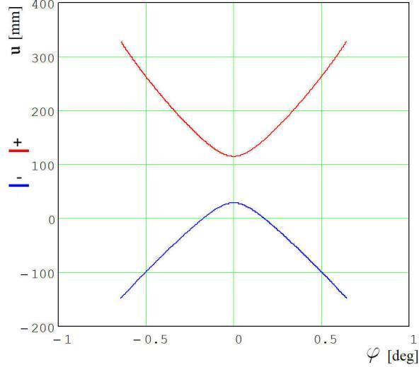
Now, computing both ��(��) dependencies given by (12) and associating them the graphical representation shown in Fig. 2, it can be decided that the real considered situation corresponds to the concave line, because the u values involved match the interval Rq ≤ u ≤ Ra. As a conclusion, the applicable ��(��) dependence is:
��1,2 = ����+��tan���� −√(����+����an����)2−4(��������tan���� −��2��sin��)cos��
2cos�� (13)
Representing function (13) for different helix angles values, it can be concluded that the maximum point of the graphic increasingly sharpens. Thus, acceptable u parameter values occur for more and more narrowing intervals of ��, as shown in Fig. 3. Inspecting the figure, it results that even the accepted solution contains two possibilities for constituting the ��(��) dependence. The first one results for the negative, while the other for the positive �� values.
Figure 2: The graphics associated with function ��(��)
Peculiarities of the Grinding Process of a Gear Hob Helical Rake Face 45
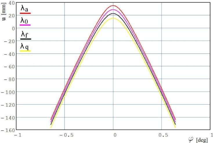
Figure 3: The variation of the accepted ��(��) function in function of the helix angles
Next goal is to build up the contact curves and using them, the grinding wheel surface. The model was numerically solved. Using the Mathcad environment, equation (11) was numerically solved for a number of �� =50 discrete and equidistant u values, �� ∈[����,����], searching first the negative and after that the positive solutions in variable ��. The procedure was repeated for the next values of the grinding wheel axis declination angle: �� ∈{����,����,��0,����}.

Figure 4: Contact curves for the positive �� values
46 N. Hodgyai, M. Máté, F. Tolvaly-Rosca, and M.V. Drăgoi
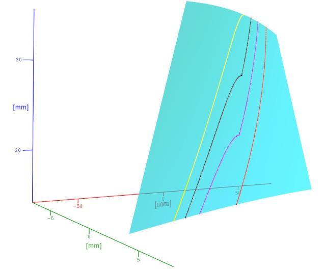
Figure 5: Contact curves for the negative �� values
The possible contact curves are represented through their discrete points, replacing the discrete arranged pairs. The contact curves on the theoretical helical rake face are shown in Fig. 4 for the negative, respectively in Fig. 5 for the positive �� values.
The colors used are red for the addendum, magenta for the pitch, black for the dedendum and finally yellow for the flute base helix angles.
Let’s denote ��=(��(2) ,��(2) ,��(2))the matrix of the coordinates of the contact curve points, where ��,��,�� are the columns of length n of the coordinates.
The axial profile of the grinding wheel can be computed by executing several computation tasks. First of all, the coordinates of the contact curve must be transposed in the frame of the grinding wheel. Here can be used the transformation matrix between frame ��1 and ��2, particularized for the ��=0 parameter value. Thus, the contact curve parameters will be comprised in the matrix �� =(��(1) ,��(1) ,��(1)). We omit here the detailed computation. Using the coordinate values in the frame of the grinding wheel, for each ����(����(1) ,����(1) ,����(1)) corresponds a profile point ����(���� �� ,���� �� ,���� ��) with the coordinates computed as follows:
���� �� =√(���� (1))2
+(���� (1))2 ���� �� =���� (1) (14)
Peculiarities of the Grinding Process of a Gear Hob Helical Rake Face 47
Using (14), the revolution surface of the grinding wheel results immediately.
The relative position of the grinding wheel’s surface and the theoretical rake face is shown in Fig. 6.
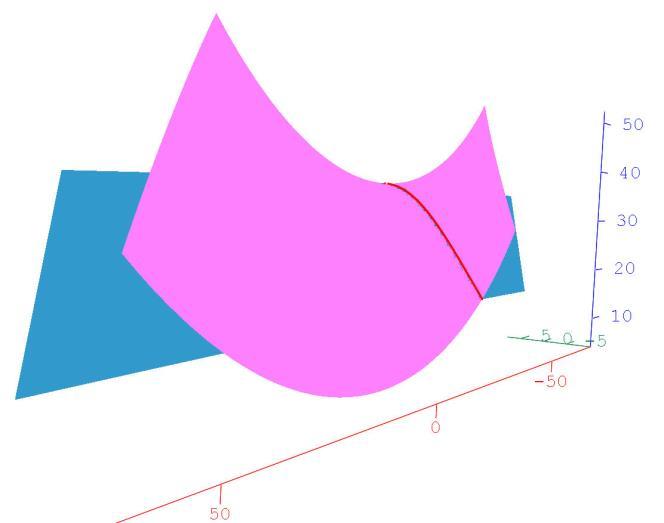
Figure 6: The relative position of the surfaces of the grinding wheel and the rake face
In Fig. 6 the blue surface represents the ideal helical rake face and the pink one the side surface of the grinding wheel.
Based also on the figure, it can be concluded that in the position of the grinding wheel where the contact curve is correct, the grinding wheel cuts under the dedendum cylinder, i.e., it cuts into the body of the gear-hob.
As the results of the numerical analysis shows, it can be concluded that the diameter of the grinding wheel required to generate the contact curve is not suitable for grinding the rake face, because the disk cuts very deep into the hob body.
Regarding the industrial generation of the gear-hob rake face we can consider two solutions: using a grinder wheel (or mill) or a grinding bit (or an end mill).
In the present paper we studied the finishing of the helical rake face of parametric equations (1), with a profiled grinding-and with a cylindrical grinding wheel.
48 N. Hodgyai, M. Máté, F. Tolvaly-Rosca, and M.V. Drăgoi
3.1 Generating the rake face using a profiled grinding wheel
As it can be seen in Fig. 7, the axis of the grinding wheel is parallel to the X0OZ0 plane. The normal vector of the helical rake face passes through the axis of rotation of the grinding wheel.

Figure 7: Rake face generation with a profiled grinding wheel
The location of the contact curves on the ideal rake face is in the negative angular range of �� (Fig. 5).
In order to be able to sharpen the gear-hob properly, the revolution surface of the grinding must not intersect the helical rake face.
3.2 Generating the rake face using a cylindrical grinding wheel
As a simplified procedure in some industrial practice, the side face (a plane surface) of a grinding wheel is used as the generator of the helical rake face. However, in the case of this simplified, practical solution, applying the appropriate equations, we do not obtain a solution to the applied function, from here we can conclude that there is no common normal, similarly to the previous cases for the undercut situation. The traces left by the flat diskare shown in Fig. 8.
Peculiarities of the Grinding Process of a Gear Hob Helical Rake Face 49
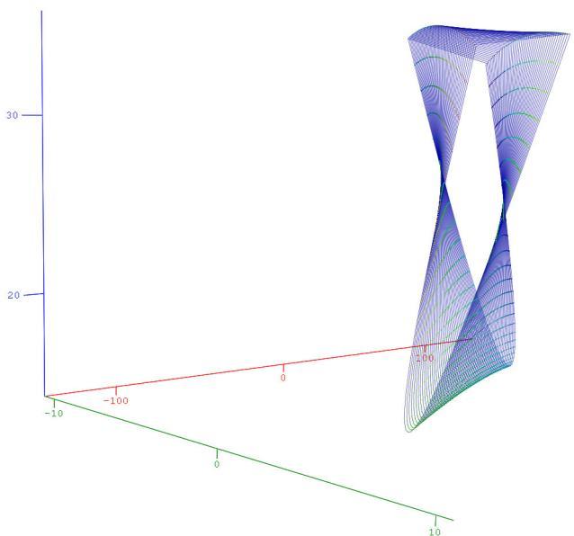
Figure 8: Numerical solution for the traces of a cylindrical grinding wheel
Generating the rake face with a cylindrical grinding wheel, and using the “Analyze Interference” command onthe assembly model (Fig. 9) it can be clearly seen, that the grinding wheel undercuts the helical rake face in all cases.
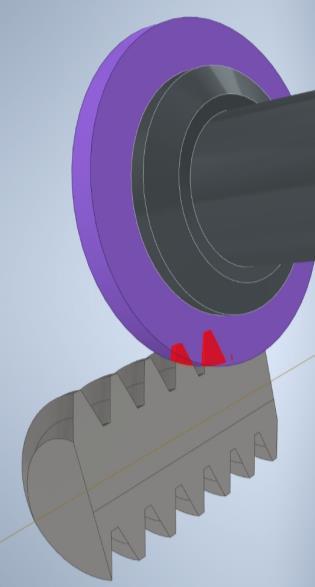
Figure 9: Analyze Interference command running on the assembly model
50 N. Hodgyai, M. Máté, F. Tolvaly-Rosca, and M.V. Drăgoi
4. Conclusions
The revolution surface of the grinding tool was computed using the theory of meshing, but it was demonstrated that this firmly undercuts the machined rake face, even in cases when the contact is correct along the computed contact curve.
The flat grinding surface (a circular disk) produces through the relative motion reported to the gear hob (or to the surface) a points cloud that includes the theoretical surface subjected to the machining process. The theoretical surface cannot result because the phenomenon of transection appears in every region of action of the grinding wheel’s generating surface. Here the undercut is surprisingly avoided.
The volume of the points cloud increases with the tilting angle of the grinding tool’s axis, e.g. the phenomenon of transection appears with ascending intensity.
Considering the computing and the models presented it can be concluded that the theoretical form of the rake face (1) cannot be achieved through classical helical grinding operation, using disk-type tools.
If for economic reasons the classical grinding procedure is still applied, the computation of the edges and of the relief face must take into consideration the real form of the rake face, that results as the trace of transection.
Acknowledgement
This work was supported by the Collegium Talentum Programme of Hungary.
References
[1] Radzevich, S.P., “Gear Cutting Tools: Fundamentals of Design and Computation”, CRC Press, NY, 2010. [2] Máté, M., “Hengeres fogaskerekek gyártószerszámai”, Erdélyi Múzeum-Egyesület, Kolozsvár, 2016. [3] He, R., Tenberge, P, Xu, X., Li, H., Uelpenich, R., Dong, P., Wang, S., “Study on the Optimum Standard Parameters of Hob Optimization for Reducing Gear Tooth Root Stress” , Mechanism and Machine Theory, vol. 156, 2021. [4] Yang, S., Chen, W., “Modeling and Experiment of Grinding Wheel Axial Profiles Based on
Gear Hobs”, Chinese Journal of Aeronautics, vol. 34, Issue 6, pp. 141150, 2021. [5] Guba, N., Hüsemann, T., Karpuschewski, B., “Influence of Gear Hobbing Feed Marks on the Resulting Gear Quality After Discontinuous Profile Grinding” , CIRP Journal of Manufacturing Science and Technology, vol. 31, pp. 314321, 2020. [6] Karpuschewski, B., Beutner, M., Köchig, M., Härtling, C., “Influence of the Tool Profile on the Wear Behaviour in Gear Hobbing” , CIRP Journal of Manufacturing Science and Technology, vol. 18, pp. 128134, 2017. [7] Troß, N., Brimmers, J., Bergs, T., “Tool Wear in Dry Gear Hobbing of 20MnCr5 CaseHardening Steel, 42CrMo4 Tempered Steel and EN-GJS-700-2 Cast Iron” , Wear, 2021. [8] Hollanda, D. “Aschiere si scule”, Reprografia I.I.S., Tg. Mures, 1982.
Peculiarities of the Grinding Process of a Gear Hob Helical Rake Face 51
[9] Litvin, F. L., Fuentes, A., “Gear Geometry and Applied Theory” , Cambridge University
Press, 2004. [10] Dudás, I. “The Theory and Practice of Worm Gear Drives”, Penton Press, London, 2000. [11] Dudás, I. “Possibilities of Exact Grinding of Conical and Globoid Worms”, International Review of Mechanical Engineering (IREME), vol. 1., no. 3, pp. 200207. [12] Balajti, Z., Mándy, Z., “Proposed Solution to Eliminate Pitch Fluctuation in Case of Conical Screw Surface Machining by Apex Adjustment”, Procedia Engineering, vol. 55, pp. 266273, 2021. [13] Balajti, Z., Ábel, J., Dudás, I., “Examination for Post-Sharpening Adjustment of Cutting Edge of a Worm Gear Hob with Circle Arched Profile in Axial Section”, Procedia Engineering, vol. 55, pp. 260265, 2021. [14] Tolvaly-Roșca, F., Máté, M., Forgó, Z., Kakucs, A., “Development of Helical Teethed Involute Gear Meshed with a Multi-Edge Cutting Tool Using a Mixed Gear Teeth Modeling Method”, Procedia Engineering, vol. 181, pp. 153158, 2017. [15] Tolvaly-Roșca, F., Forgó, Z., “Mixed CAD Method to Develop Gear Surfaces Using the Relative Cutting Movements and NURBS Surfaces”, Procedia Technology, vol. 19, pp. 2027, 2015.


