
21 minute read
Particle Swarm Optimization of a Hybrid Energy Storage System
Acta Universitatis Sapientiae Electrical and Mechanical Engineering, 13 (2021) 82100
DOI: 10.2478/auseme-2021-0007
Advertisement
János FERENCZ1 , András KELEMEN2
1 Technical University of Cluj-Napoca, Faculty of Electrical Engineering, Department of Electrical Machines and Drives, e-mail: janos_ferencz@yahoo.com 2 Sapientia-Hungarian University of Transylvania, Cluj-Napoca, Faculty of Technical and Human Sciences, Târgu Mureş, Department of Electrical Engineering, e-mail: kandras@ms.sapientia.ro
Manuscript received October 15, 2021; revised December 06, 2021
Abstract: The paper presents the energy loss minimization of a hybrid energy storage system used in an electric vehicle, composed by a battery and a supercapacitor. The optimization is carried out by searching the optimal power sharing between the energy storage devices. The power sharing factor is defined as a discrete time variable, with constant values during each subdivision of the driving cycle. The elements of the optimal solution vector are the power sharing factors and the time instants that define the subdivisions. The particle swarm optimization algorithms have been validated using the Rastrigin test function, and three versions of the boundary behaviour have been compared in case of the constrained optimization. The algorithms have been tested for the energy loss minimization in case of a simple driving cycle, and their performance has been assessed by statistical analysis for different swarm sizes.
Keywords: Particle swarm optimization, hybrid energy storage system, electric vehicle, constrained optimization.
1. Introduction
For the efficient operation of the electric vehicles, it is crucial to combine different types of energy storage devices, due to the fact each type has a limited range of operating conditions it can efficiently handle [4]. The high energy storage capability of the batteries, necessary to guarantee a high autonomy of the vehicle, is not associated with high output power capability, which is required during acceleration and deceleration. Thus, the hybridization of the energy storage system is the solution to satisfy the electrical energy supply or storage demands in different operating states [7].
Particle Swarm Optimization of a Hybrid Energy Storage System 83
The Hybrid Energy Storage System (HESS) being studied in this paper, illustrated in Fig. 1, consists of the combination of a Li-ion battery and a supercapacitor [14], in an active parallel topology that allows individual or joint power delivery to the load (to the wheel motors), energy recovery in case of braking, and energy exchange between these storage devices by means of power electronic converters. The battery life cycle is extended if it’s protected by the supercapacitor from current shocks during the vehicle power peaks [9], [13].
Figure 1: Block diagram of the active parallel hybrid energy storage system (HESS) [13]
The energy management of such a hybrid energy storage system has the task to determine in every instant of operation the “proper contribution” of each storage device to the power flow in either direction. This term can be converted to an objective function to be optimized under different constraints. One can aim to maximize the life cycles of the storage devices, to maximize the vehicle’s autonomy, to minimize the operation costs, etc. Limitations can possibly be imposed by state of charge or state of energy minima, or by maximum admissible currents, but vehicle-to-grid system requirements regarding the state of charge at peak or off-peak hours might also be feasible constraint.
Fig. 2 shows the structure of the model used to study the energy management algorithm (EMA), which provides �������� and������, i.e. the powers to be delivered by the battery and the supercapacitor, respectively, based on the following inputs: battery state of charge (SOC); instantaneous battery current, voltage, and internal resistance
(��������,��������,��������); supercapacitor state of energy (SOE); instantaneous supercapacitor current, voltage, and internal resistance
(������,������,������); instantaneous electrical power required to drive the vehicle (������ _������).
The aim of this paper is the minimization of the energy losses on the internal resistances of the battery and of the supercapacitor. The higher efficiency contributes also the increase of the vehicle’s autonomy.
84 J. Ferencz, and A. Kelemen

Figure 2: The block diagram of the model including the energy management algorithm of the hybrid energy storage system
The task of the EMA is to determine the optimal power sharing between the battery and the supercapacitor, considering their power limitations, and thus extending their life cycles.
2. The optimization problem
The performance of the vehicle is defined for standard driving cycles, representative for different characteristic operating conditions, usually formulated as theoretically or practically derived time-diagrams of speed. Thus, also the acceleration can be determined in each moment to derive the mechanical power required by the given speed profile. As we don’t aim to detail the mechanical model of the vehicle, let’s consider that the required mechanical power at a given moment is a function of the instantaneous speed ���� and acceleration ����, and the required electrical power ������ _������ results from this by considering a global efficiency ���� [10], according to (1):
1 ��(����(��),����(��)). (1)
The question is how to share this power between the energy storage devices in a way that ensures maximum efficiency, i.e. minimum power losses over a driving cycle. Generally, there should exist an optimum function of time of the sharing, which corresponds to this goal. Let’s denote by �� the share of the supercapacitor (either delivered or absorbed), defined by (2).
According to this definition, the power has the same sign at the terminals of both devices, and the case of energy exchange between them is not covered in this paper.
Particle Swarm Optimization of a Hybrid Energy Storage System 85
������ _������(��) ������ _������(��)+��������_������(��), �� ∈[0,1]. (2)
Thus, thetime dependent powers required from the supercapacitor and the battery are
������ _������ =�������� _������{�������� _������ =(1−��)������ _������, (3)
The powers delivered by the supercapacitor and the battery result by taking into account the internal losses:
{�������� =���������������� −���������������� 2 ������ =������������ −������������ 2 , (4) where in the model �������� and������ are considered constants. The supercapacitor voltage ������ is time-dependent according to (5), wich uses the notation from Fig. 3:
������(��)=������(0)−
1
������ ∫�� 0 ���������� (5)

Figure 3: The equivalent circuits of the energy storage devices We considered that the battery depletion is limited to ������ =50% (i. e. to half of the maximum stored charge Qmax), thus the linear increase of its internal resistance with the decrease of the SOC, according to (6), is a viable assumption [1], [8], [11].
��������(������)=��������|������=50% −(��������|������=50% −��������|������=100%)(������−50)/50 (6)
86 J. Ferencz, and A. Kelemen
Thus, (3) - (6) yield the currents of the storage devices:
��������−√�������� 2 −4��������(1−��)������������ 2�������� ������ =
������−√������ 2 −4�������������� _������ 2������ . (7)
The total power loss at a given instant is
2(��������−√�������� 2 −4��������(1−��)������������) 4�������� 2(������−√������ 2 −4�������������� _������) 4������ , (8)
while the energy losses until that moment are
����������(��)=∫�� 0 ��������������. (9)
A possible choice for the objective function to be minimized can be the instantaneous power loss (10), which enables online optimization, according to the procedure from Fig. 4.
���� =����������(��) (10)
As intuitively expected, and further on demonstrated in the paper, better results can be obtained according to the procedure from Fig. 5 when the objective function is the total energy loss at �� =�� (11), i.e. at the end of the driving cycle. ���� =����������(��) (11)
According to the procedure from Fig. 4, the instantaneous power loss (i.e. the objective function in this case) is calculated numerically using the discretization step ����. The power loss minimization is performed on the one dimensional solution space of the instantaneous scalar power sharing factor ��. The calculation of the energy loss is made by the integration of the instantaneous power minima to the end of the driving cycle.
The optimization from Fig. 5 is made on the multidimensional solution space of the power sharing factors that correspond to each time step of the driving cycle. The dimensionality of this problem is not manageable, and the number of components of the solution vector must be reduced as discussed in the further sections.
Particle Swarm Optimization of a Hybrid Energy Storage System 87
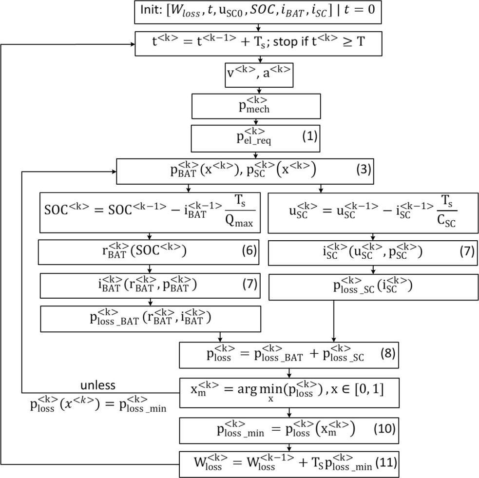
Figure 4: Flowchart in case of ����
88 J. Ferencz, and A. Kelemen
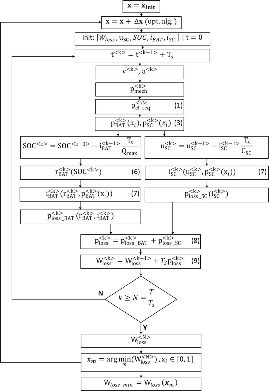
Figure 5: Flowchart in case of ���� =����������(��)
Particle Swarm Optimization of a Hybrid Energy Storage System 89
3. The particle swarm optimization algorithm
The particle swarm optimization method (PSO) has been chosen for the minimization of ���� =����������(��) [12].
This intensely studied stochastic method [3], which simulates the social behaviour of animal swarms, is appied in this paper for simultaneous search over large regions of the solution space of the objective function. The search algorithm followed by an individual particle is based both on its own “experience” and on the results obtained by other particles from the swarm.
There exist several versions of the algorithm [5], [6], [15]. However, its principle can be formulated according to the relation (12), which defines the new position of the particle by using a “speed” vector (in fact a position increment) that contains components of randomized magnitudes. In case of an unconstrained optimization, these components are derived taking into account the initial speed of the particle (inertial term), its best previous result (cognitive term) and the best previous result of the swarm (social term) [3]. {���� ��+1 =������ �� +��1����������1 �� ⊙ ���� ��+1 (������ �� −���� ��) =���� �� +���� �� + +1 ��2����������2 �� ⊙(���� �� −���� ��) ,(12) where the notations stand for: ���� �� – position vector of particle i in the k-th step of the search; “speed”of particle i in the k-th step of the search; ������ �� – individual best position vector of particle i until the k-th step of the search; ���� �� – best position vector of any particle from the swarm until the k-th step of the search; ����������1 �� and ����������2 �� are random vectors, with elements with continuous uniform distribution, in the range [0,1]; �� – inertia weight; ��1 – cognitive learning factor; ��2 – social learning factor; ⊙ – Hadamard product of vectors.
The algorithm in a two-dimensional space is illustrated in Fig. 6.
90 J. Ferencz, and A. Kelemen
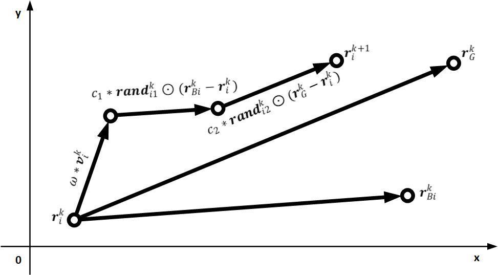
Figure 6: The unconstrained particle swarm optimization algorithm in a two-dimensional space
When the solution space is subject to constraints, the performance of swarm optimization algorithm is largely influenced by the behaviour of the boundary, especially when its position is close to the global optimum [2].
For the application of inequality-type constraints that characterize the hybrid energy storage system, in this study we analyzed the applicability of boundaries with different behaviour, reported in the literature [2]. Namely, the “absorbing” and “invisible” type boundaries have been verified for a standard test function, and the “invisible” and a newly proposed “halving” behaviour have been considered feasible in case of the HESS optimization.
These are illustrated in Fig. 7. The principle of the “invisible” limitation method is that if, according to (12), the particle should exit the solution space, the new position is omitted from the calculation, and the position of that particle is not refreshed. The “absorbing” method allows the motion of the particle in the direction given by (12), but strictly limited to the surface of the boundary.
The “halving” method preserves the direction of the speed vector (12), and it iteratively halves its length until the new position of the particle fits the solution space.
The “absorbing” method (also the “reflecting” and “hybrid” mentioned in [2]) can be efficiently applied when the intersection point “A” in the bottom diagram from Fig. 7 can be determined easily. Unfortunately, this is not the case of the HESS optimization.
Particle Swarm Optimization of a Hybrid Energy Storage System 91

Figure 7: Illustration of the behaviour of the “invisible”, “halving”, and “absorbing”, boundaries
A Matlab program has been developed to test the constrained swarm optimization algorithm applied to search the global minimum of the non-convex
92 J. Ferencz, and A. Kelemen
Rastrigin function shown in Fig. 8, where the boundary is the green transparent plane.
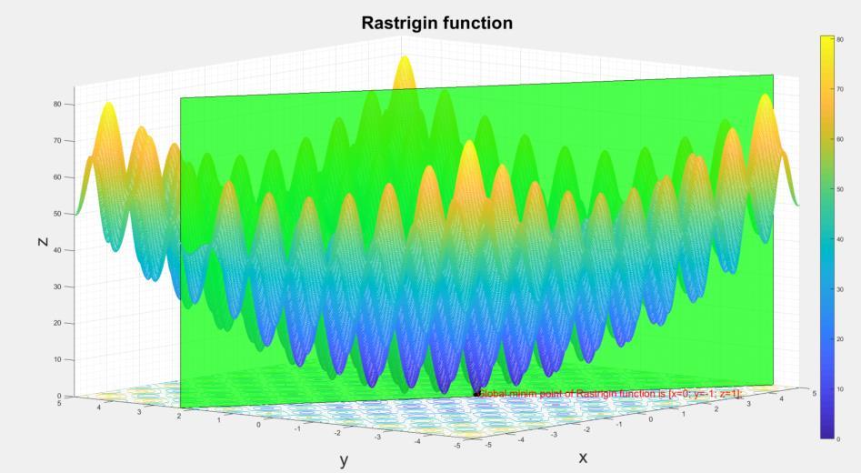
Figure 8: The Rastrigin function used for the performance test of the constrained optimization algorithm. The global minimum is set on the boundary
Table 1: The performance of the constrained optimization algorithm for different swarm sizes and boundary behaviours
Number of individuals in the swarm Boundary behaviour
Number of searches out of 100, when only local minima were found 5 Absorption 90 5 Halving 94 5 Invisible 98 10 Absorption 32 10 Halving 56 10 Invisible 81 25 Absorption 3 25 Halving 5 25 Invisible 17 50 Absorption 1 50 Halving 3 50 Invisible 7 75 Absorption 1 75 Halving 1 75 Invisible 2 Average number of iterations for the cases when the global minimum was found
146 114 142 73 130 214 54 131 365 54 130 373 52 139 363
Particle Swarm Optimization of a Hybrid Energy Storage System 93
Table 1 summarizes the results of the constrained optimization algorithm applied to the problem from Fig. 8, obtained for different sizes of the swarm and different behaviours of the boundary. The cognitive learning factor and the social learning factor were set to ��1 = ��2 =2, while the inertia weight was �� =0.073.
Several 100 searches were performed for each swarm size and boundary type combination.
It can be concluded that a swarm of 5 particles is too small to cope with this task, as more than 90% of the randomly initialized searches fail to find the global minimum. It can be also observed that the increase of the number of particles above 25 does not determine the significant decrease of the number of iterations.
The statistics from Fig. 9 demonstrate that the “absorbing” boundary is the most performant, with more than two times less iterations to the global minimum, than the “halving” one, and with 7 times less than the invisible” one.

Figure 9: Boxplot statistics of the iteration number to the global minimum for different swarm sizes and boundary behaviours
4. Particle swarm minimization of the HESS energy losses
The solution of the energy loss minimization problem is represented by the time function of the power sharing ratio ��(��). Time discretization has been made according to Fig. 5, but it became evident that the dimensionality of the problem with the solution space of �� ∈[0,1]�� is prohibitive even for a relatively short driving cycle.
94 J. Ferencz, and A. Kelemen
Two approaches are presented in this section for the reduction of the dimensionality, applied both in case of unconstrained and constrained optimization.
The first approach consists of the division of the driving cycle to a small number of equal time intervals �� ≪ �� ���� , each with a constant value of the energy sharing factor ��. Thus, the optimization task is reduced to a search in a Pdimensional solution space, i.e. the determination of a P-dimensional vector ���� =[��1,��2,…����]=argmin �� (���������� 〈��〉),���� ∈[0,1]. (13)
It is not totally surprising that such an unsupported subdivision of the driving cycle can yield results that are by far not optimal.
In the second version we propose a “dynamic” subdivision of the driving cycle. In this approach, the time instants that define the subdivision become dimensions of the solution space. Thus, the optimization task can be formulated as
���� ∗ =[����,����]=[��1,��2,…����,��1,��2,…����−1]=argmin ��∗ (���������� 〈��〉),���� ∈[0,1],���� ∈[0,1] , (14)
where ���� =
���� �� are the subdivision time instants normalized to the driving cycle
period.
The optimal solution is the vector ���� ∗ , obtained by the extension of the optimal power sharing vector ���� with the normalized vector of the optimal subdivision time instants ����.
In this way the dimension of the solution space is almost doubled, but the complexity of the problem can still be handled for simple driving cycles. We propose as an example of energy loss optimization the driving cycle from Fig. 10, which consists of a ���� =50��, �� =0.8 �� ��2 acceleration, and a ���� =50��, �� =−0.8 �� ��2 deceleration stage of an �� =1611���� vehicle. Thus, the maximum speed is �������� =144 ���� ℎ . The parameters of the energy storage devices are listed in Table 2. The capacity of the battery and the internal resistances have been distorted on purpose to obtain a large SOC variation, and to bring the HESS close to its operation limits in the short driving cycle from Fig. 10.
Particle Swarm Optimization of a Hybrid Energy Storage System 95
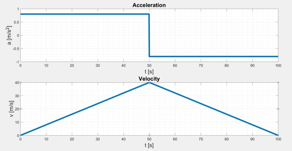
Figure 10: The simple driving cycle used to demonstrate the PSO of the total energy losses
Table 2: The parameters of the HESS, used for simulation.
Battery Capacity
Supercapacitor ������ 1000 Wh No load voltage �������� 800 V Initial state of charge �������������� 100 % Internal resistance at SOC=100% ��������|������=������% ���������� Internal resistance at SOC=50% ��������|������=����% ���������� Capacity ������ 10 F Initial voltage ������ _
�������� 800 V Internal resistance ������ ����������
4.1 Unconstrained energy loss minimization
Fig. 11 shows the minimum values of the energy losses obtained by the application of the fixed and dynamic subdivision approaches, for �� ={1,2,3,4}. To be noticed, that the fixed division of the driving cycle into three equal subintervals yields higher losses than if it was divided only in two.
On the contrary, the dynamic subdivision yields a monotonically efficiency increasing with the number of subdivision intervals.
96 J. Ferencz, and A. Kelemen
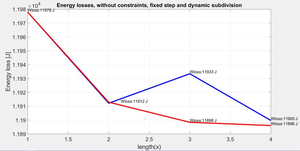
Figure 11: The results of the unconstrained PSO for fixed step (blue curve) and dynamic (red curve) subdivision of the driving cycle, versus the number of the subdivision intervals (the length of the power sharing vector) Table 3 contains the optimal power sharing vectors and the optimal subdivision vectors for different numbers of subdivision intervals, resulted from the application of the fixed-step and dynamic subdivision methods.
Table 3: The results of the unconstrained energy loss optimization.
Dynamic subdivision Fixed step subdivision
P
Optimal power sharing vector ���� Optimal normalized subdivision vector Optimal power sharing vector Optimal normalized subdivision vector
���� 1 [0.6902] - [0.6902] 2 [0.6575, 0.7299] [0.499] [0.6604, 0.7290] [0.5]
3 [0.5157, 0.6699 0.7317] [0.159, 0.499] [0.6391, 0.6936, 0.7416] [0.3333, 0.6666]
4 [0.5389, 0.6499, 0.6663, 0.7235] [0.131, 0.328, 0.503] [0.6081, 0.6693, 0.7269, 0.7471] [0.25, 0.5, 0.75]
Particle Swarm Optimization of a Hybrid Energy Storage System 97
4.2. Constrained energy loss minimization
The constrained particle swarm optimization of the HESS efficiency has been performed considering the limitation of the supercapacitor voltage:
������ , (15)
where ������ _
������ =0��,������ _ ������ =800��.
Fig. 11 and Fig. 12 demonstrate that the dynamic subdivision method yields higher efficiency over the driving cycle than the fixed-step subdivision.
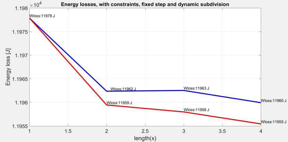
Figure 12: The results of the constrained PSO for fixed step (blue curve) and dynamic (red curve) subdivision of the driving cycle, versus the number of the subdivision intervals (the length of the power sharing vector)
The results for fixed-step and dynamic subdivision are shown in Fig. 12, while Table 4 resumes the optimal power sharing vectors and the optimal subdivision vectors in case of the constrained PSO.
Fig. 13 illustrates the variation in time of different state variables of the HESS, when this is operated in the conditions that minimize the driving cycle energy losses. It can be observed that the constraints set for the supercapacitor voltage are satisfied.
98 J. Ferencz, and A. Kelemen
Table 4: The results of the constrained energy loss optimization
Dynamic subdivision Fixed step subdivision
Optimal power sharing vector ����
Optimal normalized subdivision vector ����
Optimal power sharing vector ����
P
Optimal normalized subdivision vector ���� 1 [0.6902] - [0.6902] 2 [0.5344, 0.6917] [0.1158] [0.6868, 0.6955] [0.5] 3 [0.5327, 0.6921 0.4877] [0.1184, 0.9759] [0.6781, 0.6925, 0.6976] [0.3333, 0.6666] 4 [0.5067, 0.6579, 0.6941, 0.5535] [0.0921, 0.2148, 0.9228] [0.6654, 0.6909, 0.6967, 0.6825] [0.25, 0.5, 0.75]
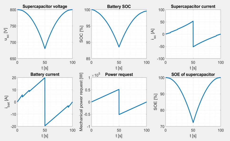
Figure 13: Time diagrams of the HESS state variables in case of operation under the condition ��∗ =���� ∗
4.3. Performance comparison of the “Invisible” and “Halving” boundaries
The influence of the boundary behaviour on the performance of the constrained optimization algorithm has been analyzed in case of the dynamic subdivision of the driving cycle to four time-intervals.
Particle Swarm Optimization of a Hybrid Energy Storage System 99
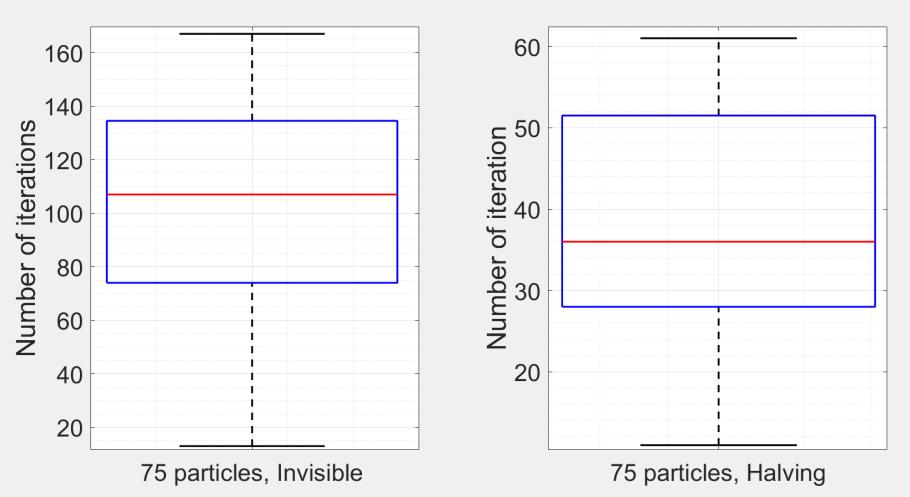
Figure 14: Boxplot statistics of the iteration number to the global minimum for a swarm of 75 particles in case of the “Invisible” and “Halving” boundaries
Thus, the dimension of the power sharing vector ��is �� =4, and the dimension of the vector �� of the subdivision time instants is 3.
In Fig. 14 it can be observed that the “Invisible” behaviour of the boundary results in almost three times more iterations to reach the global minimum, than the “Halving” behaviour. The statistics resulted from 20 search processes for each type of boundary, starting from different, randomly chosen initial positions.
5. Conclusions
In the study we aimed to minimize the losses of a hybrid energy storage system of an electric vehicle. This has been performed by means of an optimal sharing of the required electrical power between the energy storage devices. It has been shown that extending the dimension of the space of solutions with the number of the subdivision time instants of the driving cycle, the HESS can be efficiently optimized, while the dimensionality of the problem remains manageable.
The constrained optimization algorithm has been validated using the Rastrigin test function and three different behaviours of the boundary. Out of these, the “absorption” behaviour provided the best results, which is reasonable, especially in the cases when the optimum is close to the boundary.
For this test function, and a swarm of 75 particles, we found that the “Absorption” method is almost 7 times faster, and the “Halving” method is almost 3 times faster in finding the global minimum, than the “Invisible” method.
Unfortunately, the “Absorption” method can’t be applied for the constrained optimization of the hybrid energy storage system, because in this case the
100 J. Ferencz, and A. Kelemen
boundary itself is hard to be defined in the space of the power sharing factors and subdivision instants.
The local minima have been avoided by multiple initializations of the search algorithm, and combination of different stop conditions, including the clustering of the swarm, had to be applied in case of the constrained optimization.
References
[1] Chen, Q., Jiang, J., Ruan, H., and Zhang, C., “Simply Designed and Universal Sliding Mode Observer for The SOC Estimation of Lithium-Ion Batteries”, IET Power Electronics, vol. 10 Iss. 6, pp. 697705, Jan. 2017. [2] Huang, T., and Mohan, A. S., “A Hybrid Boundary Condition for Robust Particle Swarm Optimization”, IEEE Antennas and Wireless Propagation Letters, vol. 4, pp. 112117, Jun. 2005. [3] Wang, D., Tan D., and Liu, L., “Particle Swarm Optimization Algorithm: An Overview”, Springer Link. Soft Computing, vol. 22, pp. 387408, Jan. 2017. [4] Kanglong, Y., Peiqing, L., and Hao, L., “Optimization of Hybrid Energy Storage System Control Strategy for Pure Electric Vehicle Based on Typical Driving Cycle”, Hindawi. Mathematical Problems in Engineering, vol. 2020, pp. 112, Jun. 2020. [5] Chong, L., W., Wong, Y., W., and Rajkumar, R., K., “An Optimal Control Strategy for Standalone PV System with Battery Supercapacitor Hybrid Energy Storage System”, Elsevier. Journal of Power Sources, vol. 331, pp. 553565, Nov. 2016. [6] Ammari, C., Belatrache, D., Touhami, B., and Makhlouf, S., “Sizing, Optimization, Control and Energy Management of Hybrid Renewable Energy System — A Review”, KeAi. Energy and Built Environment, vol. 2, pp. 2353, Aug. 2021. [7] Romaus, C., Gathmann, K., and Böcker, J., “Optimal Energy Management for a Hybrid Energy Storage System for Electric Vehicles Based on Stochastic Dynamic Programming”, 2010 IEEE. Vehicle Power and Propulsion Conference, Sept. 2010, pp. 16. [8] Vinot, E., and Trigui, R., “Optimal Energy Management of HEVs with Hybrid Storage System”, HAL open science. Energy Conversion and Management, vol. 76, pp. 437-452, Feb. 2019. [9] Capassoa, C., Lauria, D., and Veneria, O., “Optimal Control Strategy of Ultra-Capacitors in Hybrid Energy Storage System for Electric Vehicles”, Elsevier. Energy Procedia, vol. 142, pp. 19141919, Aug. 2017. [10] Sadeq, T., Wai, C., K., Morris, E., Tarbosh, Q., A., and Aydoğdu, Ö., “Optimal Control Strategy to Maximize the Performance of Hybrid Energy Storage System for Electric Vehicle Considering Topography Information”, IEEE Access, vol. 8, pp. 113, Nov. 2020. [11] Chang, W. Y., “The State of Charge Estimating Methods for Battery: A Review”, Hindawi. International Scholarly Research Notices, vol. 2013, pp. 1-8, Jul. 2013. [12] Ye, K., and Li, P., “A New Adaptive PSO-PID Control Strategy of Hybrid Energy Storage System for Electric Vehicles”, Sage. Advances in Mechanical Engineering, vol. 12, pp. 115, Aug. 2020. [13] Ferencz, J., Kelemen, A., and Imecs, M., “Control of an Electric Vehicle Hybrid Energy Storage System”, Sciendo, Papers on Technical Science, vol. 14, pp. 7788, Aug. 2021. [14] Paul, T., Mesbahi, T., and Durand, S., “Sizing of Lithium-Ion Battery/Supercapacitor Hybrid Energy Storage System for Forklift Vehicle”, Energies, vol. 13, pp. 118, Sep. 2020. [15] Borgulya, I., “Optimalizálás evolúciós számításokkal”, Typotex Kiadó Budapest, 2011.


