STUDYOFEARTHQUAKERESISTANCE IN


AcademyofArchitecture,Mumbai
DESIGN
AUGUST-2022 GUIDED
AR.K.VPARMESHWAR
AR.
AR.
ARCHITECTURALBUILDINGCONSTRUCTIONANDMATERIALS SEMESTER7STUDIO
HIGH-RISESTRUCTURES
REPORT
BY
;
HARDIKDEDHIA;
MINALGAJJAR
STUDIOCONDUCTORS
Ar.K.V.Parmeshawar Ar.HardikDedhia Ar.MinalGajjar
STUDIOTEAM
RashmitaDake 31. SaloniPawar 32. AishwaryaRaikar 33. NidhiKhot 34. SairajHalpatrao 35. AnjaliKarpate 36. PranaliThool 37. AmeyaThanawala 38. SharvilMore 39. DhruvanshiSanghavi 40. KarishmaKaurHooda 41. HarshTank 42. TarikaDeshpande 43. PrajaktaGosavi 44. SanchitaTandel 45. RasikaSalgaonakar 46. JigishaSoni 47. PoojaTambe 48. VaishnaviSiddhapara 49. KartikaPinjarkar 50. VardhanArora 51. KrisshChavan 52. MansiBhatia
RoshaniChabhare
AcademyofArchitecture,Mumbai
1.
2.
3.
4.
5.
6.
7.
8.
9.
10.
11.
12.
15.
16.
17.
18.
19.
20.
21.
22.
23.
24.
25.
26.
27.
28.
29.
ARCHITECTURALBUILDINGCONSTRUCTIONANDMATERIALS SEMESTER7STUDIO
SejalUmare
PuneetMaru
VaibhaviKhedkar
AbhishekSuryawanshi
RohitChopade
ShivanjayBhagat
KimayaChuri
GaurangRajput
PalakBhattad
SarthakEkal
NehaJayashanker
IshaPatil 13. BhoomikaChaudhari 14. AdityaKanade
ShruteePatil
ShwetaUtekar
VaishnaviGurnalkar
ShaktiJadhav
VireshDesai
IshanLathia
PrajaktaPai
LaxareeSawant
SakshiGothankar
SimranAjgaonkar
KrishnaKhurusane
SiddhiShinde
AtharvaGirme
ManasaRavikumar
30.
53. HarshwardhanShirpurkar 54. AakashKharade 55. AditiWadate 56. MithilaGadag 57. AryaJumde
AcademyofArchitecture,Mumbai GROUP01 VAISHNAVIGURNALKAR_17 VIRESHDESAI_19 SHARVILMORE_38
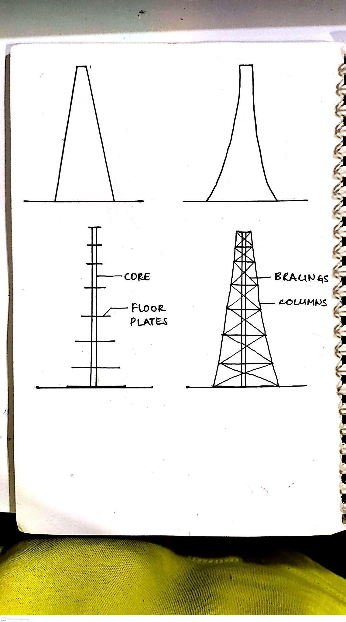
VISUALIZATION CORE
Team01| DesignReport FORMDEVELOPMENT Core Core 20000 mm 50000 mm PLAN ELEVATIONS
ANDFLOORPLATES
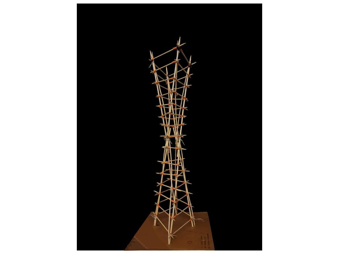
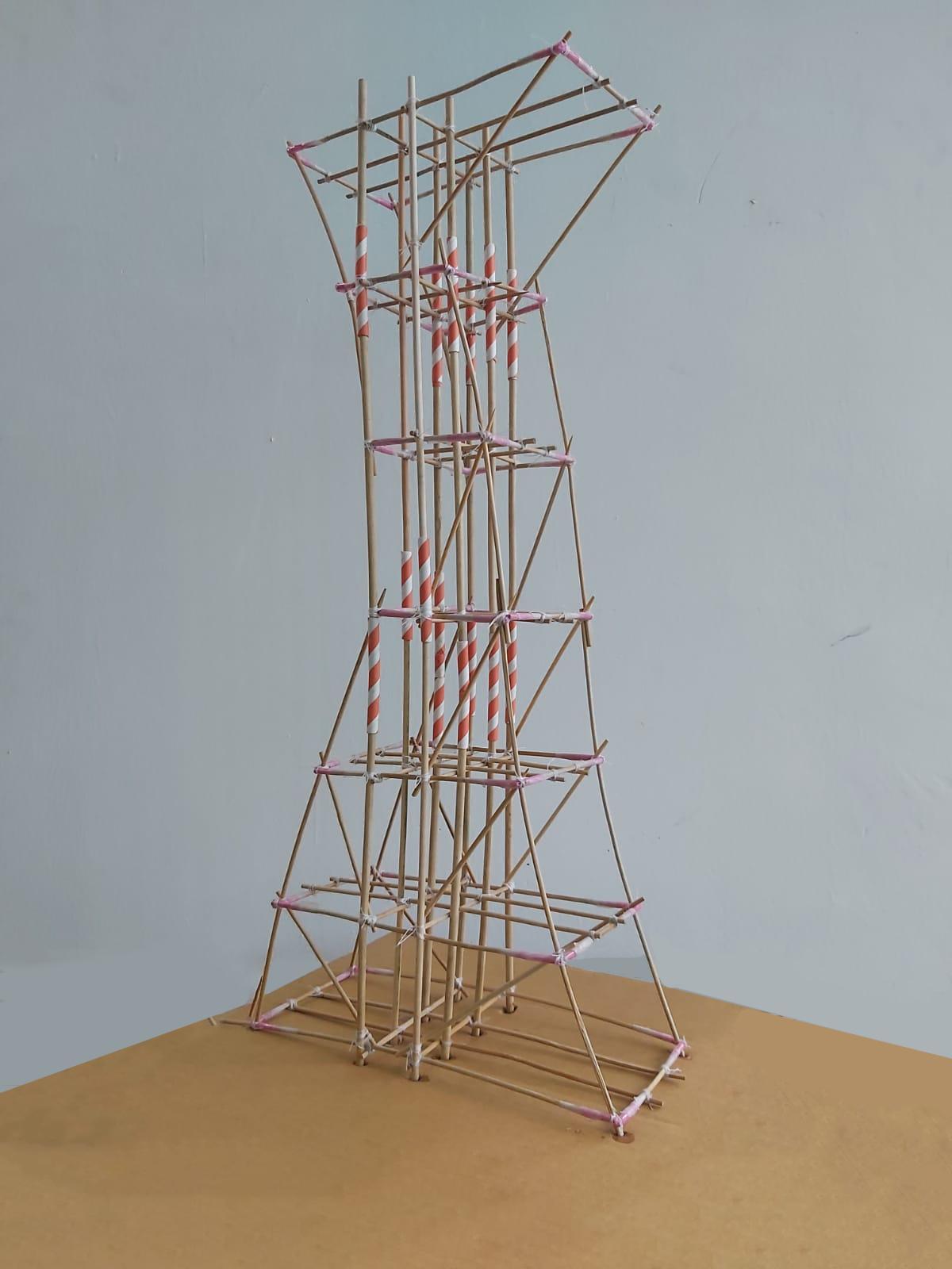
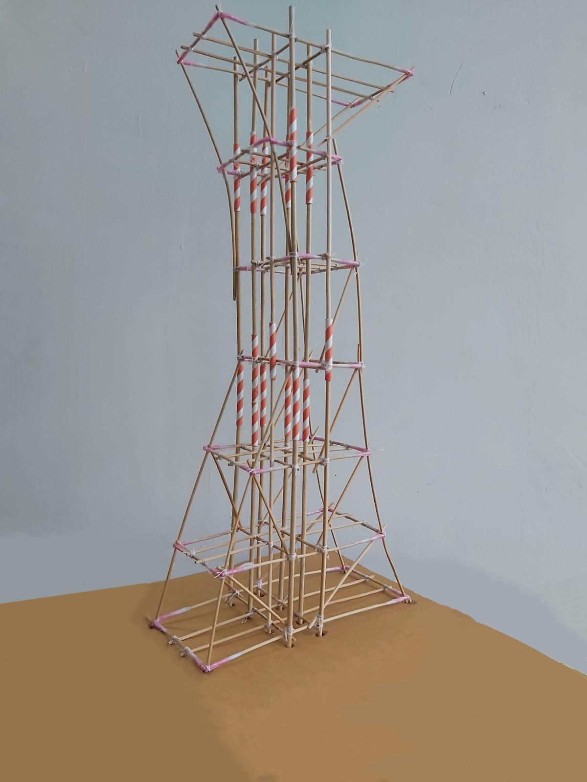
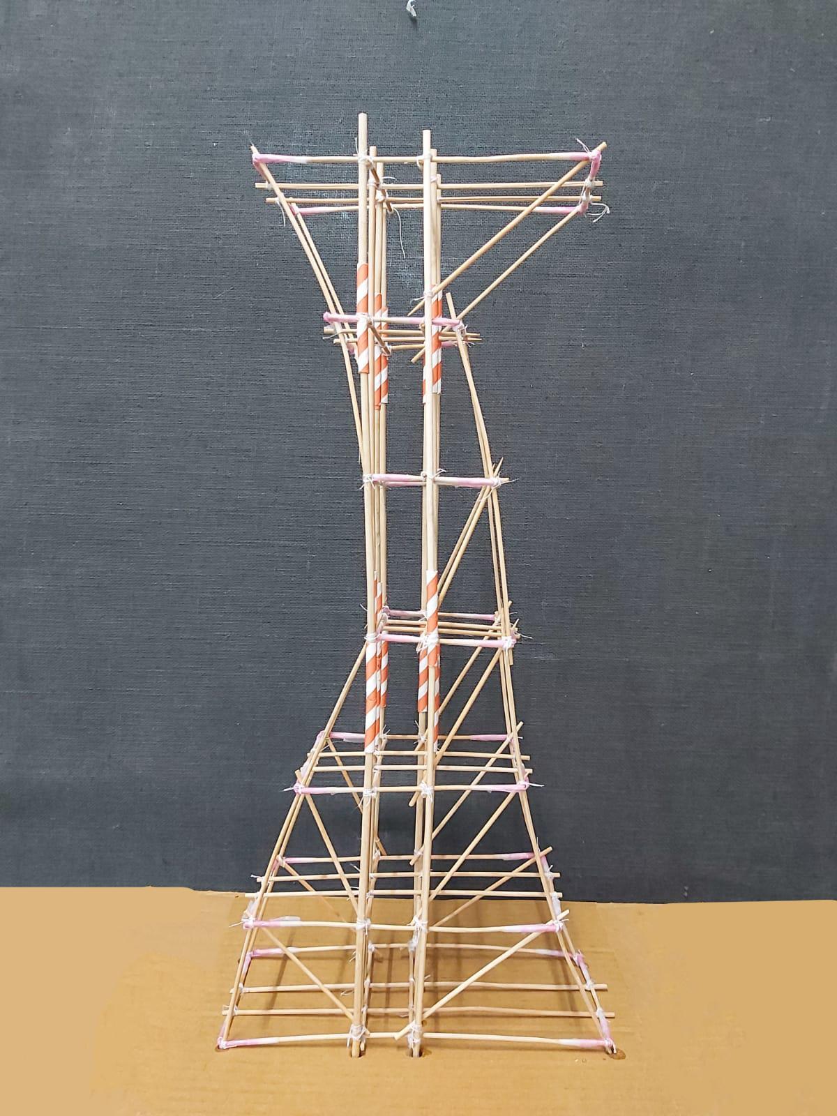
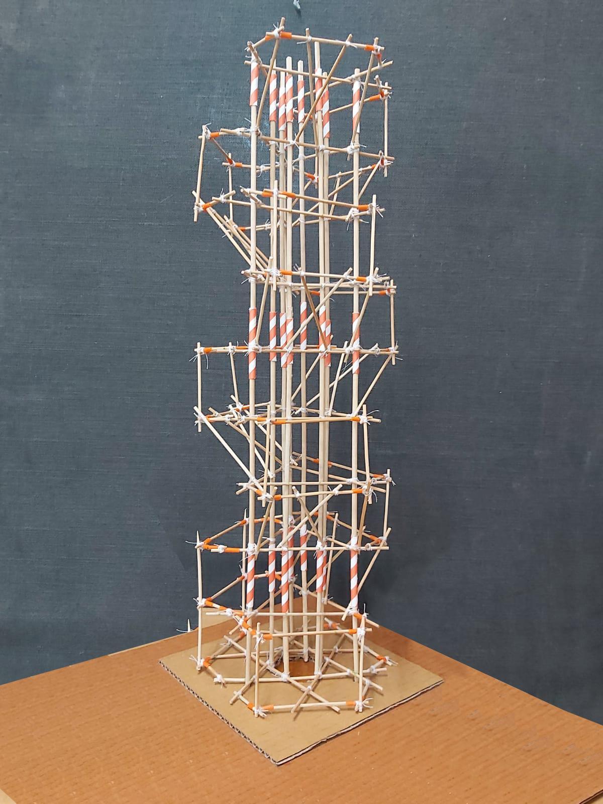
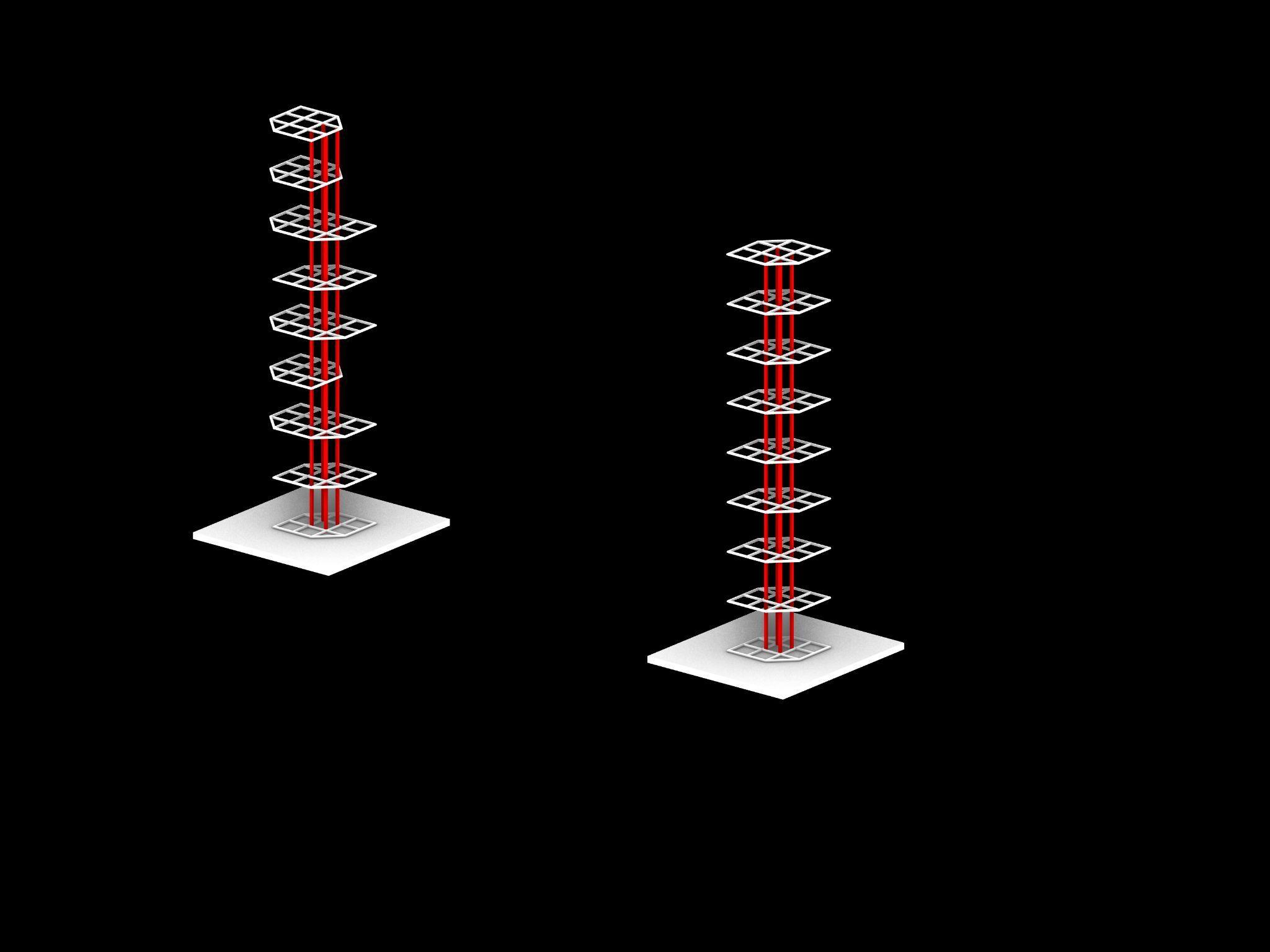
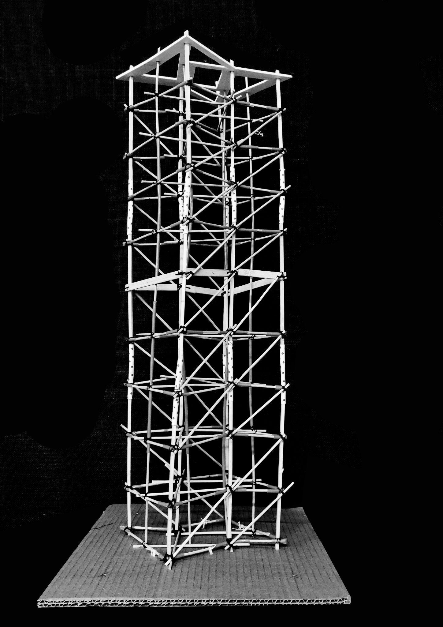
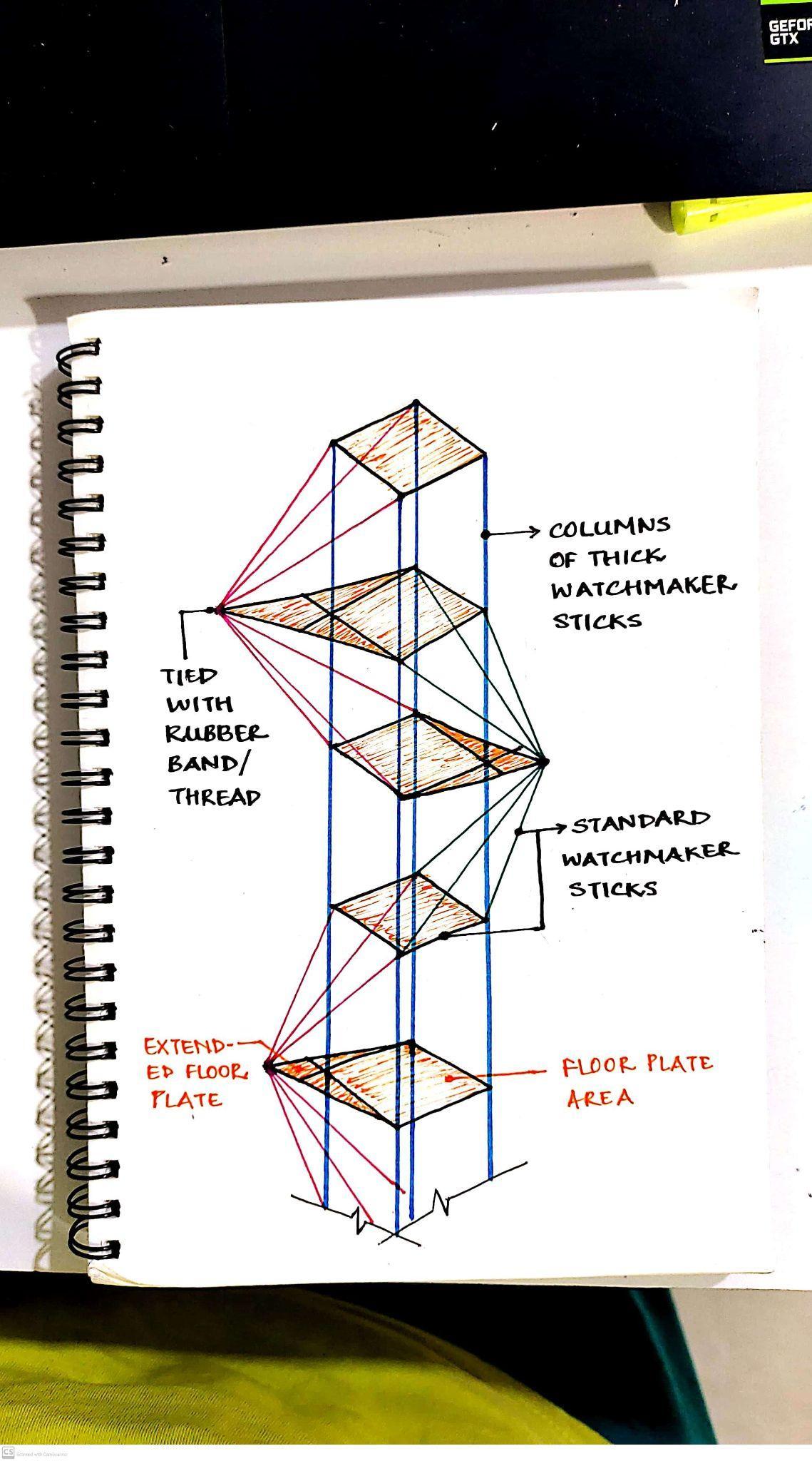
MODELWITHBRACINGONSHORTERSIDES MODELPHOTOS Team01| DesignReport
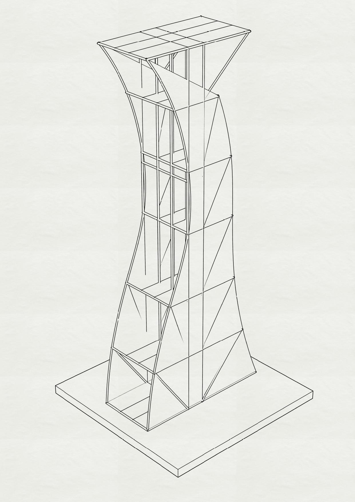
MODELWITHOUTBRACINGS
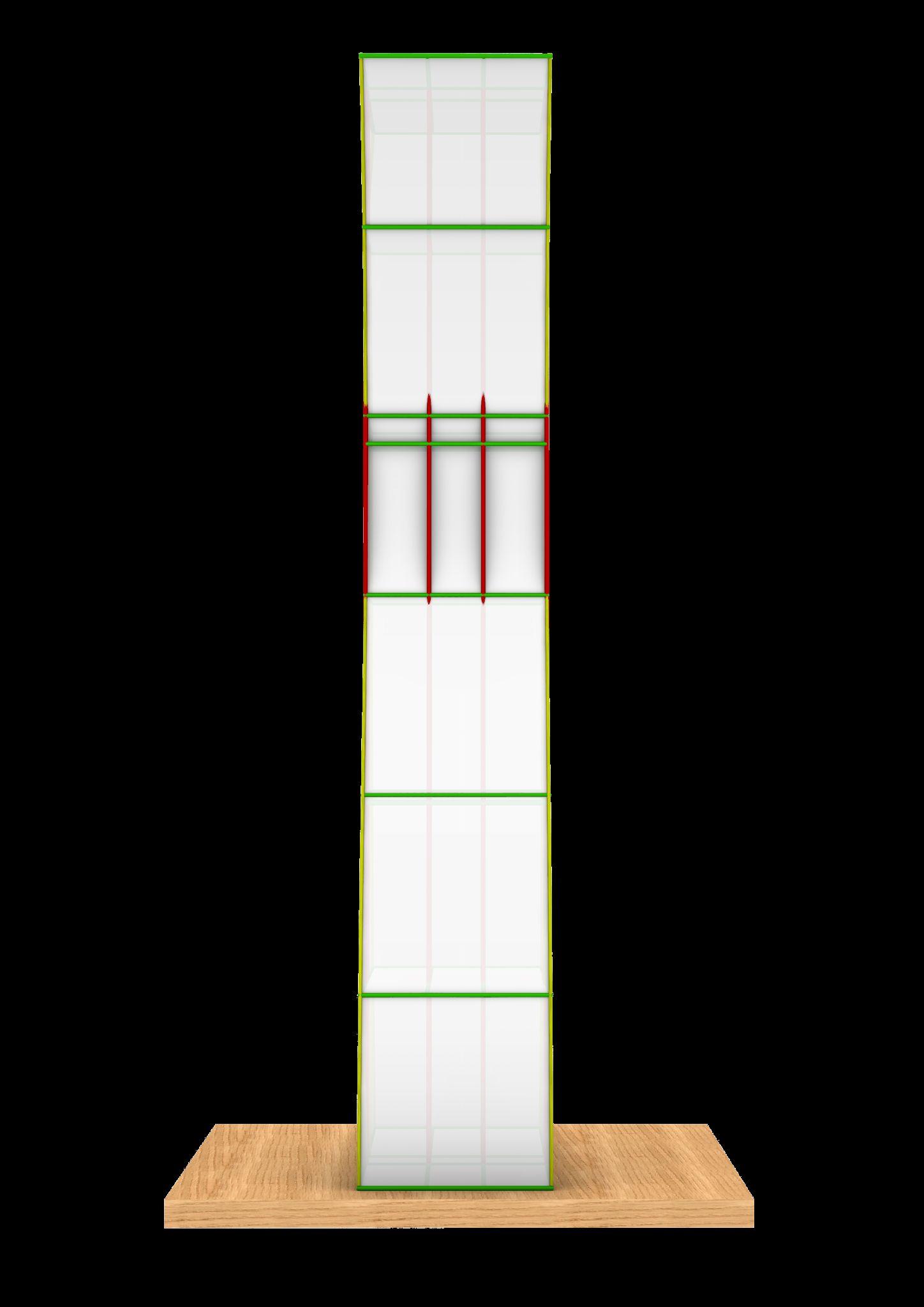
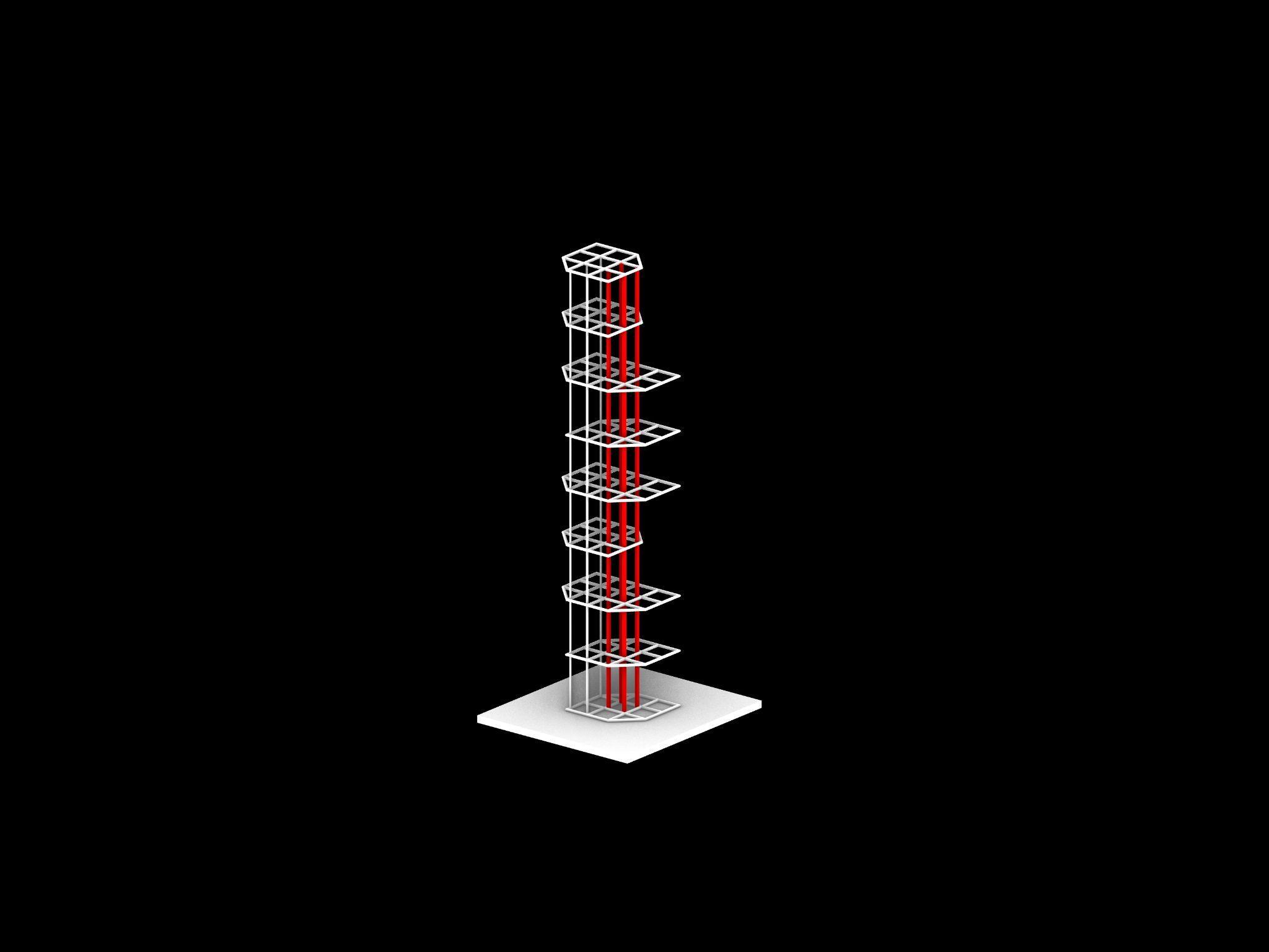
FROMLEVEL56TO75 (225MTO300M)
VISUALIZATION
FROMLEVEL38TO56 (150MTO225M)
FROMLEVEL0TO38 (0MTO150M)
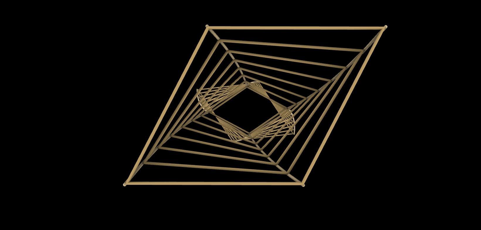
FLOORPLATES
Team01| DesignReport FORMDEVELOPMENT
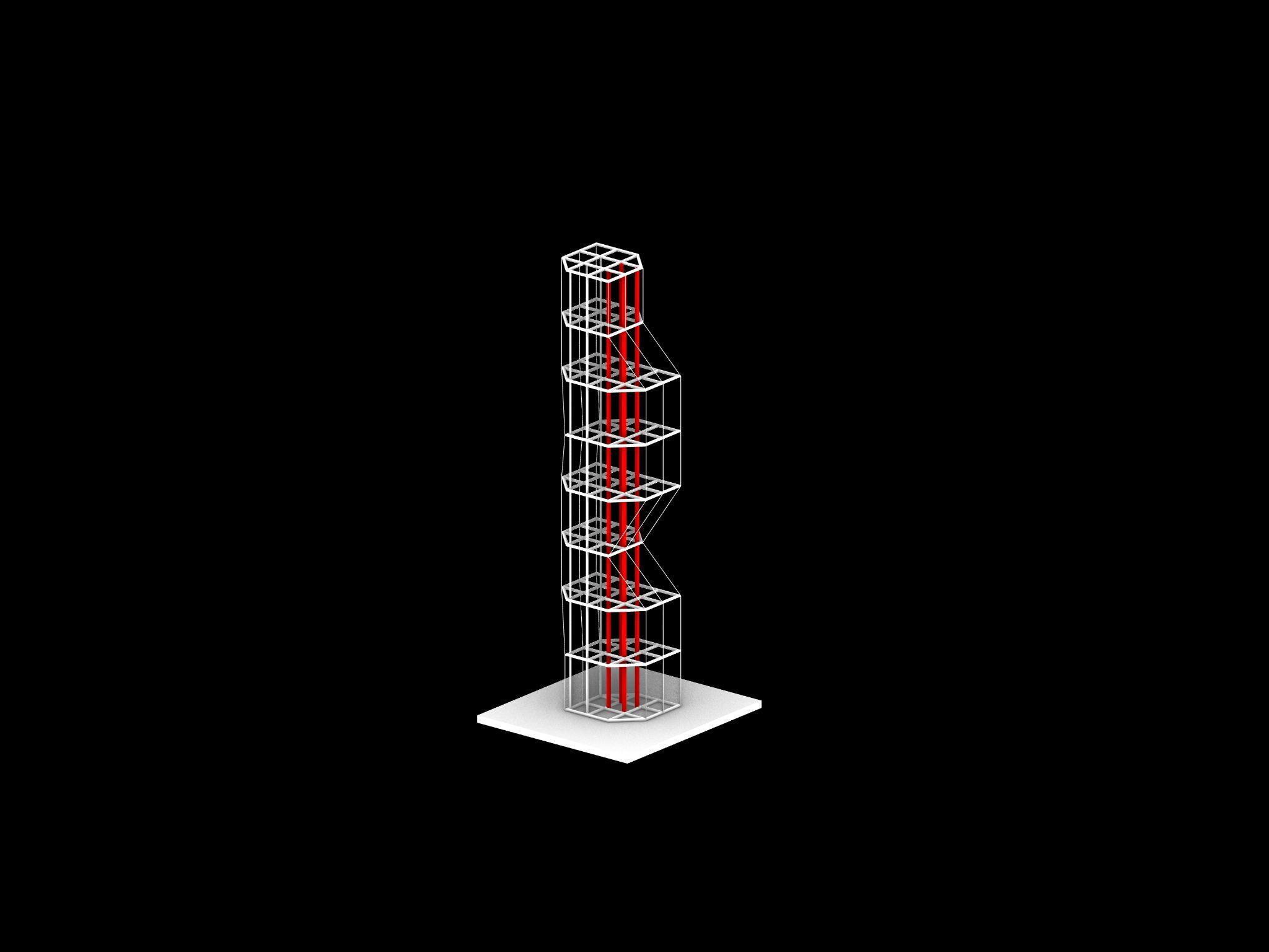
TWISTEDPART MODELPHOTOS
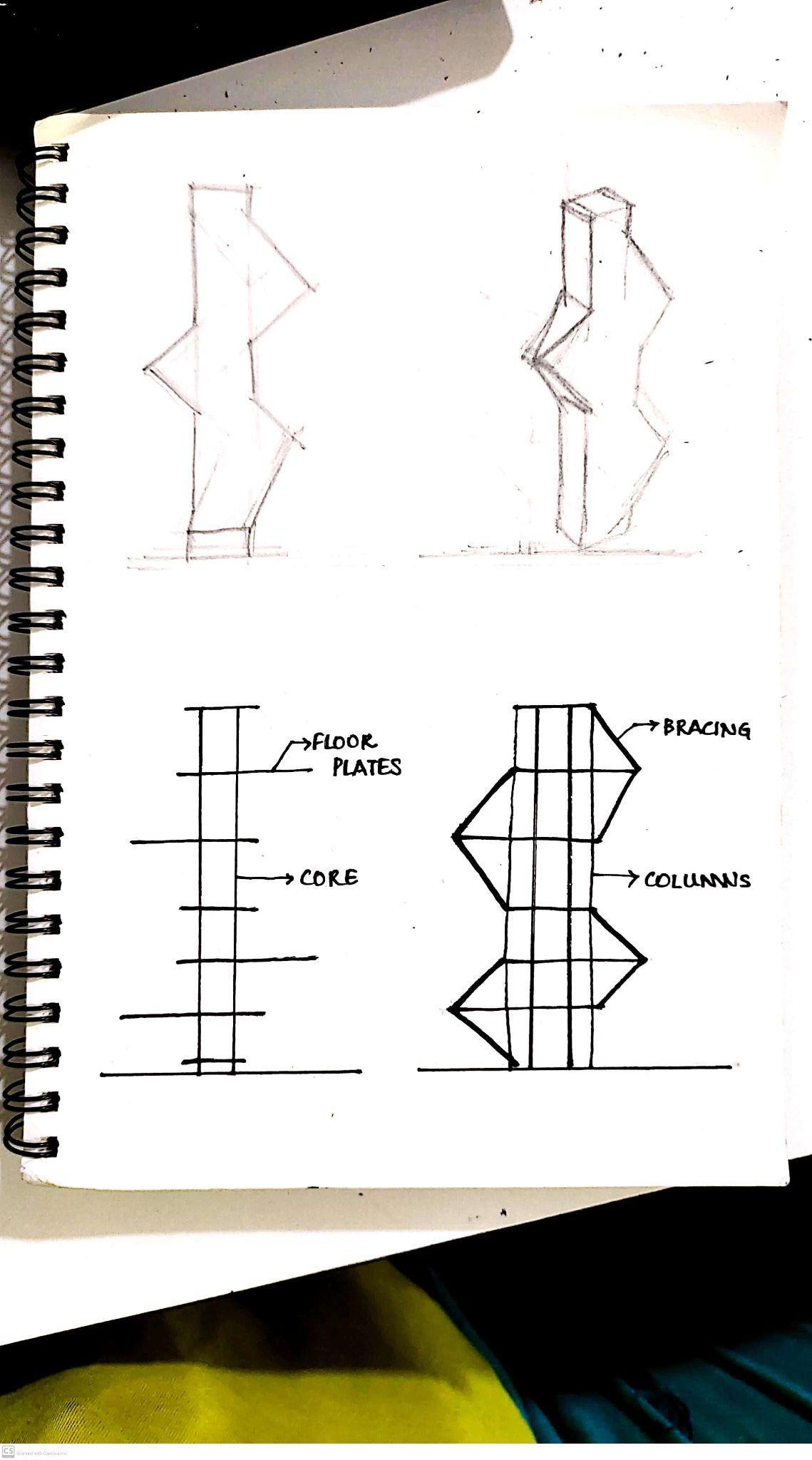
ANALYSISANDCONCLUSION
STANDARDFORM
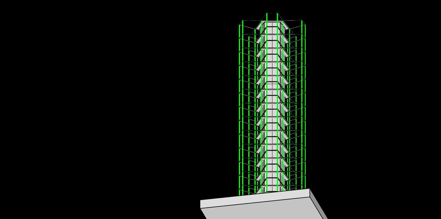
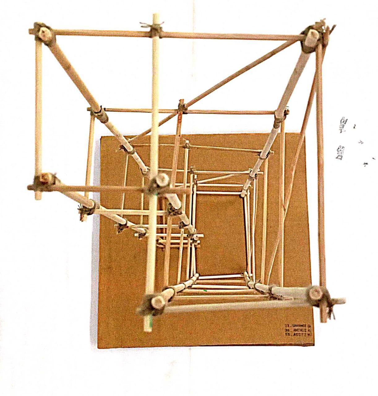
Thefirstpolygonalformtakenwasof8sideswith4shorterand4 longer sides taking inspiration from a diamond shape. The sides also faced the common core in the center for easy structural designandstability.
The model without bracings was subjected to twisting, mostly on the shorter facades. Hence, for stability bracings were added on shorted facades since they were the weak part of the structure. Thisalsohelpedtomaintainthelargerfacadesopentoviewsand alsosavingthematerial.
Team01| DesignReport CONCLUSION
TWISTING
WITHOUTBRACING STABILITYWITHBRACING
ANALYSISANDCONCLUSION
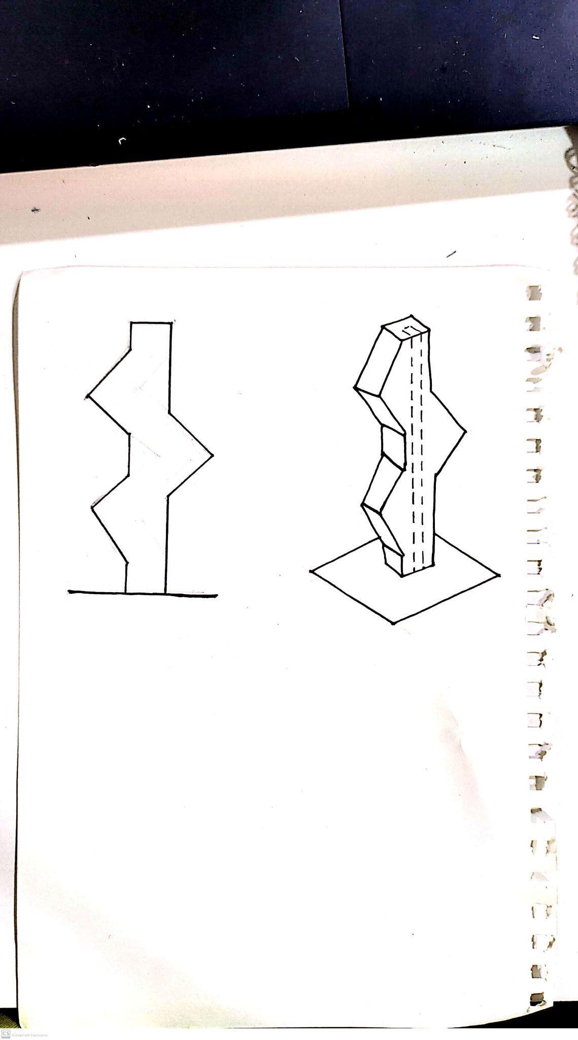
SCULPTURALFORM
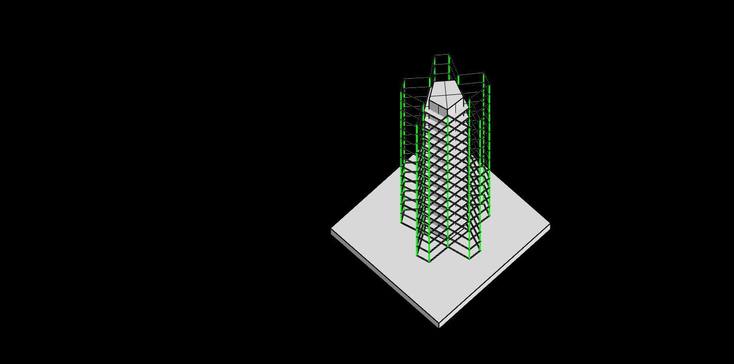
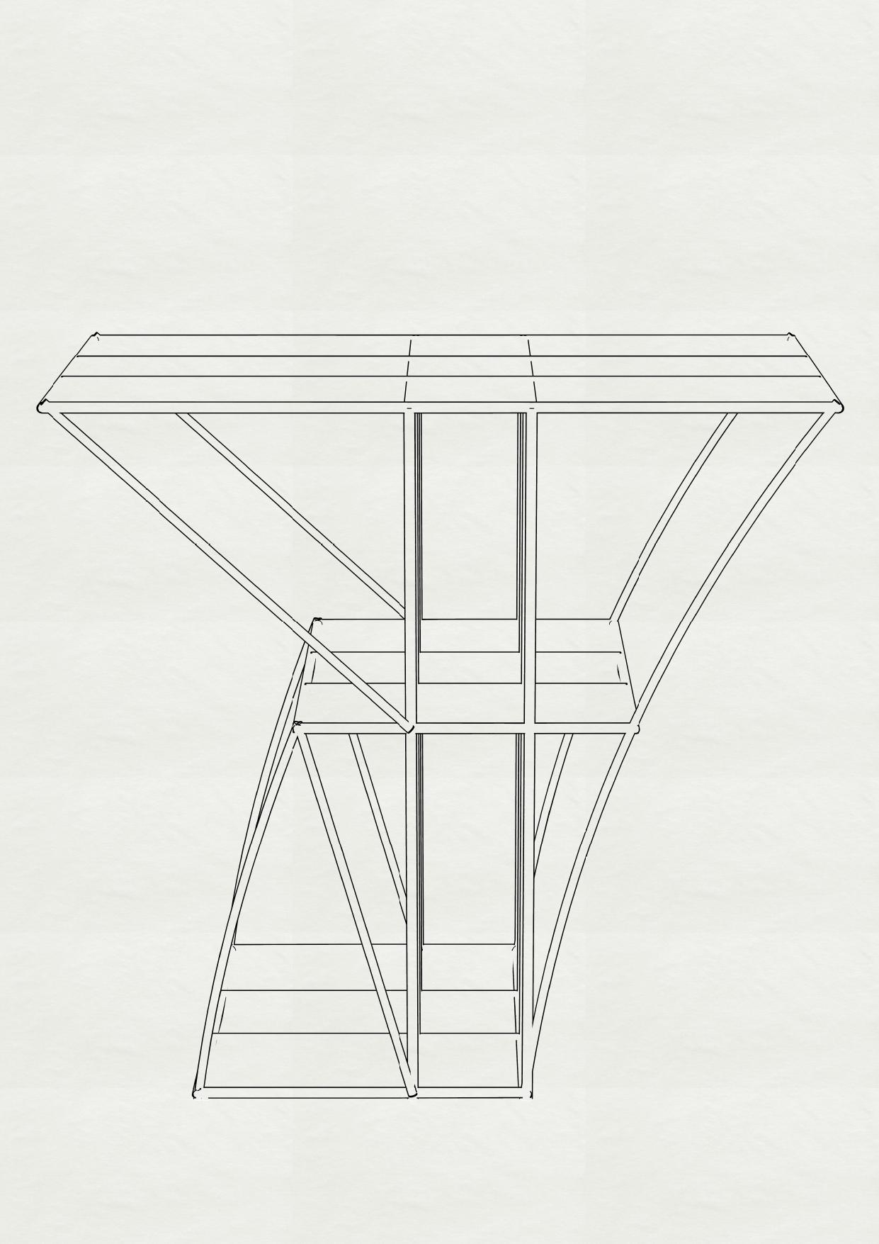
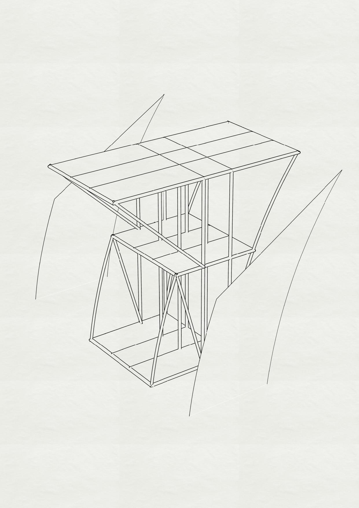
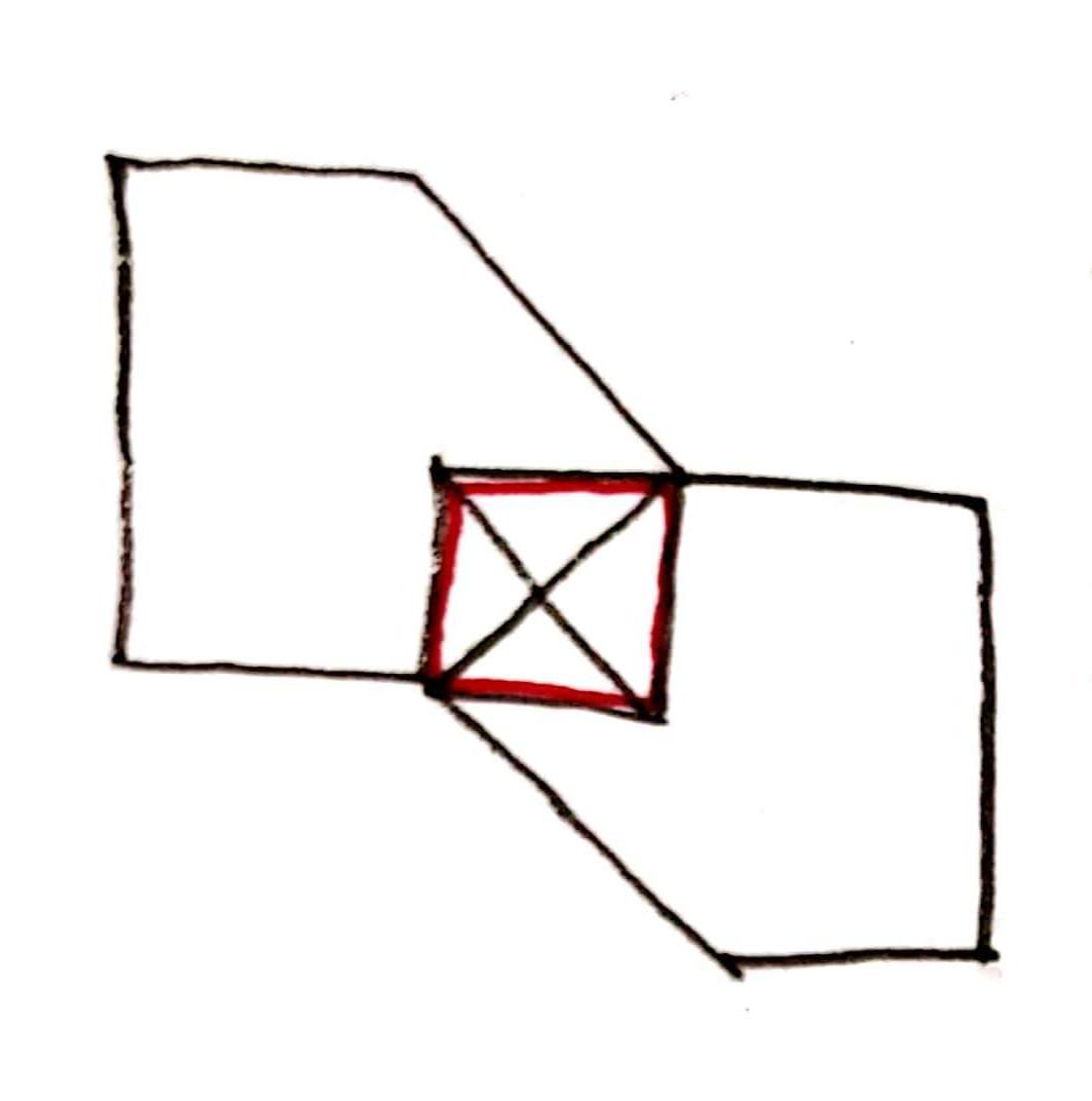
Theformwasdesignedsuchthatthetoppartishalfcantilevered With change in orientation. Like two cuboids meeting in air. The taskforthisdesigntocreateacounterweightforthecantilevered cuboidandmaintainingtheC.G.
Firstly a common core was planned for circulation and stability. Thethetopcuboidwasmajorlytakensupportsfromthecommon core. Further, without bracing, the structure was moving a lot.
STABILITYWITHBRACING
COMMONCOREFOR CIRCULATIONANDSTABILITY
PRIMARYBRACING (onthecoreside)
SECONDARY BRACING (sideadjacenttothecore)
AcademyofArchitecture,Mumbai
GROUP02 GAURANGRAJPUT_08 VAISHNAVISIDDHAPARA_48 KARTIKAPINJARKAR_49
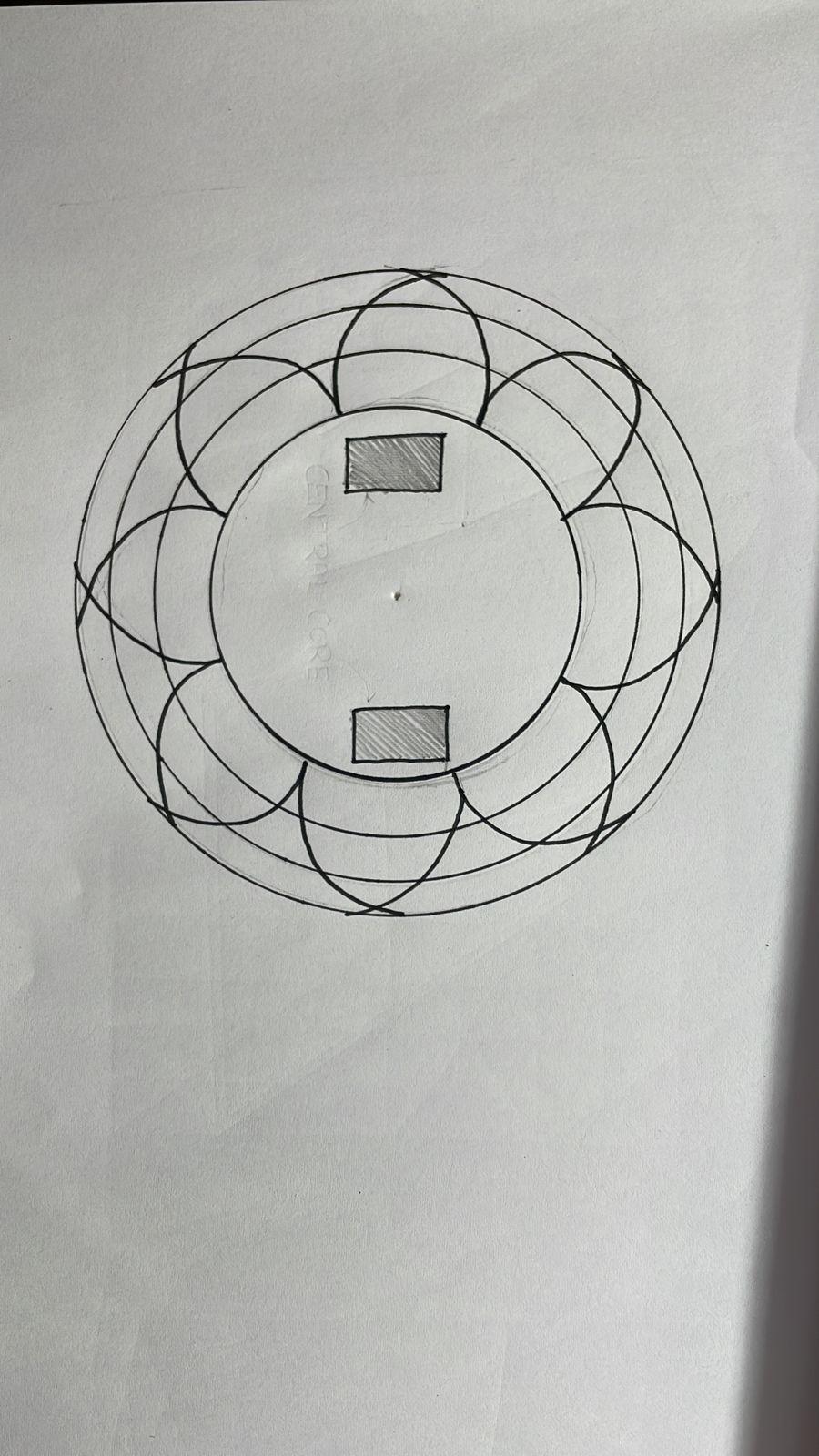
PLAN BIRDEYEVIEW

ISOMETRICVIEW WORMSEYEVIEW
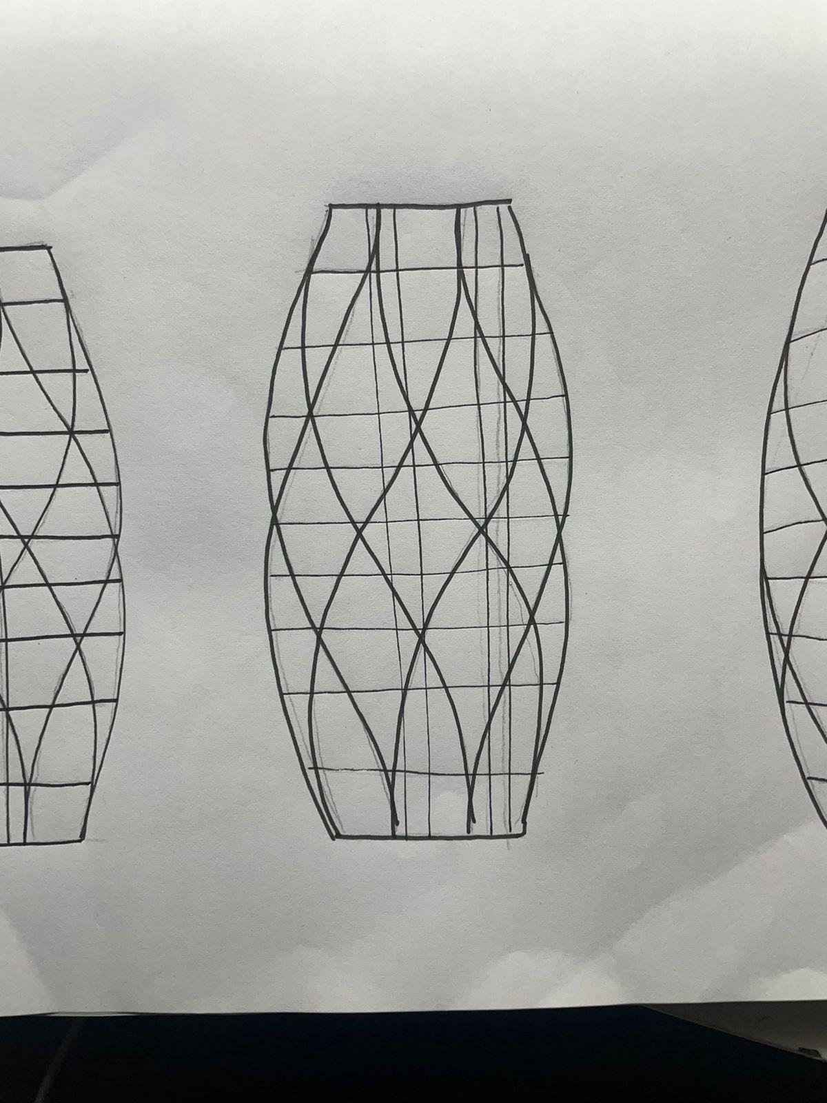
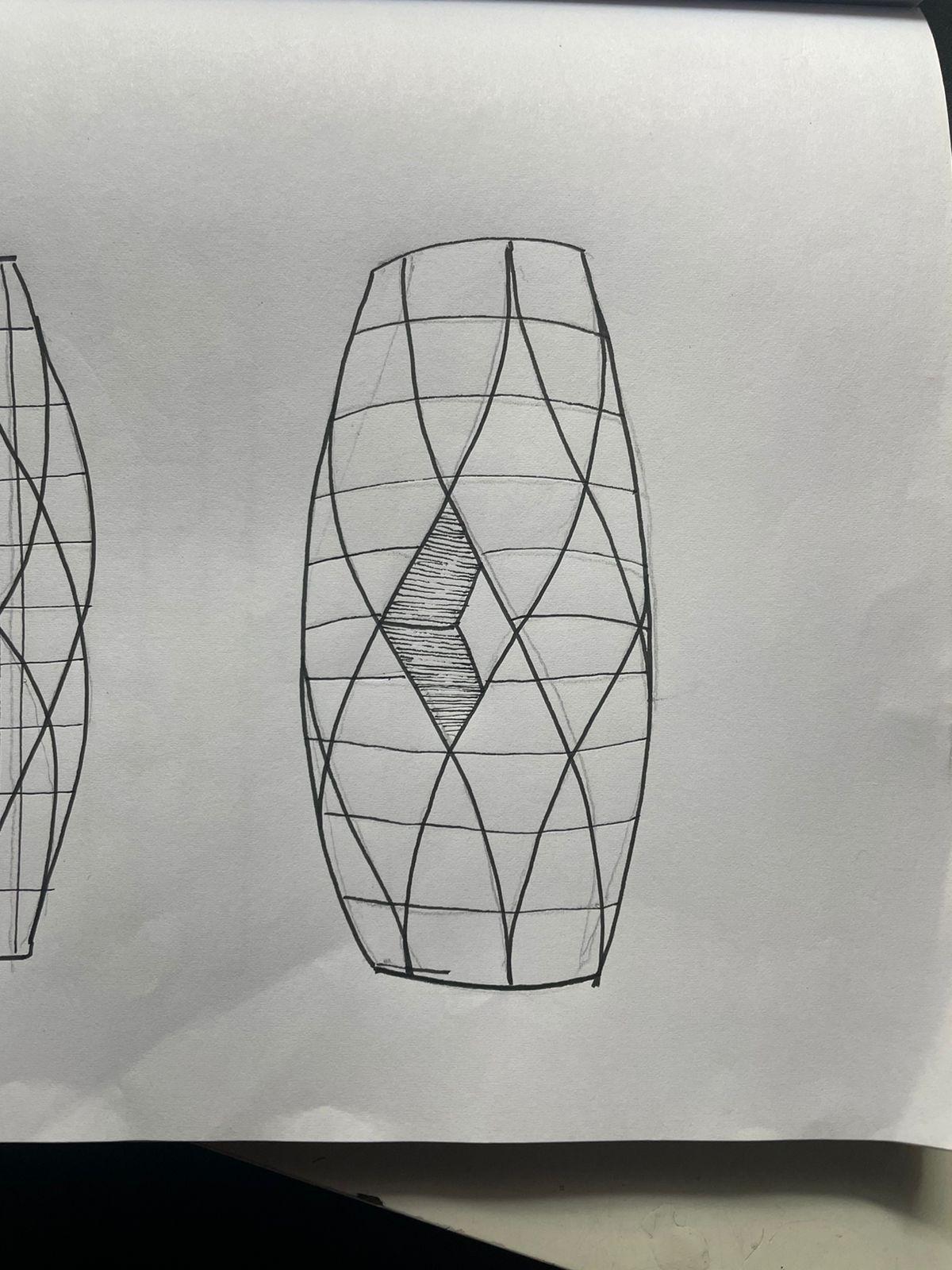
SKETCHES Team02| DesignReport
MODEL
1:GEOMETRICMODEL
PLAN BIRDEYEVIEW
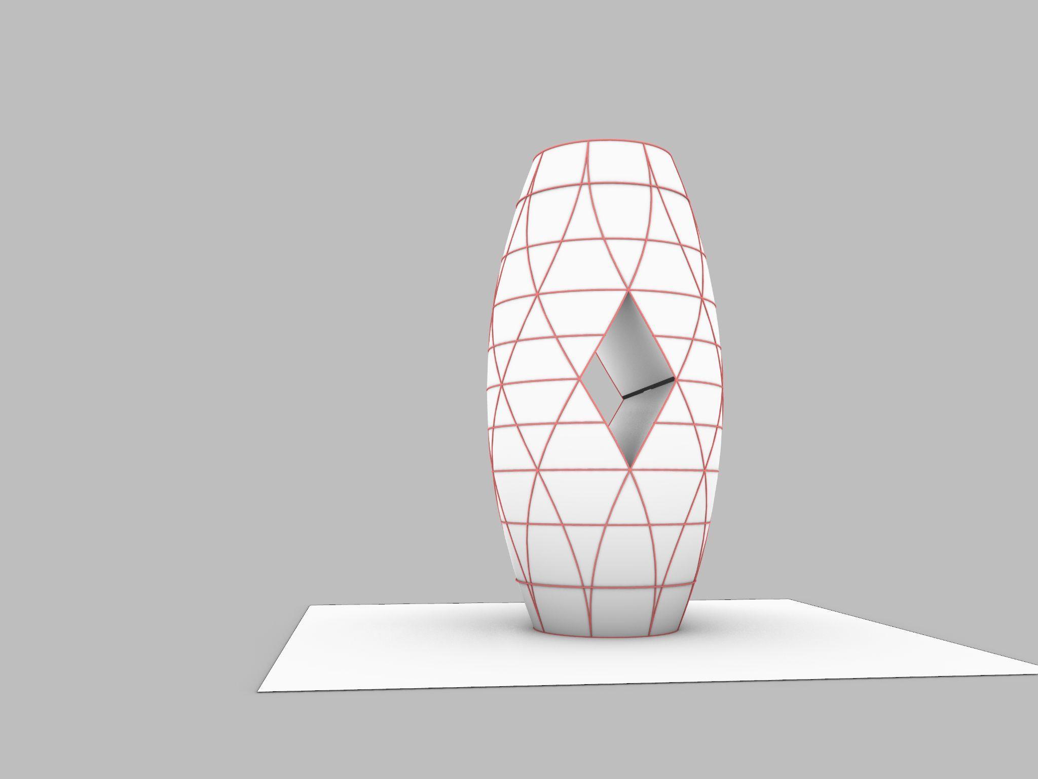
DIGITALMODELPHOTOS Team02| DesignReport
MODEL1:GEOMETRICMODEL
Team02| DesignReport MODEL1:GEOMETRICMODEL
THREEDIMENSIONALVIEW THREEDIMENSIONALVIEW SKETCHES Team02| DesignReport MODEL2:SCULPTURALMODEL
PLAN FRONTELEVATION
DIGITALMODELPHOTOS Team02| DesignReport
THREEDIMENSIONALVIEW THREEDIMENSIONALVIEW MODEL2:SCULPTURALMODEL
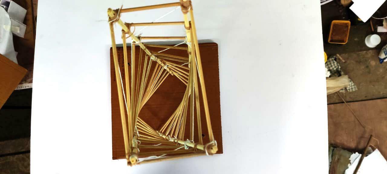
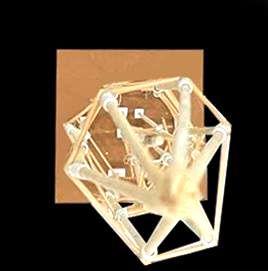
TOPVIEW VIEWOFMODELAFTERSHAKETEST
Team02| DesignReport
MODEL2:SCULPTURALMODEL
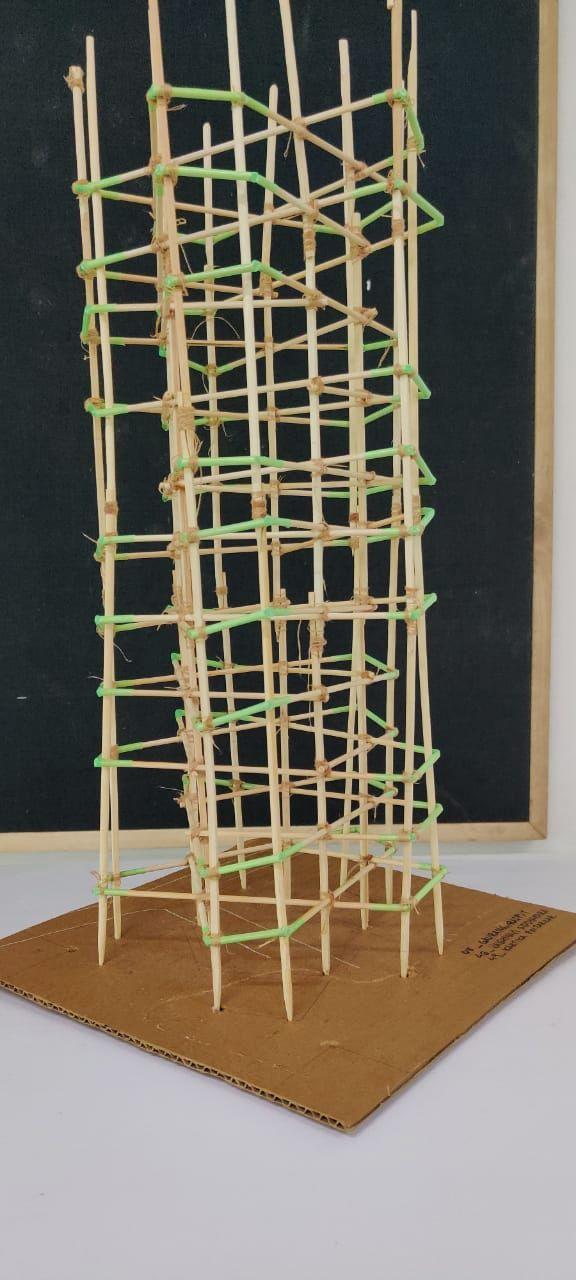
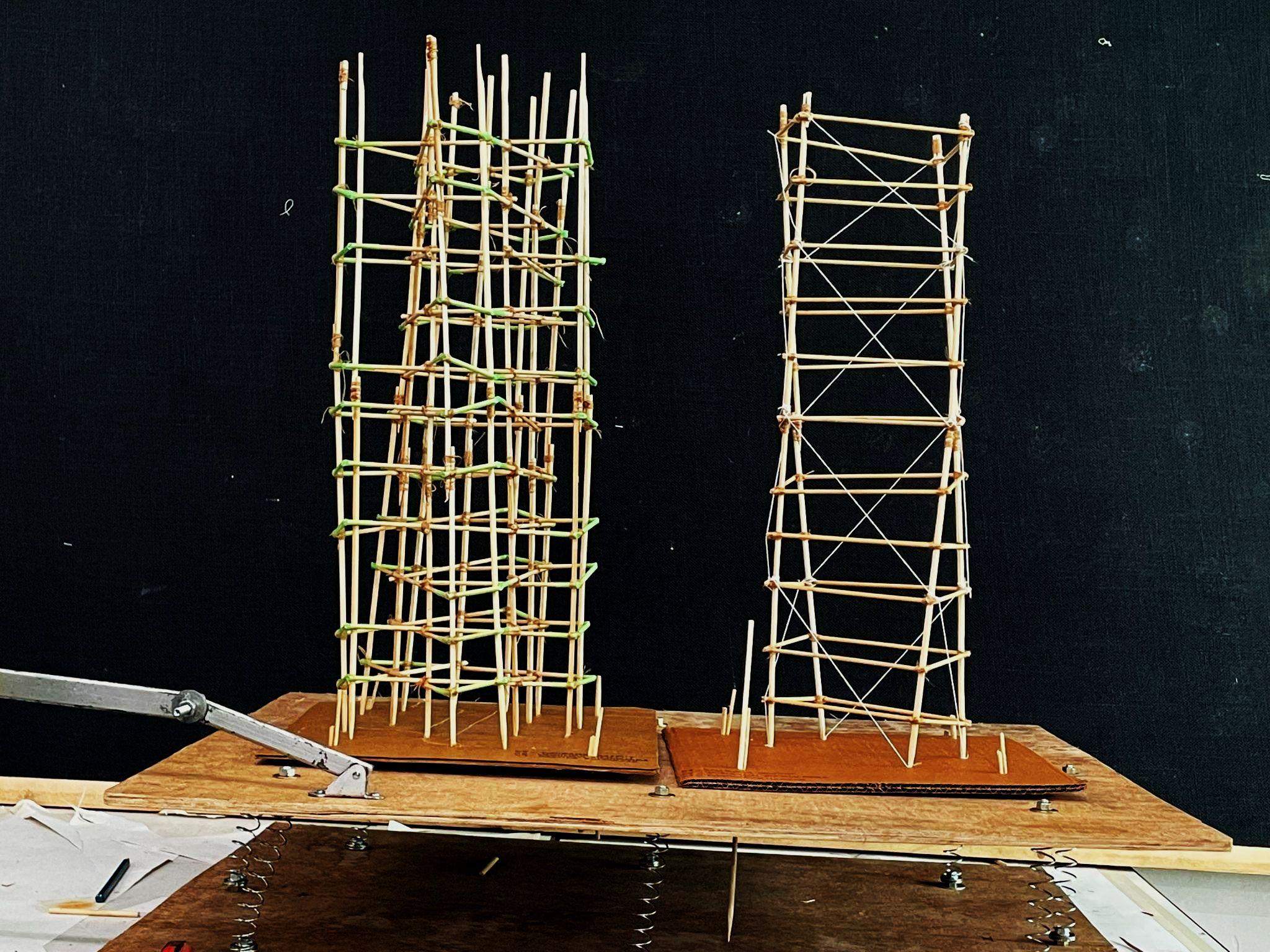
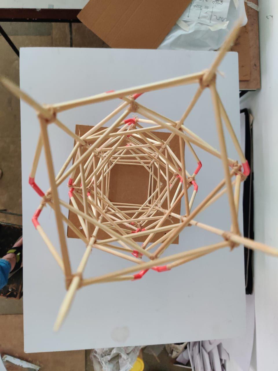
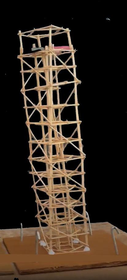
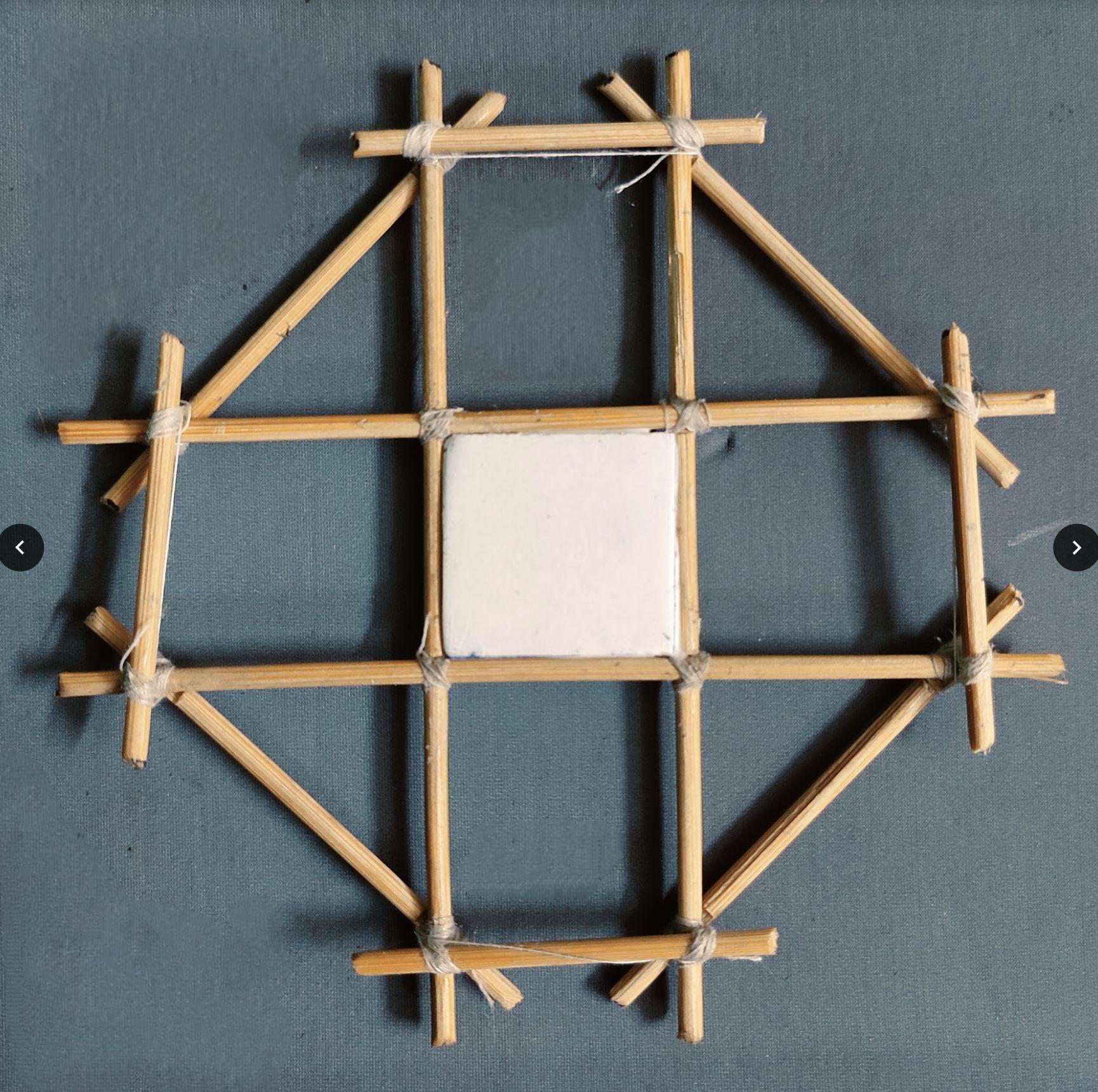
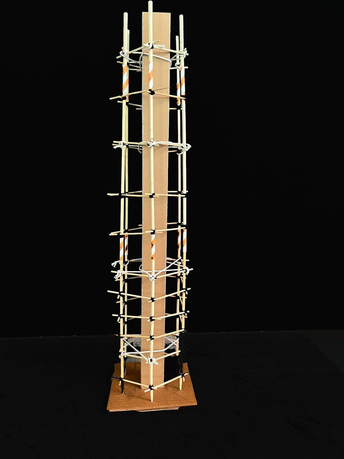
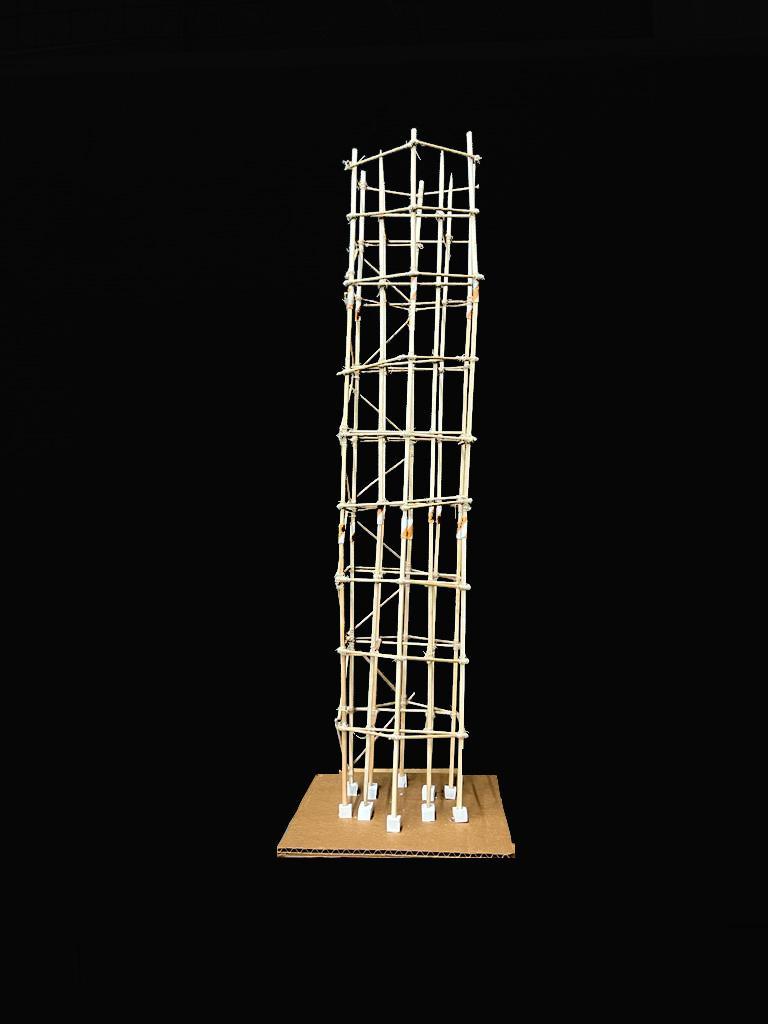
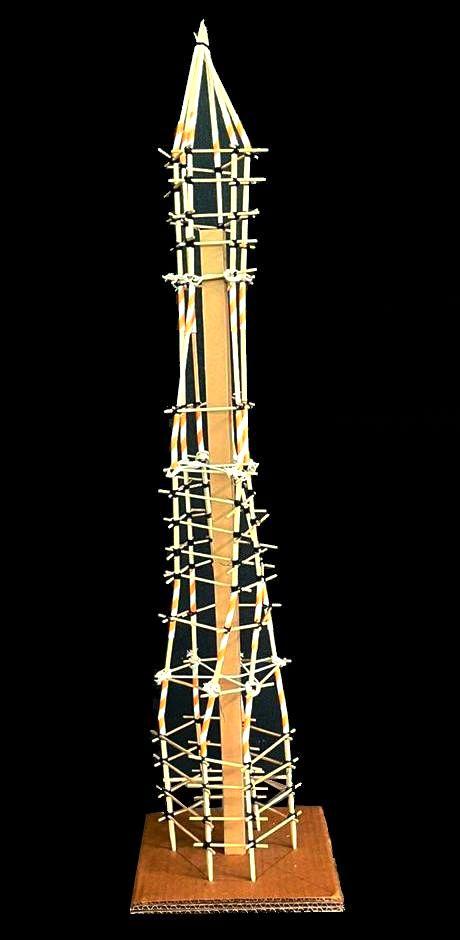
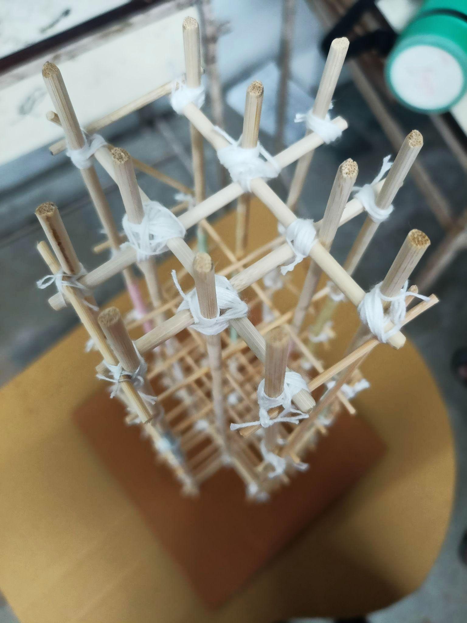
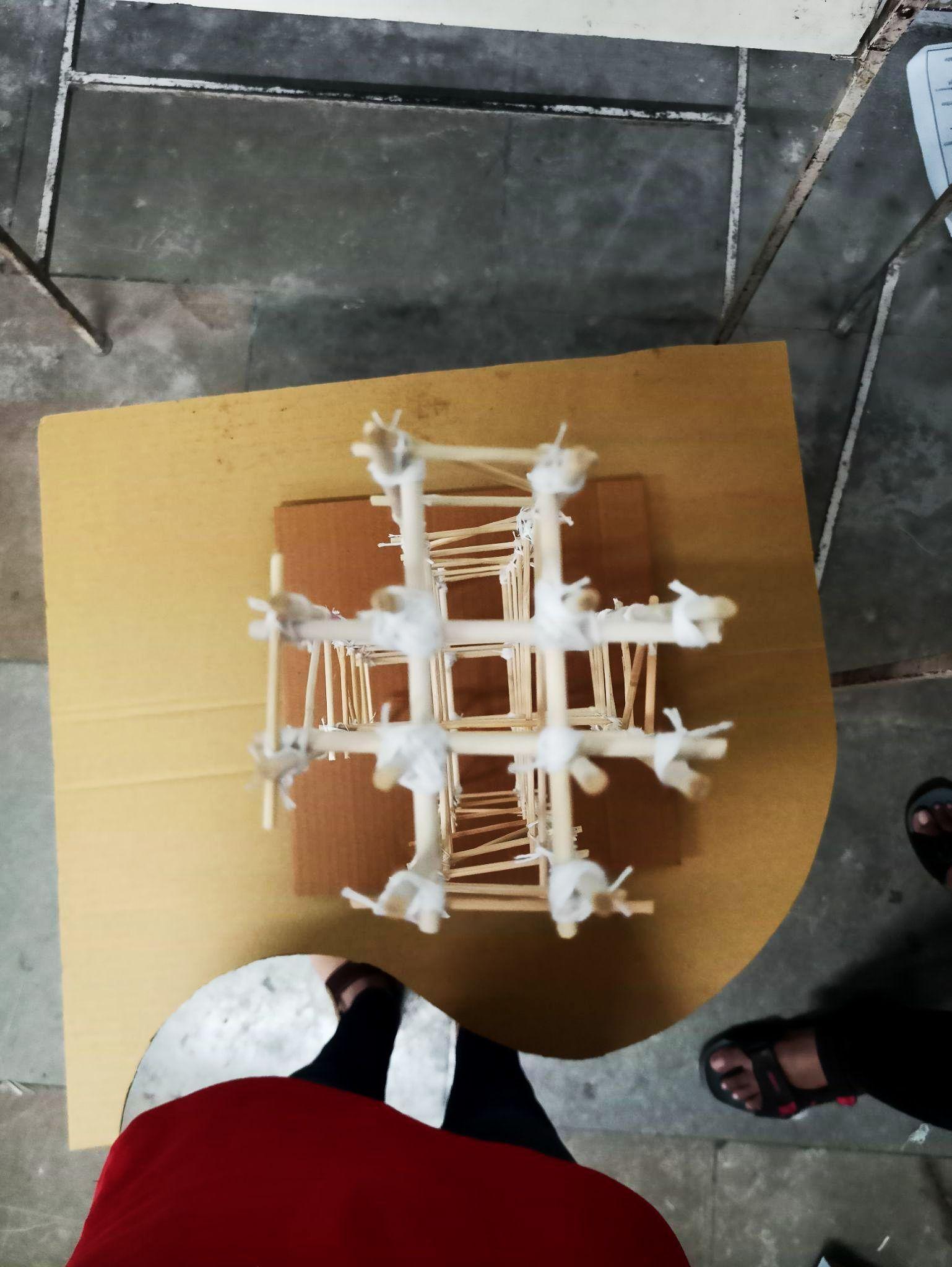
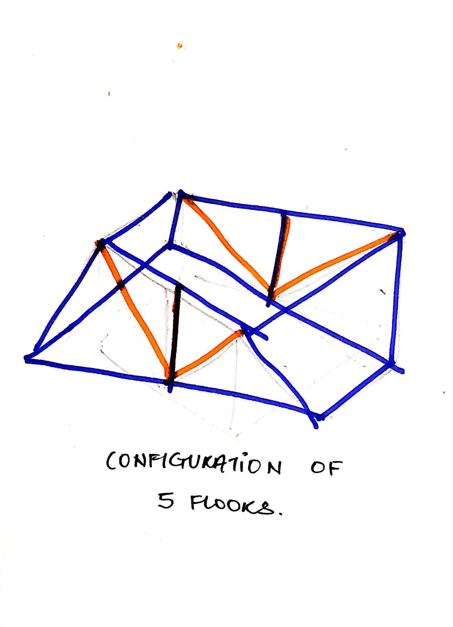
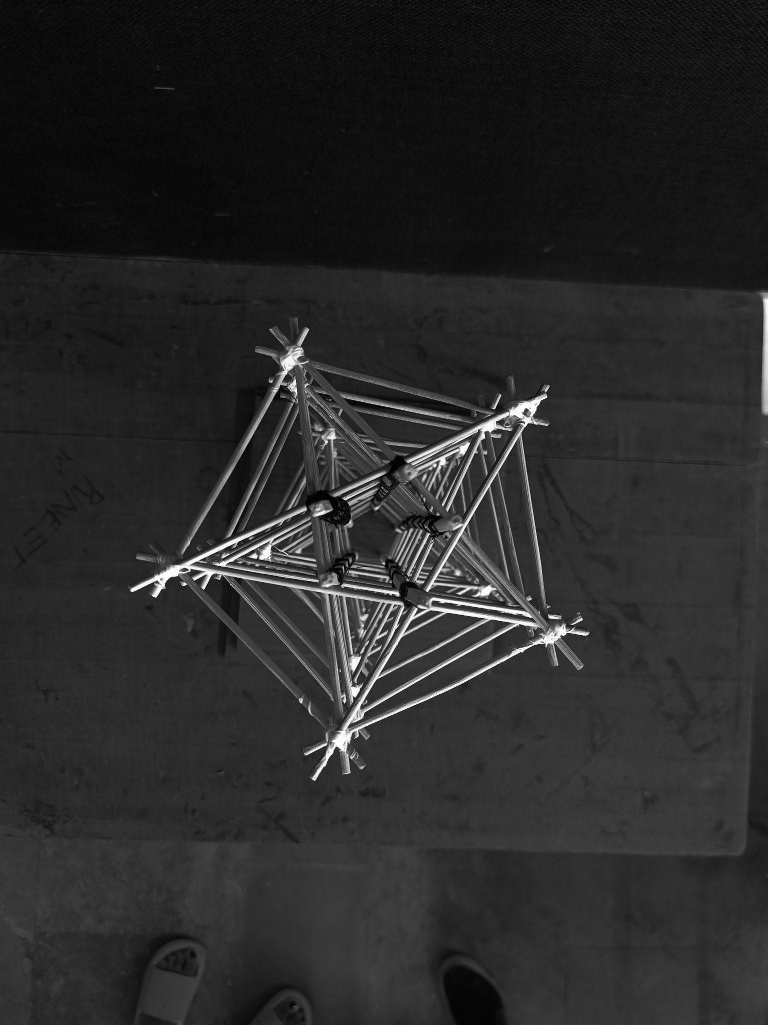
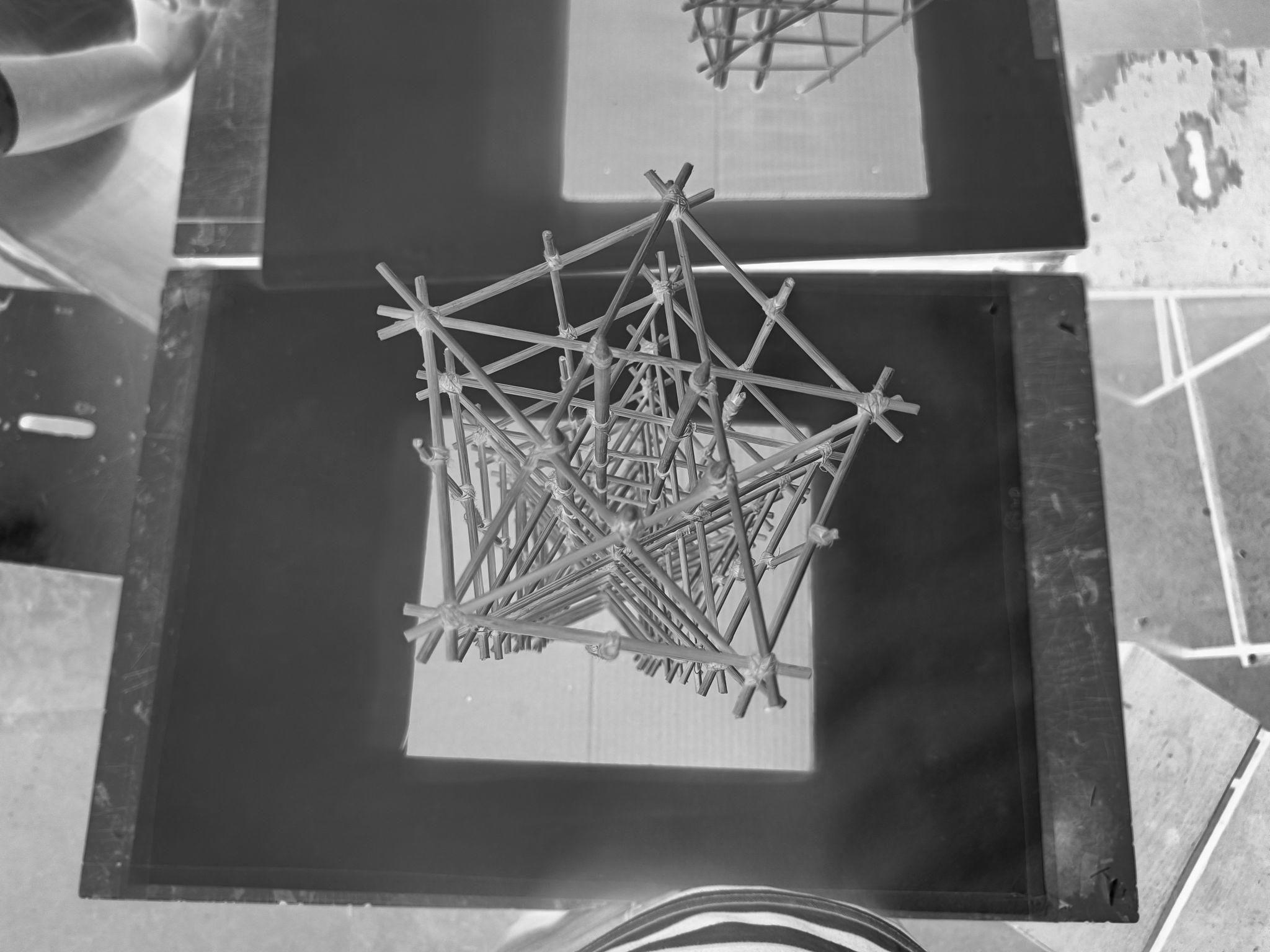
MODEL1:REGULARMODEL
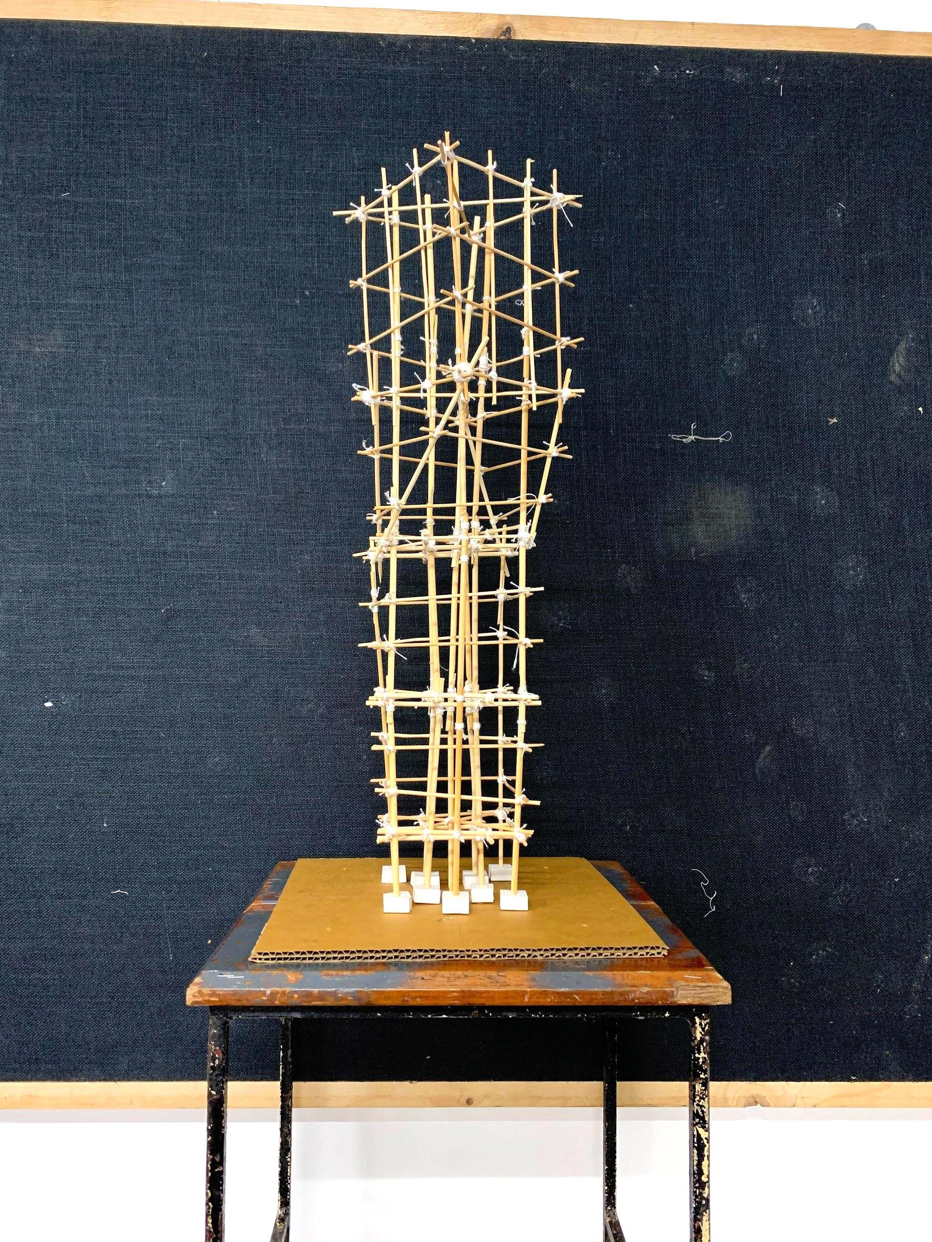
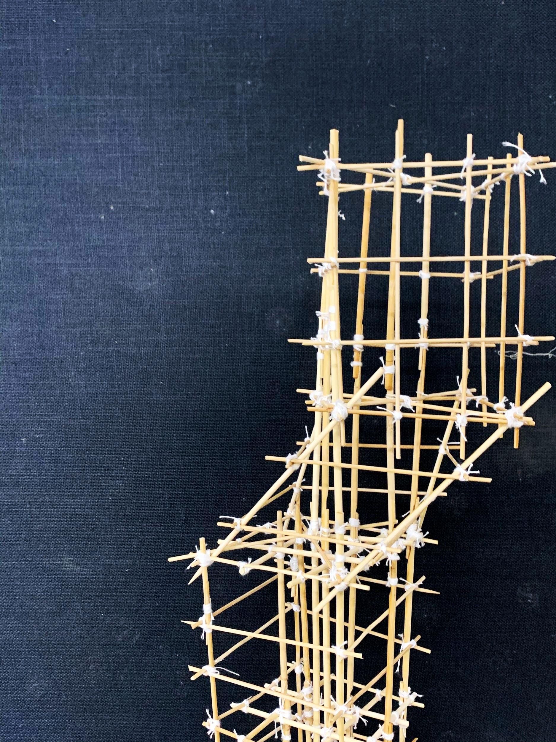
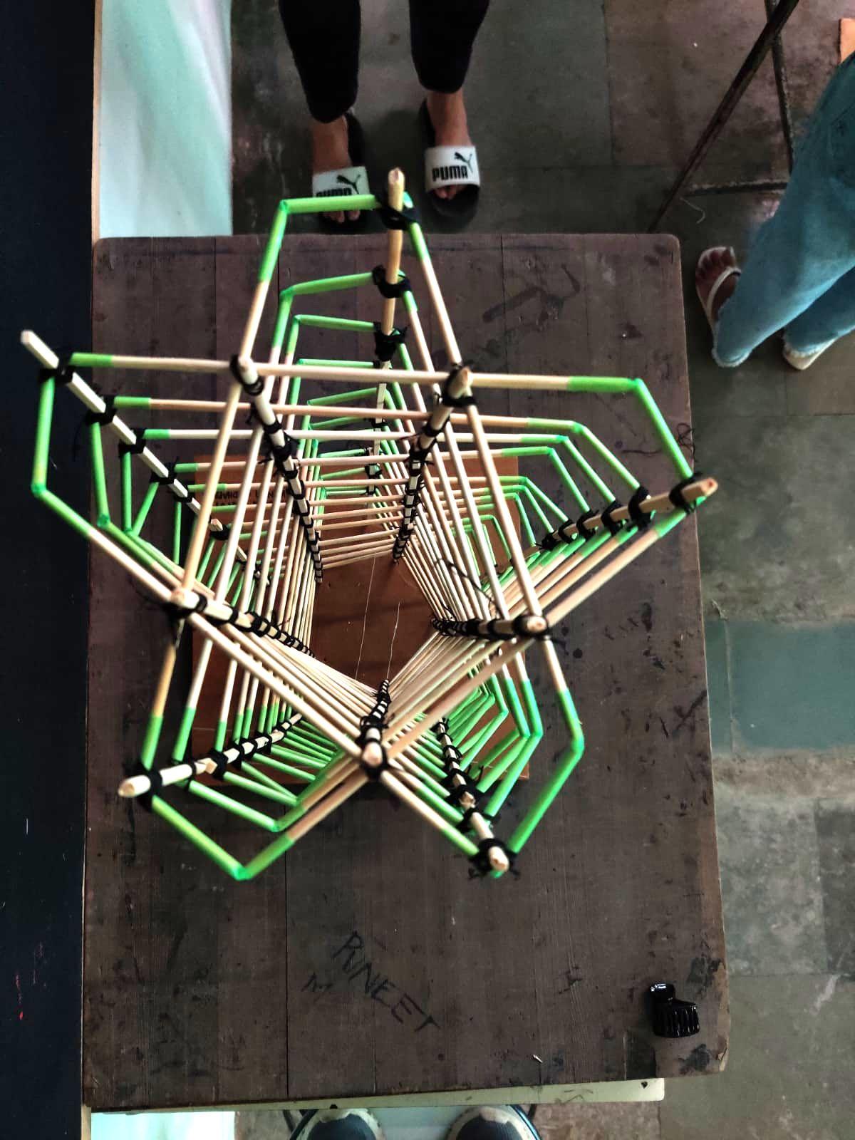
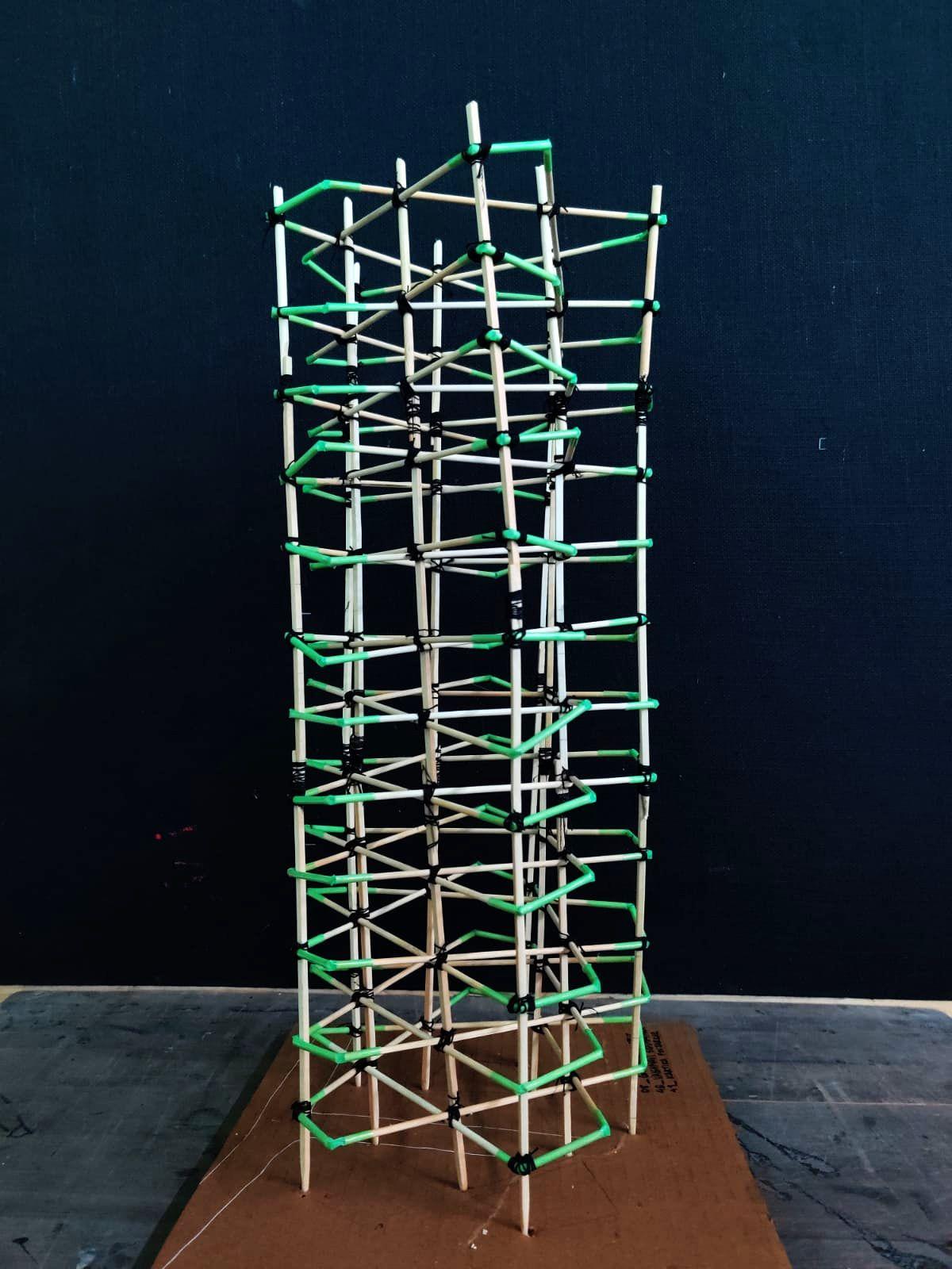
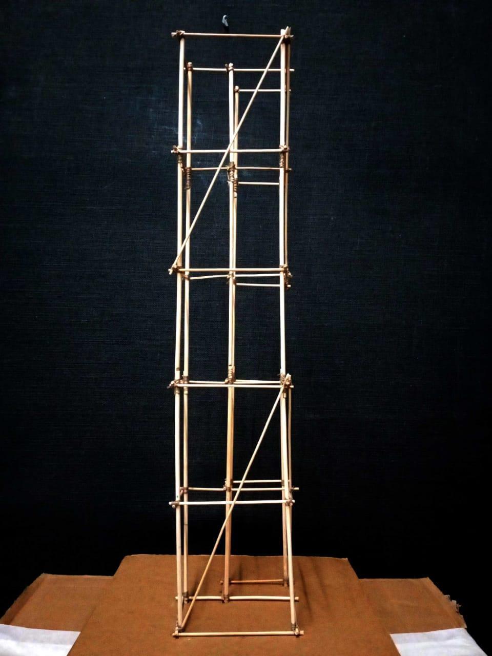
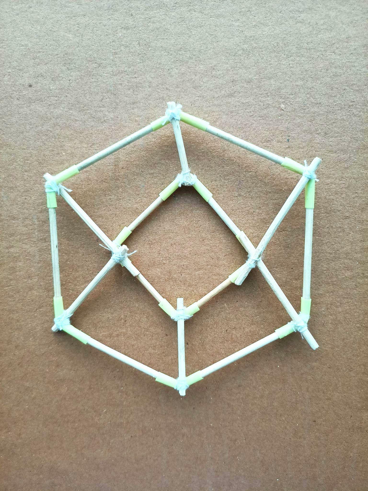
This model had a main pentagonal shaped core with 5 branches along its five sides, consisting of 15 main vertical elements and 12 horizontalbracings.
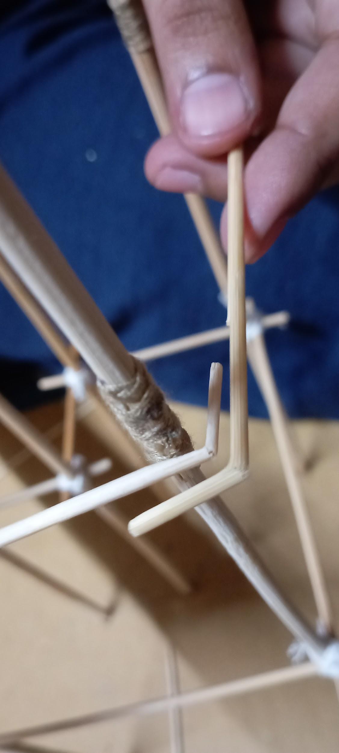
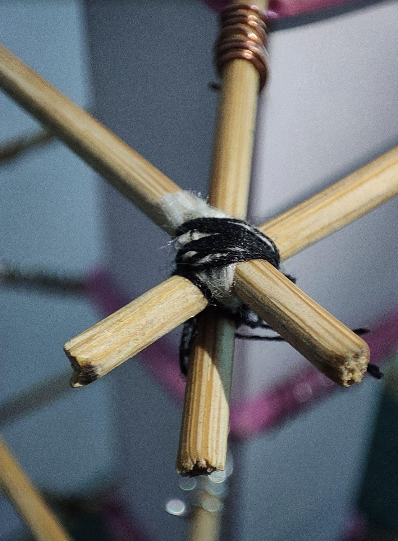
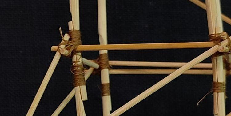
Inthehorizontalbracings,toallowmovementofjoineries,therewere straws used as make connecters for the wooden watchmakers sticks.Thesewerethentiedtotheverticalelements.
Shake table test observations : The model underwent torsion. This wasseen,asthemodel’sverticalelementsweretwistedandslightly bent in one direction. With diagonal bracings between horizontal elements,thetwistingcouldbeavoided.
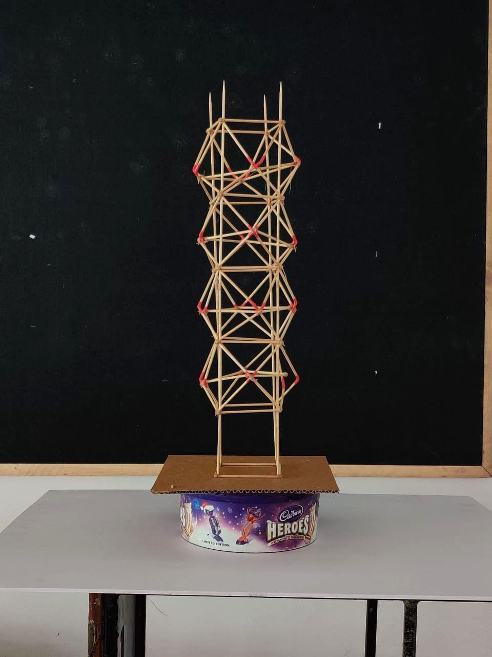
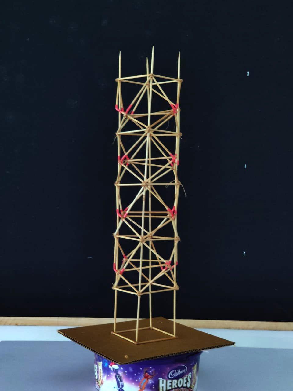
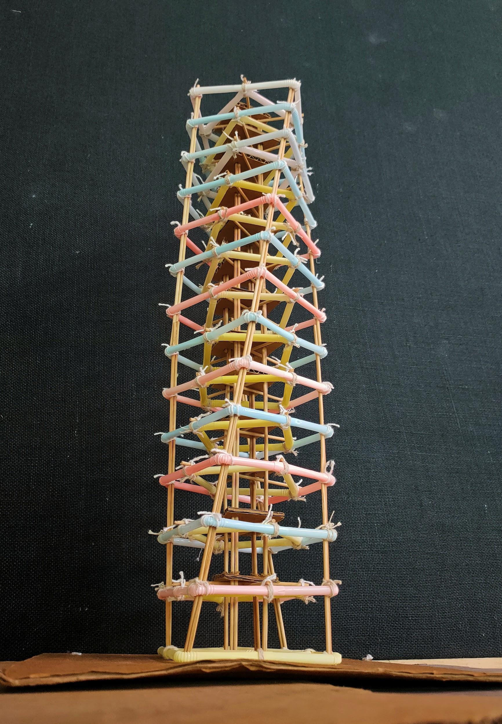
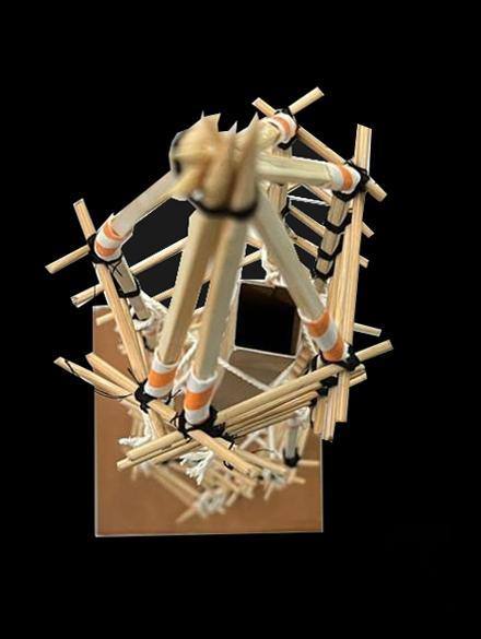
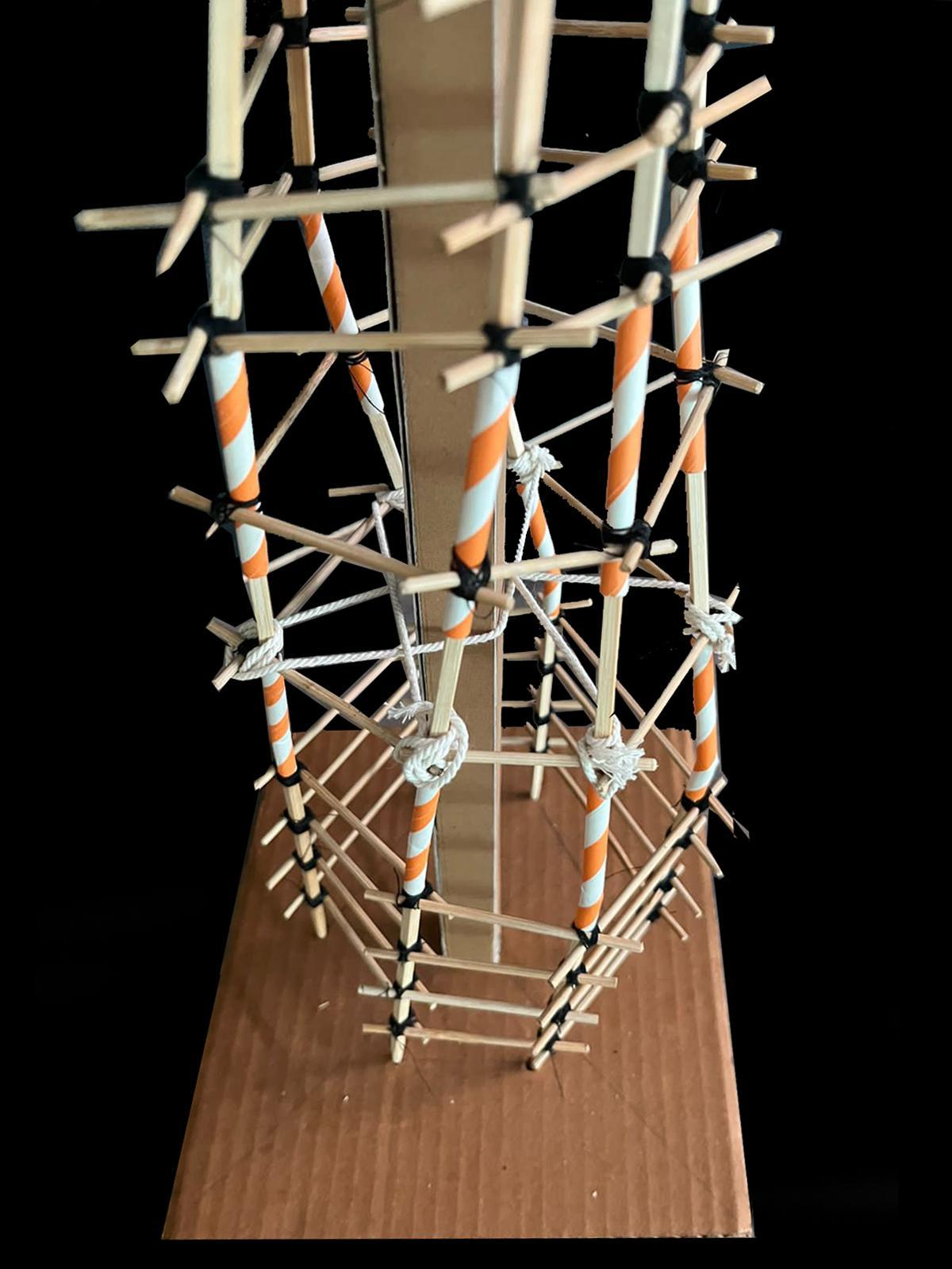
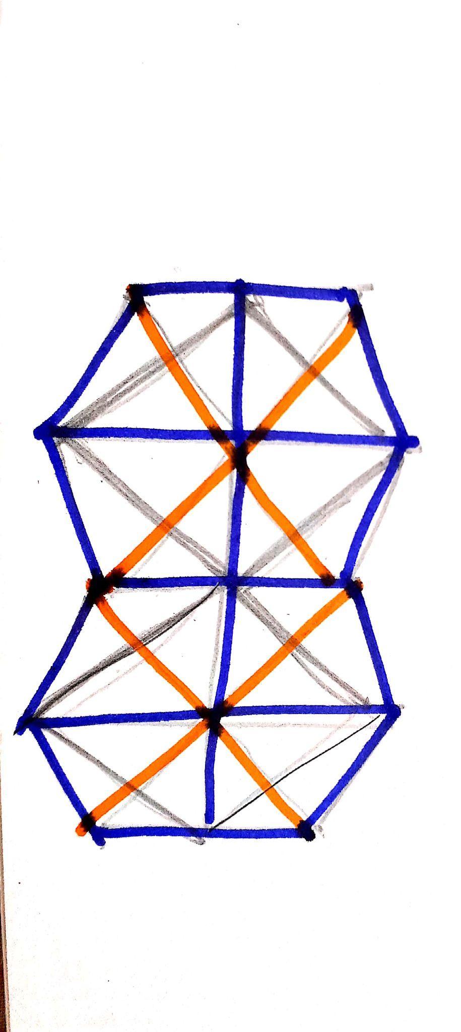
MODEL2:SCULPTURALMODEL
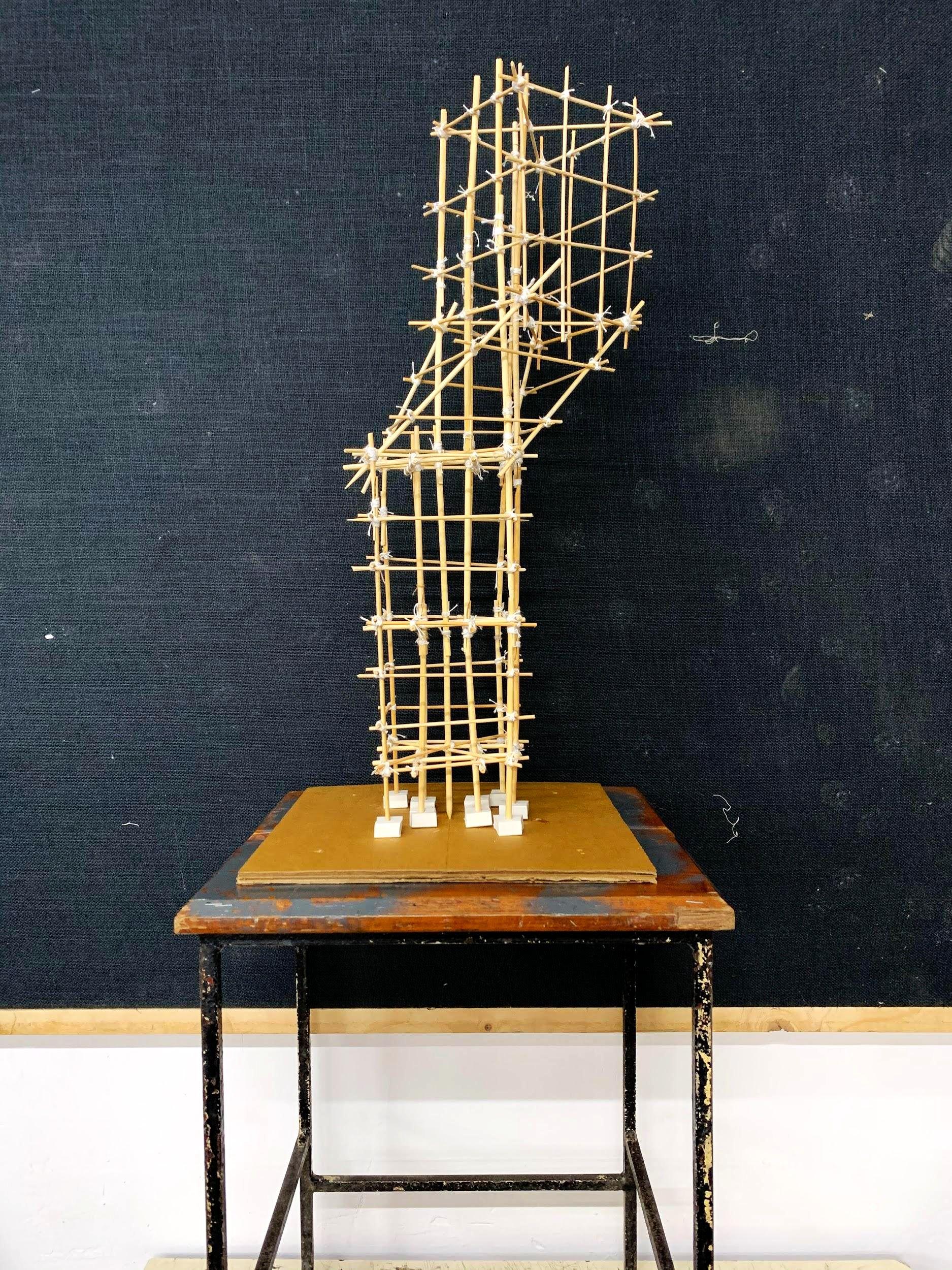
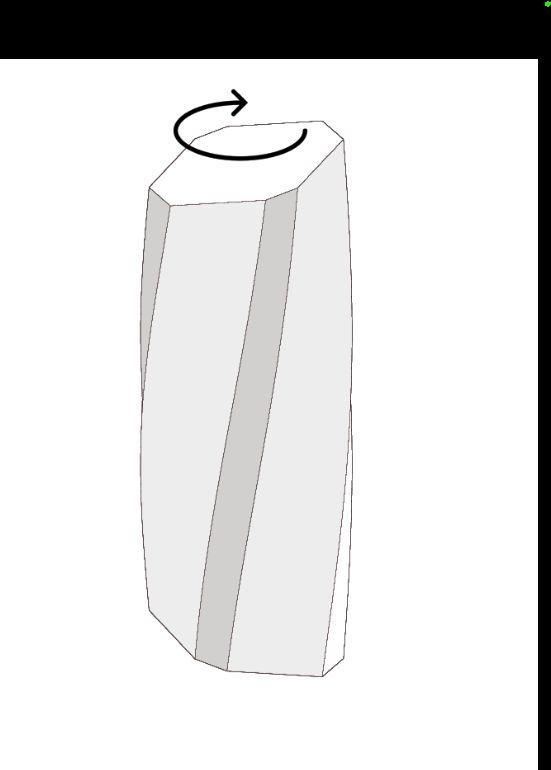
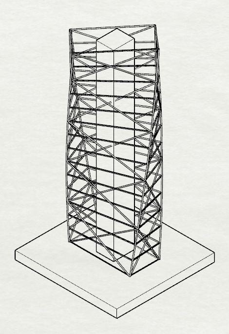
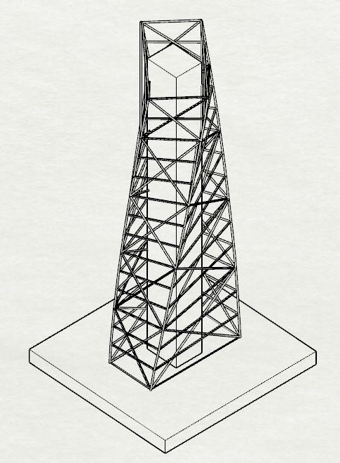
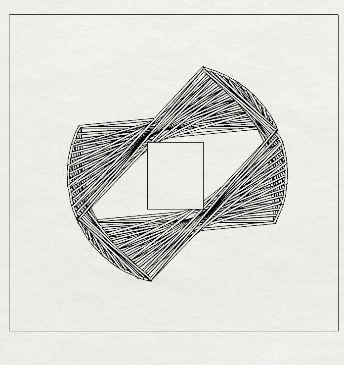
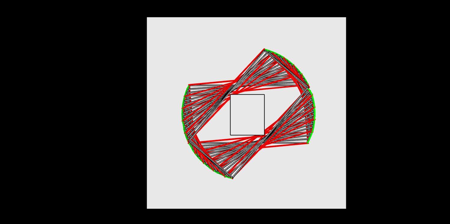
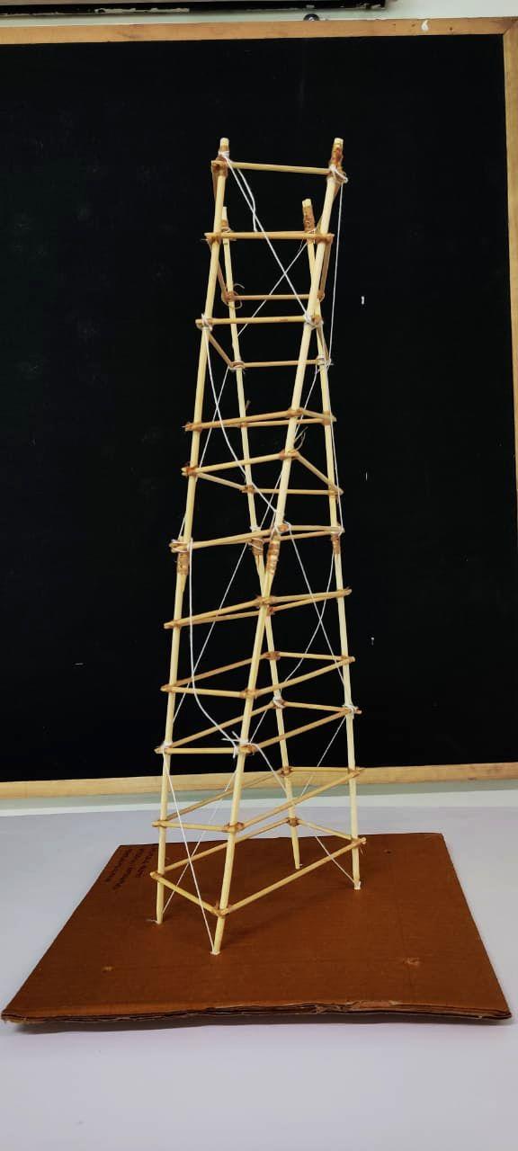
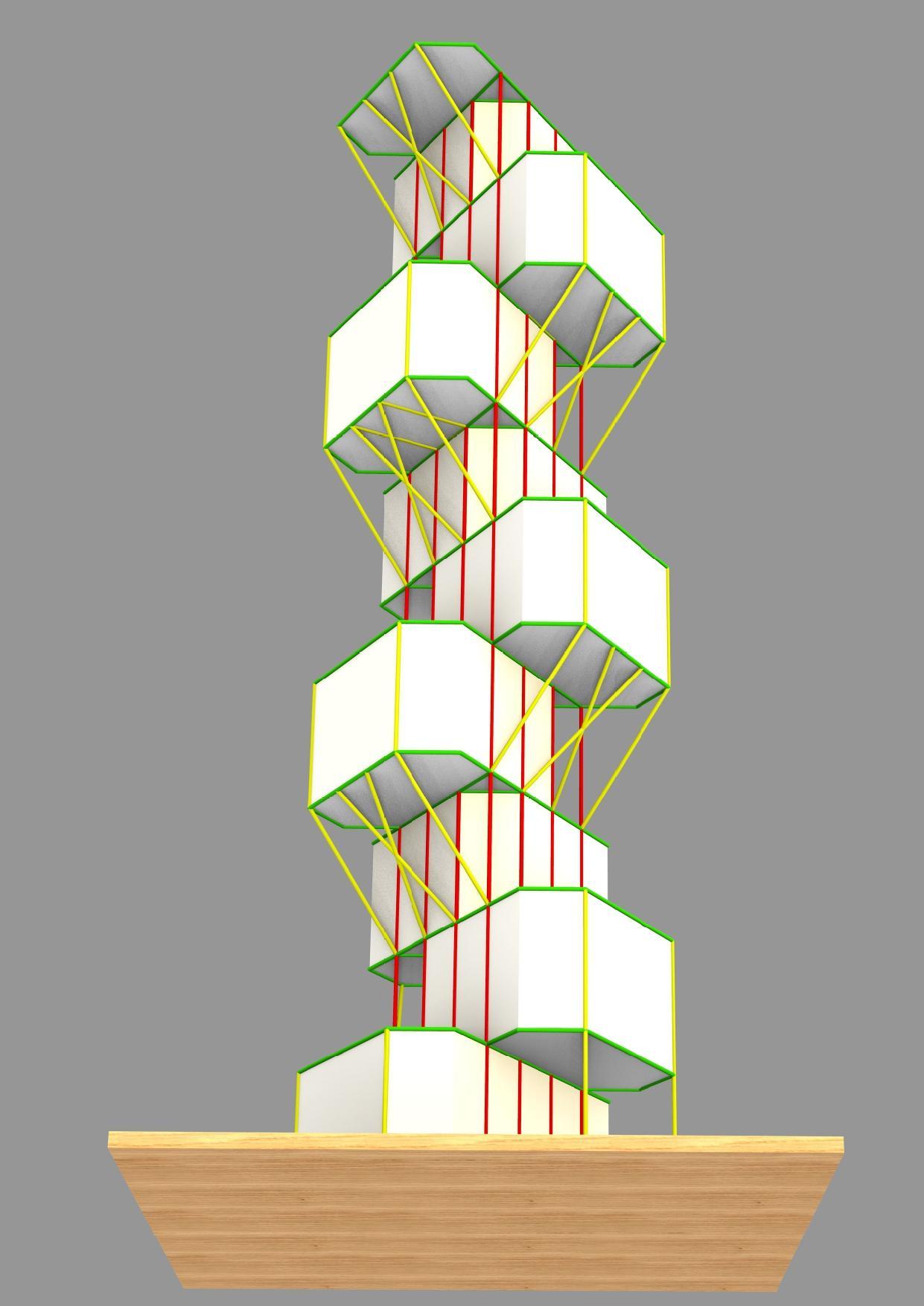
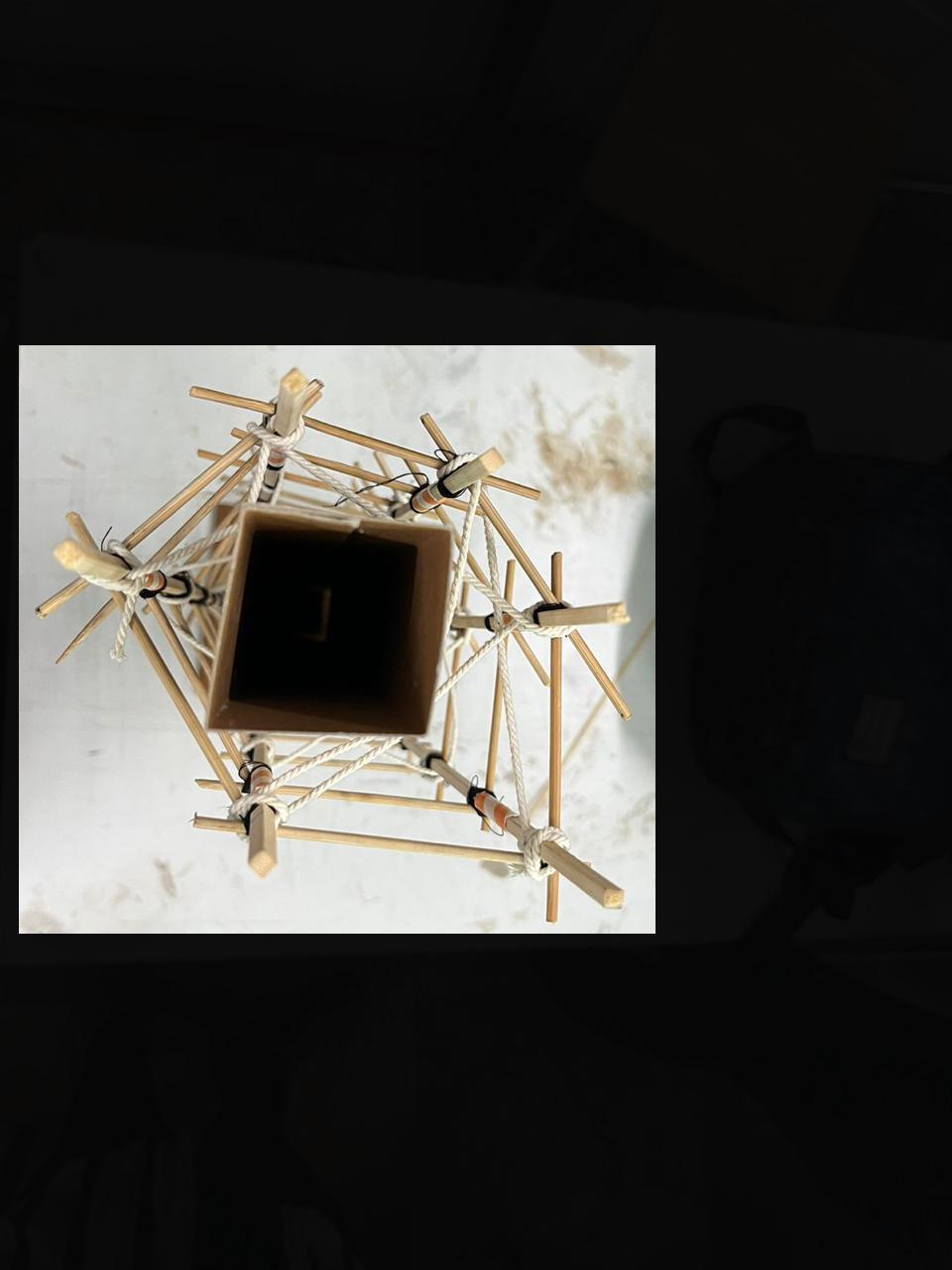
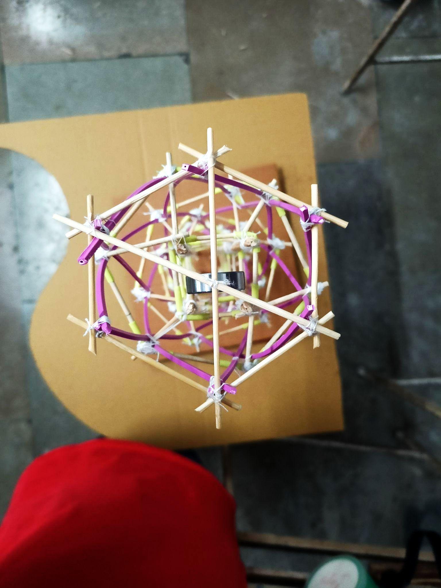
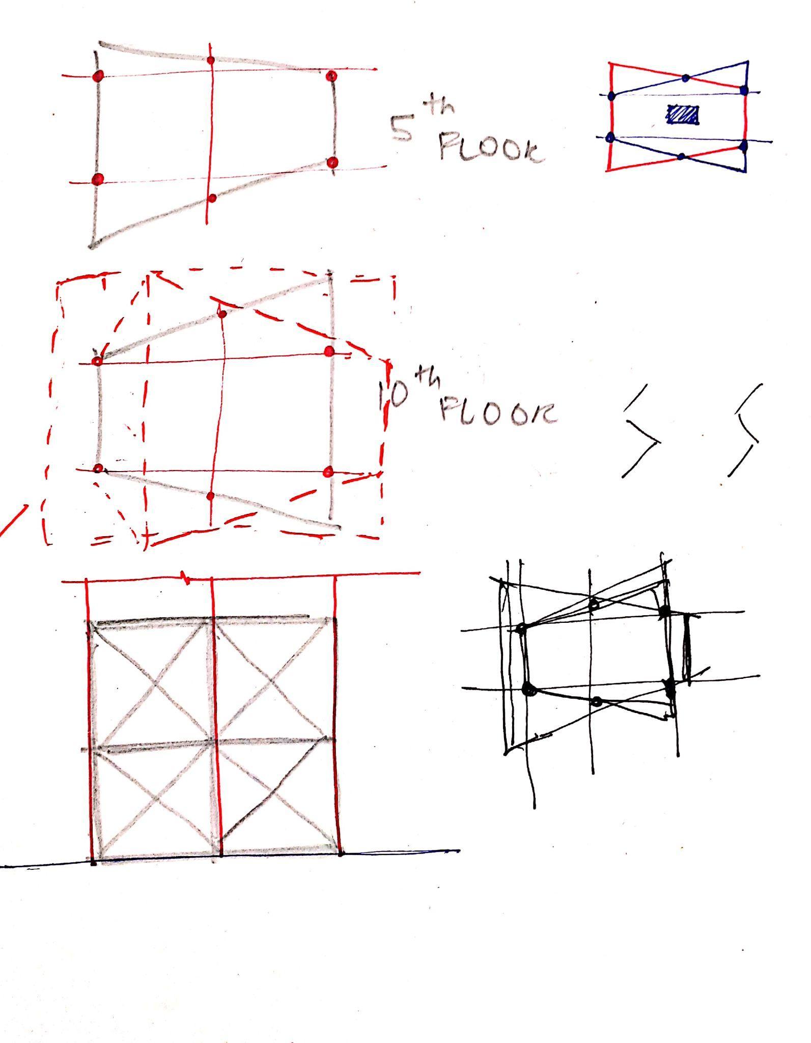
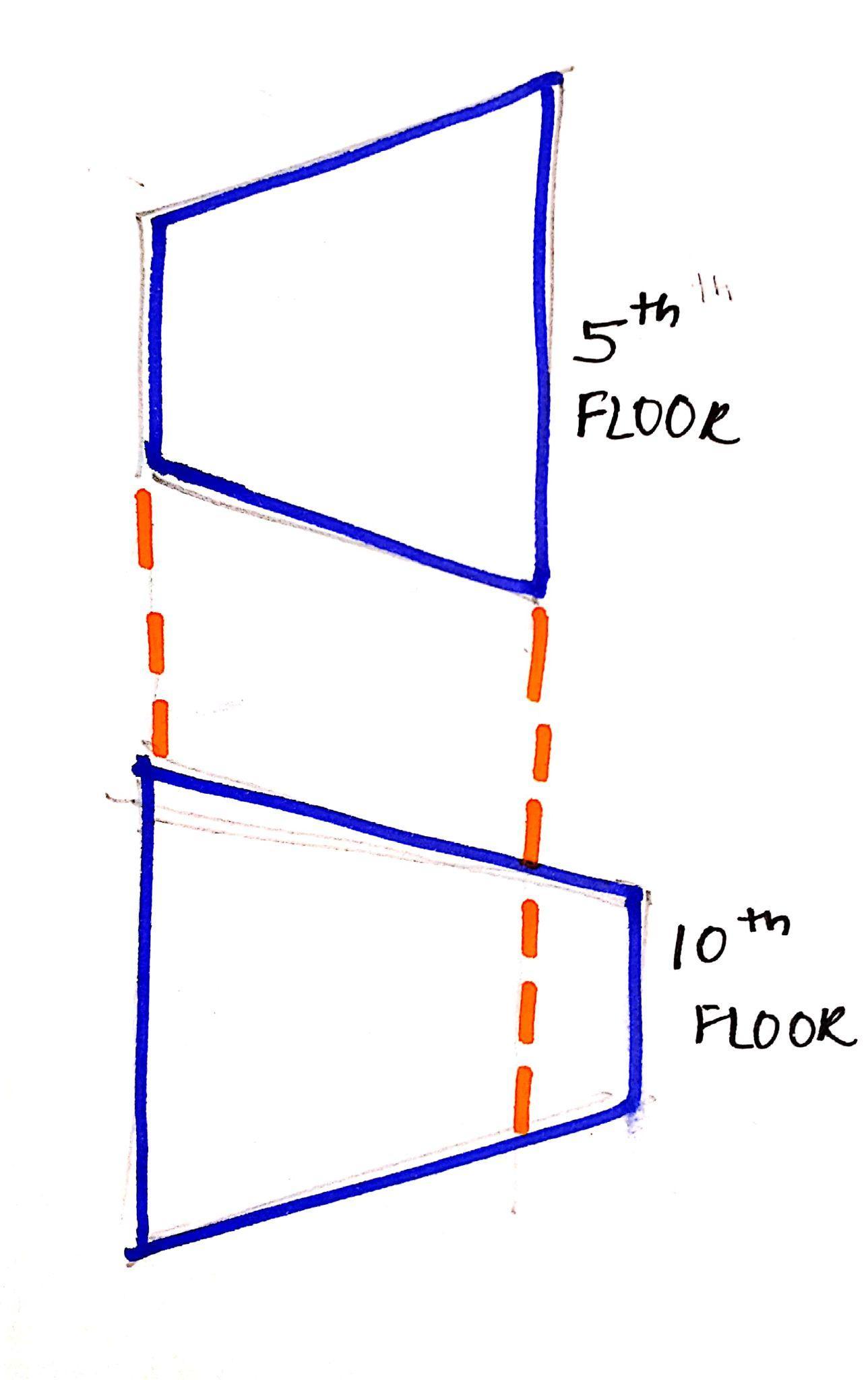
The main USP of the model was torsion (twist). Each floor plate was rotatedatanangleof3degreeswiththecentralcorecontinuingtill top. This makes the use of diagonal columns for structural stability which were connected through HALF LAP JOINT, with further use of steelcable(strings)asbracings.
Shaketabletestobservations:The model was sturdy and stiff. The bracing, made out of thick strings, replicating tension cables did undergoslightdeformations.
OVERALLINFERENCESANDCONCLUSIONS
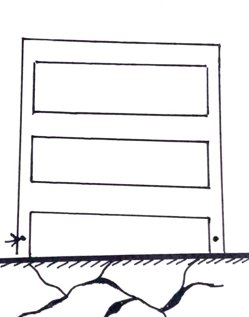
● Columns must be properly anchored to the ground in order to resistearthquakeforcesandtransferload.
● The form explorations done may or may not survive an earthquakebuttheyarestrongenoughtoallowtheresidentsto evacuatethebuildingsafelywithoutanylossoflife.
● Both the forms are a good example of aesthetic as well as structuralstability.
CONCLUSION
CONCLUSION
ANALYSISAND
Team02| DesignReport
GROUP03
SIDDHISHINDE_26 JIGISHASONI_46 ARYAJUMDE_57
AcademyofArchitecture,Mumbai

Team03| DesignReport INITIALSKETCHES
SCULPTURALMODEL-BASICPLANNING GEOMETRICMODEL-ISOMETRIC SCULPTURAL MODEL-ISOMETRIC
Team03| DesignReport GEOMETRICMODELPHOTOS
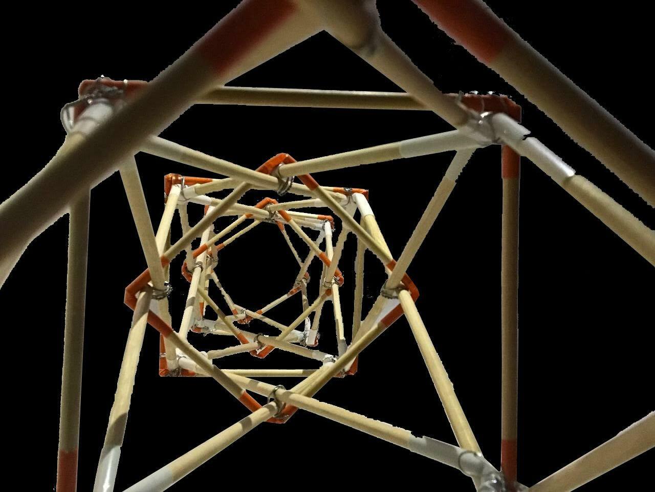
ISOMETRICVIEW1 ISOMETRICVIEW2 VIEWFROMBOTTOM ZOOMEDVIEWOFBRACING
FRONTVIEW ISOMETRICVIEW
Team03| DesignReport SCULPTURALMODELPHOTOS
TOPVIEW ISOMETRICVIEWFROMTOP
INFERENCES
● Theformofanybuildingcontributestoitsoverallstability, strengthandstiffness
● Theformshouldbesuchthatithaslessernumberofjointsor suchthatloadtransferfromregionofapplicationtothebottom isquick
● ForHighRisesduetolateralloadsitbecomesessentialto designkeepinginmindtheireffect,forwhichweusevarious kindsofbracingsystems,coresystems,foundationsystemsetc accordingly.
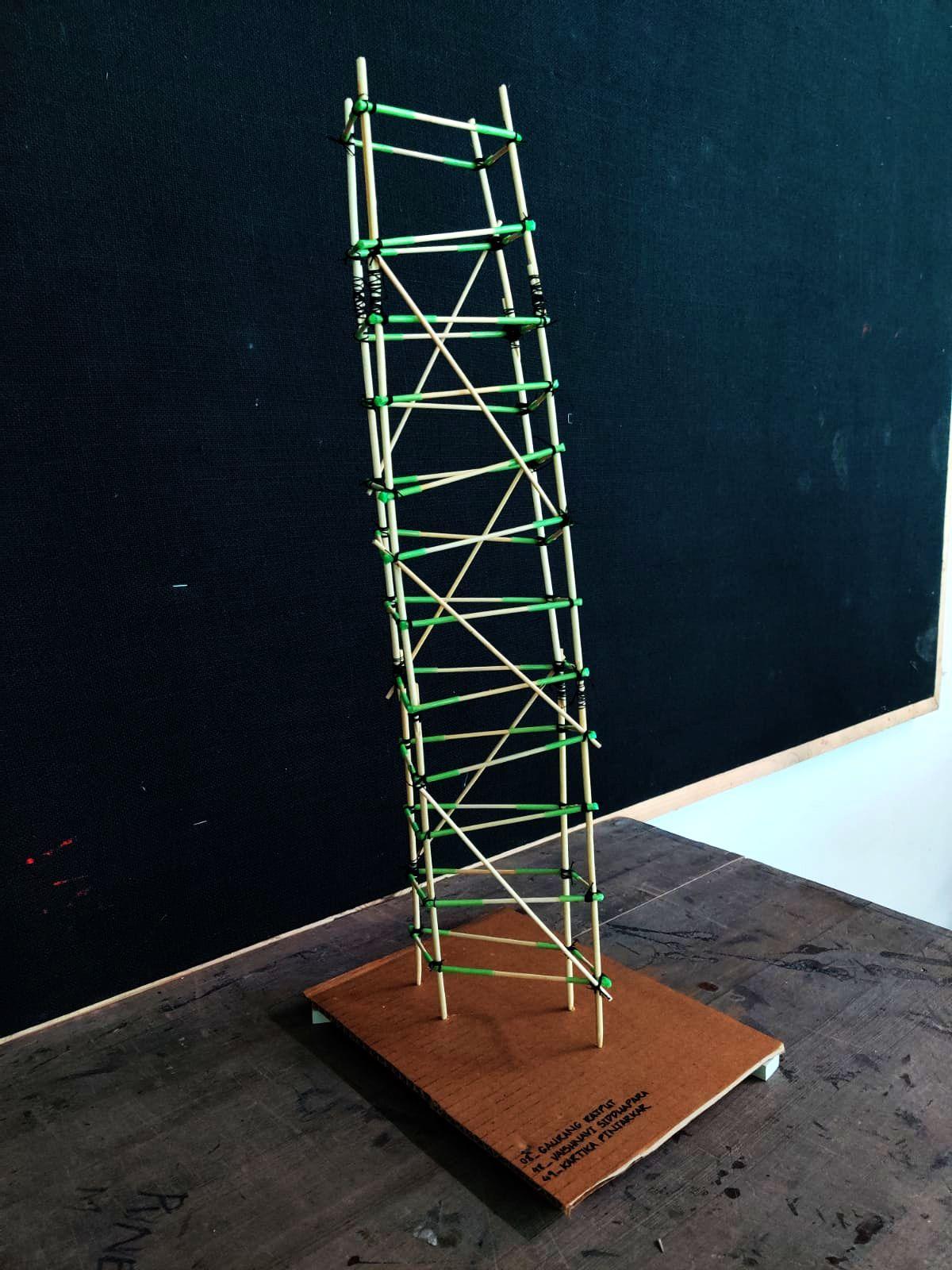
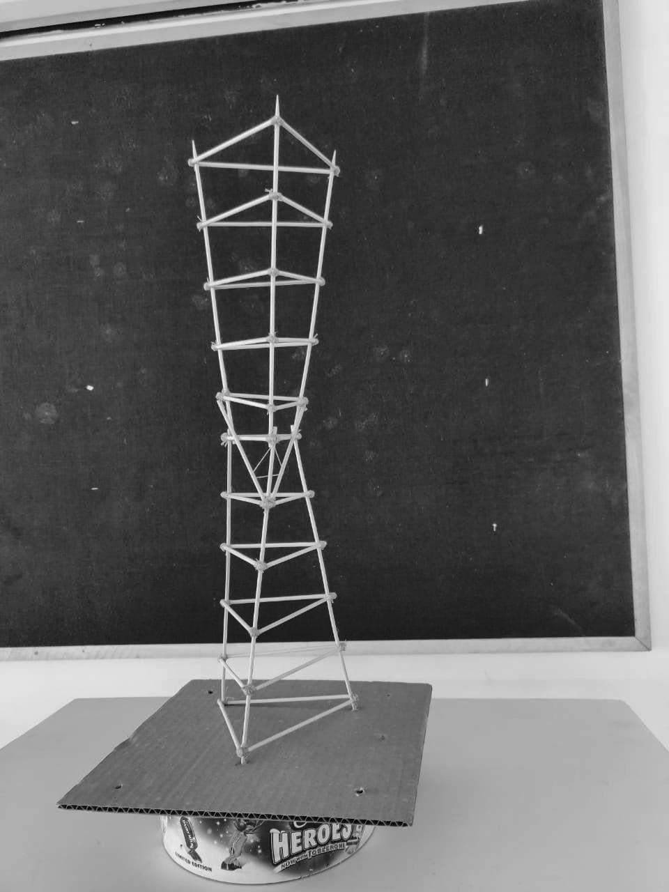
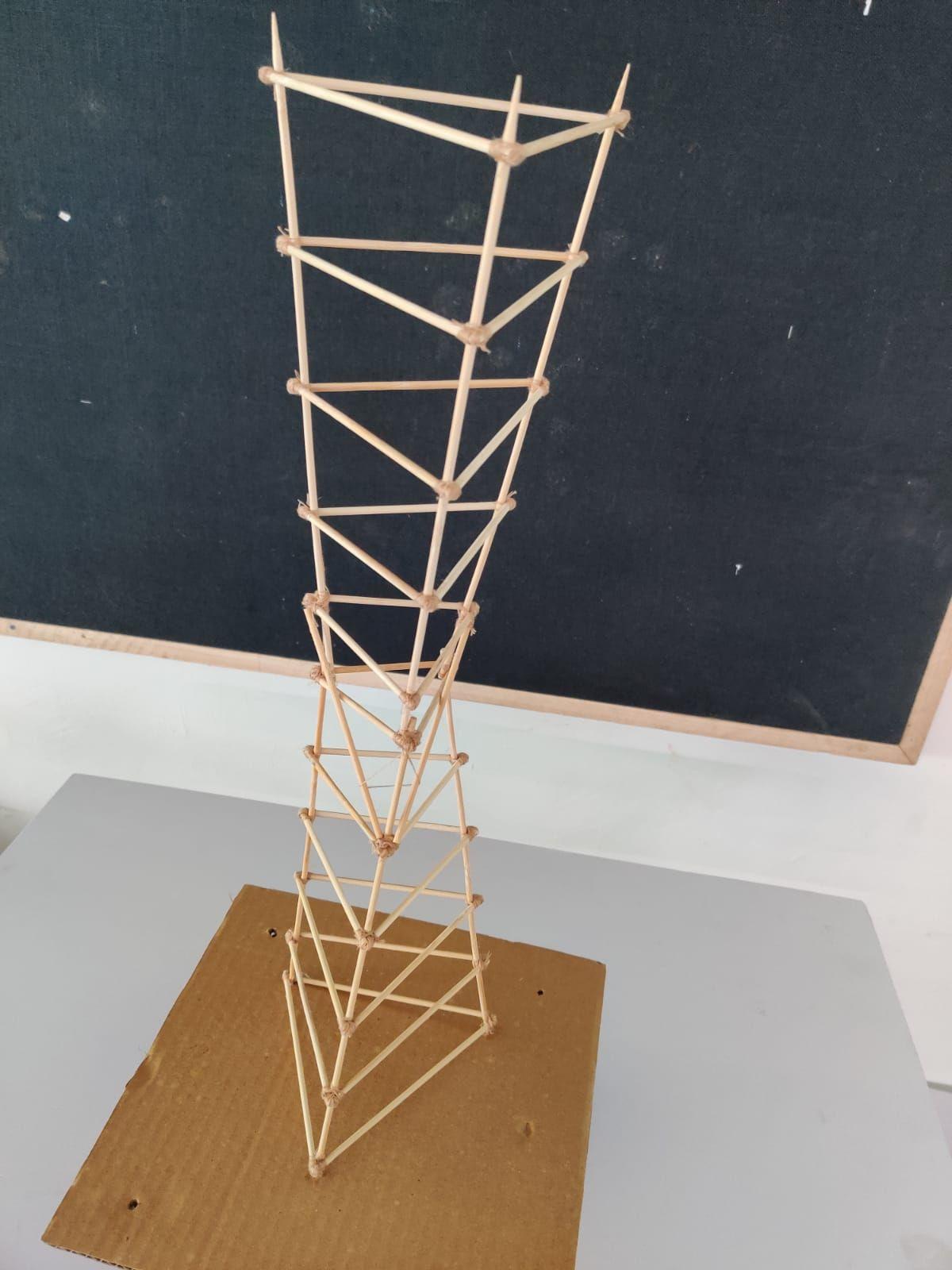
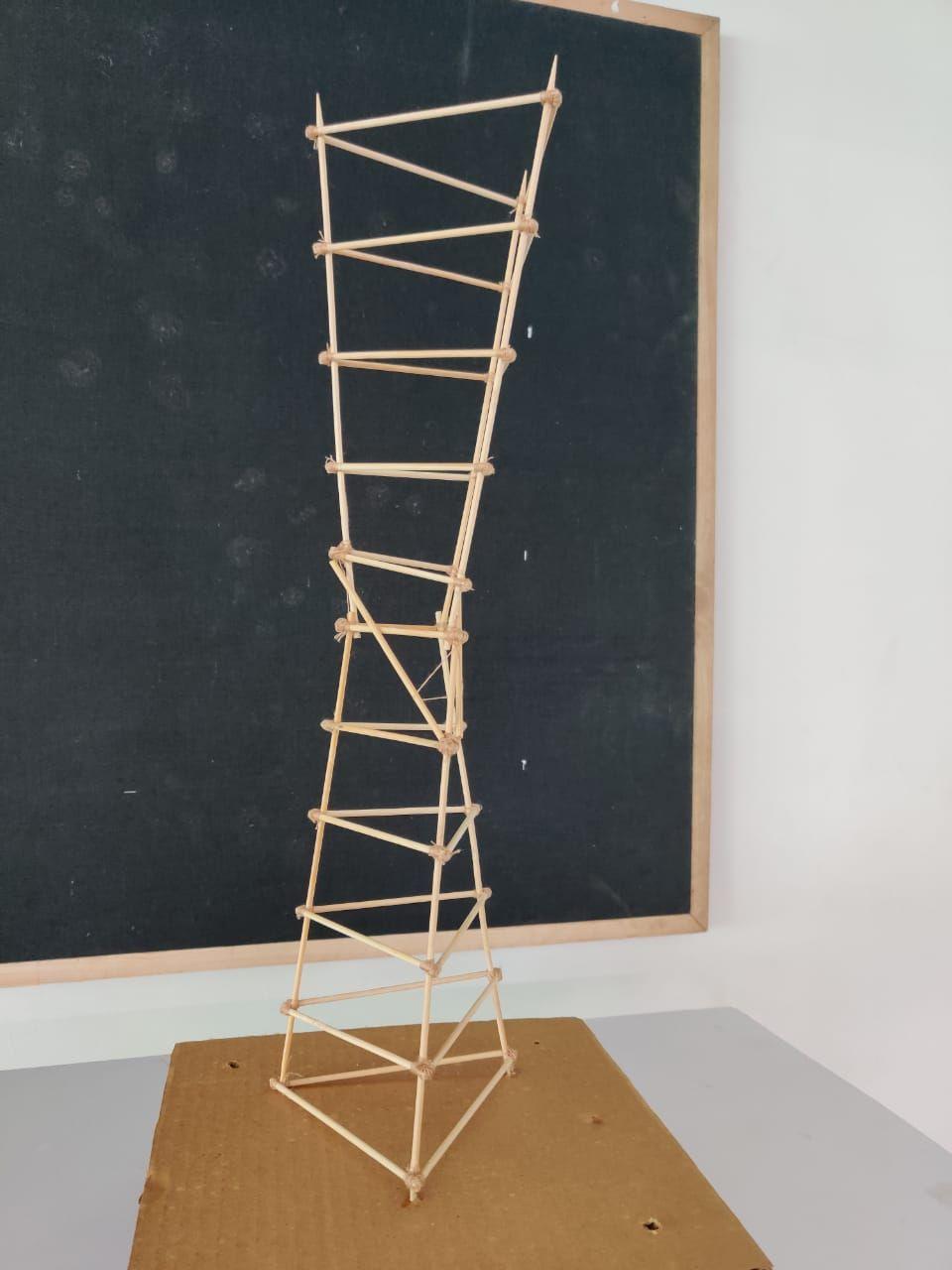
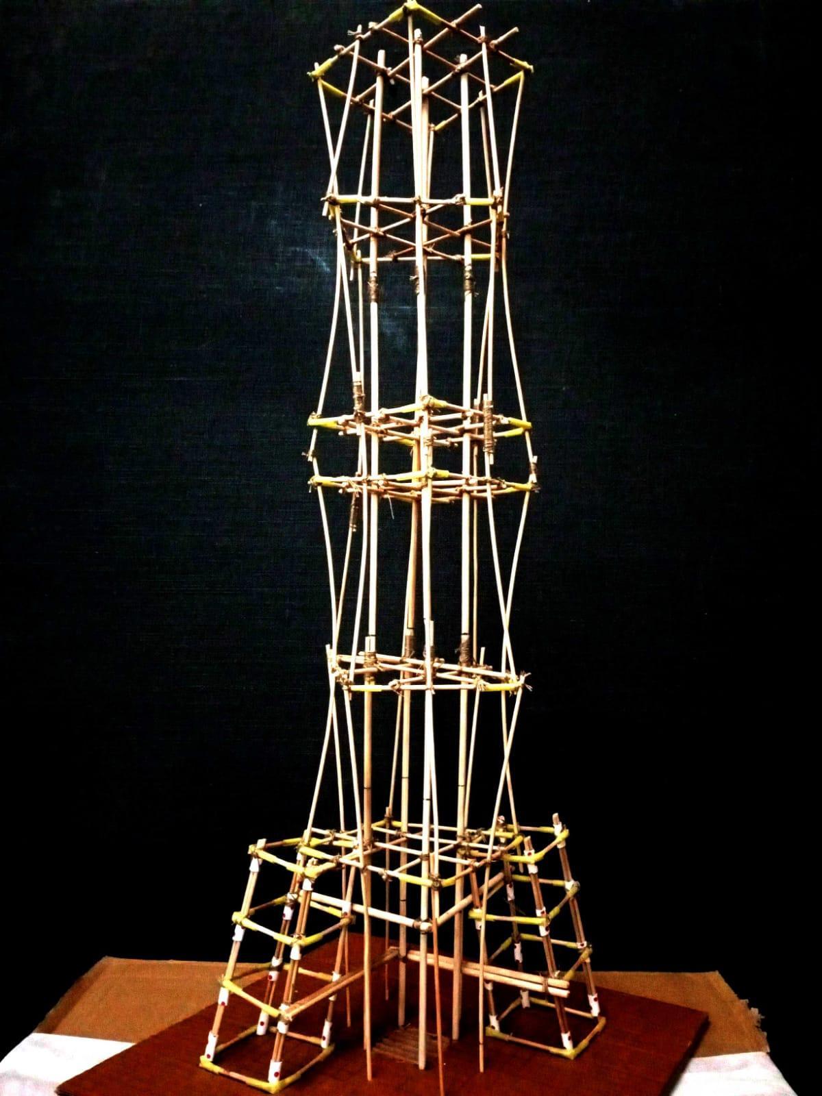
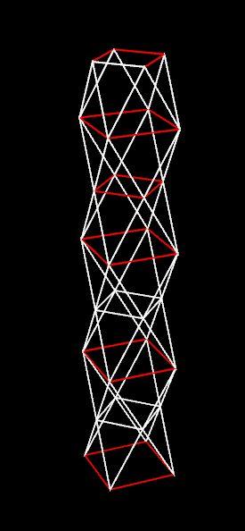
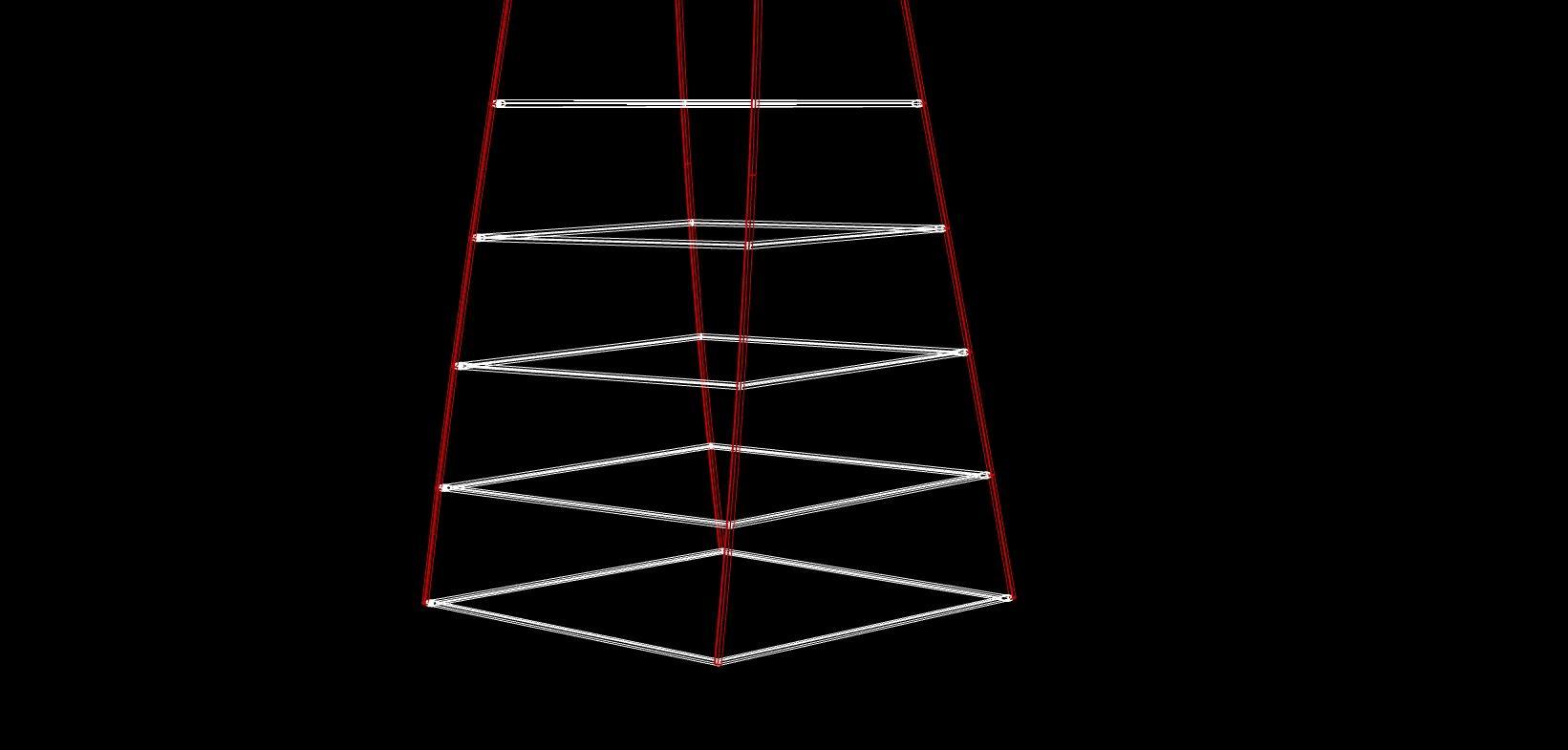
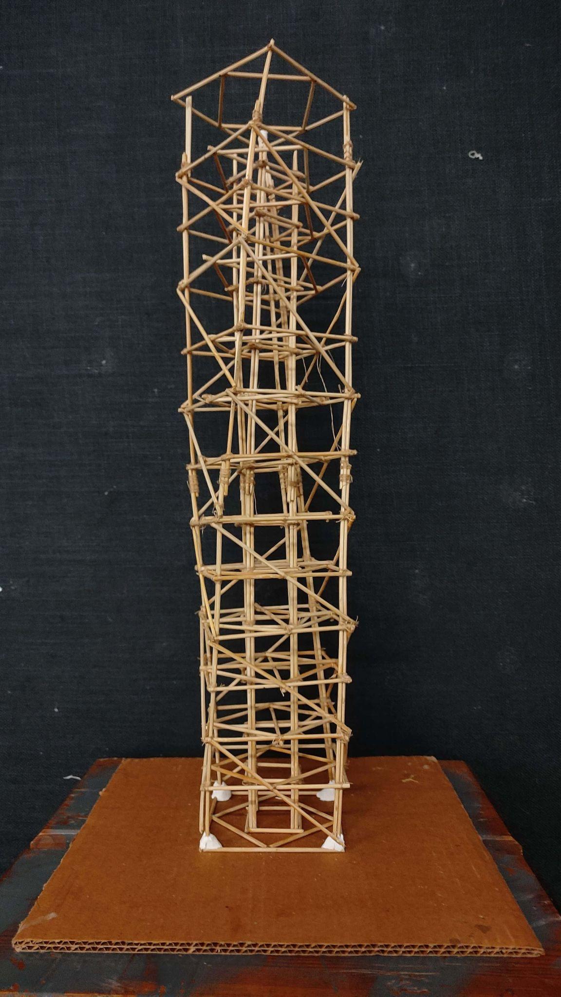
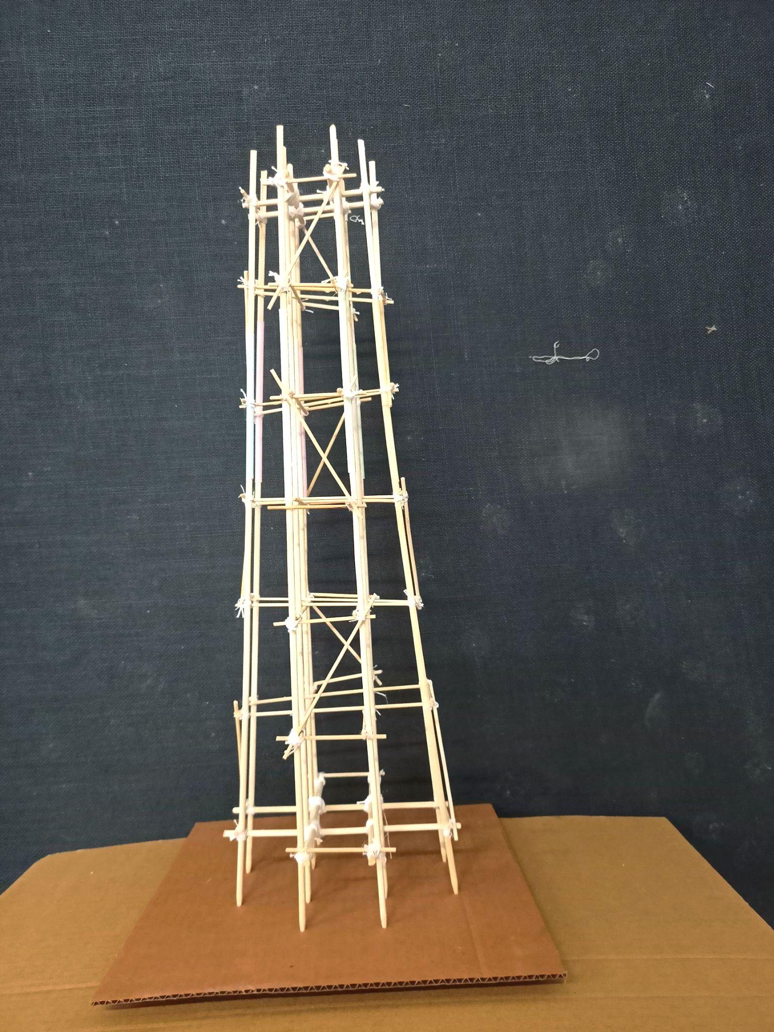
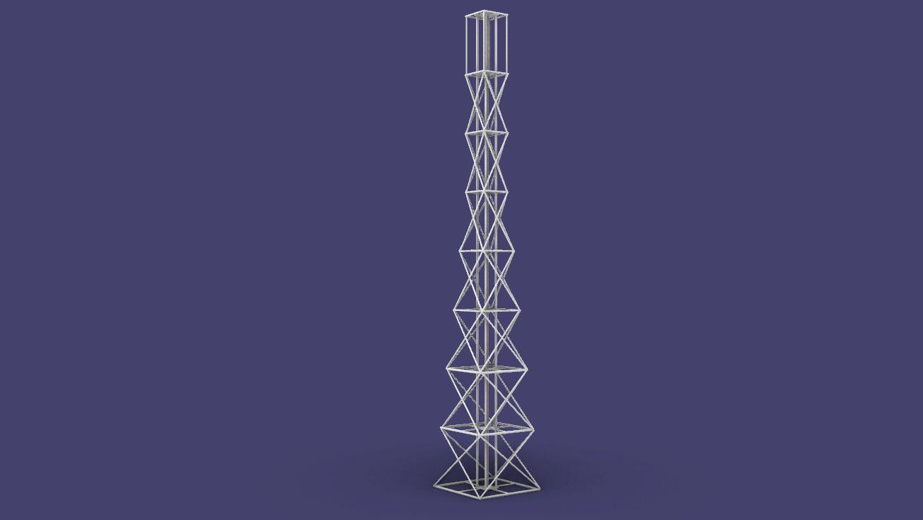
MODEL1(REGULARPOLYGON-TRIANGULARBASE)
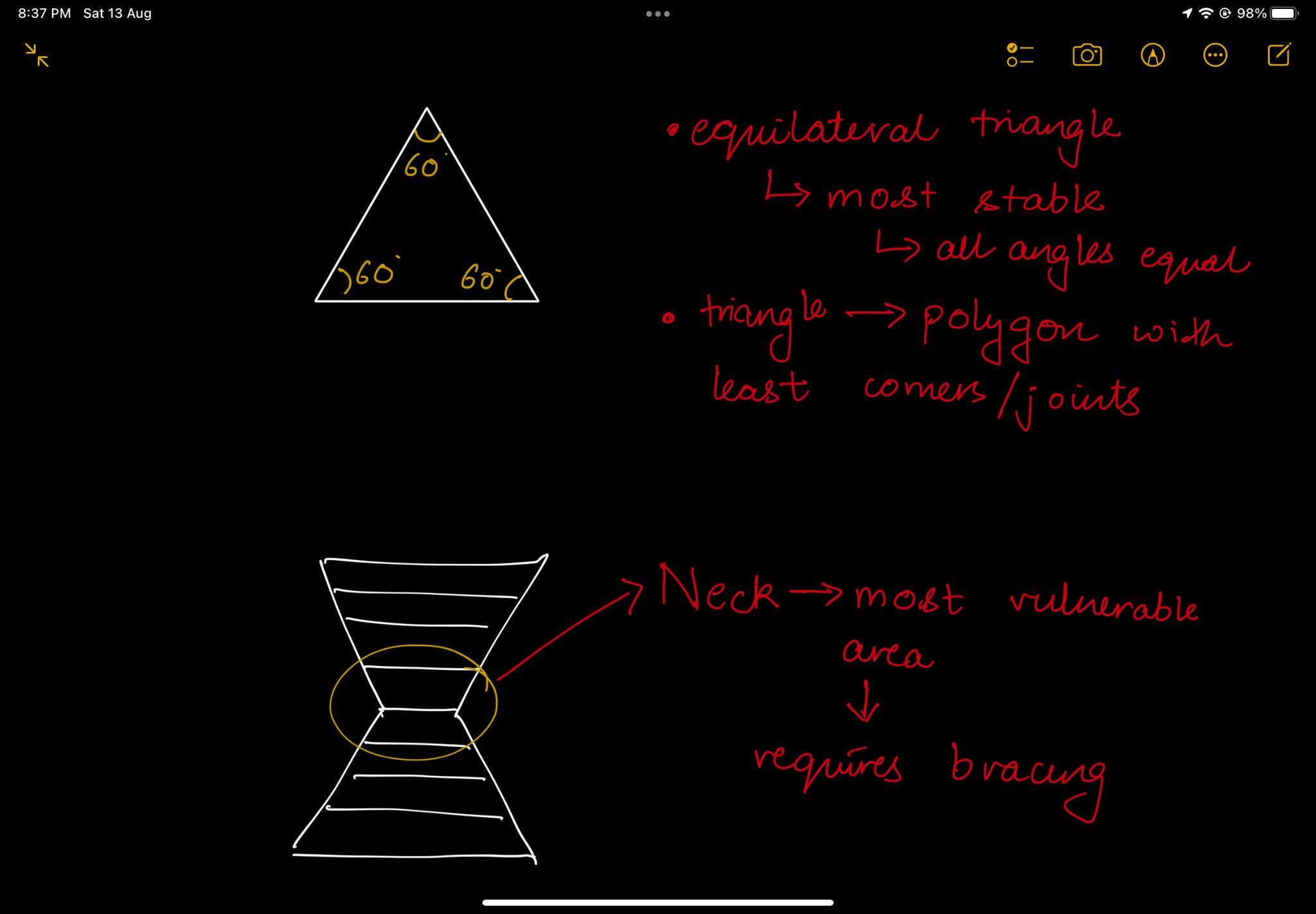
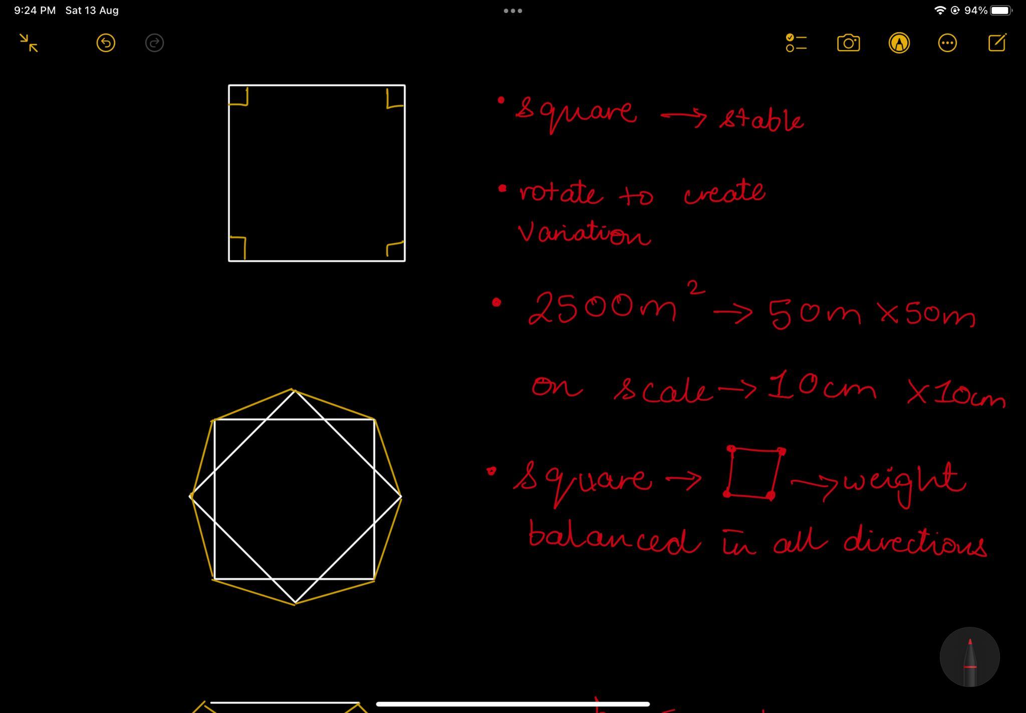
● Theuseofequilateraltriangleshapedfloorplatemakesit stable.
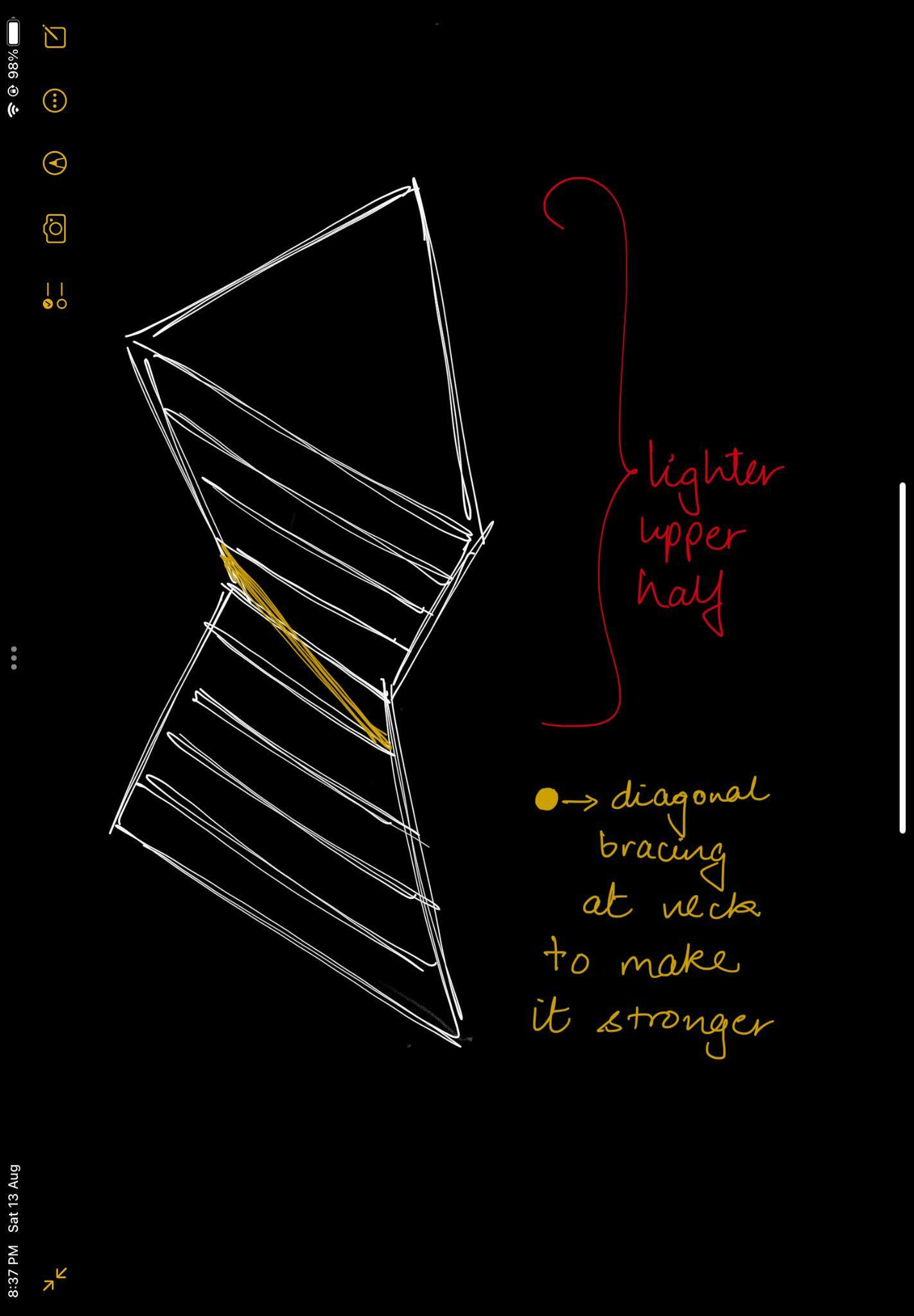
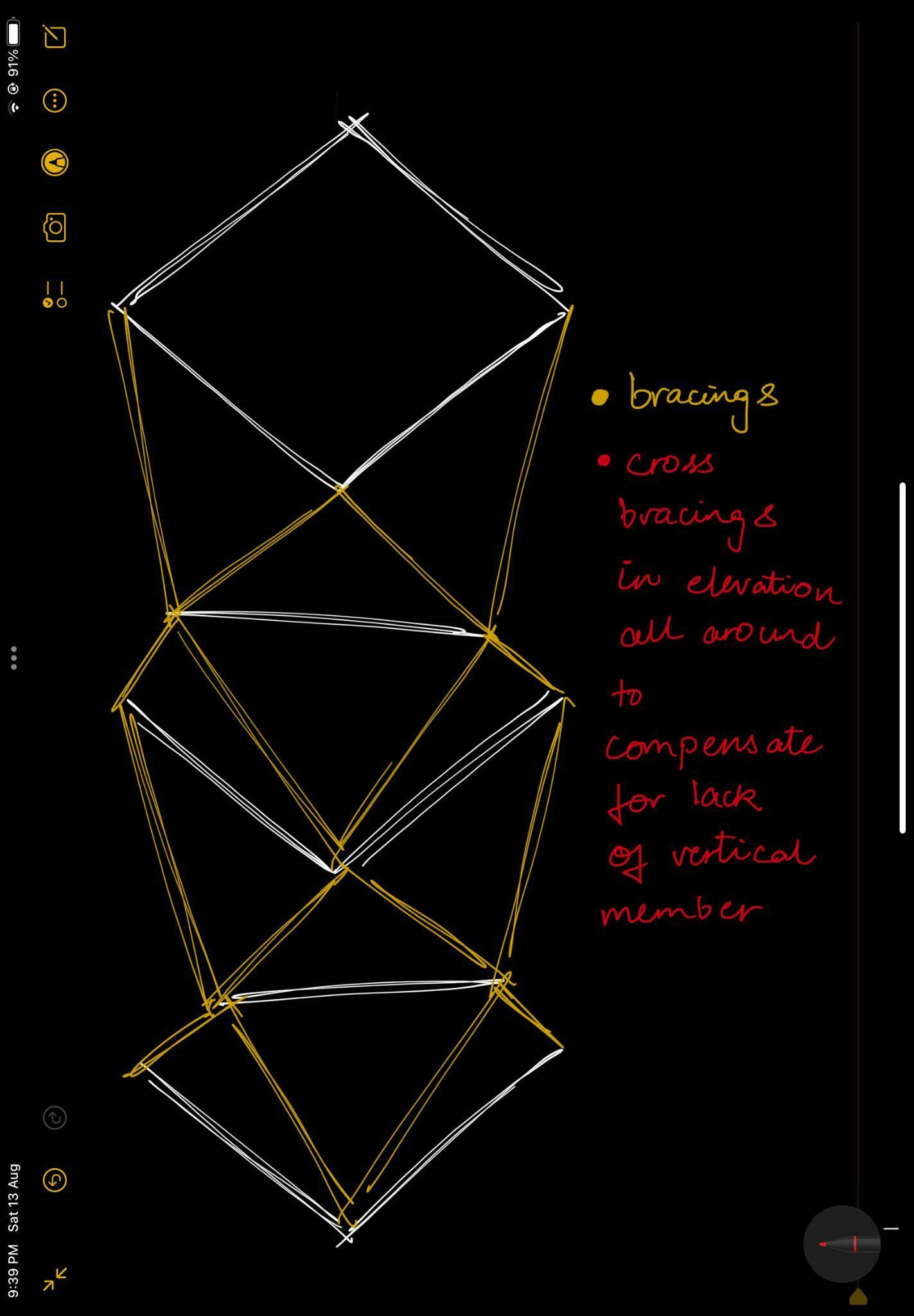
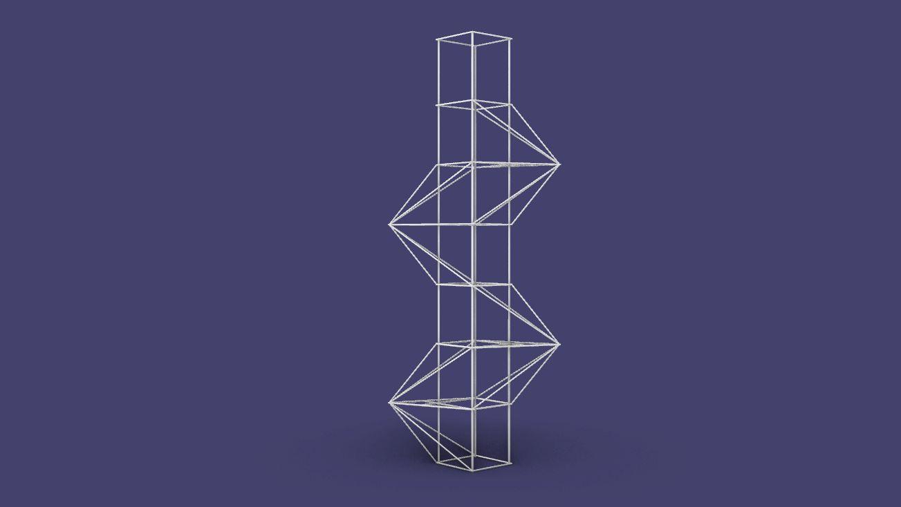
● Themodelinelevationisinthesilhouetteofanhourglass;the upperhalfismadelighterinordertoreducethedeadweight gettingappliedtothebaseviatheneck
● Theneckbecomesasensitiveregionsidetheentiredead weightoftheupperhalfisbalancedbythat;toovercomethis theneckisdiagonallybraced,theleakofwhichcausesthe structuretotwist
● Thiscontributestothestabilityofthestructuresinceithasno verticalsupportsrunningcontinuouslyfromtoptobottom
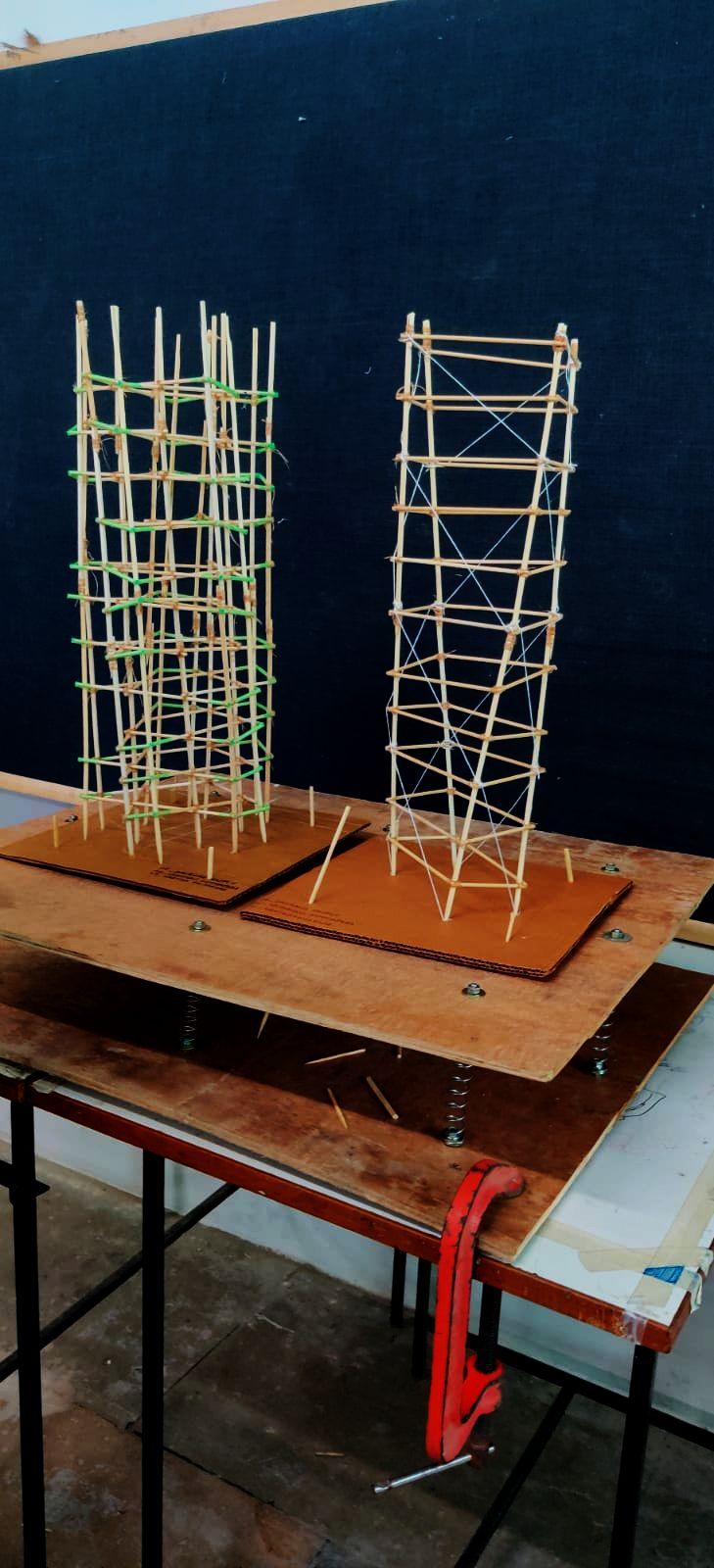
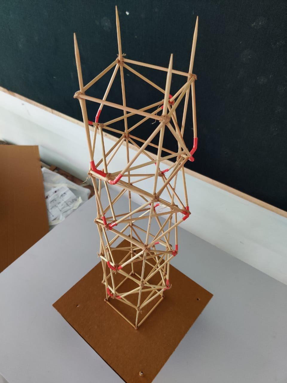
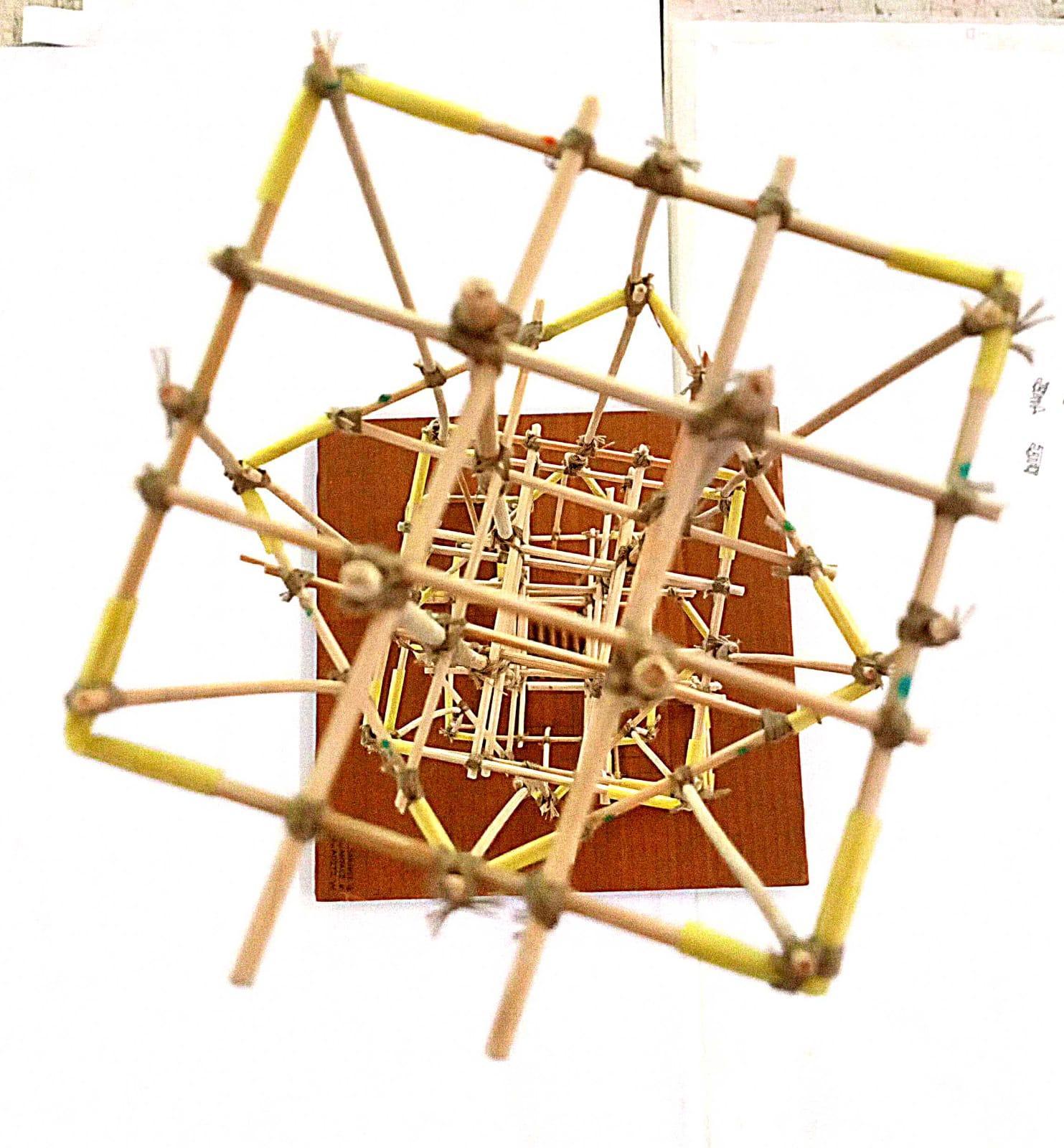
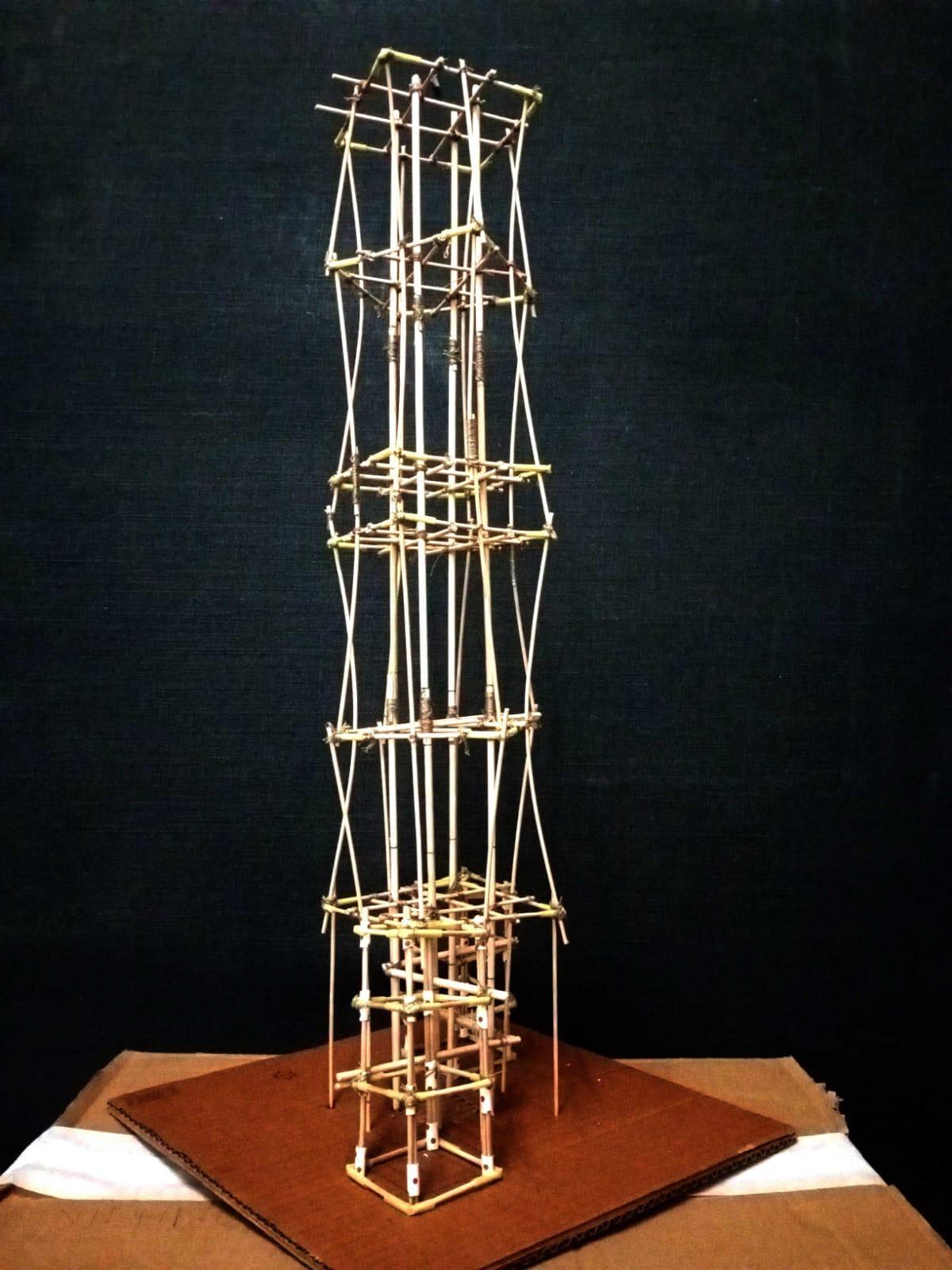
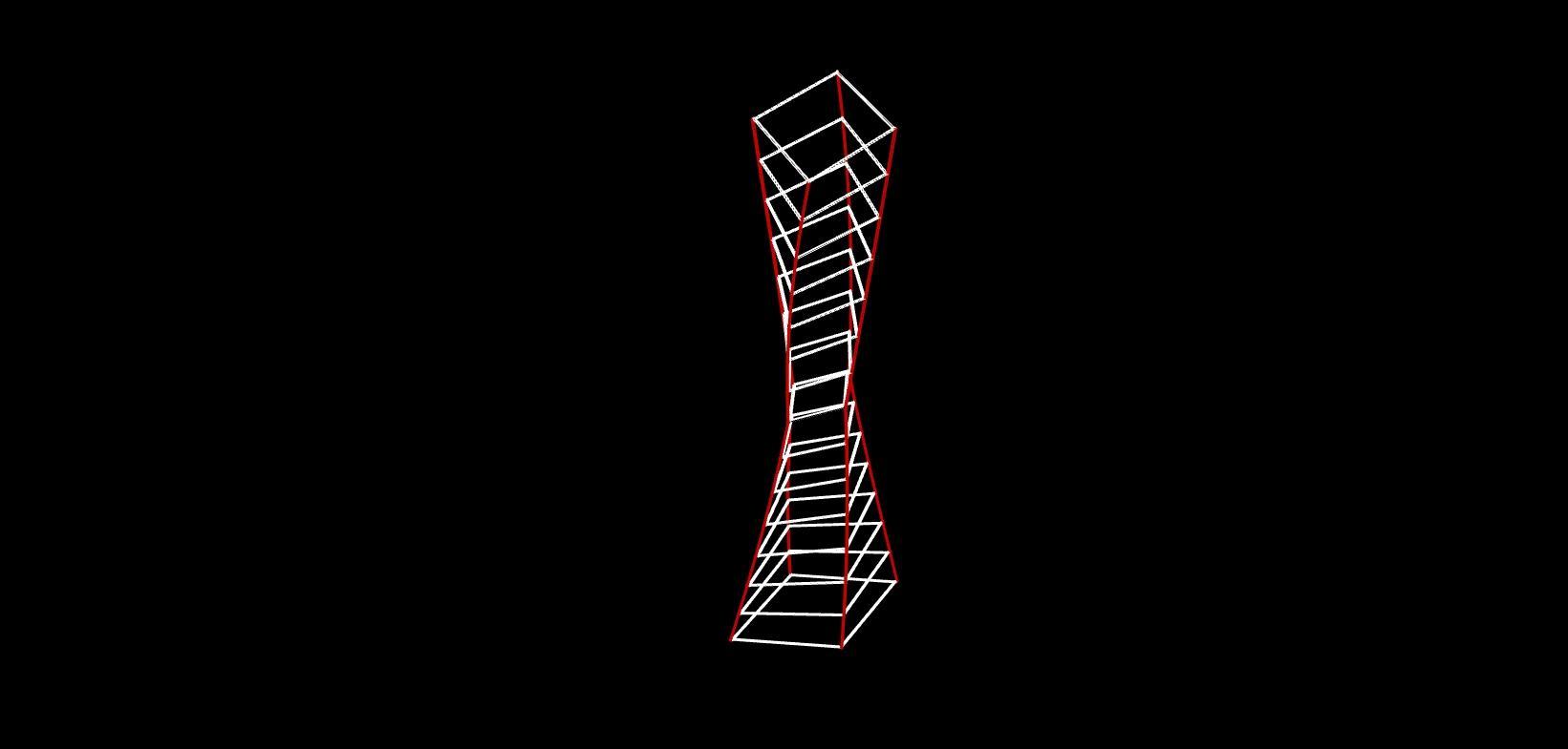
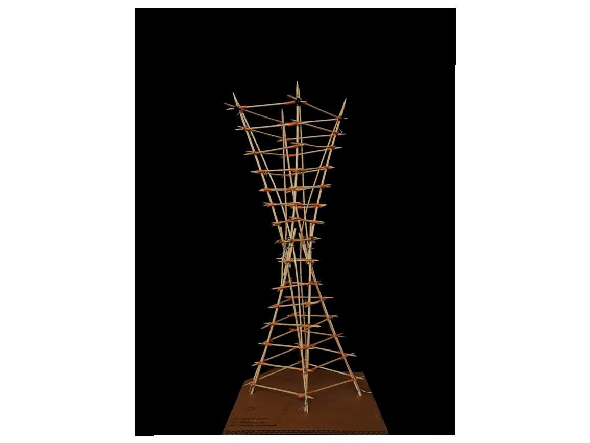
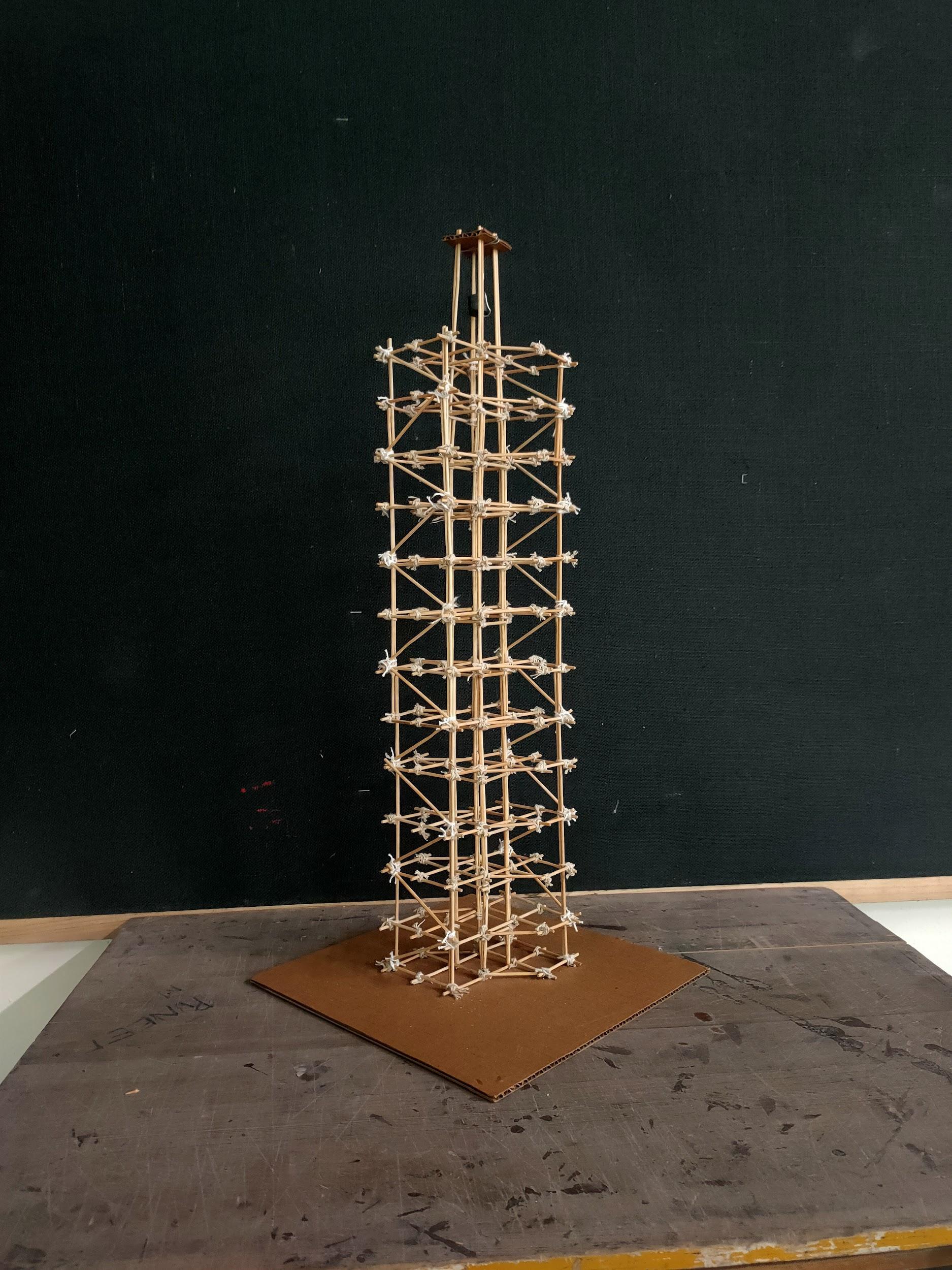
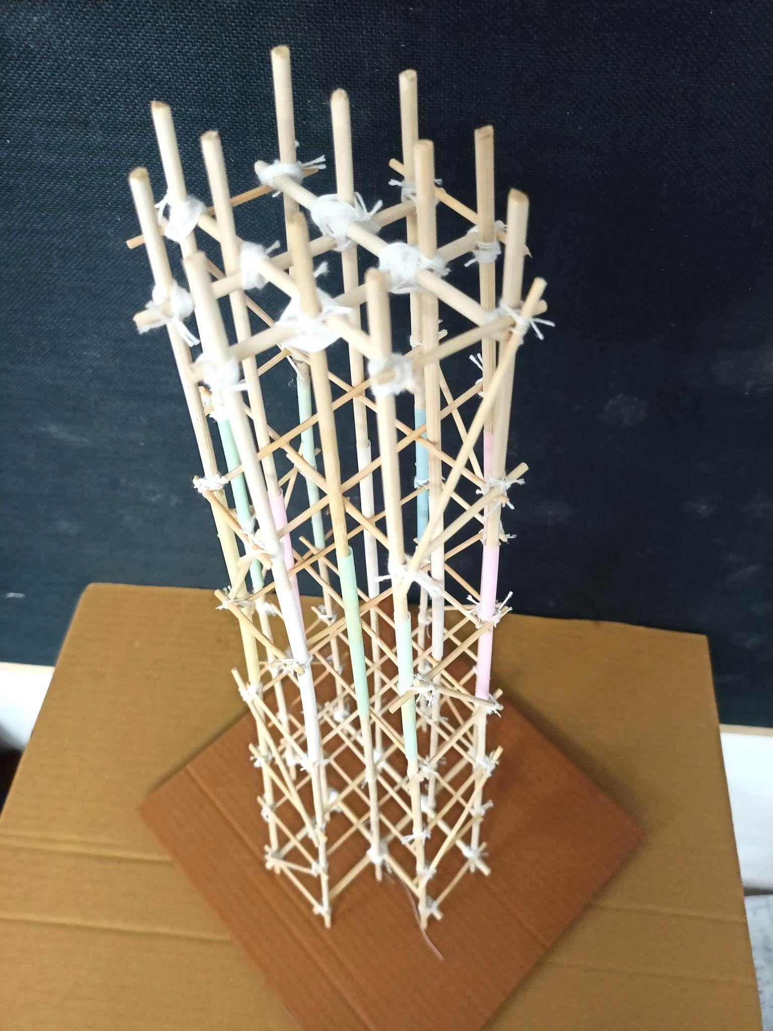
MODEL2(SCULPTURAL)
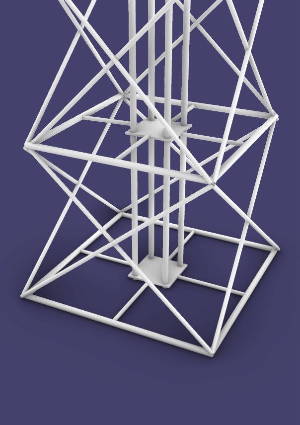
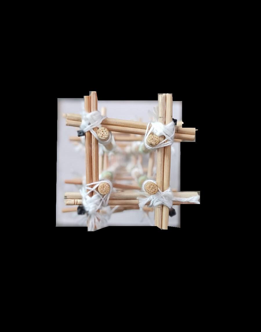
● Thesquareshapedfloorplatesmakethestructurestableiall coordinates
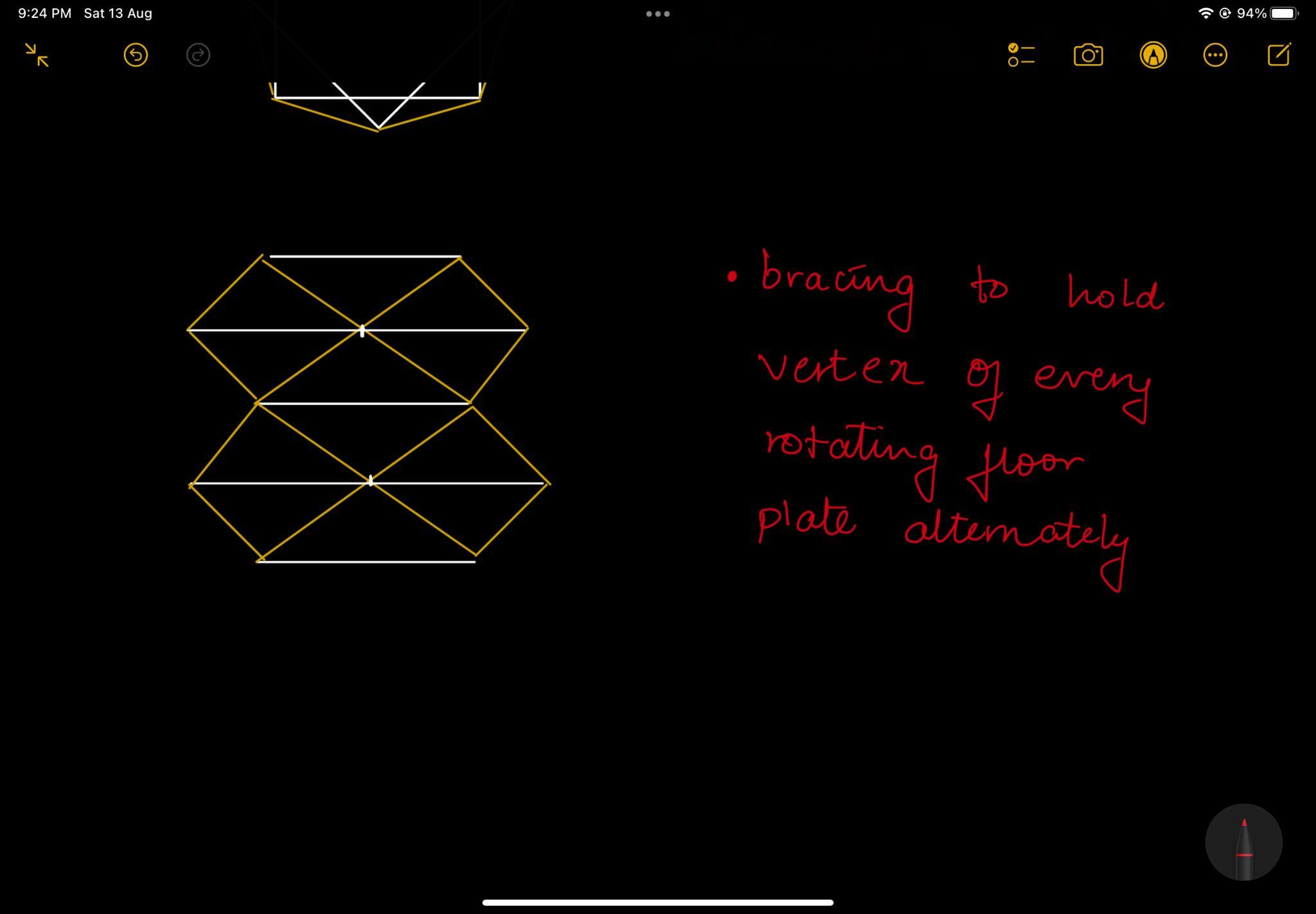
● Thealternaterotatingfloorplatesgetheldstronglywiththese squareplatesviacrossbracinginalldirections
● Theprojectingbracingsaddontothesculpturalaestheticsof thestructure
● Fourverticalsupportsonallofthevertex’ofthesquarerunfrom toptobottomandaidtodirectloadtransfer
Team03| DesignReport CONCLUSION ANALYSISANDCONCLUSION
AcademyofArchitecture,Mumbai
GROUP04 SAKSHEEGOTHANKAR_23 ANJALIKARPATE_35 ADITIWADATE_55
PLANS Isometric

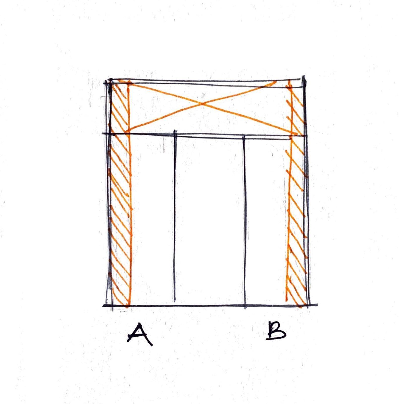
ELEVATIONWITHBRACING INDICATINGSERVICECORE Team04| DesignReport INITIALSKETCHES
ELEVATION TOPVIEW/JOINERYDETAIL ELEVATION Team04| MODELPHOTOS
ISOMETRIC
PLANS
ELEVATION
Team04| DesignReport INITIALSKETCHES
WITHBRACING ISOMETRICVIEW
Team04| DesignReport MODELPHOTOS
ISOMETRIC ELEVATION TOPVIEW ELEVATION
Geometricmodel
- Themodelislightweightwithangle bracingatsubsequent floors.
Theangledbracingsontwofacesofthestructurepassloadat thesamecolumn.
- Thecoreatoneedgeheldthefloorplatestogether
- Aftertakingthemodelonshaketable,themovementwasseen laterally,thecolumnswerecomparativelyrigidasweusedlap jointtojointwowatchmakersticksandtieditwiththreadwhich gaveextrastrengthtothecolumns.
Organicmodel
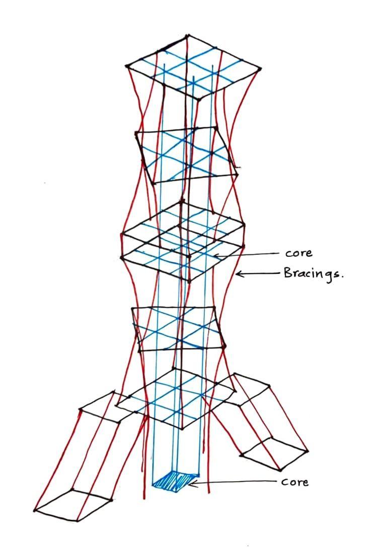
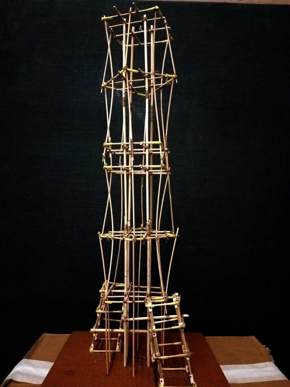
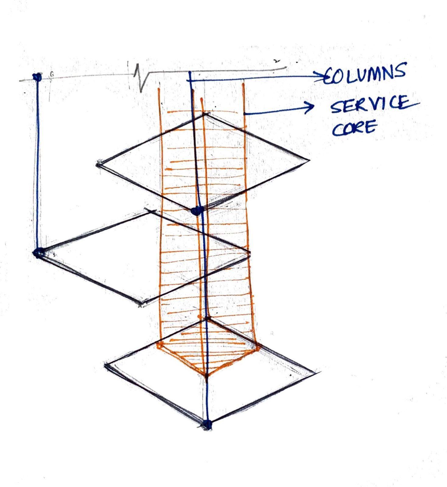
- Thesplittowersfrombottomandthesubsequentmiddlefloor platesplayacrucialroleinstructuralstrengthofthestructure. Thebareframebracingsrunningthroughthestructurewerethe pointswheremovementtookplace.
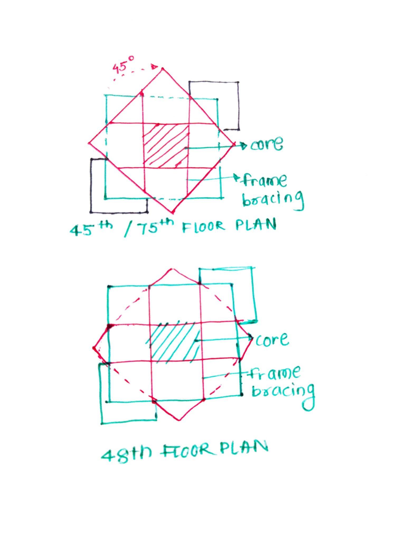
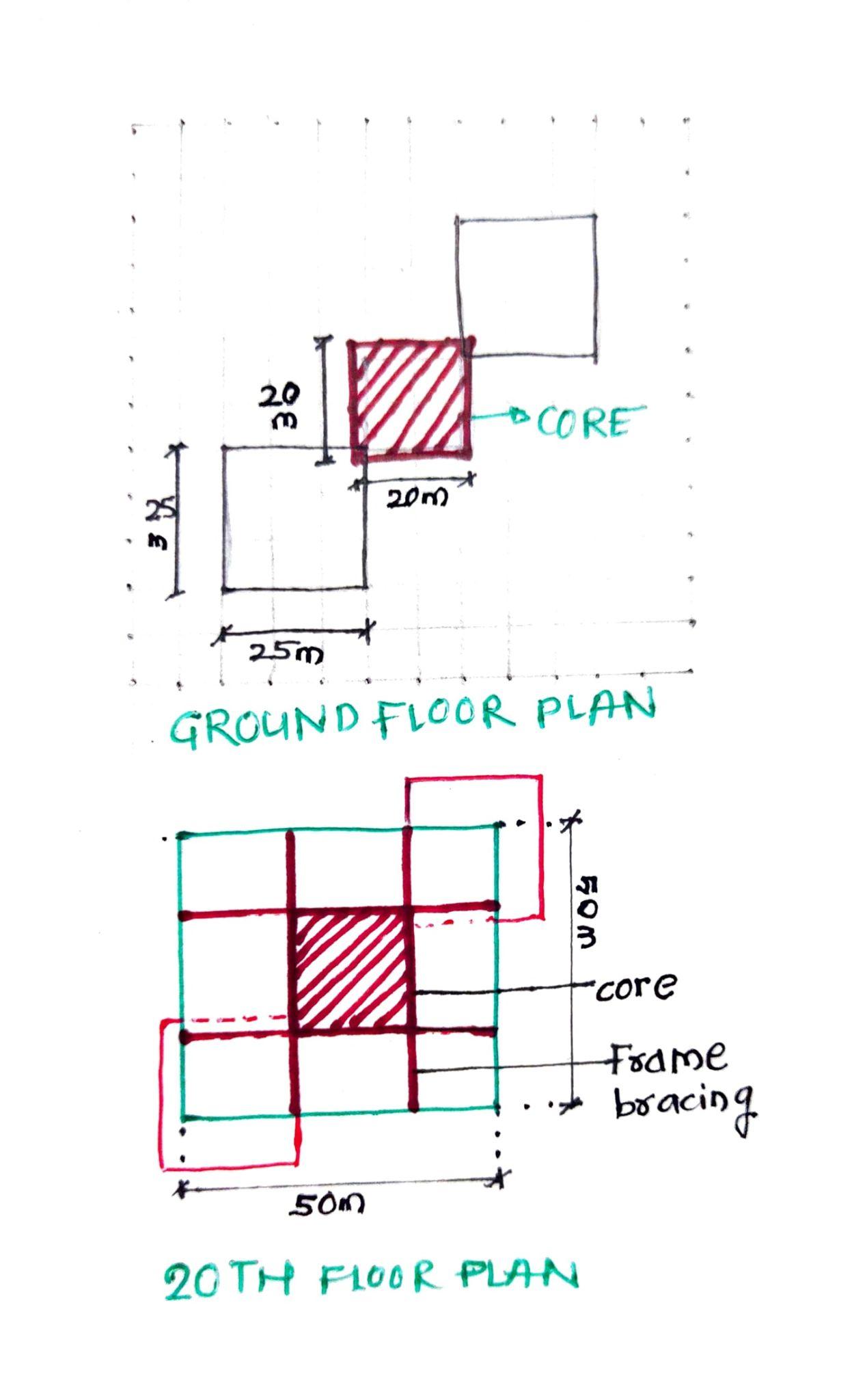
- Thecrossbracingsurroundingthecoreheldthestructure togetherandbalancedthe45degreetwistsformofthe structure.
Team04| DesignReport CONCLUSION
ANALYSISANDCONCLUSION
GROUP
05
SHAKTIJADHAV_18 PRAJAKTAPAI_21 KRISHNAKHURUSANE_36
AcademyofArchitecture,Mumbai

ELEVATIONS 3DVIEW Team05| DesignReport GEOMETRIC|DIGITALMODEL
GEOMETRY ANATOMY
TITLE IMAGETITLE PLANARVIEW
Team05| DesignReport GEOMETRIC|PHYSICALMODEL
IMAGE
ANATOMY
ELEVATION Team05| DesignReport SCULPTURAL|DIGITALMODEL
DIGITALTOPVIEW FRONTVIEW
TeamO5| DesignReport SCULPTURAL|PHYSICALMODEL
3DVIEW
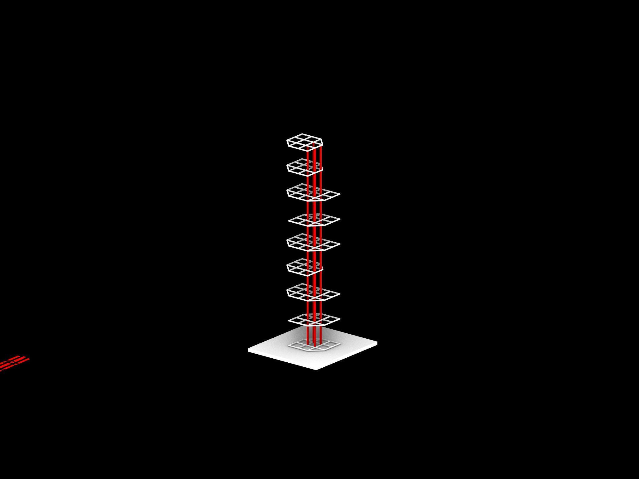
MODEL1:Geometric
● Itisacombinationofsmaller(35x35m)andlarger(50x50M)square floorplatesonevery10thfloorlevel(i.e.40m).
● Theseareconnectedbydiagridsystem,whichresistedtheearthquake pressureduringthetest.
● Someamountofswayingwasobservedinupperhalfofthestructuredue totheeffectoflateralloads.
● Thestructureachievedstrength,stabilityandstiffnessinveryless materialduetoitssymmetricalnature(C.G.atgeometriccentre)and diagridstructuralstability.
MODEL2:Geometric
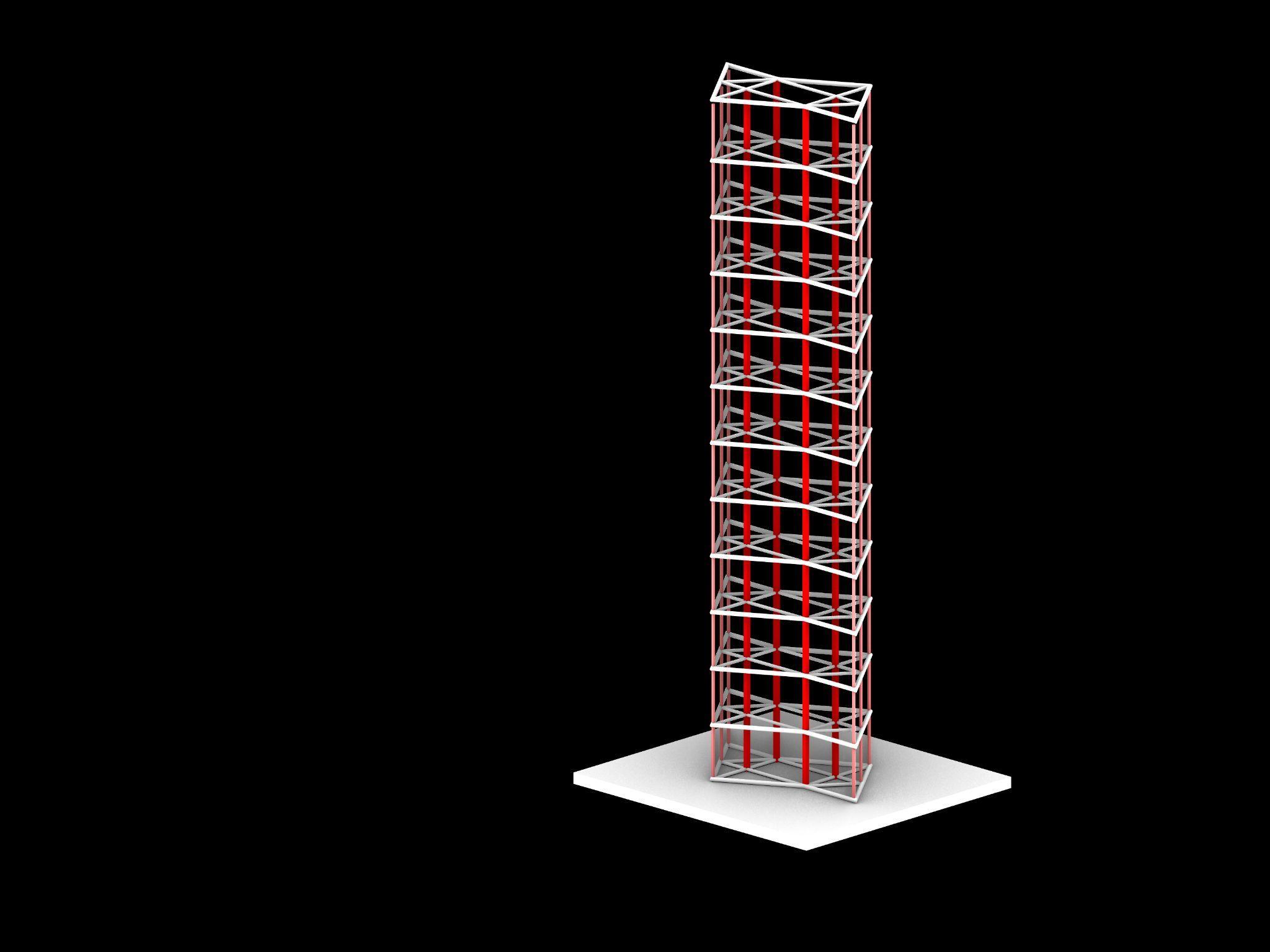
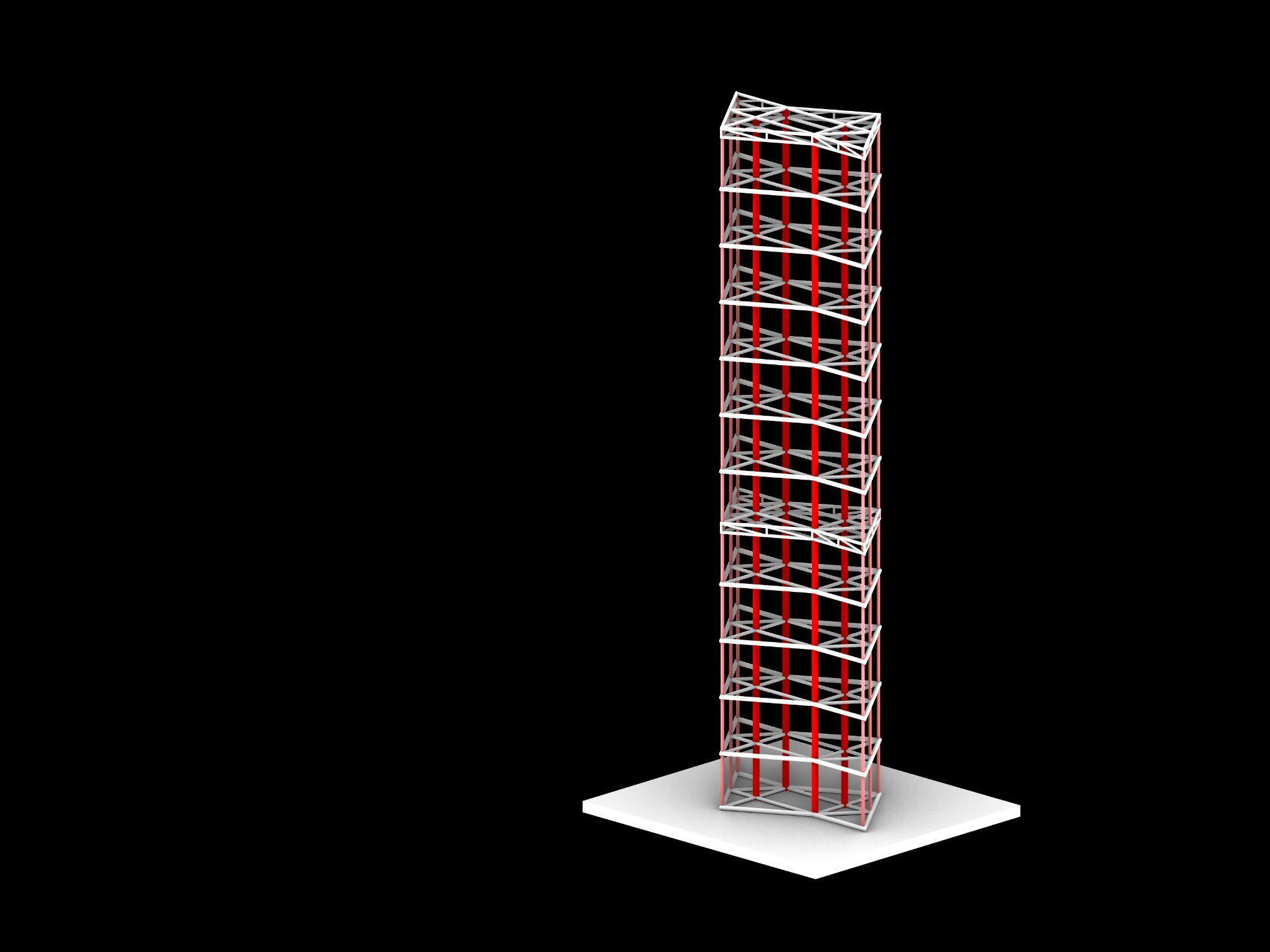
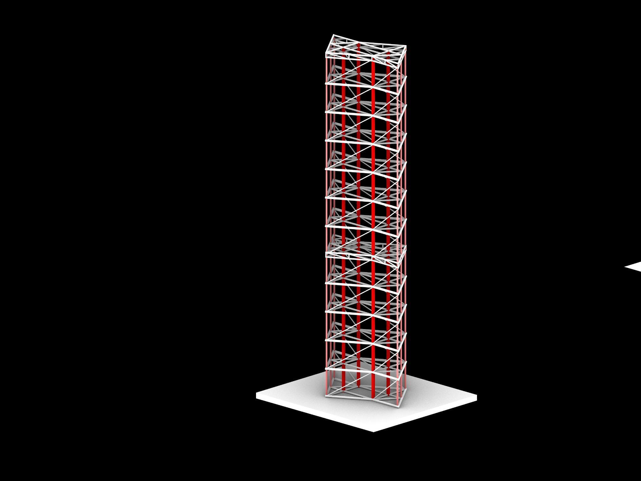
● Themodelisanexplorationintwistingandinversionofmass.
● Rhomdicalfloorplatesdecreaseinsizeandturn25degreesclockwiseat every20m'suptoaheightof140m’s.
● Thegeneratedmassismirrored,continuingthetwist,givingrisetoa softlytwistingsculpturalform
● Beforeaddingthebracing,thetwistingduetoeccentricplacementof loadswasobserved.
● Bracingfollowingthegeometryoftheform,butoppositetothedirection oftwistwereaddedtoresistdeformationandprovideadditionalsupport.
● TheBracingsprovetobeeffectiveinresistingtorsionuponadditionof minorloadsandincreasedintensityofShaketable.
CONCLUSION
● Thebracingshelpincounteringtheswayingresultingduetolateralloads suchasearthquake.
● Theswayingisobservedindecreasingintensityfromtopleveltobottom.
● TheColumnsneedtobeanchoredtothegroundfirmly.
● Thetotalnumberofjointsshouldbeminimisedforeffectiveloadtransfer.
CONCLUSION
CONCLUSION
ANALYSISAND
Team05| DesignReport
AcademyofArchitecture,Mumbai
ROHITCHOPADE_06 SAIRAJHALPATRAO_34 AAKASHKHARADE_54 GROUP06
STRUCTURALSYSTEM&FACADE
BRACINGS
COLUMNS
FLOORPLATE BEAMS
STRUCTURALSYSTEM-ZOOMEDIN
STRUCTURALSYSTEM-ZOOMEDIN STRUCTURALSYSTEM&FACADE
Team06| DesignReport INITIALSKETCHES
BIRD’SEYE-STRUCTURALVIEW WITHFACADE-ISOMETRIC BUG’SEYE-STRUCTURALVIEW FLOORPLATES-AXONOMETRIC

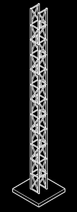
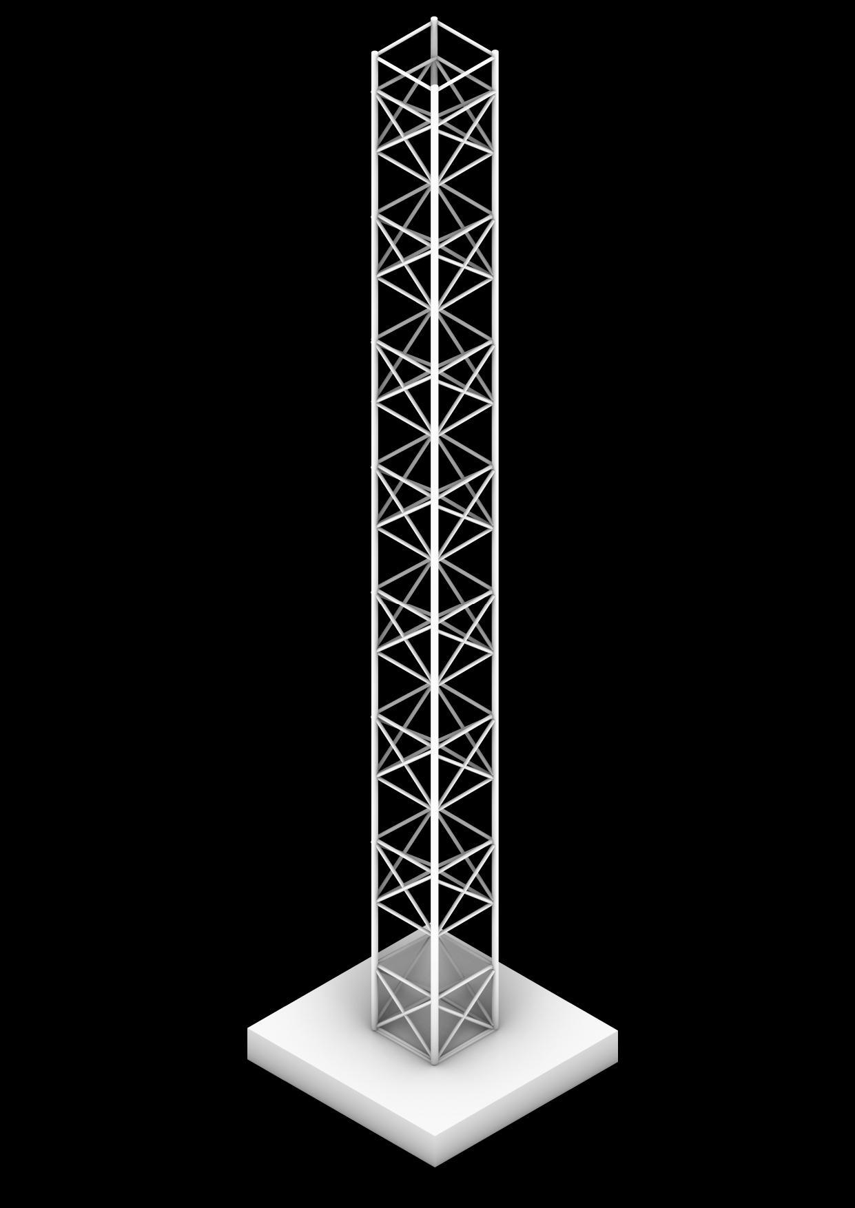
Team06| DesignReport DIGITALMODELPHOTOS Corecolumns Exoskeleton&Bracings SlabBeams
NORTHELEVATION SOUTH ELEVATION
EAST
Team06| DesignReport DIGITALMODELPHOTOS Corecolumns Exoskeleton&Bracings SlabBeams
ELEVATION WESTELEVATION
Team06| DesignReport MODELPHOTOS
MODEL-
ISOMETRIC
MODEL-ISOMETRIC MODEL-FRONTELEVATION MODEL-SITEELEVATION
Team06| DesignReport INITIALSKETCHES
BRACINGS
STRUCTURALSYSTEM STRUCTURE-ZOOMEDIN UNITPLAN-FLOORPLATE COREANDTHEFLOORPLATES
COLUMNS
FLOORPLATE BEAMS
PLAN
TOPVIEW BIRD’S
STRUCTURALVIEW Team06| DesignReport DIGITALMODELPHOTOS Corecolumns Exoskeleton&Bracings SlabBeams
BUG'SEYE-STRUCTURALVIEW ROTATINGFLOORPLATES
STRUCTURAL
-
EYE-
ISOMETRIC-WITHFACADE ISOMETRIC-WITHFACADE Team06| DesignReport DIGITALMODELPHOTOS Corecolumns Exoskeleton&Bracings SlabBeams
STRUCTURAL-ISOMETRIC MODELELEVATION
MODEL-ISOMETRIC MODEL-BACKELEVATION
 MODEL-FRONTELEVATION
Team06| DesignReport MODELPHOTOS
● Thestructureonthetopmostpartswaysmore thanonthe bottomparti.e.nearthegroundduringtheearthquaketest.
● Theswayingofthestructurewasreducedsignificantlywhen testedwithbracings.
● Columnsneedtobelargerinsizeascomparedtobeamsand needtobeproperlyanchoredtothegroundinordertotransfer load
● Buildingsmayormaynotsurviveearthquakebutthestructure canbedesignedinsuchawaythatitcanresistearthquakefor atimesufficientfortheresidentstoescapefromthebuilding anditcanbeensuredthatthereisnolossoflife.
Team06| DesignReport CONCLUSION
CONCLUSION
ANALYSISAND
07
AcademyofArchitecture,Mumbai
GROUP
SIMRANAJGAONKAR_24 AMEYATHANAWALA_37 KARISHMAKAURHOODA_40
1. StudyaHighrisewithoffsetsandbranching.
2. To understand the role of Symmetrical and Asymmetrical Formsinrestraininglateralforces.

3. To explore different Joineries between Core and offsets of theForm.
Team07| DesignReport INITIALSKETCHES_EXTRUSION
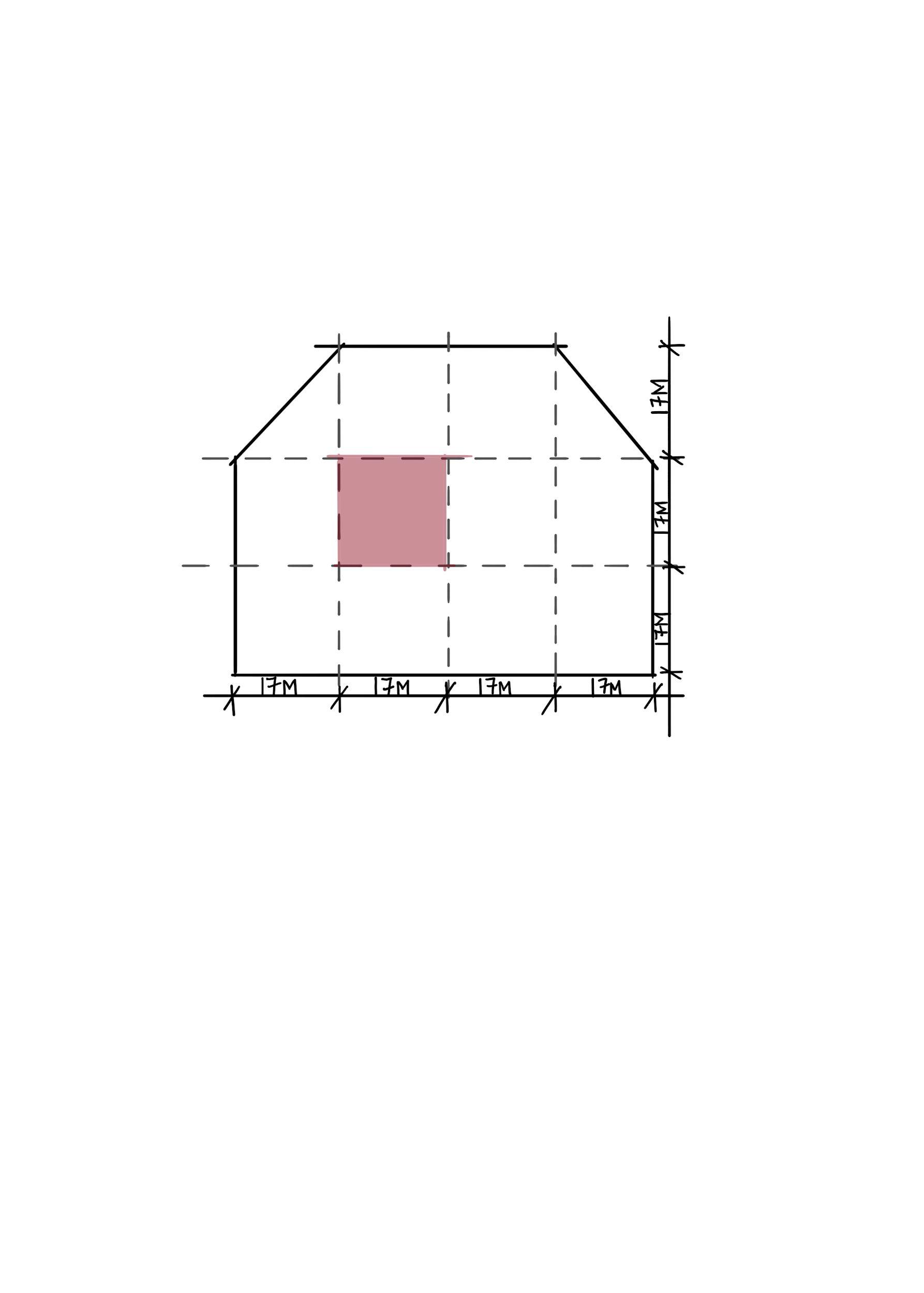
TheformisfurtherDevelopedwitha10X10Mgridandisconceptuallyresolvedwrtdimensionsandarea.
EVOLUTION_EXTRUSION
Team07| DesignReport
flexibleatthesametime,hencemakingofsmall membersisalsopossiblebyjustbreakingitinto pieces. Apart from this the material also allows variation in its usage such as clubbing of 2-3 members to make it stronger and half lap joints wherever required and gives a cleaner finish to themodel.

SKETCHES
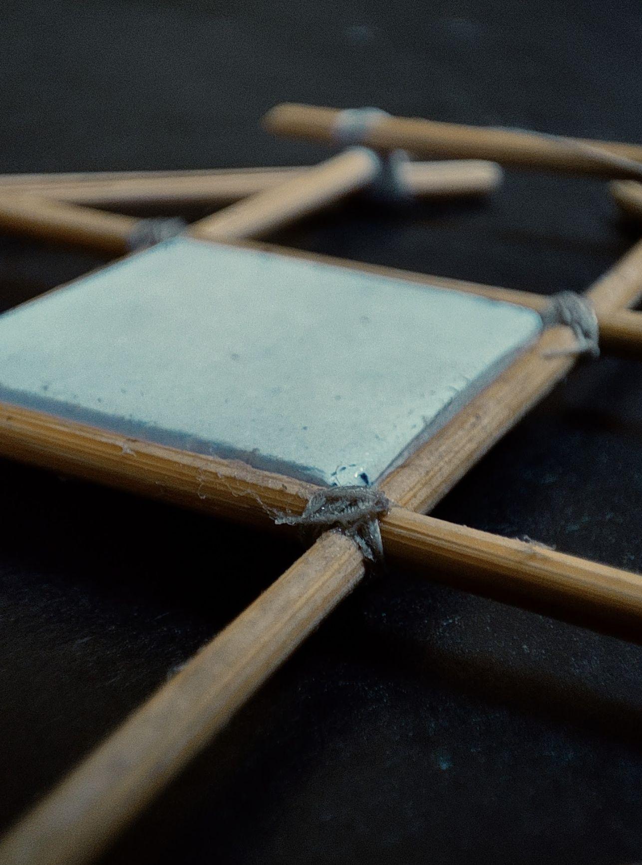
Threadwasusedasamediumoftyingtogether the members and eventually making the model stand. The white thread was initially used to tie the members but due to its thickness the knots weretoobulky.Hencetheochrecolourthreadof comparatively less thickness were used. They not only tied the members tightly but also gave a very seamless look to the model since it's colour matched with the colour of the watchmakersticks.
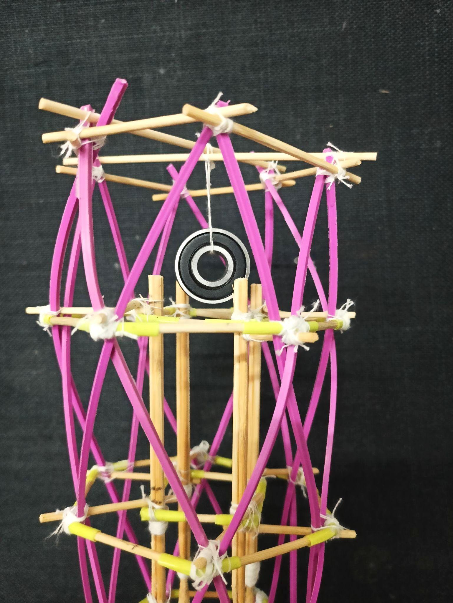
CORRUGATEDSHEET BEARING

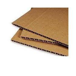
30cmx30cm square cut out of a corrugated sheet. The model was fixed onto the sheet by makingholesandinsertingthecolumnsintothe sheet which were secured from the bottom of thesheet.(actsasafoundation)
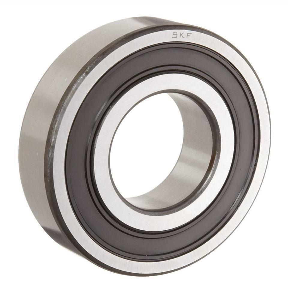
For the TMD (Tune mass damper) test, a metal bearing was used. The weight of the bearing allowstocontroltheswayofthestructureduring aninducedearthquake.
MATERIALSANDTYING_EXTRUSION
Team07| DesignReport
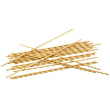
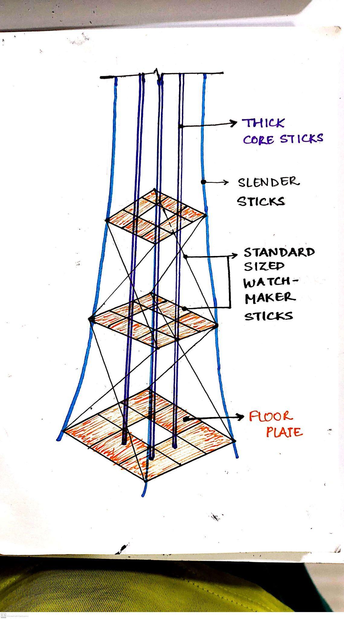
WATCHMAKERSTICKS SYNTHETICTHREADS
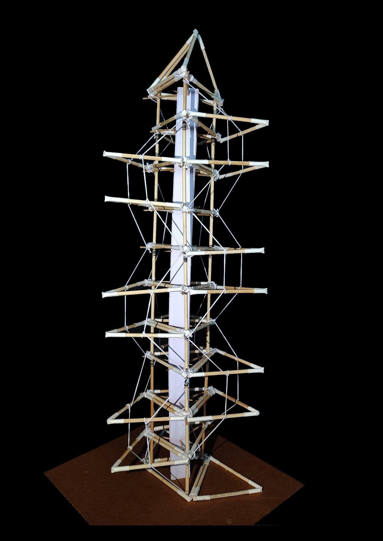
Continuing
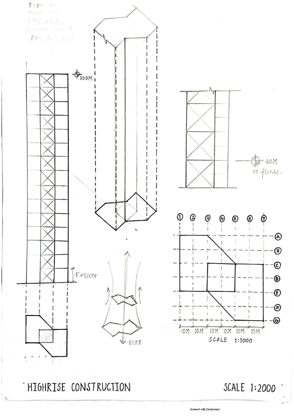
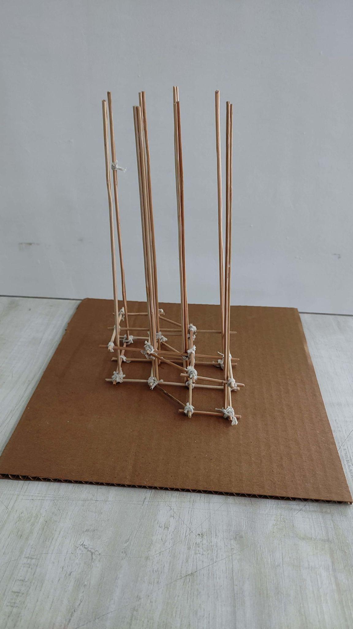
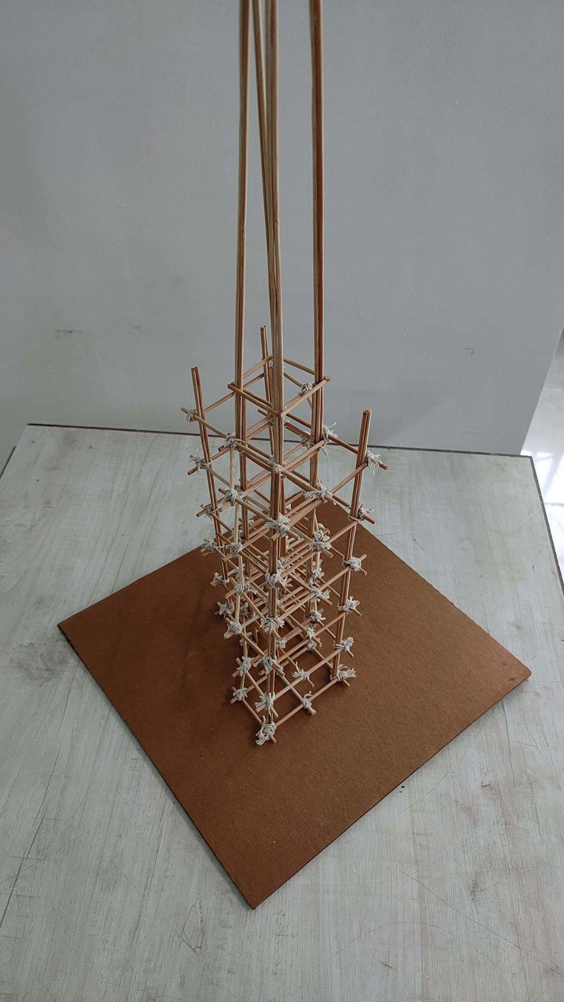
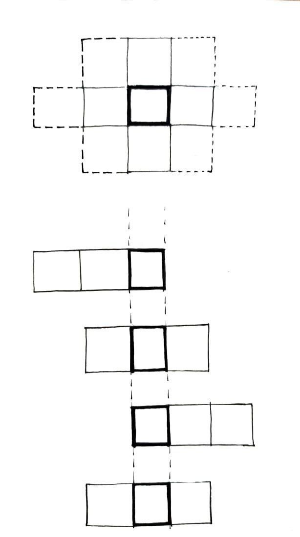
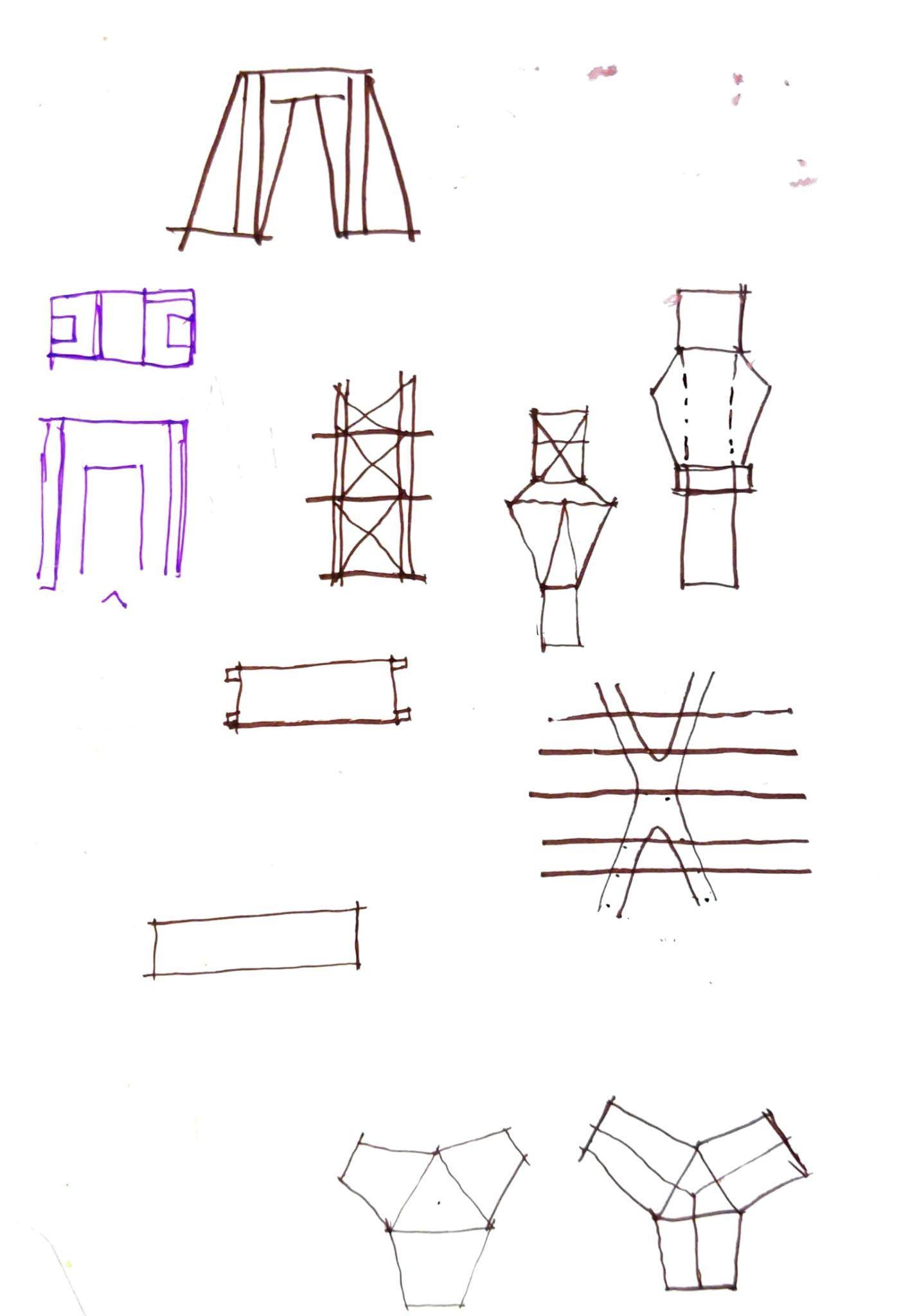
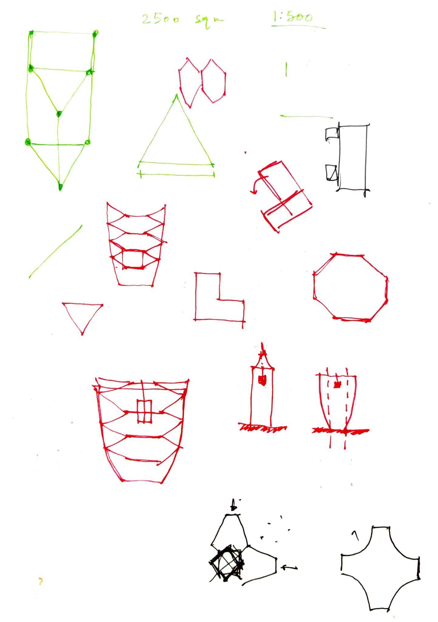
CONSTRUCTIONPROCESS 1. A module of area 2500 sqm at 1:500scaleismadeandplacedon abasesurface. 2. With referencetothemodule,the columnsareerected. 3. Thenextmoduleisinsertedwithin theframecreatedbythecolumns exactly in alignment of the base module. Coreiserectedfirstwhichfollows slipformmethodofconstruction. 4. Each module is placed in the samemannerataheightof4cm. (ie.5floorsclubbed) Team07| DesignReport
thesameprocessuntoheight of300m
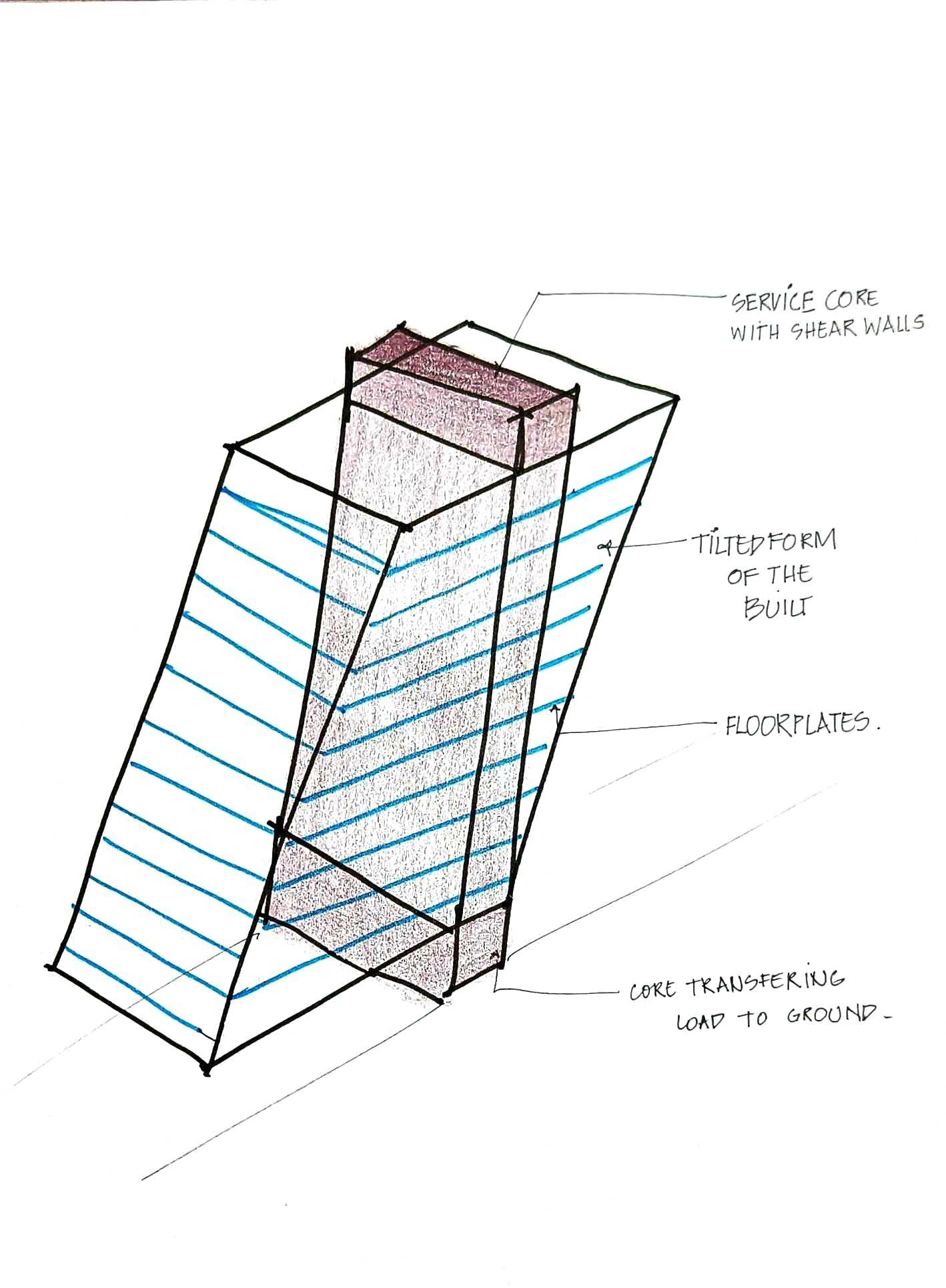
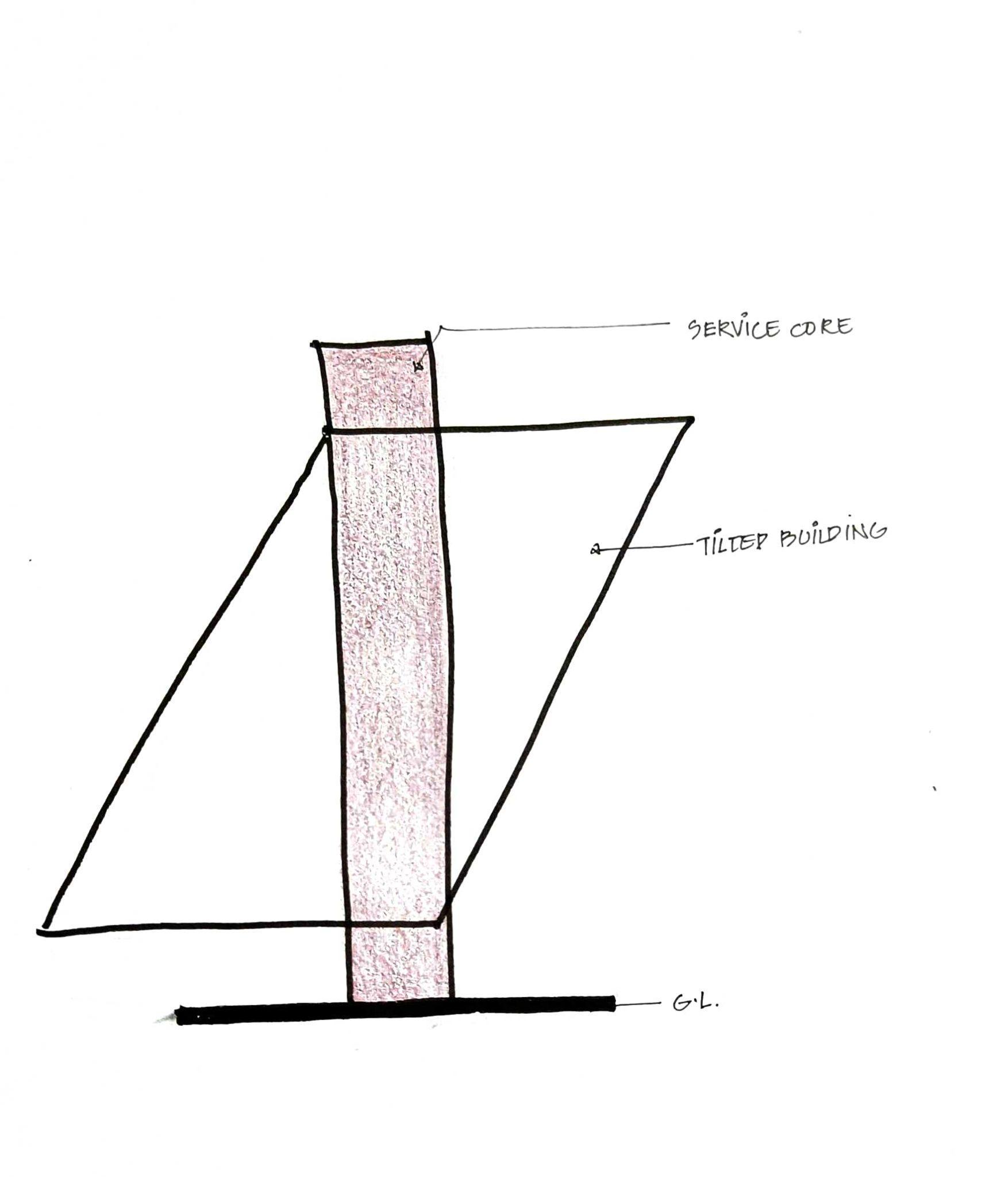
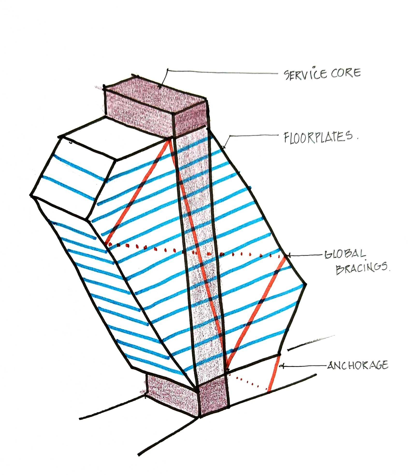
ROLEOFGREENBUFFERS ROLEOFCORE
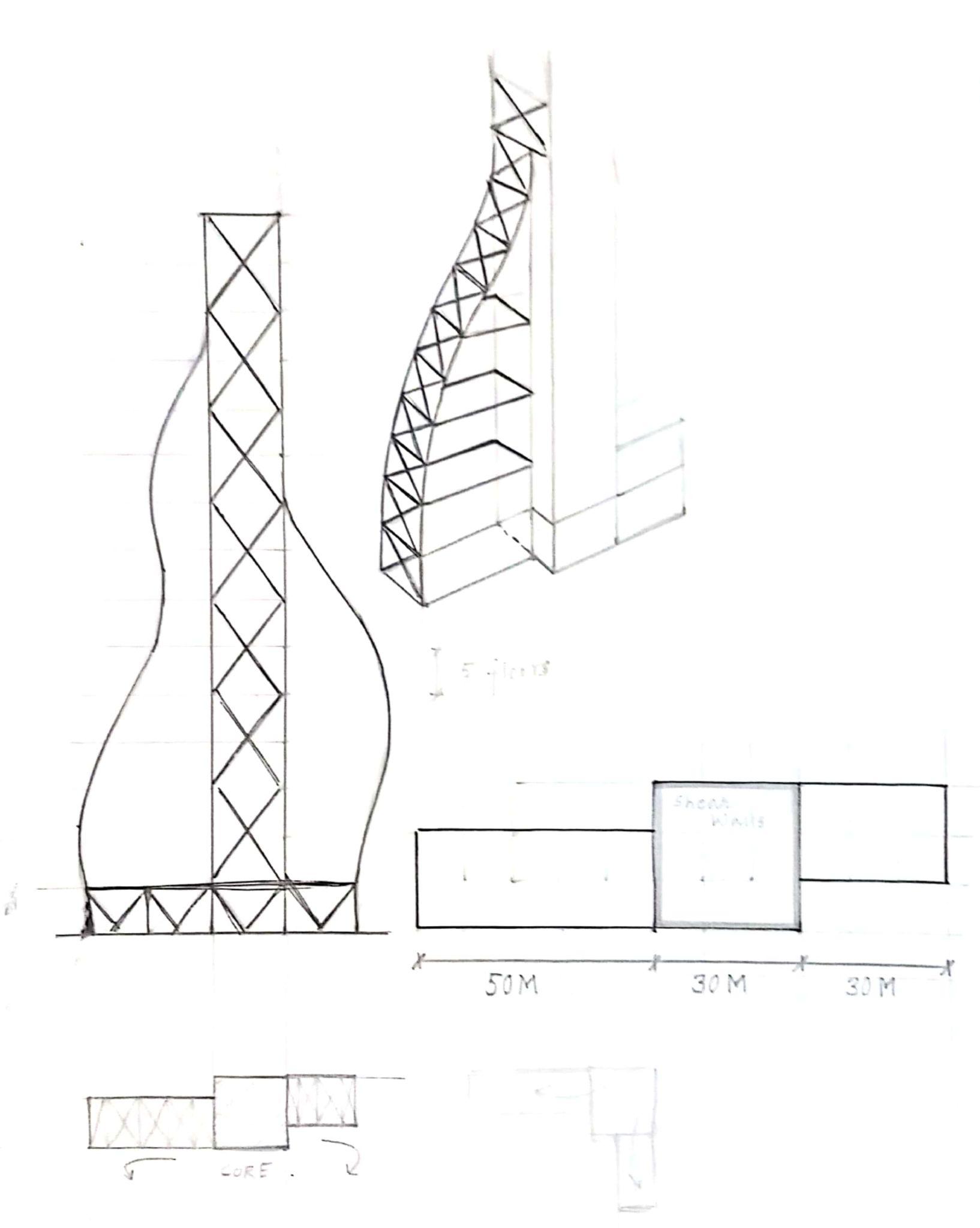
The cantilevered Spaces act as a Green Buffer betweentwozonesofthebuilding.
It also ties the two zones of the building and structurally prevents the Building from an overallShearing.
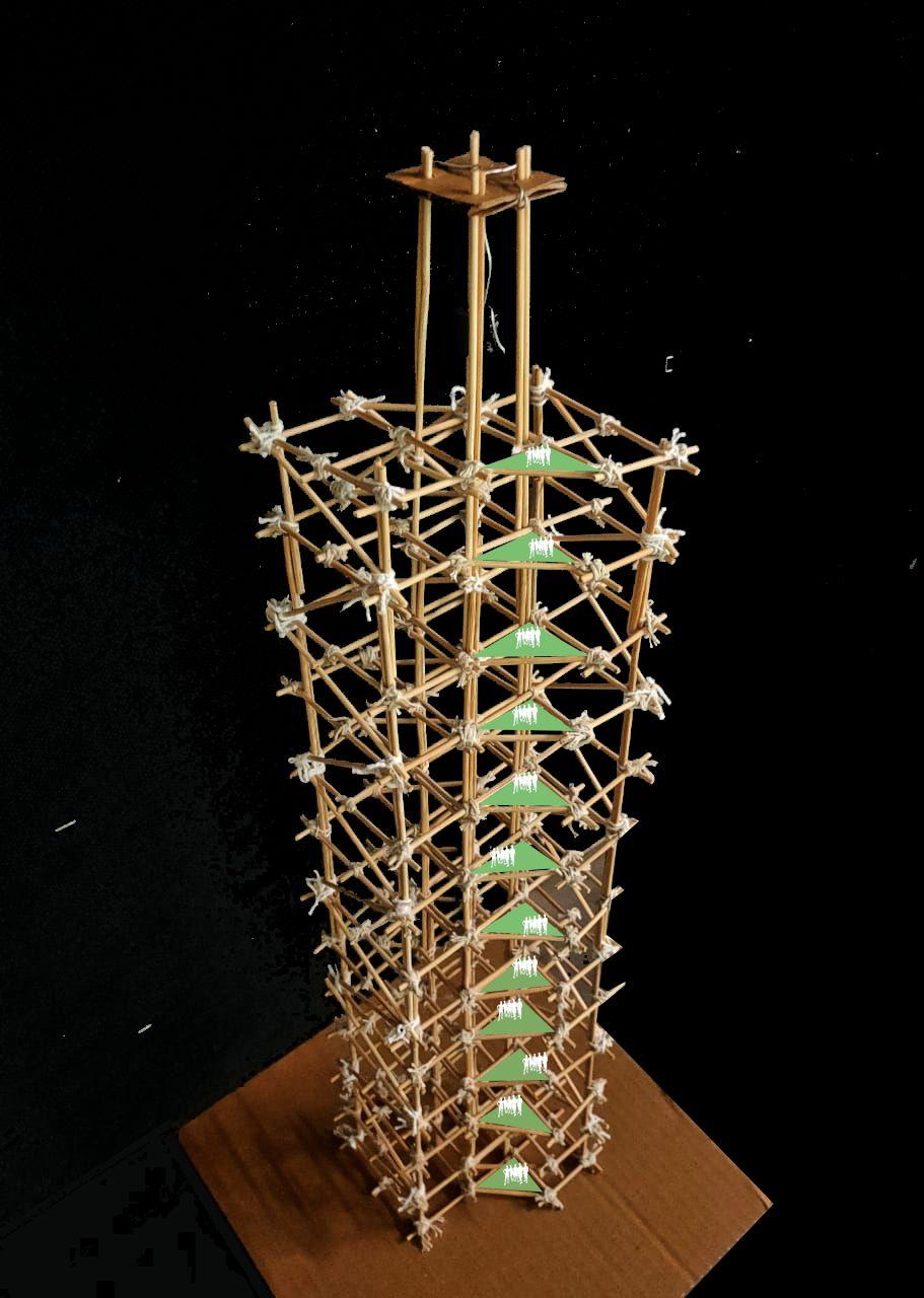
The Core in the Centre has Belt truss system whichmakesitrigid.
The two zones of the building can be used as flexiblespaces.
The core extends about 30m above the Terrace slabtohouseservicesandTMD.
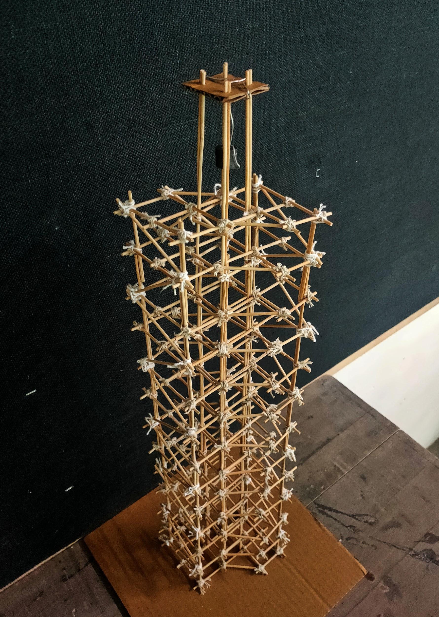
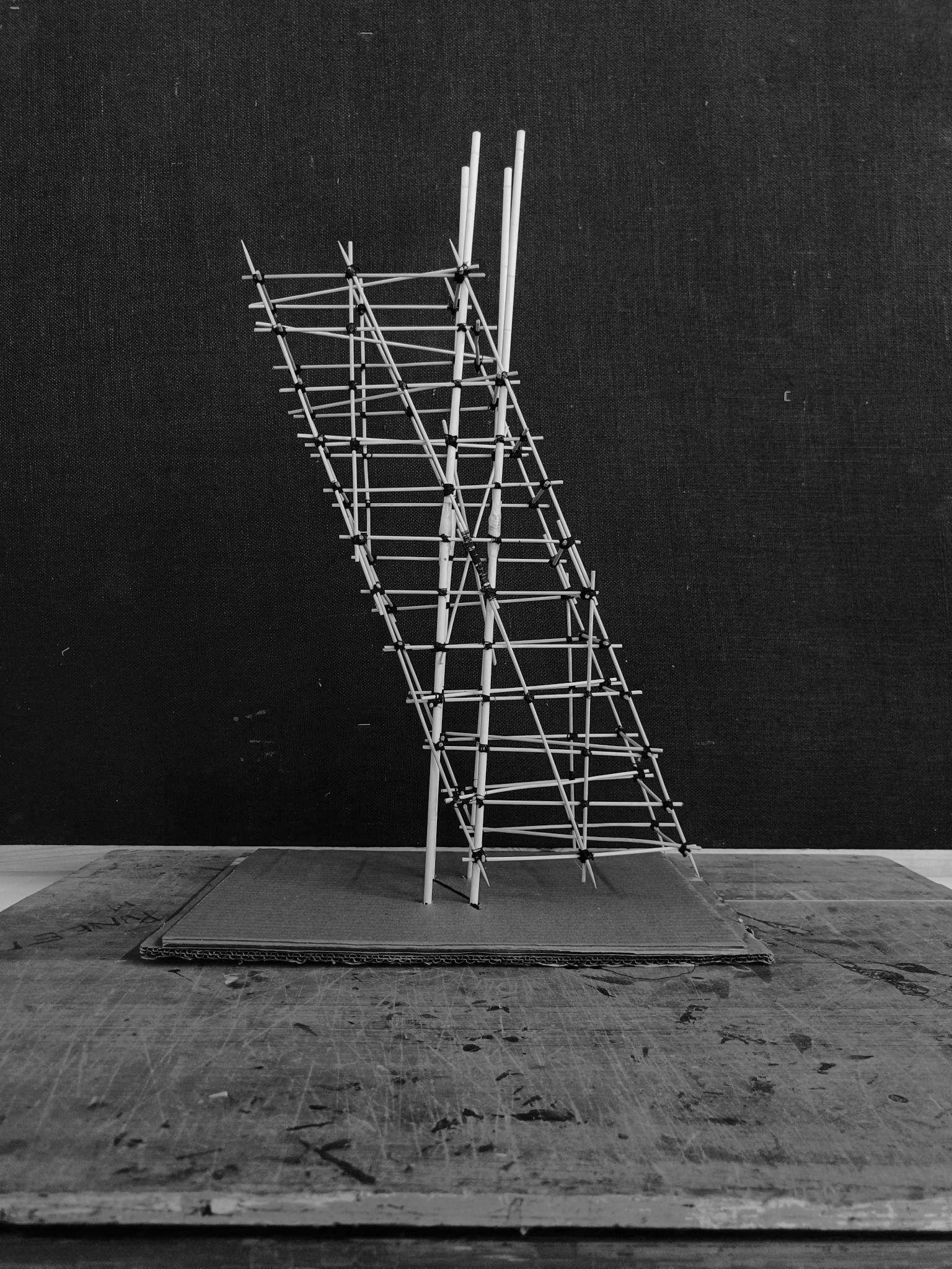
PHYSICALMODELWITHINTENDEDFUNCTIONALSPACES
Team07| DesignReport
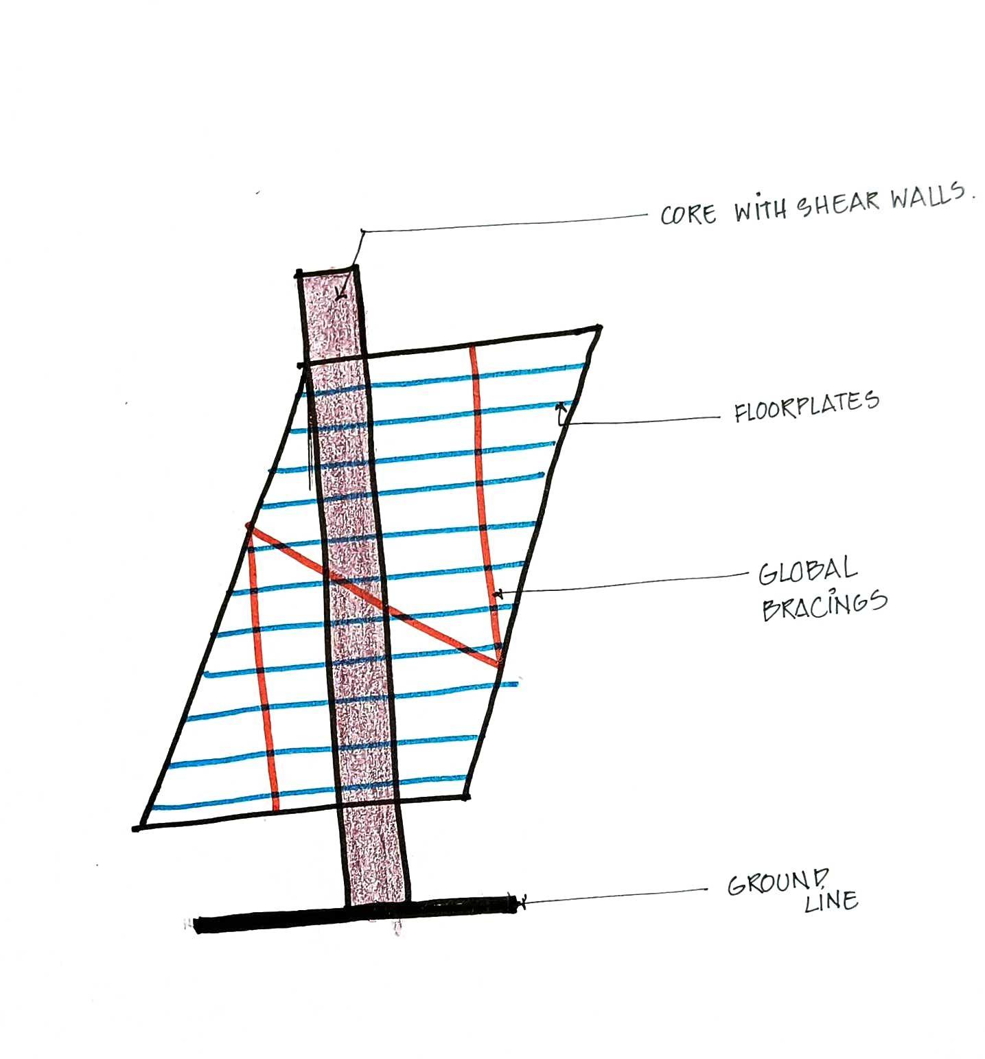
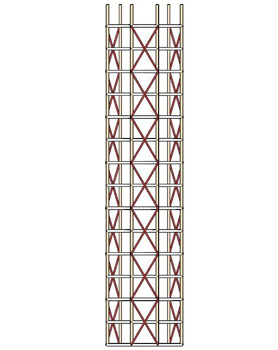
During the Shake Table test, Model without bracing undergoes a significant displacement/swaywhichmightbeundesired.
This is also because the joints are free to move andthustheydisplacewiththeactionofapplied lateralforce
Along with Sway, the phenomenon of DRIFT is also clearly visible where individual floor modulestendtoslipaway.
TheModelisbracedwithFRAMESHEARTRUSSat ends at a Global level to keep the structural integrityandmakethebuildingactasoneunit.
As the Joints are restrained, swaying automaticallyreduces.
PhenomenonofDriftisabsent.
PERFORMANCEWITHANDWITHOUTBRACING
BRACING WITHBRACING Team07| DesignReport
WITHOUT
WITHOUTBRACING+TMD
The TMD reduces the sway further by absorbing the mechanical vibrations which cause lateral forcesonthestructure.
TMD Oscillates in the opposite direction of the resultantactionthusstabilizingthestructure.
ACTIONOFLOAD
The load causes eccentric forces or bending in thestructure.
Withtheappliedload,theswayincreases.
Cross Bracing at cantilever parts and Outrigger systems would have helped to keep a check on theactionsoftheappliedload..
Team07| DesignReport PERFORMANCEWITHTMDANDAPPLIEDLOAD
TWISTINGDUETOAPPLIEDLOAD
A couple is further generated causing torsional forcesortwistingalongtheLongitudinalaxis.
A RIGID BUNDLED TUBE SYSTEM WITH OUTRIGGERS would check this action as the Longitudinal movement is restrained in a SHEARWALL.
WITHBRACINGANDTMD
Team07| DesignReport
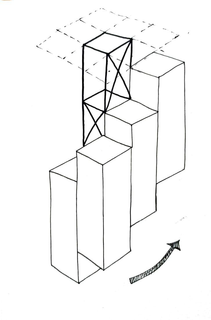
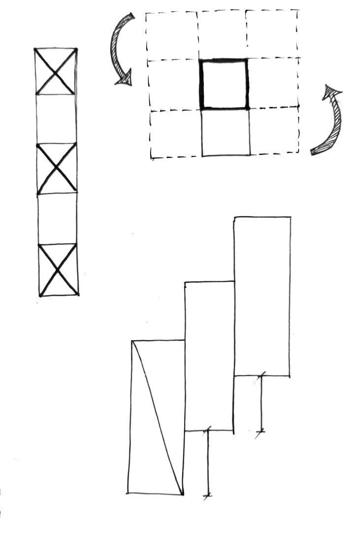
OPTION1
Organically developing modules on each side of a Squarecore
OPTION2
Alternating form of static anddynamicsquares.
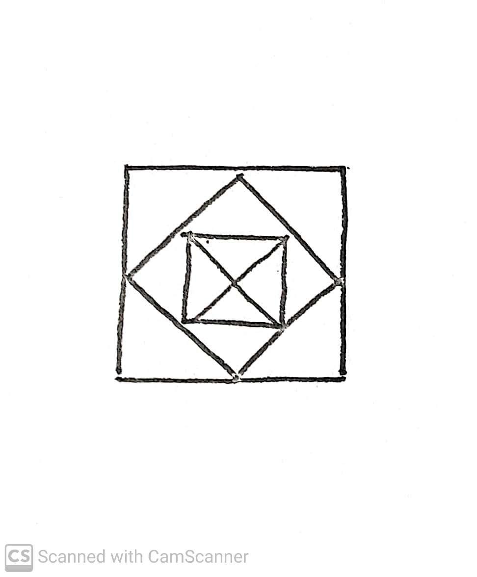
OPTION3 Square unit rotated at angle to give a twisting form
SELECTIONCRITERIA
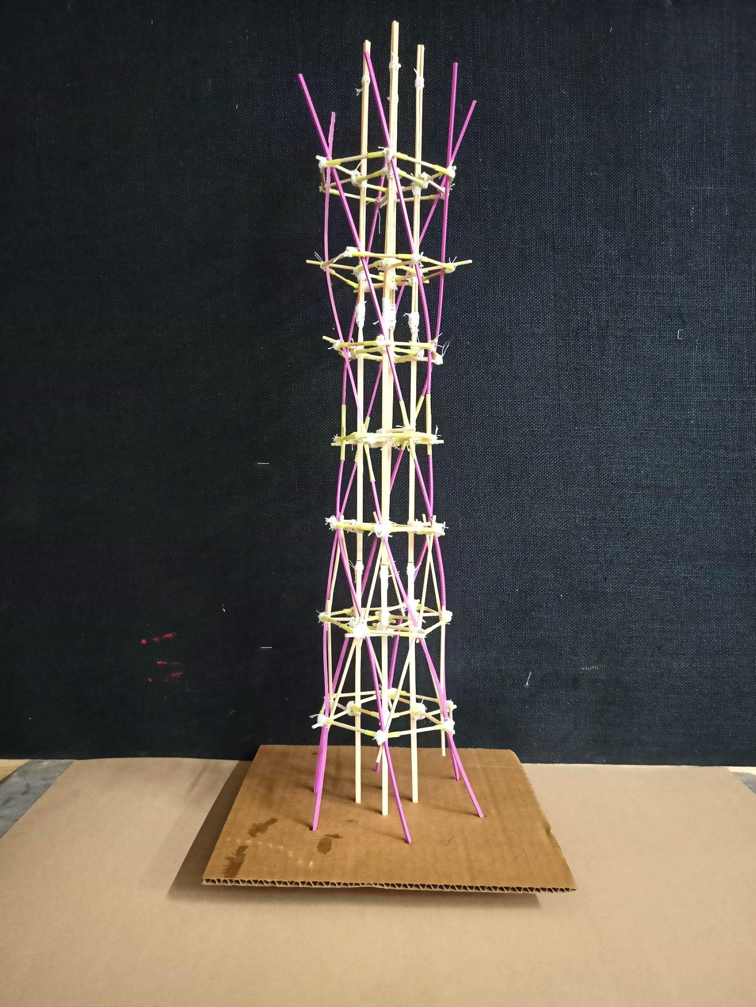
ThefollowingformisselectedfortheSculpturalForm: 1. StudytheresolutionandmodellingofaTwistedStructurewhere floorplatechangesateveryfloor 2. TounderstandBracingandfacadesystemsonangledsurfaces 3. To explore aerodynamic forms and how forms themselves can helpresistlateralloads.
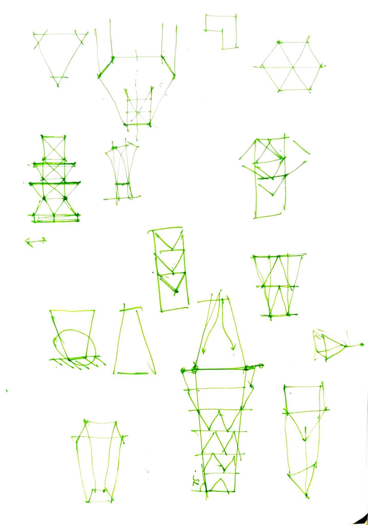
Team07| DesignReport INITIALSKETCHES_SCULPTURAL
EVOLUTION_SCULPTURAL Team07| DesignReport
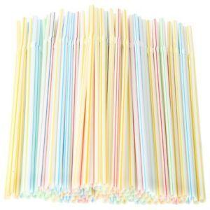
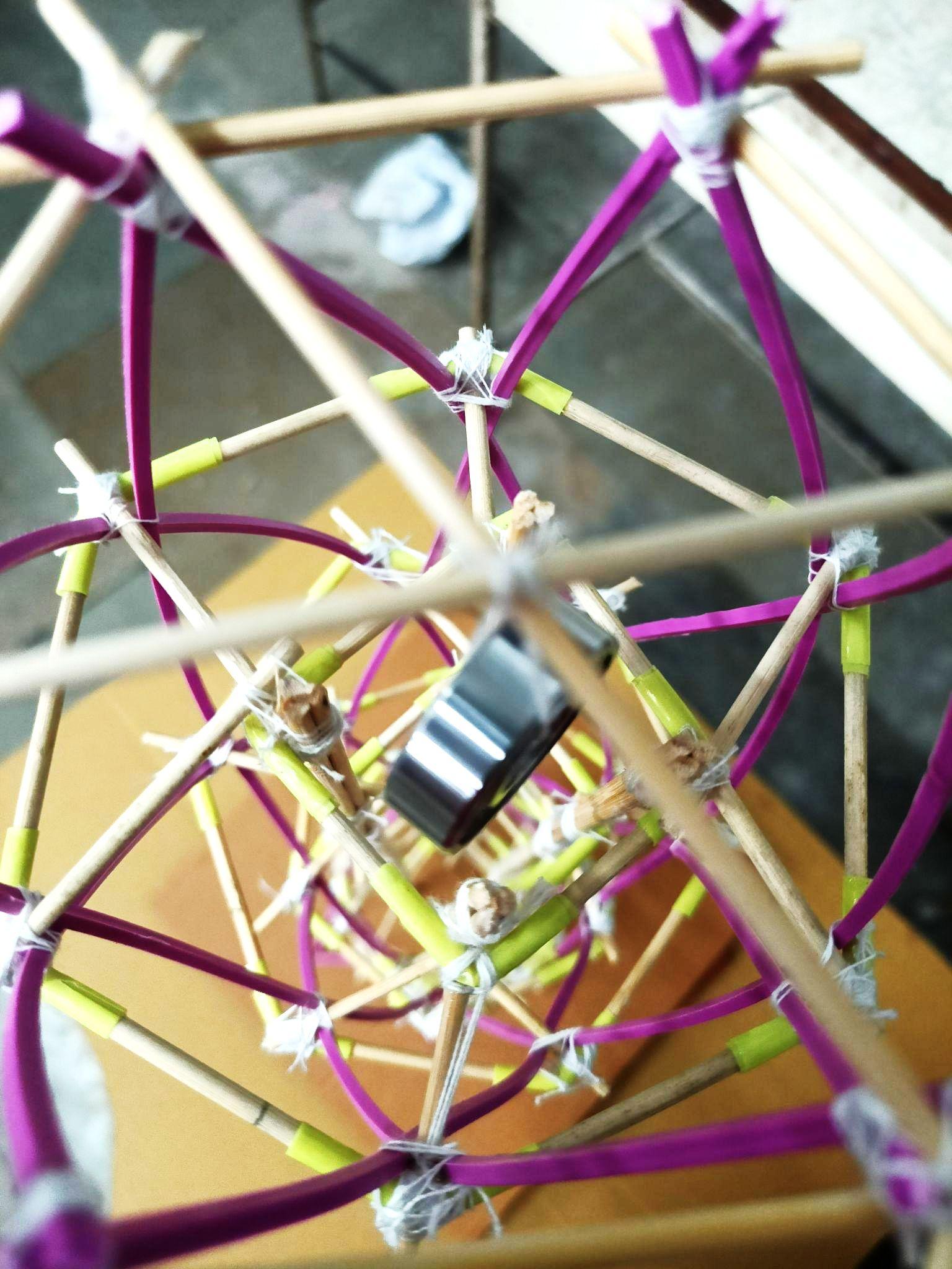
PLASTICSTRAWS
WATCHMAKERSTICKS
The plastic straws were used as a material exploration in the sculptural model since it is flexible and lightweight. Exploration in terms of combinationofmaterialwasalsoachieved
material was selected as it is rigid as well as flexibleatthesametime,hencemakingofsmall membersisalsopossiblebyjustbreakingitinto pieces. Apart from this the material also allows variation in its usage such as clubbing of 2-3 members to make it stronger and half lap joints wherever required and gives a cleaner finish to themodel.
THREADS
CORRUGATEDSHEET
Threadwasusedasamediumoftyingtogether the members and eventually making the model stand. The white thread was initially used to tie the members but due to its thickness the knots weretoobulky.Hencetheochrecolourthreadof comparatively less thickness were used. They not only tied the members tightly but also gave a very seamless look to the model since it's colour matched with the colour of the watchmakersticks.
30cmx30cm square cut out of a corrugated sheet. The model was fixed onto the sheet by makingholesandinsertingthecolumnsintothe sheet which were secured from the bottom of thesheet.(actsasafoundation)
MATERIALSANDTYING_SCULPTURAL
Team07| DesignReport
ROLEOFFORM ROLEOFCORE
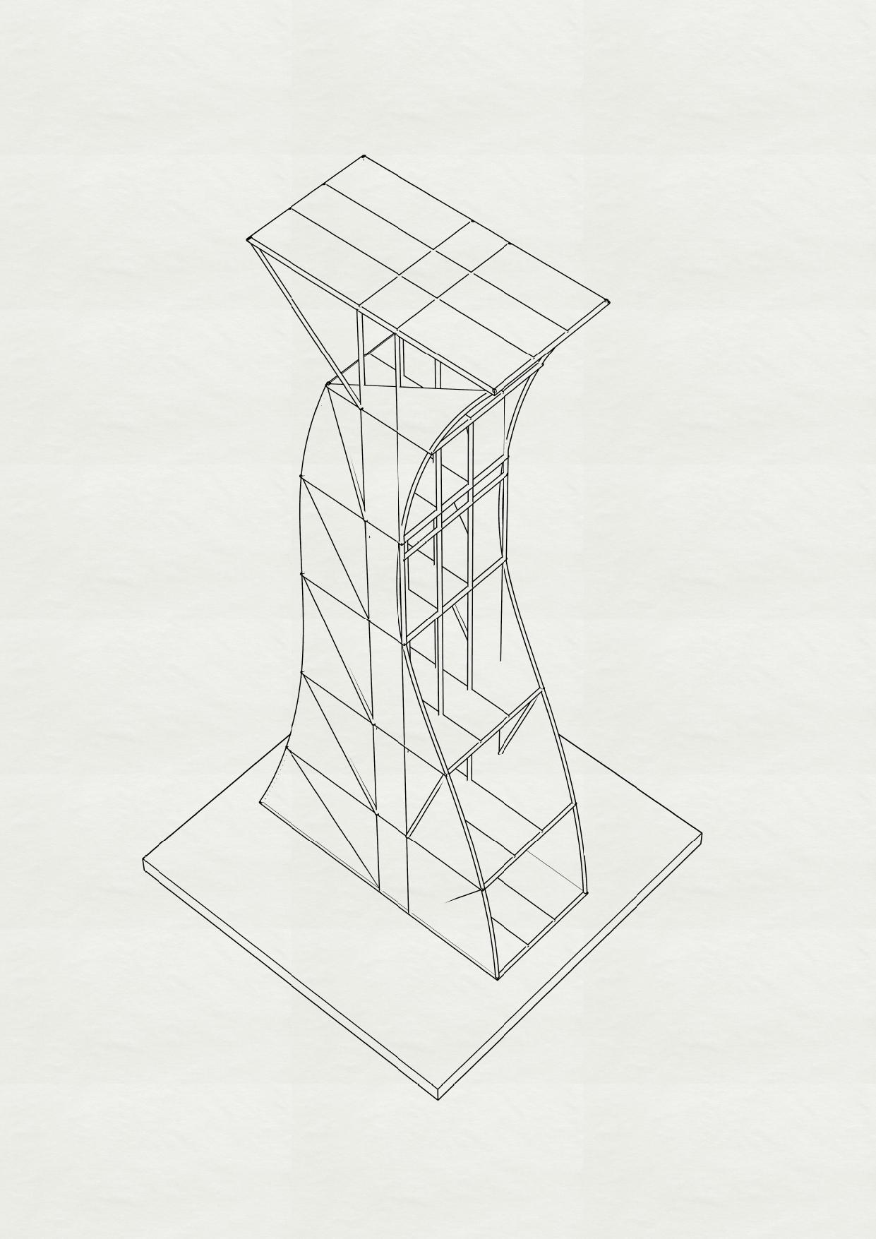
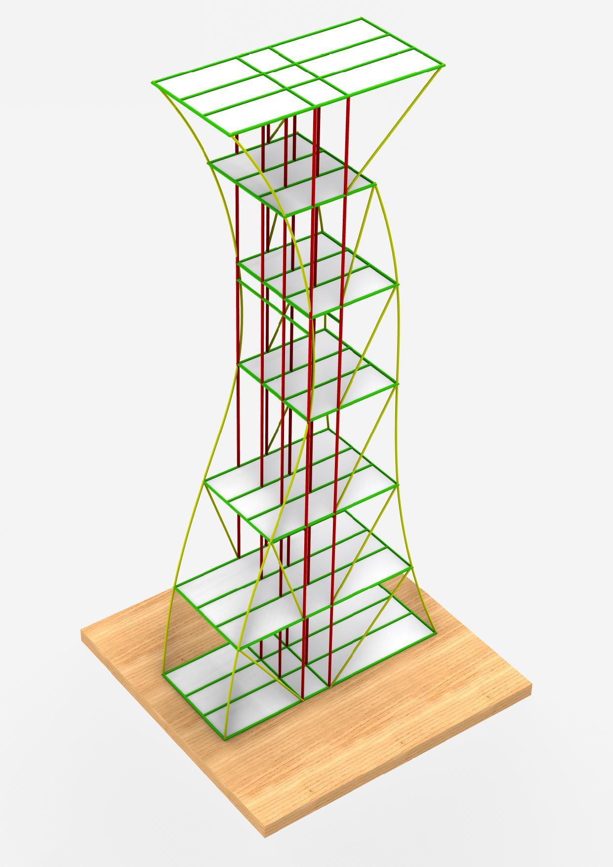
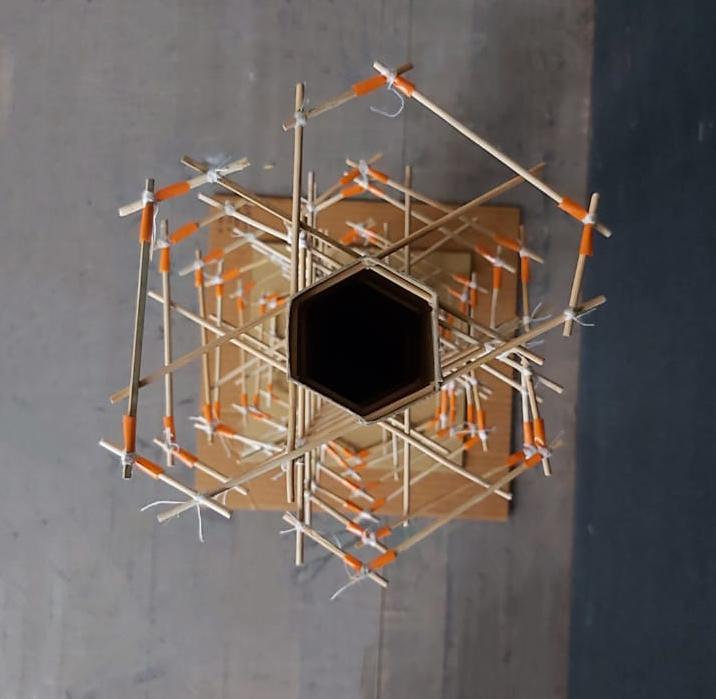
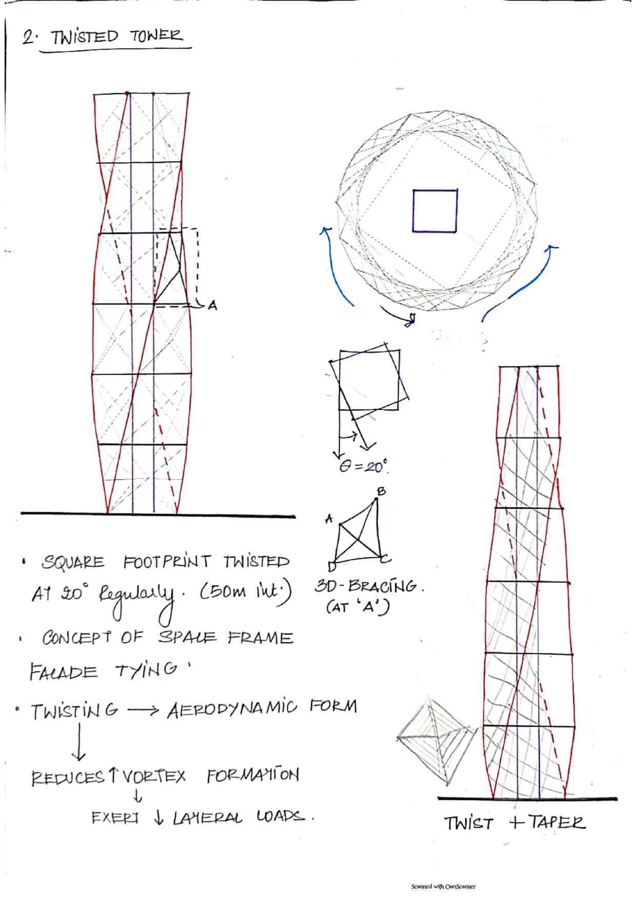
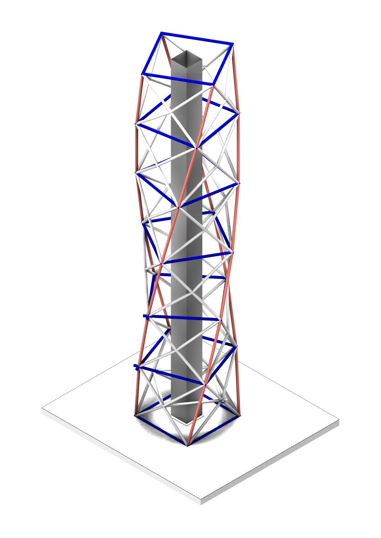
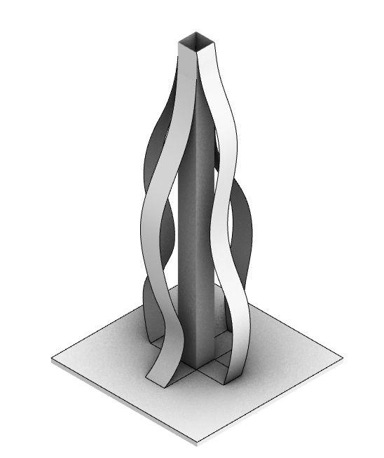
The twisting spiral around the core of the buildingopensupmulti-directionalviewsforthe usersoneachlevel.
It also resists lateral loads on the building and structurally prevents the Building from an overallTorsion.
The Core in the Centre has a Beam Outrigger systemwhichmakesitrigid.
Thebaseformofthestructureisheldinposition by the core where each floor plate turns at an angleof10degrees.
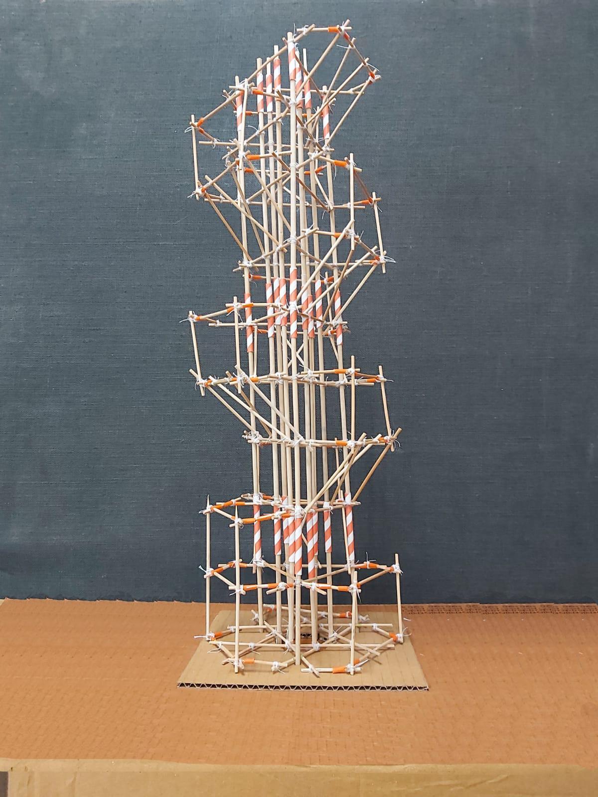
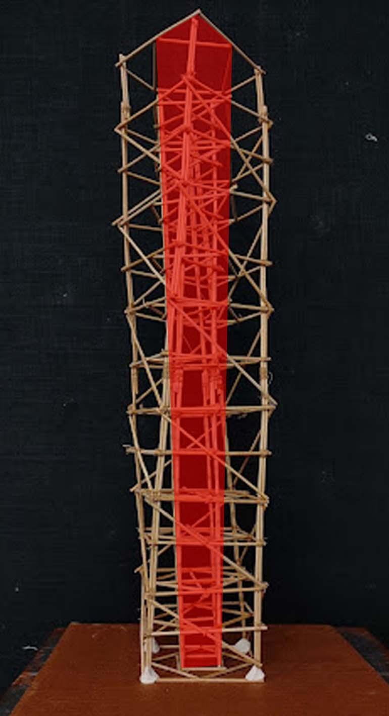
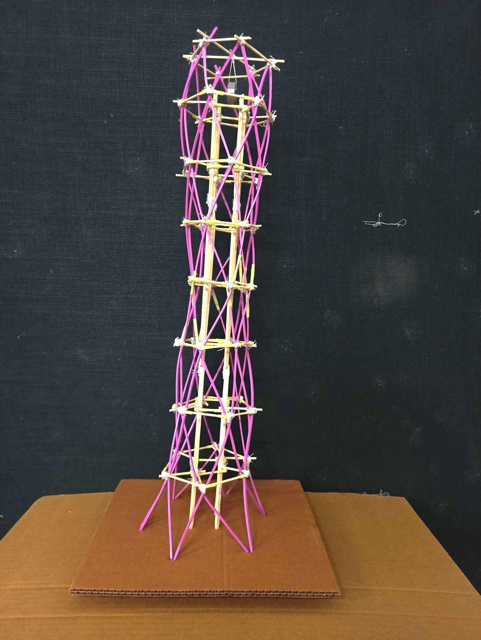
Team07| DesignReport PHYSICALMODELWITHINTENDEDFUNCTIONALSPACES
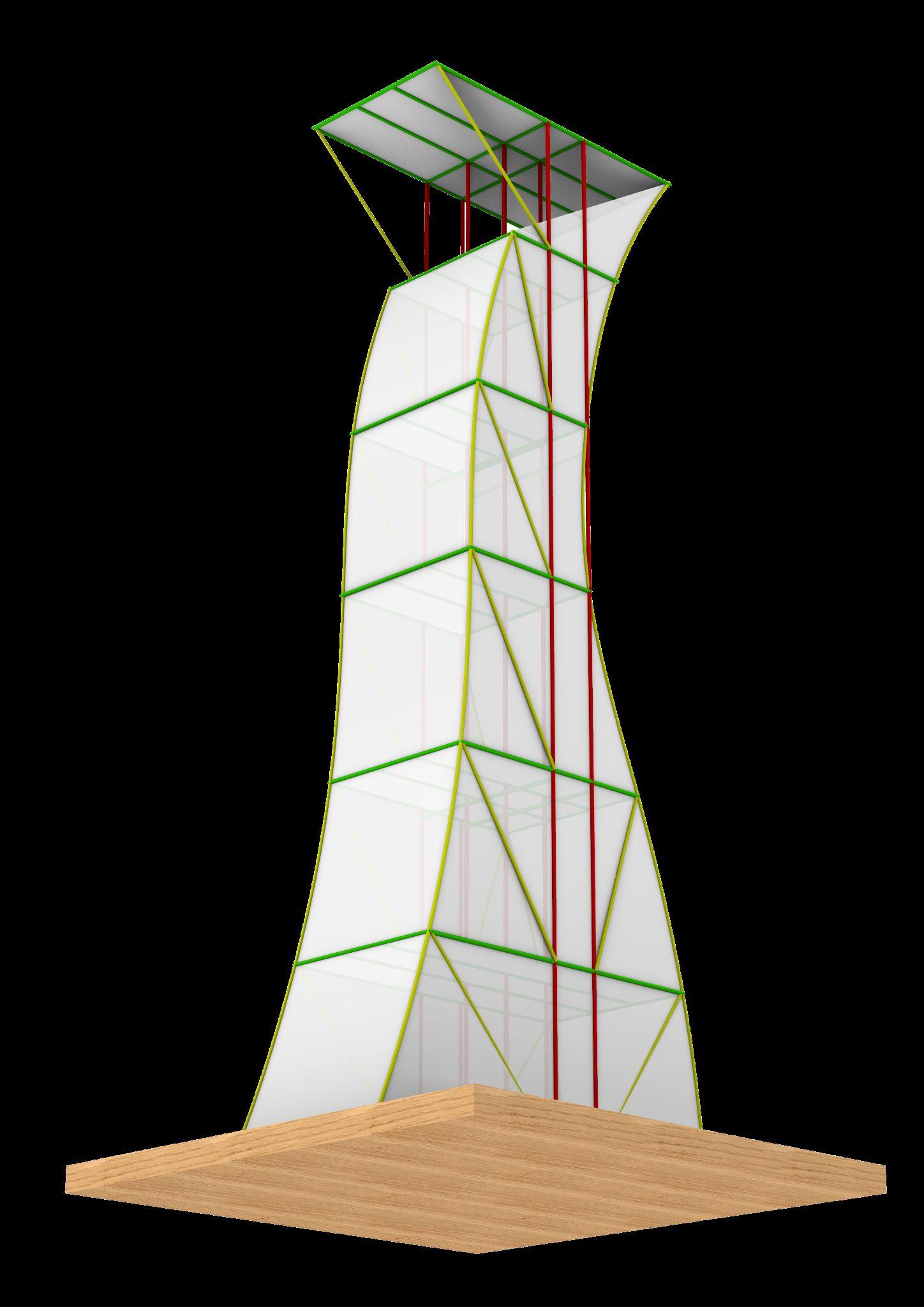
During the Shaketable test, Model without bracing undergoes a significant displacement/swaywhichmightbeundesired.
This is also because the joints are free to move andthustheydisplacewiththeactionofapplied lateralforce
As the form is twisted already, if the Joints are not restrained they tend to shear off which may causedamagetothestructure.
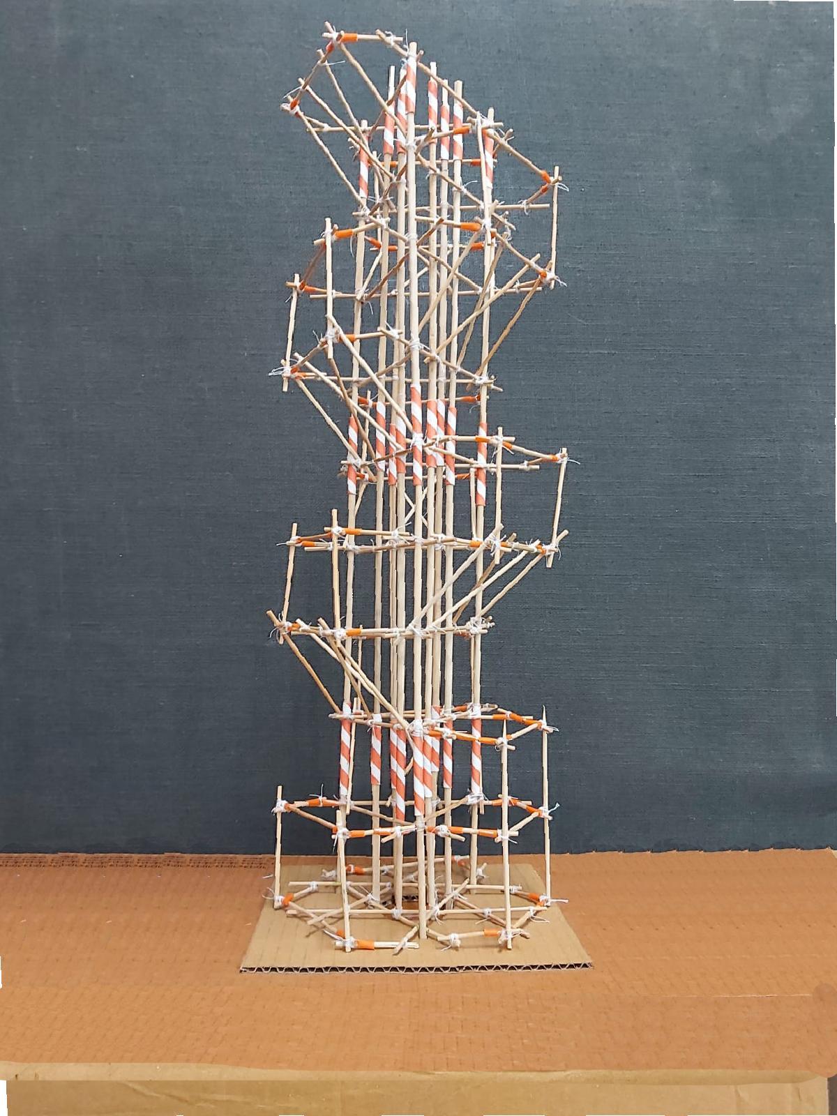
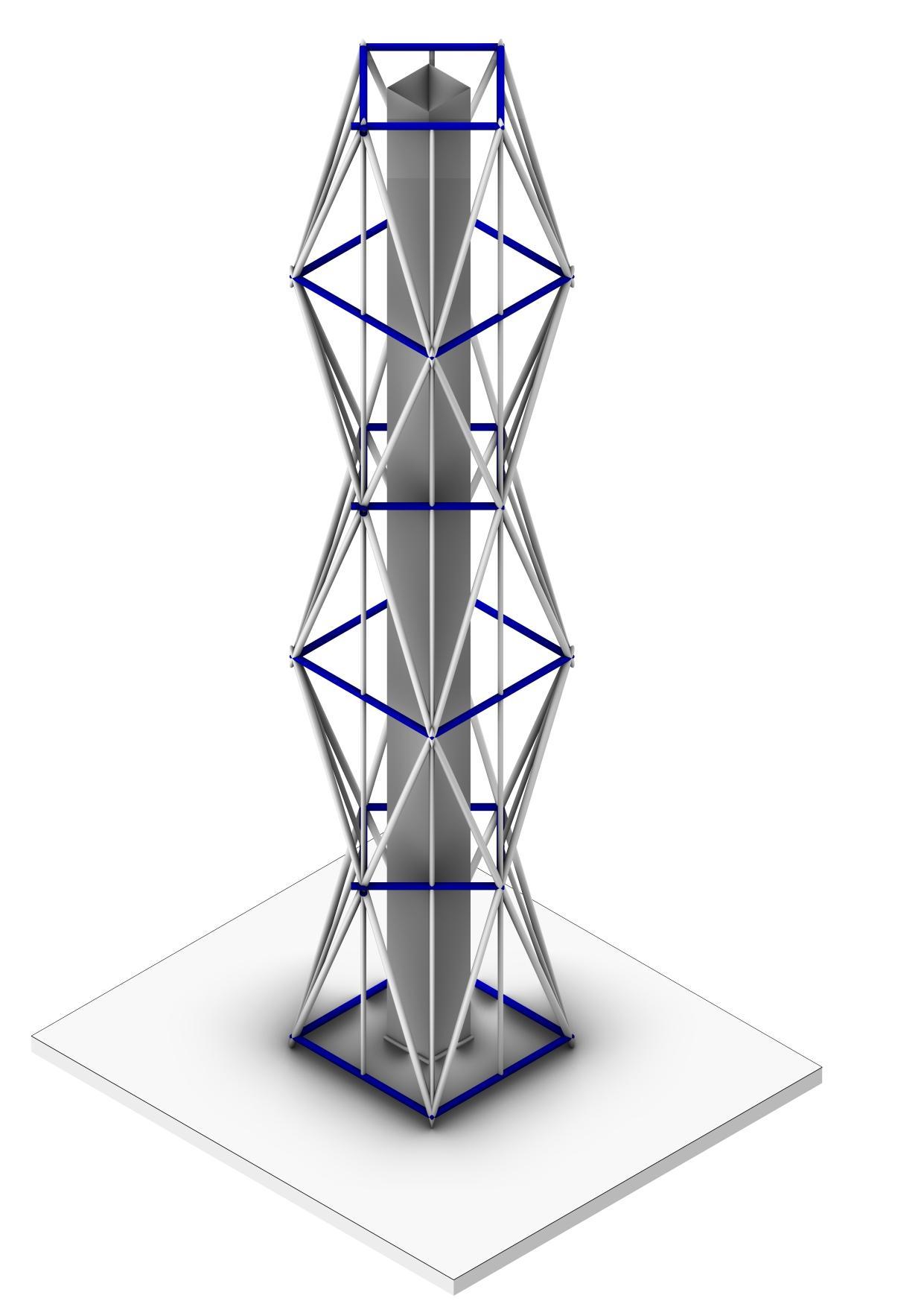
The Model is braced in one direction following theshorterdimensionandthedirectionoftwist.
This helps in tying and maintaining structural integrity.
Also the structure becomes more resistant to swaying.
Team07| DesignReport PERFORMANCEWITHOUTBRACING
WITHOUTBRACING WITHBRACING
APPLIEDLOADONMODELWITHOUTBRACING ANDMADEWITHSTRAWS
On application of a Load, The structure bends andtwistsaboutlongitudinalaction.
The twisting is vigorous as the Joints are not bracedmakingthendriftindividually.
Alsothepropertyofmaterialplaysacrucialrole. Straw being a lighter material, twists immediatelyinthedirectionoftheAction.
THUS STRENGTH, STABILITY AND STIFFNESS can be concluded as 3 major criteria for designing earthquakeresistantstructures
APPLIEDLOADONMODELWITHBRACINGAND MADEWITHWATCHMAKERSTICKS
Comparatively, The braced model acts a Rigid momentframerestrainingtorsion.
The aerodynamic form reduces impact of wind loadsandlateralloads.
Also,thestrengthofWatchmakersticksishigher than straws thus it absorbs the vibrations and dissipatesthemquicklytopreventanystructural damage.
IMAGE
Team07| DesignReport CONSTRUCTIONPROCESS
IMAGETITLE
TITLE
ANALYSISANDCONCLUSION
● The CORE, being the basis of both the models has contributed to the rigidity of the structure as the majorverticalspineagainstthelateralforces.
● Addition of Bracings helped in countering the movement of the structure as compared to the one withoutBracings.
● Differentmaterialsshowcaseddifferentbehaviorsbasedontheselfweightandflexibilityofconnecting knots. Sticks held up together more rigid as compared to the straws were strong enough to resist the forcesyetswayedmoreduetoflexibleconnections.
● Placement of the load either Axial or eccentric as well as symmetry and asymmetry of structural componentsplayakeyroleinresistingearthquakeforces.
● Too much eccentricity can cause torsion and bending thus improvisations in architectural terms is required.
● As the Slenderness ratio of a structure increases, we tend to require additional members like trusses, braces,shearwalls,spaceframestoimpartstiffnessagainstlateralloads
● Secondary measures like TUNED MASS DAMPER and base isolators show significant change in the impactofearthquakeloads
● We analysed that Either the Structure can be made flexible and is allowed to sway upto a tolerance (likeextrusionmodel)oritcanbebracedfullyandmakejointsrigidsuchthatswayingisnotpermitted (Eg.Sculpturalmodel)
● ThestructurealsobehaveslikeaCantileverasitisfixedatoneendandfreeatanother.Thustheupper partisseverelyaffectedwhilethelowerpartislessaffected.
TAKEAWAYS:
● Methodstoreduceselfweightwithoutcompromisingonthestructuralstabilityofthestructure.
● JoineriesandTyingtechniques.
● Comparingandanalysingstrengthsofmaterials
● Handsontestingofgravityloads,lateralloadsandimpactloadsandaccordingstructuralbehaviour
● Understandingactionduetoload,andhowtorestrainthatmovement.
● Makingthestructureacting asoneintegratedunit.
Team07| DesignReport
GROUP
08
ISHAPATIL_12 SALONIPAWAR_31 NIDHIKHOT_33
AcademyofArchitecture,Mumbai
MODEL2FLOORPLATES Team08| DesignReport INITIALSKETCHES
PLATES&SERVICECORE ADDITIONOFBELTTRUSSINTHE CENTREANDTOP ADDITIONOFBRACINGS Team08| DesignReport DIGITALMODELPHOTOS
FLOOR

THROUGHCORE JOINERYDETAILS Team08| DesignReport MODEL1PHOTOS
ELEVATION PLAN
ELEVATION
JOINERYDETAILS ELEVATION Team08| DesignReport MODEL2PHOTOS
PLAN
Geometricmodel
● Thisgeometricmodelhastworight-angledtrianglesandtwo equilateraltrianglesfacingeachotherinoppositedirections.
● Theformiscreatedinawaythatitcansurvivestrongwinds andearthquakesaswell.
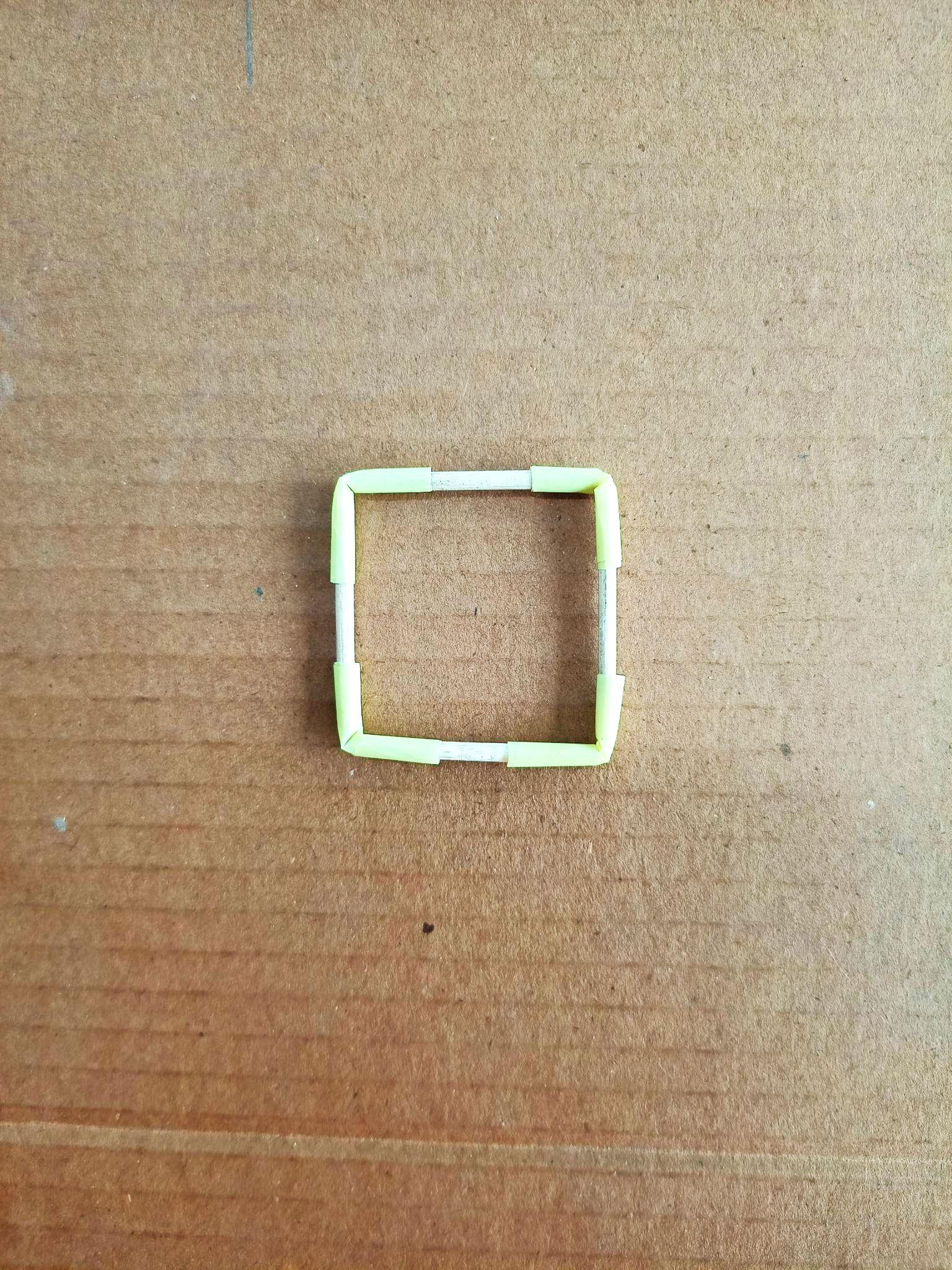
● Afloorplateiscreatedbyfourrightangledtriangleswitha squarecoreatitscentre.
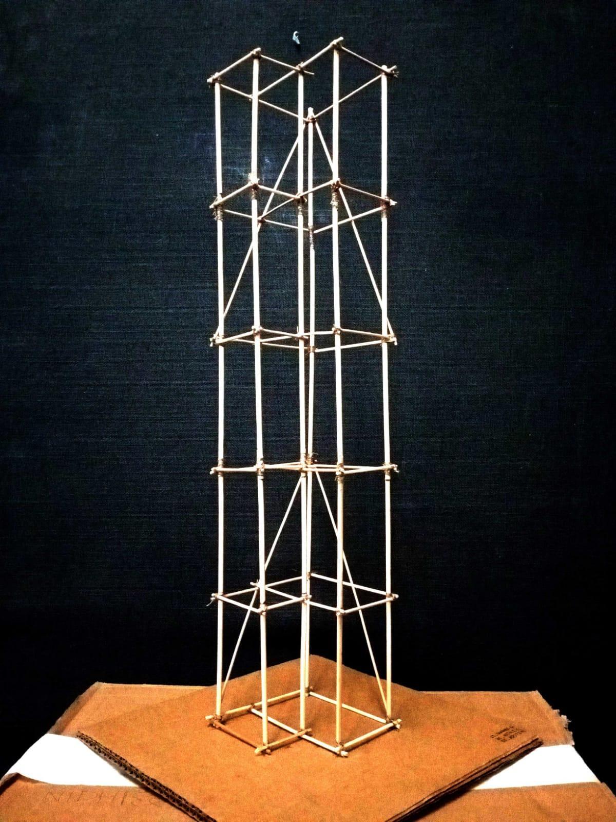
● Bracingsaredoneoneachfloor
● Afteradditionofliveloadsandseismicloads,thestructure swayedalittle.
● Itsustainedtheforcesforawhile,butfailedafteralongtimeat somepointswherethebracingswereconnected.
● Continuousbracingsacrosstwofloorplatesmighthavestayed firm
Sculpturalmodel
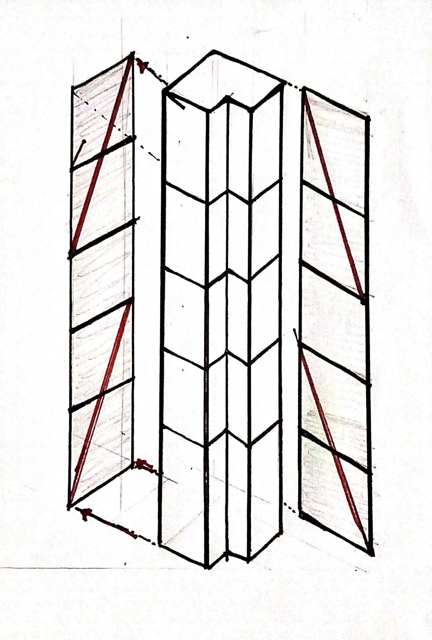
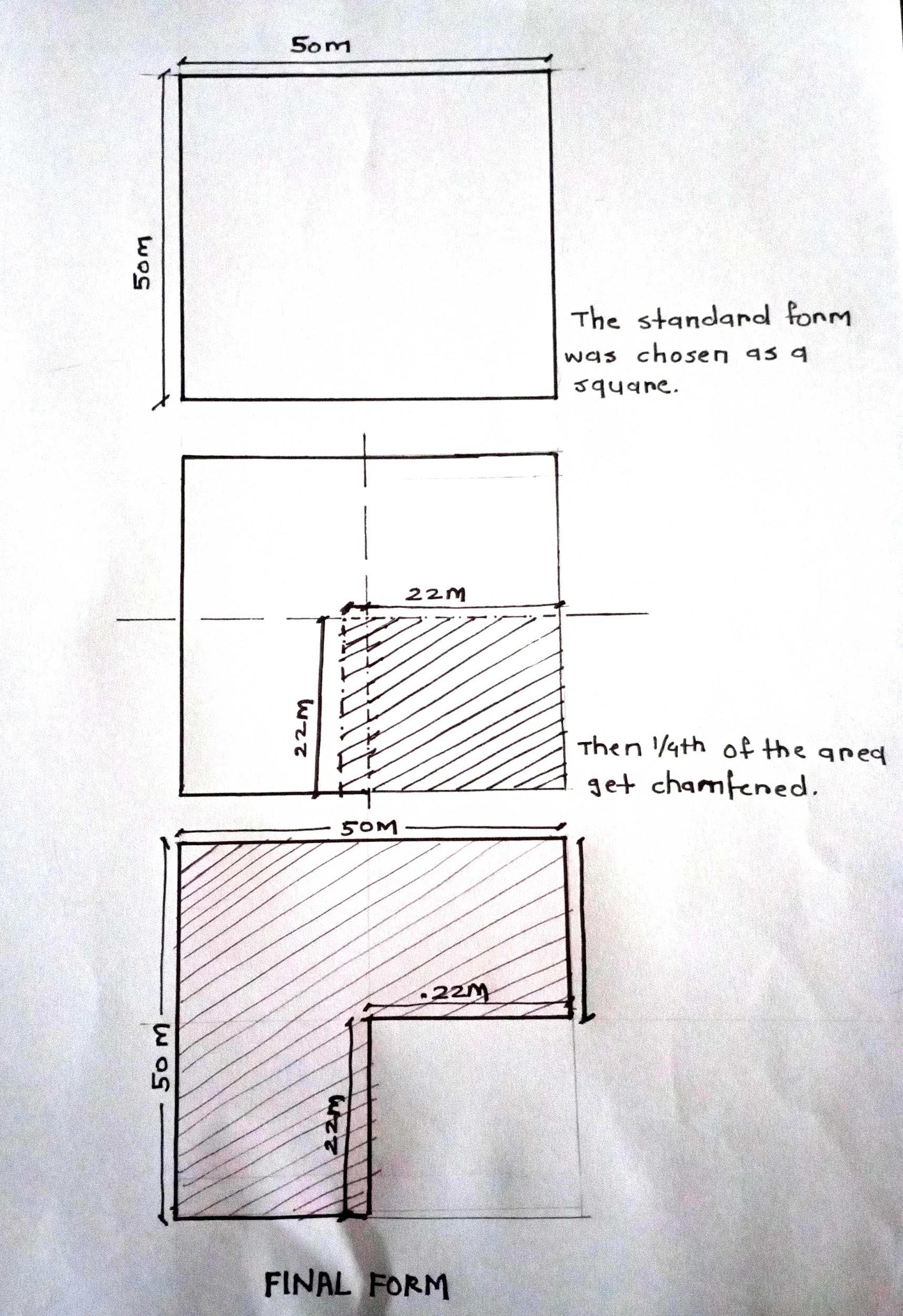
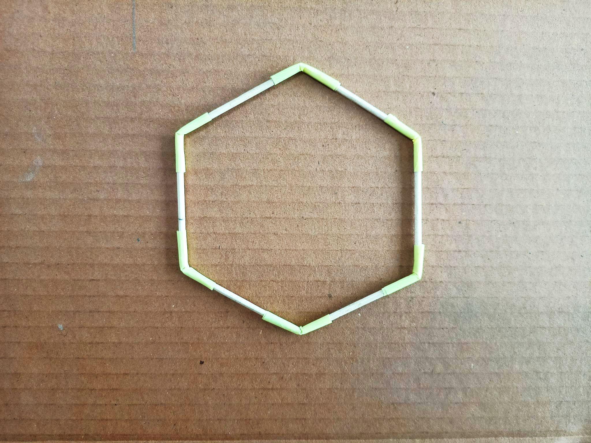
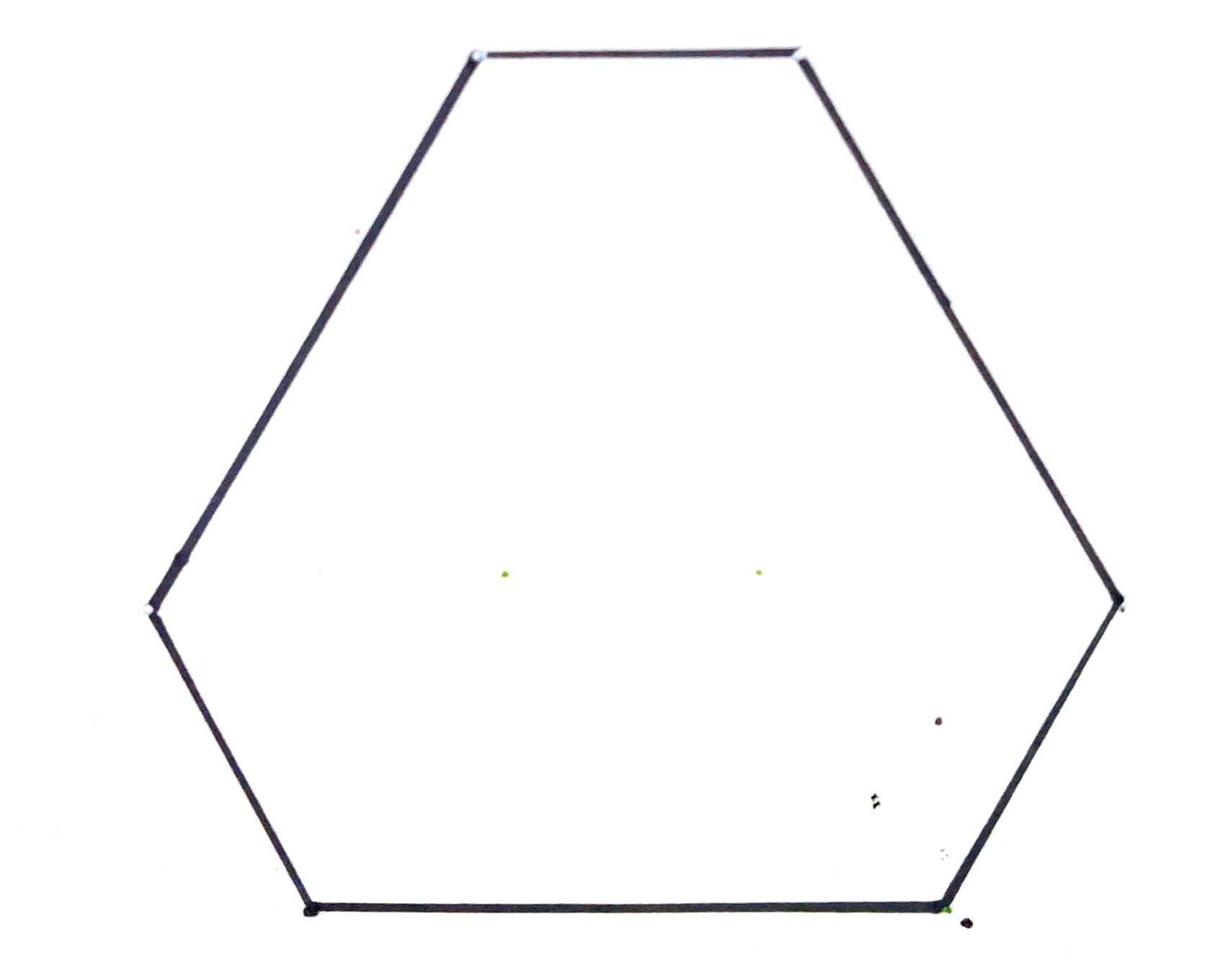
● Thismodelwasformedbychamferingtheedgesofasquare.It formedahexagonshaped.
● Repetitionoffloorplatesinastaggeringmanneralongthe servicecorecreatedlargecommonfloorplatesat3intervals.
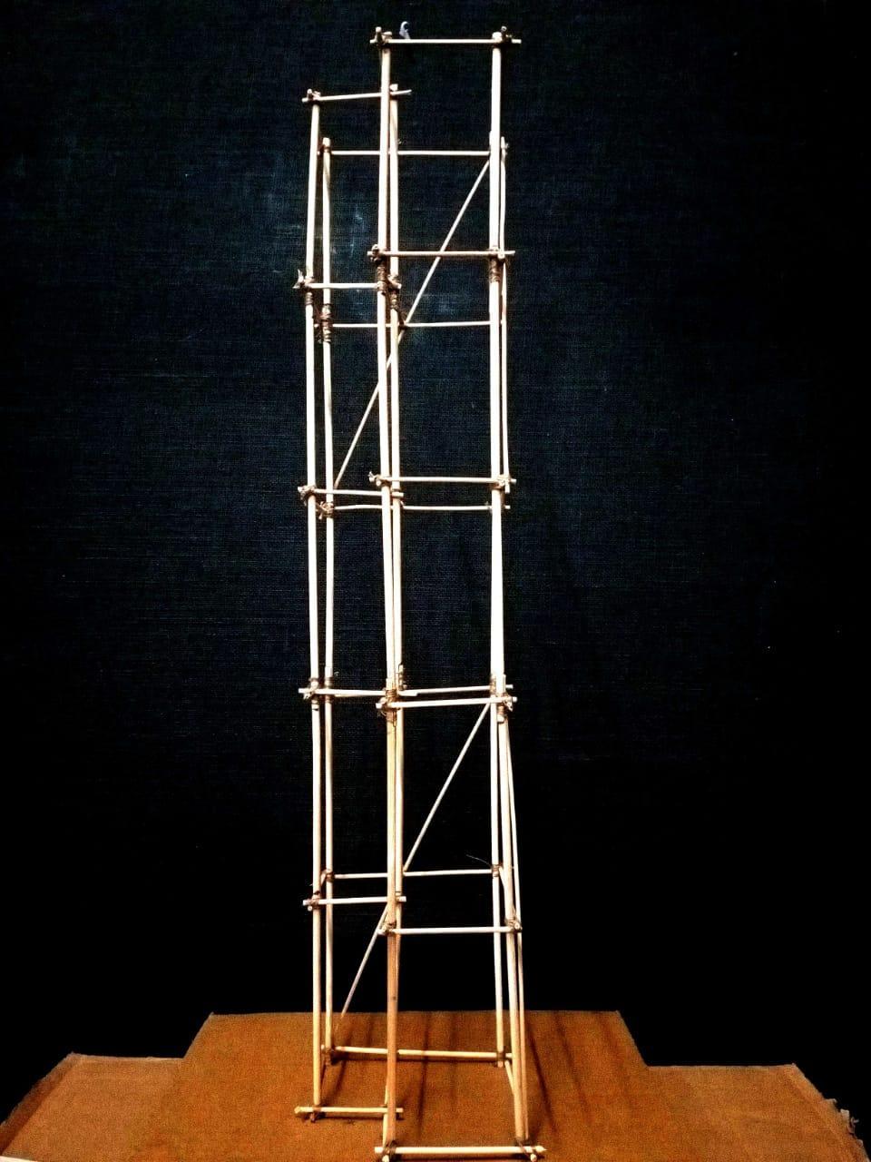
● Thefloorplateswereconnectedverticallybyaddingfacade bracingswhichhelpedthebuildingswayandnotstayrigid.
● Afteradditionofliveloadsandseismicloadsthestructure swayedandleanedontoaside.
● Additionofrigidbracingscouldhavehelpedtocontrolthelean.
Team08| DesignReport CONCLUSION
CONCLUSION
ANALYSISAND
AcademyofArchitecture,Mumbai
GROUP09 BHOOMIKACHAUDHARI_13 ADITYAKANADE_14 RASIKASALGAONKAR_45
Team09| DesignReport INITIALSKETCHES
SEISMICMODEL1 SCULPTURAL
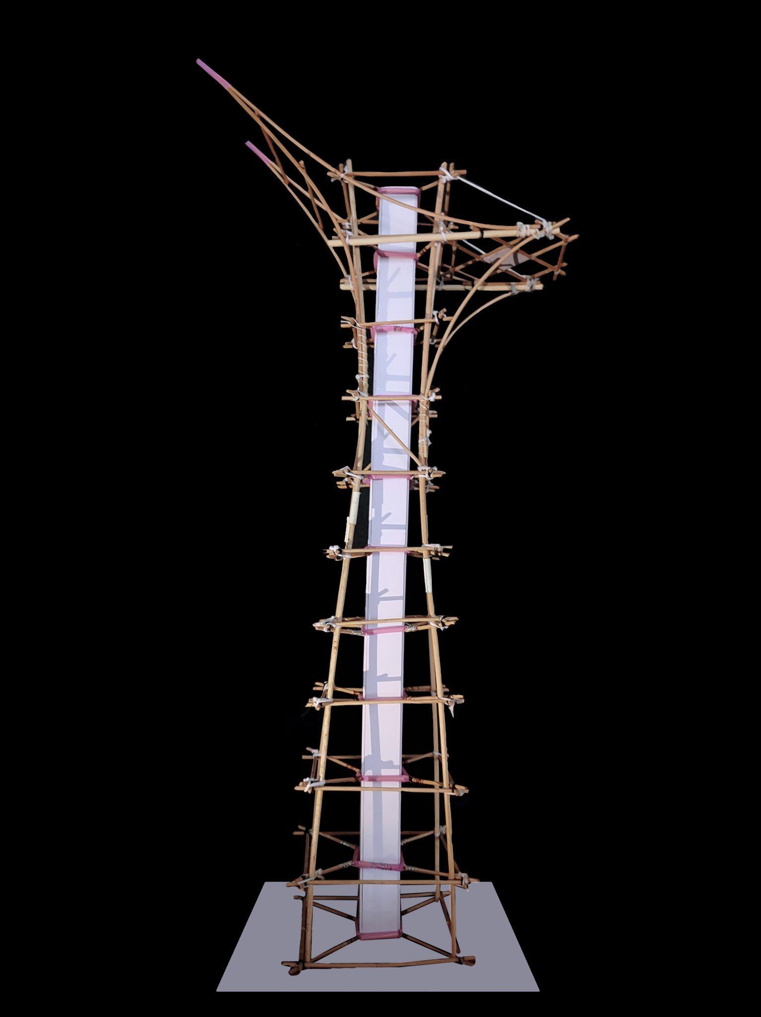
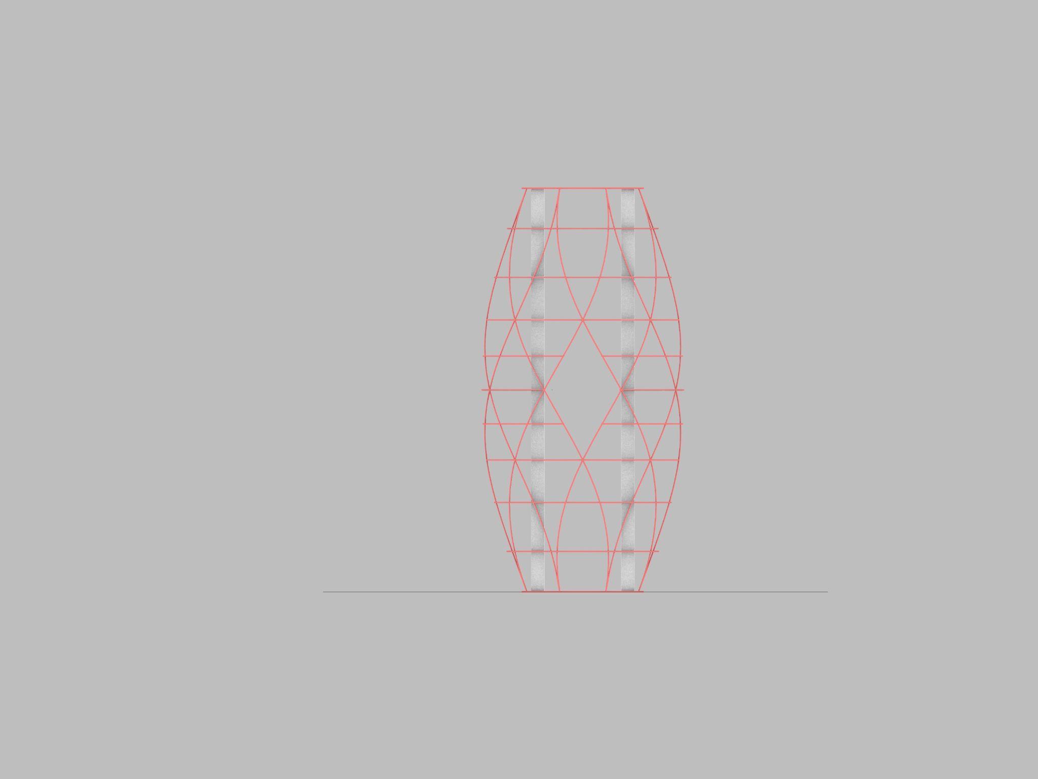
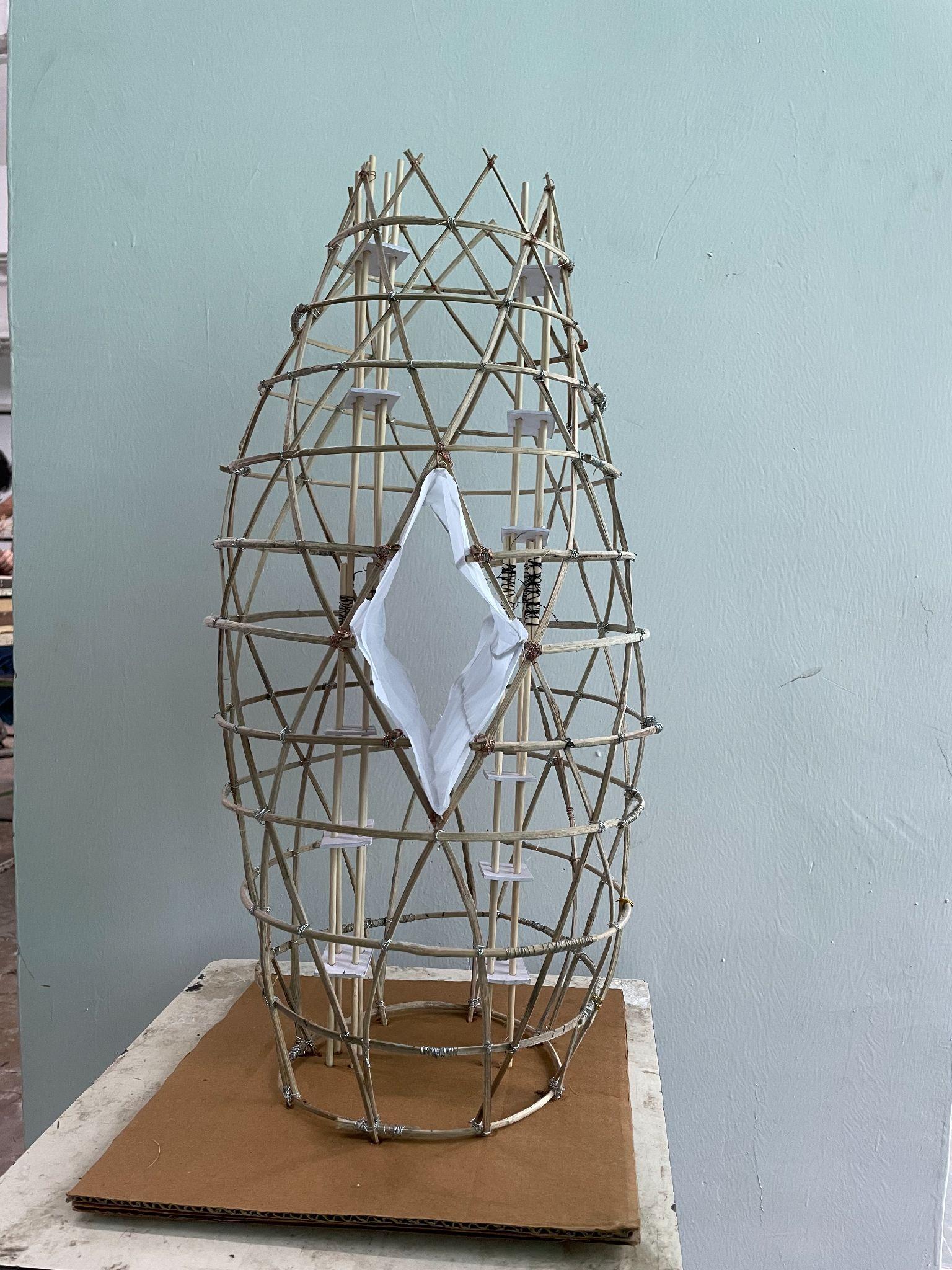
The final form is a derivative of a glass-hour; a tweaked and evolved sculptural form to become more resilientduringearthquakesalongwith the aesthetics getting even more enhanced.
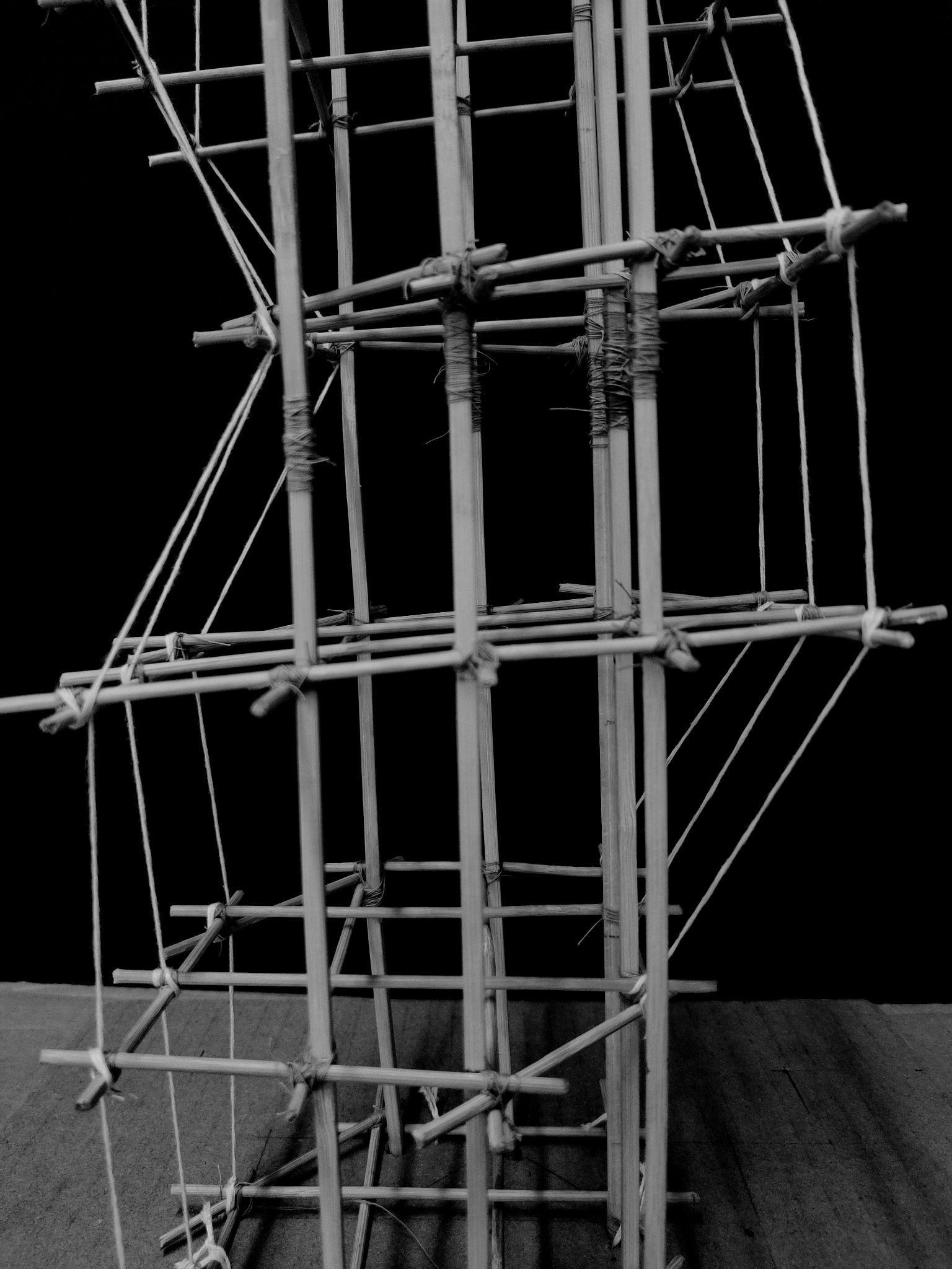
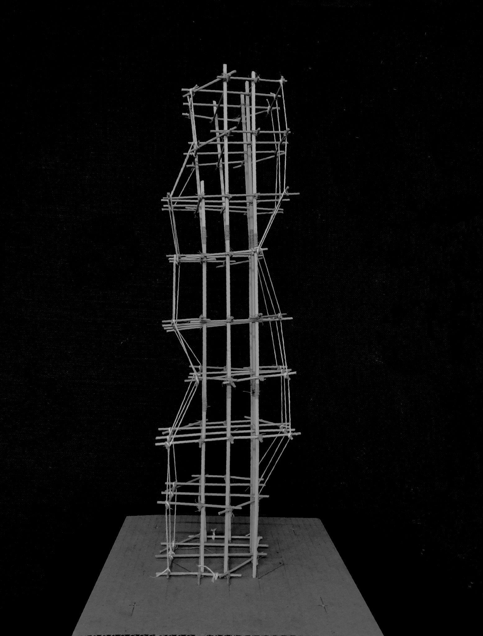
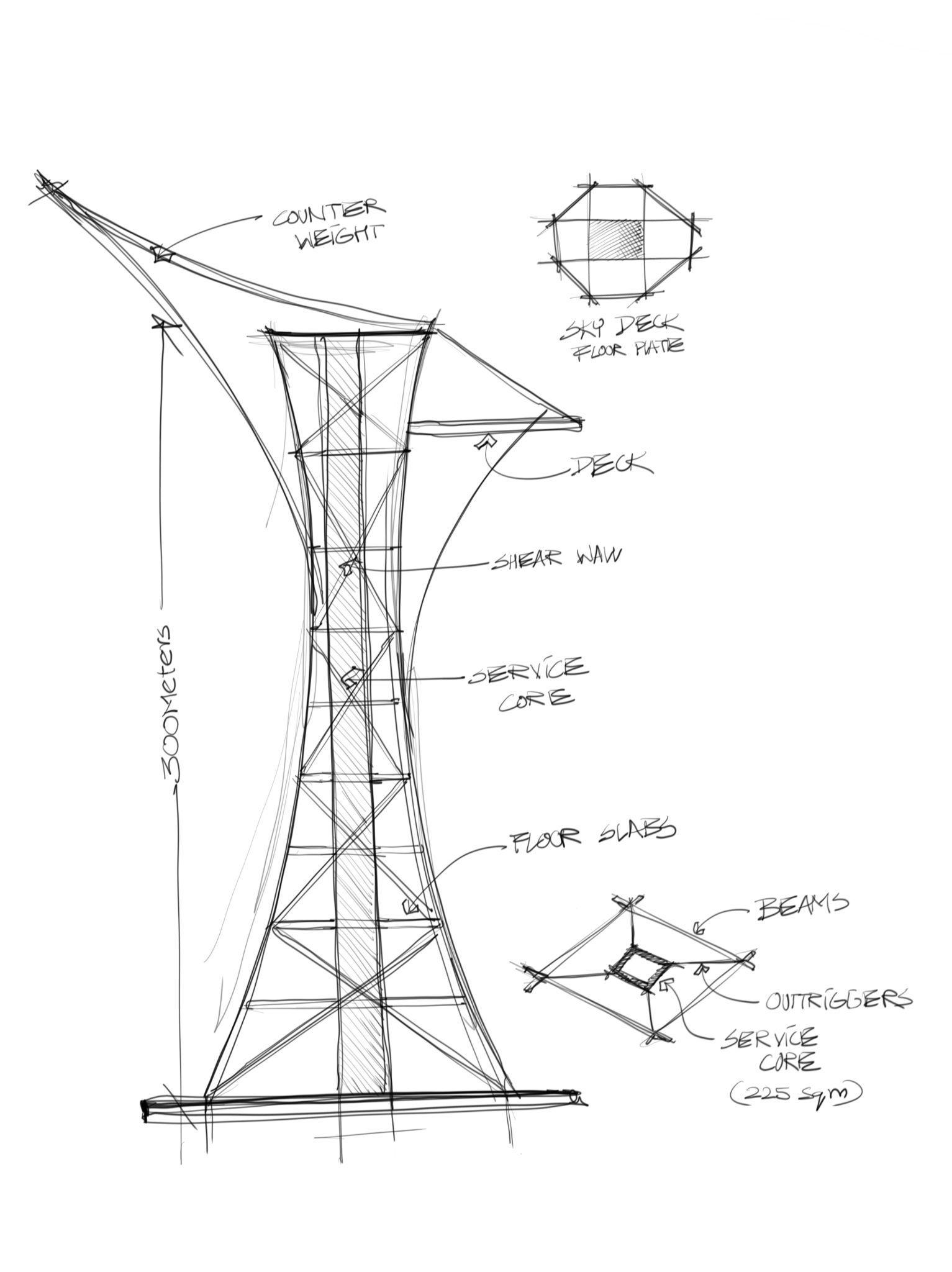
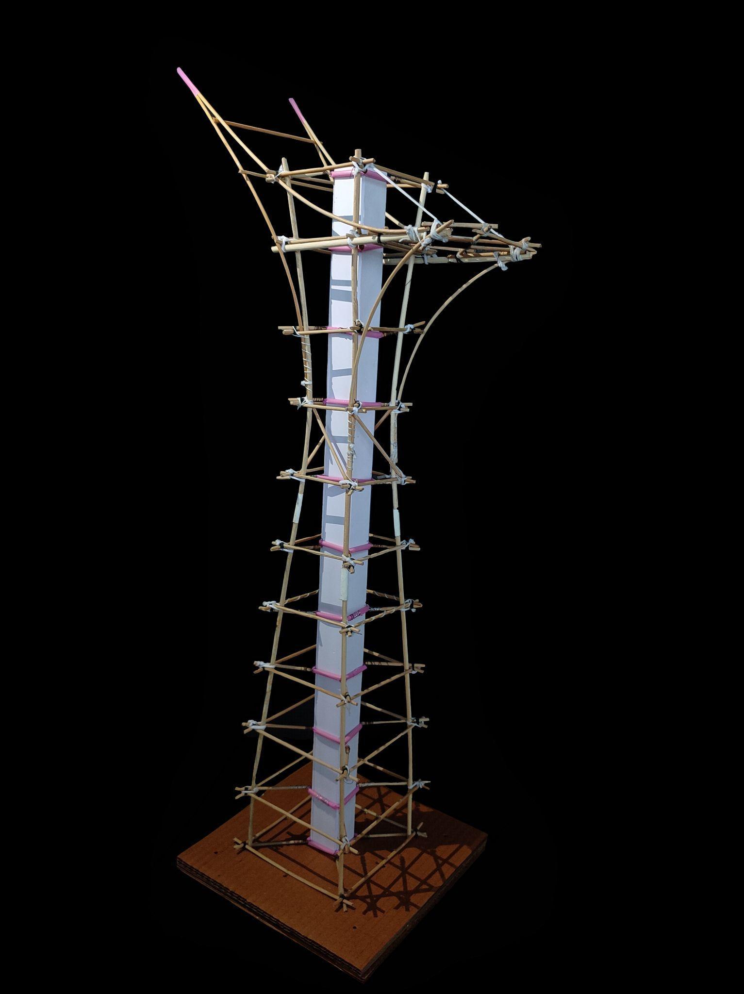
The majority of bulk mass of the structureliesbelowthenarrowestgirth andthefloorplatesaboveitalsohave small areas to ensure that the head does not become bulky, for that will make the structure more prone to swaying. The vertical columns run throughout give an inclination of 3° every10floors.The9thfloorplateoutof the10hasanoctagonalskydeckwhich is provided with a counterweight element at 180° jutting high pointedly. The load from the skydeck as well the counterweight are transferred to the vertical columns on the floors below eventually via large bracket like structural members who are again following the curvy language of the structure.
Materials-
● Columns, beams & outriggerswatchmakersticks(4mmdia)
● Service core shear wallssunboard(3mmthk)
● Service core beams to outriggers- plastic straw (6mm dia)
Joineries
● Columns and beams - cotton threadknot
● Outriggers and core beamscopperwire
Team09| DesignReport DESCRIPTION
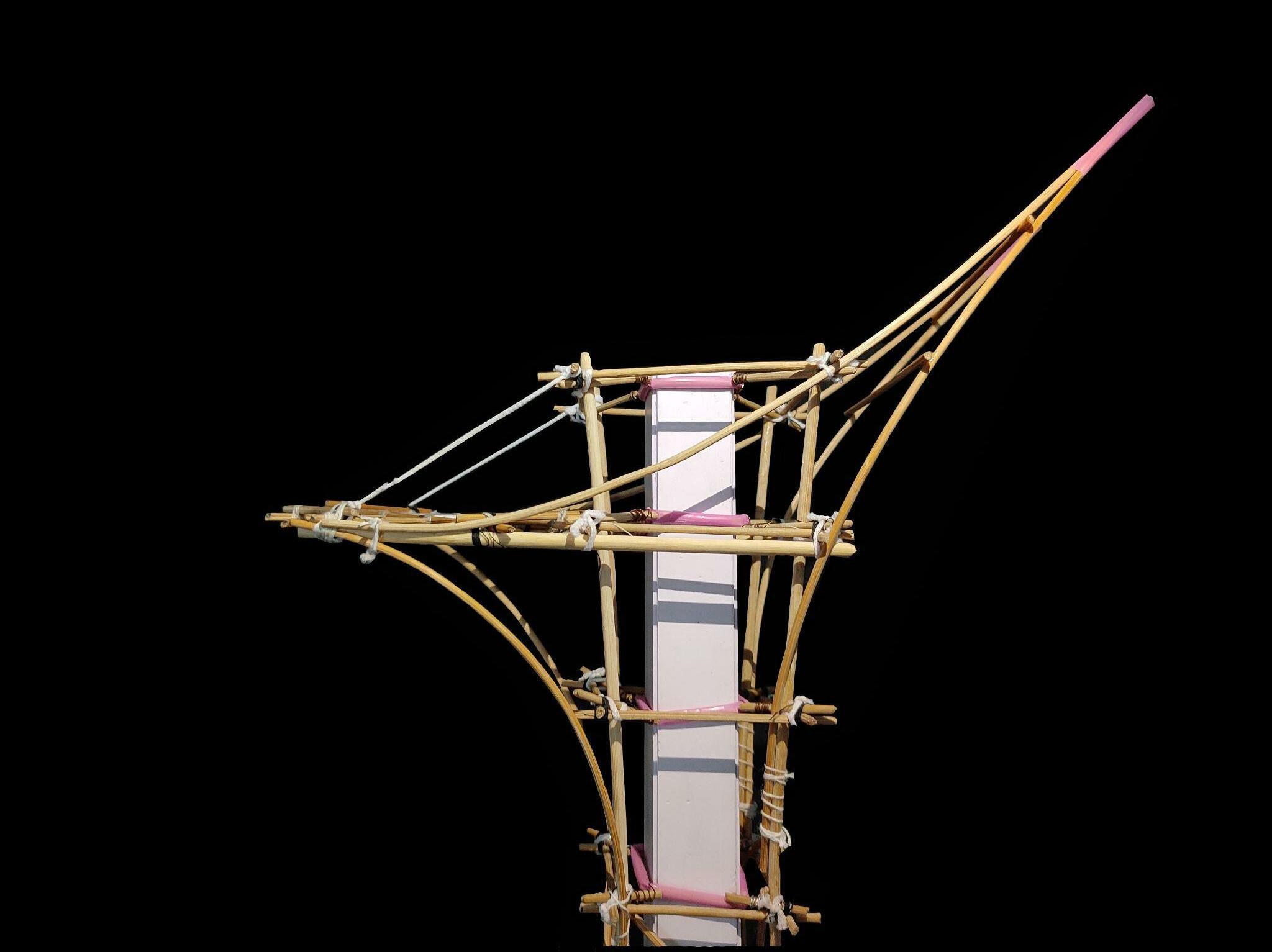
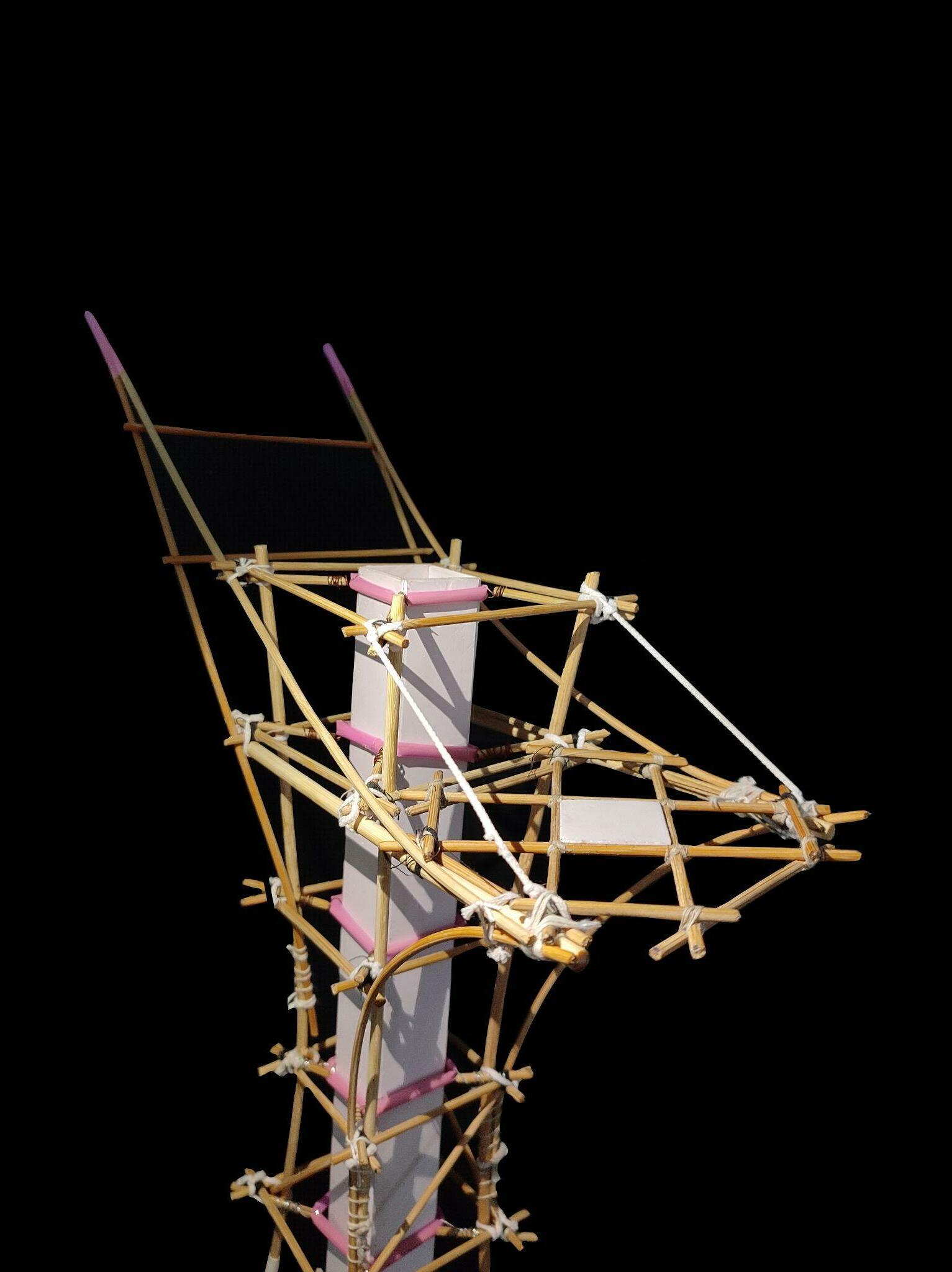
ELEVATIONALVIEW APEXVIEW VIEWOFSKYDECKFLOORPLATE AXONOMETRICVIEW Team09| DesignReport MODELPHOTOS Service core Counter weight Skydeck Columns Outriggers beams Skydeck Counter weight Service core Tension cables
Buttjointincolumns
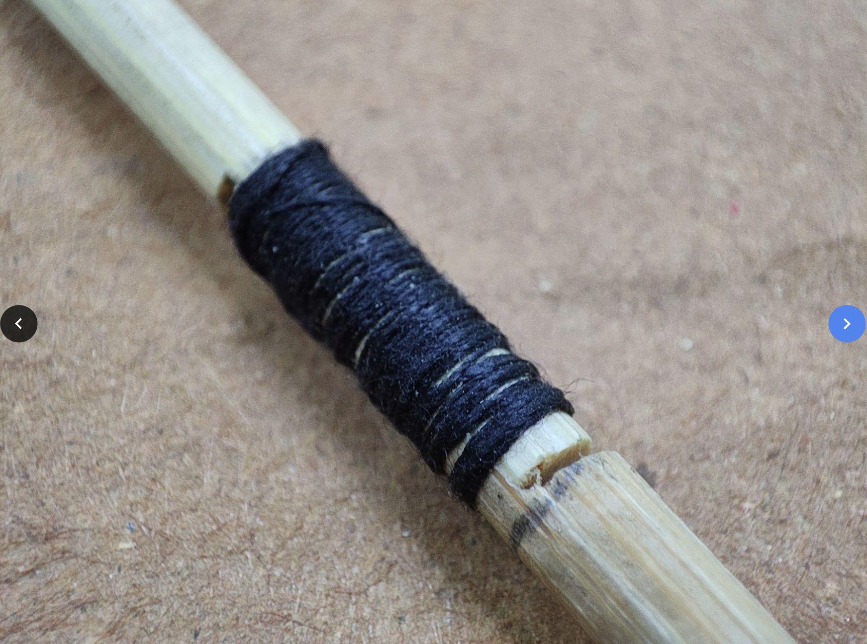
Crossknotsforsticksintersectingat90degrees Columnlapjointdetail
Team09| DesignReport INITIALSKETCHES
 Skydeckjoinerydetail Skydeckfloorplate
Team09| DesignReport INITIALSKETCHES
Skydeckjoinerydetail Joineryatintersectionof3members
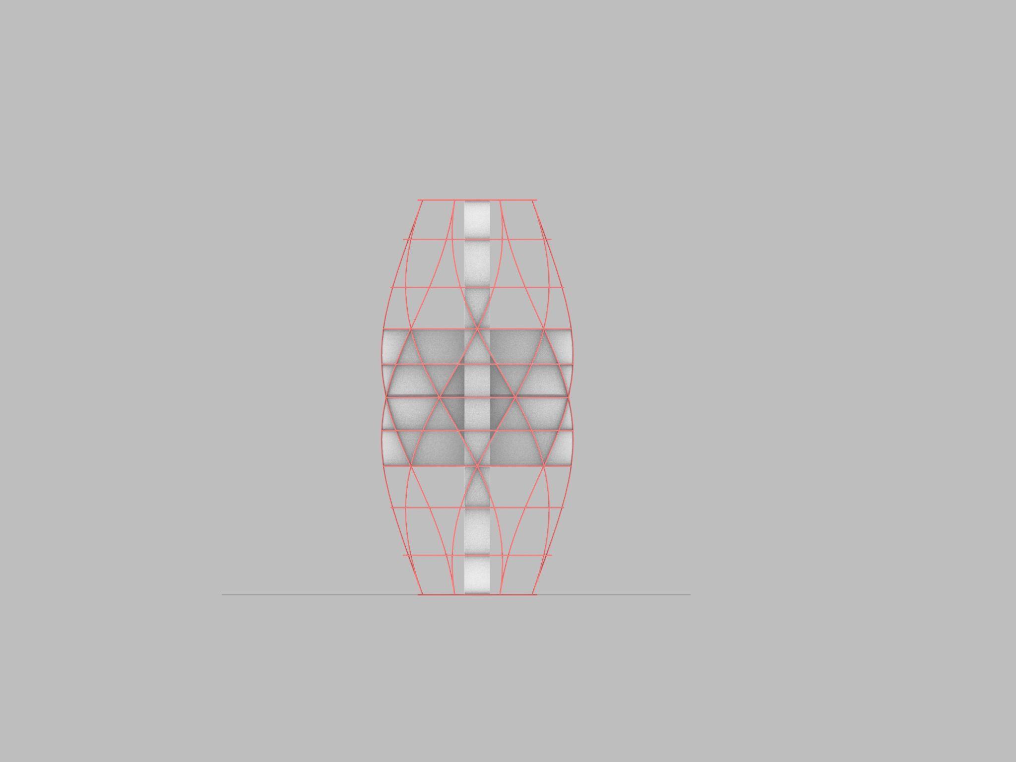
SEISMICMODEL-2 GEOMETRIC
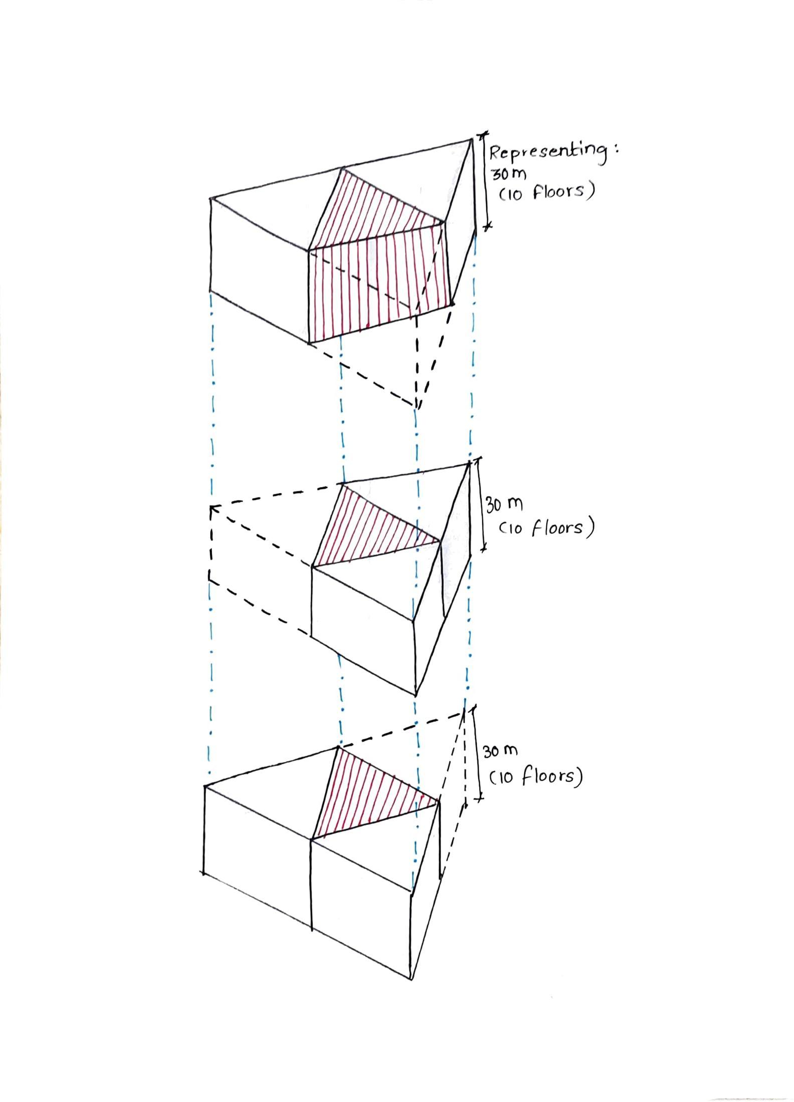
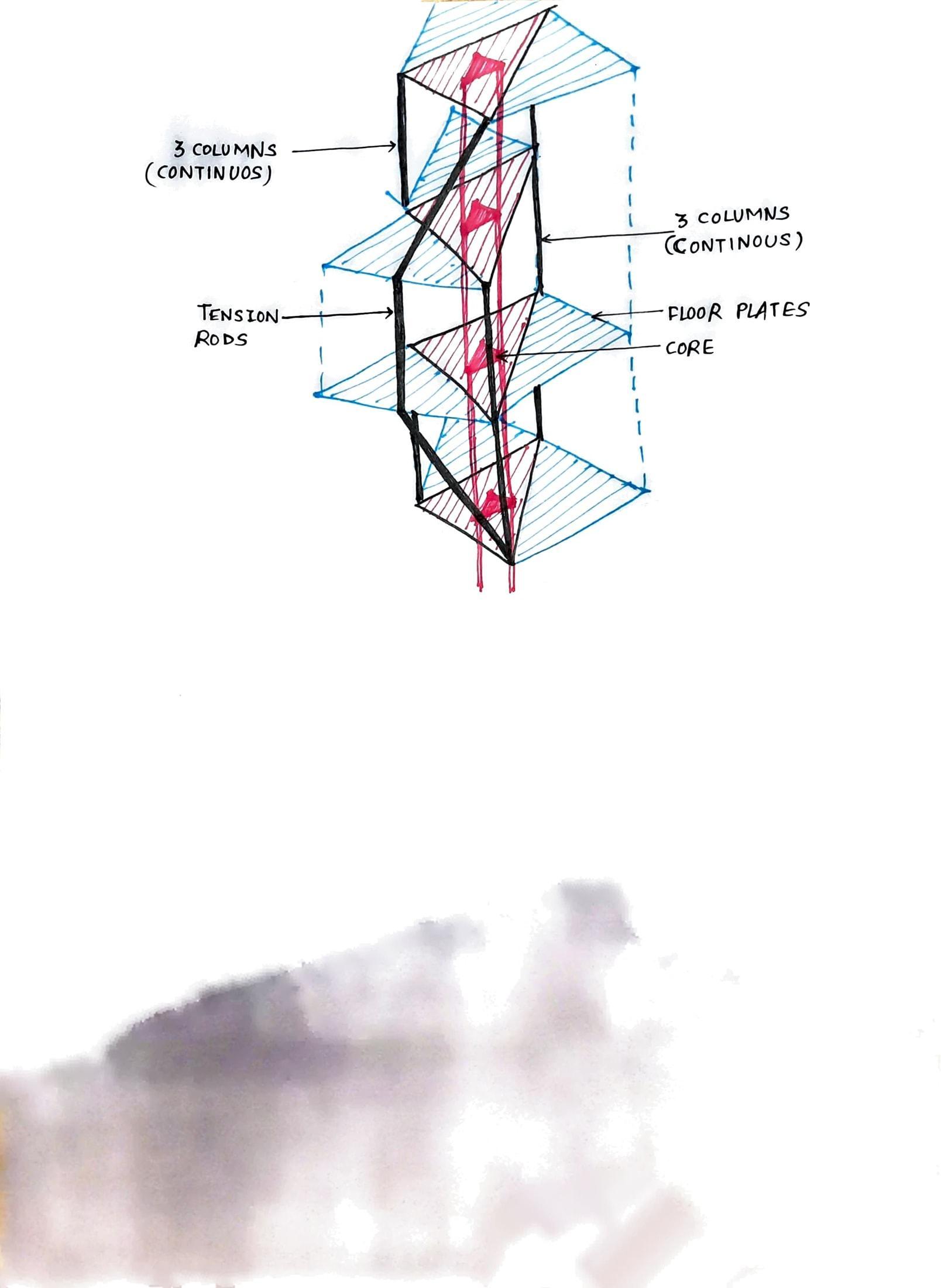
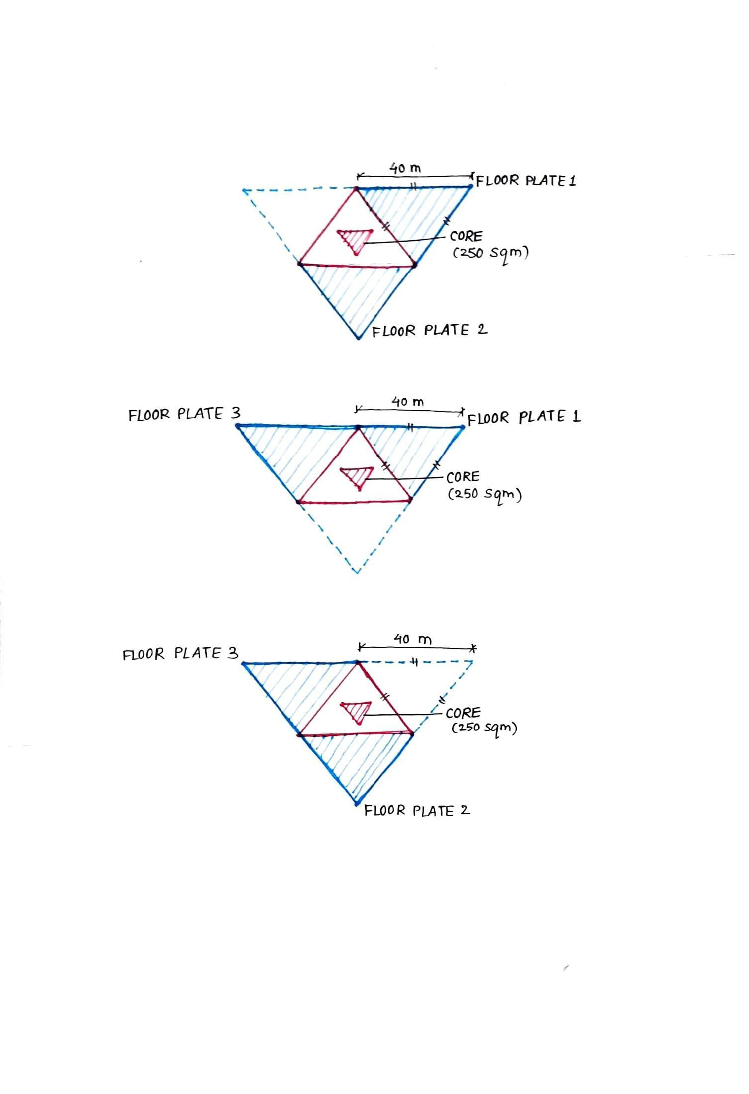
The floor plates are formed from 3 triangles alternating with a triangular core in the central triangle. The cantilevering triangles have been supported with tension rods and brackets.Thebulkmassofthestructure thoughalternatingasweriseabovehas beendistributedevenlythroughout.
3 outriggers are connected from each intersectionofthecentraltriangletothe centre of the shear wall of the core. 3 columns run vertically parallel to the core.
Materials-
● Columns, beams & outriggerswatchmakersticks(4mmdia)
● Service core shear wallssunboard(3mmthk)
● Service core beams to outriggers- plastic straw (6mm dia)
Joineries
● Columns and beams - cotton threadknot
● Outriggers and core beamscopperwire
Team09| DesignReport DESCRIPTION 09| DesignReport MODEL2
Team09| DesignReport INITIALSKETCHES
OUTRIGGERCONNECTINGFLOORPLATE
Team09| DesignReport MODELPHOTOS
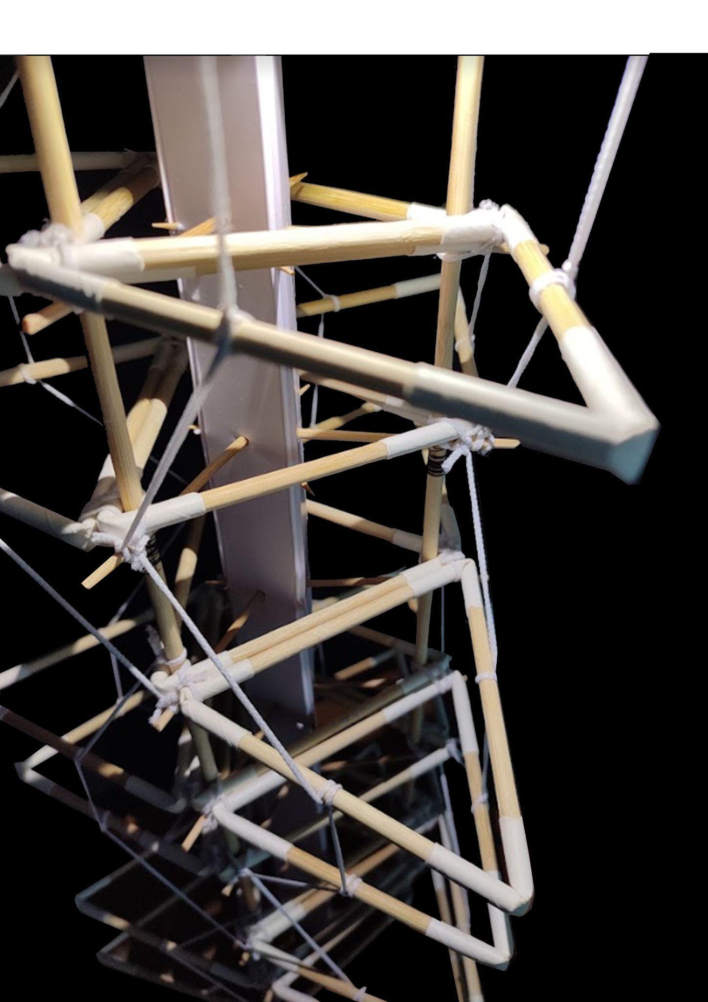
TENSIONRODSCONNECTINGFLOORPLATE
Outriggers
JOINERYDETAILS OUTRIGGERDETAILS Team09| DesignReport INITIALSKETCHES
MODEL1-Sculptural
Structuralobservations
● Due to outriggers the entire structural frame started acting as oneandtheeveryjointbecamestronger.
● The inclination of the vertical columns being only 2° does not compromisestructuralintegrity.
● Atrussbeltwasaddedatthefloorplateswithnarrowestgirthas theloadfromskydeckandcounterweightbracketsrestedatthe given intersection; being the most vulnerable section in the structure,addingabelttrusssecuredit.
Conclusion
● Provedtobeagoodexampleof‘structuralintegrity+aesthetics’
● Above form may or may not survive an earthquake but is resilientenoughtoallowtheresidentstoevacuatethebuilding.
MODEL2-Geometric
Structuralobservations
● Due to no columns for peripheral triangles minor structural instability was observed during the shake table test, but the tension rods and brackets held the entire system from failing prettywell.
● Even on trying to tug at the white stretchable strings the stiffnessandstrengthcanbeexperienced.
● Outriggers kept the central triangle on the all floors resistant to theshocksfromtheshaketabletest.
Conclusion
● Proved to be a good example of ‘structural integrity’ with experimentation into various structural systems like columns, beamstooutriggersandtensionrods.
● Thus, above form may or may not survive an earthquake but is resilientenoughtoallowtheresidentstoevacuatethebuilding.
Team09| DesignReport CONCLUSION ANALYSISANDCONCLUSION
AcademyofArchitecture,Mumbai
GROUP10 ABHISHEKJAISINGHSURYAVANSHI_04 AISHWARYASANDEEPRAIKAR_32 HARSHRAJESHTANK_41

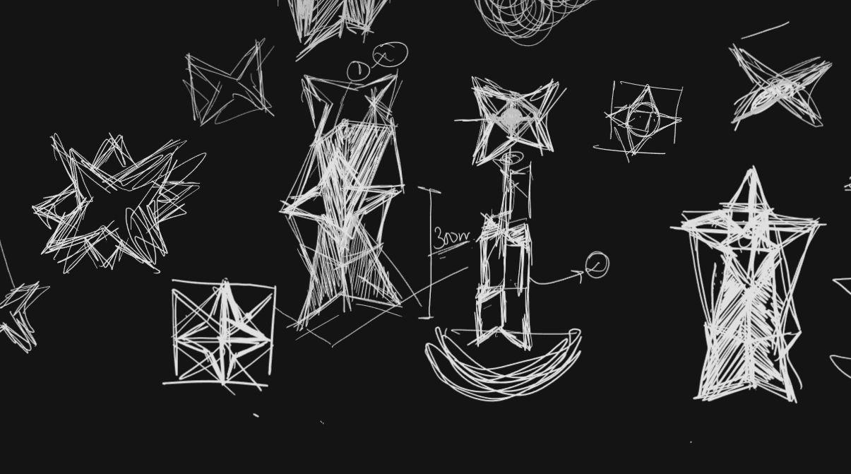
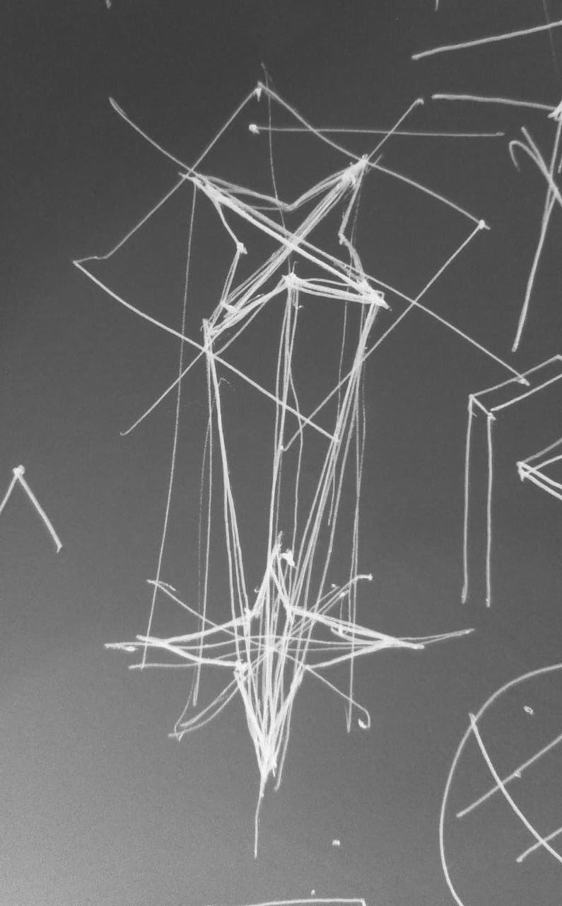
Team10| DesignReport INITIALSKETCHES
2.1Plan
Team10| DesignReport DIGITALMODELPHOTOS
1.1Plan 1.2Elevation 1.3Elevation 1.4Elevation
Team10| DesignReport MODELPHOTOS 1.3Elevation 1.4Elevation 1.1Plan 1.2Elevation
2.2Elevation
Team10| DesignReport DIGITALMODELPHOTOS
2.3Elevation 2.4Elevation
Team10| DesignReport MODELPHOTOS 2.3Elevation 2.4Plan 2.1Plan 2.2Elevation
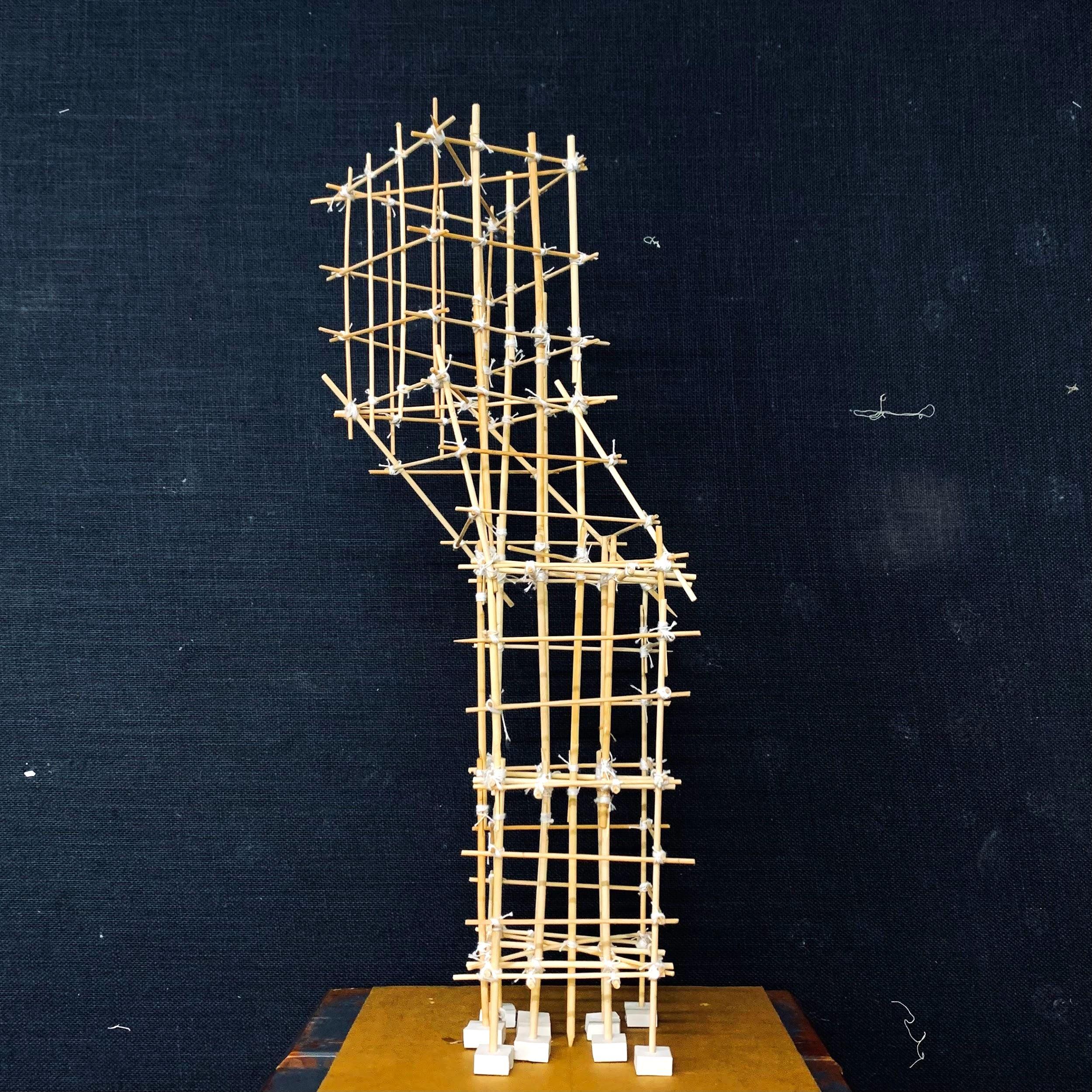
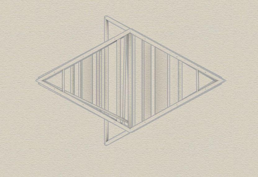
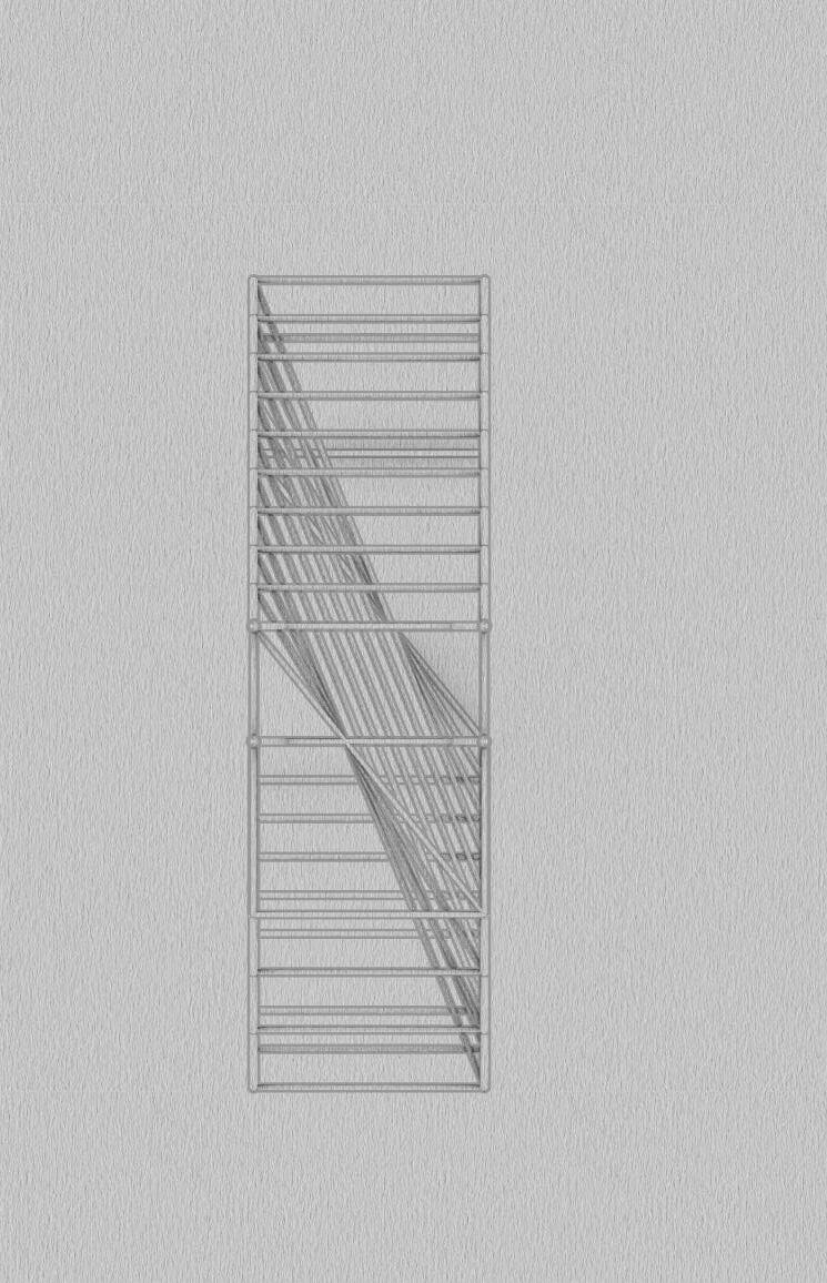
First model:
The top floor and the bottom floor composed of ‘shuriken’ are rotated by 90degreesandthenconnected.Theedgesofthefloorplateareoriented @120degrees.
● Acontinuouscolumnofgreatercrosssectionalareawasconnected tothe verticesoftheshurikenwhichactedasprimarycolumnsand areperpendiculartotheground.Thesecolumnssupportedthefloor platesbutdidnotresistthetorsionalforceandtheshearforce.
● Hencethestructurewasnotstiffenoughtoresisttheearthquake.
● Therefore additional columns of smaller cross sectional area were tiedfromonevertexofthebottomfloortotheadjacentvertexofthe top floor of shuriken. These inclined columns helped to resist the torsional force and also resisted the Bending moment generated fromtheearthquake.
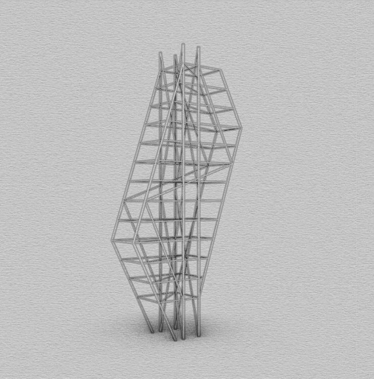
SecondModel:
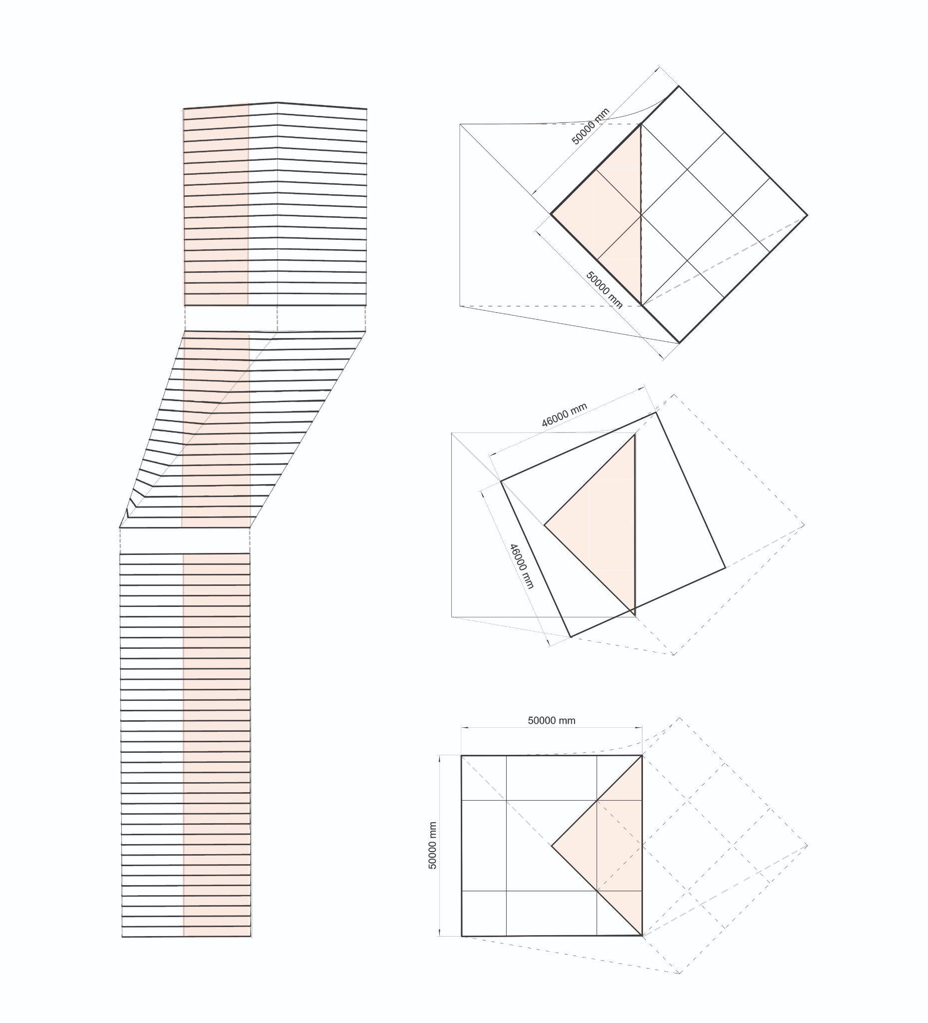
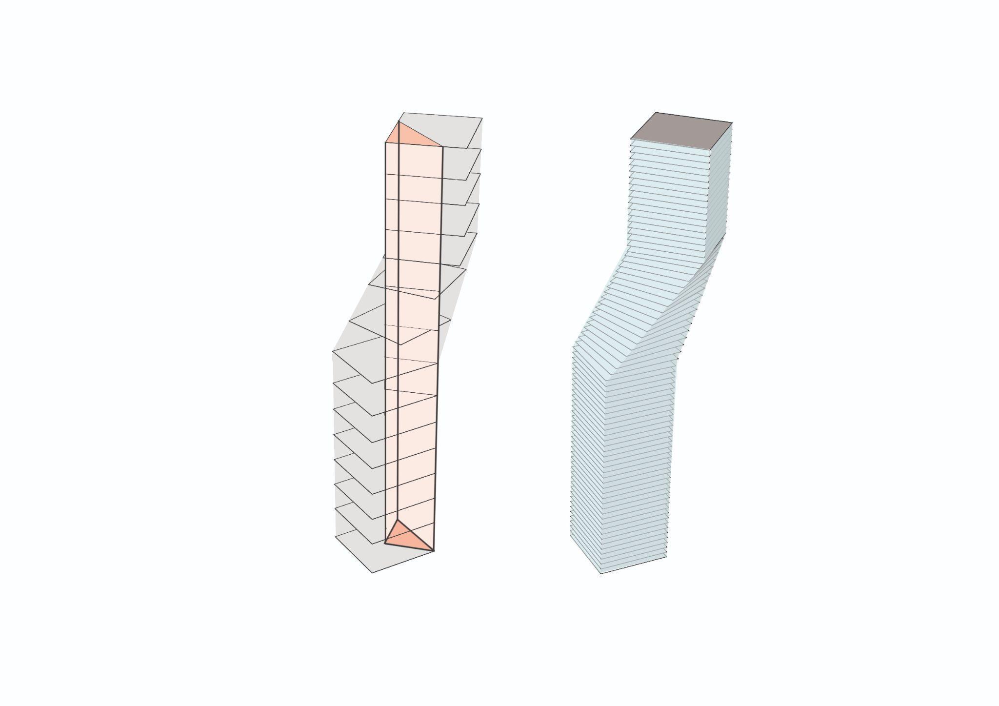
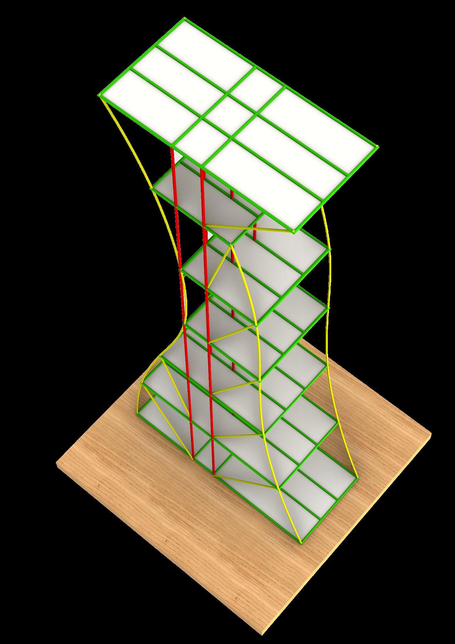
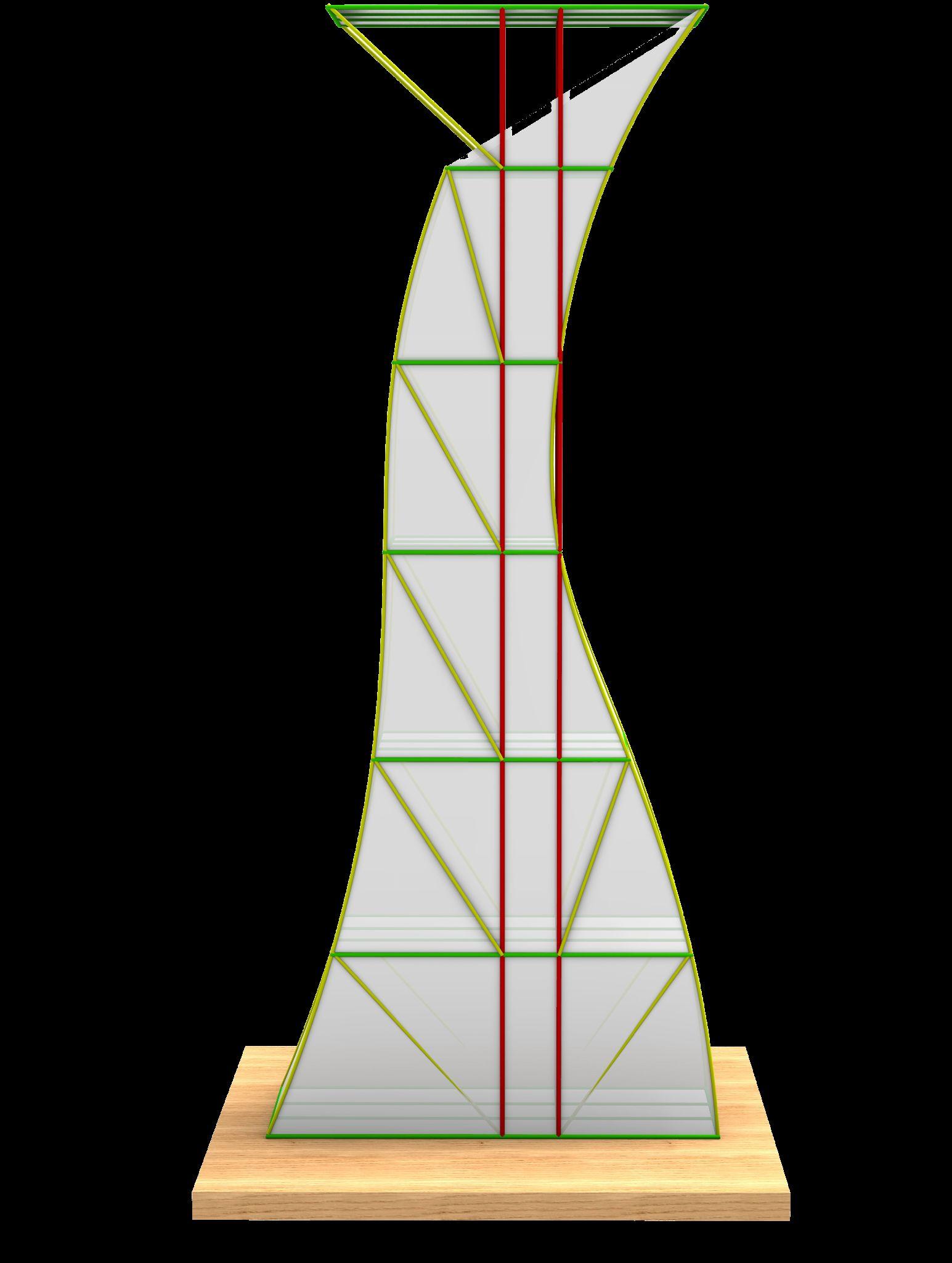
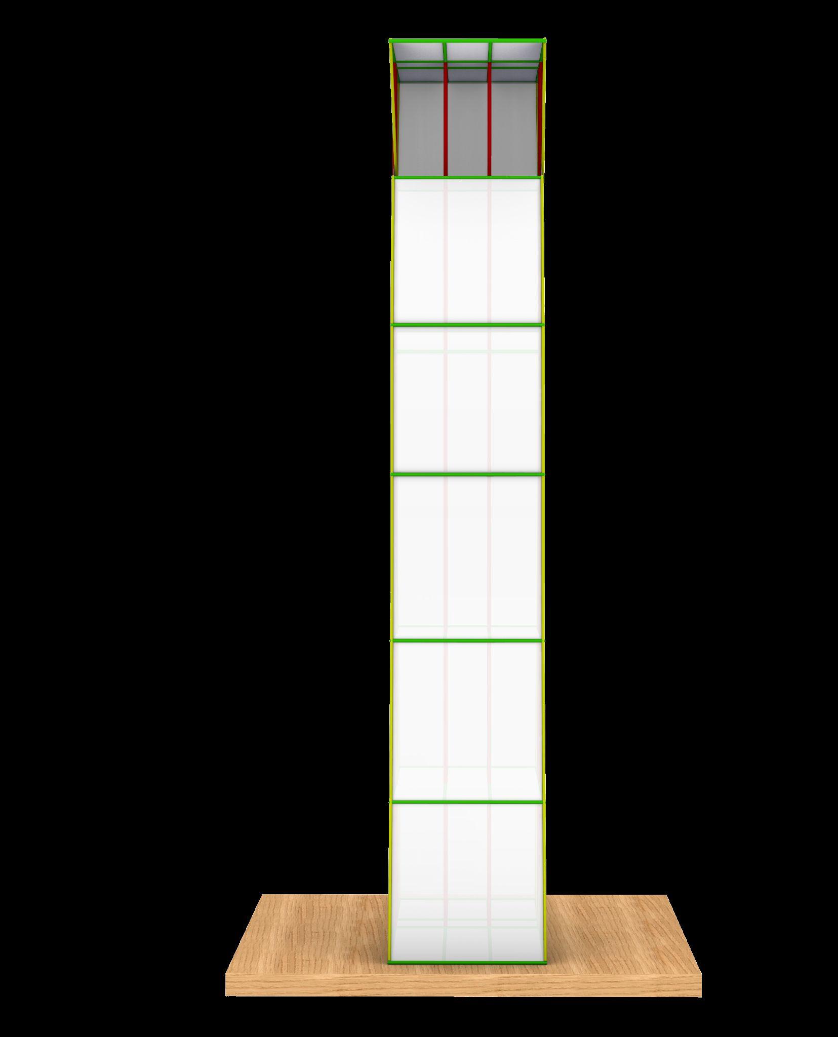
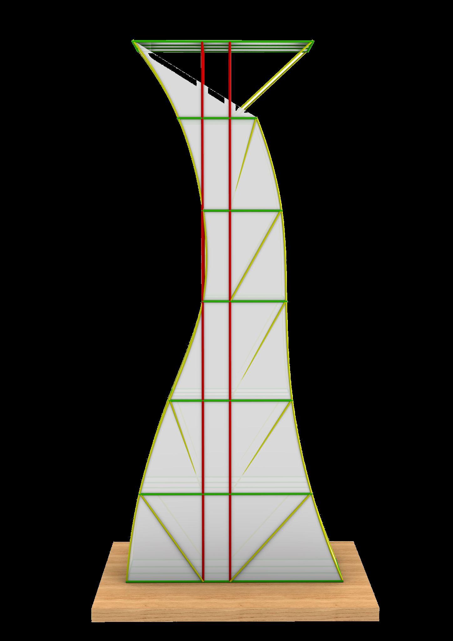
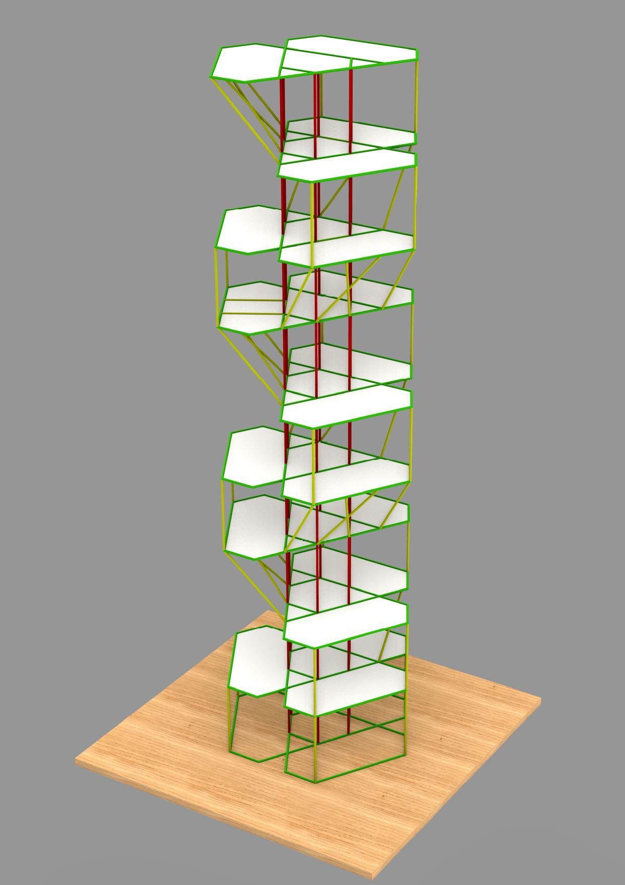
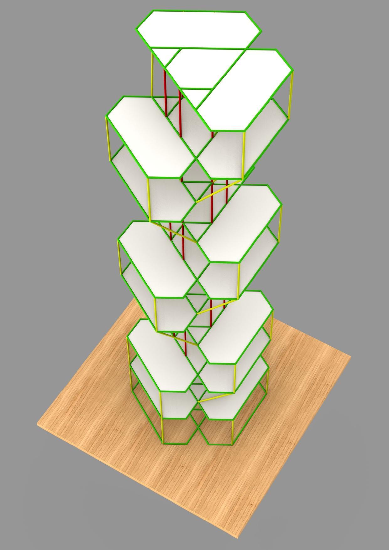
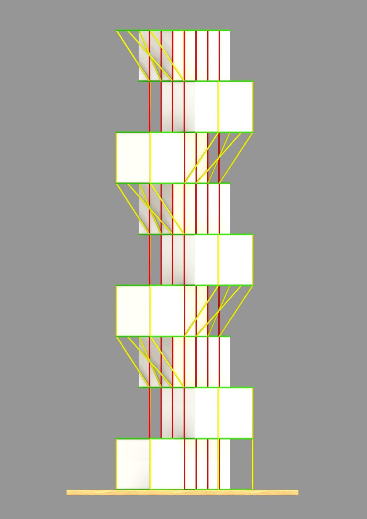
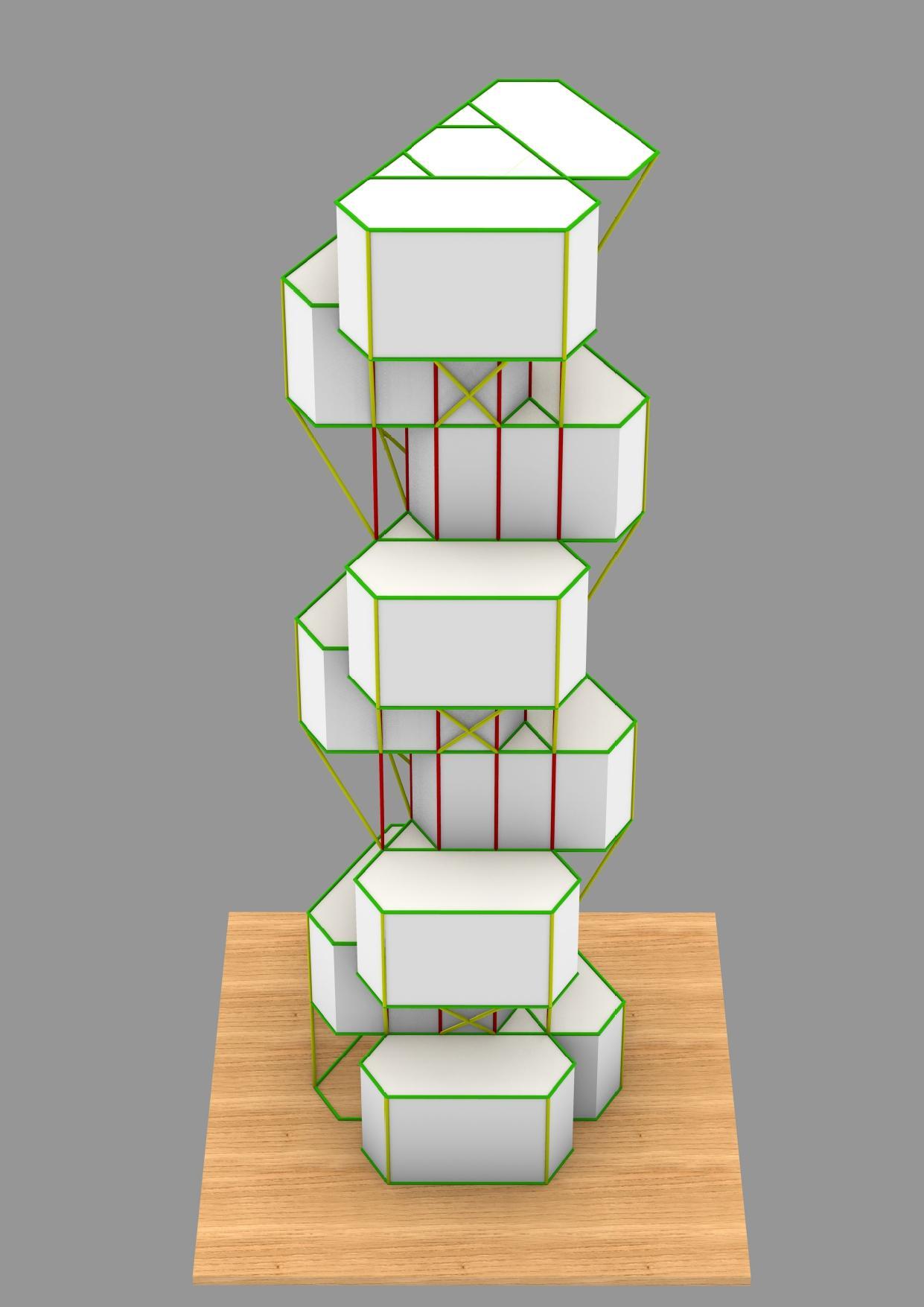
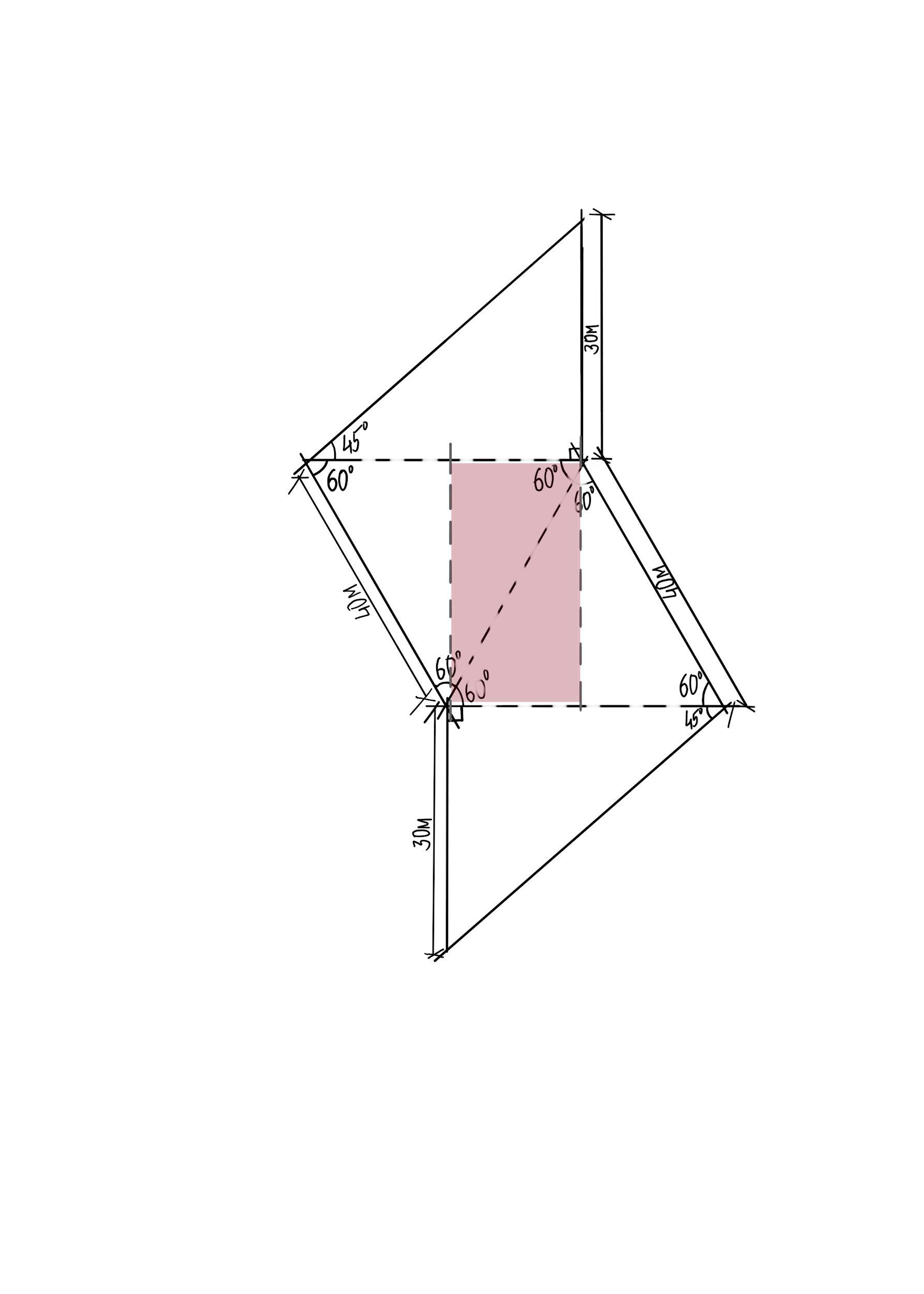
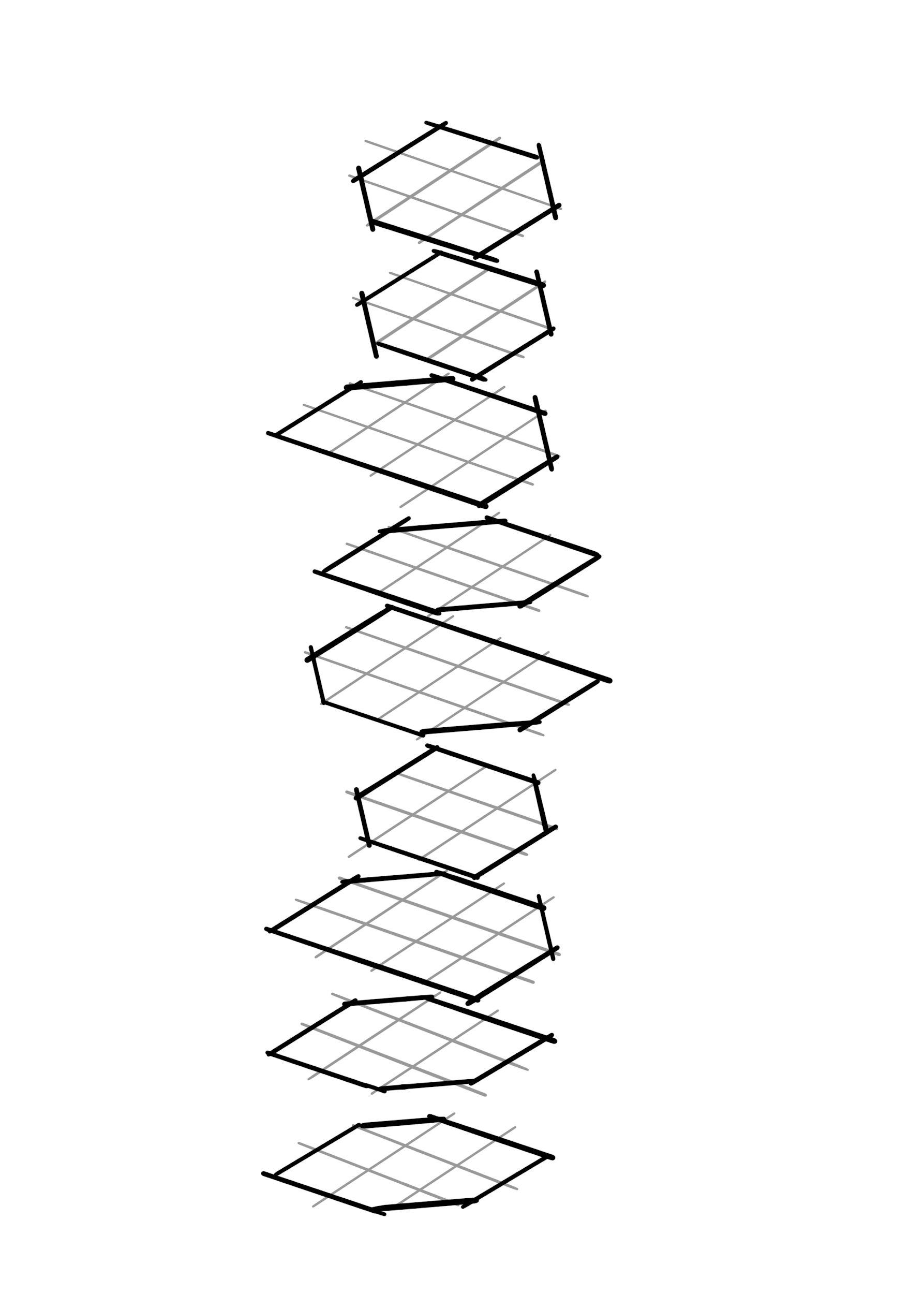
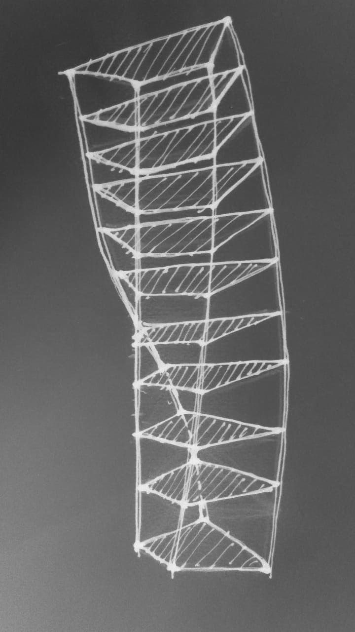
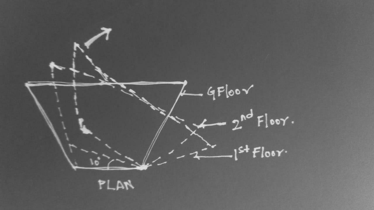
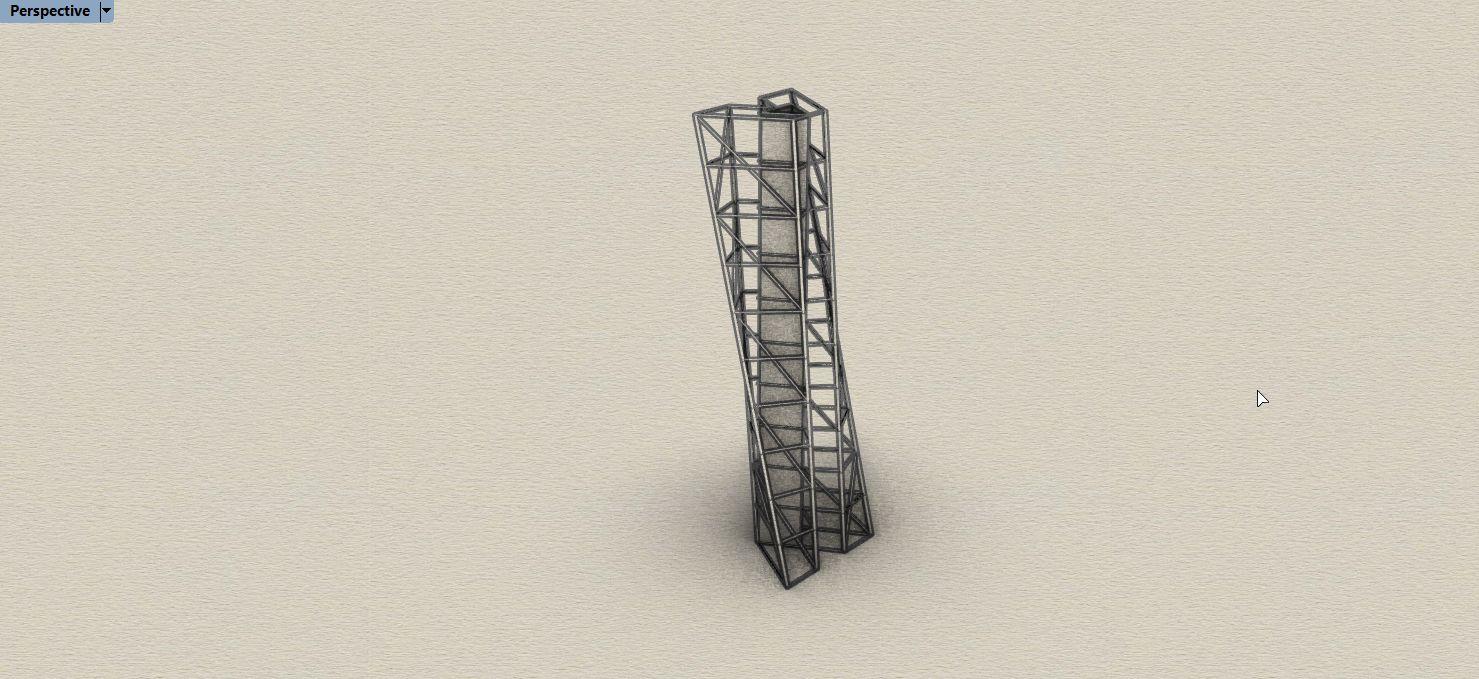
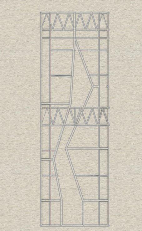
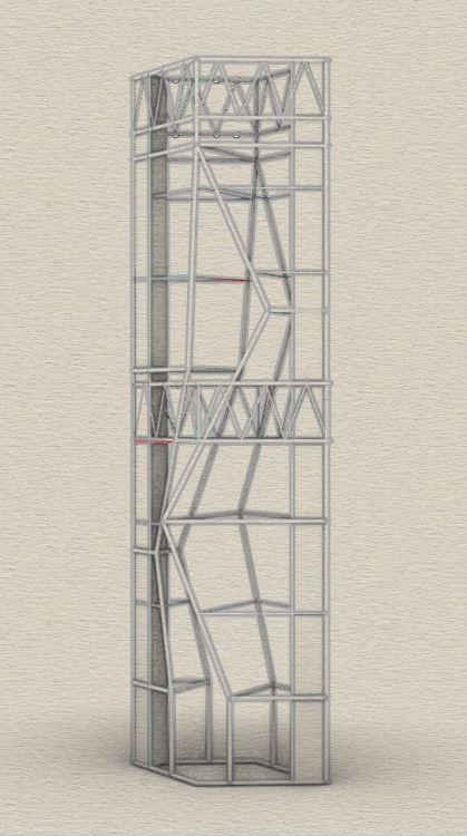
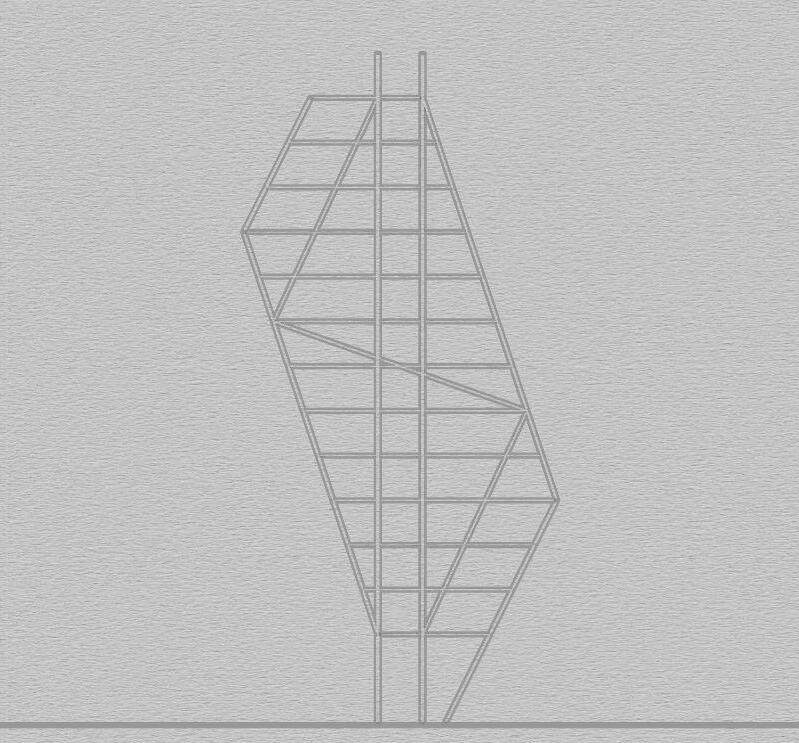
Atrapezoidalfloorplatewaspivotedalongacolumnby10degreesafter every30muptotheheightof300m.ThusaTurningstructurewasformed.
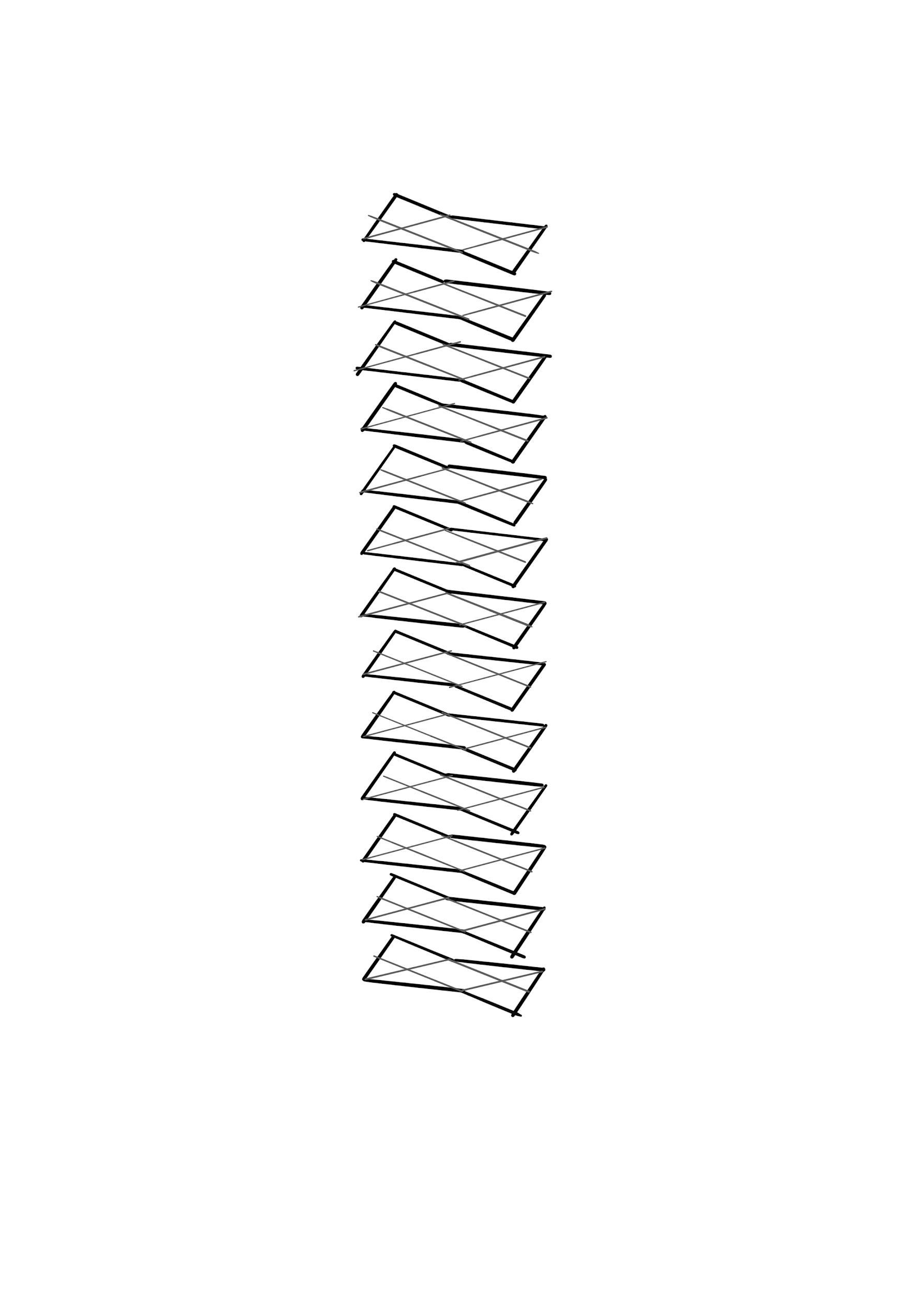
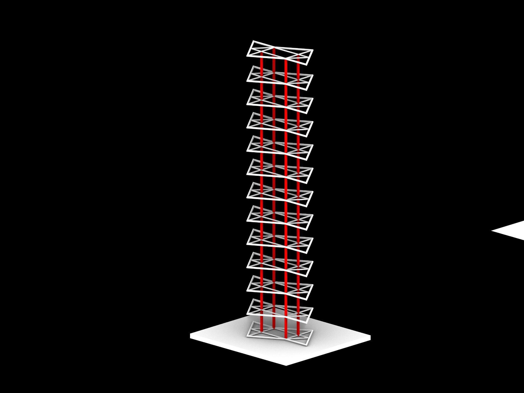
● In order to maintain the twist, diagonal columns were tied along the structure joining the vertices and following the rotation. Yet the structure was not stable and stiff, as it was unable to resist the torsionalforce.Itcamebacktoitsoriginalposition.
● In order to resist the shear and bending force, additional column wasplacedalongthelongerside.Thismadethestructurestable.
● Diagonal Bracings were joined in opposite direction with that of the rotationtoresistthetorsionalforce.
● They were joined after every 2 floors along longer side and 3 floors alongshortersideinaccordancewiththeturningfactorofthefaces.
● Thus the structure was made stiff with the bracings and additional column.
Team10| DesignReport CONCLUSION
ANALYSISANDCONCLUSION
AcademyofArchitecture,Mumbai
GROUP11 SARTHAKEKAL_10 ATHARVAGIRME_27 HARSHWARDHANSHIRPURKAR_53

Team11| DesignReport INITIALSKETCHES
IMAGETITLE IMAGETITLE IMAGETITLE IMAGETITLE
IMAGE
IMAGETITLE IMAGETITLE Team11| DesignReport MODELPHOTOS
IMAGETITLE
TITLE
SKETCHES Team11| DesignReport
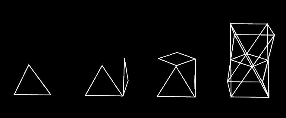
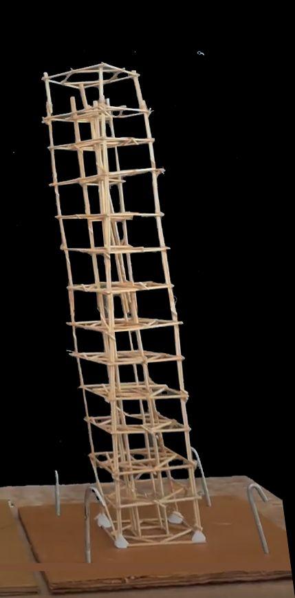
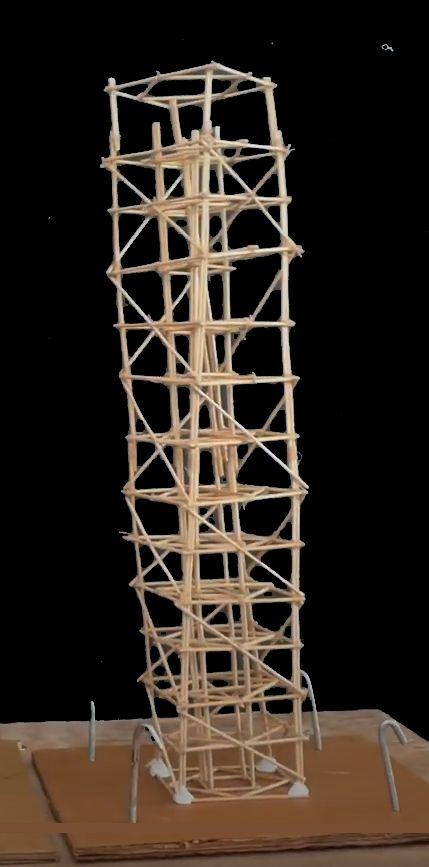
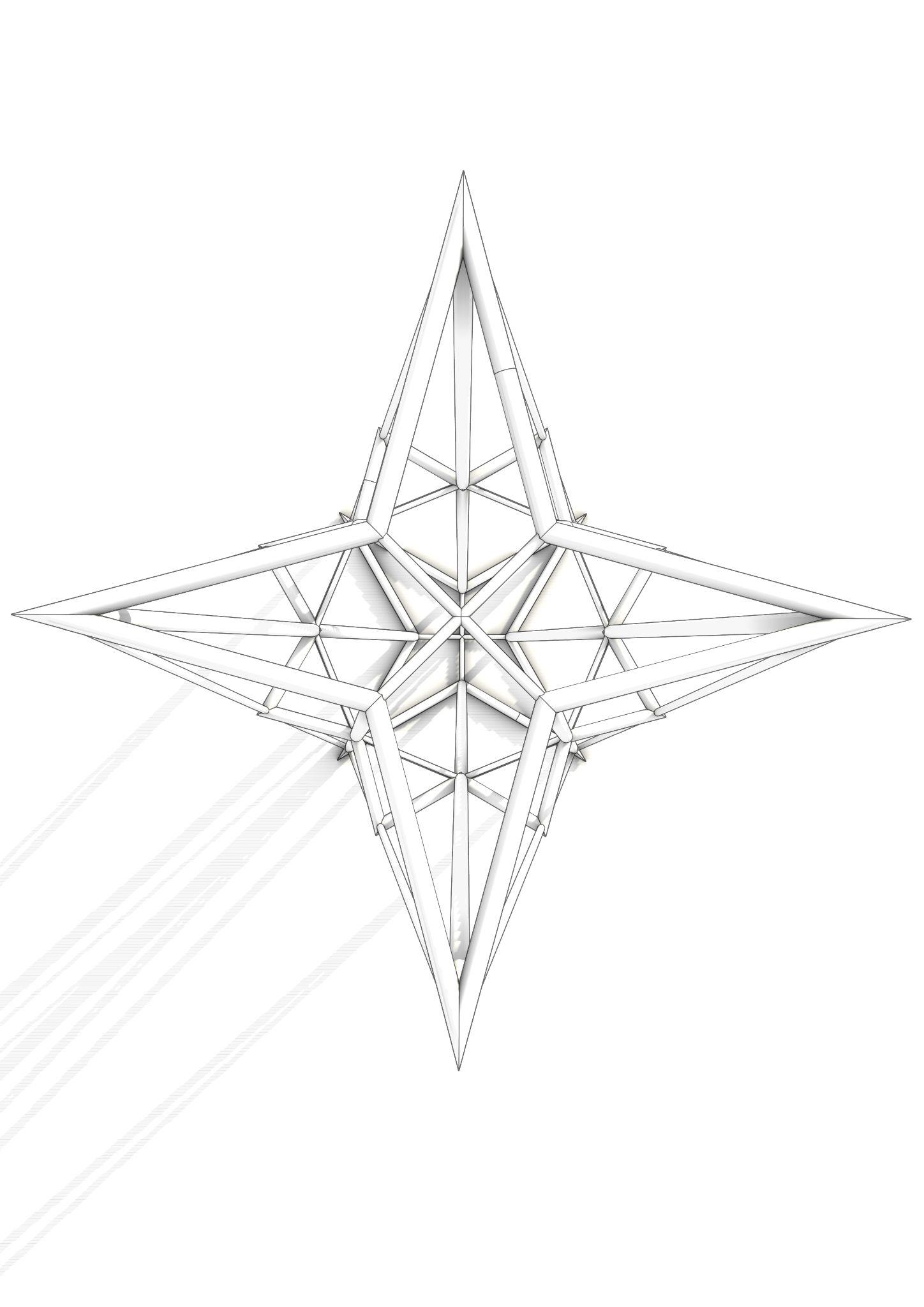
PLAN 3DVIEW ISOMETRICVIEW SIDEELEVATION MODEL1:GEOMETRICMODEL
PLAN 3DVIEW
SKETCHES Team11| DesignReport
ISOMETRICVIEW SIDEELEVATION MODEL1:GEOMETRICMODEL
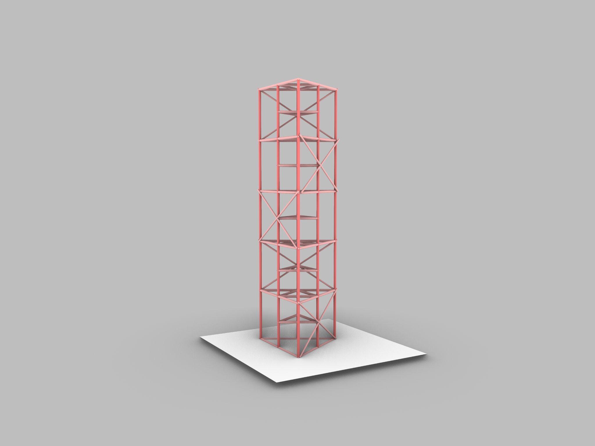
Team11| DesignReport DIGITALMODELPHOTOS
ANALYSISANDCONCLUSION
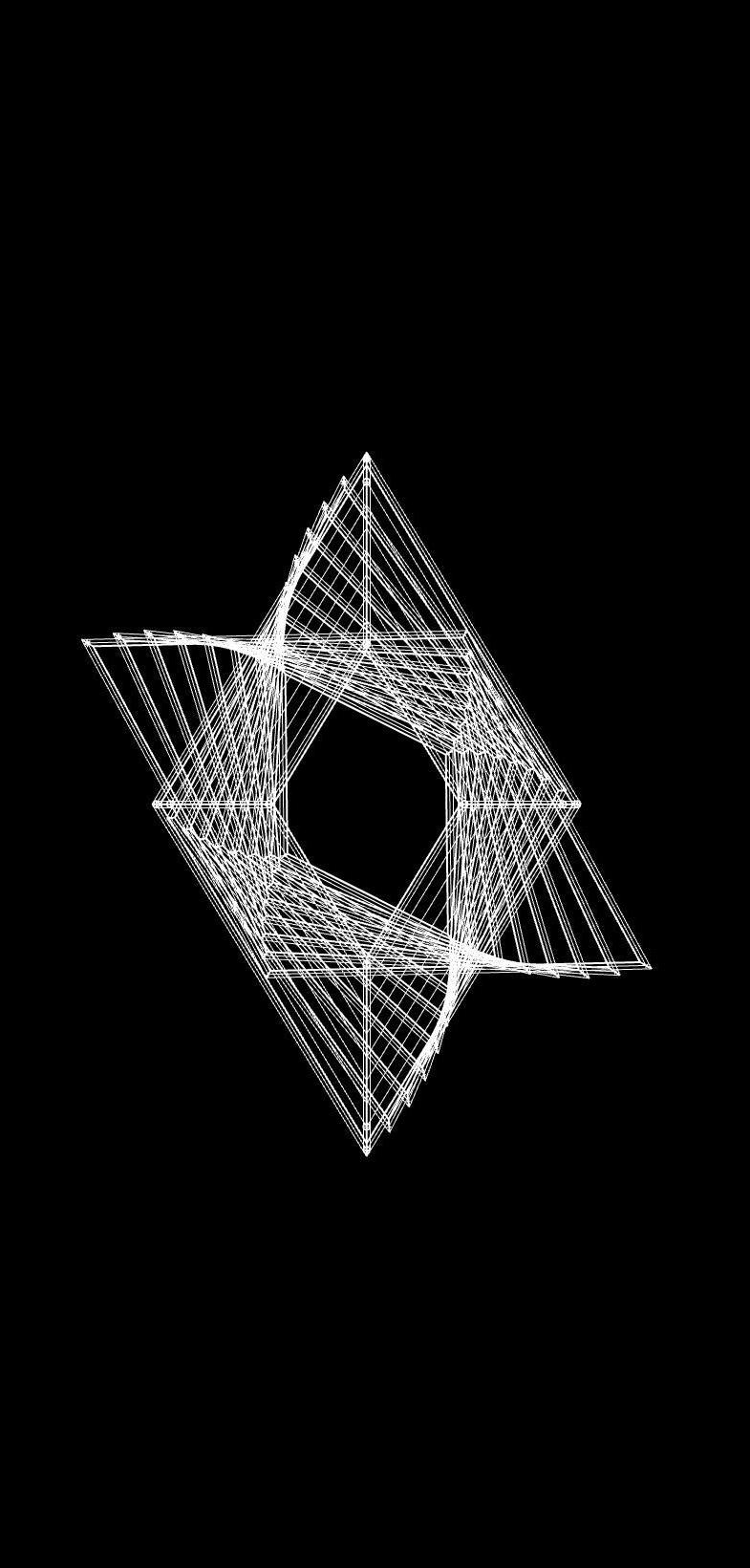
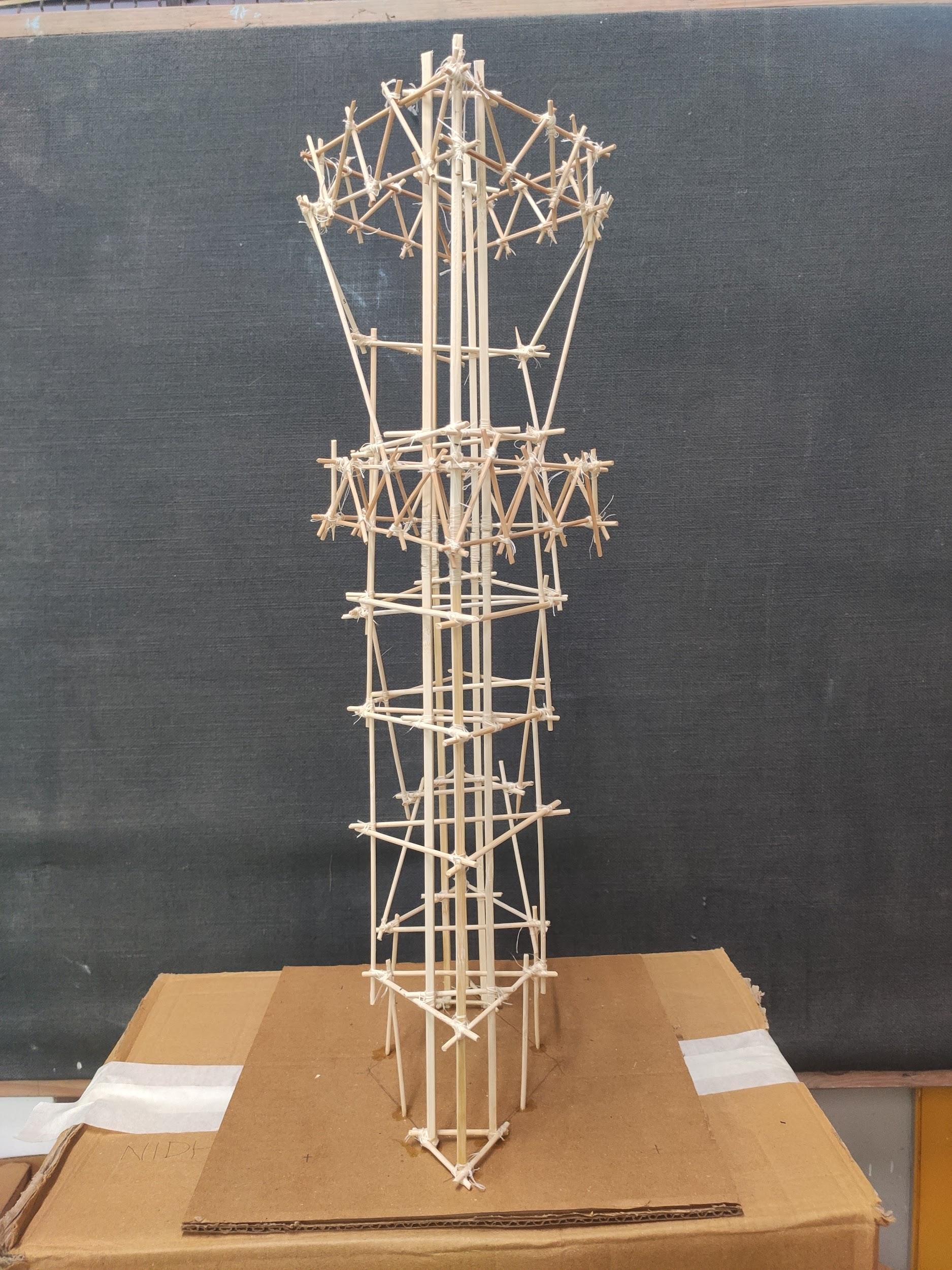
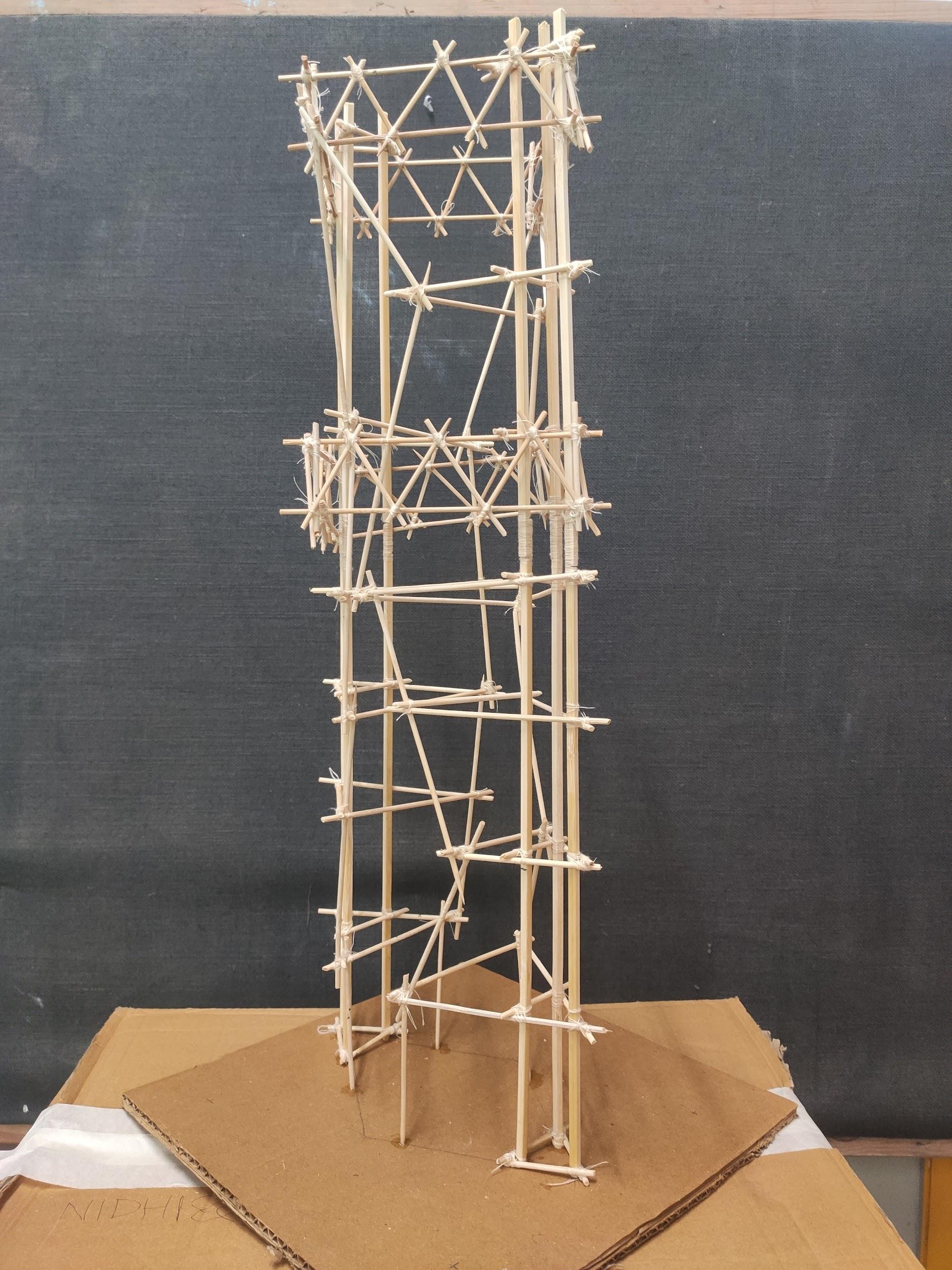
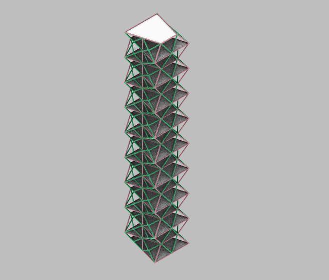
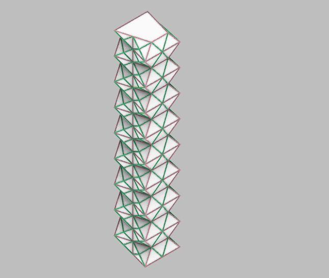
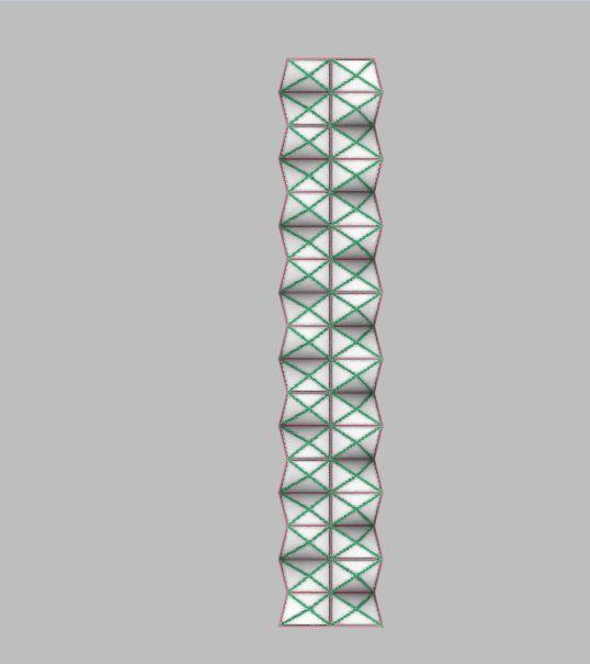
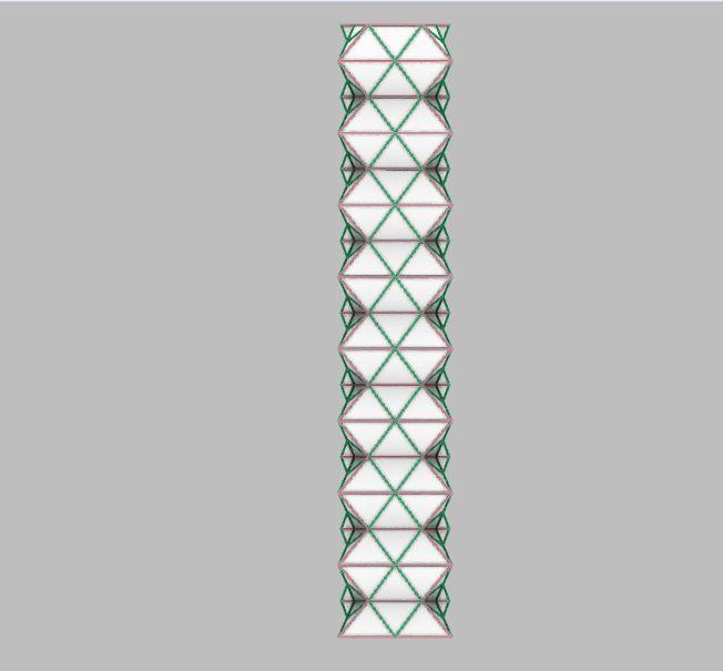
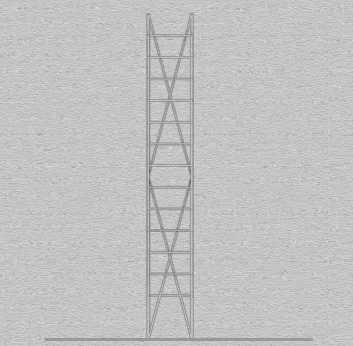
MODEL1:REGULARMODEL
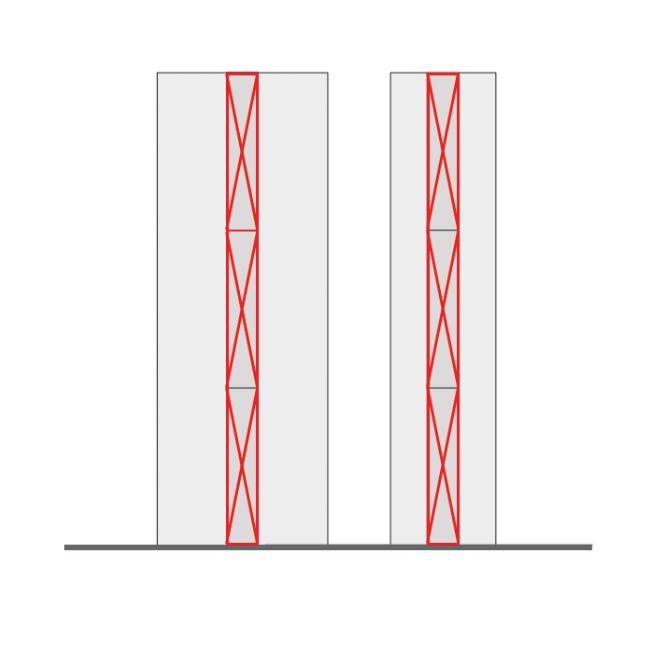
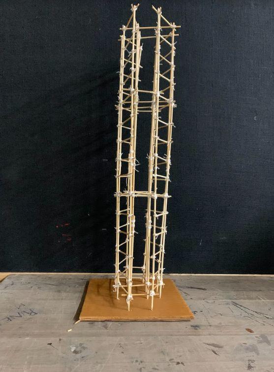
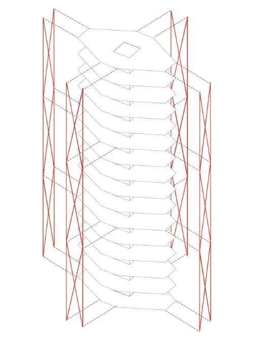
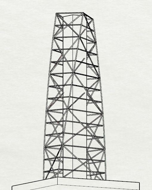
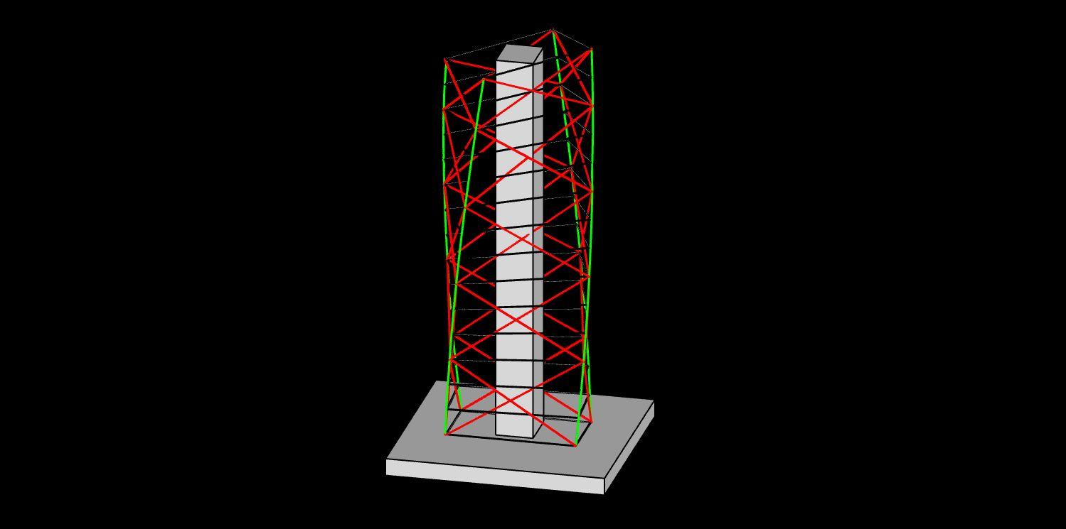
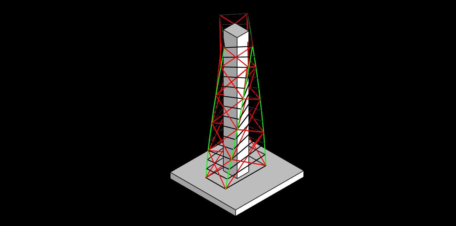
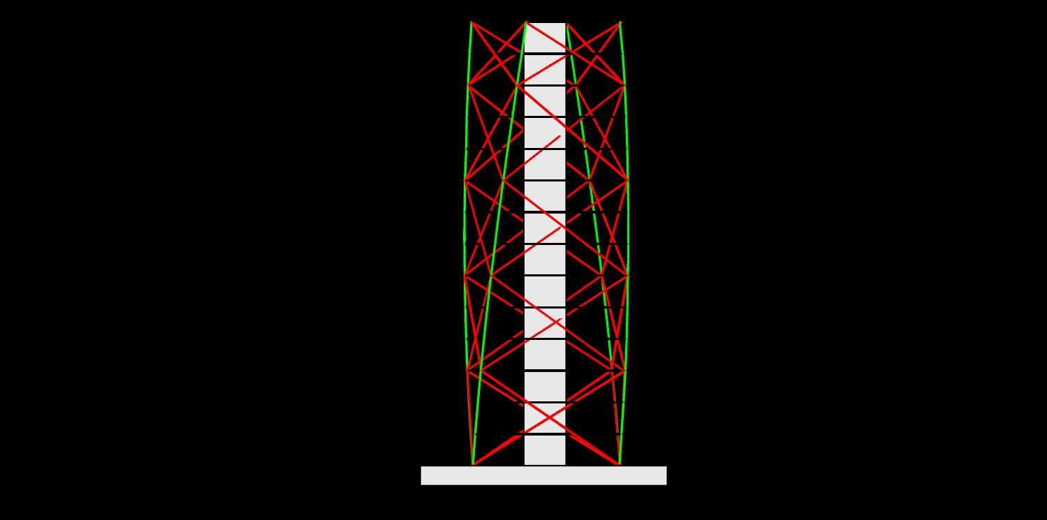
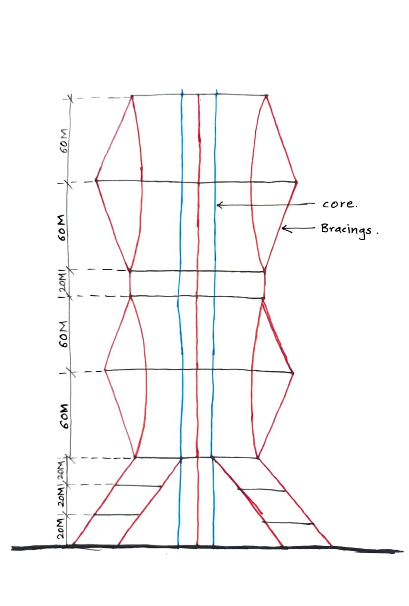
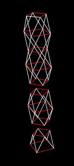
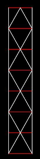
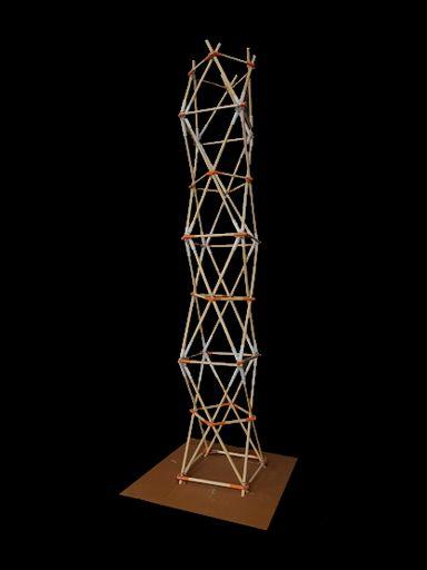
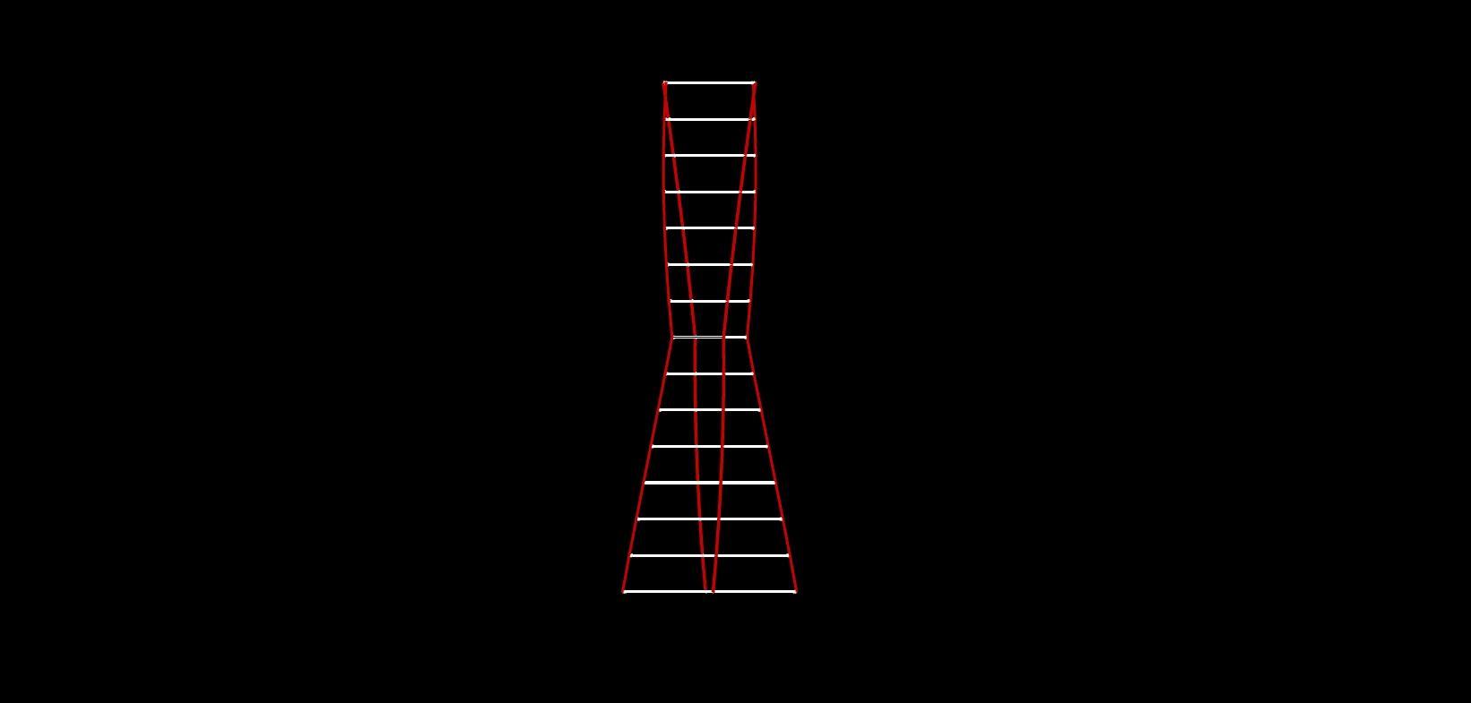
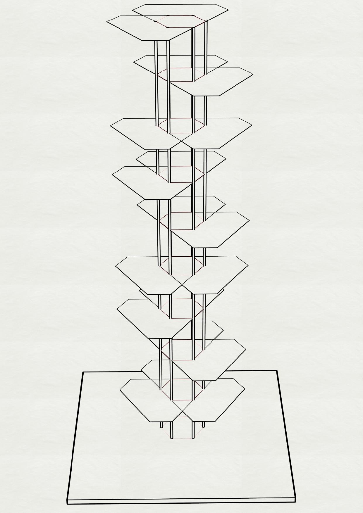
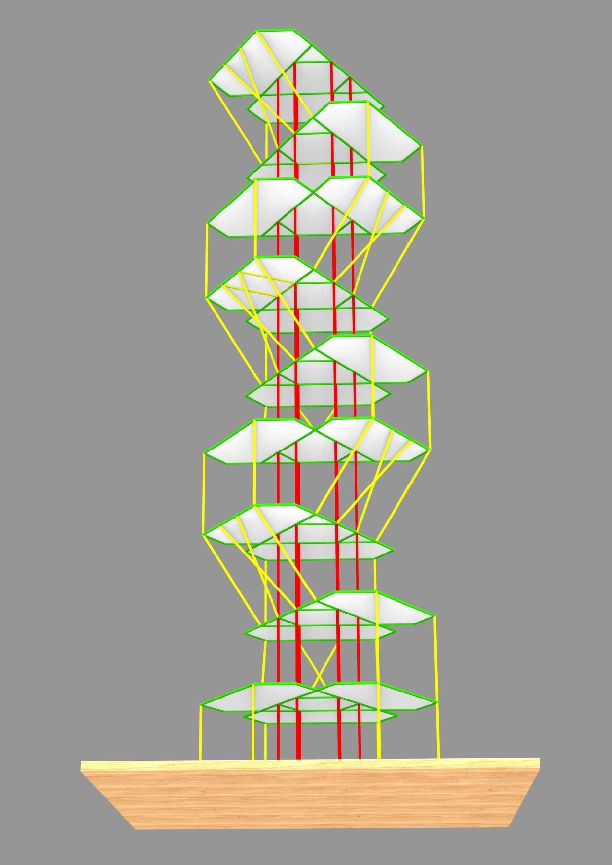
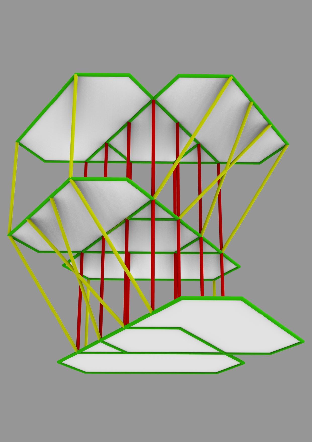
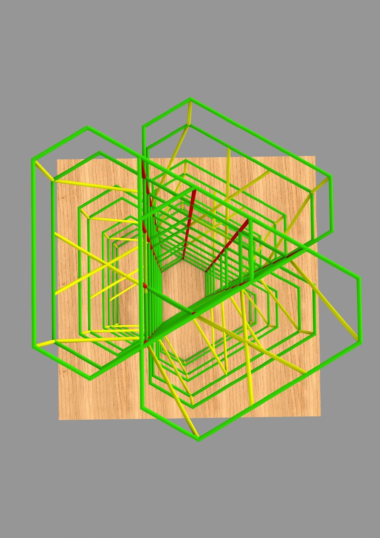
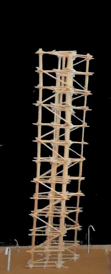
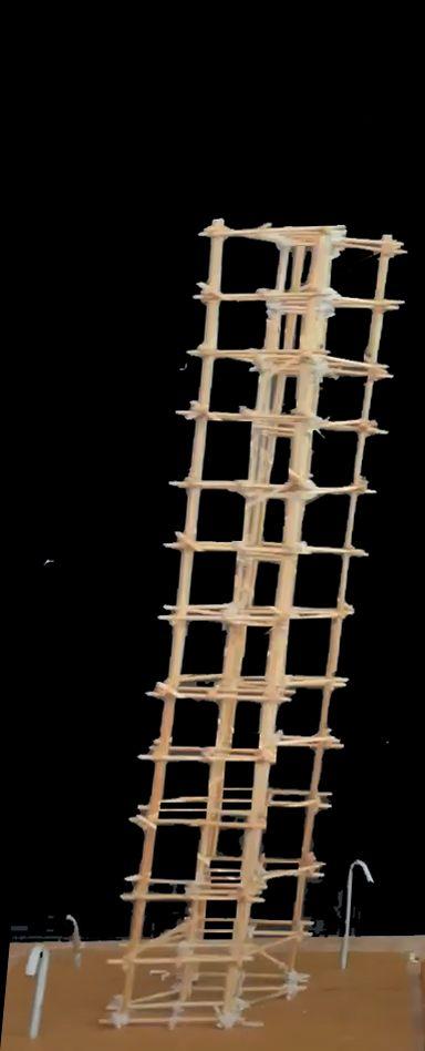
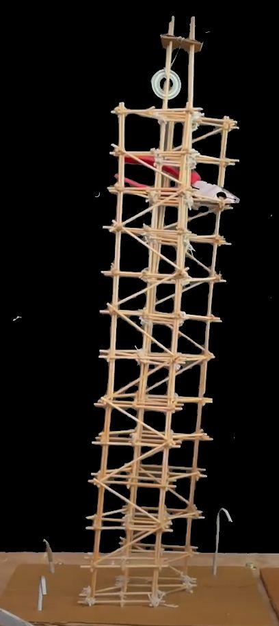
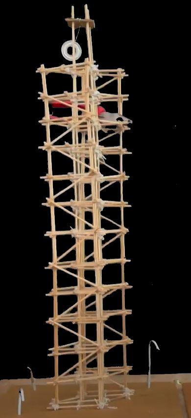
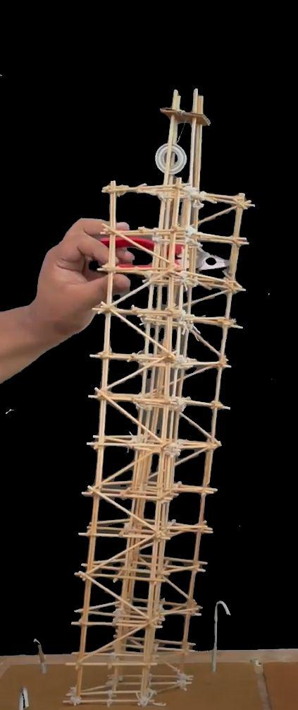
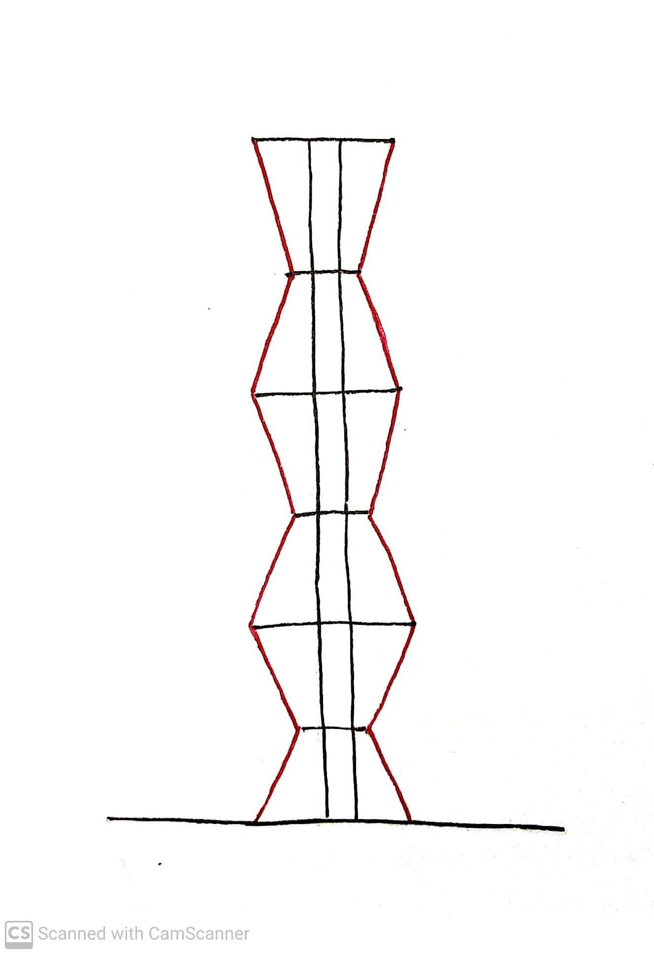
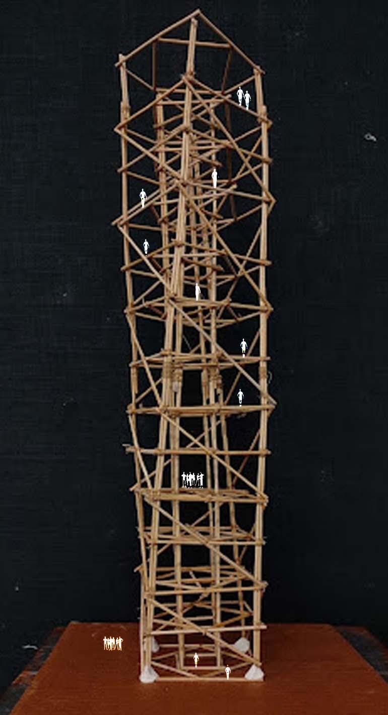
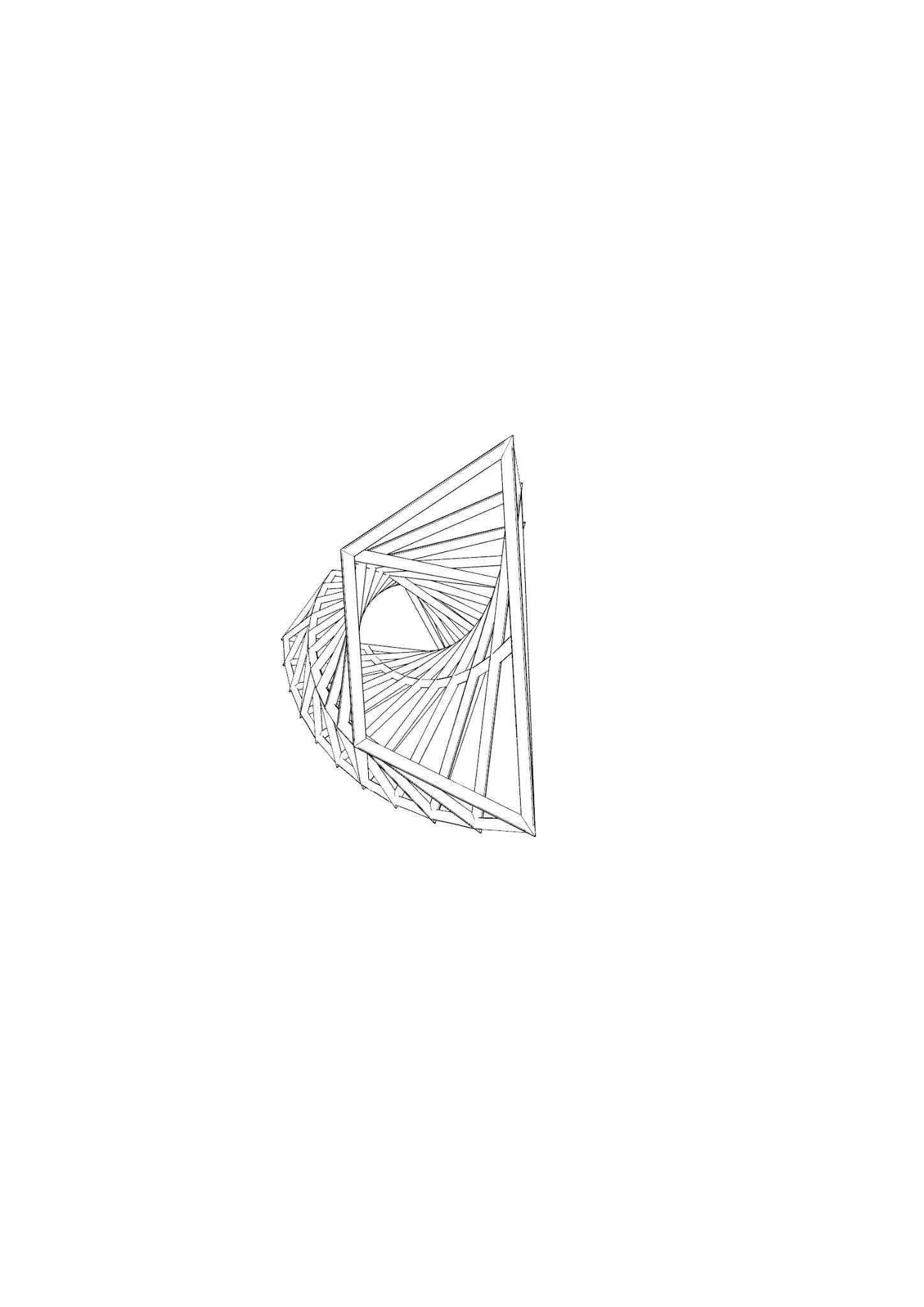
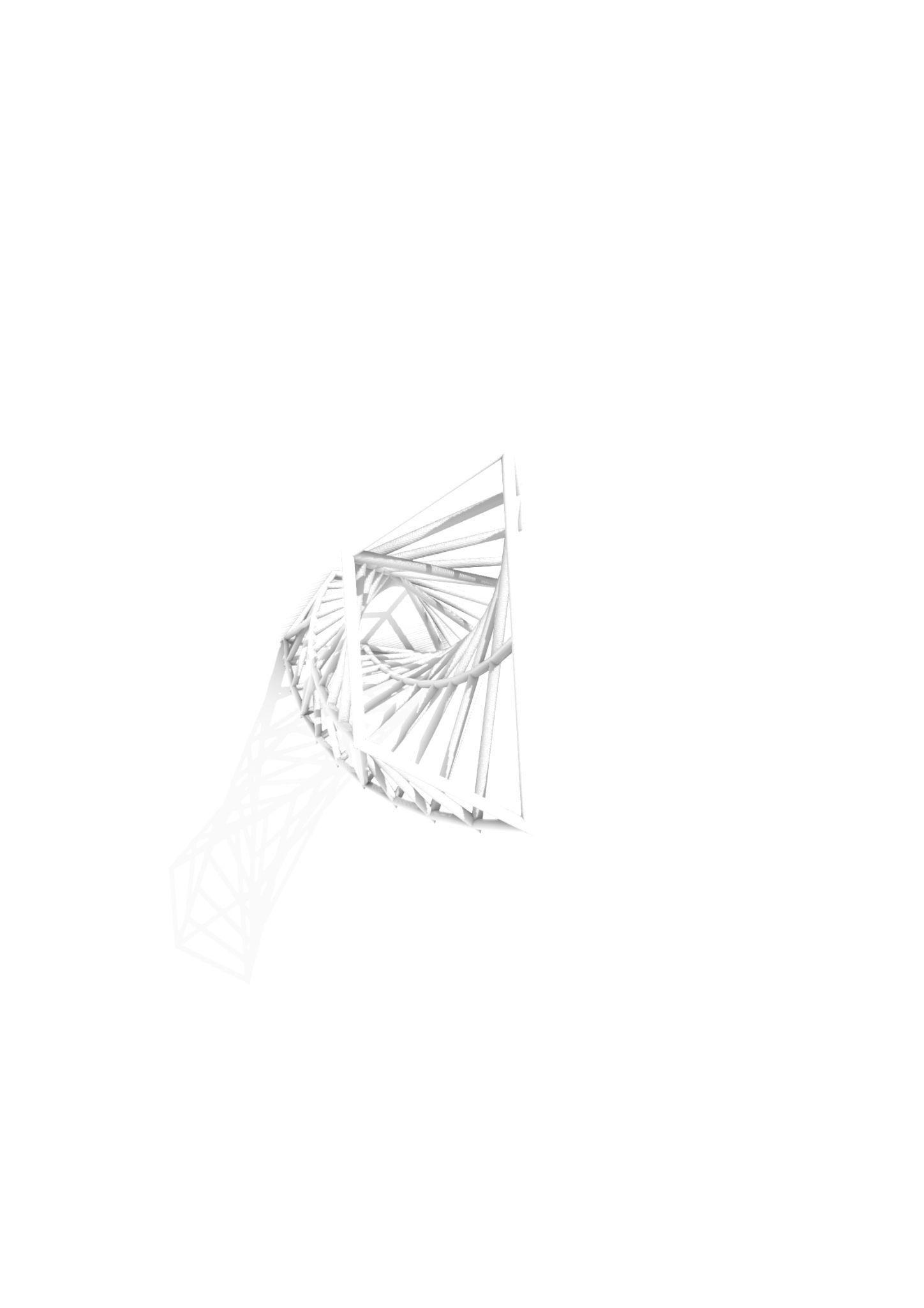
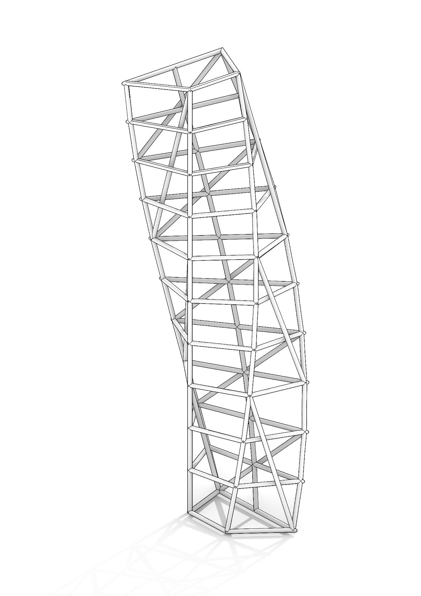
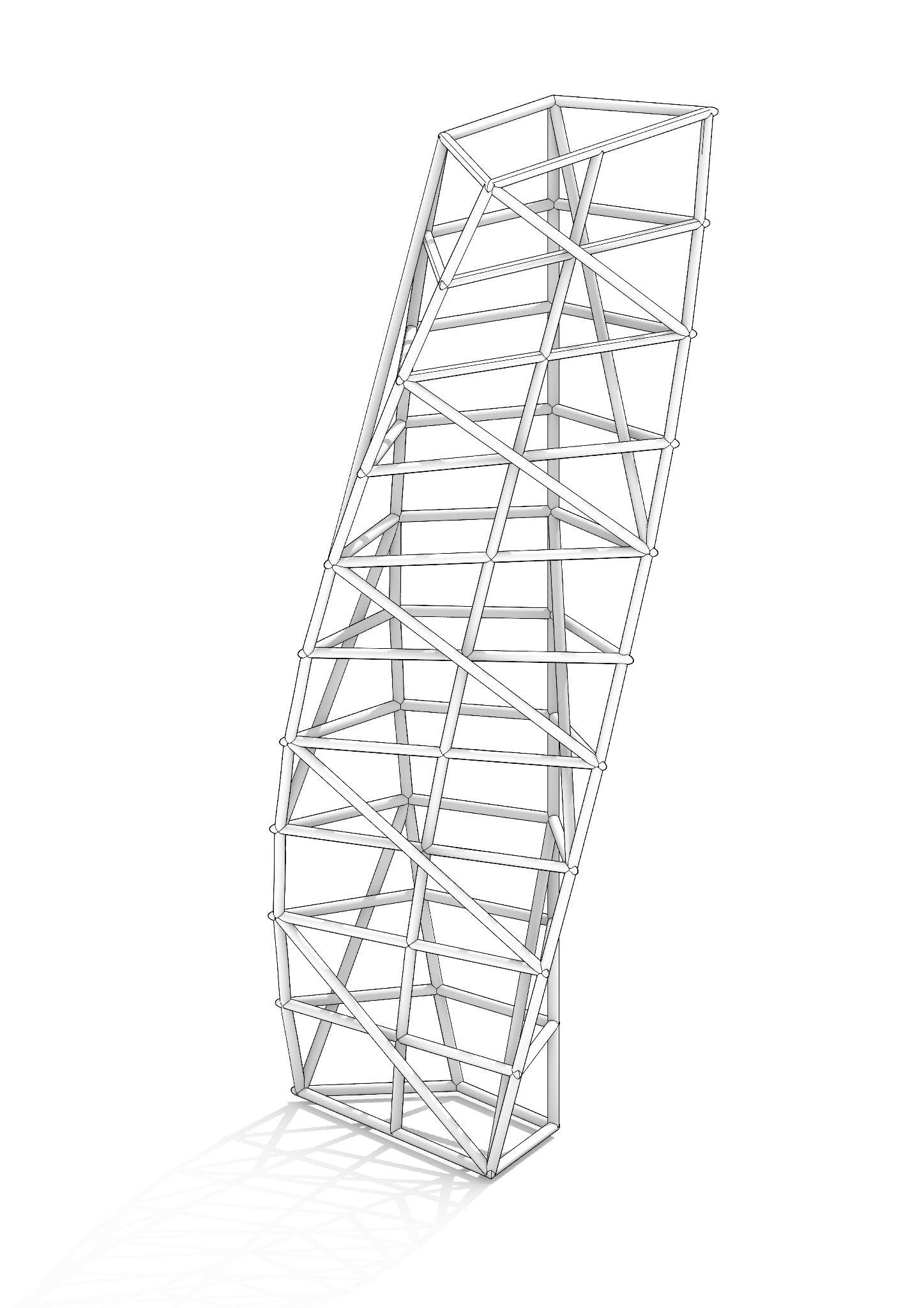
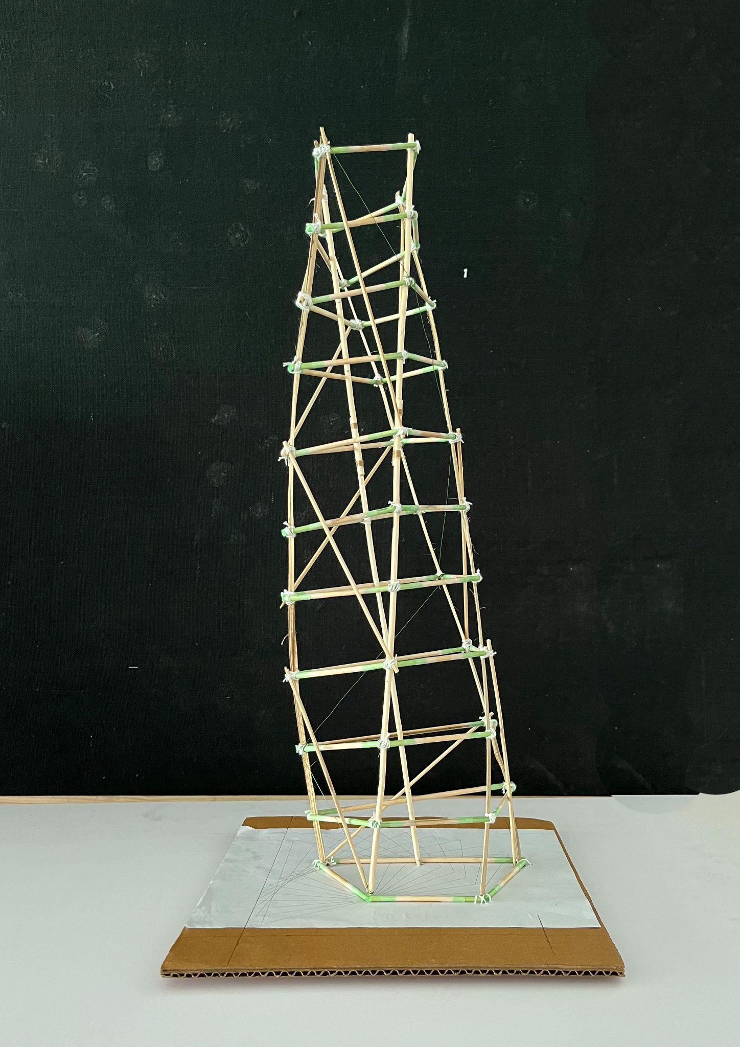
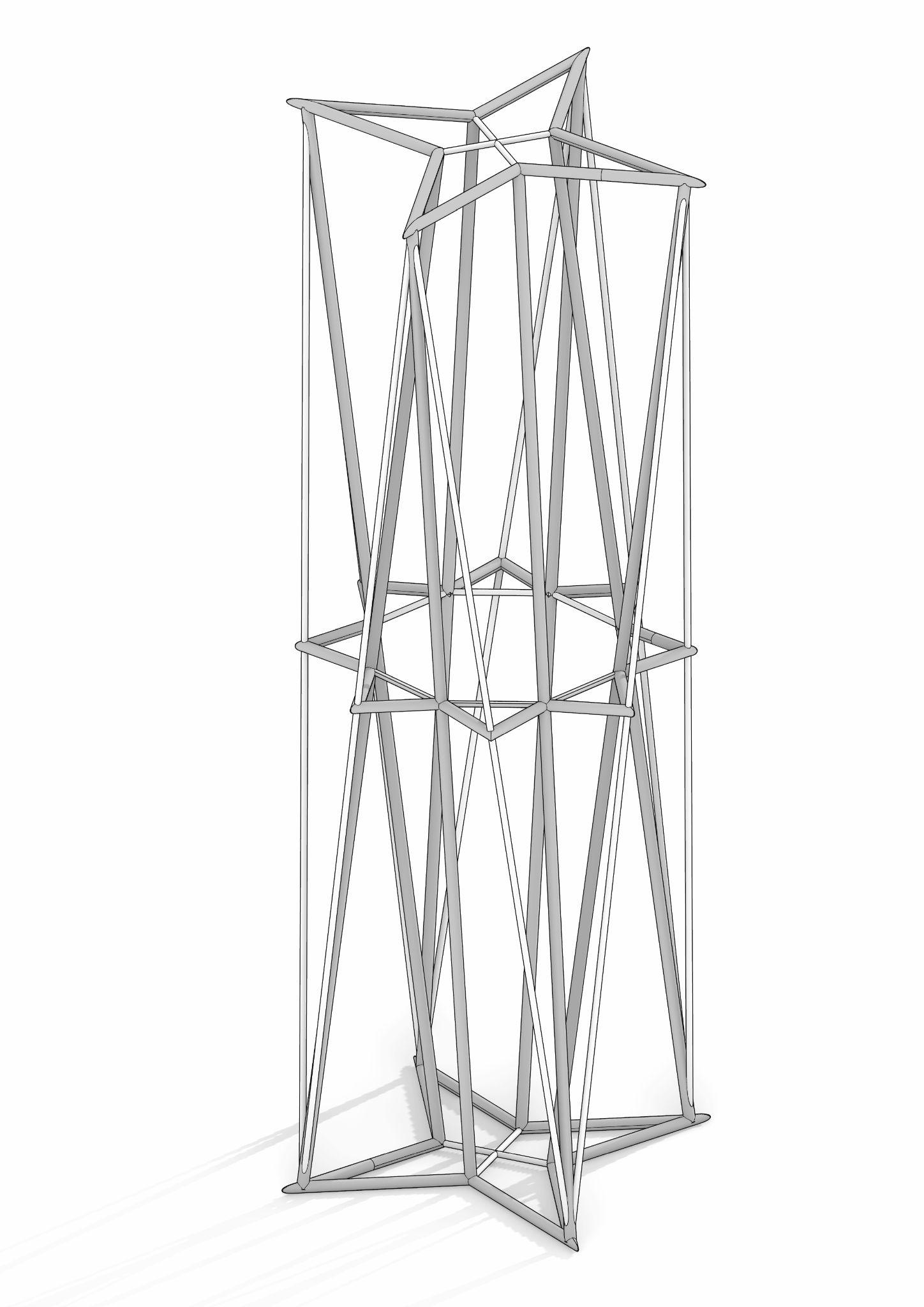
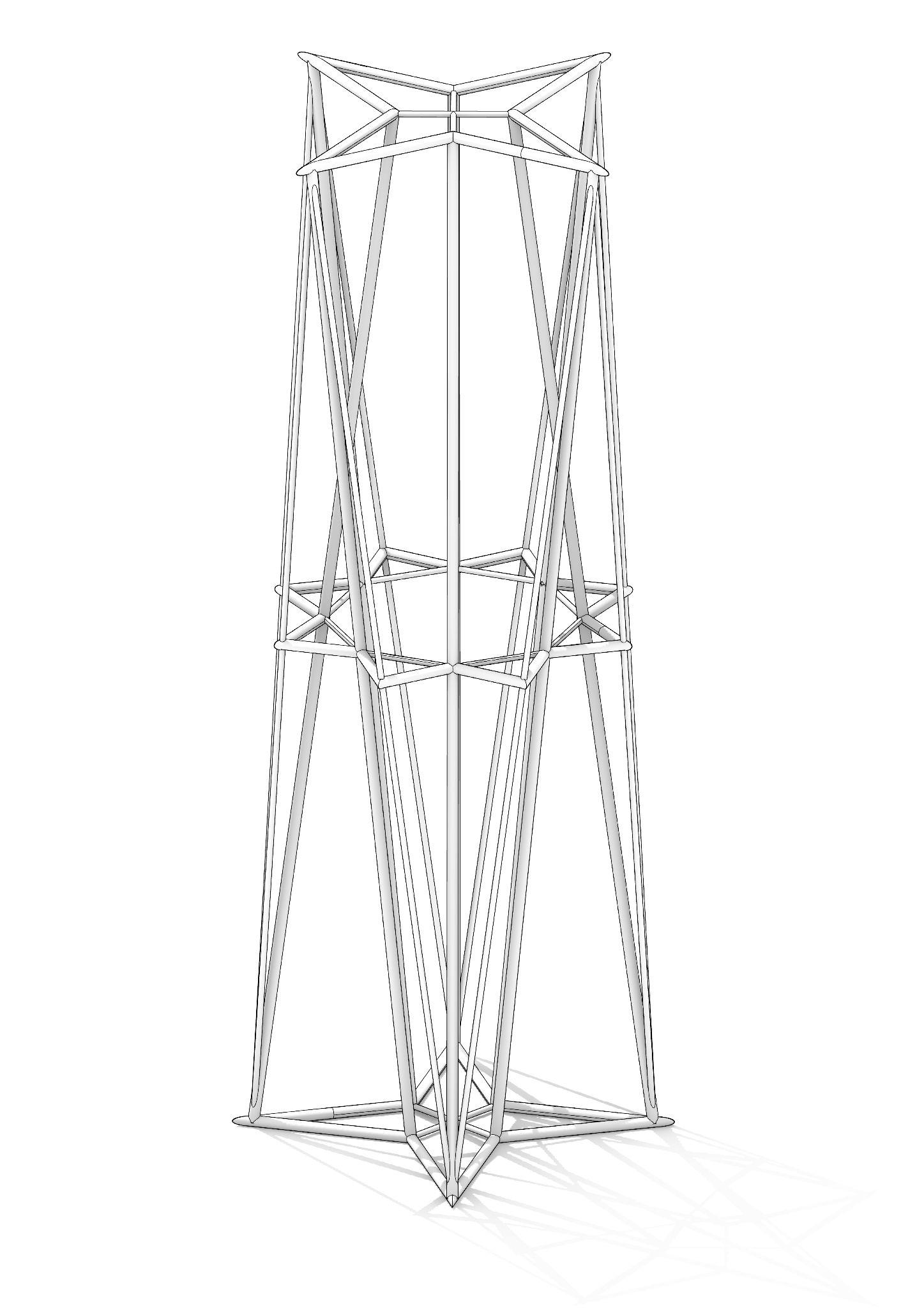
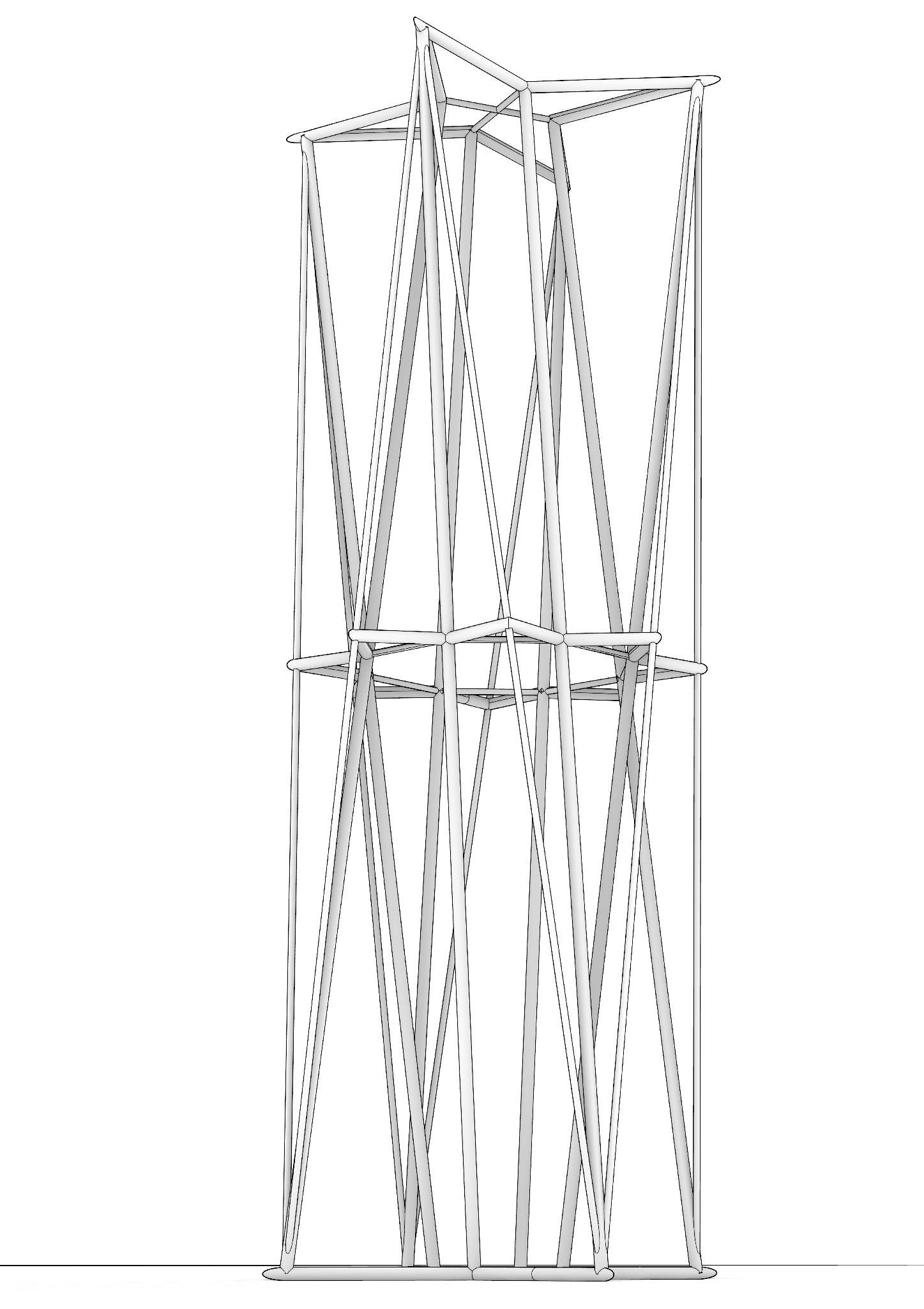
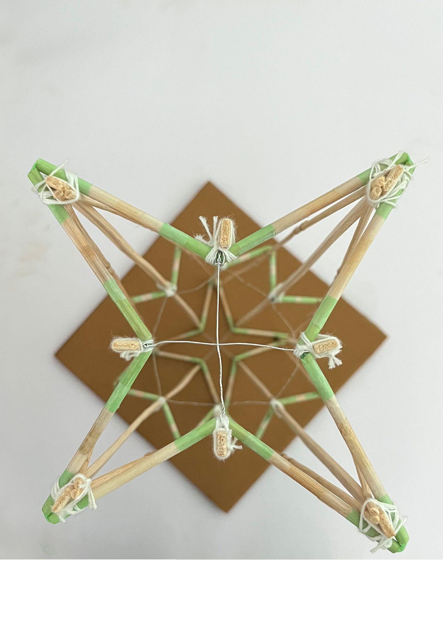
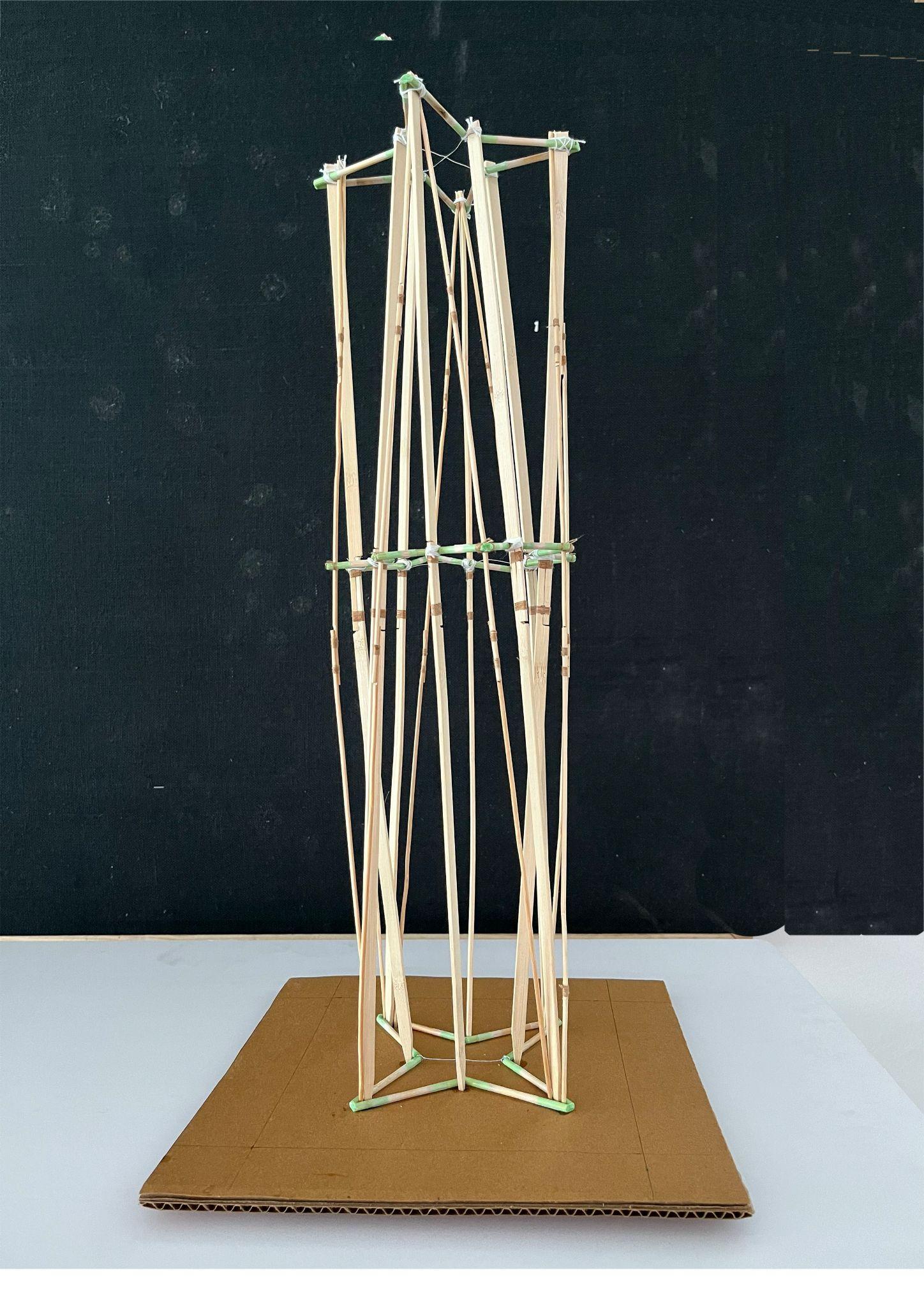
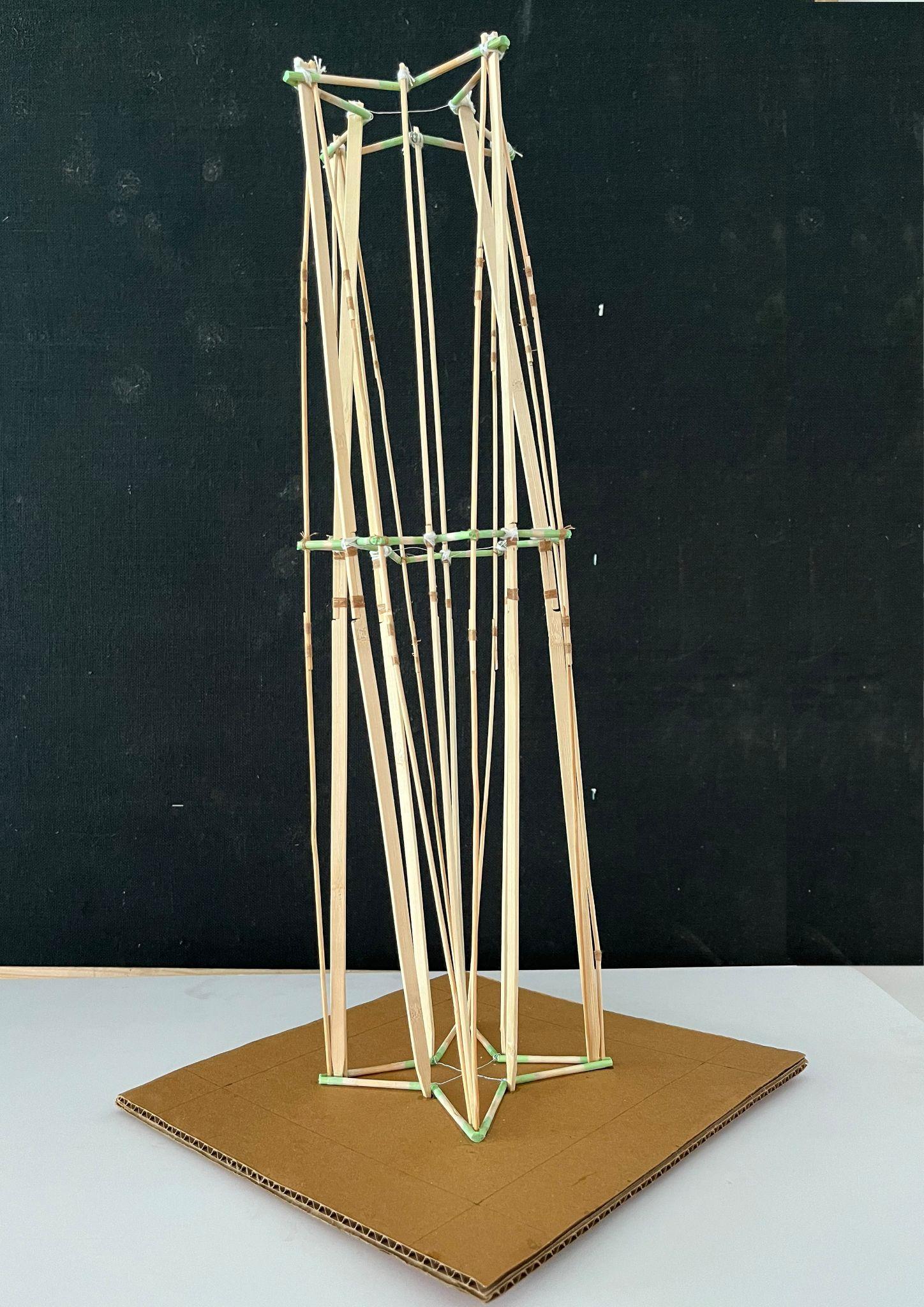
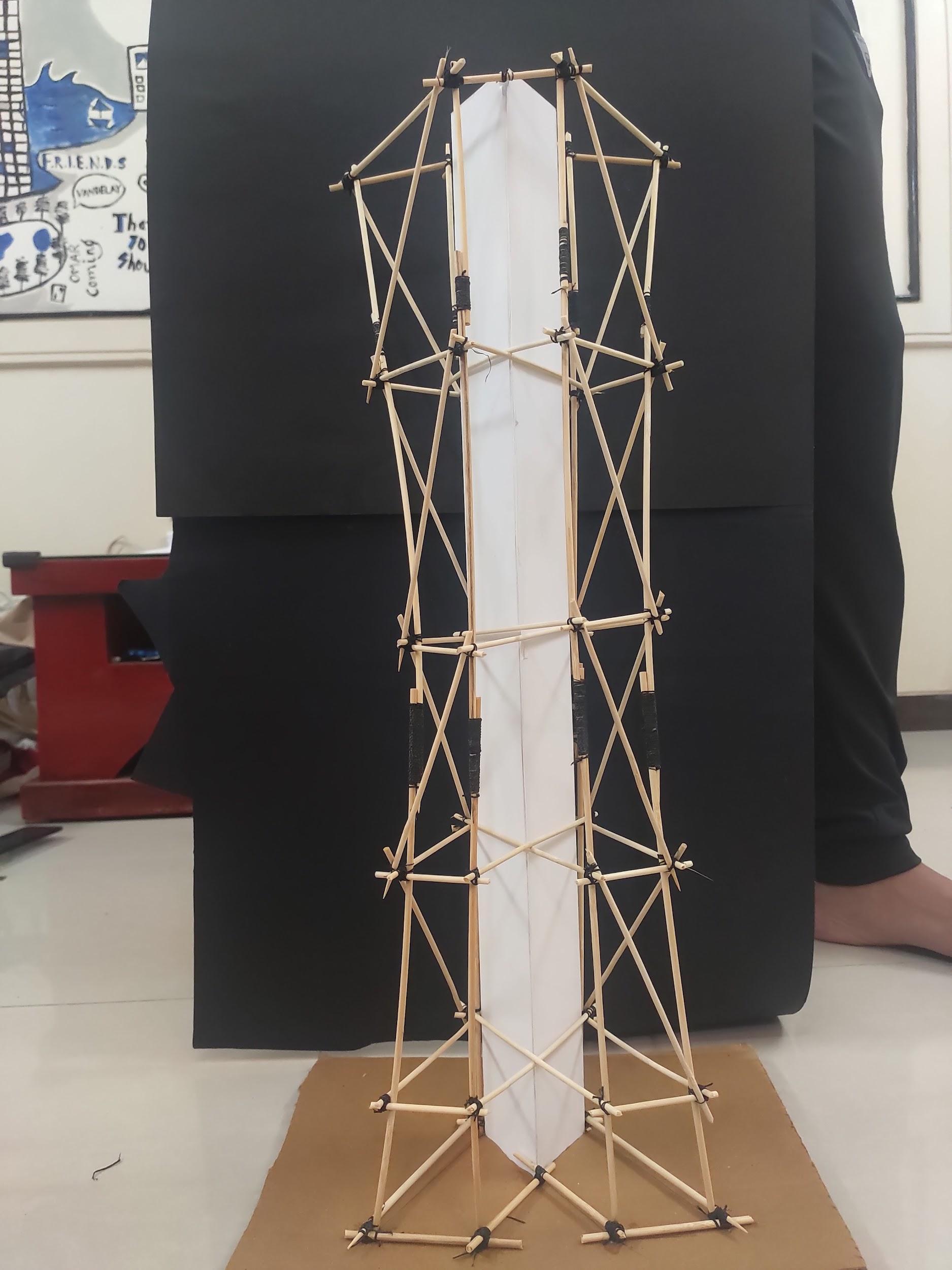
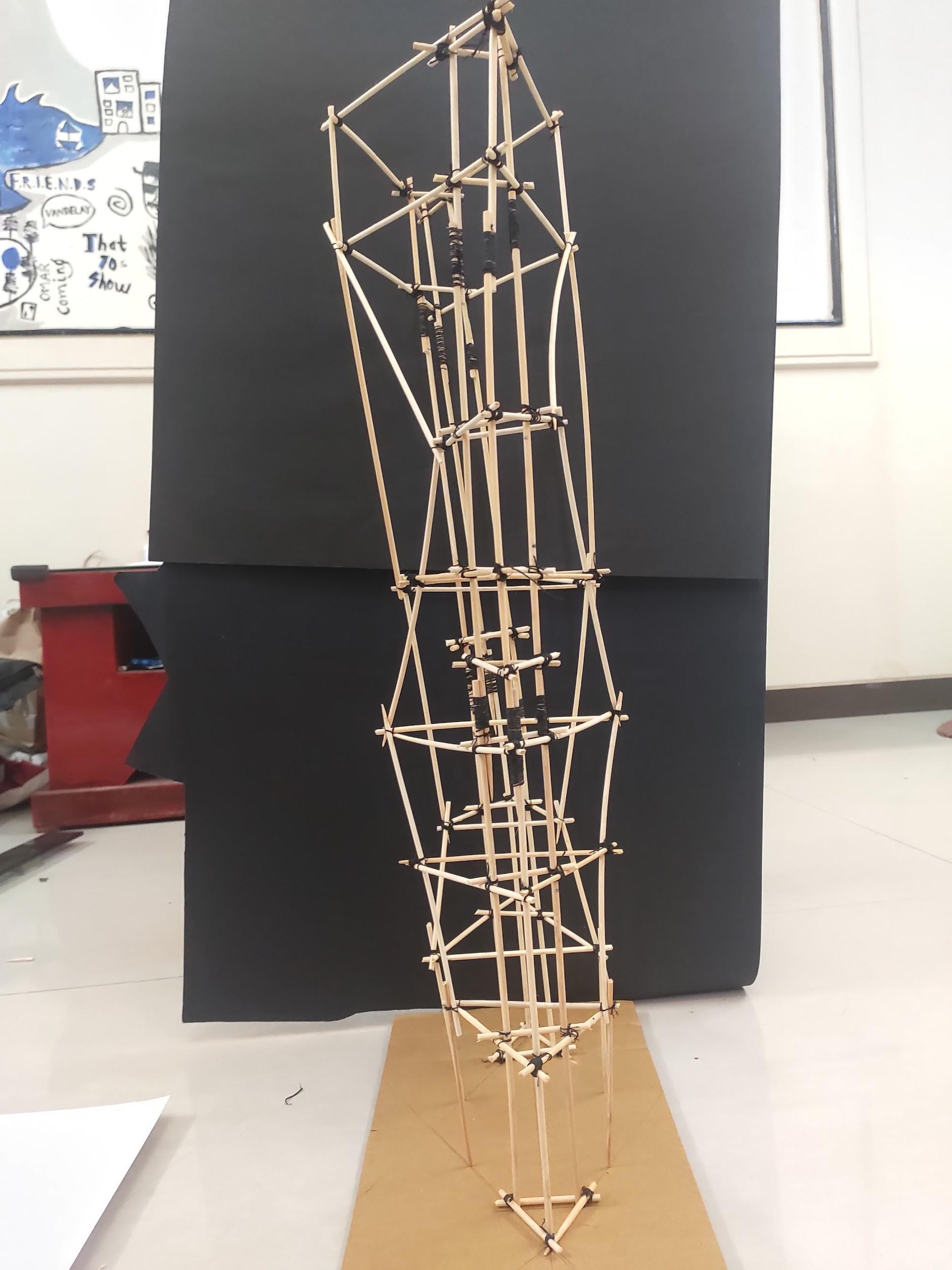
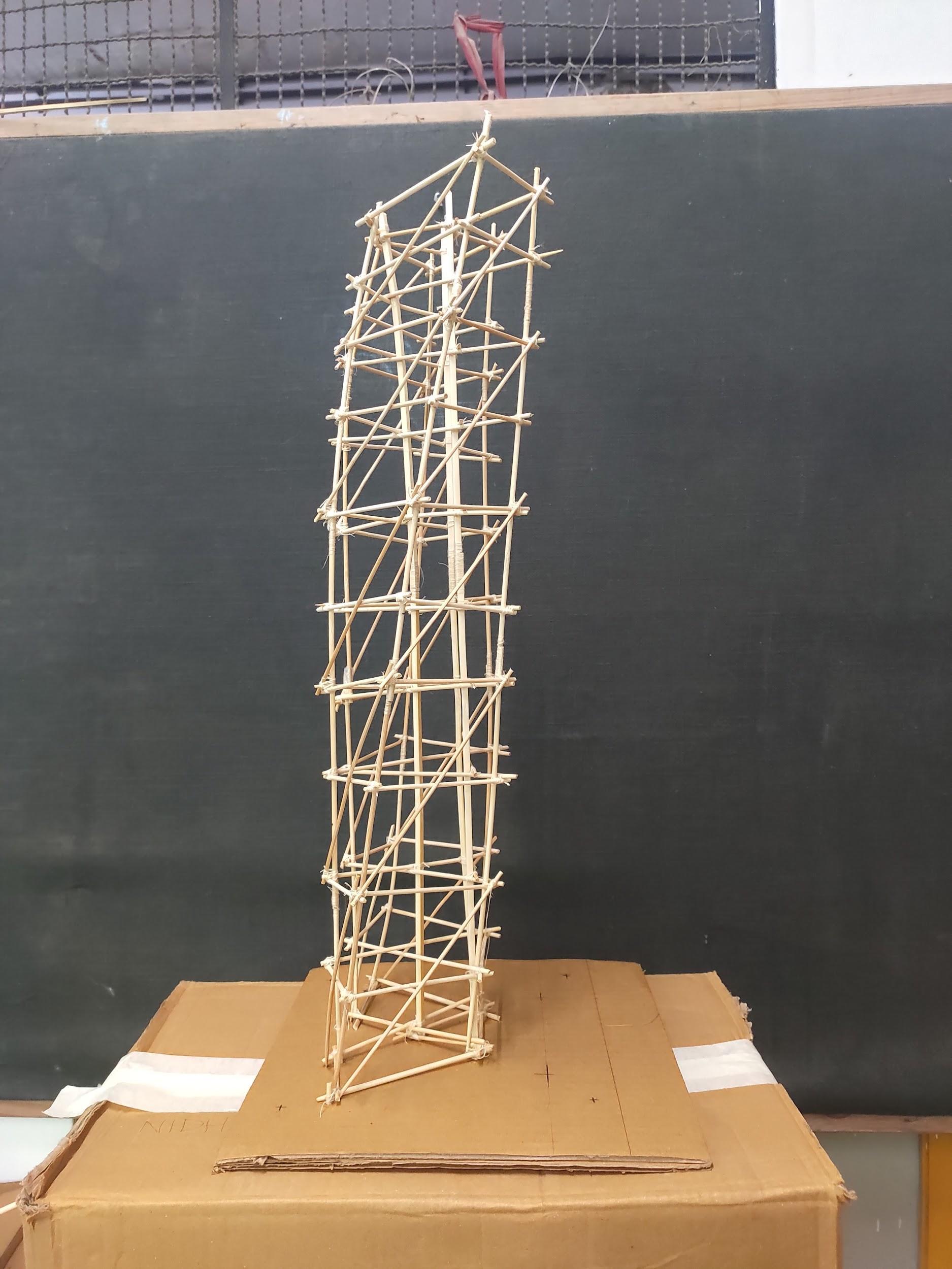
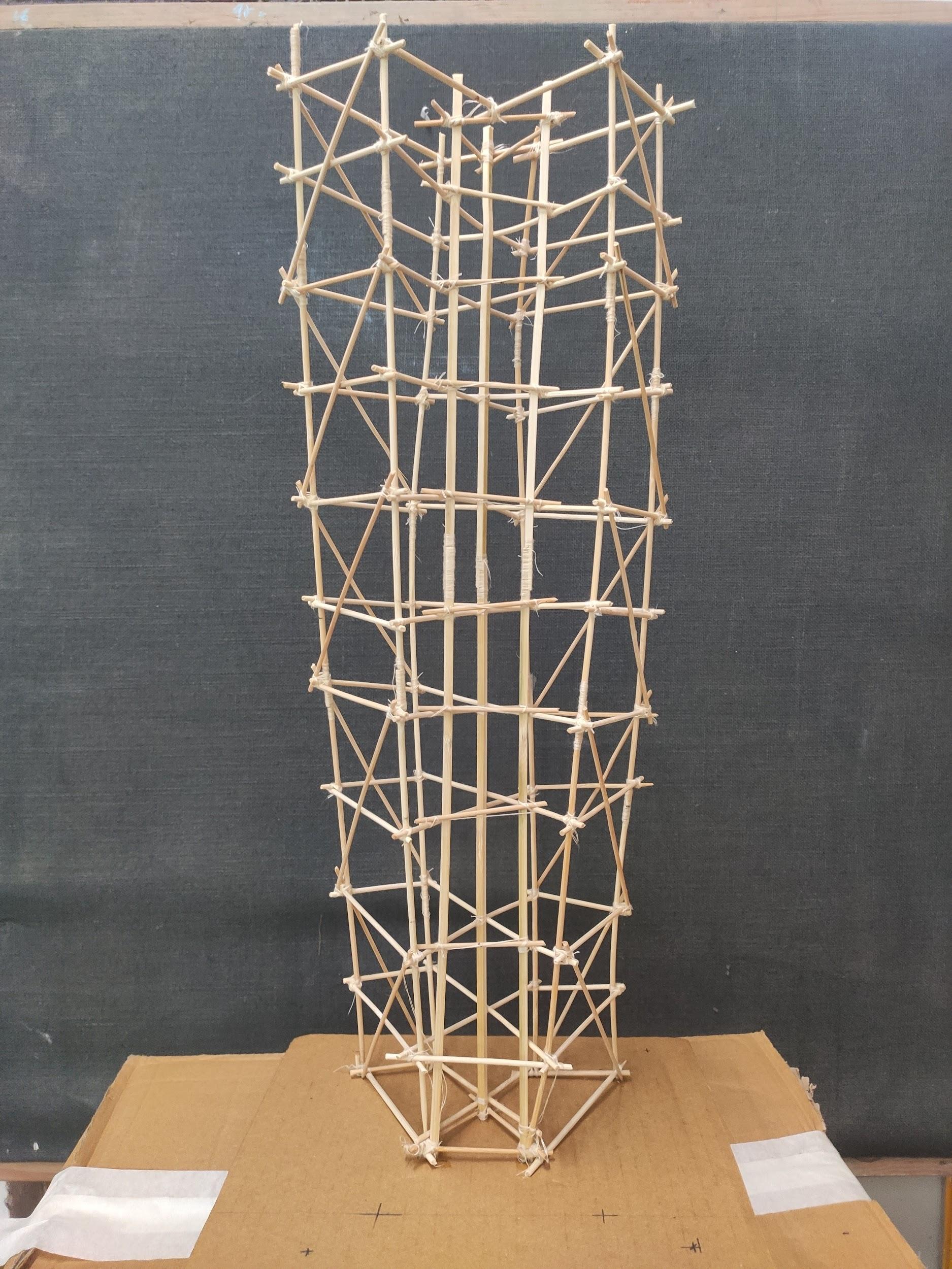
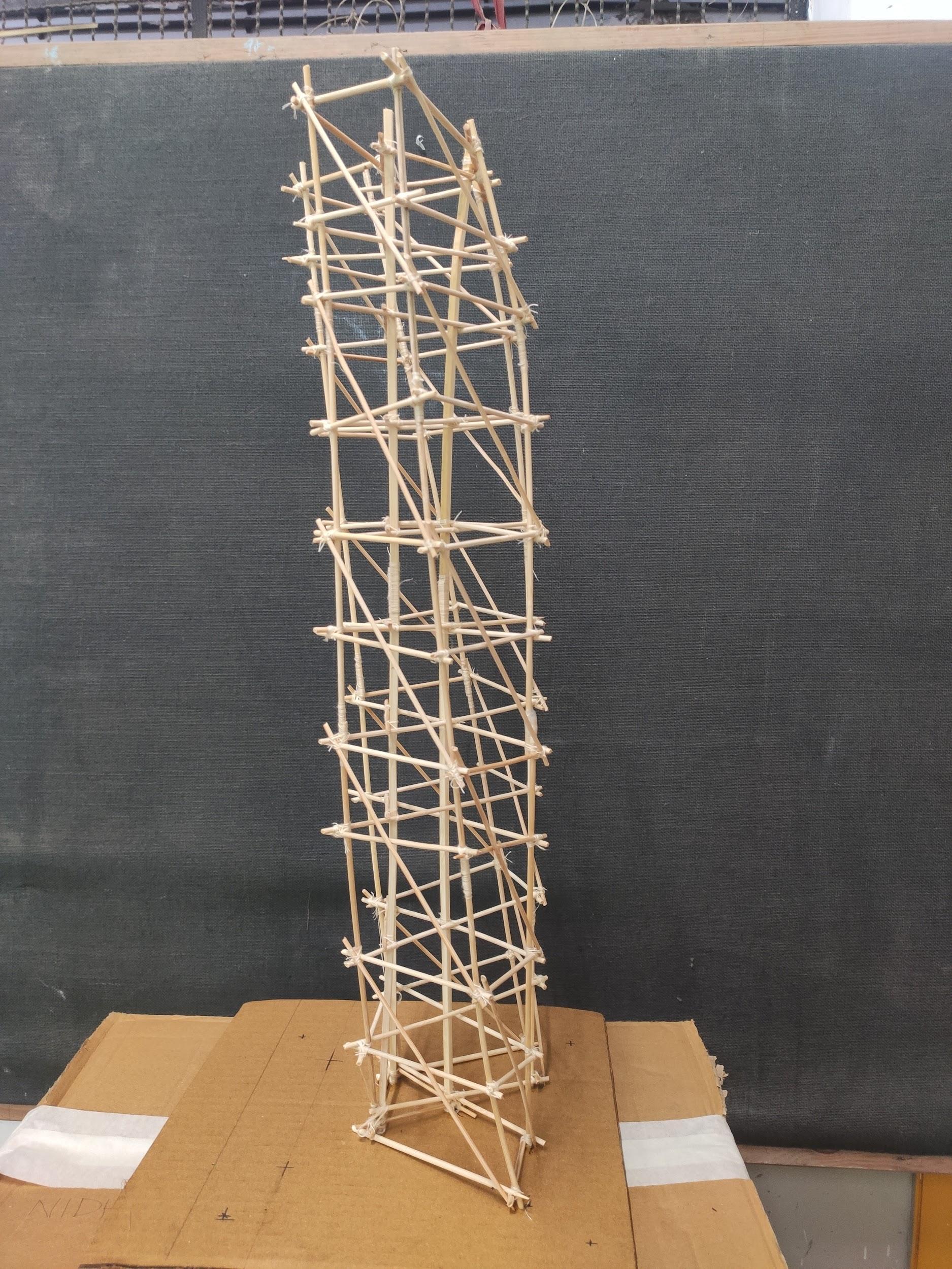
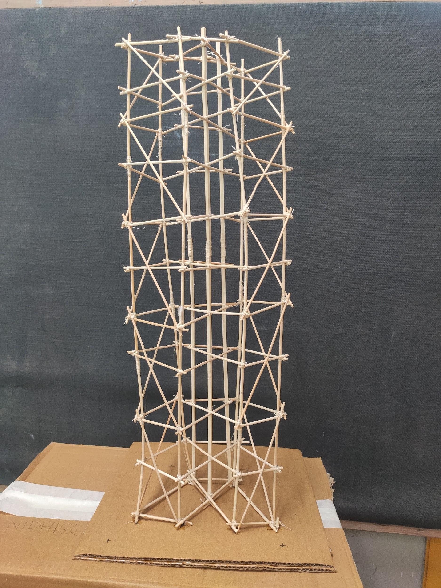
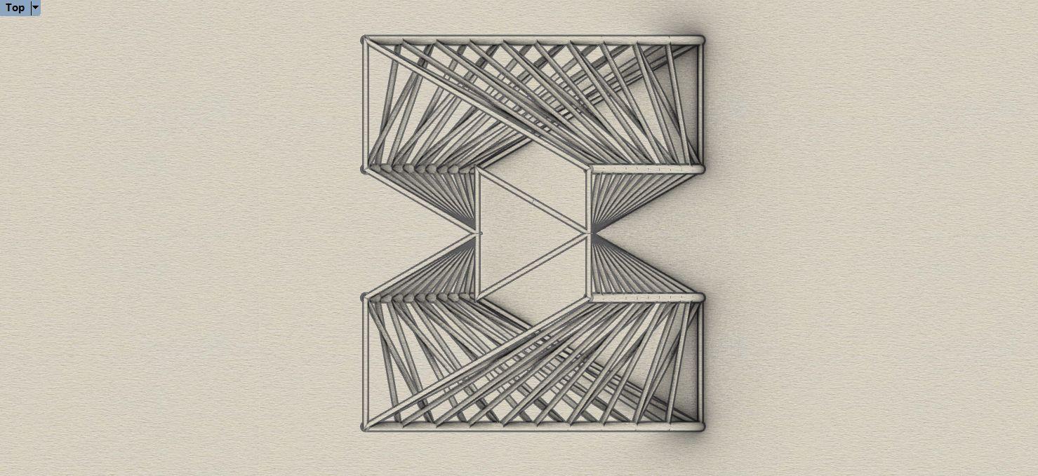
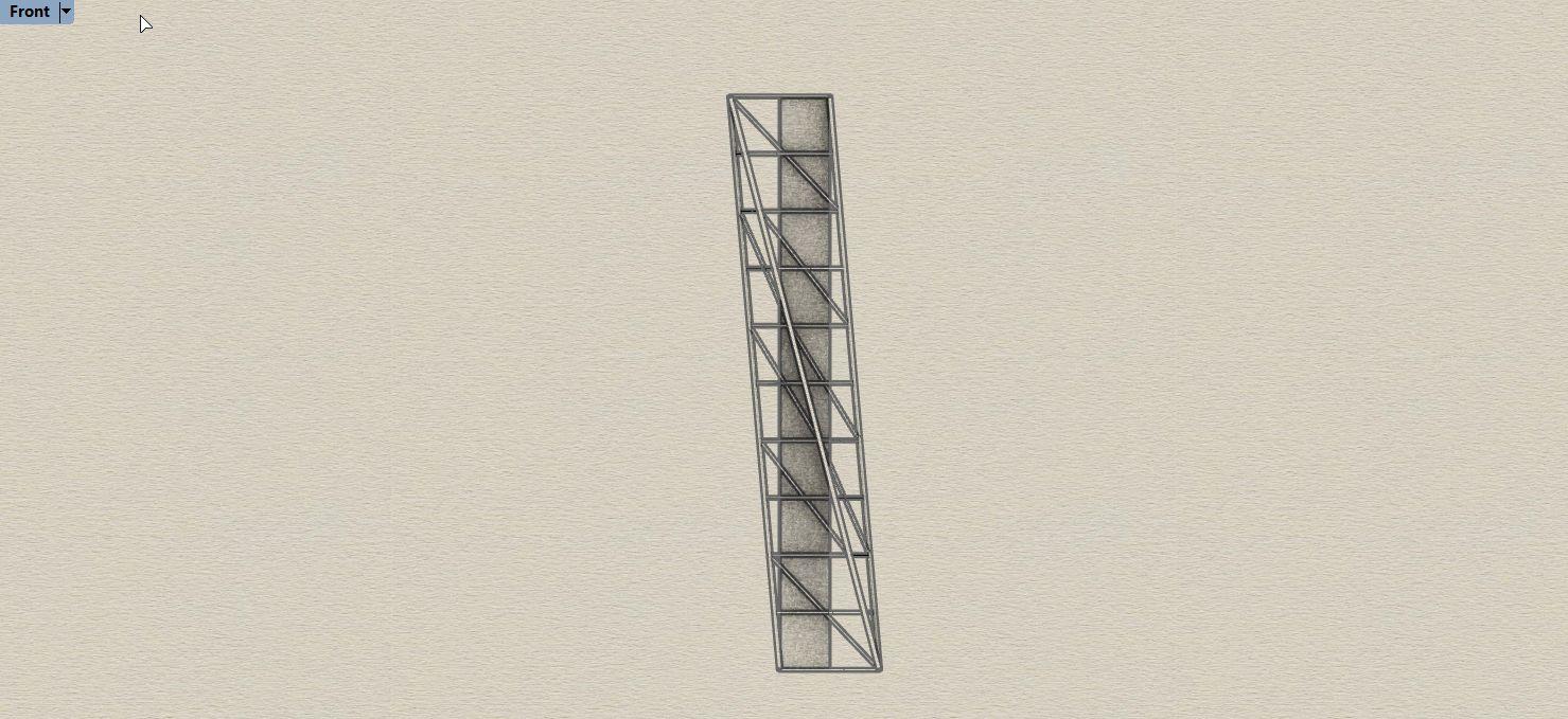
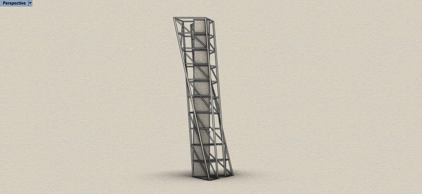
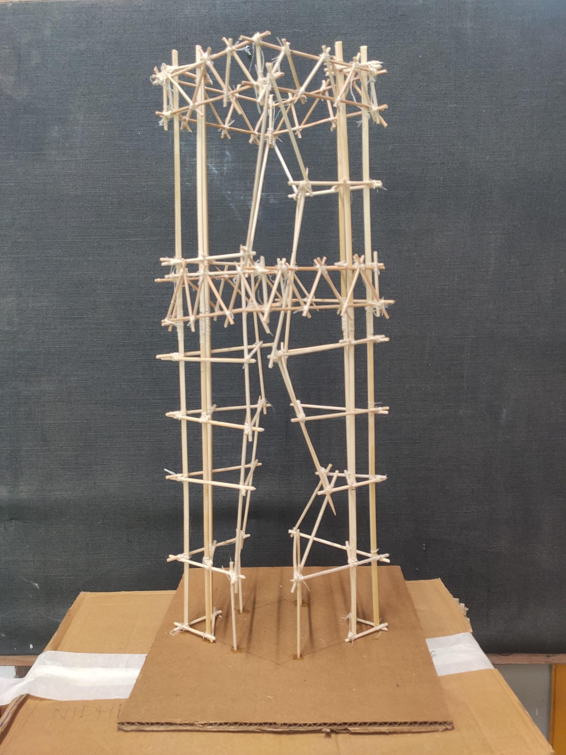
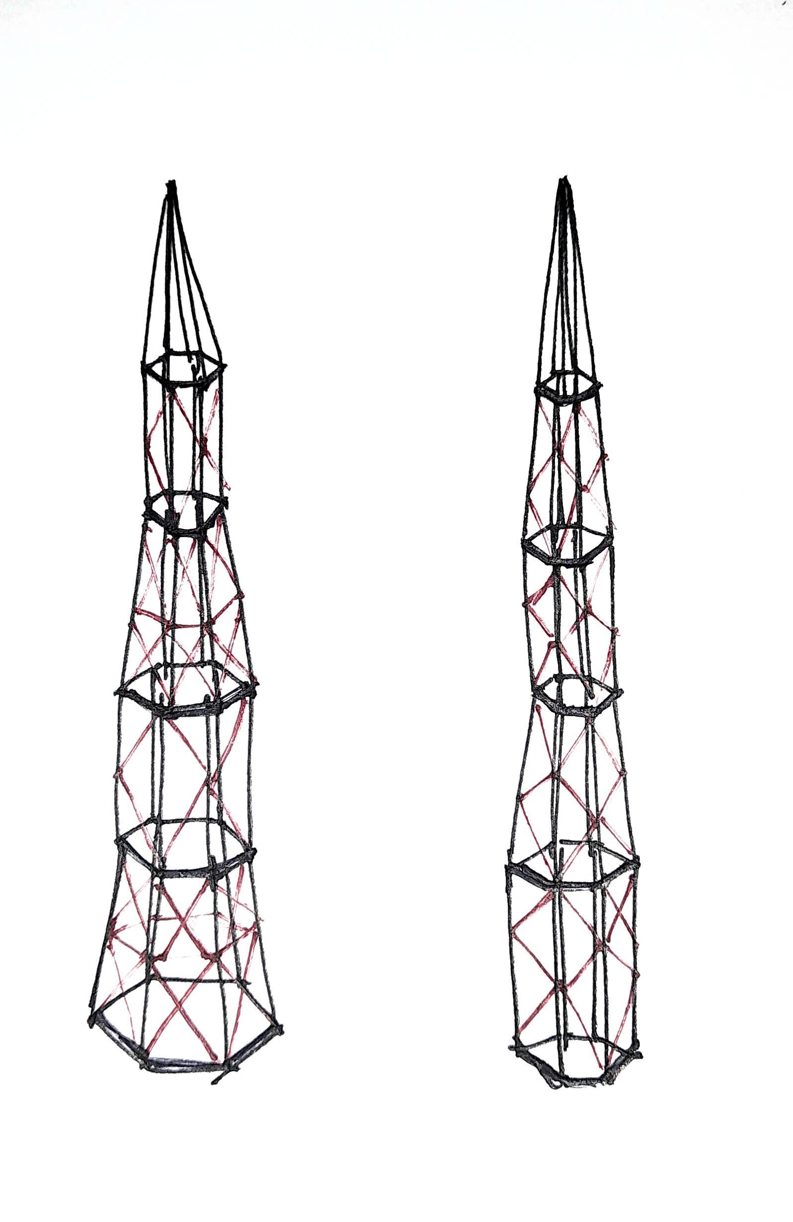
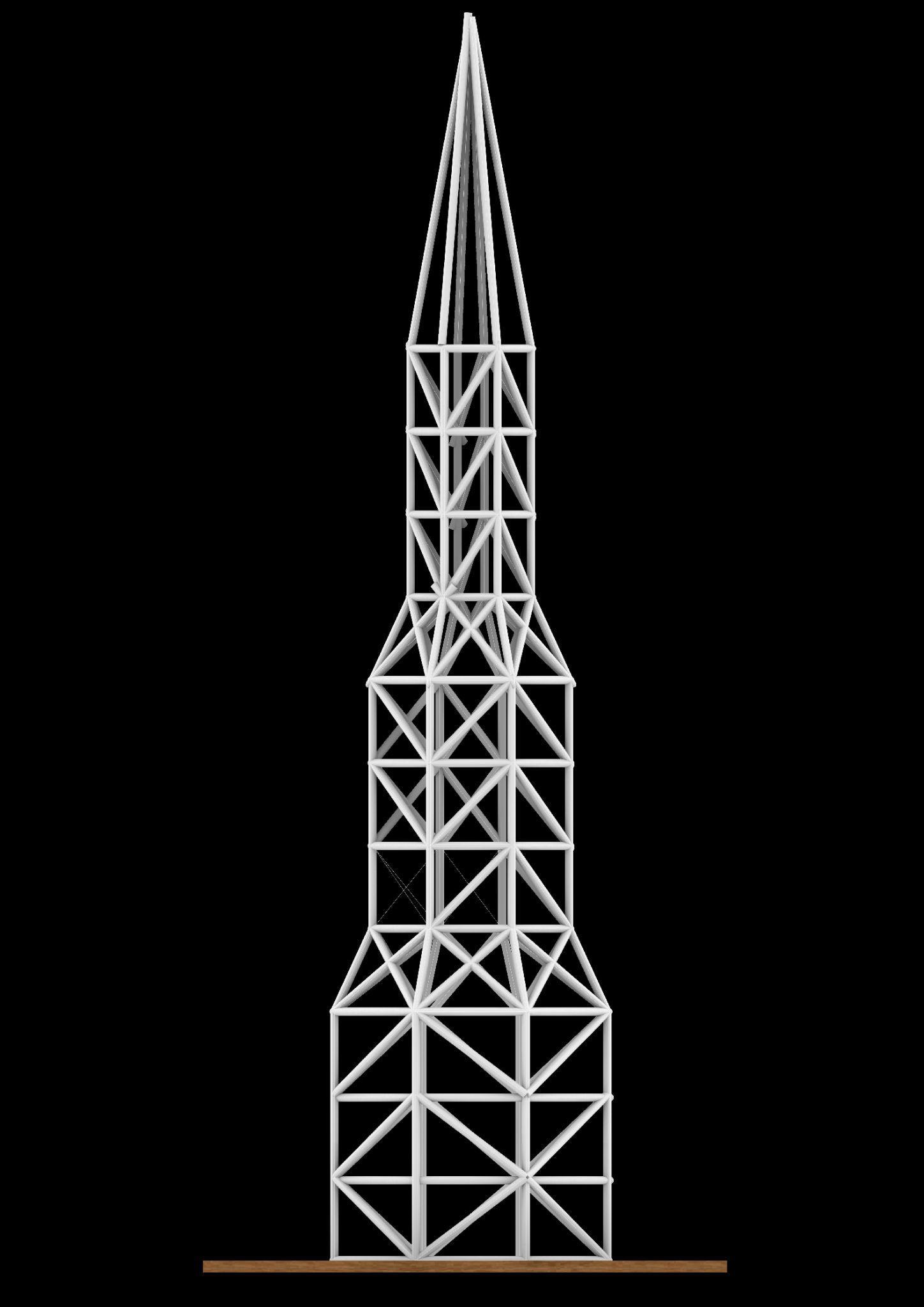
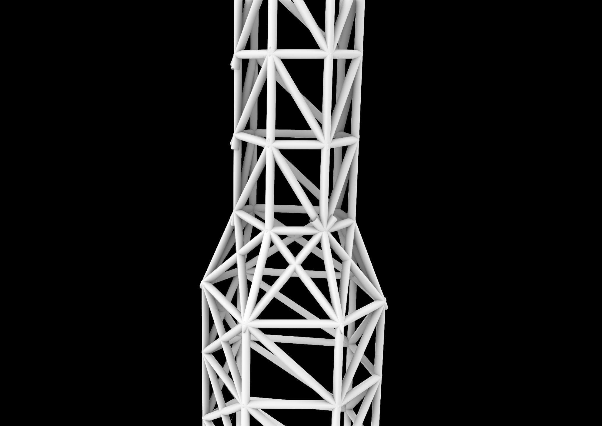
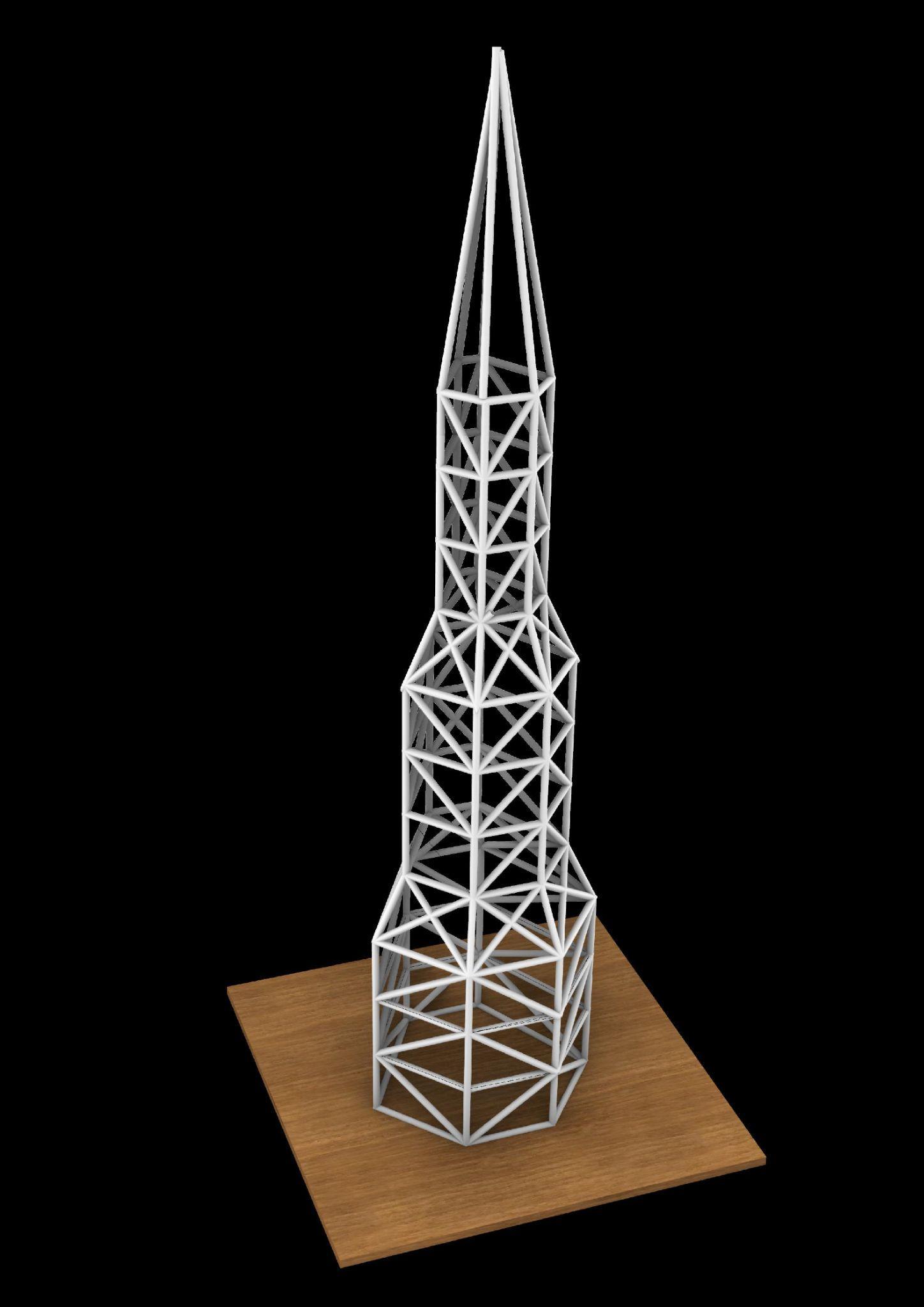
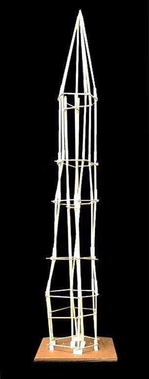
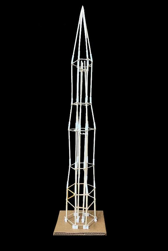
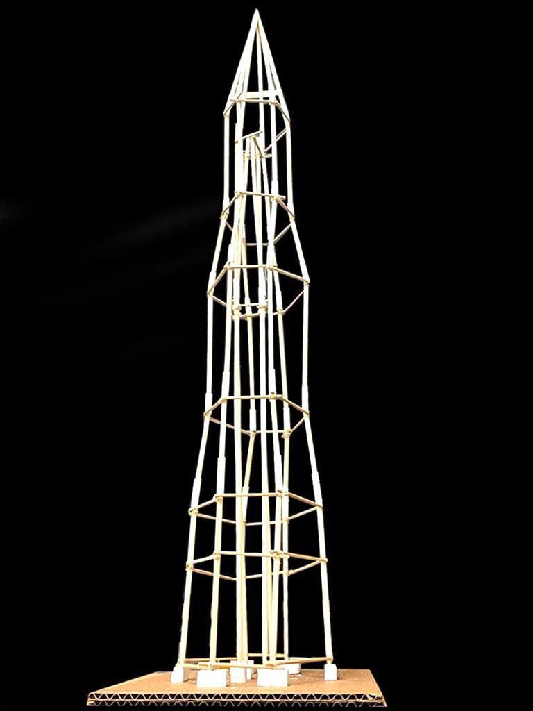
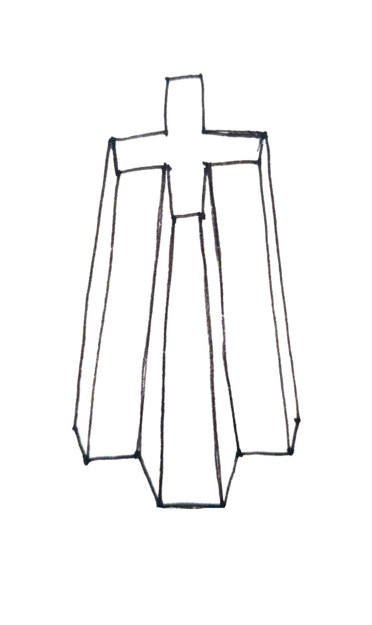
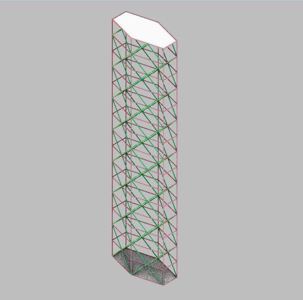
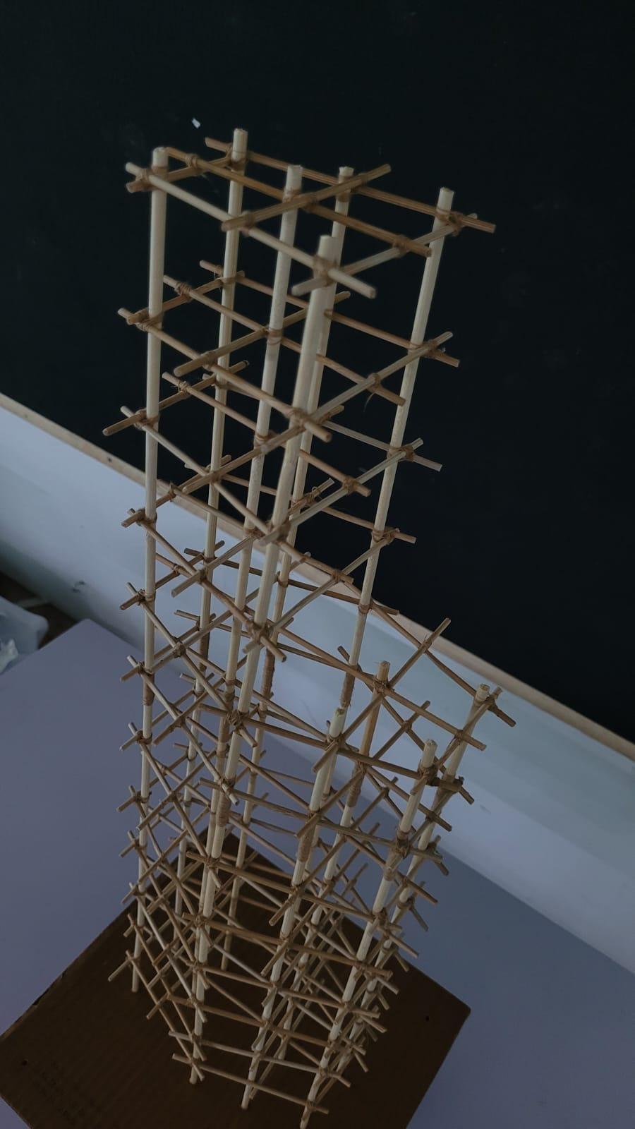
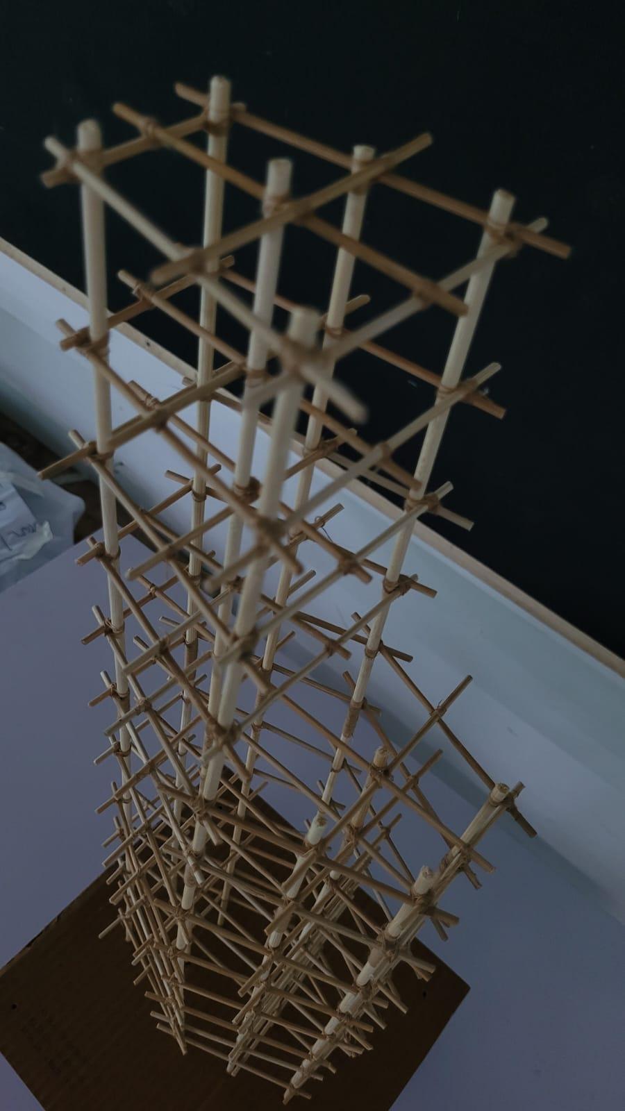
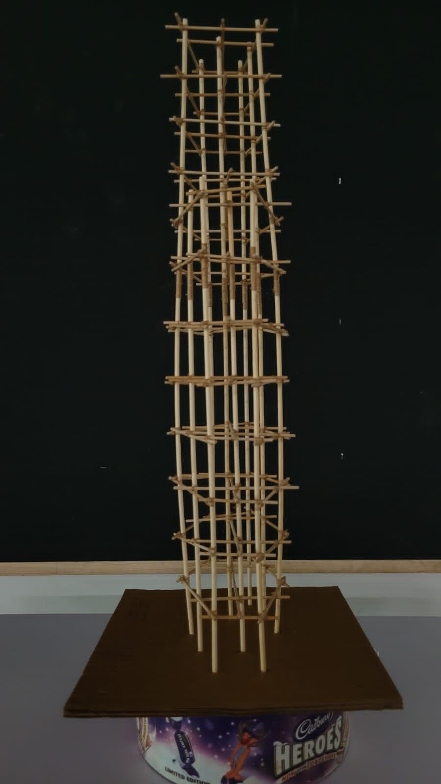
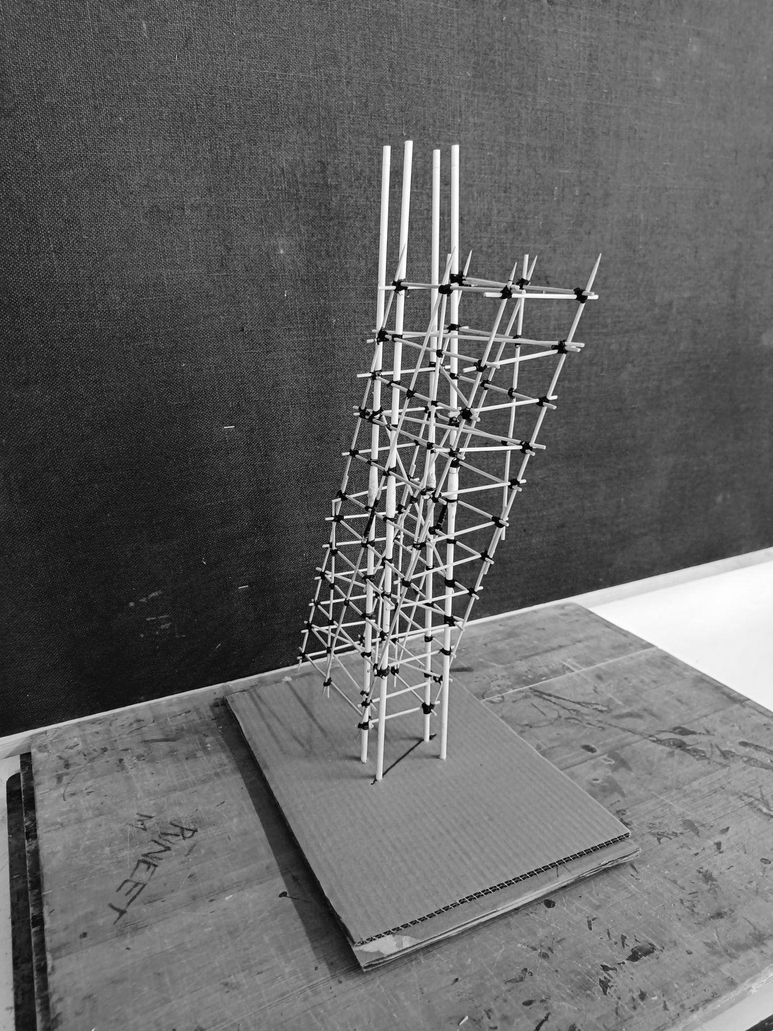
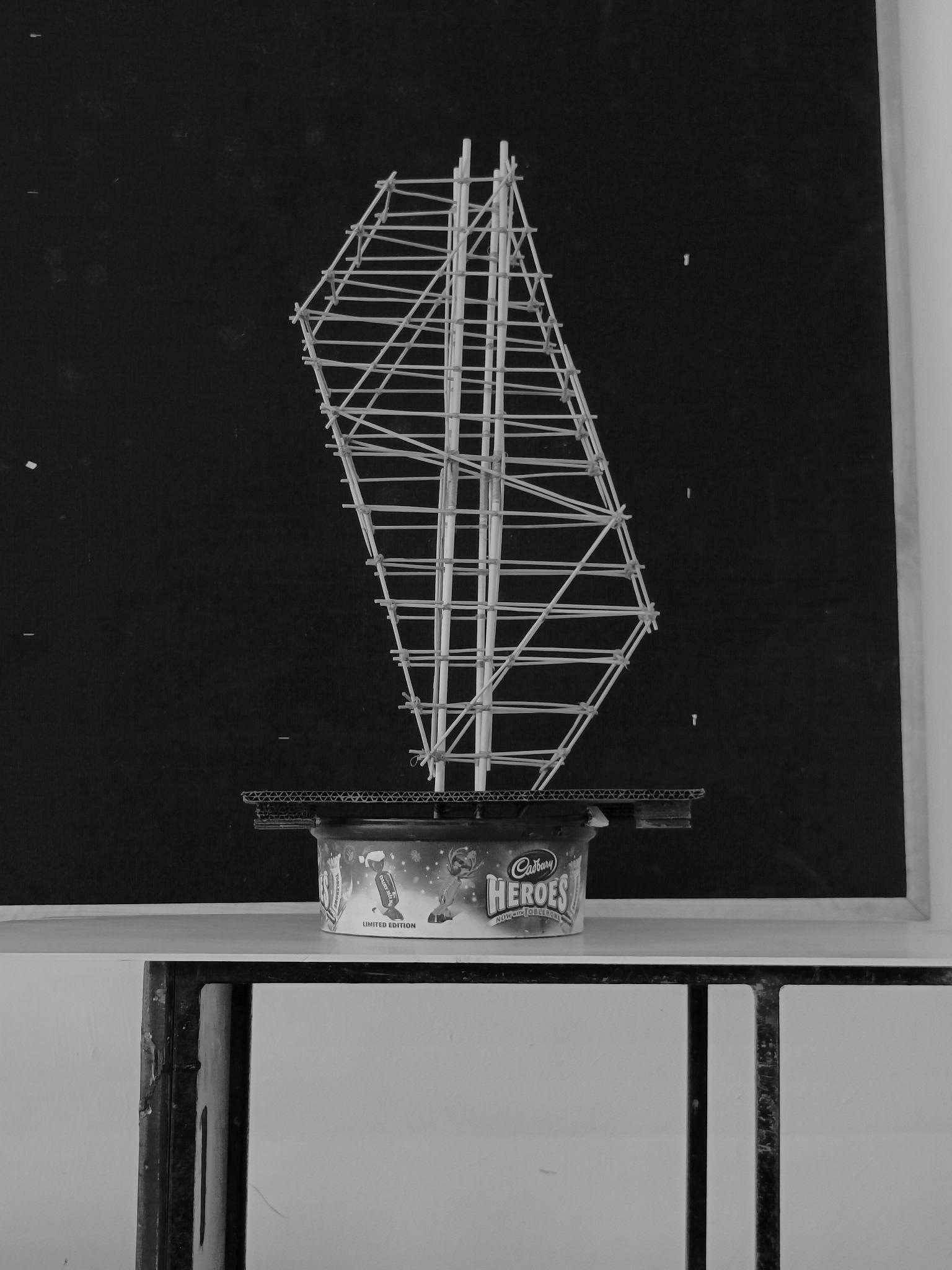
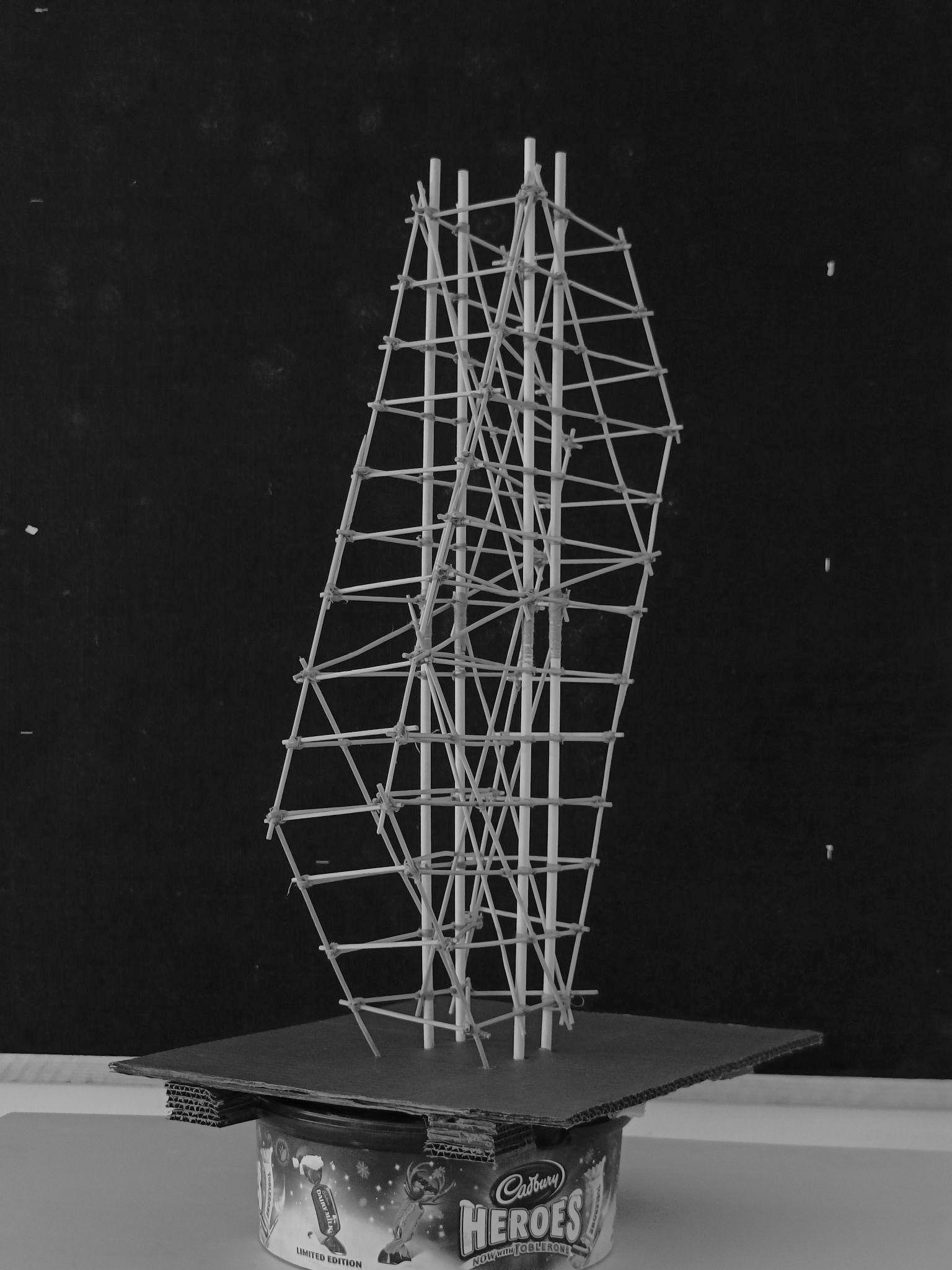
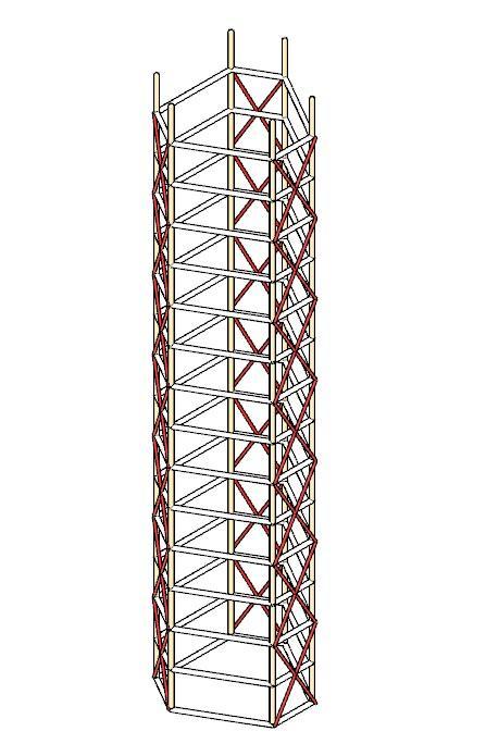
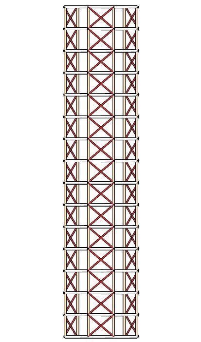
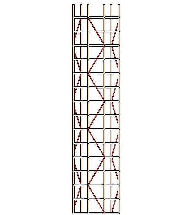
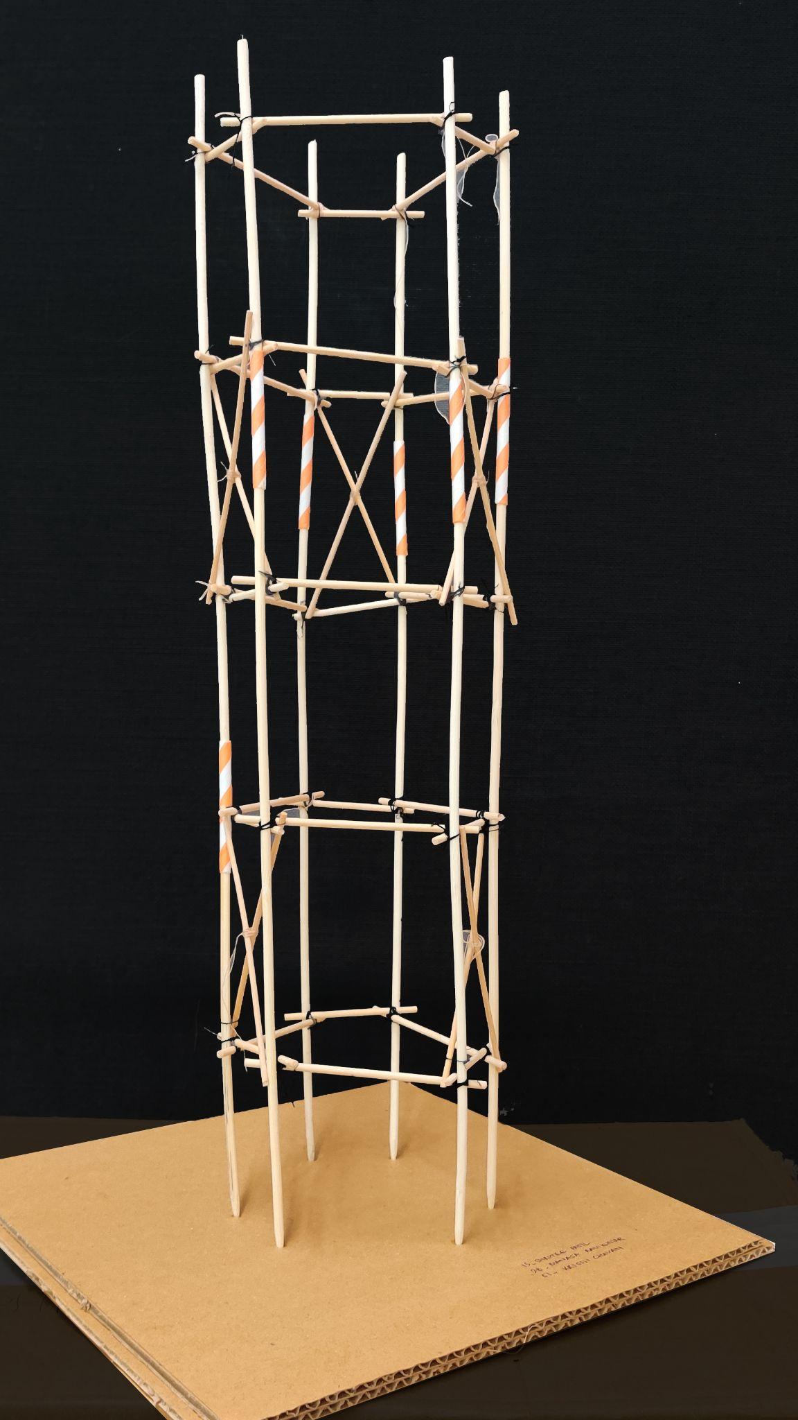
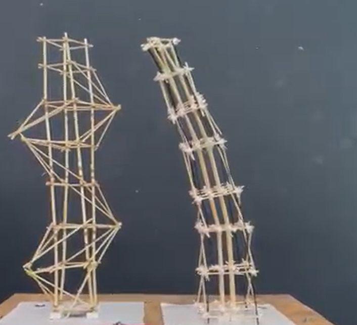
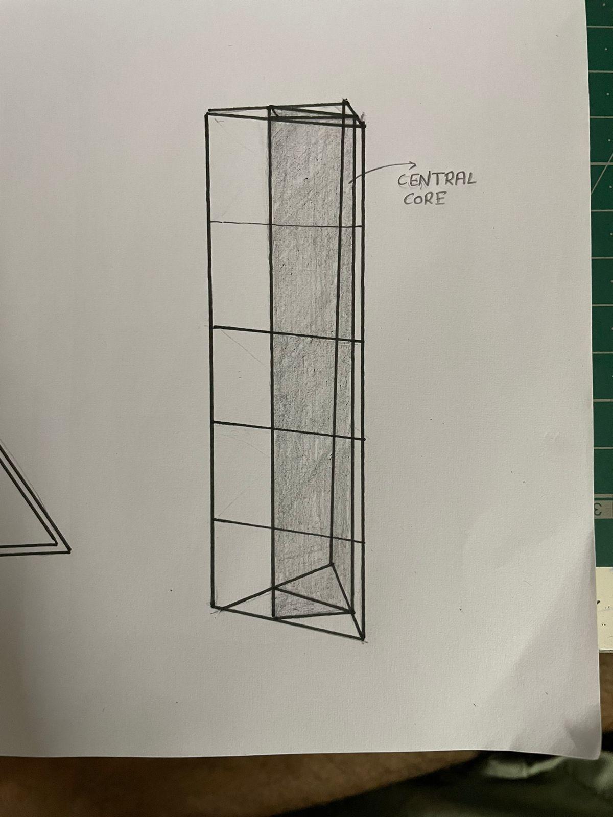
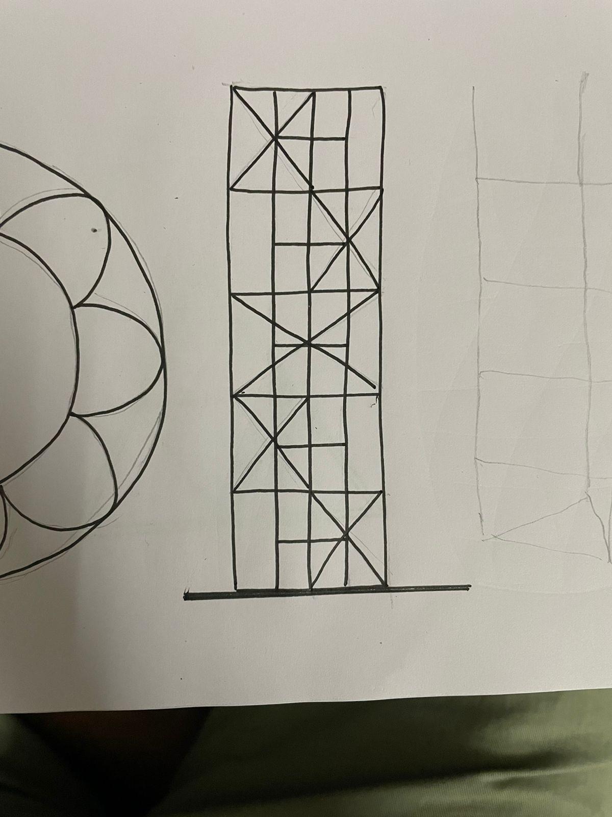
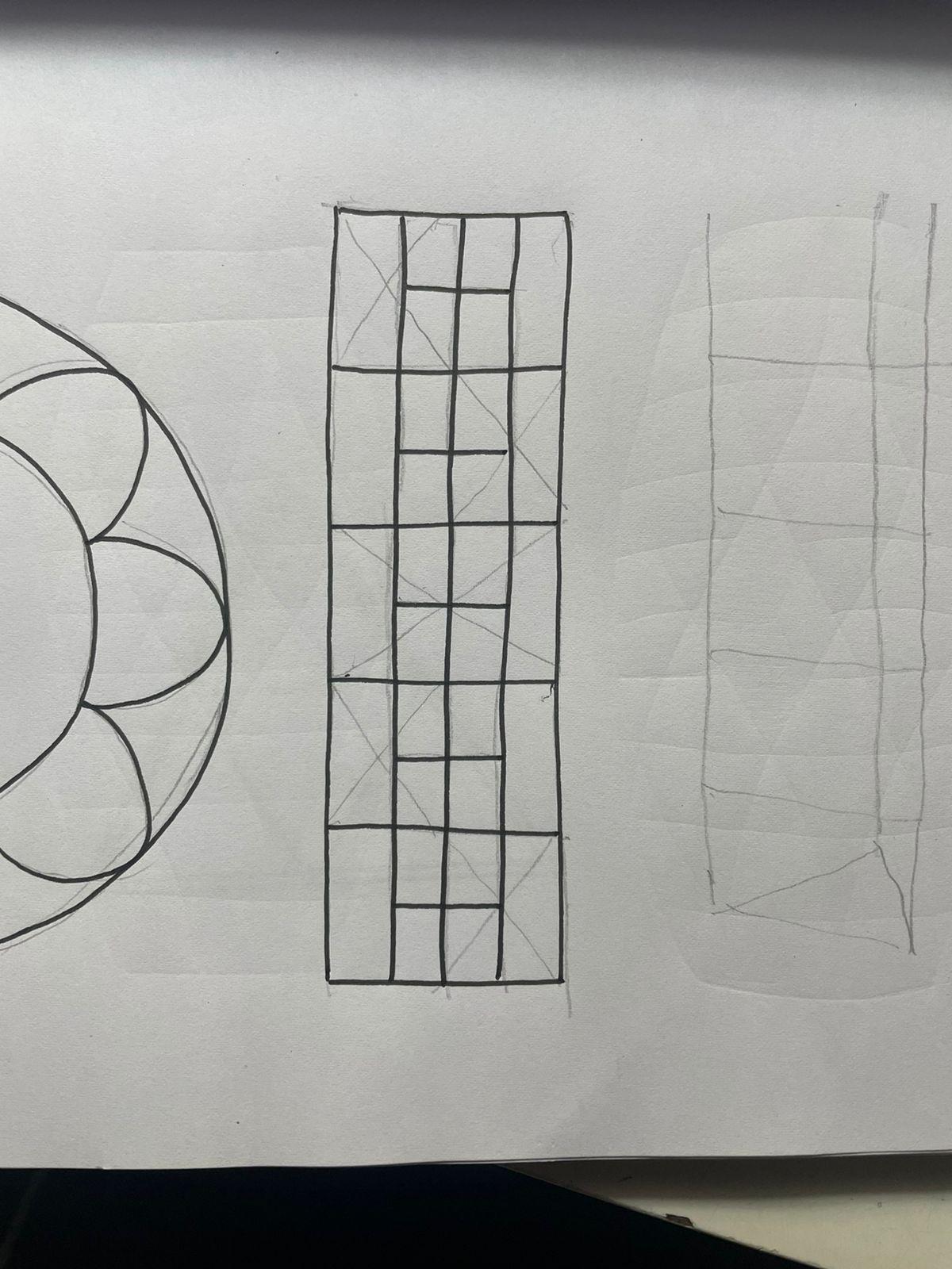
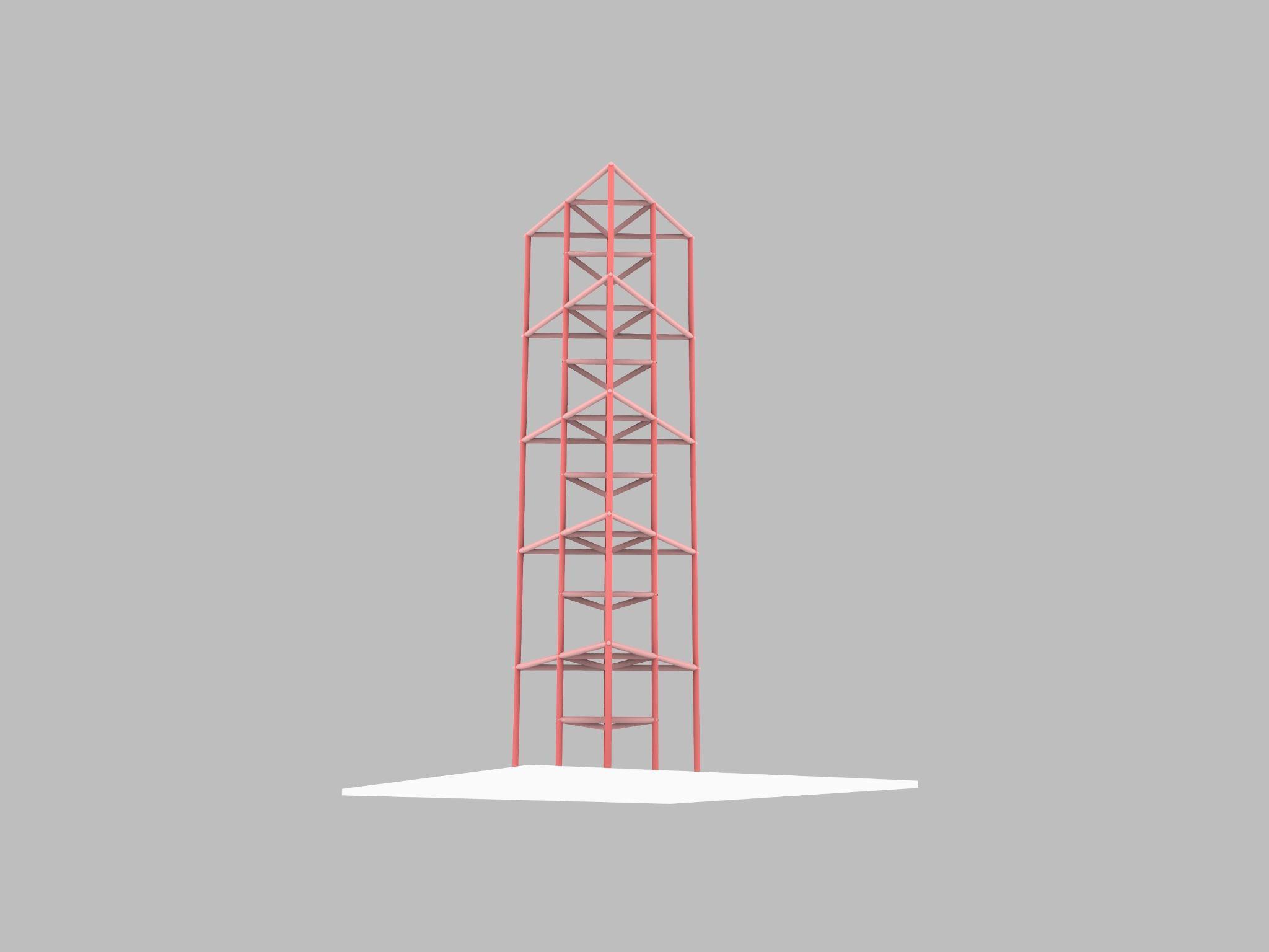
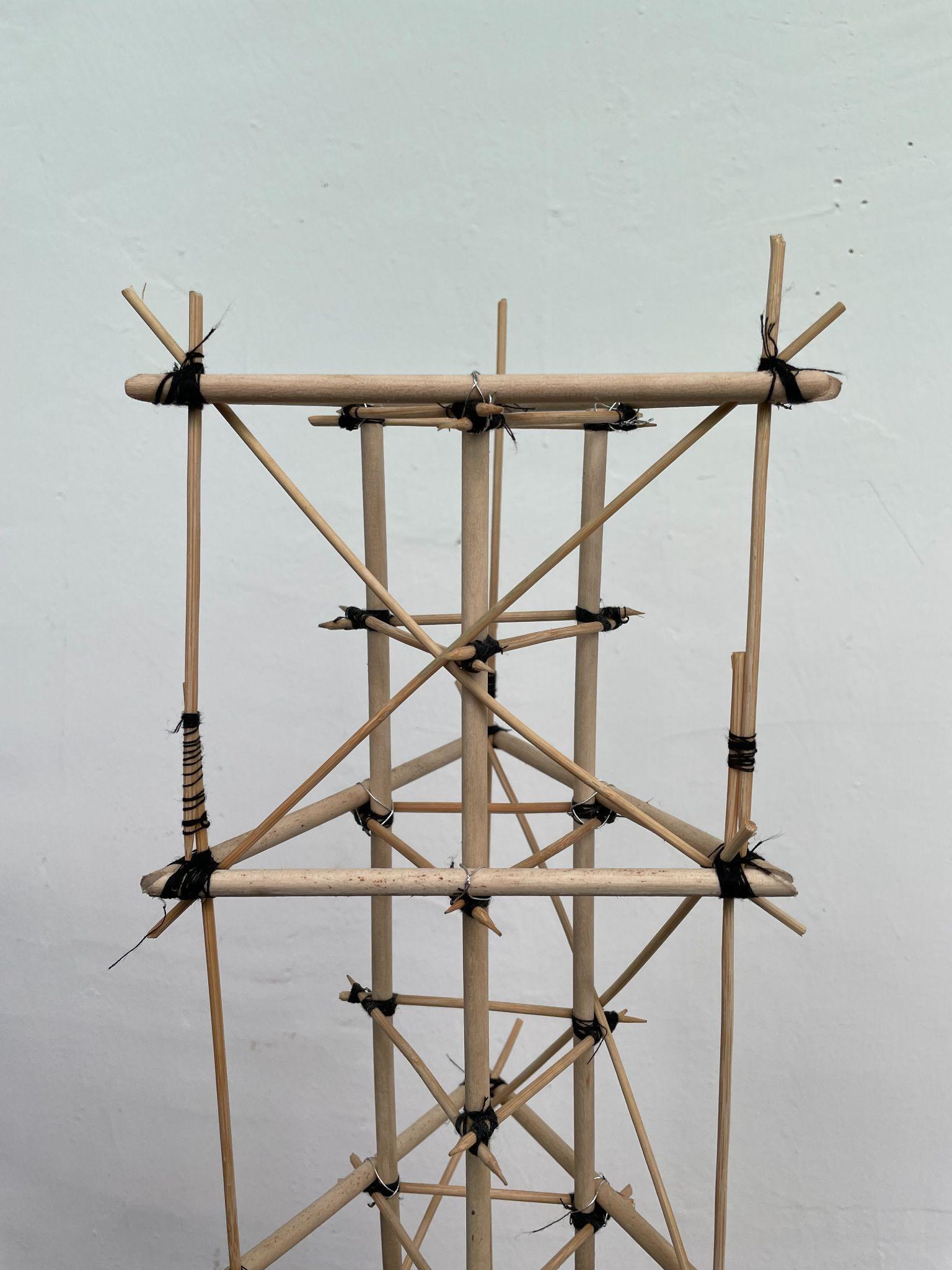
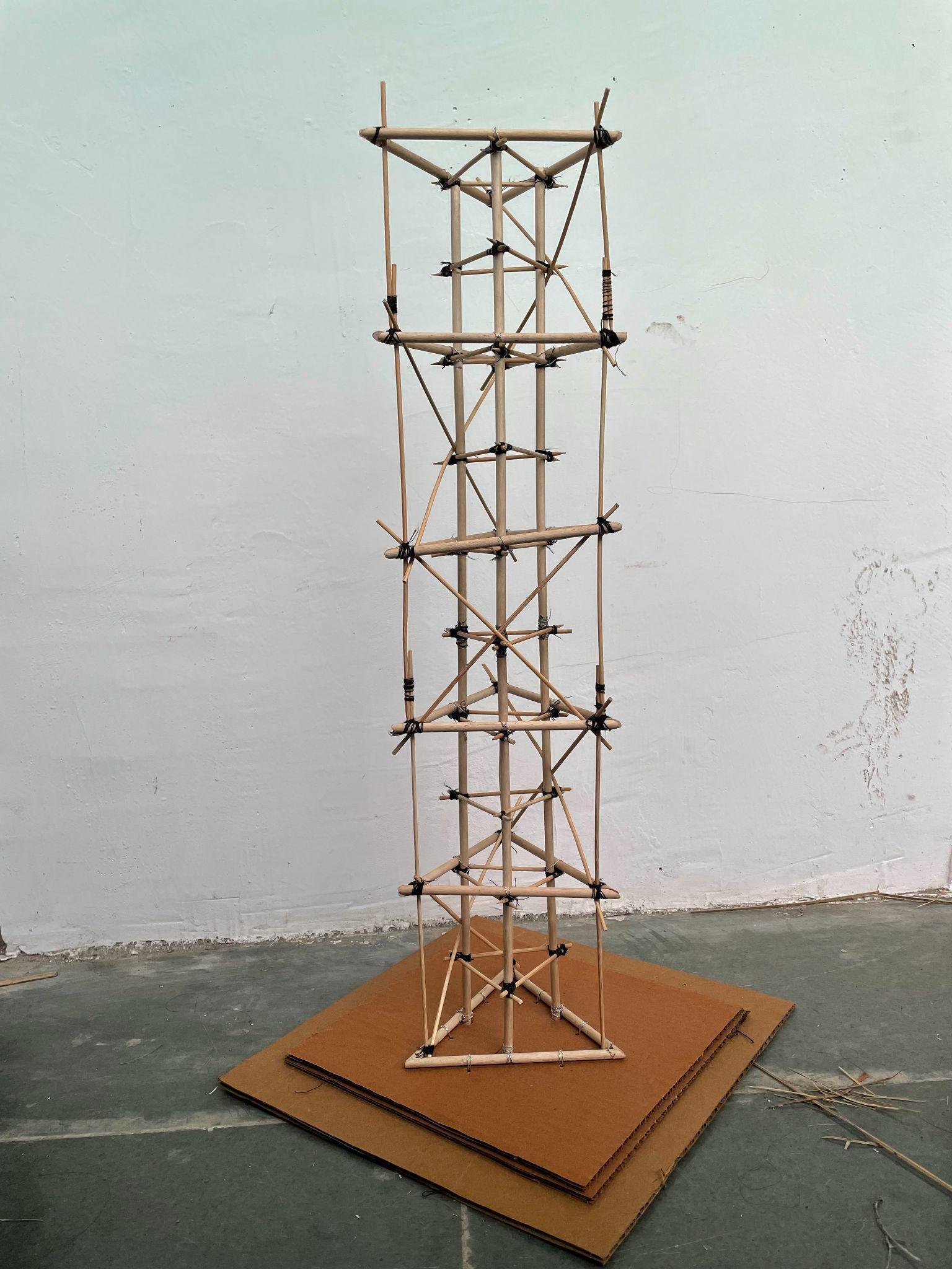
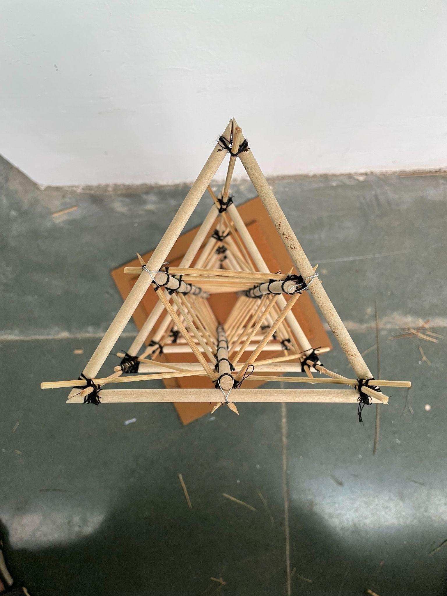
This model had a main triangular core with ‘V’ shaped plan on the ground that gradually transforms into ‘Inverted V’ shaped plan at thetop,givingthehighrisealeaningelevationconsistingof8main obliqueelementsand10horizontalintermediate bracings. Bracing system serves to stabilize the main oblique members during construction, to contribute to the distribution of load effects and to provide restraint to compression members where they wouldotherwisebefreetobuckle.
Shaketabletestobservations:TheIncreasingCantileverwithevery levelwasincreasingtheloadonthecorrespondingtiebackbracing which resulted into wear and tear of members on the diagonally oppositeside.
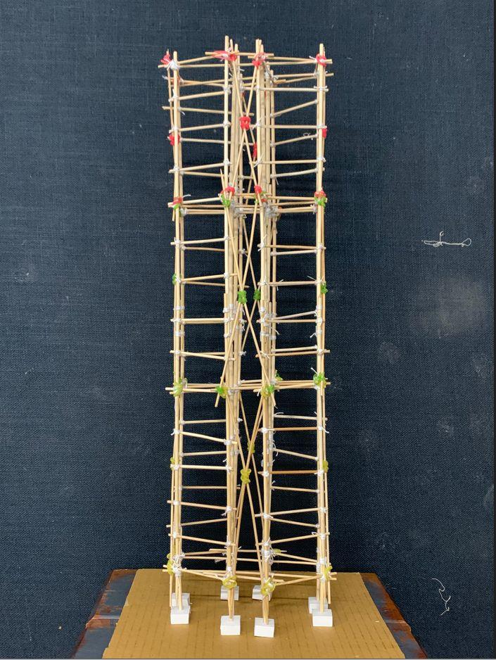
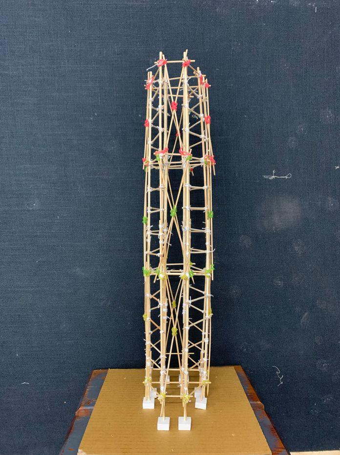
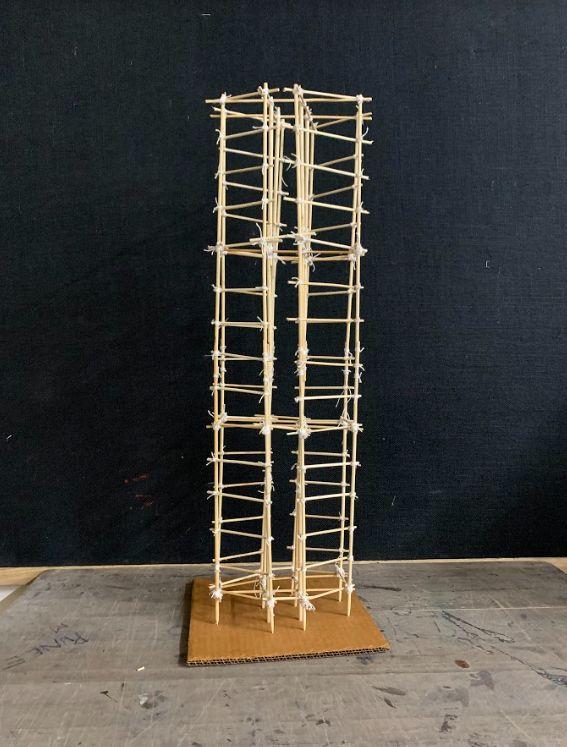
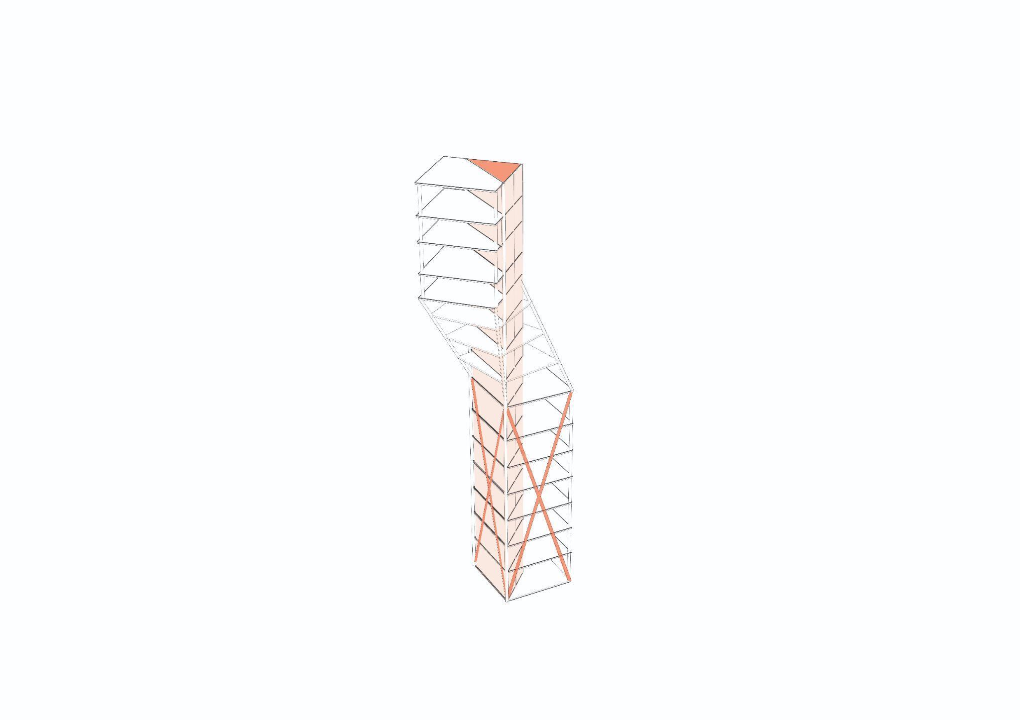
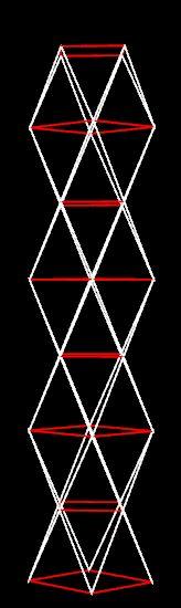
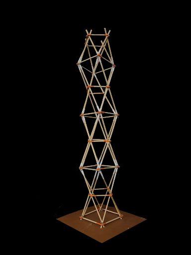
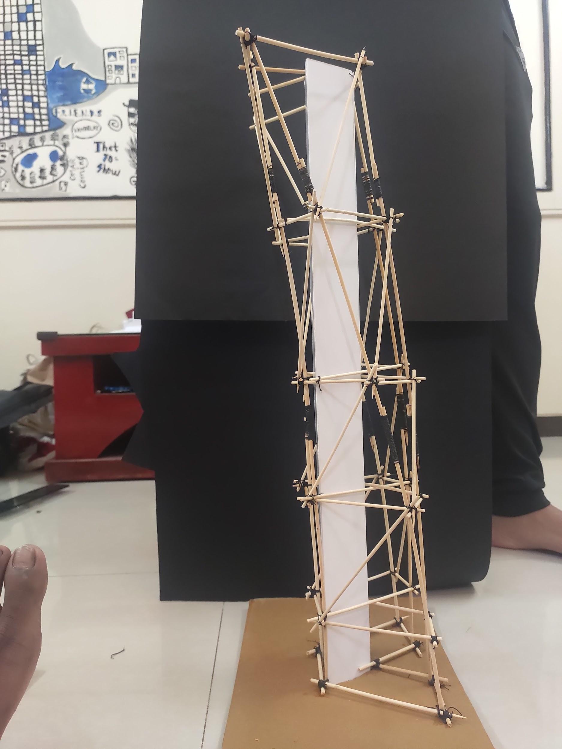
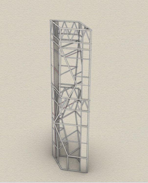
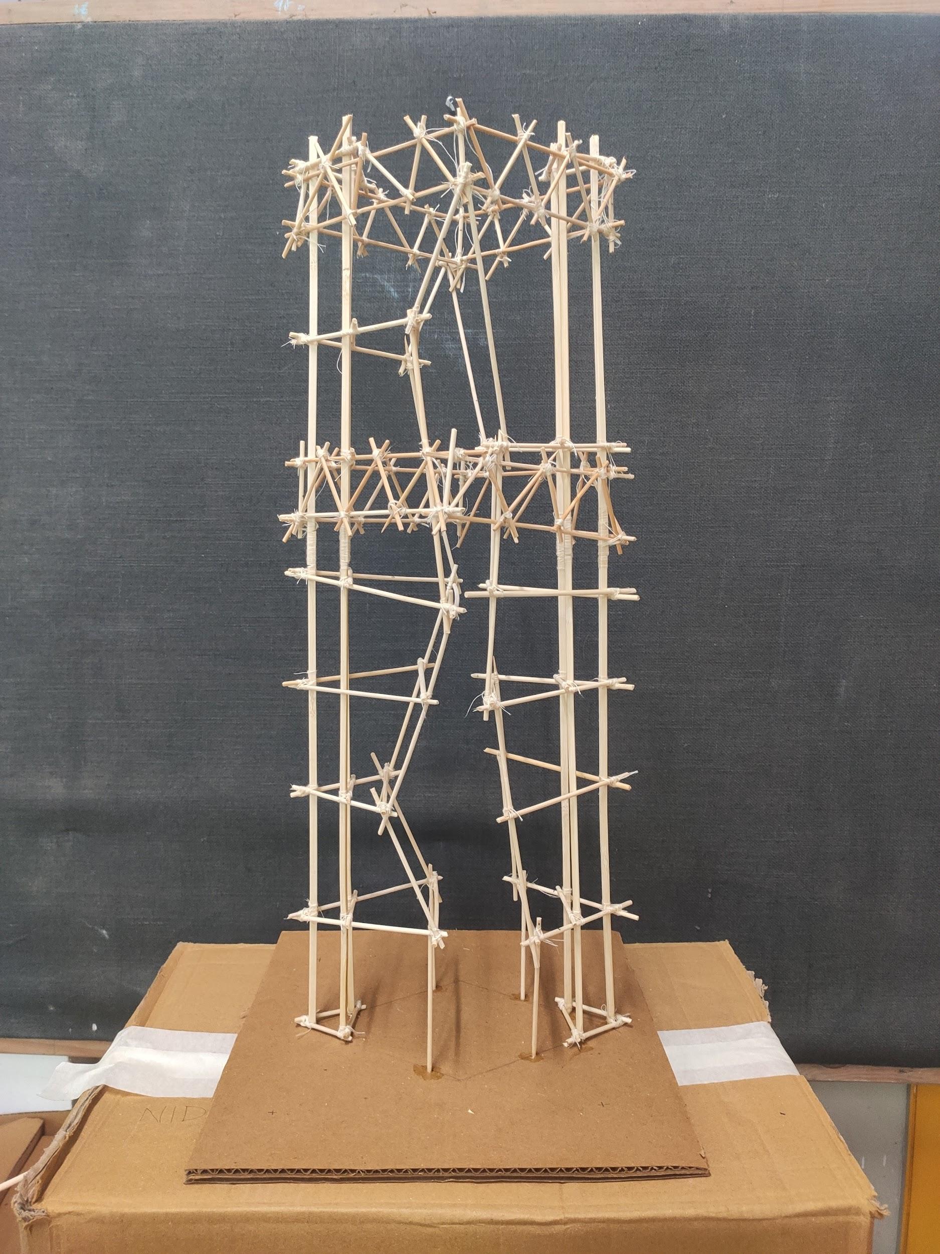
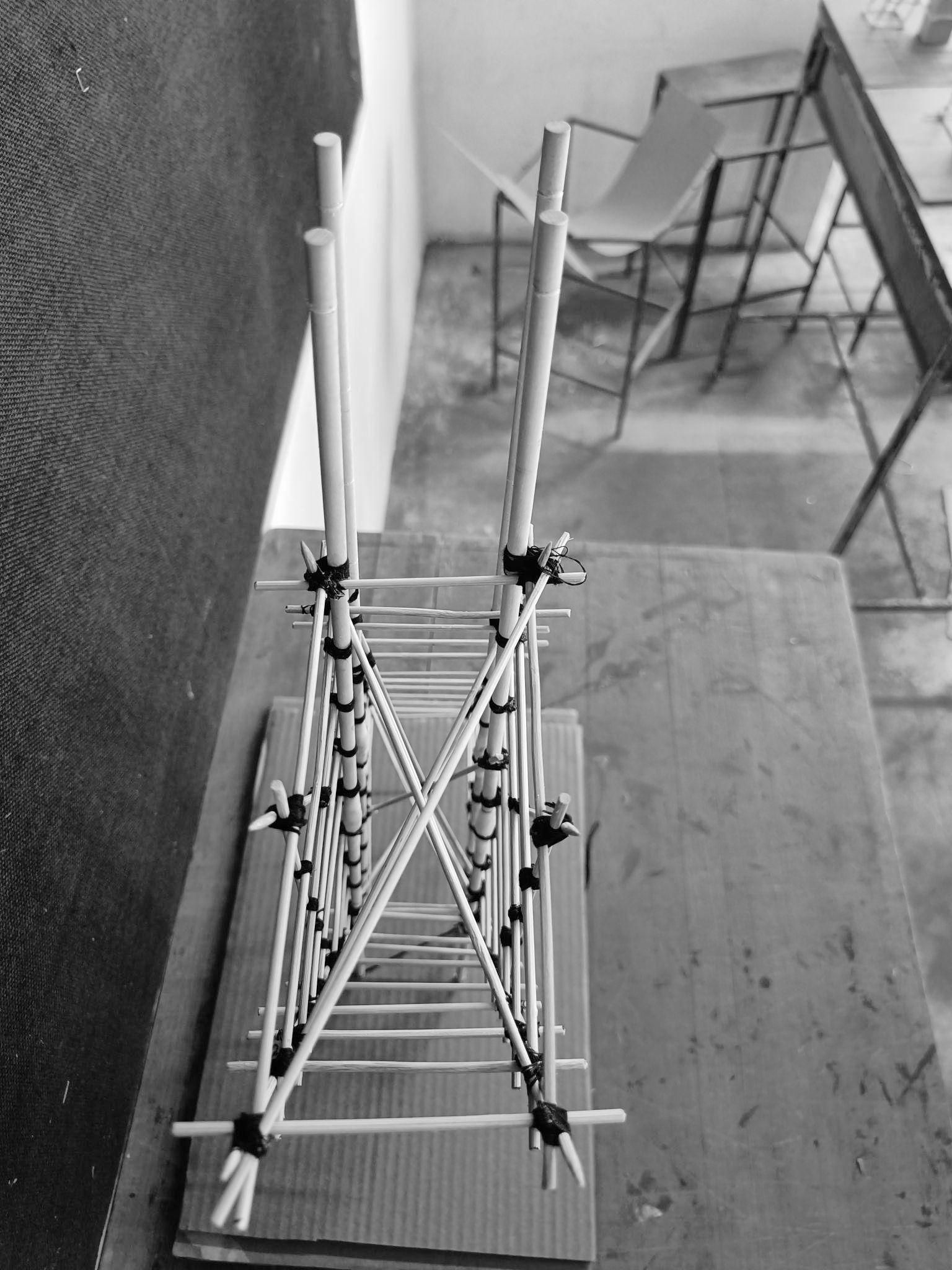
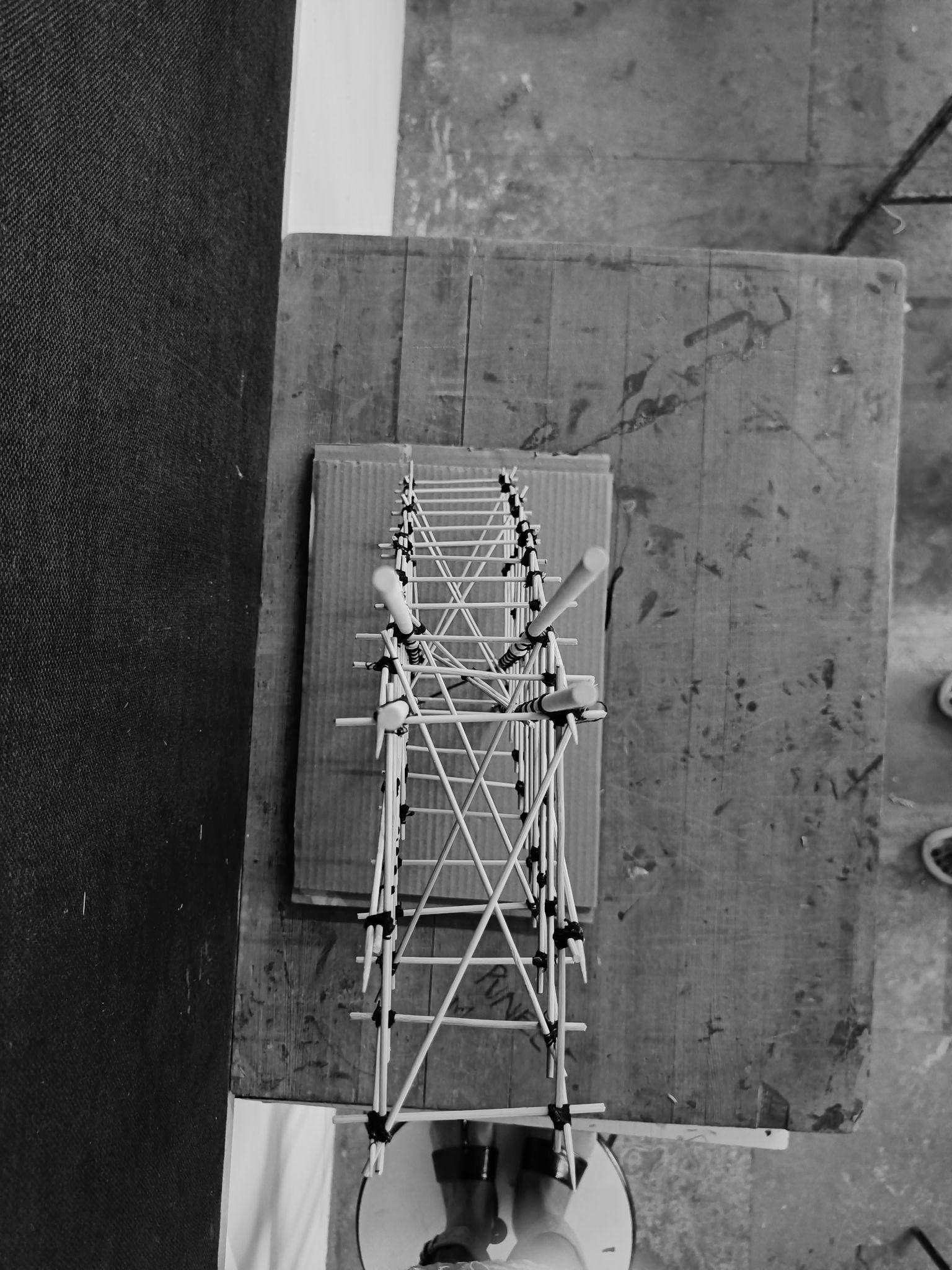
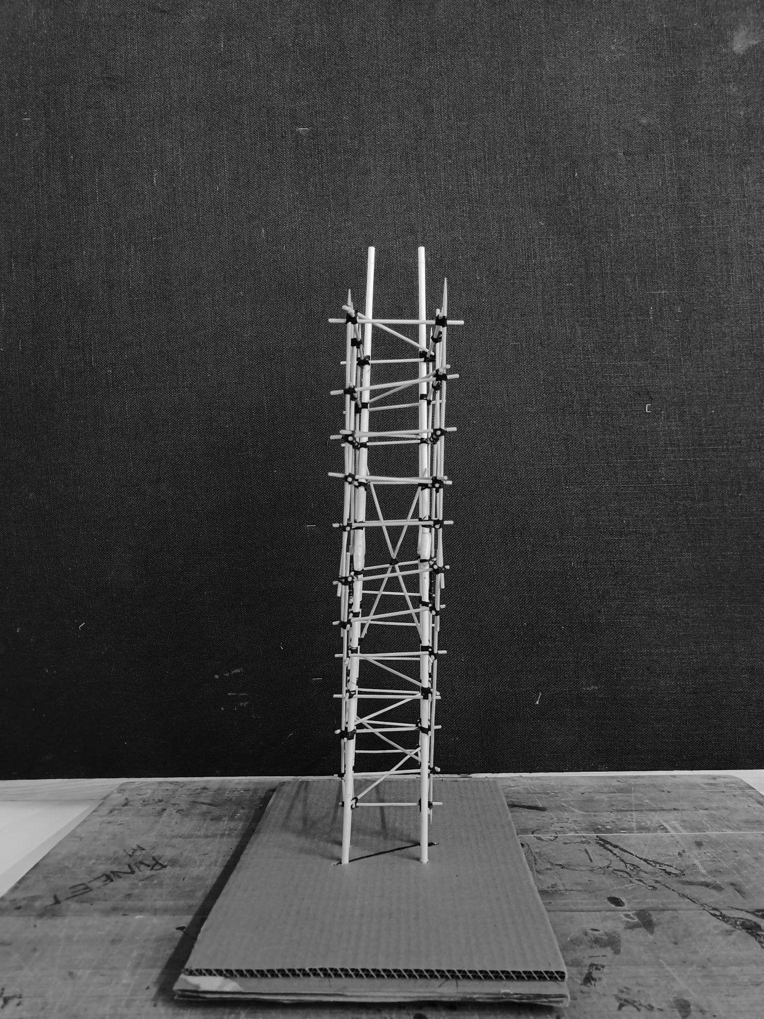
MODEL2:SCULPTURALMODEL
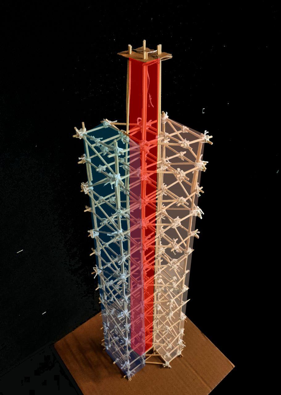
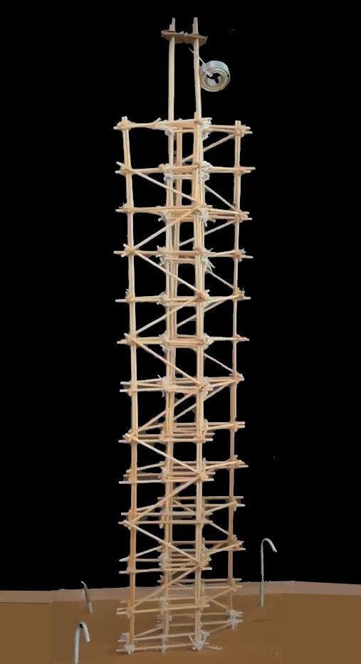
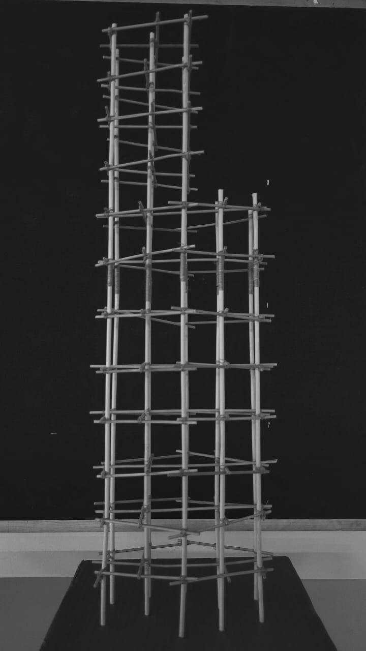
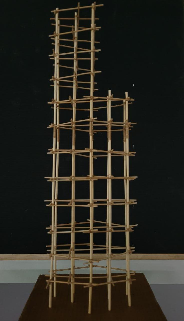
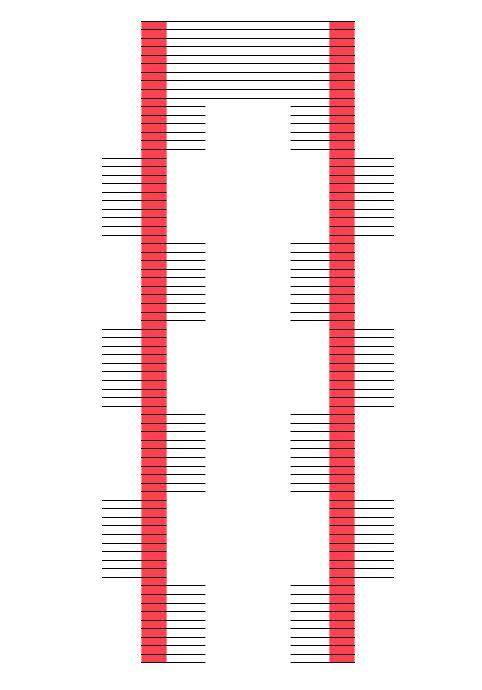
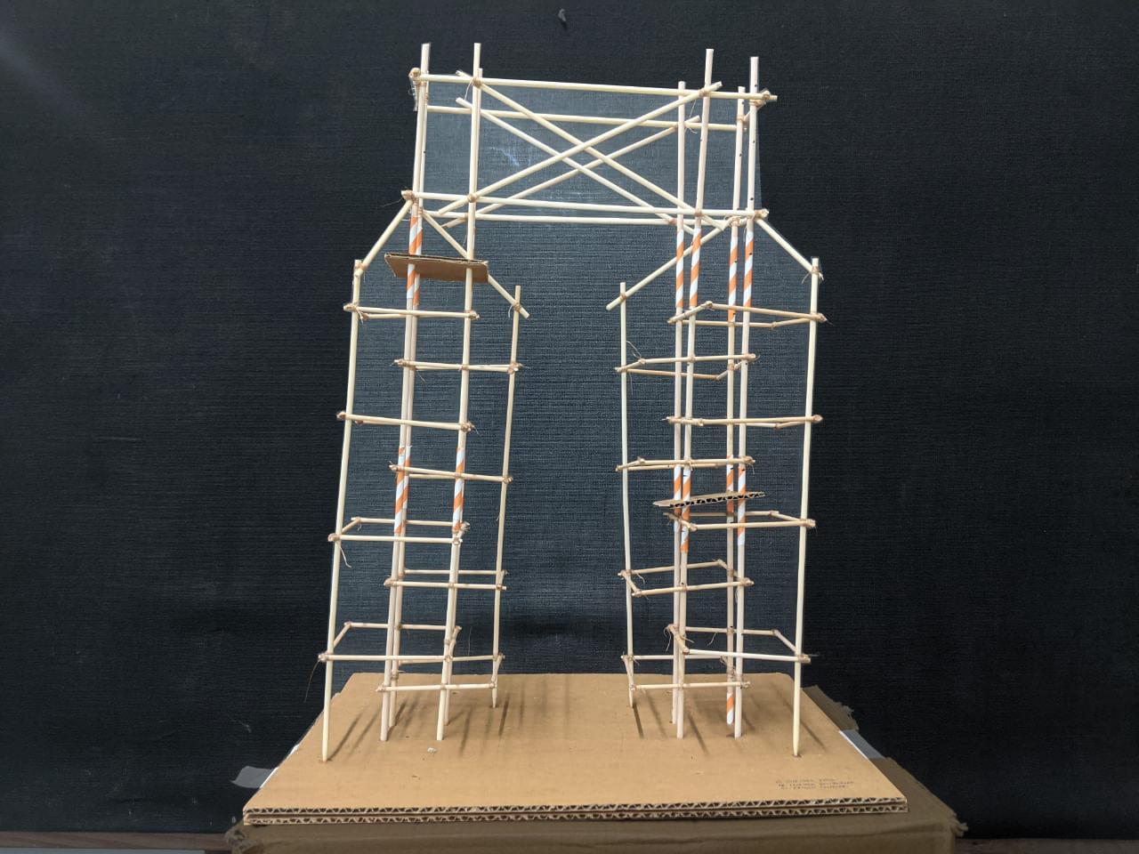
Two Triangular towers of varying cross section along its height are linkedbyTwobridgesenforcedwithbelttruss.Somefloorplatesare cantilevering inwards but are supported by the other tower via the connectingtrussbridges.
Shaketabletestobservations:Themodelswayedandbulkedmore alongtheshorterwidthascomparedtothelongerside.BridgeTruss binded the tower couple with great strength and flexibility in load transfer.
OVERALLINFERENCESANDCONCLUSIONS
The general principles to be observed in the construction of such earthquake resistant buildings as observed in this exercise are Lightness, Continuity of Load Path, avoiding/reinforcing Projecting and suspended parts, Building configuration, strength in various directions, stable foundations, Ductility of structure, Connection to non-structuralpartsandfiresafetyofstructures.
Team11| DesignReport CONCLUSION
GROUP12
NEHAJAYASANKER_11 DHRUVANSHISANGHAVI_39 MANSIBHATIA_52
AcademyofArchitecture,Mumbai
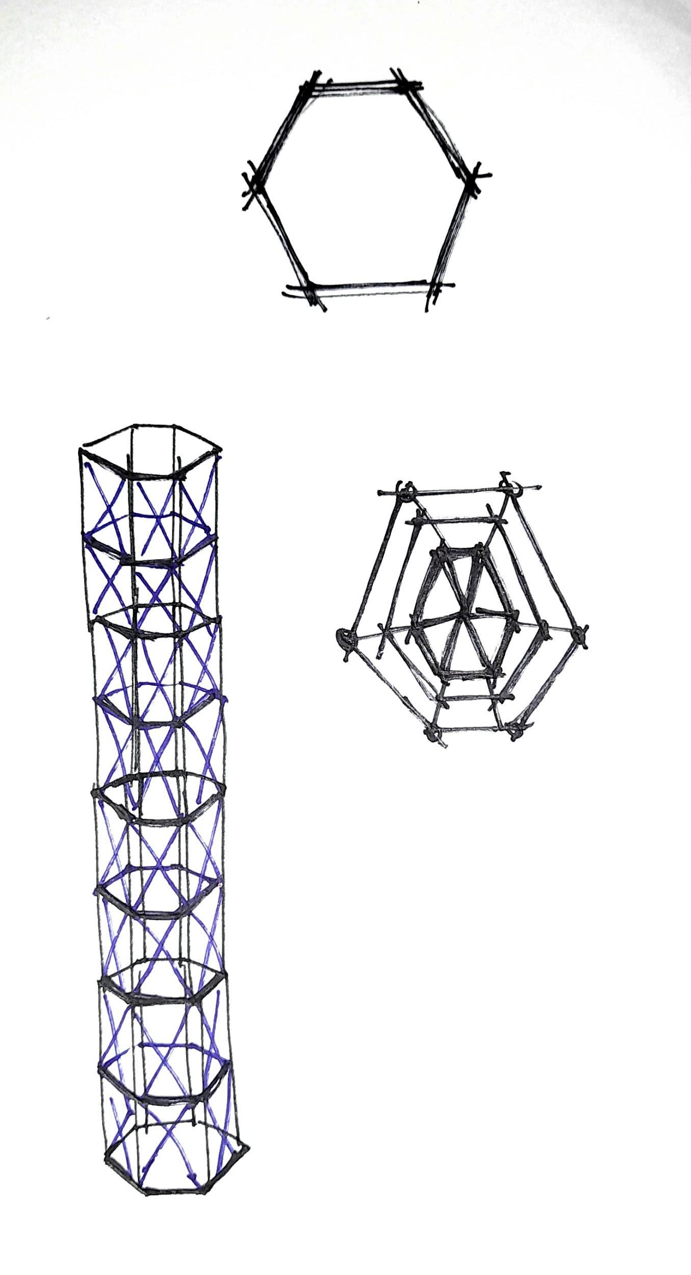
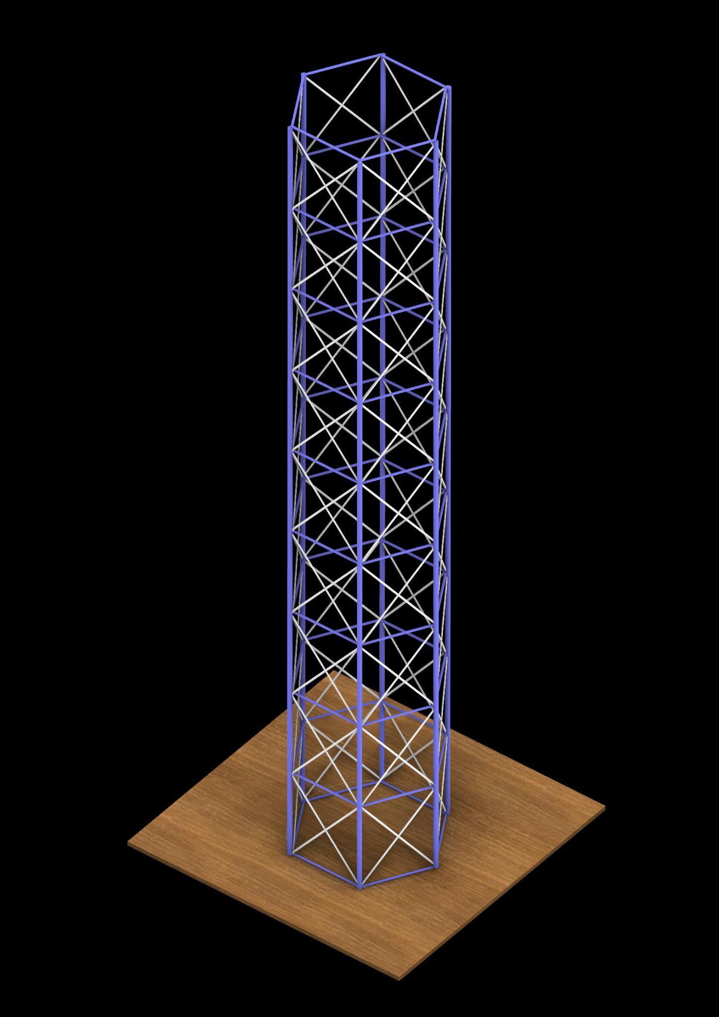
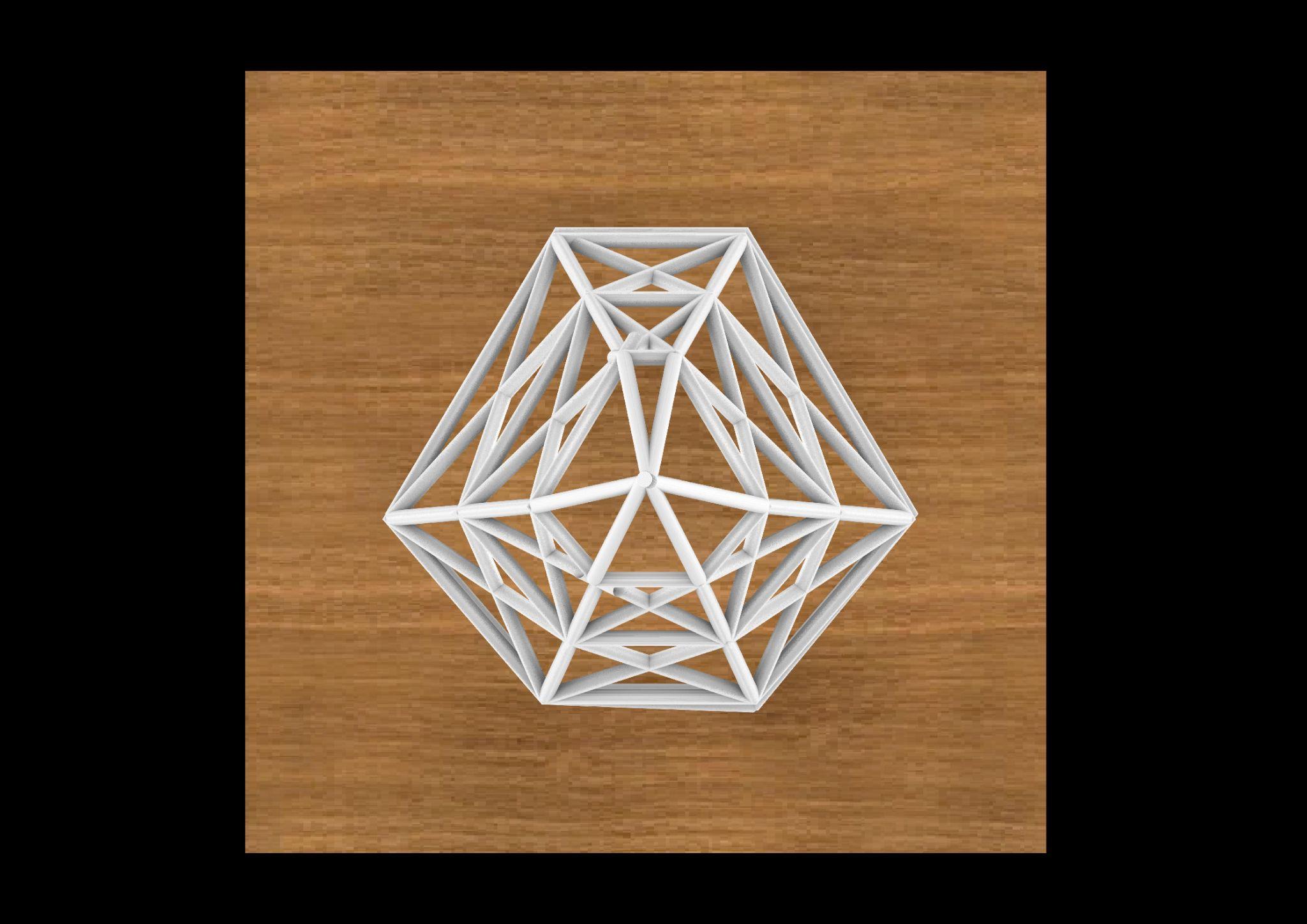
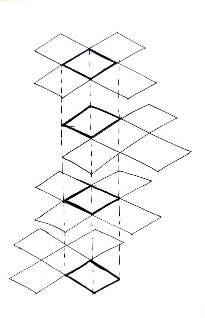
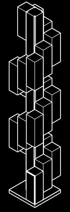
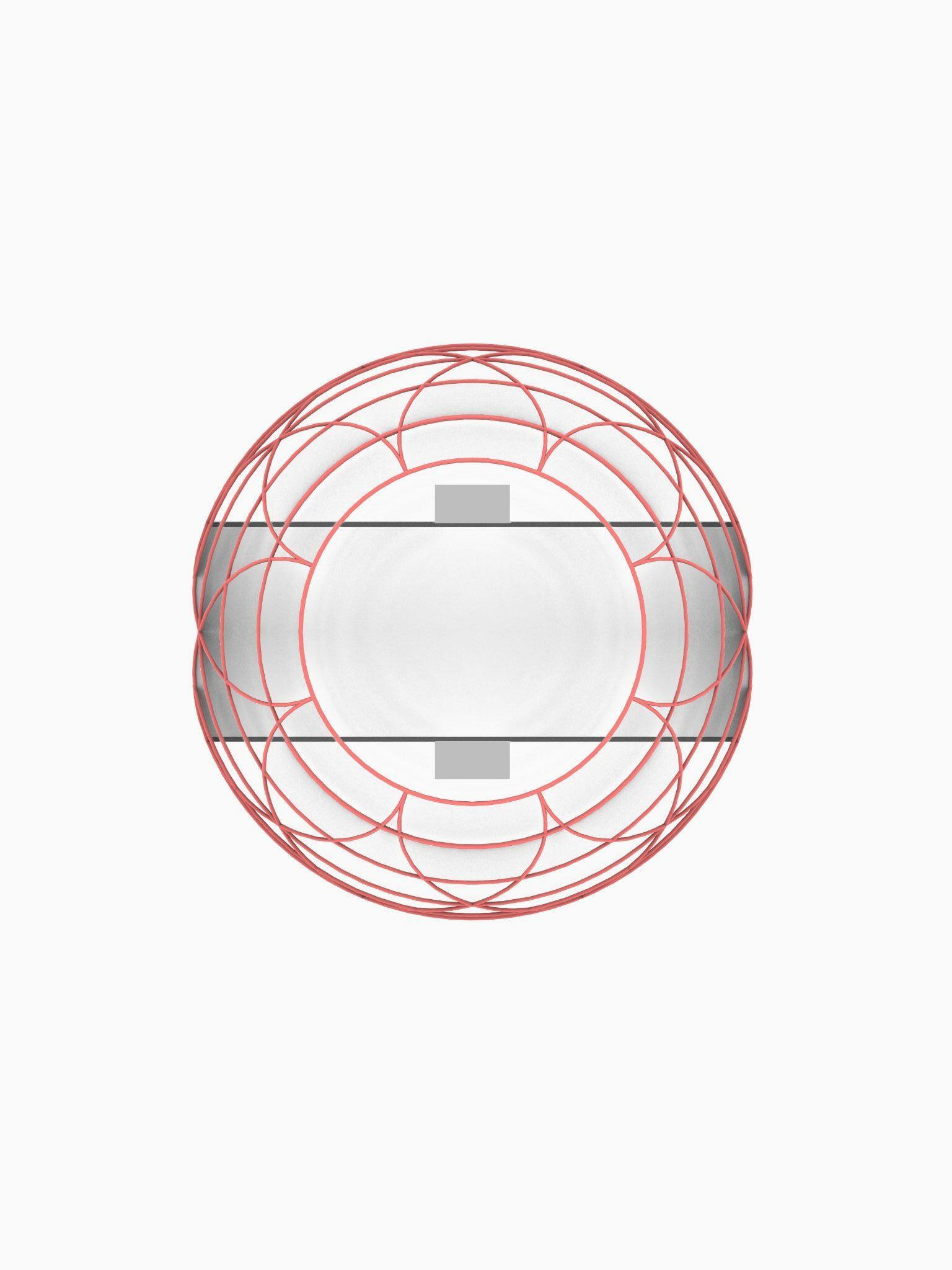
HIGHRISE BUILDING1STRUCTURAL HEXAGONAL FLOORPLATE
ELEVATION
Team12| DesignReport PROCESSMODEL
PARTMODEL
PLAN BRACING
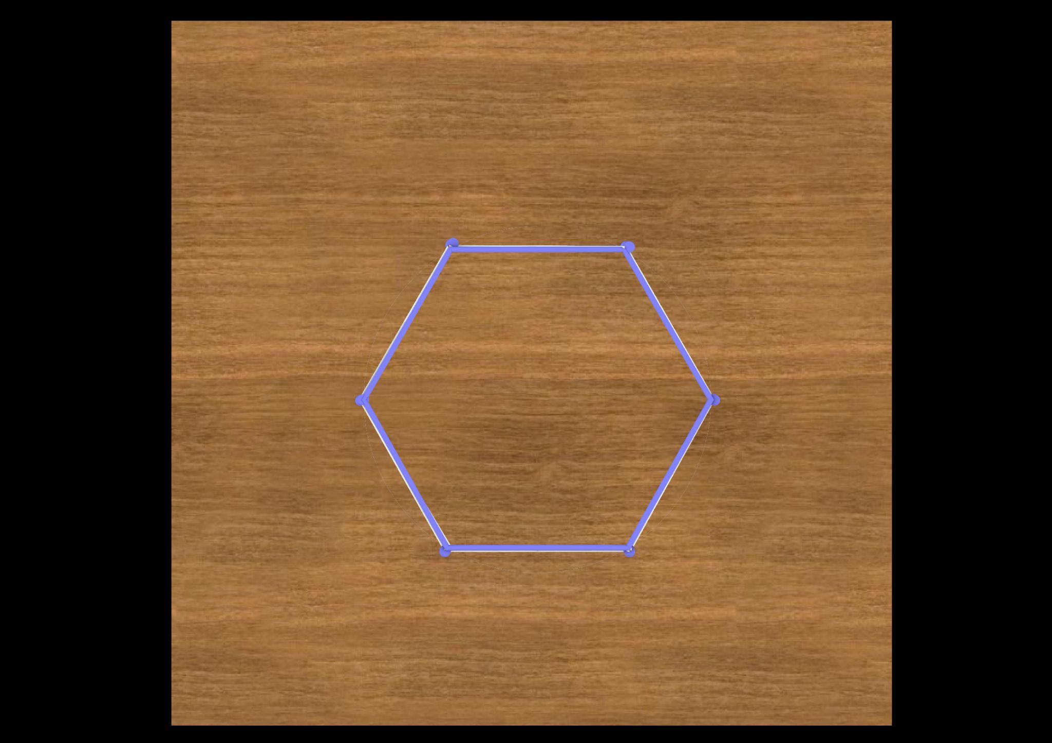
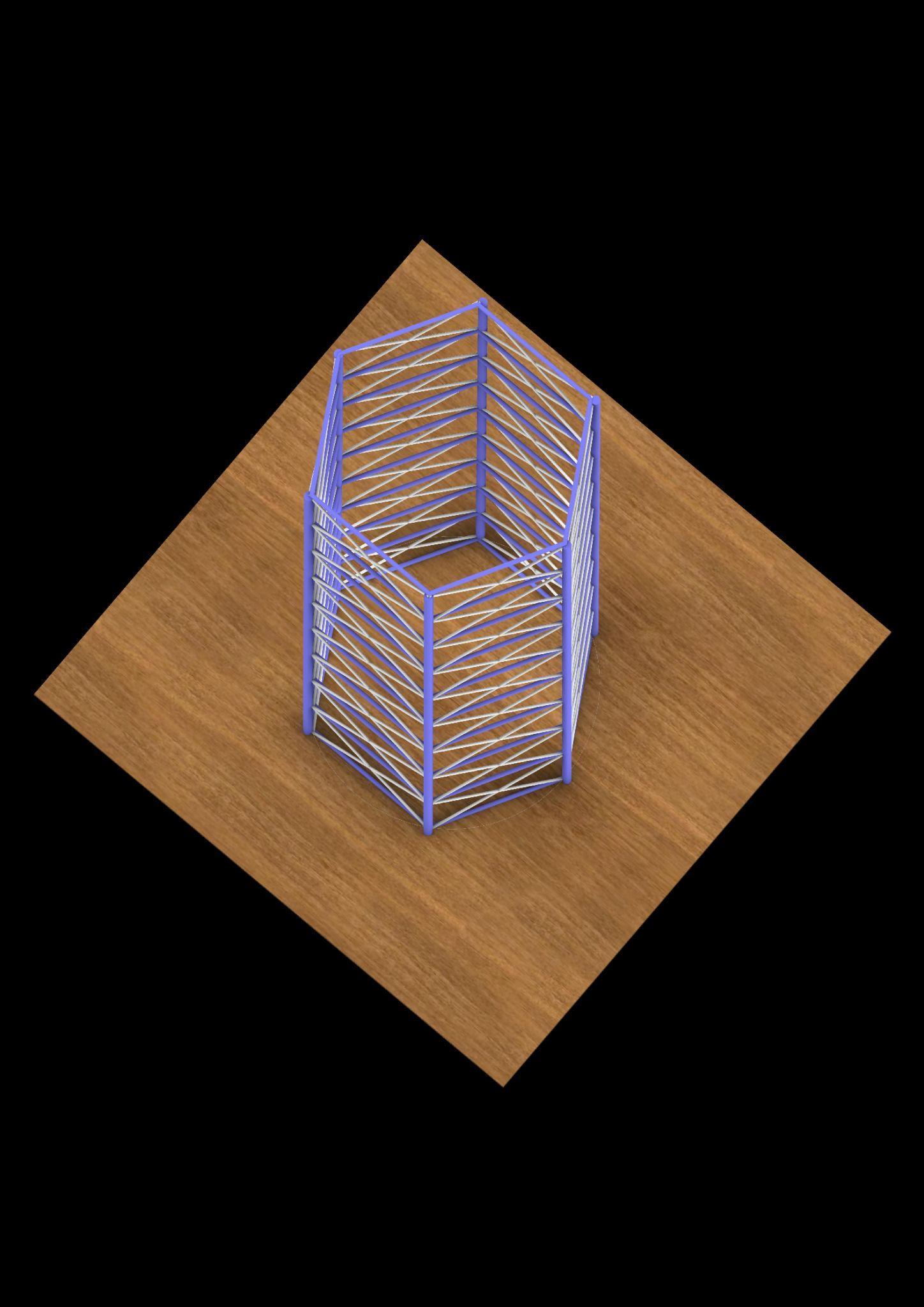
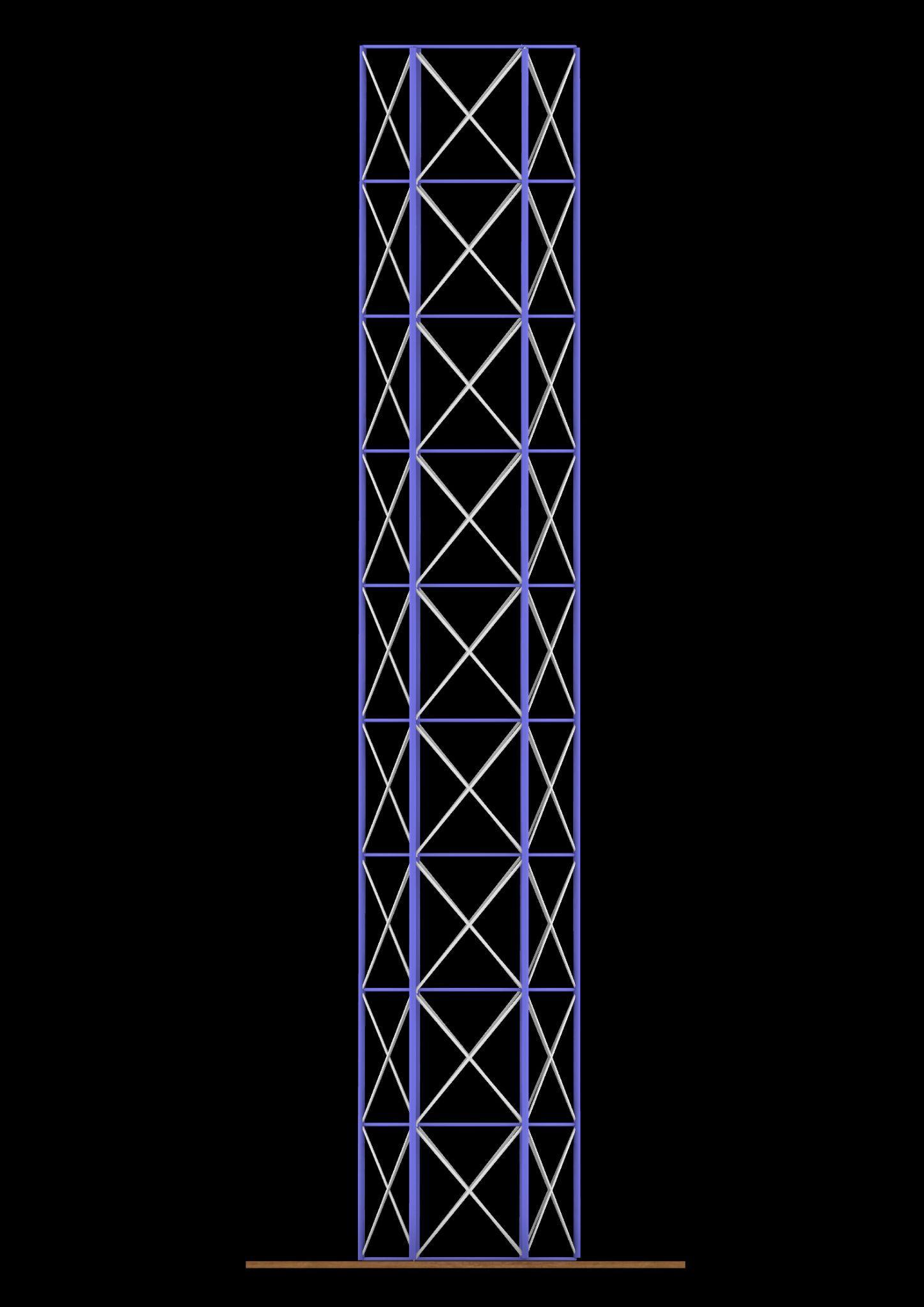
Team12| DesignReport DIGITALMODELPHOTOS
ELEVATION 3D
VIEW
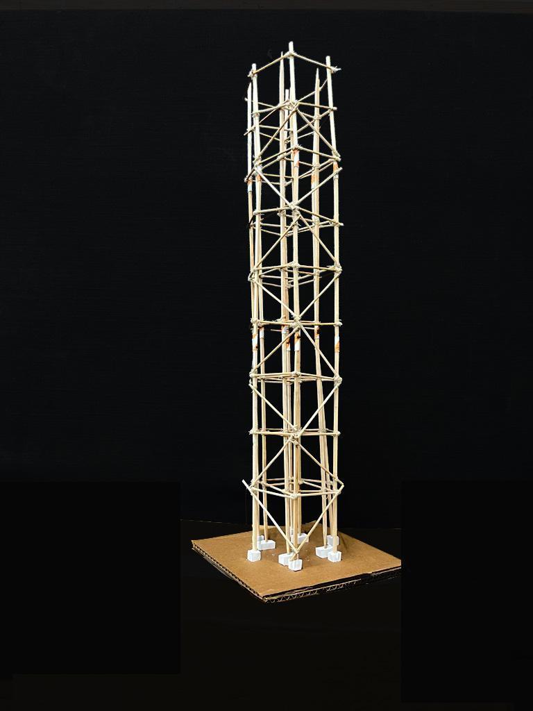
MODELPHOTOS
Team12| DesignReport INITIALSKETCHES
ELEVATION PART
SKETCHES-STRUCTURE2
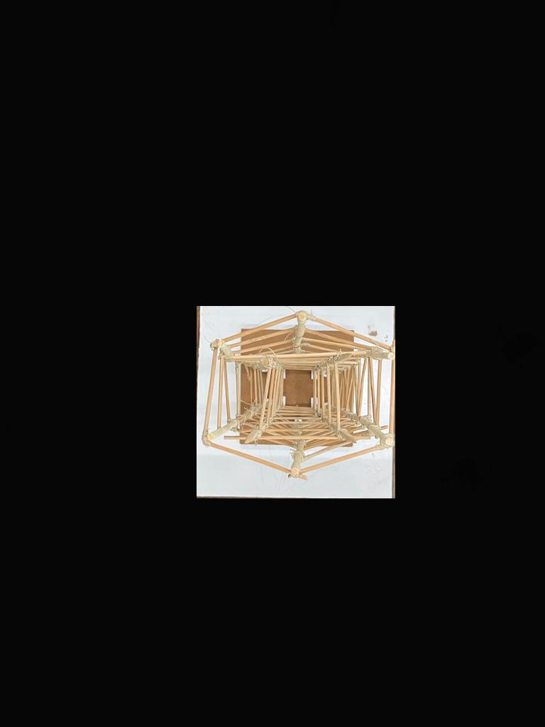
PLAN
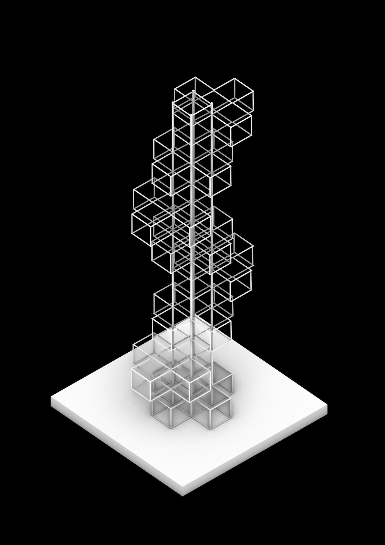
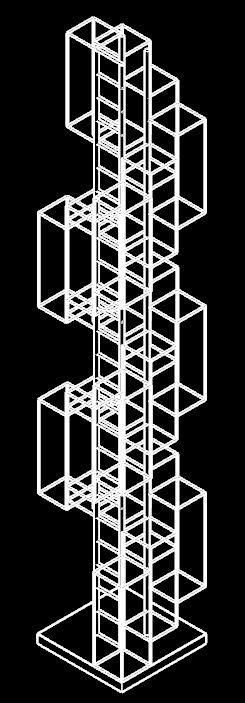
MODEL HIGHRISEBUILDING 2SCUPLTURALDIAMOND
Team12| DesignReport DIGITALMODELPHOTOS BRACING ELEVATION 3DVIEW
PLAN
PLAN 3DVIEW
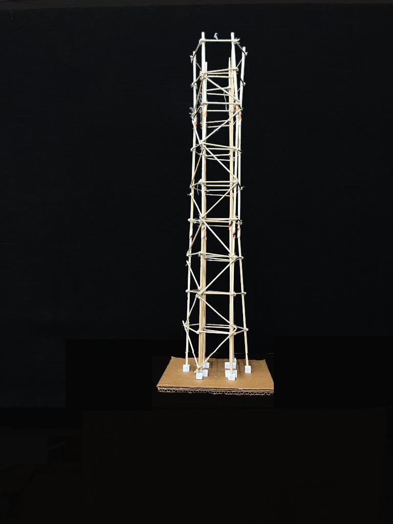
Team12| DesignReport MODELPHOTOS
ELEVATION ELEVATION
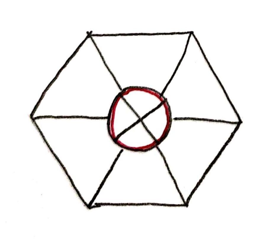
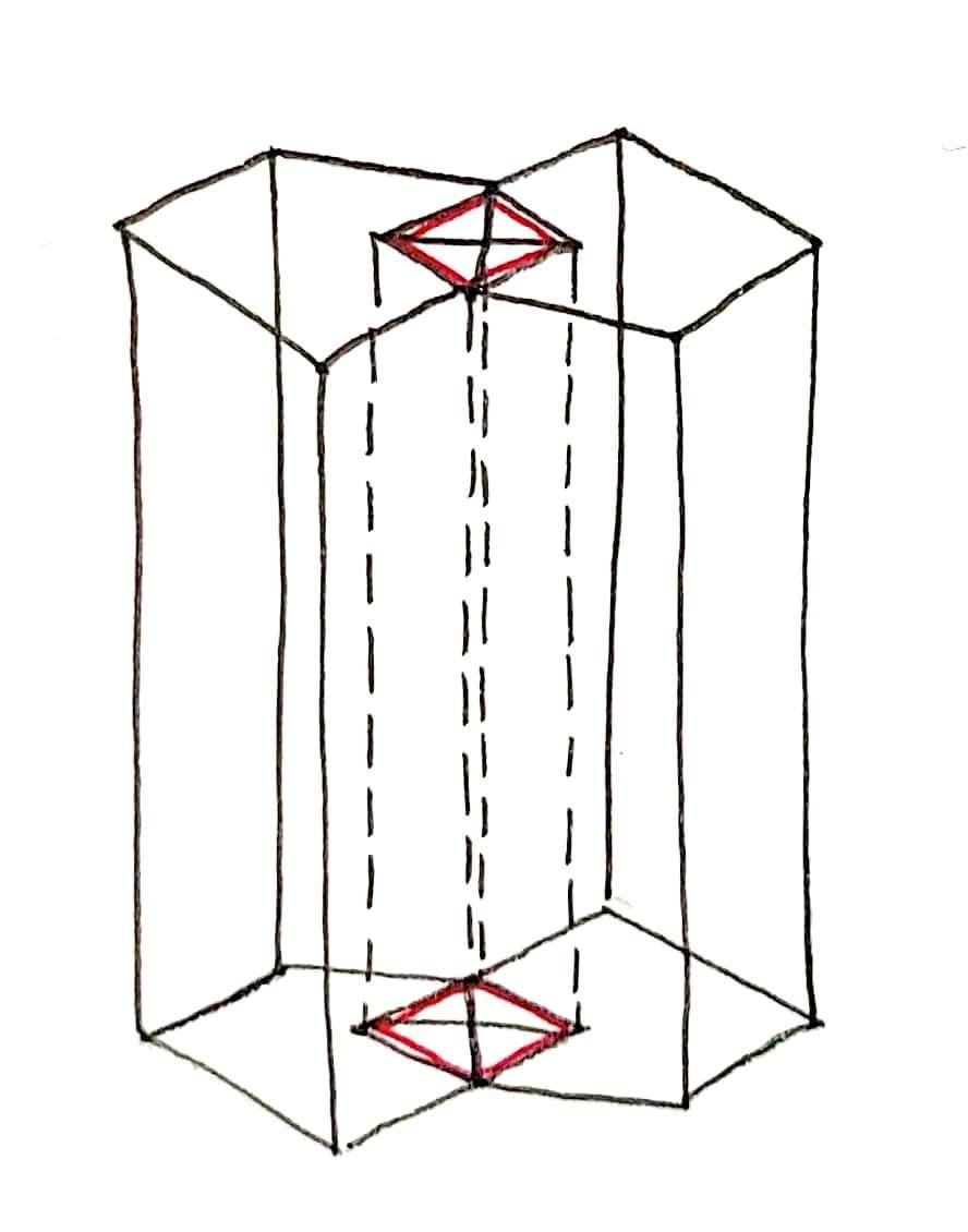
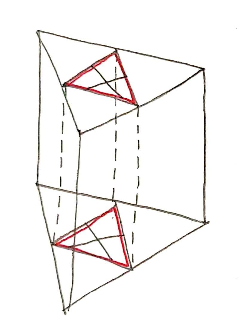
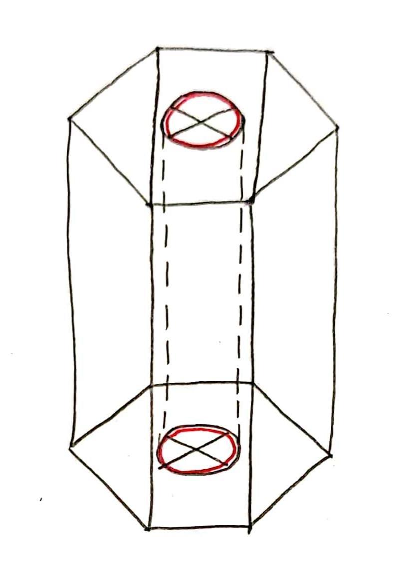
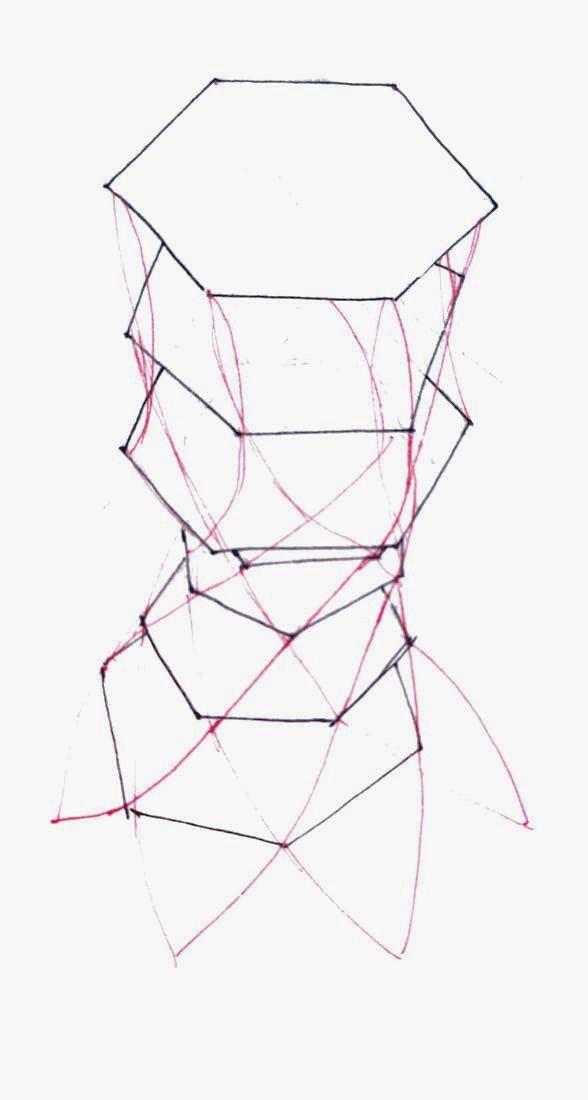
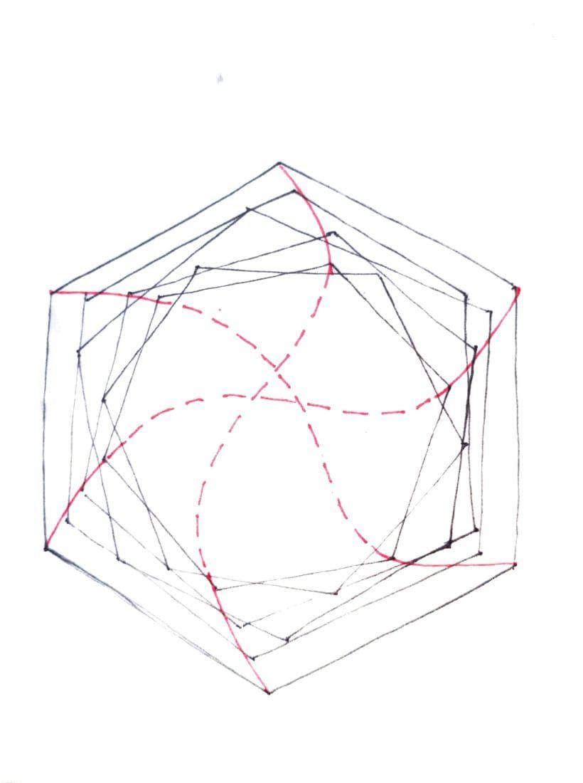
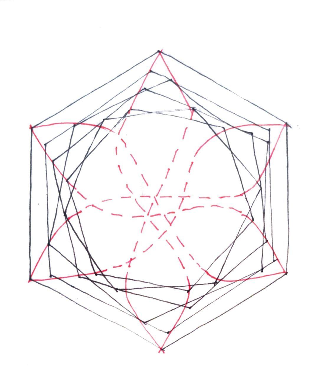
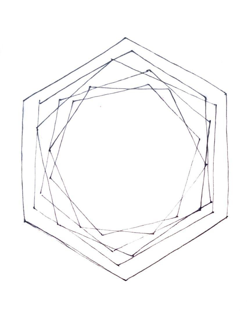
Thestructuralmodelhasaregularhexagonasafloorplatewhile thesculpturalmodelhasairregularsixsidedpolygonasafloor platethattaperstowardsthetopinorderto compareandanalyse thestabilityofthetwostructures.
Whiletestingthetwomodelsontheshaketableitwasobservedthat thestructuralmodel(regularhexagon)iscomparativelystifferand isnotmuchaffectedbytheinducedearthquakeascomparedtothe sculpturalmodelwhichbeginstosway.Theloadinthestructural modelaretransferreddirectlyfromtoptobottomwhileinthe sculpturalmodeltheloadcarryingcapacityisaffectedduetothe reducingfloorplatesandthestructuralmembersactingatanangle whichresultinreducedstability.
Onaddingthebracings,inthesculpturalmodeltheloadtransfer becomeseasierandthemodelbecomesstrongerandstifferthan beforeandthereisareductionintheswayaswetestthemodelon theshaketable. Similarlywhenthebracingsareaddedtothesculpturalmodels,they providebetter.distributionofloadfromtoptobottomasaresultof whichtheswayingmovementbecomeslesserascomparedto before. Conclusion-Fromtheaboveanalysisitcanbeconcludedthatthe earthquakeresistancedependsonthe● Formof
Team12| DesignReport CONCLUSION ANALYSISANDCONCLUSION
thestructure ● StructuralConfiguration ● LateralStiffness ● Lateralstrengthandductility ● Abilitytoredistributeforcestravellingduringseismicevent
AcademyofArchitecture,Mumbai
GROUP13 ISHANLATHIA_20 SHWETAUTEKAR_16 PRANALITHOOL_36
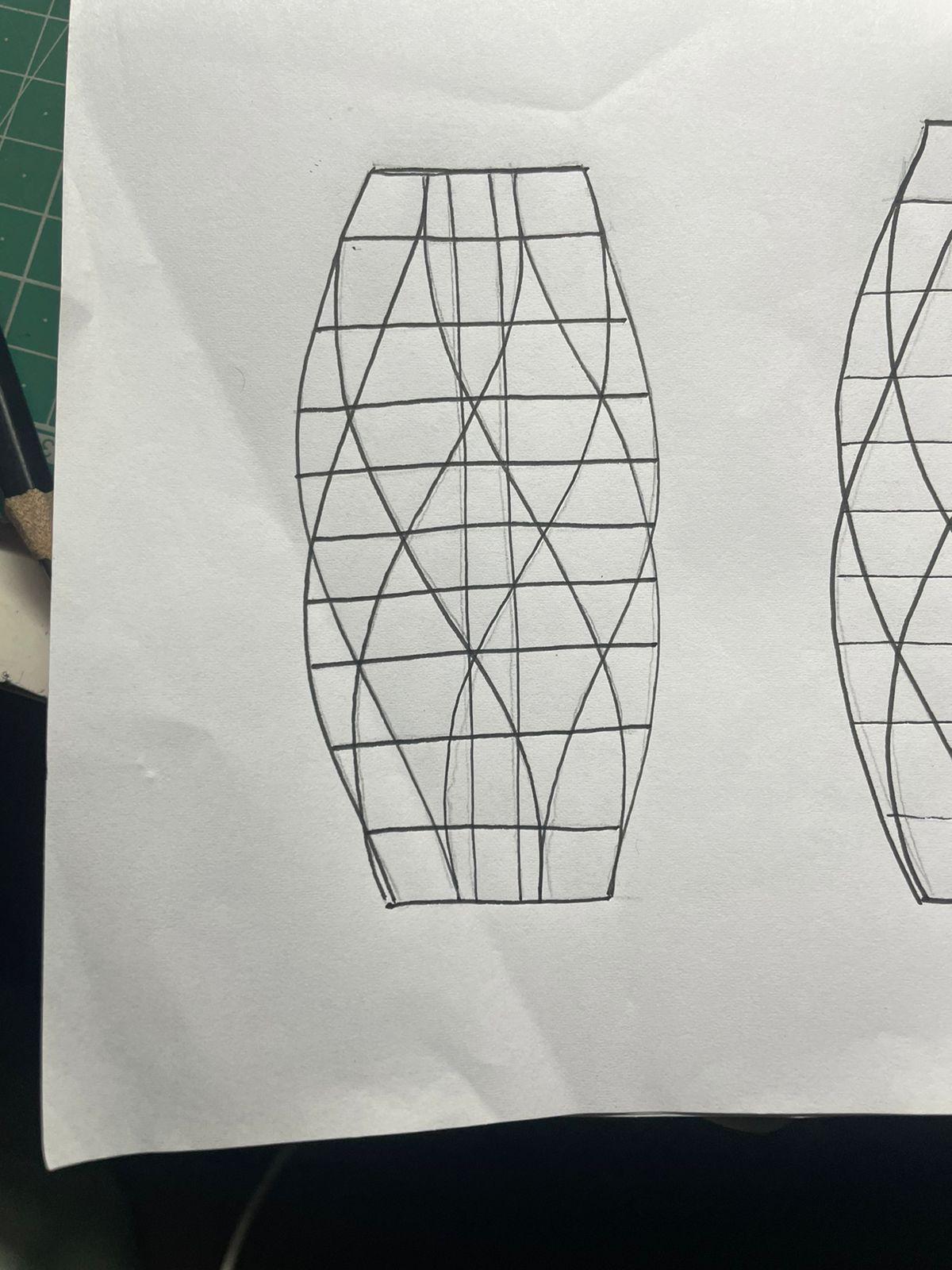
HAVINGATAPERINGFORMWITHFOURDIFFERENT WINGSTOREDUCETHENUMBEROFBRACINGS
Xshapeprovideswithfourwingsinfour directionsintersectingatrightanglestoeach otherwithashearcoreinthecenter
Team13| DesignReport SKETCHES
THETAPEREDWINGSACTASHUGERETAINING WALLSTORESISTBOTHWINDFORCEANDSEISMIC
FORCESACTINGFROMONEDIRECTIONARE RESISTEDBYTHEWINGSTANDINGONTHE OPPOSITESIDEOFTHEBUILDING
Team13| DesignReport MODELPHOTOS BRACINGS
FLOORPLATE-ROTATINGANDREDUCINGATTHESAME TIME TWISTINGFORMWITHBRACINGSTHATACT ASTHE
BRACINGS-INONEDIRECTION Team13| DesignReport SKETCHES BRACINGSINBOTHDIRECTIONS
COREANDFLOORPLATECONNECTEDWITHBEAMS Team13| DesignReport
TUNEDMASSDAMPER
Team13| DesignReport MODELPHOTOS
BRACINGSPROVIDEDINBOTHTHEDIRECTIONSActingas
TUNEDMASSDAMPER
● WindandEarthquakeloadingsaretwomajortypesoflateral dynamicactionsexperiencedbyhighrisebuildings.
● In Highrisebuildingsthereisaneedforoptimizationtosafely carrygravityandlateralloads.
● Withincreaseintheheightofthebuilding,theneed toresist lateralloadsincreasesdrastically.Thus,thebuildingismore sensitivetoearthquakeandwindloads
● Thisarisestheneedforprotectionfromtheseloadstoresist structuralandnonstructuralearthquakedamage.
● Earthquakeandwindorienteddeflectionsmustbelimitedfor multiplereasonsandhenceabundantstructuralstiffnessis important.
● Thiscanbedonebyaddingcentralcore, strongshearwalls, bracings,structuralframes,deepfoundations.
Team13| DesignReport CONCLUSION ANALYSIS
CONCLUSION
AND
GROUP14
TARIKADESHPANDE_42 PRAJAKTAGOSAVI_43 VARDHANARORA_50
AcademyofArchitecture,Mumbai
Team14| DesignReport INITIALSKETCHES
ELEVATION ELEVATION ISOMETRICVIEW ISOMETRICVIEW Team14| DesignReport DIGITALMODELPHOTOS
Team14| DesignReport MODELPHOTOS
PERSPECTIVEVIEW Team14| MODELPHOTOS
Team14| DesignReport INITIALSKETCHES
VIEW ISOMETRICVIEW Team14| DesignReport DIGITALMODELPHOTOS
ELEVATION ELEVATION ISOMETRIC
ELEVATION
Team14| DesignReport
PERSPECTIVEVIEW
PERSPECTIVEVIEW
Team14| DesignReport
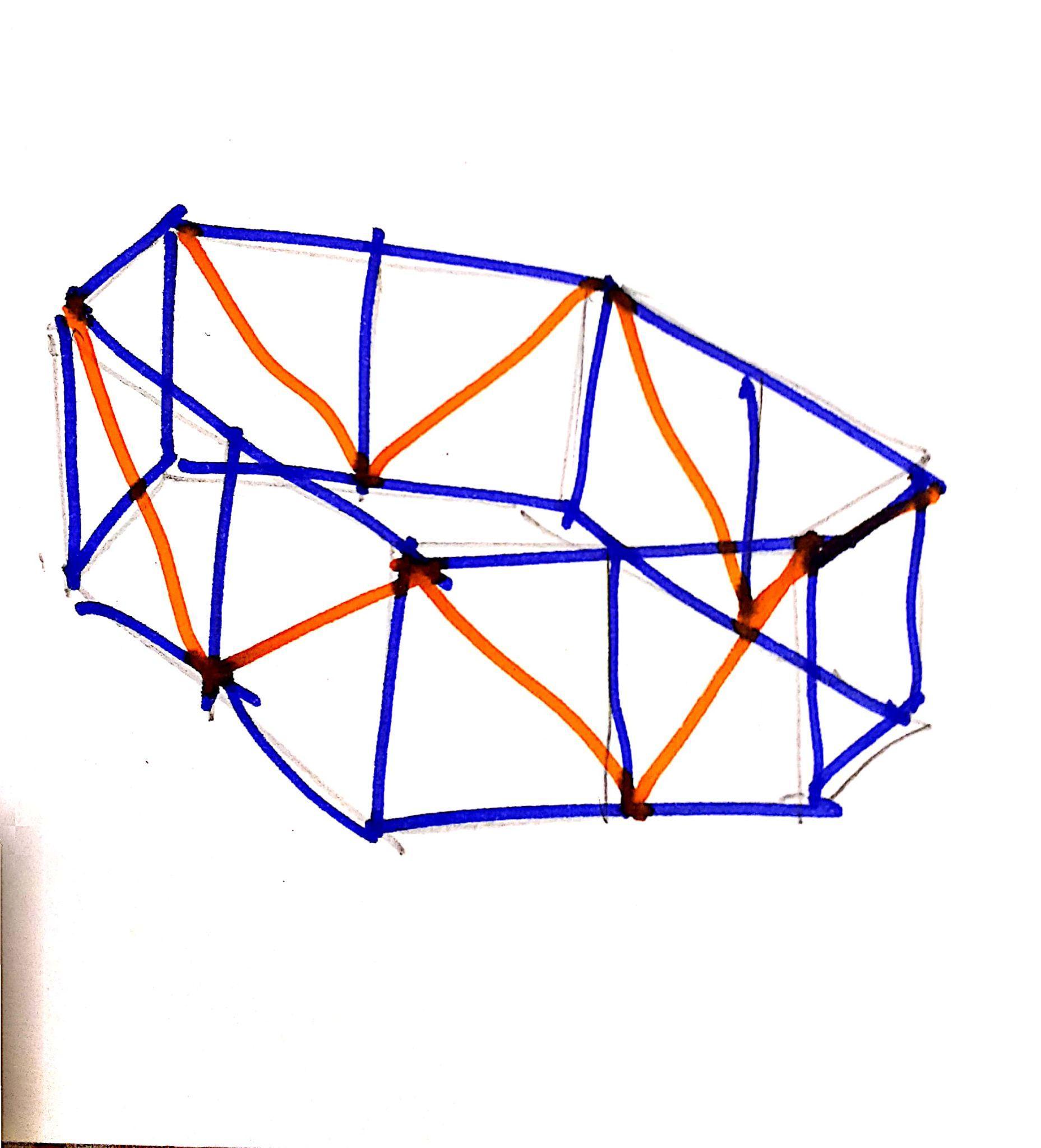
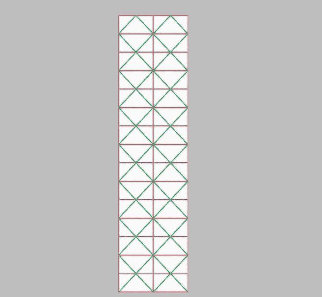
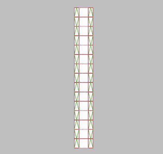
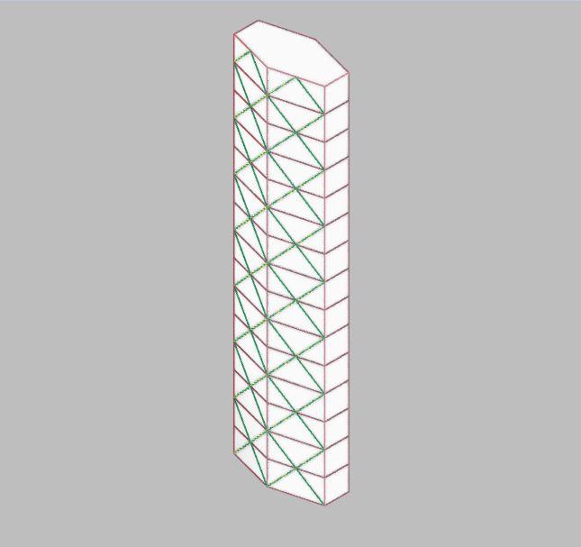
MODEL1:Sculptural
● Withatrapezoidalplan,theformofthesculpturalmodelis rotatedbya180degreeevery5floors.
● Themodelwhentestedforearthquakeresistanceinitially resistedthebendingmomentgeneratedwithitsFramework.
● Uponadditionofload,certainjointsintheTopmostpartofthe frameworkstartedtogetloose.
● Themodelisseentobeswayingafteranincreasedintensityof theshaketable.
● UponadditionofBracingstheintensityofswayingisreduced.
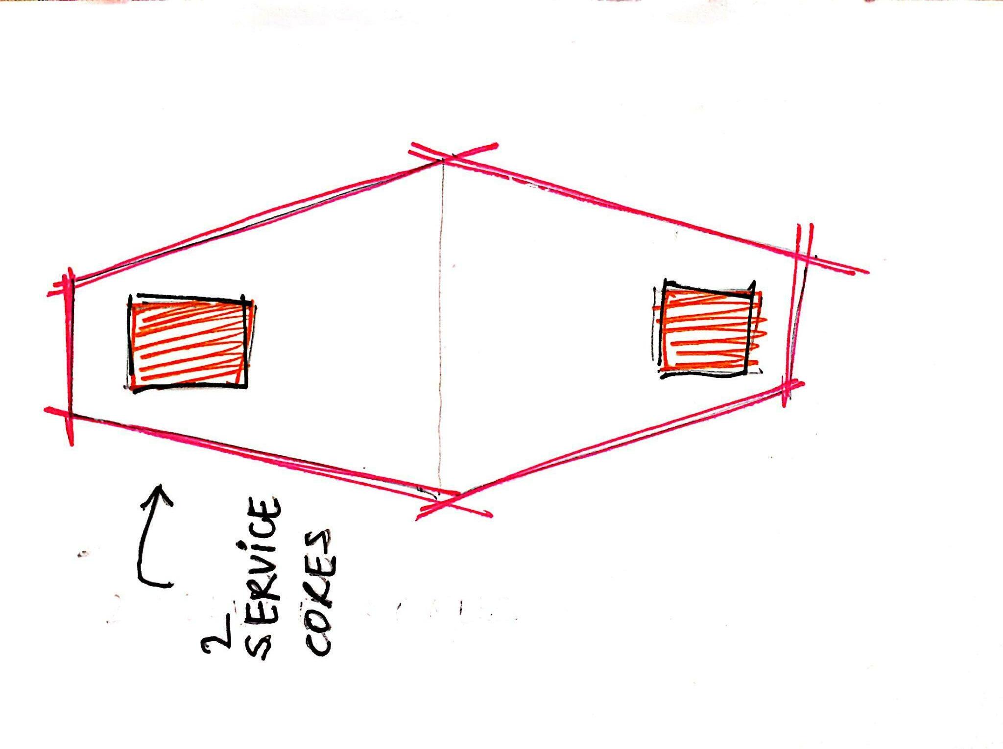
MODEL2:Geometric
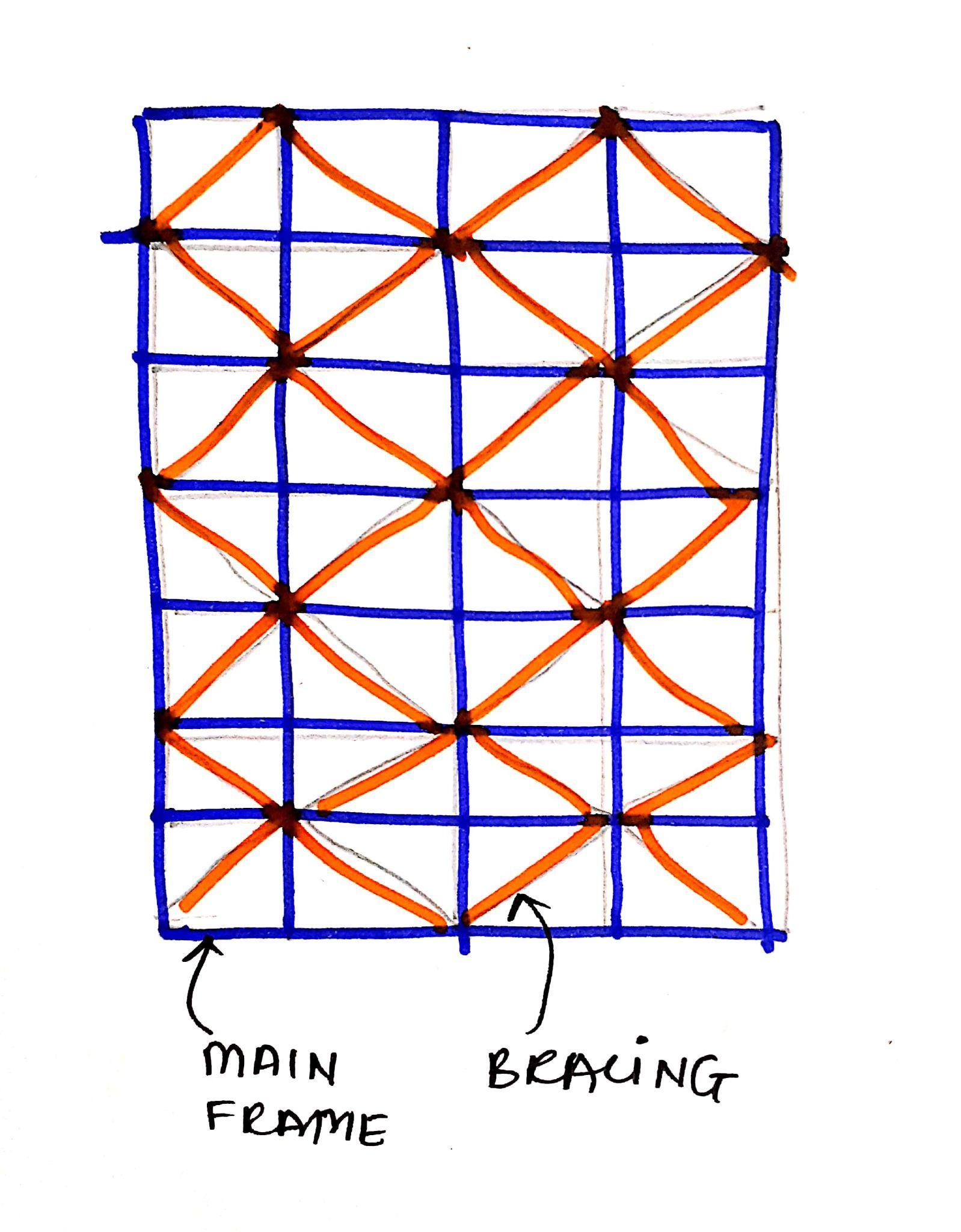
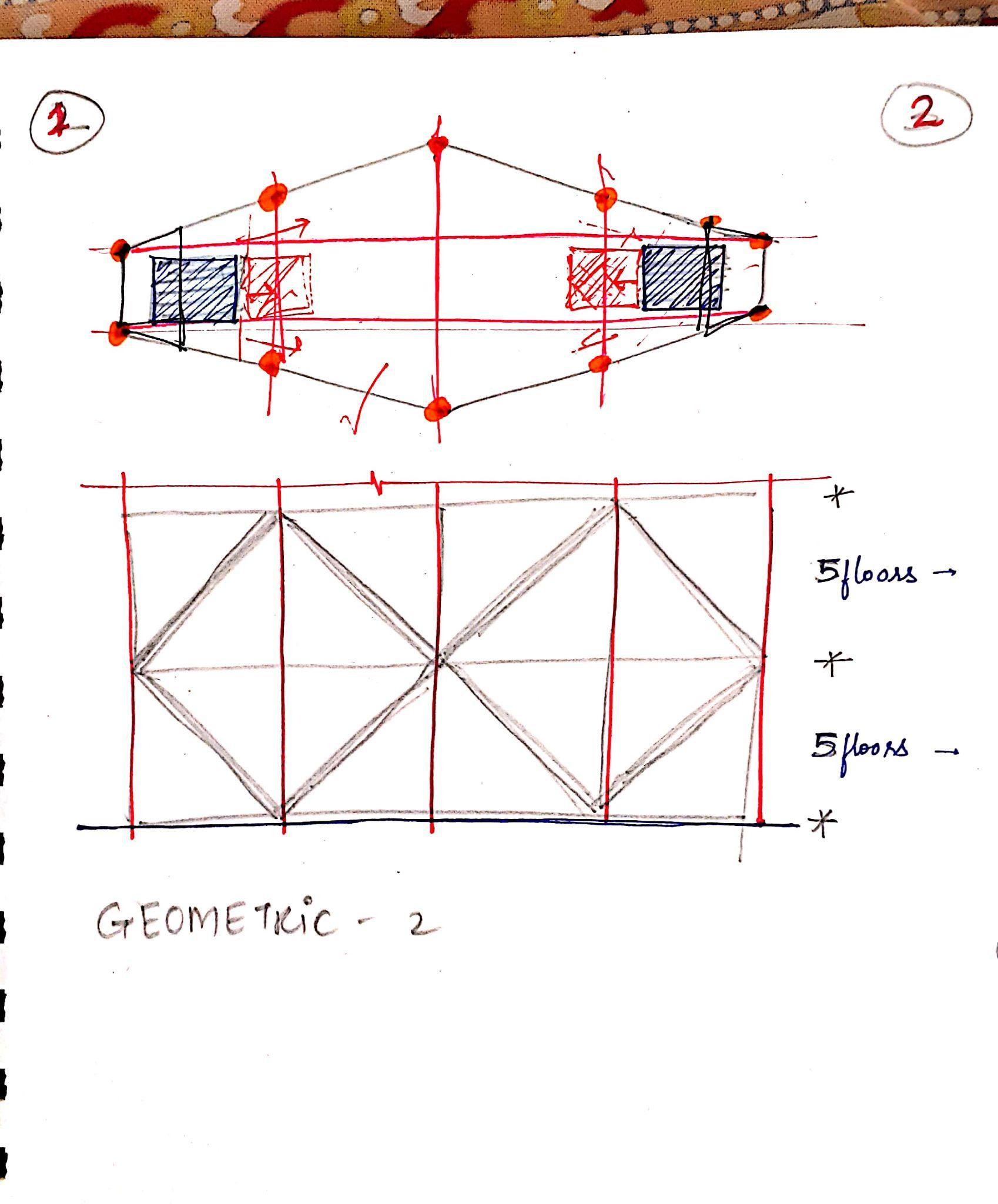
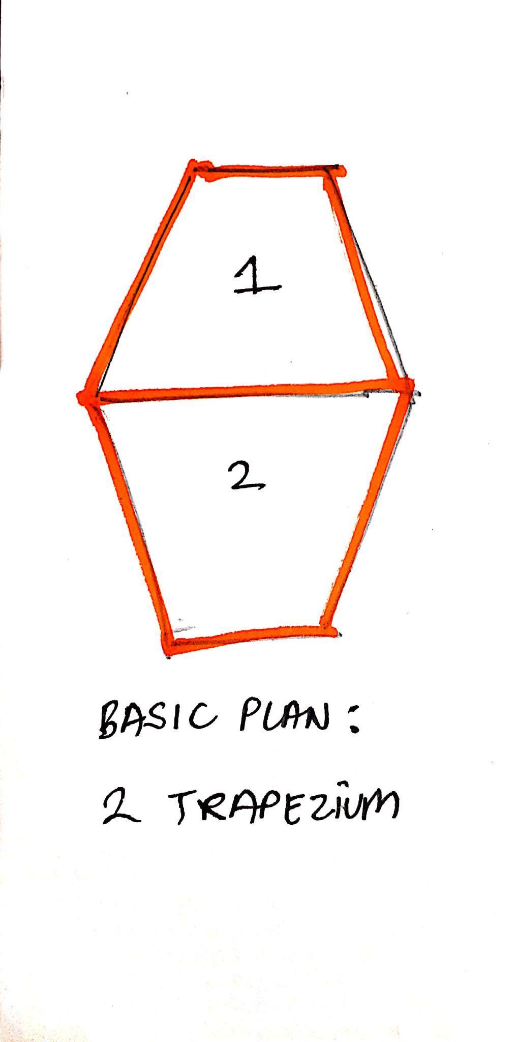
● ThemodeliscomposedofTrapeziumsinplanand2Service Cores.
● 2TrapeziumsarejoinedtoformanelongatedHexagon.
● Theservicecoresonbothsidesreducestheeffectofseismic loadsonthestructure.
● ThemodelwhentestedforEarthquakeresistanceinitiallywas seentoquitesturdybecauseofitssimpleloadtransfersystem.
● TheBracingsprovetobeeffectiveuponadditionofminorloads andincreasedintensityofShaketable.
CONCLUSION
● TheSwayingofthestructureiscontrolledwiththeeffectiveuse ofBracingSystems.
● ThestructureswaysmoreattheToppart.
● TheColumnsneedtobeanchoredtothegroundandshouldbe strongenoughtoresistloads.
● ThestructuralConfigurationandFormofthebuildingplayan importantroleinEarthquakeResistance.
● Theformshouldhavelessernumberofjointssothattheload transferfromToptobottomhappenseffectively.
Team14| DesignReport CONCLUSION
ANDCONCLUSION
ANALYSIS
AcademyofArchitecture,Mumbai
GROUP15 PUNEETMARU_02 VAIBHAVIKHEDKAR_03 PALAKBHATTAD_09
FIGURINGOUTPLAN
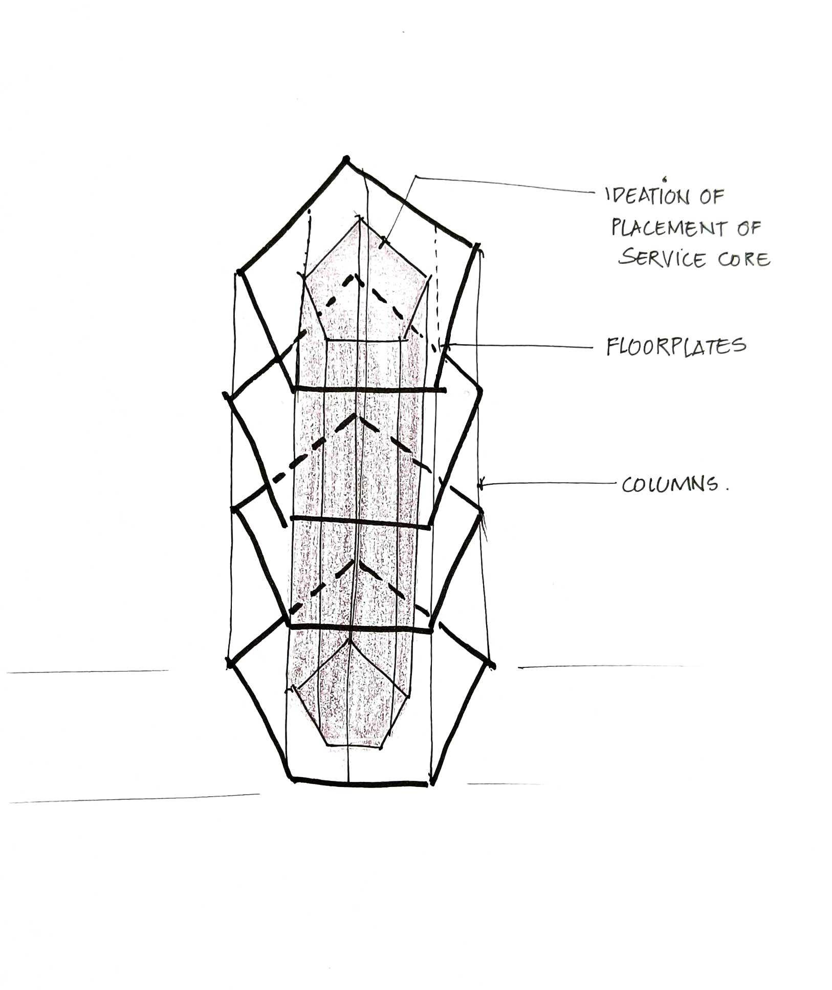
PLACEMENTOFCORECOLUMNSANDBEAMS 3DSKETCH Team15| DesignReport INITIALSKETCHES
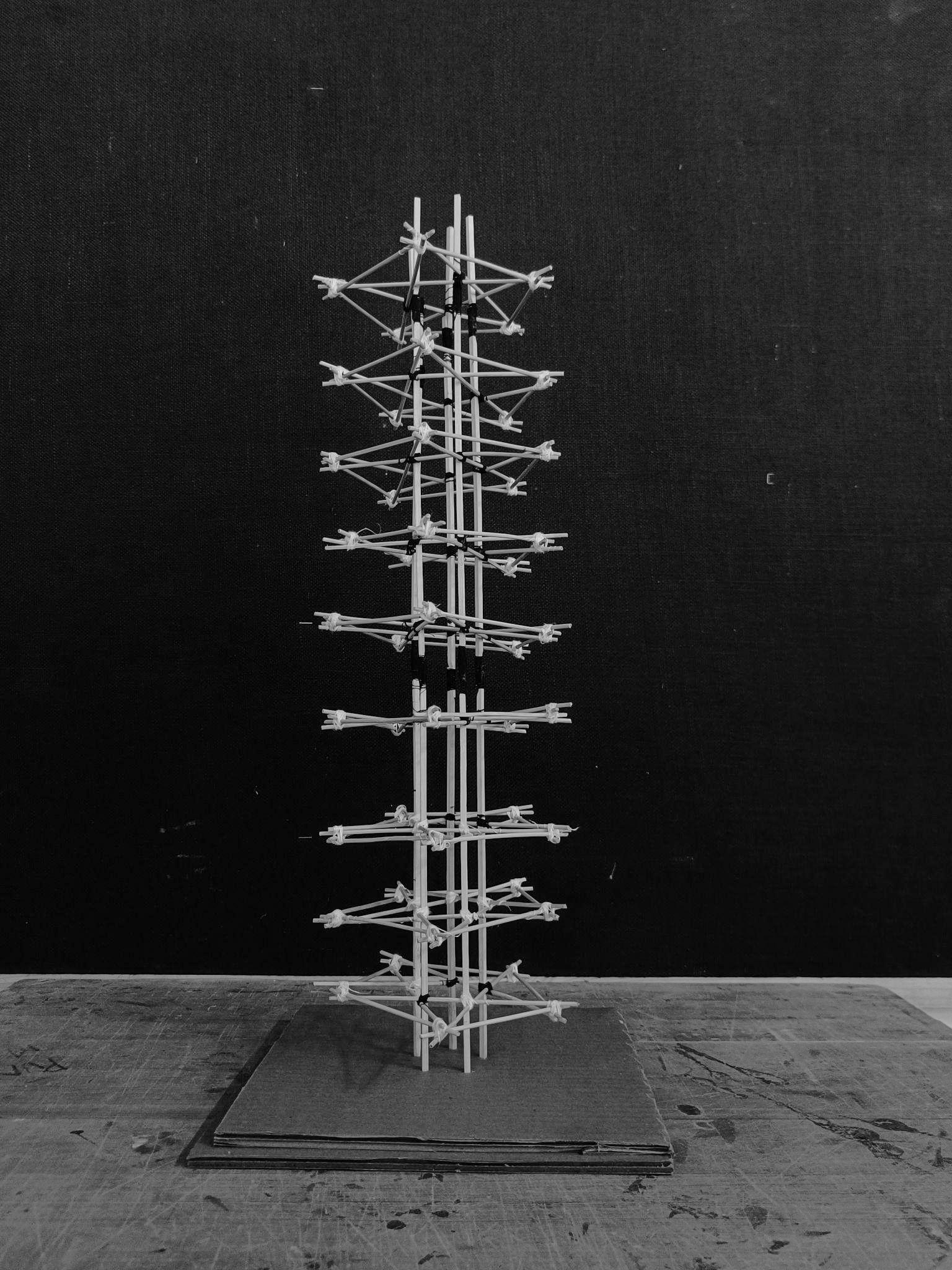
PERSPECTIVEVIEWOFTHEMODEL PLANSHOWINGSINGLEFLOORPLATE PERSPECTIVEFROMTHETOP ELEVATIONOFTHEMODEL


Team15| DesignReport DIGITALMODELPHOTOS

IDEAOFANGULARBUILDING LIFTINGITINAIRWITHACORE
FURTHERINCREASINGTHEANGLE, ADDINGBRACING,STIFFENERS
3DSKETCH Team15| DesignReport INITIALSKETCHES
Team15| DesignReport
SIDEELEVATION Team15| DesignReport DIGITALMODELPHOTOS
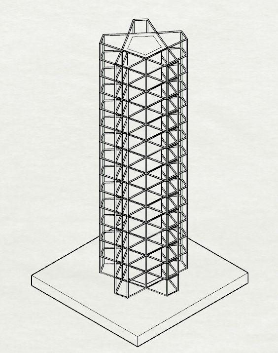
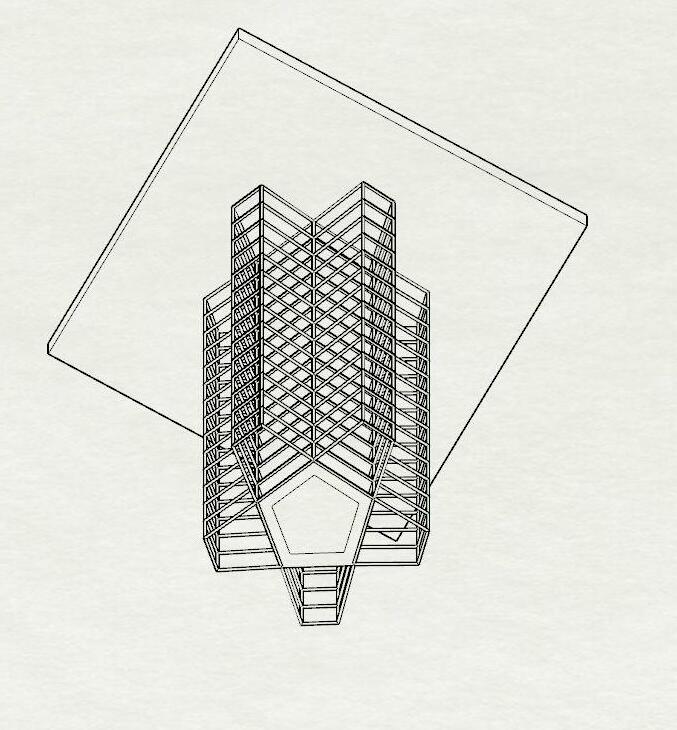
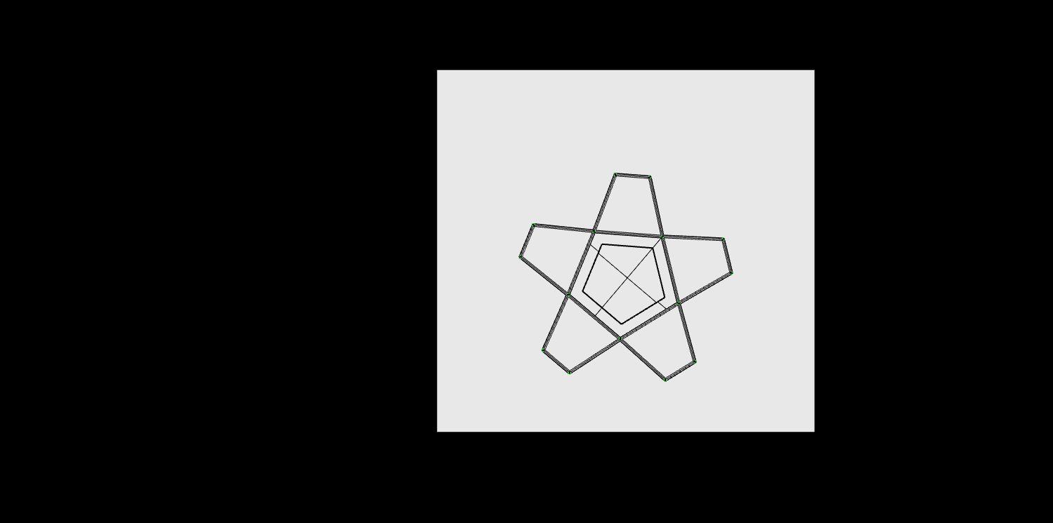
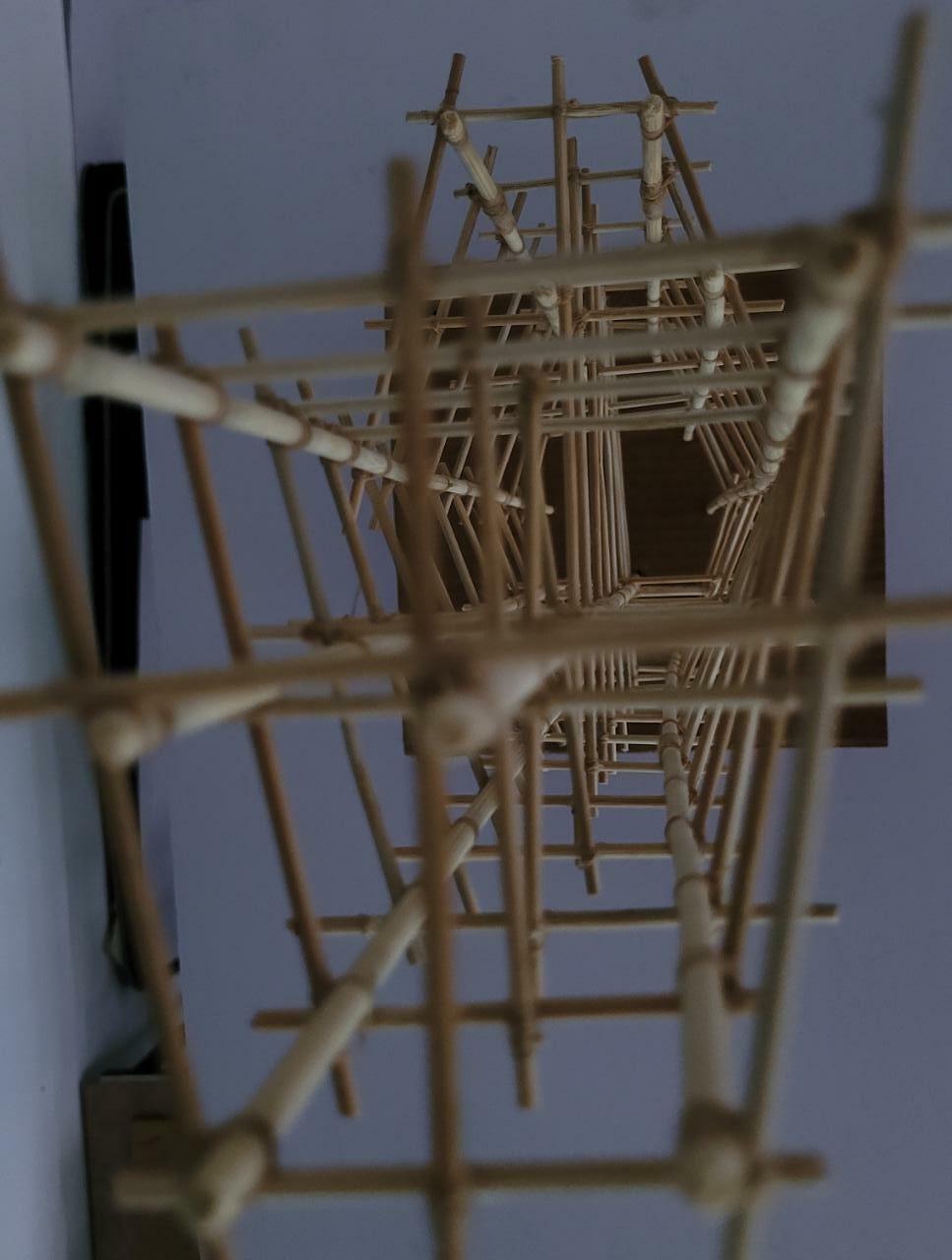
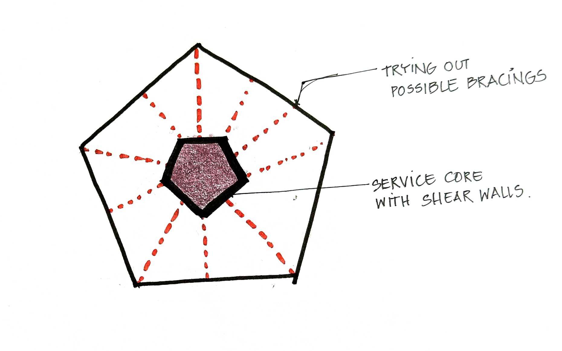
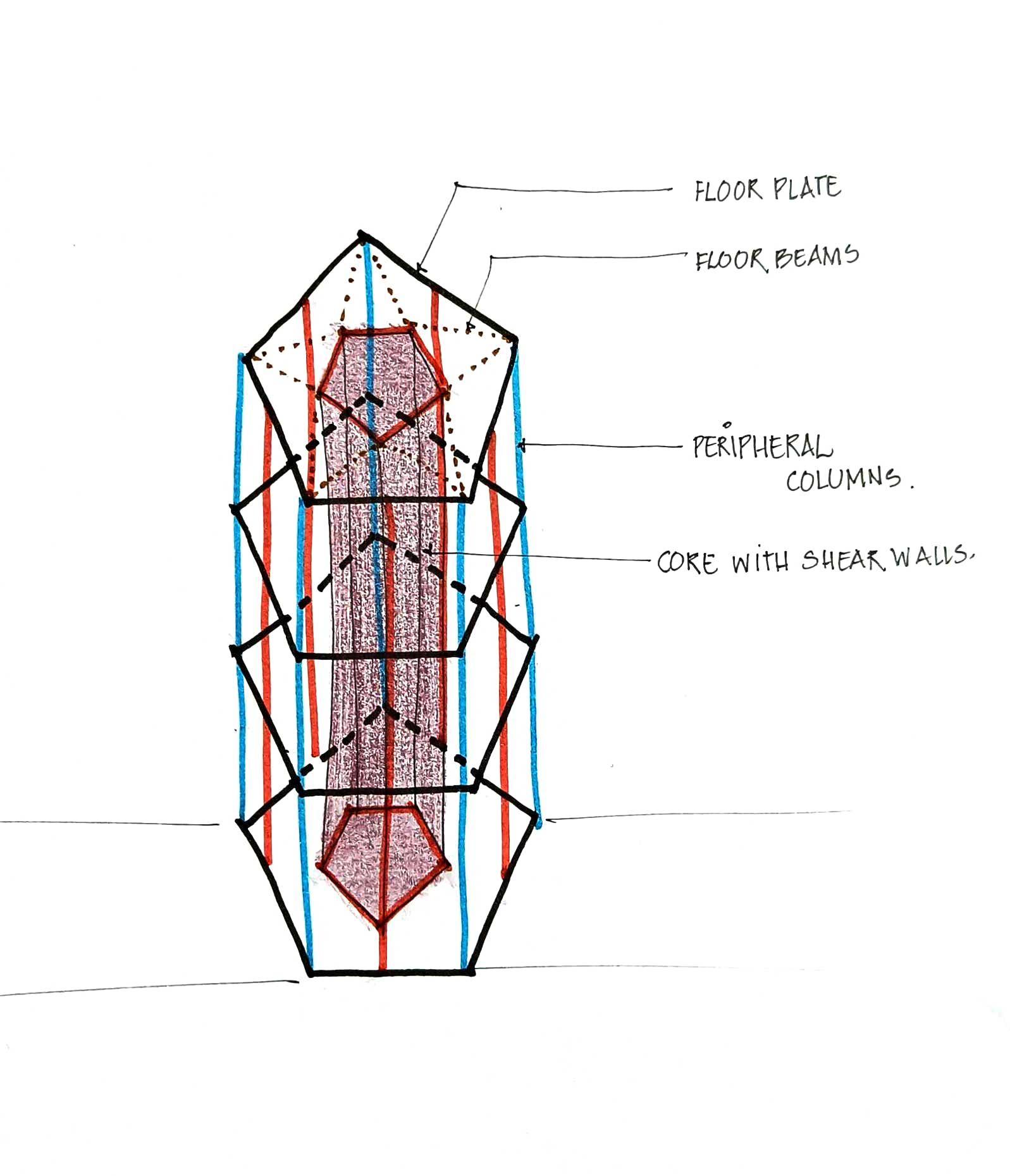
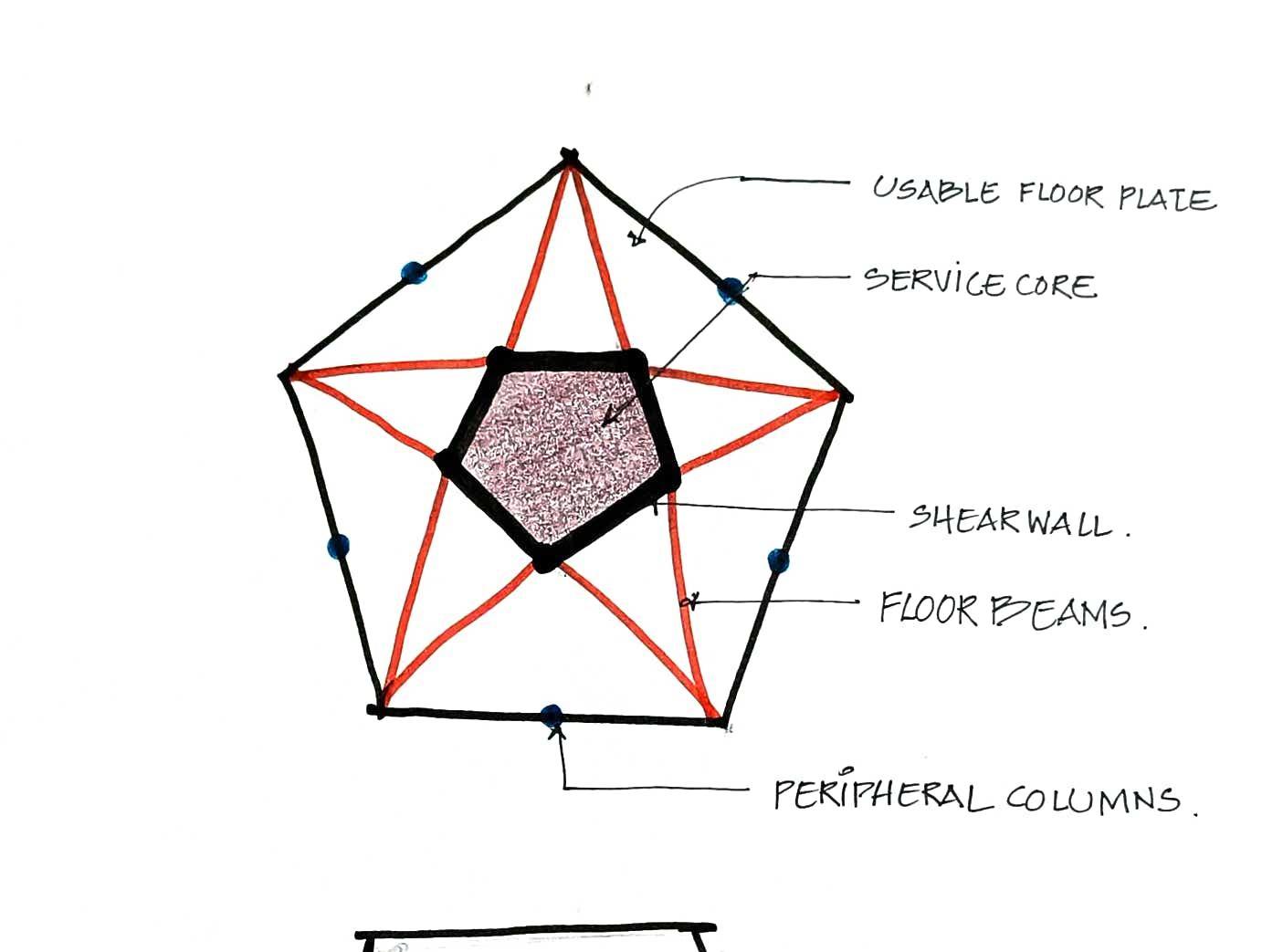
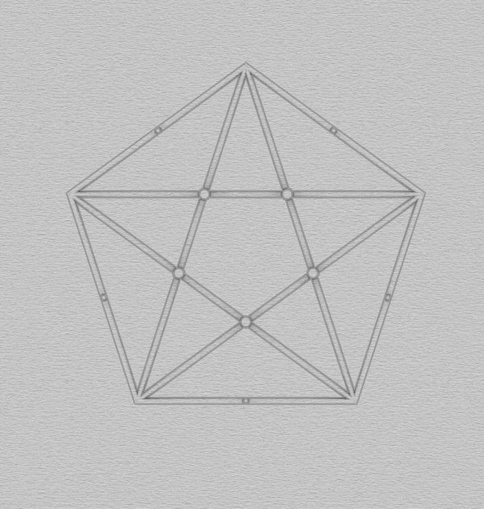
The Pentagonal Form of the building allowed easier load transfer in plan and then to the Ground. Since the Core (Pentagonal) was not concentric to the externalfaceofthebuildingitreducedtheprobabilityofatwisthencemaking eachfloorfirm.Thestararrangementofthebeamsmadethestructuremore stable by connecting the peripheral ends to each other and not just to the core.
TheStructurebeingSymmetricinplanandelevation,reducedthemagnitude of damage to the building significantly by the equal division and transfer of load.Henceduringthetest,thebuildingdidnotfail.
The scale of the model and of the materials used made it difficult to show all the columns that would be actually present hence columns at the corners of the pentagonal plan were not added which would in reality stabilize the structurefurther.
Hence Concluding that having a central core, well connected to internal and peripheralcolumnsmakesthestructuremorestable.Asymmetricallayoutfor a highrise building is always better in terms of Load transfer and countering torsioncausedbywind,thusshouldbepreferred.
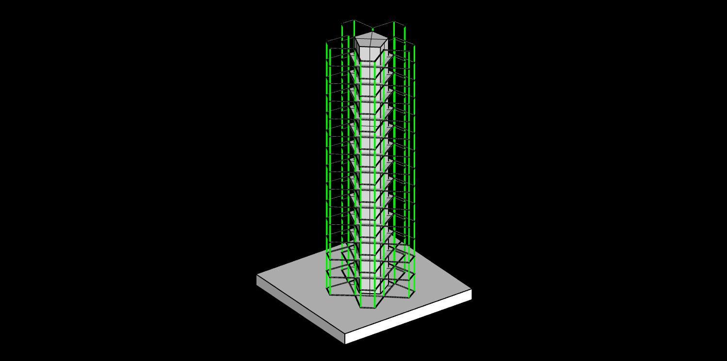
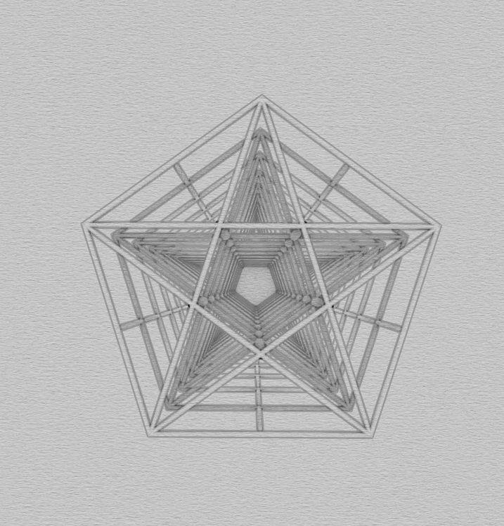
LOADTRANSFERDIAGRAM-PLAN LOADTRANSFERDIAGRAM-ELEVATION
Team15| DesignReport CONCLUSION
ANALYSISANDCONCLUSION
VERTICALLOADTRANSFER HORIZONTALLOADTRANSFER
ANALYSIS
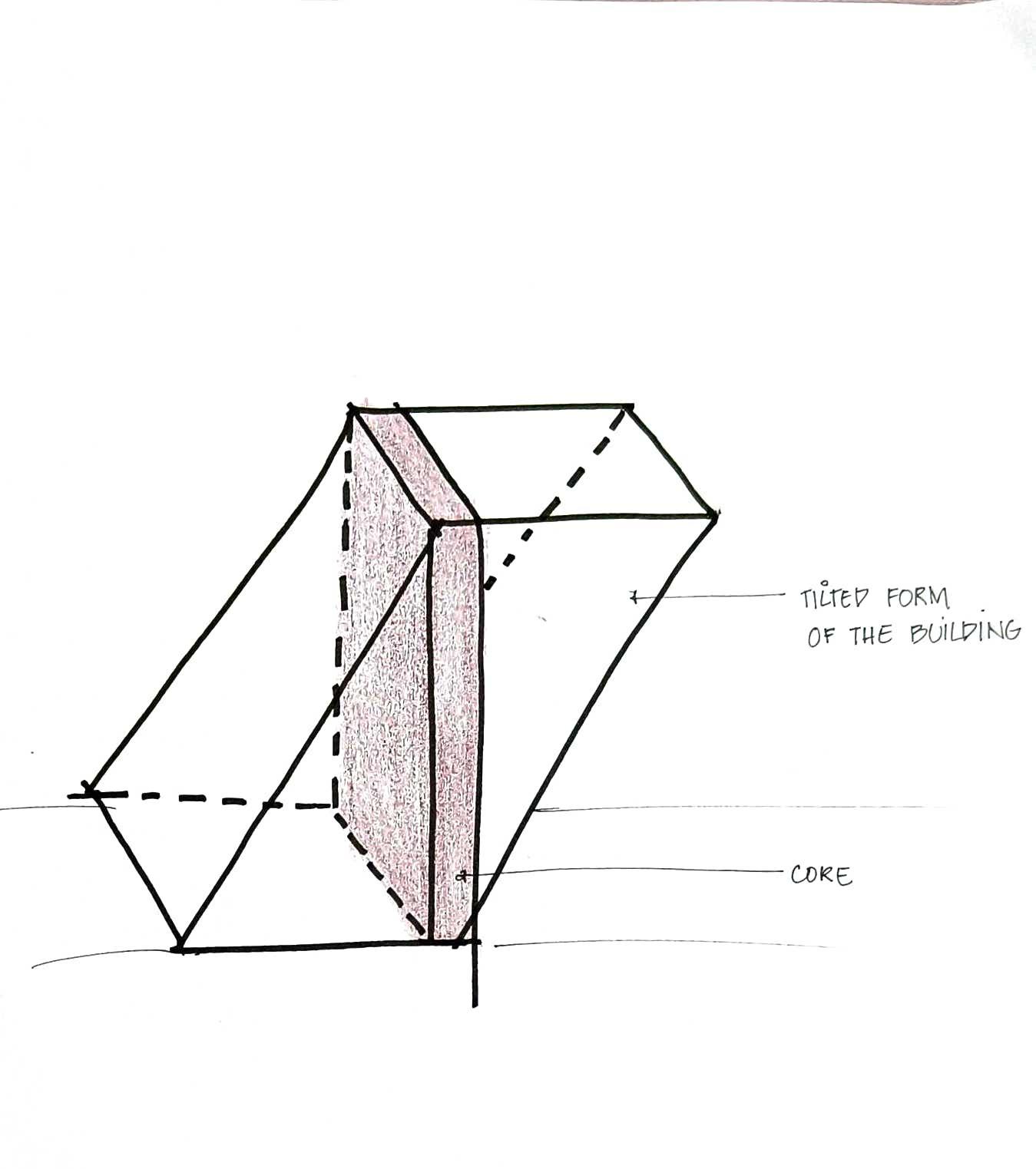
Itwasaninspirationalideaandwewantedtomakeitworkbymaking minimumcompromises.Butaftercomingtotermswiththescaleand magnitudeofthedesignweunderstoodthatastructurewithsuchacantilever wouldnotbeprobableandhencetomakeitprobable(beforemakingit earthquakeresistant)weneededtomodifyittoaformthatwouldbeableto standstableonitsownandfurtherbestableduringanEarthquake.Thiscould bedoneintwoways;
1. Reducethecantileverstoanallowablelimit.Thiswouldallowthe structuretobeabletobalanceitselfwellandnotfailevenintheabsence ofanearthquake.
2. Addverticalsupports-columnswhichwouldautomaticallyremovethe cantilever.Thiswouldmakethestructurestableandmoregrounded henceallowingeasiertransferoftheloadstotheground.Itwouldadd rigiditytotheentiremassandhencethemovement,damageduringand earthquakewouldbereduced.
Inboththecasesthedesignwouldbecompromisedhencewechoseacase combiningboththeideasintoonesolution
Team15| DesignReport ANALYSIS
WHENOPTION1WOULDBEIMPLEMENTED WHENOPTION2WOULDBEIMPLEMENTED
BRACINGANDSTIFFENING FINAL3DSKETCH Team15| DesignReport MODIFIEDSKETCHES
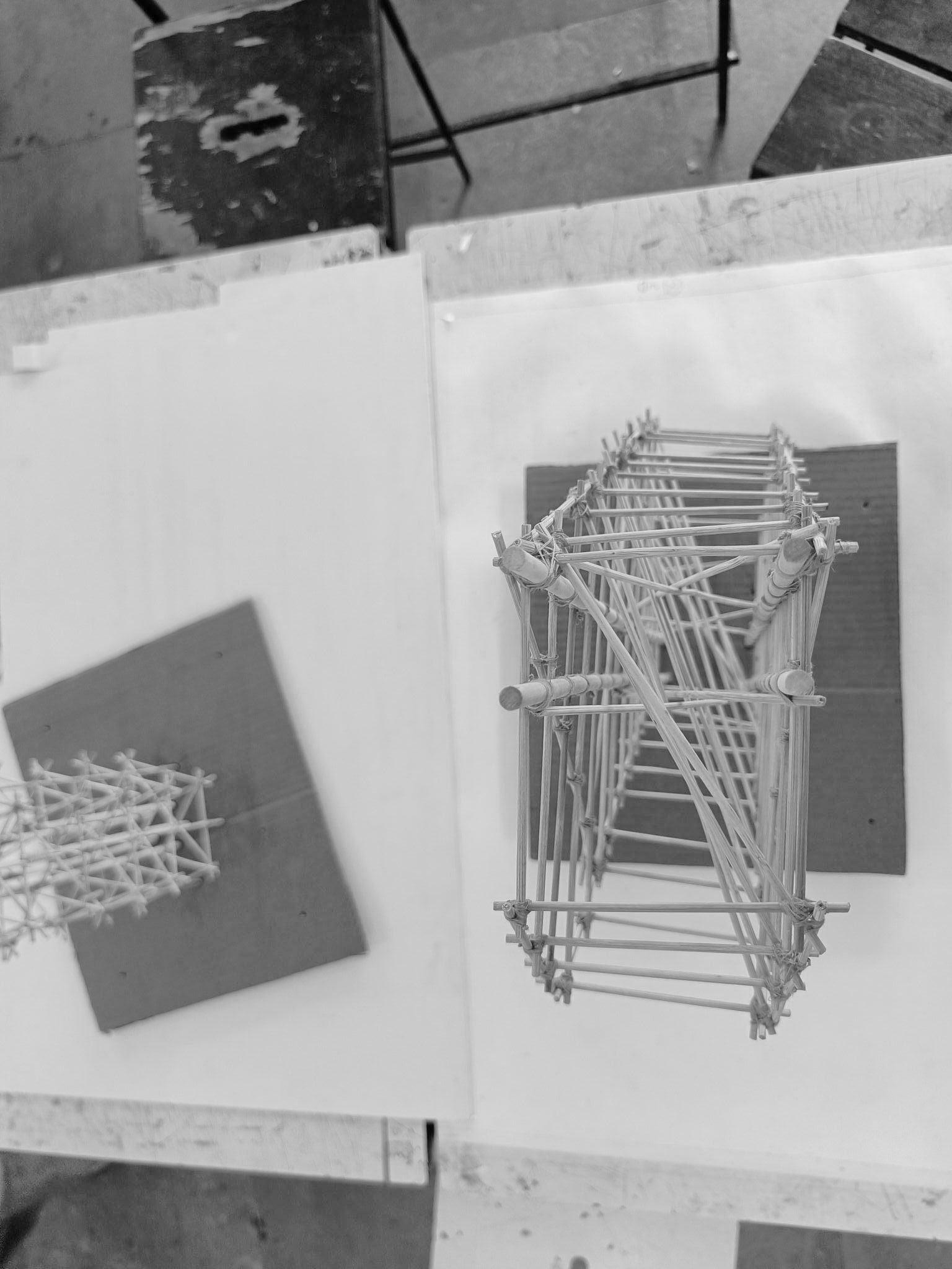
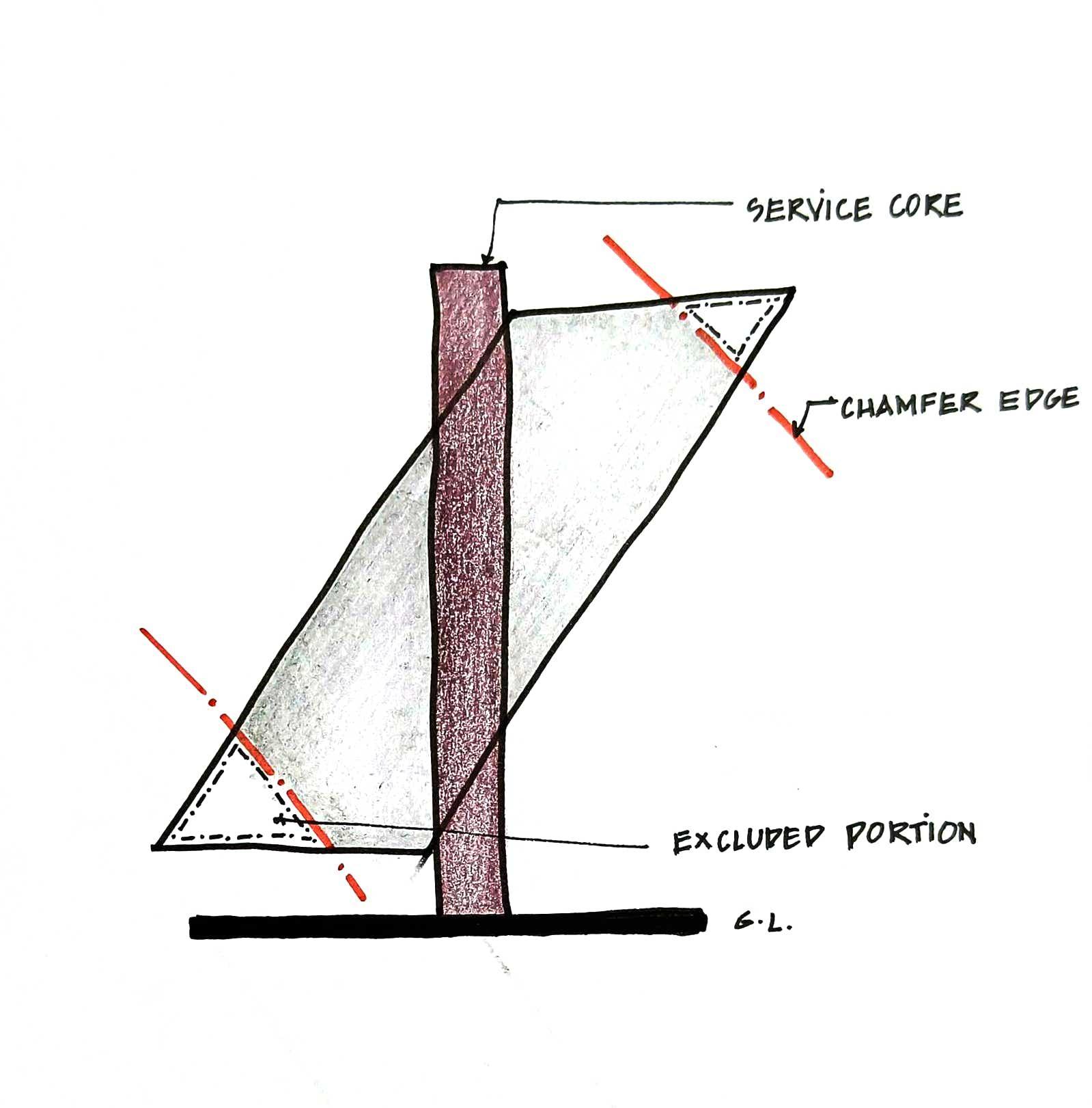
CHAMFERINGTHEFORMTOREDUCECANTILEVER ADDITIONALANCHORINGTOTHEGROUND
Despite the earthquake's magnitude, the design remained fairly stable during the test. Theform'schamferincreasedthestabilityofthestructurebyreducingthecantilever.
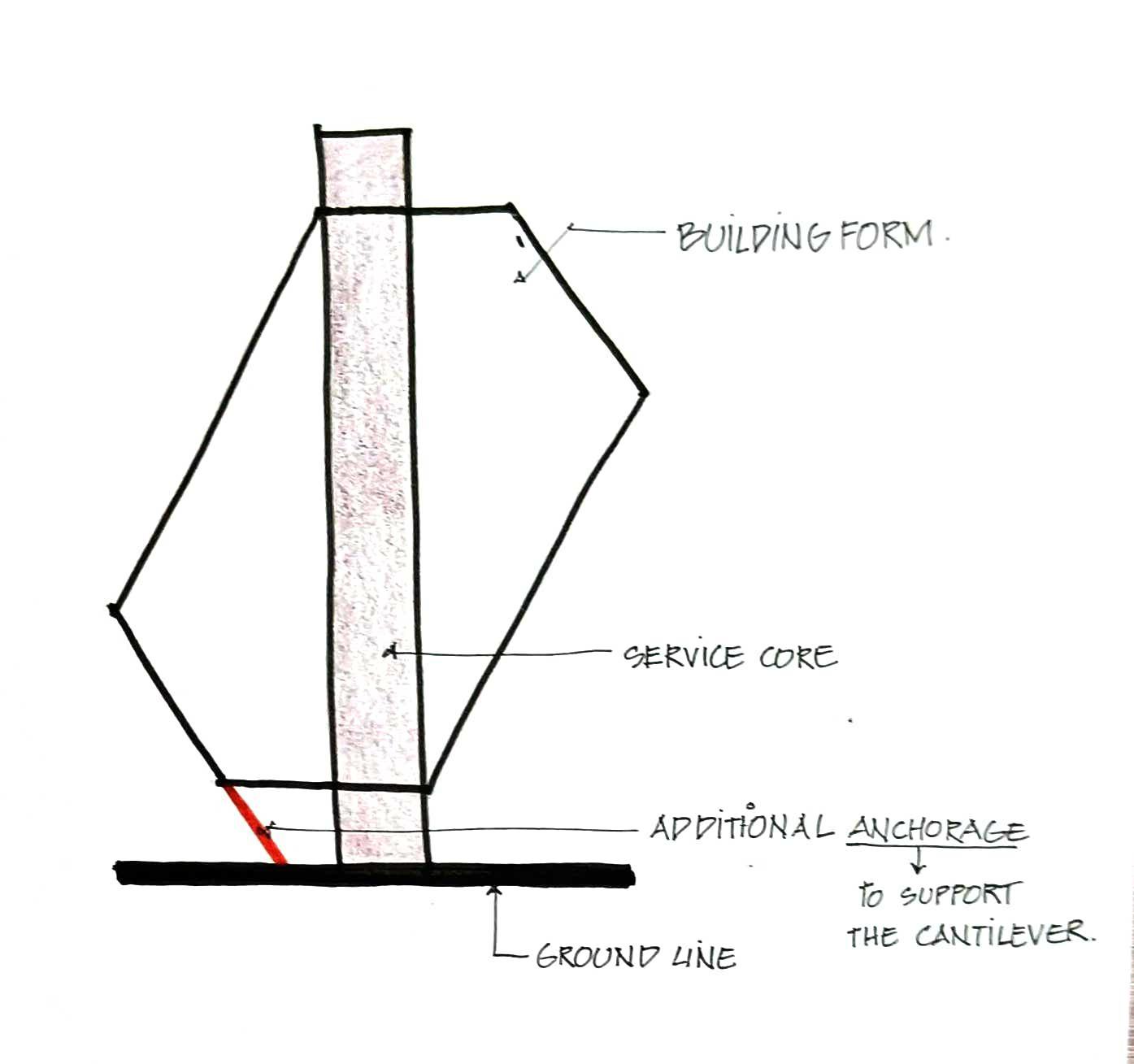
The angular column that connected the floor plates externally was extended to the ground, contributing to the structure's support and stability while providing an alternative route for load transfer to the ground. It effectively reduced the cantilever spanwhilemakingfewerdesigncompromises.
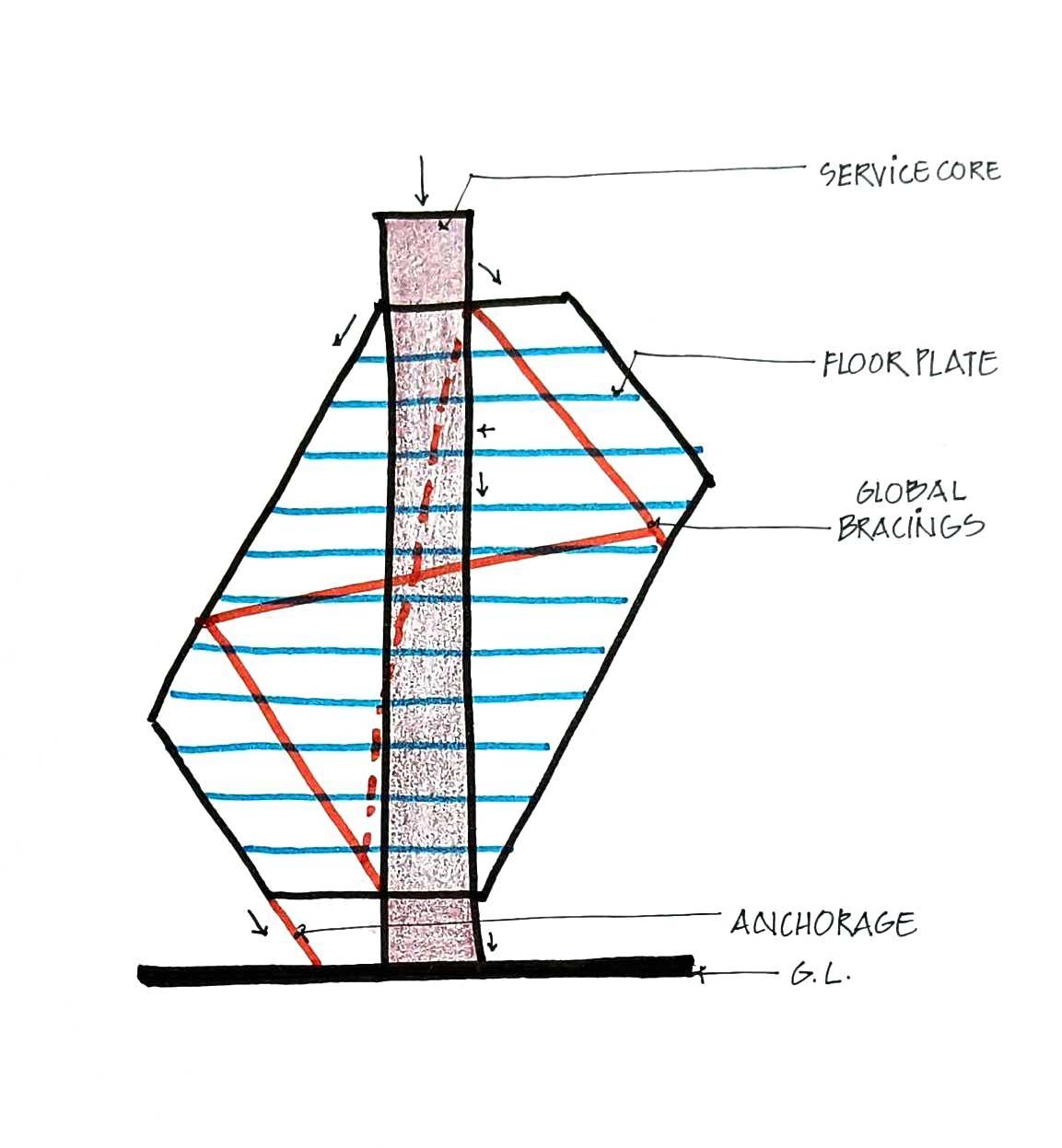
Thecoreservedasameansoftransferringtheentireloadofthebuildingtotheground. The only way to keep it from falling over owing to the weight of the cantilever was to make it stronger and more sturdy. As a result, the columns in the core were braced verticallyaswellmakingthestructurelessvulnerabletofailure. Bracing the floor plates individually also reduced the torsion and the probability of failureoftheslabbymakingtheshapemorerigid.
Topreventthehorizontaljointsfrommovingortwisting,thebracingprovidedwasatan angle (along the facade), to the overall form which made the floor beams and slabs rigidthusreducingtheirmovementandprobabilityofsnapping.
Evenintheabsenceofsymmetryinthestructure,theloadgottransferredtotheground andthestructureacedthetestbyallowingminimummovement.
Team15| DesignReport CONCLUSION
CONCLUSION
ANALYSISAND
SIDEELEVATIONSHOWINGBRACINGINTHECORE FRONTELEVATIONSHOWINGBRACING COLUMN BRACING ANGULARCOLUMN MAINBRACING
AcademyofArchitecture,Mumbai
GROUP16 SEJALUMARE_01 KIMAYACHURI_07 SANCHITATANDEL_44
REPEATINGUNIT
CORE PLAN
1/3RDSTAGGER
CROSS BRACING
1/3RDSTAGGER
Team16| DesignReport INITIALSKETCHES
IMAGETITLE
Team16| DesignReport DIGITALMODELPHOTOS
IMAGETITLE
1.1FRONTELEVATION 1.2PLAN
ELEVATION Team16| DesignReport MODELPHOTOS 3WAY CORNER JOINT
LAP EXTENSIONJOINT
2.1
HALF
FIRSTMODEL
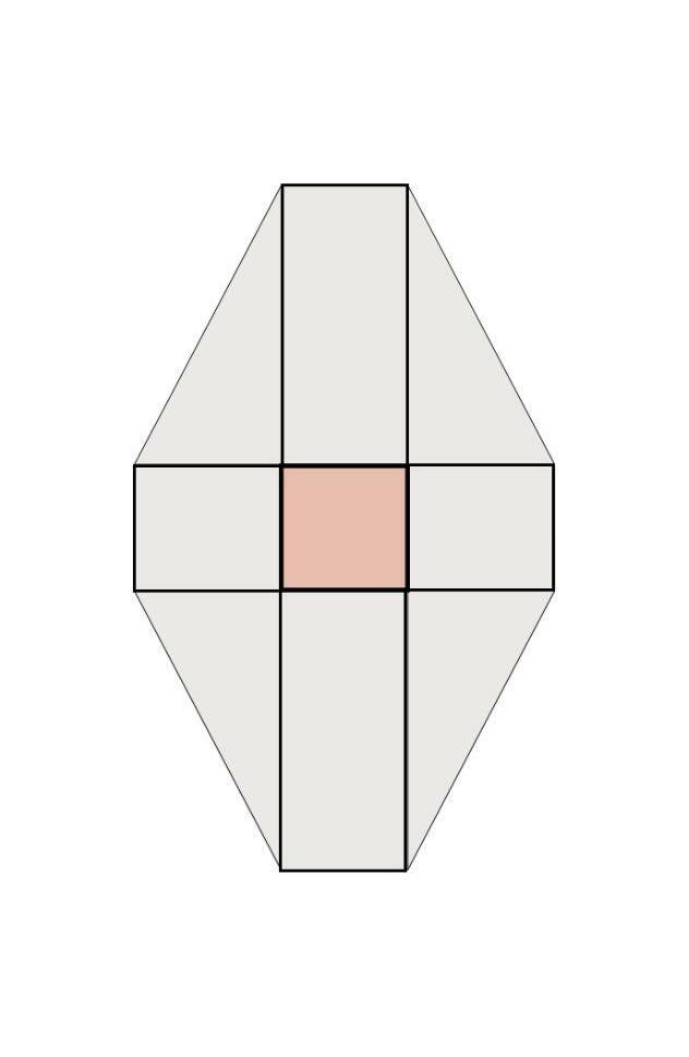
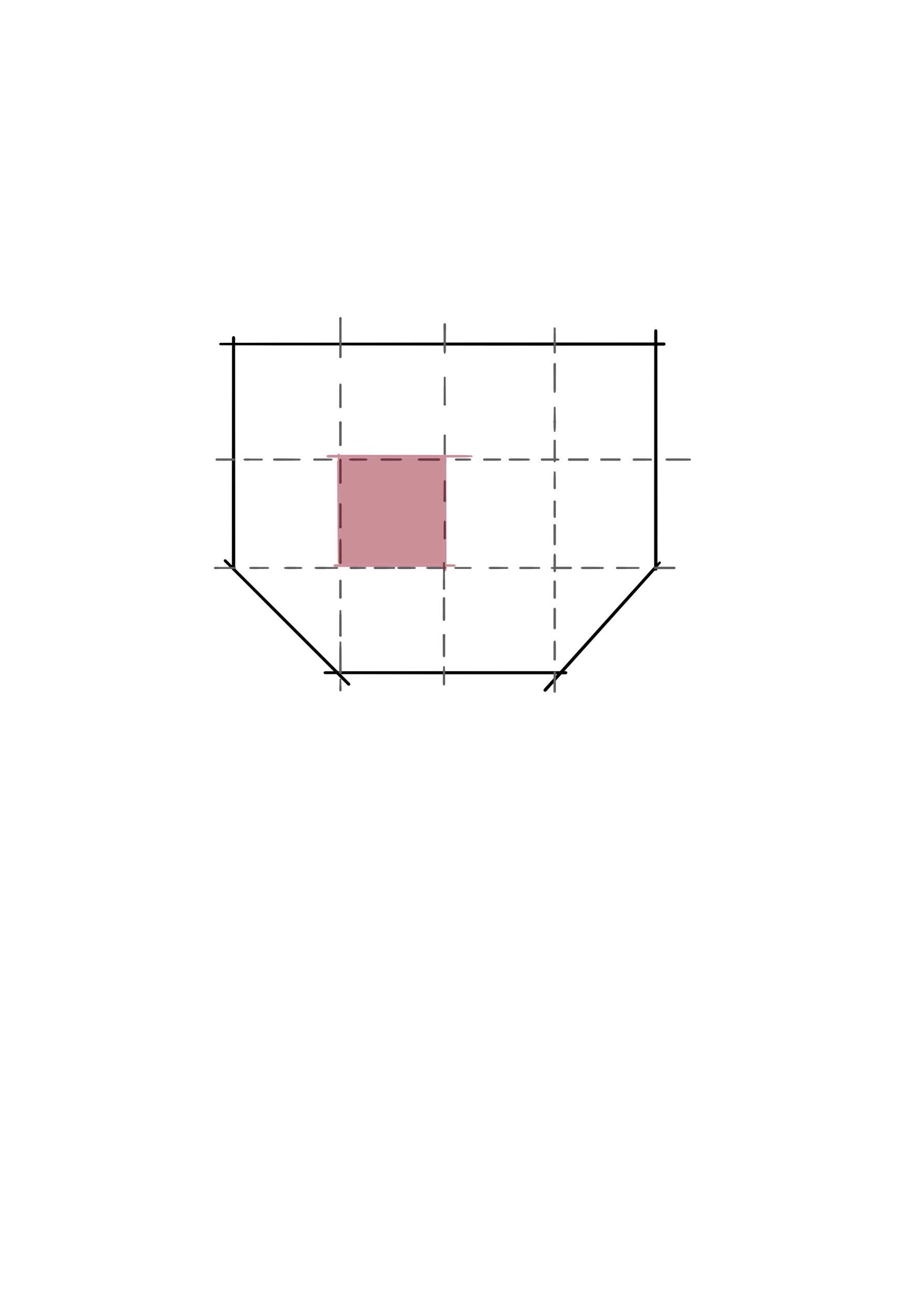
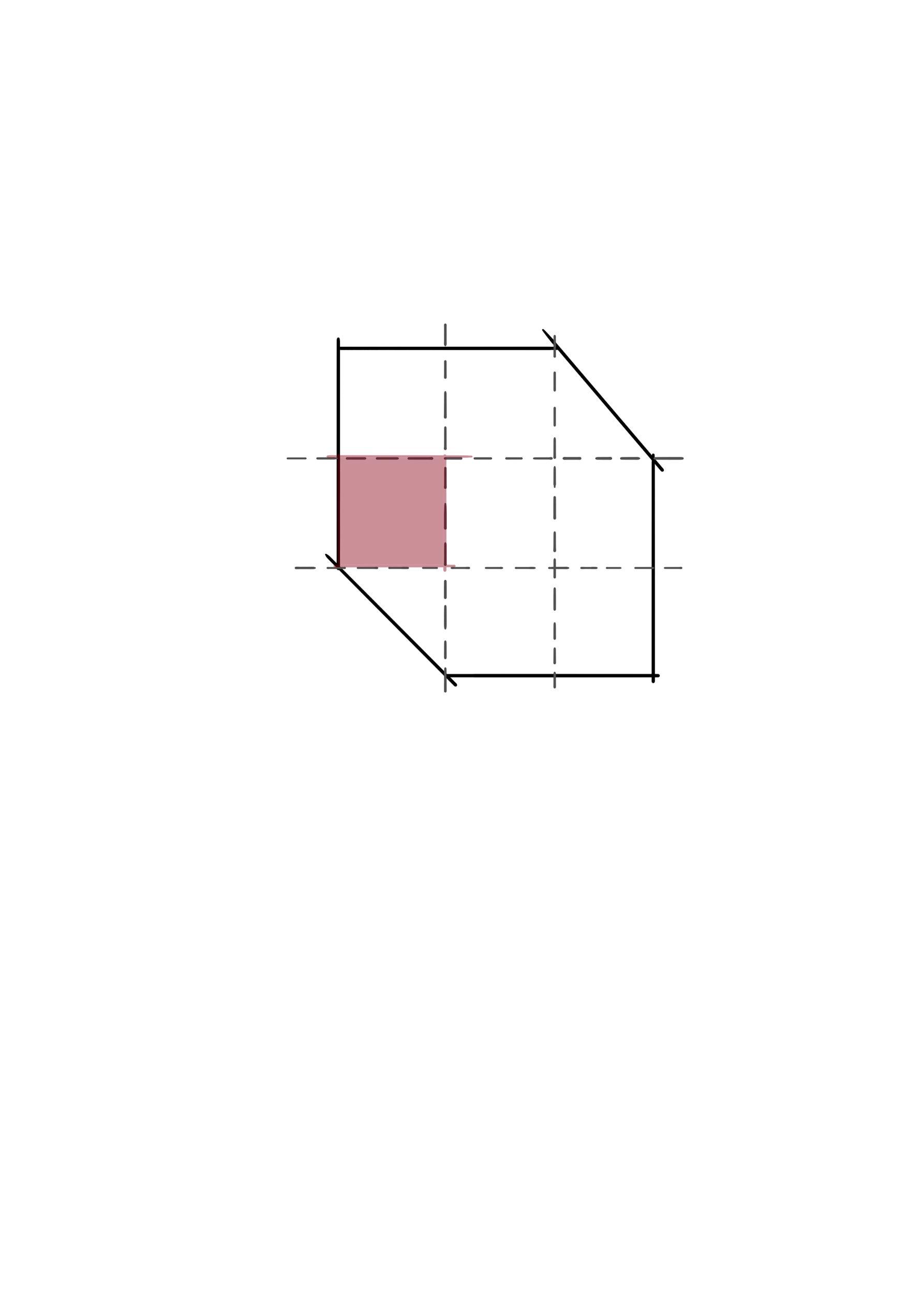
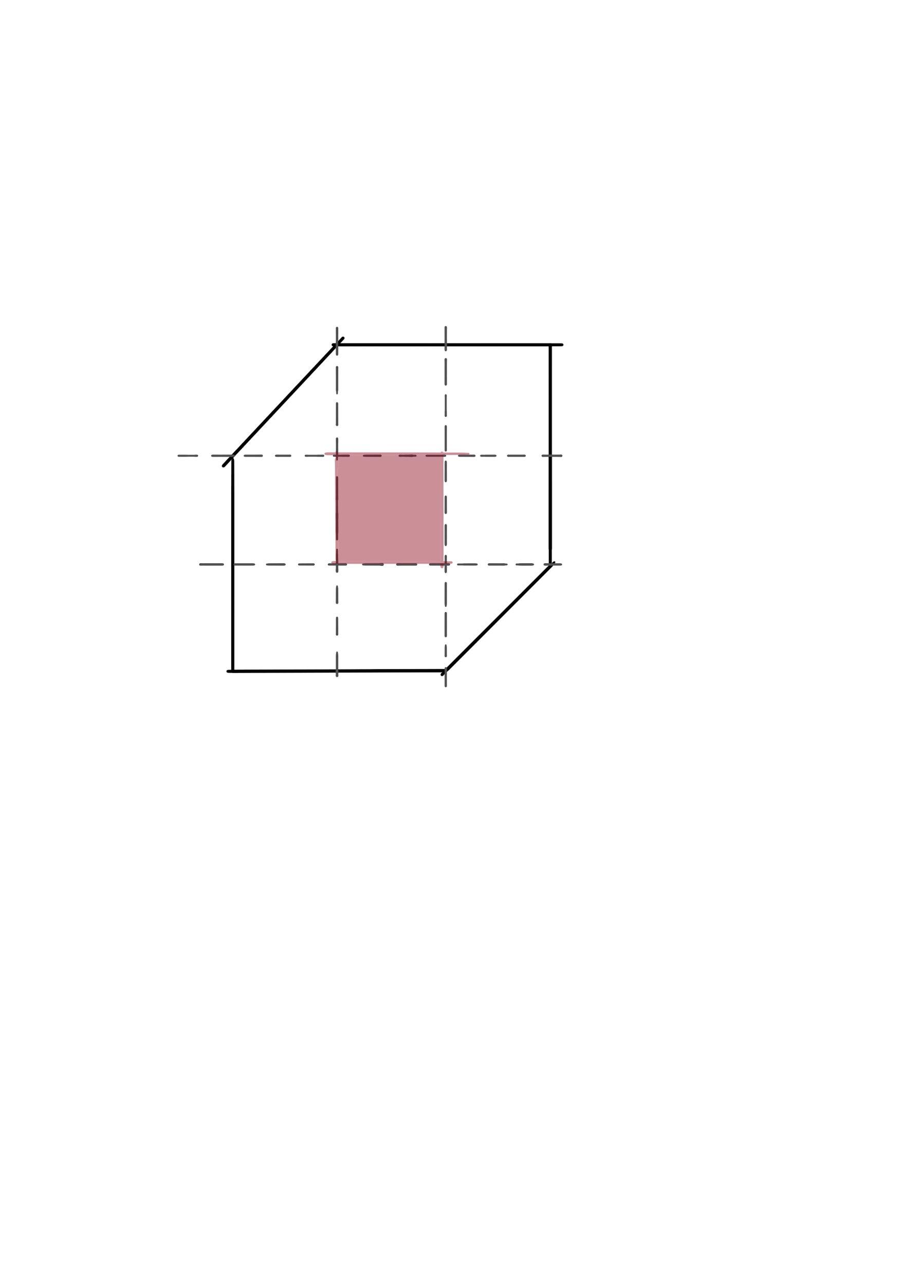
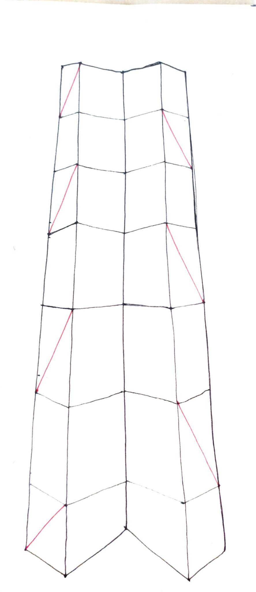
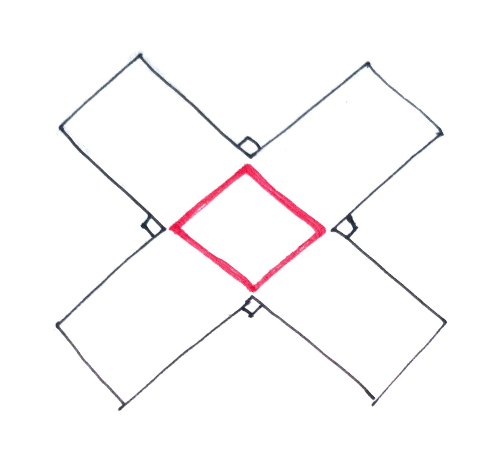
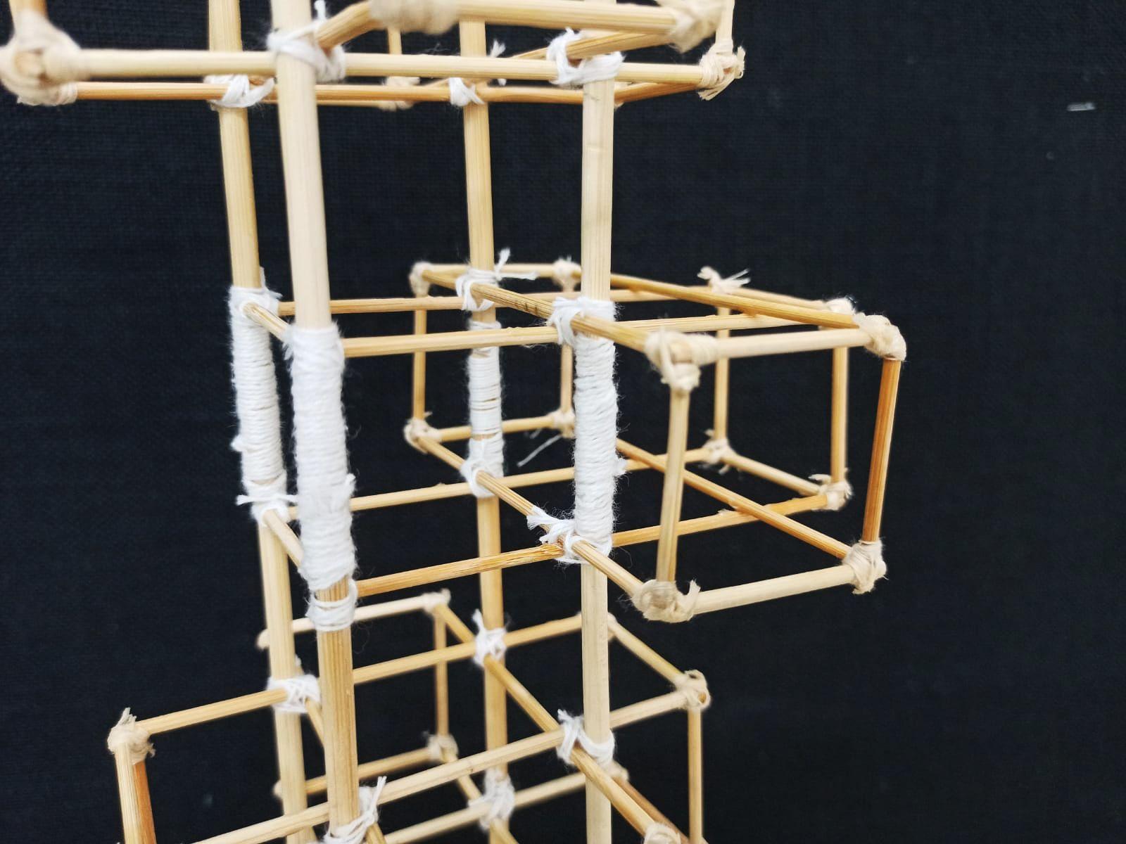
● Thisisgeometricalmodelwherethesquareshapeof 10cmx10cmisdividedequallyintonineparts.
● Subtractingthefourcornersofthesquareacrossshapedis beenformedwhichformsafloorplate foramodel.
● Thecoreatthecenterhavealternatebracingsatevery5floors
● Thefloorplateisshiftedontheupperfloorsaftereveryalternate floors,thatisthefloorplateatevery5floorsisdifferent.
● Thealternateshiftoffloorsgivessymmetryandalsocounter weightstheloadofthestructureequally.
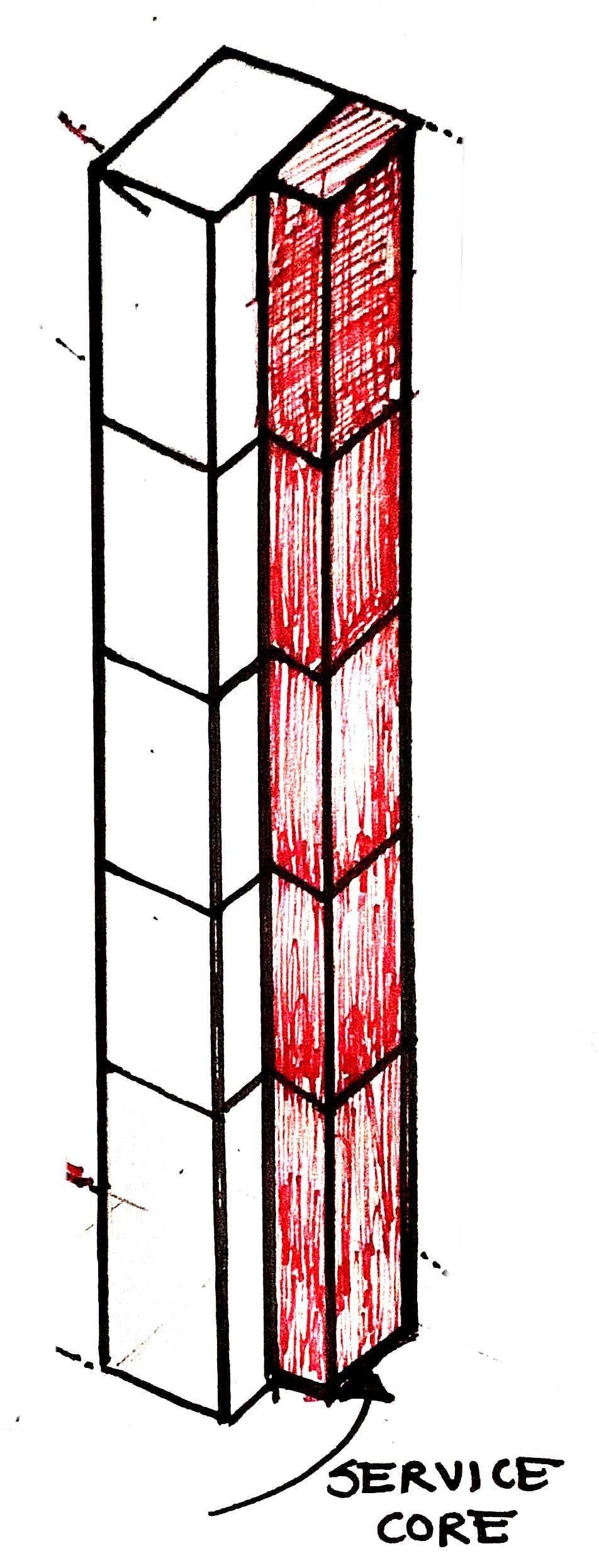
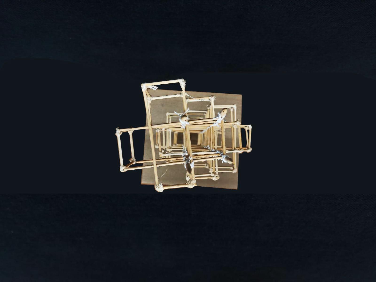
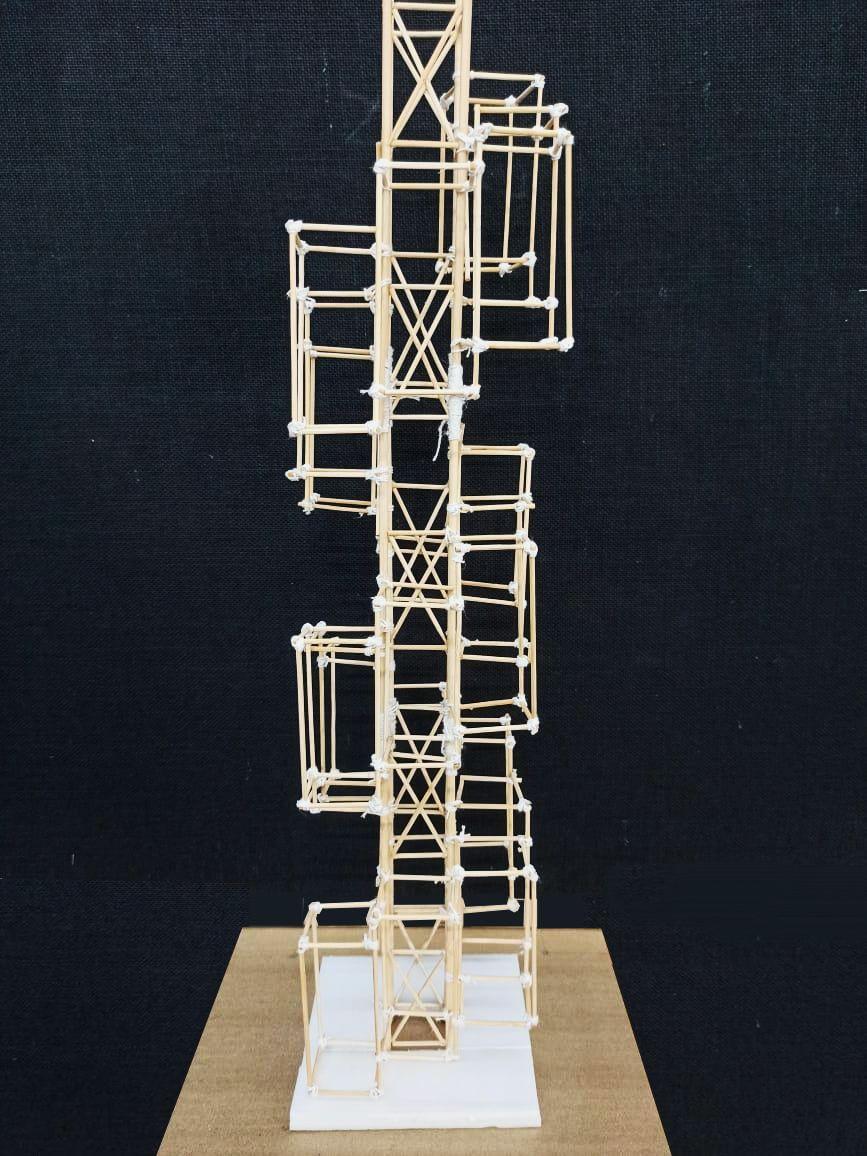
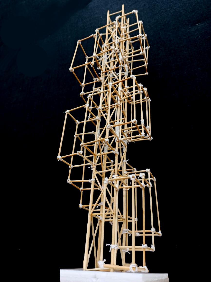
SECONDMODEL:
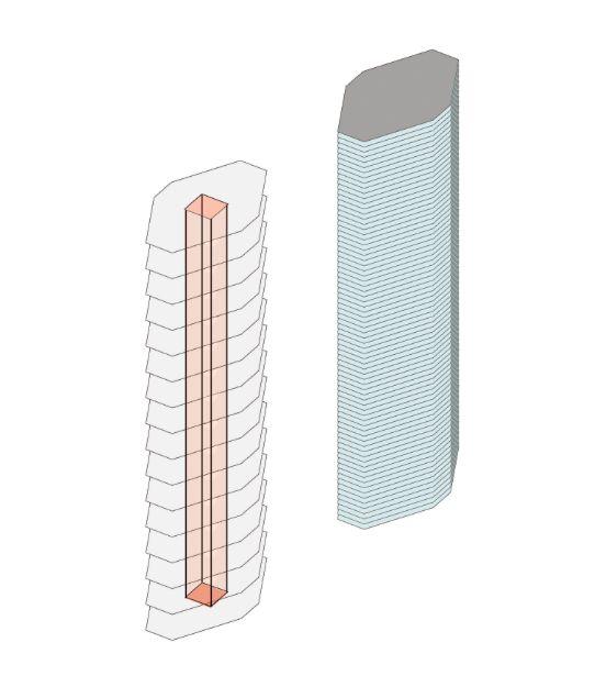
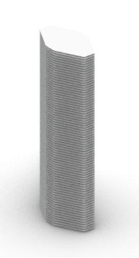
● Thecentrallyplacedcoreofsmallcross-sectioniswrapped alongtheperimeter bysquarefloorplates.
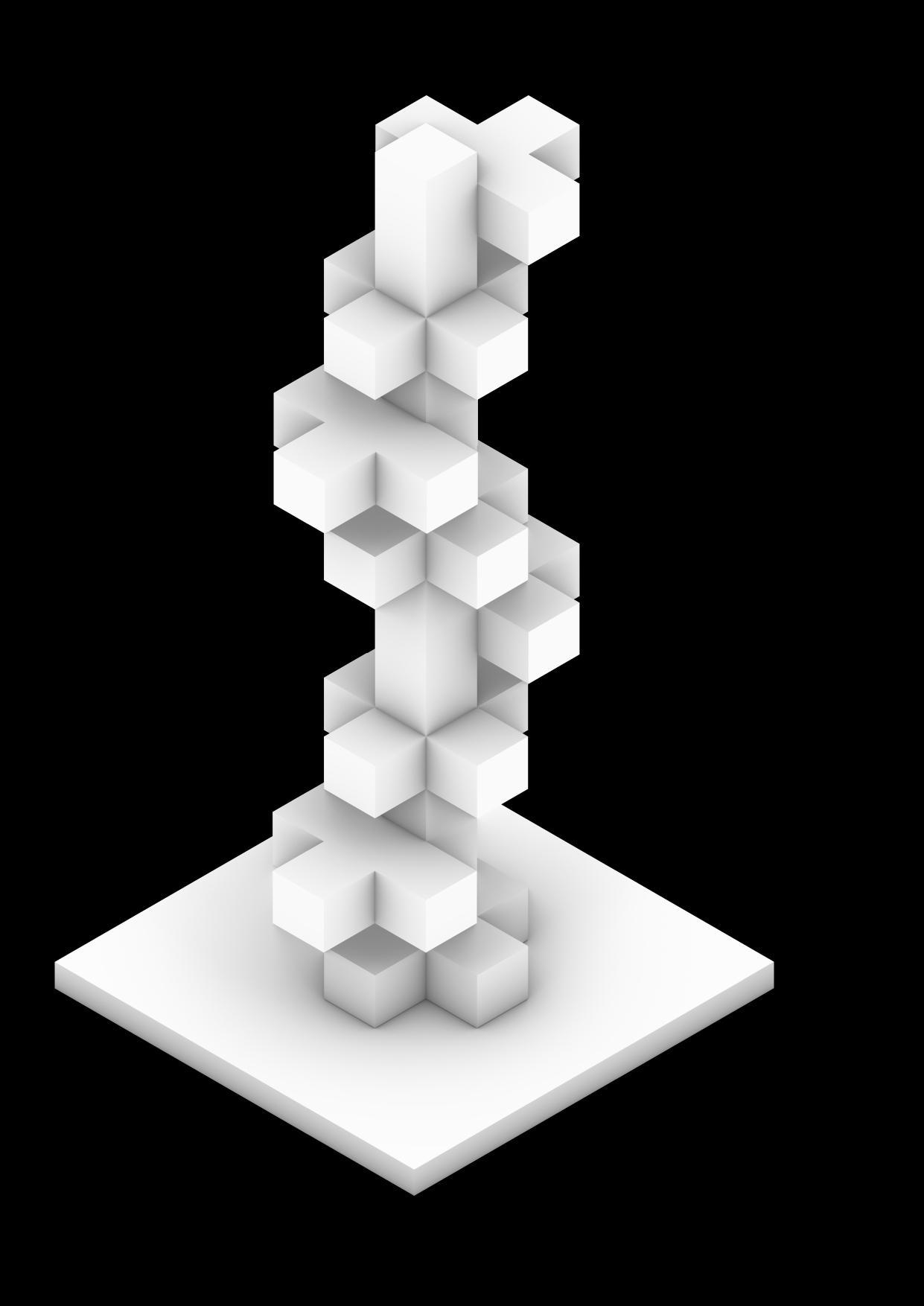
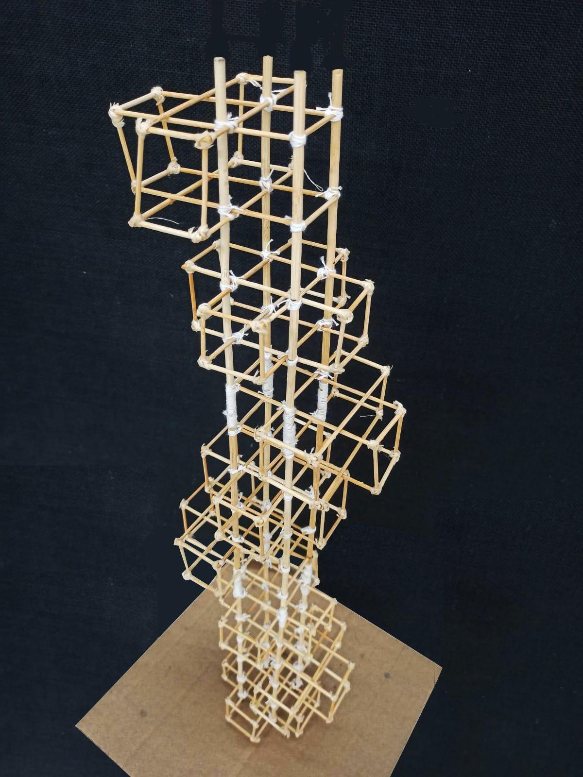
● Thecuboidconsistof5floorswitheachfloorheightupto4m. Thecuboidsareelevatedby2floorsi.e,8mineachconsecutive shiftgivinghelicalpathelevation.
● Thedoubleheightedspacescreatesterraces.
● Thecuboidsareconnectedviatransversegirdersystemtothe megacolumnsofcoretransferstheloadmakingedgescolumn free.
● Thecrossbracingsplacedalternateonoppositesidesalongthe twofloorstrengthensthecoreagainsttwistingproviding stiffness.
● Inordertocreatebalancebetweenthecantilevers,even numberofcuboidsarewrappedforonehelicalcurvewithlast cuboid placedexactlyoppositetothefirstone.
Team16| DesignReport CONCLUSION ANALYSISANDCONCLUSION
17
AcademyofArchitecture,Mumbai
GROUP
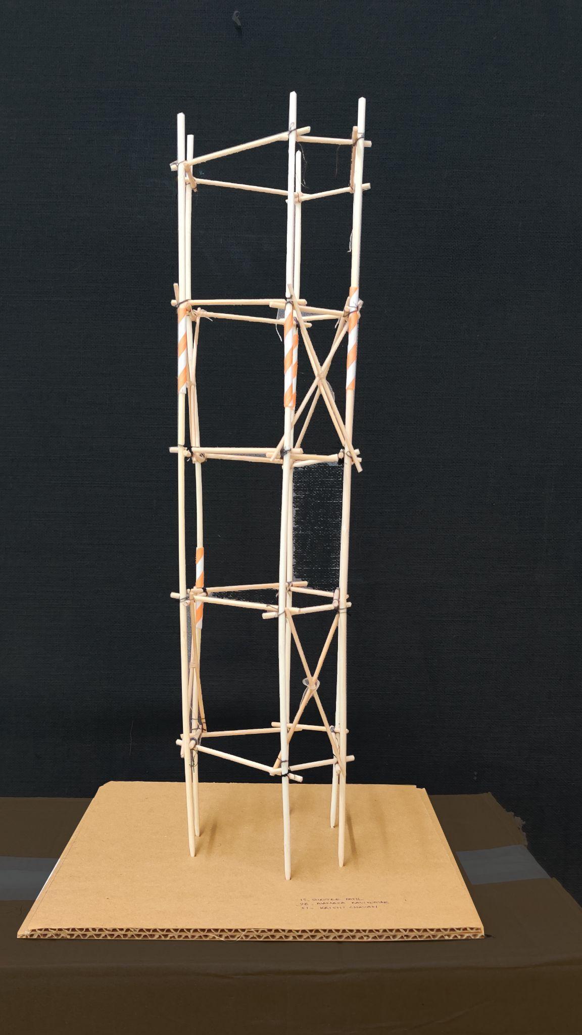
SHRUTEEPATIL_15 MANASARAVIKUMAR_28 KRISSHCHAVAN_51
EXPLORINGELEVATIONS INITIALIDEAS DECIDINGSTRUCTURALSYSTEMS
Team17| DesignReport INITIALSKETCHES
DIAGONALBRACINGOVER15LEVELS CROSSBRACINGOVER10LEVELS CROSSBRACINGOVER5LEVELS ISOMETRICVIEW
Team17| DesignReport DIGITALMODELPHOTOS
ELEVATION ELEVATION
Team17| DesignReport MODELPHOTOS
INITIALIDEAS-ELEVATION
INITIALIDEAS-ISOMETRIC
Team17| DesignReport DIGITALMODELPHOTOS
AXONOMETRIC Team17| DesignReport DIGITALMODELPHOTOS
ELEVATION
MODIFIEDELEVATION
PLAN
Team17| DesignReport MODELPHOTOS ELEVATION ELEVATION
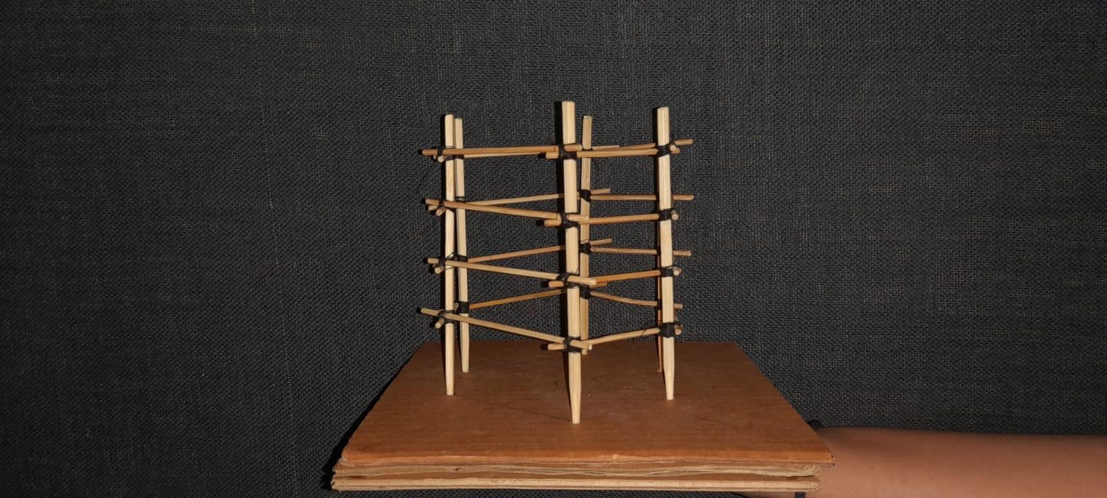
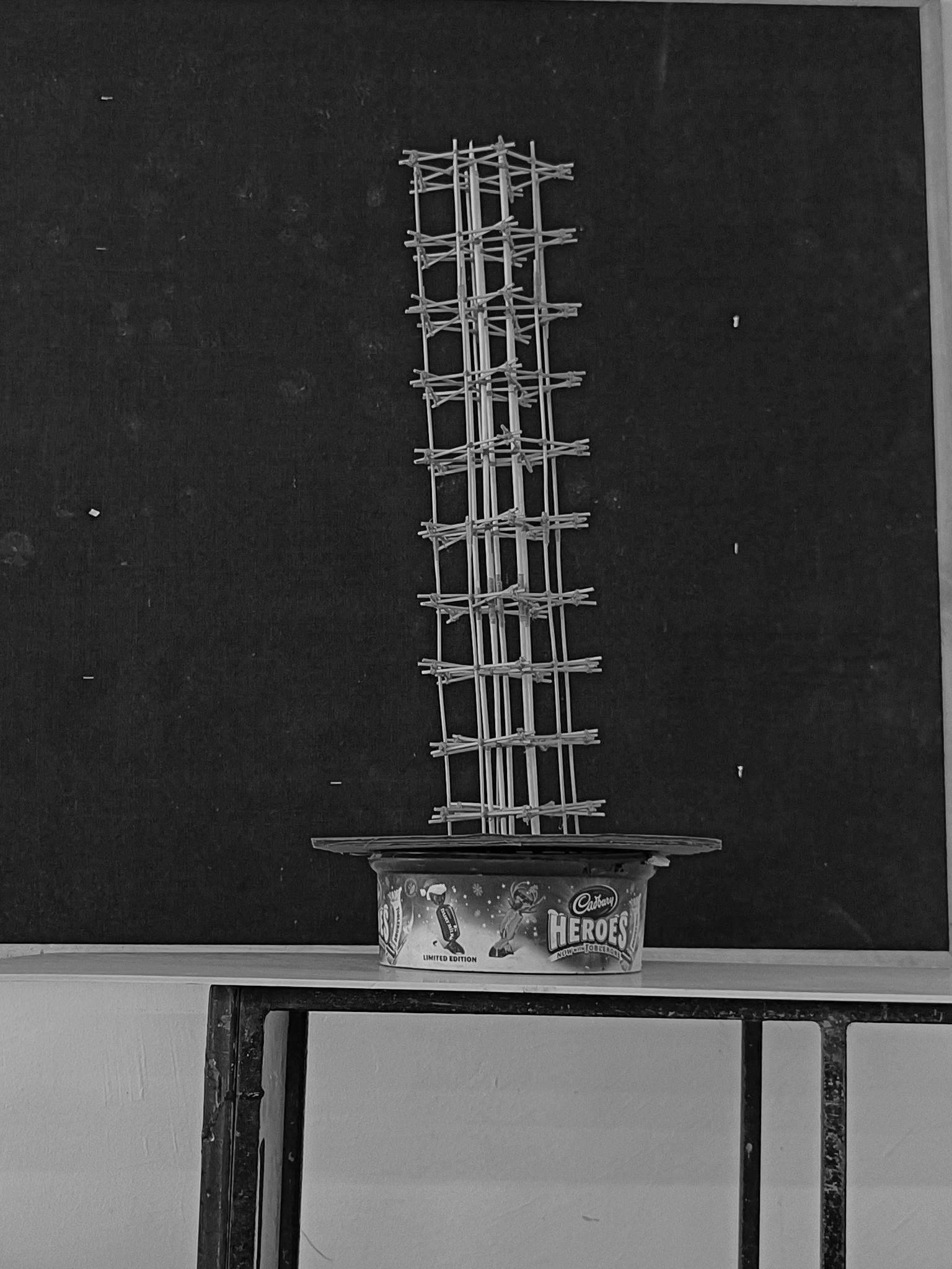
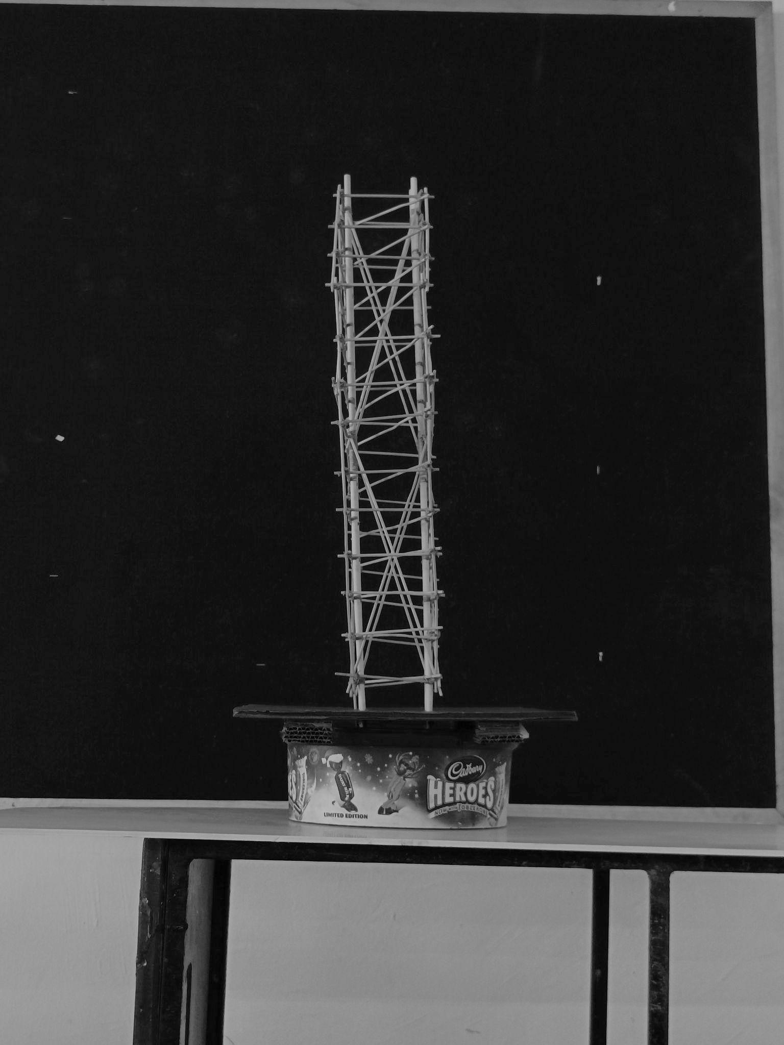
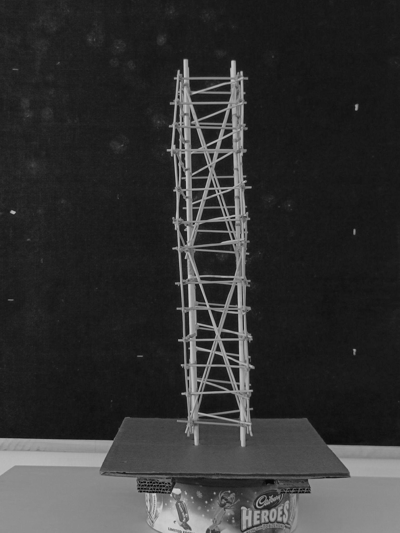
FIRSTMODEL(GEOMETRIC):
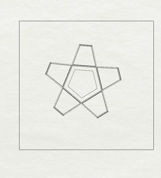
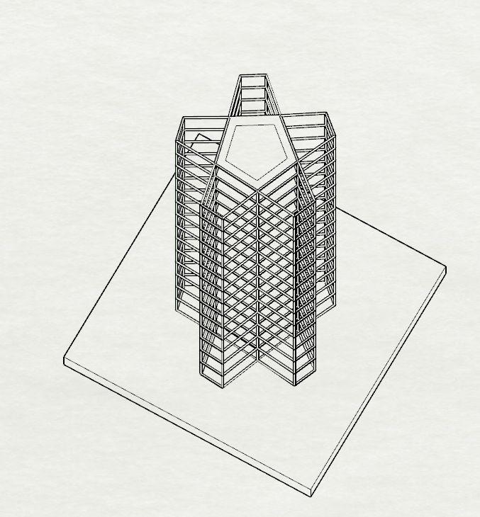
● Apentagonshapedbasewaschosenforastablebaseform andanextrudedvolumewascreatedataheightof75m.
● Theirregularshapedpentagonshadshorterandlongersides.
● Thefacadesoftheshortersideweregivendiagonalbracingson everyalternate5floorsofthebuildingsinordertooptimizethe totalnumberofmembersrequiredandused.
● This helped in tying the floors together apart from the main structuralmembers(columns)andreducedtheswayingofthe buildingofsuchheight.
● Asimpleformworkwasadaptedandworkedontounderstand thebasicsofloadtransferandplacementsofbracings.
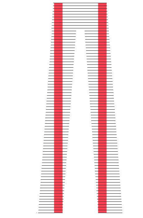
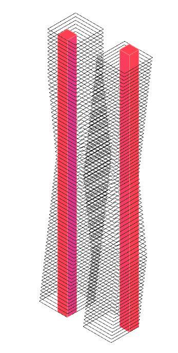
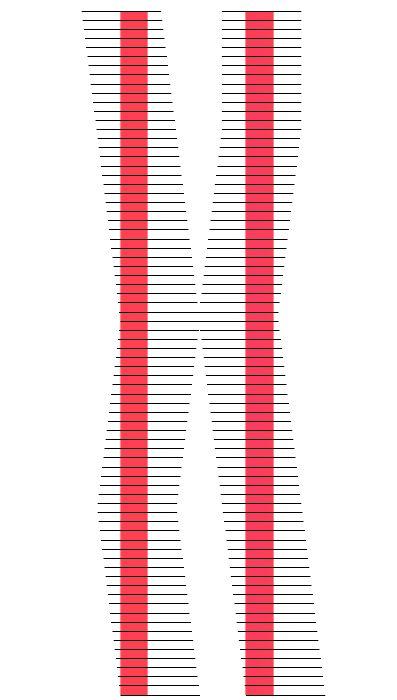
SECONDMODEL(SCULPTURAL):
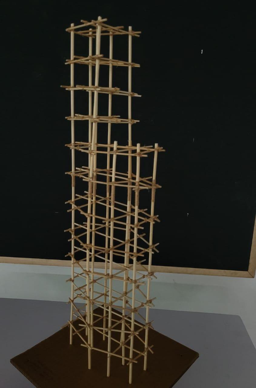
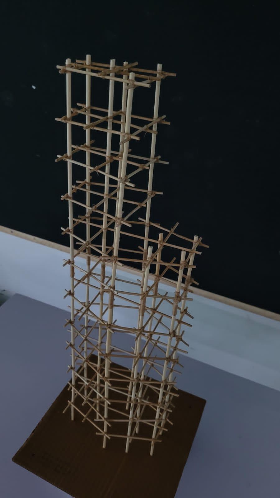
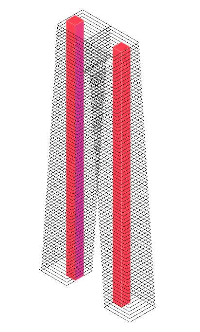
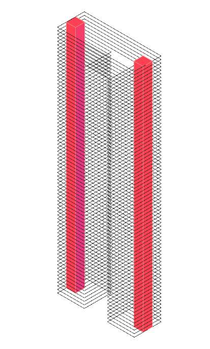
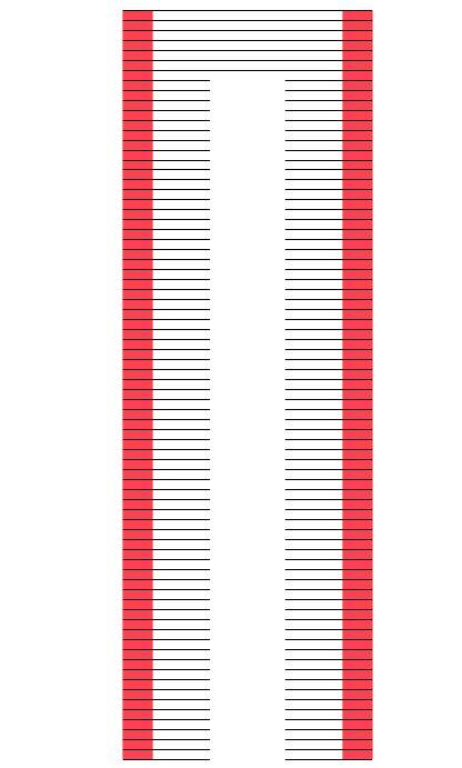
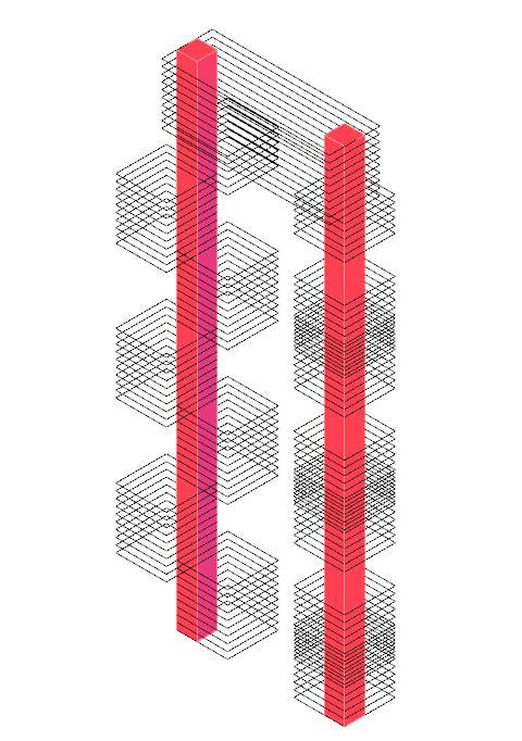
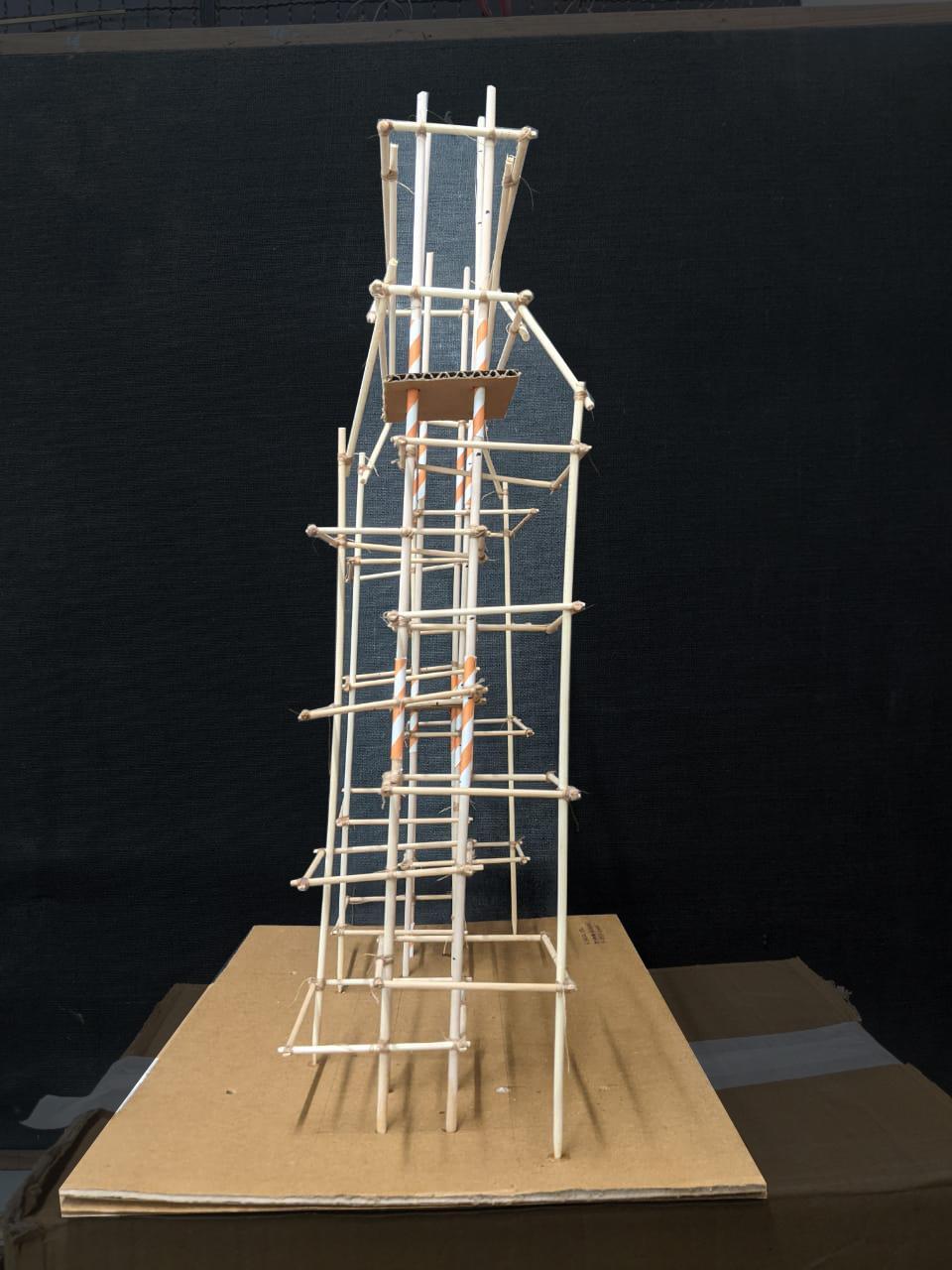
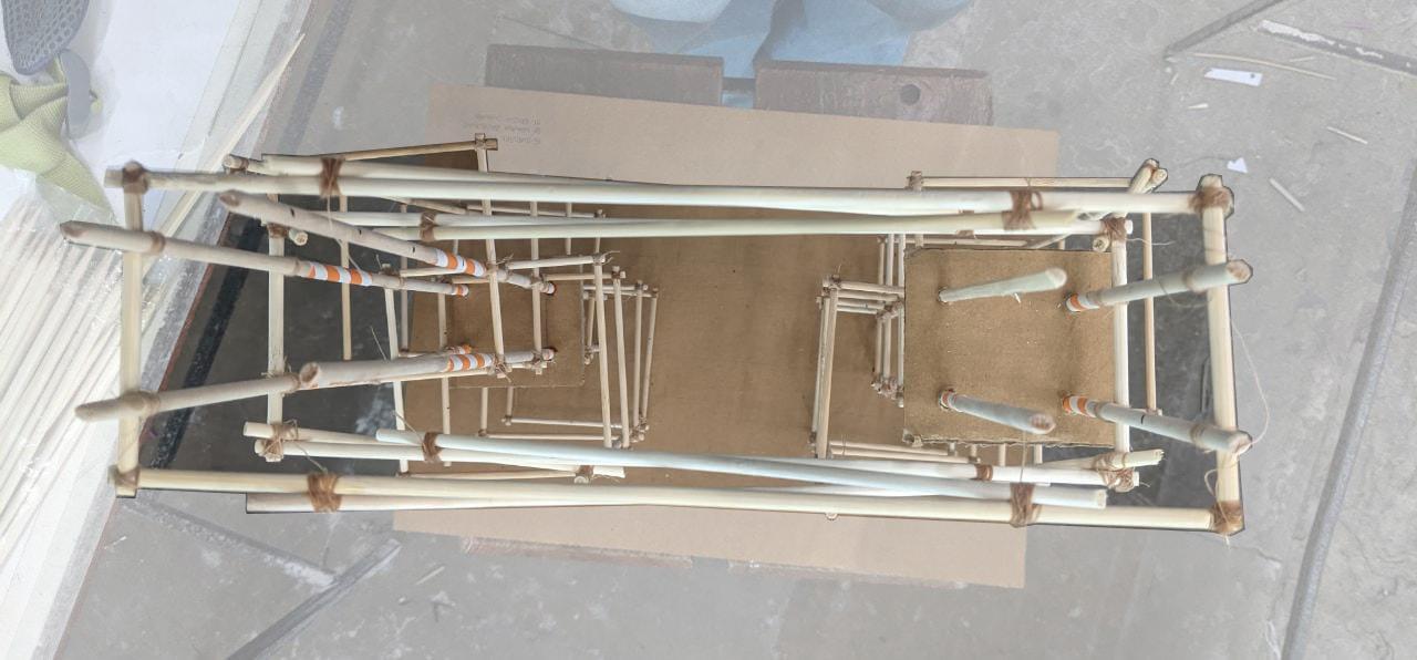
● Astructuresplitinto2joinedonthetopfloorswasthebasic outlineoftheform.Thestructureswasservedby2different servicecoreat2endswhichaddedtothestructuralsystemof thestructure.
● Thefloorplateswereshiftedtoeitherendsoftheservicecore allowingfordoubleheightspacestobeformed.Thesewere joinedtogetherusingcolumnsgoingthroughandthrough.
● Thetopportionofthestructurewhichactedasacommon joiningportion,wasbraceddiagonallyforaddedstability,soas toalsobearthestrengthofjoiningthetwodifferentbuildings andtheirservicecores.
Team17| DesignReport CONCLUSION ANALYSISANDCONCLUSION
AcademyofArchitecture,Mumbai
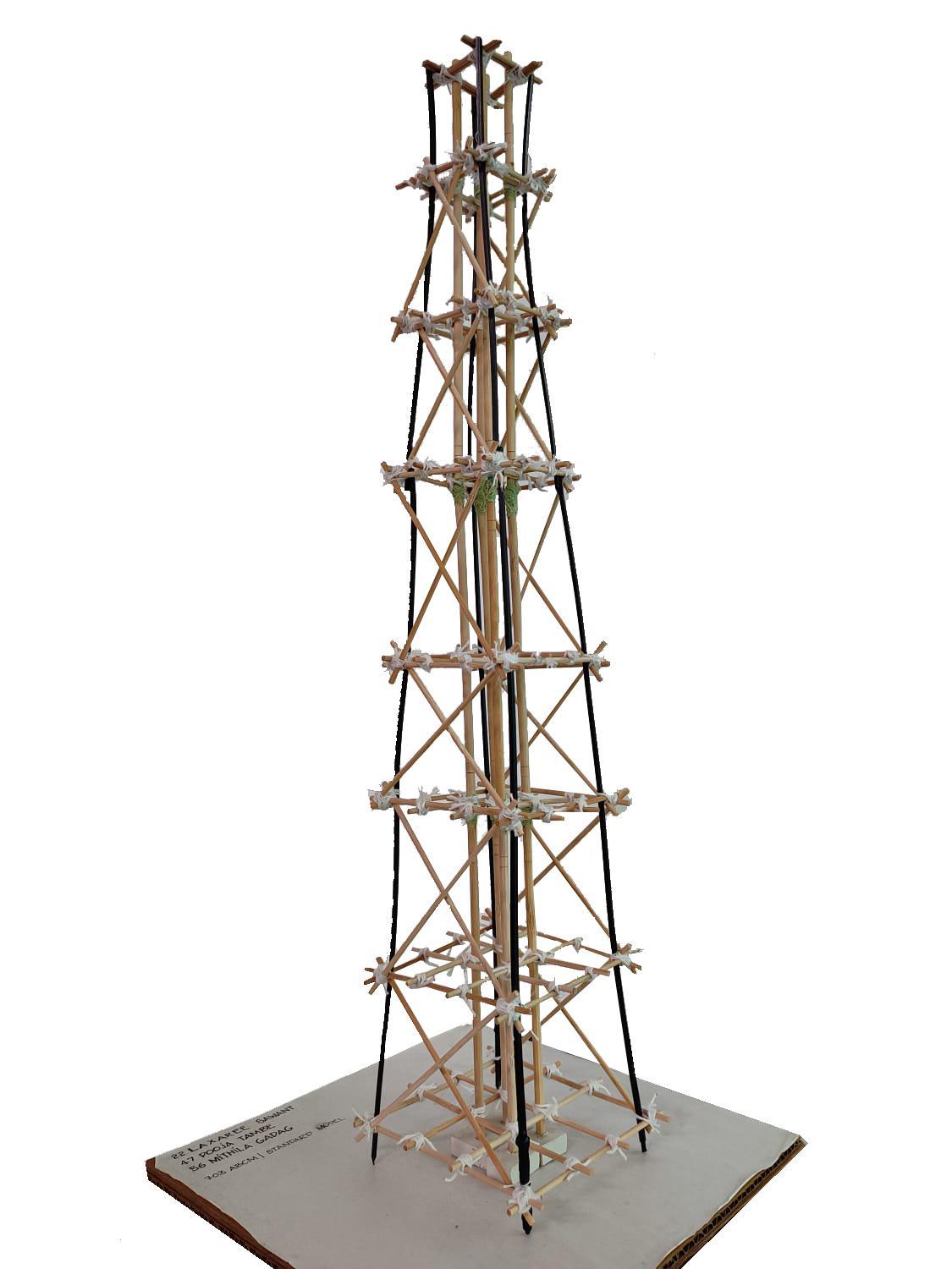
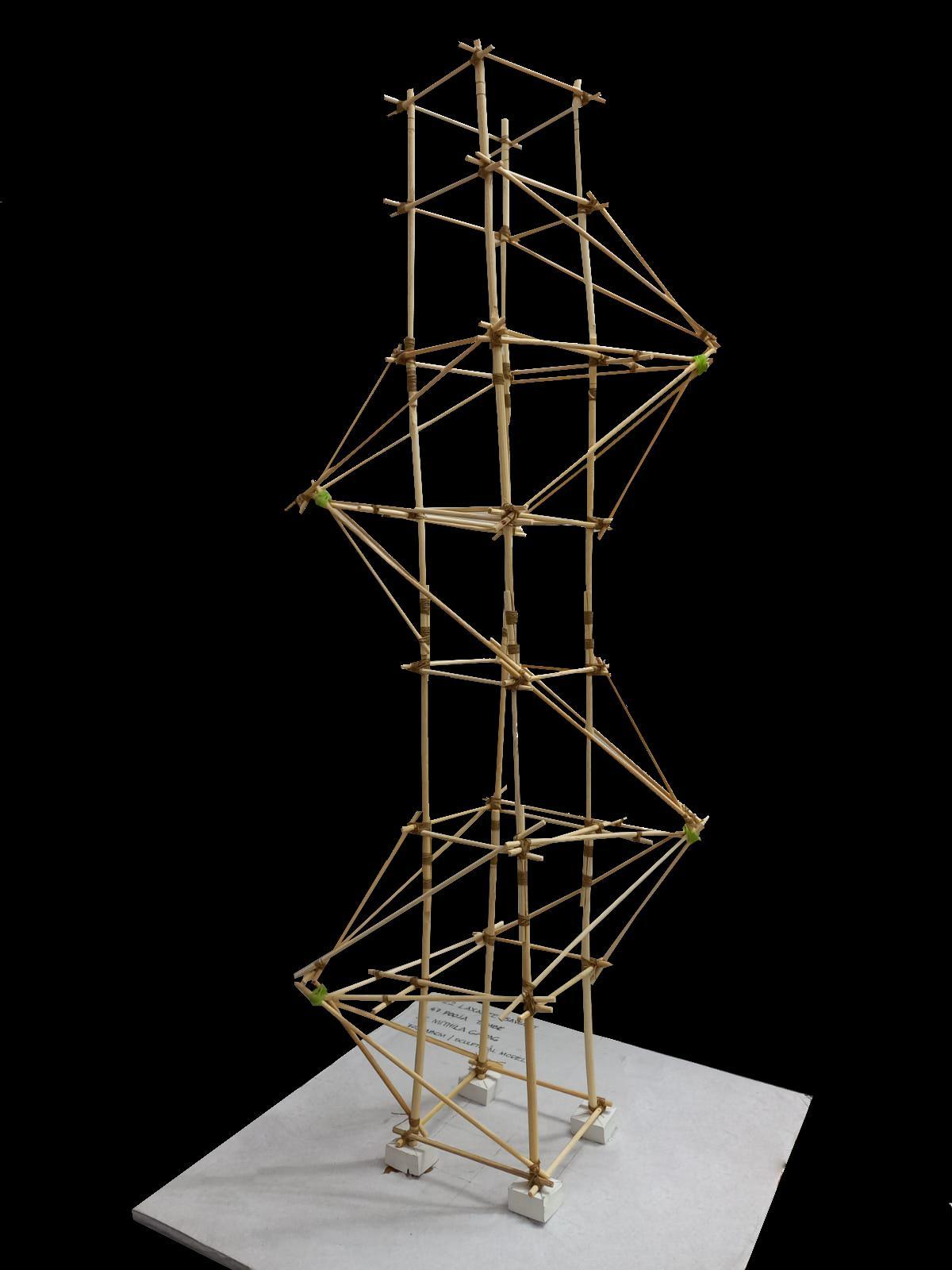
GROUP18 LAXAREESAWANT_22 POOJATAMBE_47 MITHILAGADAG_56

SCULPTURAL
in) Team18| DesignReport DIGITALMODELPHOTOS
STANDARDMODEL(Full) SCULPTURALMODEL(Full) STANDARDMODEL(Zoomedin)
MODEL(Zoomed
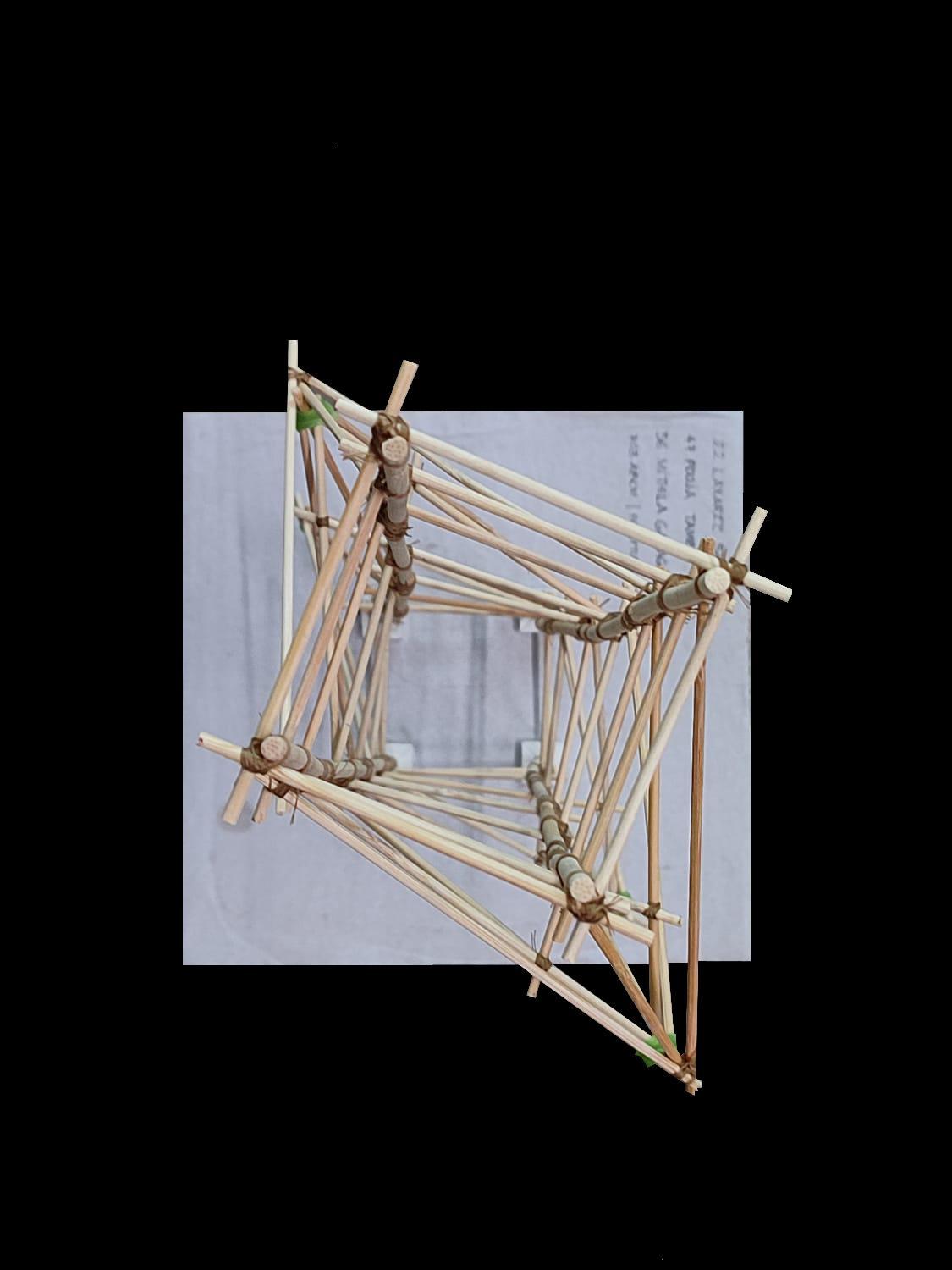
STANDARD MODEL(Plan) SCULPTURALMODEL(Plan) STANDARD MODEL(Elevation) SCULPTURALMODEL(Elevation) Team18| DesignReport MODELPHOTOS
AStructureundergoesdamageduringanearthquakeduetothe forceexertedbythemovementofthetectonicplateswhichinduces momentsinthestructure
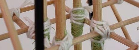
Thejointsofastructurearevulnerabletotheseforces,thusthey needtobewellsecured.
STANDARDMODEL
● Thecolumnsare connectedinabuttjoint, bydrillingholesintothe columnendandsecuring withthread.Sincethere wasnooverlap,thisiswas thepointoffailureand wherethestructurebent.
SCULPTURALMODEL
● Thecolumnsare connectedinahalflap joint,withanoverlapof 5cm,andsecuredwith thread.Thismadethe columnjoinerymore sturdyandsecure.
Plastic Hinge
AccordingtotheStrengthHierarchyofa structure,theperipheralcolumnsmust bestrongerthanthebeams.The contraryresultsintheformationof plastichingesatthebaseofthe columnswhichresultsinfailure. TheperipheralcolumnsinthisStandard Modelareslenderandsmallerin diameterthanthebeams,which contributedinthefailure,incontraryto theSculpturalModel.
Team18| DesignReport CONCLUSION
CONCLUSION
ANALYSISAND
BUTTJOINT(StandardModel)
LAPJOINT(SculpturalModel)
Theresistancetodeformationorinertiaofastructuredependson theamountofmassanditsdistancefromthecentroidalaxis. I=m×r2 where, m=Sumoftheproductofthemass r=Distancefromtheaxisoftherotation.
STANDARDMODEL
● Sinceheaviercolumns weregivenclosertothe centreofmassofthe structure,thecapacityto generate inertiawasless, causingfailure.
SCULPTURALMODEL
● Sincethecolumnswere spacedfarapartfromthe centreofmass,the structurehadmore capacitytogenerate inertia,andresist deformation.
Team18| DesignReport CONCLUSION
CONCLUSION
ANALYSISAND
GROUP19
SHIVANJAYBHAGAT_06 ROSHANICHABHARE_29 RASHMITADAKE _30
AcademyofArchitecture,Mumbai
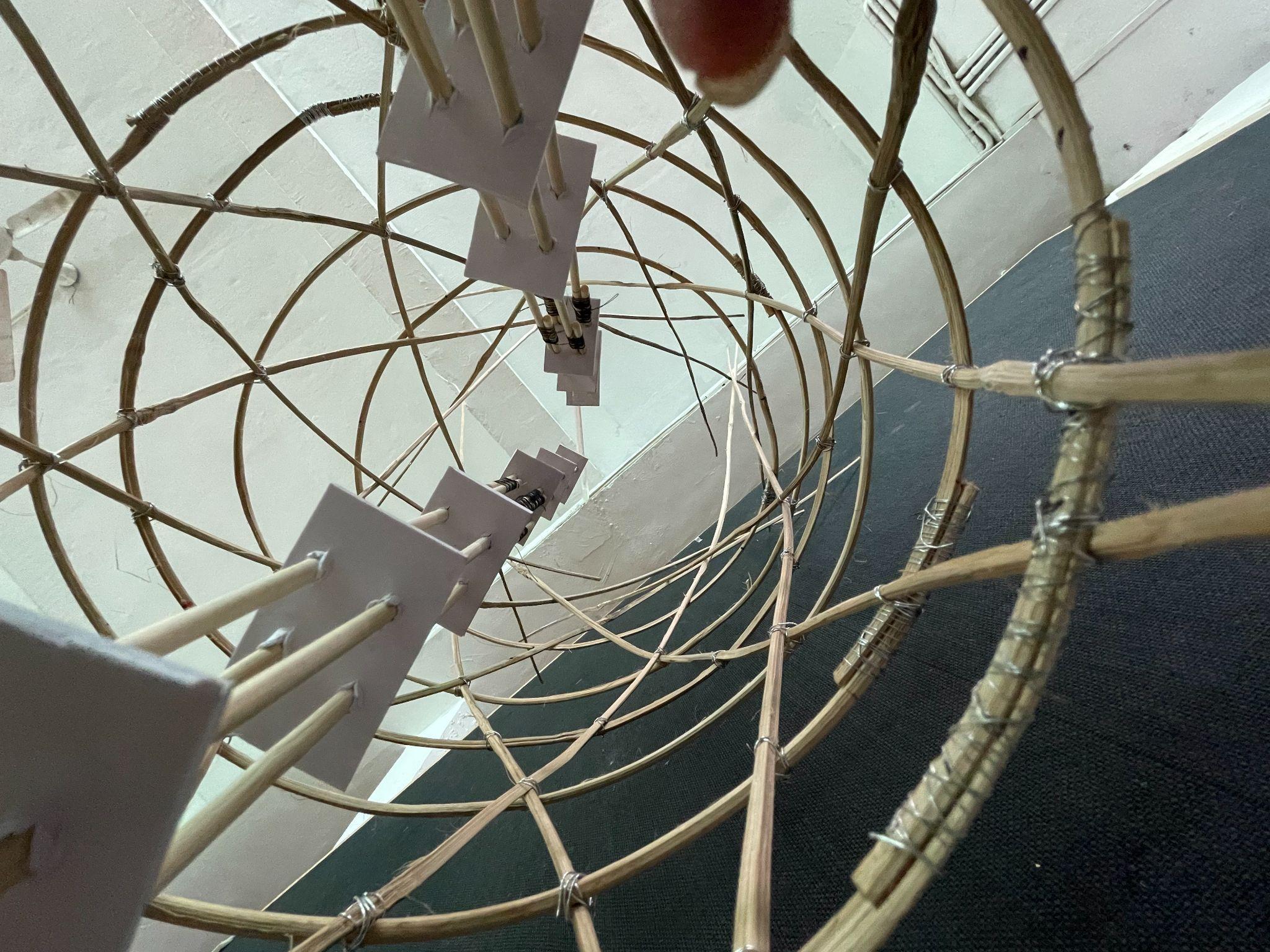
Centralvoid DiagridandSpiraljoinery
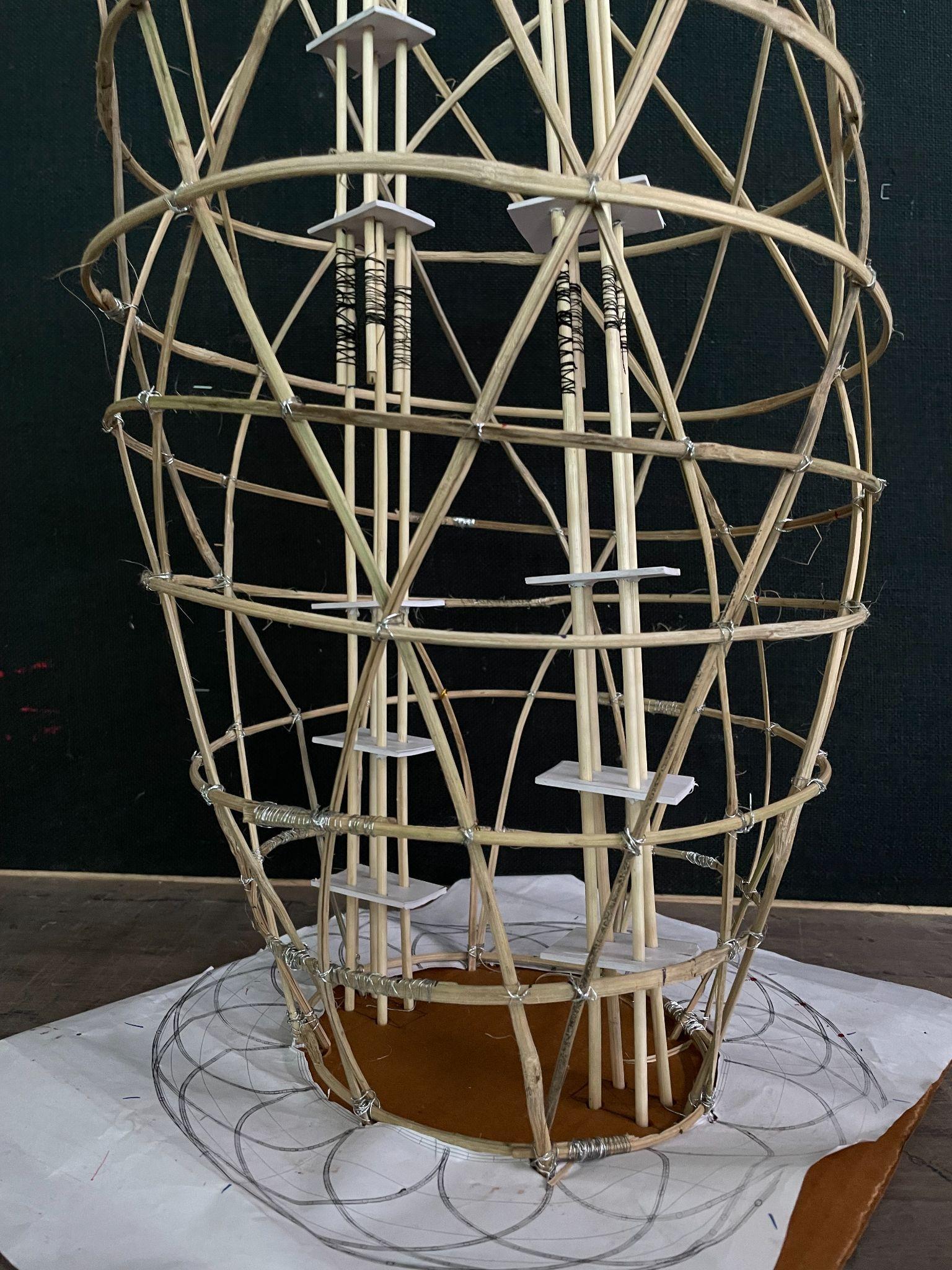 Processmodel Centralcore
Team19| DesignReport MODELPHOTOS
INITIALSKETCHES


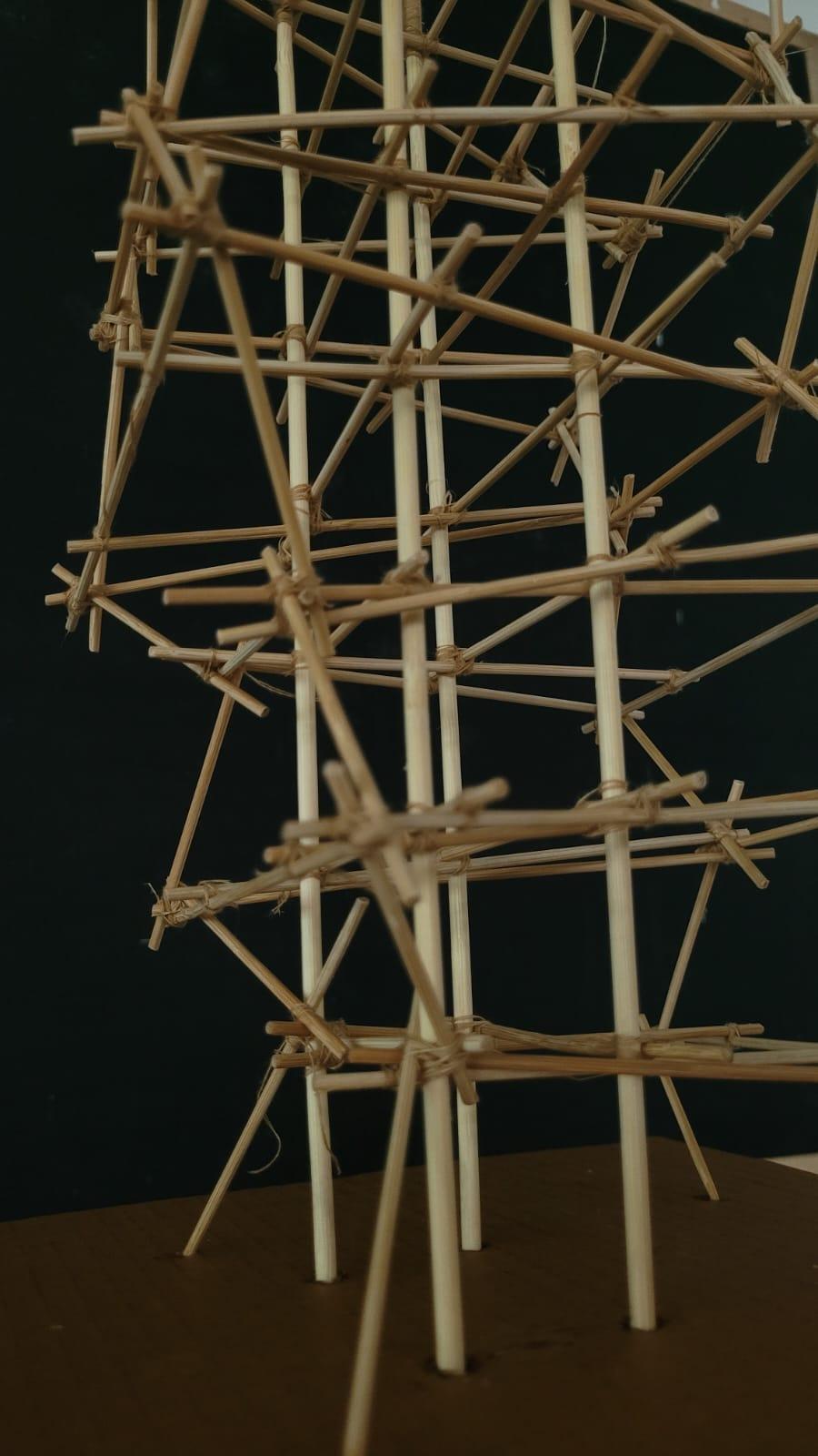
Structurewithoutbracings Structurewithbracings Joinerydetails CrossBracingjoinery Team19| DesignReport MODELPHOTOS
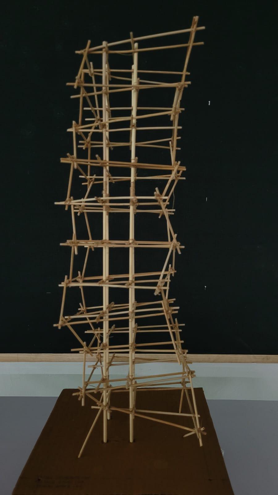
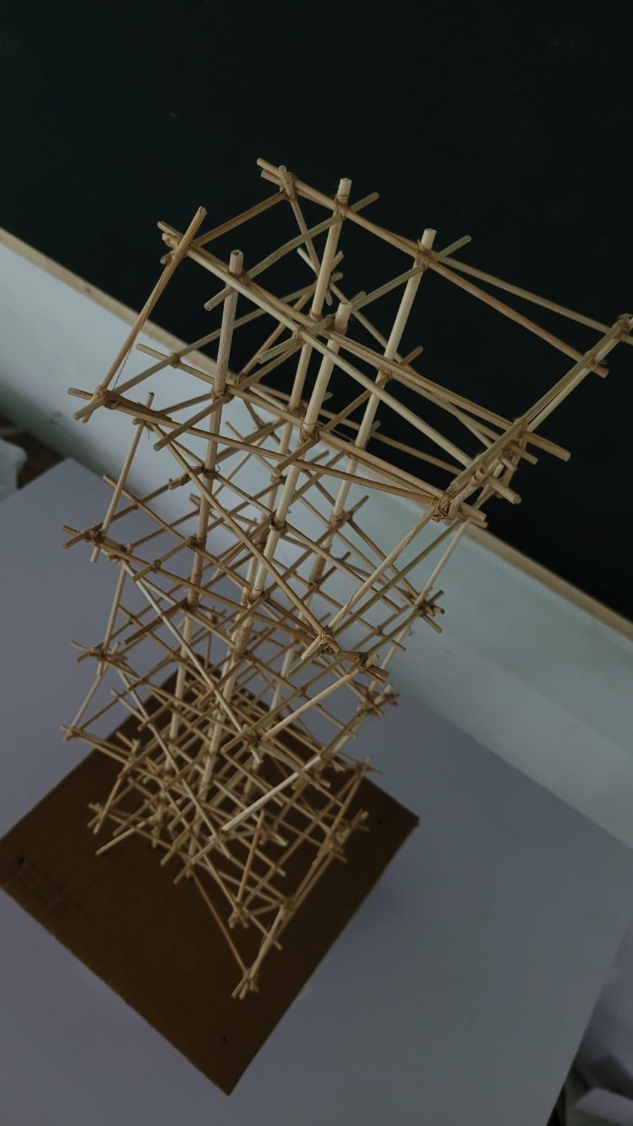
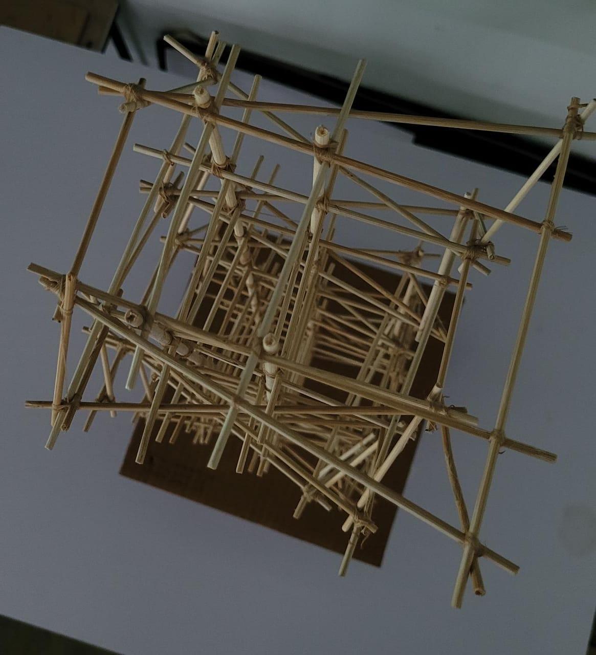
MODEL1
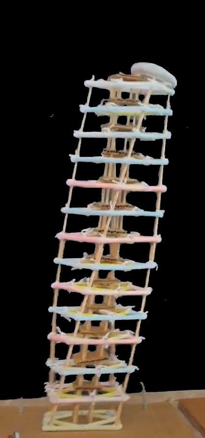
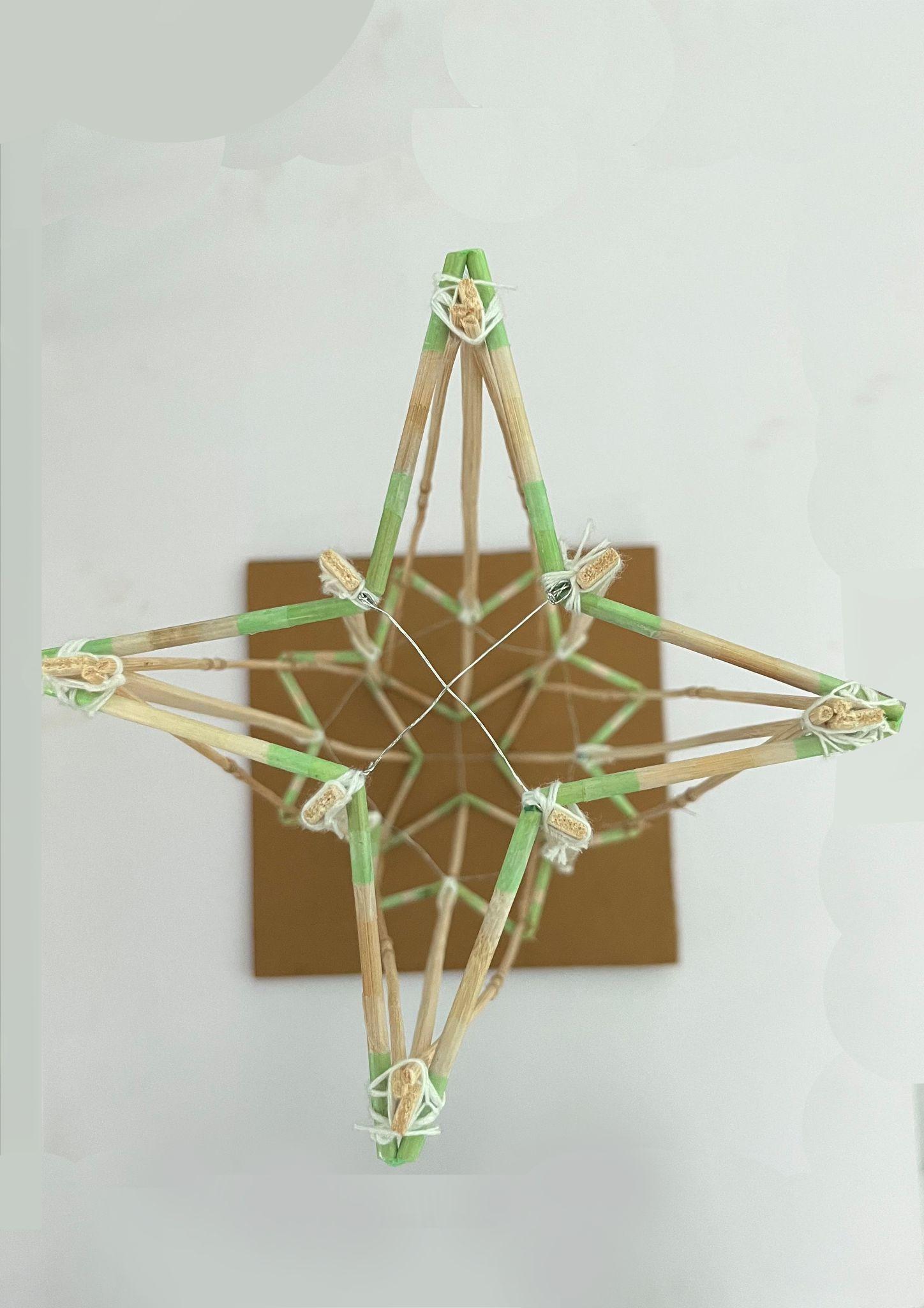
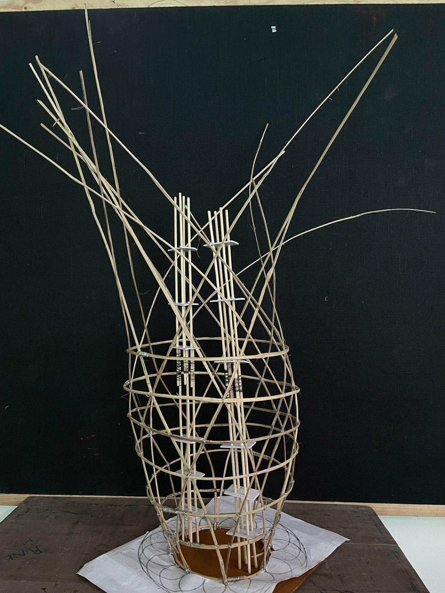
Thesculpturalmodelismadefromsmallcrosssectionsofbamboo, benttoformarches,beams,voidandincorporatedthediagrid systemofloadtransfer.
● Thedurableandflexiblenatureofbamboowasmadeuseto achievethearchesfortheorganiccurves.
● Bamboocrosssectionswerejoinedusingwiretoensure optimummaterialusageandcreateflexiblejointstohelpin earthquakefailures.
● Thecircularfloorplatesoftheformwereheldtogetherbythe diagridsystemwhichhelpedtoresistthetorsionalforceinthe highriseform.
● Diagridsenvelopedaroundthecircularformandweretiedto thebeamswhichfurtherformedthevoidinthecentrebetween thecores.
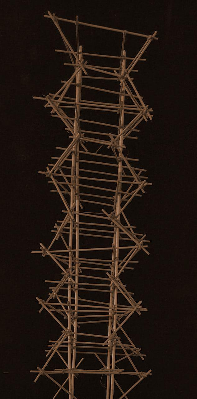
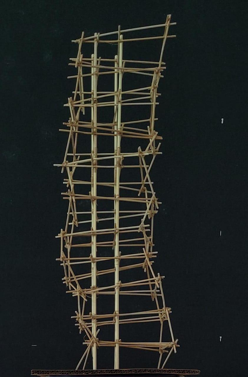
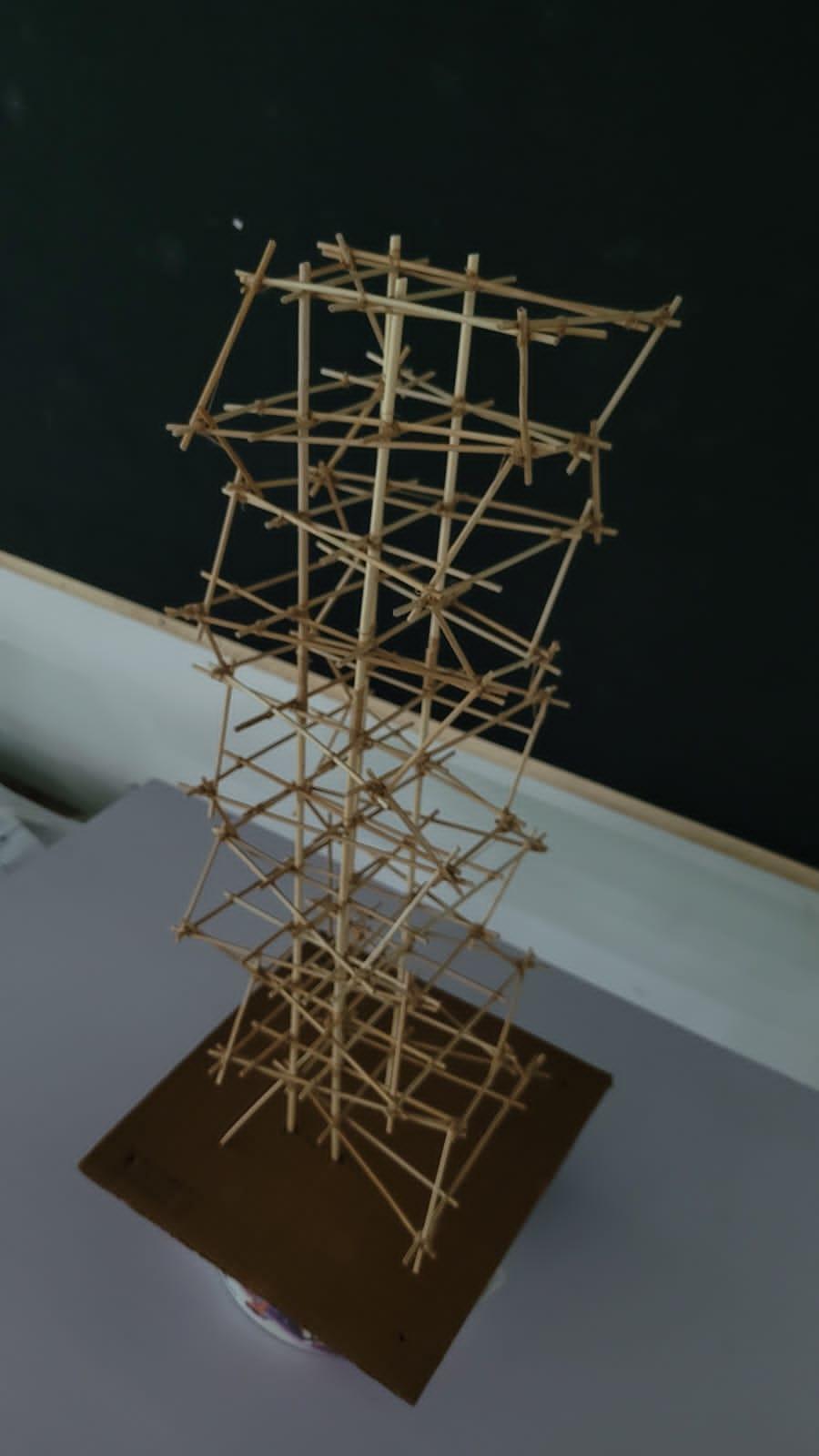
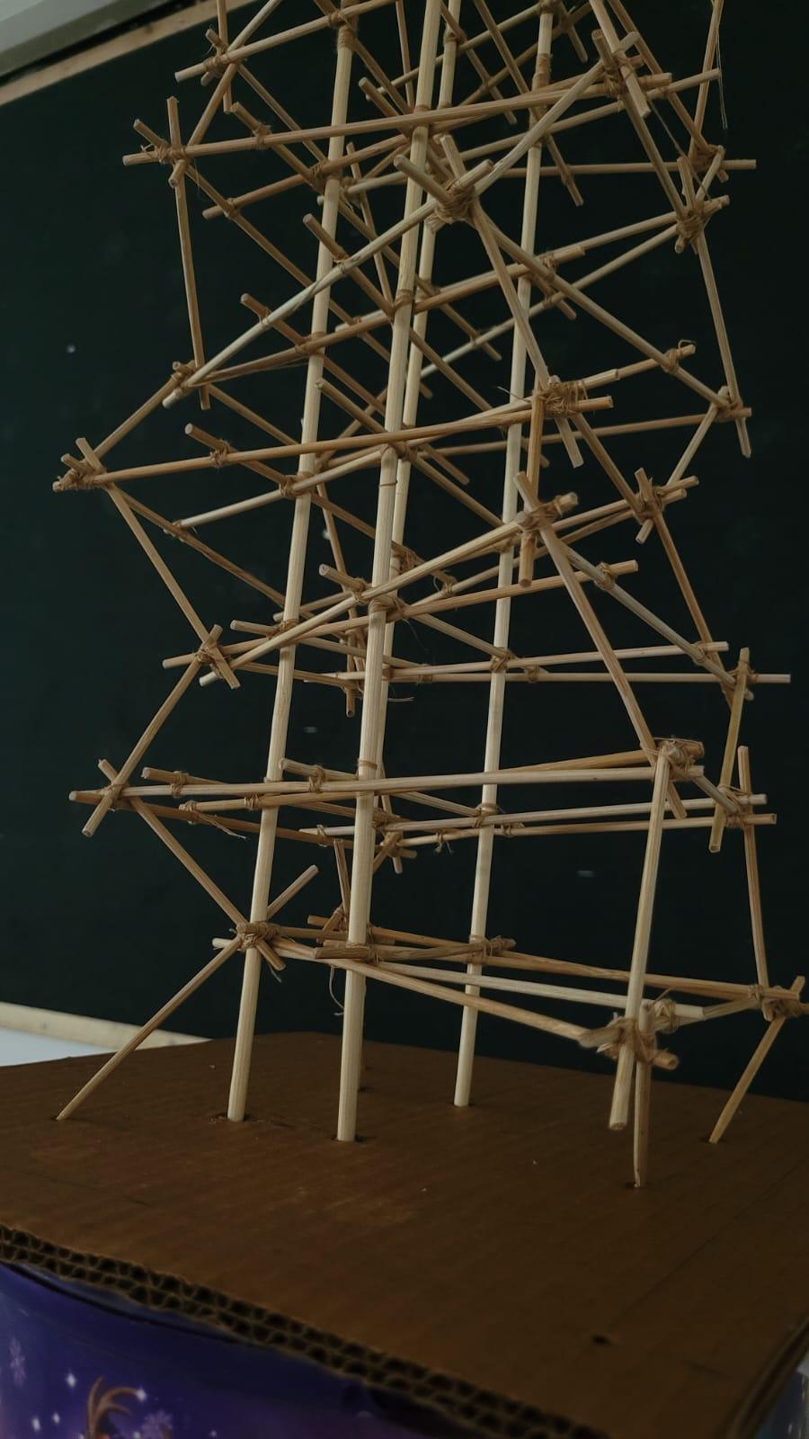
MODEL2
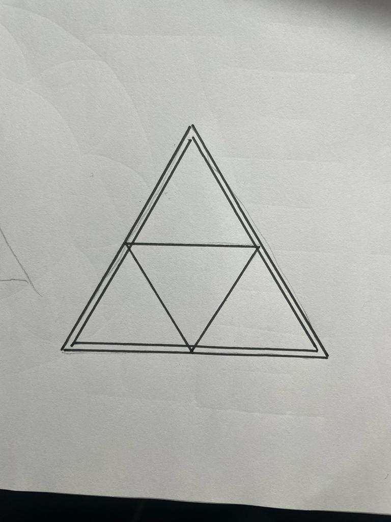
Thestructuralmodelshowcasedtriangularfloorplatesarranged oneabovetheotherwithacentraltriangularcore.
● Thelinearextrusionwasmadepossiblebysplicingthecolumns andcreatinglapjointstoachievethehighlength.
● Columntobeamjoineryweretiedusingthreadstoensurestiff butflexiblemovablejoints.
● Toresistbendingofthestructure,joinerieswerecreated betweenthetriangularcoreandthemidpointsofthetriangular floorbeams.
● Columntobeamjoinerieswereweakintorsionalforcesleading totwistandturnsinthestructureswheninearthquake; thereforecrossbracingonadjacentfacadesresistedtorsional andshearforces.
Team19| DesignReport CONCLUSION
CONCLUSION
ANALYSISAND
THANKYOU
AcademyofArchitecture,Mumbai