

ELECTIVE WORKSHOP CONSTRUCTION USING BAMBOO AND BRICKS DESIGN REPORT JUNE
2022 GUIDED
AR. SHEKOBA SANAP, AR. DHRUWANG HINGMIRE, AR. PRIYANKA GUNJIKAR, RAJENDRA SAKPAL
-
BY
Academy of Architecture, Mumbai
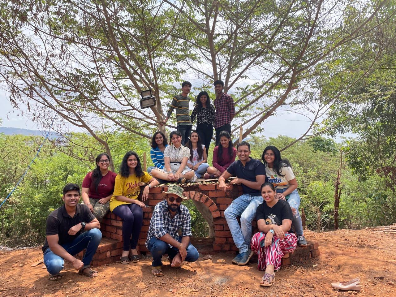
GROUP A
Academy of Architecture, Mumbai
TEAM SUMMARY GROUP
TEAM
SITE - ENTRANCE PATHWAY TEAM MEMBERS : 02_Vardhan
08_Mansi
09_Palak
22_Prajakta
23_Sakshee
29_Arya
30_Aditya
46_Aishwarya
51_Laxaree
53_Harshwardhan
54_Vaishnavi
57_Pooja
62_Sejal
Team A | Design Report - June ‘22 1 PROJECT PERENNIAL
A -
GOVARDHAN
Arora
Bhatia
Bhattad
Gosavi
Gothankar
Jumde
Kanade
Raikar
Sawant
Shirpurkar
Siddhapara
Tambe
Umare
PROCESS Team A | Design Report - June ‘22 1. Site Analysis 2. Design Process 3. Laying of Brickwork Foundation 4. Brick Pedestal and Jaali 5. Splitting of Bamboo 6. Bamboo Tying 7. Bamboo Weaving 8. Final Assembly 2
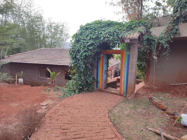
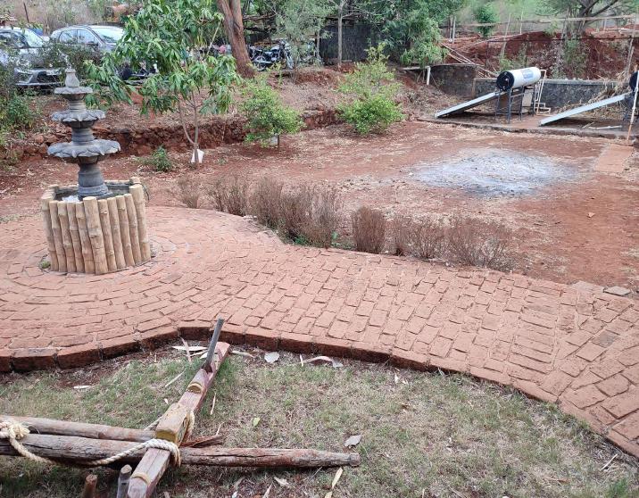
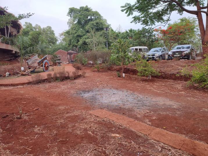
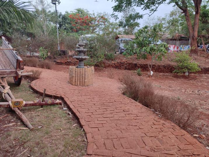
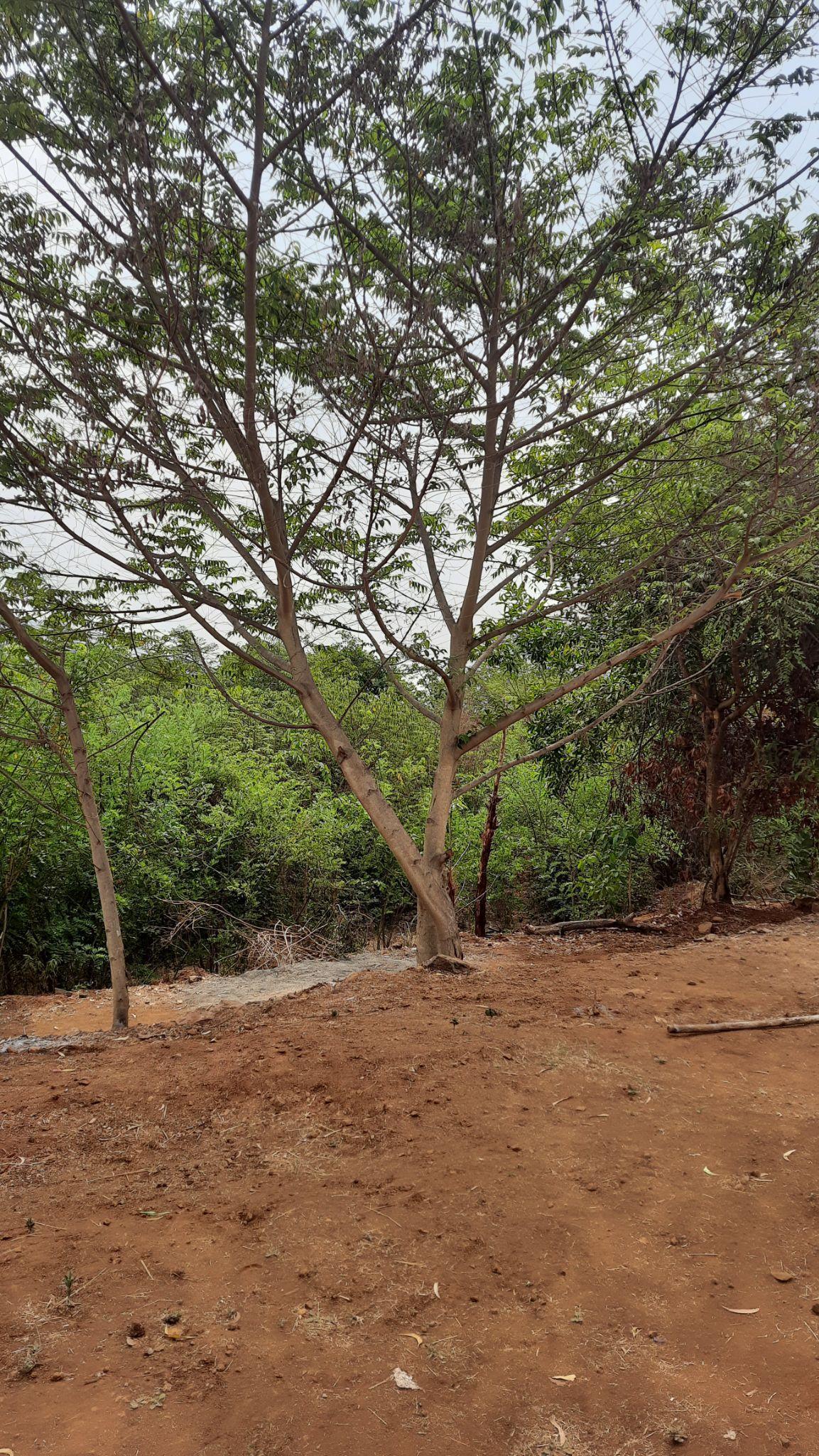
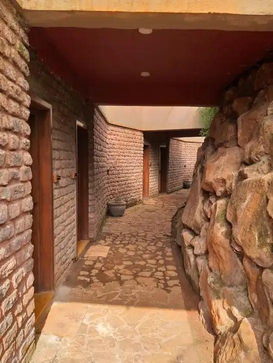
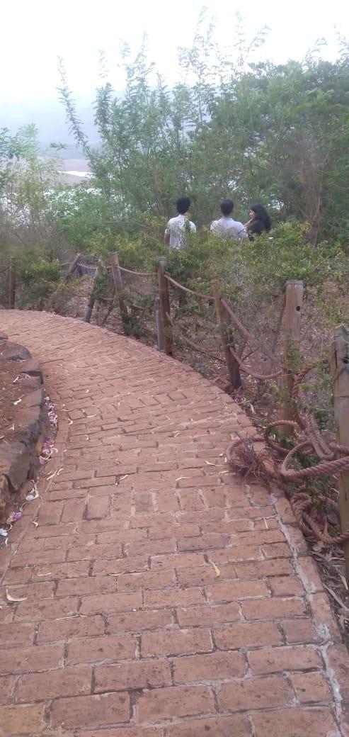
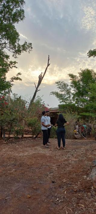
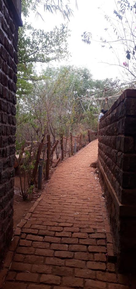
The team was given site A which was the entrance to the BambooandBricks Resort. The location had a very good potential for construction since it designated the entrance thus, our main aim was to add a welcoming factor to the bare site and give it an alluring factor.
Site plan
SITE ANALYSIS
Team A | Design Report - June ‘22
Land adjacent to the Entrance Pathway Entrance Doorway to the Resort
Entrance Pathway Junction with Fountain Potential Site identified at the Junction.
SiteA
Entrance
3
Resort
Parking
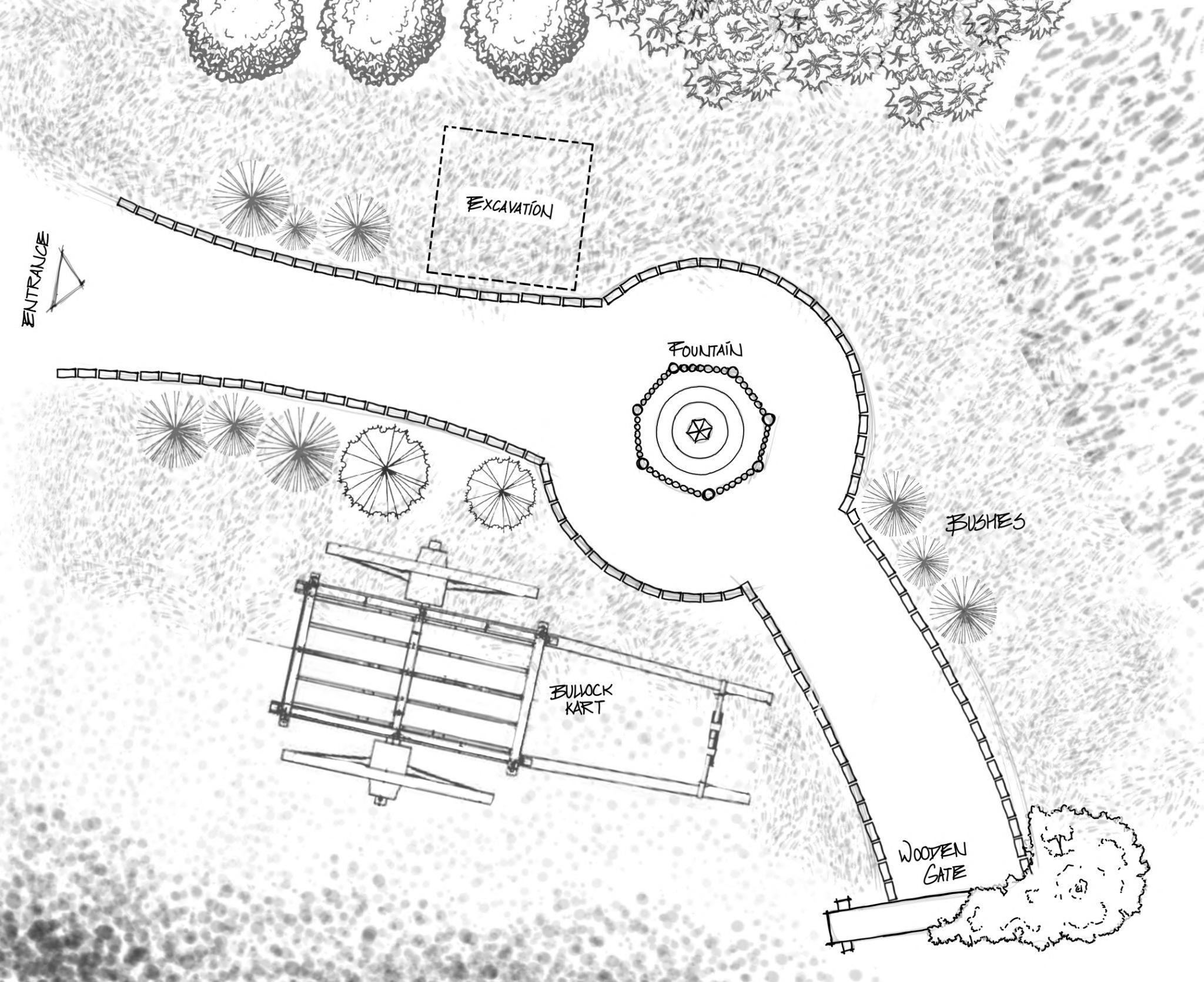
SITE PLAN Team A | Design Report - June ‘22 4
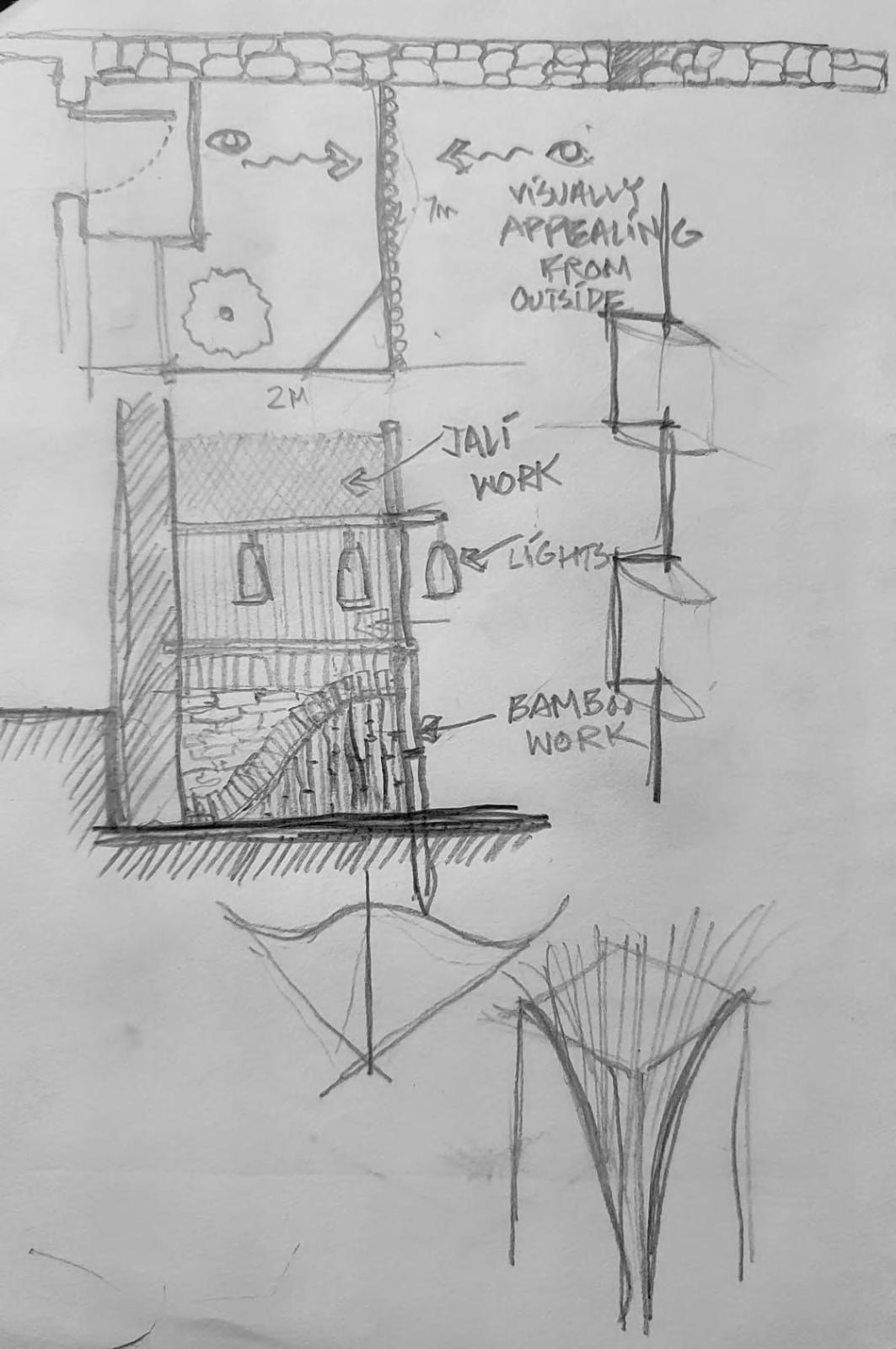
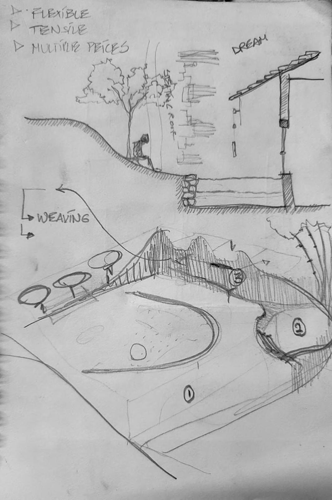
The design started with the idea of enhancing the entrance pathway and give it an alluring factor. The main aim was to create an integrated structure with the help of bamboo and brick. The entire installation is a single module to be repeated all along the pathway
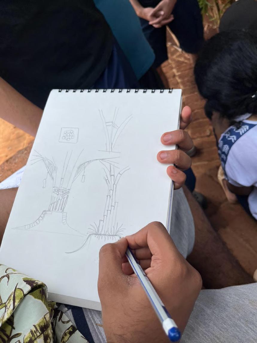
DESIGN
IDEATION
Team A | Design Report - June ‘22 5
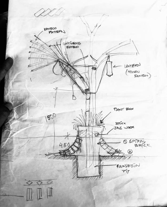
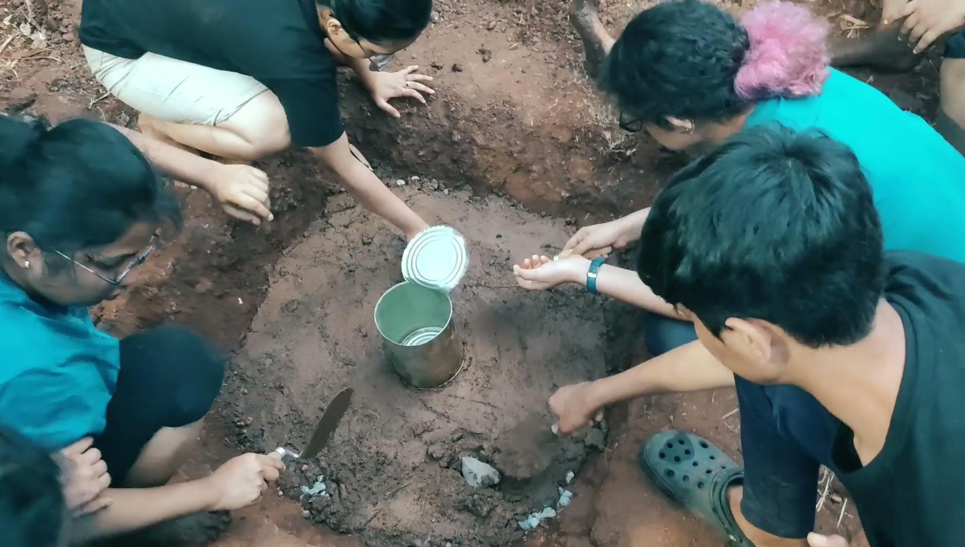
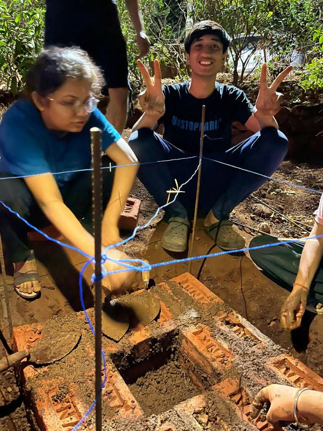
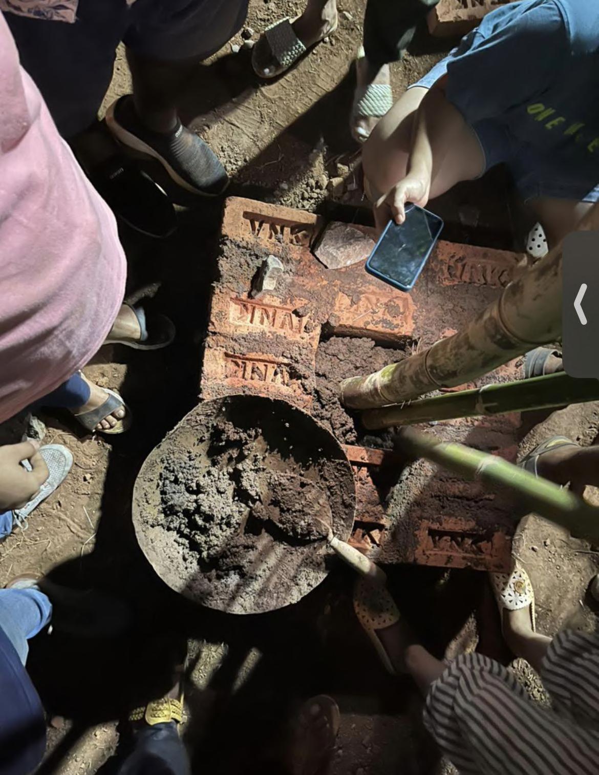
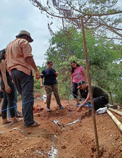
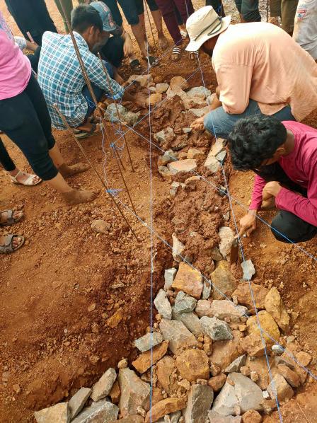
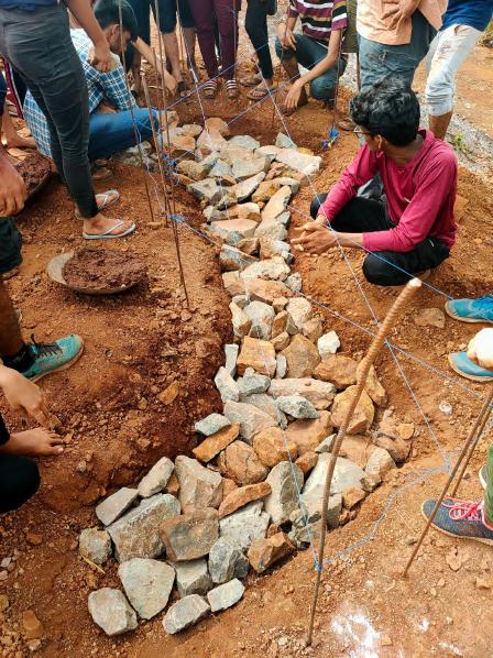
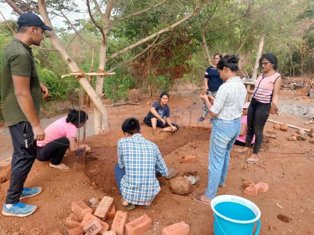
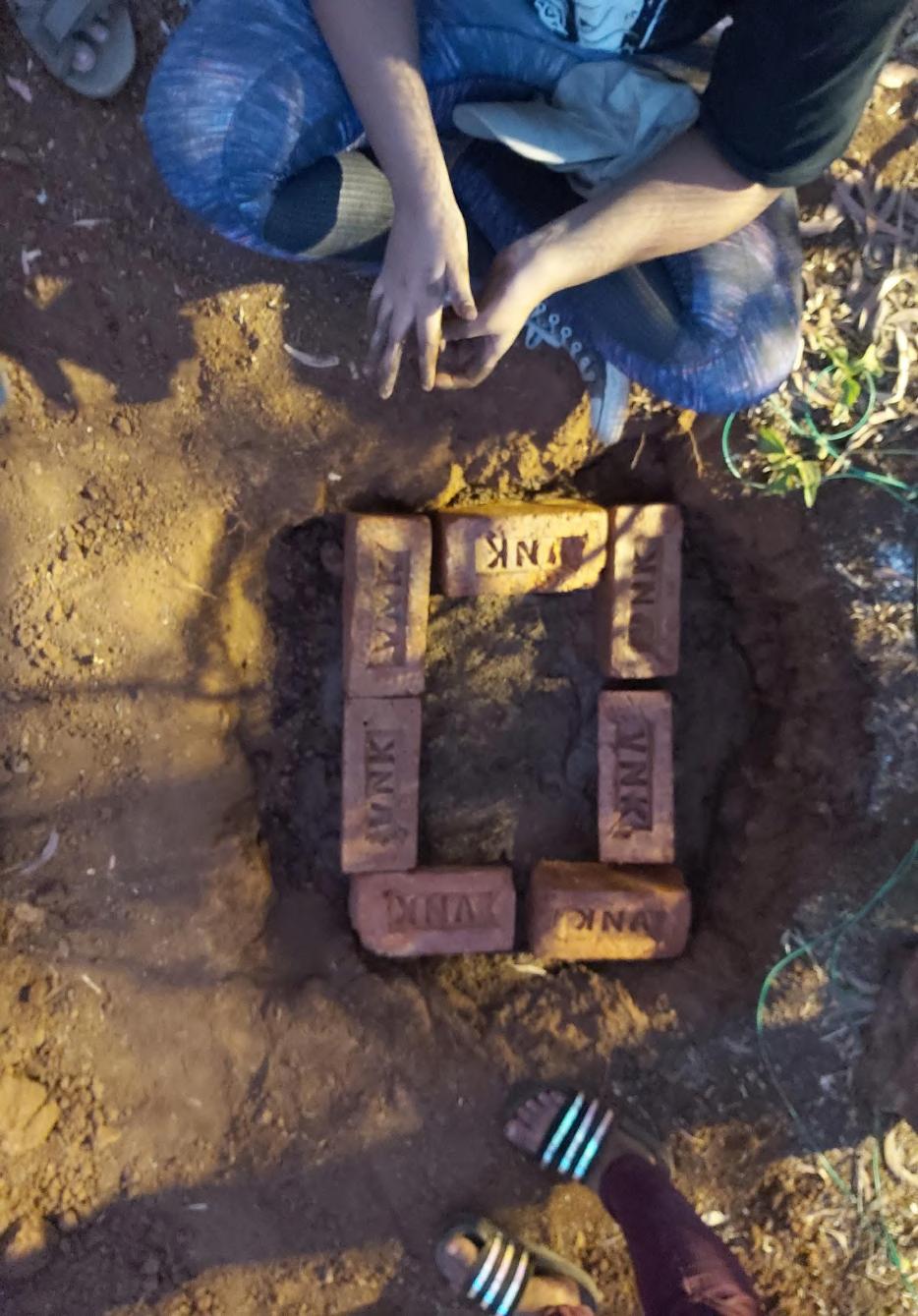
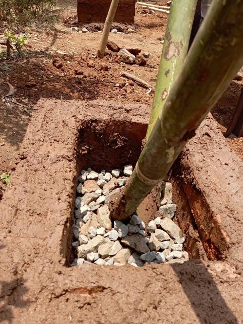
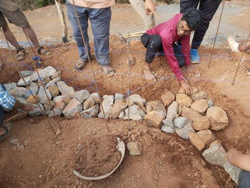
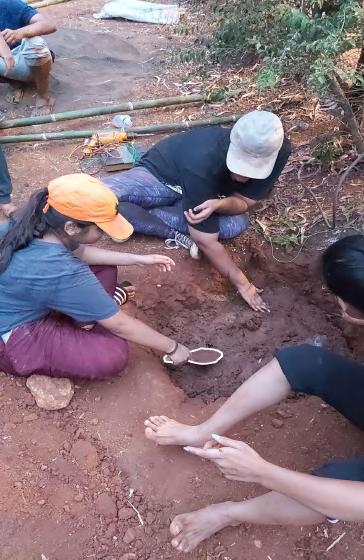
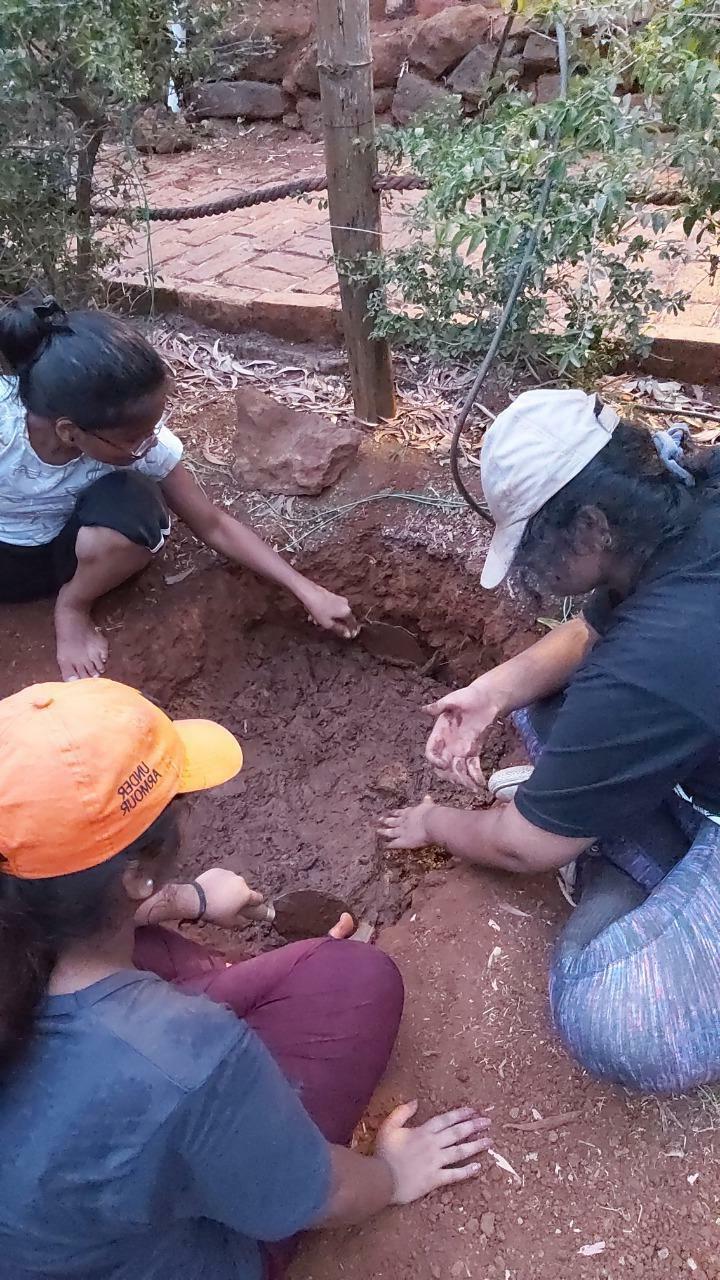
Excavating the Ground : A 1000mm x 1000mm x 350mm pit was excavated for the foundation.
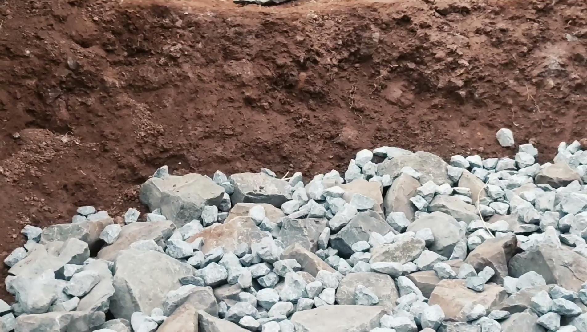
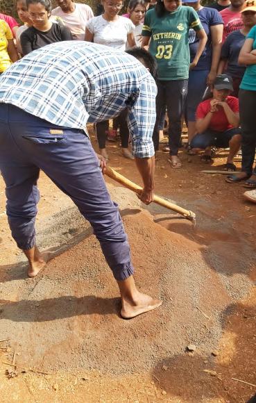
Digging up the soil : Breaking and removing big rocks to create an even surface was a major challenge.
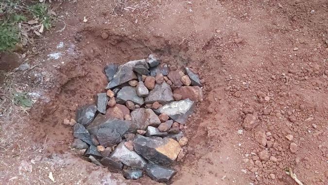
Laying of rubble : Filling the excavation with gravel made up of bigger and smaller stones to provide a levelled surface.
Laying the Mortar : Filling the gaps with mortar to create a levelled base
01_EXCAVATION AND BACKFILLING
Team A | Design Report - June ‘22
6
Video : Preparing the Bottom Layer of Foundation
Team A | Design Report - June ‘22
01_EXCAVATION AND BACKFILLING 7
Video : Preparing the Bottom Layer of Foundation
Team A | Design Report - June ‘22
01_EXCAVATION AND BACKFILLING 8
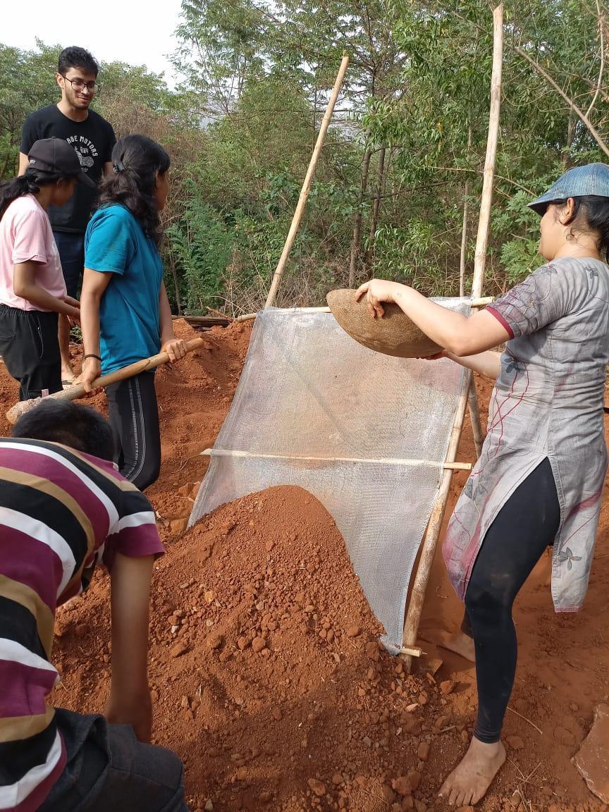
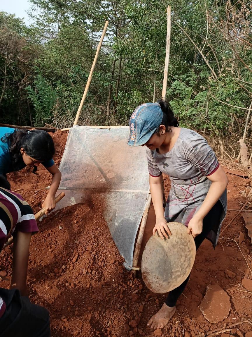
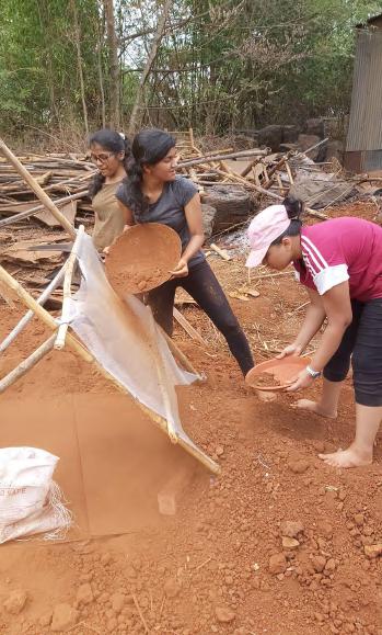
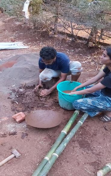
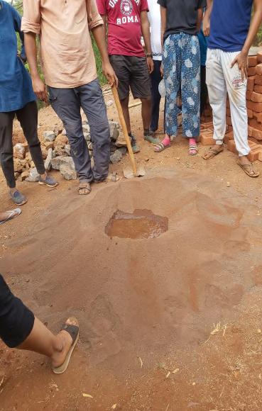
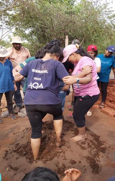
Sieving of Sand : Sieving of Red Sand for the mortar mix.
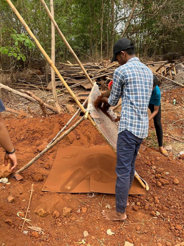
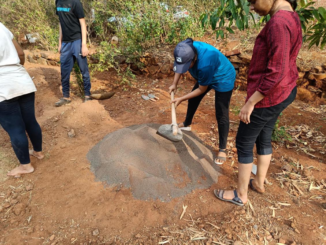
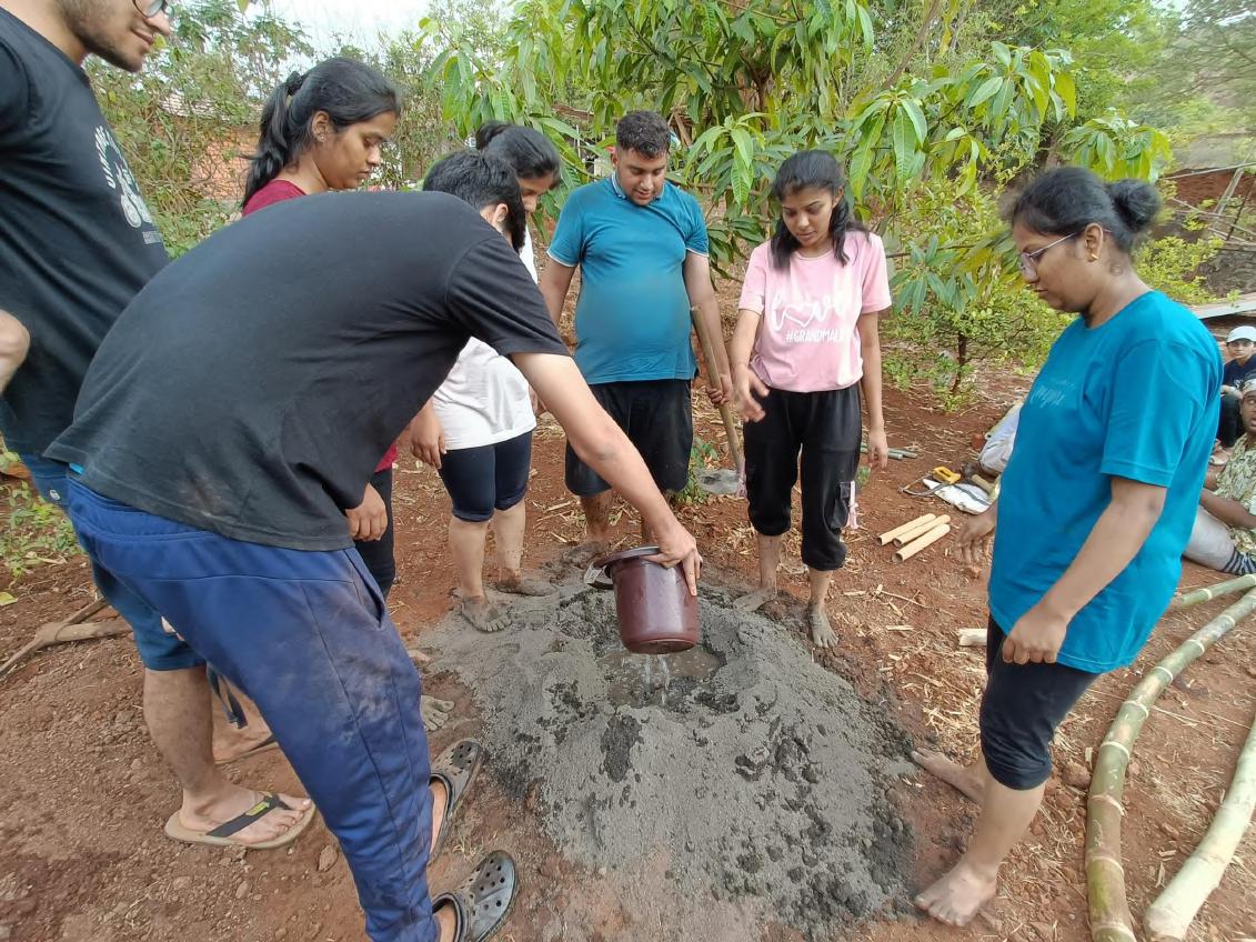
Dry mixing of Mortar : Mortar created using 1:5 Ratio (1part red sand; 5 part crushed basalt stone)
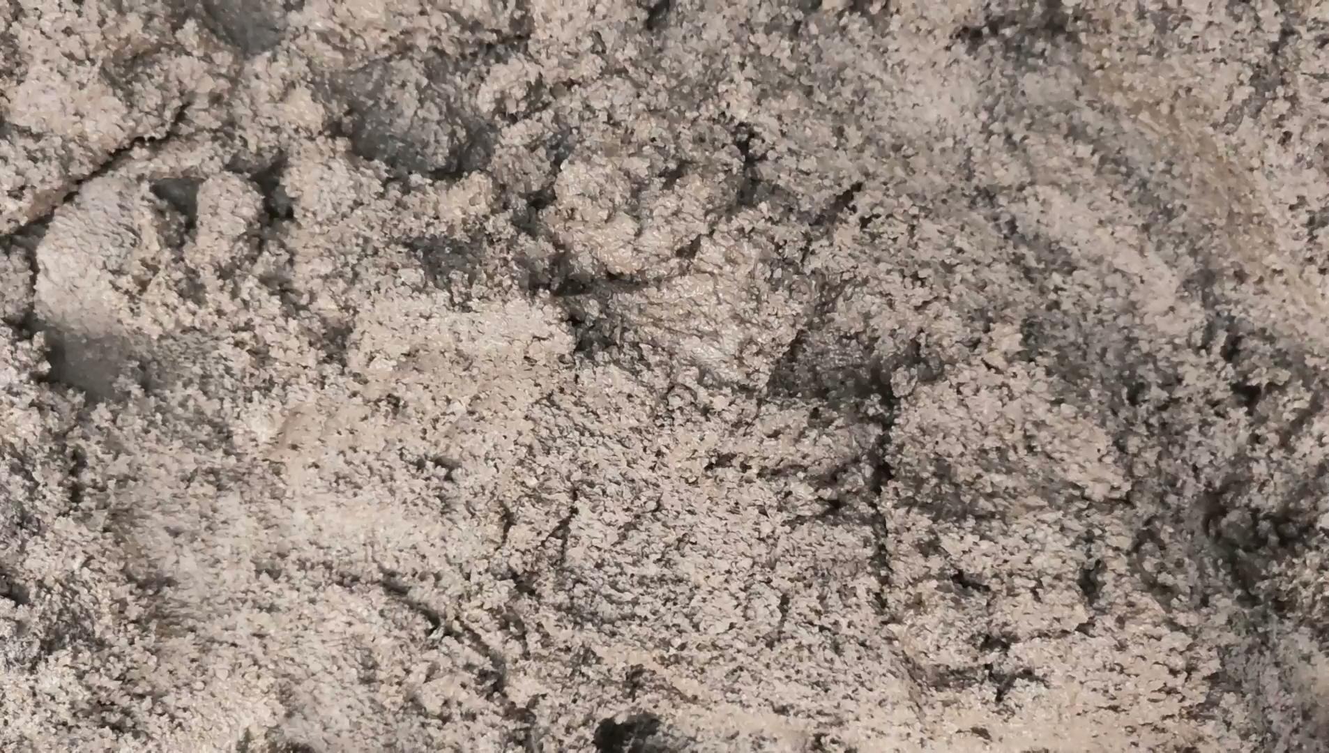
Creation of Mortar : Mortar created using 1:5 ratio mixture with adding water as needed
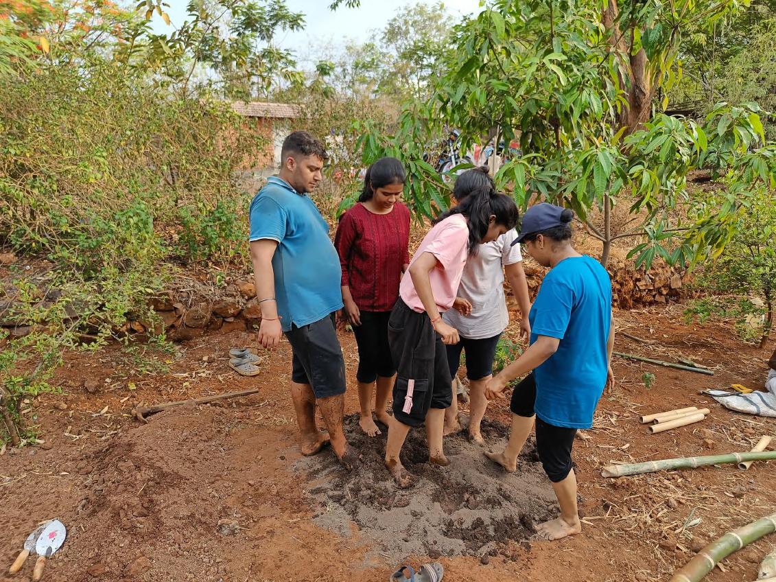
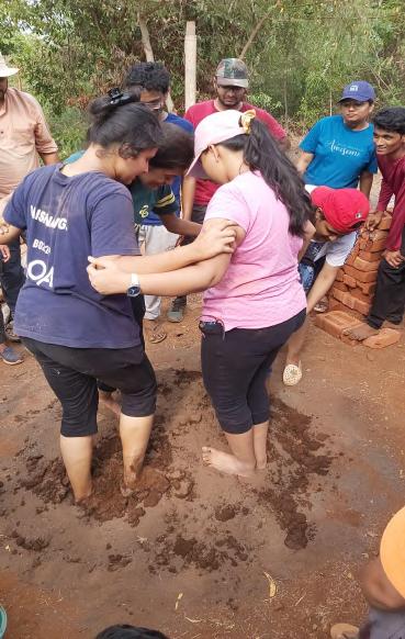
Pugging : Mixing of water and dry mix using foot force. Quite a lot of energy was required in mixing it and hence group of 4-5 participated in making it together.
02_PREPARATION OF MORTAR
Team A | Design Report - June ‘22 9
Video : Mortar Preparation
02_PREPARATION OF MORTAR Team A | Design Report - June ‘22 10
Discussion with Experts
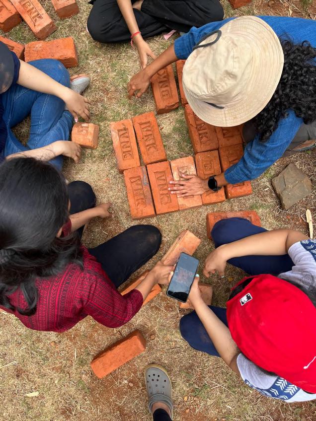
03_ RESOLVING OF BRICK BONDS
Team A | Design Report - June ‘22 11
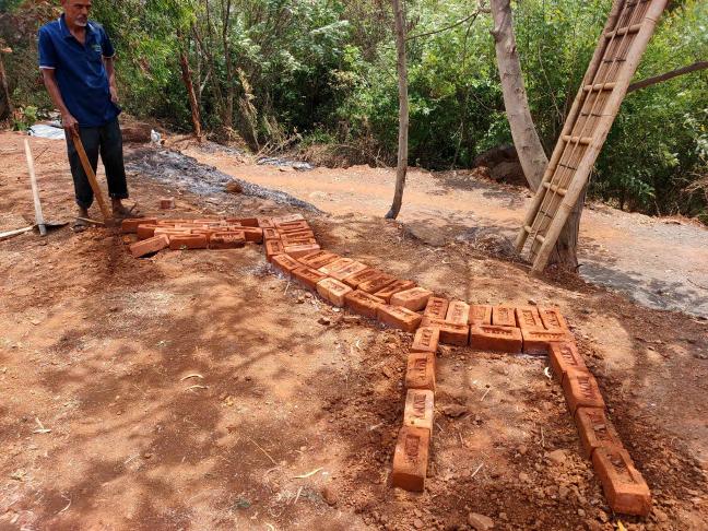
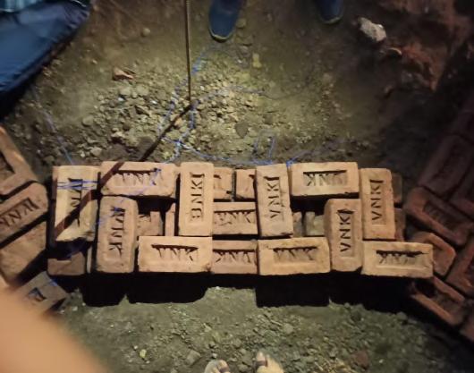
Foundation First Course
03_RESOLVING OF BRICK BONDS Team A | Design Report - June ‘22 12
Video : Laying of Bricks
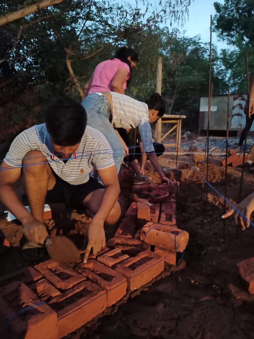
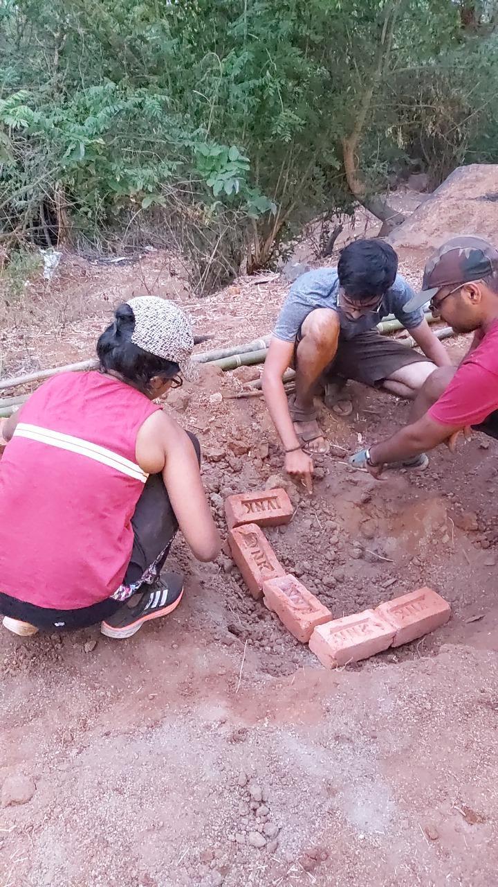
Levelling : The plumb-and-bob method was used to check the evenness.
Laying the Footing : The brick courses are laid after levelling.
04_LAYING OF BRICKWORK FOUNDATION
Team A | Design Report - June ‘22 13
Dressing the Footing : The mortar fixes the bricks in place
Completion of the Footing till G.L. : The footing consists of 2 courses of brickwork.
Video : Laying the Foundation Courses

04_LAYING OF BRICKWORK FOUNDATION Team A | Design Report - June ‘22 14
Video : Backfilling
04_LAYING OF BRICKWORK FOUNDATION Team A | Design Report - June ‘22 15
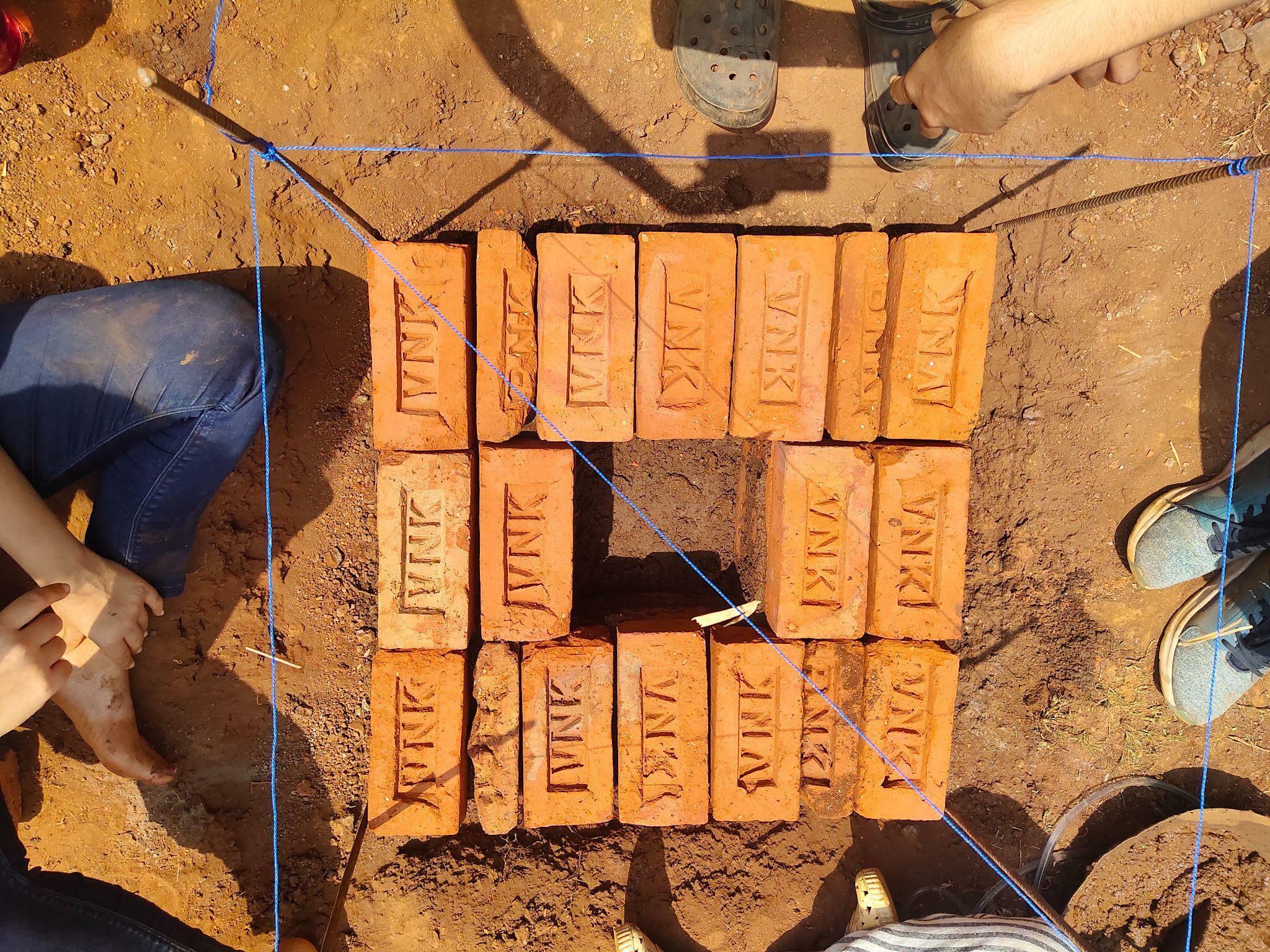
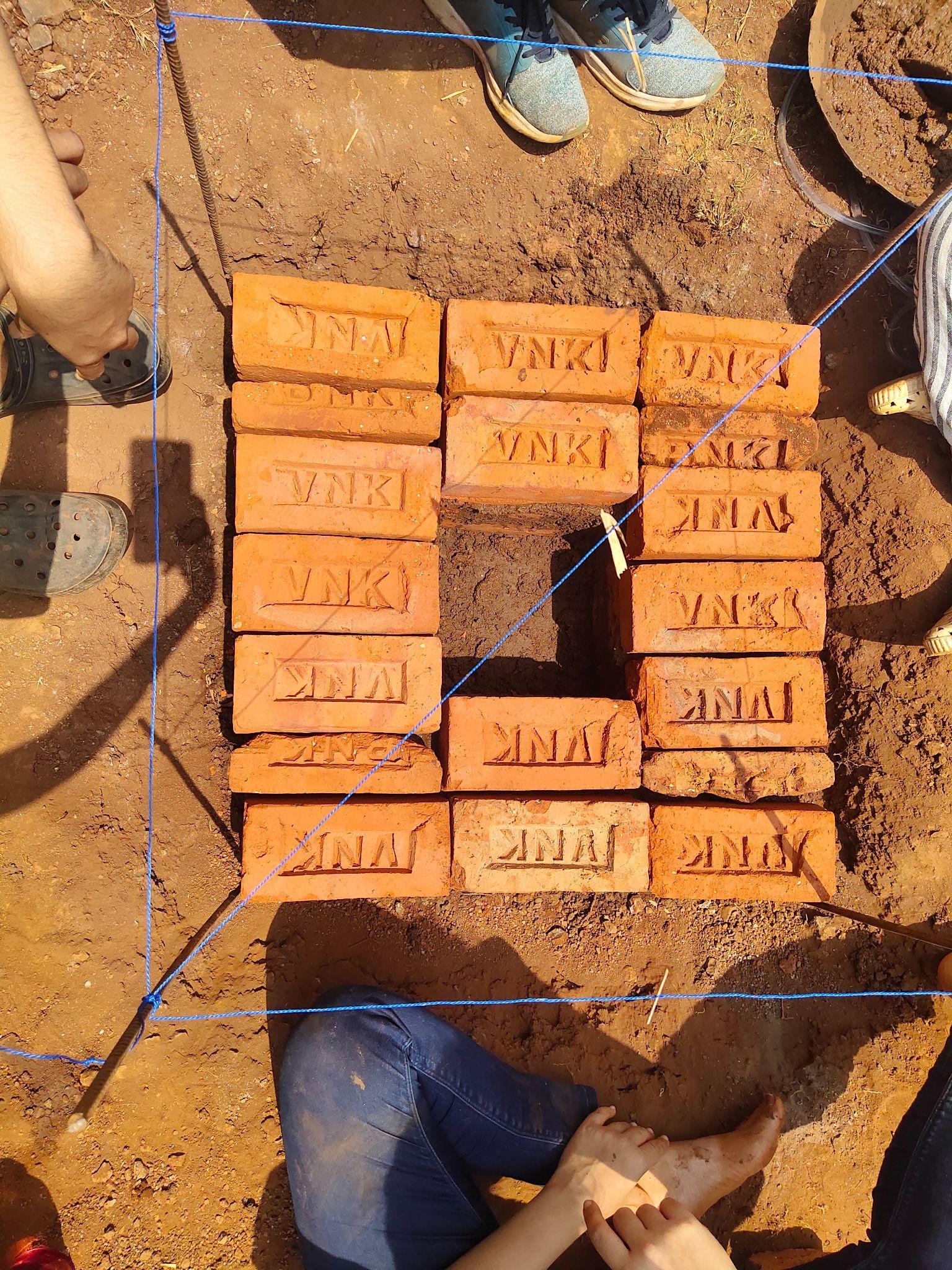
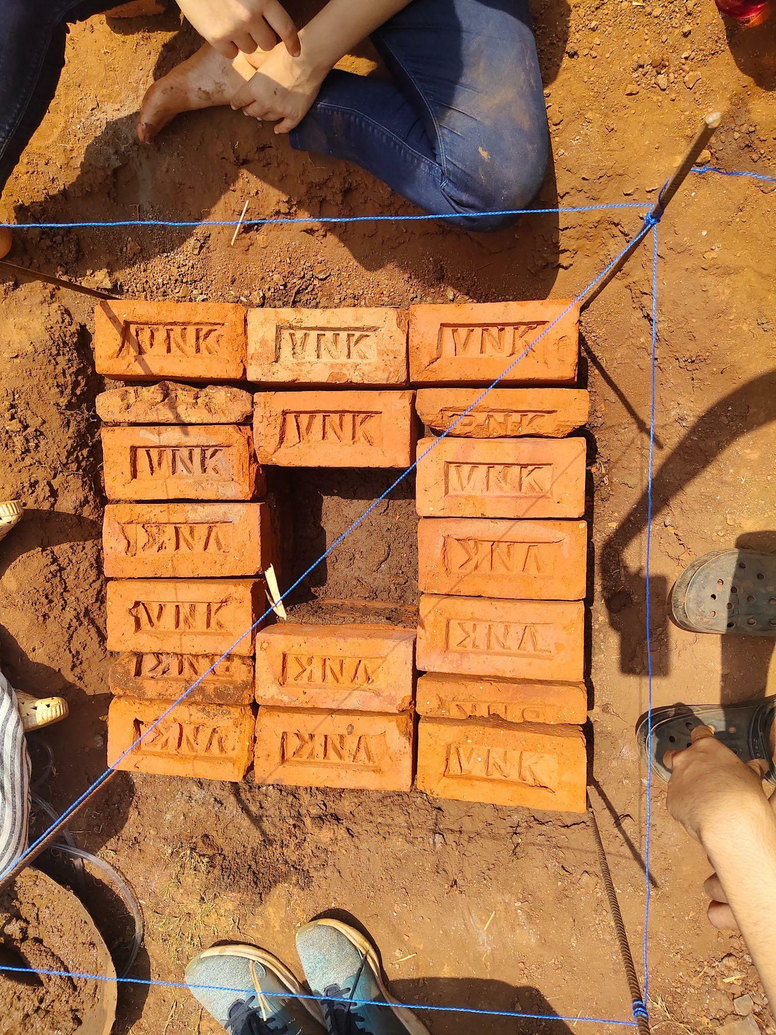
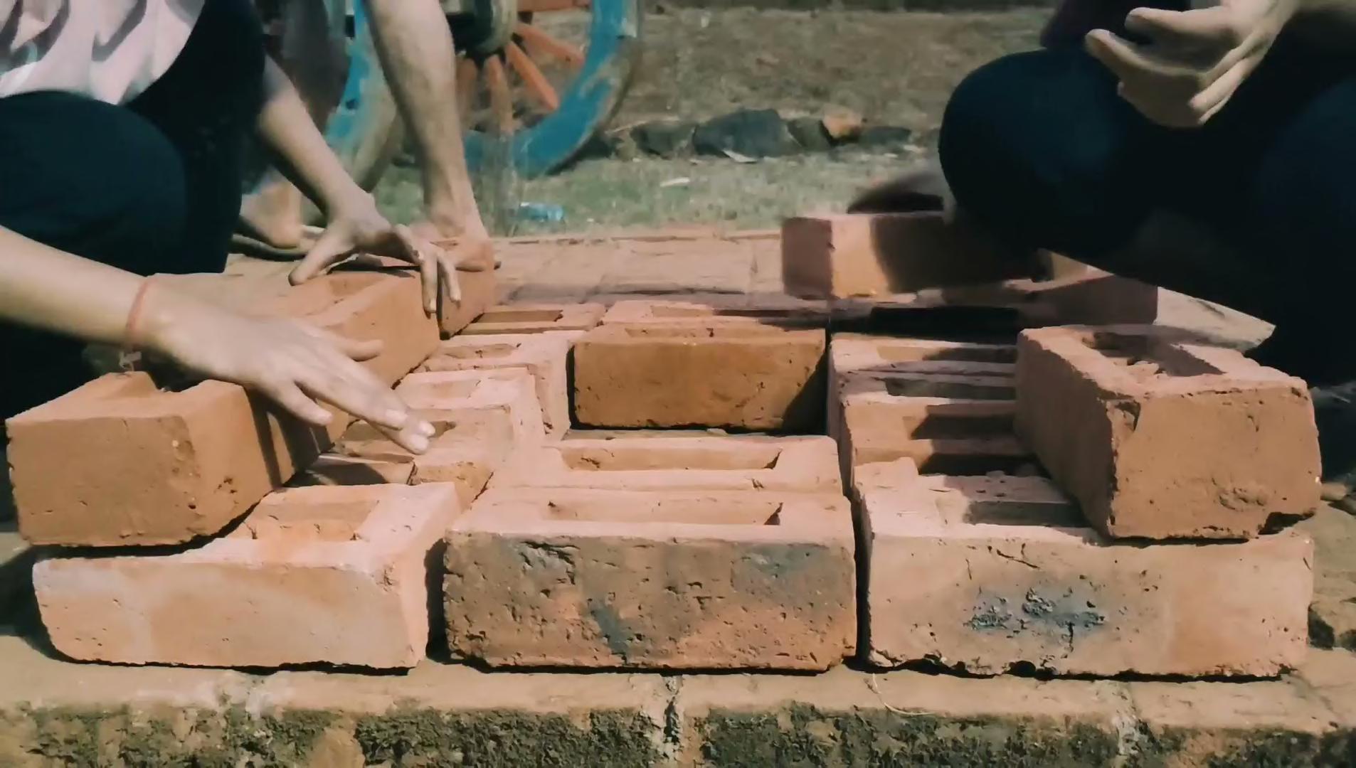
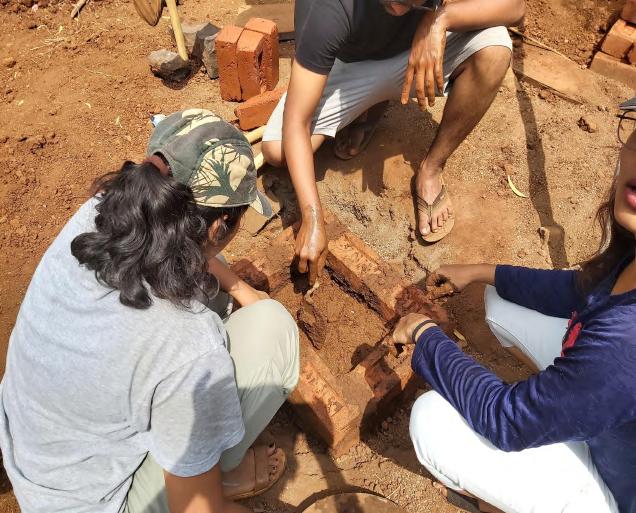
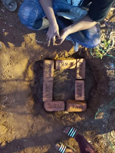
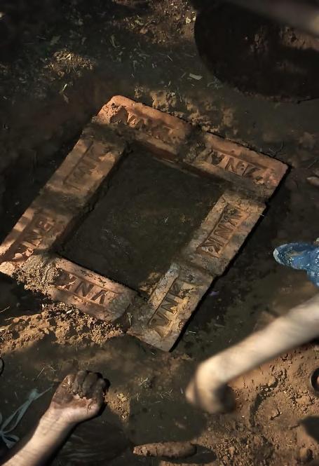
First Course: Laying of first course of jali brickwork at an angle of 45 degrees with 2 finger gap in between.
Second Course : Laying of 2nd course of brickwork at an angle of 135 degrees balanced between 2 adjacent bricks with a greater gap among them
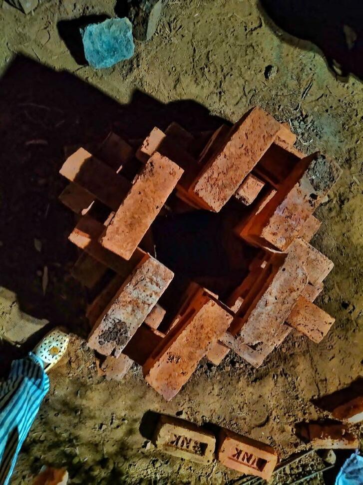
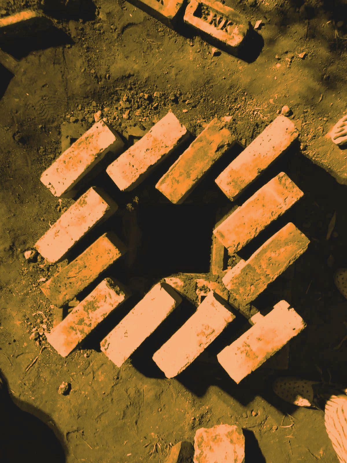
Fourth Course: The topmost brick course
05_BRICK PEDESTAL AND JALI WORK Team A | Design Report - June ‘22 16
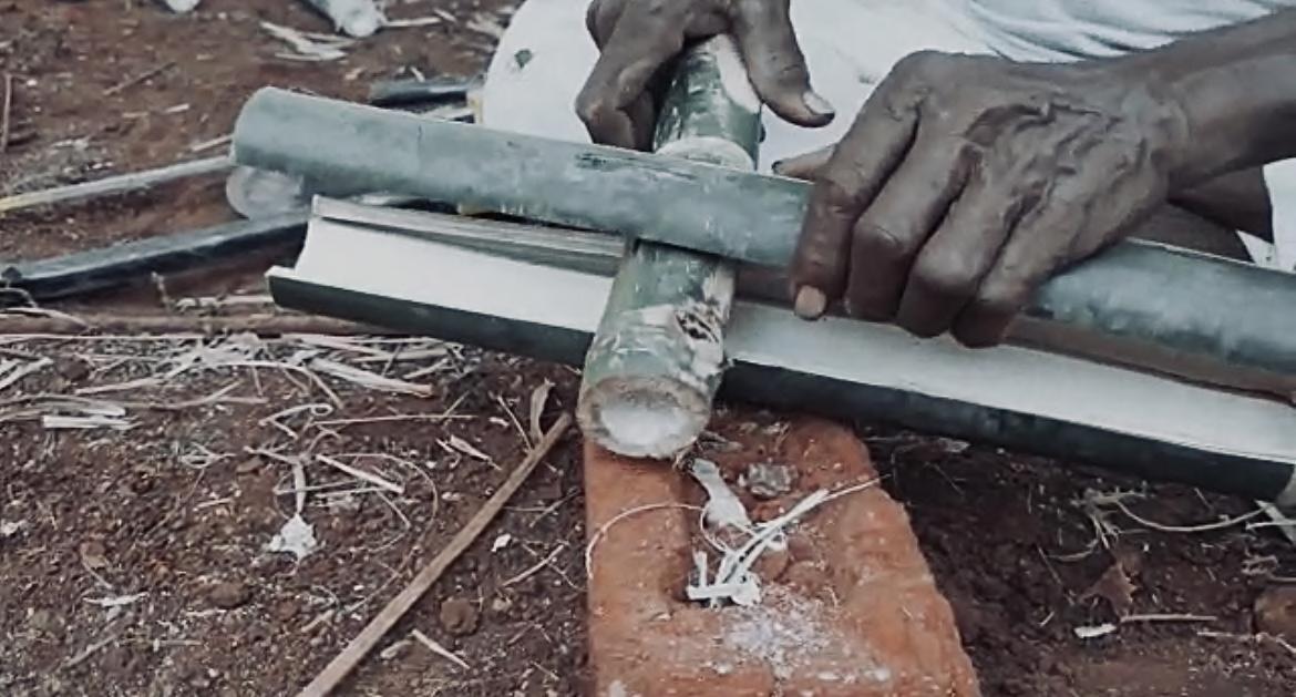
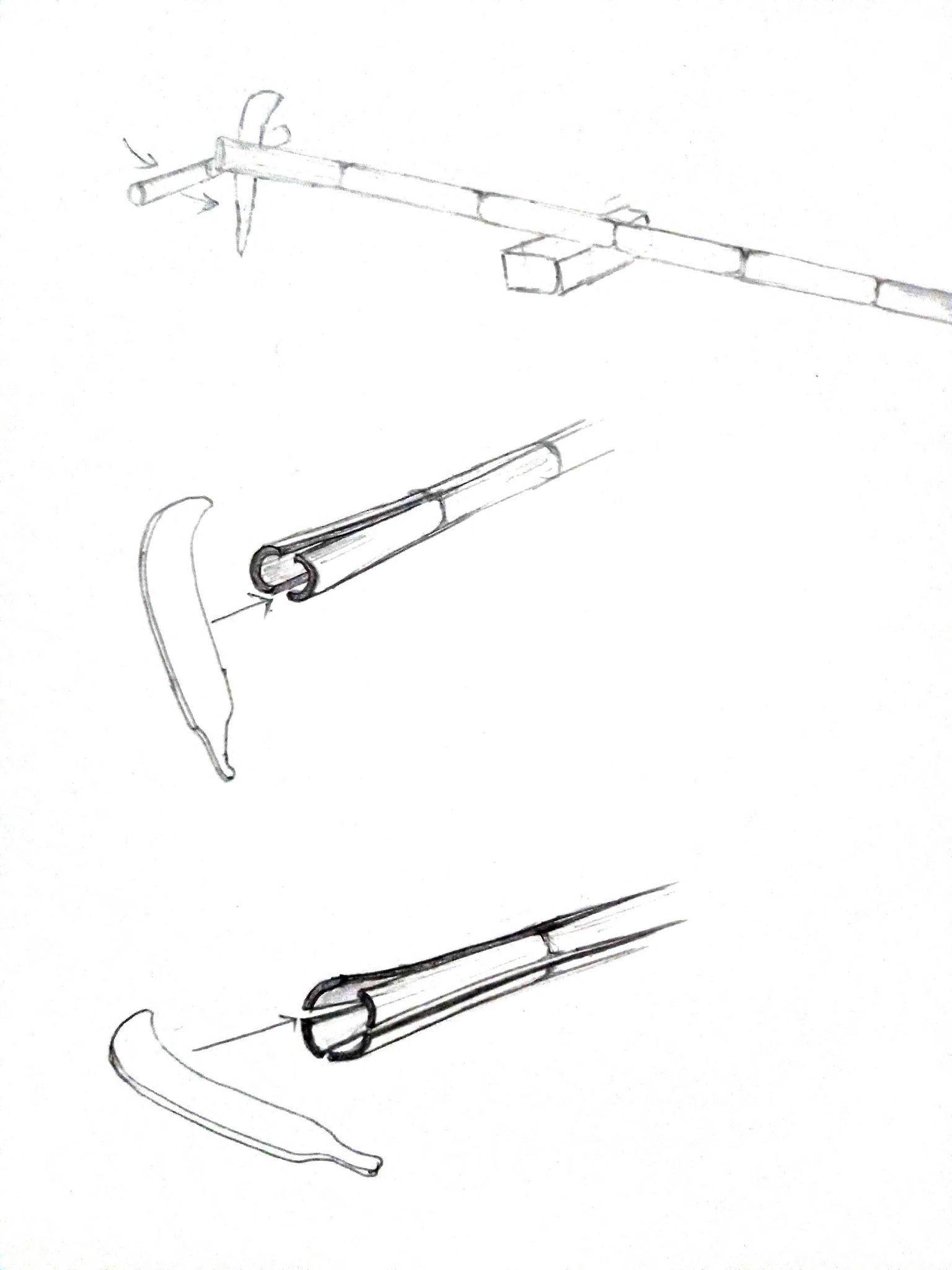
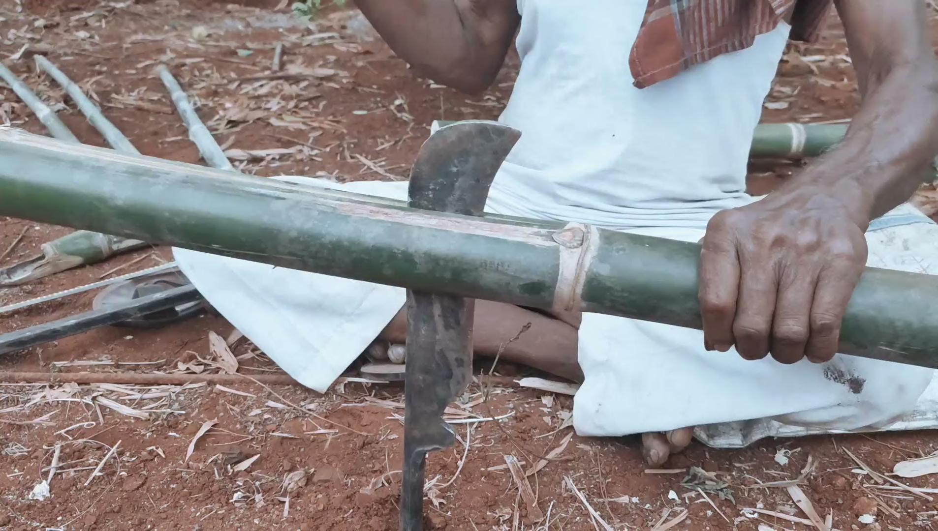
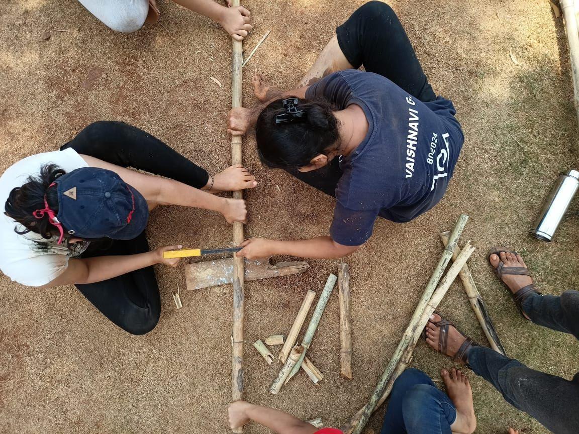
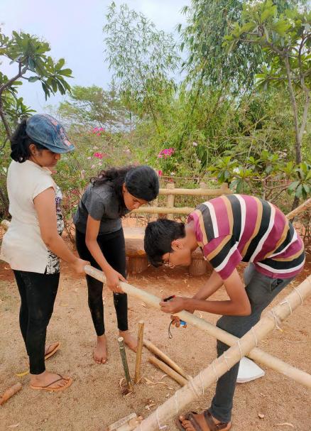
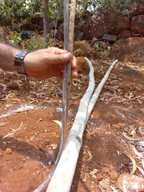
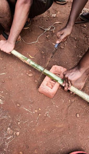
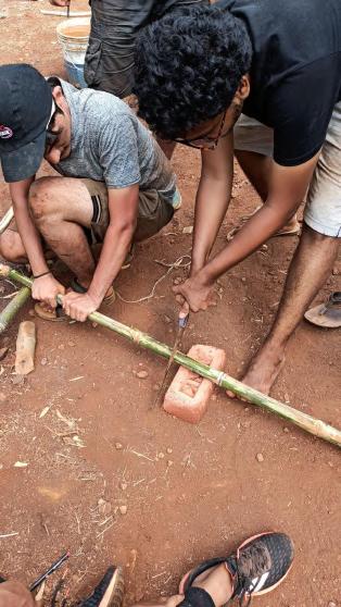
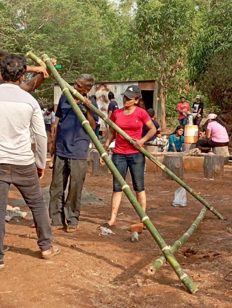
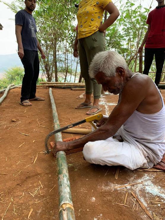
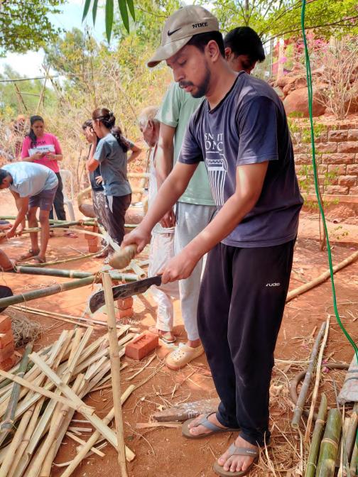
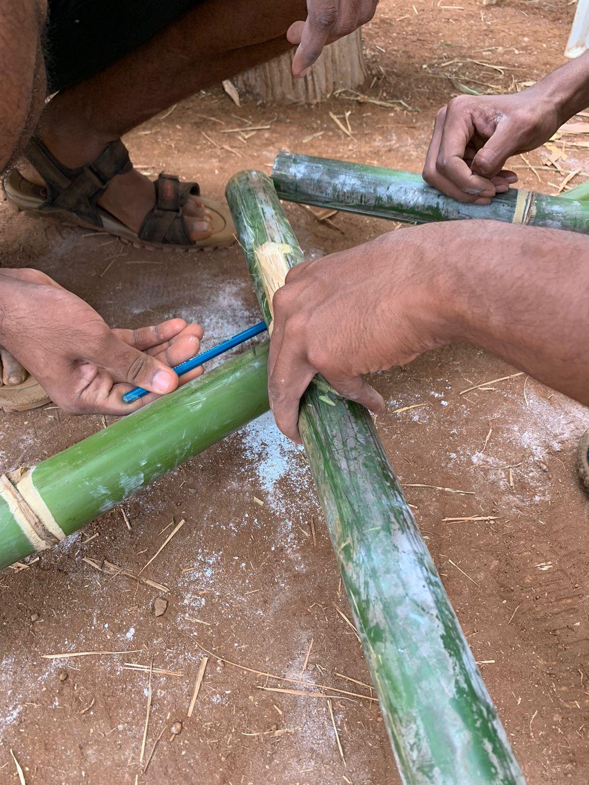
Splitting till the nodes Bending of split
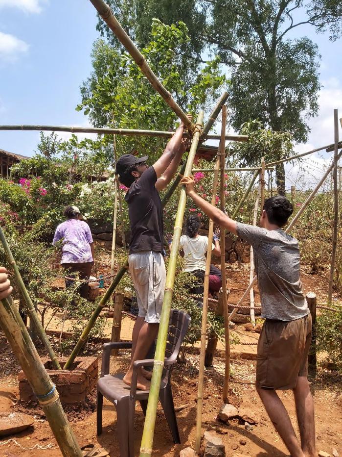
Splitting till the nodes to achieve the desired design, naturally bended bamboo were selected and splitted into multiple parts till the required length. The thinner end of the bamboo with the cutting edge of a bamboo hatchet positioned in the exact centre of the bamboo. Strike the blade on the back of the hatchet with the log gently until the cane is splitted through two or three joints.
06_BAMBOO SPLITTING Team A | Design Report - June ‘22 17
Cross cutting of culm into first sections
Cross cutting of culm into second section
Bamboo Splitting
06_BAMBOO SPLITTING 18
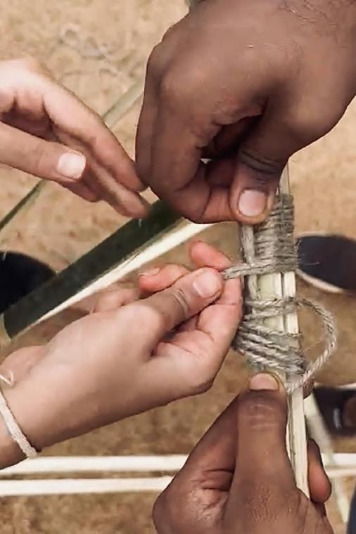
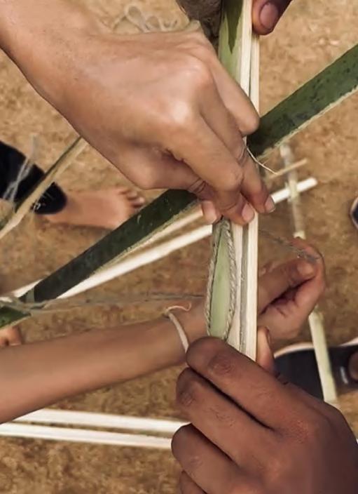
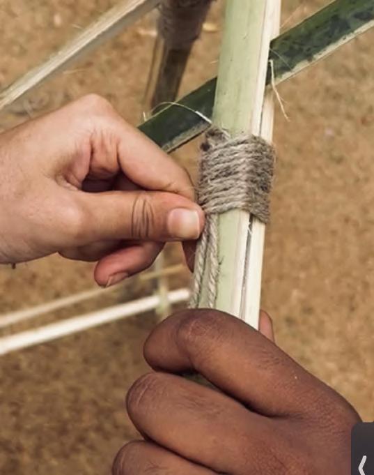
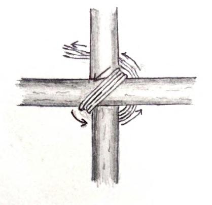
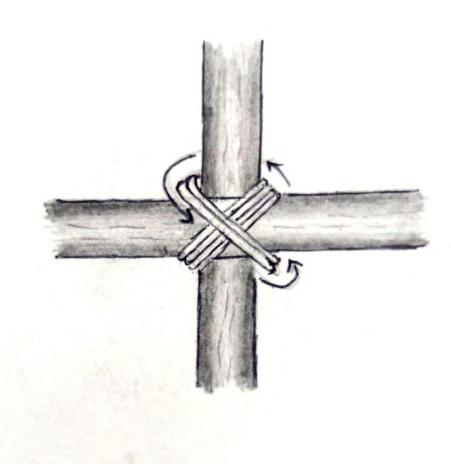
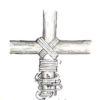
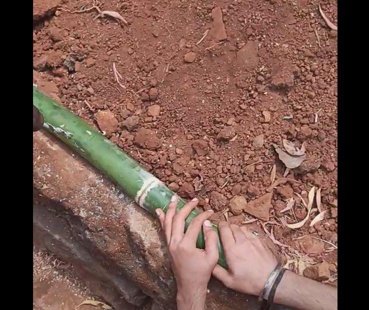
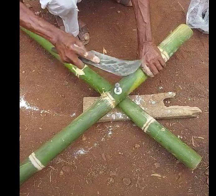
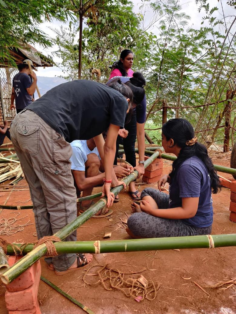
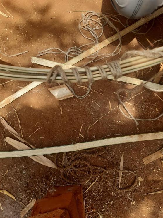
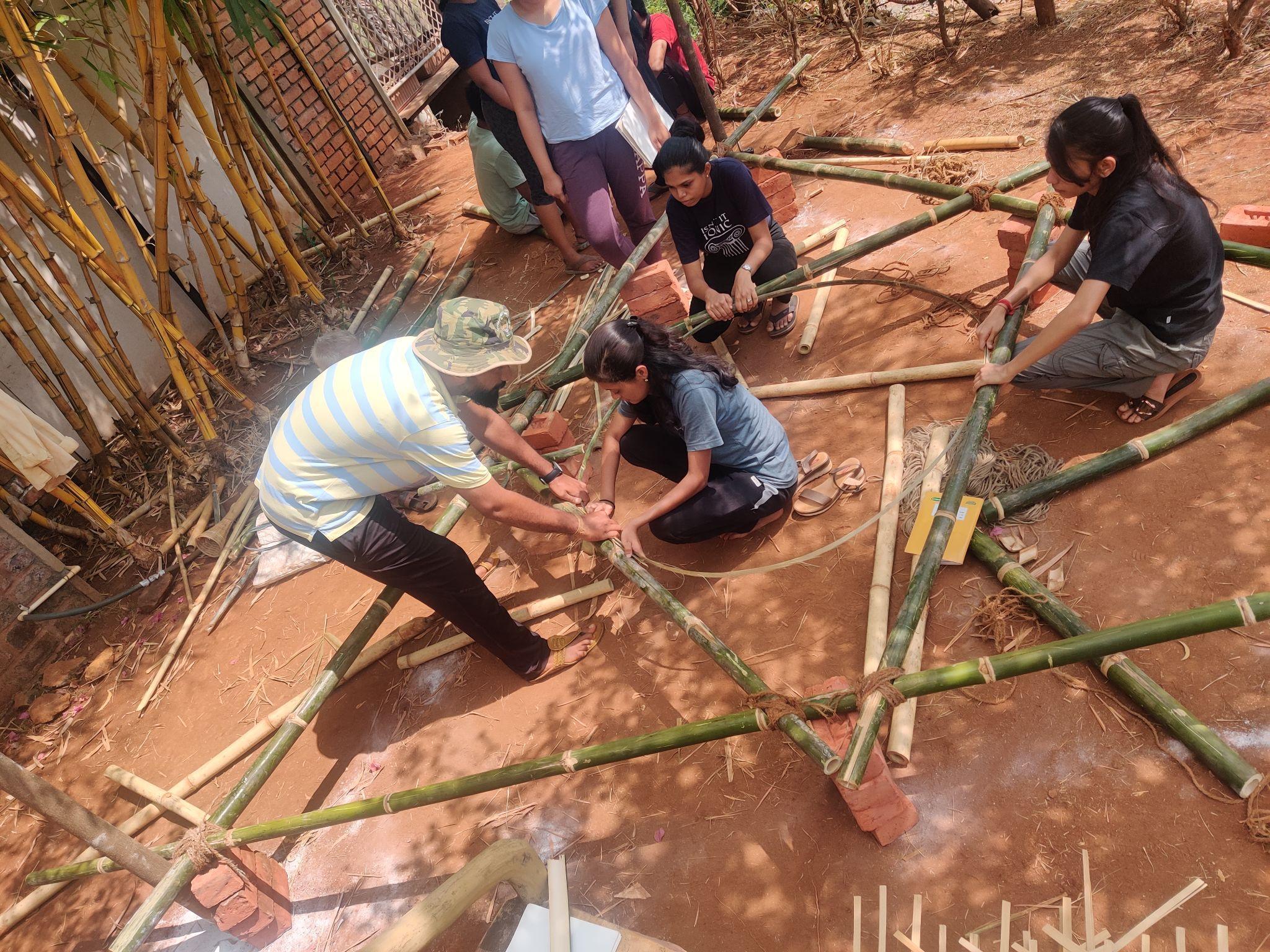
Arranging the parts to be tied
Loose wrapping since the mid of joint
Tight wrapping and pulling to rope under it
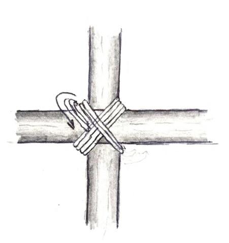
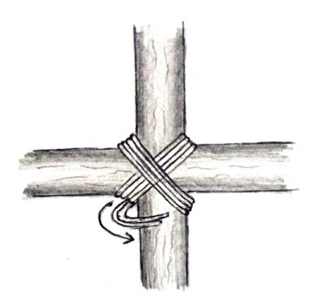
To achieve the desired design, the bamboo sections were tied firmly with jute rope. The rope was wound tightly around the joint, and pulled after each round to secure it, making sure there were no gaps.
07_BAMBOO TYING - KNOTS Team A | Design Report - June ‘22 19
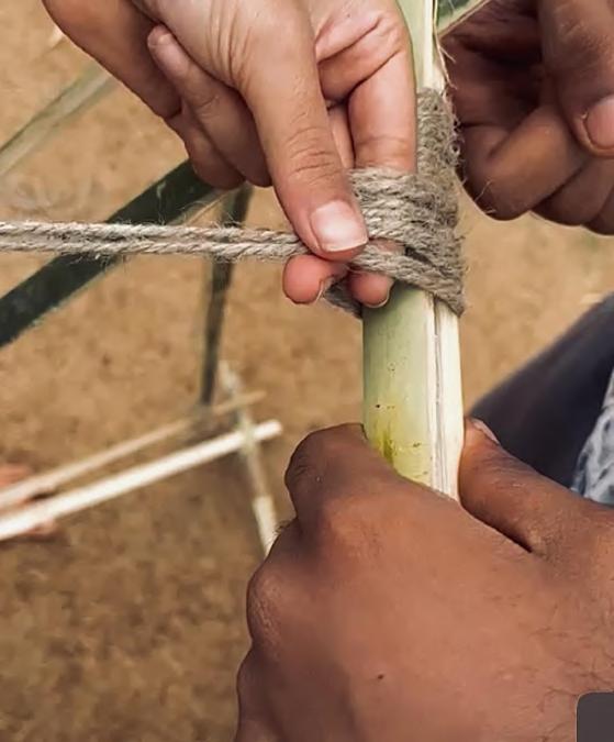
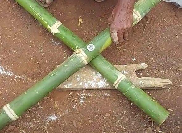
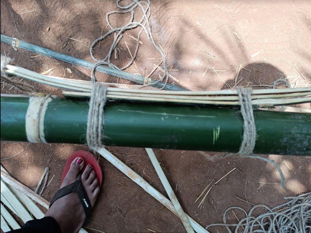
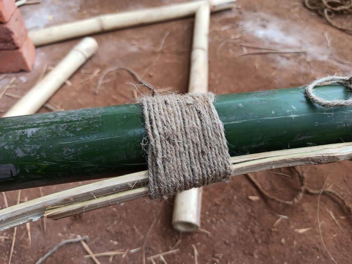
Wrapping over the rope
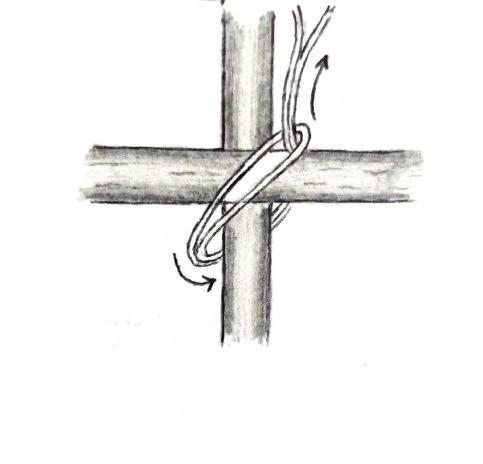
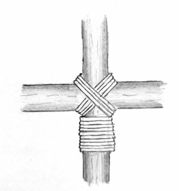
07_BAMBOO TYING- KNOTS Team A | Design Report - June ‘22 1 2 3 4 5 6 20
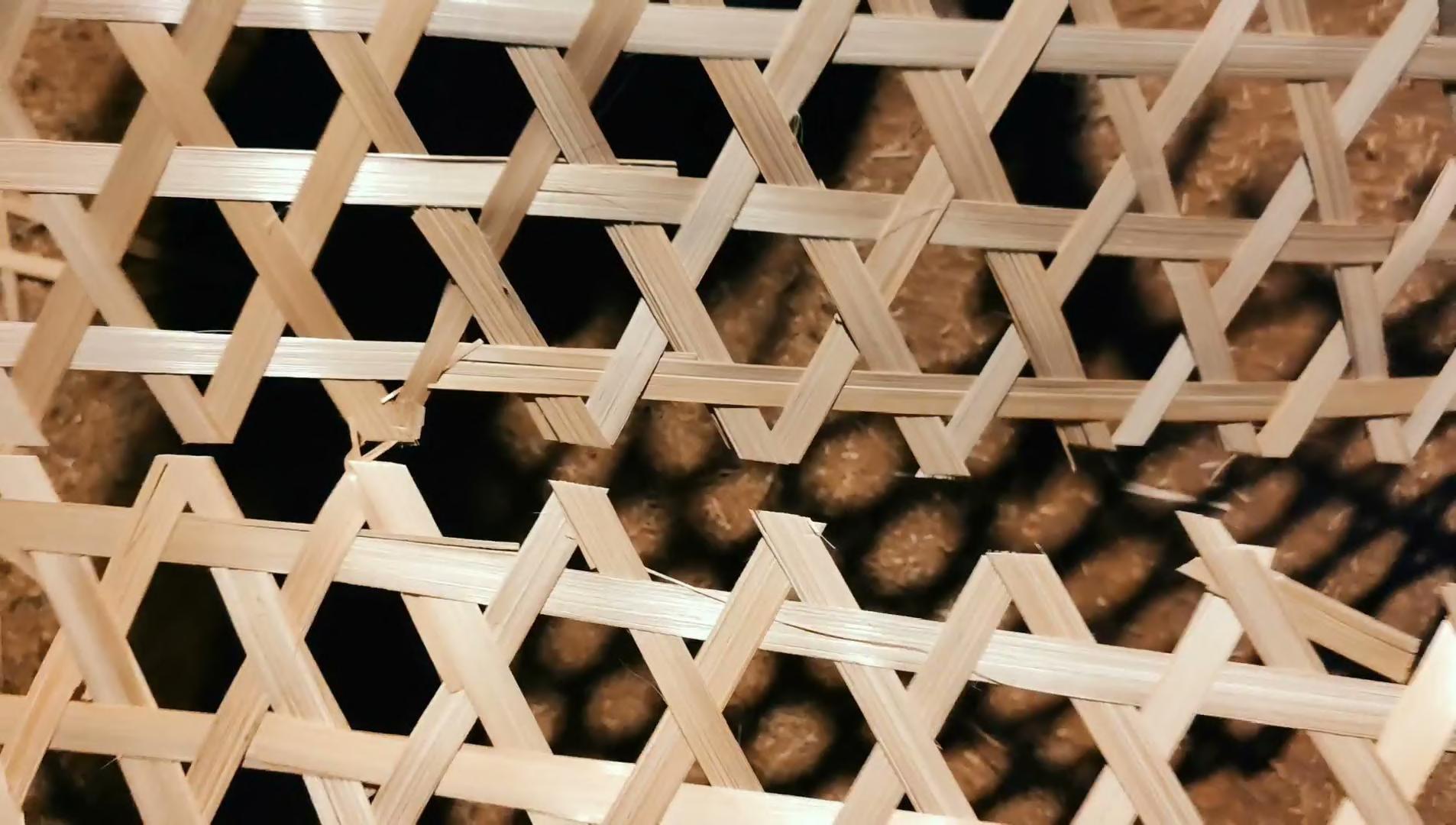
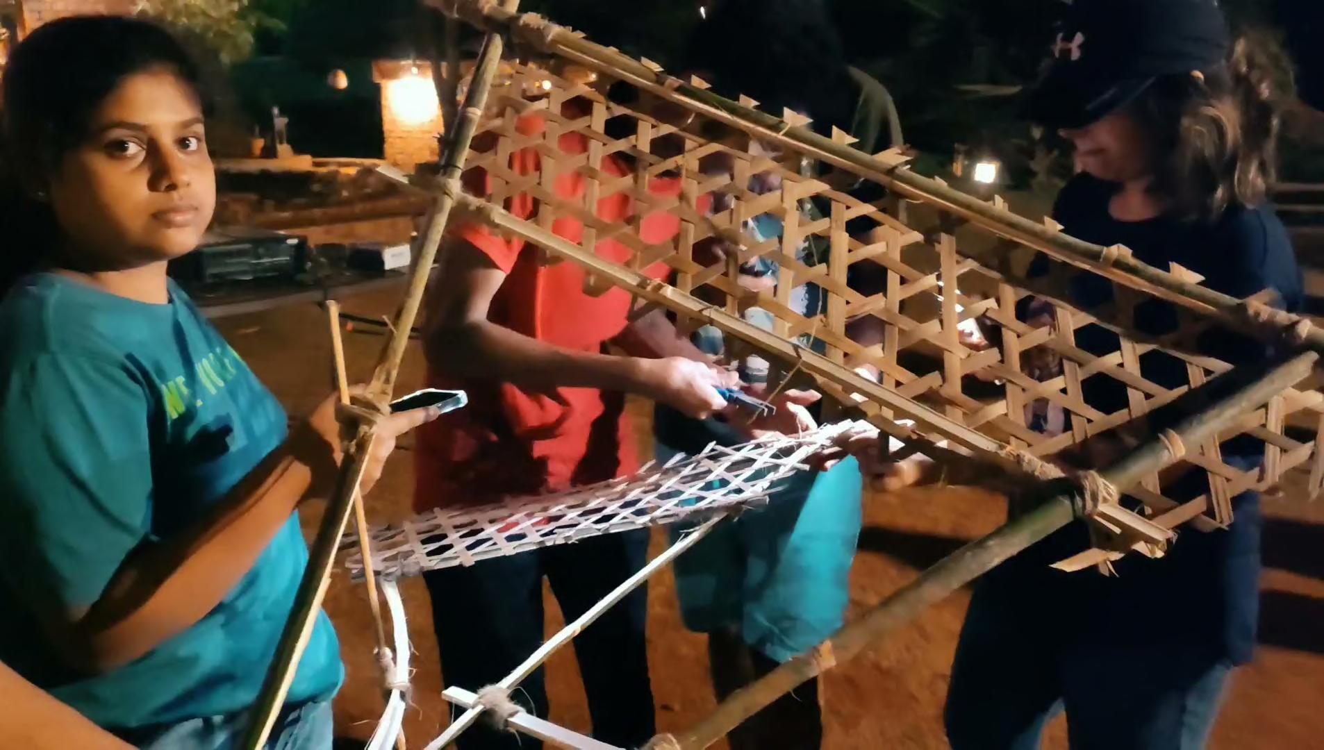
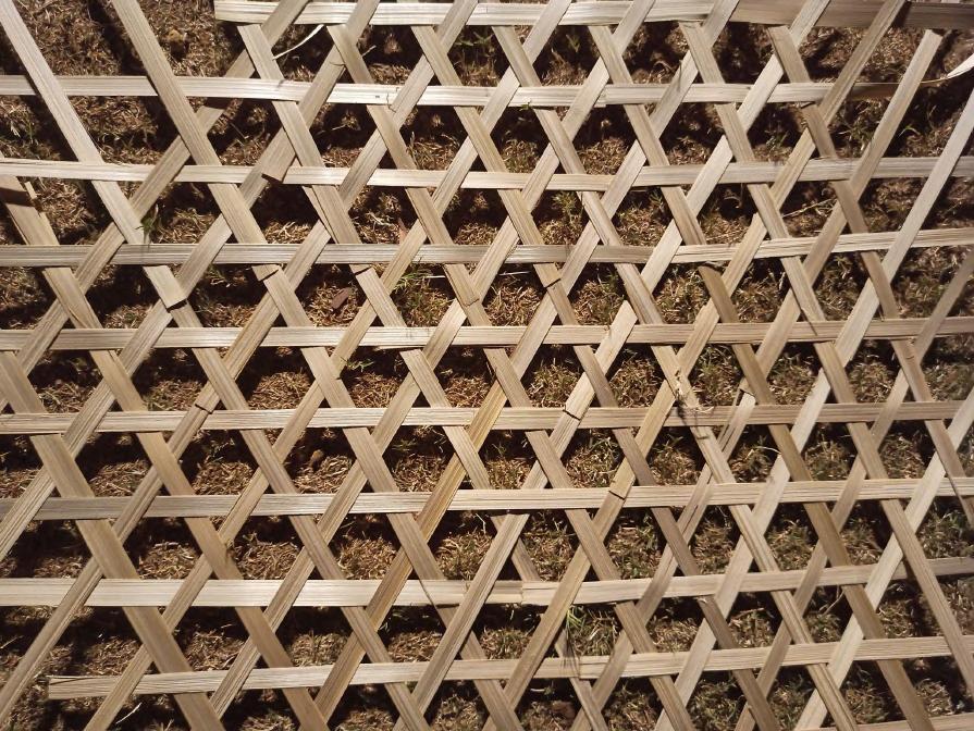
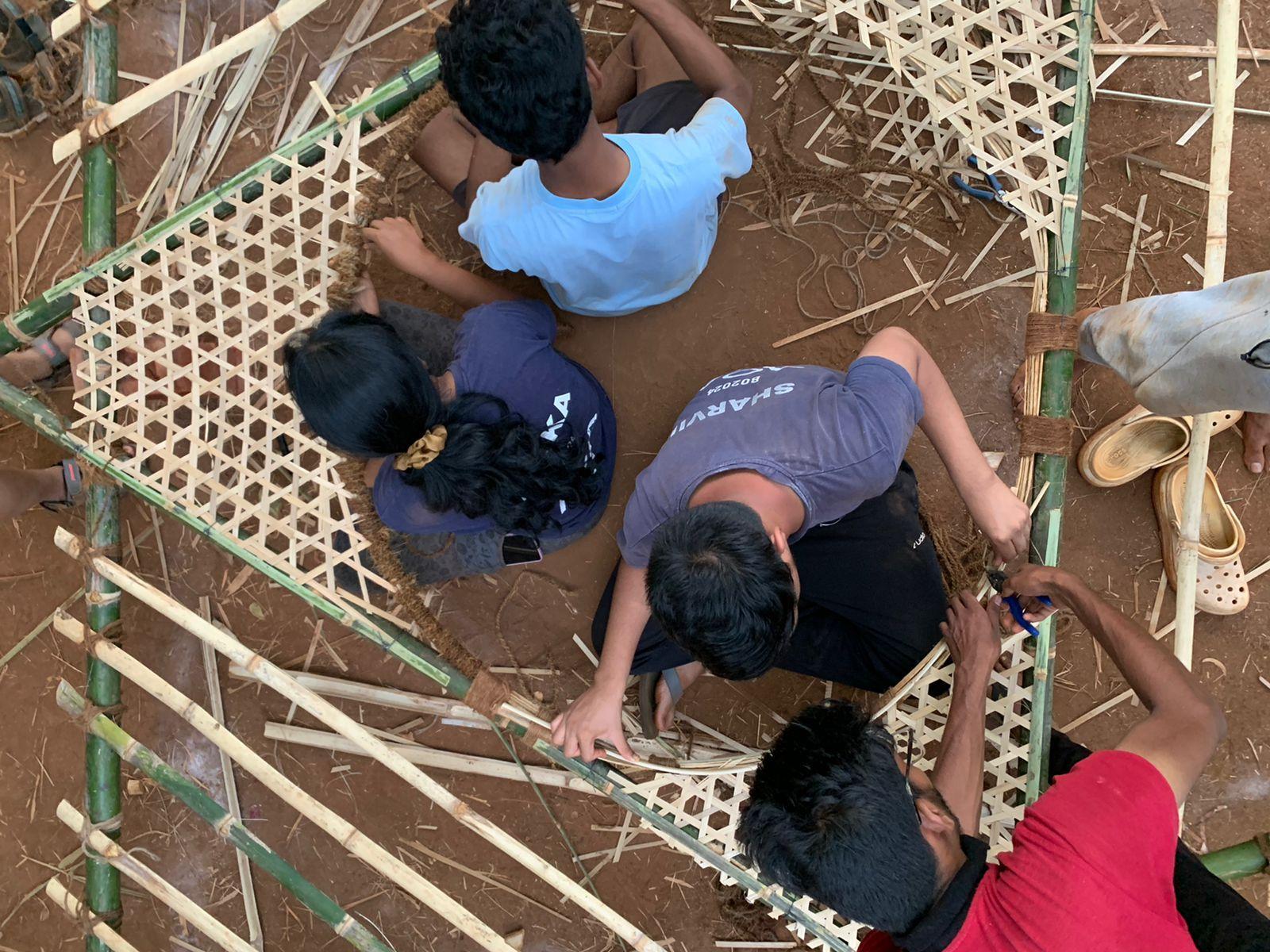
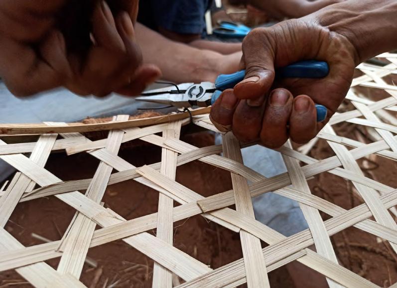
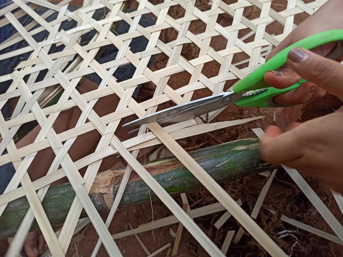
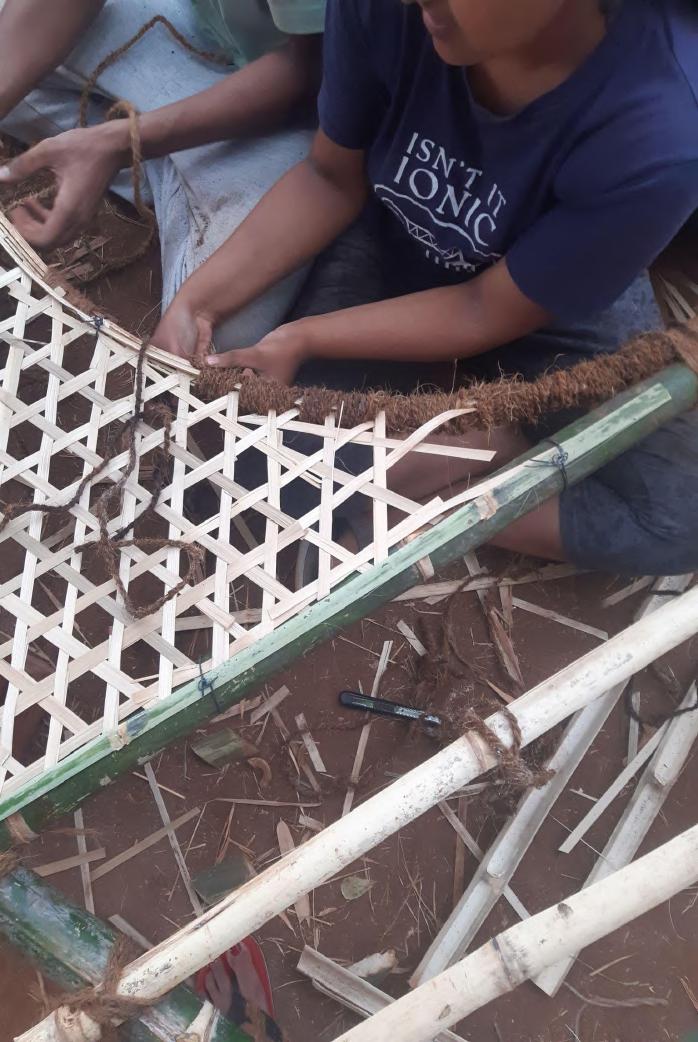
Torepresenttheleaves,stripsofbamboo wereweavedbythestepsgivenbelow.The weavingpatternformsahexagonalshapein thecentregivingitanintricatejalilook.
08_BAMBOO WEAVING Team A |
1 2 3 4 4
08_BAMBOO WEAVING Team A | Design Report - June ‘22
22
Video : Bamboo Weaving
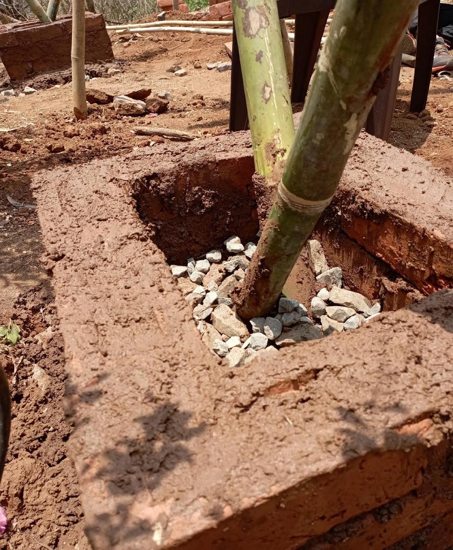
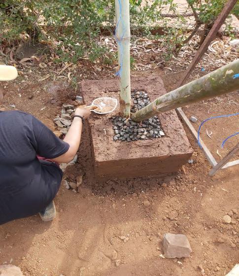
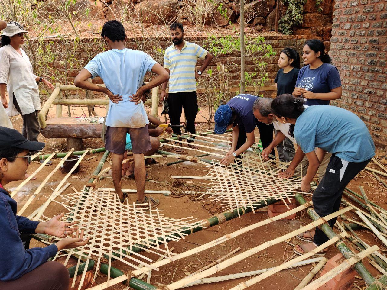
Tying of the bamboo strips to the knot
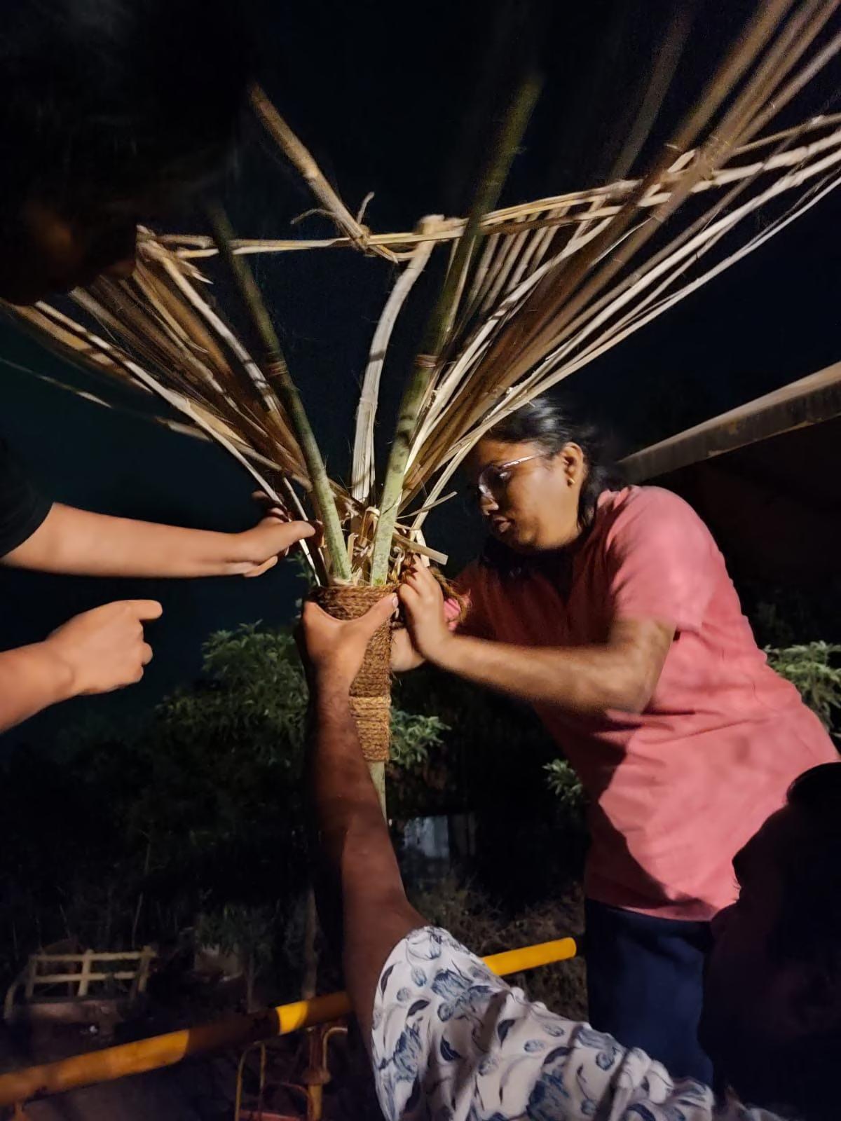
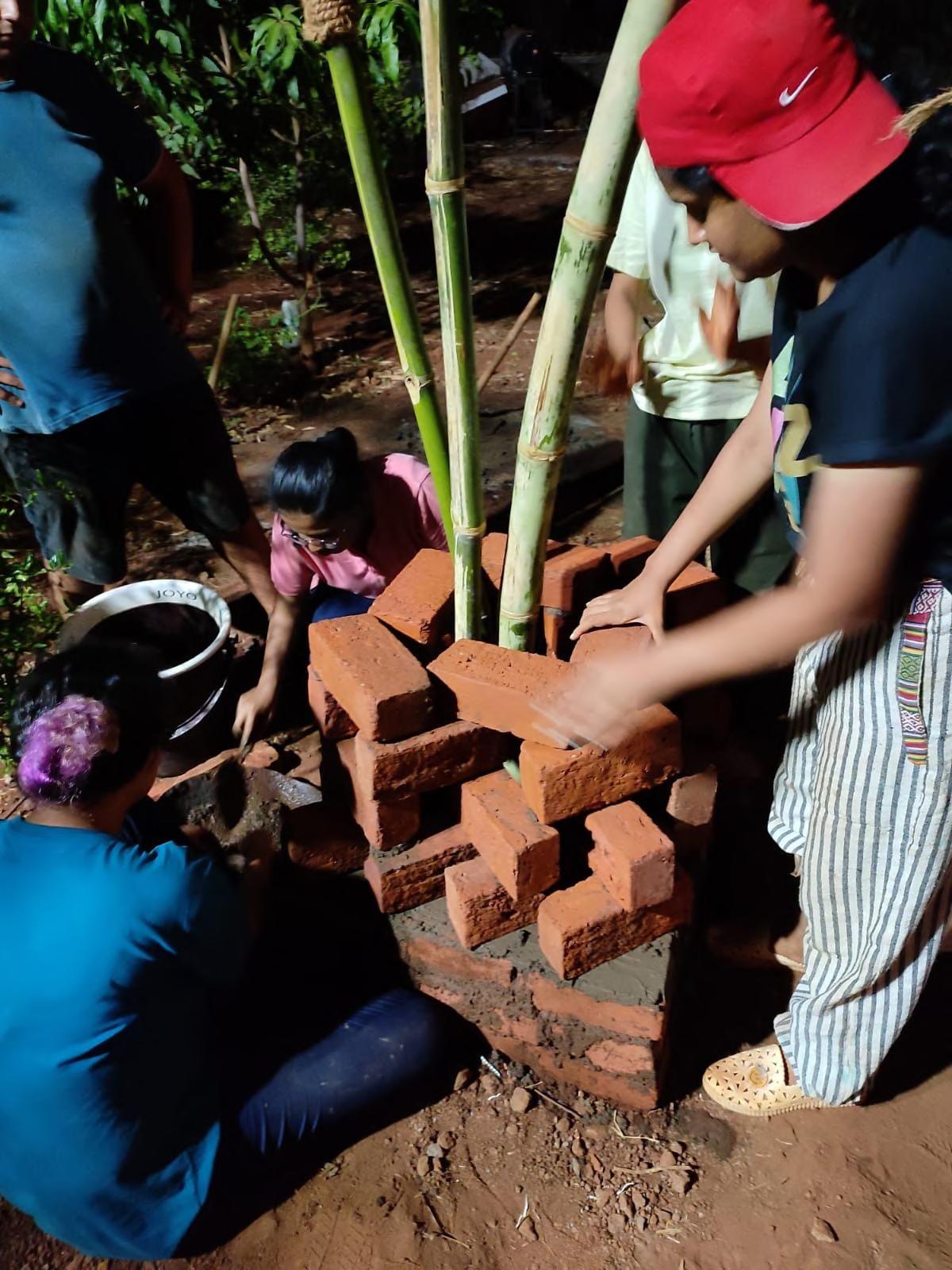
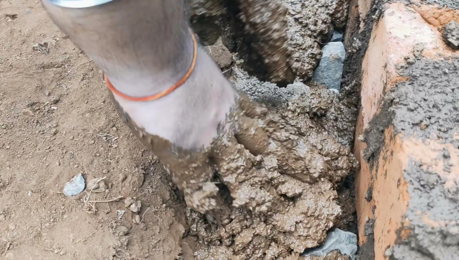
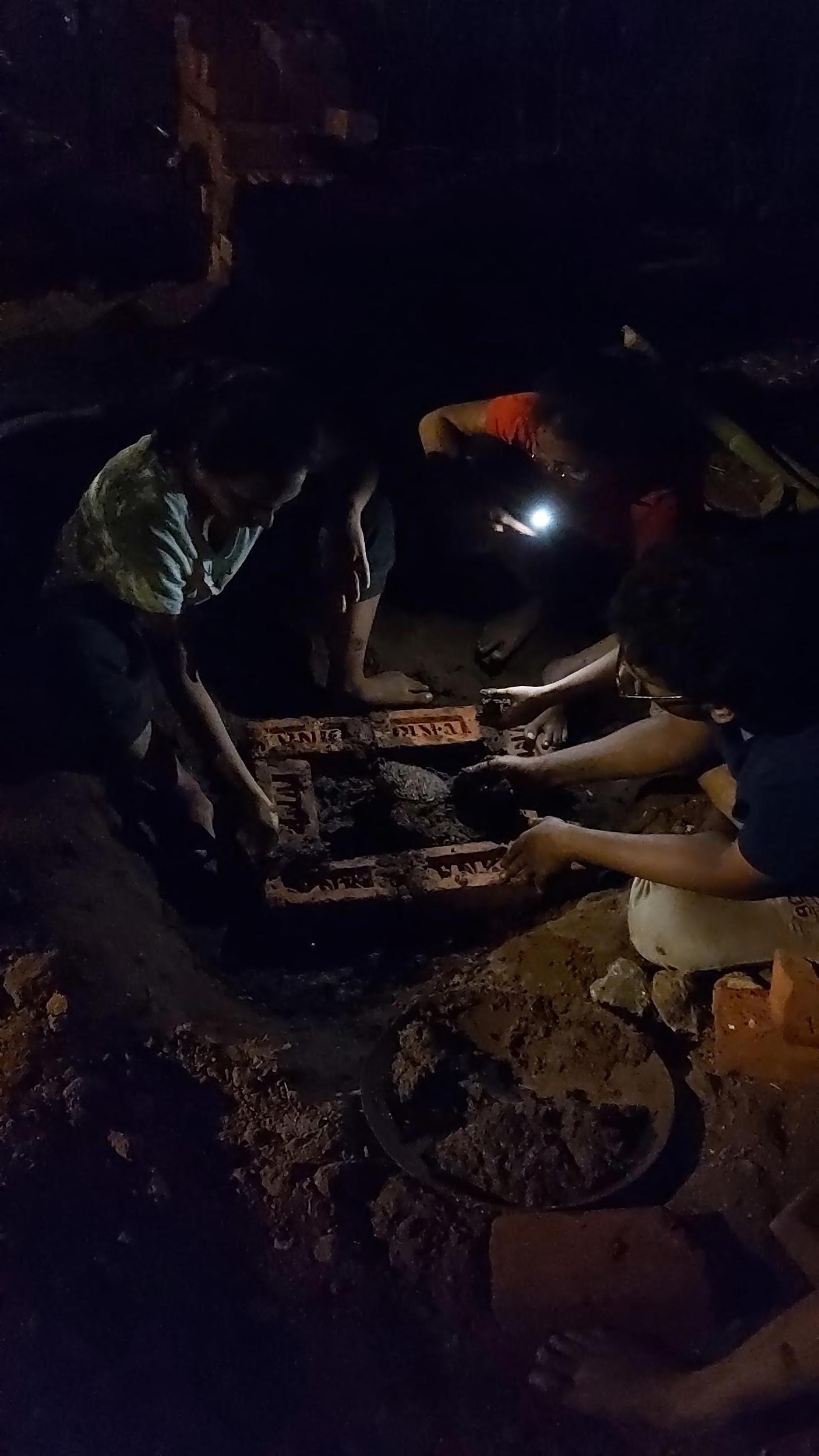
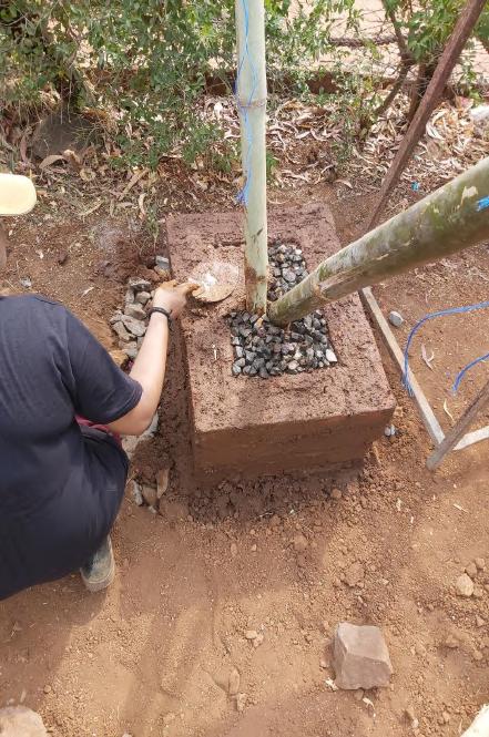
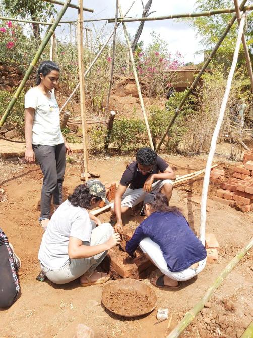
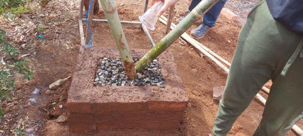
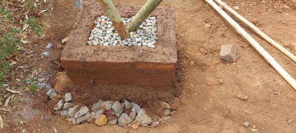
Filling of the central pit with clay and rubble to fix the structure
Laying of the jali pedestal
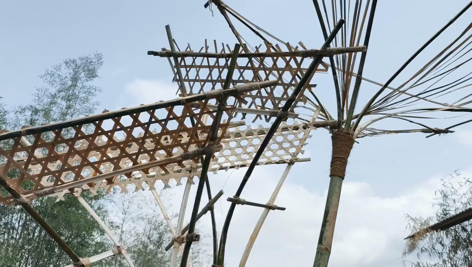
Assembling the members together
09_ASSEMBLY BAMBOO IN THE FOUNDATION PIT Team A | Design Report - June ‘22
23
09_FINAL ASSEMBLY Team A | Design Report - June ‘22 24
Video : Bamboo Assembly
09_FINAL ASSEMBLY Team A | Design Report - June ‘22 25
Video : Bamboo Assembly
Video : Final Assembly
ASSEMBLY Team A | Design Report - June ‘22 26
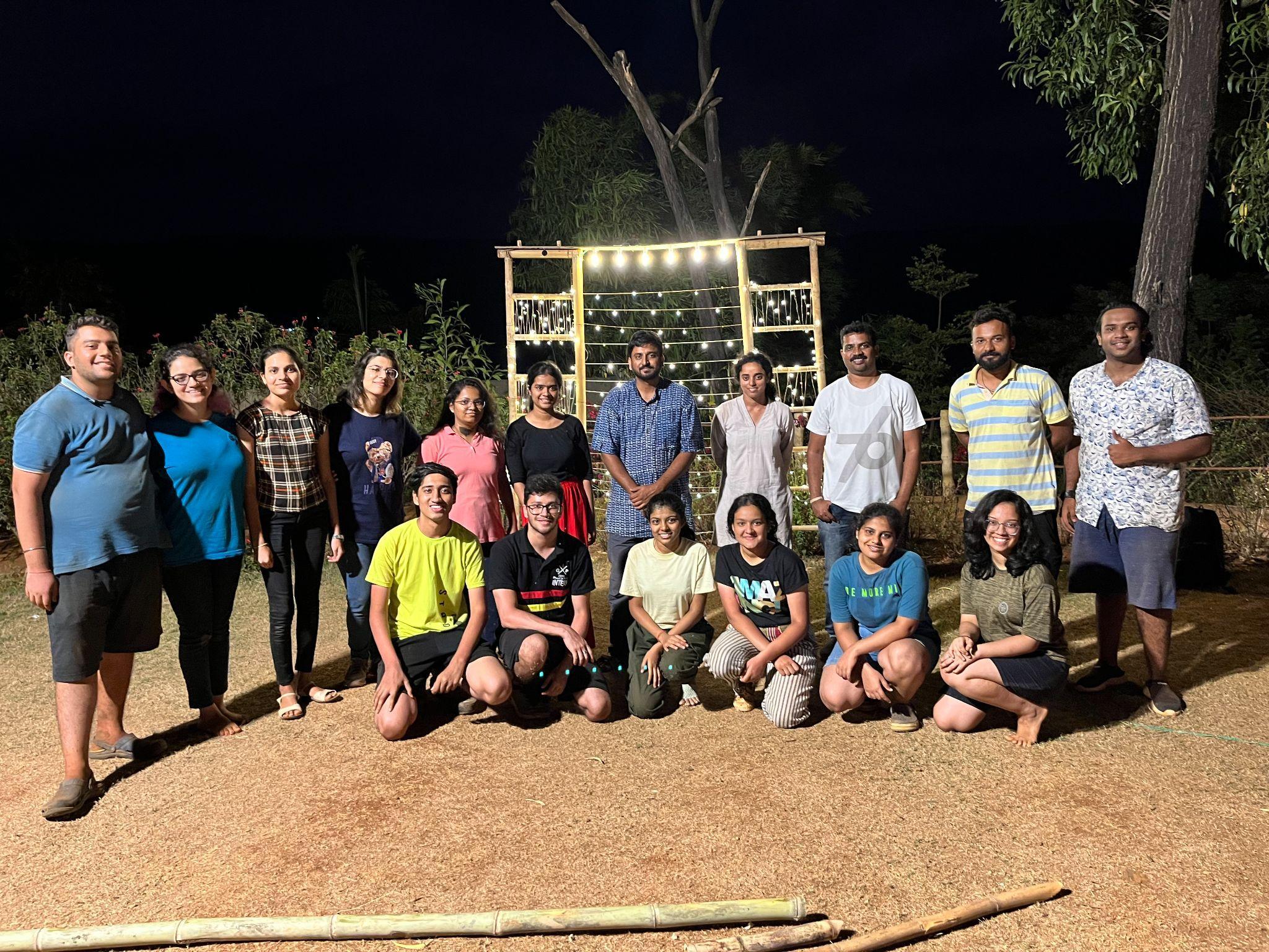
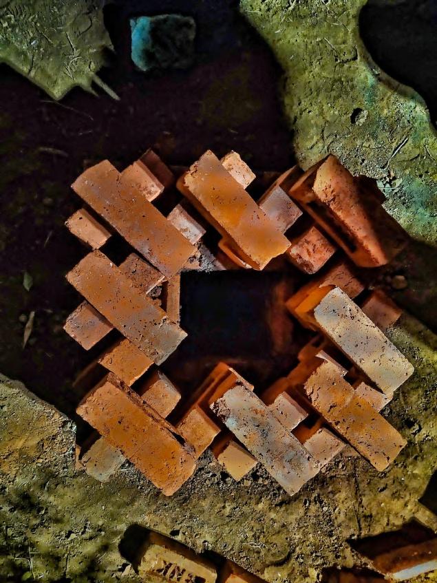
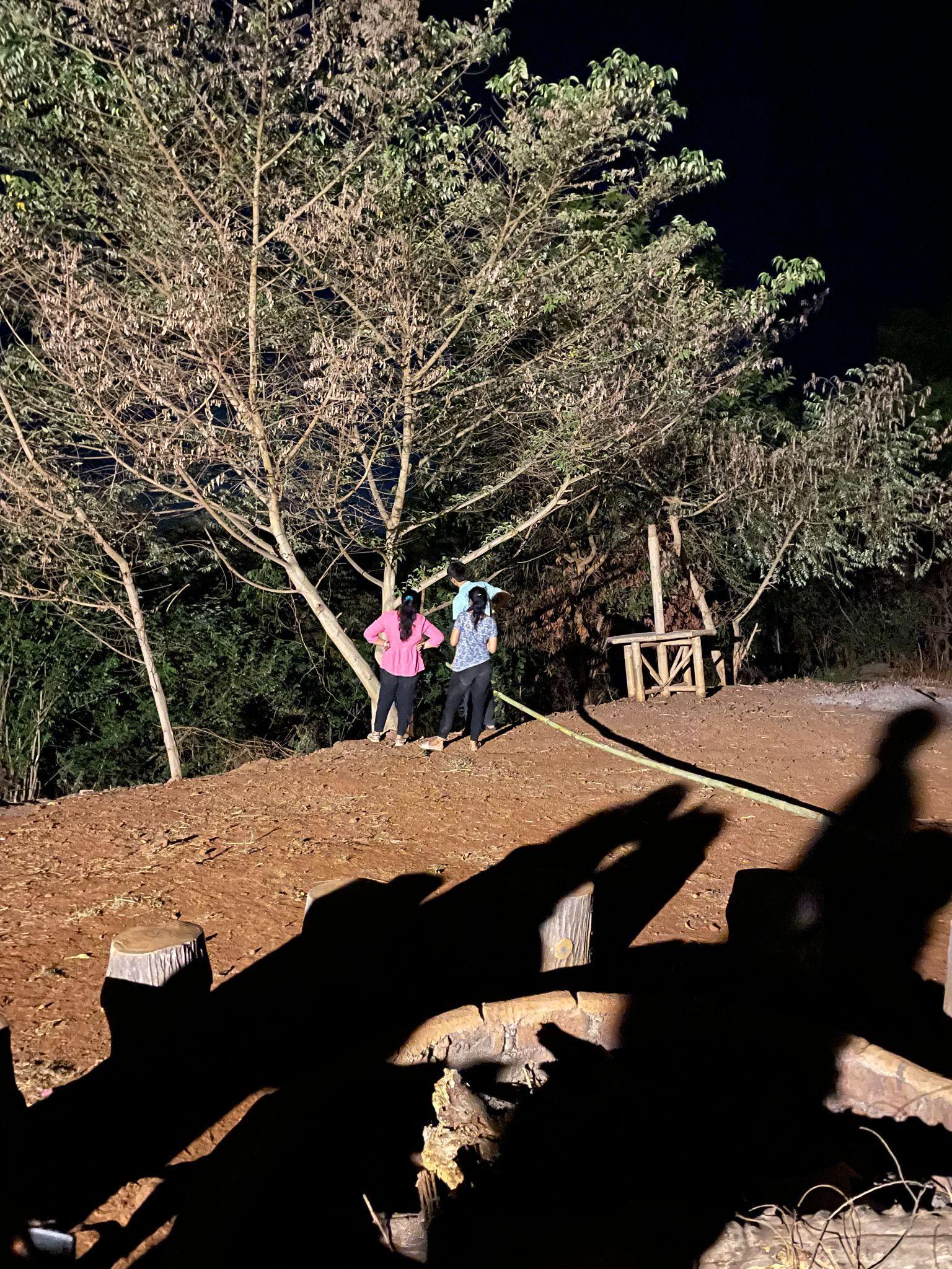
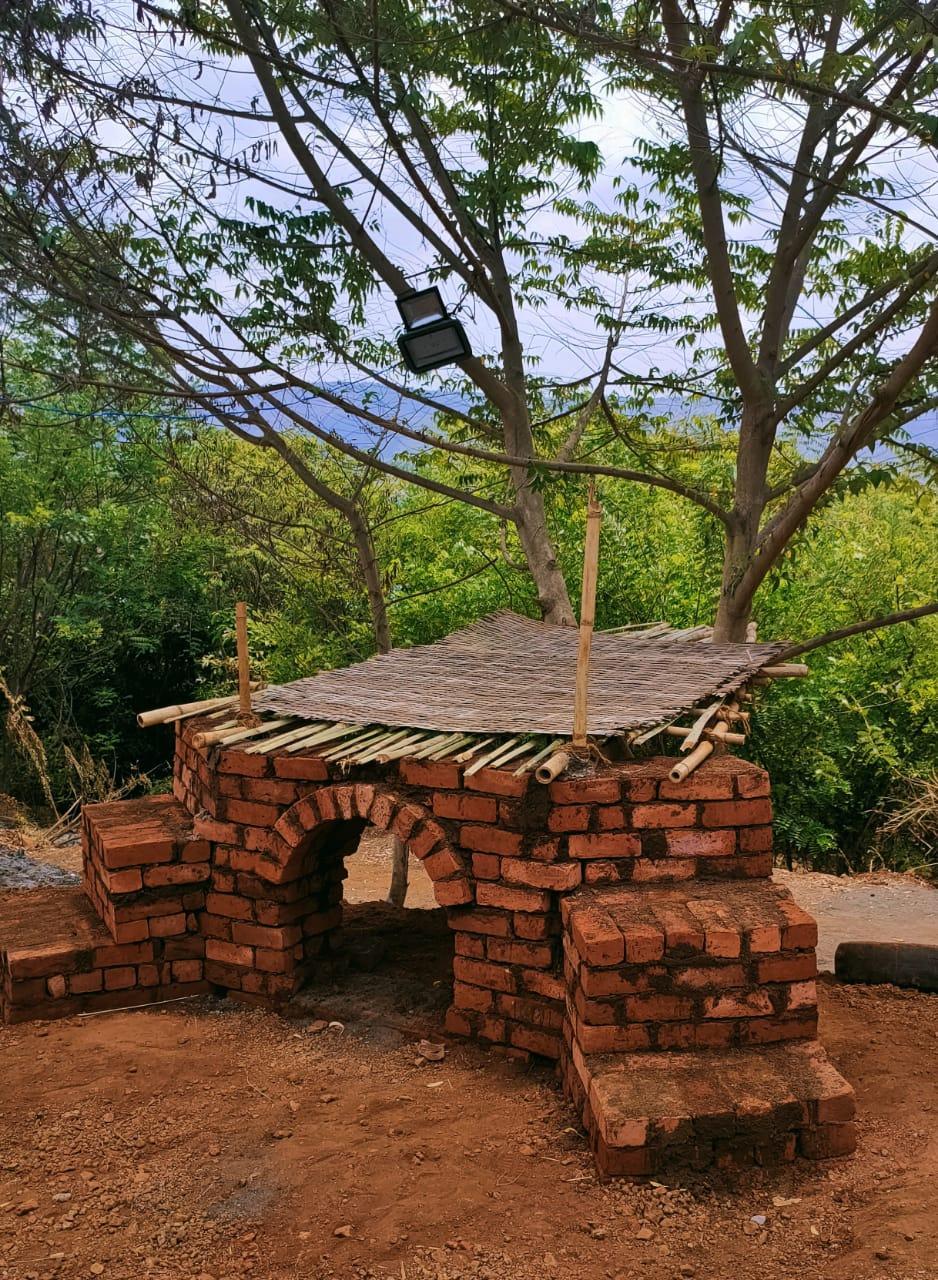
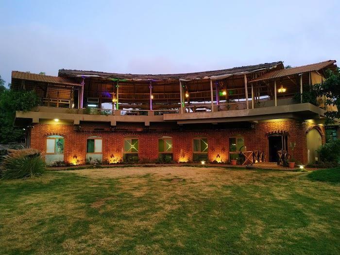
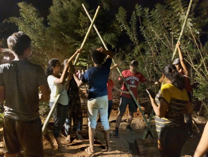
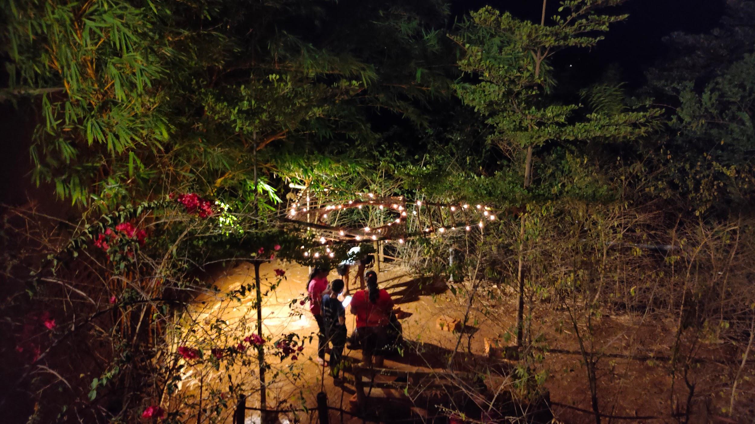
Lighting Proposal : The main intent of the installation was to enhance the sense of entry to the resort. The installation of Fairy lights along Bamboo and Halogen Light in the Brick Pedestal aims to enhance the overall appearance of the installation in the evenings. It also enhances the entrance and creates a more welcoming space.
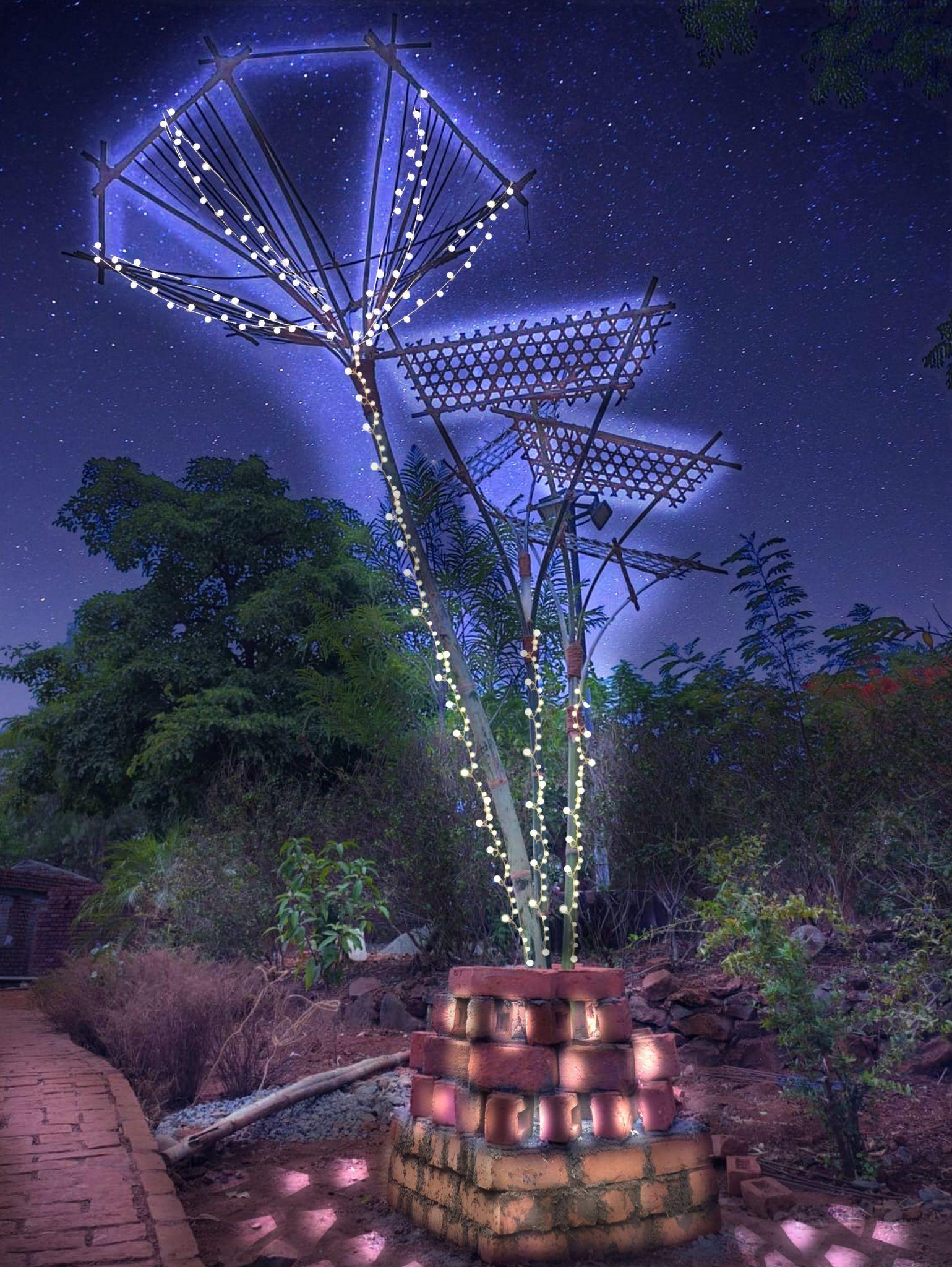
NIGHT VIEW Team A | Design Report - June ‘22 27
GROUP B
Academy of Architecture, Mumbai
TABLE OF CONTENTS Team B | Design Report - June ‘22 i. ____________________iv. ____________________v. ___________________vi. ___________________vii. ___________________xii. __________________xviii. 1. Acknowledgement 2. Introduction 3. Concept of the project 4. Brick work in detail 5. Bamboo work in detail 6. Special features 7. Learnings from the Workshop
Acknowledgements
We would like to express our thanks to the college, Academy of Architecture, Rachana Sansad and associated faculties for providing us with the opportunity to carry out this practical exploration project with Bamboo and Bricks as a part of Electives,Semester7.
We also take this opportunity to express our sincere gratitude to our coordinator, Ar. Shekoba Sanap, assisting faculties, Ar. Dhruvang, Ar. Priyanka, Mr. Sakpal, and Mr. Pawar for guiding us and imparting us sound base of knowledge pertaining to the topic that ensured the successful completion of this project and theresortmanagementfortheirhumblecorporationandhospitality. Our sincere thanks to our mates, AOA aided batch of 2024 for their help and collaboration.
TEAM B 01_SimranAjgaonkar 06_Shivanjay Bhagat 07_Rashi Bhansali 14_Kimaya Churi 19_Sarthak Ekal 21_Atharva Girme 24_Vaishnavi Gurnalkar 26_Karishma Kaur Hooda 36_Krishna Khurusane 41_Isha Patil 47_Rasika Salgaokar 55_Jigisha Soni 61_Shweta Utekar
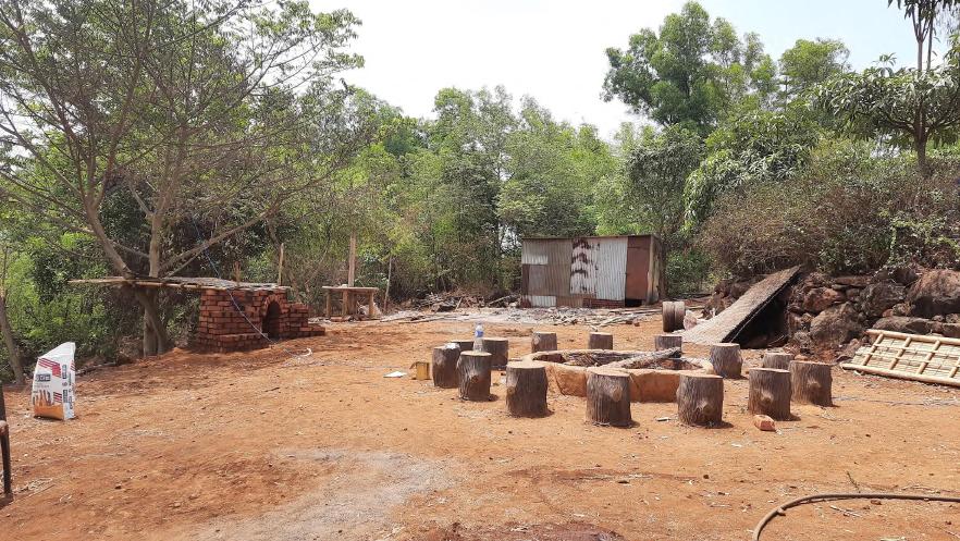
The intent of the workshop was to explore the possibilities of bamboo and bricks construction corresponding to the allotted site in the resort premises. The site portrayed a raw brown-green character celebrating the essence of nature and its protagonist picturing the bonfire. The site offered introvercy in correspondence to the existing circle of the bonfire. Yet it had views to offer towards the lake that demands anextrovertedinterventiononthesite.
Bamboo offers great tensile strength, offers as a filler material in the form of wowen slits and its elasticity allows it to weather storms and earthquakes that would break or crumble other building materials. Bamboo can be vulnerable to insect and fungus attacks. Special treatments are needed to preserve and protect it. All of our bamboos arepressuretreatedagainstinfestation.
Brick masonry is a highly durable form of construction. It is built by placing bricks in mortar in a systematic manner to construct solid mass that withstand exerted loads. There are several types of bricks and number of mortars which can be used to constructbrickmasonry.
i.
Introduction
Concept of the project
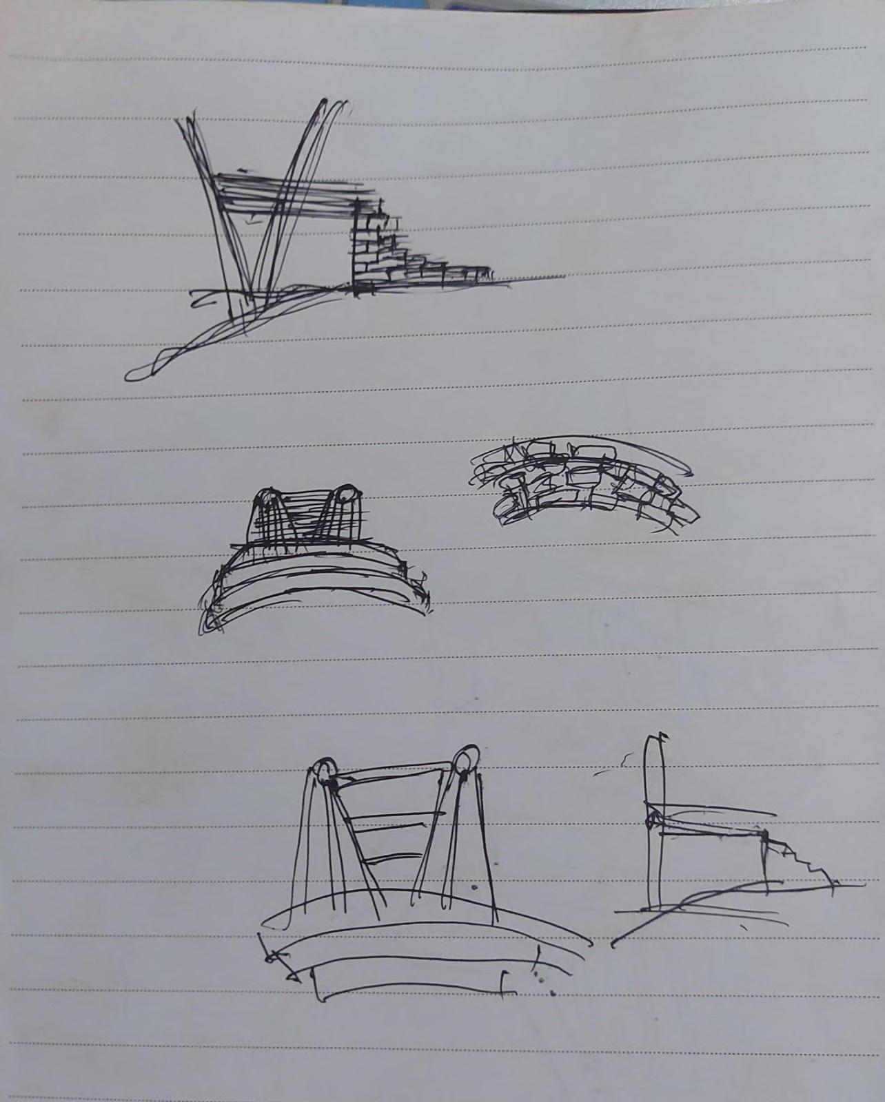
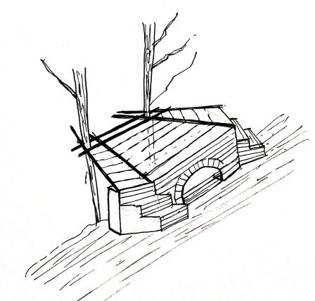
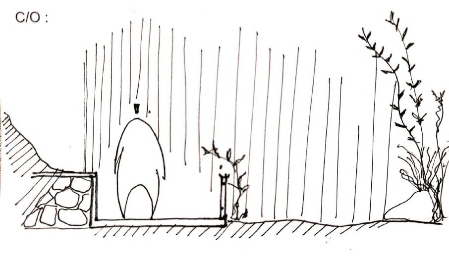
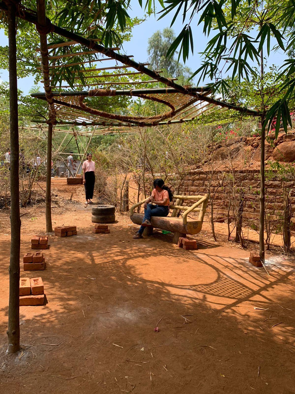
Driven by the existing character of the site and defined focus of one line perspective, the installation is proposed to respond to both, the permeability of vegetation towards the lake and an upper perspective towards the bonfire introducing a visual connection and a sense of sociability with the bonfire users. In the same line of vision, a tree focuses as another subject to our installation. The design is composed of a bamboo deck resting on a brick platform with dual entry enclosinganarchtocounterthetension.
The composition responds to the existing elements of nature on the site intervening the tree subject sensitively, which served as a backrest with its stemming branch andthedeckdefinedatthenodelevel.1.5brickthickFlemishBondmasonrysetsa mode of design continuity in the language of construction with the larger context of the resort with a 2 brick thick arch resulting in a space amplifying a user friendly experience.
Team B | Design Report - June ‘22 i.
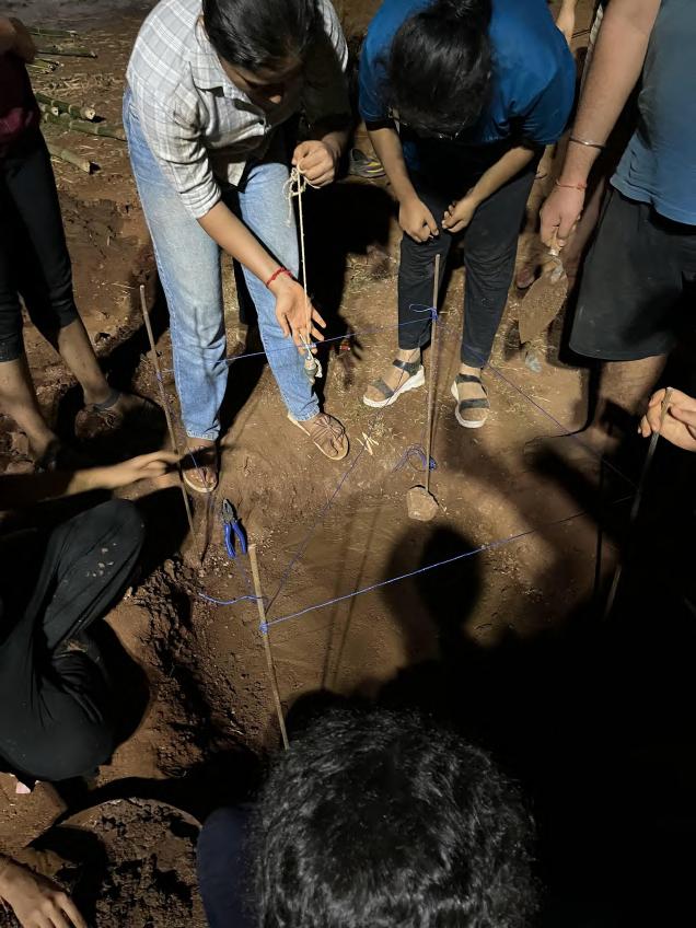
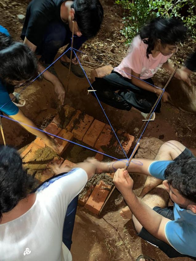
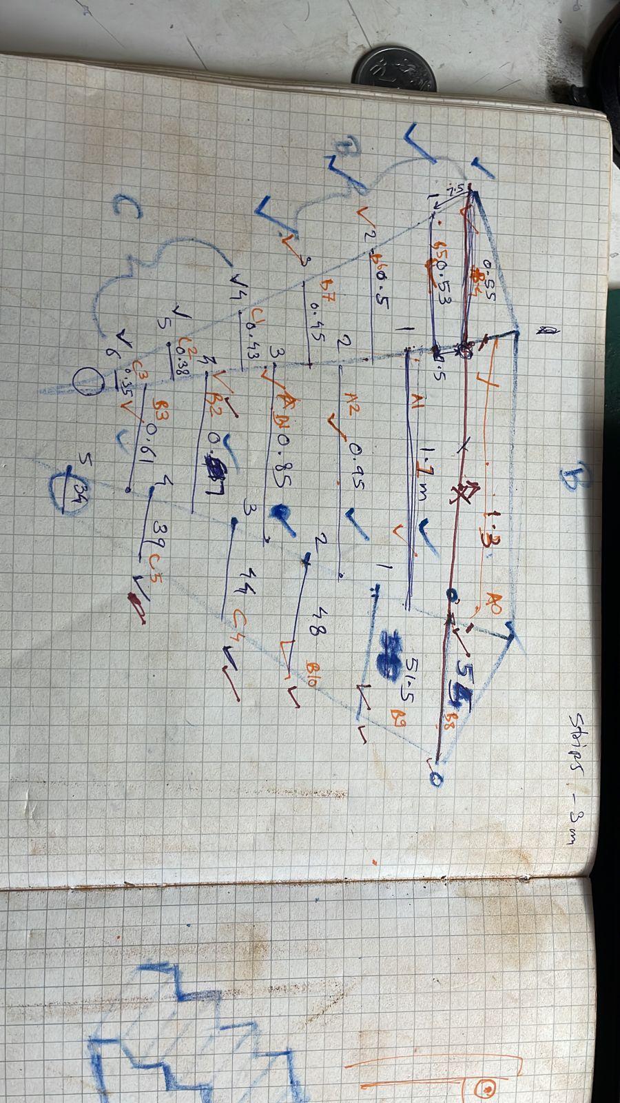
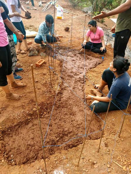
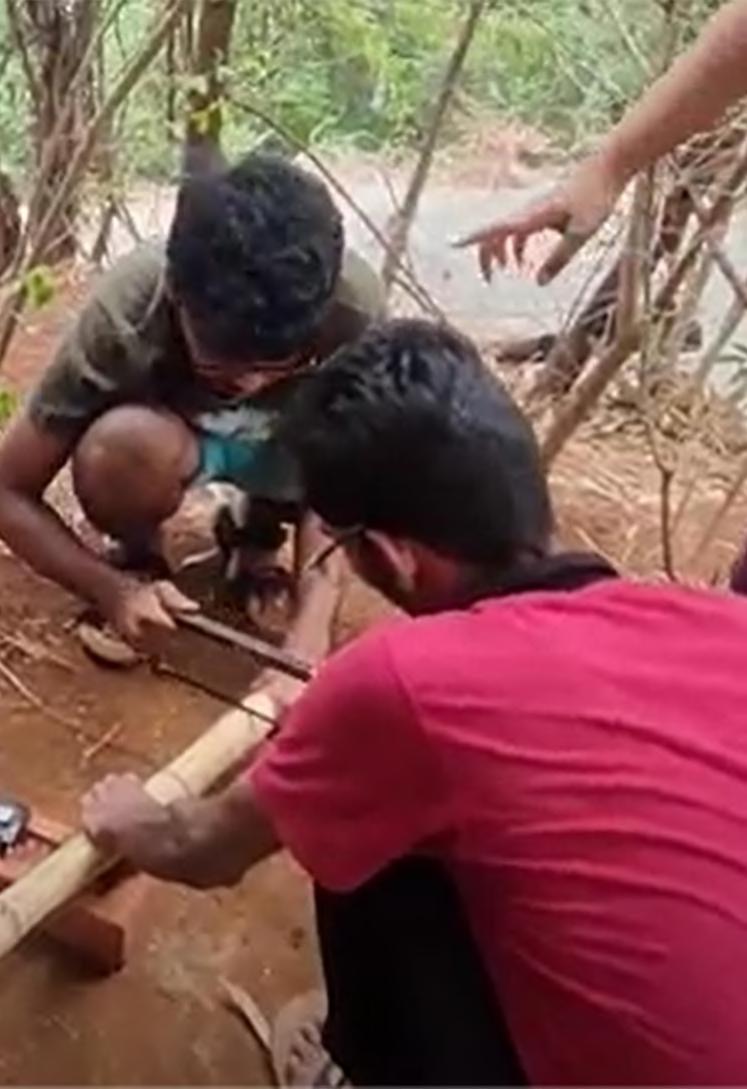
Initial setup for defining the territory of our built was demarcated by the Line out procedure. Levels were matched with the help of water level pipe. Tentative points were defined for the grid where steel rods werepinnedtotheground.
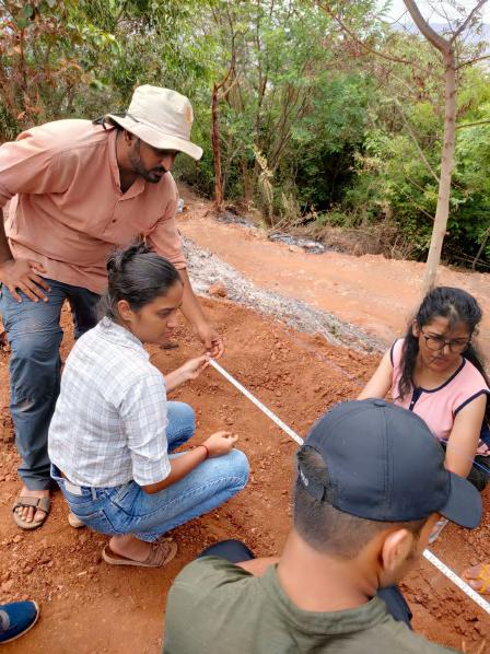
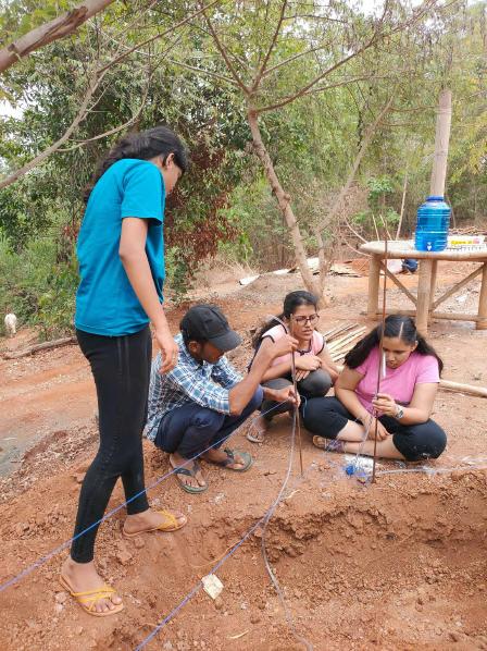
Techniques of Triangulation, Trigonometry and Pythagoras theorem were used to locate accurate points with the Plumbob and finally then excavationwasstarted.
Team B | Design Report - June ‘22 i. Brick Masonry- detail
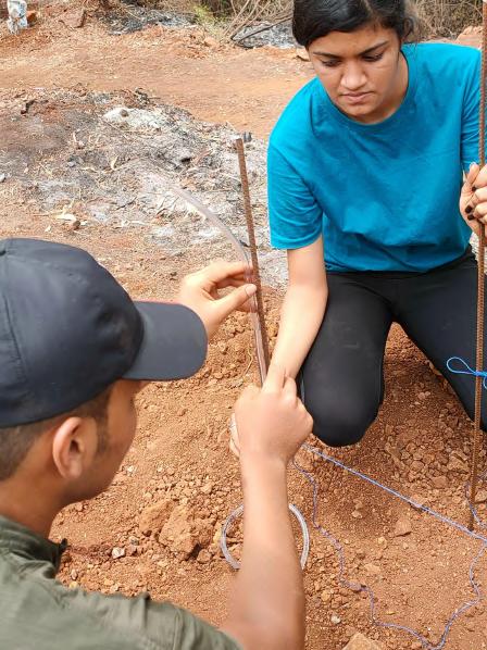
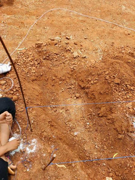
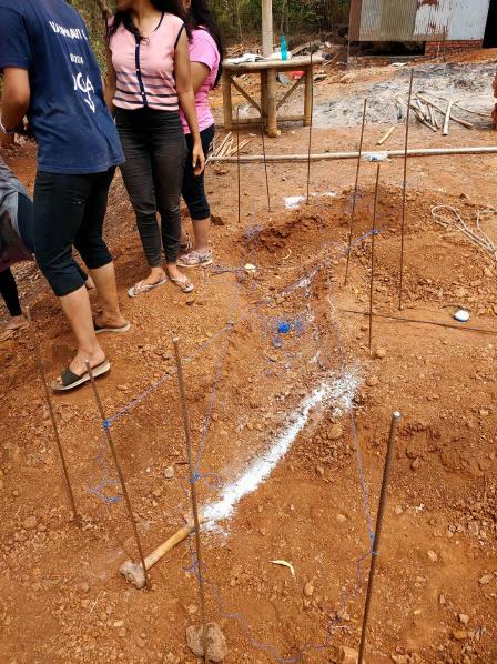
FOUNDATIONAND LINE OUT
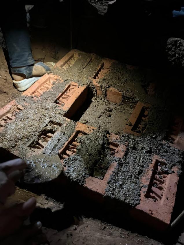
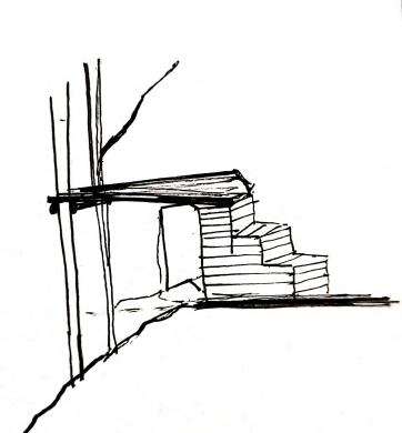
Flemishbondforthecentralcore structurethatwasmodifiedaccording tothestepsatthesidesand correspondenttothearch.Itwas chosenasithasaestheticappreance andiseconomical
The first step of staircase of tread one and half bricks and riser of 300 mm containing 3 courses of bricks. English bondwasusedasit'sstrongest.
In second step of staircase of tread one and half bricks and riser of 400 mm containing 4 courses of bricks. English bond was used as it's strongest.
In third step of staircase of tread one and half bricks and riser of 400 mm containing 4 courses of bricks. Its the topmost part of structure.English bondwasusedasit'sstrongest.
1 2 3
4
BRICK BONDS 1.5 BrickThick Flemish SAND PREPARATION
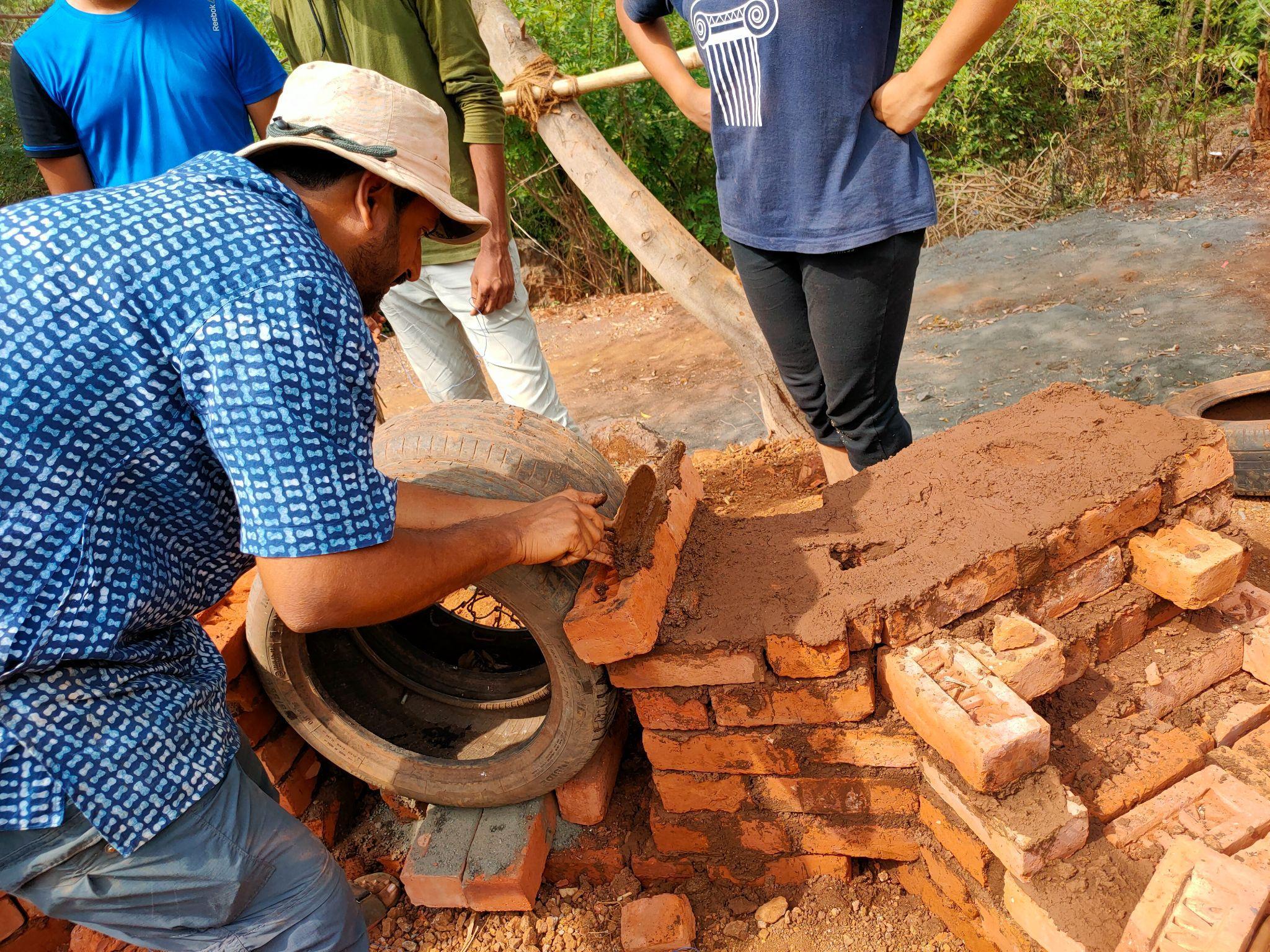
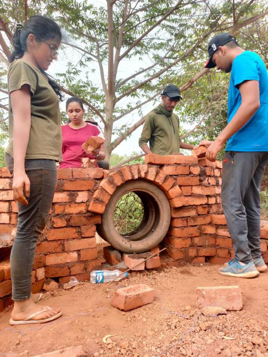
After laying the first course of bricks the rubber tyre been placed on temporary bricks with dry aggregate in between bricks and bottom of the tyre. Purpose of placing dry aggregate to remove the tyre after construction easily. After the 5 courses the actual construction of arch been started with placement of voussoirs.
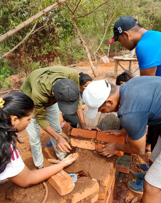
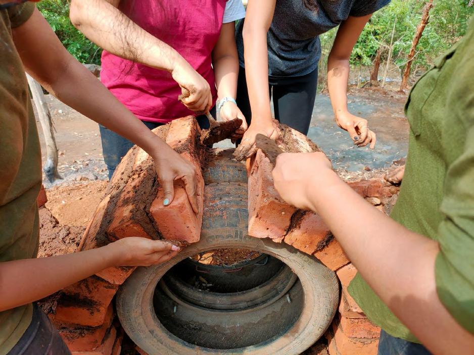
Mortar with proportion of 1:5 been used for arches which laid at an angle with thicker part of mortar laid at external edge and zero mortar towards tyre in order to achieve the wedge shape with the brick
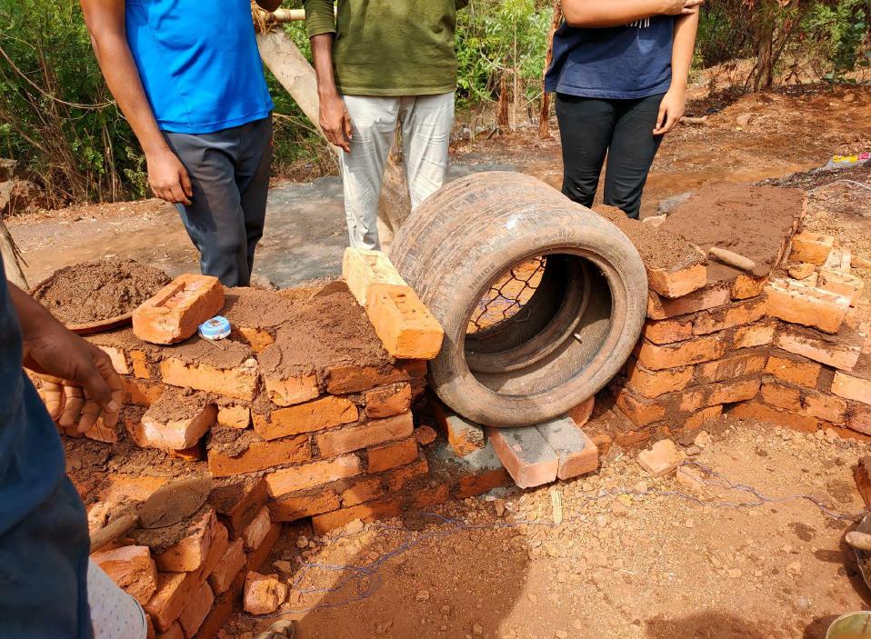
While placing the next voussoirs bricks stretchers are placed perpendicular to tyre. The process done simultaneously on both side and the built up key stone beenplacedattheendofarch.
5 6 7
After placing the key stone: mortar is made kind of slurry to it got easily filled upto to the bottom towards inner side gap i.e. horizontal where the vertical goesarefilledwithnormalmortar.
Further bricks, the topmost course was laid after arch construction to create plan surface. Tyre been removed after approximately after 45 minutes by placing heavy stones on top for primary testing.
8 9
The design consisted of a deck as an expansion of the existing tree, resting over a series of steps; the deck and its components were to be made using bamboo in order to make advantage of its properties and linearity. This viewing deck would use two support systems i.e. at both its ends, first, by resting over the brick wall and second,bybeingtiedtothetreeanditstwomaintrunks.
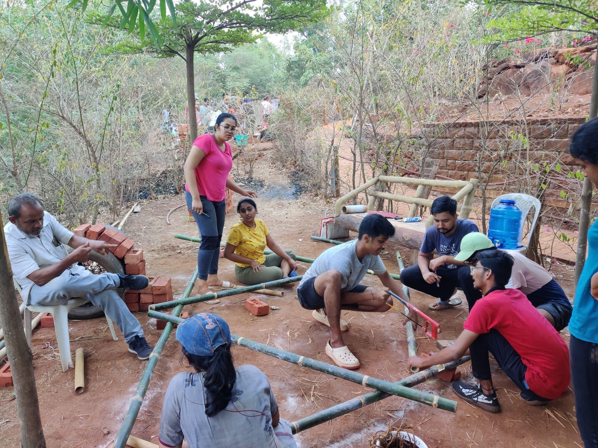
After finalising the shape of the deck, we discussed the same with the bamboo expert to understand the components and construction components and systems required to construct the deck securely. Every piece of bamboo had to be precisely cut and had to be of the appropriate dimensions to ensure sturdy

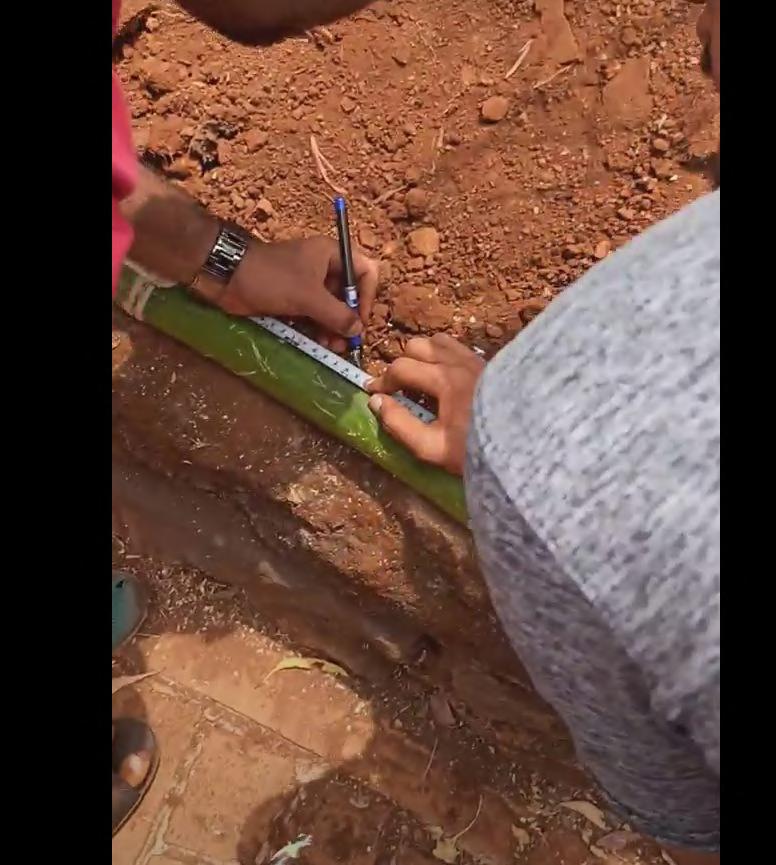
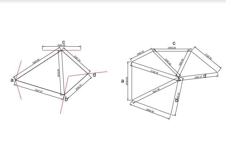
We began by taking measurements on site by using a level tube to measure heightsandmeasuringtapetomeasurerequireddistances.
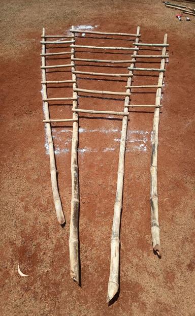
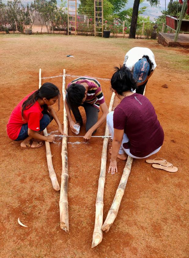
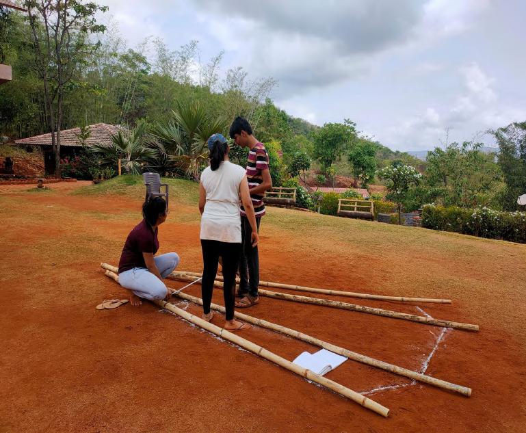
The base of the deck according to our design, had four linear members which were the main weight bearing members, whose dimensions we obtained from onsite measurements and so our first step in construction was to cutthesesteps.
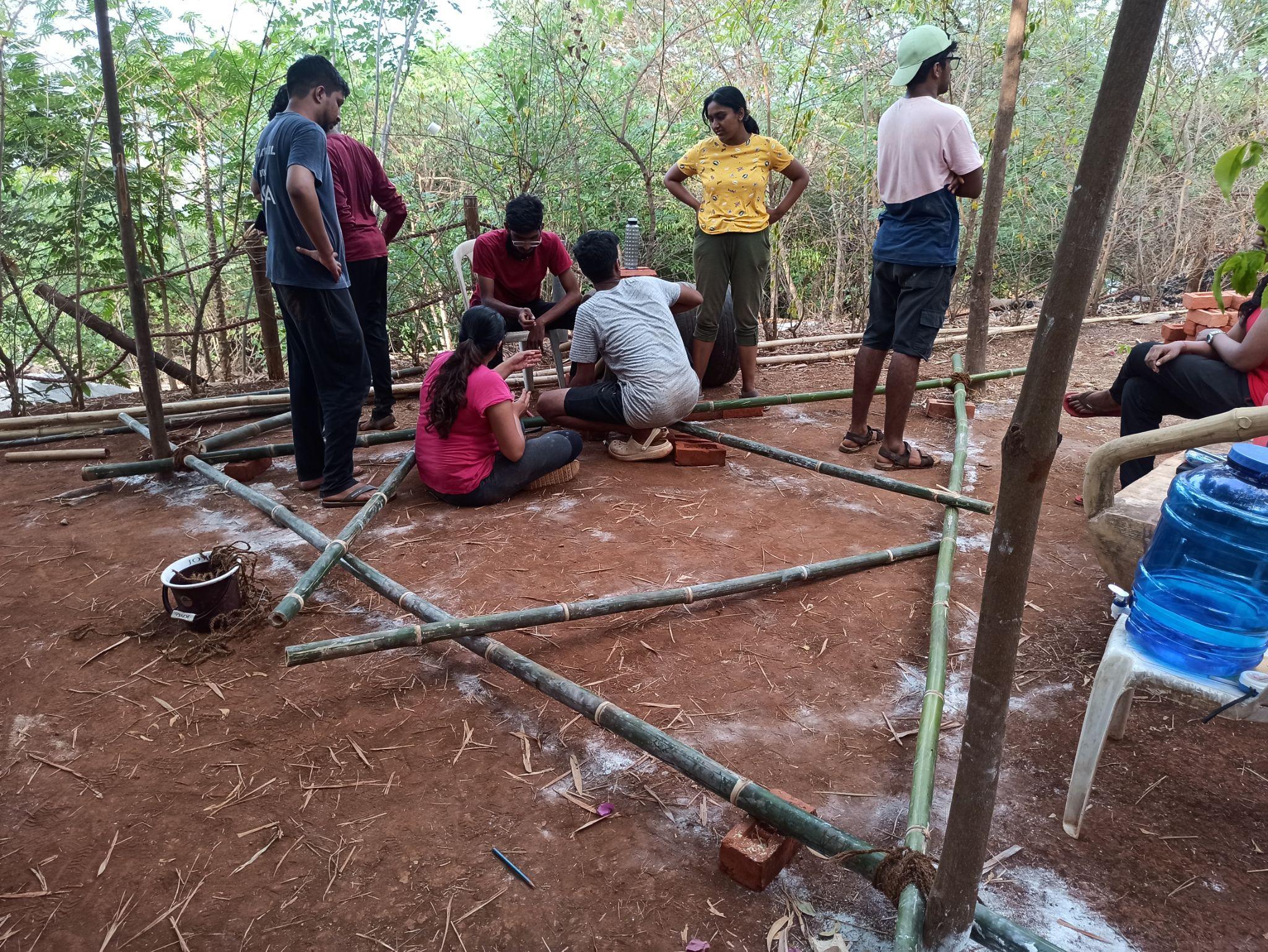
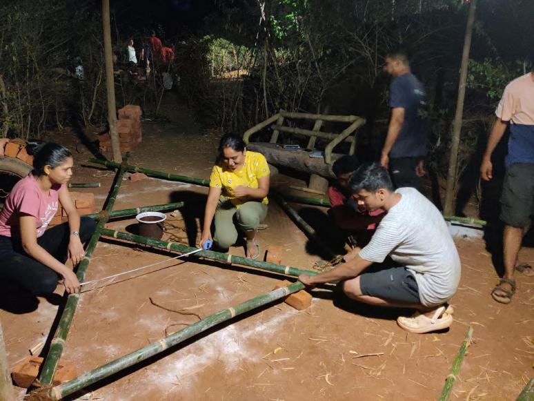
Between these four members came intermediate horizontal members, which we obtained after calculation from the main dimensions and angles. We then drafted a line out of this entire system on the ground and placed the bamboo pieces tounderstandtheprofilephysically
Bamboo work- detail Team B | Design Report - June ‘22 i.
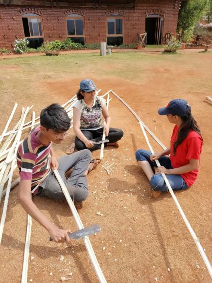
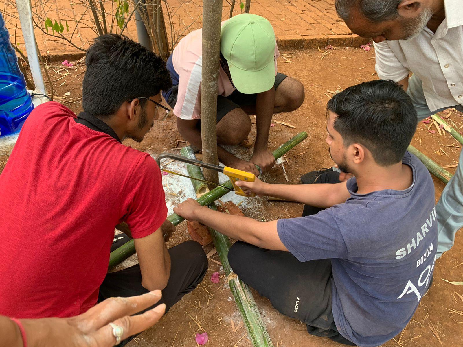
Placingtheothermembersalongalineout madeonthegroundtounderstandthe spacingbetweenthemembers
Cuttingofthebamboo’intothedesired lengthsbyusingasawonthe demarcationsmadepreviously.
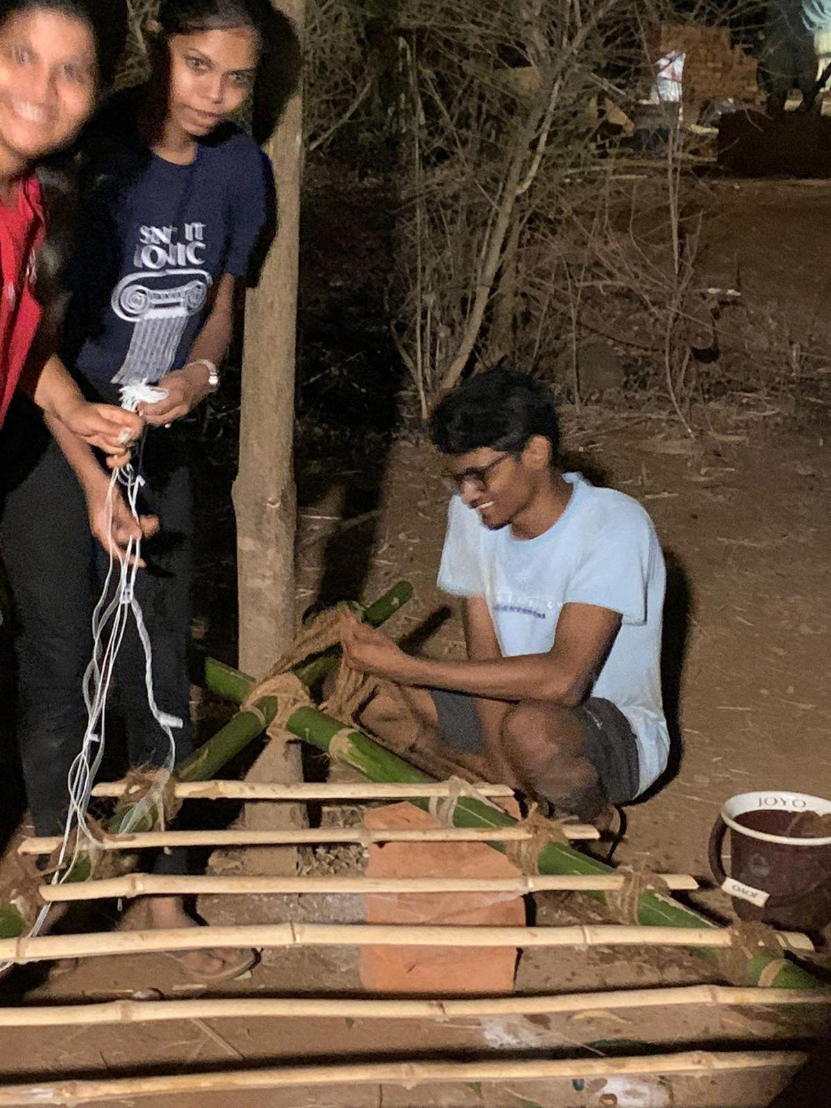
Tying two horizontal bamboo pieces to act as a base by using the tree trunks as theirsupports.
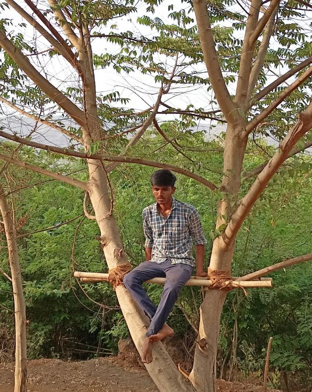
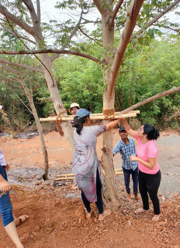
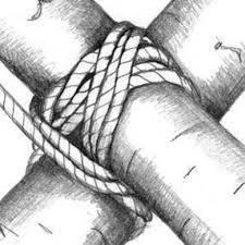
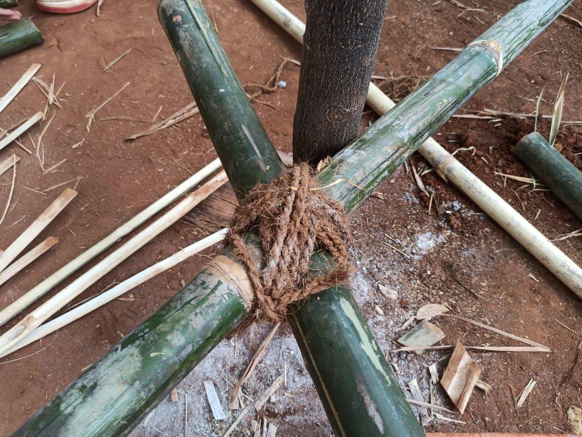
To ensure a strong hold, four thick ropes were used to tie knots which wound around the trunk and the bamboo’ in a criss cross manner repeatedly and along bothaxes
Afterattachingthesehorizontal pieces,wedidaweightchecktosee thatthisarrangementcouldhold weightaboveitself
1 2 3
4
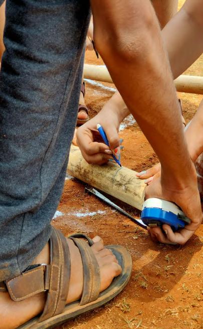
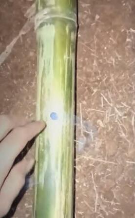
Demarcating the lengths on the pieces of bamboo’ as obtained after on site measurement so that they can further becutintotherespectivedimensions
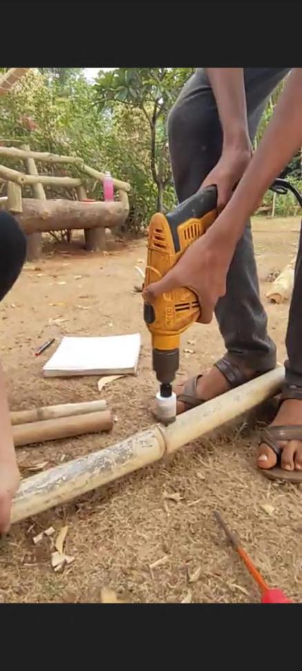
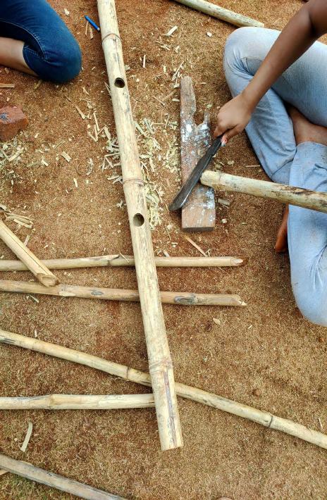
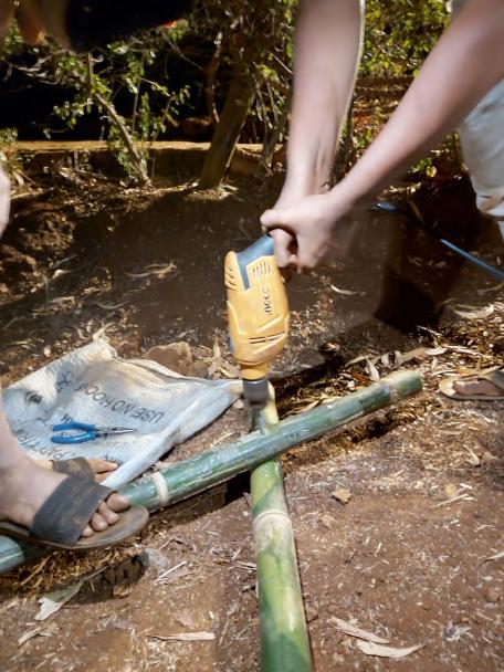
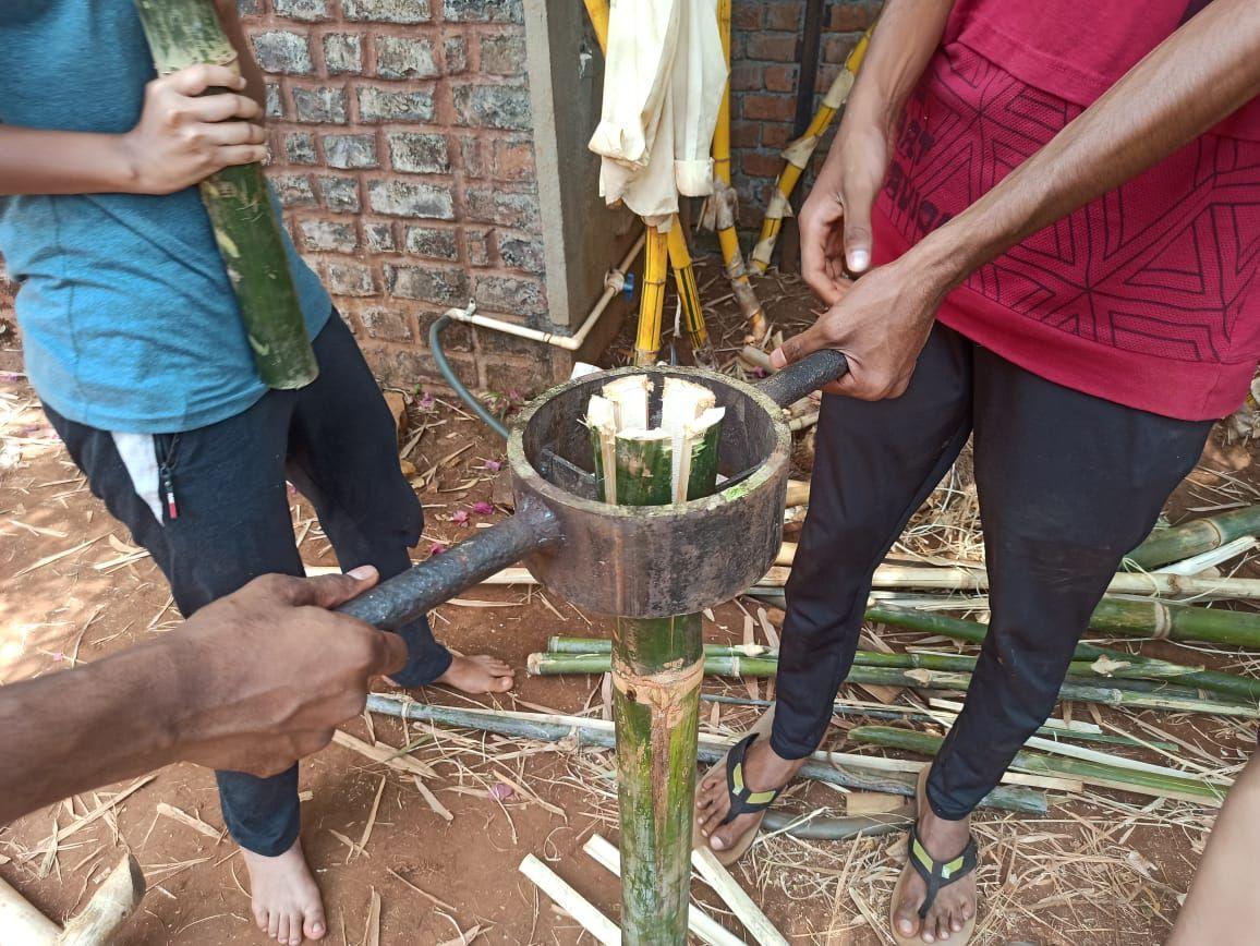
Preparing the members to drill holes onto the markings to fit in the horizontalmembers
The pin of the drilling machine was set as per the diameter of the horizontal bamboo member that would fit into that position. As per the diameters there were three broad groups for bamboos and their respective drilling pinswereused
Slicing the horizontal members so that they fit into the holes precisely andexactly
5 6 7
8
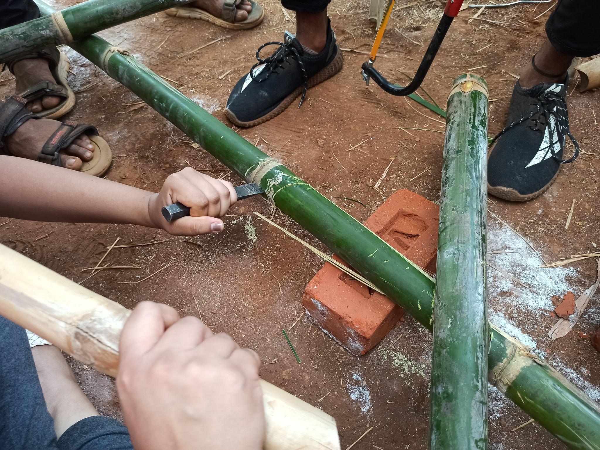
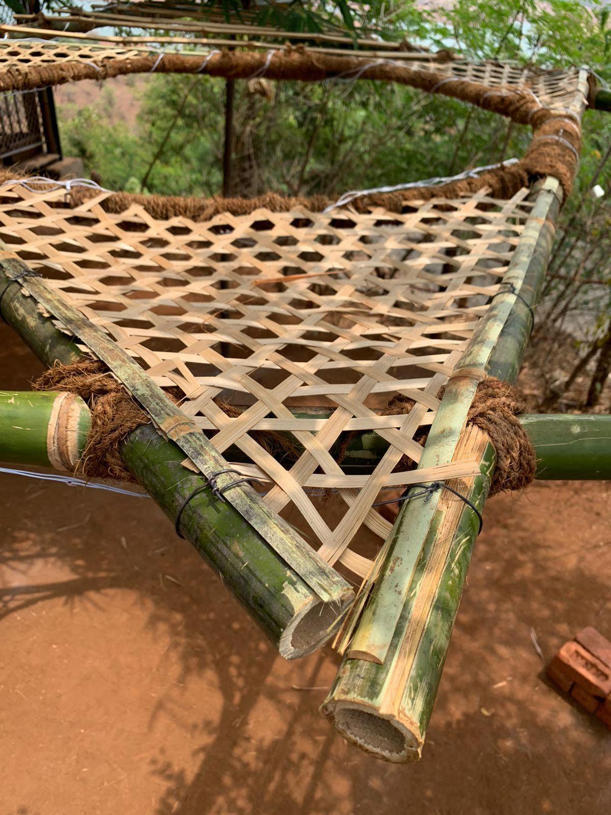
Splitting the bamboo pieces into four parts to form the topmost surface of thedeck
Slicing the nodes on these split sections to have an even surface underneath that would rest uniformly onthesupports
Drilling of holes again, through the fit in horizontal members so as to insert dowel pins to secure the memberstightly
Fitting one member to confirm workingofthesystem
9 10 11 12
FINAL OUTCOME AFTER ASSEMBLY
13
Placement and attachment of pieces on site and also using ropes to tie
● The experience of hands on materials has helped us gained practical confidence to deliver in terms of design innovation.
● Along with team work, it also trained us with techniques of tool usage and about unplanned adjustments that at times have to be done on site.
● We learned to adapt and manipulate corresponding to site conditions and available resources.
● The procedure revealed to us the idea about quality and quantity of materials being invested along with equitable distribution of workforce.
● From trimming brick bats to arranging bamboo dowels, human errors accompanied too and were satisfactorily rectified.
● Shortcomings in workmanship improved in further stages with practice.
● Comprehensively it helped us improvise and supervise our design goals with timely investment in each part of construction and permit of site intervention.
Team B | Design Report - June ‘22 i.
Learnings from the Workshop
TABLE
Team C | Design Report - June ‘22 1. Team, Project Summary 2. Project Location 3. Site Analysis 4. Design Concept 5. Process 6. Material Strength 7. Conclusion
OF CONTENTS
TEAM, PROJECT SUMMARY
Project Name : VV Pavilion
Team Members :
10RoshaniChabhare
15RashmitaDake
20MithilaGadag
27ShaktiJadhav
28NehaJayasanker
31AnjaliKarpate
32AakashKharade
33VaibhaviKhedkar
38PuneetMaru
40PrajaktaPai
43SaloniPawar
48ManasaRavikumar
59HarshTank
60AmeyaThanawala
Brief description of Project :
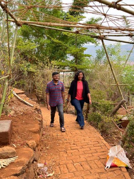
The project strives to create an experience connection for the passerby using bamboo and bricks as a core material. The pavilion created a sense of linearity and establishes a rhythm while moving through it. It doesn't just direct a person but also gives a glimpse of the scenery around it while the movement is going on. This Polyhedron Pavilion can grab a lot of fresh climbers and creepers building whole different experiences.
Team C | Design Report - June ‘22 1
PROJECT LOCATION
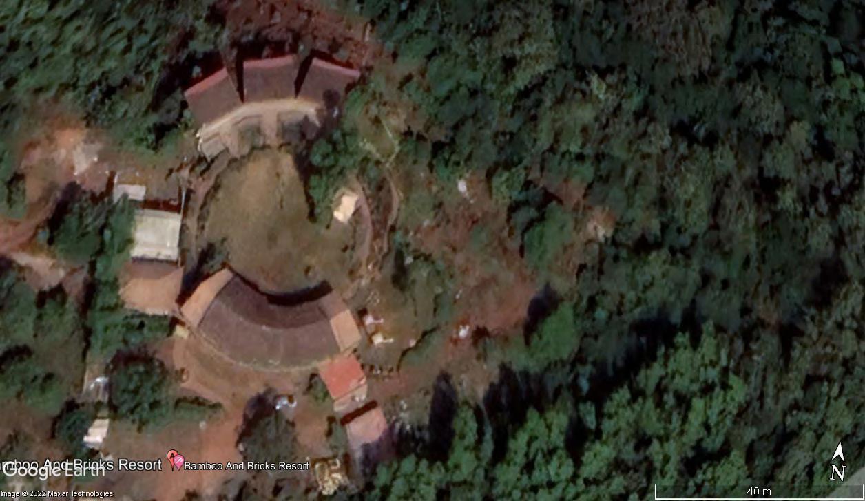
Bamboo and Bricks Resort, Panshet
The workshop dwells into creating useful and meaningful explorations on the grounds of the Resort Bamboo and Bricks.
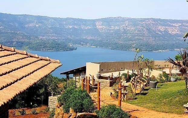
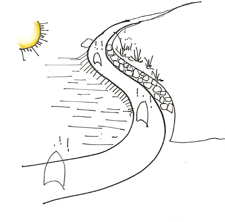
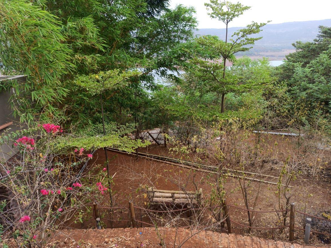
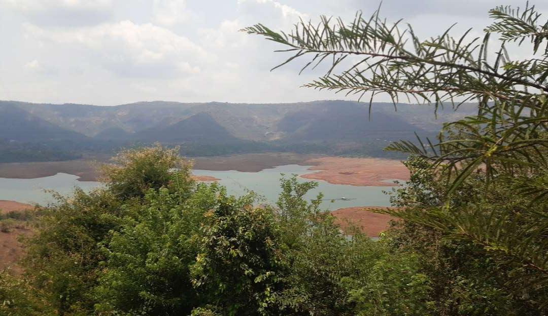
Overlooking an expansive view of the river with backdrop of Stupendous mountains, the Location offers naturalistic environments and experiences with its construction materials, techniques, landscape and topography. Each Team was allocated a Site.
Site:
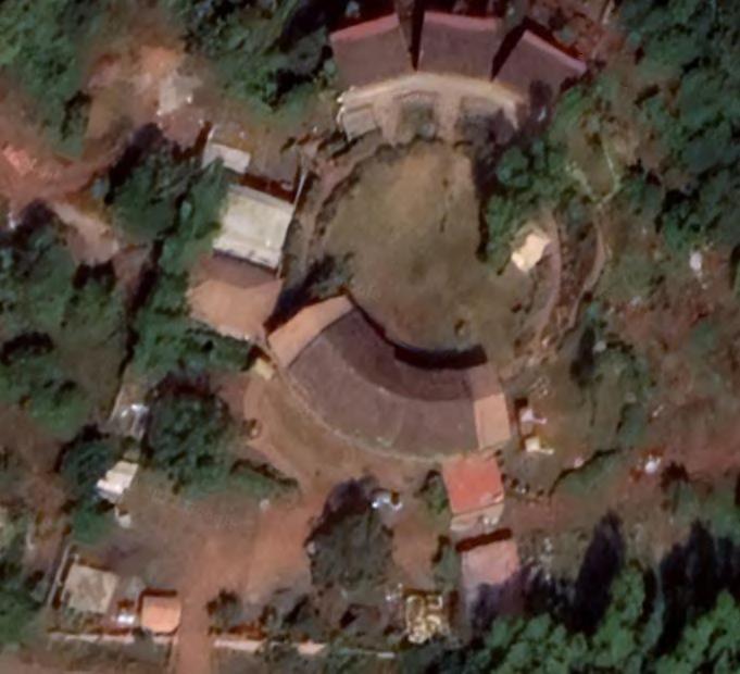
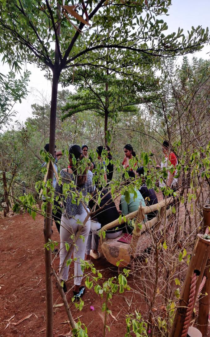
The Site is located adjacent to the pathway leading one to the Accommodation. With a gentle sloping terrain, it offers the glimpses of the lake with dense stratification of vegetation. The Master Plan of the Resort Marks the Location of the Site with respect to accommodation, landscape features, adjacent sites and material yard.
Entrance SITE Lawn Accommodation Site “C” Site D Bonfire Site B Site A Pedestrian Path Functional Proximity Views OUT Views IN
SITE CONDITIONS The Bi-directional Sloping Site Majorly sits in between The lawn, bonfire and Accommodation. The Pathway Further connects these spaces. Primordial Condition contained of wild land with leaf litter and rocks scattered here and there making it difficult and not appealing to access PartialViewsIntotheSiteviathe TreecanopiesignitingaSenseof Curiosity BarrenLandwhichcanbecleaned foruseasapausepoint Harsh Sunlight From10am-3pm Making the Site aridandunexciting Bi-Directional Slope on Site As a Connector, it can easily direct People to the site Due to level difference, the View graduallyunfolds
CHALLENGES ON SITE AND SOLUTIONS
Due to the Remoteness of the Site, it puts forth a bunch of challenges that need to be tackled. These issues are then used in genesis of design concepts. The aim is to uproot these issues and make the space more useful and valuable to the Users.
Dim Lighting Makes the Region less likely to visitorsatNight.
Thus, Integrating Lighting in the Design would create a safer environment and space.
Salient Features of the Site that can be exploited:
● Proximity to Accommodation and Bonfire
● Adjacency to the path (connector)
● Interesting Views: sense of mystery at higher level and sense of refuge at lower level
As a Connector, it can easily direct People to the site
● Slope can be used to advantage direct movement.
Team C | Design Report - June ‘22
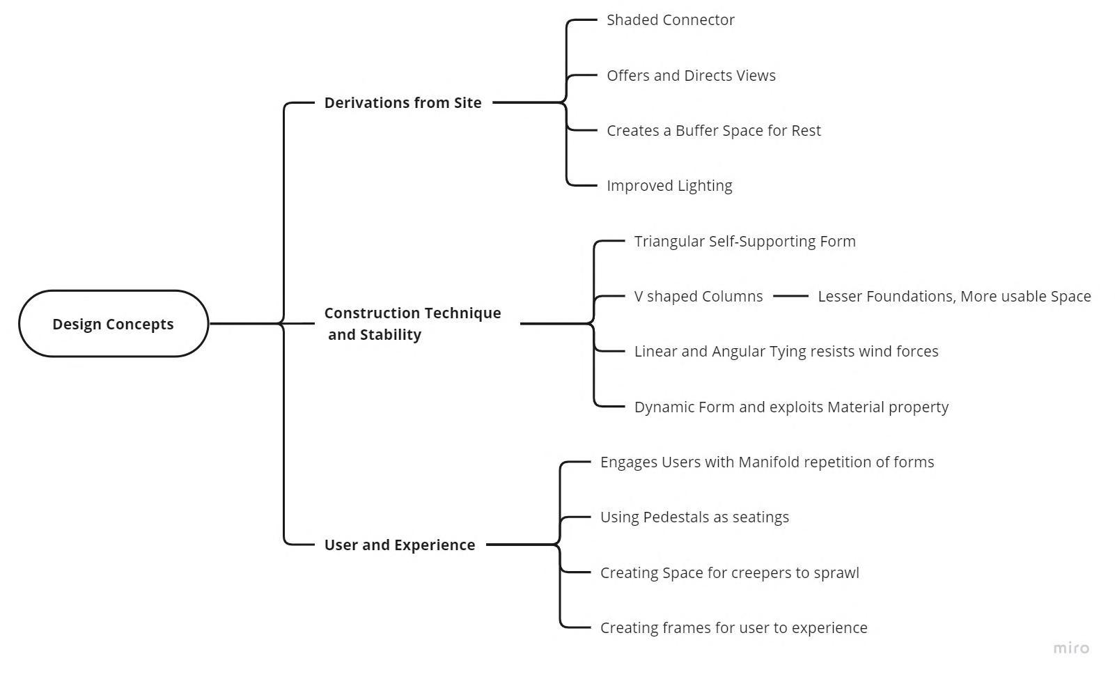
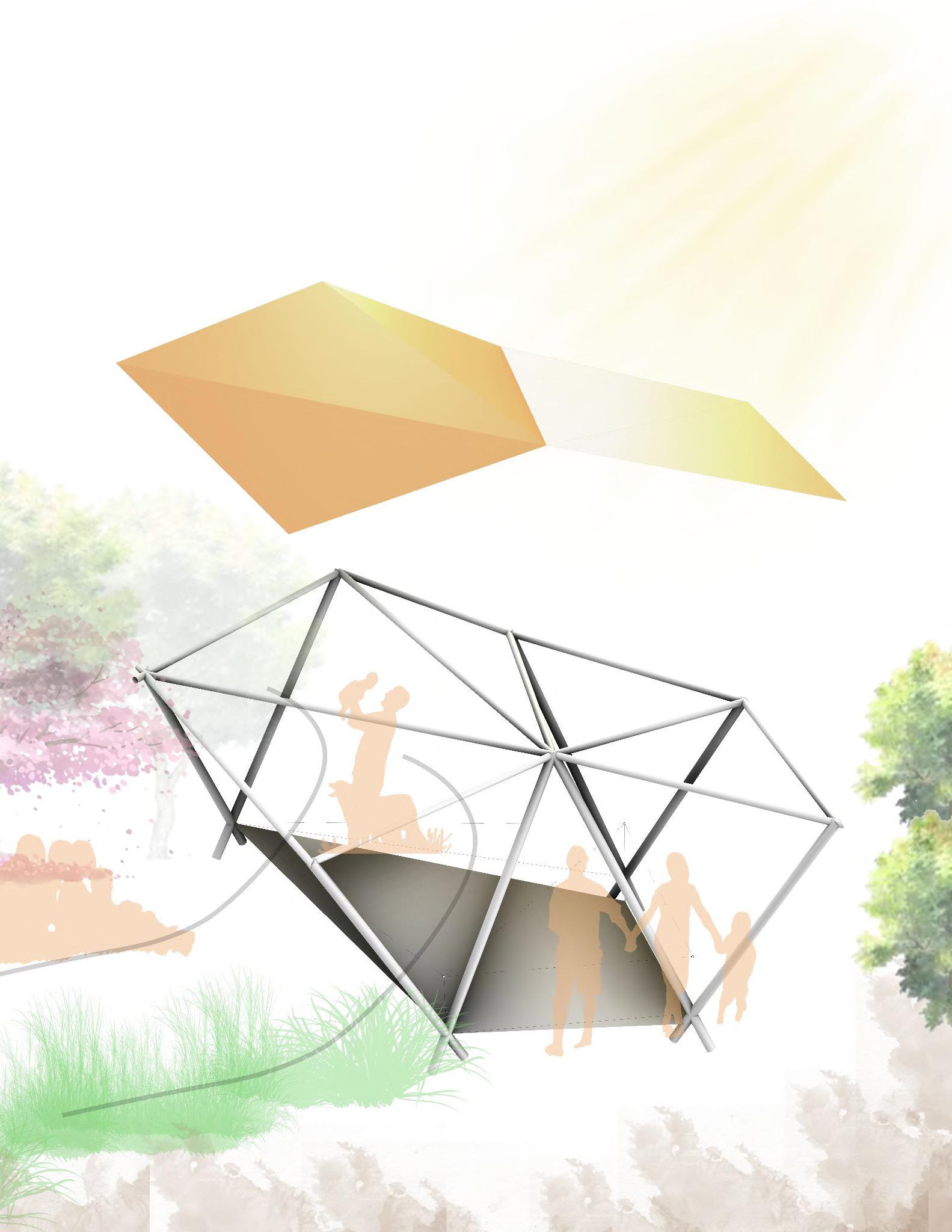
DESIGN CONCEPT
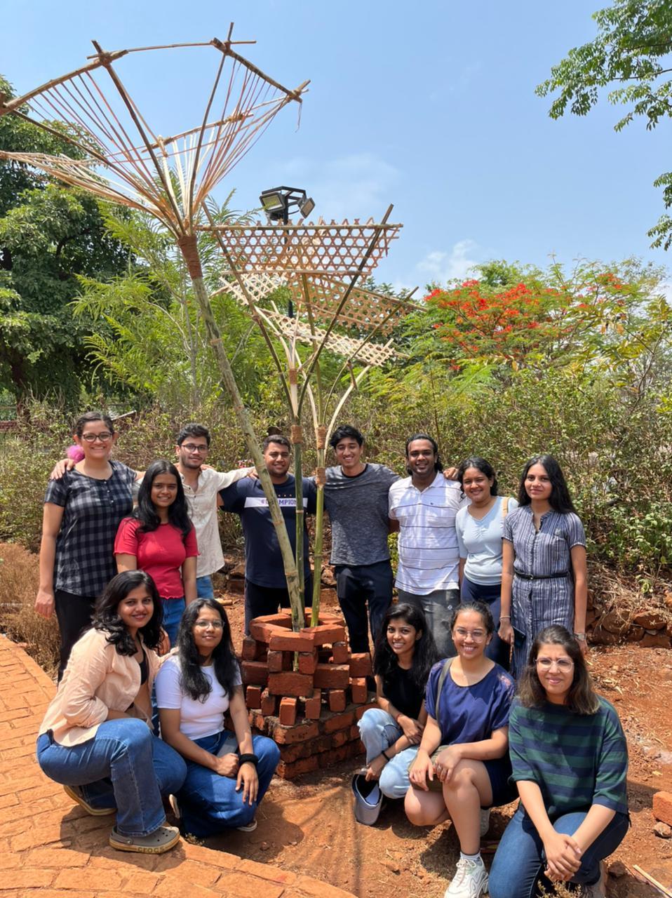
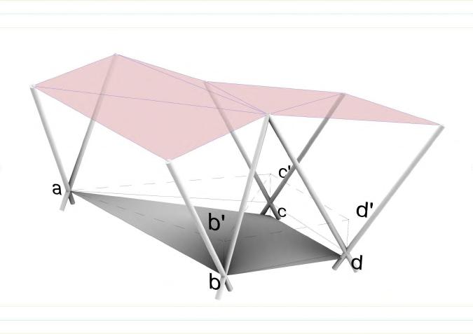
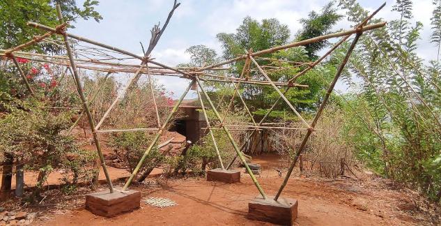
The Design is a Multipurpose Pavilion and Pergola with Triangular form which gets tessellated. The Derivation to this Design can be traced as follows:
5
DESIGN CONCEPT
A Triangular Pavilion would serve as a self supporting structure. The structure is made up of 2 parts: 1. Frame
2. Roofing
1. Frame:
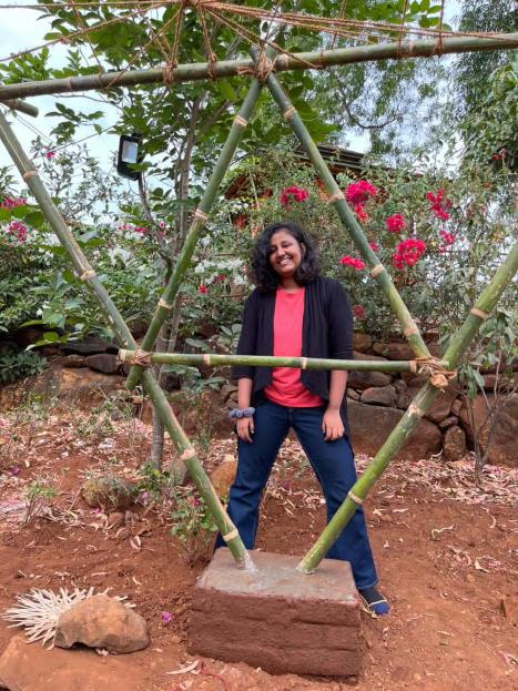
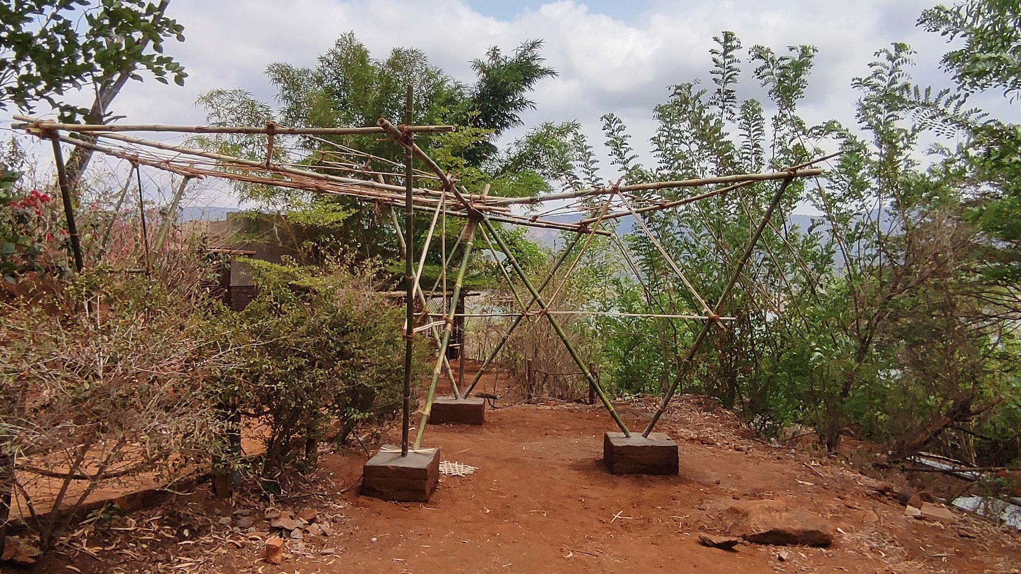
It consists of V shaped Columns which support the Tessellated Roof. V shape would require lesser footings and would also reduce spans due to its angular extensions. Moreover on a Slope, it creates dynamic angles directed to the users.
These Columns are linearly connected and braced to prevent it from wind and lateral forces. The V shape is designed to extend oppositely and then anchor in the ground. This prevents toppling of the structure and makes it more durable.
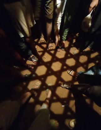
2. Roofing:
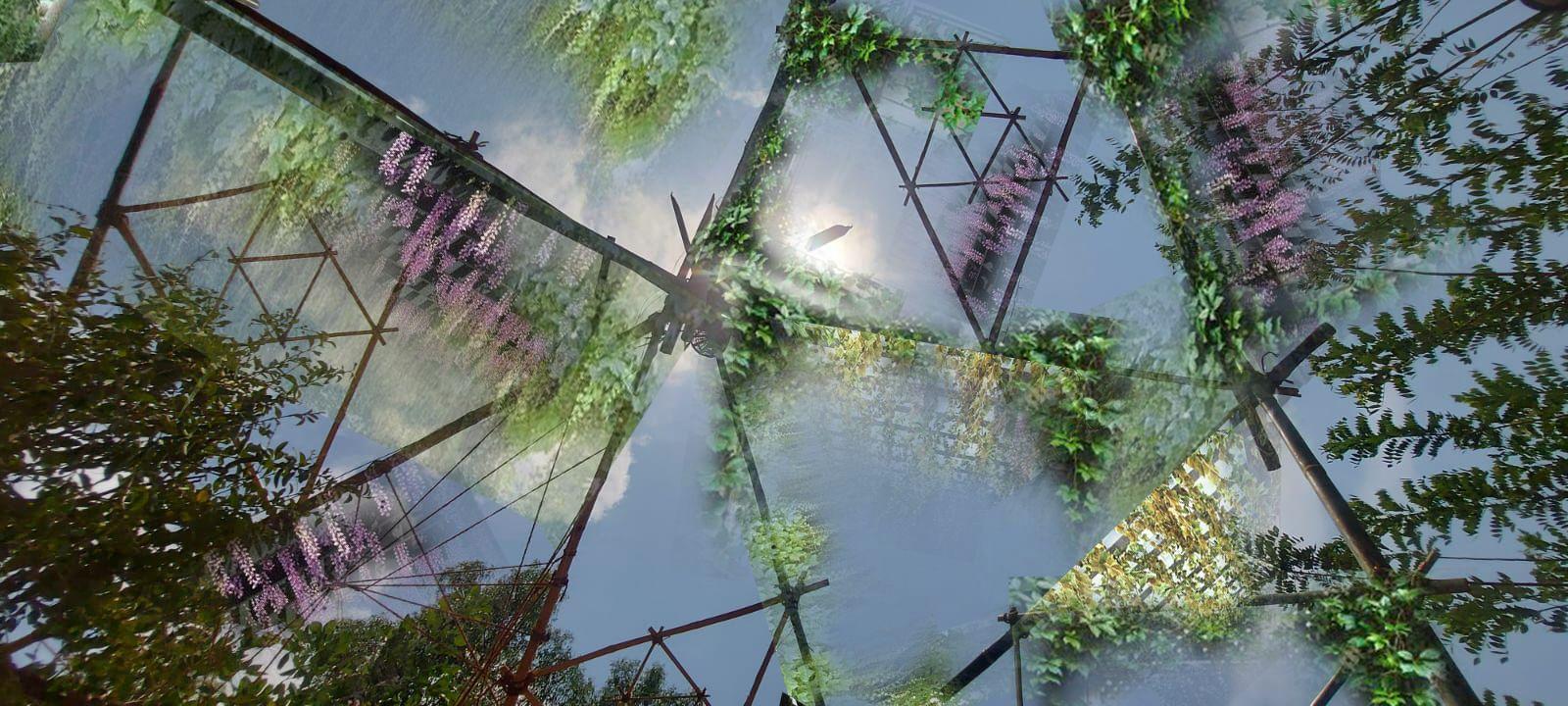
The Covering is further made up of Similar Triangles framing the Sky. The Roofing can have creepers and flowers crawling through it camouflaging the pavilion with the nature. It also has patterns made up of Ropes and Bamboo Stripes which create a play of light and shadow on ground.
Team C | Design Report - June ‘22 6
The Design blends with the greens of the landscape and creates a subtle transition between the spaces.
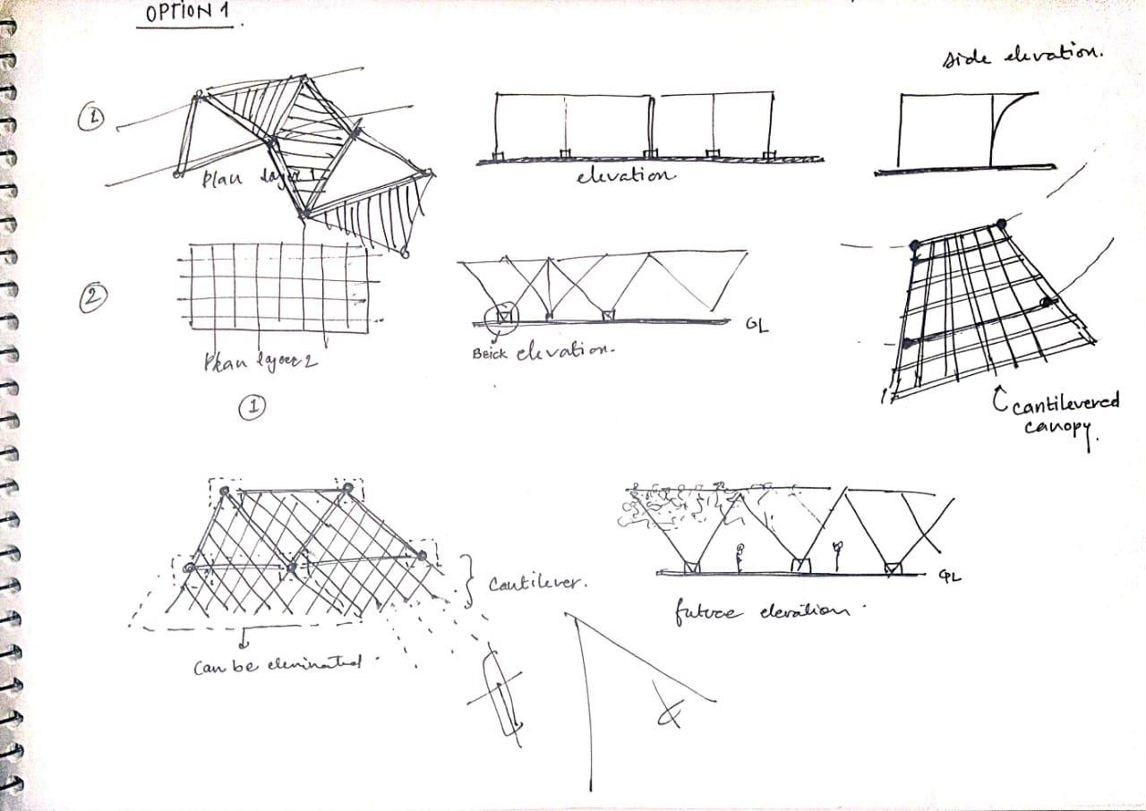
Step : Optimum usage of the space
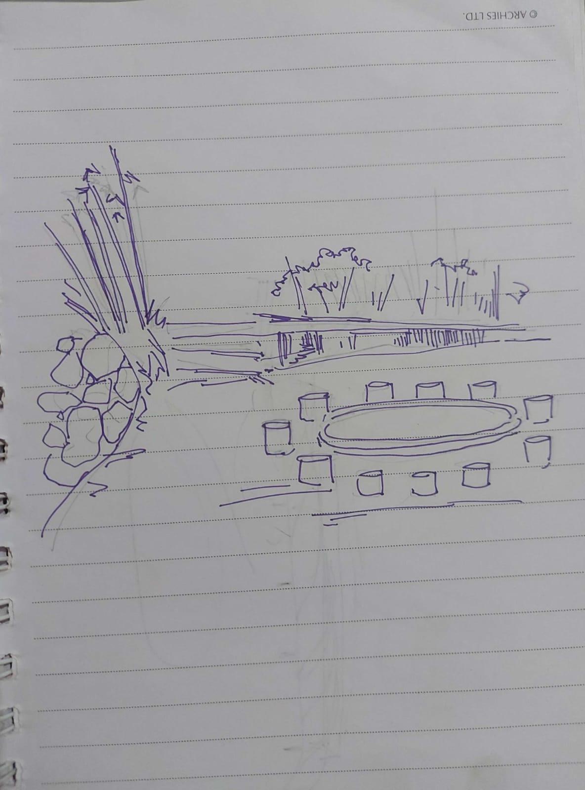
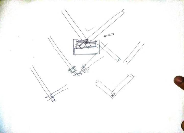
The design was envisaged to be a pavilion space that would highlight the entrance towards the quarters as well as projecting towards the exteriors. Different options were taken into consideration before finalizing the idea of a tessellated pavilion.
Fig. Design ideation and brainstorming
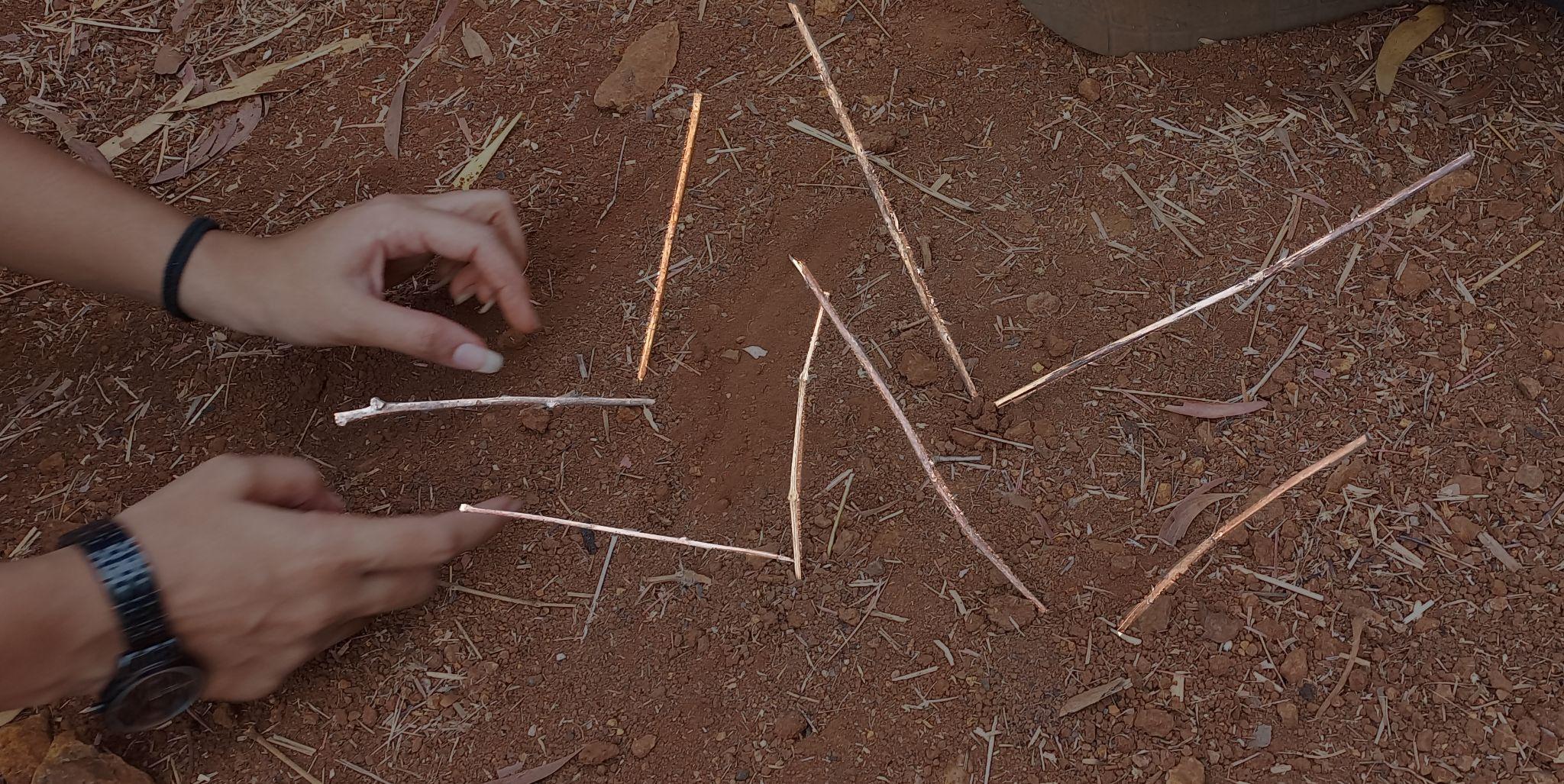
Fig. Design demonstration on site using small wooden sticks
PROCESS
Team C | Design Report - June ‘22 7
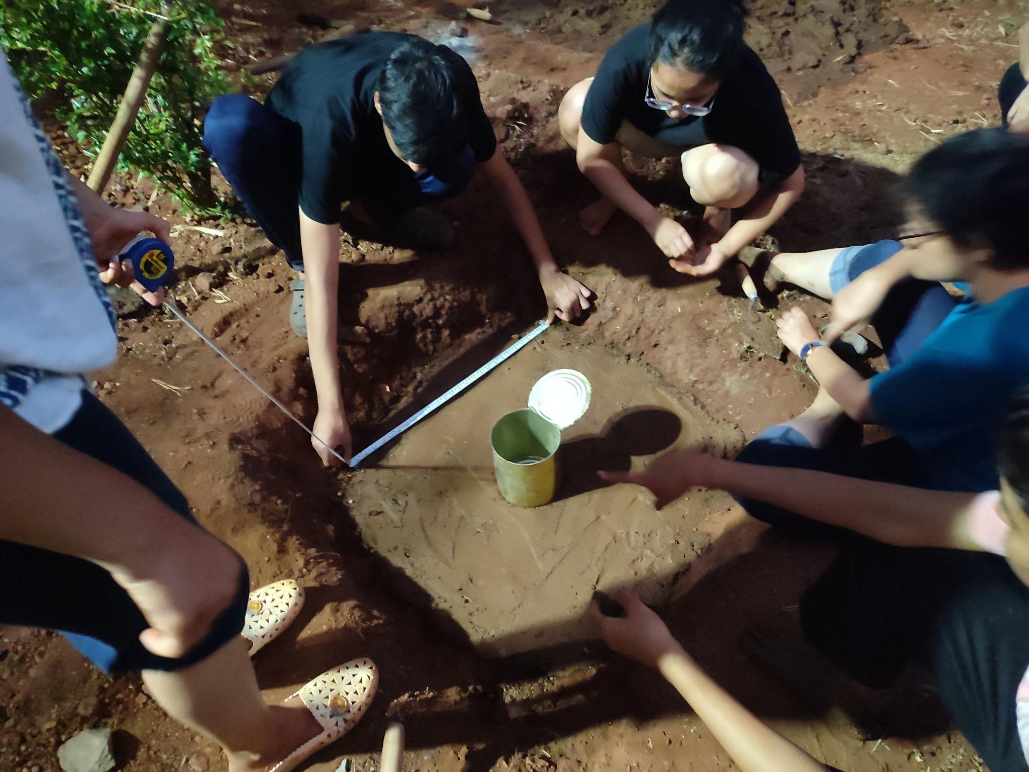
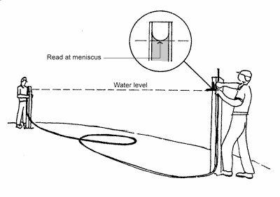
Step: Determining site levels
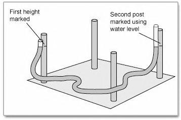
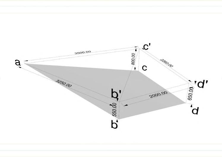
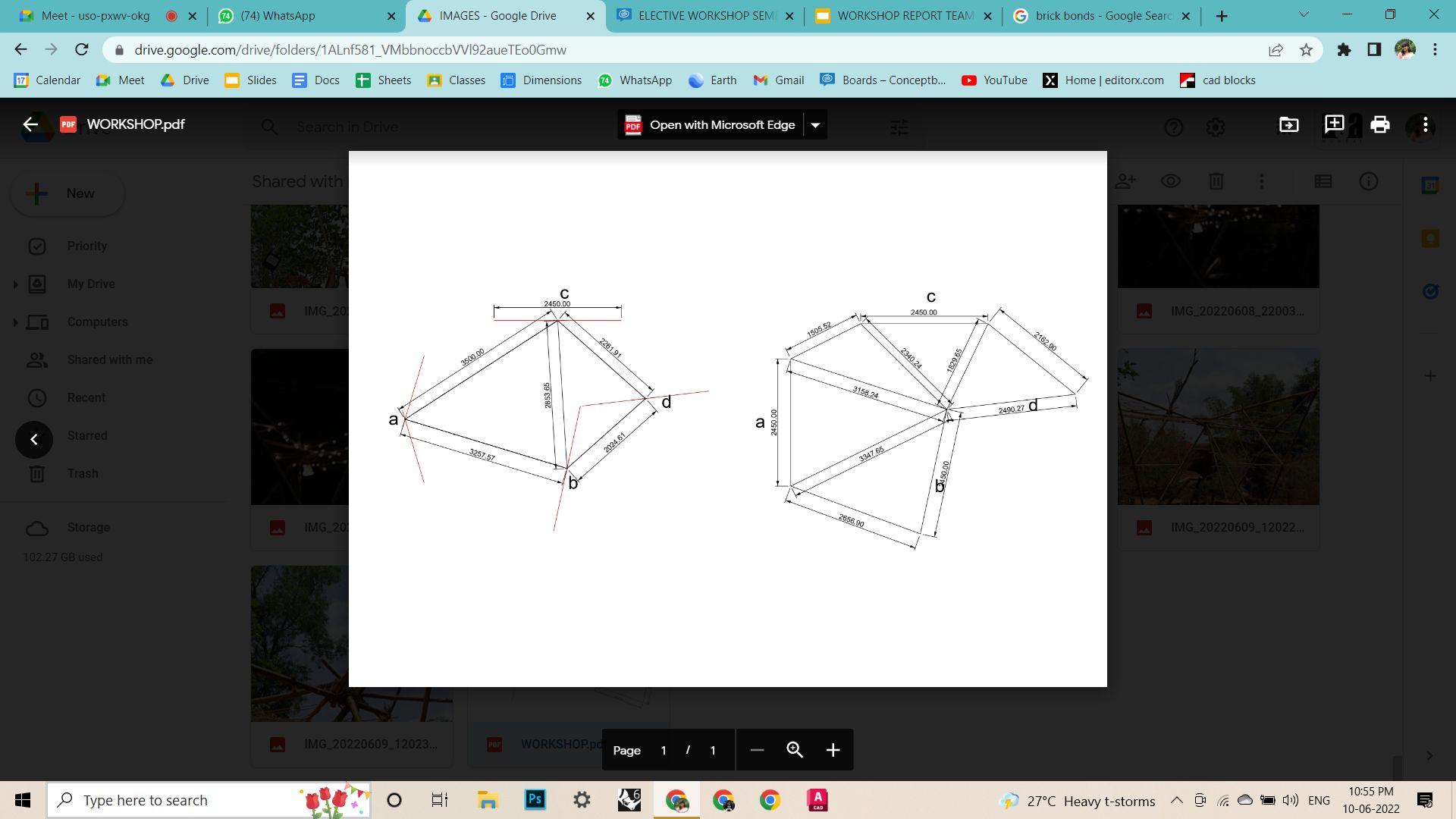
Since the terrain was sloping in two directions, we determined the elevational levels of the centers of columns using leveler. Difference came out to be between 550-800 mm.
Fig. Determining levels of column centers
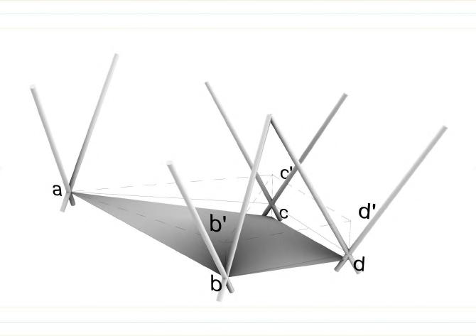
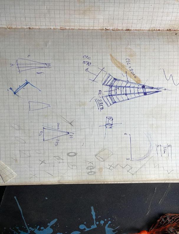
A digital model was done on rhino to determine the length of bamboo columns required to achieve clear heights. It helped to understand the column heights,spans and length of the beams that would eventually contribute to achieve the tesselation effect.
Sloping terrain
Aligned the bases of all columns
Linear bamboo beams
Angular/ Radial beams
V shaped bamboo columns
Fig. Digital model to determine the member sizes
PROCESS Team C | Design Report - June ‘22 8
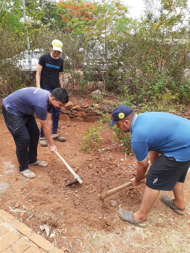
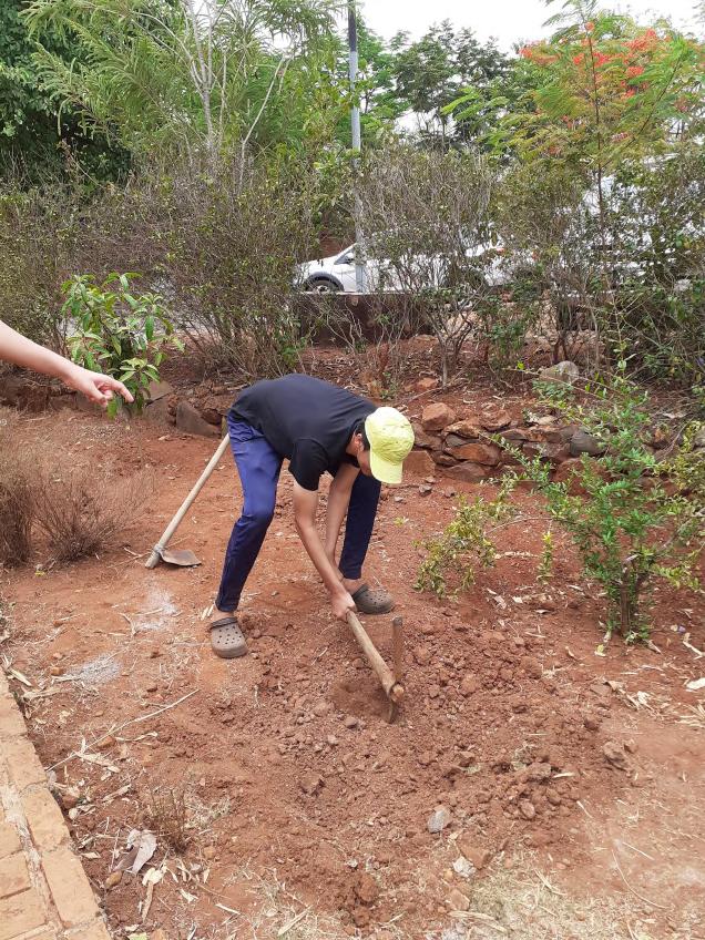
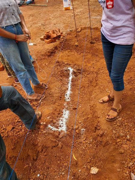
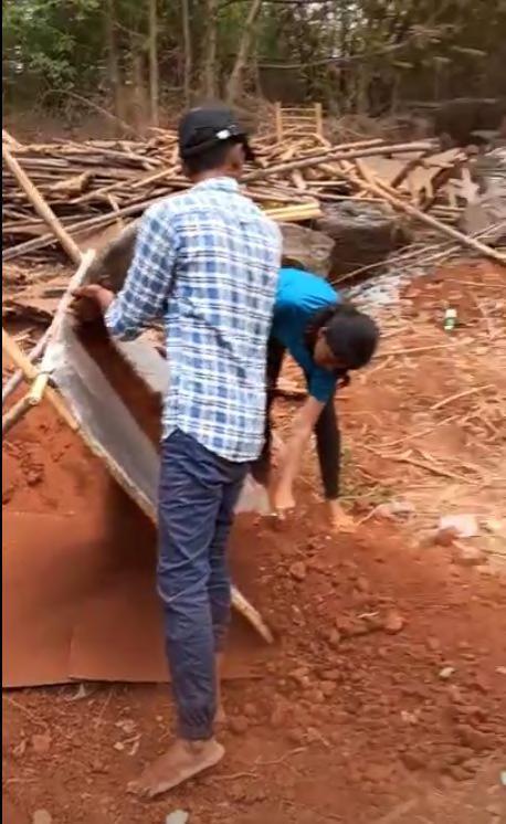
Step: Excavating for Foundation
According the line out a Rectangle of 600 x 480 mm was marked along the center point Then to dig the soil two tools were used
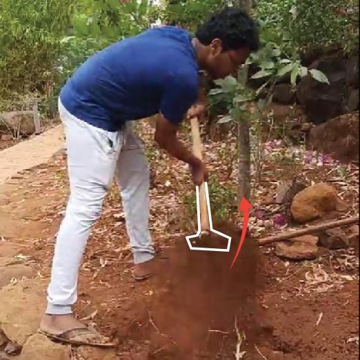
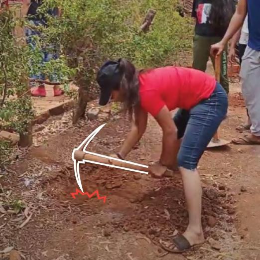
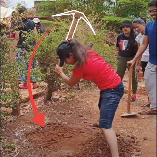
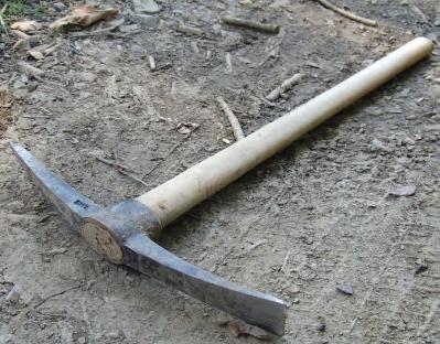
1. Pickaxe (kudal)
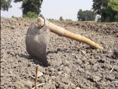
2. Grape hoe (khora)
https://www.shutterstock.com/search/hoe https://en.wikipedia.org/wiki/Pickaxe
Pickaxe
Grape Hoe
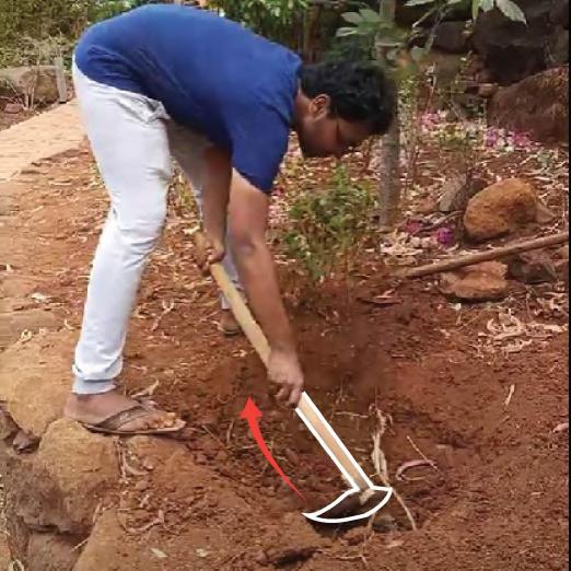
Process- First the hard soil on surface is to be loosen with a pickaxe in order to create a pit in the ground then the loosened soil which again slides back to the pit is removed aside with the help of the grape hoe. This is the basic process which is repeated for digging the ground for foundation which was 300mm deep.
1. Digging the soil- The pickaxe is a pointed tool which pierce into the ground and breaks down large lumps of soil into smaller pieces making the soil loose and easy to remove. It has to be hit to the ground in an angular manner with great force so it could pierce the soil and then dragged behind to expand the hole.
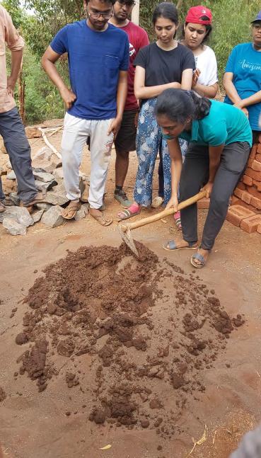
2. Removing the soil- The grape hoe is like a rectangular pan attached perpendicular to a handle which is used to remove the loosened soil from the pit very quickly. It is also used similar to the pickaxe in angular manner just the force applied is little less.
PROCESS
Team C | Design Report - June ‘22 9
Step: Making of Mortar
A. DRY MIX
The dry mortar includes following ingredients :
1. Red soil(Clay)
2. Fine aggregates
3. Water
Process:
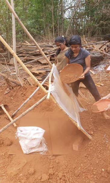
1. Preparation for red clayThe preparation of red clay includes segregation of fine clay particles from the red soil given. In this process the red sand ( with impurities ) is passed through a clay funnel which segregates the clay particles and the fine clay red sand is procured .
2. Fine aggregatesThe dry mix also includes the fine aggregates ( aggregates from basalt stone ) Which acts as a binder material in the mortar mix .
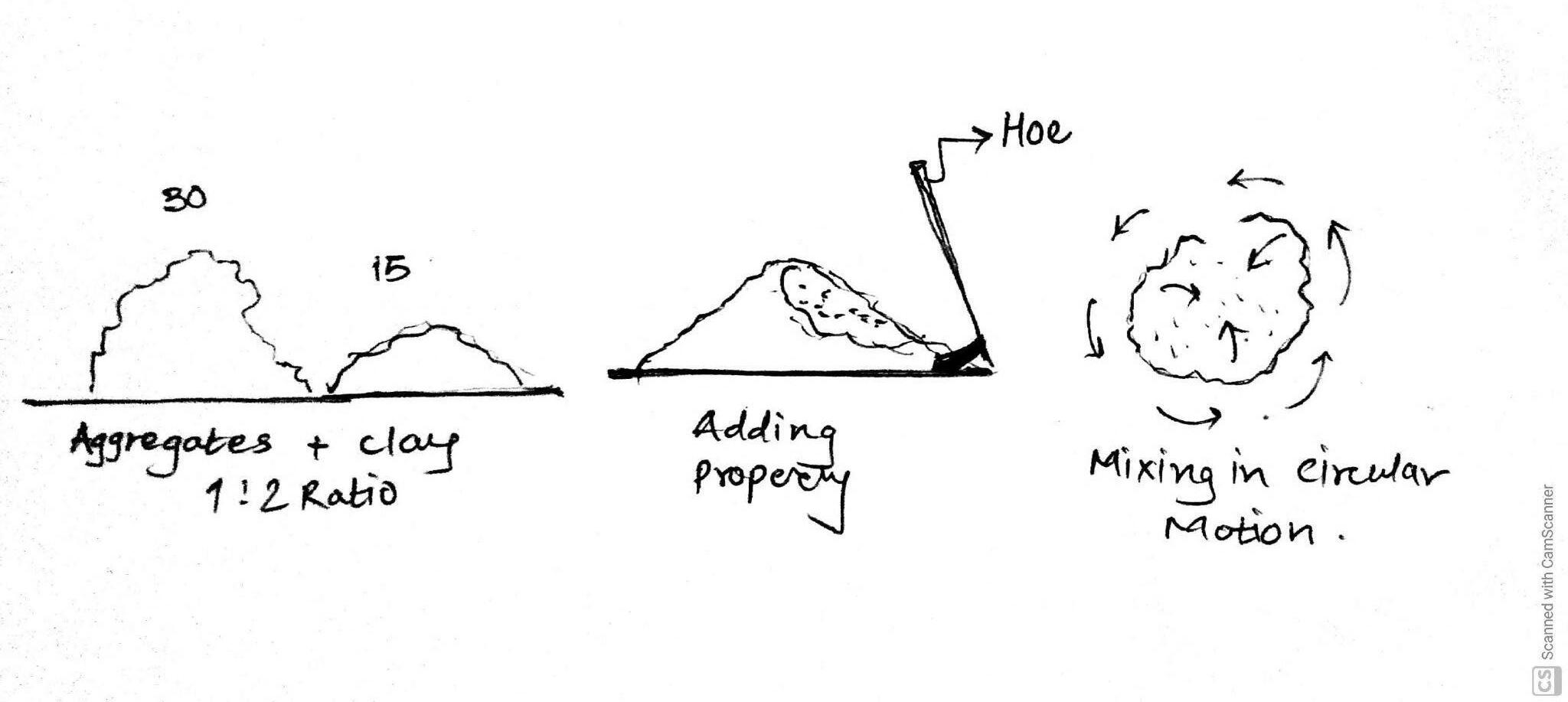
3. Deciding the clay to sand ratioThe mortar needs to hold the foundation as well as to hold the bricks in place . for the proper consistency of the mortar 1 part of clay is mixed with the 2 parts of aggregates. So the ratio used here is 1:2
PROCESS
Team C | Design Report - June ‘22 10 Fine clay Impure clay Fine clay Funnel
Step: Making of Mortar
B. WET MIX
The wet mortar includes following ingredients :
1. Dry mix
2. Water (river water )
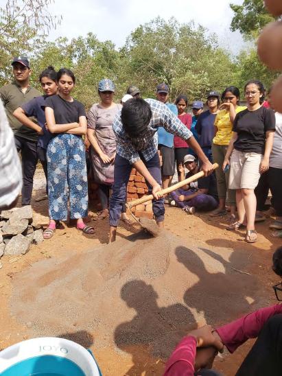
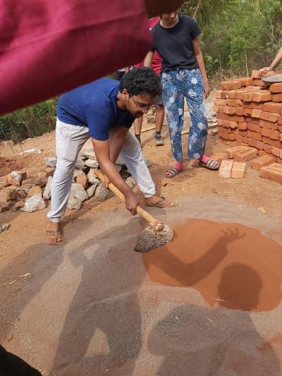
Process -
1. Mixing dry sand and water
The process starts with adding water with the dry mix. The water should be added slowly and then mixed properly using the hoe in a circular motion. Water is added in the small puddle created in the mix and then the dry mortar is moved into the water puddle.
2. Pugging
Pugging is a process in which the mortar is mixed with using the manual pressure.
PROCESS
Team C | Design Report - June ‘22 11
Fine clay
Step: Laying of Bricks for the Foundation
The bricks were laid along the outer periphery of the foundation area. It acted as the main support for the V bamboo columns, as a void was left in the centre of the foundation for the bamboo to be placed in. The foundation was half brick thick and had stretcher bond consisting of seven bricks in each layer.
Dimension of Each Brick - 230 x 100 x 70
Dimension of the Foundation - 600 x 480
Two layers of bricks for the foundation was first laid, after they dried the pit was backfilled giving it extra support. This was to prevent any movement in the bricks causing it to fail as a foundation when the V bamboo
The remaining layers of bricks were placed after the V bamboo columns were placed and their angles were
PROCESS
Team C | Design Report - June ‘22
PROCESS
Step: Making the first unit.
A single Triangular unit of Bamboo was used repetitively to form the framework. It consisted of equally sized bamboos connected using Nuts and Bolts along with washers to prevent damage to the bamboo. The first unit was to be placed at the higher level, on the left of the pathway where the soil was raised by 350 mm and retained by a stone retaining wall, and hence the height required was lesser than the other Units which were at a lower level.
Tools Used to Make the Unit were: 1. Measuring Tape 2. Hacksaw or Handsaw (as per the thickness of bamboo) 3. Drill Machine 4. Hammer or a heavy object to push the Bolt in position.
Process:
1.
2.

Drill Machine
Hacksaw
https://www.gz-supplies.com/bosch-gbm-1000-rotary-drilling-machine-professional-drill/ https://www.bahco.com/int_en/compact-hand-hacksaw-frames-470-mm-pb_306_.html

First three straight bamboos were cut to an equal size of 2800 mm. The size was decided according to
Cutting the Bamboo as per the required size
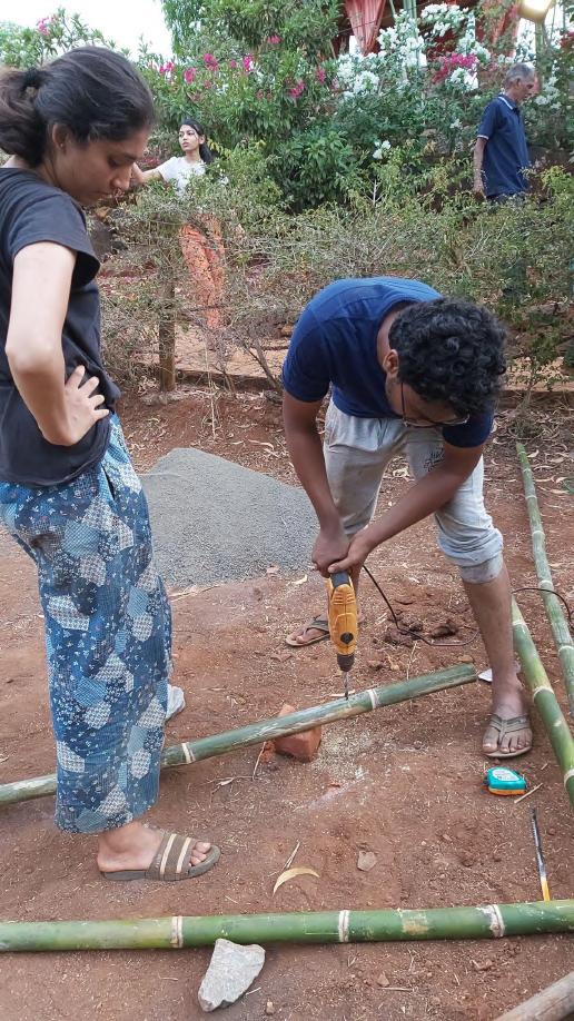
Then holes were drilled in two bamboos at 350 mm from the edge so as to fix them and allow the smaller portion to be placed in the foundation and allowing an angle of 60° which would be sufficient for the suitable clear height. For drilling the holes the bamboo had to be held in place firmly to prevent it from moving or rotating. Hence it was either placed on a flat and sturdy surface or on two supports on either side of the holes to be dug, holding it manually also provided more support and stability.
Marking the position of the hole
Holding the Bamboo firmly in place
The Hole
Team C | Design Report - June ‘22 13
Step: Making the first unit.
Process:
3. Then the two pieces of the bamboo were joined together using a Nut, a Bolt and a Washer on each side. The bamboos had to be aligned one on top of the other accurately so that the Bolt could be put through both of the bamboos at once. The bolt was pushed through the hole and then the nut was fixed from the other side. Once the two were joined, the V-Shaped Column was ready.
4. The next step involved fixing the beam in position and hence completing the unit. Holes were drilled in. //////////.the column and the beam together by placing them one on top of the other and aligned according to //////////.the location of the holes. If drilled separately there would be a possibility of error in alignment hence //////////.this method was used. Once the hole was drilled, the beam was fixed to the first column immediately .//////////so as to allow easier alignment on the other side. Once both sides of the beam were fixed to the .//////////V-Column, the Triangular Unit was ready.
PROCESS
Team C | Design Report - June ‘22 14 Beam Column V-shaped Column The Triangular Unit Drilling through the Column and Beam at once Fixing the Beam to the V-Column The Beam
Pushing the Bolt in Place The Bamboos joined together using Nut and Bolt, forming the V-Column
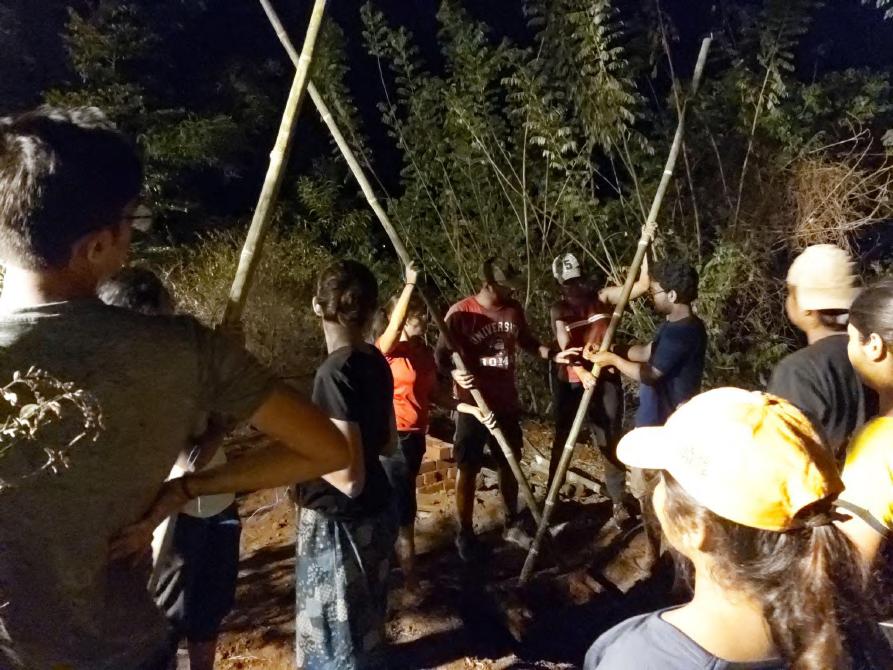
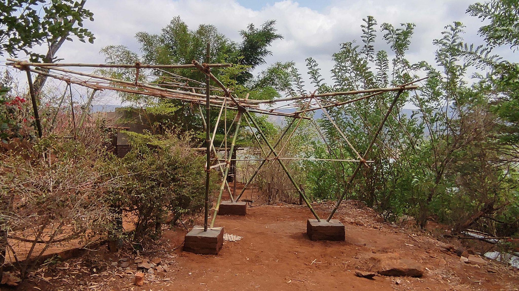
Step: Placing V Bamboo Columns
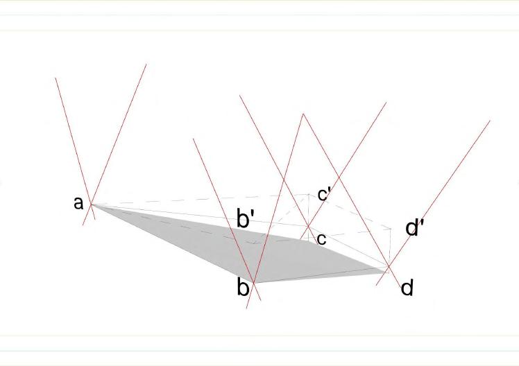
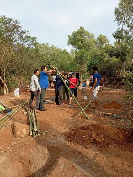
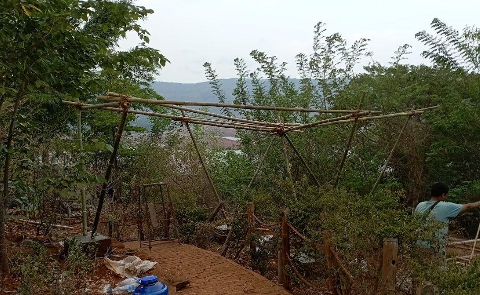
The Bamboo module that was already made were placed in the void inside the foundation. The columns at the higher position on the side of the path with a retaining wall was placed first. The angle of the columns was decided according to the slope of the path and the angles we desired in the roof. It was held in place temporarily by scaffolding placed at the top corners of the triangle. The scaffolding prevented the columns from moving till the foundation could be filled and the rest of the bamboo columns and beams could be erected. Our goal was that once they would all be erected the pavilion would become self standing.
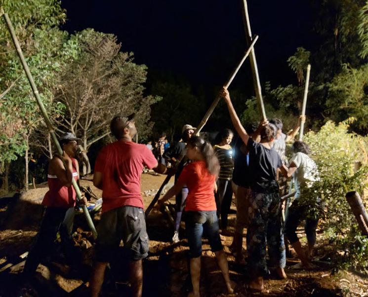
The next two columns ‘B’ and ‘C’ were erected simultaneously. Their angles were decided with respect to each other and column ‘A’. all three columns were angled towards each other vertically no matter what direction they faced horizontally. This helped reduce the distance between them and hence reducing the load on the beams which would end up tying the columns together in the end.
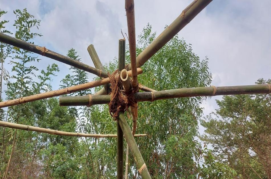
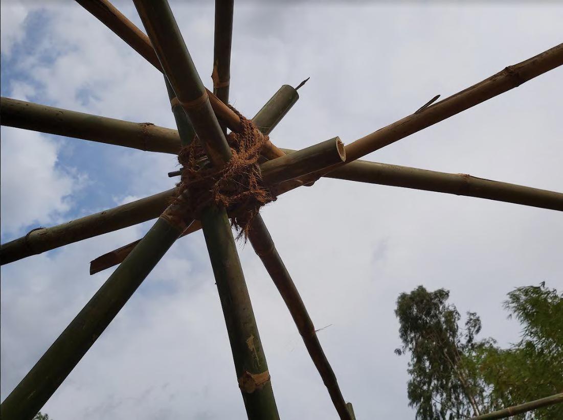
Column ‘D’ was erected last. One end of the V column was fixed to one end of the ‘B’ column. This helped decide the final angle of the V in all three directions. The foundation at column ‘D’ had to be increased by two layers, and the base height of the column was increased by 200 mm so as to make the connection of column ‘D’ and ‘B’ possible. This connection was very vital to our structure, as this was the main point to which six beams were to be tied to creating a radial pattern in the roof of the pavilion.
PROCESS Team C | Design Report - June ‘22
Column ‘B’ Column ‘D’ Column ‘B’ Column ‘D’
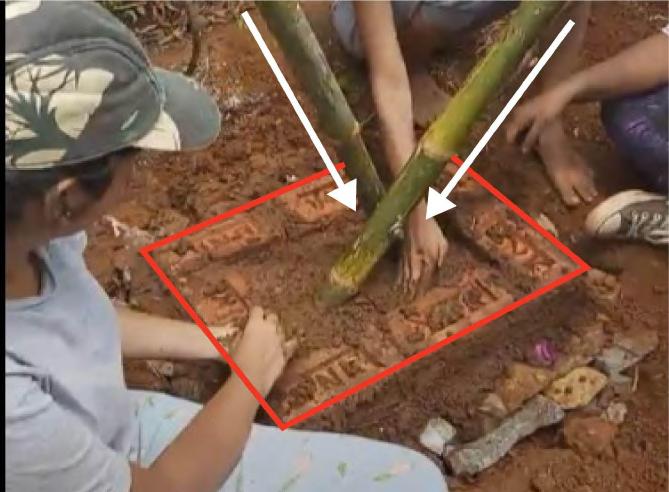
Step: Erecting of Bamboo units and completion of foundation
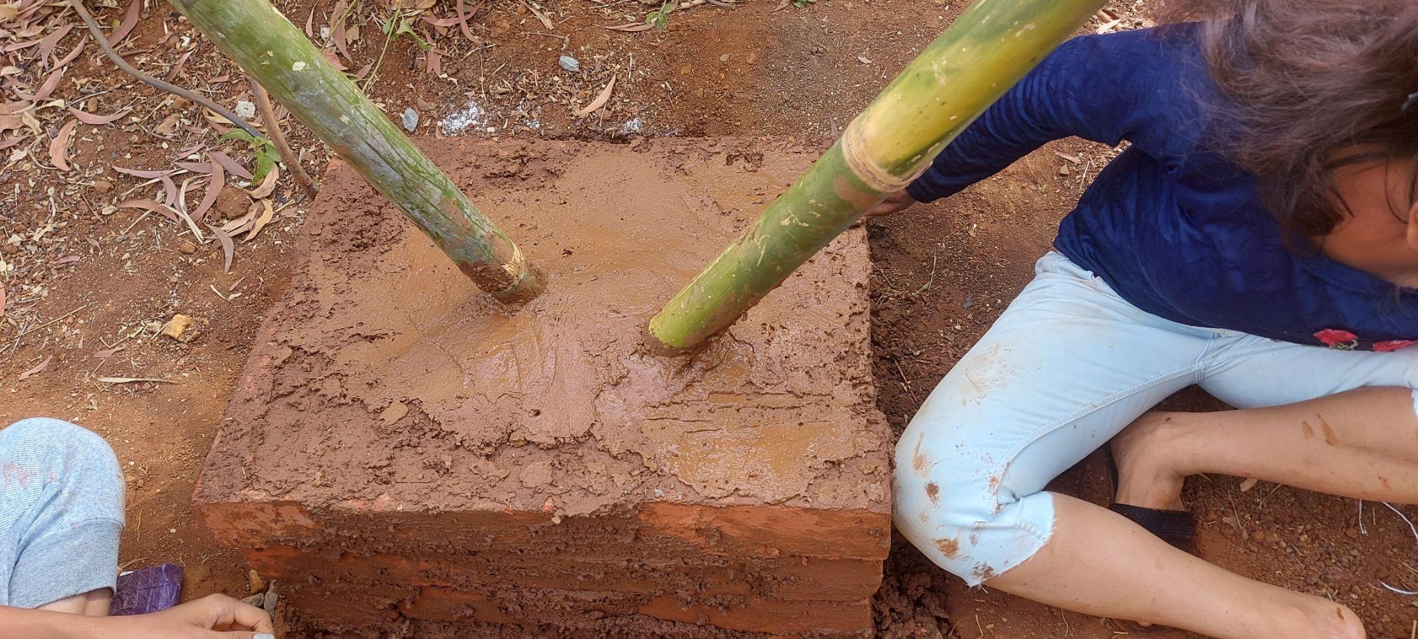

The foundation for the superstructure was laid up to the third course ie, approximately 240mm and covered filled with layers of rubble and mortar to create a base to place the rectangular module After which,
1) The module were place to understand the mock positioning of the modules.
2) Post determination and confirmation of the modules, the pit around it was filled with medium sized rubbles for its support and small spaces with smaller stones,
3) And further the layer of mortar was added. This layering of rubble and mortar was continued until the last course, ie, the sixth course. Providing the necessary strength to the module.
PROCESS
Team C | Design Report - June ‘22 16
Step: Filling the central pit area with layers of Rubble and Mortar
1. Thapi ( trowel )

2. Ghamela ( mortarpan)
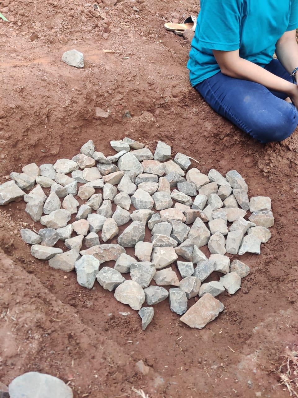
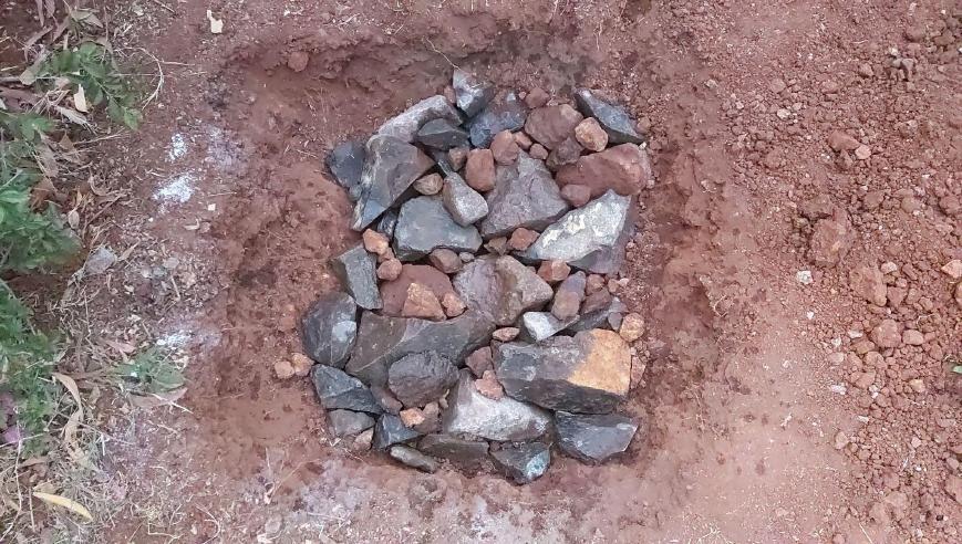
Process- To reinforce the foundation, a continuous layer of rubble and mortar was applied alternately. Small gravels were used to fill up gaps, and the process was continued until the final finish layer was not achieved.
1. Layering with rubble -
https://www.indiamart.com/proddetail/trowels-14302805488.html
Thapi ( trowel )
The big stones were first placed to form a continuous layer with a level surface on the base, and then the gap was filled in with little stones or gravels. This is known as stone 'hearting,' and it is vital because it aids in the retention of stones. Place the stone in the next layer to cover the gap between the two stones below it. To break the joint, this overlap is required.
2. Layering with mortar-
Random rubble masonry foundations done without mortar are called dry random rubble foundations. The gaps between stones are filled with smaller stones. Cement mortar is used widely. To avoid using cement, we have used mud + lime mortar. It consists of – 1 part mud, 1 part surkhi (brick powder), 1/2 part lime.. We poured the mortar paste in such a way that it filled all the gaps between stones.
PROCESS
Team C | Design Report - June ‘22 17
Step: Continuing Brick Masonry for the superstructure and
Process:
1. The excavation is performed for constructing the ground support.
2. Once the foundation layer is done, the brickwork masonry started.
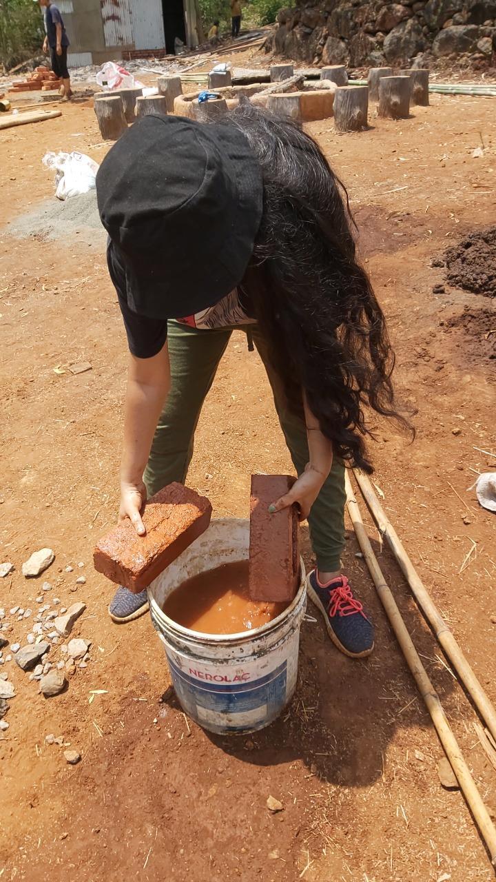
3. Before laying the bricks, they were soaked in water for sometime.
filling the pit.
4. Then the bricks were laid as per the bond and size required which was same as that of the foundation.
5. The brick courses were placed perfectly one above the other to maintain the verticality and horizontal alignment.
6. Within the process of arranging bricks we used mortar mixture to fix it properly in place and with each other
7. After finishing the masonry layer, the pit between the bricks was also filled with layers of rubble, pebbles and mortar
8. Again the mortar mixture poured on the brick course and and the process was continued.
PROCESS
Team C | Design Report - June ‘22 18
Step: Adjusting the last V column and Fixing it.
We set the location of the next two columns first, then the third column was modified according to the angle and such that the last node was at a higher point compared to the others. Hence to complete the triangle the beam was fixed in an angle as compared to the other beams which were parallel to the ground,. They can continue the pattern in the future if they want to using similar triangular units hence allowing for future expansion of the pavilion.
PROCESS
Team C | Design Report - June ‘22 19
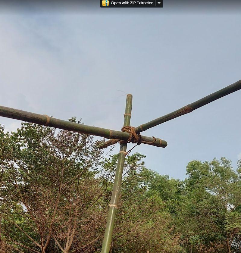
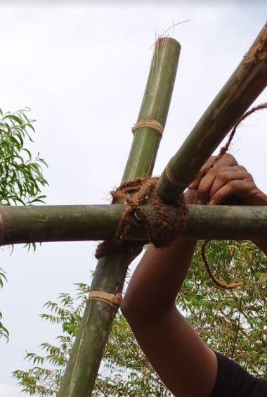
Step: Placing Beams in position
After the erection of all the V-columns, Beams were placed to strengthen the structure and bind them in position.
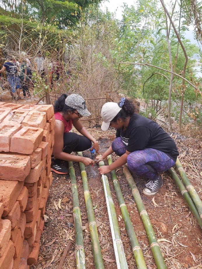
1. The measurements of each beam were taken by placing them on the columns. Then they were cut with the help of hack saw.
2. The beam were placed on the junction of the two bamboo as shown and tied with the help of the wet Similarly all the beams were tied radially starting from the pivot. Wetting helped to strengthen the knot
http://www.bamboooz.com/bamboo-ro ofing-designs-techniques-materials/
PROCESS
Team C | Design Report - June ‘22 20
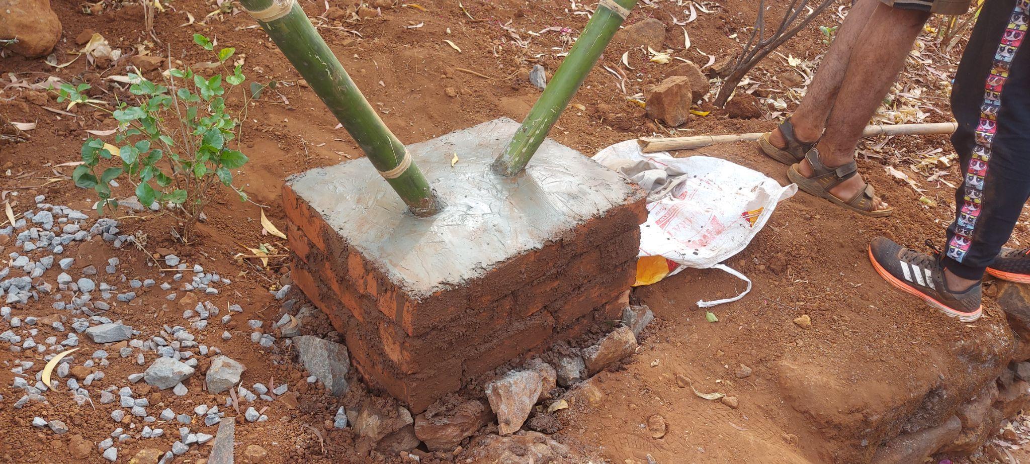
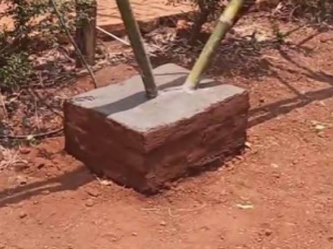
Step: Finishing the Brick pedestal
1. Creating the Pedestal:
The foundation consisted of minimum 6 courses of brick and a pedestal, 300mm high was achieved above the ground which formed a base for the bamboo columns. The 600 x 480mm brick pedestal was filled with layers of rubble, small aggregates and mud mortar which provided stability and kept the bamboo frames in a fixed locked position. The pit contained the level at which the bamboo columns were bolted together, so as to protect the joinery from surface runoff water
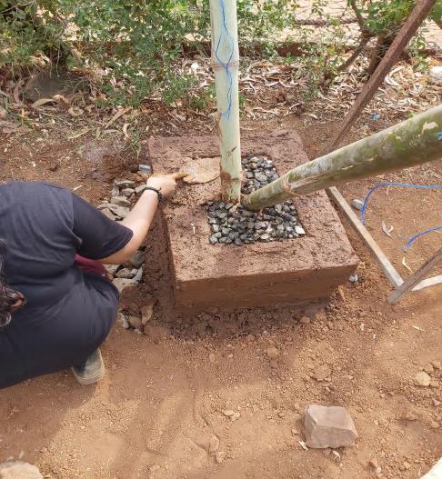
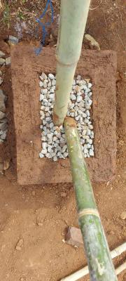
2. Surface Finish:
After filling up the pit, a thick layer of mud mortar was applied to create an even level for the pedestal surface. This was followed by a layer of OPC cement as a waterproofing finish. The dry cement was sprinkled over the mortar layer and with the help of a trowel, water was poured and gently mixed to create a thick cement paste. Trowel was used to create a smooth surface and a slope was achieved from the bamboo columns at the centre towards the pedestal end to drain the rainwater falling on the surface. The brick courses of the pedestal were finished with a layer of mud plaster. The paste of mud and water was made out of available on-site red clay. The Paste was applied over the bricks using hands and smoothened the layer by the radial movement of palms over it.
The excess pit area around the foundation was filled with rubble and medium sized stones to reach the ground level. Small pebbles were also put to fill in the voids between the rubble. Then water was sprinkled over the rubble layers to hold the soil put over them. Using grape hoe the soil was put back
PROCESS
21
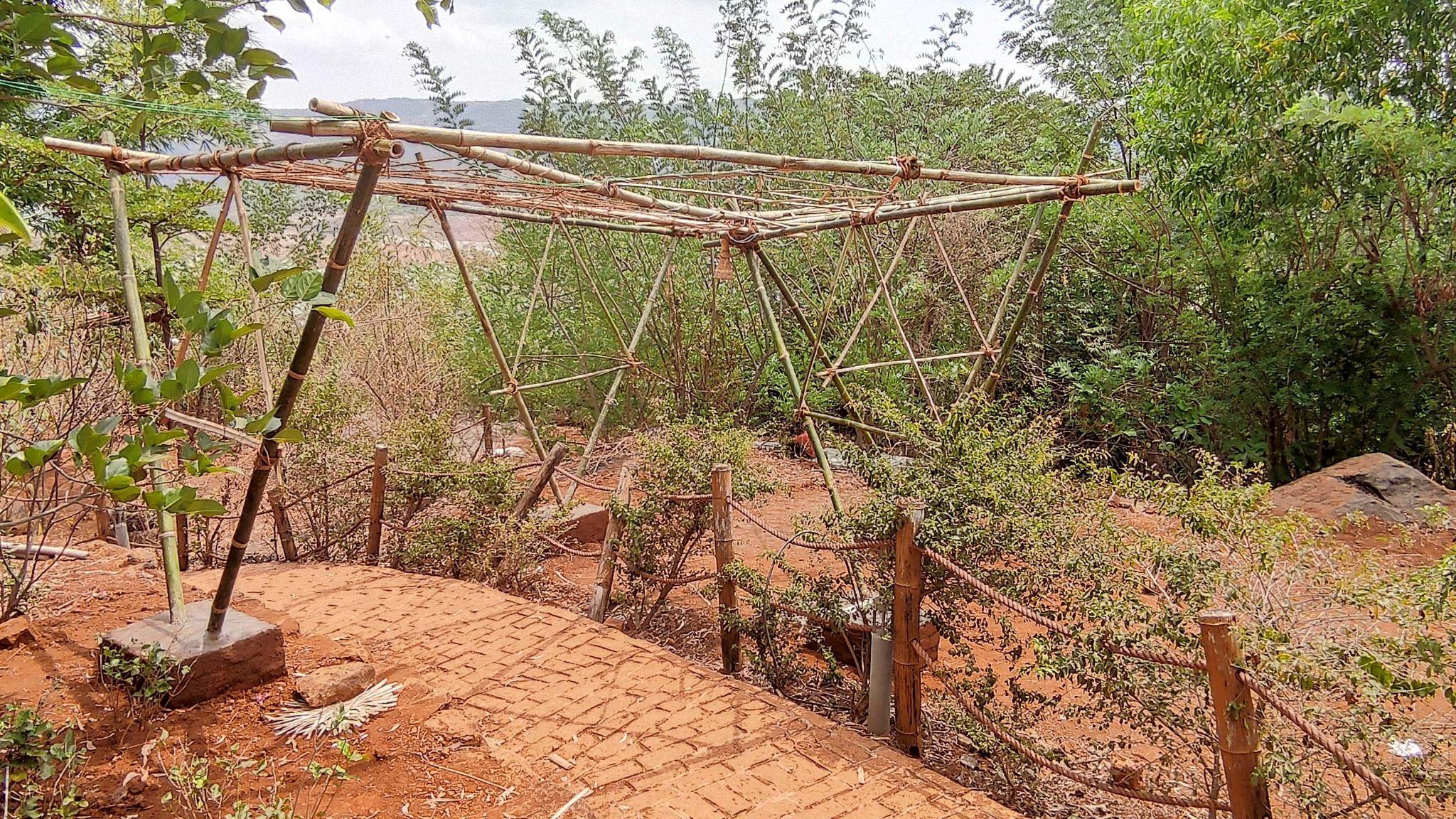
Step: Ornamentation
Bamboo was used in various methods to ornament the superstructure.

The triangular frame inside was made up of bamboo strips which was of ¼ of bamboo and the triangle inscribed within this outer triangle is of ⅛ of bamboo. These inscribed bamboo strips were tied using the Sutli as these were non- structural members hence a thinner selection of rope. These bamboo triangles were placed on the side frames and also on the roof as shown in images.
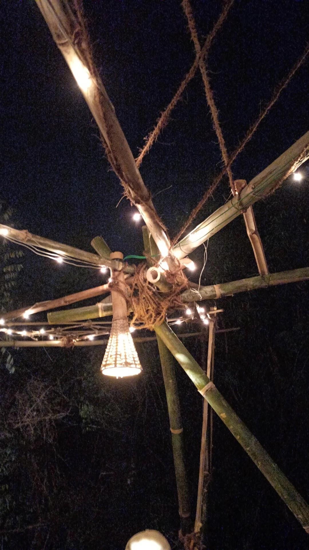
At the centre a coir was rotated within the triangle in circular pattern to create a unicursal pattern. Thus enhancing the user experience.
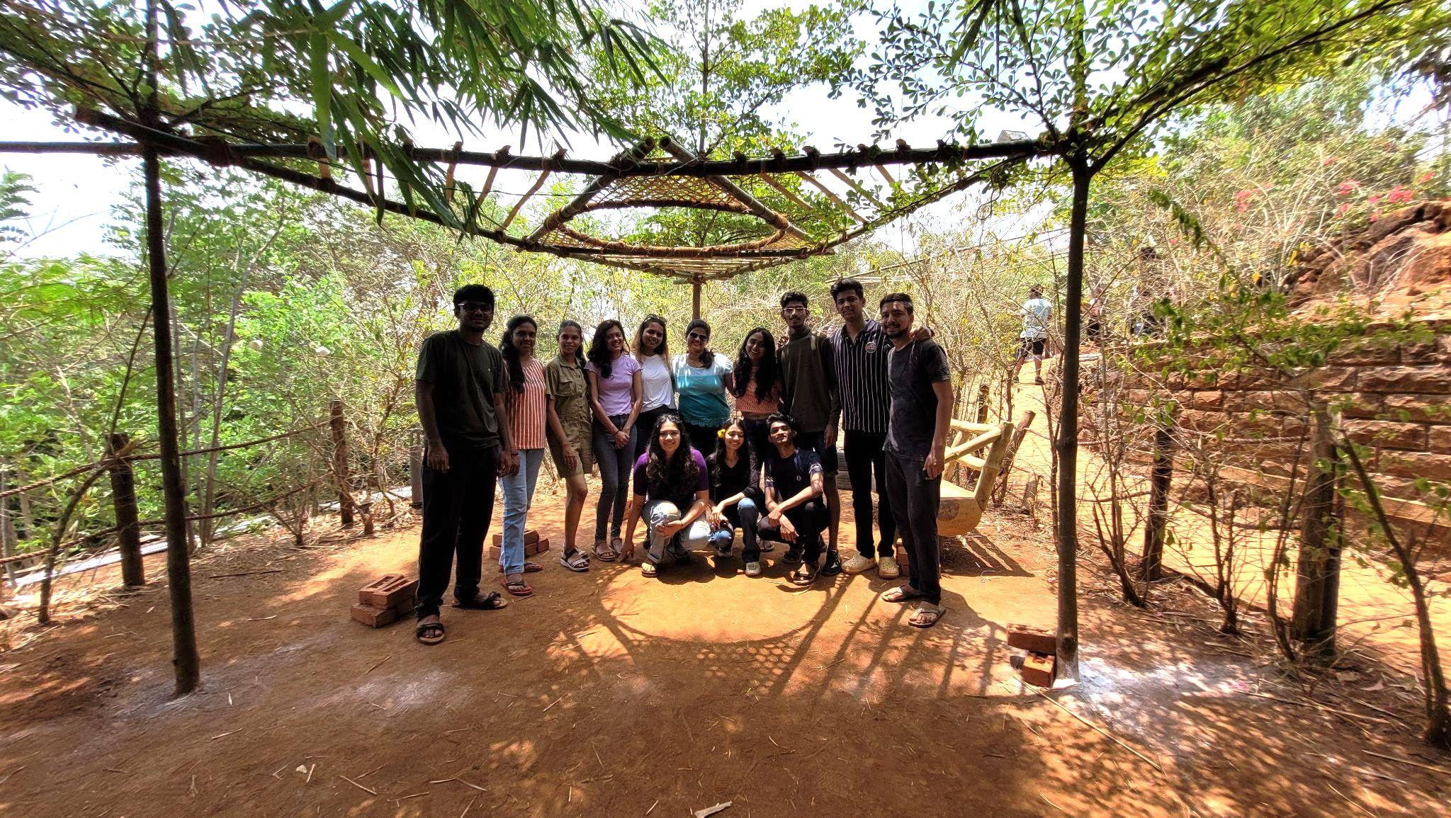
The bamboo created interesting patterns which will frame the bouganville tree and will act as selfie points for the users.
The dodecagram unicursal star was created by coir on the roof to enhance the experience while walking below it.
PROCESS
Team C | Design Report - June ‘22 22
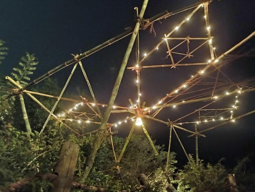
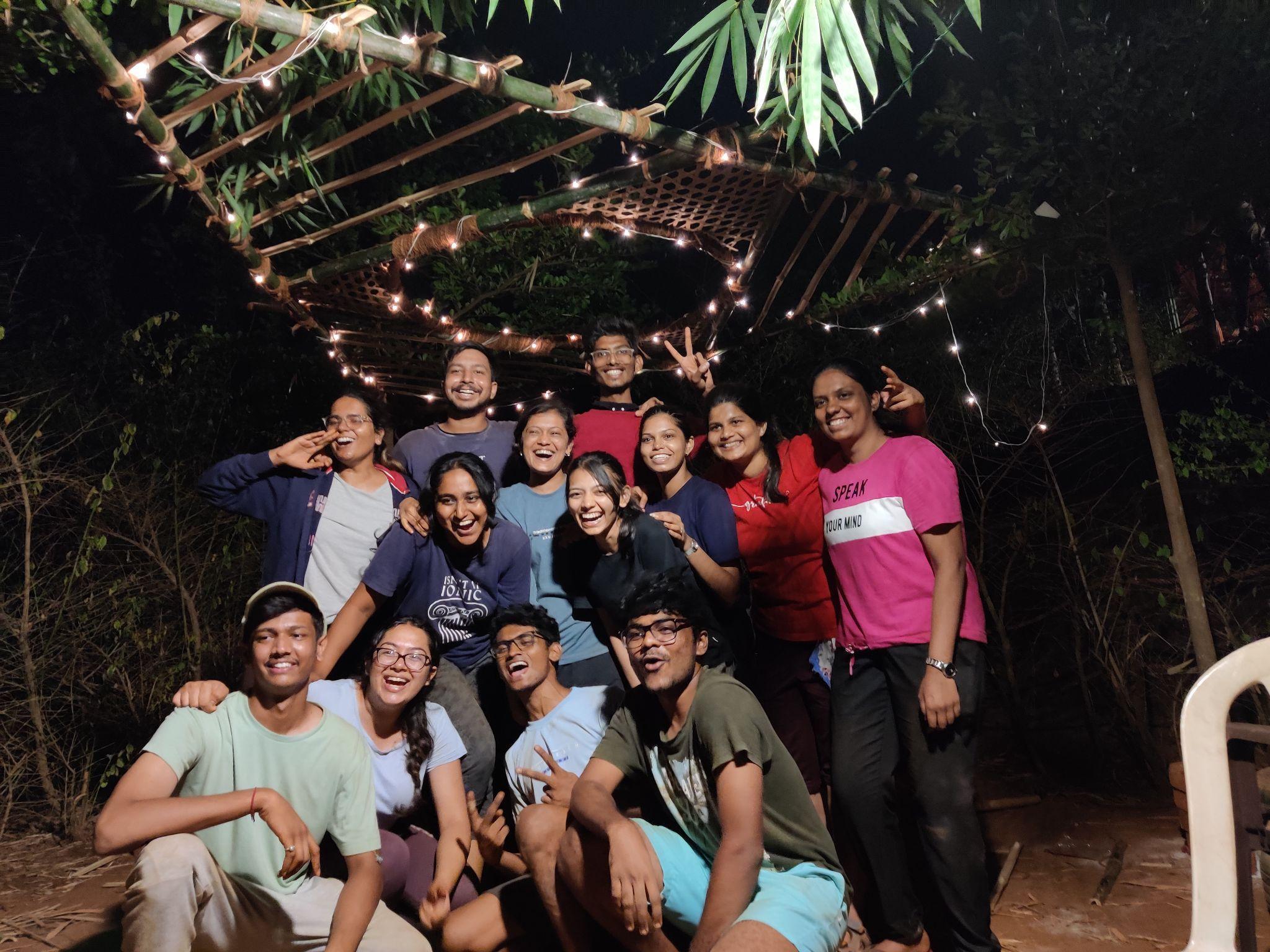
Lights and lamps were placed in a shape of triangles to create an emphasis on the roof shape.
MATERIAL STRENGTHS
Bamboo
LengthBamboo are very long due to which a single piece could be used for long spans as well to achieve the desired height.
Tensile StrengthBamboo has a great tensile strength due to which it can load easily and used for large spans and to create a frame.
Bricks
RigidAct as a Rigid Container to encompass the Bamboo Columns.
Compressive StrengthBricks have great compressive strength due to which it can take the load of the bamboo column.
Clay
BinderActs as a binder in the mortar.
TextureGives a plastered finish to the brick pedestal to give it a smooth finish.
Stones
Soling in foundationUsed to level the surface to lay the brick foundation. Transfer load of Superstructure safely to the Strata.
BackfillingUsed to fill the pit and to maintain the brick foundation
Team C | Design Report - June ‘22 23
e arid and
Largespans
Head room
● Hands on Experience with materials like bamboo, bricks, clay gave us an idea of how they behave.
● Understanding of process of design right from ideation to construction and finishing was experienced.
● Exposure to various methodologies, joineries and tools was done.
● Methods of handling resources on site was taught.
● We learnt Co-ordination, importance of teamwork, working and helping simultaneously and using everyone’s strengths.
● We learnt how materials can be cut, split, splayed and joined to create manifold variations and iterations.
● Learning the importance of levelling and providing slopes for drainage was crucial.
● We learnt how to Design subtly for the user at the same time make it experiential and beneficial.
CONCLUSION Team C | Design Report - June ‘22 24
GROUP D
Academy of Architecture, Mumbai
TEAM MEMBERS Team D | Design Report - June ‘22 i. TEAM : 11_Bhoomika Chaudhari 13_Rohit Chopade 16_Viresh Desai 17_Tarika Deshpande 25_Sairaj Halpatrao 35_Nidhi Khot 39_Sharvil More 45_Kartika Pinjarkar 50_Dhruvanshi Sanghavi 56_Abhishek Suryavanshi 58_Sanchita Tandel 61_Pranali Thool 65_Aditi Wadate
TABLE OF
Team D | Design Report - June ‘22 i. 1. SITE 2. SITE ANALYSIS 3. IDEATION 4. UTILITY OF SPACE 5. SETTING OUT ON SITE 6. CUTTING TECHNIQUES & JOINERY 7. FRAMEWORK a. TRIANGLE (MAIN FRAMEWORK) b. INNER TRIANGLE (SECONDARY FRAMEWORK) 8. CIRCULAR VOID 9. BAMBOO WEAVE PATTERN 10. RAISING THE INSTALLATION 11. FINAL VIEWS 1 2 3 4 5 6 7 8 12 13 17 18
CONTENTS
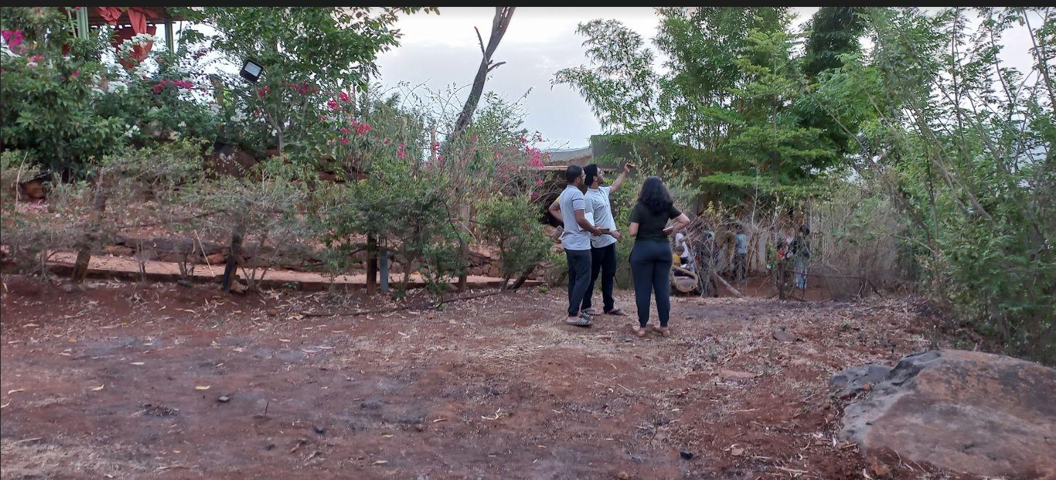
SITE PLAN
The site was located next to the row of suites and the pathway leading to them from the lawn.
SITE Team D | Design Report - June ‘22 1
SITE PLAN N
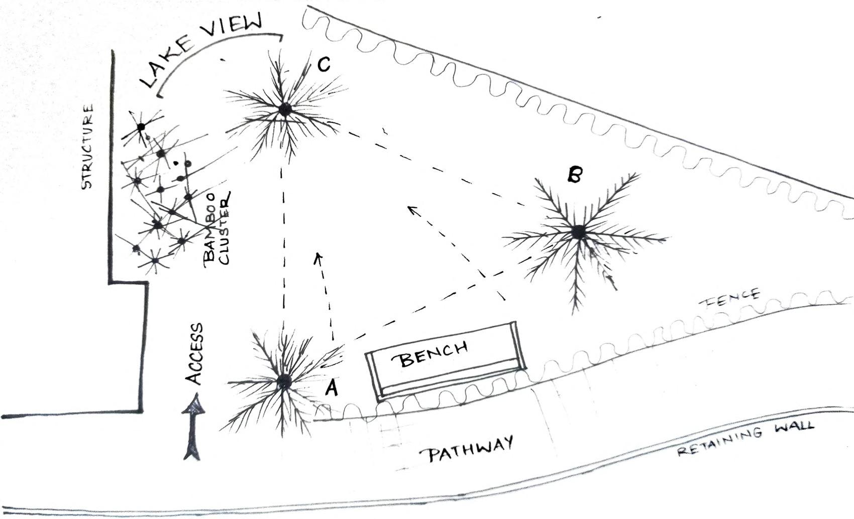
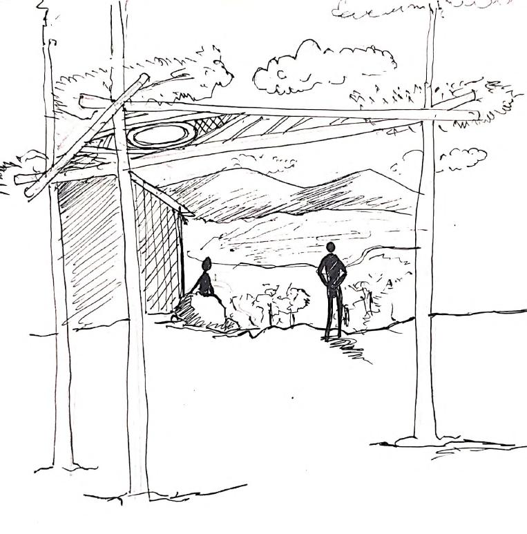
SITE ANALYSIS Team D | Design Report - June ‘22 2 SITE CHARACTERISTICS ● 3 Existing trees forming a central Triangular region ● View of the lake ● Shaded due to the existing trees ● Boundary defined by the plants ● Peaceful space - next to the rooms
OF THE LAKE FROM SITE SHADED BY TREES DIFFERENT LEAF PATTERNS FORMATION OF NATURAL VOID
VIEW
IDEA AND CONCEPT
After the site analysis, there were main factors which were taken into consideration, while ideating. The intervention proposed, was designed considering the following:
THE LAKE VIEW THE THREE TREES
The intervention should form a natural frame of the lake, while one is seated on the bench.
Main component of the site are the three trees. Thus the intervention ought to take advantage of these trees.
CANOPY PATTERNS
The site was surrounded by many trees, creating quite interesting canopy and shadow patterns which needed to be addressed.
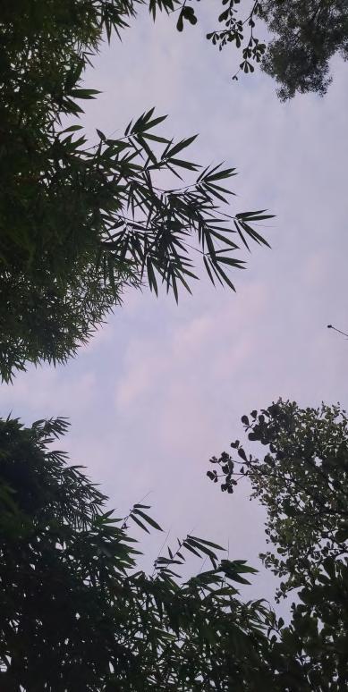
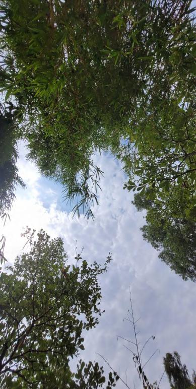
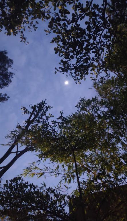
NATURAL VOID AMONGST THE TREE CANOPIES
There was a central void created naturally by the canopies, which created an interesting scene of the sky.
STARS ACROSS THE SKY
Interesting star patterns were seen in the area. This was also taken into consideration.
The site was adjacent to the rooms. Functions of the intervention should be addressing the same.

Team D | Design Report - June ‘22 3
IDEA AND CONCEPT
CONNECTING THE TREES
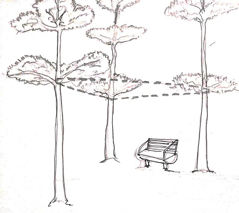
CREATING A FRAME FOR THE LAKE VIEW
CREATION OF INTERESTING PATTERNS FOR SHADOWS ON GROUND
CREATING A VOID AMONGST THE TREE CANOPIES
Team D | Design Report - June ‘22 4
UTILITY OF SPACE

LEISURE AND RELAX
Being next to the rooms, the intervention is ideal for relaxation and peace.
SHADE
Providing shade from the daily heat.
STARGAZING
The void allow one to view stars all night.
EXPERIENCING NATURE
One can enjoy peace and isolation that the site provides.


AUTHENTICITY
Usage of Bamboo.

Team D | Design Report - June ‘22 5
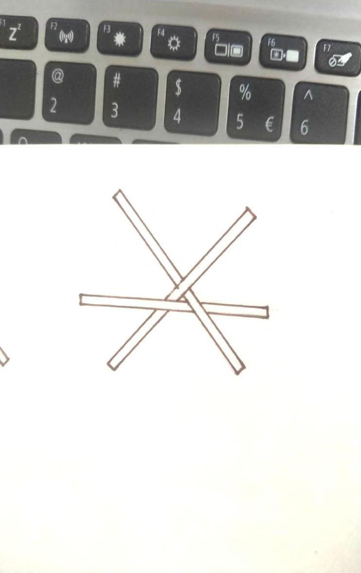
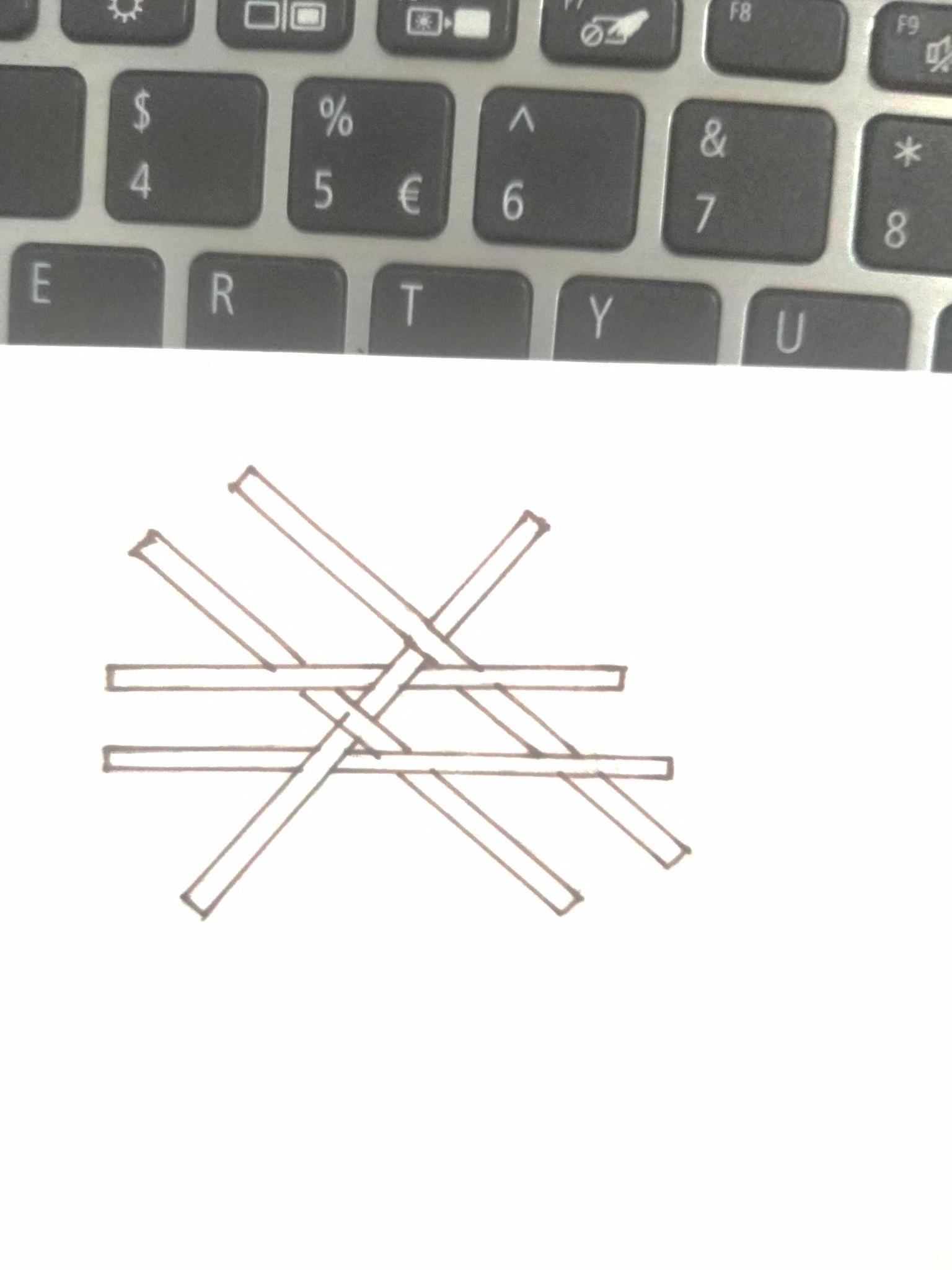
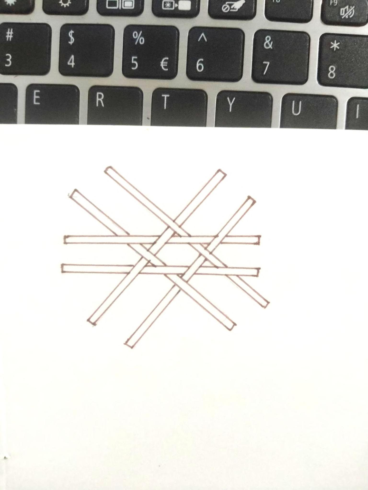
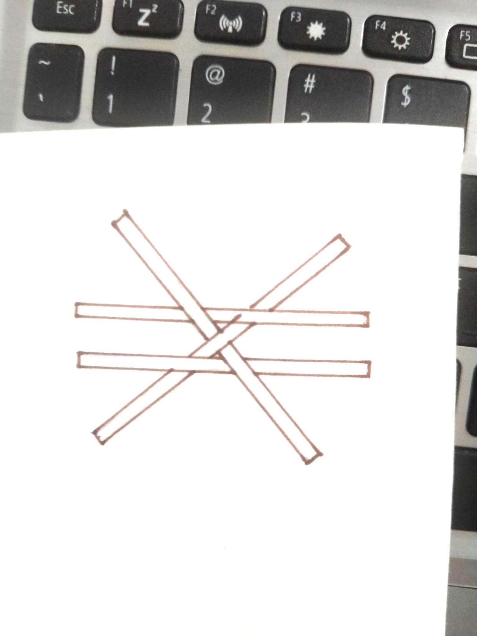
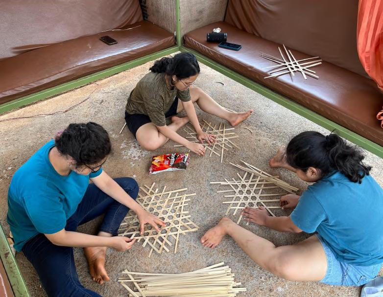
Transforming our ideas on site:
1.We started mapping the basic triangle joining the three trees on site and taking approx measurements.
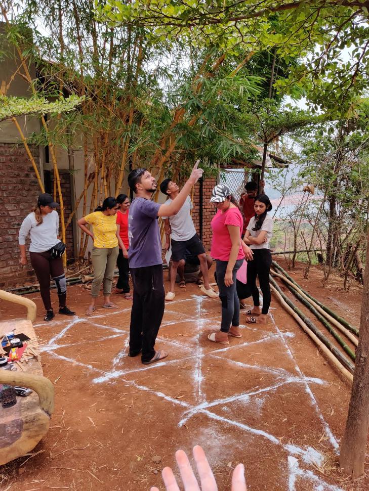
2.After that we marked the primary triangle.
3.This divided the triangle in four triangles.Further we subdivided this triangles into smaller ones.
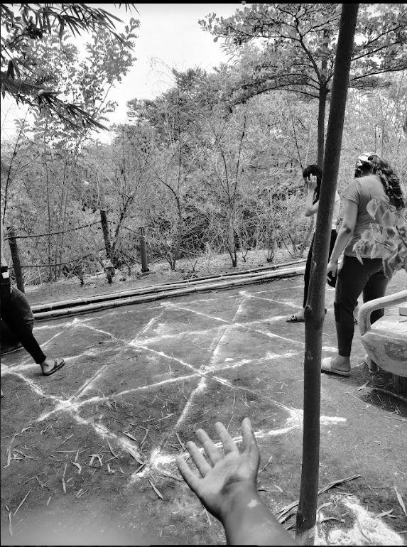
4.Then marked the central void inscribed in the primary triangle.
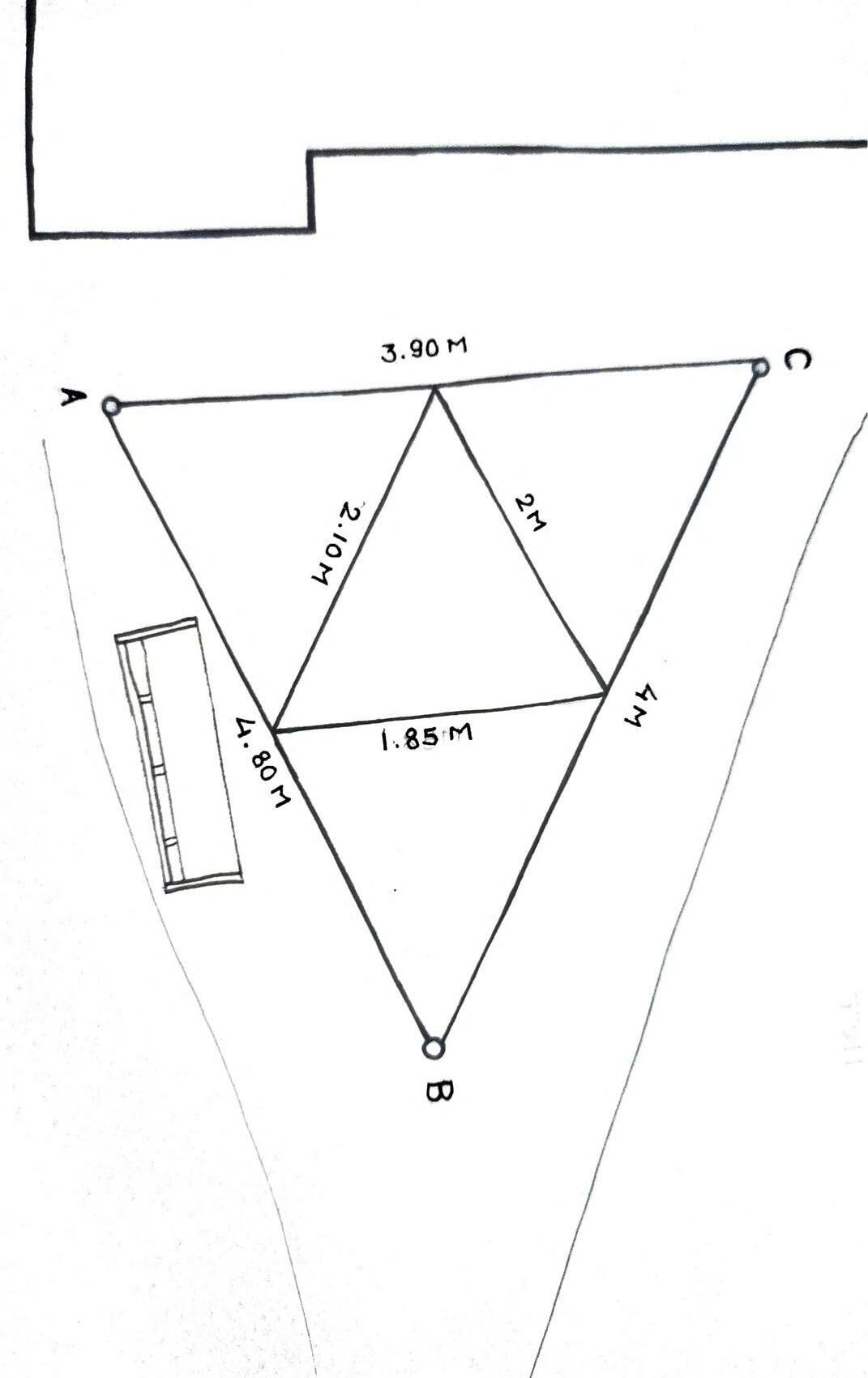
5.Then laid parallel lines at a fixed distance from the sides of the primary triangle.
6.Thus forming our basic outline for the structure.
Team D | Design Report - June ‘22 6
SETTING OUT ON SITE
N

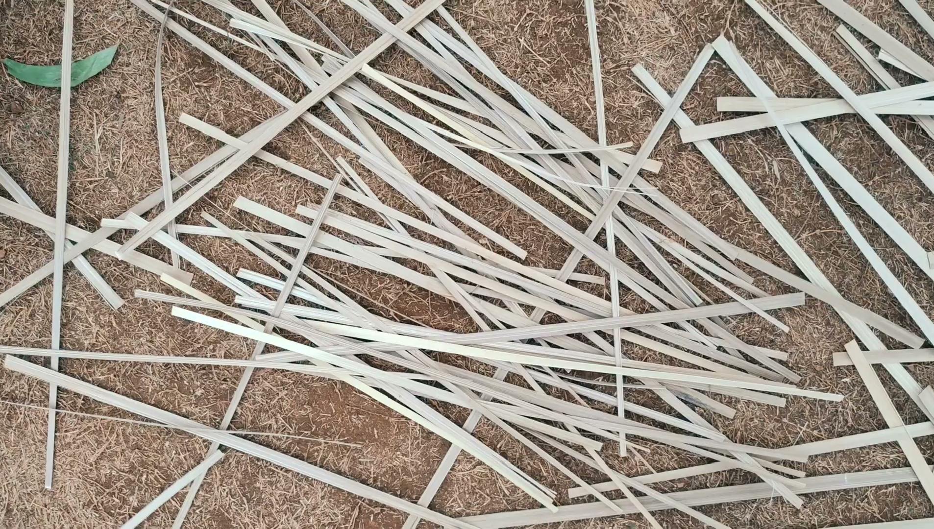
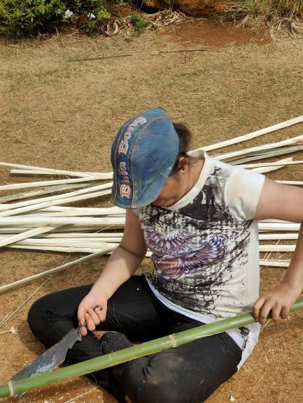
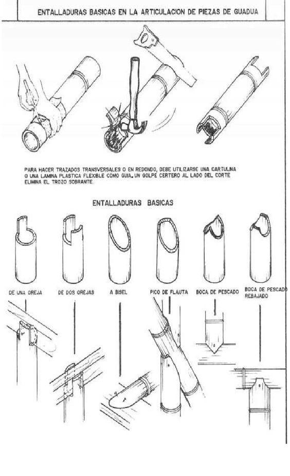
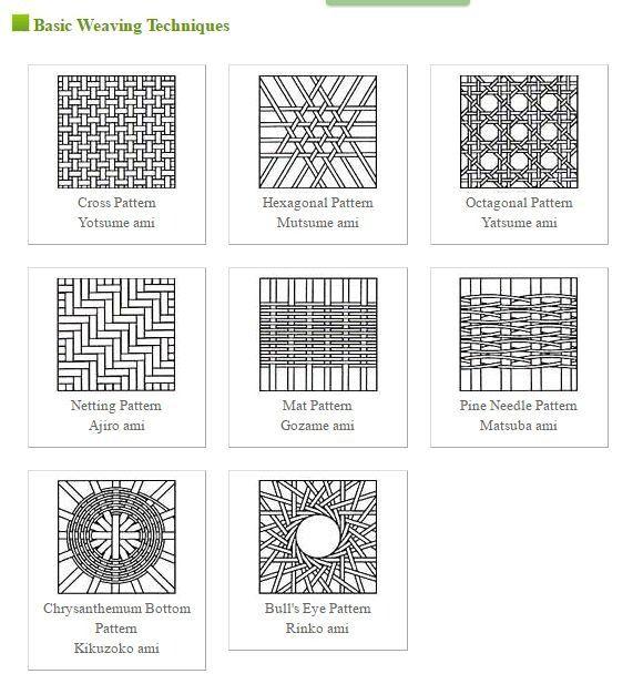
CUTTING TECHNIQUES Team D | Design Report - June ‘22 7 CUT INTO HALVES THROUGH THE CROSS SECTION FURTHER CUT INTO QUARTER SIZE SPLITTED VERTICALLY FURTHER FINER SPLITS SPLITS USED FOR WEAVING
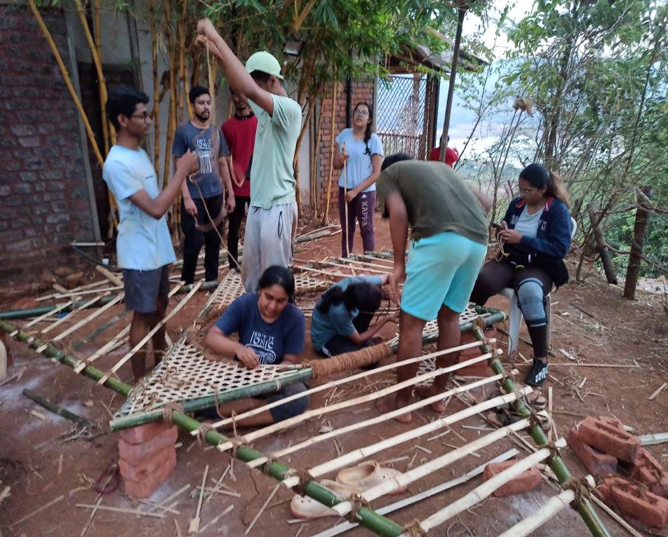
Please scan for the video.
BAMBOO
LOGS
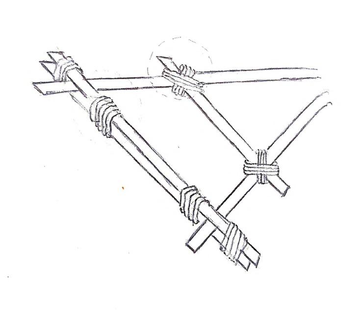
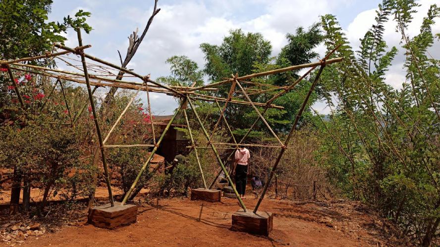
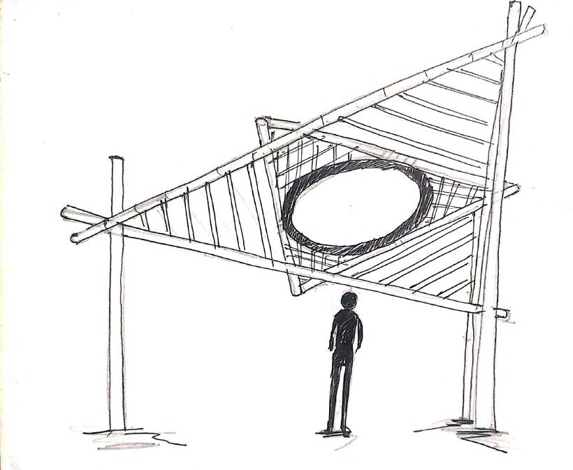
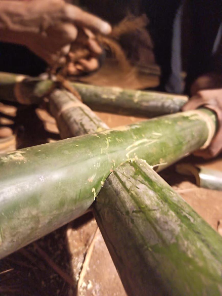
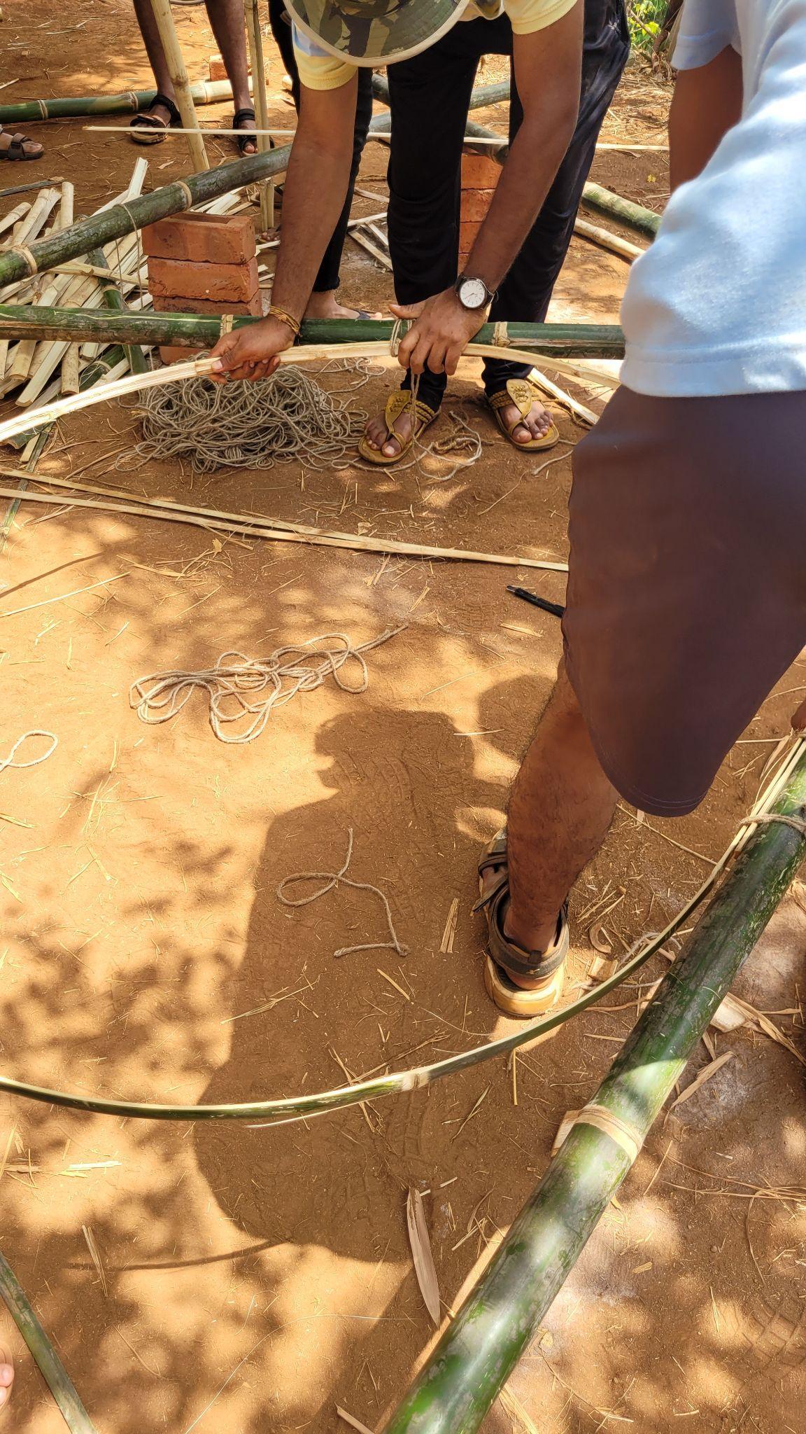
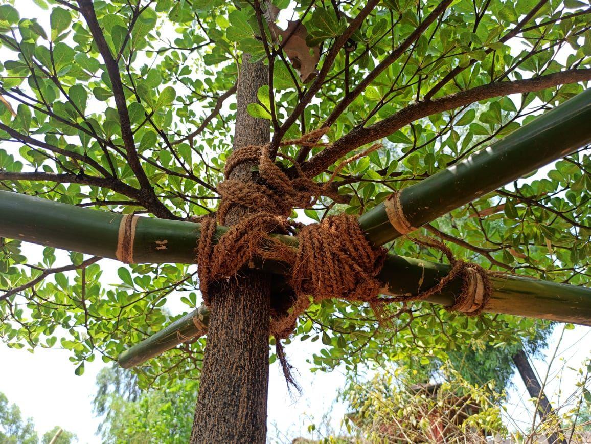
There were two frames, outer and inner triangle. First the outer triangle was made by cutting full bamboo of length approx 4.8m. Three such bamboos were then connected by half lap joinery taking the reference of the three trees on the site. The joints were then tied completing the primary outer frame. Later the inner frame was made using the same process using bamboo of length approx 2m.
Team D | Design Report - June ‘22 8
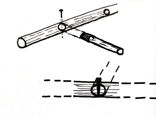
STAGE 1 - MARKING THE CUTS ON THE BAMBOO

FRAMEWORK - HALF LAP JOINT
STAGE 2 CUTTING THE BAMBOO HALFWAY ALONG THE MARKING.
STAGE 3 - PLACING THE BAMBOOS OVER EACH OTHER
STAGE 4 - USING ROPES TO TIE IN A CRISS CROSS WAY
Team D | 9
STAGE 1 - MARKING THE CUTS ON THE BAMBOO

FRAMEWORK - HALF LAP JOINT
STAGE 2 CUTTING THE BAMBOO HALFWAY ALONG THE MARKING.
STAGE 3 - PLACING THE BAMBOOS OVER EACH OTHER
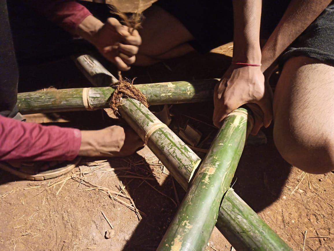
STAGE 4 - USING ROPES TO TIE IN A CRISS CROSS WAY
3
Team D | Design Report - June ‘22 10
STAGE
- PLACING THE BAMBOOS OVER EACH OTHER Please scan for the video.
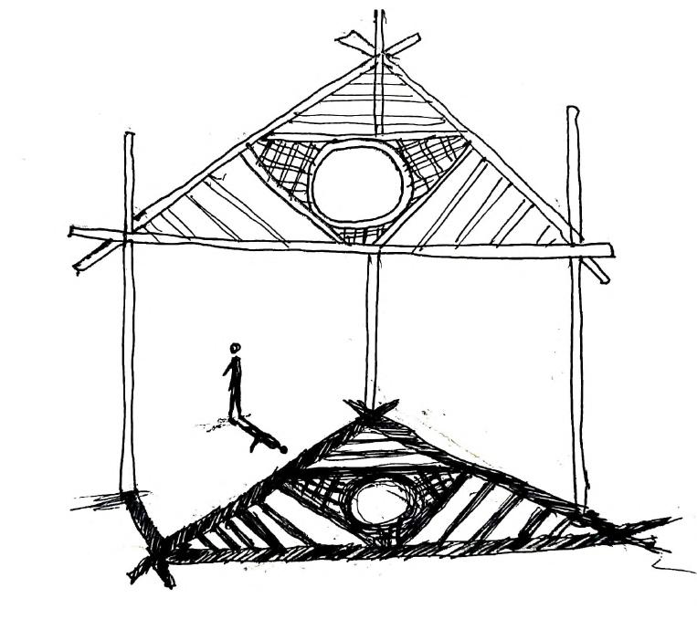
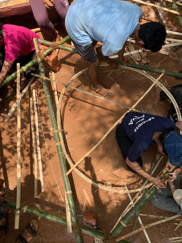
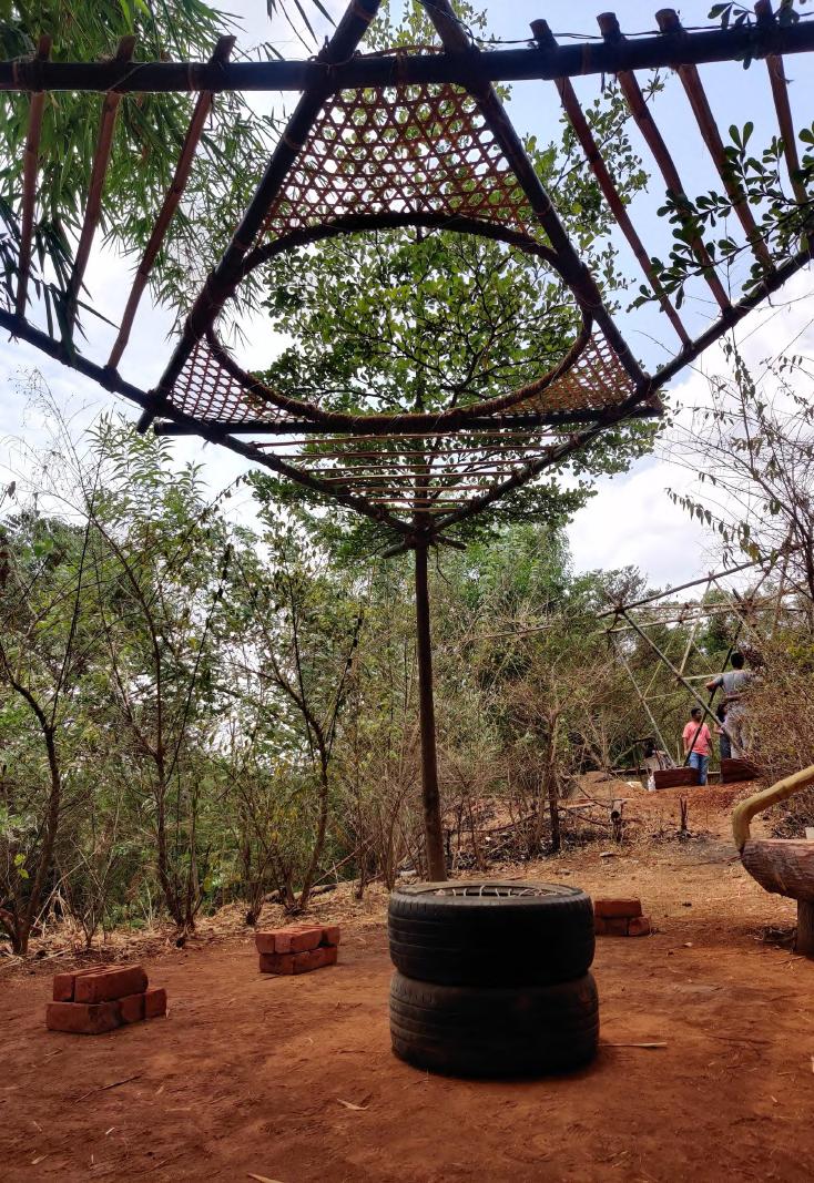
CIRCULAR VOID
Team D | Design Report - June ‘22 11
STAGE 4 - TIEING WITH THIN ROPES
STAGE 3 - CREATING A FIRM CIRCULAR VOID
STAGE 2TEMPORARILY TIENG SPLITS TO FRAMEWORK. STAGE 1 - USING SPLITS TO CREATE A CIRCULAR VOIDS
STAGE 1 - USING SPLITS TO CREATE A CIRCULAR VOIDS STAGE 2 - TEMPORARILY TIENG SPLITS TO FRAMEWORK.
VOID Team D | 12
4 - TIEING WITH THIN ROPES
3 - CREATING A FIRM CIRCULAR VOID
2TEMPORARILY TIENG SPLITS TO FRAMEWORK.
1 - USING SPLITS TO CREATE A CIRCULAR VOIDS
CIRCULAR
STAGE
STAGE
STAGE
STAGE
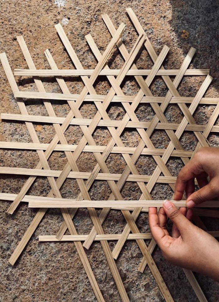
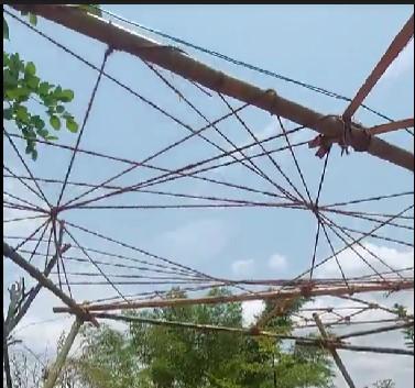
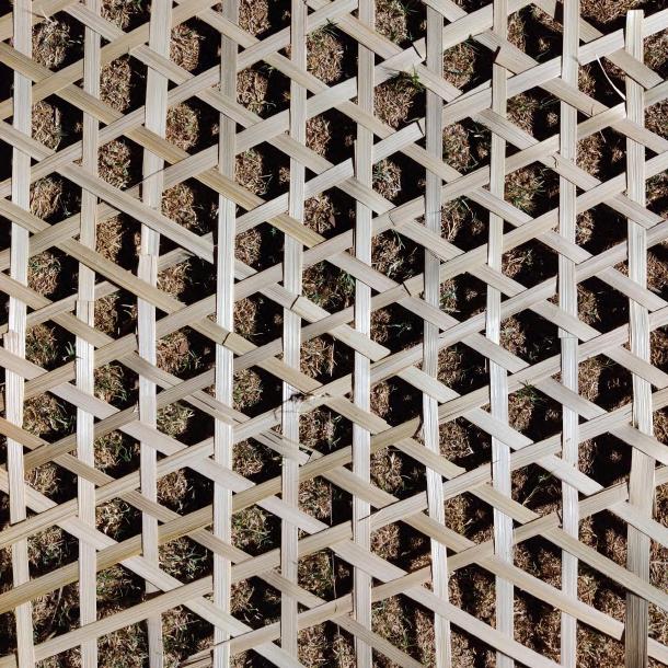
Taking forward our concept of lightness and shadows, we opted for a hexagonal weave
This helped with the stability of the structure as the splits of bamboo are very thin and

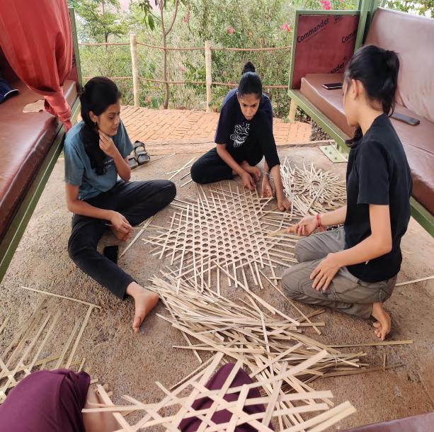
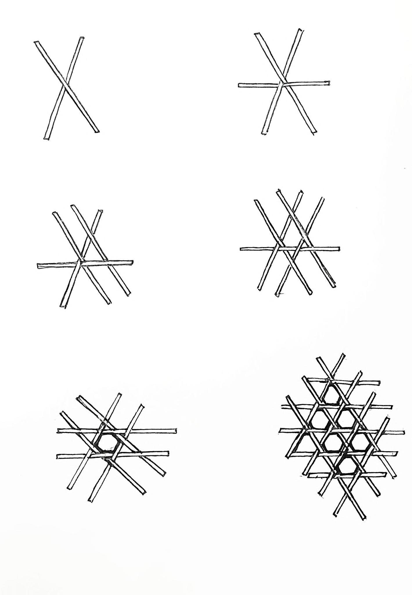

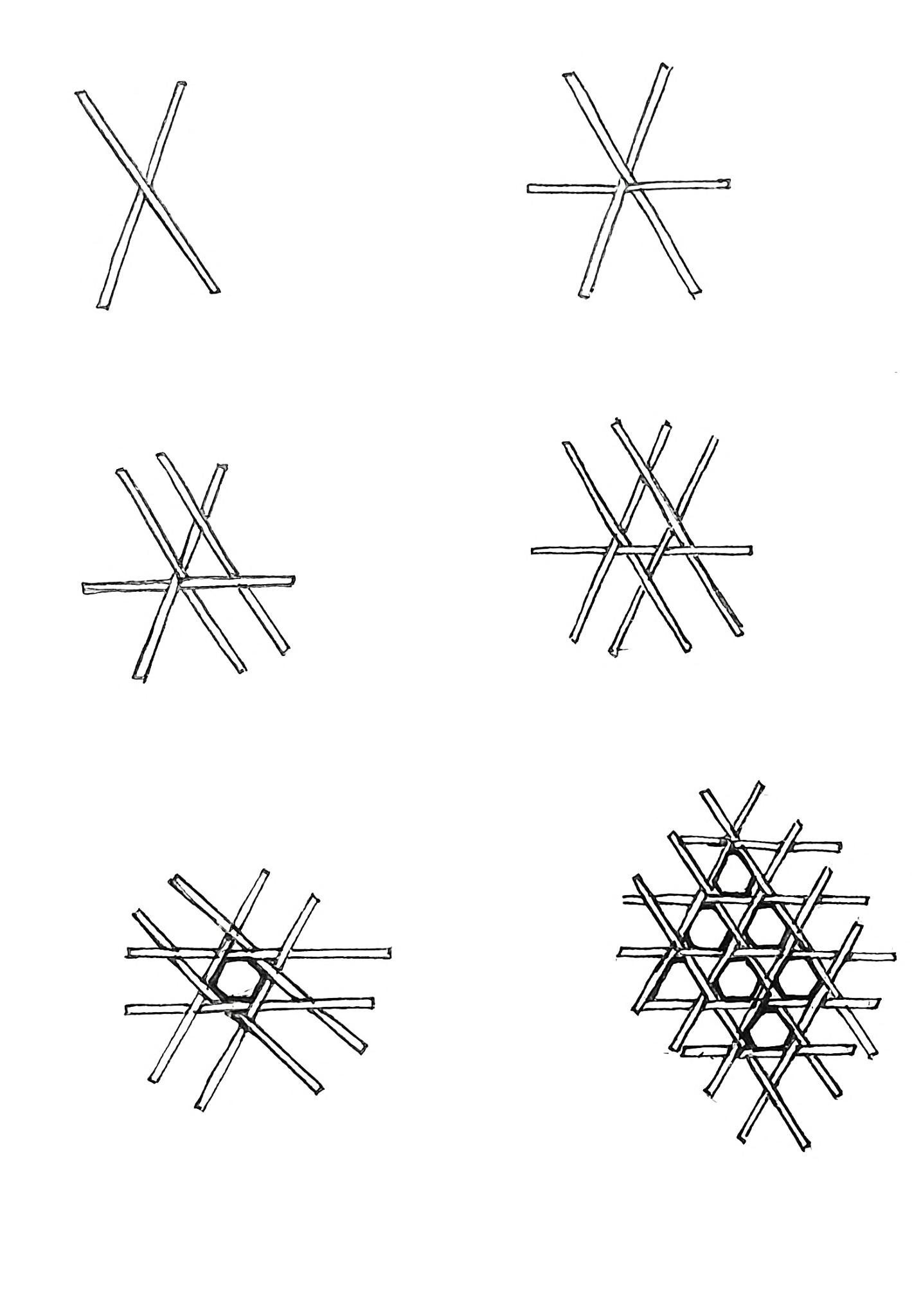
Its easy to bind, when weaved together, creates a very strong yet light bond with hexagonal
These hexagonal voids helped in accentuating
Team D | Design Report - June ‘22
Please scan for the video.

Team D | Design Report - June ‘22 14
COVERING THE IN BETWEEN VOIDS
STAGE 3 - ADDING A FRAMEWORK STAGE 4 - TIEING WITH THIN ROPES
WEAVE PATTERN Team D | Design Report - June ‘22 15 STAGE 3 - ADDING A FRAMEWORK STAGE 2 - CUTTING INTO ITS PROFILE STAGE 1 - ALIGNING THE BAMBOO PATTERN MAT STAGE 1 - ALIGNING THE BAMBOO PATTERN MAT STAGE 2 - CUTTING INTO ITS PROFILE
BAMBOO
BAMBOO & WEAVE PATTERN CONNECTION
STAGE 1 - ALIGNING THE BAMBOO PATTERN MAT
STAGE 2 - CUTTING INTO ITS PROFILE
STAGE 3 - ADDING A FRAMEWORK
STAGE 4 - TIEING WITH THIN ROPES
STAGE 3 - ADDING A FRAMEWORK
STAGE 4 - TIEING WITH THIN ROPES
Team D | 16
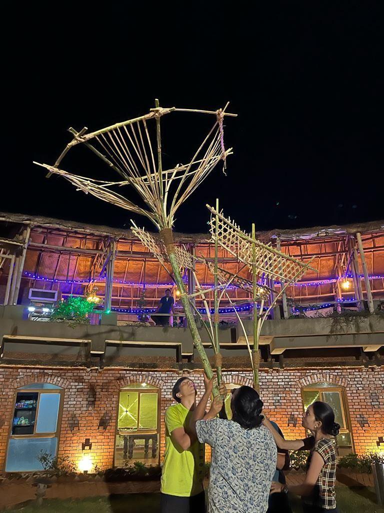
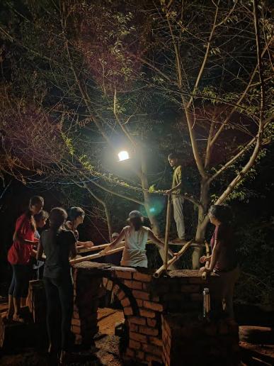
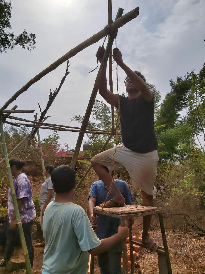
RAISING THE INSTALLATION

STAGE 2 - TIEING THE ANCHOR KNOT ON THE VERTEXES
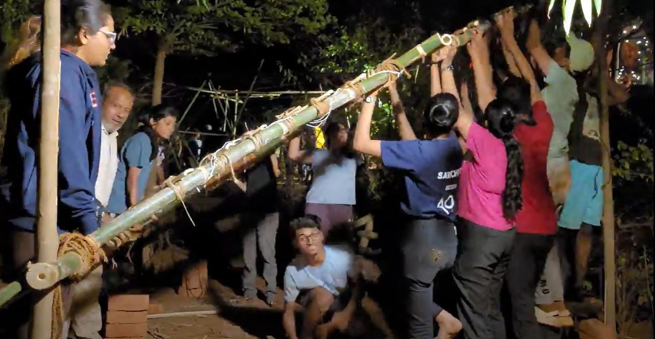
STAGE 3 & 4 - TILTING THE STRUCTURE TO PLACE ONE END ON THE BRANCHES , THEN RAISING THE WHOLE & TIEING THE ANCHOR KNOT INTO PULLEY KNOT
STAGE 4 - TRAISING THE INSTALLATION
Team D | Design Report - June ‘22 17
STAGE 3 - TILTING THE INSTALLATION
STAGE 1 -TIEING PULLEY KNOT OVER THE BRANCHES
STAGE 1 - IEING PULLEY KNOT OVER THE BRANCHES STAGE 2 - TIEING THE ANCHOR KNOT ON THE VERTICES
Please scan for the video.
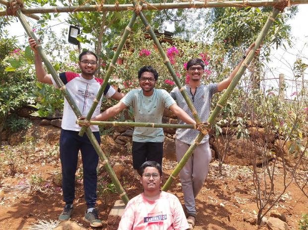
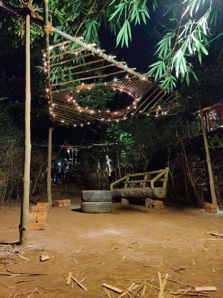
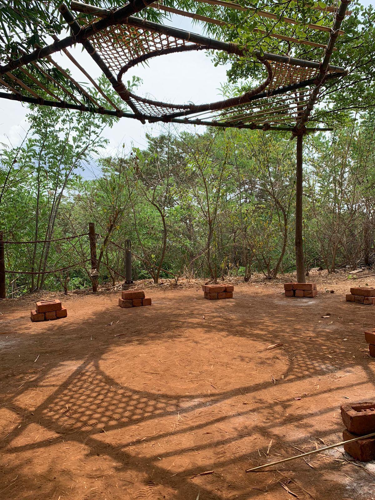
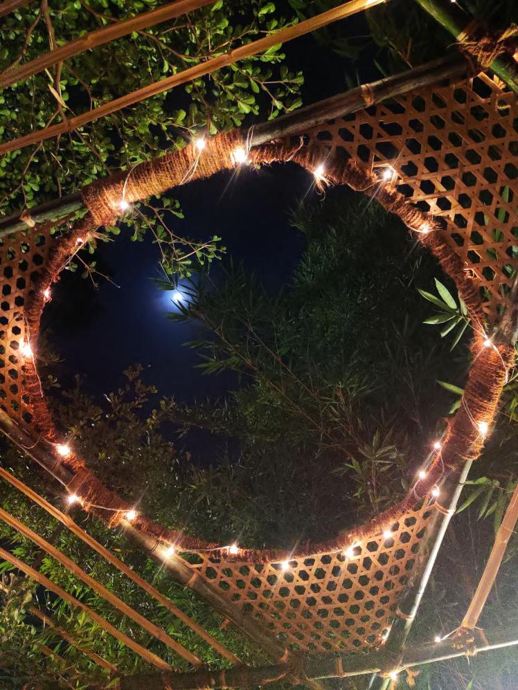
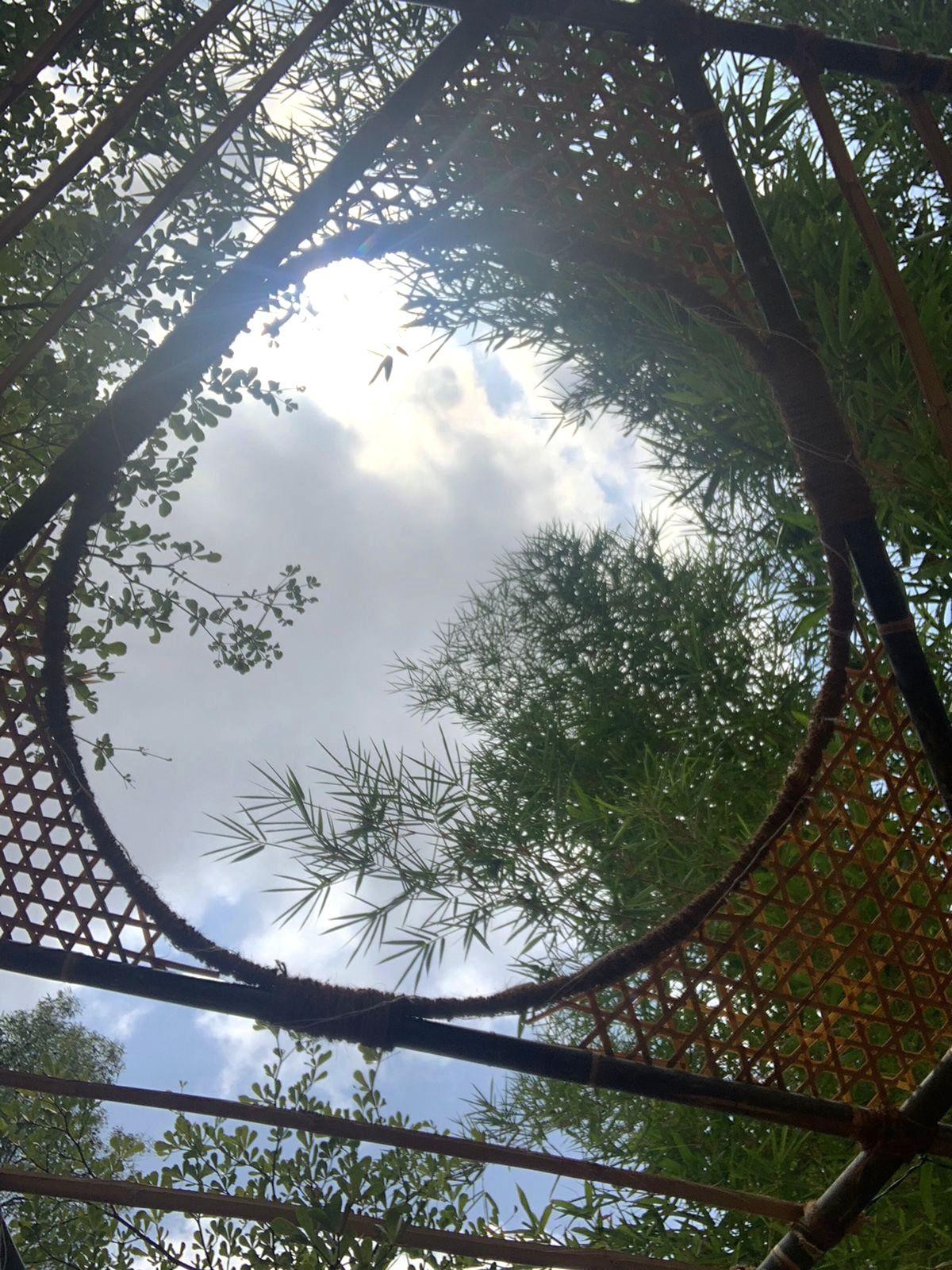
FINAL VIEWS
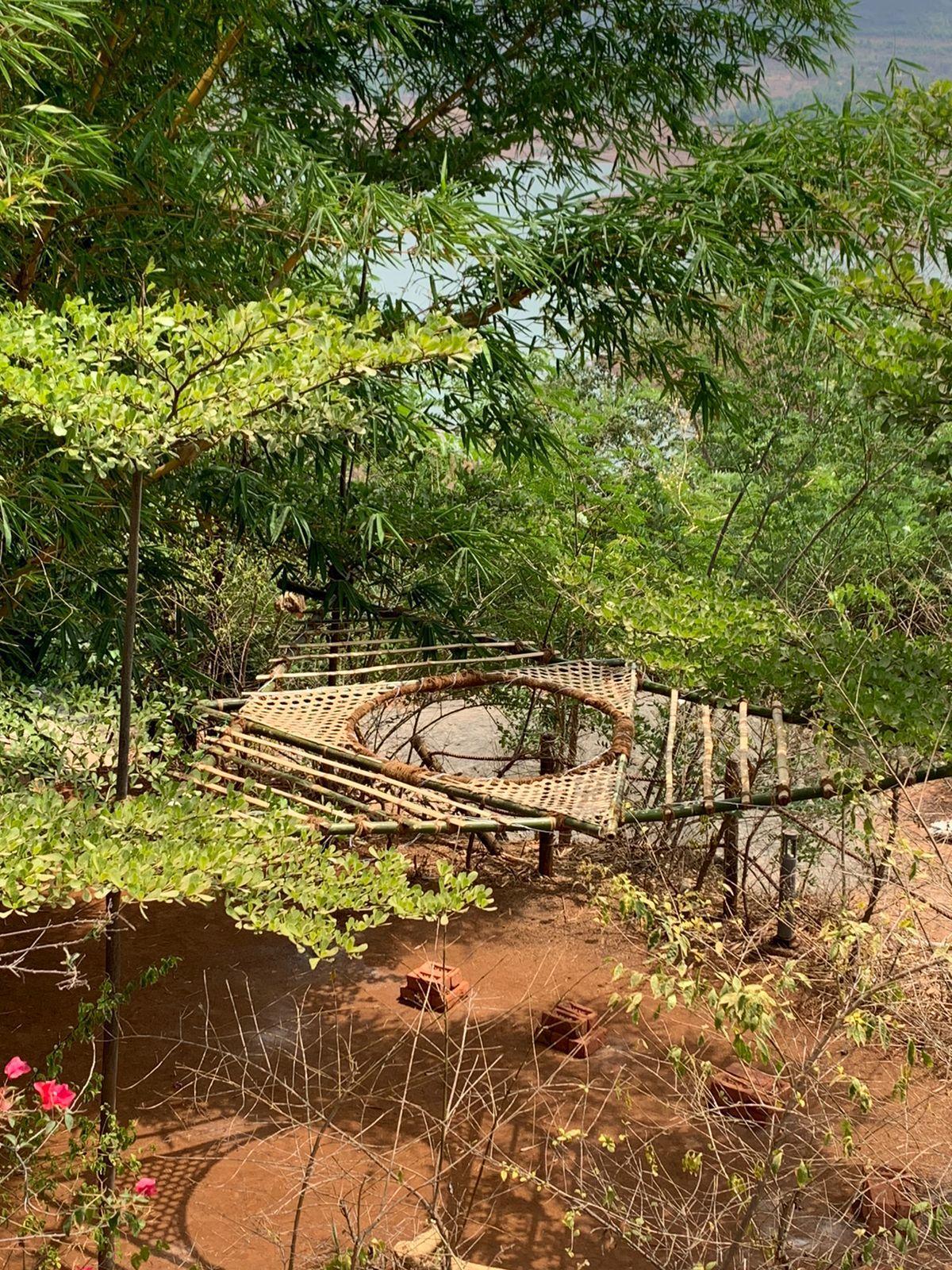
DAYTIME

Formation of shadows on ground, open comfortable shaded space in proximity to suites,
18
Please scan for the video.
FINAL VIEWS
NIGHT TIME
Decently lit open seating, lighting viewed from beneath & overviewed from
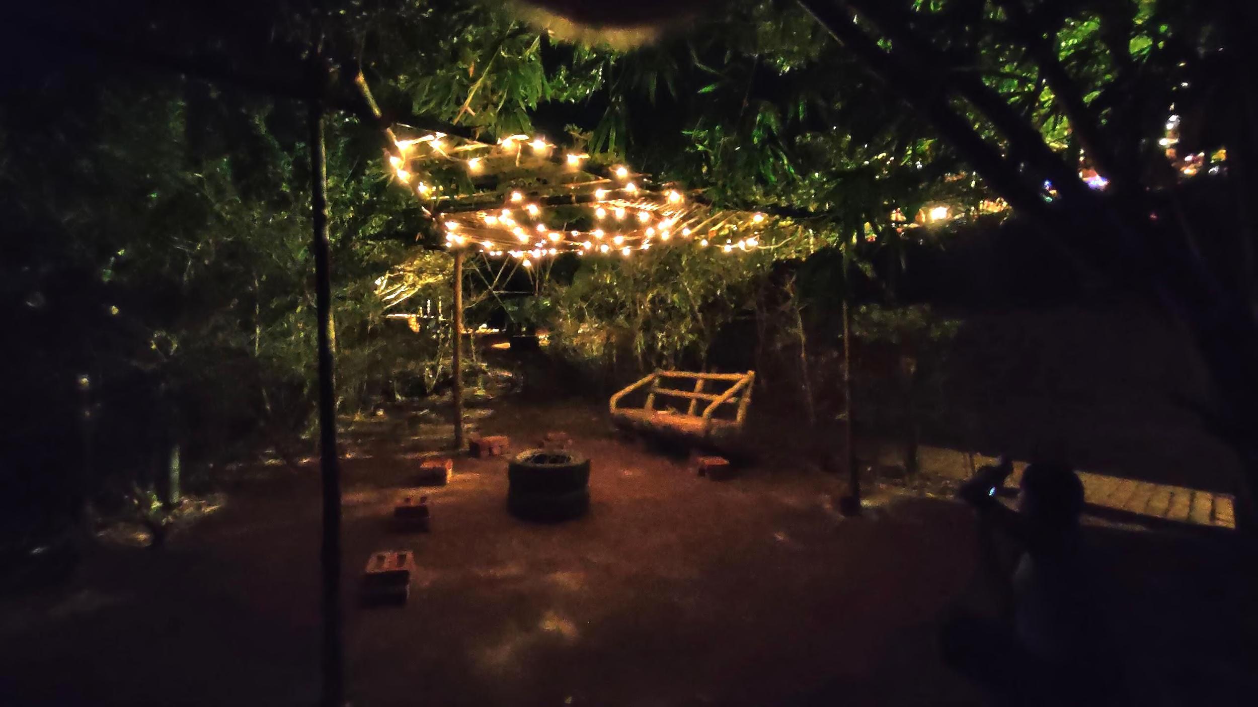
Team D | Design Report - June ‘22 19
FINAL VIEWS
Team D | Design Report - June ‘22 20
