AAMINAH PATHAN.
CURRICULUM VITAE.
EDUCATION
LIVERPOOL JOHN MOORES UNIVERSITY, LIVERPOOL, UK
MA | SEPT 2021 - 2023
LIVERPOOL JOHN MOORES UNIVERSITY, LIVERPOOL, UK
BA HONS | SEPT 2018 - MAY 2021
BOLTON SIXTH FORM COLLEGE, BOLTON, UK
PHYSICS, MATHS, FINE ART| SEPT 2016 - JUL 2018
BOLTON MUSLIM GIRLS SCHOOL, BOLTON, UK
GCSE's | SEPT 2011 - June 2016
3A*'S, 7A'S, 2B'S
SOFTWARE SKILLS
ADOBE PHOTOSHOP
ADOBE INDESIGN
AUTOCAD
REVIT
SKETCHUP
ENSCAPE
VRAY
ILLUSTRATOR
ABOUT ME
I am currently seeking a Part II position to enable me to progress onto attaining full qualification. Working on projects during my masters has helped develop an appreciation for a style of architecture focusing on integrating landscape and architecture.
I have worked on a wide range of projects but take particular interest in mixed use and residential projects, focusing on user friendly design but also aiming to create design which is concious of the environment. Good organisation and time management has enabled me to further my self development as a young architect, along with my quick ability to learn from peers.
Learning along the 5 Year journey has developed my understanding in the field but also confidence in leading group projects every year, communicating ideas to clients and peers. Thus, I am keen to expand my knowledge in the working environment to see my potential.
PERSONAL INFO
ADDRESS:
X1 LIVERPOOL ONE, DAVID LEWIS STREET
EMAIL: PATHANAAMINAH@GMAIL.COM
PHONE: 07843762579
NATIONALITY: BRITISH ENGLISH
LANGUAGES
Slow Schiedam
Location: Schiedam, The Netherlands
MA Year 2, Semester 1

Slow Schiedam is an urban design project which offers an “alternate culture where inhabitants of the new district enjoy a slower-paced environment”. The area will be home to diverse residents with work opportunities, leisure facilities and various amenities to sustain the community based on the principles of the 15-minute city.


Connected greenery stitched throughout the site create a garden festival-type sequence of public spaces, celebrating the historical significance of the Dekuyper and Nolet Distilliries, which are still crucial to the area.

New Buildings
Repurposed Existing Buildings
Market Stalls
Arts: Pop-up Markets, Learning Centre
Socialising areas, Gin bars
Pocket Park
High Street
Housing


Primary and Secondary School
Cafe and Creche
Sports Centre
Greenhouse
Horticulture Centre
Amphitheatre (Sunken and enclosed)
Wind/Sound Sculpture


Co-Housing


PROJECT INFO
Location: Lodge Lane, Liverpool Semester 2
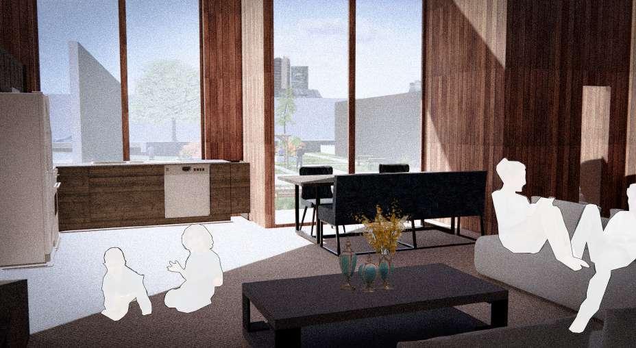
Provide for a safe environment for families to interact with other families and also individuals who are wanting a warm, friendly environment to live in. Co housing units will allow for affordable living which encourages social interaction through families and professionals residing within the space.

GROUND FLOOR 1:100
SECTION THROUGH 1:100
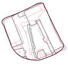
Circulation Diagram

MATERIALITY


SHOU
SUGI BAN
CLADDING
POWDER COATED ALUMINIUM

COMMUNAL DINING

CARPET

WHITE PLASTERED WALLS

GROUND FLOOR - OPEN PLAN LIVING ROOM AREA

OAK FLOORING


3 BED TYPOLOGY


8 PHOTOVOLTAIC CELLS/SOLAR PANELS
The solar panels are placed on the existing green roofs, with the roofs positioned at an angle to maximise the sunlight shining on the panels, the sunlight will then be used as a source of energy to be converted into energy to use within the building - electricity and heating. This allows for a reduction in the carbon footprint, also aiding in a reduction of costs.
4 RAINWATER HARVESTING
The design collects rainwater from the permeable surfaces of the green roofs which then recycle the water to use for the facilities within the units for greywater. The water can also be used to help water the deciduous trees in and around the site to help maintain the landscape without any waste.

3. RAINWATER CALCULATION


Total Roof Area = 601m2 x 796 (Annual Rainfall Northwest) x 0.75 (Rainfall Coefficient) x 0.9 (Filter Coefficient) = Litres Per Annum x 0.05 (Tank Size) = 16,145.865 Litres


Storage Tank around 17,000 Litres is required.
TWO BED FLAT TYPE A
TWO BED FLAT TYPE B


ONE BED FLAT

GLAZING


Central atrium is covered via a glass roof which has operating windows, allowing for more sunlight to penetrate the space. 20m height of building means for greater sunlight within units due to shorter surrounding buildings.


CLT STRUCTURAL AXONOMETRIC


Glass Atrium Roof With Timber Framing
Third Floor Unit Green Roofs With Timber Structure
Third Floor CLT Structure
Second Floor CLT Structure
First Floor CLT Structure
Ground Floor CLT Structure
GREEN ROOF
1
100 mm Timber Roof Structure
300 mm Insulation
50 x 50mm Timber Battens
20mm Timber Ceiling Finish
50/200 mm Cedar Panelling
3
45 mm Heating Screed
50 mm Insulation
150 mm CLT Timber Panel
50 mm insulation with battens
25mm Oak Ceiling Finish
30mm x 150mm Timber Louvre
5mm Triple Glazing
CDP Northern Powerhouse
PROJECT INFO
Location: Princes Dock, Liverpool
Year 3 Semester 2
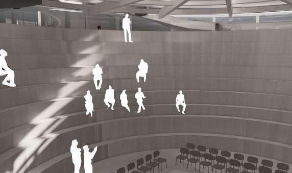
The scheme is designed to facilitate for an environment where the public voice can be heard within a parliamentary setting, the main building would host the debating chamber with a public platform setting also, a library, meeting rooms, press chamber and a cafe facing the dock.
The demonstration space acts as a means for communal gathering too. This is at the south end of the site due to it receiving the most daylight during the day.


SITE HISTORY - RIVERSIDE STATION

The Riverside Station surrounding the site is apparent in both plans originally opening in 1895.

The station interrupts the site in both plans, hence we can see that it was initially used as a transport hub for the city centre with surrounding area used for depots, marine offices and receiving houses.


RECENT HISTORY


A significant difference seen from the 20’s, 50’s plans is that the princes dock which was extended to the right of the site has now decreased in size and only fills to the edge of the site.


Riverside station had been demolished in 1971, hence it is not present within the plan. The only major difference from the 90’s to today is that there has been a clear route introduced within the site to help transport goods to and from the landing stage terminal more efficiently. 1990 2020

WEST ELEVATION

SECTION A-A


MAIN BUILDING AXONOMETRIC DRAWING OF STRUCTURE (1:500)


250mm Concrete Roof Structure With Glass Skylight
Membrane With Voids Circling Different Rooms Within Building
Double Glazing Outercase For Glass Rooms
Primary Roof Structure Of Horizontal Steel Beams (400 X 180mm)
Secondary Curved Glulam Timber Beams
8mm White Oak Strip + 25 Mm Acoustic Insulation Ceiling Finishes
Curved Glulam Beam Dome Structure + Concrete Casing
150 Mm Concrete Columns
WEST ELEVATION OF OFFICE BUILDING DOUBLE SKIN FACADE (1:20)
 1 200 Reinforced Concrete 50 mm Reinforced Screed With Integrated Heating/Cooling 50 mm Screed, Micro-Perforated Membrane
2 Double Glazed Window Structure
3 300 mm Concrete Column
4 Stainless-Steel Profile, Thermood Louves (100 X 600 mm)
MAIN BUILDING WEST ELEVATION DETAIL (1:20)
Meeting Rooms
Debating Chamber

1 PVC Sealant, Light Grey
300 mm Mineral Wool; Vapour Barrier
80 mm Corrugated Metal
Primary Beam: Steel Ipe 400, 7 M Interval, L = 7m, (Structure In Curved Areas:

23 mm Curved Corrugated Metal
Primary Beam: Steel Ipe 400, Bent Polygonally, 7m Interval, 350/200 mm Curved Glulam Secondary Beam)
2 Solar-Protection Shading Device
3 Carpet; 80 mm Reinforced Screed With Integrated Heating/Cooling Foil Sealing; 300 mm Thermal Insulation; Vapour Barrier
250 mm Reinforced Concrete
4 8mm White Oak Strips
25 mm Acoustic Insulation
5 150mm Concrete Columns


‘Weather or Not’
PROJECT INFO


Location: Otterspool Promenade, Liverpool
Year 3 Semester 1
The aim of the project has been to create a welcoming environment in which people can be educated on the surrounding area; utilising Liverpools windy climate to ventilate the building naturally whilst allowing for visitors to have a sensory experience of wind whilst visiting.


STRUCTURAL AXONOMETRIC
200mm Timber Roof Timber Beams (350750mm Deep)
300mm Timber Facade
20mm Curtain Wall
20mm Timber Floor/ Interior Walls Timber Beams (350750mm Deep)
900mm Decorative Timber Ceiling
20mm Timber Floor/ Interior Walls
Timber Beams (350750mm Deep)
20mm Curtain Wall
300mm Timber Facade
Brick Structure Planes (Varying Thickness 1-1.5m)
Concrete Raft Foundation 300-600mm Depth

Primary Structure - Load Bearing Brick Walls
Secondary Structure - Timber Facade Details, Timber Beams, Oak Flooring Finishes
RECEPTION CEILING DETAIL
30mm Oakwood Floor Finish 150 X 350mm Timber Beams With 100mm Insulation
90mm Decorative Ceiling
Timber Fins
20mm Curtain Wall Panels (inward opening vents)
100mm Insulation
60mm Oak Flooring
30mm Underfloor Heating
20mm Oak Floor Finish
RECEPTION FOUNDATION DETAIL
300-600mm Raft Foundation
70mm Rigid Insulation
15mm Sand
1 10mm Gravel
250mm Timber Roof
150 X 350mm Timber Beams w/ 100mm Insulation
30mm Oakwood Ceiling Finish
1m Brick Wall (800 X 400mm Concrete
Slab Support)
25 X 50mm Timber Beams With 80mm Insulation
30mm Timber Acoustic Panels
30mm Oakwood Floor Finish
150 X 350mm Timber Beams w/
100mm Insulation
90mm Decorative Ceiling
3
20mm Oak Floor Finish
30mm Underfloor Heating
60mm Oak Flooring
100mm Insulation
300mm-600mm Raft Foundation
70mm Rigid Insulation
