

Year 3 BA Year 3 semester 2 AS1 Detailed design scheme (6123INT)……………………………………………….3-6 BA Year 3 semester 2: AS2 Environmental and technics (6123INT)…………………………………………. 7-8 BA Year 3 semester 2: CDP Legislative Compliance and Design Management Report (6131ASA)………... 9 BA Year 3 semester 1: Integrated design 2: Interior re-modeling project (6121ASA)……………………………………………………………………………………………………….. 10-14 BA Year 3 semester 1: Integrated design 2: Supporting studies (6122INT) ………………………………………………………………………………………………………...14-16 Year 2 BAYear 2 Semester 2: Integrated Design 2 ExplorativeProject (5124ASA) ………………………………………………………………………………………………………17-18 BAYear 2 Semester 2: Integrated Design 1 Explorative Project Design (5123ASA) …………………….19-20 BA Year 2 Semester 2: Use and application of building information modeling (BIM) (5131ASA)……….21-22 BA Year 2 Semester 1: Design 5 Adaptive Reuse origination (5121INT) ………………………………….23-24 BAYear 2 Semester 1: Design 6:Adaptive Reuse-resolution (5122INT) ………………………………….25-26 Year 1 BAYear 1 Semester 2: ArchitecturalDesign 2-origination stage 2 (4124AR) …………………………….27-28 BAYear 1 Semester 1:Architectural Evaluation-(4121AR) ………………………………………………….29-30
Contents page Pages
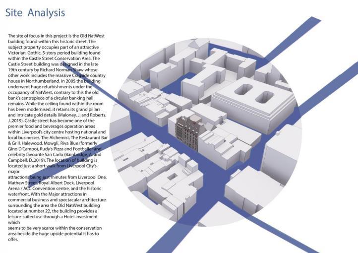
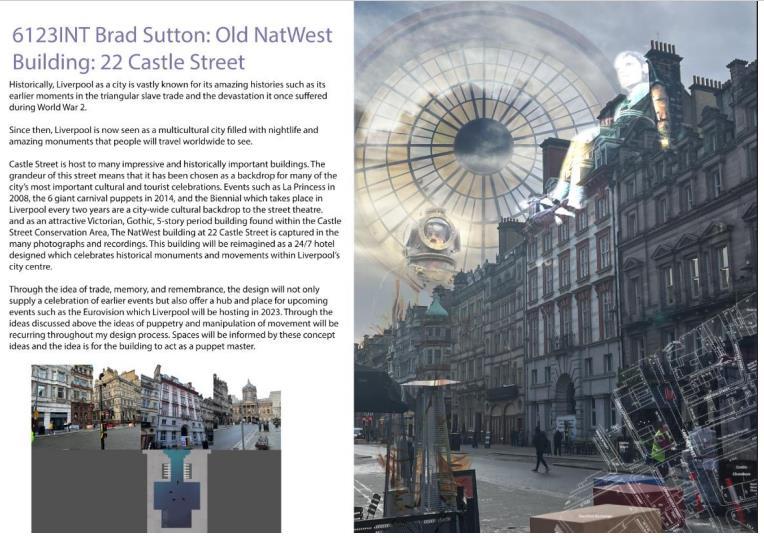
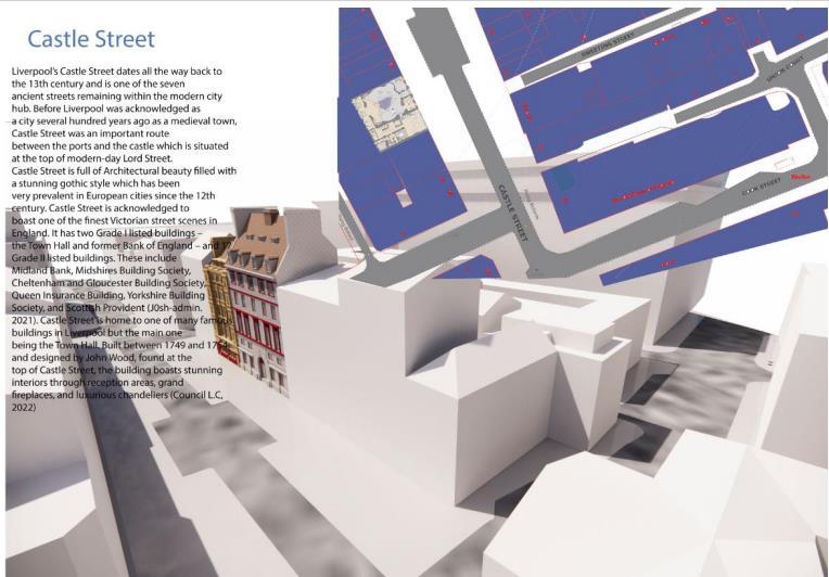
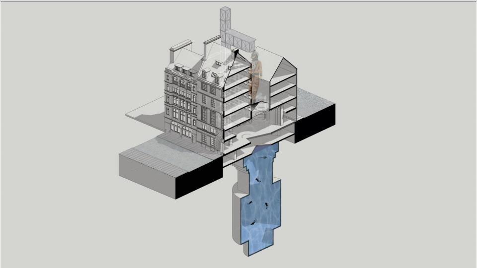
BA Year 3 semester 2 AS1 Detailed design scheme (6123INT)
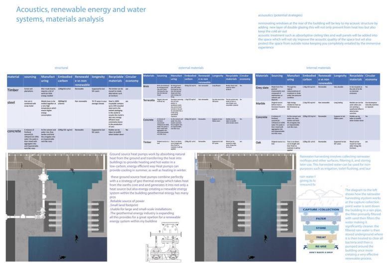
BA Year 3 semester 2: AS2 Environmental and technics (6123INT)
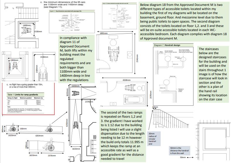
BA Year 3 semester 2: CDP Legislative Compliance and Design Management Report (6131ASA)
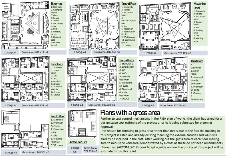
BA Year 3 semester 1: Integrated design 2: Interior re-modelling project (6121ASA)
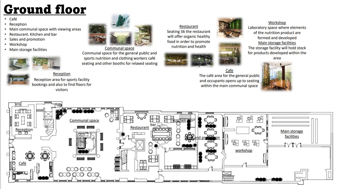
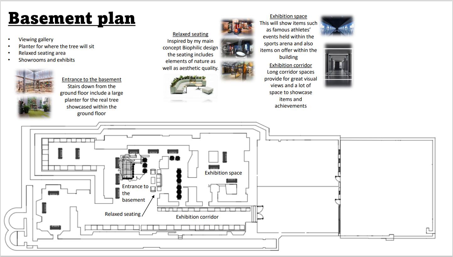
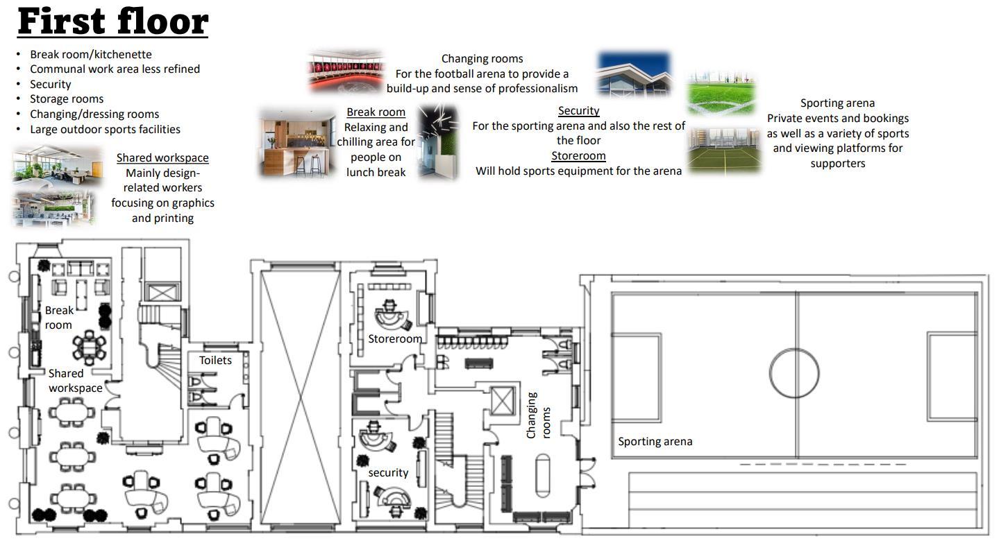
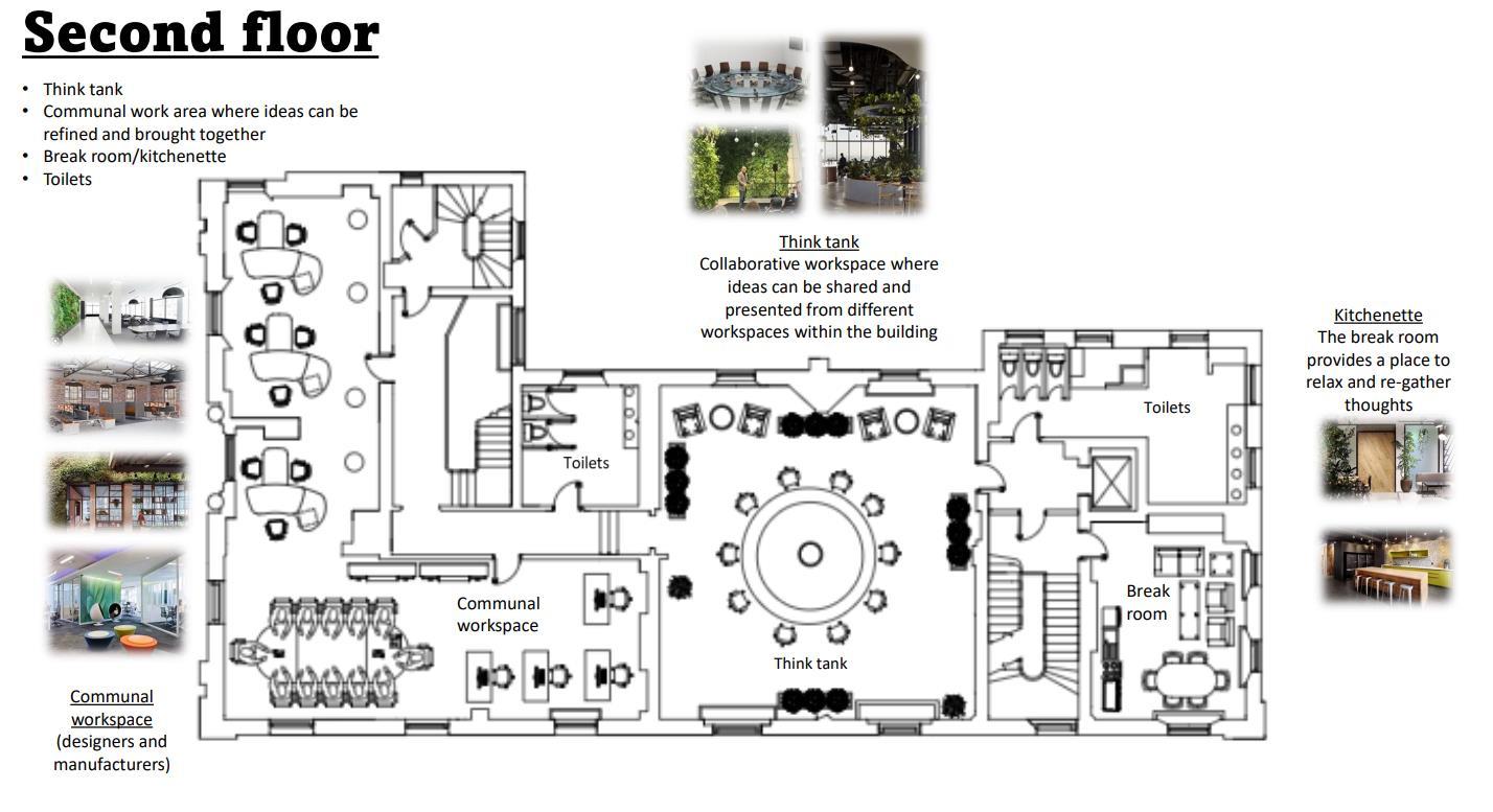
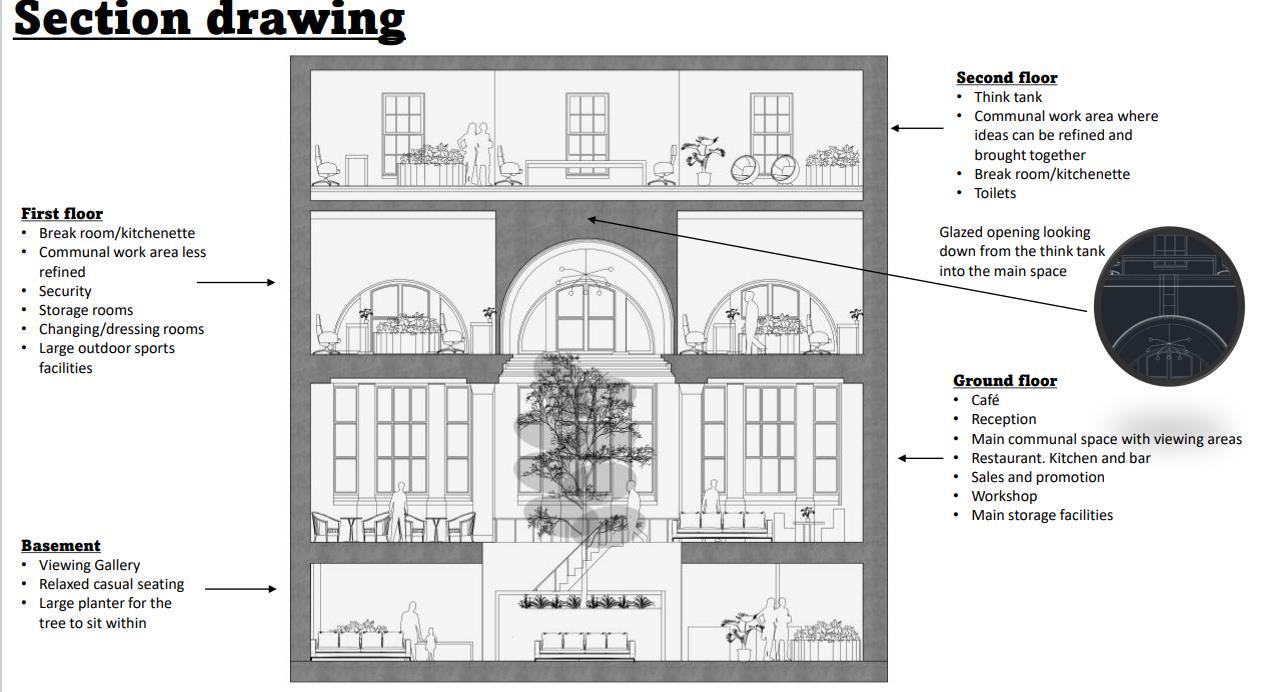
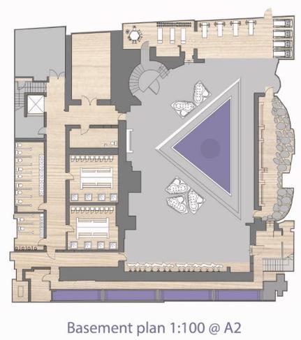
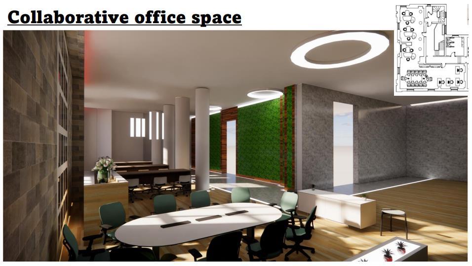
Reception area
BA Year 3 semester 1: Integrated design 2: Supporting studies (6122INT)
BAYear 2 Semester 2: Intergrated Design 2 ExplorativeProject (5124ASA)
5124ASA
this design project focused on the structural strategy in which we wanted to use an influnce for the New Zealand house. As abuilding with so much potential it seemed only fair to try and dmeontrate this potential through the strcture of the building.
for this part of the project the main idea in which i wanted to include was finding the best structural strategy aswell as providing an aesthetic please through the elememats within the structure.
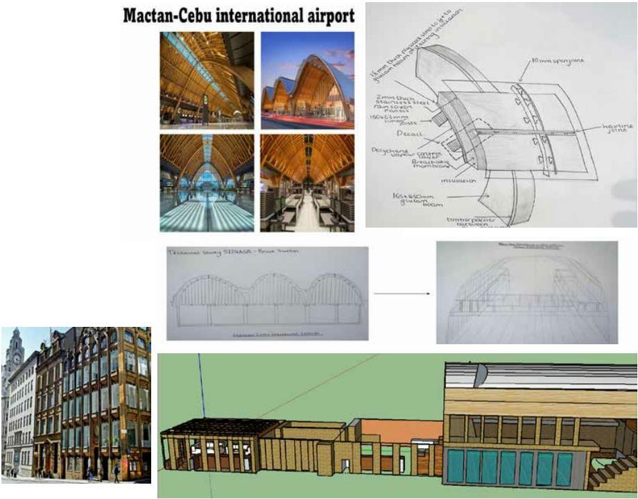
in this project i focused mainly on the roof of the New Zealand House due to the foundations of the wall within the building being so strong. this allowed me to focus on the Macten Cebu international airport, the airport provides great structural idea aswell as aesthetic please to the eye which is what i wanted to focus on for the New Zealand House.
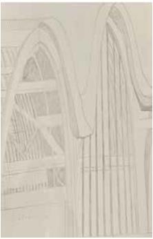
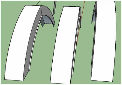
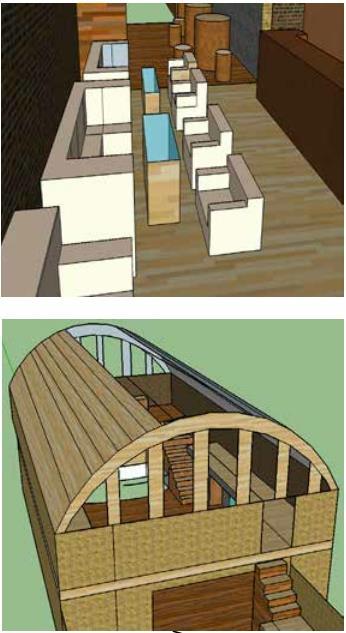
i then started to demonstrate how this could work with a range of different sketches such as the way the panelling above is attached to the Glulam beam and also the way the interior please woukld work in my project. creating another sketchup model i decided to use the structural strategies i wanted to use and present it in this way it showed the arched glulams on the entertainment zone and the large timber beams supporting the rest of the Build.
2 First Name Surname 2020 Portfolio
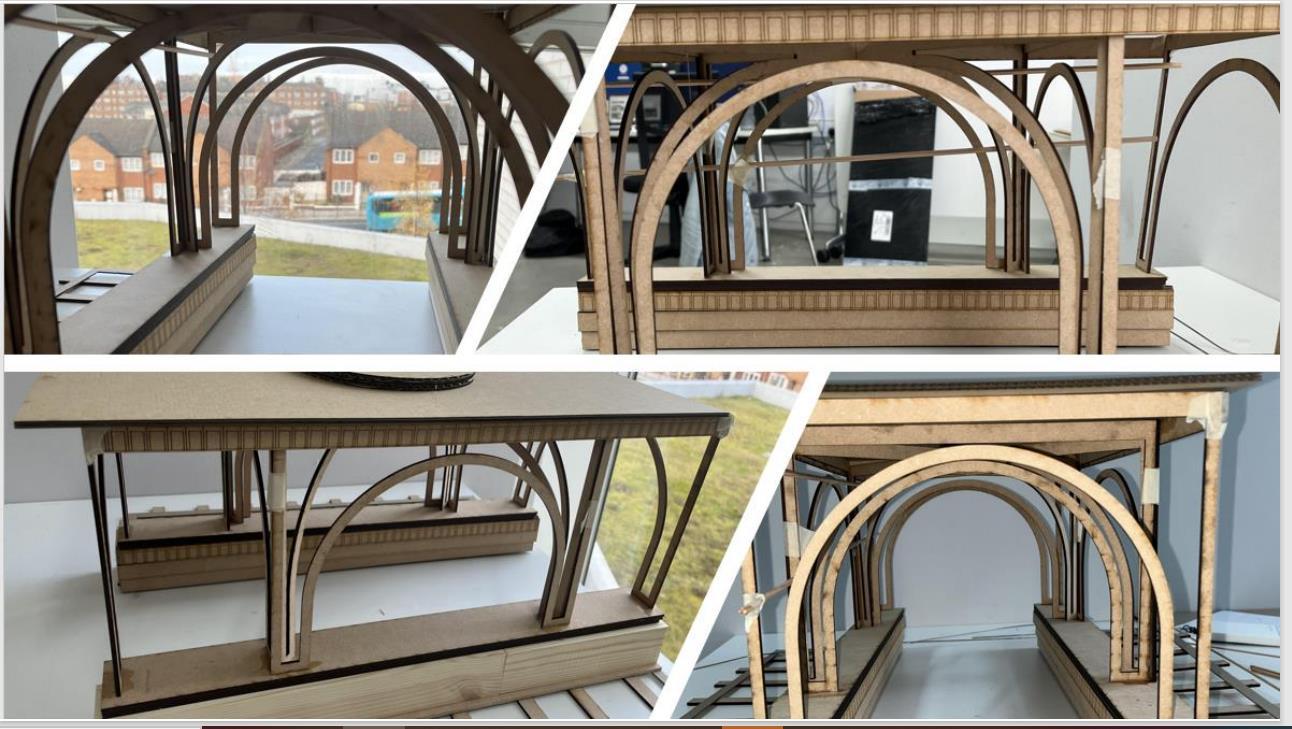
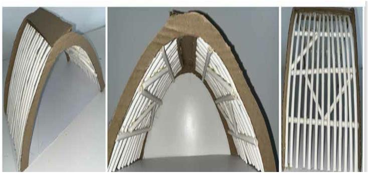
in the designs down below using a rnage of different media it alllowed me to demonstate how things were working quickly. the first drawing is an interior perspective of the Macten Cebu International Airport which allowed me to see the deatiling on the inside of the present building. i then decided to make a model at 1:50 using cardboard and paper straws. the cardboard allowed me to represent the Glulam Beams and the paper straws allowed me to demonstrate the structural system travelling the length of the Airport. this was great as the straws were an easy way to test weight and tension due to there materiality and strenght allowing me to apply pressure where tension would be, if this wasnt to work then it would completely collpase in on itself.
the image in the bottom left was done on Google SketchUP and just allowed me to show the glulam beams which would span across the Length of New Zealand House.
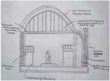
the final image shows a section of how all structural aspects will work.with the timber structures coming down from the arch this allows a more compact structural methods and prevents the cieling from bending or worse. the walls at the side are masonry cavity walls and allows the structure to stay strong and the final aspects shows ther mezzzanine being supported by tow steel beams in order to level it out.
2020 Portfolio First Name Surname 3
BAYear 2 Semester 2: Integrated Design 1 Explorative Project Design (5123ASA)
5123ASA:
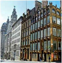
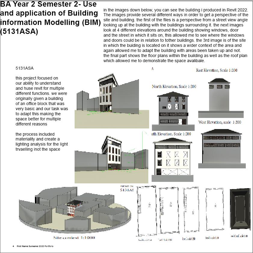
The building focused on was New Zealand House (venue) located on 18 water Street in Liverpool’s commercial district.the builidng in its previous use as the Newz Bar held captivating performances form the likes of Lady Gaga and Prime Minister,Gordon to Labour activists.
in this project the idea was to regenerte the history this building previously had by creating a new venue in order to help bring the building back to life.
The area in which i planned included a Cafe in which would be in use during the day as well as a restaurant and a live music arena in which would attract people during all hours
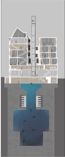
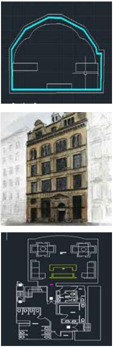
the images below show a range of different techniquies using AutoCad and Google SketchUp. the first image demonstrates a section which cut the builidng in half. this allowed me to show the roof height and interior features as well as allowing me to get a true idea of scale through the figures in the image.
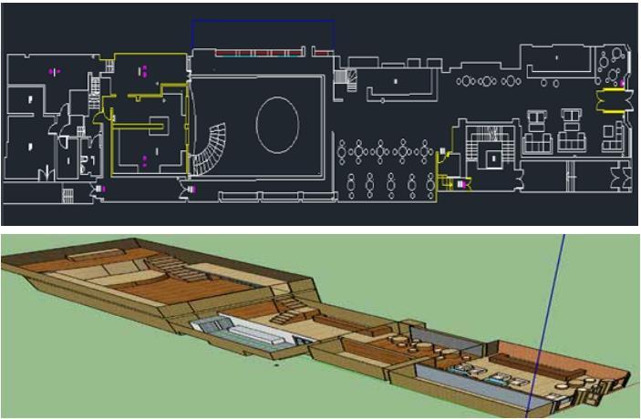
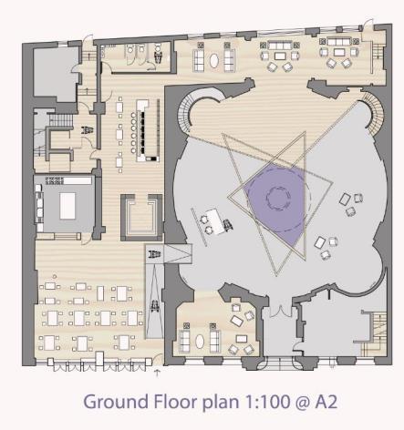
the second image is the ground floor plan of New Zealand house in its new form showing all interior features. using the plans i was able to decide tho location of each are and what i was a ble to do with each space
the final image shows a Google Sketcup model of New Zealand house with an overhead view and shows the interior fittings and objects as 3d models in order to see the space available.
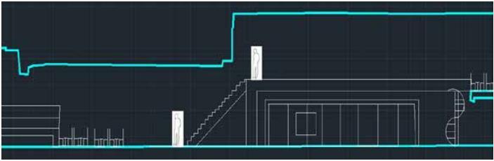
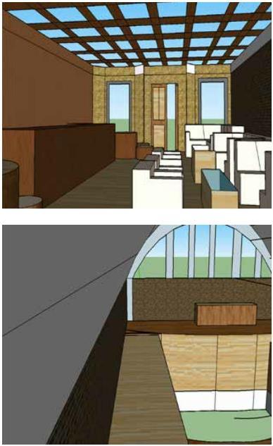
with the work shown below it provides further insight into my explorative design project. with the two AutoCAD drawings, the first is another section showing the roof and the Mezzanine i plan to add into the build. through this drawing it allowed me to see how much i would need to raise the roof by with prescise measurements due to the Mezzanine Regulations. the second rawing shows the upper part of the Mezzanine located with in New Zealand House already. This area is where the Vip guests will be located and plans to show how the area will be. the hand drawn painting provides contect into the sites location. the building is placed inbtween two other buildings which creates problmes for an arena like this due to noise however this has all been assessed. the other 4 images consist of interior perspectives of my planned New Zealand House interior, the plan is to demostarate from an eye level perspective how the spaces would look from different areas of positiong icluding the Cafe and the entertainment Zone. these images allowed me to decide materials and practicality for the location of spaces.
2022 potfolio submission: Brad sutton 1
Design5:AdaptiveReuse-origination (5121INT)
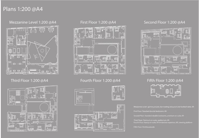
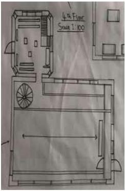
the images below consits of two different types of drawings, the first of which are floor plans, using a 1:50 scale the CAD drawn plans allow you too see what is going on on each floor. the building regulations meant that it had to have a lift and several fir exits due to the size of the building. the drawings include all interior features and were first attempts of proeprlu experimenting with AutoCAD.
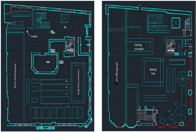
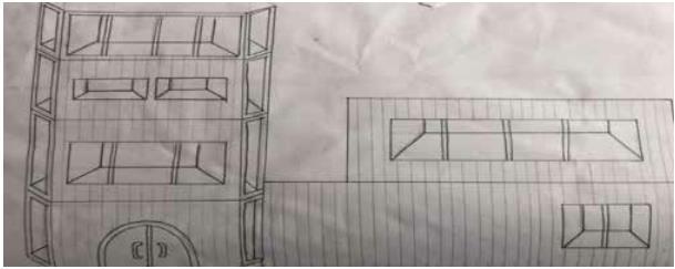
the second drawing is of a section including the ground floor and the first floor. this shows all features within the building when it has been cut in half you can see elemants such as the lift and the rock climbing wall which was included to intise customers inot the building as this project needed to be something special.
5121INT
This project an adaptive ruese project focued on the elements with in The Ashcroft Builidng. with a building located just outside the centre of town the brief was to create a space in which small businesses could come and rent out or take over the space
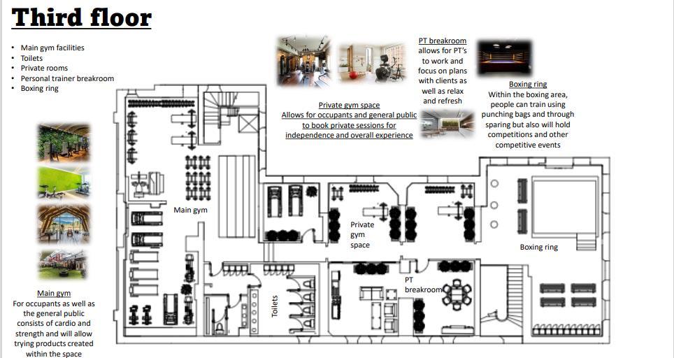
being inot sports i decided to follow up with the sports technology business. as a 4 story building it allowed plenty of spcae for something like this it allowed me to include a shop floor a testing area and a level of gym and office space which was all topped off with an area on the roof in whiuch events and activities could also be held
BAYear2Semester
1:
4 First Name Surname 2020 Portfolio
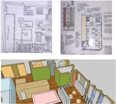
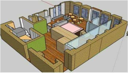
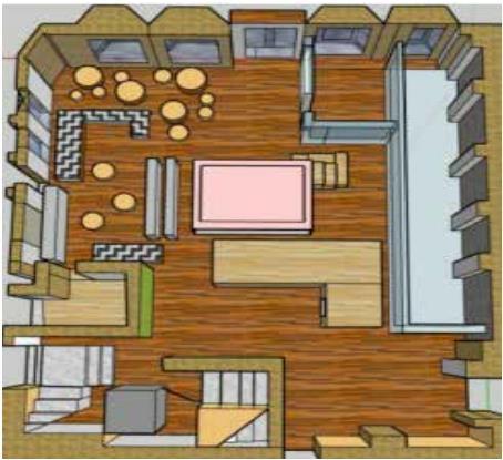
other elemants in this project icluded me making a 3d model on Google SketchUp this model showed the ground floor of the new and improved Ashcroft Builidng which was the shop floor aswell as the main point of the Rock climbing area. interior elemants icluded a boxing ring, the actual shop in which products developed within the building could be purchased, a golfing simulatot and also a health and nutrition abr for people who just fnacied coming in to try the products but also the memebers of the gym who were located further up in the building
2020 Portfolio First Name Surname 5
BAYear 2 Semester 1: Design 6: Adaptive Resuse-resolution (5122INT)
5122INT
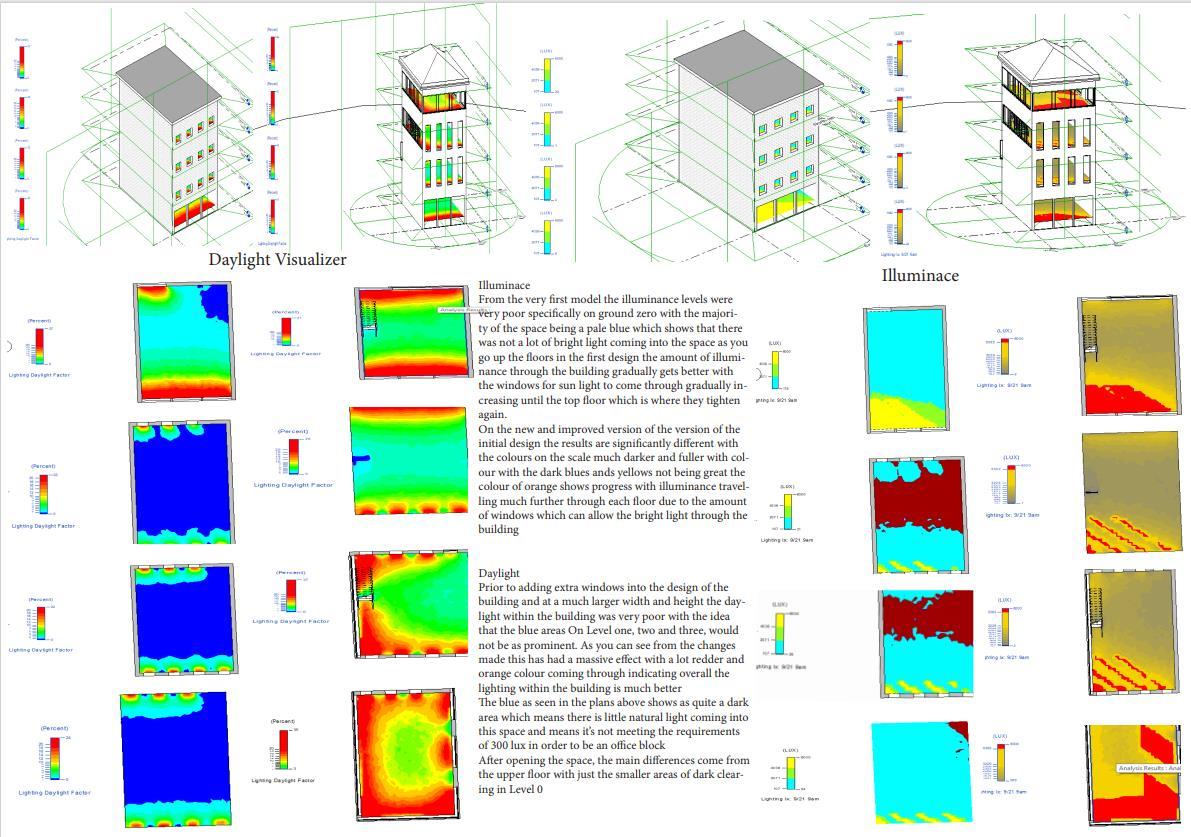
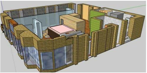
in this project the submission looked more into the technical aspects of the Ashcroft building such as lighting and ventillation
with it being such a large building this came with some challeneges especially in the ventillation aspects as the building is so large.
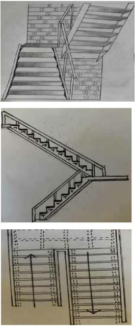
the submission also required us to include specialist details such as a staircase.
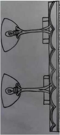
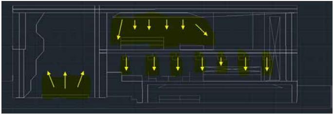
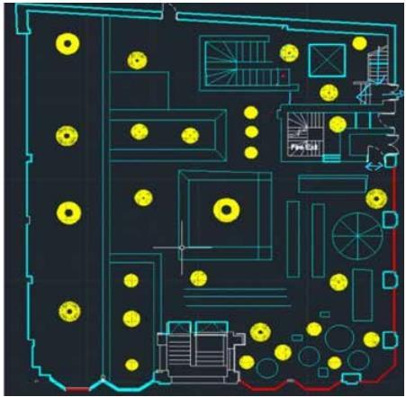
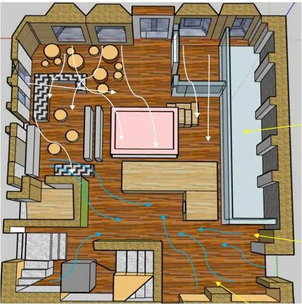
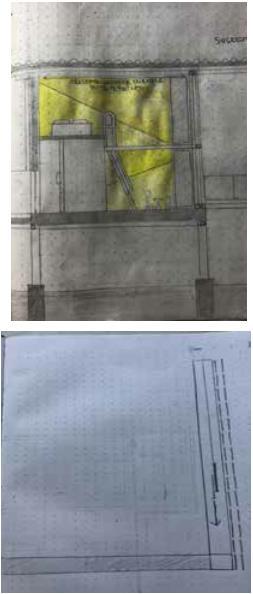
in the images below you can see a AutoCad plan of the ground floor in the Ashcroft building, showing all interior features the main aspect of this part is the yellow circles which will indicate where the lights will hang down from the cieling above, position and also size of the light relative to the area in which it is required. the section below gives and indication of the areas in which will be covered by light and areas that are not splitting the building in half allowed me to show the light and how far down it will travel on multiple floors with the yellow arrows indicating this. the image to the right of these was a hand drawn drawing of the lighting i plan to use with the dome design reflecting inot areas the light wouldnt normally reach this was a perfect solution for my design
6 First Name Surname 2020 Portfolio
this area of the design submission indicates below two different aspects. focusing in on an individual aspect of my design i decided to focus on my staircase. to svae space in a very crowded area i decided to go for a dog leg stair similar to the fire exits in which remained in the building. the drawings include a section which cuts through the stairs and shows a t platform in which will suport each step. a plan of the staircase showing direction up and down and alo dotted lines indicating the structure below, the final aspect was an eleavtion drawing of these in view the other diagram intended to show ventillation. using Google SketchUp to clearly see the space i have added arrows to show where the ventilation passes through in the groundfloor. with the windows in the building at the front of the design the white arrows indicate the natural ventilation such as outsdie air travelling throught the windows and doors as such a large space this would not be enough so indicated though the blue arrows in the unnatural ventillstion in air conditioning and air purifiers. this will be located at the back of the building.
2020 Portfolio First Name Surname 7
BAYear 1 Semester 2:
Architectural Design 2origination stage 2 (4124AR)
in the drawings below you can see several different types. the first drawing represents an elevation from Lark lane as this is where the entrance is. in the drawing you can see 3d aspects and also materiality witht the entire project being made out of wood in order to demonstrate the materials used in the Bow and arrow.
the second drawings is a site plan of the area surrounding the location of this building. the areas of yellow suggests the buildings in and around the site and the building i propose is clearly located on the map.
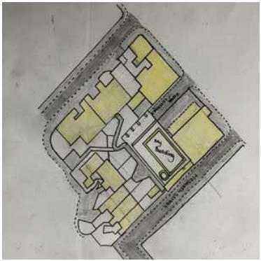
the final drawings is of the ground floor plan which includes the shop floor and also the testing range in which bows and arrows which are made on sight can be tested.
4124AR
In this project the main bjective was focussing on a craft of your choice from a list we were given and designing a space in which your chosen craft could be used and made
this meant choosing site most appropriate to the project we chose and also designing the building in na way where the aesthetic related to the chosen craft in my case the Bow and Arrow.
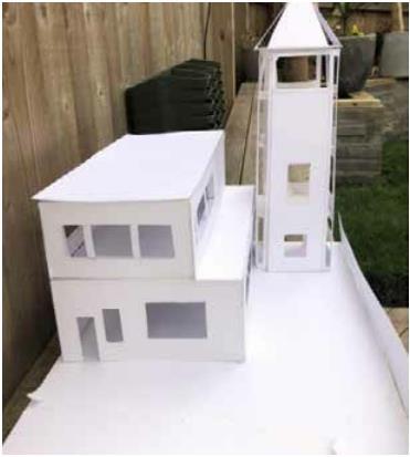
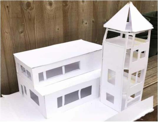
as you can see i designed the building in a way that the tower aspect of the design would represent the arrow stem and the point at the top would be the arrow head.
8 First Name Surname 2020 Portfolio
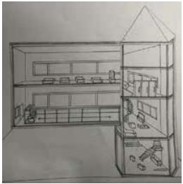
the images beloe experiment with different types of media in order to get an idea for the proposed building, the firstimage is a sectional Axonometric drawing showing interior features in a 3d perspective. this provided great insight into how much space the building would have.
the secodn is an arranged photo board of the model i decided to produce. using plain white card it provided for great photographs with the correct lighting. done at a 1:50 scale the model included flooring aswell as windows, internal and exterior doors which all added to the depth of the model.

2020 Portfolio First Name Surname 9
BAYear 1 Semester 1: Architectural Evaluation(4121AR)
the images below show 2 seperate site plans. the first of these was done at a 1:100 scale which meant the elemants on site were much more detailed and larger due to a relative size. the drawing icludes the car and trailer. the Sol Duc Cabin and the surrounding bushes, trees, and walkways which surround the area.
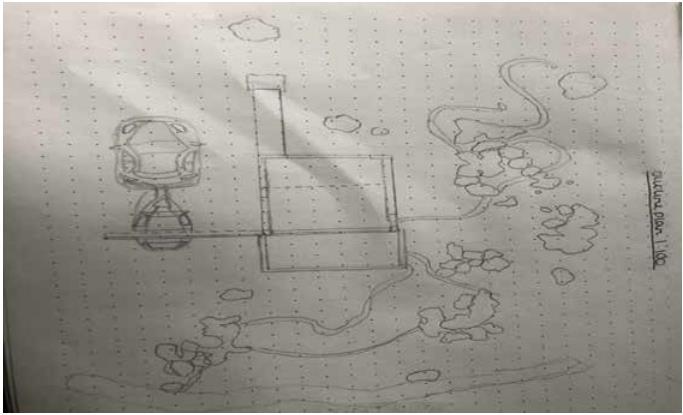
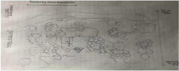
the second image is of the same site but at a 1:2500 scale which meant that the are in which was focused in was larger and less in depth. this provided a greater insight into the area in which i was looking at and gives you a greater idea of the size of the location
4121AR
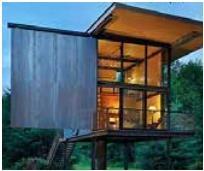
This project was a group based task but this powerpoint indicates my own individual submissions, with a rnage of different precedants we could choose from the one i decided to choose was the Sol Duc Cabin in Oslo.
a small cabi surrounded by vast woodlands, the area provides great scenic views.
in an area prone to flooding the Sol Duc Cabin had been specailly designed in order to prevent from flooding. raised on stilts the easy concept works so well in the environment in where it is located
10 First Name Surname 2020 Portfolio
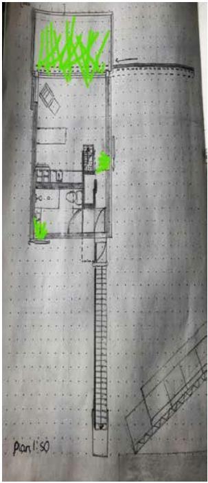
the images below range in meaning, the first one on the left is a section drawing showing interior lighting and how it travels around the space using the yellow, yeloow indicates the area in which is lit and the areas which are not suggests thatit isnt . the one below is a zoomed in drawing of how the shutters work on the Sol Duc cabin, this includes on large panel in which slides into another to protect the front of the building. the next drawing is an interior perspective drawing out of the main window in the Sol Duc Cabin which shows exterior surrounding including bushes, trees and a river to the left hand side this was hand drawn using colouring pencils for the effect. the final drawings is a 1:50 plan of the Sol Duc Cabin locating interior furnishings and other elemenats which areall included as part of the building.
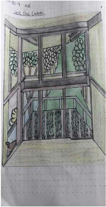
2020 Portfolio First Name Surname 11
Surname:Sutton
Forename:Bradley
Student ID: 910555
Email Adress: Bradsutt2002@gmail.com
12 First Name Surname 2020 Portfolio
