AUGIWORLD


Welcome to the zone with the new Precision 5000 Series mobile workstations, where creativity flows uninterrupted. Featuring immersive InfinityEdge display, up to Intel ® Core™ i9 processor and Dell Optimizer for Precision.
Learn more at Dell.com/Precision
As a special thank you to the AUGIWORLD community, you can find exclusive offers from Dell at Dell.com/AUGI



Hello AUGI members,
Welcome to the Industry Trends edition of AUGIWORLD!
“Technology is just one of the factors affecting the world of work. Economics, demographics, sociological trends, and government policies are four other core influences reshaping labor markets and determining how we will work for years ahead.” - Alain Dehaze
I love this quote! Our world rotates around technology, but other factors affect our world as well. In order to use our software, we must have projects to work on. Where do those projects come from? Government, state and local contracts & bids, housing needs, manufacturing needs and more.
It’s important to stay on top of industry trends to evaluate for progress that could assist us in our project workflows. But we also need to look at what we can do personally to improve ourselves and create our own trends.
“By not caring too much about what people think, I’m able to think for myself and propagate ideas which are very often unpopular. And I succeed.” - Albert Ellis
I encourage all of you to study the world around you, and then use that knowledge and inspiration to improve your personal circle of influence. Reading AUGIWORLD and other industry publications can be a source of inspiration.
Read on and I hope you gain inspiration for yourself!
Sincerely, KaDe
www.augiworld. com
Editors
Editor-in-Chief
Todd Rogers - todd.rogers@augi.com
Copy Editor
Isabella Andresen - isabella.andresen@augi.com

Layout Editor
Tim Varnau - tim.varnau@augi.com
Content Managers
3ds Max - Brian Chapman
AutoCAD Civil 3D - Shawn Herring
Bentley - Berenisce "Bear" Ramos
BIM/CIM - Stephen Walz
BricsCAD - Craig Swearingen
Tech Manager - Mark Kiker
Inside Track - Shaun Bryant
Advertising / Reprint Sales
Kevin Merritt - salesmanager@augi.com
AUGI Executive Team
President KaDe King Vice-President
Frank Mayfield
Treasurer Todd Rogers Secretary Kim Fuhrman
AUGI Board of Directors Eric DeLeon Kimberly Fuhrman KaDe King Chris Lindner
Frank Mayfield
Todd Rogers Scott Wilcox
AUGIWORLD magazine is a benefit of specific AUGI membership plans. Direct magazine subscriptions are not available. Please visit www.augi.com/account/register to join or upgrade your membership to receive AUGIWORLD magazine in print. To manage your AUGI membership and address, please visit www.augi. com/account. For all other magazine inquires please contact augiworld@augi.com
Published by:
AUGIWORLD is published by AUGI, Inc. AUGI makes no warranty for the use of its products and assumes no responsibility for any errors which may appear in this publication nor does it make a commitment to update the information contained herein.
AUGIWORLD is Copyright ©2022 AUGI. No information in this magazine may be reproduced without expressed written permission from AUGI.
All registered trademarks and trademarks included in this magazine are held by their respective companies. Every attempt was made to include all trademarks and registered trademarks where indicated by their companies.
AUGIWORLD (San Francisco, Calif.)
ISSN 2163-7547


Over the past several years, companies across the globe have made tremendous progress in fully supporting BIM/CIM and Digital Design and Delivery (DD&D) methods as a whole. Transitioning from 2D to 3D may have seemed like a long time ago, but often times doesn’t seem to have been fully embraced until recently. Although major components included in our designs are being modeled in 3D, we have been somewhat hindered by limitations in Digital Design supported software solutions that would allow us to be in full BIM/CIM compliance throughout the project lifecycle.
We’ve also been witnessing, over the past few years in particular, the many advancements to AEC Technology-focused solutions that are transforming day-to-day processes that we utilize for Design, Review, Collaboration, Visualization, and Integration purposes. New technology-focused solutions offered can range anywhere from a simple addon tool to extend current platform capabilities, to innovative automated solutions that will speed up current processes and drive consistency in everything we do, to new Industry adopted data exchange formats. This allows for seamless integration across all (well, most) major vendor products/platforms/technology solutions, even well beyond design.
That said, for us to be well prepared for this type of future, we must be equipped and understand how all new technological advancements will impact our core business from a Digital Design and Delivery standpoint moving forward. With that, we must ask ourselves a few questions:
The first big question is, “What is the best approach to incorporate a streamlined solution that is capable of such integrations?”
Taking a huge step back, we must consider all formats in which we can properly exchange our design models and associated data. When repetitive use of specific design and collaboration tools are part of your everyday workflow, it’s way too easy to keep the blinders on and focus only on what is in front of you and only leverage what you know. Client project requirements have historically dictated preferences of vendor provided solutions and software applications to be leveraged throughout the project life cycle. From a Digital Design standpoint, there is typically a heavy focus on streamlining integrations between all applications being leveraged throughout the design and pre-construction collaboration phases of a project. Beyond Digital Design, there has been a separate focus on streamlined integrations with extended design software platforms and technologies supporting Construction Management lifecycles, AR/VR/ MR integrations, Asset Management, Artificial Intelligence, Machine Learning, Digital Twin and Operational lifecycles, etc. Instead of thinking about these as separate, or even siloed, technology solutions, we need to develop strategies from project startup that will enable streamlined integrations throughout the entire project life cycle.
The second big question is, “How can we maintain Digital Integrity of Design Models and associated Metadata, and which formats present optimal results of supporting all phases of a project life cycle?”
We know there are many limitations when it comes to translating and transferring modeled components and associated metadata across many products and platforms. Some formats are easier to translate/transfer and are specifically tailored to work well with any one vendor’s
solutions. But is that a reality? Can all project stakeholders be strapped down to leverage only one vendor’s solutions? Yes, there are some instances where this type of cohesion can occur, but those situations are very rare and certainly should not be considered as an end-all solution.
Going beyond the formatted exchange of file and associated metadata, another major question that needs to be considered is, “Where will this data reside, and how will it be managed thereafter?”
When we think about what a current handoff process looks like, we tend to go back to the paper deliverable mindset where we can wash our hands of the product once delivered. As we start having discussions with all project stakeholders at project startup and develop the workflow matrix detailing integrations required throughout the project life cycle, we also need to take into consideration the Common Data Environment (CDE) in which these model and data exchange files will reside and that will facilitate, and act as a gatekeeper for, continued maintenance and upkeep. CDE determinations can be equally as important as determining the data exchange format, as some CDEs are limited in file and data format integrations, as well as support.
FROM A DIGITAL DESIGN STANDPOINT, THERE IS TYPICALLY A HEAVY FOCUS ON STREAMLINING INTEGRATIONS BETWEEN ALL APPLICATIONS BEING LEVERAGED THROUGHOUT THE DESIGN AND PRE-CONSTRUCTION COLLABORATION PHASES OF A PROJECT.
Another major question is “What new technology solutions will be present in the next 5, 10, 15 years from now that are not being considered at present time?”
This one can be one of the more difficult questions to answer as BIM/CIM and VDC professionals alike have been extremely focused on constructing, reconstructing, and maintaining BIM/CIM designs using specific software and technology solutions they are most comfortable with, or are considered the safest. When looking at what other firms are doing across the industry throughout the world, there is an appearance that some are more advanced and risk-taking, where others are a bit more reserved in their technology adoption strategy and decision making. With the rapid rate in which AEC supporting technology solutions are evolving, there are steps we can take for us to lead the pack for our companies, stand out from our competition on a technology stage, and be more proactive and anticipatory of new technology solutions being introduced in the future. I see this as only improving everyone’s bottom line, increasing growth opportunities, and attracting talent at all levels.
custom data solutions, or if boxed data solutions will suffice. That said, many companies are finding that setting up a Data Strategy from the get-go will allow them to elevate their BIM designs, taking them to the next level, and become what we would consider these days as BIM compliant.
Going beyond our age-old battle of deciphering whether BIM is a noun or a verb, we need to place an equally important emphases on the Information piece of BIM and have some real conversations about it. We’ve been hearing all over AEC that Data is the new Gold or Currency. Truth is, it’s always been there, we just haven’t been able to leverage Data to the extent of which we are able to, using today’s technology solutions on the market. Major vendors are recognizing this need as well and working collaboratively across AEC to adopt OpenBIM and OpenData integrated solutions that speed up technology migrating processes with minimal to no data loss through translations. Data itself has its own complexities associated with it, as it can come in many different shapes, sizes, and formats. BIM and CIM authoring tools are equipped with the ability to automatically associate metadata to modeled geometry in our software, but is it always the right information? Understanding downstream uses of our metadata is critical to setting up a Data Strategy and Execution Plan so we can determine if there is a need to develop
Like most strategies, setting up a Data Strategy begins with the framework. With the rapid growth in technology solutions supporting Data itself, we have just as many directions that we can take our Data being incorporated into our BIM/CIM designs as there are available technology solutions. Developing a Data Strategy is easier said than done, though, as there are many factors and phases that should be considered when it comes to executing a solid Data Strategy on our projects and best serving our clients and project stakeholders.
In the Data Strategy application and execution, one can recognize that there are some very basic phases of executing a Data Strategy. These basic phases can be further broken down into microphases depending on project requirements and scope, but at a very high-level we have:
1. Data Strategy at Project Kick-Off - Establishing any project specific strategy at Kick-Off is critical to a successful implementation. Everything we know in AEC starts with a foundation and framework. This concept is no different as it relates to various project implementation strategies. Working collaboratively with your Clients, Owners, Contractors, and all additional anticipated project stakeholders at project initiation is critical to ensure that we are focusing our strategy on providing the right data and information needed for downstream
MANY COMPANIES ARE FINDING THAT SETTING UP A DATA STRATEGY FROM THE GET-GO WILL ALLOW THEM TO ELEVATE THEIR BIM DESIGNS, TAKING THEM TO THE NEXT LEVEL
use. Where we tend to fall short sometimes, is on the execution side and follow up throughout the entire design lifecycle, thus making the next phase equally as important.
2. Data Strategy Throughout Design – Identifying which data and information will be used for downstream use is a big step in the right direction, but execution and seeing that your strategy continues to live and breathe in the event that scope and requirements change is equally as critical. We all know that projects very rarely go from start to finish without any deviations, so making sure that we have additional back up plans to accommodate, and how quickly we can adjust, is definitely a huge consideration as well. Throughout the design process, we should also consider having several checks and balances in place to ensure we are staying on track. Checks and Balances in this phase alone has the potential to include anything from simply identifying a BIM/CIM Manager to defining Model and Data Validation procedures that automate conflict resolution processes.
3. Data Strategy Throughout Construction – Data and Information being leveraged throughout the Design phase has very specific purposes and can be leveraged in many different ways. Developing a Data Strategy for Construction really isn’t much different from a high-level concept, but, when you dive into the details, the overall intent and purpose can vary on many levels. Data embedded in these BIM/CIM designs through construction will often times require a completely different set of information that can increase efficiencies, be leveraged in industry leading construction technologies, and streamline the entire construction process from design handoff to operations.
4. Data Strategy Throughout Asset Management and Operations – similar to our Data Strategy
Throughout Construction, Data and Information being leveraged for Asset Management and Operational purposes comes with a completely different set of requirements, complexities and use cases. Data and Information tracked at this level can often times be a bit more granular, and, in some cases, be connected to sensor data to track asset properties such as strength, durability, functionality, maintenance, etc. In some cases, this information is leveraged
to predict operational properties and can potentially be incorporated into new designs of the same space, essentially bringing this data and information full circle.
As we unpack all the intricacies, integrations, and downstream uses related to Data in Design, Construction, Asset Management and Operations, we’ll be able to make more informed decisions at project startup that will provide the biggest impact, and best serve our clients. That said, AUGIWorld’s new BIM/CIM Content will provide insight as to how others across AEC are implementing BIM/CIM 1.0Modeling in a BIM/CIM Environment and BIM/CIM 2.0 - Data Modeling in a BIM/CIM Environment, so that we can continue to learn from each other how best to implement and increase adoption of BIM/ CIM processes and position ourselves to embrace an OpenBIM and OpenData centric future.
Stephen Walz is, not only the BIM/CIM Content Manager for AUGIWorld Magazine, but also the Digital Design Lead within HDR’s Applied Technology Office, a global leader in Engineering, Architecture, Environmental and Construction services. Stephen has been in the AEC Industry since 2003, and with HDR since 2004 supporting multiple offices and regions and now support all Business Groups and Market Sectors across HDR at a corporate level. In Stephen’s current role, his primary focus is to work with HDR’s Business, Technical and IT Leadership, as well as our technology vendors, to identify, evaluate and implement new platforms/tools/ technologies supporting BIM | CIM processes and workflows, drive consistency with how HDR is leveraging various tools and platforms, and identifying ways to build skillsets and overall awareness across HDR to better serve their clients. Stephen can be reached for comments or questions at Stephen.Walz@hdrinc.com or subscribe to his YouTube Channel for BIM | CIM, Data Integration, and Visualization workflow video demonstrations.


There is a mountain of information online covering modeling, texturing, rendering, and lighting related to work with 3ds Max. Still, there are many steps between those and what is published and produced for media. They aren’t as flashy or alluring as the perfectly lit scene and rendered still frame, but some of these processes play an exceedingly important role while receiving a tiny spotlight. So for this month, we’ll focus on a few.
There’s a significant difference between camera work I’ve seen produced for AEC visualization in the last decade or two versus content produced for other work in 3D. I want to fracture that if I can. In the realm of AEC, camera work related to renderings follows what I would describe as a more historical or traditional approach. It focuses on composition with slow linear-speed movement. Movements like dolly toward objects, truck from left to right, a pan across the view, or a vertical boom.
Figure 1
Figure 2
These simple actions provide repeatable results but are incredibly dull and do nothing to separate the content from all the others repeating the same movements. If we want our content to stand out, we need to push the boundary and strive for more.
That can include any number of elements, but the most potent camera movements involve manipulating the lens, focus, and speed of the camera’s movement while integrating dynamic transitions between scenes. See Figure 1, for example.
In that scenario, a camera would start near the object with a narrow lens, burst back quickly for a short distance, then slowly travel backward and adjust the lens for a wider area, exposing the viewer to more of the scene in focus. This shot is compelling and often used in sports and entertainment. In Figure 2, The camera would begin with a wide lens further back and dolly or zoom in quickly to match the screen’s view, which would transition to a new scene.
That is essentially a match cut, giving the viewer the impression they moved dynamically from one scene to another through the portal of that screen. Those types of shots are rarely used in the AEC but adding more dynamic camera work will be sure to make it stand out.


Cryptomattes can be rendered through 3ds Max Arnold and render engines like Vray. Generally speaking, they are rendered images where objects are separated into colored shapes. This allows us to import that cryptomatte sequence into After FX using the cryptomatte effect to mask out and layer additional content (holograms, interactive content, video overlay, etc) or simplify for compositing in Photoshop. See Figure 3, for example.
Here are the steps to render out cryptomattes like the one displayed in Figure 3. First, add the cryptomatte node to the material slate editor. Second, drag that node onto the AOV Shaders in
Figure 3
the AOV tab located on the Render Setup window. Third, open the Arbitrary Output Variables window and add drag the cryptomatte in. You’ll see you have the option for the cryptomatte to divide the image using a specific asset, object, or material. Fourth and final step is to render and select the cryptomatte display. The mattes can be rendered like any other sequence and used for compositing.

For this article’s sake, Keying must work with a green screen. This is another crucial process with media production I see architectural visualization professionals can implement more. With today’s technology, there’s no longer a need to hire expensive studios to integrate content or actors into visualization. That allows average users the power to boost their media considerably. Moreso when the power of Keying is implemented on multiple levels. See Figure 4, for example. The lower image with the keyed-in person adds a lot of life and opportunity for connection. In addition to compositing and video production, AEC professionals can use this same technology to produce interactive content for everything from websites to electronic popup displays and kiosks.

Brian Chapman is a 3D Artist in Las Vegas with an extensive history of building content for AEC, game, film, and software development.





Now that the interviews are over, you need to decide if you want to extend an offer. Your time of vetting candidates is nearing an end and you need to make the call. Now is the time to do some last-minute thinking.

I heard a quote, and I cannot remember where I heard it, but it goes something like this, “If you are not sure that the person is the right one to hire, then they aren’t. If you are sure that they are the right one, they ‘might’ be.” What this says to me is that hiring is tough. Finding the right person is not easy. But there are some concepts that help you filter through the choice of adding someone to your team.
In the book Good to Great by Jim Collins, he has the concept of, “First who… then what.” In other words, you should consider who you have on the team before you define what they are going to do. Collins is the “right people on the bus, in the right seats”
guy. You may have heard that term before. When hiring, it is critical. He says that, “in determining the right people, the good-to-great companies place greater weight on character attributes than on specific educational backgrounds, practical skills, specialized knowledge, or work experience.” With tech hires, I like to think of the tech skills as the entry fee. Without those skills, the candidate does not get to second base. Once you determine that the candidate has the raw talent though, you move quickly to character.
So, how do you vet character and good fit? This is tough in the limited time you have with a candidate. You need to translate things you know, into possible character traits. Understand that most people are not very good at this and get it wrong, but it is worth considering. Most of the time, you need to trust your gut feeling about someone on the character issues and being a good fit. But there are indicators.
Was it Socrates that said that? Anyway, you need to know yourself, your team and you company culture. That is where you are expecting a new hire to fit in. If your firm or team is high energy that tends toward action first and planning later, then a contemplative staffer might have troubles. If you are a planner and a thinker, then someone who jumps into action before they think about root cause might get on your nerves. If you are talking to a square peg, you better know if you are a round hole.
Here are some actions you may see in an interview and what they may indicate (or not).
• Overly relaxed – might mean they are disengaged, more kick back than others, or worse case, lazy.
• Too high strung – might mean that they are tightly wound, jump to conclusions, and get easily angered or insulted
• Overly nervous – (and most people are a little nervous in interviews) – might mean they do not have the technical chops to handle the job. Might also mean that they do not react well under pressure.
• Short answers – may mean they are not good at explaining things, giving details, or asking for clarifications
• Wordy answers – might mean they are blowing smoke, too talkative or covering up some shortcoming.
• Wandering answer and can’t stay focused on question – might tell you that they have a disorganized mind or (here it comes) can’t stay focused.
• Over emphasis on some topic – might mean they are not the opposite. If they talk about structure and organization on every question, they may lack resilience, quick thinking, or creativity.
Bottom line – do you want to work with this person every day if you notice some annoying character trait that is not “wrong” just different than you would like? And all of your conclusions might be wrong. Ask others what they noticed, to verify your gut feeling.
I like to think of candidates and their viability similar to stock prices: Are they trending up or trending down? The more you see a candidate and interact, the more you have time to see if you and your team think that they are increasing in value as a candidate. Are they looking better than when you started talking with them, or are they looking less likely to be a good team member? If they are trending up, that is a good thing. The more you see of a good candidate, the higher their “stock value” goes. This is also a good question to ask other interviewers. It is hard for others to give a definitive yes or no on hiring or not, so I try to give them a scale of one to ten, or the stock value question. It shows me what they are thinking, without tying them down if they are skittish about making a call.
Upfront, I don’t really do this… but others have. They Google the person’s name and see what they get. Others have told me that they check online in Twitter, Facebook, Instagram, LinkedIn and maybe even TikTok. LinkedIn is good for checking past employment. The info is out there for anyone to see… so why not go check it out (but I don’t – I guess I am old-school). General rule would be to keep your online presence appropriate, employers are looking. I am, on the other hand, in favor of official background checks run by HR, as mentioned in the last article.
Who makes the final call? The hiring manager does. I assume that will be you, if you are the one hiring the person. You will consider all the info you glean from
MOST OF THE TIME, YOU NEED TO TRUST YOUR GUT FEELING ABOUT SOMEONE ON THE CHARACTER ISSUES AND BEING A GOOD FIT.
THE
FINAL CALL WILL BE
Give them a start date. Or ask them how soon they could start. Some folks need two weeks or more. Remind them of any company events that are coming up. Let them know about any conferences that they might attend within 6 months or training that you would like to set up for them soon. Talk long range. Act like they are part of the team already and that you look forward to getting to know them and getting started on projects.
the resume and interviews, plus the comments from your team or others that have participated in the vetting. But the final call will be yours. Move along as fast as you can, currently it is a tight job market and folks are getting gobbled up fast. I have seen many good candidates bow out of the running because they accepted an offer somewhere else.
When you make the decision and extend the offer, put it in writing. If you are physically with them, give them the offer so they can see it. If you are not, email it to them while you have them on the phone or video. I suggest that you make the contact directly with the candidate, not HR. You are still selling your company, your team, and the position. Be enthusiastic (unless you aren’t… but then why are you offering them a job?). You need to keep emphasizing the positives of the person and why they should accept. Tell them why they are a good candidate. Talk them through the offer, if needed, and explain it all. Ask if they have questions. Clarify anything where they might see as fuzzy. Explain the hidden benefits that might not jump out at them. They may be focused on the salary, but there are other reasons why your firm is a great place to work.
Make the salary as high as you can. Do your homework and make sure it is a competitive offer. Some say start off low. I say start off high. Give the person the most you can. If they fit the need and can make a positive impact on the firm, then give them the best offer you can. You do not want to miss out because you saved a few bucks. They should come in with a feeling of satisfaction and a desire to prove that they are worth what you are paying them. Make it the best offer you can.
Give them a short timeline to reply. They might accept it instantly, but if they don’t, give them a day or two at most to get back to you. In this job market, it is not good to let things linger. This should be a no brainer decision for them anyway. They should already know what the answer is. If they have continued down this road with you, they should be ready to respond quickly. If they ask for more time, I would probably not give it to them. They may be stalling for time, hoping another offer comes in.
Next time we will cover onboarding. Assuming that they accepted the offer (since it was too good to pass up), get everything prepped and ready for them to start work, then anchor them in and launch them toward success.
Mark Kiker has more than 30 years of hands-on experience with technology. He is fully versed in every area of management from deployment planning, installation, and configuration to training and strategic planning. As an internationally known speaker and writer, he is a returning speaker at Autodesk University since 1996. Mark is currently serving as Chief Technology Officer for SIATech, a non-profit public charter high school focused on dropout recovery. He maintains two web sites, www. caddmanager.com and www. bimmanager.com.

 Bentley by: Jossua Mejia
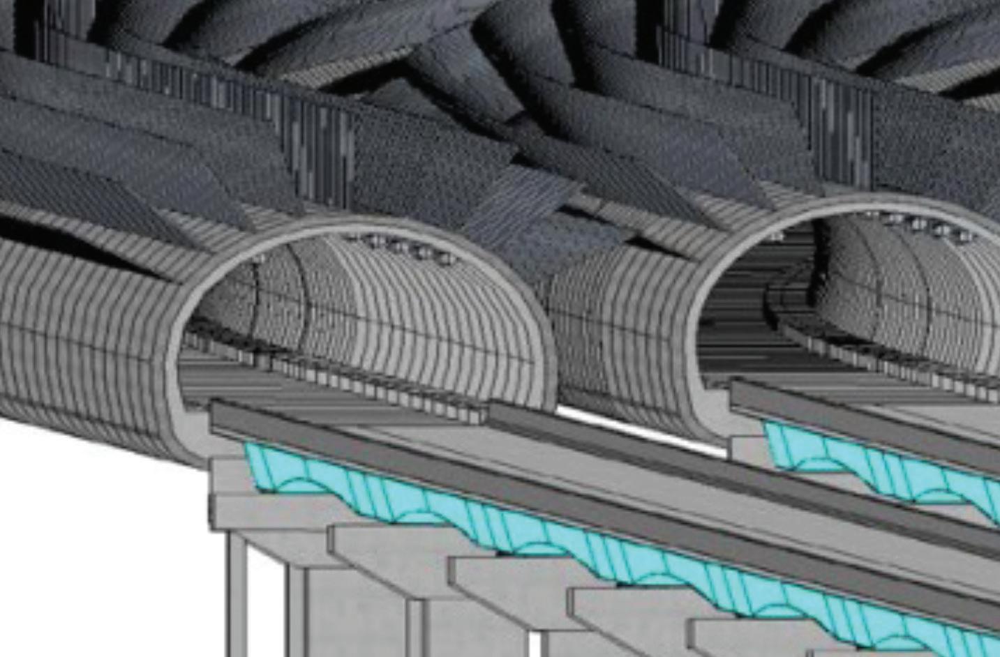
Bentley has recently launched OpenTunnel Designer, the first and only purposebuilt software for tunnel modeling and design. It introduces a centralized data environment so all project stakeholders can reliably access and share the most current files.
One of the advantages of using OpenTunnel is the easy interoperability of information with software like Leapfrog, PLAXIS®, OpenRoads™, OpenRail™, OpenBridge®, and ProStructures to identify errors and create alternatives for optimum design, safety, and performance.
OpenTunnel Designer can help produce intelligent parametric models. Rich in project information and properties for various tunnel components. The software can also model the excavation shapes, excavation tracks, tunnel lining, and tunnel reinforcement. Perform clash detection with other structures, objects, and utilities to eliminate problems before they occur.
This is a true tunnel model, analyzed and designed with a 3D solution.

Visit this link for quick tour of OpenTunnel Designer. www.linkedin.com/posts/virtuositysoftware_opentunnel-engineering-activity6980515431790845952-CMCD?utm_ source=share&utm_medium=member_desktop


You are all invited to take a deeper look to OpenTunnel: www.bentley.com/software/ opentunnel/?utm_campaign=&utm_ content=1663247081&utm_medium=social&utm_ source=twitter
Jossua Mejia graduated with a bachelor’s in civil engineering from the Universidad de Colima in Mexico in 2012 and obtained his master’s degree in Civil Engineering – in Tunnel and Underground Space in 2021. After six years of experience in bridge and roadway projects, he joined the Virtuosity team, the Bentley Systems eStore as a Product Sales Engineer for Civil Design solutions. His goal is to assist companies and professionals in accelerating their workflow by adopting the latest technology in infrastructure with innovative software to solve critical business issues and deliver quality.


The topic of CTB vs STB has been a heated discussion since STB was added to AutoCAD in the year 2000. I am sure some of you CTB users reading this are already steaming and can’t wait to tell me that I’m wrong and that STB has no place in the drafting arena. I do implore you to have an open mind and continue reading, because in my experience most CTB users have been misled about what STB can actually do and how it is supposed to work.
First, we need to take a look at CTB and give credit where it is due. CTB is a very easy drafting method, you pick a color from one to 255 and the drafting
is done. It’s also simple to tell someone to turn an object to “red” or “color 252”, and the change appears on the screen. The ease and simplicity of this method is where CTB has its advantage, and why many users prefer to use it. However, despite the popularity and long tenure of the CTB method, I have found a few issues with this way of drafting (see Figure 1).
The first issue is that if your company is anything like mine, you might work for multiple different clients, jurisdictions, and agencies - all of whom have a different CTB they want to use and they will not always be similar to one another (see Figure 2).
Figure 1 Figure 2
The second issue is related not only to drafting, but also design. Since today most designing is done right in the CAD file, being able to visually see issues and conflicts as we are working is very important. This is an area where CTB falls short. I am sure most of us at some point have drafted a CTB file where every layer not important to the sheet was relegated to one color - most likely one of the 250’s. Obviously, this causes items to be difficult to distinguish from one another. When modeled objects are all the same color, mistakes happen and issues within a project can be hard to catch until it is too late.


Figure 3
Now, I bet you’re wondering how STB is going to help fix all of this. First, let me start by removing some of the misconceptions and misinformation regarding what STB is and how it is supposed to be used. Most users’ experience with STB is solely running the CONVERTCTB command on their CTB file and getting an ugly STB with a plethora of different plot styles (see Figure 3).

Here, each plot style acts a color would in CTB. This is how most people have been introduced to STB and as first impressions go, this is not a good one. Hopefully you will give it a second chance, though, because the STB shown below is an example of how it is supposed to work (see Figure 4).
This method of STB uses the plot style to control just the screening of the layer or object. But, how do you control the thickness of the line work? The answer is in your layer manager, there is a column that controls the lineweight for each layer. This is how your STB will know how thick to plot your layer (see Figure 5).

Now we can start getting into the real benefits of STB. One thing I haven’t mentioned yet when using STB is the layer color. When using STB, the color of an object doesn’t matter with regard to how it plots. How does this help us? Well, going back to

what I said about multiple objects being the same color in CTB causing problems in design, STB fixes this issue. Now that color is independent from the way an object plots, we can standardize what colors represent in our drawings. For example, green can represent sanitary sewer/wastewater-related items, blue can represent water-related items, etc. This opens up not only the ability to standardize object colors, but also allows us the ability to visually see these items on the screen and have the ability to check for design issues without all the guesswork. This would be true for any drawing that you reference your file into, and the layer color would not change throughout the entire project. This helps keeps consistency in our drawings and makes visibility within CAD files easier.
Now, I realize this adds two additional properties to control plotting, but these items won’t need to be modified in every drawing. With STB - and to a lesser extent, CTB – you will set up your base files the way you want them to appear graphically in the vast majority of your sheets. Take, for example, a water line that will need to be emphasized only on the “water” sheets. You would pick the proper screening and lineweight in your base file, then you would only have to adjust the plot style in your sheet file to set your water items to plot black. Another benefit to using STB is the ability to plot in color. Anyone who has needed to create an exhibit in color knows how beneficial it can be in the engineering world. I am constantly sending out colorful exhibits to clarify issues or to highlight problem areas. To produce a color plot in CTB, you have to use a “true color”. However, because “true colors” can’t be loaded into a CTB, you have to manually set the lineweight of an object for it to have a thickness when plotting. With STB, this functionality is already built in. If you notice in the STB, at the bottom it had two options for color: “Color 100%” and “Color 50% Screen”. By simply

switching the plot style of a layer, we can now plot in color and with a selected lineweight. The difference between these is “Color 50% Screen” applies a screening to the color and removes some of the saturation and gives a more pastel look (see Figure 6).

The question that gets asked the most when thinking about switching to STB is how long it takes to get accustomed to using STB. Unfortunately, I can’t provide an answer to this as everyone learns at a different pace. However, I can provide some insights into the areas with which people seem to have the most difficulty. The obvious one is switching from knowing a color to knowing a lineweight. When I first switched to STB I wrote down the colors I used the most and what lineweight and screening it had. As with anything the more you do it the better and faster you will get.
One last item I wanted to touch on goes back to my earlier statement about working with CTB’s and the lack of standardization in the industry. This can be problematic for CAD managers trying to set up standards that follow multiple different CTB’s and ensuring the correct properties are being used. This
issue can be significantly reduced using STB and lineweights as I have shown here. If the standard is for everyone to use lineweights, there are fewer graphical translation issues when transferring CAD files. In a similar vein, if you name your plot styles very clearly (like shown in the example STB), anyone should be able to figure out how something is going to be plotted. This makes sharing files much easier and reduces the need for every company or jurisdiction to have their own standard.
As you can see, there are a lot of benefits to using STB. Personally, as a user who has worked with both methods for a long time I have always found STB to be a more drafter-friendly approach and I hope now you do as well.
Brandon Cole is a Sr. Designer for Huitt-Zollars, Inc. He has over 16 years of experience in civil design and CAD management. His background has mainly been in urban development, but has also been a part of many federal and transportation projects as well.

In late October, Bricsys, a part of Hexagon AB, announced and released their latest version of BricsCAD® V23 during their annual Bricsys Digital Summit. The digital summit provided an update on the latest and greatest innovations, all backed by the “Build Better” slogan. Over the last decade, software capabilities have increased yet the development of drafting software, especially 2D, has remained stagnant. This is where Bricsys has committed to “Build Better”, delivering sustainable and seamless solutions to improve productivity and support industrialized construction. Let’s take a look at some of the new features of BricsCAD V23 and uncover how Bricsys BricsCAD® has climbed to the top by building better software.
How does “Build Better” translate into the Bricsys family of products? Bricsys focuses on four principles: challenge the status quo through CAD-based innovation, intuitive to learn, use and adopt, harness new technology to super-charge productivity, and interoperable and open. BricsCAD
leads in delivering intelligent, AI-powered CAD tools for the design process. Whether it is the AEC or Manufacturing sectors, BricsCAD® Pro and Lite’s AI-powered enhancements promote innovative 2D tooling and advanced 3D modeling. Bricsys prioritizes the total user experience when buying, training, implementing, and upgrading. Bricsys products are easy to adopt into your existing workflows and the design solutions free your creativity. Additionally, Bricsys products offer the best interoperability and openness, where users can collaborate and coordinate seamlessly, extending core capabilities with third-party development. Clearly, Bricsys is on a mission to take design efficiency and productivity to the next level.
For years, BricsCAD has provided unrivaled tools promoting efficiency and productivity to its users through cutting-edge technology and artificial intelligence. Existing examples of these tools include Blockify, Propagate, CopyGuided, and

Figure 1
Command Assist tools just to name a few. Let’s take a deeper dive into those production improvements inside BricsCAD V23.

• Optimize 2D - Corrects inaccuracies in the drawing for 2D entities or 3D entities. Instead of visually scanning the entire drawing for incorrect linework, allow “Optimize” to make those corrections efficiently. (See Figure 1)
• CopyGuided 3D - Copies 3D Solids, Block references, or a set of faces from one location
Figure 2
to another, using reference faces of the user’s choice. Intuitively, trimming and extending linework automatically reduces the need to fix existing moved/adjusted linework.
• Connect - Connect coplanar 2D curves. Connect does not change the underlying geometric definition of the input curve elements, only changes the start and/or endpoints to make them connected. When possible, the now connected input curves are joined into a polyline.
• DwgHealth - Combines the functionality of multiple stand-alone BricsCAD commands that help to improve overall drawing size and accuracy, e.g.: Purge, Audit, Simplify, Overkill, Blockify, Optimize. Three modes of selection assist with the specific level of detail and involvement in drawing optimization. (See Figure 2)

Figure 3 Figure 4
• ParametricBlockAssist (Beta) - The Parametric Block Assist dialog box allows you to choose selected ACAD Dynamic Blocks in the current drawing to be converted to BCAD Parametric Blocks. (See Figure 3)

• GISImport/Export – Import/Export vector geographic features with their original location, shape, and attributes from ESRI SHP files into the current drawing and specify properties for each imported GIS Feature.
• HSPC (Hexagon Smart Point Cloud) is the new point cloud format. HSPC is a powerful, robust format for handling point cloud data.
• The HSPC format, a format created by the Hexagon research group, allows for the storage of metadata, per point, during or after preprocessing.
• Point Cloud Manager Panel - The Point Cloud Manager panel creates and manages regions in a point cloud and controls the display of point clouds based on scans, classification, and regions, all in one centralized location. (See Figure 4)

When it comes to releasing a new version of software, feature enhancements are as important
as the new features in the software. Evaluating, updating, and revamping existing functions is a crucial aspect of increasing productivity for the end user. Here are a few notable feature enhancements for BricsCAD V23:

• Express Tools for BricsCAD are fully integrated into BricsCAD V23

• Drawing Recovery Manager panel displays a list of drawing files that can be recovered after a program or system failure. (See Figure 5)
• Increased compatibility with ACAD Mechanical toolsets
• Power Dimensioning
• Define and annotate welded joints in 2D/3D
• Integrated BOM (Bill of Materials) to locate and identify ACAD parts (See Figure 6)
• Command unification while adding individual command panels for multiple BIM functions, including BOM for BIM.
• Introduced options for labeling Civil entities for TIN Surface, TIN Volume Surface, and Grading.
• Developed a user interface for importing Civil Points from the point file allowing users to specify any point file format for importing Civil Points.
• The Civil Explorer panel is used to manage and access Civil entities. Through this panel, you can access the settings and properties of Civil entities, and allows you to edit existing and add new entities and their components. (See Figure 7)

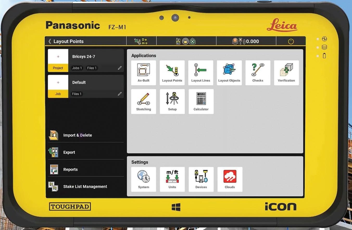
• Integration with Leica iCON Field and New 24/7 Mobile App. Connect the office and field for construction layout with Bricsys 24/7 cloudcollaboration solution and Leica iCON field software and hardware. Increase your efficiency with the simplest, most accurate constructionlayout solutions available. (See Figure 8)
The latest release of V23 of BricsCAD® Pro/Lite, BricsCAD® BIM, and BricsCAD® Mechanical delivers more AI-assisted commands and powerful capabilities in 2D/3D and modeling for designers, innovators, and engineers. V23 adds to the productivity and compatibility of workflows on Bricsys’ interoperable and open DWG platform,
enhanced for professionals across design, AEC, manufacturing, and engineering to create with intuitive tools.

In recent years, software innovation has been made up of a patchwork of solutions where users are held in a world of price and licensing inflexibility with the data, your data, often stuck within walled gardens. Bricsys recognizes the grumbling, strife, and how cynical users have become about the building software industry. Yet, Bricsys is striving to shake it up. Not to mention, Bricsys offers the most flexible business models in the industry by offering standalone, volume, and network licensing. With greater innovation with better tools for better buildings and manufacturing design processes, Bricsys has optimism to reconstruct what building software should do for all of its users. Bricsys’ mission is to build simple, well-designed, and easyto-use software. Indeed, Bricsys has built better with BricsCAD V23.
Watch the all of the 2022 Bricsys Digtial Summit sessions at https://www.bricsys.com/en-us/ summit/2022, and visit http://www.bricsys.com to start your free trial of BricsCAD V23.
Mr. Craig Swearingen is a Global Implementation Specialist and Consultant with Bricsys BricsCAD® and has over 20+ years in the CAD and Engineering Industry. In his current role, Craig provides migration and implementation guidance, strategies, and technical assistance to global companies who desire an alternative CAD software solution promoting the reduction of design software costs while increasing productivity. As a former technician and Cad Manager, Mr. Swearingen understands the importance to have the right tools to do the job. He previously spent 19 years in the civil engineering world as a technician, Civil 3D & CAD power user, and became a supportintensive CAD/IT manager in high-volume production environments. Craig is a longtime AUGI member (2009), Certified Autodesk AutoCad Professional, and enjoys networking with other CAD users and providing CAD and design solutions on LinkedIn.

Basic members have access to:
• Forums
• HotNews (last 12 months)
• AUGIWorld (last 12 months)
AUGI
Student members have access to:
• Forums
• HotNews (last 24 months)
• AUGIWorld (last 24 months)
•
Professional members have access to:

• Forums
• HotNews (full access)
• AUGIWorld (full access and in print)
• AUGI Library
•
The theme of this issue is industry focus, so I have come up with some apps (some free, some not, and some in trial mode) that apply to the Autodesk industry silos; AutoCAD (platform technology), Revit (AEC), Fusion 360 (D&M), and 3ds Max (M&E). All the highlighted apps provide you with extra tech that will enhance your use of each of the products in their respective industries.
The Autodesk App Store is full of these types of apps, not just the ones I have mentioned, so make sure you search the store, as I’m sure you will find many apps that will help you work smarter, not harder.
Here are this month’s picked and mixed opportunities to advance your skills, processes, and workflows with the most current industry-related software and hardware updates available.
(AUTOCAD – PLATFORM TECHNOLOGY)
https://apps.autodesk.com/ACD/en/Detail/Inde x?id=2366502996612760335&appLang=en&os= Win32_64
Autodesk AutoCAD Version: 2020, 2019, 2018, 2017
Autodesk AutoCAD Electrical Version: 2020, 2019, 2018, 2017
Autodesk AutoCAD Mechanical Version: 2020, 2019, 2018, 2017
The ArchBlocks Hatch Patterns library for Autodesk® AutoCAD® gives you 376 hatch patterns for architectural, interior, geological, mechanical, and landscape designers. These hatch patterns are compatible with ALL versions of AutoCAD, and Autodesk® AutoCAD LT® from the newest version AutoCAD 2020 back to AutoCAD Release 14.
This library of AutoCAD hatch patterns includes the following patterns:
• Natural stone CAD hatch patterns
• Tile hatch CAD hatch patterns
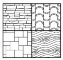
• Roofing material AutoCAD hatch patterns
CAD Flooring hatch patterns
• Lattice and chain link fence hatch patterns
Geological AutoCAD hatch patterns
This app provides you with an extensive range of AutoCAD hatch patterns. It is not a free app and retails in the App Store at $79.00. A great app even at that price!
LUMION® LIVESYNC® (REVIT - AEC)

https://apps.autodesk.com/RVT/en/Detail/Ind ex?id=1257010617153832891&appLang=en&os =Win64
Autodesk Revit
Version: 2023, 2022, 2021, 2020, 2019, 2018
Always get a real-time view of your Autodesk® Revit® 3D model in Lumion’s breath-taking, full context environments, with LiveSync for Revit.
The free Lumion LiveSync plugin lets you set up a simultaneous, real-time connection between your 3D model in Revit and Lumion 10.3. Change the model’s shape in Revit to test a modified design, and you’ll instantly see the model updated in Lumion so you can view it with accurate lighting and shadow, surrounding contexts such as urban neighbourhoods or rural settings, and beautiful, realistic materials.
Lumion LiveSync for Revit includes:
• Realtime model synchronization between Revit and Lumion
• Camera synchronization between Revit and Lumion
The ability to add and save Lumion’s beautiful materials to your LiveSync project
• Real-time materials synchronization and visualization
• Automatic model importing into Lumion (no need to separately import a model)
• Collada (*.dae) files exporter
Lumion is a world leader in 3D viewing applications, and this one is one of the best!
FM GEARS (FUSION 360 – D&M)
https://apps.autodesk.com/FUSION/en/ Detail/Index?id=6294804001663532834&app Lang=en&os=Win64
Autodesk Fusion 360
A single command is added to the Model Create menu from which Spur Gears, Internal Gears and Rack Gears can be created.

Diametrical Pitch (in English units) or Module (in Metric units), as well as Pressure Angle, Number of Teeth, Root Fillet Radius and Gear Thickness (for extrusion), are common properties for all gear types.
Bore Hole Diameter can be specified for Spur gears, Outer Diameter for Internal gears and Height for Rack gears.
The new version 1.1 adds a ‘clearance’ property to provide additional backlash clearance.
Numerical values are displayed for pitch circles and heights and sketches for pitch alignment are also provided.
A superb app that provides a great interface for gearing in Fusion 360!
AR-MEDIA (3DS MAX – M&E)
https://apps.autodesk.com/3DSMAX/en/ Detail/Index?id=4081607145537256692&appL ang=en&os=Win64
Autodesk 3ds Max
Version: 2023, 2022, 2021, 2020, 2019, 2018
The AR-media Plugin allows you to export Autodesk® 3ds Max® models directly into the AR-media Studio platform where you can create Augmented and Virtual Reality experiences, add events and interactions, add new digital assets and media to enrich the user’s experience of your 3D models and projects.
Leveraging on the AR-media Plugin, you can:
• Make a building to stand out of a blueprint or see it in the real environment where it is meant to be built
• See your best designs coming to life on your desk or in the workshop
• Create and deploy engaging experiences for your clients or friends

In order to export and deploy your models into the ARmedia Studio platform, you need to register (for free) on the platform’s website.
For more information, visit: https://www. inglobetechnologies.com/ar-media/
To visualize the exported models, you can use the free AR-media Player mobile app available for both iOS and Android devices.
(Please note this is a TRIAL version of the app).
The plugin allows you to freely upload a limited number of models, in order to increase the number of uploads you should upgrade your AR-media account. You can create a FREE account or upgrade it from here. Also, note the upload limits will be removed soon even for free users, so stay tuned for the next update.
An incredible app for those wishing to move towards VR and AR!
If you have some news to share with us for future issues, please let us know. Likewise, if you are a user of a featured product or news item and would like to write a review, we want to know. Drop me a line at: shaun.bryant@cadfmconsult.co.uk. We’d love to hear from you!

AUGIWorld brings you recent developments in Autodesk and related software items

