

AUGIWORLD
Tips and Tricks
Unlock your full potential with the latest Precision workstations. Whether you are creating groundbreaking design or performing complex coordination, these workstations are engineered to enhance your productivity. Equipped with NVIDIA RTX™ Ada Generation GPUs and integrated AI capabilities, they streamline your workflow and elevate your creative and technical endeavors.


From the President

HELLO, AUGI MEMBERS!
Time is flying by—can you believe we’re already wrapping up Q1 of 2025? So, what’s happening at AUGI? I’m glad you asked!
At our Annual General Meeting in December 2024, we expanded the AUGI Advisory Board by welcoming Rina Sahay and Gil Cordle to the team. Rina and Gil are industry powerhouses, and we’re excited for the expertise and passion they bring to help us serve you better.
We’ve also kicked off planning for AUGI CON 25, and the excitement is real! We opened the Call for Proposals, and you didn’t disappoint—submissions exceeded last year’s numbers, and the topics align perfectly with our mission of “Users Helping Users.” By the time you read this, some of this information will already be public, so be sure to check your inbox (and your spam folder!) and follow us on social media to stay in the loop.
MY FAVORITE PRODUCTIVITY TIP: TIME BLOCKING
In the spirit of this month’s AUGIWORLD theme, Tips & Tricks, I want to share a simple but powerful technique to help you get more done—time blocking.
Try this: Set aside 15, 30, or 60 minutes each day to organize your work and ensure nothing falls through the cracks. My top tip? Do this before opening Outlook and Teams. Once you open those apps, your agenda takes a backseat to everyone else’s!
I like to use my 3 P’s Planning Framework:
1. Priorities – Identify 2-3 top priorities for the day or week. Then, list 3-5 key tasks that will move them forward.
2. People – Make two columns:
• People I need to reach out to today
• People I’m waiting on for a response This keeps communication clear and ensures you’re not stuck waiting for others to move forward.
3. Projects – List 2-3 key projects and, under each, 3-5 specific next steps to push them ahead.
If you don’t protect your time, no one else will. Without intentional planning, your own work can easily take a backseat to constant firefighting. But with structured time blocking, you can take back control of your day! Thank You, AUGIWORLD Contributors!
A big thank you to all the authors who contributed to this month’s issue—your insights make AUGIWORLD possible, and we appreciate your dedication to the community.
Here’s to continuing to challenge the status quo in Q2 and beyond! �� Until next time, Eric
AUGIWORLD
www.augi.com
Editor
Editor-in-Chief
Todd Rogers - todd.rogers@augi.com
Copy Editor
Miranda Anderson - miranda.anderson@augi.com
Layout Editor
Debby Gwaltney - debby.gwaltney@augi.com
Content Managers
3ds Max - Brian Chapman
AutoCAD - KaDe King and Chris Lindner
Civil 3D - Shawn Herring
BIM/CIM - Stephen Walz
BricsCAD - Craig Swearingen
Electrical - Mark Behrens
Manufacturing - Kristina Youngblut
Revit Architecture - Jonathan Massaro
Revit MEP - Jason Peckovitch
Tech Manager - Mark Kiker
Inside Track - Rina Sahay
Advertising/Reprint Sales
Kevin Merritt - salesmanager@augi.com
AUGI Executive Team
President
Eric DeLeon
Vice-President
Frank Mayfield
Treasurer Todd Rogers
Secretary Kristina Youngblut
AUGI Board of Directors
Eric DeLeon
KaDe King
Chris Lindner
Frank Mayfield
Todd Rogers
Scott Wilcox
Kristina Youngblut
AUGI Advisory Board of Directors
Gil Cordle
Rina Sahay
Shelby Smith
Publication Information
AUGIWORLD magazine is a benefit of specific AUGI membership plans. Direct magazine subscriptions are not available. Please visit www.augi.com/account/register to join or upgrade your membership to receive AUGIWORLD magazine in print. To manage your AUGI membership and address, please visit www.augi. com/account. For all other magazine inquires please contact augiworld@augi.com
Published by:
AUGIWORLD is published by AUGI, Inc. AUGI makes no warranty for the use of its products and assumes no responsibility for any errors which may appear in this publication nor does it make a commitment to update the information contained herein.
AUGIWORLD is Copyright ©2025 AUGI. No information in this magazine may be reproduced without expressed written permission from AUGI.
All registered trademarks and trademarks included in this magazine are held by their respective companies. Every attempt was made to include all trademarks and registered trademarks where indicated by their companies.
AUGIWORLD (San Francisco, Calif.) ISSN 2163-7547


Procrastinating

In the last article I discussed taking action and getting things moving. At the end of that article, I mentioned avoiding procrastination. I want to return to that topic now. Putting things off can happen to everyone. I do it more often that I like but try not to stay in that mode too long. My suggestion in the last article was to procrastinate less. It seems like it can’t be avoided, so a goal to postpone things fewer times than you are doing now might do the trick.
PROCRASTINATE VS LAZINESS
Laziness is another topic. I trust that anyone who is reading this is most likely NOT lazy. Laziness is not the same as procrastination. Laziness typically has a goal of avoiding all effort, even when the effort will produce positive results. The lazy person just does not want to do much of anything. They know the negative side of no productivity, but they still avoid hard work. If you were lazy, you would avoid reading anything much and seek to do absolutely nothing. In fact, laziness takes work. It is hard to avoid all effort. Without going into the psychology of laziness, let it suffice that there are many root causes that may need focused assistance to get past the problem.
Procrastination, on the other hand, can be driven by many things. A desire for perfection or dreaming too big. Some thrive on crisis management and find mundane tasks boring. Others are overcommitted and just have too much on their plate which can be overwhelming, leading to avoidance due to not knowing where to start. Procrastination can be addressed by most people within themselves. Finding motivation, good self-talk, planning, etc. Much can be done to move a procrastinator to action. Let give it a go.
WORK TO DEADLINES
I find that having a deadline motivates me to get things done. It allows me to prioritize various tasks and set deadlines for me to reach. When taking a task from others, I ask them for a deadline. Back in 2018, I wrote about deadlines. I wrote that “Everything has a due date. If something does not, why are you even doing it? When someone gives you a task, ask for a due date. If they say “ASAP” I tell them “That is not a date. Please give me a date.” By having dates and times for things to be done, even if you set them yourself and no one else is demanding it be done, you have a looming point in time coming that can motivate you to not delay.
REDUCE THE DELIVERABLES
When there are a lot of things that must be completed, it can cause you to feel overwhelmed. I try to reduce the needed deliverables for projects and tasks I have. Obviously, you cannot remove critical items from project timelines, but sometimes I have found many things that are requested are not really needed. When planning or discussing a plan with others, I always ask “what are you going to do with that report (or whatever)?” I have found that some projects want reports just to have something in writing that no one fully reads. Do they NEED them every week? Do they have to cover so much? I understand the need for reports, but if they are not used or cover too broad an area, reducing the frequency or providing an executive summary style report can be more effective. I have reduced the time needed to create reports and increased the readership by reducing content to critical items, given at logical times.
STAGGERED COMPLETION
Sometimes it is staggering completion timelines that helps. You might ask, “Do you need them all at the same time? Or can I give you some critical ones and then provide others later?” Kind of sounds like procrastinating so I don’t have to deliver on some things, but it actually allows me to focus on the ones needed most and not feel overwhelmed. By staggering the completion demands, I gain more time to narrow in on the most needed items and not delay completions because not everything is included.
SLOW TIME SLUGGISHNESS
Believe it or not, there can be slow times at work. You might be in between projects, or the workload thins out and you have some down time. Coming out of down time can be tough. You may have used the down time to recover and have a breather. We all need a break. Or you may have jumped right into clearing your backlog of personal projects that have floundered because you have little time to spend on them. Whatever the case, coming out of a slow period can cause you to procrastinate. Identifying this feeling is the first step. Reluctance to “get back into it” can cause some dragging of the feet. As soon as you see your reluctance surfacing, tell yourself that it is time to get back on track and motivate yourself.
FIND WHAT MOTIVATES YOU
Motivation can come from many things. It can be internal or external. An angry boss can motivate you in the short term, but it is not the best. Internal motivations can range from a desire for good craftsmanship, quality or completion of projects. It can be clearing off your task list. It can be a desire to learn something new or make a difference at your firm. It can be the feeling of accomplishment when you have done good work. All of these are motivators. Yours may be on this list or something else. It might external motivations like a possible raise or promotion. New opportunities or removal of tedious tasks can motivate. Avoiding negatives, like disappointed bosses, can also motivate. No matter what it might be, keep it on the radar and seek out the motivators to keep you running and avoid running on empty.
DON’T BEAT YOURSELF UP
When you find yourself procrastinating (and you will), don’t be too hard on yourself. It happens to us all. Just shake off the chains of meaningless, zero return work and very easy tasks and move toward the ones that bring the best outcomes. Remember that procrastination can come at any time. Regain your focus and keep your mindset on taking action and avoiding delays.

Mark Kiker has more than 30 years of hands-on experience with technology. He is fully versed in every area of management from deployment planning, installation, and configuration to training and strategic planning. As an internationally known speaker and writer, he is a returning speaker at Autodesk University since 1996. Mark has served as Draftsman, Principal Designer, CAD/ BIM Manager, CTO and CIO. He can be reached at mark.kiker@augi.com and would love to hear your questions, comments and perspectives.
Tips & Tricks in ACA
LAYER MERGE
Layer Merge (LAYMRG) can be found in the Layer Manager in AutoCAD Architecture. At the command prompt, you can enter LAYMRG. Then in the drawing area, select an object on each layer that you want to merge, and press Enter. Next select an object on the target layer. All objects on layers that contain objects in the first selection set are moved to the target layer.
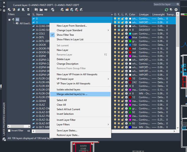
You can also do this using the Layer Properties Manager. Select the Home tab, Layers panel and then select Layer Properties. In the Layer Properties Manager, select the layers you want to merge into another layer and right-click and select Merge Selected Layers To (see Figure 1). You will need to press Crtl+click to select more than one layer. In the Merge to Layer dialog box, select a target layer. Objects on the merged layers are moved to the layer you select in this dialog box. The now empty layers are automatically deleted.
STATUS BAR
The status bar will automatically wrap onto two rows when there are more icons than can fit into a single row. At any given time, the Model tab and at least one Layout tab is always displayed. You can populate the status bar with the tools you want by clicking on the three-stacked lines (hamburger) in the lowerright corner of the editor. The Lock User Interface tool on the status bar enables you to check and uncheck multiple UI elements at one time instead of having to reopen the flyout each time. You can click the icon to enable or disable UI locking.
AutoCAD Architecture 2025
LASSO SELECTION FOR OBJECTS
Lasso Selection is an object selection feature that can be created by clicking, dragging and then releasing the mouse button (see Figure 2). You can drag from left to right to select all objects that are entirely enclosed in the lasso or drag from right to left to select all objects that are crossed by the lasso, then click Enter. You can deselect objects by pressing shift and then clicking the individual objects or dragging across multiple objects. Press Esc to deselect all objects. It is important to note that when using lasso selection, you can press the Spacebar to cycle between the Window, Crossing and Fence object selection modes.
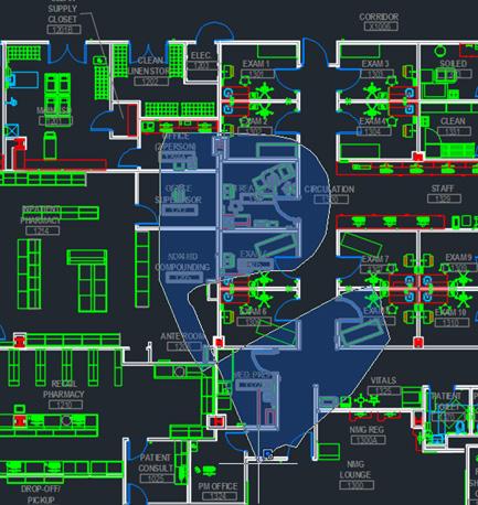
Figure 2 – Lasso Selection
AutoCAD Architecture 2025
ACA REVISION CLOUD
The Revision Cloud tool provides you with a lot of flexibility. It is accessible from the Annotate tab, Markup panel and includes several methods of creation: Rectangular, Polygonal, Freehand and convert an object to a Revision Cloud, as well as creating a cloud with calligraphy pen style (which looks totally cool). The last used creation method is remembered the next time the command is run. You can set your own default creation method using the REVCLOUDCREATEMODE system variable. Whether you create rectangular, polygonal, freehand or object revision clouds, editing their size and shape with grips is intuitive and easy. The location and behavior of grips is based on the shape of the revision cloud. There is also a Modify option that allows you to draw new revision cloud segments and erase selected portions of existing revision clouds (basically, put several revision clouds together).
TEXT ALIGNMENT AND TEXT EDIT
AutoCAD Architecture has a TEXTALIGN command that allows multiple text objects to be aligned to a base object and provides a preview of the result. After typing TEXTALIGN, the prompt Select text objects to align (alignment Options) is displayed. Select two or more objects to align and press Enter. With this command, you can easily control the spacing or alignment direction.
The TEXTEDIT command has a “multiple” option that allows you to perform multiple text edits at one time. There is also an Undo option within Multiple mode that allows you to undo Individual text edits. It is important to note that if you leave TEXTEDIT and perform an Undo, all of the edits within TEXTEDIT will be undone.
GRIP EDITS
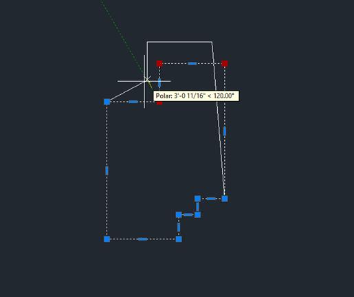
Grips allow you to move, reshape and manipulate objects when using different grip modes and types of grips. If you have locked layers, however, grips will not display objects on those layers. You can select more than one grip by pressing and holding the Shift key and then selecting the grips you want to edit. When you select more than one grip, the object keeps its shape between the selected grips (see Figure 3). When working with a circle or ellipse, you can select a quadrant grip and then specify a
distance at the Command Prompt for a new radius. When you do this, the distance is measured from the center of the circle and not the selected grip. However, grips on block references, text, circle centers and line midpoints move the object instead of stretching it.
Sometimes when we use polylines or even hatch objects with many grips, it can take a long time to select these objects. Limiting the maximum number of objects that display grips helps. The system variable GRIPOBJLIMIT suppresses the display of grips when your selection set includes more than the specified number of objects. If you add objects to the current selection set, however, the limit will not apply.
SMART DIMENSIONS
In AutoCAD Architecture, the DIM command is accessible from the Annotation tab and is
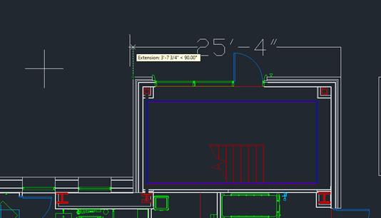
Figure 3 – Grip Edit
Figure 4 – Dimension
smart enough to detect objects and provide various visual dimension options. The DIMLAYER command can be used to create a new layer for dimensioning. You are given horizontal, vertical and aligned dimension previews when you select a linear object. From these previews, you can simply place the desired dimension. (See Figure 4) You can also select another non-parallel linear object to display and place an angular dimension. You can specify a type of dimension by using the various dimensioning options in the right-click menu. The default values are automatically assumed for the dimension text and angles, but you can
AutoCAD Architecture 2025
still change them from the right-click menu or command line. The DIM command remains active until you exit the command, allowing you to knock out multiple dimensions at one time. You can use the width sizing control to wrap dimension text, which is awesome!
XREF OBJECT EDIT
AutoCAD Architecture allows you to edit and External Reference or a Block Reference in place without having to open and edit the original drawing. You can do this by going to the Insert
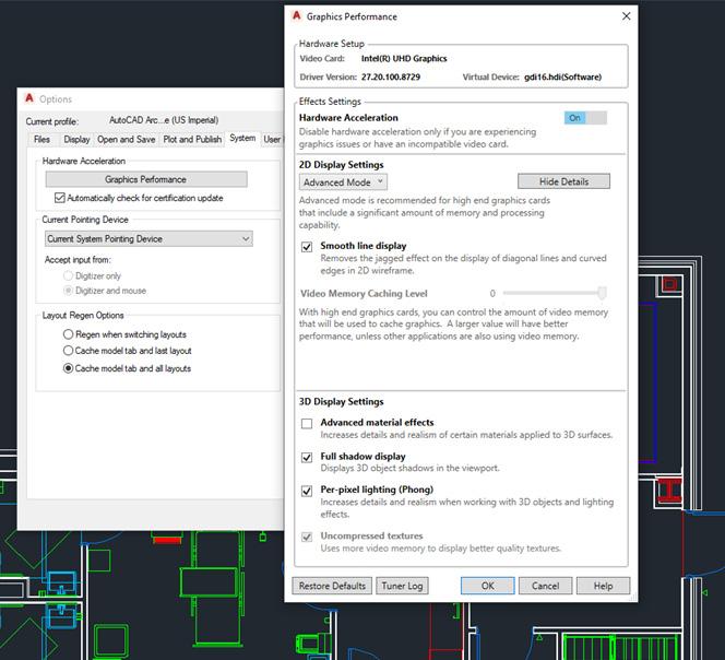
Figure 6 – Smooth Line Display
AutoCAD Architecture 2025
tab, Reference panel and then selecting Edit Reference. In your current drawing, select the reference you wish to edit. The Reference Edit dialog box will appear, and you can select the specific reference you wish to edit, then click OK. The reference file will be locked to prevent multiple users from accessing the file at the same time. Now select the objects you wish to edit in the reference and click Enter. These objects now become the working set, and all other objects will be locked and faded. Edit the objects in the working set and click Save Back Changes to Reference. The objects are saved to the reference and the xref or block is updated.
DIGITAL SIGNATURES
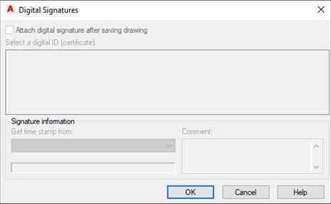
AutoCAD Architecture offers extra security controls that help to protect your drawings. You will find a variety of Security Options on the System tab of Options. One option is Digital Signature, accessible via the DIGITALSIGN command. A digital signature is a block of encrypted information that you can add to certain files to identify the originator and indicate whether a file has been altered since the digital signature was applied.
To attach a digital signature to a file, you must either have a digital certificate issued by a certificate authority or you can create a self-signed certificate using one of several utilities. (See Figure 5) You can examine a file’s digital signature. This is important when you are working on collaborative projects or if you receive an executable file. For drawing files, an icon is displayed on the status bar if a drawing file is digitally signed. When you click
the icon, you can verify information such as the validity of the signature, the name of the individual or organization that signed the file and so on.
SMOOTH LINE DISPLAY
AutoCAD Architecture has a solution to the jagged diagonal lines that you sometimes see in 2D wireframe drawings. The command is LINESMOOTHING. This variable can also be found under the Options dialog box, System tab. Click on Graphics Performance and the Graphics Performance dialog box appears. Under 2D Display Settings, click on Details. Checking Smooth Line Display removes the jagged lines (see Figure 6). If your hardware supports High Quality Geometry, you can select several options under 3D Display Settings in the Graphics Performance dialog box. Hardware acceleration must be turned on for this to work. Set LINEFADING to 1 to automatically fade geometry as you zoom into super-dense drawings. You can control the amount of fading with LINEFADINGLEVEL.
RENDERING
The rendering engine in AutoCAD Architecture is amazing and can yield great results. The Render panel on the Render tab supports the rendering engine. It includes a size drop-down where you can quickly select from standard pre-defined render sizes.
The Render Presets list includes additional options enabling you to control the render quality by setting either the number of levels to render or how much time to render. The Render Presents Manager allows you to create, modify and delete custom Render Presets. Specify Render Preset name and description as well as the duration and accuracy. You can render directly from the Render Presets Manager, choosing to render in the Render Window, the current viewport or a specified region in the current viewport.
When rendering in the render window, a drop-down list enables you to select from a list of standard render output sizes or choose More Output Settings to access the Render to Output Settings dialog box, in which you can specify the image size and resolution.
You can also choose to automatically save the rendered image to a file including BMP, TGA, TIF, JPEG and PNG formats.
A Render Environment & Exposure Palette offers powerful Image Based Lighting (IBL) environments. When the Environment control is turned on, you can select from pre-defined, image-based lighting environments (see Figure 7). The image-based lighting environments automatically apply lighting effects. Some of them include 360 background images that emulate a realistic environment as you orbit around the model. The viewport must be in a perspective view, and you must render to see the IBL environment.
A control in the Render Environment & Exposure palette enables you to use a custom background image. Custom images are static and do not emulate a realistic 3D environment as you rotate. Additional controls in the Render Environment & Exposure palette enable you to adjust the Exposure and White Balance. Exposure slides between Bright and Dark. The White Balance slides between Cool and Warm. The render window displays the current render process and allows you to save a snapshot, zoom in and out while rendering and print the rendered image. Render history is displayed in the expanded section of the render window.

AutoCAD Architecture 2025
GEOGRAPHIC LOCATION
Geographic location information in a drawing file is built around an entity that is known as the geographic marker. The geographic marker points to a reference point in model space that corresponds to a location on the surface of the earth of known latitude and longitude. The program also captures the direction of the north at this location. Using this information, the program can derive the geographic coordinates of all other points in the drawing file. You can set a geographic location using the Set Location tool on the Insert tab then easily search for an address from a map and drop a marker on the map to mark the spot. Drawing units can be easily modified.
After you insert a geographic marker in a drawing, you can do any of the following:
• Make the program automatically determine the angle of sunlight when you perform sun and sky simulation
• Insert a map from an online maps service in a viewport
• Perform environment studies
• Use position markers to mark geographic locations and record related notes
• Locate yourself on the map in real-time on systems that support location sensing
• Export to AutoCAD Map 3D and expect the model to position itself automatically
You can remove geographic location information from a drawing file using the GEOREMOVE command. The geographic marker and GIS coordinate system are removed from the drawing file. However, position markers will remain in the drawing file.

Melinda Heavrin is a CAD Coordinator & Facility Planner in Louisville, Kentucky. She has been using AutoCAD Architecture since release 2000. Melinda can be reached for comments and questions at melinda.heavrin@ nortonhealthcare.org.
Figure 7 – Render Environment & Exposure
Tips & Tricks
There are a lot of little things that go unnoticed in Civil 3D. Probably because there are a million icons and commands! Whether they are hidden away within your Toolbox, or several layers deep within the ribbon, there are some really good tools that are often overlooked. Here are some of my favorite little tasks, some new, and some oldies but goodies! I also tried something different with this article and made short videos of each of the topics. Hope you like it!
SURFACE EDITING WITH TRIANGLES OR POINTS ENABLED
Recently, Civil 3D added support to automatically enable component display when editing TIN lines or adding/moving a surface point. Why did it take so long!! This may seem like a small thing, until the first time you use it and realize how many clicks it saves you throughout the day! Here’s how:
• Select a surface – Historically you’d have to change the style in the properties or edit the surface style to turn on the triangles. Not anymore!

• After you select the surface from the ribbon, choose Edit Surface and select Delete Line
And the TIN lines magically appear!! Perform your edits as needed. When completed, hit escape (or right click twice).
• You’ll now get a message asking if you want to maintain the current display, apply the style change to the current display, or revert to the original style of the surface you had chosen.
Video - https://youtu.be/rDLA5D8IWFU
QR Code - Surface editing with triangles.png
CIVIL 3D REFERENCE OBJECTS IN LABELS
Let’s take a 4-way intersection for example. I often have the need to label the station, alignment name and even profile elevation at the intersection point along with Northing and Easting. It’s easy to set up a label style to do so. Here’s how:
Using the Alignment as a feature, Station Offset as the label type, create this new label by doing the following:
1. Add a new Text component, call it Algn1. In the Contents, include the following:
• Alignment Name & Station Value
2. Add a Reference Text and Choose Profile, call it Algn1-Prof,
• Attach it to your label as you see fit
• In the contents, select and add Profile
3. Add a Reference Text and Choose Alignment, call it Algn2. In the Contents, include the following:
• Alignment Name & Station Value
4. Add a Reference Text and Choose Profile
• Attach it to your label as you see fit
• In the contents, select and add Profile
5. Add the final component, choose Text.
• Attach it to your label as you see fit
• In the contents, select and add the Northing & Easting
6. Select OK to finalize your new label style. And try it out!! Make sure to follow the command line prompts and take note of how important component naming is!
Video - https://youtu.be/4cWZ3sgVtQY
QR Code - Civil 3d Reference Objects in Labels.png
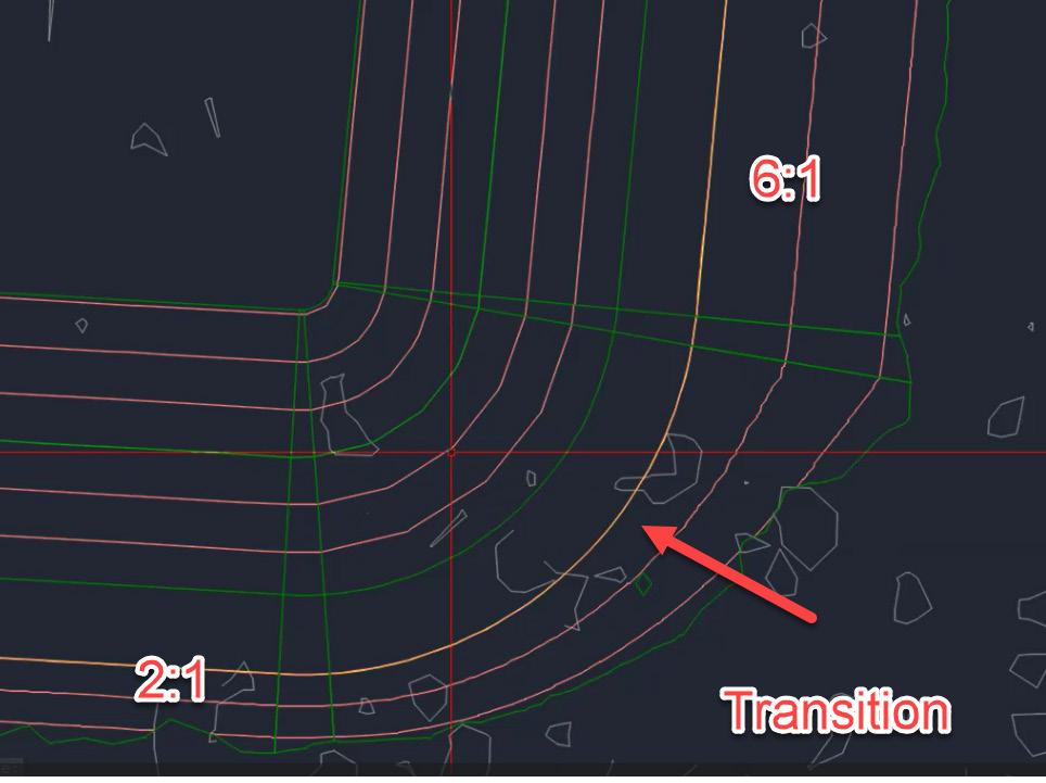
GRADING TRANSITIONS
In this instance, I have a storm pond that has 6:1 side slopes for most of the pond, but as we get close to a property line, I needed to adjust the slopes to be 2:1. But how do I transition between these 2 smoothly? The Create Transition tool works well for this scenario. Here’s how:
1. I’ve started with a feature line (created by object), that represents my top of pond. I like to keep any ponds within their own “Site”.
• Grade to Distance (5’ @ 2%)
• Grade (or slope) to Distance (18’ @ -3:1)
6. Create an Infill for the bottom
7. For the exterior, here’s where we set it up to use a transition. Grade using the following criteria:
• Grade (or Slope) to Surface. Apply to Entire Length? Say NO!
• Select a beginning and ending point.
• Select Slope for Cut and Fill, both using a 6:1 slope
• Stay in the command. Select the feature again, and the grading side. And use a slope for Cut and Fill of 2:1. Hit Enter.
8. Select Create Transition from the Grading Tools. Select the Feature Line
• Pick a point anywhere between the 2 gradings (where you left a gap)
• Hit Escape and your grading was created and transitioned between the 6:1 and 2:1 slopes seamlessly!!
Video - https://youtu.be/GlNsxfW5skA
QR - Grading Transitions for Civil 3D Pond.png
CORRIDOR SECTION EDITOR

2. Select Grading Grading Creation Tools

3. Set the Grading Group by creating a new one called Pond.
4. Set the Target Surface (Existing Ground (South TIN) in this case).
5. Grade the interior of the pond using the following criteria:
I like using the Section Editor to explore and inspect my corridor model. But did you know you can make edits and overrides in there? In this example, I have a road corridor with 6:1 side slopes, but in one small section I need a retaining wall (for absolutely no reason other than writing this article.;)). I could split my regions, create a new assembly, and add it through the typical corridor editing tools, but that seems a bit excessive. Here’s how to do it in section editor:
1. Select your corridor and choose Section Editor from the ribbon.
2. Jump to a station, for this example I’m using 17+50
3. Select Parameter Editor, from the left side data, expand until you see the BasicSideSlopeCutDitch and on the fill slope, put it 0.25 (to depict a retaining wall).
4. Notice in that one section that your left side grading changed. But this is for that specific station only. From the ribbon, choose “Apply to Station Range”, and apply this from station 17+50 to 19+50.
Autodesk Civil 3D
5. Update your corridor and take a peak at your section, it now shows the retaining wall! Cycle through additional stations to see more.
Video - https://youtu.be/ayW-FVi2dF0
QR - Corridor Section Editor in Civil 3D.png
OFFSET PARCELS
Ever have to draw in those annoying PUE or lot setbacks on a final plat? Me too!! I use the parcels along with the basic AutoCAD offset command. And my favorite command, Isolate Objects. Let’s say our front PUE is 10’ and the sides/rear are 5’. Here’s how I quickly draw these lines:
1. Start with completing your parcel layout.
2. Switch to a layer with no objects on it (for this, I used layer 0).
3. Offset the ROW lines 10’ by selecting either the ROW parcel label, or in this case, the hatch pattern from my Parcel Style.
4. Now offset the parcel, using the Parcel Lot Label, 5’.
5. Select one of the polylines on layer) and use the Isolate selected Objects command.
6. Switch to another layer that you want your easements to go on.
7. Use the BO (boundary) command to quickly select inside each closed area.
8. Select the linework on layer 0, right click and select similar, and erase!
9. Done, now you have all your PUE lines drawn in in a matter of seconds.
Video - https://youtu.be/u5SAt66-eYY
QR - Offset Parcels in Civil 3D.png
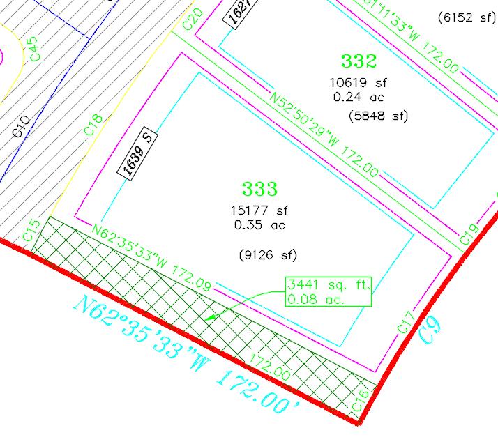
STAGE STORAGE ANALYSIS W/ A TWIST!
Need a quick volume analysis from a pond? Need that analysis every 0.5’ within the pond? The Stage Storage Tool in Civil 3D is your new best friend!
First, you need to decide what interval you need to report on. Your surface style will control the results/ interval within the report. For example, if I want the following pond volumes in 0.50’ intervals, I simply edit the surface style to display the correct interval, prior to running the analysis.
However, let’s take this one step further by using the User Defined Contour analysis from within your surface properties. Sometimes you may want to see the high-water mark, a pressure elevation or maybe a floodplain elevation. This is a great tool, and coupled with the State Storage command can help you identify true volumes much easier.
After you have edited your style to display the User Contour and your preferred contour interval, select
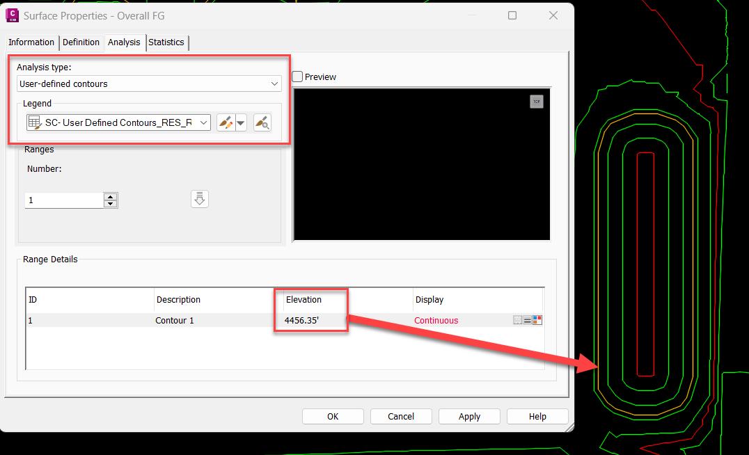
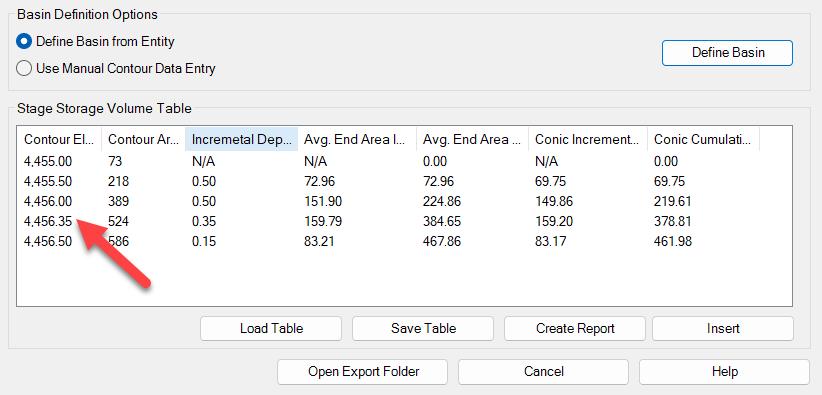
the surface you wish to analyze, and from the Analyze panel of the ribbon, choose Stage Storage.
This will launch the report dialog box, fill in the blanks as needed, and select DEFINE BASIN.
You want to then select Define Basin from Polylines and select the Extract Objects from Surface button.
Select the surface, select DEFINE back on the dialog box and select up to the polyline you wish to analyze. The dialog box should reappear with your results and notice the oddball contour interval based on our user defined contour! You can save this report to a text file, or even better, save it as a file to be used within SSA!!
Video - https://youtu.be/d9_pHT5Xuok
QR - Stage Storage Analysis with a Twist - Civil 3D.png
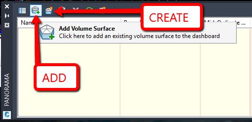
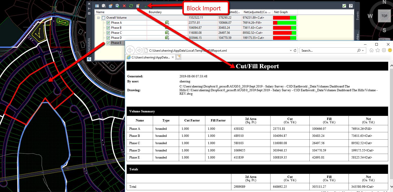
VOLUMES DASHBOARD FOR EARTHWORK PHASES
The Volume Dashboard takes a simple volume surface just one step further by allowing you to create “Bounded Volumes”. This will easily create volumes of specified areas, usually by specifying a polyline, without the need for multiple volume surfaces. So, if you have phases of a master development for example, you can easily copy in your phase lines and use those for the bounded volume areas. This is a very simple process as shown below:
1. Select Volumes Dashboard from the Analyze Ribbon.
2. Add (or create) a Volume Surface. I typically create one called “Overall Volume”
Notes:
• A volume surface must exist in the drawing before this option can be used. If no volume surfaces exist, then you can use the Create New Volume Surface option to create one.

• You can also apply an expansion or compaction factor to the materials.
3. With your phase lines located in the drawing, select the Overall Volume from the list, then select ADD BOUNDED VOLUME, then select the polyline representing your area of interest (i.e. phase, sheet, etc.)
4. Repeat the steps as needed.
5. From the list within the Volumes Dashboard Grid View, you can rename each of your selections. Notice that as you highlight each row, the polyline will be represented in red on the screen.
6. You can now reorganize the columns if needed!
There are 2 reporting options, first, you can add a block with the data into your CAD file, second, you can export out an XML report.
Video - https://youtu.be/2AbleLGQc_M
QR - Civil 3D Volume Dashboard.png
DRAFTING BUFFER – CIVIL 3D CROSS SECTIONS
Did you know you can manually draw in linework and AutoCAD annotation in cross sections and if you move the cross section it will go with it!! This is super helpful if you add additional sections/sample lines which can result in a shift. Here’s how:
Video - https://youtu.be/TZW6RerKCkE
QR - Drafting Buffer Civil 3D Cross Sections.png
CONCLUSION
There are always forgotten commands, or simple tips and tricks that may help us boost our productivity. I have been doing this for over 15 years now and I learn something every time I ask a question or simply sit back and listen to others speak. Feel free to send me any of your favorite hidden commands or tips and tricks you have learned along your Autodesk journey.
Thank you!

Shawn has been a part of the design engineering community for over 15 years in all aspects of design, construction, and software implementations. He has implemented and trained companies across the Country on Civil 3D and other infrastructure tools and their best practice workflows. Shawn can be reached for comments or questions at sherring@ prosoftnet.com.


In late 2024, I was thinking of ways to expand the sharing of knowledge beyond the monthly Buildings BIM Bulletins I have been doing for over a year now. In January, on my 49th birthday of all days, I rolled out what I am calling “Weekly BIM Mastery”. At the time of writing this article (end of January), I have shared 4 weeks’ worth of tips. Instead of giving a single quick tip about something, I give numerous tips about a single topic. We have just under 50 people in our Buildings Business Line between MEPF, Architectural and Structural. Similar to my Buildings BIM Bulletin, these tips and tricks posts are getting on average 80 unique views, some more, some less, which means others in Garver are checking them out, Before we dive into the tips I shared with my team, let me give you the description included on every Weekly BIM Mastery SharePoint post from the template I created.
“Welcome to Weekly BIM Mastery, your ultimate hub for tips, tricks, and best practices in Building Information Modeling (BIM). This weekly series is tailored for our Buildings group to enhance project efficiency, collaboration, and innovation. Each post is packed with actionable insights that empower


Weekly BIM Mastery –Tips and Tricks


you to solve challenges, work smarter, and deliver exceptional results.
Explore a wide range of topics, including timesaving techniques in Revit, advanced workflows in Navisworks, data management in Autodesk Construction Cloud, and cutting-edge trends shaping the AEC industry. Whether you’re a seasoned professional or new to BIM, these posts are designed to provide value to everyone, breaking down complex concepts into clear, practical guidance.
By staying up to date with Weekly BIM Mastery, you’ll uncover hidden features, overcome common pitfalls, and learn how to leverage BIM tools to their fullest potential. From improving design accuracy and clash detection to fostering better communication across teams, this series will elevate your mastery of BIM one week at a time.
Let’s transform how we approach our projects and make BIM not just a tool but a competitive advantage. Remember—mastery isn’t a destination, it’s a journey, and we’re here to take that journey together!”
KEYBOARD SHORTCUTS IN REVIT
General Tips for Mastering Revit Keyboard Shortcuts:
1. Learn the Defaults: Revit has a robust set of default shortcuts. Familiarize yourself with common ones like:
• MM: Mirror (pick axis)
• DI: Dimension
• AL: Align
• MV: Move
• CS: Create Similar
• ZZ: Zoom to Fit
• WT: Tile Windows
2. Customize Your Shortcuts:
• Access File > Options > User Interface > Keyboard Shortcuts to modify or create your own.
• Prioritize shortcuts for commands you use frequently but are buried in menus.
• You can also type KS to open the Keyboard Shortcuts dialogue faster.
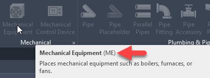
• Hovering over any of the ribbon buttons will give you a quick “fly out” dialogue and it will show you if a keyboard shortcut exists for that button.
3. Use Context-Specific Shortcuts:
• Many shortcuts are context sensitive. For example, the Tab key is useful for cycling through selections or chain selecting elements in connected models.
Figure 2 - Sample Keyboard Shortcut
Figure 1 - Weekly BIM Mastery SharePoint Banner
4. Memorize Multi-Step Actions:
• Combine shortcuts for quick actions. Example: Use VG (Visibility/Graphics) to toggle element categories on and off quickly.
5. Combine with Mouse Navigation:
• Use the Shift + Middle Mouse Button to pan and orbit while executing shortcut commands for smooth workflow.
Top Customizable Shortcuts:
Here are some useful shortcuts to add or modify:
1. HV: Hide Element (quickly toggle visibility without using the toolbar).
2. UF: Unhide Element/Category (to bring back hidden elements).
3. 3D: Default 3D View (jump directly to the default 3D view).
4. TG: Tag by Category (quick tagging in plans or elevations).
5. SE: Split Element (faster than searching in the ribbon).
Practice for Mastery:
1. Focus on Core Commands First: Start by mastering shortcuts for navigation and annotation. Gradually expand to modeling tools.
2. Use a Shortcut Cheat Sheet: Print or keep a reference guide nearby while working until the commands become second nature.
3. Set Shortcut Goals: Each week, focus on learning 3-5 new shortcuts.
4. Practice Efficiency: Challenge yourself to reduce mouse movements by using shortcuts wherever possible.
BONUS TIP:
Enable Command Search in Revit (2023 and later): Press Alt + / to search for any command or tool quickly, and Revit will show its shortcut (if assigned). This is a great way to learn shortcuts as you go.
SELECTION BOX
The Selection Box in Revit is a powerful tool that helps with isolating elements in 3D views, improving model navigation, and focusing on specific areas during the design and coordination process.
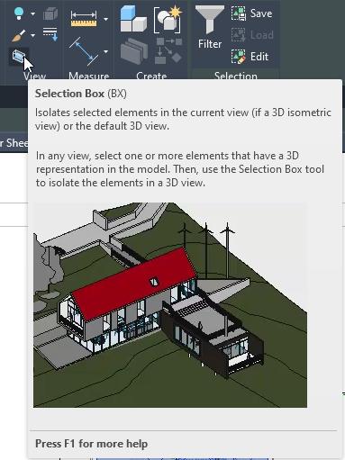
Figure 3 - Selection Box
Here are some tips for you when using the Selection Box:
Quickly Create a 3D View for Selected Elements
• Use the shortcut BX to instantly isolate selected elements in a 3D view with a selection box. This is useful when you want to focus on a particular area or resolve clashes without creating a custom 3D view.
Adjusting the Section Box
• Fine-tune the boundaries of the Selection Box by dragging the grips in 3D view.
Alternatively, use the Properties palette to precisely control the dimensions and offsets of the section box.
Leveraging Visibility/Graphics Overrides
• After isolating elements in the Selection Box, adjust visibility/graphics settings to further refine the view, such as turning off unnecessary categories or applying transparent overrides.
Combining with Filters
• Use filters in conjunction with the Selection Box to isolate and analyze specific element types, such as all doors on a floor or ductwork in a specific zone.
Temporarily Hide the Selection Box
• To declutter the view, you can temporarily hide the Selection Box by deselecting the “Section Box” option in the Properties palette while keeping the 3D crop active.
Save Custom 3D Views
• Once you’ve set up a Selection Box, save the view as a custom 3D View for quick access later. This is especially useful for team reviews or specific design iterations.
Use for Coordination
• During coordination meetings, the Selection Box can help focus on problem areas by isolating the region where clashes or issues exist.
Assign to View Templates
• If certain views always require a specific Selection Box setup (e.g., per floor or per zone), assign the settings to a View Template for consistency across projects.
Selection Box Hotkeys
• BX: Isolate selected elements with a Selection Box
• Ctrl + Drag: Box-select multiple elements before activating BX for a group focus.
Enhancing Presentations
• Use the Selection Box to create clean, focused 3D visuals for presentations, emphasizing only the critical components of your design.
QUICK ACCESS TOOLBAR
The Quick Access Toolbar (QAT) in Autodesk Revit is a customizable toolbar that provides quick access to frequently used commands, enhancing workflow efficiency. By default, it includes tools like Save, Undo, and Redo, but you can tailor it to suit your specific needs.
Show/Hide the QAT Below the Ribbon
• Move the toolbar below the Ribbon for better visibility:
• Right-click the QAT and select “Show Quick Access Toolbar Below the Ribbon.”
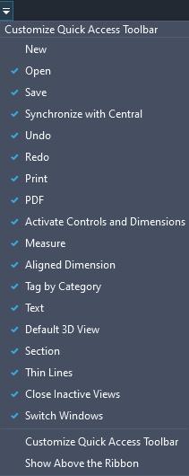
Figure 5 - Show Below Ribbon
Figure 4 - QAT in Revit 2025
• This can be particularly useful for large screens.
Customize for Frequently Used Commands
• Right-click any tool or command and select “Add to Quick Access Toolbar” to pin it.
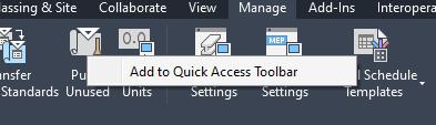
Figure 6 - Add to QAT
• Include commands like Align (AL), Trim/Extend (TR), and Tag by Category (TG) for quick access.
Group Commands for Better Workflow
• Organize commands by logical groups (e.g., annotation tools, view tools, modeling tools).
• Use separators (added via the right-click menu) to visually divide related sets of tools.

Figure 7 - Customize QAT
Reorder Commands for Efficiency
• Drag and drop commands in the QAT to match your workflow’s sequence.
• Place frequently used tools at the beginning for faster access.
Add Keyboard Shortcuts
• Pair QAT tools with custom keyboard shortcuts for even faster execution.
• Example: Assign shortcuts to tools not easily accessible via the Ribbon, like “Repeat Last Command” or “Switch Windows”
Avoid Overcrowding
• Keep the QAT concise. Too many commands can clutter and slow down navigation.
• Aim for no more than 10-15 items for optimal usability.
Sync with Workflows and Roles
• You can tailor QAT setups to specific roles:
• Modelers: Include basic modeling tools like Wall, Door, and Floor.
• Designers: Focus on annotation and detailing commands.
• Managers: Add collaboration and view management tools.
Explore Hidden Gems in the QAT Hidden Gems for Modeling and Drawing
1. Repeat Last Command
Quickly repeat the last executed command, saving time on repetitive tasks.
2. Create Similar
• Quickly start creating a new instance of an existing element (e.g., a similar wall or door).
• Especially useful in layout-heavy workflows.
3. Measure Between Two References
• Use this to measure distances without adding temporary dimensions or cluttering views.
• Customize the visibility of individual elements or categories in a view.
5. Split Element
• Quickly divide walls, floors, or other elements without navigating to the Modify tab.
Hidden Gems for Views and Navigation
1. Isolate Category
• Temporarily isolate specific categories (e.g., walls or furniture) for better visibility.
• Saves time when reviewing or modifying specific elements.
2. Switch Windows
• Navigate quickly between open views, especially helpful when working on multiple views or sheets.
3. Reveal Hidden Elements
• Turn on hidden elements in the current view without digging into view settings.
4. Close Hidden Windows
• Closes unused windows to free up system resources and declutter your workspace.
Hidden Gems for Documentation
1. Tag All Not Tagged
• Automate tagging of multiple elements in a single command, saving time during documentation.
2. Align
• Align annotations or elements precisely, especially useful for dimensions and text.
3. Select by ID
• Search for and locate a specific element in the model using its ID.
4. Reload Latest
• Useful in work-sharing environments to quickly refresh your view with the latest changes from the central file.
Hidden Gems for Management
1. Purge Unused
• Quickly clean up your project by removing unused families and types, ensuring a leaner model.
2. Sync with Central
• Keep it on the QAT to ensure frequent updates to the central model without navigating to the Collaborate tab.
3. Audit
• Useful for reviewing model integrity and catching potential issues early.
Bonus: Non-Command Additions
1. View Templates
• Add frequently used view templates for quick application to multiple views.
2. Section Box
• Quickly turn on/off section boxes in 3D views to isolate areas of interest.
3. Temporary View Properties
• Allows you to test different visual styles and settings without permanently altering the view.
LOAD AUTODESK FAMILY
The “Load Autodesk Family” button in Revit allows users to quickly access default content, such as families and templates, directly from Autodesk’s library. Here are some tips for effectively using this feature:
Understand What It Does
• This button connects to Autodesk’s cloudbased library, offering preloaded content like furniture, lighting, MEP components, and templates.
• It’s especially useful for users who don’t have custom libraries already set up.
Ensure Internet Connectivity
Since this feature requires online access to Autodesk’s library, ensure your internet connection is stable before attempting to load content.
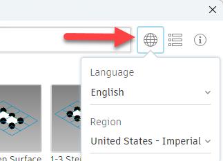
Set Up Default Content in the Correct Language/ Region
The Autodesk default library is often localized. Verify that the content matches your project’s standards,
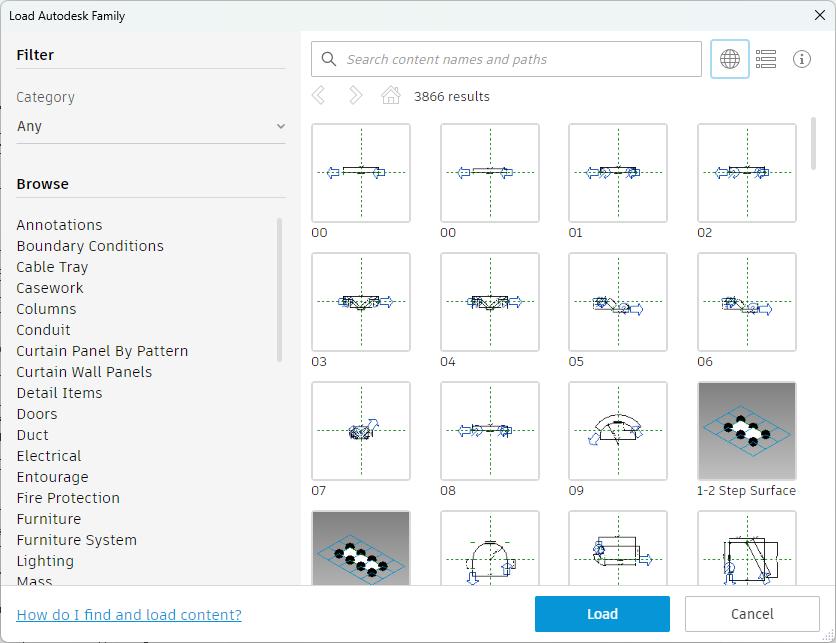
Figure 9 - Language/Region Options
Figure 10 - Search and Filters
units, and regional requirements (e.g., US Imperial vs. Metric).
Use as a Starting Point
• Autodesk default content is often generic. Use it as a base, then modify families or parameters to meet project-specific needs.
• Add shared parameters or adjust sizes, materials, and nesting to enhance the downloaded families.
• While the MEPF and Structural teams have a lot of Standard Content already there still may be some things that we do not have and the default Autodesk Content is a good place to start.
Leverage Search and Filters
• Use the search bar or filters to narrow down the content you need. This saves time compared to browsing large libraries manually.
Manage Family Sizes
• Some families in the default library are detailed and can increase model size. Evaluate the level of detail (LOD) and consider simplifying geometry for performance.
Save Families Locally
• After downloading and customizing, save the families in your firm’s local or shared library for future use. This builds a curated library of preapproved content.
• Families downloaded from Autodesk can be used as a start to your standardized content.
Check for Updates
• Autodesk occasionally updates its cloud library. Keep an eye out for new or improved content to enhance your project efficiency.
Coordinate with Project Standards
• Verify that downloaded content aligns with your project’s BIM standards, naming conventions, and data formatting.
CONCLUSION
In conclusion, the “Weekly BIM Mastery” series has proven to be an invaluable resource for our Buildings group, offering a wealth of tips, tricks, and best practices in Building Information Modeling (BIM). By consistently engaging with these weekly posts, our team has been able to enhance project efficiency, foster better collaboration, and drive innovation across various disciplines. The actionable insights provided have empowered both seasoned professionals and newcomers to solve challenges, work smarter, and deliver exceptional results. As we continue this journey of mastery, let us remember that BIM is not just a tool but a competitive advantage that transforms how we approach our projects. Together, we will continue to uncover hidden features, overcome common pitfalls, and leverage BIM tools to their fullest potential, ensuring that our projects are not only successful but also exemplary in the industry.

Jason Peckovitch is an Autodesk Revit Certified Professional for Mechanical and Electrical Design located in SE Iowa. He is a BIM Manager for Garver’s Buildings Business Line, specifically MEPF. Garver has more than 50 offices across the United States and more than 1200 employees. His CAD/BIM career spans over 25 years but he didn’t switch to the AEC Industry until 2007 as a Mechanical HVAC Drafter and transitioned into BIM Management shortly after where he has been working since. Jason is also the father of three children; Shelby – 12, Blake – 10 and Logan - 7, a published photographer, gamer, and car/tech guy. He can be reached at jmpeckovitch@ garverusa.com.

What Can I Do with a Point Cloud in Autodesk Civil 3D 2025?
With the growing use of drones and lidar capabilities to capture existing data, point clouds are becoming increasingly important to many civil workflows. So how can you use point clouds in Civil 3D? Collecting existing data for a preliminary or conceptual plan, updating a site between phases for a project, capturing an as-built overview of a project, or another objective with this data collection type are just a few of the ways I have seen point clouds being used in the civil industry.
Point clouds can be explored directly inside the Civil 3D environment for these purposes. Whether it is for visualization, referencing existing conditions or extracting data from the point clouds for design, the data can be used right inside Autodesk Civil 3D 2025.
Before we can use the data, we need to know how we can view it and what we can do with it in Civil 3D. Let’s dive into and discover some of those options in an overview of point clouds inside Civil 3D 2025.
ATTACHING A POINT CLOUD IN CIVIL 3D
To attach a point cloud in Civil 3D, it needs to be in the .rcp or. rcs file format. If you have Autodesk’s AEC collection, you already have the tools you need and can import the point cloud into Recap, save it as an .rcp or .rcs file, then attach it inside Civil 3D. You can import and open e57, las, laz, or several different point cloud file formats into Recap. But to include it in Civil 3D, you will need Autodesk Recap to convert it to an .rcp or .rcs file.
Many firms already have the AEC collection and often are not using or aware of the software options inside of the collection. Integrating Recap into your workflow with point clouds opens options for collaboration and data input. The AEC collection, rather than a Civil 3D license alone, can be invaluable for a company’s workflow. While this article’s focus is point clouds in Civil 3D, I would be doing a disservice not to mention that there are many tools in Autodesk Recap that can advance your point cloud workflow as well.
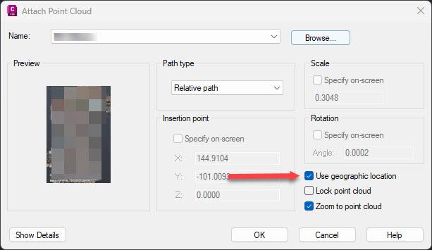
If your point cloud contains geolocation data, set up your drawing in Civil 3D with that same coordinate system prior to attaching your point cloud. This allows the point cloud in the correct location and allows the design to be built in those correct coordinates moving forward. Simply set your drawing to that same coordinate system and click the ‘Use geographic location’ check box when attaching the point cloud to a Civil 3D drawing.
HOW TO VISUALIZE POINT CLOUD IN CIVIL 3D
After attaching your point cloud to a Civil 3D drawing, there are several options to help display that point cloud in a manner that fits your project objective. Select the point cloud to edit these properties.
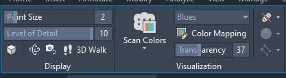
• Transparency, color mapping, cropping, point size, level of detail, and other options are available to tailor the point cloud to be displayed in a way that is most efficient, depending on the type of project on which you are working.
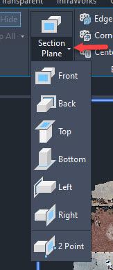
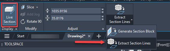
• Slice a cross-section view of the point cloud to view a cross section view of the point cloud by creating a section plane view (Note: this can be done in several views, i.e. top, side, etc. and can be easily adjusted with grips of the section plane or typing in values to adjust the size of the section plane).
USING A POINT CLOUD INSIDE CIVIL 3D
Once the point cloud is attached to a drawing, there are several ways to pull data from the point cloud to be used in Civil 3D design. (Note: this can be without any prior manipulation to the point cloud in other software other than saving it as an .rcp or .rcs file.) As mentioned previously, selecting the point cloud pops up a contextual ribbon can help guide you through those options.
• Snap to the point cloud points as nodes to draw line work or take measurements.
• Adding linework from the data collected for the point cloud manually using object snaps and drawing the linework in Civil 3D can be helpful creating the project’s geometry such as linear features that are shown inside the point cloud.
• Attaching a point cloud in Civil 3D allows you to reference your existing conditions for the project, especially if the point cloud data is colorized. (Note: If the point cloud is being used to look at the existing conditions, double check the point cloud is in the correct geolocation by turning on ESRI maps as noted earlier in this article.)
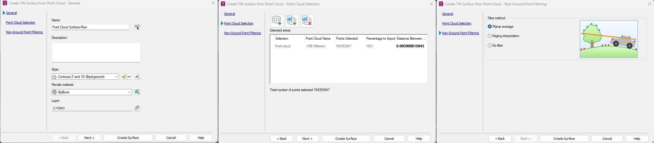
• Create a surface from the point cloud or section of the point cloud (Note: if the point cloud is large, consider decimating the point cloud inside Recap before attaching it, or cropping the point cloud inside Civil 3D to help efficiency and size of the drawing).
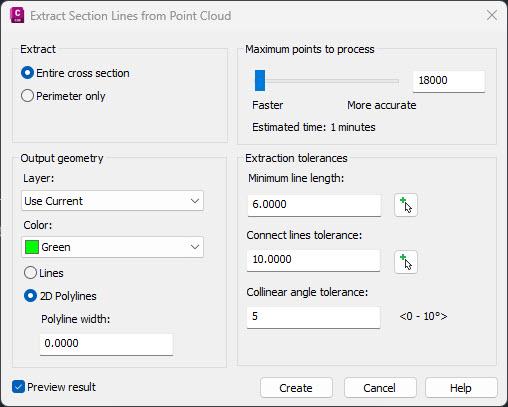
• Creating vectorized linework from a section plane of the point cloud as mentioned in ways to visualize your point cloud. Taking this step further allows automation of some of the linework that is normally drawn from a point cloud.
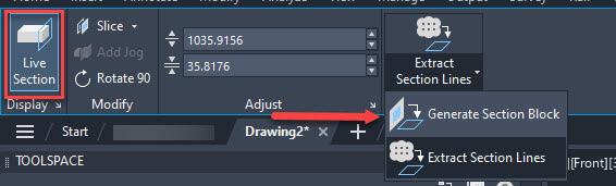
• Create a block of a section plane (note: depending on the view of this section plane, both 2D and 3D preliminary section views are created with little effort to get a better understanding of potential problem areas in the project).
This is just a peek into the options of how to utilize point clouds in your Civil 3D workflow. By using these capabilities, you can leverage point cloud data to create highly accurate and efficient civil engineering designs, improving project outcomes and minimizing errors. Whether you are working on transportation, land development, or other infrastructure projects, point clouds can enhance your modeling and design processes.

Ms. Eva Helps is an Autodesk Certified Professional in AutoCAD and Civil 3D, a Certified Autodesk Instructor, and a Bluebeam Certified Professional. Having over 25+ years in construction, survey and civil world give her a variety of experience to share through design, teaching, managing, and, providing technology solutions for engineering firms and CAD users from all over. Eva is a Civil Consulting Manager at ATG (Applied Technology Group) where she helps clients get up to speed by recognizing needs they may have in their industry, helping dial in their workflows and creating, training, and mentoring in those areas to help achieve the goals to be effective and efficient in their roles and software. She believes collaboration and sharing knowledge is the key to growing both individually and as a community in all areas of life.

Life Lessons –An OG CAD Designers' Perspective

As a “seasoned” CAD user, having worked with Autodesk products for over forty years, I have seen my share of success and failure with things that I have attempted. As I reflect on those years, I see a definite trend in the things that have had the most impact on my level of success in life (or non-success in many cases), even beyond my CAD design career.

FAILURE IS MERELY A STEPPINGSTONE TO SUCCESS
One might think that over a long history in the CAD design field, the greatest impact on a person both personally and professionally would be their achievements and successes. After all, more knowledge and experience will earn you more money and promotions. The resulting mind set of “I can fix anything with my knowledge” would be a logical extension of this mindset.
The reality is, however, that with each ensuing success, even as one becomes more confident in their abilities, people can become complacent
and lose sight of what the real goal should be, continuously learning and expanding one’s skills
I have been driven as much, if not more so, by my failures when seeking a solution rather than the successes I have had. I will try all of my known fixes with a time limit of ten minutes each. If there is no solution, I know that I have done as much as I can based on my skills. Wasting more time than that on a task is counterproductive. My failure in a particular effort is not the first to occur and will definitely not be the last.
Someone else has certainly had the same problem I am experiencing now at some point in their career. I just need to find what their solution was. The Autodesk forms https://forums.autodesk.com/ have been my best source of accurate and properly vetted solutions.

AUTOCAD IS AMAZINGLY ADAPTIVE
The AutoCAD software library covers all aspects of the design field, regardless of your chosen design specialty. Just because you work in a particular discipline, do not limit your search for a solution to discussions on that topic alone.
Basic AutoCAD functions are common to all verticals of the software, in some form. Get to the core of your current challenge and you will find that it is very similar to that of someone in another industry. Do not overlook the possibility of an architectural designer having the same challenge as a mechanical designer. Both work with creating and editing entities in their field and have similar tasks to complete. Focus your thinking on the
CAD
actual process behind a task rather than the entity being affected by said task.
There will be those who are hesitant to get actively involved in the forums (as I was for many years), their concern is being judged or looked upon in a negative light. Everyone on the forums has at some point come there with an issue. Some are seasoned users who are there to share their experiences and tips. These people started out at the same point as the newbie, looking for help. For everyone who has posted a discussion to a forum, you can bet there are ten more lurking in the background and taking in the information presented.
ADDITIONAL RESOURCES – SOME VALUABLE ASSETS, SOME NOT SO MUCH
Knowledge sources are all around us. We can google anything today and AI is now really getting into the ring as well. One must use some degree of caution when searching for solutions. General information from Google may be incorrect, which will cause more issues. When reviewing data gleaned from the internet, use your due diligence in researching the sources and their validity.
AUTODESK CHAT GROUPS – GET OUT THERE AND LOOK AROUND
An excellent source of reliable data is the many Autodesk chat groups online. Just because I use AutoCAD electrical, I do not limit my search feelers to ACADE forums. I belong to Vanilla AutoCAD forums as well as many specialized groups. Someone else, somewhere will or has needed to solve the issue I am having. Do not be afraid to join multiple chat groups, with different focuses than your software. Remember – AutoCAD is one product at heart with many varieties – you are not the first to try and solve the issue at hand
Do not underestimate the value of your experience. Chat groups are driven by user input, and as such, your experience is a valuable resource for information to someone else in the group. Your work environment and processes will, either by being successful or having failed, be a valuable lesson learned to others. Remember, we learn as much from failure as we do from a success. The solution that you found to a past challenge is going to help someone else in the future.

IN-PERSON CONFERENCES
If you can convince your employer to send you to an in-person event like https:// www.autodesk.com/autodeskuniversity/, you will have a whole new experience in learning. With 14k plus attendees’ average, Autodesk University is one of the best places to find like-minded, yet multi-disciplined CAD design professionals.
As an attendee annually for twenty years running, I have had a chance to meet, and learned from, many experts that I could never have otherwise. Being exposed to such a large pool of talent will diversify your background, making you a better-rounded employee. The connections with industry experts and friendships that I have developed have been keystones in my knowledge

database, so it has been a great investment. Having exposure to software as well as users’ experience from disciplines that I would not be able to get has expanded my understanding of what AutoCAD is truly capable of.
There are also other Autodesk conferences throughout the year if AU is out of reach for you. While these events may be more focused on a particular discipline, they are also more likely to be approved of by your employer.
FINAL THOUGHTS
“Success” in your (CAD) career and life is driven by many factors which, when properly managed, will keep you moving forward and learning new skills and techniques to improve efficiency. I have seen many in the industry overlook the benefits of learning from past failures. What does not kill you will make you stronger, as they say. Knowing how to spot and avoid pitfalls is a learned science, yet an invaluable one.

My current employer designs Automated Guided Vehicles (AGV’s) and test machines. I have worked with AutoCAD software for forty years, starting on version 1.4. Having been with my current employer for almost sixteen years and CAD manager by necessity for at least ten, I have seen their culture change many times in attempts to improve processes and become more efficient. CAD standards have become a high-profile topic recently. I am excited to share my process of implementing a user-friendly system of CAD standards with others.
by: Craig
BricsCAD® Moves the Business Needle (Part 2) – Tips and Tricks

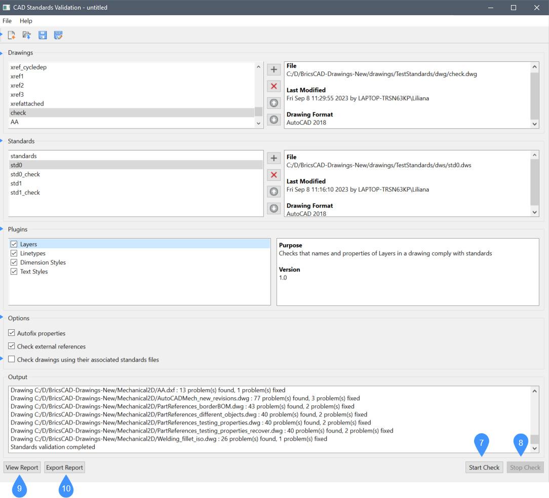
In part one of this two-part article, we discussed the business case for standards like improved efficiency, error reduction, and implementing professionalism. We also covered the benefits of best practices and standards in drafting, and how BricsCAD® tools and features to move the business needle, in turn empowering users to establish and maintain these standards seamlessly. More specifically, we looked at BricsCAD’s standards
checking, Drawing Explorer, Templates and Blocks, and a few more tools that help with best practices.
(See Fig. 1) Now that we have identified how BricsCAD can help us, how do we implement standards?
A mentor and close colleague of mine would ask, ‘Is it the standards implementation that is difficult, or is it the people?’ It’s a thought-provoking question and one that gets to the heart of many challenges in adopting standard practices. But I digress.
Standards implementation can indeed be complex. (See Fig. 2) Beyond the potential for bruised egos, there are technical hurdles, process differences, and the need for consistent training. Yet, people can often be the challenge. For whatever reason, there may be a lack of buy-in. The users could simply be resistant to change. Or they have an insufficient

understanding of the overall financial benefits to the company. Could be all or parts of all three, and there are plenty more we could list. To my point, all of that can significantly hinder the adoption process.
However, this question highlights an important truth: successful implementation isn’t just about choosing the right tools; it’s about having the right mindset. Without teamwork, consistent and constructive communication, and a willingness to adapt, even the best software can fall short. That said, it is normally not one or the other, but a combination of the two. Understanding how to balance these dynamics is key to overcoming hurdles and achieving lasting success. So, let’s figure out how to maximize the benefits of drafting standards by following these best practices:
IMPLEMENTING STANDARDS IN BRICSCAD: BEST PRACTICES
1. Develop Standards & Best Practice Documents
Start by creating a comprehensive document outlining your company’s drafting standards and the company’s best practices. For the standards document, include details on layer naming conventions, text styles, dimensioning practices, and other essential elements. This document should serve as the foundation for configuring BricsCAD’s tools and templates. As for the best practices, provide step-by-step instructions along with screenshots demonstrating the precise methodology needed to complete the task.
As far as which documents and best practices are created first, prioritize them by the sense of urgency and need. (See Fig. 3) It is highly doubtful one person knows everything, so create a team
Fig.
Fig.
BricsCAD
to assist. Keep these documents, along with all other standards and best practice materials, in a location available for all to access. Sharing and reviewing these best practices should also be a part of the new hire and onboarding process within your organization. Additionally, it would be beneficial for your existing staff to review your best practices and guidelines once a year for a refresher as bad habits die hard and require consistent reinforcement to ensure that standards are upheld, and workflows remain efficient. This regular review helps to identify and correct any deviations, keeping everyone aligned and maintaining high-quality production. You never
know when those reviews will spark a conversation about more efficient processes.
2. Leverage Templates
Use BricsCAD’s template feature to embed your standards into every new drawing. Build your own. DWT from scratch or use the default templates located in BricsCAD. Templates save time by eliminating the need to recreate standard settings and layouts for every new project. The template should include predefined layers, blocks, text styles, and layouts, reducing redundancy and ensuring consistency from the outset.
BricsCAD allows you to create templates tailored to specific project types or client requirements, ensuring relevance and alignment with your workflows. Templates also contribute to a polished and professional appearance in your drawings, which is critical for client presentations and plan submittals.
Reminder, if you currently use a .DWT file in AutoCAD®, you can also open/import that same. DWT without any file conversion.
3. Train Your Team
Invest in training to familiarize your team with both the standards and the tools available in BricsCAD. Focus on BricsCAD features related to standards, including:
• Layer Standards: How to create, apply, and maintain consistent layer settings.
• Drawing Templates: Setting up and using templates for new projects.
• Block Libraries: Accessing and managing reusable design elements.
• Sheet Set Manager: Organizing and managing project sheets efficiently.
• Standards Checker: Using tools to verify and enforce compliance with established standards. (See Fig. 4)
Ensure that everyone understands how to use the Drawing Explorer, standards-checking tool, and other features effectively. Create a shared space for tips, challenges, and solutions related to standards tools. Schedule annual or biannual refreshers on standards and tools. Encourage the team to share feedback about challenges or improvements.
Free, online, at your pace BricsCAD training available here: https://lessons.bricsys.com/
4. Automate Repetitive Tasks
Harness the power of LISP and custom scripts to automate tasks that are prone to human error. Start by identifying tasks that are performed frequently or require multiple steps, such as drawing modifications, file management, or dimensioning. This includes setting up drawing properties, inserting blocks, and running standards checks. Enforce standards compliance by creating a script that runs the Standards Checker tool in BricsCAD to ensure that any drawings generated with custom LISP routines adhere to the organization’s standards.
Found out more about BricsCAD LISP here: https:// help.bricsys.com/en-us/customization/lisp
5. Regular Audits
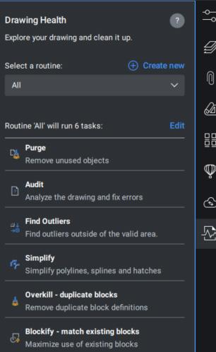
Periodically review your drawings using the standards-checking tool to identify areas for improvement. By checking that all design elements are aligned with standards, you can identify any discrepancies early, reducing the risk of errors that could affect the project down the line. In addition, BricsCAD’s DWGHealth combines the power of multiple commands (PURGE, AUDIT, FINDOUTLIERS, SOLIDIFY, SIMPLIFY, OVERKILL, BLOCKIFY, OPTIMIZE, ARRAYDETECT) in one location. (See Fig. 5)
BricsCAD
DWGHealth reduces drawing size, removes unused styles, entities, and layers, and improves drawing quality. Unique clean-up workflow in the DWGHEALTH system to help maintain superior performance in large drawings. Large or complex drawings can really bog down a machine, especially when there are erroneous elements or inefficient drawing practices involved. Completing a regular QC/QA audit within the DWG ensures that your team remains aligned with evolving standards and business needs. A consistent QC/QA process reduces the risk of client complaints or project delays, improving the overall reputation of the firm or design team. Use the audit results as feedback for continuous improvement.
Discover more about DWGHealth here: https:// youtu.be/Bricsys/DWGCleanUp
6. Feedback is Constructive
Encourage feedback from your team to refine standards over time. Remember, all feedback is good feedback. Recognize and reward compliance. Use incentives like gift cards or small rewards for completing training or providing alternative solutions. Keep in mind that using your standards and best practices in real-world projects often highlights areas where they can be tweaked to make them more practical and effective. Continue to be open to suggestions.
CONCLUSION
When implementing standards and best practices, it is much easier to handle the people when tools and strategies can tip the scales toward greater business success. BricsCAD’s versatile toolkit makes it easier than ever to implement and maintain these standards, ensuring consistency, reducing errors, and enabling automation. By embracing standards and leveraging BricsCAD’s capabilities, businesses can move the needle, achieving greater efficiency, professionalism, and profitability.
To read more about BricsCAD, click below to read Part 1 from February’s AUGIWORLD publication: https://www.augi.com
MORE ABOUT BRICSCAD®
Bricsys® BricsCAD® is professional CAD software without compromise. Accelerate your time to deliverable without compromise on performance,
cost, licensing flexibility, and data security. Not ready to buy? Download the free, 30-day trial of BricsCAD® at Bricsys.com. Would you like free lessons? We have that available with Bricsys Learning. Ready to migrate to BricsCAD®? Download the Migration Guide. The latest version of BricsCAD® improves the tools and features users love, as well as new functionality and UI that supercharge productivity. Follow us today on LinkedIn and YouTube
MORE ABOUT BRICSYS®
Bricsys®, part of Hexagon®, is the global technology company that creates the BricsCAD® family of computer-aided design (CAD) products and the Bricsys® 24/7 project collaboration platform. We are relentlessly committed to the success of our customers by offering cost-effective, missioncritical CAD software with industry-leading product support. Learn more at www.Bricsys.com
Hexagon is a global leader in digital reality solutions. Learn more about Hexagon (Nasdaq Stockholm: HEXAB) at hexagon.com and follow us @HexagonAB

Mr. Craig Swearingen is a Global Implementation Specialist and Consultant at Bricsys. Currently, Craig provides migration and implementation guidance, management strategies, and technical assistance to companies that need an alternative, compatible CAD solution. Craig spent 19 years in the civil engineering world as a technician, Civil 3D & CAD power user, becoming a support-intensive CAD/ IT manager in high-volume production environments. Craig is a longtime AUGI member (2009), a Certified Autodesk® AutoCAD® Professional, and he enjoys networking with other CAD users on social media.


How Do You Calc?
THE CALCULATOR
In the early 80s when I was still in high school it was a big deal to have access to a calculator in math class. But that was not to make it easier for me to perform operations like addition, subtraction, multiplication and division. Instead, it was so that I could perform trigonometric functions without having to waste time looking up the resulting values in a table.
Then after I graduated, my first summer job was working as a bank teller. That was again when having access to a calculator was a thing to die for. At the end of each workday, I would have to make sure my cash register balanced. This means all the customers’ cash/ check deposits and withdrawal amounts must match the totals I have. So, with the help of the calculator, I was able to quickly get this total amount. There was a time, however, I remember I was short by a hundred dollars and the bank manager pulled me aside and gave me a very unpleasant warning lecture. Then there was another time when I came up with a couple of hundred dollars extra. Instead of getting fired, this time the manager told me “Good job & keep up the good work!”
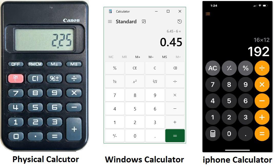
But I’ve got to say having access to a calculator back then is just as important as it is now in our computerized era. Though you may no longer need access that often to your physical calculator, you may still opt to use the calculator program that comes with Windows or better yet the calculator app that’s on your smartphone (See Figure 1).
AUTOCAD HAD NO CALCULATOR
Strangely enough though with a math intensive program such as AutoCAD, it was shipped in 1982 without offering a built-in calculator command. Perhaps the challenge in those early releases had to do with the infamous 640k barrier that DOS imposed which prevented AutoCAD from including a calculator command in their flagship computer assisted drafting product. Or perhaps the focus was on offering needed graphical commands rather than computational ones. Whatever the reasons, there was no calculator included until five releases later.
AUTOCAD’S FIRST CALCULATOR?
In 1985 AutoCAD 2.1 was released, incorporating a powerful programming language called AutoLISP. This made it at least possible to enter math operations at the command prompt. But since it’s using a computer language to invoke a mathematical operation you would have to enter it based on the rules of the programming language. So instead of just typing out at the command prompt 1+2+3 as you would do with a calculator you would have to enclose the statement with an open and close parenthesis. Also, the first entry is not a number, but the math operation symbol followed by the numbers separated with a space (See Figure 2).
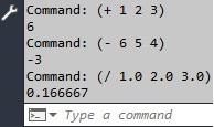
Note: To get a real number result you would have to enter real numbers and not integers.
Figure 2
Furthermore, you cannot combine multiple math operations into a single line of code. So, this means you would have to finish the addition operation statement first before executing a subtraction statement.
Obviously the AutoLISP method of calculating numbers in AutoCAD is not as intuitive as you would like and it’s not the same as inputting numbers into a physical calculator.
AUTOCAD’S SECOND CALCULATOR
In 1992 (a decade after the initial release) Autodesk came out with AutoCAD R12 and made a second attempt of including an actual built-in calculator command called “Cal”. You now can enter calculations normally at the command prompt without having to learn a new computer language (See Figure 3).
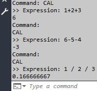
Figure 3
What I also like about the Cal command is that it supports Imperial (feet-inch) format entries. This makes it possible to do complex feet-inch calculations such as the following:
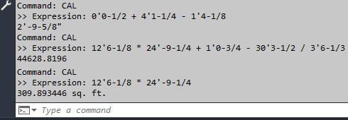
Note: When two feet-inch values are multiplied together Cal returns the result with the suffix square feet [sq. ft.] designation.
Though one of the major features AutoCAD R12 touted was offering a new custom dialog interface to assist with command entry, there was no graphical user interface that accompanied the new Cal command. For me this was very disappointing. Till this day I still wonder why Autodesk chose not to offer a custom dialog box version as the new Cal command.
MY DDCALC
This is when I decided to customize and develop my own on-screen graphical user interface calculator, I call DDCalc (see Figure 5).
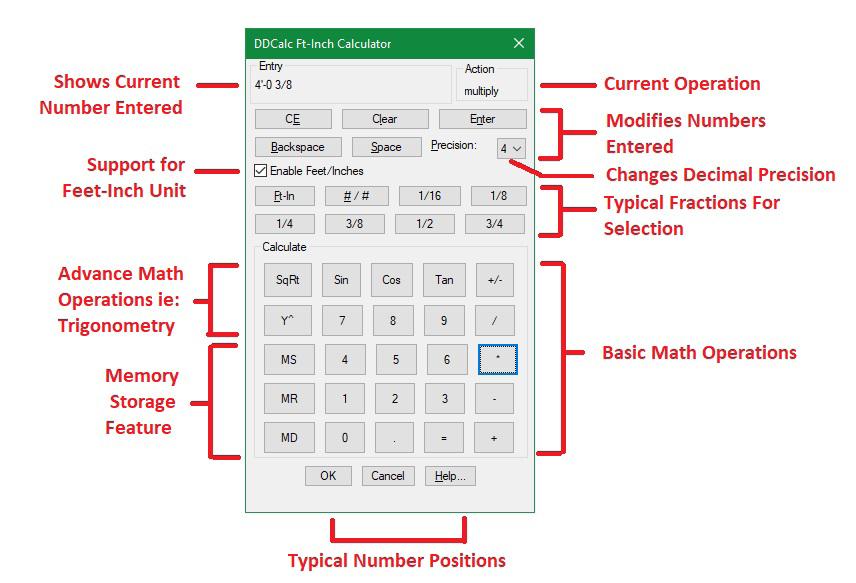
Figure 5
I wanted to accomplish the following with DDCalc:
1. Look and feel of a physical calculator:
I replicated the position of the numbers from [0] through [9] including the period [.] & the equal [=] sign to match with a typical physical calculator. The digits are then surrounded on the left, top & right with various math operations. This makes it easier for a user to find and select what they’re looking for since they’re accustomed to using a typical physical calculator.
2. More than just basic math operations:
Other than addition, subtraction, multiplication & division, I also wanted to include square root & exponentiation. Also, in honor of my
AutoCAD
trigonometry class in high school I included the basic sine, cosine and tangent functions.
3. Support for Feet-Inch calculations:
Since many of us live & work with projects in the United States, it’s very important to have a calculator that supports Imperial units. Doing feetinch calculations in my head tends to give me a headache.
The calculated value can be sent to the command line:
I programmed DDCalc so that it can be executed at the command line as a transparent command. This makes it possible for DDCalc to run within commands like Offset or Scale when it expects a numeric response by preceding the command with an apostrophe [‘] i.e.: ‘DDCalc
Note: I have offered DDCalc to the community free of charge to download & use at the Autodesk App Store: https://apps.autodesk.com/ACD/en/Detail/In dex?id=1609088558180680102&appLang=en&os=W in32_64
AUTOCAD’S LAST CALCULATOR?
Autodesk continued the status quo and did not improve on the Cal command for the next 7 releases (R13, R14, 2000, 2000i, 2002, 2004 & 2005). Finally, after 13 long years AutoCAD 2006 came out introducing the new QuickCalc command (see Figure 6):
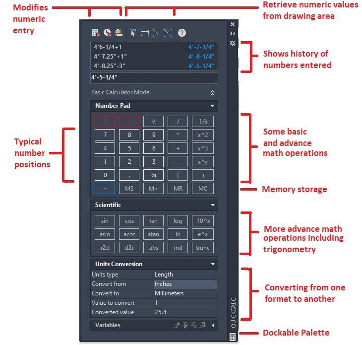
Figure 6
AutoCAD with this third attempt offered a powerful on- screen calculator. There are several advantages with QuickCalc. First, since it runs on a palette instead of a dialog box, QuickCalc can be docked or stay floating on the screen while other AutoCAD commands continue to run. Each section within the palette can be expanded or collapsed. Second, because QuickCalc supports keyboard entry the palette can be collapsed to a very small miniature window on the screen and can still function (see Figure 7).

Figure 7
Third, there are a number of basic & many more advance math functions offered. Lastly, there’s even a section that supports the conversion of numbers from one unit type to another.
Though QuickCalc is a welcome built-in calculator in addition to AutoCAD, I do have the following wish list items:
1. Update QuickCalc’s on-line help file:
For several releases the on-line help file has yet to be updated. It continues to show these toolbar icons at the top which are outdated because they have been long replaced (see Figure 8):

Figure 8
2. Feet [‘] symbol selection:
There should be a button to select the feet
symbol from the on-screen palette. Currently the only option to enter this symbol requires the user to take the hand off the mouse and find it on the keyboard.
3. Current Unit Setting:
QuickCalc depends on the overall Length Type setting in the Units command. There should be a separate setting to override this within the QuickCalc palette (see Figure 9):
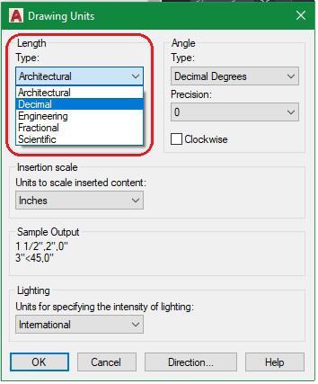
Figure 9
From AutoCAD 2006 till today’s AutoCAD 2025, there has been no major enhancements to the QuickCalc command. Could this be AutoCAD’s last calculator? Well, I will really be surprised if AutoCAD 2026 comes out at the end of March with a brandnew calculator.
WHICH TEAM CALC?
Perhaps some of you, who are reading this article, are only comfortable with the use of a physical calculator. After all, nothing can compare to the touch and feel of the real deal.
Then there are those who have abandoned the
physical calculator completely. Why keep another paperweight lying around on the desk when there are so many superior options to calculate digitally?
Lastly, there may be a third group who want to have the best of both worlds. You prefer to keep both the physical calculator around and are also very comfortable with the use of all the digital versions like AutoCAD’s Cal & QuickCalc.
I would say I’m kind of with the third group here. Though I have put away and hidden my calculator into a drawer, I still want to keep it around as a backup just in case. When there’s a power outage and my iphone is low on battery, that’s the perfect time to pull out my trustworthy physical calculator to do all the calculations I want done.

Mr. Paul Li graduated in 1988 from the University of Southern California with a Bachelor of Architecture degree. He worked in the Architectural field for small to midsize global firms for over 33 years. Throughout his tenure in Architecture, he has mastered the use and customization of AutoCAD. Using AutoLISP/ Visual Lisp combined with Dialog Control Language (DCL) programming he has developed several Apps that enhance the effectiveness of AutoCAD in his profession. All the Apps actually came out of meeting challenging needs that occurred while he worked in the various offices. He has made all the Apps available for free and can be downloaded from the Autodesk App Store. Though he recently retired from the Architectural profession, Paul continues to write articles depicting his past work experience. Some of these articles can be found in AUGIWorld Magazine where he shares his knowledge learned. Paul can be reached for comments or questions at PaulLi_apa@hotmail.com.
Welcome to AUGIWorld Inside Track! Check out the latest opportunities to advance your skills, processes, and workflows in your firm with the most current AEC-related software and hardware updates available.
Inside Track 5bLet’s Look at DiRoots! (cont’d)
Gentle Reader - today let’s continue our foray into the world of DiRoots and examine some more of their offerings.
But before that, as always, let’s get the formal introductions out of the way -
Gentle Reader - More about DiRoots
More about DiRoots - Gentle Reader
So, what’s next? Which add-ins might we be looking at today?
My esteemed cohorts have long shared that the DiRoots free tools have become a standard part of their companywide software installs (in ever-so-musical concert with the love of my life, pyRevit). We visited with these lovely tools during my last chat with you -
• DiRootsOne
• DiStem Beta
In this issue, we’re going to talk about
• DiRoots App Manager
• DiStellar - a Web-based IFC viewer to manage BIM models
• DiRootsOne for AutoCAD
I’m going to start the second part of this list with DiRoots App Manager 2.0.0!
If you’re like me, you’re very unenthusiastic at the prospect of disabling Revit add-ins. You would need to do so to address unexpected behavior like slow performance or bugs and conflicts. To manually disable add-ins, at the very least, you would need to locate this folder
C:\ProgramData\Autodesk\Revit\Addins\[Version] and temporarily move the add-in files to another location, moving them back once you’ve tested for the unexpected behavior. What a drag!
Which brings us to the hero of this part of our storyDiRoots App Manager
This add-in offers a clear and easy interface to manage all add-ins on your machine.
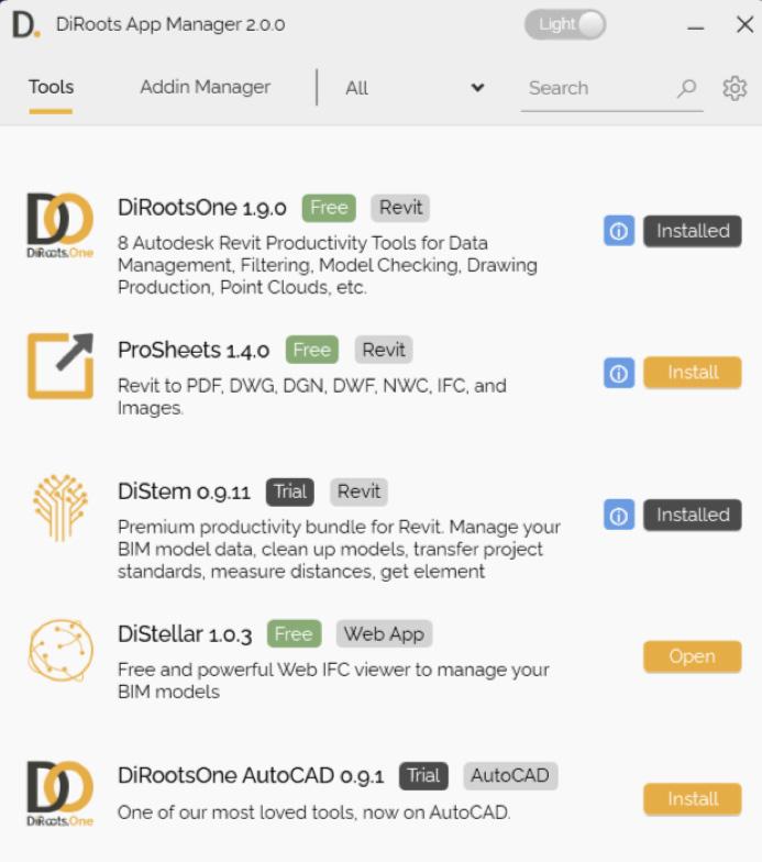
By default, it opens with a screen that updates dynamically to inform the user about add-ins which need to be downloaded, updated, installed / uninstalled or repaired.
In this screenshot taken last week, you can see that I have DiRootsOne and DiStem installed - this morning I saw that DiStem needs to be updated. It definitely helps to keep you up to date with the latest in the DiRoots world.
Using the Download, Update, Install and Uninstall / Repair buttons removes the need to go to the website to download; and extracting the ZIP file. Quite a time saver.


You can make the display simpler for yourself by clicking the All tab to filter this screen by softwareAutoCAD, Revit, or Web App.

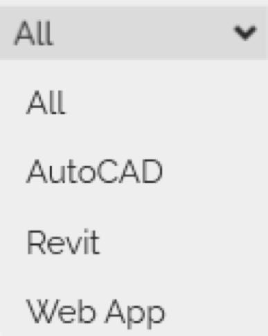
The AddIn Manager tab gives access to all add-ins installed on your machine. Enabling or disabling an add-in is now a simple matter of a mouse click.
You may notice in this screenshot that some addins are faded out. A hint - look at the bottom of the dialog box. This is because you may not have
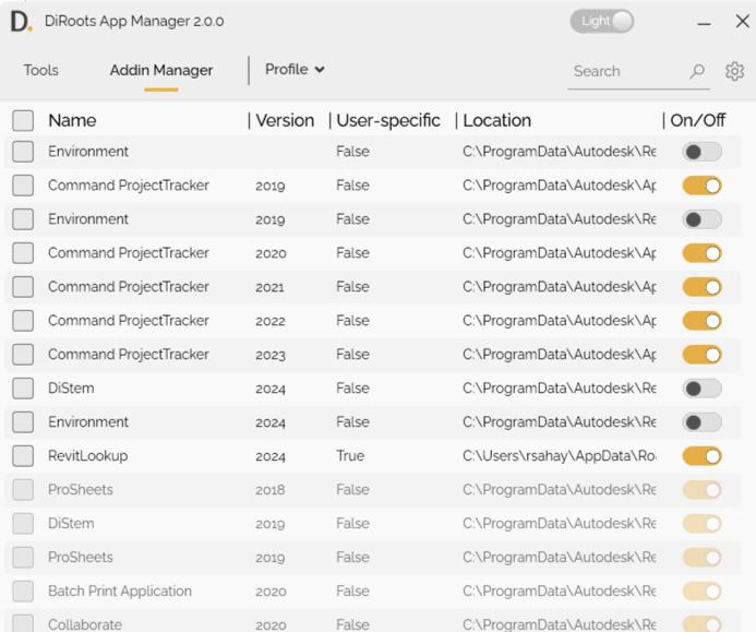
the required privileges. Right click and Open as Administrator to resolve this. You now have more firepower to test and manage your add-ins to enhance your machine’s performance.
(Note - another alternative is the Stantec Add In Manager mentioned in this Autodesk resource -
HOW TO DISABLE ADD-ONS FOR REVIT
This resource ALSO directs you towards the Ideas Forum location to vote for the idea for a native Revit Add In Manager!
Please vote!! Our votes got the tabbed Project Browser going for Revit 2025.2 - we can get this too!!).
DiStellar (Beta)
DiStellar is an online IFC viewer developed to manage BIM models. This is a completely mouse driven web app that can be opened from https:// diroots.com/apps/distellar/. You do need an account to sign in and use the tool. It supports IFC2x3 and IFC4.
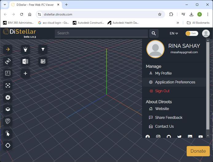
To start with, you can set up your Preferences to control and override how elements are displayed. You can even set materials to be transparent to get a better view of the inside of the model! Click on your photo at the top right and set up Application Preferences.
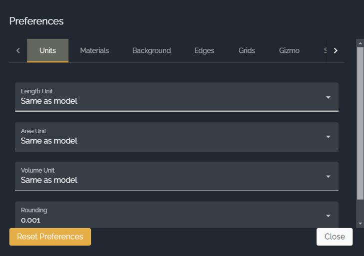
You can add multiple IFCs into the same scene
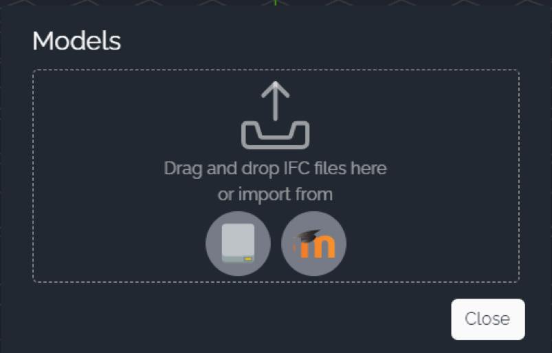

Model elements are searchable using the Model Tree or the Search function at the top of the screen.
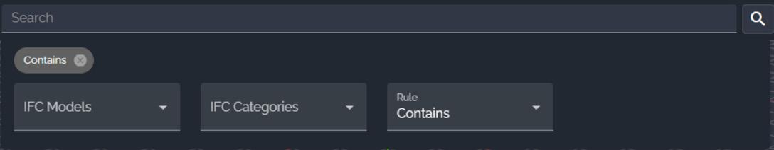
You can view the model in 3D or in a Floor Plan view, take Snapshot images of the model.
The feature that I liked the best was the dynamic Sectioning tool where you can define and drag a section plane to see what you need to.

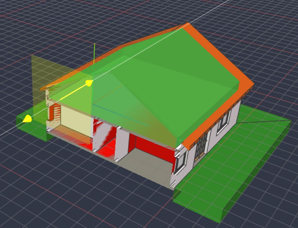
(IFC sample file - courtesy https://www.steptools. com/docs/stpfiles/ifc/ )
Here’s what I noticed during testing - DiStellar worked well with smaller IFC models, but when I opened one of my larger IFC projects basic functions like Zoom, Pan, and Orbit showed a marked loss in performance. A definite negative for larger projects - industrial, retail, healthcare, and higher ed.
Also - since this tool can view multiple IFCs at the same time, it’s a shame that it insists on saving each of them separately and won’t merge them into one. Well, it’s still in Beta stage, and I have high hopes for its future.
DiRootsOne for AutoCAD (Beta)
DiRootsOne for AutoCAD is still in its public Beta stage. It supports AutoCAD verticals like Civil 3D, Advance Steel, AutoCAD Plant 3D, AutoCAD Architecture, AutoCAD

Electrical, AutoCAD MEP, AutoCAD Map 3D, AutoCAD Mechanical, etc. through versions 2021-2024.
Currently it features OneFilter, which uses advanced conditional rules to quickly find elements
• By Layer
• By Object Type
• By Properties
In the example in the screenshot below, I am filtering the Current Selection of gridlines. I would need to click on the button next to Filter by Layers to activate it and filter the gridlines by Layer.
Elements may be searched for in
• The Whole Model
• Current Selection
• Active Space (an option I don’t see very commonly used)
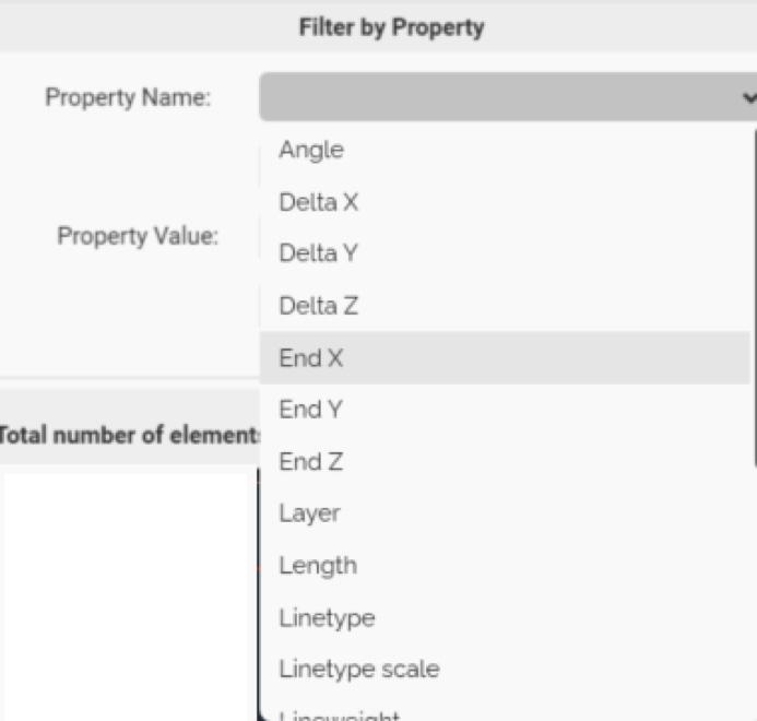

To then filter these gridlines by Property, I would need to click for the drop down for Property Name to filter by a specific Property.
A feature that is on its way is SheetGen, which automates drawing production workflows.
At the risk of repeating myself, O Gentle Readeras tempting as it may be to see your UI bedecked

with all these wonderful tools, please restrain the urge. Please don’t strain the software’s teensyweensy little brain by giving it too many add-ins to deal with! Avoid the resulting undesirable aftereffects like poor performance, possibly model corruption. Utilize them ONLY on an asneeded basis. Disable / Remove the Extension once the need has passed. Better safe than sorry!
Watch out for the next episode, Gentle Reader! Until then - Keep Reviting!

A bit about myself. I’m the BIM Manager at Abonmarche, based in glorious Grand Rapids, Michigan (Great Lakes, anyone?). Started my Autodesk journey with AutoCAD Release 10 (remember that dreary DOS interface - and the need for super-duper spelling skills?). Learned enough Revit to stay one chapter ahead of college students in the classroom. That changed in a hurry when I made a triumphantly painful return to industry as a BIM Specialist and had to use Revit in the worst way possible. I HATED it and grieved for my beloved AutoCAD every day! Until I figured Revit out - the rest, as they say, is history. Autodesk Expert Elite in 2018, presenter at Autodesk University since AU2019 (and I have Best Speaker awards for 2021 and 2022 to show for it!). And now here I am, to educate, enlighten, and hopefully, entertain.

Please let us know if you have some news to share with us for future issues. Likewise, if you are a featured product or news item user and would like to write a review, we want to know. Drop me a line at: rinasahay@gmail.com. We’d love to hear from you!

AUGI Members Reach Higher with Expanded Benefits
AUGI is introducing three new Membership levels that will bring you more benefits than ever before. Each level will bring you more content and expertise to share with fellow members, plus provide an expanded, more interactive website, publication access, and much more!
Basic members have access to:
• Forums
• HotNews (last 12 months)
• AUGIWorld (last 12 months)
DUES: Free
Premier members have access to:
• Forums
• HotNews (last 24 months)
• AUGIWorld (last 24 months)
DUES: $25
Professional members have access to:
• Forums
• HotNews (full access)
• AUGIWorld (full access and in print)
• ADN 2013 Standard Membership Offer
DUES: $100
Bright Ideas for a Bright Future

AUGIWORLD brings you the latest tips & tricks, tutorials, and other technical information to keep you on the leading edge of a bright future.