


Ihope you had a great summer and were able to enjoy some time off with your family and friends.
I can’t believe it’s September which means back to school time for a lot of kids and back to the daily grind for us parents in shuttling those kids to school in the morning along with making sure they are on time to those marching band and sport practices, private lessons, and school activities. All I know is time goes by too fast, and I’m trying to enjoy every minute of it as I have a senior in high school and another one going off to an out of state college to start her sophomore year. Where does the time go?
As for AUGI, we’ve had another crazy couple of months in successfully launching the new AUGI Community Platform.
As of early August 2024, we have about 320 new community members, and we are getting some great feedback about ease of access through the mobile app. Getting comments like the one below is really igniting us in continuing to provide our members with new perks that have direct impact on your daily work.

If you haven’t signed up already, what are you waiting for? Go to the AUGI homepage to sign up today.
In this month’s AUGIWORLD Magazine articles, it’s all about the Salary Survey. This is one of our flagship pieces of content that we produce every year, and we are very proud to be able to provide real data around salaries across different position types and industries.
Now this wouldn’t be a success without those professionals that took the time to participate by completing the survey, so thank you for your time!
And last but not least, AUGI would like to give some special recognition to Melanie Stone.
She is the force behind the scenes in getting the salary survey ready, sent out, and all data organized for publication. A lot of effort goes into this every year, and we are very grateful for her efforts and time, so please join me in giving Melanie a big THANK YOU!!
I hope you enjoy this month’s issue and a big thanks to all of the Authors that have contributed an article this month.
Until next time…
Eric
www.augi.com
Editor
Editor-in-Chief
Todd Rogers - todd.rogers@augi.com
Copy Editor
Isabella Andresen - isabella.andresen@augi.com
Layout Editor
Debby Gwaltney - debby.gwaltney@augi.com
Content Managers
3ds Max - Brian Chapman
AutoCAD - Matthew Marrero
Civil 3D - Shawn Herring
BIM/CIM - Stephen Walz
BricsCAD - Craig Swearingen
Electrical - Mark Behrens
Manufacturing - Kristina Youngblut
Revit Architecture - Jonathan Massaro
Revit MEP - Jason Peckovitch
Tech Manager - Mark Kiker
Inside Track - Rina Sahay
Advertising/Reprint Sales
Kevin Merritt - salesmanager@augi.com
AUGI Executive Team
President
Eric DeLeon
Vice-President
Frank Mayfield
Treasurer
Todd Rogers
Secretary Kristina Youngblut
AUGI Board of Directors
Eric DeLeon
KaDe King
Chris Lindner
Frank Mayfield
Todd Rogers Scott Wilcox Kristina Youngblut
Advisory Board Members
Shaan Hurley Shelby Smith
Publication Information
AUGIWORLD magazine is a benefit of specific AUGI membership plans. Direct magazine subscriptions are not available. Please visit www.augi.com/account/register to join or upgrade your membership to receive AUGIWORLD magazine in print. To manage your AUGI membership and address, please visit www.augi. com/account. For all other magazine inquires please contact augiworld@augi.com
Published by:
AUGIWORLD is published by AUGI, Inc. AUGI makes no warranty for the use of its products and assumes no responsibility for any errors which may appear in this publication nor does it make a commitment to update the information contained herein.
AUGIWORLD is Copyright ©2024 AUGI. No information in this magazine may be reproduced without expressed written permission from AUGI. All registered trademarks and trademarks included in this magazine are held by their respective companies. Every attempt was made to include all trademarks and registered trademarks where indicated by their companies.
AUGIWORLD (San Francisco, Calif.) ISSN 2163-7547


Let me preface this article with a clarification; my experience at a drafting board cannot be underestimated. I firmly believe that basic drafting board skills teach practices that last a lifetime of design.
This is my forty-fourth year of working with AutoCAD. At the time of my introduction to the software, I did not know much about Autodesk, let alone thought about the potential for changing my life.
I had just graduated high school, where I started Board based design and drafting classes my senior year. As I got better (in my mind anyway) at the board drafting in class, I saw that the design / drafting field would be my guiding path from then on. It has been a fantastic trip and a lifetime of learning and following the evolving CAD design field.
While attending community college in the evenings to learn AutoCAD, I worked on a drafting
board every day. The ability to see the unmatched productivity of CAD software while doing board work was eye opening.
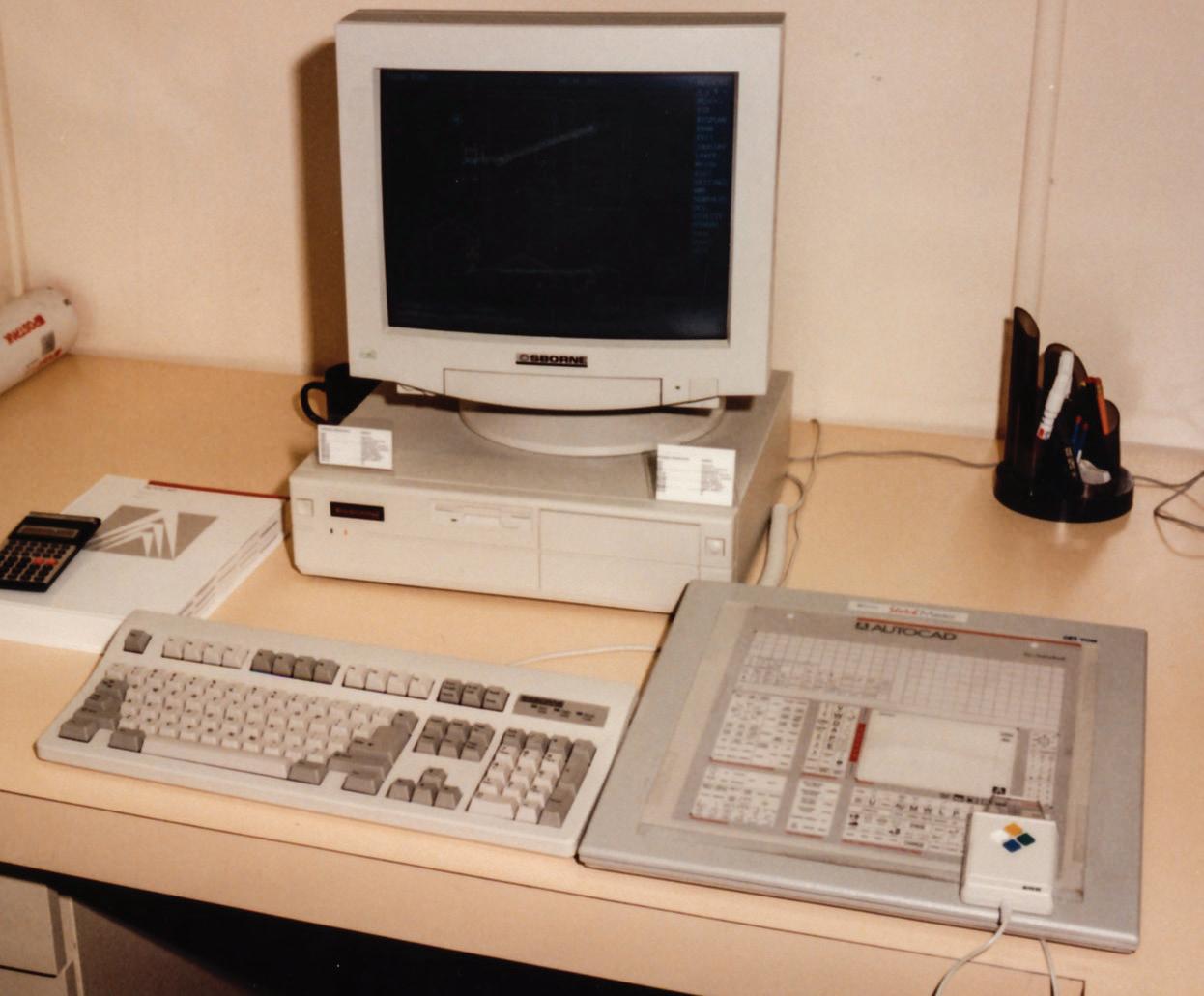
My first few CAD classes were on a dinosaur computer, which, as the classes were during fall and winter, worked to my advantage. The first computer I started on kept the room quite warm, and the CRT tube had a nice radiating warmth to it. The ambience in the room was cozy, especially with the touch screen and light pen setup. You could really feel the energy radiating from that CRT (an early version of fake tanners).

As CAD classes progressed, we got into “newer” technology, incorporating the digitizer pad, which was a great (?) leap in technology. One thing about attending a community college, instead of a wellknown university that I soon learned, is that some of the equipment was a *bit* outdated.
As I advanced in my classes, I got the knack for CAD design, and it seemed to come to me naturally. I would finish my assigned work very early in the semester and took to teaching some of the other students that needed help. I enjoyed showing other people solutions to their challenges, as I got to meet many diverse people that way.
At that time, Autodesk had their tablets serially
linked to the software on the host machine. As some of the equipment was failing with age and constant use, students would swap out the failing tablets for another. This was a major lesson learned about AutoCAD as I had just started using the tablet myself. It was just the start of my CAD management and troubleshooting path, which ran parallel to CAD design.
As luck (or fate) would have it, Autodesk stopped linking the tablet serially to the software with a new release. My knack for finding issues and working to solve them was something that I took and ran with. I can honestly say that even though there was a teacher in the classroom, the software was self-taught as was the troubleshooting skill that I developed. I credit those early years of having to learn by the “trial by fire” method with my drive to succeed in CAD design and to solve challenges that CAD users would find and present.
There is nothing more rewarding than watching someone with a challenge, work through it and find that they are more capable than they thought. My drive to succeed and get others to do so, was on.
A side effect of having others come to me with issues they found was that I could learn many more challenges about AutoCAD than if I just studied it myself. Every issue that I helped another with was an issue that I knew how to avoid in my own work. This may seem a minimal point, however, I learned early on to note the root cause of CAD issues, and find workarounds for them, making me think


outside the box as a normal routine.


The mindset of approaching a challenge from a unique angle, rather than head on when working in AutoCAD became the normal routine for me.
I learned that working with AutoCAD in the real world was a bit different than what the books taught you.


In the real world of AutoCAD, there are many paths to a common goal. I found that as users would prefer a certain path, that path would have its pros and cons. Having navigated these good and bad points made me realize that AutoCAD, for all the published benefits, had a few hidden solutions that were never taught, only learned from experience.
I worked in several places doing CAD design, each of which provided a new window into the world of AutoCAD. When interacting with new CAD designers, I found it a learning experience quite frequently. Some users were cowboys that would do their own thing and experiment with the software, while others stuck to the Autodesk training guides. This has helped me develop the mindset (which I still follow today) that any opportunity can be met with a solution if one is flexible in their approach.
I learned not subscribe to the mindset that just because Autodesk frames a function in a certain way, it must be applied as such. I have been able to apply this to many aspects of my CAD work.
I began trying out new ways of using existing commands and functions of the software as I found new challenges during my career. What I found is that there is practically anything that AutoCAD can
do, if you think about the end goal of your journey, not the road you are taking.
During my many years with Autodesk, I have been active in their research and testing activity. I have seen some excellent features, and some, not so much. The research and testing I have done with Autodesk has contributed to my “there must be a better way” mindset. The result has been that there is almost always a solution to any task I take on, even outside of CAD work. In approaching things with an open mind, one can see several paths to the same destination, rather than taking the longest or most troublesome road.

The overall impact that working with Autodesk, and AutoCAD in particular, has had on me is one of understanding a challenge as an opportunity, and creating the goal of finding the best solution to that challenge. This means looking at all (even the deeply buried) options, not just what the books call for.
In closing, I wish to leave you with this thought; the discipline and attention to detail developed in my years of CAD design have been beneficial in all aspects of my life and led me to develop certain protocols in everyday life. It is always good to be spontaneous and enjoy your time. When there is a challenge presented to me, I credit my years of working in the Autodesk culture with showing me a clear path to take.

My current employer designs Automated Guided Vehicles (AGV’s) and test machines. I have worked with AutoCAD software for forty years, starting on version 1.4. Having been with my current employer for almost sixteen years and CAD manager by necessity for at least ten, I have seen their culture change many times in attempts to improve processes and become more efficient. CAD standards have become a high-profile topic recently. I am excited to share my process of implementing a user-friendly system of CAD standards with others.

Old School vs New School, Drafters vs Techies. As technology becomes an increasingly integral part of our daily lives, the field of architecture is also experiencing a generational divide. Traditional Drafters argue that technology is limiting the creative process in design, while the Techies maintain that technology serves to enhance designs and bring them to life. However, is there not a middle ground to be found? Can technology complement the design process? Allow Revit to augment the design process, even if it entails the creation of new workflows that deviate from its conventional uses for features such as Phases, Filters, and Worksets.
In this article, we will explore the innovative application of Revit’s features beyond their standard applications to develop nine distinct drawing sets for an existing, multi-story healthcare facility. This intricate project involved numerous renovations, relocations, and a five-story addition, all partitioned into multiple phases and sub-phases. All these transformations were carried out while the facility remained fully operational.
The first thing we had to understand was who do the drawings speak to:
• the Owner desires to see the ‘pretty picture’ along with a comprehensive overview of the project, which in this case, necessitated the drawings to illustrate all sequences of events, including construction and non-construction items such as relocations, to always keep the facility operational.
• the Contractor uses them as a tool to build from, determining the means and methods for implementing the design.
• the Engineers/Consultants use the architectural drawings as a roadmap to understand the packages, phases, sub-phases, etc., and to determine their responsibilities and account for existing elements.
• the AHJ (Building Department) reviews the drawings to ensure compliance with code requirements.
• the AHJ (Healthcare Agencies) reviews the drawings to ensure compliance with healthcare guidelines and requirements.
Next, we identified what’s needed to be conveyed in the drawings to fully communicate the design’s intent. The determination of the project structure
was crucial here. For this project, multiple packages of construction drawings were submitted as individual projects for permitting. Some of these packages would occur independently, while others would overlap concurrently.
This is where Revit proved its worth as a tool for production, rather than limiting our needs due to its predetermined settings. For instance, even though Revit designates a feature as Phases, it does not necessarily have to be used only for construction phasing.
Now the fun part for the Techies: the how. Exploring how to leverage Revit’s multitude of features to bring the design to life.
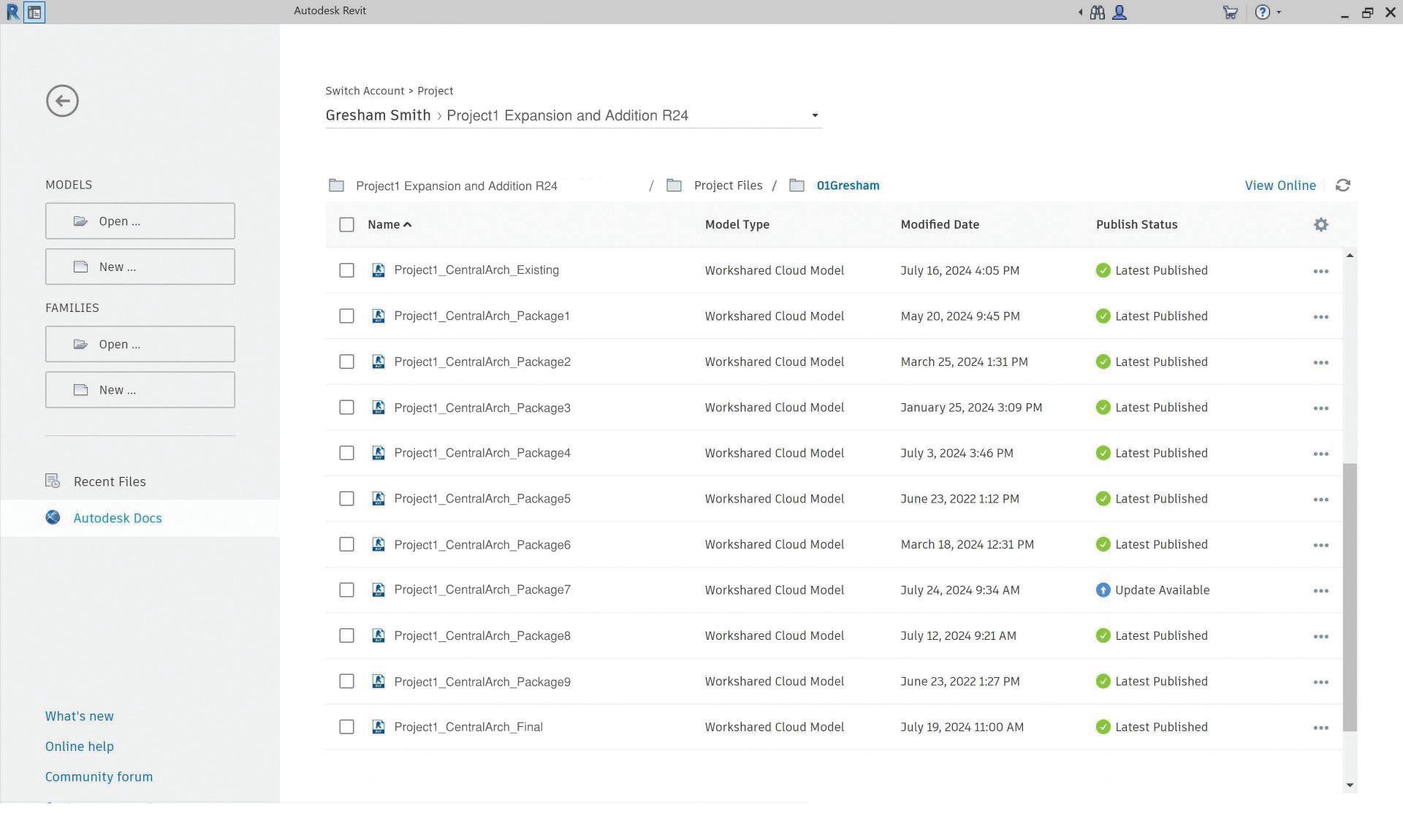
It was agreed that each package (project) would be its own Revit Model. This facilitated a more secure workflow in terms of model management. For instance, it helped reduce model size, limit the number of team members in the model at any given time, and control changes to the model once a specific Package was completed. Having a separate model per package also allowed for the repetition of Sheet Numbers, clear distinction
between and tracking capabilities of Revisions, and fewer overrides or customization of drawings settings to display the desired content, especially since the construction of some packages would happen simultaneously. This method also provided a clear scope of work area for the Design Team, Contractor, Owner, and AHJs.
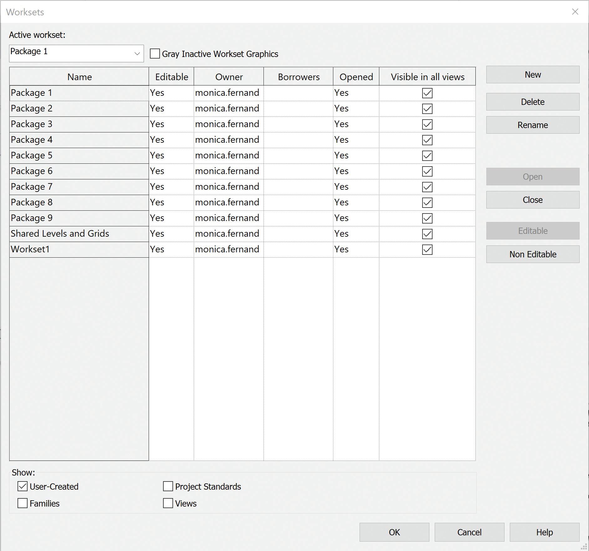
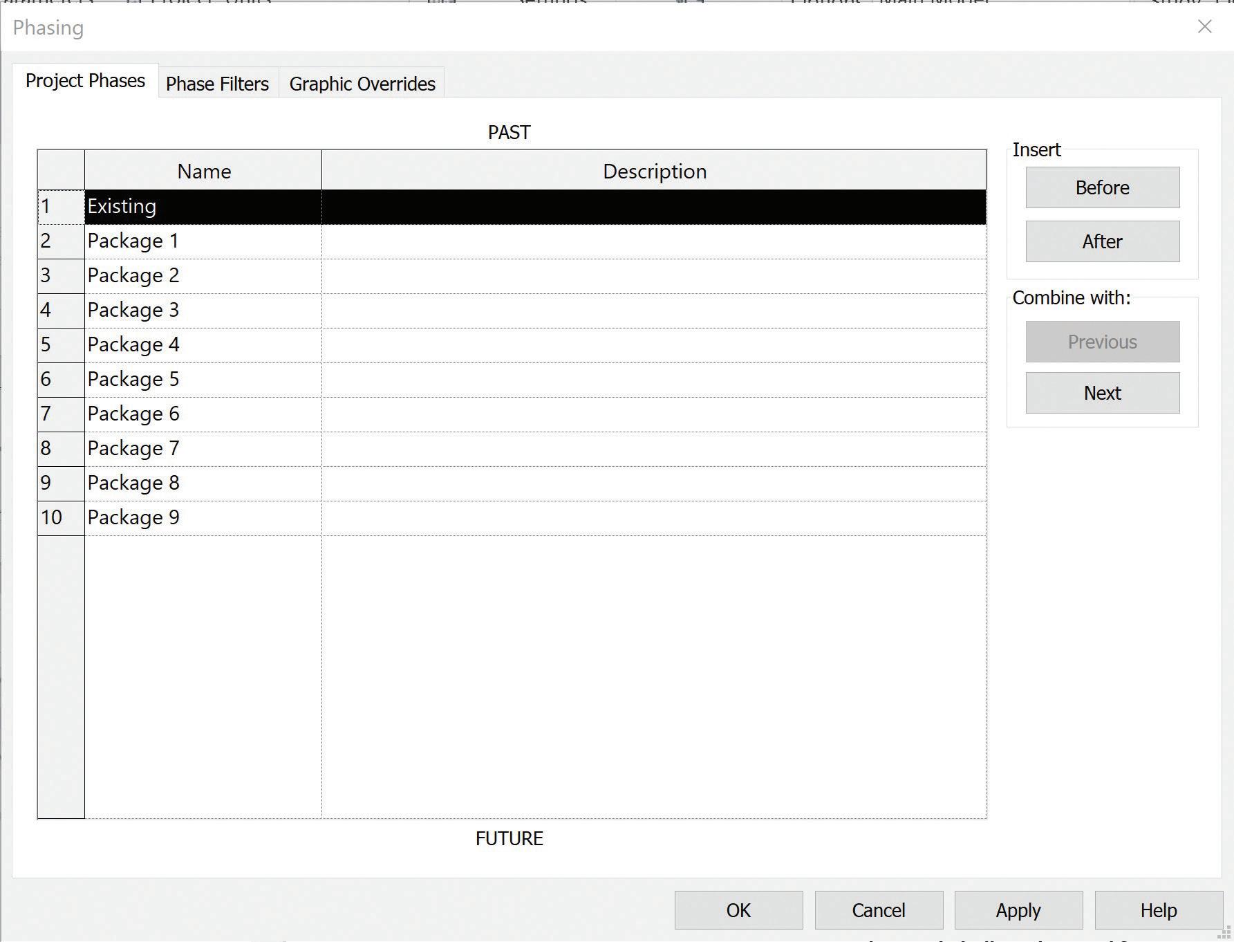
To accomplish the desired modeling sequence (Construction Phase) for the drawings, a combination of Worksets, Revit Phases, View Filters, and Templates were utilized. All elements of each package were assigned into their corresponding Workset. For instance, all elements in Package 1 Model were assigned to Workset Package 1. Along with this, Revit Phases were also created for each package and assigned to each element. In retrospect, this seemed like double work, as Revit Phases alone would have sufficed, but having both provided an extra layer of graphics visibility control when required.
It is worth noting that adding “Demo” as a Revit Phase was neither used for this project nor recommended. Doing so will cause a conflict between the applied Phase and Phase Filter, resulting in inaccurate graphic overrides.
Now, you might be wondering how Construction Phasing was represented if Revit Phases were used for each package. This is where we collaborated and explored Revit’s vast array of features and workflows to achieve our desired graphics such as line types and colors.
Within each package, View Filters were established and incorporated as a Phasing Sequence, to represent the Construction Phases for the drawings. The aim was to depict which departments were to be relocated and/ or demolished to allow new construction, while incorporating sub-phases to represent temporary construction requirements and remaining operational.
Elements were assigned to the various View Filters depending on their construction phase. In this example, we will demonstrate how these
construction phases and sub-phases were established and represented in Revit. Phase 1a entailed relocating departments to a temporary space, Phase 1b involved vacating the space and demolishing existing conditions and constructing temporary barriers, and Phase 1c focused on constructing new work scope. This process was carried out while simultaneous work occurred on a different floor for Phases 2a-2e which relocated the displaced modalities into the originally vacated spaces.
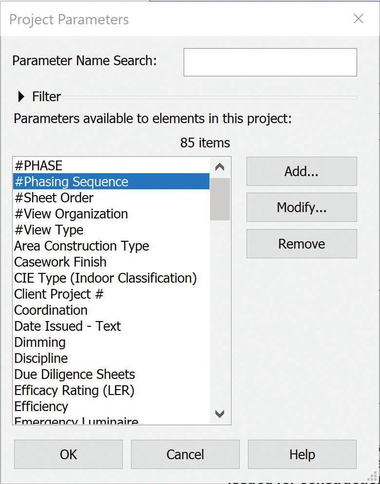
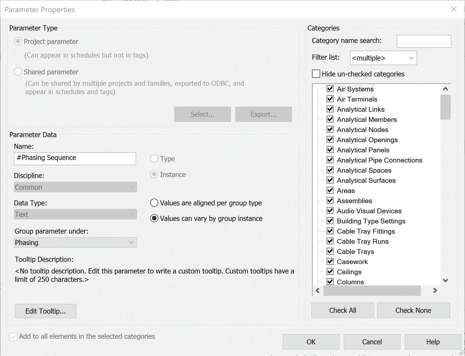
Let us clarify something: Phase Sequence? That is not part of Revit! Correct, “#Phase Sequence” was added as a Project Parameter encompassing all model objects. This parameter was applied to each View Filter to graphically control when elements appear on the drawings according to their corresponding construction sequence.
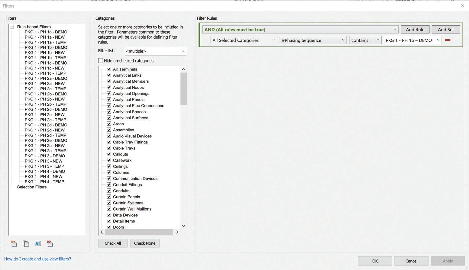
In Revit, Phase Sequence Filters were applied as follows: existing elements set to be demolished were assigned the Phase Sequence “PKG 1 - PH 1 – DEMO”. Temporary elements like partitions, doors, and spaces were added to “PKG 1 - PH 1 – TEMP”, and new construction elements were added to a filter named “PKG 1 - PH 1 – NEW”. This approach was beneficial when creating a series of drawings - be it demolition, phasing, interim, or new construction plans - by clearly designating which stage should be displayed for that specific state.
Once elements were assigned to their corresponding Workset, Revit Phase, and View Filter/Phasing Sequence, View Templates were created and assigned to each drawing. These View Templates allowed for multiple graphics visibility combinations to accurately represent the desired Construction Phase in a consistent manner across the multiple packages, phases, and sub-phases.
Whether you are a Drafter or a Techie, we all strive to achieve the best possible design for our projects and produce a clear set of Construction Documents. Fortunately, we were able to leverage Revit’s multitude of features to enhance workflows and production, allowing us to focus on what truly matters - design. As a Designer, it is crucial to guide the program and maximize its capabilities to realize the intended design rather than allowing the program to limit the design due to its predetermined functions.

Monica Fernandez is a licensed Architect at Gresham Smith which is a national architecture and engineering firm. In 2021 Monica was also licensed as a General Contractor in the state of Florida to better understand how built environment is integrated/interconnected with design. She is currently practicing in the firms’ Healthcare market but has also worked the Life and Work Place market as well. For the last 7 years working with large national accounts across multiple offices and several states Monica has worked on project of all sizes from one room renovations to multimillion square foot campuses. Monica showed her passion for Revit model integration and efficiency by leading monthly training sessions in the Miami office before transferring to the firms’ main office in Nashville. Using her BIM strategy and management experience on large projects, Monica helps her project teams develop new workflows that target specific project needs and acts as a liaison with Gresham Smith’s Practice Technology group. In her spare time Monica enjoys traveling and spending time with friends and family.

Iuse Civil 3D almost every day and mostly for single family land development projects. These are some of my daily commands I just can’t live without! Almost every project I start, or potential project, begins with some sort of GIS data, either for boundaries or for topo, prior to sending out my survey crews to capture data. Couple a rarely used surface analysis with the stage storage analysis and you just saved yourself valuable time!
By far my favorite command in Civil 3D is MAPWSPACE!! One simple command can open the portal to utilizing the power of GIS data. You could change your Civil 3D workspace to the Planning and Analysis tab, but this gets you started with using the GIS data.
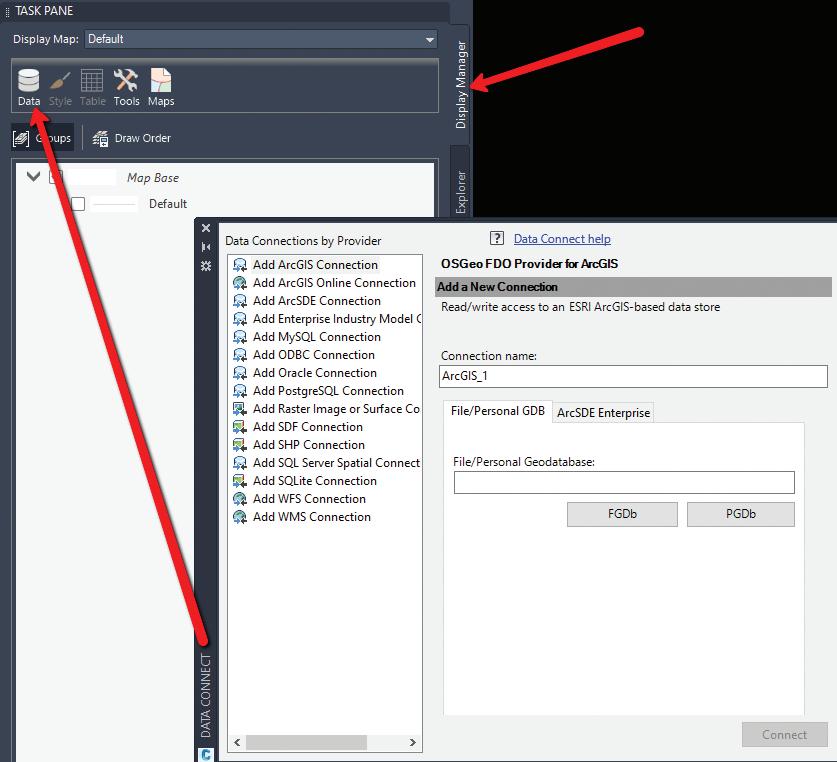
Once you type in MAPWSPACE, you then turn on the Task Pane. The Task Pane gives you quick access to frequently used features, and groups these features into task-related views. Use the Task Pane to create, manage, display, and publish maps. You’ll notice 4 tabs; in this case we will focus on the Display Manager.
In the Display Manager, you can simply select the DATA icon and connect to numerous data sources! Here you can import shapefiles, connect to external databases and even bring in imagery.
Did you know you can simply select your shapefile from Windows Explorer and drag and drop it on your screen? By far the easiest way to import GIS data!! Once dragged onto your screen, the layer will show in the task pane where you can query, theme, style, label and access all the attribute data within the DBF file. If your coordinate system is set, it will project to the correct location, or re-project as needed.
TIP: Need to do a quick concept plan? Drag and drop your parcel shapefile, select the property you wish to use, right click, check out feature and explode!! This creates a polyline that you can then utilize the parcel features on. And if your CAD manager asks who told you to explode something in Civil 3D….it sure wasn’t me!
Select the entire layer from the Task Pane, or even a feature from within model space, right click and choose SHOW DATA TABLE. This will display all attributes for that selected feature.
Right click again on the layer from the Task Pane, you can perform all sorts of analysis and creation
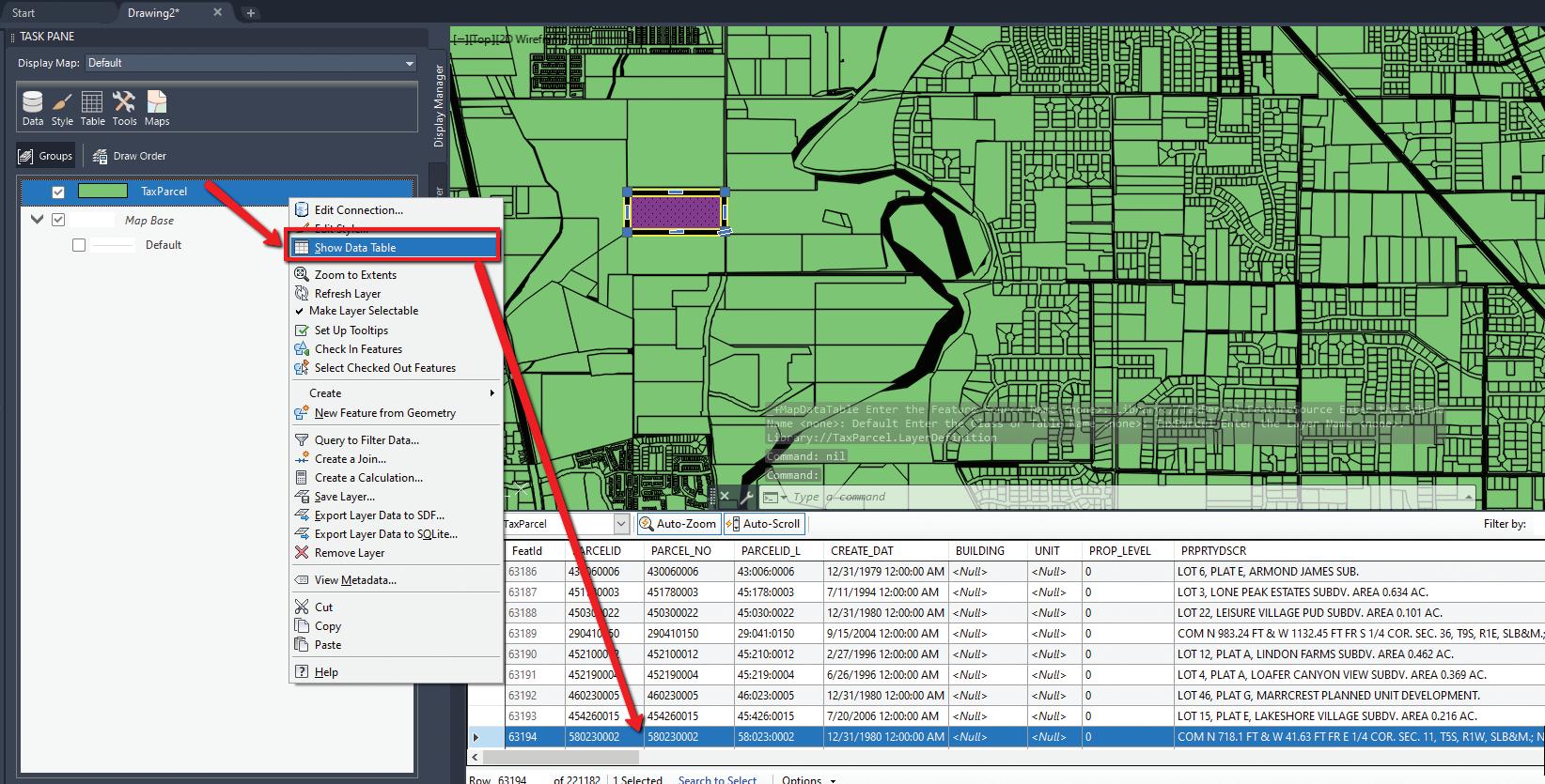
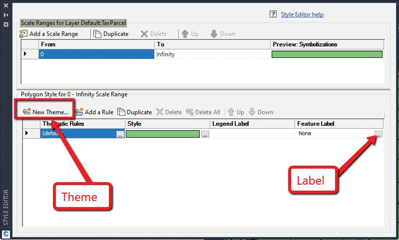
tasks right from here. Want to label and change the display? Simply select Edit Style.
In the style editor, you can perform many helpful tasks. You could, for example, theme the parcel shapefile and look for all parcels between 5-10 acres. This works great for soil types, utility line sizes and many other uses. You could also edit the style (hatch pattern/polyline) as well as add a label based on the feature attributes.
All this from dragging and dropping a shapefile and using the Task Pane! All without switching workspaces and great for just getting started with GIS data.
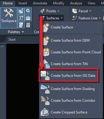
I see a lot of people struggling with creating surfaces from GIS data, specifically large datasets with a lot of contours. Users tend to import as polylines and add the polylines, with millions of vertices, to a surface and wonder why the slowdown or crashing happens.
From the Home tab of the ribbon, on the Create Ground Data panel, select surfaces and about halfway down there is a Create surface from GIS Data option!
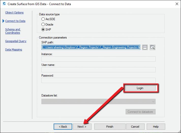
In here, you can connect to 3 different data sources:
• ArcSDE
• Oracle
• SHP – Typically most common
When connecting to a SHP file, select the SHP as the source, and path to the SHP file. Then select LOGIN (no username or password needed) and NEXT.
On the Data Mapping dialog box, simply map the elevation attribute to the elevation Civil 3D Property!
Prospective customer calls needing a quick concept? Need a quick topo map added to that concept? Have access to County or state LiDar data? If so, simply combine those first 2 commands and turn out quick concept plans in minutes!
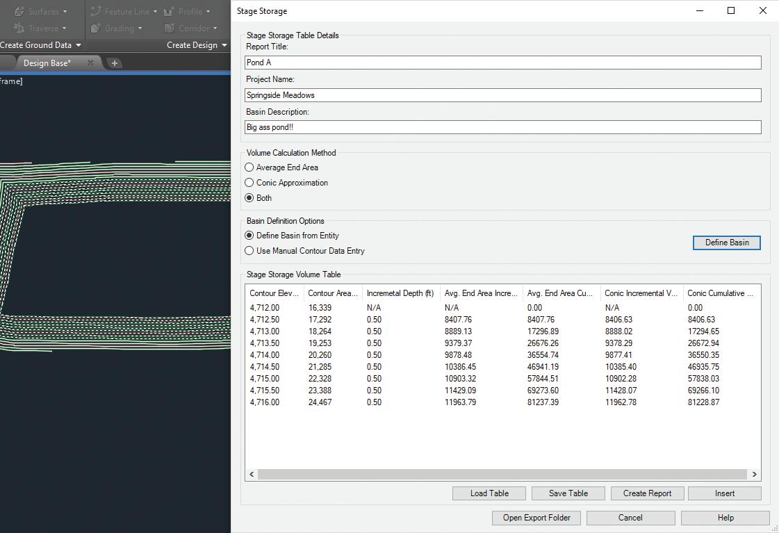
Need a quick volume analysis from a pond for example? Need that analysis every 0.25’ within the pond? The Stage Storage Tool in Civil 3D is an oldie but a goodie!!
First, you need to decide what interval you need to report on. Your surface style will control the results/ interval within the report. For example, if I want the following pond volumes in 0.50’ intervals, I simply edit the surface style to display the correct interval, prior to running the analysis.
After you have edited your style, select the surface you wish to analyze, and from the Analyze panel of the ribbon, choose Stage Storage.
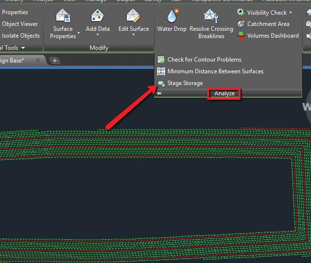
This will launch the report dialog box, fill in the blanks as needed, and select DEFINE BASIN.
You want to then select Define Basin from Polylines and select the Extract Objects from Surface button.
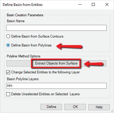
Select the surface, select DEFINE back on the dialog box and select up to the polyline you wish to analyze. The dialog box should reappear with your results! You can save this report to a text file, or even better, save it as a file to be used within SSA!!
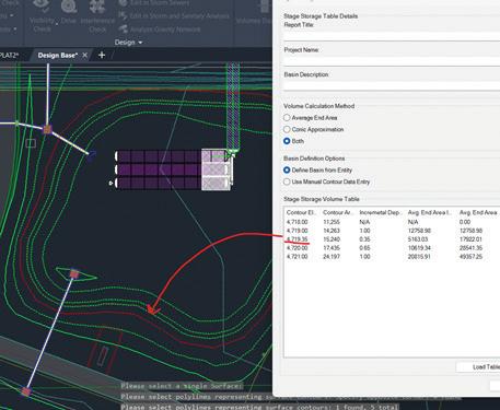
The User Defined Contour analysis is a very versatile tool. For example, if you have a highwater mark (say 4719.35), and you’d like to know the volume of a pond at that specific elevation, just run the user defined contour analysis, then display the USER CONTOUR in your surface style.
Once that is displayed, use the Stage Storage tool to extract the volume!
Another great use for that tool is to help identify a water pressure zone within your development! I use this often to easily identify those zone, which could be one elevation or multiple!
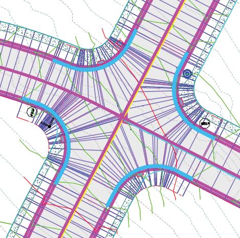
Yes, we could use the intersection tool to create this, but sometimes that just doesn’t accomplish what we want to do. Sometimes you need just a bit more control, and feature lines will allow you to do so.
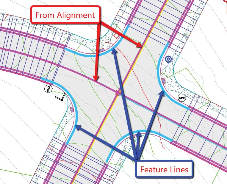
Let’s take a 4-way intersection for example. I first start with extracting the centerline feature lines as a dynamic link to either my profile or corridor. In this case I chose to use my FG profile as the feature to extract a feature line from (we will keep both crowns maintained).
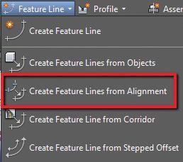
From the Home tab > Create Design panel > Feature Line drop-down > Create Feature Lines from Alignment
Select your alignment, then select the profile you wish to dynamically link to. You will then have a dynamic feature line, therefore when your Alignment and/or Profile changes, your feature line does as well.
Create your feature lines along the Lip of Gutter (Edge of Asphalt) using either a polyline and create from objects command, or manually draw in your feature line.
Set the grades as you would like along that feature line. For this example, I will assume you know how to do so.
The example I am using would look something like this. The corridor has already been started, with gaps for the intersection area to be modeled.
Once we have our assembly created and our feature lines in place, we are ready to begin modeling the intersection.
Select the Corridor, go into your Corridor Properties and select the Parameters tab.
From the parameters tab, select ADD BASELINE.
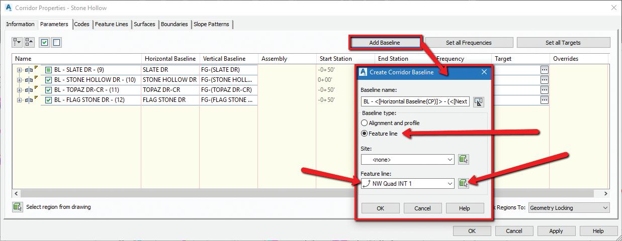
The Create Corridor Baseline dialog box will appear, select FEATURE LINE from the Baseline type.
Use the icon next to the Feature Line dropdown to select your feature line from the screen. Once selected, you may be prompted to name the feature line, I chose to name mine NW Quad INT 1. Select OK
The Baseline is now added to your corridor, and we need to add the region and select the assembly.
Right click on the new baseline and select ADD REGION.
Choose your assembly and select OK. Rebuild corridor if needed.
This will now be put in the assembly along that feature line, and no need to do a stepped offset!! Pretty good so far, right? Let’s finish up the intersection quadrant by targeting our centerline feature lines for width and elevation. I use the contextual ribbon for some very useful shortcuts. Use these to really speed up your corridor modeling workflows!
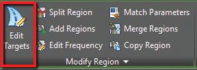
Select your corridor from the screen.
From the contextual ribbon for said corridor, select EDIT TARGETS from the Modify Region panel.
Select within the region for the intersection. The Target Mapping dialog box will appear.
We first will select the targets to set our Width. Select NONE next to Width Target for the asphalt portion.
Set the object type to FEATURE LINES, SURVEY FIGURES AND POLYLINES. Then select both centerline feature lines from the screen.
Select OK.
We now need to select the same feature lines for the Outside Elevation Target. Select NONE next to Outside Elevation Target and follow the same steps as outlined about for setting width targets.
Select OK to exit the Target Mapping dialog box and Select OK to complete the Corridor edits.
Repeat all the about for each intersection. Remember to use your contextual ribbon to assist. There is a MATCH PARAMETERS command that is very helpful in this case. This will allow you to set similar targets without going through all the same steps.
Your resulting intersection should look something like this. You may need to reverse feature lines from time to time as well, keep that in mind.
So that’s my FAB 5 of everyday Civil 3D use. There’s a few more that almost made the cut, such as using parcels for drainage design instead of catchments, but I’ll save that for an upcoming article!! Hope to hear from you on what your favorite use cases are.

Shawn has been a part of the design engineering community for roughly 15 years in all aspects of design, construction and software implementations. He has implemented and trained companies across the Country on Civil 3D and other infrastructure tools and their best practice workflows. Shawn can be reached for comments or questions at sherring@ prosoftnet.com.

Today, you’d be hard-pressed to find a device without “smart” in the name. Our phones, appliances, cars, and computers are all connected via the internet. While we don’t usually give much thought to how these devices communicate with one another, a lot can
be learned from these interactions. For this reason, clever software engineers have discovered ways to gather data from these interconnected devices that can be extremely valuable in building construction and management. We refer to this technology as the Internet of Things, or IoT for short.
In recent years, heavy strides have been made to improve this technology. Now, architects and engineers can automatically feed IoT data into BIM (Building Information Modeling) programs to automate design, construction, and management processes.
In a construction setting, the Internet of Things is a privatized network of electronic devices that constantly collect and receive data from one another in real-time to provide information pertaining to a building project. Virtually all devices with a Bluetooth or Wi-Fi connection can be connected to the Internet of Things. These devices typically include purpose-built sensors and switches; however, vehicles and personal electronic devices can also be tied into an IoT network to gather data about visitor and employee habits.
All IoT networks rely on a wireless connection, data collection devices, and a user interface (UI) to view collected information. However, when applied to construction management, a UI can be replaced with a BIM program to process, manipulate, and automate data.
• Wireless connection: A wireless connection ties the other IoT components together. After information is collected by smart devices or sensors, a Wi-Fi, Bluetooth, LTE, or 5G connection allows it to be collected by BIM software for further processing.
• BIM Software: BIM converts collected data into valuable insights with the potential to maximize efficiency and minimize cost. Most full-feature BIM programs, like Autodesk Revit, can automatically analyze data, adjust schedules, and suggest ways to improve construction safety and sustainability.
• Data Collection Devices: Smart devices are the workhorses of IoT. Sensors, construction wearables, and modern heavy machinery constantly monitor construction-affecting factors like traffic, motion, energy efficiency, temperature, humidity, and light levels.
BIM and IoT are each powerful tools in their own right. However, when paired together, they form a synergistic relationship that can enhance efficiency in all phases of construction. The integration of IoT in construction for enhanced project management elevates their capability to improve safety management, resource allocation, and scheduling—three areas that can benefit the most from pairing the two technologies.
Real-time monitoring of construction sites ensures immediate response to any hazardous conditions, significantly improving worker safety. IoT can detect issues like gas leaks, structural failures, or unsafe environmental conditions, alerting site managers instantly to prevent accidents.
By integrating IoT with BIM, managers can gain real-time insights into the exact resources required at different phases of construction, from manpower to materials. This precision prevents overstocking and underutilization, helping to optimize the supply chain and reduce waste.
IoT devices enable the tracking of real-time progress directly against the BIM models. This capability allows project managers to adjust workflows and resources dynamically, adhering more closely to planned schedules and budgets.
One of the most significant benefits of utilizing an IoT network is the ability to monitor data in real time as changes occur on a construction site. For example, in-site sensors can track factors such as the curing progress of concrete, weather conditions, and the structural integrity of construction elements, feeding this data back to the BIM model for analysis. Having an ongoing loop of information ensures that the project sticks closely to its planned schedule and budget and that contractors can react quickly to any necessary changes or interventions.
Bringing BIM and IoT together has the potential to not only support better project management but also boost overall logistics efficiency for construction firms managing multiple projects. For instance, IoT devices can be used to track building materials, equipment, and vehicles across various site locations. It seems obvious, but having the ability to keep tabs on company property dramatically reduces the risk of loss due to theft and can prevent delays caused by “doublebooking” machines.
Additionally, once IoT data is fed into BIM, sophisticated machine learning algorithms can analyze construction patterns and make suggestions where improvement can be made. These suggestions include optimizing the sequence of construction activities to reduce downtime, adjusting material specifications to improve durability or efficiency, or reworking site layouts for better worker safety and productivity. Datadriven insights like these often lead to substantial reductions in waste, contributing to a more sustainable field as a whole.
While combining BIM and IoT certainly has the potential for significant benefits, doing so does present some challenges.
One major challenge for construction teams is managing the vast amounts of data constantly being generated by IoT sensors and devices. This “data deluge” can overwhelm a firm’s information systems without adequate storage and processing power. So, successful implementation requires sophisticated data analytics tools to extract actionable insights.
Additionally, the initial setup of IoT with existing BIM technologies often requires substantial investment not just in the technologies themselves but also in training team members to use them effectively. The skill gap can be significant, especially in industries traditionally slower to adopt digital transformations.
Privacy and security are also valid concerns about the increased data connectivity that comes with IoT implementation. Transmitted data can contain sensitive information, including details about the construction designs and the operational aspects of the construction site, which could be vulnerable to cyber-attacks.
To tackle these challenges, it’s best to roll out new technology in phases, starting with pilot projects that allow for systems calibration and staff training before a full-scale implementation. After IoT and BIM are connected, it’s also crucial to periodically evaluate all systems connected to the IoT network to ensure that all desired data is collected and utilized effectively. These evaluations also provide the opportunity to perform cyber-security audits to identify any existing security breaches.

Anna Liza Montenegro develops design technology conferences for architecture, engineering, and construction (AEC) professionals as a forum to exchange innovative strategies, and best practices, and facilitate discussions into the technology trends driving significant change in building design and construction. As Director of Marketing and as a trained architect, these events are offered to AEC professionals by Microsol Resources, a value-added reseller of Autodesk, Bluebeam, Enscape, Rhino, V-Ray, CADLearning, and other various technology partnerships.

In August we all had a chance to experience the excitement that surrounded the Track & Field events of the 2024 Summer Olympics. As early as June I watched the tryouts that determined the athletes who would qualify to compete with other Olympians from all over the world. Starting with the individual sprinters, to the hurdle obstacles and to the team relay races witnessing who crossed
the finish line first was absolutely thrilling. But the most anxious part of the race was actually at the beginning. This is when the stadium went silent with each Olympian positioned at the starting line waiting for the call to, “Get ready, Set, and Go!!!”
At the beginning of this year, I introduced an article titled Dialog Fun Facts. For me, the ability to program and layout custom dialog boxes in AutoCAD gives me a similar kind of excitement
as watching the Summer Olympics. I’m writing follow-up articles on this topic so I can pass this excitement on to fellow AutoCAD users.
For this go-around, the first dialog fun fact I would like to discuss is the get_tile function. To demonstrate how get_tile works first open the Windows built-in Notepad app and create a file called MyDcl.dcl
Note: This file may already exist from following the instructions in my January article.
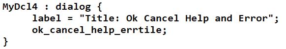
Next, enter the following lines of code in the file to define the contents of a custom dialog named MyDcl4 (see Figure 1):
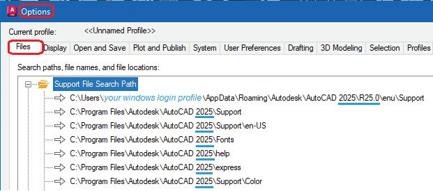
Then, save this file in one of the folders listed under AutoCAD’s Options command, Files tab, and Support File Search Path (see Figure 2).
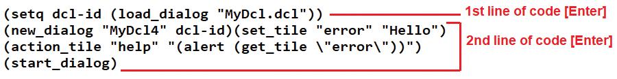
To bring up the MyDcl4 custom dialog onto the drawing area at AutoCAD’s command prompt enter the following lines of code one after the other following each line with the Enter key (see Figure 3):
The following dialog box opens in the AutoCAD graphics drawing area (see Figure 4):
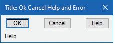
Though both the OK and Cancel buttons when clicked dismisses the dialog box, when the Help button is clicked the following AutoCAD Message window appears (see Figure 5):
One reason for the information displayed in this window to appear is because of the get_tile function as shown in this portion of the code:
(get_tile \”error\”)
The “error” in this case references the key defined for the errtile which is stored in AutoCAD’s base.dcl file. As I mentioned in my January article, there are a number of predefined dialog components stored in AutoCAD’s base.dcl file. One quick way to locate and open this text file is by entering the following at AutoCAD’s command prompt:
(findfile “base.dcl”)
Open base.dcl with Notepad and search for errtile You’ll land on the following content that shows what makes up this tile (see Figure 6):
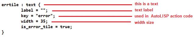
Figure 6
Besides the dcl code defining this as a text tile that has no label and a width of up to 35 characters, there’s a very important attribute called key. The key attribute is defined as “error” So, the get_tile function references the content set in the errtile by using this key. After getting the content from errtile then the alert function is used to display this in the AutoCAD Message window as shown in the following portion of the code:
(alert (get_tile \”error\”))
In the next section I’ll discuss the function used to set the content of errtile
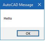
The second dialog fun fact is the set_tile function. The set_tile function is similar to the get_tile function by again referencing the errtile with the key defined as “error”. This is then followed by the content to be set which in this example is as follows:
(set_tile “error” “Hello”)
Click the OK button to dismiss the previous dialog on the screen. This time, enter the following line of code again in its entirety before hitting the Enter key on the keyboard (see Figure 7):
Figure 7
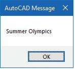
The following dialog opens now displaying in the AutoCAD graphics drawing area something different than previously (see Figure 8):
8
Notice the content has changed in the lower lefthand corner from “Hello” to “Summer Olympics”. This is because the set_tile function has now set that content with the following portion of code:
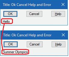
Also, when the Help button is clicked this time the AutoCAD Message window shows the new content by again using the combination of the alert and get_tile functions (see Figure 9):
9
To bring it all together, the third dialog fun fact is the action_tile function. Again, like both get_tile and set_tile, action_tile references a tile with its defined key. In both the previous examples the Help button’s defined key is called “help” (see Figure 10):
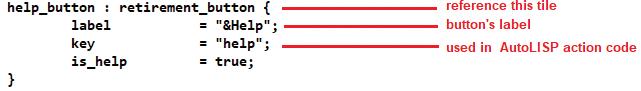
Figure 10
Then, this is followed by a statement surrounded by quotes that invokes the action to run when this button is clicked as shown in the following portion of code:
(action_tile “help” “(alert (get_tile \”error\”))”)
Click the OK button to dismiss the previous dialog on the screen. This time, enter the following line of code again in its entirety before hitting the Enter key on the keyboard (see Figure 11):
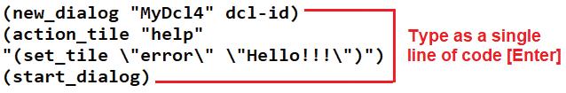
Figure 11
Notice the change in the dialog box this time.
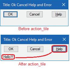
There’s no content shown in the lower left-hand corner because there’s no set_tile function implemented until after the Help button is clicked. Then, the action_tile function takes over and runs the set_tile function on the key defined as “error” with the content of “Hello!!!” (see Figure 12):
I’m going to top this article off with one more bonus dialog fun fact called the mode_tile function. Again, like the previous three functions the mode_tile function references the tile’s key to make a change to the mode of the tile. For the purpose of this next example, I’ll focus on two mode settings:
0 which enables the tile for viewing
1 which disables or grays out the tile
To demonstrate these couple of mode_tile settings once again with Notepad, open the MyDcl.dcl text file for editing. This time, enter the following content in the file and save it (see Figure 13):
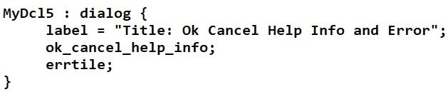
Figure 13
This time, the custom dialog box is named MyDcl5 and also notice the addition of a fourth tile called info. Again, searching for info in the base.dcl file shows the following content for the Info button (see Figure 14):
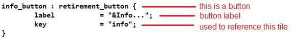
Figure 14
Before continuing, enter the following at the AutoCAD command prompt to remove the previous MyDcl4 dialog box definition from memory:
(unload_dialog dcl-id)
Then, at AutoCAD’s command prompt, enter the following lines of code again one after the other following each line with the Enter key (see Figure 15):
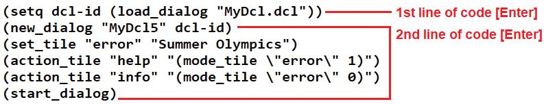
Note that this time there are two action_tile lines of code. The first line refers to the Help button key, and the second the Info button key. These are each followed by the statement to run when the corresponding buttons are clicked.
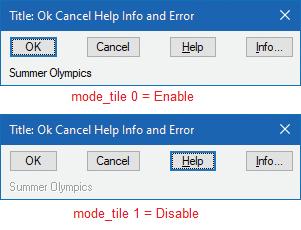
So, when the Help button is clicked the action_tile causes the content in the errtile to change its look with the use of the mode_tile function. In this case, a setting of 1 disables or grays it out. Likewise, the opposite occurs when the Info button is clicked. The action_tile this time causes the content in the errtile to change its look to enabled. A mode_tile setting of 0 enables the tile (see Figure 16):
I hope this follow up article, like the first, has introduced some easy learning methods using fun facts to implement custom dialog boxes in AutoCAD. Though we’ll have to wait four years before experiencing more fun and excitement at the next Summer Olympics, we don’t have to
wait that long to experience the same when it comes to dialog box programming. In fact, we don’t even have to wait another year for the next release of AutoCAD. But we can start customizing dialog boxes today and immediately see the fruits of our labor. It’s so easy to just put into use the many tiles and clusters already defined for us in AutoCAD. So, let’s start using the functions learned to implement your own custom dialog boxes now. There’s no need to, “Get Ready…” or even, “Set…” but instead just, “Go into Action!!!”

Mr. Paul Li graduated in 1988 from the University of Southern California with a Bachelor of Architecture degree. He worked in the Architectural field for small to midsize global firms for over 33 years. Throughout his tenure in Architecture he has mastered the use and customization of AutoCAD. Using AutoLISP/ Visual Lisp combined with Dialog Control Language (DCL) programming he has developed a number of Apps that enhance the effectiveness of AutoCAD in his profession. All the Apps actually came out of meeting challenging needs that occurred while he worked in the various offices. He has made all the Apps available for free and can be downloaded from the Autodesk App Store. Though he recently retired from the Architectural profession, Paul continues to write articles depicting his past work experience. Some of these articles can be found in AUGIWorld Magazine where he shares his knowledge learned. Paul can be reached for comments or questions at PaulLi_apa@hotmail.com.

Are you looking for powerful, costeffective drafting software? If your current software isn’t meeting your needs, it might be time to switch. DraftSight is designed to seamlessly support your existing data, knowledge, and workflows, offering professional-grade features specifically tailored for engineers, designers, and architects. Critical advantages of DraftSight include its minimal learning curve, compatibility with legacy drawings, API support, time-saving features, and flexible licensing options, all contributing to its costeffectiveness.
Want to learn more? Save the date for DraftSight LIVE 2024 - an online event for DraftSight users or anyone seeking to understand the potential of DraftSight!
DRAFTSIGHT LIVE 2024: THURSDAY, OCTOBER 24TH, FROM 9 AM TO NOON (EST).
Registration is now open and space is limited.
Register Now: https://www.draftsight.com/events/ draftsight-live
DraftSight LIVE is an opportunity to gain practical skills and valuable insights. Don’t miss this exclusive first look with our technical team at the new features coming in DraftSight 2025. DraftSight product experts and customers will share live demonstrations, tips, tricks and useful insights. You’ll learn to enhance productivity and accuracy in your daily tasks, saving valuable design time. Discover the synergy between DraftSight and other leading Dassault Systèmes solutions, such as CATIA and SOLIDWORKS, and how these integrations can streamline your processes and improve your results.
Prepare for a comprehensive agenda filled with informative sessions on a wide range of topics, including DraftSight’s role in the AEC Industry, its use in the Manufacturing landscape, and a deep dive into Customization and Automation. With professionals from diverse industries, DraftSight Live represents the broad applicability and functionality of 2D drafting, equipping you with the tools to stay on the cutting edge in your field.
Here’s why DraftSight Live 2024 is your must-attend event of the year:
Level-Up Your Game: DraftSight Live is your platform to elevate your 2D drafting skills. With informative sessions, time-saving tips, live Q&A, and seasoned speakers, you will uncover new techniques to solve everyday problems.
Discover New Tools: Be among the first to explore the advanced tools and features of DraftSight 2025.
Smart Integrations: Learn how DraftSight smoothly collaborates with solutions like SOLIDWORKS and CATIA, potentially revolutionizing your workflows.
Exclusive Learning Content: As a bonus for all attendees, exclusive on-demand webinars and learning content will be available after the event!
Whether you’re a loyal DraftSight user or simply exploring its potential, DraftSight Live has something for you. For IT, CAD, and Engineering Managers, this event provides valuable insights into network licensing and the commercial benefits of DraftSight, promising to be a revelation for your organization.
Even if you can’t join during the virtual event, registration ensures you will be the first to receive the on-demand sessions in your inbox!
Learn more: https://www.draftsight.com/events/ draftsight-live

Last time I covered how to give constructive correctives to others when done with kindness, encouragement, and tack. But what if you are the one who needs correcting? You hopefully may see it before others do or before a mistake is made? How do you catch yourself drifting, going off track or slipping? Some alarms and warnings might help.
I am the kind of guy who buys a car and keeps it for a very long time. I currently have a 2005 pickup, a 2012 SUV and a 2014 Hybrid that I use for commuting. All of them are now over 10 years old and the truck is almost 20 years old. I bring all that up to say that I do not have the latest bells or whistles that come with new cars. And I do not have the alarms and warning systems that come of the new models.
When I rent newer model cars, they have the warning lights or sounds that tell me when I am drifting out of my lane. Some jiggle the steering wheel while others beep. When I first drove a car
with some of these warnings, it caught me by surprise. Now it is commonplace. So how can use the concept of alarms when I drift off the plan or process? Like drifting in the water at the seashore, you may not know you are drifting until your look around and notice that you are far out to sea, or down the coast away from where you started.
First, set some alarms. Like milestone checkpoints. Add to the plan a period of reassessing where you are. Put it on the calendar and pause to look around. Have someone else check your progress. Break down the work to manageable chunks and have review times built in. If you are supposed to finish 10 items by Friday and you only get 8 done, check yourself and see what is causing the slowdown. Adjust before you fall even further behind… or set a more realistic target number.
New cars also help with things you may not notice in your blind spots. When a car approaches in your blind spot, a light comes on. When you start
moving toward something in the blind spot, a warning beeps… Look out!
In life and work, your blind spots may be seen by others, but you will miss them. This is beyond a drift; it is totally unseen. New alarms need to be in place for this. You need to be more proactive on blind spots. You need to ask others what they see and what you do not see. Tell them to be honest. If something was missed, or if you did not take advice from others, have them say so. Ask them for help. Make yourself vulnerable. You need others to help when they see what you are unable to see. We all have blind spots and need them to be uncovered.
I have a one-minute email delay. When I compose and send an email, I have an Outlook rule that pauses for sixty seconds on a send. It sits in my Outbox and waits for the clock to tick off, then it sends it. This has saved me a few times from sending an email addressing an issue that was already done. It has saved me from being too abrupt in my wording. It has given me time to rethink what I wanted to say. Maybe I forgot the attachment… It gives me time to catch my own mistakes.
By taking a pause when working from time to time, you can rethink things and avoid mistakes. Give yourself some time to think. You want to move at fleet speeds, but not so fast that your brain has not had time to think through the outcome of your actions.
When you catch a mistake – own it. Mistakes are made all time. No one is perfect. When you do uncover something that needs to be corrected, you should admit it to yourself and others. Don’t brush past them. Don’t try to write them off. Just admit when you are wrong. It may take some courage. Decisions that seemed good at the time can go wrong. Don’t continue that wrong decision by hanging on to it when it becomes apparent. Once addressed, you can move toward a corrective. Get input from others as needed and point yourself in the right direction.
When setting up boundaries to catch things that might need correcting, don’t overly nit-pick
yourself. Trust what you have chosen, decided and planned. Move boldly in getting things done. Be aware of when you might veer off the path, but don’t nag yourself about all the time about getting it right. If you have done your homework and know what needs to happen, then move forward with confidence.
If you notice something that needs to be corrected and it has multiple options for the correction, do not make multiple changes all at once. Make each change stand-alone so that you can tell if the adjustment made an improvement or not. Basically, don’t make too many changes at once, you may never figure out which change was the one that worked.
We all need to be willing to be corrected by others and to learn how to correct ourselves. If you get better at correcting yourself, you may reduce the comments that come from others. You also need to know that correctives make for better outcomes. They make you smarter and stronger. Embrace them, whether they come from your internal voice or the voices of others.

Mark Kiker has more than 35 years of hands-on experience with technology. He is fully versed in every area of management from deployment planning, installation, and configuration to training and strategic planning. He is an internationally known speaker, writer and former AUGI Board member and president.
Mark is currently serving as Chief Technology Officer for SIATech, a non-profit public charter high school focused on dropout recovery. He oversees two web sites, www.caddmanager.com and www.bimmanager. com. He can be reached at mark.kiker@augi.com and would love to hear your questions, comments and perspectives.

Artificial Intelligence (AI) has become a buzzword across industries, often leading to misconceptions. In the engineering sector, understanding the true capabilities and limitations of AI technologies is crucial for making informed decisions and reducing risk in critical infrastructure projects. This article succinctly explains different types of AI, their applications, and how they are transforming engineering practices.
AI is often used loosely, but it can be categorized into three main types: data-driven solutions, neural networks, and genetic algorithms. Each type has distinct methodologies and applications, providing unique capabilities:
Data-driven AI systems rely on large datasets and feedback loops. A common example is image recognition technology, where AI can identify objects or faces by analyzing patterns in images. These systems improve over time with more data and feedback, enhancing accuracy and performance.
Example: CAPTCHA systems, often used to distinguish humans from bots, also serve as training tools for AI. They collect data on how users interact with images, helping improve AI’s ability to recognize objects and patterns.
Neural networks form the backbone of many modern AI applications, such as natural language processing and image recognition. These models are trained on vast datasets, adjusting their internal parameters to minimize errors and enhance predictive accuracy. They are capable of performing complex tasks that simpler AI systems cannot.
Example: Language models like GPT-4 are trained on massive text datasets, enabling them to generate coherent text, answer questions, and perform other language-related tasks with a high degree of fluency.
Inspired by natural selection, genetic algorithms evolve solutions over time by iteratively improving a population of potential solutions. These algorithms are particularly useful in optimizing complex systems, such as the design and layout of infrastructure projects.
Example: In engineering, genetic algorithms can optimize the layout of a wastewater treatment plant by evaluating different configurations based on criteria like cost and efficiency. This iterative process helps find the most effective design.
At Transcend, we apply these AI technologies to enhance our solutions for critical infrastructure projects. For instance, we use TensorFlow for satellite image recognition, aiding in precise site
assessments. This AI-driven approach significantly improves the accuracy of identifying suitable locations for new infrastructure projects.
Additionally, we employ genetic algorithms to optimize the layout of treatment plants. This evolutionary design process tests billions of configurations, considering factors like flow efficiency and space utilization. These advanced algorithms help us create effective and efficient site layouts, tailored to specific project requirements.
The potential of AI in engineering extends beyond current applications. In the future, AI could predict optimal solutions for specific regions based on historical data, enhancing decision-making processes without the need for extensive manual analysis. Genetic algorithms could also optimize digital twins of infrastructure systems, enabling simulations of various scenarios and identifying the best operational strategies.
However, the challenge remains in distinguishing genuine AI applications from those that are merely marketing tactics. Understanding the different types of AI and their capabilities is essential for navigating the landscape of AI technologies and leveraging them effectively in engineering projects.
As AI continues to evolve, it offers unprecedented opportunities to drive innovation, efficiency, and improved decision-making in the engineering sector. By critically assessing AI applications and understanding their true potential, professionals can make informed decisions that leverage AI’s capabilities to transform how we design and manage critical infrastructure.

Gábor Kovács is an experienced computer science engineer, with various interest in different engineering disciplines. He currently works as VP of Technology at Transcend, and is an advocate of async communication.
Fresh off the heels of attending the BIM Invitational Meetup in St. Paul, Minnesota (July 22nd and 23rd), I recently shared my perspective about this conference with my co-workers and that got me thinking about the importance of conferences and that recap is the inspiration for the article that follows.
When you think about an industry-related conference, you probably think about the sessions or presentations they will have. Perhaps you are thinking about visiting a vendor expo where different companies may try to talk your ear off about their company, product(s) or services and why you should work with them as well as purchase said products/services. What else comes to mind when you think about conferences? Maybe getting swag, meeting old and new colleagues, or professional development? Sure, those things do come to mind, and I’ll discuss those in more detail a bit later.
For me, the most memorable parts of a conference are not always the sessions I attend but rather the conversations that happen between sessions, during lunch or at the post conference social events. BIM Invitational Meetup was just those conversations from the time we started until the time we ended. In fact, after I checked into the hotel, I joined the organizers; Christopher Alexander, Michael Freiert, Robert Beckerbauer, their interns Cecilia and Aiden as well as Beth Evanoo from HCM for dinner Sunday evening. We had a quite a few “pregame” conversations that night.
For a first-time conference it was small but intimate, which garnered LOTS of great conversations that we frankly did not want to end. There were 20 people in attendance with several more who were unable to make it for one reason or another (personal or the IT

outage that affected flights). The format was simple. There were four “sessions” per day with five tables that each had a “table sponsor” and topic that by no means was what had to be discussed. The discussions frequently veered into different topics at my tables. We jot down important ideas on note pads during sessions, and the interns later collate these notes and distribute them before the subsequent session. Our discussions would often spill over into lunchtime and our first evening’s social event. On Tuesday, a few of us continued our dialogue over lunch and dinner. The day concluded with a group discussion about unusual experiences we’ve encountered. Although I was disappointed the conference came to an end, I’m eager for next year’s event.
I have fond memories of the RTC events I attended in 2014 and 2015, Midwest U in 2019, the BiLTNA Virtual event in 2021 and speaking at BiLTNA in 2023. There are many reasons why Industry Conferences such as those are important to those

of us in the AEC Industry. Now there are many other conferences, like Autodesk University, that I have yet to attend but I am sure you have lots of great memories yourself. I am sure if you did a quick search using your favorite search engine or chatbot you could easily find a list of most, if not all, of the current AEC Industry related events.
All who have been to these industry events have their motivations, some of which may align with these primary reasons for attendance.
• Networking
• Professional Development
Knowledge Sharing
• Promotion and Visibility
• Staying Updated
Conferences provide a platform for professionals to meet, interact, and establish business relationships. They can enhance ongoing projects, kickstart successful ventures, or uncover unforeseen ideas.
Networking is not just about business; it’s also about building relationships. Starting conversations with small talk can help break the ice and make networking more enjoyable. Remembering and using people’s names during conversations can add a personal touch and make your interactions more memorable.
Industry leaders, bloggers, and content creators often attend these events. You probably are following a lot of them on and/or interacted with them on social media or other virtual platforms but have never met them in person. Industry conferences are very good places to meet those that have influenced your career, talk to them, get to know them and pick their brain on various things. I’ve encountered many individuals at events who’ve taught me through their blogs, forum posts, or YouTube videos, such as The Revit Kid, Aaron Maller, Steve Stafford, Paul Aubin, David Butts, and Brian Mackey, amongst many more. My apologies if I did not mention you. The essence of effective networking lies in attentively listening to your counterparts, refining a succinct 30-second pitch about yourself, and ensuring you follow up with them post-conversation.
Lastly, networking is not just about takin, it’s also about giving. Be ready to offer help, advice, or resources to
others when you can. This reciprocal approach can help build stronger, more beneficial relationships.
These gatherings often feature workshops, educational sessions, and seminars designed to enhance attendees’ comprehension of current issues and develop industry-specific expertise. They also present opportunities to gain insight into upcoming technologies and trends within the sector. The Architecture, Engineering, and Construction (AEC) sector is rapidly advancing through innovations like Building Information Modeling (BIM), Artificial Intelligence (AI), Virtual/ Augmented Reality (VR/AR), and 3D printing.
Ongoing education and skill enhancement enable professionals to navigate these shifts and maximize the benefits of these new technologies. Acquiring novel competencies and refining existing ones can lead to better productivity and efficiency. For instance, mastering a new project management software can optimize workflow processes and expedite project completion. In a fiercely competitive AEC market, those who persistently sharpen their skills and knowledge are more likely to surpass their rivals. This dedication to professional growth can open doors to improved employment prospects and ascension within one’s career. Furthermore, Professional Development bolsters problem-solving skills, which are vital in the AEC field. Faced with design dilemmas or construction obstacles, heightened proficiency can forge more efficacious resolutions. Continuous learning fosters an environment of innovation. As professionals learn and grow, they are more likely to come up with new ideas and approaches, driving innovation in the industry.
Remember, learning and skill development is a lifelong process. It requires a commitment to continuous improvement and a willingness to step out of one’s comfort zone. It’s not just about attending training sessions or earning certifications, but also about learning from experiences, staying curious, and being open to new ideas.
At conferences, professionals have the opportunity to present their work, receive feedback, and gain insights from the success stories and established methodologies of others. These events also serve to
update participants on cutting-edge technologies and current patterns within their professions through various publications and learning activities. In the realm of Architecture, Engineering, and Construction (AEC), sharing knowledge is essential for applying historical lessons and proven tactics to boost productivity and project results. This process of creating a ‘knowledge architecture’ is becoming more crucial within the AEC sector. Setting up knowledge exchange forums centered around particular subjects can promote uninhibited dialogue and mutual education. Such interactions can bring fresh energy to team gatherings and support an environment committed to ongoing learning and enhancement.
The practice of swapping knowledge creates an atmosphere conducive to cooperative innovation and progress. Consider, for example, the development of “Community AI,” which consists of combined pools of anonymous data gathered from different corporations. The amalgamated data improves search algorithm accuracy, yielding beneficial insights for all partners. Many companies in the AEC industry are reevaluating their knowledge management strategies to pinpoint potential improvements. Take Harris & Associates, for instance; they improved their internal intranet with the aim of enhancing direct communication between peers. This refinement has facilitated easier access to project information, swift identification of expert knowledge, teamwork on complex matters, and stronger team unity.
Outside of the conferences, platforms like the new AUGI Community, CAD Manager School, Revit Forum, Autodesk Forums and various other forums encourage members to share knowledge, stories, experiences, and ideas, break down industry knowledge silos, engage in research and development, identify and prioritize common challenges, develop new AEC industry practices, and connect people to knowledge and capabilities.
Attending AEC industry conferences is a powerful marketing strategy that can significantly enhance a firm’s brand recognition. By actively participating in these events, businesses can distinguish themselves from competitors and attract potential clients. Conferences provide a platform for promotion and visibility, which are crucial for generating leads and expanding market share.
These events encompass a range of activities,
from traditional networking and panel discussions to digital marketing strategies like social media engagement and content marketing. In the current digital age, AEC firms need to prioritize their presence at these digital-friendly events. This involves moving away from traditional marketing activities, like print advertisements, and focusing more on digital platforms.
Public Relations (PR) plays a vital role at these conferences, helping to boost the brand of AEC companies. By sharing the company’s story, mission, and achievements with a wide audience, PR can generate interest and excitement about the company. This, in turn, can lead to increased business opportunities, investment, and growth.
Promotion and visibility at these conferences can give AEC firms a competitive edge. By showcasing their unique projects, innovative solutions, and thought leadership, firms can stand out in a crowded market and attract more clients. Therefore, attending AEC industry conferences is not just an opportunity to learn and network, but also a strategic move to enhance brand visibility and business growth.
The AEC industry is vibrant and always adapting. Participation in industry events can help one to keep abreast of the latest market trends and cater to client expectations. This requires grasping the significance and prospects of these trends. Digital innovations remain at the forefront. Events in the industry commonly present new digital tools, such as the increasingly popular Building Information Management (BIM), which supports cooperative and effective planning, design, construction, and maintenance.
We are experiencing fundamental changes and enduring obstacles. Such industry gatherings are insightful regarding these issues and propose viable solutions. For example, firms can strategize effectively by considering increasing material costs or a shortage of skilled workforce. Being current is crucial for safeguarding projects against obsolescence, calling for foresight into future demands and embedding versatility in design and building methods. Industry conventions often cover forthcoming developments and offer advice on preparing for them.
With its significant position in promoting economic development, keeping up with the latest trends is key
for AEC firms to maintain their edge and contribute to broader economic prosperity. It’s clear that staying upto-date and continuously learning are integral parts of staying ahead of the curve in the AEC industry.
In conclusion, industry conferences are more than just events; they are dynamic platforms for growth, innovation, and connection within the AEC sector. As evidenced by the recent BIM Invitational Meetup and other notable gatherings, these conferences foster invaluable discussions, collaborative problem-solving, and knowledge sharing that extend far beyond the scheduled sessions. They are instrumental in professional development, allowing participants to stay ahead of technological advancements and industry trends. Additionally, the networking opportunities provided by these events can lead to lasting professional relationships and business ventures. By attending these conferences, professionals and companies alike can enhance their visibility, promote their expertise, and ensure they remain competitive in a rapidly evolving industry. As we look forward to the next year’s events, let us remember that the true value of these conferences lies not only in the formal presentations but also in the rich, spontaneous interactions that inspire and drive the AEC community forward.

Jason Peckovitch is an Autodesk Revit Certified Professional for Mechanical and Electrical Design located in SE Iowa. He is a BIM Manager for Garver’s Buildings Business Line, specifically MEPF. Garver has nearly 50 offices across the United States and more than 1200 employees. His CAD/BIM career spans over 25 years but he didn’t switch to the AEC Industry until 2007 as a Mechanical HVAC Drafter and transitioned into BIM Management shortly after where he has been working since. Jason is also the father of three children; Shelby – 12, Blake –9 and Logan - 6, a published photographer, gamer, and car/tech guy. He can be reached at jmpeckovitch@ garverusa.com.

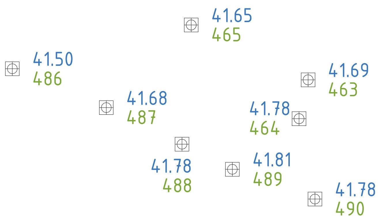
Some questions trigger to take a deep dive into the subject. For example, a recent question from someone who had received a drawing from a third party. The drawing initially contained Cogo Points, but somehow these were exploded into basic objects like a symbol and a text, which was supposed to represent an Existing Ground elevation. The objects themselves no longer had an elevation property. The question is: how (apart from requesting the original drawing) can you restore the symbols and elevation texts back into Cogo Points? Or, because the original objects are gone and unrecoverable, how to create new Cogo Points with the original location properties?
The fact that objects were exploded in a drawing does not always have to be intentional, but sometimes it is. In the past, I experienced that certain companies exploded everything because they did not want the next party to be able to use intelligent objects they had spent a lot of time on ‘for free’. For example, useful dynamic blocks or a Corridor model with complex Assemblies, you wouldn’t want someone else to take advantage of that, would you?
In the construction world, sharing a BIM model is already more common, in the civil world- not so yet. A BIM model in Civil 3D, which is also called a CIM, is
often the result of much effort and often based on own Assemblies, Styles, Templates and knowledge. Sometimes the creation of a CIM is done for one’s own convenience, for example for calculating volumes or creating stake-out drawings, and not on behalf of the client for, e.g. class detection. Then it feels a bit awkward to start giving away such a model for free.
A CIM model contains intelligence, and that is often considered the blacksmith’s secret, a kind of trade secret that must be protected. By exploding the model, you ensure that someone else has to put in as much effort as you did yourself, which feels more fair. But you better make sure you do the making of such a model on commission and get paid for it. Then the model belongs to the client, and they can decide where it goes. That way everyone benefits from it.
But it may also be that the person who sent you such a drawing only got it that way too. Or it was delivered out of ignorance by a draftsman who himself always works with AutoCAD and doesn’t know about the Civil 3D objects in the drawing. Perhaps assuming he is
doing a good deed by breaking up that silly Proxy object into recognizable objects for you. Anyway, you’re stuck with it. How do you get those objects back as Cogo Points? Well, with Dynamo of course!
You first start by analyzing the objects you do have. Do you have a symbol with a single text close to it? Or did the symbol also explode into single lines? Is the text an MText or a Text object?
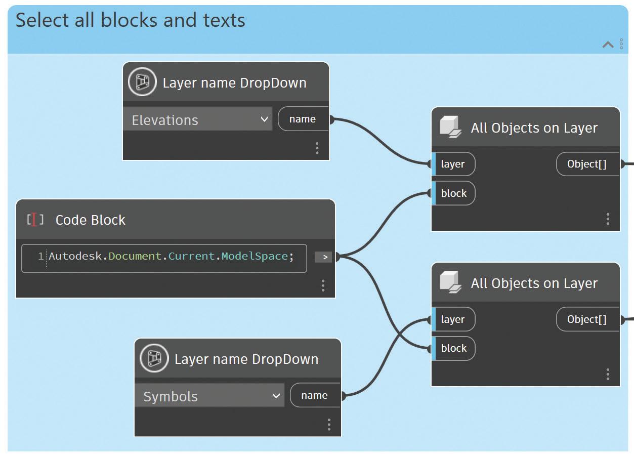
Fortunately, there is plenty of variation in the objects. In this case, the symbols are Blocks and quite easy to filter with Dynamo. They are on a separate Layer,
so you can filter by Layer, but also by object type. If they were separate entities, then you could still filter by the Circle objects. The Text objects are also on separate Layers, but otherwise you could filter by the
object’s color, and even whether a text contains a point, to filter the texts by that characteristic.
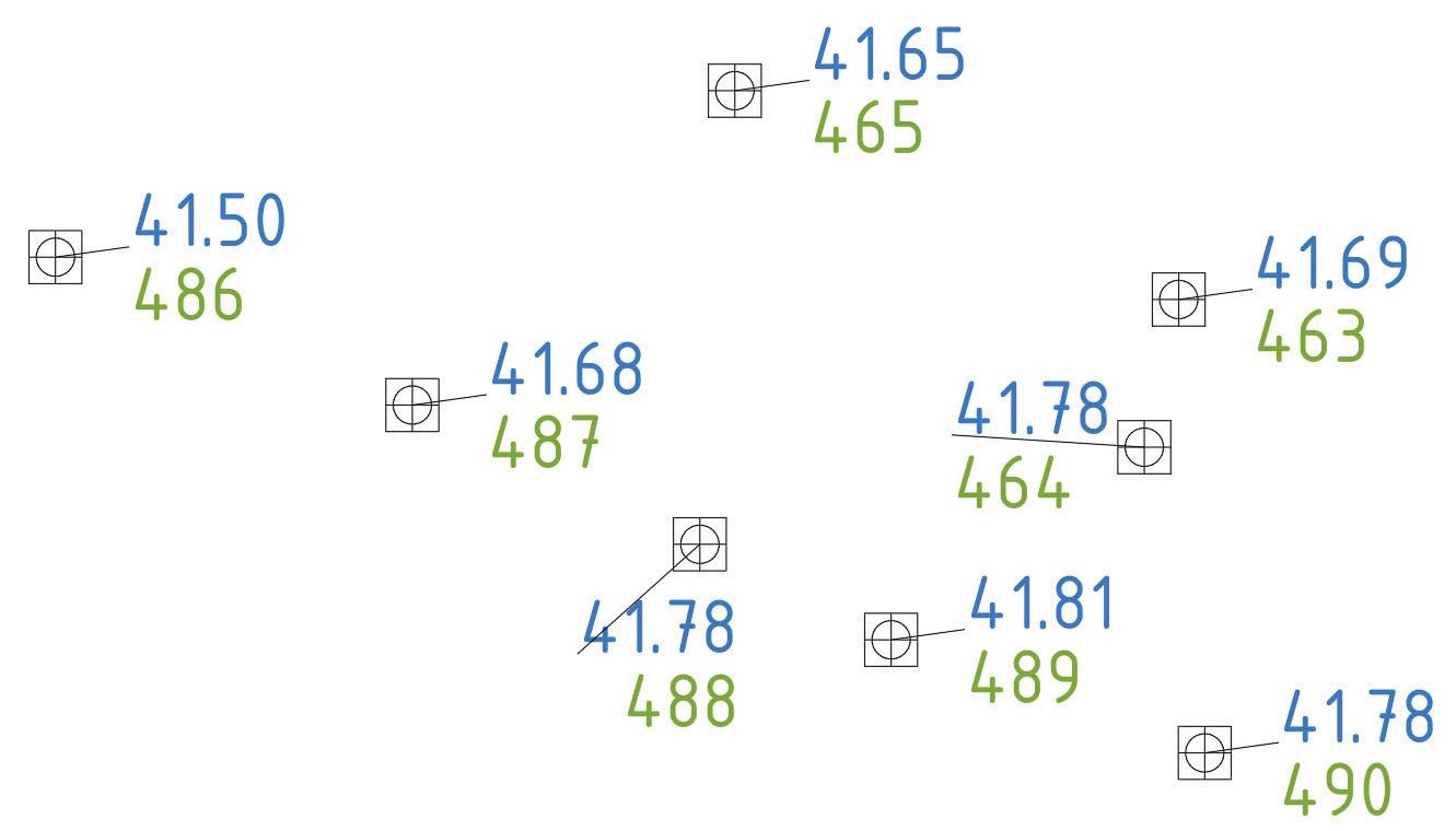
With Dynamo, you easily filter texts and symbols. In this example, the texts are on the ‘Elevations’ Layer and the symbols are on the ‘Symbols’ Layer.
It is possible to use the out-of-the box nodes, but for your convenience it is advised to add the packages ‘Civil3DToolkit’, ‘Camber’, and ‘Arkance Systems Node Library’, adding thousands of new helpful nodes to your Civil 3D Dynamo environment.
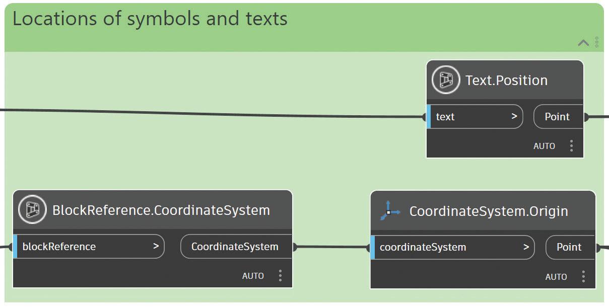
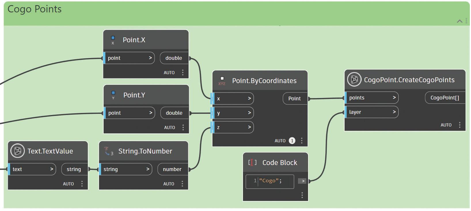
As shown in the drawing above, some texts have been moved for readability reasons. The texts were not at the insertion point of the symbol anyway. If you want to place Cogo Points at the insertion point of the symbol, you will need only the symbols, but since there is no elevation attached to the Block, you will have to find the nearest text object and extract the elevation from the text value. Now it is useful to determine the insertion point of both symbols and texts and then calculate the shortest distance, to find a list of symbols and associated texts.
To get the text positions, you need a node from the Arkance Systems Node Library. The symbol positions
are extracted from the Coordinate System property. Then you can compare each text position to the entire set of symbol positions.
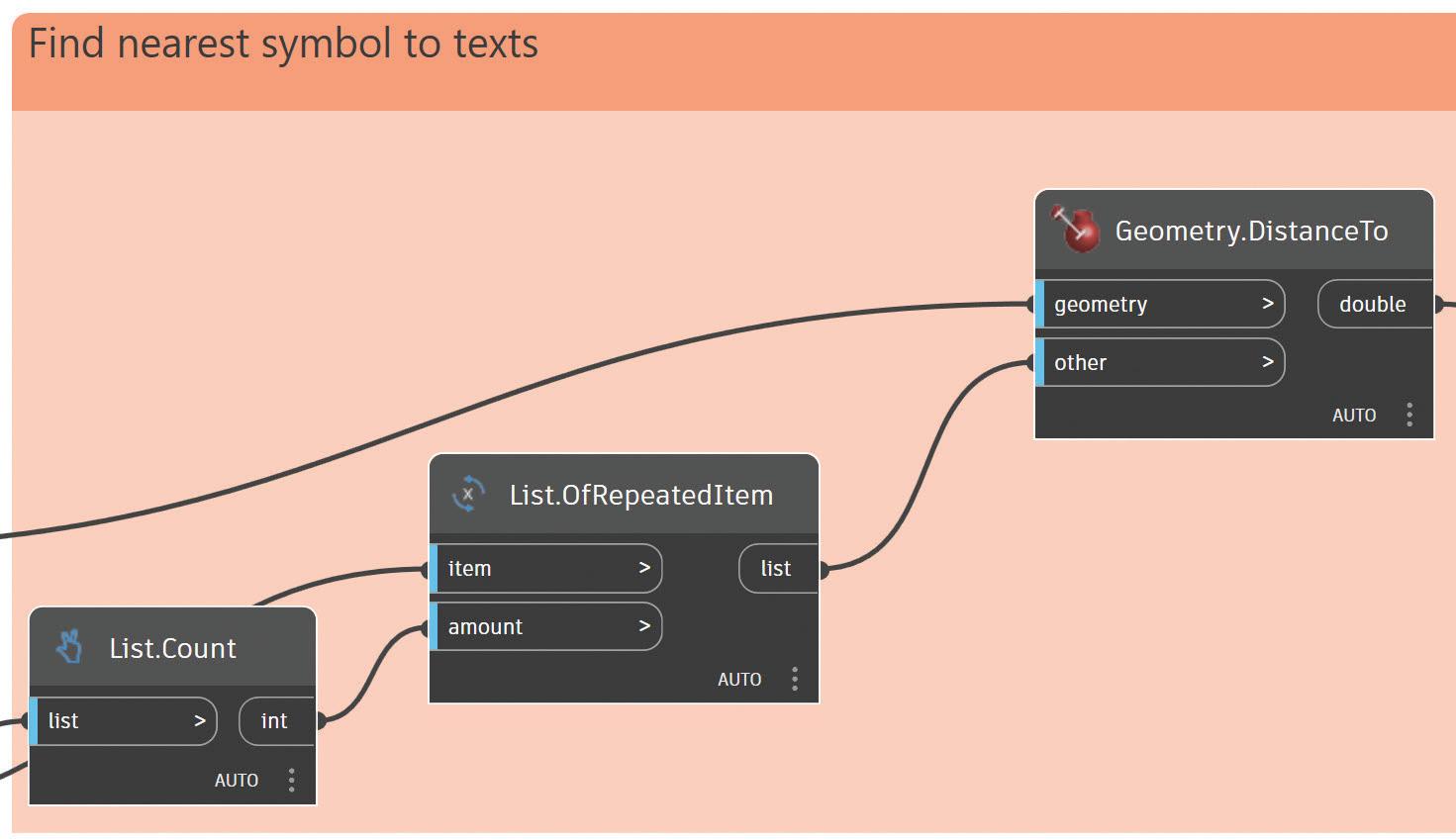
You can duplicate as many lists from the symbols as there are texts, to compare each text to the full list of symbols. I haven’t tested it, but after working this out, it occurred to me that you could also do a direct comparison with a Cross Product Lacing. Then, you wouldn’t have to duplicate the symbol list. But as is often the case, with Dynamo you can easily go in three or four different directions to achieve the same result.
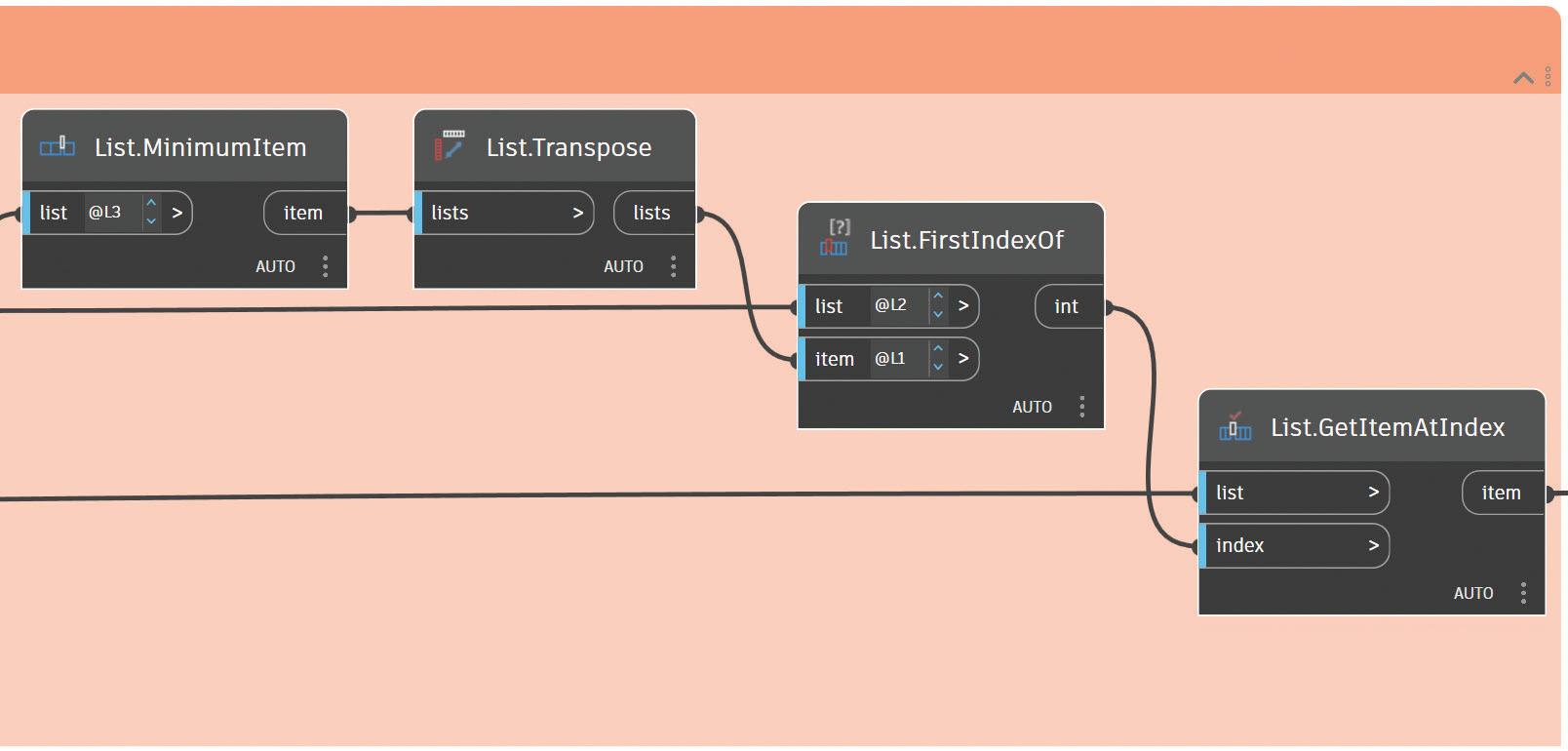
The result in this case is lists of distances, as many lists as there are texts. Each list of distances belongs to one text. From that list of distances, you have to filter out the shortest distance. But since in the end you don’t need the distance, but the symbol associated with that distance, you first find the shortest distance, then the index where it is in the list, and with that index you finally look up the symbol.
You now have the location of the nearest symbol to each text. You don’t have a guarantee that this was actually supposed to be the case, because the texts sometimes shifted, and in such a way that they might have moved closer to another symbol. You will have to build in some checks. For example, draw a construction line in AutoCAD between text and found symbol.
Often it seems correct, but in some cases it isn’t.
Another option is to change the color of the used symbols, leaving some symbols that are not colored. If there are not too many, you can still manually move the
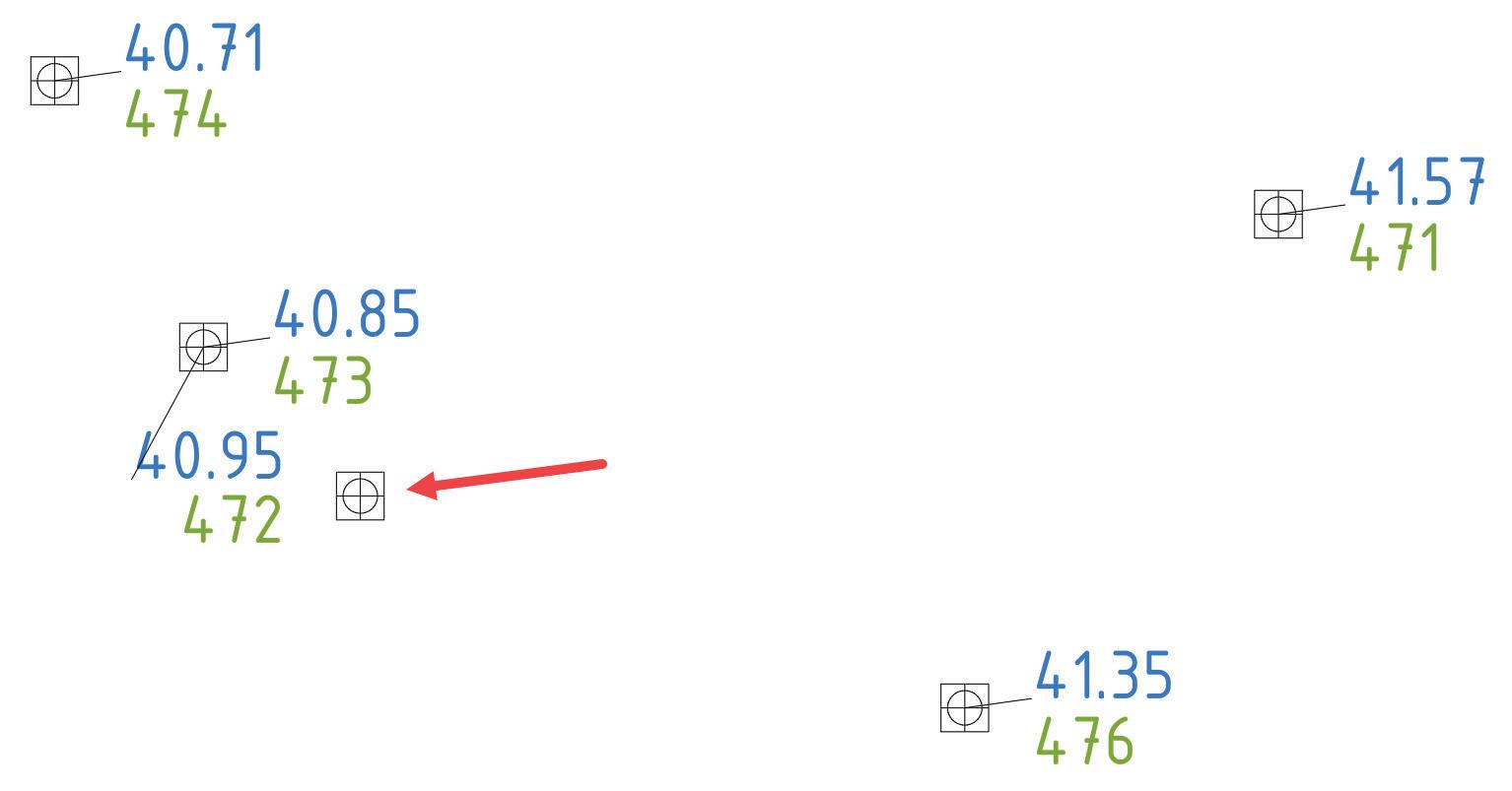
texts near the symbols, so they are closer, or afterwards adjust the generated Cogo Points that did not go well. Because you are looking for the nearest symbol to each text, the position of the generated Cogo Points might be incorrect, but the elevation will be correct. At least it is visually to be checked and the Cogo Points are easily moved to the correct symbol’s position. If you were looking for the nearest text to each symbol, the position of the generated Cogo Points would be correct, but the elevation might not, which is not easily checked and fixed.
If there are many anomalies, you may have to find another approach.
Finally, with the numerical value of the elevation and the X and Y of the symbol, you have a location to place new Cogo s on. Now your drawing contains the missing Cogo Points, with the correct elevation. Of course, first you do check that visually, or in another way, right?

As Product Manager at ARKANCE, Anton Huizinga is responsible for the development of local and global IP for the Dutch civil infrastructure market.
With extensive experience in programming .NET applications and a background in land surveying, Anton developed several valuable plug-ins for AutoCAD and Civil 3D, and a popular collection of more than 1,000 nodes in an addon for Civil 3D Dynamo.
Additionally, Anton has published several technical books about CAD and GIS. The books ‘Dynamo for Civil 3D’, ‘Using .NET to Program Plug-ins for AutoCAD’ and ‘QGIS for Land Surveyors and Civil Designers’, are helpful and educational books for everyone in the civil market.
More information about Anton can be found on his personal website https:// huiz.net
Please keep an eye out for email blasts, social media channel updates and the forums next summer so you can participate, too!
We appreciate those members who were able to take the time to participate in this year's survey. If you are reading this and do not remember seeing the emails with the survey link and salary content, please go to augi.com/account to ensure your email address is current. If you need help accessing your account, reach out to membership@augi.com. Then check augi. com/account/email-subscriptions to ensure the 'Bulletins' option is checked 'Yes'.
Our participation was down a bit this year, which makes our results less statistically significant. So, please ensure you and your colleagues come back next summer and participate.
As always, when members anonymously take the survey, they are asked to reply with the details from their most recent full-time role, and to indicate any job changes such as layoffs or furloughs in later questions. The salaries reported here (in US dollars, as participants were given a link to a currency convertor) reflect salary and bonuses for those who work 40 hours a week, and are calculated to exclude overtime pay.
The first question people have with regard to our salaries, is always the differences in Cost of Living in various areas. Metropolitan areas and rural areas can be costly or affordable no matter the location, so be sure to check additional resources to gauge those
variances. For example, according to the Job Search Intelligence ETC Salary Calculator, an Architectural Designer with an Associate's degree and 6-10 years of experience could make a median of $47,300 a year in suburban or rural Alabama or $63,000 a year in the New York City metro area. I am a big fan of www.Indeed.com/Salary, the JSI ETC Salary Calculator, Glassdoor, as well as industry- specific surveys from other professional organizations.
Please enjoy examining the factors that impact wages, and remember to come back next year to take part.
Fast facts:
• A decade ago, only 18% of workers had the benefit of telecommuting, compared to 56% today.
• Last year, 39% of companies report being adequately staffed and skilled, which increased slightly to 43% this year.
• Reported workloads appear to be very similar to 2019 levels.
• In 2023, 19% of members did not receive a raise, which increased slightly to 21% this year (which is still better than the 26% in 2019).
• 39% of people are using AI in some capacity at work, an increase over the 22% reported last year.
• Ten years ago, Engineering - Mining was the highest paid sub-specialty, this year, it is Manufacturing - Semiconductors.


What Benefits Are Available to You?
How Many Years Have You Worked for Your Current Employer?

The ability to telecommute has further increased to 56%. That is a big jump over the 15% who reported this benefit a decade ago. But, lets face it, for many design and engineering roles, it could be higher.
Survey Participants
Average Pay by Job Title
Manager - Other $119,019
Land Surveyor $117,493
Manager - BIM
$105,537
Manager - Project $100,179
Manager - CAD $99,112
Specialist $96,444
Architect $95,995
Programmer $94,294
Engineer $93,906
Application Engineer $89,387
Coordinator - CAD $86,040
Designer $85,590
Instructor / Trainer $81,842
Coordinator - BIM $80,795 Technician $77,126 Drafter $70,819 Coordinator - Other $64,571
Jobs with the Highest Mobility (percentage of each title who reported being in a new role this year)
Jobs with the Highest Feelings of Security
Reminder: All reported average pay is based upon a 40 hour workweek. It would include potential bonuses, but, is calculated to exclude overtime pay.
Jobs with the Highest Levels of Satisfaction
Survey Participants
Petroleum / Gas / Biofuels $108,582
Facility Management
$99,641
Percentage with Extremely Busy Workload
Percentage Experiencing Staffing Issues*
*For details on the type of staffing issues these companies are experiencing, please see our Hot Topics page.
Structural $97,807 MEP/FP
Construction
Civil / Survey / GIS
Architecture
$93,855
$93,311
$93,255
$92,781
Landscape Design / Architecture $92,632
Other $91,975
Sales / Marketing $87,652
Electronics $87,358
Manufacturing $85,711
Education / Training $77,243
Interior Design $67,764
Once again, Civil is leading in participation numbers!
Reporting Staffing
MFG - Semiconductor
ENG
ENG
EDU
ENG - Bridges $101,578
ENG - Subsea $101,416
ENG - Sustainability $100,951
EL - Audio / Visual $99,939
ENG - Process Plant $99,480
EL - Building Automation Systems $99,146
ENG - Mining $98,893
ENG - Structure $98,672
ENG - MEP $98,318
ENG - Utilities $97,249
AEC - Facility Management $97,154
EL - Telecommunications $96,831
AEC - Healthcare $96,642
AEC - Government $95,299
MFG - Shipbuilding $95,259
EDU - University $95,080
MFG - Aerospace $94,870
AEC - Commercial $94,343
AEC - Educational $94,305
ME - Design Visualization $93,931
AEC - Retail $93,901
AEC - High-End Residential $92,115
EDU - VAR (Reseller) $91,813
ME - Film $91,608
AEC - Residential $91,392
MFG - Consumer Goods $91,168
EDU - Primary / Secondary $90,659
ME - TV $89,833
MFG - Medical $88,497
EDU - Vocational / Technical $87,057
MFG - Automotive $86,791
MFG - Tool / Die / Molding $73,437
ME - Games $68,651
Specialties with Worst Skills Shortages
Has Your Company Done Any of the Following in the Past Year?
Have online meetings replaced conference room meetings?
No. We use conference rooms the same as pre-covid 19%
Some. We use virtual meetings, even with people in the same building 41%
Most. We use virtual meetings for most internal meetings 29%
All. We always do online meetings rather than conference rooms 25%
N/A. Our team is fully remote. 4%
The various types of staffing issues have remained consistent.
Has your company experienced staffing issues this year?
No
In 2023, 6% were using AI for marketing copy or emails, which has increased to 17% today. Becoming the most common use.
How is AI impacting your business?
Using AI for Data Analytics almost doubled over the past year.
Staffing issues have reduced by 4% since last year.
Has Your Salary Changed in the Past Year?
Average Age of Designers is 53.
Historical Average Designer Pay
Users who have experienced a decrease in pay are at 2%, which is the record low (also seen in 2007 and 2023).
Percent Who Experienced a Pay Decrease
Job Satisfaction levels are dipping pretty strongly this year.
While the percentage of Designers has remained steady over the years, the volume of members of the title of Drafter has shrunk from 28% in 2002 to only 4% today.
Percentage of Respondents Who Received No Raise

Melanie Stone is a Sr. IWMS Solutions Consultant working with R.O.I. Consulting Group. She served as an AUGI Director/Officer for over 6 years. Melanie can be reached at mstone@roicg.com or found on http://mistressofthedorkness. blogspot.com/
Gentle Reader - today we step away from the comfortable confines of my desktop to explore the world of plug-ins everywhere else.
DiRoots is a company that developed a suite of FREE Revit (and other!) add-ins that have made quite an impact on the industry. In addition, they develop bespoke custom plug-ins to automate productivity workflows and enhance efficiency.
Bear with me, O Gentle Reader, as I move this narrative forward to explore some eye-catching features of the DiRoots set of add-ins!
But before that, as always, let’s get the formal introductions out of the way -
Gentle Reader - DiRoots, DiRoots - Gentle Reader
My esteemed cohorts have long shared that the DiRoots free tools have become a standard part of their companywide software installs (in ever-so-musical concert with the love of my life, pyRevit). They are -
• DiRootsOne
• DiStem Beta
• DiRoots App Manager
In addition, there is
• DiStellar - a Web-based IFC viewer to manage BIM models
• DiRootsOne for AutoCAD
ARE DIROOTS APPS COMPATIBLE WITH ALL VERSIONS OF REVIT?
As of this morning when I reinstalled the latest versions,
• DiRootsOne is compatible up to Revit 2025
• DiStem Beta is compatible up to Revit 2024
I’m going to start from the bottom of the list with DiRoots App Manager 2.0.0!
If you’re like me, you’re very unenthusiastic at the prospect of disabling Revit add-ins. You would need to do so to address unexpected behavior like slow performance or bugs and conflicts. To manually disable add-ins, at the very least, you would need to locate this folder C:\ProgramData\ Autodesk\Revit\Addins\[Version] and temporarily move the add-in files to another location, moving
them back once you’ve tested for the unexpected behavior. What a drag!
Which brings us to the hero of the introductory part of our story:
DiRoots App Manager
This add-in offers a clear and easy interface to manage all add-ins on your machine.
By default it opens with a screen that updates
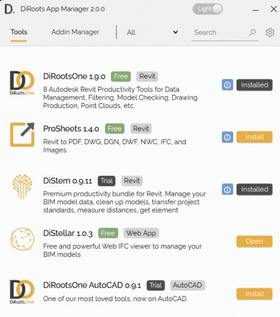
dynamically to inform the user about addins which need to be downloaded, updated, installed/uninstalled or repaired
In this screenshot taken last week, you can see that I have DiRootsOne and DiStem installed - this morning I see that DiStem needs to be updated. Definitely helps to keep you up to date with the latest in the DiRoots world.
Using the Download, Update, Install and Uninstall / Repair buttons removes the need to go to the website to download; and extracting the ZIP file. Quite a time saver.


You can make the display simpler for yourself by clicking the All tab to filter this screen by softwareAutoCAD, Revit, or Web App.

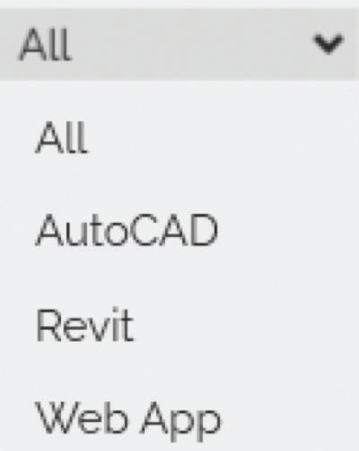
The AddIn Manager tab gives access to all add-ins installed on your machine. Enabling or disabling an add-in is now a simple matter of a mouse click.
You may notice in this screenshot that some addins are faded out. A hint - look at the bottom of the dialog box. This is because you may not have the required privileges. Right click and Open as Administrator to resolve this. You now have more firepower to test and manage your add-ins to enhance your machine’s performance.
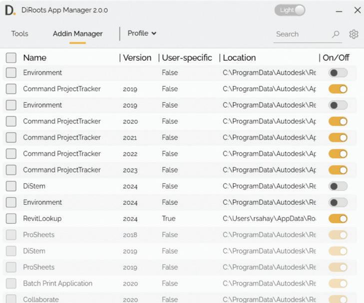
(Note - another alternative is the Stantec Add In Manager mentioned in this Autodesk resource -
This resource ALSO directs you towards the Ideas Forum location to vote for the idea for a native Revit Add In Manager !
Please do vote!! We got the tabbed Project Browser going for Revit 2024.2 - we can get this too!!)
Currently on version 1.9.1, this is the star of the overall show! Available tools are organized into groups -
• Data IO
• Views and Sheets
• Manage Find
• Utility
• Point Cloud
Let’s take a look at one tool out of each group!
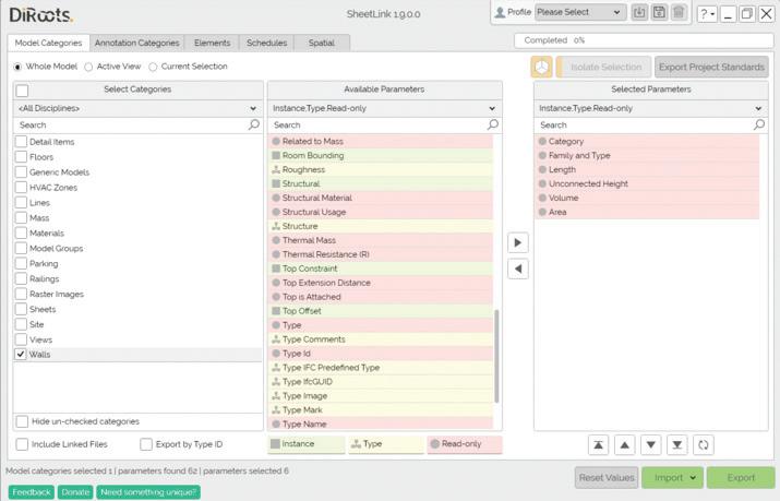
SheetLink exports your Revit model data (by categories, elements, schedules) to Excel and Google Sheets.
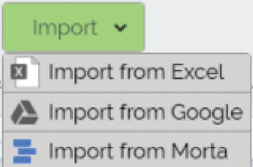
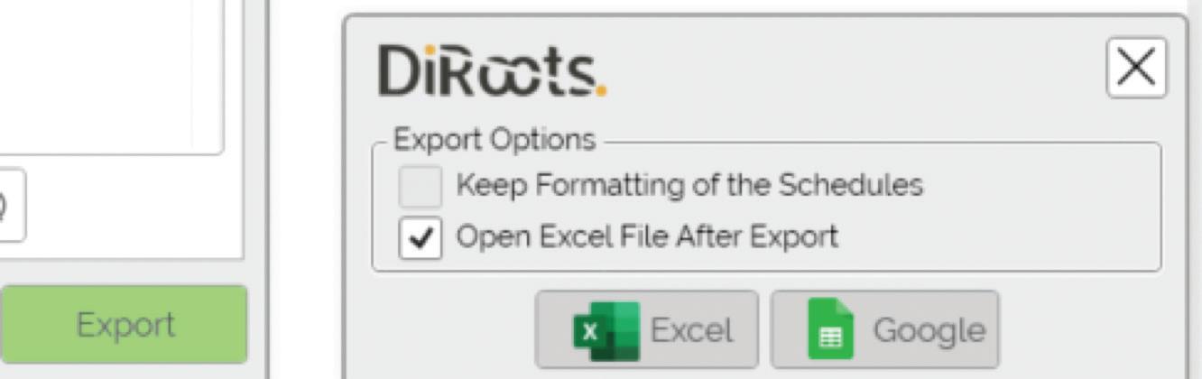
You can then edit the data in Excel and import it back to update the model
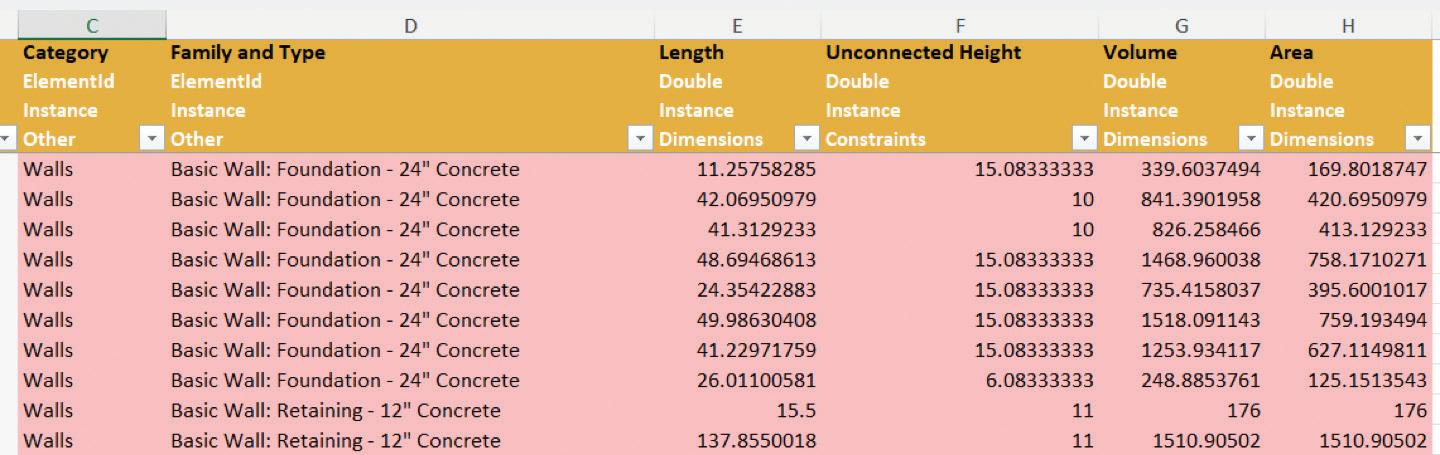
True to its name, DiRoots QuickViews easily and quickly creates Internal Elevation, Section, and Callout views from Rooms and Spaces.
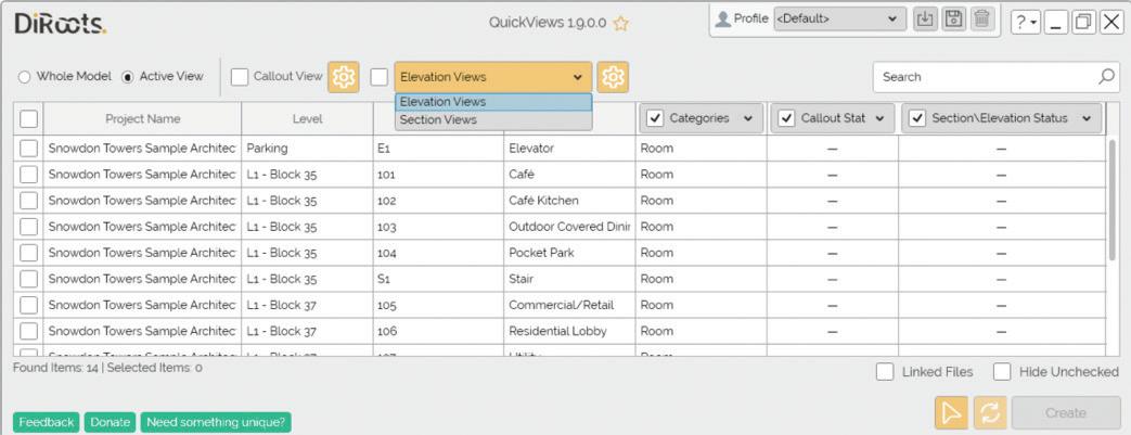
There are Settings that you can fine tune to give the exact results you want.
You can customize View settings, Naming Configuration, and Shared Parameters of the Views.
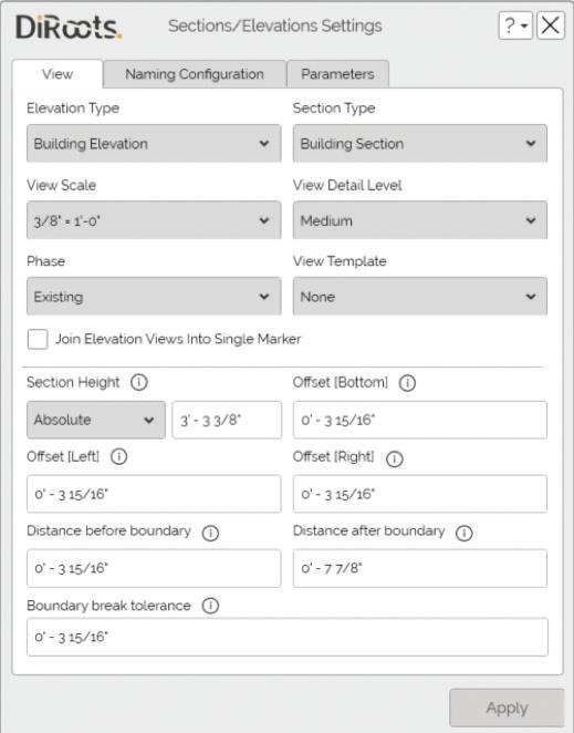
You can set the correct Section/Elevation type and assign specific View Templates and Phases to the Views.
A word of warning, O Gentle Reader. Though automation can be such a blessing, it does need to be used judiciously. Be prepared for some cleanup of possible redundancy. This tool is best used for simpler rooms to avoid strange results like this - as it is evinced by this little exercise carried out to generate interior elevations in the Cafe of the Snowdon Towers Sample Architectural model. I would have been perfectly happy with just 4 elevations - and I have received an unexpected boon of 20!
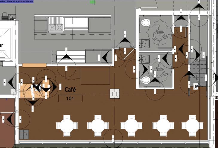
This tool is so very useful when you need to import or export multiple parameters to and from a project! Just the ability to add multiple Shared Parameters makes it so worth it.
To start with, you have the ability to edit the Group Under which each parameter is listed, also whether it’s an Instance or Type parameter.
NOTE - you can only tweak custom parameters, not OOTB ones.
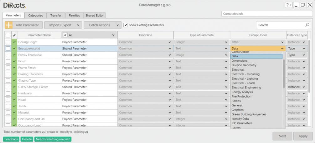
You can edit the categories that Parameters are associated with -
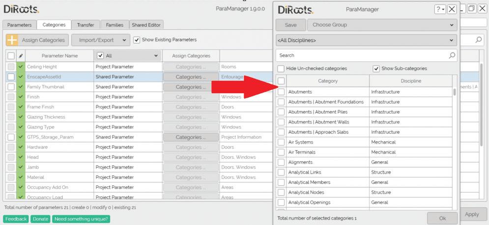
Finally, here’s the tool which I’ve found most useful (especially if you are rebuilding your Project Template!). You can import multiple Shared Parameters in one go. Used it - love it!!
Find group - Selections Manager
This tool brings up a dialog box from which you can manage Rule-based Filters as well as Saved Selections.
In this one-stop shop, you can
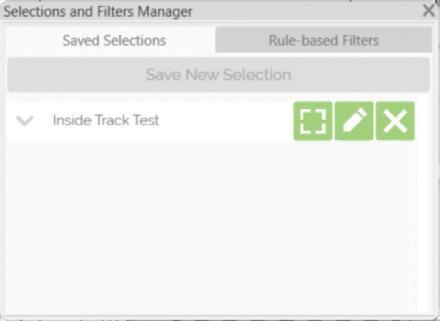
• apply or isolate the selection set,
• edit, or delete the Selections or Filters
• view a complete list of elements that have been selected in the Set.
• export the contents of the set to Google Drive, Excel, or CSV.
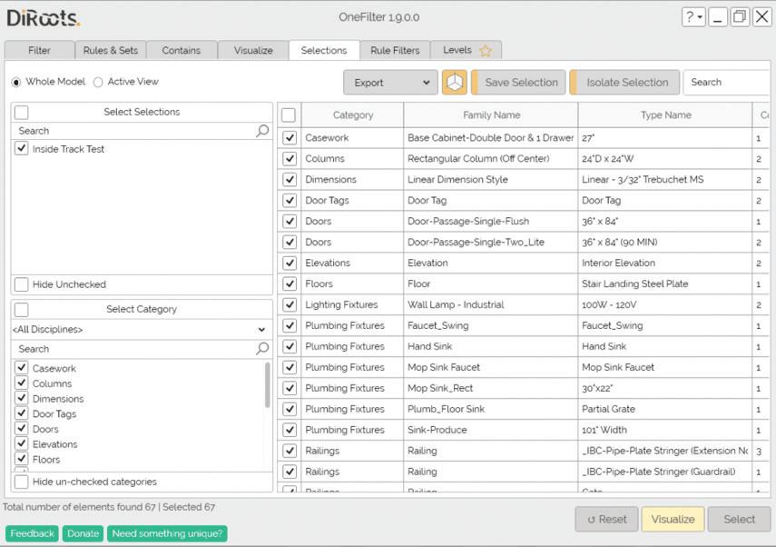
Here’s a quick look at how this tool stacks up against comparable tools offered by contenders like pyRevit, ImaginIt Utilities, and CTC Tools.
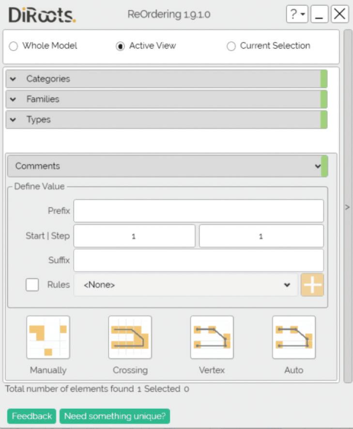
In this example, I would like to renumber Doors. Once the category has been selected, I now have the ability to select specific Families, and then I can get super-picky and select specific Types to Renumber.
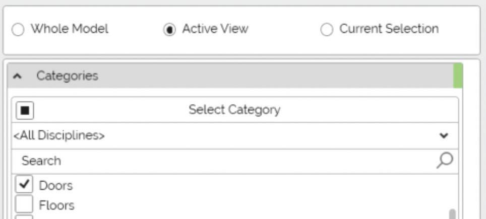
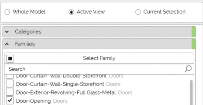
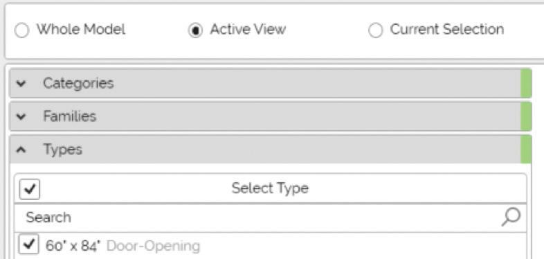
Once that is done, you can define numbering values.
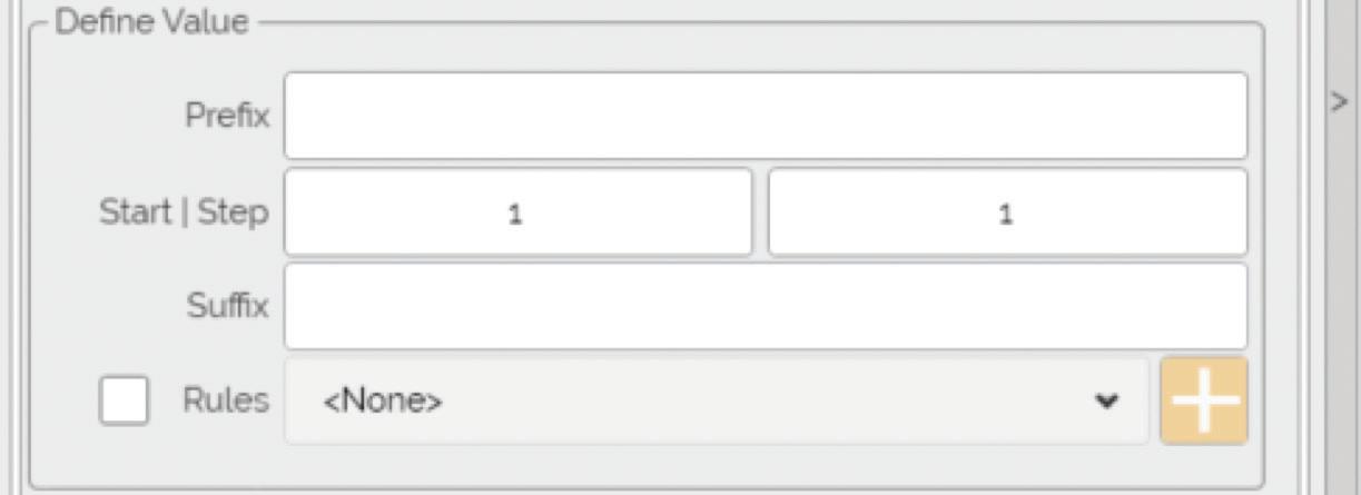
and select an option to define the sequence of renumbered elements.
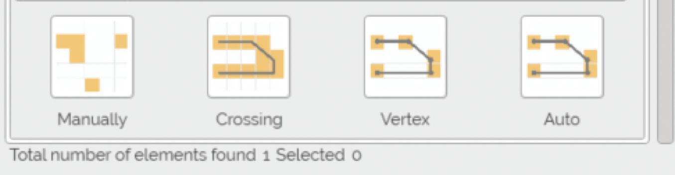
The ProSheets tool provides a one-stop shop to select and export selected sheets or sheet sets to any or multiple file formats -

You may think - Revit already has quite a few of these features natively, right? As an example, let
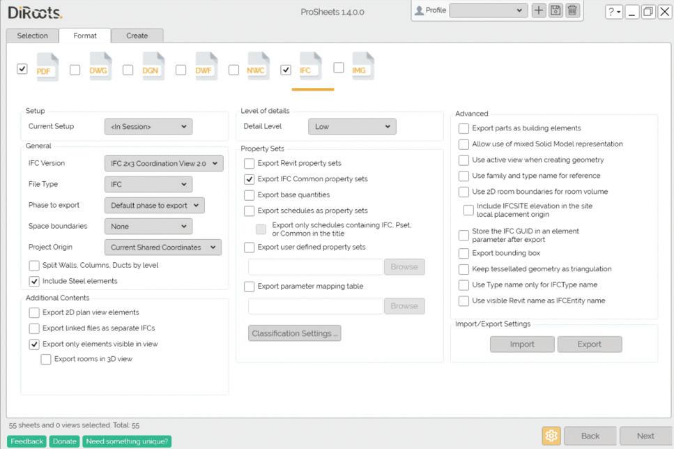
me explore for you, O Gentle Reader, the IFC Export options to illustrate the difference here -
Here’s the major benefit of the ProSheets’ setup - all required settings for successful export to IFC are on ONE screen. Less scrolling / clicking on links to make sure you have all bases covered. Helpful, right?
Bluebeam users - please remember that ProSheets uses PDF24.
Currently in version 0.10.0 or Public Beta (also in progress, with more tools being added), this bundle provides tools to
• Manage BIM model data by extracting and mapping element properties and parameters
• Clean up the Revit model
• Measure distances in 2D and 3D
• Retrieve element coordinates
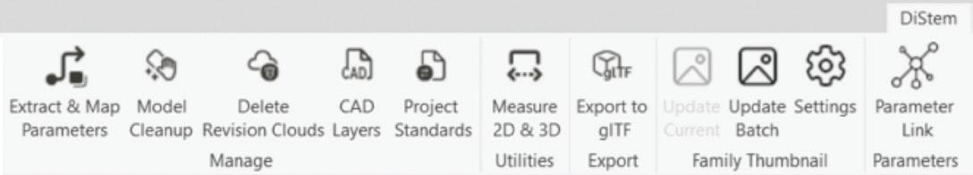
Another hot contender to model cleanup utilities offered by other providers. Similarly to other tools we have previously explored (like CTC’s Project Cleaner), this offers us a one-stop shop to clear the model of any unused elements, including Imports and Images.
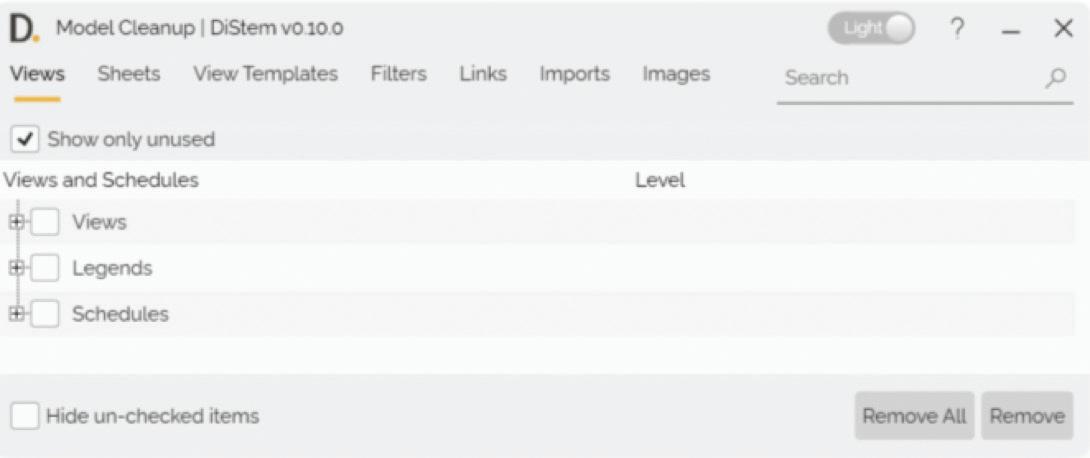
The Project Standards tool actually addresses the pain point of transferring specific families of any category between open projects.
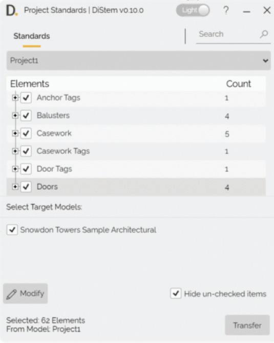
Clicking the Modify button holds more surprises! Now you can
• find and replace words
• Add a prefix and / or a suffix
• Change cases for all or selected elements of any Category in your Project Browser to comply with your company’s project standards.
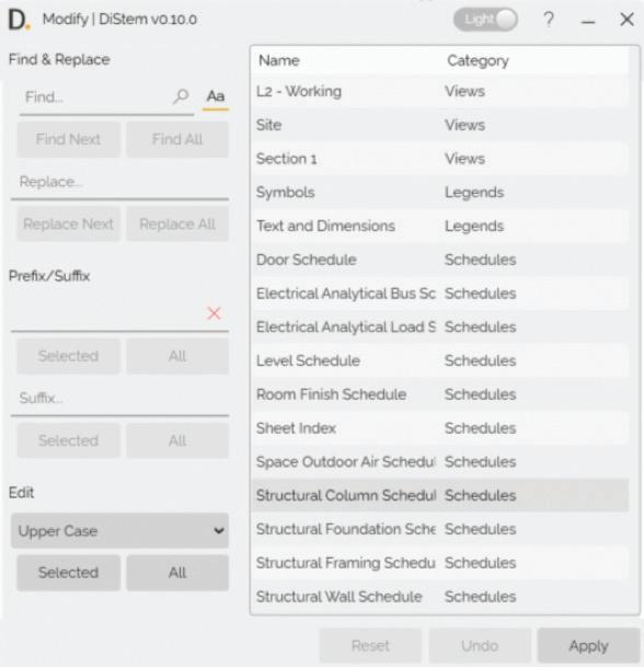
A one sentence summary of this tool - measure in 3D!! Why is that so noteworthy, you may ask - Revit already does this natively? In addition to measuring in 3D views between two references, this tool allows you to
Report the coordinates of a selected point
• Select an edge to measure (AWESOME!!)
• Copy measurements to the Clipboard
• Export measurements to Excel
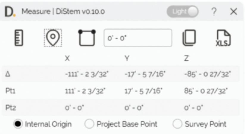
You can also select from Internal Origin, Project Base Point, and Survey Point to establish a reference point to measure against.
In my example, you see that I am locating a selected point with reference to the Internal Origin.
Firstly - what is a glTF file, you may ask? The glTF file format is an open standard developed to support 3D model geometry, appearance, scene graph hierarchy, and animation while minimizing the size and processing times for 3D assets . Three-dimensional geometry from Revit can be exported to use on other platforms, such as Unity3D, Unreal Engine, and the web.
At this point in time, Revit does not have a native glTF exporter - a shortcoming that this tool addresses. You can quickly and easily export selected element categories out of the Active View or a Current Selection, even including elements from linked files, to create a model that is optimized for rendering and animation without any redundant elements.
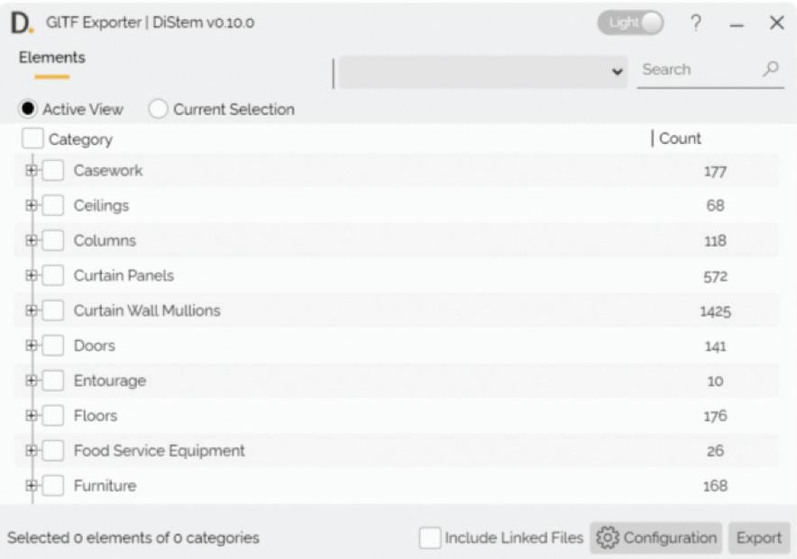
Gentle Readers - I’m sure that there are some of you that try your best to ignore the default appearance of Revit family previews. For those of you who cannot - fear not, the Family Thumbnail tools can help!
You start by editing Settings to fine tune what you would like to see in the preview.
When you click on the Appearance Settings tab, you can specify the
• Display Style,
• Detail Level,
• View Type for 2D as well as 3D families.
You can also override appearance by specific Category.
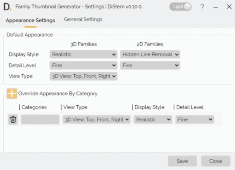
You can also specify elements to hide or display in the preview.
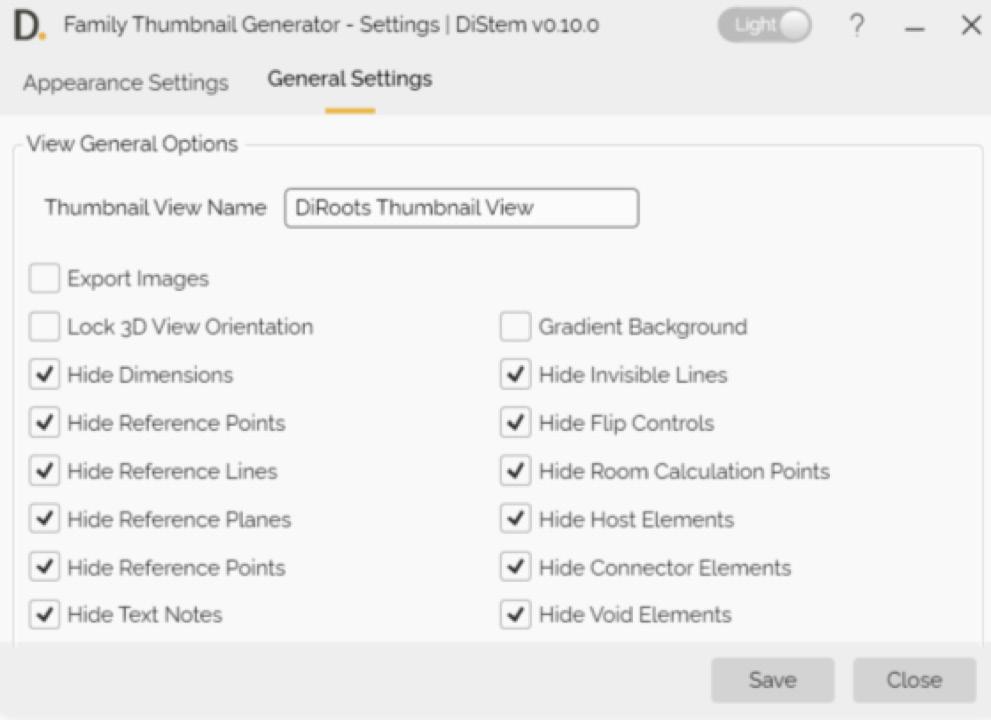
ce this is done, you can use the Update Batch tool to Update opened families
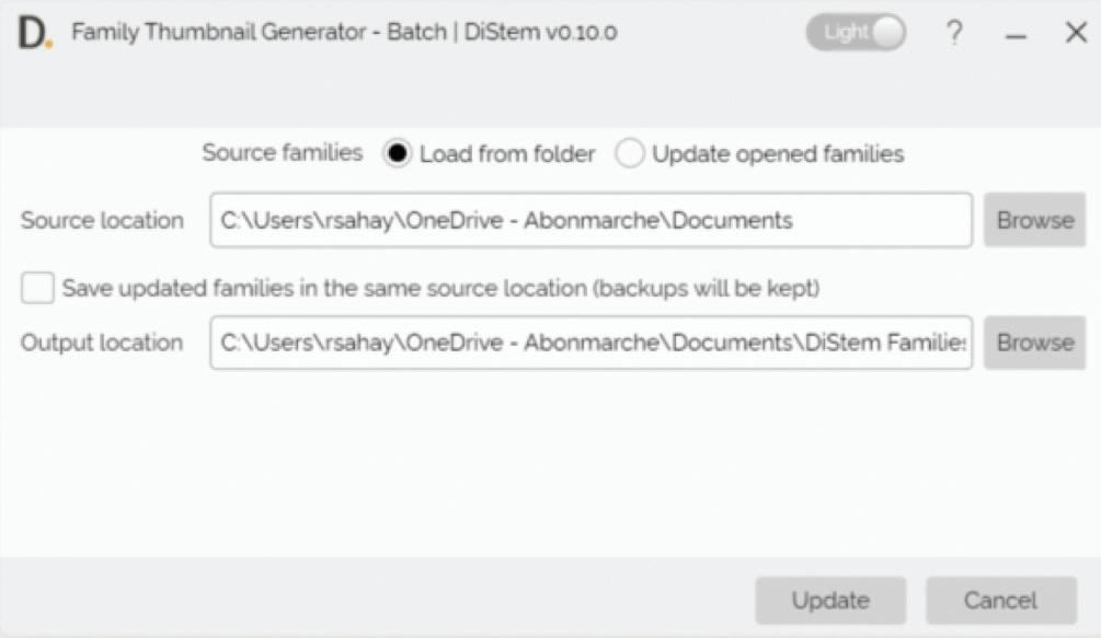
And now, O Gentle Reader, let’s take a break till the next issue, where we will continue this conversation about DiRoots add-ins!

Please let us know if you have some news to share with us for future issues. Likewise, if you are a featured product or news item user and would like to write a review, we want to know. Drop me a line at: rinasahay@gmail.com. We’d love to hear from you!

AUGIWORLD brings you the latest tips & tricks, tutorials, and other technical information to keep you on the leading edge of a bright future.