

AUGIWORLD
Standards and Strategies


Letter from the Editor

Here we are in February. February focuses on Standards. Merriam-Webster lists the definition of Standards as follows:
1. something established by authority, custom, or general consent as a model or example;
2. something set up and established by authority as a rule for the measure of quantity, weight, extent, value, or quality.
Standards is something that I have consistently worked on for the last 7 years at my company. It would be easy if we had only one office, but that’s not the case. We must do it for multiple offices, who have their own governing standards established from the city or county standards. This tends to stir up the proverbial pot! However, we have successfully established company-wide standards that work for all the offices.
As we move into this new year, 2025, I hope you are able to reflect on your past missions in implementing standards to work across the board. If not, hopefully some of these articles will help you get started in setting up standards that suit everyone in your organization. We here are AUGI are always available to help you with anything, and if we can’t, we sure do know enough people that have the knowledge to get you on the right track!
Enjoy this issue and we hope you get a lot of insight from our authors.
AUGIWORLD
www.augi.com
Editors
Editor-in-Chief
Todd Rogers - todd.rogers@augi.com
Copy Editor
Miranda Anderson - miranda.anderson@augi.com
Layout Editor
Tim Varnau - tim.varnau@augi.com
Content Managers
3ds Max - Brian Chapman
AutoCAD - KaDe King, Chris Lindner
Civil 3D - Shawn Herring
BIM/CIM - Stephen Walz
BricsCAD - Craig Swearingen
Electrical - Mark Behrens
Manufacturing - Kristina Youngblut
Revit Architecture - Jonathan Massaro
Revit MEP - Jason Peckovitch
Tech Manager - Mark Kiker
Inside Track - Rina Sahay
Advertising / Reprint Sales
Kevin Merritt - salesmanager@augi.com
AUGI Executive Team
President
Eric DeLeon
Vice-President
Frank Mayfield
Treasurer
Todd Rogers
Secretary
Kristina Youngblut
AUGI Board of Directors
Eric DeLeon
KaDe King
Chris Lindner
Frank Mayfield
Todd Rogers
Scott Wilcox Kristina Youngblut
AUGI Advisory Board of Directors
Gil Cordle Shelby Smith
Rina Sahay
Publication Information
AUGIWORLD magazine is a benefit of specific AUGI membership plans. Direct magazine subscriptions are not available. Please visit www.augi.com/account/register to join or upgrade your membership to receive AUGIWORLD magazine in print. To manage your AUGI membership and address, please visit www.augi. com/account. For all other magazine inquires please contact augiworld@augi.com
Published by:
AUGIWORLD is published by AUGI, Inc. AUGI makes no warranty for the use of its products and assumes no responsibility for any errors which may appear in this publication nor does it make a commitment to update the information contained herein.
AUGIWORLD is Copyright ©2025 AUGI. No information in this magazine may be reproduced without expressed written permission from AUGI.
All registered trademarks and trademarks included in this magazine are held by their respective companies. Every attempt was made to include all trademarks and registered trademarks where indicated by their companies.
AUGIWORLD (San Francisco, Calif.)
ISSN 2163-7547


Setting the Standards: 3ds Max Strategies for Success in 3D
Design and Visualization
In the fast-evolving world of 3D design and visualization, adopting innovative workflows, tools, and strategies has propelled many companies to success. By leveraging the potential of Autodesk’s 3ds Max, firms across industries have increased efficiency and unlocked revenue streams. Below, we explore how businesses turned these strategies into opportunities.
1. Building Digital Libraries: The Power of Reusability
The principle of asset reusability lies at the heart of successful 3D workflows. Companies that develop extensive libraries of prebuilt 3D models, materials, and textures reduce production times dramatically while maintaining consistent quality. That is fundamental to success in most production environments today.
For instance, architectural visualization studios create centralized repositories of reusable components such as furniture, lighting fixtures, and vegetation. Often managed with tools like Connecter, these allow teams to drag and drop assets into scenes effortlessly, where projects are delivered faster, enabling firms to handle more clients simultaneously. For some, internal asset marketplaces inspired by platforms like TurboSquid allow teams to monetize their creations. These libraries exist and extend to materials, animations,
character poses, props, and more, where specialists like Renderpeople.com continue to support people’s efforts in providing their clients with the best possible products.
2. Procedural Workflows: Scaling Complexity with Ease
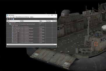
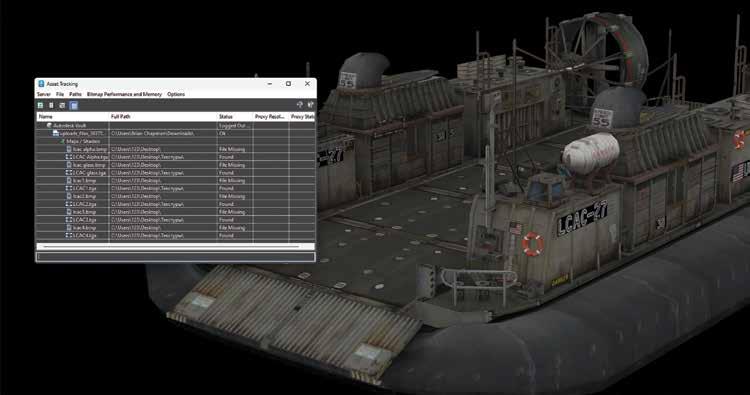
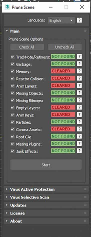
Procedural modeling tools like RailClone and Forest Pack are indispensable for companies handling large-scale projects. These plugins enable the rapid generation of complex structures, from building facades to sprawling natural environments. By focusing on procedural workflows, firms have automated tasks that would otherwise require days of manual labor. Other tools include Laubwerk, Multiscatter, Unwrella (texture program), Floor Generator, and Poly Cloth. The built-in asset tracker (displayed in Figure 1) helps optimize file contents, while more specific tools like Purne Scene levels process up, clean files, and help with organization and delivery. See Figure 2. These tools supplement efforts toward standardization in production and operations, helping companies confidently bid on larger, more complex projects, knowing they can deliver on tight timelines.
3. Photorealistic Rendering: Selling the Dream
Photorealism sells, and companies that master rendering engines like V-Ray and Corona Renderer have established themselves as market leaders.
Photorealistic visualizations allow clients to “experience” a product or space before it exists, offering a competitive edge. And with today’s standards and the market, it’s no longer a luxury, it’s a minimum requirement even to get a foot in the door. Max’s built-in engines, including Art and Arnold, and physical materials help creators rapidly produce content necessary for quick delivery. However, firms that push beyond those basics— perfecting subtle elements like lighting, materials, and environmental effects—take advantage of what 3ds Max and its creators can offer. Advanced HDRI lighting setups, displacement maps, and lens effects create renders that evoke emotion and sell visions. Having standard libraries for many elements helps build reproducible, repeatable results, helping to build 0reputations for excellence.
4. Automation and Scripting: Freeing Creative Time
Companies that embraced MAXScript and Python scripting have unlocked new levels of efficiency by automating repetitive tasks. From batch rendering multiple cameras to automatically assigning materials, scripting eliminates hours of manual labor. However, implementing these requires time and effort, and maintaining them across 3ds Max versions requires updates and maintenance. It’s essential to consider the tools you rely on and if the risk of losing them is worth the reliance or if it’s simply better to improve processes with existing tools and procedures. Often, however, when introduced with long-term consideration, this level of automation shifts resources from tedious tasks to creative problem-solving, enabling smaller teams to handle larger workloads.
5. Real-Time Integration: Transforming Client Experiences
The rise of real-time engines like Unreal Engine has revolutionized how companies deliver projects. Firms create interactive, real-time walkthroughs and configurators by combining 3ds Max workflows with tools like Datasmith.
Example Applications:
• Architecture: Clients can explore building designs in VR before construction begins.
• Product Design: Car manufacturers like Audi provide interactive configurators, enabling customers to customize their vehicles in real time.
These immersive experiences attract higher-budget clients seeking cutting-edge solutions.

6. Modular Design
Modular workflows have transformed work and have been mentioned in articles here. By designing reusable kits of modular assets—walls, props, terrain elements, pipes, structures, beams, etc.—studios quickly assemble complex worlds and mechanical structures. These efforts reduce time-to-market and empower studios to handle expanding content demands.
7. AI-Powered Productivity
AI tools have also been explored by us here at AUGI in the last few years, as it entered the scene, driving productivity gains in 3D workflows. From AI denoisers like NVIDIAs to generative AI models for concept art and models, companies are exploring how machine learning can streamline creative processes. It’s rapidly making ground in technology involving Gaussian Splat, Nerfs, and more, leading to new ways to produce and review content. These AI-powered solutions are beginning to enable studios to generate concepts, iterate designs, and refine higher-quality outputs faster than before. By reducing production times and expanding teams’ creative and critical solving capacity, studios can work to scale efficiently.
8. Monetizing Internal Tools and Data
There’s value in internal tools and data. More companies now monetize their innovations, turning plugins, shaders, or training materials into sellable products. KitBash, for example, along with Chaos Group’s V-Ray, started as an internal tool before becoming an industry-standard product. While it may not support a company, it diversifies revenue streams to create consistent cash flow beyond project-based work.
9. Cinematic Visualizations: Beyond the Static Image
Small and independent firms can now offer cinematic animations, VR experiences, and AR integrations as premium services due to the cost structures and democratization of software like 3ds Max, Unreal Engine, Unity, Adobe products and more... These deliverables engage clients emotionally, turning presentations into storytelling moments, and nearly anyone with just enough drive can access these tools and provide these solutions to their clients.
The companies that dominate in 3ds Max-related fields don’t just adopt tools—they innovate on how those tools deliver value. They standardize their implementations and workflows, from procedural modeling to real-time integration and asset reusability. These strategies are more than trade secrets, they’re pathways to sustained growth, profitability, and success. By focusing on efficiency, quality, and client experience, these firms streamline production and position themselves as indispensable partners in their respective industries. Whether you’re a solo artist or part of a multinational studio, adopting these approaches can set you on a trajectory toward success.

Brian Chapman is a Virtual Art Director and Las Vegas 2D/3D design professional who creates content for the AEC industry, games, film, entertainment, education, training, and software development. Brian can be reached at procadman@pro-cad.net.
Figure 3
Taking Action

Last time, I wrote about always leaning toward action. When planning and thinking, make sure it angles toward actionable tasks. I have a sign in my office that I pulled from a magazine ad years ago. It says, “Don’t just sit there, do something”. I have no idea what was advertised, but the sign has served me well over the years and encouraged me to get moving.
ACT
Just start moving. The time has come for action. Planning is done. Options have been reviewed. Decisions have been made. Time to stop thinking. Now it is time to move. Step one is to get moving. But movement will not necessarily make progress. Movement must be funneled into positive actions that produce good outcomes. Back in 2019, I wrote
on the Three Laws of Tech Motion. I encourage you to go back and read those articles. And remember, an object at rest remains at rest. It is time to move.
MOTIVATE YOURSELF
One way to encourage action is to lean into your motivations. What makes you excited or fulfilled? What makes you feel that you have accomplished something at the end of the day. It might be helping others or seeing someone learn something new. It might be creating something new or refining an existing process or fixing something that is broken or not working at top efficiency. When things appear on your task list, you find that you enjoy doing many of them because they motivate you. Do some of those each day and it will keep you active and satisfied that you have
done a good day’s work. Does working with teams motivate you, then ask others to team up on your tasks in small ways or large ways so that what seem trivial becomes enjoyable because you are working collaboratively with others. We can’t always do just the things we enjoy, but by mixing the mundane tasks in with the motivating tasks, it does help you complete the entire workload, without avoiding the things that drain you.
STRIVE FOR EFFECTIVE, NOT PERFECT
Wait, don’t we all want things to be perfect? We want systems to work as planned and without glitches. We desire everything to glide along without failure and stay that way forever. I know I do. BUT I do not let my desire for perfection delay achieving an effective solution. My goal is to get things running effectively to achieve the goals that are defined. If my goal were to demand perfection, then attempts to fine tune everything to be perfect will slow things down and may never be achievable. I dream of solutions that are perfect but actively seek ones that are effective. If effective is perfect, then great. But if effectiveness is not perfect, I will take something less than perfect if it gets the job done. I want results that get people back to work. Stop gap measures may be used to get the project out the door, then after the delivery has been provided, go back and seek a better solution.
THINK SUSTAINABLE
When you are taking action, always consider sustainability. The actions you are taking and the resolutions you are making need to be sustainable in the long run. Short term stop gaps (as mentioned above) may be effective in the near term but may not be sustainable. Effectiveness is defined by the attainment of the goal, but long-term solutions need to have sustainable, reproducible, and durable processes. Actions that consider extended use will work for a drawn-out time period. Quick fixes might work as proof of concept or one-time efforts, but they may not be ready for the long haul. Your actions should focus on the distant future so that they can stay in place for some time.
DEFINE MILESTONES
One way to spur yourself on to action is to define milestones. Milestones let you have the satisfaction of achieving something during a larger process or project. When things seem overwhelming, I just divide things into smaller chunks that can be achieved in shorter periods of time. Milestones
can be defined by time or quantity. They could be phases in a large project or weekly deadlines in a long timeline. They help you measure progress and adjust things downstream if needed. Make sure they are quantifiable and have measurements that everyone can see, like dates, totals, percentages, etc. Use numbers to describe the milestones. Then notify everyone involved when you hit a timeline target.
PROCRASTINATE LESS
Notice I did not say “Don’t Procrastinate”. That is because I think everyone procrastinates. All of us would rather NOT do tasks that take too much effort or that are not pleasurable. We replace it with doing “anything” other than those tasks. We delay, postpone, avoid and ignore. We may not do it all the time (sure hope not), but our minds do wander away from what needs to be done.
So just try to procrastinate less than you typically do. As soon as you sense that you are avoiding a task, shake off the avoidance and hop to it. Keep asking yourself if what you are currently doing is the best use of your time right now. If it is not, then set that aside and do something more important or time critical. When you swap high priority tasks for ones of less importance, it is called Priority Dilution. It differs a little form classic “do nothing” procrastination. Watch out for that happening.
With a mind frame that leans toward action, and inner initiative that is taking action, your projects will move toward completion. Remember, “Don’t just sit there, do something”.

Mark Kiker has more than 30 years of hands-on experience with technology. He is fully versed in every area of management from deployment planning, installation, and configuration to training and strategic planning. As an internationally known speaker and writer, he is a returning speaker at Autodesk University since 1996. Mark has served as Draftsman, Principal Designer, CAD/BIM Manager, CTO and CIO. He can be reached at mark. kiker@augi.com and would love to hear your questions, comments and perspectives.
Technology Manager’s Coin

Ring, ring… ring, ring… “What?”
Wow! Kind words from your Technology Manager when all you need is a little help, right? You’d think that would never happen, but sadly, it does. Honestly, there are times when I feel like reacting that way too—especially when I’m drowning in production work. So, how do we,
as Technology Managers, balance supporting our staff while still getting our work done? It starts with a change in mindset. We need to rethink how we approach Technology Management.
Let’s use a coin as a metaphor for a new approach. Technology Management has two major sides, just like a coin. In this article, we’ll dive into the two key aspects all Technology Managers must understand,
using the coin as an analogy. So, let’s flip a coin and see what happens.
TAILS
Handling technology—whether it’s processes, software, or workflows—is, for the most part, straightforward. Technology is void of emotion, which makes troubleshooting issues more direct. If the software isn’t working, there’s a problem to solve. This is the side of the coin most end users expect from the staff responsible for standardizing and supporting the software. The majority of calls I receive from users are about technical issues.
So, how do you handle the challenges from the “Tails” side of the coin? There are two main ways:
1. Experience: The more issues you encounter, the easier it becomes to troubleshoot. Experience builds confidence and efficiency.
2. Learning from Others: Expand your knowledge by attending conferences, taking classes, reading books, engaging in forums, and even reading articles like this one.
What does it look like when a Technology Manager has a “Tail” management style? I took a trip to San Diego for a conference last year and had to order an Uber from the Airport to my room. As I was scrolling through the app and after making a selection, it returned with “Your driver will be in a red Tesla car”. Yes! I don’t get the chance to ride in a spaceship that often. The technology in the car was amazing, the amount of information the vehicle was displaying brought me so much joy. I then remembered that Tesla has cars that drive themselves and I can see how that is with just the technology in the standard model car. The bad part of a self-driving car is the feeling of freedom in driving. Just sit back and enjoy the ride.
Technology Managers who are driven by a “Tails” management style can leave the end user little to no freedom for creativity within the technology. This generates more of a “It’s this way or the highway” environment. Technology should assist with creativity and not govern it.
Technology can solve several problems and can also cause them. Resolving technical problems involves identifying the issue and creating a plan to address it, even if that means not using the technology at times. Now let’s look beyond technology at the other side of the coin.
Technology Management

HEADS
The “Heads” side of the coin—the management side—is more complex than simply solving technical problems. This side involves assisting and supporting staff. Unlike technology, where success is measured by updating files, creating training plans, or drafting standards, supporting staff is about building relationships and trust. It’s more about public relations than technical expertise.
How do you lead when you’re not in a formal leadership position? You don’t need a title to lead. If you want to lead within your company, be someone worth following. Leadership isn’t innate, it’s a skill you cultivate. Just like developing your technical expertise, you must become a student of leadership and relationships.
• Start by reading books, listening to podcasts, and learning from talks.
• Build your leadership and interpersonal skills the same way you build your technical knowledge.
But why does a Technology Manager need “Heads” side skills? You may have risen through the ranks
Technology Management
based on your technical expertise, but now your role involves managing both software and people. Your success is no longer measured by your individual production but by how you enhance the performance of the entire team.
One of the biggest challenges is convincing users that change is necessary. And let’s be honest, most people don’t like change. Leadership and relationship skills allow you to connect with users on a personal level, making them more receptive to your suggestions and more aligned with the company’s goals.
When staff see that you’re genuinely here to help, they’ll trust you and be more willing to work with you toward success.
Let’s look at a manager who has a “Heads” side management style. My dream car is a 1967 Shelby GT500. The feeling and freedom you get from driving a car like that is hard to explain. The sound and feeling from the gas-powered engine will fill you with emotion. The 1967 Shelby GT500 did have the most up-to-date technology, but compared to a new Tesla, it has none.
Technology Managers who are driven by a “Heads” style of management typically end up having the end users with no direction on how to use the software or how to produce their work. This style of management develops a “Wild West” environment with no structure. Sure, the end users are happy at the time because they have the freedom to do whatever they want, but in the long run, the company loses so much money due to the inconsistency. Without the limitations of technology, your end users have unlimited access to the software which causes inconsistency with deliverables.
Being this type of technology manager will cause several problems. Leadership skills alone are not the only attribute that makes up a technology manager, the technology skill has to be there as well.
CONCLUSION
A couple of years ago my family got a new vehicle, a Hyundai Palisade. We took a family vacation last year to the beach and decided to use the Palisade for the drive. This vehicle has a lot of the modern technological features you would expect in a new vehicle. On the trip, I used Lane Assist and Cruise Control (it speeds up and slows down based on
the speed of the vehicles around you). I almost felt like the vehicle was driving itself, but I had full control and held the responsibility. I think that is the balance we need to work towards. The end users have the freedom to drive the software but are warned when drifting outside of the company standards.
Driving the leadership “Head” side of the coin takes time and patience. Know who your end users are and be respectful of that. A leader encourages people to be better at being themselves. Driving the technology “Tail” side of the coin takes knowledge and experience. Experience and wisdom are not knowing everything but knowing where to go to get the knowledge.
The “Heads” side of the coin represents leadership, while the “Tails” side refers to technology. To excel as a Technology Manager, you need to be fluent in both. Unfortunately, many people view this role as purely a “Tails” position—fixing problems and keeping things running. But what some users truly need is a “Heads” side leader.
Now let’s revisit that phone call.
Ring, ring… ring, ring… “Hey John, what’s going on?”
Doesn’t that sound better? Sure, we’re all busy, and life gets overwhelming, but most of the time, people just want to feel respected and listened to. If you’re too busy to help, short-tempered, or dismissive, you give users no reason to follow your lead or embrace the company’s vision.
Technology Managers must have the “Tails” side of the coin, but I hope your users see the “Heads” side first.

Gil Cordle is an accomplished CAD professional with over 20 years of experience in the industry. Based in Atlanta, Georgia, USA, Gil is passionate about pushing the boundaries of design and innovation with technology. As a seasoned instructor and CAD Manager, Gil enjoys seeing the moment when staff understands the software.

AUGI Members Reach Higher with Expanded Benefits
AUGI is introducing three new Membership levels that will bring you more benefits than ever before. Each level will bring you more content and expertise to share with fellow members, plus provide an expanded, more interactive website, publication access, and much more!
Basic members have access to:
• Forums
• HotNews (last 12 months)
• AUGIWORLD (last 12 months)
DUES: Free
Student members have access to:
• Forums
• HotNews (last 24 months)
• AUGIWORLD (last 24 months)
• AUGI Educational Offerings
DUES: $2/month or $20/year
Professional members have access to:
• Forums
• HotNews (full access)
• AUGIWORLD (full access and in print)
• AUGI Library
• ADN Standard Membership Offer
DUES: $5/month or $50/year
Clash Detection in Civil 3D

Civil 3D’s built-in clash detection is limited. While it can detect clashes in Gravity Networks, it doesn’t support Pressure Networks or the ability to compare Gravity and Pressure Networks.
This gap has forced users to rely on additional software like Navisworks for comprehensive clash detection—a time-consuming and cumbersome process.
That’s where Pipeline Crossings Check (PCC) comes in—a robust plugin for Autodesk® Civil 3D® that simplifies and accelerates the process of checking pipeline crossings. Whether you’re handling complex gravity or pressure networks
WHAT IS PCC?
PCC is a powerful tool that detects both soft and hard clashes during modeling. With an intuitive interface, it simplifies the process of selecting networks, running clash tests, and labeling results directly in your model.
Whether you’re working with Gravity Networks, Pressure Networks, or both, PCC helps you identify clashes quickly and resolve them effectively.
KEY FEATURES AND BENEFITS
• Detects soft and hard clashes in real time.
• Compares different network types or even checks within the same network. Labels clashes in the model with fully customizable settings.
• Zooms to clash locations for instant identification.
• Exports comprehensive reports in HTML format for seamless sharing.
HOW TO USE PCC IN CIVIL 3D
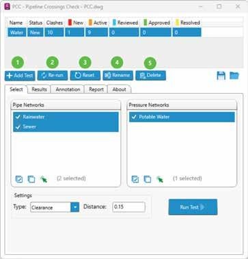
A. Running a Clash Test
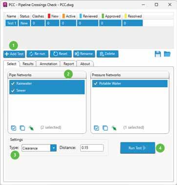
1. Add a Clash Test
• Click Add Test to create a new test entry.
2. Select Networks.
• Choose from Gravity or Pressure Networks.
• Use options like Select All, Clear Selection, or Select from Drawing for flexibility.
3. Define the Clash Type.
• After selecting the networks, choose whether to check for Hard Clashes or Clearance.
• If Clearance is selected, input the required distance in the Clearance Distance box.
4. Run the Test.
B. Managing Clash Tests
1. Add Test: Adds a new test entry.
2. Rerun: Reruns the selected test, updating any results.
3. Reset: Resets the selected test, deleting all results and detecting clashes.
4. Rename: Renames the selected test.
5. Delete: Deletes the selected test from the list.
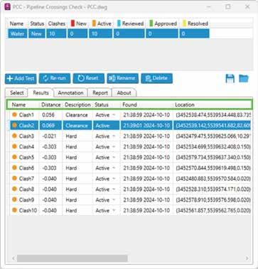
C. Analyzing the Results
1. View Clashes
After the test is complete, switch to the Results tab. The table will display the clashes, showing detailed information such as:
• Distance between pipes.
• Clash description and status.
• Parts of the network involved (e.g., pipe parts, network parts)
• The exact location of the clash in the drawing
2. Change Clash Status
You can change the status of a clash from the dropdown list. Choose from the following options: New, Active, Reviewed, Approved, or Resolved.
3. Zoom to Clashes
• You can zoom directly to the clash location by selecting an entry in the results table.
Figure 1: Running a Clash Test - PCC
Figure 2: Managing Clash Tests - PCC
• If you want to select the clash pipes, rightclick on the selected entry and choose Select from the menu.
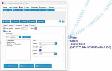
D. Annotate Clashes
• Add Sphere: Place spheres at the clash points to visually mark them. Customize the size (radius) and color of the sphere.
• Add Text: Label the clash areas with custom text. Adjust the layer, height, color, and style to fit your project’s needs.
• You can customize how clashes are labeled in your Civil 3D model by modifying the label settings in the Annotation tab. You can add: TestName, ClashName, Distance, Description, Status, Found, Location, NetworkPart1, NetworkPart1, NetworkPart2, PipePart1 and PipePart2.
• Use the Delete Annotation or Delete All Annotations buttons to delete the annotation of the selected clash test or all annotations.
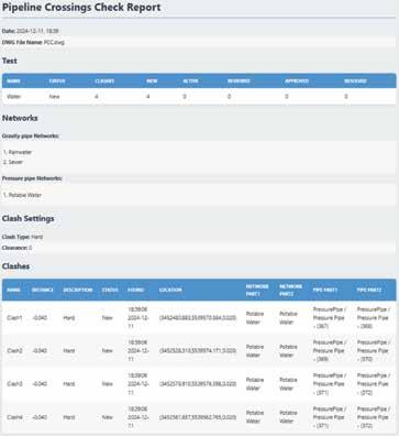
E. Generate Reports
• To create a detailed record of the clashes, switch to the Report tab.
• Click Export to export a clash report in HTML format, The report will contain all the Information.
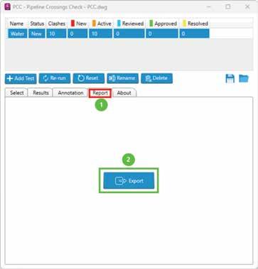

Figure 3: Analyzing the Results - PCC
Figure 4: Annotate Clashes - PCC
Figure 5: Generate Reports – PCC
F. Save Results
The Add-in allows users to save all information, including clash tests, clash results and clash settings.
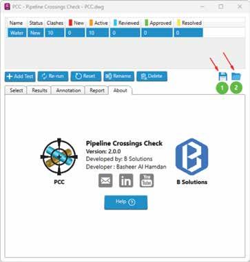
• Click the Save to File button to save the information to a file.
• Use the Open from File button to load the saved information back into the Add-in.
FAQS
1. What types of clashes can PCC detect? PCC detects both soft clashes (clearance issues) and hard clashes (physical overlaps).
2. Can I customize annotations in PCC?
Yes, PCC allows for fully customizable labels, including text size, color, and content.
3. How can I share clash results with my team? You can export results as an HTML report or save the data to a file for sharing and collaboration.
4. Does PCC work with all Civil 3D network types?
Absolutely! PCC supports gravity, pressure, and mixed network comparisons.
5. Is PCC easy to learn?
Yes, its intuitive interface and straightforward commands make it accessible for engineers of all experience levels.
Download PCC from Autodesk Appstore: https://apps.autodesk.com/CIV3D/de/Detail/Index?i d=6920726618927484879&appLang=en&os=Win64
▶️ Watch the demo: https://www.youtube.com/watch?v=xv4YvHRrayI


Basheer Al Hamdan is a BIM coordinator and project engineer for water and municipal infrastructure. He has experience in BIM coordination of infrastructure projects and the development of detailed 3D models.
Figure 6: Report
Figure 7: Save the Results - PCC
BricsCAD Moves the Business Needle (Part 1) – Standards

Harmonizing the processes across the enterprise” is a phrase my executive colleague and close friend uses all the time. At first, I would laugh about it as it was said in jest more than once. Maybe it was his Bostonian accent that triggered the laughter, but reflecting on his words, it’s no laughing matter. The depth of its meaning truly defines how essential it is to align workflows and standards for collective success. And while the specifics of elite drawing standards may or may not be understood by the executives, they understand the bottom line and how essential it is to make sure everyone is on the same page.
Standards in drafting whether for layer naming, dimension styles, or annotations are no different.
They are the foundation for effective and consistent design practices. They make a difference by ensuring clarity and efficiency across projects, departments, divisions, as well as external and internal clients. Having the proper software and using standards is beneficial to do that. BricsCAD provides an extensive toolkit that will allow you to shift the dial on productivity, drive progress in your workflows, and make an impact on project outcomes.
In part one of this two-part article, we will discuss the business case, the benefits of best practices and standards in drafting, and how BricsCAD tools and features move the business needle to empower users to establish and maintain these standards seamlessly.
THE BUSINESS CASE FOR DRAFTING STANDARDS
While we try to remain focused on the tools that will help us move the needle, we also need to understand the financial aspects because, after all, drafting standards are more than just a recommendation. They influence every aspect of a design project. Here’s how standards help move the business needle:
Improved Efficiency
When teams follow standardized best practices, they spend less time guessing or reinventing the wheel. Standards ensure everyone is on the same page, reducing the learning curve for new hires and crossfunctional teams. BricsCAD automates repetitive tasks, streamlines design processes, and reduces the time spent on manual adjustments. This allows teams to focus on high-value work, driving projects forward faster and with fewer errors. For instance, a consistent layer naming convention means users can quickly find and manipulate specific drawing entities without confusion no matter which project they happen to be working on.
Error Reduction
Errors can result in costly rework or miscommunication with clients and contractors. Standards minimize errors in drafting outputs, which are critical when projects can pass through multiple hands. Advanced features like parametric design, intelligent drafting tools, and real-time error detection ensure that designs are not only faster to produce but also more accurate. This reduces rework and leads to better project outcomes. By adopting standards and best practices, businesses can avoid these pitfalls and ensure smoother project execution.
Brand Identity and Professionalism
Nothing worse than looking through a submitted plan set full of inconsistent dimension text sizes from sheet to sheet or better yet, the company logo jumps locations and sizes upon each flip. That there is a microcosm of a larger issue. Maybe I held myself to a higher standard than most but consistency, especially in the small things, reflects a company’s commitment to quality. That commitment to quality starts at the top and flows from the top executive down to the latest new hire. Standardized title blocks, annotation styles, and line weights not only enhance visual appeal but also reinforce brand identity and peak professionalism to clients.
(Sidenote: I used to oversee refilling the main visitor conference room refrigerator with drinks for our guests. Big job, I know. That said, I was meticulous in making sure all the drinks were lined up correctly, and the stock was rotated and organized. So even before we talked business, while simply grabbing a beverage, our clients saw our commitment to excellence from the get-go, all from our conference room fridge. While some may laugh at me, as I did with my friend from Boston, or call me a little OCD, I saw it as a reflection of our level of detail and professionalism as an organization, which goes well beyond drafting.)
Scalability and Customization
As your company grows, maintaining consistency with CAD Standards and accountability across multiple teams, offices, or projects becomes increasingly challenging. Having standards ensures quality and uniformity are intact regardless of project size or complexity. Additionally, the right software adapts to the unique needs of your business, whether through custom scripts, macros, or integrations with other tools that can drive production and in turn financial performance and growth.
Integration and Automation
When you think about it, standard best practices are like the close cousin of automation in the CAD world. They go hand in hand, working together, in a specific order, to make things run smoother. Imagine using predefined templates, dynamic blocks, or data extraction workflows, none of these tools can work their magic without consistent standards to guide them. By sticking to the standards and using automation, you can take on more projects and deliver them faster without losing quality. All of that benefits the company.
BRICSCAD’S ROLE IN DRAFTING STANDARDS
Now that we have discussed some of the benefits of standards and standard practices, let us look at BricsCAD and the variety of tools designed to make implementing and managing drafting standards straightforward. Here is a look at some of the key features that can transform the way you work:
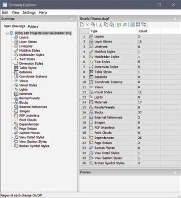
Drawing Explorer
Drawing Explorer serves as the central hub for managing drawing standards. It provides an intuitive interface to configure and control essential components, including:
BricsCAD
• Layers: Define and enforce naming conventions, colors, and line types.
• Blocks: Maintain libraries of reusable content to ensure consistency across projects.
• Text and Dimension Styles: Create and apply standardized styles for annotations and measurements.
• Line Types and Hatch Patterns: Centralize custom definitions for visual uniformity.
With Drawing Explorer, users can efficiently audit and update settings across multiple files, ensuring alignment with company standards. (See Fig. 1)
Standards Checking
BricsCAD’s built-in standards-checking tool is a game-changer. This feature allows users to:
• Compare drawings against predefined standards files (.dws). Identify deviations in layers, dimension styles, text styles, and more.
• Generate detailed reports highlighting noncompliant elements.
The standards-checking process is automated, providing users with actionable feedback and reducing the manual effort required to ensure compliance. (See Fig. 2)

BricsCAD also offers a standalone application for checking standards. Run the standards_app. exe application to open the CAD Standards Validation dialog box. (See Fig. 3)
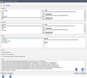
The application will check the compatibility between drawing (DWG) files and the standards (DWS) files according to the chosen plug-ins.
Figure 1
Figure 2
Figure 3
Templates and Parametric Blocks
A template drawing is a drawing file with file extension DWT. It is used to create a new drawing that is a copy of the template drawing. Any drawing with an extension DWT is considered a template drawing. The BricsCAD template drawings are located in the template folder(s). Use the TEMPLATEFOLDER command to open the folder. If you save your customized template drawings in the template folder, they are available on the Start page to create new drawings. Templates in BricsCAD simplify project setup by embedding standard elements into the initial file structure. Whether it’s title blocks, layer configurations, or predefined viewports, templates ensure that every new drawing starts with a consistent foundation.
A template drawing does not contain entities in model space, but contains settings according to the specific drawing and project requirements:
• Units: imperial or metric display
• Layers
• Dimension and leader styles
• Text styles
• Table styles
• Multiple layouts, each with title block, paper size, printer, and plot styles
• Standard blocks for notes, tables, symbols, and other entities
BricsCAD Parametric blocks add further value by introducing parametric capabilities. If you come from an AutoCAD® design environment, you may be familiar with Dynamic Blocks. AutoCAD Dynamic Blocks and BricsCAD Parametric Blocks are blocks that automate repetitive tasks by allowing users to create one block instead of many similar, separate block definitions. These blocks contain not only pure geometry but also some metadata, which affects the geometry (e.g., their size, visibility).
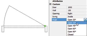
The metadata controls the way the components of the block behave. (See Fig. 4) Thus, the size and appearance of these blocks can be modified without editing the block definition. Constraints work in the same way for Parametric Blocks as they do with Dynamic Blocks. In both cases, these reusable blocks adapt to varying design requirements without compromising standards, reducing repetitive tasks and boosting efficiency.
Check out and download the BricsCAD Parametric Blocks Guide for free on the BricsCAD Migration webpage.
LISP and Customization
For advanced users, BricsCAD’s support for LISP scripting allows for a variety of customization opportunities. Users can automate repetitive tasks, enforce standards programmatically, and create custom tools tailored to specific workflows.
For example, a LISP routine can automatically set layer properties, insert standard blocks, or validate drawing elements against company guidelines. This level of automation not only saves time but also ensures adherence to standards.
Found out more about BricsCAD LISP here: https:// help.bricsys.com/en-us/customization/lisp
Sheet Sets and Publish Tools
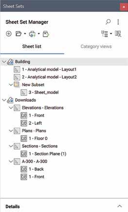
BricsCAD’s sheet set manager provides a single location to manage all sheets in a project, making it easy to organize, access, and navigate between drawings. It streamlines the organization, publishing of multi-sheet drawings, and offers a central location to create and manage production design sets. (See Fig. 5) By managing sheet templates and settings in one place, you ensure consistent layouts, naming conventions, and title blocks across all project sheets. The centralized system makes it easier for teams to work together. Features like automatic updating of fields, such as sheet numbers and project details, eliminating manual updates, reduce errors, and speed up documentation. Everyone has access to the same structured set of sheets, improving coordination and reducing miscommunication. BricsCAD Sheet Set Manager allows batch plotting and publishing of multiple sheets, reducing the time needed to produce deliverables like PDFs or paper plots. Figure 4
Tool Palettes
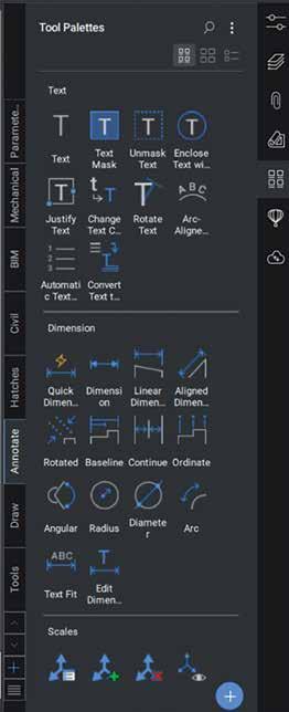
BricsCAD Tool Palettes allow quick access to frequently used commands, blocks, and tools, speeding up the drafting process by reducing the need to search through menus or type commands. The Tool Palettes panel offers a central location to access blocks, hatches, and command tools. Tool palettes are highly customizable to suit the specific needs of a project or team. Shared tool palettes can be used across teams to ensure that everyone has access to the same set of tools and blocks, reducing the potential for human error. (See Fig 6)
CUSTOMER SUCCESS
Let me give you an example of how best practices and drafting standards in BricsCAD assisted one of our clients within the last year.
A mid-sized telecommunications design engineering firm was struggling with inconsistent drawings that led to rework and delays. On top of that, the drawings they were receiving from a client were extremely slow to open.
By adopting BricsCAD and implementing standards, the firm achieved the following:
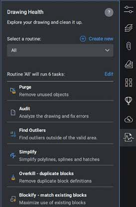
• Up to 75% reduction in Drawing Size: This firm created a LISP to run DWGHealth upon opening every DWG.
• DWGHealth significantly reduced DWG file size for thousands of dwg’s, optimized speed to open and in-drawing working efficiency, reduction in server storage space. (See Fig. 7)
• 30% Reduction in Drafting Time: Templates and automation streamlined workflows, enabling faster project completion.
• 50% Fewer Errors: Standards-checking tools identified and resolved inconsistencies early in the process.
• Enhanced Client Satisfaction: Confidently redistributed clean DWG files and provided
Figure 5
Figure 6
more consistent and professional deliverables reinforcing the firm’s reputation for quality.
While these results may vary, they prove how investing in best practices and standards can yield significant returns, positioning businesses for longterm success.
Find more Customer Stories on our website: https:// www.bricsys.com/en-us/customer-cases
CONCLUSION
BricsCAD empowers teams to bring about change by seamlessly implementing and supporting drafting standards. It allows you to push the boundaries of what is possible in CAD, enabling you to change the game in design and documentation. By adhering to the set standards and best practices, you can take it to the next level, ensuring accuracy and consistency while harmonizing the processes across your organization. BricsCAD’s versatility makes it easier than ever to implement and keep these standards, ensuring consistency, reducing errors, and enabling automation. By embracing standards and leveraging BricsCAD’s capabilities, businesses can move the needle, achieving greater efficiency, professionalism, and profitability. Make sure you come back next month as we will finish
with some tips and tricks on how we can carry out, sustain, and grow standards and best practice adoption within your organization.
MORE ABOUT BRICSCAD®
Bricsys BricsCAD is professional CAD software without compromise. Accelerate your time to deliverable without compromising on performance, cost, licensing flexibility, and data security. Not ready to buy? Download the free, 30-day trial of BricsCAD at Bricsys.com. Would you like free lessons? We have that available with Bricsys Learning. Ready to migrate to BricsCAD? Download the Migration Guide. The latest version of BricsCAD improves the tools and features users love, as well as new functionality and UI that supercharge productivity. Follow us today on LinkedIn and YouTube.
MORE ABOUT BRICSYS®
Bricsys, part of Hexagon®, is the global technology company that creates the BricsCAD family of computer-aided design (CAD) products and the Bricsys 24/7 project collaboration platform. We are relentlessly committed to the success of our customers by offering cost-effective, missioncritical CAD software with industry-leading product support. Learn more at www.Bricsys.com.
Hexagon is a global leader in digital reality solutions. Learn more about Hexagon (Nasdaq Stockholm: HEXAB) at hexagon.com and follow us @HexagonAB.

Mr. Craig Swearingen is a Global Implementation Specialist and Consultant at Bricsys. Currently, Craig provides migration and implementation guidance, management strategies, and technical assistance to companies that need an alternative, compatible CAD solution. Craig spent 19 years in the civil engineering world as a technician, Civil 3D & CAD power user, becoming a support-intensive CAD/ IT manager in high-volume production environments. Craig is a longtime AUGI member (2009), a Certified Autodesk® AutoCAD® Professional, and he enjoys networking with other CAD users on social media.
Figure 7
AutoCAD Architecture 2025 Standards in ACA

There are so many things we can talk about when it comes to Standards but for this article, I would like to take a more general approach. Why CAD Standards you ask? Well, defining CAD Standards in ACA files is important especially if you have many individuals contributing to a drawing. If you have three people all contributing to a drawing and they each just do their own thing, things can get confusing quickly. Keeping a drawing organized is key to great productivity and, well, it looks good!! Standards can be defined for several objects, including Line types, Layers, Dimension Styles, Text Styles and Multileader Styles. These standards should be gathered into a Standards File and used to maintain consistency throughout all your files. Let’s look at an overview of how to set up a file, configure standards to your drawing and audit your files.
CREATING A STANDARDS FILE AND CONFIGURING CAD STANDARDS
To create a standards file, begin by clicking the Application button and choose New menu and Drawing. Enter a template file name or press Enter to continue. In the new drawing, create any
layers, styles (text, dimension, multileader) and/or linetypes you wish to standardize. Save the drawing as a standards file (DWS). This drawing can now be associated with one or more drawing files.
Once your Standards file has been created, open the drawing you wish to associate your Standards file with and go to the Manage tab, CAD Standards panel and select Configure. A dialog box will open showing two tabs: Standards and Plug-ins. Select the Standards tab. Here you will find displayed any information regarding the standards files associated with the current drawing, once they have been added. To add a standards drawing, click the plus sign for Add Standards File. Find the file you wish to use, select it and open it, then you will see that it’s added to the list.
Multiple drawings can be added to the list; however, the order in which they appear is very important. If a conflict arises between multiple standard files in the list, that standards file listed first takes precedence. To rearrange the position of the standard files, highlight the file to be reordered and click the arrows to move up or move down. You
can also remove a Standards file by clicking the X button if you no longer need the file within your drawing.
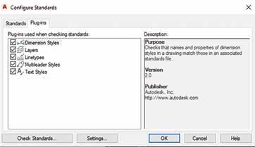
The Plug-ins tab lists and describes the standards plug-ins that are installed on the current system (see Figure 1). One will be installed for each of the named objects where standards can be defined. You can specify which of the plug-ins you wish to use when you are auditing a drawing by selecting plug-ins from this list. This is especially important if you just want to audit, for example, dimension styles only and not all of the standards. You can select all plug-ins if you wish by right-clicking in the Plug-ins list and choosing Select All.
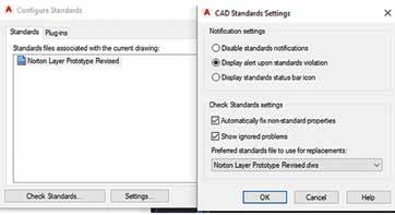
CAD STANDARDS SETTINGS
You can use the STANDARDSVIOLATION system variable or in the Check Standards dialog box, select Settings in the bottom left corner. This allows you to set options for notification of any standards violations or you can disable notifications. If you select Display Alert Upon Standards Violation in the Settings Dialog Box, an alert will display when a violation occurs while you are working in your drawing. If you are using a LISP routine in
AutoCAD Architecture
your drawing, the alert will be displayed after the routine is completed (same with Scripts). You can also choose Display Standards Status Bar Icon, and an icon will display showing you have standards violations that need your attention.
You can choose to Automatically Fix Non-Standard Properties. When this item is checked, all the properties of the objects with identical names will change to match the settings in the preferred file. The Checking Complete alert will summarize the fixed violations from the audit. There is a spot to designate Preferred Standards File to Use For Replacements. This provides a list of standards files that will control the default selection that appears in the Replace With list. You can also choose to Show Ignored Problems. When this is checked, it will show previously ignored problems when you perform subsequent standards audits. The login name of the person who previously checked it as Ignored will be shown in the Check Standards dialog along with the problem associated with the item.
STANDARDS AUDIT
Once you have associated a standards file into your drawing, you can perform a standards audit. A Standards Audit will uncover two problems in your drawing: an object with a nonstandard name and a named object that has different properties from the standard. You can audit a single drawing or multiple drawings.
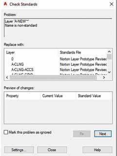
You can begin the auditing process with the command CHECKSTANDARDS or by clicking the Check Standards button in the lower left corner of the Configure Standards Dialog Box. The Check Standards dialog box is divided into three main areas: Problem, Replace With and Preview Of Changes (see Figure 3). Each of these interacts with one another.
The Problem area of the dialog box displays a description of a non-standard object found in the current drawing. The Replace With area of the dialog box lists possible replacements for the current standards violation. These replacements are the settings from the standard file you created and inserted into the drawing. If there is a recommended fix available, it will be preceded by a checkmark. If there is not a recommended fix available, no items will be highlighted in the Replace With list. The Preview of Changes area of
Figure 1 – Configure Standards Plug-ins
AutoCAD Architecture
the dialog box indicates the specific properties of the non-standard object that will be changed if the fix that is currently selected in the Replace With list is applied. You may also choose to check the box Mark This Problem As Ignored. When you do this, the login name of the user will be recorded with the fact that the problem has been ignored.
In some instances, you may want to move on to the next problem without applying a fix to the current problem. To do this, you simply need to click Next. In this case, the problem will be shown in subsequent standards audits if it is not marked Ignored.
BATCH STANDARDS CHECKER
The Batch Standards Checker is a tool that can audit a series of drawings for standards violations. The Checker will create an XML-based summary report showing all violations. The Batch Standards Checker can be opened under the Manage tab, CAD Standards panel, Batch Standards Checker. In the dialog box, you will see tabs for Drawings, Standards, Plug-ins, Notes and Progress (see Figure 4). Under the Drawings tab, click the plus sign to add drawings. Drawings are audited in the order you have them listed in so be sure to move them up and down accordingly. Under the Standards tab, you can choose to check each drawing using its associated standards files or check all drawings using the following standards files, which you would add using the plus sign. The plug-ins tab lists the standards plug-ins that are on your current system. You can specify one or all the plug-ins if you
wish for your audit. The Notes tab simply allows you to add notes to the XML report. If you add notes, be sure to click File at the top left and select Save Check File. The Progress tab gives you a summary of the status of the current batch audit. It is important to note that you cannot audit encrypted files using the Batch Standards Checker.
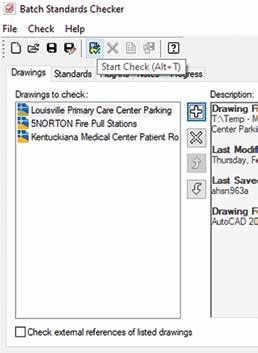
Within the Batch Standards Checker, you will see a toolbar. Once you have your drawing files and standard files listed within the dialog box, use the Start Check button on the toolbar. This begins your audit. Also, along the toolbar, you will see View Report and Export Report. View Report allows you to see an HTML report that summarizes your audit results. Export Report allows you to export an HTML report that you can share with other users.
You can view a Batch Audit Report that was previously generated if needed. Open the standards check file that generated the report you wish to view and open the Batch Standards Checker dialog box. At the top of the dialog box, click Check and select View Report. The report will open in a browser window. You can then filter the reported data for better ease of use by selecting one of the filtering options under Show: Overview, Plug-ins, Standards, Problems, Ignored Problems or All. Under For you can select individual drawings to view their audit information or view several at once, depending on what you are looking for from the audit.
Figure 3 – Check Standards
Figure 4 – Batch Standards Checker
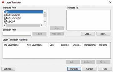
LAYER TRANSLATOR
The Layer Translator is an excellent tool that goes along with your standards by allowing you to manage your layer scheme. It allows you to specify the layers in the current drawing that you wish to translate as well as the layers to translate them to. I have found this to be extremely useful in incorporating as-built drawings from architects into my drawings. I can translate their layers into the layers I’m familiar with and vice versa. The Layer Translator allows you to control which layers are visible in the drawing area as well as purge all unreferenced layers from within a drawing. The Layer Translator can be found under the Manage tab, CAD Standards panel. Once it has been selected, a dialog box will appear that has the current drawings layer scheme shown (see Figure 5). You can also use the command LAYTRANS.
Load allows you to load layers in the Translate To list using any drawing file, CAD standards file or drawing template file. You can also create a layering scheme from scratch in which you can enter a new layer name and assign a color, linetype and lineweight to the layer by clicking New.
Transfer From specifies the layers that are to be translated in the current drawing. Layers can be specified through selection in the Translate From list or by supplying a Selection Filter. You will see a layer icon to the left of each layer name. If the icon is white, then the layer has not yet been referenced in the drawing. If the icon is dark, then it is referenced in the drawing. The Translate To list box will show you all the layers that are available for translating to and can be created from more than one drawing or from scratch.
Map is a handy tool in that it maps the layers that are selected in the Translate From list box to the layer selected in the Translate To list box. Multiple layers can be selected with this feature. With the Map Same button, no selection is needed, however. It will allow you to map all the layers that have the same name in the two lists and update them to the same properties of the layer listed in the Translate to List. The Layer Translation Mappings list box shows each layer that is to be translated, and the properties associated with each layer conversion. Here, you can select layers and edit properties by clicking Edit.
You will also notice the Settings button at the bottom left of the dialog box. This is where you can
specify to translate objects in blocks, force object color to ByLayer, force object linetype to ByLayer, etc. Be sure to check the settings to make sure everything is as you want it.
Once all the mappings have been set up, click Translate to finish translation of the layers you have mapped. The new mapped layers and their properties will replace the old layer names and their properties. If you have not mapped some of your old layers to new layers, they will be left as they were. You can save your layer translation mappings into a file that can be reused with other drawings.
CONCLUSION
AutoCAD Architecture has a lot of options for Standards that you can use to better organize your drawings, especially when multiple users are involved. There is no point in having four different dimension styles created by four different people in the same drawing that are being used for the same thing (for example)! Yes, I’ve seen that happen! Even though this article represents a quick overview of the Standards features, I encourage you to delve into it and see how better organized your drawings can be. There is a lot more we can talk about and possibly will in a future article!

Melinda Heavrin is a CAD Coordinator & Facility Planner in Louisville, Kentucky. She has been using AutoCAD Architecture since release 2000. Melinda can be reached for comments and questions at melinda.heavrin@ nortonhealthcare.org.
Figure 5 – Layer Translator
Tips for a Successful Training Program in Civil 3D

As a new year begins, we often reflect on the past year to identify areas for improvement in our work. That means training! I’m the Autodesk Civil 3D training lead for HDR and have led dozens of training sessions in recent years, helping hundreds of engineers and technicians improve their skills…
If you’re interested in starting a training program at your company, I’ll share my strategy, along with some tips and tricks, throughout this article. Some key considerations when starting your training program include who will conduct the training, where it will take place, the content, measuring success, and securing management’s support. Although “how to teach” could be a 300-page book, or 4 years of college, I will try to break down my process into manageable steps below.
GET MANAGEMENT BUY-IN
The first step is getting approval to dedicate time to training. Sometimes it’s understood that training is needed, and the idea is welcomed, particularly when staff are newer or recently hired. Other times, it could mean pointing out the uncomfortable truth that a team needs training. Being honest about
peers’ performance to their supervisor is tricky. Too specific, and you seem petty; not specific enough, and it seems pointless. Be honest yet caring when suggesting that training is necessary. Provide examples of how their lack of knowledge caused delays or extra work. The supervisor likely already knows, so be gentle, brief, and direct.
After management has agreed that training is needed, it’s important to be clear about exactly what that means. Discuss all of the following with supervisors to make sure everybody is on the same page:
• Location
• In-person is much preferred (remote learning is difficult, remote teaching is even harder)
• Ensure your office has a conference room or gathering space with enough room for all attendees (and their computers). If not, adjust the location or size of training as needed.
• Encourage them to bring a second monitor
• Time commitment
• I aim for two full days with an optional “office hours” on a third day
• Staffing commitment
• Plan for one trainer for 1-10 learners, two trainers for 10 or more
• Content
• Are you teaching an introductory course for people new to Civil 3D or a refresher course for mid-career professionals?
• Other logistical needs
• Lunches for attendees
• Travel Monitors
• White Board / Easel and pad
• Laser Pointer
Congratulations! Once you receive approval to hold the training the hard work begins.
BEFORE CLASS STARTS
Conduct a pre-session assessment of all students to gauge their expectations and set session goals for both of you. Send this out at least two weeks ahead of the class session to provide adequate time for responses and to adjust the curriculum if needed. My biggest fear used to be, “What if they already know this?” or “Will I bore them?” To ensure relevant and engaging training, I now ask these questions beforehand:
1. How long have you been using Civil 3D?
2. What discipline best describes your current design stream?
3. What do you find most difficult in Civil 3D?
4. You will consider this training a success if? (most important question)
5. If you could change one thing about Civil 3D performance and usability, what would it be?
These answers help me gauge the class’s knowledge level and needs. I might divide the class into groups based on experience (1-3 years and 3+ years). Responses to question #3 highlight areas to cover and indicate knowledge levels. Question #4 is crucial for both the students and me, shaping the curriculum and measuring training success. Question #5 often reveals performance or usability issues, or requests for automation. These insights become part of the curriculum, a measure of training effectiveness, and conversation starters.
In addition to this critical step, there are a few other tips on how to prepare:
• Create reference materials. I use a PowerPoint slide deck with screen captures of important information, heavy areas of interest, and exercise instructions. This is not a step-by-step guide, but a high level, quick reference style. Personally, I
do not provide handouts, step-by-steps, or any other take-a-ways, simply because I do not have the time to create them. But I do encourage note taking. I start each lesson with “If you are taking notes…”
• Create a simple dataset. I use a very simple data set that I am very comfortable with. Using a current project dataset might work for some users (on that project) but it should be simple. This may be the first alignment a student has ever made, the first time they have examined a surface, or even the first time they have started a new file using a template. Name your dataset files simply as well: EXISTINGTOPO.DWG, EXISTINGSURFACE.DWG, PROPOSEDROAD. DWG, CORRIDOR.DWG, ETC…
This simple approach allows attendees to concentrate on the lesson and not learn a complex naming convention, making it easier for you to give file opening instructions, look over shoulders and assess their progress on your assigned lab work.
• Have a course outline and start basic. Prepare an agenda as a rough outline but remember that you can (and should) be flexible. See a sample agenda below, it does start out basic, but this is important. Generally speaking, students will avoid raising their hand with questions, they will rely on you to teach, or for others to raise their hand.
CLASS IS IN-SESSION, NOW WHAT?
Ice breaker: Remember that not everyone knows you, and you don’t know them. Start your session with an ice breaker question during the introduction phase.
• Name, office, and something you like to do outside the office
• Name, office, discipline, favorite animal
• Name, office, first car make and model
The important part here is to make them comfortable speaking to you. Relate to a few of them. “That was my first car too, mine was blue with a huge dent in the corner…” or “I play disc golf too…”
Lessons: Perform your training in linear fashion; start a new drawing from a template, overlay base files, draw content, save drawing, assemble sheet, plot PDF. Most projects are still PDF based deliverables and are the bread and butter for most project teams.
Be flexible: Every person learns somewhat differently. Some like pictures, some like instructions, some like demonstrations, some like labs. Mix up your teaching style, mix up your delivery, mix up your voice/tone.
Phrases to avoid: “How many of you know what this tool does?” “How many of you use this tool?” or similar. The reason is simple: They are in your class because they need training. Half the class will raise their hand signaling yes, but don’t really know, and you will likely cover the topic either way, so why put them in that situation?
Have fun. I purchased a bag of 120 star-shaped stress balls from Amazon. When someone answered a question, I tossed them a star. When someone asked a great question, I tossed them a star. When someone had a different way to do something, I tossed them a star. This was very popular, and the stars were proudly displayed on desks and tables during and after training. They serve as a reminder that they attended the training as well.
WHAT DOES A LESSON LOOK LIKE?
Remember that for some students, this is the first alignment they have drawn. Give them the opportunity to draw one, reverse engineer it, play with it, stretch it, move it, and THEN do another one and add information about the dialog box, Styles, Types, Design Criteria, Layering, and Labels.
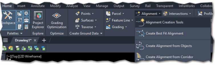
For example:
“Class, go to the home tab on the ribbon, in the Create Design area, select Alignment then Alignment Creation Tools. Let’s just hit OK and
draw an alignment; we will come back and discuss the contents of the dialog afterwards.”
Have them make a simple tangent alignment that is 200 units long. Discuss the grips on the alignment, the grips on the labels and what they do.
Have them erase that alignment, then repeat instructions on how to navigate to the ribbon and start the command, but this time have them provide a name, description, starting station, and type. Discuss the importance of naming properly but allow them to name this “anything you want.” You will prescribe a name later during lessons so you can track side streets vs mainlines.
If you spend time describing the details of an alignment before they even draw one, they will likely not retain it.
Your third alignment should include some curves. Allow them to just have fun with it, no rules on length, shape, or engineering.
Use the same formula next on profiles. Again, start simple with a surface profile. Have a file that already has a surface in it. It could be a draft or live, that does not matter.
Have them open that file, tell them the surface is already in the file; more information on surfaces will be covered later. Draw an alignment from one side to the other, name East-West, give it a description, and the type is “centerline.” They should be done in a few seconds.
See the following sample agenda for how this lesson fits into a day of learning:
Sample Agenda:
Day one Objective
Autocad screen interface “anatomy”
Autocad objects (draw one of each)
Autocad editing commands
Plotting/printing/ publishing
Troubleshooting common issues
Provides a common language/ direction/expectation
Provides a common language/ direction/expectation
Provides a common language/ direction/expectation
Provides a common language/ direction/expectation
If users understand how to fix their issues, or avoid them all together, it will decrease load time, avoid service tickets, avoid downtime, and increase productivity and product comfortability
Tips and Tricks to make basic cadd edits easy, predictable, and measurable
Exercise 1: follow directions on screen to draw a simple driveway ramp from a template
Share your time saving tips, LISP routines, Dynamo scripts, Scripts, best practices
Thank students for attending, being vocal, and participating in the discussions. Also include anything that came up during the sessions that you feel you owe them, such as a link or attachment of your PowerPoint slides, your dataset, and any other reference materials you mentioned during training. If anything didn’t work as expected during live training, make a short video and include it.
Get feedback on how you did. This is important.
I usually ask:
• Was this training provided in the best format for my learning style?
• Was the training provided at the correct speed/ cadence for my learning style?
• Was the trainer knowledgeable about the material being presented?
• How likely are you to recommend this training to co-workers?
• Would you consider this training a success?
Exercise 1 postmortem
I have them draw a simple driveway ramp and place objects on named layers. This is not a race, but you can see that the task is simple and fast. I usually show the image on the screen, describe the task, ask for final questions then say GO. I walk around the room once, then do it myself on another screen. Once I am done, I say “who else is done?” This should signal to them that it was supposed to take 3 mins to complete.
I give them a couple of minutes to complete the exercise, then I show them how I would complete it. Your way will be faster than theirs and they will learn something in how you make your layers differently, how you use the commands like offset, mirror, trim, and your use
AFTER CLASS
If you’re offering office hours after training, set up the next day after class in a conference room. Invite class attendees, or anyone else in that office who wants 1:1 mentoring, help with a specific task that would take too much time in a full classroom setting, or just want to pick your brain 1:1. Office hours allow you to engage with staff who are investing in themselves. It shows initiative and drive to be better.
After training is completely done, wait a day or two and then send a follow-up email.
• What would have made this training session(s) better?
Take these comments and results to heart. Use the feedback to make the next session better.
Let your supervisor/manager see the results. Good or bad, it’s important.
I hope this outline of a strategy helps you and your team in 2025 learn more, be more productive, and enhance your exposure to your design teams. If you read all the way through this document, you are likely to be passionate about training and advancing those around you. Find me on LinkedIn and share your stories.

Jeff Frye is the West Region Digital Delivery Lead for HDR, bringing over 34 years of experience in the AEC industry. As the lead Civil 3D trainer for HDR, he specializes in Civil 3D workflows and drafting techniques, demonstrating a deep passion for training.
Jeff began his career as a 2D drafter in the late 90s and has since become a key figure in digital delivery and BIM related activities, known for his expertise and dedication to advancing industry standards.
Building Excellence: The Role of Revit Standards

Why are standards important? If you were to look up Standards in the Oxford Dictionary, this is the definition that is given: stand·ard /ˈstandərd/ noun
plural noun: standards
1. a level of quality or attainment.
“Their restaurant offers a high standard of service.” Similar: quality, level, grade, degree, worth, caliber, merit, excellence
2. an idea or thing used as a measure, norm, or model in comparative evaluations.
“The wages are low by today’s standards.”
The webster dictionary has 10 different definitions for Standard as a noun so I won’t be including them here. You can look them up yourself if you are interested in knowing what they are. Speaking of differences, when it comes to Revit Standards, if you ask 10, 100 or even 1000 different people/companies in just the United States alone what they do for standards, you will probably get 10, 100 or even 1000 different answers.
Imagine standards as the intricate stitching in a vast quilt, binding together every patch from the efficiency of assembly lines to the imperatives of safety protocols. They’re silent architects crafting coherence in complexity.
In the world of Revit and building information modeling, standards are the blueprint that ensure every designer, engineer, and contractor is speaking the same language. On assembly lines, they dictate precise measurements and processes, allowing for seamless production where each component fits perfectly with the next. This uniformity accelerates manufacturing, reduces errors, and cuts costs—a symphony of efficiency driven by adherence to established norms.
When it comes to safety, standards become the lifelines. They’re the rigorously tested guidelines that prevent mishaps and safeguard lives. By following safety standards, organizations mitigate risks, ensure compliance with regulations, and build trust with the public. It’s like having a well-marked map in treacherous terrain; without it, you’re navigating blind.
Standards tie everything together by providing consistency and predictability. They enable diverse
teams to collaborate effectively because everyone knows the playbook. This unity is essential, especially in complex projects where misalignment can lead to costly delays or dangerous oversights.
Back in the April 2022 issue of AUGIWorld I wrote an article about Successful BIM Implementation – Revit for MEP. The second section touched on standards and read as follows:
“Unlike countries like the United Kingdom, United States firms are quite a long way away from adopting a national BIM standard as the universal standard for all firms. With that said, your deliverables can look great but to get them to look that way consistently, you will need to adopt and follow your company’s standard. What is the standard that is completely up to you and your company. Do you have a standard you have been following for another software like AutoCAD? If so, the transition to using Revit will have a clearer path. If you choose to follow a different standard like United States Army Corp of Engineers (USACE), National BIM Standards-US (NBIMSUS), US General Services Administration (GSA), or decide to forge your own path with something your company produces or a combination of several different standards, that transition from your current software might be more challenging. Your standard should include how you want your deliverables to look, as well as how they are developed and everything used to produce that final documentation.
When developing your standards, workflows and processes, I highly recommend using Revit how it is
intended to be used. There are a lot of workarounds people use that are successful but if you spend hours, days, or even weeks trying to circumvent how Revit wants you to do something for a simple task then I feel you are doing something wrong.”
CHOOSING YOUR STANDARD
Establishing a standard is a primary requirement. You should examine all the examples of standards mentioned above or in my previous article, research additional ones, including previous CAD standards like the National CAD Standard (NCS) and create examples of each. With the help of others or a committee in your company, decide what works best for your firm. Make sure you include decision makers or those with sway in these discussions. The outcome may end up being a mashup of several of those standards.
To elaborate, the process of selecting the appropriate standard should involve a comprehensive review of existing guidelines and practices. This includes evaluating the pros and cons of each standard, considering how they align with your company’s objectives, and understanding their implications for workflows and project deliverables. Engaging in discussions with key stakeholders will provide valuable insights and foster a sense of ownership and commitment to the chosen standard.
This is not an overnight process and will take some time to figure out. Be patient and with the support of those in top positions, the transition will hopefully be a smooth one. Training sessions, workshops, and continuous feedback loops should be part of the implementation strategy to ensure that everyone in the organization is on board and proficient with the new standards. Regular reviews and updates to the standards will also be necessary to adapt to new technologies and industry trends, ensuring that your company remains at the forefront of innovation and efficiency.

WHAT’S INCLUDED?
Revit Standards serve as the fundamental
framework for digital construction projects, ensuring coherence and integration across various aspects, from the accuracy of assembly processes to the intricacies of safety procedures. A comprehensive set of Revit Standards should address several critical areas to unify team efforts and enhance the overall quality of work. Here are some examples of what should be considered/ included in your standards development discussion:
1. Project Templates and Setup
• Standardized Templates: Establish templates with pre-loaded settings, views, and sheets. This ensures every project starts on the same footing, promoting consistency.
• File Naming Conventions: Define clear rules for naming files, views, and families. It reduces confusion and makes collaboration smoother.
• Project Units and Settings: Set default units, tolerances, and coordinate systems to align everyone’s workspace.
2. Modeling Practices
• Family Creation Standards: Guidelines for creating and modifying Revit families, including parameters, nested families, and levels of detail.
• Modeling Techniques: Best practices for creating elements—like when to use in-place families versus standard components—to optimize performance.
• Detailing Standards: Consistent methods for creating details, using detail components, and referencing standard details.
3. Annotation and Documentation
• Dimension Styles: Standard dimension styles for uniformity across all drawings.
• Text and Fonts: Specific fonts and text sizes to maintain a professional and cohesive look.
• Line Styles and Weights: A set palette of line types and weights to differentiate elements clearly.
4. Collaboration and Worksharing
• Worksharing Protocols: Rules for using central models, synchronizing, and avoiding conflicts.
• Team Roles and Responsibilities: Clear definitions of who does what, minimizing overlaps and miscommunication.
• Consultant Coordination: Standards for linking and coordinating models from architects, engineers, and other stakeholders.
5. Quality Assurance and Control
• Model Auditing: Regular checks for file size, errors, and adherence to standards.
• Clash Detection: Procedures for identifying and resolving conflicts between different building systems.
• Review Processes: Scheduled reviews at key project milestones to catch issues early.
6. Data Management
• Shared Parameters: A unified set of parameters for consistent data across schedules and tags.
• Parameters Naming Conventions: Clear guidelines to avoid duplicates and confusion.
• Information Management: Standards for exporting and sharing model data with external parties.
7. Visualization and Graphics
• View Templates: Preset views with specific graphic overrides for plans, sections, elevations, and 3D views.

• Rendering Settings: Standardized materials, lighting, and settings for visual consistency.
• Color Schemes and Legends: Defined color schemes for readability and aesthetics.
8. Compliance and Safety Integration
• Building Codes Standards: Integration of local and international building codes into the model elements.
• Safety Elements: Inclusion of safety features like fire exits, signage, and accessibility features within the model.

• Regulatory Documentation: Standards for documenting compliance and preparing submission packages.
9. Training and Education
• User Manuals: Comprehensive guides explaining the standards, why they matter, and how to apply them.
• Workshops and Training Sessions: Regular opportunities for team members to learn and update their skills.
• Support Systems: Channels for team members to ask questions and share knowledge.
10. Innovation and Improvement
• Feedback Loops: Mechanisms for team members to suggest improvements to the standards.
• Emerging Technologies: Guidelines for integrating tools like Dynamo for automation or VR for visualization.
• Sustainability Standards: Incorporating green building practices and energy analysis into the workflow.
By integrating these elements, your Revit Standards become the thread that ties efficiency to safety, much like an assembly line that’s both productive and secure. They provide a common language for your team, reducing errors and enhancing collaboration.
ENHANCING CLIENT SATISFACTION THROUGH STANDARDS
At the heart of every successful project lies a satisfied client. Revit Standards play a pivotal role in achieving this by delivering consistency, efficiency, and quality—all of which clients highly value. When deliverables are uniform and predictable, clients gain confidence in the firm’s ability to meet their expectations. Standardized models and documentation mean fewer surprises and a smoother project journey.
Efficiency is another significant benefit, as streamlined processes reduce redundancies and rework, leading to faster project completion. Clients appreciate when projects stay on schedule and within budget, enhancing their overall satisfaction.
Furthermore, a commitment to high standards reflects a firm’s dedication to excellence. This professionalism not only satisfies current clients but also attracts new ones through positive word-ofmouth and strong portfolio examples.
CHALLENGES IN IMPLEMENTING REVIT STANDARDS
Transitioning to a standardized workflow is not without its hurdles. Recognizing and addressing these challenges can make the difference between successful adoption and lingering frustration.
Resistance to change is a common obstacle. Team members accustomed to their methods may resist new protocols. This reluctance can stem from fear of the unknown or concern over initial productivity dips.
Training requirements are also significant. Implementing standards necessitates comprehensive training programs. Allocating time and resources for education can strain schedules, especially in fast-paced environments.

Resource allocation poses another challenge. Developing, documenting, and maintaining standards require investment. Smaller firms may find it challenging to allocate necessary resources without impacting other operations.
Technology compatibility is essential to ensure that all hardware and software are up-to-date and compatible with the latest Revit features. Legacy systems might hinder the smooth implementation of new standards.
THE EVOLUTION OF REVIT STANDARDS IN THE AGE OF AI AND AUTOMATION
As technology continues to advance, Revit Standards must evolve to leverage new tools while maintaining core principles. One significant aspect is the integration of AI and Machine Learning. AI can automate repetitive tasks such as error checking, clash detection, and routine documentation. Standards will need to include protocols for AI tool usage and oversight to ensure reliability.
The next aspect is data-driven design. With access to big data analytics, teams can make more informed design decisions. Standards should guide how data is collected, managed, and applied within Revit models to maximize efficiency and accuracy.
Additionally, enhanced collaboration tools are becoming integral with the rise of cloud-based
platforms and real-time collaboration software. Standards must address security protocols, version control, and collaborative workflows across these platforms to ensure seamless teamwork.
Finally, customization and scripting using tools like Dynamo allow for custom scripting within Revit. Standards should include guidelines on script creation, documentation, and sharing to prevent conflicts and promote reuse. By addressing these technological advancements, Revit Standards can continue to provide a robust framework for efficient, innovative, and collaborative projects.
GLOBAL PERSPECTIVES: UNIFYING MULTINATIONAL TEAMS
In our interconnected world, projects often span continents, requiring seamless collaboration across diverse teams. Standards should respect and incorporate cultural differences in work styles, communication, and business practices. This could involve flexible working hours, multilingual documentation, and culturally appropriate design considerations.
Building codes and regulations vary widely, and international compliance ensures these variations are integrated. Standards must include processes for integrating local requirements into the global model to ensure compliance and avoid costly redesigns.
Clear guidelines for communication protocols can mitigate misunderstandings. This includes standardized reporting structures, meeting protocols, and conflict resolution strategies.
Ensuring all team members have access to the necessary technology and software versions is critical, which is covered under technology accessibility. Standards might outline minimum system requirements and provide support for technological disparities.
CONCLUDING THOUGHTS: THE FUTURE OF REVIT STANDARDS
Revit Standards are more than a set of rules—they are the foundation upon which efficient, innovative, and collaborative projects are built. Looking ahead, adaptive and dynamic standards must be flexible, allowing for regular updates and adaptations to new technologies and methodologies. Emphasis on sustainability should be a priority, incorporating environmental considerations into standards to guide teams toward more sustainable design practices, aligning with global efforts to combat climate change. Enhanced user experience is crucial; making standards user-friendly encourages adoption through interactive guides, integrated help features within Revit, and accessible training resources. Community collaboration should also be fostered; engaging with the broader Revit community can promote the sharing of best
practices and the development of industry-wide standards, benefiting everyone involved. By embracing these future directions, firms not only improve their own processes but also contribute to the advancement of the entire industry.

Jason Peckovitch is an Autodesk Revit Certified Professional for Mechanical and Electrical Design located in SE Iowa. He is a BIM Manager for Garver’s Buildings Business Line, specifically MEPF. Garver has more than 50 offices across the United States and more than 1300 employees. His CAD/BIM career spans over 25 years, and he transitioned to the AEC Industry in 2007 as a Mechanical HVAC Drafter before moving into BIM Management, where he has been working since. Jason is also the father of three children; Shelby – 13, Blake – 10 and Logan - 7, a published photographer, gamer, and car/ tech guy. He can be reached at jmpeckovitch@garverusa.com, found on X under the handle ThatBIMGuy, connect with him on LinkedIn or several other user platforms like AUGI Community or BIM Heroes.

by: Rina Sahay
Welcome to AUGIWorld Inside Track! Check out the latest opportunities to advance your skills, processes, and workflows in your firm with the most current AEC-related software and hardware updates available.
Walking through the Autodesk App Store Wonderland
Welcome to 2025, O Gentle Reader! Let’s start this lovely new year with a quick walk through the Autodesk App Store Wonderland…...
We’ll look for helpful Revit add-ins. As always, I like to focus on tools that are FREE!
But before that, as always, let’s get the formal introductions out of the way -
Gentle Reader - Autodesk App Store
Autodesk App Store - Gentle Reader
But before I start - can I point you towards this lovely little surprise that recently popped up for me? AT LAST, we have a natively available Add-Ins Manager for Revit 2025!
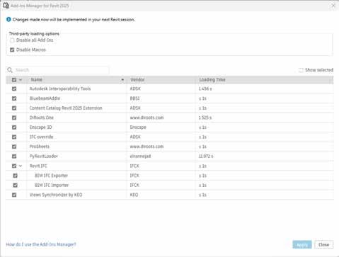
Figure 1
You can enable or disable installed add-ins as you need. However, there are some aspects in which this falls behind old(er) warhorses like DiRoots’ AppManager, which monitors, installs / uninstalls, and updates DiRoots add-ins (and not the othersthey can look after themselves, I guess!).
In a perfect world, the Add-Ins Manager for Revit would be a one-stop shop to search for, install, uninstall, and (dare I hope?) update add-ins. O Autodesk - HEAR MY CRY! Here’s hoping for the future!
Back to our walk!
Let’s take a closer look at some performers from ARKANCE (formerly U.S. CAD) -
• Smart Browser Free
• Cut Opening Free
• Smart Select Free
Something that you need to remember is that when you click to download one of these (I started with Smart Browser Free) you will install the big purple ARKANCE Dock to the right of your screen. Read on to see what this means!
THE ARKANCE | DOCK
What does the great big purple ARKANCE | DOCK to your right mean? This allows you access to install trials of other apps from this developer, make purchases, and download updates to all ARKANCE’s other offerings. Talk about convenience!


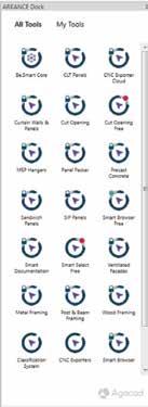
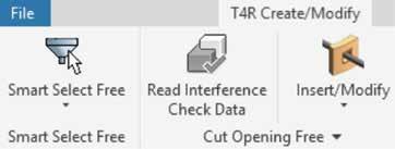
Also - if you don’t want to see the Dock, you can turn it off AFTER getting the desired tools to show up in the toolbar.
SMART BROWSER FREE
Also developed by ARKANCE, this free version of the Smart Browser app lets you browse
• Revit families
• Revit elements
• And their properties
You can easily find families in libraries on your computer, easily check their types and parameters.
The basics - The required OS is Win64. This is available in English.
Starting up - Installation is a breeze - download and run the executable if you haven’t already installed the Dock. If you have the Dock, then that’s where you can access and install the tool from. It is compatible with Revit versions 2021 through 2024you can pick and choose.

The interface - You will see a new tab added to the toolbar.
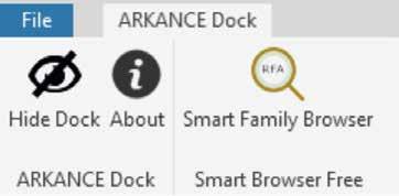
Figure 2
Figure 3
Figure 4
Figure 5
Figure 6
Inside Track
Click the Smart Family Browser tool to start your Smart Browser experience.

This will take you to a dialog box with options to Create a new library OR connect an existing library.
Create a new library will prompt you to navigate to select family folders and create a .xml format Smart Browser friendly library in the location of your choice. I was able to browse library folders stored on my network, as well as families in the cloud via Autodesk Docs. And then VOILA!!

Now you can drag and drop families into your project, review parameters and 2D / 3D views, group and filter families.
Drawbacks - It needs some groundwork to prepare the library .xml file.
CUT OPENING FREE
This free version of the Cut Opening add-in for Revit
lets you quickly and easily create holes throughout a project wherever clashes happen between ducts, pipes, cable trays, and conduits as they intersect walls, floors, roofs, or ceilings. Openings can be fireproofed, insulated, or outfitted in other ways. You can change the type and form of opening and lock the cut offset.
Starting up - You can access the software through the previously mentioned dock. This will allow you to insert or delete openings based on data from the .xml file from the interference check report.
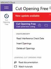
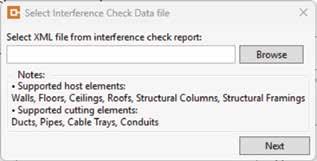
Drawbacks - This tool will not cut openings in a linked model - a major drawback.
SMART SELECT FREE
Install this plug in through the ARKANCE Dock. You can also use the installed tool from the toolbar.
A variety of selection options is presented.
I tested two of them.
1. Select Elements in Room / Space
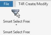

This is seriously NIFTY! Click on one element in the room and all elements of the same category light up! Variants of this tool allow you to select elements in the Room / Space by Family and Type! How absolutely cool is that?
Figure 7 Figure 8
Figure 9
Figure 10
Figure 11
Figure 12

2. Filter Elements
There is a bit of lead time when you click to use the tool as the add-in reads all elements in the model. You can filter elements by category and refine the selection by adding specific configurations. Quite cool.
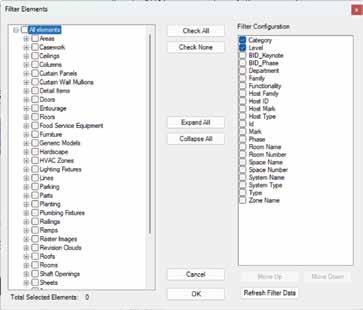
VIEWS SYNCHRONIZER
The basic premise of this add-in from KEO International Consultants is the ability to link, manage, and synchronize views across multiple linked Revit models. In simpler terms, the ability to have smart callout tags referencing views from linked models. This is an ability which I wish was natively available in Revit! The workflow is, admittedly, strange and clunky, but there may be situations where tags referencing views in linked models may be required.
The basics - The required OS is Win64. This is available in English and is compatible with Revit versions 2022-2025.
Starting up - Easy installation - just download and run the installer.
The Interface - You will see a new button in the Add-Ins tab.
Pre-reqs - When I first clicked on the tool, the add-in prompted me for information.


That left me scratching my head a little - so here are Explanations!
Here’s what the add-in will help you to do. You will create a dummy callout that pulls information from the linked models and displays it in a tag. The callout boundary is a Detail Item. The tag is a custom detail item tag. Strange, but true.
So, the required Detail Item can be ANYTHING. Believe it or not - I’d tested with a filled region (and you know how I feel about Filled Regions)! The upshot of this is that you will need to create a filled region or a Detail Item family that graphically mimics your standard callouts.
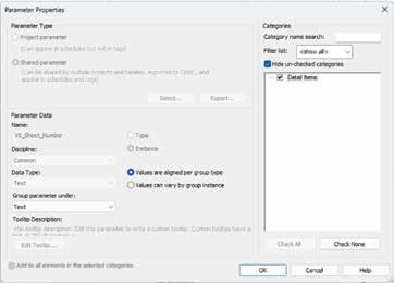
The provided Help documentation is not specific about the required parameters - Shared or Family/ Project? Once I realized that I would need to create a custom tag, I knew that Shared parameters were what the doctor ordered. I loaded the Shared parameters into the project associated with the
Figure 13
Figure 14
Figure 15
Figure 16
Figure 17
Figure 18
Detail Items category and used them to create the custom tag.

Remember - when you create the custom tag you will need to make sure it graphically mimics your standard tags. My test tag featured ALL the VS parameters, so it ended up looking pretty chaotic! Pick and choose the parameters you need to tell the story you want to tell (Figure 20
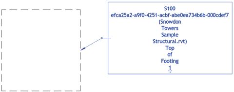
. Usage - Create the required Detail Item. Select it, click Edit Type and ensure that the VS_Enabled parameter is set to Yes. Then click the Views Synchronizer tool. You will be prompted to link to views in the linked model (as well as the host model, which, of course, you will scroll over as this part is redundant). Figure 21.
What if some information in the linked view has changed? That’s when you hit the Synchronize button. This will verify whether the change has been transferred to the detailed item and updated in the tag or not. In this case, you can see that the Top of Footing detail from the Structural model which I had linked to has not changed, so the tag is unchanged as well (Figure 22).
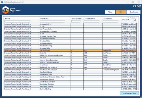
I do understand that there may be project specific situations where an approach like this would be required - work cases utilizing Views Synchronizer would be more of an exception than the rule. I just wish that this tool offered a more streamlined and elegant solution to the problem of tagging views from linked models.
Figure 19
Figure 20
Figure 21
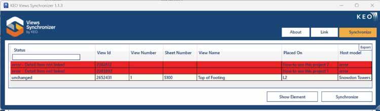
WORKSETS MANAGEMENT
Here’s another add-in from the folks at KEO! This add-in has been around since (possibly) 2022, and it allows you to
• Create, validate, and rename all or selected worksets from a TXT file
• Assign selected Revit / CAD links, grids and levels to a default or selected Workset
• Create single or combined 3D views for selected Worksets
• Assign single or multiple Families or types to selected Worksets
• Control visibility of Worksets for single or multiple View Templates
Sounds interesting, doesn’t it? Read on!
The Basics - The required OS is Win64. This is available in English. Worksets Management is compatible with Revit versions 2020-2025.
Starting up - Easy installation - just download and run the installer.
The Interface - You will see a new button in the Add-Ins tab.
Let’s take a look at some of the most helpful features I’d noticed in this add-in -
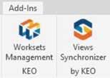
23
Usage - Click to activate the Worksets Management tool. You will be taken to a dialog box with buttons
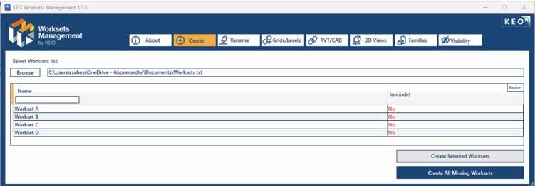
Figure 22 Figure
Figure 24
Figure 25
Inside Track
guiding you to different functionalities.
Create - I started by browsing to the TXT file where I’d created a list of Workset names. Worksets Management displays the list and prompts to create all or selected Worksets. What a totally nifty tool! Figure 25.
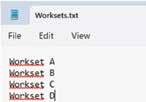
Rename - Renaming Worksets is quick and easy - all you need to do is type the desired name and click the Rename Worksets button! Figure 27.
Assign - Grids / Levels to Worksets. Figure 28.
Whew! that was quite a Walk Through the Autodesk App Store Wonderland, wasn’t it! So now, Gentle Reader, this brief Walk leaves you with more than a nodding acquaintance with some (possibly) helpful (or not!) add-ins. Hopefully you are encouraged to explore the AppStore further and find tools to enhance your Revit productivity.
Till the next Inside Track - KEEP REVIT-ING!

A bit about myself. I’m the BIM Manager at Abonmarche, based in glorious Grand Rapids, Michigan (Great Lakes, anyone?). Started my Autodesk journey with AutoCAD Release 10 (remember that dreary DOS interface - and the need for super-duper spelling skills?). Learned enough Revit to stay one chapter ahead of college students in the classroom. That changed in a hurry when I made a triumphantly painful return to industry as a BIM Specialist and had to use Revit in the worst way possible. I HATED it, and grieved for my beloved AutoCAD I bid thee farewell, O Gentle Reader! Till the next Inside Track - KEEP REVITING!!! Every day! Until I figured Revit outthe rest, as they say, is history. Autodesk Expert Elite in 2018, presenter at Autodesk University since AU2019 (and I have Best Speaker awards for 2021 and 2022 to show for it!). And now here I am, to educate, enlighten, and hopefully, entertain.
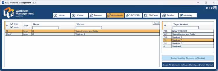
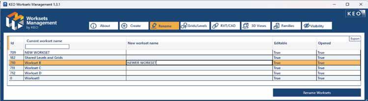
Figure 26
Figure 27
Figure 28

Bright Ideas for a Bright Future

AUGIWORLD brings you the latest tips & tricks, tutorials, and other technical information to keep you on the leading edge of a bright future.