

AUGIWORLD
Trending Technologies
Unlock your full potential with the latest Precision workstations. Whether you are creating groundbreaking design or performing complex coordination, these workstations are engineered to enhance your productivity. Equipped with NVIDIA RTX™ Ada Generation GPUs and integrated AI capabilities, they streamline your workflow and elevate your creative and technical endeavors.


From the President

HAPPY NEW YEAR FROM ALL OF US HERE AT AUGI!
As we step into the new year, it’s a perfect time for reflection, growth, and setting our sights on new horizons. For us, CAD/BIM professionals, the everchanging landscape of design technology offers endless opportunities and challenges to embrace. This year, let’s start strong by focusing on preparation, adaptability, and innovation. Here are 5 key ways we can gear up for success in 2025 and beyond…
1. Reflect and Reset. Take a moment to review the past year. What went well? What could you have done differently? Understanding your wins and challenges can offer valuable insights for improvement. Whether it’s honing your technical skills, enhancing team collaboration, or tackling inefficiencies, start by setting clear, actionable goals.
2. Stay Ahead of Industry Trends. From AI advancements to new software features, the world of CAD and BIM is always evolving. Dedicate time to learning about emerging technologies and methodologies that could elevate your projects. Joining webinars, listening to podcasts, and attending conferences like AUGI CON can keep you informed and inspired.
3. Invest in Your Productivity. The key to thriving in the face of increasing demands is working smarter, not harder. Evaluate your workflows to identify bottlenecks and explore tools or techniques that can save you time. Whether it’s learning keyboard shortcuts, adopting project management software, or using templates for standardization, small changes can lead to big improvements.
4. Strengthen Your Network. In a fast-paced industry, your network is your superpower. Connect with other professionals, exchange ideas, and seek mentorship or collaboration opportunities. Communities like the AUGI Community for CAD/BIM professionals and social networks like LinkedIn can be invaluable for support and growth.
5. Embrace a Growth Mindset. Challenges are inevitable, but they’re also opportunities in disguise. By staying curious, open-minded, and resilient, you can turn obstacles into stepping stones. Remember, even small, consistent efforts can lead to transformative results over time.
As CAD/BIM professionals, we’re not just managing tools… we’re shaping the future of design. The new year is a blank slate—full of potential to make this your best year yet. Let’s welcome the new year with optimism, determination, and a commitment to excel. Here’s to disrupting the status quo in 2025.
AUGIWORLD
www.augi.com
Editor
Editor-in-Chief
Todd Rogers - todd.rogers@augi.com
Copy Editor
Miranda Anderson - miranda.anderson@augi.com
Layout Editor
Debby Gwaltney - debby.gwaltney@augi.com
Content Managers
3ds Max - Brian Chapman
AutoCAD - KaDe King and Chris Lindner
Civil 3D - Shawn Herring
BIM/CIM - Stephen Walz
BricsCAD - Craig Swearingen
Electrical - Mark Behrens
Manufacturing - Kristina Youngblut
Revit Architecture - Jonathan Massaro
Revit MEP - Jason Peckovitch
Tech Manager - Mark Kiker
Inside Track - Rina Sahay
Advertising/Reprint Sales
Kevin Merritt - salesmanager@augi.com
AUGI Executive Team
President
Eric DeLeon
Vice-President
Frank Mayfield
Treasurer
Todd Rogers
Secretary Kristina Youngblut
AUGI Board of Directors
Eric DeLeon
KaDe King
Chris Lindner
Frank Mayfield
Todd Rogers
Scott Wilcox
Kristina Youngblut
Advisory Board Members
Shaan Hurley Shelby Smith
Publication Information
AUGIWORLD magazine is a benefit of specific AUGI membership plans. Direct magazine subscriptions are not available. Please visit www.augi.com/account/register to join or upgrade your membership to receive AUGIWORLD magazine in print. To manage your AUGI membership and address, please visit www.augi. com/account. For all other magazine inquires please contact augiworld@augi.com
Published by:
AUGIWORLD is published by AUGI, Inc. AUGI makes no warranty for the use of its products and assumes no responsibility for any errors which may appear in this publication nor does it make a commitment to update the information contained herein.
AUGIWORLD is Copyright ©2025 AUGI. No information in this magazine may be reproduced without expressed written permission from AUGI. All registered trademarks and trademarks included in this magazine are held by their respective companies. Every attempt was made to include all trademarks and registered trademarks where indicated by their companies.
AUGIWORLD (San Francisco, Calif.) ISSN 2163-7547


Leaning Toward Action

Ihave written a lot on decision making, analyzing, pondering, and weighing options. I tend to take in as much information as I can and get input from many people and places. I then think about what could happen or what should happen. After a period of time a decision is made, and action needs to be taken. But when do you take that action? When is it time to stop thinking and move forward? I suggest that you always lean toward action, even when you are thinking things through. Always keep focusing on taking action.
A TIME TO THINK
There is a time to gather input and ideas, pros and cons, strengths and weaknesses when given
a decision to make. Then there is a time to think about all the data and info you have pulled together and get some input from others. During this time of thinking and weighing your options, you should always focus on driving toward conclusions that are actionable and final.
SEEK CONCLUSIONS
Conclusions come when you have reached a point that data coalesces into patterns. Bad options begin to fall away and leave you with fewer choices. You start to see options as good, better, best. The data supports your refinements and confirms your findings. Things start to become less chaotic and foggy, and clarity is coming into view. You are
reaching for conclusions. You should then start looking for which ones are actionable.
Having a mindset of action does not mean that you move before you have a concrete idea of the action needed. It is not movement just for movement’s sake. It is not pointless activity. If I develop 10 ideas about using technology, that is movement, but if I have a concrete plan about using technology, that is action. You should not be acting before you see a roadmap of resolution or advancement.
SEEK ACTIONABLE CONCLUSIONS
Not all conclusions have obvious actions associated with them. You may have figured out the goal, but not the steps in getting to your goal. There may be no clear steps at all. The right path to take may not have any road signs. When this happens, you need to press on to seek decisions that lend themselves to taking action. A conclusion that does not lead to action is just a perspective. It is a point of view, a wish, an opinion. Just one thought among other thoughts. But a conclusion that has actions associated with it is a call to activity for you and others. Now you have something you can “do.” You have answered not just the what, but the how and when and possibly the who of the actions. Now things are leaning toward action.
Most of the decisions you must make at work are brought to you because some action is needed. A fix, a refinement, a new directive, whatever. Your goal, when entering the decision-making process, is to come out the other side with some actions.
Conclusions that come from your own personal research or exposure to technology also call for action. So, your mindset and leaning should always be toward action, to shorten the decision cycle while apply the right balance of deliberation. Think, but not delay. Ponder, but do not procrastinate.
SEEK FINAL ACTIONABLE CONCLUSIONS
Conclusions need to be actionable and also final. Understand that by final, I mean conclusions that drive you to immediate actions now. Once you have an actionable conclusion, it is time to move on it. The planning phase is over and now it is time for progress. Start as soon as it is practicable, but not sooner. Starting before you have a conclusion will increase your failure rate. Moving before you have defined actions to take may end in grasping
at solutions. And progressing before you have a final plan means you may have incomplete steps. Do not shortchange the planning phase, but don’t overextend it either.
BE OPEN TO REVIEW
Once you start taking action – review after each step. Final also does not mean set in stone. You need to review things to see if your plan is unfolding well. If adjustments are needed, make them. Some may want to review your progress because they did not agree with your conclusions. They could not stop you from starting to take action, but they could slow you down by overly reviewing and questioning everything. I am all for review, but one thing I ask before a review is “Is there is new information?” Has something changed? Is there new information available that we did not have before? Did an action not produce what was expected? If not, then a review is not called for and is just rehashing the same things you have already discussed. Nothing has changed, so keep moving as planned.
By having a mindset that leans toward action, you are nudging everything to completion. You encourage drawing conclusions, and you seek resolution. It takes practice to not move until you have some kind of plan, and you may move to soon. But having a slight lean toward focused activity will get you moving. It is easier to steer a ship that is moving than one that is standing still.

Mark Kiker has more than 30 years of hands-on experience with technology. He is fully versed in every area of management from deployment planning, installation, and configuration to training and strategic planning. As an internationally known speaker and writer, he is a returning speaker at Autodesk University. Mark has served as Draftsman, Principal Designer, CAD/ BIM Manager, CTO and CIO. He can be reached at mark.kiker@augi.com and would love to hear your questions, comments, and perspectives.
Unlocking the Power of Your Office CAD Workstation from Anywhere with Remote Access

As engineering, architecture, and design work become more mobile, so too does the need for remote access to highpowered workstations. The days of being tied to a heavy, power-hungry computer are dwindling. Imagine accessing your office’s CAD workstation—running software like AutoCAD, Civil 3D, or Revit—from anywhere with just a lightweight laptop or even a retired desktop. This setup can significantly boost productivity, allowing you to work efficiently from a client’s site, a coffee shop, or even your living room. Here’s how you can turn that vision into a reality.
1. WHY USE A REMOTE CAD SETUP?
High-performance CAD workstations are costly, resource-intensive machines that deliver unparalleled computing power. They’re essential for 3D rendering, complex simulations, and large assemblies. With remote access, you’re free from carrying the highpowered workstation to meetings or working exclusively from your desk in the office. You gain:
Mobility: Work from anywhere with internet access. Efficiency: Use a lightweight laptop or desktop to
access the processing power of a powerful CAD workstation from the road, or home.
Reduced Hardware Costs: Instead of buying multiple high-end machines, you can optimize a single workstation.
Security: Sensitive data remains on your office machine rather than traveling around on a mobile device.
2. CHOOSING THE RIGHT REMOTE ACCESS SOFTWARE
To enable remote CAD work, you’ll need specialized remote desktop software. Not all remote software is suitable for CAD work because of the high demands of 3D graphics and real-time responsiveness. Some excellent options to consider are:
Windows Remote Desktop (RDP): Built into Windows, RDP is a good choice for simple tasks and requires minimal configuration.
Parsec: Whether doing daily work in CAD, modeling an interior, or running simulations, Parsec provides the most performant workstation access on the planet.


Splashtop or TeamViewer: Both offer high-quality, low-latency screen sharing that can handle 3D graphics.
Look for software that prioritizes low latency and high-resolution streaming. Some CAD programs may also offer specific support or optimizations for remote desktop environments.
3. NETWORK AND HARDWARE REQUIREMENTS
Network Stability: CAD work requires a steady, high-bandwidth connection for smooth visuals and minimal lag. If your remote setup suffers from lag, consider upgrading your internet speed or moving to a wired connection, if possible, to reduce latency.
Graphics Processing: CAD workstations often use professional-grade GPUs, such as NVIDIA Quadro or AMD Radeon Pro cards, optimized for 3D rendering. When accessing these remotely, ensure your remote access software can transmit high-quality graphics without sacrificing performance.
Minimal Local Hardware
Requirements: Since most of the heavy lifting happens on the workstation, your remote device—be it a laptop, tablet, or desktop—doesn’t need much processing power. However, it should be capable of running the remote access software smoothly, ideally with at least 8GB of RAM and a decent CPU.
4. CONFIGURING YOUR CAD WORKSTATION FOR REMOTE ACCESS
Before setting up remote access, make sure the CAD workstation is optimized for the best remote experience.
Optimize Power Settings: To avoid interruptions, set your computer to stay awake while idle. Remote sessions are often disrupted if the workstation goes into sleep mode.
CAD

Set Up Dual Monitors: If you use a dual-monitor setup in the office, most remote software lets you view both screens remotely, making complex CAD work easier.
Adjust Resolution Settings: Lower the resolution slightly for smoother performance. Although high resolution is visually appealing, it requires more bandwidth and can slow down the remote connection.
5. TIPS FOR A SEAMLESS REMOTE CAD EXPERIENCE
Once you’re set up, consider the following tips to enhance your workflow:
Keyboard Shortcuts: Remote CAD work requires frequent use of shortcuts. Some remote desktop software can interfere with shortcuts, so it’s worth checking or customizing these settings to ensure compatibility with your CAD software.
Close Unnecessary Programs: Keep your CAD workstation’s processing power focused on the CAD software by closing unnecessary background programs before remote work.
Joining Web Meetings from Your Local Device: While working remotely, web meetings are an essential part of collaboration with team members, clients, or stakeholders. Instead of joining meetings

from your CAD workstation, which can slow down your workflow or add unnecessary load, connect to meetings directly from your local device.
6. HERE’S HOW THIS SETUP BENEFITS REMOTE CAD WORK:
Less System Load: Your CAD workstation stays focused on processing intensive tasks, not using up resources on web conferencing.
Improved Audio/Video Quality: Many remote access tools struggle with smooth audio/video playback. Joining the meeting locally avoids these issues and provides a clearer connection with team members.
Easier Screen Sharing: Instead of sharing your entire CAD workstation screen through remote software, you can use local tools to present models, slides, or sannotations without a lag. If you need to show your CAD work, you can share it through the remote connection screen itself.
Using your local device for meetings can also simplify workflows by allowing you to communicate directly from the device you’re actively using, making multitasking smoother and allowing you to stay engaged with both the CAD environment and the discussion.
7. SECURITY CONSIDERATIONS
Remote access introduces security risks. Ensure that your remote access software and workstations are protected with strong passwords, up-to-date antivirus software, and firewall protection. ProSoft IT can help you pick the method that will work best for you, and ensure your remote connection is secure and reliable.
CONCLUSION
Setting up a remote CAD workstation is an investment in flexibility and efficiency. You’ll be able to tap into the power of your office machine’s high-end specs without sacrificing mobility or comfort, making remote CAD work not just possible, but highly effective. By implementing the right software, optimizing settings, and ensuring a secure connection, you can transform a modest laptop or retired desktop into a portal to your highperformance CAD workstation—anywhere, anytime.

Bryson has worked in the IT industry since 2008. During this time, he has been involved in many aspects of IT including, Systems Administration, Networking, Telecom, Hardware, and IT consulting. He has supported large and small companies in a variety of industries including healthcare, software development, engineering, and architecture; plan, implement, upgrade and maintain their IT infrastructure.
At ProSoft, Bryson admins all aspects of the internal IT infrastructure, and oversees ProSoft’s managed IT services, and custom workstation and server division. With his knowledge and experience in IT, he consults with companies worldwide on the planning, implementation, and training of Autodesk data management and collaboration software. As well as assisting customers with the licensing, installation, and deployment of Autodesk products.

When preserving heritage buildings or tackling complex remodeling projects, precision is nonnegotiable. Point cloud technology paired with AutoCAD empowers professionals to create accurate 2D plans while honoring original structures. This article details a proven workflow for harnessing this technology effectively.
Point clouds provide a highly detailed representation of existing structures, capturing every nuance of their geometry. AutoCAD, on the other hand,
serves as a powerful tool to transform this data into accurate, actionable 2D plans. For over 8 years, I’ve specialized in this workflow, creating precise drawings that respect the original architecture while meeting modern project demands.
In this article, I will explain the step-by-step workflow I use to create 2D plans in AutoCAD from point clouds, focusing on their significance in projects like these, overcoming challenges, and ensuring precision and efficiency.
THE WORKFLOW FOR 2D PLAN DRAWINGS IN AUTOCAD WITH POINT CLOUDS
Step 1: Starting Fresh:
Start AutoCAD and click on the tab file - New and select template acad.

Step 2: Importing the Point Cloud Start by importing the point cloud file into AutoCAD. Supported formats like RCP or RCS ensure seamless integration. The easiest way is dragging your RCP file into AutoCAD, position the file at the origin (0,0,0) for consistency in workflows and compatibility with other datasets.

When one clicks on the point cloud it automatically opens a new menu, to simplify the visualization, adjust the density and transparency of the point cloud using the Point Cloud Manager. This is particularly useful for large projects where cluttered data can be overwhelming.

Step 3: Setting Up UCS for Different Perspectives
Defining User Coordinate Systems (UCS) is essential for navigating the point cloud effectively. Set up UCS for each view, including North, South, East, West, and plan views. This step ensures that every section of the structure is captured accurately and makes it easier to align different elements during tracing.
For example, in a recent heritage project, setting up a custom UCS allowed me to align the intricate details of a façade with the overall structural layout, ensuring seamless integration across drawings.
Point Clouds

Step 4: Breaking Down Complexity: Segmenting Point Clouds
Breaking down the point cloud into manageable sections is critical for efficiency. For multi-story buildings, I typically create three main cuts:
• Low Cut: At 1.2 meters from the floor to capture base details like walls and furniture.
• High Cut: Approximately 50 cm below the ceiling to focus on upper features like beams and openings.
• Thin Slice: A 40 cm slice in the middle to identify wall details and openings precisely.
This segmentation process helps reduce noise and ensures that only the relevant parts of the point cloud are used in the drawing.

Step 5: Manual Tracing and Annotation
Tracing walls, windows, and doors manually is the core of this workflow. Using tools like polyline and rectangle, I ensure that every element is accurately represented.
Unlike relying on autosnap, which can produce errors in noisy data, manual tracing allows for greater precision. For walls, I ensure that polylines form closed loops, adhering to a tolerance of ±10mm. Additionally, annotations are added to highlight critical details like wall thickness and material types.
In one instance, tracing the irregular walls of a historic church required meticulous attention to detail. By manually tracing each curve and deviation, I ensured that the final plan respected the original design while meeting modern standards.
Step 6: Adding Architectural Features
Standardized blocks for doors, windows, and furniture are inserted to enhance the clarity of the drawing. Adjustments are made to align these elements with the scanned data, ensuring accuracy.
For heritage projects, I often create custom blocks to represent unique architectural details like decorative moldings or arches. This approach not only preserves the character of the building but also provides a comprehensive reference for future renovations.
Step 7: Validating and Finalizing the Drawing
Validation is a crucial step to ensure the accuracy of the drawing. Tools like Measure and Distance in AutoCAD help verify dimensions and alignments. Cross-checking with the original point cloud data ensures that no detail is overlooked.
Once the drawing is finalized, redundant elements are removed, and layers are organized for clarity. The completed file is then exported in DWG format, ready for use in construction or client presentations.
CHALLENGES AND SOLUTIONS
Noisy Data in Point Clouds
Challenge: Point clouds often include extraneous data, especially in cluttered environments.
Solution: Preprocess the point cloud using tools like Autodesk ReCap to filter out noise and focus on relevant details.
Complex Geometries in Heritage Buildings
Challenge: Irregular shapes and intricate details can be difficult to capture.
Solution: Divide the point cloud into smaller sections and use custom UCS settings to focus on individual elements.
Limited Automation
Challenge: Automating 2D plan creation is still in its infancy.
Solution: Combine manual tracing with custom LISP routines to streamline repetitive tasks and improve efficiency.
WHY USE AUTOCAD FOR POINT CLOUDS IN REMODELING AND HERITAGE PRESERVATION?
Unlike other tools, AutoCAD excels in creating 2D plans with unparalleled precision, making it ideal for projects that require detailed documentation of existing conditions. This is especially critical in heritage preservation, where accuracy ensures that every element, from intricate moldings to structural irregularities, is recorded faithfully.
For example, when working on a 19th-century heritage building with irregular walls and unique details, AutoCAD allowed me to trace every feature precisely while maintaining the original architectural essence. Similarly, in remodeling projects, precise plans ensure that contractors can rely on the drawings to avoid costly errors and unexpected delays.
Another key advantage is AutoCAD’s flexibility to integrate with point clouds. Unlike fully automated tools, AutoCAD provides the user with complete control, making it easier to adapt to complex geometries and environments where manual input is essential.
THE HUMAN TOUCH IN A DIGITAL WORKFLOW
Despite the rapid advancements in artificial intelligence and automation, the workflows outlined here still require a human touch. The ability to interpret point cloud data, make informed decisions, and adapt to unique project requirements ensures that the final output meets both aesthetic and technical standards.
In the future, tools may emerge that can generate 2D plans from point clouds automatically. However, these tools will always depend on human oversight to verify their accuracy and ensure that the plans align with the project’s goals. As professionals, our role is not just to use technology but to guide it, ensuring that innovation complements rather than replaces our expertise.
CONCLUSION
AutoCAD remains an indispensable tool for creating precise 2D plans from point clouds, especially in projects where accuracy is paramount. Whether preserving a centuries-old structure or preparing
for a modern renovation, this workflow ensures that professionals can deliver results that respect both tradition and innovation.
By mastering this approach, we position ourselves at the forefront of technological advancements while preserving the human element that defines our profession.

Marialejandra Assunto Salcedo has over 15 years of experience working with AutoCAD and 8 years specializing in point cloud workflows within the platform. She holds a postgraduate degree in BIM and is currently pursuing a master’s degree in Artificial Intelligence applied to the AEC industry. Marialejandra has gained international experience across diverse regions, including South America, the United Kingdom, the Falkland Islands, and beyond.
As the founder of her personal brand, POINTCLOUD MODELS, Marialejandra is dedicated to educating and mentoring architecture and engineering students. Her mission is to bridge traditional hand-drawing techniques with modern tools such as AutoCAD, Revit, BIM, and artificial intelligence, fostering a new generation of well-rounded professionals equipped to meet the challenges of the evolving industry. She is passionate about empowering students and professionals worldwide to master modern architectural tools while honoring traditional design principles.
You can follow her Instagram at @ pointcloudmodels and visit her website at www. pointcloudmodels.com. She would love to hear your questions, comments, and perspectives.
IFC for the Win?

In short, no, not for what we need. Before you start cursing me up and down, I will explain below. Now I want to welcome you to 2025, the Year of the Snake according to the Chinese calendar. I hope you had a wonderful holiday with your family and friends and were able to take that much-needed vacation from work to unwind, I know I did (two weeks’ worth). As I inch one year closer to that 50-year mark (this time next year), I am definitely feeling it in my bones.
WHAT IS IFC?
I am going to explain why IFC doesn’t work for our purposes, let me define what IFC is.
The “textbook” definition of IFC is as follows. In the AEC (Architecture, Engineering, and Construction) industry, IFC, or Industry Foundation Classes, is an open, neutral file format that plays a crucial role in facilitating interoperability and collaboration
among different software applications within Building Information Modeling (BIM). Developed by buildingSMART International, IFC ensures seamless communication between project stakeholders and reduces the risk of data loss during software exchanges.
As an open standard, IFC is not tied to any proprietary software, allowing it to be implemented freely across platforms. This openness makes it a cornerstone for fostering collaboration in BIM workflows, as it provides a common language for representing building elements, spatial relationships, materials, and their associated properties. By standardizing these aspects, IFC ensures that detailed project information can be exchanged consistently and comprehensively.
IFC files come in various formats, such as .ifc,. ifcXML, and .ifcZIP, and are used for a wide range of applications in the AEC industry. For example,
they enable architects, engineers, and contractors to coordinate more effectively, support clash detection, and perform quantity takeoffs and project analyses. Furthermore, IFC is critical for adhering to BIM Level 2 and ISO 19650 standards, ensuring compliance with industry’s best practices.
The format has evolved over time, with widely adopted versions including IFC2x3 and IFC4. The latter offers improved capabilities for geometry representation, performance optimization, and metadata integration, making it a preferred choice for advanced BIM workflows. In April 2024, IFC 4.3 was released and is supported by Revit 2025.
By serving as a universal bridge for information exchange, IFC has become indispensable in creating collaborative, efficient, and standardized processes within the AEC industry.
Now on “paper” that sounds like an amazing thing but here is where things take a turn.
IFC AND REVIT
Revit 2013 was the first version to support the import/export of IFC files natively. This version included built-in IFC import/export functionality, enabling users to integrate IFC workflows more effectively into their Revit projects. Before this release, IFC compatibility in Revit was managed through external plugins or extensions. With the introduction of Revit 2013, IFC functionality became integrated directly into the software, enhancing interoperability for BIM workflows.
Revit’s IFC capabilities now include support for newer IFC schema versions, advanced mapping tools, and enhanced performance for handling large models. This ongoing development ensures that Revit remains a key tool for collaborative BIM processes.
Fast forward 10 years to Revit 2023 and this is where IFC starts breaking down and not working for our needs. Revit, as of version 2018, lets you link an IFC file into your Revit model. This method is most effective with IFC4; however, Revit 2023 does not fully support IFC4.
You see, we have a client who only uses ArchiCAD and prior to ArchiCAD v27, they would send us IFC files. When I first started at Garver, the projects with this client had a lot of complications and I was asked to work out a better way. In my extensive testing I tried several different options with varying results. Let’s look at those outcomes.
LINK IFC
When linking the IFC file to Revit, the translation to Revit was less than stellar. Everything in the linked model was categorized as Generic Models but they were also Model in Place Components. The only control you have of the IFC models’ phase is by using the Phase Mapping on the link. This does not always put things in the correct phase. All of this completely negated any view templates that were being used. If a user did not want to see something in the model, they had to right-click, hide in view separately for each element and in every one of our views. If the project scope was full MEPF, we had dozens of views, and I am sure you can imagine how time-consuming and frustrating that was. When linking an IFC, Revit also created a couple of extra files, a <file name>. ifc.rvt and <file name>.ifc. sharedparameters.txt.
OPEN IFC
Using Revit’s open IFC converts the IFC file into a Revit file. This method also proved to be painful with all elements still being Model in Place Generic Models. Other random things would occur like all the walls being individual sections, walls completely missing or random boxes everywhere for openings. With each file we received, I never knew what I would get. We at least had more control of the file, could make it work shared and edit an element to change its category if we had the time.
What I did not know when I first started looking into a better workflow for working with IFC was that importing and opening of an IFC file looked at the Import IFC options dialogue found under File → Open → IFC Options. I guess Autodesk is saying “Open” and “Import” are the same thing. This dialogue allows the user to specify which IFC Class Names and their IFC Type are mapped to which Revit Category and Sub-Category. As you can see from the screenshot, some of these IFC Class Names are already mapped. I did go through the entire list and added some additional IFC Class Names and Types. Then I mapped those IFC Class Names to the appropriate Revit Categories for the categories that matter for MEP. You also need to specify a template. This can be a custom template or one of the Autodesk provided templates, which is what I am doing.

What is not clearly identified is the exporting of the IFC file. When exporting to IFC from ArchiCAD, those using ArchiCAD need to properly map the ArchiCAD elements to the correct IFC Class Name. I don’t know what that looks like since I do not have ArchiCAD but from what I can tell it should be one of those who set it and forget it things. This step is crucial in the process. At first almost every element exported from ArchiCAD was exported as IfcBuildingElementProxy, which is the IFC equivalent to generic elements. Per the Import IFC Options settings, this was set to Generic Models by default. This explains why everything was categorized as generic models. Some of things we were dealing with for quite a while were Plumbing Fixtures were categorized as Air Terminals or Generic Models or Ceilings were categorized as Floors. Once we identified the issues, it required several iterations and discussions with the client to achieve a satisfactory export format.
Now, while we worked out most of the kinks when importing the IFC into Revit, there are still a few
things that are a pain point. The elements are mostly categorized correctly but everything is still a Model in Place component. When importing the next updated IFC model, Revit gives everything a new GUID, so if any of our Revit families are hosted to the walls or ceilings (which most of our Electrical content is), they now become orphaned or shoot off into space. If our Electrical team does not want to deal with that, they will draw reference planes everywhere and host our Electrical content to them, but they do not move if a wall or ceiling moves.
Earlier I mentioned that prior to ArchiCAD v27, they would send us IFC files. In ArchiCAD v27, the ability to export directly to a .rvt file was added. While this may be viable for some, I have found that despite that ability, the importation of the IFC file (IFC2x3) works best in Revit 2023, which is our current standard version. I know in Revit 2024 and 2025 IFC interoperability has been improved and IFC4.3 is supported, but we are not using either of those versions for these projects. Hopefully in the next few months we will make the switch to Revit 2025.
Figure 1 - Import IFC Options
Lastly, I am not using the standard Open IFC within Revit anymore but rather the IFC Exchange with ArchiCAD Revit add-in. This add-in still utilizes the Revit Import IFC Options but does something different on the back end and I have found that this is the best method for our needs in lieu of the Link IFC not working that well in Revit 2023. I will say that even though the initial process was rather painful, the client and I have since worked out a process that works for us on the many projects we have together. We anticipate transitioning to Revit 2024 or 2025 as our standard version, which will enable me to explore additional options such as utilizing IFC4 or IFC4.3 for integrating into our model and streamlining our project coordination.

IFC AND NEWFORMA KONEKT
What is Newforma Konekt you ask? Well, Newforma Konekt is a cloud-based project information management (PIM) platform designed for the AEC industry, facilitating seamless collaboration, document management, and communication across project teams. It streamlines workflows by integrating with popular design tools, like Revit or Navisworks and offers real-time access to critical project data, ensuring teams stay connected, organized, and efficient throughout the project lifecycle.

We recently rolled out Newforma Konekt on a couple of pilot projects as well as provided those project teams with training on how to use Newforma Konekt. For these projects we are primarily using it for Issue Management during our design and development for Revit and Non-Revit project team members.
Currently, Newforma Konekt does not access Revit models through the Autodesk Construction Cloud unlike similar tools. This has been part of the frustration I have been experiencing because we need to export IFC files from the Newforma Konekt Revit add-in. manually doing this for each model can take 30-60 minutes or more depending on how many elements are being exported.
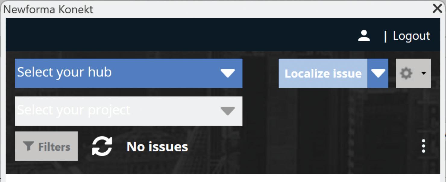
NEWFORMA KONEKT ADD-IN
There are basically two main components of the Newforma Konekt add-in, the issues dialogue and publish (export). The add-in does not automatically detect which project you are working on, so you must manually select your project hub as well as the Newforma Konekt project from the dropdown list. This project you create in the Newforma Konekt project hub is also independent from the ACC project you have. You must select the hub and project before you can access the Publish portion of the add-in.

PUBLISHING
When publishing from the add-in, you need to select the 3D view you want to export. You will need to make sure that the view has everything visible you want to see. You will also need to give the file a name. We are just using the discipline as the name, e.g. Architectural, Structural or MEPF. Under Discipline, you can select the discipline(s) that apply to the model being exported. This is pulled in from the Project Settings of the Newforma
Figure 2 - ArchiCAD Revit Add-In
Figure 3 - Newforma Konekt Logo
Figure 4 - Newforma Konekt Add-in for Revit
Figure 5 - Newforma Konekt Add-In tab in Revit
Konekt project you created and can be established in a template. If a model with the same name already exists in the project, you can specify that in the “append a new version” tab. Once the model is published and processed in the project, the file will now show a new version. Next you will want to select all of your sheets to also get published with the 3D model. Not to get off track, but you can turn

Figure 6 - Publish Dialogue
those sheets on and have them overlayed on the 3D view in the Newforma Konekt Viewer. This is similar
to how Model Coordination does it BTW.


IFC
Before you hit the Publish All button, you are going to want to modify your setup. Another annoying thing about the process is that you must modify your setup each and every time you manually publish. There are a couple of things I always change though. First, I change the IFC version to IFC4 Reference View. This has given me the best results when viewing the model. Secondly, under the Level of Detail tab, I change it from Low to High. For the rest of the settings found therein, I left them as their default.
Once that is done, just hit Publish All and sit back and wait. Be warned though, you cannot use that instance of Revit while the export is happening either so you will have to find something else to do while it goes through the 1000s of elements in your model.
There is an option to Schedule a publish as well. I highly recommend that you do this from a remote workstation and not your daily driver of a computer. The computer where the scheduled publish was created needs to be powered on. I found out the hard way several weeks after I scheduled a publish as to why the file had never updated from the initial publish. I did it from my work computer and I always shutdown when I am done for the day and the scheduled time was for a Friday afternoon. This process also utilizes the computer’s Task Scheduler. When the scheduled publish begins, it initiates an instance of Revit. However, even if Revit is already running, you will not be able to interact with the newly opened instance.

Once I figured out that the scheduled publishes were not happening, I created the publishes from a remote workstation I was given access to. I quickly ran into other issues though. Over the course of a few weeks, some of the weekly publishes did not happen and some of them happened but failed to process. Our Design Software Manager and I had numerous conversations via email and a couple of conference calls with Newforma Support to figure out what was going on. We eventually did figure it out.
In the instances where the models failed to publish, somehow the Shared Coordinates of the models were different. I am not sure how that happened, the projects were set up using Shared Coordinate. Once that was corrected, those models began to work as scheduled. The instances where the publishes happened but failed to process was an issue on the Newforma Konekt side of things that is. They are not sure what caused them to fail, but as of the time of this writing, this issue persists. If we are going to have to manually publish our models to Newforma Konekt, that workflow will consume us, and we will quickly abandon its use and not move forward. Now if Newforma Konekt can connect directly to the Autodeck Construction Cloud and pull the Revit models directly into their system, that would be the best option moving forward and exporting would not need to happen. I think they could just grab a copy of the latest model published from Autodesk Docs.
CONCLUSION
In conclusion, while the concept of Industry Foundation Classes (IFC) holds great promises for enhancing interoperability and collaboration within the Architecture, Engineering, and Construction (AEC) industry, it falls short of meeting our specific needs currently. Despite the advancements in IFC standards and the integration of IFC capabilities in software like Revit, the practical challenges we face—such as inconsistent categorization, cumbersome workflows, and the limitations of current software versions—hinder its effectiveness for our projects.
Our experiences with linking and importing IFC files into Revit have revealed significant inefficiencies and frustrations, particularly when dealing with complex models and maintaining accurate data throughout the project lifecycle. The introduction of tools like the ArchiCAD Revit add-in and Newforma Konekt offers some relief, but they also come with their own set of challenges and limitations.
As we look towards the future, the potential for improved IFC interoperability and more seamless integration with tools like Autodesk Construction Cloud remains promising. However, until these solutions can fully address the pain points, we’ve encountered, IFC will not be the win we hoped for. We remain committed to exploring and adopting the best practices and technologies that will enable us to deliver high-quality, efficient, and collaborative project outcomes.

Jason Peckovitch is an Autodesk Revit Certified Professional for Mechanical and Electrical Design located in SE Iowa. He is a BIM Manager for Garver’s Buildings Business Line, specifically MEPF. Garver has more than 50 offices across the United States and more than 1200 employees. His CAD/BIM career spans over 25 years but he didn’t switch to the AEC Industry until 2007 as a Mechanical HVAC Drafter and transitioned into BIM Management shortly after where he has been working since. Jason is also the father of three children; Shelby – 12, Blake – 10 and Logan - 7, a published photographer, gamer, and car/tech guy. He can be reached at jmpeckovitch@ garverusa.com.

Storytelling with Generative AI Video:
Beyond Plan, Elevation, and Section
Brief: Next-gen design presentation media will soon include AI-generated video as a matter of course to heighten immersion and emotional response. Curated video content conveys experiential information that is intuitive and accessible to all audiences. Once a time-consuming endeavor with steep learning curves, this presentation technique is suddenly available for architects and designers.
DESIGN PRESENTATIONS WILL NEVER BE THE SAME
An experience all designers have is the dreaded stand-up review. Your work pinned up on the wall for all to see and critique. Painstaking hours spent gluing tiny chipboard pieces together. Hours shading and blending graphite on velum. Concept diagrams abstract the ideas into a foundational parti. Renderings make an aspirational statement of intent while Plan, Elevation, and Section prove it can be done. Sweat beads up on the small of your back as you try not to forget the lines you practiced. Altogether, you hope you’ve done enough to convince the audience that your design solution actually does what you say it does. If you’re
successful, they can imagine the experience, even feel themselves there. Your representations and abstractions resonate in a way that is real to them.
DESIGN IS SALES
However, in the professional environment, designers aren’t usually presenting to architecture professors. We present to business owners, teachers, nurses, or government employees. Therefore, we strive to communicate the value of design straightforwardly as possible - as people aren’t typically immersed in the world of plan, elevation, and section. Instead, we aim to tell a compelling story about how the client’s most salient problems can be addressed by design. And as designers we should use any tools, we can get our hands on to make that story more powerful. The innovative tools for today’s generation of architects include computational and parametric design, virtual reality, 3D printing and fabrication. When used skillfully, they allow designers to weave compelling stories.
ARCHITECTS ARE LATE TO THE (VIDEO)

“Clarity Pod” - Concept for AI-powered behavioral health infrastructure dispersed throughout community parks. The new model combines mental healthcare with healing environments, increasing accessibility and fighting social stigma. - Gresham Smith, 2024
Generative AI

PARTY
But if you ask yourself, “what are today’s most advanced techniques for story telling?” It’s certainly not plan section, or elevation! It’s video, movies, and animation. So why haven’t architects adopted these techniques more universally? Architects already have the fundamental skillset to make movies about design, in fact, some of the greatest pieces of creative film are made by architects (and if you haven’t seen it, take a moment to watch the 1977 video “Powers of 10” by Charles and Ray Eames). Simply put, the expense, whether in time or dollars, is just too high to produce well-curated and immersive video content for spaces that don’t yet exist. In the case of competitive pursuits, the risk is palpable, as there’s no guarantee design teams will even recover their investment in this type of content. However, as technological and monetary barriers crumble, designers are sitting up and paying attention.
THE ERA OF AI VIDEO STARTS NOW
Today, the barrier to entry for creating high quality AI video is shockingly low, and there can be no
more excuses from the architecture industry. Although you’ll be forgiven if you’re surprised by this information, because development in this realm has been preposterously fast. Every week there seems to be a market-defining program release or functionality upgrade. I’ve never seen technological advancement in any area of architectural design change so quickly. And the results are good. Amateurs can approach the cinematic quality of high-end visualization studios with a little practice and a tiny fraction of the time investment. And if there’s anything that architects should take pride in, it’s being unafraid to become an amateur.
THE BASIC PROCESS
There are two general types of AI Visualization programs that designers should become familiar with. One is “Text-to-Image” programs like Midjourney, Stable Diffusion, Dall-E, or Adobe Firefly. These applications turn text prompts into images, with the ability to use reference images for the illustration style, scene, composition, lighting, and characters. This functionality has been instrumental in transforming text-to-image
“LDR - A.R.” - Concept for a labor and delivery room outfitted with advanced augmented reality and imaging technology that visualizes the baby’s health and customizes the delivery environment to support the mother’s emotional health. - Gresham Smith, 2024
from a novelty into a powerful story-telling tool, as designers can engineer a high level of predictability and continuity in the graphic output. The second type of program is “Image-To-Video”, such as Runway, Luna, Sora, and Kling, in which still images are transformed into 5 or 10 second video clips, with the ability to use text prompts to guide the video content. The starting image can be a traditional rendering, an AI-generated image, or even a photograph. The video clips can then be assembled with a narrative structure to convey some important sentiment. The result is a medium that transcends the level of abstraction that architects have historically relied upon to sell design ideas. Showing is better than telling, after all.
ITERATION IS KEY
While the barrier to entry is extremely low for these programs (literally “push button get movie”) that doesn’t mean you’ll produce what you need on your first try. Thankfully, the process for improving generated content is remarkably familiar for architects and designers: iterate. The road from “uncanny blooper reel” to immersive content is trial and error, where the user continuously tweaks their
prompt and reference material in order to make incremental improvements. Said another way, save what’s good and fix what’s bad. Over time, the scene you’re crafting will match the intended tone and message, with minimal “AI artifacts” that risk breaking immersion.
ARCHITECTS AS DIRECTORS
Of course, architects have long had the technology for linear walkthroughs of their designs, both pre-rendered or live. Why is that so much different from AI-assisted video? The answer is, it’s as different as two hours of security footage is to a David Attenborough nature documentary. The cinematic potential of AI video allows architects to become directors of experience, curating content to evoke emotion. From 35mm and 80mm lenses, tracking shots and shaky over-the-shoulder cameras, to timelapse and aerial drone footage, closeups of emotive faces indistinguishable from real people to sound effects, background noise, and swelling crescendos of music; architects have exciting new tools to choreograph their desired effect. “Macro-Donald’s” - Concept for a fast-food restaurant which analyzes personal, real-time biometric health data to offer a customized menu designed to achieve each individual’s pre-set long term health goals. - Gresham Smith, 2024


EXPANDED RELEVANCE
The average American adult in 2025 is forecast to spend 2 hours and 55 minutes each day watching television – meaning the typical conventions of the medium are universally understood by the general population. Compare that latent exposure to the number of times you’ve had to explain to nonarchitects how to read a plan! As architects explore video as a means for expression, the practice and parlance of cinematography will become a valuable skill set for creating design content that is immediately understood by a wide audience.
WHY VR USE HAS PLATEAUED
One overlooked aspect of video as a design medium is the communal experience of watching a movie with others. Compare this to virtual reality, which often involves one person wearing goggles while other people watch them instead of the monitor. It often feels strangely voyeuristic and disconnected. Instead, allowing each audience member to share the same transportive experience cannot be overstated. It’s the reason why I believe curated video content will become a ubiquitous
part of design presentations in a way that virtual reality content has not yet achieved.
CHARACTER-DRIVEN ARCHITECTURE
My specialty is healthcare architecture. As such, it’s paramount to understand the wildly different physical and emotional needs of patients, family and care providers. Similarly, it’s important to convey to the client, during an interview for example, that the design solution is responsive to these needs. A common tactic is to devise representative “personas” based on the facility’s census data and follow them through a “day in the life,” usually with dry, sleep-inducing flow charts. AI-assisted video has the potential to completely upend this exercise, allowing architects to create immersive stories. Whether it’s a shot of an exhausted nurse taking a moment to admire the view of the city from a break room, or a close-up of an elated grandfather standing in a delivery room and holding his grandson for the first time, designers have the chance to convey ideas in a way that has never been more personal and resonant.
“Adaptive Living” - Jayden is a young professional who is considering buying a condo in the new residential development; a partnership between his community hospital and a national developer to build housing that’s augmented with the latest biometric health monitoring technology. - Gresham Smith, 2024

THE FUTURE OF REPRESENTATION
Oddly enough, designers should see potential in the recent developments in AI generated video for the same reason that physical models have had incredible staying power in modern architectural representation. Models convey experiential information that is intuitive and accessible to all audiences. Likewise, AI-generated video will soon be a commonly employed tool for architects to heighten immersion and emotional response. In fact, the technology to do so is available right here, right now, and the learning curve is accessible. That also means that only the designers who quickly embrace cutting edge AI visualization will reap the competitive benefits. I suggest you start experimenting, if for no other reason, because I’m eager to see what our profession can shake from their sleeves with this new creative outlet.
Link 1 - Invisible: The Hospital of the Future is No Hospital - Concept Overview
Link 2 - Invisible: The Hospital of the Future is No Hospital - Problem Statement
Link 3 - Invisible: Part 1/3 - Harold

Chris is the Healthcare Market Design Leader and an architect for Gresham Smith’s healthcare practice.
As MDL, Chris sets the healthcare market’s design vision, process, and quality, leads major pursuits, and mentors emerging professionals. As a project designer, he works intimately with clients to bring cohesion to their aspirations and vision.
Chris is deeply interested in the process of design and believes a transparent, inclusive, and iterative process leads directly to better outcomes. He can be reached at chris.hoal@ greshamsmith.com
“Health Station” - As fossil fuels become obsolete, new healthcare technology reuses the old existing distribution infrastructure. Delivery of pharmaceuticals by drone is accommodated by the renovated overhead canopy. - Gresham Smith, 2024
Navigating the Complexities of Trending Technology with BricsCAD®

Let’s not overthink it. The computer-aided design industry is at the forefront of technological innovation, revolutionizing the way designers, architects, and engineers approach their creative processes and technical challenges, bringing ideas to life. Let’s face it, as software tools continue to evolve, the industry has entered a phase marked by greater complexity and enhanced capabilities. With a variety of options in the market, Bricsys® BricsCAD® exemplifies the push for versatile, AI-driven solutions that adapt to modern demands while maintaining accessibility for professionals and organizations of all scales.
Let’s dive into the nuances of trending technologies in the CAD industry, highlighting BricsCAD’s evolution and its role in addressing challenges brought by rapid advancements.
THE CAD INDUSTRY’S SHIFT TOWARD ADVANCED TECHNOLOGIES
While many of us still live in a 2D CAD world, the CAD industry has grown beyond simple 2D
drafting and modeling, embracing technologies that include artificial intelligence (AI), Building Information Modeling (BIM), cloud computing, and parametric design. Each trend brings its unique challenges, from steep learning curves to integration difficulties, but these innovations also promise transformative results:
Automation & AI-Driven Enhancements:
Like it or not, artificial intelligence is reshaping CAD workflows. Tasks that once needed manual intervention, such as generating repetitive designs or detecting clashes in complex models, can now be automated. Let’s use BricsCAD Blockify and BIMify as an example.
The BLOCKIFY tool identifies repetitive geometry and converts it into reusable blocks. BIMIFY analyzes a model, automatically classifies 3D solids to building elements, and then assigns spatial locations, spaces, buildings, and stories. It detects and classifies the external and internal walls. BIMify also can automatically detect whether a model is an Architectural, Structural, or MEP model. Optionally,

it also creates plan sections and elevations. All with a single click! (See Fig. 1) Using tools like this simplifies intricate designs by finding patterns, reducing manual input, and optimizing designs for manufacturability. BricsCAD makes it smart and easy as these tools enhance productivity while supporting an intuitive user experience.
However, adopting anything introduces challenges, let alone AI. It demands an understanding of machine learning principles and integration with existing processes. For long-term users accustomed to traditional CAD workflows, the adjustment can seem daunting. Yet, BricsCAD addresses this with user-friendly implementations of AI that don’t alienate seasoned professionals.
Cloud-Based Collaboration:
As CAD projects become more collaborative, cloud platforms have increasingly become more vital tools. Teams spread across the globe can now collaborate in real time, reducing bottlenecks and accelerating decision-making processes. (See Fig. 2)

Bricsys® 24/7 is a cloud-based common data environment for document management and workflow automation. Concerns like data security, latency, and the cost of maintaining robust cloud infrastructure always remain a significant hurdle. Bricsys 24/7 addresses this by offering role-based security and unlimited users to help ensure that the right document is in the right hands at the right time. Create metadata within the forms app and associate it with a folder or file, design workflows then release and attach them to a specific folder or file, review file status, notifications, and revision requirements, download the Mobile app for remote access anytime, sync with other integrations, e.g. LetsBuild, Aproplan or Leica.
Read more about setting up Bricsys 24/7 on the Bricsys Blog
BIM and Digital Twins:
BIM and the concept of digital twins have transformed how architects and engineers visualize construction projects. BricsCAD® BIM stands out for its streamlined workflows, allowing users to quickly create detailed building models that integrate seamlessly with external datasets. Access 3D building modeling and BIM workflows in the same, familiar
Fig. 2
Fig.
BricsCAD
BricsCAD environment without the disruption of learning new processes in a new system.
BricsCAD BIM is built on the familiar BricsCAD system, so you can leverage the 2D drafting tools as you ease into 3D workflows at your own pace. Enjoy the flexibility to create simple 3D designs, import or produce BIM for collaborations, or model with accuracy for construction and fabrication.
Digital twins have increasingly become a key part of the BIM process, making it easier to share insights consistently. These insights won’t just benefit one project, moreover, they’ll feed into the planning and design of new projects, using what we’ve learned to keep making things better. With these dynamic simulations, users of virtual twins can proactively address potential issues, explore new possibilities, and strategically plan for the future.
Just like AI, BIM adoption faces hurdles too, like standardization and interoperability across platforms. Many organizations also grapple with the sheer volume of data and the need for employees to adapt to sophisticated BIM standards. BricsCAD offers simplified yet powerful BIM tools that cater to both entry-level and advanced users, bridging the gap between complexity and usability.
Parametric Design and Computational Geometry:
Parametric and generative design capabilities enable designers to explore countless variations of a model by adjusting parameters. BricsCAD’s Parametric Design Tools have garnered attention for their versatility and ease of use, allowing users to create adaptive designs with minimal effort. Let’s use BricsCAD Parametric Blocks as an example.
Why should you use Parametric Blocks?
• It’s a better block.
• More flexible than AutoCAD® Dynamic Blocks.
• Infinitely configurable based on multiple defined parameters.
• Allows multiple instances of blocks with different parameters.
Save time: Using Parametric Blocks can save you time by making it quicker to change the geometry of a block using highly flexible and precise parameters, instead of creating similar geometry from scratch over and over again. (See Fig. 3)

Reduce file size: Using Blocks helps you reduce the amount of data in your file by reusing geometry. For example, by using BricsCAD’s Blockify functionality, duplicate geometry can be automatically identified - and replaced by block references that point to a single, common block definition, containing the geometry. This will heavily reduce file size (up to 80%) with little to no effort by the user.
Enhance performance: BricsCAD is an incredibly fast and ‘lightweight’ CAD software, capable of handling large dwg files. By using efficient Parametric Blocks and reducing your file size, you will notice improved performance on your already fast BricsCAD, in terms of faster loading times, reduced lag during view manipulations, etc.
Improve flexibility and intelligence: Smartly link multiple variations of geometry together. Parametric Blocks rely on parameters that can have an infinite number of constraints to the geometry, so you can precisely adapt a Parametric Block to your exact needs.
Uncover more about Bricsys Parametric Blocks
BRICSCAD® BALANCES INNOVATION AND USABILITY
One of BricsCAD’s most compelling traits is its ability to balance cutting-edge features with a user-friendly
Fig. 3
interface. BricsCAD has consistently emphasized accessibility without compromising on functionality.
Cross-Platform Compatibility:
BricsCAD’s reliance on the DWG file format ensures that it works seamlessly with a broad range of other software. BricsCAD®’s .dwg compatibility ensures the rapid creation of design documentation, significantly enhancing the overall 2D drawing workflow. You can open and save .dwg files directly in BricsCAD, delivering the highest compatibility. This compatibility is a significant advantage in an era where collaboration across tools is critical. Moreover, its support for various APIs (such as LISP, VBA, and .NET) enables custom workflows that cater to unique organizational needs.
Cost-Effective Licensing:
Many CAD platforms have transitioned to subscription-only licensing models, which can be a financial burden and an I.T. administrator’s nightmare. BricsCAD’s flexible licensing structure, offering both network and single-seat standalone perpetual licenses and subscriptions, has earned it praise from budget-conscious users. (See Fig. 4) This flexibility and the incredibly low total cost of ownership make it a practical choice for both startups and established enterprises.
training to infrastructure demands.
Training and Education:
One of the primary hurdles is the need for continuous education. Advanced tools like parametric design or AI-driven modeling often require a deep understanding to use effectively. BricsCAD tackles this issue with comprehensive learning resources, including online tutorials, webinars, and active community forums.
Note: In case you missed it, check out the November 2024 issue of AUGIWORLD where we discuss how to elevate your value by leveraging technology.
Hardware Requirements:
Advanced features in CAD software demand significant computational power, especially for rendering or working with complex parametric designs. BricsCAD has optimized its platform to perform efficiently on a variety of hardware setups, from modest workstations to high-end machines.
Integration with Legacy Systems:
BricsCAD is native DWG. The same DWG as you work with every day. BricsCAD offers solutions for seamless data migration and backward compatibility, allowing you to integrate new technology without abandoning your existing workflows. Import, edit, export, and collaborate with Communicator for BricsCAD which seamlessly imports geometry & PMI data from all major CAD applications. (See Fig. 5)

4
OVERCOMING CHALLENGES IN CAD TECHNOLOGY ADOPTION
While technological advancements have opened new possibilities, their adoption is not without challenges. The complexities range from workforce
LOOKING AHEAD FOR BRICSCAD®
The CAD industry’s evolution is far from over. Emerging technologies like extended reality (XR), generative AI, and quantum computing are already influencing the trajectory of CAD software.
Extended Reality Integration:
Virtual and augmented reality are becoming essential tools for immersive design reviews and client presentations. Create conceptual design and use BricsCAD’s export options (e.g., FBX, OBJ, or DWG) to prepare models for XR software.
Fig.

Generative Design:
By leveraging generative AI, designers can automate the exploration of complex design spaces. While Scan-to-BIM focuses on capturing and modeling existing conditions, generative design focuses on creating optimized, new designs. (See Fig. 6) While not the same, combining the two can create a powerful workflow, especially in projects involving both existing conditions and new design solutions.
CONCLUSION
The CAD industry’s embrace of AI, BIM, cloud computing, and parametric design is reshaping how professionals approach design and engineering tasks. BricsCAD exemplifies a platform that navigates these complexities with agility, offering tools that balance innovation, cost-effectiveness, and user accessibility. Literally, smart meets easy. While challenges persist, from workforce training to integration with legacy systems,
BricsCAD’s adaptive approach proves that even advanced technologies can be harnessed without overwhelming users. Smart meets easy! As the industry continues to evolve, BricsCAD’s commitment to innovation ensures that it stays at the cutting edge, empowering professionals to push the boundaries of design.
By addressing these complexities head-on, Bricsys BricsCAD is not just keeping pace with trends, it is defining them.
MORE ABOUT BRICSCAD®
Bricsys® BricsCAD® is professional CAD software without compromise. Accelerate your time to deliverable without compromise on performance, cost, licensing flexibility, and data security. Not ready to buy? Download the free, 30-day trial of BricsCAD® at Bricsys.com. Would you like free lessons? We have that available with Bricsys Learning. Ready to migrate to BricsCAD®?
Fig. 5

Download the Migration Guide. The latest version of BricsCAD® improves the tools and features users love, as well as new functionality and UI that supercharge productivity. Follow us today on LinkedIn and Youtube
MORE ABOUT BRICSYS®
Bricsys®, part of Hexagon®, is the global technology company that creates the BricsCAD® family of computer-aided design (CAD) products and the Bricsys® 24/7 project collaboration platform. We are relentlessly committed to the success of our customers by offering cost-effective, missioncritical CAD software with industry-leading product support. Learn more at www.Bricsys.com
Hexagon is a global leader in digital reality solutions. Learn more about Hexagon (Nasdaq Stockholm: HEXA B) at hexagon.com and follow us @HexagonAB

Mr. Craig Swearingen is a Global Implementation Specialist and Consultant at Bricsys. Currently, Craig provides migration and implementation guidance, management strategies, and technical assistance to companies that need an alternative, compatible CAD solution. Craig spent 19 years in the civil engineering world as a technician, Civil 3D & CAD power user, becoming a support-intensive CAD/ IT manager in high-volume production environments. Craig is a longtime AUGI member (2009), a Certified Autodesk® AutoCAD® Professional, and he enjoys networking with other CAD users on social media.
Fig. 6

Emerging Technologies and Software Trends for 3ds Max Users
Professionals using 3ds Max in creative media and AEC industries are witnessing a technological revolution. Advancements in AI, interoperability, and immersive technologies are reshaping workflows, offering unprecedented opportunities for innovation and efficiency.
AI-POWERED TOOLS: THE RISE OF INTELLIGENCE IN 3D DESIGN
AI is a game-changer in the 3D industry, streamlining workflows and enhancing creativity.
• Neural Radiance Fields (NeRFs): These use AI to generate 3D models from 2D images, interpreting lighting and reflections to produce photorealistic outputs. While it shares similar principles to traditional photogrammetry, it relies on a smaller data set, providing content
more suitable for visualization and virtual exploration. Plugins and various have rapidly developed to allow NeRF content to be imported into software like Unreal Engine. For more information, check out NVIDIA’s instant NeRFs.
• Generative Design: AI-driven generative tools suggest optimized layouts, materials, and designs. These continue to develop quickly. Big outfits like Adobe and NVIDIA concentrate on converting text and 2D images into 3D. A few other examples (among many) include sites online like meshy.ai and Alpha3d.io.
• Visualization with AI: Platforms like Adobe Substance and Chaos Vantage have integrated AI to accelerate asset creation and real-time ray tracing for realistic visualization. While


these technologies generally require powerful, modern computers, they provide excellent solutions for the highest-quality content.
INTEROPERABILITY WITH OPENUSD
A significant trend continues to be the adoption of Pixar’s original Universal Scene Description
(USD). OpenUSD promotes seamless collaboration by standardizing 3D asset exchange across tools. Major players, including Autodesk, NVIDIA, Apple, Unity, Adobe, and Unreal Engine, all accommodate the initiative, giving it strong potential for crossplatform workflows. Autodesk’s 3ds Max team even integrated it into their API. The most apparent strength of USD is the ability to allow
Figure 1 – Sample Rendering using Chaos Vray 6
Figure 2 – USD Scene Example
3ds Max
countless parties to contribute to a single scene simultaneously. Still, users continue to find ways to innovate, such as dynamically swapping out content for procedural and adaptive storytelling or optimizing render times by swapping in lower-level details where possible.
VIRTUAL PRODUCTION AND IMMERSIVE EXPERIENCES
Virtual production, popularized by blockbuster films, is becoming more accessible:
• Scalable LED Backdrops: Advances in hardware and software democratize this technology for smaller studios, enabling high-quality virtual sets.
• Holographic and Volumetric Video: Volumetric capture allows for realistic 3D representations, enhancing training simulations, entertainment, and live performances. In some cases, technology in phones and Apple’s iPad allows individuals to produce extraordinary results.
• Interactive Environments: Tools like Unreal Engine integrate seamlessly with 3ds Max, allowing real-time adjustments and immersive outputs. Meta Quest’s augmented reality continues to shine a light into the future of combining these technologies ke (with the glasses-style augmented reality lens shared by Meta this year).
BUILDING INFORMATION MODELING (BIM) IN AEC VISUALIZATION
AEC professionals’ benefit from the fusion of 3D scanning, BIM, and AI:
• Scan-to-BIM Workflows: Tools like Autodesk Revit combine 3D scanning with modeling, enabling precise planning for retrofitting and renovation.
• Cloud Collaboration: Platforms such as Autodesk Forma ensure real-time updates and seamless collaboration across teams, enhancing project accuracy and efficiency and implementing AI and machine learning.
• Predictive Analytics: AI integrated with BIM models forecasts long-term building performance, optimizing maintenance and energy use.
ENHANCED SIMULATIONS AND PREDICTIVE TECHNOLOGIES
Simulation tools are reaching new heights:
• Lighting and Structural Analysis: AI-driven simulations analyze and suggest improvements in aesthetics, safety, and energy consumption.
• Predictive Maintenance: Tools like Siemens Building X use AI to predict failures and optimize building operations, aligning with sustainability goals.
Popular Tools and Software in 2024
• 3ds Max: A cornerstone for modeling and visualization.
• Autodesk Revit & Forma: Essential for AEC workflows.
• Chaos V-Ray & Vantage: Industry standards for rendering and real-time visualization.
• NVIDIA Omniverse: A collaborative platform enhancing AI and real-time design capabilities.
• ReluxDesktop: Advanced lighting design driven by AI.
In summary, this year marks a pivotal moment of acceleration in technological innovation for the next century. AI rapidly shapes all technology, from redefining creative workflows to open standards like USD, enabling seamless collaboration. It’s a time when possibilities expand, blending human ingenuity with machine-driven efficiency to create a transformative digital future.

Brian Chapman is a Virtual Art Directory and 2D/3D design professional in Las Vegas who creates content for the AEC industry, games, film, entertainment, education, training, and software development. Brian can be reached at procadman@pro-cad.net.

AUGI Members Reach Higher with Expanded Benefits
AUGI is introducing three new Membership levels that will bring you more benefits than ever before. Each level will bring you more content and expertise to share with fellow members, plus provide an expanded, more interactive website, publication access, and much more!
Basic members have access to:
• Forums
• HotNews (last 12 months)
• AUGIWorld (last 12 months)
DUES: Free
Premier members have access to:
• Forums
• HotNews (last 24 months)
• AUGIWorld (last 24 months)
DUES: $25
Professional members have access to:
• Forums
• HotNews (full access)
• AUGIWorld (full access and in print)
• ADN 2013 Standard Membership Offer
DUES: $100
Bright Ideas for a Bright Future

AUGIWORLD brings you the latest tips & tricks, tutorials, and other technical information to keep you on the leading edge of a bright future.