AUGIWORLD
Collaboration: Tips for Working Together


Letter from the Editor

Here we are in April already. Spring is such a great time of the year. It’s a fresh new start. The flowers are starting to bloom, the trees are becoming full, and its football season for me! That’s right, American Football season. Some of you know that I own a women’s football league (USPWFL), and I own the team here in Houston (Houston Doom). Fun stuff!
Let’s get back on track here, and discuss this month’s subject, Collaboration. Collaboration is the process where two or more people, entities, or organizations complete a task by working together. We are always on the lookout for a better method to improve business operations.
Working together towards a common goal involves people sharing knowledge, skills, and resources to get to that point where you can say, we did it, it’s done! In the workplace, collaboration can unleash a group’s creativity that keeps employees engaged and inventive.
We as humans are naturally collaborative by engaging and connecting with each other. Everyone wants to be part of a community by nature. The power lies in having a problem or project with a shared goal.
Reaching the goal of an effective collaboration at the office, does not come without challenges. So, I hope that you can learn some different ways to collaborate from this issue, and take them back to the office where you can put those strategies in place for a better result through collaboration.
Enjoy this month’s issue of AUGIWORLD! We are still looking for new authors to contribute to the magazine. Reach out to me at todd.rogers@augi.com if you have any interest.
AUGIWORLD
www.augi.com
Editors
Editor-in-Chief
Todd Rogers - todd.rogers@augi.com
Copy Editor
Miranda Anderson - miranda.anderson@augi.com
Layout Editor
Tim Varnau - tim.varnau@augi.com
Content Managers
3ds Max - Brian Chapman
AutoCAD - KaDe King, Chris Lindner
Civil 3D - Shawn Herring
BIM/CIM - Stephen Walz
BricsCAD - Craig Swearingen
Electrical - Mark Behrens
Manufacturing - Kristina Youngblut
Revit Architecture - Jonathan Massaro
Revit MEP - Jason Peckovitch
Tech Manager - Mark Kiker
Inside Track - Rina Sahay
Advertising / Reprint Sales
Kevin Merritt - salesmanager@augi.com
AUGI Executive Team
President
Eric DeLeon
Vice-President
Frank Mayfield
Treasurer
Todd Rogers
Secretary Kristina Youngblut
AUGI Board of Directors
Eric DeLeon
Chris Lindner
Frank Mayfield
Todd Rogers
Shelby Smith
Scott Wilcox
Kristina Youngblut
AUGI Advisory Board of Directors
Gil Cordle
Rina Sahay
Publication Information
AUGIWORLD magazine is a benefit of specific AUGI membership plans. Direct magazine subscriptions are not available. Please visit www.augi.com/account/register to join or upgrade your membership to receive AUGIWORLD magazine in print. To manage your AUGI membership and address, please visit www.augi. com/account. For all other magazine inquires please contact augiworld@augi.com
Published by:
AUGIWORLD is published by AUGI, Inc. AUGI makes no warranty for the use of its products and assumes no responsibility for any errors which may appear in this publication nor does it make a commitment to update the information contained herein.
AUGIWORLD is Copyright ©2025 AUGI. No information in this magazine may be reproduced without expressed written permission from AUGI.
All registered trademarks and trademarks included in this magazine are held by their respective companies. Every attempt was made to include all trademarks and registered trademarks where indicated by their companies.
AUGIWORLD (San Francisco, Calif.)
ISSN 2163-7547
Bright Ideas for a Bright Future

AUGIWORLD brings you the latest tips & tricks, tutorials, and other technical information to keep you on the leading edge of a bright future.


Create, Contribute and Collaborate: Engineering Precision on the Court


As I watched college basketball the other night, I had a couple of thoughts. First, while I am biased, Braden Smith from Purdue University is the best point guard in college basketball. (See Fig. 1) Second, the overall team collaboration was most impressive as they adjusted down the stretch to beat a good UCLA team. While winning the game was great, what had me thinking was the overall group effort of the team. So, what goes on behind the scenes that allows such success on the court when the pressure is on?


We only saw what happened on the court. What about all of the work that went into that moment prior to? Coordinating practices, film study, the weight room, and add in the TV


contracts, parking attendants, vendors, ticket office, marketing, recruiting, gameday security,
Figure 1: Braden Smith
schoolwork, the press & media obligations, athletic trainers, travel logistics, and now NIL (Name, Image, and Likeness), the collaborative list seemingly goes on & on. For the most part, the same can be said for high-functioning engineering design and production teams.
Purdue University is a prime example of how these two worlds intertwine. While you and I will not be receiving any NIL money, we can acknowledge that Purdue, Cradle of Astronauts®, is well known for their high basketball IQ and engineering excellence. Let’s see how leadership, collaboration, specialized roles, innovation, and iterative improvement are values that guide Purdue basketball and provide a roadmap for effective engineering production staff.
STRATEGIC VISION: THE ROLE OF LEADERSHIP
Success starts with a strategic vision from the top. The chief engineer, per se, would be Purdue’s Head Coach Matt Painter. (See Fig. 2) Coach Painter is well seasoned with over 20 years of head coaching experience and has Hall of Fame coaches as colleagues and mentors. He sets long-term and short-term goals, adjusts game plans strategically, ensures everyone knows their role, is accountable, trusts in his support staff, knows his department, responsible for making critical decisions and so much more.

The assistant coaches are similar to the project managers. Just like a project engineering manager, they have a more focused objective, execute the game plan of the head coach, and are responsible for player development. They may not oversee the entire project, but they are highly integral parts of the machine.
COLLABORATION: “FUNCTIONING AS ONE SINGLE UNIT”
While Purdue basketball staff must coordinate between players, coaches, and support staff, a successful production design team requires strong collaboration between designers, production, and support staff.
One of my favorite movies of all time is the basketball movie “Hoosiers.” It was inspired in part by the Milan High School team that won the 1954 Indiana High School State Basketball Championship. What stands out are the principles outlined by Gene Hackman who plays the hardnosed, failed college coach Norman Dale. On the first day of practice, he lays out his philosophies, one of which is: “Five players on the floor functioning as one single unit: team, team, team –no one more important than the other.” (See Fig. 3)

Depending on the kind of engineering and the scope of your business, you may depend on thousands of collaborative efforts to complete a project. The department head or chief engineer has assigned the roles, and it is up to each person to play their role on the team to make it happen. Whether that is a quality assurance engineer who evaluates and refines products, complete QC/ QA, product designers who fine-tune and perfect usability, surveyors gathering topography outside in the freezing cold or scorching heat, to structural engineers who ensure load-bearing elements are reliable and strong, there is a synergy that must exist to be successful.
Figure 2: Coach Matt Painter
Figure 3: Hoosiers
INNOVATE & ADAPT: THRIVE THROUGH CHANGE
Basketball analytics technology is better than ever today. With advanced metrics and analytics (as well as the eyeball test), teams will use anything to maintain an edge or gain an advantage. Engineering and production teams rely on design specifications, simulations, and data analysis to refine designs, same as the coaching staff tracks players’ performance, shooting percentage, and defensive efficiency. Real-time adjustments are common in both arenas. Production teams are up against a deadline so teams must adjust accordingly, just like the coaches make on-the-fly, halftime, or end of game adjustments.
The Purdue staff has even gone as far as reverting to using a marker and a whiteboard to notify their team of the play. When most teams use hand signals or will audibly shout the name of the play, Purdue discreetly uses a whiteboard so that it is more difficult for the opposing team to identify which play they are about to run. Which reminds me of a few colleagues I had. Smart, old-school engineers - the kind of professionals that have seen it all, and also the kind that never left the drafting board. (See Fig. 4) These gentlemen exhibited exceptional skill and a profound understanding of the structural design. Truly amazing at their craft. However, when it came time to evolve to CAD, rather than demanding them to move, we found the best way for them to contribute was to stay with board drafting and then pass it off to the technician. Their true brilliance lay in their ability to function seamlessly as a cohesive unit to produce a deliverable and not focus so much on how they got there. Both the board drafting and CAD provided solutions, not to mention awardwinning bridge designs.

EXECUTE: IT’S GAMEDAY!
When engineering is complete, and the product reaches the production phase, efficiency and precision are the most important. The same goes for when the fans file into revered Mackey Arena (See Fig. 5) on gameday. Testing and practice are out of the way and now it’s gametime. The bright lights are on, and it is time to shine. The level of detail, the focus, the precision needed to execute, and then, at that moment, you realize there are inefficiencies in the workflow, errors are starting to accumulate, and time is running out! We need a timeout! It’s time to regroup, formulate a plan of attack, and be mindful of the time on the clock and the constraints of deadlines.

Keeping project timelines and meeting deadlines are the team’s responsibility. While the main responsibility of the failed performance may fall on the coach’s shoulders, it is up to everyone to accept accountability of their role and own the shortcomings. As importantly, it is good to recognize the hard work and performance of the team. The hours upon hours of collaboration it takes to ensure a smooth delivery cannot be overlooked.
POST-GAME ANALYSIS: KEY TAKEAWAYS & IMPROVEMENTS
After the final buzzer, whether you win or lose, there is always something to learn. Mike Tyson famously said, “Everyone has a plan until they get punched in the face.” The basketball team and staff will watch the game film, break down every part of the game, specific plays, player tendencies, passing angles, defensive positioning, and most importantly, determine how to improve going forward, especially if they were punched in the face, figuratively. That
Figure 5: Mackey Arena Figure
said, the situational experience goes a long way. The same can be said for your production design team. Was your completed design under budget, within the deadline or was it full of revisions and full of lastminute efforts to produce your deliverable? Would it be good to have a product review? Does there need to be additional training? Who stepped up when the team needed them most? What analytics are available that can help us? What steps can be taken in the future to remediate issues? What did you learn?
A WINNING CULTURE: BOILER UP!
A successful engineering production staff, like Purdue’s basketball team, does not happen by accident. Both thrive in a structured environment fueled by collaboration, leadership, teamwork, adaptability, and continuous improvement.
Purdue’s dedication to discipline and their rallying cry, “Boiler Up,” symbolizes their spirit of innovation and hard work. Similarly, a production design team excels through a shared vision and collaborative effort. Each member’s unique expertise helps overcome challenges and achieve common goals. Leadership provides direction, teamwork ensures precision, adaptability allows for innovation, and continuous improvement drives excellence. (See Fig. 6)

And just as Purdue rallies around “Boiler Up,” a production design team rallies around their mission, pushing each other to excel and create outstanding results. This constructive collaboration, commitment to excellence, and relentless pursuit of improvement set both Purdue basketball and
successful production design teams apart. More About BricsCAD®
Bricsys® BricsCAD® is professional CAD software without compromise. Accelerate your time to deliverable without compromising on performance, cost, licensing flexibility, and data security. Not ready to buy? Download the free, 30-day trial of BricsCAD® at Bricsys.com. Would you like free lessons? We have that available with Bricsys Learning. Ready to migrate to BricsCAD®? Download the Migration Guide. The latest version of BricsCAD® improves the tools and features users love, as well as new functionality and UI that supercharge productivity. Follow us today on LinkedIn and YouTube.
MORE ABOUT BRICSYS
Bricsys®, part of Hexagon®, is the global technology company that creates the BricsCAD® family of computer aided design (CAD) products and the Bricsys® 24/7 project collaboration platform. We are relentlessly committed to the success of our customers by offering cost-effective, missioncritical CAD software with industry-leading product support. Learn more at www.Bricsys.com.
Hexagon is a global leader in digital reality solutions. Learn more about Hexagon (Nasdaq Stockholm: HEXA B) at hexagon.com and follow us @HexagonAB.

Mr. Craig Swearingen is an Implementation and Customer Success Consultant at Bricsys. Currently, Craig provides migration and implementation guidance, management strategies, and technical assistance to companies which need an alternative, compatible CAD solution. Craig has over 20 years in the engineering world as a technician, Civil 3D & CAD power user, becoming a support-intensive CAD/ IT manager in high-volume production environments. Craig is a longtime AUGI member (2009), a Certified Autodesk® AutoCAD® Professional, and he enjoys networking with other CAD users on social media.
Figure 6: 2024 Final Four
Doing Nothing

After all I have written about taking action and not procrastinating… now I tell you that sometimes the best thing to do is nothing. Please let that sentence sink in for a while. Just do nothing. When you are done thinking about that… read on.
Doing nothing can be the best course of action you can take. Doing nothing is effective when used correctly. Use it incorrectly and you look like a loaf, a slacker or like you do not care. Doing nothing too often and you could get fired. You look like you do not want to help. This is not what you what to project to others. Your job is to be helpful when people are in need. How can you help people by doing nothing? Doing nothing is very effective when done with great wisdom. It is not an approach that you want to use very frequently.
NOT JUST DOING NOTHING
To help refine the thinking, let me say that “doing
nothing” is not just sitting around on your keester daydreaming of weekends away. It is not a time to empty your brain and watch the clouds pass by. Doing nothing is not really doing absolutely nothing. It is a time that is used strategically to better achieve what needs to be done. It is a time of inactivity that produces a better outcome.
Doing nothing is not to be done to avoid work. It is not a way to waste a day. It is something that is seldom done, and when used it has a defined purpose. When I am “do nothing” it is for very short periods of time. Sometimes it is a few seconds or minutes. It is most effective when followed by active response or engagement. It is a purposeful pause. Let’s take a look.
TAKING TIME TO THINK
The first use of doing nothing is to provide time for you to think. As I have said, there are many times when you need to spring into action and correct a
problem immediately. But there are times that call for a little more thought and pondering before you move forward. This is the “doing nothing” concept that you should be using most often. It should be a time of thoughtful planning or review. You are actually very active, but it may all be in your thoughts.
SILENT MEETING MINUTES
When I am leading a meeting, I try to read the room and allow some silent minutes to pass when an idea is being developed or summarized. This silent period allows the contemplative team members time to refine and present their thinking. Some process ideas slower than others. I might circle back and ask if there is anything that we have not thought about and then wait in silence as others think. Or I may even ask a team member who has been fairly silent during discussion what they think about the idea. It is good management to find out why someone is not talking. It may just be an off day, or they may have critical thoughts that others have not touched on yet. You can squeeze out some things that have not been discussed and make the decisions become clearer.
TAKE YOUR TIME WHEN RESPONDING
There are times when I delay responding when called on to help. It may annoy the person I am helping, but it really does improve the outcome in the long run. It is often better to take a minute to train someone again, or to give them some time to remember. Let’s say that someone needs help doing something that they have already been taught, and you know they can figure it out. They are just a little forgetful, but by having them figure it out, it actually deepens the training you have already provided. By given them a little more time they may remember how to do something. So, I take a minute to finish up what I am doing and then walk very slowly to their desk. Many times, but the time I get there, they have figured it out.
At other times someone may need to know something that is in the standard, but they don’t want to take the time to search the guidelines. Asking me is quicker. This can be thought of as teaching someone to fish, rather than giving them a fish. What I do when I get to their desk is ask them if they have their copy of the standard, then I tell them where to look in the guidelines and let them flip the pages and find them. They may have to dig around their desk to find their copy of the
written manual, but I silently wait. By doing this, they learn to keep their manual handy and look it up themselves.
THE PURPOSEFUL PAUSE
There are times when I do not respond at all. When someone brings up a bad idea or something that does not fit the company framework of ethics, I just tend to ignore it. I move on to other things, change the subject, ask others what they think, or just remain silent. The point is achieved - That was not a good idea, and we should not entertain it. I may get back to the person later in private to clarify why the idea was not a good one.
WHEN THE BOSS SPEAKS
Not challenging your boss in public is a good idea. Even when you dynamically disagree, you should take it offline and speak in private. Do nothing in the moment, but circle back later. Unless there is clear and present danger in not speaking, like they have incorrect data that others will act on, or it will negatively impact a project or client relationship, you should hold your tongue. If you do speak up, frame it as a clarification, not a challenge, and provide options that might work out better. Do not call into question their competence or authority. Even if they have it wrong, they deserve respect.
Remaining silent, pausing, delaying or doing nothing can be used effectively when applied to specific situations. It is not procrastinating or avoiding work. It is an attempt to make things better. Use it wisely.

Mark Kiker has more than 35 years of hands-on experience with technology. He is fully versed in every area of management from deployment planning, installation, and configuration to training and strategic planning. As an internationally known speaker and writer, he is a returning speaker at Autodesk University since 1996. Mark has served as Draftsman, Technical Illustrator, Principal Designer, CAD/BIM Manager, CTO and CIO. He can be reached at mark.kiker@augi. com and would love to hear your questions, comments and perspectives.
Collaboration in 3D: Best Tips for Working Together in 3ds Max

D projects involve creativity, technical skills, teamwork, and collaboration. Successfully collaborating in Autodesk 3ds Max requires mastering the software and streamlining communication and workflow. Here are the top tips for effective collaboration in 3ds Max:
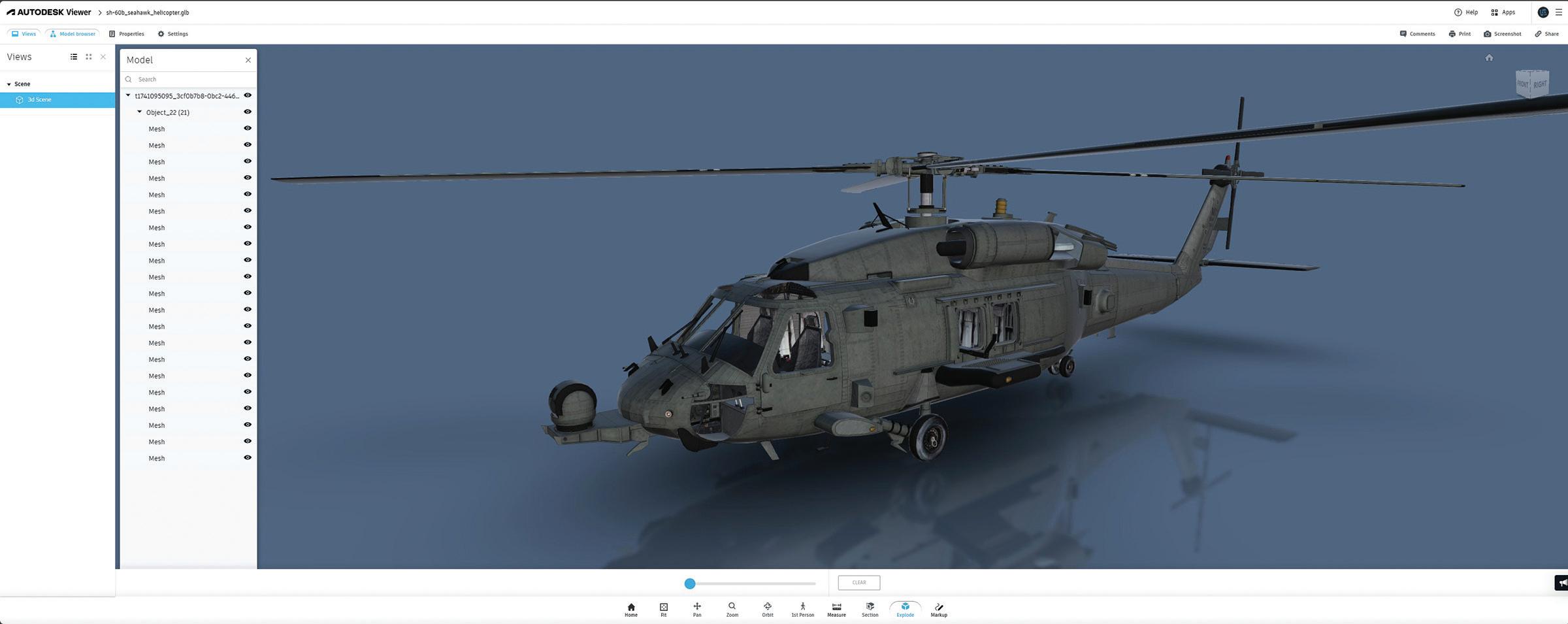
1. Use Autodesk’s Built-In Tools: 3ds Max integrates seamlessly with Autodesk Viewer and FBX Review, allowing teams to share models, review progress, and provide feedback without requiring every team member to have a complete software license. Leverage these tools to facilitate quick visual checks and annotations:
• Collaborate in Real Time: Share models with clients or team members through Autodesk Viewer for instant feedback and discussions, utilizing scene states and state sets.
• Simplify Asset Transfers: Use the FBX format to quickly move assets between industry standards 3D software and Autodesk tools like Maya, Revit, or AutoCAD while preserving textures and animations.
• Enhance Presentations: Showcase your 3D designs interactively with Autodesk Viewer or Sketchfab, eliminating the need for specialized software. See Figure 1.
2. Manage Assets with an Asset Manager: Centralize your project files using LAN, Autodesk Drive, or cloud-based software to ensure everyone accesses the latest versions. That minimizes version control issues and simplifies organizing textures, models, and renders. Tools like Perforce and Git, widely used by 3D professionals across multiple regions, provide robust features such as redundant backups and version tracking to safeguard work, allowing teams to move fast.
3. Set Up Clear Standards: Agree on a consistent naming system and directory structure to prevent confusion. Organization of everything from the layer structure to parenting and hierarchy of FBX is essential. For instance, use clear labels like “Character_v03.max” or “Scene_FinalRender_01.
max.” This simple practice saves time and avoids costly mix-ups.
• Version Control: Use version numbers (e.g., “Character_v03.max”) to track file iterations and avoid overwriting crucial work.
• Folder Organization: Create distinct folders for assets, textures, references, and renders so everyone knows where to find and save files.
• Descriptive Naming: Use meaningful names (e.g., Environment_ForestScene_Day.max”) to help team members quickly understand the file content without opening it. Avoid ambiguity and cryptic names to streamline work and quickly bring new hires on board if possible.
4. Collaborate in Real-Time with Cloud Platforms: Use platforms like Microsoft Teams, Vimeo, Syncsketch, Zoom, and others for reviews. Screen sharing helps teams solve issues together, speeding up decision-making. Vimeo offers a wide range of organizational tools, while software like Syncsketch, which has integrated 3D reviews, allows teams to sketch and markup files in real time.
5. Track Progress with Project Management Tools: Incorporate platforms like Jira or Asana to manage tasks, set deadlines, and track milestones. Linking these tools with your 3D workflow helps keep everyone accountable and organized. Utilize waterfall and agile project management approaches.
6. Automate Repetitive Tasks with Scripting: If your team frequently performs the same
operations, consider using MaxScript. That reduces manual errors and saves hours of work. These tools are often created by people with more experience and can be challenging to maintain, but the time they save on repetitive tasks is worth it.
7. Test Renders in Low-Resolution First: To avoid bottlenecks, test renders in lower resolutions to check lighting, textures, and animations. Share these smaller files for feedback before committing to longer, high-quality renders. As part of the collaboration, this becomes an essential understanding between teams, clients, and the company to ensure work proceeds efficiently.
By leveraging these strategies, teams can improve their 3ds Max collaboration, enhance productivity, and deliver high-quality 3D projects with fewer headaches. The key is balancing technical processes with clear communication, which brings creative visions to life.

Brian Chapman is a Virtual Art Director and 2D/3D design professional who creates content for the AEC industry, games, film, entertainment, education, training, and software development. Brian can be reached at procadman@pro-cad.net.
Figure 1: Autodesk Viewer
Quantity Takeoffs With Bluebeam Revu

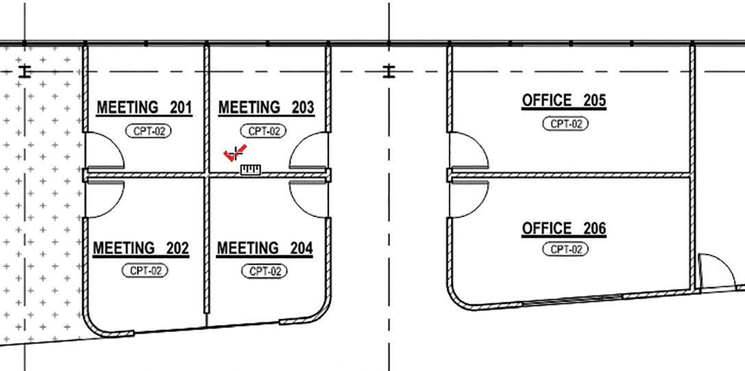
Doing a quantity takeoff is measuring the required material quantities and related labor needed for a construction project. It’s like the recipe for the building, listing the materials and the quantities needed. You review the drawings and specifications to find the needed components, like the walls, doors, windows, and other fixtures. The recorded quantities become the basis for preparing cost estimates, bids, and schedules. You can also use Takeoff to track project progress.
Quantity takeoff is not new. The traditional manual method is completing takeoff by hand, scanning paper copies of drawings, and checking each counted object or using a calculator to find totals.
But why do things manually when we can do them digitally? Digital takeoff is more accurate and much more efficient than manual quantity takeoff. And accuracy is important, as quantity takeoff errors lead to cost overruns and scheduling delays.
BLUEBEAM REVU
Bluebeam Revu [https://www.bluebeam.com] streamlines and enhances the quantity takeoff process. Its toolset includes features for measuring lengths, areas, volumes, perimeters, and doing counts. Its visual search quickly finds (and counts) blocks and other specified objects. Revu tracks and calculates the measurements for detailed cost estimates. You can link the information to Excel for sharing and advanced calculations.
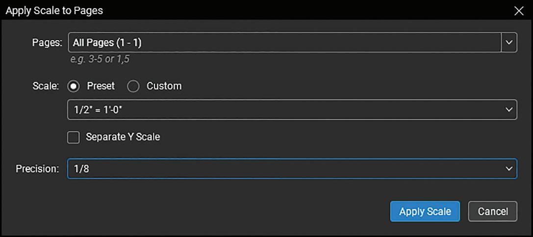
Step 1: Set the Scale Revu works with PDFs. As the PDF sources can range from different CAD systems (with different methods of creating PDFs) and scanned documents, step one of the takeoff process is calibration.
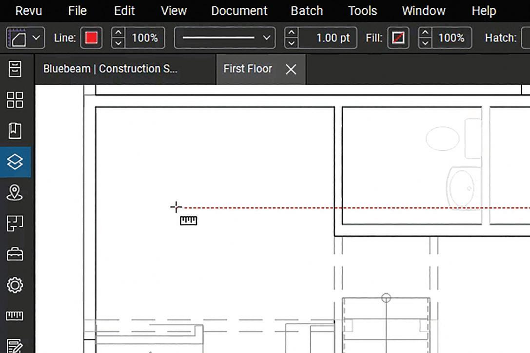
Step 2: Use the Measurement Tools
Bluebeam Revu offers a variety of measurement tools to find lengths, areas, volumes, and perimeters.
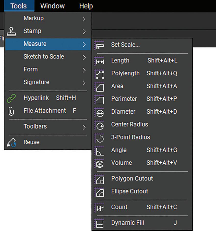
Use these measurement tools for a variety of material takeoffs. Like using poly length to measure the length of conduit, area to find the amount of flooring needed, or wall area to find the number of drywall sheets needed.
If the PDF does not have a known scale, then your measurements will not be accurate. You set the scale by selecting two points in the drawing with a known distance and entering that distance. Or, if you know the scale, simply enter it.

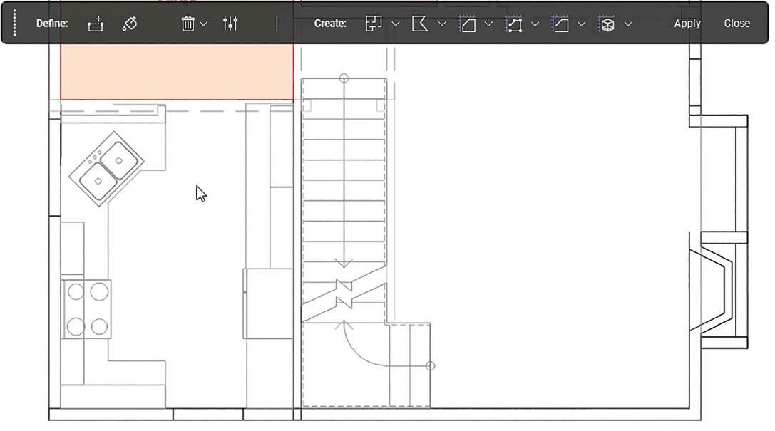
Dynamic Fill is a powerful tool that automatically detects boundaries and fills them, making quick work of area measurements. This is especially useful with irregularly shaped regions.
Figure 1: Set Scale Dialog
Figure 2: Calibrate
Figure 3: Measure Tools Menu
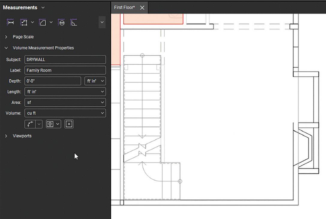
Figure 4: Volume
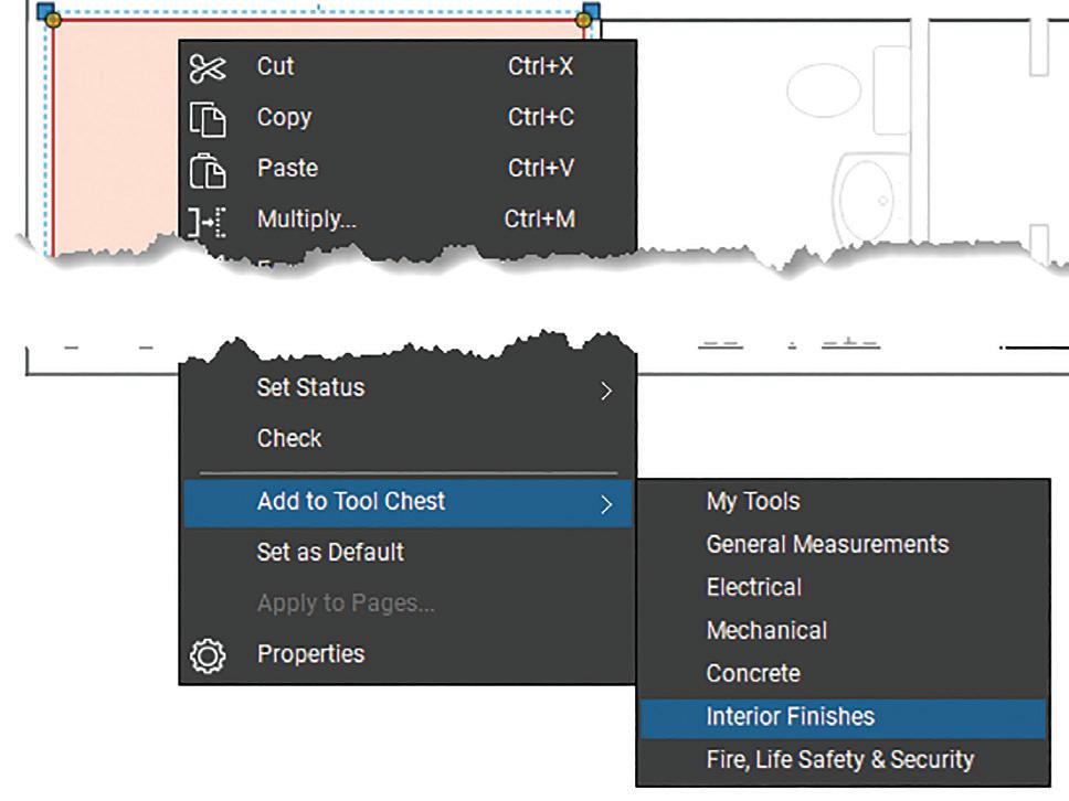
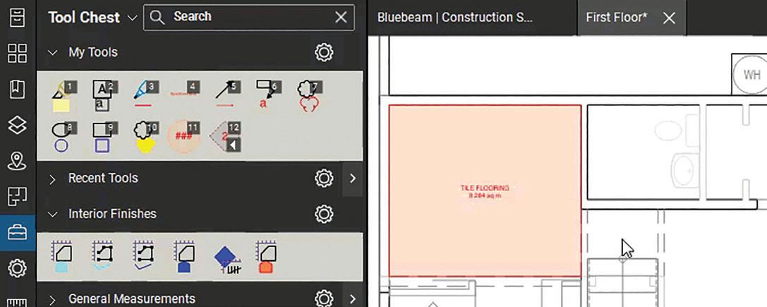
You can change measurement properties by setting the subject, label, and layer and adjusting the appearance. Layers are useful for organization and working with objects. The subject and label are important for grouping like measurements to get totals for takeoff.
And you can save markups with customized properties to Revu’s tool chest for easy reuse later.
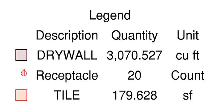
Legends are a great way to review measurement subtotals. Create legends from a toolset or an existing takeoff.
Step 3: Counting
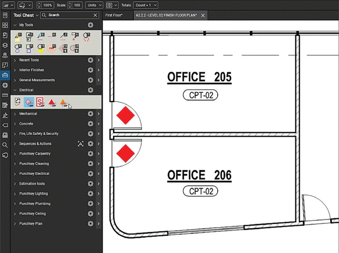
Count is as described. It counts objects. As you can set a count’s subject, use it to find the number of like doors, windows, fixtures, and other items in the plan.
Counting is only one method of counting objects. A sequence is a special markup that automatically increments each time you add it to the document. As it defaults to reuse, you can continue adding sequences until pressing ESC. And as a markup, you can make each sequence type look unique for easier identification.
Figure 5: Dynamic Fill
Figure 6: Area Measurement Properties
Figure 8: Tool Chest
Figure 9: Legend
Figure 10: Counting
Figure 7: Add To Tool Chest
Sequences are set up for counting. Do you need to start and stop the count? No problem, you can easily resume the count starting from the last sequence. Or reset the order to use the same tool for a different sequence.

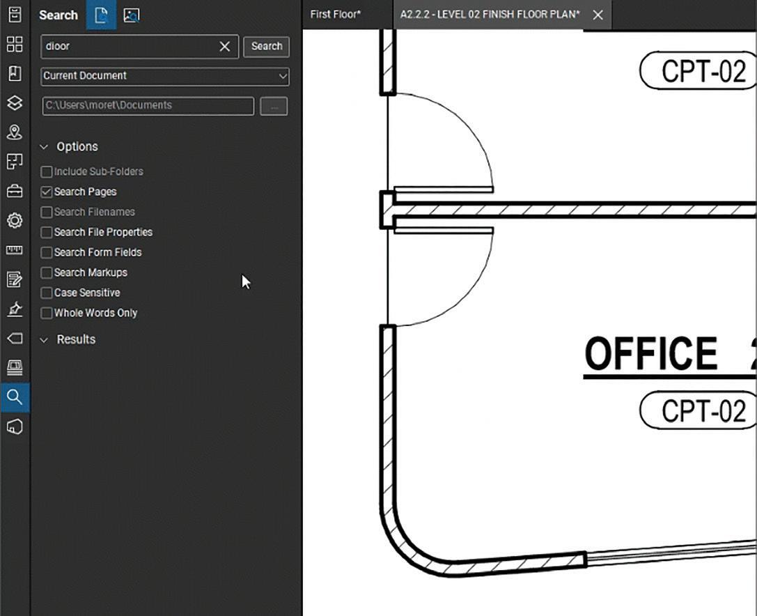
Step 4: Finding the stuff
Why count things manually when you can get Revu to count the objects for you? Visual Search is a great tool and somewhat unique to Revu. Use it to find and count identical markups or symbols based on how they look.
After selecting the view, Revu quickly finds matching objects. As you can adjust the precision, you can filter the noise so that Revu still finds it. You can then quickly add the found instances to a count and efficiently quantify these identified elements for your quantity takeoff.
Step 5: The Markups List
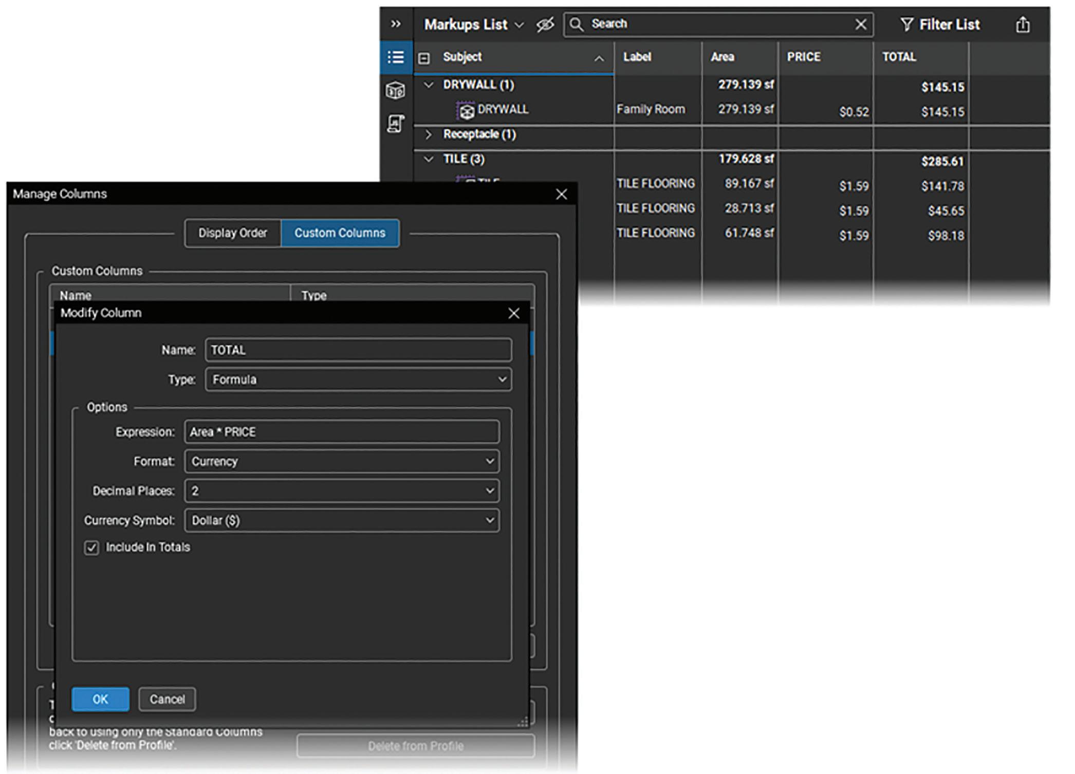
In Revu, as measurements persist as markups, it allows you to perform estimations and takeoffs through the Markups list. The Markups list automatically calculates totals for each type. Use the Markups list to sort measurements, view subtotals, and export for use in other applications.
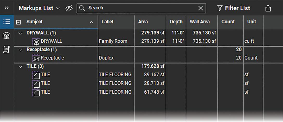
The built-in columns include measurementspecific properties like length and area. Use custom columns and formulas to create estimations for takeoffs. For example, adding material costs using a formula to calculate the total costs based on measurements.
Figure 11: Sequences
Figure 13: Visual Search
Figure 14: Markups List
Figure 12: Resume Count
Bluebeam Revu
Optionally create summary reports to share with others or further work on in other applications.
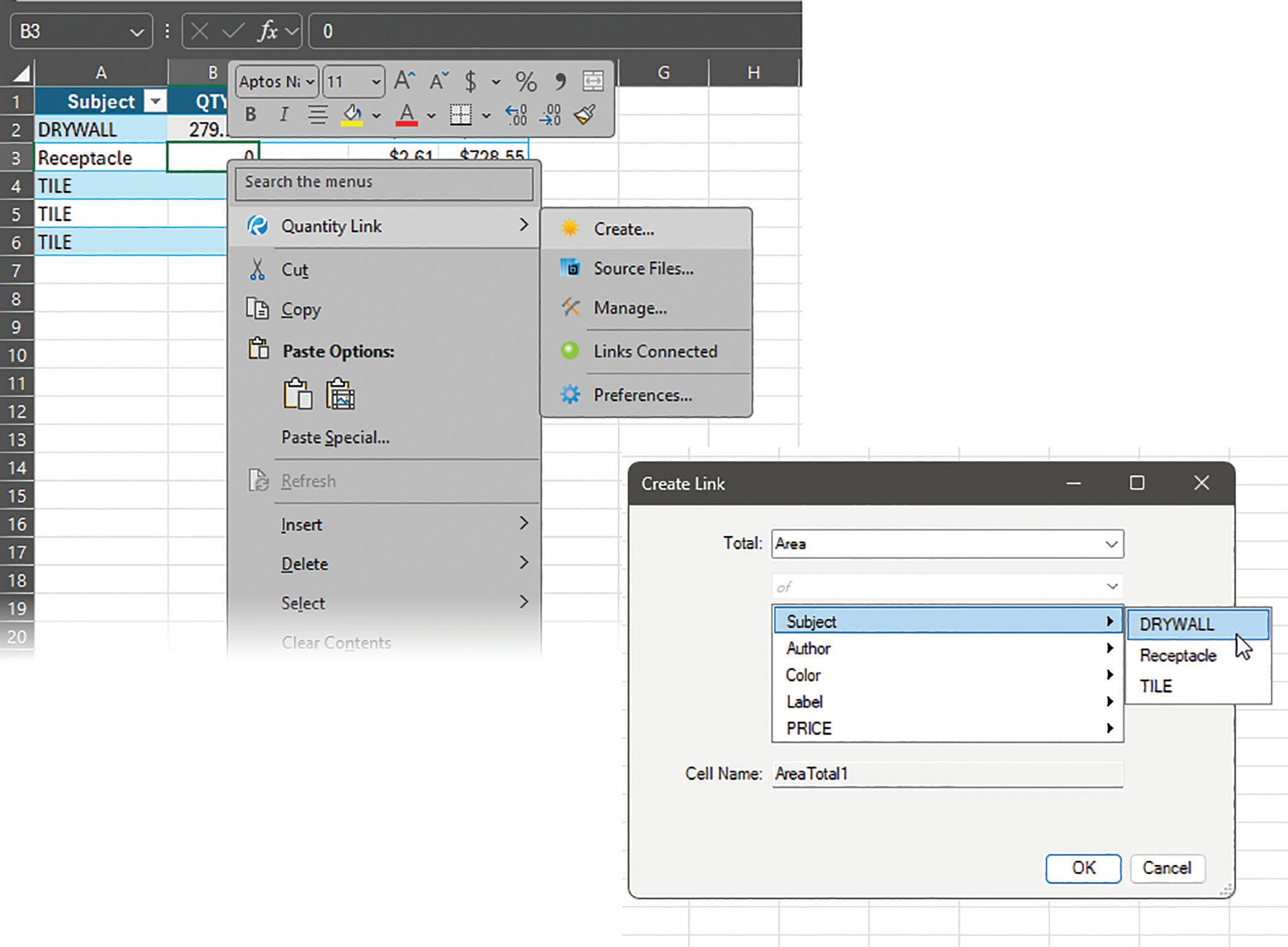
Step 6: Quantity Link
With the Excel: Quantity Link add-in, you link measurement totals from Bluebeam Revu to an
Excel spreadsheet. This creates a live connection, so any changes in Revu automatically update the spreadsheet. You can use Excel for more complex formulas, to link in additional information, or to collaborate with others.
IN SUMMARY
Revu’s takeoff and quantification process lists the materials, along with the quantities and costs, needed for the project. If you find yourself in a situation to be doing takeoff or you are looking for an upgrade of your existing process, you should check out Revu. Compared to other methods, with Revu you perform takeoff faster with more accuracy by reducing errors.
Want to learn more about Bluebeam Revu? Check out Bluebeam University [https:// university.bluebeam.com] or other courses like the ones offered by Global eTraining [https://www.globaletraining.ca/]

Mike Thomas used to work as a tech for an Autodesk reseller but later became the Technical Services Manager for a mining equipment manufacturer. Mike is in charge of technical operations and strategic growth. Mike excels at CAD, PDM, and ERP, with a focus on optimizing systems and technology. He is an Autodesk Expert Elite and a long time speaker at Autodesk University.
Figure 15: Custom Columns
Figure 16: Quantity Link

AUGI Members Reach Higher with Expanded Benefits
AUGI is introducing three new Membership levels that will bring you more benefits than ever before. Each level will bring you more content and expertise to share with fellow members, plus provide an expanded, more interactive website, publication access, and much more!
Basic members have access to:
• Forums
• HotNews (last 12 months)
• AUGIWORLD (last 12 months)
DUES: Free
Student members have access to:
• Forums
• HotNews (last 24 months)
• AUGIWORLD (last 24 months)
• AUGI Educational Offerings
DUES: $2/month or $20/year
Professional members have access to:
• Forums
• HotNews (full access)
• AUGIWORLD (full access and in print)
• AUGI Library
• ADN Standard Membership Offer
DUES: $5/month or $50/year
AutoCAD Architecture 2025 Project Navigator

The Drawing Management environment within the Project Navigator helps you organize, create and access all your project drawings in one unified interface. Creating sheets for plotting is easier with the streamlined coordination that is built into the Project Navigator. The Project Navigator has four tabs that you can use to enter project data. These tabs correspond to the main phases of project creation: general project information, creating building data (constructs) and creating building documentation (views and sheets). We will start with an overview of each and then look at them more in depth. We will end by looking at collaboration through drawing version management within the Project Navigator.
PROJECT CATEGORIES OVERVIEW
Each of the basic categories is represented by a folder in the Drawing Explorer within the project structure that helps you to organize your project files. For every building project in AutoCAD Architecture, the following basic category structure is displayed on the Project tab of the Project Navigator palette:
• <Project Name> - this is the top node in the project and is represented by a folder with the project name
• Constructs – this is the default category for constructs within the project. When you create a construct, it is saved into the Constructs category.
• Views – this is the default category for view drawings in the project. When you create a view drawing, it is saved into the Views category. It is important to note that if you create model space views within a view drawing, they will be placed under the view drawing in the same category as the view drawing itself.
• Sheets – in the project, sheets can be viewed in two ways: the Sheet Set View and the Explorer View. Each of these views will be discussed in more detail later in the article.
The main category structure listed above is fixed but you can create subcategories and subcategory trees within this structure. Subcategories typically represent aspects of your workflow. These subcategories can be set up in different ways. For example, you might set up categories by discipline, by view type (presentation, section and rendering) or by sheet type (floor plan, ceiling plan and elevation). It is important to note that you cannot mix basic category types. For example, you cannot create a Construct subcategory within the Views
category. Categories offer excellent organization for a project. Even small building projects contain a large number of individual drawings that can be difficult to track. By putting them into descriptive categories, you can quickly find the correct files you need for your project.
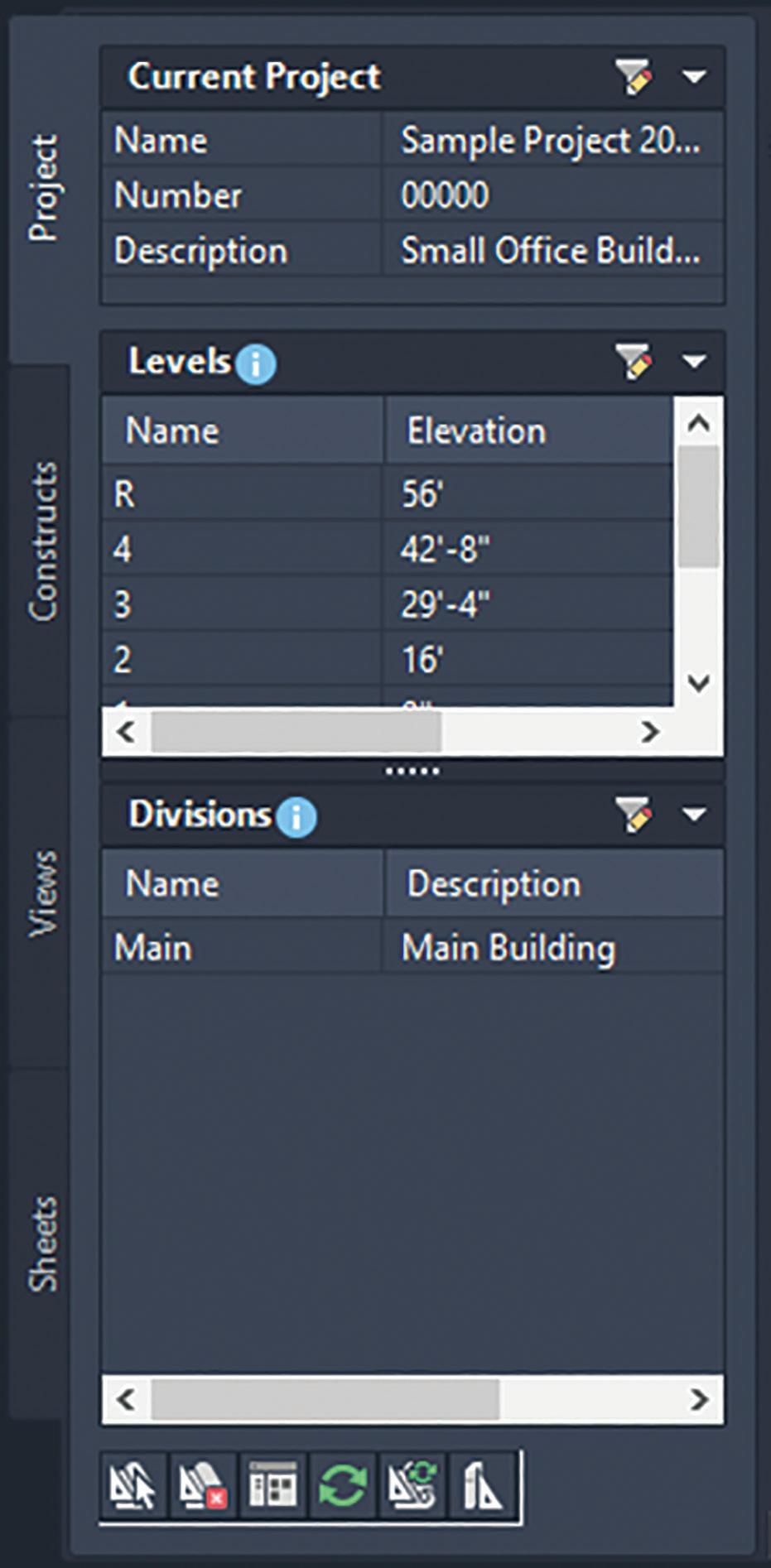
THE PROJECT TAB
The Project tab on the Project Navigator tool palette is where you enter information that pertains to the entire project (see Figure 1). The Project tab allows you to do the following: Change project properties
• Launch the Project Browser
• Launch the Content Browser to access the project library
• Add, modify and delete levels
• Add, modify and delete divisions
• Synchronize the project with project standard styles and display settings
• Enable and configure project standards
• Refresh the project
• Close the current project
AutoCAD Architecture
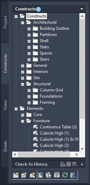
THE CONSTRUCTS TAB
You start creating constructs when you want to assemble the basic objects of your building project into base files. Typically, you begin a project by creating constructs. The Constructs tab of the Project Navigator tool palette is where you add the basic building objects for your project (see Figure 2). Constructs are basically the main building blocks of the building model. A construct represents one unique portion of a building, such as a building core or an entire floor. You will need to assign a construct to a level (floor) and a division (area of the floor) within the project. Constructs can span more than one level, which is useful for objects such as curtain walls.
The Construct tab allows you to do the following:
• Open and close existing construct and element drawings
• Add, modify and delete constructs and elements within the project
• Create categories for constructs and elements
• Launch the Content Browser to access the
Figure
Figure 2 – Constructs Tab
AutoCAD Architecture
project library
• Reference elements into constructs
A construct is a drawing (DWG) file. As opposed to non-project related drawing files, an additional XML file with the same name is created. The accompanying XML file contains information to connect the construct to the project. The XML file is created and updated automatically. You do not need to edit it but be careful not to accidentally delete it in Windows Explorer.
In multistory buildings, levels may have identical floor plans. You can create the constructs for one level and copy them to the other levels in one quick step.
You can convert an existing drawing file into a construct within a project. You specify the subcategory into which to move or copy the source drawing. When you convert a legacy drawing file into a construct:
• The drawing file is either moved, copied or connected through a link to the project category you specify
• You assign a level and a division to the construct
• You give the construct a different name and add a description to it
There are three different types of content you can place in a construct:
• Drawing objects. You can draw an entire floor, apartment layout, a frame drawing or a ceiling grid as a construct. Also, spanning objects such as curtain walls or elevator shafts are usually created directly as constructs.
• Element References. You can display repeating components within the construct, such as desk/ chair combinations, bathroom layouts or stairs.
• A combination of drawing objects and element references. If you have a floor with different office types but repeating furniture elements, you could draw the office walls directly in the construct but reference the furniture as elements.
THE VIEWS TAB
The Views tab of the Project Navigator tool palette is where you can create individual views of your building data. Views contain constructs and are the primary location for you to add annotation such as notes, tags and dimensions within the project. After you have created a view drawing, you can then create model space views within it.
After the structure of the building project has been defined and constructs have been assigned to both levels (floors) and divisions (area of the floor), you can then start to create view drawings within the project. A view drawing references any number of constructs to present a specific view of the building project (see Figure 3).
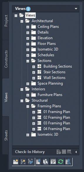
To create a view drawing, you must first decide which portion of the building you wish to look at and which type of view you wish to generate. View drawings will automatically reference the appropriate constructs in accordance to their level/ division assignments within the building. For example, to create a floor plan of the west wing of the second floor, you would create a view that references all constructs that are assigned to the second floor of the west wing.
Figure 3 – Views Tab
The Views tab allows you to do the following:
• Open and close view drawings
• Add, modify and delete model space views
• Add, modify and delete general views, detail views and section/elevation views
• Change the contents of view drawings
• Create categories for view drawings
• Launch the Content Browser to access the project library
THE SHEETS TAB
The Sheets tab of the Project Navigator tool palette is where you create and organize sheets for your project. Sheets reference views and are used for plotting drawings. The Sheets tab is also where you manage the project sheet set. This is where you will perform tasks such as creating a table of contents, managing page setups or publishing to a plotter, a PDF or a DWF file. The buttons at the top of the Sheets tab let you view sheet information in two ways: the Sheet Set View or the Explorer View.
The Sheet Set View is a tree view of the project sheet set in which you have access to all publishing capabilities. The Sheet Set view allows you to do the following:
• Add, modify and delete sheets in the project
• Open and close sheet views Assign numbers to sheet views
• Insert a table of contents
• Electronically transmit the sheet set
• Archive the sheet set
• Create sheet selections for specific tasks Manage page and publishing options
• Launch the Content Browser to access the project library
• Publish the sheet set to a plotter, a PDF, a DWF file or to an alternate page setup
The Explorer View is a view of the folder structure and sheet drawings in the project. The Explorer View allows you to do the following:
• Open, close and delete sheet drawings
• Create categories for sheet drawings
• Launch the Content Browser to access the project library
Sheets are organized into sheet subsets in the Sheet Set View (see Figure 4). Sheet subsets are a logical structure. The sheet folder category does not need to be identical to the sheet subset in which the sheet is placed. To avoid confusion, however, it is recommended that you have parallel
AutoCAD Architecture
structures in the sheet set and the sheet categories. You can rearrange sheets into different subsets within the Sheet Set View but that will not change their physical location in the category or folder. Also when you remove a sheet from a sheet subset in the Sheet Set View, only the reference of the sheet to the subset is removed. The layout itself and its containing sheet drawing are not deleted from the Sheets folder or subfolder. In the Explorer View, sheet drawings are placed in folder categories. When you create sheets or sheet views within a sheet drawing, they are placed in the sheet drawing.

EXTERNAL REFERENCES
The Drawing Management feature uses external references (xrefs) as a means to create a project and maintain it. Elements are referenced into constructs, constructs are referenced into views and views are referenced into sheets. The mechanism
Figure 4 – Sheets Tab
AutoCAD Architecture
of referencing is identical to the regular AutoCAD External References Management feature; however, the background methods employed have additional features.
Xrefs that are created in drawing management can automatically make use of project data, while those that are created manually through the xref palette or command line cannot. If you are working in a project environment, the best practice for referencing project drawings into other project drawings is to use the Project Navigator rather than the standard AutoCAD Xref Manager. The AutoCAD Xref Manager cannot differentiate between project drawings and non-project drawings. If you reference a non-project file into a project file by mistake, you cannot use the full Drawing Management functionality on that file.
It is important to keep the following considerations in mind when working with a project:
• Do not delete any XML files generated by the Drawing Management feature as they are vital for the project.
Use the Project Navigator to create, modify and reference project files within the project. If you want to use existing non-project files in a project, convert them to project files first.
• Drawing Management supports the use of relative paths for external references. In the project setup, you can decide whether to full paths or relative paths. Working with relative xref paths makes moving the project and transmitting it easier and reduces the need to repath the project.
DRAWING VERSION MANAGEMENT
In the AutoCAD Architecture Project Navigator, you have an amazing collaboration tool with drawing version management. Projects typically involve multiple users working together on a set of drawings. Because of this, it is essential to have a drawing version management tool to ensure that all changes are recorded and there are no access clashes. When you check out a drawing from the Project Navigator, all other users will have read-only access to the drawing and can view the version of the drawing that was last saved until you check the drawing back in. This is important because it ensures there are no file access conflicts and each change to a drawing is recorded. When you make changes to the checked out drawing, they are not dynamically visible to other users. As the checked
out file is saved, no xref notifications are sent to others, as this can be an interruption to their work. To check out a file, simply right click on the file in the Project Navigator and select Check Out (see Figure 5).
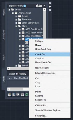
Simply hovering over a file in the Project Navigator palette shows you the status of the file, the name of the drawing and its location, the date and time the file was last checked in and the name of the user who last checked-in the file. You can tell if a drawing is checked out based on the checkmarks. Red checkmarks indicate that the drawing is checked out by another user and a green checkmark indicates that the drawing is checked out by you. You will be prompted to add comments on the changes you made when you check a file back in. You will see this information
Figure 5 – File Check Out
displayed in the Check-In Version History, along with your user name, your computer name and the date and time of the checkin. Each time you check a file back in, AutoCAD Architecture creates a backup file in the same folder that the drawing is stored in, slong with the drawing name appended with the check in time. It sometimes becomes necessary to revert to an earlier version of the drawing and the comments history makes this easy.
REFRESHING THE PROJECT NAVIGATOR
When multiple people are working on the same project simultaneously, one person’s Drawing Explorer view on the Project Navigator palette can become out of sync with the changes of another. To prevent this situation, refresh the Project Navigator by clicking Refresh Project so that all items are updated to reflect the current project status. It is highly recommended that this is done frequently during a project session if there are multiple people working on the same project.
AutoCAD Architecture
will update only if all project paths are correct and current when you zipped them. If you have moved the project to another location on your computer and did not repath it before zipping, the repathing on the new user’s machine will not work correctly. Before you zip and send a project, you must make sure that all external reference paths in the project are valid.
On the Quick Access toolbar, select Project Navigator. Next, select the tab where you want to refresh the file tree. Finally, select Refresh Project.
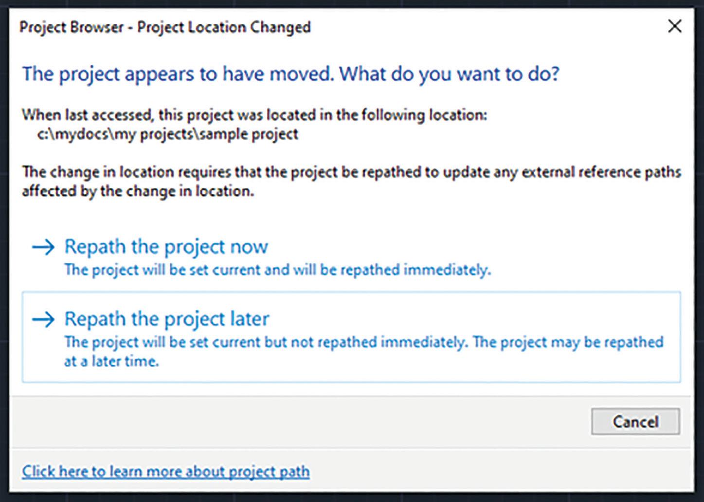
REPATH THE PROJECT
A repath is necessary after you make any of the following changes within the project:
• Rename a project file
• Move the project to a different location
• Move a project file to a different category
• Move a subcategory from one category to another
In addition to updating the project files, repathing will also update the paths of support files, images and schedules that are referenced in the project drawings.
When you zip a project and then send it to another user who unpacks the project to a different location on another computer, the project will be updated in its new location when it is set current for the first time on the new computer. However, this
You have the choice of repathing a single project file, all files in a category or all files in the project. On the Quick Access toolbar, select the Project Navigator. Next, change the name or the location of a project file or project folder in the Drawing Explorer. The Project Navigator – Repath Project dialog box will display. Specify when you want the repathing to be done (Repath Now or Repath Later).

Melinda Heavrin is a CAD Coordinator & Facility Planner in Louisville, Kentucky. She has been using AutoCAD Architecture since release 2000. Melinda can be reached for comments and questions at melinda.heavrin@ nortonhealthcare.org.
Figure 6 – Repath Project
Coordination: Then, Now, and Beyond

As design professionals, how we coordinate with each other throughout the design process has changed from time to time. We have gone from light tables and printed sheets to linking CAD files and Building Information Models. We still have a light table at our office here in Nashville, but we also have been doing something a bit different that we will get into later. Let’s talk about some of the traditional methods of coordination for design professionals.
In the 1960s, architects coordinated drawings with engineers primarily using detailed, hand-drawn blueprints on paper. Which then relied on frequent
communication and physical meetings to ensure alignment between architectural design and engineering calculations. With the early emergence of computer-aided design (CAD) systems for drafting, coordination starting to be used done in the two-dimensional cad files with several design professionals huddled around a monitor. This process was difficult at best and lacked the advanced 3D modeling capabilities that later enabled smoother coordination.
In 1975 Edgar Powers Jr. with Gresham Smith (formally Gresham Smith & Partners) developed a process which they published a book on called
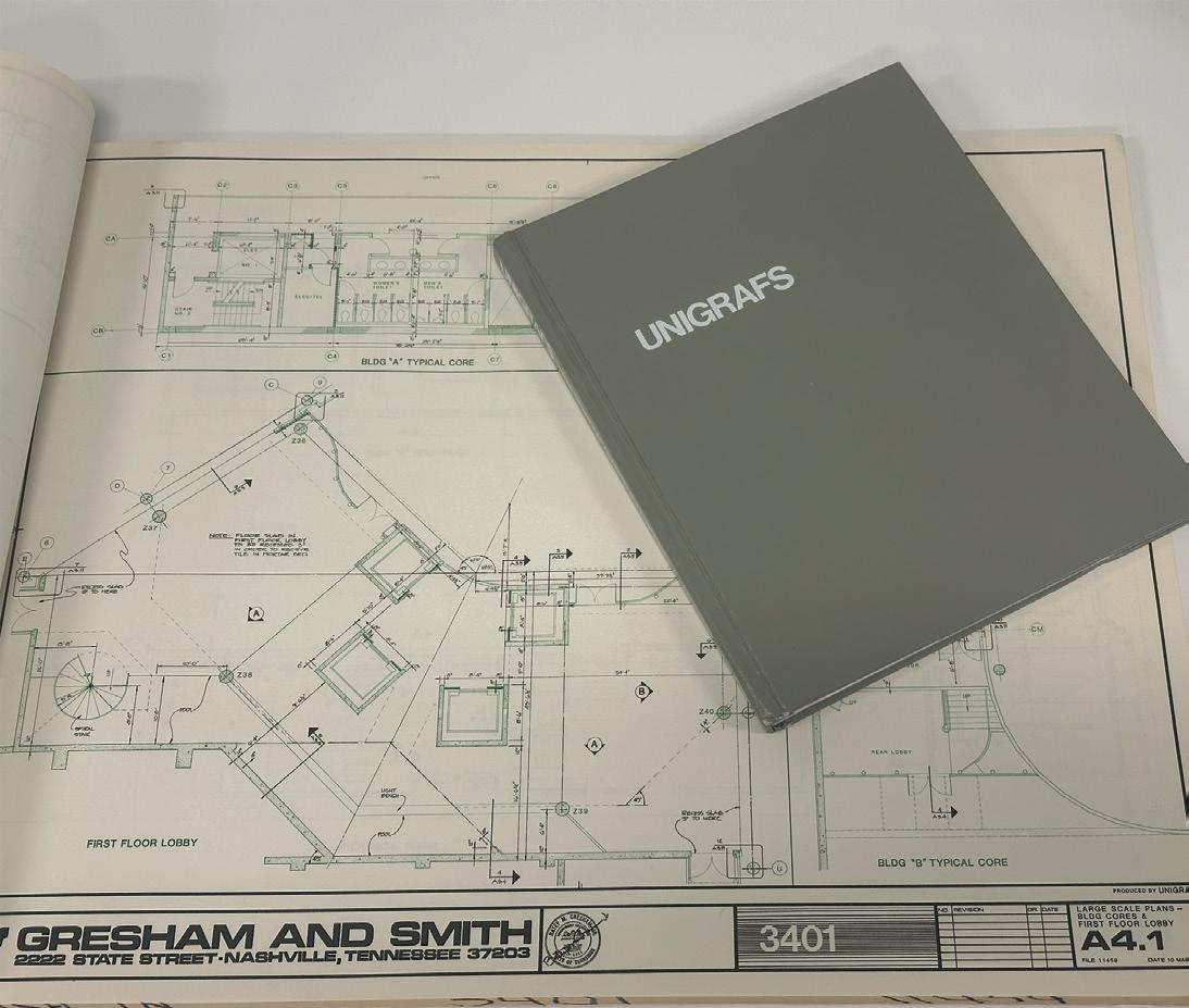

“Unigrafs: Unique Graphics for Architects and Engineers” where Systems Drafting is discussed. Systems Drafting combines pin-registered or overlay drafting with techniques such as cut and paste, photo drafting, keynoting and project organization with final printing by color offset or diazo. The result is a set of quality documents produced in less time with fewer errors than by conventional methods. This is like what we did with .dwg files and external references, which was the preferred method in the 90’s.
Along with the advent of BIM we saw a major improvement in digital collaboration, as we are now modeling in 3D. With the use of Collaboration for Revit(C4R), BIM360 and now Autodesk Construction Cloud (ACC), which allowed for live linking of models in a cloud environment. This allows us to see changes to models when files are synced and reloaded. Now with that ability for instant
collaboration some members of the industry freaked out claiming there were too many changes coming at them and couldn’t keep up with the architectural changes. The answer to this was the Design Collaboration module and what is known as controlled worksharing. Controlled worksharing allows members of the design team to elect when they want to “consume” a model from a design partner. One of the things that is cool about this is that ACC allows teams to decide if they want to live link or use a controlled work sharing to collaborate with the team. In some cases, you may choose to do both depending on where you are in the lifecycle of the project.
In the current architectural, engineering, and construction (AEC) industry, Building Information Modelling (BIM) teams collaborate in a highly integrated manner. They utilize advanced cloudbased platforms, like ACC, that allow for real-time updates and sharing of BIM models and associated data. This ensures that all team members, regardless of their physical location, have access to the most up-to-date project information.
Collaboration is further enhanced using model coordination software, where clashes between different elements of a project can be identified and resolved collaboratively. Regular meetings, both virtual and in-person, are also held to discuss project progress, challenges, and solutions. This collaborative approach not only improves efficiency and productivity but also enhances the quality of the final output, as it allows for more effective problem-solving and decision-making.
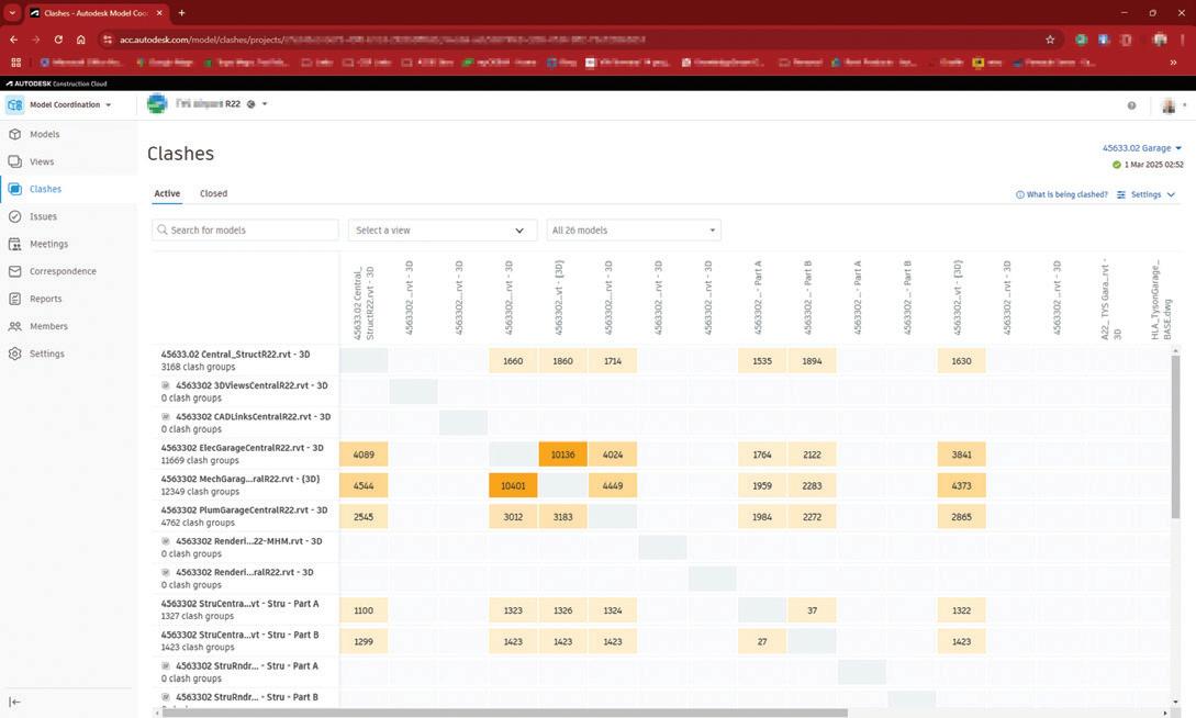
With the use of the Model Coordination module in ACC Autodesk is looking for you to modify your normal workflow of coordination and move you into a visual and rule-based clash environment. While working in ACC Design Coordination you can schedule a weekly interval for your live models to be “published”. This published model is also used in a controlled worksharing environment as mentioned above. The published model is “automagically” used to give you a clash report without the use of Navisworks or Glue or other workflows. Where the workflow changes happen is what we do next. Instead of sending countless emails and screenshots to your consultants as you discover new problems to solve, we find ourselves reviewing the clash matrix and walking through the models using Model Coordination.
Figure 1: Unigrapfs
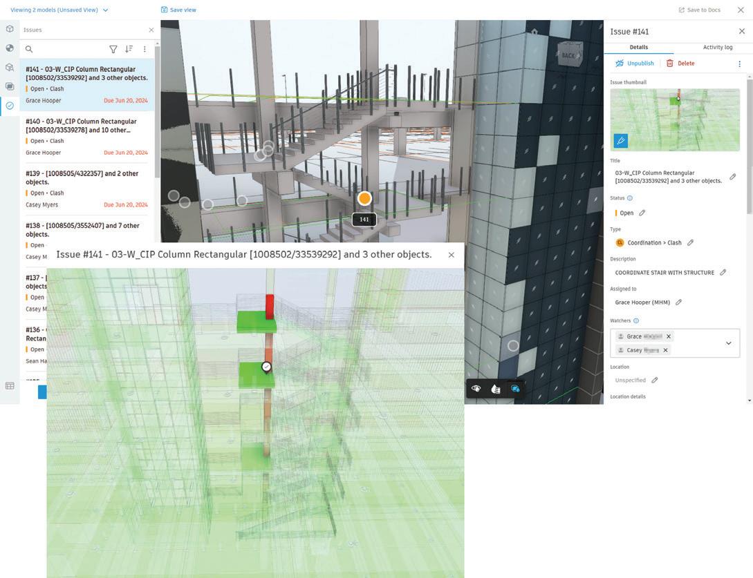
We can also create an “Issue” and assigning it to the responsible parties to resolve and even copy or add “Watchers” to the issue so they can monitor the problem. These issues that are created, with the help of an add-in for Revit, can be viewed from the Revit model to make people aware of a pending issue if they forget about the email notification that they received when the issue was created.
4: Issues
The hope is that the design team sees these notifications and markers and resolves these issues without the use of a meeting. Once all the easy issues are resolved we schedule a meeting using the Meetings tool in ACC. With the use of our outstanding issues that we could not resolve organically in Model Coordination we create an agenda. This agenda becomes a part of the project record and when the meeting is completed you can turn it into your meeting minutes.
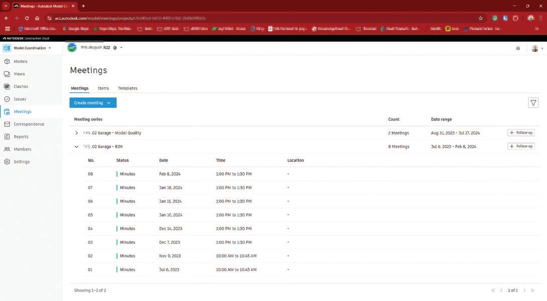

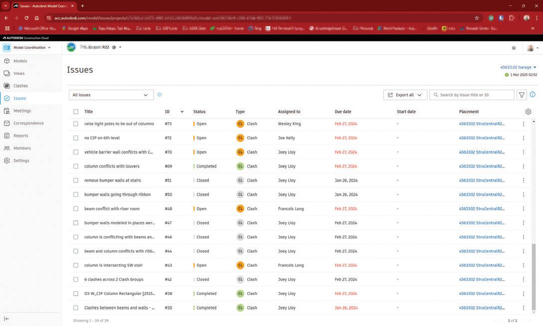
Any action item from the meeting can be assigned to a participant like an issue can. All the issues can be sent to any project team member with the use of automated reports. So, if we want a weekly report of issues open or closed for that week sent to the design team leads it will do that.
Here at Gresham Smith, we spent some time with Autodesk’s Consulting services to evaluate the use
Figure
Figure 5: Meetings
Figure 2: Clashes
and strategy of how we use their ACC products. Our approach was to utilize their tools as they intended with as little rework as possible. We customized our folder structure and user permissions to satisfy our Project Delivery and Practice Technology teams, but we wanted their tools and workflows to have the greatest chance to work for what we needed. We have not embraced the full suite of modules, but we are continuing to work using Model Coordination, Issues, Clashes, and Meetings on some projects with great success. Not all projects have the fee or hours needed to offset the learning curve associated with new workflows, but we are slowly gaining traction. The interest in the tools is very appealing to project teams and we are doing what we can to capitalize on those opportunities.
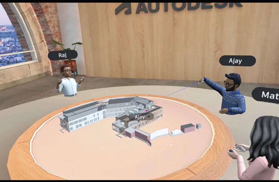
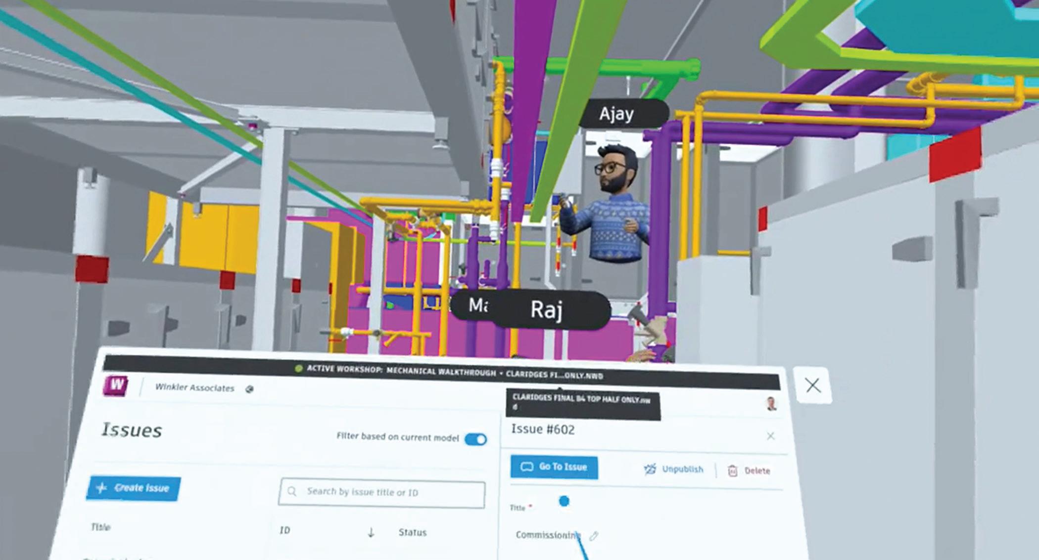
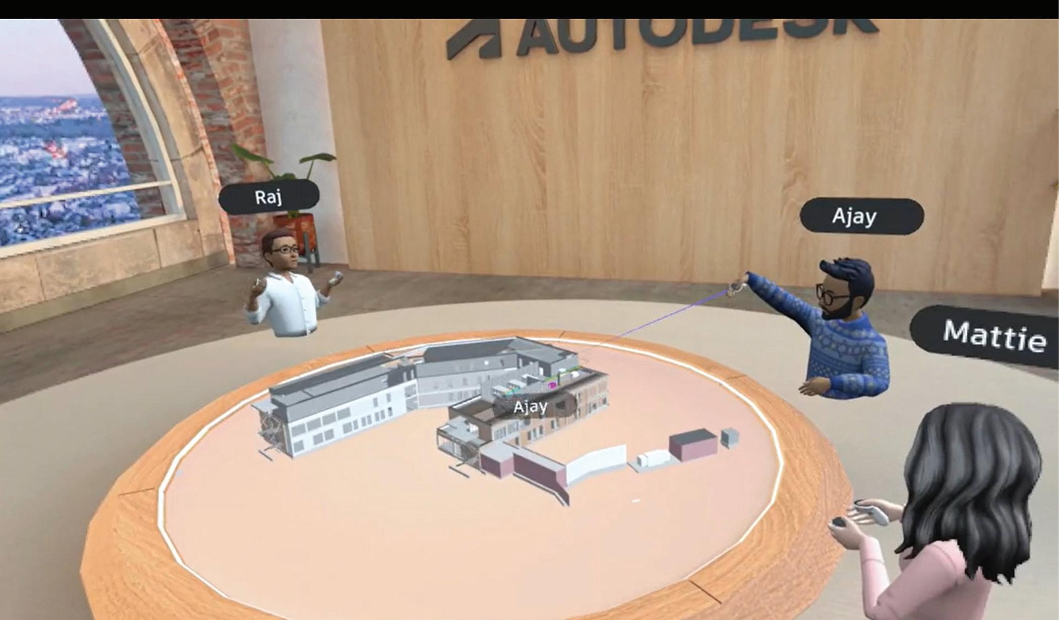
What’s next or beyond for collaboration is already upon us. Autodesk is now integrating augmented
and virtual reality into what they are calling Extended Reality or XR. This takes some of the modules in ACC and brings them to you in a VR headset environment. Review issues and clashes in an immersive environment or have a XR workshop to review a virtual scale model with your design team members. With the development of ACC, Autodesk has created an environment for all aspects of the project lifecycle. From site studies in Forma to schematic design through the entire design process Autodesk has developed tools to help design professionals create more coordinated projects.

Jonathan Massaro is a Market BIM Leader and Associate in Gresham Smith’s Aviation Market, a leading multidisciplinary design and consulting firm for the built environment. He has worked in the architectural field for almost 30 years on projects of various size and type ranging from single family homes to airport terminals, and he began working in Revit in 2009. He was initially hired by Gresham Smith to work on the first Revit projects for the firm’s Healthcare market in Tampa back in 2011 and continued his work for the firms Aviation Market. In 2016 he relocated to the Nashville office to take a support role as a part of the Gresham’s Practice Technology group where he supported all the Architectural markets and worked to help streamline the firms Revit workflows and processes. At the beginning of 2025 Jonathan rejoined the Aviation Market in their new studio in Nashville where he manages the delivery of BIM services for the Aviation Market.
Figure 6:XR Issues
Figure 6: XR Workshop
What’s New in Revit 2026

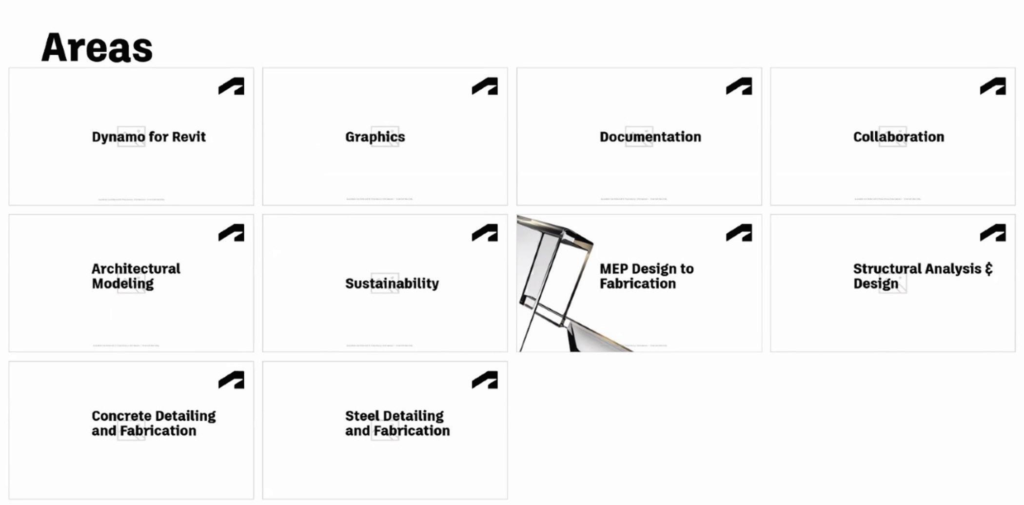
Figure 1
In the continuously advancing fields of architecture, engineering, and construction, maintaining a leading edge is essential. The latest updates in Revit 2026 are set to revolutionize the way professionals approach their projects, offering a comprehensive suite of tools and enhancements that cater to every aspect of the design and construction process. From Dynamo for Revit to advanced graphics, documentation, and collaboration features, Revit 2026 is designed to streamline workflows and boost productivity.
Architectural modeling has never been more intuitive, with new features that enhance both the design and detailing phases. Sustainability is at the forefront, with tools that allow for more accurate energy analysis and carbon footprint assessments. MEP design to fabrication is now more seamless, ensuring that every element, from HVAC systems to electrical layouts, is meticulously planned and executed. Structural analysis and design have been refined to provide more precise calculations and better integration with other disciplines.
Concrete and steel detailing and fabrication have also seen significant improvements, making it easier to create detailed, accurate models that translate seamlessly into the construction phase. Whether you’re an architect, engineer, or construction professional, Revit 2026 offers the tools you need to bring your vision to life with unparalleled accuracy and efficiency. This article will not cover all areas of improvements, features, and enhancements listed below; however, I will focus on discussing those that I find particularly noteworthy. Any updates under Architectural and Structural categories will likely be addressed by experts more specialized in those fields across the interwebs in the coming days or weeks if they have not already dropped.
GRAPHICS AND UI UPDATES
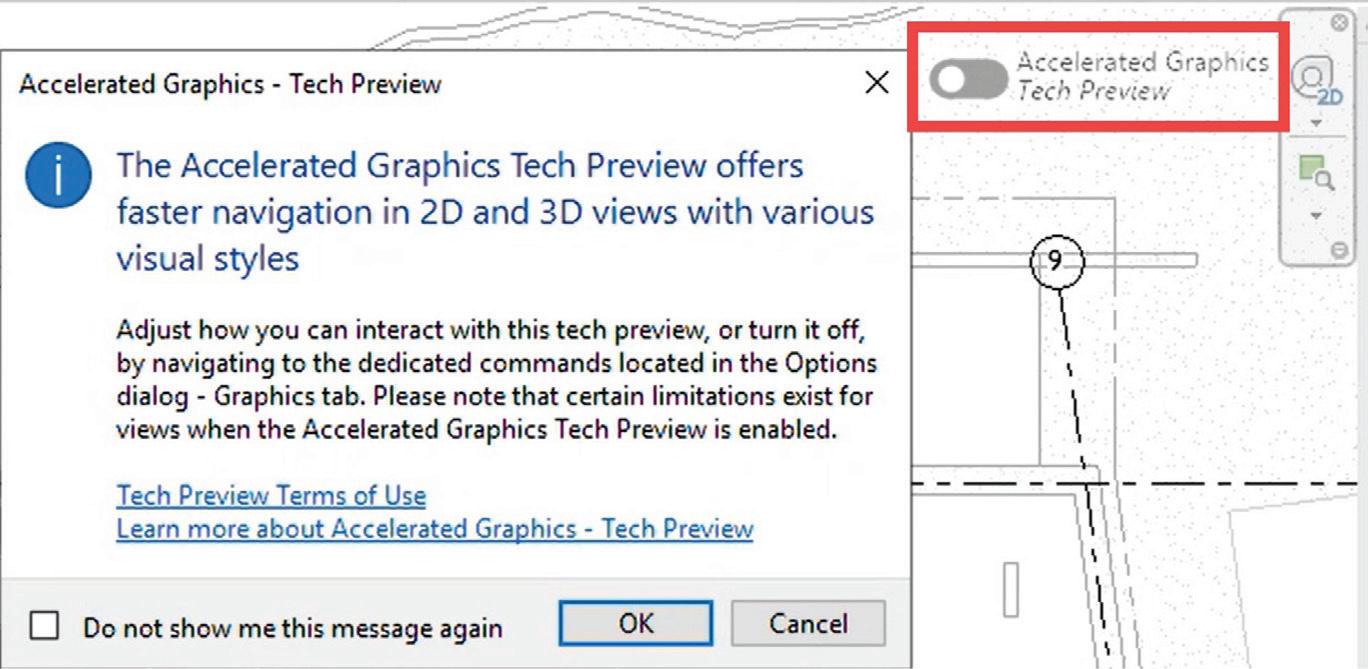
performance. Users can toggle this feature through the contextual menu or the new on-screen toolbar. Enabling accelerated graphics is indicated by a colored view border and remains active only for the current session, resetting upon closure. This mode supports graphical views but excludes Sheets, Drafting Views, and Legends, while 3D geometry is accelerated. However, Point Clouds and Coordination Models are not displayed. Certain graphic appearances, such as line patterns and weights, fill patterns, and transparency (unless set in the material), are limited. Additionally, raster images, room color fills, and sort order are not accelerated, leading to a performance impact in heavily annotated views. Unsupported effects in accelerated views include shadows, backgrounds, sketchy lines, and depth cueing, with view cropping being ignored. Structural and MEP hidden lines do not display, and print, export, and render actions use the non-accelerated view state. For
optimal performance, a dedicated graphics card with a minimum of 4GB is recommended, as well as sufficient RAM to manage high memory consumption across multiple accelerated views. Low system RAM can affect overall Revit performance.
Revit 2026 introduces accelerated graphics mode, a new per-view setting that enhances
The UI enhancements in Revit 2026 include a contextual ribbon for tags, which improves the efficiency of tag settings by placing them in the contextual ribbon instead of floating menus. This change reduces mouse movement and ensures
Figure 2 - Accelerated Graphics Tech Preview Button
Figure 3 - Modify Group in Ribbon
tag properties can be set before placement. Additionally, the move modify tools are now integrated into the ribbon, phasing out the Options Bar for tools such as Move, Copy, Mirror, Rotate, and Array. This reorganization groups controls for better usability and ensures quicker access to dimension properties.
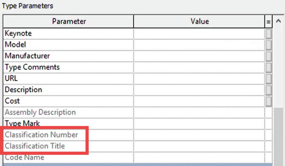
Wall-related modifications, including Attach/ Detach Top/Base, Wall Join settings, and Sweep & Reveal modifications, have also been relocated to the ribbon, eliminating the need to navigate the Properties Palette for these edits. Another update is the renaming of OmniClass fields to “Classification” in Family Parameters, offering more flexibility for users to assign other classification systems. The UI now provides a more general Classification Number & Title instead of fixed OmniClass references, and there is a new direct link to the Classification_Taxonomy.txt file in Revit settings for easy customization.
Moreover, the classification number and title are retained even if a user opens a family without the original classification definition, ensuring data consistency across different users and projects. The Reference Label parameter is now instancebased, allowing each reference view object to have a unique value. This supports global parameters, enabling users to associate Reference Labels with global parameters. New reference views automatically assign a default value to the Reference Label, and if no default is set, the value remains blank.
DOCUMENTATION
In Revit 2026, users will find expanded shared parameter support in view annotations, including
sections, elevations, callouts, and references. This update allows for greater customization, as shared parameters can now be added to these annotation families, much like View Titles. The added shared parameters will appear in view objects and can be scheduled within View List Schedules, enhancing the management and visibility of crucial project details.
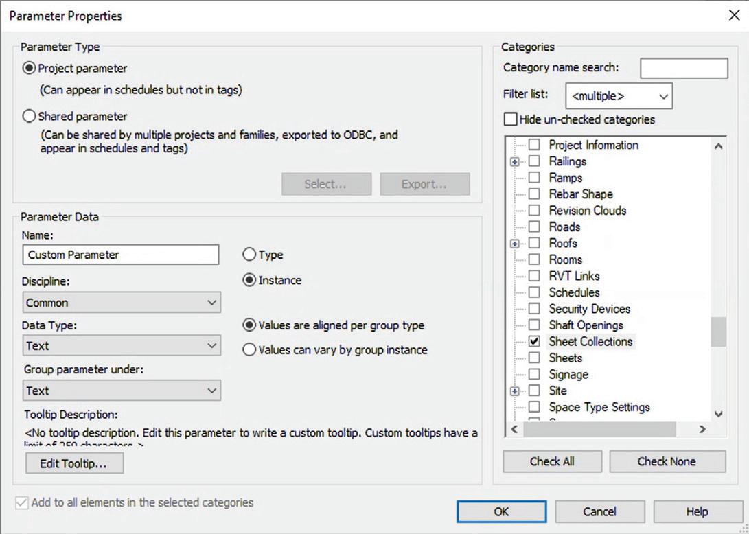
The introduction of the “Sheet Collection” category marks a significant improvement for parameters and schedules. This feature ensures that parameter values are synchronized across all sheets within a collection, with values appearing read-only on individual sheets. Any changes made to a parameter within the Sheet Collection will automatically update all related sheets. Additionally, Sheet Collections support global parameters, and schedules linked to Sheet Collections provide better control over grouped sheet parameters.
Prioritization rules for parameter data in Sheet Collections have also been established. These rules dictate that Sheet Instance Parameters take precedence over Sheet Collection Parameters, which in turn take precedence over Project Info Parameters. This clear hierarchy helps maintain consistency and accuracy in parameter data throughout a project.
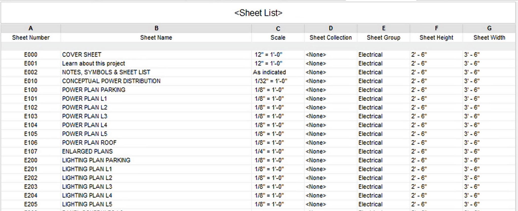
Enhancements to Sheet List Schedules now include new built-in parameters such as Scale, Sheet Width, and Sheet Height. Furthermore, built-in and shared parameters from title blocks can be scheduled. A new Primary Title Block Parameter determines
Figure 4 - Omniclass to Classification
Figure 5 - Shared Parameters for Sheet Collections
which title block provides schedule data, and while it is read-only for sheets with a single title block, it becomes modifiable when multiple title blocks exist on a sheet.
My FAVORITE feature for this version is the new “Save Position” feature which revolutionizes viewto-sheet positioning by allowing users to save view positions and reuse them across multiple sheets. When a saved view is placed on a sheet, it automatically aligns to the saved position, ensuring consistency in view placement across large projects and streamlining the coordination process. This will eliminate hours of set up time for small and large projects and everything in between.
A notable addition is the Scale Override (Multiple Values) Parameter for title blocks, allowing for textbased overrides of the title block’s scale. This feature is particularly useful for sheets containing multiple scale views, though it supports only text input and can be associated with global parameters.
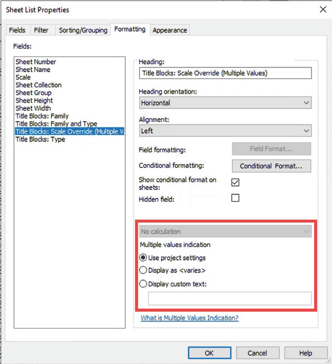

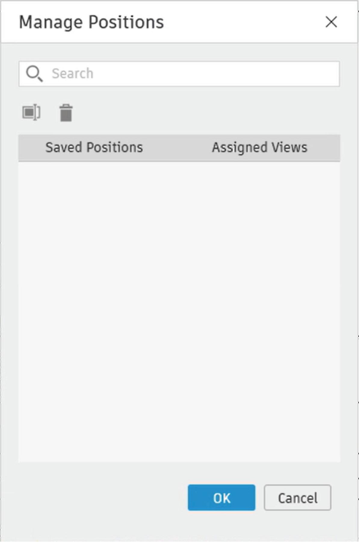
Figure 6 - Additional Sheet List Parameters
Figure 8 - Save/Saved Position
Figure 9 - Manage Positions
Figure 7 - Scale Override in Titleblocks
These updates in Revit 2026 offer enhanced customization, improved parameter management, and streamlined workflows, making it an essential tool for professionals in architecture, engineering, and construction.
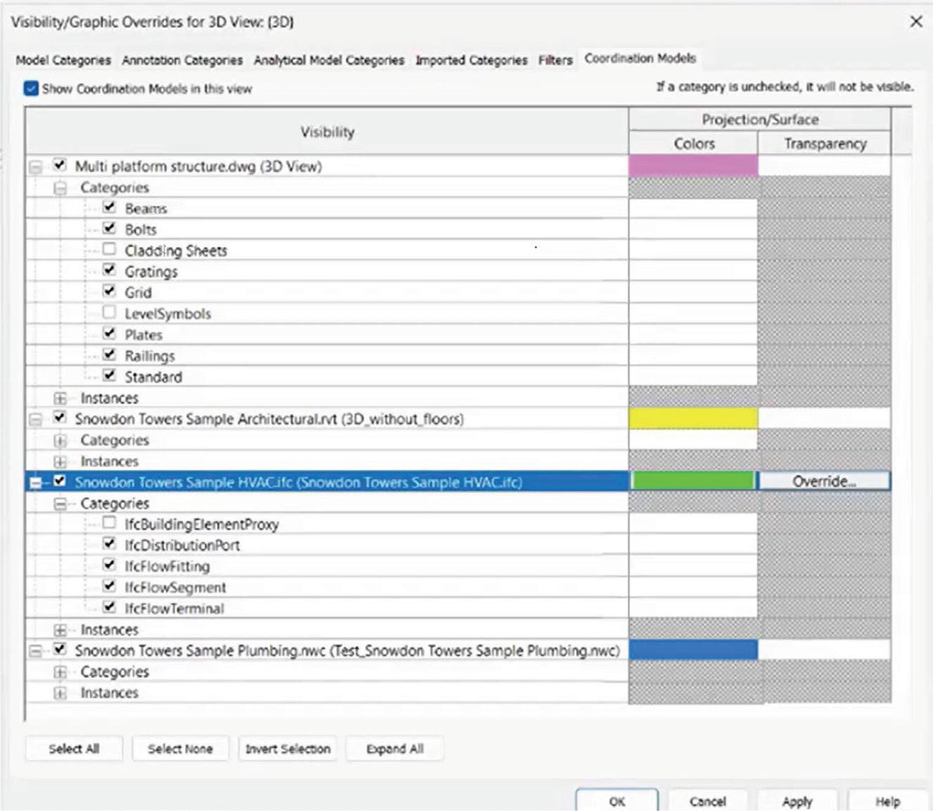
COLLABORATION
The coordination model graphical appearance and visibility control have been significantly enhanced in Revit 2026. Users can now assign colors to coordination models, making it easier to distinguish different linked models at a glance. Additionally, the enhanced visibility settings allow for filtering coordination models by category and instance,
files. This update results in better organization of CAD files within projects, allowing users to control visibility and cleanup of unnecessary imports, thus preventing model clutter by tracking imported
versus linked files. CTC Tools Import and Link Manager has been doing this for many versions so it is nice to finally get it built into Revit directly. While I think importing CAD into a Revit model is bad news, this is a great improvement to help users and BIM staff track those pesky imports down.
IFC link orientation and performance improvements are another significant update in Revit 2026. New IFC link options allow placing an IFC model based on different reference points, including Internal Origin (default), Project Base Point, and Survey Point. The linking of IFC models is now up to 50% faster compared to previous versions. These performance enhancements offer more control over model positioning when linking IFC files, ensure accurate alignment with other models in a project, and improve overall workflow efficiency.
providing precise control over what coordination model elements are visible. These improvements enhance visual clarity, improve team collaboration by making linked models easier to interpret, and help avoid errors by easily identifying different model elements.
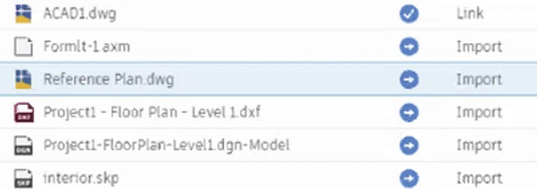
Revit now offers better management of imported CAD files with the new “Show Imported CAD” feature. Imported CAD files (DWG, DXF, DGN, SKP, AXM) are categorized in the Manage Links dialog, allowing users to “Show” or “Remove” imported files via the right-click menu. Import categories now clearly distinguish between linked and imported
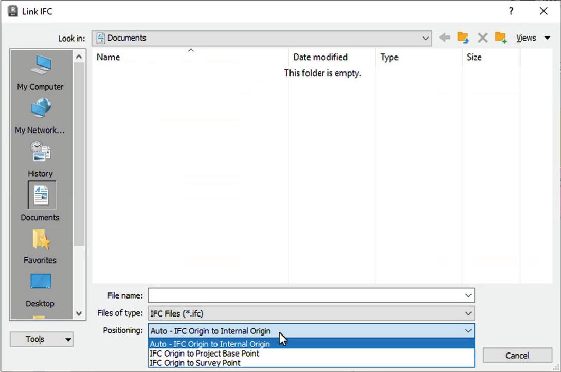
Figure 10 - Coordination Model Overrides
Figure 11 - Link vs Import in Manage Links
Figure 12 - IFC Orientation
SUSTAINABILITY
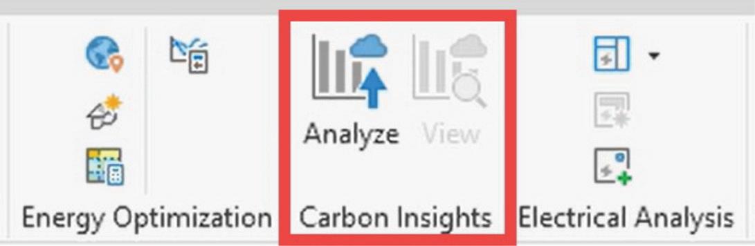
Sustainability and Carbon Analysis see major updates with the replacement of Autodesk InsightGBS by the new Next-Gen Insight (Total Carbon) system and is now embedded within Revit. InsightGBS was discontinued, with no new analysis after April 2, 2025. You can still view/download previous analyses until full access is removed on July 1, 2025. The new system integrates embodied and operational carbon calculations and provides embedded Insight tools directly within Revit 2026. This includes embodied carbon breakdowns and open dashboards, aligning Revit with the growing emphasis on sustainability and environmental responsibility.
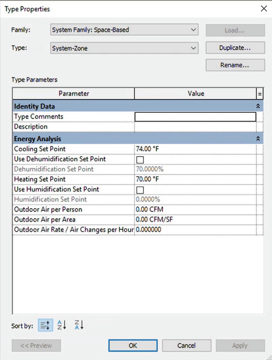
HVAC System Zoning Upgrades bring enhanced zoning capabilities for HVAC engineering. The new HVAC System Zones replace the old distinction between HVAC and System Zones, supporting creation via sketching or space selection. Instancelevel properties, such as Occupied Area, Outdoor Air Rate, and Energy Set Points (Cooling, Heating, Dehumidification), have been added and support IFC export for better interoperability. The sketchbased zoning feature allows System Zones to be independent of architectural elements.
MEPF DESIGN
Because I do not use Fabrication in Revit, I will not be covering any of those enhancements and features. In Revit 2026, compared to previous years, there are actually a decent number of updates for MEPF, mostly for Electrical to be exact. Globalizing electrical conductors brings several key enhancements. Multi-core cables are now supported, users can manually control conductor sizes, and wire type and wire size have been replaced by cable type and cable size, with the voltage drop parameter removed. These changes bring global standards into Revit’s electrical workflows, increasing flexibility for international projects.
The ability to define and use cables for any system type has also been improved. A new MEP settings dialog allows users to define cable types and sizes, and parallel cables are now supported with the option to specify multiple parallel cables per circuit. Additionally, improved material and insulation settings include conductor details such as material and temperature ratings. This update significantly expands electrical modeling capabilities, allowing for more precise specifications.

Figure 13 - Embedded Carbon Insights
Figure 14 - Zone Type Parameters
Figure 15 - Electrical Conductor and Cable Settings
Electrical models have been upgraded with automatic conversion of wire size parameters into cable types and sizes, and cable data is now used in circuits, schedules, and panel layouts. This makes upgrading existing projects more seamless, ensuring compatibility with Revit 2026’s electrical modeling improvements.
Wire types have been streamlined for wiring purposes. Wire types now exist only for drawing wires and are managed in the project browser, with wire sizing settings removed from electrical settings. This simplification enhances electrical workflows by focusing wire types solely on schematic design instead of physical modeling.
Apparent power calculation for analytical loads has been enhanced with new power calculation methods, allowing users to choose between true or apparent power. The analytical loads now default to a power factor of 1.0. These updates provide more accurate power distribution insights, enhancing electrical analytical modeling.
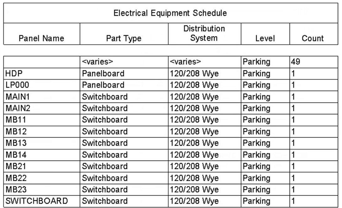
Distribution system and part type have been incorporated into schedules, allowing them to be filtered and sorted by these attributes. Improved equipment categorization now enables more effective scheduling of switchboards, panels, and transformers. These enhancements improve electrical documentation, making it easier to manage large projects.
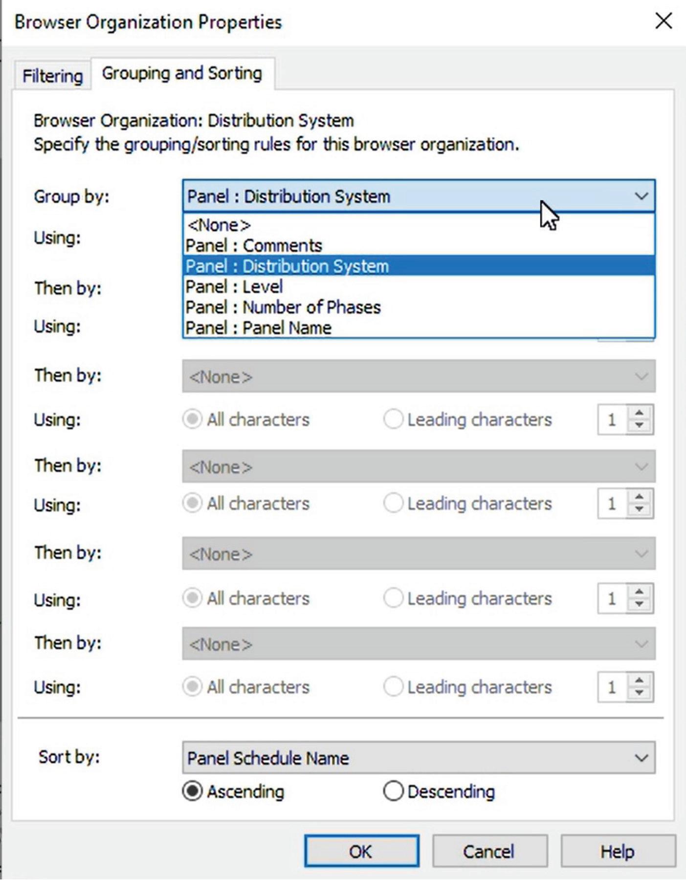
Browser organization for panel schedules has been enhanced, with schedules now able to be grouped by level and distribution system. New filtering by the number of phases, as well as project parameters and shared parameters, are now available for grouping. This improves electrical schedule organization, particularly for complex multi-phase systems.
The electrical circuit path with nested families has been improved, with circuit paths now correctly routing to the nested family location, fixing the previous issue where circuits incorrectly routed to the project origin. This enhancement increases electrical modeling accuracy and reduces documentation errors.
Tagging and view filters have also been upgraded to support distribution system attributes, and view filters can now distinguish between different panel types. This improves coordination and visualization, making electrical documentation more efficient.
Lastly, MEP categories display improvements ensure that fire protection, medical equipment, audio-visual, and signage categories now behave consistently with MEP views. Families display correctly in plan views, and elements no longer show as halftone underlays, improving MEP visualization and ensuring correct representation across different views.
Figure 16 - Distribution System and Part Type in Schedule
Figure 17 - Panel Schedule Browser Organization Options
CONCLUSION
In conclusion, Revit 2026 represents a significant leap forward in the architecture, engineering, and construction industries. Revit 2026, featuring advanced graphics acceleration, an optimized user interface, and comprehensive new functionalities, is set to transform the approach professionals take towards their projects. The updates not only improve performance and usability but also ensure greater accuracy and efficiency across all stages of design and construction.
From the intuitive architectural modeling tools to the advanced sustainability and carbon analysis features, Revit 2026 addresses the evolving needs of the industry. The seamless integration of MEP design to fabrication, along with the refined structural analysis and detailing capabilities, ensures that every aspect of a project is meticulously planned and executed. The improvements in collaboration, documentation, and coordination further enhance the overall workflow, making Revit 2026 an indispensable tool for modern professionals.
As the industry continues to advance, Revit 2026 stands out as a powerful ally, providing the tools and capabilities needed to bring innovative visions to life. Whether you’re an architect, engineer, or construction professional, Revit 2026 offers the
precision, flexibility, and efficiency required to excel in today’s competitive landscape. Embrace the future of design and construction with Revit 2026 and experience the transformative impact it can have on your projects.

Jason Peckovitch is an Autodesk Revit Certified Professional for Mechanical and Electrical Design located in SE Iowa. He is a BIM Manager for Garver’s Buildings Business Line, specifically MEPF. Garver has more than 50 offices across the United States and more than 1300 employees. His CAD/BIM career spans over 25 years, and he transitioned to the AEC Industry in 2007 as a Mechanical HVAC Drafter before moving into BIM Management, where he has been working since. Jason is also the father of three children; Shelby – 13, Blake – 10 and Logan - 7, a published photographer, gamer, and car/ tech guy. He can be reached at jmpeckovitch@garverusa.com, found on X under the handle ThatBIMGuy, connect with him on LinkedIn or several other user platforms like AUGI Community or BIM Heroes.


AUGIWORLD brings you recent developments in Autodesk and related software items