
www.autonics.com
PRODUCT
NEW
GUIDE
Safety Light Curtains SFL/SFLA Series
Safety Controllers SFC/SFC-R Series
Safety Switches SFD/SFDL/SFN/SF2ER Series
Smart Cameras VC Series
LiDAR LSC Series
Photomicro Sensors BS3 Series
Displacement Sensors BD Series
CONTENTS 4 6 7 8 10 12 13
Proximity Sensors PRD Series (IO-Link)
Remote I/O System ADIO Series
Power Controllers SPRM Series HMI GP/LP-A Series
Temperature Controllers TN Series
Closed Loop Stepper Motor System AiC-EC Series
PRODUCT
15 16 18 20 21 22
SPECIFICATIONS 14
SFL/SFLA Series
Safety Light Curtains
The SFL/SFLA series safety light curtains are installed in poten tially dangerous or hazardous areas or machines to safeguard personnel from injury. The light curtains feature ▲finger/hand/ body detection types ▲various protection height (144 mm to 1,868 mm) ▲15 m long sensing distance ▲various safetyrelated functions ▲top control output indicator & status display ▲IP65, IP67, IP67G protection structure for diverse applications.

※ Safety Rating
IEC 61496-1/2, IEC/EN 61508(SIL 3), IEC/EN 62061(SIL CL 3), ISO 13849-1/2(Cat.4, PL e)
▶ Product Specifications p.22 ᜢ ᜨ ᜪ

SFC/SFC-R Series Safety Controllers
The SFC/SFC-R series safety controllers are used together with safety input devices (switches, sensors, etc.) to provide safe working environments. The controllers feature ▲17.5 mm slim size ▲front terminal design ▲up to 20 logic inputs ▲flexible

OFF-delay output ▲safety circuit design to meet safety standards.
※ Safety Rating
IEC/EN 61508(SIL 3), IEC/EN 62061(SIL CL 3), ISO 13849-1/2(Cat 4. PL e), IEC/EN 60947-5-1, IEC/EN 61000-6-2/4, EN 50178
※ Lineup : standard unit/high performance unit/non-contact door switch unit/expansion relay unit/relay unit
6 Autonics
▶ Product Specifications p.23 ᜢ ᜨ
ᜪ
Door Switches SFD Series
Door Lock Switches SFDL Series Non-contact Switches SFN Series
Emergency Stop Button Switches SF2ER Series
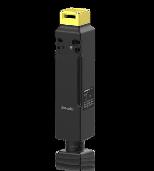
SFD/SFDL/SFN/SF2ER Series
Switches
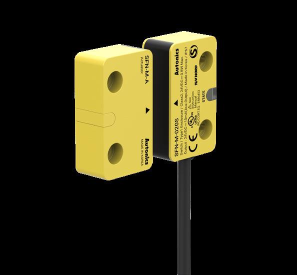
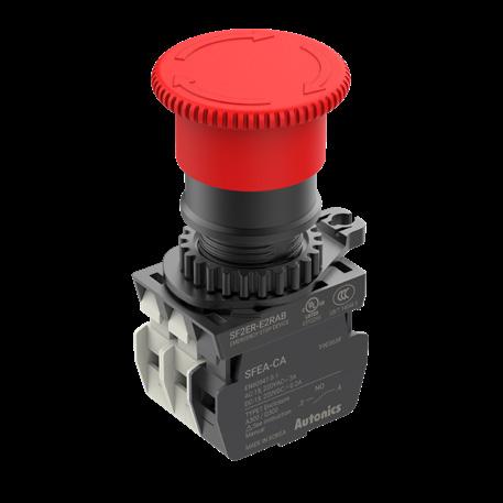
The safety switches are available in door/door lock switches, non-contact switches and emergency stop button switches.

▲The SFD/SFDL series can detect opening and closing of doors in machines offering 5 key insert directions and 6 operation key types. ▲The SFN series can be used with dedicated controllers for multiple connection of up to 30 units. ▲The SF2ER series offer mesh contact with sliding structure allowing prolonged use without contact deterioration.
※ Safety Rating
SFD/SFDL Series: IEC/EN 60947-5-1, EN ISO 14119
SFN Series : IEC/EN 60947-5-3, IEC/EN 61000-6-2/4, EN ISO 14119
SF2ER Series : IEN/EN 60947-5-1/5, EN ISO 13850
7 New Product Guide
Safety
1 2 3 4
▶ Product Specifications p.24 ᜢ ᜨ ᜪ (Except SFN Series) (Except SFN, SF2ER Series)
1 2 3 4
VC Series
Smart Cameras
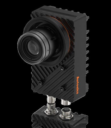
The VC series smart cameras utilize images captured by the integrated industrial camera lenses to determine the target object's code, OCR/OCV, patterns, alignment, presence, size, shape and more. The smart cameras feature ▲14 types of inspection functions ▲global shutter method ▲inspection simulator function ▲set up to 64 workgroups ▲optimized for heat dissipation ▲save data to FTP servers.
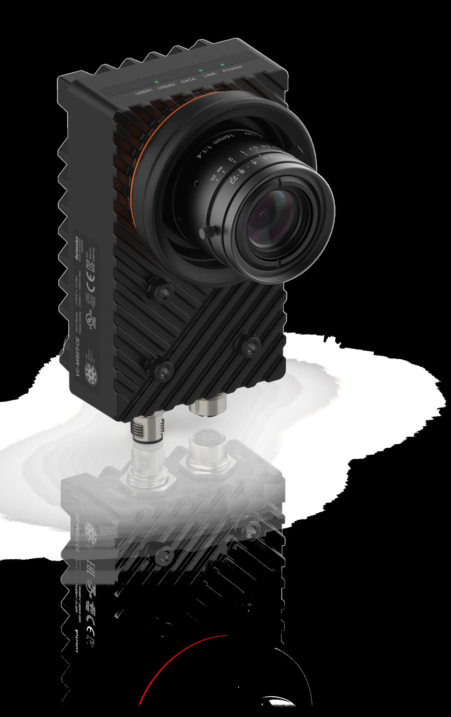
8 Autonics
ᜢ ᜨ
▶ Product Specifications p.26


LSC Series
The LSC series laser scanners measure the round trip time of the infrared laser beam to accurately detect presence of objects within a wide range area. It can be used to detect presence or entry of people and to prevent the collision of AGV (Automated Guided Vehicle). The laser scanner feature ▲270° detection angle and up to 25 m detection distance ▲teaching button for setting detection area ▲up to 16 of field setting.

LiDAR ▶ Product
Specifications p.27 *Bluetoothmodelavailabilitymaydifferbycountry ᜢ
BS3 Series
Photomicro Sensors
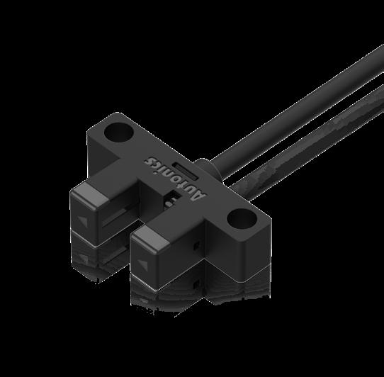
The BS3 series ultra-compact photomicro sensors are available in 5 different shapes (K, F, R, U, L types), offering maximum flexi bility for various user applications and installation settings. The sensors feature ▲operation indicator on multiple directions ▲ high resistance to shock and vibration ▲minimized detection errors occurring from foreign substances ▲2 kHz high-speed response frequency.

ᜢ ᜨ ▶ Product Specifications p.27
BD
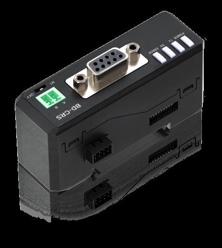
The BD series laser displacement sensors can measure thick ness, width, level difference, disparity, curve, evenness of target objects by detecting the amount of displacement. The sensors feature ▲1㎛ maximum resolution ▲max. 100±20 mm measurement range ▲0.1% of F.S. linearity ▲various calculation functions ▲easy configuration with movement average, deferential and median filters.

Amplifier Unit BD-A1 Sensor Head BD-030/065/100
Communication Converter BD-C Series
Laser Displacement Sensors ▶ Product Specifications p.28 ᜢ (BD-C Series)
Series
PRD Series (IO-Link)
Proximity Sensors
The PRD series cylindrical inductive proximity sensors are available in standard and IO-Link communication models. The sensors feature ▲easy maintenance by checking individual sensor ID for misconnection, disconnection, and installation errors. ▲predictive maintenance to prevent malfunction ▲reduce downtime by checking the location and cause of the sensor ▲various cable types ▲Bi-Color LED indicator.


14 Autonics
ᜢ ᜨ
Product Specifications
▶
p.29
ADIO Series
Remote I/O System
The ADIO series remote I/O boxes transmit various input and output signals between master devices such as PCs or PLCs and secondary devices including sensors and actuators. The IO-Link master type ADIO-ILD can exchange signals from secondary devices (IO-Link, standard I/O) to industrial networking protocols (EtherCAT, EtherNET/IP, PROFINET).
The ADIO series feature ▲IO-Link 8 channels, digital input 16 channels, digital output 8 channels ▲Push-Pull connector type ▲IP67, IP69K protection structure.

ᜢ ᜨ ▶ Product Specifications p.30
SPRM Series
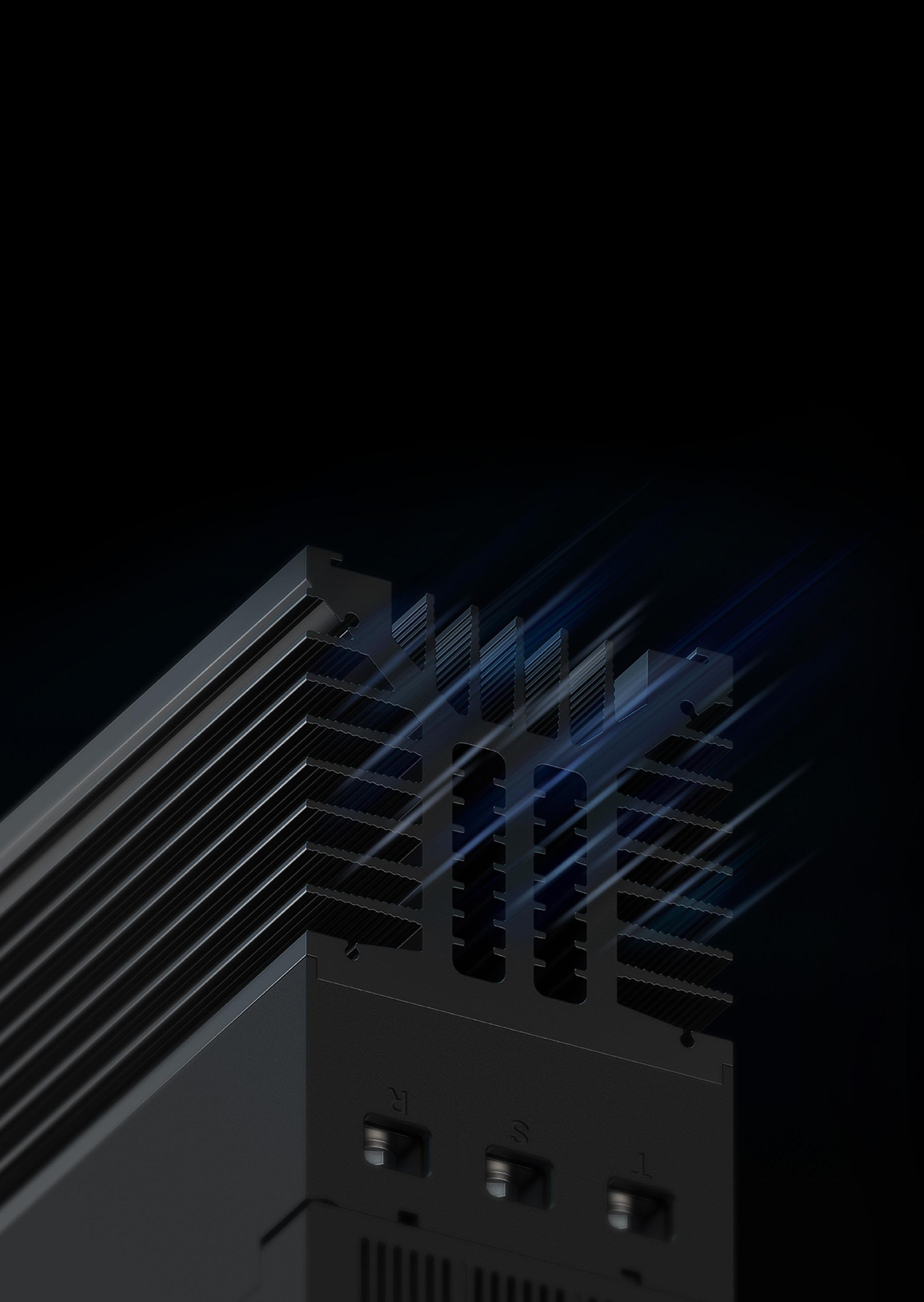
The SPRM series power controllers are used to control the amount of electric currents in devices such as heaters, furnaces, thermostats, or motors. The power controllers feature ▲single-phase/three-phase control ▲real-time monitoring load current/voltage/output/heatsink temperature/ power ▲cycle control, phase control method with feedback control (constant current, constant voltage, constant power) ▲RS485, EtherCAT communication supported.
▶ Product Specifications p.32 ᜢ ᜨ
Power Controllers


18 Autonics
GP/LP-A Series
HMI
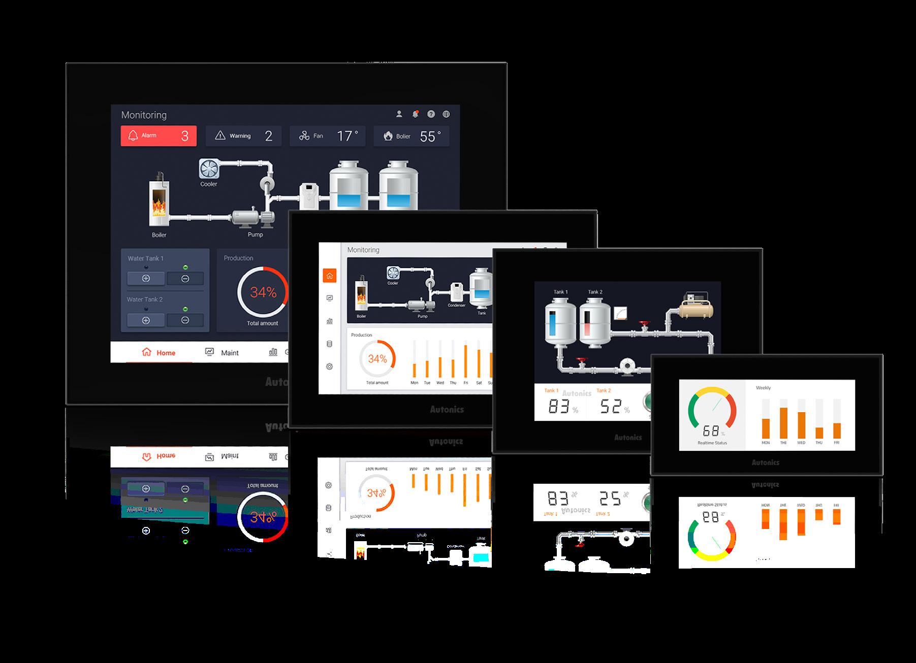
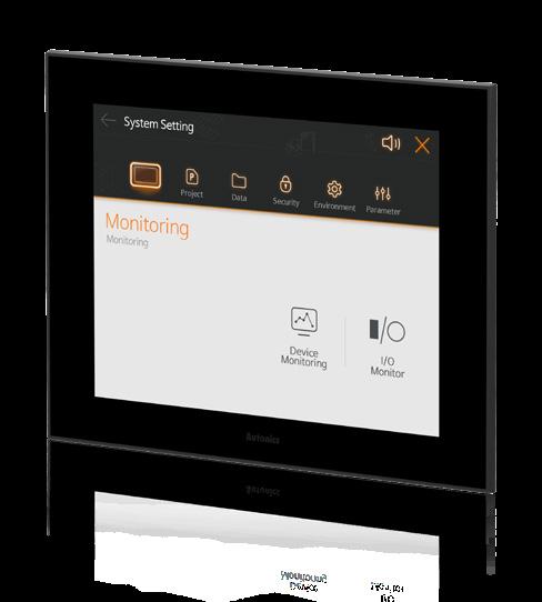
Graphic/Logic panels provide users with an interface to directly interact with machines in order to control and monitor various processes. The panels feature ▲available in 4.6-inch, 5.7-inch, 7-inch, 10.4-inch ▲TFT LCD True Color display ▲various communication interfaces : RS232C, RS422/485, Ethernet, CAN(10.4-inch) ▲script, schedule, interlock functions ▲PLC, HMI, and I/O modules functions (LP-A) for diverse applications.
※

Screen Sizes
GP-A Series : 4.6-inch, 5.7-inch, 7-inch, 10.4-inch
LP-A Series : 7-inch, 10.4-inch
19 New Product Guide
ᜢ
▶ Product
Specifications p.33
TN Series
Temperature Controllers
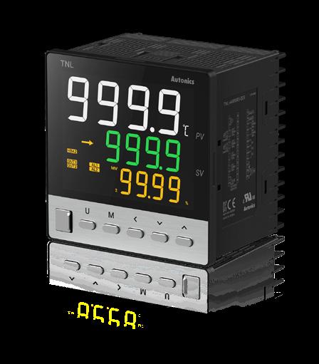
The TN series programmable temperature controllers are used to identify measured temperature and release output to maintain desired temperatures. The temperature controllers feature ▲50/100/250 ms sampling cycle ▲Zone PID, Group PID functions ▲maximum of 10 patterns (20 steps) program control ▲6 alarm output options for stable temperature control.

20 Autonics
▶ Product Specifications p.34 ᜢ
AiC-EC Series
Closed Loop Stepper Motor System
The AiC-EC series Ai-SERVO closed-loop stepper motors with EtherCAT support offers high compatibility between primary and secondary devices with EtherCAT open protocol. The AiC-EC series feature ▲multi-axis simultaneous control with 100 Mbps communication speed ▲closed-loop system with real-time position control ▲high speed and high torque drive without missed step.
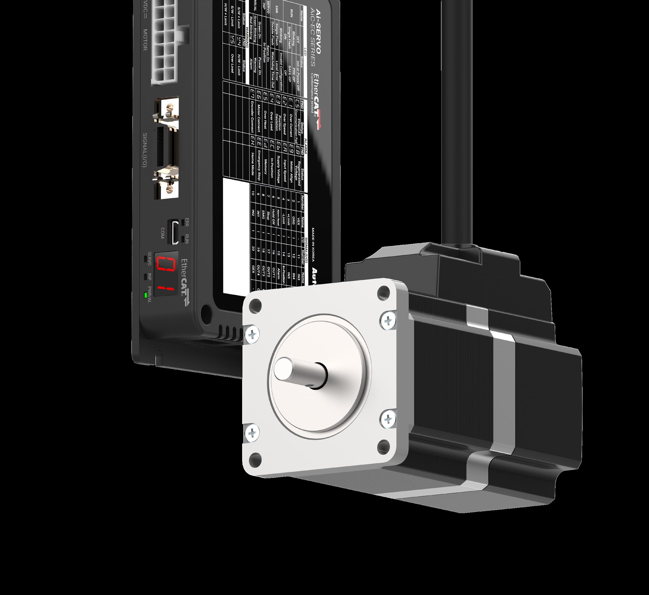
21 New Product Guide
▶ Product Specifications p.35 ᜢ
PRODUCT SPECIFICATIONS
Safety Light Curtains SFL/SFLA Series

Type Standard type
Models SFL14-□-□ SFL20-□-□ SFL30-□-□
Sensing type Through-beam Light source Infrared LED (855 nm)
Effective aperture angle (EAA) Within ± 2.5 ° when the sensing distance is greater than 3 m for both emitter and receiver.
Sensing distance Short - Long mode (setting switch)
Short mode 0.2 to 5 m 0.2 to 8 m 0.2 to 8 m
Long mode 0.2 to 10 m 0.2 to 15 m 0.2 to 15 m
Detection capability Ø 14 mm (finger) Ø 20 mm (hand) Ø 30 mm (hand-body)
Detection object Opaque object
Number of optical axes 15 to 111 12 to 68 42 to 75
Protective height 144 to 1,008 mm 183 to 1,023 mm 1,043 to 1,868 mm
Optical axis pitch 9 mm 15 mm 25 mm
Series connection Max. 3 SET (≤ 300 optical axes)
Type Advanced type
Models SFLA14-□-□ SFLA20-□-□ SFLA30-□-□
Sensing type Through-beam
Light source Infrared LED (855 nm)
Effective aperture angle (EAA) Within ± 2.5 ° when the sensing distance is greater than 3 m for both emitter and receiver.
Sensing distance Short - Long mode (setting switch or atLightCurtain)
Short mode 0.2 to 5 m 0.2 to 8 m 0.2 to 8 m
Long mode 0.2 to 10 m 0.2 to 15 m 0.2 to 15 m
Detection capability Ø 14 mm (finger) Ø 20 mm (hand) Ø 30 mm (hand-body)
Detection object Opaque object
Number of optical axes 01) 15 to 199 12 to 124 9 to 75
Protective height 144 to 1,800 mm 183 to 1,863 mm 218 to 1,868 mm
Optical axis pitch 9 mm 15 mm 25 mm
Series connection Max. 4 SET (≤ 400 optical axes)
01) It may differ depending on the models. For more information, refer to the "SFL/SFLA User Manual."
Power supply 24 VDCᜡ ± 20 % (Ripple P-P: ≤ 10 %)
Current consumption 01) Emitter: ≤ 106 mA, receiver: ≤ 181 mA Response time 01) TOFF (ON → OFF): ≤ 32.3 ms, TON(OFF → ON): ≤ 76.6 ms
Safety related output : OSSD output
Auxiliary output (AUX 1/2) 05)
Lamp output (LAMP 1/2) 05)
External input
NPN or PNP open collector Load voltage 02): ON - 24 VDCᜡ (except for the residual voltage), OFF - 0 VDCᜡ, Load current 03): ≤ 300 mA, Residual voltage 04): ≤ 2 VDCᜡ (except for voltage drop due to wiring), Load capability: ≤ 2.2 ㎌, Leakage current: ≤ 2.0 mA, Wire resistance of load: ≤ 2.7 Ω
NPN or PNP open collector Load voltage: ≤ 24 VDCᜡ, Load current: ≤ 100 mA, Residual voltage: ≤ 2 VDCᜡ (except for voltage drop due to wiring)
NPN or PNP open collector Load voltage: ≤ 24 VDCᜡ, Load current: ≤ 300 mA, Residual voltage: ≤ 2 VDCᜡ (except for voltage drop due to wiring), Incandescent lamp: 24 VDCᜡ / 3 to 7 W, LED lamp: Load current ≤ 10 to 300 mA (VF: ≤ 1.5 VDCᜡ)
Reset input, mute 1/2 input, EDM, external test
When setting NPN output ON: 0 - 3 VDCᜡ, OFF: 9 - 24 VDCᜡ or open, short-circuit current: ≤ 3 mA When setting PNP output ON: 9 - 24 VDCᜡ, OFF: 0 - 3 VDCᜡ or open, short-circuit current: ≤ 3 mA
Protection circuit Reverse power polarity, reverse output polarity, output short-circuit over-current protection
Safety-related functions Interlock (reset hold), external device monitoring (EDM), muting/override, Blanking (fixed blanking, floating blanking), reduced resolution
General functions Self-test, alarm for reduction of incident light level, mutual interference prevention
Others functions Change of sensing distance, switching to NPN or PNP, external test (light emission stops), auxiliary output (AUX 1, 2), lamp output (LAMP1, 2)
Synchronization type Timing method by RS485 synchronous line
Protection rating 06) IP65, IP67 (IEC standard), IP67G (JEM Standard), IP69K (DIN standard)
Material Case: Aluminum, Front cover and sensing part: Polymethyl methacrylate, End cap: polycarbonate, Power I/O cable and connector cable: polyurethane (PUR) or polyvinyl chloride (PVC), Y type connector cable: polyvinyl chloride (PVC), lamp output cable and series connector cable: polyurethane (PUR)
Approval ᜢ ᜨ ᜪ 07)
International standards UL 508, CSA C22.2 No. 14, ISO 13849-1 (PL e, Cat. 4), ISO 13849-2 (PL e, Cat. 4), UL 61496-1 (Type 4, ESPE), UL 61496-2 (Type 4, AOPDs), IEC/EN 61496-1 (Type 4, ESPE), IEC/EN 61496-2 (Type 4, AOPDs), IEC/EN 61508-1~-7 (SIL 3), IEC/EN 62061 (SIL CL 3)
01) It may differ depending on the models. For more information, refer to the "SFL/SFLA User Manual."
02) The values of load voltage were drawn with PNP output, and in case of NPN output, apply these in reverse.
03) Be sure that the load current should be greater than 6 mA.
04) The residual voltage was drawn with 300 mA of load current.
05) It is the non-safety output. Do not use it for safety purposes.
06) Approved certification protection ratings are IP65 and IP67.
07) The model SFL□-□-A is KCs certified. The certified models for S mark and KCs have the same functional basis. Refer to the “SFL/SFLA User Manual.”
22 Autonics
Safety Controllers SFC/SFC-R Series
Unit Basic Advanced Non-contact door switch
Model SFC-422-□ SFC-A322-2□-□ SFC-N322-2□-□
Power supply 24 VDCᜡ
Allowable voltage range 85 to 110% of rated voltage
Power consumption 01) ≤ 2.5 W ≤ 3.0 W ≤ 3.5 W
Input ON: ≥ 11 VDCᜡ ≥ 5 mA, OFF: ≤ 5 VDCᜡ ≤ 1 mA
Input time ≥ 50 ms, feedback start (manual) : ≥ 100 ms
Cable ≤ 100 m (≤ 100Ω, ≤ 10nF)
Safety output P channel FET 02)
Instantaneous 4 × 3 × 03) 3 × 03)
Off-delay 04) 2 × 03) 2 × 03)
Time accuracy ≤ ± 5% ≤ ± 5%
Load current Below 2-point output: ≤ DC 1 A, Over 3-point output: ≤ DC 0.8 A
Leakage current ≤ 0.1 mA
Operating time (OFF → ON) 05)
Safety input: ≤ 50 ms Logic input: ≤ 200 ms
Response (return) time (ON → OFF) 05) ≤ 15 ms, non-contact door switch input or logic input: ≤ 20 ms
Non-contact door switch input: ≤ 100 ms
Logical AND connections No. of connections: max. 4 units, no. of total connections: max. 20 units No. of layers: max. 5 layers, cable length: ≤ 100 m SFN connections 06) Max. 30 units
Approval
IEC/EN 61508 (SIL3), IEC/EN 62061 (SILCL3) IEC/EN 60947-5-1, EN ISO 13849-1 (Category 4, PLe) UL listed E249635
Certification ᜢ ᜨ ᜪ
Unit weight (package) ≈ 70 g (≈ 120 g) ≈ 90 g (≈ 140 g) ≈ 100 g (≈ 150 g)
01) Not include the power consumption of loads. (SFC-N exclude the power supplied to the non-contact door switch.)
02) Includes a diagnostic pulse (max. 600 ㎲). Be cautious when using the output signal as an input signal for the control device.
03) Available changing via setting switch on the back side of the product.
04) Available to set Off-delay time (max. 3 sec. / 300 sec., depends on model)
P-CHFET safetyoutput
≈ 50 ms Max. 600 ㎲
05) The operation (response) time of each model. The time increases when a logical connection or expansion relay unit is connected.
06) SFC-N units can only be connected to Autonics non-contact door switch units SFN Series.
Unit Expansion relay Relay Model SFC-ER412-□ SFC-R412-□ SFC-R212-□ SFC-R212-R2□-□
Power supply 24 VDCᜡ
Allowable voltage range 85 to 110% of rated voltage
Power consumption 01) ≤ 2.5 W ≤ 4.0 W ≤ 4.0 W ≤ 6.0 W
Input ON: ≥ 11 VDCᜡ ≥ 5 mA, OFF: ≤ 5 VDCᜡ ≤ 1 mA
Input time ≥ 50 ms, feedback start (manual) : ≥ 100 ms
Cable ≤ 100 m (≤ 100Ω, ≤ 10nF)
Safety output Relay (A contact) Relay (A contact)
Instantaneous 4 × 4 × 2 × 2 ×
Off-delay 02) 2 ×
Time accuracy ≤ ± 5%
Capacity 240 VACᜠ 5 A resistance load, 30 VDCᜡ 5 A resistance load
Life expectancy Mechanical: ≥ 10,000,000 operations, Malfunction: ≥ 50,000 operations
Contact resistance ≤ 100 mΩ
Inductive load switching IEC60947-5-1: AC-15(230 V/2 A), DC-13(24 V/1.5 A), UL508: B300/R300
Conditional short-circuit current 100 A 03)
Operating time (OFF → ON) 04) ≤ 30 ms 05) ≤ 100 ms
Response (return) time (ON → OFF) 04)
a logical connection or expansion relay unit is connected. 05) Except operation time of advanced unit, non-contact door switch unit

Pollution 3
Overvoltage category III
Impulse withstand voltage for relay unit (IEC/EN 60947-5-1)
Dielectric strength
Input terminals and relay output terminals: 6 kV
Relay contacts between 13-14 / 23-24 and 33-34 / 43-44 (37-38 / 47-48): 6 kV between 13-14 and 23-24: 4 kV between 33-34 and 43-44 (37-38 and 47-48): 4 kV
[Basic / Advanced / Non-contact door switch unit]
Between all terminals and case: 500 VACᜠ 50/60 Hz for 1 min.
[Expansion relay / Relay unit]
Between all terminals and case: 1,500 VACᜠ 50/60 Hz for 1 min.
Between input terminals and output terminals 01): 2,500 VACᜠ 50/60 Hz for 1 min.
01) In case of relay unit, output terminals between 13-14, 23-24 and 33-34, 43-44 (37-38, 47-48)
※ The specifications on this guide may be changed
23
New Product Guide
≤
Auxiliary output 1 × PNP
X2 (error) 1 × PNP
X1 Load current ≤ 100 mA ≤ 100
Leakage current ≤ 0.1 mA Expansion units connections Max. 5 units
ᜢ ᜨ ᜢ
Unit weight (package) ≈100g(≈150g) ≈110g(≈160g) ≈80g(≈130g) ≈110g(≈150g) 01) Not include the power consumption of loads. 02) Available to set Off-delay time (max. 3 sec. / 30 sec., depends on model) 03) Use 6 A fast-blow fuse under the IEC 60127 standard as a short-circuit protection device. 04) The operation (response) time of each model. The time increases when
10 ms ≤ 15 ms
transistor:
transistor:
mA
Approval IEC/EN 61508 (SIL3), IEC/EN 62061 (SILCL3) IEC/EN 60947-5-1, EN ISO 13849-1 (Category 4, PLe) UL listed E249635 Certification
ᜨ ᜪ
Safety Door Switches SFD Series
Model SFD-□□-□M20 SFD-□□-□G1/2 SFD-□□-C
Rated voltage/current for load
Resistive load: 6 A/250 VAC , 0.6 A/250 VDC Inductive load (IEC): AC-15 3 A/240 VAC , DC-13 0.27 A/250 VDC

Inductive load (UL): A300, Q300
Directing opening force ≥ 80 N
Directingopening distance ≥ 10 mm
Operating speed 0.05 to 1 m/s
Operating frequency ≤ 20/min
Insulation resistance ≥ 100 MΩ (500 VDCᜡ megger)
Contact resistance ≤ 50 mΩ (initial value)
Impulse dielectric strength Between the terminals: 2 kV (IEC 60947-5-1) Between each terminal and non-live part: 5 kV (IEC 60947-5-1)
Conditional short circuit current 100 A
Life cycle Electrical: ≥ 100,000 operations (240 VACᜠ 6 A) Mechanical: ≥ 1,000,000 operations
Protection structure IP67 01) (IEC standard, except for head)
Material Plastic head - polyamide 6, metallic head - zinc case: polyamide 6, operation key: stainless steel 304
Approval ᜢ ᜨ ᜪ GB/T14048.5 ᜫ
Connection type M20 connector cable G1/2 connector cable M12 plug connector
Unit weight (packaged)
• 1connectionoutletplastic:≈80g(≈120g) metallic:≈110g(≈150g)
• 2connectionoutletplastic:≈110g(≈140g) metallic:≈130g(≈170g)
Plastic: ≈ 85 g (≈ 130 g) Metallic: ≈ 115 g (≈ 160 g)
01) Rated protection structure is for the switch body. Be cautious about preventing the head part from entering the foreign materials such as dust and water.
Safety Door Lock Switches SFDL Series
Model SFDL-□□□-□□ SFDL-□□□-C□□
Directing opening force ≥ 80 N
Directing opening distance ≥ 10 mm
Locking pullout strength ≥ 1,300 N
Operating speed 0.05 to 1 m/s
Operating frequency ≤ 20/min
Mechanical life cycle ≥ 1,000,000 operations (20/min)
Protection structure IP67 01) (IEC standard, except for head)
Material Head: zinc, case: polyamide 66, operation key: stainless steel 304
Approval ᜢ ᜨ ᜪ GB/T14048.5 ᜫ
Accessory SFDL-□□□-□□K (Special type release keyse key) : rotating key
Applicable cable AWG22
Connection type Terminal type
Connector type
Unit weight (packaged) ≈ 375 g (≈ 440 g) ≈ 325 g (≈ 395 g)
01) Rated protection structure is for the switch body. Be cautious about preventing the head part from entering the foreign materials such as dust and water.
Contact block
Rated voltage/current for load Resistive load: 1 A/120 VACᜠ, 0.22 A/125 VDCᜡ Inductive load (IEC): AC-15 1 A/120 VACᜠ, DC-13 0.22 A/125 VDCᜡ Inductive load (UL): C150, R150
Impulse dielectric strength Between the terminals of same polarity: 1.5 kV Between the terminals of different polarity: 1.5 kV Between each terminal and non-live part: 2.5kV
Insulation resistance ≥ 100 MΩ (500 VDCᜡ megger)
Contact resistance ≤ 200 mΩ
Electrical life cycle ≥ 100,000 operations (125 VACᜠ/1 A)
Conditional short-circuit current 100 A
Solenoid
Rated voltage 24 VDCᜡ, class 2
Current consumption Supplying power: 0.26A
Normal: max. 0.2A (approx. 3 seconds after supplying power)
Insulation class Class E
24 Autonics
Safety Non-contact Switches SFN Series
Model SFN-M-□
Operating distance 01) OFF→ON ≥ 5 mm ON→OFF ≤ 15 mm
Approval ᜢ ᜨ ᜪ
Unit weight (packaged)
Cable type (2 m): ≈ 100.5 g (≈ 113.8 g) Cable type (5 m): ≈ 199.5 g (≈ 214.8 g)
Cable connector type: ≈ 58.1 g (≈ 71.6 g)
01) It is rated at 23℃ of ambient temperature, and it may be differed up to ± 20 % by ambient temperature.
Power supply 24 VDCᜡ (± 10 %)
Operating frequency 100 Hz
Power consumption 01) ≤ 400 mA
Auxiliary output PNP open collector output - 24 VDCᜡ, 10 mA
Operation indicator ON: green, OFF: red
Life expectancy ≥ 20,000,000 times (with low load)
Insulation resistance ≥ 50 MΩ (500 VDCᜡ megger)
Protection circuit Surge protection circuit, output short over current protection circuit, reverse polarity protection circuit
Protection structure IP67 (IEC standard)
Connection Cable type / cable connector type model
Cable Ø 5 mm, 5-wire, cable type: 2 m / 5 m, cable connector type: 0.3 m
Wire AWG26 (0.08 mm), 28-core, core diameter: Ø 0.74 mm
Connector spec. M12 plug connector
Material Body/CAP: PC
01) Power to the load is not included.
IEC 61508 SIL 3 IEC 62061 SIL CL 3 ISO 13849-1 PLe Cat.4
Characteristic level / Safety category (with SFC-N322)
- HFT = 1 - Diagnostic Coverage : 99 % (high) - MTTFd = 100 year (high)
- Mission time = 20 year - PFH = 3.88E-09
Safety status in case of error: the switch does not have an internal error recognition function, so it cannot maintain a safety status in the event of error. Error recognition is processed in the connected controller (SFC-N322).
Emergency Stop Button Switches SF2ER Series
Model SF2ER-□□□□-□
Rated voltage/current IEC: AC-15 (220 VACᜠ, 3 A), DC-13 (220 VDCᜡ, 0.2 A) UL: A300, Q300
Contact operating power 3.0 to 8.0 N/ 1 contact
Operation distance 5.0 mm (0/-0.5)
Rotation angle CW (clock
※ The specifications on this guide may be changed
25
New Product Guide
Material
ᜢ
ᜪ Weight
01) Setting and resetting once is counted as one operation. 02) It is only for part from front of the panel. Protection structure is guaranteed only when the switch is installed on flat and smooth surface with mounting holes Ø22mm. 03) It is switch with three contact blocks. Rated current 10 A Rated voltage 24 V 110 V 220 V 380 V AC Resistiveload(AC-12) 10 A 10 A 6 A 3 A Inductiveload(AC-15) 10 A 5 A 3 A 2 A DC Resistiveload(DC-12) 10 A 2 A 0.6 A 0.2 A Inductiveload(DC-13) 1.5 A 0.5 A 0.2 A 0.1 A Rated voltage Through current Current (A) Volt ampere (VA) Making Breaking Making Breaking AC120 V 10 A 60 6 7,200 720 AC240 V 30 3 Rated voltage Through current Current (A) Volt ampere (VA) Making Breaking Making Breaking DC125 V 2.5 A 0.55 0.55 69 69 DC250 V 0.27 0.27
wise) 52˚ Allowable operation frequency 01) Mechanical: 20 times/minute, electrical: 20 times/minute Life cycle Mechanical: ≥ 250,000 times, electrical: ≥ 100,000 times Applicable wire AWG 18 (0.823 mm2) Insulation resistance ≥ 100 MΩ (500 VDCᜡ megger) Protection structure IP65 01) (oil resistant, IEC standards)
Button: PC, body: PA6, lever in fixing unit: PA6 Approval
ᜨ
03) ≈ 66g
Smart Cameras VC Series
Model VC-M50T-CE
Image element 1 inch mono CMOS
Resolution 5 MP (2,560 × 2,048)
Frame per second 16 fps
Bit Depth 8 bit (256 gray level)
Shutter Global shutter
Exposure time 3 μs to 3 sec
Lens type C-Mount
eMMC 8 GB
DDR4 2 GB (LPDDR4), 512 MB (DDR4)
Inspectionworkgroup 64 (simultaneous inspection: 32)
Trigger mode Continuous, External Trigger, Manual, Ethernet, RS232
Communication Ethernet (TCP/IP & Modbus, 10/100/1000Base-T), RS232C
FTP trans. output YES
Indicator Power, LINK, DATA, USER 1, USER 2
Approval ᜢ ᜣ ᜨ
Unit weight (packaged) ≈ 600 g (≈ 780 g)
Power supply 24 VDCᜡ ±10%
Current consumption ≤ 1 A
Rated input signal 24 VDCᜡ ±10%
Output signal NPN-PNP open collector output setting (software)
HS OUT 0 Strobe OUT
HS OUT 1 Inspection complete, Inspection result output (PASS / FAIL), Alarm, Camera work
Load voltage 24 VDCᜡ
Load current ≤ 100 mA
Residual voltage ≤ 2.5 VDCᜡ
Protection circuit Output short overcurrent protection circuit, reverse voltage polarity protection circuit
Protection structure IP67 (IEC standard / When mounting waterproof lens cover)
Connection Connector type
Connector spec. Power I/O: M12 8-pin, Ethernet: M12 8-pin / RJ45 (cable tightening torque: 0.4 N m)
Material Die-cast Aluminum Housing
Components Ethernet connector Cap (screw plug - waterproof) × 1 (tightening torque: 0.4 N m)
26 Autonics
LiDAR LSC Series

Model LSC-C05CT3 LSC-C10CT3 LSC-C25CT3
Environment of use Indoor
Emitting property Infrared laser
Laser class CLASS 1
Wave length band 905 nm
Max. pulse output power 6 W
Beam conversion angle 9.5 mrad
Scanning frequency 15 Hz
Response time Typ. 67 ms
Detection distance 5 m 10 m 25 m
Detection distance of 10 % reflector 5 m 8 m
Detection distance error System error: Typ. ± 60 mm, statistical error: Typ. 20 mm (1 σ)
Min. object size At detection distance of 8 m: ≈ 121 mm
Angular resolution 0.33°
Aperture angle 270°
Object reflectivity > 4 %
Number of field sets 16 (1 set: Consists of subfields 1, 2, 3)
Number of field sets that can be used concurrently 1
Unit weight (package) ≈ 228 g (314 g)
Approval ᜢ, ᜣ
Power supply 9 - 28 VDCᜡ
Power consumption 01) < 4 W
Input 4 Photocoupler inputs - H: ≥ 9 - 28 VDCᜡ, L: ≤ 3 VDCᜡ
Output signal NPN-PNP open collector output setting (software)
Load voltage 9 - 28 VDCᜡ
Load current ≤ 100 mA
Residual voltage ≤ 3.0 VDCᜡ
Protection structure IP67 (IEC standard)
Connector specification Power I / O: M12 12-pin, Ethernet: M12 8-pin
Material Case: AL, Window: PC
01) Excluding power supplied to the load
Photomicro Sensors BS3 Series
Series BS3
Sensing type Through-beam
Sensing distance 5 mm
Sensing target Opaque materials
Min. sensing target ≥ 0.8 mm × 1.8 mm
Hysteresis ≤ 0.05 mm
Response time Received light: ≤ 20 ㎲, Interrupted light: ≤ 100 ㎲
Response frequency 01) 2 kHz
Light source Infrared LED
Peakemissionwavelength
Power
Current
Control
Load
Load
Residual
Protection
Vibration
Shock
1.6 mm
1.8 mm 1.6 mm t=0.2 mm
Protection rating IP50 (IEC standard)
Connection method Cable type
Cable spec. Ø 2.5 mm, 4-wire, 1 m
Wire spec. AWG28 (0.08 mm, 19-core), insulator outer diameter: Ø 0.65 mm
Material Case: PBT, sensing part: PC
※ The specifications on this guide may be changed
27
New Product Guide
940 nm
Operation mode Built-in Light ON / Dark ON Indicator Operation indicator (red)
Approval ᜢ ᜨ Unit weight ≈50 g 01) Response frequency is the value getting from revolving the circle panel below.
supply 5-24 VDCᜡ ±10% (ripple P-P: ≤ 10%)
consumption ≤ 15 mA
output NPN open collector output / PNP open collector output model
voltage ≤ 24 VDCᜡ
current ≤ 50 mA
voltage NPN: ≤ 1.2 VDCᜡ, PNP: ≤ 1.2 VDCᜡ
circuit Reverse power polarity protection circuit, output short overcurrent protection circuit
1.5 mm double amplitude (max. acceleration 196 m/s2) at frequency of 10 to 2,000 Hz in each X, Y, Z direction for 2 hours
15,000 m/s2 (≈ 1,500 G) in each X, Y, Z direction for 3 times
Laser Displacement Sensors BD Series

Sensor head
Model BD-030 BD-065 BD-100
Beam shape Standard
Spot diameter (near) ≈ 290×790 ㎛ (25 mm) ≈ 360×1,590 ㎛ (55 mm) ≈ 480×1,870 ㎛ (80 mm)
Spot diameter (reference) ≈ 240×660 ㎛ (30 mm) ≈ 290×1,180 ㎛ (65 mm) ≈ 410×1,330 ㎛ (100 mm)
Spot diameter (far) ≈ 190×450 ㎛ (35 mm) ≈ 210×830 ㎛ (75 mm) ≈ 330×950 ㎛ (120 mm) Resolution 01) 1 ㎛ 2 ㎛ 4 ㎛
Reference distance 30 mm 65 mm 100 mm
Maximummeasurementrange 20 to 40 mm 50 to 80 mm 70 to 130 mm Rated measurement ranges02) 25 to 35 mm 55 to 75 mm 80 to 120 mm
Temperature characteristic04) 0.05% F.S./℃ 0.06% F.S./℃
Power supply 05)
Light source Red semiconductor laser (wavelength: 660 nm, IEC 60825-1:2014)
Optical method Diffuse reflection
Laser class Class 1 (IEC/EN), Class I (FDA (CDRH) CFR Part 1002) Class 2 (IEC/EN), Class II (FDA (CDRH) CFR Part 1002)
Output ≤ 300 ㎼ ≤ 1 mW
Operation Indicator Power Indicator (red), Laser emission indicator (green), NEAR/FAR indicator (green)
Connection Connector type
Protection structure IP67 (IEC Standards, except connector of extension cable)
Material Case: Polycarbonate, Sensing part: Glass, Cable: Polyvinyl chloride
Amplifier unit
compatibility BD Series amplifier unit: 1
Accessory Ferrite core (made by TDK co. ZCAT2132-1130), Mounting bracket, Bolt, Nut
Approval ᜢ ᜧ ᜫ
Unit weight (packaged) ≈ 56 g (≈ 209 g) ≈ 68 g (≈ 233 g) ≈ 68 g (≈ 233 g)
01) When measuring fixed non-glossy white paper (reference temperature: 25℃, reference distance, response time: 1ms, average 128 times).
02) The rated measurement range guarantees linearity.
03) Value indicates the error with respect to the ideal straight line.
04) Value measured by using an aluminum jig fix the sensor head and non-glossy white paper.
05) Using power from the amplifier unit.
Amplifier unit
Model BD-A1
Power supply 10 - 30 VDCᜡ ±10% (when connecting BD-C Series communication converter, 12-30 VDCᜡ)
Power consumption1) ≤ 2,800 mW (30 VDCᜡ)
Control Input2) Timing / Output reset / Laser OFF / Zero-point adjustment / Bank change: No-voltage input
Judgment output (HIGH/GO/LOW) NPN or PNP open collector output (load current: ≤ 100 mA)
Alarm output NPN or PNP open collector output (load current: ≤ 100 mA)
Analog voltage output3) -5 - 5 V, 0 - 5 V, 1 - 5 V (resistance: 100 Ω, ± 0.05% F.S., at 10 V)
Analog current output3) 4 - 20 mA (load resistance: ≤ 350 Ω, ± 0.2% F.S., at 16 mA)
Residual voltage NPN: ≤ 1.5 V, PNP: ≤ 2.5 V
Protection circuit Reverse polarity protection circuit, output over current (short-circuit) protection circuit
Response Time 0.33 / 0.5 / 1 / 2 / 5 ms
Min. display unit 1 ㎛
Display type 11 segment (red, green), 6-digit, LED
Display range4) ±99.999 mm to ±99 mm (4-step adjustment, parameter)
Display period ≈ 100 ms
Material Case: PC, Cover: PC, cable: PVC
Connection Connector type
Sensorheadcompatibility BD series sensor head: 1
Accessory Mounting bracket, Side connector
Protection structure IP40 (IEC standard)
Approval ᜢ ᜧ ᜫ
Unit weight (packaged) ≈ 126 g (≈ 228 g)
01) Power to the load is not included.
02) Use after assigning to external input line.
03) It is possible to use among -5-5V, 0-5V, 1-5V, 4-20mA by parameter setting.
04) Setting range is assigned automatically when connecting sensor head.
Model BD-CRS
Power supply01)
Power Consumption ≤ 2.3 W
Communication Protocol Modbus RTU
Connection type RS-232C, RS-485
Communication speed 9600, 19200, 38400, 115200 bps (default)
Function ExecuteseveryBD-Seriesfeature,setsparameterandreal-timemonitoringbyexternaldevice(Master)
Protection structure IP40 (IEC standard)
Material Case: PC
Accessory Side connector, Connector for RS485

Sold separately Communication converter: SCM Series
Approval ᜧ ᜣ ᜫ
Unit weight (packaged) ≈ 49 g (≈ 91 g)
01) Using power from the amplifier unit. To use BD-C Series communication converter, the amplifier unit needs 12-30 VDCᜡ power supply.
• It is recommended to use Autonics communication converter. Please use twisted pair wire, which is suitable for RS485 communication.
28 Autonics
Communication Converter for Laser Displacement Sensors BD-C Series
Linearity01)03) ± 0.1% of F.S. ± 0.1% of F.S. ± 0.15% of F.S.
Proximity Sensors PRD Series (IO-Link)

Installation Flush type Model PRD□12-4D-□IL2 PRD□18-7D-□IL2 PRD□30-15D□-IL2 PRD□12-8D-□IL2 PRD□18-14D□-IL2 PRD□30-25D□-IL2
DIA. of sensing side Ø 12 mm Ø 18 mm Ø 30 mm Ø 12 mm Ø 18 mm Ø 30 mm
Sensing distance 4 mm 7 mm 15 mm 8 mm 14 mm 25 mm Setting distance 0 to 2.8 mm 0 to 4.9 mm 0 to 10.5 mm 8 mm 14 mm 25 mm Hysteresis ≤ 10 % of sensing distance Standard sensing target: iron 12 × 12 × 1 mm 20 × 20 × 1 mm 45 × 45 × 1 mm 25 × 25 × 1 mm 40 × 40 × 1 mm 75 × 75 × 1 mm
Response frequency 01) 500 Hz 250 Hz 100 Hz 400 Hz 200 Hz 100 Hz Affection by temperature ≤ ± 10 % for sensing distance at ambient temperature 20 ℃
Indicator 02) IO-Link mode, SIO mode
IO-Link mode Communication indicator (flashing green), operation indicator (orange), Abnormal detect indicator (cross-flashing green, orange)
SIO mode Operation indicator (orange), stable indicator (green), Abnormal detect indicator (cross-flashing green, orange)
Approval ᜢ ᜨ ᜬ ᜢ ᜨ ᜬ ᜢ ᜨ ᜬ ᜢ ᜨ ᜬ ᜢ ᜨ ᜬ ᜢ ᜨ ᜬ
01) The response frequency is the average value. The standard sensing target is used and the width is set as 2 times of the standard sensing target, 1/2 of the sensing distance for the distance.
02) In case of SIO mode, use the device within the range where the stable indicator (green) is ON. If the sensing target is in the too close detection distance, the stable indicator turns OFF, but it is in a stable detection state.
In case of IO-Link mode, use the device within the range where unstable detection (Byte0_bit6) turns 0. If the sensing target is in the too close detection distance, the too close detection (Byte0_bit5) is 1, but it is a stable detection state.
Power supply 12 - 24 VDCᜡ (ripple P-P: ≤ 10 %), operating voltage: 10 - 30 VDCᜡ
Current consumption IO-Link mode: ≤ 25 mA, SIO mode: ≤ 20 mA
Control output ≤ 100 mA
Residual voltage 01) ≤ 2 V
Protection circuit Surge protection circuit, output short over current protection circuit, reverse polarity protection Protection rating IP67 (IEC standard)
Connection Cable / Cable connector / connector models
Cable spec. 02) DIA. of sensing side Ø 12 mm: Ø 4 mm, 4-wire DIA. of sensing side Ø 18 mm, Ø 30 mm : Ø 5 mm, 4-wire Wire spec. AWG 22 (0.08 mm, 60-core), insulator diameter: Ø 1.25 mm
Connector spec. M12 plug connector
Material Standard type cable (black): polyvinyl chloride (PVC), Oil resistant cable (gray): polyvinyl chloride (oil resistant PVC), case / nut: nickel plated brass, washer: nickel plated iron, sensing side: PBT
01) Load current: 100 mA, cable length: 2 m
02) Cable type: 2 m, Cable connector type: 300 mm
IO-Link
Version Ver. 1.1 Class Class A Baud rate COM 2 (38.4 kbps) Min. cycle time 2.3 ms
Data length PD: 2 byte, OD: 1 byte (M-sequence: TYPE_2_2) Vendor ID 899 (0x383)
※ The specifications on this guide may be changed
29
New Product Guide
Communication Interface
Remote I/O System ADIO Series
Electrical/Mechanical specifications
Supply voltage 18 - 30 VDCᜡ
Rated voltage 24 VDCᜡ
Current consumption 2.4 W ( ≤ 216 W)
Supplying current per port ≤ 2 A/Port
Sensor current (US) ≤ 9 A
Dimensions W 66 × H 215 × D 38 mm
Material Zinc Die casting
Ethernet port
Power supply port
PDCT port
M12 (Socket-Female), 4-pin, D-coded, Push-Pull
Number of ports: 2 (IN/OUT)
Supported function: daisy chain
Input: 7/8” (Plug-Male), 5-pin
Output: 7/8” (Socket-Female), 5-pin
Number of ports: 2 (IN/OUT)
Supported function: daisy chain
M12 (Socket-Female), 5-pin, A-coded, Push-Pull
Number of ports: 1
Connection method: USB serial communication
I/O port M12 (Socket-Female), 5-pin, A-coded, Push-Pull

Number of ports: 8
Mounting method Mounting hole: fixed with M4 screw
Grounding method Grounding hole: fixed with M4 screw
Unit weight (packaged) ≈ 700 g (≈ 900 g)
Mode specifications
Mode Digital Input
Number of channels 16-CH (I/Q: 8-CH, C/Q:8-CH)
I/O common NPN / PNP
Input current 5 mA
ON voltage/current Voltage: ≥ 15 VDCᜡ Current: ≥ 5 mA
OFF voltage ≤ 5 VDCᜡ
Mode Digital Output
Number of channels 8-CH (C/Q)
I/O common NPN / PNP
Power supply 24 VDCᜡ (18 - 30 VDCᜡ), Max. 300 mA
Leakage current ≤ 0.1 mA
Residual voltage ≤ 1.5 VDCᜡ
Short circuit protection YES
Mode IO-Link
Input current 2 mA
ON voltage/current Voltage: ≥ 15 VDCᜡ Current: ≥ 2 mA
OFF voltage ≤ 5 VDCᜡ
Protection rating IP67 (IEC standard), IP69K (DIN standard)
Approvals
Approval ᜢ ᜨ ᜣ
Association approval ᜬ
30 Autonics
Communication Interface
Ethernet
Ethernet standard 100BASE-TX
Cable spec. STP (Shielded Twisted Pair) Ethernet cable over Cat 5
Transmission rate 100 Mbps
Cable length ≤ 100 m
Protocol EtherCAT
EtherNet/IP
Ethernet standard 100BASE-TX
Cable spec. STP (Shielded Twisted Pair) Ethernet cable over Cat 5
Transmission rate 10 / 100 Mbps
Cable length ≤ 100 m
Protocol EtherNet/IP
Address settings Rotary switches, DHCP, BOOTP, atIOLink
Factory settings
• IP Address: 192.168.2.3
• Subnet Mask: 255.255.255.0
• Gateway Address: 192.168.2.1 EDS file Download the EDS file at the Autonics website.
PROFINET
Ethernet standard 100BASE-TX
Cable spec. STP (Shielded Twisted Pair) Ethernet cable over Cat 5 Transmission rate 100 Mbps
Cable length ≤ 100 m
Protocol PROFINET
Address settings Rotary switches, DCP, atIOLink
GSDML file Download the GSDML file at the Autonics website.
IO-Link Version 1.1 Transmission rate COM1 : 4.8 kbps / COM2 : 38.4 kbps / COM3 : 230.4 kbps
Port class Class A
Standard IO-Link Interface and System Specification Version 1.1.2 IO-Link Test Specification Version 1.1.2
※ The specifications on this guide may be changed
31
New Product Guide
Power Controllers SPRM Series
Model SPRM3-F□R SPRM3-F□EC
Control phases Single phase 3 Ch or 3-phase
Rated load voltage Free voltage 220 - 440 VACᜠ 50 / 60 Hz
Rated load current 25 / 40 / 55 / 70 / 90 / 110 / 160 A
Display method 5 digit 11 segment LCD (white) × 4, Output BAR
Auto control input DC 4 - 20 mA × 3 Ch, 0 - 5 / 1 - 5 / 0 - 10 VDCᜡ, External adjuster (10 kΩ), RS485, EtherCAT
Manual control input Parameter setting
Digital input (DI) RUN / STOP selectable, AUTO / MANU selectable, RESET
Alarm output 250 VACᜠ 2 A, 30 VDCᜡ 2 A, 1c resistance load

Comm. output RS485 RS485, EtherCAT
Cooling method
Unit weight (packaged)
Rated load current 25 / 40 / 55 A: natural cooling Rated load current 70 / 90 / 110 / 160 A: forced air cooling (with cooling fan)
Rated load current 25 / 40 / 55 A: ≈ 4.75 kg (≈ 5.75 kg)
Rated load current 70 A: ≈ 4.8 kg (≈ 5.8 kg) Rated load current 90 / 110 / 160 A: ≈ 9.42 kg (≈ 10.55 kg)
Approval ᜢ, ᜨ, ᜣ
Control method Phase control Cycle control
Control mode Normal / Constant current feedback / Constant voltage feedback / Constant power feedback
Fixed cycle / Variable cycle
Applied load Resistance load, inductive load Resistance load
Output range 0 to 98 % 0 to 100 %
Output accuracy Varies by control mode
Normal Within ± 10 % F.S. of rated load voltage
Constant current / voltage / power feedback Within ± 3 % F.S. of rated load current / voltage / power
Power supply 24 VDCᜡ ± 10 %
Min. load current 1 A
Power consumption ≤ 15 W
Insulation resistance ≥ 200 MΩ (500 VDCᜡ megger)
Communication Interface
RS485
Comm. protocol Modbus RTU (16 bit CRC), Modbus ASCII
Application standard Compliance with EIA RS485
Max. connection 31-unit (address: 1 to 99)
Comm. synchronous method Asynchronous
Comm. method 2-wire half duplex
Comm. distance ≤ 800 m
Comm. speed 2,400 / 4,800 / 9,600 (default) / 14,400 / 19,200 / 38,400 / 57,600 / 115,200 bps
Comm. response time 0 to 9999 ms (default: 0 ms)
Start bit
Data bit 8 bit (fixed)
Parity bit None (default), Even, Odd
Stop bit 1 bit (default), 2 bit
EEPROM life cycle ≈ 50,000 operations (Erase / Write)
EtherCAT
Comm.
Connection
32 Autonics
specifications EtherCAT
Association approval 01)
class
over
cable CAT5e
or
(Shield type: SF/FTP, S/FTP, SF/UTP)
nodes
Max. comm. distance Within 100 m distance between
Max. baud rate 10 / 100 Mbps
Topology Star, Line, Tree 01) EtherCAT® is registered trademark and patented technology, licensed by Beckhoff Automation GmbH, Germany.
Graphic
Panels GP-A Series
GP-A046 GP-A057 GP-A070 GP-A104
Screen size 4.6 inch 5.7 inch 7.0 inch 10.4 inch
LCD type TFT Color LCD
Resolution 800×320 pixel 640×480 pixel 800×480 pixel 800×600 pixel
Display area 108×43.2 mm 115.2×86.4 mm 154.4×93.44 mm 211.2×158.4 mm
Display color 16,777,216 color 262,144 color 16,777,216 color 16,777,216 color
LCD view angle (top/bottom/left/right)
Within 75°/70°/80°/80° of each
Backlight White LED
Luminance adjustment Adjustable by software
Touch Resistive type (4-wire)
Approval ᜢ ᜣ ᜫ
Serial interface RS232C, RS422
Within 70°/70°/80°/80° of each Within 50°/60°/65°/65° of each Within 60°/70°/80°/70° of each
USB interface USB Host, USB Device(USB2.0)
Ethernet interface IEEE802.3(U), 10/100Base-T
CAN interface 24V CAN transceiver
External storage Micro SD up to 32GB (FAT16/32)
Real-time controller RTC embedded
Battery life cycle 3 years at 25℃
Supportive interface can be different up to model. For the detailed information, please refer to 'Ordering Information'.

Logic Panels LP-A Series
LP-A070-T9D□-C5□
LP-A104-T9D□-C6□
Screen size 7.0 inch 10.4 inch
LCD type TFT Color LCD
Resolution 800×480 pixel 800×600 pixel Display area 154.4×93.44 mm 211.2×158.4 mm
Display color 16,777,216 color
LCDviewangle (top/bottom/left/right) Within 50°/60°/65°/65° of each Within 60°/70°/80°/70° of each
Backlight White LED
Luminanceadjustment Adjustable by software
Touch Resistive type (4-wire)
Approval ᜢ ᜣ ᜫ
Serial
Real-time
Supportive
※ The specifications on this guide may be changed
33
New Product Guide
RS422
USB
USB
interface RS232C,
USB interface
Host,
Device (USB2.0) Ethernet interface IEEE802.3(U), 10/100Base-T CAN interface 24V CAN transceiver
External storage Micro SD up to 32 GB (FAT16/32)
controller RTC embedded
Battery life cycle 3 years at 25℃
interface can be different up to model. Please refer to ‘Ordering Information’ for the supportive interface per model and ‘LP-A Series user manual’ and ‘GP/LP user manual for communication’ for the detailed information about each interface.
Temperature Controllers TN Series
Model TNS TNH TNL
Size DIN W48 X H48 mm DIN W48 X H96 mm DIN W96 X H48 mm
Power supply 100 - 240 VACᜠ, 50/60 Hz ±10%
Power consumption ≤ 8 VA
Display type 11 segment, LCD type (operating value display part: 7 segment)
Sampling period 50 / 100 / 250 ms (parameter)
Input specification Refer to 'Input Type and Using Range'
Option input
Control output
Option output
CT • 0.0-50.0 A (primary current measurement range)
Digital
• CT ratio: 1/1,000
• Measurement accuracy: ±5% F.S. ±1digit
• Contact - ON: ≤ 2 kΩ, OFF: ≥ 90 kΩ
• Non contact - residual voltage ≤ 1.0 V, leakage current ≤ 0.1 mA
• Outflow current: ≈ 0.5 mA per input
Relay 250 VACᜠ 3A 1a
SSR 12 VDCᜡ ±2 V, ≤ 20 mA
Current DC 0 - 20 mA or DC 4 - 20 mA (parameter), Load resistance: ≤ 500 Ω
Alarm 250 VACᜠ 3 A 1a
Transmission DC 4 - 20 mA (load resistance: ≤ 500 Ω, output accuracy: ±0.3% F.S.)
Communication RS485
Type ON/OFF, P, PI, PD, PID
Multi SV ≤ 4 SV
Control type
Program control
Hysteresis
Group PID ≤ 8 group Zone PID 4 zones
ARW (Anti Reset Windup) 50 to 200 %
Program ≤ 10 patterns Step ≤ 200 steps (1 pattern: ≤ 20 steps)
Setting type Time setting
• Thermocouple, RTD: 1 to 100 (0.1 to 100.0) ℃/℉
• Analog: 1 to 100 digit
Proportional band (P) 0.1 to 999.9 ℃ (0.1 to 999.9%)
Integral time (I) 0 to 9,999 sec
Derivative time (D) 0 to 9,999 sec
Control cycle (T)
• Relay / SSRP output: 0.1 to 120.0 sec
• Selectable current or SSR drive output: 1.0 to 120.0 sec
Manual reset 0.0 to 100.0%
Protection structure IP65 (Front panel, IEC standards)
Loader port • TNS: top side • TNH, TNL: front side
Accessory Bracket Unit weight (packaged) • TNS: 128 g • TNH: 184 g • TNL: 301 g
Approval ᜢ ᜧ ᜣ
RS485
Comm. protocol Modbus RTU/ASCII, Sync-Master, PLC ladderless Connection type RS-485, RS-422A
Application standard EIA RS485 compliance with
Maximum connection 32 units (address: 01 to 99)
Synchronous method Asynchronous Comm. Method Two-wire half duplex
Comm. effective range ≤ 800 m
Comm. speed ≤ 115,200 bps
Response time 5 to 99 ms (default: 20 ms)
Start bit 1 bit (fixed)
Data bit 8 bit (fixed)
Parity bit None (default), Odd, Even
Stop bit 1 bit, 2 bit (default)
EEPROM life cycle ≈ 1,000,000 operations (Erase / Write)
• 1 character of ModBus RTU is fixed at 11 bit.
34 Autonics
Closed Loop Stepper Motor System AiC-EC Series
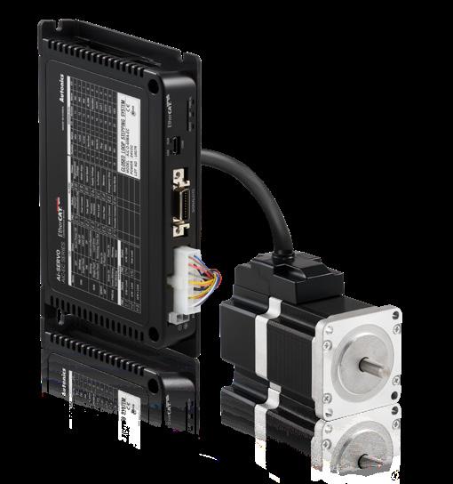
Driver
Model
AiC-D-28SB-EC AiC-D-35SB-EC AiC-D-20MA-EC AiC-D-28MB-EC AiC-D-35MB-EC AiC-D-20LA-EC AiC-D-28LB-EC AiC-D-35LB-EC
Power supply 24 VDCᜡ ±10%
Max. RUN power ≤ 60 W
Stop power01) ≤ 10 W
Max. RUN current02) 0.6 A / Phase
Stop current 20 to 100% of max. RUN current
1.0 A / Phase 1.2 A / Phase
Resolution 500, 1000, 1600, 2000, 3600, 4000, 5000, 6400, 7200, 10000 PPR 500, 1000, 1600, 2000, 3600, 5000, 6400, 7200, 10000, 16000 PPR
Model
AiC-D-42SA-□-EC
AiC-D-56SA-□-EC AiC-D-60SA-□-EC AiC-D-42MA-□-EC AiC-D-56MA-□-EC AiC-D-60MA-□-EC AiC-D-42LA-□-EC AiC-D-56LA-□-EC AiC-D-60LA-□-EC
Power supply 24 VDCᜡ ±10%
Max. RUN power ≤ 60 W ≤ 120 W ≤ 240 W
Stop power01) ≤ 10 W ≤ 12 W ≤ 15 W
Max. RUN current02) 1.7 A / Phase 3.5 A / Phase
Stop current 20 to 100% of max. RUN current
Resolution 500, 1000, 1600, 2000, 3200, 3600, 5000, 6400, 7200, 10000 PPR
01) Based on ambient temp. 25℃, ambient humi. 55%RH, Stop current 50%
02) When changing the load rapidly, instantaneous peak current may increase. The capacity of power supply should be over 1.5 to 2 times of max. power consumption.
Run method 2-phase bipolar closed-loop control method
Speed filter Disable, 2, 4, 6, 8, 10, 20, 40, 60, 80, 100, 120, 140, 160, 180, 200 ms
Motor GAIN 0 to 14, Fine Gain
Max. rotation speed 3,000 rpm
In-Position Fast Response: 0 to 7, Accurate Response: 0 to 7
Operation mode CSP, CSV, PP, PV, HM
Home search
Homing on the limit switch and index pulse Homing on the home switch and index pulse Homing without an index pulse (limit switch) Homing without an index pulse (Home sensor ON) Homing on the index pulse
Set the origin with home offset
Set the origin and reset current position
Torque homing search with home offset
Input Exclusive input: 7, General input: 5
Output Exclusive output: 2, General output: 4
External power supply VEX (Default: 24 VDCᜡ), GEX (GND)
Insulation resistance ≥ 100 MΩ (500 VDCᜡ megger)
Protection rating IP20 (IEC standard)
※ The specifications on this guide may be changed
35
New Product Guide
Communication Interface Ethernet Comm. specifications EtherCAT Association approval01) Connection cable CAT5e class or over (Shield type: SF/FTP, S/FTP, SF/UTP) Max. comm. distance Within 100 m distance between nodes Baud rate 10 / 100 Mbps Max. ID settings02) 99
EtherCAT® is registered trademark and patented technology,
Approval ᜢ ᜣ ᜥ Unit weight (packaged) ≈ 350 g (≈ 500 g)
Topology Star, Line, Tree 01)
licensed by Beckhoff Automation GmbH, Germany. 02) Max. connectable ID from Master is 1 to 65,535.
Motor
Model Ai-M-20MA
Ai-M-20LA
Max. stop torque 0.018 N m 0.035 N m
Rotorinertiamoment 2×10⁻⁷ kg · m2
Rated current 0.6 A / Phase
Basic step angle 1.8° / 0.9° (Full / Half step)
Resistance 6.6 Ω / Phase ±10% 10.5 Ω / Phase ±10% Inductance 2.1 mH / Phase ±20% 4.0 mH / Phase ±20%
Unitweight(packaged) ≈ 0.092kg (≈ 0.192kg) ≈ 0.120kg (≈ 0.219kg)
Model Ai-M-28SB
Ai-M-28MB Ai-M-28LB
Max. stop torque 0.05 N m 0.14 N m 0.16 N m
Rotorinertiamoment 9×10⁻⁷ kg · m2 12×10-7 kg · m2 18×10-7 kg · m2
Rated current 1.0 A / Phase
Basic step angle 1.8° / 0.9° (Full / Half step)
Resistance 5.78 Ω / Phase ±10% 8.8 Ω / Phase ±10% 10.1 Ω / Phase ±10%
Inductance 3.2 mH / Phase ±20% 6.0 mH / Phase ±20% 6.2 mH / Phase ±20%
Unitweight(packaged) ≈ 0.162 kg (≈ 0.260 kg) ≈ 0.222 kg (≈ 0.318 kg) ≈ 0.248 kg (≈ 0.342 kg)
Model Ai-M-35SB
Ai-M-35MB Ai-M-35LB
Max. stop torque 0.07 N m 0.13 N m 0.31 N m
Rotorinertiamoment 8×10⁻⁷ kg · m2 14×10-7 kg · m2 22×10-7 kg · m2
Rated current 1.2 A / Phase
Basic step angle 1.8° / 0.9° (Full / Half step)
Resistance 2.1 Ω / Phase ±10% 3.25 Ω / Phase ±10% 5.0 Ω / Phase ±10%
Inductance 1.25 mH / Phase ±20% 2.85 mH / Phase ±20% 5.6 mH / Phase ±20%
Unitweight(packaged) ≈ 0.180 kg (≈ 0.278 kg) ≈ 0.250 kg (≈ 0.347 kg) ≈ 0.366 kg (≈ 0.456 kg)
Model Ai-M-42SA-□
Ai-M-42MA-□ Ai-M-42LA-□
Max. stop torque 0.25 N m 0.4 N m 0.48 N m
Rotorinertiamoment 35×10-7kg · m2 54×10-7 kg · m2 77×10-7 kg · m2
Rated current 1.7 A / Phase
Basic step angle 1.8° / 0.9° (Full / Half step)
Resistance 1.7 Ω / Phase ±10% 1.85 Ω / Phase ±10% 2.1 Ω / Phase ±10%
Inductance 1.9 mH / Phase ±20% 3.5 mH / Phase ±20% 4.4 mH / Phase ±20%
Unitweight(packaged)01) ≈ 0.34 kg (≈ 0.45 kg) ≈ 0.41 kg (≈ 0.52 kg) ≈ 0.48 kg (≈ 0.59 kg) ≈ 0.67 kg (≈ 0.77 kg) ≈ 0.73 kg (≈ 0.83 kg) ≈ 0.80 kg (≈ 0.90 kg)
Ai-M-56MA-□ Ai-M-56LA-□
Model Ai-M-56SA-□
Max. stop torque 0.6 N m 1.2 N m 2.0 N m
Rotorinertiamoment 140×10-7kg · m2 280×10-7 kg · m2 480×10-7 kg · m2
Rated current 3.5 A / Phase
Basic step angle 1.8° / 0.9° (Full / Half step)
Resistance 0.55 Ω / Phase ±10% 0.57 Ω / Phase ±10% 0.93 Ω / Phase ±10%
Inductance 1.05 mH / Phase ±20% 1.8 mH / Phase ±20% 3.7 mH / Phase ±20%
Unitweight(packaged)01) ≈ 0.62 kg (≈ 0.76 kg) ≈ 0.85 kg (≈ 0.99 kg) ≈ 1.22 kg (≈ 1.36 kg) ≈ 1.15 kg (≈ 1.30 kg) ≈ 1.38 kg (≈ 1.52 kg) ≈ 1.75 kg (≈ 1.90 kg)
Model Ai-M-60SA-□ Ai-M-60MA-□ Ai-M-60LA-□
Max. stop torque 1.1 N m 2.2 N m 2.9 N m
Rotorinertiamoment 240×10-7kg · m2 490×10-7 kg · m2 690×10-7 kg · m2
Rated current 3.5 A / Phase
Basic step angle 1.8° / 0.9° (Full / Half step)
Resistance 1.0 Ω / Phase ±10% 1.23 Ω / Phase ±10% 1.3 Ω / Phase ±10%
Inductance 1.5 mH / Phase ±20% 2.6 mH / Phase ±20% 3.8 mH / Phase ±20%
Unitweight(packaged) ≈ 0.75 kg (≈ 0.89 kg) ≈ 1.13 kg (≈ 1.27 kg) ≈ 1.44 kg (≈ 1.58 kg) ≈ 1.36 kg (≈ 1.53 kg) ≈ 1.74 kg (≈ 1.90 kg) ≈ 2.07 kg (≈ 2.23 kg) 01) Listed in order of Standard type Built-in brake type
36 Autonics
Common Specifications
Motor phase 2-phase
Run method Bipolar
Insulation class B type (130 ℃)
Insulation resistance Between Motor coil - Case: ≥ 100 MΩ (500 VDCᜡ megger)
Protection rating IP30 (IEC34-5 Specifications)
Approval ᜢ ᜫ
Encoder
Encoder type Incremental rotary encoder
Frame size □ 20 mm □ 28 mm / □ 35 mm □ 42 mm / □ 56 mm / □ 60 mm
Power supply 5 VDCᜡ ± 5% (ripple P-P: ≤ 5%)
Current consumption ≤ 50 mA (No load)
Resolution 4,000 PPR (1,000 PPR × 4) 16,000 PPR (4,000 PPR × 4) 10,000 PPR (2,500 PPR × 4)
Control output Line driver output
Output phase A, A, B, B, Z, Z
Output waveform
Output Duty rate: T 2 ± T 3 A-B phase difference: T 4 ± T 4 (T = 1 cycle of A)
Inflow current ≤ 20 mA
Residual voltage ≤ 0.5 VDCᜡ
Outflow current ≤ -20 mA
Output voltage ≥ 2.5 VDCᜡ
Output Duty rate: T 2 ± T 4 , A-B phase difference: T 4 ± T 8 (T = 1 cycle of A)
Response speed 01) ≤ 1.5 ㎲ ≤ 1 ㎲ ≤ 0.5 ㎲
Max. response frequency 200 kHz 1,000 kHz 300 kHz
01) Cable length: 2 m, I sink = 20 mA
Brake
Frame size □ 42 mm □ 56 mm □ 60 mm
Rated excitation voltage 01) 24 VDCᜡ ±10%
Rated excitation current 0.208 A 0.275 A
Static friction torque ≥ 0.18 N m ≥ 0.8 N m
Rotationpartinertia moment 6×10⁻⁷ kg · m2 19×10-7 kg · m2
Insulation class B type (130 ℃)
B type brake Brake is released when power ON, brake is locked when power OFF
Operating time ≤ 25 ms ≤ 30 ms
Releasing time ≤ 10 ms ≤ 20 ms
01) In order to reduce the heat generation of the built-in brake, the voltage drops from 24 VDCᜡ to 11.5 VDCᜡ to control
※ The specifications on this guide may be changed
37
New Product Guide
Products
Sensors, Controllers, Motion Devices, Safety, Measuring Equipment, Connection Equipment and more
• Safety Light Curtains • Safety Switches • Safety Controllers • Vision Sensors • LiDAR • Displacement Sensors
• Photoelectric Sensors • Photomicro Sensors • Fiber Optic Sensors • Door Sensors • Area Sensors • Proximity Sensors • Pressure Sensors
• Rotary Encoders • Temperature Controllers • Solid State Relays • Power Controllers • Counters • Timers
• Digital Panel Meters • Digital Display Units • Sensor Controllers • SMPS • Industrial PC • HMIs • Recorders • Indicators • Network Converters
• Closed Loop Stepper Motor System (Ai-SERVO) • 5-Phase Stepper Motor & Drivers • 2-Phase Stepper Motor Drivers
• Motion Controllers • Industrial Networking • I/O Terminal Blocks • Distribution Boxes • Cables
• Control Switches/Pilot Lights/Buzzers • Pressure Transmitters • Temperature Transmitters • Software
Global Network
39, Magokjungang 5-ro 1-gil, Gangseo-gu, Seoul, Republic of Korea, 07594
Tel: 82-2-2048-1577 / E-mail: sales@autonics.com
Autonics do Brasil Comercial Importadora e Exportadora LTDA Tel: 55-11-2307-8480 / 3195-4610 / Fax: 55-11-2309-7784 / E-mail: comercial@autonics.com.br
Autonics electronic(Jiaxing) Corporation Tel: 86-573-8216-1900 / Fax: 86-573-8216-1917 / E-mail: china@autonics.com
Autonics Automation India Private Limited Tel : 91-22-2768-2570 / E-mail: india@autonics.net.in
PT. Autonics Indonesia Tel: 62-21-8088-8814/5 / Fax: 62-21-8088-4442/0 / E-mail: indonesia@autonics.co.id
Autonics Japan Corporation Tel: 81-3-6435-8380 / Fax: 81-3-6435-8381 / E-mail: ja@autonics.com
Mal-Autonics Sensor Sdn. Bhd.
Tel: 60-3-7805-7190 / Fax: 60-3-7805-7193 / E-mail: malaysia@autonics.com
Autonics Mexico S.A. DE C.V
Tel: 52-55-5207-0019 / Fax: 52-55-1663-0712 / E-mail: ventas05@autonics.com
Autonics Rus LLC
Tel/Fax: 7-495-660-10-88 / E-mail : russia@autonics.com
Autonics Otomasyon Ticaret Ltd. Sti.
Tel: 90-216-365-9117/3 / Fax: 90-216-365-9112 / E-mail: turkey@autonics.com
Autonics USA, Inc.
Tel: 1-847-680-8160 / Fax: 1-847-680-8155 / E-mail: sales@autonicsusa.net
Cong Ty Tnhh Autonics Vina
Tel: 84-28-3771-2662 / Fax: 84-28-3771-2663 / E-mail: vietnam@autonics.com
* The dimensions or specifications on this product guide may change and some models may be discontinued without notice.
202205-NEW PRODUCT GUIDE-EN-02
Brazil China India Indonesia Japan Malaysia Mexico Russia Türkiye USA Vietnam
Global Business Headquarters


