

General System
Description
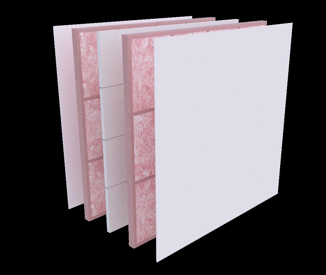
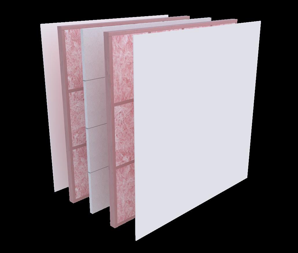
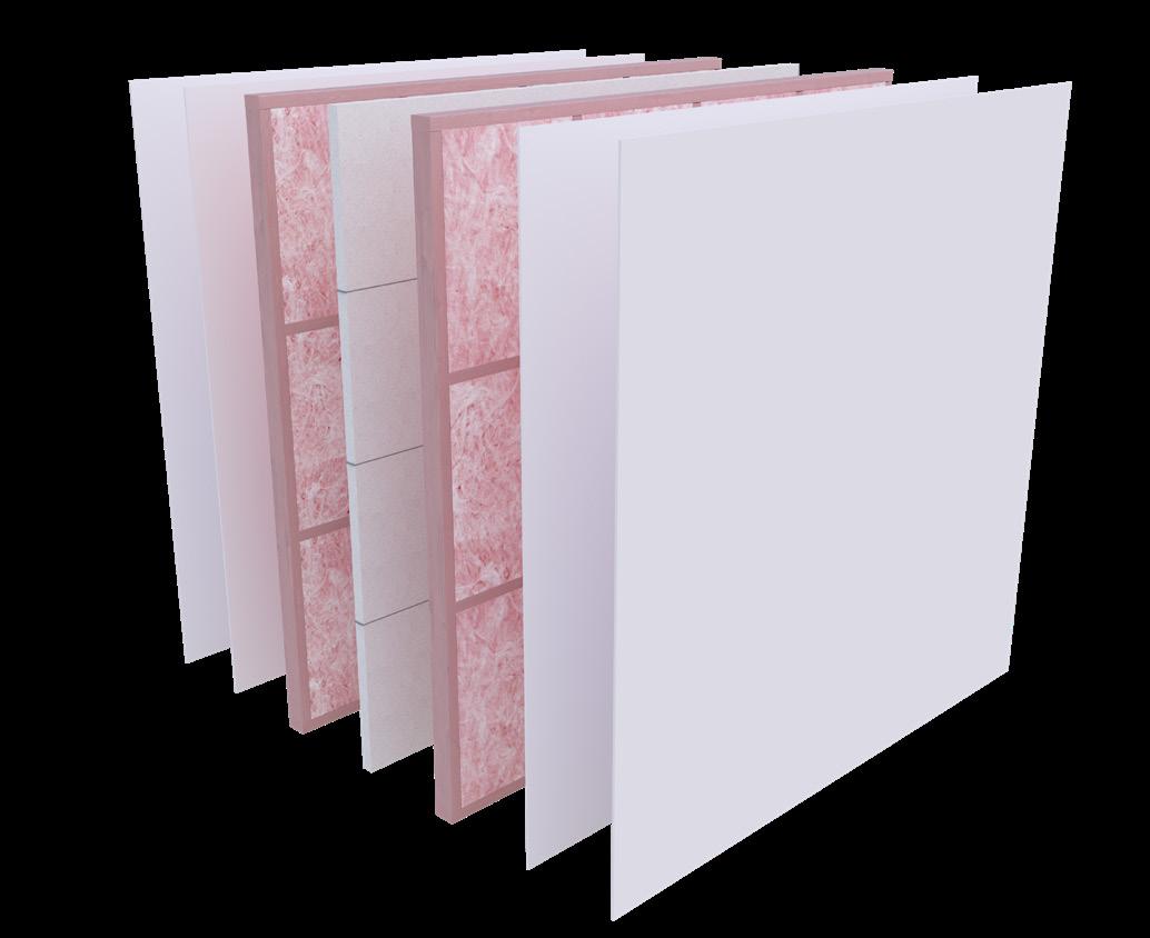
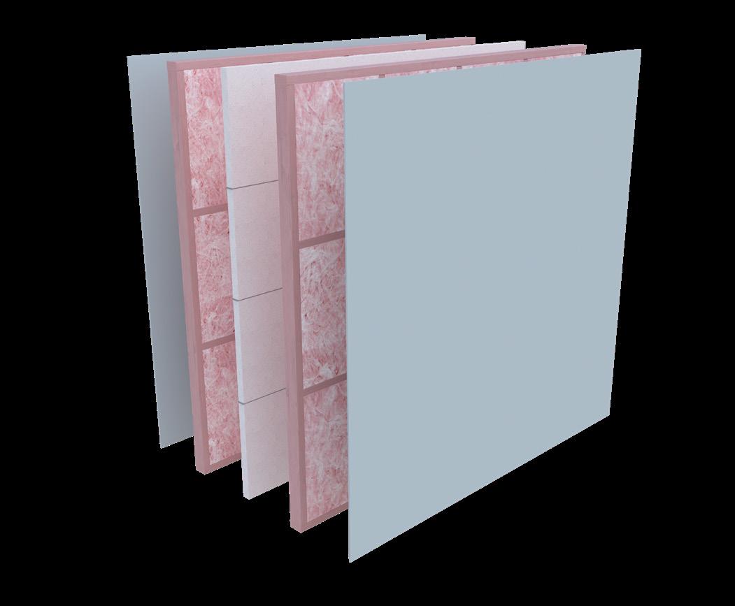
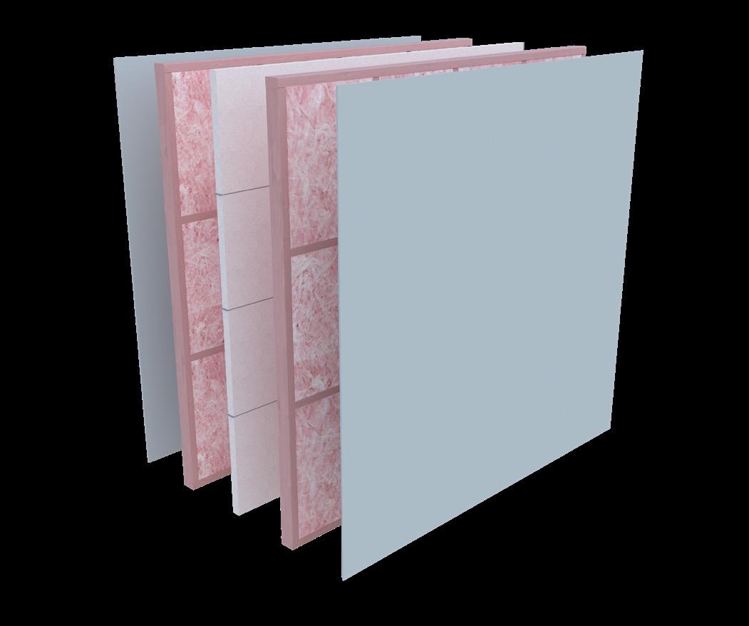
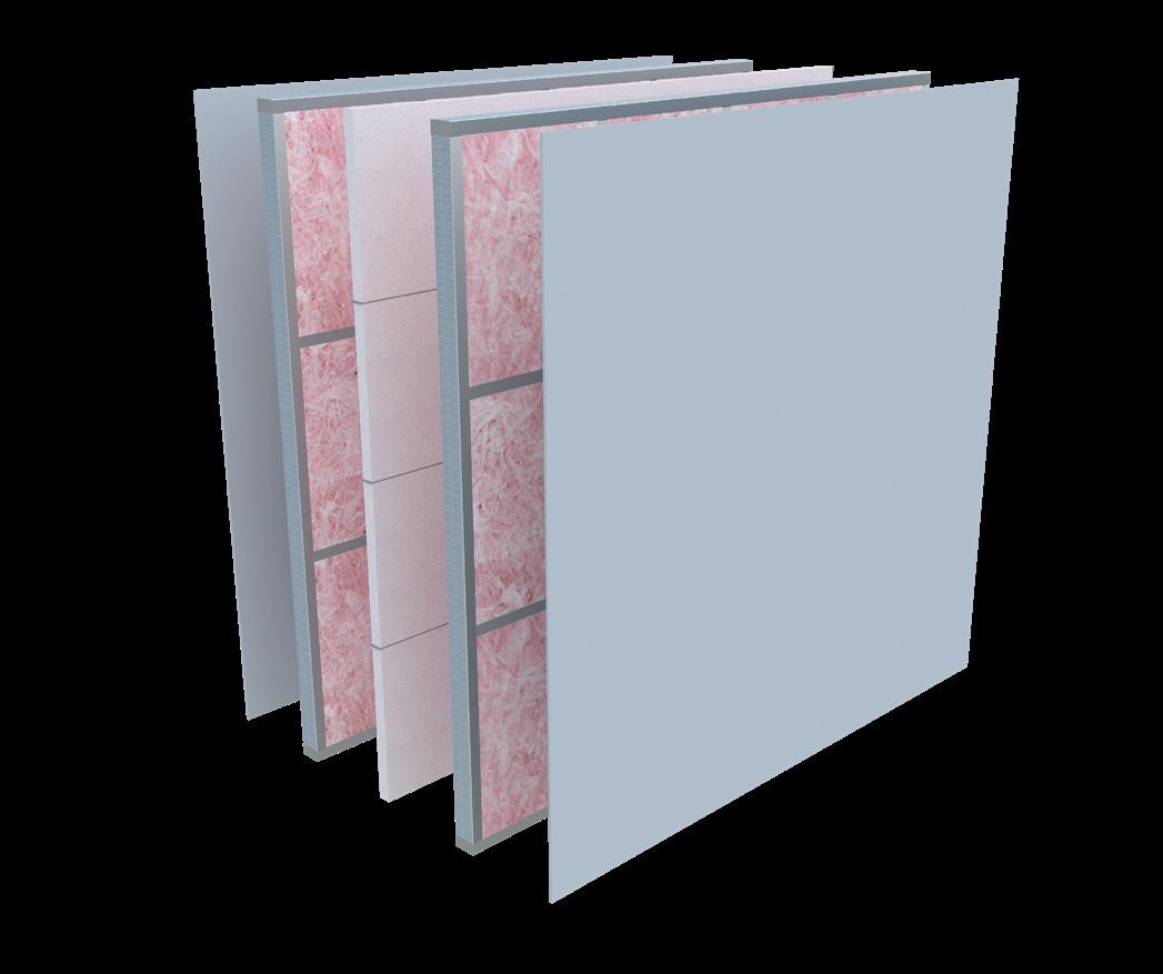
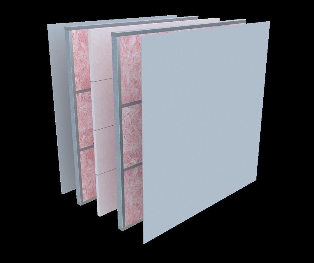
The INTEGRA Central Barrier Intertenancy System is a proprietary high-performance wall system that provides horizontal fire and acoustic separation between adjacent tenancies in the same building.
The core component of the INTEGRA system is a lightweight concrete panel and intertenancy bracket that is installed between framing that has insulation and plasterboard lining on the outer face.
A cavity is created between the INTEGRA Central Barrier and the framing through a proprietary Intertenancy Bracket and Dampener.
The INTEGRA Central Barrier Intertenancy System is suitable for use in medium and high-density housing, i.e. Terraced Housing
Terminology
Below are explanations of some of the acronyms used throughout this document. For further information, refer to the Building Code Handbook, which has additional definitions and can be found at the following link. https://www.building.govt.nz/building-code-complianc e/ building-code-and-handbooks/building-code-handbook
AS - Acceptable Solution or Australia Standard
AS1530.4-2005 - Methods for fire tests on building materials, components and structures, Part 4: Fireresistance tests of elements of construction.
FIIC - The ‘field’ or in situ measurement of Impact Insulation Class. Building tolerances and flanking noise have an effect on the performance of a partition when it is actually installed, which results in FIIC values lower than the laboratory-derived IIC values, typically 5 dB less.
Flanking Paths/Transmission - The transmission of sound energy through paths adjacent to the building element being considered. For example, sound may be transmitted around a wall by travelling up into the ceiling space and then down into the adjacent room.
FRR – Fire Resistance Rating
FSTC - The Field Sound Transmission Class is the ‘field’ or in situ measurement of Sound Transmission Class. Building tolerances and flanking noise affect the performance of a partition when it is installed, resulting in FSTC values lower than the laboratory-derived STC values, typically 5 dB less.
Habitable space (defined in NZBC G6) - A space used for activities normally associated with domestic living, but excludes any bathroom, laundry, watercloset, pantry, walkin wardrobe, corridor, hallway, lobby, clothes-drying room, or other space of a specialised nature occupied neither frequently nor for extended periods.
IIC - Impact Insulation Class measures a floor assembly’s ability to absorb impact sound
Impact Sound - Sound produced by an object directly impacting a building structure, such as footfall noise or chairs scrapping on a floor.
NZBC - New Zealand Build Code
NZS - New Zealand Standard
Rw - Sound Reduction Index is a number used to rate the effectiveness of a soundproofing system or material
SG - Stress Grade PPE – Personal Protective Equipment
Sound Insulation - When sound hits a surface, some of the sound energy travels through the material. ‘Sound insulation’ refers to the ability of a material to stop sound travelling through it.
STC - Sound Transmission Class represents a single number system for quantifying the transmission loss through a building element. STC is based upon typical speech and domestic noises and thus is most applicable to these areas. STC of a building element is measured in approved testing laboratories under ideal conditions.
Structure-Borne Transmission - The transmission of sound from one space to another through the structure of a building.
VM - Verification Method
Specification Reference
Labelling
The specification label reference allows a quick reference to a system. For example: INTA120a
IN = 50mm INTEGRA Panel
T = Timber Frame
S = Steel Frame
A = Acoustic
120 = Fire Resistance Rating
a/b/c/d/e = System Options
Product Substitution
The INTEGRA Intertenancy System is a proprietary system that has been carefully designed for New Zealand conditions and has been independently tested and assessed to make sure that it meets the performance criteria outlined in the NZBC.
It is imperative to use only Resene Construction Systems proprietary products where specified and that the design and construction of the Intertenancy System is followed to ensure the correct level of fire safety, structural and sound performance has been achieved onsite.
Components not supplied
Plasterboard Linings
The lining to each face of the wall may be any gypsumbased plasterboard that is at least 10mm thick.
The plasterboard used should have a minimum mass of
10mm standard plasterboard - 6.4 kg/m2
13mm standard plasterboard - 8.4 kg/m2
10mm noise-rated plasterboard - 8.6 kg/m2
13mm noise-rated plasterboard - 12.5 kg/m2
Thermal/Acoustic Insulation
Thermal/acoustic insulation should be included in the wall framing cavity. Either fibreglass, polyester, wool, or wool blend products are suitable.
Thermally insulate framed walls.
It fits easily into standard wall constructions, or it can be easily cut to fit in non-standard constructions
Meet the requirements of the New Zealand Building Code (NZBC) for different designs and environments.
Minimum R1.8
a minimum thickness of 75 mm.
Scope of use for the INTEGRA Central Barrier
Intertenancy System
INTEGRA Central Barrier Intertenancy System can be used: -
A Fire Resistance Rating of up to 120/120/120 is required.
Where a minimum STC of at least 55 is required
Where a maximum loading of 4.5kN/Stud is required
Where a minimum STC of at least 55 is required
Where a maximum loading of 4.5kN/Stud is required
Where an Intertenancy Wall is up to 12m in height, studs will need to be increased to meet the structural design requirements
Where a maximum individual floor/ceiling height meets NZS 3604 or if Steel Framing (NASH Handbook Best Practice for Design and Construction of Residential and Low Rise Steel Framing).
For medium and high-density housing i.e. Terraced Housing
Where timber or steel studs are specified and are rated to carry the imposed load per stud
The designer should consider the various systems depending on the required acoustic and fire performance. The designer should factor in the following: -
Height of the wall
Cavity size (typically 20mm)
Potential building movement, earthquake zones
Any lateral loads
Any floor loads must be carried solely by the timber framing (i.e. no contact with floor joists or the INTEGRA central barrier)
The framing needs to be designed for the individual project
Cavity Size
The INTEGRA Intertenancy System has been designed to use a cavity air space between 20mm and 40mm. This cavity is formed between the framing and the INTEGRA central barrier on both sides of the Intertenancy Wall.
Compliance with the NZBC
B1 – Structure
The design and specification for timber framing must be in accordance with the performance requirements of NZBC B1. Framing used per NZS3604:2011 is compliant with NZBC B1 and is the best choice when using the INTEGRA Intertenancy System. Where the framing falls outside the requirements of NZS3604:2011, we recommend that an engineer is engaged to ensure that structural compliance is met. If Steel Framing is used, E2/AS4 NASH Handbook Best Practice for Design and Construction of Residential and Low Rise Steel Framing should be used.
The INTEGRA central barrier performs NO STRUCTURAL FUNCTION, and the two timber-framed walls form part of the overall system and must be designed to accommodate all the relevant gravity, lateral, and face loads that will be present in the building. In relation to the design of the timber framing, the framing must be designed in accordance with B/AS1 3.0 Timber (NZS 3604) of B/VM1 6.0 Timber (NZS 3603) or if Steel Framing (E2/AS4 NASH Handbook Best Practice for Design and Construction of Residential and Low Rise Steel Framing).
The INTEGRA Central Barrier Intertenancy System can be used on a load-bearing or non-loadbearing wall. The INTEGRA central barrier within the wall system should be treated as non-loadbearing.
Provision should be made for temporary bracing during construction, particularly if the panel could be subjected to a high wind load or when installing the panel continuously over a single storey in height where the second framed walls have not been installed.
B2 – Durability
Under normal conditions of internal use, the INTEGRA central barrier Intertenancy System will achieve a service life in excess of 50 years and satisfy the requirements of NZBC B2.
C1-C6 – Protection from Fire
The INTEGRA Central Barrier Intertenancy System can provide passive fire protection in accordance with the requirement of NZBC C1-C6 - Protection from Fire. It has been peer-reviewed and meets the provisions of NZBC C1C6 when kept within the scope outlined in Section 6 - Scope of use for the INTEGRA Central Barrier Intertenancy System.
The INTEGRA Central Barrier Intertenancy System has been designed so that one side can collapse in a fire, leaving the INTEGRA central barrier and the opposing wall in place. The INTEGRA Central Barrier Intertenancy System Brackets are intended to melt on the fire side only, allowing collapse without damage to the remaining system.
The fire resistance rating was established through a BRANZ full-scale fire test. This fire report and opinions are available at reseneconstruction.co.nz
Fire Cells and Fire Resistance Ratings
1. The project designer will determine where the fire cells are in the building and what fire resistance ratings (FRRs) are required.
2. In most cases, an INTEGRA Central Barrier Intertenancy wall will form the common wall of a fire cell between adjacent tenancies and will require a two-way FRR.
3. The INTEGRA Central Barrier Intertenancy System has been tested in accordance with AS 1530.4: 2014 and achieves a 120/120/120-minute FRR.
4. The elements of the FRR required will depend on the specific scenario in the building in question. For example, if fire sprinklers are present and the wall is non-loadbearing, the INTEGRA Central Barrier Intertenancy System may not require structural adequacy or insulation ratings, it is only required to provide a—/ 120/—FRR.
5. Specific requirements are contained within the Acceptable Solution document that applies to the building in question.
Control of Internal Fire and Smoke Spread
1. Where the framing supports another firecell (e.g. apartment living), the plasterboard and framing on the fire side of the INTEGRA panels will have to achieve the specified FRR, independent of the INTEGRA panels, to achieve structural stability during a fire. This will also require any service penetrations through the plasterboard to be fire-stopped. Specialist advice from a fire engineer would be required in this case.
2. In some applications, the finished INTEGRA Central Barrier Intertenancy System will be required to achieve a material group number rating, which the fire engineer will specify. Table A1 in C/VM2 specifies that paper-faced gypsum plasterboard that is ≥ 9.5 mm thick, ≥ 400kg/m3 core density, < 5 % organic contribution to the board, and with a waterborne or solvent-based paint coating of ≤ 0.4 mm thick, will achieve a group number G2-S rating.
3. It is also very important that the FRR of the INTEGRA Central Barrier Intertenancy System is not compromised at the junction to fire-rated floors (at the base of the wall) and floors/ceilings (at the top of the wall) and where concealed spaces and cavities occur.
Control of external fire spread
When the INTEGRA system forms part of an external wall, the project designer will specify aspects such as the required FRRs and percentage of unprotected openings.
Exterior surface finish requirements will apply where the INTEGRA panel is the external cladding for the building.
F2 – Hazardous Building Materials
Under normal conditions of internal use, the INTEGRA Central Barrier Intertenancy System does not constitute a health hazard and meets the provisions of the NZBC Clause F2.
G6 – Airborne and Impact Sound
The INTEGRA Central Barrier Intertenancy System provides airborne noise control ratings that exceed the minimum requirements of NZBC Clause G6 – Airborne and Impact Sound. The INTEGRA Central Barrier Intertenancy System has been peer-reviewed and meets the provisions of NZBC G6 when kept within the scope (Section 6 - Scope of use for the INTEGRA Central Barrier Intertenancy System).
The STC ratings were established through a full-scale sound test at Auckland University. The reports are available on request.
The INTEGRA Central Barrier Intertenancy system does not require an STC rating when used within a roof or uninhabitable space.
Any rigid air barriers that bridge over an Intertenancy Wall should be discontinued at this point, and a flexible underlay should be installed.
Ensure that any brackets installed on the framed wall are NOT mirrored on the second wall. The brackets on the second wall should be installed on opposing studs or at least 300mm apart.
Habitable/Non-habitable spaces
The INTEGRA central barrier is designed to provide fire protection between the tenancies. The plasterboard and insulation are included to achieve the required acoustic insulation.
All habitable and non-habitable spaces separated by a party wall still require passive fire protection however, they don’t necessarily need to achieve acoustic separation. Good trade practice would be to achieve the best possible acoustic insulation across the entire wall. However, there may be instances where acoustic performance may not be required as per the definitions below.
The functional requirement of NZBC G6.2 -Building elements which are common between occupancies shall be constructed to prevent undue noise transmission from other occupancies or common spaces, to the habitable spaces of household units.
As defined in NZBC G6, a habitable space is a space used for activities normally associated with domestic living, but excludes any bathroom, laundry, watercloset, pantry, walk-in wardrobe, corridor, hallway, lobby, clothes-drying room, or other space of a specialised nature occupied neither frequently nor for extended periods.
Services
No services should penetrate the INTEGRA central barrier. However, services may be concealed within the framed section of the wall system, subject to the following constraints.
A minimum of 10mm clearance should be maintained between penetrations and the INTEGRA central barrier.
Penetrations should be no larger than 65mm in diameter or 90x50mm through the plasterboard lining.
No more than two penetrations per 600mm bay of framing are made.
The plasterboard is needed as part of the acoustic system. If the room is classed as uninhabitable, then the services through the plasterboard can be any size.
Passive fire protection is not required for these services unless the plasterboard is part of the fire-rated system. If there is a requirement to penetrate the INTEGRA central barrier, consult the designer about suitable passive fire protection for the installed service. Alternatively, refer to the FPANZ - Passive Fire Protection Register for suitable solutions that can be used with AAC. This document can be accessed at https://www.fpanz.org/docs/product-registers
Exposure to weather during construction
The INTEGRA Central Barrier Intertenancy System can be exposed to the elements for up to 3 months before the building is closed in.
Should the wall be exposed to the weather for a longer period, we recommend applying Resene Aquapel over the entire surface of the INTEGRA Lightweight Concrete Panels.
Materials
Fasteners
INTEGRA Central Barrier Intertenancy System Screws must be used; these are available in the following sizes for both timber and steel framing
12gx75mm Galvanised with EPDM Washer -Used to secure the INTEGRA Panel to the Intertenancy Bracket
Timber Framing
12gx45mm Galvanised with EPDM Washer –Used to secure the Intertenancy Bracket to the structure
Steel Framing
10-16x20mm Hex Galvanised with EPDM Washer – Used to secure the Intertenancy Bracket to the structure
Intertenancy Bracket
Aluminium bracket
Supplied in boxes of 50 brackets, including the above fasteners.
50mm wide
3mm Thick
75mm x 50mm legs
Includes a sound and heat-resistant dampener with spacers to limit contact to the surface being attached to
INTEGRA Lightweight Concrete Panels
Thermal Conductivity: 0.12 W/(mk)
Thermal Resistivity, R: 0.42m2K/W
Substrate Thickness: 50mm
Weight: 26kg/m2, 34kg per panel
2200mm long, 600mm wide
Non-Combustible (AS1530.1-1994)
PSL AAC Adhesive
Supplied in 20kg bags
Used for bonding AAC together, patching panel, and securing the panel to a concrete foundation
Anti-Corrosion Coating
Use to prime any exposed steel that may be exposed when the INTEGRA panel is cut to length or width.
Zinc Rich protective Coating such as Wurth Zinc Spray
Light Perfect
Resene Construction Systems FireWool™
FireWool™ for passive fire protection.
The ceramic fibres are known for their ability to withstand high temperatures. The wool can resist direct exposure to flames and intense heat.
FireWool™ is typically used for fire-stopping to the roofline and end wall connections of central
Density: 128 kg / m3
Non-Combustible (AS1530.1-1994)
Thickness: 25mm/50mm
Width: 100mm
System Variations
Increasing the thickness of the panel from 50mm to 75mm • Increase in timber density
Increase in the cross-sectional dimension of the framing element(s)
Decrease in stud spacing
Replace the timber studs with steel studs of equivalent structural strength to carry the imposed load per stud
Installation Guidelines
General
Before commencing any work onsite, ensure the site is clean and tidy. Try to minimise any vibration or impact directly or indirectly on the INTEGRA during installation. This will assist with minimising cracking to the mortar before it sets.
STEP 1
Framing
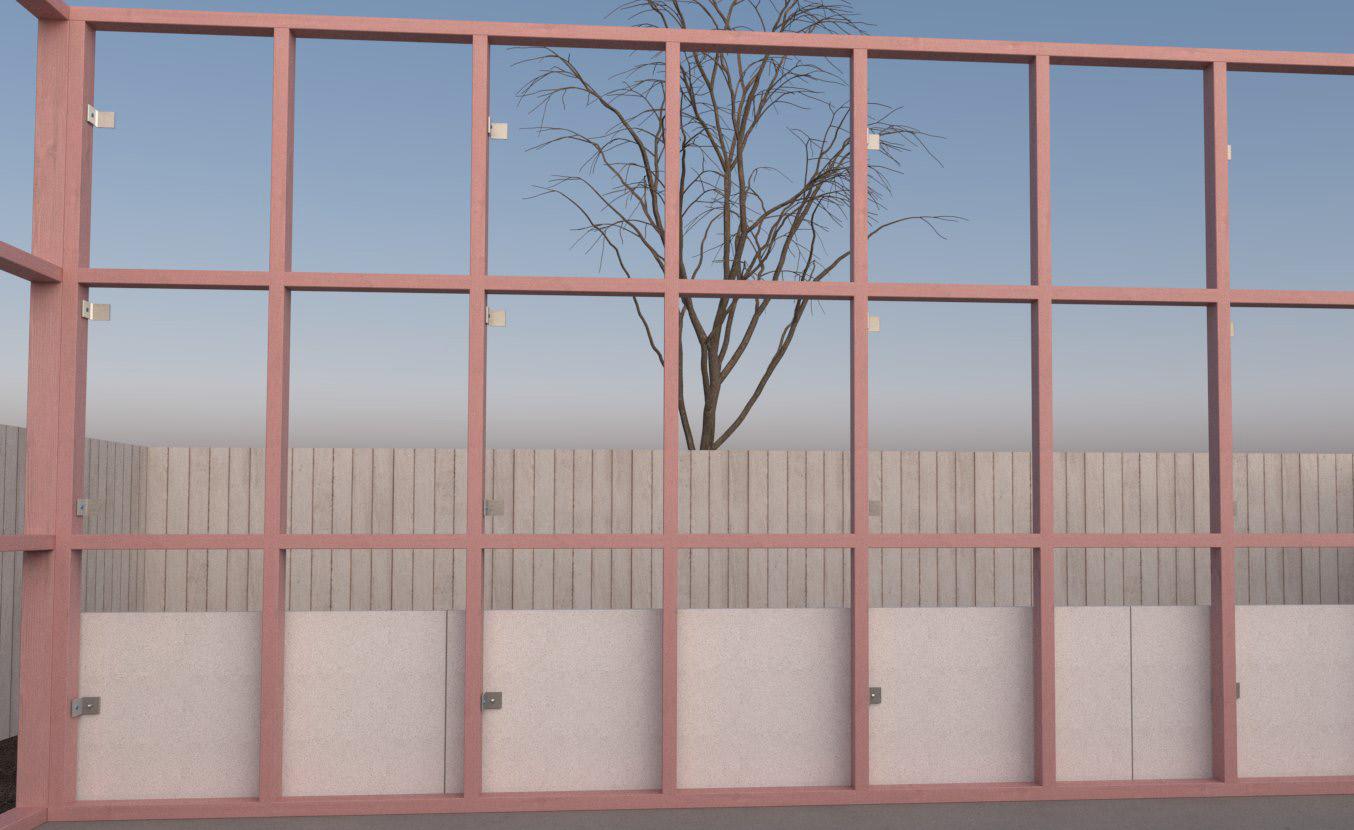
All framing should be installed straight and plumb as specified in the construction drawings. The INTEGRA system requires framing to be set out in accordance with NZS3604:2011 for timber frames or E2/AS4 (NASH Handbook: Best Practice for Design and Construction of Residential and Low-Rise Steel Framing) for steel-framed walls.
Install the framing on one side of the intertenancy wall first.
It is recommended that strapping tape be installed to the framing before installing the INTEGRA central barrier to ensure the insulation is held in place.

STEP 2
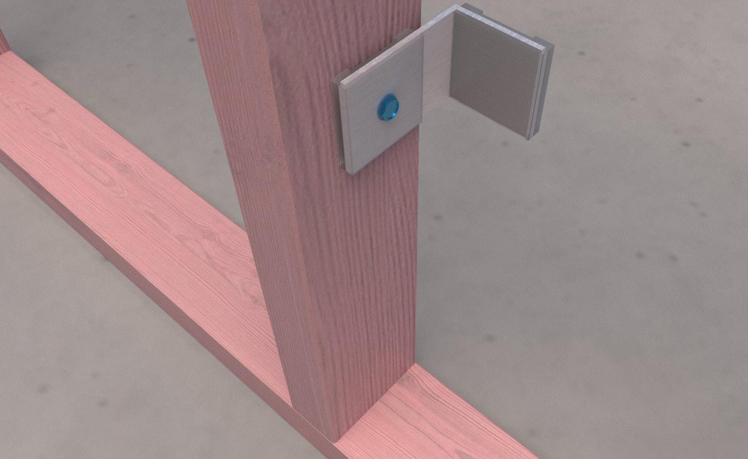
Installation of brackets
Two brackets per panel face are needed, with spacing governed by stud centres of the framing. Starting at one end of the framing, install a bracket to the end stud to be located 300mm from the Finished Floor Level. Ensure that the face of the dampener on the bracket has been installed 20-40mm (depending on the specified cavity size) off the framing line.
Use the Resene Construction Systems 12gx45mm Galvanised screw with EPDM Washer to secure the
Intertenancy Bracket to the timber-framed structure. When installing the brackets to steel framing use the 10-16x20mm Hex Galvanised screw to secure the brackets.
Every second stud should have a bracket installed in the same location. The use of a string line will help to ensure the brackets are kept straight.
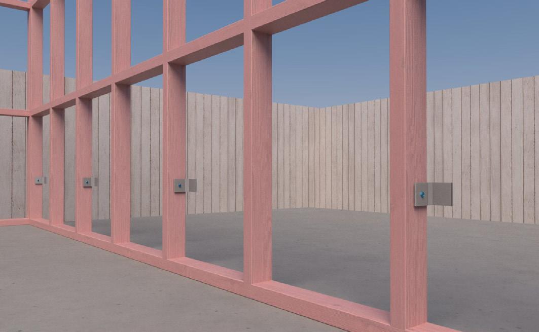
Once the first row of brackets is installed, continue to install brackets at 600 centres up the stud. A useful way to do this is to install the bottom and top brackets on the wall and then use a straight edge to align the brackets and ensure they are all on the same plane. Use a level to ensure the brackets have been installed plumb.

Image 1 – Framing being installed on the concrete slab
Image 2 – The first bracket is installed. This should be located 300mm off the floor
Image 3 – Brackets to be installed on every second stud
Image 4 – Continue to install brackets to one side of the wall
STEP 3
Mixing and Application of mortar. Install the bottom row of the INTEGRA panel
Mix up 2-3 kg of Resene Construction Systems PSL AAC Adhesive to get started. Mix to a smooth consistency, run a finger through the plaster mix, and if it remains standing, then the plaster is ready to be applied. Approximately 4 litres of water per 20kg bag is required.
The first row of panels must be adhered to the concrete floor slab using AAC Adhesive. To do this, apply the adhesive to the long edge of an INTEGRA Panel using a spatula or broad knife.
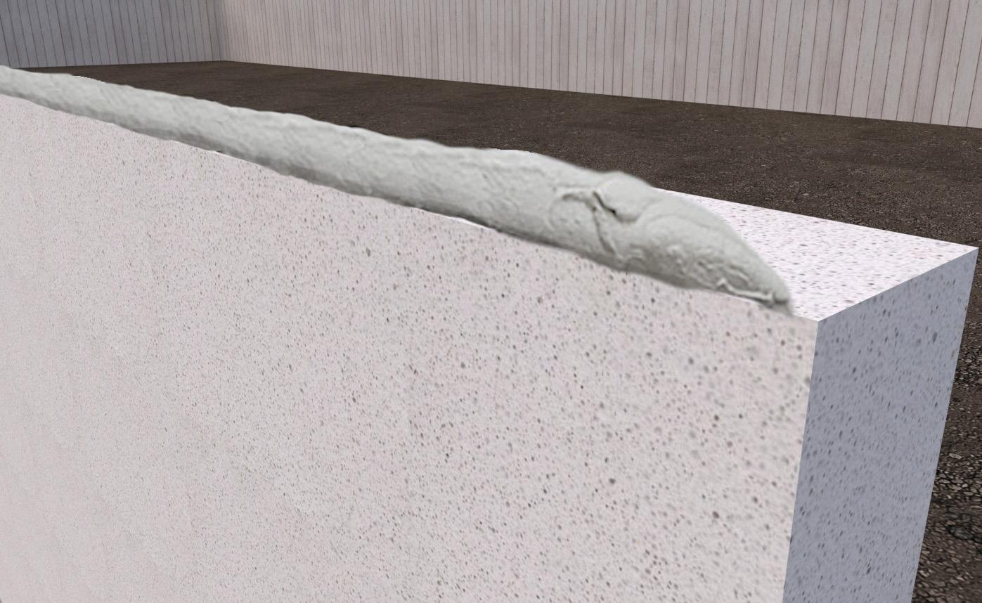
Image 5 – Mortar to be used between each panel
Then, lift and position the panel so that it is installed horizontally and rests against two brackets in a plumb position. Ensure that there are no gaps between the panel and the floor slab.
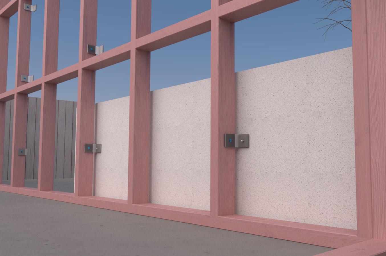
Image 6 – Install the first panel, ensuring it is mortared to the slab
STEP 4
Installation of INTEGRA Panel in the wall cavity
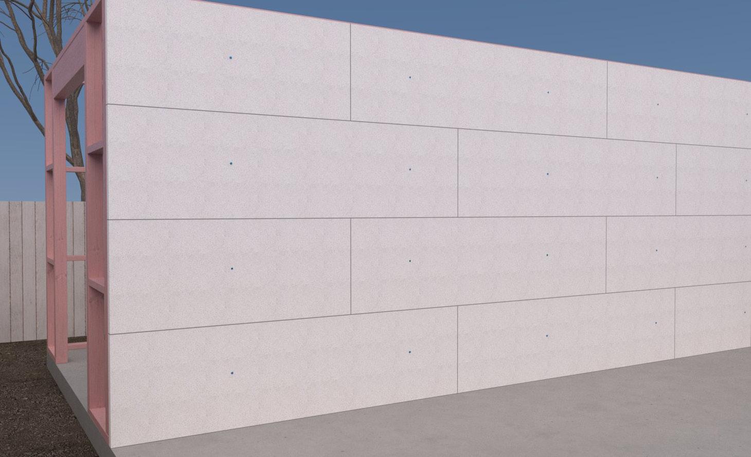
Continue along the length of the wall, installing the INTEGRA panel to form the INTEGRA central barrier. Ensure that the vertical edge of the panels is bonded together using the AAC Adhesive.
Ensure all full-length panels have two clips per panel to secure the panel to one side of the framing. If there is a section of the panel that is less than 600mm, then no bracket is required. In this situation, the AAC adhesive is relied on to bond the panels together.
Any panels can be cut on-site using a circular saw with a diamond-tipped blade. Ensure that a dust extraction unit is used as well as PPE (including glasses, dust masks, hearing protection and gloves)
Any steel reinforcement exposed during the cutting process must be coated with an anti-corrosion coating.
Any minor damage should be patched using the AAC adhesive to maintain acoustic performance and fire protection.
STEP 5
Screw fixing the panels to the brackets
As each panel is positioned, secure it to the corresponding intertenancy brackets. The screw is installed blind from the far side of the panel. To do this drill, a 2-3mm pilot hole must be made through the existing hole in the intertenancy bracket and the INTEGRA Panel Central barrier.
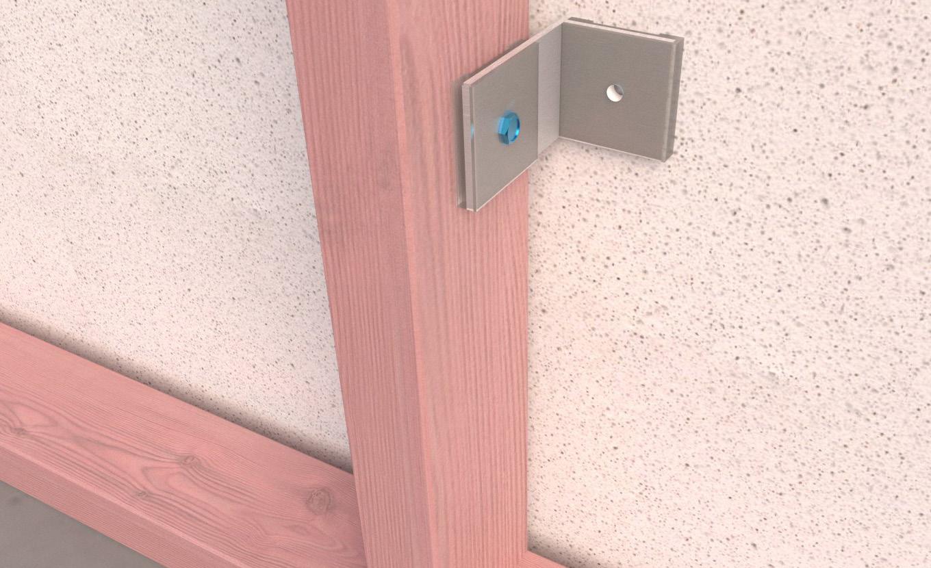
Image 8 – Drill a pilot hole through the panel
Use a Resene Construction Systems 12gx75mm Galvanised screw with EPDM Washer to secure the INTEGRA Panel to the Intertenancy Bracket through the pilot hole.
Image 7 – Continue to install the first row of panels

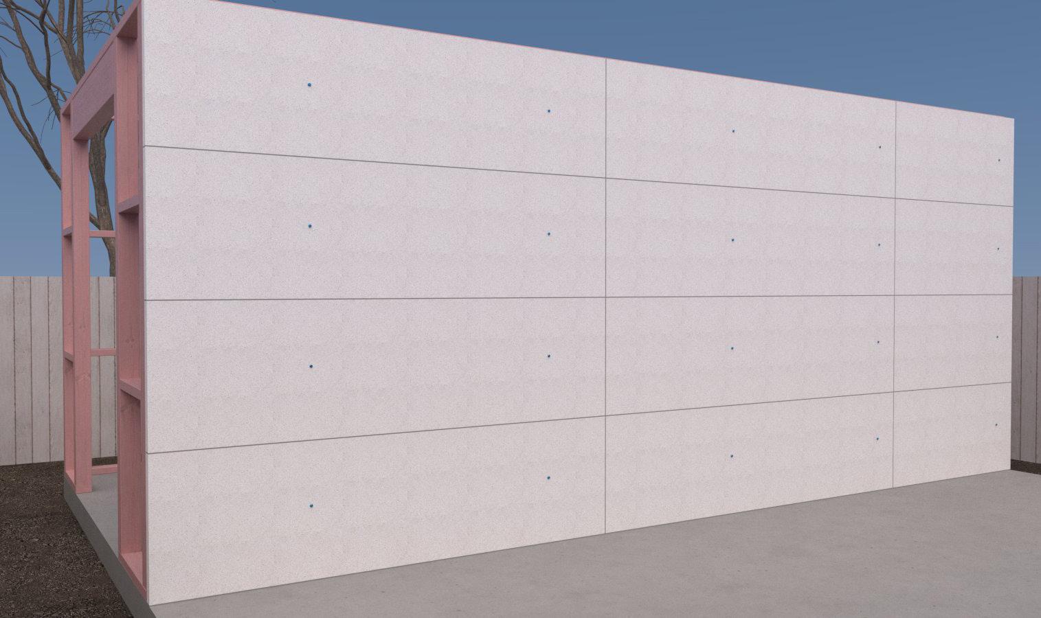
Continue to install the INTEGRA central barrier of the INTEGRA Panel in a stacker bond pattern (each sheet on top of each other so that the joins align) using the AAC Adhesive to bond the panels together.
The INTEGRA central barrier can also be installed in a stretcher bond pattern. If the panel is installed in this fashion, then consideration will need to be made regarding the bracket layout to ensure that two brackets per full panel are maintained.
STEP 6
Install the framing to the other side of the INTEGRA central barrier
The INTEGRA central barrier should be installed as close to the top plate as possible. Then, the framing for the adjacent unit can be installed. Once the framing is erected, the brackets for the adjacent unit can be installed. The brackets should be installed so they are not directly opposite the brackets on the opposing side.
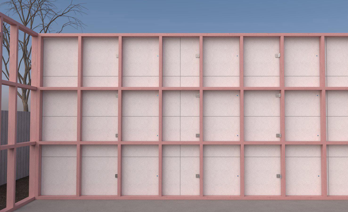
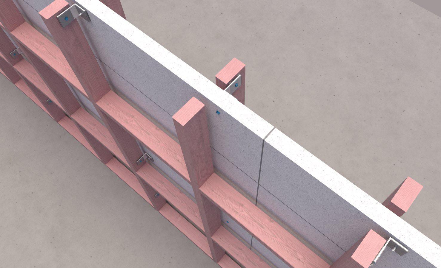
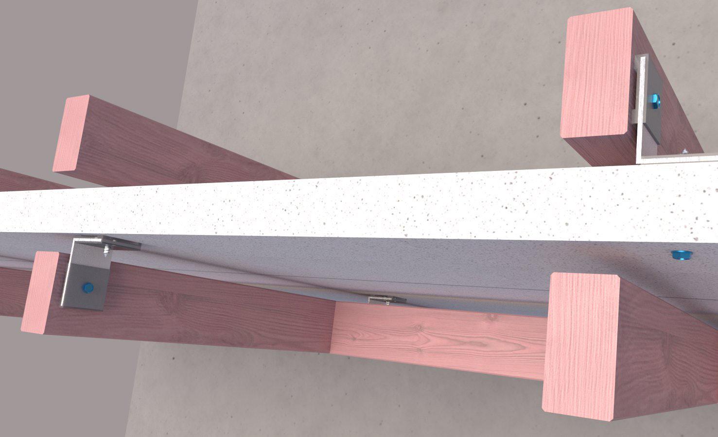
Image 10 – Panel installed in a stretcher bond pattern
Image 12 – Timber framing installed on the adjacent unit
Image 13 – Brackets have been installed on alternating studs
Image 11 – Panel installed in a stacker bond pattern
Image 9 – Attach the panel to the bracket


STEP 7
Installation of Resene Construction Systems FireWool™
Resene Construction Systems FireWool™ is used to fill any gaps that may be left between the INTEGRA central barrier and the underlay/sheathing.
It can also be used to prevent any horizontal spread of flame in the wall cavity. Tacking the firewool to the panel/ framing will ensure that it remains in place until the cladding has been installed. Check with the cladding manufacturer what type of fire protection is needed in the cavity between each unit.
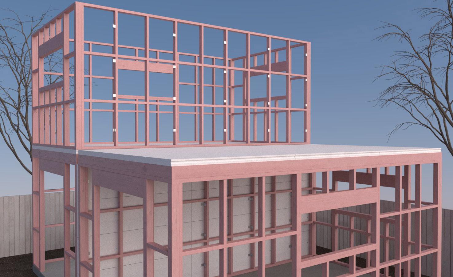
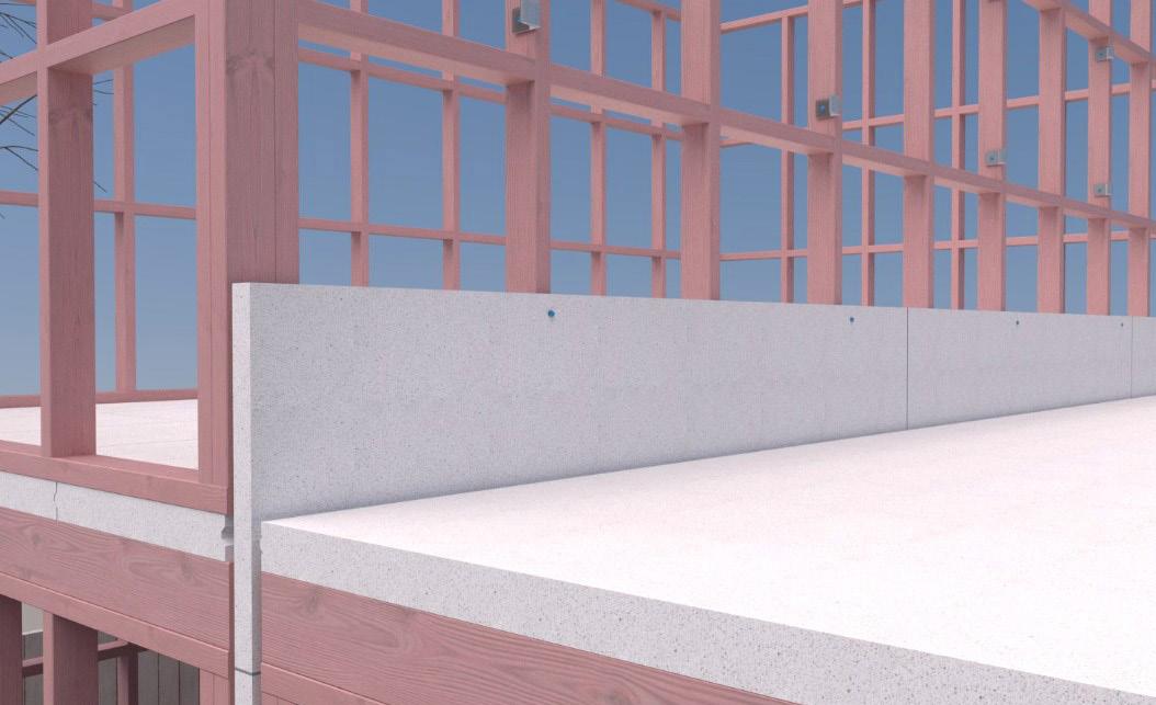
Image 14 – Second-floor framing installed
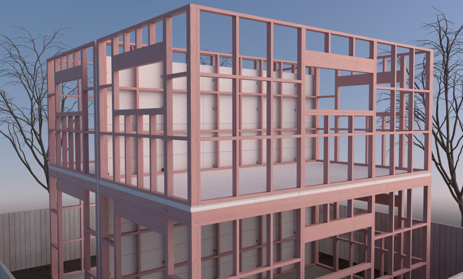
Image 17 – Adjacent units framing and brackets installed
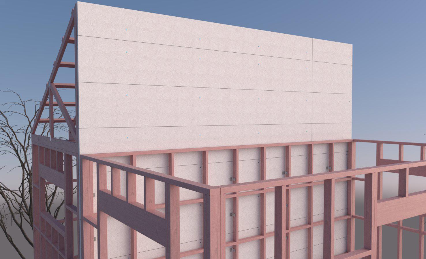
Image 18 – Roof framing installed with brackets for INTEGRA central barrier
Image 19 – INTEGRA central barrier installed to the roof framing
Image 15 – Continue installing the first row of panels to the second floor
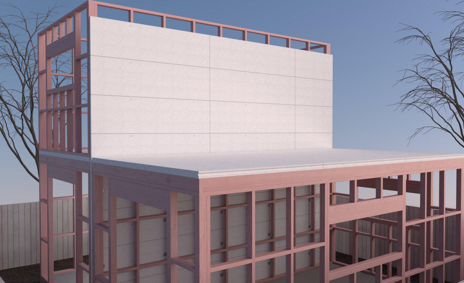
Image 16 – Remainder of the INTEGRA central barrier installed
Resene Construction Systems FireWool™ should be used at the top of the INTEGRA central barrier to close gaps between the INTEGRA central barrier and roofing underlay.
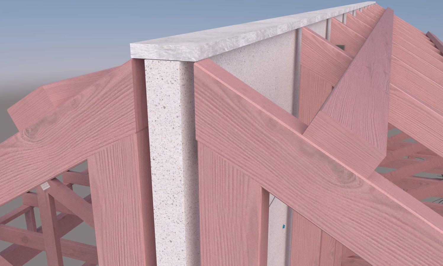
Image 20 – Roof framing is completed, and the firewool is installed at the top of the panel.
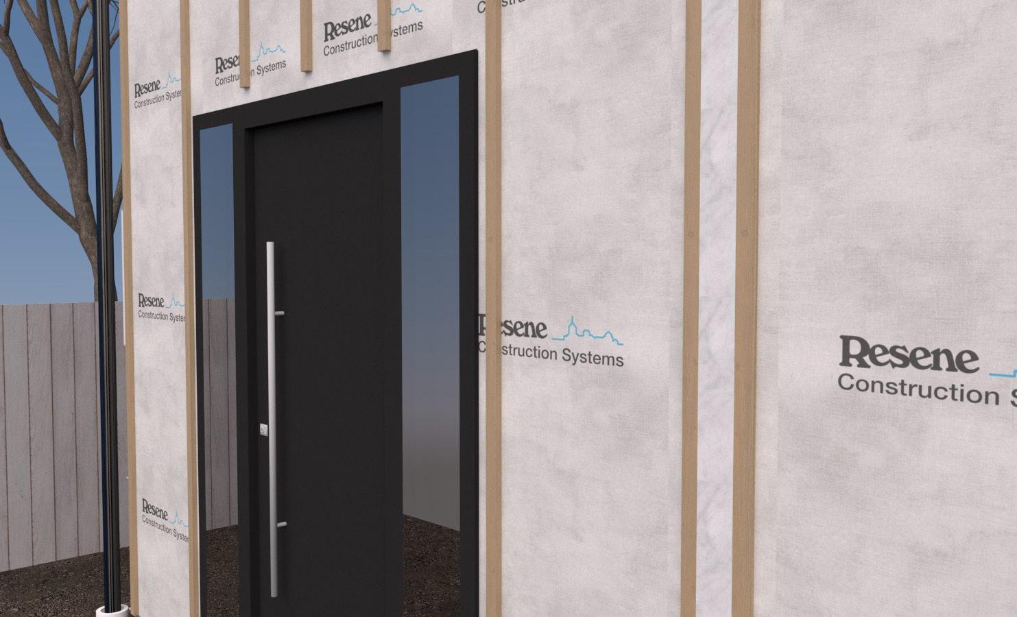
21 - The building underlay is installed, with the firewool installed on the junction between the units
Image 22 - Once the cladding is on, plasterboard can be installed
STEP 8
Installation of services
The INTEGRA central barrier should not have any services installed through it.
If there is a requirement to penetrate the INTEGRA central barrier, consult the designer about suitable passive fire protection for the installed service. Alternatively, refer to
the FPANZ - Passive Fire Protection Register for suitable solutions that can be used with AAC. This document can be accessed at https://www.fpanz.org/docs/product-registers
STEP 9
Installation of Insulation
The insulation should be installed according to the manufacturer’s specifications. It must completely fill the space between the framing. If there are any gaps between the insulation and framing, the acoustic performance will be compromised.
When installing the insulation, please ensure it is not pushed back against the INTEGRA central barrier. It is recommended that strapping tape be installed to the framing before installing the INTEGRA central barrier to ensure the insulation is held in place.
If the framing is load-bearing (i.e., supporting a floor from a different fire cell), then all service penetrations will need to be fire-stopped. Please consult a fire engineer about the best method of doing this.
STEP 10
Installation and finishing of Plasterboard
The plasterboard should be fixed vertically. Sheets shall be touch-fitted. When fixing vertically, full-height sheets shall be used where possible.
If two layers of plasterboard are being installed then the plasterboard can be installed horizontally, make sure the joins are staggered so they are different from the first installed sheets.
If the wall lining forms part of the structural bracing system, the lining type and fixings must comply with the published bracing system. Check requirements for specific bracing element hold-down connections.
Where sheet end butt joints are unavoidable, they must be formed over framing.
Jointing and finishing plasterboard are to be done according to the manufacturer’s instructions to meet the requirements of AS/NZS 2589:20T17.
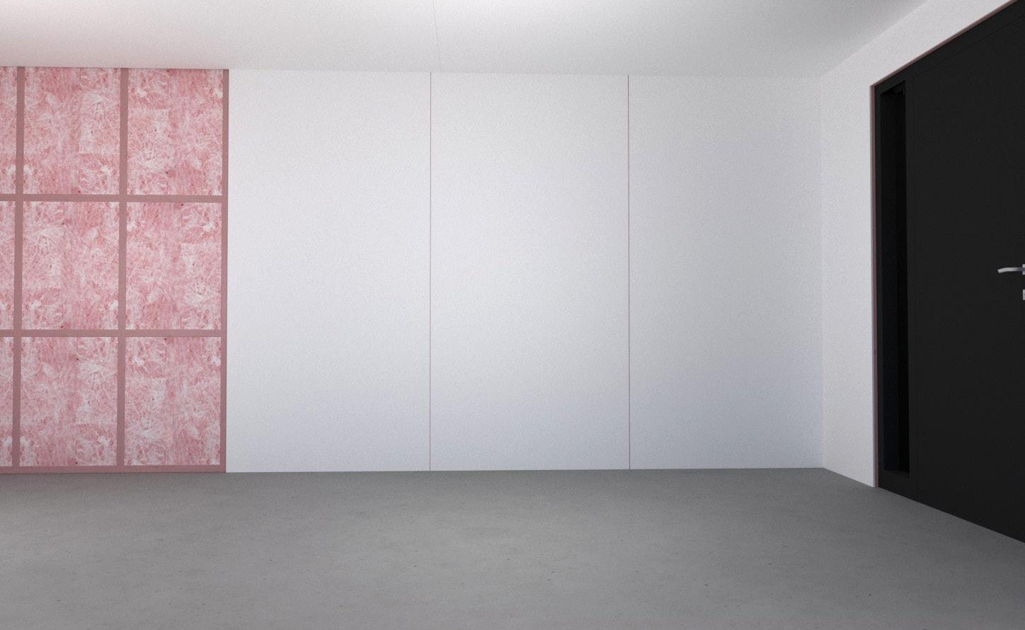
Image 23 - Show plasterboard being installed vertically with insulation installed
Image
STEP 11
Finishing services
Any gaps through the plasterboard should be sealed using an acoustic-rated sealant. The sealant should be installed according to the manufacturer’s specifications.
Special Notes when installing with Steel Framing
There will be occasions with Steel Framing setouts where a small proportion of the wall has no insulation installed in the
System Specification
voids of the steel framing. We can verify that the framing arrangement at these junctions will not compromise the acoustic rating of the wall. However, we recommend that where two such details (for example, T-Junction - Internal Wall meeting Intertenancy Wall and Corner - Internal Linings both Sides) are located within 1.8 metres of each other that insulation is placed within the steel stud cavity or an acoustic engineer reviews the details.
* Tested in accordance with ISO standard 10140-2:2010(E) “Laboratory measurement of sound insulation of building elements - Part 2: Measurement of airborne sound insulation”
1. Determined in accordance with ASTM E413 Classification for Rating Sound Insulation
2. Determined in accordance with ISO 717-1 Acoustics – Rating of sound insulation in buildings and of building elements – Part 1: Airborne sound insulation
INTA120A
TIMBER FRAME
120 MINUTE
INTEGRA Central Barrier with one layer of 10mm Standard Plasterboard to both framing lines
Framing to comply with
• NZBC B1 – Structure: AS1 Clause 3 – Timber
• (NZS 3604) or VM1 Clause 6 – Timber (NZS 3603)
• NZBC B2 – Durability: AS1 Clause 3.2 – Timber (NZS 3602)
• Studs at 600mm centres maximum
• Framing dimensions and height as determined by NZS 3604 stud and top plate tables for loadbearing walls.
INTEGRA central barrier to comply with
• NZBC Clause B2 Durability
• NZBC Clause C1-C6 – Protection from Fire
• NZBC Clause F2 Hazardous Building Materials
• NZBC Clause G6 Airborne and Impact Sound
Insulation
• In order to achieve the stated ratings the acoustic absorption product would need to be fibrous (glass fibre, polyester fibre or wool) and would need to have a minimum thickness of 75 mm.
• Minimum R-Value of 1.8
Linings
• 1 layer of 10mm Standard Plasterboard on the outside of each framing line.
• Vertical fixing permitted.
• When fixing vertically, full height sheets shall be used where possible.
• If the wall lining forms part of the structural bracing system, the lining type and fixings must comply with the published bracing system. Check requirements for specific bracing element hold down connections.
• Fastened as per plasterboard manufacturer specifications
• Where sheet end butt joints are unavoidable they must be formed over framing. When fixing horizontally all longitudinal sheet joints must be formed over nogs
Jointing
• Jointing and finishing of plasterboard is to be as per the manufacturer’s instructions to meet requirements of AS/NZS 2589:2017.
Technical Info
• STC Rating – 64
• Rw Rating – 62
• FRR – 120/120/120
• Cavity width – 20-40mm cavity
• Wall Width – 290-330mm
INTA120B
TIMBER FRAME
120 MINUTE
INTEGRA Central Barrier with one layer of 13mm Standard Plasterboard to both framing lines
Framing to comply with
• NZBC B1 – Structure: AS1 Clause 3 – Timber (NZS 3604) or VM1 Clause 6 – Timber (NZS 3603)
• NZBC B2 – Durability: AS1 Clause 3.2 – Timber (NZS 3602)
• Studs at 600mm centres maximum
• Framing dimensions and height as determined by NZS 3604 stud and top plate tables for loadbearing walls.
INTEGRA central barrier to comply with
• NZBC Clause B2 Durability
• NZBC Clause C1-C6 – Protection from Fire
• NZBC Clause F2 Hazardous Building Materials
• NZBC Clause G6 Airborne and Impact Sound
Insulation
• In order to achieve the stated ratings the acoustic absorption product would need to be fibrous (glass fibre, polyester fibre or wool) and would need to have a minimum thickness of 75 mm.
• Minimum R-Value of 1.8
Linings
• 1 layer of 13mm Standard Plasterboard on the outside of each framing line.
• Vertical fixing permitted.
• When fixing vertically, full height sheets shall be used where possible.
• If the wall lining forms part of the structural bracing system, the lining type and fixings must comply with the published bracing system. Check requirements for specific bracing element hold down connections.
• Fastened as per plasterboard manufacturer specifications
• Where sheet end butt joints are unavoidable they must be formed over framing. When fixing horizontally all longitudinal sheet joints must be formed over nogs
Jointing
• Jointing and finishing of plasterboard is to be as per the manufacturer’s instructions to meet requirements of AS/NZS 2589:2017.
Technical Info
• STC Rating – 66
• Rw Rating – 65
• FRR – 120/120/120
• Cavity width – 20-40mm cavity
• Wall Width – 296-336mm
INTA120C
TIMBER FRAME
120 MINUTE
INTEGRA Central Barrier with two layers of 10mm Standard Plasterboard to both framing lines
Framing to comply with
• NZBC B1 – Structure: AS1 Clause 3 – Timber
• (NZS 3604) or VM1 Clause 6 – Timber (NZS 3603)
• NZBC B2 – Durability: AS1 Clause 3.2 – Timber (NZS 3602)
• Studs at 600mm centres maximum
• Framing dimensions and height as determined by NZS 3604 stud and top plate tables for loadbearing walls.
INTEGRA central barrier to comply with
• NZBC Clause B2 Durability
• NZBC Clause C1-C6 – Protection from Fire
• NZBC Clause F2 Hazardous Building Materials
• NZBC Clause G6 Airborne and Impact Sound
Insulation
• In order to achieve the stated ratings the acoustic absorption product would need to be fibrous (glass fibre, polyester fibre or wool) and would need to have a minimum thickness of 75 mm.
• Minimum R-Value of 1.8
Linings
• 2 layers of 10mm Standard Plasterboard on the outside of each framing line.
• Vertical fixing permitted.
• When fixing vertically, full height sheets shall be used where possible.
• If the wall lining forms part of the structural bracing system, the lining type and fixings must comply with the published bracing system. Check requirements for specific bracing element hold down connections.
• Fastened as per plasterboard manufacturer specifications
• Where sheet end butt joints are unavoidable they must be formed over framing. When fixing horizontally inner layer longitudinal sheet joints must be formed over nogs
• Outer layer sheets can be fixed vertically or horizontally. If fixed vertically, outer layer sheet joints must be offset 600mm from those of the inner layer. Use full height sheets where possible
Jointing
• Jointing and finishing of plasterboard is to be as per the manufacturer’s instructions to meet requirements of AS/ NZS 2589:2017.
Technical Info
• STC Rating – 67
• Rw Rating – 66
• FRR – 120/120/120
• Cavity width – 20-40mm cavity
• Wall Width – 310-350mm
INTA120D
TIMBER FRAME
120 MINUTE
INTEGRA Central Barrier with one layer of 10mm Noise Rated Plasterboard to both framing lines
Framing to comply with
• NZBC B1 – Structure: AS1 Clause 3 – Timber
• (NZS 3604) or VM1 Clause 6 – Timber (NZS 3603)
• NZBC B2 – Durability: AS1 Clause 3.2 – Timber (NZS 3602)
• Studs at 600mm centres maximum
• Framing dimensions and height as determined by NZS 3604 stud and top plate tables for loadbearing walls.
INTEGRA central barrier to comply with
• NZBC Clause B2 Durability
• NZBC Clause C1-C6 – Protection from Fire
• NZBC Clause F2 Hazardous Building Materials
• NZBC Clause G6 Airborne and Impact Sound
Insulation
• In order to achieve the stated ratings the acoustic absorption product would need to be fibrous (glass fibre, polyester fibre or wool) and would need to have a minimum thickness of 75 mm.
• Minimum R-Value of 1.8
Linings
• 1 layer of 10mm Noise Rated Plasterboard on the outside of each framing line.
• Vertical fixing permitted.
• When fixing vertically, full height sheets shall be used where possible.
• If the wall lining forms part of the structural bracing system, the lining type and fixings must comply with the published bracing system. Check requirements for specific bracing element hold down connections.
Jointing
• Jointing and finishing of plasterboard is to be as per the manufacturer’s instructions to meet requirements of AS/NZS 2589:2017.
Technical Info
• STC Rating – 66
• Rw Rating – 65
• FRR – 120/120/120
• Cavity width – 20-40mm cavity
• Wall Width – 290-330mm
INTA120E
TIMBER FRAME
120 MINUTE
INTEGRA Central Barrier with one layer of 13mm Noise Rated Plasterboard to both framing lines
Framing to comply with
• NZBC B1 – Structure: AS1 Clause 3 – Timber
• (NZS 3604) or VM1 Clause 6 – Timber (NZS 3603)
• NZBC B2 – Durability: AS1 Clause 3.2 – Timber (NZS 3602)
• Studs at 600mm centres maximum
• Framing dimensions and height as determined by NZS 3604 stud and top plate tables for loadbearing walls.
INTEGRA central barrier to comply with
• NZBC Clause B2 Durability
• NZBC Clause C1-C6 – Protection from Fire
• NZBC Clause F2 Hazardous Building Materials
• NZBC Clause G6 Airborne and Impact Sound
Insulation
• In order to achieve the stated ratings the acoustic absorption product would need to be fibrous (glass fibre, polyester fibre or wool) and would need to have a minimum thickness of 75 mm.
• Minimum R-Value of 1.8
Linings
• 1 layer of 13mm Noise Rated Plasterboard on the outside of each framing line.
• Vertical fixing permitted.
• When fixing vertically, full height sheets shall be used where possible.
• If the wall lining forms part of the structural bracing system, the lining type and fixings must comply with the published bracing system. Check requirements for specific bracing element hold down connections.
• Fastened as per plasterboard manufacturer specifications
• Where sheet end butt joints are unavoidable they must be formed over framing. When fixing horizontally all longitudinal sheet joints must be formed over nogs
Jointing
• Jointing and finishing of plasterboard is to be as per the manufacturer’s instructions to meet requirements of AS/ NZS 2589:2017.
Technical Info
• STC Rating - 67
• Rw Rating - 67
• FRR – 120/120/120
• Cavity width – 20-40mm cavity
• Wall Width – 296-336mm
INSA120A
STEEL FRAME
120 MINUTE
INTEGRA Central Barrier with one layer of 10mm Standard Plasterboard to both framing lines

Framing to comply with
• NZBC B1 – Structure
• NZBC B2 – Durability
• Framing dimensions and height as determined by E2/AS4 (NASH Handbook Best Practice for Design and Construction of Residential and Low Rise Steel Framing).
INTEGRA central barrier to comply with
• NZBC Clause B2 Durability
• NZBC Clause C1-C6 – Protection from Fire
• NZBC Clause F2 Hazardous Building Materials
• NZBC Clause G6 Airborne and Impact Sound
Insulation
• In order to achieve the stated ratings the acoustic absorption product would need to be fibrous (glass fibre, polyester fibre or wool) and would need to have a minimum thickness of 75 mm.
• Minimum R-Value of 1.8
Linings
• 1 layer of 10mm Standard Plasterboard on the outside of each framing line.
• Vertical fixing permitted.
• When fixing vertically, full height sheets shall be used where possible.
• If the wall lining forms part of the structural bracing system, the lining type and fixings must comply with the published bracing system. Check requirements for specific bracing element hold down connections.
• Fastened as per plasterboard manufacturer specifications
• Where sheet end butt joints are unavoidable they must be formed over framing. When fixing horizontally all longitudinal sheet joints must be formed over nogs as per the manufacturer’s instructions to meet requirements of AS/NZS 2589:2017.
Jointing
• Jointing and finishing of plasterboard is to be as per the manufacturer’s instructions to meet requirements of AS/ NZS 2589:2017.
Technical Info
• STC Rating – 64
• Rw Rating – 62
• FRR – 120/120/120
• Cavity width – 20-40mm cavity
• Wall Width – 290-330mm
INSA120B
STEEL FRAME
120 MINUTE
INTEGRA Central Barrier with one layer of 13mm Standard Plasterboard to both framing lines

Framing to comply with
• NZBC B1 – Structure
• NZBC B2 – Durability
• Framing dimensions and height as determined by E2/AS4 (NASH Handbook Best Practice for Design and Construction of Residential and Low Rise Steel Framing).
INTEGRA central barrier to comply with
• NZBC Clause B2 Durability
• NZBC Clause C1-C6 – Protection from Fire
• NZBC Clause F2 Hazardous Building Materials
• NZBC Clause G6 Airborne and Impact Sound
Insulation
• In order to achieve the stated ratings the acoustic absorption product would need to be fibrous (glass fibre, polyester fibre or wool) and would need to have a minimum thickness of 75 mm.
• Minimum R-Value of 1.8
Linings
• 1 layer of 13mm Standard Plasterboard on the outside of each framing line.
• Vertical fixing permitted.
• When fixing vertically, full height sheets shall be used where possible.
• If the wall lining forms part of the structural bracing system, the lining type and fixings must comply with the published bracing system. Check requirements for specific bracing element hold down connections.
• Fastened as per plasterboard manufacturer specifications
• Where sheet end butt joints are unavoidable they must be formed over framing. When fixing horizontally all longitudinal sheet joints must be formed over nogs as per the manufacturer’s instructions to meet requirements of AS/NZS 2589:2017.
Jointing
• Jointing and finishing of plasterboard is to be as per the manufacturer’s instructions to meet requirements of AS/NZS 2589:2017.
Technical Info
• STC Rating – 66
• Rw Rating – 65
• FRR – 120/120/120
• Cavity width – 20-40mm cavity
• Wall Width – 296-336mm
INSA120C
TIMBER FRAME
120 MINUTE
INTEGRA Central Barrier with two layers of 10mm Standard Plasterboard to both framing lines

Framing to comply with
• NZBC B1 – Structure
• NZBC B2 – Durability
• Framing dimensions and height as determined by E2/AS4 (NASH Handbook Best Practice for Design and Construction of Residential and Low Rise Steel Framing).
INTEGRA central barrier to comply with
• NZBC Clause B2 Durability
• NZBC Clause C1-C6 – Protection from Fire
• NZBC Clause F2 Hazardous Building Materials
• NZBC Clause G6 Airborne and Impact Sound
Insulation
• In order to achieve the stated ratings the acoustic absorption product would need to be fibrous (glass fibre, polyester fibre or wool) and would need to have a minimum thickness of 75 mm.
• Minimum R-Value of 1.8
Linings
• 2 layers of 10mm Standard Plasterboard on the outside of each framing line.
• Vertical fixing permitted.
• When fixing vertically, full height sheets shall be used where possible.
• If the wall lining forms part of the structural bracing system, the lining type and fixings must comply with the published bracing system. Check requirements for specific bracing element hold down connections.
• Fastened as per plasterboard manufacturer specifications
• Where sheet end butt joints are unavoidable they must be formed over framing. When fixing horizontally inner layer longitudinal sheet joints must be formed over nogs
• Outer layer sheets can be fixed vertically or horizontally. If fixed vertically, outer layer sheet joints must be offset 600mm from those of the inner layer. Use full height sheets where possible
Jointing
• Jointing and finishing of plasterboard is to be as per the manufacturer’s instructions to meet requirements of AS/NZS 2589:2017.
Technical Info
• STC Rating - 67
• Rw Rating - 66
• FRR – 120/120/120
• Cavity width – 20-40mm cavity
• Wall Width – 310-350mm
INSA120D
TIMBER FRAME
120 MINUTE
INTEGRA Central Barrier with one layer of 10mm Noise Rated Plasterboard to both framing lines
Framing to comply with
• NZBC B1 – Structure
• NZBC B2 – Durability
• Framing dimensions and height as determined by E2/AS4 (NASH Handbook Best Practice for Design and Construction of Residential and Low Rise Steel Framing).
INTEGRA central barrier to comply with
• NZBC Clause B2 Durability
• NZBC Clause C1-C6 – Protection from Fire
• NZBC Clause F2 Hazardous Building Materials
• NZBC Clause G6 Airborne and Impact Sound
Insulation
• In order to achieve the stated ratings the acoustic absorption product would need to be fibrous (glass fibre, polyester fibre or wool) and would need to have a minimum thickness of 75 mm.
• Minimum R-Value of 1.8
Linings
• 1 layer of 10mm Noise Rated Plasterboard on the outside of each framing line.
• Vertical fixing permitted.
• When fixing vertically, full height sheets shall be used where possible.
• If the wall lining forms part of the structural bracing system, the lining type and fixings must comply with the published bracing system. Check requirements for specific bracing element hold down connections.
• Fastened as per plasterboard manufacturer specifications
Where sheet end butt joints are unavoidable they must be formed over framing. When fixing horizontally all longitudinal sheet joints must be formed over nogs
Jointing
• Jointing and finishing of plasterboard is to be as per the manufacturer’s instructions to meet requirements of AS/NZS 2589:2017.
Technical Info
• STC Rating – 66
• Rw Rating – 65
• FRR – 120/120/120
• Cavity width – 20-40mm cavity
• Wall Width – 290-330mm
INSA120E
STEEL FRAME
120 MINUTE
INTEGRA Central Barrier with one layer of 13mm Noise Rated Plasterboard to both framing lines
Framing to comply with
• NZBC B1 – Structure
• NZBC B2 – Durability
• Framing dimensions and height as determined by E2/AS4 (NASH Handbook Best Practice for Design and Construction of Residential and Low Rise Steel Framing).
INTEGRA central barrier to comply with
• NZBC Clause B2 Durability
• NZBC Clause C1-C6 – Protection from Fire
• NZBC Clause F2 Hazardous Building Materials
• NZBC Clause G6 Airborne and Impact Sound
Insulation
• In order to achieve the stated ratings the acoustic absorption product would need to be fibrous (glass fibre, polyester fibre or wool) and would need to have a minimum thickness of 75 mm.
• Minimum R-Value of 1.8
Linings
• 1 layer of 13mm Noise Rated Plasterboard on the outside of each framing line.
• Vertical fixing permitted.
• When fixing vertically, full height sheets shall be used where possible.
• If the wall lining forms part of the structural bracing system, the lining type and fixings must comply with the published bracing system. Check requirements for specific bracing element hold down connections.
• Fastened as per plasterboard manufacturer specifications
• Where sheet end butt joints are unavoidable they must be formed over framing. When fixing horizontally all longitudinal sheet joints must be formed over nogs
Jointing
• Jointing and finishing of plasterboard is to be as per the manufacturer’s instructions to meet requirements of AS/NZS 2589:2017.
Technical Info
• STC Rating – 67
• Rw Rating – 67
• FRR – 120/120/120
• Cavity width – 20-40mm cavity
• Wall Width – 296-336mm