Installation and Operation Manual
XVOCS VOC and ODOR Eliminator
Includes Installation, Operation, and Service Instructions

This manual contains specific precautionary statements relative to worker safety within appropriate sections. Read this manual thoroughly and comply as directed. While it is impossible to list all the potential hazards of pollution control equipment, this manual contains all known applicable operational compliances. It is imperative that the safe use of the equipment be discussed with a Blue Smoke Control® representative. Personnel involved with the equipment or systems should always be instructed and trained to conduct themselves in a safe manner.
CAUTION
Application of Blue Smoke Control® Equipment:
Special care must be exercised in the use of Blue Smoke Control® equipment when and where combustible materials are present. These combustible materials must be stored and handled with extreme caution as they may present a fire or explosion hazard.
A prudent user of Blue Smoke Control® equipment should consult and must comply with all national and local fire codes and/or other appropriate codes when determining the location and operation of Blue Smoke Control® equipment. Blue Smoke Control® equipment does NOT contain fire extinguishing or explosion protection equipment, except on special order.
Under no circumstances or conditions should anyone, including the machine operator, allow welding, burning objects, including lit cigarettes, into the Blue Smoke Control® system area, including hood and ducting.
Parts and Service Program
For genuine Blue Smoke Control® manufactured replacement filters and parts, call the Blue Smoke Control® Express Line:
714-696-7599
Parts Ordering Information: When ordering parts, give the model number and serial number of Blue Smoke Control® unit, part number, description, and quantity of parts desired.
Parts and Service Program
Customer Name:
Brox Industries
181 Mill St. S
Marlborough, MA. 01752
Collector:
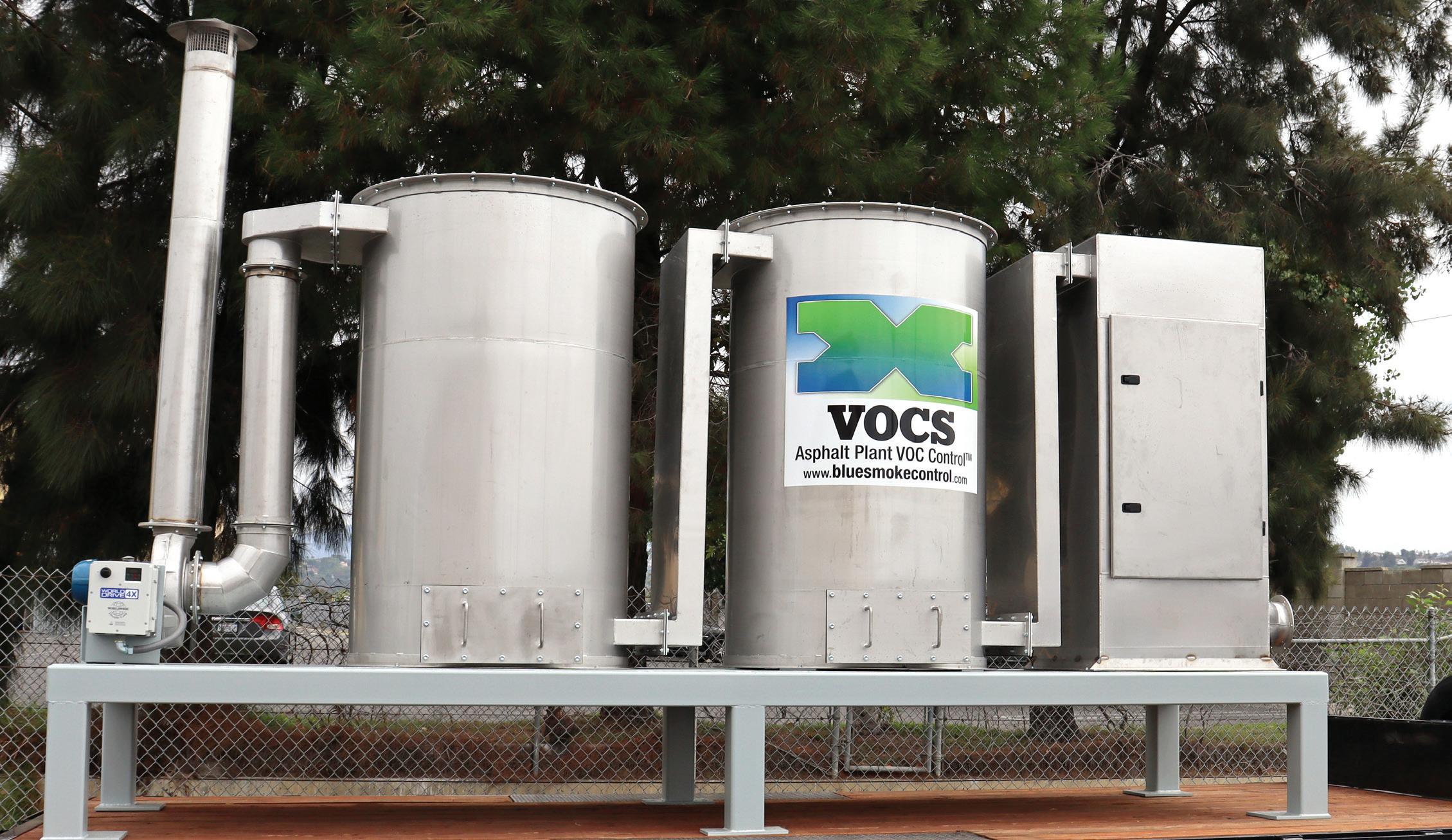
XVOCS, Model BSC 46-2-C600
Introduction
The Blue Smoke Control® XVOCS® unit is used for the collection of the blue haze (actually tiny oil droplets) that are expelled from hot oil storage tanks at hot mix asphalt plants and oil terminals. The Blue Smoke Control® XVOCS® units are designed to filter the smoke-laden air during normal operations and when the tanks are being filled.
Normal Operation
During normal operation, blue smoke-laden air enters the XVOCS® collector through a dirty air manifold connecting all tanks via a common duct manifold attached to the required vent condensers, which are attached to the hot oil tanks.
The air passes through the first (3) filter stages, which are designed to collect and coalesce large droplets and particulate. The first stage is washable and may be cleaned periodically.
During the tank-filling operation, the variable speed drive will ramp up the fan speed to collect the smoke-laden air that is displaced as the liquid level rises and the smoke is pulled from the tank through the vent condensers.
CAUTION
ALWAYS disconnect and lock out electrical power before servicing any electrical component.
Mount the properly sized starter for the blower motor in a convenient location.
Make the proper connections to the blower motor following the motor manufacturer’s instructions. All electrical apparatuses should be properly sized for the required voltage.
Start the fan/motor and check for proper rotation. Reference the rotation sticker on the blower housing. Proper rotation is extremely important. Even if the fan is running in the wrong direction, it will deliver approximately 40% of its rated air volume. Lock out all electrical input power and interchange any two wire leads (3 phase only) on the output side of the fan motor starter to reverse fan rotation.
Prestart-Up Check
Check to be sure that the inlet ducting is properly installed, and duct joints are sealed. Pitch ducting toward the XVOCS® collector to prevent oil from collecting in the ducting, which could lead to excessive weight and/or leakage. Make certain all filters are properly installed, and doors are secured.


XVOCS Filter Section


 Figure 1.1
Routine Maintenance
Monitor exhaust. Exhaust should remain visually clean throughout the filter life. If leakage is noted at the exhaust, check the fourth-stage filter element for positive gasket seals.
Monitor dirty air plenum drainage. If drainage is slow or has stopped, check the dirty air plenum drain for blockage and clean if necessary.
Monitor the third-stage filter wrap and fourth-stage filter pressure drop. Typically, if the Magnehelic gauge has risen to 7” WG, the third-stage filter wrap and/or the fourth-stage filter will need to be replaced.
Filter Service
Access the filters through the access doors. Pull out the filter closest to the door.
To clean the washable stage one filter, soak in an appropriate wash tank. Rinse and dry the filter. Reinstall it into the cabinet.
Note: Use proper protective equipment when handling asphalt oil contaminated parts.
For easiest maintenance, the third-stage filter wraps and fourth-stage filters should be changed at the same time. Change-out will be indicated when the Magnehelic gauge reaches 4” of differential pressure.
1. Pull the retention handle out and down to a horizontal position to loosen the filter.
2. Pull the filter out of the cabinet.
3. As the filter is being removed, a plastic garbage bag (supplied by the customer) can be slipped over the top of the filter. The filter may then be tipped as it is removed while the bag is being closed over the bottom of the filter.
4. Install the new filter with a new filter onto the filter retention rack with the gasket up and to the rear of the spacer plate. Push the filter to the rear of the cabinet by pushing on the installation/removal handle until it stops.
5. Lift the retention handle up until it locks into place sealing the filter to the tube sheet.
Fifth and Sixth Stage Carbon Vessels
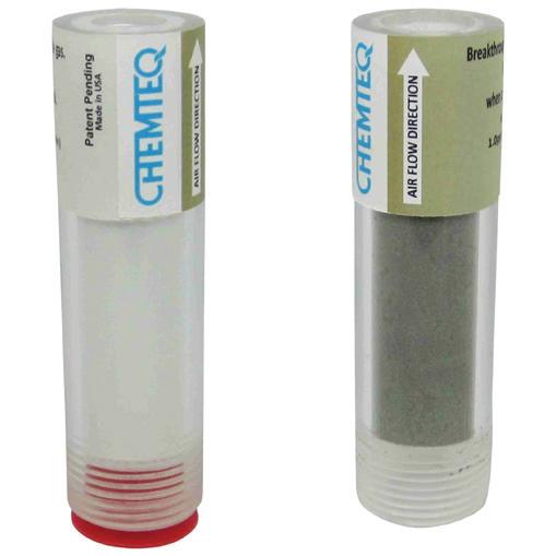
When the carbon in these vessels is spent (as indicated by the Hydrogen Sulfide Breakthrough indicator changing color to dark brown or black), the carbon in these vessels should be replaced with new or re-generated carbon.
Blue Smoke Control® X-VOCS® Carbon Absorption collectors are an industrial, self-contained, high-efficiency oil mist and VOC collector designed specifically for the Hot Mix Asphalt Industry.
The general specifications are detailed below:
Standard Housing
The units are constructed of 10-gauge, 304 stainless steel with reinforced panels and assembled onto a structural support.
Finish
Exterior base frame surfaces are painted Matte Industrial Gray (unless otherwise specified).
Filtration
The First Stage is comprised of an Amistco packed metal mesh filter. This filter is cleanable and is a dense stainless-steel mesh designed to coalesce oil droplets.
The Second Stage filter is a Merve 11 filter designed to filter out particulate. This filter should be disposed of when the filter life is determined to be completed.
The Third Stage filter is a filter wrap designed to further coalesce fine oil mist into larger filterable droplets. The vertical orientation of this filter promotes drainage of the coalesced droplets.
The Fourth Stage filter is composed of a Cartridge filter designed specially to coalesce fine oil droplets. This filter features a proprietary pleated material rated to be 95% efficient at 0.3 microns.
The Fifth Stage is a carbon bed filter containing approximately 600 pounds of activated carbon pellets specifically manufactured to absorb volatiles created in the production of hot mix asphalt. When the carbon in these beds reaches saturation, it should be removed and replaced with new or regenerated carbon.
The Sixth Stage secondary carbon bed consists of the standard carbon canister containing approximately 600 pounds of COC-HS 80 pelletized carbon specifically produced for vapor phase odor control applications involving the removal of Hydrogen Sulfide H2S.
Maintenance Access
All system filters are accessible through hinged access doors with mechanically retained oil-resistant gaskets. No special tools are required for filter access or replacement.
Hydrogen Sulfide Breakthrough Indicator Manual
1. Application
The Hydrogen Sulfide Breakthrough Indicator (PN: 185) is a qualitative (yes/no) colorimetric indicator for the end-of-service life of carbon absorbers and filters. It is designed to provide real-time indication of the breakthrough of hydrogen sulfide gas.
2. Specifications
a. Weight:
b. Dimensions:
c. Inlet dimensions:
d. Operating temperature:
e. Operating humidity:
f. Minimum detectable limit:
g. Color change:
h. Storage temperature:
i. Shelf life:
j. Service life:
k. Light effect:
Cross interferences: No interferences are known.
3. Operating Instructions
a. Ensure that the packaging pouch is intact.
28g (1.0oz)
89.9mm (3.Sin), diameter 24.5mm (1.0in)
%” MNPT
-20°C to 65°C (-4°F to 149°F)
5% RH to 90%RH
1.0ppm,min at 30 cm/sec face velocity
Light blue to brown or black
4°C to 25°C, (39°F to 77°F)
2 years at 4°C to 25°C, (39°F to 77°F}
18 months
None
b. Open the packaging pouch by tearing off the top part from one of the side notches.
c. Remove the Breakthrough Indicator from the packaging pouch.
d. Remove the 3/4” threaded plug from the carbon absorber outlet lid.
e. Remove the protective red plug to activate the breakthrough indicator.
f. Thread the Breakthrough Indicator into the 3/4” threaded carbon absorber outlet lid.

Caution: Only hand-tighten indicator into carbon absorber.
g. Replace the carbon absorber when the Breakthrough Indicator changes color to brown or black.


