UNIVERSITA’ DEGLI STUDI DI PADOVA

Department of Civil Environmental Architectural Engineering
Degree in Building and Architectural Engineering
Academic year 2020/2021
14/06/2021
PREFAB 3D CONCRETE
PRINTI
NG
/ PREFABBRICAZIONE E STAMPA 3D IN CALC ESTRUZZO
STUDENTE:
SUPERVISORE:
CO-SUPERVISORE:
SUPERVISORE ESTERNO:
CO-SUPERVISORE ESTERNO:
FILIPPO MEGLIOLI
Prof. PhD ANDREA GIORDANO
Ing. PAOLO BORIN Prof. PhD ROBERTO NABONI
Arch. LUCA BRESEGHELLO
Esplorare l’uso della Stampa 3D in Calcestruzzo nella prefabbricazione da una scala più piccola, con il disegno di una trave, ad una più grande con l’ideazione di una nuova struttura e il processo con il quale realizzarla
OBBIETTIVO
CHE COS’É?
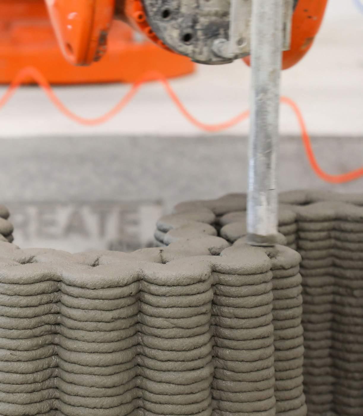
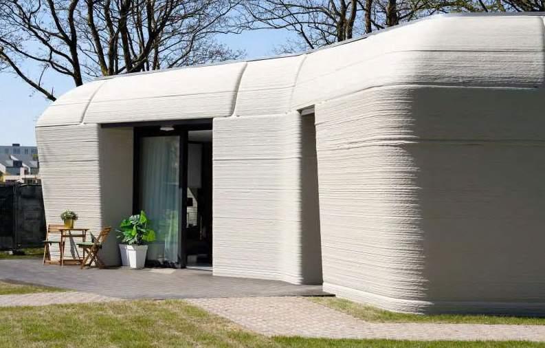
Un processo di manifattura additiva dove filamenti di calcestruzzo sono estrusi uno sopra l’altro da un sistema di spostamento per creare un oggetto tridimensionale
PERCHÉ?
RIDUZIONE DELLE EMISSIONI DI CO2
Il calcestruzzo rappresenta il 4-8% delle emissioni
RIDUZIONE DELL’USO DI ACQUA
COSTRUZIONI PIÙ VELOCI
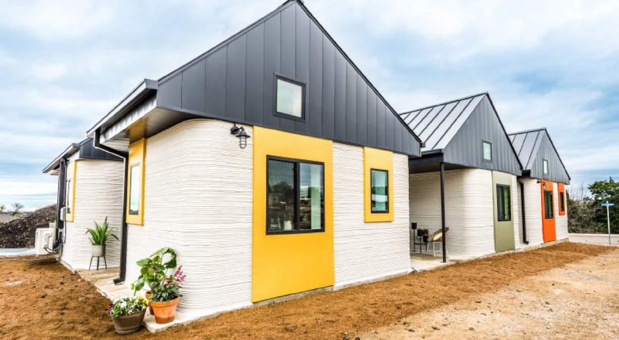
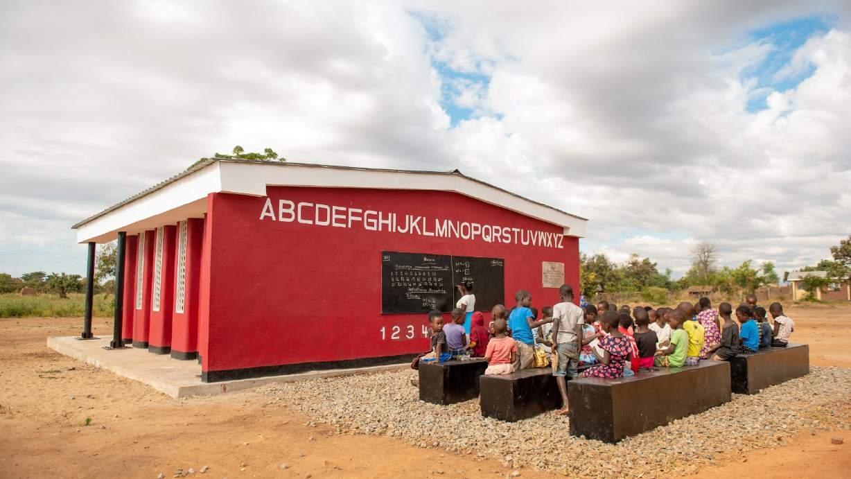
Il tempo di costruzione può essere ridotto del 50-70% (M&M, 2016)
RIDUZIONE DEI RIFIUTI DELLE COSTRUZIONI
COSTRUZIONI PIU’ ECONOMICHE
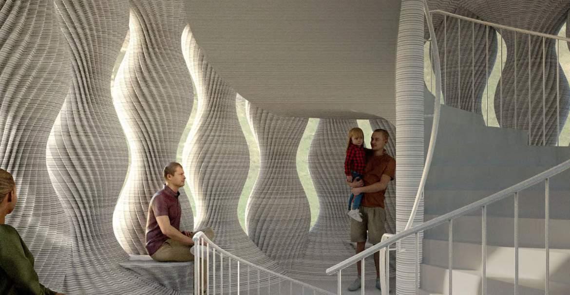
LIBERTÀ DI DESIGN


PARTE 1
STATO DELL’ARTE ESPERIENZA IN LABORATORIO
STATO DELL’ARTE
LO SVILUPPO DELLA STAMPA 3D IN CALCESTRUZZO
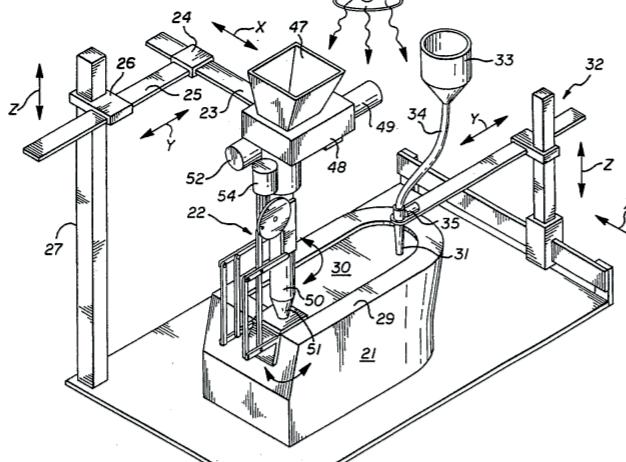
FIRST THEORIZATION OF C3DP
Prof. Khoshnevis - USA
1995
RESEARCH ON FREEFORM CONSTRUCTION Loughborough University - UK
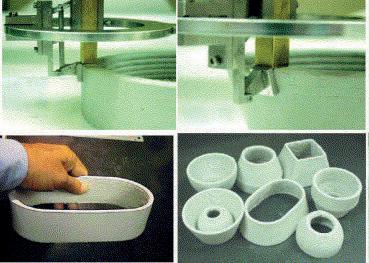
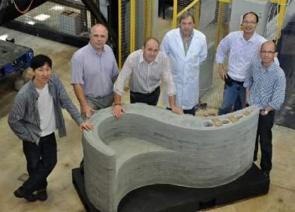
2008
START OF THE DEVELOPMENT PHASE
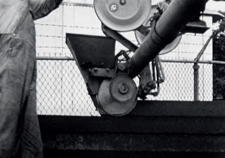
1941
MACHINE TO BUILD WALL
Urschel - USA
2004
FIRST EXAMPLE OF 3DCP
Prof. Khoshnevis - USA
2014
HIGHEST 3D PRINTED ASSEMBLED BUILDING Winsun - China

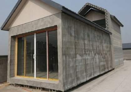
2015
FIRST 3D PRINTED ASSEMBLED HOUSES
Winsun - China
FIRST 3D PRINTED BUILDING IN EUROPE COBOD - Denmark
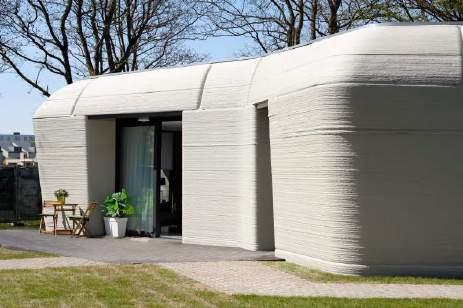

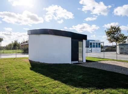
2017
3D PRINTED COMUNITY FOR HOUSELESS ICON - USA
2019
FIRST COMMERCIAL HOUSING PROJECT TU Eindhoven
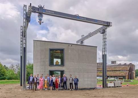
2021
2016
BIGGEST 3D PRINTED BUILDING Apis cor - Dubai
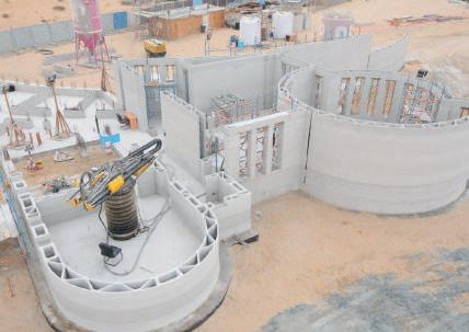
2018
FIRST 3D PRINTED BRIDGE TU Eindhoven - Netherlands
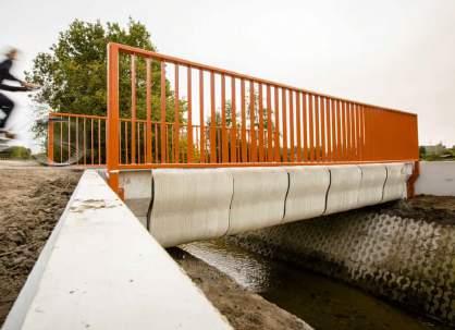
2020
FIRST PRINTED MULTIPLE STOREYS BUILDING COBOD - Denmark
SCELTA DEL SISTEMA DI MOVIMENTAZIONE ON-SITE
20
ON-SITE OFF-SITE
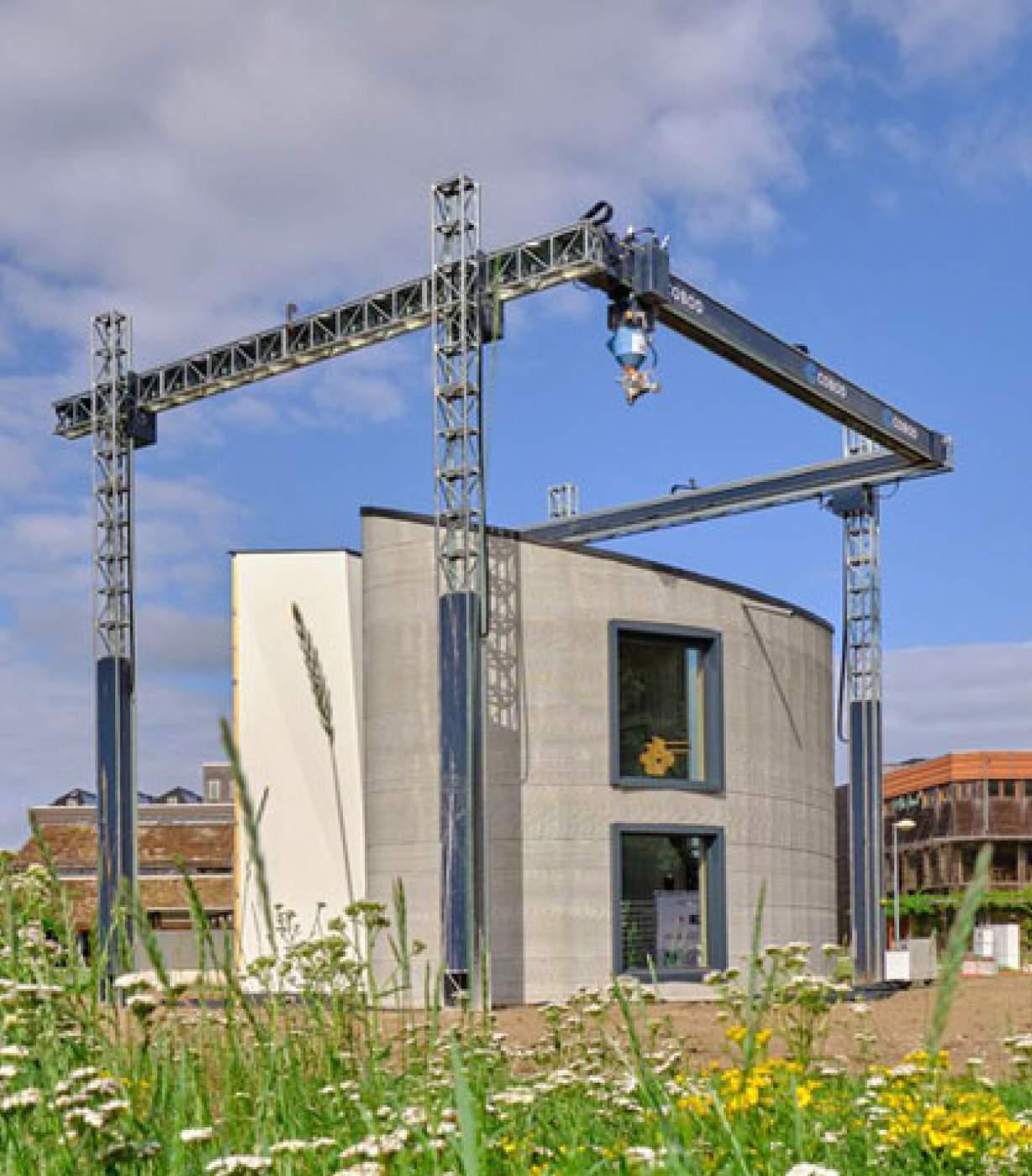 56 % Gantry System
% Movable 6-axis Robotic Arm
15 % Swing Arm
3 % 6-axis Robotic Arm
6 % Boom Arm 60 % 6-axis Robotic Arm
3 % Movable 6-axis Robotic Arm
SCELTA DEL SISTEMA DI MOVIMENTAZIONE
20 % Movable 6-axis
Robotic Arm
OFF-SITE
OFF-SITE
60 % 6-axis Robotic Arm
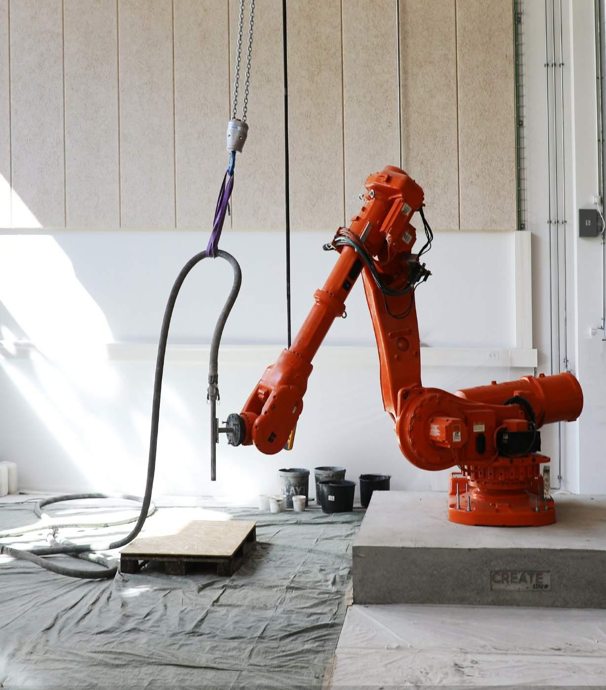
56 % Gantry System
3 % Movable 6-axis
Robotic Arm
3 % Delta system
34 % Gantry System
UN APPROCCIO COMUNE PER LE CASE
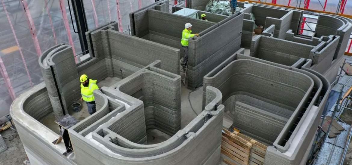
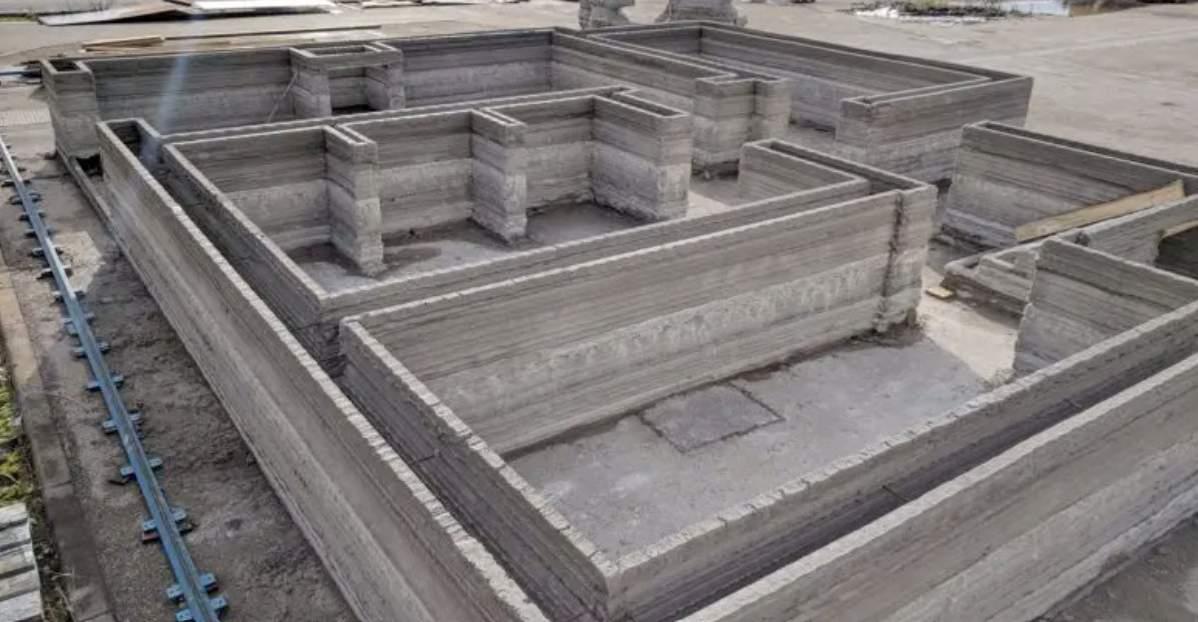
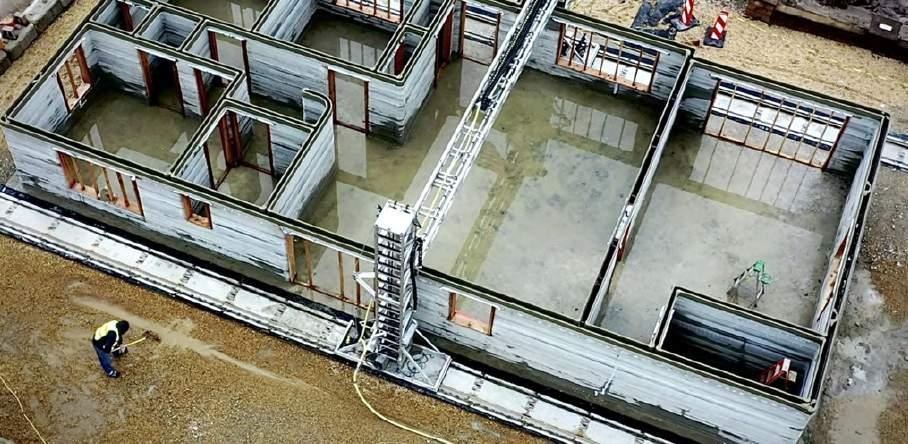
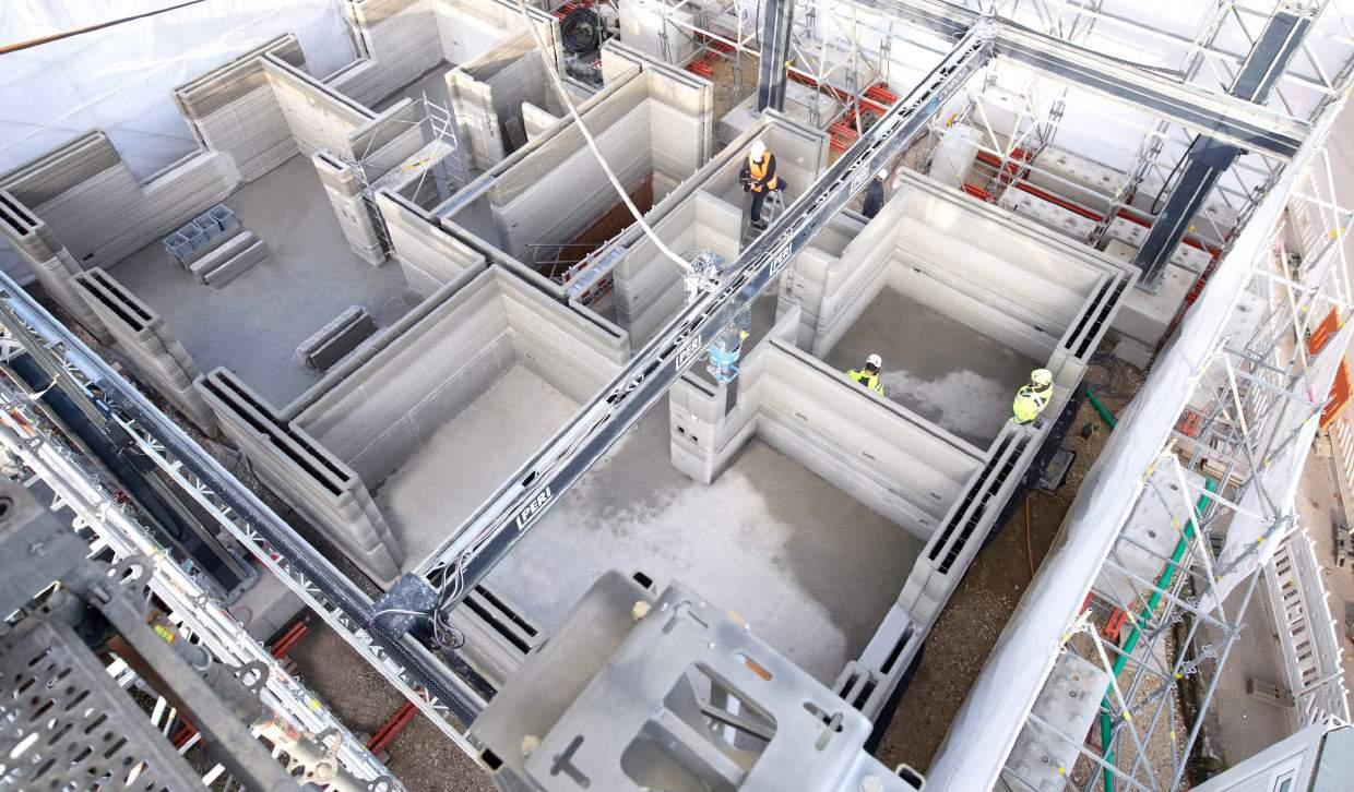
DOMANDA DI RICERCA
É POSSIBILE SFRUTTARE A PIENO I BENEFICI DELLA STAMPA 3D PER LA REALIZZAZIONE DI CASE ?
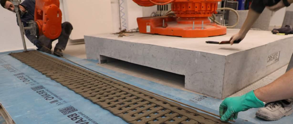
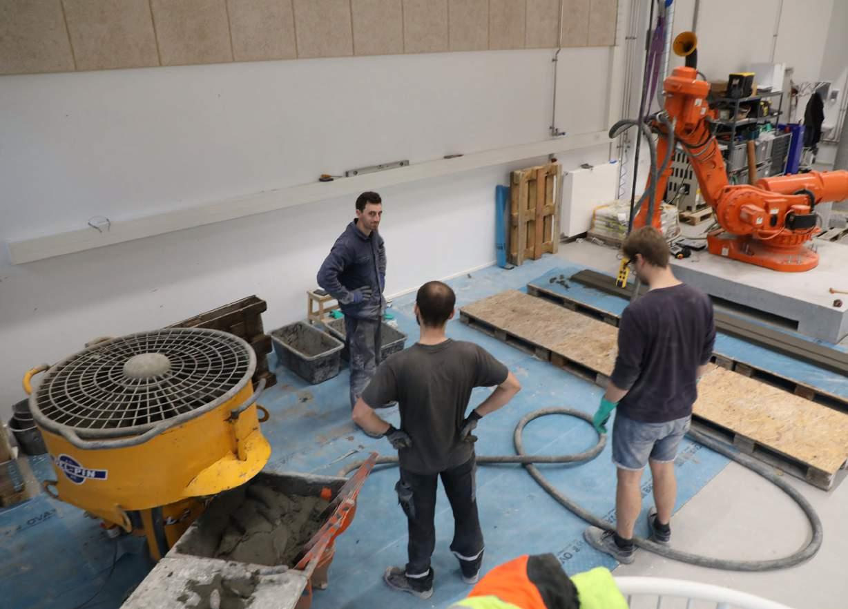
ESPERIENZA NEL LABORATORIO
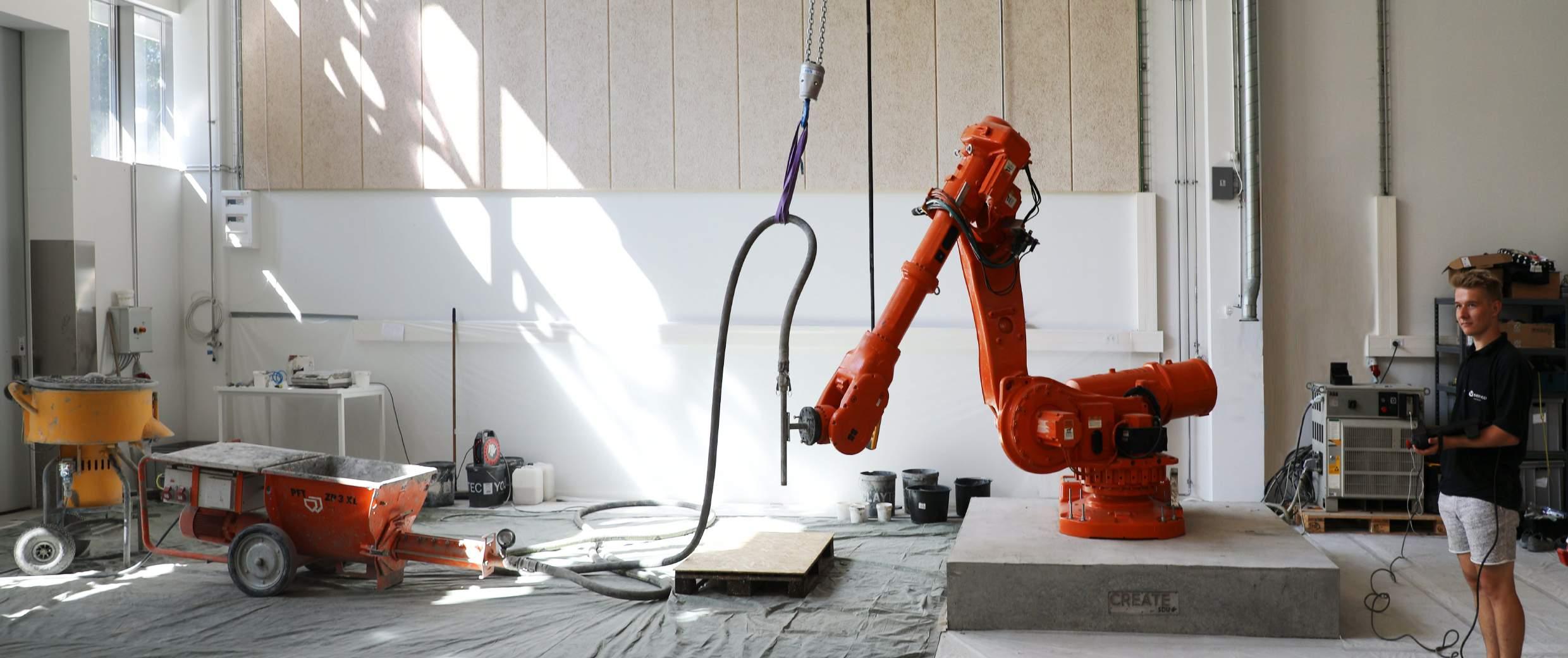
LABORATORIO CREATE
MOTION SYSTEM
MOTION CONTROL
MIXER PUMP PALLET
TEST PRELIMINARI
TEST SULLA STABILITÀ
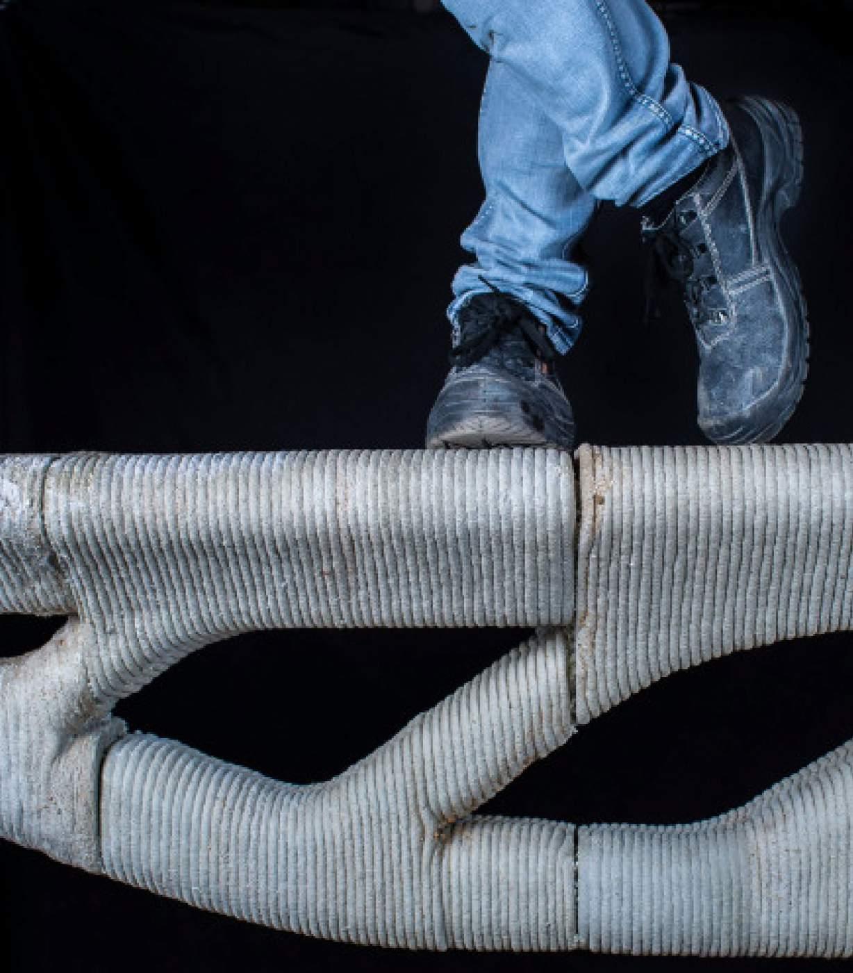
Vari test per garantire che le stampe non collassino o rispettino la qualità necessaria
RESISTENZA DEL MATERIALE
Confronto della resistenza del materiale stampato con quello gettato
INTERAZIONE CON I RINFORZI
Analisi della migliore strategia per l’inserimento dei rinforzi nelle travi
ANALISI DELLE TEMPERATURE
UNA TEMPISTICA OTTIMALE
0 5 10 15 20 25 30 Batch Temperature [°C] 00:00 Timeline [hh:mm] 00:15 00:30 00:45 01:00 01:15 01:30 01:45 00:25 Average starting time of printing Starting time of printing and batch rst temperature 1:17 Average end of printing
Temperature of batch
DI STAMPA Tempo [hh:mm] Temperatura [°C] Inizio della stampa Temperatura
OPTIMAL PRINTING TIMEFRAME
INTERVALLO
mix
SIMULAZIONI FEM
Tramite dei metodo non convenzionali è stato possibile eseguire delle simulazioni
ANALISI NON LINEARI
Grazie a Sofistik è stato possible eseguire delle analisi non lineari

RISULTATI
I risultati dell’analisi del taglio giustifica il risultato

16,9 COMPRESSION [MPa] 10.50 3.56 3.05 3.27 1.45 1.31 1.34 SHEAR [MPa] 4.01 DISPLACEMENT [mm] 224 207 TENSION OF REINFORCEMENT [MPa]
GENERAZIONE DI UN MODELLO FEM PER STAMPE 3D
DOMANDA DI RICERCA
ESISTONO ALTRI MODI PER OPERARE UN’OTTIMIZZAZIONE STRUTTURALE?
PARTE 2
B06 - CASO DI STUDIO
LAVORARE IN SEZIONE: UNA NUOVA STRUTTURA
PRELIMINARY DESIGN
calculate for each section which height bring the reinforcement to reach that value: minimum height possible for the section, by looking at the momentum of the beam. This calculus grasshopper for each section with its different value of momentum. It must be noted that s, flanges, have been calculated at each point but, as it happens in the field, a value of 30 for all the sections to simplify the design and because it guarantees that the flanges, and are under compressive stress.
so the stress of the reinforcement should be the maximum
B06 - OTTIMIZZAZIONE DELLA SEZIONE
calculate for each section which height bring the reinforcement to reach that value:

APPROCCIO
section according to t he shear force it has been calculated the minimum section needed for not shear reinforced. According to the Italian building code (NTC18) applied to the section. e are two different values that can determine the beam. , as the name suggests, is the minimum acceptable
calculate for each section which height bring the reinforcement to reach that value: height possible for the section, by looking at the momentum of the beam. This calculus grasshopper for each section with its different value of momentum. It must be noted that s, flanges, have been calculated at each point but, as it happens in the field, a value of 30 all the sections to simplify the design and because it guarantees that the flanges, and under compressive stress.
Combinare la possiblità di usare le travi T con l’utilizzo delle leggi che permettono di dimensionare una trave
height possible for the section, by looking at the momentum of the beam. This calculus grasshopper for each section with its different value of momentum. It must be noted that s, flanges, have been calculated at each point but, as it happens in the field, a value of 30 for all the sections to simplify the design and because it guarantees that the flanges, and under compressive stress.
section which height bring the reinforcement to reach that value:
CALCOLO DELL’ALTEZZA DELLA SEZIONE - MOMENTO
the section, by looking at the momentum of the beam. This calculus section with its different value of momentum. It must be noted that s, calculated at each point but, as it happens in the field, a value of 30 to simplify the design and because it guarantees that the flanges, and stress.
CALCOLO DELLO SPESSORE DELLA SEZIONE - TAGLIO
stress isn’t any compressive stress so . To calculate the minimum acceptable b it is and = . In the equations b is isolated:
shear force it has been calculated the minimum section needed for
According to the Italian building code (NTC18)
e are two different values that can determine the name suggests, is the minimum acceptable
section according to t he shear force it has been calculated the minimum section needed for shear reinforced. According to the Italian building code (NTC18) applied to the section. e are two different values that can determine the beam. , as the name suggests, is the minimum acceptable stress
minimum was chosen to be the b used for the creation of the section noted that the factor k requires the height of the section to not be any lower than
isn’t any compressive stress so . To calculate the minimum acceptable b it is and = . In the equations b is isolated:
according to t he shear force it has been calculated the minimum section needed for shear reinforced. According to the Italian building code (NTC18) applied to the section. e are two different values that can determine the , as the name suggests, is the minimum acceptable stress any compressive stress so . To calculate the minimum acceptable b it is and = . In the equations b is isolated:
to
do
strength yield
strength
Supports Shell Loads B b d c h As s yield strength


42 mm 66 mm 66 mm 84 mm 42 mm 300 mm 396 mm 110 mm 300 mm 66 mm 84 mm 66 mm 300 mm 3000mm 300mm
B06 - RISULTATO
B06 - PREPARAZIONE ALLA STAMPA
VERSO UNA SCALA PIÙ GRANDE: PREFABRICAZIONE COME RIFERIMENTO
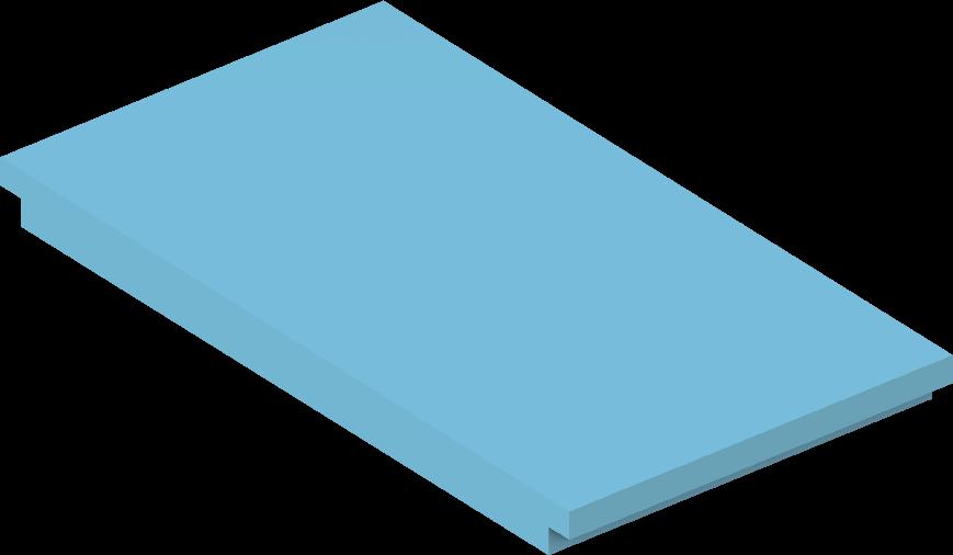


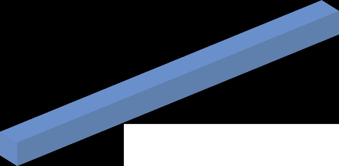
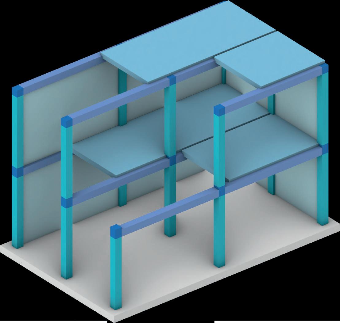
4÷8m 20÷30 cm 40÷80 cm 20÷30 cm 20÷30 cm 3÷6 m 15÷40 cm upto10m up to 4 m normal 20÷32 cm ribbed 45÷70 cm upto3m ribbednormal4÷7m 7÷10m
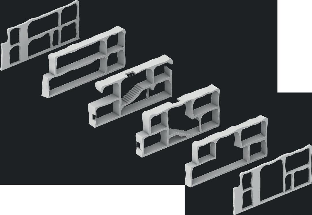
LAVORARE IN SEZIONE:
UNA NUOVA STRUTTURA
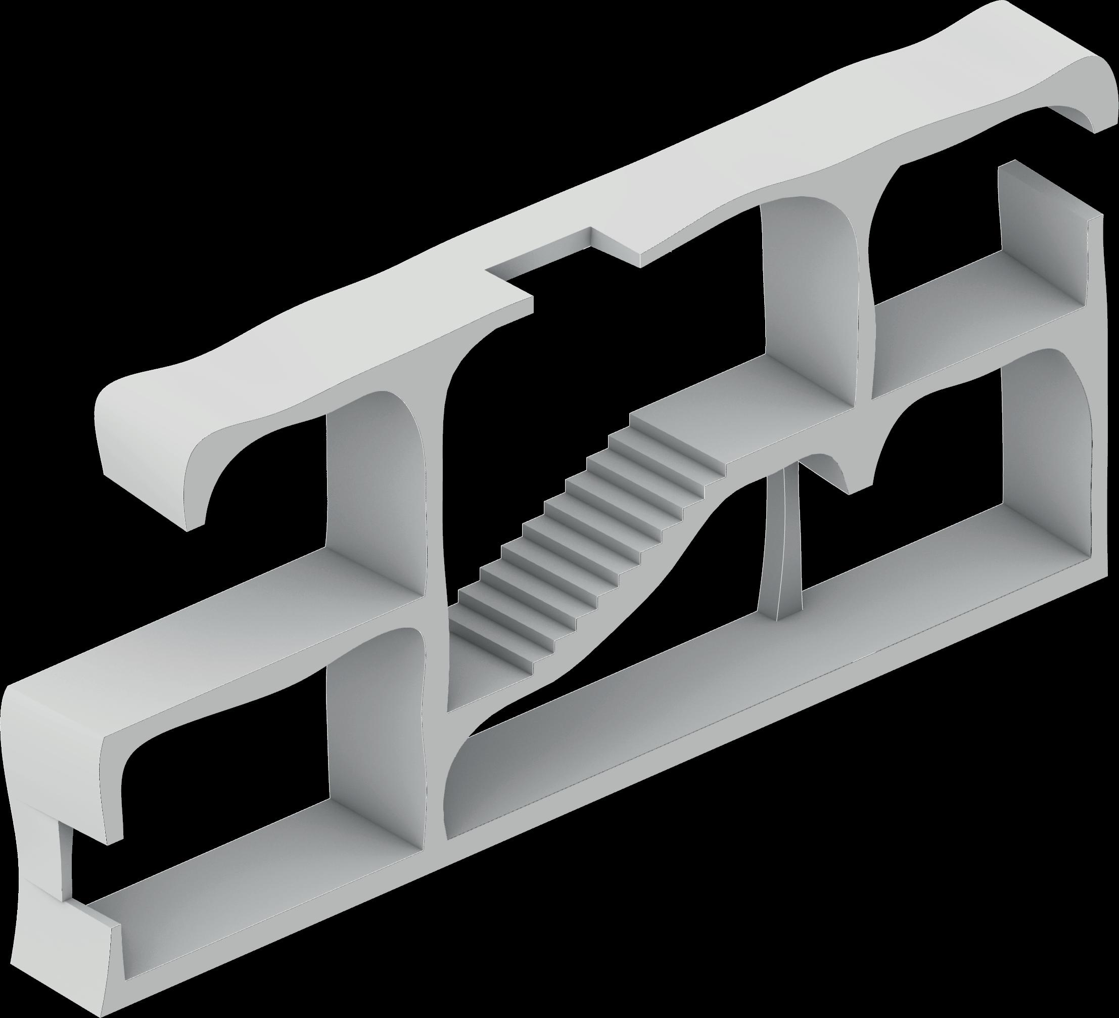
DESIGN PRELIMINARE
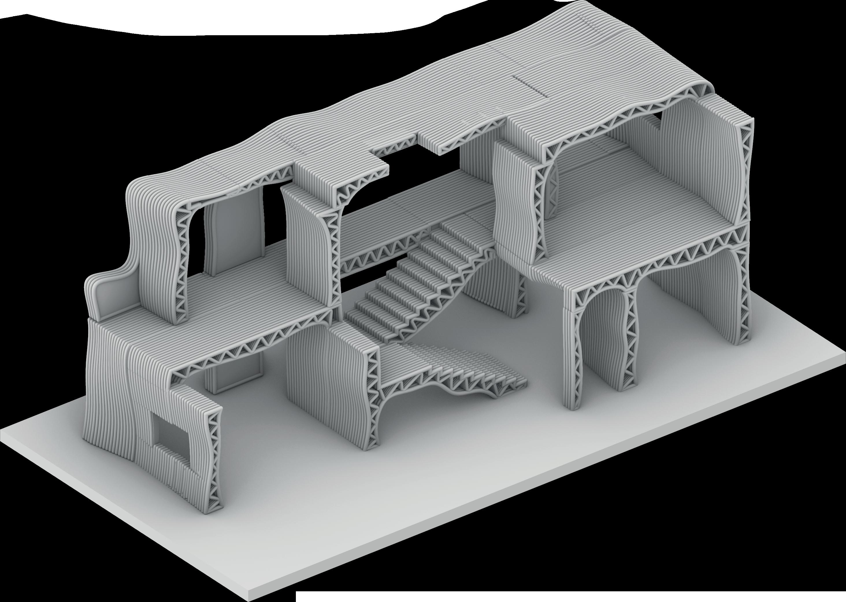
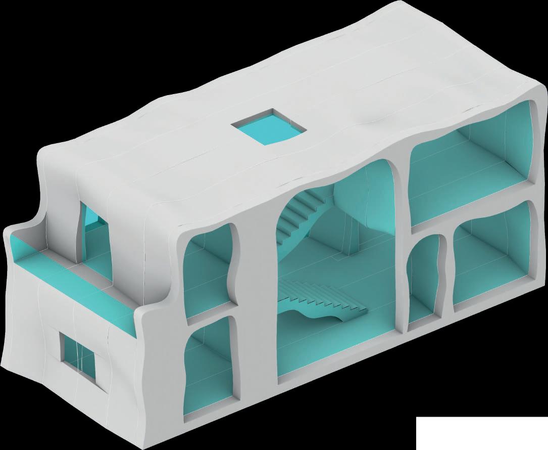
La progettazione avviene in sezione che viene poi modificata per riuscire a creare uno spazio architettontico, le sezioni sono poi estruse e poste una accanto all’altra.
OTTIMIZZAZIONE STRUTTURALE
PRODUZIONE OFF SITE
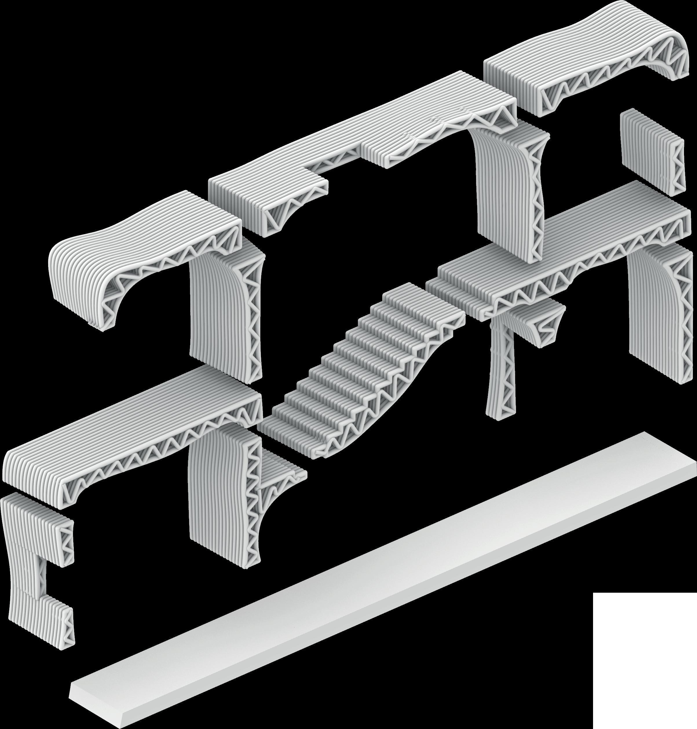
Il sistema si basa sulla prefabricazione dei componenti in una struttura adatta alla stampa 3D con il calcestruzzo
2700 2700 300 300 300 1500 300 150 180 150 5700 2100 600 600 1100 1000 10200 3000 300 300 300 2700 2700 300 300 300
OTTIMIZZAZIONE STRUTTURALE
APPROCCIO FOCUS
= Axis of translation
= Point of optimized section
= optimized section’s curve
= Point of preliminary section
= preliminary section’s curve
PRIMA DOPO
PRELIMINARY DESIGN OPTIMIZED DESIGN
Max Compressive Stress = 2,88 MPa
Max Compressive Stress = 1,52 MPa
Max Tensile Stress = 0,88 MPa
Max Tensile Stress = 0,45 MPa
OTTIMIZZAZIONE STRUTTURALE
SEZIONE 3 PRIMA

OPTIMIZED SECTION
DOPO
RISULTATO OTTIMIZZAZIONE
PREPARAZIONE ALLA STAMPA 3D IN CALCESTRUZZO
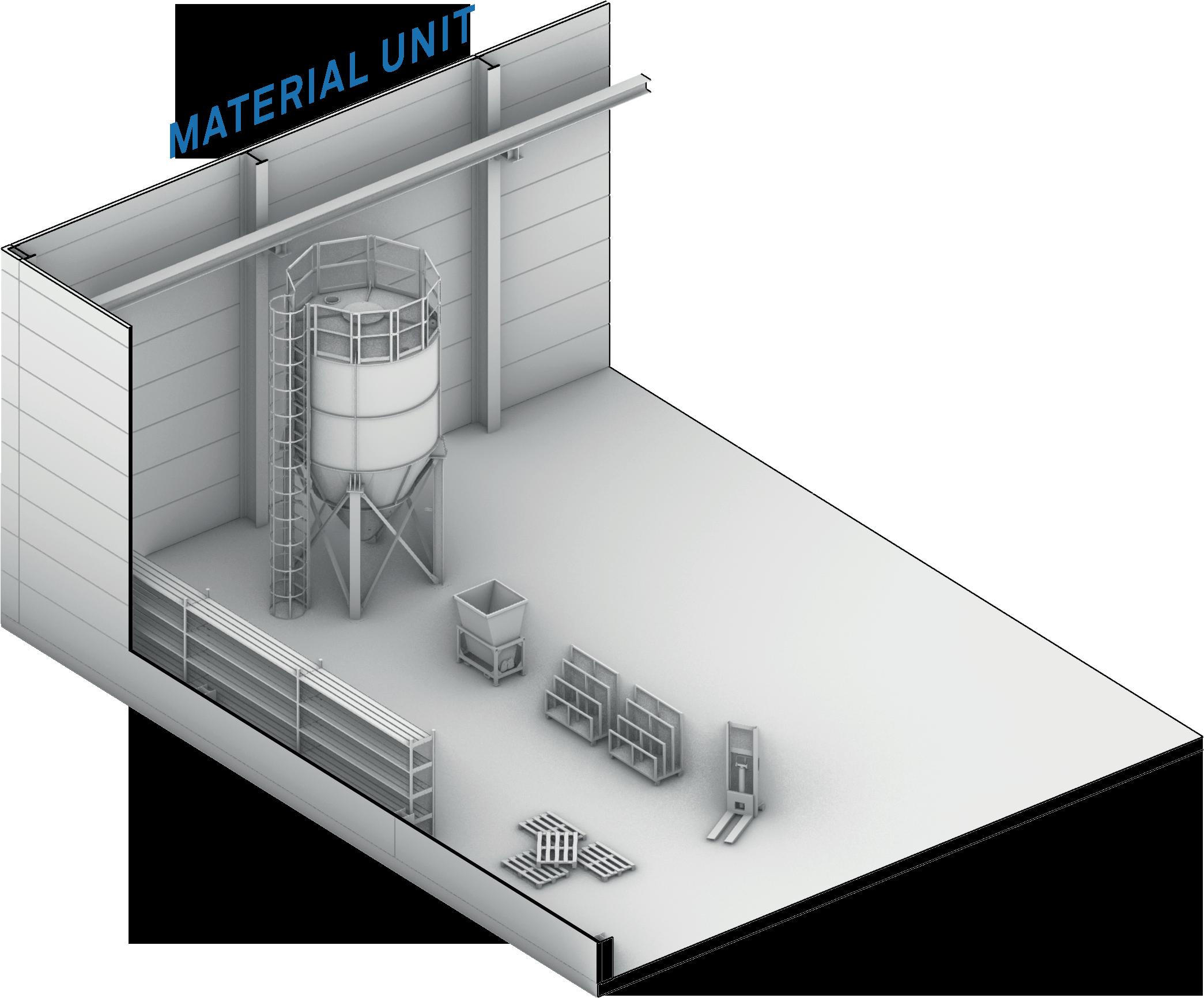
Material storage

WORKFLOW REALIZZAZIONE PROGETTO
Materials supply
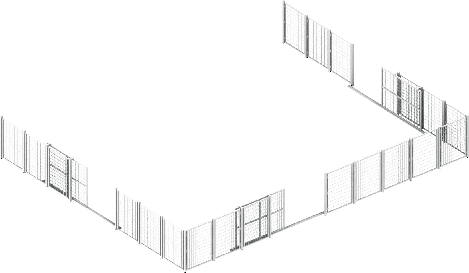
Print surfaces
1. PRODUZIONE OFF-SITE IN FABBRICA PER STAMPA 3D
Silos
Crane Bucket
Lifter
Crane
Lifter
Printed components
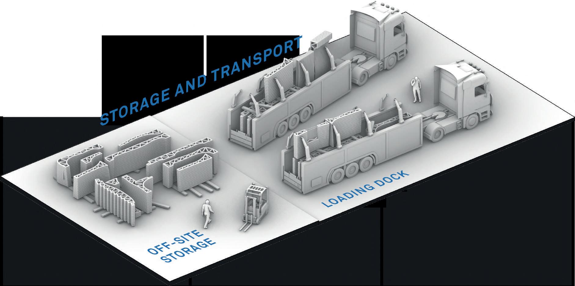
WORKFLOW REALIZZAZIONE PROGETTO
2. STOCCAGGIO E TRASPORTO DI COMPONENTI STAMPATI
Lifter InLoader
WORKFLOW REALIZZAZIONE PROGETTO
3. CANTIERE PER ASSEMBLAGGIO DELLE STAMPE
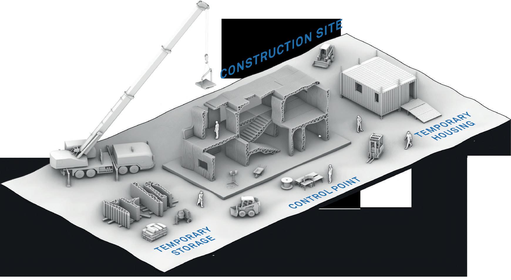
Printed components
Mixer
Mobile Crane
RISULTATI OTTENUTI
Sviluppo di un workflow per simulazione di elementi stampati 3D
Le applicazioni commerciali della stampa 3D non hanno un design particolarmente elaborato
E’ necessaria la ricerca di uno standard per la modellazione FEM di oggetti stampati in 3D in calcestruzzo
Design di una trave ottimizzata strutturalmente pronta per essere stampata
Stampare e testare B06 potrebbe dare importanti informazioni
Creazione di un workflow per il design e fabbricazione di strutture stampate in 3D ottimizzate
Un nuovo sistema di prefabbricazione è possibile ma difficile da assemblare e richiederebbe importanti risorse.
La stampa 3D in calcestruzzo ha enormi possibilità ancora inesplorate
CONCLUSIONI
GRAZIE PER L’ATTENZIONE


 56 % Gantry System
% Movable 6-axis Robotic Arm
15 % Swing Arm
3 % 6-axis Robotic Arm
6 % Boom Arm 60 % 6-axis Robotic Arm
3 % Movable 6-axis Robotic Arm


