12 minute read
Performance Pandemonium: Designing and modifying the ETFE skylight system for the Calgary Zoo’s Panda Passage Exhibit
PERFORMANCE PANDEMONIUM:
Designing and modifying the ETFE skylight system for the Calgary Zoo’s Panda Passage Exhibit
By Jelena Bojanic, BSc, P. Eng, Project Engineer, Read Jones Christoffersen Ltd.
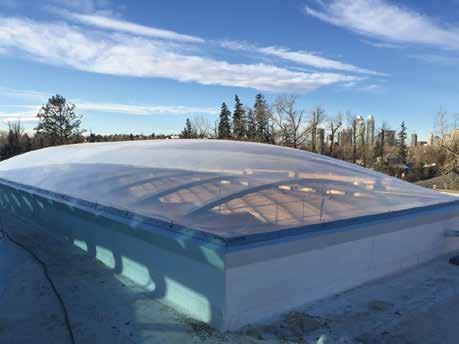
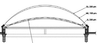
The panda exhibit ETFE skylight at the Calgary Zoo. Figure 1: Section through ETFE skylight showing thickness of individual layers. (Image imported from ETFE manufacturer’s shop drawings1.)
The former Eurasian Gateway & Elephant Crossing at the Calgary Zoo has been reused and re-adapted multiple times since 1963 to house animals including elephants, giraffes and the more recent rhinos and komodo dragons. In 2015, the Calgary Zoo announced that the giant pandas are being transferred from Toronto in 2018 to be housed in the former Eurasian Gateway building at the Calgary Zoo. The well-being of the pandas was predicated on creating a habitat in which the animals would thrive. The Calgary Zoo, along with the support of the project design team, decided to install two new ethylene tetrafluoroethylene (ETFE) skylights above the panda exhibit. ETFE is a highly transparent material over a wide spectrum of natural light providing better conditions for the pandas.
Read Jones Christoffersen (RJC) provided technical support for design considerations including snow and wind design loads, hail impact, temperature fluctuations and recommendations to address inherent air barrier deficiencies and thermal bridging. Support was also provided during the installation to ensure the intended design parameters were achieved and that performance aligned with current industry standards. The ETFE skylights were designed and manufactured in Germany and installed by a local contractor. These are some of the first ETFE installations in Western Canada.
Background
ETFE was proposed for this project because the material is one of the few tensile fabrics used for roofs that allow UV light to pass through and complies
with the living building challenge “Red List” material restrictions. Other important considerations for choosing this product included cost, future recyclability, embodied energy, durability, chemical resistance, etc. RJC’s Calgary office, along with a few other offices (Edmonton, Toronto, and Vancouver), worked together to research a product that incorporated key design objectives and that was within the client’s budget.
Originally invented for the aeronautics industry, ETFE was introduced to the construction industry in 1980s and has since been utilized on projects around the world. It is a lightweight material, weighs approximately one per cent of glass and allows up to 95 per cent of light transmission. The latter can be adjusted by varying the number of cushions and applying films. Thermal performance is higher in a threelayer ETFE system versus a singlelayer system. To incorporate the new dome-shaped ETFE skylights above the panda exhibit, the existing glulam beam supported metal roof deck underwent structural and building envelope modifications.
Design considerations
There were several design considerations the team had to take into account while working on this project, from cushion design and the supporting structure to the air barrier and drainage, and to thermal performance.
Cushion design and supporting structure
For the ETFE skylight to resist specified snow and wind loads, and hail impact, design was focused on the individual foil thickness, number of layers and internal cushion pressure. The cushions are inflated with a built-in blower/compressor that maintains air between the individual layers and pre-stresses each layer resulting in a dome shaped skylight that is stable against wind and snow loads1. The skylight manufacturer used RJC’s recommendations for snow and wind loads, and Calgary’s temperature fluctuations to ensure conformity with the local standards. RJC posed the question regarding hail impact damage testing for the ETFE. The manufacturer provided a paper with test results from experiments conducted in Zurich, Switzerland. It also highlighted case studies with hail damage. The results showed that the ETFE can, indeed, be damaged by hail, dependent on the size of individual hail pieces and temperature of the film itself2. The extent of damage varies from dimpling of the surface to full puncture2. Given that Calgary experiences severe hail storms during spring and summer months, with hail pieces 25 millimetres to 50 millimetres in size, this was an imperative design load to consider. The solution was incorporating a three-layer system with a slightly under-inflated outer cushion. The inner and outer layers (IL, OL) are each 250µm thick, while the middle layer (ML) is 100µm thick, as shown in Figure 1.
The two cushions are inflated to different internal pressures, with the inner cushion at 300Pa, and the outer at 250Pa1. The translucency of the ETFE foil was reduced slightly, with a three layered system; however, the resultant light transmittance was approximately 76 per cent3, which was within acceptable range for the panda exhibit. The inner ETFE layer is supported by steel pipe arches that are fastened to steel perimeter beams made of square tube sections. The beams are further supported by steel columns also made of square sections. Tension rods are incorporated throughout the frames to mitigate deflection of the structure.
Air barrier and drainage
The air barrier plane for the ETFE system relies on multiple components, including the ETFE foil, the ethylene propylene diene monomer (EPDM) edge gasket, the EPDM cover gasket and the air barrier membrane tied from the aluminum profile to the existing roof deck. The manufacturer’s shop drawings had inherent air barrier and drainage flaws. The design showed a condensation gutter that drained externally through the air barrier membrane (Figure 2, part 23) via four drain pipes, two on each of the east and west elevations, and none on the south and north elevations. The drain pipes were positioned at quarter points with a large spacing. A metal sheet section was shown to extend from the underside of the aluminum profile to the exterior sill (Figure 2, part 41) creating thermal bridging within the assembly.
Calgary experiences significant temperature fluctuations and extreme cold weather conditions with a winter design temperature of -32˚ Celcius4. Openings to the exterior would introduce cold air into the system, resulting in higher levels of condensation and freezing of any moisture in the system. Ice build-up inside the system could block the intended drainage path and damage connections along the gutter. Typical metal skylights glazed with sealed units
PART NO. PART NAME
1 2 4 5
Condensation gutter 7 EPDM cover gasket 9, 10, 11, 12 Stainless steel hex head bolt, washer, nut
Aluminum cover profile EPDM edge gasket Aluminum frame profile
22 Metal sill flashing 23 Condensation drain pipe 24, 25, 26 Outer, middle and inner layer of ETFE foil
29 Air barrier
41 Metal sheet Figure 2: Section through the ETFE system with external drainage (red line) through air barrier (blue line). (Image imported from ETFE manufacturer’s shop drawings1.) Figure 3: Revised ETFE system with internal drainage (green line) and air barrier detail (blue line). (Imported from ETFE manufacturer’s shop drawings1.)
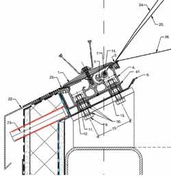
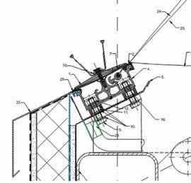
incorporate pressure equalization and internal drainage without impacting the air barrier or resulting in thermal bridging. RJC suggested that the above items be revised as they were not acceptable per industry standards. The proposed spacing between drain pipes was likely inadequate for water to access and expel out of the system and should be revised. The sill should be water and air-tight, with no unsealed openings through the air barrier. We suggested providing internal drainage if draining to the exterior was not a possibility without affecting the air barrier. The metal sheet (Figure 2, part 41) was to be modified to eliminate the thermal bridge through the skylight sill.
The manufacturer revised their design following most of RJC’s recommendations. Internal drainage was provided through the condensation gutter and directed to the interior panda space. The layout of the drain pipes was not changed during design revisions. Thermal bridging was mitigated by removing the metal sheet section intended to provide support for the roof membrane tie-in. The final design included tying the air barrier into the aluminum profile, creating a continuous air barrier plane. Figure 3 shows the revised section of the system.
Thermal performance
The thermal transmittance (U-Value) for the ETFE aluminum profile was calculated to be 5.90 W/m2K, 1.9 W/m2K for the three-layered ETFE cushion, and 2.1 W/m2K for the combined system3. These values were calculated by the manufacturer using set temperature parameters of 20˚C for interior and -10˚C for exterior3. Condensation is expected along the EPDM edge gasket and along the aluminum base. Realistically we expect a higher volume of condensation as Calgary temperatures can reach -32˚C4 during winter. This moisture is intended to drain via condensation gutter underneath the aluminum profile and expel from the system via drain pipes.
To address air and water tightness concerns ahead of time, RJC asked for a small corner sample of the aluminum profile that would show the corner joinery and frame sealing. Unfortunately, the corner sample was not provided, rather a small typical section of the frame arrived that did not show either items. RJC was told that the EPDM cover gasket would be glued at the corners with an EPDM adhesive, and the aluminum frame would not be sealed at the corners. Water that gets through the frame would be captured within the condensation gutter and drained to the interior.
Construction
In the construction industry, it is often expected that as-built details won’t always align with the initial design. This is tolerated to a degree, because one cannot predict the exact site conditions during construction. Identifying and correcting these deficiencies during early construction stages is crucial for a project to be on schedule and to avoid additional costs. During installation deficiencies with the skylight frame and ETFE
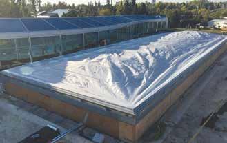
Far right: ETFE skylight above panda exhibit being inflated with a blower.
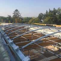
Right: Steel frame structure for ETFE skylight with steel arches, beams, columns and tensioning rods.
cushions were noted. One of the first obvious issues was the inadequate gap at the mitered corners. The aluminum profiles were misaligned such that the coupling surfaces at the corners were offset from one another. The misalignment was partially due to the aluminum profile not being set true and level. The structural steel below the aluminum profile was not perfectly level, and the aluminum profile did not incorporate adjustability (i.e. levelling nuts or incremental shims). The suggested improvement was for the contractor to adjust the positioning of the aluminum frame by using adjustable levelling bolts/nuts, see parts 9, 10 and 12 in Figures 2 and 3.
During a subsequent review, standing water was visible in the skylight gutter after a rainfall. This was prior to the ETFE foil being installed. As suspected, water was not draining properly; the system did not incorporate a transitional slope from the north and south elevations (without drain openings), nor to the east and west elevations (with drain openings). The drain layout was not practical for the perimeter of the skylights. Water was actively dripping through the condensation gutter corners and at the bolted connections, indicating that the membrane liner was not continuously sealed in these
High Performance Engineering Services
Building Enclosures Building Energy Modelling Façade Engineering Waterproofing Investigations & Evaluations

RJC Engineers rjc.ca
locations. The repair strategy included installing additional drain openings on the north and south elevations and additional sealing of the corners and at the bolted connections.
Once the ETFE cushions were attached to the aluminum profile they were inflated with the blower. Each skylight was inflated in approximately one hour, with minor adjustments required for the EPDM edge gaskets, which were displaced during ETFE install.
The contractor used ETFE tape as additional reinforcing at the corners. The air barrier membrane was tied in from the roof deck, onto the new built-up curb, and tied into the aluminum profile. In addition to the air barrier membrane, the contractor tied the thermoplastic polyolefin (TPO) single ply roofing membrane into to the aluminum profile, increasing the overall material thickness. This created problems for installing the EPDM cover gasket and cover plate. The solution was to terminate the TPO membrane at the top of the curb, instead of extending it onto the aluminum profile to allow for sufficient and continuous pressure between the gasket and the air barrier.
The metal sill flashing was installed without a slope, resulting in standing water along the sill and EPDM gasket. The flashing was modified to ensure it slopes away from the cushions and the main gasket. The EPDM cover gasket was glued at the corners and reinforced with an additional EPDM strip using an EPDM adhesive to reduce the risk of moisture ingress. Field diagnostic testing such as air leakage characterization and water penetration resistance could not be completed because of the project schedule restraints that impeded safe access for testing. RJC recommended thermographic scanning from the exterior once the building was commissioned to normal interior operating parameters.
Closure
Most of the flaws identified during the initial design and construction were corrected during each phase by being proactive with our input and discussions with the manufacturer and contractor. As the building envelope consultants, the goal was to ensure the design and installation of the ETFE skylights conformed to industry standards, with the aim of improving the long-term durability of the ETFE skylights and its supporting structure, and eliminate air/moisture barrier deficiencies. By providing recommendations for design loads, air barrier and drainage components and consistent input during construction this goal was achieved. The key benefit of the building envelope consulting services provided by RJC was the team’s local knowledge of practical issues that affect building envelopes in Calgary and the ability to bring these to the forefront, assisting the sophisticated ETFE manufacturer from Germany.
Considering that this is not a typical product installed by the construction industry in western Canada, several issues were anticipated during design and construction. As this system installation becomes more mainstream in the future these issues will likely diminish as designers and installers become more familiar with the product. References
[1] Seele Cover GmbH, Shop
Drawings and Structural Analysis
ETFE Skylights, Obing Germany, 2017-04-28
[2] Peter H. Flueler, Swiss Federal
Laboratories for Materials Testing and Research, Flueler Polymer
Consulting GmbH, Zurich
Switzerland, “ETFE Membrane
Structures: and What About Hail
Impact Resistance?”, RCI 22nd
International Convention, pp. 29-37.
[3] Seele Cover GmbH, U-value, g-value and light transmission
ETFE-cushion, 2017-06-07
[4] Alberta Building Code 2014
Volume 2
About
Jelena Bojanic, BSc, P. Eng., is a building envelope and restoration project engineer at Read Jones Christoffersen. She graduated from University of Calgary as a civil engineer. Since joining Read Jones Christoffersen in 2014, Jelena gained a wide variety of project experience in the assessment and restoration of structures and building envelopes. Her range of services include assessment and rehabilitation of structural elements, building envelopes including roofs, fall protection and heritage buildings. n


