
www.ies.org.sg


www.ies.org.sg
06 Construction demand to remain strong for 2025
08 Three new stations to connect Downtown Line to North-South Line
10 MoU signed to deliver digital and smart city solutions across ASEAN
12 Ramboll wins Best Project Award at Malaysian Construction Industry Excellence Awards 2024
Aurecon appoints new Asia Chief Executive to continue growth trajectory
COVER STORY
14 Aqueous CO2 sequestration and utilisation in ultra-low carbon concrete production
18 NTU Singapore scientists develop new 3D concrete printing method
20 Redefining learning in a digital age


President Er. Chan Ewe Jin
Chief Editor T Bhaskaran t_b_n8@yahoo.com
Publications Manager Desmond Teo desmond@iesnet.org.sg
Publications Executive Nuraini Ahmad nuraini@iesnet.org.sg
Editorial Panel
Dr Victor Sim
Dr Chandra Segaran
Dr Ang Keng Been
Dr Aaron Sham
Mr Jaime Vega Bautista Jr
Mr Soon Ren Jun
Media Representative Trevor Teh IES@mnc-link.com
Design & layout by 2EZ Asia Pte Ltd
Cover designed by Irin Kuah
Cover images by Dr Zhao Ming Shan


www.ies.org.sg
24 Engineering for a digital future
26 Funding support to accelerate adoption of technological solutions and equipment
28 Implementation of Earth Control Measures at construction sites
30 Design economics of offshore integrated energy farms
37 Developing the heart of Luyang
38 Slewing bearing for Europe’s largest lifting swing bridge
39 The SP 33 slipform paver
40 Zoomlion releases aerial work platform


The Singapore Engineer is published monthly by The Institution of Engineers, Singapore (IES). The publication is distributed free-of-charge to IES members and affiliates. Views expressed in this publication do not necessarily reflect those of the Editor or IES. All rights reserved. No part of this magazine shall be reproduced, mechanically or electronically, without the prior consent of IES. Whilst every care is taken to ensure accuracy of the content at press time, IES will not be liable for any discrepancies. Unsolicited contributions are welcome but their inclusion in the magazine is at the discretion of the Editor.


The Building and Construction Authority (BCA) projects the total construction demand, i.e. the value of construction contracts to be awarded, to range between SGD 47 billion and SGD 53 billion in nominal terms, in 2025. Normalised to real values, 2025’s demand is projected to range between SGD 35 billion and SGD 39 billion, which is between 0.3% to 11.7% higher than pre-COVID levels in 2019.
The strong demand is underpinned by the expected award of contracts for several large-scale developments, such as Changi Airport Terminal 5 (T5) and the expansion of the Marina Bay Sands Integrated Resort, alongside public housing development and upgrading works.
Other contributors include highspecification industrial buildings, educational developments, healthcare facilities, Mechanical and Engineering contracts for the Thomson-East Coast Line Extension (TEL) and Cross Island Line (CRL), and infrastructure works for the Woodlands Checkpoint extension and the Tuas Port.
construction
The preliminary total construction demand for 2024 reached SGD 44.2 billion in nominal terms, exceeding BCA’s mid-year revised forecast of between SGD 35 billion to SGD 41 billion. This was mainly attributed to the rolling out of more public institutional projects, as well as public and private housing projects.
Over the medium-term, BCA expects the total construction demand to reach an average of between SGD 39 billion and SGD 46 billion per year from 2026 to 2029.
The medium-term demand will continue to be supported by developments such as T5, a steady pipeline of public housing
developments, MRT projects such as the Cross Island Line (Phase 3) and the Downtown Line Extension to Sungei Kadut, Integrated Waste Management Facility (Phase 2), Tengah General and Community Hospital, Siglap South Integrated Development, Woodlands North Coast industrial estate, redevelopment of various Junior Colleges, commercial building redevelopments, and other urban rejuvenation developments.
While the medium-term construction demand is projected to be robust, the schedules and phasing of projects are subject to change, particularly due to potential unforeseen risks arising from an uncertain global economic climate. Furthermore, as the T5 development is likely to be a oneoff, exceptional project, over the medium term, overall industry demand could eventually moderate after this period.
Based on the contracts awarded in the past few years and the construction demand forecast for 2025, total nominal construction output is projected to increase to between SGD 39 billion and SGD
42 billion in 2025, up from the preliminary estimate of about SGD 38.4 billion in 2024.
The anticipated uptrend is expected to be supported by the increase in actual construction demand over the last few years and the expected increase in 2025 construction demand.
Normalised to real values, total construction output in 2025 is projected to range between SGD 30 billion and SGD 32 billion, which is slightly higher than that in 2019.
Adjustments to CORENET X implementation timeline
Against the backdrop of robust demand projections, Singapore’s Built Environment sector will continue its transformation efforts to achieve better outcomes through better coordination and increased productivity. A key component in this transformation effort is CORENET X, a one-stop digital platform for integrated regulatory submissions for building works.
Over the past year, the regulatory government agencies have been working closely with industry partners and practitioners on CORENET X. Feedback from industry has been useful in refining
p: Preliminary; f: Forecast
*Construction demand: Value of contracts awarded
^Construction output: Value of certified progress payments
Construction demand and output.
the processes and the platform. Many firms have invested resources and successfully submitted their projects via CORENET X during the voluntary submission phase.
The hands-on experience gained from going through the new regulatory processes in actual projects was invaluable in strengthening collaboration amongst project teams and fostering better understanding of the new CORENET X requirements. Insights gleaned from these projects also helped project parties to review their internal processes, to be able to leverage CORENET X for more streamlined workflows across the value-chain.
It is recognised that CORENET X entails significant changes to existing workflows and that some firms need more time to adjust internal processes and familiarise themselves with the new requirements. In addition, smaller consultancy firms may not have had sufficient projects to try out the new processes during the voluntary submissions phase. Hence, the implementation
timeline will be adjusted, as shown in the tabulation below.
For smaller-sized new projects with GFA below 30,000 m2, project teams are encouraged to take the opportunity to make submissions through CORENET X ahead of the mandatory timelines, to familiarise themselves with the new process and submission portal.
Aside from CORENET X, the Built Environment sector is also fostering closer collaboration via collaborative contracting.
Collaborative contracting is a mechanism that facilitates deeper collaborations amongst developers, consultants and builders. It provides a framework that allocates risks and gains more equitably. It aligns the incentives of parties, builds trust, and encourages everyone to work towards better project outcomes.
In 2024, BCA, together with NEC, launched an additional set of contract clauses (Y clauses) to adapt the NEC4 contract form with
Date Implementation
1 October 2025
1 October 2026
1 October 2027
Singapore’s laws. To further support the adoption of NEC4 contracts in Singapore, BCA has further developed additional clauses (W and Z clauses) that incorporate local dispute resolution protocols, current Government procurement rules, and established local industry practices.
NEC is a division under Thomas Telford Ltd, the commercial arm of the Institution of Civil Engineers (ICE), the owner and developer of NEC suite of contracts.
The NEC4 contract is the latest edition of a suite of collaborative contracts for construction and facilities management projects.
Firms may download these clauses and other resources, from BCA’s website, to kickstart their collaborative contracting journey. Also, BCA Academy, industry associations (e.g. the Society of Construction Law), Institutes of Higher Learning (e.g. Singapore University of Social Sciences), and other training providers, have introduced programmes for firms to build up their skills and competencies in collaborative contracting.
Mandatory CORENET X submission for all new projects with Gross Floor Area (GFA) ≥ 30,000m2
Mandatory CORENET X submission for all new projects, regardless of GFA
Mandatory onboarding to CORENET X for all ongoing projects
Timeline for implementation of CORENET X.
W clauses
Z clauses
Details of W and Z clauses.
Dispute resolution options incorporating local dispute resolution protocols and practices, such as the Singapore Infrastructure Dispute-Management Protocol 2018 (SIDP) and appointment of Senior Representatives for dispute resolution.
Additional conditions of contract for project-specific requirements that take into consideration public sector procurement requirements and local practices. This includes the use of eGuarantee template, Progressive Wage Mark requirements and suitable project response timelines.
The Land Transport Authority (LTA) has announced the alignment and station locations for the Downtown Line 2 extension (DTL2e). DTL2e will connect the Downtown Line (DTL) from its existing terminus at Bukit Panjang station to a new NS6/DE2 interchange station on the NorthSouth Line (NSL).
Enhanced accessibility and time savings for commuters
The route length of DTL2e is approximately 4 km. Travelling towards the northwest, the first station (DE1) after Bukit Panjang Station will be an underground station located along Sungei Kadut Avenue. The new terminus for the DTL will be an underground interchange station (DE2) connected to a new aboveground NSL station (NS6) between Yew Tee and Kranji stations.
These new stations will enhance rail connectivity in the northwestern region, providing improved access to existing and new growth areas such as Yew Tee Village and the future Sungei Kadut EcoDistrict, as well as amenities such as the Rail Corridor and Pang Sua Park Connector.
DTL2e will shorten travel times for commuters travelling to and from the north and north-western parts of Singapore. For instance, a commuter travelling from Yew Tee Village to Chinatown will enjoy travel time savings of 20 minutes – from an hour by train and bus today, to 40 minutes on the DTL.
In addition, DTL2e will improve rail network resilience in the north-western region, by providing commuters with alternative travel and transfer options for their journeys. Residents living in the north-western region can currently take the NSL or Thomson-East Coast Line to travel to the downtown area. DTL2e will provide another MRT route for commuters to reach their


Artist's impression of NS6/DE2 interchange station.
destinations in the city centre.
Construction works for DTL2e are expected to commence in the fourth quarter of 2025, with the stations opening by 2035. The Environmental Study for DTL2e, which involved the engagement and consultation of nature groups, has been completed. The relevant reports will be published on LTA’s website for public feedback.
An Environmental Monitoring and Management Plan will be implemented, with mitigation measures to minimise the environmental impact of the works. These include the provision of a wildlife corridor along the Rail Corridor, during construction, to allow continued movement of
fauna, as well as regular monitoring of sensitive habitats by ecologists for adaptive management.
When DTL2e is completed, the DTL will have a total of 39 stations, including the upcoming Hume station that will open in the second quarter of 2025, as well as the DTL 3 extension (DTL3e) comprising Xilin and Sungei Bedok stations that will open in the second half of 2026.
Together with other rail network expansions over the next decade, DTL2e will bring the country one step closer to achieving the Land Transport Master Plan 2040 target of having 8 in 10 households within a 10-minute walk to a train station, by the 2030s.


The Chartered Engineering Registry aims to provide professional recognition to qualified Engineers, Technologists and Technicians across all sectors.
Being registered as a Chartered Engineering Professional will be an external validation of your experience, expertise and practising competence; and is a quality mark to differentiate your professional standing in the following sectors of engineering:


Japan Overseas Infrastructure Investment Corporation for Transport and Urban Development (JOIN) and Meinhardt (Singapore) Pte Ltd recently signed a Memorandum of Understanding (MoU) to jointly explore and deliver digital and smart city projects in third countries, with a special focus on ASEAN nations.
The MoU was formalised at the Meinhardt Group headquarters in Singapore by Mr Tatsuhiko Takesada, President and CEO of JOIN, and Mr Omar Shahzad, Group CEO of Meinhardt, in the presence of representatives from the Singapore Cooperation Enterprise (SCE); Ministry of Land, Infrastructure, Transport and Tourism (MLIT) of Japan; Embassy of Japan in Singapore, and Economic Research Institute for ASEAN and East Asia (ERIA).
The MoU underscores a shared commitment to promoting innovation and sustainable urban development in third countries by leveraging the complementary expertise and synergies of both organisations, and their respective ecosystems.
JOIN is able to garner its extensive network and expertise in supporting Japanese infrastructure exports whilst Meinhardt can bring to bear its global leadership in integrated planning, design and project management solutions. Together, the two parties aim to advance innovative and sustainable urban solutions, especially in the growing sector of digital and smart cities. By exchanging knowledge and resources, the collaboration aims to catalyse transformative projects that prioritise citizencentric solutions, digitalisation and sustainability.
The collaboration is set against the backdrop of the Memorandum of Cooperation (MoC) signed between MLIT and SCE in

November 2024, which fosters the development of digital and smart cities in ASEAN and other regions. Building on this framework, the MoU will provide a platform for JOIN and Meinhardt to share information, identify synergies and collaborate on projects from the early stages, to drive meaningful impact across borders.
Mr Tatsuhiko Takesada, President and CEO of JOIN, said, “We are pleased to sign this MoU with Meinhardt today. We look forward to further strengthening our partnership with Meinhardt and working together to encourage both Japanese and Singaporean companies to participate in digital and smart city projects from the upstream stage.”
Mr Omar Shahzad, Group CEO of Meinhardt, said, “This partnership marks a significant milestone in deepening our engagement with like-minded Japanese partners, especially in international markets where Meinhardt Group has strong presence.”
“We see our collaboration with
JOIN as an important opportunity to harness our collective capabilities, creating innovative and practical solutions that address urban challenges, while ensuring long-term sustainability and commercial viability. Together, we can better shape the foundations of people-centric cities, and smarter and more connected communities across ASEAN and beyond,” he added.
JOIN and Meinhardt share a common mission of delivering excellence in urban development and infrastructure projects. With JOIN’s mandate to support Japanese businesses through policy-based investments and Meinhardt’s legacy of engineering innovation, the partnership is well-positioned to lead the way in digital and smart city transformations. The partnership will also contribute to the broader agenda of strengthening bilateral ties between Japan and Singapore, showcasing the power of publicprivate collaborations to drive innovation and economic growth.

Ramboll, together with IJM Construction, won the 2024 Malaysian Construction Industry Excellence Awards in the Best Project category for the civil and structural design work done for Affin Bank, situated within Tun Razak Exchange in Kuala Lumpur.
The Malaysian Construction Industry Excellence Awards, presented by Construction Industry Development Board (CIDB) Malaysia, recognises projects by organisations that have pioneered innovation, quality and sustainability, and have made significant contributions to the industry.
The Affin Bank development comprises a 43-storey office tower atop a 4-storey podium carpark and three basement levels. Its 210 m high main structural frame is supported by reinforced concrete (RC) perimeter columns and an off-centred core wall, with RC flat slabs providing horizontal load distribution.
At level 26, four of the tower columns were transferred, altering the building’s structural behaviour and drift performance. To address this challenge, an outrigger system was designed and implemented at level 28.
This system effectively redistributed loads, reduced lateral deflection, and enhanced overall stability, ensuring the building’s structural integrity under wind and seismic forces.
Additionally, the off-centred core wall presented its own complexities, requiring precise analysis and engineering to maintain balance and stiffness in the tower. The integration of these advanced solutions highlights the ingenuity and precision required to construct a high-rise of this scale in a dense urban environment.
An innovative solution was also implemented to eliminate two mega columns in the auditorium area, avoiding the need for a transfer floor and significantly reducing superstructure costs. Notably, it is the only high-rise in the development built without a piled foundation, achieving additional savings of RM 20 million to 25 million, through advanced geotechnical engineering.
Ramboll has successfully showcased its commitment to innovation, quality and sustainability across the industry with a number of structurally challenging projects in Malaysia.
The company is a global

architecture, engineering and consultancy founded in Denmark, in 1945. In the Asia Pacific, Ramboll brings integrated expertise and experience in the built and natural environments to drive sustainable change.
International design, engineering and advisory company, Aurecon, has announced the appointment of Mr Gabe Carter as its new Chief Executive for Asia to drive the company’s continued growth across the region.
Effective 1 March 2025, Mr Carter will join Aurecon’s Group Executive Leadership Team and relocate from Thailand to Singapore, overseeing the performance of approximately 2,100 people across nine locations.
The current Aurecon Asia Chief Executive, Mr Stephane Asselin, will transition into the role of Senior Advisor at Aurecon. In this role, Mr Asselin will work closely with Aurecon’s Chief Client & Growth Officer, Mr Andrew Maher and his team, focusing on client management and strategic market development across Asia
Pacific.
Mr Carter joined Aurecon in 2003, after graduating from the University of New South Wales in Australia, and since then has played a pivotal role in delivering several major projects across Asia Pacific.

With over a decade of experience in Asia, Mr Carter’s comprehensive understanding of the region’s unique market dynamics and invaluable local knowledge has helped him build many enduring client relationships. In 2021, Mr Carter was promoted to Aurecon’s Managing Director for Vietnam and Thailand, leading a team of 700 people.

by Dr Zhao Ming Shan, Assistant Professor, Engineering Cluster, Singapore Institute of Technology (Team Leader); Er. Colin Yip, Woh Hup (Private) Limited (Team Member); Dr Daneti Saradhi Babu, Alliance Concrete Singapore Pte Ltd (Team Member); Mr Chua Guan Feng, Singapore Institute of Technology (Team Member); Ms Jamie Yujie Chong, Singapore Institute of Technology (Team Member); Mr Yeo Tze Yuen, Singapore Institute of Technology (Team Member); and Dr Jin Fei, School of Engineering, Cardiff University, UK (Team Member)
The team developed an innovative, cost-effective aqueous carbon sequestration system to produce sustainable ready mixed concrete (RMC), addressing environmental and industry needs in Singapore. This system uses carbon dioxide (CO2)-enriched solutions to replace plain water, converting inorganic carbon into nano-sized calcium carbonate (CaCO3) that is permanently stored in the concrete. The nano-CaCO3 enhances cement hydration and reacts with cement components to allow up to 80% replacement with blast furnace slag, reducing embodied carbon by 65%.

Aqueous CO2 sequestration and utilisation in ultra-low carbon concrete production. The developed aqueous CO2 sequestration and utilisation technology innovatively introduces nano-sized CC particles in the fresh cement, which act as effective nucleation sites for the formation of C-S-H. Simultaneously, they react with aluminate phases in PC and GGBS to form hemicarbonate and monocarbonate, stabilising the voluminous ettringite, thereby reducing porosity and enhancing the long-term properties of hardened cement and concrete.
INTRODUCTION
Urbanisation and economic development increase the demand for new buildings and infrastructure, consequently escalating the need for concrete. Currently, concrete materials are responsible for over 50% of global resource consumption (the second most used material by
mass, after water) and their usage is projected to more than double by 2060. Although concrete has a low specific CO2 emission, of less than 200 kg/m3, its extensive use accounts for 8% of man-made CO2 emissions, thereby becoming a major contributor to climate change. Over 90% of concrete’s carbon
footprint arises from the production of Portland cement (PC) clinker, used at approximately 400 kg/m3 in normal concrete. In Singapore, around 12 million m3 of RMC is used annually, contributing approximately 4.8 million tonnes of embodied carbon per year (about 9% of total carbon emission in
Singapore, as per the data from the 2022 statistics).
To achieve the target of net zero by 2050 and accommodate the growing demand for new buildings and infrastructure, there is a compelling need for commercially viable low/ultra-low carbon RMC.
The team addressed the environmental and industry demands for sustainable construction materials through several innovations, including the following:
• Sustainable development via the use of an aqueous CO2 mixing method to enable up to 80% PC replacement in RMC and reduction of embodied carbon by up to 65%.
• Achieving improvements in concrete production, such as enhanced workability and cooler fresh concrete to facilitate transportation without additional energy input.
• Achieving cost-effectiveness with only a marginal increment in operational cost.
• Achieving enhanced engineering properties including higher early strength and better workability, with comparable permeability and durability.
The team specifically focused on developing a cost-effective aqueous carbon sequestration and utilisation system for the production of low/ ultra-low carbon RMC. This was achieved by experimenting with different CO2-enriched solutions to replace plain mixing water during the production of fresh concrete, with various design mixes.
The CO2-enriched solutions are produced using an agitated aeration system that injects gaseous CO2 into a liquid medium which has the capacity to chemically bond and retain CO2 stably in a pressurised or unpressurised tank.
The carbonated mixing water effectively sequesters CO2 and reacts with PC to introduce uniformly distributed nanosized CaCO3 into the cement matrix, fixing CO2 up to 0.6% by

Nucleation sites of nano-sized CaCO3 formed in the cement paste with 80% GGBS. Dissolved inorganic carbon (DIC) is converted into nano-sized CaCO3 and stored permanently in concrete. Nano-sized CaCO3 (300 nm to 500 nm) acts as a filler to provide additional surface for nucleation and the formation of hydration phases such as calcium-silicate-hydrate (C-S-H).

Scanning electron microscope - Energy Dispersive Spectroscopy (SEM-EDS) identifying uniform distribution and mingling of CaCO3 with aluminate phases in the cement paste incorporating 80% GGBS. The current technology converts a small portion of free calcium in the fresh concrete into calcium carbonate during early carbonation. The remaining large portion of cement will undergo the normal hydration reaction process which produces typical hydration products, such that alkalinity of the pore solution and paste remains high at pH>12, and thermogravimetric analysis suggests that there is abundant Ca(OH)2 remaining in the hardened concrete after 28 days.
weight of PC, as quantified by thermogravimetric analysis (TGA).
Compared to other commercially available gaseous CO2 mixing/ curing methods that rely on twophase gas-solid reactions (with direct carbonation efficiency typically between 0.1% and 0.5%), this technology sequesters CO2 through single-phase reaction between the dissolved inorganic carbon and PC in the semi-fluid state, hence increasing the
sequestration rate and efficiency.
Essentially, this technology innovatively introduces nano-sized calcium carbonate (CC) particles in the fresh cement, with significantly high surface area and chemical reactivity. The nano-sized CC particles act as effective nucleation sites for the formation of calciumsilicate-hydrate (C-S-H) which is the main strength-giving phase in PC and reduce the effective water-to-cement ratio, significantly
shortening the induction period of cement hydration and accelerating early strength development.
Simultaneously, they react with aluminate phases in PC and ground granulated blast furnace slag (GGBS) to form hemicarbonate and monocarbonate, stabilising the voluminous ettringite. These reactions increase the volume of the hydrates, thereby reducing porosity and enhancing the longterm properties of hardened cement and concrete.
PRACTICE AND ENVIRONMENTAL ASPECTS
While PC clinker can be partially replaced with supplementary cementitious materials (SCMs), byproducts of industrial processes, the substitution is typically limited to 20% to 30% for superstructure applications, achieving a CO2 reduction of less than 24%. At the same time, commercially available carbon capture, utilisation and storage (CCUS) technologies typically exhibit relatively low CO2 sequestration efficiency and provide limited information on the performance of cements with a large proportion of SCMs.
In this applied research, these novel concrete mixtures have demonstrated mechanical and rheological characteristics that are comparable with those of traditional RMC formulations, while incorporating up to 80% replacement of PC with GGBS, thus significantly reducing carbon footprints.
The promotion of green chemistry and a circular economy is compelling researchers and industries to explore various waste streams as potential precursors for generating valuable materials.
This research and technology has set a solid foundation to utilise the abundant alkaline wastes, widely available globally, to produce carbonated products for use in construction materials, offering alternatives to mined limestone and generating significant environmental benefits in waste treatment and climate change mitigation.
Reducing embodied carbon by up to an estimated 65%. In the aqueous CO2 mixing method to produce RMC, CO2 could be used as an admixture (≤0.6%) to fine-tune the properties of ultra-low carbon RMC incorporating 50% to 80% GGBS in the cement. These low/ultra-low carbon concretes have a performance that is comparable with that of normal concrete, in terms of hydration and strength development.

Commercial impact
The technology has been successfully implemented beyond laboratory research into a pilot plant process integrated to Alliance Concrete Singapore’s local concrete batching plant. Following successful trial production and test bedding in non-structural concrete, the pilot plant has successfully produced
over 350 m3 of structural concrete which has been deployed in two residential building projects, demonstrating its cost-effectiveness and commercial feasibility. With a target of reducing carbon footprint of building construction by 40% over the next 5 to 10 years, the potential market for ultra-low carbon concrete is expected to reach approximately several million cubic metres per year.
Cement production significantly contributes to global climate change. Substituting PC clinker with CC and SCMs, and incorporating CCUS in construction materials are considered as crucial steps towards achieving net-zero emissions. Compared to conventional PC-based concrete, these ultra-low carbon concrete mixtures incorporate a large volume of SCMs, leading to a substantial reduction in PC consumption (by up to 80%) and embodied carbon (by up to an estimated 65%).
Assuming the deployment in a typical commercial building, requiring about 12,000 m3 RMC, up to 3,120 tonnes of embodied carbon could be saved, which is equivalent to removing 678 typical cars from street for a whole year
(~4.6 tons of CO2 per car).
By the middle of the century, as the world’s population approaches 10 billion, embodied carbon is projected to account for half of the entire carbon footprint for new construction, threatening to consume a notable portion of our
remaining carbon budget.
This innovation has the potential to contribute significantly to the World Green Building Council’s vision of 40% less embodied carbon by 2030 and net zero embodied carbon by 2050, for new buildings and infrastructure.

Images: Dr Zhao Ming Shan.
The project ‘Aqueous CO2 sequestration and utilisation in ultra-low carbon concrete production’, by SIT, was one of the winners of the IES Prestigious
Engineering Achievement Awards 2024, under the Applied Research and Development category.
The Awards recognise projects
that demonstrate noteworthy engineering skills and significantly contribute to engineering progress and quality of life in Singapore.

A major highlight of the technology is the capture of carbon dioxide.
Scientists at Nanyang Technological University, Singapore (NTU Singapore) have developed a 3D concrete printing method that captures carbon.
The innovative method, detailed in the scientific journal ‘Carbon Capture Science & Technology’ [1], aims to significantly reduce the carbon footprint of cement –a material responsible for 1.6 billion metric tonnes of carbon dioxide (CO2) or about 8% of global CO2 emissions [2] – through lower material usage, and reduced construction time and labour.
The newly developed 3D concrete printing process involves injecting steam and CO2, captured as the by-products of industrial processes, into the concrete mix which then directly incorporates and stores the CO2 in the concrete structure.
Results have shown that the CO2 and steam injection method improved the mechanical properties of the concrete, offering increased strength compared to conventional 3D printed concrete.
Principal investigator of the study, Professor Tan Ming Jen from NTU School of Mechanical and Aerospace Engineering (MAE), and NTU’s Singapore Centre for 3D Printing (SC3DP), said, “The building and construction sector causes a significant portion of global greenhouse gas emissions. Our newly developed 3D concrete printing system offers a carbon reducing alternative by not only improving the mechanical properties of concrete but also contributing to reducing the sector’s environmental impact.”
“It demonstrates the possibility of using CO2 produced by power plants or other industries for 3D concrete printing. Since traditional cement emits a lot of carbon, our

method offers a way to plough back CO2 through 3D concrete printing,” Professor Tan added.
The new development builds on previous 3D printing for construction research by Professor Tan and his team at NTU’s SC3DP, as well as international collaborators.
Improved printability, increased strength and more carbon captured To develop their 3D concrete printing system, the research team connected the 3D printer to CO2 pumps and a jet that sprays steam. When activated, the system pumps CO2 and steam into the concrete mix, as the structure is printed. CO2 reacts with the components in the concrete, turning into a solid form that stays locked inside the material (sequestered and stored). At the same time, the steam improves the absorption of CO2 into the 3D printed structure, enhancing its properties.
In lab tests, researchers found that the printed concrete structure showed a 50% improvement in printability – meaning it can be shaped and printed more efficiently.
The structure also displayed better strength and durability. The printed concrete was up to 36.8% stronger in compression and up to 45.3% stronger in bending, compared to
regular 3D printed concrete. Notably, the method is also greener, absorbing and trapping 38% more carbon dioxide compared to traditional 3D printing methods.
First author, Lim Sean Gip, PhD candidate from NTU School of MAE, said, “We are at a critical time where the world is accelerating efforts to meet climate change targets. We believe our technology could contribute to making the construction industry more sustainable.”
Co-author, Dr Daniel Tay, Research Fellow from NTU School of MAE, said, “Our proposed system shows how capturing carbon dioxide and using it in 3D concrete printing could lead to stronger, more eco-friendly buildings, advancing construction technology.”
A US patent application for the innovation has been filed jointly by NTU and collaborators.
References
[1] Paper titled ‘Carbon capture and sequestration with in-situ CO2 and steam integrated 3D concrete printing’ published online in Carbon Capture Science & Technology, 26 September 2024 https://doi.org/10.1016/j. ccst.2024.100306
[2] https://www.weforum.org/ stories/2024/09/cement-productionsustainable-concrete-co2-emissions/


Empowering a new generation through integrated learning.

As we step into a new year, the promise of fresh beginnings brings opportunities for growth and learning. BCA Academy’s Integrated Work-Study Diploma (IWSD) programmes combine practical experience with forward-thinking education, offering students an engaging and transformative path into the dynamic built environment sector.
At the heart of these programmes is the ‘Learn as you Work, Work as you Learn’ approach which seamlessly integrates 1.5 years of immersive classroom learning with 1.5 years of on-the-job training through internships and workplace learning in key firms.
This model bridges the gap between knowledge and practice, accelerating skills development while enabling students to earn as they learn, making education both practical and rewarding.
These programmes cultivate students with the skills and knowledge in three critical areas of expertise.
The Diploma in Digital and Sustainable Architecture empowers students to shape a sustainable future. By leveraging the latest
digital tools, they design ecofriendly buildings that balance aesthetics and function. Students learn to address key challenges, such as reducing carbon footprints and enhancing accessibility, while mastering the latest digital technologies.
The Diploma in Construction Engineering (Digital) drives students to lead the digital revolution transforming construction. Through hands-on experience with tools such as 3D models and digital twins, students reimagine traditional practices and unlock new levels of efficiency and innovation.
The Diploma in Digital and Smart Facilities Management prepares students to excel in managing smart and sustainable environments. Combining technical expertise with data analytics, students develop the skills to create energy-efficient, occupant-friendly spaces that prioritise sustainability and well-being.
Diploma graduates from BCA Academy are poised to meet industry demands. According to the 2023 Graduate Employment Survey,


85% of BCA Academy graduates received job offers within three months from completion of studies and 81% of them secured full-time employment within six months with a median monthly salary of SGD 3,100 per month. Among them, local graduates achieved 100% employment rate.
Recognised qualifications, such as eligibility to register as a Resident Technical Officer or attain Green Mark Accredited Professional (GM AP) certification, further enhance career prospects.
Engineering firms have the opportunity to be part of the IWSD training community by taking in students for workplace learning or hiring graduates, contributing to the development of future-ready professionals.
BCA Academy’s IWSD programmes are more than an educational pathway, they are a launchpad for impactful careers. Whether designing iconic structures, revolutionising construction practices, or managing smart facilities, students gain the foundation to redefine the future of the built environment.

An integrated & fast-tracked educational format. Integrated Work-Study Diploma (IWSD) Programmes

Diploma in Digital and Smart Facilities Management

Diploma in Digital and Sustainable Architecture
Diploma in Construction Engineering (Digital)
Recognised Qualifications

• Register as a Resident Technical Officer with Diploma in Construction Engineering (Digital)
• Earn a Green Mark Accredited Professional (GM AP) Certificate with Diploma in Digital and Sustainable Architecture and Diploma in Digital and Smart Facilities Management
$3,100
* full-time employment 6 months from completion of studies
Scan to learn more about the IWSD programmes.


Preparing engineers for lifelong impact.
The engineering profession is undergoing rapid transformation to tackle global challenges such as climate change, resource scarcity and the rise of artificial intelligence (AI). Engineers today require more than technical expertise. They must embrace interdisciplinary knowledge, adaptability and a commitment to lifelong learning.
Engineering education must evolve to prepare graduates for the fast-changing industry demands driven by digital transformation and sustainability. The curriculum at the Singapore Institute of Technology (SIT) blends interdisciplinary learning with practical applications, producing holistic problem-solvers equipped for the workforce.
SIT’s applied learning pedagogy blends hands-on industry applications and theoretical knowledge. The Integrated Work Study Programme (IWSP) immerses students in real-world challenges alongside industry practitioners, while industry-sponsored capstone projects enable students to develop innovative solutions tailored to market needs.
This practical approach extends to adult learners through upskilling and reskilling opportunities, ensuring working professionals stay ahead of industry trends. By merging technology, ethics and sustainability in its programmes, SIT nurtures engineers who are prepared to tackle interconnected global challenges.
Digital transformation and the AI revolution
As digitalisation and AI reshape the engineering landscape, SIT equips graduates with cutting-edge skills to lead this revolution. Degree programmes, such as Robotics Systems and Digital Supply Chain, train students in AI, Machine Learning and the Internet of Things

(IoT), preparing them for pivotal roles in Industry 4.0. Similarly, the Computer Engineering degree programme focuses on designing intelligent systems like smart transportation solutions, addressing the growing need for software development in engineering.
For working professionals, SIT’s continuing education offerings include advanced courses in AI, machine learning and data analytics. For example, a newly launched micro-credential, Data Analytics for Engineering, empowers learners to harness data effectively and stay competitive in the digital age.
In response to workforce transformation needs, SIT is leading the charge with Competency-Based Education (CBE), a forward-thinking approach designed to future-proof the engineering workforce. SIT launched the Competency-Based Stackable Micro-credential (CSM) pathway, in 2024, offering working professionals the flexibility to
pursue standalone micro-credentials or stack them towards an SIT degree.
This pathway also focuses on mastering industry-relevant skills through job-specific learning and competency assessments. Degree programmes like those on Electrical and Electronic Engineering and Infrastructure and Systems Engineering are tailored to meet industry demands while supporting workforce transformation.
By aligning education with industry needs, CBE empowers individuals and organisations to adapt, innovate and thrive, fostering meaningful contributions to the workforce and driving long-term success.
Contact SITLEARN to find out more.


The aim is to strengthen innovation, improve productivity and create quality jobs.
The National Environment Agency (NEA) is providing a new tranche of SGD 90 million in funding support to the Environmental Services (ES) industry through the Productivity Solutions Grant (PSG).
Funding support will be made available throughout the grant application period, from Q4 2024 until 31 March 2027, together with an updated list of supportable equipment and solutions.
The grant was first made available to the environmental services industry in September 2018, with SGD 30 million set aside for eligible companies.
Subsequently, more than SGD 30 million was also provided as additional funding support to the industry. NEA has approved close to 2,000 applications and completely fulfilled the initial funding that was set aside for the ES industry.
The grant supported the transformation of more than 600 companies, through the adoption of equipment, technologies and digital solutions. Examples of solutions that were adopted, using this grant, include floor cleaners and scrubbers (both autonomous and ride-on versions), sweepers (autonomous and ride-on), smart litter bins, handheld mini 2-in-1 vacuum and scrubber, and steam cleaners.
The environmental services industry plays an important role in providing essential services to keep Singapore clean and liveable. Innovation and technology remain at the forefront of driving transformation and capability development in the industry.
The additional funding is timely and useful to enhance industry capability by further accelerating the adoption of technological solutions and equipment. It will also spur companies to improve productivity, strengthen capabilities
and build a skilled workforce.
NEA will continue to reach out to businesses to share relevant initiatives and programmes under the Environmental Services Industry Transformation Map, that will enable the industry to grow competencies and develop a skilled and resilient workforce.
National Environment Agency
The National Environment
Agency (NEA) is the leading public organisation responsible for ensuring a clean and sustainable environment for Singapore.
EXAMPLES OF SOLUTIONS ADOPTED USING THE PSG
Company: LS 2 Services Pte Ltd.
Sector: Cleaning. Solutions: Combi Truck, Imop Floor Scrubber, Rideon Floor Scrubber.


for
efficiently. With their ergonomic design allowing the operator to ride on them, the
reduce physical strain and fatigue. These machines boast large tank capacities, robust scrubbing capabilities and enhanced manoeuvrability, to tackle heavy soiling across diverse hard floor surfaces.
Company: Plaspulp Union Pte Ltd. Sector: Waste Management. Solutions: Ride-on Sweeper, Rotator Forklift.

The Ride-on Sweeper allows one operator to efficiently clean large areas, increasing productivity and reducing the physical strain on workers. As a result, cleaners can focus on more specialised tasks, improving job satisfaction and potentially leading to higher job retention.

Traditionally, Plaspulp’s production operators are required to manually move plastic scrap into a machine for processing. With the Rotator Forklift, only one operator is needed for the process, thus saving manpower and time. This equipment also reduces strenuous work for operators and lowers the risk of injuries due to manual labour.
Company: Ecospace Pest Management Pte Ltd. Sector: Pest Management. Solutions: Termite Detector, Konnect Digital Software.

The Termite Detector (T3i Detector) has enabled Ecospace to shorten inspection time by 40% to 50%. With increased accuracy, it reduces any guesswork, giving clients greater assurance of the pest control services provided.

The Konnect Digital Software allows Ecospace to digitalise operations. Previously, operational teams needed to manually issue the job order form, onsite, and return the forms back to the office for recording and filing. With Konnect Digital, office schedulers can manage and allocate tasks online efficiently, resulting in productivity gains.
Company: Marina Bay Sands Pte Ltd. Sector: Premise Owners. Solutions: Floor Scrubber, Ride-on Cleaner/ Scrubber, Escalator Cleaner.

The Adlatus autonomous floor scrubber cleans the corridors of The Shoppes at Marina Bay Sands during afterhours. It features a userfriendly interface that allows team members to operate it easily. The scrubber can identify obstacles within the mall, such as glass panels and manoeuvre around them, effortlessly, while in operation.

Stand-on scrubbers are used to clean hard floors at The Shoppes, Sands Expo and Convention Centre, ArtScience Museum and the hotel foyer, allowing team members to provide a clean and safe environment for guests, in an efficient manner.

With the introduction of the Rosemor escalator cleaner, the time required for cleaning of escalators across Marina Bay Sands has been significantly reduced. The equipment cleans the vertical and horizontal sections of the escalator steps and effectively removes grease, spillages and foreign objects trapped between escalator gaps.
Ensuring Singapore’s extensive drainage system operates efficiently to prevent floods and keep the waterways clean and beautiful.
Singapore’s drainage network, which conveys rainwater to 17 freshwater reservoirs, consists of over 8,000 km of drains, canals and rivers.
Given that two-thirds of Singapore’s land area is water catchment, it is important for construction sites to comply with the required Earth Control Measures (ECM), to prevent silty discharge from flowing into the waterways and reservoirs.
When rainwater mixes with exposed earth materials and soil, at construction sites, it creates silty water. Untreated silty water entering drains and canals would lead to silt accumulation over time, which reduces the effectiveness in channelling stormwater flow. This can increase the risk of flash floods, during heavy rain.
ECM requirements are stipulated under the Code of Practice on Surface Water Drainage, issued by
PUB, Singapore’s National Water agency. Contractors are required to plan and implement adequate ECM at construction sites, to contain and treat silty water before discharging it into public drains.
Before the commencement of earthworks, contractors must engage a registered Qualified Erosion Control Professional (QECP) to design a comprehensive ECM plan for PUB’s approval.
Professional Engineers, registered with the IES/ACES QECP Registry, as QECPs, are engaged by developers/ contractors of a project, to design and check the implementation of ECM at construction sites.
Financial penalties and stop work orders may be imposed by PUB on errant contractors. Under the Sewerage and Drainage Act, offenders are liable for prosecution and may be fined up to SGD 50,000. In the past three years, PUB has
1 Developer / Owner: Land Transport Authority
Builder: Taisei Corporation – China State Construction Engineering Corporation Limited (Singapore Branch) JV
QECP: Er. Toh Chee Kiong
ECMO: Rajendran Surendran
2 Developer / Owner: Housing & Development Board
Builder: Welltech Construction Pte Ltd
QECP: Er. Lew Chun Keong
ECMO: Palaniyappan Anbyukkarasan
3 Developer / Owner: Land Transport Authority
Builder: CCCC-SINOHYDRO Joint Venture
QECP: Er. Ng Chew Chiat
ECMO: Settukasinathan Prakash
taken enforcement action against 226 contractors – of which around half were repeat offenders –for failing to comply with ECM requirements.
Collaborative approach to enhance ECM best practices
PUB works closely with industry partners, contractors and stakeholders, to build industry competencies and establish high ECM standards. PUB conducts regular industry engagement sessions to raise awareness and promote ECM best practices, and to facilitate capability building amongst trained ECM Officers (ECMOs).
Inaugural ECM Project Award
At the ECM Night, held on 8 November 2024, the Institution of Engineers, Singapore (IES) and Association of Consulting Engineers
Building Works at Kallang Whampoa Contract 74
LTA Contract CR208 - Design & Construction of Clementi Interchange Station and A&A Works for Cross Island Line
Singapore (ACES) jointly presented the inaugural ECM Project Award. This new award honours projects that demonstrate exceptional ECM standards through the teamwork of QECPs, ECMOs, contractors and developers. Through this award, IES and ACES hope to inspire and engender industry-wide commitment to protecting the environment and the waterways.
Thirty-four nominations were received from the construction industry and evaluated, based on the design, implementation and maintenance of ECM at the respective worksites. Three projects received the inaugural ECM Project Award, serving as a good role model for industry best practices.
Leveraging technology and conducting regular checks
To ensure compliance with the Code of Practice, PUB regularly inspects construction sites to ensure proper ECM implementation. In addition, all construction sites of 0.2 hectares and above are required to install CCTVs to monitor the treated water discharge into public drains. The visual feed from the CCTVs is analysed in real-time, with automatic alerts sent to relevant parties, including the Project Manager or the ECMO, enabling prompt action if silty discharge is detected.
Furthermore, PUB encourages the installation of treatment systems with an auto-intervention feature that stops operations when the treated water discharge exceeds the limit of 50 milligrams per litre (mg/L) of Total Suspended Solids (TSS).
This feature is available in the market and has proven effective at several work sites. It lessens the need for manual monitoring and helps prevent silty discharge into public drains. PUB continually reviews the available technologies related to ECM and will incorporate them as part of ECM requirements for implementation, where applicable.

Cut-off drain around the site boundary
• Cut-off drains collect and channel silty runoff from the site to the holding pond and silty water treatment plant.

Isolation of bare earth areas using silt fences
• Silt fences provide an additional layer of protection to minimise silt from entering the adjacent cut-off drain.

Usage of ECM Blankets to cover bare earth and stockpiles
• Bare earth and exposed areas not undergoing active works are covered with ECM blankets to prevent silty run-off during rainfall events.
• ECM blankets are deployed at areas with active and ongoing construction work as and when necessary (e.g. during heavy rainfall).

Use of steel plates with hardcore for access path/road
• Steel plates with hardcore are used for temporary vehicular access, which allows runoff to seep into the ground, ensuring the site remains relatively dry.
Examples of ECM Best Practices.

ECM Holding Pond
• Silty water is temporarily stored in the holding pond before it is channelled to the silty water treatment plant.

Silty Water Treatment Plant
• Flocculants and polymers are injected into the tank to separate the silt from the water. The treated water is subsequently discharged into the public drain, while the residual sludge will be dried and disposed together with the excavated soil.

ECM Smart Switch Control System at Discharge Sampling Tank
• Sensors are deployed at the discharge sampling tank to monitor the level of Total Suspended Solids (TSS) in the treated water.
• If TSS exceeds 50 mg/L, the sensor will trigger to stop operations at the silty water treatment plant, cutting off discharge into the public drains.
by L Y Cheung, Bob Cheung Offshore Consultants
The article proposes an integrated, multi-energy platform capable of supporting faster and cheaper green energy production, from a single source or multiple sources (wind, wave and solar), without having to use expensive new equipment.
Many extreme natural disasters around the world in recent years (mega typhoons, rapid melting of glaciers and heavy flooding in many countries) have delivered a strong warning to us all. Climate disasters will be more frequent and severe, if no urgent action is taken now. In fact, we are only 25 years away from the worldwide agreedto net-zero timeline of 2050. The world is far behind the zero carbon emission goals and therefore energy transition must be accelerated.
As of today, the world is still relying on fossil fuels and green energy production is far below the desired target. Only a handful of European countries, with huge investment budgets, are making good progress in energy transition, but their achievements are insufficient for the worldwide transition. China is the only developing country making extremely good progress in green energy production but has committed to only a net zero timeline of 2060.
Net-zero is the biggest challenge for the world. The plan to cap the maximum temperature rise to 1.5 ⁰C against pre-industrial levels, in the Paris Agreement, may not succeed. The reason for the worldwide net-zero inaction is the unaffordable, extremely high cost of energy transition.
Nowadays, every big offshore wind farm project in Europe costs well over USD 5 billion. The cost will most likely increase in the near future. Why is it so expensive? We need to find cheaper methods to quicken renewable energy
production of all sorts (wind, wave and solar), in the next 25 years.
To develop a sizeable offshore wind farm, the time-frame is more than 10 years, from Final Investment Decision (FID) on the project to commissioning. The extra-long wind turbine installation schedule is one of the major problems. Can we find a speedy alternative?
Wave energy is much more complex [1], [2]. A large-scale offshore wave farm is nowhere in sight. There are many wave energy conversion methods in the market and making a sound selection is not simple. Can we come up with a suitable solution for development?
To develop a sizeable and longlasting offshore solar farm, the time-frame is uncertain. In fact, R&D activities are ongoing in many countries to develop sizeable and durable offshore structures. The coastal floating solar farm concept will not work in rough seas [3]. Can we come up with a quick and workable solution?
In recent years, many countries have realised the benefits of multipurpose platforms for integrated wind and wave energy production [4], [5]. However, commercial progress is almost zero. Can we come up with a speedy solution, using the experience gained from the oil & gas sector?
ONSHORE ENERGY FARMS
Onshore energy farms are most economical but attract lots of
criticism. Onshore wind farms produce too much wind noise, on a 24/7/365 basis, which makes daily life unbearable for nearby residents. A farm also needs a very large land area and a large network of roads to connect all the wind turbines. This is a big issue for many small countries.
Onshore solar farms take up lots of valuable flat land space which can be put to other uses. They are not acceptable to many countries with an important agriculture sector. Inland floating solar farms have lots of marine growth and contamination issues, relating to clean water resources. An inland floating farm will also curtail fishermen’s activities and earnings. Many countries do not totally rely on this option. A less problematic option is to go offshore.
However, an onshore energy farm must always be the primary consideration, if viable.
1. Offshore wind farms
To get the most out of an offshore wind farm, fixed or floating, it has to be placed in a windy region. However, strong winds will generate big waves in open seas with unobstructed wind-fetch. This natural wind-wave relationship can add extra costs to offshore wind farm installation.
We need strong winds to drive wind turbines and very calm seastates to install all the structures. However, good weather windows (very calm sea-states) for offshore installation are usually short and infrequent. For example, in central North Sea, a harsh windy and wavy
area, a good weather window can be as little as 30 days in a year, but in Southeast Asia, it is longer, in few coastal countries.
How many wind turbines can we install within a weather window, in a year? How can we avoid this restriction? We should aim at reducing the lengthy offshore installation schedule.
In nearshore shallow waters, a wind turbine is usually fixed in a location by mounting it on a large diameter mono-pile foundation or seating it on a piled jacket [6], [7]. Which structure can perform better?
A jacket is usually designed to support a few thousand tons of oil/ gas topside and is a more rigid and easily accessible structure. Unlike a wind turbine sitting on a monopile foundation, we do not need a purpose-built crew transfer vessel to access a turbine.
In terms of cost, a stripped, small, wellhead jacket or tripod in shallow waters (<70 ft) should cost less than USD 5 million to fabricate, based on a fabrication rate of 50 man-hours per ton, in Southeast Asian yards. A mono-pile is not cheap either. Comparing with a mono-pile, it is simple to load out and upend a small jacket in the field or in a yard.
To upend a mono-pile, we need special upending tools on the wind turbine installation vessel (WTIV) to do the job. In a wind farm project, the big budget items are the wind turbines, blades, offshore activities, installation of subsea cables and farm maintenance.
Many contractors built special jack-up vessels for turbine installation, special crew transfer vessels and special wheellay barges for subsea cables installation. Is this the costeffective method to develop a wind farm?
To build a new jack-up WTIV to install 10 MW to 15 MW turbines in shallow waters, the cost can be over USD 400 million in East Asia and over USD 700 million in the US. These huge investments are driving
up the vessel/barge day-rates. In good weather, it may take 25 days to transport and install one wind turbine in nearshore waters.
In reality, the WTIVs are not very productive in bad weather. This new equipment does not always yield good economic results. Can we find a cheaper solution? Heavy seas will delay project completion, regardless of any downtime contractual allowance. Can we avoid or reduce using these expensive weather-sensitive vessels in installation? We have to look for alternative methods for nearshore wind farm development.
To catch stronger winds to feed the new generation of bigger wind turbines, a few developers have suggested that wind farms should go further offshore, into deep waters. They use a small semi-submersible structure to support a super large wind turbine, and station-keeping is achieved by spread-mooring or tension tendons. Wind turbines will be preinstalled in the yard, prior to towaway. Is this the best approach? The whole project is designed to support super large 15 MW to 16 MW wind turbines. However, in this situation, the depth of the water is usually less than 150 ft to 200 ft.
In the oil & gas industry, this is not considered as deep water. In fact, it is a simple job to install a 4-pile jacket (a fixed structure) in a water depth of 200 ft, in 7 to 10 days, in Southeast Asia. Is it necessary to go for small semisubmersibles? Maybe there is no big WTIV available.
Can we stay with fixed jacket structures? Can we find ways to install a 15 MW or 20 MW turbine on a jacket without a super WTIV? For a floating wind farm, the cost of maintenance, repair, replacement and decommissioning could be more expensive than the corresponding costs for a nearshore fixed wind farm. Is a floating wind farm the best economic solution for super wind turbines?
There are a few floating solar farms in the world, mostly in protected waters with very small winds and waves, or in reservoirs or lakes. Protected water is ideal for fish farming and other food production activities.
Can we avoid these waters used for food production activities? Can seafood production and an inland floating solar farm co-exist?
In recent years, there are several new ideas on offshore floating solar farms, but they are all being implemented on a trial basis and on a small scale. It could be years before we can see some results.
Based on offshore oil & gas experience and the success record over the past 70 to 80 years, we can design an offshore floating structure that can support solar energy production without major R&D work. However, the comparison of the investment required versus the possible returns from an offshore solar farm could be a major business concern, due to the small energy output of solar panels.
3. Offshore wave farms
Wave energy is the biggest and the most complex among all the renewables, and we use WaveEnergy-Converter (WEC) technology to extract the energy to generate electricity.
Unlike wind turbines and solar panels, WEC technology has different conversion methods. The development cost is always very high and the production output is low. Many of the WEC inventions are difficult to maintain and repair, unless they are at the shoreline.
Some work on the water surface and others work at the bottom of the sea. The water surface operating Overtopping WEC system and the sea floor-mounted Oscillating-Body WEC system are very expensive to install and maintain. Even WEC classifications can be complicated. This is due to the true nature of wave energy.
The classification based on working principles given in [1]
and [2] is more useful. However, different working principles need completely different support systems. From a practical consideration, an offshore floating wave farm, using spread mooring or tension tendon cables, is less efficient and problematic, with regard to maintenance and repair. Since many WECs have many rotating parts in the water, fatigue failures will likely occur often. This is a big problem. It is not safe for divers to work near a moving structure and underwater repair should be avoided.
In summary, it is not possible to design a single, universal structure capable of supporting all types of WEC functions. It is important to remember that the major cost of a wave farm is in installation, transmission, replacement, maintenance and decommissioning. Going for a floating wave farm structure is not a sound economic option. We should consider an alternative method.
DESIGN OBJECTIVES
A fixed jacket-type structure with integrated decks is more suitable for both offshore wind and wave farms, and the use of semisubmersible platforms can be an option for offshore solar farms [3]. However, this is not acceptable for meeting our objective to have a single, integrated, multi-energy production platform. Since solar panel power output is the smallest, we should adopt a fixed structure for the production of energy from all three energy sources. This means that the solar farm will have a smaller space for the solar panels. To increase wind energy output, we propose to install two 10 MW wind turbines separated by 700 ft, instead of one 20 MW wind turbine.
In the present article, presenting a project-specific Scope of Work is not possible. Instead, putting forward a list of project objectives
is more meaningful. A cost-effective multi-function energy farm must be easy to maintain and durable, within its design life. It must be economical in the long run and possess the following:
• The ability to support energy production from single or multiple energy sources (wind, solar and wave). The selected WEC is based on the Oscillating Water Column (OWC) method using Wells air turbines with a wind turbine output of 10 MW.
• Ease of fabrication and loadout.
• Ease of transportation to site.
• Ease of installation.
• The ability to reduce the cost of cable installation.
• Ease of maintenance, repair and replacement.
• Ease of decommissioning.
The proposed special jacket is a piled structure capable of supporting wave risers based on WEC-OWC air turbines, super wind
turbines and solar panels (Figures 1, 2 and 3).
Installation is the most important consideration which will greatly affect the project cost. For installation, we have three options (launch, lift and wet-tow).
For the launch option, we can observe from the images (Figures 4, 5 and 6) that a deep-water heavy jacket (of over 9,000 tons) with built-in buoyancy can float, after being launched into the sea. If the proposed structure weighs more than 30,000 tons, then finding a suitable launch barge could be difficult.
For the lifting option, the structure may need massive strengthening. Therefore, wet-tow is a better option. Upon arrival, the jacket will be flooded and piling work will begin. Since the new structure is not far away from shore, the installation operation is easier.
For a new type of energy platform, Certification Authorities may insist on model testing to confirm the response behaviour.


The existing offshore design codes should be applicable [8], [9]. There is no need for major R&D work. However, we will present the thinking behind the design.
• Ability to support energy production from multiple energy sources
As shown in Figures 1, 2 and 3, this is a multi-function platform supporting two 10 MW wind turbines, 12 wave risers for wave energy converters, and 3,500 solar panels.
All the solar panels are placed on the solar deck at +100 ft. The wind turbines are located at both ends, sitting on the solar deck, and all the wave risers are located along the two long outboard sides of the structure at the wave (WEC) deck at +50 ft. Overhead cranes will be provided for the servicing of OWCair turbines. The wave riser locations can facilitate WEC installation and replacement, from the platform deck crane or a derrick barge.
The solar deck has been set back along the long sides, to assist lifting from a derrick barge. The wave riser dead weight will be supported on the wave deck, similar to a typical riser anchor support on an oil platform. As for the wind turbine tower, it has been cantilevered out so that a derrick barge or a jack-up rig can be positioned at a distance, to avoid possible accidental collision.
If needed, we can re-design the wind turbine supports to suit the derrick barge. We do not use a solid turbine tower, to reduce wind load. Since the jacket structure is piled and stable, we can design a ginpole to service the blades. We also have a helipad, living quarters, deck or gantry cranes on the deck and a boat landing at the far end. Almost everything is on the two dry decks. If we need the air chamber in the wave riser to be longer, to accommodate a bigger volume of air for the air turbine, we can extend the wave risers to the top deck. The wave risers will have a bell end at the bottom and a tapered section in the middle, to


increase the vertical speed of the water particles. The air turbine will be installed on top of the wave riser, using bolted connections, for easy repair [10].
• Ease of fabrication and loadout
The proposed structure is 800 ft x 300 ft x 200 ft. The actual dimensions will be projectdetermined. It consists of two levels – a solar deck and a wave deck. We believe that this size can be handled
by many yards in Southeast Asia and East Asia.
However, some yards may have to upgrade the seafront water depth, in front of the quay wall, to facilitate the floating loadout operation [11], using multi-wheel transporters (Figure 7). This is a cheaper option. Piled skid-ways and loadout shoes (Figure 8) are not needed.
The cost saving will be many millions of dollars, because constructing piled skid-ways and
fabricating many 500 plus tons skid-shoes are costly and timeconsuming. The proposed structure is similar to the space frame structure shown (Figures 9 & 10).
• Ease of transportation to site
The mode of transport is dictated by the selected installation method as explained in the next section. We will discard the launching and the lifting options to cut cost. The structure will be loaded out onto a submersible heavy transporter. It will then submerge and floatout at a suitable water depth near the yard for installation of topside facilities including solar panels, wave energy converters, wind turbines, living quarters module, helipad, and inter-connecting cables.
Some yards may have to build a simple finger pier to carry out this out-fitting work. After topside installation and pre-commissioning, the structure will be submersed to a suitable depth for towing to the field. This type of wet-tow operation has been employed in the North Sea and elsewhere, more than 40 years ago. Many concrete gravity platforms have been wet-towed to the fields. The structure will have to be designed for this operation and certified by a Certification Authority. Model testing in a wave-tank is highly recommended.
• Ease of installation
There are three ways to install a structure in the water (launch, lift and wet-tow/controlled flooding). For launching, we can see from Figures 4, 5 and 6, that a 600 ft long heavy jacket can float after it is launched. However, launching is a misleading term. In fact, the jacket is actually not shooting out, the barge is actually shooting backwards (Figure 6).
The cost for getting a big launch barge is high, as there are only a few super launch barges in the world capable of doing the job. To carry-out a launch, we need to add a launch cradle to the jacket and build launch skid-ways.
For lifting, the cost is high and difficult. We need a barge with a big lifting radius and capacity to do the job. It is very difficult to find a single derrick barge meeting our needs.
To get a semi-submersible lifting vessel with two big cranes is very expensive and the jacket must be re-designed and strengthened for the lifting operation, also. That is again an extra fabrication cost.
For wet-towing, we will need a bigger marine-spread to manage the job, but the cost is cheaper than the other two options including the wave tank model testing. Nowadays, many drilling companies still use wet-tow for jack-up rig-move operations. Once arriving at the target location, the jacket can be flooded down and piling started.
• Cost reduction in cable installation
The deck space provided is about 120,000 ft² and is capable supporting 3500 solar panels. With a dry deck, the total land cable cost is cheaper as the installation is mostly done on dry deck.
• Ease of maintenance and repair
We do not need special crew transfer vessels to go from platform to platform. We can use the helipad or boat landing on the platform. Repairing or replacement work can be done on dry deck. To service the wind turbine, we have positioned the turbine within the lifting radius of a typical derrick barge. However, the wind turbine supports may have to be lower, to suit the barge. Alternatively, we can service it from the solar deck. To service the WECs, we can use the overhead cranes and the laydown areas on the wave deck.
• Ease of relocation and decommissioning
Pile cutters can be used to cut off all the piles at the mudline and the farm towed back to the yard for reconditioning.
There are a few important points to be noted.


• The structural design section is intentionally omitted. However, we will highlight a few main points. The overall imposed dead load should be less than 7000 tons. The load cases should include fabrication
support, loadout, transportation, installation in-place and removal. This is a long process. For the design, we have to decide our intended load-paths and design, accordingly.

• In the drawings, we showed two 10 MW wind turbines. This is to emphasise that the fixed integrated farm should be designed to suit the barges available in the area, for maintenance.
• If we plan to use 15 MW to 20 MW super wind turbines in the future, we have to incorporate a system on the solar deck, to service the turbines. Since the turbine tower is of a lattice tower design, we can add a section on top, to accommodate the bigger wind turbine.
For installation, we can rig the tower up on the solar deck with tie-backs to install the new turbine. This is a large piled structure, so lifting on the top deck will present no problems as long as the original design has taken this into consideration.
• If we forego the solar farm, the overall size can be reduced and the deck steel tonnage can also be reduced. The cables can also be cut down. It may improve the return on the investment.
• If needed, we can install two more wind turbines on one platform.
• All the wave risers should be placed at easily reached locations, for maintenance reasons.
It is clear from the above images and discussion, that the proposed integrated energy farm is a simple, fixed space frame structure. The main point of this article is to show how offshore work can be avoided,
as much as possible. Onshore fabrication is much cheaper and quicker.
A fixed, integrated, energy farm can be put into service in less than three to four years. It can also create many jobs for the local shipyards and there is no need for expensive, weather-sensitive installation vessels.
This is similar to the development of a typical oil & gas project. In the past, we have fabricated and installed one production platform and two wellhead platforms, in deep water, in East Asia. The time taken was 13 months, from contract award to first oil production. The 100-year design wave is more than 80 ft. The detailed Front-End Engineering Design (FEED) was done before the job award.
The author would like to thank Mr Seto Jian, former Engineering Manager of OCS Singapore, for providing the jacket launch images.
[1] Antonio F de O Falcao (2009): ‘Wave energy utilization: A review of the technologies’, Renewable and Sustainable Energy Reviews, 14 (2010) 899-918, Elsevier Ltd.
[2] IRENA (2014): ‘Wave Energy Technology Brief 4’, June 2014, International Renewable Energy Agency.
[3] Cheung Bob L Y (2024): ‘Design Economics of semi-submersible
offshore floating solar farms’, The Singapore Engineer, January 2024, 24-28, The Institution of Engineers, Singapore.
[4] Bohan Wang, Zhiwei Sun, Yuanyuan Zhao, Zhiyan Li, Bohai Zhang, Jiken Xu, Peng Qian and Dahai Zhang (2024): ‘The Energy Conversion and Coupling Technologies of Hybrid WindWave Power Generation System: A Technological Review’, Energies 2024, 17, 1853. https://doi.org/10.3390/ en17081853
[5] Perez-Collazo C, Greaves D M and Iglesias G (2015): ‘A Review of combined wave and offshore wind energy’, Renewable and Sustainable Energy Reviews, 42, pp 141-153.
[6] Cheung Bob L Y (2021): ‘Design Economics of Multi-Purpose Offshore Wind Farms’, The Singapore Engineer, March 2021, 22-28, The Institution of Engineers, Singapore.
[7] J Ray McDermott (1984): ‘Design and Construction of Offshore Platforms’, In-house Seminar for South East Asia: Design and Construction Aspects of Offshore Oil and Gas Production, May 1984, J Ray McDermott & Co Inc.
[8] American Petroleum Institute: ‘Recommended Practice for Planning, Designing and Constructing Fixed Offshore Platforms’, API RECOMMENDED PRACTICE 2A (RP2A) NINETEENTH EDITION, AUGUST 1, 1991.
[9] American Petroleum Institute: Recommended Practice 2SK. ‘Design and Analysis of Stationkeeping Systems for Floating Structures’, RP 2SK, Third Edition, October 2005 and Addendum October 2014.
[10] Manabu Takao and Toshiaki Setoguchi (2012): ‘Air Turbines for Wave Energy Conversion’, International Journal of Rotating Machinery, Vol 2012, Article 1D 717398, 10 pages, doi: 10,1155/2012/717398.
[11] Cheung L Y and Foong K G (2008): ‘Design Considerations of a Loadout Skid Frame for a 14,000 tons Upper Hull Structure’, IES Journal Part A: Civil & Structural Engineering, Vol 1, No 1, 83-95, IES.
(More information may be obtained from bob.cheung@rocketmail.com)
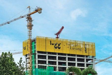
Providing formwork, scaffolding and engineering solutions for Sabah’s major mixed-use development.
Located within the beautiful coastal town of Kota Kinabalu, the district of Luyang is home to one of the most impressive and ambitious multi-purpose developments, in Sabah, East Malaysia.
Self-described as ‘an iconic mixed-use development that blends a middle upscale lifestyle boulevard, mall and offices with residential and hotel towers to create a new and holistic landmark for the future’, The Logg is built around ‘five strategic pillars’, namely the Shorea n Astoria, Park Hill Residences, Avani Hotels and Resorts, The Logg Mall and an office complex.
Working in conjunction with KTI Sdn Bhd, Doka was engaged to provide complete formwork and engineering services to ensure the timely delivery of this multifaceted, USD 200 million project, while meeting its specific challenges, including space constraints due to limited access.
Starting with the overall scope, Doka was entrusted to provide the formwork solution for four separate packages. These included one 28-storey building with 250 units of affordable housing; a 10-storey building with two levels of commercial property, eight levels of car parking, three levels of offices, plus basement parking; two blocks of service suites extending to 432 units; and one 450-key hotel tower.
In terms of formwork, Doka’s team proposed Dokaflex and Doka Lightdek, in order to enhance speed on site. As a result, the tables could be lifted to the next area, which saved on dismantling and installation works. Doka Lightdek was introduced as a replacement for the plastic-based ‘green form’ proposed by the subcontractor, thereby delivering a lighter solution with higher reusability.

In order to adhere with the requirements for working at the building’s edge, Protection screen Xclimb 60 was used, negating the requirement for scaffolding, while maintaining a faster pace on site. Additionally, its systematic design ensured fewer loose items, while remaining spare-partsfriendly. Doka’s Protection Screen, Xclimb 60, provided the option to showcase the client’s own branding.
In terms of the planning, materials were delivered on a just-in-time basis, in order to work with the restricted site access and space. This meant a highly efficient performance from the logistics teams who have maintained an accurate and consistent service.
Doka also provided on-site training, a supervision foreman and a trainer, each of whom ensured site teams were fully competent at operating all formwork systems
provided, while helping to maintain a clean site with less construction waste.
Commenting on the project’s development, Doka Engineering Supervisor, Andy Law said, “After several face-to-face meetings with the client, we were able to share our extensive experience, which included having great project references like our work within the Tun Razak Exchange district.”
“Supported by our highly detailed plan, which came with many timesaving products and services, our work to-date has kept the project moving at a good pace, while helping to solve many of the issues concerning site access and space. This has been further supported by our aftersales team, which has ensured all aspects of our services are maintained to the highest standards,” he added.
The Logg is expected to be completed by 2026.
Designed to last 100 years, the bearing will enable the rotation of the central bridge section.
Liebherr-Component Technologies AG, the components product segment of the Liebherr Group, is supplying the heart of the rotating pillar for the bridge Friesenbrücke which is being erected for Deutsche Bahn (DB) in Weener, Germany. It comprises a 5 m, 12.5 t combined roller and ball bearing, along with eight matching pinions.
This rotating pillar and the associated mechanical systems by Hermann GmbH Maschinenbautechnologie support the 145 m long, 1,800 t central section of Europe’s largest lifting swing bridge to-date.
The Friesenbrücke is the key part of the 173 km long rail route between Groningen in the Netherlands and Bremen in Germany.
“With its total length of 335 m, it is the largest lifting swing bridge in Europe, carrying not only rail traffic, but also footpaths and cycle lanes. The bridge spans the river Ems and opens the way for ships, by rotating up to 90°. This is where Liebherr’s slewing bearing and pinions come into play,” said Alexander Volgmann from Deutsche Bahn.
The combined roller and ball bearing along with eight matching pinions ensure that the bridge can rotate on its central pillar.
“The technology used here is a lift-and-rotate mechanism. First, the rotating section of the bridge is unlocked. The central section is then lifted by the rotating pillar, releasing it. Finally, the hydraulic drive and the slewing bearing swivel the bridge,” explained Karl Völkl from Hermann GmbH Maschinenbautechnologie, the supplier of the rotating pillar for the Friesenbrücke.
The bridge section will be rotated around 1,850 times a year. To support optimum operating times, Liebherr has designed the

slewing bearing for a service life of 100 years and verified it by Finite Element (FE) analysis. Moreover, the bearing has been coated with a C5 anti-corrosion layer, specifically designed for use in or near water.
“Additionally, our intelligent bearing clearance monitoring system measures wear on the axial raceway, allowing efficient monitoring and maintenance of the bearing,” explained Michael Sander, Technical Sales Engineer for slewing bearings at Liebherr-Components in Biberach, Germany.
This solution integrates sensors directly into the bearing, with the measurement results fed directly into the customer’s system.
“The seamless integration into the customer’s control system is a key innovation. We provide a specially developed and protected code, allowing the customer to integrate the data into their own system, using their own logics and interface,” added Sander.
No additional gateway is required, reducing system complexity, thanks to the software-integrated bearing clearance monitoring system.
Liebherr-Component Technologies
This segment of the Liebherr Group specialises in the development, design and manufacture of high-

performance components in the fields of mechanical, hydraulic and electric drive and control technology. Liebherr-Component Technologies AG, based in Bulle, Switzerland, coordinates all activities in the component product segment.
Liebherr Group
The Liebherr Group is a family-run technology company with a highly diversified product programme. The company is one of the largest construction equipment manufacturers in the world.
Deutsche Bahn Group
The Deutsche Bahn (DB) Group is the leading integrated provider of public mobility in Germany, and of logistics solutions and combined transport, throughout Europe.
The SP 33 slipform paver from Wirtgen is characterised by versatility, manoeuvrability and efficiency.
Available in two configurations, the Wirtgen SP 33 concrete paver, thanks to the fully modular construction concept, enables the paving of monolithic concrete profiles such as curbs and berms, rectangular profiles, concrete safety barriers up to a height of 1.3 m (52 in), and drainage and gutter profiles.
In the offset paving configuration, it can effortlessly pave concrete slabs with a pave width of up to 2.2 m (7 ft), also in combination with a trimmer up to 2.4 m (8 ft) wide.
The crosspave version can pave slabs, up to a width of 3.0 m (10 ft), transversely to the direction of travel of the machine. Both solutions can be controlled by the innovative operating concept with an event-driven graphic display. The ECO mode detects every working situation, without the need for manual intervention by the operator, and ensures automatic, load-optimised regulation of engine output for optimum engine efficiency, maximum fuel economy and low noise emissions.
The operator is further assisted by the AutoPilot 2.0 control system. The two crawler units, with parallelogram swing legs at the front and a laterally adjustable crawler unit at the rear, enable zero-clearance installation and maximum flexibility. This makes it an ideal choice for use on construction sites that demand a high degree of manoeuvrability and the paving of tight radii.
With its concrete paving train orchestration, Wirtgen also offers completely coordinated machine technologies and practice-oriented equipment variants. They help users to fulfill quality requirements, in particular, ensuring outstanding


evenness of the paved concrete surface. The production system comprises a placer/spreader, WPS 102i; an inset slipform paver SP 124i; and a texture curing machine, TCM 180i.
Conventional concrete paving methods rely on a physical stringline for controlling the paving process. As an alternative to this, Wirtgen offers its field-proven AutoPilot 2.0 control system which is available for all offset pavers and placer/spreaders. The need for a
physical stringline is eliminated, which results in considerable savings in terms of time and effort, and increases the safety of the paving crew.
At the same time, the system precisely controls both the height adjustment and steering of the machine. A GNSS signal and, depending on the configuration, various local sensors – for example, an ultrasonic sensor on the machine – serve as a reference. It also enables fast and precise paving of tight radii and complex geometries.
Zoomlion Heavy Industry Science & Technology Co Ltd, from China, has released a series of groundbreaking aerial work platform (AWP) products, including what is said to be the world’s tallest straight boom aerial work platform, the ZT82J which has a height of 82.3 m. These products further solidify Zoomlion’s leadership in the AWP sector and underscore its commitment to global market development.
The 82.3 m ZT82J boasts a platform amplitude of 34.1 m, a maximum working load of 454 kg and a climbing capacity of 35%. Not only is it a reliable, stable and intelligent AWP, it also delivers a high safety performance, with ultra-long boom composite movement and double-cylinder synergistic control technology, and 21 safety protection measures.
Furthermore, Zoomlion has introduced the ZT51JEH, an extended-range electric straight boom AWP that reaches a working height of 50.6 m and also supports a maximum load of 454 kg. It can operate in either electric or diesel mode, to meet the construction needs of both urban/indoor projects and outdoor
working conditions, without access to electricity. It can work continuously for more than seven days, when fully charged and refuelled, effectively addressing the endurance challenge of pure electric products.
The ZA42J is currently Zoomlion’s largest crank boom AWP, and is characterised by its spanning capabilities. It features a spanning height of 24.5 m and a working height of 44.03 m. This model utilises multi-stage cylinder telescoping technology, enhancing its reach and versatility, and includes fast lifting and probing functions to efficiently address various operational demands.
Zoomlion’s telehandlers include seven models, both fixed and rotary types, with working heights ranging from 6 m to 25 m and loads from 2.5 tons to 4.5 tons. These versatile products support multiple attachments, such as forks, buckets, and spreader platforms, offering flexible solutions for diverse applications.
During bauma CHINA 2024, Zoomlion also introduced intelligent wearable safety equipment, an intelligent AWP management system and a global
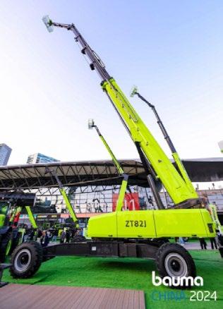
spare parts shop, and secured new orders from over 20 clients from regions including Australia, Latin America, Southeast Asia, the Middle East and Europe.
bauma CHINA 2024, the International Trade Fair for Construction Machinery, Building Material Machines, Mining Machines and Construction Vehicles, was held from 26 to 29 November 2024, in Shanghai, China.
INDEX
IES Chartered Engineer
IES Membership
IES-INCA
SBS

