
11 minute read
SICUREZZA/SAFETY LA PROGETTAZIONE DEI SISTEMI DI SICUREZZA STRU MENTATI/ THE DESIGN OF INSTRUMENTED SAFETY SYSTEMS di Davide Enrico Arnoldi
I principi fondamentali per la progettazione dei sistemi strumentali di sicurezza (SIS) secondo la normativa IEC 61511 rappresentano la base teorica per manager e ingegneri che vogliono comprendere gli aspetti fondamentali della sicurezza funzionale e del ciclo di vita di sicurezza e i metodi di valutazione SIL nell’ambito della progettazione.
Advertisement
Davide Enrico Arnoldi*
SIL – Safety Intergrity Level: un acronimo oramai riconosciuto a livello internazionale, che riporta immediatamente all’ambito della Sicurezza funzionale. Ambiente conosciuto a livello mondiale e adottato dai più grandi EPC con
tractor ed End Users, comporta definizioni, studi, analisi e verifiche sia in fase di Ingegneria che in fase di commissioning e plant operation, in vari aspetti quali in Automotive, Freni di emergenza dei treni, Macchine e ovviamente anche nei Processi Industriali. La Sicurezza Funzionale, in generale, è definita dalla “madre” di tutti gli standard che ne sono derivati ovvero la IEC 61508, e dove alla parte 4 definizione 3.1.9: “Parte della sicurezza globale relativa ai dispositivi sotto controllo e al sistema di controllo di questi, che dipende dal corretto funzionamento dei sistemi di sicurezza Elettrici, Elettronici ed Elettronici Programmabili, altri sistemi di sicurezza di diversa tecnologia e a servizi esterni di riduzione del rischio”. Quindi, in ambito di Sicurezza Funzionale, nella parte di controllo di qualsiasi Processo rezza adatti. L’IEC 61511 è, infatti, lo standard che risulta essere l’implementazione dell’IEC 61508 per l’Industria di Processo, ed è oramai adottato in tutto il mondo dai più importanti EPC’s ed End Users.
[Fig.1] Fasi del ciclo di vita in sicurezza di un SIS e stadi di valutazione della sicurezza funzionale secondo la Norma CEI EN 61511 Figura 5 – Fasi del ciclo di vita in sicurezza di un SIS e stadi di valutazione della sicurezza funzionale secondo la Norma CEI EN 61511
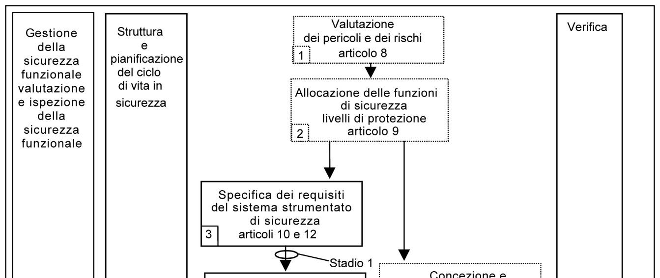
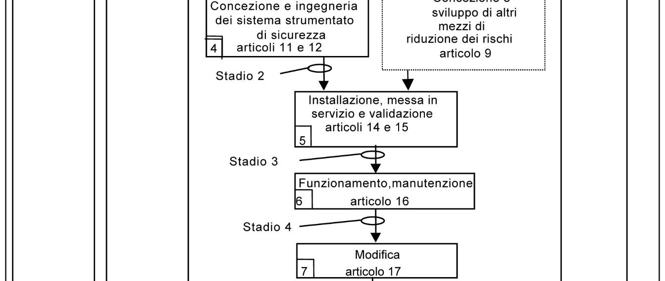
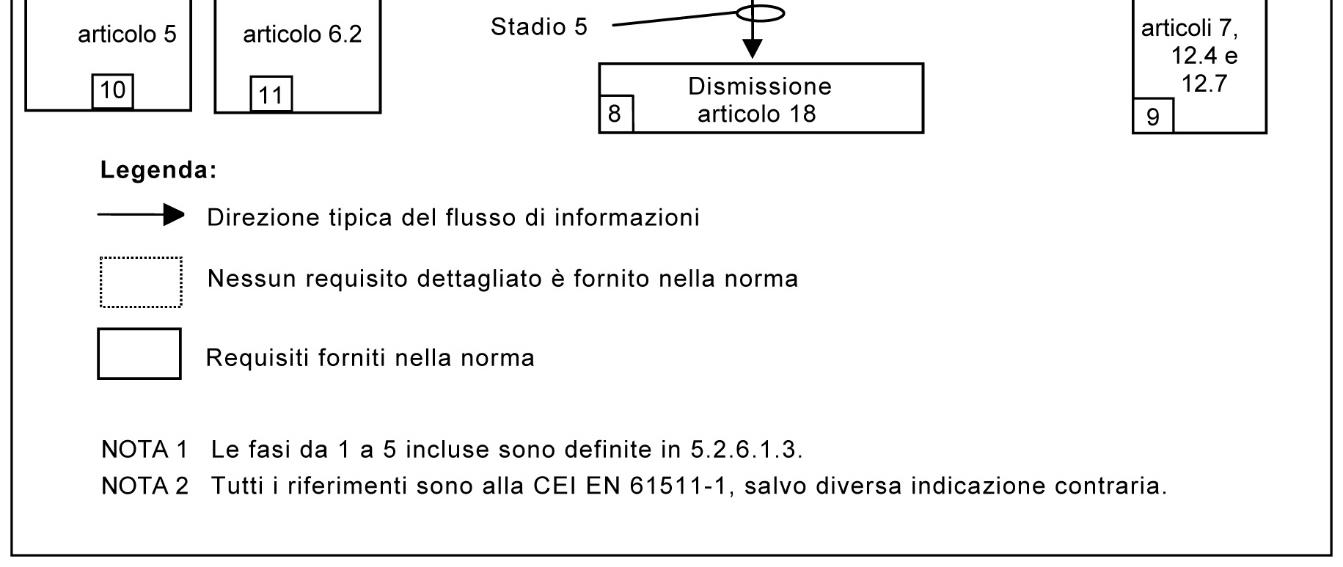
L’organizzazione europea di normalizzazione CENELEC, ha normalizzato tale standard e quindi è anche conosciuto come EN 61511, facendo in modo che per tutte le nazioni europee, sia applicabile come standard internazionale. È importante sapere che in esso si specificano i requisiti per raggiungere la sicurezza funzionale, ma non specifica chi è il responsabile dell’attuazione dei requisiti stessi (ad es. progettisti, fornitori, proprietario/società operativa, appaltatore). Questa responsabilità sarà assegnata a diversi parti secondo la pianificazione della sicurezza, la pianificazione e la gestione del progetto e regolamenti nazionali. Esplorando l’aspetto tecnico dello standard, è necessaria una definizione per il Sistema di Sicurezza Strumentato, oggetto della nostra progettazione con lo scopo di garantire la sicurezza agli impianti.
La IEC 61511 è titolata “Sicurezza Funzionale: Sistemi di Sicurezza Strumentati (SIS) per l’Industria di processo”, si rivolge ai sistemi composti da strumentazione ed è indirizzata ai progettisti SIS, agli integratori dei sistemi ed End Users. Gli stessi SIS saranno progettati utilizzando strumenti conformi allo standard IEC61508 dedicato ai progettisti e produttori dei dispositivi di sicurezza elettrici, elettronici ed elettronici programmabili (E/E/PE). IEC61511 affronta tutte le fasi del ciclo di vita della sicurezza SIS, dal concetto iniziale, progettazione, implementazione, funzionamento e manutenzione fino alla sua disattivazione.
Un SIS è composto da qualsiasi combinazione di sensori, risolutore logico ed elementi finali. Comprende anche elementi per la comunicazione e le apparecchiature ausiliarie (ad esempio cavi, tubi, alimentazione, linee di impulso, tracciamento del calore).
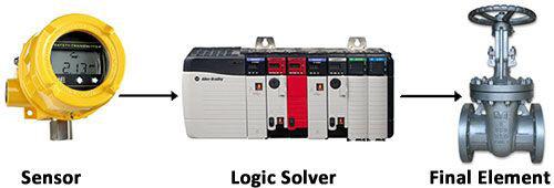
[Fig.2 Struttura SIS]
Ovviamente considerando dispositivi elettronici programmabili, nella progettazione del SIS deve essere compresa anche la programmazione software (definita come Application Program secondo IEC61511 rev 2016). Se trasliamo il concetto di Sicurezza Funzionale ad un sistema SIS, possiamo dedurre che un Sistema di Sicurezza Strumentato è funzionalmente sicuro al 100%, se tutti i guasti non provocano malfunzionamenti del sistema di sicurezza e non danno origine conseguenze quali lesioni o morte di esseri umani, sversamento di sostanze nell’ambiente o perdita di attrezzature o di produzione. Il SIS è quindi il contenitore di tutti i “loop di sicurezza” come definiti sopra, da sensore ad elemento finale, che prende il nome di Funzione di Sicurezza Strumentata (SIF) e dove il SIS è utilizzato per implementare uno o più SIF. La particolarità della SIF è che va a riferirsi ad una singola funzione da controllare, come ad esempio un trip ad alta o a bassa pressione (situazioni pericolose), evitando eventi pericolosi e guidando il processo verso uno stato di sicurezza. Lo standard IEC 61511 nasce proprio con l’intento di definire i rischi e progettare le SIF con affidabilità richiesta per ridurre ogni probabilità di evento pericoloso. Seguendo il ciclo di vita dello standard si parte con la valutazione dei rischi e pericoli (H&RA) (clausola 8) con l’obiettivo generale di stabilire la necessità di funzioni di sicurezza e le relative misure di fallimento per garantire un processo sicuro. Lo
Novità sulla sicurezza www.myndservices.com
standard consiglia di intraprendere un H&RA finale una volta che i piping and instrumentation diagram (P&ID) siano stati finalizzati. Questa analisi finale generalmente utilizza un approccio formale e completo, procedura documentata come studio di pericolosità e operabilità (HAZOP - vedere IEC 61882:2003). Allo step successivo (clausola 9) del ciclo di vita della IEC61511, risulta di fondamentale importanza considerare i livelli di protezione già esistenti e quanta riduzione di rischio possono fornire. Se è necessario uno strato di protezione SIS, sarà necessaria una determinazione del livello di SIL di ciascun SIF assegnato al SIS. Il livello di SIL corrisponde alla riduzione del rischio richiesta, che viene determinata confrontando il rischio di processo senza il SIS con il rischio tollerabile (attività nota anche come “studio SIL”, SIL analisi” ecc). Questo può essere determinato su a base quantitativa o qualitativa utilizzando le tecniche della IEC 61511-3: (ad esempio Risk Graph- LOPA ecc). Lo sviluppo della SRS (clausola 10) per un SIS è una delle attività più importanti dell’intero ciclo di vita della sicurezza. Attraverso questa specifica che l’utente è in grado di definire come vuole ogni SIF da progettare e integrare in un SIS ed è di vitale importanza poiché la convalida finale del SIS viene effettuata utilizzando questa specifica. L’obiettivo delle clausole 11 e 12, è di fornire indicazioni per la progettazione del SIS. Arrivati a questa attività, ogni SIF avrà assegnato il proprio SIL. È importante notare che in questa fase di verifica (detta comunemente “Verifica SIL”) viene calcolata l’affidabilità delle SIF e verificati altri vincoli di architettura e capacità sistematica. Tutta questa attività può dirsi come la trasposizione della riduzione rischi dall’ingegneria all’impianto reale. Queste rappresentano le prime fasi per l’applicazione della IEC 61511 dedicate alla fase di ingegneria.
Keywords: SIL, SIF, SIS, EPC, Safety, IEC 61511, P&ID, H&RA, SRS, Risk Graph- LOPA, Hazop Verifica SIL, Valutazione Rischi
THE DESIGN OF INSTRUMENTED SAFETY SYSTEMS
The basic principles for the design of safety instrumentation systems (SIS) according to IEC 61511 provide the theoretical basis for managers and engineers who want to understand the fundamental aspects of functional safety and the safety lifecycle and SIL assessment methods in the context of design. Davide Enrico Arnoldi*
SIL - Safety Intergrity Level: an internationally recognized acronym that immediately brings you back to the field of functional safety. Environment known worldwide and adopted by the largest EPC contractors and End Users, involves definitions, studies, analysis and testing both in Engineering and in commissioning and plant operation, in various aspects such as Automotive, Train Emergency Brakes, Machinery and of course also in Industrial Processes. Functional Safety, in general, is defined by the “mother” of all the resulting standards, i.e. IEC 61508, and where in part 4 definition 3.1.9: “Part of the global safety related to the devices under control and their control system, which depends on the proper functioning of Electronic, Electronic and Programmable Electronic safety systems, other safety systems of different technology and external risk reduction services”. Therefore, in the area of Functional Safety, in the control part of any suitable Processes. IEC 61511 is, in fact, the standard that is the implementation of IEC 61508 for the Process Industry, and is now adopted worldwide by the most important EPC’s and End Users.
IEC 61511 is titled “Functional Safety: Instrumented Safety Systems (SIS) for the Process Industry”, is addressed to instrumentation systems and is addressed to SIS designers, system integrators and End Users. The same SIS will be designed using instruments conforming to the IEC61508 standard dedicated to designers and manufacturers of electrical, electronic and programmable electronic safety devices (E/E/ PE). IEC61511 addresses all phases of the SIS safety lifecycle, from the initial concept, design, implementation, operation and maintenance to its deactivation. The European standardisation organisation CENELEC, has standardised this standard and is therefore also known as EN 61511, making it applicable as an international standard for all European countries. It is important to know that it specifies the requirements to achieve functional safety, but does not specify who is responsible for implementing the requirements (e.g. designers, suppliers, owner/operating company, contractor). This responsibility will be assigned to different parties according to safety planning, project planning and management and national regulations. Exploring the technical aspect of the standard, a definition for the Instrumented Safety System, which is the subject of our design with the aim of ensuring safety, is required. to the implants.
A SIS consists of any combination of sensors, logic solver and final elements. It also includes elements for communication and auxiliary equipment (e.g. cables, pipes, power supply, pulse lines, heat tracking). Obviously considering programmable electronic devices, the SIS design must also include software programming (defined as Application Program according to IEC61511 rev 2016). If we transfer the concept of Functional Safety to a SIS system, we can deduce that an Instrumented Safety System is 100% functionally safe, if all failures do not cause malfunctions of the safety system and do not give rise to consequences such as injury or death of human beings, spillage of substances into the environment or loss of equipment or production. The SIS is therefore the container of all “safety loops” as defined above, from sensor to final element, which is called Instrumented Safety Function (SIF) and where the SIS is used to implement one or more SIFs.
The peculiarity of SIF is that it refers to a single function to be controlled, such as a high or low pressure trip (dangerous situations), avoiding dangerous events and guiding the process towards a safe state. The IEC 61511 standard was born with the intent to define the risks and design the BIPs with the reliability required to reduce any probability of a dangerous event. Following the life cycle of the standard starts with the risk and hazard assessment (H&RA) (clause 8) with the overall objective of establishing the need for safety functions and related failure measures to ensure a safe process. The standard recommends undertaking a final H&RA once the piping and instrumentation diagram (P&ID) has been finalised. This final analysis generally uses a formal and comprehensive approach, documented procedure as a hazard and operability study (HAZOP - see IEC 61882:2003). In the next step (clause 9) of the IEC61511 life cycle, it is of paramount importance to consider the already existing protection levels and how much risk reduction they can provide. If a SIS protection layer is required, a determination of the SIL level of each SIF assigned to the SIS will be required. The SIL level corresponds to the required risk reduction, which is determined by comparing the process risk without the SIS with the tolerable risk (activity also known as “SIL study”, SIL analysis” etc.). This can be determined on a quantitative or qualitative basis using the techniques of IEC 61511-3: (e.g. Risk Graph- LOPA etc.). The development of SRS (clause 10) for a SIS is one of the most important activities of the entire safety lifecycle. Through this specification the user is able to define how he wants each SIF to be designed and integrated into a SIS and it is vital because the final validation of the SIS is carried out using this specification. The purpose of clauses 11 and 12 is to provide guidance for the design of the SIS. Once this has been done, each PIL will have assigned its own SIL. It is important to note that in this verification phase (commonly referred to as ‘SIL Verification’) the reliability of the PILs is calculated and other constraints of architecture and
systematic capability are verified. All this activity can be described as the transposition of risk reduction from engineering to the actual plant. These represent the first steps for the application of IEC 61511 dedicated to the engineering phase.
Keywords: SIL, SIF, SIS, EPC, Safety, IEC 61511, P&ID, H&RA, SRS, Risk Graph- LOPA, Hazop SIL Verification, Risk Assessment

*Davide Enrico Arnoldi, Mynd Services
A working day for him with less job pressure
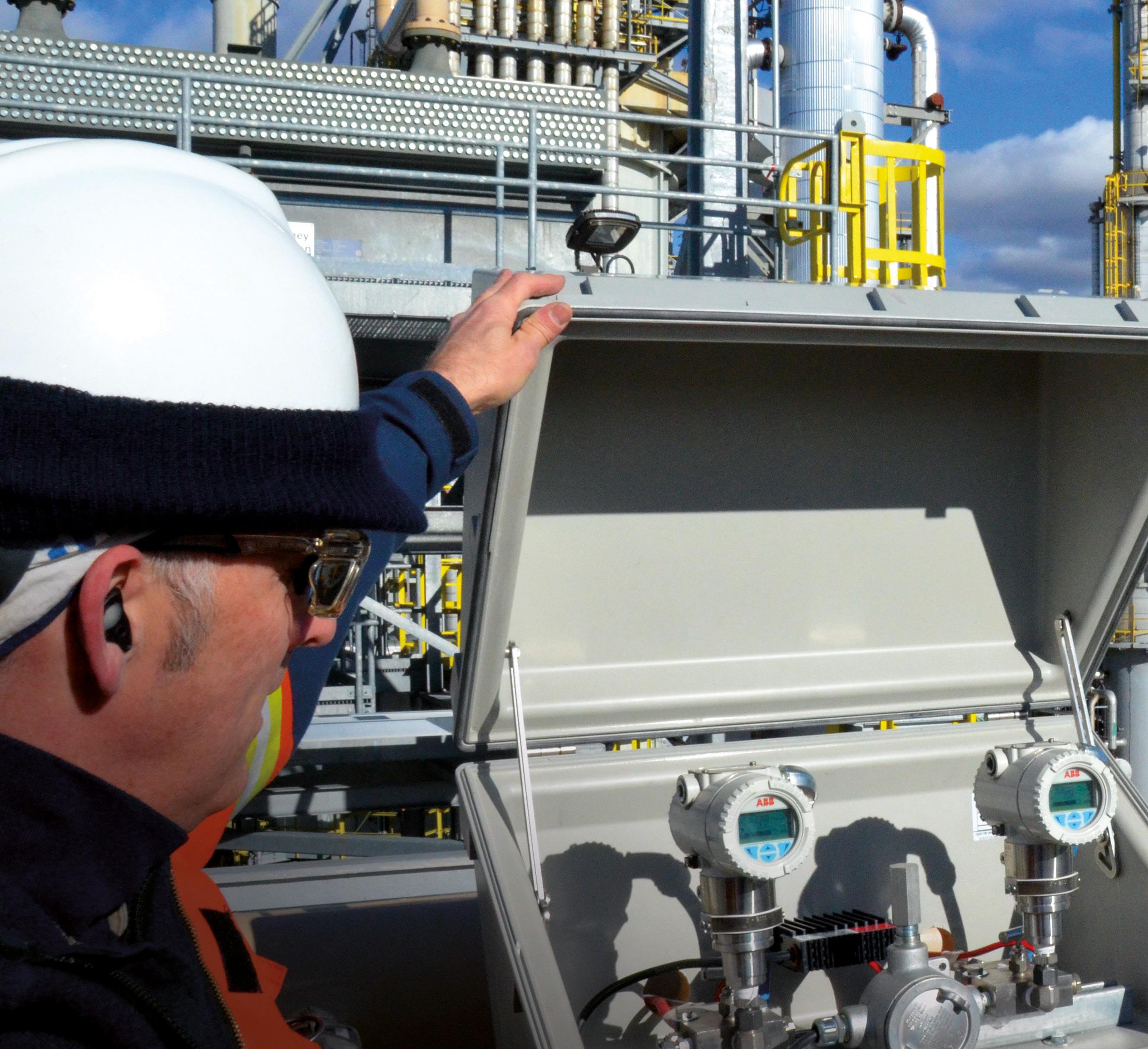
Pressure transmitters accurate to ±0.025% 365 days a year
— What’s your measure?
ABB’s 266 Series Pressure transmitters match the highest accuracy performance on the market. Plus they are packed with features like ‘Easy Setup’ auto-configuration menu and ‘Through-The-Glass’ HMI that take the pressure off your team when it comes to installation and maintenance. However you measure the world, a partnership with ABB is a simple choice to make. Measurement made easy.


