25 minute read
PROCESSING Know Your Gas Quality
Know Your Gas Quality!
In almost all long-term global energy scenarios natural gas is the fossil fuel whose share in the global energy mix is growing most significantly. However, the label “from yesterday, no longer up-to-date” is attached to the epithet “fossil”. Instead, everyone is talking about alternative, so-called “green”, gaseous fuels: biogas from natural or synthetic sources and hydrogen from renewable “power-to-gas” technologies. However, the latter will not be available in sufficient quantities to replace traditional natural gas for years to come. In the interconnected natural gas networks, there will therefore be more and more gas mixtures of all these sources: natural gas, conditioned biogas, LNG (liquefied natural gas), LBM (liquified biomethane), all with and without the addition of hydrogen. As a result, the gas quality can fluctuate strongly from point to point within a short time. Strong fluctuations in gas quality can also have a local origin: Boil-off gas from an LNG tank can be very different from the gas that is pumped from the bottom of the tank and vaporized, e.g. to supply a ship’s engine.
Advertisement
In addition to these technical boundary conditions, stringent legislation on air pollution and greenhouse gas emission and stakeholders’ foremost interest to operate their equipment as safely and efficiently as possible all drive the need for gas quality sensing.
Gas quality sensing: the gasQS technology
The standard tool for determining the gas quality is a process gas chromatograph (PGC), which is used to determine and output the molar composition of the sample gas (Fig. 1). After the measurement, further parameters such as compressibility or calorific value can be determined with the appropriate calculation rules. PGC-based systems require a connection to a carrier and calibration gas. Acquisition and maintenance cost-intensive, space-consuming and discontinuously working (cycle times in the range of a few minutes) are adjectives of PGCs, because of which low-cost, robust alternatives are often sought in order to determine the gas quality even in places where this was previously not possible. Mems AG offers microelectromechanical
Figure 2 By Dr. Ph. Prêtre, Mems AG.
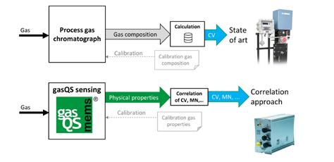
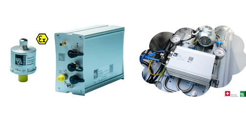
(MEMS) sensors, which meet the requirements of speed, robustness, size and price for fixed installations (gas engines and turbines, industrial burners, combined heat and power, fuel cells) and mobile control systems of natural gas vehicles (NGV). Based on a silicon chip with integrated, micro-thermal sensing head, thermo-physical properties of a gas are measured with subsequent correlation of gas Figure 1 quality factors such as calorific value, Wobbe index, methane number, compressibility or the air/gas ratio. No compositional analysis as in the case of PGC is performed, but at the same time, no knowledge of the gas composition is needed in the correlation approach. Depending on the application, different sensor options are available, from stand-alone devices up to plug-and-play measurement systems (Fig. 2). Common to all variants is the ease of installation and integration into existing measurement and control systems. High contents of up to 100% of hydrogen in natural gas are no more a problem than high amounts of inert gases in bio, coal mine or LNG boil-off gas.
Applications
Gas engines and turbines manufacturers require minimum gas qualities for safe operation of their equipment. However, not only safe but also efficient operation of the machinery depends on gas quality. While the former aspect is handled with a minimum methane number to be guaranteed by the gas supplier, efficiency is not so easy to control if no gas quality measurement is available. Besides determining methane number as the
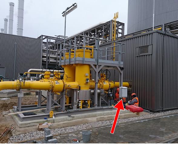
classical quality index, the correlation approach of the gasQS technology opens up the access to more significant engine parameters such as optimal ignition angle or exhaust gas recirculation (EGR) limit rate ( https://doi.org/10.1016/j. measurement.2016.05.098 ) for most efficient use of the gaseous fuel. A 400 MW coastal power plant will increase its efficiency due to the installation of an outdoor gasQS measurement system as seen in Fig. 3. Several hydrogen injection field trials are accompanied by gasQS sensors in order to monitor in real time the distribution process of hydrogen in the local gas network. While a pair of sensors at the mixing station determines the exact amount of hydrogen added, remote sensors distributed over the local network communicate the measured gas quality via IOT-gateways to an industrial connectivity cloud that allows to manage and combine all collected data for a complete picture of the actual hydrogen concentration at any point in the network. As in the case of hydrogen feedin, it will be important in future to know the calorific value at every point in a gas network so that each gas customer can be billed individually for the energy supplied to him. This process is supported by reconstruction programs that calculate the gas distribution in the network based on network models. However, when implementing the system and

periodically recurring, a plausibility check of the simulation with data measured at selected points of the network is necessary (Fig. 4). If no such software tools are applicable, deployment of gas quality sensors within highly branched and widely extended gas networks can replace the time-consuming and thus cost-intensive, periodic gas sampling procedure for accounting purposes. Encrypted data is exchanged via cellular phone networks between sensors and a cloud-based hosting service where all data is stored and managed. Some process industries, especially glass production, are sensitive to changing gas qualities. There is therefore a need for a fast gas quality sensor system that can detect such changes within a few seconds and thus be integrated into closed-loop control systems. Due to their small mass, chip sensors are predestined for fast measurements in comparison to process gas chromatographs, where a new measurement value is due only every few minutes.
Conclusions
Gas quality sensing is no more a nice but rather need to have add-on to all process equipment that has to cope with the increasingly varying gas quality. Ready solutions for gas network operator, gas power plant managers, engine operators or process industry owners are available at low capital and operational expenditure compared to traditional process gas chromatographs. The correlation approach of Mems AG allows not only the measurement of standard gas qualities namely calorific value or methane number, but also processspecific parameters such as optimum ignition angle for gas engines or the monitoring of the mixing process when feeding hydrogen into natural gas networks. •
Mems AG
Telephone: +41 (0)56 470 92 00 E-mail: info@mems.ch Website: www.mems.ch
Digital Plant Documentation Speeds up Loop Checks
Every time a process plant is newly built, modernized or expanded, its reliability has to be exhaustively tested before it can go into operation. Plant constructors or operators implement loop checks to ensure that all loops are functioning correctly, that the sensors and actuators assigned to them are correctly parameterized and that they are interacting as planned. Plants in the process industry often have several hundred loops that need to be tested by consistently following checklists. If several teams are working in shifts in order to speed up acceptance, it is almost impossible to keep an overview with paper checklists. In this situation, digital plant documentation is the remedy.
Anyone who has been involved in commissioning a plant in the process industry is familiar with the time-consuming procedure: checklists are generated (as far as the plant planning tool allows) for the loop checks which are one of the essential preliminaries. Then all loops have to be rigorously tested in the field. The results are noted on the checklist. At the end of the day, each employee returns a stack of checklists to the project manager. Depending on the size of the project, he accumulates files full of documents which he has to go through if he wants to get an overview of the present status of the project. If testing is being done in several shifts to speed things up, a proper handover from one shift to the next is basically not possible. If shiftwork is not used, it would be possible for the project manager to catch up on his overview after work – overnight, so to speak – and then prepare the test assignments for the next day. However, this is extremely laborious, and who wants to manage a project by working a night shift for weeks? Everything is a great deal easier with the digital plant documentation tool LiveDOK NG by Rösberg. Many plant constructors and plant operators use the tool for documentation in the operational phase. It renders valuable services in commissioning, Factory Acceptance Tests, and of course loop checks: during checks, the tool enables data to be directly digitally recorded, meaning that the project manager has an overview of the test status in real time. Dipl.-Ing. (BA) Martin Dubovy, Head of Plant Solutions at Rösberg Engineering GmbH. This enables good planning and the effective deployment of employees, and has a determining influence on the time management of a project. “I assume that by using the software, the time for loop checks can be cut by as much as half, depending on the application concerned” says Helge Laubach, Account Manager Plant Solutions at Rösberg.
Digital checklists give an overview
How does the digital documentation tool support loop checks? With I&C-CAE planning tools like ProDOK, for instance, checklists can be generated for the stored loops. These are transferred to LiveDOK in PDF format. The project manager then distributes their individual tasks to the employees who are carrying out the tests, usually via a tablet. When working through the tests they can tick off the individual steps on the checklist, and also stamp the document appropriately. And with LiveDOK a differentiated status like e.g. “installed”, “tested” or “released” can be assigned individually to documents, depending on the project in hand. This enables people working on the project to see the status without having to open the document. When the installation of a plant component is completed, the employee assigns e.g. the status “installed” to the document. Ideally, the employee carrying out the test is connected to

the company network during testing. His
Helge Laubach, Account Manager, Plant Solutions at Rösberg.
changes are then not only stored locally on his operating station but also centrally on the LiveDOK server. This gives all employees access to the current data of the plant documentation. For the project manager this means, for instance, that he can generate at the touch of a button an overview of which plant components already have the status “installed”. Thus rather than having to wait until the end of the day’s testing and then work through countless lists, the project manager receives the exact up-to-the-minute status while the tests are running, and can plan accordingly. If the tests are taking longer than anticipated, more manpower can be brought in at an early stage. This makes sense particularly if plant modifications are planned to be carried out during a strictly-defined time window – e.g. a scheduled plant downtime.
Use Case BASF Antwerp
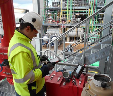
At BASF Antwerp, two new plant sections for the production of aniline and nitrobenzene were added at the end of 2018. When the extension work was completed, around 300 loops had to be tested in the field. For this BASF used the digital documentation tool LiveDOK. To avoid the use of paper altogether, the testers worked with tablets. This enabled them to enter all the necessary information directly on-site. Once a loop had been successfully checked, the relevant checklist received the appropriate status. If changes had to be made to individual I&C devices, these could be directly noted using the redlining palette of the documentation tool. These checklists were then returned to the planning office where they were checked, the noted changes taken over in the planning tool and a new documentation without redlining
generated. This procedure has already proved very advantageous in practical use, because it simplifies the work, gives better results and also substantially reduces the time needed for the checks.
Independent of the operating system
Because there are frequently Ex-zones in the chemical industry, Ex-approved tablets were required for this application. In situations where more Ex-proof tablets are required at peak times than in everyday business, it may make sense to hire additional Ex-safe tablets. For cases like this, in addition to their software tools and project management know-how, the automation experts from Rösberg offer suitable hardware for hire. In past years the choice of Ex-safe tablets on the market was relatively small, but in the meantime numerous variants using different operating systems are available. Therefore the automation experts have now created LiveDOK Web, a solution that is operating system-independent and web-based, and can be used on a wide range of different mobile devices. Users do not need to install any software in order to use the web application; they simply need an internet browser on the relevant operating device. The software solution is designed for touch operation, and works independently of the operating system, so it can be used equally well with Windows, Android or iOS devices. The user interface is responsive, i.e. it adapts flexibly to different display sizes.
Making life easier for plant constructors, too
A digital plant documentation system that can be used directly on-site on mobile end devices does not only simplify plant operation. A solution of this kind can also be very useful at the commissioning stage. It makes plant constructors’ work easier, and enables them to deliver the as-built documentation to the plant operator promptly following commissioning. In many cases this is not just “nice to have” – it is an essential requirement. Many contracts specify that a project will only be regarded as completed, and will be only be paid for, once the current documentation has been handed over. With digital plant documentation tools, changes can already be made to the original documentation during the test phase, and the as-built documentation can be delivered directly after completion of the loop tests.
The I&C-CAE System ProDOK
Modern process plants can only be effectively operated if the data from the engineering phase are also available for operation, maintenance and modernization. As-built plant reality has to reliably match the documentation at all times. Only if all data are consistent can costly new entries and the unnecessary use of engineering resources be avoided. This is exactly where the I&C-CAE system ProDOK comes in. It ensures an integrated planning process with unified rules. Because all the data are collected and exchanged within the same system, there is no more trouble with tiresome data transfer errors. Functions include basic and detail planning, functional planning, implementation planning and installation planning for new construction projects, plant alterations and extensions, as well as operational support, covering the whole life cycle of a plant. By its continuous, consistent documentation ProDOK ensures that the documentation really does reflect plant reality at all times. In combination with the real-time documentation system LiveDOK, it enables the complete documentation to be centrally administered and maintained, simply and inexpensively. The result is a significant improvement in quality and efficiency, plus substantial savings in terms of time and costs. Security of investment is ensured by wide acceptance of the system in the process industry and the use of state-of-the-art software technology.
Hardware: Hiring instead of buying
For the loop checks at BASF Antwerp, the chemical company hired the complete test environment, comprising laptops, Ex zone tablets, LiveDOK licenses and much more, from the automation experts. Users who hesitate to invest in buying the hardware and software for similar applications, because they may only need to use them once, can benefit from this complete care-free package. All components are hired out on a monthly basis. • Rösberg Engineering GmbH W: www.roesberg.com, www.LiveDOK.com E: info.ka@roesberg.com T: +49 721 95018-0
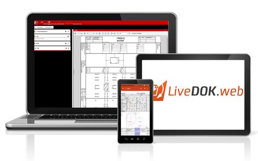
Right: LiveDOK Web can be used on a wide range of mobile devices because it is independent of any specific operating system. This means that during testing, changes can be entered in the digital documentation directly on-the-spot. (Copyright: Rösberg)
Sour Gas Production: The Benefits of Chemical Free Processing
By Bart Prast (PDEng., MSc.) Head of Technology, Twister BV.
Key Challenges
Sour fossil resources have always posed problems for operators. If in the past, a highly sour resource might have been considered unattractive for development relative to other assets, today operators are forced to develop fields containing as much as 30% H2S following the trend of diminishing availability of easy-to-produce conventional hydrocarbon resources as well as the opening of Russia, Central Asia and the Middle East to international operators. Their sour petroleum resources have historically characterized these geographical regions, and international oil and gas companies must be ready to face the challenges of highly sour production in exchange for the opportunity to operate in these rich petroleum provinces. Hence, the development of sour oil and gas resources is rapidly emerging as a major industrial and technological theme.
Processing sour gas is characterised by the following key challenges: • Safety - Due to its high toxicity, H2S requires special operating procedures to ensure worker safety during drilling and in production operations. The chemicals involved traditionally in gas processing pose additional risks in handling. • Economics - Removing H2S in excess of the required specifications is one of the most expensive aspects of the treatment of gas streams requiring additional large installations. Specifically, in an offshore environment, this dramatically increases project costs. • Flexibility - Varying levels of H2S require constant monitoring and adjustment and could require different technologies depending on H2S and CO2 content for an optimum gas treatment.
Traditional chemical-based systems applied for sweet gas processing will often come with start-up and shut down delays. Contaminants such as salts, lube oil, condensate, crude oil and corrosion products are present in abundance in liquid phase and in minute “trace” amount in the gas. They continually plague operators in their glycol systems, and the symptoms of these problems are fouled equipment, foaming in the system resulting in expensive glycol losses, and insufficient process capability [1]. Shutting a plant down to thoroughly clean and repair all the equipment is a periodic necessity and very expensive. To our knowledge so far no glycol systems have been applied in major sour gas projects. Twister addresses these key challenges as follows:
SAFETY
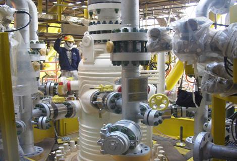
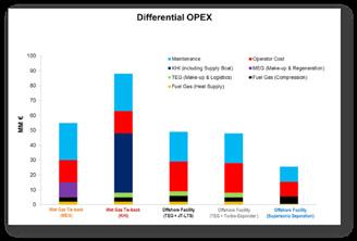
The Twister technology combines dehydration and dewpointing in a closed loop system. This reduces HSE vulnerabilities, minimizes flaring and gas release, and brings an end to the risks from glycol-based systems, such as toxic H2S contamination and high H2S gas inventories. The Twister Supersonic Separator (see Figure 1) is classified as piping due to its small volume and contains no moving parts, which results in 50% less FTE and the inherent reliability of Twister’s solutions can reduce operator intervention by 75%. Twister is a combination of known physical processes, aerodynamics, thermodynamics
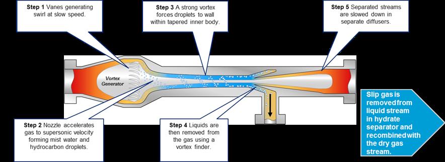
and fluid dynamics that produce a robust and compact gas conditioning process. When combined with the patented Hydrate Separator - used to separate hydrates and liquids from natural gas without using chemicals - the result is low maintenance, a low sour hydrocarbon inventory and reduced equipment count. Unlike traditional glycol-based systems that often come with start-up and shut down delays, the chemical-free, fully automated Twister system delivers on-demand gas almost immediately. First commercially applied in 2003, Twister has been successfully dehydrating sour gas with

3500 ppm/v H2S and 20 mole% CO2 on the Shell-operated B-11 600 MMSCFD production platform in Malaysia [2]. Twister is fully static equipment integrating expansion cooling and separation in a single device. Twister uses expansion for cooling and separation as per Figure 1 above. The liquids produced by the Twister flow into a mono-cyclone separator which is designed to separate gas hydrates. This Hydrate Separator uses internal heating to warrant that the internal surface temperatures are well above the Hydrate Formation Temperature (HFT).
Figure 2: CAPEX comparison for a 600 MMSCFD offshore processing plant Figure 4: Up to 6 Twister Supersonic Separators can be connected to the Twister Hydrate Separator.
ECONOMICS
By combining the dehydration and dewpointing into one unit, the weight and space can be reduced significantly on offshore structures and Twister reduces complexity on offshore facilities. The absence of chemicals further reduces the size of the offshore structure and hence CAPEX. Decreasing the complexity of offshore operations by applying compact technology enables application of remote operated platforms reducing CAPEX and OPEX even further. For a typical 600 MMSCFD gas processing plant, the Twister Supersonic Separator technology can save up to topside weight savings of between 30 and 60% and CAPEX savings of a similar percentage. When operating in chemical-free dehydration and dewpointing mode, Twister will not reduce the H2S content of the export gas, but as no longer (free) water is present in the export gas, the H2S-containing gas can be safely transported to onshore for further processing. With chemical-free gas processing using Twister technology, dehydration can typically be down to a water content of 5 lbs/ MMscf and hydrocarbon dew point of 0 °C
(Cricondentherm).
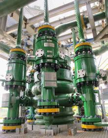
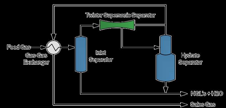
Figure 5: Twister Supersonic Technology - Typical flow scheme. Up to 6 Twister Supersonic Separators can be connected to a single Hydrate Separator providing turn-down capability.
FLEXIBILITY
Unlike traditional glycol-based systems that often come with start-up and shut down delays, Twister delivers on-demand gas almost immediately. Twister’s light-weight, flexible gas processing solution can be scaled up to handle varying gas flow rates unconstrained by operating pressure and can be optimized for a broad variety of applications from dehydration and hydrocarbon dewpointing applications through to NGL recovery applications at higher pressure drops. The Twister operation is not affected by variations in H2S content. The H2S content merely determines the material selection (through NACE standards) for the construction of Twister, as this will be working in a sour wet gas environment. A basic flow scheme based on Twister technology is shown in Figure 5.
OPERATIONAL EXPERIENCE
Since December 2003, Twister technology has been in continuous operation on B11, a large offshore gas production platform in the South China Sea, near Sarawak, Malaysia. It was the first sour gas development in the offshore region of Sarawak Malaysia and contains up to 3500 ppm/v H2S and 20 mol% CO2. All traditional concepts were considered, and based on the evaluation of risks and economics

made the operator decide in 2001 to select the Twister technology as the base case, based on the following premise: • Safety: Closed system (no H2S emissions); No chemicals. • Operations: Normally unattended operation; Minimum LQ facility. • Economics: Lowest CAPEX, lowest Life
Cycle Cost (LCC), 25% less weight. • Simplicity: No glycol regeneration and associated operations. • Availability: Guaranteed uptime of >98%. • Flow assurance: Protection of 65 km CS pipeline (no free water). The goal was to provide a safe gas processing solution with minimal environmental impact, while providing a significant reduction in capital and operational expenditure. Since the Twister option required a pressure drop of 35% at a nominal export pressure of 95 bar(g), a plateau pressure of 145 bar(g) was chosen, allowing for a plateau production of at least 500 MMSCFD for 5 years. Compared to TEG, Twister would bring compression investment forward from year 8 to year 6. However, these 2 years difference in NPV did not weigh up to the higher CAPEX an OPEX saving. In 2020, the B-11 platform continues to be operated now by Petronas.
CONCLUSION
Twister is particularly suited to sour gas fields. Twister provides a robust, compact gas conditioning solution characterised by condensation and separation taking place at supersonic velocity; and the Hydrate Separator isolates hydrates and liquids from natural gas without the need for chemicals using cyclonic separation and heating coils, which melt the hydrates. The combination of these two technologies results in a closed system, low maintenance, a low sour hydrocarbon inventory and reduced equipment count. There is also no chemical degradation due to H2S, no emissions and very limited operator intervention – a significant benefit in sour gas fields. Furthermore, the fact that Twister’s supersonic gas solution dehydrates gas on the basis of expansion cooling instead of glycol absorption, as well as being a closed system, means that it is the safest means of dehydrating and dewpointing sour gas on the market today. The reduced weight and plot space on offshore platforms of Twister with the Hydrate Separator also results in significant cost savings. The Twister Supersonic Separator technology is deployed on the initially by Shell operated B11-platform in Malaysia, and still successfully processing 600 MMscfd with higher than normal sour gas contaminant levels. •
Twister BV
bart.prast@twisterbv.com REFERENCES 1. Notes MEG Regeneration Technical
Meeting 18 June 2009, SPE, Port
Campbell 2. Ten Years of Twister Operations -
Benefits Delivered, Betting, M., Prast,
B., Proceedings of the GPA Europe
Technical Meeting in Leiden, May 2014. 3. The Challenges of Qualifying a Kinetic
Hydrate Inhibitor for an Offshore Sour
Lean Gas Field, Rithauddeen, M.A.; Al-
Adel, S., Proceedings of the 9th North
American Conference on Multiphase
Technology, 2014.
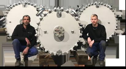
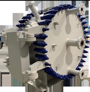
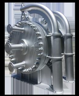
The Nexson Group Spiral Heat Exchanger used in ExxonMobil FLEXICOKING™ process is a customized unit that can be a cooler or/and an economizer depending on its position in the process. In coker unit processes, the goal is to convert heavy feeds to lighter products and flexigas. The main advantage of this process is to create high-value liquid products as well as clean flexigas, which can be used in different ways either as refinery fuel or power generation. With wide channels, compact sizes and correctly selected geometry for optimal speed of media streams, GreenSpiral TM have successfully solved the fouling problem of heat exchanger equipments in the difficult ExxonMobil FLEXICOKING™ process.
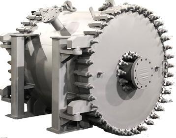
ABOVE: In this position, the aim of the slurry stripper feed / bottoms Nexson Group Spiral Heat Exchanger, is to use the heat of the slurry stripper bottoms to preheat the slurry stripper feed from the venturi scrubber. In the second position, the aim of the dilute slurry Nexson Group Heat Exchanger cooler is to cool down the slurry stripper bottoms for the slurry stripper. The Nexson Group spiral heat exchanger used in MEG reclamation process, is a low-fouling spiral heat exchanger allowing to heat the high-flow salty MEG. The goal of MEG reclamation process is to put a MEG-water-salt mix in contact with a heated recycled stream of MEG in order to recover the MEG and water components.
BELOW: Our MEG rich heater heats the high-flow salty MEG : • Without fouling. A turbulent flow is created to handle tough medias. Since it is a single channel heat exchanger, if there is any cross section reduction inside the channel, flow velocity will increase, flushing out the deposits. • Without allowing suspended particulate matter to settle in the channel, Nexson spiral heat exchangers are designed to handle suspended fibers / particles in the media. • Without the recycled MEG being exposed to high temperatures which could cause its degradation.
HEAT EXCHANGERS
LET US BUILD THE PERFORMANCE OF YOUR PROCESSES

Born from a true passion of 30 years in the field of compact welded heat exchangers, Nexson Group, 100% French company, was founded in 2011 and quickly became an international reference. At Nexson, we have been developing exchangers for many years. Basing our expertise on the characteristics developed in partnership with our customers, we have over the years created innovative products for all types of applications.
NEXSON GROUP HEAD OFFICE GARCHIZY (France) PHONE : +33 3 86 60 13 04 WEB: https://www.nexson-group.com/
Reorganization designed to enhance Aramco’s competitiveness and support its vision to be the world’s preeminent integrated energy and chemicals company. The Saudi Arabian Oil Company (“Aramco” or “the Company”) today announced the reorganization of its Downstream business to support and enhance integration across the hydrocarbon value chain and better position the Company to drive financial performance, value creation and global growth. The Company’s Downstream operating model will include four commercial business units: Fuels (includes Refining, Trading, Retail and Lubes); Chemicals; Power; and Pipelines, Distribution & Terminals. These business units will be supported by three corporate functions: Manufacturing, Strategy & Marketing and Affiliates Affairs. This reorganization is designed to enhance the effectiveness and efficiency of Aramco’s existing Downstream assets, but does not represent a fundamental change in the overall business structure. Abdulaziz M. Al Gudaimi, Senior Vice President of Aramco Downstream, said: “I am excited that we are launching a new operating model that we believe will help streamline our operations and reinforce our position as a major global energy and petrochemicals player. This reorganization is yet another step in Aramco’s strategy to develop a global integrated Downstream business that enhances our competitiveness by maximizing our value capture across the hydrocarbon value chain.”
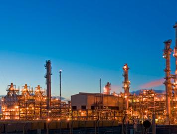
The reorganization, which is expected to be in place by the end of the year, further strengthens Aramco’s industry leadership in safety, sustainability, efficiency and reliability. Aramco has a large, strategically integrated global Downstream business that leverages the Company’s competitive Upstream position. The Company’s Downstream strategy focuses on creating growth opportunities across the hydrocarbon chain in order to expand the Company’s sources of earnings, providing resilience to oil price volatility and capitalizing on rising demand for petrochemical products. •
Emission reduction solutions
Cool Sorption is dedicated to VOC emission reduction and has an extremely high expertise in vapour processing, vapour treatment, vapour recovery and product recovery.


