
books
Build Your Own 4-Axis Multifunctional CNC Machine Plot, Cut, Drill, Mill, and Laser with the Z99
José Ganseman
Build Your Own Multifunctional 4-Axis CNC Machine Plot, Cut, Drill, Mill and Laser with the Z99
● José Ganseman
● This is an Elektor Publication. Elektor is the media brand of Elektor International Media B.V.
PO Box 11, NL-6114-ZG Susteren, The Netherlands Phone: +31 46 4389444
● All rights reserved. No part of this book may be reproduced in any material form, including photocopying, or storing in any medium by electronic means and whether or not transiently or incidentally to some other use of this publication, without the written permission of the copyright holder except in accordance with the provisions of the Copyright Designs and Patents Act 1988 or under the terms of a licence issued by the Copyright Licencing Agency Ltd., 90 Tottenham Court Road, London, England W1P 9HE. Applications for the copyright holder's permission to reproduce any part of the publication should be addressed to the publishers.
● Declaration
The Author and Publisher have used their best efforts in ensuring the correctness of the information contained in this book. They do not assume, and hereby disclaim, any liability to any party for any loss or damage caused by errors or omissions in this book, whether such errors or omissions result from negligence, accident, or any other cause.
All the programs given in the book are Copyright of the Author and Elektor International Media. These programs may only be used for educational purposes. Written permission from the Author or Elektor must be obtained before any of these programs can be used for commercial purposes.
● British Library Cataloguing in Publication Data
A catalogue record for this book is available from the British Library
● ISBN 978-3-89576-527-8 Print ISBN 978-3-89576-528-5 eBook
● © Copyright 2022: Elektor International Media B.V. Editor: David Reid
Prepress Production: D-Vision, Julian van den Berg
Elektor is part of EIM, the world's leading source of essential technical information and electronics products for pro engineers, electronics designers, and the companies seeking to engage them. Each day, our international team develops and delivers high-quality content - via a variety of media channels (including magazines, video, digital media, and social media) in several languages - relating to electronics design and DIY electronics. www.elektormagazine.com
● 4
Chapter
Chapter
Contents ● 5 Contents
............................................................
...............................................
Preface
8 Unlimited safety pages
10
.............................
1 • Installation (Windows 10 or 11)
12
.............................
................................
......................................
............................
......................................
..................................
2 • The X2Y4Z Printed Circuit Board
17 2.1 Schematic design X2Y4Z.sch in KiCad
18 2.2 X2Y4Z PCB Top and silkcreen
19 2.3 Component list X2Y4Z PCB for Z99 19 2.4 X2Y4Z bipolar steppers 26 2.5 Stepper bipolar driver modules . . . . . . . . . . . . . . . . . . . . . . . . . . . . . . . . . . . . . 28 2.6 Unipolar stepper for solder paste dispensing
30 2.7 The PIC microcontroller code
33 2.8 Programming the PIC 37 2.8.1 Programming the PIC with MikroE programmer 37 2.8.2 Programming the PIC with Pickit3
38
Design
3D
..............................
................................................
.............................................
...................................
......................................
Chapter 3 •
and
printing settings
41 3.1 Designing the 3D parts........................................... 41 3.2 Setup of Slic3r 42 3.2.1 Print settings
42 3.2.2 Filament settings
44 3.2.3 ‘Printer Settings’ – ‘Extruder 1’
45 3.3 Make G-code files with Slic3r
46
• Hardware parts Z99 ....................................... 48 4.1 Tools you need for construction and operation........................... 48 4.2 Skeleton ..................................................... 48 4.3 Core parts ................................................... 50 4.4 Summary hardware parts Z99...................................... 53
• Construction Z99.......................................... 55 5.1 Skeleton construction ............................................ 55 5.1.1 Table top version ............................................. 55 5.1.2 Finish
bottom side ......................................
5.1.3
Chapter 4
Chapter 5
the MDF
57
Mounting the fan and the PCB 57
5.2.1 Stand-alone version ........................................... 59 5.3 Longer X shafts 60
5.4 Overview of 3D parts ............................................ 60 5.5 Assembly of the corner pieces ...................................... 61 5.6 Assembly of X axis terminals ...................................... 63 5.7 Assembly of right and left Y axis .................................... 64 5.8 Assembly of Z carriage 66 5.9 Putting the skeleton together ...................................... 67 5.10 Possible elevation of the four corner pieces ............................ 68
Chapter 6 • The Z carriages ........................................... 70
6.1 Assembly of a laser module without Z motor 70 6.2 Assembly of a laser module with Z motor 74 6.3 Assembly of plotter and cutter ..................................... 77 6.4 Assembly of drill and mill ......................................... 80 6.5 Assembly of solder paste dispenser .................................. 82
Chapter 7 • Z99 dedicated to drilling and milling .......................... 85 7.1 Fixing for drilling or milling 85 7.2 Add suction to mill and drill ....................................... 87
Chapter 8 • C Sharp source code . . . . . . . . . . . . . . . . . . . . . . . . . . . . . . . . . . . . . . . 90 8.1 Overview of the code ............................................ 90 8.2 Dedicated class for serial communication 90
Chapter 9 • Working with XYZ.exe ...................................... 96 9.1 Main menu .................................................. 96 9.2 Setup ....................................................... 97 9.3 Command mode ............................................... 98 9.4 Draw 101 9.5 Plotter ..................................................... 103 9.5.1 Plot a large format schematic design. .............................. 105 9.5.2 Plot a PCB with etch resist pen ................................... 107 9.5.3 Plot a PCB with conductive ink pen ................................ 108 9.5.4 Engraving with the laser 110 9.6 Using the Cutter .............................................. 112 9.6.1 Cutting vinyl ............................................... 114
Build Your Own Multifunctional 4-Axis CNC Machine ● 6
9.6.2 Cutting with laser ............................................ 114
9.7 Drilling holes with the drill 115
9.8 Solder paste dispensing ......................................... 117
9.9 Milling ..................................................... 121
9.9.1 Milling a PCB ............................................... 121
9.9.2 Laser ‘milling’ a solder paste mask ................................ 122
9.9.3 Milling, cutting text with laser 125
Chapter 10 • Creating source files for the Z99 ........................... 127
10.1 Inkscape – design your letters to plot or cut .......................... 127
10.2 DesignSpark PCB (DS) ......................................... 132
10.2.1 Plot a PCB with etch free ink or conductive ink 132 10.2.2 Create a solder paste mask file (*.gbr) in DS 134 10.2.3 Create a copper Gerber file in DesignSpark PCB ...................... 135 10.2.4 Create a drill file (*.drl) in DesignSpark PCB ......................... 137 10.2.5 Create a Gerber text file in DesignSpark PCB ........................ 139 10.3 KiCad 140 10.3.1 Plot a large format schematic 140 10.3.2 Create a Gerber solder paste mask file in KiCad ...................... 142 10.3.3 Create a Gerber copper file in KiCad .............................. 143 10.3.4 Create a drill file in KiCad...................................... 143 10.3.5 Create a Gerber text file in KiCad 144 10.4 FlatCAM - Convert Gerber to G-code files 146 10.4.1 How to create a G-code file for milling a PCB ........................ 146 10.4.2 FlatCAM. Create a solder paste mask.............................. 149 10.4.3 FlatCAM. Create G-code text files for plotting, cutting, or milling text ....... 152
Chapter 11 • File formats accepted by XYZ.EXE .......................... 154
11.1 HPGL language .............................................. 154 11.2 Drill files ................................................... 155 11.3 Gerber files ................................................. 156 11.4 G-code files ................................................. 159 Appendix ........................................................ 161 Index ........................................................... 170
Contents ● 7
Preface
Our goal was to build a multifunctional 4-axis machine. From idea to successful operation took quite some time. We will not bore you with the description of all the failed prototypes we have built. Several times we had an apparatus that worked well, but was rather difficult to build and even more difficult to explain how to build it. Repeatedly, we re-started from scratch. Finally, we dare to say now that everybody who can drill a hole in an MDF baseplate can construct the Z99.
Some examples for using are:
• Drawing on screen and large format plot output, up to A3+.
• Plot a PCB with etch resist ink.
• Plot a circuit with conductive ink.
• Plot a large format poster.
• Cut vinyl letters.
• Cut paper.
• Drill holes.
• Mill a PCB.
• Engrave, cut and make a solder pad masks with a laser.
•
Most of the components stay the same for all functions.
Two main factors contributed to the success of creating a precision apparatus:
•
3D printer
Ordinary people, like the author, are now able to build complex 3D parts at home. A few years ago, we could only dream of this possibility. Just as important is the advent of ad vanced free 3D creation software like OpenSCAD (www.openscad.org).
•
Spare parts for 3D printer
Not only are 3D printers widespread now, but also all the parts to build them.
All the construction parts are available on various websites like eBay or AliExpress and many others. There are no hard to get or very expensive parts used in this project. Most of the parts are also used in 3D printers.
About the name Z99
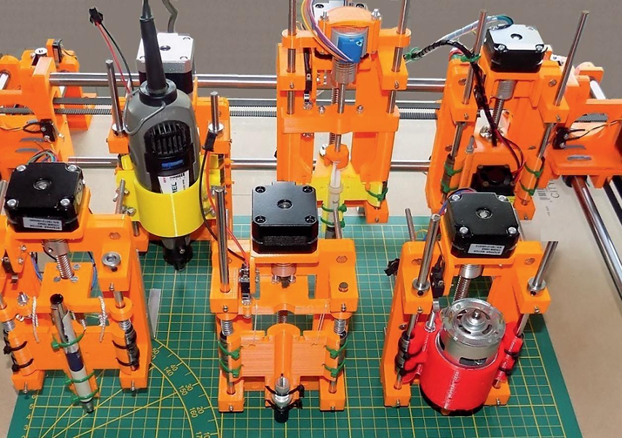
All the options use the same XY mechanism. The only component with some differences is the Z carriage. Previous names we thought of were Z3, Z4, Z5...
However, the number of possibilities is not yet exhausted, hence the name Z99.
Build Your Own Multifunctional 4-Axis CNC Machine ● 8
Perhaps the number 99 is also close to the number of prototypes we have built.
How long does it take to build the machine from scratch?
The mechanical build of the machine takes most people less than half a day. However, printing of all 3D PLA parts can take several days depending on the type and size of your 3D printer.
How much will it cost?
According to the capabilities and options you require, it is much cheaper than an equivalent commercial machine. A lot will depend on the basic parts you already have at home and the place where you buy them.
Reading this manual
Several components collaborate closely for successful operation, the Windows PC software, the electronics and microcontroller code, 3D parts, motors, and constrction.
We follow this order:
• Installation of the software and source files.
• Electronics, PCB, stepper motors and drivers and microcontroller code.
• Printing the 3D parts.
• Mechanical construction.
• The PC software code, using the Z99 as a plotter, cutter, solder paste dispenser,
• Drilling and milling machine.
• Creating source files for working with the Z99.
Before starting to build, it is wise to quickly read through the entire manual. Afterwards start thoroughly with the beginning and go step by step through the manual.
If you don’t understand something in one section, it will probably become clearer in a later chapter.
We wish that you will have as much joy building and using the Z99 as we had in developing it!
Preface ● 9
Unlimited safety pages
DC power supply 3 Ampere – 30 Volt
- Use only a fused power supply with a quality label.
Ear protection
- Use protective headphone on all noisy construction and operation.
Eye protection
- Wear safety glasses when drilling, cutting and all dusting activities.

Heat injury
- Never touch the nozzle of a 3D printer.
- The same remark applies for soldering and hot air gun.
Dust and fume extraction
- Milling and drilling can produce a lot of dust.
- Use appropriate dust suction.
- Wear a quality safety mask.
- Vinyl cutting with laser can produce toxic fumes: use fume extraction and filtering. Even better is to do it outside or not.
Mechanical
- The 6 X and Y stepper motors are strong and quick. Stay out of reach during operation,
- Do not wear lossy clothes. Keep visitors out of reach. Turn power off during maintenance.
Laser

Build Your Own Multifunctional 4-Axis CNC Machine ● 10
- Read the safety instructions that come with your device.
- Work only with a weak 500 mW blue laser.
- Do not turn on laser if it is not properly mounted with ray directed downwards.
- Never use on reflective surfaces, glossy paper, glossy vinyl, copper or other reflective metal surfaces. Reflected laser rays are dangerous.
- A weak laser doesn’t work on glossy or white surfaces.
- The laser itself could be destroyed by the reflections.
- Wear always protection glasses of decent quality.
- Do not allow anybody else to enter the room during laser operation.
- Keep fire extinguisher at hand.
Remark
The Z99 apparatus as described here has no CE or EMC qualifications. Personal use is allowed. Commercial use is not allowed.
Unlimited safety pages ● 11
Chapter 1 • Installation (Windows 10 or 11)
All code is provided as a zip file, InstallZ99.zip. The download file is available on the Elektor website https://www.elektor.com. An alternative download is available at GitHub https://github.com/opaJG/Z99. Click on the green button 'Code' and download the file InstallZ99.zip.

Save the zip (InstallZ99.zip) to any directory on your hard disk. Right-click on it and select extract all.


Select as extraction directory C:\Z99.
There is only one file extracted with name C\Z99\InstallZ99.exe. Right-click on it. Select properties and verify the digital certificate.
Build Your Own Multifunctional 4-Axis CNC Machine ● 12
The installation is straight forward. Double click on C\Z99\InstallZ99.exe. Select ‘Next’


Install in directory C:\Z99.
Installation to any other directory is possible.

Select “create a shortcut” in Start Menu and Desktop.

Chapter 1 • Installation (Windows 10 or 11) ● 13
By creating a Desktop shortcut, the Z99 icon is placed on your desktop. When the installation is finished, you may launch XYZ.exe but it is probably better to wait until your Z99 is built and you have learned to work with the software.


Open ‘Windows Explorer’ and have a look in the C:\Z99 directory.
There are seven subdirectories
• 3Dparts: Contains all the 3D parts: See chapter 3.
• CSharpCode: The C# source code for Visual Studio. See chapter 7.
• DemoFiles: HPGL, Gerber, Drill, Gerber, and G-code files. See chapter 8.
• MikrocontrollerCode: PIC microcontroller code and Z99.hex file. See chapter 2.

• PCB_LayoutAndSchematicDesign: Contains the drawing and PCB layout. See chapter 2.
• WindowsSoftware: XYZ.exe: Contains the PC software. See chapter 8.
Some of the subdirectories contain subdirectories.
Build Your Own Multifunctional 4-Axis CNC Machine ● 14
Subdirectories of C:\Z99\3DParts
A. ScadSourceCode: The *.scad source code for all 3D components.

B. STL: The stereo lithographic files, made with A. When you have no 3D printer and need to send the files to a 3D printing firm, these are the files they need so they can print the parts for you.

C. G-code: This directory is empty. G-code files are printer dependent. We will explain later how to generate them from the *.stl files.
Subdirectories of C:\Z99\DemoFiles
• Dispenser: *.disp files for solder paste dispensing.
• Drill: *.drl files to drill.
• G-code: *.gcode files to mill text or PCB. G-code files are made from Gerber files by means of FlatCAM. This is explained in chapter 9.
• Gerber: *.gbr files made with a PCB design program.
• HPGL: *.hpgl or *.plt files for plotter or cutter.
Subdirectory C:\Z99\CSharpCode
After registration, Visual Studio is free and available from the Microsoft website: https://visualstudio.microsoft.com/downloads/
The software was created with Visual Studio 2015, later tested also with Visual Studio 2019 and Visual Studio 2022.
If you are not familiar with C# or Visual Studio there is an informative book that will set you on track in no time:
C# Programming for Windows and Android from John Allwork
● 15
Chapter 1 • Installation (Windows 10 or 11)
The E-Book is available in the Elektor shop.
Open C:\Z99\CSharpCode\XYZ.sln with Visual Studio to see all the files.
Structure of the software
The structure of the software is quite simple. No files are installed in a Windows directory.
Installation without the installation program is possible. Moving the software to another PC just requires you to copy the C:\Z99 directory and all its contents to the other PC. If you move Z99 in this manner, without using the installation program, you will get no shortcut on Windows desktop.
In Windows explorer, right-click on C:\Z99\WindowsSoftware\XYZ.exe and select ‘Send to desktop’ to create a Desktop icon.
Build Your Own Multifunctional 4-Axis CNC Machine ● 16
Chapter 2 • The X2Y4Z Printed Circuit Board
About the name X2Y4Z
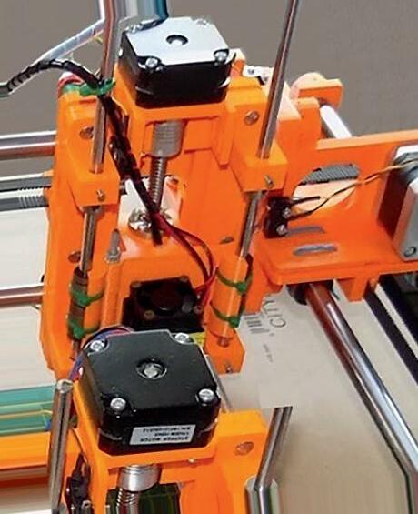
X axis is controlled by two bipolar steppers. Y axis is controlled by four bipolar steppers. Z axis is controlled by one bipolar stepper.
Why so many XY motors?
For XY movement 2 or 3 steppers motors are enough for a common 3D printer with XY dimension of up to 200 mm and linear shafts of 8 mm diameter. Linear shafts of 8 mm are not strong enough for our size of the working area and the heavy workloads like-, drilling and milling. Even 10 mm shafts were not strong enough. Only 12 mm was strong enough. Driving two 12 mm shafts at a reasonable speed with one Nema17 stepper was not very reliable.
However, the main reason for the six steppers is that we obtain a higher resolution in the XY plane! Nema17 steppers and drivers are no longer expensive.
One Nema23 stepper and suitable driver is still much more expensive then 2 Nema17 steppers!
Why is the X2Y4Z PCB not using SMD component?
Stepper driver modules and the connectors occupy the most space. All components are easily available as Dual Inline Package (DIP). An SMD PCB wouldn’t be any smaller because the connectors and modules are still the same size.
Schematic design and PCB layout were done in DesignSpark PCB 8.0 from RS Components. A download of this powerful PCB design software is available as freeware on the RS Components site: http://www.rs-online.com/designspark/electronics/eng/page/designspark-pcb-home-page
After buying and reading the Elektor book ‘KiCad Like a Pro’ from Dr Peter Dalmaris, I also redrew the schematic in KiCad. This software is also available for free from: https://kicad-pcb.org/
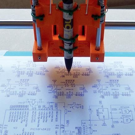
We will later show you how it is possible to plot the design on A3+ format. This gives better overview than printing on A4 format.
Chapter 2 • The X2Y4Z Printed Circuit Board ● 17
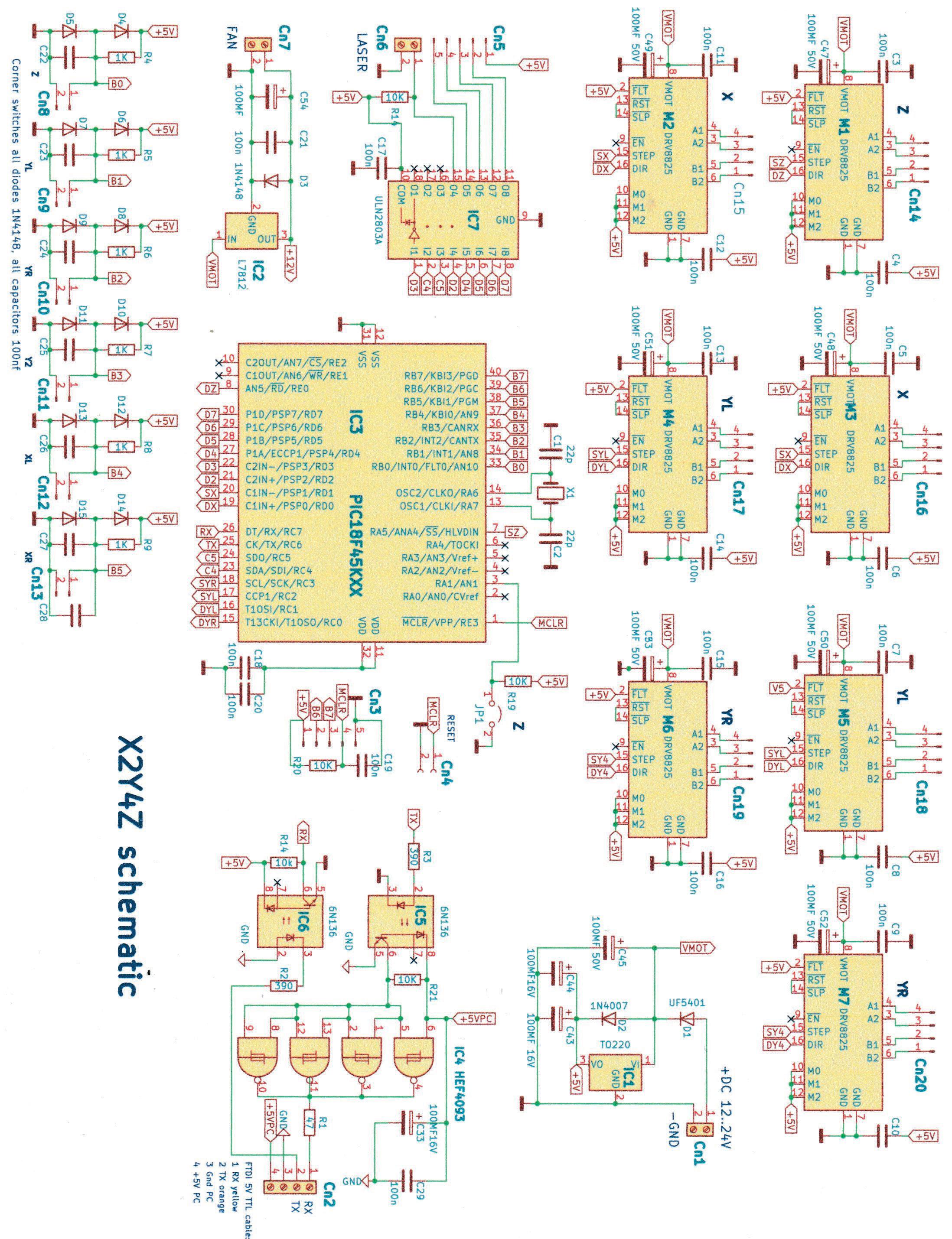
2.1 Schematic design X2Y4Z.sch in KiCad
Build Your Own Multifunctional 4-Axis CNC Machine ● 18
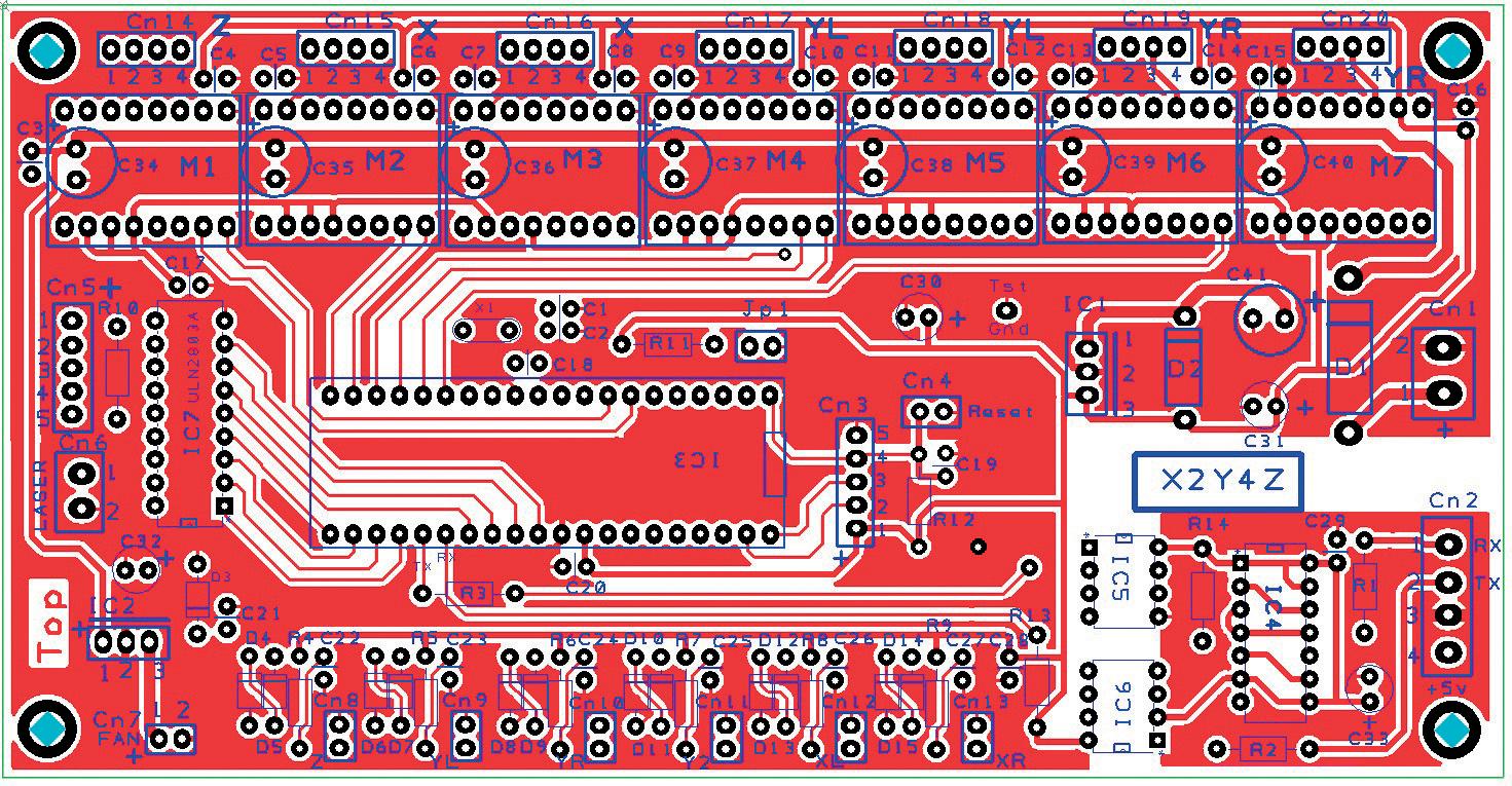
2.2 X2Y4Z PCB Top and silkcreen ‘Top’ should be readable after manufacturing.
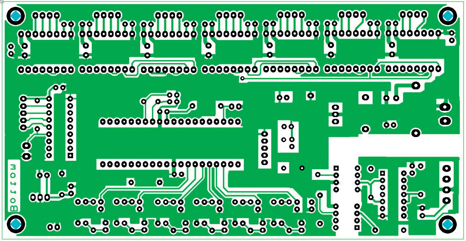
X2Y4Z bottom copper. ‘Bottom’ should be readable after manufacturing.
2.3 Component list X2Y4Z PCB for Z99 Capacitors
- C1, C2 22 pF,16 V. Pitch 0.1 inch.
- C3 to C29 100 nF, 35 volt decoupling capacitors. Pitch 0.1 inch.
- C30 to C33 100 uF Elco, 16 V. Pitch 0.1 inch or 2.5 mm.
- C34 to C40 100 uF Elco, 50 V. Pitch 3.5 mm.
Chapter 2 • The X2Y4Z Printed Circuit Board ● 19
Resistors
- R1 47 ohm.
- R2, R3 390 ohm.
- R4 to R9 1K ohm.
- R10 to R14 10 K ohm.
Diodes
- D1 Diode 3 ampere UF5400, UF5401 or similar in D0-201 package. Protection against reverse DC power supply connection.
- D2 Diode 1 A, 1N4004 or similar in D0-41 package.
- D3 at D15 Diodes 1N4148.
IC’s
- IC1 7805, +5 V regulator with cooling fin T0-220 or a switching regulator.
- IC2 7812, +12 V regulator.
- IC3 PIC18F45KXX microcontroller 40 pins DIP version.
Originally this was a PIC18F45K22.
Actually (2022), due to the global chip shortage, most suppliers have it not in stock. Alternatives are PIC18F45K40 and PIC18F45K42. Both IC’s are available.
In the download are hex files for all of the three IC’s.
- IC4 HEF4093 Schmitt trigger inverter DIP version.
- IC5, IC6 Optocouplers 6N136.
- IC7 ULN2803, 5 V DIP version.
Miscellaneous
- X1 Crystal 14.7456 MHz.
- M1 at M7. Seven DRV8825 stepper modules.
- Male headers 60 pins.
- Female headers 8 pins, 14 pieces for mounting of the DRV8825 modules.
Make sure to mount the headers parallel, otherwise insertion of the modules is cumber some.
You need 1 socket 40pins, 1 socket 18 pins, 1 socket 14 pins and 2 sockets 8 pins.
Connectors (Cn)
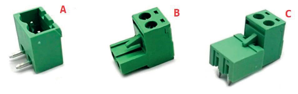
Cn1. Connect to DC power supply (12-30) V, 2 A or more.
Search for “removable screw terminal block with pitch 0.2 inch” (5.08 mm). Two poles Straight and rectangular types are both OK. Below is a rectangular type.
Build Your Own Multifunctional 4-Axis CNC Machine ● 20
A: socket, solder on PCB.
B: plug, screw the wires into it.
C: plug is in socket. Connector
Cn1
VDC) 2 DC Power Supply Ground
Cn2. Connect to 5-V TTL FTDI compatible USB-SERIAL cable.
Search for removable screw terminal block with pitch 0.15 inch (3.81 mm). Four poles
Straight and rectangular types are both OK.
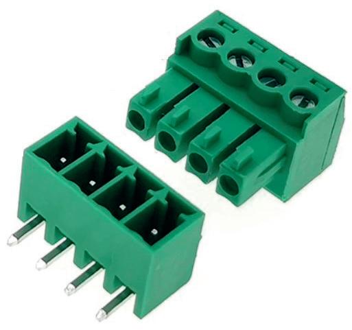
Chapter 2 • The X2Y4Z Printed Circuit Board ● 21
ID Pin Number Description
1 DC Power Supply Voltage(12-30
Connector ID Pin Number Description Colour code in case of FTDI cable Cn2 1 PC RX yellow 2 PC TX orange 3 PC Ground black 4 PC +5 V red
Cn3. Programming header. Five pins male header, pitch 0.1 inch.
Connector ID Pin Number Description
Cn3 1 + 5 V PCB 2 PGC pin 39 of PIC 3 PGD pin 40 of PIC 4 MCLR pin 40 of PIC 5 Ground PCB
Cn4. Two pole male header, 0.1 pitch. Makes reset of the PIC possible without powering on and off. It is not required to mount,
Cn5. Five pole male header, 0.1 pitch. Connections to the solder paste dispensing mo tor, 28BYJ-48. Is only necessary if you want to build the solder paste dispenser. Pin 1, +5V for the red wire of ST28.
Cn6. Connection to laser module. Search for “removable screw terminal block with pitch 0.15 inch” (3.81 mm).
Connector ID Pin Number Description
Cn6 1 Laser ON-OFF 2 DC Power Supply Ground
Cn7. Connection to fan 12 V.
Connector ID Pin Number Description
Cn7 1 +12 Volt 2 DC Power Supply Ground
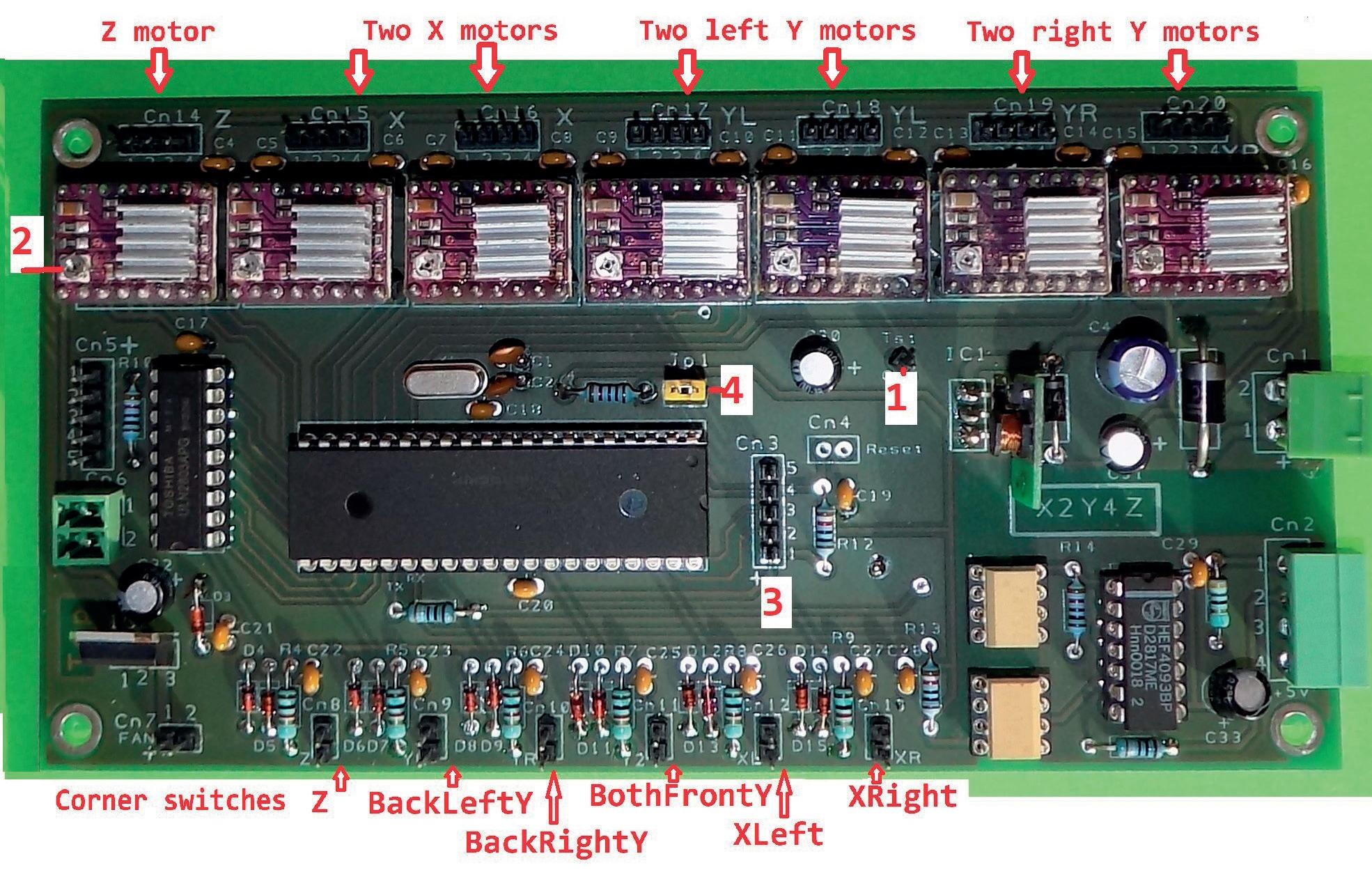
Cn8 at Cn13. Six corner switches. Male header 2 pins, pitch 0.1 mm. Pin order has no importance. Switches are normally off and become closed when end position has been reached.
Connector ID Description
Cn8 Z axis top switch
Cn9 Y axis back left switch
Cn10 Y axis back right switch
Cn11 Y axis both front switches parallel
Cn12 X axis left switch
Cn13 X axis right switch
Build Your Own Multifunctional 4-Axis CNC Machine ● 22
Cn14 at Cn20. Connectors for the bipolar stepper motors. Male headers 4 pins, pitch 0.1 mm.
Connector ID Pin Number
Description Most used colour code
Cn14 at 20 1 Coil A+ red 2 Coil A- blue 3 Coil B+ green 4 Coil B- black
Cn14. Z axis stepper motor.
Cn15 and Cn16. Two X steppers. As both X steppers turn the same way, switching con nections Cn15-Cn16 is allowed.
Cn17 and Cn18. Two left Y steppers. As both left Y steppers turn the same way, switch ing connections Cn17-Cn18 is allowed.
Cn19 and Cn20. Two right Y steppers. As both right Y steppers turn the same way, switching connections Cn19-Cn20 is allowed.
Some details of the components
IC3 +5 V regulator. Power supply is 24 to 30 V. When using a linear regulator type 7805, about 25 V x 0.1 A = 2.5 Watt cooling is necessary. There is room on the PCB for a large T0-220 cooling fin. However, it is better to use a switching regulator of at least 0.5 A. Use only a type that supports more than 30 V input, E.g TSR 1-2450 converter DC/DC 5V, 1 A SIP (Farnell order code 2007987).
Optocouplers
Bidirectional data traffic between PCB and PC is optical isolated by means of two optocouplers 6N136, IC5 and IC6. Observe the polarity of the optocouplers on the PCB. The optocouplers avoid ground loops between PC and PCB and protect your PC.
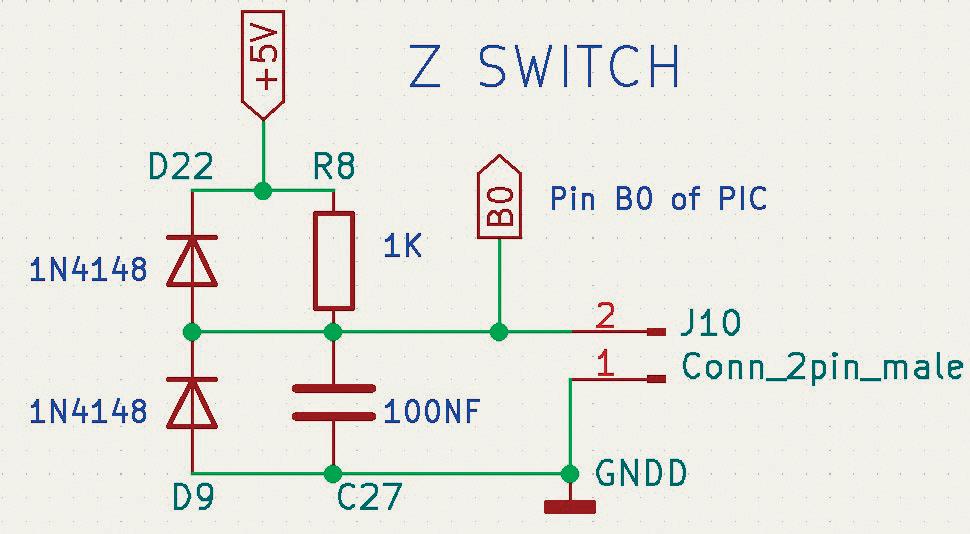
Detail of protection circuit corner switch
In an early version the pull up resistors were 10K. An unexpected stop of the Z99 occurred sometimes. It took quite some time to find out why. Changing the value of the pull up resistors with 1K was the solution. The wiring to the right XY switches is rather long. Twisting the wiring to the switches reduces common pickup noise. It is a good idea to twist the wires of the switches. Most 3D printers also have corner switches with twisted wiring.
Chapter 2 • The X2Y4Z Printed Circuit Board ● 23
Timing constant of R8 x C29 is 100 microseconds. Even at the highest speed no micro step can be done after a switch is closed.
IC4 Output buffer TX signals from PCB to PC
The signal is buffered by four gates from an HEF4093 Schmitt trigger, IC4. The resistor R1 47 ohm is necessary for good output drive capability!
At 57600 baud a cable length of four meters is possible without errors. If you need a longer cable, use an active USB2.0 extension cable to obtain 5 or 10 meters more distance.
Build Your Own Multifunctional 4-Axis CNC Machine ● 24
Finished X2Y4Z PCB for Z99
Index
C
C sharp 90
Conductive ink 108, 132 Construction Z99 55 Corner switches 23, 25, 100 Cut 77, 112, 114
D
Designspark PCB 17, 109, 125, 132 Drill 80, 115, 137, 134, 155
E
Engrave 71, 104, 110 Etch resist pen 107, 132
F Fan 57 FlatCAM 121, 146
G
Gerber files 135, 139, 143, 146, 156 G-code 46, 121, 146, 159
H
Hardware part Z99 48 HPGL 154
I
Inkscape 127 Installation 12 K
KiCad 17, 105, 126, 140
L Laser 10, 11, 70, 74, 100, 110, 114
M
MDF 48, 55, 86 MikroC 33 Mill 80, 121, 137, 143
Nema 17 26 Nema 17 driver modules 28
Open SCAD 41 Overview 3D parts 60 P
PCB Z99 19 Pic code 33 Pic programming 37 PLA 44 Plot 77, 103, 132, 140 S
Serial communication 90 Schematic design 48 Slic3r 42
Solder paste mask 122, 134, 142 Solder paste dispensing 82, 117
Tools for construction 48 U Unipolar stepper 30
113, 125
Build Your Own Multifunctional 4-Axis CNC Machine ● 170
N
O
T
V Vinyl
W Wireless Bluetooth connection 161 X X2Y4Z PCB 17 XYZ.exe 96 Z Z carriages 70
booksbooks
Build Your Own 4-Axis Multifunctional CNC Machine
Plot, Cut, Drill, Mill, and Laser with the Z99
This book covers the construction, hardware, software, and operation of the Z99 - CNC machine. This is a multifunctional 4-axis machine for home construction.
The capabilities of the Z99 machine include:
• large-format schematic plotting
• PCB plotting with etch-resist pens
• schematic plotting with conductive-ink pens
• letter cutting out of vinyl
• paper cutting
• PCB/substrate drilling
• PCB/substrate milling
• text milling
• laser engraving
• laser cutting of solder paste masks
By making the support software available as freeware, readers of the book are challenged and encouraged to develop new applications for the Z99.
The machine would not be of much use if the user has no option to create suitable files for the designs in mind. A large part of this book is dedicated to creating source files in a variety of freeware software packages, including Inkscape, DesignSpark PCB, KiCad, and FlatCAM.
The book is also useful for readers keen to comprehend and then master the basic structure of HPGL, Gerber, Drill, and G-code files, as well as to have a go at deciphering them using software.
José Ganseman, MD. (1951) was occupied as a General Practitioner for 35 years.

He is a passionate, lifelong electronics hobbyist and software programmer in several languages. He is also an Elektor reader from the seventies on.
After his retirement in 2010 he decided to build a multifunctional machine for personal use. The machine can be used for several tasks like plotting, cutting, milling, and laser etching/cutting.
Elektor International Media BV www.elektor.com

