27 minute read
Yves Poitevin


THE EUROPEAN TBM PROGRAMME: TESTING IN ITER THE TECHNOLOGIES THAT WILL ENSURE SUSTAINABILITY OF D-T FUSION IN FUTURE PLANTS
Yves Poitevin · Italo Ricapito · Milan Zmitko · Joelle Vallory (Fusion for Energy) · Alessandro Spagnuolo (EUROfusion)
Advertisement
©ITER
Yves Poitevin · Italo Ricapito · Milan Zmitko · Joelle Vallory (Fusion for Energy) · Alessandro Spagnuolo (EUROfusion)
TRITIUM BREEDING BLANKET IN FUTURE FUSION REACTORS: PRINCIPLES
Unlike deuterium, tritium is a rare resource on earth. Only a few tens of kg are present in our environment: about 3.5kg come actually from a natural origin – tritium is generated by cosmogenic neutrons impacting oxygen and nitrogen atoms in the high atmosphere – whereas the rest is a leftover from atmospheric tests of nuclear weapons in the middle of the last century: about 520-550kg of tritium were released in the atmosphere between 1950-60, but only a few tens of kg are left today because of natural decay. None of this tritium is economically accessible. Few kg of tritium is also produced every year by the fission industry. Few commercial or dedicated reactors were licensed specifically for tritium production, reaching a production of 1-3kg per year (e.g. Watts Bar I reactor in the US; Ruslan and Ljudmila reactors in the Russian nuclear complex of Maïak). However, the greatest production of tritium occurs mostly in civil heavy water reactors like CANDU’s in which heavy water (D2O) is used both as coolant and neutron moderator. These reactors produce typically ∼230 g of tritium per GW of produced electricity (GWe) and full power year. In order to keep tritium activity in moderator and coolant systems within acceptable limits, tritium is usually extracted onsite in dedicated tritium removal facilities (e.g. OPG station in Darlington, Canada), and then stored. The amount of tritium reserve depends today on the yearly production of plants in operation versus natural decay (tritium sells to laboratories or industries are today marginal). However, on a longer time scale, the question of the replacement of plants coming to the end of their lifetime is introducing scattering in the various reserve projections. If Canada would not replace its CANDU type reactors at their end of lifetime, a peak of 24kg of tritium reserve would be reached in the next decade, then decaying over time. Such a tritium reserve, about 20kg, is sufficient to supply laboratories or industries over the next decades for their activities. It is also sufficient to provide the fuel for ITER operation over its lifetime. It may also be suffi-
cient to provide the start-up inventory of the first fusion DEMO reactor. But, looking at a much longer time scale, it is far from being sufficient to cover the yearly consumption of a fusion nuclear reactor. Indeed, a fusion reactor producing 900MWe would consume more than 300g of tritium every day, which is more than a hundred kg per year. It is, therefore, necessary to design future fusion reactors with the capacity to regenerate in situ the tritium that they will consume in the plasma, even with a surplus to compensate the losses and prepare the start-up of a new reactor. This is a sustainability requirement called the tritium self-sufficiency of a fusion reactor. It is usually defined by the Tritium Breeding Ratio (TBR), which is the ratio between the tritons regenerated in the reactor divided by the tritons consumed in the fusion reaction. The tritium self sufficiency is reached when the TBR is greater than 1. It shall even be strictly greater than 1 in order to provide the surplus mentioned above. It is here essential to note that this requirement does not apply to ITER – there will be sufficient external tritium reserve – but may be needed right after in a DEMO fusion reactor, since the existing tritium reserve may not cover its yearly consumption. In DEMO or future fusion power reactors, the system that will regenerate the tritium in situ is called the Tritium Breeding Blanket. The concept is simple (see Figure 1): tritium is produced by neutronic absorption in lithium (this is a transmutation type reaction).
Fusion (plasma): T + D ➔ 4He + n + 17.6 MeV Blanket: n + 6Li ➔ 4He + T + 4.8 MeV
Balance: D + 6Li ➔ 2 4He + 22.4 MeV
Fig.1. Simplified principle of tritium self-sufficiency in a fusion reactor.
Yves Poitevin · Italo Ricapito · Milan Zmitko · Joelle Vallory (Fusion for Energy) · Alessandro Spagnuolo (EUROfusion)
The technological solution consists therefore in filling the blanket surrounding the plasma with a material containing lithium – this is the tritium breeder material. It is indeed recalled that the neutrons produced from the DT fusion reaction are not sensitive to the magnetic confinement, will escape the plasma and will enter the surrounding blanket. If the blanket is designed adequately, these neutrons may preferably be captured by lithium and tritium will be produced in sufficient quantities. Breeder materials like eutectic lead-lithium, lithiated ceramics or molten salts containing lithium can be envisaged. Several remarks are important to progress then, step-by-step, in the technical complexity of a blanket design. • First, one may repeat that such a technology is not needed in the ITER blanket since the tritium reserve existing today is sufficient to cover the full ITER operation. In ITER, the blanket has mostly the function of capturing neutrons in order to protect the vessel structure and the superconducting coils behind. A block of steel cooled by water is sufficient for that purpose. • In a future blanket, the capture of neutrons by other atoms not participating in the tritium breeding is unavoidable, for instance in atoms of the structural material. There are also other types of unavoidable neutrons losses. In order to reach tritium self-sufficiency at reactor level, it is therefore needed to multiply the neutrons entering the blanket in order to increase the overall number of neutronic captures in lithium, and therefore the quantity of tritium produced.
For that purpose, neutron multiplier (i.e. (n, 2n) reaction) materials like beryllium or lead are used also in the blanket. • For the same reason, it is also needed to maximize the probability that a neutron entering the blanket ‘sees’ the lithium atom and is captured for producing tritium (this probability is called the cross-section of the (n,t) reaction). This probability depends on both the incident neutron energy and the isotope form of lithium. At typical energies of neutrons in a blanket, this probability is higher for the isotope 6Li rather than for its most common natural isotope 7Li (indeed, the 7Li reaction works with neutrons with energies higher than 1 MeV and it produces an additional n that is available for a successive reaction). Therefore, breeder material shall be enriched in 6Li isotope.
• The blanket surrounding the plasma has two other functions essential in a power plant: first, the extraction under economically attractive conditions of the heat generated by the neutronic captures in the blanket; second, like in
ITER today, the radiation shielding of the vacuum vessel and superconducting coils. • Regarding heat extraction, the goal in the future is to produce electricity under economically attractive conditions. For that purpose, blankets are designed for operating with high-temperature coolants, e.g. pressurized water, helium, or more advanced concepts like liquid metal. It is interesting to note that the neutron emitted by a DT fusion reaction carries about 80% of the fusion reaction energy (the other 20% is carried by the alpha particle and contribute to the plasma heating). The blanket is therefore the component in a reactor where most of the fusion energy can be recuperated.
• The structural material of the blanket shall be able to operate at high temperatures and to maintain proper dimensional stability and mechanical properties under irradiation for the target lifetime of the blanket. In addition, considering the large amount of blanket structures in a reactor, the structural material shall feature a reduced activation capacity so that, after dismantling, it can return to low activity waste on a reasonable time scale, typically less than 100 years. Various types of materials are envisaged in Europe. For shorter-term application, Europe has been developing a reduced activation ferritic-martensitic steel, called Eurofer97. Longer-term candidates able to reach higher operating temperatures are also studied like oxide dispersion strengthening steels or SiCf/SiC composite.
The design of a breeding blanket has then to optimise the combination of several materials, namely: • A tritium breeder material containing lithium (e.g. eutectic lead-lithium, lithiated ceramics, molten salts containing lithium). • A neutron multiplier material (lead or beryllium). • A coolant (pressurized water, helium, liquid metal). • A structural material (steel, vanadium alloy, SiC/SiC composite).
Yves Poitevin · Italo Ricapito · Milan Zmitko · Joelle Vallory (Fusion for Energy) · Alessandro Spagnuolo (EUROfusion)
Not all combinations are however possible in practice: engineers shall take into account materials chemical compatibility, combined performances, safety requirements, etc.
OVERVIEW OF EUROPEAN BLANKET CONCEPTS UNDER DEVELOPMENT
Among the various materials listed above, development levels are very different. For a DEMO reactor, Europe has chosen to prioritize two concepts necessitating R&D attainable in the shorter term.
The water-cooled lead-lithium (WCLL) features a eutectic of lead-lithium (Pb-16Li) as neutron multiplier, tritium breeder and tritium carrier, Eurofer97 ferritic-martensitic steel as structural material and pressurized water as coolant. Water operates at typical pressure of fission pressurized water reactors (15.5MPa) and inlet-outlet temperatures of 295-328°C. The lead-lithium eutectic, which has a melting temperature of 235°C is under liquid form in the blanket, slowing circulating in the blanket (few mm/s), then circulating outside the blanket for tritium extraction. The helium-cooled pebble beds (HCPB) uses lithiated ceramic in the form of pebbles bed (Li4SiO4, Li2TiO3) as tritium breeder, beryllium or beryllide as neutron multiplier, Eurofer97 as structural material and pressurized helium as coolant (8MPa, 300-500°C). Tritium extraction is obtained by the circulation of helium purge gas at low pressure (0.1MPa) doped with H2 (0.1vol%) through the pebble beds. The ceramic pebbles have an operating temperature ranging between 600-900°C.
Other blanket concepts are also being developed in Europe for reaching enhanced reactor thermal efficiency, but they necessitate longer R&D effort. One may cite for instance the dual-coolant lead-lithium (DCLL) concept using Oxide Dispersion Strengthening steel as structural material and combining helium and liquid metal cooling; or the self-cooled lead-lithium (SCLL) concept using SiCf/SiC composite as structural material and liquid metal heat extraction, thus allowing reaching outlet temperature in the order of 1,200°C.
For both the WCLL and HCPB concepts studied in priority, the tritium self-sufficiency (i.e. TBR>1) can be reached according to numerical simulation and R&D has been running for decades to develop and qualify their key technologies individually. The challenge consists today in realizing an integrated technological experiment under relevant tokamak conditions, in order to qualify their overall performance and behaviour: tritium production capacity, heat extraction, materials temperature control, structural behaviour under tokamak loadings, etc. This extensive technological test will be realized in ITER in the Test Blanket Module (TBM) programme.
INTRODUCING THE EUROPEAN TBM PROGRAMME IN ITER
Among the various scientific and technological objectives of ITER, one is saying: ‘the device should test tritium breeding module concepts that would lead in a future reactor to tritium self-sufficiency, the extraction of high-grade heat and electricity production.’ This is the ITER Test Blanket Module (TBM) program. Several ITER Members are engaged in this programme. Europe is one and has the mission to test and validate, during ITER operation, mock-ups of both the WCLL and HCPB blanket concepts in view of preparing the design and construction of a DEMO reactor. For that purpose, Europe is today:
• Designing modules (the Test Blanket Modules - TBM) that reproduces in
ITER operating conditions close to the ones foreseen in the WCLL and
HCPB DEMO Blankets. • Designing ancillary systems (cooling, tritium extraction, etc.) able to establish and maintain the desired operating conditions in TBMs. • Contributing to the development and validation of predictive modelling tools that are essential for exploiting the test results from ITER and designing the
DEMO Blankets.
Each TBM connected to its ancillary systems form a so-called TBM System (TBS) that is a complex nuclear system integrated into the ITER machine. A description of the two European TBM Systems under development is given later.
Yves Poitevin · Italo Ricapito · Milan Zmitko · Joelle Vallory (Fusion for Energy) · Alessandro Spagnuolo (EUROfusion)
Of course, it is clear that ITER will not offer the same loading conditions as in a bigger DEMO reactor. For instance, the cumulated neutron irradiation dose on TBM materials will be limited to 1-2 displacement per atom (dpa), whereas DEMO blanket structures are expected to reach 20-50 dpa. Here, the material test facility IFMIF will be essential to DEMO designers for complementing the return on experience from the sole TBM Programme. Other loading differences exist between ITER and DEMO, e.g. the intensity of the transient magnetic loads, or the ratio of the plasma heat flux over the neutron wall flux impacting blanket modules. This is the art of TBMs designers to pass from the conceptual design of DEMO blanket modules to reduced-size TBMs that can fit into an equatorial port of ITER, using materials and fabrication technologies that can be extrapolated to DEMO blanket and reaching, as much as possible, operating conditions close to the ones expected in a future DEMO blanket.
Another challenge for TBM designers is that ITER will reach its most relevant DT plasma operation only progressively over several operational stages. A first TBM will be installed during the H/He plasma phase of ITER with no production of neutrons. Then, progressively, ITER will turn to D and DT plasma, first with short pulses of 300-500 s, then with longer plasma pulses of 1,0003,000 s where the most relevant loading conditions for TBMs are expected. The strategy of TBM designers consists, in each ITER operational phase, to keep the same TBM basic design, but adapting the TBM internal instrumentation to staged learning curve along the evolution of ITER operation. Typically, electromagnetic instrumentation in the first module to qualify the behaviour of the box under electromagnetic loads or, for the WCLL, the PbLi magneto-hydrodynamic behaviour. Then, in later modules, to favour progressively neutronic, thermo-mechanical and then tritium sensors, thus covering the maximum spectrum of return on experience. In total, about three to four specifically instrumented TBM of each concept shall be tested sequentially in ITER. Along the whole TBM program in ITER, numerical tools will continue to be developed and will be validated on the basis of the ITER experimental results.
For DEMO blanket designers, the TBM tritium breeding capability and its comparison with the numerical prediction is the primary output of the TBM Programme. They will benefit also from much more return on experience: materials behaviors, full system operability, licensing and regulatory feedback, validation of safety functions, quantification of parasitic effects in tritium processing, identification of unexpected phenomena, etc. Also, the actual cost of R&D and the first industrialization of TBM technologies will give essential input to DEMO designers for properly setting weighting factors in any future cost comparison between various DEMO concepts under development.
GENERAL DESCRIPTION OF THE EUROPEAN TBM SYSTEMS IN ITER
As mentioned in the previous sections, in the frame of the ITER TBM Programme, Europe is committed in designing and manufacturing two TBM systems: the Water Cooled Lithium-Lead Test Blanket System (WCLL-TBS) and the Helium Cooled Pebble Beds Test Blanket System (HCPB-TBS). Both TBS derive from the ‘parent’ breeding blanket concepts that Europe is developing for DEMO. In particular, each of the two TBS retains the three following top-level technologies of their parent breeding blanket concepts: • the structural material of the in-vessel component (TBM box): Eurofer97; • the tritium breeder and neutronic multiplier: flowing Pb-16Li for the WCLL-
TBS; ceramic lithiated material and beryllium for the HCPB-TBS;
• the coolant type and thermo-hydraulic conditions: water at PWR conditions for the WCLL-TBS; pressurized He for the HCPB-TBS.
The TBS keeps also the same system architecture like a breeding blanket system for DEMO. The WCLL-TBS architecture is shown in Figure 2, and Table 1 gives the main functions and operative conditions of the sub-systems.
Yves Poitevin · Italo Ricapito · Milan Zmitko · Joelle Vallory (Fusion for Energy) · Alessandro Spagnuolo (EUROfusion)
Fig. 2. Architecture of WCLL-TBS, acronyms and functions are defined in Table 1.
Table 1. Main functions of the WCLL-TBS sub-systems (P: pressure; T: temperature).
PbLi loop
LiPb +Q2 He + Q2
He + H2
LiPb
TBM Set
He TES
PBS 56 – WCLL-TBS
Q2 (+He) PBS 32 – Tritium Processing
NAS
He
He + Traces* TAS
Q2(+ He)
TEP
WCS
Heat Sink CCVS-1 Imp. +
O 2 +
H 2 O CPS
H2O + additives He(+ Q2 )
Traces* = Q2, O2, N2 DS
SUB-SYSTEM PROCESS FLUIDS
TBM set TBM box+shield
WCS Water Cooling System
CPS Coolant Purification System · flowing Pb-16Li · water - P=15.5 MPa, - Tin-out =295-328°C pressurised water - P=15.5 MPa, - Tin-out =295-328°C water - mean P=0.9 MPa - mean T=70°C MAIN FUNCTIONS
· Convert nuclear to thermal power · Generate tritium
· Extract thermal power generated in the
TBM · Remove activated corrosion products · WCS chemistry control · Remove contaminants · Extract tritium from water · Concentrate tritium and route to TAS
PbLi loop
TES Tritium Extraction System
TAS Tritium Accountancy System
NAS Neutron Activation System Liquid Pb-16Li - flowrate 0.2-1.0 kg/s - T: 295-350°C Helium - H2 at 0.1%vol. - low P Helium containing - H2 - HT · Pb-16Li and tritium recirculation outside
Vacuum Vessel · Remove activated corrosion products · Extract tritium from PbLi · Concentrate tritium and route it to TAS
· Account tritium received from TBS · Deliver tritium to ITER Tritium Plant
Helium, low P, room T · Measure TBM neutron flux · Measure TBM neutron spectrum
The architecture of the HCPB-TBS is similar to the WCLL-TBS one. The main difference is that TES is directly connected to the TBM box for the extraction of tritium generated in the pebble beds made by a mixture of lithium ortho-silicate (Li4SiO4) and lithium meta-titanate (Li2TiO3). The tritium extraction function is accomplished by a low-pressure purge He stream containing a hydrogen molar fraction of about 0.01.
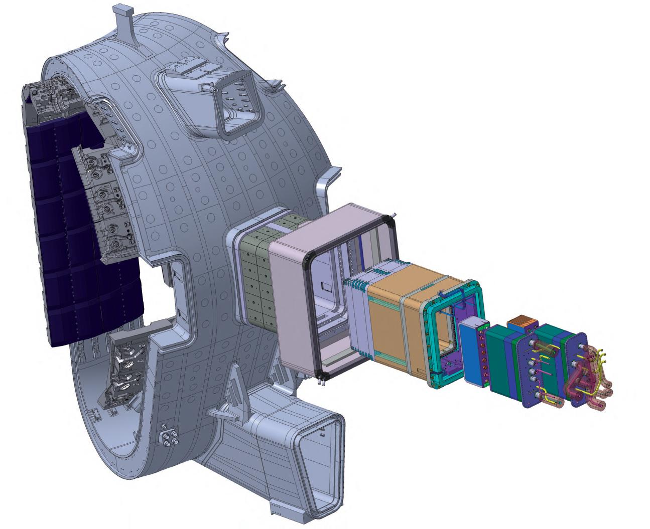
The TBM box is the source of tritium production and nuclear heating. It must withstand severe loads of different types, mainly high pressure and temperature, neutron irradiation and an electromagnetic field of several Tesla. It is also is the component in which the maximum level of relevancy shall be reached with respect to the technologies envisaged for DEMO. Therefore, the design of the TBM box and its fabrication technologies are extremely challenging. One shall remember that the TBM box will be made of Eurofer97. This is a new material for nuclear applications and a strong effort is ongoing for including its design limits in the RCC-MRx nuclear design and construction code and to prepare
PbLi outet pipe
Back plate 1 Back plate 2 Back plate 3 Back plate 4 Stiffening unit Stiffening grid First wall
Side cap
FW Water inlet pipe Water outlet pipe BZ Water inlet pipe
Stiffening rod nut Tie rod nut
I&C pipe PbLi internal pipe
PbLi inlet pipe Double walled tubes Stiffening rod Stiffening rod screw
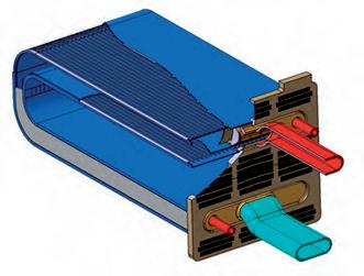
Tie rods Fig. 3a. WCLL-TBM box, main components (courtesy of CEA, ESTEYCO and EUROfusion Consortium).
Yves Poitevin · Italo Ricapito · Milan Zmitko · Joelle Vallory (Fusion for Energy) · Alessandro Spagnuolo (EUROfusion)
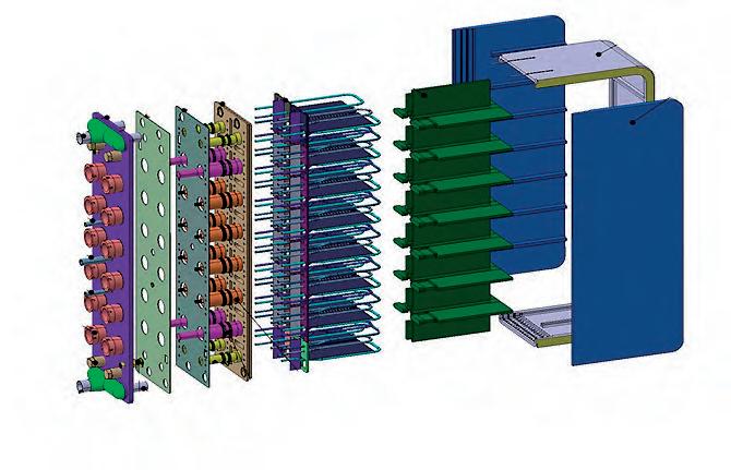
Fig. 3b. HCPB-TBM box, main components (courtesy of ESTEYCO, IDOM and Fusion for Energy). the welding specifications. All this justifies the important R&D program that is currently under implementation (illustrations are given later in this section). Figure 3 shows the preliminary design of the WCLL-TBM and HCPB-TBM box with the three main regions: the first wall, the breeder unit and the back manifold system made of series of back plates. Beyond the development of the TBM box, the integration of the other TBSs sub-systems in ITER is also a challenging task. In fact, the TBS integration involves many functional interfaces with around thirty other ITER systems (e.g. vacuum vessel, Tritium Plant, ITER cooling systems, etc.). The main reason of this high number of interfaces lies in the large physical dimensions of the TBS, whose layout is deployed over different areas of the ITER Tokamak Complex (Figure 4). Integration within the ITER safety demonstration is also an essential task (ITER is a ‘Nuclear installation’), aimed at providing to the French Safety Authority the
Back plate 1 Back plate 2 Back plate 3 Back plate 4 Back plate 5
Purge gas inlet pipe
I&C pipe
He outlet pipe PartA
He by-pass pipe
He inlet pipe
Tightness bellows
Purge gas outlet pie Back plate 0
Back plate BU Breeder unit Stiffening grid
Tie rod
Stiffening rod Mod stiffening rod First Wall
Side Cap
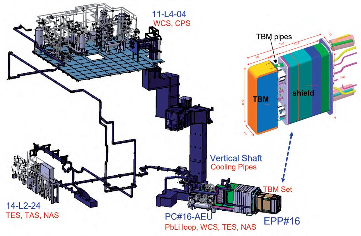
Fig. 4. Layout of WCLL-TBS (similar for HCPB) (by courtesy of ©ITER Organisation, EUROfusion and Fusion for Energy).
Yves Poitevin · Italo Ricapito · Milan Zmitko · Joelle Vallory (Fusion for Energy) · Alessandro Spagnuolo (EUROfusion)
evidence that the TBS in normal and accidental conditions do not challenge the safety limits and features of ITER. The safety demonstration activities have also a relevant impact on the TBS design, particularly on the development of the ‘safety important components’ (SIC) and on the configuration of the Instrumentation and Control (I&C) system. The implementation and outcomes of all these activities constitute an important part of the return on experience for the DEMO designers.
FROM RESEARCH TO A TECHNOLOGICAL SOLUTION
One of the challenges of the TBM programme is to transform the outcome of laboratories research into technological components or systems that can be manufactured by industry and be licensed for operating in a nuclear facility like ITER. This encompasses the production and qualification of EUROFER97 steel, the fabrication of the TBM box, the breeder materials, the tritium extraction technologies, etc. This is illustrated below with two key topics: fabrication of the TBM box, and tritium technologies.
TBM box fabrication development
Both TBM concepts consist of a EUROFER97steel box with an internal stiffening grid, which provides mechanical resistance in case of accidental pressurization in case of coolant leakage. This grid segregates the box internal volume into cuboids containing breeder/multiplier materials and heat extraction cooling plates or tubes. All structures of the TBM box are made of EUROFER97 steel. The envelop TBM structures and some of the internal ones are actively cooled by circulation of pressurized coolant in embedded channels having a rectangular cross-section. These channels run within the thickness of the structure and form meandering paths. These channels cannot be built by conventional manufacturing techniques like drilling because of multiple internal U-turns.
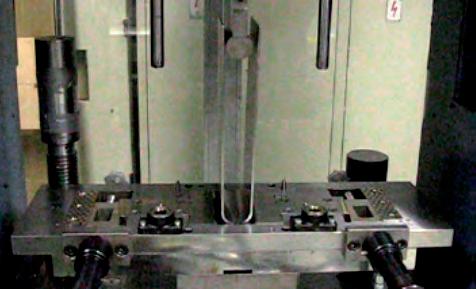
Therefore, more innovative fabrication processes are used like Hot Isostatic Pressing (HIPing). Although HIPing is not a new technology for industry, in the case of TBM structures the manufacturing process had to be further developed, for instance combining laser beam welding and HIPing, or 2-step HIPing. Indeed, once a meandering groove has been machined in a plate thickness, it is needed to close this groove in a fully leak-tight way before recovering it with another plate to reconstruct by HIPing the full structure. This is illustrated in Figure 5.
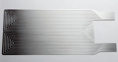
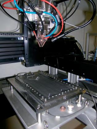
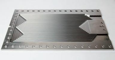

Fig. 5. Key steps of the fabrication by ATMOSTAT/ CEA of a TBM sub-component by adapted Hot Isostatic Pressing (HIPing) technology (courtesy of Fusion for Energy); (top right) grooved plate before welding of the mono-bloc strip; (top left) mono-bloc strip; (bottom left) YAG laser beam welding of the mono-bloc strip on the grooved plate; (bottom right) the cooling plate (CP) machined after the HIP cycle (assembly for a leak tightness test).
Yves Poitevin · Italo Ricapito · Milan Zmitko · Joelle Vallory (Fusion for Energy) · Alessandro Spagnuolo (EUROfusion)
Fig. 6. Fabrication by the Karlruhe Institute of Technology (KIT) of a cooling plate by drilling, spark erosion and bending; (top left) global view of HCPB breeder unit (courtesy of KIT and Fusion for Energy); (top right) CP bending and a bending tool; (bottom left) global view of HCPB CP mock-up; (bottom middle) various cross-sections of the CP with internal cooling channels; (bottom right) microstructure of the cooling channel cross-section (after etching).
Fig. 7. Assembly by ATMOSTAT/CEA of a TBM box mock-up by a TIG robot (courtesy of Fusion for Energy); (left) multi-pass TIG welding of vertical stiffening plate inside the TBM box; (middle) multi-pass TIG welding of 14 horizontal stiffening plates inside the TBM box; (right) full scale TBM structure assembly (poloidal height of 1,670mm).
2mm
Another example, when there is no internal U-turn of the channel, consist in combining drilling, spark erosion and bending. Drilling provided a first hole for the channel, then precisely formed by spark erosion on a relatively large length; the bending of the structure is applied with minimization of deformation of the channels cross-sections. See Figure 6, illustrating the fabrication of the HCPB cooling plate. For the assembly of the TBM-Box, more conventional welding technologies are used, like TIG welding. However, the difficulty of access during the welding sequence necessitates using a robot and a 3-axis positioner (see Figure 7).
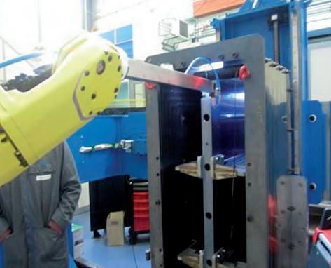
The welding sequence itself is also optimized in order to reduce the overall deformation of the structure, since each joint is obtained by multi-passes TIG welding, which deposit an important amount of heat.
Tritium Technologies and modelling to reconstruct the tritium balance
Establishing a methodology for the reconstruction of the tritium balance in a complex system like the TBS, and demonstrating its validity, is the key mission of the TBM Program. The reconstruction of the tritium mass balance consists in mapping the tritium distribution among all TBS sub-systems and systems, including the evaluation of tritium losses by permeation from the TBS to the outside (controlled) environement of the plant, for a given a mass of tritium generated in the TBM box in a given period of time. The methodology considered so far consists of three key elements: 1. measurement of tritium concentration along the TBS sub-systems and components; 2. measurement of tritium delivered to the Tritium Plant; 3. development of mathematical simulation models for the simulation of tritium transport through TBS materials and components.
1. Measurement of tritium concentration along the TBS sub-systems and components This step is accomplished by the use of sensors able to measure on-line the tritium concentration in the TBS process fluids (e.g. helium, Pb-16Li, etc.) with good performance in terms of sensitivity, accuracy, response time and repeatability. To this purpose, promising results have been achieved with the ionization chambers for tritium concentration measurement in helium and permeation-based sensors for tritium concentration measurement in flowing Pb-16Li. The principle of operation of the ionization chambers (see Figure 8) is based on the gas ionization generated by the beta particles emitted by tritium (av. beta energy of 5.6keV). Higher is the tritium concentration in the sensitive chamber, higher is the rate of
Yves Poitevin · Italo Ricapito · Milan Zmitko · Joelle Vallory (Fusion for Energy) · Alessandro Spagnuolo (EUROfusion)
Ionization Chamber
Incident radiation particle
Electric field Anode
Ion Current
DC Voltage Source
Fig. 8. Principle of operation of an ionisation chamber (G. Knoll (1999). Radiation detection and measurement, 1999, New York: Wiley). Key
Ionisation event Electron +Ve ion Cathode
InstrumentationTools.com
emitted beta particles and higher is the amount of electrical charges per unit time collected at the electrodes of the chamber. The performance of the ionization chambers for tritium measurement needs further work of optimization because of the low energy of the emitted beta particles and the problem of the tritium memory effects on the electrodes. Another important technology under development deals with the tritium concentration sensor in flowing PbLi. Exploiting the high permeability of tritium through steel and the low solubility in Pb-16Li, it has been preliminarily designed and tested a sensor where tritium permeation from PbLi into an empty thin steel capsule takes place. The permeated tritium is then measured in gas phase and correlated through thermodynamic (Sieverts’ law) or transport (Richardson’s law) equations to the tritium concentration in the liquid PbLi. Measurement of tritium solubilized in structural materials can be done off-line by post-irradiation examination (PIE) techniques, which essentially consist in degassing the material at high temperature and measuring the desorbed tritium amount (e.g. by scintillation counting).
The deployment of the tritium measurement sensors along the TBS sub-system chain together with the PIE analysis on the structural materials is then needed to map the amount of the tritium lost by permeation and leakages and tritium solubilized in the different materials.
2. Measurement of tritium delivered to the Tritium Plant This key step in the reconstruction of the tritium mass balance requires the operation of a system at the interface between the TBS and the ITER Tritium Plant with the function to measure all tritium transported by the TBS process fluids and to be delivered to ITER Tritium Plant. This system is called Tritium Accountancy System -TAS- (see Figure 2), whose preliminary design has been developed with KIT (Germany) in a first phase and with IDOM (Spain) in a second one. In a given period of time, the difference between the tritium generated in the TBM box and the amount of tritium measured in TAS must be the sum of the tritium solubilized in the functional and structural materials and tritium lost by permeation or other leakages, determined in the step A.
3. Development of mathematical simulation models for the simulation of tritium transport through TBS materials and components
The tritium transport model development is the last but not less important element in the tritium balance reconstruction. In fact, once tritium transport models have been validated against the experimental tritium mapping (achieved by the steps a. and b.), then they have the capability to predict the tritium inventories and losses in the TBS (then reconstructing the tritium balance) under a wide range of operative conditions. Europe is developing several models and simulation tool in this area. Among them, it is worth to be mentioned a tritium transport simulation tool, based on the EcoSimpro platform developed by Empresarios Agrupados (Spain) in collaboration with Ciemat (Spain), which shows a good potential for large and complex system like a TBS. Its refinement and validation program are still ongoing. Figure 9 represents the model and the simulation results of the tritium diffusion and permeation from PbLi into the cooling water through the double wall tubes.
T
T
PbLi
LM BL
EUROFER
H
H
T
Fe
H
T
T
T
T
H
EUROFER
T
H
T
Water
H
H H
H2, HT, T2, HTO, H2O
Tritium permeation rate in TBM from PbLi to Water
Permeation rate (mg/d) 8.00E-01 7.00E-01 6.00E-01 5.00E-01 4.00E-01 3.00E-01 2.00E-01 1.00E-01 0.00E-01 0 5 10 15 20 25 30 Time (d)
Fig. 9. Model and simulation results for tritium diffusion and permeation from PbLi to water coolant (courtesy of CIEMAT-Empresarios Agrupados).
Yves Poitevin · Italo Ricapito · Milan Zmitko · Joelle Vallory (Fusion for Energy) · Alessandro Spagnuolo (EUROfusion)
CONCLUSION
The capacity of a future fusion reactor to reproduce the tritium consumed in the D-T plasma reaction is of paramount importance for guaranteeing the sustainability of D-T fusion energy. This shall be achieved in a dedicated system of future reactors, called the tritium breeding blanket, which will make use of the neutrons produced by the D-T fusion reaction to reproduce tritium by transmutation of lithium. This system will be installed inside the vacuum chamber, facing directly the plasma. It will also recover the energy deposited by the neutrons in order to heat a coolant at economically attractive conditions in view of electricity production. Tritium breeding blanket concepts have been developed in Europe for decades, and a large R&D program is still ongoing. Several material candidates – structural, tritium breeder, neutron multiplier, coolant – have been identified and studied, but only few combinations are possible from an engineering point of view. Among the key requirements for concepts selection, the most important ones are the tritium production capacity (it shall be higher than the consumption in the plasma), the mechanical resistance of materials to neutrons irradiation and to specific loadings induced by intense electromagnetic field and transients like in a tokamak, the thermal efficiency, the lifetime, the cost, etc.
Europe has selected two breeding blanket concepts to be developed and tested in priority in a real tokamak environment with ITER. This technology testing program, the Test Blanket Module (TBM) program, is ambitious: it shall design and fabricate reduced size modules of future Breeding Blanket making use of the material candidates developed so far (some are very innovative), connect those modules with a series of ancillary systems deployed in the ITER tokamak complex (cooling, tritium extraction, coolant purification, etc.), and be able to operate without disturbing the ITER experimental program and regenerate tritium in quantities that shall be very precisely estimated. All the technological and testing return of experience of the TBM program is aimed at serving the design of the future fusion demonstration reactor DEMO.


