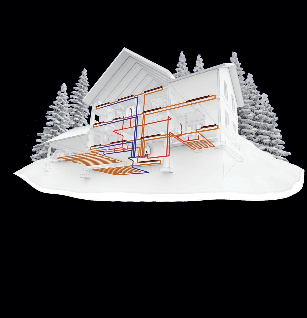
HYDRONICSMODERN 2022FALL INENERGYDISTRICTNWT Pellet boiler fires up heating system in Yellowknife. OPTIMIZING BRAZED PLATE HEAT EXCHANGERS CIRCULATORS: TEMPERATURE OR PRESSURE TROUBLESHOOTINGCONTROLTIPS&LARGEPUMPSa publication of

Not All Glycols Are Created Equal CHEM-FROSTSafeForAllSystems Including Aluminum and Solar Premier Inhibitors Higher Temperature Rated LowyourViscositylocalwholesalerorvisitchemfax.com CHEMFAX Manufacturer of Specialty Chemicals LowyourViscositylocalwholesalerorvisitchemfax.com TM


NotAllGlycolsAreCreatedE CHEM-FROSTSafeForAllSystems IncludingAluminumandSolar PremierInhibitors HigherTemperatureRated Lowchemfax.comwholesalerViscosityyourlocalorvisit NotAllGlycolsAreCreatedEqual CHEM-FROSTSafeForAllSystems IncludingAluminumandSolar PremierInhibitors HigherTemperatureRated Lowchemfax.comwholesalerViscosityyourlocalorvisit Chem100%Frost Brand R Brand O Brand H Brand U Brand D Pail Size 20L 18.9L 18.9L 20L 20L 18.9L ConcentratePGAmount 95/5 92/8 N/A 94/6 95/5 95/5 AluminumSafe YES LIMITED TO 65C NO NO NO NO Solar Safe YES NO LIMITEDSOME NO NO NO GeothermalSafe YES LIMITED N/A N/A N/A N/A TemperatureRating 325F 275F 250F 250F 250F 220F Viscosity @ 35% 60C 5.5cP N/A N/A N/A N/A N/A Boiling Point @ 100% 417F 370F 370F 370F 370F 370F ApprovedCFIA YES YES NO NO YES NO RawGradePG FOOD INDUSTRIALGRADE INDUSTRIALGRADE INDUSTRIALGRADE INDUSTRIALGRADE INDUSTRIALGRADE Purity PropyleneofGlycol 99.94%+ N/A 98% N/A N/A N/A Phosphate / Nitrate NONE YES YES YES YES YES InhibitorType NONPDT-TOXIC DIPOTASSIUMPHOSPHATE DIPOTASSIUMPHOSPHATE DIPOTASSIUMPHOSPHATE DIPOTASSIUMPHOSPHATE DIPOTASSIUMPHOSPHATE LEED YES NO NO NO NO NO *Based on information provided on respective manufacturers’ websites * **Subject tochange** HEAT TRANSFER FLUID - INHIBITED PROPYLENE GLYCOL COMPARISON CHART Based on information provided on respective manufacturers’ websites* **Subject to change**
CIRCULATIONMEDIACOORDINATORDESIGNERMANAGERPUBLISHERCOO CONTENTS
David Skene (416) 510-6884 DSkene@hpacmag.com
Doug Picklyk (416) 510-5218 DPicklyk@hpacmag.com
Kim Rossiter (416) 510-6794 KRossiter@hpacmag.com
Logan Caswell (416) 728-6209 LCaswell@hpacmag.com
Urszula Grzyb (416) 442-5600, ext. 3537 ugrzyb@annexbusinessmedia.com
Emily Sun esun@annexbusinessmedia.com
MODERN HYDRONICS WWW.HPACMAG.COMMH4 FALL 2022 MH6 SYSTEM DESIGN Differing Deltas Both temperature control and pressure control of circulators can work when matching flow rate with heating demand, but there are important distinctions. By John Siegenthaler MH10 PUMPS Bright Ideas – Troubleshooting 101 From home maintenance to commercial mechanical room operations, problem solving always requires a Byplan.Mike Miller MH15 SHOW PREVIEW Modern Hydronics 2022 - The Summit The sixth edition of the Summit returns as a one-day in-person event with new twists. By HPAC Staff MH20 DISTRICT HEATING Heating Yellowknife New pellet boiler district energy system helps NWT government reduce its carbon footprint. By Ellen Cools MH26 COOLING Dew Drop Inn A quick lesson in condensation prevention when considering radiant cooling. By Curtis Bennett MH28 HEAT EXCHANGERS Opposing Currents When it comes to designing systems with brazed plate heat exchangers, stick with counterflow Bypiping.John Siegenthaler HPAC Magazine receives unsolicited materials (including letters to the editor, press releases, promotional items and images) from time to time. HPAC Magazine, its affiliates and assignees may use, reproduce, publish, re-publish, distribute, store and archive such unsolicited submissions in whole or in part in any form or medium whatsoever, without compensation of any sort. NOTICE: HPAC Magazine, Annex Business Media, their staff, officers, directors and shareholders (hence known as the “Publisher”) assume no liability, obligations, or responsibility for claims arising from advertised products. The Publisher also reserves the right to limit liability for editorial errors, omissions and oversights to a printed correction in a subsequent issue. HPAC Magazine’s editorial is written for management level mechanical industry personnel who have documented training in the mechanical fields in which they work. Manufacturers’ printed instructions, datasheets and notices always take precedence to published editorial statements. Contents Copyright © 2022 by Annex Publishing & Printing Inc. may not be reprinted without permission. Proud member of: We acknowledge the financial support of the Government of Canada through the Canada Periodical Fund (CPF) for our publishing activities.
Peter Leonard (416) 510-6847 PLeonard@hpacmag.com
Scott Jamieson EDITOR ASSOCIATE EDITOR ASSOCIATE PUBLISHER ACCOUNT
HYDRONICSMODERN
111 Gordon Baker Road, Suite 400, Toronto, ON M2H 3R1 TEL: 416.442.5600 FAX: 416.510.5140 www.hpacmag.com a supplement of Heating PlumbingAir Conditioning Magazine


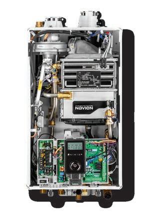
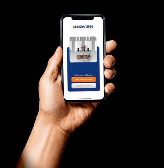
The leader in condensing technology...does it again. HEATING UP TO 150,000 BTU/h DHW UP TO 210,000 BTU/h NCB-H High capacity, High performance combi-boilers Navien NCB-H high efficiency combis bring the highest level of whole house comfort to any size home...big or small • Highest DHW maximum BTUs in residential condensing combi-boilers... up to 210,000 per hour • Highest DHW flow rate @ 70°F rise... up to 5.4 gallons per minute • Highest number of BTU sizes for the North American residential combi-boilers • Highest residential combi-boilers domestic hot water turndown ratio...15:1 • Highest residential combi-boilers heating turndown ratio... up to 11:1 • Highest number of built-in zone controls for valves or pumps... up to three • Highest full lineup 2" venting lengths... up to 65 feet • Highest number of cascade capable units with up to 15 tankless water heaters • High altitude certification... up to 10,100 feet (NG or LP) Aim high with Navien NCB-H combi-boilers... To learn more visit Navieninc.com Scan to download the new Navien mobile app
SIEGENTHALERJOHNCOURTESYIMAGE
BY JOHN SIEGENTHALER
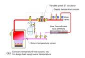
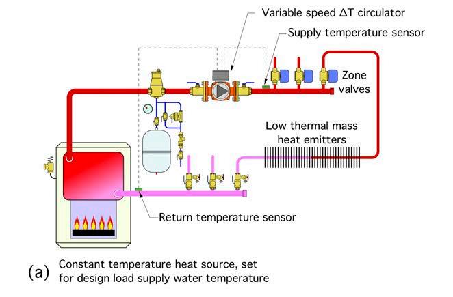
MODERN HYDRONICS WWW.HPACMAG.COMMH6 FALL 2022 DESIGN O ver the years I’ve had a lot of questions asking if I prefer to operate zoned hydronic systems based on a set tem perature drop between supply and re turn water temperature (e.g., ∆T control), or a set pressure drop across the distri bution system (e.g., ∆P control). Both methods of speed control at tempt to match the flow rate in the sys tem with the current heating requirements of the building. The ulti mate goal is to reduce electrical energy use without compromising comfort. The choice between ∆T and ∆P con trol of a circulator has, at times, been the subject of rather “heated” debates. It’s almost as if a few Toronto Maple Leaf fans are disputing superior goaltending with some Calgary Flames fans. There appears to be some strong opin ions involved. Maybe it derives from selfjustification that refuses to believe any opposing view. Perhaps there’s a bit of brand loyalty mixed in, or some mathe matical manipulation that “proves” what nature will surely do whenever the sys tem being analyzed is put in operation. Being someone who’s not ready for a fisticuffs defense of how a circulator oper ates, or interested in faceless banter on the Internet, I tried to look at this subject from a sterile engineering perspective. I used software that is based on very accurate empirical models of heat emit ters such as finned-tube baseboard to see what happens to the heat output of a hydronic distribution that is forced to operate at an assigned (and fixed) ∆T as the supply water temperature is de creased. I refer to this as “constrained ∆T” operating logic. IT WORKS WHEN… What I found is that imposing a fixed ∆T between supply and return can work when the following conditions are all present: 1. Multiple heating zones are controlled
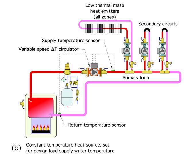
Imposing a fixed delta-T between supply and return requires certain conditions are present in the system. These two examples meet those conditions. on MH8
DIFFERING DELTAS Both temperature control and pressure control of circulators can work when matching flow rate with heating demand, but there are important distinctions.
Continued
If the heat emitters were not over sized for the design load, all zones would, in theory, remain on until the de sign load condition subsided (or other factors such as internal gains or inten tional thermostat setbacks began influ encing the zone loads). When design load is no longer pres ent in one zone, and the associated thermostat turns off the zone valve or secondary circulator, less heat is being removed from the distribution system. This change reveals itself as an increase in return water temperature (assuming that the supply water temperature re mains constant). The temperature dif ference (e.g., ∆T) between the beginning and end of the distribution system de creases. A circulator operating based on con strained ∆T logic would sense this de crease and respond by reducing speed so that the design load ∆T was reestab lished for the zones that remain active. This process would repeat when an other zone turned off. This method of control reduces circulator energy use during partial load conditions. When a zone turned on, and the sup ply water temperature remains fixed at the design load value, the return water temperature decreases because more heat is being removed from the distribu tion system. A circulator operating based on constrained ∆T logic would sense this increase in ∆T and respond by increasing speed to reestablish the design load ∆T.
The requirement that the distribution sys tem have low thermal mass heat emitters implies that the temperature changes on the return side of the system would ap pear quickly as zones turn on and off. A high thermal mass distribution sys tem, such as a heated concrete floor slab, could significantly delay these tempera ture changes due to heat being absorbed into or released from the thermal mass.
MODERN HYDRONICS WWW.HPACMAG.COMMH8 FALL 2022
DESIGN with valves, or multiple secondary cir culators supplied from a common pri mary loop.
MASS MATTERS
2. The system uses low thermal mass heat emitters.
The mounting of the temperature sen sors could also affect how quickly the electronics in the circulator respond to the change in temperature. The constrained ∆T method of control forces the active portion of the system to operate as if it is always at design load conditions. When a zone doesn’t require design load heat input the ther mostat for that zone would have to cycle the zone valve or zone circulator on and off to avoid overheating the space. This, in effect, directs “pulses” of heat into each zone whenever its thermostat calls for heat. The rate of heat delivery during each pulse remains at the design load rate. The duration of each pulse is the time that the zone valve or zone cir culator is on. The design load heat transfer rate multiplied by the “on-time” of the zone determines the total heat added to the space during each pulse. This method of heat delivery has been used in millions of North American hy dronic systems over many decades. It is generally acceptable if the thermostat differential and boiler high limit differen tial are reasonable.
It’s important to understand that not all hydronic systems meet the three pre viously stated constraints. Many modern systems use outdoor re set control to vary the water temperature supplied to the distribution system based on outdoor temperature. When outdoor reset control is combined with a circula tor operating on constrained ∆T logic, the heat output from the distribution system decreases faster than it should based on outdoor reset control theory. This could lead to a reduction in building comfort under partial load conditions. For this reason, I recommend that circu lators using constrained ∆T control only be used in systems that meet all three of the previously stated constraints.
∆P CONTROL Differential pressure (e.g., ∆P) speed control is intended for use in hydronic systems that use any type of valvebased zoning (e.g., zone valves, thermo static radiator valves, or manifold valve actuators).A∆Pcirculator operates by continually comparing its pressure differential against some reference condition. The latter could be a fixed value (e.g., constant ∆P control), or a calculated value based on flow rate (e.g., proportional ∆P control). Constant ∆P is preferred when most of the head loss of the distribution system occurs in the branch (e.g., zone) piping, rather than the “common piping” through “∆P control does require the installer to set the circulator for the required ∆P (or in some cases the required head) of the distribution system at design load conditions.”
3. The heat source maintains a constant supply water temperature, at the de sign load value, whenever any zone is calling for heat. Figure 1 shows exam ples of two systems that meet these Considercriteria. a low thermal mass hydronic heating system that supplies design load heat output when all zones are active and the supply water temperature re mains constant at the design load value.
Proportional ∆P control is preferred when the head loss in the piping mains (rather than the branches) is a large por tion of the overall head losses. The lat ter is typical for “2-pipe” direct-return or reverse-return systems.
A ∆P circulator determines its current ∆P based on the electrical load on the motor, specifically the position of the ro tor shaft relative to the magnetic field applied to stator coils. It uses this information along with a “mapping” of motor operating charac teristics to infer both its flow rate and ∆P. It then adjusts motor speed up or down to bring its operating condition as ducers or variable frequency drives. Response time is short—a few seconds. This is an advantage over ∆T control that depends on the temperature re sponse of two sensors.
Both ∆T and ∆P methods of circulator speed control can work, given the right application and adherence to the con straints mentioned above. Both have been used in the field for several years. Looking ahead, it’s likely that even more refined methods of circulator speed control will be developed, based on mul tiple sensed inputs, as well as coordina tion with other hardware in the system, such as boilers or heat pumps. <> John Siegenthaler, P.E., is a professional engineer with more than 40 years of experience designing hydronic heating systems.
7”w x 5”h WE ARE PROUD TO SPONSOR THE HYDRONICS 101 SESSION Come by to see us & get a complimentary magnetic tray. For information and to register: www.modernhydronicssummit.com WE ARE SPECIALISTSHYDRONIC WE HAVE A COMPLETEHYDRONICOFFERING WE PROVIDE SUPPORTPROJECTnextsupply.ca We hydronics!know September 15, 2022 HPAC_NextSupply_Aug22.indd 1 2022-07-27 11:50 AM
∆P control does require the installer to set the circulator for the required ∆P (or in some cases the required head) of the distribution system at design load conditions. Some installers balk at this require ment, claiming they have no way of de termining it. My response is: How do you know what size circulator is needed if you haven’t attempted to es timate its operating point when all zones are operating?
IN SUMMARY
Modern Hydronics MODERN HYDRONICSWWW.HPACMAG.COM MH9FALL 2022 which all system flow passes. This is typ ical for “homerun” distribution systems.


BY
I had about 45 minutes of commuting left, plenty of time to develop a compre hensive plan. I now knew that the prob lem was either with the house electrical system or the lamp. The house electri cal system consisted of the circuit breaker, the house wiring and the recep tacle. The lamp consisted of the electri cal cord, the lamp switch and perhaps the light bulb. To eliminate the house electrical sys tem, my plan upon arriving home was to turn off and on the electrical breaker at the electrical panel. The next step was to inspect the lamp switch, the lamp wir ing and the receptacle. I have a digital volt/ohm meter, which would make test ing the receptacle, the lamp wiring and the lamp switch a breeze. By this time I was almost home, and I felt confident that I had worked out a comprehensive plan to diagnose and solve the problem. Upon arrival I asked my wife to put the maintenance to room solving requires a plan. MIKE MILLER
STOCKYULI/ADOBERIBALKAPHOTO: PUMPS Continued on MH12
BRIGHT IDEAS TROUBLESHOOTING– 101 From home
commercial mechanical
always
operations, problem
MODERN HYDRONICS WWW.HPACMAG.COMMH10 FALL 2022
We have all had opportuni ties to do troubleshooting. It seems as though I have been in the troubleshoot ing business the majority of my profes sional career. I am often asked, “What is troubleshooting? Where do I start? And what do I do? In its purist form, troubleshooting is the process we go through to solve a problem. As for where to start? My re sponse is always: start at the beginning. And when it comes to, “What do I do?”, the answer is, “Develop a plan.”
I’m going to share a simple example of my thought process when it came to solving a small problem at home, and then I will provide you with a real pump troubleshooting situation that I was asked to solve not too long ago. So, earlier this year I left the office on my way home. The commute is little over an hour. When I first got on the road, I called my wife to give her an estimate as to my arrival time. She informed me that one of the lamps in the living room was no longer working. She also said that she replaced the light bulb with a new one that she knew was working because she tested it in an other lamp. The new bulb did not illumi nate. I told her that I had about an hour or so of driving and would think about it on my way Followinghome.myown advice, I started at the beginning and started to list the things that I knew and those that I did not know. I knew there was electric power avail able because my wife tested a bulb in another lamp. I also knew there were two lamps in the living room. One lamp was activated by a wall switch and the other lamp was plugged into a live elec trical outlet. I know that the lamps are about 26 years old which is the same age as the circuit breaker, the wiring and theWhatreceptacle.Ididnot know was which lamp was not working, the wall switched lamp or the live receptacle lamp. Time to do some interviewing. I called my wife and asked several questions. Her answers revealed the following: the lamp in question is connected to the live receptacle, and that the lamp was work ing fine the day before. I could now focus my attention on the lamp connected to the live receptacle which allowed me to develop a plan.

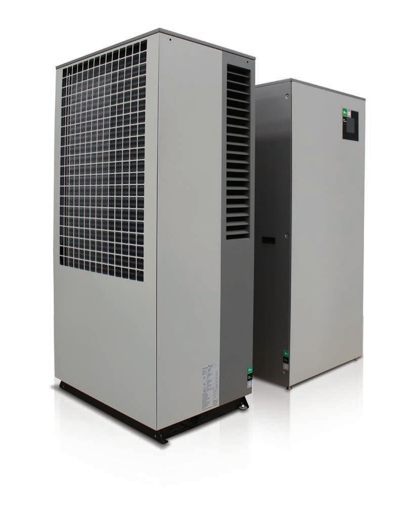
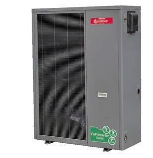
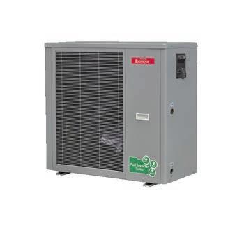
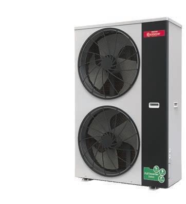
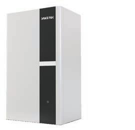
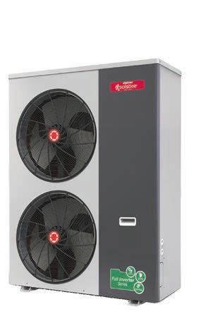
Working Smarter Not Harder with Air-to-Water The latest innovations in air source technology + the clean and efficient characteristics of hydronics = the most capable and highest performing heat pumps available SpacePak’s Inverter Series of Solstice Air-to-Water Heat Pumps Heating and cooling for your green building goals, fit for even the coldest of climates. • Industry leaders of air-to-water technology since 2011 • The most complete line-up on the market for residential and light commercial applications • Industry proven for reliability, performance, & longevity • Thousands of installations across the US and Canada • All-in-one solution for year-round whole house heating, cooling, and DHW offset • All the advantages of a hydronic system without the use of fossil fuels • High performance heating capabilities down to -20°F • Perfect match for radiant and solar applications • Industry leading 10-year compressor warranty and 5-year parts for certified contractors Solstice Inverter Monobloc SIM Solstice Inverter Split SIS Solstice Inverter Extreme ILAHP GREEN SOLUTIONS CARBON FREE COMFORT Utility Rebates Available and more!


6. The cooling towers use an indoor sump.
8. The pressure differential was mea sured across the pump at approxi mately 25 FT.
MODERN HYDRONICS WWW.HPACMAG.COMMH12 FALL 2022 wall switched lamp on so that I could check the circuit breaker. I went into the basement, walked over to the electrical panel and identified the breaker for the living room. Fortunately for me the breakers were well labeled, and I imme diately found the appropriate switch.
2. The customer is concerned that the flow is less than the original design (approximately 850 GPM) and that the flow may have been less than de sign for the entire 10 years.
3. There are five pumps installed, four operating in parallel one standby. 4. The original design flow was 1,200 GPM and 25 FT for each pump.
The line diagram along with the photo graphs indicated that the suction header was at the same elevation as the pump suction connection. In other words, the centerline of the suction header was at the same elevation as the centerline of the pump suction.
The elevation of the water level in the sump was 4 FT above the centre line of the pump. At this point I had a hunch that the suction gauge may not be giving us the actual suction pressure. I contacted the customer and asked for a short video of the suction gauge while the pump was running. The video revealed that gauge dial was resting on the gauge pin at 0 PSIG with no movement. Time to do some calculations. The suction header was 20 inches in diameter and approximately 30 feet long and was connected directly to the cooling tower indoor sump. Calculations
10. Voltage and amperage at the VFD in put with motor operating at design load. After my initial interview on the phone, while waiting for him to send along his information, I collected some documen tation including pump data, motor data and drive data. Now it was time for me to develop a plan.Idecided to create a four-step plan. The first was to review the published data along with the drawings, and the second was to review the information provided by the customer. I needed to evaluate the data before moving on to steps three and four.
PUMPS Continued on MH14
On and off went the breaker, and on and off went the wall switched lamp. The breaker was not the problem.
The photos also revealed that the dis charge gage was reading 11 PSIG (ap proximately 25 FT) and the suction gage was reading 0 PSIG (0 FT) for a differen tial pressure of 25 FT at 60 Hz.
5. The pumps serve a condenser water system with an open cell cooling tower.
8. Suction pressure with the one pump running at pump suction flange.
7. The flow was estimated by measur ing the pressure drop across the chiller condenser water barrel with one pump running.
9. Discharge pressure with the one pump running at pump discharge flange.
I asked for some additional information, including: 1. One line diagram of the piping sys tem.
2. Photos of the piping and pumping system. 3. Water level in the sump relative to the centerline of the pump. 4. Photos of the pump and motor name plates. 5. Pump speed in RPM. 6. Water temperature. 7. Suction pressure with the pumps off measured at pump suction flange.
I grabbed my volt/ohm meter and went upstairs to the living room. Before pro ceeding any further, I decided to replace the lamp bulb just in case. I removed the illuminated bulb from the wall switched operating lamp and installed it in the of fending lamp. Just as my wife indicated earlier, the bulb did not light up. The next step was to use my volt/ohm meter and test the receptacle that the lamp cord was plugged into. In order to access the receptacle, I had to move the sofa away from the wall because the receptacle was hidden by the sofa. As soon as I moved the sofa to reveal the receptacle, I had my answer. At this point you might have guessed that the lamp cord was not plugged into the wall. But you would be wrong. You see, several years earlier, I pur chased a digital timer which can be pro grammed to activate and deactivate a device such as a lamp based on the time of day. The digital timer has an override switch (or on switch) which al lows the digital timer’s outlet to be on continuously. I removed the digital timer and plugged the lamp directly into the wall receptacle and the lamp bulb im mediately illuminated. Problem solved. The digital timer failed and no longer provided power to the lamp. My troubleshooting steps were cor rect, and I followed my plan. However, I could have determined the problem ear lier if I had been more comprehensive during the interview process. I should have asked my wife to look be hind the sofa to see if the lamp was plugged in. That simple request would have revealed another possible course of action and I would have modified my plan. Lesson learned. As promised, let me walk you through a real-life pump troubleshooting prob lem that I was asked to solve. I received a call from one of our cus tomers regarding what was perceived to be a pump problem. I asked the cus tomer to provide a brief verbal descrip tion of the issue. He revealed the following:
1. The pumps were installed about 10 years ago and have been in service since.
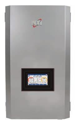
Products you need from people who care Our new TFTN touch screen with EZ Setup Wizard is faster and smarter! Copyright © 2022 NTI Boilers Inc. All rights reserved. Subject to change without notice. Designed with installers in mind...more powerful and user-friendly interface. • EZ Setup Wizard • Wi-Fi, remote access to programming, monitoring, diagnostics and troubleshooting (including access to complete error log) • Easy-to-read, 7'' touch screen with full color graphics • Three Zones + DHW control. Expand to six zones with optional N-Link Control All backed by NTI’s legendary support, reliability, and technology. Contact your nearest NTI Distributor or visit ntiboilers.com net MoreLearn TOTAL PROGRAMMING CONTROL AT YOUR FINGER TIPS SetupZoneDetailsBoilerDetailsCascadeErrors 158oF 100% 141oF 126oF18 PSI Burner AutomaticCentralDemand:RunState:HeatDetails:Temperature Control 199 MBH Manager 41oF 199MBH145OnoF Target159oF 169OffoF 7518RPM Burner PowerOutlet Inlet Press 112DHW Boiler DHWSystemPumpPumpRecirc PriorityCallingCalling Kitchen1. 2. RoomLiving Bedroom3. Entrance4. Bedroom5. 2 Bedroom6. 3 SetpointDHW 125oF


Again, back to the drawings and the photos to determine what was between the pipe connection at the header and the pump suction connection. This re vealed a butterfly isolation valve and a basket strainer. I now had enough infor mation to complete my plan. I asked the customer to replace the conventional suction gauge with a com pound gauge. A compound gauge can read pressure values both above and below 0 PSIG. I also asked the customer to take suc tion pressure readings with the basket strainer screen both in and out. Here is what he recorded:
• With one pump running at full speed (1760 RPM) the suction pressure at the pump flange read + 3.5 FT (basket strainer screen out). These new readings proved that the actual pump pressure differential was 25 FT – (-12 FT) or 37 FT. At this pressure differential the pump curve indicated the flow to be approxi mately 850 GPM. The problem was not the pump but the unanticipated pres sure drop of the basket strainer (with screen in). I recommended that the customer in vestigate replacing and/or relocating the basket strainer—problem solved.
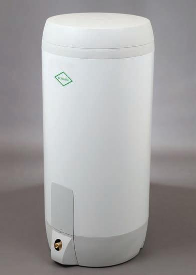
MODERN HYDRONICS WWW.HPACMAG.COMMH14 FALL 2022 PUMPS INTRODUCING ECO-KING STAINLESS STEEL ELECTRIC TANKS INTRODUCING ECO - KING STAINLESS STEEL ELECTRIC TANKS ECO-KING INTRODUCING ECO - KING STAINLESS STEEL ELECTRIC TANKS ECO KING FOR MORE kingheatingproducts.comINFORMATION 50 and 80usg sizes, 3kw or 5kw elements Lifetime warranty Mixing valve for superior performance, T&P and drain valve all included Also featuring our Made in Canada Combi Boilers Products available across Canada HPAC_ECOKING_HALF_OCT_BAS.indd 1 2021-09-29 2:27 PM proved that with one pump operating, the pressure drop was negligible in the suction header. Therefore, the pressure at the pump suction pipe where it con nected to the header should be + 4 FT.
Admittedly not all troubleshooting problems will be this easy to solve, but the principals are the same.
First, identify the problem. Second, collect data including manufacturers data, drawings, diagrams, field mea surements, photos and videos (you can never have too many photos and vid eos). Third, do some calculations (if ap propriate), and finally develop a plan. Have fun on your next troubleshooting adventure and drop me a line to let me know how you are making out. <> Mike Miller is vice presi dent of sales, Canada with Taco Comfort Solutions and a past chair of the Canadian Hydronics Council (CHC). He can be reached at hy dronicsmike@tacocomfort.com.
• With one pump running at full speed (1760 RPM) the suction pressure at the pump flange read – 25 Inches of Hg (approximately – 12 PSIG with basket strainer screen in).
• With all the pumps off the suction pressure at the pump flange read + 4 FT (basket strainer screen in)


MODERN HYDRONICS
The Sixth edition of the Summit returns as a oneday in-person event.
BY HPAC STAFF SUMMIT
Location: Universal EventSpace (6250 Hwy 7, Vaughan, ON) Thursday, September 15 9:30 am - 10:30 am Registration and Trade Show Floor Open 10:30 am - 11:30 am
PREVIEW
KEYNOTE Part II: Hydronics for Net Zero Homes (John Siegenthaler) 5:00 pm -5:15 pm Sweet Heat Contest Results 5:15 pm -8:00 pm Dinner/Bar Continued on MH16
KEYNOTE Part I: Hydronics for Net Zero Homes (John Siegenthaler) 11:30 am - 1:00 pm Lunch & Trade Show 1:00 pm -1:45 pm Zone Circulators or Zone Valves? (Mike Miller, Dave Holdorf) 1:45 pm -2:00 pm Break/Trade Show 2:00 pm 2:45 pm Critical Nature of Boiler Chemistry (Jeff House, Brian Morgan) 2:45 pm -3:00 pm Break/Trade Show 3:00 pm -3:45 pm Regulatory Outlook – Boilers & Water Heaters (Tom Gervais) 3:45 pm -4:00 pm Break/Trade Show 4:00 pm -5:00 pm
Since 2013 HPAC Magazine has been hosting a one-day Modern Hydronics Summit ev ery two years in the fall, with the event getting bigger and attracting larger crowds every time. With the pandemic placing all live events on the sidelines in 2021 the HPAC Team made a pivot to hold a vir tual two-day Modern Hydronics Summit in March of 2021 attracting viewers from across Canada – drawing the larg 2022 - THE SUMMIT
Schedule The 2022 Modern Hydronics Summit includes five educational sessions deliv ered by industry experts on topics that will set contractors up for success.
Modern Hydronics MODERN HYDRONICSWWW.HPACMAG.COM MH15FALL 2022

THANK YOU TO OUR SUMMIT SPONSORS
PLUS: Meet a line-up of HVAC social media influencers as they work on a live pre-fab boiler panel build. In attendance will be: Jess Bannister (@hvacjess); Aaron Bond (@bond_aaron); Terence Chan (@the_impetus); Gary McCreadie (@hvacknowitall1); Tyler Dynes (@dyneshvac); Kiefer Limeback (@toolaholic); Mike Flynn (@flynnstone1); George DeJesus (@Georgetheplumber).Continued on MH18
The trade show portion of the Modern Hydronics Summit will feature over 60 tabletop exhibitors, all specialists in the field featuring technology and services dedicated to this market niche. And of course the line-up of educa tional sessions will once again set up at tendees for success. Our featured keynote speaker, HPAC writer John Siegenthaler, will be detailing how hy dronic heating and cooling fit into mod ern Net Zero buildings. He’ll be identifying the advantages of hydronics systems for these applications and how to put the systems together with off-theshelf components to create simple, re
MODERN HYDRONICS WWW.HPACMAG.COMMH16 FALL 2022 SUMMIT PREVIEW Untitled-2 1 2022-08-08 8:27 AM est attendance in the event’s history. This year, the 2022 Modern Hydronics Summit returns to a traditional one-day in-person format, Thursday, September 17 at the Universal Eventspace located in Vaughan, Ont., just north of Toronto.
While the virtual Modern Hydronics Summit in 2021 provided access to in dustry professionals from coast to coast, there is no replacing the value of personal interactions at our live hydron ics events. Meeting up in person with colleagues who share a passion for this industry, whether it’s sharing a laugh with an old friend or meeting up with new contracting pros, making connec tions and networking is how this seg ment of HVAC business continues to grow and prosper.
THE LIVE EXPERIENCE
Platinum sponsor: Resideo. Keynote sponsor: Caleffi Hydronics 101 sponsor: NEXT Supply Tool sponsor: Kane Canada Event Sponsors: Lochinvar (AquaTech); Roth; Taco; Uponor; Viessmann And over 60 exhibitors for the trade show featuring all you need for your next hydronics projects.

HYDRONICSMODERN 2021FALL SWEET HEAT 2021 This year’s contest-winning projects CONSIDERATIONSCHEMISTRYBOILERLAYOUTSMULTI-ZONEPLANNING WAREHOUSEINSTALLATIONIN-FLOOR SIZING PANEL RADS FOR LOW WATER TEMPS a publication of HYDRONICSMODERN 2022SPRING ADDSHEALTHMONTREALNETWORKHEATPUMPS Part of an $18.8 million energy efficiency project &PELLETOPTIMIZATIONSNOWATWCONTROLLINGHEATPUMPSMELTBOILERSFORCEDAIR a publication of FREE to qualified subscribers! Please fill in the following and fax today to 416-442-2230 or visit our website and click on subscribe www.hpacmag.com YES! I wish to receive/continue to receive HPAC Magazine absolutely FREE! No CityAddressCompanyTitleName Province Postal Code Business Phone # ( ) Business Fax # ( ) Your FREE subscription also includes our FREE e-newsletter, please provide your e-mail address below: SignatureE-mail: Date / / (Must be signed and dated to be valid) D M Y Publisher reserves the right to determine qualification & limit distribution. FAX: 416-442-2230 August 2022 IS CANADA’S #1 SOURCE FOR HYDRONIC COVERAGE: products, applications, events, news and more. HYDRONICSMODERN 2022FALL INENERGYDISTRICTNWT Pellet boiler fires up heating system in Yellowknife. OPTIMIZING BRAZED PLATE HEAT EXCHANGERS CIRCULATORS: TEMPERATURE OR PRESSURE TROUBLESHOOTINGCONTROLTIPS&LARGEPUMPSa publication of I SEE YOU’RE HYDRONICS…INTO SINGLEMISSDON’TACOPYOFHPAC. 1. Company Business Activity? (Check ONE only) Mechanical Contractor Refrigeration Service Engineer/Contractor Fuel Oil Dealer/ Contractor Wholesaler/Distributor/Agent Consulting Engineers/Specifying Writer Plumbing Inspector Government Hospitals and Related Institutions Utilities General Building Construction Others Allied to the Field (please specify) 2. Do you specify, purchase and/or approve the purchase of mechanical products or services? Yes No 3. Company Job Sector? (Check ALL that apply) Commercial Residential Industrial Institutional 4. Number of employees at this location? 1 - 4 20 - 49 200 - 499 2500 + 5 - 9 50 - 99 500 - 999 Unknown 10 - 19 100 - 199 1000 - 2499 5. Company Job Activities? (Check ALL that apply) Plumbing (i.e DHW, Piping etc.) Ventilation Hydronic Heating Refrigeration Forced Air Heating Fire Protection Electric Heating Air Conditioning Other(please specify) HPAC Magazine 111 Gordon Baker Rd. Suite 400, North York, ON M2H 3R1


The Sweet Heat prizes will be awarded after the final ses sion at this year’s Modern Hydronics Summit.
SUMMIT PREVIEW peatable designs. Attendees will also be entered into a draw to win a signed copy of Modern Hydronic Heating for Residential and Light Commercial Buildings (4th edition) which was released this spring. Other presentations will include: the pros and cons of zone valves and zone circulators; a dive into boiler chemistry; and a look at current and pending regulatory changes and how they will effect new and retrofit hydronic system design.
“There is no replacing the value of personal interactions at our live hydronics events.”
MODERN HYDRONICS WWW.HPACMAG.COMMH18 FALL 2022
SOCIAL ENGAGEMENT
HYDRONICS 101 For the first time this year’s Modern Hydronics Summit is add ing a special track for those who are new to the industry or looking to improve their knowledge on hydronic systems and the components that make them work. This parallel track is being designed for HVAC or plumbing contractors who are considering adding hydronics to their rep ertoire, or those who want to get their technicians up to speed. We have dedicated space at the Summit where industry ex perts will walk attendees through the basics of hydronic sys tems and help them understand why this technology is growing so rapidly. Each session will be hosted by a product ex pert and every session will be very interactive and a lively Q&A will be encouraged!
SWEET HEAT
There will be draws for useful tools after each session, and there will also be Blue Jays tickets up for grabs. Along with a day of education and networking, registration also includes lunch, dinner and a post-event drink.
Also, live on-site a team of HVAC social media influencers in cluding Gary McCreadie, Aaron Bond, Terence Chan, Jess Bannister, Tyler Dynes, Kiefer Limeback, Michael Flynn and George DeJesus will be working on prefabricating three boiler panels. These HVAC pros will be interacting and live streaming action from the event while also sharing their own tips and tricks using the latest products and tools available.
REGISTER NOW
The 2022 Modern Hydronics Summit takes place September 15th. Registration is $99 (plus tax & service charge, $119.84 incl.) for the main event, special pricing is available for groups and Hydronics 101. For more information and to register to day visit: modernhydronicssummit.com. <> AM
HPAC_Rhella_Aug22.indd 1 2022-07-27 9:25
In the Fall of 2020 HPAC magazine launched the first ever Sweet Heat contest, inviting hydronic contractors across Canada to get their cameras out and share their creativity, artistry and re sourcefulness in delivering “Sweet Heat” to their customers. The response was great with over 30 entries last year. For 2022 a generous sponsorship has been attached to the con test, with winners this year (one commercial and one residen tial project) will each be receiving a $3,000 spending spree courtesy of their local EMCO location. In addition, the winning entries will be featured in the October 2022 edition of HPAC.


COMBIEFFICIENT
HIGH
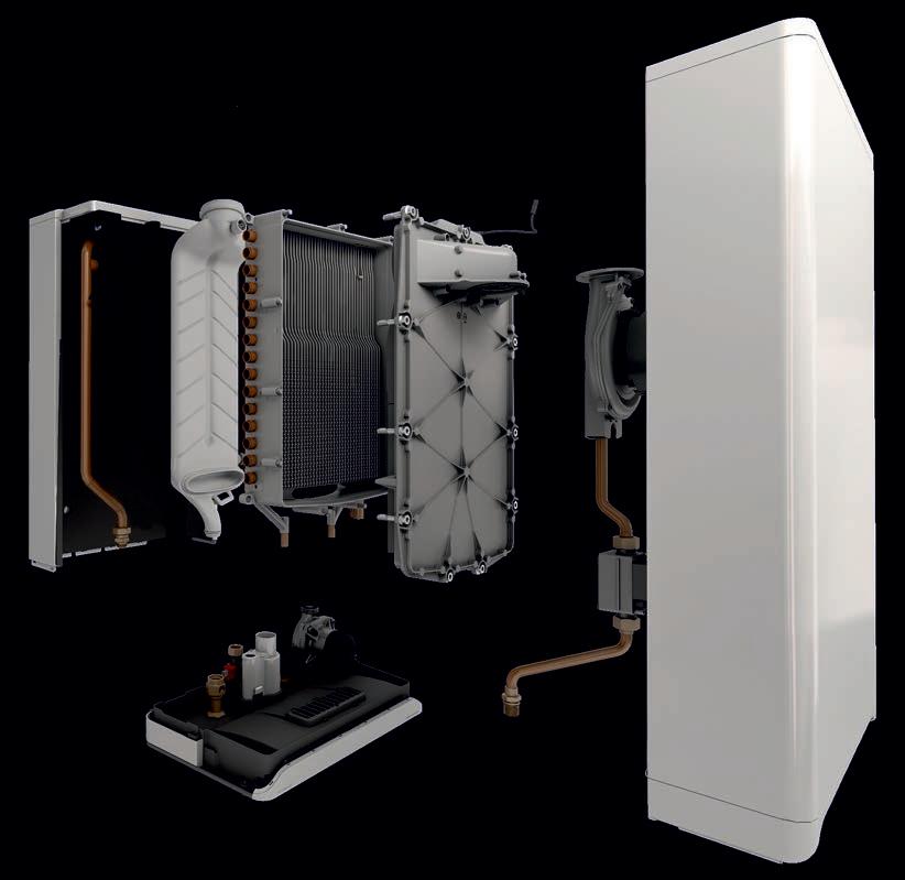
You expect your boiler to provide enough hot water for both your kitchen and bathroom, as well as enough heat to make your home cozy and snug. Combining DHW & space heating in a single compact design featuring two independent copper waterways embedded in a cast aluminium heat exchanger, the SFC Combi is designed to do just that. The SFC Combi contains cutting-edge, solid-state electronics to control its gas valve, fan and ignition. By doing so, we’ve succeeded in reducing the number of moving parts, made servicing simple, and increased reliability. EFFICIENCY DUAL FIRED COMBI BOILER SIMPLE • RELIABLE •
This product meets a stringent set of our internally defined sustainability standards.
www.ibcboiler.com


MECHANICALJ&RCOURTESYPHOTO
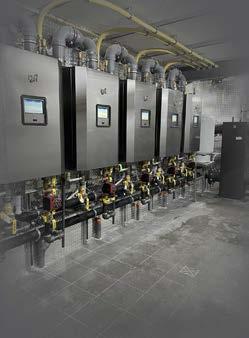
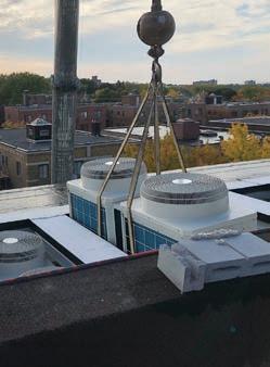
This 200-kW heat transfer station at the GNWT warehouse in Yellowknife allows J&R Mechanical to meter the heat for billing clients. It also provides a hydraulic disconnect between the client building heating system and the district heating system.
Continued on MH22
BRINGING BIOMASS NORTH
Around the same time, J&R Mechanical began installing district heating systems for different govern ment clients. Their first system was for an Indigenous government client in Behchok , NWT, installing a plant that
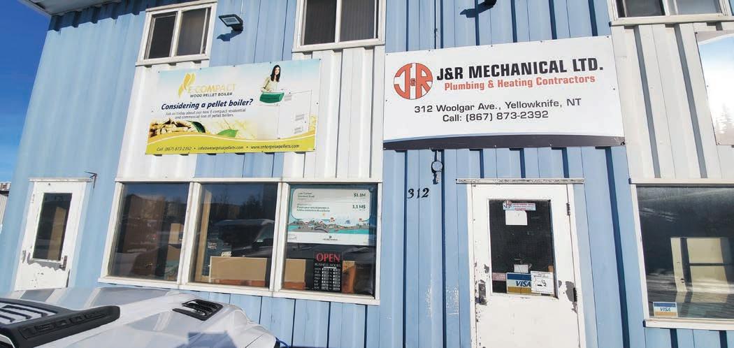
HEATING YELLOWKNIFE New pellet boiler district energy system helps NWT government reduce carbon footprint.
This is not the first time that J&R Mechanical has installed a district en ergy system. According to owner Ken Miller, the company, which was founded in 1977, has been installing biomass boilers for over 12 years. When these types of boilers started becoming popu lar in the NWT, the territorial govern ment embraced the potential environmental benefits of using wood pellets instead of fossil fuels. Consequently, “Our government con tracts were specifying installations with biomass – in schools predominantly, at first – and that’s how we got involved in biomass,” Miller says. “In the years after that, when tenders would come out for different systems, we focused on that as part of our regular scope of plumbing and heating. The heating became bio mass, and we became a prominent in staller of biomass boilers for the government and the private sector.”
J&R Mechanical, a plumbing and heating contractor in Yellowknife, NWT, is one of the companies leading the charge. Last year the company began operating a new $1.1-million district en ergy system, called the Woolgar District Heating System, to provide heat to a government of NWT (GNWT) warehouse and three other private businesses, helping to reduce the government’s reli ance on fossil fuels.
MODERN HYDRONICS WWW.HPACMAG.COMMH20 FALL 2022
DISTRICT HEATING A s more communities become aware of the benefits of using biomass to heat and power their buildings, more district energy systems are coming online in Canada. Remote northern areas in par ticular have recognized the opportunity to use bioenergy to reduce their reliance on fossil fuels and lower their green house gas (GHG) emissions.
BY ELLEN COOLS
Scan for more product informationsmartviessmann.caheating solutions made Introducingeasy Viguide Your all-in-one Digital assistant Download the Viguide app today Our new Viguide app connects to any Vitodens smart generation boiler to streamline and simplify each installation. + All-in-one app for installation, service, maintenance & monitoring + Enhanced customer experience maintenance reminders + Faster installation with guided step-by-step start-up and commissioning reporting + Simplified maintenance with replacement parts guide + Proactive monitoring with remote diagnostics & notifications with annual automated


The territorial government agreed to their proposal to switch the warehouse over to a district heating system. J&R Mechanical also approached other busi nesses in the area that could benefit from the system, which led to 30% of the block coming on board.
The system itself is fairly simple, with two main components: a shipping con tainer housing a 1330 MBH (390-kW) Viessmann Vitoflex 300-UF boiler and a silo to store the wood pellets. Fink Machine of Enderby, B.C., the supplier, assembled the boiler in the containerized plant, which was then shipped to J&R Mechanical, who in stalled it and connected it to their own systems. Meanwhile, the wood pellets came from a pellet plant in Alberta.
DISTRICT HEATING provides heat to eight buildings from one biomass boiler. “As we continued to do more and more of those, we had this opportunity to propose a project that was literally right in our backyard – the Woolgar District Heating System – and the main client is the GNWT warehouse,” Milller says. “They have a list of buildings they wanted to switch to biomass, and this one was on their list.”
The project took two years from pro posing the idea to completion, including the planning and design, permits and in stallation.
MECHANICALJ&RCOURTESYPHOTOS Continued on MH24
According to Miller, the system is very similar to any other hydronic heating system: “You heat water and you trans fer the heat to buildings through various different types of heat exchangers, whether it be baseboard radiation or unit heaters, radiant in-floor heaters or radiant panel heating.
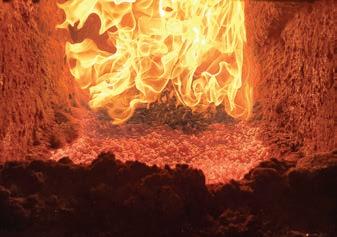
The pellet boiler fired up.
“The average design temperature here is to -45C; we’ve seen the boiler operate just perfectly in those tempera J&R Mechanical in Yellowknife has been installing biomass boilers for over 12 years.
FROM WOOD PELLETS TO HEAT
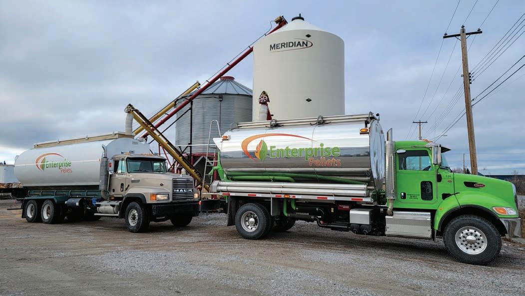
“The process of burning wood pellets to create the heat source is the only real difference,” he continues. “We unload and load them, redistribute them to dif ferent silos in the community where these pellets are then extracted by au gers or different devices to feed the boiler, based on the demand for heat.”
The boiler produces heat, water vapour, carbon dioxide and ash. The heat from the water vapour is transferred to each build ing’s space heating system through un derground pipes, Miller explains.
J&R Mechanical ran into a few issues during the construction and installation process, mainly permitting issues, Miller says. “You can only dig in the summer here, so we started the project too late to get everything – the permits and all of that – on time in the previous summer (2019),” he explains. “Even into the con struction season, in the summer of 2020, we were delayed because of per mits. We didn’t have everything in place. So, it took us into the winter, which caused some issues for us and left us with some seasonal deficiencies.” But, the system officially came online in March 2021, and has since been pro viding heat to the three businesses, the GNWT warehouse and a GNWT data cen tre that is connected to the warehouse.
Yellowknife, of course, is extremely cold in the winter, which means the sys tem has to be able to operate in a harsh climate. So far, there have been no is sues with the boiler, Miller says.
MODERN HYDRONICS WWW.HPACMAG.COMMH22 FALL 2022


J&R Mechanical established Enterprise Pellets in 2009 to supply, install and maintain biomass boiler systems for residential and commercial heating application in the area. The company distributes pellets to silos in the community.
“If our client base grows – and it poten tially will with some new developments next year or the year after – we possibly will have to expand the size of the heat ing plant to accommodate,” he says. For now, though, the company is al ready planning to add one or two more buildings to the system and continue running it as is. <> This article originally appeared in Canadian Biomass (published by Annex Business Media, owners of HPAC). Ellen Cools served as Editor of Canadian Biomass.
REDUCING FOSSIL FUEL RELIANCE
MODERN HYDRONICS WWW.HPACMAG.COMMH24 FALL 2022 DISTRICT HEATING tures,” he says. “It’s operating as it was designed to operate, with low mainte nance and fairly high efficiencies. It’s worked out well.”
The system has also had a big impact on the NWT government’s fossil fuel use, as it has cut oil use for the warehouse by 92% – from 60,000 litres per year to just 4,800 litres. The system has also re duced the warehouse’s GHG emissions by 145 tonnes of carbon equivalent. The project, which cost $1.1 million, was a big capital investment for J&R Mechanical. The NWT government gave the contracting business a $274,000 grant for the project, but the company footed the rest of the bill. However, Miller says their business plan calls for paying off that investment in four to five years of operations. So far, the feedback from the commu nity and the territorial government has been very positive, Miller says. He be lieves there are opportunities for other northern communities to develop simi lar district energy systems using woodburning boilers to reduce their reliance on fossil fuels. “I think everyone is looking at them as a better solution – looking at biomass boilers to heat buildings – so I think it has been kind of proven that this is a good way to go,” he says. Nevertheless, there are a few barriers to overcome when installing a system like this. One such challenge is under standing the potential impact on a com munity’s infrastructure. “We bury pipes in the ground, and that can be very disruptive,” Miller ex plains. “There’s other stuff in the ground that you don’t see – power lines, water and sewer pipes, telephone lines and things like that, depending on where you’re trying to install it. So, engineering design can be a big challenge.”
“The average design temperature here is to -45C; we've seen the boiler operate just perfectly in those temperatures.”
MECHANICALJ&RCOURTESYPHOTO
However, the benefits far outweigh the costs, and J&R Mechanical is look ing at possibly expanding the Woolgar District Heating System.
AutoFill™ is the original, automatic, fast-filling boiler valve, offering precise pressure control in hydronic or cooling systems. Set it and forget it with a simple dial set point adjustment, factory pre-set at 15 psi. The valve combines with optional ASSE 1012 dual check or ASSE 1013 reduced pressure zone backflow preventer to save time and reduce space requirements. An optional pressure gauge offers effortless adjustments as needed—no more guessing.
CALEFFI GUARANTEED. www.caleffi.com SET IT FORGETANDITWITHAUTOFILL ™


“I like radiant cooling, it just needs to be done correctly or you will have a very homeowner.”mad
DEW DROP INN A quick lesson in condensation prevention when it comes to radiant cooling.
STOCKANNA/ADOBESUBBOTINAPHOTO:
The condensation that forms is often called dew, or at least that’s what we call it when it forms on the grass and flowers in the yard—when the grass is cold from the night and the morning sun warms up the atmosphere. The point at which the condensation starts to form is call the “Dew Point”. The dew point of an item is a calculation that involves the relative humidity of the air as well as the temperature of the item. The calculation is a pretty math heavy, but don’t worry we won’t get into it. Well, ok, just a little bit. Relative humidity is actually a ratio. A ratio of how much hu midity the air has in it to how much hu midity it could hold at that temperature.
The dew point calculation tells us at what temperature that humidity starts to squeeze out of the air. This is where the problem for radiant cooling comes in.
BY CURTIS BENNETT COOLING
Ihave one distinct memory about my great grandparent’s homestead. At the entrance, where the two fences met between their land and the neigh bour’s, there was a large rock with the words: “Dew Drop Inn”. I always thought it was a really cool message. I have seen this little saying around in other places since, but I know that rock was there since around 1925, so they might have been the first. At least I like to think so. Well, that saying leads me to the topic of the day: condensation. Radiant cooling has been on the verge of being mainstream since I got into the hydronics industry 20 years ago. Working with geothermal heat pumps provides the capability, and we have the piping infrastructure for the heating sys tem, so adding cold water into the mix should just work, shouldn’t it? Well it’s not that simple. Radiant cooling runs into a very big problem, especially in areas with high humidity. You know when you bring a can of Coke out of the fridge and put it on the counter, and those little beads of con densation form on the outside—it’s like the Coke is telling you that it’s perfect and ready for drinking. Well if that same condensation forms on the pipes run ning through your walls or on your radi ant floors, then we have a big problem.
Don’t get me wrong, I like radiant cool ing, it just needs to be done correctly or you will have a very mad homeowner. In many cases it could be the flooring with pipes are running through it that will condense or some sort of radiant cool ing panel.
MODERN HYDRONICS WWW.HPACMAG.COMMH26 FALL 2022

<> Curtis Bennett C.E.T is product development manager with HBX Control Systems Inc. in Calgary. He formed HBX Control Systems with Tom Hermann in 2002. Its control systems are designed, engi neered and manufactured in Canada to accommodate a range of hydronic heat ing and cooling needs commonly found in residential, commercial and indus trial design applications.
HPAC_AquaTech_June22.indd 1 2022-05-17 12:46 PM
So what do we need to do? We need to control, very precisely, the tempera ture of the fluid going into these areas. Having said that how do we make sure? It starts with the calculations. It is possible to have a different dew point in each room, so the dew point needs to be individually calculated from each room. That will mean each room must have a humidity sensor built into the thermostat. These calculated values all need to be sent to a “CENTRAL” control. This is the important part. The system needs to communication as a “SYSTEM”, it can’t be individual rooms. All the rooms have to know the informa tion from the other. This way the system can determine the proper temperature that is required to be entering the system. It has to know dew point values in each room because it needs to go with the high est calculated temperature. If we chose the lowest temperature, or just an average temperature, we could have condensation forming in some rooms but not others. This is bad. When condensation forms on woods floors, it will eventually wreck them. If condensation forms on cooling panels that have been embedded in the ceiling. Well guess what, bad news as well. I think you see where this is going. Once the control system has figured out the ideal temperature to be pushed out to the system, we need to get it there, so there will need to be some mix ing to properly control the temperature. Going even a touch colder than the dew point will lead to the formation of condensation, and it does not go away as soon as you push above that temper ature. So it’s very important not to go below it in the first place. Ok, I’ve kept this short and sweet, and hopefully to the point. In future articles I may have to do a lit tle elaboration and get into more of the math, because radiant cooling is getting bigger every year and it’s critical that we control for that dew point or installa tions could become homes with dew drops within.
Modern Hydronics MODERN HYDRONICSWWW.HPACMAG.COM MH27FALL 2022
A
Represented By Aqua-Tech Sales and Marketing Inc. 4390 Paletta Court, Unit M, Burlington, ON L7L 5R 2 P: 905.631.5815 • F: 905.637.8655 1585 Broadway Street, Unit 106, Port Coquitlam, BC V3C 2M 7 P: 778.285.9596 • F: 778-285.9598 aquatech-canada.com With Your Industry Experts. ™ offers innovative Lochinvar® commercial and residential building heating and hot water solutions that empower engineers, specifiers, builders and contractors to use solutions that dependably deliver. building is about more than just products. It’s about people. Your customers, who live, learn, or work in the facilities must have heating and hot water solutions that perform and give them peace of mind. Turn to one of your best resources for heating and hot water solutions, value and people support. Grow your business with AQUATECH.
AQUATECH
Partner


LAVALALFAOFCOURTESYIMAGE
There are two possible ways to pipe up a flat plate heat exchanger. The two en tering fluids streams could be moving in the same direction, or in opposite direc tions. When the two streams flow in the same direction the configuration is called “parallel flow.” When the two streams flow in opposite directions the configura tion is called “counterflow.” These two flow configurations, along with represen tative temperature changes of both fluid streams, are shown in Figure 3. You can see that the temperature dif ference between the hot fluid and cool fluid changes considerably depending on where it is measured within the heat exchanger. For the parallel flow heat ex changer the temperature difference at the left side, where both fluids enter, is
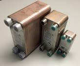
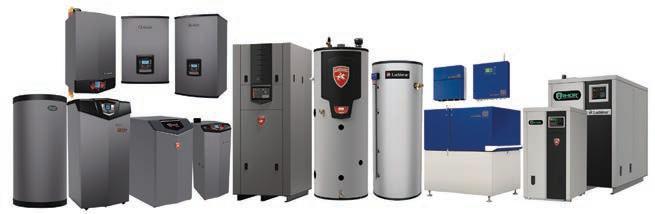
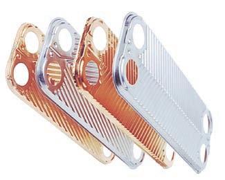
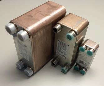
MODERN HYDRONICS WWW.HPACMAG.COMMH28 FALL 2022 Heat exchangers, in all their var ied types and sizes, allow heat to move from one fluid to an other without any contact be tween those fluids. They add considerable versatility to hydronic sys tem design. Common applications in clude domestic water heating, snow melting and hydronic subsystems for ga rage floor heating. Flat plate heat exchangers have cap tured much of the market. More specifi cally, “brazed plate” stainless steel flat plate heat exchangers (BPHX) are now available from several suppliers in a wide range of sizes. They are ideally suited for residential and light commer cial applications. This type of heat exchanger is made by assembling a stack of pre-formed stain less steel plates that have copper bonded to them around their perimeter, and at points of contact between adjacent plates. The concept is shown in Figure 1. The stack is then compressed and heated in an oven to approximately 2,000F to braze the surfaces and pe rimeters together. Most manufacturers of brazed plate heat exchangers have standardized plates sizes. Typical plate dimensions are 3 x 8 in., 5 x 12 in., and 10 x 20 in. For a given plate size, heat exchange ratings are increased by adding plates to the “stack” that become the overall heat exchanger. Brazed plate heat exchangers are com monly described by the nominal size of their plates and the number of plates in the stack. For example, a 5 x 12 x 40 brazed plate heat exchanger has 40 plates, of nominal dimension 5 x 12 in. One unique plate forms the back of the heat exchanger (e.g, it has no holes through it). Another unique plate forms the front of the heat exchanger, and tran sitions to the four piping connections. Figure 2 shows examples of brazed plate stainless steel heat exchangers ranging from a 5 x 12 x 100 plate unit, to a rela tively small 3 x 8 x 10 plate unit. FLOW DIRECTION MATTERS Assuming the channels between the plates were numbered, one fluid passes from one end of the heat exchanger to the other through the odd numbered channels (1,3,5,6, etc.). The other fluid passes from one end of the heat ex changer to the other through the even numbered channels (2,4,6,8, etc.).
When it comes to designing systems with heat exchangers, stick with counterflow piping.
Figure 3. There are two ways to pipe up a flat plate heat exchanger: parallel flow or counterflow.
OPPOSING CURRENTS
Figure 2. Examples of complete brazed plate stainless steel heat exchangers.
BY JOHN SIEGENTHALER
Figure 1. Example of typical brazed plate stainless steel flat plate heat exchanger (BPHX) assembly.
HEAT EXCHANGERS
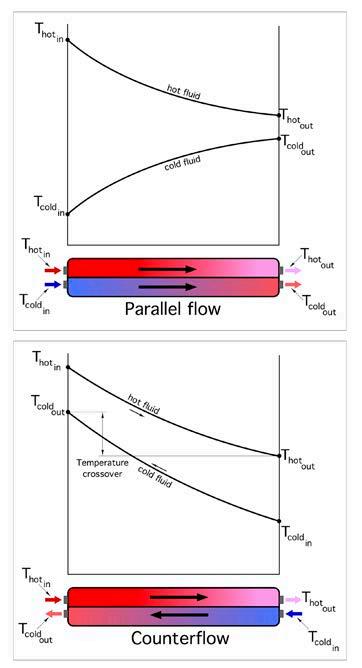
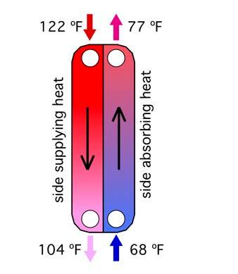
Modern Hydronics MODERN HYDRONICSWWW.HPACMAG.COM MH29FALL 2022 very large. But this difference decreases rapidly as the fluids exchange heat and move toward the outlet ports. There’s also a variation in the temperature difference between the fluids as they move through the counterflow heat exchanger. The rate of heat transfer depends on how the temperature differences at all locations along the fluid pathways “average out.” Heat transfer theory can be used to prove that this aver age temperature difference, which is more specifically called the “log mean temperature difference” (abbreviated at LMTD), can be calculated using Formula 1. Formula 1: Where: LMDT = log mean temperature difference (F) (∆T)1 = temperature difference between the two fluids at one end of the heat exchanger (F) (∆T)2 = temperature difference between the two fluids at the other end of the heat exchanger (F) ln [ ] = the natural logarithm of the quantity in the square brackets. Here’s an example of how to use Formula 1: Calculate the LMTD of the heat exchanger shown in Figure 4 (next page). Just carefully put the numbers into the formula. Let (∆T)1 be assigned to the top end of the heat exchanger. Thus (∆T)1 = 122-77 = 45F. This means that (∆T)2 is at bottom end of the heat exchanger. Thus (∆T)2 = 104-68 = 36F. Putting these val ues into Formula 1 yields: Reversing the ends of the heat exchanger representing (∆T)1 and (∆T)2 would make (∆T)1 = 36F, and (∆T)2 = 45F. Putting these values into formula 1 yields the same result. WE HAVE THOUSANDS OF VALVE BODIES IN STOCK! • Globe –style control valves ½-4” • Full line of NSF 61 rated valves for any application • Actuators for every application • Thermostats • Retrofits – All brands • Projects www.spartan-pd.com HPAC_Spartan_Aug22.indd 1 2022-07-22 12:42 PM Continued on MH30
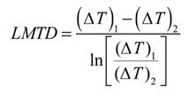
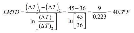
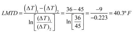


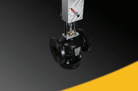


Figure 4. Figure 5. forschematicPipingconfiguredcounterflow.
3. Finally, if the heat exchanger will be op erating with chilled fluids, which are lower than the interior dewpoint tem perature, be sure it’s fully wrapped with elastomeric foam insulation or other va pour impermeable insulation material. Stick with counterflow piping and the details mentioned above, and then stand back and be amazed at the in credible performance of modern brazed plate heat exchangers.
Several types of brackets are avail able and they range from a simple steel “shelf” bracket, to brackets that bolt directly to the threaded studs supplied on some heat exchangers.
MODERN HYDRONICS WWW.HPACMAG.COMMH30 FALL 2022 HEAT EXCHANGERS
MAXIMIZING LMTD The higher LMTD at which any heat ex changer operates, the greater the rate of heat transfer, all other conditions be ing equal. Heat transfer theory can also be used to prove a very important concept in the application of heat exchangers: The LMTD of a heat exchanger config ured for counterflow will always be higher than that of the same heat ex changer configured for parallel flow, and having the same entering and exiting conditions for both flow streams. This implies that heat exchangers should always be configured for coun terflow when the goal is to maximize the rate of heat transfer. Figure 5 shows a piping schematic where the heat exchanger is configured forAlwayscounterflow.check your piping schematics, or schematics that you may be approv ing for others to use, to be sure that all heat exchangers are piped for counter flow. Check any installations that you are inspecting, that include heat exchang ers, to be sure that they are operating in counterflow. LET SOFTWARE DO THE HARD WORK
2. Always support heat exchangers to re duce stress on the connecting piping.
<> John Siegenthaler, P.E., is a licensed professional engineer with more than 40 years of experience in designing modern hy dronic heating systems. Siegenthaler is the author of the textbooks Modern Hydronic Heating (4th edition available now) and Heating With Renewable Energy (see www.hydronicpros.com).
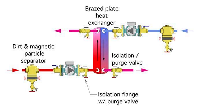
Although it’s possible to manually esti mate heat exchanger performance, the calculations are complex and time con suming. Modern practitioners use one of several available heat exchanger soft ware tools available from manufactur ers to rapidly evaluate “what if” scenarios, which lead to a final model selection.Inmost cases a brazed plate heat ex changer will be sized to pass a given rate of heat transfer when the differ ence between the entering hot fluid tem perature and the leaving cooling fluid temperature is no more than 5F. Here are a few final application points regarding heat exchangers: 1. “Cleanliness is next to godliness" when it comes to heat exchanger perfor mance. It’s always a good idea to put a high efficiency dirt separator, prefera bly one with a magnet, up stream of both inlet ports of any heat exchanger. You can see these in Figure 5, along with isolation and purging valves. The latter can be used, if ever necessary, the isolate each side of the heat ex changer and chemically clean scaling from internal surfaces.
“It's always a good idea to put a high efficiency dirt separator, preferably one with a magnet, up stream of both inlet ports of any heat exchanger.”
INNOVATORSORIGINALTHE LINED-UP DEPENDABILITYFOR With the latest innovations and long-lasting reliability, it’s the trusted product line. TRIANGLETUBE.COM Caleffi 548 Series Separator (Shown Mounted) • Tank in Tank Technology • 439 Stainless Steel Fire Tube Heat Exchanger • Peace of Mind Warranty Program • No Fault Forward Manufacturing ALWAYS INNOVATING LASTING RELIABLILITY

PRESSFROMSOLUTIONSHYDRONICRESIDEO Press fittings consistently create uniform, clean and reliable joints — saving you time and money. Learn more Resideo.com/Pro/Waterat