General Assembly Procedure
Hydraulic Mining Shovel PC3000-6
AS PC3000-6 rev7 Edition October 2005
1
Assembly Procedure PC3000-6
All stated information corresponds to the present development and is subject to possible future changes without prior notice.
AS PC3000-6 rev7 Edition October 2005
2
Assembly Procedure PC3000-6
GENERAL CONTENT 1.
PAGE
1.1 1.2 1.3 1.4 1.5 1.6 1.7 1.8 1.9 1.10
General ................................................................................................5 Delivery of the Excavator .................................................................. 5 Assembling of the Excavator............................................................. 5 Transportation and Lifting.................................................................. 7 Manpower / Assembly Time*............................................................. 9 Assembly Site Requirements .......................................................... 11 Space and Placing Requirements ................................................... 15 Preparation for Assembly ................................................................ 15 Basic Measurements (Z 24015) ...................................................... 17 Transport Dimensions and Weights (as example)........................... 17 Illust. Configuration of Components on Erection Site ...................... 19
2.0 2.1.
Assembly sequence.......................................................................19 Assembly of Undercarriage (Z 24016; Z 24017; Z 24018) ...................... 21
2.1.1 2.1.2 2.1.3
2.2 2.3. 2.4. 2.5 2.5. 2.6. 2.7. 2.8. 2.9 2.10
Assembly ....................................................................................................21 Determination of the tightening torque .......................................................25 Final works .................................................................................................29
Assembly of Superstructure onto the Undercarriage (Z 9031a).............. 31 Mounting of Boom and Boom cylinders(Z 9032; Z 20949)...................... 35 Mounting of Fuel Tank (Z21924)............................................................. 37 Mounting of Hydraulic access Ladder (Z 24022) .................................... 39 Mounting of Cab Base (Z 24023)............................................................ 41 Mounting of Counterweight (Z 24024) .................................................... 43 Mounting of Handrails, Steps and Gratings (Z 24025)........................... 45 Mounting of Cab (Z 24029) ..................................................................... 47 Pre-checks prior Initial Start up............................................................... 49 Mounting of Stick .................................................................................... 53
2.10.1 Backhoe Attachment (Z 24030) ......................................................................53 2.10.2 Bullclam Bucket Attachment (Z 20950; Z 20951; 20952)................................55
2.11
Assembly of the bucket to the stick......................................................... 61
2.11.1 Assembly of the backhoe to the stick (Z 23005) .............................................61 2.11.2 Assembly of the bullclam bucket to the stick (Z 20953) ..................................63
2.12
Mounting of the Pin Seals....................................................................... 67
2.12.1 Backhoe (Z 23006)..........................................................................................67 2.12.2 Bullclam bucket (Z 21963) ..............................................................................69
2.13 2.14
Putting the Central Lubrication System into operation (Z 24031) ........... 71 Standard Application Torque Chart......................................................... 73
2.14.1 Metric standard thread ....................................................................................73 2.14.2 Metric fine thread ............................................................................................75 2.14.3 Torque Chart for Flange Joints .......................................................................76
AS PC3000-6 rev7 Edition October 2005
3
Assembly Procedure PC3000-6
AS PC3000-6 rev7 Edition October 2005
4
Assembly Procedure PC3000-6
1.
General
1.1
Delivery of the Excavator The excavator is being delivered disassembled into its main components. For the correct dimensions and weights please refer to the packing list of your machine. For assembling the excavator follow the instructions in this manual.
1.2
Assembling of the Excavator
ã
• Personnel entrusted with work on the machine must have read the Assembly Manual, the Operation,- Lubrication- and Maintenance Manual and in particular the section on safety before beginning work. Reading the instructions after work has commenced is too late. If there are any questions concerning the assembling procedure, contact your local Service Center. Prior to first operation, inspect the excavator thoroughly with the Service Engineer responsible for the erection of the machine. Check all fluid levels according to the Lubrication and Maintenance Schedule. Damages and defects caused by incorrect operation and maintenance are not covered by the manufacturers guarantee.
)
• If the excavator is equipped with a fire suppression system, make sure that the system is ready for operation.
AS PC3000-6 rev7 Edition October 2005
5
Assembly Procedure PC3000-6
AS PC3000-6 rev7 Edition October 2005
6
Assembly Procedure PC3000-6
ã
• Before assembling/disassembling, lifting or transporting this excavator contact your local Service Center for all the necessary instructions for safe and economic assembling/ disassembling, lifting and transportation procedures of your excavator.
The sequence of assembly as shown in this Manual. Disassembling is basically the reverse order of the assembling procedure.
1.3
Transportation and Lifting The transport dimensions and weights of the excavator’s components are listed in this manual are for general information only. For the correct dimensions and weights please refer to the packing list of your machine. Observe the operating permits of the low-bed trailers used for transportation. They contain the permissible load, loading width and height.
ã
• Observe the federal, state and local laws and regulations for transportation of heavy units. Know the safety rules and laws before you transport this Excavator. • Make sure the flat-bed trailer and the components of the Excavator are equipped with the correct safety devices. • Secure the Excavator and all components transported on the trailer against movement. • Use exclusively approved handling equipment. • When lifting components make sure that the handling elements do not cause damage to the component. • Secure the components safely before removing the lifting straps, ropes or chains.
AS PC3000-6 rev7 Edition October 2005
7
Assembly Procedure PC3000-6
AS PC3000-6 rev7 Edition October 2005
8
Assembly Procedure PC3000-6
ã
1.4
• Wear safety clothing, goggles, respirator and other safety devices, whenever working conditions make this necessary. • Provide hoists of sufficient capacity to lift heavy units. Refer to the weight specifications. • Be sure to observe the instructions in the ”Assembly Procedure Manual”. • Lifting gear, tools and other suspension systems must be in good condition and of sufficient lifting capacity. • Be sure hydraulic cylinders and attachment components are properly supported from hoist and securely fastened, before removing supporting pins. • Floors must be clean and dry. After draining operations be sure all spillage is cleaned up.
Manpower / Assembly Time*
Customer Supervision
1 Electrician 4 Fitters/ Mechanics
Dealer or Komatsu Mining Germany
1 Service Engineer
Days Assembly Time*
6**
*Dependent on mine conditions (shifts, weather, ...) **Without testing and customer acceptance.
AS PC3000-6 rev7 Edition October 2005
9
Assembly Procedure PC3000-6
AS PC3000-6 rev7 Edition October 2005
10
Assembly Procedure PC3000-6
1.5
Assembly Site Requirements
Assembly Site Requirements: − Well leveled and compacted ground approx. 150 x 150 ft/50 x 50 m − A container to store the tools, to keep the paper work and for sheltering − 2 mobile cranes 90 metric tons − 1 small crane, load capacity approx. 25 metric tons No. 1 2 3 4 5 6 7 8 9 10 11 12 13 14 15 16 17 18 19
Qty. 01 04 04 04 04 04 04 04 04 04 01 01 01 60 10 02 02 01 01
20 21 22 23 24 25 26 27 28*
01 01 01 01 01 01 01 01 01
29
01
30
AS PC3000-6 rev7 Edition October 2005
Specification 6 metric tons 6 metric tons 35 metric tons 5 metric tons t 1 metric ton each M10/12/14/16/18/20 30 metric tons - 8 m length 25 metric tons - 8 m length 16 metric tons - 8 m length 12 metric tons - 8 m length ∅ 50 mm x 1000 mm length ∅ 50 mm x 2000 mm length 5 kg 300 x 300 x 1000 mm 300 x 300 x 2500 mm 10 metric tons 50 metric tons 50 m each 6/7/8/9/10/12/13/14/15/17/19 mm 22/24/27/30/32 mm each 41/46/50/55/60/ 65 mm each 7 mm up to 55 mm 3/4” 1/2” 1/2” 3/4” each 13 mm up to 19 mm 24 mm up to 36 mm Only useable with torque wrench (PN793 374 73) (refer to page 28)
0 – 9900 Nm (refer to page 28) 1.2 l; till 700 bar (refer to page 28)
11
Designation Telescopic fork lift Chain pull Shackles Shackles Shackles Eye bolts Ropes Ropes Ropes Ropes Pry bar Pry bar Large hammer Wooden blocks Wooden blocks Hydraulic jacks Hydraulic jacks Cable drum Combination spanner Single ended open spanner Double end open spanner Impact wrench Impact wrench Ratchet Ratchet Sockets for ½” Ratchet Socket for 3/4” Ratchet Tightening tool for bolts center section side frame connection (PN793 376 73) including special tightening nut This tool is required to ensure: - that the reaction torque is supported at the bottom of the neighbor bolt - that no bending moment effects the neighbor bolt Hydraulic torque wrench (PN793 374 73) Electric hydraulic power pack (PN793 375 73)
Assembly Procedure PC3000-6
Yazaki Connector Set No.
Qty.
Designation
Part No.
1
2
Connector 3-pole
891 040 40
2
2
Connector 3-pole
891 032 40
3
2
Connector 2-pole
891 039 40
4
2
Connector 2-pole
891 031 40
5
2
Connector 1-pole
891 038 40
6
2
Connector 1-pole
891 030 40
AS PC3000-6 rev7 Edition October 2005
12
Assembly Procedure PC3000-6
31 32 33
Qty. 01 01 01 01
34 35 36 37 38 39
01 01 01 01 01 01
40 41 42 43 44 45** 46 47 48 49 50 51
01 07 03 03 01 02 02 01 02 01 01 01
52 53 54 55 56 57
01 01 01 01 01 01
Specification 30/32/36/41/46/55/65/75 mm Range 0 - 250 Nm Range 250 - 600 Nm Range to 140 Nm
5, 6, 8, 10, 12, 14 mm 14, 17, 19 mm 2 up to 19 mm
600 bar 60 bar 25 bar 15 bar
0 - 2500 min-1 1,5 mm² 30 m from M6 - M 36
Set Set
Designation Sockets HD for hydr. torque wrench Torque wrench ⇒ drive ½” Torque wrench ⇒ 3/4” Cordless Impact Wrench 1/2 “ P/N 793 828 73 Hand drill Screw driver sockets for 1/2” drive Screw driver sockets for 3/4” drive Hex keys (Allen keys) L-type Electric welding machine Lights for the illumination of the working area Hand lamp Pressure gauge Pressure gauge Pressure gauge Pressure gauge Multi-meter P/N 232 619 40 Cable set P/N 232 496 40 Contact less revolution indicator Cables with connectors Thread cutting set Level gauge Test adapter proportional/solenoid valves P/N 232 537 40 / 232 538 40 Yazaki connectors (refer to table ) Screw driver Side cutter Tip plier Combination plier Pipe plier
*
ã
• If the specific tool and the prescribed assembly procedure are not used for assembling the crawler carriers to carbody KMG will not carry the warranty for the undercarriage!
** If available an electronic testing device for pressure, voltage and RPM, similar Hydrotechnic System 6000
AS PC3000-6 rev7 Edition October 2005
13
Assembly Procedure PC3000-6
AS PC3000-6 rev7 Edition October 2005
14
Assembly Procedure PC3000-6
1.6
Space and Placing Requirements On the following page, the components are indicated in their approx. dimensions. They are unloaded in a way that a min. space of 1 meter (3 ft) is left between the components, and that there is enough space for the trucks and the cranes.
1.7
Preparation for Assembly Unload all components so that no more move is necessary! All pins, bushings, borings, bearings and contact surfaces of components must be clean Torque values are listed in section 6.9 of the Lubrication- and Maintenance Manual - unless being listed in this Assembly Procedure Booklet. Obey all applicable safety and local regulations strictly! Ensure correct lifting procedures and ensure use of adequate lifting gears! High voltage installation works must be carried out by authorized specialists only.
AS PC3000-6 rev7 Edition October 2005
15
Assembly Procedure PC3000-6
Z 24015 AS PC3000-6 rev7 Edition October 2005
16
Assembly Procedure PC3000-6
1.8
Basic Measurements (Z24015)
1.9
Transport Dimensions and Weights (as example)
AS PC3000-6 rev7 Edition October 2005
17
Assembly Procedure PC3000-6
AS PC3000-6 rev7 Edition October 2005
18
Assembly Procedure PC3000-6
1.10
Illust. Configuration of Components on Erection Site
2.0
Assembly sequence
1. 2 3. 4. 5 5. 6. 7. 8. 10. 11. 12. 13.
AS PC3000-6 rev7 Edition October 2005
Subject Assembly of Undercarriage Assembly of Superstructure onto the Undercarriage Mounting of Boom and boom cylinders Mounting of Fuel Tank Mounting of Hydraulic access Ladder Mounting of Cab Base
Illustr. (Z 24017) (Z 9031a) (Z 9032) (Z 21924) (Z 24022) (Z 24023)
Page 21 31 35 37 39 41
Mounting of Counterweight Mounting of Handrails, Steps and Gratings Mounting of Cab Mounting of Stick /Stick cylinders Assembly of the bucket to the stick Mounting of the Pin Seals Putting the Central Lubrication System into operation
(Z 24024) (Z 24025) (Z 24029) (Z 24030) (Z 23005) (Z 23006)
43 45 47 51 59 65
19
(Z 24031) 69
Assembly Procedure PC3000-6
AS PC3000-6 rev7 Edition October 2005
20
Assembly Procedure PC3000-6
2.1.
Assembly of Undercarriage (Z 24016; Z 24017; Z 20418)
2.1.1
Assembly 1.
2. 3.
)
Align right side frame horizontally in both directions very exactly. From outside place water level gauge onto steel structure of side frame. Clean the flange areas metallically blank (free of oil, grease; paint; ..) Attach carbody to the crane (oil supply lines to the travel motors pointing in direction of the travel motors).
• Insert the corresponding lines for the chain tensioning system before installing the side frame.
4. 5. 6. 7.
Align carbody with the side frame. Lubricate all bolts (M48) (head supporting surface and thread) with International Compound No. 2 (PN 324 969 40). Insert the bolts (2 x 18 pieces + 2 measuring bolts)* with a resilient sleeve and tighten with 2100 Nm. Support carbody with wooden blocks in a way that the free side is approx. 200 mm higher than the attached side. (This makes it easier to attach the 2nd side frame).
*Insert the 2 measuring bolts (1) at the upper corners!
AS PC3000-6 rev7 Edition October 2005
21
Assembly Procedure PC3000-6
Z 24018
AS PC3000-6 rev7 Edition October 2005
22
Assembly Procedure PC3000-6
8. 9. 10. 11.
Clean the flange areas of the second side also metallically blank (free of oil, grease; paint; ...). Lift the 2nd side frame with the crane and align with the carbody. Insert the bolts (2 x 18 pieces + 2 measuring bolts)* with a resilient sleeve and tighten with 2100 Nm. Lift the undercarriage so far that it is possible to remove the wooden blocks.
*Insert the 2 measuring bolts(1) at the upper corner - refer to drawing (Z 24016)!
AS PC3000-6 rev7 Edition October 2005
23
Assembly Procedure PC3000-6
Z24019
AS PC3000-6 rev7 Edition October 2005
24
Assembly Procedure PC3000-6
2.1.2
Determination of the tightening torque The required tightening torque for all fastening bolts has to be determined with the 4 measuring bolts (7), which dimension is analogous to the fastening bolts. The required axial tension force of the bolts is determined by means of the elongation of the fastening bolts. The tightening torque must be determined at the first assembly of the excavator at the operation site and for the first inspection and after 1000 operation hours. The required measuring device (PN 92847640) is delivered with the excavator. To determine the tightening torque, 4 specially prepared measuring bolts are supplied besides the normal fastening bolts. The measuring bolts can be recognized at the machined area at the end of the bolt. The measuring device is composed of the following items and will be delivered with each new machine (refer to drawing Z 24020). Procedure to determine the tightening torque for the first assembly (pre-condition side frame is assembled and bolts tightened to 2100 Nm) 1. Loosen all 4 measuring bolts. Do not lubricate the measuring bolts again. 2. Tighten the 4 measuring bolts with 150 Nm. 3. Install the measuring device (refer to drawing Z 24020a). 4. Adjust the dial gauge to the zero position. 5. Install the special hydraulic torque wrench (Z 24021; PN 79337473 + 79337673). 6. Adjust the pressure at the hydraulic torque wrench to 2100Nm and tighten the measuring bolt. 7. Increase the pressure further by steps of 10 bar until the required elongation of 0.93 mm of the measuring bolts is reached. 8. List the pressure and the change of the bolt length in a table. 9. Repeat this procedure for all 4 measuring bolts. 10. Add all 4 determined hydraulic pressures and then divide by 4. 11. With this average pressure tighten all other bolts.
AS PC3000-6 rev7 Edition October 2005
25
Assembly Procedure PC3000-6
AS PC3000-6 rev7 Edition October 2005
26
Assembly Procedure PC3000-6
Procedure to determine the tightening torque for inspection after 1000 operating hours 1. Loosen all 4 measuring bolts. Do not lubricate the measuring bolts again. 2. Tighten the 4 measuring bolts with 150 Nm. 3. Install the measuring device (refer to drawing Z 24020). 4. Adjust the dial gauge to the zero position. 5. Install the special hydraulic torque wrench (Z 24021; PN 79337473 + 79337673). 6. Adjust the pressure at the hydraulic torque wrench to 2100Nm and tighten the measuring bolt. 7. Increase the pressure further by steps of 10 bar until the required elongation of 0.93 mm of the measuring bolt is reached. 8. List the pressure and the change of the bolt length in a table. 9. Repeat this procedure for all 4 measuring bolts. 10. Add all 4 determined hydraulic pressures and then divide by 4. 11. Now only loosen one of the other bolts and tighten up to the determined average pressure. 12. Repeat this procedure for all the other bolts step by step.
W
• Do not lubricate the bolts again. • Do not loosen more than one bolt at the same time.
Measuring Device (PN 928 476 40) (Z 24020a) Position
Part name
Part No.
Number
1
Angle bar
928 475 40
1
2
Dial gauge
092 706 40
1
3
Screw M5x16
502 515 98
1
4
Feeler
477 172 40
1
5
Bolt M10x25
307 777 99
2
6
Washer
517 122 98
2
7
Measuring bolt
933 613 40
4
AS PC3000-6 rev7 Edition October 2005
27
Assembly Procedure PC3000-6
PN79337673
PN79337473
PN79337573
AS PC3000-6 rev7 Edition October 2005
28
Assembly Procedure PC3000-6
2.1.3
Final works 1. Connect hose pipes between the oil supply lines of the carbody to the travel motors. 2. Open the cocks inside the side frames for the hydraulic crawler tensioning system (refer to the Maintenance Manual).
W
• Do not open the cocks before all hydraulic lines are connected with the rotary joint. The lines in the side frame are under pressure!
3. Fill up and/or check the gear oil levels (travel gear, brake, final drive - refer to the Maintenance Manual).
AS PC3000-6 rev7 Edition October 2005
29
Assembly Procedure PC3000-6
Z 9031a
AS PC3000-6 rev7 Edition October 2005
30
Assembly Procedure PC3000-6
2.2
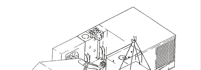
Assembly of Superstructure onto the Undercarriage (Z 9031a)
)
• Hang the superstructure platform horizontally at the cranes.
1.
Attach the superstructure to the cranes, lift up the superstructure and carefully clean the surface (contact area) of the slew ring. Clean very carefully the contact surfaces of the slew ring and the carbody. Check if the “S” position of the inner and outer ring of the slew ring is left and right of travel direction. Prepare all bolts (03), sleeves (02) and lubricate the threads as well as the head surface of the bolts, also clean off any paste of the bolts (Refer to Service Bulletin AH00511b!).
2. 3.
)
• Remove the cam of the rotary joint before install the superstructure.
)
• Install 2 threaded pins (M30 x 100 mm long, one end pointed, to be manufactured) displaced by 180° to slew ring at superstructure. This simplifies the alignment of the slew ring to the undercarriage.
4.
Align superstructure to the carbody and lower the superstructure as required to insert 4 bolts. Insert one bolt at each 90° (for guiding) and lower superstructure so that there is a very thin gap between slew ring and carbody. Install all bolts and tighten hand tight. Tighten the bolts crosswise with the required torque. (Refer to Service Bulletin AH00511b).
5. 6. 7.
)
• If approx. 10 bolts (front and rear) are tightened the superstructure can be unhooked from the crane.
AS PC3000-6 rev7 Edition October 2005
31
Assembly Procedure PC3000-6
AS PC3000-6 rev7 Edition October 2005
32
Assembly Procedure PC3000-6
AS PC3000-6 rev7 Edition October 2005
33
Assembly Procedure PC3000-6
Z 20949
AS PC3000-6 rev7 Edition October 2005
34
Assembly Procedure PC3000-6
2.3.
Mounting of Boom and Boom cylinders(Z 9032; Z 20949)
)
• For the mounting of the pin seals please refer to page 65. • We recommend mounting stick cylinders to the boom before installing the boom.
1.
Lift the boom with the stick cylinders and boom cylinders attached. Align the boom with the boom bearings of the superstructure. Lower the boom that the borings of the boom and the boom bearings are aligned. Insert the two pins (01) and secure with the retainers (02)
2. 3. 4.
The boom must be still attached to the crane! 5.
Lift one boom cylinder with an other crane or chain pull and disconnect the transport fastenings. Lower the boom cylinder until the boring of the cylinder and the superstructure bearings are aligned.
6.
)
• If necessary lower or raise the boom for easier alignment.
7. 8. 9.
)
Insert the pin (03) and secure with the retainer (04). Fix the 2nd cylinder in the same manner. Connect the pipes resp. hoses for the boom, stick and backhoe cylinders as much as possible. Unhook boom from the crane. • The boom may be unhooked earlier but be careful and pay attention while opening the hydraulic lines. There may be still a little pressure in the system. Therefore be careful when opening the hoses.
AS PC3000-6 rev7 Edition October 2005
35
Assembly Procedure PC3000-6
AS PC3000-6 rev7 Edition October 2005
36
Assembly Procedure PC3000-6
2.4.
Mounting of Fuel Tank (Z 21924) 1. 2. 3. 4.
AS PC3000-6 rev7 Edition October 2005
Lift the fuel tank. Lifting eyes are delivered with the machine. Align the fuel tank with the superstructure. Lower the fuel tank fully down and install all bolts. Tighten the bolts with the resp. torque. Connect fuel lines and electric cables.
37
Assembly Procedure PC3000-6
Z 24022
AS PC3000-6 rev7 Edition October 2005
38
Assembly Procedure PC3000-6
2.5
Mounting of Hydraulic access Ladder (Z 24022) 1. Install the platform (1) with 8 bolts(45) – M24x130 and the sleeves (46). 2. Install the appendant handrails (2). 3. Mount the hinged ladder according to “Detail A” Position 47 49 50 51 52 54
Designation Hydraulic cylinder Pin Washer Cotter pin Self locking nut Bearing assy.
4. Tightening Procedure for Self Locking Nuts (52): Screw on the nuts until they have contact with the ladder carrier frame. Then tighten the nuts further by turning them through an angle of 45° (1/8 turn). 5. Lubricate both eyes of hydraulic cylinder (47). Make sure both pivot pins (49) are properly secured with cotter pins. 6. Connect the hydraulic hoses to the cylinder. 7. Connect the Accumulators (54) inside the platform (1).
AS PC3000-6 rev7 Edition October 2005
39
Assembly Procedure PC3000-6
AS PC3000-6 rev7 Edition October 2005
Z24023 40
Assembly Procedure PC3000-6
2.5.
Mounting of Cab Base (Z 24023) 1. 2. 3. 4.
AS PC3000-6 rev7 Edition October 2005
Lift the cab base. Lifting eyes are delivered with the machine. Align the cab base with the superstructure. Lower the cab base fully down and install all bolts. Tighten the bolts with the resp. torque. Connect electric cables according to the Electric Circuit Diagrams of the machine.
41
Assembly Procedure PC3000-6
M42x550 4950 Nm
Z 24024
AS PC3000-6 rev7 Edition October 2005
42
Assembly Procedure PC3000-6
2.6.
Mounting of Counterweight (Z 24024) 1. 2.
Lift the counterweight. Clean surfaces “A” absolutely free of dirt; oil; fat and paint (metallic clean). Align the counterweight with the superstructure. Lower the counterweight fully down and fasten it with the bolts and washers (01 + 02). Tighten the bolts with the resp. torque.
3. 4.
)
• Apply Paste „Optimol White“ PN 999 039 on heads and threads of the bolts (01).
AS PC3000-6 rev7 Edition October 2005
43
Assembly Procedure PC3000-6
Z24025
AS PC3000-6 rev7 Edition October 2005
44
Assembly Procedure PC3000-6
2.7.
Mounting of Handrails, Steps and Gratings (Z 24025) 1.
During this stage of assembly the handrails, steps and gratings can be mounted to the superstructure, cab base and machinery house. This provides more safety during further assembly.
Position 19 20 21 22 23 24 25
AS PC3000-6 rev7 Edition October 2005
Designation Pair of half clamps Cover plate Bolt Washer Nut Bolt Locking plate
45
Assembly Procedure PC3000-6
Z 24029
AS PC3000-6 rev7 Edition October 2005
46
Assembly Procedure PC3000-6
2.8.
Mounting of Cab (Z 24029) 1. 2. 3. 4. 5. 6.
AS PC3000-6 rev7 Edition October 2005
Lift the cab. Lifting eyebolts are delivered with the machine. Align the cab with the cab base. Lower the cab fully down and fasten the cab with bolts (1) M16x2 and sleeves (02). Connect electric cables and the hydraulic hoses. If the machine is equipped with an air conditioner, connect the air hoses and cables. Mount the handrails to the cab if not yet done.
47
Assembly Procedure PC3000-6
Z 20371a
AS PC3000-6 rev7 Edition October 2005
48
Assembly Procedure PC3000-6
2.9
Pre-checks prior Initial Start up
Engine commissioning • The local working safety rules must be strictly observed. • Only service personnel necessary for first start up testing are allowed to be on the excavator. • The operator must have read and understood the operation manual. • Remove all tools and other not fixed material from excavator especially from moving parts.
ã • •
• •
• • •
• • •
•
Be sure that all hand rails, catwalks and steps etc. are correctly installed. Make sure that all hoses and electrical connections are correctly established (refer to the electrical and hydraulic circuit diagrams). Ex works, all disconnected hose lines and electrical cables are marked with identification numbers. Fill up the hydraulic oil tank and the fuel tank *. Check all fluid levels and correct if necessary *. Fill up or use filled respective grease container for the Central lube system and the Swing circle lube system *. Make sure that the shut off valve between the main hydraulic tank and the suction tank is completely open. Bleed the engine fuel lines and filters. Bleed the suction side of each main pumps *. Use adequate receptacle to collect out flowing oil. Be sure that the plug seal is in good condition. Tighten the plug securely. Fill up each main pump housings with hydraulic oil *. Bleed pump housing of the fan piston pump *. Check to make sure that the pressure relief cock for the hydraulic track tensioning system are CLOSED and the shut-off cocks in the crawler carriers are OPEN (refer to Illust. Z20371a). Open all lowering throttle valves of working attachment. At works are all closed. Do not forget to adjust the throttle valves after complete mounting of the attachment (Refer Service Bulletin AH02518 last edition).
Now the engine can be started and the machine can be operated for any additional assemblies. During and after starting pay attention to the instructions in the Operation Manual. *(Refer to the next pages).)
AS PC3000-6 rev7 Edition October 2005
49
Assembly Procedure PC3000-6
Z 25014
AS PC3000-6 rev7 Edition October 2005
50
Assembly Procedure PC3000-6
HYDRAULIC SYSTEM - Vent Hydraulic Pumps (Z25014) 1. 2.
3.
4.
5. 6.
7.
Loosen vent plug (A) of suction oil reservoir (1). Retighten vent plug (A) when the out flowing oil is free of air bubbles. Vent main pump (2) by loosening leakage oil line connector(B) and by opening vent valve (C). Retighten (B and C) when the out flowing oil is free of air bubbles. Vent main pump (3) by loosening leakage oil line connector(B) and by opening vent valve (C). Retighten (B and C) when the out flowing oil is free of air bubbles. Vent oil cooler fan drive pump (4) by loosening leakage oilline connector (D). Retighten (D) when the out flowing oil is free of air bubbles. Vent control oil pump (5) by loosening vent plug (E) at the suction line flange. Retighten (E) when the out flowing oil is free of air bubbles. Vent main pump (6) by loosening leakage oil line connector(F) and by opening vent valve (G). Retighten (F and G) when the out flowing oil is free of air bubbles. Check hydraulic oil level and the whole hydraulic system for leakage.
REMARK After changing the oil of the PTO gear vent the PTO lubrication pump (7) by opening vent plug (H) at the suction hose flange. Retighten (H) when the out flowing oil is free of air bubbles.
AS PC3000-6 rev7 Edition October 2005
51
Assembly Procedure PC3000-6
Z 24030 AS PC3000-6 rev7 Edition October 2005
52
Assembly Procedure PC3000-6
2.10
Mounting of Stick
2.10.1
Backhoe Attachment (Z 24030) 1. 2. 3. 4.
Lift the boom with the excavator hydraulic. Lift the stick by a crane in nearly vertical position. Lower the stick until stick and boom borings are aligned. Insert pin (1) with mounting sleeve* (2). *Protection cap for the thread Remove the mounting sleeve (2). Install a whirl (M20) in the nut (5). Lift the final cap (3) with a crane, tilt it and turn it on the pin (1) by using the nut (4) (M30).
5. 6. 7.
8. Secure the cap as shown with the bolt (6). 9. Secure the bolt (6) with the cotter pin (8). 10. Install the stick cylinders to the stick. 11. Install hoses at boom/stick connection.*
ã )
∗ There may be still some pressure in the system. Therefore be careful when opening the hoses. • There is only one mounting cap for all pins.
Position 1 2 3 4 5 6 7 8
AS PC3000-6 rev7 Edition October 2005
Designation Pin Cap for mounting Final cap Nut for mounting the final cap Nut for mounting the whirl Safety bolt Hole for the cotter pin Cotter pin
53
Assembly Procedure PC3000-6
Z 20950
AS PC3000-6 rev7 Edition October 2005
54
Assembly Procedure PC3000-6
2.10.2
Bullclam Bucket Attachment (Z 20950; Z 20951; 20952)
1. 2. 3. 4. 5.
AS PC3000-6 rev7 Edition October 2005
Hook up bucket cylinders that way that rod side shows approx. 45° up to the bearings at the boom. Align the rod eyes with borings at the boom. Install pin (1). Install axle stirrup (2). Install shackle (3) with washer (4) and bolt (5).
55
Assembly Procedure PC3000-6
Z 20951
AS PC3000-6 rev7 Edition October 2005
56
Assembly Procedure PC3000-6
6. 7. 8. 9. 10.
AS PC3000-6 rev7 Edition October 2005
Lift the stick. Lift the stick to the bearing position stick to the boom. Lower the stick until stick and boom borings are aligned. Install pin (1), stirrups (2), Plate (3); washers (4) and bolts (5). Lower the stick by means of crane and place lower end onto a pile of wood.
57
Assembly Procedure PC3000-6
Z 20952
AS PC3000-6 rev7 Edition October 2005
58
Assembly Procedure PC3000-6
11.
Hook up stick cylinder to chain pull and remove transport fastening. 12. Lower stick cylinder by means of chain pull and extend cylinder rod. Align with bearing at stick. 13. Install pin (1), plates (2) and washers (3) with bolts (4).
AS PC3000-6 rev7 Edition October 2005
59
Assembly Procedure PC3000-6
Z 23005
AS PC3000-6 rev7 Edition October 2005
60
Assembly Procedure PC3000-6
2.11
Assembly of the bucket to the stick
2.11.1
Assembly of the backhoe to the stick (Z 23005)
Position 1. 2. 3. 4. 5. 6. 7. 8.
Designation Pin Cap for mounting Final cap Nut for mounting the final cap Nut for mounting whirl Safety bolt Hole for the cotter pin Cotter pin
Installing of this kind of pins: 1. Secure the thread with the mounting cap. 2. Install the pin. 3. Remove the mounting cap. 4. Install a whirl (M20) in the nut (5). 5. Lift the Final cap (3) with a crane, tilt it and turn it on the pin(1) by using the nut (4) (M30). 6. Secure the cap as shown with the bolt (6). 7. Secure the bolt (6) with the cotter pin (8).
)
• There is only one mounting cap for all pins.
)
• For further information about the standard tooth system refer to Service Bulletin AH03510.
AS PC3000-6 rev7 Edition October 2005
61
Assembly Procedure PC3000-6
Z 20953
AS PC3000-6 rev7 Edition October 2005
62
Assembly Procedure PC3000-6
2.11.2
Assembly of the bullclam bucket to the stick (Z 20953) 1. 2. 3. 4. 5. 6. 7. 8. 9.
)
Place the rear wall as shown on the ground. Lift the attachment and retract the stick cylinders until the stick is in a vertical position. Move the excavator to the bucket. Align the bores of the stick with the bores of the bucket. Push the pins (1) from (A) to (B) so far that the axle stirrup (2) can be installed. Install the parts (3; 4 and 5). Tighten bolts. By moving and extending the bucket cylinders align the cylinder eyes with the bores of the bucket. Now push pins (7) from outside to inside so far that axle stirrup (6) can be installed. Secure the bolts with parts (8; 9 and 10). Tighten bolts.
• For mounting of the pin seals please refer to page 65.
AS PC3000-6 rev7 Edition October 2005
63
Assembly Procedure PC3000-6
Z 20954
AS PC3000-6 rev7 Edition October 2005
64
Assembly Procedure PC3000-6
10. Place the clam shell into the position as shown. Align the rear wall borings by moving boom, stick and bucket cylinder with the clam borings. 11. Install pins (5) and lock catch (3 and 4). 12. Extend clam cylinder to align them with borings in the clam. Install pins (1) and lock them with catch (2 and 3). 13. Connect all hose lines to the bucket cylinders and to the clam cylinders in the rear wall. 14. Connect all grease lines to the bucket and ensure that all grease points are greased before machine is put into operation
AS PC3000-6 rev7 Edition October 2005
65
Assembly Procedure PC3000-6
Z23006
AS PC3000-6 rev7 Edition October 2005
66
Assembly Procedure PC3000-6
2.12
Mounting of the Pin Seals
2.12.1
Backhoe (Z 23006) Position 02; 06; 11; 15 03; 07; 12; 16 04; 08; 13; 17 05; 10; 14 20; 21; 22
Designation seal ring upper ring half lower ring half seal fixing bolt
The illustration shows the mounting places of the one piece design seals.
)
• Fill the groove of the fixing halves with grease before installing. • Proper functioning of the seal is only established in case of an intact seal ring.
AS PC3000-6 rev7 Edition October 2005
67
Assembly Procedure PC3000-6
Z 21963
AS PC3000-6 rev7 Edition October 2005
68
Assembly Procedure PC3000-6
2.12.2
Bullclam bucket (Z 21963) The illustration shows the mounting places (A, B; C) of the one piece design seals of the bullclam bucket attachment. Mounting procedure (For example place “B�) 1. 2. 3.
AS PC3000-6 rev7 Edition October 2005
Insert both seals (1). Assemble the stick and the rear wall as described on pages before. Install both fixing halves (2) over the seal ring and tighten bolts (3).
69
Assembly Procedure PC3000-6
Z24031
AS PC3000-6 rev7 Edition October 2005
70
Assembly Procedure PC3000-6
2.13
Putting the Central Lubrication System into operation (Z 24031) In order to ensure adequate pre-lubrication of all attachment bearings. It is necessary to manually lubricate the attachment bearings by applying a grease gun to the grease fittings on each grease injector. To this, remove protection cap (3) and press in grease until a grease collar appears at the connected bearing. Be sure to repeat the procedure until all pivot bearings of the attachment and cylinder bearings are lubricated.
W
• Before handing over the excavator to the customer the first PM Clinic Service has to be carried out according to the Inspection Procedure Manual.
AS PC3000-6 rev7 Edition October 2005
71
Assembly Procedure PC3000-6
In order to keep the excavator in first-class operating condition use only genuine Komatsu Mining Germany replacement parts. The use of any part other than the genuine parts releases the Komatsu Mining Germany for any guarantee.
AS PC3000-6 rev7 Edition October 2005
72
Assembly Procedure PC3000-6
2.14 2.14.1
Standard Application Torque Chart Metric standard thread
Bolt size (mm)
Wrench size (mm)
Tightening torque MA (Nm) 8.8
10.9
12.9
M 8
6
13
21
31
36
M 10
8
17
43
63
73
M 12
10
19
74
108
127
M 14
12
22
118
173
202
M 16
14
24
179
265
310
M 18
14
27
255
360
425
M 20
17
30
360
510
600
M 22
17
32
485
690
810
M 24
19
36
620
880
1030
M 27
19
41
920
1310
1530
M 30
22
46
1250
1770
2080
M 33
24
50
1690
2400
2800
M 36
27
55
2170
3100
3600
60
2800
4000
4700
65
3500
4950
5800
70
4350
6200
7200
75
5200
7500
8700
80
6700
9600
11200
85
8400
12000
14000
90
10400
14800
17400
95
12600
17900
20900
100
15200
21600
25500
M 39 M 42
32
M 45 M 48
35
M 52 M 56
41
M 60 M 64 M 68
46
The torque indications on the chart attached are valid only when the bolts are manufactured according to DIN. Threads and bolt heads must be lubricated carefully with grease KP2K. The surfaces of contact which should screwed together have to be free of grease. Divergencing torques: Bolts at excavator slew rings (see Service Bulletin AH00511a)
AS PC3000-6 rev7 Edition October 2005
73
Assembly Procedure PC3000-6
AS PC3000-6 rev7 Edition October 2005
74
Assembly Procedure PC3000-6
2.14.2
Metric fine thread
Bolt size (mm)
Wrench size (mm)
Tightening torque MA (Nm) 8.8
10.9
12.9
M 8x1.00
6
13
23
33
39
M 10x1.00
8
17
48
70
82
M 12x1.25
10
19
81
119
139
M 14x1.50
12
22
127
187
219
M 16x1.50
14
24
191
280
330
M 18x2.00
14
27
270
385
450
M 20x2.00
17
30
380
540
630
M 22x2.00
17
32
510
720
850
M 24x2.00
19
36
680
960
1130
M 27x2.00
19
41
990
1410
1650
M 30x2.00
22
46
1380
1960
2300
M 33x2.00
24
50
1850
2650
3100
M 36x3.00
27
55
2300
3250
3850
60
3000
4200
4950
65
3750
5300
6200
70
4600
6600
7700
75
5700
8100
9500
80
7300
10400
12100
85
8900
12600
14800
90
11000
15600
18300
95
13300
19000
22200
100
16100
22900
27000
M 39x3.00 M 42x3.00
32
M 45x3.00 M 48x3.00
35
M 52x3.00 M 56x4.00
41
M 60x4.00 M 64x4.00 M 68x4.00
46
The torque indications on the chart attached are valid only when the bolts are manufactured according to DIN. Threads and bolt heads must be lubricated carefully with grease KP2K. The surfaces of contact which should screwed together have to be free of grease. Divergencing torques: Bolts at excavator slew rings (see Service Bulletin AH00511a).
AS PC3000-6 rev7 Edition October 2005
75
Assembly Procedure PC3000-6
2.14.3
Torque Chart for Flange Joints
- Service Information Buscherhofstr. 10 40599 Düsseldorf Phone +49 (0)211 7109 0 Fax +49 (0)211 74 33 07
AS PC3000-6 rev7 Edition October 2005
76