





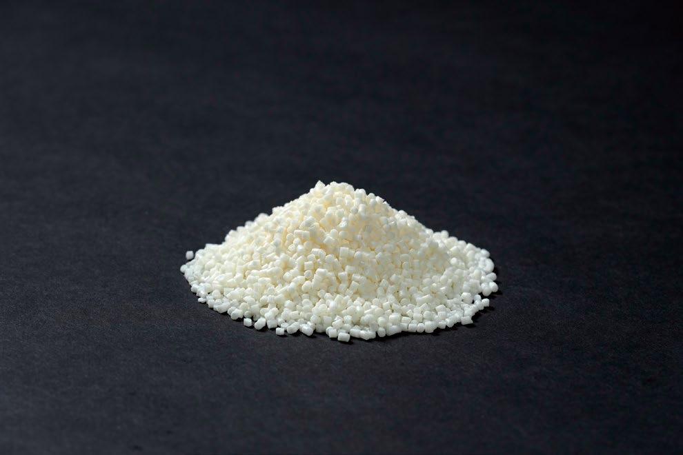
• At RYER, all our feedstocks are manufactured to the highest level of quality, with excellent batch-to-batch repeatability.
• RYER is the ONLY commercially available feedstock manufacturer to offer all five debind methods.
• RYER offers the largest material selections of any commercially available feedstock manufacturer.
• RYER offers technical support for feedstock selection, injection molding, debinding and sintering.
• A direct replacement for all current commercially available catalytic debind feedstocks
• Improved flow
• Stronger green and brown parts
• More materials available and better surface finish
• Custom scale-up factors available
• Faster cycle times
• 65°C / 150°F mold temperature
• Water Debind
• Custom scale-up factors available
• Large selection of available materials

• Solvent, Super Critical Fluid Extraction (SFE) or Thermal Debind methods
• Hundreds of materials available
• Custom scale-up factors available
Publisher & Editorial Offices
Inovar Communications Ltd
11 Park Plaza
Battlefield Enterprise Park
Shrewsbury SY1 3AF
United Kingdom
Tel: +44 (0)1743 469909 www.pim-international.com
Managing Director & Editor
Nick Williams, nick@inovar-communications.com
Group News Editor
Paul Whittaker, paul@inovar-communications.com
Advertising Sales Director
Jon Craxford
Tel: +44 (0)207 1939 749 jon@inovar-communications.com
Assistant Editor
Amelia Gregory, amelia@inovar-communications.com
Assistant News Editor
Charlie Hopson-VandenBos charlie@inovar-communications.com
Digital Marketer
Mulltisa Moung, mulltisa@inovar-communications.com
Production Manager
Hugo Ribeiro, hugo@inovar-communications.com
Operations & Partnerships Manager
Merryl Le Roux, merryl@inovar-communications.com
Office & Accounts Manager
Jo Sheffield, jo@inovar-communications.com
Technical Consultant
Dr Martin McMahon
Consulting Editors
Prof Randall M German
Former Professor of Mechanical Engineering, San Diego State University, USA
Dr Yoshiyuki Kato
Kato Professional Engineer Office, Yokohama, Japan
Professor Dr Frank Petzoldt
Ingenieurbüro Dr. Petzoldt, Geestland, Germany
Dr David Whittaker
DWA Consulting, Wolverhampton, UK
Bernard Williams
Consultant, Shrewsbury, UK
Subscriptions
PIM International is published on a quarterly basis as either a free digital publication or via a paid print subscription. The annual print subscription charge for four issues is £150 including shipping.
Accuracy of contents
Whilst every effort has been made to ensure the accuracy of the information in this publication, the publisher accepts no responsibility for errors or omissions or for any consequences arising there from. Inovar Communications Ltd cannot be held responsible for views or claims expressed by contributors or advertisers, which are not necessarily those of the publisher.
Advertisements
Although all advertising material is expected to conform to ethical standards, inclusion in this publication does not constitute a guarantee or endorsement of the quality or value of such product or of the claims made by its manufacturer.
Reproduction, storage and usage
Single photocopies of articles may be made for personal use in accordance with national copyright laws. All rights reserved. Except as outlined above, no part of this publication may be reproduced or transmitted in any form or by any means, electronic, photocopying or otherwise, without prior permission of the publisher and copyright owner.
Design and production
Inovar Communications Ltd.
ISSN: 1753-1497 (PRINT)
ISSN: 2055-6667 (ONLINE) © 2024 Inovar Communications Ltd.

In October, the Powder Metallurgy World Congress series returns to Japan for the first time in twelve years, and, again, the vibrant city of Yokohama will host.
In the period since World PM2012, the Metal Injection Moulding industry landscape has changed beyond recognition. I clearly remember the MIM Special Interest Seminar at World PM2012 in which information on Apple’s MIM Lightning Connector – the catalyst for this transformation – was first publicly introduced.
While the significance of that moment was clear to everyone in the room, I think few fully appreciated the transformative impact that this application would have, powering the value of MIM sales in China from $300 million in 2012 to nearly $1.5 billion in 2021.
It feels as if we are now at a similar crossroads, with sinter-based Additive Manufacturing technologies such as Binder Jetting offering MIM producers the opportunity to take a leading role in the Additive Manufacturing revolution.
It remains to be seen what exact revelations will be revealed in Yokohama this autumn, but it’s certain that members of the international MIM community will have lots to discover. I hope to see you there!
Nick Williams Managing Director & Editor
Cover image
Fully automatic deburring of MIM turbocharger components (Courtesy Schunk)

SIMPLIFY YOUR SINTERING
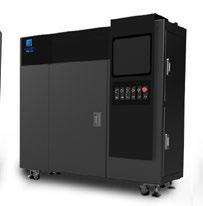
Affordable, state-of-the-art furnace designed as a total industry solution – not just for sinter-based AM, but also for PM, MIM, and other sectors that could benefit from a compact, highpurity vacuum furnace for combined debinding and sintering.
Breakthrough, patentpending furnace design features a vacuum retort and delivers parts-perbillion levels of purity
Heating elements and insulation are located outside vacuum retort so oxygen, water vapor, and binder cannot contaminate sintering environment
Ti-tested™, delivering better Ti6Al4V performance results for density, tensile strength, and elongation*
More than a dozen fans cool from 1,420°C to 200°C in <4H without watercooled walls
Airtight design and efficient cooling dramatically lower operating costs
Compact footprint and automated, vertical hood enables access to 15.8L retort

*With Ti6Al4V, the PureSinter furnace delivered higher part density — greater than 98% — than a popular, premium third-party vacuum furnace with much less power, in addition to other performance benefits. See complete PureSinter brochure for more details.
PureSinter delivers the highest quality sintered parts, on par or better than industrial furnaces with higher acquisition and operating costs. Even titanium can be easily sintered with a high degree of confidence without the complex preparations and getter materials required with other furnace. SINTERING INNOVATION
Download the brochure and see the video at teamdm.com/puresinter


26 14

63 Industrialising innovation: Discovering the future of MIM at Schunk Sintermetalltechnik GmbH
In Metal Injection Moulding, as in all manufacturing industries, business can either be won by competing to be the lowest-cost supplier amongst fierce global competition, or by offering the most innovative technologies for the most demanding applications.
Here, Dr Georg Schlieper reports from a recent visit to Germany’s Schunk Sintermetalltechnik GmbH, a company that has taken the latter path, setting itself the goal of being a leading supplier to the aerospace industry and, at the same time, offering its customers unique solutions for the next generation of MIM applications. >>>


77 A tooling expert’s ‘primer’ on Metal Injection Moulding: What technology newcomers need to know
Metal Injection Moulding often has an aura of mystery around it. Whilst those in the industry understand the technology well, there are many ‘on the outside’ who are more apprehensive.
In this article, Declan Coyle takes some of the mystery out of MIM technology in relation to tooling. Having gone through his own ‘MIM initiation’ process when tasked with developing the tooling for Apple’s Lightning connector in 2011, Coyle is wellpositioned to offer some practical ‘do and don’t’ suggestions from a tooling engineer’s perspective. >>>






in Greater China: MIM industry collaboration and a new applications centre with HP
If you were to place a bet on which country was going to take metal Binder Jetting to the highest volumes of commercial production, China would probably be high on your list. As the world’s manufacturing hub for consumer electronics, China already accounts for nearly half of global MIM sales by value. So with markets on the doorstep, and sintering capacity and metal powder supplies ready and waiting, where’s Binder Jetting in China? Here, Dr Q and Dr James report on developments, including a new Sintering Application Center at BJ–TECH Co. featuring HP’s Metal Jet technology. >>>
91
Industry insight from the 2024 International Conference on Injection Molding Metals, Ceramics and Carbides
MIM2024, the International Conference on Injection Molding of Metals, Ceramics, and Carbides, was held in Raleigh, North Carolina, from February 26 to 28, 2024.
Attended by more than a hundred delegates from ten countries, this latest event in the well-established series was deemed to be an innovative success. This year was – to the relief of both attendees and the Metal Powder Industries Federation (MPIF) – an in-person only event.
Dr Animesh Bose, CEO, Optimus Alloys, reviews some of the highlights from the technical programme. >>>
Discover the leading suppliers of materials and equipment for MIM, CIM and sinterbased AM, as well as part manufacturing partners and more. >>>
View a list of upcoming events for the MIM, CIM & sinter-based AM industries. >>>

The PIM International newsletter is sent to several thousand industry professionals worldwide. Register today to ensure you benefit from reading the latest industry news and advances in Metal Injection Moulding, Ceramic Injection Moulding and sinter-based AM technologies.
www.pim-international.com/e-newsletter



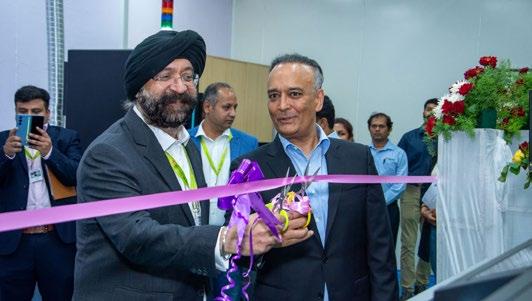
Indo-MIM, headquartered in Bangalore, India, has officially opened its new Additive Manufacturing production cell, acquired as part of its strategic partnership with HP.
Announced at last year’s Formnext exhibition, Indo-MIM has invested in three HP Metal Jet S100 Binder Jetting machines.
Krishna Chivukula Jr, CEO at Indo-MIM, and Savi Baveja, President at HP 3D Printing, inaugurated the new cell. Also celebrating the installation of the new Additive Manufacturing machines were Jagadish Holla, Senior Vice President of Sales and Marketing at Indo-MIM Limited, and Dr Shivashankar T S, Vice President of Operations at Indo-MIM.
Announcing the partnership last year, Baveja stated “We are proud to partner with Indo-MIM to create
new possibilities for their customers leveraging our S100 solution and metals Additive Manufacturing capabilities. We are thrilled to work with Indo-MIM to drive new metals applications, expand material possibilities and increase precision and productivity.”
Chivukula Jr also said at that time, “Our partnership with HP signifies a milestone in our journey to provide cutting-edge production ready 3D metal binder jet solutions to our customers. The acquisition of HP’s Metal Jet S100 printers equips us with the latest technology, enabling us to meet the growing demands of our customers with efficiency and precision, as well as expand the library of materials qualified on the HP printer platform.”
www.indo-mim.com
www.hp.com
Ecrimesa Group, headquartered in Santander, Spain, reports that the serial production of metal injection moulded parts has begun at Mimecri USA, the group’s new MIM facility in Thomasville, Georgia, USA. The US plant is now fully equipped to produce high-quality, complex MIM components for the automotive, aerospace, defence, and medical sectors.
Ecrimesa Group was the first company to develop the process of MIM manufacturing in a continuous furnace using catalytic debinding, in collaboration with BASF and Cremer Thermoprozessanlagen GmbH. Today, with four continuous lines for debinding and sintering and two vacuum batch lines for sintering, the company has processing capacity for more than 250 tons of feedstock per year and can produce more than 1.2 million parts every month.
Mimecri USA is backed with a complete metallurgical laboratory with skilled technicians who oversee various critical processes. In addition to managing the continuous controls of the melting process and heat treatments, they conduct X-Ray controls, digital tomography, fraction controls (hot and cold), digital image analysis, microstructure examination, corrosion controls, and non-destructive testing.
mimecriusa.com
ecrimesagroup.com
Greene Group Industries (GGI) Inc, a leading manufacturer of complex components via Metal Injection Moulding, headquartered in Oceanside, California, USA, has announced the acquisition of the

Greene Group Industries has acquired Holo and its PureForm AM technology (Courtesy Holo Inc)
assets of Holo, Inc, a producer of metal additively manufactured parts based in Newark, California, USA. Holo uses its patented PureForm AM technology for the rapid prototyping and scaled production of metal parts.
Willingham added, “PureForm Additive Manufacturing technology will strengthen our partnerships with customers by supporting faster iterations through the entire product life cycle, while GGI maintains its premium engineering service and quality performance.”
The terms of the transaction were not disclosed.
Alexis Willingham, GGI’s CEO, said, “Holo’s technology is a great addition to our comprehensive offering of Metal Injection Moulding, stamping and precision machining. This transaction enables GGI to deliver prototype metal parts, with a surface finish and feature resolution comparable to Metal Injection Moulding, in a best-in-class lead time of less than two weeks.” Holo’s PureForm Additive Manufacturing technology begins with a proprietary slurry of MIM powder and photoresistive polymer binder. Parts are built layer-bylayer with high resolution, high throughput optical printers developed by Holo. The resulting ‘green state’ parts are then sintered to remove all traces of binder, resulting in highly pure final parts with qualities approaching bulk material. Suitable materials in production or development include >99.9% copper, 316 and 17-4 stainless steels, CoCrMo ASTM F75, Ti-6Al-4V, Inconel 625, Hastelloy C22 and Al 2O 3
www.greenegroup.com www.holoam.com
The US has announced plans to exempt its AUKUS partners, Australia and the UK, from its International Traffic in Arms Regulations (ITAR). In addition, the US Commerce Department also announced an expansion of the scope of licence-free trade to AUKUS nations by amending the Export Administration Regulations on April 18, 2024.
The department cited the need “to enhance technological innovation among the three countries and support the goals of the AUKUS Trilateral Security Partnership”. This followed the US National Defense Authorization Act (NDAA), which was passed in December 2023. The NDAA set specific criteria for the Australian and British governments to meet before the exemptions took effect.
These reforms are expected to significantly reduce licensing
requirements for the UK and Australia as well as facilitate public and private sector security institutions’ delivery of a more integrated defence industrial base.
While the specific parameters have not been announced, the new exemptions that will remove licensing requirements for ‘most military goods and technology items’ are expected to reduce the burden associated with US export licenses for dual-use goods to Australia worth almost $2 billion (AU $3.1 billion). This appears to include both Pillar I submarine components and Pillar II advanced technologies.
The Australian government responded with its law in March of this year, offering an exemption for the UK and US from export control permit requirements. This exemption is expected to take effect in September 2024.
Similarly, the UK will release its Open General Export Licence in September 2024 to implement the exemption for Australia and the US.
These US reforms are occurring as the AUKUS roadmap progresses, with news that British company Rolls-Royce has started producing components for the nuclear reactor to be installed in the first SSN-A, a nuclear-powered attack submarine.
However, the UK Ministry of Defence (MoD) noted that, despite reaching the 120-day milestone set by the NDAA, the UK is in the process of finalising the remaining technical steps in order to benefit from the NDAA provisions.
“We are confident that by the next 120-day period we will have completed all the requirements for full implementation of the ITAR exemptions,” said the UK MoD in a release welcoming the reforms. www.gov.uk www.defense.gov www.defence.gov.au
Experience the power of performance, the spark of innovation, and the strength of partnership
Performance:
As a global leader in powders, pastes, and granules, we excel in materials like Aluminum, Copper, Titanium, and more. Our precision manufacturing ensures superior product attributes tailored to your requirements.
Innovation:
Utilizing state-of-the-art research and development alongside cutting-edge technologies, we provide tailored solutions for PM and additive manufacturing. Our emphasis on materials and process advancements positions us as industry leaders in quality, service, and operational excellence.
Partnership:
Count on us as your trusted development and production ally. Our expertise in metal powders and alloys ensures top-tier materials for critical applications, empowering industries worldwide.
At Kymera International, we’re not just a powder provider; we’re your strategic partner in the world of specialty material solutions and additive manufacturing. Contact us today to revolutionize your projects
www.kymerainternational.com
info@kymerainternational.com
Dowlais Group plc has announced Jean-Marc Durbuis as the new Chief Executive Officer of GKN Powder Metallurgy. Durbuis joined the company on March 12, following the departure of Diego Laurent who served GKN for thirty-one years.
GKN Powder Metallurgy is a leading provider of powder metal materials, components, applications, and electrification solutions
through its three business units
GKN Powders/Hoeganaes, GKN Sinter Metals and GKN Additive.
“I want to thank Diego for his thirty-one years at GKN. He has achieved so much during this time at both GKN Powder Metallurgy and GKN Automotive. I am particularly grateful for all he has done to maintain GKN Powder Metallurgy’s position as one of the world’s

A report published by PwC, London, UK, titled ‘Climate Risks to Nine Key Commodities: Protecting People and Prosperity,’ has stressed that CEOs’ need to accelerate action plans to safeguard the production of critical commodities, as heat stress and drought risk rise globally. The report, which analysed nine commodities across critical minerals (copper, cobalt, lithium), key crops (wheat, rice, maize) and vital metals (zinc, iron, aluminium), found that although reducing emissions will decrease heat and drought risks, key commodities will still face significant stress, even under a low emissions scenario. According to the report, by 2050, even if the world sharply reduces its carbon emissions, over 70% of cobalt
and lithium production could face significant, high, or extreme drought risk – up from near zero today. Less than 10% of copper production faces significant or greater drought risk today, rising to over half in a 2050 low-emissions scenario and over 70% in a high-emissions scenario. Cobalt, copper and lithium are integral to electronics and clean-energy technologies.
PwC research also found that vital metals face increasing amounts of risk. In particular, over 60% of the world’s bauxite and iron production may face significant or greater heat stress risk by 2050, even in a low-emission scenario (up from 30-50% currently). In a high-emission scenario in 2050, 40% of the world’s
leading suppliers of powder metal materials and sintered metal components,” stated Liam Butterworth, CEO of Dowlais Group Plc.
Over the past twenty years, Durbuis has held several senior executive positions in the chemical sector, leading global teams in complex and demanding businesses. He has a proven track record across all operational functions and has been a member of several executive committees and boards. He joins GKN Powder Metallurgy from Allnex, a global supplier of resins and additives to the coating and inks industry, where he was the Executive Vice President of one of Allnex’s global divisions and was a member of the Allnex Executive Committee and Board of Directors.
Durbuis added, “I am delighted to be joining GKN Powder Metallurgy as its new CEO. It is a world-class business and will play a vital role in introducing new products to market, as we navigate the transition to EVs. I look forward to working with the team and meeting my new colleagues across the globe.”
www.gknpm.com
zinc production may face significant or greater drought risk (up from zero significant drought risk currently). Aluminium (from bauxite), iron and zinc are widely used in manufacturing, transport, and infrastructure.
Production of all nine critical commodities is also concentrated in a limited number of countries – many of which face increasing climate risks. For each resource, at least 40% – and as much as 85% – of its global supply is produced from a distinct set of no more than three countries.
Companies and CEOs are increasingly recognising the impact of climate disruption and taking action. Already, 47% of CEOs have taken proactive measures to safeguard their workforces and physical assets from climate change, according to PwC’s 2024 Annual Global CEO Survey. However, more needs to be done if the global economy is to adapt to climate risk, the report is keen to stress www.pwc.com
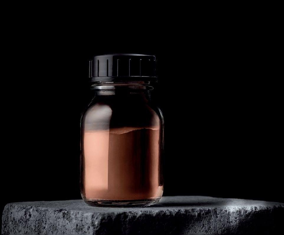
We’ve expanded our webshop selection of premium-quality titanium, maraging steel, nickel-based superalloys, and stainless steels to include Osprey® C18150. This new copper-based metal powder for additive manufacturing is tailored for excellent conductivity and strength at high temperatures. The checkout process is simple, and we accept credit card payments. Just add to cart at any time, and we’ll ship within 48 hours.
EASYMFG, based in Wuhan, China, has expanded its range of metal Binder Jetting (BJT) Additive Manufacturing machines with the launch of the M550Max and M150Inno. The lineup now includes three models, with the M550Max targeted at medium to large-sized parts, the M400Pro for small-scale production and the new entry-level M150Inno aimed at R&D applications.
Founded in 2013, EASYMFG is one of China’s earliest adopters of Binder Jetting technology. In addition to metal, it offers sand and full-colour BJT machines.
M550Max
This flagship M550Max is designed to efficiently produce medium and large-sized parts. The machine has a build chamber of 550 x 370 x 200 mm with the layer height adjustable from 30 to 200 µm, and offers a maximum build rate of up to 2,442 cm 3/hour.
The new M550Max features 9,600 nozzles arranged across a width of 350mm, with a resolution of 600 NPI. With the capability to simultaneously deposit 3.3 pl droplets, the M550Max achieves a single-layer printing time of 12 seconds while maintaining surface quality and precision.
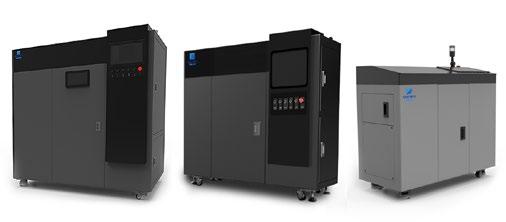
EASYMFG now offers three metal Binder Jetting Additive Manufacturing machines. L-R M550Max, M400Pro and M150Inno (Courtesy EASYMFG)
SINTX Technologies, Inc, Salt Lake City, Utah, USA, and Prodways Printers SAS have announced a deep technical partnership and ceramic slurry supply agreement. SINTX and its subsidiary Technology Assessment and Transfer, Inc, will supply ceramic-filled, additively manufacturable slurries to Prodways and will assist in process development and customer support. The scope of collaboration will allow an end-to-end workflow collaboration on advanced technical ceramics, including, in particular, casting applications.
Prodways looks to leverage SINTX’s silica and alumina-qualified
slurries on the latest MovingLight machine generation, specifically developed for the demanding requirement of ceramic application. In particular, the machine will provide a unique combination of high resolution and build envelope while maintaining process scalability with flexible build envelope configuration and process-oriented parameters control.
Ann Kutsch, General Manager of the SINTX-Maryland site, commented, “Our outstanding engineering team has six years of experience working with Prodways printers, and we have already used
Moreover, it can produce green parts with a density exceeding 60%, leading to a post-sintering density of up to 99% for stainless steel components.
The M550Max can process a wide range of metals, including titanium alloy, tools steel, copper, stainless steel, and more.
The M400 Pro was launched in 2023 and is specifically designed for the rapid production of small-scale production-grade parts. It offers fast and reliable manufacturing capabilities, catering to the needs of medium-sized products.
The machine has a build chamber of 400 x 250 x 200 mm, a maximum build rate of 1,440 cm 3/hour and an adjustable layer height ranging from 40 to 200 µ m.
M150Inno
The M150Inno is an entry-level model for metal Binder Jetting designed to cater to the research and development needs of universities and institutions.
This machine offers a build chamber of 150 x 70 x 70 mm and has a build rate of 189 cm 3/hour. It also has an adjustable layer height ranging from 40-200 µ m. www.easymfg3d.com
their equipment to commercialise multiple resin compositions and part designs. I expect that a more formal partnership will lead to some breakthrough developments and novel solutions for all our customers.”
Vincent Icart, CTO and COO of Prodways, added, “Prodways has had a very early exposure to ceramics 3D printing. Before this partnership, we were only supplying customers with internal capabilities development. We are thrilled to bolster our specifically developed MovingLight machineries with SINTX slurries, as our joint expertise will allow us to be an end-to-end solution provider for the most demanding ceramic printing applications.”
www.prodways-group.com
www.sintx.com
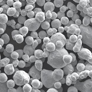
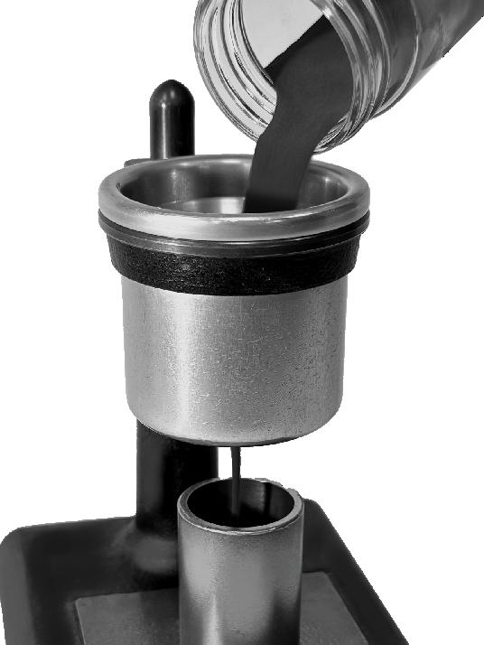


These two binder systems have excellent characteristics during the production process and combine attractive prices with worldwide availability
High performance as well for the 3D-Printing process based on the water soluble binder system


Masan High-Tech (MHT) Materials Group, headquartered in Ho Chi Minh City, Vietnam, parent company of H C Starck Tungsten, has signed a framework agreement with Mitsubishi Materials Corporation Group (MMC), Tokyo, Japan, for the sale of all shares in HC Starck Holding GmbH. MMC, which operates its own site for the recovery and processing of tungsten as well as the manufacturing of tungsten-based tools, is a long-standing customer of the Goslar-based company. It acquired a 10% stake in MHT in 2020, shortly after the latter took over HCS from the former HC Stark Group. As a result of the Acquisition, MMC Group will have tungsten operations in four major markets: Japan, Europe, North America and China.
MMC stated that Japan New Metals Co., Ltd (a wholly owned subsidiary of MMC) and HC Starck
will work together to create synergies and increase corporate value by strengthening R&D capabilities and promoting cross-selling, as well as developing a global tungsten recycling business.
Dr Hady Seyeda, CEO of HCS, stated, “We know Mitsubishi Materials very well as a customer and investor. Their extensive activities in Japan and our own global presence complement each other perfectly.”
www.masanhightechmaterials.com www.mmc.co.jp
www.hcstarck.com

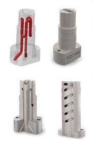
Indo-MIM, headquartered in Bangalore, India, reports that it is using metal Binder Jetting (BJT) to produce M2-grade tool inserts for its Metal Injection Moulding business. After exploring various Additive Manufacturing methods, the company adopted the BJT process in mid-2022 and has since produced over 800 inserts.
Tool inserts have been additively manufactured using laser-based Powder Bed Fusion (PBF-LB) for over a decade, explained Jagadish Holla, Sr VP-Marketing at Indo-MIM. However, the process can be relatively slow and it is only possible to use Maraging Steel for tool insert applications. “This material can, at best, get to 55 HRC post heat treatment, making it unfavourable for many tooling applications.”
“Given our material development and sintering expertise, fine-tuned
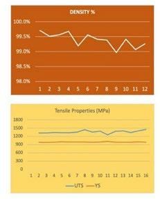
over twenty-five plus years, our M2-grade material offers 50-80% increase in wear resistance, 40% better machinability compared to conventional wrought M2 material,” added Holla. “These are accomplished through finer grain microstructure and 99% minimum
density post sintering. Our M2 material can guarantee 63-66 HRC hardness consistently.”
Indo-MIM can use BJT to build tool inserts weighing between 300 g and 8 kg, all to near-net shape and including complex conformal cooling channels. As well as producing these for in-house use, the company also offers the production of tool inserts as a service to its customers.
www.indo-mim.com
Binder Jetting allows for the inclusion of complex conformal cooling channels, as well as offering improved mechanical performance (Courtesy Indo-MIM)
A new online metal powder marketplace has been established by qualloy, a Düsseldorf, Germanybased intermediary for buyers and sellers in the metal powder market. The platform is designed to transform the way businesses procure metal powders for Additive Manufacturing and related applications by providing full transparency on prices and delivery terms. It is expected to enable users to make informed decisions quickly.
“Our team at qualloy is dedicated to driving innovation in the Additive Manufacturing industry,” stated Yannik Wilkens, co-founder of qualloy. “With the launch of our marketplace, we are empowering businesses to access a diverse range of high-quality metal powders with ease and efficiency.”
The qualloy marketplace offers a range of features designed to enhance the sourcing experience for users, including advanced search algorithms, transparent pricing, and detailed product specifications. Additionally, qualloy’s team is on hand to provide guidance and support throughout the procurement process. The marketplace will connect customers with globally certified powder suppliers by way of a variety of filtering options, including application, base material, atomisation process, and particle size distribution. This is intended to allow users to find the most suitable metal powder for their requirements with ease. As soon as powders are in the shopping basket, the purchase can be confirmed with one click. The marketplace’s interface and clear

qualloy has launched an online metal powder marketplace (Courtesy qualloy)
categorisation of products is an effort to simplify navigation, making the sourcing process effortless.
“We believe that our marketplace will not only simplify metal powder sourcing but also accelerate the adoption of Additive Manufacturing technologies,” added Wilkens. www.qualloy.com


Desktop Metal, Inc, headquartered in Burlington, Massachusetts, USA, has announced its financial results for the fourth quarter and full year ended December 31, 2023. For the full year, the company reported record recurring revenue of $65 million, a 29% increase over the prior year that now represents 34% of revenue, up from 24% in 2022.
“Despite a challenging capital investment environment led by elevated interest rates and slower sales cycles, I’m proud that Team DM buckled down and delivered a much-improved operating performance including reduced net loss and a record adjusted EBITDA performance,” said Ric Fulop, founder and CEO of Desktop Metal.
“While we didn’t make our internal target of A-EBITDA positive by the end of the year, as some customer projects rolled into 2024, we are now very, very close to that goal,” he continued. “We now enter the year with a lower cost structure that makes us resilient for the long term. The hard work will continue as we drive toward profitability, a goal that is clearly within sight despite the tough market conditions.”
Fulop noted that Desktop Metal continues to see strong demand for production Binder Jetting AM machines. “Our all-time high recurring revenue levels prove that customers who have adopted our technology are using it successfully and getting great value from our technologies,” he said.
Revenue for Q4 2023 was at $52.3 million, down from $60.6 million in the same quarter a year ago, and up 22% sequentially over the prior quarter. GAAP gross margin was 32%, negatively impacted by restructuring activities in the quarter. Non-GAAP gross margin was 34%, a year-overyear increase of 39.9%.
www.desktopmetal.com
Seco/Warwick has reported it is opening a sales and service office in Monterrey, Mexico. As Mexico’s second-largest city, Monterrey is convenient for road, rail, and air transportation, and close to Gulf Coast ports and US points of entry.
As one of Mexico’s hubs focused on steel production, the region is also a major manufacturing centre.
The Mexico office will also take on aftermarket support for customers throughout Latin America. “We’ve always had furnaces and heat treat Partners to support, from Mexico down to Chile. That demand has grown to the point that it is time to open a base of operations dedicated to that market,” stated Sławomir Woźniak, Seco/Warwick Group’s CEO. www.secowarwick.com

Over 6,500 production and laboratory furnaces manufactured since 1954

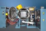


• Metal or graphite hot zones
• Processes all binders and feedstocks
• Sizes from 8.5 to 340 liters (0.3–12 cu ft.)
• Pressures from 10-6 torr to 750 torr
• Vacuum, Ar, N2 and H2
• Max possible temperature 3,500°C (6,332°F)
• Worldwide field service, rebuilds and parts for all makes
Legor Group SPA, headquartered in Vicenza, Italy, is a manufacturer of premium metal alloys, plating solutions and precious metal powders catering to the jewellery, luxury goods and fashion sectors. With the launch of its new 3D Metal Jet Printing Service, the company is promoting a new way of creating jewellery and fashion accessories by exploiting the full potential of metal Additive Manufacturing.
The 3D Metal Jet Printing Service is part of the Legor’s 3D Metal Hub, a division launched two years ago whose goal is to experiment and produce jewellery, fashion, and industrial components using metal Binder Jetting (BJT) Additive Manufacturing technology.
Partnering with HP Metal Jet
Through collaboration with HP, Legor is reported to be the first Italian company to introduce its Metal Jet technology for full-scale production. This provides an exclusive Additive Manufacturing service for developing new solutions in a variety of sectors, from the jewellery and fashion industry – Legor’s core business – to potential applications in the automotive, aerospace, and electronics industries.
Legor believes that its 3D Metal Jet Printing Service could benefit the entire manufacturing sector. Applications include rapid prototyping, the production of complex geometrical parts, the reduction of material waste and related costs, and the ability to manufacture parts with different functions in a single object, thereby reducing assembly needs. It also offers cost savings for complex parts or low volumes and promotes greater sustainability.
Powder production
In anticipation of further widespread adoption of Additive Manufacturing in the jewellery and fashion sectors, Legor has developed its own range of metal powders under the Powmet brand. The range of certified metal powders is reported to be produced using an exclusive atomising process that enables perfectly spherical, extra-fine and homogeneous particles to be obtained, featuring uniform chemical composition and low levels of impurities.
Currently, Legor can produce parts in steel (316L, Panacea nickel-free, 17-4 PH), bronze, silver (925) and platinum (950). The company’s next step will be Additive Manufacturing with 18-carat gold.
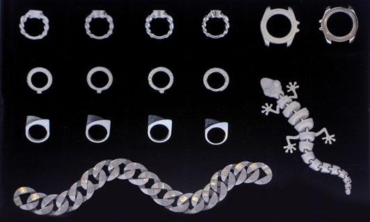

Legor has adopted HP Metal Jet Binder Jetting for its Additive Manufacturing (Courtesy Legor)
In addition to the production opportunities in terms of agility and sustainability, the intent of the 3D Metal Jet Printing Service is to encourage more players in the manufacturing sector to rethink the entire production process, revolutionising it in every single phase, both in the realisation of objects and in the concept, design, and aesthetic enhancement possibilities.
Thanks to Additive Manufacturing, designers, first and foremost, can create objects that are currently not even possible to produce with other technologies, thus expanding the boundaries of creativity. In this sense, Legor has promoted its ‘Beyond Extraordinary’ concept – an invitation to think beyond the ordinary, outside the box, to shape the future through innovative methodology within an increasingly dynamic and evolving market. The company is spreading this message through numerous webinars and workshops aimed at the manufacturing sector. Through the 3D Metal Jet Printing Service and showcasing the potential of AM, Legor explains that it is positioning itself as a catalyst for innovation in the jewellery and fashion accessory sector. It sees its role as being able to facilitate the integration of cutting-edge technology with the artistic and creative vision of designers, bringing exceptional and personalised metal products to the market. www.legor.com

Japan’s Kyocera Corporation has secured a place on the ‘A List 2023’ for outstanding environmental transparency and achievements in the fight against climate change. Awarded by the international nonprofit organisation CDP (Carbon Disclosure Project), the list includes fewer than 400 companies globally and is said to recognise Kyocera’s ongoing efforts to be a leader in environmental disclosure and to actively shape a sustainable future.
A direct consequence of this recognition is Kyocera’s repeated classification as a Supplier Engagement Leader by CDP. For the fifth consecutive year, the award recognises Kyocera’s comprehen -
sive strategy to reduce greenhouse gas emissions throughout its supply chain. By aiming to reduce emissions by 46% by fiscal year 2031 compared to 2020 and increasing the use of renewable energy by 20x (compared to 2014), Kyocera is said to be committed to taking significant steps towards climate neutrality by 2051 and supporting the global effort to limit global warming to below 1.5°C.
The company has also been named to Clarivate‘s Top 100 Global Innovators 2024 list for the eighth consecutive year. Kyocera stated that these awards are also considered an incentive to continue to be at the forefront of techno -
3DCeram, based in Sinto, BonnacLa-Côte, France, has introduced CERIA Set, its Artificial Intelligence software designed to enhance users’ manufacturing processes. CERIA Set offers three main features: assistance with part conception and precise placement within the tank, thorough analysis of the final tank configuration for optimal results as well as tailored and optimised scraping parameters to ensure flawless builds.
CERIA Set was developed in-house by 3DCeram’s teams and artificial
intelligence experts. It is intended to complement its two other software products: Build-It and CPS 2.0.
Reduced waste and simplified manufacturing experience
CERIA Set is intended to eliminate complexity and reduce the error rate in builds by anticipating part design faults in its geometric structure. It also enables users to comply with the design rules inherent in Additive Manufacturing. CERIA Set also assists users in the design of

CERIA Set offers three main features: assistance with part conception and precise placement within the tank, thorough analysis of the final tank configuration and tailored, optimised scraping parameters (Courtesy 3DCeram)

Kyocera manufactures cutting tools for a wide range of industries (Courtesy Kyocera)
logical progress and environmental protection.
In addition to a broad product portfolio, Kyocera manufactures Powder Metallurgy cutting tools for a wide range of industries. www.global.kyocera.com
manufacturing tanks, highlighting the spaces to be occupied, the layout of parts, etc. CERIA Set’s functions and user-friendly interface are intended to make the manufacturing process smooth and efficient.
CERIA BB Set analyses build files to identify potential problems (empty spaces, sizing errors, etc.) that could hinder the manufacturing cycle. In this way, users can save both material and time while increasing the success rate.
CERIA’s functionality
After downloading the build files, CERIA Set performs an analysis that highlights areas for improvement. With simple messages and recommendations, CERIA Set guides users to optimised manufacturing results.
CERIA Set also detects empty spaces, enabling the efficient use of materials and minimising waste. Users can check the progress of their part layer-by-layer, thanks to CERIA Set’s intuitive colour-coding system. Visual cues are intended to simplify the building process, from design to completion. White represents the part, yellow the fixed slurry zones and red potential slurry leaks. www.3dceram.com

Then we could be your match.
With our materials experts, you are in the best of hands. Not only are we passionate of what we are doing, we also bring 30 years of experience in metal powder injection molding to the table.
Your vision is our incentive.
Materials and solutions from Schunk are advancing industries all over the world.
As an expert manufacturer of complex MIM components, we stand for exceptional service, the highest quality and enthusiasm for what we do. In close cooperation with you, we develop innovative and customized solutions for your business.

Rely on our expertise in molding processes such as
> metal injection molding
> graphite injection molding
> axial pressing
EN9100, IATF16949, ISO9001, ISO14001, ISO 50001 certified
Feel free to challenge us.

Schunk Sintermetalltechnik GmbH

Roßtrappenstraße 62 06502 Thale, Germany
+49 3947 7 1560
At thorsten.klein@schunk-group.com schunk-mobility.com


Malvern Panalytical, part of Spectris plc, Egham, Surrey, UK, has announced the launch of the Mastersizer 3000+, its new laser diffraction particle sizing instrument. The Mastersizer 3000+ uses integrated artificial intelligence (AI) and data-sciencedriven software solutions for method development support, data quality feedback, instrument monitoring, and troubleshooting advice.
Size Sure is a new feature which looks more deeply into each sample, analysing both its steady and transient states and ensuring the reproducible measurement of sample size distribution while providing more insight into other factors, including contaminants.
Obtaining the highest quality data starts with developing the right analytical method. SOP Architect, fuelled by machine learning algorithms, is intended to build the best possible method for each sample and provides a guided workflow. Embedded data quality guidance, based on Malvern Panalytical’s advice, looks to flag any issues as soon as they occur, enabling users to


Malvern Panalytical’s new Mastersizer 3000+ laser diffraction particle sizing instrument (Courtesy Malvern Panalytical)
correct their course and move on. Both features aim to help deliver data more quickly and simply than before, regardless of the user’s experience level. In addition, method transfer between the Mastersizer 3000 and Mastersizer 3000+ is equally straightforward.
Smart Manager connectivity reportedly delivers pre-emptive advice on any maintenance requirements, including part failure and replacement, allowing each instrument runs optimally and minimising any analytical downtime.
As an evolution of the Mastersizer 3000, all the advances incorporated in the new Mastersizer 3000+ platform are designed to appeal to both experienced laser diffraction particle size analysts and new users alike, in industries ranging from mining to battery manufacture, Additive Manufacturing and pharmaceutical quality control.
Paul Senior, Micromaterials Product Manager, Malvern Panalytical, shared, “We had a challenging task to improve upon our own market-leading laser diffraction instrument, the Mastersizer 3000! But we have made significant leaps forward, especially in the Mastersizer 3000+ software where we’re thrilled to bring our customers an even smarter way to measure particle size. I’m particularly excited to see how the Mastersizer 3000+’s use of cutting-edge, integrated AI will simplify the route to achieve best-quality particle size data, positively impacting product research, development and manufacturing across the world.”

Mark Fleiner, President, Malvern Panalytical, added, “I’m delighted to see the launch of the Mastersizer 3000+ as the worthy successor to the most popular and best-trusted particle size analysis system in the world! At Malvern Panalytical, we strive for continuous improvement and innovation, and we’re committed to supporting and enabling our customers across the globe. With the AI and data science embedded in the new Mastersizer 3000+, we’re excited to see the positive impact on our customers’ workflows, releasing their time to continue making our world cleaner, healthier and more productive.”
www.malvernpanalytical.com
Markforged Holding Corporation, headquartered in Watertown, Massachusetts, USA, announced that, on April 11, 2024, the jury in the US District Court for the District of Delaware awarded Continuous Composites Inc, Coeur d’Alene, Idaho, $17.34 million in monetary damages against wholly-owned subsidiary Markforged Inc.
In July 2021, Continuous Composites filed a patent-infringement lawsuit against the company. While the jury found one of the two patent claims Continuous Composites asserted at trial against the company to be invalid and not infringed, they found that Markforged had infringed the other patent claim and awarded monetary damages.
While the company reports that it cannot predict what additional action Continuous Composites may take, it is possible that Continuous Composites may seek additional relief through post-trial motions for royalty payments on future revenue, which could materially impact the Markforged’s business and operations.
Markforged reportedly disagrees with this verdict and intends to seek to overturn the verdict in post-trial motions with the District Court. The company is said to be exploring all available options, including seeking to overturn the verdict and any resulting judgment through the appeals process.
While the company is currently assessing the verdict’s impact on its business, given its current balance sheet, effective cost controls and new product line, it intends to remain focused on the future of the company and its ability to drive the adoption of Additive Manufacturing on the factory floor.
www.continuouscomposites.com www.markforged.com
CMG Technologies, Woodbridge, Suffolk, UK, has promoted Rob Kirk to the position of General Manager. Kirk joined CMG in September 2022 as Operations Manager, bringing a wide range of management skills from various fields, along with engineering experience in the telecoms and automotive industries.
“Taking on this new role feels great. I’m really excited,” Kirk shared. “What we have here is unlike any other business I have worked at before. We have so many talented people here who are supportive of one another. It is key to what we do and is why we’re so successful.”
Rachel Garrett, Managing Director, stated, “We would not have experienced such fantastic growth were it not for his efforts. We look forward to seeing him continue to thrive in his new role.”
www.cmgtechnologies.co.uk


Desktop Metal, Inc, headquartered in Burlington, Massachusetts, USA, has announced the launch of a Reactive Safety Kit for its Production System P-1 metal Binder Jetting (BJT) Additive Manufacturing machine. The P-1 is capable of processing 17 metals, but the Reactive Safety Kit is required for the Additive Manufacturing of titanium and aluminium.
Reported to be in development and testing for more than two years, the P-1 Reactive Safety Kit features ATEX-rated components, as well as critical hardware and software updates to ensure the highest level of safety. ATEX certification is given to equipment that has undergone rigorous testing outlined by European Union directives and is considered safe to use in specific environments with explosive atmospheres.
“Titanium and aluminium are two of the most frequently-requested materials at Desktop Metal, and we’re proud to say that we can now
offer a commercial 3D printer with the necessary safety features to binder jet 3D print these materials,” stated Ric Fulop, founder and CEO of Desktop Metal. “Based on our ongoing projects with major manufacturers, we know our technology is well on its way to unlocking new designs that deliver higher performance, weight reductions, and other benefits – all with our high-speed 3D printing technology that makes Additive Manufacturing more affordable for production volumes. We are diligently following our roadmap to deliver high-volume production of these materials on our largest printers in the future.”
A number of Desktop Metal’s customers are already Binder Jetting titanium and aluminium. “Our team at TriTech has found Binder Jetting to be a good complement to our Metal Injection Moulding business,” said Robert Swenson, owner of TriTech and also the former owner of AmeriTi. “With binder jet 3D printing, titanium production of even
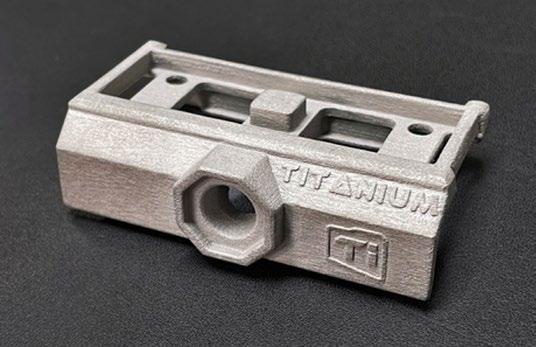
Users can now additively manufacture titanium alloy Ti6Al4V parts, such as the one shown here made by TriTech Titanium Parts LLC, on Desktop Metal’s Production System P-1 using the Reactive Safety Kit (Courtesy Desktop Metal)
the most complex geometries can be greatly simplified and achieved at a lower cost. We’re excited to offer this cutting-edge manufacturing technology to our customers.”
Additionally, Desktop Metal has several projects in development with manufacturers using a variety of speciality materials developed by Kymera International, including titanium and aluminium. “Since formalising our partnership in 2021 through a Joint Development Agreement, we have been excited to work closely with Desktop Metal to develop a range of metal powder solutions optimised for the Binder Jetting process,” said Joe Croteau, Technology Manager – Specialty Materials with Kymera.
A global supplier of specialty materials and surface technologies, Kymera International has contributed decades of metallurgical expertise and process knowledge to offer sintered aluminium alloys with excellent performance.
“Kymera’s well-established relationships with a diverse group of customers has given us the opportunity to focus on the needs of high-volume manufacturers, and we are proud to now have a commercially-established solution. Over the past two years, we’ve successfully printed a variety of aluminium geometries and part sizes through multiple programmes.”
The production System P-1 is qualified to additively manufacture seventeen metals, including stainless steels, low-alloy steels, copper alloys, tool steels, nickel-based alloys, precious metals, and more.
With this announcement, titanium (Ti6Al4V) is now classified as Customer-Qualified on both the P-1 and X-Series models when upgraded with an inert atmosphere and other safety features. Aluminium is also now classified as Customer-Qualified on the X-Series and R&D Qualified on the P-1 when upgraded with an inert atmosphere and other safety features.
www.desktopmetal.com

Arburg GmbH + Co KG, headquartered in Lossburg, Germany, has announced it will make changes to its management team over the course of 2024.
The company stated that Steffen Kroner will take charge of the Finance, Controlling, IT and Human Resource Management division in July. Gerhard Böhm, Managing Director Sales and After Sales, will retire this year, with his successor already appointed but not named at this time.
At the end of 2023, the management team underwent changes that led to the establishment of the new Finance, Controlling, IT and Human Resource Management division: Renate Keinath, who had been responsible for Human Resource Management as Managing Partner since 2005,
retired from operational business at the end of the year and is now a member of the newly created Advisory Board. In addition, Jürgen Boll, Managing Director Finance, Controlling, IT, retired at the end of 2023.
Kroner was most recently Commercial Director of the Liebherr Tower Crane Division and the Liebherr plant in Biberach and has international expertise, many years of management experience and extensive knowledge of business administration issues.
Gerhard Böhm‘s already-appointed successor will take up the position of Managing Director on October 1 at the latest. Until then, Böhm, who has been responsible for Sales and After Sales as Managing Director since 2016, will be familiarising his successor with the role.
In a separate announcement, Arburg also reported it has appointed Mitchell Yang as Managing Director of its subsidiary in Taichung, Taiwan. Yang has taken over from Michael Huang, who successfully established the subsidiary in 2015 and had built a strong, competent local team.
Yang holds a Bachelor’s degree in Electronic Engineering and an Executive MBA. He also brings extensive management and sales experience to his new job.
The Taiwanese market is seen as an important one for Arburg. As a leading centre for the production of electronic semiconductors, the country offers mechanical engineering and injection moulding experts a wide range of market opportunities. Industries such as 3C electronics (computers, consumer electronics and communication), sporting goods and medical technology are all developing at a rapid pace in the country. www.arburg.com


Lithoz GmbH, based in Vienna, Austria, showcased its global Ceramic 3D Factory network at this year’s ceramitec exhibition in Munich, Germany, April 9-12. In addition to the Ceramic 3D Factory, Lithoz also launched its CeraControl software and gave live demonstrations of its CeraFab System S65.
The establishment of the Ceramic 3D Factory is designed to connect Lithoz technology and contract manufacturers all over the world, in one global network for interconnected serial production.
The company’s new CeraControl software allows for up to 100 globally-interconnected CeraFab S65 3D ceramic Additive Manufacturing machines.
Visitors to the exhibition were also able to witness the company’s entry-level CeraFab Lab L30 in action at the Almatis booth, a customer of Lithoz. The two companies have enjoyed a successful partnership for over a decade, with Almatis providing high-quality 99.8% thermally reactive alumina powder for aerospace, healthcare, and engineering applications.
Reflecting the growing interest in additively manufactured healthcare applications in recent years, bioresorbable ceramic implants made of hydroxyapatite were also on show, as well as multi-material medical parts combining various bioresorbable ceramic materials.
More insight into these medical applications was presented by Dr Daniel Bomze, Director Medical Solutions at Lithoz. In his conference presentation, Dr Bomze discussed ‘How patients and medical professionals benefit from ceramic 3D printing.’ www.lithoz.com
Digital Metal AB, based in Höganäs, Skåne County, Sweden, has officially changed its name to Markforged Sweden AB, effective from April 18, 2024. Digital Metal, acquired by Markforged in 2022, uses a proprietary Binder Jetting Additive
Manufacturing technology that enables intricate, detailed parts to be manufactured in high volumes, whether identical or of custom design.
The decision to change the company name is intended to strengthen the brand’s identity and position it for continued success. Markforged added that no additional changes have been made to the company following the official renaming.
www.markforged.com
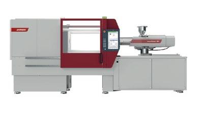
EcoPower & SmartPower Energy-efficient injection molding

Teibow Co Ltd, Hamamatsu City, Japan, has received a bronze EcoVadis Sustainability Rating. This accomplishment places Teibow among the top 35% of rated companies and reflects the quality of the sustainability management system, as well as the company’s commitment to fostering transparency throughout the value chain.
EcoVadis is an organisation that evaluates the sustainability of more than 130,000 companies in 220 industries and 180 countries around the world. Its sustainability evaluation focuses on the themes of environment, labour & human rights, ethics, and sustainable procurement. The award is evaluated based on global sustainability standards.
Teibow commenced manufacturing and selling metal parts by Metal Injection Moulding in 1994. In addition to MIM, the company manufactures a range of writing instruments and cosmetic brushes. On announcing the award, Teibow stated that it “will continue to focus on sustainability initiatives, aiming to realise a prosperous society through porous and MIM technology.”
www.teibow.co.jp | www.ecovadis.com
Arc Completa’s
Arc Completa, Inc, headquartered in Waltham, Massachusetts, USA, has established Four Nines Metals, a company offering a range of metals including highpurity copper powder.
The ultra fine copper powder is reported to be 99.9998% pure. The product line also includes nickel wire (99.76% pure), aluminium ingots (98.7% pure), platinum (99.95% pure), and lithium (99.5% pure). Certifications are provided by Institut fur settene Erden und Metalle e.V. (ISE) 2020 and Independent Global Assaying Services (IGAS) 2018.
“We are excited to offer these high-purity metals to the marketplace,” shared Gary Ainsworth, president of Arc Completa. “We know there is heavy demand for quality materials and a sustainable supply, and Arc Completa can facilitate access to these material at a discount. Our team of experts is always available to help guide customers through quality certs, purchasing, and logistics to reliably receive their materials. The website is another tool for users to easily obtain information about our metals and other services.”
www.fourninesmetals.com | www.arccompleta.com

Lithoz GmbH, based in Vienna, Austria, has joined the UK’s Manufacturing Technology Centre (MTC) to drive ceramic Additive Manufacturing for industrial end users. Through Lithoz’s membership, the MTC will extend its range of Additive Manufacturing options to push the boundaries of ceramic AM across sectors including power and energy and defence.
Using Lithoz’s CeraFab Additive Manufacturing machine, MTC engineers will be able to process a variety of high-performance ceramics, enhancing the MTC’s capability to design and manufacture complex ceramic geometries.
Lithoz CEO, Dr Johannes Homa, stated, “We are very excited to be a part of the MTC community! There is certainly a very active and inspiring ceramic industry to be seen in the UK, as well as a strong 3D printing hub – we look forward to shaping the latest ceramic innovations being achieved by experts at the MTC using the industry-leading Lithoz CeraFab S65 3D printer technology.”
www.lithoz.com
Kennametal Inc, based in Pittsburgh, Pennsylvania, USA, has announced that Sanjay Chowbey, currently VP of Kennametal Inc. and president of Metal Cutting Segment, will succeed Christopher Rossi as president and CEO. Rossi has decided to retire from the company after nearly seven years, effective May 31, 2024.
“On behalf of the entire Board, I want to thank Chris for his many contributions to Kennametal and congratulate Sanjay on his welldeserved appointment as CEO,” said William M Lambert, Chairman of the Board. “Chris is leaving the company better than he found it, having successfully executed the company’s Simplification/Modernisation strategy, which improved the efficiency and customer service level of its factories while enabling the manufacturing of new product inno -
vations. In addition, Chris led the company through the challenges of COVID-19, drove a significant and lasting cultural transformation and improved the underlying performance of the business.”
Rossi will continue to serve on the company’s Board of Directors until his retirement, at which time Chowbey will join the Board. Rossi and Chowbey will work together to ensure a seamless transition.
Chowbey joined Kennametal in 2021 as President of the Metal Cutting segment. Under his leadership the business has grown its customer base, consistently delivered sales growth, expanded its operating margins and launched more than twenty new products.
“I am honoured and excited to serve as the next CEO of Kennametal,” stated Chowbey. “We

Kennametal Inc has announced Sanjay Chowbey as its President and CEO (Courtesy Kennametal)
have a proud eighty-six-year legacy of helping customers make products that touch everyday life and enable people to drive, fly, power and build. We have extraordinary employees who are focused on serving stakeholders around the world and working to do things better than we did the day before. I look forward to accelerating our transformational journey to create shareholder value through growth, margin expansion and a balanced capital allocation strategy.” www.kennametal.com


Volume Graphics GmbH, headquartered in Heidelberg, Germany, has released the latest version of its software suite developed to help users collaborate and evaluate product quality from CT and other Non-Destructive Testing (NDT) technologies.
The widespread digitisation of manufacturing is enabling companies to make products faster. As a result, the physical inspection of finished goods, based on CT and other industrial product-scanning technologies, has taken on even more importance, explains Volume Graphics. As the digital productdevelopment pathway has become increasingly sophisticated, simple scan-data-based, quality-assurance software may be key to its successful application in aerospace, automotive, electronic, medical, and other industries.
The newest release of Volume Graphics’ advanced non-destructive evaluation software suite is intended as a response to this easeof-use need. It features enhanced data interpretation, collaboration and presentation capabilities, enabling users to more easily refine, integrate and share their product-manufacturing-quality results and initiatives.
The underlying architecture of the suite (which includes VGSTUDIO MAX, VGSTUDIO, VGMETROLOGY, VGinLINE, and myVGL) harnesses algorithms developed over decades, incorporates greater automation, and now includes customised deeplearning tools. The latest updates enable even the non-expert user to quickly and effectively apply these powerful resources to quality evaluation throughout the product lifecycle – and collaborate with its experts in a common language.
Interactive reports and PNG format for easier sharing New in 2024.1 is a HTML report functionality that supports 3D interactive part or result views. Self-contained documents are now accessible with any Chromium-based browser like Edge or Chrome, so that analyses can be interactively viewed at any stage of the quality-assurance process
Along with this, a new userrequested PNG export functionality is available. When using PNG as a storage or data-exchange format, all images produced by Volume Graphics analyses can now be copied and pasted directly into almost any kind of media without the need for additional file conversions. This change

On-screen callouts of industry-standard abbreviations makes it easier to perform GD&T evaluations based on scan data to determine product quality (Courtesy Volume Graphics)

Porosity inclusion analysis results are colour-coded to show whether pores in a manufactured part are within industry tolerance standards (Courtesy Volume Graphics)
provides for more powerful visualisations, reports and presentations – and a faster workflow for importing or exporting volume data.
Linear functionality is valuable for users concerned with geometric dimensioning and tolerancing (GD&T). The common abbreviations used to indicate linear sizes are now visually represented directly within report graphics. This simplifies standard conform measurements by providing direct support for modifier symbols – and enables easier evaluations for many size features such as two-point measurements (LP), envelope requirement €, and global modifier symbols like (GG).
PIA updates – of particular interest to the casting industry
Updates in Volume Graphics’ porosity inclusion analysis (PIA) capabilities make it easier for casters to meet industry-compliance requirements P 202 and P 203. Multiple regions of interest can be evaluated to determine whether they are in tolerance, or not – with instant, colour-coded viewing of tolerance states. www.volumegraphics.com








Ipsen, headquartered in Cherry Valley, Illinois, USA, celebrated its seventy-fifth anniversary in 2023. In this milestone year, the company also achieved several significant accomplishments, including record revenue and substantial growth. During the year, Ipsen shipped more than fifty vacuum furnaces to customers across ten countries, demonstrating its international reach across a diverse user base. Ipsen also reported exceptional performance in the aftermarket sector, where it achieved a 38% increase in replacement hot zone orders for both Ipsen and non-Ipsen furnaces compared to its previous record year.
Due to the increasing demand, Ipsen repurposed its former ceramics facility to expand hot zone production capacity.
Additionally, Ipsen completed ISO/IEC 17025:2017 accreditation for pyrometry services, ensuring its adherence to the highest industry standards. Ipsen also conducted calibration and temperature uniformity surveys costing over $1 million.
Recognising the growing service needs of the industry, Ipsen made significant investments in its workforce during the year. The company hired over sixty new employees in 2023 and established a dedicated team for recruiting and training field service engineers in order to further grow its service presence. www.ipsenglobal.com
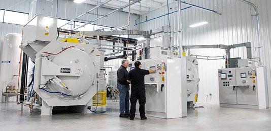
Ipsen celebrated its 75 th anniversary with a year of record revenue and growth (Courtesy Ipsen)
NSL Analytical Services, Cleveland, Ohio, USA, has announced the relocation of one of its two metallurgical testing laboratories to a new 1,850 m 2 facility in the same city. The move approximately doubles the size of the lab and will provide the comprehensive infrastructure to support NSL’s growth as one of the nation’s leading independent materials testing services companies.
NSL now offers high-temperature stress rupture testing services for Additive Manufacturing, aerospace, space and other manufacturing clients. The company specialises in testing metals, alloys, plastics, composites and ceramic materials in powdered, solid, or liquid form.
“This move represents the next chapter of growth for NSL Analytical Services,” according to Ed Herderick, Vice President of Science and Technology Development. “Our new ANAB- and Nadcap-accredited metal -
lurgical testing lab has meaningfully expanded both NSL’s testing capacity and testing capabilities. We are thrilled to be offering our customers a more expansive line of metallurgical testing solutions and look forward to supporting their future testing needs
with excellent service that they have come to expect from NSL.”
The new facility, opened in late March, includes an office space and also supports operations at NSL’s analytical laboratory, located about 3.2 km away in Warrensville Heights, Ohio. Approximately 70% of NSL’s clients utilise the services of both testing laboratories. www.nslanalytical.com

NSL has doubled the size of its metallurgical laboratory with a recent relocation (Courtesy NSL Analytical Services)
Ceramitec 2024 organiser Messe München has reported the conclusion of another successful event. The biennial show included some 466 exhibitors from thirty-six countries across 33,000 m 2 of exhibition floor space. Attendees numbered over 13,000 from eighty-four countries, an increase of 30% over the 2022 exhibition.
“Ceramitec 2024 is a great success,” added Dr Jürgen Blumm, Managing Director of Netzsch-Gerätebau and Chairman of the ceramitec Advisory Board. “Compared to the last event in 2022, there were significantly more visitors and many new contacts made. The exhibiting companies also showcased innovations this year, especially in the areas of automation, sustainability and energy efficiency. All in all, it is a great event with many world premieres and advancements from the exhibitors along with many enthusiastic visitors.”
This year’s event proved again its global appeal. “With an international share of 57% of visitors and 65% of exhibitors, ceramitec has clearly demonstrated its relevance for the ceramics industry as a whole,” stated Collin Davis, Executive Director at Messe München. “We have seen the

topics here that are driving the industry, from digitalisation to zero emissions, decarbonisation and resource efficiency as well as new applications for ceramic solutions – at the stands, but also in our conference programme.”
Stephan Eirich, President of Maschinenfabrik Gustav Eirich, stated, “Ceramitec 2024 once again made Munich the world capital of the ceramics industry. Numerous decision-makers and experts were on hand providing deep insights into the challenges and opportunities facing the industry. The result was productive talks highlighting genuine interest in technical solutions and innovations.”
Johannes Heckmann, CEO of Nabaltec AG, said, “For us, ceramitec is the trade fair in Europe where the refractory and ceramics industry comes together. As always, the quality of discussions with the expert audience is outstanding.”
Dr Moritz von Witzleben, Managing Director at Inmatec Technologies, added, “For us, ceramitec is an industry highlight and the most important trade fair –there is simply no alternative.”
The next ceramitec will take place from March 24-26, 2026, again in parallel with analytica, the world’s leading trade fair for laboratory technology, analysis and biotechnology, at the exhibition grounds in Munich.
www.ceramitec.com
Ipsen, headquartered in Cherry Valley, Illinois, USA, has announced its new digital gateway, Ipsen Connect. The customer service portal is intended to simplify access to essential resources, including order history, service requests, and furnace documentation. Ipsen Connect will enable users to request or reorder parts, schedule maintenance, troubleshoot, and arrange calibration appointments. The portal also provides access to troubleshooting guides, online training videos, and answers to frequently asked questions.
Ipsen stated that its Digital Technologies team worked with internal and external stakeholders over several years, leveraging insights to develop and evaluate the portal before its launch.
“By aligning our digital initiatives with our customers’ needs, our goal is to provide cutting-edge solutions that enhance efficiency, productivity, and customer satisfaction,” stated Aymeric Goldsteinas, Ipsen’s Vice President of Digital Technologies. Following a beta test with forty customers, Ipsen Connect is now available to all existing US customers with vacuum furnace equipment. The service doesn’t require any software installation and can be accessed through any internet-connected PC or mobile browser. www.ipsenglobal.com
Sweden’s Sandvik AB has launched Osprey C18150, a copper-based metal powder tailored for applications which require increased mechanical strength at high temperatures, whilst maintaining high electrical and thermal conductivity. These attributes are said to make the powder suitable for electrical, electronic and thermal transfer components in a variety of industries such as aerospace and automotive.
Osprey C18150 (CuCrZr) is a copper-based alloy that contains small amounts of chromium and zirconium to balance copper’s high conductivity and heat dissipation capabilities. Thanks to the precipitation of Cr- and Zr-rich particles upon ageing, this balance persists even at elevated temperatures. It can withstand service temperatures up to 500°C. The alloy has been developed as fine powder for Metal Injection Moulding and Binder Jetting (BJT) using Osprey High Yield Technology, but also as a coarser powder for Laser Beam Powder Bed Fusion (PBFLB) and Directed Energy Deposition (DED).
“Our metal powder portfolio continues to grow, and we are very excited about our latest addition, Osprey C18150,” stated Dr Eleonora Bettini, Customer Application Specialist for Metal Powder at Sandvik. “With our wide range of Osprey C18150 powders, with customised properties and particle size distributions, manufacturers from a variety of industries can enjoy the many benefits that this material has to offer.”
Osprey C18150 is manufactured by inert gas atomisation, said to produce a powder with a spherical morphology and providing good flow characteristics and high packing density. The powder has been tested and qualified with in different industries and for different applications.
Available via the Osprey Online webshop in Europe and through KBM Advanced Materials in the US, Osprey C18150 is also available in other fractions and for other manufacturing technologies from Sandvik. www.metalpowder.sandvik

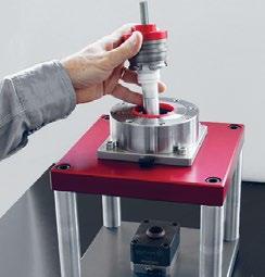
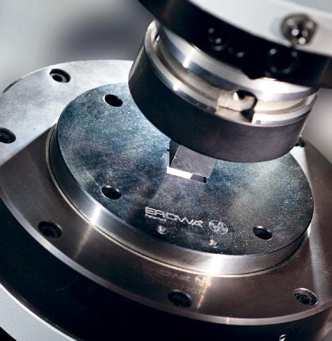
2024 Pittsburg, USA June 16-19, 2024 The EROWA PM Tooling System is the standard interface of the press tools between the toolshop and the powder press machine. Its unrivalled resetting time also enables you to produce small series profitably.


Nabertherm GmbH, headquartered in Lilienthal, Germany, showcased its new LH..DB range of compact sintering furnaces at this year’s ceramitec 2024 exhibition in Munich, Germany, ahead of its official market launch in May. The LH..DB series looks to set new standards in the heat treatment of ceramic parts and additively manufactured ceramic components on a laboratory scale, as well as meeting the thermal post-processing requirements of additively manufactured components.
It is stated that the furnaces can be easily converted from air atmosphere to operation with inert gas, which offers a wide range of
applications for debinding and sintering AM metallic and ceramic components.
During the debinding phase, the DB debinding package is said to guarantee the highest safety standards. Outgassing from the materials are diluted and reduced to a non-ignitable atmosphere in the furnace by preheated fresh air, which minimises potential risks and ensures a smooth process flow.
With the LH..DB series, Nabetherm offers a complete solution that is not only versatile but also easy to operate. The furnaces will be available in two sizes, with furnace volumes of 120 or 216
CADchat, headquartered in Columbia, South Carolina, USA, has officially launched its cloud-based digital workspace. Developed with the needs of product development teams in mind, it offers tools intended to extend the functionality of traditional video calls into a persistent collaborative environment.
“Product development doesn’t end when the meeting does, and neither should the tools we use,” said Graham Bredemeyer, CEO of CADchat.
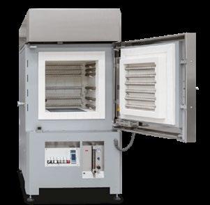
Nabertherm’s LH 120/13 DB machine (Courtesy Nabertherm GmbH)
litres and for maximum furnace temperatures of 1,200 or 1,300°C. When using the optional gassing box, processes up to 1,100°C can be performed. www.nabertherm.com
“With CADchat, we are thrilled to offer a platform that not only supports realtime collaboration but also enriches the continuity of teamwork. Our digital workspaces ensure that everything from 3D models to critical feedback remains accessible and interactive long after the calls have ended.” CADchat’s environment retains every interaction after the discussion has ended. Communication within the platform is integrated with the actual work, enabling conversations to lead
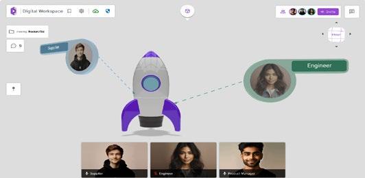
development without the need for app-switching. Unlike repository web services, CADchat’s hub offers interactive collaboration on documents and designs, allowing users to conduct real-time or asynchronous design reviews, and pin comments on designs and 3D models.
CADchat aims to enhance the value of CAD tools like Fusion or SOLIDWORKS by embedding them within a broader context of team collaboration, allowing for the creation and collective refinement of 3D models. All project communications and files are kept and remain accessible to users in an environment protected with AES-256 encryption, meeting SOC 2 compliance.
In the case of one customer, CADchat reportedly enabled GE Vernova to reduce part and tooling development cycle times from two to three months to as little as one to two weeks, an improvement of over 90% in efficiency achieved without any system or hardware changes.
CADchat is now available for teams looking to enhance their productivity and reduce the time spent on project coordination. Those interested can sign up for a free trial. www.CADchat.com


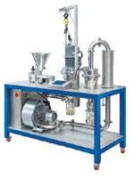

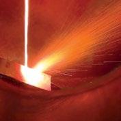
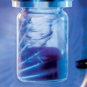
● GAS AND ULTRASONIC ATOMIZERS FOR SPHERICAL POWDERS WITHOUT ANY SATELLITES for LPBF, MIM, Binder Jetting and other Additive Manufacturing applications. High purity, sphericity and wide range of reproducible particle size distribution.
● WATER ATOMIZERS FOR MORE IRREGULAR POWDERS ideal for recycling/refining process, press & sinter process and others.
● AIR CLASSIFIERS FOR THE PRECISE SEPARATION OF METAL POWDERS into fine and coarse powder fractions especially in the range < 25 µm
● MAXIMUM PURITY BY OXIDATION-FREE PROCESSING
● FOR A WIDE RANGE OF METALS AND FOR SMALL TO MEDIUM AMOUNTS
● ALL SYSTEMS DESIGNED FOR EASY HANDLING AND CLEANING, QUICK ALLOY CHANGE WITH MINIMUM CROSS CONTAMINATION
Malvern Panalytical, part of Spectris plc, Egham, Surrey, UK, announced the launch of Revontium, an XRF spectrometer. This new instrument delivers elemental analysis in a compact footprint for the optimal balance between precision and efficiency. Revontium offers an alternative to 1-2 kW floor-standing systems, and is said to deliver high-quality, repeatable results at a reduced cost of ownership and environmental impact. Together, these benefits are intended to open new possibilities for elemental analysis across multiple industries.
X-ray fluorescence (XRF) is a nondestructive technology for elemental analysis, with a number of gains over techniques such as inductively coupled plasma spectroscopy (ICP) and atomic absorption spectroscopy
(AAS). However, large floor-standing wavelength-dispersive (WDXRF) instruments can be both energyand cost-intensive. Revontium is reportedly the only XRF spectrometer on the market delivering comparable results and data quality to these larger instruments, at a reduced footprint.
Revontium’s cost of ownership is reportedly more than 25% lower than that of WDXRF, AAS, and ICP instruments. This is due to its reduced need for consumables, and simpler maintenance and sample preparation requirements. Revontium is said to need fewer consumables, such as acids and high-purity gases, than ICP, requires no daily calibration, and analyses samples in ambient conditions. Unlike high-powered WDXRF

instruments, there are reportedly no external chiller requirements and associated costs, thanks to internal cooling in the Revontium system. Its power consumption is only 250 watts per hour, compared with 2,000 watts per hour for traditional WDXRF. After non-destructive XRF analysis using Revontium, the same sample can still be measured using ICP, AAS, XRD, or other methods if required. www.malvernpanalytical.com

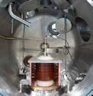


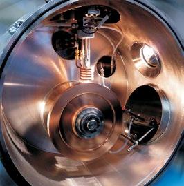
The Technical Programme for the 2024 World Powder Metallurgy World Congress & Exhibition (World PM2024) has now been published. Organised by the Japan Powder Metallurgy Association and Japan Society of Powder and Powder Metallurgy, the event will take place October 13-17 in Yokohama, Japan.
In addition to the all-topic conference, World PM2024 will include an international exhibition, providing excellent opportunities for exchanging information, networking and meeting colleagues from around the world.
Keynote Presentations
The conference will begin with three Keynote presentations:
• Metallurgy-Inspired Solar Panels Recycling, by Y Shen, University of New South Wales
• Mechanical Properties and Reliability of Structural Materials for Spacecraft Applications, by E Sato, ISAS/JAXA
Iwatani’s Efforts Towards the Realization of a Hydrogen Society, by M Tsuyoshi, Iwatani Corporation
Special Interest Seminars
There will also be fourteen Special Interest Seminars, these include:
• SIS1 Powder Production SIS2 Novel processing strategies for beam-based AM
• SIS3 Promising Future of Sinter Based AM
• SIS4 Trends and Sustainability of MIM
• SIS5 MIM Challenges for New Materials
• SIS6 Industrial Application of Functional Materials
• SIS7 Powder Design for Industrial Application
• SIS8 Sintered Materials
• SIS9 Hard Materials
• SIS10 Amorphous/Nanocrystalline Soft Magnetic Materials
• SIS11 Energy Materials
• SIS12 Carbon Neutrality (CN) in PM
• SIS13 Circular Economy and Sustainability in PM
• SIS14 DX in PM
General Sessions
The conference will include general sessions covering all aspects of PM, MIM and metal AM. Topics include:
• Powder Production
• Compaction and Sintering
• Modelling and Sintering
• Hot Isostatic Pressing Field Assisted Sintering Technologies
• AM Beam-based Technologies
• AM Sinter-based Technologies MIM – New Processing Routes
• MIM – Stainless Steel and Heat Resistant Alloy
Innovative Technology
• High Profile Automotive Component Technology
• PM Technologies to Support Future Society
• Tribology in PM
• Ferrous Materials
Non Ferrous Materials
• High Temperature Materials
• Hard Materials
• Hard Magnetic Materials
Soft Magnetic Materials
• Composite/Hybrid Materials
• Non-oxide Materials
High Entropy Alloys
• Materials Characterisation of AM Materials
Registeration discount Early-bird discounted registration is available until September 2. www.worldpm2024.com

Japan’s Metal Injection Moulding industry on show at World PM2024
World PM2024 will also include a pavilion showcasing Japan’s Metal Injection Moulding industry. This will feature the following Japanese companies, each engaged in MIM production or the provision of materials and technology to the MIM sector: atect Corporation • CASTEM Co.,Ltd • IWAKI Diecast Co.,Ltd • JUKI Aizu Corporation • Nakahara Precision Co.,Ltd • Nippon Piston Ring Co.,Ltd • Oriental Chain Mfg.Co.,Ltd • OSAKA Titanium Technologies Co.,Ltd • Osaka Yakin Kogyo Co.,Ltd • Pacific Sowa Corporation • Repton Co., Ltd • Taisei Kogyo Co., Ltd • Teibow Co., Ltd • Toko Tsusho Corporation
Arburg GmbH + Co KG, headquartered in Lossburg, Germany, has reported that over 5,000 guests attended this year’s Arburg Technology Days, which were held in Lossburg from March 13-16. Arburg added that in total, the event has attracted over 100,000 visitors since it began twenty-five years ago.
“We are very satisfied with the Technology Days 2024,” shared Dr Christoph Schumacher, Vice President of Global Marketing at Arburg, in summary. “Despite the difficult economic environment worldwide and the upcoming NPE and Chinaplas trade fairs in North America and Asia, customers from over forty countries came to Lossburg, knowing that we would assist them with all their questions and showcase innovations that can deliver real added value.”
In arburgSOLUTIONworld, visitors were able to find out which parameters could be leveraged to increase efficiency and reduce costs in their own injection moulding production. Six stations around an LED column provided personalised advice and information on topics such as Arburg’s ‘Action Plan: Energy’, the ALS host computer system and arburgXworld customer portal that can be linked to it, and the Gestica control system with its intelligent assistance and pilot functions.
The keynote speech entitled ‘Enabling your future – smart and system-orientated solutions’ by Managing Directors Gerhard Böhm and Guido Frohnhaus was also met with great interest. Around 300 guests attended the three keynote speeches followed by a panel discussion.
Arburg has been offering its own automation and turnkey solutions for exactly thirty years, and a number of current customer projects related to this were once again on display at the Technology Days 2024. One example was an electric Allrounder 370 A Metal Injection Moulding machine, with a shortened linear robotic system mounted inside the machine guard, so that the footprint was not increased.
An electric two-component Allrounder 520 A with a clean air module above the clamping unit was automated with a horizontally engaging Yaskawa six-axis robot positioned between the two injection units in the L-position to save space.
Another application was the fully automated production of cartridges with IML labels made from monomaterials on a hybrid Allrounder 820 H.
www.arburg.com





Atomising Systems Ltd (ASL), headquartered in Sheffield, North Yorkshire, UK, has announced that the sixteenth edition of its two-day course, Atomisation for Metal Powders, will take place in Manchester, UK, September 26-27, 2024. The intensive course will cover the main methods of atomising metals; specific requirements for different metals; the design, operation and economics of plant; and manufacturing and characterising powder for Additive Manufacturing and other advanced manufacturing techniques.
The course will be presented by ASL management members John Dunkley, chairman; Dirk Aderhold, Technical Director; and Tom Williamson, Research and Development (R&D) Manager. It will combine up-to-date practical information with atomising theory.
Revisions to this year’s content reflect growing interest in Additive Manufacturing and other advanced manufacturing and special alloy powders. The course covers: Systems engineering of entire plants, melting to cooling, drying, dewatering, sieving, conveying, feeding etc.

• The factors affecting the relative attractiveness of atomisation and alternative methods
• Both current practice and key areas of current interest in advanced manufacturing, including the main atomisation techniques in current use and powder requirements for different applications, in particular Additive Manufacturing
• The principles of atomisation and the physical processes involved when atomising different metals
• Manufacturing different metal alloy powders, including Ti alloys ASL specialises in powder production via atomisation. Established in 1992, the company and its founder have over forty years of experience in the technology and have delivered more than 130 plants for metal powder atomisation in thirty-five countries on six continents. ASL currently operates four different atomisers for industrial powder production at its facility.
www.atomising.co.uk



MPP, headquartered in Noblesville, Indiana, USA, has collaborated with Tactile Engineering, an Indianabased startup developing advanced assistive technologies, to help design a metal injection moulded core plate for Tactile’s Cadence tablet, a ground-breaking braille reader for the visually impaired.
The Cadence tablet is reported to be the first tactile device able to display tactile graphics that move and change beneath the user’s fingers. The pocket-sized tablet, around the size of a large mobile phone, enables users to interact and experience live events and enter -
tainment, as well as provide access to dynamic content, textbooks, and collaborative tools.
The innovative tablet also helps students of all ages to learn and use braille. The tablet’s pop-up dots provide just the right amount of resistance for comfortable and easy reading, with up to eight lines of text for quick navigation of long passages and complex information.
The new MIM core plate was designed to meet tight tolerances, requiring flatness, the absence of any flashing, and specific magnetic properties, essential for the tablet’s functionality. If the part was not

The Cadence tablet is reported to be the first device to display tactile graphics that move and change beneath a user’s fingers (Courtesy MPP)
The 21 st Plansee Seminar has been announced for June 1-6, 2025, at the Plansee Group’s facility in Reutte, Austria. Returning to its usual fouryear cycle, the conference will enable participants to openly discuss all aspects of refractory metals and hard materials.
The Plansee Seminar will cover a variety of topics including applications, materials, processes, sustainability and testing methods. These will be addressed in key-note lectures and contributed papers, in a number of oral and poster sessions.

MPP helped Tactile Engineering develop a core plate for Tactile’s Cadence tablet using Metal Injection Moulding (Courtesy MPP)
produced within the precise specifications, it would run a risk of creating a short and the inability to function.
With that in mind, MPP used 17-4 Stainless Steel, as per MPIF Standard 35, for the magnetic latching. Utilising a proprietary feedstock formulation, MPP was also able to ensure material flow through the moulding.
Transitioning to Metal Injection Moulding from traditional manufacturing methods led to a 40% reduction in waste and a 10x cost saving per piece. The MIM solution simplified the manufacturing process and improved assembly efficiency, allowing Tactile Engineering to commit to larger volumes for their customers.
www.tactile-engineering.com www.mppinnovation.com
The event also coincides with the 100 th anniversary of the discovery of rhenium, one of the rarest elements and an important alloying element, especially for tungsten and molybdenum. To celebrate the occasion, there will be a number of special lectures on scientific and industrial topics relating to the metal.
The Plansee Seminar First Circular can be downloaded from the website. www.plansee-seminar.com

Advanced Technology (Bazhou) Special Powder Co.,Ltd
No.76 Xueyuan Nanlu, Haidian, Beijing 100081,China
Tel: +86-13701029643
Email: powdermetal@atmcn.com
1958
• Powders for magnetic core and SMD
• Powders for MIM
• Pre-alloy powders for diamond tools
• Powders for auto engine valve seats and guides
• Powders for filtering materials
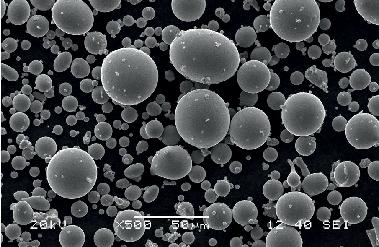
Sales Agent in Europe Burkard Metallpulververtrieb GmbH
Tel. +49(0)5403 3219041
E-mail: burkard@bmv-burkard.com
TA1 is a commercial pure grade of titanium which exhibits low density, excellent corrosion resistance and biocompatiblity and, whilst its tensile strength is not high compared with many Ti alloys, it has good toughness and exceptional ductility. Typical applications include medical devices, dental parts, smart wearable devices, and in areas requiring high oxidation resistance in corrosive environments. Titanium is also known to be a difficult to machine metal and Metal Injection Moulding has been found to be an ideal high volume manufacturing process for TA1 titanium
near-net shape components having complex shapes at lower cost.
A group of researchers in China and New Zealand have been studying the use of MIM to produce TA1 components using spherical TA1 powder and a water-soluble binder and the results of this research have been published in a paper available online (February 2024) in the Journal of Adhesion Science and Technology entitled: ‘Microstructures and mechanical properties of TA1 sintered samples prepared by injection moulding using water-soluble binder’. The authors of the paper include
Table 1 Composition of TA1 titanium powder. (From paper: ‘Microstructures and mechanical properties of TA1 sintered samples prepared by injection moulding using water-soluble binder’, Journal of Adhesion Science and Technology (February 2024), by W. Zhang et al)
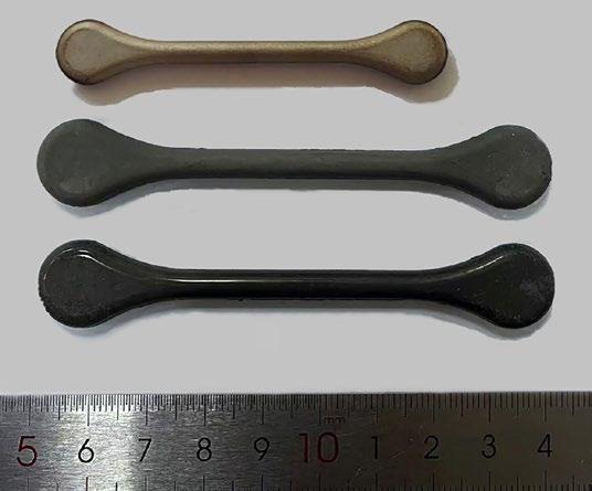
Fig. 1 Comparison of the injection moulded, water debound, and sintered TA1 titanium samples (from bottom to top). (From paper: ‘Microstructures and mechanical properties of TA1 sintered samples prepared by injection molding using water-soluble binder’, Journal of Adhesion Science and Technology (February 2024), by W. Zhang et al)
Weichen Zhang, Lu Li, Peng Cao, Gang Chen and Muhammad Dilawer Hayat. The authors reported that three groups, each containing three MIM TA1 samples, were sintered at different temperatures (1250°C, 1300°C and 1350°C), and that the main focus of their research was to explore the reasons for the different properties in the sintered samples, such as the differences in relative densities, microstructures and mechanical properties. Because TA1 has a high affinity for carbon and oxygen elements, the impact of the distribution of these elements in the sintered microstructure and on the final properties of MIM TA1 samples was also analysed. TA1 spherical pure titanium powder having the composition shown in Table 1 was mixed with a water soluble binder composed of polyethylene glycol (PEG), polymethyl methacrylate (PMMA), and stearic acid, and the resulting pellet MIM feedstock was injection moulded to produce nine tensile test parts. The injection moulded green MIM TA1 parts were first soaked in a water bath at 50°C for 24 h to remove the main PEG binder component, and any residual PEG and PMMA binders were removed in the thermal debinding stage which was done simultaneously with sintering because of the cleanliness of PMMA.
The nine injection moulded tensile test samples were divided into three groups - A, B, and C which corresponded to the sintering temperatures used of 1250°C, 1300°C, and 1350°C, respectively. Fig. 1 (bottom to top) shows an example of the injection-moulded TA1 part in the as-moulded, debinderised, and sintered condition. Relative densities of the sintered MIM TA1 parts were found to increase with the increase in the sintering temperature from 1250°C to 1300°C, showing a rise of 1.07% to 4.189 g/cm 3, or 92.85 ± 0.03% relative density, in sample B. At 1350°C the sintered density of sample C increased by only 0.28% to 4.202 g/ cm 3
The sintered TA1 titanium samples were then tensile tested to ascertain their mechanical properties which

are shown in Table 2. The tensile strength and elongation of sample A was 499 MPa and 11.49% at the lowest sintering temperature of 1250°C, respectively, whereas those of sample B sintered at 1300°C are higher: 592 MPa and 12.95%, respectively. The tensile strength and elongation were found to decrease as the sintering temperature increased. The authors stated that the influence of the sintering temperature on the mechanical properties of MIM TA1 specimens is related to both to the relative density and the existence of carbides and oxides.
The carbon and oxygen contents were determined for each of the three groups of sintered MIM TA1 samples as shown in Table 3. The carbon and oxygen contents were determined by plasma emission spectrometry. The sintered microstructures were observed by Optical Microscopy, and EPMA was used to measure the distribution of the compounds formed by carbon and oxygen elements with titanium. The microstructures and fractures of the MIM TA1 samples were observed by SEM, and the forms of carbon and oxygen were determined using a field emission SEM. The relationship between the forms of carbon and oxygen and the orientation of pure titanium matrix was analysed by TEM.
The authors stated that the carbon contents of the three groups studied showed little difference as can be seen in Table 3, but the oxygen content was found to increase with the increase in sintering temperature. Because TA1 has a high affinity for carbon and oxygen elements, the impact of the distribution and forms of carbon and oxygen elements on the final properties was also analysed.
One sample was selected from each sample group A, B, and C to study its microstructure, and Fig. 2 shows the SEM images of three samples at different magnifications. The figure shows that the microstructure is dominated by equiaxial α phases. The authors established that the grain size of sample B is significantly smaller than that of
Table 2 The mechanical properties of the three groups of sintered TA1 samples. (From paper: ‘Microstructures and mechanical properties of TA1 sintered samples prepared by injection molding using water-soluble binder’, Journal of Adhesion Science and Technology (February 2024), by W. Zhang et al)
Table 3 Carbon and oxygen contents in the three groups of sintered TA1 samples. (From paper: ‘Microstructures and mechanical properties of TA1 sintered samples prepared by injection molding using water-soluble binder’, Journal of Adhesion Science and Technology (February 2024), by W. Zhang et al)

Fig. 2 Metallographic images of the three groups of samples at different magnifications: (a, b) sample A; (c, d) sample B; (e, f) sample C. (From paper: ‘Microstructures and mechanical properties of TA1 sintered samples prepared by injection molding using water-soluble binder’, Journal of Adhesion Science and Technology (February 2024), by W. Zhang et al)
sample A, as shown in Figs. 2 (a), 2 (c), and 2 (e). However, the grain size of sample C is larger. Obvious precipitates at the grain boundaries are visible in Fig. 2 (c), and many needle-like structures exist in Fig. 2 (d). Fig. 2 (f) also shows the same needle-like structures but in smaller quantities. These are presumed to be composed of β -Ti according to their locations, and further analysed by TEM. In addition to point-like precipitates, Figs. 2 (c) and 2 (e) also show lump precipitates (red circle). FESEM was employed to determine its composition further.
The authors concluded that the MIM TA1 samples in group B possess the best mechanical properties when sintered at 1300 C. The β -Ti is present in the sample, while TiC and a small amount of TiO 2 are produced. TiC particles hinder the dislocation movement and grain boundary growth. Solid solution strengthening, second phase strengthening, and grain refinement increase the strength of the sample and grain refinement, and the presence of β -Ti improves the elongation of the sample.
www.tandfonline.com/journals/ tast20
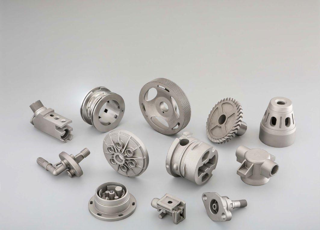
Material Options (Metal)
Material Options (Ceramics)
Build Envelope
Quantity
Tolerance capability
CONTACT FOR MORE DETAILS
17-4PH, SS 316, Tool Steel M2 & S-7, Inconel 625, 4140
Alumina 99.5%, Zirconia
~ 300 grams max, Footprint equivalent of baseball size or less, 0.02” (0.50 mm) wall thickness minimum
10~50 samples based on footprint. Larger quantities up to 1,000 pcs welcome depending on the part size.
Within 2% of the feature size, 2~3 Ra Surface finish, Option of finishing to closer tolerances available.
NORTH AMERICA Email: Mukund.N@indo-mim.com Ph: +1 (210) 557-1594
EUROPE Email: InfoEU@indo-mim.com Ph: +49 1732656067
ASIA Email: InfoHQ@indo-mim.com Ph: +9198459 47783 / +91 98450 75320
ISO 9001:2015 / IATF 16949:2016 / AS
MIM 316L is an austenitic stainless steel based on the AISI Standard having exceptional corrosion and oxidation resistance and good mechanical properties, including excellent ductility and elongation. It is also non-magnetic. Thanks to these characteristics 316L stainless steel has become one of the most common of MIM stainless steels, and has emerged as the preferred choice of material for a diverse range of mass produced MIM components used in biomedical, consumer, electronic, automotive, marine and aerospace applications. However, when sintered MIM 316L stainless steel comes into contact with other surfaces and experiences relative movement or friction, it can cause adhesive or abrasive wear which could significantly shorted the lifespan of the component.
There is today limited knowledge on the tribological properties of 316L stainless steel components made by MIM, and a research group based at three centres in Thailand (The National Metal and Materials Technology Center (MTEC), the Chulalongkorn University Bangkok, and the Thailand National Nanotechnology Center (NANOTEC)) has undertaken work to ascertain the influence of mechanical surface treatment such as severe shot peening (SSP) on the tribological and wear properties of MIM 316L stainless steel. The results of their work have been published in the Journal of Materials Research and Technology Vol. 29, 2024, 4072-4085. The lead author of the published paper: ‘Surface modification and enhanced wear performance through

severe shot peening treatment in 316L stainless steel manufactured by metal injection moulding’ is Kittichat Wiratkapun at MTEC.
The authors stated that severe shot peening (SSP) is a mechanical surface treatment that has gained significant attention due to its practicality, simplicity, and efficiency. In their research, SSP treatment was undertaken using high-velocity particles made from 304 stainless steel (ranging in size 300 to 500 µ m) to bombard the sintered MIM 316L component surfaces, creating a work-hardened surface, compressive residual stress, and surface nanocrystalisation. SSP treatment was found to improve surface quality, physical properties, static and dynamic mechanical properties, as well as wear performance.
The MIM 316L stainless steel used in this research work was produced using a spherical powder having an average particle size of 10.8 µ m which was mixed with a polyacetal binder with powder
FEATURES
• Metal or Graphite Hot Zones
• Metal and Graphite Retorts
• Debinding & Sintering • Trapping Systems to Suit
loading at 65 vol.%. The feedstock was injection moulded to produce sub-size tensile test pieces which were then thermally debound under a nitrogen atmosphere with a maximum debinding temperature of 500°C for 1 h and sintered at 1350°C for 2 h in an Ar atmosphere. The relative sintered density of the MIM 316L stainless steel was greater than 97% for all specimens, but the as-sintered surface of the MIM parts did have some surface notches or pores, unlike the dense surface of a comparable wrought 316L. The tensile strength properties of the as-sintered MIM 316L test specimens used in this research met the minimum values outlined in the MPIF 35 Standard.
The sintered MIM 316L parts were subjected to SSP using a direct pressure-type shot blast machine. The shot peening parameters used are shown in Table 1. Specimens underwent intermittent SSP on the turntable, with each surface exposed to peening for a total of 30 s. The specimen before shot peening is
Media type
Nozzle
Shot-peening pressure
Coverage
Shot peening intensity 0.2 mmA (0.2 mm arc height of type A Almen strip)
Average mass flow rate 4.4 kg/min
Table 1 Severe shot peening parameters used in this study (From paper: ‘Surface modification and enhanced wear performance through severe shot peening treatment in 316L stainless steel manufactured by metal injection moulding’, by K. Wiratkapun, et al, Journal of Materials Research and Technology Vol. 29, 2024, 4072-4085)
denoted as ‘as-sintered,’ and the shot-peened specimen is denoted as ‘SSP’.
The authors reported on the surface characteristics and microstructures of the MIM 316L parts by
measuring the surface roughness in the as-sintered condition and after SSP. Surface roughness was measured on the top surface of the as-sintered and SSP parts using a 3D measuring laser microscope. As
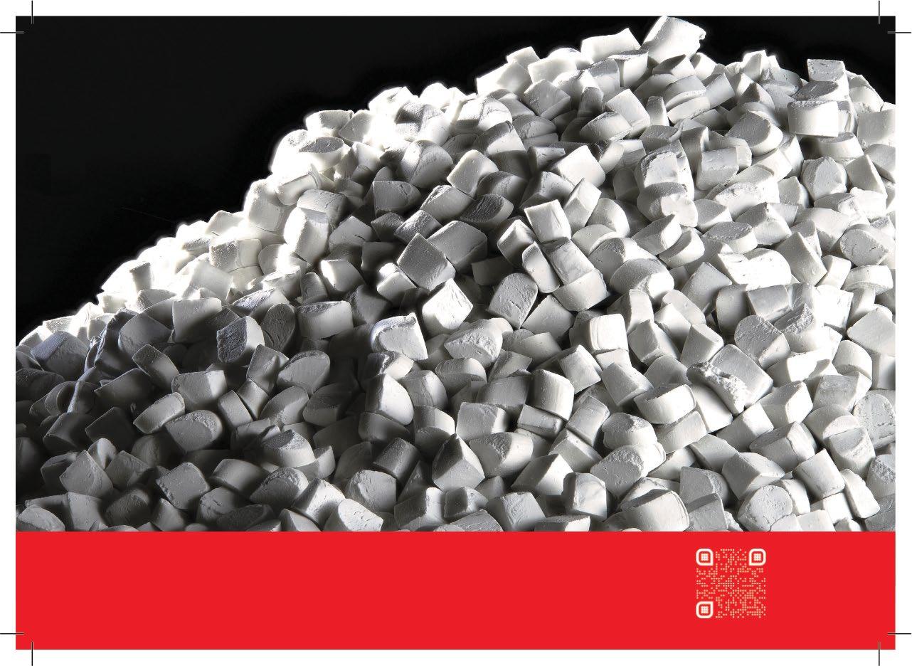

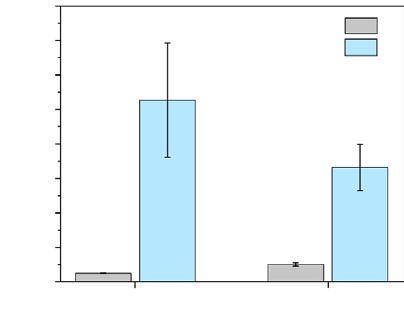


gas & humidity measuring


can be seen in Fig. 1 the Ra of the SSP specimen (2.56 µ m) is higher than that of the as-sintered specimen (1.24 µ m), while Rz is slightly lower. This is attributed to the initial surface characteristics of the MIM specimen, which exhibits good surface quality with some surface porosity, resulting in a relatively low Ra with a slightly higher Rz. The SSP treatment was found to generate large but shallow dimples and eliminates surface porosity to a depth of approximately


Fig. 1 Surface roughness (Ra and Rz) of the as-sintered and SSP MIM 316L specimens(From paper: ‘Surface modification and enhanced wear performance through severe shot peening treatment in 316L stainless steel manufactured by metal injection moulding’, by K. Wiratkapun, et al, Journal of Materials Research and Technology Vol. 29, 2024, 4072-4085)
60 µ m. The surface morphology of the as-sintered and SSP specimens is shown in Fig. 2 (a) and (b). The surface of the as-sintered specimens appears relatively flat but exhibits noticeable pores across its surface. Conversely, the SSP specimen surface displays large but shallow dimples distributed throughout, with no evidence of surface pores. Fig. 2 (c) and (d) present the cross-sections of the as-sintered and SSP MIM 316L specimens.

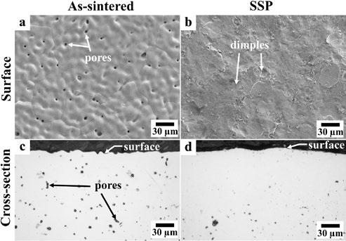


Fig. 2 SEM micrographs of the surface and optical micrographs of the cross section of (a, c) as-sintered and (b, d) SSP specimens (From paper: ‘Surface modification and enhanced wear performance through severe shot peening treatment in 316L stainless steel manufactured by metal injection moulding’, by K. Wiratkapun, et al, Journal of Materials Research and Technology Vol. 29, 2024, 4072-4085)
The evolution of Vickers microhardness for both the as-sintered and SSP MIM 316L specimens is shown in Fig. 3. The as-sintered parts were found to have a relatively stable microhardness level of 143 HV from the surface to the centre of the parts, whilst the SSP MIM 316L parts show enhanced microhardness from 10 µ m to around 250 µ m below the topmost surface. The microhardness value at a depth of 10 µ m measured 324 HV, which represented a 126% increase compared with the as-sintered MIM 316L specimens.
Reciprocating sliding tests were done to measure wear performance using a universal tribometer with an Al 2O 3 ball acting on the MIM 316L stainless steel substrate. Strainhardening and mechanically-induced martensite occurred during the sliding wear tests. The SSP treatment significantly improves wear performance under testing loads of 10 and 20 N with abrasive, adhesive and oxidative wear dominating, but showed no significant difference when testing load was increased to 30 N. The wear mechanisms, including abrasive, adhesive wear, and oxidative wear, remained similar at lower testing loads (10–20 N). However, when the testing load was increased to 30 N, the strengthening effect of SSP treatment was surpassed, leading to the dominance of severe adhesive and oxidative wear. As a result the wear resistance at 30 N exhibited insignificant differences between MIM 316L specimens before and after SSP treatment.
The authors further reported that SSP treatment had minimal effect on the average coefficient of friction (COF) of MIM 316L stainless steel although the surface roughness of both specimens varies. The average COF values for both as-sintered and SSP specimens under 10 N, 20 N, and 30 N loads ranged from 0.37 to 0.54, with the lowest values observed at the 10 N load. Table 2 shows COF, wear volume and specific wear rate of as-sintered and SPP MIM 316L specimens under different loadings. www.sciencedirect.com/journal/ journal-of-materials-research-andtechnology

Depth from surface (µm)
Fig. 3 Vickers microhardness evolution as a function of depth from the topmost surface of as-sintered and SSP specimens, showing significant improvement of hardness after SSP treatment (From paper: ‘Surface modification and enhanced wear performance through severe shot peening treatment in 316L stainless steel manufactured by metal injection moulding’, by K. Wiratkapun, et al, Journal of Materials Research and Technology Vol. 29, 2024, 4072-4085)
“The SSP treatment significantly improves wear performance under testing loads of 10 and 20 N with abrasive, adhesive and oxidative wear dominating, but showed no significant difference when testing load was increased to 30 N.”
Table 2 COF, wear volume and specific wear rate of as-sintered and SPP MIM 316L specimens under different loadings (From paper: ‘Surface modification and enhanced wear performance through severe shot peening treatment in 316L stainless steel manufactured by metal injection moulding’, by K. Wiratkapun, et al, Journal of Materials Research and Technology Vol. 29, 2024, 4072-4085)

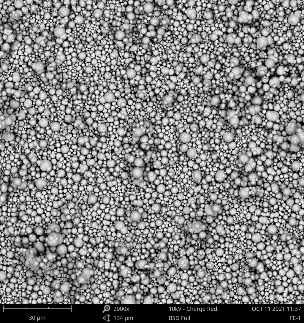


A group of researchers in Taiwan, based at the Ming Chi University of Technology, Chang Gung University, and MIM part producer - Zu Shing Co.Ltd (New Taipei City), have reported on the development of a rapid tooling technology (RTT) injection mould made from aluminum-filled epoxy resin for use in injection moulding of MIM components. The researchers claim that RTT offers offer significant time and cost savings compared with having to produce injection moulds from steels, especially when developing new MIM components for market testing or for low volume production. The results of their research have been published in Polymers Vol. 15, 2023 (August 2023), 21pp.
The authors of the published paper (Chil-Chyuan Kuo and Xin-Yu Pan) stated that whilst conventional machining methods for producing steel moulds for MIM can be cost effective for high volume component production, they can have disadvantages, including complicated manufacturing processes, long processing time, and high production cost. This can significantly impact the cost of developing new MIM parts. In addition, conventional machining has limitations on the complexity that can be achieved in a MIM steel mould. To address these drawbacks the authors have compared the characteristics, such as as-moulded surface quality, dimensions and tool life, of injection moulded MIM parts using RTT moulds and also steel moulds made by conventional machining.
The injection moulding tool used in the research had two cavities (Fig. 1) which allowed two pieces to be moulded simultaneously with one side of the tool using the mould made by rapid tooling technology (RTT) and the other using a mould fabri -

Fig. 1 Injection moulds fabricated by rapid tooling technology and STAVAX steel (From paper: by C –C Kuo and X-Y Pan: ‘Development of a Rapid Tool for Metal Injection Molding Using Aluminum-Filled Epoxy Resins’ Polymers Vol. 15, 2023 (August 2023), 21pp)
cated conventionally by machining of STAVAX stainless steel. This allowed the authors to evaluate the performance of the two different mould inserts under the same injection process parameters as shown in Table 1.
Green parts were injection moulded from a feedstock comprising a mixture of spherical iron powder having particle size of 3 µm and nickel powder (particle size 6 µm) mixed with a binder based on polypropylene and paraffin wax (50:50) with metal powder loading in the feedstock at 60 vol.%. Fig. 2 shows green Fe 2Ni parts produced using the RTT mould and the conventional STAVAX steel mould. The green Fe 2Ni parts were debinderised
Injection pressure (MPa) 70
Injection speed (mm/s) 80
Packing pressure (MPa) 50
Packing time (s) 1
Moulding temperature (°C) 160 Mold temperature (°C) 20
Table 1 MIM process parameters based on practical experience in the industry (From paper: by C –C Kuo and X-Y Pan: ‘Development of a Rapid Tool for Metal Injection Molding Using Aluminum-Filled Epoxy Resins’ Polymers Vol. 15, 2023 (August 2023), 21pp)

rapid tooling via the MIM process. (From paper: by C –C Kuo and X-Y Pan: ‘Development of a Rapid Tool for Metal Injection Molding Using AluminumFilled Epoxy Resins’ Polymers Vol. 15, 2023 (August 2023), 21pp)
using solvent debinding followed by sintering in vacuum at 1300°C. The shrinkage in length, width, and thickness of the final sintered MIM part was around 22%.
The service life of the two kinds of injection moulds was carried out using a MIM injection machine with the value of centreline average surface roughness (Ra) used to evaluate the changes in the surface roughness of the two kinds of injection moulds. The authors stated that the surface
roughness of the moulded parts was affected by the surface quality of the RTT and steel moulds, and changes in the surface roughness of the green MIM Fe2Ni parts is crucial to assess the longevity of the RTT tool. Fig. 3 shows the average surface roughness of mould surface for both steel and RTT moulds as a function of injection moulding cycles. The results clearly show that the changes in the average surface roughness of the RTT mould increased propor -

Number of injection mouldings

Number of injection mouldings
tionally with increasing the injection moulding cycles after 1300 cycles. The tool life of the injection mould made from conventional mould steel is estimated to be around 100,000 moulding cycles. The dimensions of the green MIM Fe 2Ni parts part as a function of injection moulding cycles for both types of injection moulds are shown in Fig. 4.
The authors also investigated the production costs and manufacturing time of an injection mould fabricated by RTT and the conventional machining process. The total manufacturing time of a conventional steel injection mould was said to be around 76 h. This includes preparation time of 60 h, micro-hole machining of 0.5 h, wire-cut machining time of 1.5 h, CNC machining time of 5 h, precision milling time of 1 h, and mirror finish machining time of 8 h. The total manufacturing time of an RTT mould was said to be only 53 h which includes mould manufacturing time of 48 h, CNC machining time of 4.5 h, and precision drilling time of 0.5. This gives a saving in manufacturing time of an injection mould made by RTT technology of about 30.3%. In terms of production cost the injection mould made by Al-filled epoxy resin was said to be about 30.4% cheaper compared with conventional mould steel.
The authors stated that the results obtained were very practical and economical for making large-sized injection moulds for the MIM process and offer potential for many applications in the MIM industry. They did, however, point to some limitations of RTT tools fabricated with Al-filled epoxy resin including their low mechanical properties and heat transfer capability compared with STAVAX stainless steel. These limitations could be improved by adding copper, molybdenum disulphide, zirconia ceramics, or silicon nitride ceramic powders to the Al-filled epoxy resin mixture. These issues are currently being investigated, and the results will be presented in a later study.
www.mdpi.com/journal/polymers





Lithium-ion batteries (LIBs) were first commercially produced by Sony Inc. in 1991 and have since become indispensable for many small scale applications in consumer electronics such as smartphones and laptops, as well as larger scale applications in electric vehicles and microgrids thanks to their high energy density and long cycle life. However, whilst LIBs still remain the most efficient electrochemical energy storage devices, improving their energy density and safety is limited when using the conventional tape casting

Fig. 1 Backscattered electrons mode scanning electron microscopy images of LTO/C surface of the parts for the stages: (a) green, (b) brown, (c) sintered (From paper: ‘High-capacity Li 4Ti 5O12-C thick ceramic electrodes manufactured by powder injection moulding’ by I. I. Romero-Garcia et al, Journal of the European Ceramic Society, Vol. 44, 2024, pp 978-985) c)
electrode process. The presence of non-active materials (binders, solvent, and conductive agents) is necessary in this manufacturing process, and reduces the total specific capacity of the cell which, in turn, imposes a limitation on the thickness of the LIBs electrodes to typically a few dozen microns.
Attempts have been made by a group of researchers based in Spain (Universidad Carlos III de Madrid, Leganes), Germany (Helmholtz Institute Ulm (HIU), and Italy (Sapienza University of Rome), to reduce the amount of non-active components and increase the thickness of the LIB electrodes. The researchers initially used the Powder Extrusion Moulding (PEM) process for producing thicker (500 – 1000 µm) ceramic electrodes from Li 4Ti 5O 12 powder for lithium-ion battery applications.
More recently the researchers have also investigated the use of Powder Injection Moulding (PIM) for the first time for producing LIB electrodes. Both PEM and PIM electrodes are quite similar in that they consist only of active material because the binder used in processing can be removed, which in addition to increasing their thickness, increases considerably the areal and volumetric capacities of the cell. Moreover, these binder-free electrodes greatly facilitate their recycling.
A paper entitled: ‘High-capacity Li 4Ti 5O 12-C thick ceramic electrodes manufactured by powder injection moulding’ by I. I. Romero-Garcia et al , has been published in the Journal of the European Ceramic Society, Vol. 44, 2024, pp 978-985 (available online). The paper details the use of a blend of the anodic Li 4Ti 5O 12 powder with 2 wt.% carbon black addition which was processed by PIM yielding, after subsequent debinding and sintering processes, ultrathick (>500 µm) ceramic binder-free electrodes
for potential use in high capacity LIBs.
The authors reported that a commercially available Li 4Ti 5O 12 (LTO) powder was used as the active material, having particle size of 0.2, 1.0, and 3.0 µm for d10, d50, and d90 distribution values respectively. The particles are irregular in shape and are slightly aggregated. Due to the insulating character of sintered LTO, conductive carbon black Super C65 (2 wt.%) was added. The binder used for PIM was based on a multicomponent mixture made up of polypropylene (PP) as the polymeric backbone; paraffin wax (PW) to reduce the viscosity of the mixture; and stearic acid (SA) as a surfactant. The volumetric proportion of PP, PW, and SA was 50:46:4. Six different LTO+C feedstock formulations were prepared to investigate the optimal feedstock composition: 50, 51, 52.5, 55, 56.5 and 58 vol.%. However, considering the requirement for a high porosity, thick PIM electrode, it was decided to use the feedstock with 50% of powder loading. This feedstock was injection moulded to produce disk-shaped green LTO+C parts in a 12 mm x 0.7 mm mould.
Solvent debinding of PW and SA was done in n-heptane at 50°C, followed by thermal debinding by heating to 200°C for a 30 min plateau, then further heating to 450°C for 60 min using an atmosphere mixture of Ar/H 2 (5 vol%) at a pressure of 2 bar. Sintering was done using the same atmosphere at 900°C for one hour. Fig. 1 shows a comparison of the microstructure of green (a), brown (b), and sintered (c) LTO+C parts. The resulting sintered diskshape electrodes have a diameter of 11.2 ± 0.2 mm, a thickness of 0.65 ± 0.01 mm, and a porosity of 25.7%. The authors stated that no traces of binder were found in the sintered parts indicating a successful debinding process. Also, the typical porosity reduction and grain growth were not observed in the sintered parts due to the low sintering temperature used. This, the authors stated, is preferred, since the electrodes should be porous rather than

Regardless of the complexity of your custom application and formulation, it remains standard for us with our quality systems, technical support, and two proprietary binding systems.


We ensure 100% batch-to-batch consistency, a wide range of alloys, and 36 years of supplying MIM feedstocks for mission-critical parts.
Advanced Metalworking Practices (AMP) manufactures and supplies a wide range of both standard and custom-configured MIM feedstocks for your application. Contact Chris Chapman at cchapman@ampmim.com or 724-396-3663.
Scan the QR code or click here to view our current list of alloys www.ampmim.com/resources




Charge 15th cycle (C/12) 1st cycle (C/24)
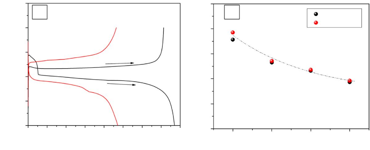
Charge
Fig. 2 (a) Potential of the PIM LTO/C electrode versus specific capacity.(b) Variation of the charge and discharge capacities of the electrode through the cycles (From paper: ‘High-capacity Li4Ti 5O12-C thick ceramic electrodes manufactured by powder injection moulding’ by I. I. Romero-Garcia et al, Journal of the European Ceramic Society, Vol. 44, 2024, pp 978-985)
compact in order to have a larger electrode-to-electrolyte surface area ratio.
The conductivity of the sintered LTO/C samples was determined by impedance spectroscopy. For comparison, conductivity tests were also performed on a reference sample of commercial LTO, without added carbon, which
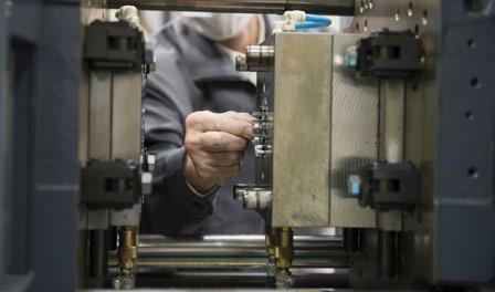


Nishimura Advanced Ceramics Co.,Ltd
Ko Nishimura (Global sales)
3-2 Kawata Kiyomizuyaki Danchi-cyo, Yamashina-ku, Kyoto - 607-8322 JAPAN
Phone: +81-80-8305-9205
Phone (Kyoto Office): +81-75-591-1313
npc-e3@nishimuratougyou.co.jp
http://www.nishimuratougyou.co.jp/english/
CIM Feedstock
Ko Nishimura (Global sales)
High Strength Translucent Alumina FS (Al2O3 99.99%)
96% ~ 99.9% Alumina FS (White, Black)
Zirconia FS (White, Black, Blue)
Mullite FS
was uniaxially compacted and sintered in air at the same temperature and heating rate (same thermal treatment) as the LTO/C. The conductivity value of 7.7 (± 0.1) ⋅ 10 −9 S cm −1 at 0.1 Hz of pure LTO corresponds to that of a typical insulator. This conductivity value is significantly improved by 1.5 orders of magnitude in the sintered LTO/C material with 2.8(± 0.1) ⋅ 10 −7 S ⋅ cm −1. Therefore, the authors were able to confirm by EIS analysis that the addition of conductive carbon can significantly improve the conductivity of pure LTO.
The electrochemical performance of the sintered LTO/C was evaluated by means of galvanostatic cycling with potential limitation inside pouch-bag cells. Metallic lithium was used as the counter-electrode, along with a glass fibre separator and commercial LP30 as the electrolyte. The authors reported that the PIM LTO/C electrodes were capable of cycling against metallic lithium at C/24 and C/12 rates, and offered high values of volumetric and areal capacities, up to 403 mA ⋅ h ⋅ cm −3 and 26.0 mA h cm −2 , respectively (Fig. 2). These values were said to be slightly higher than those obtained for LTO samples obtained by Powder Extrusion Moulding.
The results obtained are considered by the authors to be an intermediate step in research that proves that ultra-thick LTO/C electrodes processed by the PIM technique are an attractive option to produce electrode components for high-capacity batteries.
www.sciencedirect.com/journal/journal-of-the-european-ceramic-society


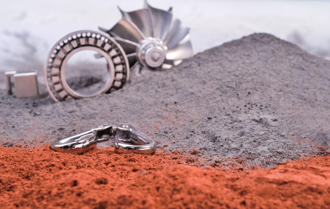
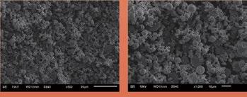




In Metal Injection Moulding, as in all manufacturing industries, business can either be won by competing to be the lowest-cost supplier amongst fierce global competition, or by offering the most innovative technologies for the most demanding applications. Here, Dr Georg Schlieper reports from a recent visit to Germany’s Schunk Sintermetalltechnik GmbH, a company that has taken the latter path, setting itself the goal of being a leading supplier to the aerospace industry and, at the same time, offering its customers unique solutions for the next generation of MIM applications.
Moulding process have been developed at universities and research institutions over the years, with examples including two-material MIM and the MIM of high-temperature materials such as nickel- and cobalt-based superalloys. Schunk Sintermetalltechnik GmbH has set itself the task of transforming many such developments into commercially successful applications, notably making significant progress in the commercial production of MIM aero-engine components. Working in close cooperation with raw material suppliers, equipment manufacturers and end users, Schunk has overcome many of the technical challenges that were once seen as a barrier to the acceptance of MIM for the most demanding of applications. Thanks to the financial commitment of the company’s board, the necessary investments were made, and success has followed –most notably with the production of state-of-the-art components for aero engine applications.
Founded in 1913, the Schunk Group is a globally active technology company that can look back on more than a hundred years of developing and manufacturing technical components. With 9,700 employees at sixty-five locations in twenty-six countries, the organisation generates annual sales of around €1.6 billion.
In addition to carbon materials and technical ceramics, Powder Metallurgy-based parts production makes a significant contribution to the company’s success.
Schunk Group is headquartered in Giessen-Heuchelheim, Germany (Fig. 1). This location is also home to some of the company’s ‘press

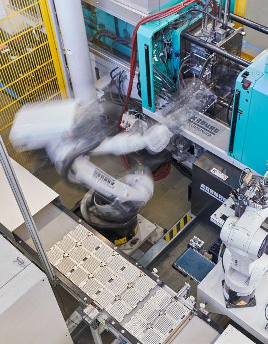
and sinter’ PM component production, as well as carbon applications, some produced by carbon injection moulding. Schunk’s other PM production locations are in Thale, Germany, and Ocoyoaca, Mexico.
At the Thale site, located on the northern edge of the Harz Mountains, 450 Schunk Group’s employees manufacture PM-based components using conventional PM, Metal Injection Moulding and metal Additive Manufacturing. As part of a visit to the plant, PIM International spoke extensively with Thorsten Klein, Head of the MIM Strategic Business Area (SBA), and Ingolf Langer, Head of Development – MIM Technology, about the evolution of Schunk’s MIM business and the company’s future plans.
“In the early days of MIM technology, both the main PM plant GiessenHeuchelheim and the plant in Thale produced MIM parts, but with different binder systems developed independently of each other. For around twentyfive years, the two MIM technologies functioned in parallel...”
Last year, the Thale plant celebrated thirty years of MIM production, making the company a true pioneer in this sector. The company’s beginnings go back to Metallico Pulverspritzguss GmbH, founded in 1993 and later taken over by Schunk. Klein, who has been in his role since last year, and Langer, who has been with the company for twenty-five years, told PIM International that the recent anniversary celebrations were very well received by the workforce. Since staff turnover at the plant is very low, some of the celebrating employees had witnessed the beginnings of MIM technology at the company, whilst some retired employees also returned to take part in the celebrations.
In the early days of MIM technology, both the main PM plant in Giessen-Heuchelheim and the plant in Thale produced MIM parts, but with different binder systems developed independently of each other. For around twenty-five years, the two MIM technologies functioned in parallel until, about twelve years ago, the decision was taken to relocate MIM production from Giessen to

Thale. Today, Thale is Schunk’s sole MIM production location.
Since conventional PM production was already very well established in Thale, with Schunk being a major supplier of PM parts to the automotive industry, the location initially focused its new MIM manufacturing capabilities on automotive applications. The company benefitted from the fact that the automotive sector consumes the necessary high volumes of parts required for costeffective MIM production. As a result, Thale quickly developed into one of the leading MIM locations in Europe. A high degree of automation (Figs. 2 and 3) has since enabled a high level of production efficiency and, to this day, automotive applications account for a large portion of MIM production in Thale.
The binder system developed in-house is still used exclusively in Thale today. The required feedstock is produced on two kneaders followed by a granulating unit. The
“The potential of MIM technology to produce parts from a wide range of metals and alloys has been fully explored at Schunk, with Langer estimating that around 200 different material compositions have been produced so far, most of them to meet specific customer requirements.”
injection moulding department has sixteen injection moulding machines, all of which are fully automated: pick-and-place robots remove the green parts, separate them from the sprues and place them on trays for further transport to the debinding area. In eight large debinding units, most of the binder is removed by a solvent process. For secondary debinding and sintering,
three continuous ‘walking-beam’ furnaces and two batch vacuum sintering furnaces are available.
The potential of MIM technology to produce parts from a wide range of metals and alloys has been fully explored at Schunk, with Langer estimating that around 200 different material compositions have been produced so far, most of them to meet specific customer
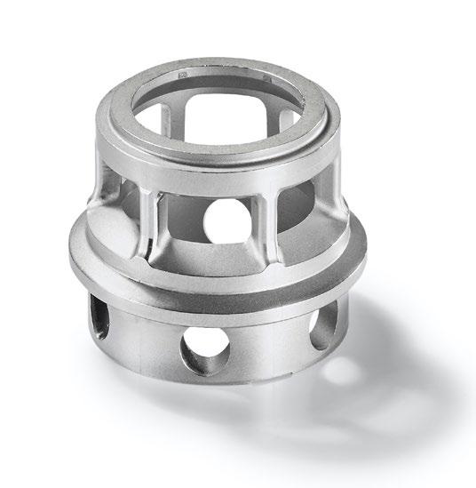
Fig. 4 This adjustment insert enlarges or tapers the intake port of a turbocharger. The diameter is 60 mm, the maximum wall thickness is 7 mm, and the part weighs 184 g (Courtesy Schunk)

Fig. 5 Assembly for an industrial robot consisting of five MIM parts (three gears, cage, plate). The gears are hardened from 100Cr6, cage and plate are made from Fe2Ni (Courtesy Schunk)
requirements. Many experimental materials do not go into volume production, but, when a material is used in a series part, it is given an official factory designation.
For many years, Schunk has used the Kanban method for process control. This serves to avoid supply bottlenecks with the lowest possible level of stocks held in storage facilities. The various production departments (namely feedstock preparation, injection moulding, debinding, and sintering) are independent of each other. Orders are placed with the preceding operational area as soon as each unit is aware of it. “This procedure has proven to be extremely efficient,” said Langer.
Klein and Langer spoke in unanimously high terms of the social commitment of the company’s management. Schunk is by far the largest employer in the area and it invests in the education and training of its employees to enable them to progress to higher roles within the company. The two stated that employees have a close affinity with the company and have little inclination to move to another employer.
With two-material parts in commercial production (also known as two-colour, or two-component, MIM (2C-MIM), Schunk occupies a leading position in the industry. 2C-MIM is achieved by co-injecting two different feedstocks into one mould cavity; this is followed by the debinding and sintering of the parts.
One such application produced by Schunk is the adjustment lever and pin that combines weldable stainless steel and a wear-resistant cobalt alloy in each component (Fig. 6). The two parts are used in a turbocharger with variable turbine geometry. The pin must be weldable and have a surface that is resistant to wear and corrosion, and the adjustment lever must be corrosion-resistant and not wear out despite contact with the pin.
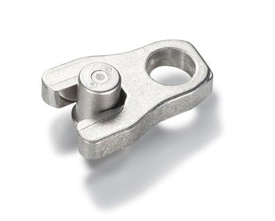


Fig. 7 The shunt (left) is a component made of a copper alloy with defined conductivity that should remain constant over a wide range of temperatures. The pins make it easy to solder to a circuit board. The connection terminals made of high-purity copper are optimised for maximum conductivity. The 2C-MIM process eliminates the need for a joining process and improves contact resistance at the interface between terminals and shunt. (Courtesy Schunk)

Numerous challenges had to be overcome before these parts could be produced to the necessary quality in large quantities. Several formulations were tested with different binders and powders. The sprues of the different materials had to be collected and recycled separately, cycle times had to be extended, and
a common sintering regime had to be found for both alloys to produce parts with high density and uniform shrinkage.
Figs. 7 and 8 show further examples of multi-component capability. This technology is expected to open up many new applications for MIM, as it allows designers to integrate their
desired material combinations into a single component. Examples include soft magnetic and wear-resistant materials, soft magnetic and nonmagnetic materials, weldable and wear-resistant materials, wear- and heat-resistant materials, low-cost and expensive materials, and metal and ceramics.
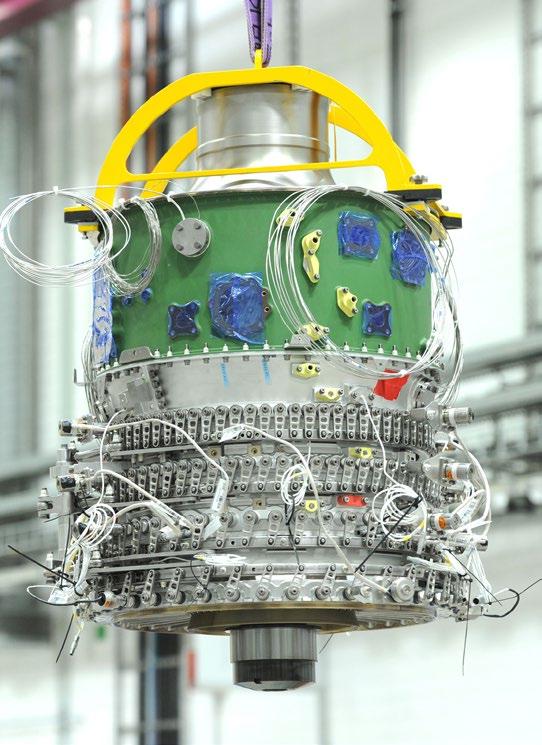
Langer spoke at length with PIM International about how Schunk had to overcome many hurdles on the road to becoming certified for the production of aerospace parts. Langer has served as Head of Research and Development at Schunk for many years, studying metallurgy at the Technical University Bergakademie Freiberg. Today, he leads a team of five engineers and two technicians who dedicate the majority of their time to MIM projects.
The R&D team is chiefly made up of employees who have been trained in-house. Highly skilled young machine fitters are, for example, encouraged to build on their qualifications through training, thereby enhancing their career prospects within the company.
In close cooperation with RollsRoyce Deutschland Ltd. & Co.KG – the company’s first development partner from the aerospace industry – Schunk achieved certification of its quality management system for MIM products according to ISO 9100, the international standard for the aero -
space industry. The company was fully aware that the requirements of the aerospace industry, in terms of documentation and verification, are significantly higher than in the automotive industry.
“The implementation of this standard was hard work,” stated Langer. “It was a great help to us that we had already introduced a management system in accordance with ITAF 16949, the standard of the International Automotive Task Force (IATF), because many procedures of the aerospace standard are based on the automotive standard. Nevertheless, it took us more than a year of preparation before we were able to apply for ISO 9100 certification.”
The qualification of new parts was carried out according to the guidelines of IATF 16949.
Qualification for a new product starts with product development. This includes defining the manufacturing technology, the material and all the details of the component design. Once this is complete, the second phase (‘process development’) follows. Here, all manufacturing steps are defined, including prototyping, an assessment of production capacity, secondary operations and required quality control measures, packaging, etc. At the end of the process development phase, once the products have been approved by the customer, production begins.
The ISO 9100 certification covers the entire MIM process, from the raw materials to the finished part, and Schunk is committed to renewing it every year. The vacuum sintering process for MIM applications in the aerospace sector is also subject to much stricter requirements than in the automotive industry. With the support of the furnace manufacturer, a furnace was equipped with a large number of thermocouples in order to verify and document the temperature uniformity of the furnace load throughout the entire sintering process. In accordance with the requirements of the aerospace

10 Rolls-Royce’s Pearl 15 jet engine. The red circle marks the location of the MIM compressor vanes (Courtesy Rolls-Royce plc)
standard, the accuracy of these thermocouples is checked every three months.
Schunk’s board was fully aware that application development for the aerospace industry takes much longer than for automotive applications – and that achieving a return on investment also takes more time. The long lead times up to the start of regular deliveries are, however, more than compensated for by the fact that aerospace products have a very long service life. With production volumes in the region of 50,000 parts per year, MIM is the most efficient and costsaving method for producing smaller engine vanes.
Guidelines for the development of new products in the aerospace industry distinguish between materials and process. This stems from the conventional manufacturing of wrought materials but does not take into account the fact that, in the MIM process, the material is ‘produced’ simultaneously with the component. This means that the material devel -
opment step has to be undergone twice, without gaining any additional information. In this respect, Langer would welcome an adaptation of the guidelines relating to the qualification of MIM production.
Schunk’s entry into the market for jet engine components occurred in several phases. Its first MIM part for the aerospace industry was launched in 2009. This was an ‘unclassified’ part, meaning that the requirements for quality management are comparable to those of the automotive industry. The part is a lever attached to the cold exterior of a jet engine that is used to adjust the working angle of the vanes in relation to the gas flow (Fig. 9). Initially, these levers – located around the perimeter of the engine – were all of different sizes. Rolls-Royce changed the design so that identical levers
could be used, reducing the need for multiple tool sets and making MIM cost-effective. As a result, the manufacturing cost of the engine could be significantly reduced.
The development of compressor vanes for aircraft engines at Schunk also began in 2009. “We went through several approval stages before the parts were finally released for production,” explained Langer. “Our newly developed products are compressor vanes that are part of static compressor rings. These compressor rings are exposed to temperatures of up to 700°C (Fig. 10). These are classified as ‘sensitive’ parts, which means that while a failure would not endanger lives, it would severely affect the engine’s performance.”
The compressor section of a jet engine consists of a large number of rings, each of which is equipped with around 100 vanes. The temperature to which these rings are subjected rises from the cooling air intake (on the left) to the combustion zone and
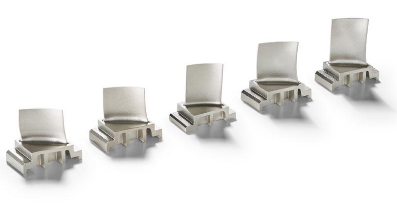
exhaust (on the right). The coolest vanes at the air intake are made of stainless steel, whilst Schunk’s MIM vanes are used in stages 5-9, where temperatures reach up to 700°C; the hottest vanes are made of a singlecrystalline material.
Aircraft engine parts place extremely high demands on their materials. On the one hand, excellent creep resistance at high temperatures is required, and, on the other hand, the material must be resistant to hot gas corrosion. Schunk already had experience with heat-resistant materials for turbocharger components, but the requirements for
compressor vanes are much higher. For this application, a nickel-based alloy Inconel 713 LC with a high aluminium content was required.
Aluminium forms a thin layer of aluminium oxide on the surface and thus provides the necessary resistance to hot gas corrosion. However, the powder particles immediately form an oxide layer upon atomisation, which hinders the sintering process. “Thanks to the close cooperation with our powder supplier, we succeeded in sintering the material to a high density despite the high aluminium
“Eventually, the cause of the lower strength was found, and we succeeded in reproducibly sintering the material to a density of more than 99%. Our sintering process is so stable that we can go without the need for a subsequent Hot Isostatic Pressing (HIP) process.”
content,” said Langer. Achieving this necessitated the installation of a new vacuum sintering furnace in the Thale factory.
The development of MIM technology for high-temperature materials at Schunk received funding from the German government and was carried out in cooperation with a leading research institute. The project succeeded in sintering the material to 98% of its full density, but the strength values of the wrought material were initially not achieved at temperatures above 600°C. Further improvements to the material were then achieved with financial support from Rolls-Royce.
“Eventually, the cause of the lower strength was found, and we succeeded in reproducibly sintering the material to a density of more than 99%,” stated Langer. “Our sintering process is so stable that we can go without the need for a subsequent Hot Isostatic Pressing (HIP) process.”
The final release of the material in 2016 was a milestone in product development; the subsequent process development phase lasted until the end of 2017. At the beginning of 2018,
commercial production of the first turbine vanes for this engine started. The parts are currently injected in a mould with two cavities.
Following the successful market launch of the first MIM compressor vanes, the customer commissioned tool sets for further related vanes made of the same material (Fig. 11), illustrating the level of confidence that Rolls-Royce now has in MIM technology. Rolls-Royce’s engineers have since systematically searched their product portfolio for parts that could be manufactured by MIM with a cost advantage. Numerous suitable parts have been identified.
Process simulation is an important topic at Schunk. “We carry out mould filling studies for each new tool set and document them,” stated Langer. “Before deciding on a particular computer simulation software, we asked a student to compare the results we had obtained with different types of simulation software. The one that came very close to our filling studies is the one now being used by us.
“The aerospace industry expects the entire manufacturing process to be able to be simulated, which simply is not possible in MIM today,” he continued. “While injection moulding can already be simulated very well, sintering – in particular the shape changes during sintering – cannot. The shape changes during sintering are well known and reproducible, but a simulation solution that provides completely reliable predictions does not yet exist.”
Certifications in accordance with international standards are an essential basis for a modern quality management system. Schunk holds certifications according to EN 9100, IATF 16949, ISO 9001, ISO 14001 and ISO 50001, which are regularly

12 Detail of the Pearl 15 engine showing the MIM vanes – located on the right-hand side of the engine (Courtesy Rolls-Royce plc)
“The aerospace industry expects the entire manufacturing process to be able to be simulated, which simply is not possible in MIM today. While injection moulding can already be simulated very well, sintering – in particular the shape changes during sintering – cannot.”
renewed and brought up to date.
An integral part of quality management is the training of employees, which is also documented. The company must demonstrate that its employees are capable of performing their duties (i.e. have the necessary expertise and skills). Before a part is manufactured for the aerospace
industry, the manufacturer must prove that its processes can achieve the part dimensions specified in the drawing. If the process is reproducible, subsequent testing efforts can be reduced.
The requirements for the dimensional accuracy of the compressor vanes are, in many cases, tighter

than MIM can guarantee. Therefore, a 100% inspection of certain dimensions is required. The vane stands on a relatively solid platform, which is machined after sintering to maintain the required positioning accuracy and to save weight. The support structure of the platform is necessary to reduce distortion during sintering. “There is some distortion in the vanes during sintering,” said Langer, “but it is predictable and can be compensated for in the design of the mould cavity. The final manufacturing steps
are barrel finishing and polishing to optimise the aerodynamic properties with an excellent surface finish.”
Very high importance is attached to the quality of the raw material used. The main properties of the powder are the particle size distribution (PSD) and the bulk density. The tolerances imposed on the chemical composition of the powder and the permissible impurities, such as oxygen and carbon, are much tighter than usual.
“The entire manufacturing process is based on the principle that all production conditions are recorded and documented, and data manipulation is prohibited so that, in the event of a component failure, it is possible to trace back how this component was manufactured.”
The main characteristic of a feedstock is the melt flow index, which is determined for each batch. When production is started with a new batch of raw material, the machine operator checks whether the part can be fully formed with the specified machine parameters. If the integrity of the green part and the weight of the part are satisfactory, the raw material and the machine are released for production. During the entire production run, all machine parameters are automatically recorded and documented. As soon as one of the machine parameters is out of specification, the machine is automatically stopped to allow for corrective actions.
Similar requirements apply to sintering. The entire manufacturing process is based on the principle that all production conditions are recorded and documented, and data manipulation is prohibited so that, in the event of a component failure, it is possible to trace back how this component was manufactured.
In order to meet the extremely high quality requirements, extensive testing is required. In addition to a 100% visual inspection, all parts are checked for cracks after machining. A set of standard tensile and fatigue specimens is moulded and sintered with each furnace load to verify the material quality in accompanying tests. The chemistry of the alloy –including any carbon and oxygen impurities – is regularly checked. Density and hardness measurements, as well as metallographic investigations of the microstructure, are also part of this. Schunk benefits from the fact that the accredited Friedrich Eisenkolb materials testing laboratory, which is well-equipped for these tests, is located on the factory premises (Fig. 13).
Thorsten Klein remarked that, as part of his new role, he plans to transform perceptions of MIM with a new marketing strategy. “Our focus will be on innovative applications in the medical device sector, general industrial engineering, and consumer markets,” he said. “Electromobility also offers opportunities, and here the focus is on replacing business lost as the production of internal combustion engines comes to an end.”
Work has already been undertaken on cost optimisation, and part throughput times have been significantly reduced. Trade fair participation and workshops are expected to attract new business.
Schunk has enjoyed close application development partnerships with its customers and, for several years, it has met the demand for ever-shorter development times by producing prototypes in just a few days using metal Additive Manufacturing. To achieve this, Schunk installed sinter-based Additive Manufacturing

Fig. 14 Cage for an electric motor made of soft magnetic pure iron. The part is 17 mm in diameter, has a wall thickness of 0.5 mm, and weighs 12.5 g. Concentricity and ovality are subject to tight tolerance requirements (Courtesy Schunk)
“Our focus will be on innovative applications in the medical device sector, general industrial engineering, and consumer markets. Electromobility also offers opportunities, and here the focus is on replacing business lost as the production of internal combustion engines comes to an end.”
capability. The process that is used falls within what ISO/ASTM categorise as Material Extrusion (MEX). At Schunk, feedstock pellets are used rather than the more widely-known metal-containing filaments as used in Fused Filament Fabrication (FFF).
Called Composite Extrusion Modelling (CEM) by the AM machine’s developer, custom modifications have been made so that the same feedstock granules that are already used by Schunk in MIM can be processed. This allows customers to evaluate prototypes that are almost identical to tool-made serial parts. The comparability of CEM-produced and injection moulded materials was demonstrated on standard test bars made of 17-4PH
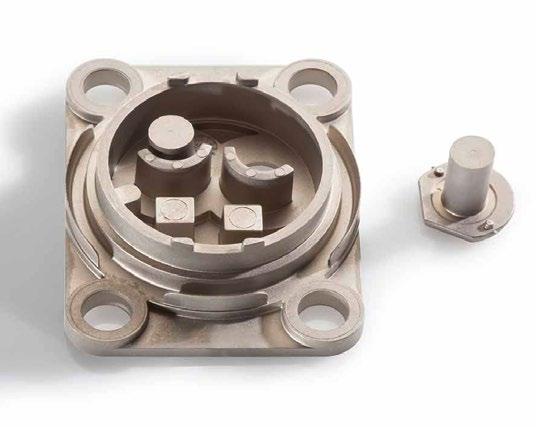
Fig. 15 Base plate and carrier of a housing for the pressure sensor of a passenger car’s ABS system. The part is mounted on the steering. The material is 17-4PH, the part’s width is 50 mm, and wall thicknesses vary between 0.4 and 5 mm (Courtesy Schunk)
and a nickel-based superalloy. The additively manufactured test bars were debound and sintered according to the same technical specifications as serial parts made from these materials. Properties determined in tensile tests at room and elevated temperatures matched the specifications of the MIM materials.
Only the roughness of the surface in CEM manufacturing was inferior to the MIM parts, as a ‘staircase’ effect was apparent on sloping surfaces. Therefore, the surfaces of additively manufactured prototypes may need to be finished. Since the microstructure tests and chemical analyses showed no differences between CEM and MIM components, this method was approved for additively manufactured prototypes of parts which are subsequently to be mass-produced as MIM parts.
Following the successful completion of qualification and certification of the compressor vanes for Rolls-Royce, materials development work continues towards alloys with even higher heat and creep resistance for new applications in even hotter zones of aircraft engines.
“We have some very well-trained materials engineers in our development team and can therefore, in most cases, meet our customers’ needs for special materials,” said Langer. “Through our proprietary binder system, and thanks to our powder supplier supporting us with alloy development, we have the freedom and capacity to produce and test new alloys in a relatively short period of time.”
The market’s demand for lower noise emissions, lower fuel consumption, and fewer pollutant emissions requires the development of new generations of aero engines. With this market development, Schunk believes that it can be considered as the go-to MIM producer and make important early contributions towards component development and the reduction of production costs.
In parallel, the company is keen to leverage the opportunities presented by MIM when conventional PM technolgy reaches its limits. MIM technology offers the ability to cover almost the entire spectrum of metallic materials, especially for high-temperature applications, and, as has been demonstrated, the process can be used to provide dispersion-hardened and intermetallic materials, especially with two-material MIM.
Thorsten Klein Schunk Sintermetalltechnik GmbH D-06502 Thale Germany
thorsten.klein@schunk-group.com www.schunk-sintermetals.com
Author
Dr Georg Schlieper D-45149 Essen Germany info@gammatec.com


The demands on industrial production are constantly increasing. A rising need for complex and individualized parts, even shorter product cycles, a scrutinization of proven supply chains plus a desire for increased sustainability in this transformation – these are the challenges faced by industries worldwide. It is also a chance for AM to showcase its expertise and creativity.
Formnext 2024 provides the ideal platform to showcase your solutions in Additive Manufacturing or along the entire process chain. Actively design the future of production.
Register now as an exhibitor at Formnext and request an offer without any obligation.
Metal Injection Moulding often has an aura of mystery around it. Whilst those in the industry understand the technology well, there are many ‘on the outside’ who are more apprehensive. In this article, Declan Coyle takes some of the mystery out of MIM technology in relation to tooling. Having gone through his own ‘MIM initiation’ process when tasked with developing the tooling for Apple’s Lightning connector in 2011, Coyle is well-positioned to offer some practical ‘do and don’t’ suggestions from a tooling engineer’s perspective.
I have a small confession to make: I still have a copy of PIM International from December 2012. Why? Because this issue had the newly-unveiled Apple Lightning connector on the front cover. And that little connector owned most of my life for a solid eighteen months. It was my introduction to Metal Injection Moulding, the application which taught me about MIM from the bottom up. A true baptism of fire.
I’ll give a little more background to my introduction to the technology back in 2011: I was a new tooling engineer at Apple. My history included a mix of manufacturing experiences that helped me get involved in a variety of tooling flavours. I was eager to learn and grow, so I volunteered for the offbeat stuff as much as possible.
One day, my boss approached my desk and asked me to join him for a five minute catch-up. At the end, he said, “Oh yeah, that reminds me. We have a MIM part coming that may interest you. Sound good? Away you go, have fun, figure it out, and help make this happen.”
And that’s how I got the chance to dive into the deep end of Metal Injection Moulding: on an application that ended up with a production run of billions and, in the process, reshaped an industry.
Building the building blocks
You may be wondering how I approached this mammoth task. What did I do to start my MIM

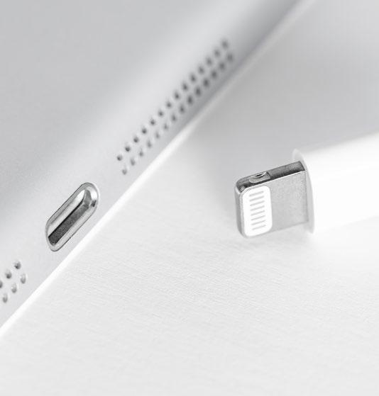
Fig. 2 This little connector owned most of life for a solid eighteen months. It was my introduction to Metal Injection Moulding, the application which taught me about MIM from the bottom up (Courtesy Baurzhan - Adobe Stock)
“My goal here is for you to take away some practical ‘do and don’t’ suggestions from a tooling engineer’s perspective. We won’t get too entangled in specific materials or go too deep into sintering science...”
journey? A few of you may even be wondering how you can start on your own MIM journey.
Well, I started by reaching out to people with MIM experience within Apple, I ordered all the books on the science and application of the technology, and I jumped on a few planes to visit MIM vendors. I asked lots of questions – hundreds of questions. These included:
• What are the most important MIM-related things to know and appreciate as a tooling engineer?
• What makes MIM different from regular injection moulding?
• Do you do anything special with your MIM tool design?
What else do I need to know?
How can I be a better tooling engineer for a MIM programme?
• What do I need to know about material preparation?
• How does the raw material affect part quality?
• Does the material need to be dried?
• How does moulding quality affect what happens after moulding?
• What problems do you suffer from most, and what causes these issues?
With the support of many colleagues and industry professionals, I eventually learned a bit about MIM technology and its application. It’s a magical technology; I still find it hard to believe that it actually works. Now, I want to guide you through these lessons and take some of the mystery out of MIM technology in relation to tooling.
My goal here is for you to take away some practical ‘do and don’t’ suggestions from a tooling engineer’s perspective. We won’t get too entangled in specific materials or go too deep into sintering science – you can do a deep-dive into the aspects that interest you another time. Instead, we’ll chat about overarching concepts, hints and actions that will be useful in all MIM settings. Are you ready? Let’s do this.
Why does anyone use MIM? It’s used to reduce machining time and to create unmachinable geometries. Add the possibility of high-volume production to these two reasons and you can see the obvious economic advantages.
A good place to start our MIM story is with the terms that had me scratching my head way back in 2011. All of these descriptive terms are standard for everyone in MIM, but they shouldn’t be a barrier to newcomers:
• Brown part
• Green part
Feedstock

Brown part
Green part
Sintered part
• Final part
Debinding
• Sintering
• Sintering fixtures
• Re-striking
What does all this mean? Well, let’s take a quick look at the basic manufacturing cycle of a typical MIM part. Fig. 3 shows the basic steps: feedstock (raw material pellets) > green part > brown part > final part. The main operation transitions to focus on are:
1. Moulding
Injection moulding the feedstock, which produces the green part.
2. Debinding
Melt away the ‘polymer’ binder material, which produces the brown part. Debinding will take place at ~500°C.
3. Sintering
High-temperature ‘baking’ to ‘melt’ the porous part into a solid metal component. Note that the sintered part is ~20% smaller than the brown part. Sintering takes place at around 1,200°C for stainless steels (Fig. 4).
Some thoughts on binders: there are many different types of binder, but the typical makeup is a combination of polymer, wax and other materials. Binders are designed so that around 90% can be removed in the debinding stage, while 10% remains to hold the brown part together ahead of sintering (Fig. 5). This 10% is known as the ‘backbone binder.’

Moulding / green part
Debinding / brown part
Sintering / finished part

Fig. 5 A simplified presentation of a green part, brown part and sintered part. In the moulding stage (A), the material contains metal and binder locked together as a solid. During debinding, 90% of the binder is melted away, while the remaining 10% (the backbone binder, illustrated here as the red lines between) maintains the component’s structure (B). During sintering, the backbone is finally melted away as metal is sintered, shrinking to fill in the gaps, creating a solid part (Courtesy Declan Coyle)
“Why does anyone use MIM? It’s used to reduce machining time and to create unmachinable geometries. Add the possibility of high-volume production to these two reasons and you can see the obvious economic advantages.”
“...use proto tooling to find and push a few limitations. Like all injection moulding, you have an open opportunity to approach proto with a sense of exploration. Take some risks. I can tell you, it’s mentally liberating to look at proto tooling as a throwaway.”
All tooling and moulding journeys begin with the prototyping, or the ‘proto’, stage. What’s the best way to approach MIM proto tooling? You may be tempted to do the businessas-usual approach: “Let’s play it safe and make a one -or two-cavity proto tool.” Sounds reasonable, right? First, though, ask yourself: Is this a missed opportunity? What extra value can you get from prototyping?
Why not build a four- or eightcavity tool as well as a simple single or double cavity tool? Even if the CAD part design is 75% complete and still needs lots of work. Be brave. Make the tool with the current CAD maturity. The comparison data between two cavities and eight cavities will teach you a lot.
Imagine the following scenario: you have created the perfect twocavity tool. Parts look amazing, dimensions are within tolerance. Everyone is delighted with the cosmetic quality. High fives allaround! And then you discover the whole process falls apart when you add more cavities. This can be a real spanner in the works.
Instead, you can use proto tooling to find and push a few limitations. Like all injection moulding, you have an open opportunity to approach proto with a sense of exploration. Take some risks. I can tell you, it’s mentally liberating to look at proto tooling as a throwaway. Tell yourself that this tool is not going beyond
proto. Instead, squeeze every single drop of learning and data from this tool. That’s the best attitude to have. Sometimes, however, engineering teams are under pressure to make use of the proto tool in the next stage of development, but be careful. This may limit your design and part performance optimisation and lock you into a safe bet that may not be the best option.
What are the first things I think of when comparing MIM to regular injection moulding? Well, MIM really is a stand-alone technology, so my list is a bit long. Here goes:
1. Material separation
2. Material preparation
3. Feed system
4. The moulding process
5. Sintering fixtures
6. Restrike
7. Tool maintenance
8. Machining after sintering
Let’s dig into each one of these with a bit more detail. As POM is one of the most popular binder materials, we’ll use it as a binder stand-in here. POM stands for polyoxymethylene, and its use was commercialised by BASF SE with its Catamold brand of feedstock. POM-based systems are now avail -
able from pretty much all binder and feedstock suppliers.
Hesitation and pressure drop are things that we watch for in regular injection moulding. It can cause bad welds, trapped air, and difficultto-solve cosmetic issues in plastic parts. Hesitation and pressure drop in MIM have a bigger and less forgiving impact. Why? It creates metal-binder separation. Metal gets left behind in situations where the wall section decreases abruptly, whilst it’s easier for the polymer binder to keep flowing forward.
Imagine a mixture of honey and golf balls. Yes, this sounds messy, but bear with me for a few seconds. In your mind’s eye, put the honey and balls in a bowl. Now give it a good mix. You have just created a proxy for MIM material when heated to moulding temperature (~200°C). In this example, the golf balls represent the metal and the honey is the binder material (Fig. 6).
This mixture flows freely and in partnership when the part wall section is big enough for the golf balls (metal powder) to move freely. That all changes when things get a bit restrictive. If the flow path becomes cramped, the honey finds it easier to continue flowing ahead. Is this mental picture working for you? The honey will glide through the restrictive area. “See ya later golf balls. Gotta keep moving. We’re outta here.” You get the idea.
The metal powder and binder in MIM behave in a similar fashion during moulding, splitting from each other when the going gets tough. This phenomenon can create areas in your part that are binder-rich and a bit low on metal.
And why does this restriction and separation matter, you ask? Well, as you risk getting a part with areas that are binder-rich and metal-poor, mechanical properties can be affected as well as cosmetic issues appearing. So what can you do? Better manage your wall section transitions. MIM does not like sudden changes in wall sections
or tight geometry transitions, so give your wall section transitions a generous ramp lead-in. Be generous with radii. Radii help with flow and give the MIM material an extra few microseconds to react more positively.
2. Material preparation
Material consistency is a critical first step. It’s super, super important in MIM. If you get this step wrong, all other steps will have issues. It’s even more important than getting material preparation right in regular injection moulding. So what do you need to focus on in material preparation?
• Homogeneity
• Dust control
• Pellet size control
Contamination management
Most MIM parts are likely to have a set percentage of reused material. Material from runners and badly moulded parts gets re-compounded back into pellets. This recycled material is then added to virgin material at a specific percentage, dispersed evenly by a mixer. This material needs to be sieved after mixing. Why? The mixing creates extra dust and smaller pellets. You have to remove the dust from your feedstock before moulding.
3. Feed system
You may notice that the gating area of your part is sometimes much darker than the surrounding area. So why does this happen? Because the darker area has a higher metal powder concentration. The material flowed through the runner and then came to the gate restriction. The binder material said, “See ya later,” and flowed ahead. That’s why you get a metal concentration at the gate area (Fig. 7).
But is there anything you can do to avoid this? If you are using a hot runner system, try to land the feed on a mini runner outside of the part. Why? There will be a concentration of metal-rich material at the machine nozzle and hot runner tip. This happens on each cycle as you get

powder

Fig. 7 You may notice that the gating area of your part is sometimes much darker than the surrounding area. This is because the darker area has a higher metal powder concentration (Courtesy Declan Coyle)
material in these areas waiting for the next injection.
Whilst metal-rich areas may be perfectly fine from a mechanical performance perspective, the cosmetic challenges they present are called discolouration. In the end, the criticality of this depends on the cosmetic requirements of your part and the surface finishing specification; if you’re blasting and plating, discolouration will not be an issue.
4. The moulding process
As stated, one of the most popular binder materials is POM. Here’s something to think about if you are moulding this type of material; hopefully it will help you progress without getting stalled with MIM technicalities too early. Forget about the metal component of the feedstock for a while. Treat the material as if it’s plastic only. This will get you 85% through tool design

Fig. 8 A sintering fixture, or setter, is a shaped support on which you place your parts before putting them into the sintering furnace (Courtesy Declan Coyle)
twist during the sintering stage. Parts may get a bit wonky in a few areas. This is OK. Accept it. Relax. Breathe out. This is setting healthy expectations.
Restrike allows you to hit the part with a ‘hammer’ to correct issues with angles, flatness, etc. Don’t try to design your process to eliminate re-strike. Instead, accept the fact that re-strikes will be part of the process. Think of minimising instead of eliminating warp and bend. You will never eliminate it 100%. Embrace the restrike.
Restrike fixtures are like simple press tools. What do they do?
• Hold the part
• Align and locate the part
“Here’s a simple truth that will liberate you as you take on a MIM project: things are going to bend and twist during the sintering stage. Parts may get a bit wonky in a few areas. This is OK. Accept it. Relax. Breathe out. This is setting healthy expectations.”
and process considerations. You will need to make some adjustments to get the last 10-15% of MIM-specific optimisation.
Most people assume that as MIM feedstock is rich in metal it is super aggressive, wearing down everything it comes in contact with: a merciless grinding material. In fact, the opposite is closer to the truth: the binder ensures that your barrel, nozzle and tool steel get practically zero metalto-metal engagement. MIM materials mould easier than you may expect.
Your first question: what is a sintering fixture? It’s a shaped support on which you place your parts before putting them on a tray and into the sintering furnace. Fixtures hold and control parts whilst they are getting ‘cooked’ at 1,200°C and, as such, they are made from
heat-resistant materials like ceramic and molybdenum.
Here’s a mental model I found helpful when designing sintering fixtures: Think of a part as hot, cooked pasta strips. At 1,200°C, the part will fall, collapse, and distort. Thinking of pasta helps you visualise and minimise warpage in advance, informing your fixture design and helping you think ahead to restrike. First, focus on the biggest flat surface; this will be the master surface. It is common to put this in direct contact with the fixture. Features that are likely to sag and warp will require some support. The top part in Fig. 8 represents this type of scenario.
Here’s a simple truth that will liberate you as you take on a MIM project: things are going to bend and
• Control the limits of the intended positive distortion
It’s always a good idea to make your restrike tools adjustable and tunable. This will make setup easier and give you maintenance adjustment options. A few tips for your restrike fixture design:
• Determine the speed and impact of the hit
• Create tools to restrike 10, 20, 100 parts in a single hit
It’s also worth noting that it’s a good idea to factor in a second hit. This will eliminate some of the variation from the main hit; Cpk tracking will tell you if you need it or not.
MIM tools require the same maintenance as regular injection mould tools. There is one major difference, however: you need to pay more attention to keeping the tools clean. It’s easier for MIM flash to break off and create debris in your tool, impacting shut-offs and causing cosmetic issues.
What’s the best way of cleaning a MIM tool? Easy. Take the tool to the tool-room bench. Remove all critical slides, inserts, cavity inserts, core inserts. Pop these parts into an ultrasonic bath. Make sure that the ultrasonic bath is either exclusively
dedicated to your MIM tooling or thoroughly cleaned in advance. Cleaning is a critical component of overall MIM tool maintenance. Depending on your part and production volumes, you will need to clean tools every 3-10 days of operation. The optimal frequency can be determined based on the gradual formation of flash and cosmetic yield reduction.
In short, don’t wait until something demands attention and don’t wait for things to break down. Maintain your tools on a schedule.
8. Machining after sintering
For high-accuracy MIM engineering components, there is usually a bit of extra material left in place for post-sintering machining. Features like round bosses, round holes and location surfaces are CNC machine finished to control accuracy. Keep this in mind with restrike when designing flexibility into your part and process.
You may be thinking, does MIM make moulding life easier in any way? It’s not all extra complexity. MIM can provide a few shortcuts to the tooling engineer. One example is in weld lines, which are more forgiving in MIM as the sintering process erases tiny, localised inconsistencies. The weld simply gets melted and morphed out of existence. Great news for mechanical and cosmetic quality.
With regards to mirror finishes, these are difficult in any injection moulding setting. Every tooling engineer asks, “Do you really need a polished finish? Really, really?” MIM adds to this challenge. It will make life easier if you avoid highly polished finishes on MIM parts. Why? MIM has a habit of producing micro-pores. This is caused by a combination of steel grain sizes and micro gas traps; pores can get uncovered during the polishing process. And there is nowhere to hide if the surface is mirror-like.
“MIM is a fantastic technology; the industry and the people working in the industry are mature and capable. If you are new to MIM, follow the road signs in this article and you will learn, grow and be successful.”
Blasting makes these tiny, tiny, dents invisible. Even a light blasted texture will make your parts look 500% better, massively improving your cosmetic quality and yield rates.
Don’t panic if you have a moulded part that looks a bit strange, with wavy-looking surfaces in a rainbow of grey hues. You may be worrying about a problem that disappears further down the line. Put your parts through the full process before getting upset about a blemish at the moulding stage.
The same applies to a part after sintering – no need to overreact. You may still have the surface polishing (and possibly plating) waiting to save the day. Try not to get upset too early. Let the game play out.

That’s it! A sweeping trip through the MIM cycle from a tooling engineer’s perspective. MIM is a fantastic technology; the industry and the people working in the industry are mature and capable. If you are new to MIM, follow the road signs in this article and you will learn, grow and be successful. Have fun with engineering. You will always not know more than you do know. That’s natural. That’s good. That’s where innovation happens.
Author Declan Coyle Owner & Founder, Furro furrolab@gmail.comwww.furrolab.com

The PIM International newsletter is sent to several thousand industry professionals worldwide. Register today to ensure you benefit from reading the latest industry news and advances in Metal Injection Moulding, Ceramic Injection Moulding and sinter-based AM technologies.
www.pim-international.com/e-newsletter


To all Ceramics Manufacturers, Distributors, Raw Material Suppliers and Research Institutes: WE WANT YOU! Country Pavilions: Italy, China, Germany, United Kingdom, Thailand


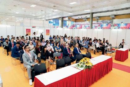
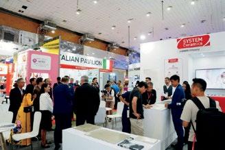


If you were to place a bet on which country was going to take metal Binder Jetting to the highest volumes of commercial production, China would probably be high on your list. As the world’s manufacturing hub for consumer electronics, China already accounts for nearly half of global MIM sales by value. So with markets on the doorstep, and sintering capacity and metal powder supplies ready and waiting, where’s Binder Jetting in China? Here, Dr Q and Dr James report on developments, including a new Sintering Application Center at BJ–TECH Co. featuring HP’s Metal Jet technology.
Binder Jetting (BJT) is one of the seven Additive Manufacturing technologies defined in the ISO/ASTM 52900 International Standard. The technology enables the use of a wide range of metal and ceramic powders to form ‘green’ parts at a relatively high speed.
These green parts are produced by selectively spraying a liquid binder into a metal powder bed. The parts are then sintered to obtain dense functional components. During the BJT process (Fig. 1), the sprayed binder droplets interact with the powder particles, bonding together to form the unit of the cross-sectional layer. Once a layer is completed, a new layer of powder is reapplied on top of the previous layer, and the layer-bylayer process is repeated to create a finished green part.
The unbound loose powder in the powder bed surrounding the parts supports any inverted or overhanging structures during the build process and can be removed using,
The Metal Binder Jetting process begins with the application of metal powder onto a build platform, serving as the foundation for the printing process. The metal powder is dispensed through a hopper or feed bed. Typically, fine metal powders with a moderate flowability are used. A roller is used to evenly spread and compact the powder. Achieving a dense and uniform powder layer is crucial for final part density and distortion.
In the next step the binding agent is selectively applied to the powder bed through the use of a thermal or
for example, compressed air after the build.
Once printing is finished, the binder must be cured or cross-linked to ensure the structural integrity and stability of the printed green part. For this purpose, the entire powder bed is heated in an oven to
Once the powder has been removed, the green parts undergo thermal treatment to burn off the binder and then sinter the powder particles together to produce the part at full density and strength.
After the binder is cured, the printed green parts are removed from the powder bed and cleaned of residual powder. Excess, unbonded powder is carefully removed using compressed air, brushes, or vibration.
piezoelectric inkjet print head. The print head generates binder droplets that penetrate the surface of the powder bed. These droplets wet the powder particles and are absorbed into the powder bed through capillary forces. An optional drying process can be executed after each binder application by using a heat lamp. During this step, a portion of the binder’s solvent is evaporated, and the powder particles are bound together. The powder application and printing process steps are repeated until the desired part geometry is completely built.
global and Chinese BJT machinery landscape
temperatures of up to 200°C to activate the chemical reaction of the binder or to completely evaporate the solvent. The atmosphere used depends on the material but is typically air.
At the end of 2023, I undertook a survey of Binder Jetting machine manufacturers. As one would expect, the most well-known companies in the field are Desktop
Proper depowdering is crucial as any remaining powder becomes part of the component during sintering, affecting the final geometry. Printing
Fig. 1 A schematic of the Binder Jetting process, as published in ‘Metal Binder Jetting Implementation: A strategic guideline to implement Metal Binder Jetting (Courtesy Ampower GmbH & Co. KG)

Metal (incorporating ExOne) and HP (Fig. 2).
“Due to the confidentiality demands of end-user customers, actual data disclosure is rare, but it can be understood that there are many projects underway and that more customers will start using BJT in the second half of 2024.”
The offerings from both these companies are quite transparent, and there is potential for third-party powder usage and cooperation with third-party sintering suppliers. From my experience with potential purchasers of such technology, the greater the level of system openness and transparency, the lower the level of hesitation from potential users and, therefore, the greater the potential demand.
Japan’s Ricoh is also developing its technology in this space, and was quite open about its plans. Chinese manufacturers of Binder Jetting machines are all relatively conservative in their reporting and further data will be gathered this year. One Chinese BJT machine producer with growing visibility is EASYMFG, based in Wuhan (Fig. 3).
The current status of Chinese BJT parts manufacturers has also been studied. Due to the confidentiality demands of end-user customers,
actual data disclosure is rare, but it can be understood that there are many projects underway and that more customers will start using BJT in the second half of 2024.
Some of the most noteworthy among these are the customers from the Metal Injection Moulding industry, where producers are using their long-established MIM sintering equipment and post-processing capabilities (CNC machining, heat treatment, polishing, etc.) to accelerate the adoption of BJT. This has been a trend for some 3C applications since 2020.
The specific nature of the types of orders is difficult to ascertain, although we know they take advantage of BJT’s fast prototyping and aesthetic capabilities. Customers’ demand for samples in a short period of time – or even for small production runs to test the market’s temperature – has also enabled MIM manufacturing companies to have product breakthroughs even during the COVID-19 pandemic. Using this as a metric, it is fair to assume there will be growing demand for products even beyond 3C from this year.
Two BJT contract manufacturers as of the end of 2023 are listed in Table 1.
It is my belief that BJT machine providers will form strong alliances with the MIM industry to improve the design and mass production of small, MIM-like metal products in small, medium and large production volumes from, for example, 100 to 10,000 parts and beyond.
The following concerns exist in the minds of those moving forward in this combined industry:
Powder shape and particle size
At present, powder usage specifications of Binder Jetting are in the range of d10 >3 µm, d50 = 15-18 µm, and d90 <30 µm, with one current limitation being the need to use gas atomised powders with high sphericity. Compared with MIM, where the
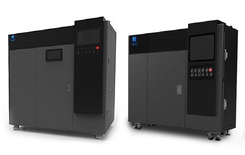

mainstream values are d10 >0.5 µm, d50 = 5-15 µm (determined by surface roughness and material type requirements) and d90 <22 µm, there is a significant gap.
This means the price of BJT powder is still higher than that of MIM. The metal powder industry must be looked to in order to solve this gap between BJT and MIM. As
part of this work, we are currently researching the application of hybrid water/gas atomised powders in BJT.
Materials diversification
Compared to the wide variety of MIM materials processed, BJT is typically limited to stainless steels and tool steels, with 304L, 316L, 17-4PH, and 18Ni300 being the main materials. A
“It is my belief that BJT machine providers will form strong alliances with the MIM industry to improve the design and mass production of small, MIM-like metal products in small, medium and large production volumes...”
“More materials are expected to be launched by the end of this year, including other stainless steels, tool steels, copper, and popular titanium alloys [...]. In the future, the certification of Chinese-made powders will also be undertaken...”
small number of non-ferrous metals are cobalt, aluminium, copper, and titanium alloys. The powder must, of course, be a pure elemental powder or a powder that has been fully pre-alloyed. External research is needed to address certain challenges when processing some specific alloys.
Sintering process considerations
BJT is an ‘indirect’ Additive Manufacturing, meaning that parts require a subsequent sintering step to achieve their final properties. This is in contrast to ‘direct’ AM processes such as Laser Beam Powder Bed Fusion (PBF-LB). However, BJT and other sinter-based AM technologies stand out from direct AM technologies through their low-energy consumption in the forming of green parts, high build rates, and the potential to sinter large quantities of parts at a time. This energy-efficient approach has been shown to be successful in the MIM industry for many years.
However, if a green part does not have a suitable flat area that can be used when it is placed on sintering trays, the green parts must be additively manufactured with a support base during the build process to support them as they shrink during the sintering process, thus avoiding deformation (Fig. 4).
Compared to sintering supports in MIM that can be reused, these ‘live setters’ require additional mate -
rial consumption. This is an area for further study. Such problems are not unique to BJT; overcoming deformation caused by gravity, friction, and material phase changes is a common issue in powder-forming technologies and has been solved in other processes.
In addition to the powder used, sintering technology is crucial to the success or failure of BJT. Fortunately, the larger powder particles used makes BJT sintering less likely to fail. In addition to this inherent advantage, China’s MIM sintering equipment industry has made rapid progress since 2012. This means that one of BJT’s biggest challenges – sintering – should be relatively easy to overcome.
In the future, it is our intention to develop easily movable green part processing and depowdering solutions. It is only with the full automation of the BJT process that MIM operators will be able to significantly expand the technology’s use. The post-treatment of parts will also have to become standard for Binder Jetting. In addition to sintering and machining, these include surface treatment technologies such as sealing, polishing, electroplating, and PVD coating.
This value-added treatment service for products has already found a home in the Pearl River
Delta region, which has many years of experience in the manufacturing of MIM watches, jewellery, and mobile phone parts.
In December 2023, Guangdong BJ Tech Co, Ltd teamed up with HP to establish the Sintering Application Center of HP Metal Jet. The company is located in Silicon Valley Power 2025 Park, Dongcheng District, Dongguan City, Guangdong Province.
The company is investing in the latest Binder Jetting contract manufacturing technology and is focused on serving the thriving Greater Bay Area (Guangdong, Hong Kong, and Macao), providing sample and smallscale production services of 316L and 17-4PH parts to a wide range of designers and customers. A dedicated high-pressure sintering furnace from Sinterzone Technology Co., Ltd is installed, and my consultancy, You neeD Technical Office, is commissioned to provide support for sintering and metal parts post-treatment. More materials are expected to be launched by the end of this year, including other stainless steels, tool steels, copper, and popular titanium alloys. These additions are expected to gradually build up the promotion of BJT in China and, eventually, the world.
In the future, the certification of Chinese-made powders will also be undertaken, allowing more Chinese powder manufacturers to participate in the global Binder Jetting industry.
As Laser Beam Powder Bed Fusion (PBF-LB) has developed over the past two decades, so BJT is bound to experience the same tests and growth. At present, there is still difficulty when challenging traditional metal processing. While industry can accept the fact that metal AM products are currently more expensive, the biggest challenge that metal AM technology faces is comparing dimensional accu -
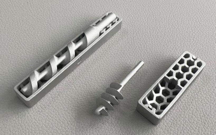
racy and mechanical performance with traditionally manufactured products.
So many of the technical reference articles and reports that I have reviewed as part of my BJT technology survey only discuss the green part forming stage of the process. It appears that too many in
the industry are unfamiliar with the critical high-temperature sintering step.
When it comes to powder handling in the BJT process, there also appears to be a lack of willingness to break the status quo and create technical solutions for depowdering that will work in industrial settings.
“So many of the technical reference articles and reports that I have reviewed as part of my BJT technology survey only discuss the green part forming stage of the process. It appears that too many in the industry are unfamiliar with the critical hightemperature sintering step.”
These are all stumbling blocks ahead of metal Binder Jetting entering the industrial manufacturing and mass production arenas in the next five years. We look forward to more young people joining the ranks of this new powder forming technology, thus adding to the gathered wisdom and accumulated experience to break through any limitations of the technology.
Contact
Dr Q (Y H Chiou)
You neeD Technical Office chiou_yh@yahoo.com.tw


MANUFACTURING INNOVATIONS:
Part design
Part Inspection • Tooling • Secondary Operations • Molding • Simulation • Debinding • Competing Technologies • Sintering • Coatings
MATERIALS ADVANCEMENTS:
• Metals & alloys
• Ceramics
• Hardmaterials
• Binder Technologies
• Mixing
• Mechanical Properties
TARGETED AUDIENCE:
• Product designers • Engineers • End users
Manufacturers
Researchers
Educators
Students


MIM2024, the International Conference on Injection Molding of Metals, Ceramics, and Carbides, was held in Raleigh, North Carolina, from February 26 to 28, 2024. Attended by more than a hundred delegates from ten countries, this latest event in the well-established series was deemed to be an innovative success. This year was – to the relief of both attendees and the Metal Powder Industries Federation (MPIF) – an in-person only event.
Dr Animesh Bose, CEO, Optimus Alloys, reviews some of the highlights from the technical programme.
The purpose of the MPIF’s annual MIM conference is to survey the advances in the injection moulding of metals, ceramics and carbides, foster innovation, and act as a conduit for cross-fertilisation and technology transfer across different areas of Metal Injection Moulding (MIM), Ceramic Injection Moulding (CIM) and sinter-based Additive Manufacturing (AM). The event also serves to keep the community updated about other technologies that could impact markets in both positive and negative ways.
This year’s conference included twenty-five technical presentations that focused on some of the recent advances in MIM, CIM and sinter-based AM processes, materials, testing, tooling, and sintering. The technical programme was well augmented by ten minute presentations by various companies during the ‘Technological Process and Product Innovations’ sessions that highlighted each company’s respective technology. Nearly thirty companies showcased their products and services during a tabletop exhibit that was well-attended.
Several Metal Injection Molding Association (MIMA) functions took place alongside the conference, including meetings of the MIMA Standards Committee, the MIMA Board of Directors and MIMA member meetings. As is tradition, a
PIM Tutorial was organised by the MPIF prior to the event, conducted by Matt Bulger, a former MIMA president.
One additional attraction at this year’s event was a reception and tour of Kymera International’s


“Student participation was encouraged through the
provision
of five
grants
The opening keynote lecture – ‘ESG/ Sustainability: A smart decision that goes beyond regulatory compliance’ –was delivered by Barton White, CEO, Kymera International. White’s first slide pointed out that the comprehensive approach to ESG adopted by Kymera shows an unwavering commitment to the triple bottom line: People, Planet, and Profits. He pointed out that Kymera’s approach to ESG includes measurable objectives, an emphasis on safety, inclusive reward structures, and community engagement to further the company’s well-rounded dedication to responsible business practices.
that allowed students to
attend
themselves
the conference and immerse
in the technology. Two of the five were from Europe.”
copper (alloys and oxide), tin and antimony powder and paste plant in Research Triangle Park (RTP), North Carolina. Approximately sixty people attended, taking the opportunity to network with Kymera staff.
MPIF continues its mission of educating the next generation of PM professionals by engaging students and exposing them to the world of PM technologies, including MIM and sinter-based AM. Student participation was encouraged through the provision of five grants that allowed students to attend the conference and immerse themselves in the technology. Two of the five were from Europe.
These grant recipients were exposed to a plethora of insightful presentations, as well as being provided with the opportunity to connect with other professionals, gain exposure to the MIM industry, and grow their network. Additionally,
each of the five students was given the opportunity to present the research they were engaged in at their universities. The five student grant recipients this year were Margarete Hufnagl, Montanuniversitaet Leoben, France, Ian Wietecha-Reiman, Penn State University, United States, Juan Jiminez Alumbreros, UCLMUniversidad de Castilla-La Mancha, Spain, Fatou Ndiaye, University of Louisville, United States, and Kaustubh Deshmukh, Virginia Tech, United States.
This review will only be able to cover a small number of the presentations delivered at the conference. So many of the presentations added value to the industry, meaning that the task of selecting what to feature in this report was a difficult one. My apologies to those presenters whose work could not be covered due to space restrictions.
White then delved into more details on the three parts of ESG. In the environmental portion, the question was raised: when did the environment become a global concern? To the surprise of many, White stated that the answer is as far back as 500 BC, when some ancient yet forward-thinking authors discussed concern for environmental degradation resulting from human activity. However, in modern times, according to White, Theodore Roosevelt was the first US president to really take action, establishing approximately 230 million acres of public lands between 1901 and 1909, including 150 national forests. Some sixty years later, it was JFK who became the first to talk about ‘climate control’ in 1961 – a topic broached by every US president since. ESG as a whole, however, only came into prominence in 2006, when companies were encouraged to ‘put their money where their mouth is.’
It is well known that the PM industry is significantly impacted by the transition from the Internal Combustion Engine (ICE) to Electric Vehicles (EVs). However, as often is the case, stated White, commitments are often made by government and companies without fully realising what they are signing up for. This, he stated, was the case with the EVs, when, in April 2023, the US Government mandate was that two-
Plug-in hybrid
Gasoline engines
Plug-in hybrid w/eFuels
Pounds of CO 2 emitted per year from single vehicle (estimations by Barton White) Hybrid eFuels
Pounds of CO 2 emitted per year from single vehicle
thirds of new vehicles sold in the US must be fully electric by 2032. In 2021, GM committed to only sell EVs by 2035 – but in 2023, GM sold 76,000 EVs compared to its total of 2.6 million, or 3% of its (volume) sales. The 2023 sales of EVs were 1.1 million (7.6% of total volume), while 2024 sales are forecasted to reach 9.6%.
White pointed out that EV inventory remained in stock for an average of 113 days compared to only sixty-nine days for ICE and hybrid vehicles. He also pointed out that EVs, despite zero tailpipe emissions, are not necessarily as environmentally friendly as one may first think, and have their own issues with the social and governance portions of ESG. This, he stated, was particularly the case with regards to mining for raw materials.
Another concern with EVs, according to White, is the lack of necessary infrastructure. Currently, Level 1 charging (plugging into a domestic wall socket) takes 40-50 hours to charge. Level 2 charging points (the type of charger that EV owners will typically install at their residential address), takes 5-10 hours to charge – or overnight. Level 3 charging stations (known as superchargers, or DC Fast Chargers) take 30 minutes to 1 hour to fully charge.
White stated that to meet 2030 mandates, >2 million Level 2 charging points and >200,000 Level 3 charging stations will be needed, costing an expected $25 billion. For reference, in 2023 fewer than 25,000 Level 3 charging stations were operational in the US. White also raised the case of power failures, especially
in the event of a natural disaster when evacuation is required.
In comparison, it was stated that significant improvements to ICEs have been made, and continue to be made. Toyota and Mazda have vastly improved the thermal efficiencies of their vehicles’ engines, meaning the fuels are more efficient (burn off slower) and thus efficiency improved. Other areas of improvement in ICE-based vehicles include better aerodynamics, cylinder deactivation when a car is stopped, and turbocharging, which have also improved fuel efficiencies over the years.
White stated that some of the alternate types of vehicle power sources that are currently being developed include hydrogen-based fuel and eFuels. Currently, Shell and Exxon are working to develop novel eFuels. Shell is developing a blend of second-generation ethanol derived from sugar cane waste and other biofuels to create a fuel that is 100% comprised of feedstocks categorised as ‘renewable’ under the applicable regulatory frameworks. This eFuel is expected to produce 60-80% less CO 2 compared to traditional fuels. If one considers the CO 2 emissions, it can be observed that gasoline engines are bad (emitting nearly more than double than that of other types of power sources) while all electric and plug-in hybrids with eFuel are the two lowest CO 2 emitters.
The social impact of ESG, according to White, is often overshadowed by the environmental aspects. He stated that the social aspect of ESG is meant to reduce social inequalities (defined ‘condition[s] where people have
unequal access to valued resources, services, and positions in society’) in the workplace and beyond. He outlined five types of inequalities: racial, wealth, gender, geographical, and educational. White commented that the ‘S’ should humanise ESG inside the workforce through competitive compensation, positive company culture, trust, fairness, communication, professional development, diversity and inclusion.
White went on to state that the ‘G’ (Governance) in ESG also does not receive as much attention as it should. In governance it is important to pay attention to the following: board composition; business ethics; anti-corruption; incentive structure; and supply chain management. He went on to add that corporate governance is foundational to the realisation of ESG, and makes his case by raising the question that if there is a question around the ethical behaviour of an organisation, how can stakeholders trust that the reported environmental data is accurate? And, if employees and customers do not trust an organisation’s ability to operate fairly, employee turnover will increase, customers will look for alternate suppliers and investors will be wary of management’s ability to drive success. White cited the examples of Volkswagen’s emission test scandal and Facebook’s misuse of data.
ESG accreditation can now be done through EcoVadis, a globally recognised business sustainability rating provider. Scores account for efforts relating to the following ESG themes: environmental, ethics, labour/human rights, and sustain -
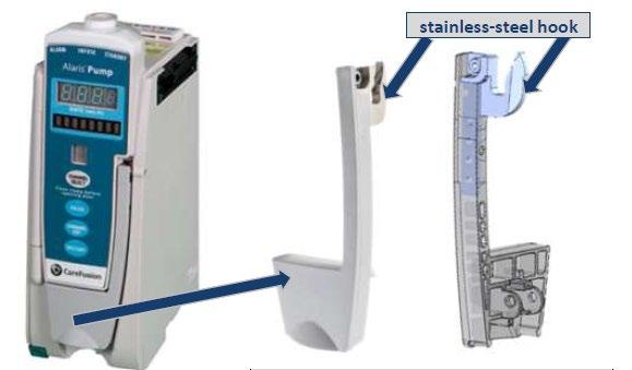


able procurement. White stated that Kymera’s 2027 goal is to be among the top 1% of all EcoVadis-rated companies. He stressed Kymera’s employee-centric initiatives – as well as its governance – for transparency and accountability that leads to overall stakeholder confidence.
White concluded his presentation stating, “Sceptics will say that ESG is just a money pit and adds no value to an organisation, but I think it is the complete opposite. Not only because it is the smart thing to do, but also because it’s the right thing to do.”
Jason Osborne and Jeff Howie, from Alpha Precision Group’s MIM Division, part of Nichols Portland
Inc, co-authored an interesting presentation entitled ‘Comparison of MIM and conventional PM material properties, cost considerations and other business case factors for an aftermarket medical hardware component.’
Osborne, who presented the paper, stressed that for the purpose of such a study, a part must be carefully chosen to ensure that it can be fabricated by both the conventional PM ‘press & sinter’ process, as well as by the MIM process, without the part offering any major advantage or disadvantage to either.
The investigation was prompted by current economic conditions (high interest rates and inflation) that have negatively impacted the business case for new capital equipment, leaving some businesses
more likely to repair and refurbish equipment, or turn to the used or refurbished equipment market for their immediate needs.
These conditions offer growth potential for the service parts industry supplied by OEMs and aftermarket suppliers. The part exemplifying this was a medical infusion pump module that sells for $2,600 for a new OEM unit, with the cost of a refurbished or aftermarket version costing between $550 and $850 (referenced prices were based on Google Shopping search results for ‘Alaris 8100 Infusion Pump’).
The OEM replacement parts offer performance and durability identical to the original factory parts because they are manufactured from the same PM tools, using the same production process, material and acceptance criteria. However, OEM replacement PM parts are more expensive as the manufacturing process, which is best suited for high-volume production, is not cost-effective for lower-volume replacement needs.
Aftermarket providers can offer different designs, manufacturing processes and materials, ranging from low-cost ‘knockoffs’ to premium solutions that provide improved durability and/ or performance. A technically-savvy aftermarket supplier can develop a solution that is both cost-effective and better performing than the OEM service part.
This presentation detailed one case study of the aforementioned medical infusion pump module produced by two different technologies: (a) the OEM assembly where the component is produced using conventional PM technology and (b) the aftermarket assembly where the component is produced using MIM. The presentation compared the material properties, performance, and enterprise cost of the aftermarket and OEM production.
The findings showed that MIM technology offers a competitive, robust solution for the lowervolume aftermarket requirements. The OEM production model uses
a door latch sub-assembly with a conventional PM stainless steel hook while the lower-volume aftermarket and refurbished models use a MIM stainless steel hook in the door latch sub-assembly. The replacement cost of door latch sub-assembly is ≈ $80+ for the OEM version, and ≈ $35-48 for an aftermarket version (referenced prices based on Google Shopping search results for ‘Alaris 8100 Infusion Pump replacement door latch’).
The presentation went on to provide more details on the application and the requirements of the part. Due to the high cost and function of an infusion pump unit, its reliability is crucial; it will not function if the door latch does not sit properly. Functionally, the stainless steel hook is the most highly loaded component in the door latch system, and it must withstand regular opening and closing events. The hook interacts with a roller mounted to a spring-loaded stainless steel MIM latch component. As the application is a medical device, the hook must also be corrosionresistant and able to withstand any contact with various disinfectant cleaners (ammonia, bleach, carbolic acid, hydrogen peroxide, etc.).
The processing steps for the PM and MIM components are quite


different (as shown in Fig. 7), the most notable being in the green shaping technique (die pressing for PM parts and injection moulding for MIM parts);
the debinding process; and the sintering process (a continuous furnace for PM parts versus a batch furnace for MIM parts).
The resulting final properties do


exhibit some differences as shown in Table 1.
Conventional PM 316N-35 (nitrogen alloyed, sintered at 1,290°C in dissociated ammonia atmosphere) has high strength and good corrosion resistance compared to other conventional PM 300 series stainless steel alloys. It should be noted that the 6.7g/cm 3 density equates to roughly 87% of theoretical density (13% porosity). MIM 316L has higher UTS, elongation and superior impact resistance compared to PM SS-316N. The 7.6 g/cm 3 density for MIM parts equates to roughly 98% of theoretical density (2% porosity).
The higher sintering temperature (in a vacuum) and near full-density (98%) of the MIM-316L offers superior corrosion resistance compared to conventional PM 316N2, with a minimum of five times the corro -
sion resistance (<0.005 g/dm 2/day vs. 0.024 g/dm 2/day).
A detailed cost estimate analysis was carried out when comparing the conventional PM versus the MIM process. The cost estimation had the following assumptions:
1. Workplace fixed costs were based on new replacement cost of equipment, 10-year straightline depreciation schedule, 10% interest rate, $7.70/ 0.09 m 2 (1 ft 2) cost for space (manufacturing space national average, January 2024), 245 production days/year, 3 shifts/day x 8 hours/shift, 80% workplace uptime
2. Workplace variable costs were based on $0.08/kW-h electricity cost (national average, November 2023), $0.03/scf hydrogen cost
3. Operator cost is $22/h labour cost (national average for non-
union manufacturing labourer in 2022)
4. Technician cost is $29.25/h (operator cost + 33% premium)
Osborne pointed out that the cost analysis does not include the following as they can vary significantly from one company to another: SG&A, workplace repairs and routine maintenance costs, tool refurbishment and replacement costs, indirect labour and overheads, scrap, and profit margin.
Based on the above considerations, Osborne and Howie concluded that lot sizes (quantity per set-up) play a big factor in which process is more competitive. Conventional PM is more cost-effective for production lots over 1,000 pieces, while MIM is a more cost-effective process for production lots under 1,000 pieces. This difference is primarily due to the set-up time required for conventional PM presses. Upfront tooling investment is different for each technology: conventional PM tooling for a ≈100t multi-level press (two upper punches, two lower punches, shelf-die, four core rods & adapter hardware) ≈ $25,000-30,000 while MIM dual cavity tooling for master unit die ≈ $17,00020,000. Thus, the ≈ $5,000-13,000 difference in tooling cost has to be factored into the business case.
* MPIF Standard 35-SP does not include published properties for SS-316N2 @ 6.7g/cc density, so the values in the chart above are based on average values of SS-316N2-33 (6.5g/cc) and SS-316N2-38 (6.9g/cc).
Based on the above cost considerations, the authors concluded that the enterprise cost for either technology is heavily dependent on the final customer volume requirements. If the customer only wants a one-time production run, MIM is more competitive up to ≈ 21,000 pcs. For recurring spot buys for lot quantities of 1,000 pcs or less, MIM has a clear cost advantage for both the up-front investment and the cost per piece. For lot quantities of 2,500 pcs, it would require more than thirteen orders before conventional PM comes out ahead (due to the higher up-front tool cost); for lot quantities of 5,000 pcs, it would require more than three orders before conventional PM comes out ahead; and for lot quantities of 10,000 pcs, it would require more than two orders before conventional PM comes out ahead. Any recurring orders over 21,000 pieces gives conventional PM the cost advantage.
In summary, the authors concluded that, from a performance standpoint, MIM-316L offers superior mechanical properties and corrosion resistance compared to PM 316N2-35. In theory, this should translate to a more robust aftermarket component with an improved lifespan compared to the OEM component. They also pointed out, however, that there is no data available showing the lifespan or failure mode of OEM versus aftermarket latches in the field. From a cost perspective, the MIM solution does offer a cost advantage at lower production volumes.
Typically, the volume for service requirements is a fraction of the production volumes, so MIM can be very cost effective for aftermarket applications, with the up-front investment for MIM tools also offering a lower cost of entry for new aftermarket applications. Unfortunately, the price of the aftermarket latch is roughly half the price of the OEM latch, which would tend to suggest that the aftermarket products are likely marketed as low-price alternatives rather than high-performance upgrades to the OEM latch. The price of a replacement latch (OEM or aftermarket) is low compared to the purchase of a new infusion
Switch-over to holding pressure
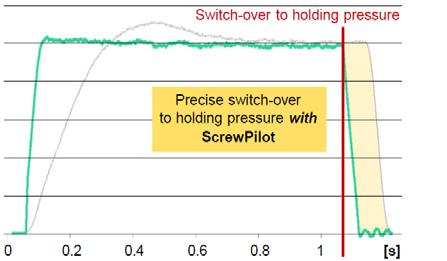
Precise switch-over to holding pressure with ScrewPilot
Injection regulation (hydraulic) aXw control ScrewPilot (hydraulic/electric)
pump unit, so it makes sense to replace the latch if it fails. However, it’s a nuisance whenever an expensive infusion pump unit becomes inoperable due to the failure of a low-cost part. The more robust MIM 316L hook reduces the likelihood of a repeat latch failure.
The authors concluded that different sinter-based technologies (conventional PM and MIM) both offer viable solutions for the stainless steel latch based on specific market needs. Conventional PM is a low-cost solution for the high-volume OEM production unit, while MIM is a more robust solution that offers cost advantages for lower-volume aftermarket service requirements. It is not often that presentations are made on a detailed cost comparison between two PM technologies, but this paper did an excellent job of a detailed cost comparison between conventional PM and MIM for the same part.
Marko Maetzig from Arburg GmbH & Co KG presented a paper entitled ‘Machine setup and significant parameters to adjust the MIM moulding process.’ He had divided his presentation into two parts:
1. Machine options for improved injection moulding for MIM that
included drive technology, aXw Control ScrewPilot, PIM cylinder assemblies, and PIM nozzles
2. Vacuum system and machine parameter setup and impact on moulding process that included melt preparation, the moulding process, and monitoring.
In the area of drive technology, Arburg has a wide product range with a modular system – from fully hydraulic to fully electric, enabling optimum configuration to be achieved for each application. Various machine sizes with a practice-oriented range of clamping forces and injection units are also available, further driving customisation through modularity.
The aXw Control ScrewPilot provides a controlled injection process based on precise measurement of screw position, and the injection speed is actively adapted in the event of external fluctuations; it also allows for in-cycle control with the switchover point remaining constant.
Arburg also offers special automatic control technology for hydraulic injection units. The benefits of this system include even flow front characteristics, switch-over to holding pressure at the same filling level, and injection parameters that are unchanged, resulting in a stable injection process. This also provides high injection dynamics; dynamic and active braking (Fig. 8) is also possible.
Reduced sprue length with PIM - nozzle
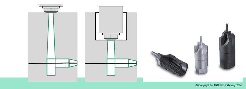
In the area of the cylinder assembly, Arburg achieves high wear protection and long service life through the use of a bimetal cylinder for MIM operations, whereas the cylinder for CIM has hardmetal liners. The screws for MIM processing are made from PM steel, while screws for CIM operations are made from hardmetal. The nonreturn valve is made with hardmetal inserts, with the option of having the non-return valve made from hardmetal drive technology. The nozzles incorporate a special design that results in a short sprue because of its extended length versus the traditional nozzle, resulting in optimal material utilisation (Fig. 9).
The vacuum system provides several advantages, including prevention of flow-line issues and binder migration, resulting in consistent part quality, the prevention of air inclusions, enabling complete mould filling, uniform filling behaviour, programming with dedicated symbols, and flexible programming that integrates all common vacuum concepts. A reliable evacuation that results in good process or quality control is achieved by the recording of signal patterns and their presentation in a monitoring visualisation, with the
monitoring of extreme values and their precise evacuation sequence also taking place.
The parameter setup and its impact on the moulding process was covered in detail by Maetzig. He pointed out that the physical and thermo-physical properties of MIM feedstocks are substantially different from those of the binder, including the fact that the density of MIM feedstocks is typically 3.5 times the density of the binder; the heat conductivity of MIM feedstock is around 6 times the heat conductivity of the binder, and the heat capacity of MIM feedstock is generally around one-third of the heat capacity of the binder.
During melt preparation, the temperature adjustment of the plasticising unit is set to temperatures according to suppliers’ recommendations – preferably at lower end thereof to avoid overheating of the feedstock that can result in material degradation – while the feed yoke temperature is adjusted to the lowest melting point of binder components. Dosage speed and the back pressure during dosing also play important roles in the melt preparation step. Low dosage speeds are generally preferred to avoid exces -
sive shear of feedstock and it is recommended to use cooling time for the dosing process. Low back pressure during dosing is also preferred.
Nozzle retraction/sprue break should be used on moulds with cold sprue, and feedstock freeze-off in the nozzle at the mould contact area should be avoided. Pressure peaks during moulding and injection of cold slug should also be avoided. During the moulding process, attention should be paid to flow rate adjustments which, if too slow, can lead to premature freezing of feedstock and cold pushing; if it is too high, it can lead to powder-binder separation, air entrapments and burn spots.
Switch-over point adjustment is carried out when the fill cavity is 95-98% filled. If this is done too early, one can have filling via holding pressure with loss of position/speed control, while doing it too late can result in pressure peak and compressive stresses. Mould filling analysis is a helpful tool to analyse filling behaviour. To use this, it is recommended that the operator adjusts the flow rate and pressure used in production and keeps all holding pressure parameters to a minimum (flow rate, pressure, holding times), delaying the time for dosing and varying the injection flow rate to optimise filling.
Monitoring of injection parameters plays a critical role in the MIM process. The pressure at switchover point should be constant in order to achieve consistent part quality and a stable process. Pressure variation can happen if the switchover point is too late or too early, if different feedstock batches are used, or when changing the balance of virgin and re-granulated feedstocks.
Dosage time should also be kept constant to achieve constant cycle time and consistent part quality. Reasons for dosage time variations include cylinder and screw roughness, granulate size and size distribution, and the use of re-granulated feedstock.
In conclusion, Maetzig pointed out that the moulding process is an important step towards high-quality MIM parts, and the right moulding machine configuration can help achieve this. A good understanding of process parameters and setup is the key to achieving high-quality MIM parts.
An excellent case study entitled ‘Utilizing Metal Injection Molding (MIM) in the manufacture of a large tungsten heavy alloy WHA firearms component – problems and solutions’ was covered in a presentation by Gaetano Mariella of PTI Tech Inc., New Jersey, USA.
In the presentation, Mariella detailed the study based on a unique high-density tungsten-based alloy that was used to produce a firearm component. A major firearms manufacturer approached PTI Tech in search of a solution to a machined part. As part of the firearm’s bolt design, the customer required a component with a large amount of mass in a limited volume that would act as a dampening mechanism/vibration absorber.
Looking through the list of available high-density metals and alloys, most materials were removed
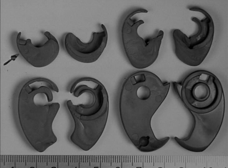
from consideration as they were too expensive (gold, platinum), too difficult to process in the elemental form (W) or too toxic (uranium). The material that was found to be applicable was a class of tungsten alloy known as tungsten heavy alloy.
These alloys are a two-phase composite comprised of a pure W phase combined with a binder phase that contains some dissolved tungsten. Liquid Phase Sintering (LPS) of these alloys achieves >99.2% of theoretical density. The density of the alloys can be varied, and the final alloy density can be close to pure W. The alloy has good machinability, and common machining techniques can be employed. The alloy has a strength similar to medium carbon steels, has a high elastic modulus (stiffness), low CTE, high thermal
conductivity, and low toxicity. Depending on the alloy density, tungsten heavy alloys have been divided into several different classes as shown in Table 2.
The initial question was which composition would be best for the application. The issue with lower tungsten containing alloys is the higher volume of liquid that is formed during liquid phase sintering, which can result in slumping and distortion. The solution was to choose alloy compositions that would have lower liquid volumes (which then become the matrix phase), thus lowering the distortion. The alloy that was chosen for MIM production in order to mitigate sintering distortion and retain ductility had a composition of 95W-3.5Ni-1.5Fe wt. % and the alloy had a theoretical density of 18.16 g/cm 3
Table 2 Class of tungsten heavy alloys (Courtesy PTI)
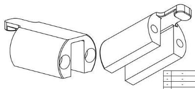


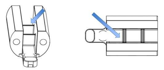
“...the relatively heavy lobes, which had thin web areas at the bottom, tend to bend over during liquid phase sintering. To solve this, another design modification was made: two support ribs were added to the structure.”
Another major design consideration was the thick cross-section of the lobes, which would create problems during the debinding process. PTI worked with the client to incorporate the largest through holes possible to facilitate the debinding of the thick cross-sections. This was a critical design modification that was needed for the part to be properly debound.
The next challenge was that the relatively heavy lobes, which had thin web areas at the bottom, tend to bend over during liquid phase sintering. To solve this, another design modification was made: two support ribs were added to the structure (Fig. 13) to mitigate the distortion of the part during liquid phase sintering. This would then add an additional step where the two support ribs would need to be removed by machining.
PTI explored several gate locations; configurations and sizes prior to final tab gate location shown in Fig. 14. The company had to iterate numerous moulding profiles to achieve a fully filled part with no large flow or knit lines. The parts

were subjected to solvent debinding which was followed by thermal debinding. The final sintering was carried out in a pusher furnace, using a flowing H 2 atmosphere, with a sintering temperature around 1,500°C peak temperature and a hold time of 2-3 hours.
The final density of the part was around 18.0-18.05 g/cm 3, which was more than 99% of theoretical density, and the part’s weight was around 250 g. There was significant shrinkage between the green and the sintered part as shown in Fig. 15. The two ribs and the tab gate are removed by machining to achieve the final part. This case study shows the successful fabrication of a large component made by MIM from a high-density tungsten heavy alloy.
Feedstock modification and debinding methodologies
An interesting presentation entitled ‘A review of the attributes and debinding methodologies of binders utilized in MIM process’, authored by Dwight Webster and Lane Donoho of Advanced Metalworking Practices (AMP), Indiana, USA, was presented by Webster.
It is not too often that presentations are on the subject of MIM binders and their modifications to achieve desired flow behaviour. This presentation reviewed two of the most common binder systems. It discussed methods of adjusting flow properties via various manipulations of the binder systems, and reviewed examples of applications.
Over the years, a multitude of mixtures of powders and binders have been formulated to make MIM feedstocks. Often, MIM processes are distinguished by the binder removal methods (debinding) of which the three common ones are based on water debinding (polyethylene glycol (PEG)-based), thermal-solvent debinding (wax-polymer based) and catalytic debinding (polyoxymethylene (POM)-based). This presentation focused on the latter two debinding technologies and their binder systems.
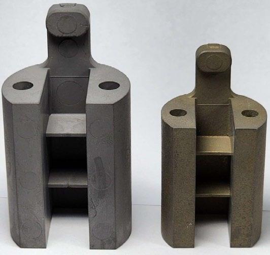
15 Comparison of size between the green (left) moulded part and the sintered part (right) (Courtesy PTI)
“It is not too often that presentations are on the subject of MIM binders and their modifications to achieve desired flow behaviour. This presentation reviewed two of the most common binder systems.”
Generally, both binder systems have two main constituents: the primary binder (wax or POM) and the secondary binder (backbone binder). A multi-component binder system often has a few more minor additives, but the two primary constituents are the ones outlined as primary or secondary. The primary constituent typically accounts for more than 50% of the total binder composition (by weight) and is removed first, resulting in an open pore structure.
Once the primary binder is removed, the backbone material (secondary binder) provides the strength and integrity to support the
subsequent handling of the parts. The backbone material is typically removed thermally as part of the sinter cycle. The open pore channels created in the structure after the primary binder removal creates the pathways for the easy removal of the secondary binder(s). The feedstock produced at AMP is generally evaluated using a plastometer for flow behaviour, a gas pycnometer for the measurement of the feedstock density and a capillary rheometer that is also used to measure the flow (including characterising the viscosity versus shear rate behaviour). Examples of several wax-polymer-based
formulation, for targeting properties between AM1 and AM2 AM-4
One of two formulations developed for stainless steel applications, with enhanced flow, and modified backbone AM-5
2nd of two formulations developed for stainless steel applications, with enhanced flow, and modified backbone AM-6
Modified version of AM-4 using higher wax, developed for high metal loading applications
Intermediate flow formula, between AM-4 & AM-6 custom developed for an orthodontic application
Table 3 Examples of several wax/polymer-based binder systems used at AMP (Courtesy AMP)
Change in the viscosity when the percentage of the primary binder is varied. Solids loading is 59 vol.% using water atomised powder (d90 of 16 µm) (Courtesy AMP)
binder systems are shown in Table 3. Keeping the solid loading constant at 59 vol.% using water atomised powder that has a d90 particle size of 16 µm, Fig. 16 shows the change in the viscosity when the percentage of the primary binder is varied. It can be observed that as the percentage of primary binder in the binder composition is increased, the viscosity of the feedstock is lowered. This behaviour does make sense, as the primary binder is generally the lower viscosity component of a wax-polymer-based binder system. A similar behaviour is also observed in the case of gas atomised powder where the solids loading is kept constant at 61 vol.% using a gas atomised powder with a d90 of 22 µm (Fig. 17). It is interesting to note that the gas atomised powder, even at the higher solids loading, shows a lower viscosity when the primary binder percentage is the same.
17 Change in the viscosity when the percentage of the primary binder is varied. Solids loading is 61 vol.% using gas atomised powder (d90 of 22 µm) (Courtesy AMP)
A case study with the wax-polymer binder system was described by Webster where AMP received an enquiry for a thin-walled part made from 17-4 PH stainless steel material and where the customer was open to using either the pre-alloyed powder or the master alloy blend. The customer was having difficulty filling parts with their current feedstock material. They also stated that
the part was cost-sensitive and that target shrink equated to 60% solids loading.
Based on discussions with the customer, it was decided to use pre-alloyed water atomised powder having a d90 – 16 µm. Based upon AMP’s experience, it was suggested that the best flow option would be achieved with AM6, the company’s highest-flowing wax-polymer binder.
For the POM-based binder system, Webster presented three different systems (AC-1, AC-2, and AC-3) with the same percentage of primary and secondary binders but with three different POMs with varying flows. The first one (AC-1) was based on a low-flow POM that had a flow rate of 10.5 g/10 min at 190°C, while the next one (AC-2) had a medium-flow POM that had a flow rate of 55 g/10 min at 190°C, and the last (AC-3) had a high-flow POM that had a flow rate of 120 g/10 min at 190°C. The secondary material in all three binders was an AMP proprietary backbone component. The details of the POM binder system are shown in Table 4.
The presentation highlighted the differences in the viscosity between the wax-based and POM-based binder systems as shown in Fig. 18. For the same solids loading (61 vol.%), it can be observed that the POM-based binder (using the low-flow POM) has a higher viscosity when compared to the wax-based binder system. However, when using the highest flow rate POM – even when using a higher solids loading – the viscosity can be lower than the wax-based system. There are a few important pieces of data that will be filled in at a later stage (e.g. determining the viscosity of a feedstock that has a solid loading of 61 vol.% that uses the AC-5 based binder system and comparing it with the wax-based binder system as well as the AC-1 (POM-based) binder system.)
A case study was also discussed by Webster that outlined the need of a customer who was trying to fill small components using a feedstock with a target loading of 62 vol.%. As the parts were small, AMP opted to first use the lowest viscosity
Table 4 Details of the three AMP POM binder systems in tabular form (Courtesy AMP)
Fig. 18 Comparison of the viscosity when using the wax-based and POM-based binder systems at different solid loadings (Courtesy AMP)
“...AMP made some modifications to its existing standard binder systems. After a couple of iterations, the company was able to achieve the customer’s desired target shrink and green strength requirements.”
binder system AC-5. However, the customer needed slightly lower shrinkage, so a feedstock was made with a slightly higher solid loading. The shrinkage was matched; however, the customer needed the parts to have a higher green strength. To achieve this, AMP made some modifications to its existing standard binder systems. After a couple of iterations, the company was able to achieve the customer’s desired target shrink and green strength requirements. The presentation also included a few other interesting case studies that have not been included in this write-up.
Proprietary extrusion screw & barrel
Barrel & screw profile adapted to microextrusion for 3D printing application (low residence time to avoid material degradation)
Proprietary extrusion die
Compactable qith different alloys and nozzle sizes (up to ⌀ 30mm) to fit the required specifications (resolution, abrasive and filled materials, etc.)

In my report on last year’s conference, I pointed out the interesting trend of a steady increase in the number of sinter-based Additive Manufacturing (AM) presentations. This trend continued this year at MIM 2024, and, it would appear, the trend is here to stay. The inclusion of these papers is, of course, fully justified as more and more sinter-based AM processes with similarities to MIM

are becoming mainstream and being adopted by both well-established MIM companies and startups.
This year, to serve as a lead into this trend, I presented a paper entitled ‘Several MIM-like sinter-based AM processes,’ discussing several sinter-based AM technologies that have close similarities with MIM. The presentation this year did not cover Binder Jetting (BJT), but chose to cover some of the less common AM platforms.

Material cartridge
Contains ±1L of pellets, refillable , including configurable feeder to optimise the material entry flow
Thermal control
Three thermal control points per extruder to ensure a good material processability. Heating parameters are open to the user
In all sinter-based AM platforms covered, the common thread was the mixing of inorganic powders and organic binders to form a feedstock similar to MIM feedstocks (or, in some cases, into flowable pastes). A significant part of the presentation was based on Fused Filament Fabrication (FFF), which falls within the Material Extrusion (MEX) category of AM technology. A part of the presentation focused on the Vat Photopolymerisation (VPP) process and a few technologies that are based on feedstocks in the form of paste. The presentation showed the subtle differences between some of the FFF platforms, stemming from the differences in the form of the feedstock material introduced into the heated nozzle for extrusion. The different forms of feedstock included material in the form of filaments wound into coils (a prevalent form of FFF practiced by Markforged, Fraunhofer IKTS, and several other research organisations and universities) and feedstock converted into solid rods that are used as the feed material, sometimes known as Bound Metal Deposition (Desktop Metal). A number of MEX processes now also

use feedstock in the form of granules or pellets, as offered by Pollen 3D and AIM3D.
The surface finish of parts from such MEX-based platforms is not comparable with the smooth MIM surface finishes to which we are accustomed (prior to any secondary finishing steps).
In my presentation, I also introduced two hybrid processes (additive and subtractive) that have currently been commercialised. The first one is a process known as Moldjet practiced by Israel’s Tritone. This process first additively manufactures a mould cavity layer using an inkjet system, then follows it up with a pass of a paste material (from which the part is made) that is deposited and spread to fill the cavities created by the mould material.
The layer of the deposited mould cavity and the paste filling the mould cavity is inspected, and if a defective layer is detected, the layer is removed by micro-machining. The layers are then dried, and the process is repeated till the part is completed. The mould surrounding the part is removed by heating and the parts are subsequently sintered like MIM components and can achieve similar properties.


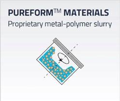

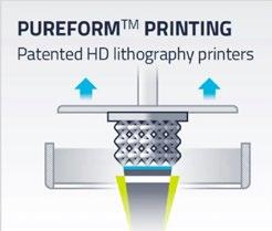

The second hybrid process is from Mantle 3D. This process starts with the formulation of a flowable metal or alloy paste that is extruded through a nozzle to form the desired shape. While still in the AM machine, the deposited layers are automatically shaped using high-speed cutting to improve the surface finish and detail. The parts are subsequently sintered to achieve the desired high density.
Mantle has focused almost exclusively on the business of forming moulds and mould inserts for injection moulding tooling. The tool has withstood more than 1.65 million cycles with no signs of wear. The additively manufactured H13 and P2X steel inserts have shown to be as accurate and durable as traditional S7 machined steel inserts. The time required to make the additively manufactured tools and inserts is significantly shorter than conventional machined inserts.
Another section of my presentation covered AM processes based on Vat Photopolymerisation (VPP) where technologies from three companies were touched on. The first company was Austria’s Lithoz, which focuses on what it calls lithography-based Additive Manufacturing. The compa -
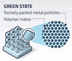
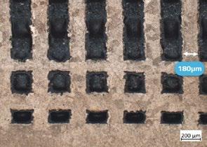
ny’s CeraFab Multi 2M30 uses the full capability of Additive Manufacturing to enable combined processing of different materials, such as ceramics and metals, in one single component, though the company primarily focuses on ceramics.
In its process, a ceramic slurry is automatically dispensed into a vat and the build platform is dipped into the slurry, which is exposed to light from below. This cures the entire surface of a layer at once, greatly speeding up the process compared to laserbased technologies. After undergoing a debinding and sintering process, the fully dense and high-performance AM parts are ready.
The second process covered was the Holo process, the processing steps of which are shown in Fig. 24. The figure also includes a shape that shows the ability of the process to create fine structures.
The last process presented in this series is a Vat Photopolymerization process mainly for metals and alloys that is practiced by Incus, an Austrian company which started as a spin-off from Lithoz. The company recently introduced a new larger metal Additive Manufacturing machine capable of producing metal parts with excellent surface quality (almost similar to MIM) and high reproducibility. Incus recently launched a larger AM machine, the Hammer Pro40, which has a build volume of 200 x 153.6 x 150 mm in the X, Y, and Z directions, respectively, as well as two scrolling projectors. The increased size of the machine makes it suitable for higher volume production with the same quality as the smaller predecessor Hammer Lab35 machine. The green part shown in Fig. 25 is around 90 mm tall and the sintered part is around 74 mm tall. A cross-cut section showing the internal structure of the full part is shown on the left of each image, while the full structure is shown on the right.
My last presentation topic was an AM process known as screen printing. Fraunhofer has conducted extensive investigations into this process, and so far, Exentis Group AG, Switzerland, and a number of global customers
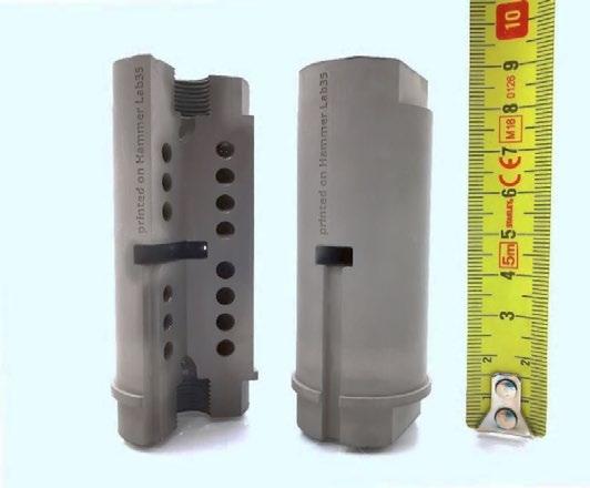
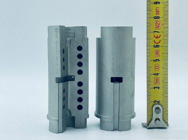
Fig. 25 An as-printed (top) part and a sintered part (bottom) of an in-line heater for solvent-based fluids, built in a matter of hours using an Incus Hammer Lab35 machine out of 316L stainless steel (Courtesy Incus)
have commercialised the technology. Eric Bert from Exentis North America presented on this technology in detail at the conference.
AM screen printing is based on making the desired powder into a paste that can then be extruded through the fine openings of a part-specific screen. Exentis has developed an Additive Manufacturing technology platform to create precision parts with ultrafine structures using a conventional screen-printing approach combined with high-speed optical alignment and automated handling. This enables the mass production of complex parts using a wide


range of materials, such as metals, ceramics, polymers, and pharmaceutical materials available in powder form.
The specialised high-speed AM machines deposit layers of paste until the desired part height is
achieved. The screen tools and optical layer alignment deliver ultra-fine part features in a repeatable manner while the high-speed, automated systems enable costeffective mass production volumes, though it is important to recognise

that changing the X-Y geometry in a part requires changing of the screen tool, which does add both cost and time. Also, this process limits overhangs, and internal channels are possible.
Layer thickness can be varied from 10-150 µ m, enabling very fine feature resolution. The twelve-second stroke cycle times deliver full productionscale throughput. The process is geared for high-volume production of thousands to millions of parts.
Exentis has extensive experience in screen manufacturing – a precision process with high accuracy and stringent cleanliness requirements (as the company also works in pharmaceuticals). The mesh size is flexibly selectable (20-500 µ m and coarser), and the screening technology is mature (established for decades). The cost of screens is independent of the complexity of the screening structures, with screen tool costs ranging from $1-2K and having 50,000-80,000 stroke life.
Overhangs Wall thickness
Aspect ratio
Aperture size
Channel width Sealed cavities

Fig. 29 Tolerances and design features of Exentis’s additive screen-printing process (Courtesy Exentis)
According to Eric Burt, since Exentis Additive Screen-Printing uses screens as hard tooling, “Very small, high-aspect-ratio holes, fine features, and precisely-toleranced parts that were previously outside the capability window of conventional and Additive Manufacturing processes are now achievable and available at costs that meet production requirements.”
Exentis has been selling systems in Europe since 2017 and is now in the process of building up a North American presence via the newly formed Exentis North America subsidiary in Boston, Massachusetts. Applications based on the Exentis Technology Platform are diverse and include precision heat sinks, complex filtration components, high-density electrical interconnection components, and bi-polar plates for hydrogen fuel cells.
mesostructured stainless steel
An interesting study entitled ‘Processing of mesostructured stainless steels using FFF technology’ was presented by Juan Jiménez-Alumbreros as part of the results of his master thesis at DYPAM Research Group at Universidad Castilla La Mancha, Spain, which was performed within the topic-related research line led by Dr Javier Hidalgo and Dr Gemma Herranz as the group leader.
The presentation introduced the concept of ‘multi-functional
Print area 430 x 430 mm
Height 0.10 to 50 mm
Wall thickness 70 µm
Min hole dia 100 µm
Aspect ratio up to 100:1
Surface roughness Ra = 2 µm
Solid content - pastes 40-50 vol.%
Density green bodies 60-70 vol.%
Layer thickness 5.0-100 µm (fabric screen), 100 µm (metal stencil)
Screen mesh 20 to 500 µm
Screen wire up to 10 µm
Shrinkage 5-20 %
Particle size between 1 and 50 µm (d50)
Geometric ± 30 µm
Table 5 Part size, feature capabilities, print envelope and tolerances of a typical Exentis additive screen-printing process (Courtesy Exentis)

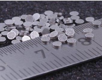
Fig. 30 An in-line diesel fuel filter made from 316L stainless steel. The part diameter is 2 mm, the thickness is 600 µm, the hole diameter is 120 µm, and the wall thickness is 100 µm (Courtesy Exentis)
components by advanced processing technologies’, where two or more dissimilar materials can be combined into one component (copper/17-4 PH stainless steel; 316L/17-4 PH; AISI M2/ 316L). It emphasised the technological advancements in this field, enabling disruptive applications. Furthermore, the presentation outlined the current
MSS/ASS (Koseki et al. 2014)
MSS/TWIP (Feng et al. 2023)
MSS/TWIP (Dong et al. 2022)
MSS/TWIP (Liu et al. 2021)
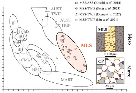
“Conventional manufacturing of mesostructured steels typically involves roll-bonding different materials into a single structure. However, this process faces limitations in fabricating complex geometrical shapes and can lead to interfacial voids due to severe plastic deformation.”
state of advanced complex phase (CP) steel, where different phases serve distinct purposes (Fig. 31).
It also discussed the limitations of uniformly distributed microstructures in overcoming the strength-ductility trade-off. The concept of mesostructured steels, exemplified by Damascus Steel and multi-layered composite steels (MLS, typically with a mesostructured scale in the range of 100 µm), was explored. These steels offer a unique property range surpassing other steel families, as depicted in Fig. 31.
Conventional manufacturing of mesostructured steels typically involves roll-bonding different materials into a single structure. However, this process faces limitations in fabricating complex geometrical shapes and can lead to interfacial voids due to severe plastic deformation. Innovative methods, such as ‘direct’ Additive Manufacturing processes including Powder Bed Fusion (PBF) or Directed Energy Deposition (DED), were discussed in the presentation and also the challenges including microstructural control, residual stresses, and powder recycling difficulties (unless one is magnetic and the other is non-magnetic in nature).
Jiménez-Alumbreros discussed the benefits of processing mesostructured steels using FFF, outlining its


Fig. 33 Variations in microstructure, phases, composition, and microhardness across the two stainless steel layers, including the interfacial region (Courtesy DYPAM)
associated challenges. The objective of the investigation was to tailor the properties of 316L and 17-4PH stainless steels for multi-material FFF technology (Fig. 32), focusing on optimising process parameters and material performance.
Key considerations for multimaterial FFF include powder selection with equivalent particle size distribution to ensure comparable optimal loadings, rheology, and shrinkage. Additionally, the filament fabrication, Additive Manufacturing, and debinding processes must be carefully designed to be compatible with both materials. Sintering, based on criteria such as temperature ranges, densification, and grain sizes, was crucial. Detailed studies on gradient monitoring and control showcased variations in microstructure, phases, composition, and microhardness across the two stainless steel layers, including the interfacial region.
Conclusions drawn from the investigation include successful filament development for FFF, defect-free green part Additive Manufacturing, and tuneable compositional gradients through sintering. Jiménez-Alumbreros suggests further research areas the group is
currently exploring, including more detailed sintering studies using dilatometry, controlling shrinkage by adjusting powders and solid loadings, and investigating the effects of mesostructure compositions on mechanical and corrosion properties.
This write-up presents only a small selection of all the interesting presentations that added tremendous value to the conference. It was difficult to pick and choose the papers that have been covered in this report and many presentations that could not be covered for lack of space were also extremely good.
I was unable to cover any presentations on powders and powder production, the majority of the presentations from the students who had excellent research work results in their presentations, software and simulation tools; a couple of hybrid metal AM tooling presentations; a few papers that discussed environmental factors (e.g. includes carbon footprint reduction, mould cleaning and maintenance using dry ice, and hydrogen production at site location).
The table-top exhibitors had short presentations that were dispersed
between the regular presentations. These short presentations were very informative and of great value to attendees who were not familiar with the products offered by these companies. The tabletop exhibits also provided an excellent networking opportunity that the attendees were able to take advantage of.
This year, MPIF was able to totally eliminate the COVID-era hybrid conference format. Only one presentation was presented virtually, and that was due to the presenter’s sudden illness. The opportunity to finally have a get-together without the threat of COVID looming overhead was a huge relief for all attendees and will be reflected in the industry at large.
I would like to thank MPIF staff Jim Adams, Bill Edwards, Paul Sedor, and Diane Haggerty for their support. I would also like to thank the presenters for their help with the figures used in this article.
Author Dr Animesh Bose CEO OptimusAlloys Leesburg, Virginia, USA animeshbose53@gmail.com







PIM International is the only business-to-business publication dedicated to reporting on the technical and commercial advances in the MIM, CIM, and sinter-based Additive Manufacturing industries. Available in both digital and print formats, PIM International is the perfect platform to promote your company to a global audience.
Metal powders
Advanced Technology & Mat. Co., Ltd. 45 www.atmcn.com/english Continuum Powders 31 www.continuumpowders.com Epson Atmix Corporation 08 www.atmix.co.jp
Indo-US MIM Tec Pvt Ltd 47 www.indo-mim.com
Jiangsu Jinwu New Material Co., Ltd. 34 en.jsjinwu.com
Jiangsu Mengda New Mat. Tech. Co., Ltd. 27 hwww.shmengda.cn
Jiangxi Yuean Advanced Mat. Co., Ltd. 54 www.yueanmetal.com
Kymera International 11 www.kymerainternational.com LD Metal Powders
GmbH
www.metshape.de Schunk Sintermetalltechnik GmbH
www.schunk-mobility.com
Combining digital and print publishing for maximum exposure
Every issue of the magazine is distributed via multiple channels, including our website, newsletters and social media networks.
The print edition is distributed at numerous industry events worldwide as well as to a core subscriber base.
All past editions of PIM International magazine are freely accessible via our digital archive, adding extended exposure for your brand and products.
For more information contact: Jon Craxford, Advertising Sales Director Tel: +44 207 1939 749 jon@inovar-communications.com
As the usage patterns of PIM International magazine’s audience develop and change, we have expanded our social media activities, enabling us to connect with our global audience on multiple levels.
As the only magazine for MIM, CIM, and sinter-based AM, our LinkedIn, Twitter, and Facebook channels serve as indispensable sources for the latest industry news.

www.twitter.com/PIMMagazine
www.linkedin.com/company/piminternationalmagazine/
www.facebook.com/PIMInternationalmag


The 7th edition of the International Conference on Powder Metallurgy and Additive Manufacturing of Titanium, PMTi2024, will gather, for the first time in Spain, researchers and professionals on the processing, design and application of titanium and its alloys fabricated by powder metallurgy and additive manufacturing technologies.
The conference will take place in person in Madrid, after a successful series of previous conferences held in Australia, New Zealand, Germany, China, the United States and Canada.
Topics covered in the conference are the following:
• Powder production and characterization
• Metal Injection Molding (MIM)
• Consolidation of PM alloys
• Sinter-based Additive Manufacturing
• Powder-bed and powder-deposition Additive Manufacturing
• Alloy design in PM and AM
• Titanium Aluminides and Ti Metal Matrix Composites
• Properties and characterization
• Part and process qualification
• Applications
• Recycling and sustainability




PIM International is dedicated to driving awareness and development of the MIM, CIM and sinter-based AM industries and their related technologies. Key to this aim is our support of a range of international partner conferences.
View our complete events listing on: www.pim-international.com
PowderMet2024 / AMPM2024
June 16–19, 2024 Pittsburgh, PA, USA www.powdermet2024.org / www.ampm2024.org
RAPID + TCT 2024
June 25–27, 2024 Los Angeles, CA, USA www.rapid3devent.com
EPMA Powder Metallurgy Summer School
July 15–19, 2024 Alessandria, Italy www.summerschool.epma.com
ImplementAM
July 24, 2024 Penn State Erie PA, USA www.implementam.com
Formnext + PM South China
August 28–30, 2024 Shenzhen, China www.formnext-pm.com
5 th Workshop on Sinter-based Additive Manufacturing 2024

If you would like to see your CIM, MIM or sinter-based AM related event listed in this magazine and on our websites, please contact Merryl Le Roux: merryl@inovar-communications.com
September 4–5, 2024 Bremen, Germany www.ifam.fraunhofer.de/en/Events/sinter-basedadditive-manufacturing-workshop-2024.html
PMTi 2024
September 4–6, 2024 Madrid, Spain www.pmti2024.com
IMTS 2024
September 9–14, 2024 Chicago, IL, USA www.imts.com
Euro PM2024
September 29 – October 2, 2024 Malmö, Sweden www.europm2024.com
The Advanced Materials Show USA October 8–9, 2024 Pittsburgh, PA, USA advancedmaterialsshowusa.com
World PM2024
October 13–17, 2024 Yokohama, Japan www.worldpm2024.com

AM Ceramics 2024
October 23–24, 2024 Berlin, Germany www.amceramics.cc
Advanced Engineering
October 30–31, 2024 Birmingham, UK www.advancedengineeringuk.com
Formnext
November 19–22, 2024 Frankfurt, Germany www.formnext.com
ASEAN Ceramics
December 11–13, 2024 Ho Chi Minh City, Vietnam www.aseanceramics.com

MIM2025
February 24–26, 2025 Costa Mesa, CA, US www.mim2025.org
PM China 2025
March 10–12, 2025 Shanghai, China en.pmexchina.com
Fraunhofer Direct Digital Manufacturing Conference DDMC 2025 March 12–13, 2025 Berlin, Germany www.ddmc-fraunhofer.de
AM Forum Berlin March 17–18, 2025 Berlin, Germany www.am-forum.de
AMUG 2025
March 30–April 3, 2025 Chicago, IL, US www.amug.com

Formnext Chicago 2025 April 8–10, 2025 Chicago, IL, US www.formnextchicago.com
RAPID + TCT 2025
April 8–10, 2025 Detroit, MI, US www.rapid3devent.com/rapid-me
The PIM International newsletter is sent to several thousand industry professionals worldwide. Register today to ensure you benefit from reading the latest industry news and advances in Metal Injection Moulding and Ceramic Injection Moulding technology.
Newsletter subscribers also benefit from a free digital subscription to PIM International magazine. As soon as each new issue is available we’ll send you an email containing a direct link to our digital edition.

www.pim-international.com/e-newsletter-andfree-digital-subscription/


Organised by:
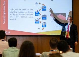

Dive into the heart of the PM industry at Euro PM2024, where industry leaders, academics, and professionals converge.
With 250 presentations over three days, including Keynote paper presentations and Special Interest Seminars, this event promises to redefine industry standards and unveil the latest PM advancements.
Explore the latest trends and advancements in PM as you connect with industry-leading suppliers, engage with potential clients, and discover cutting-edge PM solutions

Embark on a journey to meet the driving forces behind powder metallurgy technology, industry and innovation at Euro PM2024.
New this year: Micro stands can be reserved by new exhibitor at the Euro PM2024 and the Exhibition will provide an area dedicated to showcasing Sweden’s PM industry!
Don’t miss out the opportunity to attend our social events: The Welcome reception on Sunday evening, the poster reception on Monday and the congress dinner at Slagthuset on Tuesday.


