REINTERPRETING SURFACES THE CATALONIAN WAY
1
Copyright © 2021 All rights reserved. No part of this publication may be reproduced, distributed, or transmitted in any form or by any means, including photocopying, recording, or other electronic or mechanical methods, without the prior written permission of the publisher, except in the case of brief quotations embodied in critical reviews and certain other non-commercial uses permitted by copyright law. For permission requests, write to the publisher, at the address mentioned below: Intersection Foundation, 124, Ambli Gam - Mandir Vado Vas, Village: Ambli, Ahmedabad, Gujarat, India. email: info@intersection.org.in website: www.intersection.org.in Printed in Ahmedabad, India
REINTERPRETING SURFACES The Catalonian Way
4 REINTERPRETING SURFACES
Participants Devesh Patel Gagan Prajapati Hemin Pansera Hetvi Joshi Hetvi Patel Jaival Shah Kavisha Soni Khushil Kanani Mansi Patel Mohit Trivedi
Nishant Patel Preeti Jaisinghani Ria Sheth Ritik Sharma Ruchesha Thaker Ruju Patel Rushina Dave Shaily Bhavsar Sweta Prajapati Vaishali Chandan
Programme Guides Kiran Vaghela Satya Vaghela Arfat Sodha Mitesh Bhudiya
Pratik Zaveri Helly Desai
Artisans
Sunil Dhadhar Kiran Bhai Uttam Kunwar
Tejas Bhai Dhanaj Bhai
Student Editorial Team Gagan Prajapati Harsh Shah Jaival Shah Kavisha Soni Khushil Kanani Mohit Trivedi
Nihar Soni Princy Patel Ruchesha Thaker Ria Sheth Shaily Bhavsar Sweta Prajapati
Faculty Editorial Team Shreya Kaul Naitik Vakharia Priyanshi Pathak
Bhanupratap Shrama Vivek Sheth Pratik Zaveri
5
ACKNOWLEDGMENT Firstly, we would like to express our sincere gratitude to IDEA, Indus University for letting us do handson experience through the Reinterpreting Surfaces Workshop. Studio Dot and Intersection Foundation for not only providing us an opportunity to participate in the workshop but also letting us engage in on-going construction. We would like to thank Kiran Vaghela who gave us fruitful insights on reinterpreting surfaces in a Catalonian way and for broadening our vision towards generating forms and understanding materials by experimentation. Special thanks to all the artisans: Sunil, Kiran, Uttam, Tejas, and Dhanaj for sharing their experience while helping us with patience in handling various tools. Thanks to the team of Studio Dot- Ar. Satya Vaghela, Arfat Sodha, and Ar. Mitesh Bhudiya for sharing their learnings and clearing all our doubts. Ar. Tejas Kotak for introducing various earthen materials and construction techniques such as rammed earth, mud rolls, stabilized earth blocks, etc. Lastly, we would like to appreciate all the interns and volunteers who attended this workshop and made the learning a fun process. Preeti and Vaishali for all the fun times at work on site.. And the entire team, Devesh, Gagan, Hemin, Hetvi J, Hetvi P, Jaival, Kavisha, Khushil, Mansi, Mohit, Nishant, Ria, Ritik, Ruju, Rushina, Shaily, and Sweta from 3rd year, Ruchesha from 5th year, including faculties, Pratik Zaveri and Helly Desai without whom the journey couldn’t have been possible.
6 REINTERPRETING SURFACES
PREFACE This book is a treatise of the Reinterpreting Surfaces workshop along with the exploration that the students of IDEA, Indus University did at Studio Dot, Bhuj, Gujarat. It aims to provide an insight into form generation and construction techniques through the means of Laminated-tile shell. It mainly focuses on the idea of creating uninterrupted
volumes
by
employing
critical
understanding of geometry and its functioning. In the first chapter the laminated-tile as a material is broadly explained through historical context and its technological application. The second chapter is inclined towards the exploration of form with the means of six different types of ruled surfaces. The third chapter is the synthesis of how forms are generated through geometric calculations and material properties with the example of four forms made on site throughout the workshop. The fourth chapter is a brief about the visits conducted after the site work for understanding the material response to the geographical and climatic conditions of Bhuj.
7
8 REINTERPRETING SURFACES
CONTENT Understanding of Material and Technology (Terracotta Tile & POP)
13
• Origin and Evolution • Properties of Materials
Form Generator
19
• Understanding Ruled surfaces • Form and geometry
Material Hands-On
31
• Handling of Material • Construction Process • Hands on Exploration - Sphere, Ellipsoid, Catenary, Cone
Project By: Studio Dot
Visits in Bhuj
73
Outcomes
81
Glossary
84
Bibliography
85
Illustration Credits
86
9
10 REINTERPRETING SURFACES
OBJE CTIVE The objective of the workshop was to study Laminated-tile shell as a means of generating larger uninterrupted volumes. This technique of construction dates back to the early 14th century when the Moorish builders started building tile vaults near Valencia, Spain, which was known within the Mediterranean region. The method of construction was further developed as the timbrel vault by Rafael Gustavino in the late 19th century and early 20th century. The tile vaults construction was recognised again by various Catalonian architects such as Antonio Gaudi as a result of which it is commonly known as Catalonian shell construction. The workshop gives insights upon reinterpreting the Catalonian approach towards tile vaults in today’s context.
Project By: Studio Dot
11
12 REINTERPRETING SURFACES
U nd e r s t a nd ing Ma t e r ia l a nd Te c hno lo g y
(T e rracotta T ile & P OP ) Reinterpreting a construction method requires an understanding of materials. Through this chapter, an understanding of the properties of the material is attempted along with the origin and transformation of the tile vault technique. The approaches of architects since its origin has been studied with the factors affecting change. The rationale behind most approaches is based on the geometric understanding of the form while in a few cases the form is given more importance.
Project By: Studio Dot
13
Origin and Evolution In the 14th century, the process of constructing tile vaults was developed by Moorish builders near Valencia, Spain, which was quite prevalent within the Mediterranean region. The lightweight approach together with an inexpensive method of construction as compared to traditional stone vaulting made the tile vaults a revolutionary solution. The tile vaults were called the boveda tabicada in Spanish. When compared to traditional stone vaulting, tile vaulting uses much less material and can be built way more quickly. Because the slim bricks are laid flat, with the narrow edges in contact, the overall thickness of the vault is a smaller amount compared to conventional masonry, as a result of which, the self-weight and corresponding horizontal thrust are reduced. In the traditional tile vault, the tiles used to be joined with water-based slurry of Plaster of Paris, which
(A)
sets quickly enough that the inside of the vault doesn’t require any support or formwork from below during the construction process. As against this, a typical stone arch has got to be supported on formwork while constructing and is stable on its weight only when the keystone is in place. By building out from a wall in successive arcs, tile vaulting can be constructed with minimal to no formwork. In the early 16th century, many Spanish builders were practicing the tile vault method but it was in the late 18th and early 19th centuries that Rafael Guastavino, the Spanish engineer, and architect made a noteworthy
(B)
contribution by various innovative changes to the traditional method. He described tile vault construction as a cohesive construction method of building that depends on the adhesion of materials rather than the traditional gravity system of constructing vaults. Instead of
Fig 1. Comparison of the traditional stone vault (A) and the Guastavino tile vault (B) https://www.structuremag.org/?p=2046 http://web.mit.edu/cron/Backup/project/guastavino/www/MroszczykMurphy-GuastavinoBPL.pdf
14 REINTERPRETING SURFACES
constructing a single layer vault, doing another layer with staggering joints and mortar significantly reduces the weight as compared to a similar stone vault and also provides greater load capacity because of the cohesion of materials. Guastavino’s works were first introduced in America through the Centennial Exhibition of 1876 in Philadelphia. In 1881, there was a huge availability of Portland cement in the United States while it had been unavailable in Spain during those times. This gave him the Fig 2. City Hall Subway Station, Rafael Gustavino, 1904
possibility of employing Portland cement with a quicksetting mortar which reduced the construction time and cost drastically. Boston Public Library in 1888 gave his career a push and later in 1889 the Guastavino Fireproof Construction
Company
was
officially
incorporated.
By 1910, there were around 100 projects of his firm being constructed simultaneously hence making this method known through as the timbrel vault named Rafael Guastavino. Later the method became widely known as the Catalonian way of constructing using tiles. The laminated tiles were used by many other architects using different approaches and articulation. Fig 3. Top View of Sagrada Familia Schools, Antoni Gaudi, 1909
Antoni
Gaudi,
Catalan
architect,
designed
certain
buildings including the Sagrada Familia School using Catalonian bricks of 29X14X4 cm. Here the base is of the masonry walls and the floor was constructed out of stone to protect the structure from humidity. The three-layered conical vaults are supported by wooden beams that rest on a central metal girder which is a horizontal member from one end of the building to another. Although this school has been constructed using laminated tiles with conical vaults, it cannot be considered a convincing example of a tile vault. Their roof is not self-supporting but is created using beams and steel posts.
Fig 4. Sagrada Familia Schools, Antoni Gaudi, 1909 http://web.mit.edu/cron/Backup/project/guastavino/www/MroszczykMurphy-GuastavinoBPL.pdf http://www.gaudiallgaudi.com/sagrada-familia-schools
15
Reinterpreting
the
traditional
method
of
construction and understandings, architects such as Sameep Padora have integrated the form using modern software in such a manner that it weaves the whole space together. The Maya Somaiya Library located in the town of Kopargaon, Maharashtra, is a roof made out of a doubly curved surface that acts as an enclosure without walls. The three-layered brick vault spans 145 feet long and 25 feet wide without being supported by columns or beams. The roof was created using a 3D-modeling program called Rhinoceros to design a structure that gets stability by compression solely. A similar kind of vault has
Fig 5. Maya Somaiya Library, Sameep Padora, 2018
been made and developed by the Block Research Group at ETH Zurich. Although the technique dates back to the 14th century, the various interpretations have led towards a flexible design approach. The primary rationale behind the stability of form remains constant throughout the history of this technique.
https://architizer.com/blog/practice/details/sameep-padora-maya-somaiya-library/
16 REINTERPRETING SURFACES
Properties of Materials Terracotta tiles have been used in various ways in construction such as flooring, cladding, paving, etc. The terracotta tile is mainly comprised of clay and silt. One of the key properties of terracotta tiles is that it is fireresistant. As clay is a mineral that expands when water is added to it. The terracotta tiles are soaked in water before Fig 6. Terracotta tiles are soaked in water before using construction
using them for construction so that all the air bubbles get filled with water. Plaster of Paris tends to absorb water which results in a lack of strength of bricks if not soaked well. If the tile absorbs too much water, the lifespan of the structure decreases. Plaster of Paris releases heat when reacts with water. It won’t attain good strength if it does not release heat properly. If it is hard and water comes in contact with it then its quality degrades and it doesn’t bond properly. Once water is added, it sets very fast as a reason for which POP slurry is made in small batches. It is beneficial to wear rubber gloves while working with POP.
Fig 7. Plaster of Paris releases heat when reacts with water
In the case of cement mortar, cement binds sand when reacts with water. As the terracotta tiles are brittle, a layer of chicken mesh is added between two layers of tiles. If the structure encounters a brittle failure, it might collapse without giving enough time to rescue. By adding chicken mesh, it doesn’t mean that it won’t collapse but the mesh will convert brittle failure into a plastic or elastic failure.
Fig 8. Construction without chicken mesh - Brittle failure
Fig 9. Construction with chicken mesh - Elastic failure
Fig 10. Laminated terracotta tile ( 230 mm X 75 mm X 15 mm)
Participants
17
18 REINTERPRETING SURFACES
Form Generator To
understand
the
structure,
one
needs
to
understand the form and geometry. The geometry defines the laws of structure and guides in generating stable structural forms. In this chapter, a brief about the basic shapes is given along with its three-dimensional form. The various parameters involved in making the form using the ruled surface. The geometrical understanding not only helps in the construction of form but also helps in calculating the amount of material to be used to construct the form.
Project By: Studio Dot
19
Ruled Surface A ruled surface is a surface that can be generated by moving a line in space. To make a ruled surface, two curves are joined using straight lines from start to the endpoints of the curves such that the respective curves have the same parametric value. The straight lines connecting the two curves are called generatrixes while the two curves that are connected by generatrixes are called an axis. The ruled surfaces are divided into three major types namely, Conoid, Right conoid, and Circular
Fig 12. Conoid
conoid. There are certain ruled surfaces where the generatrixes are parallel to a plan which is known as the directrix plane of the surface. This kind of ruled surfaces is called conoid. When the surface is generated by moving the generatrixes (straight line) along the axis (two curves) in such a manner that the lines are always perpendicular to its directrix plane then it is called a right conoid. If the directrix is a circle then the conoid is called a circular conoid.
Fig 13. Right conoid
Fig 11. Ruled surface
20 REINTERPRETING SURFACES
Fig 14. Circular conoid
Form and Geometry To understand forms it is necessary to understand geometry. All the geometric forms are derived out of 2D shapes.
Circle A closed curve or a loop formed by points that are equidistant from a fixed center point on a plane can be Fig 15. Terms related to circle
defined as a circle. The length of the curve encompassing the circle is the circumference. The length of two points which connect the circumference is called an arc. The center of the circle is the point from which all points on the circumference are equidistant. The distance from the center of the circle to any point on the circle is called the radius of the circle. A line segment connecting any two points on a circle is known as a chord. Diameter is the longest chord of the circle which connects two points on the circle such that it passes through the center of the circle. A line that intersects a circle at two points is called a secant and the part of the circle divided by a secant
Fig 16. Terms related to circle
is known as a segment. A line intersecting one point of the circle is a tangent that is always perpendicular to the center of the circle. When the circumference of any circle is divided by its diameter, the answer is the same, this number is approximately 3.142 which is called Pi. Area of a circle: πr2
Circumference of a circle: 2 πr
Sphere A form having every point equidistant from the center is known as a sphere. The sphere when cut from Fig 17. Sphere
anywhere is a circle. The section cut through the diameter
21
of the circle is known as the great circle while all the other circles are known as small circles. The diameter of the great circle is the diameter of the sphere. The ends of the axis of the circle of the sphere are called poles. The nearer the circle to the center of the sphere, the greater is its area. The sphere, when divided into two parts through the great circle, is called a hemisphere. A plane perpendicular to a radius at its extremity or its surface is a tangent to the sphere. When two spheres intersect with a plane that is perpendicular to the line joining the centers of the spheres and the center of the plane is on that same line is always a circle.
Area of a sphere: 4πr2
Volume of sphere: 4/3 πr3
Spherical zone The sphere is divided using two parallel planes to form a spherical zone. There are two types of spherical zones namely, the spherical zone of one base and spherical zone of two bases. The bases of the zone are the circumference of the sections formed by the intersection of two parallel planes with the sphere. The distance between these two bases is called the altitude. The only
Spherical Zone of Two Bases
difference between one base zone and two base zone is that in one base zone, one of the parallel plane cutting the sphere is tangent to the sphere. It is worth noting that when the altitude is double the radius then the surface area of the zone will be equal to the surface area of the sphere. The surface area of any zone is equal to the product of its altitude h and the circumference of the great circle of the sphere. Area of spherical zone: 2πRh
Volume of a spherical zone: 1/3π h2(3R - h)
Spherical Zone of One Bases Fig 18. Spherical zones
22 REINTERPRETING SURFACES
Spherical segment The spherical segment is the solid area bounded by two parallel planes through a sphere. The parallel planes form two bases of the spherical segment where the radii of the lower and upper sections are denoted as a and b. The segment is one base when a or b is zero and when both a and b are zero then the solid is a whole sphere. If one of the parallel planes is tangent to the sphere, the solid thus formed is a spherical segment of Fig 19. Spherical Segment of Two Bases
one base. The spherical segment with one base is called a spherical cap while the one with two bases is known as a spherical frustum.
Area of a spherical segment: π(a2 + b2 + 2Rh) Volume of a sphere: 1/2πh(3a2 + 3b2 + h2)
Ellipse An oval-shaped closed curve is called an ellipse. Here the addition of the distance from two fixed points (focus) to any point on the ellipse is constant. The midpoint of the line connecting two foci is the center of an ellipse. It is the point of intersection of the major and minor axis. There are two focal points on the major axis which defines the ellipse. These are equidistant from the center of the ellipse. The longest diameter that passes through the center of the ellipse is called the major axis while the shortest diameter that passes through the center is the minor axis. Half of the major axis is known as the semimajor axis or the major radius of the ellipse. Similarly, half of the minor axis is known as a semi-minor axis or the minor radius of the ellipse. The points of intersection of the major axis to the ellipse are called vertex and the points of intersection of the minor axis to the ellipse are called Fig 20. Ellipse
co-vertex. Every ellipse has four vertices. A line segment
23
connecting two points in the ellipse is called a chord, which makes the major axis as the longest chord. An arc is the two points on the ellipse which connects the circumference of the ellipse. A line that touches the ellipse at one point only is known as the tangent. It always makes equal angles with the generator line. Directrix is the line that is parallel to the minor axis of the ellipse and related to both the foci of the ellipse. It is the line parallel to directrix and passes through any of the focus of an ellipse. The focal parameter is the distance between the directrix and the focus. Area of an ellipse: πab
Arc length of an ellipse: P=2 π √(a2+b2 )/2 Eccentricity of an ellipse Eccentricity is the factor related to conic sections which show how circular the conic section is. More eccentricity means less spherical and vice versa. It is denoted by “e”. The eccentricity of an ellipse is shown by the ratio of the distance between the two foci, to the size of the major axis, e = 2f/2a = f/a. where e = Eccentricity, f = The distance from the center to anyone of the foci and a = The semi-major axis. The eccentricity of an ellipse is between 0 and 1 (0 < e < 1). If the eccentricity is zero, the foci match with the center point and become a circle.
Ellipsoid The ellipsoid is a 3-dimensional surface, the points of which, in Cartesian coordinates, satisfy the following equation: x2/a2 + y2/b2 + z2/c2 =1
S.A. of an Ellipsoid : SA=4π ((apbp+apcp+bpcp)/3)1 p Volume of an Ellipsoid : V=4/3 πabc Fig 21. Ellipsoid
24 REINTERPRETING SURFACES
Parabola A parabola is a set of all the points in the plane equidistant from a given line i.e. the conic section directrix and a given point that is not on the line. Here Directrix is the line that is perpendicular to the axis of symmetry but it does not pass through the focus. An ellipse with one focal point and another focal point as infinity is called a parabola. Focus is a special point on the axis of symmetry which defines the parabola. The line perpendicular to Fig 22. Parabola Curve
the directrix which passes through the focus divides the parabola into two equal parts is known as the axis of symmetry. The point where the parabola and the axis of symmetry intersect with each other is called the vertex. The curve of the parabola is quite abrupt at the vertex. The parabola has the vertex as the midpoint of the focus and the directrix. The distance between the focus and the vertex on the axis of symmetry is called the focal length. The line segment passing through the focus and parallel to the directrix is the Latus rectum of the parabola. In parabola, let a is the distance from the focus to the vertex, which is equidistant from the vertex to directrix.so the distance from the focus to the directrix is 2a. The distance from the focus to the point on the plane is equidistant from focus to directrix that is, 2a. The focus is on the axis of symmetry which is the midpoint of the latus rectum, which shows that half of the latus rectum is 2a and the length of the latus rectum is 4a. Area of segment parabola: A = 2/3 x a x b Arc length of segment parabola:
L=1/2 √(b2+16.a2 )+(b2/ 8 x a) ln ((4.a +√(b2+16.a2 )/2)
.
25
Eccentricity of parabola Eccentricity is the factor related to conic sections which show how circular the conic section is. More eccentricity means less spherical and less eccentricity means more spherical. It is denoted by “e”. The eccentricity of the parabola is the ratio of the distance between the focus and a point on the plane to the vertex and that point only. As the parabola is a locus of all the points which are equidistant from the focus and the directrix, its ration will always be 1 that is, e = 1
Paraboloid A solid generated by the rotation of a parabola around its axis of symmetry. Surface area of a paraboloid :
A = πb2 + (πb/6a2)((b2+4 a2)3 2 )-b2)
Volume of a paraboloid : V=1/2 πb2a
Hyperbola When a circular cone intersects with a plane at a smaller angle than the side of the cone symmetrical
Fig 23. Paraboloid
open curve is formed which is known as a hyperbola. A line segment that passes through the focus of the hyperbola is called the traverse axis and it has vertices on its endpoints. A line segment formed by connecting the co-vertices on its endpoints which is perpendicular to the traverse axis is known as the conjugate axis. The point at which both the axis intersect is the center of the hyperbola. A rectangle that is formed by connecting the midpoints of the vertex and co-vertex is called the central rectangle. A distance between two foci points is the focal distance. The line from which the hyperbola curves move away is the line directrix. This line is perpendicular to the
26 REINTERPRETING SURFACES
Fig 24. Hyperbola curves
axis of symmetry. The directrix is used to generate the hyperbola curve. The point of the curve that is closest to the center is the vertex. All hyperbolas have an eccentricity value greater than 1. Also, all hyperbolas have asymptotes, which are straight lines that form an X that the hyperbola approaches but never touches.
Hyperboloid A hyperboloid is a quadratic surface which Fig 25. Hyperboloid
may
be
one-
or
two-sheeted.
The one-sheeted
hyperboloid is a surface of revolution obtained by rotating a hyperbola about the perpendicular bisector to the line between the foci, while the two-sheeted hyperboloid is a surface of revolution obtained by rotating a hyperbola about the line joining the foci.
Catenary A ‘U’ shaped curve formed by hanging a rope or a chain by fixing two endpoints is called a catenary. Similarly, a catenary shell is formed by a solid form generated by Fig 26. Formation of catenary arch
rotating a catenary arch along its axis of symmetry. One of the important properties of the catenary arch is that it is a more stable shape as compared to a hemispherical dome or parabolic dome. As the vertical force of gravity is converted into compression along the arch’s curve, catenary shapes and forms are very strong. Triangle A three-sided polygon is called a triangle. It consists of three line segments that are linked end to end by forming three angles. The corner of the triangle is
Fig 27. Properties of triangle
called the vertex and every triangle has three vertices. The
27
at the bottom although it is not mandatory to take the bottom one as the base. The perpendicular distance from the base to the opposite vertex is the altitude. In certain cases, the base needs to be extended to have an altitude. As there are three possible bases, there are also three possible altitudes. The point at which all three altitudes intersect is the orthocentre of the triangle. The sum of all three sides of the triangle gives the perimeter of the triangle. The angles formed by the three sides are called the interior angles while the angle between a side of a triangle and the extension of an adjacent side is called the exterior angle. The total of the interior angles of a triangle is always 180° while the total of all the interior angles of a triangle is always 360°. The shortest side is always opposite to the smallest interior angle and vice versa. Area of a triangle : A = h b/2 Perimeter of triangle : P = b a + b + c
Cone A solid or a hollow object formed by a circular base that tapers at one end is known as a cone. The line moving on a circular base of the cone is known as the generator. The point at which all the generator lines meet
Fig 28. Oblique cone
is called the vertex of the cone. A line that passes through the center of a circular base and the vertex is known as the axis. The directrix is the circular planer cure at the base of the cone. The perpendicular distance between the vertex and the plane of the base is known as the altitude. It is denoted as h. Every section of the cone formed by a plane passing through the vertex and containing two points of the base is a triangle. A section of the cone that is perpendicular to its axis is called the right section. The cone in which the altitude and axis are equal is the right cone.
28 REINTERPRETING SURFACES
Fig 29. Right cone
Cross sections of cone The cone can be cut into different parts based on the way one is cutting the cone. The possible cross-sections from a cone are circle, ellipse, parabola, and hyperbola. A circular section is produced when the cone is cut from a plane that is perpendicular to the axis of the cone. An elliptical or a parabolic section is produced when the cone is cut from a plane that is not perpendicular to the axis of the cone. In circular, elliptical, and parabolic sections, the Fig 30. Cross Section of Cone
cone is being cut with one nappe. The curve produced by a plane intersecting both nappes is a hyperbola. Surface area of a Cone = πr √(r2+h2 ) Volume of a cone : V = 1/3π r2h
Cone frustum area : A = π (a+b) √(h2+(b-a))
Cone frustum Volume : v = 1/3 πh (a2+ab+ b2) Cone Shell Volume : f (a,b,h,t )
Introduction to Ruled Surfaces_Geometry Authors : Satya Vaghela
29
30 REINTERPRETING SURFACES
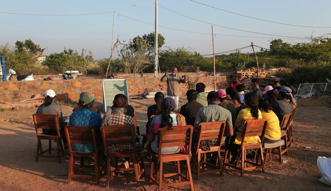
Material Hands-on Engaging with materials is in itself a means of learning. While trying to construct the forms on-site, one learns how the drawings are translated into a physical reality. At every level of making, questions arise and their solution arrives from experimenting with the materials. How much water will it require to make slurry? How to handle tools? How much time does this take? How does the texture of the tile feel? All these kinds of questions arise while working with materials. The nature of the material is thus learned by handling it. The hands-on experience also involves us at every scale of form, from the overall dimensions to the minute detail where two or more materials come together. This chapter is a compilation of the learnings from hands-on exploration on site.
Photo Credit: Gagan Prajapati
31
9/25/2020
_MG_5823.CR2
Handling of material The handling of the material on site is a very engaging process of learning materials. To handle material on-site, certain precautionary measures are to be taken. Some of the basic requirements of safety remain standard for any kind of construction process such as wearing gloves. There are certain measures to be taken based on the material properties as well.
Plaster of Paris
Fig 31. Adding water in POP
Fig 32. Maxing PoP with water 9/25/2020
_MG_5843.CR2
While working with Plaster of Paris it is important to wear rubber gloves as POP emits heat when comes in contact with water. Not wearing gloves while working with POP might result in dry skin. As the POP dries very fast when it comes in contact with water it is economically beneficial to make its slurry in small batches to minimize wastage. If the slurry is made in a bowl, it will be a tedious process of removing the dried off slurry while cleaning the bowl. This might even hamper the process of construction hence it is better to keep a plastic bag or waste plastic sheet as a base. Once the extra POP dries on it, one can easily dust it off and can quickly use it again. By doing so,
Fig 33. Applying POP on tile
https://mail.google.com/mail/u/0/#inbox/FMfcgxwJXxxgkTxlpdNTCCbJpLSscfss?projector=1
Fig 34. Tile cutting 1/1
there are fewer chances of getting dried POP crumps of the previous batch in the fresh slurry. It is very important to note that POP is added to water to make a slurry and not the other way around. If water is added to POP, then there are chances of getting lumps in the slurry.
Laminated Terracotta Tile The Laminated terracotta tiles come in a pack of 20 tiles each. It has a smooth surface on one side while on the other side it has grooves. Before using them, it is
32 REINTERPRETING SURFACES
https://mail.google.com/mail/u/0/#inbox/FMfcgxwJXxxgkTxKJrvSjsQBkxhlplbf?projector=1
Fig 35. Soaking tiles in water
Fig 36. Pack of tiles
necessary to soak them in a tub full of water. As terracotta tile is clay-based material, when it comes in contact to water, clay expands and hence all the air gaps get filled with water. When POP is applied, it absorbs water hence it results in a better bond between POP and terracotta tiles. The tiles when soaked, it absorbs too much water then it means that the tile is not of good quality. Depending on the scale of the form, there is a need to cut the tiles in two or more parts. It is preferable to cut the tiles using a tile cutter machine for aesthetic reasons. Fig 37. Stretching the chicken mesh 9/25/2020
_MG_5967.CR2
9/25/2020
_MG_5975.CR2
Chicken Mesh The Chicken mesh is available rolls based on fixed width and variable length. For working with the chicken mesh it is necessary to wear thick gloves to avoid cuts. First, the chicken mesh has to be unwrapped like a carpet. This requires two people, one holding the roll while the other pulling it and spreading it on the ground. Once the mesh is opened, the binding wires on the longer sides are cut at certain intervals using a plier to make it more flexible to use. The mesh is then stretched so that it becomes flexible
Fig 38. Cutting extra chicken mesh
Fig 39. Tying mesh on the form
enough to cover the form properly.
Cement Plaster The sand used for making cement plaster has to be filtered properly using chhanni before use. To make the plaster consistent, cement, water, and sand are to be mixed. For every one bag of sand, three bags of cement are mixed. The water is added as per need until the mixture becomes consistent. The plaster should not be too thick or too watery. Once the mixture is made, it should https://mail.google.com/mail/u/0/#inbox/FMfcgxwJXxxgkTxKSmkbDvZhLjQlKhpk?projector=1
Fig 40. Filtering of sand
1/1 https://mail.google.com/mail/u/0/#inbox/FMfcgxwJXxxgkTwqstFlGGtCFGhbsNNv?projector=1
Fig 41. Making mortar
not be kept unused for too long or it will start to get dry. 1/1
33
9/25/2020
_MG_6126.CR2
Cement Mortar Unlike POP, cement mortar does not set quickly. It takes time to dry. The bonding agents get activated once cement reacts with water. To make cement mortar, cement is added to water and mixed well-using hands to avoid lumps. One should apply the cement mortar such that it doesn’t leave stains on the face of terracotta tiles as it might leave stains if it dries. Hence it is preferable to keep the surface of the tile clean and apply the mortar only in the grooves.
Tools
Fig 42. Applying cement mortar on tile
Fig 43. Spreading cement mortar on tile
Fig 44. Channi
Fig 45. Pawdo
In constructing any structure, materials are not the only thing to be understood. The tools and machines used for construction are equally important. There are specific tools to be used for a specific purpose. There are various tools employed in the laminated tile shell construction technique, namely, Channi, Pawdo, Lelu, Tagaru, Olambo, Measurement tape, Pakkad, Grinder, and Cutting machine. The Channi is used to filter the sand. There are different types of sand required for different purposes. There are different sizes of channi available. The cement mortar requires finer sand as compared to the cement
https://mail.google.com/mail/u/0/#inbox/FMfcgxwJXxxgkTxcfQbjbMNklSLhlQrP?projector=1
plaster. To mix cement plaster, Pawdo is used. This tool is not only used for mixing cement plaster but also for removing soil after digging. It is also used to fill taggaru with sand, mortar, plaster mix, etc. The Lelu is used to plaster as well as to apply mortar on the tiles. There are two different types of Lelu available. To mix the materials and to take materials, Taggaru is used. It also acts as a measuring unit.
34 REINTERPRETING SURFACES
Fig 46. Lelu
Fig 47. Tagaru
This tool is also used to transfer materials from one place to another on-site. The Olambo is to check if the surface is constructed straight or if there is any deviation. If the Olambo doesn’t match then necessary changes are made in the structure to make it accurate. Measurement tape helps in measuring the construction on site. There are different units of measuring tapes, the standard ones are available in feet-inches and metrics. To cut wires and chicken mesh, Pakkad is used. This tool is also used to cut wires and other such things on-site. The Fig 48. Olambo
Fig 49. Measurement tape
grinder and cutting machine are used for cutting certain materials. The grinder is a handy version of the cutting machine. Most of the tools in construction are commonly used everywhere, the names may differ from region to region based on the spoken language of that particular region. The tools that require electricity should be operated with the utmost safety. If one learns how to operate the tools it becomes easy to work on site. Learning about tools is the primary step for working hands-on.
Fig 50.
Pakkad
Fig 51. Grinder
Fig 52. Cutting machine
35
Construction Process Base Step 1: The base of the object is marked. The ground is leveled and gravels are removed to make a firm base. To mark the geometry on the ground first reference point is marked using a metal rod or a wooden stick. If its a circular form then one end of a string is tied Fig 53. Marking the reference point
Fig 54. Drawing curve with reference
at the base of the first reference point while the other end is tied to a sharp stick or a pencil. The length of the string has to be equal to the length of the radius. Then a circle is drawn using these two sticks and string such that its as accurate as possible. Step 2: The base of the object is made. Once the base is marked, a layer of cement mortar is laid on that acts as a foundation. The center of the form is then marked by putting a straight stick or a metal rod.
Fig 55. Marking base of the form
Fig 56. Marking center line on base
Fig 57. Leveling the base
Fig 58. Fixing reference rod for height
36 REINTERPRETING SURFACES
The First Layer Construction Step 3: The first layer of tiles is laid. When the cement mortar dries, the first layer of tiles is laid using tiles and POP. The POP is applied on two adjacent sides of the tile and is held for a while to let the POP setting. The tiles are placed such that the plain face of the tile is on the inside. Here the POP is made in small batches in a quantity that can fix 3-4 tiles at a time. If more amount of POP is made then it dries off and becomes unusable.
Fig 59. The layer of tiles is laid
Fig 60. Checking dimensions
Fig 61.
Applying PoP on tile
Fig 62. Layering of tile
Fig 63.
A guide is use
Fig 64. First layer of construction
Step 4: The use of a guide to check the dimensions. It is necessary to keep a check on the dimensions. The guide should be used for laying the tile. This guide helps the tile to attain the angle and shape of the form. The type of guide changes based on the form that is being constructed. A measuring tape is also used as and when required for marking reference dimensions on the guides.
37
The Second Layer Construction Step 5: The first layer of plaster. Once the form is attained by layering the terracotta tiles, the whole form is plastered with cement plaster. The layer of the plaster is around 5-6mm. The plaster layer makes it a monolithic structure. Step 6: To wrap the chicken mesh around the form. When the plaster layer dries, the chicken mesh is wrapped
Fig 65. Applying cement plaster
Fig 66. To wrap the chicken mesh
Fig 67. Tying the chicken mesh
Fig 68. Second layer plaster
on the form. The grinder is used to cut off the extra chicken mesh and the plier is used to attach the wire mesh around the form. Step 7: The second layer of plaster. The chicken mesh is covered with a layer of cement plaster of approximately 5-6mm. This makes the plaster layer 12-14mm thick including the chicken mesh. By doing so the form attains tensile strength that converts the brittle failure into a plastic or elastic failure.
Fig 69. Covering the form with cement plaster
38 REINTERPRETING SURFACES
The third layer of construction Step 8: Cladding of terracotta tile. The plaster is then covered with terracotta tile such that the finished surface is facing the exterior. Cement mortar is used to clad the tiles. Here the tiles can be clad to form the desired pattern on the surface. Step 9: Cutting terracotta tiles. Fig 70. Tile cutting
Fig 71. Applying cement mortar
To cover the surface using terracotta tiles, the parts where the tile doesn’t touch the surface, the tile has to be cut into parts to cover that area. Step 10: Filling the groove. The grooves between the tiles are filled using cement mortar. The face of the tile is cleaned simultaneously so that there remain no stains of mortar on the finished surface.
Fig 72. Removing air gaps
Fig 73. Cladding the form with tile
Fig 74. The finished form
39
40 REINTERPRETING SURFACES
Sphere A sphere is a surface generated by rotating the circle 360 degrees along a fixed axis. All the points on the surface of the sphere are equidistant from the center of the sphere. Any section that is cut from a sphere, gives a circular cut out. A sphere has curvature and the maximum area is obtained at the center of the sphere. Hemisphere is obtained by dividing the sphere into two equal parts. To make a sphere, the center of the sphere is the most important point. It has to be used as a guide in order to construct the surface of any spherical form.
Photo Credit: Gagan Prajapati
41
Conceptual Sketches
Fig 75.
Fig 76.
Initially, the conceptual position of the void was explored
The opening on the side was decreasing the strength and
using sketches. The idea was to have openings of different
stability of the spherical form. The height of the placement
sizes for different purposes. The first sketch shows a semi-
of the void was further explored to solve the problem.
circular opening with the sphere submerging in the ground. By pushing the sphere in the ground, the form can have stability.
Fig 77.
Fig 78.
The semi-circular opening was becoming a very large void
To provide more stability, the shape was again pushed
in the overall form hence the opening was transformed
deeper into the ground. By doing so the surface area
into a circle. Here the size of the radius of the void was
touching the ground increased, which acts as a stable
taken almost half of the sphere. The idea was to have
base for the form to rest on.
two circular openings in such a manner that one can see through that void.
42 REINTERPRETING SURFACES
Sketches & Calculation Radius of Sphere (r) = 710 mm Height of Sunken part (h) = 220 mm Tile dimensions = 230 mm x 75 mm x 15 mm Surface Area of Tile = 230 x 75 = 17250 mm
Fig 79.
After going through the initial stages of conceptualization, the final spherical form was arrived at. The overall height of the form above the ground level was kept at 1200mm. The radius of the sphere was derived as 710mm as per the availability of tiles and the surface area
No. of Tiles used per Sphere = 500 tiles No. of Tiles used on each side = 250 tiles Surface Area of Tiles on each side = 17250 x 250 = 43,12,500 mm2
of the sphere. Surface Area of Sphere = 4πr2
= 4 x 3.14 x ( 710 )2 = 63,31,496 mm2 Surface Area of Spherical Cap = 2πrh = 2 x 3.14 x 710 x 220
Fig 80.
= 9,80,936 mm2
The void was kept in such a manner that the stability of the form does not decrease. The above sketch shows the elevation view of the form from the side.
Surface Area of Sphere (Above ground) = S.A. of Sphere – S.A. Spherical Cap = 6331496 – 980936 = 53,50,560 mm2 Surface Area of Sphere = Surface Area of Tiles on Each side = 43,12,500 mm2 Area of Cut out on Sphere = S.A. of Sphere (Above ground)
Fig 81.
The void when looked at from the front view, one can see how its height is for a human scale. One can easily peep into the void.
– S.A. of Form = 5350560 – 4312500 = 10,38,060 mm2
43
Final Drawings
Fig 82. Plan of sphere
Fig 83. Section of sphere
44 REINTERPRETING SURFACES
Fig 84. Exploded view of sphere
Fig 85. Elevation of sphere
Fig 86. 3D views of sphere
45
To construct the spherical form on site, the base of
Fig 87. Marking base on ground
Fig 88. Marking guide for reference
Fig 89. First layer of tiles
Fig 90. Layering of tile
Fig 91. Wrapping chicken mesh
Fig 92. Second layer of plaster
the form is marked on the ground using a stick. A thread of the length of the radius is tied on one end of the stick while the other end of the stick is kept on the ground. Then a pencil or another sharp stick is attached to the other end of the thread. Using this device as a compass, a circle of 710 mm radius is drawn on the ground. A straight stick of the 1420 mm length is fixed in the center of the circle. Now a thread of the radius of the sphere is tied on the stick. This thread acts as a guide for constructing all the points on the surface of the spherical form. The layers of tile along with POP slurry are laid horizontally.
46 REINTERPRETING SURFACES
Fig 93. Cladding tile on surface
Fig 94. Tile claded surface
Fig 95. Cladding in process
Fig 96. Finished sphere
Fig 97. Finished spherical form
47
48 REINTERPRETING SURFACES
Catenary The catenary curve is formed using a rope, wire or a chain hanging freely from two points forms a U shape. The 2d shapes and the 3d forms are strong because they redirect the vertical force of gravity into compression forces pressing along the arch’s curve. A catenary is a stable shape as compared to a hemisphere.
Photo Credit: Gagan Prajapati
49
Conceptual Sketches
Fig 98.
The designing of form started with plan, to decide the orientation of the openings and the shape of the base. The initial idea was to create a bridge like structure with openings on either sides. As the catenary form was not stable with that large amount of void, the amount of void was decreased
Fig 99.
Fig 100.
The openings were designed based on the human scale.
Having multiple openings at the bottom of the form was also
A small opening is created at the base for children. The
explore through sketches. The problem here was that if the
opening on the higher level was created such that one
base is punctured a lot then the structural stability of the form
can peep inside the catenary form.
decreases.
50 REINTERPRETING SURFACES
Sketches & Calculation Radius of Paraboloid (b) = 500 mm Height of Paraboloid (a) = 1500 mm Tile dimensions = 230 mm x 75 mm x 15 mm Fig 101.
Finally, the radius of the form is decided as 500mm, and the height as 1500mm based on the number of tiles available.
Surface Area of Tile = 230 x 75 = 17250 mm2 No. of Tiles used per form = 450 tiles No. of Tiles used on each side = 225 tiles Surface Area of Tiles on each side = 17250 x 225 = 38,81,250 mm2
Surface Area of Paraboloid : Fig 102.
The cut-outs are placed in such at the base of the form. There is a void on the top of the form as well so that one can peep through.
=
40,44,250 mm2
Surface Area of Form = Surface Area of Tiles on Each side = 38,81,250 mm2 Area of Cut out on Form = S.A. of Cone – S.A. of Form = 4044250 – 3881250 = 1,63,000 mm2
Fig 103.
The height of the form is almost the height of the human eye level. The view above shows how one can stand beside the form as support.
51
Final Drawings
Fig 104. Plan of catenary
Fig 105. Section of catenary
52 REINTERPRETING SURFACES
Fig 106. Exploded view of catenary
Fig 107. Elevation of catenary
Fig 108. 3D views of catenary
53
Fig 109. Making base on ground
To construct the catenary form, first, the base of the form is marked on the ground. A thread of the length
Fig 111. Checking with guide
Fig 110. Fixing vertical guide
Fig 112. First layer of tiles
Fig 113. First layer of plaster
of 500 mm for the base is tied on a straight stick. The other end of the thread is tied on another stick. Using this device, a circle is drawn on the leveled ground. A straight metal rod is fixed at the center of the circle. The rod is then marked with points with equal intervals of tile heights for reference. A wire is tied around the rod to mark the radius for the changing heights. The layers of terracotta tiles using POP slurry is constructed horizontally to form the catenary form. The radius of the form is checked while laying every tile. The radius of the form keeps on decreasing as the form develops vertically.
54 REINTERPRETING SURFACES
Fig 114. Chicken mesh layer
Fig 115. Tile cladding
Fig 116. Applying cement mortar
Fig 117. Second layer of tile
Fig 118. Finished catenary form
55
56 REINTERPRETING SURFACES
Ellipsoid An ellipse is an oval-shaped closed curve. The two foci of an ellipse are the main points for achieving the form. Both the foci are at equidistance, which makes the form stable. The present form design includes the two guides placed equidistance that acts like foci of the design. There was a structural challenge to tilt the form at a certain angle keeping one focus at the ground to stabilize the form. The special character about this type of form is that if a person standing is at one focus and another person on other focus, then one can hear a person standing on opposite foci. Due to the reflective property of Ellipse.
Photo Credit: Gagan Prajapati
57
Conceptual Sketches
Fig 119.
The form of the object was explored by tilting it such that one-fourth of the form goes inside the ground. The openings were thought of as voids on either side such that one can see through.
Fig 120.
Fig 121.
To have a stable form it is necessary to tilt it at a specific
The first focus is kept on the ground such that it forms a
angle or else the form might collapse. The angle of the tilt
30-degree angle with the ground line. The opening is then
was decided based on that.
placed in such a manner that it changes the character of the form and its experience as well. The opening is big enough for children to sit inside the form.
58 REINTERPRETING SURFACES
Sketches & Calculation Major Axis = 1820 mm Minor Axis = 900 mm Foci (f) = 620 mm Axis a = 910 mm Fig 122.
The above sketch represents the ellipsoid with the longer axis vertically. It is not possible to construct the form without a proper base.
Axis b = 450 mm Axis c = 450 mm Tile dimensions = 230 mm x 75 mm x 15 mm Surface Area of Tile = 230 x 75 = 17250 mm2 No. of Tiles used per form = 400 tiles No. of Tiles used on each side = 200 tiles Surface Area of Tiles on each side = 17250 x 200 = 34,50,000 mm2 Surface Area of Ellipsoid :
Fig 123.
To support the form, the ellipsoid is tilted at an angle of 45 degrees to have a firm base. The ellipsoid is sunken in the ground for better stability.
,where,
p = 1.6 =
43,91,047 mm2
Surface Area of Sunken Part = 7,45,191 mm2 S.A. of Ellipsoid (Above ground) = S.A. of Ellipsoid – S.A. of Sunken part = 4391047 – 745191 = 36,45,856 mm2 Surface Area of Form = Surface Area of Tiles on Each side = 34,50,000 mm2 Area of Cut out on Form = S.A. of Ellipsoid (Above ground)
Fig 124.
The opening was placed almost at the bottom of the form. The height of the ellipsoid is such that one can sit on it.
– S.A. of Form = 3645856 – 3450000 = 1,95,856 mm2
59
Final Drawings
Fig 125. Plan of ellipsoid
872 mm Fig 126. Section of ellipsoid
60 REINTERPRETING SURFACES
Fig 127. Exploded view of ellipsoid
Fig 128. Elevation of ellipsoid
Fig 129. 3D views of ellipsoid
61
To construct the ellipsoid form, the placement of two foci points is very important. The first step is to mark those foci on the site using a metal rod or wooden stick. As the form is tilted, one of the foci points is higher
Fig 130. Fixing the vertical guide
than the other. These points are marked with the help of measurement tapes. For understanding the form and measuring the distance and height of the two foci, a full-scale geometry is drawn on the wall. Based on the dimensions, a string is tied on both the points such that the length of the string is equal to the focus of the ellipse. This string acts as a guide for constructing the ellipsoid form. The guide helps in generating accurate curvature and angle of tilt for the shape. There was a gradual change in the angle of tiles to attain the curvature of the form. The tiles are laid using PoP slurry to make the layers. The guides and references for generating the
9/26/2020
Fig 132. Making base
_MG_5839.CR2 9/26/2020
Fig 131. Drawing full scale _MG_6143.CR2
shape play a very important role in the stability of form. That decides the structural strength. There are chances of the structure collapsing as a brittle failure if the structure is deformed. The ellipsoid collapsed as a result of such a brittle failure. While applying the first layer of plaster, the tiles couldn’t take the force at which the plaster was applied. Also one of the reasons in the form getting collapsed was the watery consistency of cement plaster. The excess of water in cement plaster weakened the bond of PoP. Hence it is very important for this construction technique to have accuracy and precision in everything.
62 REINTERPRETING SURFACES
Fig 133. Using guide for tile
Fig 134. First layer of plaster
Fig 135. Second layer of plaster
Fig 136. Collapsed structure
Fig 137. Brittle failure of form
Fig 138. Tile cladding on form
Fig 139. Final layer of cladding
Fig 140. Finished ellipsoid form
63
64 REINTERPRETING SURFACES
Cone Cone is a solid or a hollow surface with a circular base that tapers on the top. The cone can be made by having a center of the circle and giving a definite height. Various shapes can be produced by cutting the cone at different angles. Shapes such as hyperbola, parabola, circle, and ellipse are formed by cutting the cone. Thus, the form design includes cutting of cone to explore the opening forming hyperbola and ellipse. The guide in this design is placed in the center to attain the height of the cone.
Photo Credit: Gagan Prajapati
65
Conceptual Sketches
Fig 141.
Fig 142.
The initial idea for designing this object was to explore
After cutting the object with a tilted plane, the form was
various shapes formed by cutting the object. The shape
also tilted to explore. But because the form was becoming
was sliced using a vertical plane to form a parabolic
less stable to be constructed with this material, the form
curved opening. It was noticed that when a tilted plane
was kept with a circular base.
is used to cut the cone, an ellipsoidal curved opening is attained.
Fig 143.
Later both the voids were generated by using tilted planes at different angles.
Fig 144.
Looking at the object from the top, it can be seen that the opening was shifted off-center to attain the elliptical curved opening.
66 REINTERPRETING SURFACES
Sketches & Calculation Radius of Cone (r) = 600 mm Height of Cone (h) = 2100 mm Lateral Height of Cone (l) = 2184 mm
Fig 145.
Finally, the radius of the base has arrived at 600mm and the total height of the cone was decided 2100mm based on the availability of tiles.
Tile dimensions = 230 mm x 75 mm x 15 mm Surface Area of Tile = 230 x 75 = 17250 mm2 No. of Tiles used per form = 420 tiles No. of Tiles used on each side = 210 tiles Surface Area of Tiles on each side = 17250 x 200 = 36,22,500 mm2 Surface Area of Cone = πrl = 3.14 x 600 x 2184 = 41,14,656 mm2
Fig 146.
The above diagram represents the cut-outs using a vertical plane and a tilted plane. This gave two different kinds of curves namely parabolic and elliptical.
Surface Area of Form = Surface Area of Tiles on Each side = 36,22,500 mm2 Area of Cut out on Form = S.A. of Cone – S.A. of Form = 4114656 – 3622500 = 4,92,156 mm2
Fig 147.
The height of the form concerning humans is higher than the human eye level. The openings are placed on opposite sides on the top and bottom.
67
Final Drawings
1120 mm
Fig 148. Plan of cone
Fig 149. Section of cone
68 REINTERPRETING SURFACES
Fig 150. Exploded view of cone
Fig 151. Elevation of cone
Fig 152. 3D views of cone
69
Fig 153. Fixing the vertical guide
To construct a cone, the circular base of the form is marked as per the radius. Once the circle is marked, the guiding stick or rod is fixed in the ground that is equal
Fig 155. First layer of tile
Fig 154. Measuring as per guide
Fig 156. First layer of plaster
Fig 157. Wrapping chicken mesh
to the overall height of the form. A string or a thread is then tied on the top of the rod that acts as a guide for constructing the tile layers. The length of the string should be equal to the length of the cone. Instead of one, there can be two or more such strings so that many people can work simultaneously. It is to be noted here that the guide is always kept towards the outside because as the number of tile layers keeps on increasing, the guide cannot be used from the inside. Then after every layer, the decreasing radius is marked that acts as a guide for the tile layers.
70 REINTERPRETING SURFACES
_MG_6269.CR2 Fig 158. Second layer of plaster
Fig 159. Cladding of tile
Fig 160. Final layer of cladding
Fig 161. Finished conical form
71
Project By: Studio Dot
72 REINTERPRETING SURFACES
Project By: Studio Dot
VISITS IN BHUJ Material related visits Catalonian shell structure by StudioDot Hunnarshala Foundation
Khamir- The craft resource center Karigar Shala LLDC
Shrujan
Other visits Lakhpat
Chattardi
Khari river
Ajrakh Studio Khatri
Project By: Studio Dot
73
Catalonian shell structure by StudioDot The Catenary structure that we visited was quite interesting than the ones that we were familiar with. In this particular structure, three catenary forms were intersected to form the whole space. The catenary forms were designed in an increasing order of height. The entrance was formed by a catenary form that was sliced half and the other side of the form intersected with another catenary form with more height such that the intersection formed a parabola curve. The intersecting forms wasn’t the only thing that intrigued us, it was also the ear like
Fig 162. Catenary structure
openings at the sides. The landscape was such that it allowed us to have a look at the structure from a raised perspective. The first instincts was to check the acoustics inside the space. The way the structure intersects with neat joints and precise curves was amazing. Hunnarshala foundation Designed by: Hunnarshala team Founded after the earthquake of 2001 in Gujarat, India, Hunnarshala engages in both community and
Fig 163. Catenary structure
artisan empowerment. It works with a network of artisans to
combine
traditional
techniques
with
innovation
resulting in buildings, including in post disaster situations, that are at once eco-friendly, resilient and in keeping with local vernacular. Many different materials like rammed earth, wattle and daub, CSEB, Adobe, Mudrolls, COB etc are explored. They constantly find new hybrid solutions to elevate vernacular architecture with innovation. For example, experiments have led to the use industrial waste, in rammed-earth construction and joining thin strips of waste wood from shipwrecks to make structural
74 REINTERPRETING SURFACES
Fig 164. Hunnarshala
flooring, doors, and window frames. All new materials and techniques are extensively tested in Hunnarshala’s lab in Bhuj, and the organization works with local governments to develop technical guidelines, which are added to regional manuals for new construction. The campus has a fair bit of rammed earth construction; using a waste product generated in china clay factories as an additive to the earth mixture. The campus is incorporated with Balinese thatching Fig 165. Hunnarshala
technique in the roof. Rice husk was used for thatching. Apart from these we have experimented with other earth technologies and roofing techniques in the campus. Khamir Designed by: Ar. Neelkanth Chhaya Khamir is a platform for the crafts, heritage, and
cultural ecology of the Kachchh region of Gujarat. The
campus was constructed using sustainable, earth-based
construction technologies such as wattle and daub, Fig 166. Khamir
rammed earth, and stabilized earth blocks. Instituted after
the earthquake of 2001 used as a space for engagement and development of art and craft industries. The campus
is the manifestation of the idea of local sustainability employing some unique strategies of vernacular and earthquake resistant architecture having the sense of openness. The circulation in the campus moves through a series of progression and pauses.
Fig 167. Khamir
75
Karigarshala Designed by: Hunnarshala team Hunnarshala’s anxiety has been seeing the
tremendous flood of building action in the nation that is as a rule utilizing vitality concentrated industrialized
materials like concrete and steel and then again observing the fast decay of artisanship and utilization of
reasonable materials like stone, earth, cover, bamboo, and so forth.
Fig 168. Karigarshala
One of the lasting ventures is instruction activity as
a business enterprise as an incubation cell is Karigarshala or craftsman school where some train dropouts from the
conventional instruction framework matured between 16 to 18 in carpentry and brick work. Toward the finish of their yearlong preparing, the school assist them with looking for employment as craftsman. LLDC The living and Learning design centre (LLDC) is located
in Paddhar village, about 18kms from Bhuj. The idea of
Fig 169. Karigarshala
establishing an institution of this nature emerged soon after the earthquake of 2001.In the wake of this disaster,
Shrujan, an NGO based in Kachchh led by Chandra Shroff,
led the initiative to restore the livelihood of people. They intervened at several levels, building temporary shelters
and workspaces for women to go to and work. The overall
master plan has three main components: The museum,
The crafts school and residential enclaves. Its strict guidelines for conservation and preservation of textiles
meant that the building had to be inherently thermally stable to rely less on artificial means of conditioning.
76 REINTERPRETING SURFACES
Fig 170. LLDC
Shrujan Shrujan
is
a
non-governmental
organization
working in the field of women’s self-employment programs through the revival and development of traditional embroidery crafts since 1969, based in Kachchh region of Gujarat State in Western India. The Shrujan campus is situated in Bhujodi 10 kms from the city of Bhuj in Kachchh. The program incorporates an expressive public face with its main retail store, visitor’s lounge, an exhibition gallery, Fig 171. Shrujan
as well as internal workshop areas, textile design cell, offices, textile conservation cell, auditorium space, and residential quarters. Sustainable architectural response taking into account seismic stability and the harsh desert climate was taken into consideration. Lakhpat Lakhpat is a scantily populated town and sublocale in Kachchh district in the state of Gujarat situated at the mouth of Kori Creek. The town is encased by 7 km long eighteenth-century post dividers. Lakhpat likewise
Fig 172. Lakhpat
has a high strict importance for India’s three greatest religions: Islam, Sikhism and Hinduism. It is here in Lakhpat that Guru Nanak, the organizer of Sikhism, made his last stop before at last moving to Mecca. His burial chamber is a stone development with very complex carvings. Chattardi The development of cenotaphs or chhatris by the Royal groups of past realms in Gujarat and close by locales had been stylish for a long time. These umbrellaformed vault structures, inherent memory of royals
Fig 173. Chattardi
can likewise be discovered everywhere on the close by
77
districts of Rajasthan and furthermore in certain pieces of Madhya Pradesh which are associated with the Rajput heredity. Built during 1770 AD, this cenotaph had numerous individual overhangs. The structure used to be secured with a rooftop with intricate carvings yet currently they lie spread around the headstone. Ajrakh Studio Ajrakhpur is a town 15 km from Bhuj, where precursor of Muslim Khatri people groups of Block printers adjusted the craft of Ajrakh, an Arabic expression of ‘doesn’t blur’.
Fig 174. Chattardi
The block printing utilizes hues got from nature, for example, indigo, henna, turmeric, pomegranate, iron and mud. The printing blocks are hand-cut and work includes no apparatus or mechanization work. Ajrakh print includes relentless work with complex cycle of 16 unique phases of dying and printing which takes 14-20 days to finish one texture. The printing is finished by wooden blocks, produced using hard woods. The design is carved out on the blocks which are discrete for each shading. Last item accompanies wonderful print in the wake of washing it. Fig 175. Ajrakh studio
78 REINTERPRETING SURFACES
79
80 REINTERPRETING SURFACES
Ou tc om e s The collaborative developed a basic understanding of form, shape, and material. Throughout the workshop, every aspect of the laminated tile shell technique was explored through handson experiments. The reinterpreting theme of the workshop led to a relevant approach to thinking about the materials. The lectures, discussions, and hands-on interaction with the materials gave rise to various insightful thoughts. Terracotta tiles have been used in many ways in today’s time, but the true capabilities and possibilities of the material are lost. The tiles are much more than a cladding on the wall. Understanding geometry was the most crucial part of learning as it is important for deriving the form. The basic properties of geometric shapes guide the formation of the 3d forms. Accuracy is the most difficult and important point to develop while performing hands-on. A negligible error in laying the tile or defect in fixing of the guide can lead to deformation and structure might collapse. As it was seen in the Ellipsoid, days of effort and hard work collapsed in seconds. The form collapsed before the chicken mesh was applied, resulting in brittle failure. The consistency of the cement plaster was watery because of which the bond of PoP between the tiles weakened. It was quite
81
82 REINTERPRETING SURFACES
a disappointing moment but it was not the end of the ellipsoid. The form was made again with more speed and a better understanding of the material. To break the vertical bonds in laying the tile is the primary rule for any bond-forming construction. The tile is staggered in the second layer and is clad in the direction perpendicular to the first layer of tile. The interactive sessions and visits to places such as Hunnarshala, Khamir, etc. gave a view of the materiality around the context of Bhuj. The
collaboration
communications
allowed
with
people
many
informal
from
different
backgrounds. The endless conversations during those tea and coffee breaks and the bonfires in the late evenings. It was quite a learning experience to work on the ongoing construction at the site. Working on the roof while looking at our form from a bird’s eye view was very encouraging. The way the other artisans and the workers worked on-site, made us wonder how quickly they can construct these structures with utmost precision and finishing. In all, it was an experience that involved our senses to work with the materials through experiencing and learning.
83
Glossary Chicken mesh
The mesh formed by twisting wire forming a honeycomb shape. The mesh is to provide tensile strength to any structure. Chhanni (Filter)
This is a tool for filtering sand. Pawdo (Hoe)
A tool with a sharp-edged, typically rectangular, metal blade and a long handle, used for digging, sand, turf, etc. Lelu (Trowel)
It is a small hand tool that is used in digging, applying, smoothing the surface, or moving a small amount of material. Tagaru (Tub)
A Tagaru is a tub used as a measurement and for moving materials such as sand and cement on site. Olambo (Plumb bob)
It is a tool to check if the surface is constructed straight or if there is any deviation. Pakkad (Plier)
It’s a tool for cutting wires on site.
84 REINTERPRETING SURFACES
Bibliography John Ochsendorf, Ph.D. Guastavino Masonry Shells. May 2014 . Mroszczyk, Lisa J. Rafael Guastavino and the boston public library. June 2004. LInk
http://www.gaudiallgaudi.com/sagrada-familia-schools https://architizer.com/blog/practice/details/sameep-padora-maya-somaiya-library/ Pdf Satya Vaghela, Introduction to Ruled Surfaces_Geometry
85
Illustration credits Fig 1. https://in.pinterest.com/pin/367324913348996975/?nic_v2=1a4tSMkqN Fig 2. https://media.architecturaldigest.com/photos/568ef28e0c81a2ea0f95c336/master/w_1600%2Cc_limit/guastavino-tile-arches-01.jpg Fig 3. https://blog.sagradafamilia.org/wp-content/uploads/2019/08/teulada-escoles-sagrada-familia.jpg Fig 4. https://blog.sagradafamilia.org/wp-content/uploads/2019/08/escoles-basilica-sagrada-familia.jpg Fig 5. https://www.metalocus.es/sites/default/files/styles/mopis_news_carousel_item_desktop/public/metalocus_mayasomaiya_01.jpg?itok=eqku0GJY Fig 11. https://lh3.googleusercontent.com/6oQ3zrAlhhX5vPXyE-HD3DPKuVrpL6uQM7N9RrzEigiWHlIHjAOci34q4aPOKtY_nx_k=s110 Fig 12. https://upload.wikimedia.org/wikipedia/commons/a/aa/Conoid-parabolic.png Fig 13. https://lh3.googleusercontent.com/FYZ58LCXJ3bTUFbc0UwoNr4mKs65gCFgKjyAD1WAI0-JSBcb0Ol6duRDEtoGFGJ-bs7wOQ=s151 Fig 14. https://upload.wikimedia.org/wikipedia/commons/e/e1/Conoid-circle.svg Fig 15. https://nl.pinterest.com/pin/847239748636008760/?nic_v2=1a4tSMkqN Fig 16. https://lh3.googleusercontent.com/CXw6FChX1fU6UYP82tGnM4NT7Ormcbf58D9YhYvYQr4sMgUqBaDdPEPxVLoucfCz419n2w=s108 Fig 17. http://www.binarytranslator.com/images/sphere1.jpg Fig 18. https://www.mathalino.com/reviewer/solid-mensuration-solid-geometry/spherical-zone Fig 19. https://www.mathalino.com/reviewer/solid-mensuration-solid-geometry/spherical-segment Fig 20. Introduction to Ruled Surfaces_Geometry, Authors : Satya Vaghela Fig 21. https://www.brolliesgalore.co.uk/Files/95313/Img/19/object_volume_ellipsoid.png Fig 22. https://lh3.googleusercontent.com/dw4rBAiuKnydZ7SSnrsMbyWn9BcehV9a6DIqE0476-3G-tHHaLuPW1D2sXSEhf5o-L1X=s115 Fig 23. https://ar.pinterest.com/pin/302374562472290839/?nic_v2=1a4tSMkqN Fig 24. https://lh3.googleusercontent.com/i72B4b948WcDLJo1bDGX2Brg1UXrz56DmQRsaOuOGPKfnBGh_BZrp2KFQq7GABlj-C2rAg=s142 Fig 25. https://img.tfd.com/ggse/8f/gsed_0001_0006_0_img1232.png Fig 26. http://glosarthistory.com/More%20Gothic%20style..pdf Fig 27. https://in.pinterest.com/pin/470555861058842471/?nic_v2=1a4tSMkqN Fig 28. https://ph-static.z-dn.net/files/d15/7f31a4dd12ee95e0e24c746b1e051082.jpg Fig 29. https://ph-static.z-dn.net/files/d15/7f31a4dd12ee95e0e24c746b1e051082.jpg Fig 30. https://commons.wikimedia.org/wiki/File:Parabolic_conic_section.svg Fig 44. https://lh3.googleusercontent.com/_J_2u2otWf9gfSl7ukY3mTgXkPgPvbzql9xr4bBhC4-xBu2ZdwE0tppmFT-VKYfEmPrp_xY=s110 Fig 45. https://in.pinterest.com/pin/337699672055357662/ Fig 46. https://www.amazon.com/MARSHALLTOWN-Premier-Line-33-9FG/dp/B001RIWVLA Fig 47. https://lh3.googleusercontent.com/g5V1SMsmm8ksbMvh76Mfu3qU9mCXgi1wDQJhCbOjIJAadRO2Tsc9bQKBphXGtggQZOf4Fg=s85 Fig 48. https://ar.pinterest.com/pin/303148618646863722/?amp_client_id=CLIENT_ID%28_%29&mweb_unauth_id=%7B%7Bdefault.session%7D%7D&simplified=true Fig 49. https://www.tradeindia.com/Seller-2243547-MATCHLESS-INDUSTRIES/Measuring-Tools-Equipment-525.html Fig 50. https://www.amazon.in/Taparia-Combination-Cutter-1621-6-Length/dp/B0785KX9Z4 Fig 51. https://encrypted-tbn0.gstatic.com/images?q=tbn%3AANd9GcQ7nsDhm5UJQGQmjDX3-uNvwO7_kwgO9bR7zQ&usqp=CAU Fig 52. https://www.indiamart.com/proddetail/domestic-wood-cutter-13510729955.html Fig 166. https://thinkmatter.in/2019/05/15/khamir/11-21/ Fig 167. https://in.pinterest.com/pin/313774299023865696/ Fig 170. http://indigo-architects.com/project/lldc/ Fig 171. http://indigo-architects.com/project/shrujan/ Fig 175. http://indigo-architects.com/project/ajrakh_studio/
86 REINTERPRETING SURFACES
IMAGE CREDITS HANDLING OF MATERIAL
ELLIPSOID
SKETCHES
Khushil Kanani Gagan Prajapati Ria Sheth Ruju Patel Mohit Trivedi Jaival Shah Hetvi Patel Hetvi Joshi Hemin Pansera Ritik Sharma Rushina Dave Sweta Prajapati Nishant Patel
Mohit Trivedi Hetvi Joshi Hetvi Patel Preeti Jaisinghani Sweta Prajapati Gagan Prajapati
Shaily Bhavsar Nihar Soni
SPHERE Khushil Kanani Ria Sheth Devesh Patel Ruju Patel Rushina Dave Gagan Prajapati CATANERY
CONE Jaival Shah Gagan Prajapati Hemin Pansera Mansi Patel Vaishali Chandan Ritik Sharma
DRAWINGS Harsh shah Nihar Soni TEXT Ruchesha Thaker FORMATTING Princy Patel
VISIT IN BHUJ Ria Sheth Khushil Kanani Shaily Bhavsar Jaival Shah Khushil Kanani
Kavisha Soni Shaily Bhavsar Gagan Prajapati Nishant Patel Ruchesha Thaker
87