MACHINING AESTHETICS v 4.2
TENSION MORPHOLOGY
Danqing Zhu, 5097755
Tension: noun.
1. The state of being stretched tight.
Morphology: noun.
1. The study of the forms of things.
2. A particular form, shape, or structure

2 3
Acknowledgement
Team Members: Nan Li
Neil Luo
Studio Leaders: Paul Loh David Leggett
Technical Support: Ryan Huang
Structural Engineer: Sascha Bohnenberger
4 5
The design project is focusing on morphing a surface through tensile force. From manipulating pulling points to pulling surfaces, a series of forms are tested in order to create an new organization of Queen Victoria Market.
The project started with machine making and prototypes, which is a bottom-up strategy to formulate design and construction procedure. Learnt from the failures and problems, the machine evolved and the making process was simplified and improved. The prototypes generated by the machine reflects a certain aspects of materiality and spatial qualities in real structure. Through this way, design itself is treated as an iteratively improving approach to the final design outcome.
At the same time, the form finding logic of machine also inspires the actual construction procedure, proposing a new construction method of concrete shell using fabric.
The design attempts to structure an open public space for Queen Victoria Market to optimize the current situation on the ecological and sociological level.
8 9
1.0 Introduction
2.0 Precedent Study
CHURCH OF OUR LADY OF THE MIRACULOUS MEDAL Felix Candela|Mexico|1954
The church breaks the traditional form of Gothic and reinterprets it by using the hyperbolic paraboloid. The unique structure expresses innumerable light-and-dark effects and creates a sense of solidity and sanctity. Although the structure applies a series of curavatures, the form is still based on linear arrangement.
Contrast to the visual expression of the interior heaviness, the actual structure is surprisingly lightweight. The thickness of the concrete shell is only 4 centimeters for most of the area.
Candela did not treat the ground as a solid datum, but a malleable urban fabric. The form was like a draped fabric, with points on the surface pulled up by invisible hands. A series of hyperbolic paraboloids are constructed as a continuous envelope, which merges the boundary between the roofness, wallness and planeness.
11
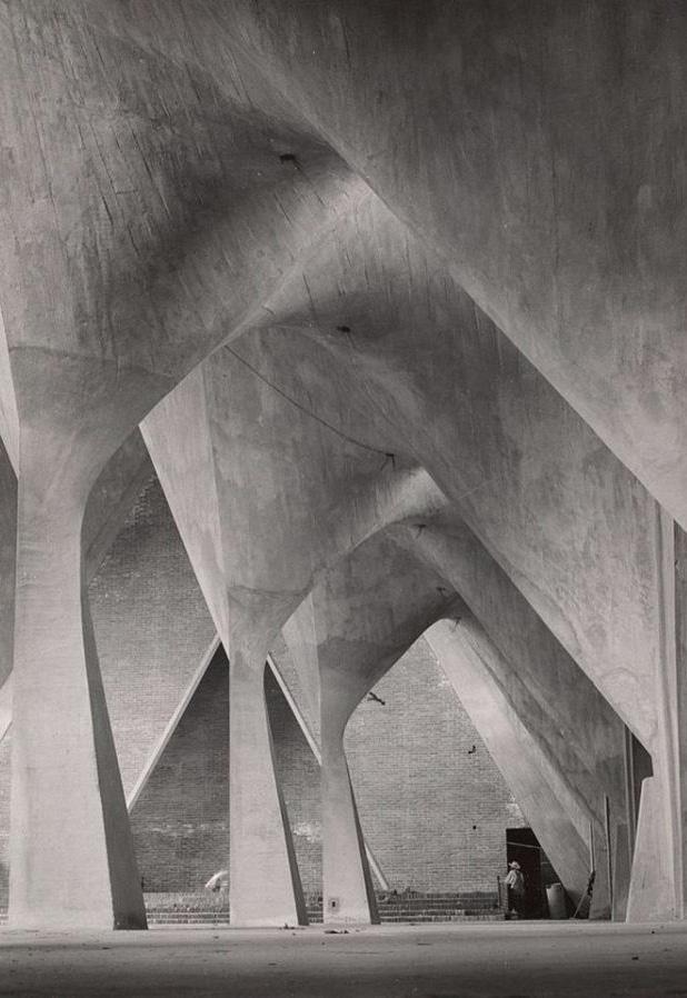
Figure 2.00. The space formed by tensile roofs with twisted columns in the Church of our Lady of the Miraculous Medal Lola Alvarez Bravo Archive, 1995, Center for Creative Photography, The University of Arizona Foundation 93.6.70.
12
Figure 2.01. Axonometric view of the church, showing the envelope strategies of different functional programs
The form of the roof shell serves both the structural function as well as the internal expression. The shell alone is the space enclosure. A series of cuvatures, hyperbolic paraboloids are built aligning with the straight lines — creating something transcendent innovatively, while maintaining the traditional form of Gothic at the same time.
14 15 2.1 Envelope Strategy 2.2 Construction Fabrication
1 2 3 4 5 6
1. Thickened ridge - 14cm thick concrete to reduce the tension along the edge of hypar
2. Triangular thickened edge beam
3. Hyperbolic paraboloid concrete shell - 4cm thick
4. Stiffening structure for edge beam - concrete
5. Tilted column - align with the axis of hypar
6. Inverted umbrella foundation - reinforced concrete
Figure 2.02. Strategy diagram showing the design process of the envelope.
Figure 2.03. Structural analysis of a typical bay of hyperbolic paraboloids.
2.3 CONSTRUCTION ASSEMBLY
A dry mix of concrete was placed on the steel reinforcement by human labour and the workers smoothened the surface manully.
Following construction of the formboards, the steel reinforcement was placed on top of it.
Candela conceived two methods of placement of the form boards. One is wedge-shaped boards, 1.27 centimeters thick with different width, another is parallel boards, 1.27 centimeters thick with wedges between them.
The construction process lasting ten months, begins with digging the form of inverted umbrellas out of the ground, scaffolding a temporary structure of wood that supports the form boards and wet concrete.
Firstly, workers made the formwork for the thickened edges of each bays, using triangular wood forms and then proceeded to construct the formwork for the bays.
16 17
STEP 4 - SHORTCRETE
STEP 3 - STEEL REINFORCEMENT
STEP 2 - FORM BOARDS
STEP 1 - FORMORK
Figure 2.04. Axonometric diagram to show construction process
3.0 Defining Moment
Candela’s method of applying tensile force on points of a surface provides a direction to find the form.
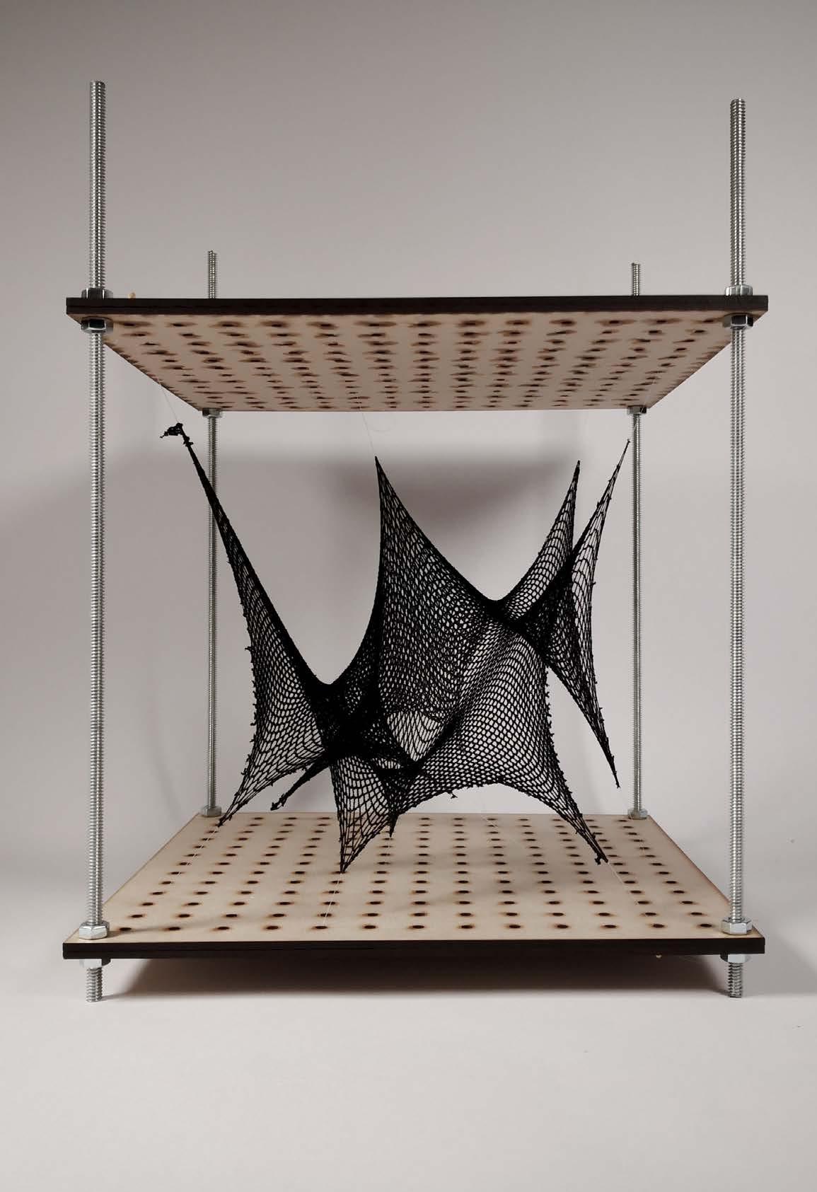
Our defining moment is to find the form by manipulating points. By testing several elastic material, from nylon to net fabric, we are able to create the tensile shapes by anchoring certain points.
The initial machine provides a simple way to assemble and adjust the form. Several artifacts generated by the machine give us a rough but straightward concept of the feasibility of using fabric and plaster. Together with the digital tool, the machine test provides and validates several variables, which are the basic rules for us to follow, in order to develop the machines afterwards.
19
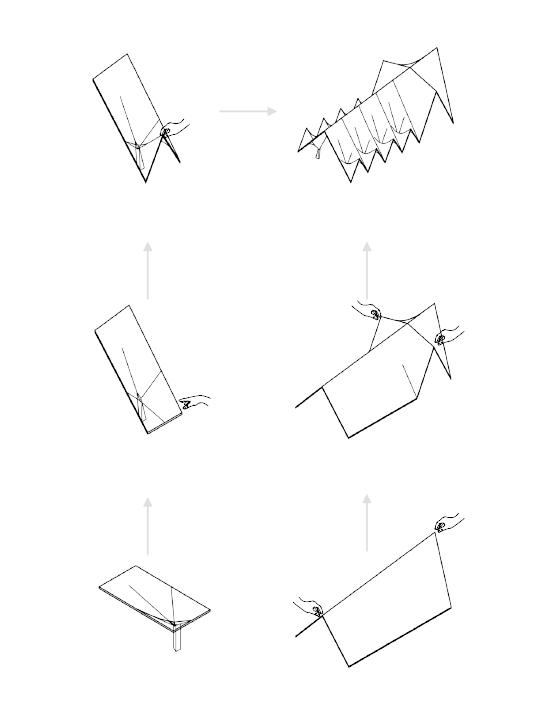
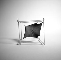
Figure 3.00. The initial study machine to observe and explore the form and surface by changing anchor points
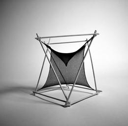
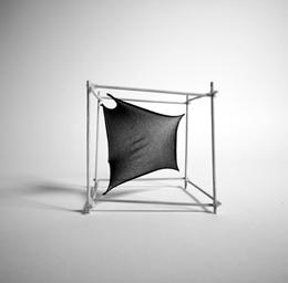
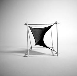
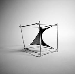
3.1 MORPHOLOGY TEST | Nylon Stocking
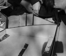
The series of photos on the right illustrate different methods we used to study the topology of the fabric forms. As the frame defines the bourndary and the forces are applied through anchor points, a flat piece of fabric can be formed into various shapes.


20 21
Cubical Frame Square Fabric 6 Anchor points
Figure 3.01. Concept models to test the form
Distorted Cubical Frame Square Fabric with 1 cut 6 Anchor points
Twisted Frame Rectangular Fabric 8 Anchor points
Rectangular Frame Rectangular Fabric with 1 cut 8 Anchor points
3.2 KANGAROO SIMULATION
Kangaroo a plug-in to Rhino-3d, is used to simulate the outcomes after adding anchor points and forces onto a surface. There are several variables that can be controlled to generate the form: anchor points, forces applied on these points and gravity. The topology of the base surfaces was also tested to analyze the effect. A closed surface can form a shell if being stretched; a surface with an opening can generate a hollow space if certain forces were applied at all vertices. A combination of two surfaces under different control conditions may create an interesting space in between.
22 23
0 z y x z 0 z 0 z y x z 0 z 0 y x 0 z y x z 0 z 0 y x 0 z y x z 0 z 0 y x 0 z y x A B C D A B E E E E F F G G H C D A A A’ A A’ B B’ B B’ C C’ C C’ E’ E’ DD’ DD’ A A’ E E’ HH’ GG’ F F’ B B’ C C’ DD’ A A’ B B’ C C’ DD’ B C D E F G H A B C D E F G H A B C D E F G H A B C D A B C D A B C D E F G A B C D E F G A B C D A B C D A B C D Anchor: A (0,0,300) B (300,0,300) C (300,300,300) D (0,300,300) Gravity g = 1600 Anchor: A (0,0,300) B (300,0,0) C (300,300,300) D (0,300,0) Gravity = 0 Anchor: A (0,0,300) B (300,0,0) C (300,300,300) D (0,300,300) Gravity g = 0 Anchor: A (0,0,300) B (300,0,300) C (300,300,300) D (0,300,300) E (150,150,0) Gravity g = 0 Anchor: A (0,0,300) B (300,0,300) C (300,300,300) D (0,300,300) E (150,150,300) Gravity = 1300 Anchor: A (0,0,300) B (300,0,0) C (300,300,300) D (0,300,300) E (80,80,300) F (240,90,300) G (110,240,300) Gravity g = 1800 Anchor: A (0,0,300) B (300,0,0) C (300,300,300) D (0,300,300) E (80,120,0) F (240,120,0) G (110,240,0) Gravity g = 0 Anchor: A (0,0,300) B (300,0,300) C (300,300,300) D (0,300,300) E (125,125,300) F (175,125,300) G (175,175,300) H (125,175,300) Gravity g = 3000 Anchor: A (0,0,300) B (300,0,300) C (300,300,300) D (0,300,300) E (98,76,300) F (177,43,300) G (225,145,300) H (145,177,300) Gravity = 3000 Anchor: A (0,0,300) B (300,0,0) C (300,300,300) D (0,300,300) E (125,125,0) F (175,125,0) G (175,175,0) H (125,175,0) Gravity g = 0 Anchor: A (0,0,300) B (300,0,0) C (300,300,300) D (0,300,300) E (80,0,0) F (300,80,0) G (220,300,0) H (0,220,0) Gravity g = 0 Anchor: A/A’ (150,0,0) B/B’ (300,150,300) C/C’ (150,300,300) D/D’ (0,150,300) E’ (150,275,0) Gravity g1 = g2 = 0 Anchor: A/A’ (0,0,300) B/B’ (300,0,300) C/C’ (300,300,300) D/D’ (0,300,300) E’ (150,150,0) Gravity g1 = 1000 g2 = 0 Anchor: A/A’ (0,0,300) B/B’ (300,0,300) C/C’ (300,300,300) D/D’ (0,300,300) Gravity g1 = 1700 g2 = 2600 Anchor: A/A’ (0,0,300) B/B’ (300,0,300) C/C’ (300,300,300) D/D’ (0,300,300) E/E’ (125,125,300) F/F’ (175,125,300) G/G’ (175,175,300) H/H’ (125,175,300) Gravity g1 = 2800 g2 = 4000 Anchor: A (0,0,300) B (300,0,0) C (300,300,300) D (0,300,300) E (120,0,0) F (300,150,0) G (150,300,300) Gravity g = 0
Figure 3.02. Diagram of kangaroo simulations, giving each point a precise coordinate, the force of gravity a clear figure.
3.3 MACHINE TEST | ANCHOR POINTS
Based on kangaroo simulation, we develop a machine to test the shape in reality.
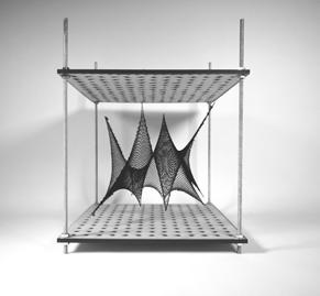
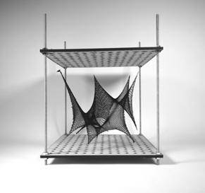
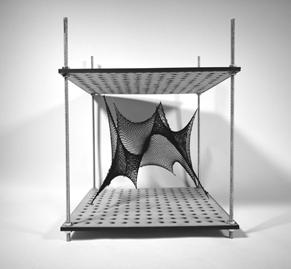
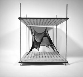
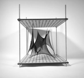
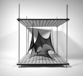
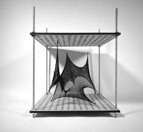
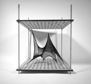
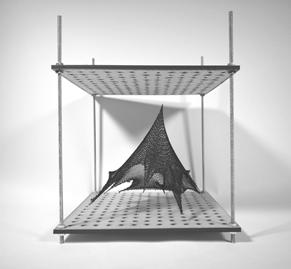
There are 2 vaviables that can be adjusted to modify the shape.
1. Distance between 2 perforated MDF panels;
2. Locations of anchor ponits.
Using the same piece of fabric, by positioning anchors differently, a series of various forms were created.
7mm diameter Steel Threaded Rod together with Thin Hex Nuts to adjust the height of the machine
Wooden Stick with Transparent String to tie and pinch fabric 2 pieces of 3mm thick MDFs sticked together with 25x25 punched holes to fix sticks
24 25
Figure 3.03. The line drawing of the study machine
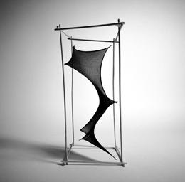
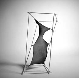
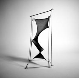
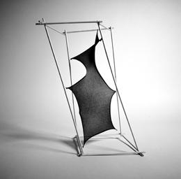
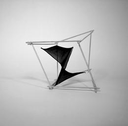
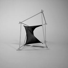
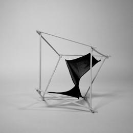
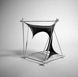
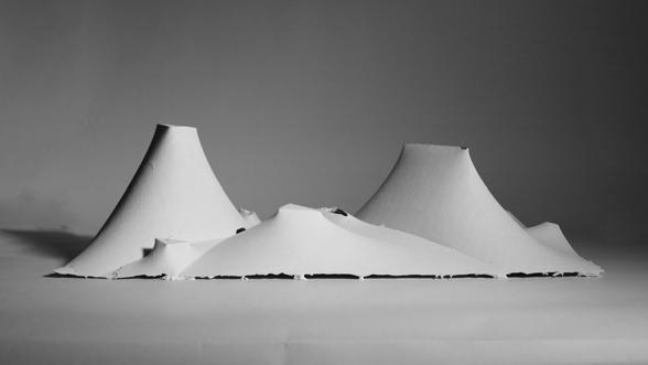
Figure 3.04. A series of concept model to test the shape. From top left to bottom right, the numbers of points pulling up are gradually increasing.
Mix plaster with water in ratio 100:65

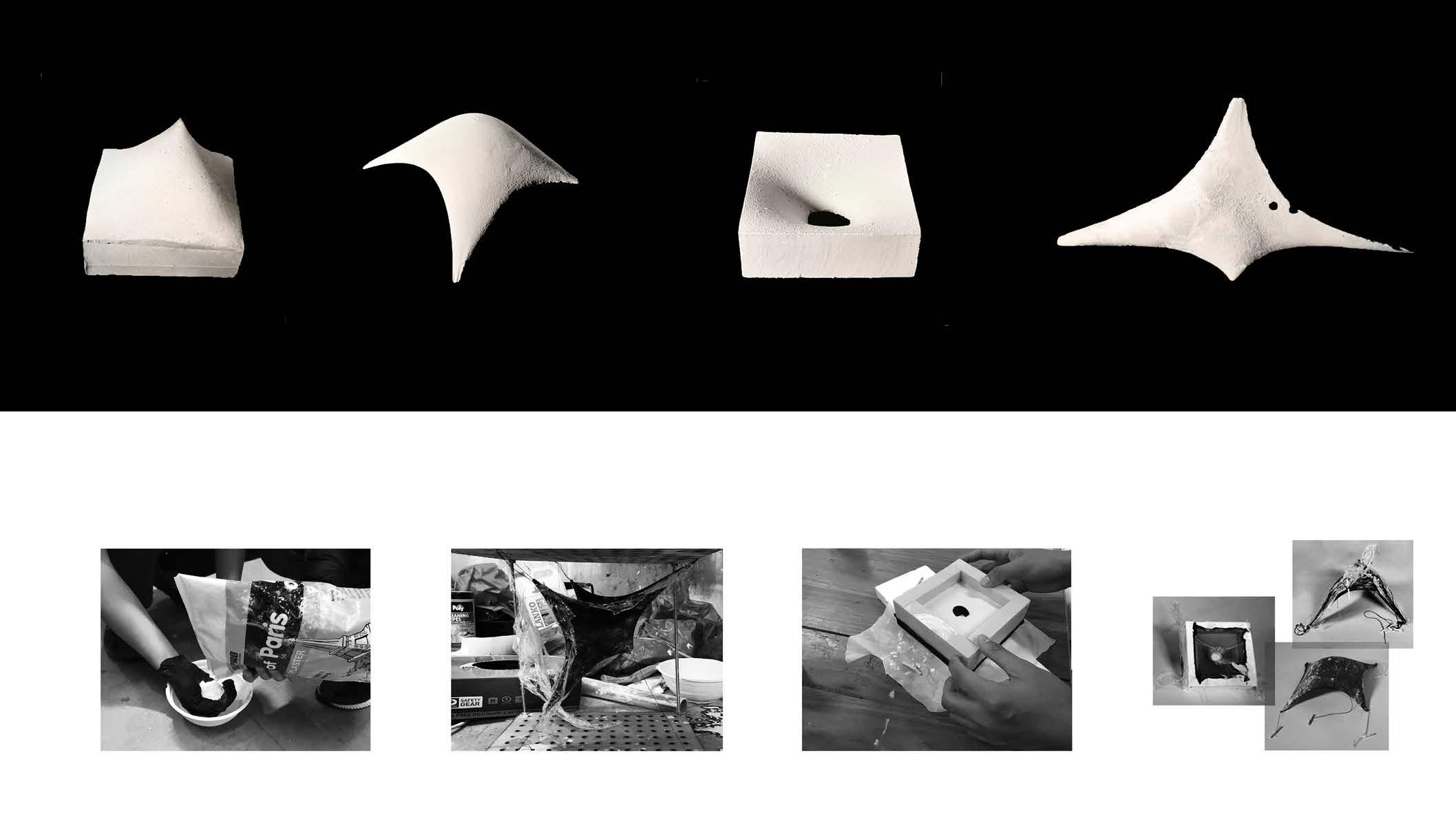
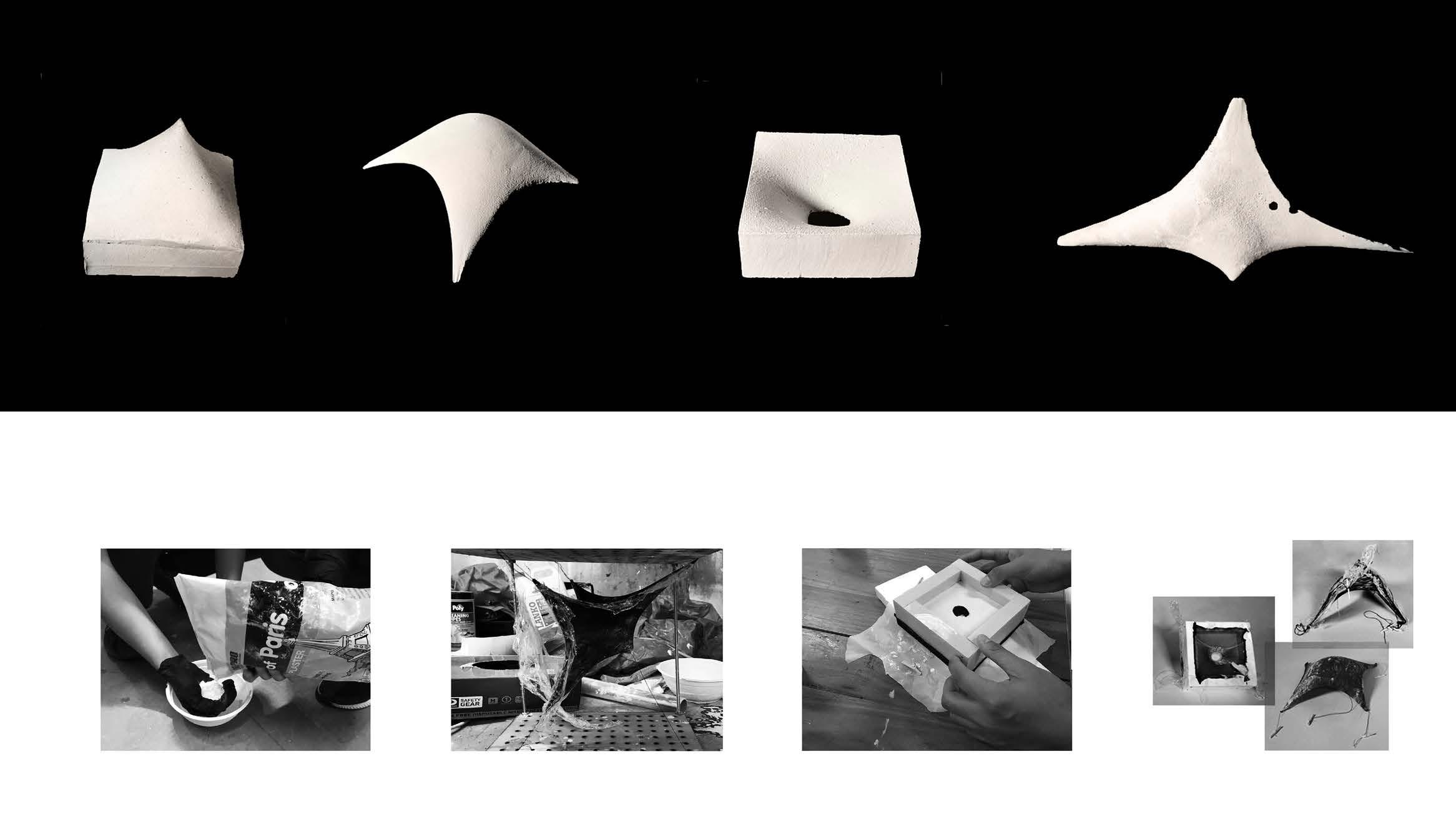

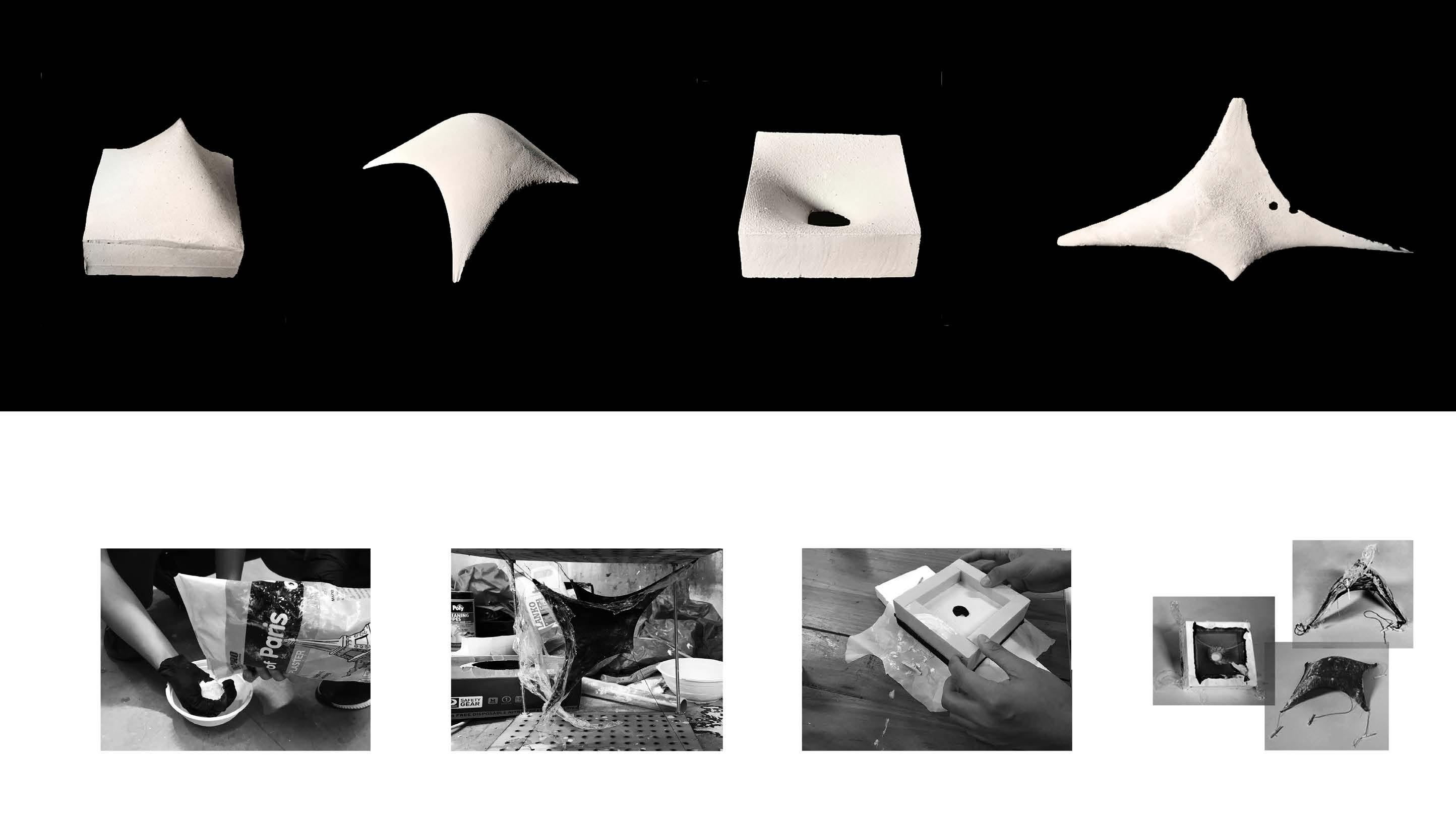
Use the study machine to strech two layers of tensile fabrics (stitch together) and pour plaster in the gap to
26
Figure 3.06. Photos of a series of artefacts for surface test
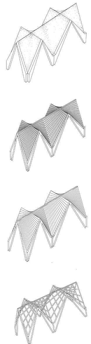
4.0 Machine
In the machine test, the way of pouring plaster in the gap of two layers of fabric does not form the shape as expected. The deformation is mainly caused by the gravity of the plaser which counterweighs the stretching force. To make the procedure and outcome predictable, we turn our direction to apply plaster directly to the surface of fabric to create just one single layer ...
On the other hand, the forms created initially are isolated artifacts. But for an architectural evelope, a form which is replicable and continuous is needed. Starting from Machine V.1, we utilised a continuous cable to create a cantenary network in which fabric is streched over to produce subdivision.
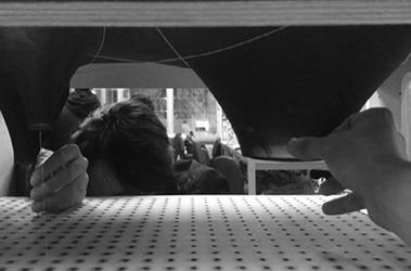
Our making procedure can be concluded as making digital models of machine using Rhino, purchasing necessary materials, laser cutting or CNC crafting machine panels, assembling the machine, linking to Arduino script, then starting making prototypes. From minor things like selecting and stitching fabric to major things like designing machine, each step counts and implicates lots of effort and considerations,
29
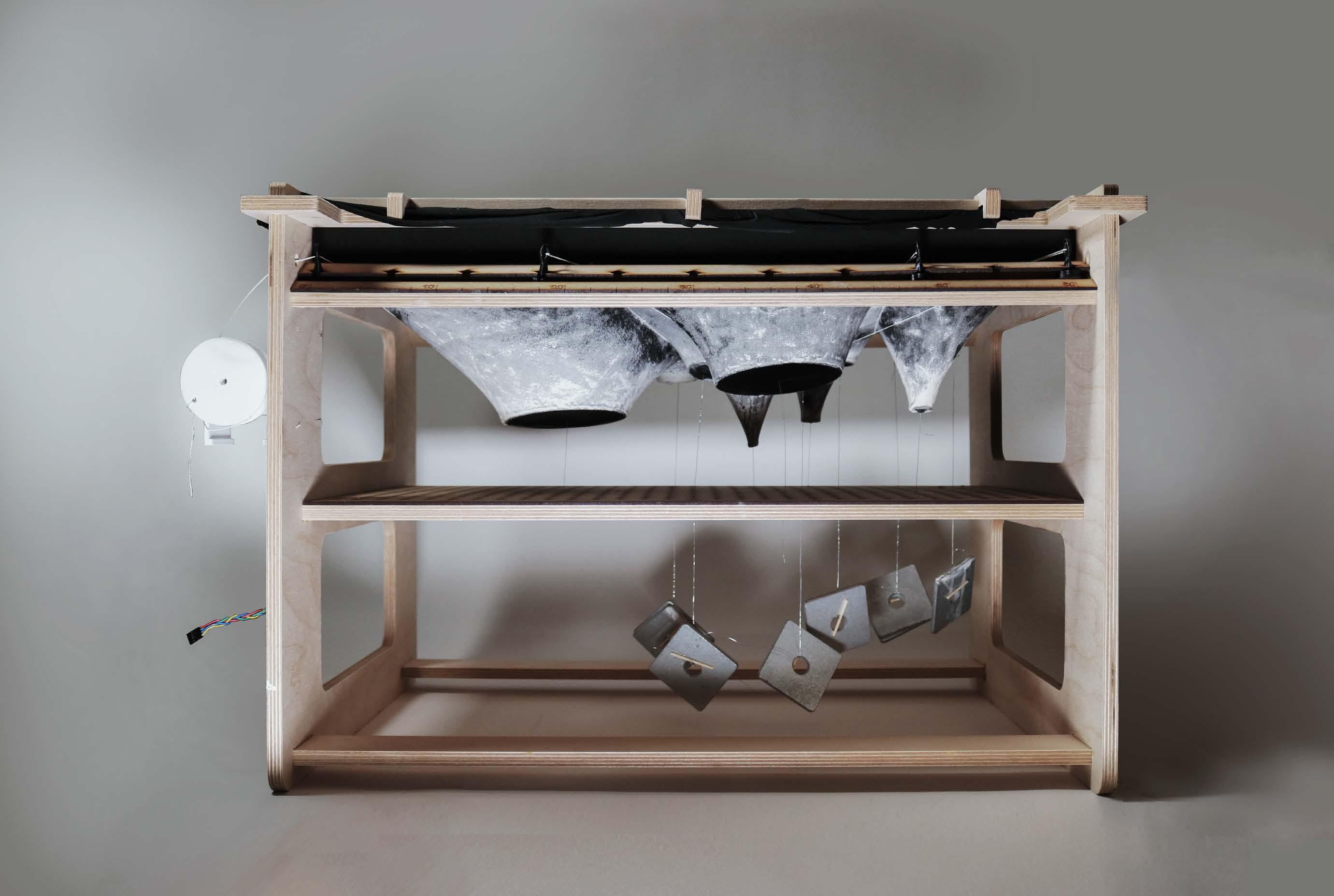
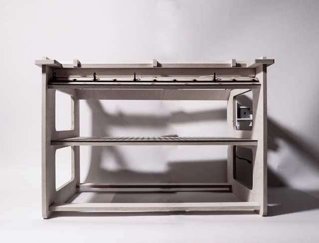
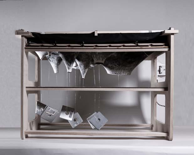
Figure 4.00. Machine V.2 in action
4.1 RULES AND PARAMETERS
The diagram lists all the possibilities of iterations of vaults generated by the machine.
The fabric surface, the strings and the slides of the machine are reverted to the planar, lines and fixed anchor points, to simplify the conditions of vault segmentation. Each area has a corresponding central point to pinch vertically in 3d to generate the vault.
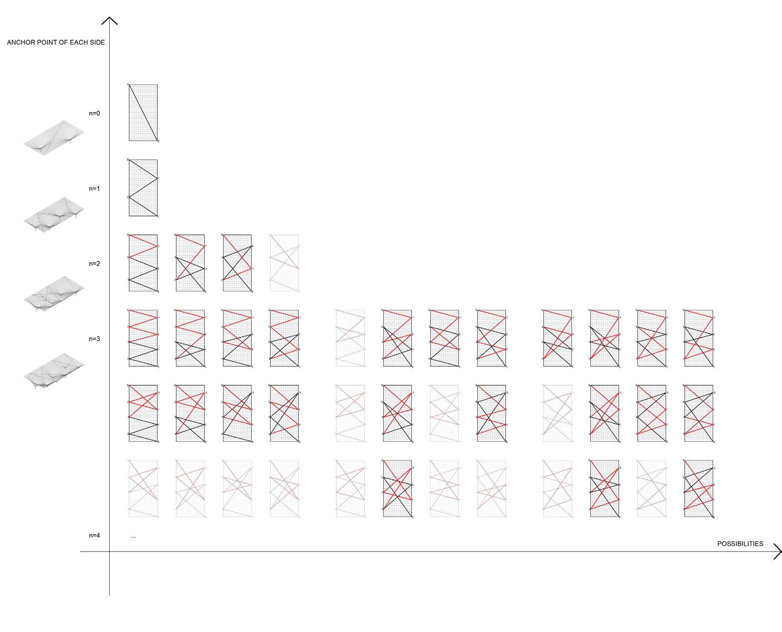
It should be noted that each diagram only focused on the influences caused by numbers of slides, winding methods of strings.
Each iteration can generate hundreds of possibilities with the movement of slides. Different positions of the pinching points for each segment area are ignored in this diagram.
The diagram is arranged according to the anchor point of each side, from no point to three points on each side. As the start point and the end point are fixed, and each anchor point can only be connected once, it is impossible to have different numbers of anchor points on the two sides.
30 31
Figure 4.01. Matrix of rules and parameters
Anchor Point
Pitch Point to centroid of shape X
Sliders to control the arrangement of string
A pulley to control the tightness of the string
7mm diameter
Steel Threaded Rod together with Thin Hex Nuts to adjust the height of the machine
300x600 outer MDF frame to adjust strings,with 550x240x270 inner MDF frame to fix the fabric
2 pieces of 3mm thick MDFs sticked together with 25x50 punched holes, wooden Stick with Transparent String to tie and pinch fabric
4.2 MACHINE V.1 | DIMENSION: 300
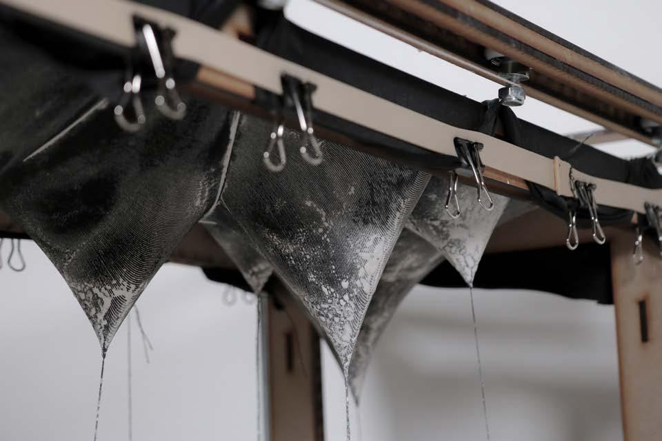
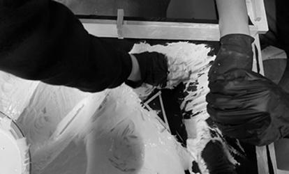
The Machine V.1 takes the making procedure of the precedent study as a reference. We use plaster to replace concrete. MDF broad is like the scaffold for construction. Fiber glass is used to simulate steel reinforcement in the shell. By mopping plaster directly to the single layer of fabric rather than pouring plaster into the gap between two layers as we did in the study machine, we are able to build a thin shell similar to candela’s work.
One challenge of the machine designing is how to control the strings and create a flat surface of fabric directly above the planar of the string. Thus a machine of two frames come out.
The outer frame is made of 2 tracks. To achieve the flexibility, rollers are installed into tracks so that we could adjust the positions easily. The fabric is fixed onto the inner frame independently by rubber band. The fabric then can be pulled down and anchored to the MDF board below, with the trace of the strings.
We also think about goring upwards rather than pulling down. However, in this situation, the strings should be above the fabric planar to keep the trace, which will make it difficult to mop the plaster on the fabric.
32 33
Figure 4.02. Axonometric line drawing of the Machine V.1
x 600MM
MACHINE ASSEMBLY
34 35
4.2.1
Figure 4.03. Photos showing details of Machine V.1
Rubber Band to tie the fabric
MDF board as coordination plane
Pulley to control the length and relaxation of string
Inner frame to fix the fabric
Threaded Rod
Outer frame as the track frame
Siding roller to adjust the position of anchors
Figure 4.04. Exploded axonometric line drawing of Machine V.1
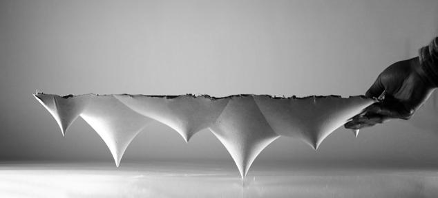
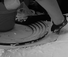
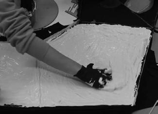
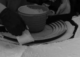
4.2.2 MAKING PROCESS
Fixing the sliding rollers in determined positions according to the mark on track; Pull down the center points of each region and tie it to the MDF board
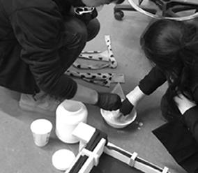
Prepare plaster and mix it with fiber glass as reinforcement
Mope the mixed plaster to the fabric and use brush to smooth the surface, wait until it is dry
36
Take out the portotype from the machine, tear out the fabric
Figure 4.05. Photos of making process.
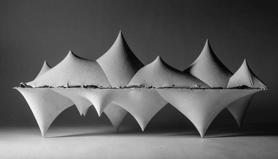
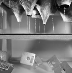
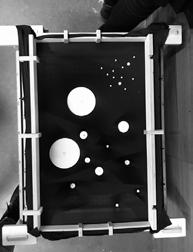
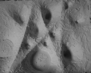
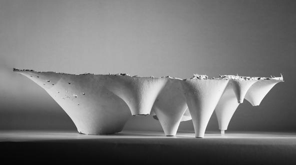
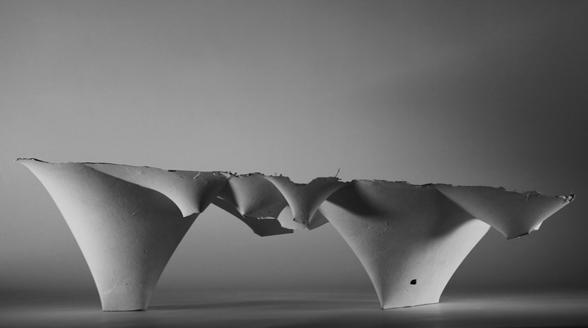
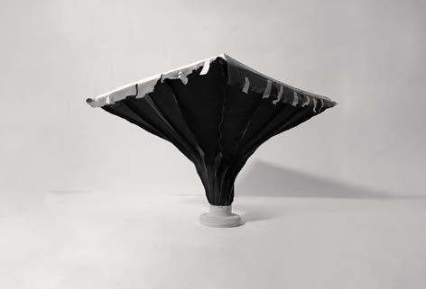
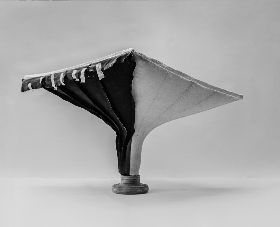
Figure 4.06. The photo of one prototype coming from Machine V.1
Controling strings effected by stretching force shape cantenaries
The way of mopping plaster on the fibric creates a very thin shell.
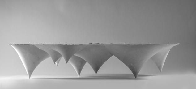
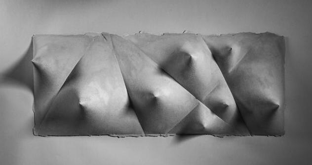
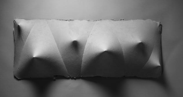
With three pulling points anchored to the ground, the shell can be self-supported. With the density of regions changes, different space qualities are created.
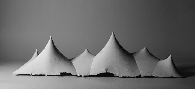
A region can be subdivided into extremely small regions, which do nor divide the space but can be served as the skylights later in our design, giving more possibilities of spaces.
38 39 4.2.3
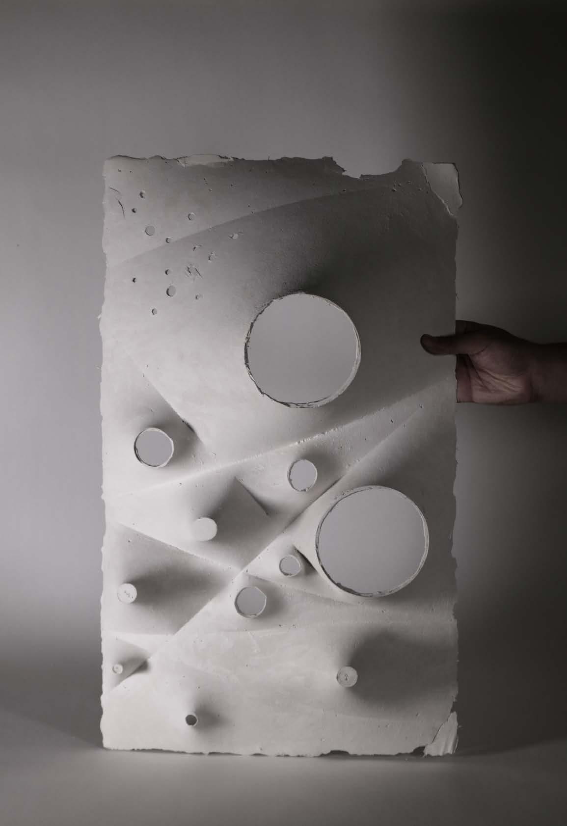
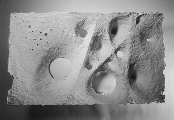
PROTOTYPE
PROTOTYPE 1
PROTOTYPE 2
PROTOTYPE 3
Figure 4.07. Top and elevation views of the prototypes
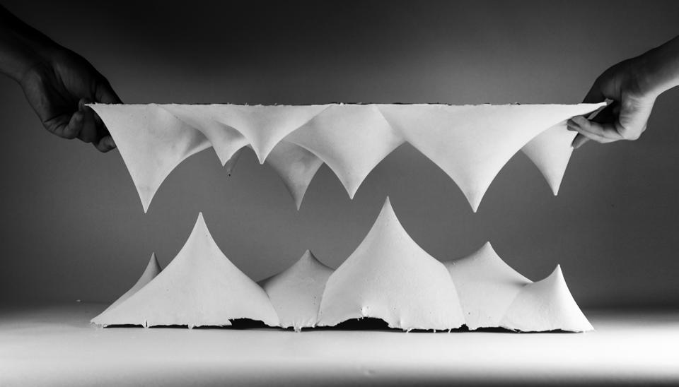
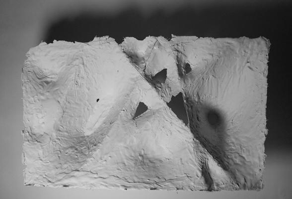
4.2.4 PROTOTYPE+
40 41
Figure 4.08. Two prototypes overlayed together to seek the possiblity of forms
Reverse
Stack
The upgraded machine basically uses the same principle as Machine V.1, but focusing more on details.
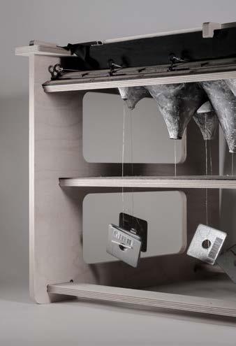
In Machine V.1, it is hard to fix the fabric onto the frame due to the string underneath. At the meantime, the material of MDF can easily cause deformation. For Machine V.2, we use CNC milled 12mm plywood to provide more strength and stiffness. The fabric now is fastened by the joint of wood on four sides, to make it easy to fix fabric on the frame. Additionally, the track and sliding rollers are redesigned to be able to smoothly slide and easily fixed in position.
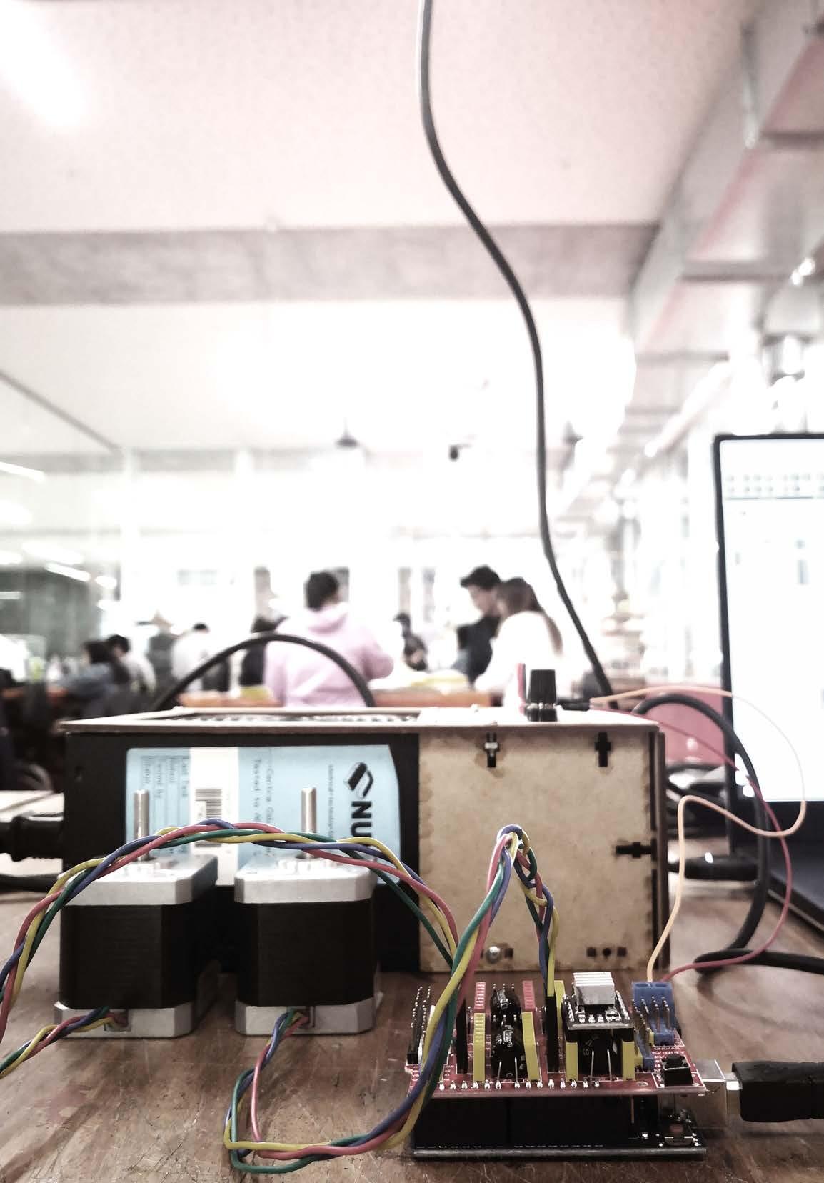
We use Arduino connecting to stepper motor to release, realx and fastern the string. Steel weights gives us a quantitive figure of the force pulling down.
42 43
The pulley drived by the stepper motor to adjust the tightness of the string
8 Sliders to control the arrangement of string
2 pieces of 3mm thick MDFs sticked together with punched holes
CNC milling frame as the structure
Figure 4.09. Axonometric line drawing of the Machine V.2 4.3 MACHINE V.2 | DIMENSION: 400 x 600MM
4.3.1 MACHINE ASSEMBLY
1. Eight 3d printing sliders with two fixed ones as the start and end points of the sting
2. CNC milling plywood ahchor clips to fix the fabric
3. CNC milling plates to hold the fabric and stablize the machine
4. Laser cut tracks to move and fix sliders
5. CNC milling plywood frame to fix the fabric
6. CNC milling frame as the structure
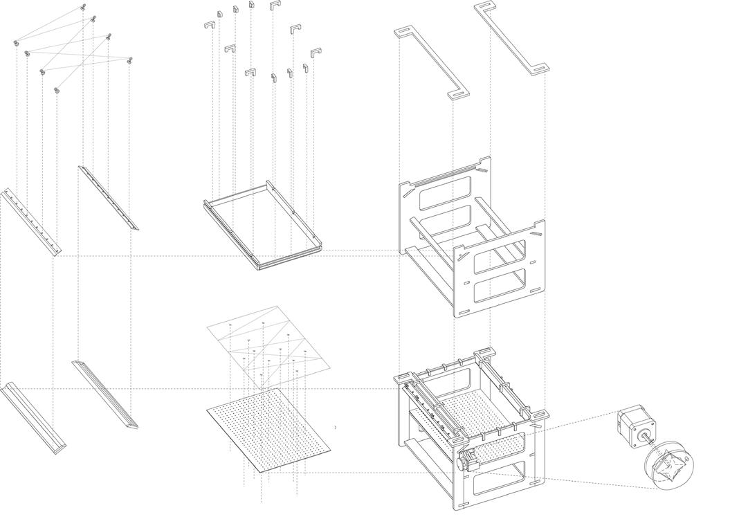
7. CNC milling plywood as the tracks
8. Streched fabric piniched by weights and holded by the string
9. Laser cut panels with punched holes to locate the pinch points
10. The whole machine
11. The pulley drived by the stepper motor to adjust the tightness of the string
44 45
Figure 4.10. Photos showing details of Machine V.2
1.
4.
7.
2.
5.
8.
9.
3.
6.
10.
11.
Figure 4.11. Exploded axonometric line drawing of Machine V.2
4.3.2 MAKING PROCESS
Fix the sliders into the slot in the track, adjust the arrangement of the string, then put round or triangle panels of different scales to the region accordingly Adjust the tightness of string to modify the catenary, tie weights on the round or triangle panels and prepare plaster and mix it with fiber glass as reinforcement
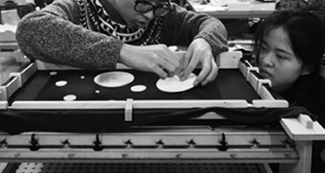
Mope the mixed plaster to the fabric and use brush to smooth the surface, wait until it is dry
Unlock the wooden clips and take out the model, then tear out the fabric
46
Figure 4.12. Photos of making process.
Figure 4.13. The photo of one prototype coming from Machine V.2
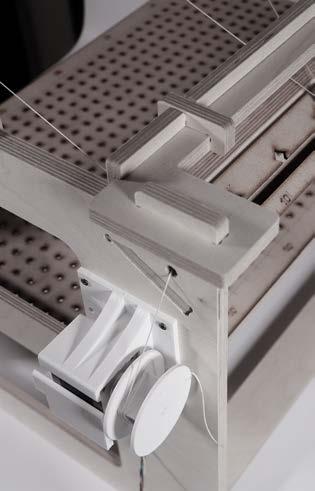
4.3.3 CIRCUIT SCHEMATIC

In order to control the length and relaxation of the string in quantification, Arduino together with stepper motor was introduced to the machine. We will use CNC shield that fits over the arduino uno or mega board to connect with stepper motor driver (DRV8825), power supply and stepper motor. Motor driver enables control of stepper motor through arduino type programming firmware and software. Also we will use a 17 bipolar stepper motor with power supply (5v-12v) to provide with power.
48
Stepper Motor(X)
Arduino UNO
CNC Shield
Power Supply (5v-12v)
Stepper Motor Drive
Computer with Grasshopper and Firefly
StepperMotor (Y)
Figure 4.14. Circuit diagram
Figure 4.15. Photo of arduino and stepper motor.
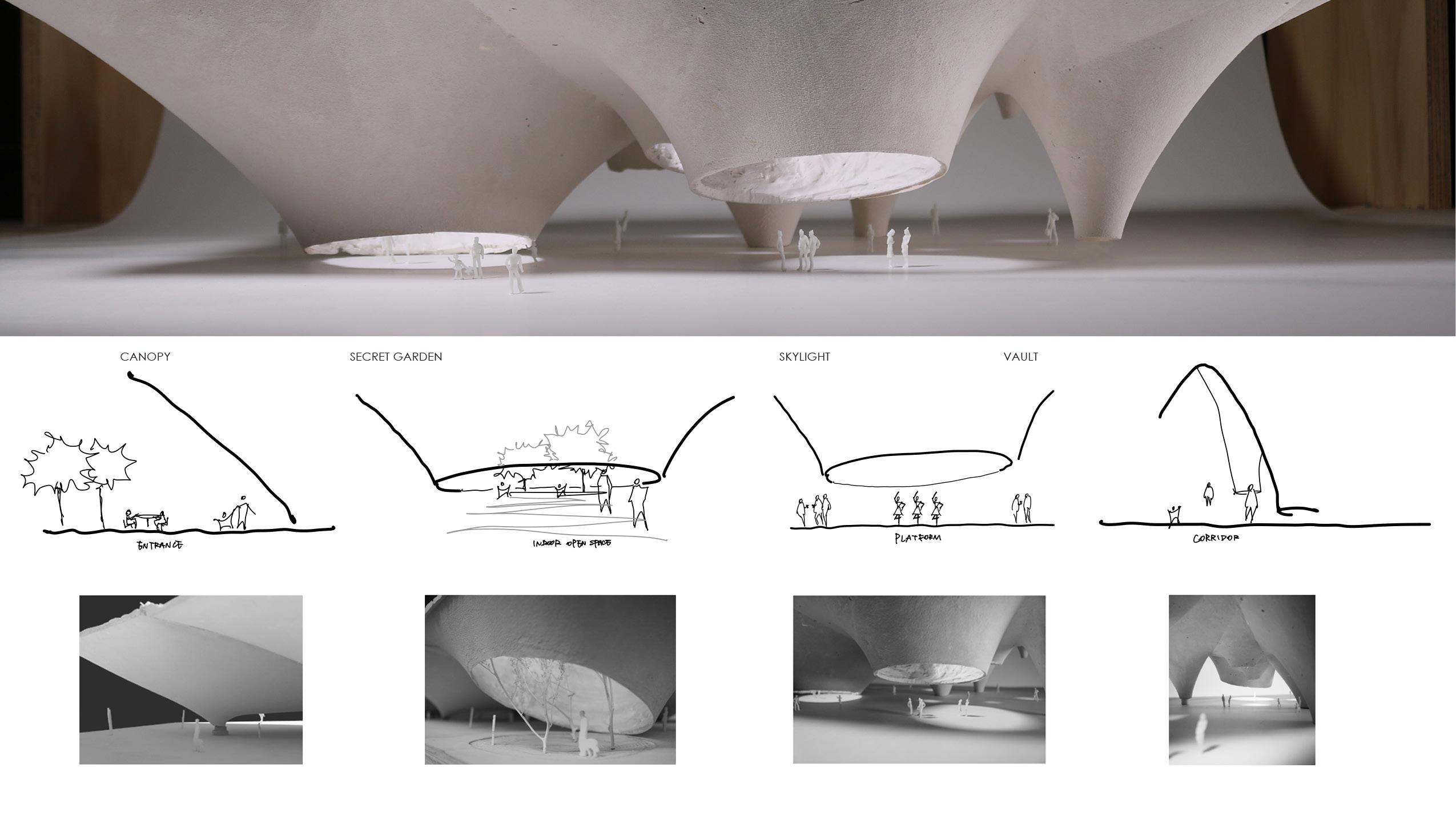
The evolution from piniching points to circles shows the attempt to apply more architectural language to the form —— openings, columns, entrances, and rooms.
Triangle shape shows a breakthrough from the test of piniching points to circles to irregular shapes, laying the foundation to further apply the stretching force to free forms.
50 51 4.3.4
PROTOTYPE
PROTOTYPE 4
PROTOTYPE 5
Figure 4.16. Photos of prototypes
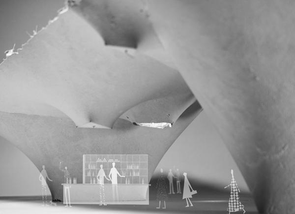
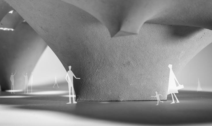
4.4.2 SPATIAL EXPLORATION | SCALE
54 55
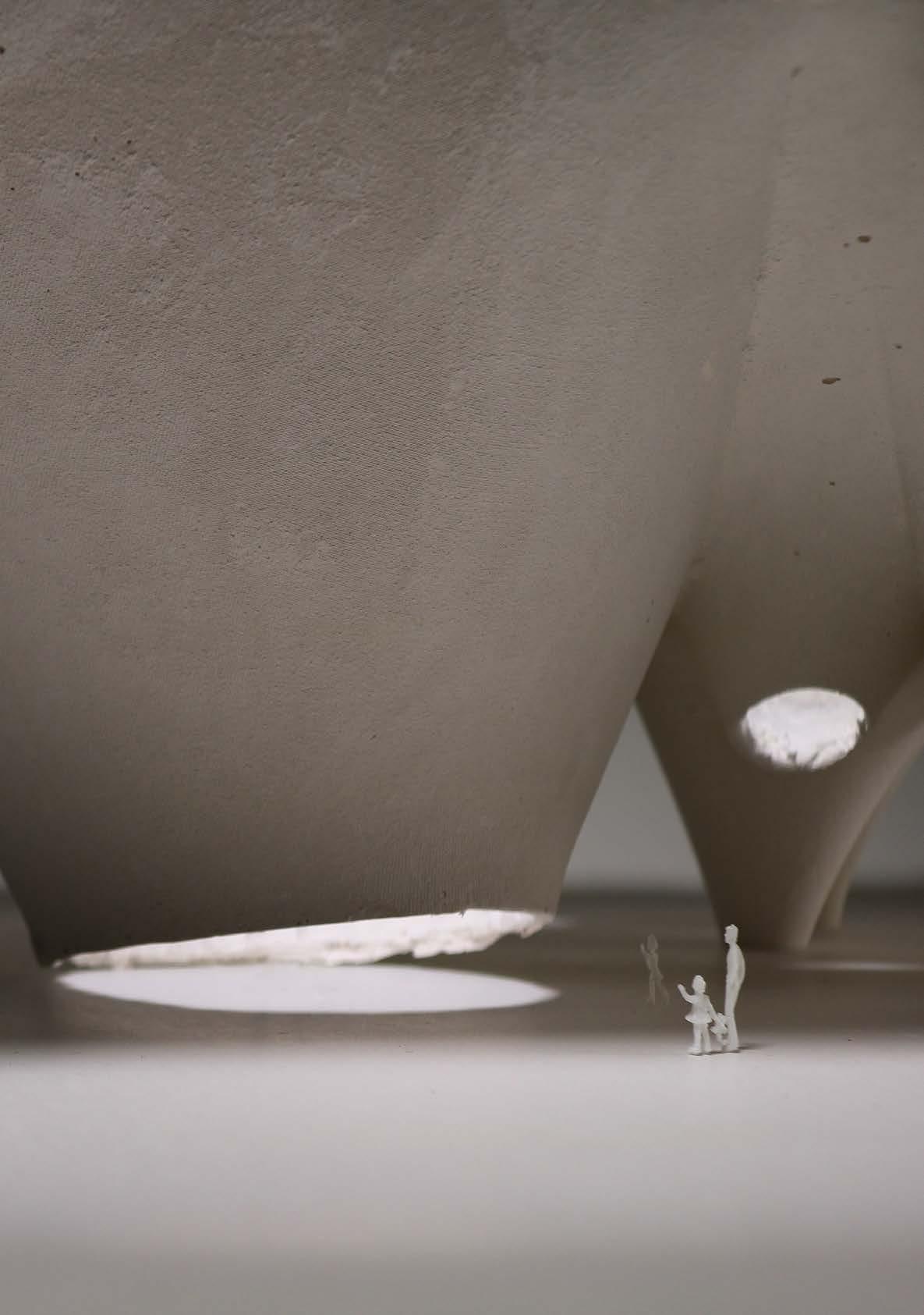
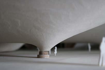
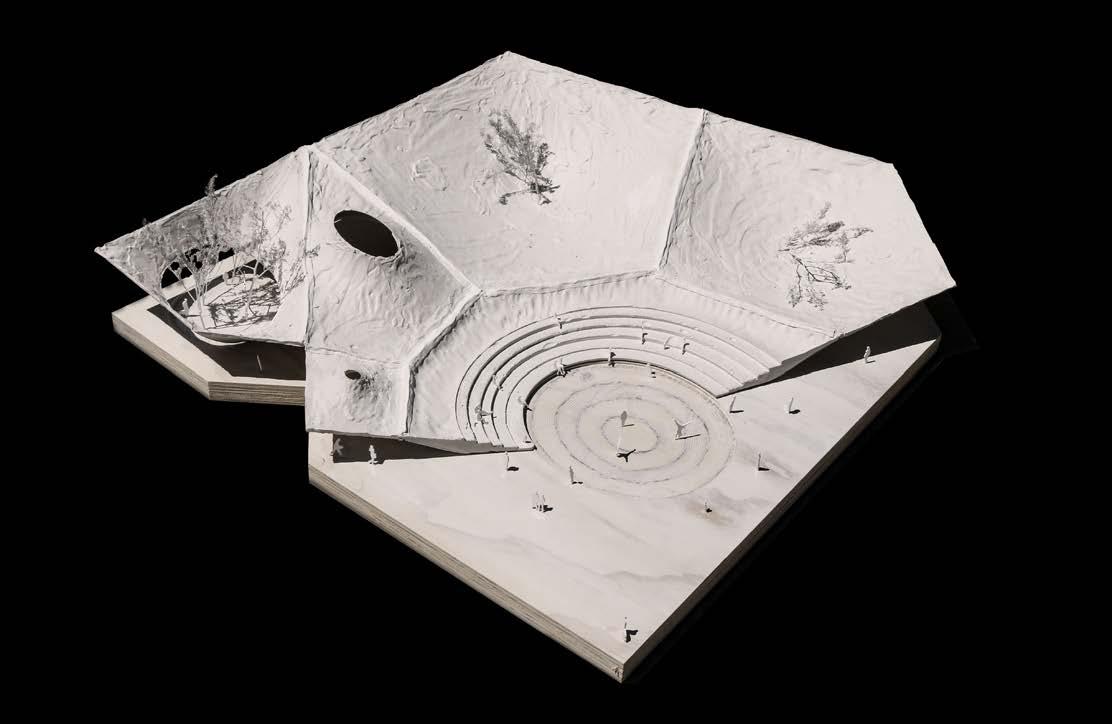
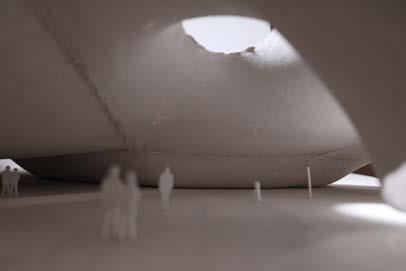
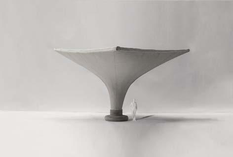
Figure 4.18. Photos of the prototypes with peoples of different scales to imply spaces of different scales.
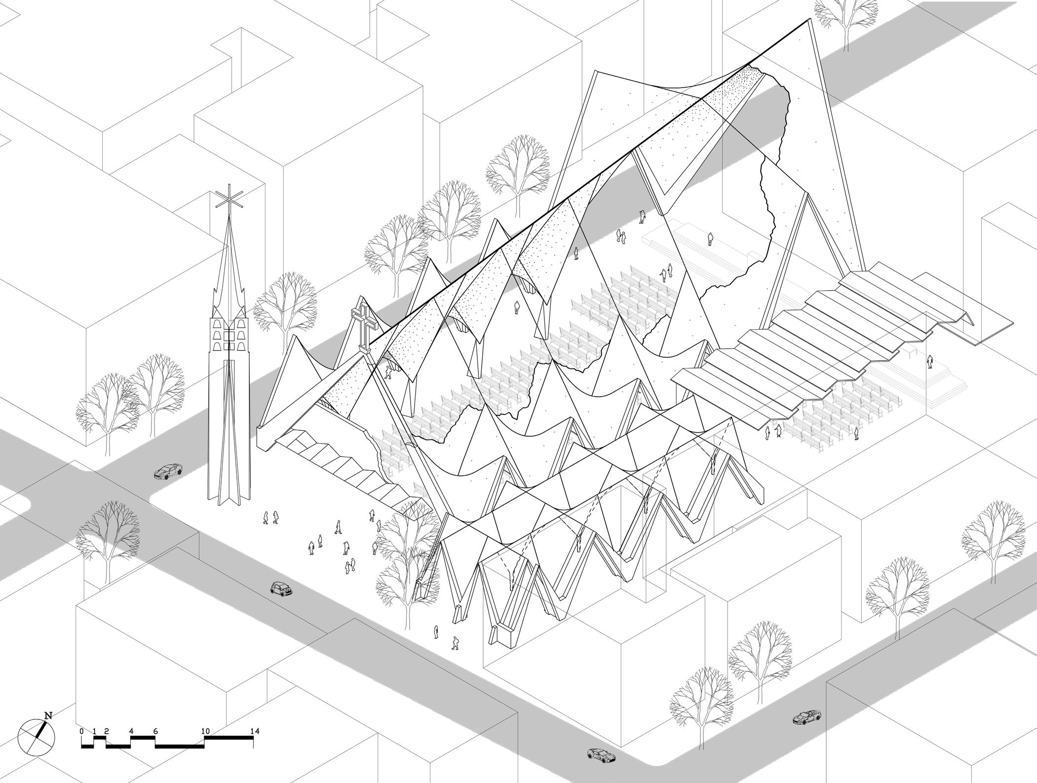
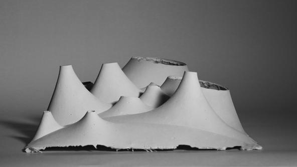
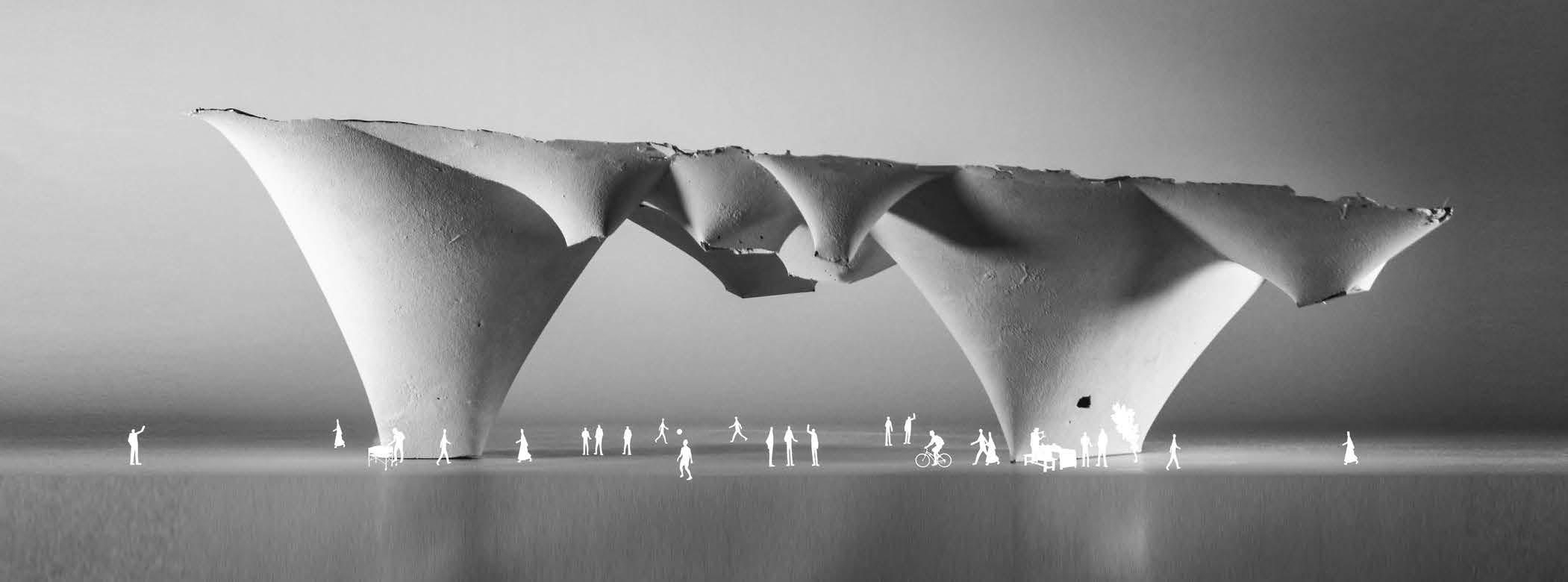
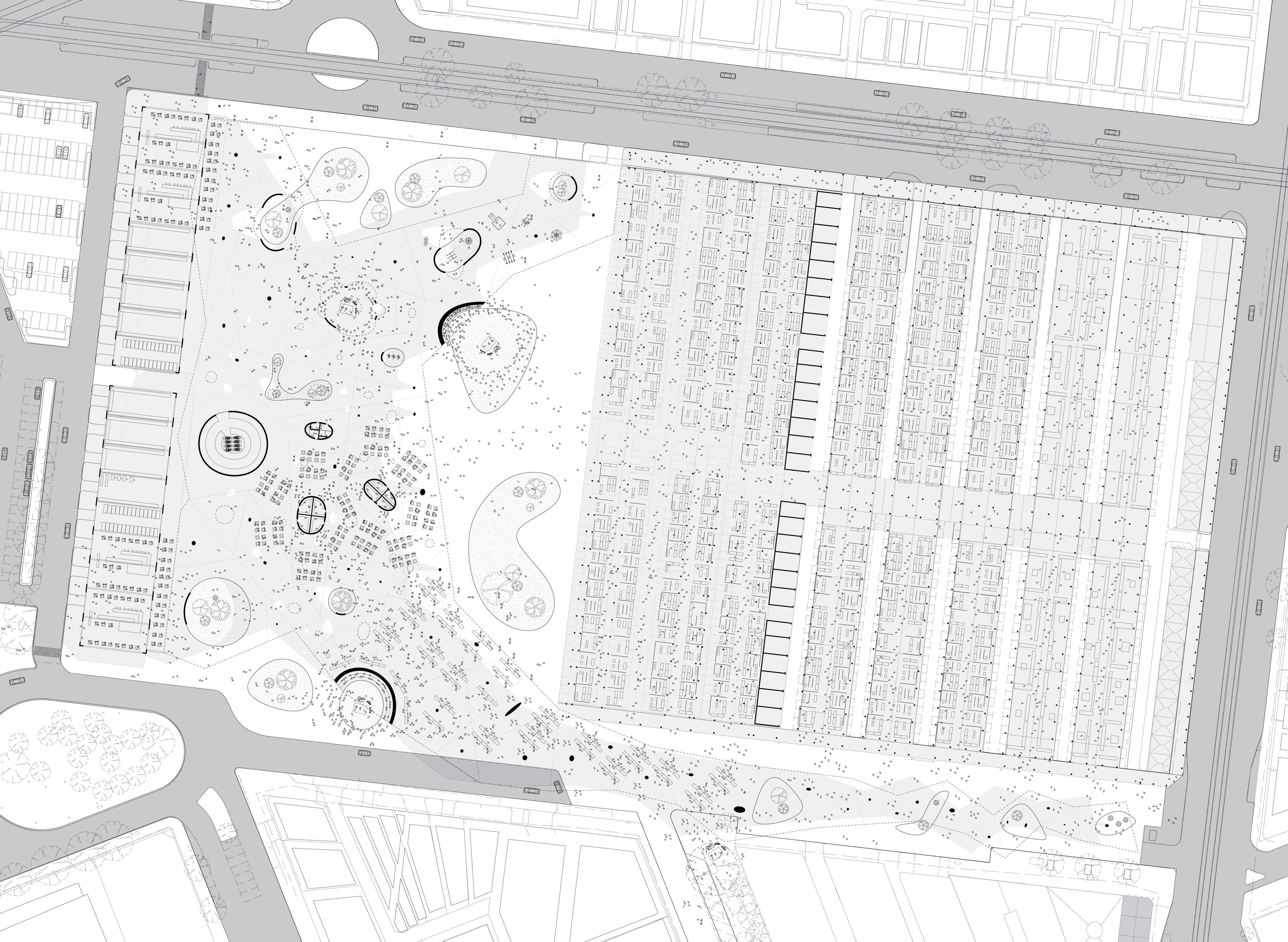
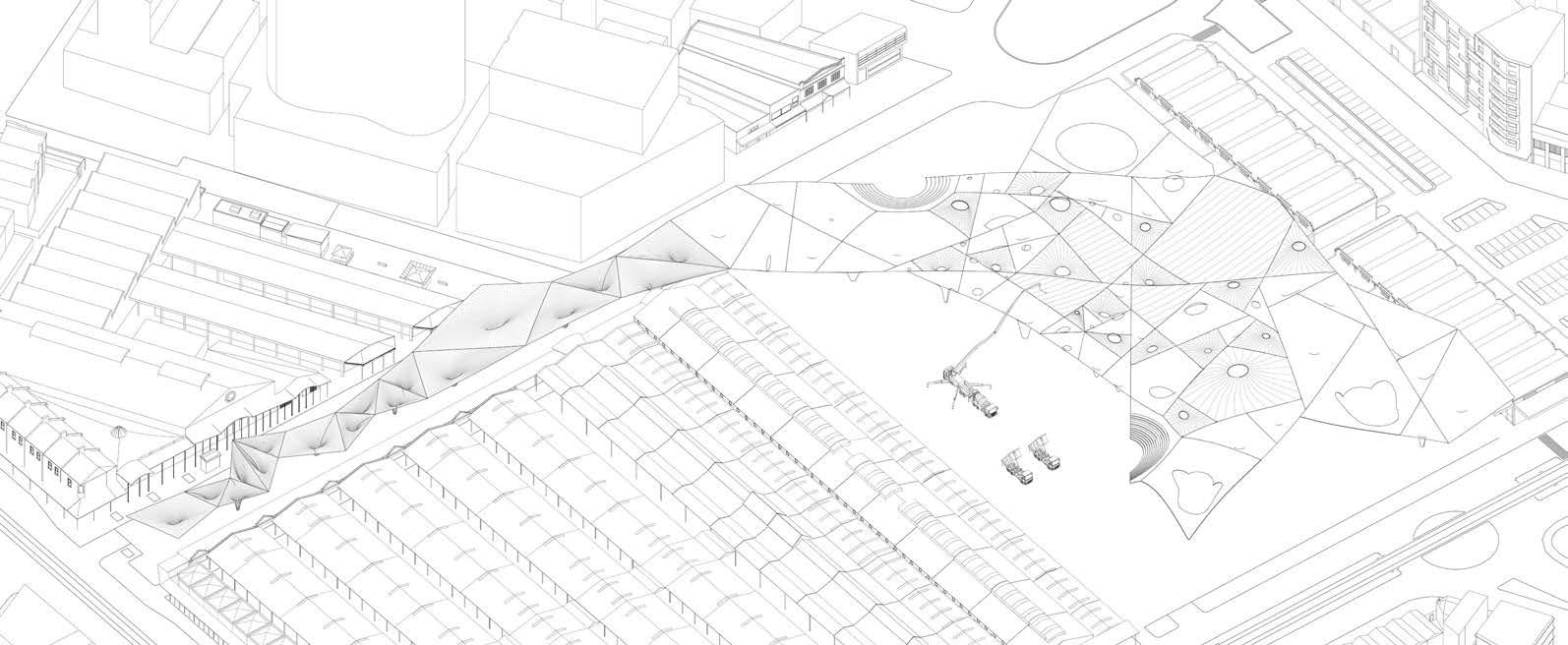
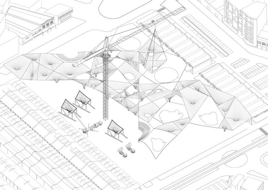
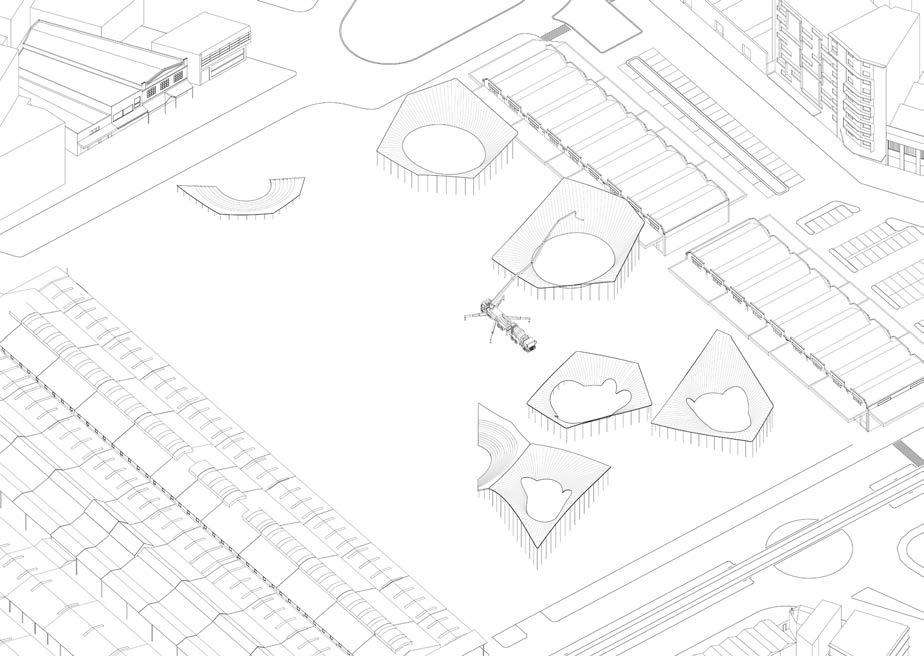
5.0 Queen Victoria MarketTension Morphology
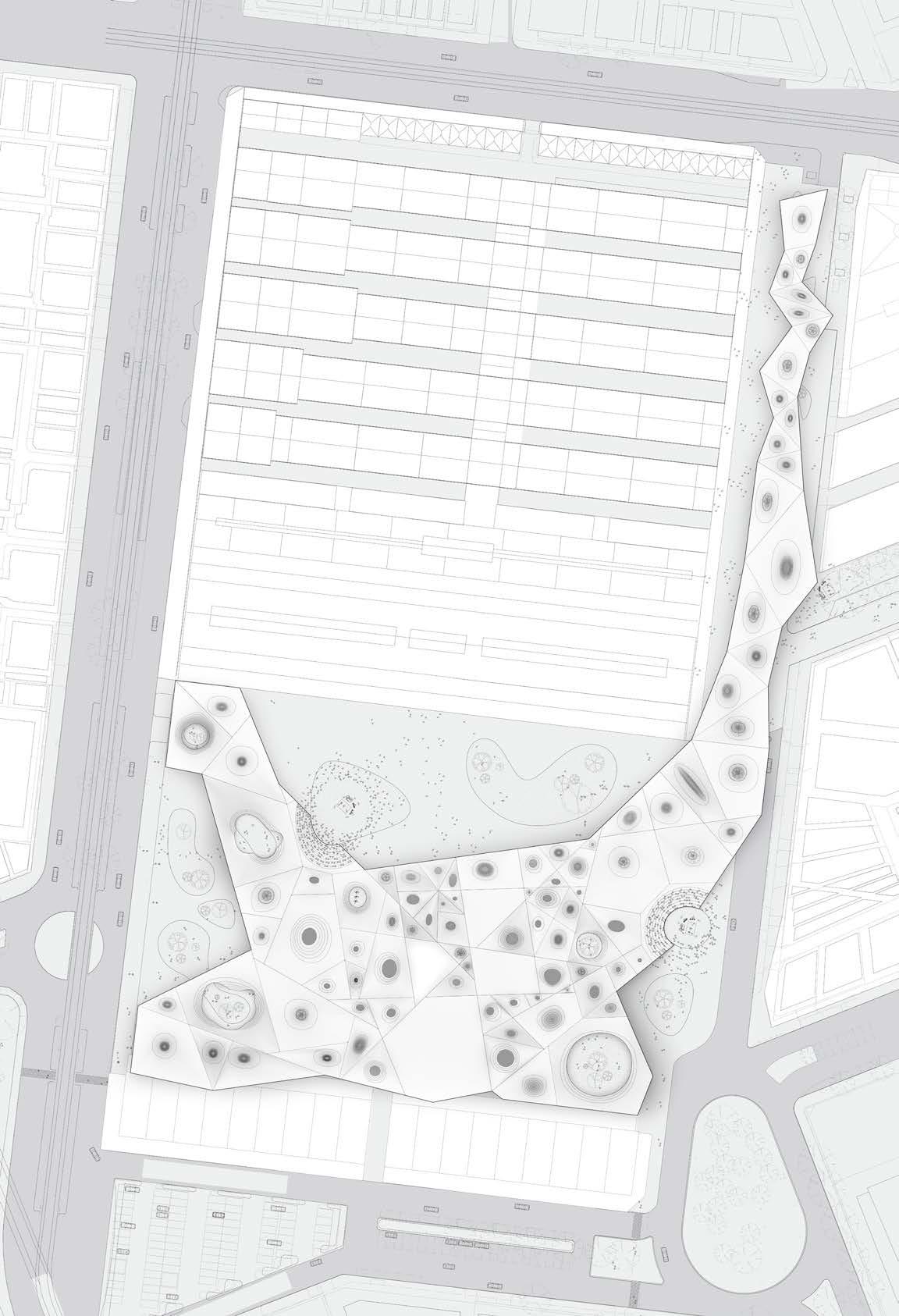
The site includes the present car park and the surrounding streets.
The design project is aimed at structuring a roof structure in Queen Victoria Market to create an open public space to benefit citizens, as well as enhance the ecological and social standards of the market. The site includes the present car park and the surrounding streets, with the heritage structure kept.

After investigating the existing infrastructure, there are still space to improve with the storage and recycling issues. We rearrange the circulation routes for the folklifts and storage spaces for the stalls. At the same time, the rainwater recollector and the solar power supply in the existing market drive us to think about creating another ecological system.
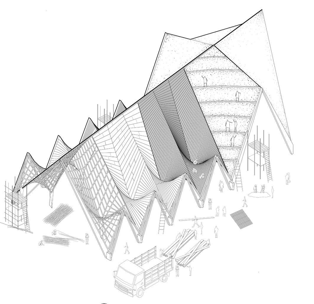
Based on the previous study, the proposal of a lightweight concrete shell is naturally formed. The form finding logic of machine is translated into the actual construction procedure. Fabric is still an important material involved, but appiled in a slightly different way in real construction.
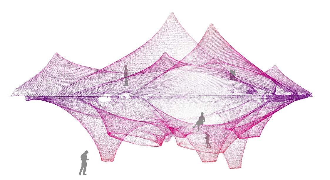
We focus much on the movement of human activities when designing. At a certain sense, programs of different functions guides the development of ‘cell‘ - the basic repeatable form - to be skylights, secrete gardens or columns. We leave the space open, keep human activities naturally happened. Like a live creature, once born, the structure grows with its own logic.
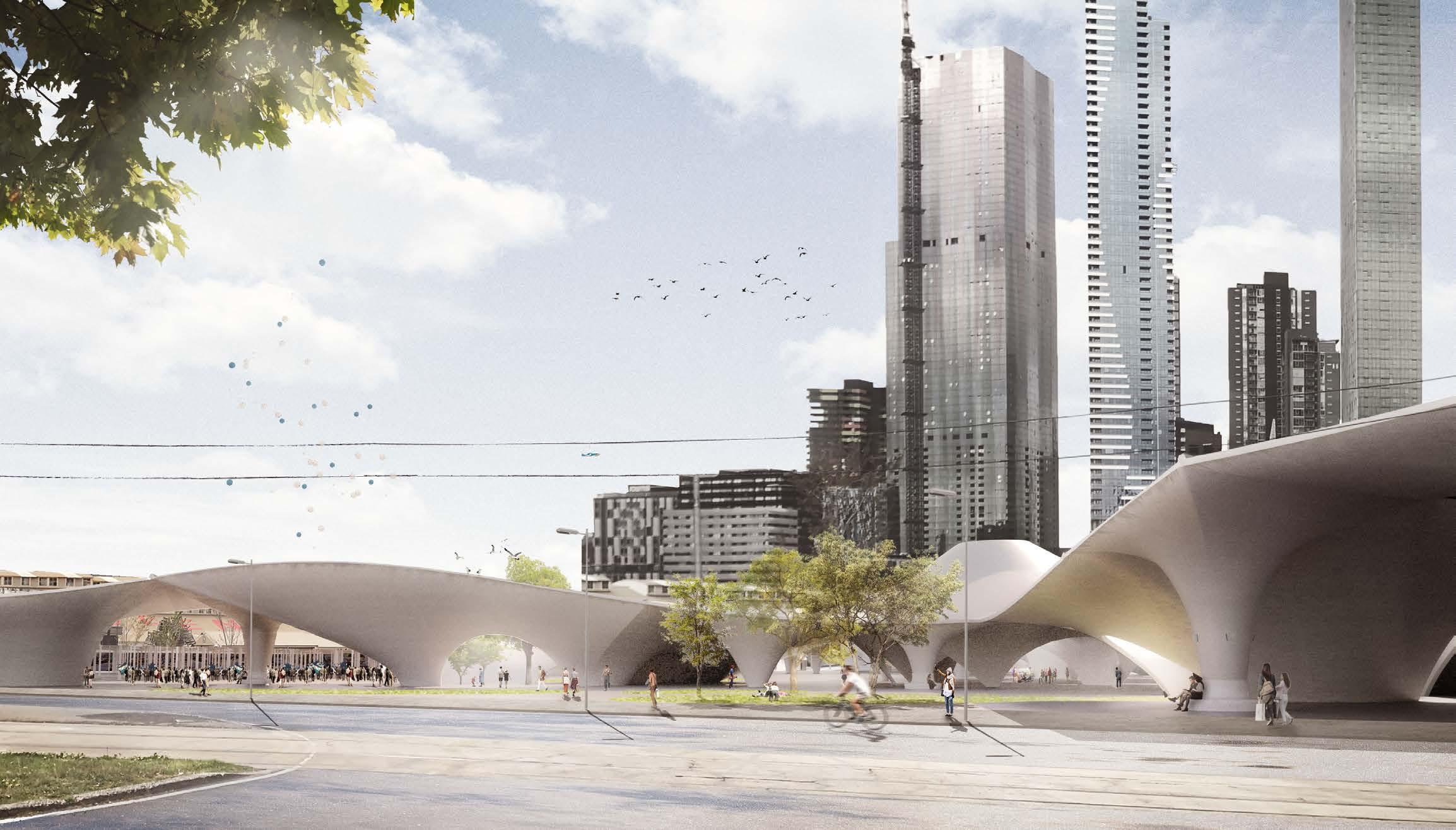
57
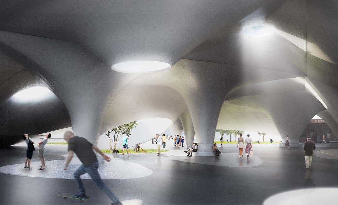
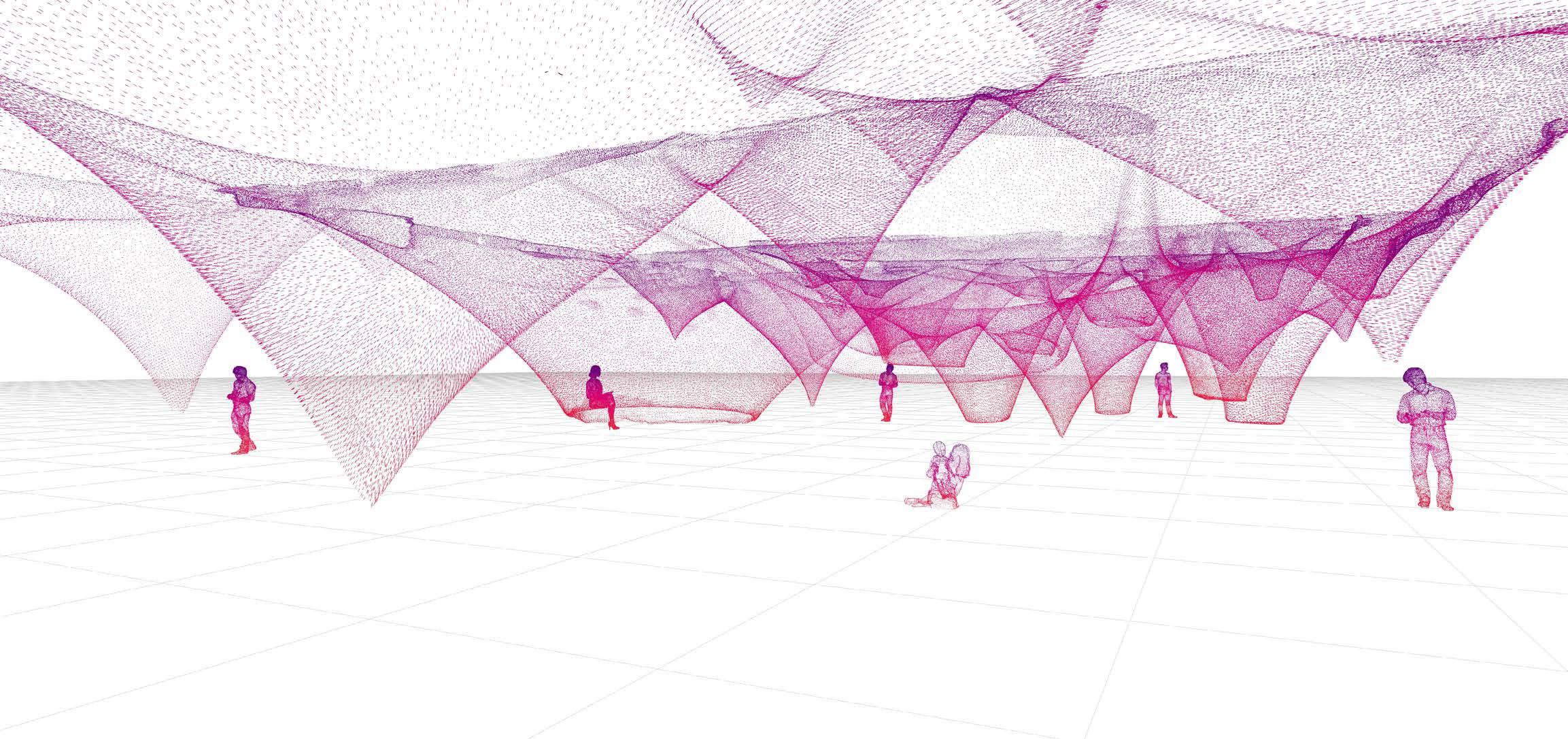
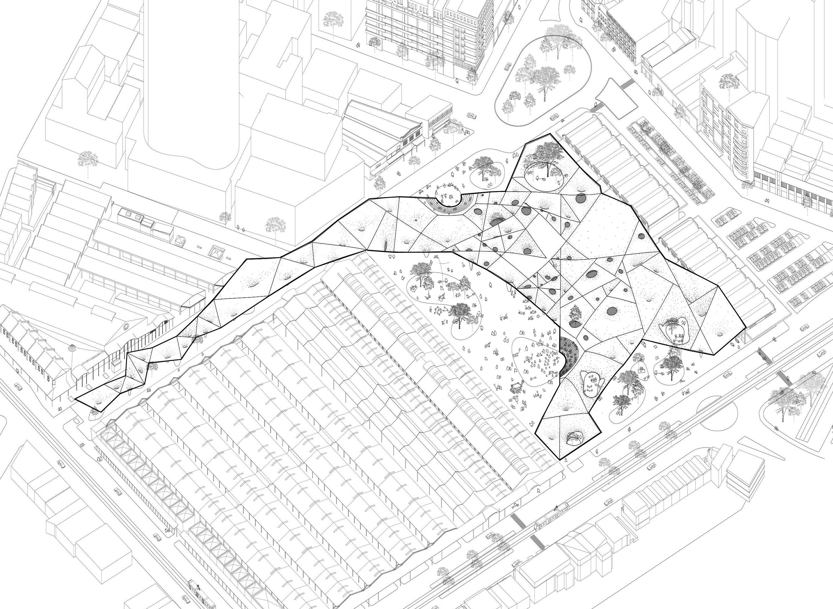
Figure 6.00. Rendering image of the design proposal.
BOUNDARY
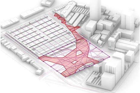
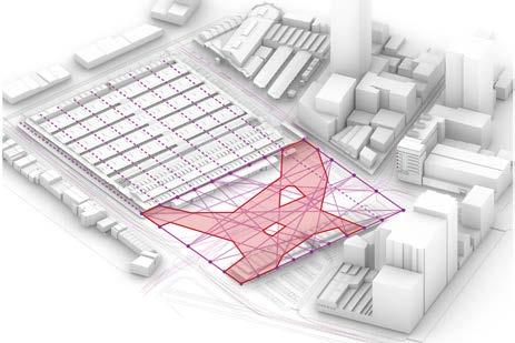
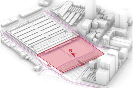
The site includes a sales shed, a metered parking and a storage shed in between the William St, Queen St and Franklin St. The whole site is 197m wide and 106m long.
5.1 DESIGN RESPONSE
OPEN & COVER
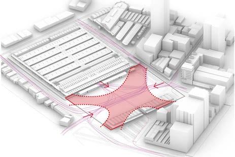
Our design aims to disrupt and reorganize the circulation by creating a new sheltering space in site to suck people in and gather. We trim the four edge of the rectangular shape to visualize our purpose and test the rough relationship of open and cover.
Roof to touch the Queen Victoria Market to create a sense of continuity
The space exposed to the sky to create an open area to breathe from all-direction covered space.
Extended canopy to create shelters for the public.
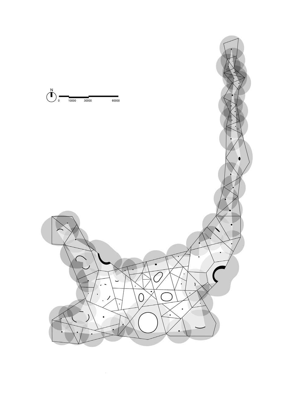
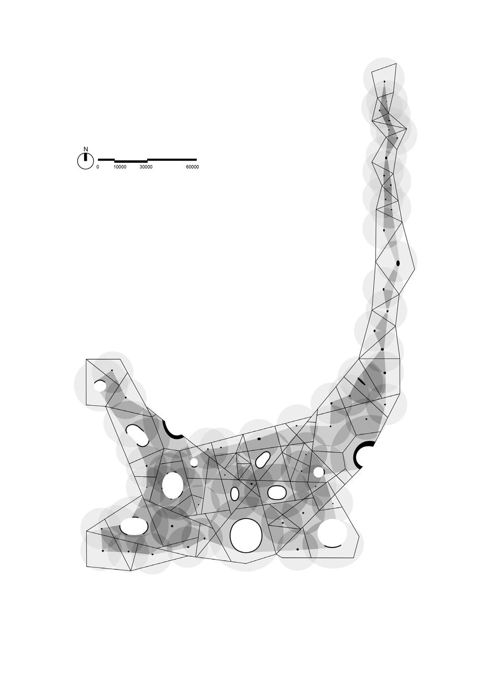
REGION
To link back to our machine and matrix, the shape can be rebuilt by the lines linked by the control points of the four edges of the site. The layout of the control points is set according to the structural grid of Queen Victoria Market.
Roof cativilivered high with high openings to embrace the public from the garden in the south-west .
Roof with low columns to define the crowded retailing area.
Low Column
Middle Vault
High Opening
EXTENDED TERRITORY
To benefit not only the site but also the surrounding territory, a series of small regions are pieced together and extend to the Queen St and the William St, strengthening the relationship between the site and the Queen Victoria Market and the garden.
58 59
5.1.1 MULTIPLICATION
With the application of 3D scanner, we are able to further study the space by multiplying the base models and applying it at architectural scale. By tacking, inverting, aligning the shells, different spatial quality are created to explore different possibilities of each functional space.
60 61
5.1.2 CONSTRUCTION METHORD (EARLY STAGE)
The diagram shows a feasible way to build the shell as the Church of Our Lady of Miraculous Medal, constructed with concrete with tensile reinforcement.
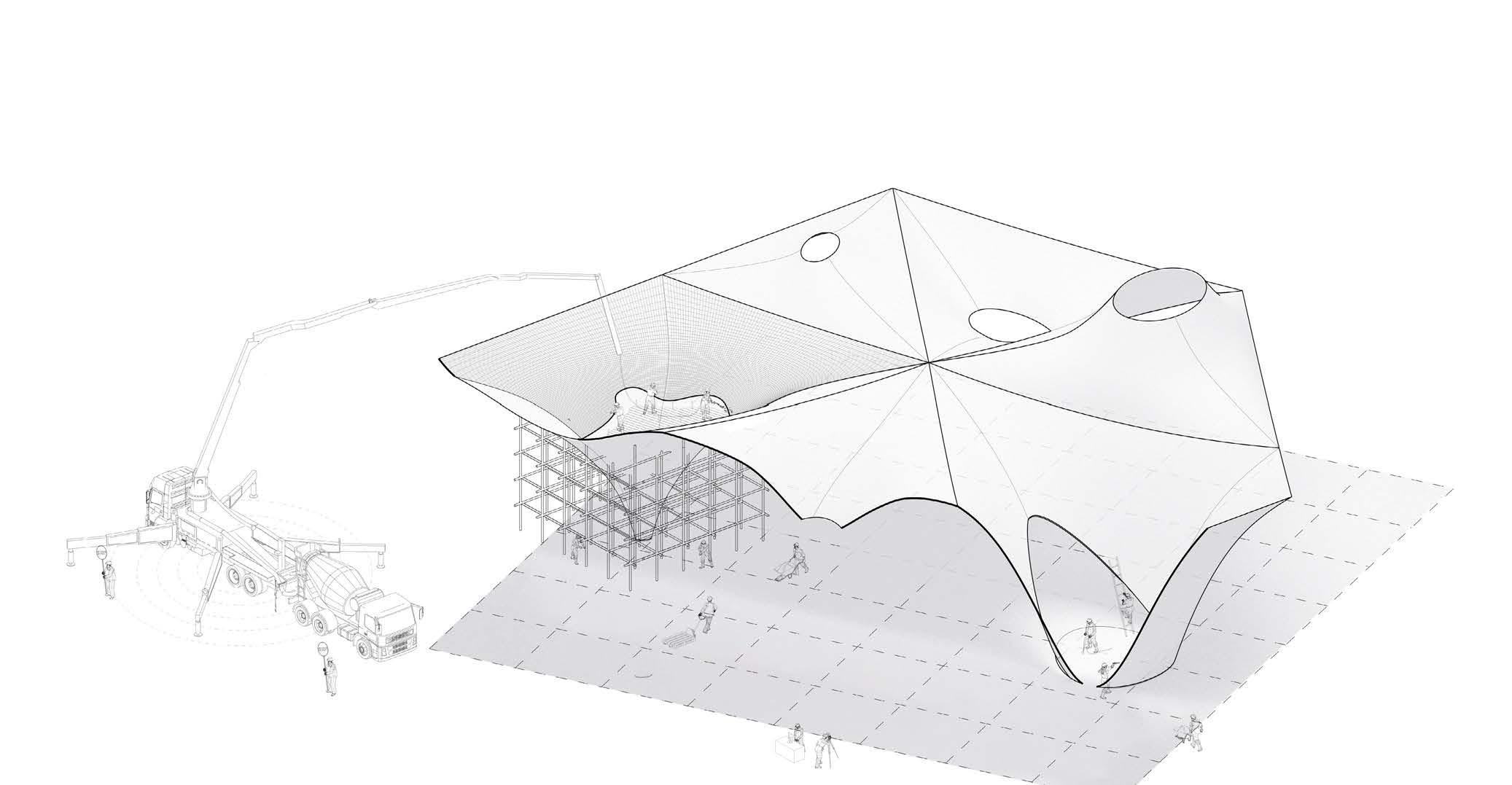
The workers will erect scaffolding to build the formworks first. The steel reinforcement will be covered onto form boards, providing tensile force for the shell. Concrete will then be sprayed to form the surface.
However, this construction method is quite separated from how the shape actually formed. There might be a better way to construct, making use of the stretching force.
62 63 0 5 10
5.2 SITE CONDITION
The initial design response is mainly derived from the machine and precendent study. Site analysis provides us with another perspective to find opportunities through the pheunomenon in real life.
We analysize the existing facilities through power and water supply, metal box storage and parking, trying to find a breakthrough by bridging the machine logic with the existing situation.
65
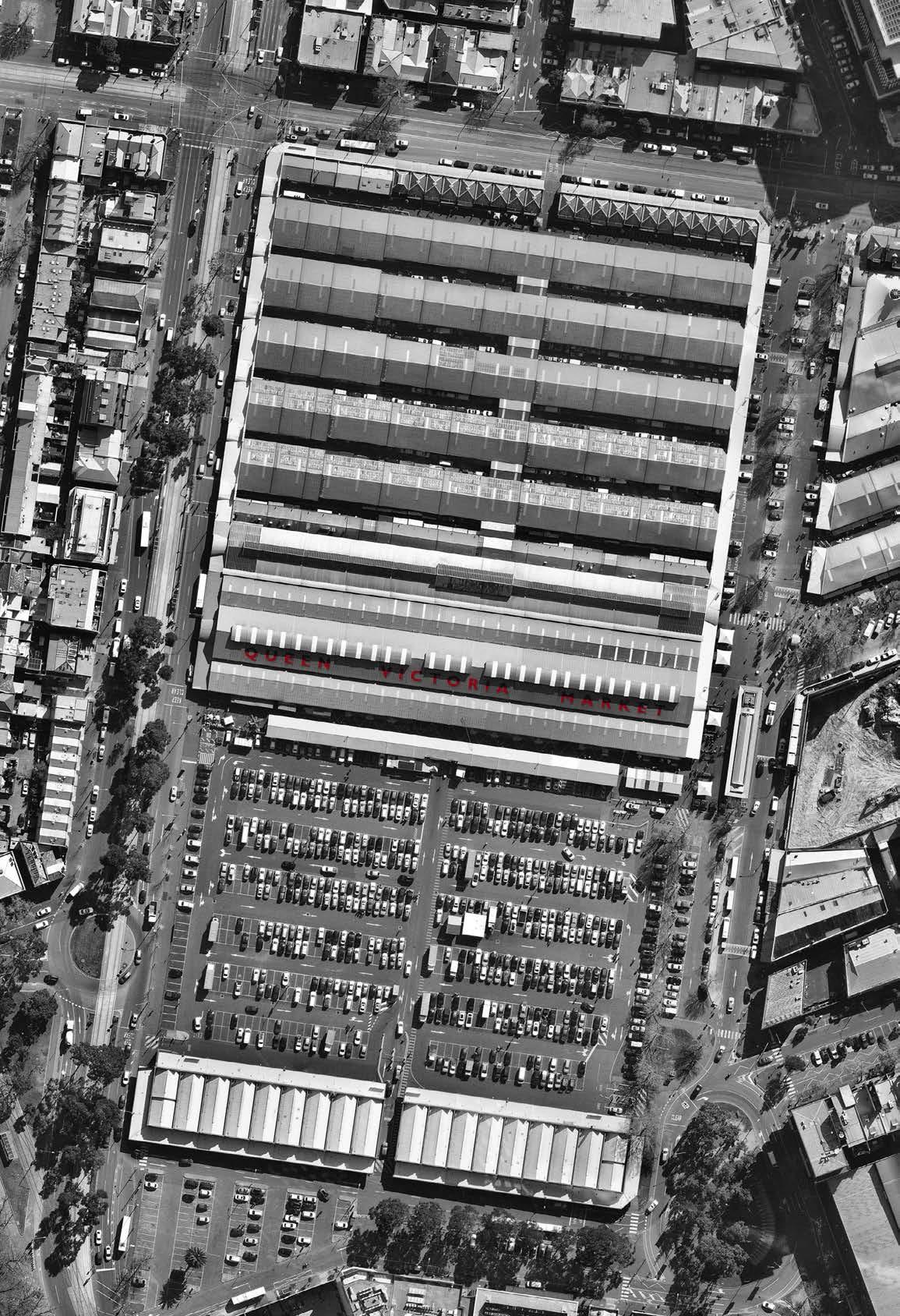
Figure 5.01. The map of QVM with highlighted region to show the location of site.
The Upper Market is characterised by heritage open air market sheds, the first of which were constructed in 1877, which have never been comprehensively adapted to meet contemporary retail market trading requirements. The sheds therefore lack basic facilities and consequently a particular style of market trading has evolved over time that attempts to maximise the potential of the Upper Market within the heavy constraints.
ISSUE 1
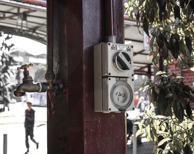
- Not enough power and water supply for all stalls. Seen from the mapping diagram, Shed A-B are equipped with sufficient electricty and water supply points, while Shed C-E have no access to both. Several power points are provided in Shed J-L but not every stall can have an access.

66 67 VICTORIA S T R EE T PEEL ST R EET F R ANK L INST R E ET EXISTING CAR PAR K QU E EN ST R E E T SHED A SHED B SHED C SHED D SHEDH SHEDI SHED E SHED F SHED J SHED K SHED RK/RL SHED L
5.2.1 EXISTING FACILITIES
Figure 5.02.(left) The location of power, water supply and toilet locations in QVM
Electricity supply Non-potable water Water fountain Toilet
Figure 5.03.(right) Photo of power and water supply in QVM.
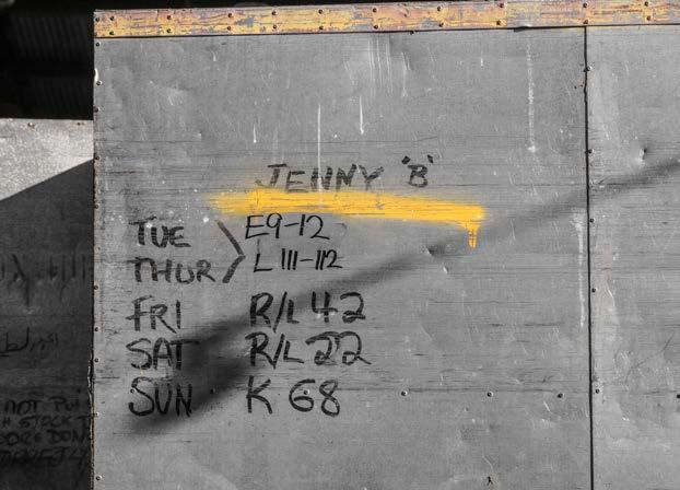
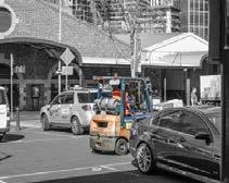
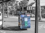
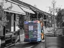
Jenny’s Metal Box
Movable Stalls
Fixed Stalls
Storage for Vegetables & Fruits
Storage for Boxes
Maintance Depots for Box Hire
Site Office
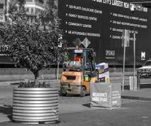
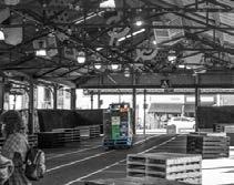
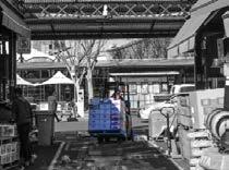
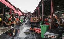
5.2.2 METAL BOX STORAGE
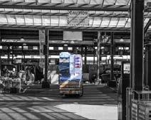
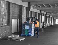
The boxes perform multiple roles – as mobile storage units, as designation of individual traders locations; as physical partitions or walls to demarcate trading areas, and increasingly as fixtures to present product. The organisation of the boxes drives the market’s set up and pack down process. Currently there are 5 box hire operators providing a total of 936 boxes. There is also 1 trestle table hire operator who operates out of the storage cage in the customer car park.
ISSUE 2
- For movable stalls, the metal boxes will be stored in depots overnight and be brought to a new place in the morning.

68 69 VICTORIA S T R EE T PEEL ST R EET F R ANK L INST R E ET EXISTING CAR PAR K QU E EN ST R E E T SHED A SHED B SHED C SHED D SHEDH SHEDI SHED E SHED F SHED J SHED K SHED RK/RL SHED L TUE THUR SUN FRI SAT
Figure 5.04.(left) The daily movement of the metal boxes.
Figure 5.05.(right) Photo of a typical metal box with the mark of the stall arrangement.
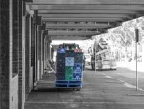
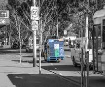
5.2.3. INEFFICIENCY OF STORAGE
There is increasing demand for onsite cool storage by fruit and vegetable operators, despite the opportunity for them to provide short-term storage on their stalls. This demand cannot be met in Franklin Street, and local warehouses are used in lieu.
ISSUE 3
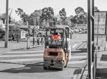
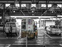
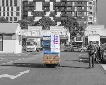
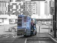
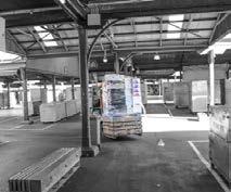
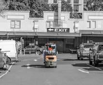
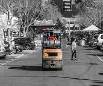
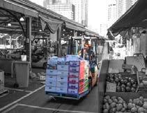
- The storage for vegetables is located at furthest end on Franklin Street, folklifts have to move across the whole market in 3 main paths, which potentially have safety issues with public transportation.
71 T PEEL ST R EET NST R E ET EXISTING CAR PAR K QU E EN ST R E E T SHED A SHED C SHED D SHEDH SHED E
Route 3 Route 2 Route 1
Figure 5.06. The daily movement of folklifts from shed to depot.
Parking Area for Traders
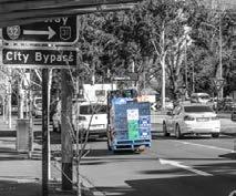
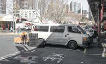
5.2.4 PARKING - TRADERS
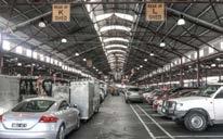
The daily rearrangement of the Upper Market, combined with the lack of storage also brings with it a heavy reliance on vehicles. Market traders rely on individual vehicles which can be parked onsite on their stalls. At any given time up to 200 vehicles are parked within the sheds and service lanes during market trading.
ISSUE 4
- For traders' convenience, they always drive from Peel Street into market and park inside their own stalls or in the aisles between sheds.Sometimes they even occupy the whole Shed L-RL.
72 73 VICTORIA S T R EE T PEEL ST R EET F R ANK L INST R E ET EXISTING CAR PAR K QU E EN ST R E E T SHED A SHED B SHED C SHED D SHEDH SHED SHED E SHED F SHED J SHED K SHED RK/RL SHED L
Figure 5.07. The location of parking area for traders.
5.3 DESIGN PROPOSAL
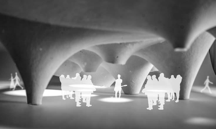
As an open public space, visitors in Queen Victoria Market are not only visually linked by programs and facilities, but also by other perceptions. The spread of sound, the flow of wind and the transition of light and dark also interwave people together. With roof structure going up and down, even anchoring to the ground somewhere to become outdoor auditorims, people are expected to naturally involved in the dynamic place.
74 SUN & SHADOW CIRCULATION PROGRAM WIND & ACOUSTIC
0 10 20 40
Queen Victoria Market Roof Plan
Figure 5.08. Diagrams illustrate the strategy to gather people and trigger public activities.
Figure 5.09. Roof plan shows the general arrangement of the structure in the existing site.
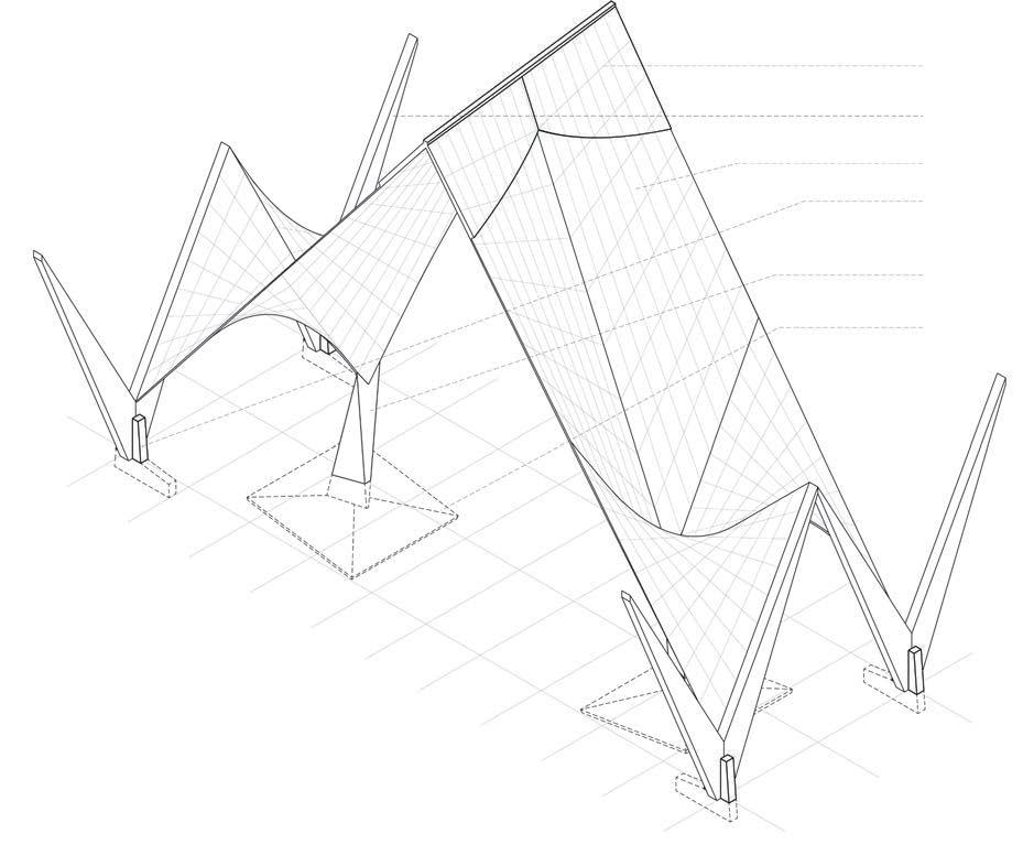
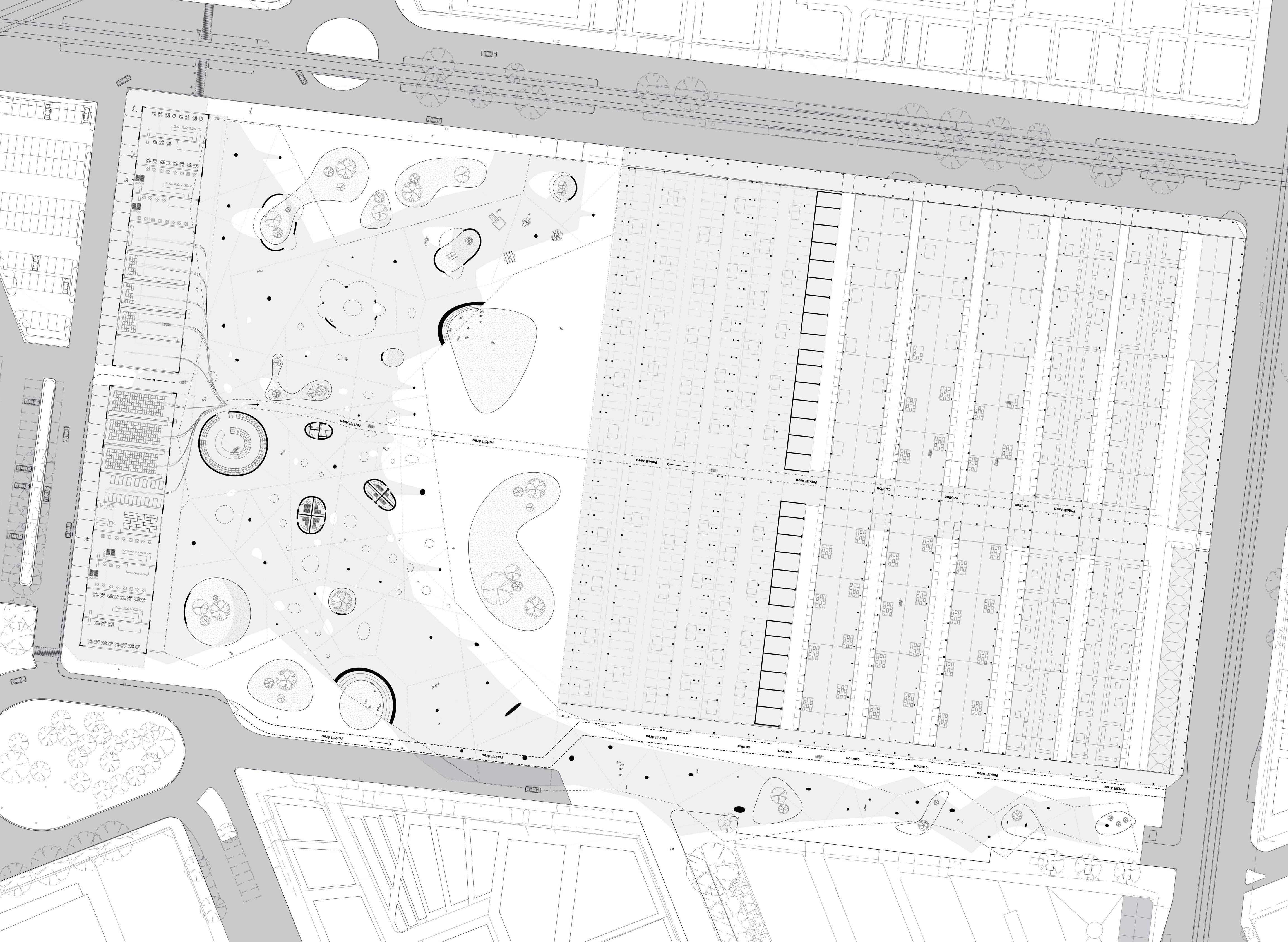
SPAN


According to the rules of thumb
Span to depth radio: 100
In order to make the thickness of the shell less than 250mm, the span between two columns should be less than 25000mm.
We set the radiation range(d) to be 12500mm. If the areas of the region cover the whole plan despite the cantilever parts, the structure can work.
CANTILEVER
According to the rules of thumb
Span to depth radio: 50
In order to make the thickness of the shell less than 250mm, the span between two columns should be less than 12500mm.
We set the radiation range(d) to be 12500mm. If the areas of the region cover the whole outer edge, the structure can work.

76 77
Figure 5.10. Structure diagram shows how the structure of the inner span works.
Figure 5.11 Structure diagram shows how the structure of the cantiliver work.
AXONOMETRIC DRAWING
Figure 5.11. Axonometric view shows a typical senario of Queen Victoria Market
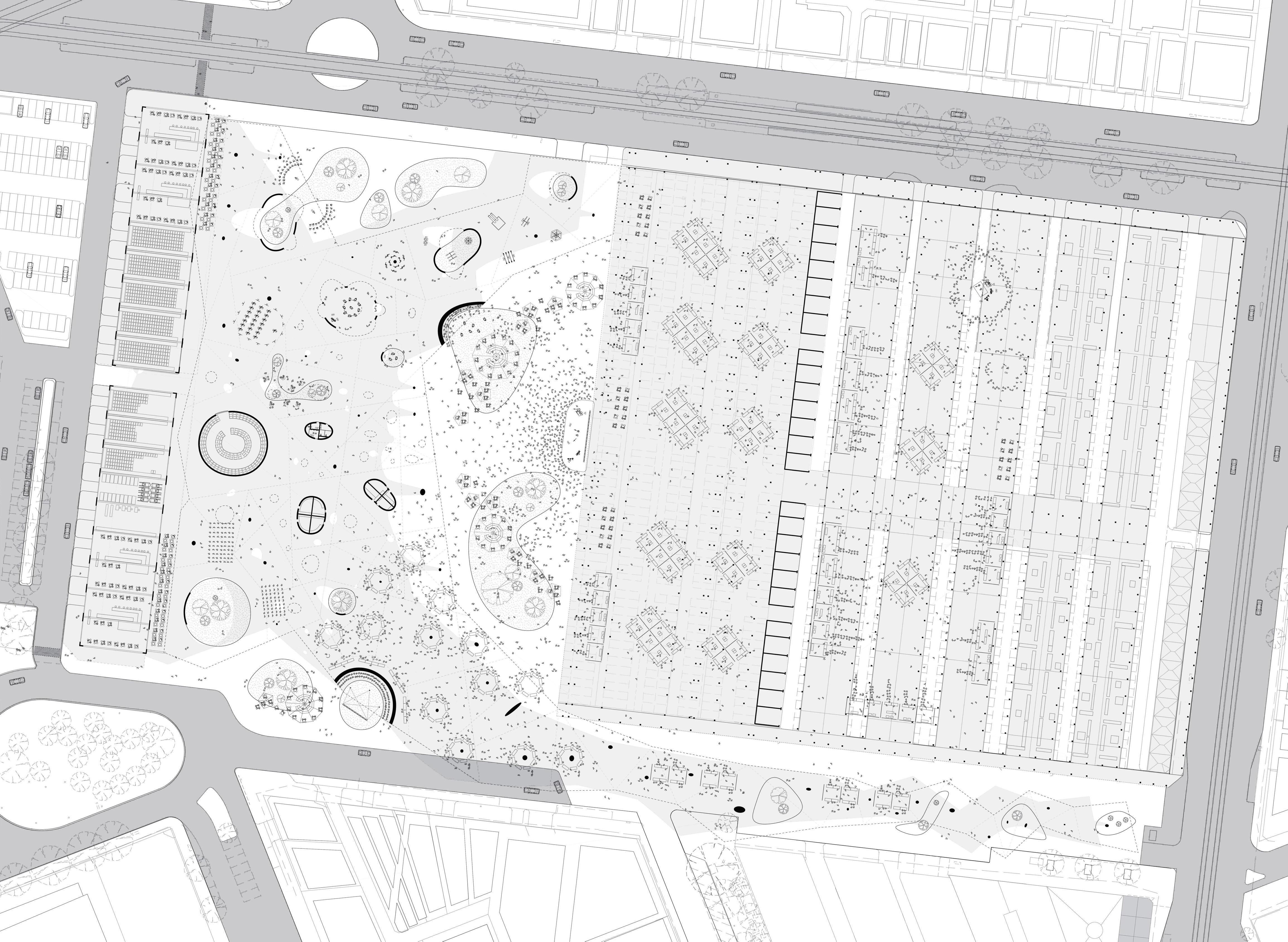
SCENARIO 1 - SUNDAY NOON
Figure 5.12. Plan shows a scenario on an ordinary Sunday Noon,
0 5 10 20 40
Queen Victoria Market G/F Plan
Queen
G/F Plan 0 5 10 20 40 SCENARIO 2 - WEDNESDAY NIGHT
Victoria Market
Figure 5.13. Plan shows a scenario on an ordinary Wednesday Night,
SCENARIO 3 - TUESDAY NIGHT
0 5 10 20 40
Queen Victoria Market G/F Plan
Figure 5.14. Plan shows a scenario on an ordinary Tuesday Night.


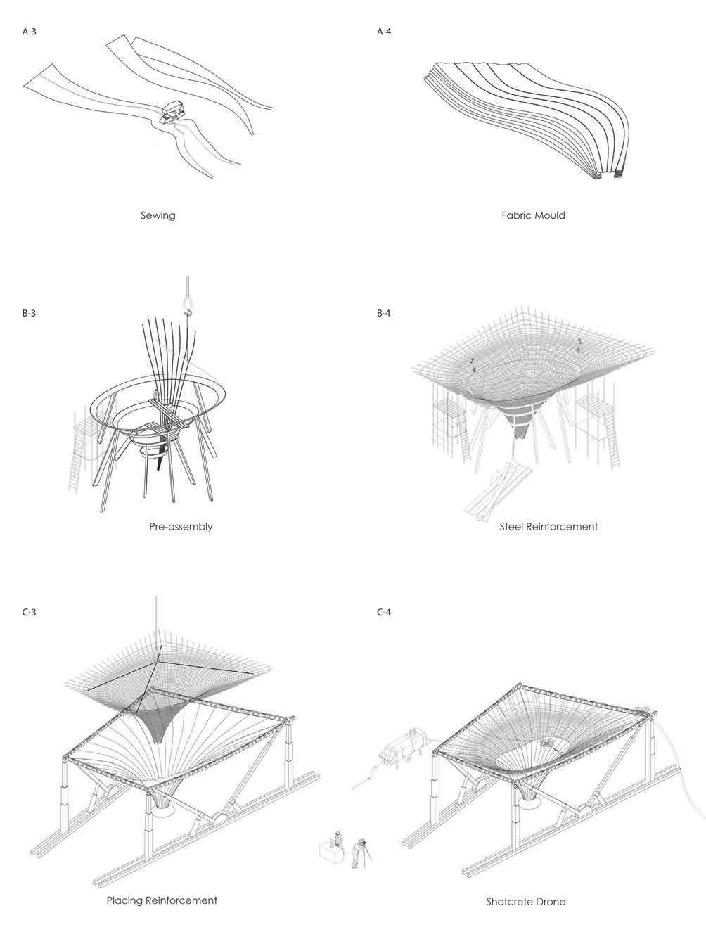
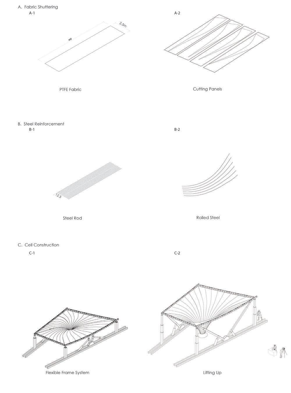
CONSTRUCTION SEQUENCE - A SINGLE CELL
88 89
Figure 5.15. Construction sequence shows a prefabricated ‘cell‘ as a column.
CONSTRUCTION SEQUENCE - ASSEMBLY
90 91
Stage 1 - Cast-in-situ complex structures
Figure 5.16. Construction sequence shows the sequence of construction of ‘cells‘, secrete gardens, columns, then skylights and the corridor.
Stage 3 - Cast-in-situ
Stage 2 - Prefabricated structures
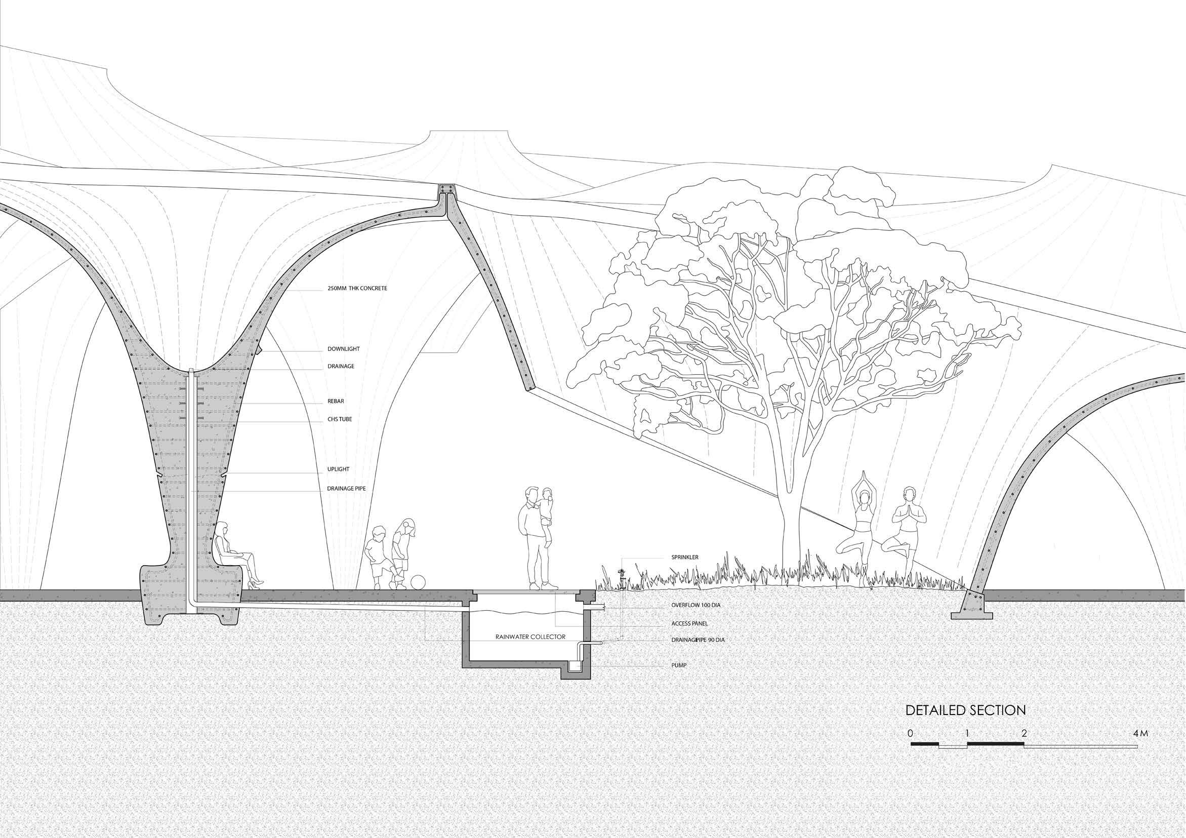 Figure 5.17. Detailed section shows how rainwater can be collected by ‘cell‘ and reused for irrigation and how 'cells' are connected.
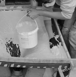
Assemble the panels to frame the structure. Prepare fabric to form the surface.
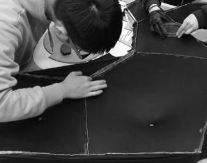
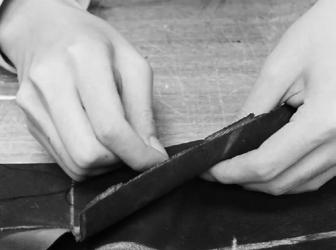
Use the iron sheet to insert and fix the fabric into the gap beween two layers of panels. Iron sheet can help make the edge clean.
Apply vaseline to the iron sheet before mopping plaster on the fabric.
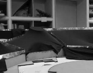
Fill plaster into the mold of the staircase, mop plaster to link the existing 'cells'. Use plaster bandage to thicken the edge.
94 95
1:50 PHYSICAL
MODEL
Figure 5.18. Image of the making process of the model.
Figure 5.19. Images of 1:50 physical model
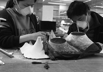
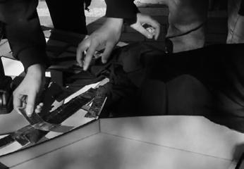
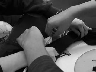
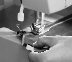
Print out the unrolled profiles of one single 'cell' . Trace them down on the fabric and cut the shapes out .
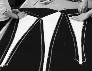
Stitch the pieces together in order by sewing machine or hand.

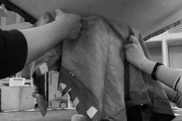
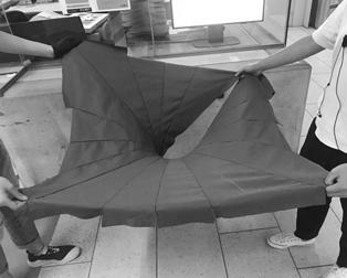
The 3D form then naturally generated. Use masking tape to fix the 'cell' on the framework.
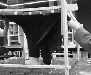
Mope the mixture of plaster and fiberglass on the fabric. Apply several times to control the thickness of the shell. Tear out the fabric after the plaster dry.
96 97
1:10
PHYSICAL MODEL
Figure 5.20. Image of the making process of the model.
Figure 5.20. Images of 1:10 physical model
98 99
Figure 5.21. Rendering exterior image of the design proposal.
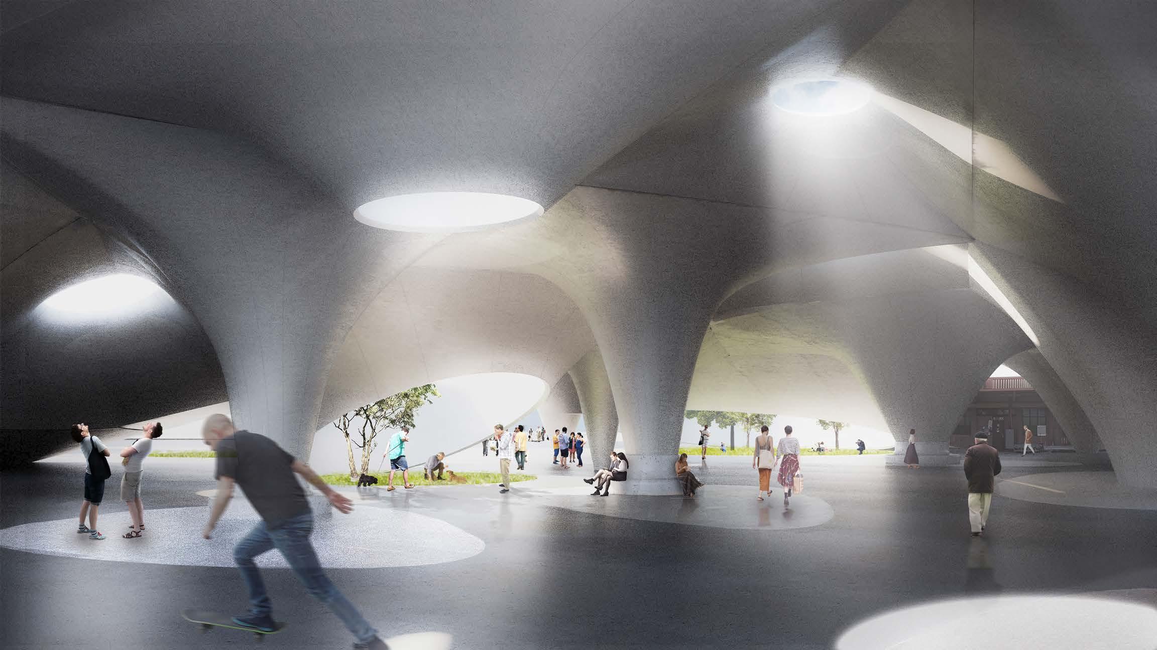
100 101
Figure 5.22. Rendering interior image of the design proposal.


