


HANDBOOK Powering shipping’s emissions-cutting ambitions Propulsion stream | Alternative fuels stream | Technical visit Two days of conference streams exploring compliant technology & fuel solutions to meet IMO’s 2050 milestone and EU’s Fit for 55 proposed tandem regulation, specifically the journey to 2030 shore power. This year the programme will also feature sessions on eFuels & Bio Fuels, Ammonia, Methanol and Multifuel engines. While providing industry leaders a space to network and knowledge share. Chairmen: Lars Robert Pedersen, Deputy Secretary General, BIMCO Reinhard Lüken, Managing Director, VSM German Shipbuilding and Ocean Industries Association visit: propulsionconference.com contact: +44 1329 825335 email: conferences@propulsionconference.com #MotorshipPFF
Organised by: MOTORSHIP INSIGHT FOR MARINE TECHNOLOGY PROFESSIONALS THE 22 24 Hamburg Germany NOV 2022 2022 43RD Supported by: Sponsored by: Headline Sponsor Silver Sponsors
Le Meridien Hotel, Hamburg, Germany
Headline Sponsor :
What determines the maritime fuel mix of the future?
By 2030, 5% of the energy for shipping should come from carbon-neutral fuels. The new Maritime Forecast to 2050 report outlines under what conditions each new possible fuel type will proliferate and what production, distribution and bunkering infrastructure investments are required. Download your free copy. dnv.com/maritime-forecast
 NICK EDSTROM Editor, The Motorship

Dear delegates,
Welcome to the latest Motorship’s Propulsion & Future Fuels Conference. We are delighted to welcome our attendees back to Hamburg, after last year’s enforced sojourn in Copenhagen.
Our conference has covered innovations in the marine fuels and propulsive technologies field since 1979, and offers a unique opportunity for shipowners, OEMs and other interested parties to come and keep track of the regulatory, technical and market developments in the gaseous fuels market. We are excited to bring together a strong programme of leading industry experts, class society specialists and a number of ship owner sand ship operators. Our focus on gaseous and alternative liquid fuels, including ammonia and methanol, and the rapid pace of developments since our last conference means that regulatory and technical themes are more topical than ever.
Our conference opens with a topical High Level Panel discussion, which will cover the expected impact of requirements for shore-power infrastructure development under the Alternative Fuels Infrastructure Regulation (AFIR), as well as the FuelEU Maritime Regulation which will come into effect in 2025, imposing life cycle GHG footprint requirements on the energy used on board ships.
The major change in the years since our conference was last held in Hamburg is the amount of investment that is flowing into upstream developments for the production of biofuels, renewable hydrogen, ammonia and methanol.
The concurrent introduction of upstream fuel (or hydrogen vector) production with dualfuel vessels capable of operating on methanol (or ammonia from 2024) will lead to profound changes in the fuel mix used in the deep-sea shipping market. Similar changes are occurring in the LNG market, where bio-methane and subsequently synthetic LNG, are likely to reduce GHG emissions from the market.
It is fascinating to see how the order of methanol and ammonia-fuelled vessels by a number of progressive shipowners and cargo owners is creating demand for methanol and ammonia, which in turn is spurring investment in the production of fuels by others. Far from being part of the problem, shipping is acting as an enabler for the faster introduction of solutions.
3 Welcome Letter 2022 43RD
We include a number of technological case studies from shipowners and technology partners who have adopted innovative technologies. The shortlist for the editor’s award focuses on four innovative projects that have demonstrated the potential for GHG emission savings, including
Egil Ulvan Rederi’s zero-emission self-discharging hydrogen-fuelled bulk carrier design, With Orca; Hoegh Autoliners’ multi-fuel and zero carbon ready Aurora Class vessel; the Northern Lights’ liquid-CO2 carriers in carbon-transport-and-storage project; a series of hybrid DF PCTC vessels for NYK Line and Wärtsilä’s retrofit-optimised solution to convert existing 2-stroke electronically-controlled engines to run on either LNG, methanol or ammonia.
Once again, we are fortunate enough to be joined by a strong programme of leading industry experts, class society specialists and ship owners and ship operators.
Our thanks go to our dedicated and knowledgeable advisory committee members and our kind sponsors, including Gold Sponsor DNV and Silver Sponsors Accelleron and GTT, without whom this event could not have taken place.
It is our hope that our conference permits an exchange of ideas around the decarbonisation issue. I wish you a productive, illuminating and thought-provoking few days in Hamburg and I look forward to witnessing, as always, a generous exchange of ideas.
Yours sincerely, Nick Edstrom Editor, The Motorship
Welcome Letter 4
LARS ROBERT PEDERSEN Deputy Secretary General, BIMCO
Dear delegates,
Once again the time has come to welcome you all to Hamburg and the 43rd Propulsion and Future Fuels conference.
While I write this the world is gathering in Sharm El Sheikh, Egypt for the 27th conference of the parties to the UNFCCC to discuss how climate change can be tackled effectively. Climate change is the overarching challenge now and in the future for all sectors of society – and that includes shipping.
We will continue to explore options to fuel future ships in a carbon limited world.
This year we take a closer look at some of the regulatory initiatives which will likely affect shipping in the coming years. We will also explore deeper some of the new fuels. Energy transition is all about electrification. Green sustainable electrons deployed in the grid or to produce sustainable Hydrogen.
We will explore some of the electric applications in shipping such as shore power, hybrid propulsion, and generation onboard ships.
What role will digitalisation play in decarbonising shipping? We will dive into this aspect in a dedicated session on digital and other future technologies.
Decarbonisation also have to be good business. That is why we will explore the state of economic measures to close the price gap between old and new solutions.
Lastly, but not least the Motorship Award will be given to one of the five projects in the run-up.
As always I look forward to helping you manoeuvre the many different aspects presented in the 2-day packed program of 2022PFF.
Yours sincerely, Lars Robert Pedersen Deputy Secretary General, BIMCO

Chairman’s Welcome Letter
5
2022 43RD
REINHARD
LÜKEN
Managing Director, German Shipbuilding and Ocean Industries Association (VSM)
Dear delegate,
A warm welcome to you all attending to for the 43rd edition of the Propulsion & Future Fuels Conference here in Hamburg.
International shipping accounts for the lion’s share of the global transport volume - 90 per cent of world trade is carried by sea. Ships are by far the most efficient mode of transport, but with a total annual consumption of around 350 million tons of conventional fuels, they are also responsible for almost three per cent of global greenhouse gas emissions. This immense fuel demand predestines shipping to be a pioneer in exploiting the market potential of synthetic, climateneutral fuels and enabling their widespread use in other sectors of the economy as well.
Together with our Colleagues from VDMA VSM has tabled a PtX Roadmap for the maritime energy transition describing the technological and required regulatory levers to achieve the ambitious climate targets.
New fuel and propulsion solutions are a necessary requirement on our path to climate-neutral shipping. However, for the road to success efficiency and energy saving will be key. We need to reinvent the entire system ship. For innovative minds these are exciting times!
This conference will provide you with great opportunities to listen, to present your ideas, and to listen to others, to learn, to discuss and to exchange views on challenges and opportunities. I wish you fruitful days and a great time in the city of Hamburg.
Yours sincerely, Reinhard Lüken Managing Director, German Shipbuilding and Ocean Industries Association (VSM)

Chairman’s welcome letter
6
2022 43RD
Move further

Contents 8 Contents Welcome Letter............................................................................................................................................... 03 Welcome Address .......................................................................................................................................... 05 Lars Robert Pedersen, Deputy Secretary General, BIMCO Chairman’s Welcome 06 Reinhard Lüken, Managing Director, German Shipbuilding And Ocean Industries Association (VSM) Gold Sponsor Welcome ........................................................................................................................... 12 Rasmus Stute, Area Manager, DNV DAY 1 TUESDAY, 22 NOVEMBER 2022 Keynote Panel: ShorePower ................................................................................................. 14 Session 1 Electrification for big ships .................................................................. 22 Session 2 Digitalization, digital efficiency and the future technology of the maritime sector ............................ 44 Session 3 The Motorship Awards ............................................................................ 71 DAY 2 WEDNESDAY, 23 NOVEMBER 2022 Session 4 Carbon Levy Solutions ........................................................................... 90 Session 5 Market Based Measures ...................................................................... 112 Session 5.1 eFuels & Bio Fuels .................................................................................. 114 Session 5.2 Sustainability through alternative fuels ...................................... 142 Session 6 Alternative Fuels..................................................................................... 166 Session 6.1 Ammonia .................................................................................................... 168 Session 6.2 Methano ...................................................................................................... 187 Session 7.1 Multifuel Engines.................................................................................... 213 Session 7.2 Retrofit Solutions .................................................................................... 254
Passion for innovation and technological excellence serving a sustainable world
With almost 60 years of experience, GTT is the partner of choice to design cutting-edge technological solutions for an improved energy efficiency. We bring our passion for innovation and our technical excellence to the service of our customers, in order to meet their transformation challenges both for today and tomorrow.

Our expertise goes from LNG ships to LNG-fuelled ships. We support all your LNG related operations, train and assist your crews to optimise your vessel economics. As shipping is turning digital, GTT Digital proposes Shipping Solutions, combining our experiences and skills to offer a wide range of digital services to the maritime industry.
The GTT teams are at the heart of our mission. Committed and united, we are determined to contribute to building a sustainable world.
gtt.fr © Joseph Lynch
LARS ROBERT PEDERSEN Deputy Secretary General, BIMCO
BIOGRAPHY
Deputy Secretary General Lars Robert Pedersen is responsible for BIMCO’s technical and operational activities involving all technical and nautical issues within the area of marine environment, ship safety and maritime security.
Lars Robert is furthermore responsible BIMCO’s activity related to regulatory developments relevant for shipping at international, regional and national levels. He joined BIMCO In early 2010 after a long career at A.P. Moller-Maersk. For more than 25 years he was involved in regulatory affairs at IMO level, technical management of the Maersk fleet of container ships and prior to that as seagoing engineer officer. Lars Robert holds an unlimited Chief Engineers license.
Chairman 10
REINHARD LÜKEN
Managing Director, German Shipbuilding and Ocean Industries Association (VSM)
BIOGRAPHY
After five years at the executive office of the Treuhandanstalt in Berlin, the German privatisation agency, Mr. Lüken joined the Meyer Shipyard in Papenburg, Germany in 1998, taking charge of politics and strategy.
In 2000, the Community of European Shipyards Associations (CESA) appointed him first as Brussels Representative and half a year later as Secretary General.
As the first Secretary General of SEA Europe he managed in 2012 the formation of the new joint association for shipyards and marine equipment producers. He then returned to his home country to take the helm at the German association.
Mr. Lüken chairs the SEA Europe Market & Trade Committee since 2015, represents CESA as its Chairman, and was elected as President of the German Maritime Centre at its inauguration in 2017.
Mr. Lüken holds a PhD in political science, economics and sociology.
Chairman 11
RASMUS STUTE

Area Manager, DNV Maritime
BIOGRAPHY
A naval architect, Rasmus Stute has worked for DNV for the past 18 years in different management positions both in Asia and Europe. Before being appointed as Area Manager for Germany, he worked to develop the new Containership Excellence Centre in Hamburg and was its founding Director, before taking the lead of the German Business Development team in 2020. Mr Stute is also currently a member of BIMCO’s marine safety and environment committees.
Gold Sponsors Welcome
12
Engineering state-of-the-art Gas Systems for the Maritime Industry


TGE Marine Gas Engineering is the leading liquified gas systems‘ provider specialising in cargo handling systems for gas carriers (LPG, LEG, NH3, Ethane, CO2 & LNG), FSRUs and bunker vessels, including tanks.
Furthermore, TGE Marine is a pioneer in fuel gas systems for LNG, NH3 and other alternative fuels. The company has been contracted for more than 250 gas handling, fuel gas and storage systems globally.
Fuel Gas Systems
LNG, LPG, Ethane, NH3 and other alternative fuels, including storage
• LPG / Ethylene and other Gas Carriers
Gas handling and storage systems for LPG, LEG & CO2 carriers
• LNG / NH3 Shuttle Tankers & Bunker Vessels
Cargo handling and fuel supply systems as well as type C storage solutions
• Floating Storage Units
FS(R)Us & F(P)SOs
• CO2 Carriers
Shipping of and floating solutions for Carbon Capture & Storage
www.tge-marine.com
Fuel Gas Systems Floating Storage & Regasification Units LNG Tankers (Shuttle Tankers & Bunker Vessels) LPG / LEG / CO2 CO2 Carriers
Innovations for Greener Shipping The Gas Experts
The journey to 2030 with Shorepower
14
KEYNOTE PANEL
RICARDO BATISTA
Policy Officer, Directorate-General for Mobility and Transport European Commission
BIOGRAPHY
Naval Architect and Marine Engineer, specialized and working in sustainable energy systems for ships. Currently working at European Commission, Directorate-General for Mobility and Transport – Maritime Transport unit. In the Commission, Ricardo is engaged in the development, negotiation and preparatory work for implementation of the FuelEU regulation, under the Fit for 55 package. In addition, In DG-MOVE, Ricardo is also the chair of the European Sustainable Shipping Forum on Sustainable Alternative Fuels & Power Systems for ships (ESSF – SAPS), an expert group assisting the Commission with all different aspects related to the development, promotion, identification of barriers and scientific discussion related to alternative fuels and power systems. At international level, Ricardo is part of the IMO working group on development of the IGF Code and associated interim guidelines for the safe use of alternative fuels.
Before joining the European Commission, Ricardo worked in the European Maritime Safety Agency (EMSA) for seven years, responsible for technical and scientific support to the Commission on several topics of Ship Safety and Sustainability/Pollution Prevention.
In addition to the above, Ricardo has Classification Society experience, having worked in the American Bureau of Shipping (ABS), in London, integrating the Advanced Analysis team, as well as previous experience as a Marine Engineer onboard naval ships and Naval Architect responsible for shipyard/dockyard work.

Keynote Panel – Speaker 1
15
VALTER SELÉN
Senior Policy Advisor Sustainable Development, Cruise and Ferry Network, EcoPorts Coordinator, ESPO
BIOGRAPHY
Valter Selén joined ESPO as senior policy advisor for sustainable development in June 2020, having previously worked with drafting the first annual EU MRV Report during his time in the European Commission (DG CLIMA). Valter dedicates his career to EU climate policy and sustainable development, focusing his attention on the maritime sector.
Valter holds a double-degree Master in European Governance from the University of Utrecht, The Netherlands and Konstanz University, Germany. Valter wrote his thesis on how European business associations gain access to EU institutions in order to influence climate policy negotiations.

Keynote Panel – Speaker 2
16
MARTIN KRÖGER
Chief Executive Officer, VDR German Shipowners’ Association

BIOGRAPHY
Since 2012 Martin Kroeger is Managing Director of the German Shipowners’ Association, VDR, and a specialist in international shipping policy and related government affairs management. He has worked in the international maritime community for over a decade and serves as a leading industry representative to many international and intergovernmental organisations.
Martin also holds the position of Managing Director of the German Shipping Foundation, a facility founded to co-sponsor training and education of seafarers in Germany. Martin is delegated member to several European and international maritime related advisory committees and expert groups. As alternate member of the Board of Directors of the European Community Shipowners Association - ECSA in Brussels and acting Chairman of the ECSA Safety and Environmental Committee, he actively engages in EU policy making for the maritime sector.
Before joining VDR, Martin worked as Managing Director for the Association of German Seaports Operators and was actively involved in the work of the Federation of European Private Port Operators – FEPORT in Brussels. Martin was admitted to the bar of the State of Hamburg in Germany as attorney-at-law (Rechtsan-walt) in 2007. In the same year, his law and consultancy practice was founded, headquartered in Hamburg, Germany.
Martin was educated in Germany and Australia before he graduated in 2001 from the University of Hamburg in Germany with a degree in Law and Legal Studies. In 2003 he earned a Master of Laws degree in Shipping Law with honours at the University of Cape Town. Martin has been awarded with the Capt. Bob Deacon Shipping Law Prize of the University of Cape Town in 2004. In 2006 he was awarded with a Doctor of Laws (Dr. jur.) by the University of Hamburg in Germany.
Martin is an alumnus of the Harvard University’s John F. Kennedy School of Government executive education program on International Trade Policy, which he successfully concluded in 2016, and the programme on Climate Change and Energy, which he successfully concluded in 2019.
Keynote Panel – Speaker 3
17
DR. KAI-DIETER CLASSEN Deputy Director External Affairs, Hamburg Port Authority
BIOGRAPHY
Kai-Dieter Classen studied jurisprudence in Kiel, Stockholm, Ham-burg and Berkeley. He holds a PhD degree (Doctor iuris) from Hamburg University in European Law and a Master of Laws (LL.M.) degree from University of California at Berkeley in US and International Law. He worked as a graduate research assistant at the Universities of Hamburg and Berkeley, as a private lecturer and as a lawyer. Dr. Classen then became an official for the Ham-burg State Government. He served i.a. as a National Expert in the EU Commission’s Legal Service in the field of International Trade Law. In 2012, he joined the Hamburg Port Authority’s (HPA) In-ternational Affairs Division. There, he works as a senior strategic legal and policy advisor with a broad range of topics.
Dr. Classen is a member of the Legal Committee of the International Association of Ports and Harbors (IAPH) as well as of the Legal Advisory Committee and the Port Governance Committee of the European Seaport Organization (ESPO).
As an adjunct professor at Hamburg University’s Law School he teaches WTO-Law and European Seaports Law and is a Member of the Board of Examiners for European and International Law. He publishes frequently on port- and shipping-related topics.

Keynote Panel – Speaker 4
18
WOLFRAM GUNTERMANN Director Regulatory Affairs Fleet,

Hapag-Lloyd AG
BIOGRAPHY
Captain Wolfram Guntermann graduated with his Masters Licence at the Marine Polytechnic Elfleth/Germany in combination with a scholarship at the Plymouth Polytechnic of Marine Science. He also received his Engineers Licence at the Hamburg Polytechnic in order to serve as Ship Operation Officer holding a dual licence.
After having set his feet for the first time on deck a vessel in 1979 he went through the ranks receiving his first command as Master in 1996. He also took various assignments ashore as Trio Tonnage Center London and Director Marine Operations in the Hapag-Lloyd America Office in Piscataway/New Jersey for almost nine years.
After repatriation to the Hamburg based Headquarters the current function as Director Regulatory Affairs was taken with a lot of challenging opportunities emerging in light of new environmental legislation and initiatives.
Keynote Panel – Speaker 5
19
BIOGRAPHY
TORSTEN SCHRAMM
President Maritime, DNV
Torsten Schramm is the President of DNV Maritime.
Mr Schramm joined Germanischer Lloyd in 1989. He held a number of positions within the company including the role of Principal Surveyor for Japan, Area Manager for China, Region Manager for Europe, the Middle East and Africa as well as Chief Operating Officer.

A Marine Engineer by training, Mr Schramm served on board Gas Carriers before joining GL, rising to the rank of Chief Engineer.
Mr. Schramm also represents DNV on the Council of the International Association of Classification Societies (IACS).
Keynote Panel – Speaker 6
20
A smarter perspective

wingd.com
on a low carbon future
Electrification for Big Ships
22
SESSION 1
DR. TORSTEN BÜSSOW Managing Director, Electrical & Power Systems Business, Wärtsilä

BIOGRAPHY
Dr. Torsten Bussow manages Wärtsilä’s electric & power systems business which includes electric drive solutions such as diesel-electric, hybrid, zero emission,shaft generator and shore connection systems. He has been bringing newtechnologies, often around digital innovations, into shipping for over 13 years as businessunit director in DNV GL and Wartsila. Before that he ran digitalisation and strategytransformation projects in a global consultancy brand.
Speaker
23
STEFAN GORANOV General Manager, Sustainability Solutions, WinGD
BIOGRAPHY
In his current role, Stefan is responsible for sustainability advisory and creating value-based solutions that improve the environmental and financial performance of ships operations through electrification and digitalisation.
His career in the maritime industry has spanned over 20 years, where he has held various technical and managerial positions.
Today, Stefan’s team advises ship owners, operators, charterers, and financers in the field of sustainability in the maritime industry – from technical and economic assessments, to defining system features and user experience. They also develop and deliver turn-key energy efficiency solutions for new and existing ships, tailored to concrete requirements.

Speaker
24
SIMONE BERNASCONI
Head of Global Product Line Upgrades, Accelleron
BIOGRAPHY
Simone heads Global Product Line Upgrades, a cross-functional product line focusing on supporting owners and operators in achieving higher operational efficiency with lower fuel consumption while meeting environmental regulations.
Simone began his career at ABB Turbocharging in 2008 as an application engineer. He later led Engine & Turbocharging Systems in Technology, following which he joined the Service organization and held several positions before leading the Upgrades team, a position he has held since 2020.
Simone holds a master’s degree in mechanical engineering from the ETH Zurich and a Certificate of Advanced Studies in Corporate Finance from the University of Zürich.

Speaker
25
Turbocharging solutions to support the decarbonization journey
ABSTRACT
To support shipping’s journey towards decarbonization, easy-to-implement turbocharger technology can play an important role in reducing the CO2 footprint of existing installations. But to achieve any significant impact, wide market adoption is key. Combining greater efficiency with a sound business case will be vital to maintaining a competitive edge in a low carbon world.
INTRODUCTION
Maximizing the fuel efficiency of merchant vessels has always been a key goal of the shipping industry. Fuel costs are the major operating expense in marine transport [1] and have risen meanwhile to dramatic high values.
However, there is a new aspect that has joined the game: the decarbonization mega-trend is gaining momentum at fast pace and further enhances the need for improving transport efficiency.
Ambition loop and disruption of transport sector
The development of the long-term decarbonization ambition of virtually all players in the maritime industry has been showing unprecedented expansion in the last 5 years.
One of the first game changers was formulated by the IMO in 2018, targeting a reduction of CO2 per transport work of 40% by 2030 when compared to levels in 2008, and an absolute reduction of 50% by 2050 irrespective of the (increased) globally transported volume [2].
Figure 1: IMO decarbonization goals [3]

Back in 2018 those targets were perceived by many with skepticism: being too strict, costly and not realistic. Many players in the maritime industry were questioning why shipping should decarbonize at all.
Looking at the market nowadays, only 4 years later, we now observe a completely different picture. An ongoing, continuous ambition loop towards considerably stricter targets supported by key players across the industry. Meanwhile, decarbonization is not only accepted, but also expected.
Conference Paper 26
An increasing number of customers in marine transport (e.g. Nike [4] and IKEA [5]) are openly declaring commitment to improving their environmental impact and decarbonizing their supply chain. Financial institutions like bank and insurance companies are defining frameworks as e.g the Poseidon Principles for banks and insurances [6] to enforce the compliance of their financed / insured portfolio of ships with the 2050 IMO global GHG emission target. Local and regional regulation as well as taxonomy are being defined and we can expect them to enter into force in the next decade, e.g. the fuel GHG standard FuelEU Maritime [7] and the inclusion of shipping in the EU ETS [8]. Global efficiency standards will be tightened and enhanced in the coming years [9], e.g., IMO’s EEXI [10] and CII[11]. These regulatory developments will further accelerate the decarbonization of the maritime industry.
Overall, the commercial, political, and social pressure on the maritime industry to reduce the environmental impact is high and we expect it to grow exponentially. The disruptive innovation of the energy and transport sector has started.
[6]
DECARBONIZATION APPROACHES FOR THE MARITIME INDUSTRY
In spite of showing the lowest specific CO2 emission per weight of transported goods [12] and distance as well as of having achieved solid specific emission reductions in the last decades, the maritime industry doesn’t have the image of being clean. The global perception is rather negative, often seeing maritime transportation as dirty and from time to time even non-compliant.
The expectation on our industry is high, and we - as the maritime industry - are expected to make the difference in the future. Key to success are two main aspects that must be considered and can’t be ignored when it comes to decarbonization: a holistic approach and wide adoption.
1) Holistic approach
Decarbonization needs to be implemented throughout the whole value chain, considering the overall CO2 emissions and environmental impact. Drawing the system boundary on the vessel and focusing only on downstream emissions stemming from its chimney (tank-to-wake) is not sufficient [13]. The origin of the fuel and the grey energy involved (well-to-wake) need to be considered to avoid distortion and in the worst case, global increase of CO2 emission despite of clean shipping on paper. Such life-cycle considerations, although being highly complex, are paramount to a sound decarbonization journey.
2) Wide adoption
Unlike the local character of NOx emissions, CO2 and its effect on climate plays a global role. The decarbonization targets are ambitious and consequently, to achieve a perceptible global impact, solutions for decarbonization and efficiency improvements must be widely adopted. Flagship projects are required for showcasing new technology, but their direct global impact is marginal. It is pivotal to success that technology demonstrations become widely adopted

Conference Paper 27
Figure 2: Carbon intensity target and trajectories for the global fleet [gCO2/tnm]
standards within a reasonable timeframe. This may be achieved by considering global availability as well as affordability from the very early conception phase of the proposed technology.
Long term solutions (net zero transportation)
As a matter of fact, net zero maritime transportation is already possible nowadays. Fully electrified short range ferries and even medium range ferries may be possible, provided the electricity has a net zero carbon footprint. For short range ferries first installations have been already in operation for a few years [14].
For long range transportation the fully electrical approach by means of batteries is technically not applicable. A containership sailing from Asia to Europe with a 1-month travel time, would need as many as 100’000 tons of batteries on board, 60% of the freight capacity [15]. This approach is financially and environmentally not sustainable.
A Net zero carbon footprint can be actually achieved by the use of sustainable fuel like biofuels or fuels generated from renewable energy sources (e.g. solar, wind, hydro, ...). From a vessel and engine technological perspective a full transition to net zero emission vessels is actually possible in less than 10 years. The major engine OEM announced availability of Ammonia engines from 2025, pilot initiatives with sustainable fuel are multiplying (e.g. Maersk [16], AIDA [17]).
Yet the global transition will take several decades to be implemented. The reasons behind this huge difference can be named directly: fuel.
The biggest challenge to overcome is the global availability and distribution of net zero carbon fuels (e.g. even for a globally well available fuel as LNG, the distribution and local availability is still a challenge for many ports). This is going to be a long process that take decades to implement and is not directly in the hands of the shipping industry itself. There will be fierce competition for sustainable energy between industries at local and global level, onshore and offshore (electricity, heating, private transportation, aviation, construction, ...).
The only technical alternative to chemical energy carriers for long haul maritime transportation would be nuclear energy. However, this technology nowadays faces low acceptance.
Transition phase - short and medium term
Presently, we are at the beginning of the carbon transition journey. Whereas the target and ambition are known, the exact means of implementation are widely unknown, and there will be many paths towards the common target.
Existing fleet
For a large portion of the existing fleet investment / divestment decisions are required. Investment strives to improve the carbon footprint of the vessel to keep its competitiveness in the market and avoid divestment.
It is certain that during the decades of carbon transition a vast diversity of technologies will emerge which cater to incremental CO2 footprint improvements. There won’t be a one fits all solution and most likely a single solution will not do the job. A sound combination of multiple incremental improvements are the key to making the existing fleet fit for the decarbonization journey.
The IC engine is at the heart of emissions related to the maritime industry. During the conversion from chemical to mechanical energy, CO2 is released during the oxidation of hydrocarbon fuels. Future fuels, such as methanol, ammonia or hydrogen, once available, will enable a global netzero CO2 balance. Yet it is paramount to operate the engine as efficiently as possible: (1) in the
Conference Paper 28
case of traditional fuels to reduce the amount of released CO2 and (2) in the case of future carbon neutral fuels to improve the financial sustainability (renewable fuel prices are expected to be higher compared to today’s costs of Diesel & LNG).
The following section will shed light on one of the low-hanging fruit technologies already available today to decrease the CO2 emission of IC engines: turbocharger upgrades.
The turbocharging system is a key component of the marine engine. Through its direct interaction with the engine, an upgraded turbocharger with higher efficiency has a leverage on emissions: (1) directly lowering specific fuel consumption and hence CO2 emissions by improved overall system efficiency and (2) enabling new engine tuning and concepts for even higher reduction potential.
So how do we integrate the latest available turbocharging technology within existing installations while maintaining a wide global adoption through a positive business case?
MARINE EQUIPMENT & TURBOCHARGER UPGRADE STRATEGIES
Maritime assets have a lifetime spanning over several decades, from 15 to 30 and more years depending on the vessel type. During this long time span the marine equipment is required to be serviced to ensure acceptable reliability, operational safety, and energy efficiency.
There are two main service approaches described below when it comes to servicing marine equipment. In this paper a third one combining the benefits from both approaches is presented.
1) The standard approach: classical service
When components need to be repaired or replaced, the conventional service approach is to install new equipment (like-for-like) having the same design & technology that was available when the vessel was delivered (old technology).
This approach has certainly the advantage of being straight forward to implement, no adaptation to interfaces and automation is required and the service event can often be implemented during already scheduled port stay (in the best case, no impact on vessel schedule). The downside of this approach is that owner and operator do not profit from the technological developments achieved by our industry over the last decades. The maintenance budget is spent buying old technology, striving to achieve the original performance of the vessel during its maiden voyage.
This traditional service concept is no longer sufficient.
In view of the increasingly stringent decarbonization targets, regulatory developments, as well as high fuel prices, our industry needs to rethink the approach when it comes to marine service. Every investment in servicing or replacing marine equipment is also an opportunity to apply an upgrade instead and increase the competitiveness of the vessel.
2) The upgrade approach: exchange to newer equipment design
An alternative approach to the classical service is to apply an upgrade instead. Older equipment is removed from the vessel and replaced by newer components with a more recent design. The approach has the advantage of letting owners and operators profit from the latest technology developments in efficiency, ease of service and spare part availability.
Unfortunately, changing equipment to a newer version requires in many cases adaptations of the interfaces as well as to the automation of the vessel. This increases the technical complexity, project management effort and downtime required to complete the installation.
Conference Paper 29
In many cases the increased complexity, direct and opportunity costs of the upgrade have a negative impact on the business case, resulting in reduced adoption of the upgrade technology in the market.
To achieve wide adoption of upgrades globally, the financial sustainability needs to be further improved.
3) The new way: component upgrade (combine simplicity with benefits)
It becomes obvious that to open the door for a wide adoption of upgrades in the market it is required to combine the benefits of the previously described approaches:
1) The simplicity of the standard service. No adaptation of interfaces, implementation during an already scheduled port stay, technical complexity the same as for a standard service.
2) Implement the latest technology in terms of design and material achieving higher efficiency, same or higher reliability, same or higher spare part availability, reduced maintenance costs.
But how can this be achieved? How can we apply upgrades while keeping the complexity at a similar level to a standard service event?
Figure 3: Integration of latest technology into older turbocharger generation

The turbocharger component upgrade is the solution to this dilemma, and is based on a simple concept:
5 The latest know-how in design and materials for the newest turbocharger generation is modified to fit into older turbocharger equipment from a previous generation.
5 Only the turbocharger internal performance relevant components are replaced by new upgrades, while the turbocharger casings and all interfaces to the engine remain untouched.
Conference Paper 30
The component upgrade approach requires a dedicated development, qualification and verification effort by equipment OEM’s. Once available it provides a great alternative to the standard service for owner and operators. A great instrument to simultaneously improve the CO2 footprint and competitiveness of their vessels, without interfering with the already scheduled maintenance scheme.
PRACTICAL EXAMPLES
In line with the market requirements and targeting a wider industry adoption, Accelleron has developed several products that can support owners and operators to reduce CO2 emissions, fuel expenses and support the compliance with new regulations for the existing fleet.
4-stroke engines with TPL-A and TPL-C turbocharger
A wide portfolio of component upgrades covering the entire TPL-A and TPL-C turbocharger range has been developed. The product requirements have been strictly based on four main pillars:

1) The turbocharger upgrade shall enable a positive business case for the end customer to ensure wide adoptions globally;
2) The turbocharger efficiency shall be substantially increased to reduce the engine fuel consumption and engine thermal load;
3) The time required for implementation and technical complexity shall be similar to a standard turbo service event;
4) The recommended exchange interval of the turbocharger rotating component shall be extended by 50%.
The environmental benefits can be separated into two categories: 1) direct CO2 reduction by reduced engine fuel consumption; 2) indirect CO2 reduction by reducing the number of spare parts required (grey energy for production and transport) enabled by an increased recommended exchange interval of the rotor and reduced thermal wear & tear of the engine hot components exposed to the exhaust gases.
One more thing, how to multiply the benefits?
The component upgrades have been developed in close cooperation with engine OEM’s and for many engine platforms the increased turbo efficiency is unlocking new upgrades on the engine side. The combination of engine with turbo upgrade are generating great synergies that enable fuel consumption reductions to be multiplied up to a factor of four (4x more benefits).
Conference Paper 31
Figure 4: Turbocharger component upgrade, upgrade only the core turbo performance components
2-stroke engines with TPL-B and A100/200-L turbos
Many 2-stroke engines feature a fuel optimization in the power range above 75%-85% load but are operated for most of the time at lower engine power. Furthermore, in many cases EPL (Engine Power Limitation) must be applied to fulfill the EXXI limits, further reducing the service power. For those vessels there is a mismatch between the relevant engine operating range, and the actual optimal operating range of the engine. This mismatch leads to inefficiencies in terms of increased CO2 emission, increased fuel expenses and increased maintenance efforts due to higher thermal load and carbon deposits.
Figure 5. EPLO fuel reduction characteristics

Engine Part Load Optimization (EPLO) is a solution based on a turbocharger component upgrade to reduce the fuel consumption and improve the engine operation at part load (engine power <70%) for 2-stroke engines.
The basic concept is as simple as it is effective. The turbocharger specification is optimized for a specific engine power range provided by the customer (below 75% power). To maximize the benefits, the engine tuning, and optionally also key engine components, are optimized to leverage synergies in the engine-turbo interaction.
This opens the question of engine operation at higher loads after the EPLO implementation. Two different options are possible:
1) Keep 100% MCR capability by installing an exhaust gas wastegate. The resulting fuel consumption at high load will be slightly higher compared to the reference case, but is irrelevant for the overall yearly vessel performance.
2) Apply permanent engine derating, where the maximal engine power is permanently reduced. No wastegate is required.
Both of the set-ups above combine well with EPL (Engine Power Limitation) to fulfill the EEXI requirement.
4-stroke engines with older generation turbochargers
For older generation turbochargers (like the VTR generation) the best upgrade option is to switch to a newer turbo version, by replacing the complete turbocharger, see Figure 6.
As described above it needs to be considered that due to the change of the turbo footprint the interfaces between turbo and engine need to be adapted. The benefits in terms of efficiency gain and reduction in turbo maintenance costs overcome the drawbacks from increased complexity of the project.
Conference Paper 32
CONCLUSION
The maritime industry is going through a disruptive decarbonization journey. Even though the transition to net zero emission vessels on a global scale could be completed in less than 10 years (technology development), this process is in reality going to require several decades to complete. Whereas electrification may play a role for short range vessels, chemical fuel carriers will continue to play a key role in long range transportation. The major challenge we are facing is the global availability and local distribution capability of carbon neutral fuel.
In the transition phase it is pivotal to combine measures to progressively improve the energy efficiency of shipping and relentlessly reduce the carbon footprint. To make a significant difference in a global context efficiency measures need broad adoption. This is only possible if the technology is reliable, and the implementation is financially sustainable (positive business cases are enabled).
Internal combustion engines are at the core of emission generation for the shipping industry. Measures to reduce their environmental impact can’t be removed from the global sustainability equation and must be carefully evaluated.
The turbocharger component upgrade is a simple measure that can be integrated into the regular maintenance scheme of the turbocharger. It reduces the direct CO2 emission onboard the vessel through lower fuel consumption, and also the indirect CO2 emission (grey energy for production) by increasing the lifetime of key components (50% extended replacement intervals of rotor, reduced wear & tear of hot parts).

The key to enabling wider adoption globally relies on two main pillars: 5 Integration of the upgrades into the regular turbocharger maintenance plan, without additional engine downtime. This minimizes direct and opportunity costs of the upgrades.
5 Replace only the core performance components of the turbocharger whenever possible while keeping all interfaces untouched. This reduces the complexity of the upgrade to the level of a standard service.
Outlook
A further step towards CO2 reduction would be to leverage data to further optimize the turbo performance and maintenance pattern. This increases the productivity of the equipment, while reducing emissions directly by lowering engine fuel consumption and indirectly by optimizing the required maintenance reducing the grey energy required for its production, transport and installation.
Conference Paper 33
Figure 6: Upgrade by replacing the turbocharger with a new generation version
Data may play a key role in optimizing and giving enhanced flexibility to conventional maintenance schemes by considering individual equipment status and existing customer maintenance schedules.
The recently launched Turbo SmartCare product by Accelleron [18] is a good example of data enabled service targeting highest performance, reliability, and optimization of turbocharger maintenance based on data and health assessment.
REFERENCES
[1] https://www.morethanshipping.com/fuel-costs-ocean-shipping/ (accessed on September 26th, 2022)
[2] RESOLUTION MEPC.304(72). https://unfccc.int/sites/default/files/resource/250_ IMO%20submission_Talanoa%20Dialogue_April%202018.pdf (accessed on September 26th, 2022)
[3] DNV. Achieving the IMO decarbonization goals. https://www.dnv.com/expert-story/ maritime-impact/How-newbuilds-can-comply-with-IMOs-2030-CO2-reduction-targets. html (accessed on September 26th, 2022)
[4] https://about.nike.com/en/impact (accessed on September 26th, 2022)
[5] https://about.ikea.com/en/sustainability/value-chain-climate-footprint (accessed on September 26th, 2022)
[6] Poseidon Principles. Assessment of climate alignment. https://www.poseidonprinciples. org/finance/wp-content/uploads/2019/07/Poseidon_Principles_Assessment.pdf (accessed on September 26th, 2022)
[7] Regulation of the European Parliament and of the council on the use of renewable and low-carbon fuels in maritime transport and amending Directive 2009/16/EC https://ec.europa.eu/info/sites/default/files/fueleu_maritime_-_green_european_ maritime_space.pdf (accessed on September 26th, 2022)
[8] Directive (EU) 2018/410 of the European Parliament and of the Council of 14 March 2018 amending Directive 2003/87/EC to enhance cost-effective emission reductions and low-carbon investments, and Decision (EU) 2015/1814. EUR-Lex - 32018L0410 - EN - EUR-Lex (europa.eu)
[9] https://www.imo.org/en/MediaCentre/PressBriefings/pages/MEPC76.aspx (accessed on September 26th, 2022)
[10] Resolution MEPC334(76). 2021 Guidelines on survey and certification of the attained Energy Efficiency Existing Ship Index https://wwwcdn.imo.org/localresources/en/ OurWork/Environment/Documents/Air%20pollution/MEPC.334(76).pdf (accessed on September 26th, 2022)
[11] Resolution MEPC.339(76). 2021 guidelines on the operational carbon intensity rating of ships (CII rating guidelines, G4) https://wwwcdn.imo.org/localresources/en/OurWork/ Environment/Documents/Air%20pollution/MEPC.339(76).pdf (accessed on September 26th, 2022)
[12] Environmental Performance: Comparison of CO2 Emissions by Different Modes of Transport. https://www.ics-shipping.org/shipping-fact/environmental-performanceenvironmental-performance/ (accessed on September 26th, 2022)
[13] IMO, Cutting ships’ GHG emissions - working towards revised strategy. https://www.imo. org/en/MediaCentre/PressBriefings/pages/MEPC-78-.aspx (accessed on September 26th, 2022)
[14] Electric Ship Moves Closer to reality, Motorship Mai 6th, 2015
[15] NZZ Magazin, Die Giganten der Weltmeere müssen sauber werden, July 2nd, 2022
[16] https://www.maersk.com/news/articles/2021/08/24/maersk-accelerates-fleetdecarbonisation (accessed on September 26th, 2022)
[17] Press release, AIDA Cruises starts the use of biofuels, July 22, 2022
[18] Robban Assafina, Volume 14, Issue 81 – Sept/Oct 2022, page 83. http://magazine. assafinaonline.com/books/jnhf/#p=1 (accessed on October 3th, 2022)
Conference Paper 34

BIOGRAPHY
NATALIA ZUBENKO
Business Development Manager, Gaztransport & Technigaz (GTT)
Natalia joined the GTT engineering team in France in 2011 as a lead process engineer. Five years later, she was promoted to Business Development Manager with a key focus on EU area.
Previously she held positions in DNV as an approval engineer and also in Moss Maritime, as a process engineer. Natalia graduated in 2007 from Gubkin Russian State University of Oil and Gas in Moscow with a master degree in gas processing engineering.

Speaker
36
Motorship conference • November • 2022
Improving energy efficiency including electrical production for LNG fueled vessels.
Improving energy efficiency including electrical production for LNG fueled vessels
By Natalia Zubenko, Business Development Manager, GTT
Introduction
Introduction
The LNG as fuel revolution has taken off. To succeed in this transition, ship-owners need to modernize and adapt their fleets to comply with the new international regulations and environmental standards. How can we improve the fuel gas system in order to optimise the efficiency of a LNG fuelled vessel, in particular the electricity production on-board?
The LNG as fuel revolution has taken off. To succeed in this transition, ship-owners need to modernize and adapt their fleets to comply with the new international regulations and environmental standards. How can we improve the fuel gas system in order to optimise the efficiency of a LNG fuelled vessel, in particular the electricity production on-board?
LNG fuel system functions
LNG fuel system functions

First, let’s recall few key functions of LNG as fuel system: primary purpose to is fed engines to produce power to propel the vessel, then electrical power needs to be generated for hotel load. Boil-off has to be managed using consumers or, in exceptional cases, by the boiler or the vent mast.
First, let’s recall few key functions of LNG as fuel system: primary purpose to is fed engines to produce power to propel the vessel, then electrical power needs to be generated for hotel load. Boil-off has to be managed using consumers or, in exceptional cases, by the boiler or the vent mast.
Figure1: LNG fuel system functions
Figure1: LNG fuel system functions
More and more main engines (ME) are equipped with the Shaft Generator, also called Power Take Out (PTO). Shaft generator is driven by the main engine (slow or medium speed) and supply power to the main switchboard (instead of auxiliaries). This mode is called PTO or SG mode. The opposite is also possible and called Power Take In (PTI). PTI provides propulsion power to the shaft that boosts the ME with extra power. It can also be used as an emergency backup machinery to propel the ship to the nearest shore. PTO can improve ship Energy Efficiency Design Index (EEDI), while PTI can deteriorate the EEDI figures if used for increasing the ship’s speed.
More and more main engines (ME) are equipped with the Shaft Generator, also called Power Take Out (PTO). Shaft generator is driven by the main engine (slow or medium speed) and supply power to the main switchboard (instead of auxiliaries). This mode is called PTO or SG mode. The opposite is also possible and called Power Take In (PTI). PTI provides propulsion power to the shaft that boosts the ME with extra power. It can also be used as an emergency backup machinery to propel the ship to the nearest shore. PTO can improve ship Energy Efficiency Design Index (EEDI), while PTI can deteriorate the EEDI figures if used for increasing the ship’s speed.
This document is strictly confidential. Any unauthorised access to, appropriation of, copying, modification, use or disclosure thereof, in whole or in part, by any means, for any purpose, infringes GTT’s rights. This document is part of GTT’s proprietary know-how and may contain trade secrets protected worldwide by TRIPS and EU Directives against their unlawful acquisition, use and disclosure. It is also protected by Copyright law. The production, offering or placing on the market of, the importation, export or storage of goods or services using GTT’s trade secrets or know-how is subject to GTT’s prior written consent. Any violation of these obligations may give rise to civil or criminal liability. © GTT, 2010-2022
Conference Paper 37
Figure 2: Propulsion layout
Figure 2: Propulsion layout
Figure 2: Propulsion layout
Fuel Gas Handling System for MEGI engine
Fuel Gas Handling System for MEGI engine
Fuel Gas Handling System for MEGI engine

Here below is the basic FGHS for a vessel equipped with a MEGI engine.
Here below is the basic FGHS for a vessel equipped with a MEGI engine.
Here below is the basic FGHS for a vessel equipped with a MEGI engine.
Figure 3: FGHS for a vessel equipped with a MEGI engine
Figure 3: FGHS for a vessel equipped with a MEGI engine
Figure 3: FGHS for a vessel equipped with a MEGI engine
BOG is sent to gen-sets and boilers through the low pressure compressors. LNG is sent to the ME through PVU at approximately 300 bar and +45°C. It can be difficult to handle the BOG when you have low gen-set consumption. The very first solution is to select high performance insulation with very low BOR, as offer by GTT Mark III Flex membrane tanks. Then, one option is to add an HP compressor, but this comes with high CAPEX and OPEX. The simpler option is the recondenser, with low CAPEX and almost no OPEX. The principle of the re-condenser is to use the cold power from the LNG to recondense the BOG.
BOG is sent to gen-sets and boilers through the low pressure compressors. LNG is sent to the ME through PVU at approximately 300 bar and +45°C. It can be difficult to handle the BOG when you have low gen-set consumption. The very first solution is to select high performance insulation with very low BOR, as offer by GTT Mark III Flex membrane tanks. Then, one option is to add an HP compressor, but this comes with high CAPEX and OPEX. The simpler option is the recondenser, with low CAPEX and almost no OPEX. The principle of the re-condenser is to use the cold power from the LNG to recondense the BOG.
BOG is sent to gen-sets and boilers through the low pressure compressors. LNG is sent to the ME through PVU at approximately 300 bar and +45°C. It can be difficult to handle the BOG when you have low gen-set consumption. The very first solution is to select high performance insulation with very low BOR, as offer by GTT Mark III Flex membrane tanks. Then, one option is to add an HP compressor, but this comes with high CAPEX and OPEX. The simpler option is the recondenser, with low CAPEX and almost no OPEX. The principle of the re-condenser is to use the cold power from the LNG to recondense the BOG.


This document is strictly confidential. Any unauthorised access to, appropriation of, copying, modification, use or disclosure thereof, in whole or in part, by any means, for any purpose, infringes GTT’s rights. This document is part of GTT’s proprietary know-how and may contain trade secrets protected worldwide by TRIPS and EU Directives against their unlawful acquisition, use and disclosure. It is also protected by Copyright law. The production, offering or placing on the market of, the importation, export or storage of goods or services using GTT’s trade secrets or know-how is subject to GTT’s prior written consent. Any violation of these obligations may give rise to civil or criminal liability. © GTT, 2010-2022
This document is strictly confidential. Any unauthorised access to, appropriation of, copying, modification, use or disclosure thereof, in whole or in part, by any means, for any purpose, infringes GTT’s rights. This document is part of GTT’s proprietary know-how and may contain trade secrets protected worldwide by TRIPS and EU Directives against their unlawful acquisition, use and disclosure. It is also protected by Copyright law. The production, offering or placing on the market of, the importation, export or storage of goods or services using GTT’s trade secrets or know-how is subject to GTT’s prior written consent. Any violation of these obligations may give rise to civil or criminal liability. © GTT, 2010-2022
Conference Paper 38
Recondensor solution is pushing LNG as fuel efficiency to a higher level
Recondensor solution is pushing LNG as fuel efficiency to a higher level
On engines side, 2-stroke technology have emerged as widely adopted as propulsion of choice, mainly due to better efficiency and reduced methane slip. However, feeding those engines have raised 2 main questions, especially when they are of high pressure type:
On engines side, 2-stroke technology have emerged as widely adopted as propulsion of choice, mainly due to better efficiency and reduced methane slip. However, feeding those engines have raised 2 main questions, especially when they are of high pressure type:
5 How to simplify boil-off gas management system – in particular with alternatives to High pressure compressors?
5 How can the wasted cold power during LNG vaporization process towards engines be recovered?
-How to simplify boil-off gas management system – in particular with alternatives to High pressure compressors?

-How can the wasted cold power during LNG vaporization process towards engines be recovered?
With this in mind, GTT proposes a solution that manages to solve these 2 questions at once: a compact and easy to operate recovery system – called RECYCOOL that is:
With this in mind, GTT proposes a solution that manages to solve these 2 questions at once: a compact and easy to operate recovery system – called RECYCOOL that is:
5 Compact passive system, easily integrated to recover cold on way to main engine
5 Highly efficient & improves operability of existing supply system
Compact passive system, easily integrated to recover cold on way to main engines
5 CAPEX competitive
Highly efficient & improves operability of existing supply system
5 Reduces burden on auxilairy engines
CAPEX competitive Reduces burden on auxilairy engines
5 Reduces vessel carbon footprint
Reduces vessel carbon footprint
5 Significant fuel savings in particular when combined with Shaft Generator (PTO)
Significant fuel savings in particular when combined with Shaft Generator (PTO)
Figure 4: Simplified diagram of RECYCOOL
Figure 4: Simplified diagram of RECYCOOL
This document is strictly confidential. Any unauthorised access to, appropriation of, copying, modification, use or disclosure thereof, in whole or in part, by any means, for any purpose, infringes GTT’s rights. This document is part of GTT’s proprietary know-how and may contain trade secrets protected worldwide by TRIPS and EU Directives against their unlawful acquisition, use and disclosure. It is also protected by Copyright law. The production, offering or placing on the market of, the importation, export or storage of goods or services using GTT’s trade secrets or know-how is subject to GTT’s prior written consent. Any violation of these obligations may give rise to civil or criminal liability. © GTT, 2010-2022
Conference Paper 39
Figure 5: RECYCOOL integrated in the PVU unit
Figure 5: RECYCOOL integrated in the PVU unit
Figure 5: RECYCOOL integrated in the PVU unit
Concept : The otherwise wasted cold energy is stored inside LNG tank as a reserve for operating cost reduction, optimization of operation and safety.
Concept : The otherwise wasted cold energy is stored inside LNG tank as a reserve for operating cost reduction, optimization of operation and safety.
Concept : The otherwise wasted cold energy is stored inside LNG tank as a reserve for operating cost reduction, optimization of operation and safety.


Main system features
Main system features
Recondensor is like a reliquefaction plant of excess gas – which helps to reduce burden on auxiliary engines and boil-off management.
Main system features
Recondensor is like a reliquefaction plant of excess gas – which helps to reduce burden on auxiliary engines and boil-off management.

5 Static equipment only: heat exchangers, valves… to be connected downstream existing low pressure compressors

5 Small footprint / compact system / easy integration
5 No additional rotating machines
Static equipment only: heat exchangers, valves… to be connected downstream existing low pressure compressors
Recondensor is like a reliquefaction plant of excess gas – which helps to reduce burden on auxiliary engines and boil-off management.
5 System reactivity / cool-down time reduced
Small footprint / compact system / easy integration
5 Advanced control system for HP pump cavitation monitoring:

Static equipment only: heat exchangers, valves… to be connected downstream existing low pressure compressors
5 Compatibility with oil-injected screw compressors
No additional rotating machines System reactivity / cool-down time reduced
Small footprint / compact system / easy integration


No additional rotating machines
System reactivity / cool-down time reduced

Advanced control system for HP pump cavitation monitoring: Compatibility with oil-injected screw compressors Enhancement of ship performance using PTO systems:
o Fuel savings
Advanced control system for HP pump cavitation monitoring: Compatibility with oil-injected screw compressors
Enhancement of ship performance using PTO systems:
This document is strictly confidential. Any unauthorised access to, appropriation of, copying, modification, use or disclosure thereof, in whole or in part, by any means, for any purpose, infringes GTT’s rights. This document is part of GTT’s proprietary know-how and may contain trade secrets protected worldwide by TRIPS and EU Directives against their unlawful acquisition, use and disclosure. It is also protected by Copyright law. The production, offering or placing on the market of, the importation, export or storage of goods or services using GTT’s trade secrets or know-how is subject to GTT’s prior written consent. Any violation of these obligations may give rise to civil or criminal liability. © GTT, 2010-2022
Fuel savings
Conference Paper 40
5 Enhancement of ship performance using PTO systems:
o Fuel savings
o GHG emissions: methane slip reduced
o GHG emissions: methane slip reduced
o GHG emissions: methane slip reduced
o Fuel savings
o Fuel savings
o Fuel savings
o GHG emissions: methane slip reduced
o GHG emissions: methane slip reduced
o GHG emissions: methane slip reduced
o Aux. engines maintenance costs reduced
o Aux. engines maintenance costs reduced
o Aux. engines maintenance costs reduced
Recycool: performance overview
Recycool: performance overview
Recycool: performance overview
Figure 6: BOG management capacity with RECYCOOL for 7k TEU container vessel
Figure 6: BOG management capacity with RECYCOOL for 7k TEU container vessel
Figure 6: BOG management capacity with RECYCOOL for 7k TEU container vessel

What we see on the figure 6 is the consumption vs ship speed. The genset consumption is constant (in grey). The quantity of BOG we can recondense (in blue) will depend on the LNG flow consumed by the ME, which varies with the vessel speed. On this example for 7000 TEU vessel RECYCOOL is able to recondense half of the natural BOG at 15kts and 100% at 20kts.
What we see on the figure 6 is the consumption vs ship speed. The genset consumption is constant (in grey). The quantity of BOG we can recondense (in blue) will depend on the LNG flow consumed by the ME, which varies with the vessel speed. On this example for 7000 TEU vessel RECYCOOL is able to recondense half of the natural BOG at 15kts and 100% at 20kts.
What we see on the figure 6 is the consumption vs ship speed. The genset consumption is constant (in grey). The quantity of BOG we can recondense (in blue) will depend on the LNG flow consumed by the ME, which varies with the vessel speed. On this example for 7000 TEU vessel RECYCOOL is able to recondense half of the natural BOG at 15kts and 100% at 20kts.

Figure 7: Example: 15k TEU / trade Asia-Europe
Figure 7: Example: 15k TEU / trade Asia-Europe
Figure 7: Example: 15k TEU / trade Asia-Europe
What happen if we put the same graph in the real life, with varying speed and varying gen-sets load?
What happen if we put the same graph in the real life, with varying speed and varying gen-sets load?
What happen if we put the same graph in the real life, with varying speed and varying gen-sets load?
This document is strictly confidential. Any unauthorised access to, appropriation of, copying, modification, use or disclosure thereof, in whole or in part, by any means, for any purpose, infringes GTT’s rights. This document is part of GTT’s proprietary know-how and may contain trade secrets protected worldwide by TRIPS and EU Directives against their unlawful acquisition, use and disclosure. It is also protected by Copyright law. The production, offering or placing on the market of, the importation, export or storage of goods or services using GTT’s trade secrets or know-how is subject to GTT’s prior written consent. Any violation of these obligations may give rise to civil or criminal liability. © GTT, 2010-2022
This document is strictly confidential. Any unauthorised access to, appropriation of, copying, modification, use or disclosure thereof, in whole or in part, by any means, for any purpose, infringes GTT’s rights. This document is part of GTT’s proprietary know-how and may contain trade secrets protected worldwide by TRIPS and EU Directives against their unlawful acquisition, use and disclosure. It is also protected by Copyright law. The offering placing on the market of, the importation, export or storage of goods or services using GTT’s trade secrets or know-how is subject to GTT’s prior written consent. violation these obligations may give rise to civil or criminal liability. © GTT, 2010-2022
Conference Paper 41
The recondensing capacity varies with the speed. This is the area between the dotted line and the gen-sets consumption (in grey). The BOG has its own variation, as it depends on the tank filling, the external temperature, and is represented in light blue line.
We can see on the figure 7 that the RECYCOOL recondense a good part of the BOG (in dark blue). We also see the periods where the gen-sets are sufficient.
Let’s focus on periods where BOG is higher than gen-sets and RECYCOOL combined. This can be handled in 2 ways: if it is a short time, just let the pressure rise, and use more recondensing capacity afterwards. Otherwise anticipate this low consumption period and send more BOG to recondenser beforehand.
The recondensing capacity varies with the speed. This is the area between the dotted line and the gen-sets consumption (in grey). The BOG has its own variation, as it depends on the tank filling, the external temperature, and is represented in light blue line. We can see on the figure 7 that the RECYCOOL recondense a good part of the BOG (in dark blue). We also see the periods where the gen-sets are sufficient. Let’s focus on periods where BOG is higher than gen-sets and RECYCOOL combined. This can be handled in 2 ways: if it is a short time, just let the pressure rise, and use more recondensing capacity afterwards. Otherwise anticipate this low consumption period and send more BOG to recondenser beforehand. So, we are always able to handle the BOG.
So, we are always able to handle the BOG.
Figure 8: Example: Ship trade : 15k TEU - 53 days - LNG bunkering SING
Figure 8: Example: Ship trade : 15k TEU - 53 days - LNG bunkering SING

If we push the study a little bit further and see the potential benefit for OPEX and emissions (figure 8). ME consume less and has less methane slip than 4-stroke engines. This is why PTO solution is gaining momentum. The OPEX reduction with a PTO can be around 2%, because you still use gen-sets often as the main BOG management solution onboard. Combining with RECYCOOL, the use of PTO can be maximised to reach 5% OPEX reduction and dramatic cut of gen-sets emissions.
If we push the study a little bit further and see the potential benefit for OPEX and emissions (figure 8). ME consume less and has less methane slip than 4-stroke engines. This is why PTO solution is gaining momentum. The OPEX reduction with a PTO can be around 2%, because you still use gen-sets often as the main BOG management solution onboard. Combining with RECYCOOL, the use of PTO can be maximised to reach 5% OPEX reduction and dramatic cut of gen-sets emissions.
This document is strictly confidential. Any unauthorised access to, appropriation of, copying, modification, use or disclosure thereof, in whole or in part, by any means, for any purpose, infringes GTT’s rights. This document is part of GTT’s proprietary know-how and may contain trade secrets protected worldwide by TRIPS and EU Directives against their unlawful acquisition, use and disclosure. It is also protected by Copyright law. The production, offering or placing on the market of, the importation, export or storage of goods or services using GTT’s trade secrets or know-how is subject to GTT’s prior written consent. Any violation of these obligations may give rise to civil or criminal liability. © GTT, 2010-2022
Conference Paper 42

SESSION 2
Digitalization, Digital Efficiency and the Future Technology of the Maritime Sector 44
MIA ELG R&D Manager, Deltamarin

BIOGRAPHY
Mia has 15 years of experience with various ship energy efficiency and machinery design related tasks. Mia Elg’s current role as R&D manager is related to leading the development of Deltamarin’s products and services. Mias areas of expertise include: Thermal engineering, product development and productization of different energy- and environmental services, energy balance calculation, energy flow simulation and environmental impact assessment. In addition to this, she has led the development of zero emission ship machinery in several projects. Mia has a Master’s degree in Thermodynamics. At the side of the work at Deltamarin Mia is also committing doctoral studies at Aalto University in the field of energy efficiency in marine applications. As a “high level task” both at Deltamarin and in the studies, Mia develops an advanced energy efficiency analysis method, suitable for maritime and offshore domain.
Speaker
45
Shipping decarbonization and digital thread
Shipping decarbonisation can be technically divided into three main categories: operational optimization, design and equipment improvement and optimization and low-carbon fuel alternatives. In our earlier studies, such as in a joint industry project regarding tanker decarbonisation alternatives together with DNV, Total and Minerva Marine in 2020 we have evaluated the total cost of ownership of the case ships with various fuelling alternatives. In the study we estimated that over 90% decarbonisation of the ships on a well to wake perspective could easily double the total cost of ownership of the vessels, compared to the current fossil fuel operated modern designs. Therefore, focusing on energy saving is nowadays more important than ever. The development is also pushed from legislative perspective in form of ship carbon intensity index CII or energy efficiency index for existing ships, EEXI.
Improving ship energy efficiency with single actions, such as optimizing ship hull further in single specified conditions is not alone enough to provide substantial energy savings for ships. Rather, the still untapped potential of energy saving lies in optimizing the designs and selecting the ship equipment and energy saving devices considering the realistic operational patterns. The operational profile includes also estimating the magnitude of operative energy management and optimization, such as weather routing performed on route. This hybrid of operational- design and technology optimization is also at the heart of an ongoing EU-project CHEK, where Deltamarin is the ship design partner in the large consortium consisting of technology providers, research parties, classification society representation and ship charterer and owner. The enabler for the design optimization in the project is digital modelling, which works as a platform for the studied operational improvements and energy saving technologies integrated in the ship design.
Digital twins and Digital thread
Digital twins based on measured system data are often suggested as technical tool for shipping decarbonisation, at least in connection to energy savings and for maintaining good operational efficiency. A digital twin can be formed of a ship utilizing measurement data of the operating vessel. One clear benefit of digital twin is that it can function as a single point of contact to a highly complex system, such as a ship. However, if we want to make the largest possible impact for a ship regarding her overall performance, the key decisions are made long before the ship or her digital twin are born: during the early concept design phase. This is also the time for ensuring a necessary capacity onboard the ship for future sustainable fuels.
Therefore, creating a digital representation of the ship as early as possible during ship life cycle enables focusing on the cost efficient technical ship optimization, such as system dimensioning and machinery, hull and propulsion system optimization when it is still possible. Creating ship digital models in several “generations” is a pragmatic way to combine the ship environmental performance development in the traditional ship design phases form conceptual design to basic and detail design and ship building, followed by the operational phase.
Dimensions of ship digital model
For a ship designer a ship digital model should be rather a flexible combination of scalable tools and processes, which allow a holistic evaluation of the vessel energy and environmental efficiency, considering even the ship entire life cycle. The figure below illustrates Deltamarin’s in-house tools and processes for this.
Conference Paper 46
The first dimension includes the ship hull and volume model including the ship main structures and the cargo carrying capacity. This model including the main equipment is the basis for performing economical evaluations, in addition to the necessary naval architectural analysis.
The second dimension of the digital ship model is the virtual operation profile of the vessel including the external forces caused by wind and waves and other environmental factors. This part of the analysis introduces a realistic propulsion power profile for the vessel and together with the environmental conditions it is the input for the energy model of the ship.
The third dimension, the ship energy simulation “layer” combines the ship energy consumers, such as heat, electricity and mechanical power requirements to the machinery and other equipment onboard. Modelling the energy conversions onboard including the stored energy onboard in form of fuel or batteries and considering also renewable energy sources and shore power, for instance. The result of this dimension is simulation of ship fuel consumption and environmental performance on a typical route.
A digital representation of the ship enables studying a large number of variations regarding any single aspect of shipping decarbonisation. Most of all, the method is valuable in evaluating the impact of a combination of design, operational or technical improvements and the impact of alternative fuels. The digital model can also be utilized for performing various optimization routines with correct set-up. This optimization platform is in Deltamarin’s technical development focus in project CHEK.

Conference Paper 47
Digital thread in action
In the project CHEK we perform the digital modelling in three generations. The first phase, digital prototyping included compiling the preliminary ship models including operational profiles based on historical reference ship operation. First estimations of the project technical development results were obtained. The digital master generation of the models includes creating a digital representation of the ship performance, including hull and propulsion system modelling, in addition to the typical energy consumers and machinery set-up. Various calibration and validation rounds are performed against reference ship data regarding the operational baseline. The final phase is called “digital twin”, where the results of onboard ship equipment testing and also results of various in laboratory tests are fed into the pure digital models of the project case ships.
Also, in our design projects validation and calibration of the ship digital model components is performed as a natural part of the process. The ultimate indicator of a successful newbuilding or retrofit project is the full-scale results with the operating ship data.
During the conference we present examples from Deltamarin’s journey in the digital modelling and digital thread forming in the latest development project as well in our recent design projects.
Conference Paper 48
GREGORY PUCKETT Head of Group Digital, MAN Energy Solutions
BIOGRAPHY
Gregory Puckett is Vice President & Chief Digital Officer for MAN Energy Solutions, leading the company’s global digital strategies and operations. In this role, he is responsible for working with business segments and engineering to identify and deliver digital strategies that drive greater levels of customer satisfaction, produce new revenue sources and make MAN-ES products more efficient.
Gregory has many than 20 years of experience in digitalization and information technologies. Gregory Joined MAN-ES in 2016 to support the establishment of the digital team in MAN-ES. Prior to that Gregory has held digital transformation roles in the HI-TECH and Industrial segments.

ABSTRACT
The Digital Wave
In his presentation, Mr. Puckett describes the “digital wave” within MAN-ES. From connectivity, to cloud, from data to artificial intelligence. The digital wave is continuous, it is variable, it can be calm one moment, and stormy the next. Most interesting it will never not turn back.
Speaker
49
The Digital Wave
Hand in Hand –Decarbonizaton and Digitalzation
Decarbonization calls for new technologies

5 Digitalization makes entirely new business -Limit global warming to below 2° Celsius models possible -Intelligent software embedded in every device 5 Carbon neutrality by 2030 -Data analytics enable unprecedented insights
Digitalization makes entirely new business models possible

5 Intelligent software embedded in every device 5 Data analytics enable unprecedented insights

Conference Paper 50
A disturbance or variation that transfers energy progressively from point to point in a medium and that may take the form of an elastic deformation or of a variation of pressure, electric or magnetic intensity, electric potential, or temperature -© 2022 Merriam-Webster, Incorporated


Continous Movement

Conference Paper 51
Digital Partnerships
Connectivity
Analytics, ML Platform Applications
Connectivity
Rough Surf
In the beginning: “No Silver Bullet”, Required On-Site Visit, Value Proposition was not clear
As the waters calmed: Educate sales team on Cyber Security, “move from metal to digital”. Exploration of Digital Partnerships mainly for 2s retrofits
Swimming: Self Installation, Added Value Proposition, Engaged with Ships Cyber Security, Engine Connection ready at the yard. Continue exploration of Digital Partnerships
Safe to Swim: “Advice on Vessel” Mobile Application, Data Services


Platforms and Applications
Deep Water Wave
In the beginning: “One Ring to Rule them all”
As the waters calmed: Advanced “Engineers” platform. Focused on Domain Experts
Swimming: Sharp Segment partnership with Engineering and After Sales. Domain Experts and Software Engineers alike. decarbonization becomes essential
Safe to Swim: Aligned applications for vessel based and cloud based use cases. Focus on CII, Performance and Fleet advise. Application Server on board to host MAN-ES and 3rd party applications – Over the air updates for Marine Products.
Analytics and Machine Learning
Deep Water Wave
In the beginning: Focus on “rules based” approaches. Mainly with component health
As the waters calmed: Focus models on variants, ML comes to light with “health score”
Swimming: Data Scientist working with domain experts, focus on feature teams to drive quicker releases
Safe to Swim: Leverage models across solutions (on vessel/cloud) quicker releases specifc to fuel and performance scores with fleet view .
Conference Paper 52
Partnerships
Spilling waves
In the beginning: Sign the Memorandum of Agreement and get a press release
As the waters calmed: Alignment with partners to help solve connectivity topic(s). Infrastructure as a service. At this point to also leverage cloud synergies with latest technology
Swimming: Partnering with Classification Societies exploring how to use data together for digital commissioning and classification.
Safe to Swim: Exploration of unique mixed services to enhance our engine domain expertise, e.g geo spatial, weather, on-board reporting. Hosting of 3rd party applications
What’s Next
Spilling waves
Decarbonization: Continue to support our customers in providing solutions (Metal and Digital) to comply with sweeping global regulations
Partnerships: No one can do it alone! We will continue to partner with all industries to enhance digital capabilities for MAN-ES, our customers, and the Industry

Conference Paper 53
MATTHIAS WINKLER Managing Director, CM Technologies
BIOGRAPHY
Matthias Winkler, Managing Director of CM Technologies GmbH, formerly known as Kittiwake GmbH, has acquired his experience in ship and engine operation processes via various positions at sea and ashore throughout his career.

After graduating as a technical marine engineer at the University in Rostock with main focus on ships engines he started his career in a German shipping company to be later appointed as Technical Superintendent.
Mid of the nineties he turned his focus on the area of condition monitoring with working in positions with responsibilities for product development, technical services and assistance to key customers. Since 2002 he runs his own business which is concentrating on condition monitoring technologies with the marine industry as main sector. Following that strategy the company, formerly known as Kittiwake GmbH, has recently changed its name to CM Technologies GmbH, in short CMT, to reflect the core business activity.
Speaker
54


Conference Paper 55
5
5
5
5
5
5
5
Combustion Optimization / Performance Monitoring What is needed to judge engine efficiency?
Information about conversion of energy
Combustion Process
Can only be done by indicating
Most essential part regarding
fuel efficiency,
NOx emission and
engine conditions
How is it done??? By monitoring the complete combustion process Digital tool to ensure engine efficiency
p – alpha diagram
Using additional acoustic emission signal (AE)


Conference Paper
Tier III engine
Measurement on a testbed


Conference Paper 57
Performing the analysis
5 Who can do the job? 5 Chief Engineer 5 Superintendent 5 Dedicated Marine Engineer 5 Experienced with DPA 5 Time to do the analysis 5 External / Internal


The common way
5 C/E takes a measurement 5 Loads the data into a PC and is happy 5 Report is going into the office 5 Often as PDF or hardcopy with doubtful results


What is the result out of that?
5 SI gets frustrated and does not look into the data again. 5 C/E is expected to deal with the problem on his own. 5 M/E is relied on online system only. 5 Auxiliaries are neglected.
Conference Paper 58
A good concept for engine performance evaluation:
5 C/E takes a measurement
5 Sends the data into a cloud service 5 An external marine engineer will evaluate the data shortly 5 Problems are discovered and solutions are returned


A good concept for engine performance evaluation:
5 The C/E will act accordingly 5 Than takes another measurement. 5 The SI can concentrate on his normal duties. 5 He has at any point access to all data anytime, anywhere. 5 Fuel consumption is optimized. 5 No engine will be neglected!

What is paramount for successful indication?

5 Simple task with limited areas for mistakes.
5 Enough accuracy. 5 Quick check for data reliability on the device 5 Direct input for additional parameters 5 Easy data transfer

Conference Paper 59


Conference Paper 60
5 Easy
5 Best
5 Not
5 Results
5 Remote
5 Easy
5 History
Requirements for a Cloud System
data transfer
direct from device
limited to manufacturer
anytime anywhere
engine data setting
and quick external help
/ Comparision
can we gain? 5 Optimized
5 Good
5 Optimized
Ecological
5 Each
5 Each
5
Important is the Measuring Chain What
fuel consumption
combustion
maintenance
effect of ignorance:
degree delayed combustion increases exhaust gas by about 8‐10°C
degree that ignition is retarded increases SFOC by approximately 2%
Each bar increase in average pmax results in about 0.25% reduction of SFOC
What is the conclusion?

Ecological and economic gains through digitalisation of combustion analysis.
5 Just a good diesel indicator is not enough.
5 You can truly optimize emission and efficiency.
5 You can also reduce maintenance and cost!
Conference Paper 61
PASCAL REOLON
Head of Digital Product Management, Digital Customer Solutions, Accelleron
BIOGRAPHY
Pascal is the Head of Digital Product Management in the Digital Customer Solutions product group at Accelleron (formerly ABB Turbocharging), where he is responsible for the development of the Tekomar XPERT product range throughout its full lifecycle.

Before joining ABB, Pascal was CIO of Tekomar Group Ltd. His professional career started at Wärtsilä Switzerland in Technical Service as General Manager Technical Information.
He holds a master’s degree in Information Systems from the University of Zurich.
Speaker
62
The significance of data in achieving sustainable performance
ABSTRACT
This paper describes how we created an interactive display and forecasting for ships’ CII (Carbon Intensity Indicator) rating during specific reporting periods. The analytic layer on top of mandatory emission reporting allows ship owners and operators to constantly assess energy efficiency information and to act early on deviations from set targets.
Introduction and context
In past decades, fuel efficiency was mainly the concern of those who paid for the fuel bill. Although advanced ship owners always had an eye on the technical specification and condition of their owned fleet, keeping the engine performance at its maximum level was typically only an objective of companies with strong technical departments. Engine optimization to new built (FAT/shoptest) condition accounts for savings of FOC in the range of 2% and depending on engine type involves either changing user settings in the engine control system, or maintenance work. The latter means investment, substantial modifications on the engine and turbocharger (potentially subject to recertification) to adjust the engine performance to new operation patterns like permanent slow steaming. Although there is, from a technical perspective, no doubt about the effectiveness of such activities, the contribution to lowering FOC remains in the lower single-digit area.
From a practical point of view, the absolute fuel oil consumption in terms of metric tons per day is impacted by many factors. Draft, weather, hull condition etc., make assessment of vessel fuel efficiency a challenge. This results in performance baselines in commercial charter contracts (speed/consumption curves) which aim to incorporate the most unfavourable conditions, respectively defined the conditions under which the ship performance can be assessed at all (design draft, calm see, good weather, etc.). This approach allowed ship owners and charterers to run their business without extensive data acquisition and analytical solutions, a basic noon reporting system being the minimum standard also related to charter party compliance assessment.
With the introduction of ISO19030, the industry turned to a more data driven mode. The concept of high-frequency data acquisition, over a longer period, allows to statistically eliminate outliers (due to external factors) in the speed consumption diagram and to derive typical (service) relations by using linear or polynomial approximation. This in fact gives insights into whether a vessel’s hull and propeller performance has decreased over a period, compared to a previous period just after dry docking.
Relevance for the involved parties
Monitoring hull and propeller performance now receives additional attention because of the new CII regulations. The new metrics become relevant for all involved parties because a vessel’s operational energy efficiency is globally benchmarked. We have identified the following challenges for the different players in the shipping industry:
Conference Paper 63
5 Ship owner / Ship manager (chartering out vessel)
o How are our vessels operated related to CII?
o Which CII rating will result at the end of the year (with continued, unchanged operation).
o Can the ship operation be changed to remain within the CII boundaries (rating C)? What impact would this have on the result?
g How to avoid a vessel’s CII rating being reported at a level where amended appropriate measures need to be filed in the SEEMP III
g Under pressure from consumers, vessels with sub-standard energy efficiency rating may have difficulties finding new charter contracts
g Poseidon principles may move the financing and insurance sector to change the conditions for financing/insuring vessels not meeting requirements.
5 Ship operators / Charterers
o How will the owner’s concern about CII of owned vessels impact ship operation?
o What is the basis for discussion around operational measures related to CII?
It is to be expected that both owners and operators will seek closer cooperation and exchange to agree on appropriate measures during reporting periods.
We are convinced that CO2 emission management will become an additional driver for remote diagnostics. While the FOC, for the above reasons, had previously only moderately driven the analytics around asset condition, the new regulations will bring it to everyone’s table.
Motivation for the development
Accelleron has a long record of accomplishment in the field of turbocharger design, manufacturing, and servicing. This expertise on performance of high-, medium- and low speed engine components is inherent in our organization. With the acquisition of Tekomar, Accelleron broadened its competencies towards engine performance and the related management of operational engine performance data.
The recent shift in the relevance of the fuel efficiency topic in the shipping industry, combined with Accelleron’s capabilities to ingest, store and process timeseries data efficiently (existing architectural building blocks of our engine- and turbocharger remote diagnostics solutions), is our motivation for raising these discussions around emissions forecasting functionality.
We want to provide an analytic solution which addresses the above needs of the shipping industry. The objective is an interactive display of a ship’s CII profile, for each voyage and year to date, and the forecasting of end-of-period CII ratings based on historic data and simulation parameters.
Data requirements
We are excluding from this paper the prerequisite of collecting the relevant operational data. There are numerous solutions available in the market and we are convinced that the amount of instrumentation, data loggers and gateways should be kept at a minimum level. Also, in the digital era, data collection remains costly to be established and maintained. Therefore, we aim
Conference Paper 64
to generate value out of existing data streams, consequentially increasing the ROI for the data acquisition infrastructure and simplifying the management of a less heterogenous information management landscape.
Being compulsory for international shipping operations, the EU MRV or IMO DCS standards can be met with traditional voyage, bunkering and noon reporting, the final submission, however, being nowadays required in electronic format.
We have defined the minimum requirements as follows, based on IMO DCS:
5 Event reports for departure o Date/time and location
o Remaining on board (respectively bunkered mass) per fuel type
o Distance travelled (for voyages)
5 Event reports are required for these events o Port exit
o Port entry
o Bunkering
The data acquisition where the described work is based on used additionally noon reports as part of the reporting process.
The challenge of voyage detection
A flow of events with consumption and distance travelled alone does not yet enable us to run the CII calculation (nor the emission reporting). An algorithm is required to calculate the fuel consumption for each voyage or port stay because bunkering may take place at any point in time. The sailed distance reported covers the distance since last event, but the port entry event does not necessarily report the distance travelled during the full voyage if noon reports have been submitted in between.
Thus, the algorithm initially detects the first (departure) and the last (arrival) event in the series. Afterwards it takes the bunkering, respectively the noon reports into consideration.
EX = Port exit event report
BU = Bunkering event report
NO = Noon report
EN = Port entry event report
ROB = Remaining on board [mt]
In sequence of EX-NO-NO-BU-EN, the total fuel consumption and distance travelled are: Voyage fuel oil consumption [mt] = ROB(EN) - ROB(EX) + . bunkered amount (BU) Distance travelled [NM] = . distance travelled (NO) + distance travelled (EN)
The calculation for port stay fuel oil consumption is in analogy of the above.
Depending on the data source/reporting system used, there may be an additional challenge: if the crew is allowed to enter events in the system and complete/correct them afterwards, the calculation for both parameters must be repeated whenever changes occur. Without introducing the necessity of a “report changed” flag, which would cause additional negotiation of the data interface, we have solved this in the way that the derived voyages and port stays in our system are constantly compared with the algorithm output which re-evaluates all data in a reasonable look-back period (e.g., 30 days).
Conference Paper 65
Voyage vs. period CII
Having voyages and port stays properly detected, allows to plot each voyage’s duration and CII in the timeline display of CII. Port stay CII cannot be calculated, because the denominator of the CII calculation formula always results in 0 (no distance travelled). At the same time the boundaries for each CII rating are visualized in classical colour coding (similar to consumer goods).


Engineered visualization of the voyage CII and CII ratings. This example shows the 2nd voyage of the year having a CII of 19.96 which is not visible in the chart for scaling reasons.
Based on each voyage and each port stay data, the accumulated CII year-to-date for each event is calculated in the same way as the full year’s CII is calculated. Port stay emissions must be included here but are not visualized. The 2nd voyage of the year has a relatively high CII and enormous impact on the year-to-date CII at that point in time. The more lower CII rated voyages occur, the less impact single voyages have on the aggregated CII. The line smoothens out during the period. In this example, that is perfectly fine because this vessel (a product tanker) sails at moderate speed and achieves an excellent CII rating. The situation would be different if the aggregated CII converged at higher levels and bringing it down would require constantly high efficiency (low CII voyages) for its improvement.
Adding accumulated “to date” CII
In the case where the historic year-to-date operation is representative of the rest of the period, the result already gives an indication where this vessel’s CII will be without changes to the operational pattern or technical factors. The problem is that these are not unchanged.
Conference Paper 66
CII forecasting
To fully understand the forecasting challenge, we have assessed the several factors which impact the CII.
On the operational side:
5 Log speed (higher speed requires more propulsion power per distance travelled)
5 Cargo (increasing propulsion power at same log speed due to higher draft)
5 Port stay duration (auxiliary engine operation without distance travelled)
On the technical side:
The main technical factors affecting CII are:
5 propulsion power per distance travelled)
5 Engine performance (decreased fuel efficiency means more CO2 emissions per kWh)
All these parameters can be set by the user when simulating the year-end forecast. For the operational parameters we provide default values from historic data, where available and as average (log speed, cargo, % of time in port). Deriving historic values for the technical parameters from the underlying emission reporting dataset is not possible. Detecting historic hull performance degradation would require additional, continuous data and an extensive analytic layer which is beyond the scope of this paper. The same applies for the propulsion engine condition where signals from the main engine are required.
Despite the absence of a historically determined hull performance degradation, we decided to add a default value of 1% per month to the initial forecast view. Starting from the year-to-date CII, the constantly increased emissions due to the need for additional propulsion power to compensate the increased hull resistance must be added to the historic emission level.
Adding forecasting line including 1% of hull resistance increase.
For a complete simulation of the year end CII, all technical and operational factors shall be added to the forecasting in the same way. Log speed is the most important driver for CII, and as easy as it is to be impacted technically, as challenging it is on the operational side. Contractual obligations may not allow longer travelling time, logistic schedules may require arriving at port in time. However, if there are upcoming changes in contracts (spot market

Conference Paper 67
or charter) which imply different operational patterns, the simulation helps to determine the appropriate conditions.
As a last example of our engineered approach, we simulate the addition of log speed increase. This vessel was sailing at an average log speed of 10 kn. Adding 1 knot (10%) additional log speed already has an immense impact on the year end CII, moving the rating from the superior boundary to the lower boundary.
CII forecast including 1% of hull resistance increase per month and 10% of average log speed increase

From our research we conclude that the following influencing factors are both relevant and practical for simulation:
As detailed: 5 Log speed 5 Hull resistance
Not detailed: 5 Port stay duration 5 Hull cleaning
Combining data streams into to a scalable solution
The above procedure to assess CII can be done manually, no doubt. The challenge is, however, to constantly monitor and forecast the energy efficiency rating and act in time. Therefore, we decided to plug in the existing IMO DCS dataset to the system. The configuration of each vessel’s emission model must suffice with a limited number of parameters (vessel type and capacity) which can be easily obtained. This builds the basis for the CII calculation and rating boundaries.
After initial consideration, we moved away from out of the box dashboard solutions and decided to develop our own user interface based on web development toolkits. This required heavy customization to achieve the desired look and feel, incorporating all the elements which are of interest. The result is an appealing CII forecasting chart with interactive simulation capabilities.
Conference Paper 68
Interactive display of voyages and accumulated CII, including CII ratings for consecutive years (emission reduction trajectory)

Conclusion
Having an automated system available which displays current and forecasted CII is expected to be one of the must-have tools for ship owners. Harnessing the compulsory emission reporting data and adding an analytic layer on top provides the insights which enable ship owners and operators to act early on CII ratings. The simulation of different scenarios can serve as basis for both short term operational changes as well as long term investment planning related to technical measures. The increased transparency with permanent assessment of ship energy efficiency boosts awareness for sustainability. In a world with an increasing number of regulatory measures being introduced, these informed decisions are key to leading the way to decarbonization.
Conference Paper 69

Your trusted adviser on your newbuild journey
Download newbuild or retrofit guide
Lloyd’s Register and variants of it are trading names of Lloyd’s Register Group Limited, its subsidiaries and affiliates. Copyright © Lloyd’s Register Group Limited, 2022. A member of the Lloyd’s Register group.
SESSION 3
The Motorship Awards 71
MICHAEL NORTH
Sales & Marketing Manager for Norway & Iceland, Lloyd’s Register

BIOGRAPHY
Michael North is Lloyd’s Register’s Sales and Marketing Manager for Norway and Iceland. He leads LR’s commercial activities in the area and has many years of experience in the Marine industry having started his career as an Electro-Technical Officer sailing on cruise vessels before moving into shore-based sales and project roles. Originally from the United Kingdom, he started working regularly in Norway in 2007 and then moved permanently to Oslo in 2009 and now is also a Norwegian citizen.
Speaker
72
HENRIK ANDERSSON
Head of Sustainability, Hoegh
BIOGRAPHY
Head of Sustainability, Henrik Andersson. Henrik has had numerous positions within Höegh Autoliners, having worked for the Norwegian based company for since 2014. He was responsible for fuel efficiency, risk management and worked with technical fleet management and environment before assuming the position as Head of Technical Development two and a half years ago.
In 2022 Henrik became Head of Technical Development and he is overall responsible for the green transition and technical development of the fleet.

Speaker
73
The steps on our path to zero…
CO2


neutral

2008 2020 2023 2025
Reduced carbon intensity by 38% (EEOI 2008-2020):
The New Horizon series delivered 2015 2016, are the largest and greenest PCTC vessels in the world (emit only half of the CO2 per car transported compared to a standard car carrier)
On offer to all customers

Modifications to existing vessels (new bulbous bows, optimised propellers, hull cleaning for improved energy efficiency
Carbon neutral voyages available to all customers: Simple commercial proposition, including certification processing
Use of biofuel where supply and costs permit
2021 2022 Net Zero carbon
Reduction in customer emission footprint from newbuilds:
Delivery of first, zero carbon ready, vessels in new building program with Multi Fuel engine
Partnerships with sustainability focused OEMs Continued development of commercially attractive green proposition

Conference Paper 74
CO2
CO2
2030 2040
Supplemented with ‘real’ carbon capture projects within Höegh’s own business system through RVC Achieving net zero : Own and operated fleet approaching zero carbon emissions
2025
Availability of net zero carbon shipping: Delivery of first zero carbon vessels from 2025 Conversion to new technologies Replacement of 80% of existing owned fleet by 2030
The Aurora Class - the future of deep sea shipping
Bulb optimization improved overall efficiency by 5%


Continuous focus on fuel efficiency has resulted in major emission reductions

Conference Paper 75


Conference Paper 76
Since 2008 Höegh Autoliners has improved CO2 emissions per Nm and car by 38%

Improved efficiency goes hand in hand with cost saving

Conference Paper 77
Note: Effect of shorepower connection is not accounted for


Conference Paper 78
The fleet performance is ahead of IMO’s fleet target, however continued improvement will be necessary
The Aurora class: GREENER – BETTER – SMARTER

Conference Paper 79
KRISTAIN MOGENSEN Principal Specialist and Promotion Manager, MAN Energy Solutions
BIOGRAPHY
Kristian Mogensen is working as a promotion manager for MAN-ES in Copenhagen, where he assist and support various of stakeholder in the Marine Sector. He started his career as a seagoing Marine engineer, later went ashore to work with energy efficiency in a shipping company. In 2015 he started in MAN-ES 2-Stroke operation department. During his five years in the operation department Kristian was the author of serval service letters and operational guidelines, as well as responsible for the lubrication oil strategy for the LNG burning engines.

Speaker
80
Solutions for groundbreaking carbontransport-and-storage project
Technologies from MAN Energy Solutions for carbon capture and transport
How to deal with unavoidable emissions has been a central question in the race to achieve climate goals. Certain industries such as concrete and cement simply have very limited alternatives to their methods. In fact, cement production alone, which emits large amounts of carbon dioxide (CO2) into the atmosphere from the chemical reaction that turns limestone into cement, is responsible for 8 percent of all CO2 emissions – four times the amount of Germany. This means innovative new approaches are urgently needed – chief among them: carbon capture, transport and storage. At MAN Energy Solutions, we believe that developing technologies that support this approach is a key part of the journey that will achieve deep decarbonization of the sectors that matter most.
The Norwegian Government’s Longship project aims to demonstrate that carbon-capture technology can be applied to larger industrial plants and set a new standard for future industrial projects. From the summer of 2024, the HeidelbergCement Norcem plant near Oslo, Norway will be the first to use the Carbon Capture Heat Recovery technology (CCWHR®) developed by MAN Energy Solutions and Aker Carbon Capture to capture 400,000 tons of CO2 annually, corresponding to 50% of its overall emissions. The gas will be compressed, liquefied and subsequently transported by Northern Lights by use of the new carriers powered by MAN B&W ME-GI engines, before it is safely and permanently stored 2,600 meters under the seabed on the Norwegian continental shelf.
In the following, we will touch upon the technologies from MAN Energy Solutions that support this groundbreaking project.
Capturing, compressing and liquefying CO2
HeidelbergCement Norcem will be the first to use the ‘Carbon Capture Heat Recovery’ technology (CCWHR®) developed by MAN Energy Solutions and Aker Carbon Capture. A new process allows the heat emerging from the compressor system to be recovered and used as steam to meet approximately one third of the total heat demand from the Aker Carbon Capture plant. Consequently, the system solution demands significantly less energy compared with conventional carbon-capture technologies.
The scope of work by MAN Energy Solutions includes the supply of an electrically-powered compressor train – type RG 63-7 with integrated CCWHR® technology – which allows the compression heat of the recovery compressor to be exploited. The steam generators cool the CO2 mixture between the compressor stages and generate steam that is in turn used for capture. Thanks to the use of innovative digital tools, the compression system for the CCS application has been significantly simplified.
Keeping emissions low while transporting liquefied CO2
As part of the first phase of the CO2 transport and storage infrastructure development, Northern Lights is building two dedicated CO2 carriers. Naturally, the green credentials of these two vessels have been carefully examined, and the primary fuel will be liquefied natural gas (LNG) to keep emissions low. Therefore, the two 7,500 m3 carriers will be equipped with MAN B&W 7S35 ME-GI dual-fuel engines. Each engine will feature MAN Energy Solutions’ proprietary exhaust gas recirculation (EcoEGR) system, which – in combination with the high pressure diesel cycle engine technology – allows for high efficiency and only negligible methane slip.
Conference Paper 81
The MAN B&W ME-GI (Gas Injection) engine has set new industrial standards for two-stroke propulsion engines aboard vessels such as LNG carriers, container vessels, car carriers and bulk carriers – and now also for LCO2 Carriers. The ME-GI engine provides ship-owners and operators with a peerless solution within environmentally friendly and high-efficiency twostroke technology, with close to zero greenhouse gas emissions – also when it comes to methane slip. Consequently, the ME-GI engine has quantified and guaranteed methane slip levels in a range from 0.20 – 0.28 g/kWh over the engines’ load range.
In order to optimize the performance of the engines even further, our EcoEGR technology is applied. It is based on more than ten years of service experience with our EGR design, which has enabled both refinements and optimizations of the technology. The latest design is a perfect example of such optimization, where the latest generation EGR is employed on the our dualfuel ME-GI engine. EGR has become an integral tuning tool for all our low-speed engines and its maturity will allow further exploration of the potential for optimizing engine performance well into the future.
While LNG will be the primary fuel for the two vessels, other technologies, such as a windassisted propulsion system and air lubrication, will be installed as well to reduce carbon intensity further.
Moving big things to zero - together
While the carbon capture technologies are developing, the shipping industry has an obligation to push forward to ensure that the necessary infrastructure offers solutions that support deep decarbonization. The dedicated CO2 carriers will potentially set new standards for CO2 shipping on coastal trading routes and lead the way for a new, interesting ship segment – a segment which is expected to grow significantly in the coming years, as carbon capture, transport and storage from shore based emitters rises. At MAN Energy Solutions, we are proud to contribute to this development, by engineering solutions for the sectors that matter most.
Conference Paper 82
STAM ACHILLAS
Head of Business Development & Sales, 2-Stroke Fuel Conversions, Wärtsilä
BIOGRAPHY
Stam Achillas is the Head of Business Development & Sales, 2-Stroke Fuel Conversions at Wärtsilä, where he’s spearheading the commercialisation and business growth of 2-stroke decarbonisation solutions globally.

Growing up in a seafaring family and having graduated from the Merchant Marine Academy in Greece, Stam started his career on board vessels as a marine engineer officer. Following further education in Mechanical & Marine Engineering, he entered the field of diesel engine development with Cummins and later led production and service departments in the defence industry with Kraus-Maffei Wegmann. As a senior project manager with WinGD (formerly Wärtsilä Switzerland) and subsequently with AVL in Austria he led the development and productization of 2-stroke and 4-stroke diesel and dual fuel engines for marine, power generation and rail applications. Stam transitioned into more commercial roles with ABB Turbo Systems (currently Accelleron) as the global Head of Product Management, Low-Speed Turbocharging before re-joining Wärtsilä.
Patrick Rebecchi Program Manager for Two-Stroke Future Fuel Technology, Wärtsilä

As a Program Manager, Patrick leads several technology projects to develop retrofit solutions for the safe and reliable implementation of future fuels in existing two-stroke marine engines.
Patrick’s career in the marine sector began at Wärtsilä in 2012 as an Engine Perfor mance Expert, playing a key role in the development of the first 2-stroke dual-fuel en gine. He later led projects in marine engineering at WinGD and energy infrastructure before moving to the Wärtsilä Services organization in early 2022.
Patrick holds a PhD in Combustion Control Theory from the University of Stuttgart, a master’s degree in mechanical engineering from the ETH Zurich and a Certificate of Advanced Studies in General Management from the University of Applied Sciences in Business Administration Zurich.
Speakers
83
LNG and future fuels
ABSTRACT
Fuel conversions can be an effective way of reducing emissions and ensuring regulatory compliance long into the future. But the cost and complexity of converting vessels can be a significant barrier. A new two-stroke future fuels conversion platform deploys innovative fuel injection technology to significantly reduce integration complexity, capital cost and onboard footprint, bringing the environmental advantages of LNG and future fuels within reach of an even wider range of vessels.
1. INTRODUCTION
The ability to convert vessels for new fuels once they are in operation is an important part of future-proofing the global fleet in line with increasingly strict emission regulations. Fuel flexible solutions ensure that, while the availability of future fuels matures, vessels can take advantage of the fuels that become viable to their particular business and operating case.
Wärtsilä’s new Two-Stroke Future Fuels Conversion Platform is based on newly developed injection technology that enables the fuel supply system to be dramatically reconsidered. The pilot conversion is planned for 2023, closely followed by the first commercial conversion project.
The conversion platform offers two fuel pathways. For operators in need of an immediate impact on air pollution and greenhouse gas emissions, an initial conversion to LNG is one option. The environmental impact of LNG can be further improved by replacing fossil-based LNG with carbon neutral bio- or synthetic LNG as it becomes available, either as a blend or in full substitution. An LNG conversion can also be prepared in advance to minimise retrofitting requirements for a future onward conversion to other net-zero fuels.
The second route is to convert directly from diesel to methanol or ammonia when these fuels are available affordably and at sufficient scale. This approach offers an instant step to using carbon-neutral or zero-carbon fuel and meeting long-term decarbonisation targets.
2. THE SOLUTION
The Wärtsilä Two-Stroke Future Fuels Conversion Platform is a new fuel injection technology and combustion concept for retrofitting vessels. The solution combines the benefits of Diesel (high pressure) and Otto (low pressure) combustion cycles – low-pressure supply with high power density and low methane slip.
Because fuel preparation processes are incorporated in the on-engine systems, allowing the supply of low-pressure cryogenic LNG directly to the engine, less onboard space is needed for the fuel gas supply system. Furthermore, additional power demand is minimised by powering the fuel preparation processes with excess energy from the engine’s servo oil and jacket cooling water systems. Because of the proprietary hybrid combustion process, the converted engine will also benefit from negligible methane slip (≤0.3 g/kWh).
The result is a concept that cuts the capital investment and complexity associated with an LNG retrofit, while delivering a system that minimises maintenance requirement and operational cost. Compare the diagram below (Figure 2) to the configuration above (Figure 1) as a graphic illustration of the simpler installation.
Conference Paper 84
A better way to convert two-stroke engines for
Wärtsilä’s technology platform features a cryogenic fuel supply system and flexible combustion process. Cryogenic LNG is supplied from the tank to the engine at -150°C and at low pressure, around 10 bar. On-engine amplification raises the pressure of the gas fuel to more than 100 bar before injection into the cylinders.

No major changes to the engine are required beyond new cylinder covers and add-on components. And because the fuel is supplied at low pressure and at tank temperature, no large compressors, pumps and heat exchangers are required as part of the fuel gas supply system. The system also offers redundancy and operational flexibility, with the capability of switching to use conventional liquid fuels like HFO, MDO or VLSFO.
Methanol
The conversion of a two-stroke propulsion engine’s fuel storage and supply system to methanol is less complex. Methanol is a liquid fuel, stored at ambient temperature and pressure and as such, easier to handle than LNG. In fact, existing fuel (HFO or MGO) storage tanks can be converted to hold methanol as long as a ventilated cofferdam is put in place to comply with class rules for storing low-flashpoint fuels. Additional methanol can be stored in tanks placed on deck.
Because Wärtsilä’s Two-Stroke Future Fuels Conversion technology incorporates on-engine fuel pressure amplification and control, it requires only a simple low-pressure fuel supply system with low energy demand. The use of a three-layer flexible stainless-steel pipe - combining methanol supply, return and vacuum insulation - maximises retrofit flexibility, making the fuel conversion possible even for installations with limited space. The platform’s hybrid combustion technology ensures negligible fuel slip and in turn a minimal risk of formaldehyde formation as a by-product of the combustion.
Minimising off-hire time
As off-hire time is often a barrier to fuel conversion projects, the platform is designed to ensure rapid retrofitting. Equipment is skid mounted as much as possible using prefabricated, preassembled modules to speed up installation. Off-hire time is minimised with the engine conversion taking approximately three weeks, and a target to complete the vessel fuel
Conference Paper 85
conversion within five weeks at a repair yard. This time saving should not detract from the fact that any conversion project needs to be carefully prepared. A typical project can take up to a year and a half from initial planning to completion (Figure 1). However, the time savings in the project phase make a significant difference to costs
Figure 1: Illustrative planning period for a typical fuel conversion project
3. THE OUTCOME
Converting two-stroke engines for future fuels brings substantial economic benefits for a range of applications. Table 1 indicates the competitive 2-stroke engine conversion costs for three vessel types.
Conversions can also bring a great deal of flexibility as operators plan their compliance. Vessels can remain compliant with IMO’s Carbon Intensity Indicator longer by converting to use LNG or future fuels. As well as extending the vessel’s operational lifetime - and its future earning potential – conversions can also offer greater flexibility for ship operators. The charts below reveal how.

Figure 2: Future proofing a 15,000 TEU containership (LNG pathway)
Looking at the case of a 15,000 TEU containership, a conversion to enable the use of LNG can offer around a 20% improvement in Annual Efficiency Ratio. This can be improved further at a later date by adding synthetic or bio-LNG as a drop-in fuel. Figure 3 shows how a vessel that would fall into CII’s D rating in 2023 can keep within the C rating until at least 2030 by using LNG. Adding a blend of 20% bio-LNG will keep the vessel compliant in an even higher category for even longer – the vessel stays within category A until around 2030.

Conference Paper 86
These significant improvements in AER can be useful in two ways. First, the owner and/or operator can choose to keep in the highest available CII rating – complying to the maximum extent and opening up the benefits that this brings in terms of access to green finance and work from charterers demanding high levels of compliance. Alternatively, the vessel owner can choose to make use of the gap between maximum compliance and required compliance to operate with greater flexibility.
If the vessel only needs to stay within CII’s C rating, the operator can choose between several options. For example, they can increase vessel speed, which would increase emissions but still within the required limit. This could allow operators to increase utilisation of the vessel and to access charters that require a higher speed. Or the operator could choose to take advantage of the difference in fuel prices, for example by adjusting the proportion of bio-LNG used, or even running on conventional fuel for some voyages – while still staying within compliance.
The flexibility to either increase speed or take advantage of fuel price differences could be a crucial benefit compared to operators who choose to walk the compliance line without a future fuel conversion. These operators could maintain compliance by slowing down – and potentially losing valuable business – or by using drop-in fuels compatible with conventional fuels, in which case they would be dependent on the limited supply of these fuels, whatever the cost.
Figure 3: Operational flexibility within compliance limits for a 15,000 TEU containership with LNG conversion

Conference Paper 87
STEFAN GORANOV General Manager, Sustainability Solutions, WinGD
BIOGRAPHY
In his current role, Stefan is responsible for sustainability advisory and creating value-based solutions that improve the environmental and financial performance of ships operations through electrification and digitalisation.

His career in the maritime industry has spanned over 20 years, where he has held various technical and managerial positions.
Today, Stefan’s team advises ship owners, operators, charterers, and financers in the field of sustainability in the maritime industry – from technical and economic assessments, to defining system features and user experience. They also develop and deliver turn-key energy efficiency solutions for new and existing ships, tailored to concrete requirements.
Conference Paper
88
Sauer Compressors is well known as a reliable partner for commercial shipping with their most modern and economic starting- and working-air compressors. As the perfect addition for state-of-the-art propulsion systems we also offer lowand high-pressure nitrogen boosters for any gas engine in the market as well as specific BOG compressors.
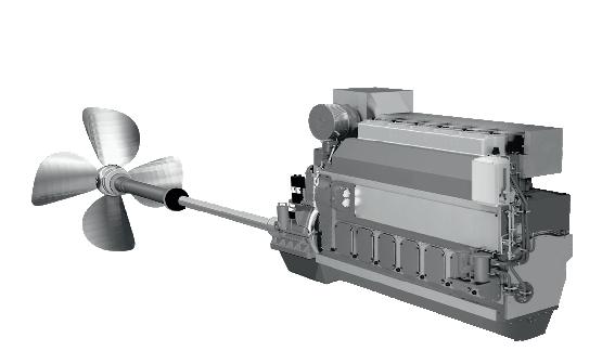
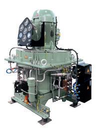
Dependable up to 500 bar – anywhere, anytime, anygas.
For more than 135 years your reliable partner − also for gas booster s .
www.sauercompressors.com Low- and high-pressure nitrogen boosters for any gas engine BOG compressors
Our gas solutions
B3-5
booster
3-stage air-cooled starting-air compressors
WP3325
Nitrogen
SESSION 4
Market Based Measures 90
JOHN BUCKINGHAM Chief Mechanical Engineer, BMT
BIOGRAPHY
John Buckingham has over 35 years’ experience in marine systems design. He has modelled and analysed the performance of energy saving technologies for commercial and naval vessels. He is currently focussing on the issues with alternative fuels, the design and modelling of wind-based propulsion, microbubble drag reduction and novel refrigeration systems.

Speaker
91
The Future of Bunker Fuels for the World’s Shipping Fleet
There is currently a diverse range of candidate bunker fuels to choose from to address the current and enduring need to achieve much lower greenhouse gas emissions from the world’s shipping fleet. There are competing commercial pressures and a range of supply chains that may be much affected by future trends in world fuel markets and their availability.
Whilst currently the IMO’s emphasis is on tank to wake, there are moves to address the whole fuel life cycle so that a holistic approach (source to exhaust) is adopted and low-carbon benefits are achieved. There are also possible issues with the current MARPOL rules for alternative (nonfossil) fuels which are not to have a worse NOx emission than the fuels they replace together with the technical challenges relating to stability, viscosities, and specific energy density.
This paper outlines the likely future fuel source and supply chains for commercial shipping using trend analysis and assessments of the world’s ability to supply the large volumes required for future ship energy demands. BMT is able to provide an independent perspective which is objective and technically substantiated by published evidence.
The future fuels will also be assessed for their suitability for a range of ship types. The likely worldwide shape of fuel supply and support will be evaluated, together with how this benefits the global greenhouse emissions from the world’s shipping fleet in the years to come.
Introduction
The IMO’s target of Net Zero by 2050 is largely based on the challenging requirements for quick and early measures to be implemented by 2030 for a much lower carbon intensity index (CII). As with many other sectors such as aviation, construction, metal production, and the even the fashion industry, etc. There is the start of a major structural shift in energy supply chains.
The required transition in maritime bunkers fuel is one of many structural changes to the energy supply chain. Many technical solutions are in development and are offered and in use today by pathfinder projects bravely led by a few key consortia often comprising prime mover suppliers, ship owner operators and in some cases those responsible for cargo transfer, or cargo owners. In each sector, there has always been changes in energy supply chains. Metal production has moved form coal, to oil to electric induction and the domestic power generation has likewise changed from hydro-electric, coal, oil nuclear and now gas-fired gas turbines before the introduction of hydro-electric, wind and solar based supplies.
The world has steadily increased its energy requirements and as this has grown this has made alternative technologies become more applicable to society’s needs as shown in Figure 1.
Conference Paper 92
Figure 1 Historical global energy mix Source: Grubler et al. (2012).
Figure 1. Historical global energy mix Source: Grubler et al. (2012).
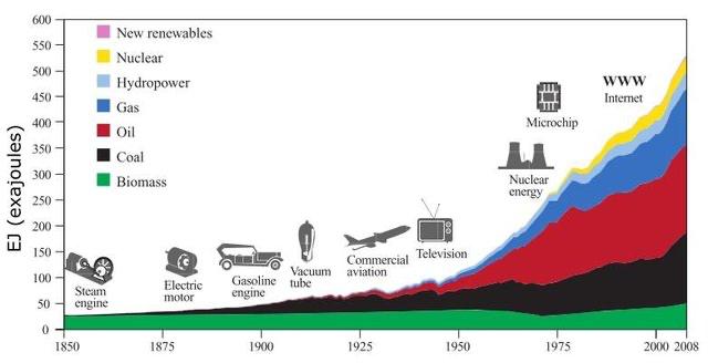
Figure 1 Historical global energy mix Source: Grubler et al. (2012).
Figure 1 shows the exponential growth of global energy demand, largely mirrored by the shipping population. The general date of key technical innovations is shown as way markers along the past.
Figure 1 shows the exponential growth of global energy demand, largely mirrored by the shipping population. The general date of key technical innovations is shown as way-markers along the past.
Figure 1 shows the exponential growth of global energy demand, largely mirrored by the shipping population. The general date of key technical innovations is shown as way markers along the past.
Arguably, the opportunity and the lower cost of new energy sources and fuels has fed the development of the advanced technical society we live in and the increased economic growth which in turns requires more energy. Until recently economic growth was tied in with increased energy consumption, but a range of parameters have indicated that such growth need not be attended by increased energy demands, this largely due to increases in energy efficiency and conservation.
Arguably, the opportunity and the lower cost of new energy sources and fuels has fed the development of the advanced technical society we live in and the increased economic growth which in turns requires more energy. Until recently economic growth was tied in with increased energy consumption, but a range of parameters have indicated that such growth need not be attended by increased energy demands, this largely due to increases in energy efficiency and conservation.
Arguably, the opportunity and the lower cost of new energy sources and fuels has fed the development of the advanced technical society we live in and the increased economic growth which in turns requires more energy. Until recently economic growth was tied in with increased energy consumption, but a range of parameters have indicated that such growth need not be attended by increased energy demands, this largely due to increases in energy efficiency and conservation.
One way of showing large trends in parameters over time is to use the Grubler function, F/(1-F) where F is the market fraction of the technology.
One way of showing large trends in parameters over time is to use the Grubler function, F/(1-F) where F is the market fraction of the technology.
One way of showing large trends in parameters over time is to use the Grubler function, F/(1 F) where F is the market fraction of the technology.
Figure 2. Technology development s curve, (Grubler, Technology and Global Change, 2003), & (Grubler, 2012)
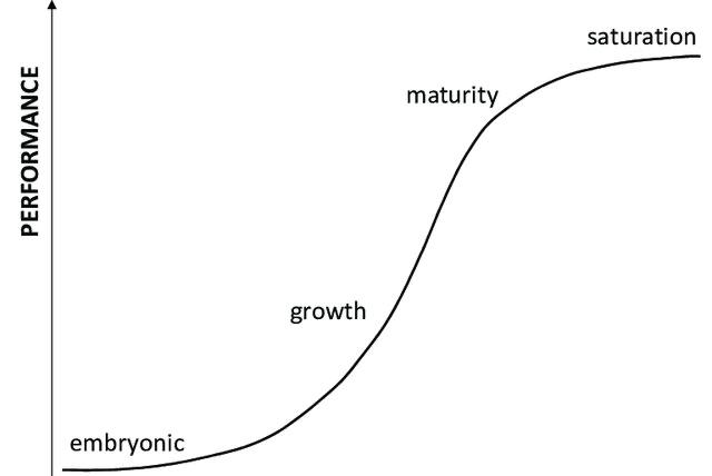
Figure 2 Technology development s curve, (Grubler, Technology and Global Change, 2003), & (Grubler, 2012)
Figure 2. Technology development s-curve, (Grubler, Technology and Global Change, 2003), & (Grubler, 2012)
Figure 2 shows how Grubler maps technologies starting in an embryonic form before rapid growth leading to maturity. Now shown in this simplified plot is the almost inevitable decline
Figure 2 shows how Grubler maps technologies starting in an embryonic form before rapid growth leading to maturity. Now shown in this simplified plot is the almost inevitable decline
Figure 2 shows how Grubler maps technologies starting in an embryonic form before rapid growth leading to maturity. Now shown in this simplified plot is the almost inevitable decline of a technology as a different one replaces it due to cost, performance improvement and obsolescence.
Conference Paper 93
of a technology as a different one replaces it due to cost, performance improvement and obsolescence.
In the UK, the change of power supply generation is within the control of the UK government that can influence growth of existing power plant technologies as well as funding the development and introduction of new technologies. In the early years of the 21st century, the UK made a significant investment in onshore and then offshore wind. This made best use of the significant natural assets offered by the windy location of the UK.
In the UK, the change of power supply generation is within the control of the UK government that can influence growth of existing power plant technologies as well as funding the development and introduction of new technologies. In the early years of the 21st century, the UK made a significant investment in onshore and then offshore wind. This made best use of the significant natural assets offered by the windy location of the UK.
Figure 3. UK Power Generation trends, 1970-2021, (Government, 1970-2021)
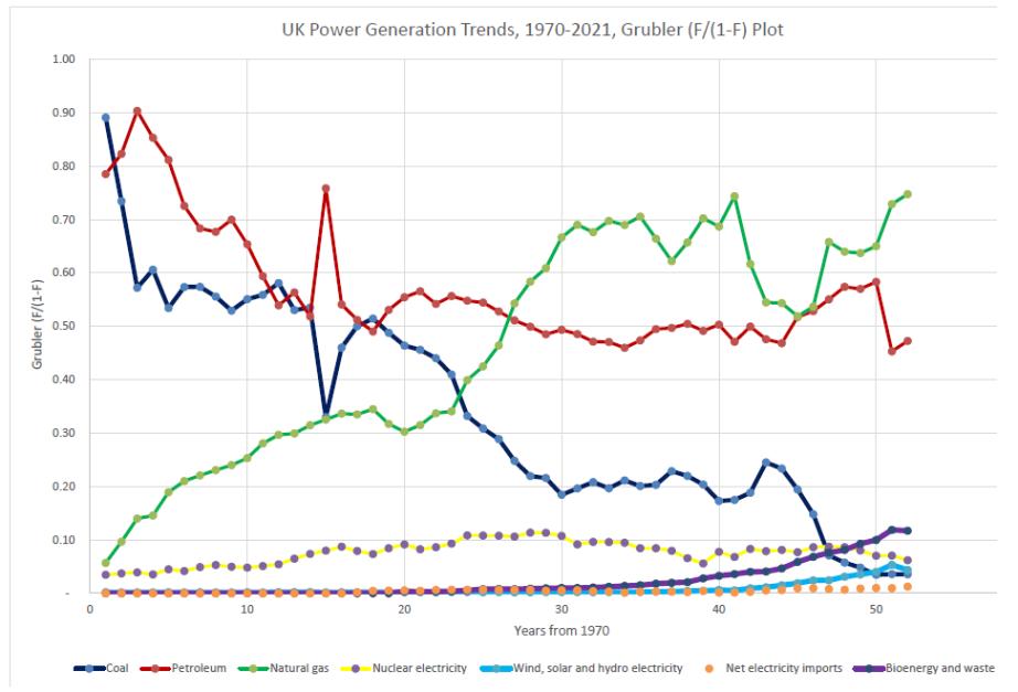
Figure 3 shows a plot of the Grubler function for each energy source where the fraction F, is used to compute the Grubler function = F/(1 F). This is a convenient way to shown a larger range of market penetration on one concise plot.
Figure 3 shows a plot of the Grubler function for each energy source where the fraction F, is used to compute the Grubler function = F/(1-F). This is a convenient way to shown a larger range of market penetration on one concise plot.
The trends of the update of wind and other technologies are useful indication of the rate of change achievable within a controlled sector. This fifty year change profile shows that for even for a well-known technology such as natural gas (green) change is both not steady and is subject to variation to market penetration as other technologies fall from use and even newer ones (wind and solar) start to take a larger market share.
The trends of the update of wind and other technologies are useful indication of the rate of change achievable within a controlled sector. This fifty year change profile shows that for even for a well-known technology such as natural gas (green) change is both not steady and is subject to variation to market penetration as other technologies fall from use and even newer ones (wind and solar) start to take a larger market share.
Ship Propulsion Energy
Ship Propulsion Energy
Historic changes in the ocean going ship propulsion have shown trends from sail to steam, and from steam to motor engines. Figure 2 shows the simplified Grubler plot for several different ship propulsion energy sources.
Historic changes in the ocean-going ship propulsion have shown trends from sail to steam, and from steam to motor engines. Figure 2 shows the simplified Grubler plot for several different ship propulsion energy sources.
Note how the timelines for change within ship propulsion are much longer, than the UK power generation market This is partly due to the open market of the global shipping world which for many centuries has been largely unregulated with regard to safety both for ships, people and environment. This changed when the IMO MARPOL convention was adopted in
Note how the timelines for change within ship propulsion are much longer, than the UK power generation market. This is partly due to the open market of the global shipping world which for many centuries has been largely unregulated with regard to safety both for ships, people and environment. This changed when the IMO MARPOL convention was adopted in 1973 introduced requirements and limits for air pollution and global climate change. Changes to ship propulsion were driven by the speed opportunity of coal-fired and then oil-fired steam-engines which were then overtaken by diesel engines which were even more fuel efficient and less bulky.
Conference Paper 94
Figure 3. UK Power Generation trends, 1970 2021, (Government, 1970 2021)
1973 introduced requirements and limits for air pollution and global climate change Changes to ship propulsion were driven by the speed opportunity of coal-fired and then oil-fired steamengines which were then overtaken by diesel engines which were even more fuel efficient and less bulky.
Figure 4. Ship propulsion Grubler Plot
Figure 4. Ship propulsion Grubler Plot
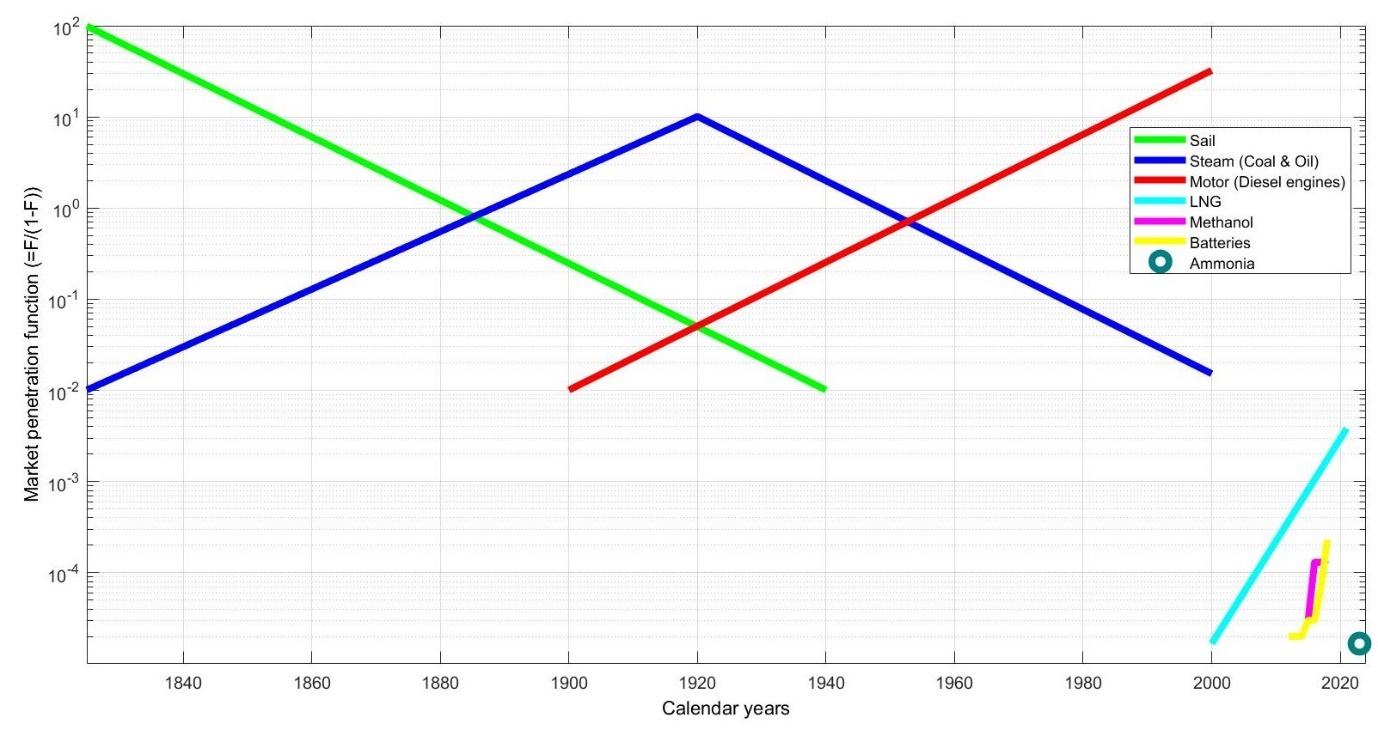
The current energy source for the world’s 70,000 ocean-going cargo ships is predominantly low sulphur heavy fuel oil (LSHFO) with a rough estimate of 300 million tonnes (MT) consumption pa leading to approximately 1,000 MT.CO₂ equivalent carbon dioxide emitted pa.
The current energy source for the world’s 70,000 ocean-going cargo ships is predominantly lowsulphur heavy fuel oil (LSHFO) with a rough estimate of 300 million tonnes (MT) consumption pa leading to approximately 1,000 MT.CO? equivalent carbon dioxide emitted pa.
IMO Legislation
IMO Legislation
There was a growing concern that ships were providing substantial pollution both to the sea and to the air. With the MARPOL convention, the IMO introduced a series of regulations based around a set of Annexes some of which relate to the emission of NOx, SOx and now carbon dioxide (chiefly related to fuel combustion and consumption). Figure 5 shows how green-house gas emissions legislation has developed both internationally by the IMO and by other parties such as the EU and the UK government.
There was a growing concern that ships were providing substantial pollution both to the sea and to the air. With the MARPOL convention, the IMO introduced a series of regulations based around a set of Annexes some of which relate to the emission of NOx, SOx and now carbon dioxide (chiefly related to fuel combustion and consumption) Figure 5 shows how green house gas emissions legislation has developed both internationally by the IMO and by other parties such as the EU and the UK government.
Figure 5 Summary of Shipping Regulations for Air Pollution
Figure 5. Summary of Shipping Regulations for Air Pollution
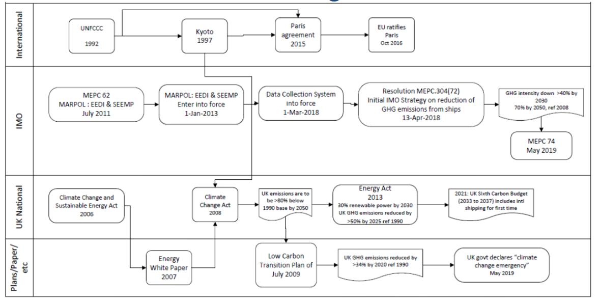
Alternative Bunker Fuels
Alternative bunker fuels require land based feedstock and process solutions which do not themselves lead to the results of a lifecycle analysis (LCA) showing an overall CO₂.eq emissions balance which is worse than at present. Figure 6 shows a sub set of the multitude of pathways for chemical transformation of a variety of waste materials which leads to liquid fuels, methanol and others which may be considered as drop in.
Conference Paper 95
Figure 5 Summary of Shipping Regulations for Air Pollution
Alternative Bunker Fuels
Alternative Bunker Fuels
Alternative bunker fuels require land-based feedstock and process solutions which do not themselves lead to the results of a lifecycle analysis (LCA) showing an overall CO?.eq emissions balance which is worse than at present. Figure 6 shows a sub-set of the multitude of pathways for chemical transformation of a variety of waste materials which leads to liquid fuels, methanol and others which may be considered as drop-in.
Alternative bunker fuels require land based feedstock and process solutions which do not themselves lead to the results of a lifecycle analysis (LCA) showing an overall CO₂.eq emissions balance which is worse than at present. Figure 6 shows a sub set of the multitude of pathways for chemical transformation of a variety of waste materials which leads to liquid fuels, methanol and others which may be considered as drop in.
Figure 6. Feedstock to Fuel Flowchart
Figure 6. Feedstock to Fuel Flowchart
The key fuels of interest are 5 Biofuels 5 Synthetic Fuels 5 Methanol 5 Ammonia 5 Hydrogen
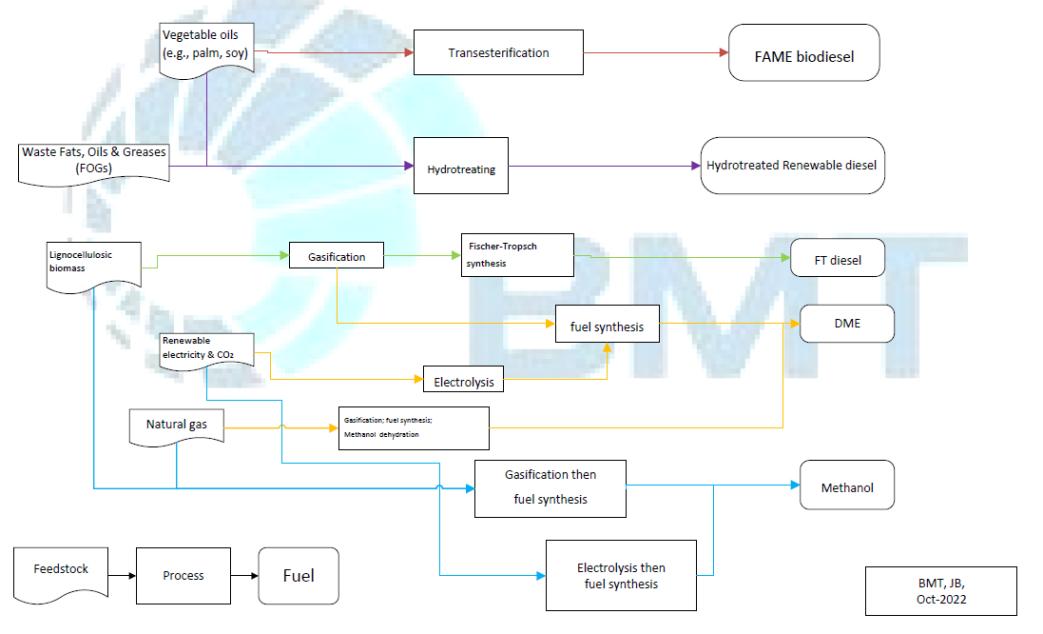
The key fuels of interest are
BioFuels
The production of a direct fossil fuel replacement is costly and challenging. Although biofuels (BF) would be a good drop-in they have become a political issue as the land required to produce such feedstock for such fuels often competes with the land allocated for food production. Fourth generation fuels which could offer a solution using algae-based methods are still in their infancy.
BF continue to be trialled with commercial ships and indeed navies have often used biofuel blends when they embark marine gas oil, which is often contaminated with automotive BF. Most BF has little or no sulphur content but has Fatty Acid Methyl Ethers (FAME) which makes it very vulnerable to microbiological contamination as it is miscible with water. BF are still made in small relatively amounts and biodiesel is an even smaller component. Ten years ago Jatropha was a promising feedstock source which could be grown on marginal land. However yields were lower than touted and the measures and time to grow it as a crop were too challenging. When the issues with land-use and sustainability are included, the BF offering as it stands is considered to be unlikely as a future world-wide bunker fuel
Conference Paper 96
Synthetic Fuels
The treatment of waste oil from onshore processes such as deep-fat fryers and such like can lead to fuel of a paraffinic quality to standards such as EN15940. This fuel standard is widely accepted by suppliers of marine two and four-stroke engines as it is clean of sulphur but also has a sufficient lubricity to reduce wear. The production volumes of fuel to EN15940 are comparatively low as the networks for waste fuel collection are relatively small with the quantities involved being much smaller than the 300 MT oil equivalent.
Synthetic fuels can be created from a wide variety of feedstocks which are themselves created using ‘green’ hydrogen derived from renewable energy electrolysis which is then combined with other chemicals to create the feedstocks. Such fuels can be called electro-fuels, (Mariliis Lehtveer). They promise to provide high quality fuels (i.e. low oxygen content etc). These will be highly sought after by the aviation industry who also need to decarbonise but cannot afford to compromise on fuel quality. Such fuels will be very costly and will struggle to be competitive apart from special areas. One case may be the creation of green-ammonia from remote highsolar, low-population places such as Australia. This fuel can then be shipped to Asia and also used for ship bunkers.
Synthetic fuel from waste (principally plastic, household and wood) has been considered as a viable feedstock for synthetic fuel but as these waste streams are diverse and unaggregated, the organisation required to achieve this is challenging and is not currently co-ordinated. If the full potential could be realised up to 50MT oil equivalent could be generated. (Buckingham, 2020)
LNG
The trend for LNG-fuelled ships is shown in cyan in Figure 4. The growth was led by the need to met more stringent IMO air pollution requirements due to NOx and then mainly the SOx limit of 0.5%. Although exhaust scrubbers are one option there are issues with the safe collection and storage of the sulphurous water. In 2015, Liquefied Natural Gas (LNG) was becoming a much more marketed fuel and LNG carriers were carrying LNG from the Middle East all round the world. The price was less than one third the current price (as of October-2022) (https:// tradingeconomics.com/commodity/natural-gas) as the US and Russia and many other nations also produced and supplied LNG and so the price fell. LNG became the favoured bunker fuel for low sulphur emissions even though the cryo-genic machinery installation is more costly than standard installations and safety-critical.
It is estimated that up to 2,000 ships are at sea or are in build with LNG bunkers for propulsion. However, due to the 2008 global financial crisis and now the Russian invasion of Ukraine, the price of LNG has increased three-fold and so the uptake has been somewhat stalled.
With the IMO’s requirements for Net Zero in 2050 and the imposition of progressively much stricter carbon emissions limits, specifically by employing specific CII reduction target of 40% by 2030, much has been made of the ~20% CO? reduction due to the combustion of LNG compared to marine diesel oil (MDO).
Others have cited the use of LNG as a pathway fuel for the increased introduction of other fuels with flash points below 61°C, i.e. methanol (9°C) and the maximum safe storage of temperature of ammonia (52°C) .
Methanol Bunker Fuel
Figure 4 (magenta) shows the slight uptake of methanol as a bunker fuel. The Stena Germanica is an example of a successful working methanol ferry with four-stroke engines which has been operating on methanol for seven years. Also two-stroke engines in ships operated the
Conference Paper 97
Waterfront Shipping company (owned by Methanex) have also been running on methanol for over years.
Methanol is widely used as a fuel for heating. It reduces emissions of PM by 95%, SOx by 90% and NOx by 60%. It reduces CO? emissions by 25% at point of use. The safety hazards are manageable with the IMO IGF code (IMO). However its calorific density is about half that of current marine fuels.
The Chinese market comprises 50% of global production and consumption with relatively little or no production in Europe. World production is of the order of 100 million tonnes which is equivalent to 40 million tonnes oil eq. so a much smaller proportion of global shipping bunker demand of 300MT. Almost all methanol is currently manufactured by non-renewable processes (65% natural gas, 35% coal) which produce almost three times the CO2 per unit energy than marine gas oil. About 1% is produced by biomass and renewable energies.
Worldwide distribution and availability of methanol is also good and it is widely traded (one of five popular seaborne commodities) and has been carried as a chemical feedstock product for over 50 years. The use of methanol as a bunker fuel is being supported by the Swedish government, Maersk and the Royal Netherlands Navy (Astley, 2020) principally for short sea shipping.
Such fuels have low sulphur emissions but they need significant health and safety measures to avoid vapour exposure to crew and passengers and special fire protection measures.
In 2013, only 1% of methanol was made from renewable sources. Besides the production challenges there are infrastructure challenges too; methanol’s volumetric energy density is only 40% that of diesel, so clearly there would have to be more regular bunkering and therefore widespread availability.
At present, such fuels are not a feasible solution of the GHG challenge unless CCS is employed or they are manufactured using renewable energy, so called electro-fuels. They will be costly and not cost effective for shipping in the short-to-medium term.
With an energy density of 19.7 MJ/kg, methanol’s volumetric energy density is only 40% that of diesel fuel oil, so clearly there would have to be more regular bunkering and therefore widespread availability.
Safety
Hygroscopic so will absorb water which is an issue wrt condensation and sea water
May have cold weather starting issues but can be managed through pre-heating
There are safety issues with flammability and toxicity so ventilation and fire precautions are required.
The amended EU Fuel Quality Directive adopted in 2009 allows up to 3% v/v blend-in of methanol in petrol. Not believed to be widely adopted.
Currently there are successive order for ships fuelled with methanol, the Maersk group have ordered 19 tankers fuelled by green methanol using a supply chain controlled by Maersk. The ships will be in class with ABS who have issued guidance for methanol as a bunker fuel (ABS, Feb-2021)
Conference Paper 98
Ammonia
Ammonia can be used as a fuel in modified two-stroke engines and trials are being undertaken in Japan to assess the overall, impact on emissions and performance, (Motorship). There are no known ships operating at sea on ammonia.
Ammonia is also made through energy intensive Haber-Bosch process, usually using natural gas as the feedstock. Using the Steam methane Reforming (SRM) and the Haber-Bosch process to combine the N? and the H?, the ammonia has an LCA of about 0.85kg.CO?/kg.NH?. This can be halved using renewable methods, (Yusuf Bicer, 2016). Almost half of current ammonia production is used for urea and fertiliser manufacture.
As with methanol, ammonia can be made with hydrogen derived from renewable energy and has the benefit that it does not carry a carbon atom and so cannot form a carbon oxide molecule, although NOx will also be produced during combustion.
Ammonia also has significant health and safety challenges but as with methanol, it is widely traded as a sea-going commodity and so there are already storage and handling measures in place from the IMO and classification societies. The IGF code is also applied together with IACS guidance for machinery and fuel handling requirements.
The energy density is poor compared to current fuels so a widely spread distribution if refuelling pots is a requirement. It is therefore considered that ammonia fuelled ships would operate on well-defined regular voyages (i.e. tankers) between ports with ammonia bunkering facilities.
When compared to the carriage of hydrogen onboard, ammonia is seen as the better hydrogencarrier. If it can be reliably combusted in large two stroke engines, this may be the favoured way in which hydrogen is moved from the sun-belt hydrogen generation nations to Europe and the USA, on ammonia-carrying vessels transporting their cargo in a way comparable to LNG carriers.
Hydrogen
The use of hydrogen directly embarked onto ocean-going ships as a bunker fuel for fuel cells or adapted diesel engines, is considered to be a challenge currently beyond the technology on the market today. Whilst in the format of Liquid Organic Hydrogen (LOHC) carriers which make use of the ability of some chemicals such as toluene to absorb and readily release hydrogen modules. Although the absorption requires pressures up to 50bar and temperature up to 200°C, this processing is on the supply land-side. To release the hydrogen heat is required to drive the endothermic reaction at temperature up to 320°C. Often steam-based systems are used to allow heat capture and re-use. Consequently, the whole process requires very high integrity due to ease with which hydrogen can pass sealing arrangements due to its very small molecule size. The balance of plant will also be considerable in size making it necessary to consider the use of LOHC with cryogenic and high-pressure hydrogen storage in the round, i.e. principally the considerations of energy density, bulk, transport, handling , safety and cost.
Whatever the hydrogen storage format, it is likely that for reliable running of a compression engine or a fuel cell, the energy output would be electrical. Therefore, hydrogen solutions would be better suited to those short-sea shipping vessels that have a highly variable duty cycle and more opportunities for re-fuelling.
Conference Paper 99
Conclusions
The current situation with bunker fuel costs and the transformation is very much in flux. There are a range of supply side companies offering low carbon fuels but the interesting observation is the degree of demand-side change whereby leading shipping companies are working with ship owner operators to produce ships which can operate with duel fuel engines on methanol or ammonia. There are few if any ships at sea on ammonia fuel but there are several ships running on two and four stroke engines burning methanol.
The immediate future for sea-going cargo and ferry ships is likely to continue to be a patchwork of ships operating on a range of alternative bunker fuels, probably influenced by their regular routing and the local fuel opportunities and their prices. It may be that future engines may be dual-fuel for ammonia and methanol, but the low energy density of such fuels means that synthetic drop-in fuels and even future carbon capture and storage onboard remain potential candidates for future low carbon shipping.
Costs will drive behaviours but the key, and necessary, trend which has yet to be seen is the lack of a significant uplift in the low-carbon production of the alternative fuels outlined above. Although shipping may benefit from the lower grade by-products of aviation synthetic aviation fuel (SAF) processes, it may still be the largest consumer of liquid fuels once land vehicles trend to batteries and hydrogen fuel cells. The costs for the production of alternative fuels for shipping will be very large burden on the cost of sea transport. This may yet lead to significant changes in modal transport networks and the movement of the centres of production.
References
ABS. (Feb-2021). Sustainability Whitepaper: Methanol as Marine Fuel., (pp. https://absinfo. eagle.org/acton/media/16130/sustainability-whitepaper-methanol-as-marine-fuel).
Astley, G. a. (2020). Exploring the impact of methanol as an alternative, cleaner fuel for the auxiliary and support vessels within the RNLN. INEC. IMarEST.
Buckingham, J. E. (2020). Future Fuels for Commercial Shipping. RINA LNG/LPG and Alternative Fuels Conference. London.
Government, U. (1970-2021). DUKES databases, 1.1.1.B (CO2.eq).
Grubler. (2003). Technology and Global Change. Cambridge University Press. Grubler. (2012). Energy Primer. In Global Energy Assessment - Toward a Sustainable Future. (pp. 99–150). Cambridge, UK; New York, NY, USA and Laxenburg, Austria: Cambridge University Press and International Institute for Applied Systems Analysis. https://tradingeconomics.com/commodity/natural-gas. (n.d.).
IMO. (n.d.). International Code of Safety for Ship Using Gases or Other Low-flashpoint Fuels (IGF Code). IMO.
Mariliis Lehtveer, S. B. (n.d.). “What Future for Electrofuels in Transport? Analysis of Cost Competitiveness in Global Climate Mitigation”. Environmental Science & Technology 2019 53(3),1690-1697 . DOI: 10.1021/acs.est.8b05243.
Motorship. (Sep-2019). J-ENG to investigate hydrogen and ammonia as combustion fuels.
Yusuf Bicer, e. a. (2016). Comparative life cycle assessment of various ammonia production methods. Journal of Cleaner Production, Volume 135 (pp. 1379-1395). ISSN 0959-6526.
Conference Paper 100
SEBASTIAN EBBING
Technical Advisor, Climate, Marine fuels, Innovation, Funding, VDR - Verband Deutscher Reeder
BIOGRAPHY
As Technical Advisor at German Shipowners’ Association, Sebastian Ebbing provides profound technical expertise to the ongoing regulatory developments on EU and IMO-Level. With his background in nautical science, marine engineering and international maritime management he is dedicated on regulatory climate-protection affairs, the maritime energy transition incl. the development of alternative climate-neutral fuel strategies, digitalization and innovation projects in shipping.
Sebastian Ebbing´s technical expertise is accompanied by experience in fleet performance management within a globally operating shipping company. The German Shipowners’ Association (VDR) is a leading professional association within the German business community.

It was founded in 1907 by the regional shipowners’ associations in order to enable them to have common and uniform representation of their interests. Today, the VDR represents the German maritime shipping segment not only in Berlin and Bonn, but also in Brussels, London, Geneva and at global level. With its over 150 member companies from different shipping sectors, the association represents the German shipping industry, which currently boasts the world’s fifthlargest merchant fleet. As an employers’ association, it conducts collective bargaining and social partner negotiations.
Sebastian Ebbing is founding- and board member of the “Research Institute for Innovation and Sustainable Logistics” situated at Jade University of Applied Science, where he is lecturing on Maritime Technologies with special focus on climate neutral shipping and alternative propulsion technologies.
Speaker 101
CHRIS WADDINGTON Technical Director, International Chamber of Shipping
BIOGRAPHY
Chris Waddington is Technical Director at the International Chamber of Shipping (ICS).
He is responsible, in conjunction with the Nautical Manager for the development and implementation of ICS policy on technical, operational and environmental regulatory risks affecting international shipping. He actively participates in IMO Committees and industry associations, to represent the interests of ICS Members, shipowners and operators.

The first 23 years of his career has been founded in the shipping sector, mainly working on the design, construction and operational support of passenger ferries. For the subsequent 15 years he has focused on the floating production sector of the Oil and Gas industry, project managing FPSO and FLNG design work, supporting field developments, and supervising procurement of floating production vessels. He has also acted as Lenders’ Technical Advisor on behalf of banks and Export Credit Agencies. He is a chartered engineer, a Fellow of the Royal Institution of Naval Architects, and a member of the Society of Naval Architects and Marine Engineers.
Chris has worked in Australia, Italy, Poland, Singapore, Vietnam and the UK.
Speaker
102
Development of IMO’s Market Based Measure
1. Introduction
The objective of this paper is to provide a summary of the development by IMO of a marketbased measure (MBM), or what ICS now prefers to describe as an economic measure. When implemented, this will form part of a “basket” of measures that is intended to help drive the decarbonisation of the global shipping industry.
In 2018, and in response to the Paris Agreement by the United Nations Framework Convention on Climate Change (UNFCCC), IMO adopted its Initial GHG Strategy to phase-out all GHG emissions from international shipping as soon as possible.
IMO’s Strategy sets levels of ambition (targets) to be achieved by the international shipping sector as a whole, rather than by individual ships, and contains a list of candidate measures to help achieve these levels of ambition. The IMO’s GHG Strategy is thus a policy document to guide the development of new GHG regulations, in the short, medium and longer term. It does not itself contain regulations applicable to individual ships. The strategy is summarised in Figure 1.
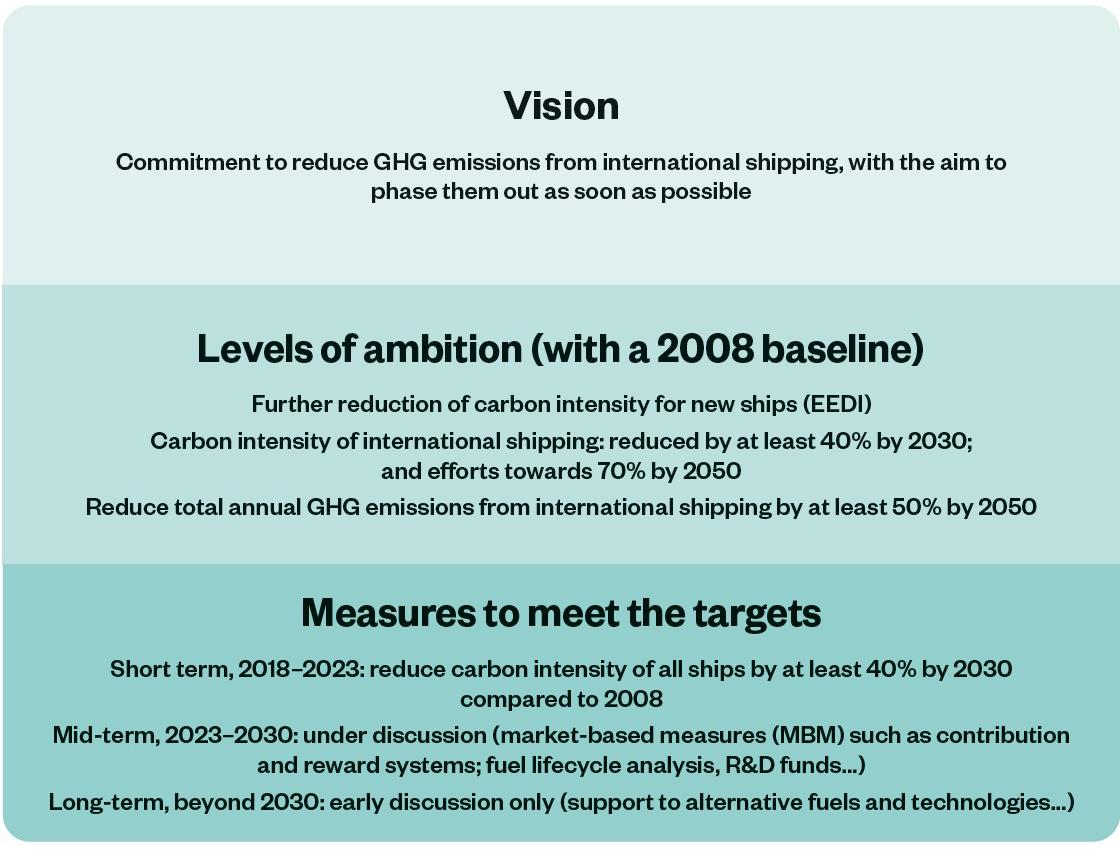
Conference Paper 103
Figure 1 Outline of the 2018 Initial IMO GHG Strategy
As part of the initial GHG strategy, IMO has the following timeline for development of regulatory measures:
1. Short-term measures (2018-2023);
2. Mid-term measures (2023-2030);
3. Long-term measures (beyond 2030).
The short-term measures are focused on improving the fuel efficiency of ships, through design improvements, and optimisation of operations. The mid and long-term measures may include an MBM, i.e. an economic measure intended to narrow the price gap between low/ net zero emission fuels and conventional fuels and expedite the production and uptake of alternative fuels.
IMO is scheduled to revise its GHG Strategy by mid-2023, and this process is expected to result in even more ambitious GHG reduction targets being agreed for the sector, with many IMO Member States now calling for the complete phase-out of most GHG emissions by 2050. ICS itself supports the adoption by IMO of a net zero CO2 emissions target for 2050, and a new interim target for 5% of the energy used by shipping in 2030 to be generated from alternative fuels, so as to reach a ‘take off’ point on the pathway to complete decarbonisation.
2. Short-Term Measures
In line with its 2023 deadline, IMO has already developed the following short-term measures:
2.1 Energy Efficiency Design Index (EEDI)
The EEDI provides a standard or design index, intended to ensure that new build ships achieve a required level of fuel efficiency. It is periodically revised by the IMO MEPC to increase stringency for future ships. Since January 2013 It has been a mandatory requirement for vessels of 400 Gross Tonnage or above to report their attained EEDI to their flag Administration or Recognised Organisation (RO). Ships above minimum size thresholds also have EEDI targets they must reach. The size thresholds vary according to vessel type.
2.2 Energy Efficiency Existing Ship Index (EEXI)
EEXI is a very similar metric to EEDI, but applies to existing ships. From the first IAPP survey after 1st January 2023, existing ships of 400 Gross Tonnage or above must report their attained EEXI to their flag administration or Recognised Organisation (RO). Ships above minimum size thresholds also have EEXI targets they must reach. The size thresholds vary according to vessel type.
2.3 Carbon Intensity Indicator (CII)
The carbon intensity indicator is an operational measure that applies to new and existing ships above 5,000 Gross Tonnage, and will take effect from 1st January 2023. Vessels will be allocated a banded rating A to E, dependent on their annual return to IMO’s Data Collection System (DCS). Bandings will be progressively reduced, to a cumulative 2026 reduction of 11%.
Within the first 3 years of its implementation, CII will be within a review phase, and soft enforcement measures will apply, i.e. ships placed in band D for 3 consecutive years, or band E for 1 year, will be required to submit a corrective action plan. As long as a corrective action plan is produced, and followed through, there is no provision within the system to suspend or withhold certification. Noting that the guidelines defining the range of available CII correction factors is currently termed “interim”, the level of enforcement is consistent with the status of the CII system.
By 1st January 2026 IMO is due to complete a review of the CII system. The review will include consideration of alternative metrics that may supplement or replace the current AER and cgDIST metrics. It will also consider the need for a wider range of correction factors, voyage
Conference Paper 104
adjustments and reference lines. Following completion of the review, it is possible that harder enforcement measures may apply. The review will also consider the effectiveness of the EEXI measure.
3 Mid and Long-Term Measures
3.1 The Workplan
IMO has developed a work plan to support the implementation of mid and long-term measures. This has the following three phases:
1. The first phase involved the collection of proposals and initial consideration of those for development of mid-term and long-term measures and was completed in June 2022.
2. In phase 2, measures will be assessed and selected for further development (Time period- June 2022-June 2023).
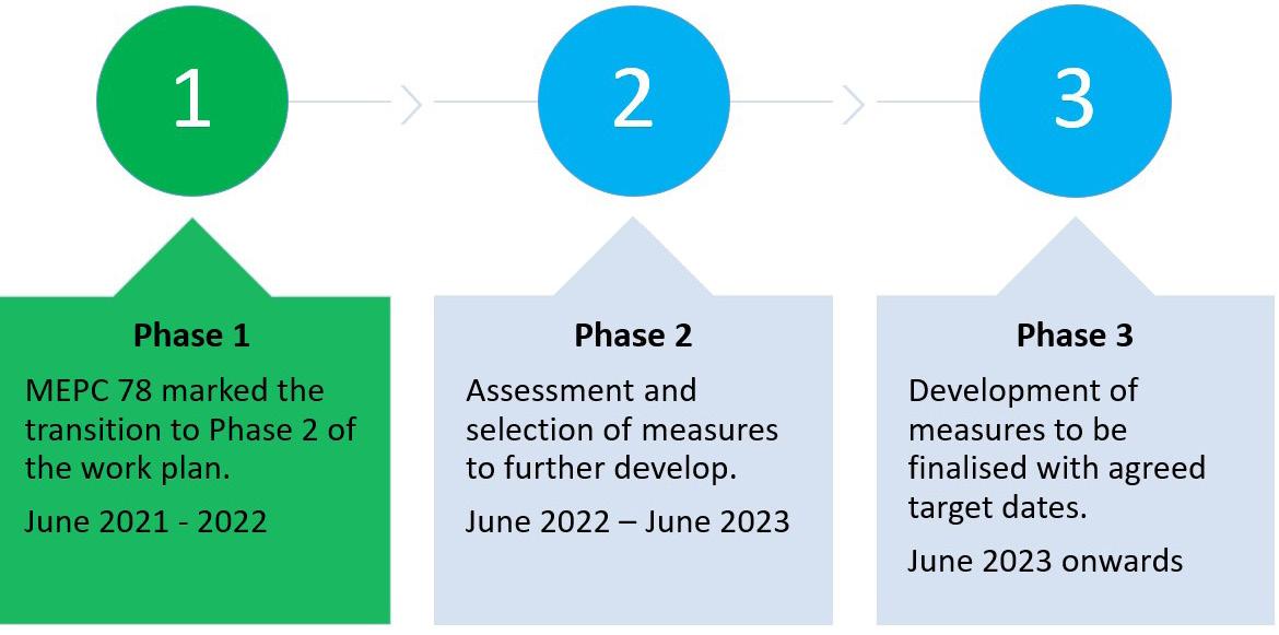
3. In phase 3, measures will be developed and finalised within a specified deadline (Time period: June 2023 onwards – Target dates to be agreed in line with IMO strategy).
3.2 MBM Submissions to ISWG-GHG-12
Within phase 1 of the work plan, mid and long-term measures were most recently considered by the MEPC in June 2022 and are being considered in detail by an Intersessional Working Group, The agenda of the most recent working group meeting (ISWG-GHG 12) included consideration of proposals for an MBM. The meeting received a wide range of submissions, and these may be considered under the following categories:
Conference Paper 105
Figure 2 IMO’s Workplan for Mid and Long-Term Measures – Source IMO
MBM Proposals
Sponsors
Flat rate contribution on CO2 emissions
Collection and use of funds raised by a flat rate contribution by ships per tonne of CO2 emissions
ICS and INTERCARGO
Cap and Trade
Proposal for an emissions cap and trade proposal Norway
Fund and Reward or Feebate
Proposal to establish an International Maritime Sustainability Funding and Reward (IMSF&R) mechanism as an integrated midterm measure
Proposal on Market-based Measures (MBMs) to incentivise GHG emission reduction and to make equitable transition with an overview of mid and long-term measures
Argentina, Brazil, China South Africa and United Arab Emirates
Japan
Global Fuel Standard (GFS)
Consideration of the CII in relation to a new GHG fuel standard Norway
Proposal for a GHG Fuel Standard
Table 1 Summary of MBM
European Union (EU) Member Countries
Proposals Submitted to ISWG-GHG-12
N.B. although a GHG fuel standard cannot be considered an MBM, it could be adopted as a complementary technical measure alongside a separate economic measure as part of basket of mid-term measures
3.3 Discussion of MBMs
The following sections discuss the main features of the MBMs and summarises their strengths and weaknesses.
3.3.1 Flat rate contribution system
A flat rate contribution system has previously been proposed by ICS and separately by the Marshall Islands and Solomon Islands. In essence, such a system can be relatively simple, with a financial levy applied to the fuel used by each ship, dependent upon the CO2 emitted. The necessary data to support the system could be supplied through the existing IMO Fuel Oil Data Collection System (DCS). The funds collected by IMO could be retained within sector, and utilised to support the decarbonisation process, and also to support developing countries, including Small Island Developing States (SIDS) and Least Developed Countries (LDCs) through the transition process. The quantum of the contribution per tonne of CO2 emitted would be defined for a 5 year period, hence providing stability and certainty for shipowners, charterers and national economies, given the particular concerns expressed by developing countries about the potential impacts on trade. At the end of the set period, the effect of the contribution on availability of new fuels may be ascertained and also its impact on world trade, before deciding whether an adjustment is necessary. Hence the effect of a flat rate contribution system is relatively stable, and its magnitude is easily controlled.
Conference Paper 106
A number of international institutions, including the World Bank and the IMF, have concluded1 that the most appropriate MBM for shipping is probably a flat rate contribution based system The World Bank and the IMF have noted that a such system gives price certainty, and so more stability for making transport decisions and developing long-lived emissions saving technology.
3.3.2
Cap and Trade
A cap and trade system has been advocated by Norway. The EU and North America have already established similar systems for other industrial sectors and the EU is finalising regional legislation to extend its existing emissions trading system to international shipping. Under such a system, a maximum cap is set on the total amount of greenhouse gases that can be emitted. Allowances for emissions are then auctioned off or allocated for free, and can subsequently be traded. Participants must monitor and report their CO2 emissions, ensuring they hand in enough allowances to the authorities to cover their emissions. If emissions exceed what is permitted by the allowances, a participant must purchase allowances from others. If a participant has performed well, it can sell its remaining credits. However, based on the experience of existing cap and trade systems, the traded price of carbon allowances can be variable and volatile, and hence it is harder for a ship owner to budget for the associated cost than with fixed flat rate contribution system. In extreme cases, particularly for SMEs, it might become difficult for certain ship types to remain in business, and this may have unintended consequences.
3.3.3 Fund and Reward, or “Feebate” system
This is a relatively new concept that was first discussed in detail at ISWG-GHG-12 and has since been elaborated in a revised Fund and Reward (F&R) proposal made by ICS to ISWG-GHG 13, which meets in December 2022. ICS has suggested that with political will, such a global Fund and Reward System could be in place by 2024.
Two similar submissions were initially made to ISWG-GHG 12, one led by China and cosponsored by Argentina, Brazil, South Africa and United Arab Emirates, and the other by Japan. The concept of a Fund and Reward (F&R proposal) is currently evolving. But by using most of the contributions collected to reward ships for the CO2 emissions prevented by the use of “eligible alternative fuels”, the initial quantum of the contribution can be set at a level which is relatively low, achieving the goal of narrowing the price gap with conventional fuels, whilst avoiding disproportionately negative trade impacts on developing countries.
Noting that in the early stages of decarbonisation, the number of vessels consuming conventional fuel will far outnumber the ships that have adopted low and zero carbon fuels, such systems can provide significant rewards to first movers whilst maintaining the fee that is applicable to those ships that burn fossil fuel at reasonable levels. Hence such systems should provide strong first mover incentives whilst ensuring reasonable financial stability for the remainder of the world fleet.
These proposals envisage a proportion of the raised funds being utilised to support developing countries through the transition period, provided the funds are used in sector
3.3.4 R&D Funding
Consistently advocated by ICS, the proposal to ISWG-GHG-12 for an International Maritime Research and Development Board, and an IMO Maritime Research Fund, received wide cosponsorship from member states and Non-Governmental Organisations (NGOs). Although originally intended as a short-term measure to kick start the decarbonisation process, IMO’s Marine Environmental Protection Committee (MEPC) has decided to consider it within the discussion of the mid and long-term measures, which is unlikely to conclude for several years. The architects of the IMRB and IMRF had intended for it to support first movers and to enable significant numbers of low and zero carbon ships to be in place by 2030. However, noting the extended schedule now imposed on the consideration of this system by MEPC, even if it were to be adopted, the potential effectiveness of the system has been diminished by its movement to the mid and long-term measures debate.
1 World Bank and IMF (2012). Market-based instruments for international aviation and shipping as a source of climate finance. Keen, M., Parry, I., Strand, J. (January 2012) WPS No. 5950, Washington, DC: World Bank.
Conference Paper 107
Nevertheless the idea of an MBM supporting R&D, has in the meantime been adopted by other proposals. For example, the latest ICS proposal for a fund and reward mechanism proposes that a proportion of the revenue should be allocated to support an R&D programme.
3.2.5 GHG Fuel Standard
A fuel standard on its own is regarded as a technical measure rather than an MBM. However within their proposal to ISWG-GHG-12, the European Member Countries, acknowledge that such a system must go through a transitional period, until such time as there is wide availability of low and zero GHG fuels. During this period, it will be necessary to incentivise the early uptake of zero emission fuels. Hence, the Sponsors envisage a reward mechanism for over achievers, and fees to be paid by under achievers to an IMO GHG fund. In this respect the proposal has similarity with the Fund and Reward or Feebate systems.
4.0 Next steps for the MBM
During his summing up, the chair of ISWG-GHG-12 noted considerable convergence within the group, and a strong willingness to advance in accordance with the work plan. The group were encouraged to work together intersessionally, with a view to exploring how different elements of the proposals could be combined. A further intersessional working group ISWG-GHG-13 is planned for 5th to 9th December 2022. The outcome of the working group will be reported to the next MEPC meeting which is scheduled for 12th to 16th December 2022.
The process of developing the MBM is currently within phase 2 of IMO’s mid-term measures workplan. Phase 2 is focused on assessment and selection of measures, and is due to complete by June 2023. Phase 3 will start immediately after, with the objective of finalising the MBM.
5.0 Preparations for ISWG-GHG-13
The next IMO intersessional working group (ISWG-GHG-13) is to be held from 5th to 9th December 2022. At time of writing, most of the submissions have been released and from these it is apparent that several of the Sponsors have followed the advice of ISWG-GHG-12’s Chair, and have combined their MBM proposals with other measures. The following table summarises these developments:
MBM Proposals
ICS
Sponsors
ISWG-GHG-12
Levy and willingness to consider GFS
Japan
Argentina, Brazil, China South Africa and United Arab Emirates
Feebate
Feebate
Norway Cap & Trade
European Union (EU) Member Countries GFS
Republic of Korea No submission
Marshall Islands & Solomon Islands No submission, although previously proposed a Levy based system to MEPC 77
ISWG-GHG-13
Revised Fund and Reward Proposal and willingness to consider GFS
Feebate & GFS
Submission sets out broad principles for an economic measure using a contribution system
Cap & Trade + GFS
Levy & GFS
Levy & GFS
Levy & GFS
Table 2 Comparison of ISWG-GHG-13 MBM submissions versus ISWG-GHG-12
Conference Paper 108
Further submissions may yet be published, but it does appear that there could be convergence, with many delegations favouring some kind of Fund and Reward measure using a flat rate contribution system, potentially complemented by a separate global fuel standard.
6.0 The Importance of Global and Holistic GHG Regulations
In parallel with the development of IMO’s economic measure , the EU has been taking steps to extend its Emissions Trading Scheme (ETS) to the shipping sector. This is a cap and trade measure which already applies to other industries within the EU. This process is currently within Trilogue negotiations between the regulatory bodies of the EU, and until the negotiations are finalised the exact outcome is uncertain. However, the measure may enter force as early as 2023, and it is very likely that ships engaged on international voyages in and out of the EU will then be expected to purchase and surrender carbon allowances, regardless of whether the ships fly an EU flag, or whether the shipowner is incorporated within the EU. Despite the objections from many of the EU’s major trading partners, the unilateral application of the EU ETS to shipping is likely to generate significant revenues, primarily from international shipping, something which in time is time is likely to be emulated by other regions and countries. In effect, this could result in the world’s seas becoming a maritime version of a toll road, with vessels paying a carbon fee each time they cross a territorial boundary. Such a scenario would hinder world trade, and there would be no certainty that revenues raised would be used to fund the decarbonisation of shipping. Although such measures would motivate ship owners to adopt the alternative fuels (e.g. ammonia, hydrogen, methanol etc.), there is also no certainty that the timing of such measures would be aligned with IMO’s implementation of safety and training requirements for such fuels. In these respects IMO’s approach to decarbonisation represents a much more holistic approach, which balances the need for decarbonisation with other important factors such as ensuring an equitable transition, earmarking of revenues for decarbonisation, facilitation of world trade, and ensuring safety and crew welfare.
Nevertheless, the EU have not ruled out substituting IMO’s MBM when it comes into force, and ICS hopes that the EU, and indeed all member states of the IMO ultimately choose to adopt a global economic measure instead of domestic or regional alternatives.
Conference Paper 109
7.0 Conclusions
IMO’s GHG short-term measures are in place and the mid-term measures are now under consideration, including an MBM/economic measure.
Phase 2 of IMO’s workplan for the mid and long-term measures is underway and is assessing several MBM concepts before selecting an economic measure for further development. The proposals being considered fall within the following categories (or combinations of these):
5 Flat rate contribution
5 Cap and trade;
5 Fund and Reward (F&R)or Feebate;
5 Global fuel standard linked to an economic measure.
Following the most recent intersessional working group (ISWG-GHG-12) significant convergence and cooperation was apparent, and the delegates have been tasked to work collaboratively between sessions to try and merge proposals. The next intersessional working group will be held from 5th to 9th December 2022, and will report to the next IMO MEPC meeting, which is scheduled for 12th to 16th December.
At time of writing, most MBM submissions for ISWG-GHG-13 have been released, and convergence is apparent, with many delegations potentially willing to accept some kind of Fund and Reward measure using a flat rate contribution system, potentially complemented by a separate global fuel standard. In parallel to the development of IMO’s MBM, the EU has been taking steps to extend its Emissions Trading Scheme (ETS) to the shipping sector.
Nevertheless, the EU has not ruled out substituting IMO’s MBM if and when it comes into force, and ICS hopes that the EU, and indeed all member states of the IMO ultimately choose to adopt IMO’s MBM, instead of domestic or regional alternatives.
Conference Paper 110
MERTEN STEIN Head of Shipping Advisory West Europe, DNV SE

BIOGRAPHY
Merten is a senior principal consultant with >20 years of strategy consulting experience, leading DNV’s Shipping Advisory Hamburg & Dubai team. Before joining DNV in 2012, he was with management consultancy Booz & Company for 11 years. Delivering insights from blending commercial, technical and regulatory expertise has been a major professional theme of Merten’s work. Amongst others, he led techno-economic feasibility studies on alternative fuels and technologies, growth/turnaround/innovation strategies and market assessments for a broad range of clients in the maritime and other industries.
Speaker 111
SESSION 5
Future Approaches 112
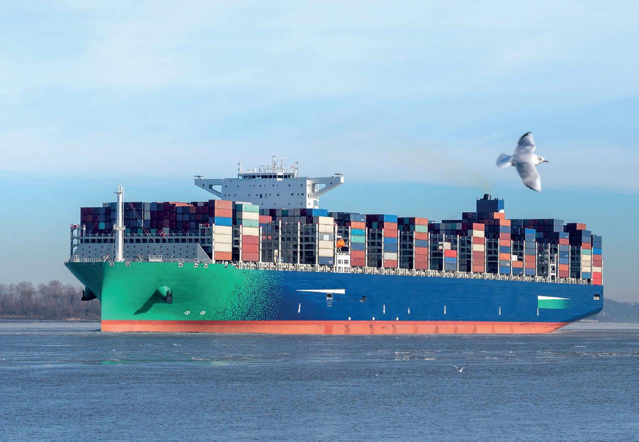
Talusia Universal The single cylinder oil solution for all 2020 compliant fuels. Find out more at totallubmarine.com/tu
SESSION 5.1
eFuels & Bio Fuels 114
DANIEL CHATTERJEE
Director Technology Management & Regulatory Affairs
Head of the Green-and High-Tech and NetZero@ PowerSystems Program, Rolls-Royce

BIOGRAPHY
Daniel Chatterjee is responsible for technology management and regulatory affairs of RollsRoyce Power Systems, a world-class provider of power solutions for marine and infrastructure applications. Since 2015, Daniel is also in charge of the Greenand High-Tech Program, which drives the development of new technologies and solutions for environmental friendly propulsion and power solutions. Further he took over also the lead of the NetZero@ PowerSystems climate strategy program in order to achieve “net zero carbon“ in 2050 Daniel Chatterjee began his career in 2001 at Daimler AG, where he worked as a project manager for Exhaust Gas Aftertreatment in the R&D department. In 2009, he transferred to MTU Friedrichshafen, which became part of Rolls-Royce’s Power Systems division in 2014. Here he held various management positions for the areas of product management and exhaust after treatment. Daniel studied physics in Heidelberg and obtained his doctorate in chemical physics in 2001.
Speaker
115
Power-to-X - Decarbonisation with future maritime Fuels
Abstract
Defossilization of high-power applications represents a challenging task as complete electrification often is not possible in most cases. One promising option for the reduction of greenhouse gas emission of high-power applications are renewable electricity-based fuels, so called e-fuels including hydrogen, that are produced by Power-to-X (PtX). While e-fuels are not an economically viable option yet, a market ramp-up is expected after 2030, evoked by ambitious CO2 reduction targets and decreasing prices due to scale-up of production sites. PtX enables the coupling of the electricity and mobility sectors and allows the usage of existing infrastructure for the transportation of renewable fuels globally.
The potential of e-fuels produced with PtX is covered in the first part of this paper. The global projected demands of e-fuels as well as the efficiencies of different fuel options (well-to-wake) are identified and shown for high power marine applications. Furthermore, production costs of e-Fuels are analysed and the implications of the location and its suitability for renewable energy harvesting is assessed globally and represented by a harvesting factor. The second part of this publication showcases promising alternative new propulsion technologies that are developed for e-fuels, like methanol combustion engine and fuel cell as well as their respective challenges. Besides the overall market potentials, the work also demonstrates a pathway from economic production of renewable fuels to the usage of the e-fuels in highpower maritime powertrain.
1. GHG Reduction Strategies in High Power Applications
To reach the goals of the Paris agreement to limit global warming well below 2, preferably below 1.5 degrees Celsius, a severe reduction of greenhouse gas emissions is necessary across all sectors. This is especially challenging for high power applications due to the need for energy carriers with a high energy density. A key application of high-power propulsion is the marine sector. First targets for the marine applications are set by the International Maritime Organization (IMO), which adopted an initial strategy on the reduction of GHG emissions from ships in 2018 [1]. A reduction in carbon intensity of international shipping by at least 40% by 2030, pursuing efforts towards 70% by 2050, compared to 2008 are envisaged. The total annual GHG emissions from international shipping should be reduced by at least 50% by 2050 compared to 2008 and a reduction to zero emission within this century as soon as possible is targeted. Rolls-Royce pledged to be at the head of this transformation by joining the UN race to zero in 2020 and in line with this published the Net Zero transformation programme in 2021 [2]. The main milestones of the NetZero at Power Systems programme are depicted in Figure 1. In this context the most important engine series will be ready for sustainable fuels by 2023.
Conference Paper 116
as possible is targeted. Rolls Royce pledged to be at the head of this transformation by joining the UN race to zero in 2020 and in line with this published the Net Zero transformation programme in 2021 [2] The main milestones of the NetZero at Power Systems programme are depicted in Figure 1 In this context the most important engine series will be ready for sustainable fuels by 2023.
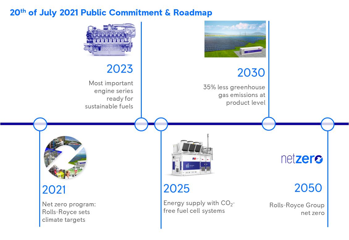
Figure 1: NetZero program at Rolls-Royce Power Systems
Figure 1: NetZero program at Rolls Royce Power Systems
Regarding marine high-power applications, several GHG mitigation measures summarized in [3], like speed reduction, improved hydrodynamics and improved propulsion systems including after treatment measurements, are possible. However, the measurement with the highest GHG emissions reduction potential and the only one to reach zero emission shipping represents the transformation to renewable CO2 neutral energy carriers. Therefore, in the mid to long term a strong substitution of fossil fuels by renewable fuels is required to reach the GHG reduction goals. To meet the IMO goals a mixture of technical improvements increasing energy efficiencies and the substitution of fossil oil by low- and zero-carbon fuel alternatives are required as forecasted by DNV-GL [4]. This will imply a massive fuel switch and uptake of alternative fuels which will have to overcome significant barriers like technical readiness of the propulsion system, regulation and safety issues, onboard fuel storage, fuel availability, competitive prices, and bunkering infrastructure. Biofuels and complete electrification will play a limited role in the maritime sector. Complete electrification is only applicable for short-sea vessels. Production capacity of biofuels is currently ramped up, however it will not be able to meet the demands of all sectors due to limited amount of sustainable feedstocks. In contrast to that, a severe market ramp-up of e-fuels is forecasted from 2030 onwards. Low carbon fuels which are electro-based fuels (e-fuels) like e-hydrogen, e-ammonia, e-methanol or e-MGO will cover the largest share of the maritime energy demand in the long term and play a crucial role. Overall, the fuel roadmap is becoming significantly more heterogeneous, requiring new propulsion and storage technologies for different use cases and there will be no “one fits all solution” in place.
Regarding marine high power applications, several GHG mitigation measures summarized in [3], like speed reduction, improved hydrodynamics and improved propulsion systems including after treatment measurements, are possible. However, the measurement with the highest GHG emissions reduction potential and the only one to reach zero emission shipping represents the transformation to renewable CO2 neutral energy carriers. Therefore, in the mid to long term a strong substitution of fossil fuels by renewable fuels is required to reach the GHG reduction goals. To meet the IMO goals a mixture of
2. e-fuels: renewable electricity-based fuel production
E-fuels or electrofuels are synthetic renewable energy carriers that are produced from renewable electricity via electrolysis of water and optional further fuel synthesis with carbon dioxide or nitrogen. Nitrogen and carbon dioxide can be separated from the air. While nitrogen capture in air separation units is state-of-the-art, CO2 separation from the air, so called direct air capture (DAC), is under development and suffers from high energy consumption and high space requirements due to the low CO2 concentration in the air. Beside DAC also CO2 separation from concentrated point sources like biomethane upgrading units or other biogenic processes
Conference Paper 117
as well as industrial processes like cement or steel production can be used. The main e-fuels are hydrogen, e-ammonia, e-methanol, e-methane and e-diesel.
Compared to direct electric propulsion, the e-fuel pathway achieves significantly lower wellto-wheel efficiencies (Figure 2). However, e-fuels have the advantage that they can be globally traded and imported due to the high energy density. Therefore, e-fuels will be produced at locations with superior renewable energy potential with low levelized costs of electricity and a high-capacity utilization. This results in comparable overall energy harvesting ratios as for the electric propulsion pathway based on locally produced electricity in Germany. Additionally, for some of the e-fuels required bunkering, transportation and distribution infrastructure is existing as energy carriers like ammonia, methanol, methane or natural gas respectively and diesel are globally traded already today. In comparison to biogenic fuels, e-fuels offer a much higher scale-up potential in conjunction with the expansion of renewable energies.
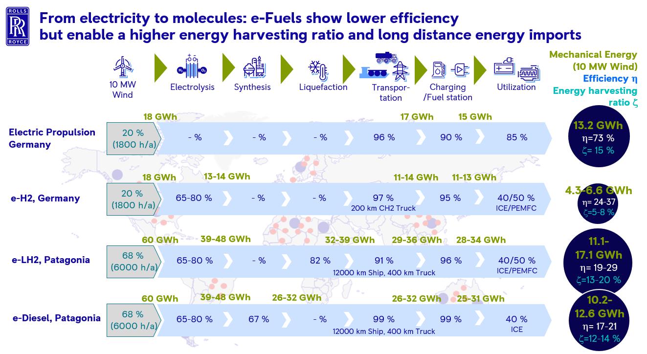
3. Comparison of alternative fuel options
As discussed in the previous sections, alternative fuels play the central lever for the realization of (net) zero emission high power propulsion systems. The optimum sustainable fuel option of the future is dependent on various criteria and will vary strongly for different applications and use cases. One key criteria of fuels represent the gravimetric and volumetric energy density, as space and weight of mobile applications is limited. In this context, the space requirement and the weight including the fuel storage and on a more detailed level, the integrability in the mobile application must be considered. Regarding energy density, all the alternative fuels are inferior to diesel and the space requirement for fuel storage at least doubles or the operation range is halved for methanol and e-LCH4 followed by ammonia and liquid hydrogen reaching about one third of the operation range of diesel. Due to the low energy density batteries and compressed hydrogen are only applicable for short-sea vessels, where reduced operation range with shorter bunkering intervals is possible. Beside the energy density, the availability of alternative fuels, infrastructure as well as fuel prices play a central role for their market ramp up. Biofuels are not yet widely available and are limited in quantity due the limitations in sustainable biomass. Because of that, it is expected that from 2030 to 2035 on e-fuels will significantly ramp up driven by falling prices of renewable electricity and reduced investment costs due to the scale-up of the technology. The local availability of hydrogen will depend strongly on the
3. Comparison of alternative fuel options
As discussed in the previous sections, alternative fuels play the central lever for the realization of (net) zero emission high power propulsion systems. The optimum sustainable fuel option of the future is dependent on various criteria and will vary strongly for different applications and use cases. One key criteria of fuels represent the gravimetric and volumetric energy density, as space and weight of mobile applications is limited. In this context, the space requirement and the weight including the fuel storage and on a more detailed level, the integrability in the mobile application must be considered. Regarding energy density, all the alternative fuels are inferior to diesel and the space requirement for fuel storage at least doubles or the operation range is halved for methanol and e LCH4 followed by ammonia and liquid hydrogen reaching about one third of the operation range of diesel. Due to the low energy density batteries and compressed hydrogen are only applicable for short sea vessels, where reduced operation range with shorter bunkering intervals is possible. Beside the energy density, the availability of alternative fuels, infrastructure as well as fuel prices play a central role for their market ramp up. Biofuels are not yet widely available and are limited in quantity due the limitations in sustainable biomass. Because of that, it is expected that from 2030 to 2035 on e-fuels will significantly ramp up driven by falling prices of renewable electricity and reduced investment costs due to the scale up of the technology. The local availability of hydrogen will depend strongly on the buildup of hydrogen pipeline networks like the European H2 Backbone as other transportation modes of compressed hydrogen are not competitive. The transportation of liquid hydrogen is in the pilot phase with the Kawasaki Heavy Industries’ Suiso Frontier being in operation since this year with a capacity of 75 t
Conference Paper 118
Figure 2: Comparison of energy efficiency and harvesting ratio of e-Fuel and direct electrification
Figure 2: Comparison of energy efficiency and harvesting ratio of e Fuel and direct electrification
ons
energy hot spots with low electricity generation costs and high capacity utilization, internal analysis by Rolls Royce expect e fuels to become competitive with biofuels by 2030.
buildup of hydrogen pipeline networks like the European H2 Backbone as other transportation modes of compressed hydrogen are not competitive. The transportation of liquid hydrogen is in the pilot phase with the Kawasaki Heavy Industries’ Suiso Frontier being in operation since this year with a capacity of 75 tons [5]. In contrast to that, transportation of ammonia, methanol and LNG by ship is well experienced and bunkering infrastructure is already in place at many sites. Several projects for the production of e-ammonia and e-methanol are announced, in construction or already in operation. IEA lists 54 projects for e-ammonia and 31 projects for e-methanol with the aim to ramp up production up to the GW-range within the next decade [6]. Based on a massive ramp up of production capacity at renewable energy hot spots with low electricity generation costs and high-capacity utilization, internal analysis by Rolls-Royce expect e-fuels to become competitive with biofuels by 2030.
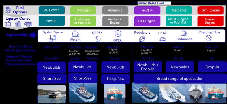
Beside the production cost, the fuel prices for specific applications depend on costs for distribution, refueling and taxes. Based on the assumption of a H2 pipeline network being in place in the midterm, H2 will be the most cost effective chemical energy carrier followed by ammonia and methanol. Despite rising CO2 taxes, alternative renewable fuels will remain more expensive compared to fossil diesel in the midterm (Figure 3). This gap must be closed by measurements like Carbon Contracts for Differences (CCfD) to ramp up renewable fuel production which will boost GHG emissions reduction in all sectors. To access the potential of alternative renewable fuels for specific applications in detail, technoeconomic analysis based on defined use cases are necessary.
Beside the production cost, the fuel prices for specific applications depend on costs for distribution, refueling and taxes. Based on the assumption of a H2 pipeline network being in place in the midterm, H2 will be the most cost-effective chemical energy carrier followed by ammonia and methanol. Despite rising CO2 taxes, alternative renewable fuels will remain more expensive compared to fossil diesel in the midterm (Figure 3). This gap must be closed by measurements like Carbon Contracts for Differences (CCfD) to ramp up renewable fuel production which will boost GHG emissions reduction in all sectors. To access the potential of alternative renewable fuels for specific applications in detail, technoeconomic analysis based on defined use cases are necessary.
Figure 3: Comparison of alternative renewable fuel options
4. Technoeconomic analysis of propulsion solutions
The previous section described various alternative fuels and their production paths for high power applications. These fuels in turn enable various propulsion technologies. This results in countless combinations of fuel and propulsion technologies that could be relevant in future. To derive these combinations systematically, we have developed a morphological box (see Figure 4). This allows different energy system configurations, including energy source, main energy carrier / fuel and main energy storage, to be combined with different propulsion system configurations, including overall architecture, energy transmission, and main energy converters. As an example, the diesel-mechanical internal combustion engine (ICE) system architecture is shown in Figure 4, where fossil diesel (liquid at ambient temperature), is converted to mechanical energy by an internal combustion engine (self-igniting) in a single drive train concept. By following different paths in the morphological box, relevant system architectures can be systematically derived, ensuring that no combination (system architecture) is overlooked.
4. Technoeconomic analysis of propulsion solutions
The previous section described various alternative fuels and their production paths for high power applications. These fuels in turn enable various propulsion technologies. This results in countless combinations of fuel and propulsion technologies that could be relevant in future. To derive these combinations systematically, we have developed a morphological box (see Figure 4). This allows different energy system configurations, including energy source, main energy carrier / fuel and main energy storage, to be combined with different propulsion system configurations, including overall architecture, energy transmission, and main energy converters. As an example, the diesel-mechanical internal combustion engine (ICE) system architecture is shown in Figure 4, where fossil diesel (liquid at ambient temperature), is converted to mechanical energy by an internal combustion engine (self igniting) in a single drive train concept. By following different paths in the morphological box, relevant system architectures can be systematically derived, ensuring that no combination (system architecture) is overlooked.
Conference Paper 119
Figure 3: Comparison of alternative renewable fuel options
For potential users of these alternative energy and propulsion system solutions, it is important to find out which solutions best fit their requirements, while for manufacturers it is important to find out which solutions are attractive to customers. For both, therefore, model-based techno-economic analyses are key. It should be noted that the suitability of alternative system architectures depends heavily on the customer’s specific use case. In the maritime industry, for example, a tugboat has different requirements than a luxury yacht. While the former requires low investment costs and low total cost of ownership and thus high efficiency, the latter requires low volume (and low mass). Therefore, to determine the future potential of alternative system architectures, it is crucial to compare them across a wide range of applications and use cases. We have developed a systematic benchmarking approach (see Figure 5), that begins with a thorough analysis of applications and use cases, including load profile analyses and intensive discussions with customers and experts, followed by intensive technology scanning and screening that identifies and characterizes current and emerging (energy and propulsion) technologies. The results are collected in a comprehensive technology database that contains technical and cost information on the relevant energy storage and propulsion technology components. It also contains projections (with different scenarios) for future cost development in terms of fuels on the one hand and technical components on the other hand. This step is complemented by knowledge screening and leads to architecture ideation, where potential architectures are collected. In the next step, a limited number of attractive system architectures are refined and dimensioned according to relevant load profiles and finally benchmarked in the architecture evaluation. Relevant benchmark criteria are volume, weight, investemt and fuel cost.
For potential users of these alternative energy and propulsion system solutions, it is important to find out which solutions best fit their requirements, while for manufacturers it is important to find out which solutions are attractive to customers. For both, therefore, model-based techno-economic analyses are key. It should be noted that the suitability of alternative system architectures depends heavily on the customer's specific use case. In the maritime industry, for example, a tugboat has different requirements than a luxury yacht. While the former requires low investment costs and low total cost of ownership and thus high efficiency, the latter requires low volume (and low mass). Therefore, to determine the future potential of alternative system architectures, it is crucial to compare them across a wide range of applications and use cases. We have developed a systematic benchmarking approach (see Figure 5), that begins with a thorough analysis of applications and use cases, including load profile analyses and intensive discussions with customers and experts, followed by intensive technology scanning and screening that identifies and characterizes current and emerging (energy and propulsion) technologies. The results are collected in a comprehensive technology database that contains technical and cost information on the relevant energy storage and propulsion technology components. It also contains projections (with different scenarios) for future cost development in terms of fuels on the one hand and technical components on the other hand. This step is complemented by knowledge screening and leads to architecture ideation, where potential architectures are collected. In the next step, a limited number of attractive system architectures are refined and dimensioned according to relevant load profiles and finally benchmarked in the architecture evaluation. Relevant benchmark criteria are volume, weight, investemt and fuel cost.
Conference Paper 120
Figure 4: Morphological box of alternative system architectures with different energy and propulsion solutions
Figure 4: Morphological box of alternative system architectures with different energy and propulsion solutions
Electric motor Electrical Fossil Biogenic Diesel Methane Ammonia Methanol Liquid Main energy storage Liquefied Compressed 380 bar Mechanical Transmission SystemConfiguration SystemElement Main energy carrier Hydrogen HVO Compressed 500 bar Energy system Propulsion system OME/ DME Energy source Mix Renewableelectricity Electricity Battery Serial hybrid Parallel hybrid Single powertrain Architecture Main energy converters Internal combustion engine CI Fuel cell Internal combustion engine SI
The benchmark results are available at a very detailed level showing the individual contribution of single components, such as main energy converter (ICE / Fuel Cell, FC), exhaust gas treatment (selective, catalytic reduction, SCR), electric machine, auxiliary power unit, primary energy storage, high power and high energy battery, methanol reformer etc. to the overall key performance indicators (KPI) (volume, mass, CAPEX, CAPEX + fuel costs). Figure 6 shows exemplary results of CAPEX and fuel costs for a harbor tug. Other use cases we have analyzed are conventional ferries, fast ferries, displacement yachts, semi-displacement yachts, crew transfer vessels for offshore wind farms, fast support vessels amongst others. In this way, the suitability of the system architectures for specific applications and use cases, the levers for each KPI, and future technology development targets for individual components can be determined. This enables strategic decisions for both users and manufacturers of alternative fuel and propulsion solutions.
The benchmark results are available at a very detailed level showing the individual contribution of single components, such as main energy converter (ICE / Fuel Cell, FC), exhaust gas treatment (selective, catalytic reduction, SCR), electric machine, auxiliary power unit, primary energy storage, high power and high energy battery, methanol reformer etc. to the overall key performance indicators (KPI) (volume, mass, CAPEX, CAPEX + fuel costs). Figure 6 shows exemplary results of CAPEX and fuel costs for a harbor tug. Other use cases we have analyzed are conventional ferries, fast ferries, displacement yachts, semi displacement yachts, crew transfer vessels for offshore wind farms, fast support vessels amongst others. In this way, the suitability of the system architectures for specific applications and use cases, the levers for each KPI, and future technology development targets for individual components can be determined. This enables strategic decisions for both users and
of single components, such as main energy converter (ICE / Fuel Cell, FC), exhaust gas treatment (selective, catalytic reduction, SCR), electric machine, auxiliary power unit, primary energy storage, high power and high energy battery, methanol reformer etc. to the overall key performance indicators (KPI) (volume, mass, CAPEX, CAPEX + fuel costs). Figure 6 shows exemplary results of CAPEX and fuel costs for a harbor tug. Other use cases we have analyzed are conventional ferries, fast ferries, displacement yachts, semi-displacement yachts, crew transfer vessels for offshore wind farms, fast support vessels amongst others. In this way, the suitability of the system architectures for specific applications and use cases, the levers for each KPI, and future technology development targets for individual components can be determined. This enables strategic decisions for both users and manufacturers of alternative fuel and propulsion solutions.
Figure 6: Benchmark results of CAPEX + fuel costs for the harbor tug use case for the year 2025
Figure 6: Benchmark results of CAPEX + fuel costs for the harbor tug use case for the year 2025
Figure 6: Benchmark results of CAPEX + fuel costs for the harbor tug use case for the year 2025
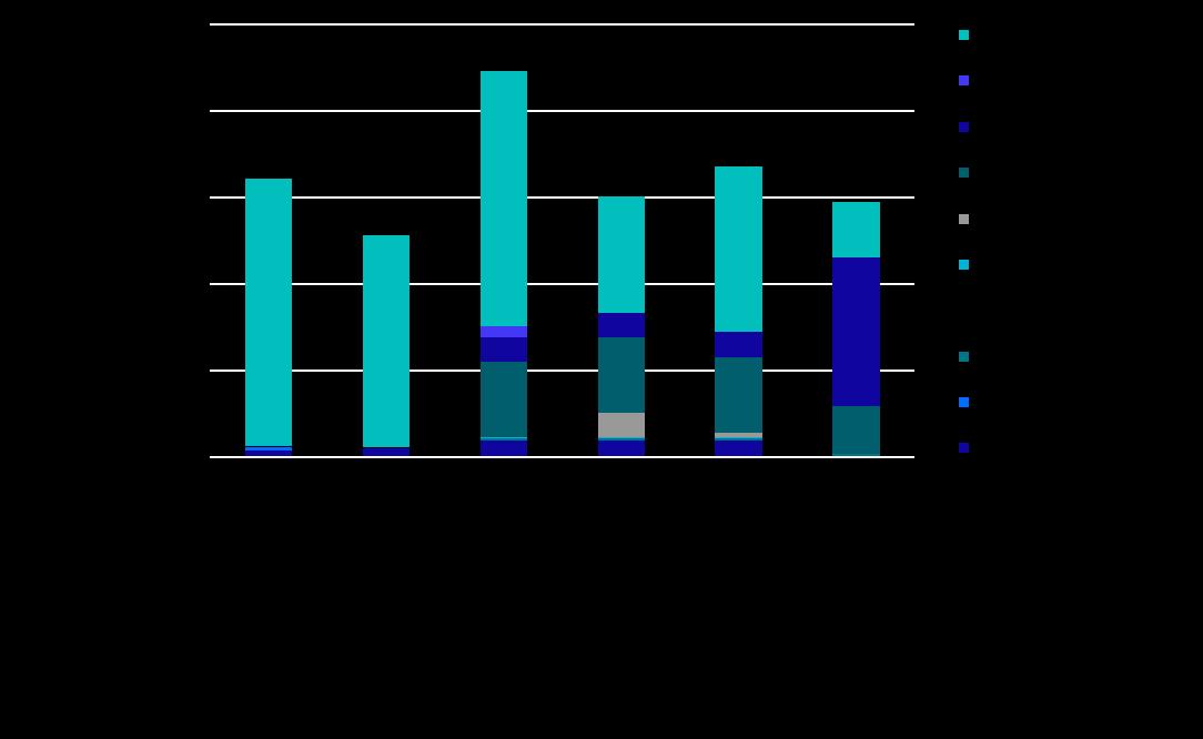
5. Development of alternative mtu propulsion solutions
5. Development of alternative mtu propulsion solutions
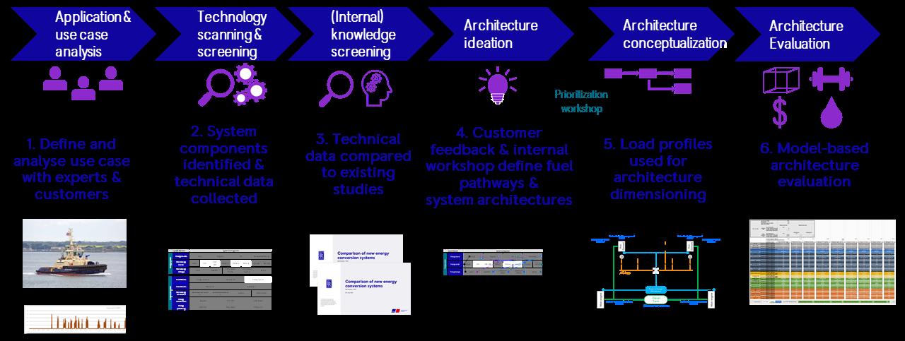
121
As a result of in-depth technoeconomic analysis of various use cases, methanol and fuel cell solutions are revealed as attractive options for marine applications.
5. Development of alternative mtu propulsion solutions
Figure 7 shows the benefits and challenges of the medium methanol. The composition of methanol leads to a lower CO2 level and less air demand. As mentioned above about twice the tank volume is necessary compared to diesel for equivalent range coverage. Methanol offers high efficiency potential and the utilization in variant combustion concepts. Mixture formation and cold start behavior is challenging due to high enthalpy of vaporization. Methanol will impact the tribology on the moving parts of the combustion chamber as well as the entire lubrication system due to the risk of oil dilution. Methanol as a low flashpoint fuel requires a special focus on safety for handling, storage, and operation. As most regulations are still interim agreements, concepts need to be developed in collaboration with marine class societies. Methanol is water soluble and therefor limits the environmental impact in case of any undesired contamination.
As a result of in-depth technoeconomic analysis of various use cases, methanol and fuel cell solutions are revealed as attractive options for marine applications.
Figure 7 shows the benefits and challenges of the medium methanol. The composition of methanol leads to a lower CO2 level and less air demand. As mentioned above about twice the tank volume is necessary compared to diesel for equivalent range coverage. Methanol offers high efficiency potential and the utilization in variant combustion concepts. Mixture formation and cold start behavior is challenging due to high enthalpy of vaporization. Methanol will impact the tribology on the moving parts of the combustion chamber as well as the entire lubrication system due to the risk of oil dilution. Methanol as a low flashpoint fuel requires a special focus on safety for handling, storage, and operation. As most regulations are still interim agreements, concepts need to be developed in collaboration with marine class societies. Methanol is water soluble and therefor limits the environmental impact in case of any undesired contamination.
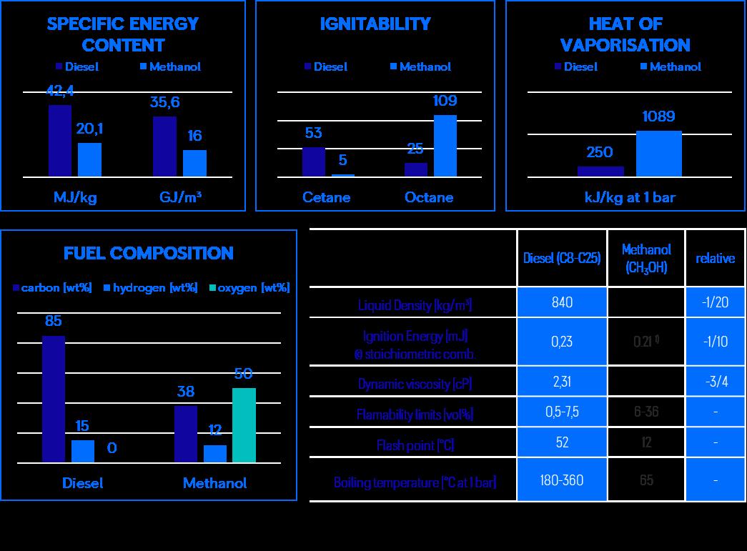
Figure 7: Material properties of methanol compared to diesel
Figure 7: Material properties of methanol compared to diesel
Based on the properties of methanol as a fuel and the requirements of potential marine applications engine concepts have been developed and evaluated. Figure 8 pictures the major development areas. Most certainly, the fuel system technology and the combustion concept are in focus. This will also affect the entire engine layout and component design, as well as the engine control management. The trade-off between engine performance, exhaust emissions, system complexity and thereby costs must be aligned with high reliability of the entire propulsion system for demanding operation, also in commercial environment. First test indicating promising results for IMO Tier III applications.
Based on the properties of methanol as a fuel and the requirements of potential marine applications engine concepts have been developed and evaluated. Figure 8 pictures the major development areas. Most certainly, the fuel system technology and the combustion concept are in focus. This will also affect the entire engine layout and component design, as well as the engine control management. The trade-off between engine performance, exhaust emissions, system complexity and thereby costs must be aligned with high reliability of the entire propulsion system for demanding operation, also in commercial environment. First test indicating promising results for IMO Tier III applications.
Conference Paper 122
Figure 8: Main impact of Methanol on engine subsystems visualized on a mtu S4000 Diesel engine
Increasing interest in complete emission free propulsion is also driving the development of fuel cell (FC) propulsion for marine applications. Fuel cell component manufacturers move to larger components and FC module sizes to increase power density, make use of production cost advantages and also address new market segments. Marine applications with higher power requirements (>800kW) will benefit from larger fuel cells as this reduces the effort on the system integration side. Nevertheless, the development of marine fuel cell solutions brings some new technical challenges: Using fuel cells for propulsion in a vessel requires the implementation of an electric power transmission and electric drive of the propellerswhich in most marine applications is not the standard today and can be seen as a substantial change in vessel propulsion, thus also providing new degrees of freedom on future vessel design. In general, the introduction of the electric power transmission provides a flexible platform to include variable numbers of combustion engine driven gensets, batteries or fuel cells which creates a flexible solution on a system level to implement different sustainable solutions over the 30+ years lifetime of a vessel. Fuel cell solutions always include high voltage batteries for providing starting energy to the fuel cells, support on transient requirements and ensuring DC-bus stability. Using fuel cells in a propulsion system usually favors the use of high c-rate batteries, enable a more constant power use of the fuel cells, while covering the transient requirements of the application with the battery. Today, available marine batteries are more located on the lower c-rate end, so that there is potential for further weight and volume reduction with the use of higher c-rate batteries. Marine FC solutions in the MW power range will use several fuel cell modules in parallel operation. Parallel connection of fuel cells can be challenging due to insulation resistance issues, which implies the use of galvanically isolated DC/DC converters or transformer-based AC isolation. The integration of fuel cells and hydrogen storage in an under-deck installation, needs careful engineering on safety related topics and close collaboration with marine class society.
Increasing interest in complete emission free propulsion is also driving the development of fuel cell (FC) propulsion for marine applications. Fuel cell component manufacturers move to larger components and FC module sizes to increase power density, make use of production cost advantages and also address new market segments. Marine applications with higher power requirements (>800kW) will benefit from larger fuel cells as this reduces the effort on the system integration side. Nevertheless, the development of marine fuel cell solutions brings some new technical challenges: Using fuel cells for propulsion in a vessel requires the implementation of an electric power transmission and electric drive of the propellers - which in most marine applications is not the standard today and can be seen as a substantial change in vessel propulsion, thus also providing new degrees of freedom on future vessel design. In general, the introduction of the electric power transmission provides a flexible platform to include variable numbers of combustion engine driven gensets, batteries or fuel cells which creates a flexible solution on a system level to implement different sustainable solutions over the 30+ years lifetime of a vessel. Fuel cell solutions always include high voltage batteries for providing starting energy to the fuel cells, support on transient requirements and ensuring DC -bus stability. Using fuel cells in a propulsion system usually favors the use of high c rate batteries, enable a more constant power use of the fuel cells, while covering the transient requirements of the application with the battery. Today, available marine batteries are more located on the lower c rate end, so that there is potential for further weight and volume reduction with the use of higher c rate batteries. Marine FC solutions in the MW power range will use several fuel cell modules in parallel operation. Parallel connection of fuel cells can be challenging due to insulation resistance issues, which implies the use of galvanically isolated DC/DC converters or transformer based AC isolation. The integration of fuel cells and hydrogen storage in an under deck installation, needs careful engineering on safety related topics and close collaboration with marine class society.
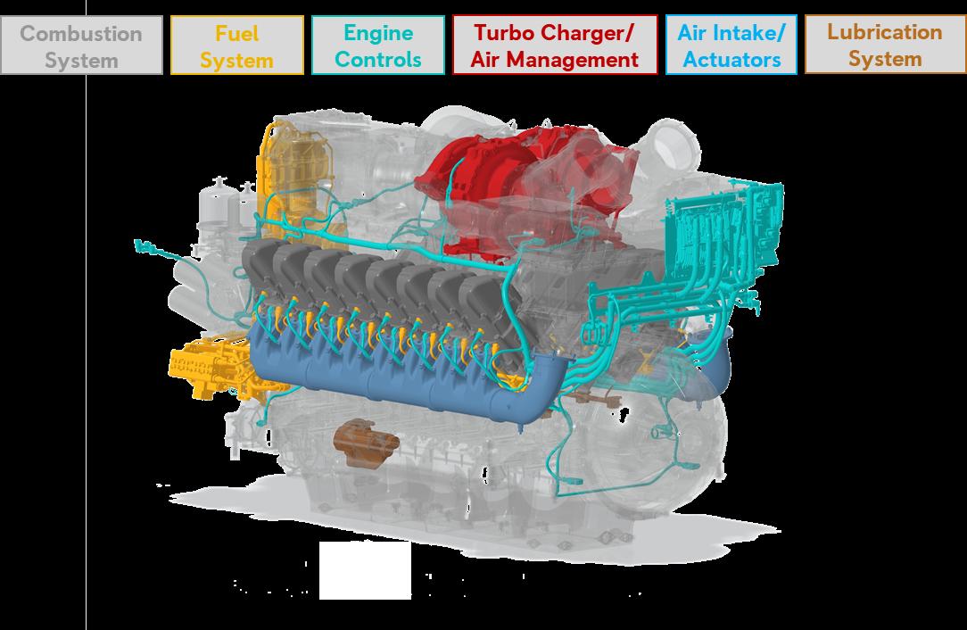
Conference Paper 123
Figure 8: Main impact of Methanol on engine subsystems visualized on a mtu S4000 Diesel engine
Rolls-Royce Power Systems meets that challenge in developing fuel cell marine solutions based on its long experience in marine propulsion systems using different fuel cell technologies.
Rolls Royce Power Systems meets that challenge in developing fuel cell marine solutions based on its long experience in marine propulsion systems using different fuel cell technologies.
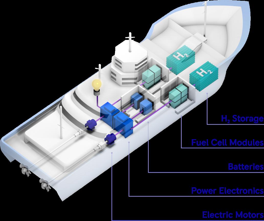
Figure 9: Illustrative integration of a hydrogen fuel cell based propulsion system in marine applications
Figure 9: Illustrative integration of a hydrogen fuel cell based propulsion system in marine applications
6. Conclusion
6. Conclusion
Alternative fuels and especially e-fuels produced by Power-to-X technology are forecasted to be the dominant measure for the reduction of GHG emissions in the maritime sector. These fuels are offering high energy density, a strong reduction in net GHG emissions, utilization of existing infrastructure and a huge scale-up potential in conjunction with the expansion of renewable energies. While Power-to-X suffers from lower efficiency compared to the direct electrification pathway, it enables the utilization of renewable energy hot spots resulting in a comparable harvesting factor to direct electrification. By global trading of renewable e-fuels and a massive scale-up of production site by 2030, e-fuels are becoming competitive to biofuels by 2030 with further cost reduction potential in the further course. Nevertheless, alternative fuels/e-fuels will be more expensive than diesel in the midterm and additional measure like carbon contracts for difference (CCfD) are required to ramp up their production. Very promising e-fuels are methanol to defossilize maritime propulsion and hydrogen to reach zero emission solutions. Generating propulsion from renewable e-methanol based on green hydrogen within an internal combustion engine offer the possibility of CO2-neutrality. Even though methanol is limited to about half the energy density of diesel it seems a promising solution for high demanding and high energy consuming applications compared to other e-fuels. Challenges in transportation, handling, bunkering are easier to overcome due to its liquid state and a worldwide availability of grey methanol as chemical product already today. To answer the increasing demand in marine industry - methanol and fuel cell solutions need to become a part of the maritime propulsion portfolio.
Alternative fuels and especially e fuels produced by Power to X technology are forecasted to be the dominant measure for the reduction of GHG emissions in the maritime sector. These fuels are offering high energy density, a strong reduction in net GHG emissions, utilization of existing infrastructure and a huge scale-up potential in conjunction with the expansion of renewable energies. While Power -to-X suffers from lower efficiency compared to the direct electrification pathway, it enables the utilization of renewable energy hot spots resulting in a comparable harvesting factor to direct electrification. By global trading of renewable e fuels and a massive scale up of production site by 2030, e fuels are becoming competitive to biofuels by 2030 with further cost reduction potential in the further course. Nevertheless, alternative fuels/e-fuels will be more expensive than diesel in the midterm and additional measure like carbon contracts for difference (CCfD) are required to ramp up their production. Very promising e-fuels are methanol to defossilize maritime propulsion and hydrogen to reach zero emission solutions. Generating propulsion from renewable e methanol based on green hydrogen within an internal combustion engine offer the possibility of CO2 neutrality. Even though methanol is limited to about half the energy density of diesel it seems a promising solution for high demanding and high energy consuming applications compared to other e fuels. Challenges in transportation, handling, bunkering are easier to overcome due to its liquid state and a worldwide availability of grey methanol as chemical product already today. To answer the increasing demand in marine industry methanol and fuel cell solutions need to become a part of the maritime propulsion portfolio.
Conference Paper 124
Literature
[1] IMO 2018, Adoption of the initial IMO strategy on reduction of GHG emissions from ships and existing IMO activity related to reducing GHG emissions in the shipping sector, Note by the International Maritime Organization to the UNFCCC Talanoa Dialogue, 18. April 2018.
[2] Rolls-Royce 2021, Leading the transition to net zero carbon, available from https://www.rolls-royce.com/~/media/Files/R/Rolls-Royce/documents/others/rr-netzero-full-report.pdf
[3] DNV 2021, Maritime Forecast to 2050, Energy Transition Outlook 2021.
[4] DNG 2021, Energy Transition Outlook 2021
[5] Retrieved online 7/20/2022: https://maritime-executive.com/article/suiso-frontierdeparts-australia-with-first-liquid-hydrogen-shipment
[6] IEA 2021, Hydrogen project database, available from https://www.iea.org/data-andstatistics/data-product/hydrogen-projects-database
Conference Paper 125
FRANCISKA KJELLSTRÖM
Global Application Manager, Marine Fuels, Alfa Laval
BIOGRAPHY
Franciska Kjellström started at Alfa Laval in 2015 and today she is responsible for development of the Adaptive Fuel line, driving process optimization and new technology solutions for fuel treatment as well as various business development projects within the Marine Separation product portfolio.

ABSTRACT
A major shift from traditional fossil fuels to renewable alternatives is required to reach local and IMO emission reduction targets, as 99.9% of today’s marine fuels are still fossil based.
Both new technologies and fuel types are required for the change. In a transition phase, flexi bility will continue to become more important, and the design for any new ship in the coming years should consider how it can switch to low- and zero-emission fuels.
Several different fuel types are being discussed as potential replacements for fossil fuels, in cluding green and blue hydrogen, ammonia, methanol, and biogas. However, the supply infra structure and technological readiness for these fuels remain to be developed. Several biofuel alternatives are already available today, and more variations are expected to become available soon.
Some alternative fuels are very similar to petroleum fuels and are consequently spoken of as drop-in fuels. However, most alternative fuels, including drop-in fuels, behave differently and require adaptation of the fuel handling and treatment systems, as well as operational proce dures. Biofuels, which include biodiesels and renewable diesels, differ from fossil fuels in both chemical and physical properties.
There is currently a high interest in biofuels including FAME and HVO as well as methanol. Ships can already bunker these fuels and engine combustion technology is available. We will discuss the impact of various new fuel types on the ship’s fuel cleaning and fuel supply systems.
Speaker
126
On the Way to Zero Emissions: Considerations for the Design and Operation of Fuel Treatment Systems
Limiting greenhouse gas (GHG) emissions from international shipping and fulfilling IMO’s decarbonization goals can be done by using biofuels or biofuel blends, among many alternatives. Today there is a wide range of biofuels, including FAME, HVO, pyrolysis oils, e-fuels and alcohols such as ethanol and methanol. Several biofuel alternatives are already available today, and more are expected to become available in the future.
Some alternative fuels are very similar to petroleum fuels and are consequently spoken of as drop-in fuels. However, most alternative fuels, including drop-in fuels, behave differently and require adaptation of the fuel handling and treatment systems, as well as operational procedures. Biofuels, which include biodiesels and renewable diesels, differ from fossil fuels in both chemical and physical properties.
For a fuel such as methanol the need for treatment and improvement of its characteristics before it reaches the methanol-fuelled engine is different compared to fossil fuels. Instead, the important considerations for methanol equipment are focused on safe handling onboard and ensuring operation in a controlled and safe environment. Alfa Laval has methanol fuel supply systems already installed on more than 25 vessels and years of experience of supporting customers in operation. Heading into the future, new solutions are also under development to comply with the methanol fuelled engines of tomorrow.
In the following article we cover considerations in our fuel treatment systems concerning biofuels and biodiesels. Many biofuels have been adopted by the automotive industry, and based on experience, Fatty acid methyl ester (FAME) and Hydrogenated Vegetable Oil (HVO), are believed to have the greatest potential for application in marine diesel engines. FAME is the most widely available type of biodiesel in the industry and often blended with regular marine diesel oil. Today’s experience of biodiesel use in ships and fuel treatment systems is positive as separators, fuel conditioning systems and filters are handling fuel blends well. Some adaptations are required for HVO, such as low-density related aspects for separators with gravity discs. Other considerations to be addressed are operational procedures, attention to long term use and impact as well as impact of potential increase of biodiesel content in fuel blends in the future.
FAME is derived from lipids such as vegetable oils, animal fats or waste cooking oils through a transesterification process, in which triglyceride from the feedstock reacts with methanol in the presence of a catalyst, forming the mixture of fatty acid esters and glycerol.
A cost comparison between biofuels and fossil fuel oils shows that biofuels are more expensive. However, FAME and HVO prices are volatile and highly dependent on the price of the feedstock, which is largely independent from the crude oil price. Stricter legislations are expected to encourage the transition towards decarbonization, and the marine fuel specification standard ISO 8217 is currently being evaluated whether to allow higher FAME ratios in residual fuels in the upcoming revision. Today the maximum concentration of a FAME biodiesel in a blend with fossil diesel is 7%, without modifications needed on the engine or fuel treatment systems.
The main differences between FAME and HVO are their chemical compositions, storage qualities and impact of cold weather on the fuel characteristics. The required tank volume plays an important part in the evaluation of future fuels. Although HVO is a low-density fuel, it has a relatively high volumetric energy content and hence requires less storage space than FAME.
Conference Paper 127
The use of FAME and HVO will place new requirements on both equipment and operator. The process of transesterification introduces oxygen into the fuel, which may cause issues with freezing temperature, microbial growth, separation during storage and emissions.
Renewable diesels such as HVO, just like petroleum fuels, consist of hydrocarbons. However, the hydrocarbons in renewable diesels are mainly paraffins, whereas petroleum fuels comprise a mix of several types of hydrocarbons, including paraffinic, naphthenics and aromatic molecules. Thus, renewable diesels present new challenges. Renewable diesels have low density, for example, which puts additional requirements on the fuel treatment system.
Special attention should be considered for operation onboard, including fuel storage and treatment. Alfa Laval recommends taking fuel samples of each bunker and send them for laboratory analysis.
Challenges and considerations related to the use of biofuels such as FAME and HVO can be summarized to the following:
5 Temperatures and flow properties. As with other fuels, the viscosity of FAME is highly dependent on temperature. Because cold conditions may cause wax precipitation, both the storage and separation temperatures should always exceed the cloud point. In the event that wax crystals appear, FAME must be heated to above the wax melting point in order to regain liquid properties, especially in higher concentrations. Both the cloud point and the wax melting point are dependent on the specific fuel blend and may differ greatly between blends.
Note that while a high enough temperature is required, temperatures that are too high may cause the fuel to polymerize, meaning that it becomes a gum-like material. It is therefore important to avoid concentrated spots of higher temperature, i.e. hotspots.
5 Water and microbial growth. Accumulated water in biodiesel fuel can lead to microbial growth, such as bacteria and fungi. Issues such as excessive sludge formation, clogged filters and piping are related to microbial growth. Microbial contamination can be controlled through the water content. Water risks entering the bunker tank by means of inadequate ventilation or leaking coils, for example. Pockets of water within a tank create the perfect conditions for uncontrollable growth of bacteria and mould, which can be devastating for the fuel. Water should continuously and actively be removed from the storage system, and frequent water level checks are recommended. Note that microbes grow over time, which means that using the fuel as soon as possible is more critical for FAME than for fossil fuels. Reducing microbial growth with biocides is generally not recommended, due to environmental and health concerns. Instead, overall housekeeping of the fuel system is key. Clean tanks, continuous dewatering and control over the separation process allow ship operators to process FAME just like any petroleum fuel.
5 Oxidation stability and degradation. The fuel’s oxidation stability must also be managed. FAME has a lower oxidation stability, meaning it is more prone to degrade over time and form hydroperoxides, aldehydes, carboxylic acids, alcohols and insoluble material. Increased water content accelerates the formation of acidic products, because water facilitates the hydrolysis of esters into carboxylic acids when acids (low pH) or bases (high pH) are present.
The formation of acid groups leads to polarity changes that can affect the fuel’s compatibility with polymer materials. As degradation products and deposits in piping and engines can form, increasing sludge build-up, potentially
Conference Paper 128
clogging filters, separators and injectors and thus compromising operational performance.
This can lead to increased fuel acidity, which could result in corrosion in the fuel system and accumulation of deposits in pumps and injectors. Water’s accelerating effect on the degradation process further underlines the importance of maintaining good fuel system housekeeping, removing water and using the fuel as soon as possible. However, the degradation of FAME is inevitable.
For fuel blends containing FAME concentrations of 0/30/50 v/v %, Alfa Laval has investigated fuel compatibility and the degradative effect on various wetted components made of polymeric materials and steel, such as discs, O-rings and seal rings. Tested fuel blends were shown to be compatible, with no noteworthy forms of degradation evident. However, fuel blends containing higher concentrations of FAME may degrade the components’ materials.
The recommendation is to treat the fuel and use it within a relatively short period of time, eliminating long term storage before use.
5 Corrosion. As mentioned, the acidic products may corrode the fuel system’s components, increasing stress on filters and mesh, damaging fuel pumps, piston rings and injectors. To avoid irreversible damages, corrosion must be monitored continuously, preferably by means of frequent visual inspections. Relevant Alfa Laval equipment offered today, including separators and fuel conditioning systems, can withstand the acidity of all fuel grades specified in ISO 8217. For older equipment of any brand, however, Alfa Laval recommends verifying compatibility with the supplier. For biodiesels in higher concentration, corrosion related issues can multiply. It is important to verify components and material compatibility and endurability in combination with biofuels.
Other aspects to consider include, amongst others, the low density of FAME and HVO compared to fossil-based fuels. Fuel treatment systems and especially separators are designed and sized for specific fuel properties which must be verified for biofuels. In some cases separator components such as gravity discs need to be replaced. Equipment settings should be optimized for FAME and HVO treatment. Such a software change can easily be to add FAME and HVO fuel settings.
FAME’s high flashpoint in combination with a high oxygen content increases both fuel consumption and NOx formation. This leads to quicker accumulation of unspent biofuel, soot in the lubrication oil and NOx in the exhaust. The peak combustion temperature, which affects NOx formation, can be lowered by reducing the injection pressure and retarding injection times. Alfa Laval recommends confirming the specifics with the engine maker.
FAME’s high solvency may also cause deposits within fuel tanks and treatment systems to dislodge, thereby clogging filters. Furthermore, it can degrade rubber parts as well as attacking certain metals.
Overall the recommendation is to be aware of the new challenges that are introduced with new fuel alternatives such as FAME and HVO, followed by proper fuel handling, operation and storage and to verify compatibility of materials and existing equipment with new fuel blends and characteristics.
Flexibility will continue to grow more important, and the design for any new vessel in the coming years should consider how it can switch to low- and zero-emission fuels later on.
Conference Paper 129
LEX NIJSEN
Senior Vice President and Head of Sales 4-Stroke engines for our EMEA region, MAN ES
.
BIOGRAPHY
Lex Nijsen has a long career with MAN Energy Solutions SE in the marine business. MAN ES based in Augsburg Germany is creating solutions for sustainable prosperity.
After studying Marine Engineering in Rotterdam Lex started his career in 1990 sailing onboard tankers on global trade.
In 1996 he started as representative for MAN B&W, selling these products in the BeNeLux.
After joining the MAN company in 2006 Lex founded MAN Diesel & Turbo Benelux and was member of the management team.
In his role as Director of Sales he was responsible for the sale of the complete product portfolio and the service for Turbo Machinery in the BeNeLux countries.

In 2011, Lex moved to Augsburg, Germany to become the Head of Global Sales Medium Speed and three years later as Head of Four-Stroke Marine.
His current position as Vice President is Head of Marine Europe focus on sales Low-, Medium-, and High-speed marine engines.
Speaker
130
Avoiding Stranded Assets
MOTORSHIP 43 2022
Avoiding Stranded Assets
The reduction of greenhouse gas (GHG) emissions in the maritime industry plays an inescapable role in successfully halting global warming. The most recent estimate from an IMO GHG Study 2020 shows that emissions from the maritime sector are increasing and reached almost 3% of world emissions in 2018, [1] following a continued growth path in global shipping. It is estimated to have accounted for 1000 million tons of CO2 equivalent in 2018 [1]. This makes shipping a major contributor to global emissions. The success of the maritime industry’s decarbonization effort depends on various interdependent factors that will determine development of different technologies, including low-carbon fuels and Carbon Capture and Storage (CCS). In 2018 IMO adopted the Initial Strategy [1] to reduce greenhouse gas emissions in marine industries with the aim of becoming carbon neutral as soon as possible, by undertaking the following steps to reduce carbon intensity and GHG emissions compared to 2008 (Figure 1):
The reduction of greenhouse gas (GHG) emissions in the maritime industry plays an inescapable role in successfully halting global warming. The most recent estimate from an IMO GHG Study 2020 shows that emissions from the maritime sector are increasing and reached almost 3% of world emissions in 2018, [ 1] following a continued growth path in global shipping. It is estimated to have accounted for 1000 m illion tons of CO2 equivalent in 2018 [1]. This makes shipping a major contributor to global emissions. The success of the maritime industry’s decarbonization effort depends on various interdependent factors that will determine development of different technologies, including low carbon fuels and Carbon Capture and Storage (CCS)
In 2018 IMO adopted the Initial Strategy [ 1] to reduce greenhouse gas emissions in marine industries with the aim of becoming carbon neutral as soon as possible, by undertaking the following steps to reduce carbon intensity and GHG emissions compared to 2008 (Figure 1):
5 Introduction of EEXI
5 Reduce CO2 emissions as measured by the payload-distance freight metric by 40% by 2030 and 70% by 2050
Introduction of EEXI
Reduce CO2 emissions as measured by the payload distance freight metric by 40% by 2030 and 70% by 2050
5 Reduce total annual GHG emissions in international shipping by 50% by 2050
Reduce total annual GHG emissions in international shipping by 50% by 2050
Currently IMO regulation only focuses on energy efficiency measures and ship emissions. However, to achieve the necessary GHG emission reduction, energy efficiency has to be supplemented by the introduction of alternative fuels with the fuel feedstock supply chain (WTT emission) included in the overall emissions calculation. Along with new initiatives by IMO to adopt lifecycle CO2 and other GHG emissions in evaluations, new specific regulatory legislation has been included in the EU’s ‘Fit for 55’ package proposal. New regulations, published in 2021, integrate the global interactions of different value chains, including biogenic and synthetic fuels including production and storage (WTW emission). One of the objectives of the new FuelEU Maritime regulation proposal is to support the Green Deal target for climate neutrality by 2050.
Currently IMO regulation only focuses on energy efficiency measures and ship emissions. However, to achieve the necessary GHG emission reduction, energy efficiency has to be supplemented by the introduction of alternative fuels with the fuel feedstock supply chain (WTT emission) included in the overall emissions calculation. Along with new initiatives by IMO to adopt lifecycle CO 2 and other GHG emissions in evaluations, new specific regulatory legislation has been included in the EU’s ‘Fit for 55’ package proposal. New regulations, published in 2021, integrate the global interactions of different value chains, including biogenic and synthetic fuels including production and storage (WTW emission). One of the objectives of the new FuelEU Maritime regulation proposal is to support the Green Deal target for climate neutrality by 2050.
Figure 1: IMO regulations
Figure 1: IMO regulations
Figure 2 illustrates the difference in global GHG emission regulation for various fossil and alternative fuels from biogenic and synthetic feedstock. The values are based on the 2021 proposal of the Fit for 55 regulation package. Fehler! Verweisquelle konnte nicht gefunden werden. indicates that the feedstock of a fuel will play a significant role in fuel selection to achieve decarbonization targets.
Figure 2 illustrates the difference in global GHG emission regulation for various fossil and alternative fuels from biogenic and synthetic feedstock. The values are based on the 2021 proposal of the Fit for 55 regulation package. Fehler! Verweisquelle konnte nicht gefunden werden. indicates that the feedstock of a fuel will play a significant role in fuel selection to achieve decarbonization targets.
With the marine industry’s intention to comply with requirements, a high focus on sustainability and decarbonization of supply chains will push international companies to take more aggressive positions and speed up the process of decarbonization. The transition of the marine industry will have a significant impact on asset values and earning capacity.
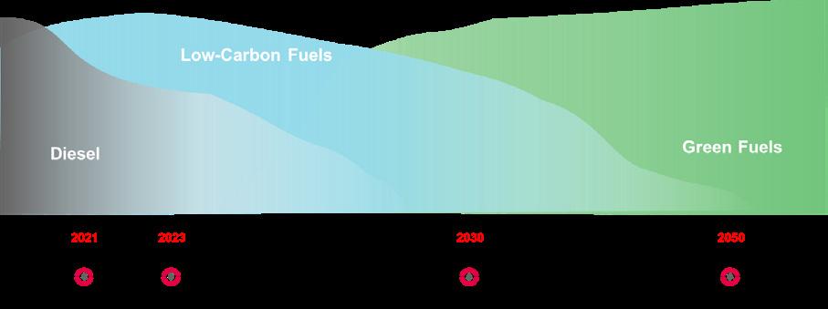
Conference Paper 131
MAN Energy Solutions
2
Avoiding Stranded Assets
MOTORSHIP 43 2022
With the marine industry’s intention to comply with requirements, a high focus on sustainability and decarbonization of supply chains will push international companies to take more aggressive positions and speed up the process of decarbonization. The transition of the marine industry will have a significant impact on asset values and earning capacity.
Figure 2: Well to Tank and Tank to Wake emissions for different fuels (indicative illustration based on [ 2] and authors’ assumptions)
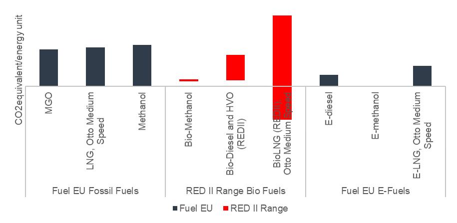
Figure 2: Well-to-Tank and Tank-to-Wake emissions for different fuels (indicative illustration based on [2] and authors’ assumptions)
Currently ship-owners are looking for flexible approaches to commission conventionally powered vessels that are Future Fuel Ready and therefore certain to be capable of operation in the short-term and long-term. Applications with differences in operational profiles and technical requirements may experience challenges in adopting some fuels and technologies. Bunkering frequency, trades and distances are considered to be some of the main constraints in adopting fuels with low energy density. Table 2 highlights trends in adopting gaseous and liquid pathways as well as the possibility of implementing Ship Based Carbon Capture (SBCC) solutions.
Currently ship owners are looking for flexible approaches to commission conventionally powered vessels that are Future Fuel Ready and therefore certain to be capable of operation in the short term and long term. Applications with differences in opera tional profiles and technical requirements may experience challenges in adopting some fuels and technologies. Bunkering frequency, trades and distances are considered to be some of the main constraints in adopting fuels with low energy density. Table 2 highlights trends in adopting gaseous and liquid pathways as well as the possibility of implementing Ship Based Carbon Capture (SBCC) soluti ons.
Application Liquid Gaseous CCUS Trends
Cruise t t t
Application Liquid Gaseous CCUS Trends
Liquid and gaseous pathway
Cruise
Ferry t t t
Liquid and gaseous pathway. Ferry
Liquid and gaseous pathway. Easier to adopt alternative fuels with low energy density due to operation condition
Liquid and gaseous pathway. Easier to adopt alternative fuels with low energy density due to operation condition
Tugs t
Tugs
Cargo
Service vessels
Navy
Liquid pathway with potential for hybrid and electrical solutions.
Cargo t t t
Service Vessels
Navy t
Liquid pathway with potential for hybrid and electrical solutions
Liquid pathway is preferable; gaseous has high potential for some applications. Carbon Capture, Utilization and Storage (CCUS) is possible due to size of some vessels
Liquid pathway is preferable; gaseous has high potential for some applications. Carbon Capture, Utilization and Storage (CCUS) is possible due to size of some vessels
Liquid pathway is preferable. Hydrogen and ammonia are possible.
Liquid pathway is preferable. Hydrogen and ammonia are possible
Standards considerations
Standards considerations
Table 1: Technology adoption by marine application
Table 1: Technology adoption by marine application
Conference Paper 132
MAN Energy Solutions
3
t t
Forecasting the future is a tricky business. Figure 3 shows the fuel price deve lopment and ratios between fuel prices of alternative fuels to MGO over the years 2019 2022. W here even the prices of fossil fuels (which already have a predictable supply situation) show massive fluctuations, f orecasting either the supply and demand or the prevalence of one future fuel option over another is currently impossible.
Forecasting the future is a tricky business. Figure 3 shows the fuel price deve lopment and ratios between fuel prices of alternative fuels to MGO over the years 2019 2022. W here even the prices of fossil fuels (which already have a predictable supply situation) show massive fluctuations, f orecasting either the supply and demand or the prevalence of one future fuel option over another is currently impossible.
Forecasting the future is a tricky business. Figure 3 shows the fuel price development and ratios between fuel prices of alternative fuels to MGO over the years 2019-2022. Where even the prices of fossil fuels (which already have a predictable supply situation) show massive fluctuations, forecasting either the supply and demand or the prevalence of one future fuel option over another is currently impossible.
Figure 3: Fuel Price and Fuel Price Ratio to MGO
Figure 3: Fuel Price and Fuel Price Ratio to MGO
Figure 3: Fuel Price and Fuel Price Ratio to MGO
Regulation has not yet stabilized, however the 2021 package proposal [ 1] has given some boundary conditions against which the options can be tested. Moreover, even with changing targets within this package or through IMO developments, this is exactly the benefit of having options it is possible to react. Figure 4 shows drop in energy percentage for alternative fuels to comply with regulations.
Regulation has not yet stabilized, however the 2021 package proposal [ 1] has given some boundary conditions against which the options can be tested. Moreover, even with changing targets within this package or through IMO developments, this is exactly the benefit of having options it is possible to react. Figure 4 shows drop in energy percentage for alternative fuels to comply with regulations.
Figure 4: Fuel Mix to comply with regulations
Regulation has not yet stabilized, however the 2021 package proposal [1] has given some boundary conditions against which the options can be tested. Moreover, even with changing targets within this package or through IMO developments, this is exactly the benefit of having options – it is possible to react. Figure 4 shows drop-in energy percentage for alternative fuels to comply with regulations.
Figure 4: Fuel Mix to comply with regulations
Figure 4: Fuel Mix to comply with regulations
To address potential uncertainties for shipowners and operators, MAN have analyzed potential scenarios taking current regulations into consideration. Two main pathways have been assessed for liquid (MGO, HFO, LS Fuels)
To address potential uncertainties for shipowners and operators, MAN have analyzed potential scenarios taking current regulations into consideration. Two main pathways have been assessed for liquid (MGO, HFO, LS Fuels)
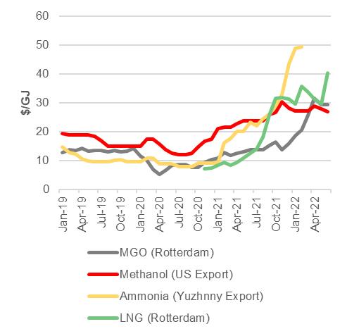
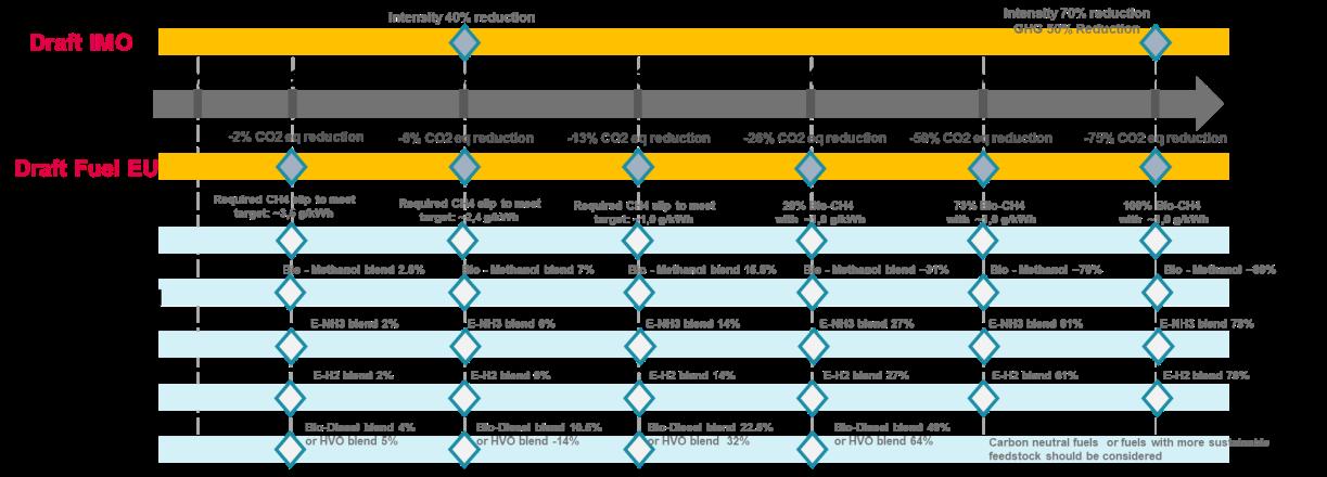
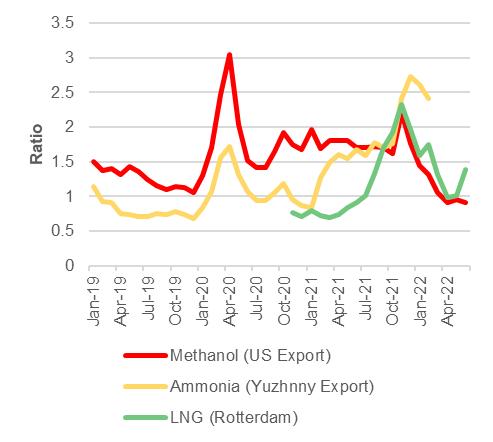
To address potential uncertainties for shipowners and operators, MAN have analyzed potential scenarios taking current regulations into consideration. Two main pathways have been assessed for liquid (MGO, HFO, LS-Fuels) and gaseous (LNG) vessels driven by DF engines. Examples of possible scenarios for DF and liquid engines with potential adoption of different fuel types are given in Figure 4 and Figure 5.
MOTORSHIP 43 2022 4
4
Conference Paper 133
Avoiding
Stranded Assets
MOTORSHIP 43 2022
and gaseous (LNG) vessels driven by DF engines. Examples of possible scenarios for DF and liquid engines with potential adoption of different fuel types are given in Figure 4 and Figure 5
As mentioned, LNG has the potential to reduce CO2 emission by 20% compared to HFO. However, methane emissions during upstream processes and me-thane slip from the combustion process can significantly reduce the decarboni-zation potential of LNG due to its global warming potential. In recent years, MAN has managed to halve the methane slip of 4-stroke engines through improved engine design and will halve it again more than once in the future [4].
As mentioned, LNG has the potential to reduce CO2 emission by 20% compared to HFO. However, methane emissions during upstream processes and me thane slip from the combustion process can significantly reduce the decarboni zation potential of LNG due to its global warming potential. In recent years, MAN has managed to halv e the methane slip of 4 stroke engines through improved engine design and will halve it again more than once in the future [4].
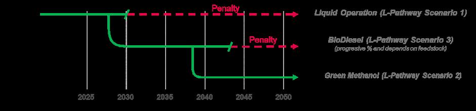
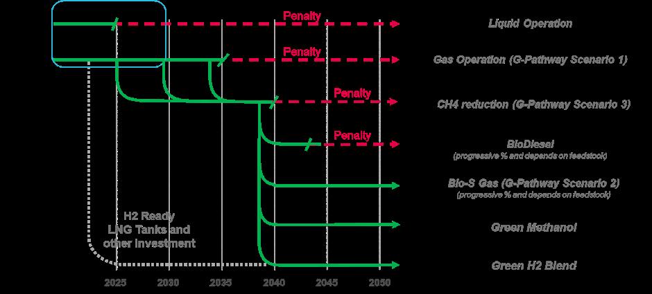
These and other highly advanced tech-nologies will ensure that LNG will repre-sent a solution to comply with regulation for more than 15 years. Based on the current proposal, after that date, drop-In fuels or retrofit of the ships will be re-quired. E-LNG and Bio-LNG represent an alternative perspective as carbon-neutral fuels, with the greatest ad-vantage of compatibility with existing infrastructure and engines, but with anticipated significantly higher costs compared to fossil alternatives. A DF propulsion solution thus provides the largest platform from which to adapt to any potential development in the regulatory and supply environment. 5
These and other highly advanced tech nologies will ensure that LNG will repre sent a solution to comply with regulation for more than 15 years. Based on the current proposal, after that date, drop In fuels or retrofit of the ships will be re quired. E LNG and Bio LNG represent an alternative perspective as carbon neutral fuels, with the greatest ad vantage of compatibility with existing infrastructure and engines, but with anticipated significantly higher costs compared to fossil alternatives. A DF propulsion solution thus provides the largest platform from which to adapt to any potential development in the regulatory and supply env ironment.
Conference Paper 134
Figure 6: Liquid engine decision chart [authors’ illustration]
Figure 5: Decision chart [authors’ illustration]
Figure 6: Liquid engine decision chart [authors’ illustration]
Summary
Decarbonization of the maritime industry has entered a new level of relevance for policy makers, ship owners, operators and equipment manufacturers. Tightening emission regulations and current market trends are currently the main drivers for developing new technologies for decarbonization that incorporate the adoption of alternative fuels.
The choice of a suitable engine technology by ship owners is normally based on economic benefits, but also fuel characteristics and strongly on emission reduction potentials. Other very important topics are availability of alternative fuels at major ports and the infrastructure needed for bunkering, and of course a homogenous, reliable and ubiquitous fuel supply to reduce risks for ship owners.
The potential cost implications for the future fleet, based on new regulatory context, should be continuously analyzed and assessed. Based on the current situation, MAN Energy Solutions’ proven four-stroke dual fuel technology, can provide ship owners with high flexibility in the adoption of alternative fuels in a short and long term perspective to avoid potential penalties and stranded assets and to keep their fleet operational. The decision they take now also supports future fuel-type decisions.
While the decarbonization goals have been set, it needs a joint effort by all involved stakeholders in the maritime business to reach them.
Bibliography
1 International Maritime Organization. 2021. Fourth IMO GHG Study 2020, 4 Albert Embankment, London SE1 7SR.
2 European Commission. 2021. Regulation of the European Parliament and of the Council. On the use of renewable and low-carbon fuels in maritime transport and amending. Directive 2009/16/EC. European Commission, Brussels.
3 IPCC, 2014: Climate Change 2014: Synthesis Report. Contribution of Working Groups I, II and III to the Fifth Assessment Report of the Intergovernmental Panel on Climate Change [Core Writing Team, R.K. Pachauri and L.A. Meyer (eds.)]. IPCC, Geneva, Switzerland
4 MAN Energy Solution. 2021. Whitepaper - Managing methane slip, Augsburg
Conference Paper 135
MONIQUE VERMEIRE
Fuels Technologist, Chevron
BIOGRAPHY
Monique Vermeire, holds a Master Degree in Chemistry of the University of Ghent, Belgium and joined Texaco Technology in 1987, where she was responsible for the Analytical division within the Chemical and Analytical Section group. In 1998 she moved to Texaco’s Heavy Fuel Technology department where she provided technical and marketing support on marine fuels. Since 2004, she has been in charge of all global technical support for marine distillate and residual fuels to Chevron’s marine and powergen business.
Monique is member of CIMAC Fuel Oil WG7, represents Chevron in industry organisations such as IPIECA, OGCI Transportation Workstream, EI and since 2011 she is the Convenor of the ISO Classification and Specification of Marine Fuels Working Group. In 2021 she was also appointed as Convenor of the Working Group ‘Specifications of alternative fuels for marine applications’. She is actively involved in many industry initiatives related to marine fuels quality and regularly attends IMO MEPC/MSC meetings.

Speaker
136
Moving Biofuels into the Mainstream
November 2022 - Lower carbon intensity alternatives for shipping are being driven by international and regional regulations and initiatives. The International Maritime Organization (IMO) has set specific targets, both short and long-term, to reduce greenhouse gas (GHG) emissions from international shipping. The shorter-term measures include reducing carbon intensity, meaning the CO2 produced per tonne mile, by at least 40 percent from 2008 levels by 2030. There are also technical and operational measures aimed at improving the energy efficiency of ships.
Over the longer-term, the IMO has targeted a reduction in carbon intensity by at least 70 percent compared to 2008 levels. By 2050, IMO’s aim is to achieve a reduction in GHG emissions of at least 50 percent by 2050 compared to 2008, whilst pursuing efforts towards phasing them out completely. The IMO’s 4th GHG study concluded that this would require the introduction of low or zero-carbon marine fuels. A revision of the IMO’s initial strategy, adopted in 2018, is set to be adopted in 2023, likely leading to new or more stringent regulations, as well as the introduction of specific requirements regarding the carbon footprint of marine fuels.
The European Union (EU) Commission has also introduced proposals aimed at improving the sustainability of shipping operations, including adding shipping to its Emission Trading System (ETS). The ETS allows for the purchase of allowances to offset emissions. Other EU initiatives include FuelEU Maritime, a goal-based GHG intensity programme that aims to boost the production and uptake of low-carbon fuels (LCF) in marine transportation. It also obliges container and passenger ships to use onshore power supply (OPS) and ports are expected to facilitate both. The programme will gradually increase in stringency, and essentially requires ships calling at EU ports to reduce the carbon utilized in producing onboard energy.
Another European directive is the Energy Taxation Directive (ETD), which establishes the EUs framework conditions for the taxation of certain fuels. This could now be applied to marine bunker fuels.
The move towards the widespread adoption of lower carbon intensity marine fuels is gaining momentum, with collaboration between fuel producers, engine manufacturers, and stakeholders throughout the maritime sector being an essential enabler.
Alternative fuel options
There are a number of alternative lower carbon intensity marine fuels currently under consideration, and engine manufacturers are developing means for utilising them. At the same time, studies are also being undertaken and demonstration projects initiated on the viability of continuing to use conventional fossil fuels along with onboard carbon capture and storage (CCS) systems.
In assessing the carbon footprint of alternative low or zero-carbon fuels, the production pathway for each should be taken into account. The current IMO GHG strategy is based on a Tank-to-Propeller basis, which means that to establish the carbon intensity of fuels, a full lifecycle approach should be adopted, where not only emissions from the combustion of fuel on board the ship are considered, but also upstream emissions from the production, transport, and distribution of fuels are taken into account. This means using a Well-to-Wake (WtW) assessment, which constitutes the environmental impact of Well-to-Tank PLUS Tank-to-Wake. Of the alternative ‘future’ fuels, liquefied natural gas (LNG), as we know it today (grey LNG), is relatively well established already in marine applications. LNG can be considered as a
Conference Paper 137
transitional fuel bridging the gap between conventional marine fuels, and new alternatives fuels not yet widely available. One reason behind the adoption of LNG is the fairly rapid development of the associated supply infrastructure, with many of the world’s major ports now able to bunker the fuel. LNG requires cryogenic storage conditions, and its energy content, on a volume basis, is approximately 55 percent of that of today’s very low sulphur fuel oil (VLSFO). One of the concerns of LNG is the methane slip, which is a limiting factor for its GHG reduction potential on a WtW basis.
Methanol is another liquid fuel being currently used, mainly by methanol carriers, and because methanol is toxic and has a low flashpoint, safety guidelines have necessarily been developed. Today’s “grey” methanol is produced from natural gas, and the energy content is lower than conventional marine fuels (approximately 40 percent). Furthermore, on a WtW basis, it offers no real CO2 reduction compared to conventional fuels. Bio-methanol and e-methanol offer a more significant GHG reduction potential.
Liquid ammonia and hydrogen have an even lower energy density than methanol and LNG, but they both come with a safety risk. When produced from natural gas, so-called grey ammonia and grey hydrogen, do not contribute at all to lower GHG emissions, rather an increase is noted as illustrated in Figure 1.
Figure 1: WtW emissions in gram CO2eq per kWh (GWP100)
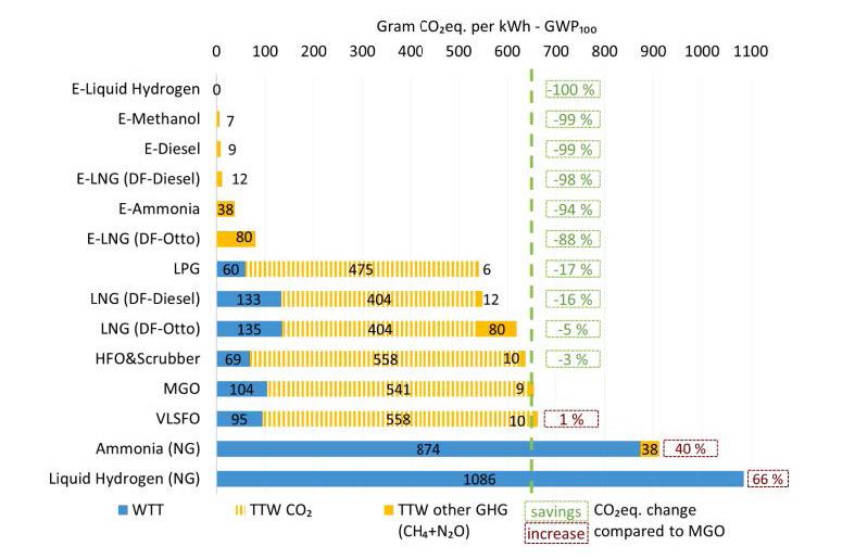
(Reduction of maritime GHG emissions and the potential role of E-fuels, Lindstad et al, 2021)
Liquid Biofuels
The use of liquid biofuel in a diesel engine is not new. In fact, Rudolph Diesel himself predicted that vegetable oils may over the course of time become as important as petroleum products.
Liquid biofuels are produced from biomass or organic waste and can be classified by generation. First generation biofuels, also called conventional biofuels, such as ethanol, hydrotreated vegetable oil (HVO), and the most widely used liquid biofuel Fatty Acid Methyl Ester(s) (FAME),
Conference Paper 138
generally referred to as “biodiesel”, are typically produced from crops or vegetable oils through technologies such as fermentation, hydrogenation or esterification. They are increasingly restricted from use as transportation fuel since they can compete with food production. Second generation biofuels use waste-based feedstocks, such as used cooking oil, forestry and agricultural residues, and municipal solid waste (MSW). The latter may require more sophisticated production processes, such as hydrothermal liquefaction or fast pyrolysis, while third generation biofuels are based on aquatic autotrophic organisms such as algae.
Figure 2 illustrates that second-generation biofuels offer the greatest GHG reductions of the listed biofuels – between 70 percent and almost 100 percent (WtW) compared to marine gas oil (MGO). This is due to their minimal impact on land usage, a large biogenic carbon uptake, and modest use of fossil fuel energy for feedstock conversion.
Figure 2: The potential of liquid biofuels in reducing ship emissions (ICCT, September 2020)
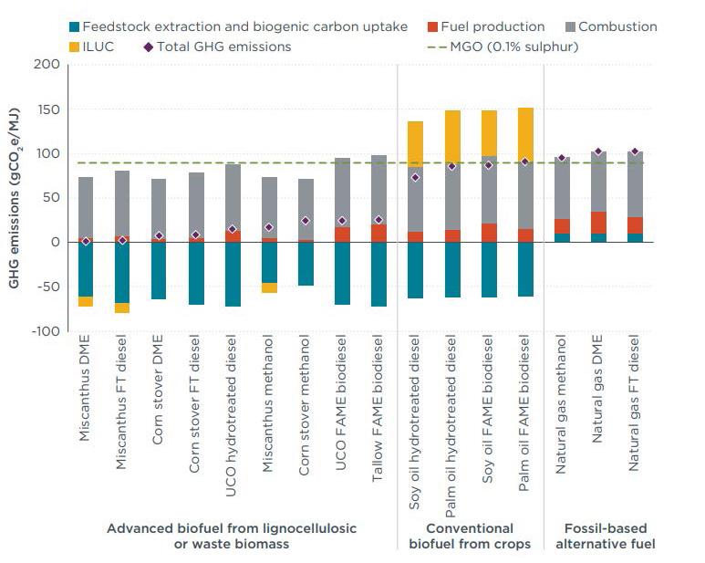
Blending liquid biofuels into fossil fuels not only reduces WtW emissions, but also has a positive impact on SOx and particulate matter emissions.
A barrier to biofuel usage in shipping has been the requirement under regulation 18.3.2.2 of MARPOL Annex VI stating that: ‘… fuel oil for combustion purposes derived by methods other than petroleum refining, shall not cause an engine to exceed the applicable NOx emission limit set forth in paragraphs 3, 4, 5.11 and 7.4 of regulation 13....’
This has necessitated ships to ask for an exemption from the flag state to run the biofuel trial, and to verify if the NOx emissions are in accordance with the relevant provisions of the NOx Technical Code 2008. At MEPC 78 however, a unified interpretation was adopted, where biofuel blends up to 30 v% are to be taken as being regular oil-based fuels. For biofuels and biofuel blends above 30 v%, no NOx emission measurements are required when NOx critical components and settings, or operational values, are in accordance with the engine manufacturer’s technical file.
As a marine drop-in fuel, liquid biofuels are compatible with existing marine engines and the supply infrastructure. The ISO 8217 marine fuels standard already allows the use of HVO and
Conference Paper 139
up to seven v% FAME in distillate marine fuels where the FAME is in compliance with EN 14214 or ASTM D7963. In fact, a number of demonstration projects with biofuel blends, have either been announced or successfully completed, where FAME was blended at up to 20v% or more with residual fuel oils.
FAME has good lubricity properties and improves the ignition/combustion of the fuel blend, as illustrated in Figure 3. An FIA/FCA analysis shows an increased estimated cetane number (ECN), a higher rate of heat release (ROHR), and an improvement in other FIA/FCA parameters.
Figure 3: FIA/FCA analysis (IP 546)
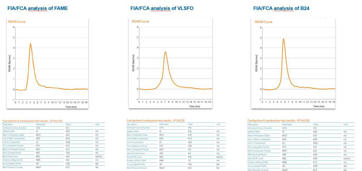
FAME has typically a lower viscosity than fossil fuels, which results in the final fuel oil blend having a lower viscosity than a fossil fuel oil, thereby potentially impacting the handling of fuel oil onboard the ship (e.g. pre-heating temperature, centrifugal cleaning settings). The cold flow characteristics (typically higher pour point) and the higher susceptibility to oxidation of FAME might impact onboard storage aspects. At higher FAME levels, additional attention to the potential effect this may have on fuel system materials, such as seals, is warranted. Also, the lower net heating value of FAME in comparison to fossil fuels will have to be taken into account when considering fuel consumption.
The potential barriers to the broad acceptance of liquid biofuels as a marine drop-in fuel include the availability of sustainable biomass feedstock, the technology readiness of some production pathways, and competition for supply from other sectors, such as road and aviation applications. Cost will, of course, always be a consideration for the industry. When looking into more affordable biofuel options for the shipping industry, it should be emphasized that prior to use, the quality of other biomass-based products should be carefully evaluated.
In summary
The availability of a supply chain and bunkering infrastructure will be an influencing factor for the penetration of other alternative, lower or zero carbon fuels, such as methanol, ammonia, and hydrogen. Cost, energy density, and safety considerations for both the ship and its crew, will also influence the viability of such fuels.
Biofuels represent a readily available lower carbon intensity alternative for the shipping industry. They offer a reduction in CO2 emissions on a WtW basis, with no need for engine modifications or major additional procedures. The main barrier for use in marine applications is competition from other transportation sectors that can affect its availability.
Conference Paper 140


Conveying ultra low sulfur fuels with KRAL screw pumps. Measuring consumption for monitoring and reporting with KRAL flowmeters. Pumps and Flowmeters. KRAL GmbH, 6890 Lustenau, Austria, Tel.: +43 / 55 77 / 8 66 44 - 0, e-mail: kral@kral.at www.kral.at
SESSION 5.2
Sustainability through alternative fuels 142
SEBASTIAN EBBING
Technical Advisor, Climate, Marine fuels, Innovation, Funding, VDR - Verband Deutscher Reeder
BIOGRAPHY
As Technical Advisor at German Shipowners’ Association, Sebastian Ebbing provides profound technical expertise to the ongoing regulatory developments on EU and IMO-Level. With his background in nautical science, marine engineering and international maritime management he is dedicated on regulatory climate-protection affairs, the maritime energy transition incl. the development of alternative climate-neutral fuel strategies, digitalization and innovation projects in shipping.
Sebastian Ebbing´s technical expertise is accompanied by experience in fleet performance management within a globally operating shipping company. The German Shipowners’ Association (VDR) is a leading professional association within the German business community.
It was founded in 1907 by the regional shipowners’ associations in order to enable them to have common and uniform representation of their interests. Today, the VDR represents the German maritime shipping segment not only in Berlin and Bonn, but also in Brussels, London, Geneva and at global level. With its over 150 member companies from different shipping sectors, the association represents the German shipping industry, which currently boasts the world’s fifthlargest merchant fleet. As an employers’ association, it conducts collective bargaining and social partner negotiations.
Sebastian Ebbing is founding- and board member of the “Research Institute for Innovation and Sustainable Logistics” situated at Jade University of Applied Science, where he is lecturing on Maritime Technologies with special focus on climate neutral shipping and alternative propulsion technologies.
Moderator 143
ULF HANSEN
Senior Advisor, I-tech

Speaker
144
Why Advanced Coatings Will be Essential to Success in the Age of the Carbon Levy
Introduction
Biofouling has been a perennial headache for the shipping industry for centuries. However, it is a problem that is set to get far worse in coming years, particularly for vessels idling from a few days or more in warmer waters. With ocean temperatures rising on a global scale, biofouling marine organisms are posing a greater risk to ships in coastal areas and hotspots where these organisms flourish are increasing in size and severity, leaving more ships at risk of the negative impacts of biofouling on ship efficiency.
Barnacles, in particular, create a huge amount of frictional resistance on the hull of a ship and so, have the most damaging effect on fuel use and emissions from inefficiencies in the underwater hull area. Removing barnacles from a ship hull is a tricky undertaking that can cause great damage to the antifouling coating. The first week after settling, the surface between the barnacle and the hull is very small and the barnacles constantly release “barnacle” glue to bond to the surface. At this stage the barnacles can be easily removed by a hull cleaning without damaging the coating. The older and larger a barnacle becomes, the more difficult it will be to remove the barnacle from the hull without damaging the coating. When removing at a later stage, the antifouling will be taken off together with the base plate of a barnacle, removing all the fouling protection.
On January 1, 2023, the International Maritime Organization (IMO) will introduce the Energy Efficiency Existing Ship Index (EEXI) and Carbon Intensity Indicator (CII) measures for every ship above 5,000gt in size as a means to reduce GHG emissions from international shipping. In particular, the CII, as an operational index, will be impacted by biofouling load on the underwater hull surface. This is due to accumulated biofouling creating additional hydrodynamic drag that necessitates a ship to burn more fuel when sailing through water to maintain a set speed.
With the inclusion of shipping within the EU ETS, calls for a market based measure (MBM) in the form of an IMO-driven carbon levy based on mandatory contributions for each tonne of CO2 emitted from ships exceeding 5,000 gross tonnes were put forward by the International Chamber of Shipping (ICS) and Intercargo in 2021. If a carbon levy was introduced on a global scale for the international shipping activities, the necessity to reduce emissions would further intensify.
This paper explores the connection between biofouling and ship decarbonisation in the shadow of incoming CII ratings, carbon levy proposals and potential global inclusions in ETS. It also highlights the key findings of I-Tech’s extensive research into global fleet idling and why ship operators should be concerned about the impact of biofouling in terms of both ship performance, profitability, and commercial reputation.
Biofouling and Idling – a lethal combination for vessel profitability
A vessel that has accumulated barnacles on the hull experiences increased hydrodynamic drag as it moves through the water. One commonly cited statistic in the marine coatings sector comes from a 2007 study written by Michael P Schultz which proclaims that vessels with 10% barnacle coverage would need a 36% shaft power increase to maintain the same speed. Since biofouling causes increased frictional resistance when water flows across the hull, ships with heavy fouled hulls must burn more fuel to maintain the same speed through the water. Or if a vessel is operating on fixed shaft power, speed penalties will occur. Therefore, a bio fouled
Conference Paper 145
vessel results in either higher fuel costs, lower speeds, or lost-time costs during hull cleaning for the ship operator.
Also, hull cleaning services must be factored into a ship operator’s operating expenditures (OPEX) but as global biofouling risk increases, hull cleaning is likely to be required more frequently, increasing maintenance costs. Repeated cleaning of the hull to remove soft fouling can also remove layers of the antifouling coating, reducing its service life.
Quantifying the true extent of barnacle fouling across the global fleet
A research study conducted by I-Tech and the Safinah Group in 2020 revealed the true extent to which barnacle fouling impacts the global fleet, and the results were surprising. For the study, the Safinah Group analysed underwater hull fouling condition on a sample of 249 ships which drydocked over a four-year period between 2015-2019. It was discovered that over 40% of vessels surveyed had hard fouling coverage on over 10% of the hull, mainly caused by barnacles. Since anything more than 10% coverage is deemed to cause an ‘unacceptable’ impact on vessel performance by experts, the global fleet is really suffering the consequences.
On many of the vessels surveyed, fouling levels were even worse; approximately 15% of vessels had between 10-20% of hard fouling coverage on the hull, 10% of vessels had 20-30% of hard fouling coverage and the remaining 10% of vessels had between 40-80% of hard fouling coverage.
Extrapolating from published data taken from the 2011 study by Michael P. Schultz, this level of hard fouling (assuming a 10% coverage of hard fouling on 40% of the fleet) could be responsible for at least 110 million tonnes of excess carbon emissions, and an additional US $6 billion spent on fuel per year for the global commercial fleet. The true figure is likely to be higher, as this is a conservative calculation based on today’s low fuel prices.
Quantifying vessel idling profiles across the global fleet
An extensive, independent study undertaken by I-Tech and Marine Benchmark of global fleet data up to, and including, the year 2020 explored the issue of idling and resultant biofouling. The results gave novel insight into differences between sectors of the industry confirmed a large increase in vessel idling over the past decade.
Remarkably, no in-depth study has been previously conducted that quantifies the true level of idling in the global fleet or in specific vessel type segments of the global fleet. Many shipowners hold extensive statistics and knowledge on their own fleet’s activity, with statistics on vessel performance and operating parameters such as average speed, fuel use, etc. Also, studies that examine idle capacity of different market segments used as an indicator for available capacity and future price developments can be found. But no current studies include the quantification of idling period length against water temperature and fouling pressure.
The Marine Benchmark web platform used for this study has capability for a full bottom-up AIS based fuel consumption calculation, globally and by countries EEZ (Exclusive Economic Zones). The database uses an online feed from IHS Markit including a feed from their AIS antennas and IMO vessel register. Its algorithms are run live 24/7 on its 18 servers performing global calculations of distance, speed, fuel consumption, cargo onboard, transport work and Energy Efficiency Operational Indicator (EEOI).
Defining idling – a disputable issue
Since disputes arise between the shipowner and the coatings supplier in the wake of coating failures, and there is no clear definition of idling when idling guarantees are based on this it is important to quantify what we considered to be “idling” conditions for this study. To complicate matters further different coating suppliers may offer their own definition of?idling and there is no clear industry standard on how idling is defined. The narrowest definition is a vessel on a
Conference Paper 146
defined spot without any movement. But what happens with very short trips or manoeuvring. If an idling guarantee stipulates a maximum period, some shipowners may make a short trip prior to the maximum period being exceeded with the intention to limit the idling time and thereby keeping the guarantee active.
To begin, we introduced “fouling idling” as distinct from “commercial idling”. Where the purpose of commercial idling is to measure the commercial activities and inactivity’s of vessels, and the purpose of fouling idling is to define idling as a risk for operations due to the resultant fouling. If we take an example of a vessel waiting for discharge of cargo or being stationary as a floating storage, that vessel is commercially employed and active, but it is idling when it comes to fouling exposure.
In the collected data, stationary times at yards will not be counted as fouling idling because the vessels are usually dry-docked and, in most cases, a long stay implies that the vessel will be re-coated with new anti-fouling coating. For fouling idling, it is important to also link the idling to water temperature and how long the vessel is fouling idling in an unbroken sequence.
The results of this study have been obtained using the following steps for all AIS data available during the time from 1st Jan 2009 to 31st Dec 2020.
1. The vessel has a registered IMO-number
2. Divide all vessel movements for AIS in 3 vessel activities depending by speed and if the vessels are at yard or not
a. Stationary - below 1 knot (at yard and outside yards) b. Manoeuvring - 1 to 6 knots
c. Steaming - above 6 knots
3. Stationary times for fouling calculation allow following intermediate activities:
a. Up to 12 hours manoeuvring is allowed between 2 stationary activities b. Up to 6 hours steaming are allowed between 2 stationary activities
4. Exclude all yard calls since these vessels are going into drydock, meaning idling will not impact operations afterwards.
5. The distance between first AIS observation and last AIS observation for each fouling idling period is calculated and a maximum distance of 100 nautical miles are allowed
6. Sea water surface temperatures in three groups below 15, 15 to 25, above 25°C.
7. Data is divided in number of vessels staying in fouling idling periods above 14, above 30 & above 45 days.
Key study findings
In-depth analysis of the global fleet patterns based on AIS data for all IMO-registered vessels of the global fleet, revealed a substantial increase in the numbers of idling vessels over the past decade.
The overall idling picture within the complete global fleet from 2009 to 2020 shows a steady increase in the number of vessels idling for longer periods.
Looking at the trends of idling over the complete global fleet, one can see that fouling idling, in line with our definition, increased constantly since 2009. With a starting point of 25.4% to a peak of 35.0 % in May 2020. However, when looking at the number of vessels, the difference is much bigger since the fleet has also experienced a substantial growth in the number of vessels trading on the world’s oceans. The absolute number of idling vessels increased from 8,000 in 2009 to over 16,000 in 2020, indicating that the total idling problem has roughly doubled over the past 10 years.
I-Tech found that ‘Fouling Idling’, as defined in the study, has increased constantly since 2009, with a starting point of 25.4% to a peak of 35.0% in May 2020. Given the growth of the fleet, this
Conference Paper 147
means that the absolute number of vessels idling in the global fleet has doubled between 2009-2020.
Significantly, the study also found that vessels are increasingly idling in so-called biofouling ´hotspots´, where water temperatures above 25°C. Vessels spending the majority of their time sailing in these regions are at acute risk of excessive hard fouling accumulation.
5 The total number of vessels idling has roughly doubled over the last decade.
5 A high percentage of idling is occurring in water temperatures above 15°C.
5 Many bulker vessels are idling even outside of peaks. The level of idling for this vessel type is regularly above 1000 vessels monthly.
5 The number of idling tanker vessels has constantly increased since 2009, peaking at 1421 vessels in 2020.
5 During the idling peak in 2020, nearly all idling container vessels were laid up in warm waters and almost half of all container vessels had long idling periods of more than 30 days.
5 Cruise vessels at anchor for more than 14 days in 2020 increased from an average of 3% to between 20-30%.
5 Depending on season, between 50% - 85% of idling is occurring in water temperatures of above 15oC.
5 During 2020, compared to previous years (2018-2019), the number of vessels idling for more than 14 days increased for most segments within the global fleet.
There was a clear peak in June 2020 with 99 container fleet vessels sitting idle in warm temperature waters, 96 vessels idling in medium temperature waters and 2 vessels idling in cold temperature waters giving a total number of 197 vessels being idle. Comparing this to June 2019 when there were only 22 vessels idling in warm temperature waters, 13 in medium temperature waters and 1 in cold temperature waters giving a total number of 36. This represents an increase of over 447% year-on-year.
The effects of the COVID-19 pandemic had an impact within the bulker fleet. There was an increase from 1,100 vessels being idle in the beginning of 2020 to over 1,500 in April 2020. The majority of vessels were idling in water warmer than 25oC.
For the tanker fleet, idling was at its highest level in May 2020 since 2009, with 15.4% vessels sitting idle. A notable 84.2% of the idling activity happened in medium to warm waters with high risk of fouling. At the peak in May 2020, 1421, tanker vessels were idle for more than 14 days.
The cruise fleet results show an extreme picture. Comparing the time before the COVID-19 outbreak with after, vessels at anchor for more than 14 days increased from an average of 3% to between 20-30%. In numbers, idling went from less than 10 vessels with long idling periods monthly, to over 60 vessels being laid up.
When looking at the proportion of the global fleet idling for 30 days or more the results were very interesting. For example, looking at the peak in 2015, 5,5% of all container vessels (10000 to 13499 TEU) were idling for more than 30 days, and at the 2020 peak, the number was close to 3%.
For Suezmax tanker vessels (130,000 to 199,900 DWT) idling was peaking to above 4% on regular occasions and during the peak in 2020, 8,5% of vessels were idling for over 30 days. Capesize bulkers (120,000 to 349,900 dwt), are also part of this trend with several idling peaks between 2009-2020 where 2-4% of all vessels in this segment had idling periods of longer than 30 days.
Conference Paper 148
Container Fleet
It can be seen that idling is not uncommon, quite the opposite. We know that external factors are causing vessels to idle, and over the past 10 years we can see multiple idling peaks within the container fleet. Included in the data analyses are all container vessels larger than 2,000 TEU.
In 2020, Covid-19 resulted in long periods of idling for almost 200 container vessels. Exposing their hull to extreme risk of marine growth. Looking not at the percentage of the fleet the picture is very similar. In 2009 there was a peak of idling with 8 % of the total container fleet being idle compared to 6.4 % being the peak in 2020.
Figure 1. Percentage of all container vessels over 2,000 TEU, 2009-2020 on a monthly basis with idling longer than 14 days.
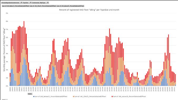
30 days idling – intense fouling risk
It is commonly known that lying at anchor for more than 14 days exposes a vessel´s hull to a high risk of biofouling, which is why it is interesting to look at even longer periods, when the fouling risk is highly intensive. We see that many vessels are idling for more than 30 days, and some even for longer than 45 days. For example, looking at the peak in 2015 when 8,4% of the container fleet were idling for more than 14 days, a whole 5,5% of the fleet were idling for more than 30 days. At the 2020 peak, almost half of all container vessels at fouling idling had long idling periods of more than 30 days, exposing the vessels´ hulls to an extreme risk of hard fouling.
Figure 2. Percentage of all TEU, 2009-2020 on a monthly basis with idling longer than 30 days.
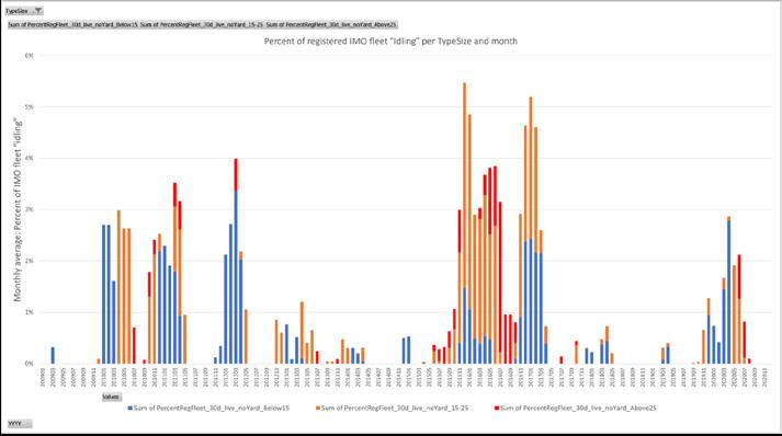
Conference Paper 149
Bulker fleet
For the bulker segment, the peaks are not as prominent as they are for the container fleet. However, there is a constant substantial number of vessels idling, many in warm temperatures, and these are exposed to high fouling risks. Included in the data analyses are all bulkers bigger than 5,000 DWT.
Similar to the idling statistics of the container fleet, there has been several peaks of idling between Jan 2009 - Dec 2020, although, the peaks aren’t as evident. The lowest number of vessels at idle for more than 14 days since 2009 was still higher than 800 vessels, while the highest number was during the peak of 2016 when over 1600 vessels were experiencing long periods of idling. Since 2011, the number of bulker vessels at idle for more than 14 days was never lower than 1000 vessels.
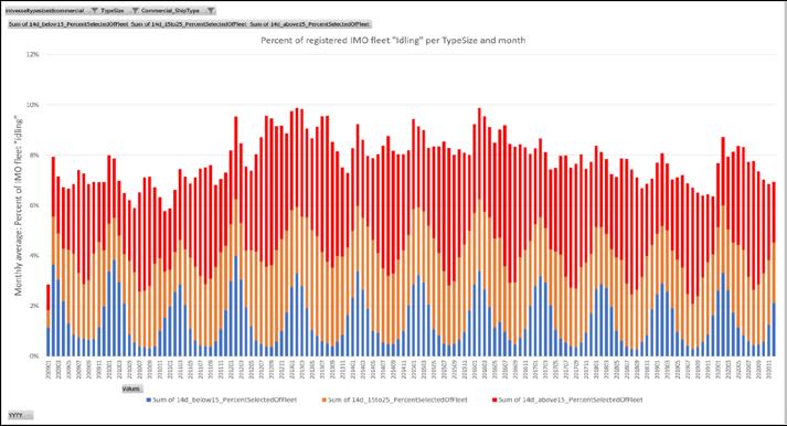
Since the fleet has been growing in numbers since 2009, we are looking at the data as percentages too. We can see that it is common for 6-8% of the bulker fleet to lie at anchor for long periods, with regular peaks of more than 8% idling vessels. The highest peak was in February 2016 when 9.9% of the fleet were idling compared to 8.7 % laid up in February 2020. In February 2020, 61.8% of the idling vessels were located in medium or warm waters with high exposure to marine growth.
Figure 3. Percentage of all bulker vessels 2009-2020 on a monthly basis with idling longer than 14 days.
Any additional time at idle increases the fouling risk
Comparing the number of days that bulker vessels were idling; we see that quite a lot of vessels have idle periods of more than 30 days. Within the study, results has been divided between +14, +30 and +45 idling days. For example, we looked at Capesize bulkers of 120,000 to 349,900 dwt at idle for longer than 30 days (see graph). There are several idling peaks between 2009-2020 where between 2-4% of all vessels in this segment had idling periods of longer than 30 days.
Conference Paper 150
Figure 4. Percentage of Capesize Bulkers 120,000 to 349,900 dwt, 2009-2020 with idling for longer than 30 days.
Tanker Fleet
Even though there are no extreme idling peaks, we can see that the number of tanker vessels idling for longer periods has increased steadily since 2009. All tankers over 5,000 DWT are included in the analysis.
In 2020, COVID-19 resulted in long idling periods for more than 1,400 tanker vessels. We can see that the number of tanker vessels at idle for longer periods has increased steadily since 2009, from the lowest number of 200 vessels at the beginning of 2009, to around 1,000 vessels in 2019.
During 2020, we see a peak of 1,421 vessels at idle for long periods, and it is extra notable that over half of the vessels were then idling in water temperatures of above 25°C.
Tanker vessels exposed to marine growth in warm waters during the 2020 idle peak
Between 2009-2020, an average of about 10-12% of tanker vessels were at idle. The peak in May 2020 at 15.4% was the highest level since 2009. A notable 84.2% of the idling took place in medium to warm waters with high risk of fouling.
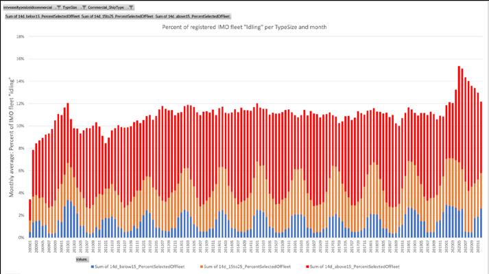
Figure 5. Percentage of tanker vessels 2009-2020 on a monthly basis with idling longer than 14 days.
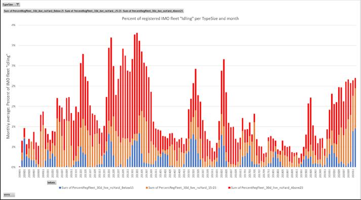
Conference Paper 151
30 Days of idling
The graph below shows Suezmax tanker vessels of 130,000 to 199,900 DWT at idle for +30 days. Regular peaks showed that more than 4% of all vessels were idling for over 30 days, and in many of these scenarios for even longer than 45 days. During the peak in 2020, around 8,5% of the vessels had idling periods of more than 30 days.
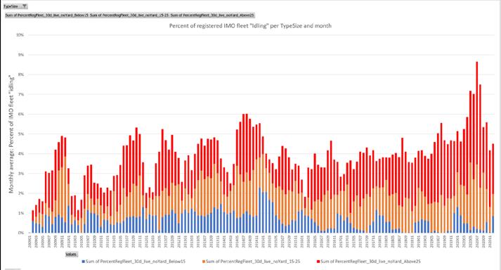
Figure 6. Percentage of Suezmax Tankers of 130 to 199.9 dwt 2009-2020 with idling longer than 30 days.
The 2020 idling peak
Taking a closer look at the most recent peak during 2020, here we are comparing 2020 to the previous years (2018-2019). As expected, the number of vessels idling for more than 14 days increased for all segments during the peak compared to the previous years.
5 Half of all idling container vessels were laid up in biofouling hotspots
5 1500 Bulker vessels idle in April 2020
5 Over 1000 Tanker vessels were idle in high fouling risk zones
Conclusion
With the industry facing the IMO 2050 GHG reduction targets and the impending introduction of EEXI, CII for existing ships and potential global carbon levies on fuel, these findings should serve as a reminder that a clean hull should be the first step of a fleet’s decarbonisation strategy. Achieving that state is the cause of much debate. Arguably, the best start point is to take a robust preventative approach concerning antifouling technology within marine coatings.
The issues highlighted in this study prove the need for high performance, advanced antifouling technology in the maritime industry. Ship operators are increasingly demanding antifouling coatings that are well-suited to both specific ship trading patterns and varying activity levels, and that also provide protection against both soft and hard fouling. When looking at the future trading potential, ship operators need to ensure that their ship is protected, whether it is in constant active service, idle for long periods of time, or at risk of fluctuating between the two.
The” idling study” conducted by I-Tech and Marine Benchmark reveals a surprising increase in the idling problem in the global fleet, and also proves that peaks of increased idling for all types of vessels occur regularly due to unpredictable circumstances around the world. At the same time as the global fleet is increasing – and with that the number and problem of idling vessels, so are the water temperatures, and the high-risk areas for fouling. With larger risk zones
Conference Paper 152
and hundreds of idling vessels, we can assume that there are increasing numbers of vessels suffering from biofouling. At the same time, technology is advancing, and several methods to tackle the biofouling issue are available. For example, antifouling solutions with high static performance could be a rewarding investment. Moreover, with measurable regulations such as EEXI and CII coming into force, ship owners need to thoroughly analyse what is the best way to make their vessel sustainable in the long run. Even though there are many ways to reduce emissions, all efforts will benefit from the vessel´s hull and niche areas having a solid protection against fouling.
External factors can always have some disruptive effect on operations and make predictions difficult. The most important thing is to ensure that, after any idling, the vessel is in good condition to perform optimally. Familiarisation with the individual vessel’s risks of biofouling based on its operating footprint is a good starting point.
In addition, we are seeing first-hand that climate change is having an impact on biofouling and hard fouling levels and owners need to be looking at where their vessels are operating. Warmer tropical and sub-tropical waters contain the highest concentration of creatures responsible for hard fouling. Vessels spending the majority of their time sailing in these regions are at acute risk of excessive hard fouling accumulation.
As shipping continues to be a vital part of the global economy, these fouling windows could intensify, with ports becoming more congested, so more ships could find themselves facing a new, higher risk of barnacle fouling colonization. It is becoming clear that the problem of fouling as a result of idling is not decreasing - the fleet is growing and so is the incidence of fouling in many commonly used shipping routes and ports.
A preventative approach is key
The best steps can be to examine an antifouling technology mix within an antifouling that is suitable for the vessel type, activity, and trading patterns but that also offers an assurance of extended static protection against barnacle fouling during unexpectedly long idling periods. Building on this, operators would benefit from planning their potential idling periods away from the biofouling high-risk zones whenever commercial considerations allow.
With unpredictable operations resulting in long idling periods being a fact, it is more important than ever to examine the idle period guarantees provided by coating manufacturers and identify what components can enable protection during extended idling periods. Only a few premium coatings offer guarantees based on 30 days idling and the vast majority may stop after 14 or 21 days.
However, the study has proven that it is not uncommon for a vessel to be idling for more than 30 days, and in some cases even longer than 45 days. It is therefore clear that owners and operators need to take into consideration that only the best protection guarantees are sufficient. For many antifouling coatings on the market this is made possible by the inclusion of?the antifouling agent Selektope®. This can also be considered alongside the prospective operating geography for their vessels, especially if they foresee operating and idling in warmer, tropical waters, which are well-known barnacle fouling hotspots. With unpredictable operations resulting in long periods of idling being a fact, it is more important than ever to examine the idle period guarantees provided by coating manufacturers and identify what components can provide protection during extended idling periods. Apart from the owners investigating the guarantees, it has also become clear that there is a need for an industry definition of idling to clarify the meaning of guarantees and make it easier to choose the most suitable antifouling system for a vessel´s operation.
For most antifouling coatings, protection guarantees range between 14 and 21 idle days, with the majority of premium antifouling coatings offering up to 30 days idle guarantee. Some
Conference Paper 153
few premium antifouling coatings offer idle guarantees over 30 days. However, under tough market conditions such as those encountered during the current COVID-19 pandemic, this study has proven that it is not uncommon for a vessel to be idling for more than 30 days, and in some cases even longer than 45 days. It is therefore clear that owners and operators need to take into consideration that only the best protection guarantees are sufficient. For many antifouling coatings on the market this is made possible by the inclusion of?antifouling agent Selektope®. This can also be considered alongside prospective operating geography for their vessels, especially if they foresee operating and idling in warmer, tropical waters, which are well-known barnacle fouling hotspots.
Case Study
In April 2021, after 5 years of operation, coated with a Selektope®-containing antifouling paint, the 8.900 TEU Container vessel went in for dry dock. The hull was completely free of barnacles after operating in areas with high risk of biofouling.
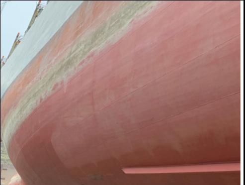
In March 2016, the container vessel was coated with a copper free coating solution containing Selektope, supplied by Chugoku Marine Paints (CMP), SEAFLO NEO CF PREMIUM.
During the following 60 months, the vessel moved at an average speed of 17 knots worldwide with an average operation factor of 78%. Even after operating in waters with high fouling pressure, with no cleaning, the vessel hull was free of barnacle during its drydock inspection.
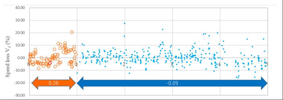
The performance degradation of the vessel was evaluated to be comparable to the in-service performance indicator of ISO 19030 (see figure). The vessel showed an impressing zero speed loss.
Because of the outstanding hull performance, this vessel was able to achieve 16.5% in fuel savings and reduce its emissions by 85,500 ton CO2 compared to market average antifouling products in use over 60 months.
Figure 7. Speed loss evaluation over five years. (Provided by Chugoku Marine Paints)
Figure 8. Underwater hull surface after 60months of trading between Asia and North America
Conference Paper 154
RENE TAUDAL POULSEN

Programme Director for BSc Program in International Shipping and Trade, Copenhagen Business School, Denmark
BIOGRAPHY
René Taudal Poulsen is associate professor, PhD and program director for the BSc program in International Shipping and Trade at Copenhagen Business School, Denmark. His research concerns processes of environmental upgrading in international shipping and the commercial, political and operational factors that influence the environmental footprint of ships. His work have appeared in academic journals such as Global Environmental Politics, Journal of Cleaner Production, Marine Policy, Transportation Research Part D, and Global Environmental Change.
Speaker
155
Who can improve energy efficiency in ship operations and bring down emissions?
To mitigate climate changes, the IMO aims to enhance energy efficiency in ship operations. From next year, it will make ship-owners and technical managers subject to the new mandatory Carbon Intensity Indicator and a more demanding mandatory Ship Energy Efficiency Management Plan with the aim of reducing emissions per transport-work. The success of the new regulatory measures will depend upon ship-owners’ and technical managers’ capacities to make such improvements.
In new research, just published in the academic journal Transportation Research (https://www. sciencedirect.com/science/article/pii/S1361920921004156), we explore who can improve energy efficiency in ship operations and shed new light on the limitations of the current regulatory approach of the IMO.
We document how a large network of decisions-makers, including cargo-owners, commercial managers, ship operators, port stakeholders and public actors, make important decisions for voyage planning and execution, which influence energy efficiency. We find that they often pursue commercial objectives, which undermine energy efficiency.
The IMO approach for energy efficiency has some major limitations in mitigating climate change, because it fails to acknowledge that ship-owners, technical managers and their crews do not have full control over ship operations and energy efficiency.
To mitigate climate change, the IMO should broaden its regulatory focus to the markets that condition energy efficiency and emissions. Instead of narrowly focusing on ship-owners and technical managers, policy makers should also direct focus towards the stakeholders, who benefit from maritime transport and influence emissions.
Further info about our work is also available in our recent article in Lloyd’s List (December 2, 2021): https://lloydslist.maritimeintelligence.informa.com/LL1139157/IMO-must-includecargo-owners-in-emissions-reduction-policy
Conference Paper 156
René Taudal Poulsen (presenter), Martin Viktorelius, Hanna Varvne, Hanna Barbara Rasmussen and Hannes von Knorring
Conference Paper 157
Efficiency Operational Indicator (EEOI)
can improve energy efficiency in ship operations and bring down emissions?
EEOI CO2 emissions Transport-work = CO2 emissions Cargoes carried x distances travelled =
Efficiency Ratio (AER) EEOI CO2 emissions Transport-work proxy = CO2 emissions Deadweight x distances travelled =
2018, average EEOI has improved by one third
2020)
Energy efficiency metrics Energy
Who
René Taudal Poulsen, Martin Viktorelius, Hanna Varvne, Hanna Barbara Rasmussen and Hannes von Knorring
Annual
From 2008 to
(IMO
8.6 9.3 7.94 3.9
EEOI for four aframax tankers CO2 emissions per transport-work in 2018: Grams of CO2 emitted per metric tonnes carried * nautical miles travelled, according to EU MRV data
5 Team ethnographic research – to unravel how shipping managers and crews conduct their work
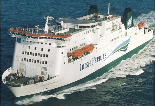
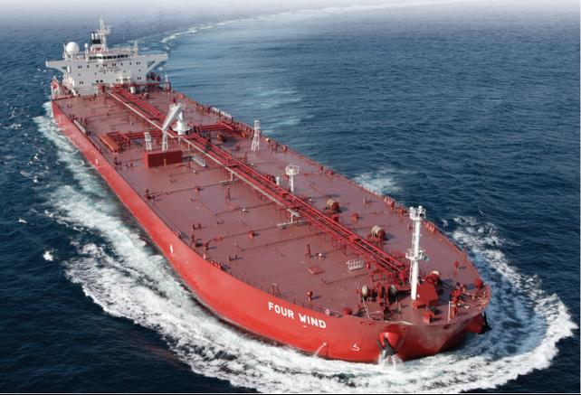
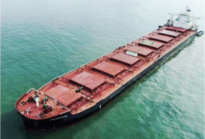
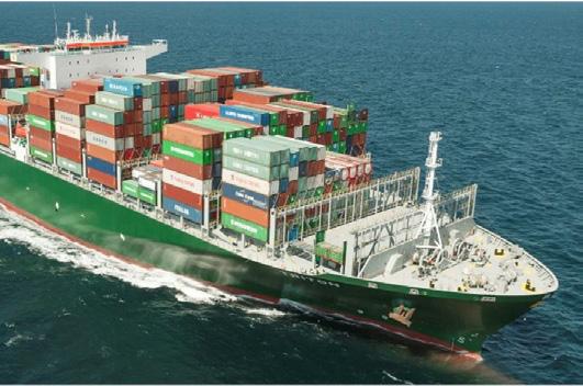
5 Non-participant observation studies onboard eight merchant ships and over 100+ interviews with shipping managers and crews, 2012-21
5 A unique opportunity to study not only managers’ and crews’ perceptions on energy efficiency but also their behavior
5 We control for effects of freight rates and fuel prices on decision-making with a longitudinal data set and field material Three
Conference Paper 158
Methods
main segments + one niche
Timing of data collection
Design factors for energy efficiency
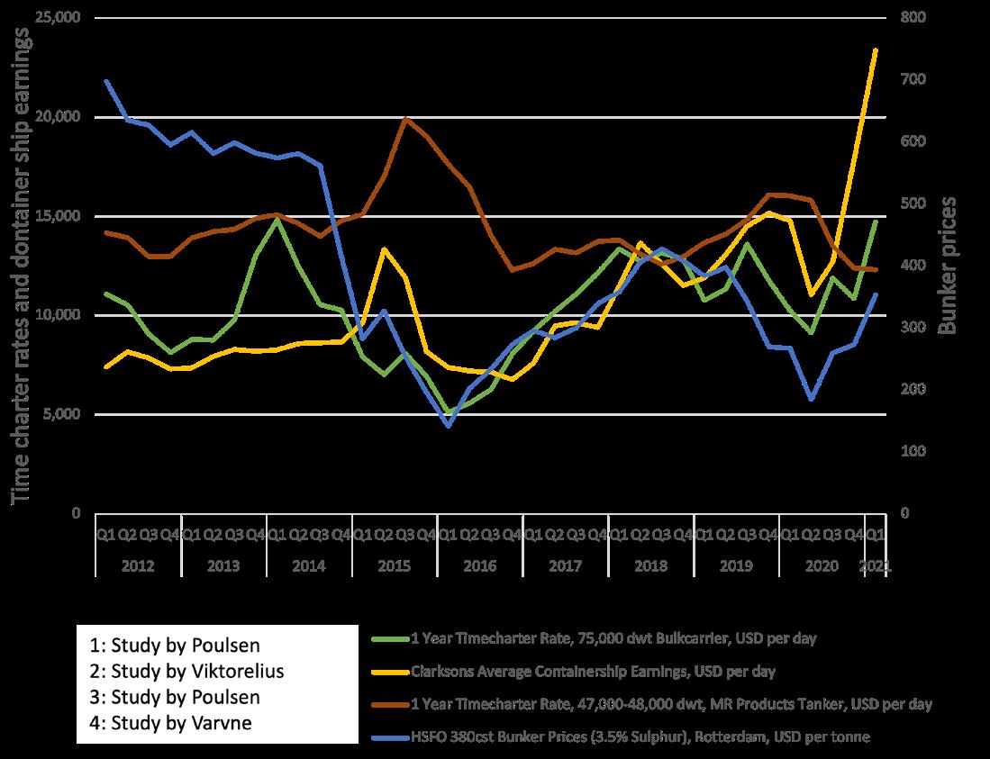
5 Measures which require investments in equipment (fuel saving devices)
5 Installation of waste-heat recovery system; Installation of auxilary wind propulsion system (such as Flettner rotors); Installation of counter-rotating propellers etc.
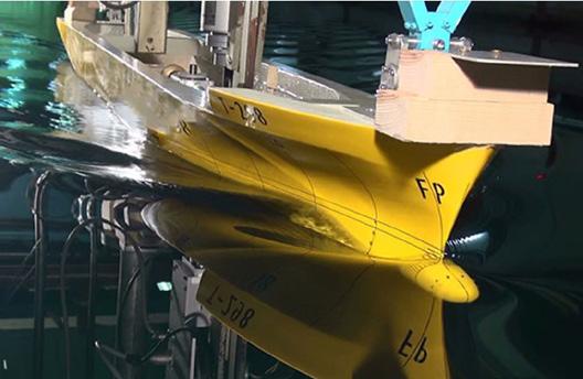
Conference Paper 159
Nautical decisions for energy efficiency
“...the waves come from astern of the ship. The ships benefits from the current, which provides extra speed. Our course is planned such that the vessel benefits from the current.”
Fieldnotes, the ‘Northern Hemisphere’
“One of the masters was very aggressive, and his maneuvering reflected this. I mean, he accelerated quickly, from full stop to full steam ahead... regardless of water depth. And if the water is shallow ...you will actually just use more energy, but not move forward any faster “
Former head of ferry line
Crews and technical managers make numerous nautical decisions, which can improve energy efficiency.
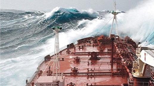
However, they are limited in their actions by commercial constraints and safety considerations, which often undermine energy efficiency
Route choice
Voyage execution
5 Weather routing – to reduce effects of counter currents and adverse weather
Voyage execution
Speed choice
Punctual departure from port – to ensure low service speed
Equalize speed over voyage – to avoid energy consuming speed changes
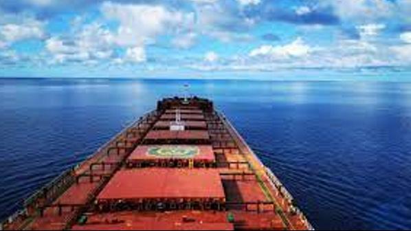
Take shallow water effect in consideration –to reduce fuel consumption
Just-in-time arrival to port - to avoid idle time at anchorage and ensure low service speed
Ship handling
Trim and ballast optimization
Optimize auxilary engine use
Avoid unnecessary rudder corrections
Conference Paper 160
5
5
5
5
5
5
5
Voyage execution
Matching vessels and cargoes
Maximize utilization of vessel capacity: 5 Minimize time in ballast condition 5 Optimize networks and schedule in liner shipping 5 Triangulate in tanker and dry bulk shipping 5 Assign tankers/bulkers to commercial managers The pursuit of commercial objectives can improve energy efficiency
However, this is not always the case – sometimes commercial objectives undermine energy efficiency
“Our claim to fame… is to run operations as efficiently as possible…”
COO for container line
“If the vessel is not full … the number [the EEOI] quickly moves in the wrong direction”
Energy efficiency manager for tankers
“We should not use the shorter ballast [voyage], if a longer ballast [voyage] pays more money”
VP for tanker operations
Ferry companies maintain high service frequencies despite low traffic volumes because government tenders require them to do so.
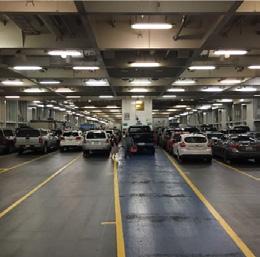
Commercial decisions for energy efficiency
Voyage execution
Route choice
5 Use canal transits, when possible – to reduce distance sailed and fuel consumption
Speed choice 5 Reduce service speed – to save fuel 5 Adjust liner schedules – to allow for longer transit times and speed reduction
5 Use virtual arrival in tanker and bulk shipping – to allow for speed reduction in case of port congestion
Speed choice is highly market dependent and current speed reductions are potentially reversible
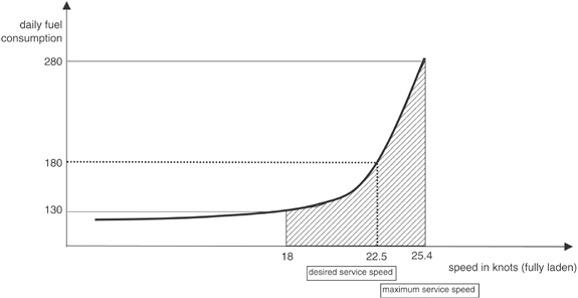
Speed choice has highly networked nature: Cargo-owners’ transit time preferences translate into voyage plans by operations managers or schedules for ferry and container services
Shipping managers are willing to sail longer routes and increase fuel consumption to avoid costly canal transits (in Panama, Suez or Kiel).
“The starting point is today’s market. What pays the best? If the market is 40,000 dollars per day, we obviously go at full speed, in order to make as many voyages as possible.”
Director for product tanker shipping pool
Conference Paper 161
Key energy efficiency decisions
Voyage planning: Commercial decisions
Matching vessels and cargoes
5 Minimize time in ballast condition
5 Optimize networks and schedule in liner shipping
5 Triangulate in tanker and dry bulk shipping
5 Assign tankers/bulkers to pool managers
Speed choice
5 Reduce service speed – to save fuel
5 Adjust liner schedules – to allow for longer transit times and speed reduction
5 Use virtual arrival in tanker and bulk shipping – to allow for speed reduction in case of port congestion
Route choice
5 Use canal transits, when possible – to reduce distance sailed and fuel consumption
Actors who influence energy efficiency
Cargo owner
Shipowner
Charterer
Ship operator
Commercial ship manager
Technical ship manager
Voyage execution: Nautical decisions
Speed choice
- Punctual departure from port – to ensure low service speed
- Equalize speed over voyage – to avoid energy consuming speed changes
- Take shallow water effect in consideration - to reduce fuel consumption
- Just-in-time arrival to port - to avoid idle time at anchorage and ensure low service speed
Route choice
- Weather routing – to reduce effects of counter currents and adverse weather
Ship handling
- Trim and ballast optimization
- Optimize auxilary engine use
- Avoid unnecessary rudder corrections
A company with a need to transport its cargoes. In tanker shipping, the main cargo-owners are oil majors and commodity traders. In some cases, oil majors own ships, but in the vast majority of cases they charter in vessels in the freight/charter markets to perform transport work.
A company, which owns ships. It makes money by chartering out its ships in the freight/charter market or through asset play in the second hand markets for ships. Some ship-owners have inhouse commercial and technical management for the ships, while others choose to outsource these activities to third parties.
A company, which charters in (i.e. leases) ships in the chartering market. A charterer may be an oil major in need of transportation for its cargoes, or a ship-operator in need of ships to perform transport work, for which it has committed itself on behalf of a cargo-owner.
A company, which provides transportation services to cargo-owners. It does not own ships, but charters in these in the freight/charter markets. It subsequently charters them out, and makes a profit from the margins between the charter-in and charter-out rates.
A company, which provides commercial management for ships on behalf of ship-owners. It finds employment for the ships in the freight/charter markets, and earns a profit from the management fee that it receives from ship-owners. It is also known as a pool manager.
A company, which provides crewing and technical management for ships on behalf of shipowners. It maintains and crews the ships, and earns a profit from the management fee that it receives from ship-owners.
Conference Paper 162
Source: René Taudal Poulsen, Stefano Ponte, Judith van Leeuwen and Nishatabbas Rehmatulla, 2021. The potential and limits of environmental disclosure regulation: A global value chain perspective applied to tanker shipping, Global Environmental Politics, 21:2
Conclusion
5 Shipowners and technical managers are not in full control of energy efficiency
5 Nautical decisions for energy efficiency are relevant under all market conditions, but crews and technical managers who make such decisions are limited by commercial constraints and safety considerations, which often undermine energy efficiency.
5 Commercial decisions depend on dynamic market conditions and matter more for energy efficiency than nautical decisions do.
5 Cargo-owners, commercial managers, ship operators, port stakeholders and public actors make important decisions for voyage plans, which often undermine energy efficiency.
5 To mitigate climate change, policy makers should broaden the regulatory focus to the markets that condition energy efficiency and emissions – and direct attention towards the stakeholders, who benefit from maritime transport and influence emissions.
Conference Paper 163
STAM ACHILLAS
Head of Business Development & Sales, 2-Stroke Fuel Conversions, Wärtsilä
BIOGRAPHY
Stam Achillas is the Head of Business Development & Sales, 2-Stroke Fuel Conversions at Wärtsilä, where he’s spearheading the commercialisation and business growth of 2-stroke decarbonisation solutions globally.
Growing up in a seafaring family and having graduated from the Merchant Marine Academy in Greece, Stam started his career on board vessels as a marine engineer officer. Following further education in Mechanical & Marine Engineering, he entered the field of diesel engine development with Cummins and later led production and service departments in the defence industry with Kraus-Maffei Wegmann. As a senior project manager with WinGD (formerly Wärtsilä Switzerland) and subsequently with AVL in Austria he led the development and productization of 2-stroke and 4-stroke diesel and dual fuel engines for marine, power generation and rail applications. Stam transitioned into more commercial roles with ABB Turbo Systems (currently Accelleron) as the global Head of Product Management, Low-Speed Turbocharging before re-joining Wärtsilä.

Speaker
164
BENJAMIN WEINACHT
Managing Director, Compagnie Maritime Belge (CMB)
BIOGRAPHY
Shipping Executive, Benjamin Weinacht has worked for the CMB Group for the past 16 years in various position in Europe. Before being nominated Managing Director CMB Germany and Managing Director Hydrogen Ports, he worked as Managing Director for the Saverys controlled feeder line Team Lines.

He is part of the Executive Committee of Windcat Workboats which is a worldwide leading provider of highly specialised Crew Transfer Vessels (CTVs) and forms also part of the CMB Group.
Benjamin holds a Bachelor of Logistics.
Speaker
165
SESSION 6
Alternative Fuels 166
ARE ALTERNATIVE FUELS READY FOR THE MARITIME INDUSTRY’S NEEDS?

A decarbonized shipping industry is just over the horizon.
Having helped pioneer safety and performance standards for 200 years, Bureau Veritas looks to the future fuels that will help shape shipping’s energy transition.

Learn more at marine-offshore.bureauveritas.com Shaping a better maritime world.
SESSION 6.1
Ammonia 168
PETER SANDERS Senior Process Engineer, Høglund

Speaker
169
RENÉ SEJER LAURSEN
Director – Fuels & Technology, Global Sustainability Copenhagen, ABS
BIOGRAPHY
Mr. René Sejer Laursen Holds an M.Sc. in Mechanical Engineering from the Technical University of Denmark in 1989. Until 1992 he was employed at Risoe National Laboratory where he worked with super critical oxidation technology. Until 1994 he worked with waste incineration boilers at Aalborg Industries and until 1998 he worked with drilling equipment for the Greenland Ice Core Investigations Project and research equipment at the Niels Bohr Institute of Copenhagen.
He joined MAN B&W Diesel in 1998, and in early 2004 he started in the ME-GI project group as Product Manager. In 2010 he was promoted to Promotion Manager, looking after the market for gas fueled merchant ships and LNG carriers, including the market for engines using new fuels such like ethane, methanol, LPG and ammonia. Have succeeded introducing LNG in 2012, methanol in 2013, ethane in 2014 and LPG in 2018 to the marine market.

In 2020 Rene was working on the Mar-e fuel project, investigating e-fuels alternatives for the marine. The Mar-e-fuel project is initiated by Torben Anker Sorensen and is a cooperation between APMM, DFDS, OMT, Denmark Technical University and MAN.
In the mid-2020 René joined ABS in Copenhagen, working in the Global Sustainability Group as Director with responsibility for fuels and new technology. The task for the sustainability group within ABS is to support and assist shipowner in their selection of the right technology mix for their fleet, so the shipowner is well prepared to meet coming emission regulations and staying competitive.
Speaker
170
ANDREAS SCHMID General Manager Technology Development, WinGD
BIOGRAPHY
Andreas Schmid has a degree in Mechanical Engineering from The Swiss Federal Institute of Technology (ETH) in Zurich. He completed his PhD on Automotive Sprays in 2012 and has over 10 years of international experience in researching, developing and validating engine technologies.
Andreas joined WinGD in 2011 as a Spray and Combustion Research Scientist before taking over the lead of the Future Technologies team in 2016. He was responsible for the coordination of collaborative research with a focus on the development of measurement technologies, piston running and for acquiring a better understanding of spray and combustion. In 2019 Andreas took on the role of General Manager, Technology Development. In this role, he is leading the team who oversee research and development in the field of decarbonisation, fuel injection, ignition, tribology as well as emission formation and abatement.

Speaker 171
ABSTRACT
Industry interest in carbon-free fuels has reanimated development towards ammonia-fuelled ship engines. This paper outlines the challenges engine designers are working on and the research tools being deployed to bring safe, reliable and efficient ammonia-fuelled engines to market.
Introduction
With ammonia emerging as one of the leading clean fuel candidates for decarbonising the shipping industry, WinGD has faced an important development challenge over the past two years: to design an ammonia-fuelled two-stroke marine engine concept that can be applied to both newbuild engines and by retrofit to the existing installed base of WinGD dual-fuel and diesel engines.
WinGD’s existing portfolio of two-stroke marine engines includes both diesel and LNG dualfuel engines, using both high-pressure Diesel cycle and low-pressure Otto-cycle processes. While a robust engine structure designed for LNG means WinGD engines are already designed for high pressures and temperatures, the requirements of new fuels such as ammonia need to be investigated before an engine concept is proposed.
Combined with the simultaneous development of a methanol-fuelled engine concept, this has been a major focus for investment for WinGD. The research draws on WinGD’s own capabilities and facilities – including the Engine Research and Innovation Centre in Winterthur – and engine builder partners in China and Korea.
After initial exploration WinGD announced that it would make commercial engine concepts for methanol and ammonia available from 2024 and 2025 respectively. This rapid development timeframe means that WinGD and its partners are already well advanced in working on many of the challenges associated with using ammonia as a marine fuel.
The challenge
Ammonia is a fuel unlike any other previously used in marine engines. It contains no carbon, which is its great advantage when it comes to reducing shipping’s climate impact. Although derived from hydrogen, it is much easier to handle and store at ambient temperatures and pressures, and has a higher volumetric energy density, making it potentially much more suitable for use in deep-sea shipping compared to hydrogen.
However, ammonia also has some characteristics that make its use as a ship fuel challenging. It is toxic, meaning that safety precautions need to be taken to eliminate leakage into either the air or the sea. Containing ammonia is challenged by its corrosiveness, meaning specific resistant materials need to be used, while its very low viscosity means that adequate sealing to prevent leakages is also essential. Further it does not offer much lubrication to moving parts, which must be taken into account when developing components with long life spans and overhaul intervals.
These safety risks have a direct impact on the commercial engine concepts. For example, how can an ammonia-fuelled engine be maintained without risking the safety of those responsible for maintenance? How can they safely inspect or disassemble such an engine? And how does the engine room need to be vented to minimise exposure to even low levels of ammonia?
The safety concept is just one area in which basic questions need to be answered. Ammonia both ignites and burns slowly, meaning that ignition and valve timings need to be considered carefully. This has implications for the combustion concept (how to admit and burn the fuel) and the fuel injection concept (how to pressurise the fuel and what materials to use).
Conference Paper 172
The impact of ammonia on the piston running concept also needs investigation to ascertain how ammonia in lube oil affects the oil’s properties, the impact of ammonia contact on the liner or other hot components, and the risk of contamination for other fluid systems (such as system oil or cooling water).
Further basic questions include understanding the emissions abatement concepts that will be needed for a commercial engine concept using ammonia. Emissions will include NOx, which is a potent air pollutant that is regulated against by IMO and the US Environmental Protection Agency. But N20 – or laughing gas - is arguably even more concerning as a strong contributor to global warming. The full emissions profile of ammonia needs to be appreciated before abatement concepts can be considered.
Another important consideration is which combustion process is likely to be needed for ammonia. While the Otto-cycle is arguably less complex – engine hardware would be similar to existing dual-fuel engines – a Diesel cycle engine concept could be more efficient and could benefit from being developed alongside a similar concept for methanol fuel.
One challenge is the lack of models to allow for front loading and computational approaches. To develop an ammonia engine, understanding of emission formation is key. A design that fulfils all customer requirements can only be made with reliable computational tools. These tools need to be developed and refined, iteratively checking their reliability at the same time as developing the engine design.
Research process
The task of answering these questions and bringing an appropriate commercial engine concept to market can be broadly divided into three stages.
By answering questions based on iterative experimentation and simulation, we can arrive at the engine concept. Later in the process, further experimentation helps to refine the concept design and analyse performance further. Finally, with a view to delivering a manufactured product, a range of other tests – including rig testing, single- and multi-cylinder engines and field testing – enable designers to validate the commercial concept.
For example, when developing the injection system, the first step is to identify the best approach to fuel distribution. From there, the requirements of the fuel injection - such as the number and position of injectors, fuel pressure, injector materials and geometry - need to be defined. During this development, the designed injector concept is proven and improved with simulations and later validated with experiments.
Within this framework, the most promising concepts have been selected to maximize efficiency whilst minimizing emissions. The field is further narrowed by considering system safety and cost analysis as well as the results of tests.
Research tools
WinGD has drawn on wide collaboration to advance its investigation of ammonia as a fuel and appropriate engine concepts. Collaborators include universities, class societies, engine builders, shipyards and ship operators.
As an example of early-stage research collaboration, WinGD’s proprietary models for ammonia engine concepts have been improved through work with universities to hone modelling of chemical mechanisms. Also with the use of university research facilities[1][2][3], WinGD has used an optically accessible test rig - Flex-OeCos for example – to investigate combustion processes in an engine-like environment. The next stages of research are being undertaken in large part in WinGD’s own facilities and capabilities. Some of the key research facilities are listed below.
Conference Paper 173
Spray Combustion Chamber
The Spray Combustion Chamber was developed as part of the Europe-funded HERCULES project. This unique test rig has been used extensively to obtain a better understanding of combustion in large two-stroke diesel engines when applying conventional and alternative marine fuels. This knowledge now serves as a basis for assessing the impact of alternative fuels on combustion characteristics.
By developing the SCC further – for example with the use of high-speed, high-energy laser technology and special optics in combination with line-of-sight methods – the combustion phenomena can be observed in configurations even more representative of actual engine combustion systems. This setup has been used for assessing the impact of clearly distinct alternative fuels on combustion.
Future fuels lab
WinGD has developed fuel systems test rigs designed specifically to assess the compatibility of any alternative liquid fuel with existing fuel systems. These test rigs simulate the actual operation of injection systems in service at relevant conditions. The rigs typically include all key elements of the systems, including a variety of fuel pumps, common rail and injection actuation elements as well as the injection valves.
Dimensions and arrangement of components and connecting pipes are selected such that the configuration can be considered as representative of an actual engine. The modular setup allows either simultaneous testing of different design variants or to facilitate the exchange of key components.
On test rigs, the fuel is injected into a chamber and then recirculated to the inlet of the pump. This injection cycle is repeated, at relevant operating conditions, in the range of hundreds of thousands to millions of times.
The injection system performance is monitored to identify any degradation that might occur due to fuel property changes during operation or unfavourable interactions with component materials.
Single cylinder engine
To accelerate fundamental research into fuel flexible engine concepts, WinGD has developed a Single Cylinder Engine (SCE) that will enable rapid iteration and validation before testing is scaled up to multi-cylinder engines. The SCE will be crucial in determining the combustion parameters and emission profile of ammonia and other clean fuels.
The unique test engine relies on expertise from across CSSC; it was designed by WinGD, built by Hudong Heavy Machinery Co and calibrated at the China Shipbuilding Power Engineering Institute in Shanghai. It is now being installed within a dedicated building at WinGD’s Engine Research and Innovation Centre (ERIC) in Winterthur.
Ammonia and methanol supply are being established and the SCE will be used to test ammonia engine concepts from next year.
Global Test Centre
WinGD’s Global Test Centre in Shanghai is a collaboration with partner company China Shipbuilding Power Engineering Institute Co. It comprises two 2-stroke test engines and several test rigs for the validation of sub-systems such as fuel injection, pumps or gas admission valves. Testing focuses on new fuels including methanol and ammonia, and on the further development of WinGD’s low pressure dual-fuel technology.
Conference Paper 174
Current status
To date WinGD has taken several important steps toward the development of ammonia engines. The required software tools have been developed and optimised to a reliable level in collaboration with our partners in Switzerland and the EU. At present CFD investigations are focusing on three combustion concepts featuring high- and low-pressure fuel admission. For each combustion concept, fuel admission configurations have been investigated to fully understand the impact on engine design, safety and costs.
First experiments have now taken place in the SCC to verify the combustion behaviour and emission formation from the simulations. Once these have been confirmed, the combustion concepts will be further tested on first the Single Cylinder Engine, next year, and then our multi-cylinder test engines.
As this process continues, WinGD has also initiated joint development projects with multiple engine builders to prepare for the production of commercial engines, as well as the fuel supply and emissions abatement systems that will be needed to operate engines with alternative fuels.
The developments to date are in line with WinGD’s stated timeframe of producing commercial ammonia engines by 2025.
References
1. Comparison of pilot fuel ignited premixed ammonia versus methane dual-fuel combustion, S. Wüthrich, P. Albrecht, P. Cartier, and K. Herrmann, Conference Proceedings - Rostock Large Engine Symposium 2022
2. Optical investigation and thermodynamic analysis of premixed ammonia dual-fuel combustion initiated by dodecane pilot fuel, S. Wüthrich, P. Cartier, P. Süess, B. Schneider, P. Obrecht and K. Herrmann, Fuel Communications 12 (2022) 100074
3. Experimental study of RCCI engine – Ammonia combustion with diesel pilot injection, A. Dupuy, P. Brequigny, A. Schmid, N. Frapolli, C. Mounaïm-Rousselle, 1st Symposium on Ammonia Energy, Cardiff
Conference Paper 175
PREMET® Cloud - Performance efficiency on the go
Carbon-neutrality for the maritime shipping is an ambitious goal and it will not be achieved in the next years. We need to work on solutions, that help the ecological footprint today. Controlling the emissions will help strongly with a green tomorrow.
With that in mind, CM Technologies has developed our modern PREMET® devices. Control over the engine is control over the emissions.
All trials run by CM Technologies have shown big improvements with even simple corrections at the machinery. As shown in the graph on the left, the engine shows around 10% improvement of the peak pressure with a simple angle correction. With the runtimes of ships and the fuel amount being used this is a big impact.
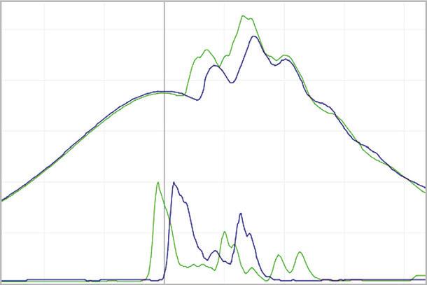
The PREMET® devices show many other severe problems. Important parameters are ignition delay, timing and length and accurate power readings are also important.

The correct settings for the engine will reduce material stress. Reduced material wear will make your engine last longer, work more efficiently and therefore reduce emissions.
Extensive - complete analysis with no compromises
Reduce Emissions - Save Fuel
The timing of maritime engines is very important. That is the reason, the PREMET® s are using a very high sampling rate.
The PREMET® X and M are great tools for every ship. With a Kistler Sensor at its heart, they take the most precise measurements. The software has been designed specifically to show all key factors for the analysis with simple graphs and bar charts.

The idea of the PREMET® devices is to be usable by every member of the crew. The software is simply structured. The device will check that the measurement is recorded with all valuable and necessary data.
This does not only come in handy, for the onboard adjustments, but also for further analysis.
Data this complex provides the user with more insight. Experienced analysts are able to see the full picture quickly and efficiently. Send all data in small files to the cloud and analysis can be done anywhere at any time from laptops or mobile devices.
The PREMET® Cloud is designed to handle these complex data to its fullest potential and store all of the results. The trends of regular measurements are the key to show developing problems at an early stage.
The PREMET® Cloud is the most complete solution on the market. The biggest benefit of the PREMET® Cloud is availability. As all data is stored online, the measurements are available all over the world. Analytics can be done by everybody on your team, or even external personal. The CMT analytics team is a time and resource saving addition, that can be inserted seamlessly into your workflow.
The analytics team from CMT will not only analyse the results but also provides solutions to the problems in a detailed report.
The complete service within a short span of time is a very valuable tool for every superintendent. Allocate your time and resources more efficiently.
Analysis by CMT
CM Technologies GmbH • Tel: +49 4124 50 443 00 • info@CMTechnologies.de • www.CMTechnologies.de
50
40 30 20 10 0 -20 -10 0 10 20 30 40 Angle [deg] Pressure [bar]
KRISTAIN MOGENSEN
Principal Specialist and Promotion Manager, MAN Energy Solutions
BIOGRAPHY
Kristian Mogensen is working as a promotion manager for MAN-ES in Copenhagen, where he assist and support various of stakeholder in the Marine Sector. He started his career as a seagoing Marine engineer, later went ashore to work with energy efficiency in a shipping company. In 2015 he started in MAN-ES 2-Stroke operation department. During his five years in the operation department Kristian was the author of serval service letters and operational guidelines, as well as responsible for the lubrication oil strategy for the LNG burning engines.
Speaker 177
Engineering the ammonia engine of the future
MAN B&W engines for new marine fuels
Today, low speed two-stroke combustion engines with directly coupled propellers power most of the world fleet of deep sea merchant ships. The future will see cleaner fuels, and the two-stroke engine technology will likely remain the primary propulsion source for deep sea shipping.
In recent years, MAN Energy Solutions has tailored two-stroke engine technology to accommodate various new fuels such as methanol, methane, ethane, and liquefied petroleum gas (LPG), see Fig. 1. Our portfolio contains dual-fuel low speed engines designed for the use of these fuel types in addition to their inherent fuel oil operability. Depending on the origin of the fuel, medium to large reductions of CO2 intensity, and thereby also GHG intensity, are feasible.
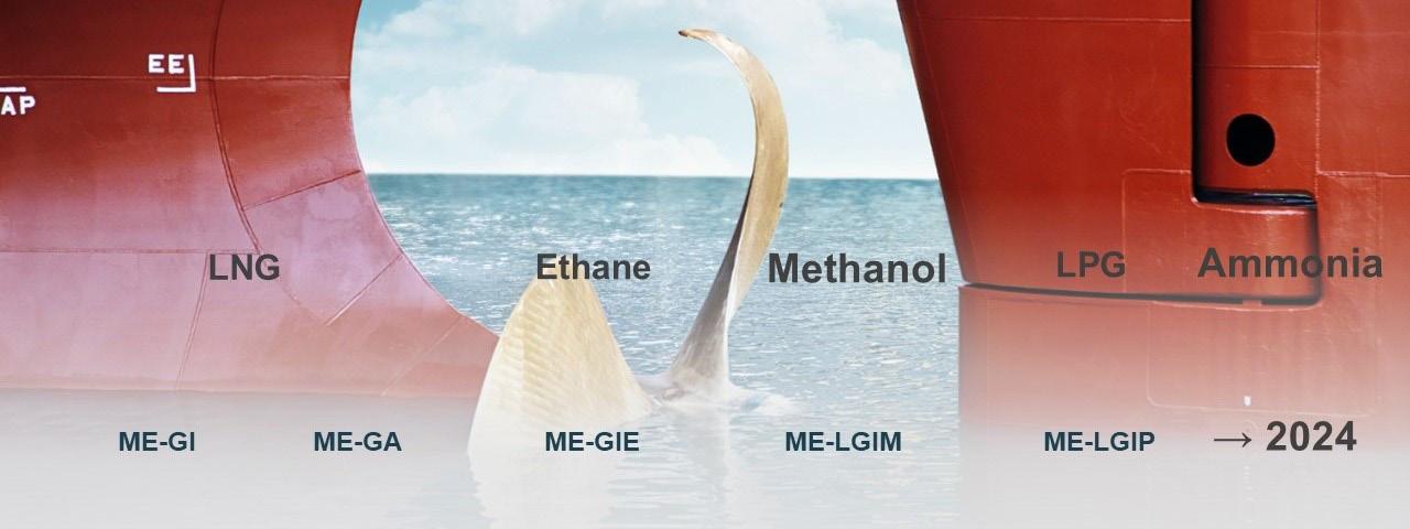
These dual-fuel engines are increasingly gaining a major share of the newbuilding market and are also available for retrofit.
Fig. 1: Dual-fuel ME-GI and ME-LGI engine types and corresponding references as of August 2022, and the future ammonia engine
Next step on the decarbonisation path will be the development of the ammonia-burning MAN B&W low speed two-stroke engine. Thanks to the carbon- and sulphur-free molecular composition of ammonia, burning it in a two-stroke engine creates near-zero CO2 and SOX emissions. Also from a well-to-wake perspective, ammonia can become a carbon-neutral fuel when produced using renewable energy sources like electricity produced from hydropower, wind, or solar energy. Furthermore, emissions of air pollutants related to carbon (soot, unburned hydrocarbons) and carbon monoxide (CO) will be practically eliminated.
An ammonia-burning engine represents a platform for ultra-low GHG emissions while using sustainable green ammonia as the fuel.
The ammonia engine development project at MAN Energy Solutions was initiated in 2019 (see Fig. 2), and the first combustion of ammonia is expected to take place in one of the cylinders of a two-stroke engine in our Research Centre Copenhagen late 2022.
Based on extensive test results, further tuning of the concept will be made with the target that one of our licensees will build the first commercial MAN B&W ammonia engine in 2024.
Conference Paper 178
Fig. 2: Ammonia development schedule
In today’s market, it can be challenging to select the right engine concept for a newbuilding project due to uncertainties regarding the future environmental regulations and the availability of alternative fuels. The MAN B&W engines of ME-C and dual-fuel designs are future-proof by their modular design and can be adapted to alternative fuels, including ammonia, in the future.
With the ability to adapt to new fuels the low speed two stroke engine is a good platform to allow shipping to adapt new fuels, without having to adapt a new basic approach to propulsion and crew training. A direct coupled piston machine with a large propeller remains the most efficient configuration for large merchant ships. And at the same time this configuration allows for a hybrid approach when coupled with a shaft generator (PTO/PTI), waste heat recovery systems and wind assisted propulsion.
Main focus areas of the engine development
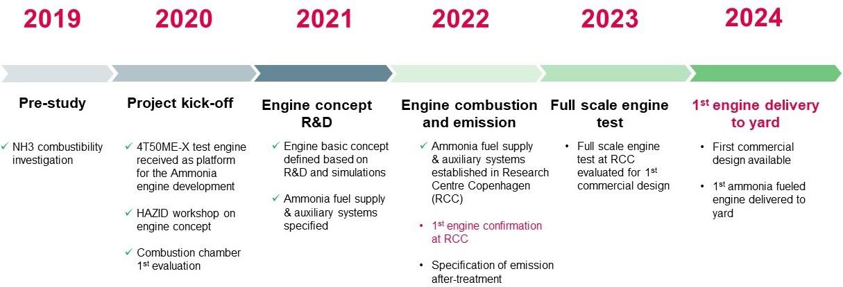
The overall objectives of the engine development are to ensure stable and efficient combustion, safe and robust engine tribology, and to ensure that the influence from the corrosive nature of ammonia is investigated for all conceivable engine design parameters.
Furthermore, the fuel supply design for vessel installation must be corrosion-resistant, safe, stable, and be able to meet the fuel supply requirements at the engine.
Combustion and efficiency
Since ammonia does not burn like a hydrocarbon-based fuel, part of the research and tests has been focused on establishing the characteristics of ammonia combustion in a two-stroke engine and fine-tuning the process. Defining parameters related to the combustion will be different. For example, ammonia burns with a slower flame propagation and the ignition of ammonia has proven to require more attention.
However, the marine two-stroke combustion engine is tolerant to low fuel quality. The fundamental reasons for the large tolerance to poorly ignitable and burning fuels are the low speed of the engine, allowing sufficient time for the combustion to take place, and the large dimensions, leading to large volume-to-surface ratios which are beneficial for a complete combustion and low heat loss. The engine concept allows for thermodynamic conditions to be widely adjusted, to ensure the technology can deliver on our efficiency and emission related development goals.
The LGI combustion principle
The ammonia engine design philosophy resembles the ME-LGI, which has obtained considerable service experience. The ammonia engine will inherit the dual-fuel operating principle – which gives two operating modes. One is the dual-fuel mode shown in Fig. 3, where ammonia (NH3) is injected into the cylinder and is ignited by a small pilot flame. The other
Conference Paper 179
operating mode is the fuel oil mode, where the engine runs on compliant fuel only, identical to the pilot oil. The efficiency in this mode is identical to the performance of the conventionally fueled engine.
Fig. 3: Pilot oil and ammonia injection and combustion
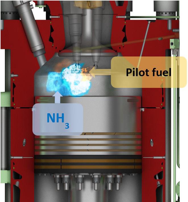
The LGI injection system
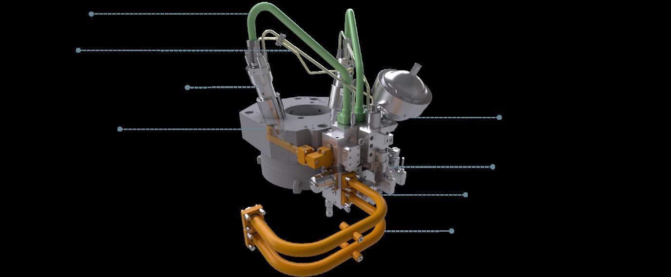
The LGI injection system designed for safe and reliable ammonia operation contains the main components shown in Fig. 4.
Fig. 4: Cylinder cover components for running on ammonia
Materials
Due to the nature of ammonia, the effect on fuel system components in direct contact with the ammonia fuel has to be identified and whether this effect calls for a new choice of material compared to other dual-fuel engine component designs. Ammonia is corrosive to copper, copper alloys, alloys with a nickel concentration larger than 6%, and plastic.
Conference Paper 180
Our current findings related to materials:
Fuel supply system:
5 316L steel is recommended
5 To be welded with backing gas/pickling
Injection system components:
Current materials are expected to perform satisfactorily.
Elastomers: Suitable material found for both O-rings and accumulators.
Stress corrosion cracking in mild steel: The industry already requires a small amount of water in the ammonia and puts requirements to the steel grades, welding procedures, etc.
Auxiliary systems
Generally, the safety concept of the existing dual-fuel MAN B&W combustion engines will be used, including the double-walled piping in the engine room compartment, and many other class approved features with a long track record of safe operation.
Due to the toxic nature of ammonia, further refinement of the concept has been necessary, involving a system for safely catching any leftover liquid ammonia and all ammonia vapour, thereby completely eliminating the need for releasing it to the surrounding environment during an engine stop.
MAN Energy Solutions is continuously investigating and implementing measures in the engine concept based on the learnings from establishing our test facility and our dialogue with the classification societies and ammonia industry.
Fuel supply system concept
Liquid ammonia can be stored at a pressure above 8.6 bar at ambient temperature (20°C). To keep it in the liquid phase if the ambient temperature increases, it is common to design nonrefrigerated ammonia tanks for approximately 18 bar.
The ammonia tank design must account for the lower calorific value of ammonia compared to LPG:
5 46.4 MJ/kg for propane (LPG)
5 18.6 MJ/kg for ammonia (NH3)
Naturally, also the sailing distance between bunkering needs to be considered carefully when designing an overall optimum system from CAPEX and OPEX perspectives.
Fig. 5 shows the main systems of the ammonia supply system. The ammonia fuel supply to the engine comes from the storage tanks via the fuel supply system. A small part of the fuel supply continuously recirculates via the recirculation system to maintain the required fuel conditions at the engine.
Conference Paper 181
Fig. 5: Principles of the ammonia supply system showing main systems
Fuel supply and recirculation
The fuel supply contains the equipment necessary to deliver ammonia to the engine at the required temperature, pressure, and quality. The equipment consists of a high-pressure pump, a heater, filters, valves, and control systems to maintain the ammonia fuel pressure and temperature at varying engine consumptions.
The recirculated ammonia will heat up on the engine during operation. To avoid two-phase conditions, a certain amount of the ammonia fuel is recirculated to a dedicated recirculation line. The same recirculation line recovers ammonia from the engine whenever dual-fuel operation is stopped. The recirculated fuel may contain traces of sealing oil from the injection valves. The recirculation line eliminates the risk of contaminating fuel storage tanks with oil, and it also separates and bleeds-off nitrogen from the recovered ammonia.
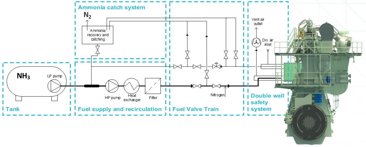
Fuel valve train
The fuel valve train (FVT) is the interface between the engine and the auxiliary systems. The purpose of the FVT is to ensure a safe isolation of the engine during shutdown and maintenance, and to provide a nitrogen-purging functionality. This functionality ensures a safe environment on the engine after shutdown.
Double-walled safety system
To maintain a safe engine room, it is vital to detect any leakages from the ammonia fuel system and direct these to a safe location. This has led to the double-walled design of ammonia fuel systems and piping in the engine room. A constant flow of ventilation air is kept in the outer pipe in accordance with IMO requirements.
Ammonia catch system
The catch system concept illustrated in Fig. 6 will free the engine from ammonia without venting the toxic and volatile ammonia vapour to the atmosphere, and at the same time reusing the liquid ammonia.
The catch system interfaces to the engine, the fuel recirculation system, and nitrogen supply, and it is connected to the vent mast of the ship. The system uses a water seal to trap the ammonia vapour and allows only nitrogen to pass through to the vent.
In some operating scenarios, the engine knock-out drum can contain liquid ammonia. To reuse the ammonia in the fuel circulation system, the knock-out drum has been fitted with a recovery tank from which ammonia can be returned to the fuel recirculation system.
Conference Paper 182
A separate knock-out drum (and recovery tank) should be in place for the fuel gas supply system.
Fig. 6: Engine ammonia catch system during an engine stop, where the engine piping must be cleared from liquid ammonia
Emission reduction
Nitrous oxide (N2O, laughing gas) is a potent greenhouse gas. The potential formation of nitrous oxide (N2O) during combustion of ammonia, and the solution to remove it by engine tuning, is an ongoing investigation. As described in the section “Combustion”, the two-stroke engine characteristics allow for wide adjustment possibilities of the thermodynamic properties and, hence, it is our development target to design an ammonia combustion process eliminating any formation of nitrous oxide at the origin.
SCR technology is an after-treatment process, where both NOX formed during the combustion and unburned ammonia are removed from the exhaust gas in a catalytic reduction. In Fig. 7, a schematic overview shows the principles of SCR combined with a two-stroke engine, where:
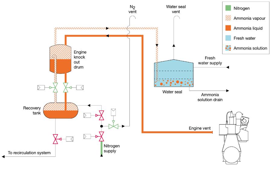
5 Unburned ammonia (NH3) and NOX are removed in the SCR reactor
5 Dosing of additional ammonia for the SCR reaction, if needed
5 Known SCR technology is suitable (MAN SCR reactor can be applied)
5 Engine designed for both fuel oil and ammonia as fuel
Conference Paper 183
Fig. 7: Unburned ammonia and NOX are removed in the SCR reactor
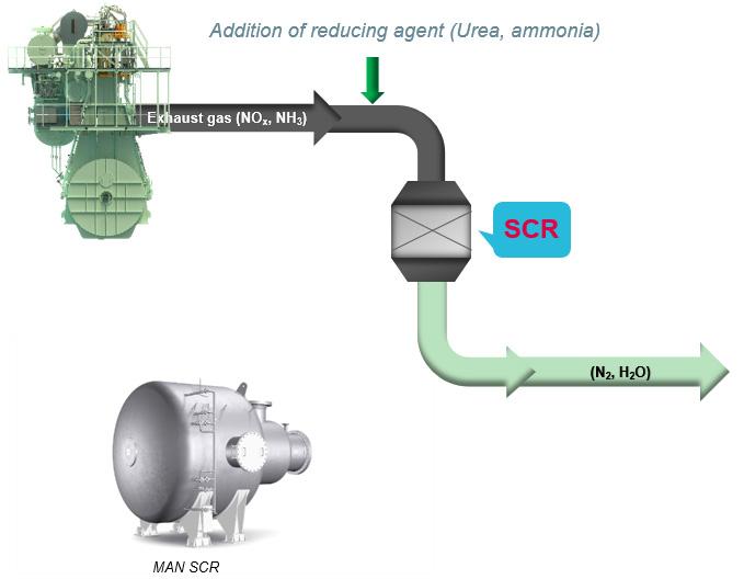
The potential of engine modular design
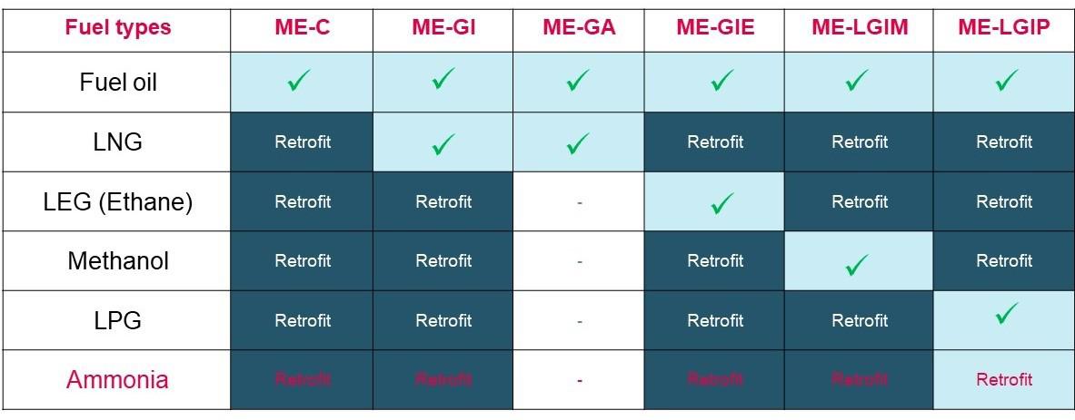
An ME-C engine already in service can potentially be retrofitted to any of the dual-fuel concepts; ME-GI for LNG or ethane, and ME-LGI for LPG, methanol, or ammonia. All ME-C engines are delivered as so-called “dual-fuel ready” engines. Therefore, in new projects, the engines can be regarded as being prepared for later conversion to dual-fuel operation, independent of vessel application (tanker, bulk, container, etc.).
Table 1: Modular engine design and retrofit possibilities
MAN Energy Solutions is working diligently towards being able to offer retrofit conversion of ME-C engines (including –GI, -GIE, -LGIP, and -LGIM variants) to ammonia.
Conference Paper 184
Summary
Decarbonisation constitutes one of the largest transitions encountered by the marine industry, and the short deadline to succeed requires a united and committed approach from the entire supply chain from well to wake.
At MAN Energy Solutions, we are committed to continuously optimise the environmental impact of both existing and future engines. The modular design of MAN B&W ME-C and dualfuel engines gives the possibility to adapt these to alternative fuels, including ammonia, in the future.
To develop an engine for a new fuel such as ammonia calls for partnerships, cooperation, and an understanding of the market interests. MAN Energy Solutions works diligently towards designing the MAN B&W engine for operation on ammonia and offering retrofit conversions to ammonia of existing two-stroke engines.
As an engine designer, we have had to learn a lot about building an ammonia handling facility and in that process, we have made a few alterations to our original plan. Safety is a top priority and finding such additional safety measures is expected as the development project progresses. This means that we have decided to extend the precautions around the bunkering facility at Research Centre Copenhagen beyond the requirements set to the site, to ensure that we have the level of safety and reliability around our site that is required by our own standards.
Our ammonia engine concept has been defined for engine testing and further tuning of the concept will be made based on the test results. The target is that one of our licensees will build the first commercial MAN B&W ammonia engine in 2024.
Literature
[1] MAN Energy Solutions, MAN B&W two-stroke engine operating on ammonia, 2020
Conference Paper 185
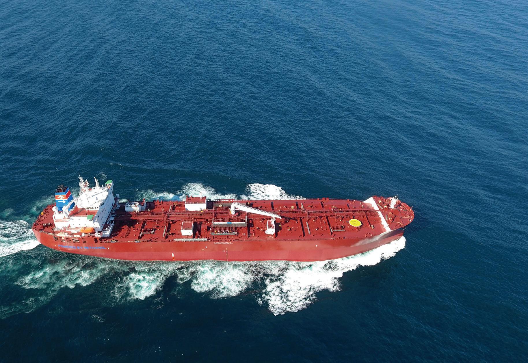
www.methanol.org
A safe, sustainable, available, and affordable marine fuel; 2020-compliant, reducing maritime emissions today; and providing a low carbon pathway.
187
Methanol SESSION 6.2
HELGE BARTELS Chief Operating Officer, Bernhard Schulte
BIOGRAPHY
Helge Bartels is Chief Operating Officer at Bernhard Schulte since Jan. 2021, while joining the ship owning arm of the Schulte Group already in 2019. Mr. Bartels has more than 20 years’ experience in shipping and is responsible for the operations and proper asset management of around 90 fully and partly owned vessels.

Mr. Bartels started his professional career building and servicing different types of engines and building engine test and repair facilities (e.g. for Navies & Military purposes and the auto industry). He then worked in senior leadership roles at HATLAPA and served as Executive Consultant within a Management Consultant Company. Lateron he took on roles at E.R. Schiffahrt and BestShip as Managing Director and from 2018 at Zeaborn Ship Management as General Manager.
Mr. Bartels holds a Master of Engineering degree from the University of Hannover. He is a member of the Nautical Society of Hamburg, German Society for Maritime Technology and German Society of Engineers.
Moderator 188
MATTHIAS ÓLAFSSON Chief Representative Europe, Methanol Institute

BIOGRAPHY
Directing the EU affairs of the Methanol Institute, methanol expert and government relations specialist Matthías Ólafsson manages a range policy and business development activities in the methanol sector. With a background in eMethanol business strategy and communications, Matthías has hands-on experience in navigating the EU’s regulatory landscape and international methanol trade.
Speaker
189
Methanol Institute
About Methanol Institute
About Methanol Institute


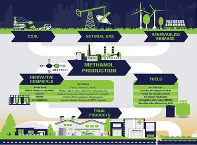


•


The Methanol Institute (MI) was established in 1989


• More than three decades later, MI is recognized as the trade association for the global methanol industry


• We facilitate methanol’s increased adoption from our Singapore headquarters and regional offices in Washington DC, Brussels, Beijing and Delhi

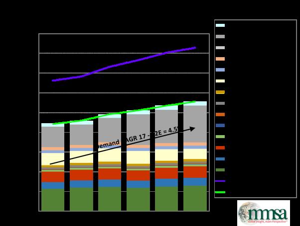
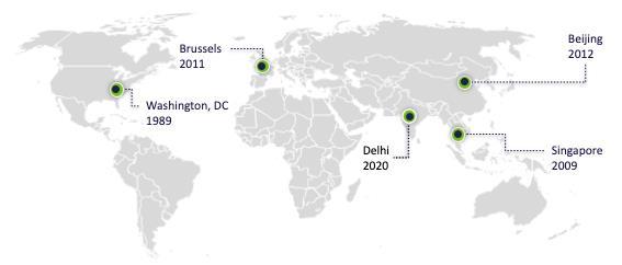

The Methanol Institute (MI) was established in 1989 5 More than three decades later, MI is recognized as the trade association for the global methanol industry 5 We facilitate methanol’s increased adoption from our Singapore headquarters and regional offices in Washington DC, Brussels, Beijing and Delhi


Members
www.methanol.org
Conference Paper
6/6/2022
us Members Tier 1 Tier 2 Tier 3 Tier 4 Essential Methanol 3
www.methanol.org/join
www.methanol.org
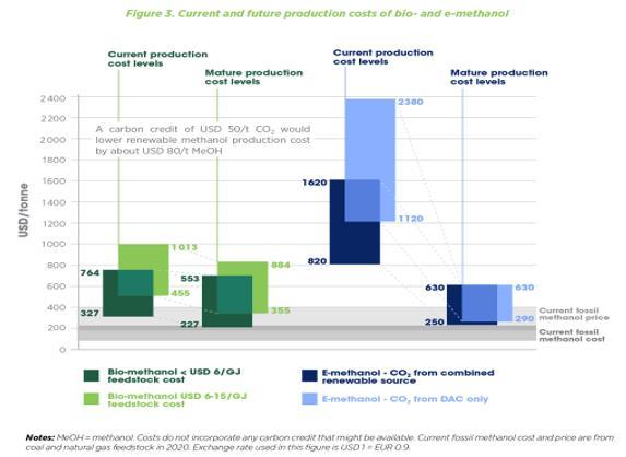
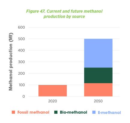


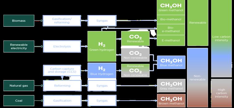

Conference Paper 191 Essential Methanol Brown, Grey, Blue and Green Cost of Production 2 Essential Methanol
4
methanol org Brown, Grey, Blue and Green
www.methanol.org 5 6
3
Brown, Grey, Blue and Green www.methanol.org/renewable/ Cost of Production
5 6
www.methanol.org
6/6/2022 www
www.methanol.org/renewable/
6/6/2022
www methanol org
More & More Renewable Projects
www.methanol.org/renewable/
More & More Renewable Projects
www.methanol.org/renewable/
More & More Renewable Projects
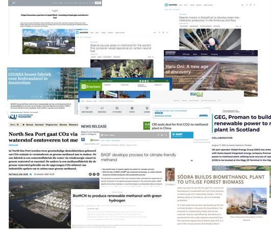
www.methanol.org
Carbon Footprint of Methanol
Carbon Footprint of Methanol
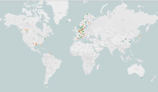
Carbon Footprint of Methanol
www.methanol.org/policy initiatives/europe/
www.methanol.org
• The carbon footprint of methanol depends on the feedstock and production pathway, considering all the emissions caused directly by the supply chain and by energy and materials used in the supply chain.
The carbon footprint of methanol depends on the feedstock and production pathway, considering all the emissions caused directly by the supply chain and by energy and materials used in the supply chain.
• The majority of emissions in fossil pathways concerns stoichiometric end of life emissions, when using methanol as a fuel for internal combustion engines (69 g CO2eq/MJ).
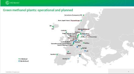
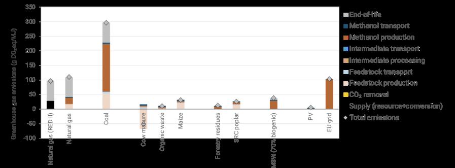
www.methanol.org/policy initiatives/europe/
5 The majority of emissions in fossil pathways concerns stoichiometric end-of-life emissions, when using methanol as a fuel for internal combustion engines (69 g CO2eq/MJ).
• Modern facilities producing from natural gas have carbon footprint of 93 110 g CO2eq/MJ, depends on carbon content of natural gas feed and tools like CO2 recycling back to methanol reactor. Default EU RED II value is 97 g CO2eq/MJ which is two decades old and does not reflect current carbon accounting.
• Production of bio methanol (biomethane, solid biomass, MSW) and e methanol from green hydrogen (solar, wind, hydro, geothermal) and CO2 (flue gas, biogenic, DAC) have very low carbon footprints of 10 40 g CO2eq/MJ and even some pathways with negative emissions ( 55 g CO2eq/MJ from cow manure biomethane.
• The carbon footprint of methanol depends on the feedstock and production pathway, considering all the emissions caused directly by the supply chain and by energy and materials used in the supply chain.
• The majority of emissions in fossil pathways concerns stoichiometric end of life emissions, when using methanol as a fuel for internal combustion engines (69 g CO2eq/MJ).
5 Modern facilities producing from natural gas have carbon footprint of 93-110 g CO2eq/MJ, depends on carbon content of natural gas feed and tools like CO2 recycling back to methanol reactor. Default EU RED II value is 97 g CO2eq/MJ which is two decades old and does not reflect current carbon accounting.
• Modern facilities producing from natural gas have carbon footprint of 93 110 g CO2eq/MJ, depends on carbon content of natural gas feed and tools like CO2 recycling back to methanol reactor. Default EU RED II value is 97 g CO2eq/MJ which is two decades old and does not reflect current carbon accounting.
www.methanol.org
• Production of bio methanol (biomethane, solid biomass, MSW) and e methanol from green hydrogen (solar, wind, hydro, geothermal) and CO2 (flue gas, biogenic, DAC) have very low carbon footprints of 10 40 g CO2eq/MJ and even some pathways with negative emissions ( 55 g CO2eq/MJ from cow manure biomethane.
5 Production of bio-methanol (biomethane, solid biomass, MSW) and e-methanol from green hydrogen (solar, wind, hydro, geothermal) and CO2 (flue gas, biogenic, DAC) have very low carbon footprints of 10-40 g CO2eq/MJ and even some pathways with negative emissions (-55 g CO2eq/MJ from cow manure biomethane.
www.methanol.org
Conference Paper 192
6/6/2022 4
7 8 4
7 8
10
Significant CO2 Reduction Potential
Significant CO2 Reduction Potential
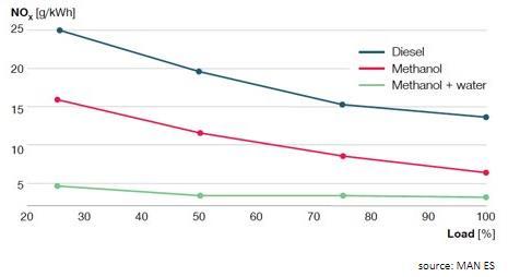
www.methanol.org
www.methanol.org
Improving Local Air Quality
ission reduction potential:
The Methanol Molecule
Improving Local Air Quality www.methanol.org
5 Methanol molecule is the same energy and chemical characteristics no matter how it is produced
• Methanol molecule is the same energy and chemical characteristics no matter how it is produced
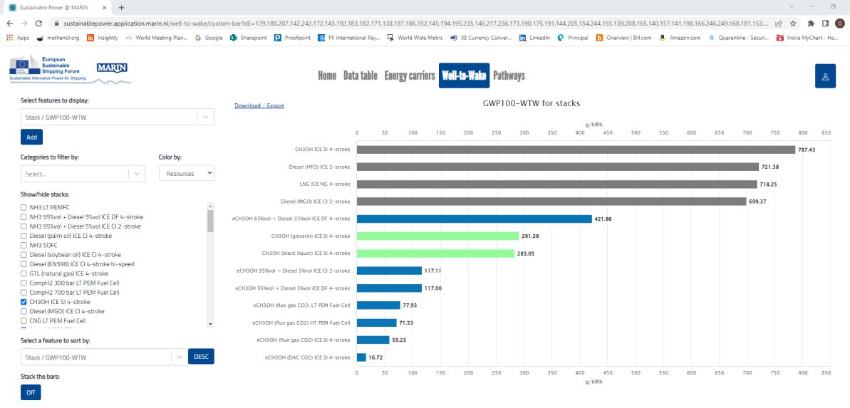
Marine 11
5 Completely fungible from grey to blue to green facilitating blending with reduced carbon intensity as low carbon and net carbon-neutral supply grows
• Completely fungible from grey to blue to green facilitating blending with reduced carbon intensity as low carbon and net carbon neutral supply grows
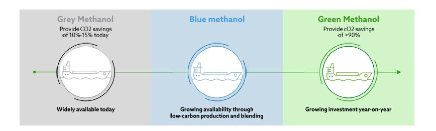
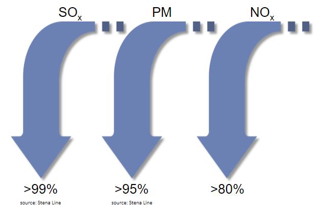

• Immediate benefits in reducing SOx, NOx, and PM
5 Immediate benefits in reducing SOx, NOx, and PM
5 Methanol runs well in existing engines with few modifications and significantly lower CAPEX when compared with other available alternative fuels
www.methanol.org
Conference Paper 193
6/6/2022 5
10
9
5
9
Improving Local Air Quality www.methanol.org 6/6/2022
The Methanol Molecule
• Methanol runs well in existing engines with few modifications and significantly lower CAPEX when compared with other available alternative fuels


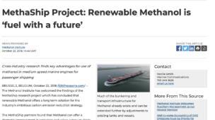

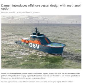


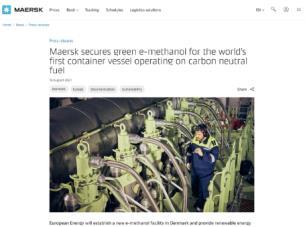

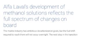


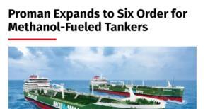

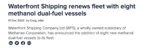

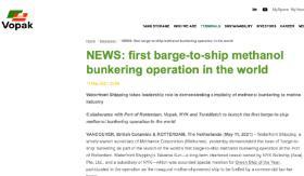


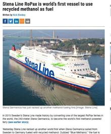

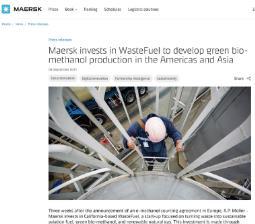

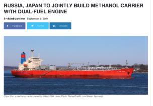


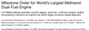

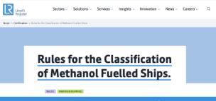

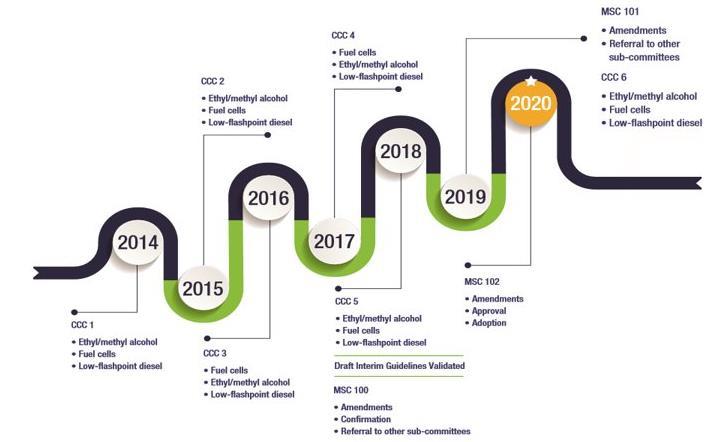
Conference Paper 194 Marine Methanol Making Headlines Game Changer 1: IMO IGF Code Methanol Approval www.methanol.org www.methanol.org/join us Marine www.methanol.org/marine/ 11 12 6/6/2022 www.methanol.org/join us Methanol Making Headlines Game Changer 1: IMO IGF Code Methanol Approval 13 6/6/2022 7 www.methanol.org/join us Methanol Making Headlines Game Changer 1: IMO IGF Code Methanol Approval 13 14
Game Changer 2: Maersk
Game Changer 2: Maersk Methanol Vessel Orders
Methanol Vessel Orders
Game Changer 2: Maersk Methanol Vessel Orders
• 21 Feb 2021: Maersk announces that the world’s first carbon neutral container vessel by 2023 will operate on dual fuel methanol
5 21 Feb 2021: Maersk announces that the world’s first carbon neutral container vessel by 2023 will operate on dual-fuel methanol
• 21 Feb 2021: Maersk announces that the world’s first carbon neutral container vessel by 2023 will operate on dual fuel methanol
• Maersk has now ordered 2,100 TEU methanol duel fueled feeder vessels from Korean shipyard
5 Maersk has now ordered 2,100 TEU methanol duel fueled feeder vessels from Korean shipyard
• Maersk has now ordered 2,100 TEU methanol duel fueled feeder vessels from Korean shipyard
• 24 Aug 2021: “Maersk accelerates fleet decarbonization with 8 large ocean going vessels to operate on carbon neutral methanol”
• 24 Aug 2021: “Maersk accelerates fleet decarbonization with 8 large ocean going vessels to operate on carbon neutral methanol”
5 24 Aug 2021: “Maersk accelerates fleet decarbonization with 8 large ocean-going vessels to operate on carbon neutral methanol”
• More than half of Maersk’s 200 largest customers have carbon targets for their supply chains
5 More than half of Maersk’s 200 largest customers have carbon targets for their supply chains
• More than half of Maersk’s 200 largest customers have carbon targets for their supply chains
• 16,000 container (Twenty Foot Equivalent TEU) vessels
• 16,000 container (Twenty Foot Equivalent TEU) vessels
• Delivery in 2024, option for 4 additional vessels in 2025
• Delivery in 2024, option for 4 additional vessels in 2025
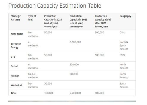
5 16,000 container (Twenty Foot Equivalent –TEU) vessels
• $1.4 billion order each vessel $175 million 10 15% more expensive
• $1.4 billion order each vessel $175 million 10 15% more expensive
5 Delivery in 2024, option for 4 additional vessels in 2025
• Each ship will require 35,000 40,000 tons of methanol annually or a total of 500,00 tons of methanol
5 $1.4 billion order each vessel $175 million 10-15% more expensive
• Each ship will require 35,000 40,000 tons of methanol annually or a total of 500,00 tons of methanol
5 Each ship will require 35,000-40,000 tons of methanol annually or a total of 500,00 tons of methanol
www.methanol.org
www.methanol.org
Game Changer 2.1: Maersk Methanol Off-Takers
5 10 March 2022: Maersk announces strategic partnerships with six leading companies -- including MI members Proman and Wastefuel -- with the intent of sourcing at least 730,000 tons/year of green methanol by end of 2025
Game Changer 2.1: Maersk
Methanol
Game Changer 2.1: Maersk Methanol Off -Takers
Off -Takers
5 Maersk estimates will need 6 million tons of renewable methanol by 2030 to fuel 25% of their 700-vessel fleet
• 10 March 2022: Maersk announces strategic partnerships with six leading companies including MI members Proman and Wastefuel with the intent of sourcing at least 730,000 tons/year of green methanol by end of 2025
• 10 March 2022: Maersk announces strategic partnerships with six leading companies including MI members Proman and Wastefuel with the intent of sourcing at least 730,000 tons/year of green methanol by end of 2025
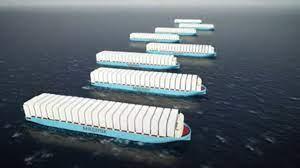
• Maersk estimates will need 6 million tons of renewable methanol by 2030 to fuel 25% of their 700 vessel fleet
• Maersk estimates will need 6 million tons of renewable methanol by 2030 to fuel 25% of their 700 vessel fleet
www.methanol.org
www.methanol.org
Conference Paper 195
8
“That means that if we end up finding exactly the right solution then there will be a big retrofit opportunity for us.” Maersk CEO Soren Skou speaking during Maersk’s on 10 February earnings call
“The reason that we have gone for methanol on the first one is that it is the most mature from the technology perspective; we can get an engine that can burn it.” Morten Bo Christiansen, head of decarbonization at Maersk
15 16 8
“That means that if we end up finding exactly the right solution then there will be a big retrofit opportunity for us.” Maersk CEO Soren Skou speaking during Maersk’s on 10 February earnings call
“The reason that we have gone for methanol on the first one is that it is the most mature from the technology perspective; we can get an engine that can burn it.” Morten Bo Christiansen, head of decarbonization at Maersk
15 16
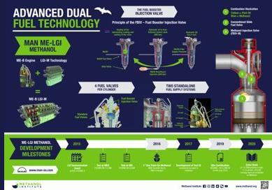
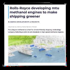
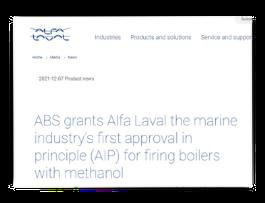
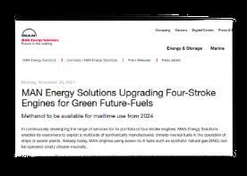
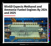

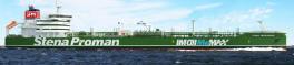
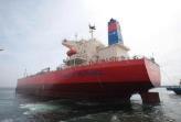
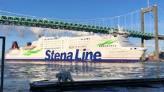


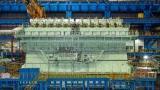

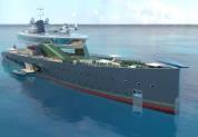

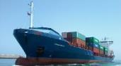


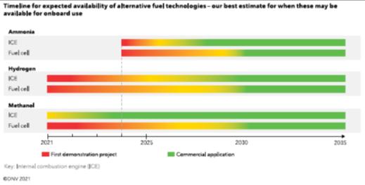
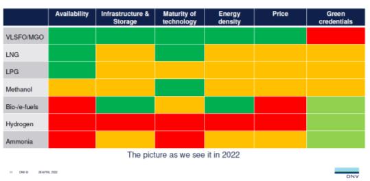
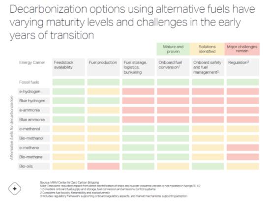
Conference Paper 196 Engines Available and More Coming On the Water and On the Way Technology Readiness 6/6/2022 9 Engines Available and More Coming www.methanol.org On the Water and On the Way www.methanol.org www.methanol.org/marine/ 17 18 9 Engines Available and More Coming www.methanol.org On the Water and On the Way www.methanol.org www.methanol.org/marine/ 17 18 6/6/2022 Technology Readiness www.methanol.org Available and Easily Bunkered 19
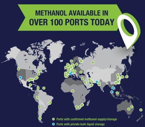

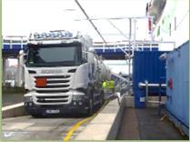

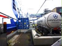


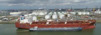

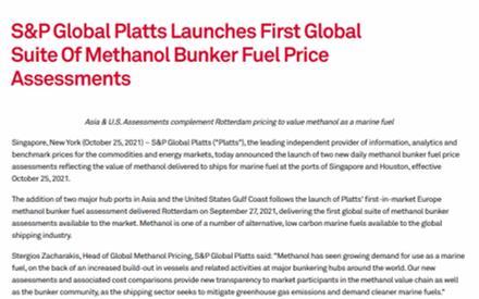

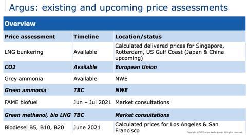


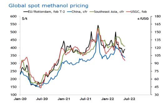
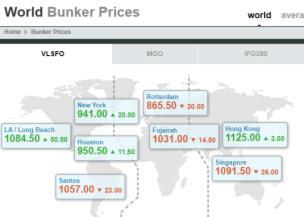
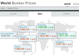
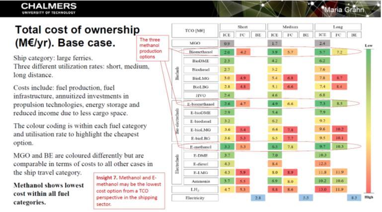
Conference Paper 197 Available and Easily Bunkered Methanol Pricing Stacking Up Green Competition 10 www.methanol.org Available and Easily Bunkered www.methanol.org 19 20 6/6/2022 Methanol Pricing www.methanol.org Stacking Up Green Competition 21 6/6/2022 Methanol Pricing www.methanol.org Stacking Up Green Competition www.methanol.org 21 22
• IRENA “Decarbonise the Shipping Sector”
• Short term, advanced biofuels play key role
• Medium and long term e methanol and e ammonia more promising green hydrogen based fuels
Projections – Methanol vs Ammonia
Projections – Methanol vs Ammonia
• By 2050, shipping uses 38 million tonnes of renewable methanol and 183 million tonnes of renewable ammonia
• IRENA “Decarbonise the Shipping Sector”
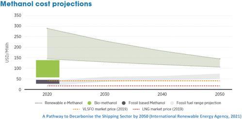
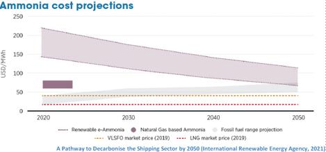

• Short term, advanced biofuels play key role
• Medium and long term e methanol and e ammonia more promising green hydrogen based fuels
• By 2050, shipping uses 38 million tonnes of renewable methanol and 183 million tonnes of renewable ammonia
www.methanol.org
What if ammonia not accepted
www.methanol.org
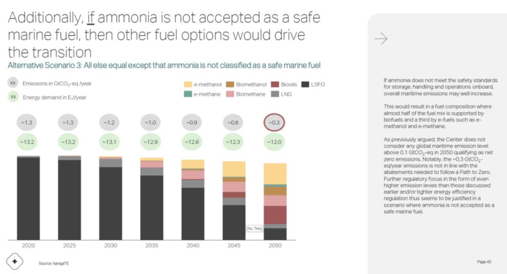
What if ammonia not accepted
What if ammonia not accepted

Marine Spills Still Happen…
•
www.methanol.org
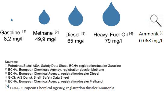
www.methanol.org
•
Conference Paper 198
6/6/2022 12
23 24 12
Projections – Methanol vs Ammonia
23 24 6/6/2022 Marine Spills Still Happen….
[5] 15,400 mg/l
www.methanol.org Methanol
Meth
is
more
anol
a
environmentally benign fuel in marine environments
LC 50: Lethal Dose: Fish Regulatory Developments 25
In a waterbody, nearly 200 times more methanol is needed to kill half the number of fish than marine heavy fuel oil
www.methanol.org
Regulatory Developments
Regulatory Developments
• FUELEU Maritime poised to grow methanol demand significantly
o WtW approach recognizing reduced carbon intensity in upstream profile
o EP & Council developments indicate eligibility of use of “blue” product and blends
• ETS sets price on carbon but does not recognize reduced carbon intensity of methanol TTW approach under EU MRV
o May include CH4 now and more GHG at later stage
Measuring Maritime Emissions
• RED employs 1.2 multiplier for renewable fuels in maritime and sets a high GHG reduction targets; How will MS implement?
• ETD stipulates energy content based taxation bridging the price gap between alternative fuels and fossils significantly
• Discussion at IMO level on WtW approach pressure from the EU
Measuring Maritime Emissions
www.methanol.org
Measuring Maritime Emissions
The Methanol Institute (MI) is call ing on maritime policy makers to adopt a ‘well to wake’ approach in GHG accounting of fuels to support the decarbonization of maritime transport. MI believes an approach that accounts for GHG emissions of the fuel’s entire value chain is essential to stimulate the uptake of renewable fuels that can drive the maritime industry’s energy transition.
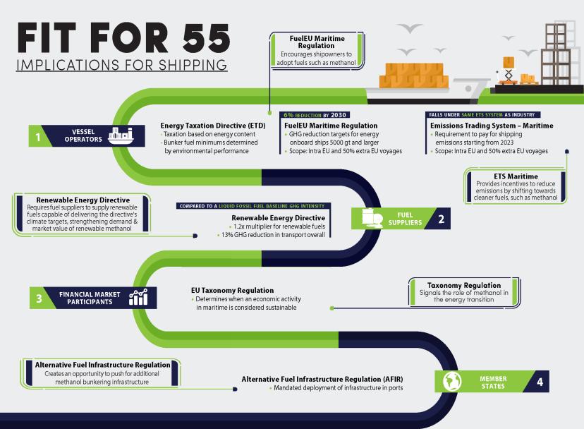
The Methanol Institute (MI) is call ing on maritime policy makers to adopt a ‘well to wake’ approach in GHG accounting of fuels to support the decarbonization of maritime transport. MI believes an approach that accounts for GHG emissions of the fuel’s entire value chain is essential to stimulate the uptake of renewable fuels that can drive the maritime industry’s energy transition.
www.methanol.org
Methanol as a Hydrogen Carrier
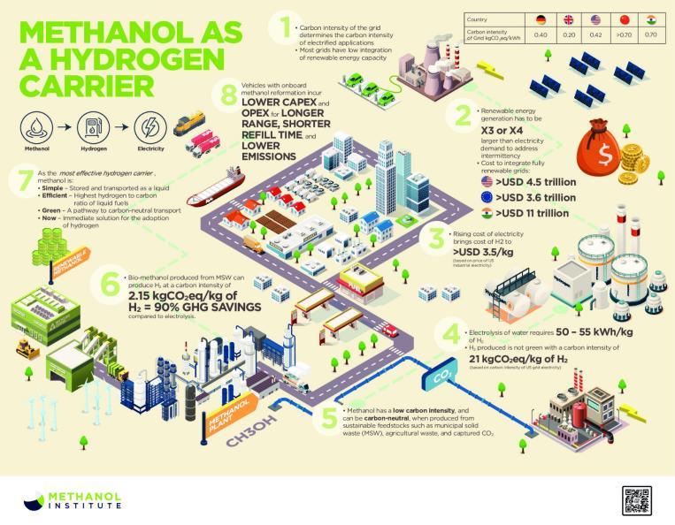
Methanol as a Hydrogen Carrier
www.methanol.org
www.methanol.org/fuel cells
www.methanol.org
Conference Paper 199
13
25
6/6/2022
26
27 6/6/2022
27 28
fit for 55 position paper
The Methanol Institute’s view on the restructuring of Europe’s regulatory landscape for fuels
Regarding:
1. The FuelEU Maritime Regulation and the extension of the EU ETS (Emissions Trading System) to mobility.
Methanol Institute Position
5 Adopting a well-to-wake approach in measuring emissions from maritime transport under FuelEU maritime is pivotal to the development of true carbon neutrality. To ensure interoperability between other Fit for 55 proposals and regulations formed on the international level, the well-to-wake/LCA methodology imposed by FuelEU maritime should be reflected in the EU ETS and EU taxonomy for measuring emissions from maritime activities. The IMO should be encouraged to take up a well-to-wake approach as implemented under the FuelEU Maritime.
5 The pooling mechanism introduced under FuelEU Maritime represents an important first-mover and extra-compliance benefit, serving as a critical incentive to facilitate the integration of carbon-neutral vessels in the short term.
5 The ETS and FuelEU Maritime should expressly state that GHG accounting be based on CO2eq, not solely on CO2 levels – considering all major greenhouse gases.
5 The legislation should apply a dual-term Global Warming Potential (GWP20-100). To better account for short-lived climate pollutants in marine transport, the GWP should reflect a shorter timeframe of 20 years. For GHG with a longer lifetime, a GWP of 100 years should be applied.
5 The Methanol Institute expresses its general support for the Commission’s proposal to extend the Emissions Trade system (ETS) to mobility, promoting a shift towards a cleaner future for Europe by increasing GHG reduction from covered sectors to 61% by 2030. Overall, supplyside mechanisms aimed at spurring the uptake of renewable fuels should be emphasized over instruments to make fossil fuels more expensive to avoid shifting the economic burden of the energy transition to general citizens.
5 The ETS system should calculate the GHG performance of fuels based on a well-towake approach and apply a CO2eq to reflect the complete environmental profile of fuels, in alignment with the provisions of FuelEU Maritime.
5 The Methanol Institute recommends a phase-in approach regarding applying ETS to maritime transport within the European Union to allow the fuel supply chain to react to policy and locate potential policy bottlenecks to be amended as implementation unfolds.
5 The Methanol Institute recommends the incremental increase of the FuelEU Maritime GHG reduction targets beyond 2030, accelerating at a quicker pace to direct investment towards alternative fuels with transitional pathways towards carbon neutrality. The final reduction target in 2050 should be 100% following the objective of the Climate Target Plan (CTP) and the European Green Deal (EGD).
Conference Paper 200
5 FuelEU Maritime should support the use of fuels sourced from biomass as long as they deliver climate benefits and do not cause a displacement effect on previous agricultural land management and practices.
The extension of the Emission Trade System (ETS) into mobility proposed under the set of legislative proposals collectively labeled the Fit for 55 packages is central to the drive towards carbon neutrality. As a carbon pricing mechanism, it is pivotal that the revision yields prices on carbon that prove sufficient to trigger a systemic shift towards renewable and low carbon fuels. Considering provisions of other instruments aimed at addressing the energy transition under the Fit for 55 packages, the price of carbon under ETS, in the case of road transport and building and shipping and industry, should be moderate and in line with the EU governance principle of proportionality. Furthermore, the ETS and FuelEU Maritime initiative should collectively aim to address the most significant challenge to the decarbonization of the maritime sector, which is the lack of clear vision and corresponding support required to ensure uptake of sustainable marine fuels. To facilitate increased supply and use of fuels in addition to the instruments already introduced under the Commission’s proposals, the Methanol Institute offers the following recommendations:
1. Life Cycle Assessment (LCA) approach to be reflected in other policy instruments under Fit for 55
We strongly endorse adopting a Well-to-Wake accounting approach to measure maritime emissions under the FuelEU Maritime initiative, as it gives a complete picture of the environmental profile of fuels and avoids a shift of emissions to upstream production processes. However, to ensure consistency and significant enforcement challenges, it is essential that all instruments pertaining to measuring GHG emissions of fuels be based on the same methodology and principles.
The Emission Trade System should apply the same method in determining emissions from mobility. The methodology has already been produced under FuelEU Maritime with reference to the average GHG values of the Renewable Energy Directive. The EU Taxonomy measures only funnel emissions from maritime activities from 2026. The EU MRV, which will monitor ETS’s extension to maritime transport, does not yet operate under the same LCA approach as the FuelEU Maritime. The instruments must be fully harmonized to reflect an intelligible market environment truly supportive of alternative fuel uptake. Furthermore, to better consider short-lived climate pollutants in maritime transport, such as methane, FuelEU Maritime should impose a dual term Global Warming Potential (GWP), with a 20-year timeframe (GWP20) for short-lived pollutants and GWP100 for GHG with a longer lifetime.
2. Phase-in mechanism to ensure a stable market environment for fuel suppliers and vessel owners
While the Methanol Institute fully supports the extension of ETS grounded on LCA and CO2eq to maritime mobility, we propose a phase-in approach to help overcome industry resistance to change and allows lessons learned in the early stages to be incorporated into the overall policy moving forward. Furthermore, the fuel supply development incentivized under the proposed legislation is limited today and will take several years to develop. Thus, we suggest a 5-year phase-in of ETS to marine mobility starting from 2023. Furthermore, and to the same end, the complexity of regulating extra EU voyages warrants a degree of caution. A holistic problem, climate change impacts the entire world and would better be fought through collective action. However, in the absence of effective leadership on behalf of the EU, it is unlikely that the ambition and climate action of the IMO would be sufficient. ETS with a phase-in would encourage and enable developments at the IMO level to materialize in lieu of inaction. Should the opportunity to impose a global fuel levy arise within the phase-in period, policymakers should be empowered to abandon the extension of ETS to maritime transport in favor of a more effective instrument with a more global encompassing scope.
Conference Paper 201
3. Accelerate GHG reduction target in maritime transport beyond 2030
The transition of maritime transport towards renewable and low carbon fuels requires targeted investment across the value chain in fuel infrastructure, bunker procurement, vessel design, and operation. The carbon price resulting from the extension of ETS to maritime transport will by no means represent an investment signal strong enough to supply the sector with sufficient low carbon and net carbon-neutral fuel to carry out the energy transition, neither should it, as such would incur too high a social cost. The Methanol Institute commends the GHG intensity reduction target proposed by the Commission. However, we recommend a steeper expansion of targets after the initial phase-in period of 6% GHG reduction by 2030. Further, to provide a clear pathway towards carbon neutrality, the Commission’s current proposal should be amended to recommend a trajectory closing at net carbon neutrality by 2050. To that end, the 2035 target should be increased to 25%, 70% in 2040, 90% in 2045, and the final reduction target in 2050 should be 100%, following the objective of the Climate Target Plan (CTP) and the European Green Deal (EGD).
4. Remove provision impeding synthetic fuels sourced from captured biogenic CO2
The LCA methodology described in the FuelEU Maritime proposal should be amended to remove any regulatory barriers for fuels sourced from biomass as long as they deliver the climate benefits targeted under the legislation and do not cause a displacement effect on previous agricultural land management and practices. Fuels sourced from carbon dioxide, biological or non-biological, should be eligible under FuelEU Maritime in correlation with other EU policies about fuels and sustainability.
Conference Paper 202
www.cargoconnections.net


www.ufofreight.com ONE OF THE ONLY EXCLUSIVE FREIGHT FORWARDER NETWORKS IN THE WORLD ESTABLISHED IN 2000 ISO 9001 & ISO 14001 CERTIFIED UNIVERSAL FREIGHT ORGANISATION
Cargo Connections provides independent forwarders access to a global network of agents who can handle their shipments, whilst working professionally under strict Membership Rules.
will
of
per
The ISO 9001 and ISO 14001 certified organisation offers a Restricted Representation policy, which means membership
only be offered to a limited number
agents
country.
NEED RELIABLE PARTNERS TO HANDLE YOUR FREIGHT FORWARDING NEEDS? Then join the international network with 100+ of the world’s top independent freight forwarders, located in 100+ countries, to increase your business. www.digifreight.live DigiFreight YouTube Our unique platform with built in time zones enables forwarders to connect with one another directly through their mobile device across several communication platforms (Skype, Zoom, Google Meet and WhatsApp). A project has come up and you don’t have time for a long back and forth email trail. Our powerful interface enables you to quickly schedule a meeting with your DigiFreight partner at a mutually convenient time with time zones automatically considered. Plus Face-to-Face Meeting in Croatia from 4-6 September 2022 THE NEW ERA IN NETWORKING FOR THE FREIGHT FORWARDING INDUSTRY DUBAI 11th Annual Summit 27-29 November 2022 After a challenging few years, it will be fantastic to see each other again. Our exciting event will be all about celebration and business. VIRTUAL EVENTS EVERY 6 MONTHS projectcargonetwork.com UK Based Head Office Established 12 Years Professional Online Training ISO 9001 & ISO 14001 260+ Specialist Members 115+ Countries New Virtual Meeting Hub Smartphone Service Every 6 months, we allocate a series of days where Members are invited to participate in virtual meetings (at no extra charge). The perfect opportunity to follow-up on our face-to-face meetings. NETWORKING PLATFORM FOR THE WORLD’S TOP PROJECT CARGO SPECIALISTS MORE BUSINESS MORE CONNECTIONS MORE EVENTS ONLINE TRAINING: Heavy Lift The clear and highly effective 6 module course consists of 66 x 10-minute video sessions, which cover industry terminology, dimensions, weights, and forces, heavy transport, heavy lifting, jacking, skidding and loadouts. pcntraining.com
BIOGRAPHY
DR GWANG-HYEON YU
Senior
Researcher, Green Oiwer & Engine Systems Research, Hyundai Heavy Industries
Dr. Gwang Hyeon, YU is a senior expert in HHI’s engine combustion research.
He is developing the combustion system for the alternative fuels including the HiMSEN methanol engine.
Before joining HHI, he has investigated novel combustion concepts such as HCCI, RCCI and Dual-Fuel engines over 10 years.
He holds a Ph.D degree in mechanical engineering from Ulsan National Institute of Science and Technology (UNIST), South Korea.

Speaker
204
Development of World 1st Methanol Engine for Very Large Container Ships
ABSTRACT
The regulations on pollutant emissions being tightened over the years. According to international marine organization (IMO) 2050, the international shipping should reduce total greenhouse gas emission, at least 50% by 2050 compared to 2008. In turn, shipping companies are increasingly interested in the engine powered by low-carbon fuel. To achieve carbon-neutrality, Hyundai Heavy Industries (HHI) has invested in development of engine powered by carbon neutral fuel. The methanol powered engine developed by HHI, H32DF-LM, uses methanol as main fuel and marine diesel oil (MDO) as main and micro-pilot for fuel and both fuel are injected by high pressure fuel injection pump (FIP). Also, H32DF-LM is designed to inject methanol and MDO with one injector. The reason for this is because of the fuel characteristics of methanol. Since methanol has half the heating value and greater latent heat of vaporization than that of conventional diesel, we had to consider ignition stability for stable operation. Moreover, since methanol is toxic, we needed to ensure safety. For engine development, system performance is calculated through 1D simulation, and based on this results, 3D combustion simulation is performed to investigate combustion characteristics and performance. In addition to methanol engine, HHI is also developing engines powered by ammonia and hydrogen. In addition, fuel supply system for each fuel type are being developed. Through these, we are doing our best as a total marine solution provider.
Introduction
As the years go by, global interest in environmental pollution and climate change is increasing. Greenhouse gas (GHG) emissions are mentioned as a major factor in climate change. Effort to reduce GHG emissions have continued since the early 2000s. According to IMO`s strategy on GHG, the international shipping should reduce total GHG emissions, at least 50% by 2050 compared to 2008 [1]. In turn, shipping companies are increasingly interested in the new technology to reduce GHG emissions. There are various methods to reduce GHG emission such as engine efficiency improvement, low speed operation, optimum route, and methane slip reduction, etc. However, the most effective method is converting the fuel. Instead of fossil fuel containing a lot of carbon, it is necessary to switch to low-carbon fuels such as methanol, ammonia, and hydrogen.
Diesel Methanol
Table 1 Fuel characteristics [2]
Table 1 shows the characteristics of each fuel such as diesel and low-carbon fuel. Among the low-carbon fuel, methanol is the first to be commercialized. Since the boiling point of methanol is 65 degrees, it is liquid at room temperature. So, it is easy to store and transportation. There
Conference Paper 205
Ammonia Hydrogen Chemical formula C5-C12 CH3OH NH3 H2 Boiling point [°C] 150-380 65 -33 -253 Auto-ignition temperature [°C] 250 500 693 500 Lower heating value [MJ/kg] 42.5 19.9 18.8 120 Latent heat of vaporization [kJ/kg] 250 1103 1369 461
is only one carbon atom in the methanol molecule, so carbon dioxide emissions are lower than conventional diesel. Moreover, it contains oxygen atoms, so it produces low smoke. And due to the low flame temperature, the NOx emissions are about 50% compared to diesel. However, due to the lower heating value, the storage tank size has to be increased for the same engine power. And also the amount of fuel injected into the cylinder has to be increased. In addition, methanol is difficult to ignite due to its high auto-ignition temperature. Also, the combustion cylinder temperature is lower than that of diesel engine due to the higher latent heat of vaporization, then there is a high possibility of combustion instability. Nevertheless, it is emerging as an alternative fuel because of its low pollutant emissions and easy to storage and transportation.
Figure 1 HiMSEN DF engine development history

HHI is conducting research on eco-friendly engines to cope with GHG regulation. HHI made a lot of efforts to develop eco-friendly engines. In 2012, it completed the diesel engine line-up and began to develop dual fuel (DF) engines. It have completed a DF engine line-up that can cover various power range such as H35DF, H27DF, H22CDF, and H54DF. HHI also developed a CLEAN (Customer, reLiability, Environment-friendly, Adaptive technology, No defect) diesel engine that improved the performance. Recently, HHI started developing a low-carbon fuel engine, a next-generation engine, to cope with the emission regulation.
Description
Specification
Engine model H32DF-LM
Engine type Diesel, methanol, 4-stroke
No. of cylinder [EA] 6 ~ 9
Power per cylinder [kW] 500
Engine speed [rpm] 720 / 750
Bore x Stroke [mm] 320 x 400
Table 2 HiMSEN methanol engine specification
Conference Paper 206
Introduction to H32DF-LM
In 2021, HHI signed a contract with A. P. Moller Maersk, the world`s largest shipping company, to order a large container ship powered by methanol. In these ship, MAN`s two-stroke engine is equipped for main propulsion, and H32DF-LM is equipped for auxiliary power generation. The methanol engine developed by HHI, H32DF-LM, is the world`s first medium speed engine developed exclusively for methanol. It can use methanol and diesel as a fuel and they are injected directly into the cylinder. There are some differences between H32DF-LM and the conventional HiMSEN DF engine.
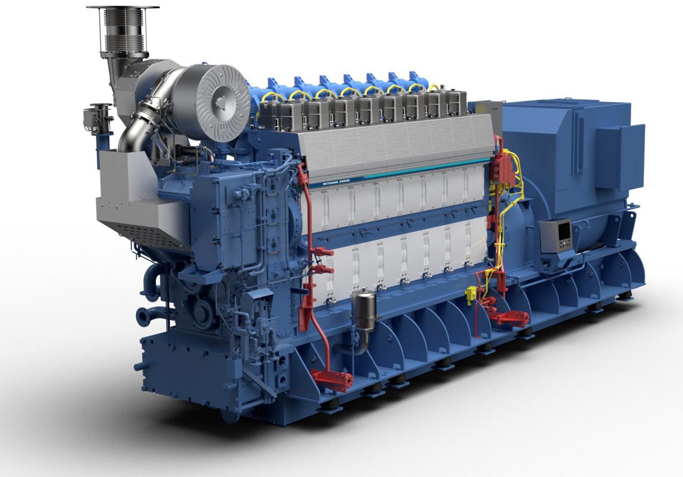
Figure 2 HiMSEN methanol engine: H32DF-LM
First, diesel fuel is mechanically injected, but the injection timing and duration can be electronically controlled by e-FIP. This makes it easy to optimize the engine operating parameter for methanol fuel. The operation method of e-FIP is not much different from the existing FIP. The fuel is pressurized using cam same as mechanical injection pump, but the solenoid valve is equipped and can be used to control the injection timing and duration. Figure 3 shows the schematic and simple operating principles of e-FIP. Second, diesel and methanol are injected by one-body injector. Third, main diesel and pilot diesel is injected by the same fuel injection valve (FIV). Since, methanol, main/pilot diesel are all injected by one injector, the injection system is simple and the space of engine system can be used efficiently. Table 2 shows the engine specification of H32DF-LM.
Conference Paper 207
Figure 3 e-FIP
To develop a methanol combustion system, cooperation from various organizations is needed. Engine development is completed through various processes such as conceptual design, fundamental and detailed design, manufacturing, assembly, and test, etc. Engine research institutes mainly investigated engine performance and durability by simulation and analyze the test results. The fundamental design of combustion system is performed using 1D performance simulation to matching target engine power and fuel oil consumption. Through this process, the compression ratio, valve timing, engine size, and T/C specification are determined. After that, a detailed design is performed based on the 1D simulation results. For this purpose, 3D combustion, structure, vibration, and heat & flow simulation are performed. As mentioned earlier, methanol has lower heat value and higher latent heat of vaporization than those of diesel. Therefore, the amount of fuel required is large and combustion instability is easily to occur due to a cylinder temperature reduction. In addition, since both diesel and methanol are directly injected into the cylinder, it is necessary to consider spray interference.
Simulation and Test Results
HHI has developed a 3D combustion model to consider combustion characteristics of lowcarbon fuel, methanol. Using the developed combustion model, the specification of diesel and methanol injector were determined by considering both combustion stability of methanol and combustion performance. As shown in figure 4, through the combustion simulation, various methanol combustion characteristics are investigated such as normal flame, weak flame and misfire.
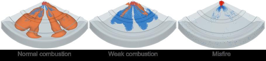
Figure 4 Methanol combustion characteristics
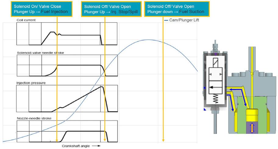
Conference Paper 208
After that, methanol prototype engine is made and we conducted diesel and methanol mode tests. The diesel mode performance is similar compared to existing diesel engine, because the performance optimization for each load was carried out. Through the methanol mode test, the diesel/methanol changeover process was optimized. As is known from the literature, NOx is reduced by 50-60% compared to diesel engine, and smoke was also much lower than diesel engine.
Figure 5 Cylinder pressure and heat release rate of methanol and diesel mode (Test)
Figure 5 shows the cylinder pressure and heat release rate of methanol and diesel from field test. As you can see, the combustion characteristics such as maximum cylinder pressure, the trend of cylinder pressure, and rate of heat release of diesel and methanol are similar. Since both diesel and methanol modes are operated by diesel cycle. However, for LNG/diesel DF engine, gas and diesel mode have different combustion characteristics such as the maximum cylinder pressure of gas mode is lower than diesel mode and cycle-to-cycle maximum cylinder pressure variation of gas mode is higher than diesel mode because both diesel and gas modes are operated by Diesel and Otto cycle, respectively.
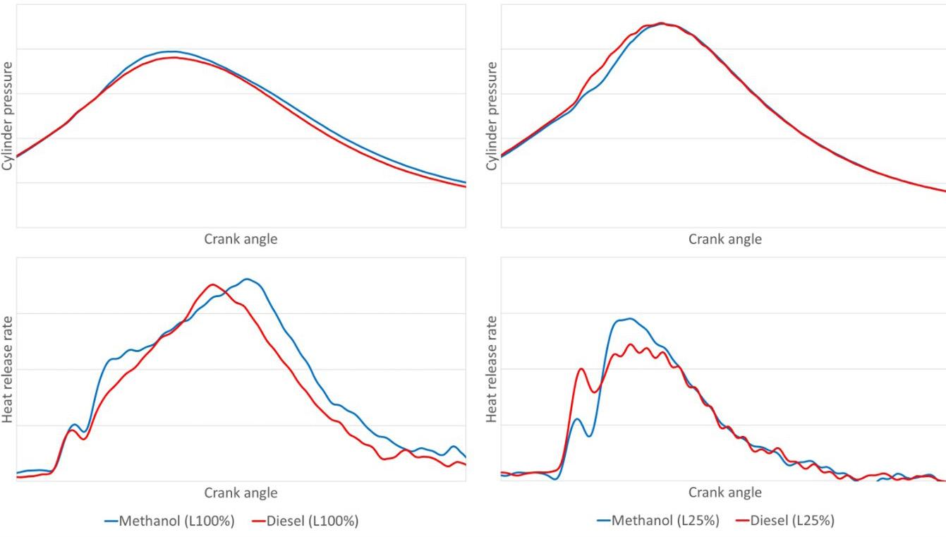
Conference Paper 209
As you can see from figure 6, HHI received approval from classification societies such as KR, DNV, ABS, LR, NK, RINA, BV in September, 2022. In addition to H32DF-LM, HHI will expand methanol engine line-up, H22CDF-LM (`23) and also develop engines fueled by ammonia (`24) and hydrogen (`25) and existing DF engine will be improved to further reduction of methane slip with new technologies and after-treatment equipment. Moreover, the development of fuel supply system for each fuel type, fuel cell, and water electrolysis technology is in progress. Through these, we are doing our best as a total marine solution provider.
Conclusion
HHI has developed world`s first medium speed methanol engine, H32DF-LM. It will be mounted on a large container vessel. The main features of H32DF-LM engine are as follows: (1) One-body injector (Diesel/Methanol), (2) Diesel main and pilot are injected by same FIV. (3) Injection timing and duration of diesel are controlled by e-FIP. The field test results shows that the combustion characteristics of methanol is similar to diesel. Moreover, NOx and Smoke from methanol combustion is much lower than diesel combustion. In September, HHI received approval from classification societies. In addition to H32DF-LM, HHI will expand methanol engine line-up and also develop engines fueled by ammonia (`24) and hydrogen (`25).
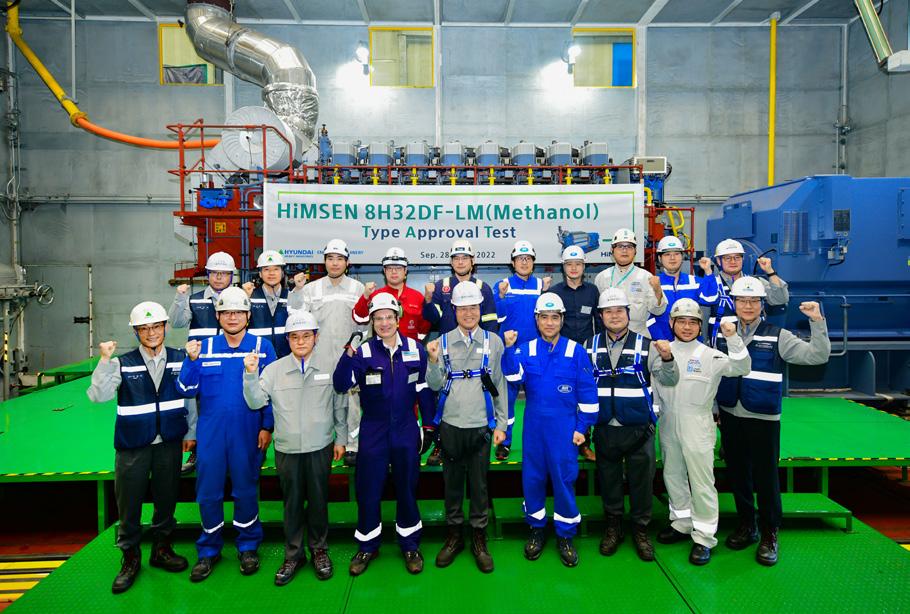
Reference
[1] Third IMO Greenhouse Gas Study 2014
[2] M. Aziz, et al, Ammonia as effective hydrogen storage: A review on production, storage and utilization, 2020, Energies 13
Conference Paper 210
Figure 6 HiMSEN 8H32DF-LM engine type approval test (TAT)
Main heading
BIOGRAPHY
DANIEL BARCAROLO

Senior Sustainability Engineer, Global Sustainability Copenhagen, ABS
Daniel Barcarolo is a Senior Engineer for the ABS Sustainability Center in Copenhagen. In his current role, he works on initiatives that advance innovation, technology development and safety related to sustainable shipping, with a focus on decarbonization both at ABS and at the Mærsk McKinney Møller Center for Zero Carbon Shipping. He is also the ABS representative for the IACS Environmental Panel.
Speaker
211


to free digital editions of our suite of publications for the passenger shipping industry www.cruiseandferry.net/magazines/subscriptions Subscribe
SESSION 7.1
Multifuel Engines
213
ROLF STIEFEL Regional Chief Executive, Bureau Veritas Marine & Offshore

BIOGRAPHY
Rolf Stiefel is the Regional Chief Executive for Bureau Veritas Marine & Offshore, responsible for Central Europe. Based in Hamburg, his expertise in the maritime industry spans two decades and two continents. His maritime career started with Wärtsila, first covering the German market, then moving to Switzerland to work on low-speed engines, and finally joining the Shanghai team covering the Merchant shipping segment in Asia and worldwide. Rolf was Vice President Sales & Marketing for Winterthur Gas & Diesel (WinGD) between 2015 and 2020, focusing on low-speed main propulsion engines, before joining Bureau Veritas in 2020. Rolf holds a Master’s in Industrial Engineering from the University of Hamburg.
ABSTRACT
The advent of multi-fuel systems is a key step towards 2030 and 2050 decarbonisation targets, yet a number of challenges must be addressed – from the safety and control of fuels with different properties, to storage, bunkering, infrastructure and regulatory considerations.
Speaker
214
propulsion
IMO 2050 TARGETS/ and the role of new fuels and technologies
CO2 emissions per transport work: at least 40% by 2030, pursuing efforts towards 70% by 2050, compared to 2008
Total annual GHG emissions: reduced by at least 50% by 2050 compared to 2008
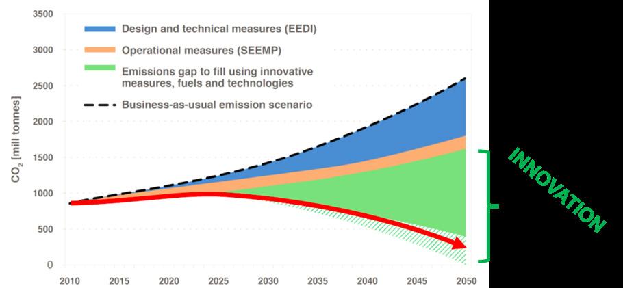
Conference Paper 215
Will “multi-fuel”
engines be the solution to solve the “future fuel” uncertainty?
ALTERNATIVE FUELS AND TECHNOLOGIES
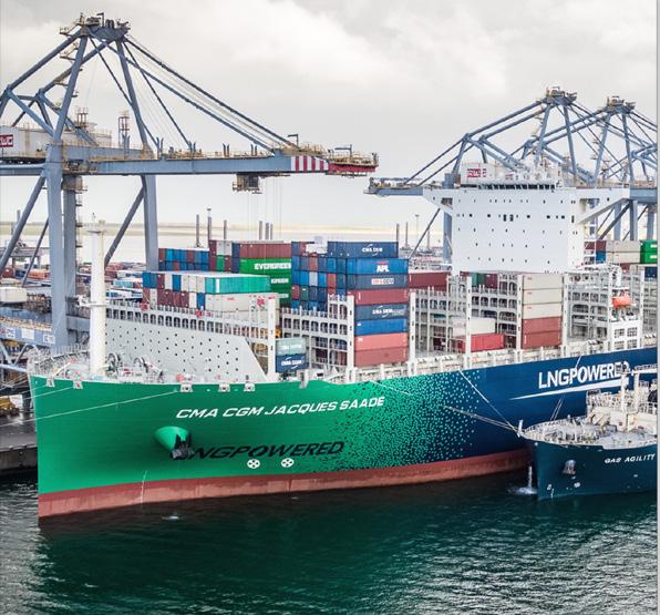
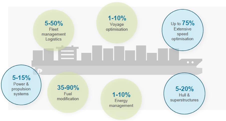
Conference Paper 216
HOW TO ACHIEVE THE GOAL?
A mix of technical operational and innovative solutions
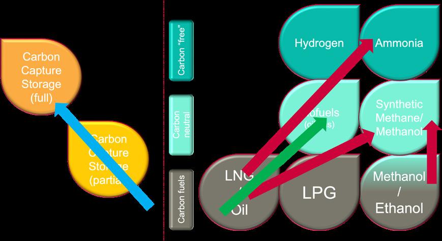
Conference Paper 217
TO ACHIEVE THE GOAL?
2050 – alternative fuel/technology Options Multifuel considerations Physical/Chemical properties of the fuels • Specific energy by weight and volume • Gaseous /liquid • Cryogenic • Ignitability • Safety aspects /flammability/toxicity Converters availability • ICE • Fuel cells • Others? Availability and Cost • Regional/global • Drop in capability CCS pathway Carbon neutral/free pathway
HOW
Towards
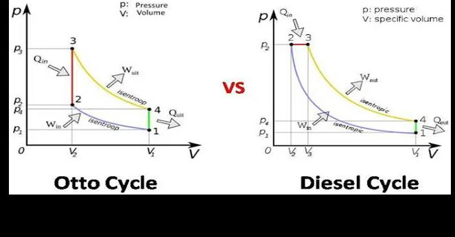
Conference Paper 218
WITH ICE ---- HIGH LEVEL
fuel! After treatment system depending on engine concept and fuel: 5 SCR catalyst 5 EGR (high/low pressure) 5 Particle filter 5 Oxidation catalyst 5 Scrubber 5 Engine type Marine applications HFO MDO LNG LPG Methanol Ammonia H2 Bio Diesel 4-stroke Diesel <500kW X O O X O X 4-stroke Otto X >100kW X O X 2-stroke Diesel X X HP X X O - X 4-stroke Otto LP O OX: available technology O: Technology under development or consideration // * N2O emissions need to be avoided/ abatement technologies yet not tested
MULTIFUEL
OF FUEL FLEXIBILITY ICE are with the Diesel-, Otto- cycle and combinations thereof in the same engine very flexible to accommodate different fuels. Basic parameters, fuel injection as well as ignition is varying substantially with fuels and technology. Multifuel (beyond Dual-Fuel with Diesel) will need major retrofits on the engines depending from which to which
Fuel cell and mulitfuel --- possible
Fuel cells as energy converters are capable to operate also on a variety of fuels: (PEMFC, SOFC) 5 H2 5 Methanol 5 Ammonia 5 Methane 5 LPG
Basically, the fuel other then Hydrogen (H2) is converted in or prior to the fuel cell by a “reformer” into H2 and NO2/CO2 depending on the H2 carrier used. There is the possibility to integrate a CCS system to ensure GHG free overall.
+ efficiency up to 70% + no moving parts + no noise + no “emissions” - limited lifetime - load acceptance
The reformers are requiring additional energy. The process is different depending on the primary fuel applied!
Conference Paper 219


Conference Paper 220
Defining the complexity of the vessel propulsion, fuel storage and supply system onboard! Fuel type Mass energy density LHV [MJ/kg] Volumetric energy density LHV [GJ/m3] Storage pressure [bar] Storage temperature [°C] Relative tank volume (without insulation) Marine Gas Oil (reference) 42.8 36.6 1 20 1 LNG 50 23.4 1 162 1.6 Ethanol 26.7 21.1 1 20 1.7 Methanol 9.9 15.8 1 20 1.7 Liquid Propane 50.3 26.7 1 42 1.4 7 20 Liquid Ammonia 18.6 12.7 1 33 2.9 10 20 18 45 Liquid Hydrogen 120 8.5 1 253 4.3 Compressed H2 120 7.5 700 20 4.9
ALTERNATIVE FUELS Fuel characteristics H2liquefied LNG - fosill - Bio - Synthetic Ammonia - C02 free - toxic Methanol - toxic

Conference Paper COMPLEXITY OF BUILD AND OPERATE OCEAN GOING SHIPS CCS* Ammonia Methonal LNG H2** COMPLEXITY TO RETROFIT / OCEAN GOING SHIPS CCS* Ammonia Methonal LNG H2** * Partial CCS to meet future EEDI/CII targets ** Liqufied storage on board * Partial CCS to meet future EEDI/CII targets ** Liqufied storage on board COMPLEXITY OF BUILD AND OPERATE/ SMALL-COASTAL CCS Ammonia Methonal LNG H2* * Pressurized H2/metal hydridstorage Electric needs”Diesel-Electric” design
MULTIFUEL / RETROFIT STUDY CONTAINER VESSEL SUMMARY RESULTS
study on Multifuel/Retrofit concepts for a 15k TEU Container vessel
Analyzing:
5 Capex and other costs
5 GHG life-time emissions
Varying parameters: 5 Various “multifuel” readiness designs
5 Lifetime before conversion
5 Full range/reduced range (tank size)
Summary results:
Converting from Fuel Oil:
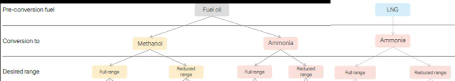
5 to Methanol cost between 11% to 16% of vessel building cost (150m) equal 16.5-24.0 m
5 to Ammonia cost between 16% to 24% of vessel building cost (150m) equal 24.0-36.0m

Converting from LNG:
5 to Ammonia cost between 10% to 15% of vessel building cost (174m) equal 17.4-26.1 m
5 operating on e-Methane would be without additional investment cost! (not considered in the study)
Full report here: https://www.zerocarbonshipping.com/publications/preparing-container-vessels-forconversion-to-green-fuels-2/
Conference Paper 222
WELL-TO-TANK EFFICIENCY OF E-FUELS
Cost will play a major role regarding the selection of a future e-fuel for shipping beside global supply infrastructure.
One major factor regarding the cost will be the efficiency of the conversion process from green electricity via Hydrogen to the e-fuel.
Figure 18: E-FUELS OVERALL WELL-TO-TANK EFFICIENCY
Methanization efficiency 80% Ammonia syn. Haber-Bosch process efficiency 86% Methonal systhesis efficiency 80% Fischer-Tropsch efficiency 70% Transport efficiency* 80% 80% 95% 95% 95% e-Methane 43% e-Ammonia 54% e-Methanol 51% e-Liquid fuels 44% * Transport including compression in the case of
-RULES AND GUIDELINES FOR ALTERNATIVE FUELS
IMO IGF Code
IGF Code Alternative design (2.3) Guideline under development
December 2020 Interim Guidelines (Circ. 1621, MSC.1)
IGF Code Alternative design (2.3) Not IGC (toxity) Storage: IGC
IMO safety provisons for ships using fuel cells Guidelines under development
Wind assisted propulsion system Full wind propelled ships Please visit our website https://marine-offshore.bureauveritas.com/rule-notes-and-guidance-notes
Fuel Supply Covered in “Fuel Cell” Storage (IMO MSC 420(97), ISO, EN, ASME,...)
Conference Paper 223
LNG LPG Methenol Ammonia Fuel Cell Hydrogen Wind BV Rules and guidelines NR 529 (2020) NI 647 (2018) NR 670 Release in 2021 NR 671 Release in 2021 NR 547 New revision in 2022 Covered by ‘Fuel Cell’ NR 547 NR 206 (2021)
BV
Electricity e-Hydrogen e-Methane e-Ammonia e-Methonol e-Liquid fuels Battery Electric Vehicle Fuel Cell ICE Fuel Cell ICE ICE ICE ICE WTT Renewable power 100% 100% 100% 100% 100% 100% Transmission efficiency 95% 95% 95% 95% 95% 95%
Electrolysis efficiency 70% 70% 70% 70% 70% e-Hydrogen 67% 67% 67% 67% 67%
and
CONCAWE
hydrogen
methane. Source:
PROJECTS TOWARDS DECARBONIZATION
MORE
JDP`s ongoing to ensure safe and reliable operation on board of ships and bunkering Guideline: NR 671
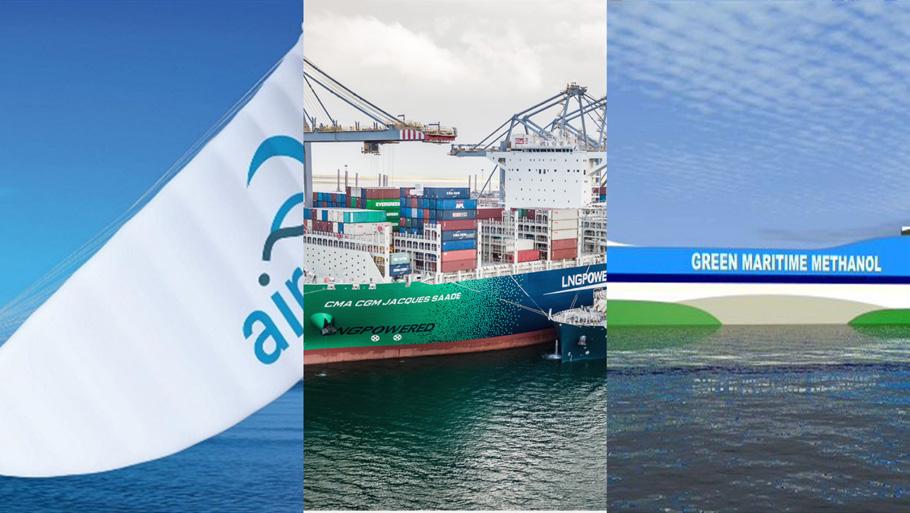
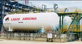
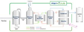
AIP for use of Hydrogen Fuel cells granted. First installations in operation Guideline: NR 547
AIP´s ongoing. JIP for demonstrators under development.

Conference Paper 224
Assisted Propulsion/ leading Class LNG as Fuel / leading Class Methanol as fuel / JDP/AIP`s ongoing
WORLDWIDE INVOLVEMENT WITH INNOVATIVE
Wind
Fuel Hydrogen
INNOVATION IN THE PIPELINE... Ammonia as
Generation on Board Carbon Capture and Storage
CONCLUSION
5 Multifuel engine developments will support later adaptations to carbon neutral fuels.
5 Complexity and cost of retrofits might be higher than anticipated.
5 Exhaust aftertreatment to reduce pollutants need to be considered with changing fuels.
5 On board storage, bunkering and supply systems are highly different with different fuels. The multifuel system has a higher CAPEX then a single fuel layout.
5 Carbon neutral drop-in fuels like synthetic-Diesel and synthetic-Methane will be most cost-efficient solution to reduce GHG emissions for vessels build with today´s available technology and limited lifetime when e-fuels are becoming available/mandatory.
5 Hybrid-propulsion solutions (especially for small and coastal ships) will open many more possible solutions for retrofit.
Conference Paper 225
...by Decarbonization of Shipping
MAIKEL ARTS
General Manager, Market Innovation, Wärtsilä Marine Power

BIOGRAPHY
Maikel Arts is General Manager Market Innovation at Wärtsilä Marine Power. Wärtsilä is the global leader in innovative technologies and lifecycle solutions for the marine and energy markets. The company purpose: ”Enabling sustainable societies through innovation in technology and services” is close to his heart. Maikel works at the intersection of maritime C-suite challenges and cutting-edge technology development with a strong focus on decarbonisation. He uses this technology with his experience and network to create solutions that deliver on sustainability and business economics.
Based in The Netherlands he finds himself in one of the world’s Maritime hot spots. With a broad view on macro-economic developments, upcoming legislation and market dynamics, he has expertise on the impact that these changes will have on the maritime industry and how companies can mitigate business risks and capture opportunities.
Maikel earned a BA degree in engineering and a degree in commercial business, however he is also a certified tutor in engineering. This enables him to explain complex problems and solutions to a wide range of audiences. He has 20+ years of experience in commerce and business development in complex and competitive environments. This combination of technology, business understanding, and communication makes him a frequent speaker at events and an ideal boardroom advisor.
ABSTRACT:
The Multi-fuel engine technology enables the transition from fossil to renewable fuels through its built in technical feasibilities and economic viability. Infrastructure and availability of green fuels need time to mature while Multi-fuel engine technology enables shipowners a safe transition journey starting already today
Speaker
226
Wärtsilä Multi fuel engine, one main corner stone of a successful fuel transition
1. Introduction
To comply with the decarbonisation targets, radical change is needed. One of the challenges is fuel and the related global investments in its production and infrastructure. Wärtsilä is leading the way in developing a wide range of fuel technologies to help navigate the route to reduced greenhouse gas emissions – whatever fuel is chosen.
1. Introduction
To comply with the decarbonisation targets, radical change is needed. One of the challenges is fuel and the related global investments in its production and infrastructure. Wärtsilä is leading the way in developing a wide range of fuel technologies to help navigate the route to reduced greenhouse gas emissions whatever fuel is chosen.
Before we begin discussing future fuels, an important distinction should be made between socalled ‘carbon-neutral’ and ‘zero-carbon’ fuels.
Before we begin discussing future fuels, an important distinction should be made between so called ‘carbon neutral’ and ‘zero carbon’ fuels.
5 Carbon-neutral fuels are those that have no net carbon emissions, meaning their production and use does not increase the amount of CO2 in the atmosphere. Examples include synthetic fuels made with renewable energy plus re-circulated carbon, and certain biofuels.
• Carbon neutral fuels are those that have no net carbon emissions, meaning their production and use does not increase the amount of CO2 in the atmosphere. Examples include synthetic fuels made with renewable energy plus re circulated carbon, and certain biofuels.
5 Zero-carbon fuels release no CO2 when used as they do not contain any carbon. While hydrogen is an example of a zero-carbon fuel, it can only be called carbon neutral when it is produced with renewable energy.
• Zero carbon fuels release no CO2 when used as they do not contain any carbon. While hydrogen is an example of a zero carbon fuel, it can only be called carbon neutral when it is produced with renewable energy.
Wärtsilä is investigating a wide range of fuels (fig 1), including bio and synthetic liquefied natural gas (LNG) and natural gas along with ammonia, methanol/ethanol, hydrogen and biofuels. Wärtsilä’s research draws on deep experience gained through decades of building engines as well as supply and storage systems for a wide range of fuels.
Wärtsilä is investigating a wide range of fuels (fig 1), including bio and synthetic liquefied natural gas (LNG) and natural gas along with ammonia, methanol/ethanol, hydrogen and biofuels. Wärtsilä’s research draws on deep experience gained through decades of building engines as well as supply and storage systems for a wide range of fuels.

When moving towards a complex fuel future, Wärtsilä’s goal is simple: to continue to be a provider of complete solutions for all available future fuels. Given the market demand, in the next decade we will commercialise engine technologies that will allow to make use of all fuels currently under discussion. Given the modularity of modern engines this means also that owners can already today plan how to use new fuels when they become available.
When moving towards a complex fuel future, Wärtsilä’s goal is simple: to continue to be a provider of complete solutions for all available future fuels. Given the market demand, in the next decade we will commercialise engine technologies that will allow to make use of all fuels currently under discussion. Given the modularity of modern engines this means also that owners can already today plan how to use new fuels when they become available.
Fig 1. Fuel roadmap – focusing on renewable
fuels
Conference Paper 227
Fig 1. Fuel roadmap focusing on renewable fuels © Wärtsilä FUEL ROADMAP
3 2030 2050 2020 2040 Fossil CNG & LNG Bio CNG & LNG Synthetic CNG & LNG Gas Fossil liquid Bio liquid Synthetic liquid Liquid § CNG & LNG are the cleanest fossil fuels, 5 to 20% GHG reduction (well to
§ Unburned fuel
great reduction
further reduction
§ Bio & synthetic fuels
GHG 70
100%
§ Bio & synthetic fuels
rules
regulations exist and supply
*) renewable Hydrogen *) renewable Ammonia *) renewable Methanol, Ethanol § Zero carbon, no CO 2 emissions § Can be blended with CNG & LNG, 15 25% vol possible already today § Liquid storing possible, at 253 °C § Zero carbon, no CO 2 emissions § Can be blended with liquid fuels or gases § Toxic, safety concepts and regulation being developed § Carbon neutral, can be blended with liquid fuels § Technology developed, one engine product released § Toxic, safety regulations exist *) timing depends on market demand CNG/LNG Compressed/Liquified Natural Gas; GHG Greenhouse gas 28.2.2022 Public
– SUSTAINABLE SOLUTIONS EXIST
wake/power)
release high on agenda,
achieved and
on going
reduce
to
(well to wake/power)
possible already today, infra,
and
infrastructure adaptation started
2. A FOCUS ON LNG – AND FUEL FLEXIBILITY
There are uncertainties around every prospective fuel, including when and where they will be available and at what price. Building on fuel flexibility, and where appropriate, retrofitting powerplants and older ships – offers a hedge against these risks.
To start with, Wärtsilä believes that the transition to clean fuels will be easiest, most cost effective and fastest for those power plants and ships powered by NG/LNG, which already offers GHG emission reductions of between 5 and 20% compared to heavy fuel oil, calculated on the well to power/wake value chain. Bio and synthetic NG/LNG can be used initially as drop-in fuels alongside conventional NG/LNG to reduce carbon content and later, as supply increases, to replace conventional NG/LNG entirely. Additionally, this solution requires only existing infrastructure, minimising the amount of investment needed. Bio NG/LNG also has the big advantage that it can be produced using many kinds of sustainable feedstocks, from Agricultural waste via sewage residue to forest residue and many other types of waste.
Other alternative fuels might take between 10 and 20 years to be available, considering the time required to develop reliable, global fuel supply, infrastructure and bunkering facilities. However, NG/LNG is not a perfect solution – methane leakage during production and combustion is still a challenge that negatively impacts the GHG footprint of NG/LNG. Nevertheless, over the last 25 years we have reduced methane slip by 85% from our internal combustion engines and are continuing to reduce it further with new combustion technologies.
3. EXLORING MANY ALTERNATIVE FUELS
There are many fuels that can be used in reciprocating combustion engines. In the Marine and Energy markets these are the main candidate fuels for the future in addition to NG/LNG and liquid fuels:
HYDROGEN
Wärtsilä already has a strong understanding of hydrogen, and our dual-fuel (DF) engines and spark-ignited (SG) gas engines can already operate with fuel blends of hydrogen in NG/ LNG comprising of up to 25%-vol Hydrogen, further highlighting the flexibility of our engines. We started with using hydrogen in our gas engines in 2015 and are continuing development towards a pure hydrogen engine. Fuel distribution, storage and supply remain a challenge for hydrogen due to its low volumetric energy density. The current hydrogen supply is fossil based so in future it would have to be made in an environmentally sustainable way i.e. by electrolysis of water to hydrogen and oxygen by using renewable electricity. According to DNV (DNV, 2022) the global hydrogen uptake is reaching 0.5% of global final energy mix in 2030 and 5% in 2050, although the share of hydrogen in the energy mix of some world regions will be double these percentages.
AMMONIA
The exploration of ammonia as a fuel is progressing fast. It has several advantages over hydrogen, for example its greater energy density and the fact that it does not need to be stored under compression or at very low temperatures. Ammonia is toxic and highly corrosive, making it challenging to handle. Furthermore, the current ammonia supply is fossil based so in future it would have to be made in an environmentally sustainable way with synthetic hydrogen and nitrogen.
Wärtsilä is not starting from scratch in this area. We have several years’ experience of designing cargo-handling systems capable of handling ammonia for use on LPG carriers. We have performed combustion tests with ammonia in our fuel laboratory and have now taken the step to full-scale Proof of Concept type technology development tests.
Conference Paper 228
performed combustion tests with ammonia in our fuel laboratory and have now taken the step to full scale Proof of Concept type technology development tests.
METHANOL / ETHANOL
METHANOL / ETHANOL
Until now, methanol/ethanol has not been widely used as a fuel. This industrial alcohol is today made predominantly from natural gas, but the use of hydrogen from renewable electricity and recaptured carbon to make green methanol/ethanol would make it carbon neutral. Also, Bio based methanol/ethanol can achieve significant reduction of the carbon footprint. And with better combustion and easier storage and handling than ammonia, methanol/ethanol is a key component of decarbonisation in the maritime industry.
Only a few marine engine builders have experience with methanol engines. A project to convert a Wärtsilä Z40 engine on the Ro-pax vessel Stena Germanica to burn methanol started operation in 2015. The engine now can run on methanol, and the success of the installation has inspired Wärtsilä to investigate this fuel further and we are currently handling additional methanol engine contracts.
Until now, methanol/ethanol has not been widely used as a fuel. This industrial alcohol is today made predominantly from natural gas, but the use of hydrogen from renewable electricity and recaptured carbon to make green methanol/ethanol would make it carbon neutral. Also, Bio based methanol/ethanol can achieve significant reduction of the carbon footprint. And with better combustion and easier storage and handling than ammonia, methanol/ethanol is a key component of decarbonisation in the maritime industry. Only a few marine engine builders have experience with methanol engines. A project to convert a Wärtsilä Z40 engine on the Ro pax vessel Stena Germanica to burn methanol started operation in 2015. The engine now can run on methanol, and the success of the installation has inspired Wärtsilä to investigate this fuel further and we are currently handling additional methanol engine contracts
BIOFUELS
BIOFUELS
Fuels derived from biomass have great potential as a carbon-neutral energy source. They can be made in a variety of forms that can be used in both diesel and gas engines, either as a dropin fuel or as a standalone fuel. As biofuels are compatible with existing engine, fuel supply and storage technologies they could offer simple and capital efficient decarbonisation of shipping.
Fuels derived from biomass have great potential as a carbon neutral energy source. They can be made in a variety of forms that can be used in both diesel and gas engines, either as a drop in fuel or as a standalone fuel. As biofuels are compatible with existing engine, fuel supply and storage technologies they could offer simple and capital efficient decarbonisation of shipping.
4. THE FUTURE OF THE FUELS MARKETS (Cornerstone 1)
4. THE FUTURE OF THE FUELS MARKETS (Cornerstone 1)
The Marine industry is on the verge of moving from a single-fuel industry into a multi-fuel industry.
A complete decarbonisation of the marine industry would require a full transfer to Zero carbon fuel as illustrated by Fig 2.
The Marine industry is on the verge of moving from a single fuel industry into a multi fuel industry. A complete decarbonisation of the marine industry would require a full transfer to Zero carbon fuel as illustrated by Fig 2
Fig 2. Distribution of fuel types for Decarbonisation 2050 (1.5°C scenario), EJ (Wärtsilä)
Currently the main fuels consumed onboard ships are the fossil HFO, VLSFO/MGO and LNG. According to IMO (IMO, 2021) these three fuels cover almost all (99.95%) of the bunker fuel consumed. The volumes sold to ships within internal trade is 217 million tonnes (Mt) in 2019 according to sales figures from IEA (International Energy Agency, 2021).
Conference Paper 229
Fig 2 Distribution of fuel types for Decarbonisation 2050 (1.5°C scenario),
Zero carbon fuels Carbon neutral fuels Fossil and green fuel blends LNG VLSFO / MGO HFO 0 4 8 12 2020 2030 2040 2050
EJ (Wärtsilä)
Currently the main fuels consumed onboard ships are the fossil HFO, VLSFO/MGO and LNG. According to IMO (IMO, 2021) these three fuels cover almost all (99.95%) of the bunker fuel consumed. The volumes sold to ships within internal trade is 217 million tonnes (Mt) in 2019 according to sales figures from IEA (International Energy Agency, 2021).
Replacing these fuels with Zero carbon fuels will require a large amount of renewable energy to be produced for the production of the fuel itself. According to the European Commission and IRENA (IRENA, 2022) the needed renewable energy to produce the future green hydrogen for the zero carbon fuels and other uses “must not detract from availability of electricity for other essential and more effective uses – it must be additional”. Production of renewable energy would have to triple from today’s 290 GW worldwide per year to more than 1 TW per year by mid 2030s and over 10 TW of solar and wind power would be needed by 2050, which is 40% of the total energy production in the world today. Considering the efficiency of producing green hydrogen, and its derivative green ammonia, this would require an electrolyser capacity of 4-5 TW by 2050, the report states.
Replacing these fuels with Zero carbon fuels will require a large amount of renewable energy to be produced for the production of the fuel itself. According to the European Commission and IRENA (IRENA, 2022) the needed renewable energy to produce the future green hydrogen for the zero carbon fuels and other uses “must not detract from availability of electricity for other essential and more effective uses it must be additional”. Production of renewable energy would have to triple from today’s 290 GW worldwide per year to more than 1 TW per year by mid 2030s and over 10 TW of solar and wind power would be needed by 2050, which is 40% of the total energy production in the world today Considering the efficiency of producing green hydrogen, and its derivative green ammonia, this would require an electrolyser capacity of 4 5 TW by 2050, the report states
It seems evident that it will take large scale investment and time to ramp up the production and distribution of zero carbon and carbon neutral fuels. Further, next to time and money, there are geographical and seasonal factors that play a role, for example the availability of biomass to produce bio based fuels or the availability of low cost green electricity to produce synthetic fuels. And there are political factors that can impact the ramp up of the low/zero carbon fuel landscape such in a positive way the regional stimulation of green fuels, or in a catastrophic way the impact on LNG prices from the war in Ukraine. Shipowners today need to prepare to operate their ships in the coming decades with a variety of fuels on the market. By preparing for fuel flexibility, they make sure they can balance their risk and cost with compliance and market demand.
It seems evident that it will take large scale investment and time to ramp up the production and distribution of zero carbon and carbon neutral fuels. Further, next to time and money, there are geographical and seasonal factors that play a role, for example the availability of biomass to produce bio-based fuels or the availability of low-cost green electricity to produce synthetic fuels. And there are political factors that can impact the ramp up of the low/zero carbon fuel landscape such in a positive way the regional stimulation of green fuels, or in a catastrophic way the impact on LNG prices from the war in Ukraine. Shipowners today need to prepare to operate their ships in the coming decades with a variety of fuels on the market. By preparing for fuel flexibility, they make sure they can balance their risk and cost with compliance and market demand.
5. MULTIFUEL STORAGE TECHNOLOGIES (Cornerstone 2)
5. MULTIFUEL STORAGE TECHNOLOGIES (Cornerstone 2)
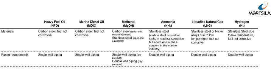
While the energy transition and renewable energy storage technologies are developed and scaled up on land, the onboard storage technologies of ships also need to be studied from a multifuel perspective. The introduction of LNG as fuel onboard ships already started in the beginning of the 2000s by early adopters and can be seen as a good example of the same type of transition we can undertake today and in the coming years.
While the energy transition and renewable energy storage technologies are developed and scaled up on land, the onboard storage technologies of ships also need to be studied from a multifuel perspective. The introduction of LNG as fuel onboard ships already started in the beginning of the 2000s by early adopters and can be seen as a good example of the same type of transition we can undertake today and in the coming years.
LNG as transition fuel can be debated but the possibilities to use onboard LNG tanks for other fuels in the future shall not be underestimated. With the right selection of material combability and insulation of LNG tanks on ships these can also cover the storage for Ammonia or Methanol.
LNG as transition fuel can be debated but the possibilities to use onboard LNG tanks for other fuels in the future shall not be underestimated. With the right selection of material combability and insulation of LNG tanks on ships these can also cover the storage for Ammonia or Methanol.
Fig 3. Material combability and piping requirements (Wärtsilä)
While the material itself used in the tanks for storing liquified natural gas today can also be used for storing other fuels such as Ammonia and Methanol, also the impact of weight, safety systems and autonomy needs to be considered for multifuel tanks. Lessons around multifuel storage can be drawn from modern gas carriers, where the cargo storage and handling systems are designed to carry many different products taking into consideration in the design the differences in the cargos impact on material as well as the cargo density change.
Conference Paper 230
Fig 3 Material combability and piping requirements (Wärtsilä)
storing other fuels such as Ammonia and Methanol, also the impact of weight, safety systems and autonomy needs to be considered for multifuel tanks. Lessons around multifuel storage can be drawn from modern gas carriers, where the cargo storage and handling systems are designed to carry many different products taking into consideration in the design the differences in the cargos impact on material as well as the cargo density change
Fig 4. Fuel type and fuel storage considerations (Wärtsilä)
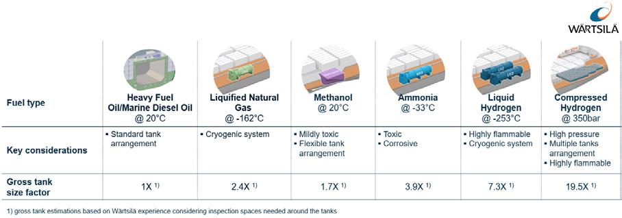
On the detailed level looking at piping and equipment pressure rating as well as the material combability can be acceptable from a fuel flexibility point of view, however the volumetric energy density will cause the mass of the pumped liquid or transferred gas to be increased compared to the main fuels used today, resulting in consequences on the sizing of the equipment downstream of the storage equipment.
On the detailed level looking at piping and equipment pressure rating as well as the material combability can be acceptable from a fuel flexibility point of view, however the volumetric energy density will cause the mass of the pumped liquid or transferred gas to be increased compared to the main fuels used today, resulting in consequences on the sizing of the equipment downstream of the storage equipment.
From a fuel supply system point of view one of the main questions are also related to whether the fuel will be transferred to the consumers in liquid or gas form. While the gas form transfer can require additional evaporators upstream and gas regulation the liquid form transfer can require a higher degree of safety arrangements due to the potential larger amount of compressed fuel that is transferred. For toxic fuels additional vent processing equipment will also be needed. Such equipment can comprise of catch system, vent gas burner, vent gas scrubber and each system can comprise of different tank, valves, and pump arrangements.
From a fuel supply system point of view one of the main questions are also related to whether the fuel will be transferred to the consumers in liquid or gas form. While the gas form transfer can require additional evaporators upstream and gas regulation the liquid form transfer can require a higher degree of safety arrangements due to the potential larger amount of compressed fuel that is transferred. For toxic fuels additional vent processing equipment will also be needed. Such equipment can comprise of catch system, vent gas burner, vent gas scrubber and each system can comprise of different tank, valves, and pump arrangements.
At the design stage of the multifuel vessel the space reservation for the different fuel storage solutions, for liquid or gas, as well as processing equipment and additional engine exhaust after treatment systems needs to be considered. Modularised Fuel preparation systems for easier change of the relevant equipment such as pumps, evaporators, fuel filters and valves into compliance with other fuels can accommodate for some of the required fuel flexibility. However, a multifuel vessel would need to also accommodate into the design the needs to treat not only possible toxic releases but also the additional needed possibility to carry larger amounts of the lower volumetric energy density fuels.
At the design stage of the multifuel vessel the space reservation for the different fuel storage solutions, for liquid or gas, as well as processing equipment and additional engine exhaust after treatment systems needs to be considered Modularised Fuel preparation systems for easier change of the relevant equipment such as pumps, evaporators, fuel filters and valves into compliance with other fuels can accommodate for some of the required fuel flexibility. However, a multifuel vessel would need to also accommodate into the design the needs to treat not only possible toxic releases but also the additional needed possibility to carry larger amounts of the lower volumetric energy density fuels.
Shipowners today need to make sure their vessel designs have a strategy to handle and store one or multiple future fuels. This will strongly depend case by case on what is technically possible and what are sound investments to balance future readiness with today’s financial constraints. Have your future conversion roadmap ready. Therefore, a holistic case by case study would be necessary for the ship owner or ship designer, working on a specific vessels or concept, to understand what type of storage technology can be used looking from a multifuel approach.
Shipowners today need to make sure their vessel designs have a strategy to handle and store one or multiple future fuels. This will strongly depend case by case on what is technically possible and what are sound investments to balance future readiness with today’s financial constraints. Have your future conversion roadmap ready. Therefore, a holistic case-by-case study would be necessary for the ship owner or ship designer, working on a specific vessels or concept, to understand what type of storage technology can be used looking from a multifuel approach.
6. THE MULTIFUEL ENGINE (Cornerstone 3)
The internal combustion engine is an efficient and robust energy converter for almost any fuels. The choice of the best engine type to select for a certain application is depending on many parameters such as fuel flexibility, CAPEX, OPEX, space required, emission compliance, loading performance, reliability. And not to forget the fact that the entire maritime industry has currently people and processes in place to work efficiently with internal combustion engines.
Dual Fuel engines have the ability to run on two different types of fuel. Wärtsilä has 20+ years of experience with The Dual Fuel engine in the field that run on diesel (liquid) and the gas.
Conference Paper 231
While the
itself used in the tanks for storing liquified natural gas today can also be used for
material
Fig 4 Fuel type and fuel storage considerations (Wärtsilä)
performance, reliability. And not to forget the fact that the entire maritime industry has currently people and processes in place to work efficiently with internal combustion engines
Dual Fuel engines have the ability to run on two different types of fuel. Wärtsilä has 20+ years of experience with The Dual Fuel engine in the field that run on diesel (liquid) and the gas. This allows vessels to run on LNG where they can/want and have pure diesel as a backup capability. This has proven a strong risk mitigation element for shipowners making a choice for LNG as a fuel. Also, the ability to switch from gas to diesel without any interruption on power and engine speed has been a strong decision factor for ship owners choosing Wärtsilä DF engines. Wärtsilä also has Dual Fuel liquid engines that are capable of running on Methanol and Diesel. Again, here the same advantage applies as for the LNG case.
This allows vessels to run on LNG where they can/want and have pure diesel as a backup capability. This has proven a strong risk mitigation element for shipowners making a choice for LNG as a fuel. Also, the ability to switch from gas to diesel without any interruption on power and engine speed has been a strong decision factor for ship owners choosing Wärtsilä DF engines. Wärtsilä also has Dual Fuel liquid engines that are capable of running on Methanol and Diesel. Again, here the same advantage applies as for the LNG case.
For our land-based Energy business activity Wärtsilä also offers for example pure gas engines (SG type) which are offering a slightly increased efficiency and slightly decreased emissions however at the cost of the obvious disadvantage of not having a backup capability.
For our land-based Energy business activity Wärtsilä also offers for example pure gas engines (SG type) which are offering a slightly increased efficiency and slightly decreased emissions however at the cost of the obvious disadvantage of not having a backup capability.
Fig 5. Engine basic technologies and their suitability for various fuels (Wärtsilä)
In highly charged medium speed engines the aim is to find and optimise the area between misfiring in a too lean mixture and knocking in a too rich, or hot, area. The higher one can go up in BMEP (Brake Mean Effective Pressure), the higher will be the efficiency be the lower will be the emissions. This is a win win situation where a gas engine is superior in most aspects. Additionally,
In highly charged medium speed engines the aim is to find and optimise the area between misfiring in a too lean mixture and knocking in a too rich, or hot, area. The higher one can go up in BMEP (Brake Mean Effective Pressure), the higher will be the efficiency be the lower will be the emissions. This is a win-win situation where a gas engine is superior in most aspects. Additionally, the Otto combustion is a faster process and provides excellent loading and transient behaviour, provided that one can control the combustion. However, are there other considerations which can favour other combustion processes over the Otto cycle in a multifuel engine.
Diesel combustion processes for Wärtsilä DF engines enables running on diesel fuel as well as low viscosity fuels. These combustion modes use diffusion combustion (diesel combustion) of the selected fuel. The high-pressure gas diesel engine is a multifuel engine that can operate on both gaseous fuels as on liquid fuels. The engine is rather insensitive of the fuel quality, thanks to the diesel combustion. The fuel systems can be divided so that the engine can easily switch between different fuel modes when requested or required. There are also possibilities to operate the engine on both gas and liquid fuel simultaneously i.e., fuel sharing.
The already available and coming engine concepts shows that the adaption of alternative fuels and low viscosity fuels for internal combustion engines is well supported. In addition to the different combustion processes Wärtsilä is continuously developing and commercialising technologies that are reducing both local and global emissions, a key technology here is the
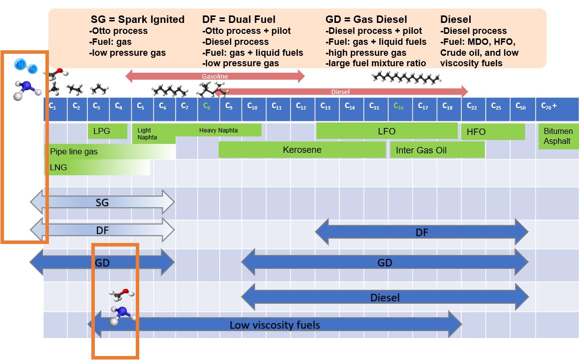
Conference Paper 232
Fig 5 Engine basic technologies and their suitability for various fuels (Wärtsilä)
electronic control. Also, modern engine design by Wärtsilä is embedding from start a modular approach into the core of the engine design enabling future fuel flexibility in practice at an affordable level. The combustion engine is evidently not at the end of the development cycles as the marine sector will, in order to decarbonise, in most cases start with the blending together the alternative fuels with the currently used fuels. Allowing for the vessels to operate as before while the build-up of the alternative fuel infrastructure, availability and usage can adapt to the increasing demand driven by customer demand and the need to decarbonise to reduce greenhouse gas emissions worldwide.
7. CONCLUSIONS
The foundation for the three cornerstones of a successful fuel transition into zero carbon shipping is in the making. The journey into zero carbon shipping as presented in this paper is one of the greatest development tasks in modern history. Long term it does not only embed the marine sector but also the energy production sector as well as large parts of other transport sectors. Thanks to the extensive know-how into complex mechanical systems, long term testing of alternative fuels and extensive Research and Development background, Wärtsilä is today developing concepts and technologies enabling the Multifuel engine. In chapter 3 we explored the different fuels considered as future fuels while in chapter 4 we elaborated on what will be needed in order to make the fuels available, which is key as the first one to scale up has better chance than the perfect solution. Embedding future fuels storage into new vessels is one key to also enabling the multifuel engine success and this we presented in chapter 5. The multifuel engine will offer flexibility by fuel blending and fuel selection, having backup fuel options, while at the same time targeting high efficiency and decreased emissions, especially reducing carbon dioxide emission helping the hard to abate sectors.
REFERENCES
1. International Energy Agency (IEA 2021), World Energy Statistics. Paris: International Energy Agency
2. International Maritime Organisation (IMO, 2021), Report of fuel oil consumption data submitted to the IMO Ship Fuel Oil Consumption Database in GISIS.
3. International Renewable Energy Agency (IRENA 2022), Report, Global Hydrogen Trade to Meet the 1.5C Climate Goal – Part 1: Trade Outlook for 2050 and Way Forward
4. DNV (DNV, 2022) Hydrogen Forecast to 2050, Energy Transition Outlook June 2022
Conference Paper 233
HARRIET BRICE Technology Manager - Marine Engine Oils, Lubrizol
BIOGRAPHY
Harriet began her career in the lubricant additives industry over 10 years ago as a Research Chemist developing new additive chemistries. Her current role as Technology Manager for Lubrizol’s large engine business involves directing research and formulation activities to bring new lubricant solutions to the market to meet the unique operating conditions of marine engines.

Speaker
234
Alternative Fuels – Preparing for the impact on marine lubricants
Introduction
The Fourth International Maritime Organisation (IMO) greenhouse gas (GHG) study 2020 estimated that GHG emissions from shipping – including carbon dioxide (CO2), methane (CH4) and nitrous oxide (N2O), expressed in carbon dioxide equivalent CO2e - represented 2.89% of the total global anthropogenic emissions for 2018. i Of these emissions 1,056 million tonnes were CO2 and without additional measures long term economic and energy scenarios for shipping project this could continue to grow.
CO2 emissions are the result of combusting carbon containing fuels and depend on the carbon content of the fuel and the total fuel consumption. Fuel consumption is impacted by engine efficiency and the energy content of the fuel.
Through the Initial Strategy on reduction of GHG emissions from ships, the IMO has set out its ambition for at least a 50% reduction in total annual GHG emissions by 2050 and reductions in carbon intensity, meaning CO2 emissions per transport work, by at least 40% by 2030, compared to 2008.ii There is a diverse range of options to decrease GHG emissions through energy-saving technologies and speed reduction of ships which result in reduced total fuel consumption and thus a corresponding decrease in equivalent carbon dioxide emissions. However, achieving the reduction in CO2 required to realise the 2050 GHG ambition with these options alone will be difficult and so the effective uptake and global availability of alternative low carbon (fossil free) and zero carbon fuels will be integral to achieving the overall ambition.
Large two stroke marine engine designers have been clear in their messaging that they will have engines available, designed either from scratch or facilitating retrofit options, that enable alternative fuels. Working alongside the engine designers are the additive and lubricant companies that research and develop new cylinder and system oils for these engines. All fuels have differing characteristics that can bring specific challenges to the engine, affect cylinder condition, and interact with the lubricants in different ways. The challenge in developing lubricants for alternative fuels is the limited prolonged or widespread usage in marine applications or in the case of ammonia the absence of engine related usage data. This paper describes how testing of lubricants is taking place to ensure that the engine’s lubrication requirements are met when operating on methanol, biofuels and ammonia.
The role of the cylinder lubricant is to provide a lubricating film between the piston, piston rings and cylinder liner to reduce friction, minimise the risk of seizures and form a gas tight seal. It also contains additives that maintain engine cleanliness and control corrosion by providing a source of base to neutralise acids formed during combustion. It is termed as a ‘once-through’ lubricant as it is not re-used. The primary role of the system oil is to lubricate the bearings (main, crosshead & crank pin), crosshead guides & drive gear/chain and provide cooling to piston undercrowns. It is largely kept free from contamination by combustion products by the stuffing box but is still required to keep the crankcase and piston cooling spaces clean of deposits and have good resistance to oxidation and thermal degradation. Additionally, it may be used as a hydraulic fluid and as part of the fuel injection and exhaust valve control system. The system oil is recirculated and remains in service for extended periods. iii
Both cylinder lubricants and system oils are made up of base oil and a performance package which contains additives. Detergents are a major portion of the lubricant performance package as they are an efficient way to deliver cleanliness and a source of base for neutralising acids.
Conference Paper 235
Dispersants, anti-oxidants, anti-wear and corrosion control additives are added depending on the application and required performance characteristics. Cylinder lubricant is at the interface of the fuel and the engine hardware. Therefore, its formulation must also consider the interactions of the fuel and lubricant and ensure there are no adverse interactions that could impact the lubricant performance.
Methanol
Methanol (CH3OH) is a liquid fuel that combusts to form CO2 and water and is attractive as a marine fuel as it is sulfur free and reduces nitrogen oxides (NOx) and particulate matter. Methanol contains only 0.375 mass to mass (m/m) carbon compared to 0.86 m/m for light fuel oil (LFO) but due to its lower energy content (22 MJ/kg to 42 MJ/kg) approximately twice the quantity is required for equivalent energy output to diesel.iv This results in a small reduction in CO2 emissions from combustion (tank to wake), but it has the potential to be carbon neutral if produced from renewable sources.
Methanol engines have been in operation since 2016 and whilst there is some established understanding of the required lubrication regime it is based on a small number of ships. Methanol is a low viscosity (<1 cSt) polar liquid that is miscible with water. Its solubility in oil is low but has the potential to form emulsions and this was an issue for early adopters which resulted in blocking of filters. This has been resolved for those engines in operation but more widespread use in different engines could see similar issues re-emerge. Due to its low viscosity any fuel dilution has the potential to reduce the lubricant viscosity significantly. Reduced viscosity is a concern as the lubricant may not be able to provide sufficient film strength to prevent seizures.
Biofuels
Biofuels are diesel fuel substitutes that can be made from either vegetable oils or animal fats. The predominant types of biofuels available are Fatty Acid Methyl Esters (FAME) made from waste cooking oils and plant-based feedstocks including rapeseed, soybean and palm oil. Biofuel can be used on its own (referred to as B100) but is more commonly blended with conventional (fossil derived) residual or distillate grade marine fuel in varying proportions and are described as BX where X is the % of renewable content. ISO 8217:2017 currently allows for up to 7% FAME content in certain distillate grades but there are no residual grades that include FAME.v Interest in higher percentages of renewable content has led to B10 - B50 and in a small number of cases B100 fuels recently being trialled in marine applications.
Experience from the introduction of biofuels for use into automotive diesel engines indicates that contamination of the lubricant by biofuels through fuel dilution accelerates oxidative degradation compared to mineral diesel fuel.vi The severity of oxidation, which increases the propensity for deposit formation, is also linked to the feedstock source with some leading to higher levels of deposits than others. The lower volatility of biofuels compared to mineral diesel also means any biofuel introduced into the lubricant is more likely to remain mixed with the lubricant so has more chance to stimulate oxidation. The increased renewable content levels being evaluated for marine are likely to lead to higher fuel dilution rates which means the lubricant is more at risk of oxidative degradation and higher deposit formation.
If demand increases for biofuels with higher renewable component ratios, additional raw material components maybe introduced, or mixtures of biodiesel sources used to meet demand. This diversification is beneficial in broad terms, allowing biodiesels to be blended using a variety of sources, but could create complexity and challenges for the lubricant due to the differing performance characteristics of the different feedstocks.
Ship owner / operators continue to run trials using biofuels however, the focus has been on operational aspects and CO2 savings and have not taken into consideration cylinder
Conference Paper 236
condition. Some engines do require modification to run optimally on biofuels otherwise liner temperatures could increase which can speed up lubricant oxidation leading to higher piston deposits.vii In addition, recent trials have often been over a short duration of running hours or use of available fuel. Longer trials offer the opportunity for the careful monitoring of the engine and the lubricants to determine the impacts and, if necessary, introduce lubricants with different performance attributes. Lubricants with a higher resistance to oxidation and improved cleanliness would be the recommended choice to ensure long term safe and reliable operation on biofuels.
Ammonia (NH3)
Ammonia (NH3) is composed of nitrogen and hydrogen and in its pure form, known as anhydrous ammonia, it is a colourless pungent-smelling gas at room temperature that can be easily compressed into a liquid. It is hygroscopic so readily combines with water to form ammonium hydroxide (NH4OH), a colourless solution that is basic and corrosive. Most metals have good corrosion resistance to ammonia gas, liquid ammonia, and ammonium hydroxide. However, copper and copper containing alloys are susceptible to corrosion by ammonia and some of these materials are currently utilised in marine engines. It was therefore of interest to conduct testing to look at how the presence of a lubricant may protect the copper containing materials and also check additional engine related materials resistance to ammonia induced corrosion. As an example, the results for the testing of copper coupons are shown in Table 1 and 2. Table 1 shows how without any base oil or lubricant present the copper changes to a bright green/blue colour which indicates the formation of a copper – ammonia complex. To test if the presence of an oil film was enough to protect the copper from corrosion by the ammonia a coupon was immersed in base oil prior to testing. This showed an improvement across most of the coupon surface, but corrosion was still observed as shown by the blue area at the top of the coupon. With a fully formulated lubricant present no corrosion was observed on any areas of the test coupon indicating the additives are providing additional corrosion protection.
Table 1: Copper test coupons before and after exposure to ammonia
To simulate the exposure of copper containing components in the engine to lubricant contaminated with ammonia, further testing was undertaken with the copper coupons and two different lubricant formulations that had been pre-contaminated with ammonia, results are shown in Table 2. Lubricant 1 was selected to represent a lower performing lubricant and Lubricant 2 was selected to represent a high performing lubricant. At ambient temperature there is no change to the copper after testing with either lubricant. However, at high temperature, which was selected to be representative of engine conditions, there are differences observed between the two formulations. For Lubricant 1 the whole coupon had a moderate tarnish with a clear area of heavy tarnish in the middle. For Lubricant 2 the coupon had a light tarnish which agrees with the results for standard copper-lubricant compatibility testing, so it can be concluded the lubricant is maintaining performance and there is no additional impact of the ammonia contamination. This indicates that selecting a high performing lubricant can offer better protection to copper containing materials against corrosion from ammonia at high temperatures. As the ammonia engines are still in development the selection of materials remains the consideration for the engine designers and it is not known if copper containing materials will remain in use or be substituted for corrosion resistant alternatives.

Conference Paper 237
Table 2: Copper test coupons after being immersed in different lubricant formulations that had been pre-contaminated with ammonia. Testing run at ambient and high temperature.
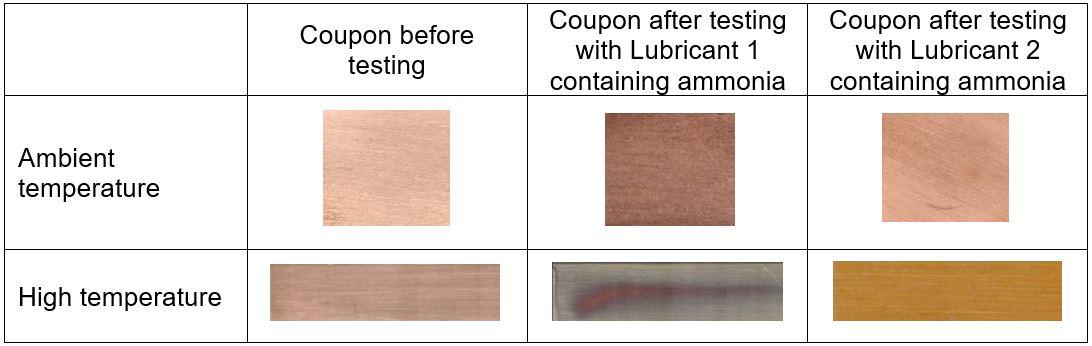
At ambient temperature and pressure ammonia has low solubility and miscibility with mineral oils and synthetic hydrocarbon lubricants. However, at temperatures and pressures experienced in an engine the solubility increases, with the potential for several % of ammonia to be dissolved in the cylinder lubricant.viii This will depend to a degree on how long the ammonia is present in the cylinder before combustion occurs or how quickly any unburnt ammonia is expelled. Ammonia is difficult to ignite and has a slow burn velocity so a small amount of pilot fuel will be used to initiate combustion. It is worth noting that some fuel dilution of cylinder lubricants does occur with conventional marine diesel fuels that are more easily combusted. It was therefore necessary to study if the presence of ammonia in the lubricant leads to unfavourable interactions with the different additives that could affect the performance of the lubricant. A number of lubricant formulations were tested that contained different combinations of additives. Table 3 shows the results for two of these before and after exposure to ammonia. For Lubricant 3 there was no interactions observed however for Lubricant 4 there has been a reaction indicated by a change in appearance - the lubricant has become hazy. Whilst further testing is required this indicates not all lubricants maybe readily compatible for use with ammonia. In situ interactions could reduce the lubricants effectiveness or affect the stability, the result of which could be increased formation of deposits which can impact engine performance over time.
Table 3: Differences in appearance observed between different lubricant formulations before and after exposure to ammonia. Hazy appearance of Lubricant 4 indicates an interaction between the ammonia and lubricant has occurred.
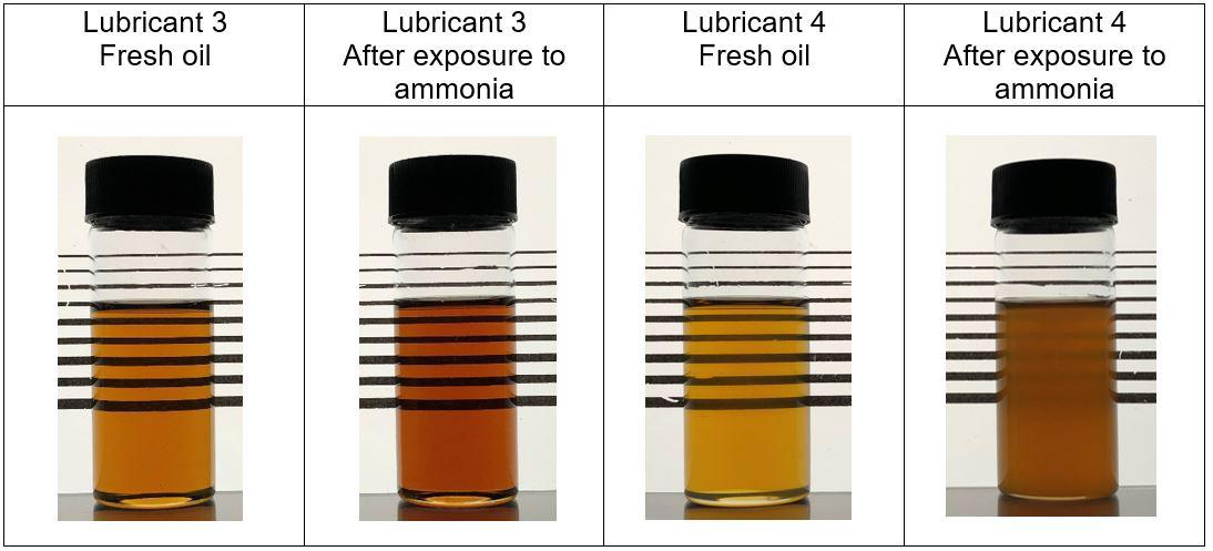
Conference Paper 238
Conclusion
Each of the alternative fuels discussed are unique in their physical and chemical properties and the challenges they pose to the engine and lubricant. Whilst some testing has been able to be progressed in the laboratory, the complexity of the chemical reactions in a highpressure engine system with pilot fuel (if required) and lubricant present is not possible to fully replicate. For methanol and biofuels engines already exist that can run on these fuels which enables significant real-life data to be collected to inform the lubricant development and recommendation. For ammonia, the first tests due to be conducted this year by MAN ES on their ammonia test engine will provide that much needed data that will further our understanding of challenges posed to the lubricants by ammonia and enable refinement of lubricant development and testing. ix
The use of methanol, biofuels and ammonia alternative fuels will all play a role in the strategy to achieve IMO’s 2050 GHG reduction ambition. Research and development into how the fuel characteristics impact engine hardware and lubricant-fuel interactions, such as the examples presented in this paper, are imperative to ensure that engines continue to be protected and demonstrates the critical role lubricants play in enabling the use of alternative fuels.
References
i IMO, 2021. Fourth IMO Greenhouse Gas Study 2020; London: International Maritime Organisation (IMO)
ii IMO, 2018b. Resolution MEPC.304(72), Initial IMO Strategy on reduction of GHG emissions from ships; London: International Maritime Organisation (IMO)
iii CIMAC, 2017. CIMAC Recommendation 31: THE LUBRICATION OF TWO-STROKE CROSSHEAD DIESEL ENGINES, CIMAC Working Group 8
iv Herdzik, J., 2021. Decarbonization of Marine Fuels – The Future of Shipping, Energies, 14,4311
v ISO, 2017. ISO 8217:2017 Petroleum products — Fuels (class F) — Specifications of marine fuels
vi McCabe, M. & Jones, Craig, J., 2012. Biodiesel: Impact on Engine Oil Durability, Journal of the JIME, 47(1), p. 89
vii MAN, 2022. Operational guidelines for biofuels FAME, similar FAME-type fuels, HVO, and blends thereof, TWL.09.2022, available on request from MAN Energy Solutions, Copenhagen.
viii Feja, S., Hanzelmann, C. & Zuber, S., 2018. PT and viscosity measurements of high-temperature ammonia heat pump lubricants, International Journal of Refrigeration, 88, p 221-228
ix The Motorship, 2022. Engine and ammonia lubricant solutions on track: MAN ES’ Jacobsen, available at www.motorship.com/interviews (Accessed: 21 September 2022)
Conference Paper 239
EDDIE FISH Market Development Advisor, ExxonMobil Marine & Aviation Fuels
BIOGRAPHY
Eddie Fish is a specialist in marine fuels and lubricants and has worked at ExxonMobil for close to 30 years, with more than two decades in the marine group. During this time he has held a number of sales, marketing and technical roles with key assignments including the launches of ExxonMobil Premium HDME 50 TM , EMF.5TM and most recently bio marine fuel oils such as BMF.5 TM. Additionally he continues to champion the wider adoption of accredited Mass Flow Metering Systems and measurement transparency in ports around the world.
In his current position as Market Development Advisor, Eddie is focused on helping the marine industry prepare for the challenges on the journey beyond 2020.
Eddie graduated with an honours degree in Managerial and Administrative studies from Aston University, UK, specialising in Marketing and Operations.

Speaker
240
High science on the high seas
Advancing new technologies for lower-emission fuels
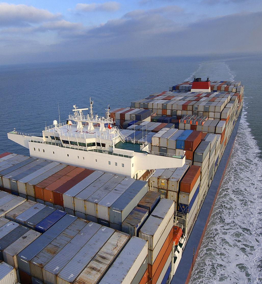
Conference Paper 241
Darren W. Woods

Conference Paper 242 High science on the high seas 3
“We’ll continue to innovate and provide solutions that meet the growing needs of society, including its net -zero emissions ambitions, by fully leveraging our competitive advantages of scale, integration, technology, functional excellence, and our highly skilled people.”
ExxonMobil Chairman & CEO
The energy transition
ExxonMobil’s commitment to driving emission reductions in support of a net zero future.
reductions in support of a net zero future.
ExxonMobil is committed to helping society reduce overall greenhouse gas emissions by decreasing our emissions and by developing and deploying emission reducing technologies and products We have been a leader in innovation for more than 130 years, supplying products that people need to live healthy, prosperous lives in an ever changing world.

As a major marine fuel supplier, ExxonMobil supports the International Maritime Organization (IMO) with a plan to be part of the solution. Our commitment to driving emission reductions in support of a net zero future is outlined in our Advancing Climate Solutions 2022 Progress Report.
Components of a path to net -zero include:
We plan to invest more than $15 billion on initiatives to reduce greenhouse gas emissions, with a significant share focused on biofuels, carbon capture storage, and hydrogen by 2027
Our objective is to provide more than 40,000 barrels per day (2.3 million metric tons p.a.) of lower emission fuels by 2025 and have a further goal of 200,000 barrels per day (11.3 million metric tons p.a.) by 2030
Through the development of new projects, repurposing refinery infrastructure, co processing bio feeds, executing purchase agreements, utilizing existing and exploring new CCS technologies, we are advancing a number of options for producing lower emission solutions.
Commercially viable alternatives along with energy efficient process technology, will play an essential role in helping achieve the transition to a net zero future.
Conference Paper 243 High science on the high seas 4
The need for loweremission solutions
A path to greenhouse gas emissions reduction
The International Maritime Organization (IMO) aims to reduce the carbon intensity of international shipping by at least 40% by 2030, moving to 70% by 2050, compared with 20081
While the shipping industry is under increasing pressure to reduce greenhouse gas (GHG) emissions, substantial emission reductions in the coming decades are likely to require additional technology development and the introduction of lower carbon fuels.
Ship owners will select fuel based on individual circumstances such as their routes, vessel sizes and geographical location.
Increased cooperation, commun ication and consultation among various stakeholders, will likely be necessary to fulfill the IMO’s ambitions. While some emerging technologies have matured in the interim, we will continue to work closely with customers to help determine their best route towards meeting the IMO's ambitious goals.
1https://www.imo.org/en/MediaCentre/HotTopics/Pages/Reducing greenhouse gas emissions from ships.aspx
Conference Paper 244 High science on the high seas 5
ExxonMobil marine
in the energy transition
ExxonMobil has supplied highquality fuels, provided technical expertise and supported regulatory compliance to the marine industry for more than 50 years.
Quality, reliability and innovation are the three values that continue to define ExxonMobil’s global commitment to our customers The Company is committed to providing and improving critical products while working toward IMO targets, and creating greater value for all its stakeholders.
To date, our recent marine innovations include pioneering the use of third party accredited Mass Flow Metering systems (MFMS) and
the development of branded fuels such as P Premium HDME 50 ™, a fuel that complies with ECA 0.10% sulfur limits; E EMF 5™, which can safeguard engines running on 0.50% sulfur fuels; and B BMF 5™, our fuel oil and biodiesel blend, which is a 0.50% sulfur residual based fuel (VLSFO), processed with a second generation waste based FAME component and has the potential of up to 34% reduction in Well to Wake GHG emissions*.
A successful sea trial of B BMF 5™ took place with shipping company Stena Bulk bunkered in the port of Rotterdam. The trial demonstrated that B BMF 5™ can be used in a relevant marine application without
*Benefit is up to 34 percent compared with conventional petroleum based HFO/VLSFO, calculated on an energy basis. Well to Wake GHG emissions reduction calculated using the rules as published in the Directive 2009/30/EC of the European Parliament and of the Council Annex IV A and EN 16258. Actual values are reported from purchases of Annex IX part A feedstock as supplied to ExxonMobil in Europe in 2020.
Conference Paper 245 High science on the high seas 6
Planning to play a leading role
engine modification. The sea trial was designed and completed as part of ExxonMobil’s assessment and trial protocol to demonstrate no adverse equipment effects when operating with higher levels of bio components. ExxonMobil’s new marine biofuel oil meets the need for quality fuels that are both reliable and ISO compliant and can help operators reduce their GHG emissions.
There are few challenges more important than meeting the world’s growing demands for energy while reducing environmental impacts. ExxonMobil is committed to doing its part across the industries and sectors we serve, including marine. Our sustained investment in R&D plays an important role in helping to develop breakthrough solutions.
Conference Paper 246 High science on the high seas 7
Emerging technologies
A future of energy alternatives
ExxonMobil is investigating several potentially viable alternatives to conventional fuel formulations including biofuels, hydrogen, methanol and ammonia. Lower emission biofuels are a “drop in” alternative that can be used in existing engines without the n eed for extensive modifications. These biofuels have the potential to reduce GHG emissions by at least one third compared with conventional marine fuel oil.
On a Well to Wake basis, methanol, ammonia and hydrogen have the potential to reduce the carbon footprint of shipping However, one of their challenges is their lower energy content and the comparatively lower amount of energy they can store in the tanks of a ship. Ship designs would require changes to accommodate fuel containment and gas supply systems or frequent bunkering.
ExxonMobil wants to be part of the solution while responsibly providing affordable energy required to power the economy. We have the experience, capabilities, capacity and commitment to help meet this critical need.
Carbon capture and storage ExxonMobil’s efforts are reinforced by the establishment of ExxonMobil Low Carbon Solutions, a business that is working to commercialize and broadly deploy emission reduction technologies. This business is initially focusing on carbon capture and storage ( CCS) and is already advancing plans for several new CCS opportunities worldwide. We are also leveraging our experience in producing hydrogen which, when coupled with CCS, is likely to play a critical role in a lower carbon energy system.
Conference Paper 247 High science on the high seas 8
Hydrogen
ExxonMobil is evaluating strategic investments in hydrogen to increase the use of this important lower emissions energy technology. The Company has extensive experience with hydrogen and produces about 1.3 million metric tons annually. Hydrogen is a zero carbon energy carrier that could serve as an affordable and reliable energy source for hard to decarbonize transportation such as aviation, marine, and heavy duty trucking, as well as energy intensive industrial processes in the steel, refining, and chemical sectors. ExxonMobil can produce low carbon hydrogen from low carbon electricity via electrolysis of water, natural gas reforming coupled with carbon capture and storage, and other processes. Low carbon hydrogen from natural gas with carbon capture and s torage is called blue hydrogen, and is available for deployment at scale today.
ExxonMobil is a member of the U.S. HyBlend consortium, a collaborative research and development project designed to address the technical barriers of blending hydrogen into natural gas pipeline streams.

Conference Paper 248 High science on the high seas 9
We have also signed a memo randum of understanding with SGN and Macquarie’s Green Investment Group to explore the use of hydrogen and carbon capture to reduce emissions in England’s Southampton industrial cluster. In addition, the Company is studying large scale production of hydrog en for the Rotterdam industrial complex and has provided funding to Hydrogen4EU, a cross sectoral research project confirming that hydrogen is essential to help meet the EU Green Deal’s 2050 net zero targets. Additional ongoing projects include:
Blue Hydrogen in Baytown, Texas along with associated CO2 storage
Acorn Hydrogen/CCS in Scotland , UK leverages existing O&G infrastructure and well understood offshore CO 2 storage
Hydrogen Hub in Southampton, UK lowering industrial emissions, including EM Fawley complex potentially using blue H2
Air Liquide Normand’Hy to construct a 200 MW capacity electrolyzer in the industrial zone of Port Jerome, France for the production of green hydrogen
Methanol
ExxonMobil is exploring a mosaic of lower emission fuel options, including second generation or advanced biofuels and synthetic fuels created by using hydrogen and captured CO2 to form methanol. Methanol can be used for a fuel as is in Marine and other applications, or further converted to fuels for hard to de carbonize sectors like aviation
Conference Paper 249 High science on the high seas 10
Ammonia
ExxonMobil has signed a memorandum of understanding along with Grieg Edge, North Ammonia, and GreenH to study the potential production and distribution of green hydrogen and ammonia for lower emission marine fuels at the ExxonMobil Slagen terminal in Norway. The study would explore the potential for the terminal, powered by hydroelectricity, to produce up to 20,000 metric tons of green hydrogen per year and distribute up to 100,000 metric tons of green ammonia per year. The hydrogen would be produced from hydro powered electrolysis.
ExxonMobil is also investigating the potential role of ammonia as a marine fuel by participating with partners in Singapore to assess safety protocols and potential gaps in the supply chain and are also participating in a HAZID to inform ship designs operating on ammonia as a fuel.
Conference Paper 250 High science on the high seas 11
Market motivation
The demand for growth
Today’s transportation fuel demand growth is driven by increased commercial activity moving more people and products by bus, rail, plane, truck, and marine vessel. Shipping plays an indispensable role in the global economy, transporting more than 80% of total trade volume and generating 3% of global GHG emissions. Among several modes of cargo transportation, it enables the regional and intercontinental movement of large quantities of cargo in the most fuel efficient way at a lower cost. Based on the projected growth of the shipping industry using various future scenarios (IMO, 2014), the
energy consumption is estimated to be around 12 14 EJ in 2030 and about 15 36 EJ in 2050.**
In designing for the future, the advent of modern dual fuel engine technology will likely make the transition to low er and zero carbon fuels easier to achieve than in the recent past. The transition to alternative fuels can be made much more attractive if it is planned at the new building design stage. In particular, the design of the fuel tank should be specified based on all the fuels planned to be used throughout the life of the vessel.2
Conference Paper 251 High science on the high seas 12
**Maritime Energy & Sustainable Development (MESD) 2 ABS Setting the Course to Low Carbon Shipping view of the value chain
Regulatory policy
Advancing the energy transition
ExxonMobil advocates for a low carbon fuel standard (LCFS) to provide a predictable long term pathway of reductions in carbon intensity (CI) of the fuel pool to support the IMO’s ambition of reducing GHG emissions from shipping. To enable this, policy should include the following attributes:
Set declining annual targets for the Well to Wake CI of the consumed marine fuels expressed in gCO2equivalent/MJ
Be technology neutral to encourage multiple pathways and innovation
Provide flexibility to manage investments in the fleets and the growth of lower GHG emission emerging technologies and energy
Support lower carbon fuels, as the life cycle assessment approach helps to provide an effective tool for comparing alternative fuels
Include reporting of the fuel CI on the Bunker Delivery Notes
In case of non compliance, a pre determined buy out could provide revenues to a global fund dedicated to the marine sector
ExxonMobil is active in industry committees, standards committees, and trade associations and encourages policies and standards to support the production of transport fuels with lower life cycle greenhouse emissions.
Conference Paper 252 High science on the high seas 13

MOTORSHIP MARINE TECHNOLOGY THE Contact us today Reach industry professionals with The Motorship Promote your business to the right audience in the right place at the right time. Engage with our audience of senior marine engineers, from ship owners and operators to ship builders. The Motor Ship multi-media platforms offer our commercial partners a wide range of opportunities for campaign delivery. We provide bespoke marketing packages with quantifiable ROI. Motor Ship’s valued content is relied upon by shipping professionals and is delivered through multiple channels. Sue Stevens, Brand Manager t: (+44) 1329 825 335 e: sales@motorship.com www.motorship.com MAGAZINE RECIPIENTS DECISION MAKERS PAGEVIEWS PER MONTH 19,600 72% 39,300
SESSION 7.2
Retrofit Solutions 254
SEBASTIAN EBBING
Technical Advisor, Climate, Marine fuels, Innovation, Funding, VDR - Verband Deutscher Reeder
BIOGRAPHY
As Technical Advisor at German Shipowners’ Association, Sebastian Ebbing provides profound technical expertise to the ongoing regulatory developments on EU and IMO-Level. With his background in nautical science, marine engineering and international maritime management he is dedicated on regulatory climate-protection affairs, the maritime energy transition incl. the development of alternative climate-neutral fuel strategies, digitalization and innovation projects in shipping.
Sebastian Ebbing´s technical expertise is accompanied by experience in fleet performance management within a globally operating shipping company. The German Shipowners’ Association (VDR) is a leading professional association within the German business community.
It was founded in 1907 by the regional shipowners’ associations in order to enable them to have common and uniform representation of their interests. Today, the VDR represents the German maritime shipping segment not only in Berlin and Bonn, but also in Brussels, London, Geneva and at global level. With its over 150 member companies from different shipping sectors, the association represents the German shipping industry, which currently boasts the world’s fifthlargest merchant fleet. As an employers’ association, it conducts collective bargaining and social partner negotiations.
Sebastian Ebbing is founding- and board member of the “Research Institute for Innovation and Sustainable Logistics” situated at Jade University of Applied Science, where he is lecturing on Maritime Technologies with special focus on climate neutral shipping and alternative propulsion technologies.
Moderator 255
TUOMAS RISKI
CEO, Norsepower

BIOGRAPHY
Tuomas Riski, M.Sc. (Econ. & Tech.), is a serial entrepreneur and CEO of Norsepower Oy Ltd, a Finnish clean tech and engineering company that is pioneering modern auxiliary wind propulsion for the global maritime industry. Before Norsepower, Tuomas was partner and Vice President of Innofactor Plc, the largest Finnish IT service provider focusing on Microsoft technology where he had a pivotal role in developing the business from five people to a publicly listed company of more than 200 employees.
Norsepower’s Rotor Sail Solution is a proven, low-maintenance, easy to use, and reliable fuel saving technology, which is designed to support the decarbonisation of the shipping industry. The company’s Rotor Sails are installed onboard five different vessels including a tanker, a bulker, a ferry and two Ro-Ros. Norsepower has calculated that Rotor Sail technology is technically applicable to around 30,000 vessels currently in operation, which represents more than a third of the global maritime fleet. Based on this, Norsepower estimates that this could reduce CO2 emissions of global shipping by more than 80 megatonnes per year just by using Rotor Sails alone.
ABSTRACT
Norsepower is the leading global provider of modern auxiliary wind propulsion solutions to the maritime industry, and the first to sell and deliver a commercial wind-assist technology.
Norsepower’s technology carries huge efficiency and profitability benefits and is proving increasingly popular as a retrofit solution to help ship owners and operators meet IMO 2030 and 2050 targets.
Scandlines installed a 30mx5m Rotor Sail on its hybrid ferry M/V Copenhagen in July 2019. The Rotor Sail’s performance has been verified in sea trials to save fuel and reduce emissions 4-5 % on average. Following a year of demonstrated results, Scandlines has prepared the sister ferry M/V Berlin for its own Rotor Sail installation in Q2 2022.
There is huge potential to increase efficiency and profitability by utilising retrofits in conjunction with other efficiency measures. When installed aboard Scandlines’ M/V Copenhagen Norsepower’s Rotor Sails sit alongside measures such as hydrodynamic hull optimisation, and a hybrid electric propulsion system with a battery powered energy storage system.
Such environmental improvements are essential for meeting the requirements of Poseidon Principles’ and Sea Cargo Charter signatories, while simultaneously providing positive emission ratings for the IMO’s Carbon Intensity Indicator. Collectively, such measures improve operators’ access to finance, commercial competitiveness, trade utilisation, and profitability on an annual basis, while also maintaining a fully regulatory compliant vessel that retains its asset value. This particular example showcases the value of combining technologies to maximise efficiencies and savings.
Speaker
256
Combining efficiency technologies with wind to deliver results beyond compliance
SUMMARY
Wind propulsion has been proven to produce significant fuel savings on commercial vessels. The typical savings potential of wind propulsion on conventional cargo ships is 5-25%. On the other hand, voyage optimization and weather routing has been shown to produce similarly large fuel savings in the order of 15%. Wind is an intermittent energy source, and it often occurs together with waves, making ships installed with wind propulsion especially interesting from weather routing point of view. This means that a holistic approach is needed when conducting weather routing for ships with wind propulsion.
Using detailed simulations, this paper studies how the fuel savings potential of wind propulsion can be further improved by coupling it with state-of-the-art voyage optimization software. Via case study examples, it is shown that the savings potential of wind propulsion can be doubled in some cases by using voyage optimization. This paper also gives examples of some other technologies, which are complementary to wind propulsion, available today, and can increase the energy efficiency of ships further and help to minimize the fuel consumption of them.
1. INTRODUCTION
The shipping industry is facing increasing pressure to search for alternatives for common fossil fuels. There are multiple drivers for this development. First and perhaps most prominently, regulatory frameworks such as EEDI/EEXI and CII issued by IMO require ships to emit less and be more energy efficient. At the same time the oil prices are currently record high - at the time of writing, the Brent quality crude oil is priced nearly $100 per barrel. Furthermore, there is new demand from the cargo owners and operators to decarbonize the logistics chain. Finally, many financial institutions have integrated climate considerations into their lending considerations in frameworks such as Poseidon Principles [1].
There are various strategies to accomplish a shift from fossil fuel-based transportation to sustainable logistics chain. Much of the discussion has been revolving around carbon-neutral fuels, as it is evident that especially ships which travel on long ocean routes, will always need a fuel to enable making the voyage within a predictable timeframe. It is anyhow evident today, that any future carbon neutral fuels of ships will be highly expensive – current forecasts hint that the energy price of them will equivalent to from around $150 up to $200 per barrel of oil [2]. Also the energy density of such fuels will be a huge issue, because it will be very hard to develop carbon neutral fuels which could fit the required amount of energy in the same volume which conventional fuel tanks currently have [3]. Because of both of these reasons, it makes a lot of sense to minimize the need for fuel, which this is an example of an efficient and important decarbonization action which can be started already today.
Especially direct wind propulsion is a way to supply the ship with significant source of thrust to propel the ship. And as wind is an intermittent energy source, it is highly beneficial to couple the wind propulsion technology with modern voyage optimization tools and other technologies to gain the maximal benefits from wind without added losses due to waves etc.
The purpose of this paper is to demonstrate the combined benefits of Rotor Sails -based wind propulsion combined with other compatible technologies, and voyage optimization is used as an example of a such technology. The impact of combining technologies is studied through various examples on global routes representing some of the busiest trading.
Conference Paper 257
2. GLOBAL EMISSIONS REDUCTION POTENTIAL OF ROTOR SAILS
2. GLOBAL EMISSIONS REDUCTION POTENTIAL OF ROTOR SAILS
A study from 2020 [4] presents the global GHG reduction potential of Rotor Sail technology and wind propulsion in general. It demonstrates full scale measurements of rotor sail performance onboard the LR2 tanker Maersk Pelican. It is concluded in the study that the rotor sail technology has saved 8.2% of fuel during the first year of operations. Using the performance model verified by these results, global CO 2 emission reduction potential of rotor sails has been estimated. The following Table 1 summarizes the results of the study.
A study from 2020 [4] presents the global GHG reduction potential of Rotor Sail technology and wind propulsion in general. It demonstrates full scale measurements of rotor sail performance onboard the LR2 tanker Maersk Pelican. It is concluded in the study that the rotor sail technology has saved 8.2% of fuel during the first year of operations. Using the performance model verified by these results, global CO2 emission reduction potential of rotor sails has been estimated. The following Table 1 summarizes the results of the study.
Table 1 estimated global CO2 reduction potential of Rotor Sails on the global fleet
Table 1 estimated global CO2 reduction potential of Rotor Sails on the global fleet
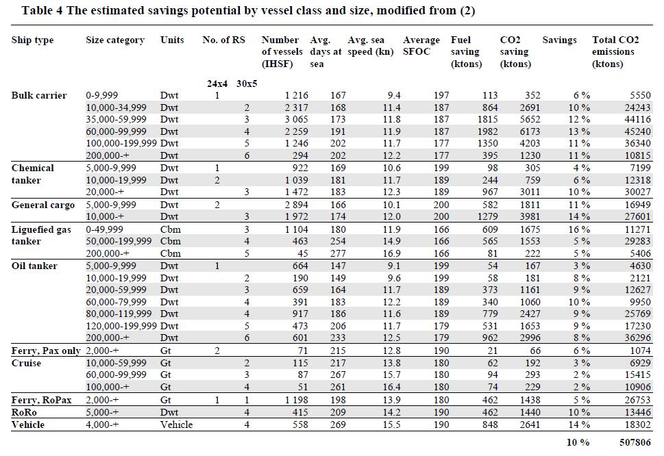
The study [4] concludes (Table 1) that by using rotor sails only, it is possible to reduce the emissions of applicable vessels related by an average of 10% of annual global emissions of 508 000 MT of CO2 while keeping the current operational profiles. This corresponds to 51 MT of CO2 emissions reduction on annual basis. The study also demonstrates that the primary renewables, such as wind propulsion, have important benefits over other carbon neutral propulsion technologies. It is anyhow noted that without major changes in operational aspects of the commercial shipping, it is unrealistic to expect wind propulsion to fulfil the total propulsion power requirement. This highlights the importance of well designed integration of different means of propulsion, and also hints that it is highly beneficial to combine different efficiency technologies to exploit the performance of them into full extent.
The study [4] concludes (Table 1) that by using rotor sails only, it is possible to reduce the emissions of applicable vessels related by an average of 10% of annual global emissions of 508 000 MT of CO2 while keeping the current operational profiles. This corresponds to 51 MT of CO2 emissions reduction on annual basis. The study also demonstrates that the primary renewables, such as wind propulsion, have important benefits over other carbon neutral propulsion technologies. It is anyhow noted that without major changes in operational aspects of the commercial shipping, it is unrealistic to expect wind propulsion to fulfil the total propulsion power requirement. This highlights the importance of well-designed integration of different means of propulsion, and also hints that it is highly beneficial to combine different efficiency technologies to exploit the performance of them into full extent.
3. ROTOR SAILS AND VOYAGE OPTIMIZATION
Voyage optimization with wind propulsion has been recently studied [5] by running a simulation with 384 sailed voyages (using AIS data) as comparative baselines on routes including US – EUR, EUR – US, CN – SA, SA – CN, CN – AUS, and AUS – CN. The total number of simulated voyages was more than 2200. The simulation was conducted using NAPA Voyage Optimization, which provides solutions for improving operational efficiency by optimizing route and speed profiles for any sea passage. To study the impact of the Rotor Sails on the potential fuel saving for ships, a comparative simulation experiment was conducted with different of routing methods. The experiment was based on historical voyage data
Conference Paper 258
CN, CN AUS, and AUS CN. The total number of simulated voyages was m ore than 2200. The simulation was conducted using NAPA Voyage Optimization, which provides solutions for improving operational efficiency by optimiz ing route and speed profiles for any sea passage To study the impact of the Rotor Sails on the potential fuel saving for ships, a comparative simulation experiment was conducted with different of routing methods. The experiment was based on historical voyage data
The performance model used for Rotor Sails was based on full scale experiments and verifications [4], which was hence proven to produce results that match with the operational experience and long-term performance measurement. The weather data considered in the simulations consisted of wind, wind waves, swell and ocean currents.
The performance model used for Rotor Sails was based on full scale experiments and verifications [4], which was hence proven to produce results that match with the operational experience and long term performance measurement. The weather data considered in the simulations consisted of wind, wind waves, swell and ocean currents.
An example of simulated routes on voyage US-EUR is shown in Figure 1. It can be seen there that the original route (route collected from AIS) follows the rhumb line, whereas the introduction of Rotor Sails allows the route to be offset further away from the original. All of the routes have the same arrival time. [5]
An example of simulated routes on voyage US EUR is shown in Figure 1. It can be seen there that the original route (route collected from AIS) follows the rhumb line, whereas the introduction of Rotor Sails allows the route to be offset further away from the original. All of the routes have the same arrival time . [5]
Figure 1 An example of simulated routes on voyage US-EUR [5]
Figure 1 An example of simulated routes on voyage US EUR [5]
The following Figure 2 illustrates the simulated savings potential on different routes. To allow comparison between routes of different length, the results are shown in a form of total fuel consumption divided by the total number of days spent on the voyages. This means any potential differences in voyage times are also taken into account. The savings in figure 3 correspond to cases “With sails, baseline voyage” and “With sails, optimized route, constant engine RPM”. [5]
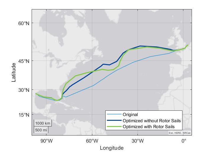
Conference
259
Paper
The following Figure 2 illustrates the simulated savings potential on different routes. To allow comparison between routes of different length, the results are shown in a form of total fuel consumption divided by the total number of days spent on the voyages. This means any pot ential differences in voyage times are also taken into account. The savings in figure 3 correspond to cases “With sails, baseline voyage” and “With sails, optimized route, constant engine RPM”. [5]
Figure 2 Savings potential on different routes with Rotor Sails and Rotor Sails coupled with voyage optimization. [5]
Figure 2 Savings potential on different routes with Rotor Sails and Rotor Sails coupled with voyage optimization. [5]
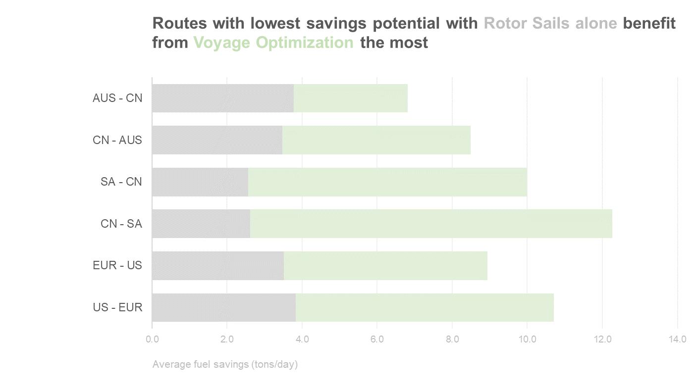
The studies [4] and [5] and Figure 2 illustrate clearly, that both voyage optimization and Rotor Sails are able to produce significant savings on their own. The average savings potential of Rotor Sails for the configurations studied in [5] was 7% when the ships operation was not adjusted to accommodate the Rotor Sails. With voyage optimization only the savings potential was 17% (when assuming a constant engine RPM). However, when these two technologies were combined, the accumulative savings potential reached 24%. It is also worth noting that the average contribution of Rotor Sails to the total propulsion power was rather modest in the cases studied. It can be anticipated that as the contribution of the wind propulsion increases, also the importance and benefit of the voyage optimization coupled with wind propulsion increases. Typically, the proportion of wind propulsion depends on the number and size of the sails installed. For example, the vessel considered in the study [5] for the Persian Gulf – China route was a VLCC equipped with three 35m tall Rotor Sails with a diameter of 5m.
The studies [4] and [5] and Figure 2 illustrate clearly, that both voyage optimization and Rotor Sails are able to produce significant savings on their own. The average savings potential of Rotor Sails for the configurations studied in [5] was 7% when the ships operation was not adjusted to accommodate the Rotor Sails. With voyage optimization only the savings potential was 17% (when assuming a constant engine RPM). However, when these two technologies were combined, the accumulative savings potential reache d 24%. It is also worth noting that the average contribution of Rotor Sails to the total propulsion power was rather modest in the cases studied . It can be anticipated that as the contribution of the wind propulsion increases, also the importance and benefit of the voyage optimization coupled with wind propulsion increases. Typically, the proportion of wind propulsion depends on the number and siz e of the sails installed. For example, the vessel considered in th e study [5] for the Persian Gulf China route was a VLCC equipped with three 35m tall Rotor Sails with a diameter of 5m.
Based on the study [5], i t can also be noted that voyage optimization evens out the differences between “good routes” and “weak routes” for wind propulsion significantly. It appears that voyage optimization supports especially those ships with wind propulsion that may have the weakest business case with wind propulsion only, which hints towards the importance of voyage optimization in expanding the commercially viable market of wind propulsion.
Based on the study [5], it can also be noted that voyage optimization evens out the differences between “good routes” and “weak routes” for wind propulsion significantly. It appears that voyage optimization supports especially those ships with wind propulsion that may have the weakest business case with wind propulsion only, which hints towards the importance of voyage optimization in expanding the commercially viable market of wind propulsion.
4. DISCUSSION AND CONCLUSIONS
The studies [4] and [5] presented in this paper illustrate clearly, that Rotor Sails and voyage optimization are able to produce significant fuel savings on their own, but when combined, they can produce state-of-the-art fuel savings and CO2 emissions reductions for all global routes. This is probably because a typical feature of wind propulsion is its intermittency, which means that the available energy in wind varies over time. Furthermore, the prevailing wind conditions vary over the location. At one place wind speeds are typically higher than in another. Similarly, the prevailing wind directions may be different from place to place. Because of this, combining wind propulsion with voyage optimization enables harnessing potential on both technologies on global routes in a very efficient way.
Conference Paper 260
There are probably no other technologies than voyage optimization, which can be combined with wind propulsion so that the overall gained benefit is in some cases larger than the original benefits of the individual technologies being combined. There are anyhow numerous technologies available, which can increase the energy efficiency further and help to minimize the fuel consumption of ships. A good example of a ship with such additional technologies being implemented is Sea Cargo’s “Connector” – the ship has been retrofitted with two (35 meter x 5 meter) Rotor Sails, and the ship also has a battery container on board [6]. In the most favorable wind condition, a ship like this could keep on sailing for some time even with all engines being shut down, because the battery containers enable feeding electricity for Rotor Sails and other electrical equipment on board. And another important example of such ships are Scandlines’ sister ferries “Copenhagen” [7] and “Berlin” [8], where rotor sails sit alongside measures such as hydrodynamic hull optimisation and hybrid electric propulsion system with a battery powered energy storage system.
As the carbon footprint requirements for shipping get more stringent, it is likely that the wind propulsion becomes more integral part of the ships energy system. Furthermore, this opens new opportunities and interesting challenges: when the wind propulsion corresponds to larger parts of ships total propulsion, it is conceivable that the ships’ conventional engines can be downscaled. This leads to the business case of wind propulsion being partly covered by the expense saved on the fuel engine. However, to achieve this, it is necessary to introduce the operational considerations at the design stage of the vessel to ensure the at the ship is capable to fulfil its mission requirements, such that the passage times can be kept as required with high enough confidence level. In addition, reaching this state requires that also other efficiency technologies such as voyage optimization are combined with wind propulsion in an efficient way.
The study [4] concludes that with rotor sails alone, annual CO2 emissions reductions of up 51 MT can be reached, and study [5] demonstrates that the effect of wind propulsion can be doubled in some cases when combined with voyage optimization software, especially on longhaul routes. Since there are today numerous energy efficiency technologies available for ships, it can be claimed that annual CO2 emissions reductions of at least 100 MT could be reached by fitting the ships shown in Table 1 with technologies which are already available today. This would correspond to 20% of total annual CO2 emissions of such ships. In order to reach the ambitious long-term global emissions reduction targets for global shipping, an efficient decarbonization action like this should be implemented already today. As the energy prices of shipping keep on soaring when the shift towards carbon-neutral fuels proceeds, also the business case of an action like this should become a “no-brainer” for all shipowners.
Conference Paper 261
5. REFERENCES
[1] Poseidon principles, https://www.poseidonprinciples.org/finance/about/, Retrieved 15.09.2022
[2] The hydrogen trajectory - What does research tell us about the pace of development of hydrogen technologies?, https://home.kpmg/xx/en/home/ insights/2020/11/the-hydrogen-trajectory.html, Retrieved 28.09.2022
[3] Why shipping pure hydrogen around the world might already be dead in the water, https://www.rechargenews.com/energy-transition/special-report-whyshipping-pure-hydrogen-around-the-world-might-already-be-dead-in-thewater/2-1-1155434, retrieved 28 September 2022
[4] Paakkari et. Al. ROTOR SAIL GHG REDUCTION POTENTIAL, MODELLING AND SEA TRIAL VALIDATION; The 5th Int. Conference on Innovation in High Performance Sailing Yachts and Sail-Assisted Ship Propulsion, Gothenburg, Sweden. 2020
[5] Voyage optimization with wind propulsion, V Paakkari, H Wang, C Stigler, September 2022.
[6] Setting sail onboard Sea Cargo’s SC Connector: Experiencing efficiency and sustainability in action, https://www.norsepower.com/post/setting-sail-onboardsea-cargos-sc-connector-experiencing-efficiency, Retrieved 27.09.2022
[7] Latest Norsepower Rotor Sail installation completed on Scandlines ferry in just hours, https://www.norsepower.com/post/latest-norsepower-rotor-sailinstallation-completed-on-scandlines-ferry, Retrieved 27.09.2022
[8] Norsepower installs Rotor Sail on second Scandlines hybrid ferry following successful results achieved on sister vessel, https://www.norsepower.com/post/ norsepower-installs-rotor-sail-on-second-scandlines-hybrid-ferry, Retrieved 27.09.2022
Conference Paper 262
JAN P. BRUGGER Co-Founder & COO, FuelSave
BIOGRAPHY
Jan has a graduate degree in Business Management and a BA in Business Administration (DHWB Mannheim). In 2001, he began his career as Head of Sales in telecommunications for MediaMarkt, Europe’s largest consumer electronics retailer, before moving into the automotive industry.

He worked for several companies as CFO and CEO, before filling the position of CFO (2007) and later ecoming shareholder and CEO (2010) of In Form GmbH, an automotive services company, working for BMW, Mercedes, Audi and Volkswagen by providing highly skilled and rare specialists in Europe on demand.
In 2014, he sold his “In Form” stock and co-founded FUELSAVE GmbH together with Dirk Hoffman (CTO) and Marc Sima (CEO) to focus on cleantech and energy efficiency enhancement ventures in a variety of sectors.
Speaker
263
Retrofit Solutions
ABSTRACT
FUELSAVE GmbH has developed FS MARINE+, a patented, field and lab proven retrofit solution that tackles combustion inefficiencies - reducing fuel consumption and emissions. This innovative technology, known as advanced combustion conditioning, dynamically injects hydrogen, oxygen, water and (m)ethanol into the combustion process. This results in leaner, cleaner combustion, reducing particulate matter by up to 40%, CO2 emissions by 10 - 15%, NOx by 30 - 80%, and black carbon emissions by up to 33%.
The solution is future-proof, compatible with other efficiency enhancement/emission reduction measures, and suitable for use with current/future fuels, whether liquid or gaseous. This includes alternative clean fuels envisaged by shipping, such as bio/synthetic fuels and gases, as well as methanol and ammonia.
FS MARINE+’s versatility makes it an important tool in decarbonisation efforts as shipping strives to meet 2030 and 2050 climate targets. It helps customers to increase their profitability through NET OPEX savings, while reducing their environmental footprint to stay compliant with regulations.
In recent years, FUELSAVE has won a total of €5.2M funded projects from the European Union (EU) to support development of FS MARINE+ for four-stroke and two-stroke engines. FUELSAVE has secured LOIs for over 220 ships, rigs and power plants, including some of the world’s leading shipping companies, and signed contracts with Van Oord and Seadrill to deploy its technology in the offshore sector.
FUELSAVE is working to further extend the benefits of its technology, helping customers reach IMO tier 3 requirements and beyond, while supporting a viable clean fuel transition.
Conference Paper 264
The Role of Retrofitting in the Clean
AS A KEY PILLAR TOWARDS NET ZERO
1. RETROFITTING AS A KEY PILLAR TOWARDS NET ZERO
To steer maritime towards net zero emissions, shipowners and operators need to find commercially viable solutions to reduce their carbon output while staying competitive. As the Maersk McKinney Moeller Center for Zero Carbon Shipping points out, the primary focus which is the low hanging fruit option needs to be the reduction of energy use through energy efficiency enhancements, as clean fuel will not come cheap. Any energy that is saved by the vessel has to be produced and transported and dispatched to the vessel.
out, the primary focus –which is the low-hanging fruit option – needs to be the reduction of energy use through energy efficiency enhancements, as clean fuel will not come cheap. Any energy that is saved by the vessel has to be produced and transported and dispatched to the vessel. Some of the most prominent
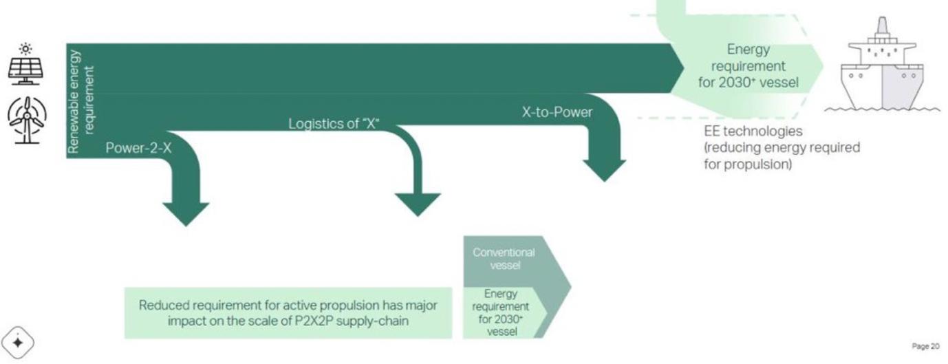
Some of the most prominent pathways on the decarbonization journey are:
Source: https://www zerocarbonshipping com/publications/
In the following core pillars, companies such as FUELSAVE GmbH are providing a modular solution for retrofitting options for CO2 and CO2e / GHG reduction, to achieve IMO tier III compliance and beyond.
2) DEPLOY EMISSION ABATEMENT TECHNOLOGIES
3) SWITCH TO CLEAN FUELS
Þ While SCR aftertreatment is an effective choice for NOX reduction, it comes at a high CAPEX and significant OPEX penalty. Furthermore, it has a large installation footprint, which is not practical or attractive for many vessel owners
Þ An Advanced EGR add on module such as the FS EGR+ is faster and more cost effective to deploy than an SCR. It also produces far less OPEX, resulting in big savings for shipowners and operators as it does not require consumables such as urea or ammonia. The limitation of a basic EGR system is that for higher levels of
Conference Paper 265
To steer maritime towards net-zero emissions, shipowners and operators need to find commercially viable solutions to reduce their carbon output while staying competitive. As the Maersk McKinney Moeller Center for Zero Carbon Shipping points
pathways on the decarbonization journey are:
In the following core pillars, companies such as FUELSAVE GmbH are providing a modular solution for retrofitting options for CO2 and CO2e / GHG reduction, to achieve IMO tier III compliance and beyond. 1) ENERGY EFFICIENCY ENHANCEMENTS 2) DEPLOY EMISSION ABATEMENT TECHNOLOGIES 5 Selective catalytic reduction (SCR) 5 Exhaust gas recirculation (EGR) 5 Carbon Capture and Storage (CCS) 3) SWITCH TO CLEAN FUELS 5 LNG as an intermediary step before RNG / SNG become available 5 E-Methanol 5 E-Ammonia 5 Hydrogen ==>
+++++++++++++++++++++++++++++++++++++++++++++++++++++++++++++++++++++ FUELSAVE GmbH RETROFITTING FOR THE CLEAN FUEL TRANSITION 1.
Fuel Transition Source: https://www.zerocarbonshipping.com/publications/
While SCR aftertreatment is an effective choice for NOX reduction, it comes at a high CAPEX and significant OPEX penalty. Furthermore, it has a large installation footprint, which is not practical or attractive for many vessel owners.
RETROFITTING
1) ENERGY EFFICIENCY ENHANCEMENTS
• Selective catalytic reduction (SCR) • Exhaust gas recirculation (EGR)
• Carbon Capture and Storage (CCS)
• LNG as an intermediary step before RNG / SNG become available • E Methanol • E Ammonia • Hydrogen
==> An Advanced EGR add-on module such as the FS EGR+ is faster and more cost effective to deploy than an SCR. It also produces far less OPEX, resulting in big savings for shipowners and operators as it does not require consumables such as urea or ammonia. The limitation of a basic EGR system is that for higher levels of NOX reduction the PM / hydrocarbon deposits increase and negatively impact the engine. Advanced combustion conditioning, found in the FS MARINE+ system, counteracts this limitation due to the cleaner combustion and reduced levels of PM and NOX from the source.
We found an attractive synergy for effective NOX and emission reduction, without any CAPEX and OPEX drawbacks, while being able to widen the ability to perform combustion optimization for fuel consumption reduction, between:
5 advanced combustion conditioning (hydrogen, oxygen, water and methanol)
5 waste heat recovery and conversion
5 EGR with co-activation through syngas and additives
5 ECU alignment (optimized fuel efficiency and ignition timing within desired emission tier)
o EEXI o CII
While there are engines with EGR to achieve IMO tier III without urea consumption, this retrofit option is not commonly available to the market. However, the FS MARINE+ EGR add-on changes that.
In combination with FS MARINE+, it is possible to have a considerable smaller installation footprint for lower cost than a SCR and current EGR systems. This supports operators’ decarbonization strategy by helping them to reduce their emissions and optimize fuel oil consumption, with the synergies of combustion conditioning utilizing hydrogen, oxygen, water and (m)ethanol providing a unique win-win.
The system is applicable for today and future clean fuels to help optimize combustion. For example, methanol and ammonia benefit from the availability of hydrogen for combustion conditioning, and the optimization of combustion via the air intake side or from natural gas for the ignition and the reduction of the methane slip.
These retrofit measures help to further reduce NOX and PM emissions, creating cleaner fuels that drive shipping towards zero emissions and enable further engine optimization for fuel efficiencies (reduced costs and emissions).
Conference Paper 266
2. RETROFITTING TOWARDS EEXI & CII COMPLIANCE
2. RETROFITTING TOWARDS EEXI & CII COMPLIANCE
2.1 Market Driver Energy Efficiency Existing Ship Index (EEXI)
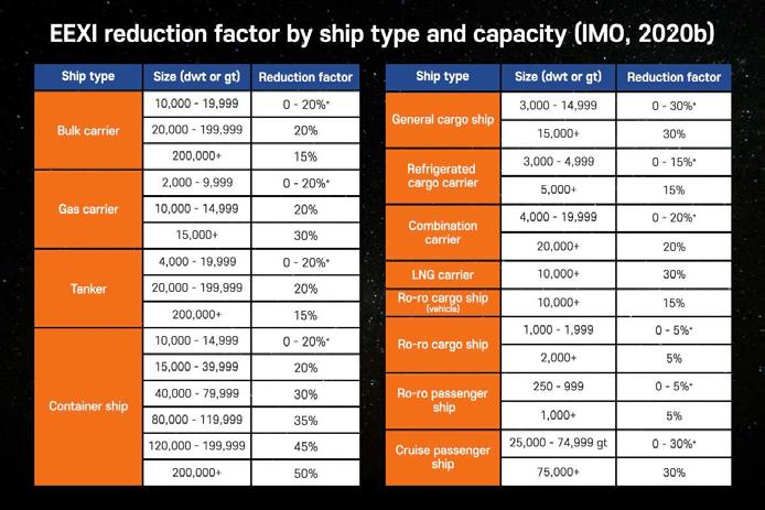
2.1 Market Driver – Energy Efficiency Existing Ship Index (EEXI)
Fifty three per cent the global container fleet needs to adapt EEXI measures. While may vessels have Engine Power Limitations (EPL) to cut their power and travelling speed to reduce emissions and comply with regulations, other solutions are required to help owners with improving their EEXI and CII rating.
Fifty-three per cent the global container fleet needs to adapt EEXI measures. While may vessels have Engine Power Limitations (EPL) to cut their power and travelling speed to reduce emissions and comply with regulations, other solutions are required to help owners with improving their EEXI and CII rating.
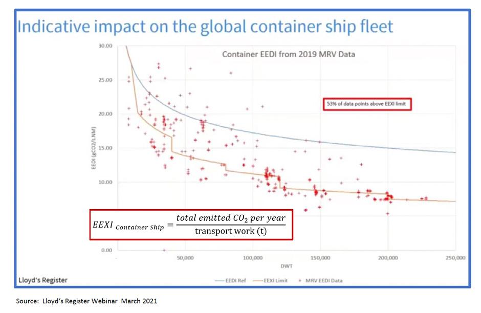
Conference Paper 267
+++++++++++++++++++++++++++++++++++++++++++++++++++++++++++++++++++++ 6 FUELSAVE GmbH Altrottstr. 31 D 69190 Walldorf
FUELSAVE GmbH RETROFITTING FOR THE CLEAN FUEL TRANSITION
(T) + 49 6227 381 111 (F) + 49 6227 381 200 (E) info@fuelsave.de (W) www.fuelsave.de
à EEXI COMPLIANCE RETROFIT SOLUTION: EGR WITH FUEL SAVING OPTION FOR FUEL EFFICIENCY OPTIMISATION --> EEXI COMPLIANCE RETROFIT SOLUTION: EGR WITH FUEL SAVING OPTION FOR FUEL EFFICIENCY OPTIMISATION
FUELSAVE GmbH RETROFITTING FOR THE CLEAN FUEL TRANSITION
2.2 Market Driver – Carbon Intensity Indicator (CII)
2.2 Market Driver – Carbon Intensity Indicator (CII)
2.2 Market Driver – Carbon Intensity Indicator (CII)
CII defined as CO2 emissions per transport task (e.g., CO I F DWT X nautical mile). From 1 January 2023, all ships above 5,000 gt have to calculate and report their cii annually
CII defined as CO2 emissions per transport task (e g , CO I F DWT X nautical mile). From 1 January 2023, all ships above 5,000 gt have to calculate and report their cii annually
CII defined as CO2 emissions per transport task (e.g., CO I F DWT X nautical mile). From 1 January 2023, all ships above 5,000 gt have to calculate and report their cii annually.
Based on the CII, ships will be rated from A to E (where ‘A’ is best), according to the following scale:
Based on the CII, ships will be rated from A to E (where ‘A’ is best), according to the following scale:
à CII compliance retrofit solution: EGR with fuel-saving option for fuel efficiency optimization
--> CII COMPLIANCE RETROFIT SOLUTION: EGR WITH FUEL SAVING OPTION FOR FUEL EFFICIENCY OPTIMISATION
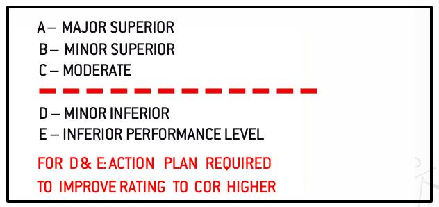
à CII compliance retrofit solution: EGR with fuel saving option for fuel efficiency optimization.
2.3 Milestones For Compliance With EEXI and CII
To meet EEXI and CII regulations, shipowners have to prepare their vessels to comply with the relevant requirements to cut carbon footprints through technical and operational measures. Retrofitting is the quickest, most viable option to ensuing existing vessels satisfy regulations and stay competitive amid the transition.
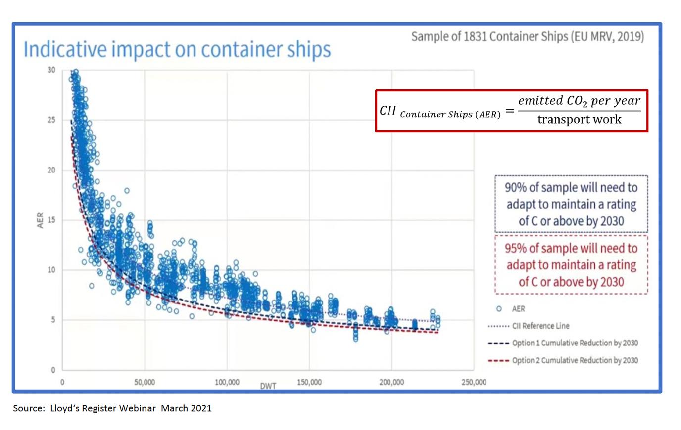
+++++++++++++++++++++++++++++++++++++++++++++++++++++++++++++++++++++
Based on the CII, ships will be rated from A to E (where ‘A’ is best), according to the following scale: +++++++++++++++++++++++++++++++++++++++++++++++++++++++++++++++++++++
FUELSAVE GmbH
FUELSAVE GmbH
Altrottstr. 31 D 69190 Walldorf
Altrottstr. 31
D 69190 Walldorf
(T) + 49 6227 381 111 (F) + 49 6227 381 200
(T) + 49 6227 381 111 (F) + 49 6227 381 200
268
(E) info@fuelsave.de (W) www.fuelsave.de
(E) info@fuelsave.de (W) www.fuelsave.de
7
7
Conference Paper
FUELSAVE GmbH RETROFITTING FOR THE CLEAN FUEL TRANSITION
2.3
Milestones For Compliance With EEXI and CII
To meet EEXI and CII regulations, shipowners have to prepare their vessels to comply with the relevant requirements to cut carbon footprints through technical and operational measures. Retrofitting is the quickest, most viable option to ensuing existing vessels satisfy regulations and stay competitive amid the transition.
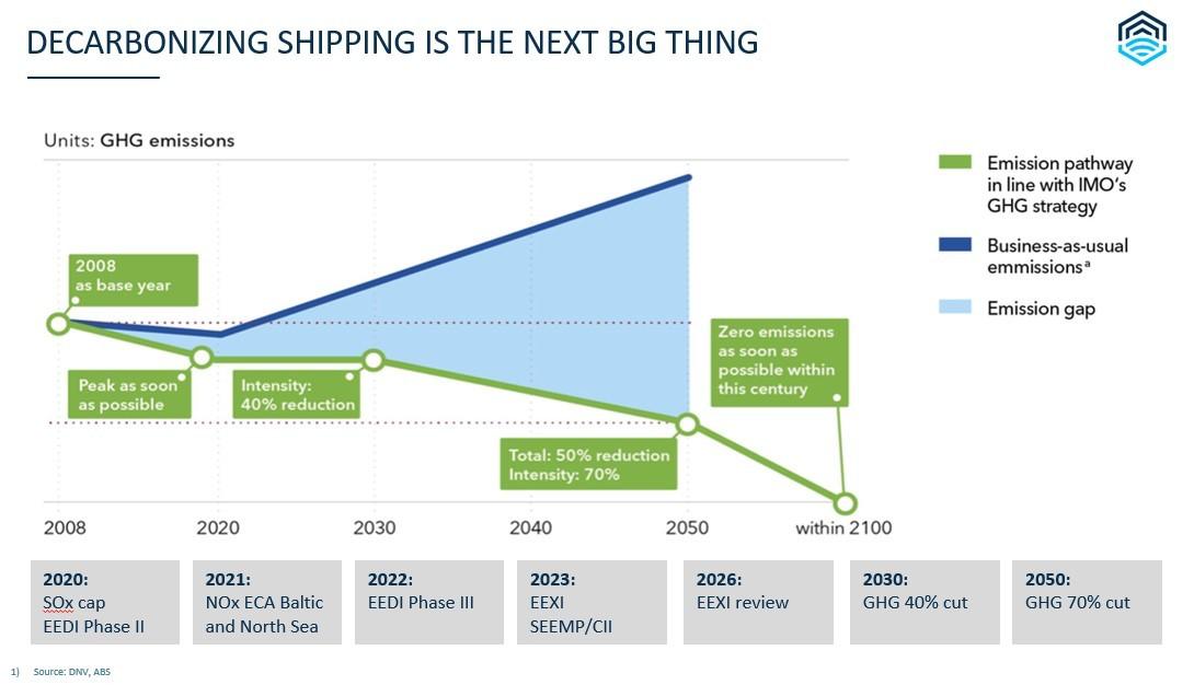
Key dates when preparing for the new regulations:
Key dates when preparing for the new regulations:
5 September 2022: completion of EEXI assessment and adoption
• September 2022: completion of EEXI assessment and adoption
5 December 2022: establishing a carbon intensity profile and enhanced Ship Energy
• December 2022: establishing a carbon intensity profile and enhanced Ship
2.4 EEXI & CII compliance from 1 January 2023
2.4 EEXI & CII compliance from 1 January 2023
Measures to address both technical and operational aspects of restricting GHG emissions.
1) Energy efficiency existing ship index (EEXI)
Measures to address both technical and operational aspects of restricting GHG emissions.
A technical or design efficiency index that requires a vessel to achieve a required level of technical efficiency.
1) Energy efficiency existing ship index (EEXI)
A technical or design efficiency index that requires a vessel to achieve a required level of technical efficiency
--> Calculating EEXI will utilize the existing Energy Efficiency Design Index (EEDI) reference lines.
à Calculating EEXI will utilize the existing Energy Efficiency Design Index (EEDI)reference lines.
--> The required EEXI is the vessel’s required maximum grams of CO2 it emits x the vessel per capacity tonne mile under reference conditions in line with its type and capacity.
--> The attained EEXI for a vessel must be less than or equal to the ‘required EEXI.’
à The required EEXI is the vessel’s required maximum grams of CO2 it emits x the vessel per capacity tonne mile under reference conditions in line with its type and capacity.
2) Annual operational carbon intensity indicator (CIL)
à The attained EEXI for a vessel must be less than or equal to the ‘required EEXI.’
Working to continuously improve the vessel’s operation carbon intensity within a specific rating level. This involves developing an enhanced SEEMP to meet mandatory CII and rating scheme (A-E)
2) Annual operational carbon intensity indicator (CIL)
Working to continuously improve the vessel's operation carbon intensity within a specific rating level. This involves developing an enhanced SEEMP to meet mandatory CII and rating scheme (A E)
--> New regulations will be introduced to establish a required annual operational CII for specified vessel types.
--> The CII determines the annual reduction factor needed to ensure continuous improvement of the vessel’s operational carbon intensity in the rating scheme
à New regulations will be introduced to establish a required annual operational CII for specified vessel types.
+++++++++++++++++++++++++++++++++++++++++++++++++++++++++++++++++++++
FUELSAVE GmbH
Altrottstr. 31 D 69190 Walldorf
(T) + 49 6227 381 111 (F) + 49 6227 381 200
(E) info@fuelsave.de (W) www.fuelsave.de
Conference Paper 269
8
à The CII determines the annual reduction factor needed to ensure continuous improvement of the vessel’s operational carbon intensity in the rating scheme
3. NOX REDUCTION – KEY ENABLER FOR ENGINE OPTIMIZATION & CII / EEXI
3. NOX REDUCTION – KEY ENABLER FOR ENGINE OPTIMIZATION & CII / EEXI
By creating NOX reduction, the operator achieves a NOX buffer within the emission tier, which can be used to optimize the engine with higher pressure and earlier ignition In turn, this leads to better fuel efficiency and a significant reduction in fuel oil consumption, both of which help vessels with being EEXI and CII compliance.
By creating NOX reduction, the operator achieves a NOX buffer within the emission tier, which can be used to optimize the engine with higher pressure and earlier ignition. In turn, this leads to better fuel efficiency and a significant reduction in fuel oil consumption, both of which help vessels with being EEXI and CII compliance.
Below is a list of some NOX reduction options, besides changes to other clean fuel types:
Below is a list of some NOX reduction options, besides changes to other clean fuel types:
Source: DNV
Source: DNV
Selective catalytic reduction (scr)
Selective catalytic reduction (scr)
• If using urea / ammonia, the customer faces a cost penalty of around 8% (DNV report).
à Through a cleaner exhaust with FS MARINE+, we can use less urea and reduce further the OPEX accordingly, providing additional benefits for systems with SCR installed. It also decreases overall emissions further than if only using SCR, and across all load phases where the SCR cannot achieve IMO Tier III in part loads
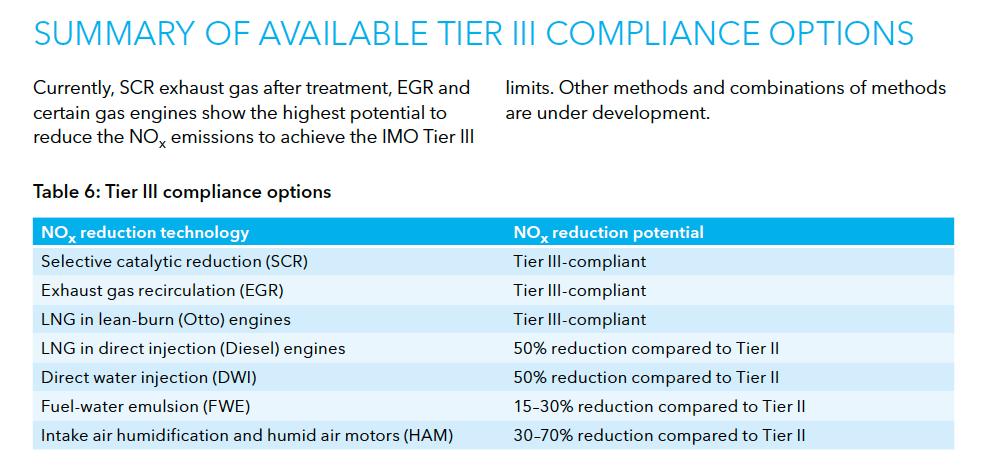
--> Through a cleaner exhaust with FS MARINE+, we can use less urea and reduce further the OPEX accordingly, providing additional benefits for systems with SCR installed. It also decreases overall emissions further than if only using SCR, and across all load phases where the SCR cannot achieve IMO Tier III in part loads.
3.1 FS MARINE+ CO2 & CO2-e + NOx Abatement Technology
3.1 FS MARINE+ CO2 & CO2-e + NOx Abatement Technology
FUELSAVE GmbH has developed FS MARINE+, an awarded field- and lab-proven HW retrofit solution for reciprocating combustion engines. It helps operators to reduce emissions while saving OPEX by increasing the combustion efficiency with a leaner and cleaner combustion at reduced temperatures. This is achieved through the dynamic injection of the following gaseous and liquid additives: 5 Hydrogen 5 Oxygen
Water 5 Methanol / Ethanol (Low Cetane / High Octane – Alcohol)
FUELSAVE GmbH has developed FS MARINE+, an awarded field and lab proven HW retrofit solution for reciprocating combustion engines. It helps operators to reduce emissions while saving OPEX by increasing the combustion efficiency with a leaner and cleaner combustion at reduced temperatures. This is achieved through the dynamic injection of the following gaseous and liquid additives: • Hydrogen • Oxygen • Water • Methanol / Ethanol (Low Cetane / High Octane Alcohol)
5 If using urea / ammonia, the customer faces a cost penalty of around 8% (DNV report). +++++++++++++++++++++++++++++++++++++++++++++++++++++++++++++++++++++
FUELSAVE GmbH Altrottstr. 31 D 69190 Walldorf
(T) + 49 6227 381 111 (F) + 49 6227 381 200 (E) info@fuelsave.de (W) www.fuelsave.de
Conference Paper 270
9
5
Applying different quantities and combinations of additives, according to the load of the engine in three varying locations of the air intake, creates a cooler air intake, increasing the efficiency of the turbocharger and a cooler combustion reducing stress on all heat bearing components. It also harmonizes the combustion in the different cylinders for a smoother engine run with less vibrations and less soot and deposits, extending the lube oil lifetime by reducing contamination and wear and tear in the cylinders.
Abatement Method / Control Principle: 1. Optimized Combustion 2. Reducing peak temperature 3. Reducing residence time at peak temperature
4. Use of clean fuel alternatives
The primary NOx reduction / prevention measures that are being combined:
- Leaner Burn
- Optimization of Air Fuel Ratio
- Steam/ Water Injection
- Delay in ignition and enhancement of the premix phase (due to effective use of water and methanol that is transformed to a steam and recovering also part of the thermal energy to increase thermal and volumetric efficiency of the engine)
- Cooler air intake / reduced air pre-heat
- Replacement of some air with additive mediums without Nitrogen
- Substituting some of the primary fuel against cleaner fuel alternatives that produce less emissions.
Air-fuel ratio and ignition type
- The fuel-air ratio can be used to control combustion temperature and can be adjusted to minimize NOx generation. Lower peak temperature will limit the amount of NOx formation
- For internal combustion reciprocating engines, retardation of injection or spark ignition, or an air-fuel ratio that departs from stoichiometric conditions will reduce peak temperature.
- Delaying injection of fuel in a compression ignition (diesel) engine can reduce the NOx emissions, however through different dosing of the additives, the ideal set point can be influenced as well as he cylinder pressures to optimize the fuel oil consumption while controlling NOx emissions, for example.
Advanced combustion conditioning, such as FS MARINE+, does not change the use of the primary fuel and is not touching the fuel supply system, or any part or working- or safety principle of the engine. This means full fault redundancy without impacting the operating engine when it is switched off, making it compatible with other methods for helping to reduce CO2 and GHG / CO2-e emissions (N2O, BC) and air pollution (NOx, PM).
In combination with a EGR add-on module emission reduction beyond IMO tier III is being achieved which enables the option to apply fuel efficiency optimization and more efficient combustion, using the created NOx reduction as a buffer for achieving further fuel savings to adhere to EEXI and CII regulations.
Conference Paper 271
3.2 Co2e / GHG Reduction Beyond Current standards
FUELSAVE GmbH has identified the following areas for further potential improvement of emission reduction and overall efficiency and fuel oil consumption reduction in the combustion conditioning process that are natively combined and attracted great interest from various segments for the technology in the light of the EU ETS and corporate decarbonization strategies and EEXI requirements.
Waste Heat Utilization for higher evaporation rate in colder climates 5 as add-on for FS MARINE+ for higher NOx and PM reduction and higher fuel oil savings benefits from existing FS MARINE+ technical infrastructure as a “light” add-on 5 enhances round cycle efficiency with use of waste heat
Co Activation air intake with special type of SCR in combination with advanced combustion conditioning such as FS MARINE+ 5 Lower PM 5 Lower NOx 5 Lower Fuel Oil Consumption
Combination of Waste Heat Recovery & Co-Activation with EGR principles 5 overcomes typical challenges of a EGR due to cleaner exhaust already due to FS MARINE+ benefits from FS MARINE+ effects on exhaust gases 5 reduces emissions significantly (NOx and PM)
Spray Picture Optimization
5 Improvement of the Liquid % to Benefit % ratio (i.e. 1% change of liquid to % of NOx reduction)
5 Simulation, design for different nozzles adapted to different injection locations and loads in injection bars 5 Model adaptable for different engines
ECU Optimization – Research & Development + Testing 5 Fine-tuning for injection timing and angles and quantities in the ECU for further optimization of NOx reduction and FOC reduction with the use of hydrogen and methanol as additives. This method can be used to substitute more fuel to reduce EEXI and CII, especially for two-stroke applications where injections are directly into the cylinder and can overcome the necessity for EPL
Set Point Optimization per fuel & engine type and operating conditions
5 Simulation of additive injections for engine types based on thermodynamical, physical and chemical models for the effects of such additives to different engines. Such models, which are not currently available for OEMs, will further help to optimize the maximum effect
5 Optimization of set points before being onboard for better system design, and higher cost savings and emission reduction
5 Quantities (Ration FOC), mixing the ratio, timing and combination with H2 and o2
In-Field Emission and Performance Monitoring and Analysis
Finding automated ideal setpoints in the field with analysis of constant emission measurement system (CEMS)
5 Automation for more intelligent system fine tuning to find set points for ideal fuel oil consumption and emission performance.
5 Automated test program – records all values running through different mixes and quantities at different loads and records and monitors:
- Cylinder pressures and temperatures
- Emissions and FOC
Conference Paper 272
FINANCIAL BENEFITS
5 Comply with IMO Tier III regulations without adding chemicals
5 Higher OPEX savings compared to SCR
5 No logistics required for consumables like urea
5 Higher OPEX savings compared to FS MARINE+ without add-on with fuel consumption optimization
5 Cost-effective as an add-on to FS MARINE+, as infrastructure can be used
BETTER OVERALL PERFORMANCE POSSIBLE
5 Possibility to further reduce fuel oil consumption while controlling the emissions via FSM+ with EGR
5 Higher NOx reduction enables further optimization towards fuel oil reduction and cost savings
5 Co-activation of exhaust with alcohol and synergies with FS MARINE+ lead to no fuel penalties, and further potential fuel oil reduction.
5 The same drawbacks seen with other EGR are not applicable, due to integration and benefits in combination with FS MARINE+ and the cleaner exhaust.
OPERATIONAL BENEFIT
5 Overcoming challenges that other EGRs face
5 EGR is fast to retrofit
5 EGR has a much smaller footprint than a SCR
5 EGR is easier to maintain than SCR
From ABS Advisory Guidance document:
An additional operating mode option, available for engines equipped with EGR, is the use of the Eco-EGR mode. In this mode a small quantity of EGR rate (about 10-15%) is used during operation in Tier II mode, which enables an increase in firing pressure by lowering combustion temperatures, leading to lower fuel consumptions. During the Eco-EGR operation, the fuel consumption in Tier II mode is improved by about 4% compared to the typical reference consumption for Tier II mode.
--> These levels can be further improved upon in combination with advanced combustion conditioning measures that help to reduce NOx and lead to a cleaner combustion at higher efficiency, such as with FS MARINE+ and even more in combination with ignition time optimization for fuel efficiencies.
Conference Paper 274
5. CONCLUSION
To comply with upcoming regulations and support shipowners and operators in their journey towards zero emissions, retrofitting and emission reduction are key enablers. They can replace measures such as EPL, enabliing operators to increase their competitiveness while complying with regulations.
Besides retrofits for clean-fuel conversions to, say, methanol, we have seen with the latest addon for enhanced emission reduction and fuel reduction optimization that the advanced EGR technology represents an attractive alternative for SCR deployments for IMO tier III compliance. This is because the EGR is cheaper in terms of CAPEX (significantly so for OPEX) compared to a SCR since no consumables like urea and its logistics are required and maintenance of the catalyst is not necessary. Furthermore, it features a much smaller footprint and is faster to install.
Advanced combustion conditioning with FS MARINE+ in combination with the EGR add-on benefits from the synergies of a cleaner combustion and already much reduced temperatures and NOx levels. These benefits mitigate previous challenges with a EGR like soot formation or fuel penalty and enables higher NOx reduction at lower EGR rates, providing even more capacity to optimize the combustion towards fuel efficiencies while improving the emission performance for a unique win-win.
Conference Paper 275
CLAES TRETOW
Managing Director, Stena RoRo AB
BIOGRAPHY
Claes Tretow has a master’s degree in Naval Architecture from the Royal Institute of Technology in Sweden and is currently working as Project Manager Newbuildings at Stena RoRo.

Since 2018 he has been working within Stena group of companies, previously as Project Manager at Stena Teknik.
Claes has experiences from a vide range of propulsion and power generation systems onboard RoRo and Ropax vessels including DF engines, Methanol and hybridization with batteries.
Speaker
276
KARSTEN HOCHKIRCH Head of Ship Performance Center, DNV SE
BIOGRAPHY
Dr. Karsten Hochkirch is heading the Ship Performance Center of DNV’s Maritime Advisory Services. After more than eight years of academic research he started as an entrepreneur in 2001 to offer unique hydrodynamic optimization consultancy to the Marine industry. In 2009, he and his team joined the GL-Group, which subsequently merged with DNV.

Karsten and his team has been involved in numerous maritime design projects, ranging from the largest container carriers, tanker, bulkers to America’s cup sailing yachts, where their advanced methodology was utilized to unveil unknown performance gains.
His references include more than 40 publications in maritime research, conferences and journals.
Speaker
277
Economic and Ecological Considerations for Wind-Assisted Ship Propulsion Systems
ABSTRACT
Rising fuel prices and a society being more aware of the consequences of CO2 emissions fuels the revitalization of wind propulsion. A variety of wind assisted propulsion systems are on the market today, including rigid-sail systems, Flettner rotors and kites. The main options are discussed with pros and cons, a short historical perspective, and recent installations. Key factors for success of wind assisted propulsion are discussed and a case study for a multipurpose vessel is used as illustration. The business case of wind assisted propulsion is complex due to high nonlinearities.
1. Introduction
The idea of wind-assisted propulsion systems (WAPS) as a powerful lever for saving energy and lowering emissions is not new. In 1988, Bertholdt and Riesch, [1] prophesied already: “Using the wind means using the most environmentally friendly energy source. Saving (fossil) fuel means emitting fewer pollutants. Time will come, in which this aspect will be considered more valuable than pure commercial interest.”
WAPS pioneer Peter Schenzle has argued that sea transportation particularly lends itself for first steps away from carbon combustion, for three reasons, [2]:
5 Its uniquely low energy demand could be largely covered from solar sources.
5 Wind is easily available at sea and can directly drive ships without transformation losses.
5 Weather routing and energy management can largely compensate for the variable input.
The ambitious IMO targets are asking for just this. Cutting greenhouse gas emissions with mandatory targets has driven ship owners and operators to re-think their propulsion systems. One possible solution to cope with IMO’s requirements is to install a WAPS to supply part of the propulsive power.
The performance of modern WAPS is often underestimated in the marine industry. Table 1 compares three high-performance marine vehicles that set records in world circumnavigation:
5 The “Earthrace”, https://en.wikipedia.org/wiki/MY_Ady_Gil, holds the circumnavigation record for power boats. The vessel was powered by twin diesel engines (2 x 400 kW), running on biofuel.
5 The “Tûranor PlanetSolar”, https://en.wikipedia.org/wiki/Tûranor_PlanetSolar, is the world’s largest solar-powered boat. 536 m2 solar panels supply an average propulsion power of 20 kW.
5 The “IDEC Sport”, https://en.wikipedia.org/wiki/IDEC_SPORT, is the world’s fastest going sailing vessel with a sail area of 557-828 m2. It circumnavigated the globe in 2/3 of the time of the powered racing trimaran “Earthrace”!
Conference Paper 278
Vessel Earthrace Tûranor PlanetSolar IDEC Sport
Propulsion
Biofuel diesel Solar cells Sails
Circumnavigation time 61 days 160 days 40 days
Length 24.00 m 31.00 m 31.50 m
Breadth 7.00 m 15.00 m 22.50 m
Displacement 26 t 85 t 18 t
Table 1: Record-holding vessels for world circumnavigation
2. Technical Aspects
The following discussion is taken from a more extensive DNV paper, [3]. We compare here three typical, but fundamentally different WAPS, Fig.1: Rotor Sails (a.k.a. Flettner rotors), https://en.wikipedia.org/wiki/Flettner_rotor, Rigid Wingsails, https://en.wikipedia. org/?wiki/?Wingsail, and DynaRigs, https://en.wikipedia.org/wiki/DynaRig.


Fig.1: Rotor Sail (left), Rigid Wingsail (center) and DynaRig (right), [4]
These systems were chosen for three main reasons:
1. These devices are proven to be feasible. E.g., Rotor Sails are installed in presently operating commercial vessels; Rigid Wingsails are nothing else than vertical, fully studied airplane wings; and DynaRigs are successfully used in several large sailing yachts.
2. These devices are the most likely ones to be adopted by the shipping industry due to their market availability and reference installations. Also, most of the technical papers on WAPSs in recent years have focused on the development, implementation, analysis and validation of these three devices.
3. Our limited time for this assessment. In the future, we may also assess other WAPS, including kites and turbosails.
The following subchapters will cover each of the selected WAPS devices, presenting the state-of-the-art and a bit of history, available configurations, and further references.
Conference Paper 279
2.1. Rotor sails (Flettner rotors)
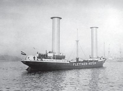
The Rotor Sail is an active rotating cylinder that generates aerodynamic loads due to the Magnus effect. It is commonly called a Flettner Rotor, named after the German inventor Anton Flettner, who designed and built an experimental rotor vessel named ‘Buckau’ in 1924, Fig.2. Two 15.6 x 2.8 m Rotor Sails were installed with a total rotor area of 87.4 m2, as an additional source for propulsion to reduce fuel consumption. A few more ships were equipped with Rotor Sails in the decades to follow, but due to low the oil prices, Rotor Sails had no convincing business case and remained an exotic side note until the beginning of the new millennium when interest in WAPS revived with energy efficiency and reduced carbon footprints coming on the agenda.
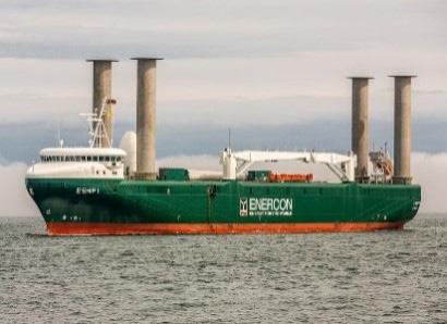
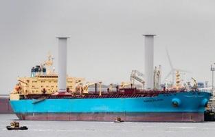
In 2008, E-Ship 1 was launched, https://en.wikipedia.org/wiki/E-Ship_1, Fig.2. Four 27 x 4 m Rotor Sails were installed. Enercon, the owner and operator of the E-Ship 1, claimed operational fuel savings of up to 25% compared to same-sized conventional freight vessels. In 2018, the ‘Maersk Pelican’ was fitted with two 30 x 5 m Norsepower Rotor Sails, Fig.4. Through measurements before and after installation Norsepower determined fuel savings of 8.2% during the trial period, [5].
Advantages of Rotor Sail systems for cargo ships are:
5 As for all WAPS, fuel savings and thus lower operational cost
5 Easy handling, not requiring extra crew or even much training
5 Lower cost for installation and maintenance per thrust force than other WAPS, [6]
5 Very good maneuverability for ship
5 Passive load limitation: Since all rotating cylinders have a maximum operating spinning velocity, if they encounter high wind speeds, their velocity ratio drops and, consequently, their aerodynamic loads follow the same trend. Thus, Rotor Sails depower them-selves which makes them a hurricane proof device, an advantage not inherent in other type of WAPS.
Disadvantages of Rotor Sails are:
5 Rotor-induced vibrations may cause crew discomfort or even structural damage.
5 Rotor Sails are active rotating devices, requiring some electrical power to spin.
5 Rotor Sails have a relatively small lift-to-drag ratio; thus they are less effective for fast vessels where the apparent wind angles are generally smaller.
Fig.2: ‘Buckau’ (1924) Fig.3: E-Ship 1 (2008) Fig.4: ‘Maersk Pelican’ (2018)
Conference Paper 280
2.2. Rigid Wingsails
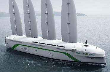
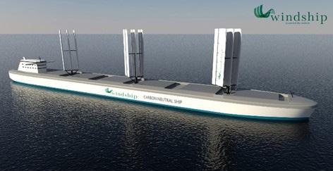
Rigid Wingsails are airfoils, similar to airplane wings. Their main differences are their vertical orientation and their ability to generate lift on either side. This last characteristic is vital for a vessel since, unlike airplanes, they must tack while following the wind. For this reason, Rigid Wingsails have generally symmetric NACA profile cross sections. Also, they may feature flaps:
5 Leading-edge flaps increase the maximum lift of an airfoil by delaying its stall angle but are rarely implemented.
5 Trailing-edge flaps generate additional lift through an increase in the effective camber of the airfoil, but also induce earlier stall. Plain flaps and slotted flaps are the most common in the maritime sector.
The idea of Rigid Wingsails dates back at least to the 1920s. In the 1960s, John G. Walker designed and built the “Planesail”, a 10 m long Rigid Wingsail propelled cruiser, Fig.5, [7]. Popularly called Walker Wings, they were the first successful maritime implementation of Rigid Wingsails. In the 1980s, the U.S. government commissioned a study with Walker on the economic feasibility of wind assisted propulsion in response to soaring fuel prices. While Rigid Wingsails fitted aboard commercial vessels demonstrated 15-25% fuel savings, they failed to be widely implemented due to the low oil prices at the time. In the early 21st Century, Rigid Wingsails entered high-performance sailing yielding unprecedented speeds e.g. in America’s Cup regattas. Rigid Wingsails have featured in several high-profile design projects, such as the British Windship Technology project, https://windshiptechnology.com/, Fig.6, and the Swedish Wind-Powered Car Carrier, wPCC, https://www.walleniusmarine.com/our-services/?ship?design-newbuilding/ship-design/wind-powered-vessels/, Fig.7. However, so far these projects have remained in the design stage.
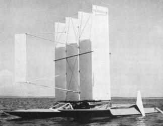
Conference Paper 281
Advantages of Rigid Wingsails are: 5 Easy handling requiring no extra crew 5 Easy installation and maintenance 5 Most of them are retractable (less risk of overload in storms and easier cargo handling) Disadvantages are: 5 Relatively expensive (compared to traditional sails) 5 Larger deck-space requirements (possible interference with cargo handling and other deck operations)
Fig.5: Planesail
Fig.6: Windship Technology project Fig.7: wPCC project
2.3. Dyna Rig
The DynaRig is a square rig developed in the late 1960s by Wilhelm Prölss. The main characteristic of this WAPS is its free-standing mast with the yards connected rigidly to it. The sails are trimmed to the wind by rotating the mast. Prölss designed the DynaRig for cargo ships. He carried out wind tunnel tests for a 6-masted bulk carrier of 16,000 dwt at the Hamburg University in the 1960s and the 1970s, Fig.8. The DynaRig proved to be about twice as efficient as traditional square rig sails. Prölss took patents of his design in all shipbuilding countries world-wide, but due to low fuel prices and the difficulty to build a full-scale mast with sufficient stiffness, the idea did not take off until the beginning of the new millennium.
The DynaRig was first installed on the megayacht “Maltese Falcon” in 2006, [8]. Ten years later, the DynaRig sailing yacht “Black Pearl” was released. Also some design concepts for commercial vessels involve this technology, e.g. the WASP EcoLiner Project, Fig.9, https://?www.dykstrana.nl/designs/wasp-ecoliner/.
Advantages of DynaRig are:
5 Fully automated requiring no extra crew
5 Same as Rigid Wingsails, DynaRigs are highly controllable
5Aesthetic design appealing also to the yacht market
The main disadvantage is:
5Higher lifecycle cost than for Rigid Wingsails

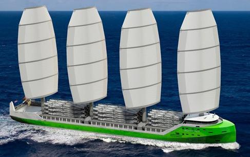
2.4. Performance prediction program & Route optimization model
DNV developed a 6 DoF (degrees of freedom) Performance Prediction Program (PPP) for windassisted cargo ships to contribute to the knowledge on WAPS performance utilizing DNV’s modular performance prediction workbench FS-Equilibrium. It is a fast and easy tool able to predict reasonably accurately the performance of any commercial ship equipped with one of three different WAPS: Rotor Sails, Rigid Wingsails and DynaRigs. The tool requires only ship main particulars and general dimensions as input data and is based on semi-empirical methods and a WAPS aerodynamic database created from published data on lift and drag coefficients. All WAPS data can be interpolated to scale to different sizes and configurations.
Conference Paper 282
Fig.8: Wilhelm Prölss with DynaRig Fig.9: WASP EcoLiner
The PPP software has a modular set-up. Key modules are:
5 Hull model (all forces acting on the hull, such as gravity, buoyancy, resistance, propeller thrust, wind forces, rudder forces, etc.)
5 Rotor sails model (forces created by Flettner rotors)
5 Rigid Wingsail model (forces created by Rigid Wingsails)
5 DynaRig model (forces created by DynaRigs)
For details of the PPP, we refer to [3].
The Route Optimization Model (ROM) consists of optimizer, route evaluation algorithm and the multi-objective optimization algorithm. The optimizer randomly selects a set of free variables. The route evaluation algorithm builds the route with these free variables. The optimizer checks if the route is violating the constraints at any point of the route. If it does, the route becomes invalid and is discarded right away. If the constraints are satisfied, the algorithm calculates the objectives according to the free variables selected. These objectives are feedback for the optimizer and the Non-dominated Sorting Genetic Algorithm II (NSGA-II) optimization algorithm. A new selection of free variables is based on this feedback. This process is repeated until the Pareto-optimal set is found. The route optimization differs from normal weather routing for cargo ships reflecting short-term course changes (tacking) required by WAPS ships but atypical for normal cargo ships. For details of the ROM, we refer to [3].
2.5. Fuel Savings
Fuel savings strongly depend on the trading area and ship’s speed. Higher typical wind speed vw and the lower ship speed v increase the expected fuel savings. The correlations are nonlinear, making generic statements of X% savings to be expected by device Y dubious. Instead, case by case analyses are needed employing performance prediction programs.
Norsepower, www.norsepower.com, gives for the “Maersk Pelican” (with 2 Flettner rotors) savings in sea trials of 8.2% fuel consumption. Table 2 gives the estimates of our PPP for various ship speeds and trading areas (with associated typical wind speeds). Savings range between 1.4% and 41%!
v Tropical vw = 6 m/s North Sea vw = 8 m/s Nordic Ocean vw = 10 m/s 6 kn 25% 39% 41% 8 kn 10% 18% 22% 10 kn 4.7% 9.1% 13% 12 kn 2.5% 4.9% 7.4% 14 kn 1.4% 2.8% 4.4%
Table 2: Estimated fuel savings for “Maersk Pelican” depending on speed and trading area
Larger (rotor) sail area increases the fuel savings. Our PPP predictions for the “E-Ship 1” (4 Flettner rotors), validated against measurements for selected points, illustrate this impressively, Table 3. More than 100% mean here that wind power could be used to generate electrical energy for board systems if appropriate installations were in place.
Conference Paper 283
v Tropical vw = 6 m/s North Sea vw = 8 m/s Nordic Ocean vw = 10 m/s
6 kn >100% >100% >100%
8 kn 44% 80% 90%
10 kn 21% 40% 52%
12 kn 11% 22% 32%
14 kn 6.2% 13% 20%
Table 3: Estimated fuel savings for “E-Ship 1” depending on ship speed and trading area
Route optimization (tailored to WAPS) offers considerable additional savings. For transatlantic routes, we estimate for a ship like the “E-Ship 1” average savings (per year) of 8-20% on westbound legs, and 12-38% on eastbound legs, compared to using the Rhumb-line average (straight line on navigation maps using Mercator projection).
3. Case Study
The aim of this case study is to quantify the energy saving potential of wind-assisted propulsion for a typical cargo ship and also look at the economical side of. The virtual cargo ship used to perform these calculations is a multi-purpose vessel, similar in size to the “E-ship 1”, Table 4. The ship is assumed to be outfitted with three Flettner rotors of 30 x 5 m.
Lpp 130 m DWT 12550 tdw B 21 m speed 15 kn T 8 m trip 10000 nm
Table 4: Case study ship
The daily charter rate for such vessel is currently at 8,500 USD/d. The installation cost of the three Flettner rotors are assumed with 2.250 million USD and a yearly maintenance of 2.3% of the initial investment is required. Depreciation is set at 10 years and capital is subject to 4% interest rate. The case study assumes a trip of 10000 nm and considers 60% sailing time (220 days/year) of the vessel. The consumption of the auxiliary power systems is estimated with 2.2 t/d. The electric power needed to spin the three rotors is considered with 100 kW and thus increases the auxiliaries fuel consumption by about 0.5 t/d. Table 5 summarizes these assumptions. Although not yet implemented for shipping, discussions on trading schemes for emissions are ongoing and, at least for the EU, it seems likely that shipping will be included in the ETS. This would mean extra costs for using fossil fuel and currently a ton of CO2 is traded at 40 € (~ 50 USD/t), https://ember-climate.org/data/carbon-price-viewer/.
Conference Paper 284
Charter rate of conventional powered vessel 8500 USD/d
Capital cost of WAPS installation 2.250 mUSD
Maintenance cost of WAPS system 2.3% pa
Depreciation period 10 years
Interest rate 4%
Auxiliary fuel consumption 2.2 t/d
Power to spin the rotors 100 kW ~ 0.5t/d
Fuel price 400 - 600 USD/t
CO2 emission trading 50 USD/t
Costs for port call 50000 USD/trip
Table 5: Economic assumptions
Assuming a trading area in the Nordic Ocean with an average wind speed of 10 m/s, our analyses predict savings in fuel consumption and CO2 emission of 17% (for 15 kn) to 60% (for 6-8 kn), Fig.10. The speed reduction alone would already reduce the CO2 emission by 60%; thus, the total emission reduction (WAPS + speed reduction) can be more than 80%. These savings are substantially lower if the ship is trading in low wind-speed areas such as tropical areas. Fig.11 shows possible CO2 reductions for areas with mean wind speed of 6 m/s. Here, only for very low speeds attractive savings can be achieved.
Fig.10: Fuel savings and CO2 reduction due to WAPS Fig.11: Fuel savings and CO2 reduction due to WAPS at 6 m/s av. wind speed
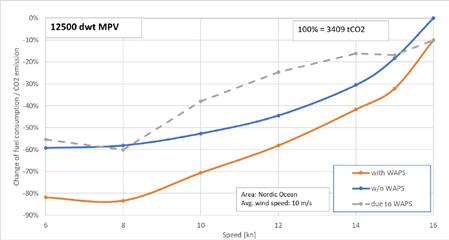
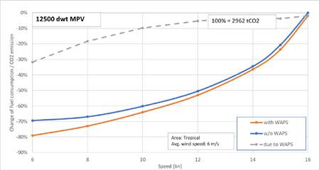
Unfortunately, besides the attractive reduction in CO2 emission, the economic side will always play an important role. Therefore, we have tried to assess the cost impact on a typical trip of 10000 nm.
Fuel prices are changing frequently, with low-sulphur fuel traded at ~500 USD/t. Assuming the “Nordic Ocean” wind condition with an average of about 10 m/s, the WAPS system provides attractive savings regardless of the speed, Fig.12. An optimum is at a ship speed of about 8-10 kn. The relative increase of costs for very low speeds is mainly a result of the charter costs which are applicable on a daily basis and anti-proportionally increase with the reduction of ship speed. The same applies to costs for powering the auxiliaries and fixed costs such as port fees, pilots etc. Fig.13 shows the split up of the total trip costs for different speeds for the WAPS supported vessel for an 8 m/s wind speed average.
Conference Paper 285
Naturally, a wind assisted propulsion system heavily depends on the wind speeds and if the wind is not strong enough the business case becomes quickly weak. Fig 14 shows on the left side that for an 8 m/s average wind area the cost savings are marginal for speeds above 12 kn and for even lower wind speeds 6 m/s (Bft. 4) the investment costs of the WAPS system cannot be recovered, regardless of speed.
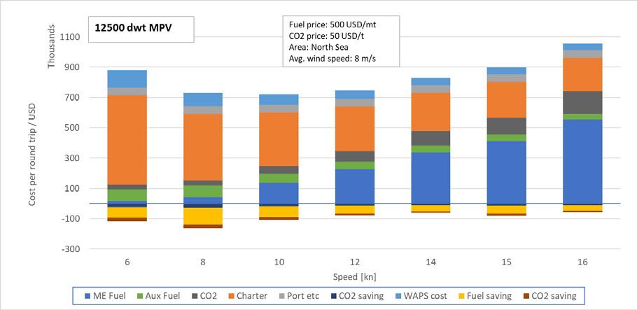
Fig.12: Cost reduction (North Atlantic trading, average wind speed = 10 m/s)
Fig.13: Cost split up for different ship speeds
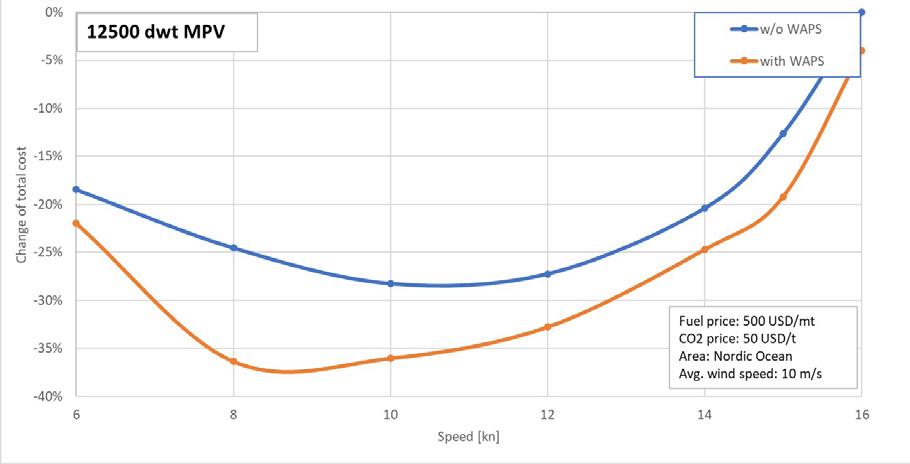
Conference Paper 286
Fig.14: As Fig.12, but for 8 m/s (left) and 6 m/s (right) average wind speed
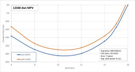
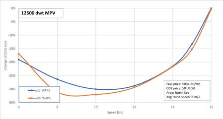
4. Conclusions
Wind-assisted propulsion systems gain in technical maturity, importance, and adoption in the maritime industry. In all cases, they save substantially CO2 emission and fuel consumption. The cost saving largely depends on future fuel prices and the possible cost of CO2 emissions. However, global standard savings cannot be given; the business case depends in each application on many factors. Quick analyses are possible using semi-empirical performance prediction programs as developed by DNV, [3]. Such analyses can guide design and retrofit decisions, as well as operational optimization. From the presented data the business case is weak if looking at monetary saving, only. Additional measures to make CO2 reductions attractive to the industry will help to make such systems even more relevant.
References
[1] Bertholdt, J. and Riesch, H. Windschiffe, VEB Technik Verlag, (1988).
[2] Schenzle, P. Wind Ships in the 21st Century? - Current concepts for wind propulsion of ships method, Jahrbuch der Schiffbautechnischen Gesellschaft, Springer, pp.55-65, (2010).
[3] Hollenbach, U., Hansen, H., Hympendahl, O., Reche, M. and Ruiz Carrio, E. Wind Assisted Propulsion Systems as Key to Ultra Energy Efficient Ships, 12th HIPER Conf., Cortona, http://data.hiper-conf.info/Hiper2020_Cortona.pdf, pp. 543-561, (2020).
[4] Schenzle, P. Wind as an aid for ship propulsion, 8th WEGEMT Summer School ‘Ship Design for Fuel Economy’, Gothenburg, (1983).
[5] Paakkari, V., Hurford A. and Carddock, C. Rotor Sail GHG Reduction Potential, Modelling and Sea Trial Validation, 5th Innov’Sail Conf., Gothenburg, (2020).
[6] Borg, J. Magnus effect: An overview of its past and future practical applications, Naval Sea Systems Command, Department of the Navy, (1985).
[7] Walker, J.G. “High Performance Automatic Wingsail Auxiliary Propulsion System for Commercial Ships”, J. Wind Eng. and Industrial Aerodynamics 20/1-3, pp.83-96, (1985).
[8] Dijkstra, G., Perkins, T. and Roberts, D. The Maltese Falcon: The Realization, 18th Int. HISWA Symp. Yacht Design and Yacht Construction, Amsterdam, (2004).
Conference Paper 287


Greenport Congress Oceania


15 17 February 2023, Newcastle, Australia
The Greenport Oceania offers the latest in sustainable development and environmental practices within the ports environment. portstrategy.com/greenport-congress-oceania
Coastlink Conference

3 4 May 2023, Royal Liver Building, Liverpool, UK
Coastlink is a pan European network dedicated to the development of a competitive supply chain and promotion of short sea and feeder container shipping coastlink.co.uk


Seawork, incorporating Marine Civils
13 15 June 2023, Mayflower Park, Southampton, UK Europe’s leading annual three day commercial marine exhibition and conference. Seawork incorporates Marine Civils Europe's leading event dedicated to showcasing the latest equipment and solutions for marine, coastal and other challenging civil engineering projects Attend in person and virtual seawork.com
Commercial Marine Network Conference & Business Briefings
13 15 June 2023, Mayflower Park, Southampton, UK
Get set for Workboat 2050', a hybrid conference with expert panellists discussing decarbonisation compliance, aspects of vessel operations and safety in the workboat industry The conference venue also hosts free to attend business briefings, including sessions with the MOD & DIT seawork.com/our-conferences
Seawork USV/Hybrid & Electric Propulsion Conference
14 15 June 2023, Mayflower Park, Southampton, UK
The Seawork Conference is a must for all involved in the commercial marine industry who wish to explore the challenges, changes and emerging opportunities in today’s and tomorrow’s commercial marine and workboat sector seawork com/cmc
18th
Greenport Congress & Cruise


18 20 October 2023 Location in Southern Europe to be confirmed
The yearly congress provides environmental departments in Ports and Terminals with methods of greening their operations. portstrategy.com/greenport-cruise-and-congress

44th Propulsion & Future Fuels Conference
21 23 November 2023, Hamburg, Germany
The Propulsion & Future Fuels Conference will be returning to Hamburg to explore the latest emissions cutting technology and shipping propulsion innovation in association with The Motorship propulsionconference.com
conferences@mercatormedia com
Mercator Media Ltd, Spinnaker House, Waterside Gardens, Fareham, Hampshire, PO16 8SD,UK • Tel: +44 1329 825335 Fax: +441329 550192
2023 Events Schedule
Bunkerspot provides a comprehensive, accurate – and always independent – view of the multi-faceted global marine fuels industry


Bunkerspot magazine focuses on the technical, operational, commercial, environmental and legal aspects of bunkering, and also keeps its readers up to speed on innovations and trends in vessel and fuel ef ciency technologies.


Bunkerspot Price Index
If you need accurate, up-to-date bunker price indications in an easy to use and highly cost-effective format, BPi ticks all the boxes.

Delivered via the Bunkerspot website or through the BPi app, the Bunkerspot Price Index offers spot bunker prices in over 350 global ports, updated daily and with easy to see tracked price changes. www.bunkerspot.com/bpi
Bunkerspot industry roundtables
Bunkerspot regularly partners with key industry stakeholders to host roundtable discussions where shipping, marine fuels and legal experts offer insights on the main issues and developments impacting the bunker sector.
The Bunkerspot website includes a subscription-based real-time news and pricing service, as well as information channels, industry announcements and updates on conferences, exhibitions and other key events. To
+44 1295 814455
your
Subscribe to Bunkerspot www.bunkerspot.com/subscribe
discuss how
organisation can bene t from the market intelligence and solutions provided by Bunkerspot, contact: Lesley Bankes-Hughes, Director of Publishing. Tel:
. Email: lesley@petrospot.com The essential and authoritative source of information for marine fuels professionals.
2022 43RD
Conference Contacts:
Markell Charles-Bailey Conference Producer
Tel: +44 1329 825335 Email: mcharlesbailey@mercatormedia.com
Sue Stevens Brand Manager
Tel: +44 1329 825335 Email: sstevens@mercatornmedia.com
Nick Edstrom News Editor
Tel +44 1329 825335 Email: nedstrom@motorship.com
Marianne Rasmussen-Coulling Events Director
Tel: +44 1329 825335 Email: mrasmussen@mercatormedia.com
Andrew Webster Chief Executive Officer
Mercator Media Limited
Spinnaker House, Waterside Gardens, Fareham, Hampshire, PO16 8SD, UK t: +44 1329 825335, f: +44 1329 550192 www.mercatormedia.com
The organisers and publishers accept no responsibility for the statements made neither in this publication nor for any errors or omissions which may have occurred.
©Mercator Media Limited 2022
Contact Us 291


Media Partners: #MotorshipPFF For more information visit: propulsionconference.com contact: +44 1329 825335 or email: conferences@propulsionconference.com JOIN US FOR PROPULSION & FUTURE FUELS 2023 MOTORSHIP MARINE TECHNOLOGY THE

