ACT III / THE FOUNDRY INDUCTION / CORE STUDIO I 2018 / 2019
TEAM
SHENGNING ZHANG CIRO ROMER RAZA KAZIM NASIA PANTELIDOU HILLA GORDON
LUIS GIL OMAR EQBAL HASAN DANISH PATRICK BIRCH WYATT ARMSTRONG
DESIGN + MAKE / CORE STUDIO
2
CONTENTS
INHERITANCE (ACTS I & II) 4 GLOBAL DESIGN 10 RING-BEAM 22 RING-BEAM EXTENSION 34 WINGS 42 SKIN 56 ROOF 64 DOORS 72 FINAL 82
FOUNDRY 3


DESIGN + MAKE / CORE STUDIO4


FOUNDRY / INHERITANCE (ACTS I & II) 5
INHERITANCE (ACTS I & II)
ROBOTICS FABRICATION VISITING SCHOOL
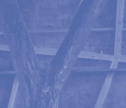
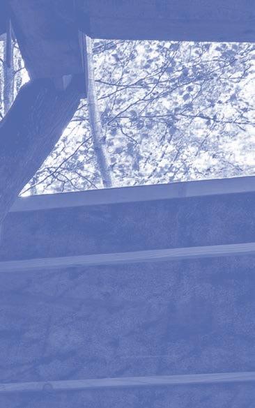
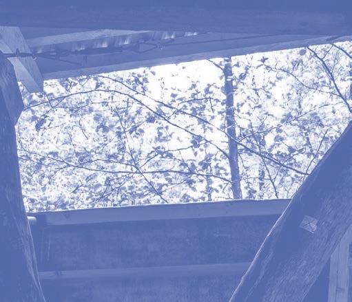
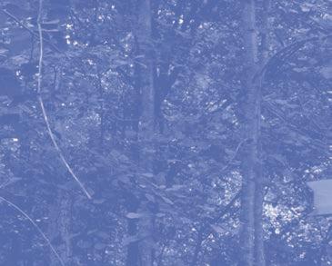
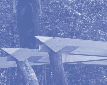
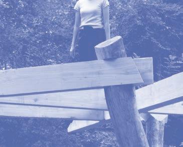
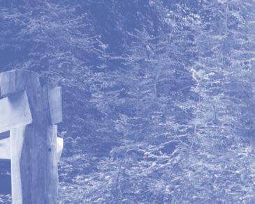
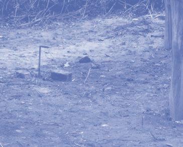
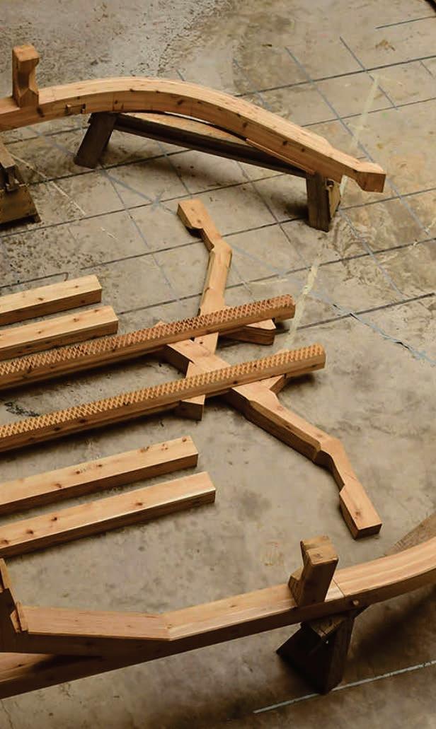
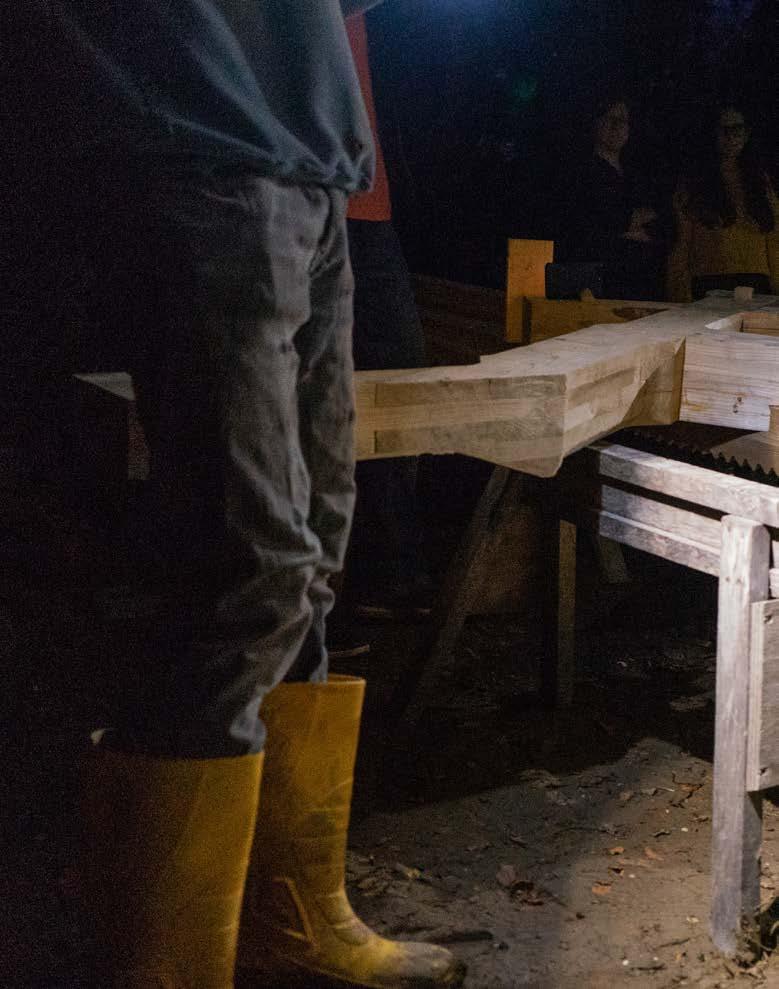
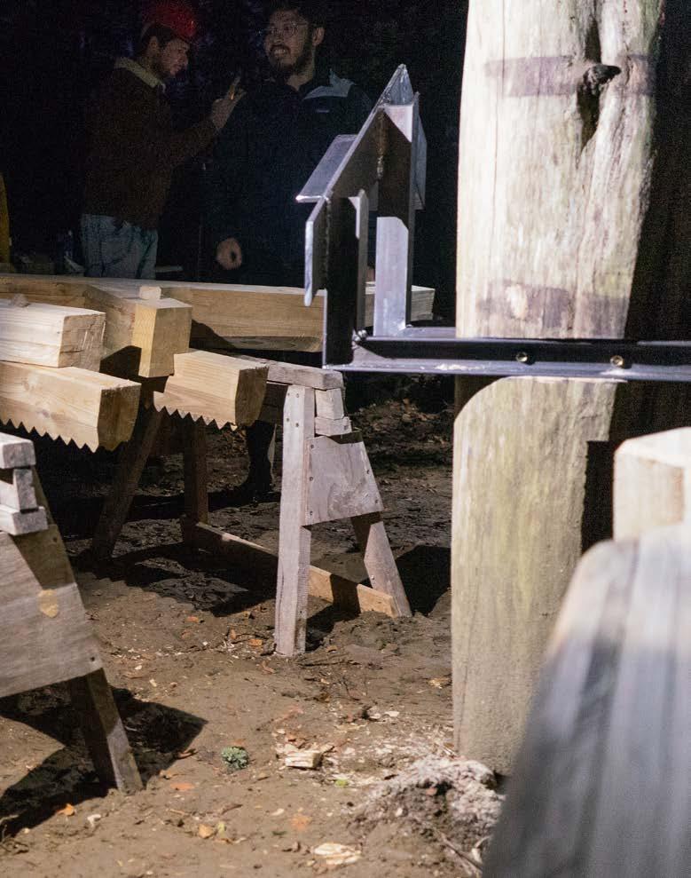
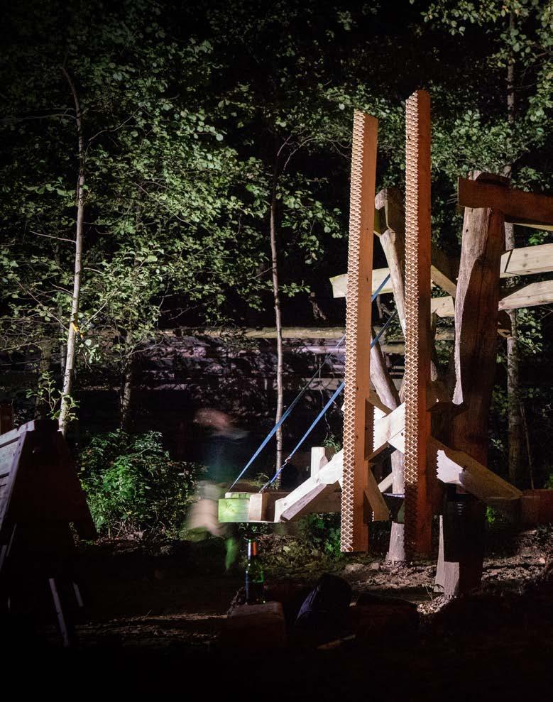
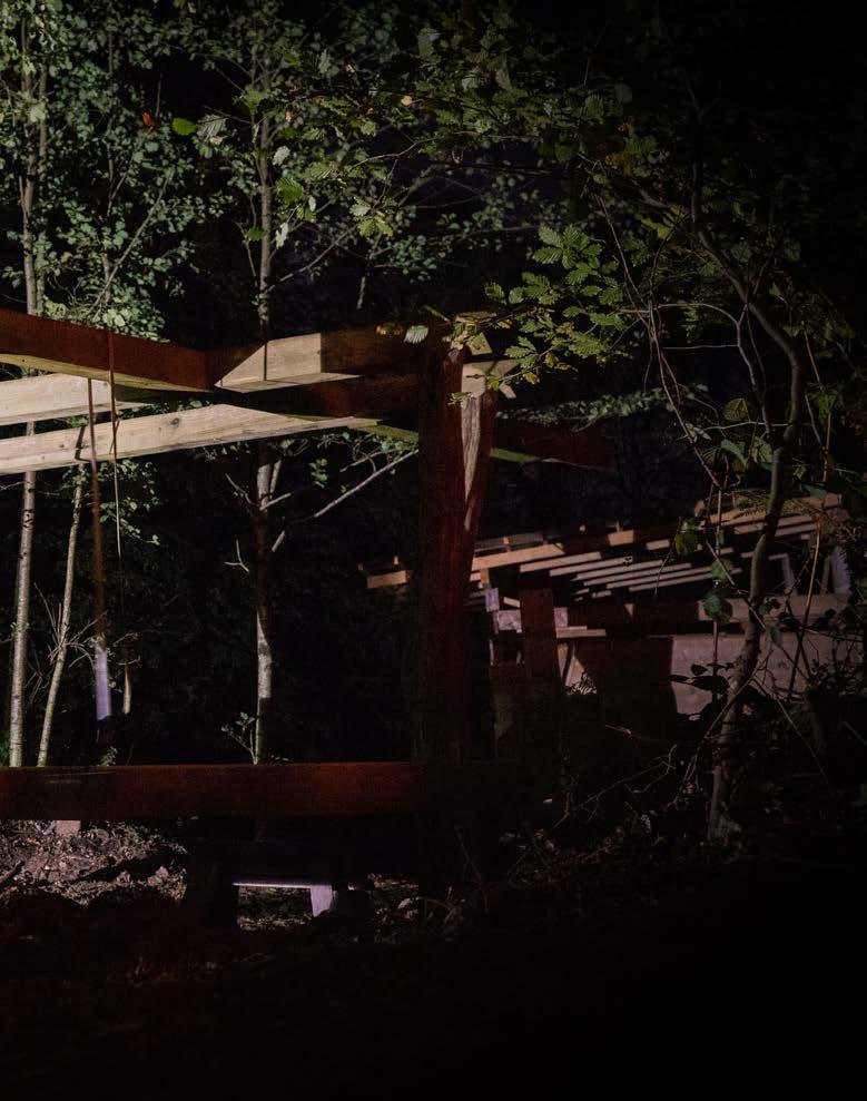
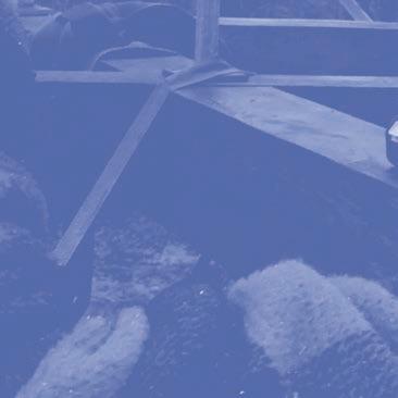
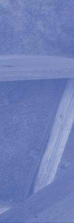
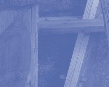
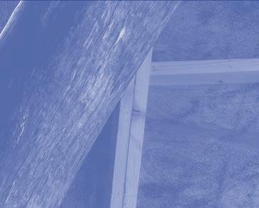
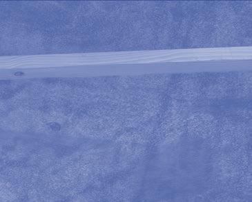
Our assignment for the induction and core studios is Act III of the Foundry. We inherited a site developed through two previous acts as part of the Robotic Fabrications visiting school. The Chainsaw Choreographies in 2016 produced a composition of three standing beech forks connected by a series of douglas r beams, and the Bandsaw Manoeuvres
in 2017 added a robotically detailed glue laminated ring beam.
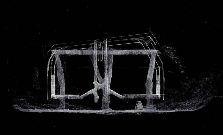
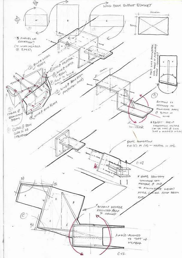
At the start of our induction studio we were presented with a series of sketches to be treated as suggestions that inform the global geometry. The studios were laid out as a skill building exercises with detail design involved.
DESIGN + MAKE / CORE STUDIO
6
FOUNDRY / INHERITANCE (ACTS I & II) 7
DESIGN + MAKE / CORE STUDIO8
FOUNDRY / INHERITANCE (ACTS I & II) 9


DESIGN + MAKE / CORE STUDIO10


FOUNDRY / RING-BEAM 11
RING-BEAM
SZ / CR / NP / RK / HG / LG / OE / HD / PB / WA
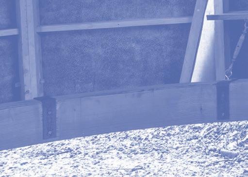
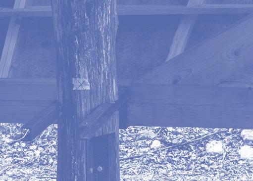
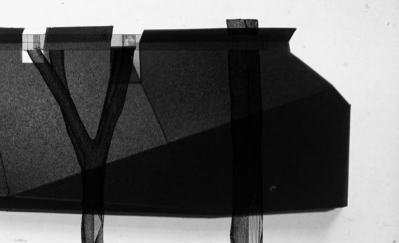
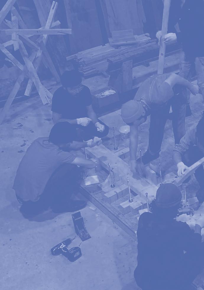
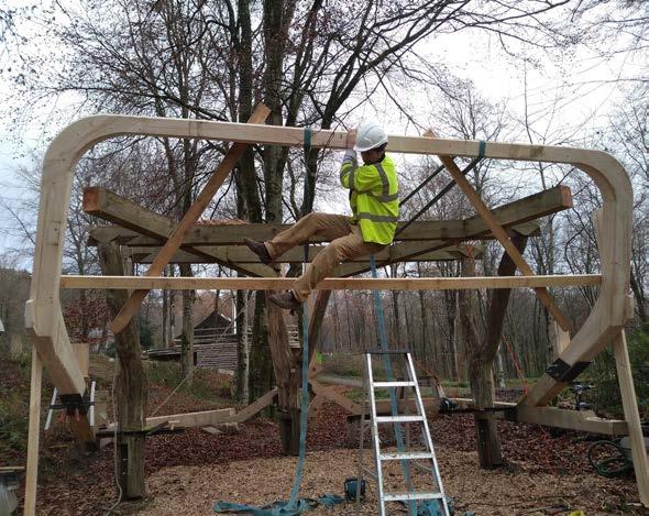
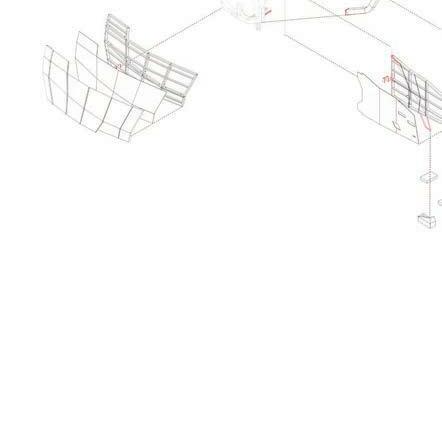
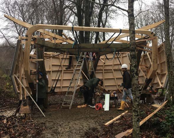
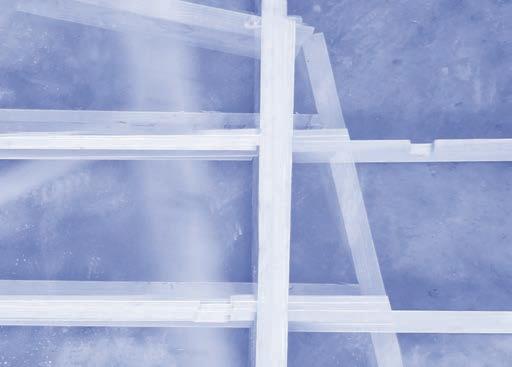
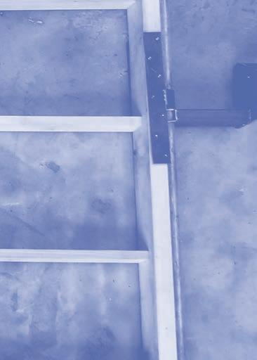
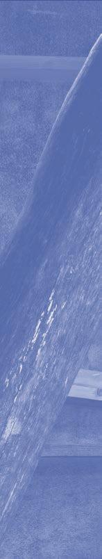
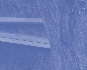
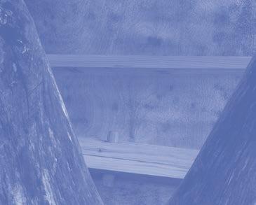
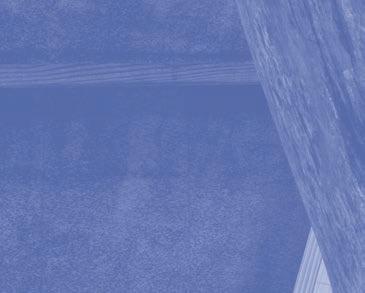
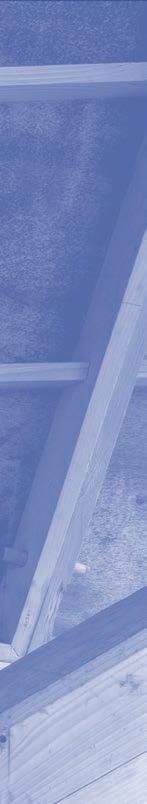
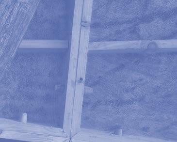
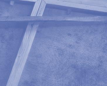
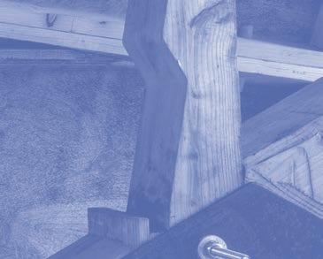
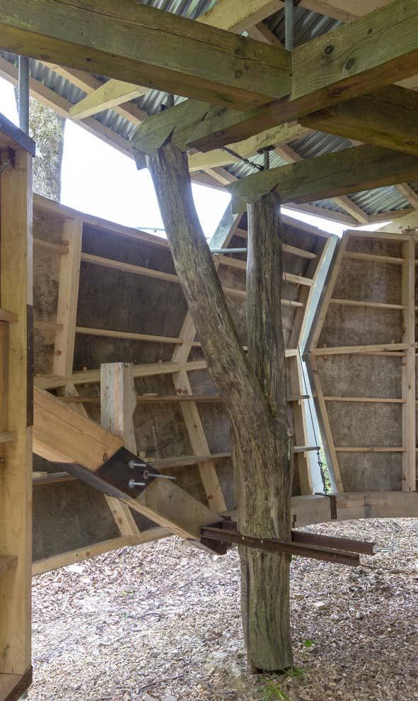
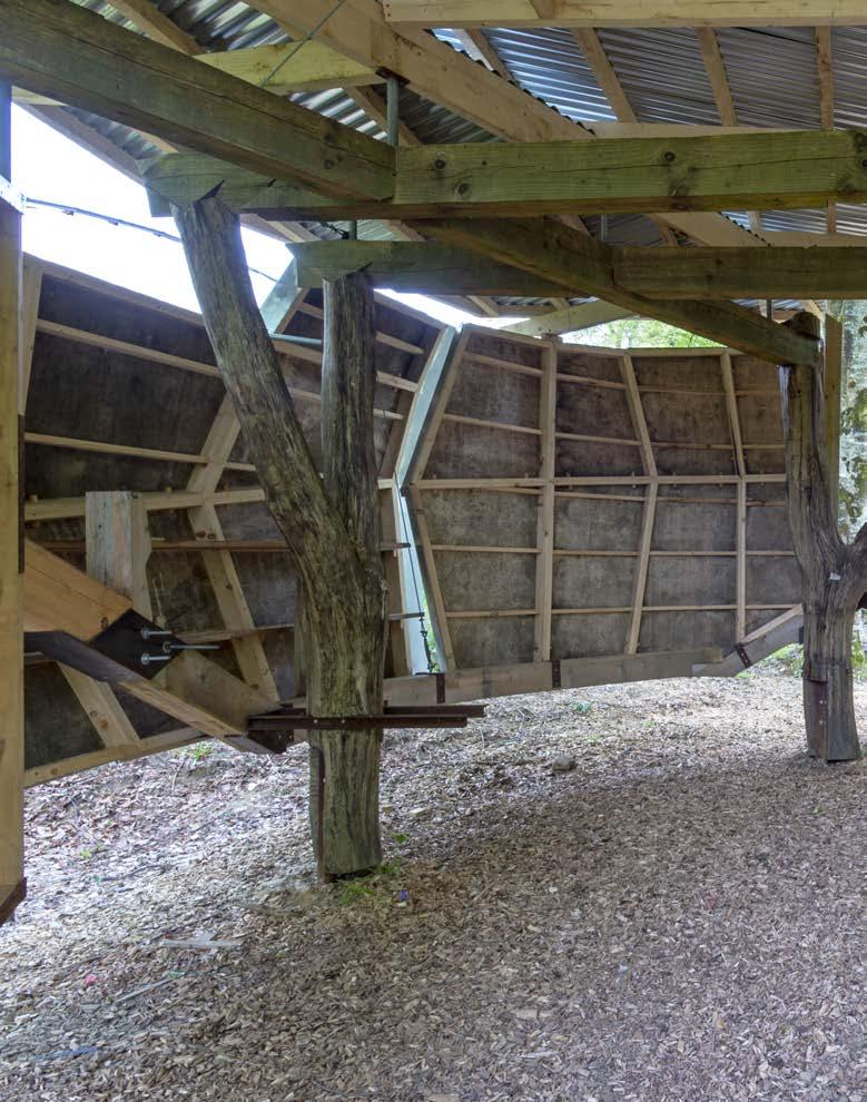
The Ring Beam from Act II of the Foundry’s construction was the rst element to be incorporated into the primary structure. The orientation of the ring beam is determined by alignment to the three forked trunks which delineate a symmetrical axis that matched the geometry of the ring beam.
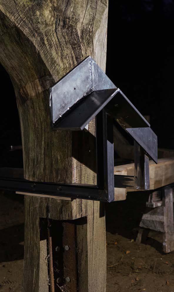
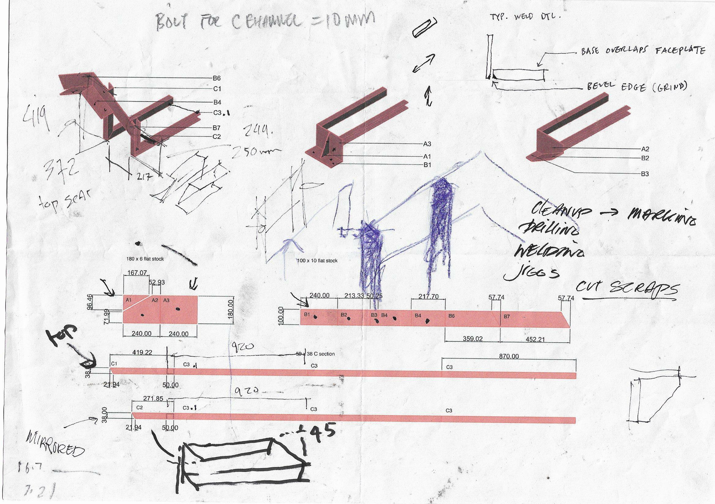
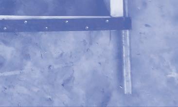
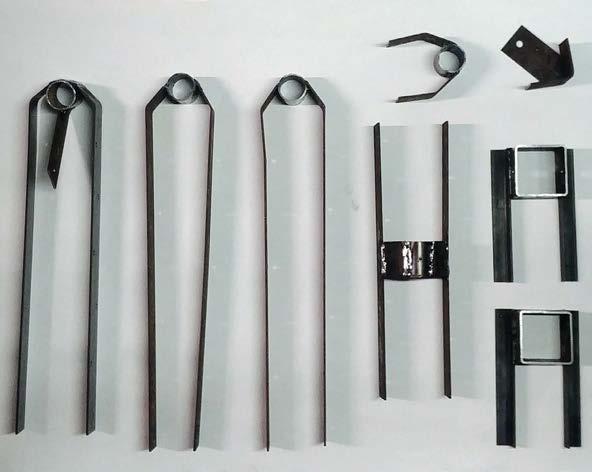
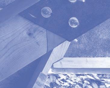
Three connector elements transfer the load of the ring beam to the trunks. Each was designed to provide a level interface and allow for adjustments during installation through. This hardware, with it’s protruding brackets, anticipates a future round of interior buildout.
For installation, two parallel notches are cut out at the base of each tree trunk that allows the connectors to slide in and bear into the wooden shoulders, while cut with enough room to
allow for shimming for leveling. Once located they are xed by bolts.
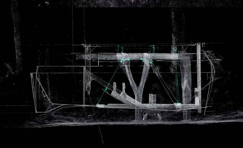
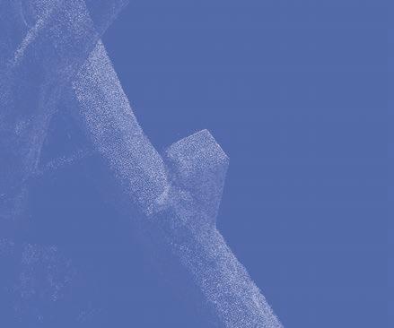
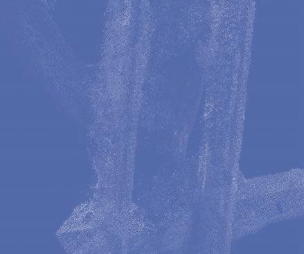
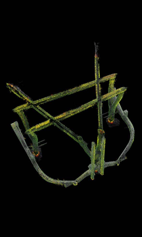
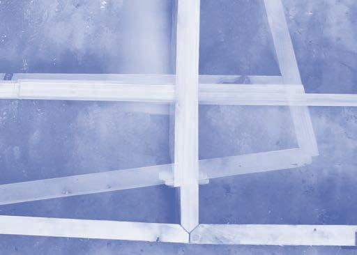
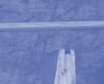
The ring beam is installed as three interlocking components, with the middle module erected rst as a stabilizer element for the anking members. Ratchet straps are used to temporarily hold up the beam until the wing panels are installed. As a precaution to test the de ection caused by the loading of the ring beam onto the forked trunks, the assembly is rst scanned through photogrammetry.
This generates a point cloud that is measured against the digital reference model used to fabricate the ring beam and forks. The amount of de ection is recorded and cross-checked with a measured survey. This allows for corrections in the modeling and locating of the wing panels.
DESIGN + MAKE / CORE STUDIO
12
 FOUNDRY / RING-BEAM
13
DESIGN + MAKE / CORE STUDIO14
15FOUNDRY / RING-BEAM
DESIGN + MAKE / CORE STUDIO16
 FOUNDRY
/ RING-BEAM 17
DESIGN + MAKE / CORE STUDIO18
 FOUNDRY / RING-BEAM
19
DESIGN + MAKE / CORE STUDIO20
 FOUNDRY
/ RING-BEAM 21
DESIGN + MAKE / CORE STUDIO22
FOUNDRY / RING-BEAM EXTENSION 23
RING-BEAM EXTENSION
RK
OE
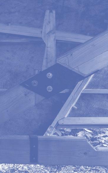
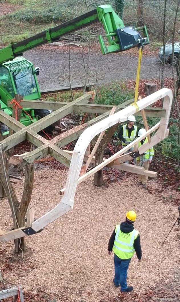
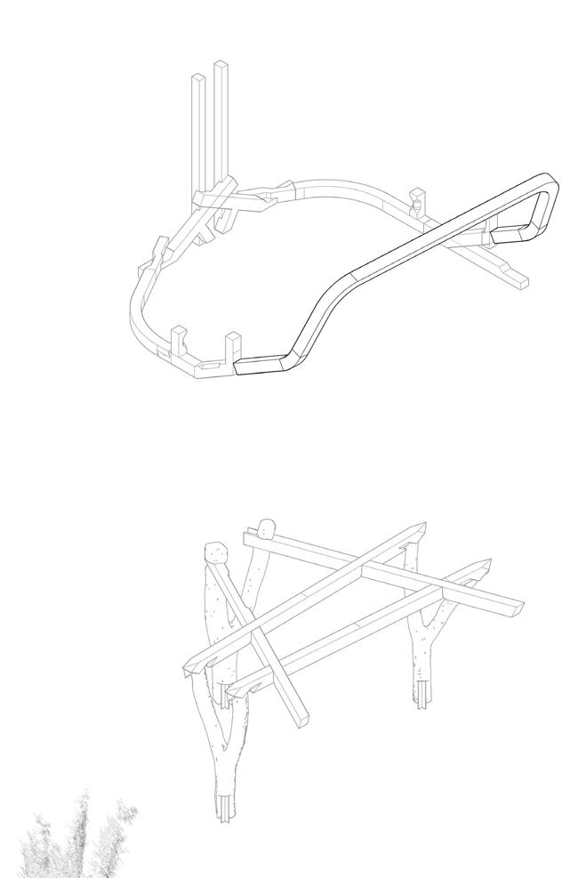
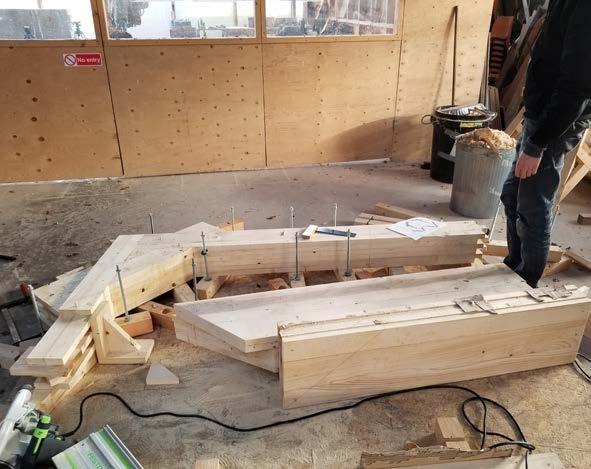
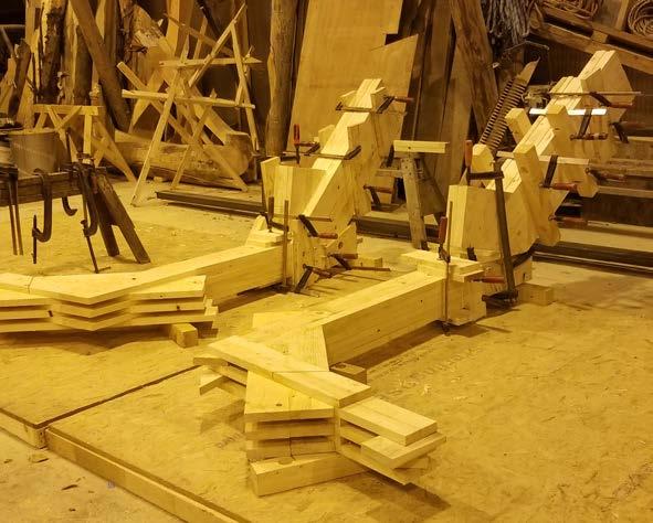
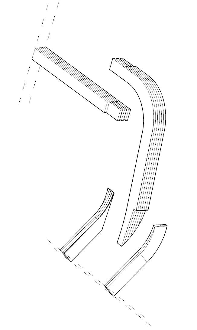
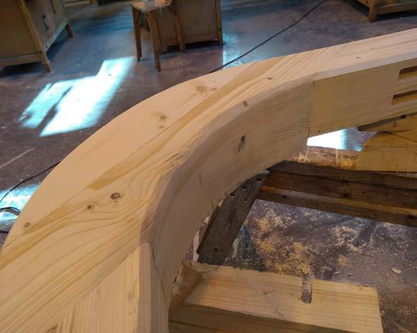
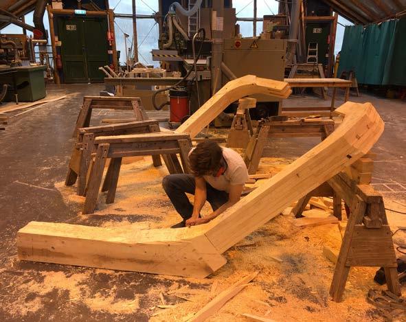
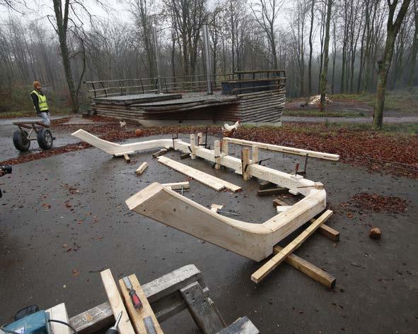
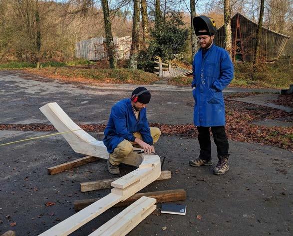
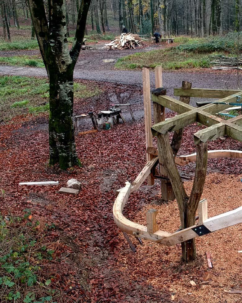
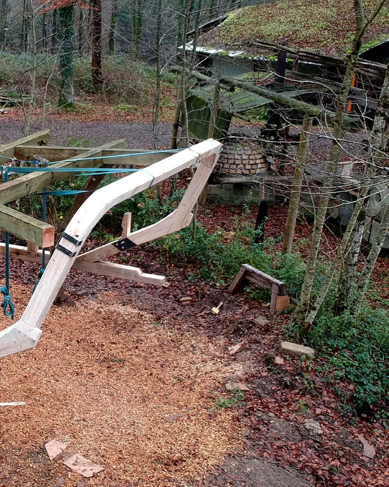
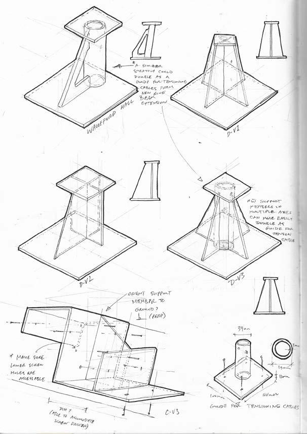
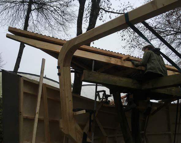
The “structural team” was tasked with extending the existing ring beam, the structural element which would support the walls, kinetic element and the roof. The complexity of designing the beam extension lay in nding the right balance between the dynamic ow hinted at in the drawings and the connection to the various inherited components. Because of the multidirectional datums, the ring beam extension had to hit the decision was made that rather than robotically machining the glue-laminated components, like the originals the components, the extension would be assembled and then sculpted by hand. Allowing for a more organic articulation of the new component.
The chosen geometry consisted of both an upward and a sideways movement in order to maximize the gluing surface
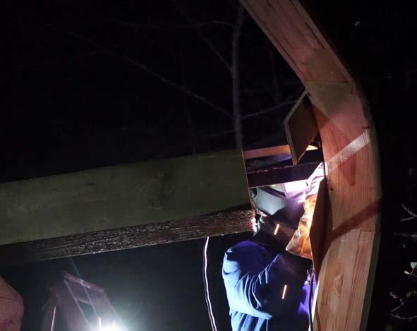
and maintain e ective grain direction throughout it was decided to use two lamination directions. These were timber jointed at four distinct locations. The rst two consolidating the transition between the rotation and the upward movement in the larger lapped connection at the lower part of the beam, and the second two connecting the top at with ngers joints, part of the way past the bend to minimize the moment stress on the joint. Once fully assembled it was lifted into place into two steel brackets at the lower part of the beam, connecting to the existing ring beam, and two larger steel appendages extending outwards from the existing Douglas r roof beams. Finally, a central tension cable ran from the centre of the ring beam extension along with the original forked members down to the front of the inherited ring beam.
DESIGN + MAKE / CORE STUDIO CR /
/
24
 FOUNDRY
/ RING-BEAM EXTENSION 25
DESIGN + MAKE / CORE STUDIO26
 FOUNDRY
/ RING-BEAM EXTENSION 27
28 DESIGN + MAKE / CORE STUDIO
29
FOUNDRY / RING-BEAM EXTENSION
30 DESIGN + MAKE / CORE STUDIO
31
FOUNDRY / RING-BEAM
EXTENSION
32 DESIGN + MAKE / CORE STUDIO
33
FOUNDRY / RING-BEAM EXTENSION


DESIGN + MAKE / CORE STUDIO34


FOUNDRY / GLOBAL DESIGN 35
GLOBAL DESIGN
HG / PB
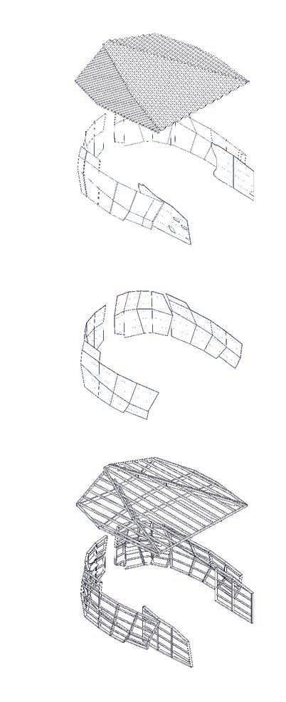
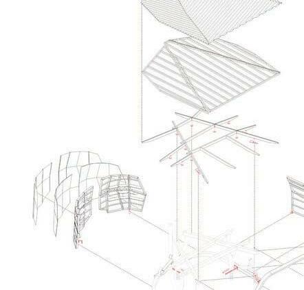
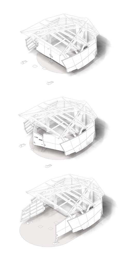
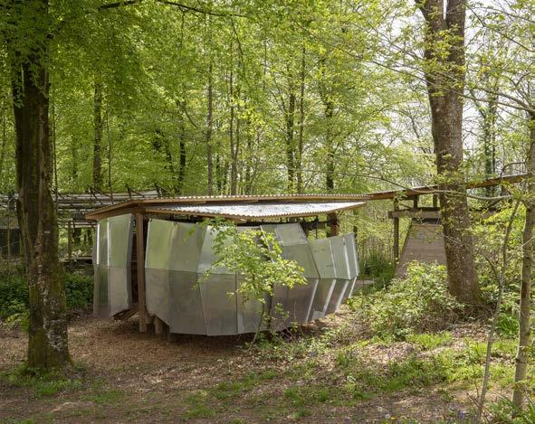
The re nement of the global geometry required the integration of material and fabrication constraints, the need to secure the wings to the inherited ring beam structure, and an installation sequence heavily dependent on the use of Hooke Park’s telehandler. Given limitations in component machining using the Kuka robot arm the faceted geometry had to accommodate member lengths no less than 400mm and no greater than 1500mm, the need for 4-sided panel frames, angles no greater than 40 degrees at frame component junctions, angles no less than 20 degrees at the point where two frames met, and the need for two straight vertices in the two forward most wing components to e ectively transfer load from
the roof to primary structure. It was determined that to maintain a sense of levitation, an e ect that creates a stark contrast to the visual weight of the wing components themselves, the load of the wings would be taken up predominantly by the ring beam. Subsequently, a series of unique steel support brackets were developed, carrying the wings to the exterior of the primary structure and maintaining the clawlike aesthetic of the brackets designed to support the ring beam extension. Finally, in an e ort to further accommodate the aforementioned machining limitations and simplify installation of the walls the design was divided into four distinct components.
DESIGN + MAKE / CORE STUDIO
36
FOUNDRY / GLOBAL DESIGN 37

DESIGN + MAKE / CORE STUDIO38
FOUNDRY / GLOBAL DESIGN 39
DESIGN + MAKE / CORE STUDIO40 CLADDING SYSTEM 1mm glavanized corrugated roof 0.8mm aluminum cladding Cnc fabricated panels Standing seam overlap Riveted and screwed connections Cedar door cladding WALL PANELIZATION 6mm baltic plywood Cnc cut with perforated attachment points SECONDARY STRUCTURE 50x75mm spruce roof battens 50x150mm noridc spruce roof rafters 90x45mm spruce framing Circular saw robot fabrication Cedar peg and spline connections


FOUNDRY / GLOBAL DESIGN 41


DESIGN + MAKE / CORE STUDIO42


FOUNDRY / WALLS 43
WALLS
SZ / WA
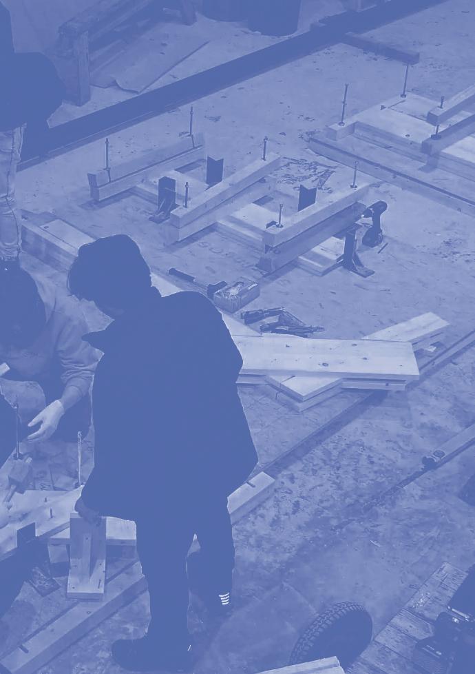
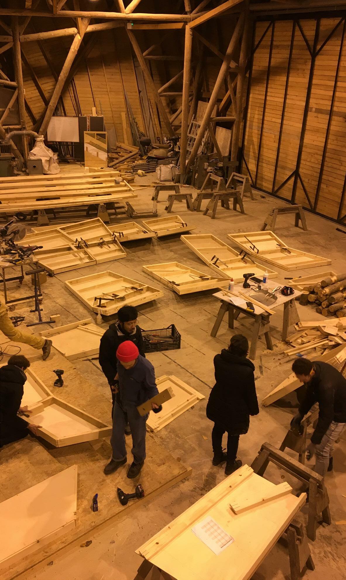
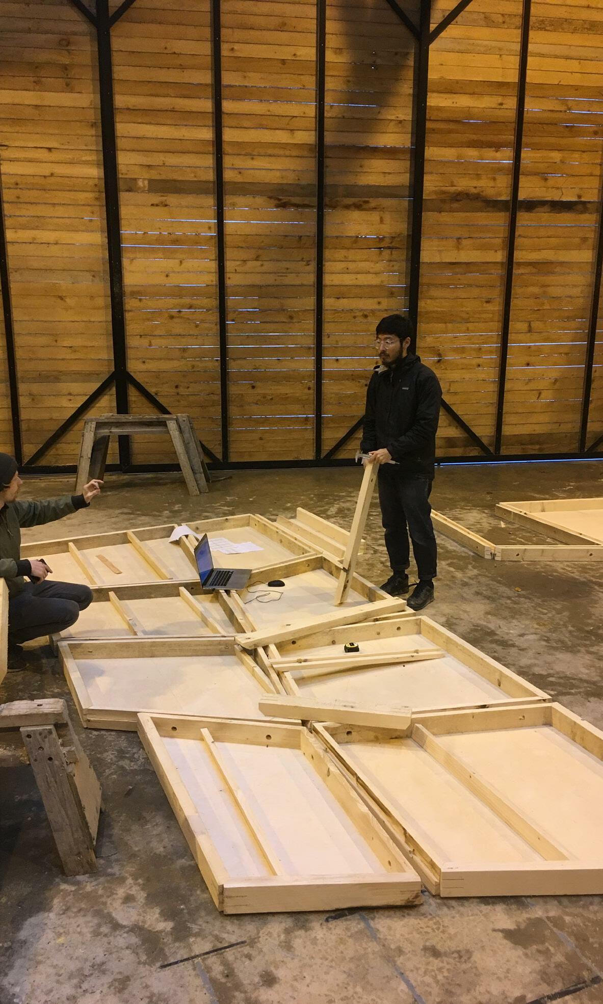
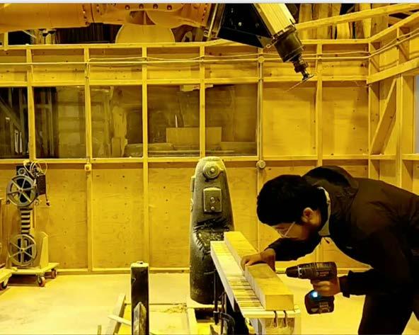
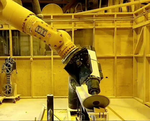
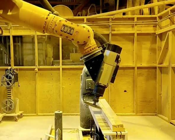
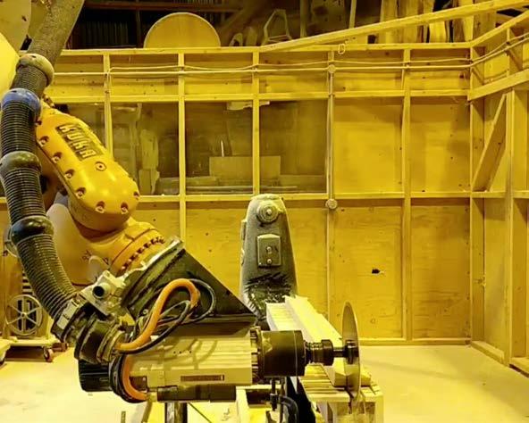
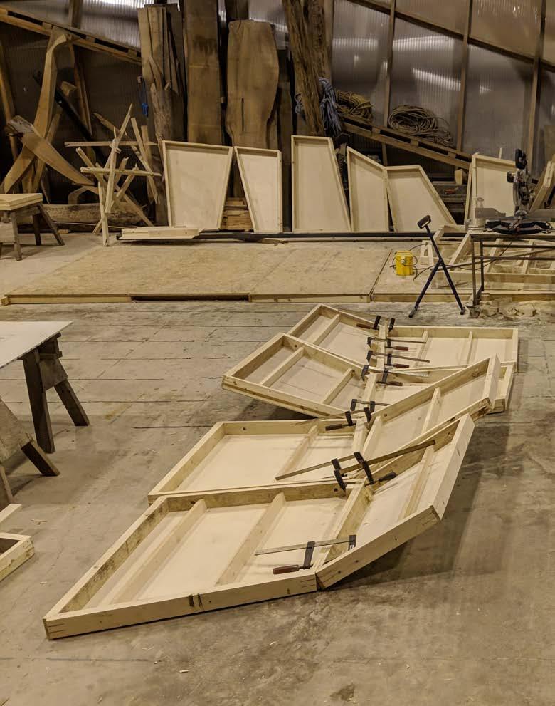
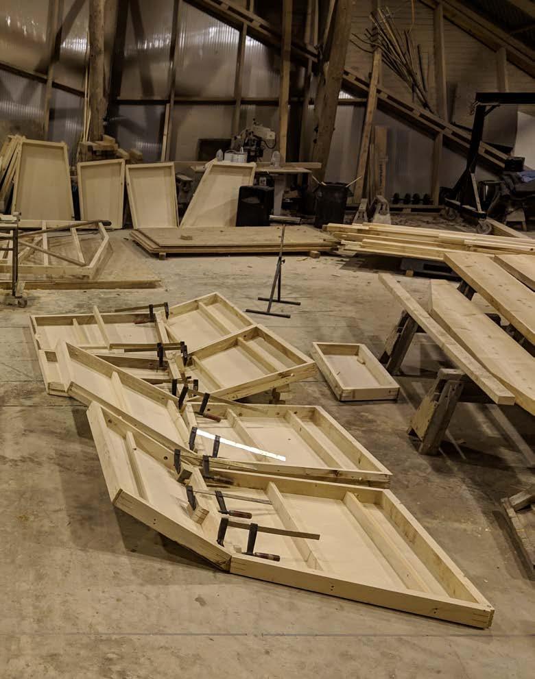
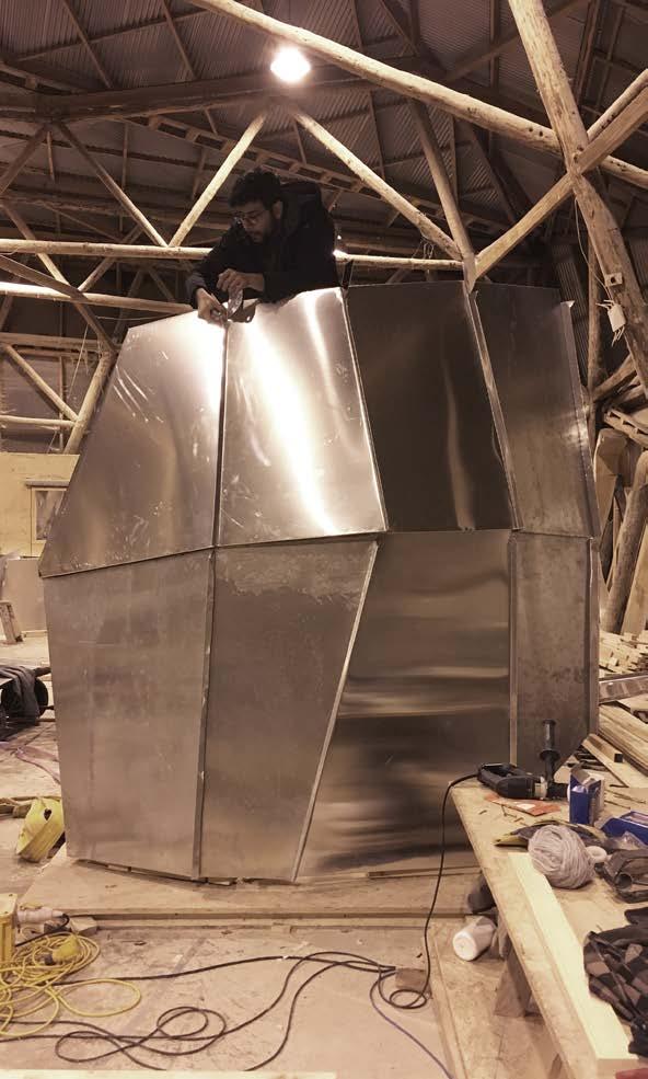
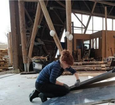
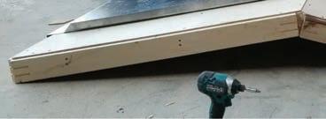
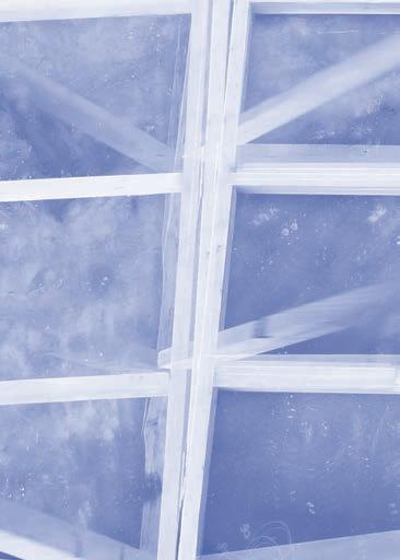
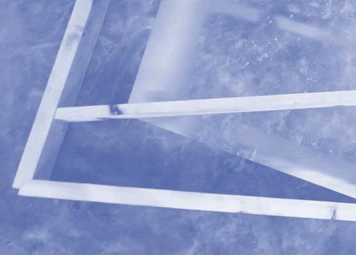
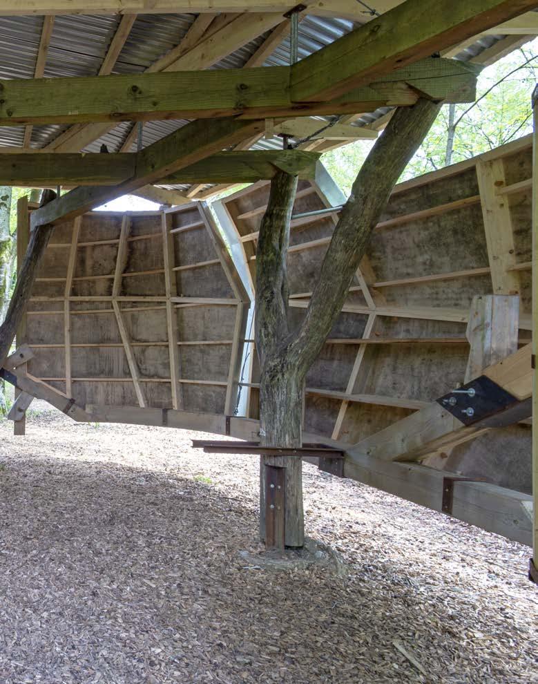
The concept for the foundry walls arose out of the necessity to be self-stable and a manageable scale during fabrication and assembly. A functional concern was for the surfaces to be used as storage within the enclosure. The planar facets, de ned by the global geometry, were backed by plywood to form an interface for the aluminum skin.
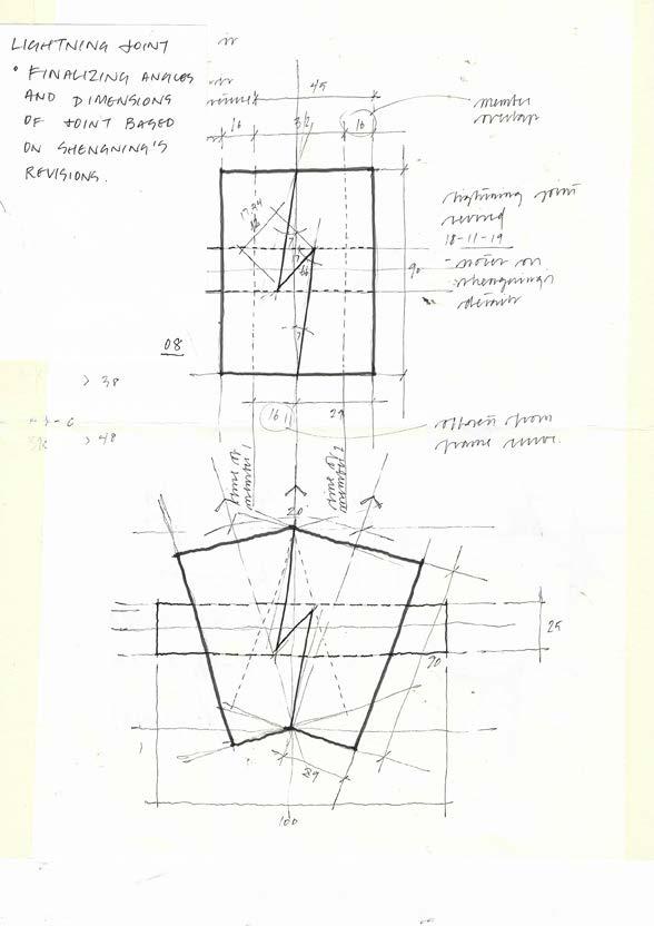
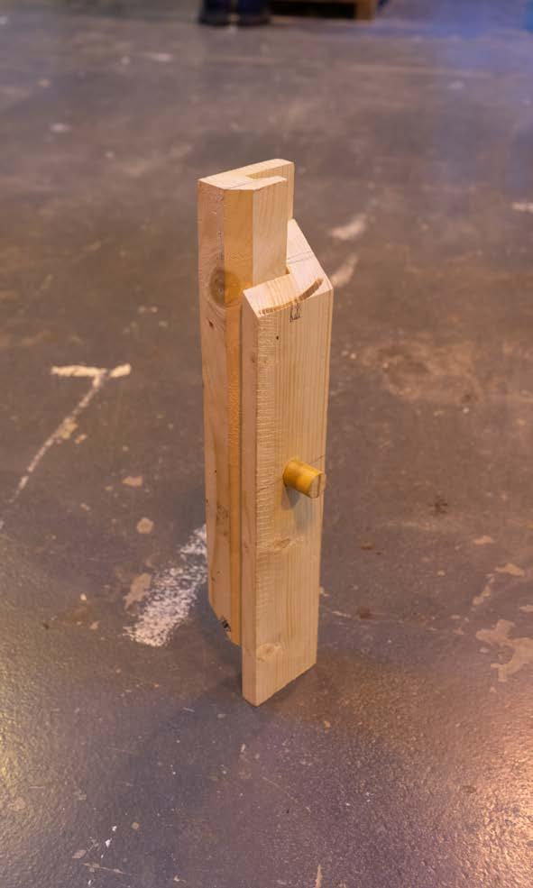
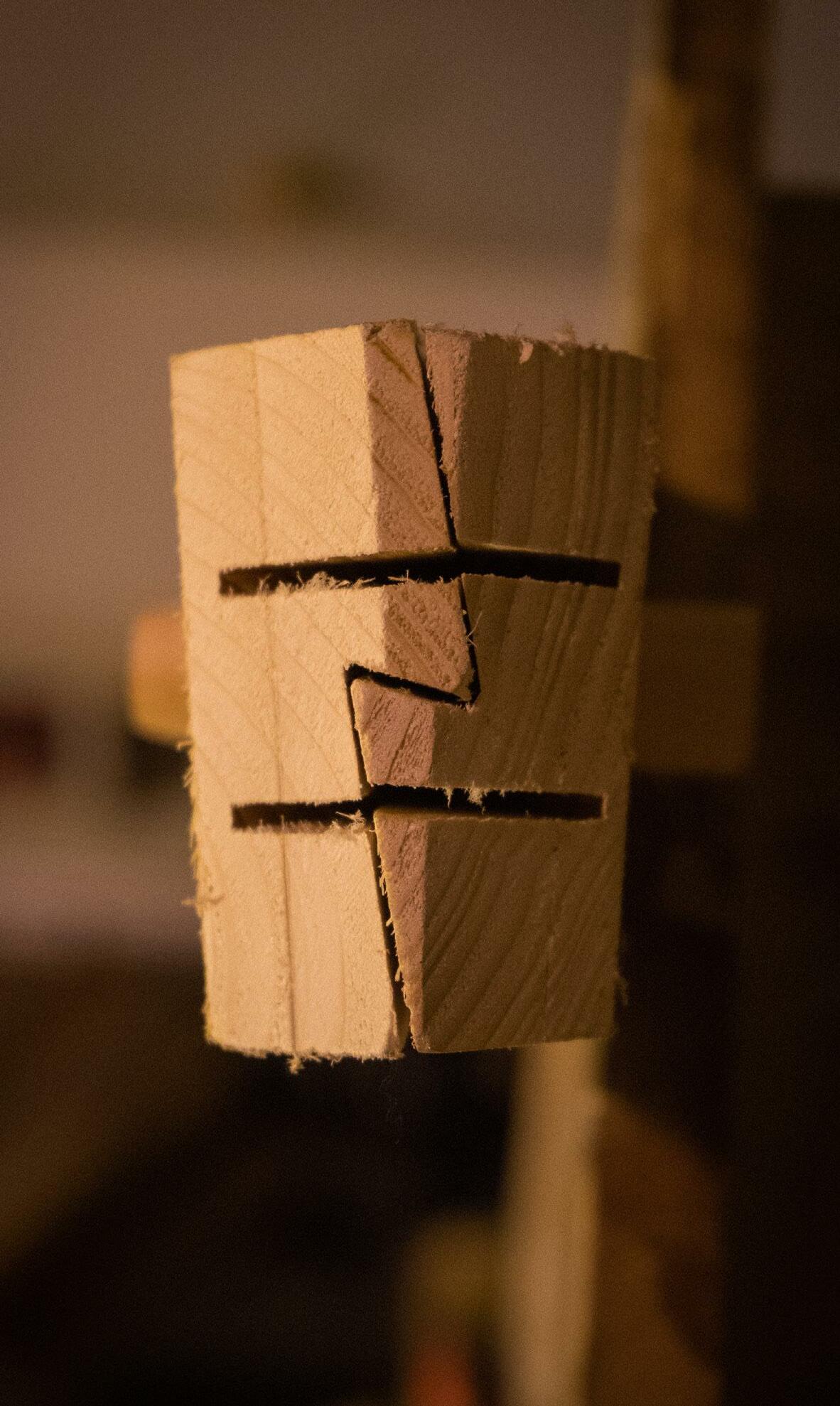
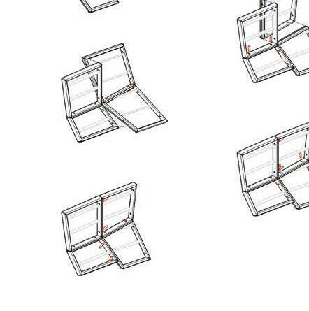
The corners of individual frames are connected by two keyed miters. Battens run parallel along the length of each panel, their orientation set along horizontal datums. The frame modules are joined along their seam through a ‘lightning’ pro le that registers and locks during assembly. Wood pegs replace mechanical fasteners as the main connection method for the assembly.
The panels were fabricated on the robot due to the nonrepeating nature of the envelope geometry, and the compound angles of cuts. A circular saw end e ector ripped the lightning joint and cross cut the mitered ends of each framing member. Plunge cuts on both ends form the keys for the miters. The battens are fabricated on a miter saw using instructions generated via a grasshopper script that facilitated the identi cation, logging, and cutting procedure of each piece.
Once the panels were individually fabricated, pairs are matched and pegged together. Four wing assemblies are lifted and attached to the ring beam and roof beam via welded connector plates.
DESIGN + MAKE / CORE STUDIO
44
 FOUNDRY /
WALLS 45
DESIGN + MAKE / CORE STUDIO46
FOUNDRY / WALLS 47
DESIGN + MAKE / CORE STUDIO48 23.00 origin of rotation 20.00° 23.00 50.00 15.00° 12.42° 5.00° 20.00° face of panel 13.00 origin of rotation 5.00° 12.42° 10.00° 50.00 15.00° face of panel 15.00° 90.00 origin of rotation face of panel 5.00° 50.00 90.00 20.00° 90.00
 FOUNDRY
/ WALLS 49
DESIGN + MAKE / CORE STUDIO50
51
FOUNDRY / WALLS
DESIGN + MAKE / CORE STUDIO52
 FOUNDRY
/ WALLS 53
DESIGN + MAKE / CORE STUDIO54
 FOUNDRY
/ WALLS 55


DESIGN + MAKE / CORE STUDIO56


FOUNDRY / SKIN 57
SKIN
LG / HG / HD
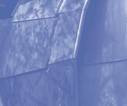
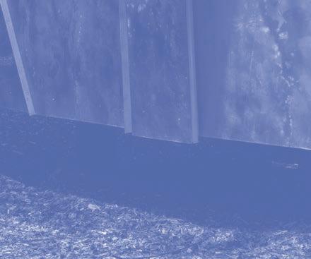
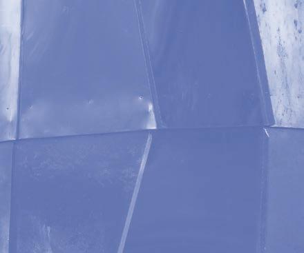
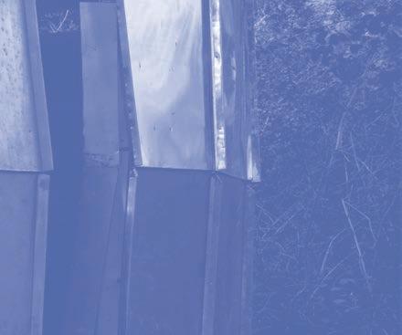
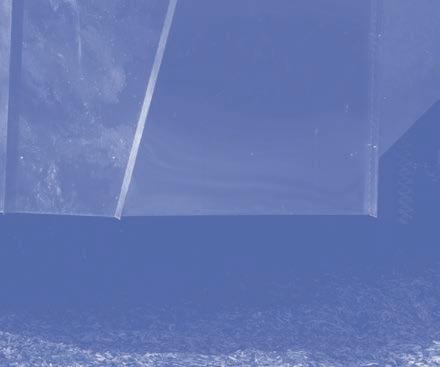
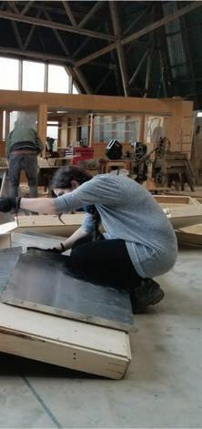
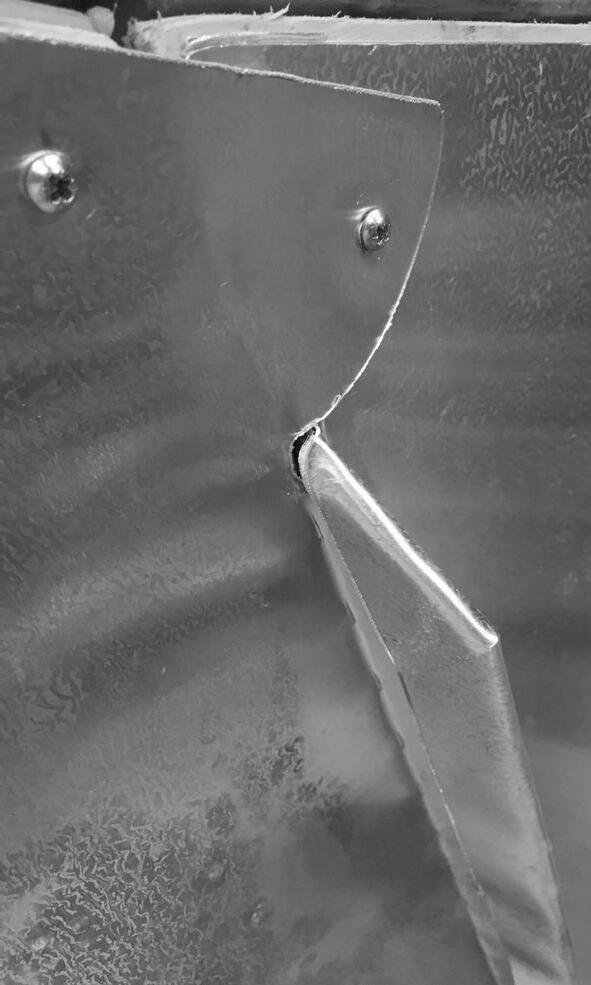
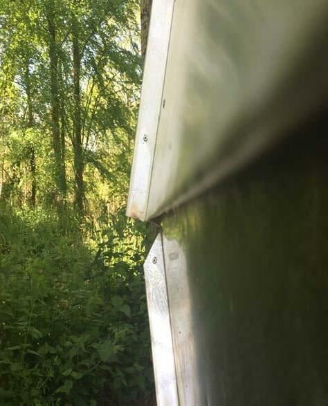
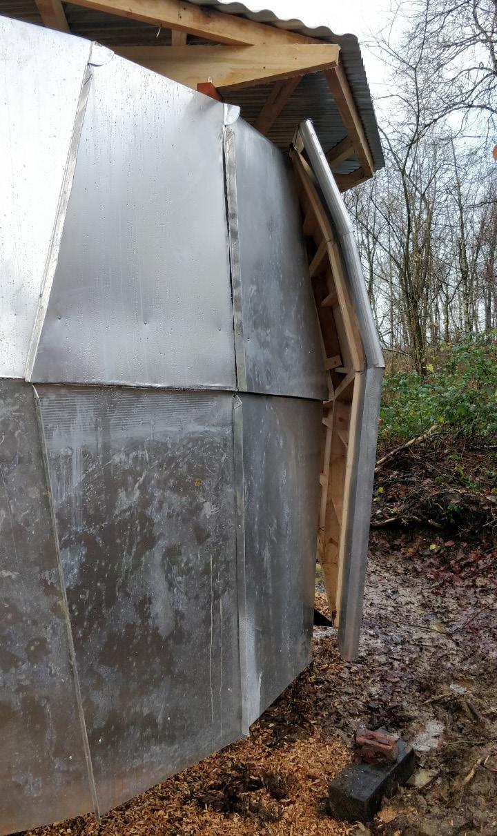
Aluminium cladding was designed to follow the geometry of the timber-built frames, to complement its complexity. The standard approach to standing seams was rethought in order to have a clean transition between surfaces of di erent angles, with oversized eaves to create a shadow gap and handle the water drippage without a need for gutters. Edges of the two side wings of the Foundry were designed to curve, so as to take advantage of the relative exibility of aluminium as a material.
The production of the aluminium sheets was through CNC scoring. This was done double-sided on the CNC machine. Lines that need to be cut are scored from both sides
and lines that indicate a fold is scored with a dashed line on the opposite side to the bending direction. Obviously, such an operation requires millimetric accuracy, and there was an e ort invested in streamlining the process to achieve it.
This exercise highlighted the contradictions between timber and aluminium: timber being a rigid material on the one hand, but easily manipulated on the other hand, and aluminium being harder to manipulate, but when it does it has exibility in the form it can take. This, along with the di erent properties of their depths and volumes are juxtaposed in the foundry to create a light-weight e ect for the structure.
DESIGN + MAKE / CORE STUDIO
58
FOUNDRY / SKIN 59
DESIGN + MAKE / CORE STUDIO60 geometryprocess originalplywood geometry fourpointed polylines sidewaysextentionsto bridgepotentialgaps extentionsforseams andoverlaps trimmingedges, additionalcovers additionsfortop panels 135 246
FOUNDRY / SKIN 61

DESIGN + MAKE / CORE STUDIO62
FOUNDRY / SKIN 63


DESIGN + MAKE / CORE STUDIO64


FOUNDRY / ROOF 65
ROOF
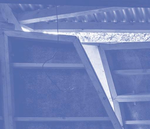
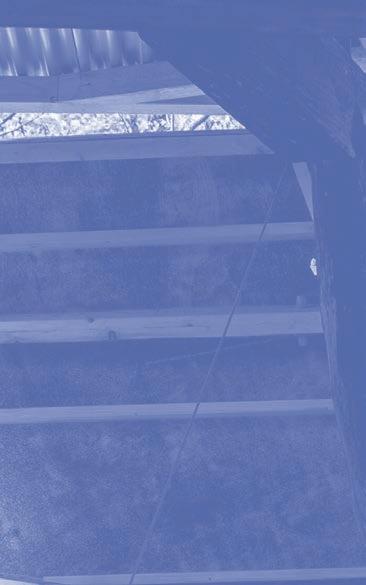
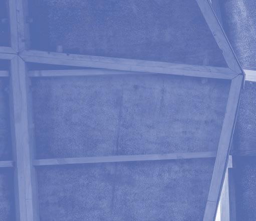
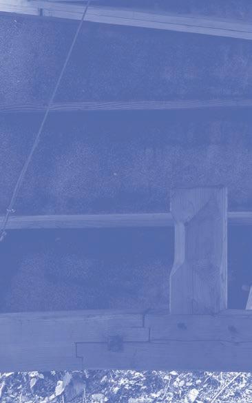
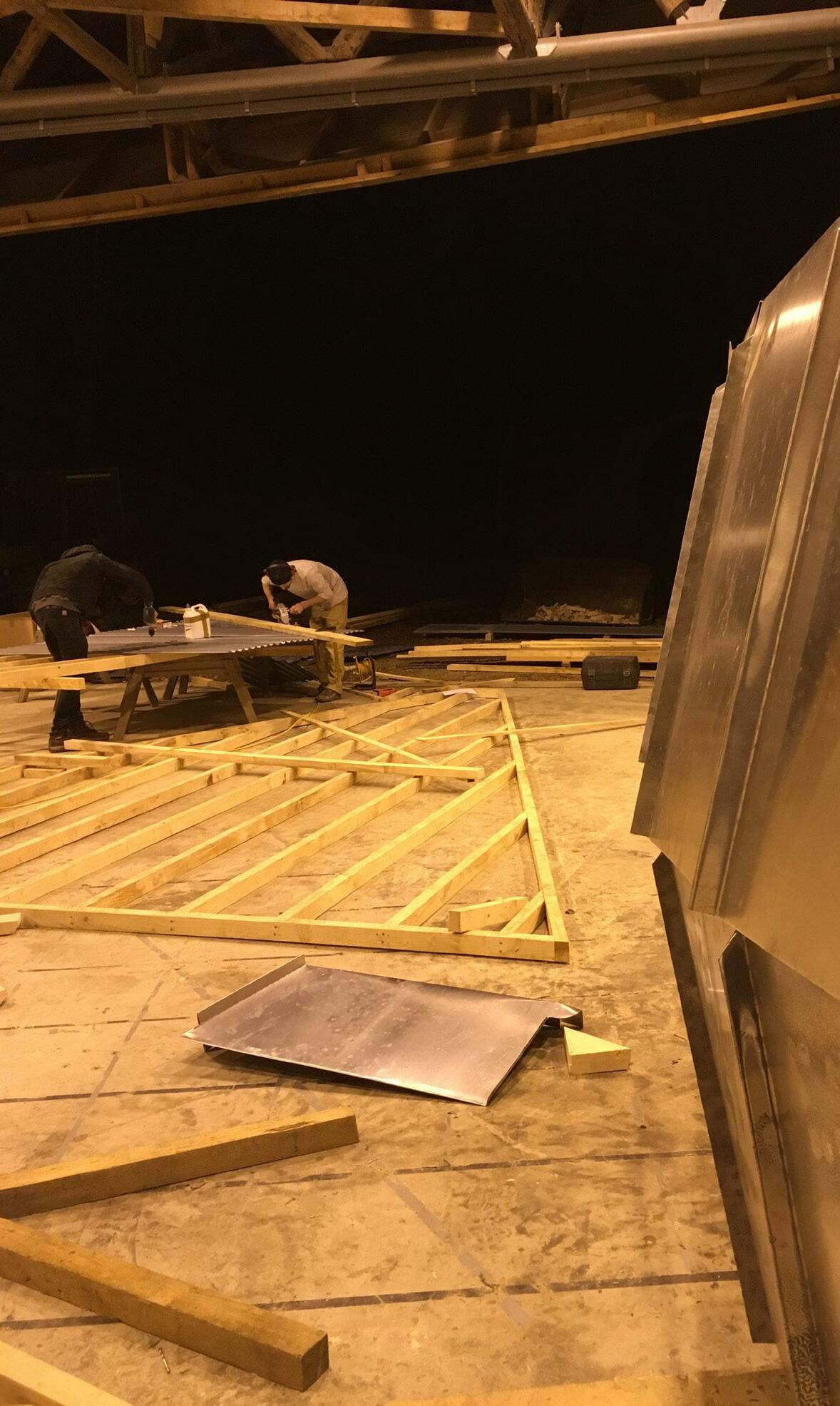
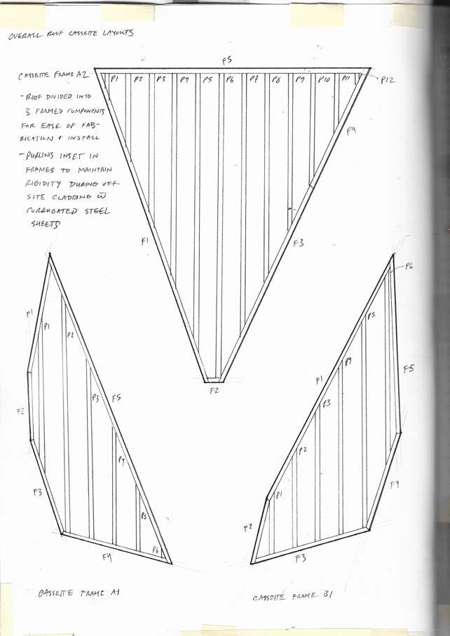
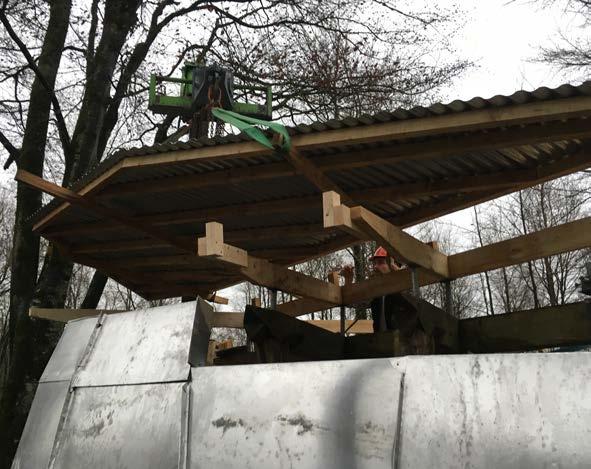
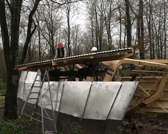
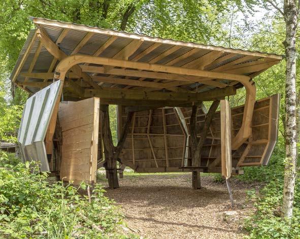
Given the height of the ring beam extension, a shallow roof pitch was developed, keeping the roof structure as close as possible to the r beams that span between the three forks. These serving as the only suitable structure upon which to mount support brackets. Broken into a distinct frames, much like the four wall components, the three roof panels are composed of 38 unique members. Each cut by hand. These three frames sit atop primary roof beams supported by 12 distinct steel props. This primary support structure installed in advance of the fabrication of the frames.
While the original intent was to clad the roof structure in CNC cut aluminum panels as well, material constraints required the use of corrugated steel sheets. This was, however, a favorable alteration. The mounting strategy for corrugated steel accommodating the roof design
quite well in its amenability to any potential purlin arrangement and the directing of water by the corrugations. Secured using stock fasteners the edge details were cut using an orbital grinder following application to the frames. In this way, any irregularities in timber component fabrication or assembly could be easily mitigated. While the two smaller roof frames were installed with little complication by way of securing strops to underlying timber supports and lifting them into place the larger roof section proved more di cult. This uppermost frame nesting within the other two, it could not be lifted into place using similarly overstanding supports. Instead, 3 releasable I-bolts were strategically drilled into the frame, acting as anchors for the strops and thereby allowing the frame to be lower into position with little con ict.
DESIGN + MAKE / CORE STUDIO CR / PB 66
 FOUNDRY / ROOF
67
DESIGN + MAKE / CORE STUDIO68
 FOUNDRY / ROOF
69
DESIGN + MAKE / CORE STUDIO70
 FOUNDRY
/ ROOF 71

DESIGN + MAKE / CORE STUDIO72


FOUNDRY / DOORS 73
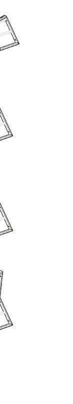
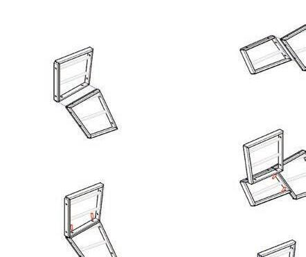
DOORS
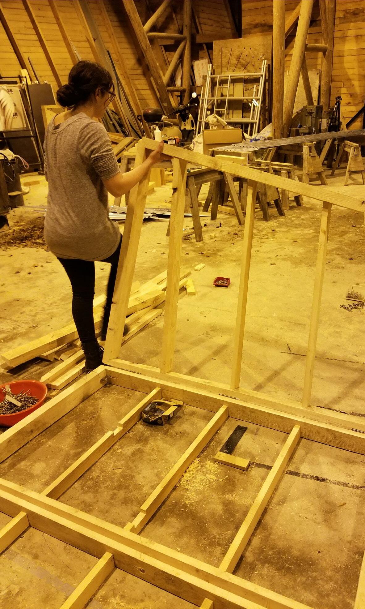
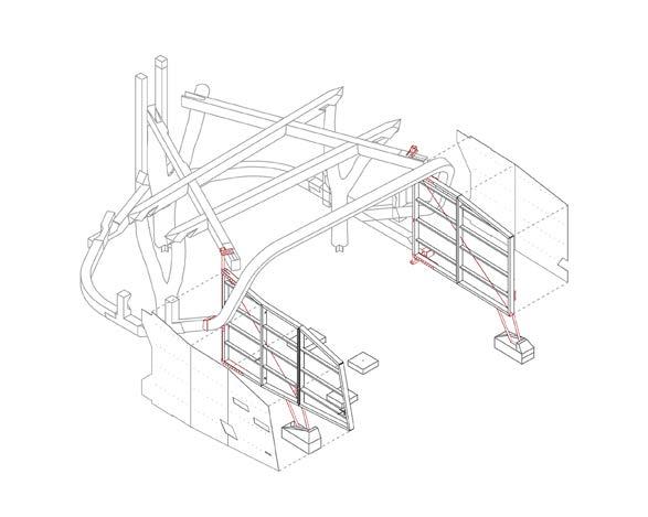
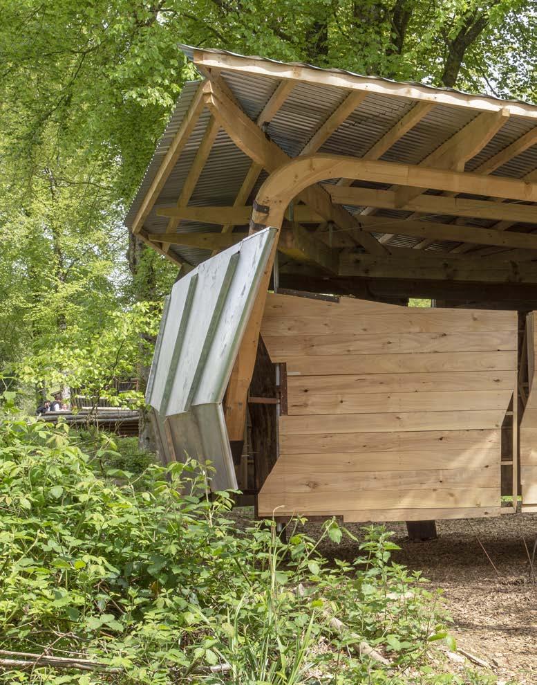
The west side face of the foundry is treated as a dynamic, operable wall that oats above the ground. This dynamic wall is divided into two dynamic wall components that allow three di erent con gurations as per the user’s needs. The rst con guration takes place when the space is not in use, suggesting a smaller territory for the foundry space while the second con guration of the doors suggests a ‘a private working mode’ that allows the user to expand the interior space. The third state suggests an ‘open up’ mode that allows the union of the foundry with the outdoor space serving workshops held in the foundry that demand a larger number of people. The change of state for the walls makes the space readable from the outside
informing the outside viewer of the foundry if the space is in use or not.
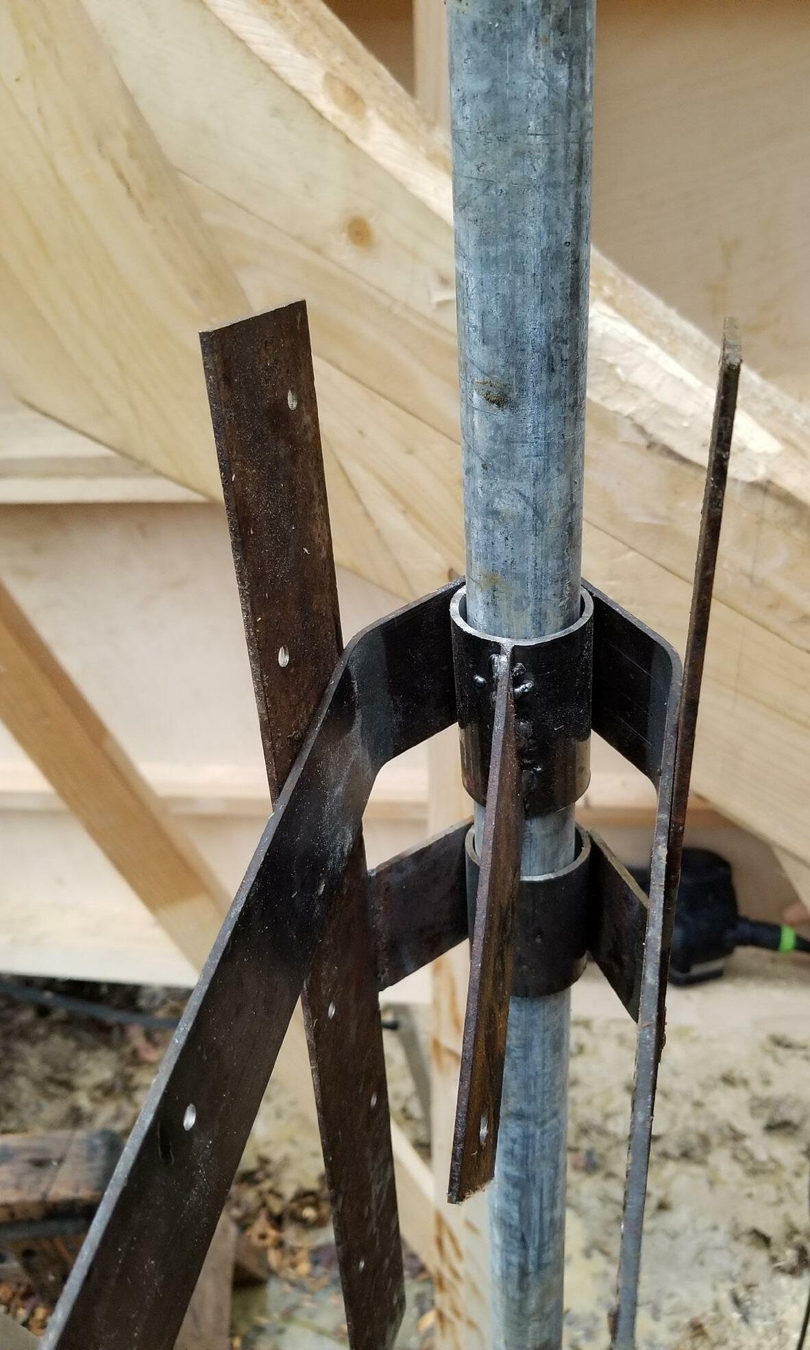
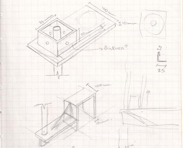
The two dynamic wall components are performing around two main custom-made hinges that are taking support by the ring beam while the smaller dynamic part of the folding door is supported by smaller industrial hinges. In order to allow for tolerance during the on-site assembly process, an adjustable steel detail component was introduces on the top edge of the two main hinges that allowed adjustments on the position of the axes. Each frame was prefabricated and transported on-site while the custom-made hinged and the steel brackets were prefabricated and then assembled on-site.
DESIGN + MAKE / CORE STUDIO NP / EQ 74
 FOUNDRY
/ DOORS 75

DESIGN + MAKE / CORE STUDIO76
FOUNDRY / DOORS 77
DESIGN + MAKE / CORE STUDIO78
FOUNDRY / DOORS 79
DESIGN + MAKE / CORE STUDIO80

FOUNDRY / DOORS 81


DESIGN + MAKE / CORE STUDIO82
FOUNDRY / FINAL 83
DESIGN + MAKE / CORE STUDIO84
FOUNDRY / FINAL 85
DESIGN + MAKE / CORE STUDIO86
FOUNDRY / FINAL 87
ACKNOWLEDGEMENTS
MARTIN SELF
EMMANUEL VERNUYSSE
ZACHARY MOLLICA
MICHAEL ARNETT
JACK DRAPER
CHARLIE CORRY-WRIGHT
CHRISTOPHER SADD
EDWARD COE