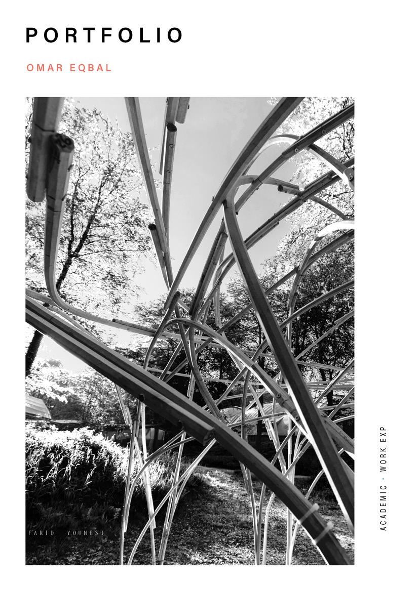
Work Experience
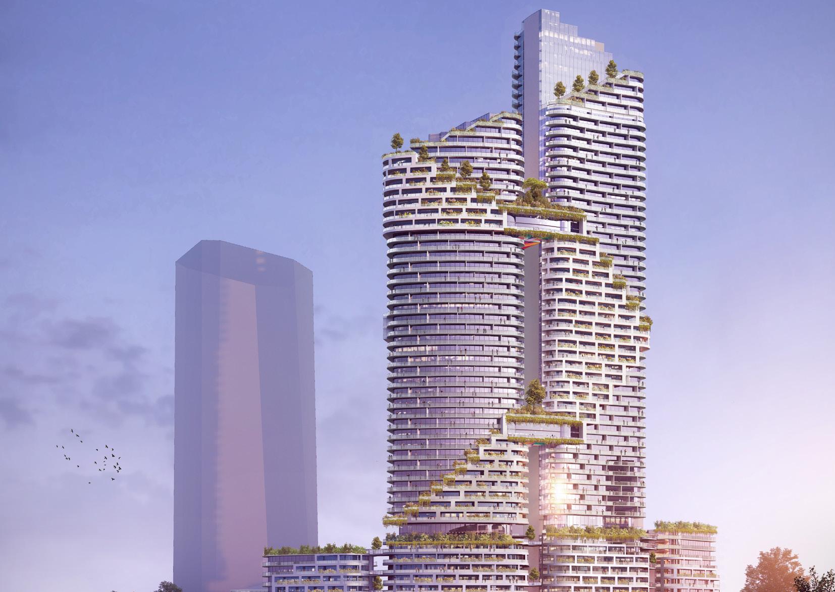
Pacific (Ankara, Turkey)
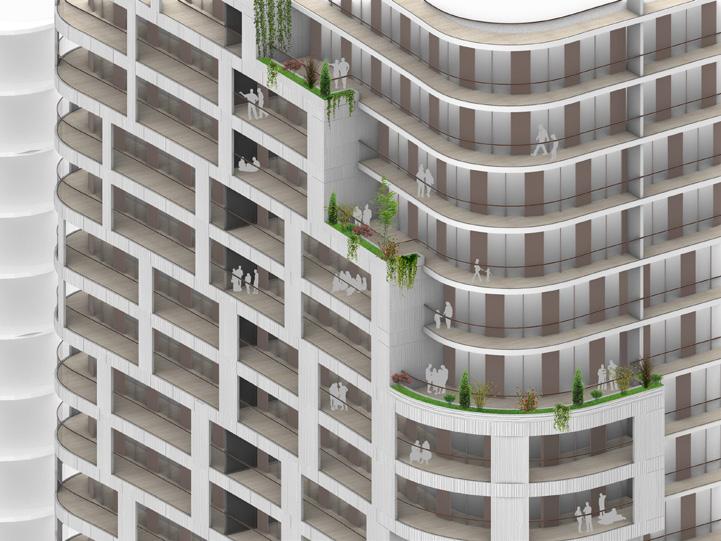
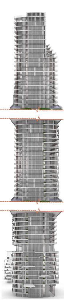
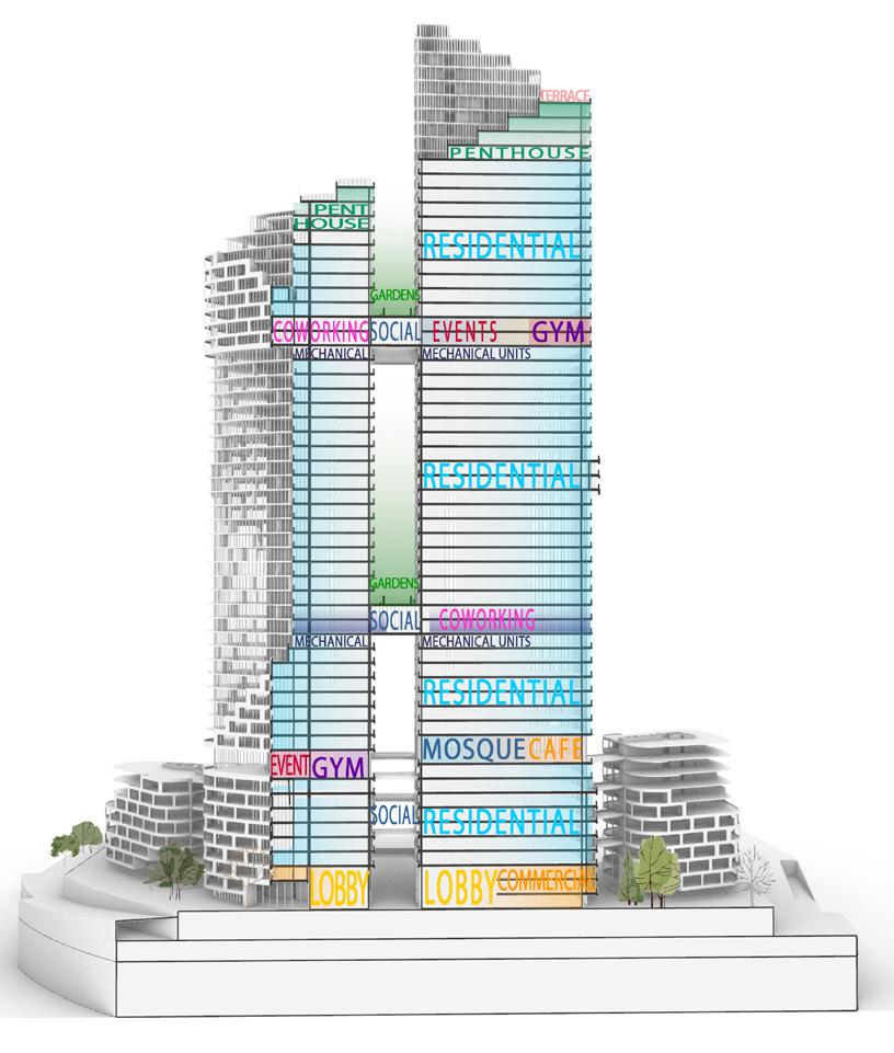
A 60 floor twin towers mixed use development in Ankara, housing residential, recreational, retail, offices and exhibition spaces that is connected by a green ribbon from ground to bridges, giving people and families space to meet, greet and enjoy amids the sky.
My Role :
#Designing and resolving technical details of the exterior facade. #Developing design options in collaboration with design team. #Preparing, developing and editing drawings and models relating to project development.
#Designing and running solar / wind simulations to verify design decisions.
#Research and proposal of materials and construction methods.
#Modeling detail drawings of the building skin. #Making presentation drawings for client meetings.
Rhino - Grasshopper, Revit, Adobe Suite
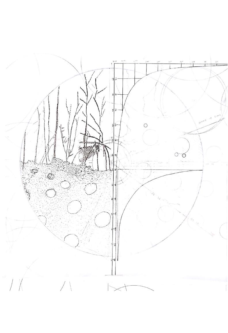
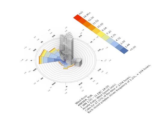
Shaping of the building form to maximize the views and channel the wind
Design Development
Wind analysis of the site - 1 Jan - 31 Dec
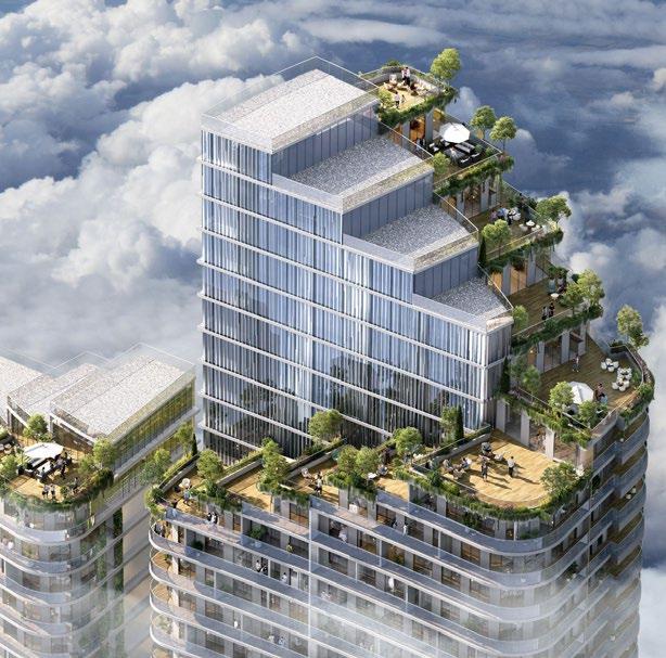
Connecting the towers through bridge Subtracting the above areas to divide the terrace region for penthouses and social areas
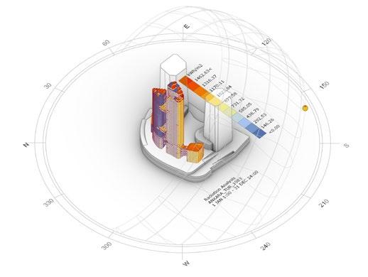
Solar Radiation Analysis - on site - 1 Jan - 31 Dec
Adding those subtracted ares on the facade as flat extinctions and tacking the solar radiation
A green spine going all around the building
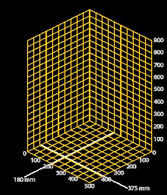
Site
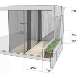
Condition 1
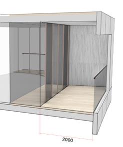
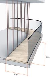
Balcony conditions
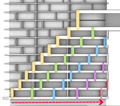
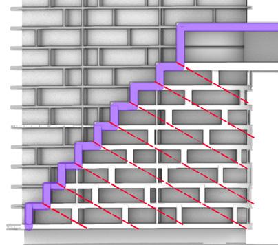
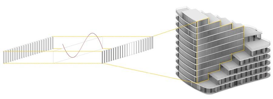
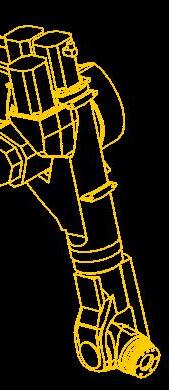
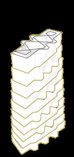
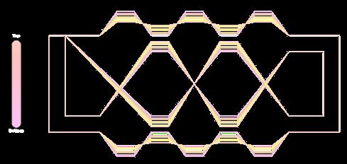
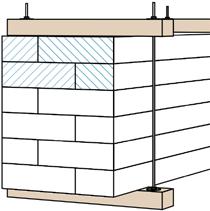
The exterior skin has several partitions designed with a parametric logic of distance and width to form a step like pattern
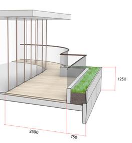
Condition 2
Equal thickness Width decreasing diagonally


Condition 3
Condition 4
Loggia Design Extension Building
Balcony Facade
Exterior fins design
Curve
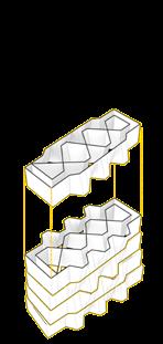
The exterior skin has several partitions designed with a parametric logic of distance and width to form a step like pattern
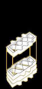
The exterior skin has several partitions designed with a parametric logic of distance and width to form a step like pattern
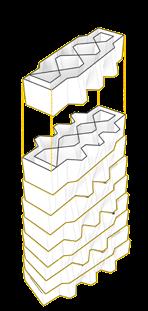
The exterior skin has several partitions designed with a parametric logic of distance and width to form a step like pattern
Indicating that the width is matching both in vertical and horizontal at the start of each floor
Indicating that the width is matching both in vertical and horizontal at the start of each floor
Indicating that the width is matching both in vertical and horizontal at the start of each floor
Indicating that the width of the vertical sun-breakers is decreasing diagonally
Indicating that the width of the vertical sun-breakers is decreasing diagonally
Indicating that the width of the vertical sun-breakers is decreasing diagonally
The exterior fins are coming on the parts where the structural core is part of the facade
The exterior fins are coming on the parts where the structural core is part of the facade
The pattern is created parametrically to depict the motion of the waves that is created in the ocean
The exterior fins are coming on the parts where the structural core is part of the facade
The pattern is created parametrically to depict the motion of the waves that is created in the ocean
The pattern is created parametrically to depict the motion of the waves that is created in the ocean
Loggia Design
Loggia Design
defining the rotation of the fins
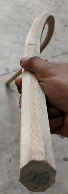
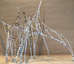
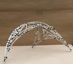
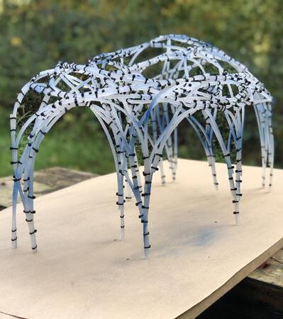
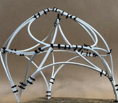
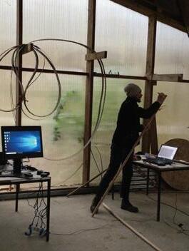
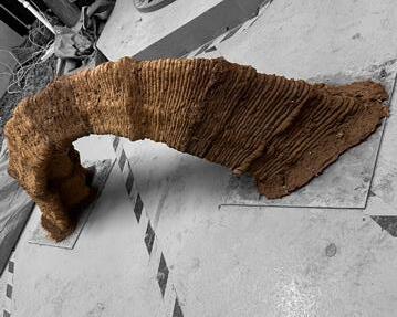
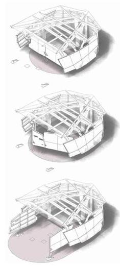
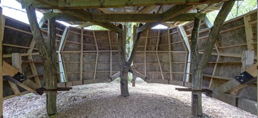
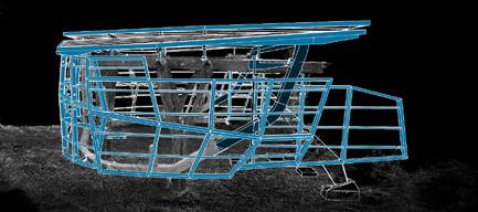
Free Form Steam Bending
Rhino, Grasshopper, 3D Scanning
# Research on embracing tolerances in architecture.
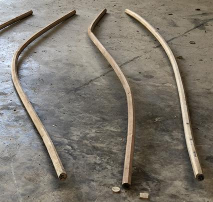
# Steam bending test, documentation and material research on Beech wood.
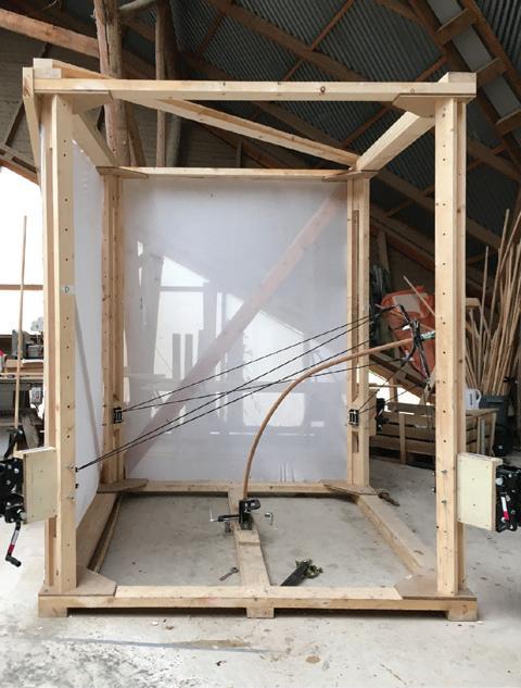
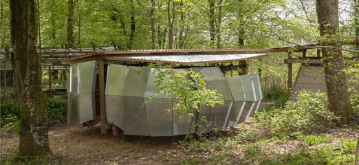
# Making of the transportable Free Form system in 1:1 scale.

# Refining the setup and process of stem bending to obtain the desired bends.
# Making prototypes to test and push the limitations of our research.
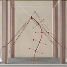
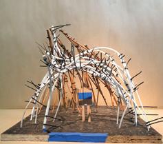
# Procedural modeling in 1:10 scale for finding the geometry for the pavilion.
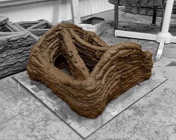
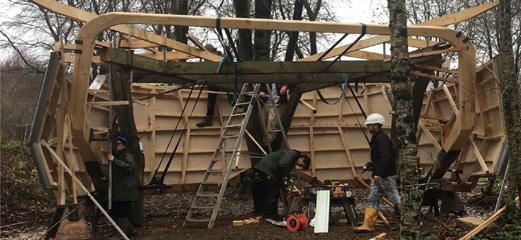
# Fabricating and combining 160+ steam bent laths to build the project.
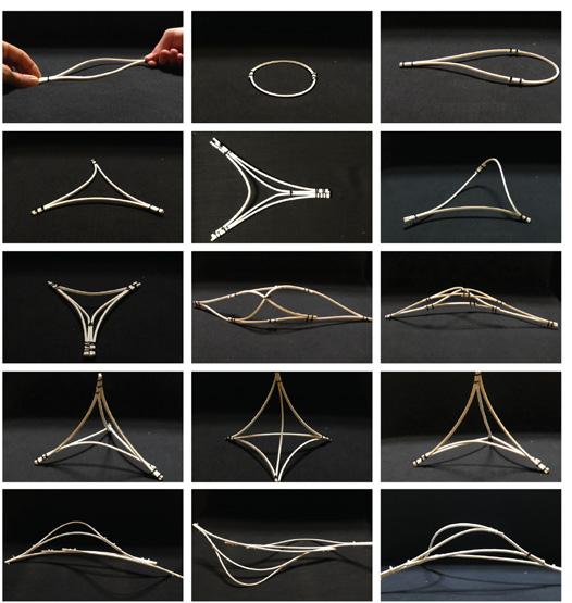
Scaled model testing
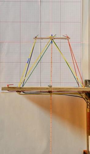
To help understand and comprehend the materiality of wood. We fabricated a setup that positioned a lath (30 x 30 mm cross-section) between the steel nodes tensioned using ratchet straps to manipulate the bend in 3D space
To understand the system logic, we went through a series of mock-ups to analyses and logged the change in shape of lath with every tensioning move
Breaking the previous iteration into segments, we tested the accuracy by targeting a shape drawn digitally and replicating it with the model
With an average tolerance of 8mm we decided to scale up this system, as it was giving us the desired result
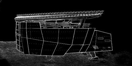
Scaling up
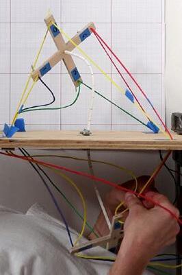
The system works in a very similar way, like a piece of wood held in hands at each end, by controlling the amount of pressure, movement and rotation of hands, the whole length of timber can be manipulated, and very informal feedback
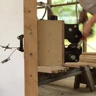
The node

After scaling up the system, a lot of minor refinements and fine-twining of the parts, bending method and co-ordination experiments were done to find a process which worked efficiently
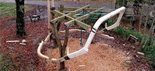
The full-scale jig was 1.8m to 2.5 m laths. This length was worked out to maximise the number of slats that can be milled from a tree. Trunks of a Beech generally 4.5m – 5m long to get two sets of 2.5m boards and minimise wastage. We designed the jig, working backwards the proportions and size for different components of the system. The jig comprises a square base, at each corner vertical posts hold a winch box, with the flexibility to travel up and down along the length of posts. The winch box comprises of two winches mounted
Winch box
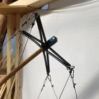
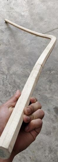
30
Image of Jig with an extreme bend
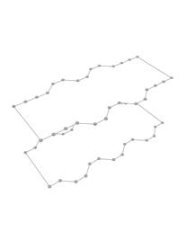
Modeling
Workflow
Adding splines one by one with the understanding of the fabrication process
The sticks are friction fixed using zip-ties
We make sticks out of propylene sheet; it allowed us the flexibility to manipulate the material and also try multiple options before at an individual stick
Through intuition and balancing the friction between sticks, modules were formed, which is well under the range of our fabrication process
Intuitive hand Modeling
Hand crafted 1:10 scale model to have interesting and wide range of bends
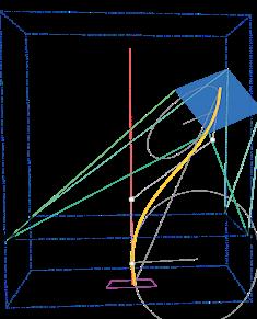
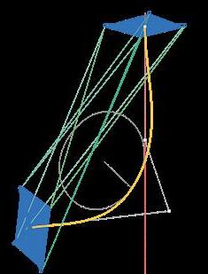
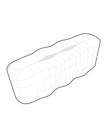
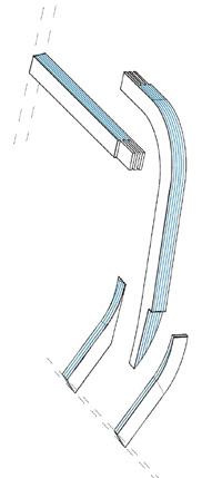
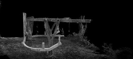
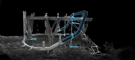
3D Scanning
Bringing the curve data from the model to digital world
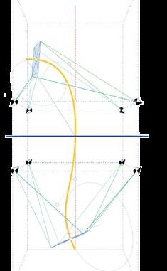
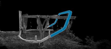
Curve Extraction

Drawing splines on Rhino using the scan data and referring the model
Generating Cable lengths
Feeding the curves in the script to generate the data for fabrication


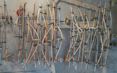
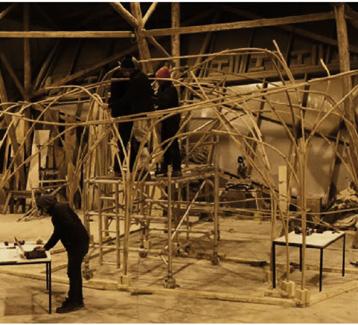
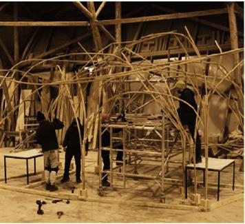
Production
Steaming & bending 140 discrete bends to form the Pavilion
53
Images of the model exploration for form-finding of the Pavilion
Images of the model exploration for form-finding of the Pavilion
We extracted the point cloud from the scan.
Rhino Model
We extracted the point cloud from the scan.
Assembly
Rhino Model
For generating data
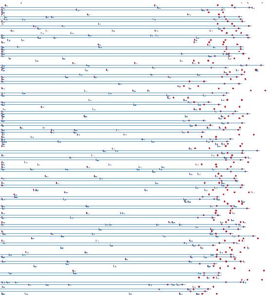
A python script was created that was to premark the drill points and adjoining lath location on every lath before steaming and bending
For generating data
Though which we drew the curves to feed in the JIG script
The project was group effort of four students, pursuing there Master’s in the AA.
Though which we drew the curves to feed in the JIG script
Pre-marking
Pre-marking
>Connections
Almost every part of the project required us to either work in groups of two or four.
>Connections
>Target points
>Target points
>Lath orientation
>Lath orientation
Finding where faces meet and connect to each other, which later we use for pre-marking each lath
Finding where faces meet and connect to each other, which later we use for pre-marking each lath
The parts of the projects which I worked on was more on the physical experiments and scripting of the setup digitally.
We pre-mark the components by plotting a 1:1 scale length of laths. Marking the connections before bending.
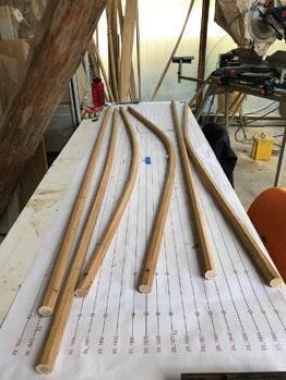
We pre-mark the components by plotting a 1:1 scale length of laths.
Marking the connections before bending.
The project on one hand is very manual while on the other the making of each piece and fabrication as a whole required considerable computation on the back end.
Step 1 : Fixing the laths touching the ground
Circular marking for dill holes and line for the adjacent lath Components
Circular marking for dill holes and line for the adjacent lath
Components
Step 2 : Connecting the basic structure
Real-time feedback setup
Step 3 : Weaving along basic structure
DIY digital setup was created from two sides to track the bends in real-time
Step 4 : Adding redundancy in weak points
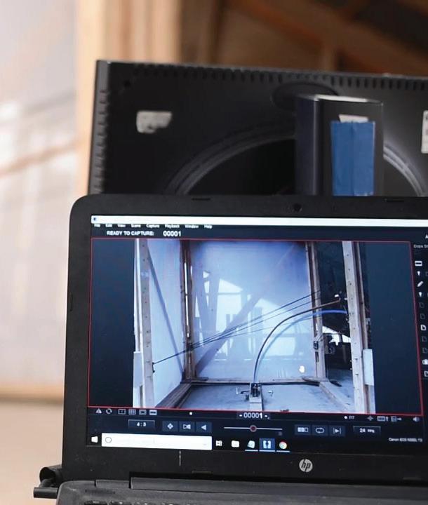
By overlaying the digital image of the digital shape with a real-live video of the process, a visual system was set to get a real-time feedback to check the accuracy and shape of the bend.
Pre - Marking
Pre-marking 75
A python script generated to premark the drill points and adjoining lath location on every lath.
Image 2: Pre-marking connection and drill points form a 1:1 scale lath plotted sheet.
75
Image 1 : Pre-marking the orientaion on lath
Image 2: Pre-marking connection and drill points form a 1:1 scale lath plotted sheet.
Image 1 : Pre-marking the orientaion on lath
Urban Design / Documentation (Sringeri)

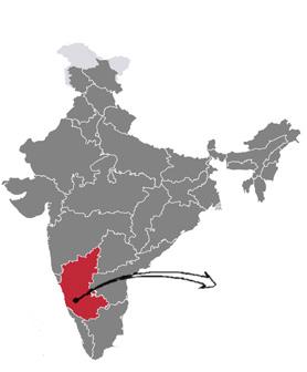
Sringeri is located in the state of Karnataka, India. One of the prime religious center of Hinduism. Temple is the main attraction that is dedicated to the Hindu goddess who is the embodiment of knowledge and learning.
My role:

# Typology studies of the town through sketches.
# Making digital town planning drawings and per documentation.
# Developed survey documents for residents and tourist to develop a brief and identify the site
# Design proposal for the Visitor’s center and river side development
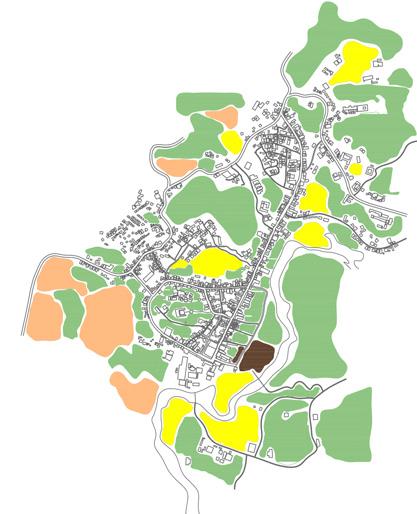
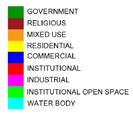
Land Use Mapping
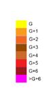
Building height

Open Ground mapping

Building condition
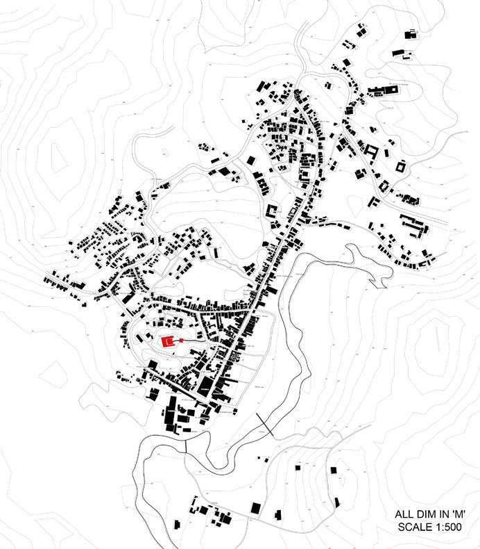 Figure Ground Mapping
Academic
Karnataka
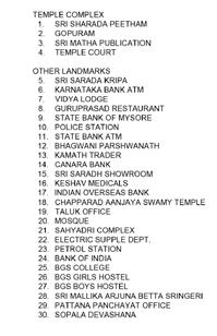
INDUSTRIAL RESIDENTIAL INSTITUTIONAL INSTITUTIONAL OPEN SPACE WATER BODY COMMERCIAL MIXED USE RELIGIOUS GOVERNMENT INTERNAL ROAD WAY MANIPAL SOLAPUR-MANGALO HIGHWAY TEMPLE COMPLEX 1. SRI SHARADA PEETHAM 2. GOPURAM 3. SRI MATHA PUBLICATION 4. TEMPLE COURT OTHER LANDMARKS 5. SRI SARADA KRIPA 6. KARNATAKA BANK ATM 7. VIDYA LODGE 8. GURUPRASAD RESTAURANT 9. STATE BANK OF MYSORE 10. POLICE STATION 11. STATE BANK ATM 12. BHAGWANI PARSHWANATH 13. KAMATH TRADER 14. CANARA BANK 15. SRI SARADH SHOWROOM 16. KESHAV MEDICALS 17. INDIAN OVERSEAS BANK 18. CHAPPARAD AANJAYA SWAMY TEMPLE 19. TALUK OFFICE 20. MOSQUE 21. SAHYADRI COMPLEX 22. ELECTRIC SUPPLE DEPT. 23. PETROL STATION 24. BANK OF INDIA 25. BGS COLLEGE 26. BGS GIRLS HOSTEL 27. BGS BOYS HOSTEL 28. SRI MALLIKA ARJUNA BETTA SRINGERI 29. PATTANA PANCHAYAT OFFICE 30. SOPALA DEVASHANA
Auto Cad, Sketch Up, Adobe Suite
WAY MANIPAL UR-MANGALO HIGHWAY TEMPLE COMPLEX 1. SRI SHARADA PEETHAM 2. GOPURAM 3. SRI MATHA PUBLICATION 4. TEMPLE COURT OTHER LANDMARKS 5. SRI SARADA KRIPA 6. KARNATAKA BANK ATM 7. VIDYA LODGE 8. GURUPRASAD RESTAURANT 9. STATE BANK OF MYSORE 10. POLICE STATION 11. STATE BANK ATM 12. BHAGWANI PARSHWANATH 13. KAMATH TRADER 14. CANARA BANK 15. SRI SARADH SHOWROOM 16. KESHAV MEDICALS 17. INDIAN OVERSEAS BANK 18. CHAPPARAD AANJAYA SWAMY TEMPLE 19. TALUK OFFICE 20. MOSQUE 21. SAHYADRI COMPLEX 22. ELECTRIC SUPPLE DEPT. 23. PETROL STATION 24. BANK OF INDIA 25. BGS COLLEGE 26. BGS GIRLS HOSTEL 27. BGS BOYS HOSTEL 28. SRI MALLIKA ARJUNA BETTA SRINGERI 29. PATTANA PANCHAYAT OFFICE 30. SOPALA DEVASHANA MANIPAL SOLAPUR-MANGALO HIGHWAYNH-13 TEMPLE COMPLEX 1. SRI SHARADA PEETHAM 2. GOPURAM 3. SRI MATHA PUBLICATION 4. TEMPLE COURT OTHER LANDMARKS 5. SRI SARADA KRIPA 6. KARNATAKA BANK ATM 7. VIDYA LODGE 8. GURUPRASAD RESTAURANT 9. STATE BANK OF MYSORE 10. POLICE STATION 11. STATE BANK ATM 12. BHAGWANI PARSHWANATH 13. KAMATH TRADER 14. CANARA BANK 15. SRI SARADH SHOWROOM 16. KESHAV MEDICALS 17. INDIAN OVERSEAS BANK 18. CHAPPARAD AANJAYA SWAMY TEMPLE 19. TALUK OFFICE 20. MOSQUE 21. SAHYADRI COMPLEX 22. ELECTRIC SUPPLE DEPT. 23. PETROL STATION 24. BANK OF INDIA 25. BGS COLLEGE 26. BGS GIRLS HOSTEL 27. BGS BOYS HOSTEL 28. SRI MALLIKA ARJUNA BETTA SRINGERI 29. PATTANA PANCHAYAT OFFICE 30. SOPALA DEVASHANA
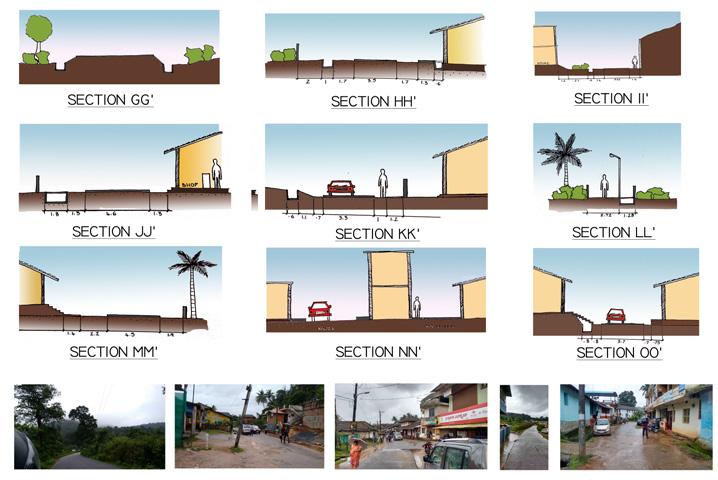
Street Sections
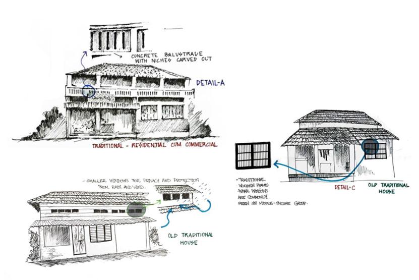
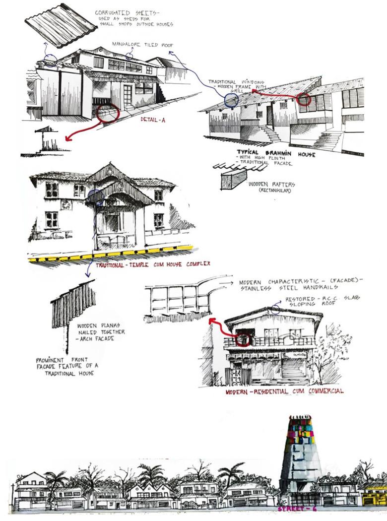
Building studies using pen and Ink
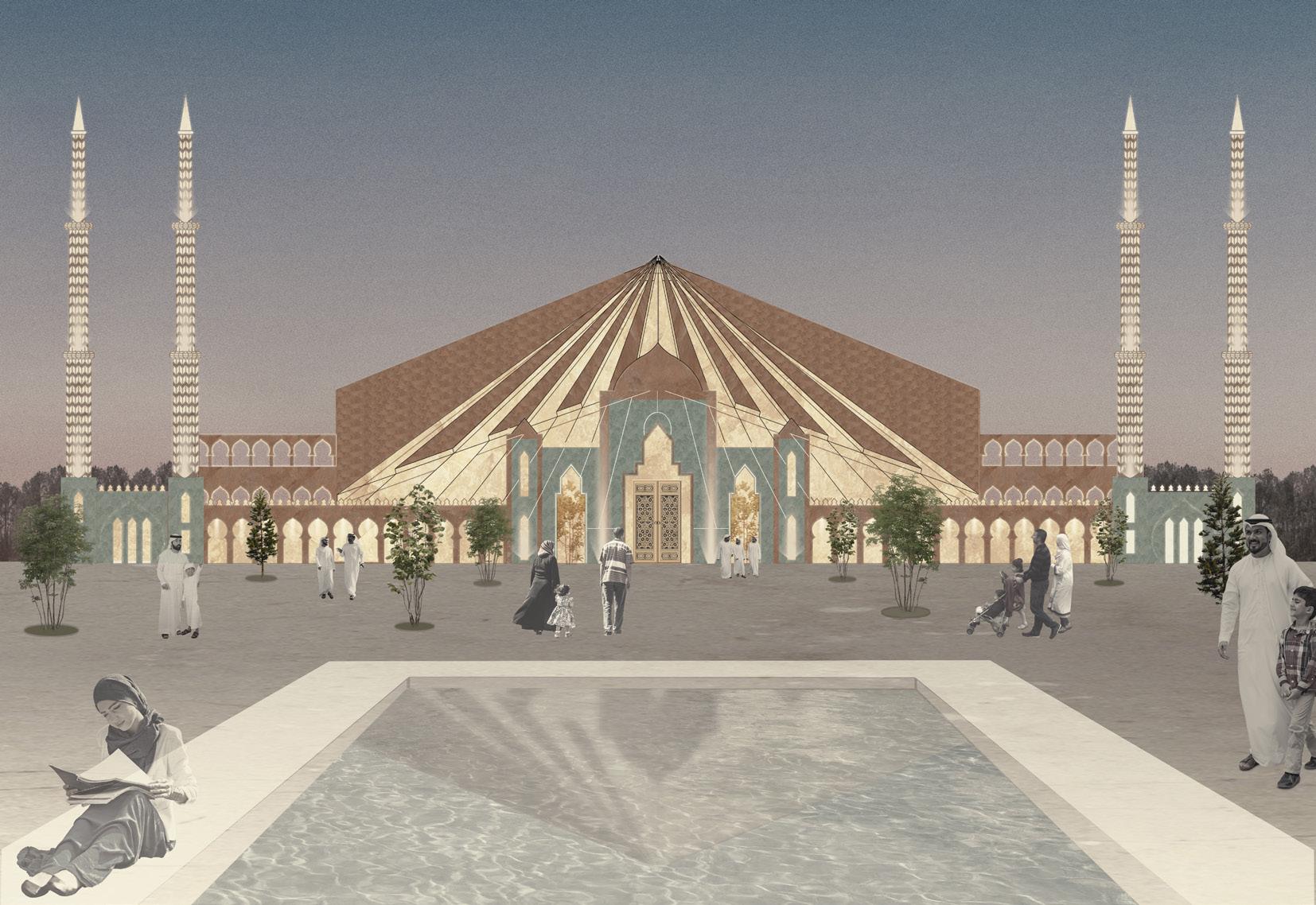
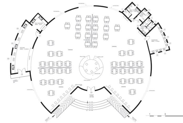
Islamic Cultural Centre
Revit, Adobe
Individual design proposal
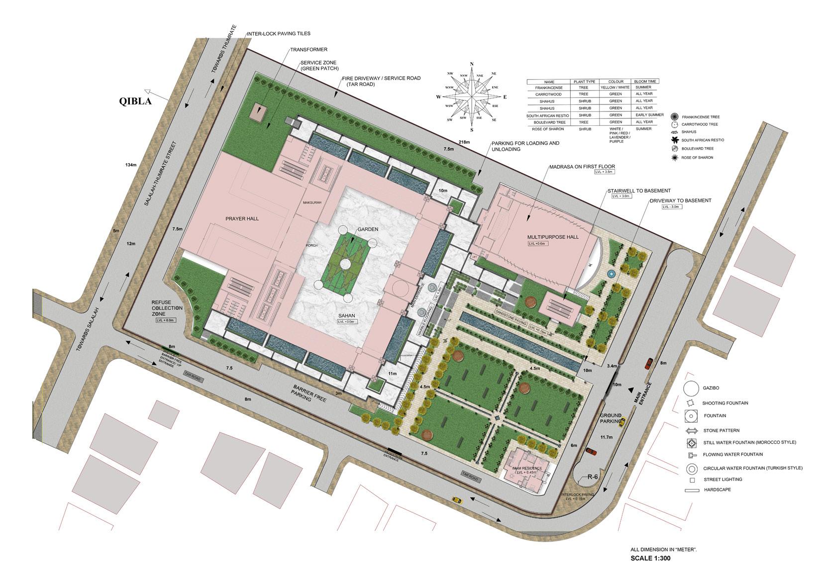
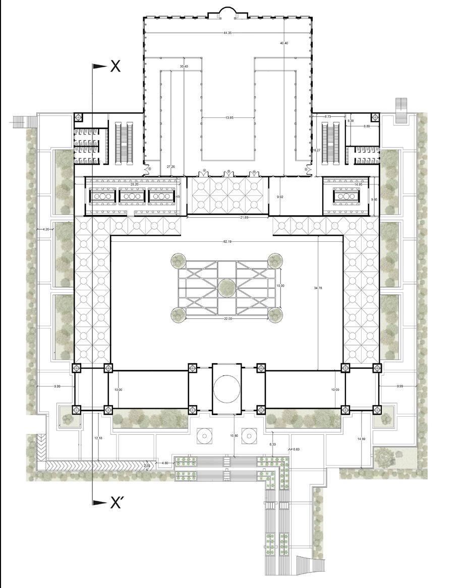

Legend 1 Prayer Hall 2 Ablution (male) 3 Washroom (Male) 4 Library 5 Corridor 6 Main entrance 7 Shoes zone 8 Washroom (female) 9 Ablution (Female) 10 Storage 11 Imam office 12 Garden 1 3 2 5 6 7 12 All dim in ‘meters’ 4 5 8 9 10 7
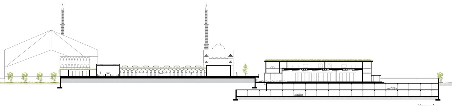
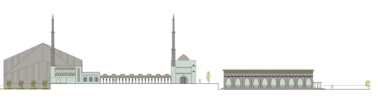
West Elevation
Section XX’
Robotic cob PRinting
KUKA PRC Scripting in Grasshopper / Wall Assembling Process
# Research and physical testings to derive the material composition to be used for printing
# Making design options keeping in mind the limitations of our printing setup.
# Scripting the logic of printing to find the G-code for printing.
# Devising a production process for making material, loading of material and printing.
# Testing the printing of double curved surface geometries.
Tool Path / G - Code
The G-code for the robot was scripted with the understanding of nozzle size, continuity of printing, base plane and area limitation of movement.
The main parameters are :
Nozzle size = 2.5 cm (height of each layer)

Base plane = 90 degree
Printable area = 50 x 50 cm length & width
Each layer was divided into 50 polylines, resulting in printing the designed block geometry.
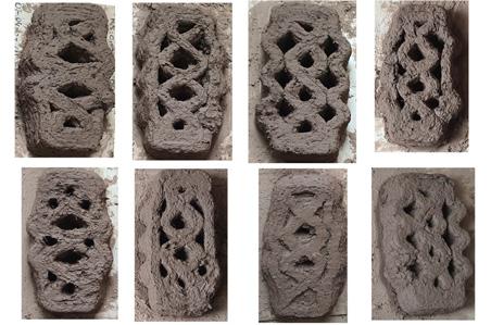
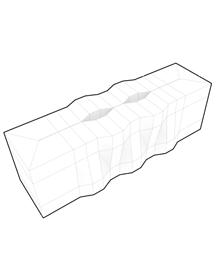
The blocks, when stacked, were designed to have a tapering effect on the width, creating a monolithic geometry.
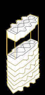
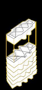
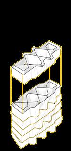
-----------------------------------------------------------------------------------------Block 01 3 undulations Block 02 2 undulations Flipped Block 03 2 undulations Block 04 3 undulations Flipped Block 05 3 undulations Block 06 2 undulations Flipped Block 07 2 undulations Block 08 3 undulations Flipped Block 09 3 undulations
G - code for printinG
Layers iLLustrated with coLors accordinG to their order
Parametric Logic
Step 01
Create top/bottom rectangles, and split longer edges into equal divisions
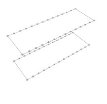
Step 01
Step 02
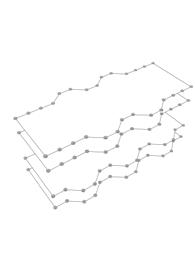
Move vertices based on a specific pattern (0, 0, 1, 1) for the bottom rectangle with the opposite order for the top layer, with the first and last four vertices set to zero
Step 03
Step 02
Create a duplicate of top and bottom rectangles towards the centre of the block
Step 04
Loft the four curves to create a base SubD geometry, and thicken walls to calculate the volume
Step 03
Step 04
Step 05
Smooth SubD geometry
Step 05
 Individual printed blocks of different shapes and sizes
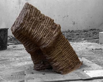
3D printing of blocks using the dual mechanical extruder, double curvature block design and printing
3D printing of blocks to form an arch made out of cob using dual extruder and Kuka Prc robotic arm
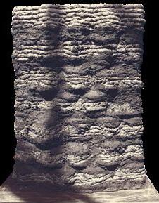
Blocks forming a wall using cob mortar
Individual printed blocks of different shapes and sizes
3D printing of blocks using the dual mechanical extruder, double curvature block design and printing
3D printing of blocks to form an arch made out of cob using dual extruder and Kuka Prc robotic arm
Blocks forming a wall using cob mortar
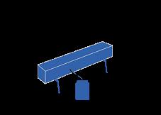
# Research on Glue lam structures and making.
# Designing and making of the glue lam wooden beam.
# Design and fabrication of bespoke joints to rest the beam on the columns.
# Design of the kinetic door to respond towards the requirements of the space.
# Making scaled models to understand how to build the door.
# Resourcing materials and producing fabrication drawings for construction.
# On site installation of the beam and the door.
Foundry Rhino, Grasshopper
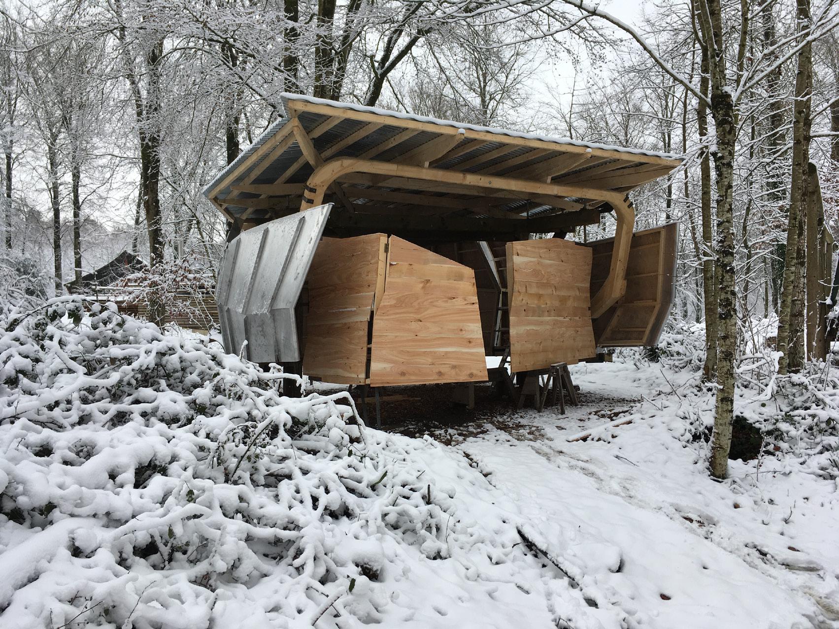
Cross laminating 6 layers of timber, made in 7 separate parts, combining to form a bespoke ring beam using finger, lap and dual joints.
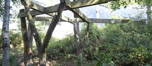
The beam is supported by columns taken directly from trees that surround us.
DIY clamp system to compress all layers together.
3D Scanned data
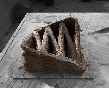
DESIGN + MAKE / CORE STUDIO 46
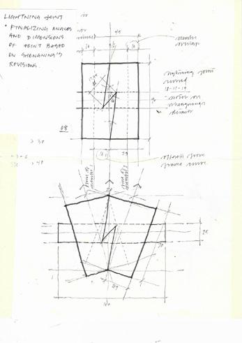
Robotically milled lightning joint forming the skeleton of walls.
Space transformation
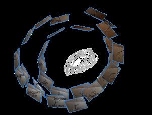
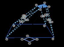
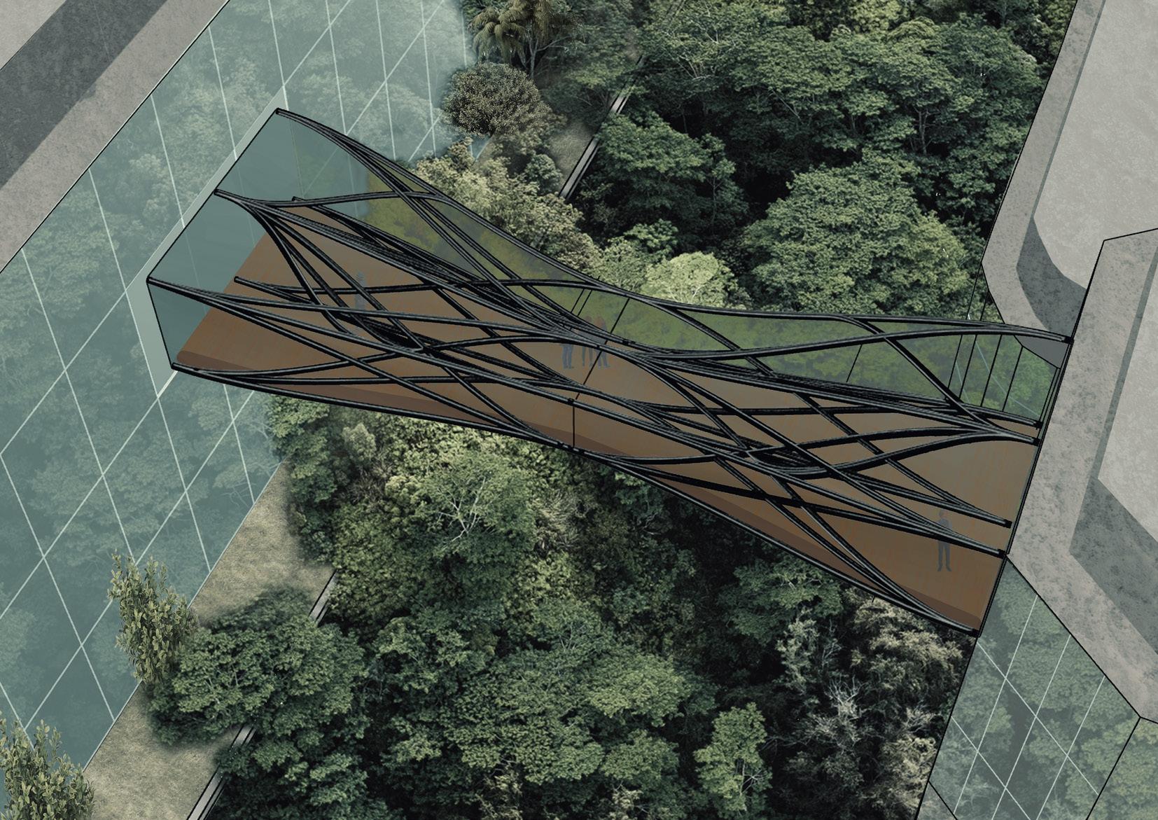
Spline bridge
Grasshopper, GH Python
Individual design proposal for a competition
Physical modeling
Scripting Logic
Step 1 :
Defining start and end connections
Both have separate parameters to give flexibility in design options
Step 2 :
Scripting splines b/w the start and ends, giving the start and end points a random parameter
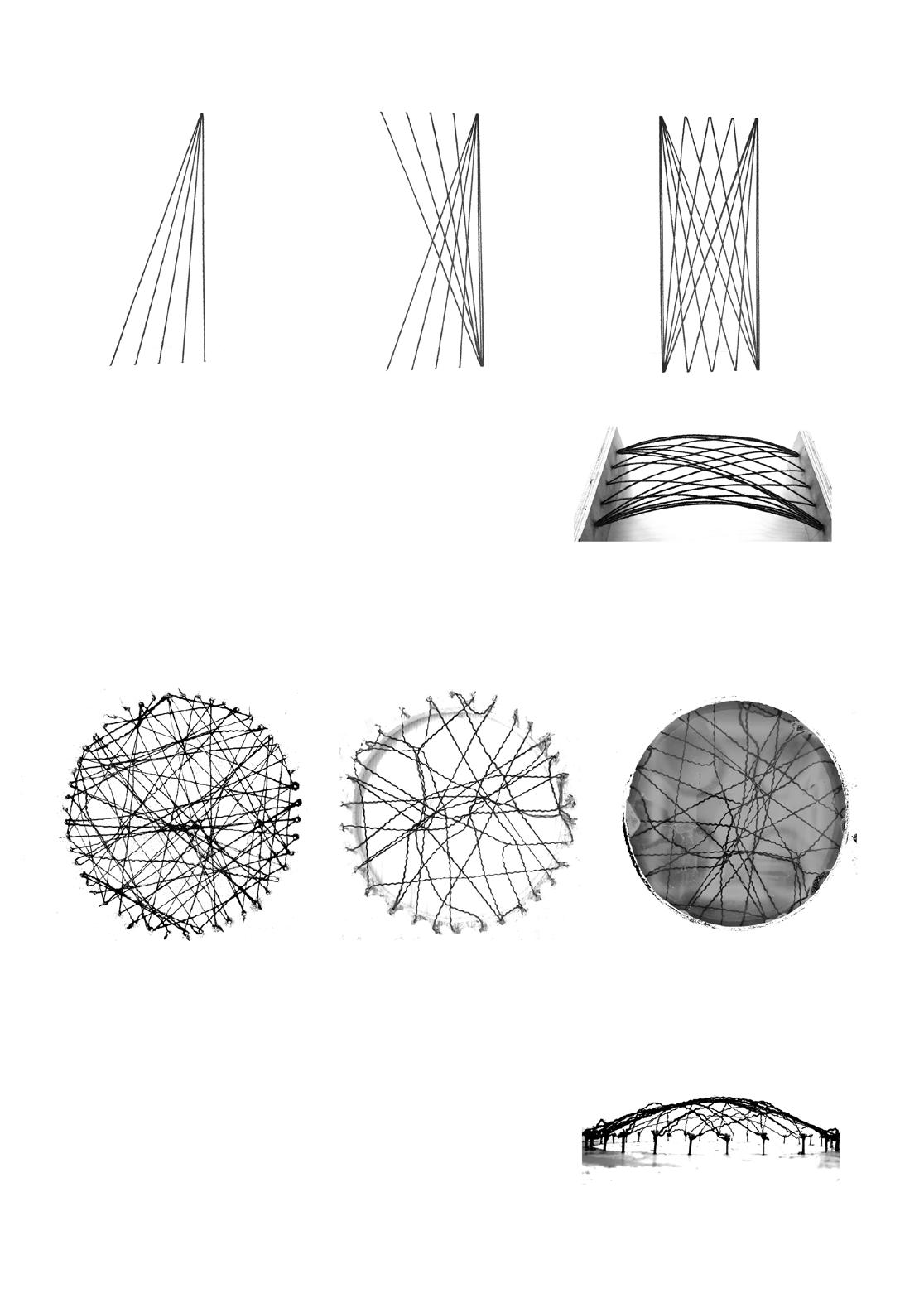
Tread model using defined threading path
# Planned slacked wool thread lines in the rectangular space
# Dipping the threads carefully inside the soap water upside down
Tread model using undefined threading path
# Making random slacked wool thread chords in the circle space
# Dipping the threads carefully inside the soap water upside down
# Placing soaked threads upside down to form find the network
Step 3 :
Re-parametrize the start and end connections to explore the different forms generations
Step 4 :
Taking control over the spline handles to have control over the spline smoothness
Step 5 :
Populating the threads and making interwoven secondary splines in between the primary ones to create a woven network
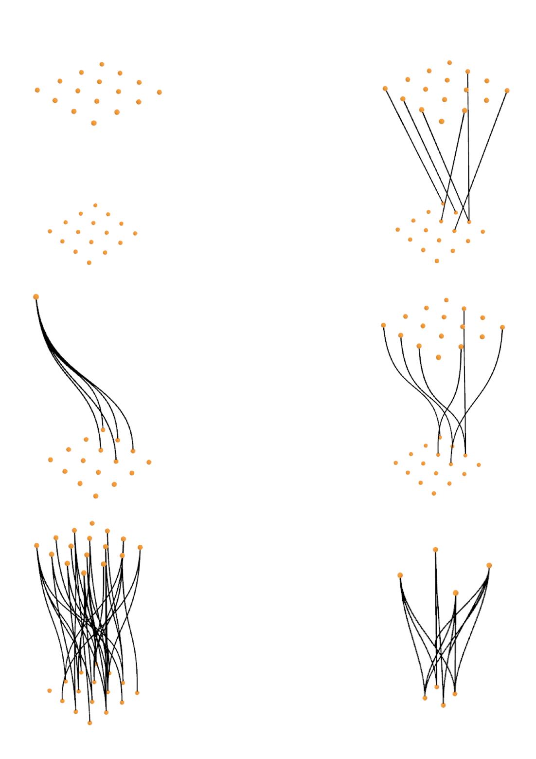
Step 6 :
Exploring forms that can work with our functional constraints and also satisfying our aim to develop a root geometry kind of network
Mixed Use
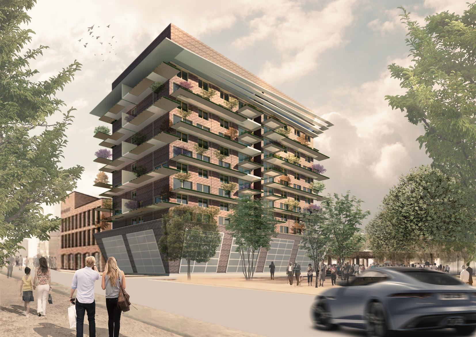
Exterior glass finish for viewing
Running track projected outside the structure
View of green on every floor
Trees acting as sun breaker during day time
Stick system curtain wall
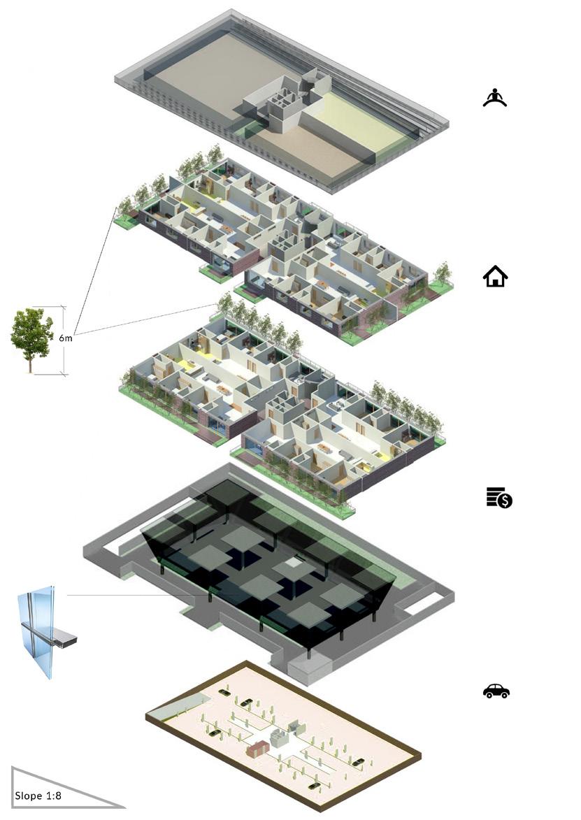
Recreational : Top floor
Divided in 4 parts
a. Gymnasium
b. Yoga / Zumba area
c. Indoor sports area
Residential units :
10 floors with four and three bedroom, hall and kitchen per floor
Green view from all bedroom and living spaces with maximum utilization of natural light
Basement parking for residents
Commercial :
Separate parking and drive for commercial area
Basement Parking :
Parking and lift for residential users
Material study : Testing scaled material prototypes to understand the haptic experience. Every building has a different feel, but similar language.
Texture study : Identifying the shadows and light created by different finishings.
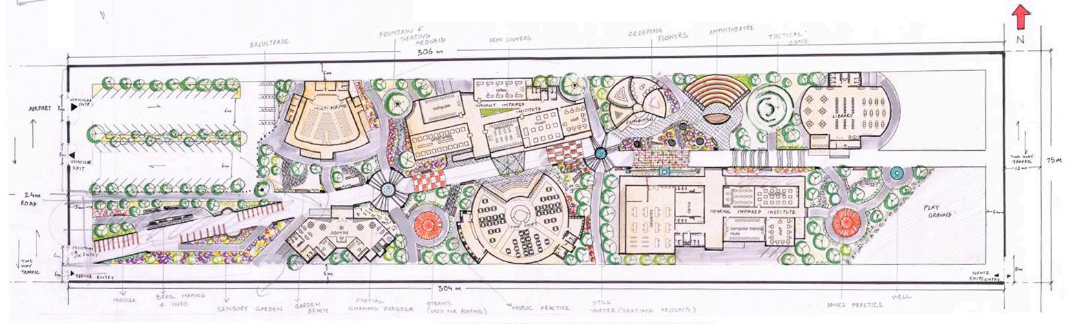
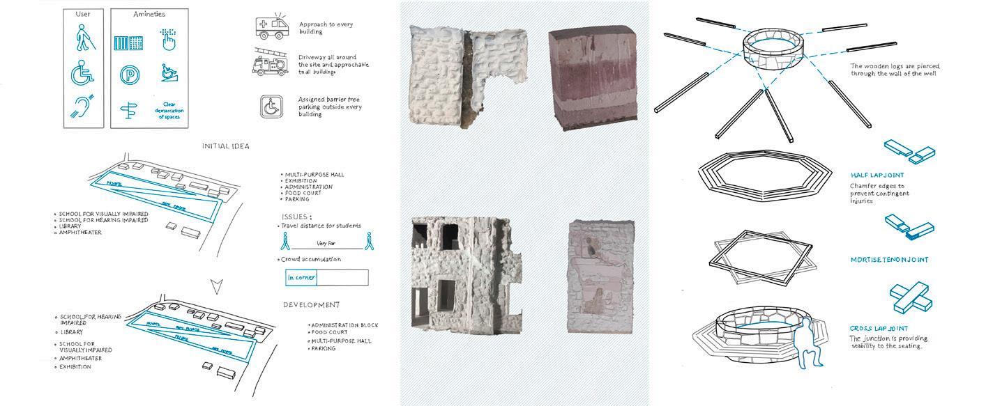
School
for differently abled

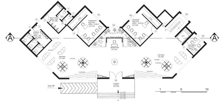
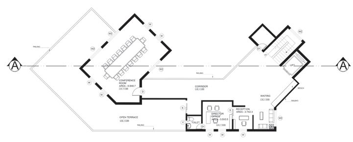
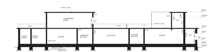

Administrative building Ground Floor Plan First Floor Plan Section All dim in ‘meters’
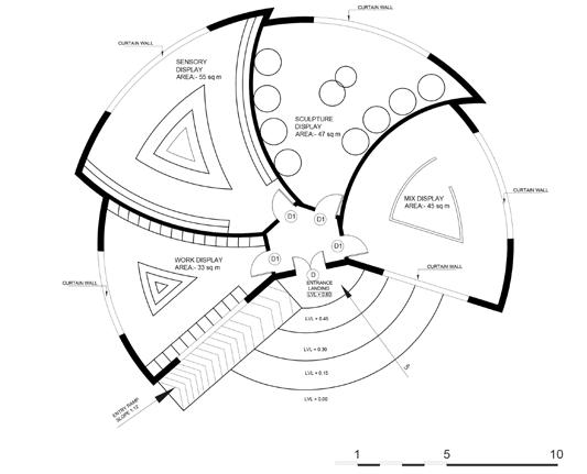
Exhibition building
Food
court building
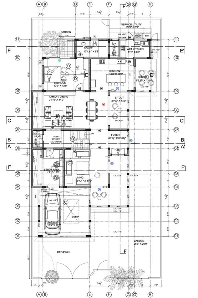
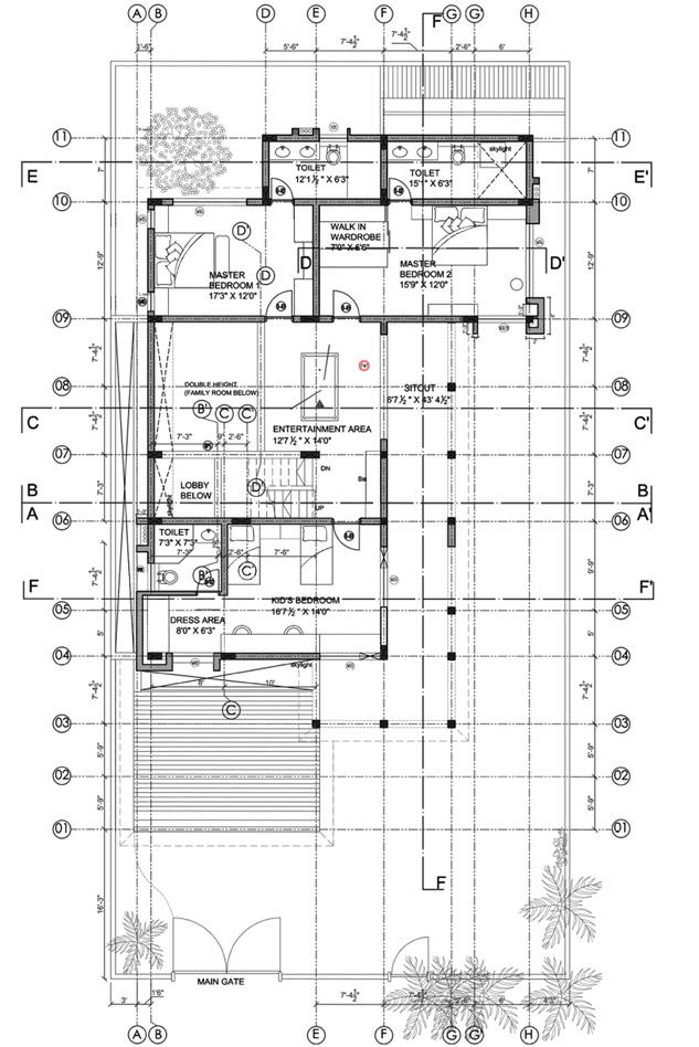
Prakirit Villa Ground Floor Plan First Floor Plan
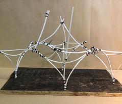
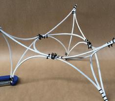
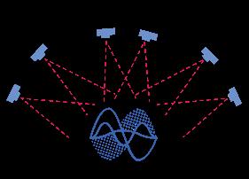
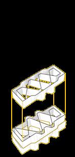
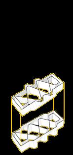
Dancing Mesh
The project is a free form exploration where the data for the design is extracted from the infamous dance of Fred and Ginger to bring tensile mesh, clear acrylic and 3D printed plastic to achieve the final output
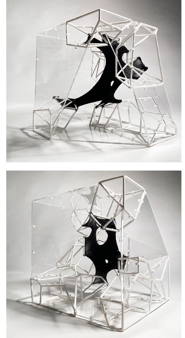
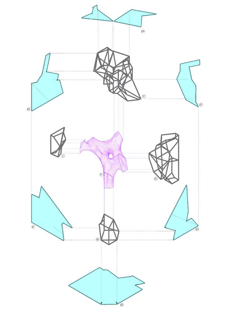
Exploded Axonometric drawing of parts
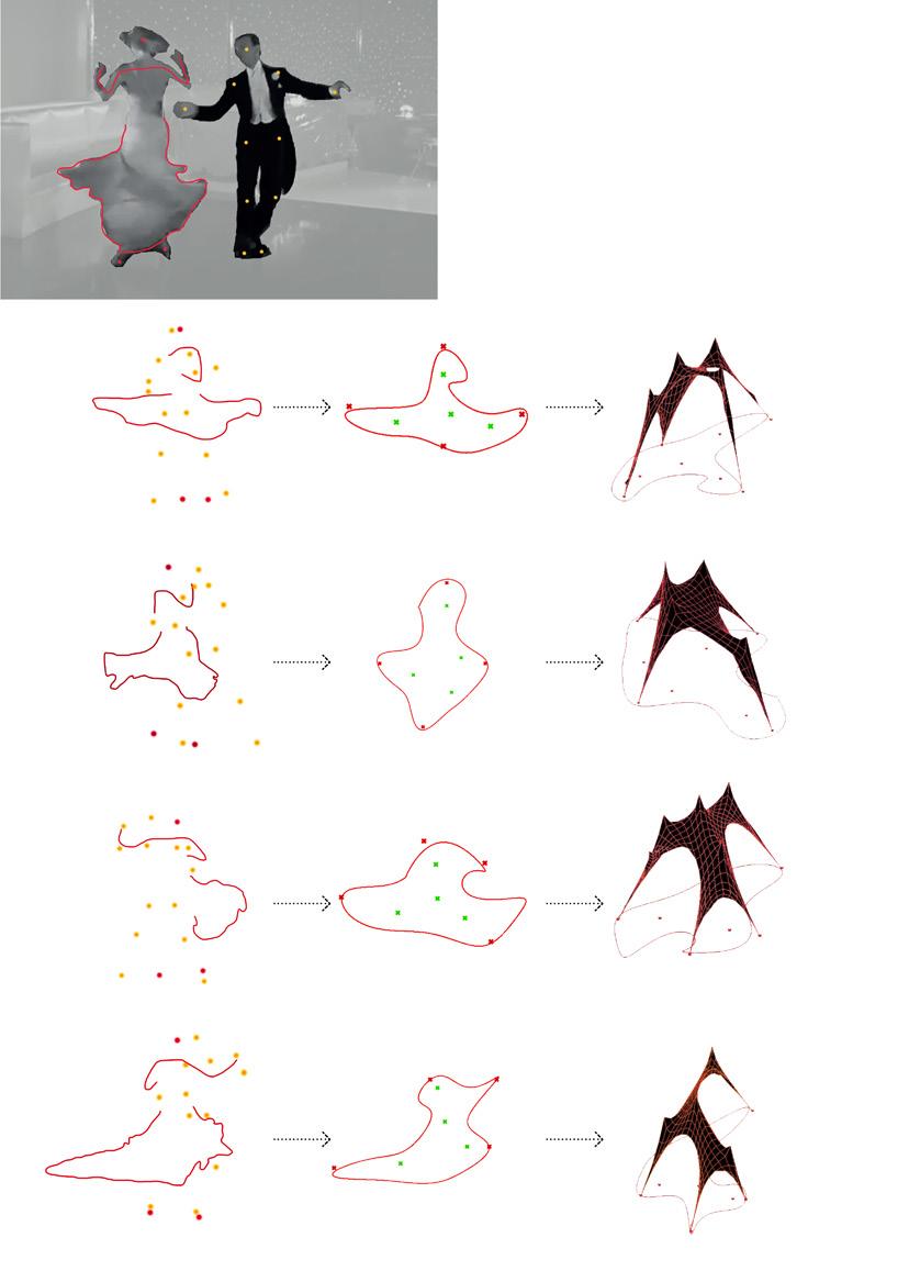
Fred and Ginger Dance
Exploration - Planar mesh
This simulation is assigning negative gravitational load to attractor points (green points) to generate a tent like tensile structure
Exploration - Cylindrical mesh
Time frame 0.01 min
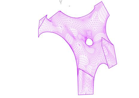
Relaxed mesh form
4 Anchor - 4 Attractor
Motion tracking of Dance
Time frame 0.30 min
Relaxed mesh form
4 Anchor - 4 Attractor
Time frame 1:00 min
Relaxed mesh form
4 Anchor - 4 Attractor
Tracing the frames in Z axis
Time frame 1:30 min
Relaxed mesh form
4 Anchor - 4 Attractor
Converging and relaxing the mesh to find the form
Carbon Capture Testing
Carbon Craft
The research was exploring the potential of capturing Carbon Pm particles from the air and make things out of it to de-carbonizes our environment and lock the captured particles into objects
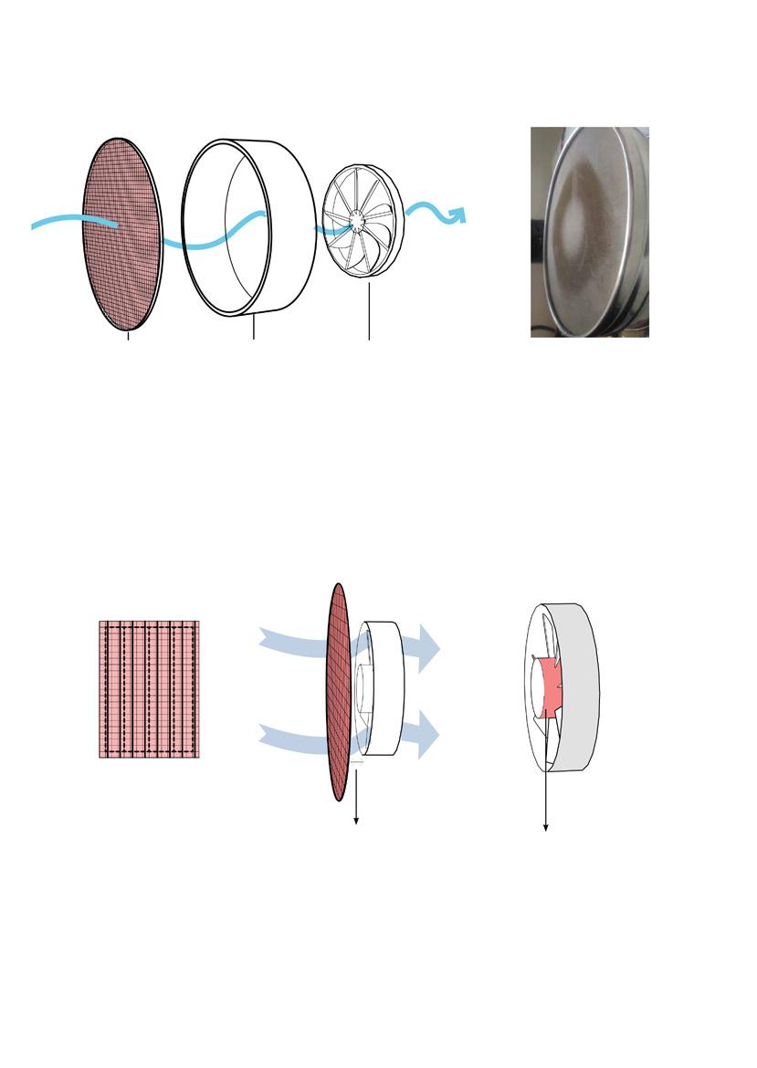
We stitched a custom filter for the next prototype
Prototype 1
Aim: To understand the pollution capture by filter-motor arrangement by letting the prototype suck air for 48 hours.
Equipments : 4” fan of 22W 2550RPM 95CFM; Filter; circuit board; backing cover.
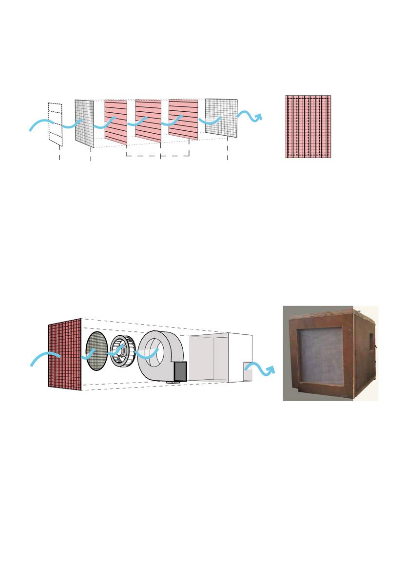
Prototype 2
Aim: To understand the pollution capture by filter-motor arrangement in an enclose volume of 216,000cm3 ; motor was allowed to run for 8 hours a day for 3 days.
Equipments : 160mm fan of 150W 2800RPM 350CFM; Filter 10 micros ; circuit board; 18mm plyboard.
Observation:
Micron filter is needed Distance between the filter and fan is crucial (dust accumulated only in central region)
Conclusions:
Mortar power has to be increased
• Understand the types of motors and there functionalities, differentiation and limitations.
• Find the relation between filter and fan distance.
• Research on appropriate filters for outdoor conditions.
Observation:
Suction was working on the entire filter surface.
The white filter was yellow in color with dust particles of varied sizes.
The fan had a constant running noise, which needs to be taken care.
Conclusions: In this prototype the floor area of 150 sq.ft, According to AHU research “150-200 CFM would be required with a filter area of 1 sq.ft”. Hence, the amount of dust captured and the relation between area and equipment will be a standard reference of our upcoming proposals.
Micron Filter Exoskeleton Fan
10 micron filter
Textile mesh Glass fiber sheet Textile mesh Stitch
Second proposal - Exhibition
This design is an exhibition space built in the fabric of day to day life spaces, to spread the awareness and give them an experience of what they should be breathing than what they are breathing.
The mechanism is inspired by natures law of breathing in and out from same spot.
A place where people would come, be around, relax, take a break and know about the grave dangers of the environment and how, as an individual one can do to fight it.
A facade installation to be installed in the public park, where people can come and experience the difference between the air they should be breathing in comparison to the air that is surrounding us in densely populated areas.
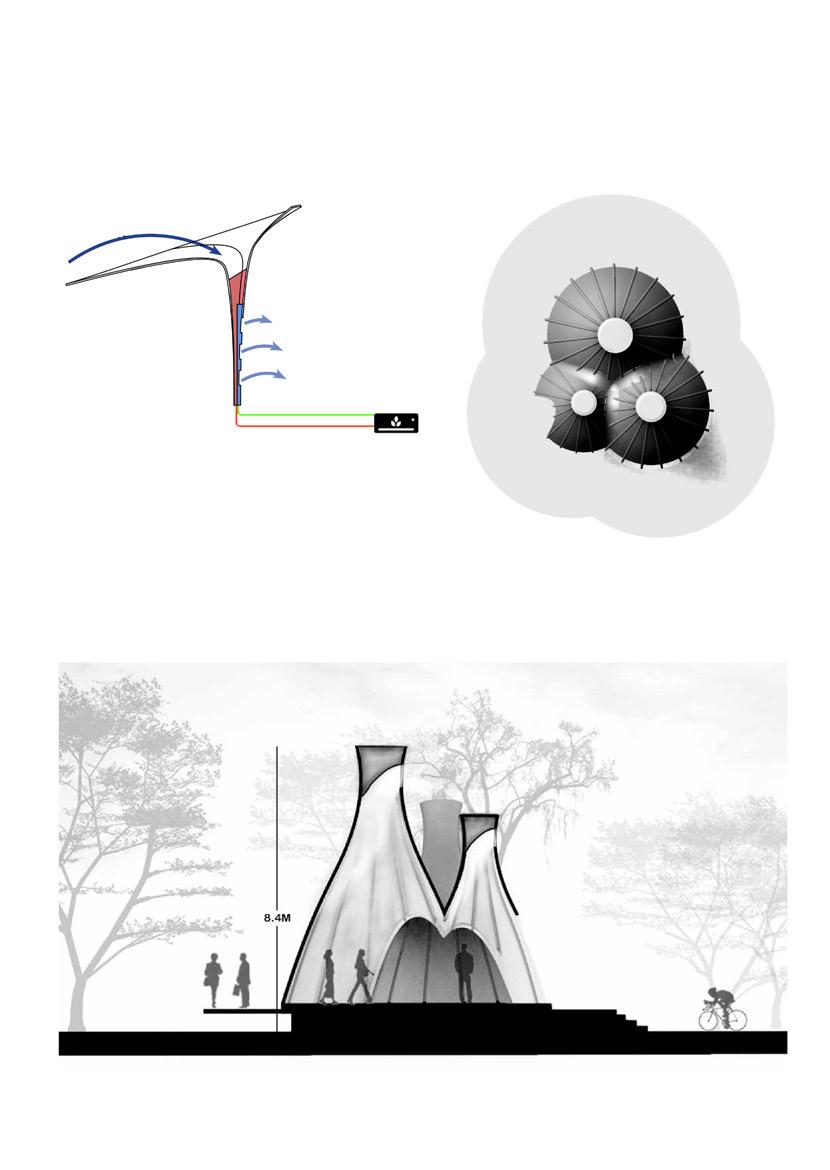
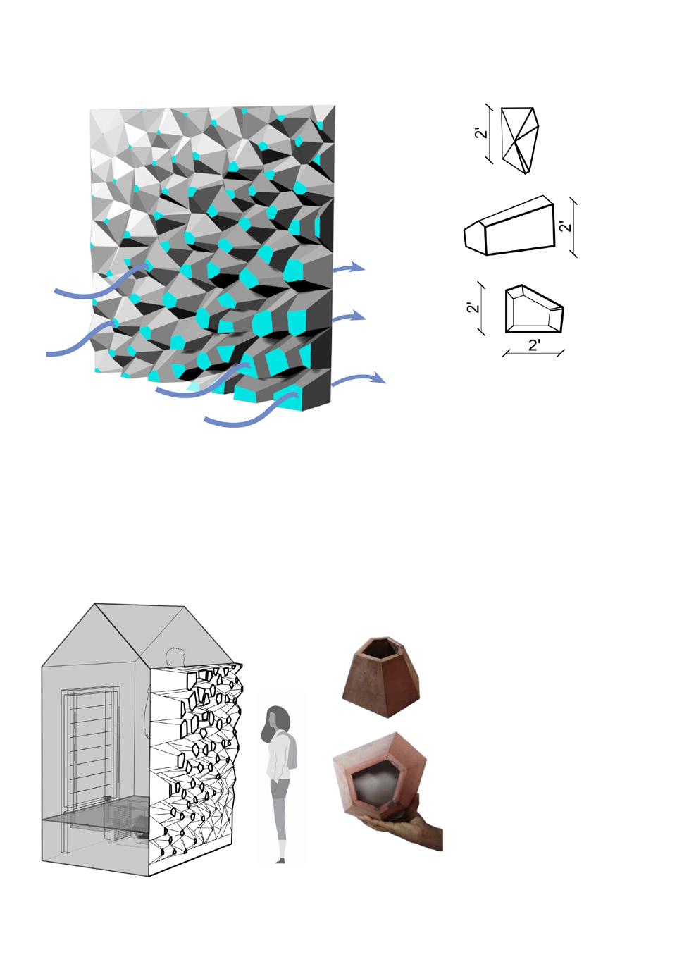
The design is an experiential space for one person at a time yet the bold design is making the wait worthwile for the people.
The local fired clay as the primary material because it is has a soothing experience a craft that empowers local
First proposal - Awareness
Clean air Polluted air