free form steam bending
Team portfolio
Design + Make
Association
Architectural
ARCHITECTURAL ASSOCIATION SCHOOL OF ARCHITECTURE GRADUATE SCHOOL PROGRAMMES
COVERSHEET FOR SUBMISSION 2018 20
PROGRAMME:
DESIGN & MAKE MARCH
STUDENT NAME(S):
Omar Eqbal; Luis Gill; Raza Kazim; Hassan Danish
Dissertation Title
DECLARATION:
“I certify that this piece of work is entirely my/our own and that any quotation or paraphrase from the published or unpublished work of others is duly acknowledged.”
Signature of Student(s):
Date:
Free Form Steam Bending 10 Jan 2020
Edited by Luis Gil & Raza Kazim
Texts by Luis Gil & Omar Eqbal
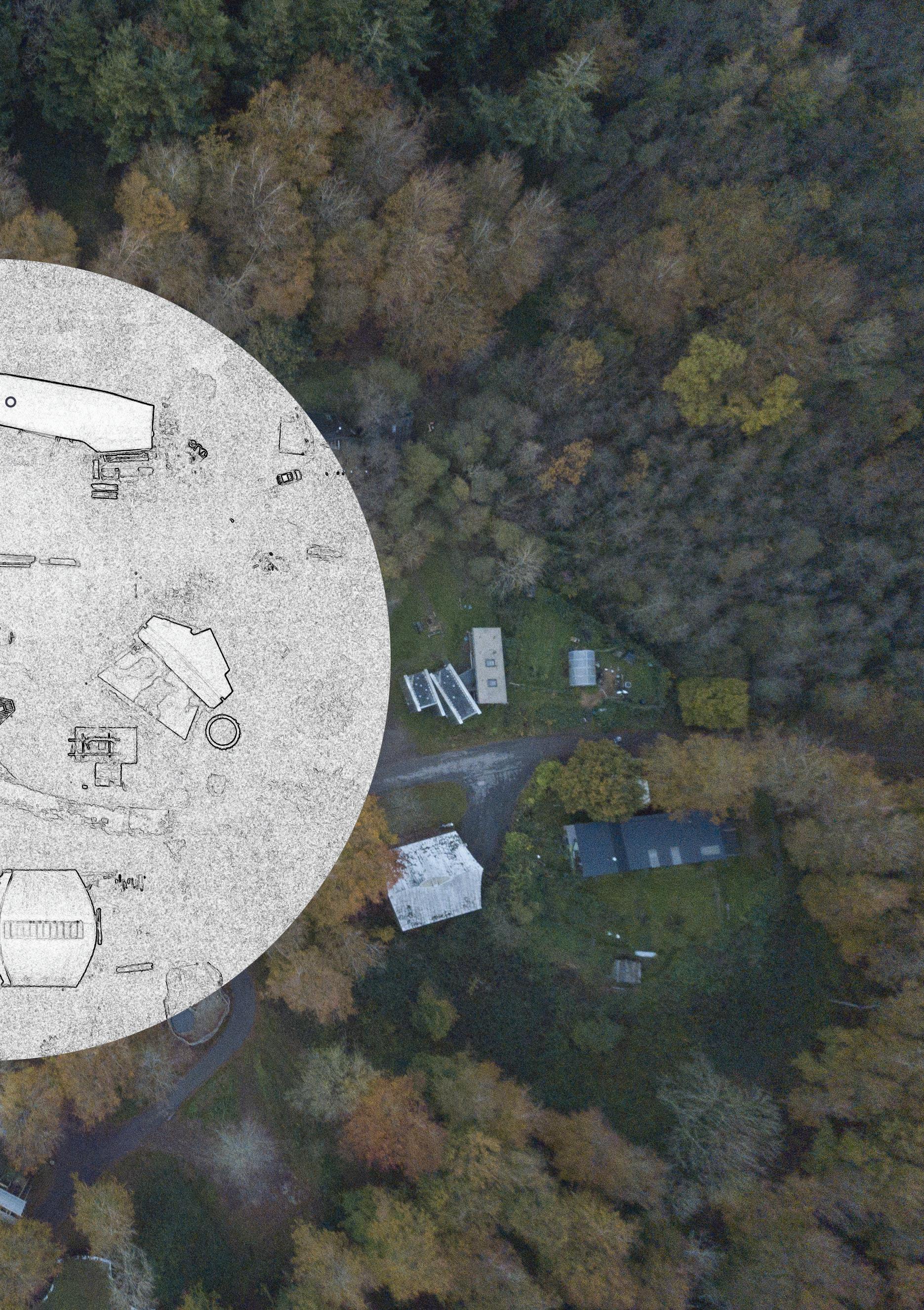
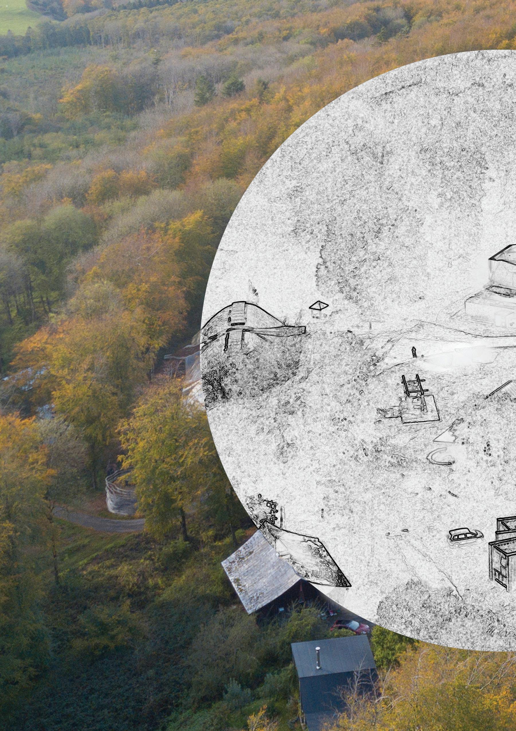
IntroductionThis is the project documentation for 2018-2019, a De sign & Make Masters programme project at the Architec tural Association ‘s woodland campus at Hooke Park. It is a collaboration between four students who designed and built a Pavilion which is a test on the technical research on plastic deformation of wood. The project has been possible with the support of an inspiring group of tutors, technical staff and an enthusiastic team of Summer volunteer, all contributing to make the project an enriched learning experience.
This document presents the development of our project over its one-year lifespan. As a collaborating pair of students, we have worked very closely together, forming ideas and ambi tion in mutual discussion and debate. Where there is identi fiable individual authorship of a sketch, drawing, picture, or stated argument, we have annotated this with our initials, HD, LG, OE & RK
Hassan Danish, Luis Gil, Omar Eqbal & Raza Kazim
[RK]
Free Form Steam Bending

Free Form Steam Bending Pavilion
The initial brief encompassed the construction of a pavil ion-scale building, to act as a vehicle for specific advanced research as the continuation of existing agendas of techni cal speculation at Hooke Park. One of the areas of potential research was to explore further the plastic deformation of thin timber laths to form compression structures. The aim was to design a pavilion scale building applying steam bending process picking up the research developed before by the Timber Seasoning Shelter.
Exploring the possibilities of bending a piece of wood freely through space, we set the ambition to design a jig that can do so. The idea was to develop a new stream bending technique to achieve specific curves and produce a range of discrete free-form components without the need for individual moulds. The project development has largely been intuition led, rather than analytically per-determined, refined through prototyping and proved through testing.
What are the possible structural configurations of a de vice that free form slats using steam bending?
Through the presentation, we will guide you through our making process, showing you the free-form steam bending technique we had developed so far. We will start explaining how the jig evolved, how we tested its possibilities and limitations through prototypes, as well as, our ambitions for the final project and the workflow to get there.
10
11
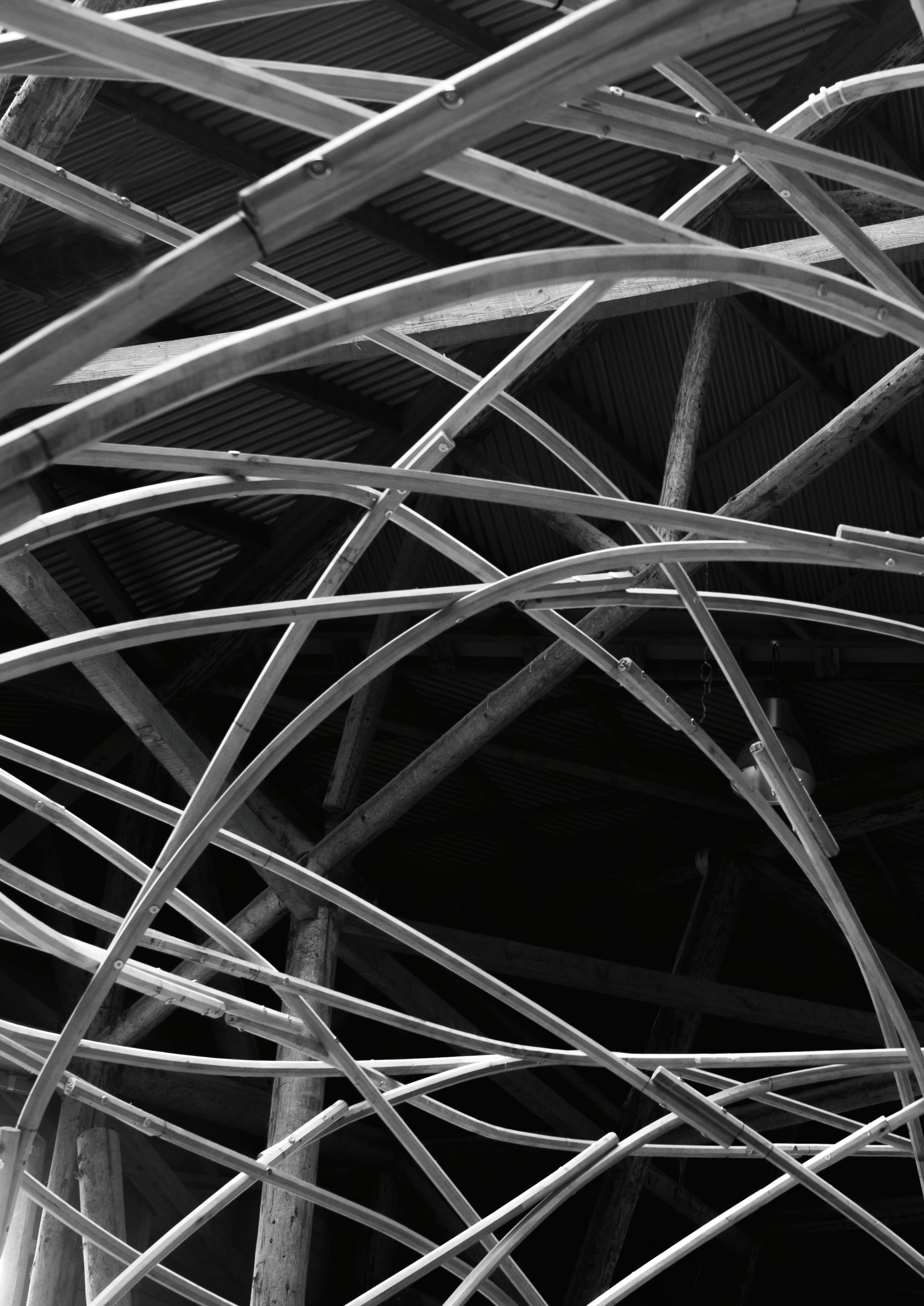
Image of the pavilion as built
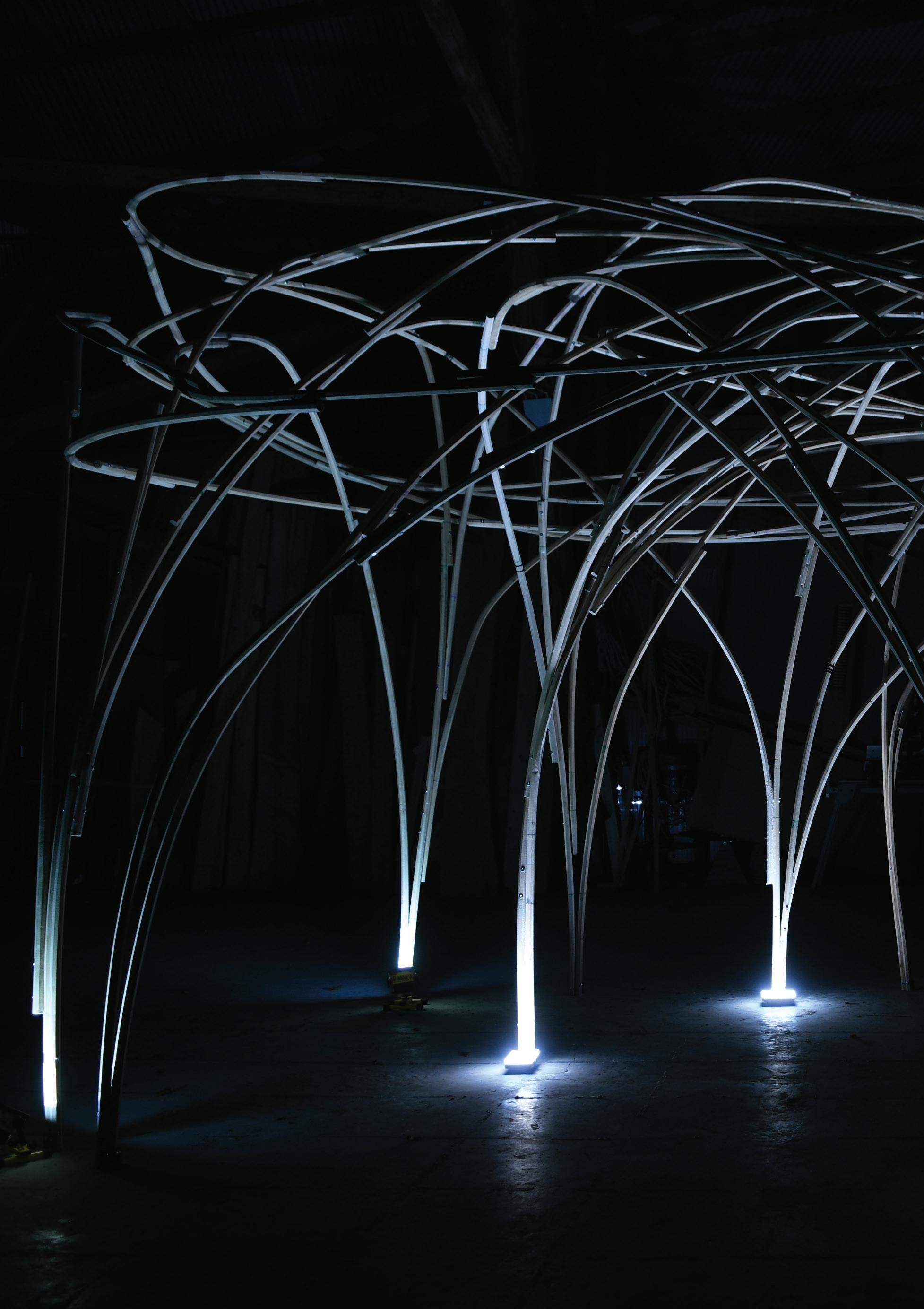 Photo by Nuria Benítez

[RK]

16
17
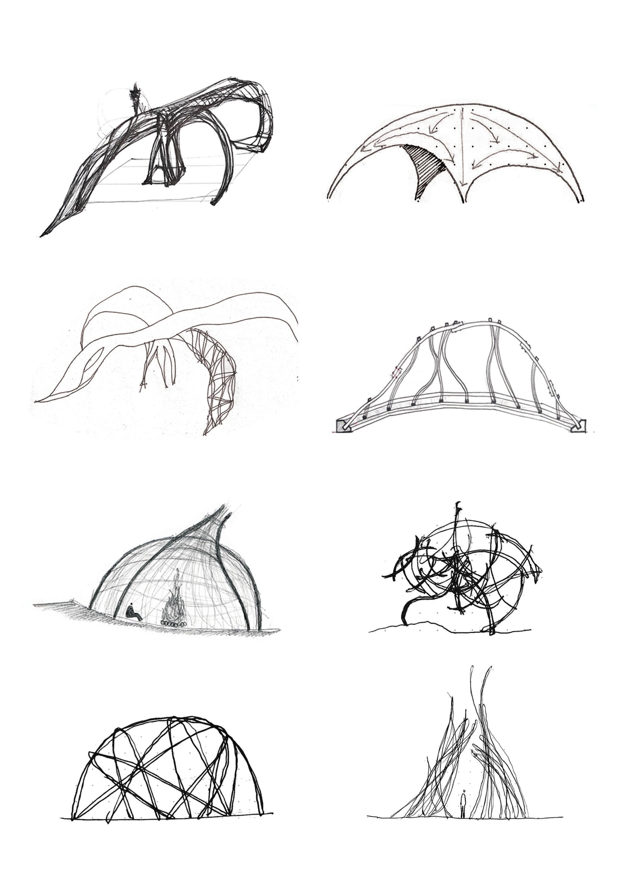

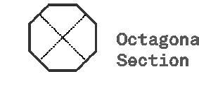
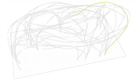
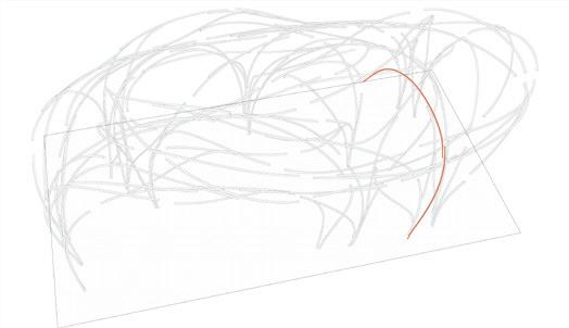
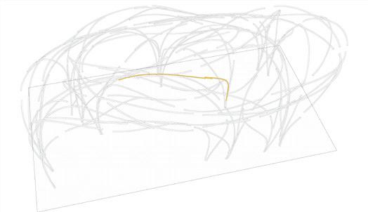
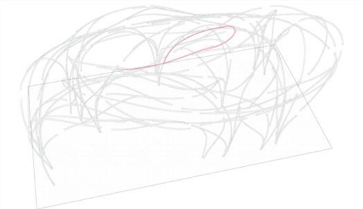
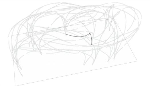
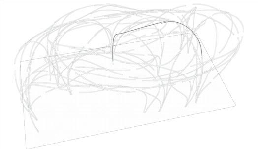
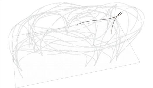
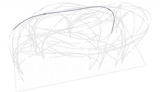
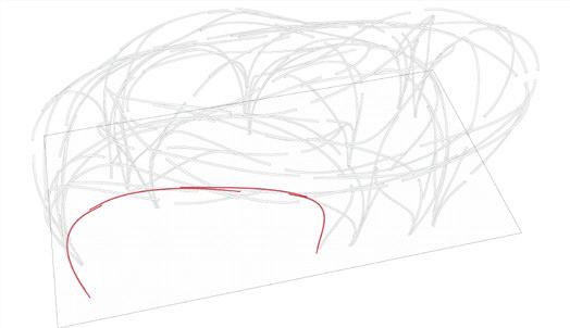
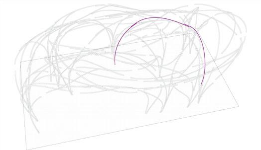
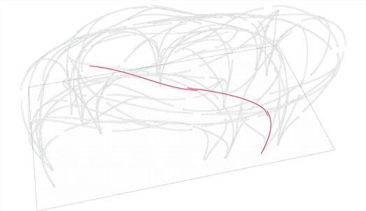
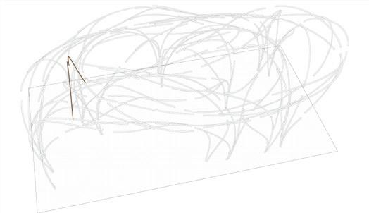
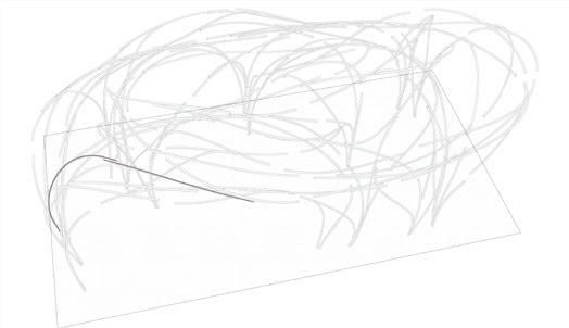
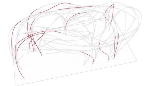
Conceptual drawing of a curve steering in 3-dimensional space.

20
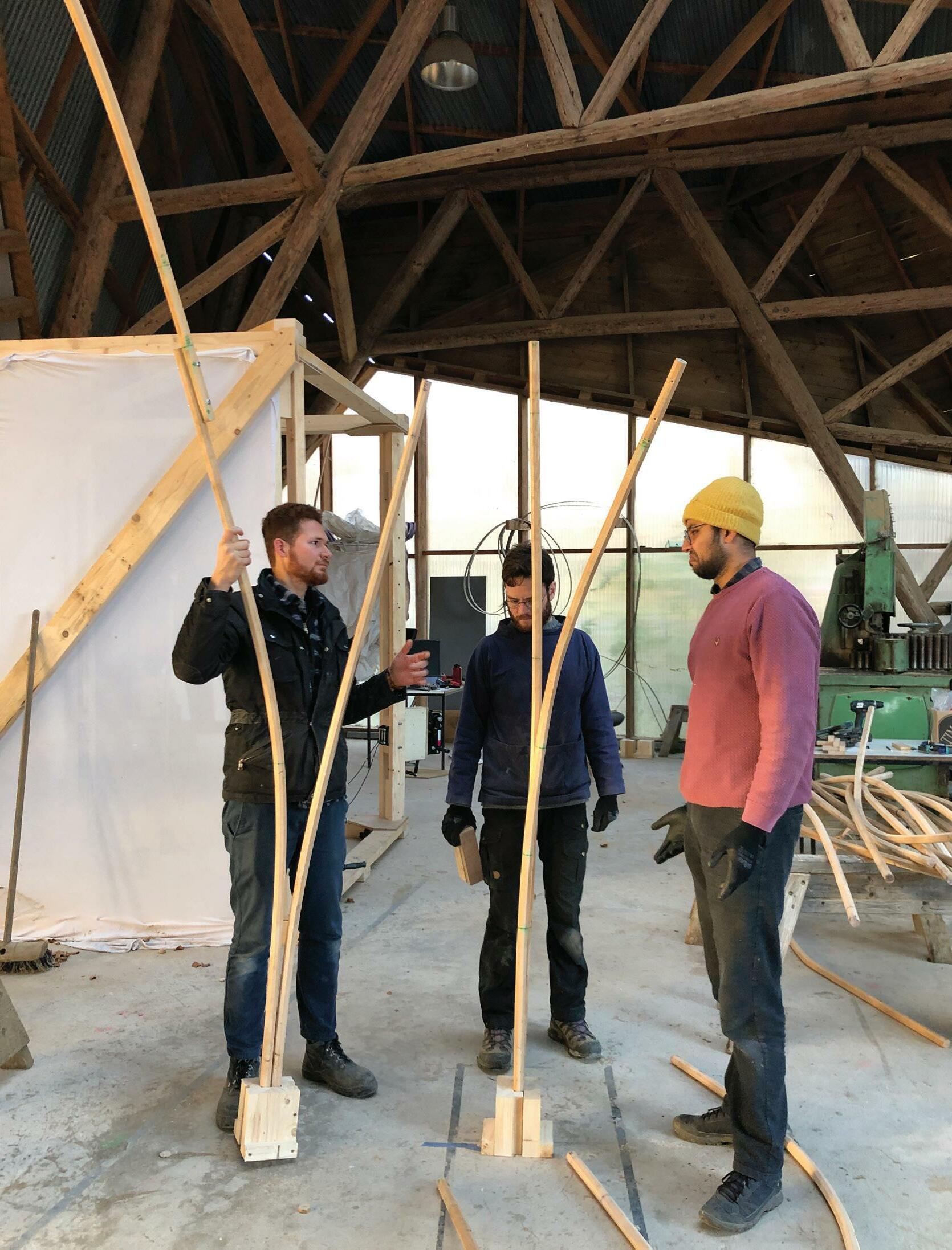
Steer a lath through space: Bending timber
Drive by the idea of stirring a piece of wood freely through space; we dived into steam-bending. Traditionally, individual jigs are used to manipulate timber into specific shapes; every bend has its own mould and strap to prevent the wood from blowing up. The TSS research tackled this matter by understanding this technique and designing one jig to fabricate all the structure. The jig used during this process only worked in two dimensions.
Picking up the research developed before by the Timber Seasoning Shelter to design the pavilion using steam bending, we set the ambition to design a jig to produce a range of discrete free-form components without the need for individual moulds: one Jig to produce 3D free form slats. What started a self-contained tensioning mechanism, later evolved to a massive frame where the bending mate rials are active participants in the production of the form. By adding or releasing tension to a cable system, the jig can locate a point in space to bend timber, into any desired shape, by adding compression to the piece.
21
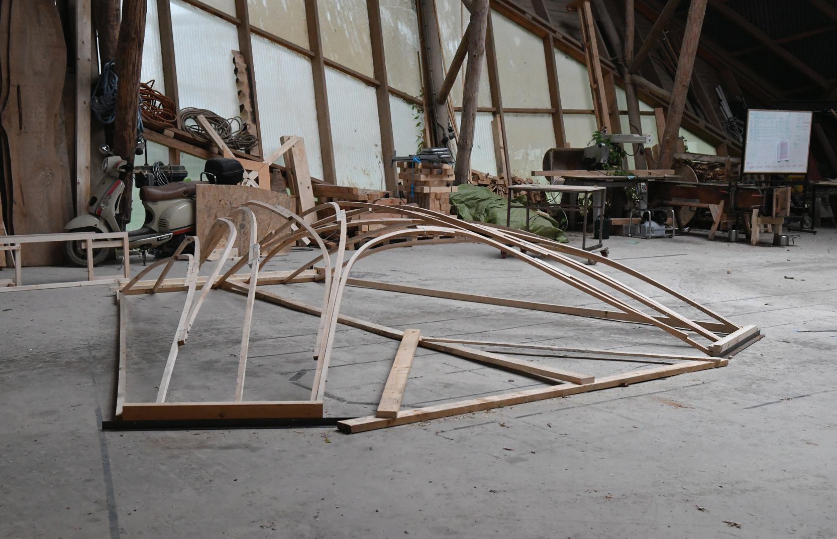
Early development Evolution of the free-form bending technique

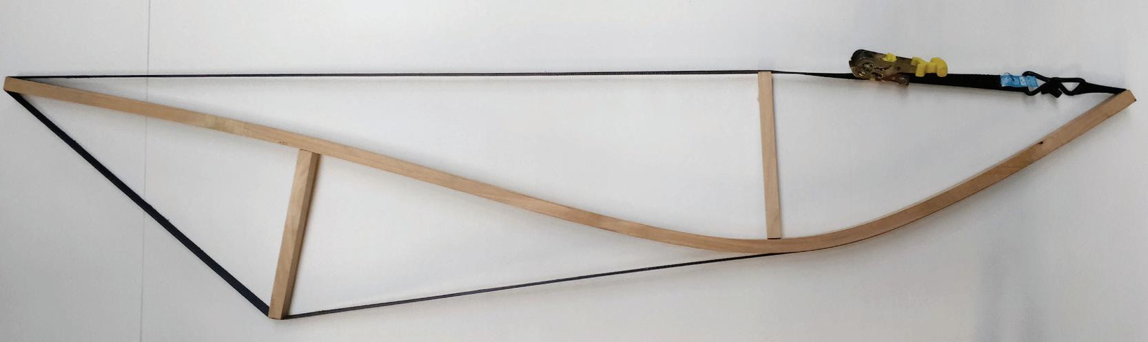
First ratchet straps tests:

Just to tease out a feeling, we started with by using ratchet straps, in a wraparound arrangement, to intro duce compression, controlling the bends by adding wooden blocks, that worked as pressure points.
The test worked as self contained tensioning system; the wrap-around ratchet acted as a compression strap to contain blowouts.
22
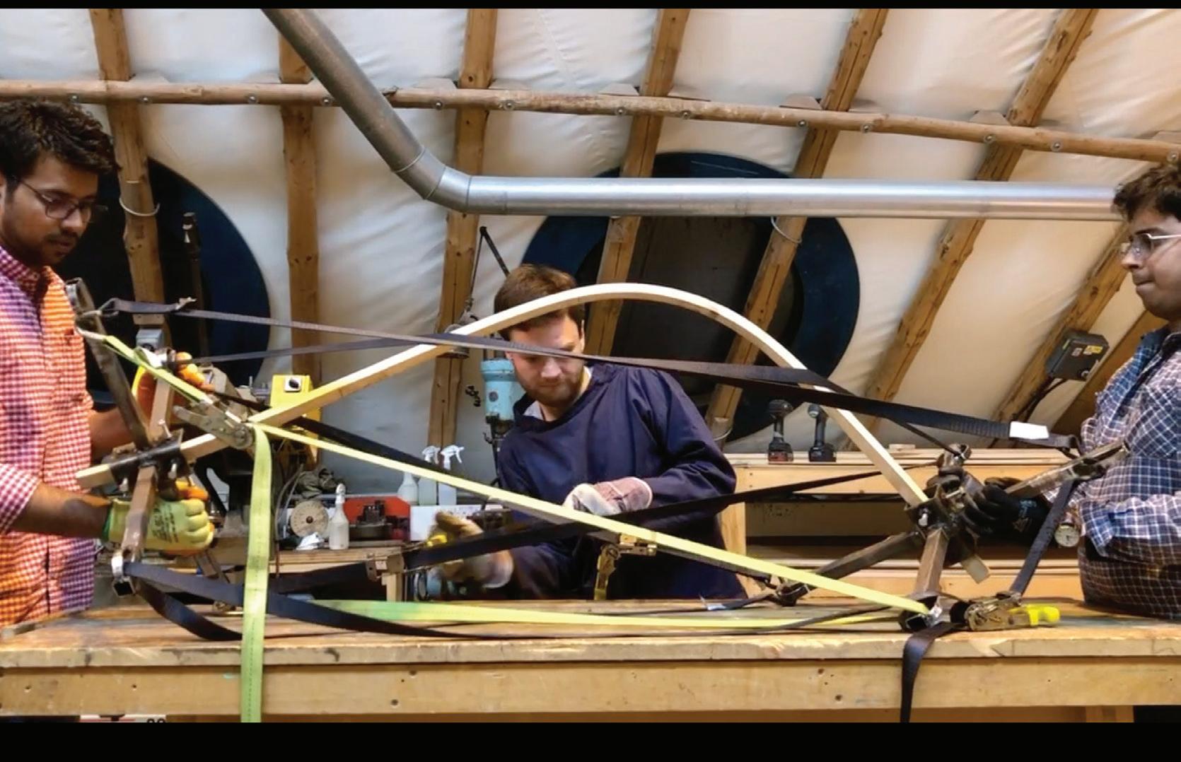
Adding three-dimensionality: Further taking the ratchet strap system to bend pieces three-dimen sionally, we fabricated a cross node that positioned the lath between tensioning straps to manipulate the bends.
To understand and comprehend the information from these tests proved a little hard as there were no reference points, as the ratchet straps, wooden
lath and the nodes move.

23
Adding three dimensionality
Further taking the ratchet strap system to bend pieces three dimensionally, we fabricated a cross node that posi tioned the lath between tensioning straps to manipulate the bends.
To understand and comprehend the information from these tests proved a little hard as there was no reference points, as the ratchet straps, wooden lath and the nodes were not fixed, move.
24
25
Image
1:
Initial bending test in process
Image
2: Initial bending test result
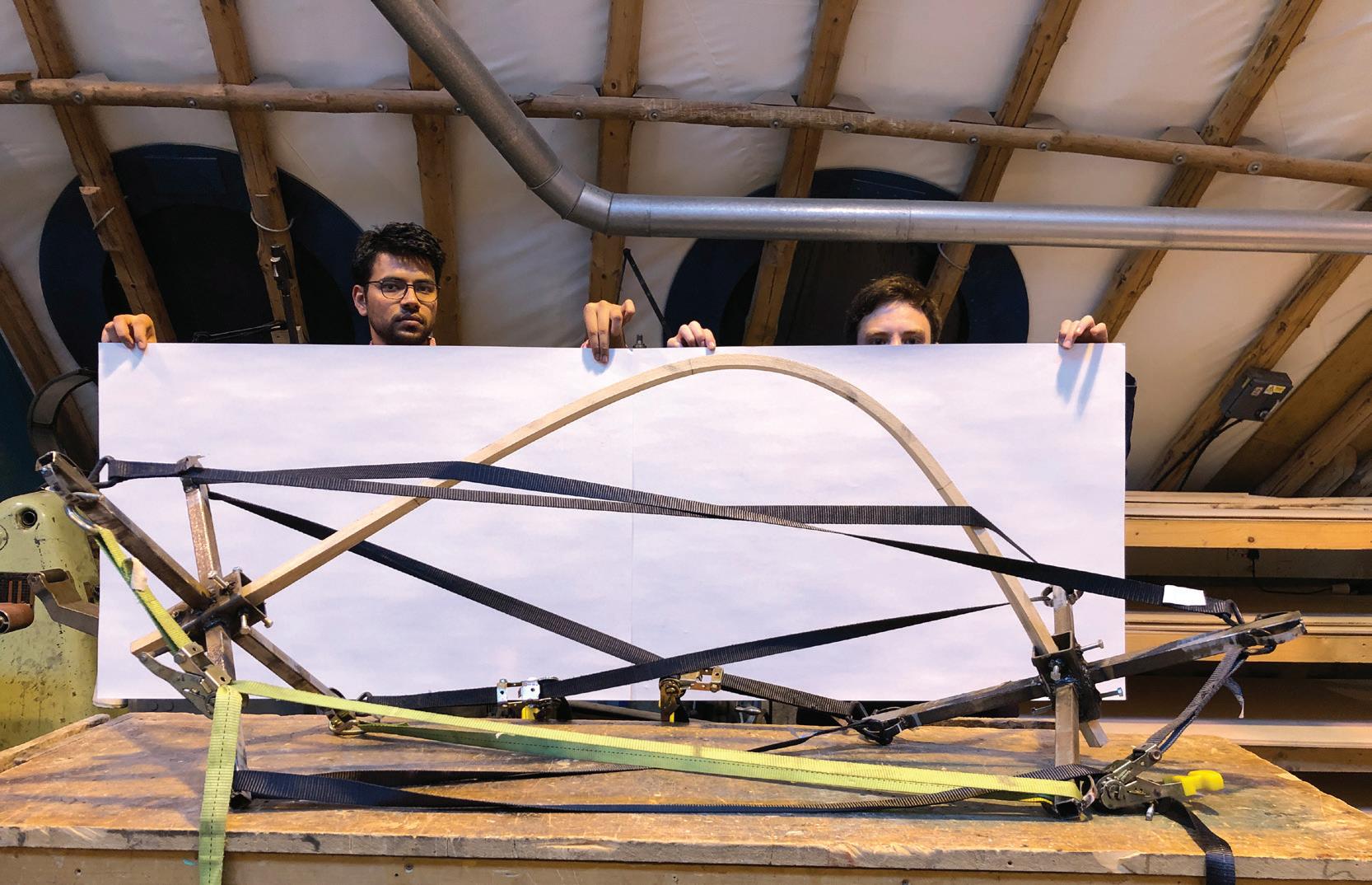
Mock-ups: Understanding the system
At this point, we realise the jig needed to evolve. In order to do so, we took a step back to understand the system logic through a series of mock-ups.
Breaking the previous iteration into segments, we tested the accuracy by targeting a shape drawn digitally and repli cating it with the model.
So we changed the configuration again. The versatility worked better with gravity, and the new columns provided the opportunity to pull from different angles.
After minimising the gap between both digital and physical tests, we decided it was time to scale up the jig.
26
Image 1: Mockup model for under standing the behaviour of lath when centre node fixed.

Image 2: 1:10 scale model for accura cy testing.
27
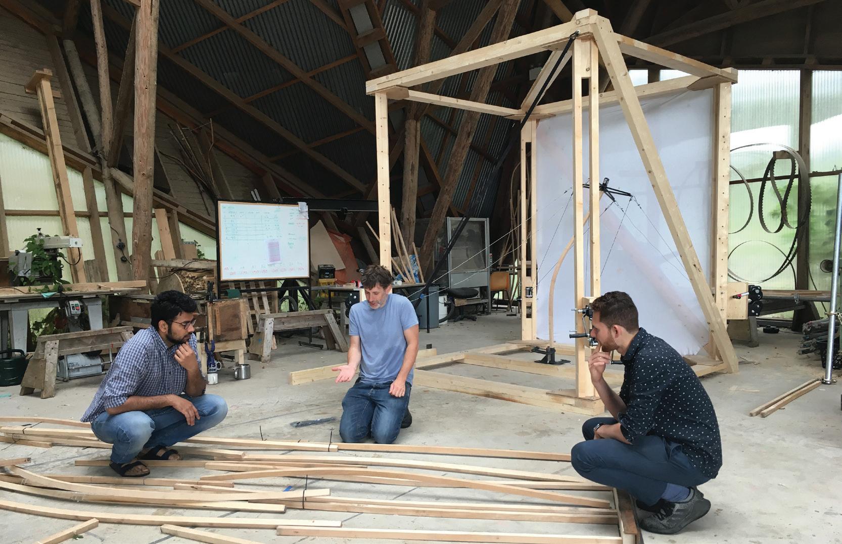
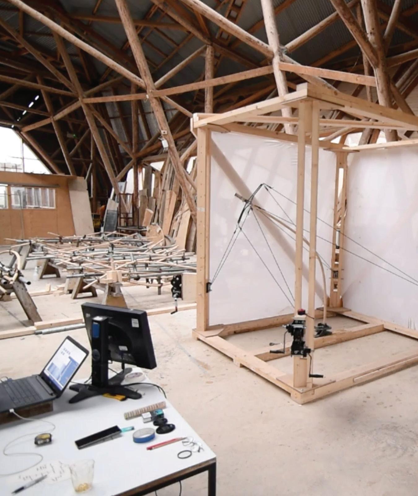
Scaling up Fabricating 1:1
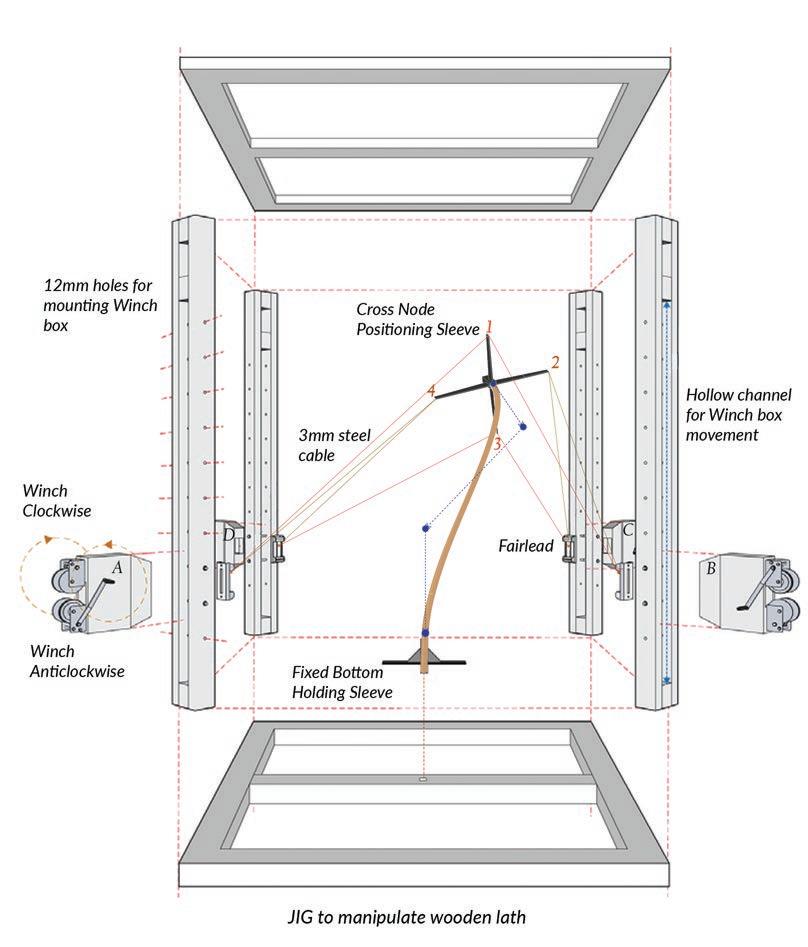
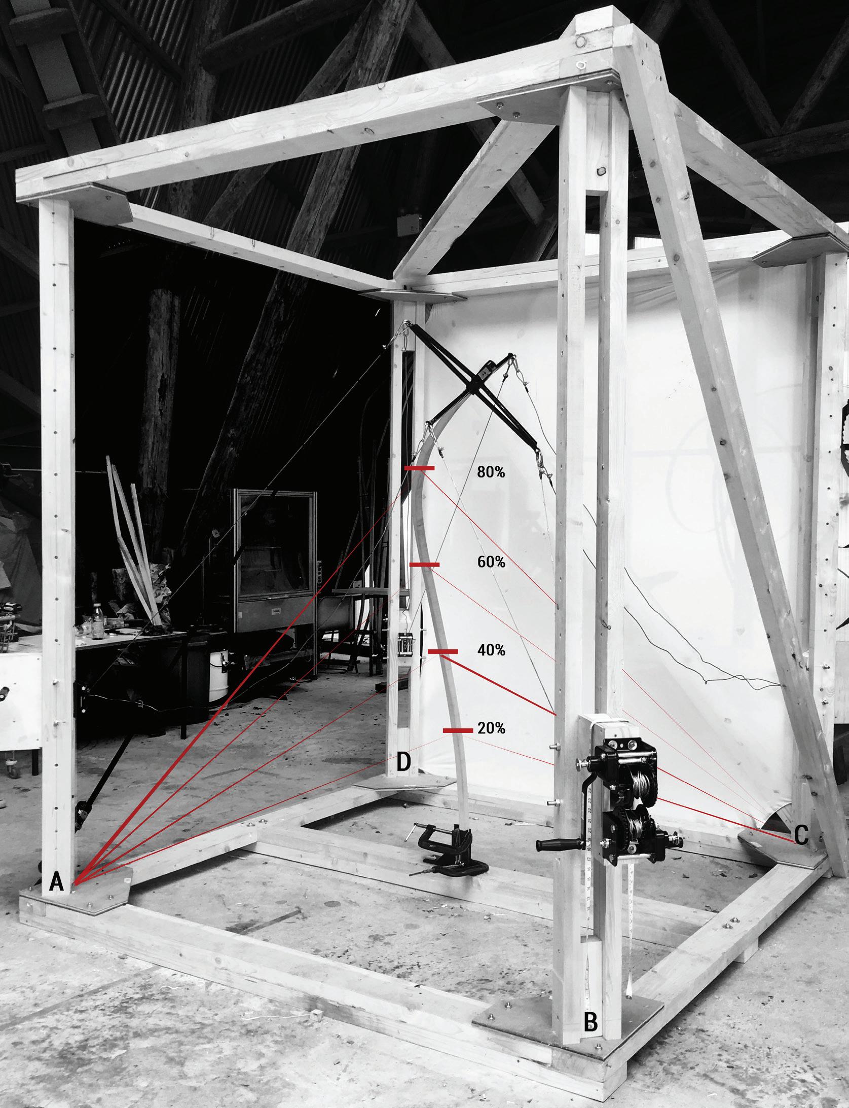
THE JIG
The system works in a very similar way, like a piece of wood held in hands at each end, by controlling the amount of pressure, movement and rotation of hands, the whole length of timber can be manipulated, and very informal feedback from the wood can felt.
The full-scale jig was designed to manipulate 1.8m to 2.5 m laths. This length was worked out to maximise the number of slats that can be milled from a tree. Trunks of a Beech tree in Hooke Park are generally 4.5m – 5m long to get two sets of 2.5m boards and minimise wastage. We designed the jig, working backwards the proportions and size for different com ponents of the system.
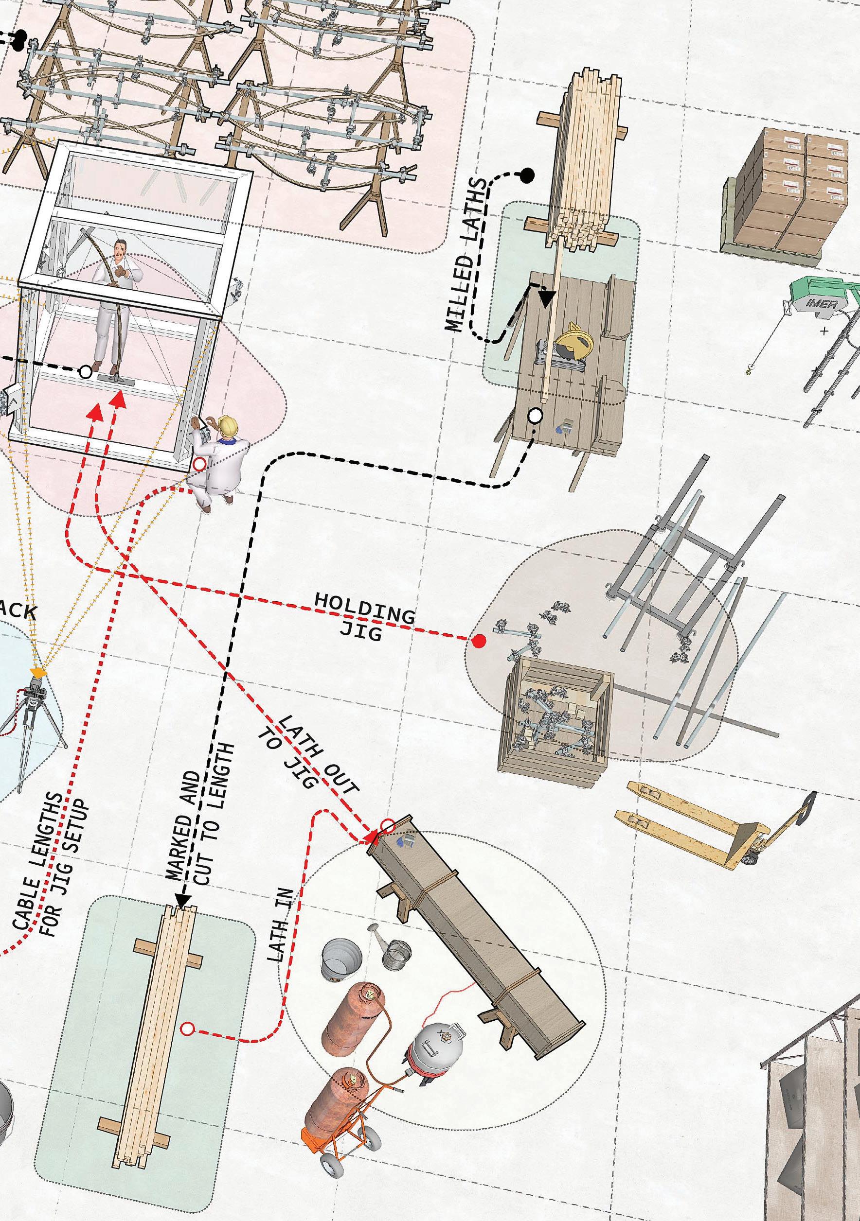
The jig comprises a square base, at each corner vertical posts hold a winch box, with the flexibili ty to travel up and down along the length of posts. The winch box comprises of two winches mounted
30
Image of Jig with an extreme bend
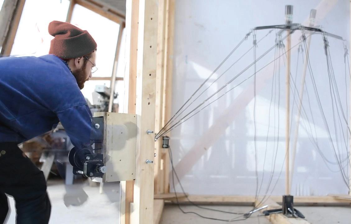
vertically, with each handle on either side of the box, which makes operating two winches at the same time only one-person job. The winches are winded with the steel cable that connects to the cross node which grips the one end of the lath.
Fairleads are mounted on the winch box that guides cable into the winches, without the cable rubbing against the wood for fric tionless travel. Fairlead also serves as a datum point for measuring cable lengths to cross node.
Our success depended on the careful coordination between each of us winch ing at each corner of the jig. For each of the bend component, we would analyse the cur vature and where the cross node would ultimately end up within the jig’s space, then sequence the order and pace each person needs to start winching.
Exploded view showing every part of the jig. [HD]
31
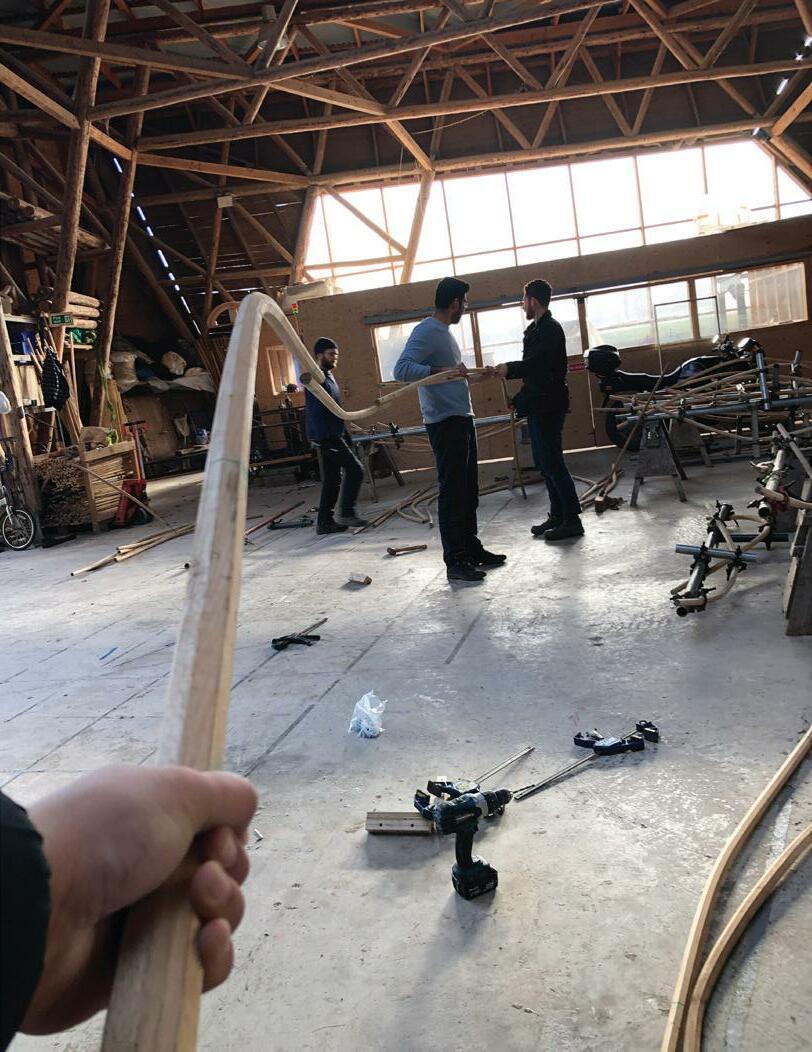
Testing Refining the technique
During the summer build programme, eager students helping us expedite our experimentation and tests.
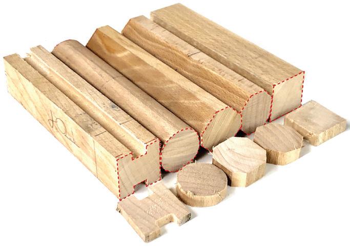
We tested different cross sections of laths, kept a log for steaming making a note of temperature every 15minutes; bending laths and comparing between the target shapes and the bent laths.
The tests analysis and
results defining the pa rameters of the achievable curvatures to work with.
We tested different pro files to define which section would be more efficient for the bends we wanted to achieve.
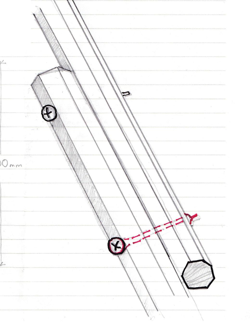
We decided to build the Prototype with octagonal laths as the target curves were more accurate and unlike circular section, we have flat faces to connect another lath tangentially.
Sketch showing the pre-marked drill location and the top and bottom parts of lath which were cut before assembly.

32
33
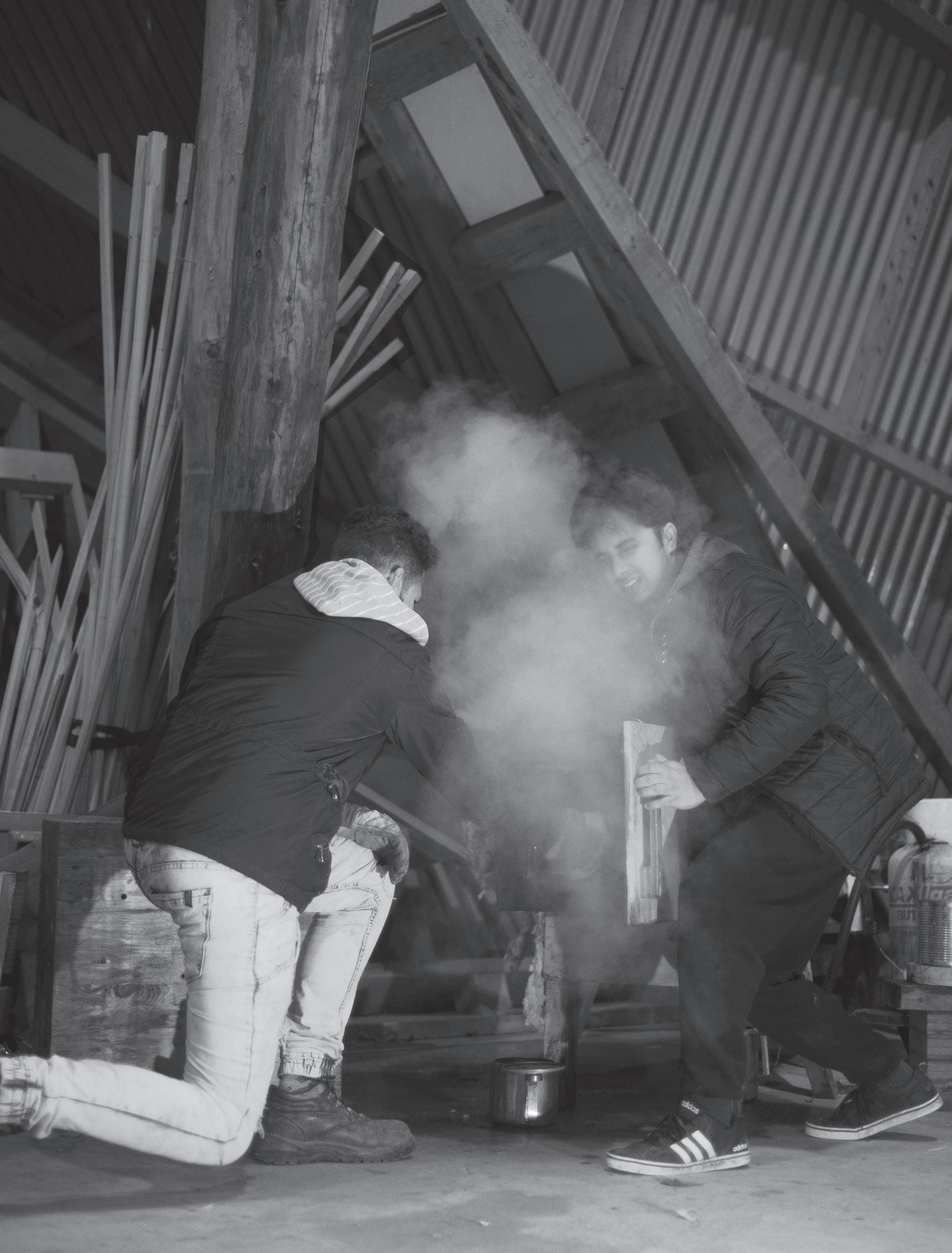
Image of steam coming out of the steam box in the process of taking out the lath
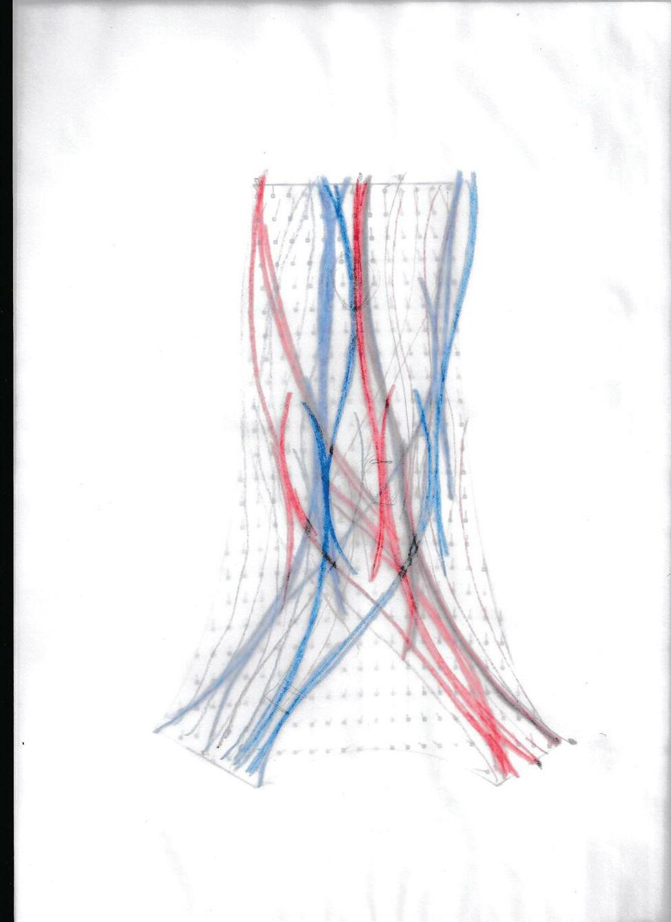
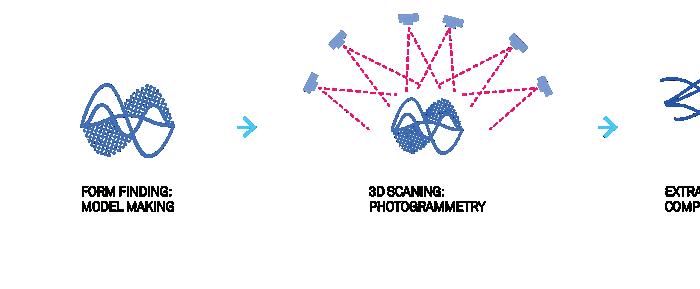
Surface Logic: Mapping laths through the stress lines
WORK FLOW
FORM FINDING: DYNAMIC RELAXATION
FORCE FLOW LINES: TENSION + COMPRESION
MAPPIN ELEMENTS: DEFINE GEOMETRY [LG]
34
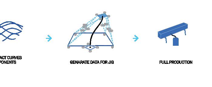
EXTRACT CURVES
35
COMPONENTS GENARATE DATA FOR JIG FULL PRODUCTION 1917 1 3 4 3 4 1 1819 1279 1160 2547 2338 1989 1995 A B CD 2 2
Connection Logic
We tested different section profiles
Square lath - Worked better for making face to face connections , but had very floppy results.
Circular lath - The bending was quite on point, but solving the connection logic seemed like adding another layer of diffi culty.
Octagonal lath - Combined the best of two worlds. It was accurate, almost hitting the target shape, while maintaining the connection logic.
Unlike the circular section this one had flat faces to connect another lath tangential ly.
So, we decided to use furniture scale oc tagonal sections of 30x30mm cross-section and length ranging from 1700 - 2300 mm. to prototype structure.
Sketch suggesting the end to end connection detail.

36
We started to form a Pallet of bends we got from that the first iterations with the cross node system.
We assembly those components to start testing how they could connect together, in the process we developed a matting logic of tangential connections that can happen: end to end, end to middle, middle to middle.
Image of prototype formed by combining the bends tested for a pallet of bends for cross node testing

37
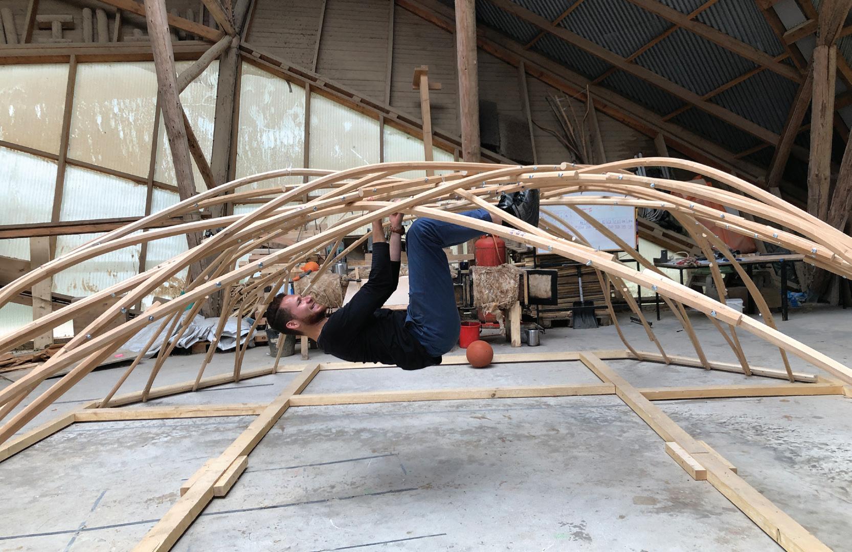
Prototyping
Prototype 1 was done in square laths of 30mm cross section.
The bent curves were quite off from the target curve. Pieces were forced into position.

It was made with square sections, and it was the first time we were using the Jig to fabricate bends for a
structure.
The bends achieved in this prototype where quite gentle bends.
Learnings from Prototype 1:
- Every component has to be premarked before steaming.
- A strategy for spring back has to be devised, possibly leaving the bends
in the holding jig for at least 24 hours.
- Minimum length of a lath we can work with to add to avoid only horizontal motion while bending.
38
Sketch suggesting the strategy of mapping laths on the surface Sketch of mapping laths on the three leged dome shape
39
Image 1 : Image capturing a moment of discussion to assemble Prototype 1
Image 2 : Prototype 1 after assembly
01 & 02
Prototype 2 was done in octagonal laths of 30mm cross section.
The bent curves were quite close to the target curve. Piec es required less force to bring them into position.
As it we kept on understanding the behaviour of the ma terial with every bend.Some bends achieved in this proto type where quite curvy and S shape splines.
This time every component have was premarked before steaming, bends were kept to drying for atleast 48 hours. The spring back was much less than in prototype 1, and every lath was in the length range of 1800 - 2300 mm.
We had to bend 78 components to build this prototype, Forming two layers of a dome shape. After assembly and structural stiffness test, we could say the system works.
40
Prototype

41
Image 1 : Prototype 2 assembled.
Image
2 : Physical load testing on pro totype after assembly.

44
Image showing the location of measuring points on the lath to analyse the accuracy of the system.
Image 1:
Cross-section tested during sum mer-build. Each test was measured to points along the lath to compare the section performance, as well as the system performance; comparing the accuracy between the digital shape

and the physical test.
Image 2: Accuracy check of lath with square section

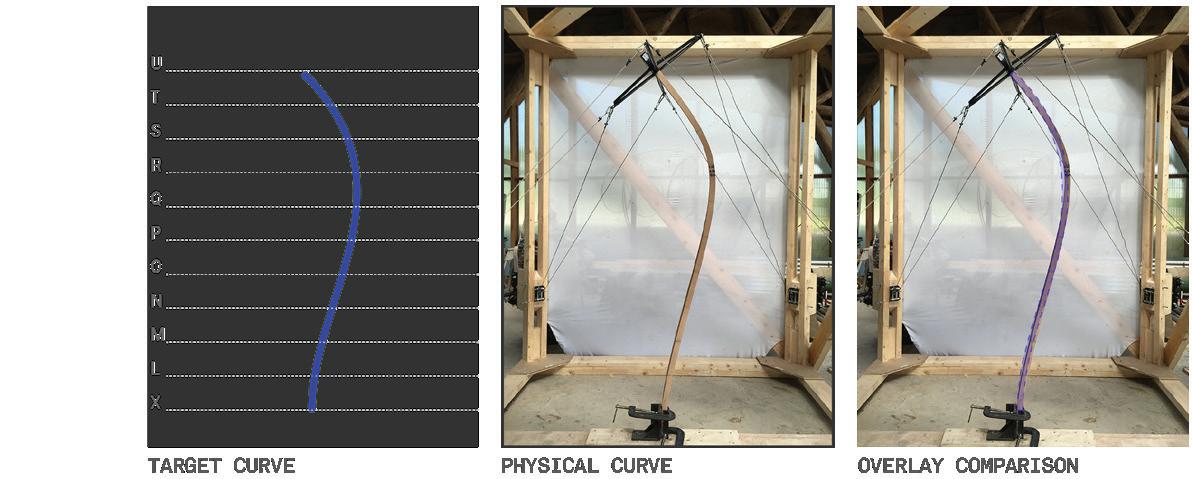
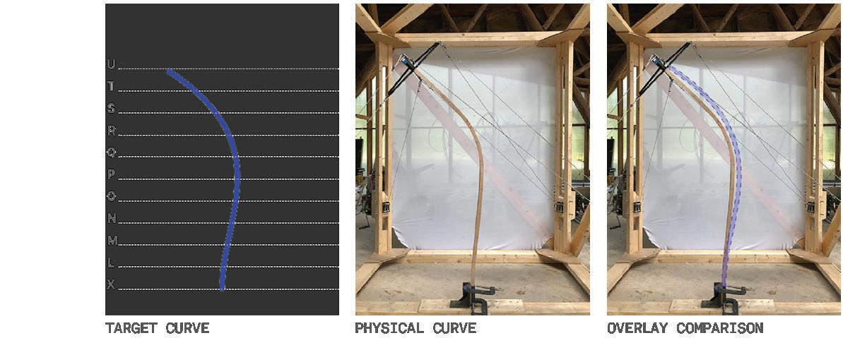
Image 3: Accuracy check of lath with circular section.
Image 4: Accuracy check of lath with octagonal section.
45
STEAMERS Res methodology Summer Build
_Method to refine the research and improve the process.
_Priority exercises for upcoming week. _M3 [30.Aug].
JIG MECHANICS
_How to use the cables best to improve bending?
_Refine position node: Pull at an angle of 45º from the cross node.
_Locking and measuring.
_Add an extra node?
LATH BEHAVIOUR
_Bending predictability.
_Monitoring steam process, curvature, and spring back.
[HD.LG]
_Spread sheet/chart: data pool.
_Refine position node: Pull at an angle of 45º from the cross node.
_Test different sections.
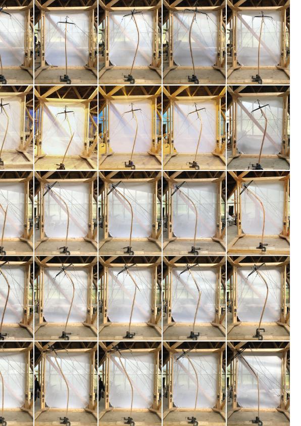
POSITION CHECKING
Live feedback of the bend.
[RK.OE]
_Live cast into Pr/Ps: real time overlay of the target shape.
_Project front and side view of target shape.
Flow chart organizing the research subtopics to test with the help of the summer builders; latter implemented in the design and making of the second prototype
SPRING-BACK STUDY[SB]
[HD.RK.OE]
_Strategies to measure & record SB to compare with target shape. _Over bending strategies.
_How much extra bend we do?
_Add bending by extracting each crv + multiply deformation by 2/3.
HOLDING JIG [HJ]
[LG.RK]
_Leave the pieces more time in the HJ to reduce SB: Test 24hr & 48hr. _Test assembly components in the HJ. _Stack HJ rig.
CONNECTION
[LG.OE]
_Use template with the straight top and side view to pre-mark the connections of each piece before bending (also helps with measuring the accuracy while assembling). _Fabrication & assembly drawings.
GEOMETRY:
_Bigger version (50-80%)
[LG.OE]
_Do not add too much complexity: keep it simple.
_4 pts. crv. & 2 consecutive pts @ 90º each side.
46
Bending Process
At the time, bending solid wood was revolutionary, and it has not lost any of its fascinations to this day. The step by step process is:
1. Woodcut
First, a beech board turns into a rod. Thanks to the short wood fibres, beech wood is very stable and especially suitable for the bentwood process. The fibre di rection is of enormous importance for the bending operation: if bent against the fibre structure, the wood will break.
2. Steaming
The steam bending process starts by plac ing the timber in a steam box. The amount of time spent in the tube is determined by species, initial moisture content, and thickness of the section. For this research we used beechwood laths of 30 by 30 mm section, the slats remained in the steamer for 1 to 1 1/2 hours before bending them. The wood is steamed at over 100 degrees Celsius. The material remains under pres sure in the steam boiler for approximately one hour. Due to this pressure, the steam is forced into the wood until is it saturated. The high temperature makes the beech lath extremely elastic – the essential precondi tion for the subsequent bending process.
3. Preparation of the bending process
The wooden slat is now placed into the bending jig without any metal strip—used traditionally fixed on the outer edge to prevent the wood fibres from stretching on the outer radius.
4. From wooden laths. Now the bending begins: Once the material is thoroughly heated, the lath is removed from the steam box and quickly transitioned and placed into the free form bending mechanism and manipulated into the desired form. The tensioning system preset with the lengths for each specific bent. The material is then secured in the bending system.
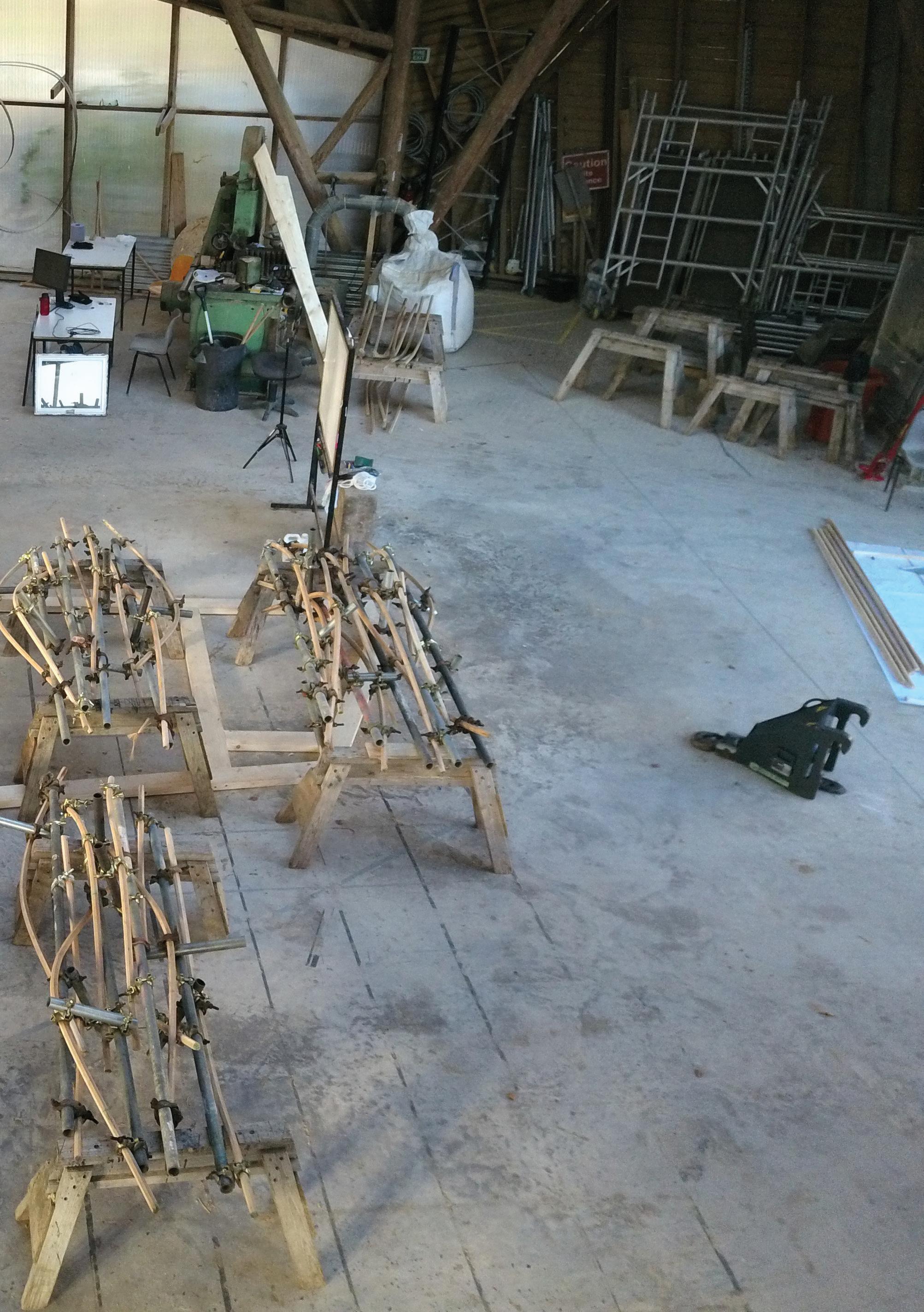
5. Drying
To dry the finished pieces, we place them in a holding jig consisting of tubes attached with swivels scaffolding clamps to the cen tral pole holding the bent lath in shape. For the curved backrest to stay in its new form, the wood spends two days in a drying. After this process, the slat is then removed from the holding jig.
47
Bending parameters
After prototyping it was deduced that:
- Maximum range of curve achieved were 60 cm radius.
- Lath length range 1800 mm to 2300 mm.
After 2 Prototypes and many testings of bends it was analysed the surface mapping logic is not exploiting the maximum potential of the JIG.
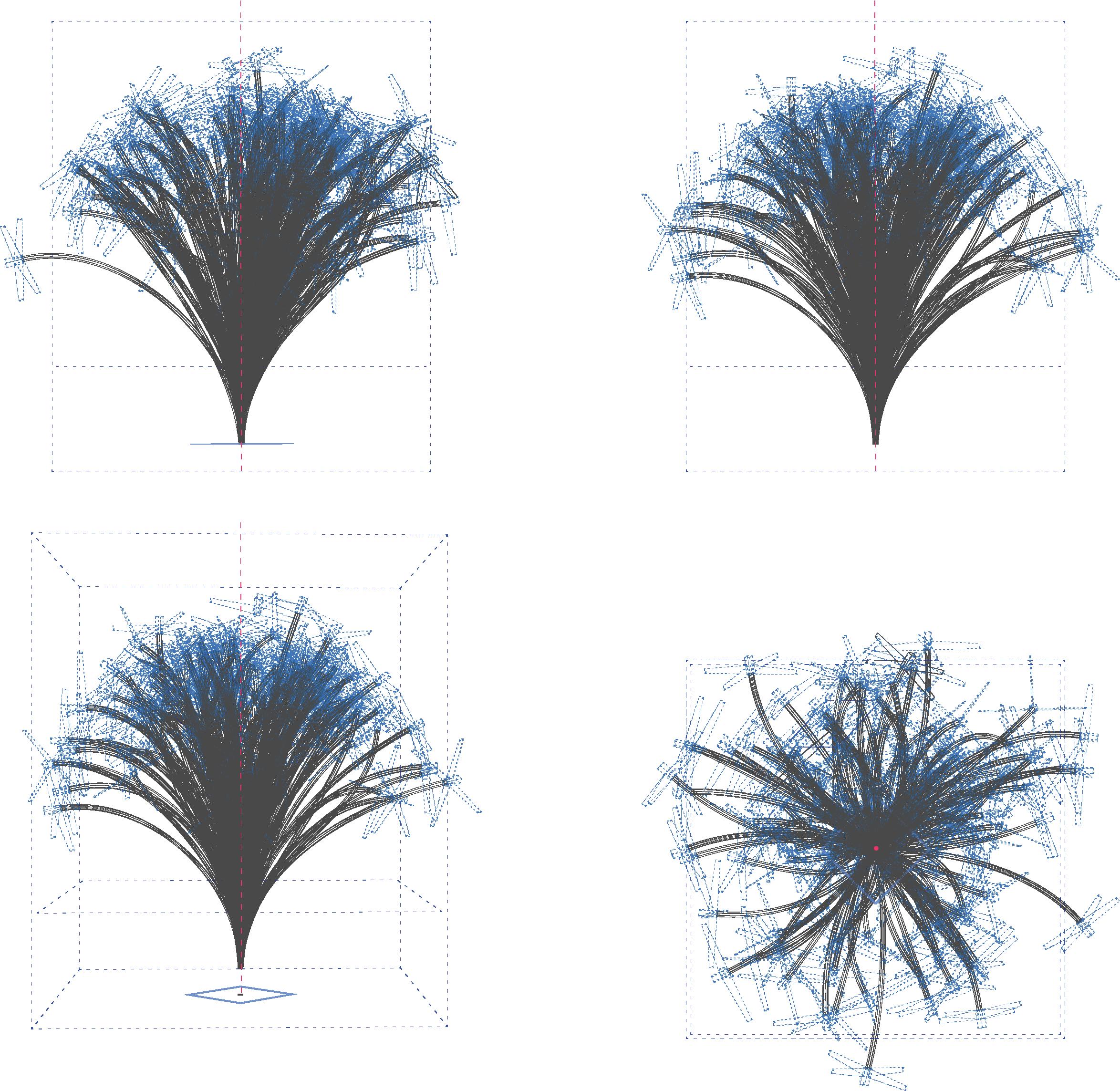
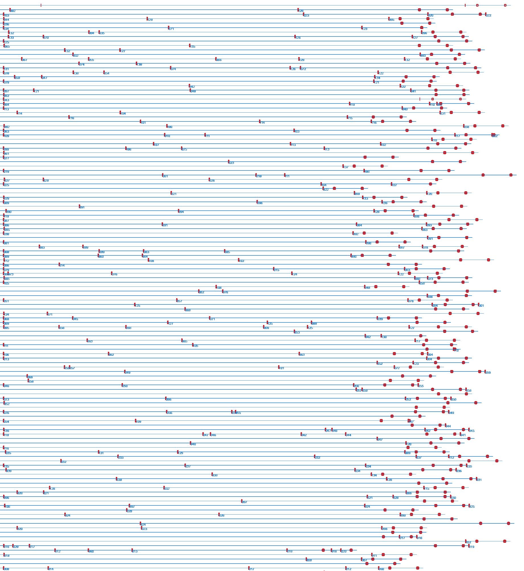
Image showing the digital generation of data of cable lengths [LG]
48
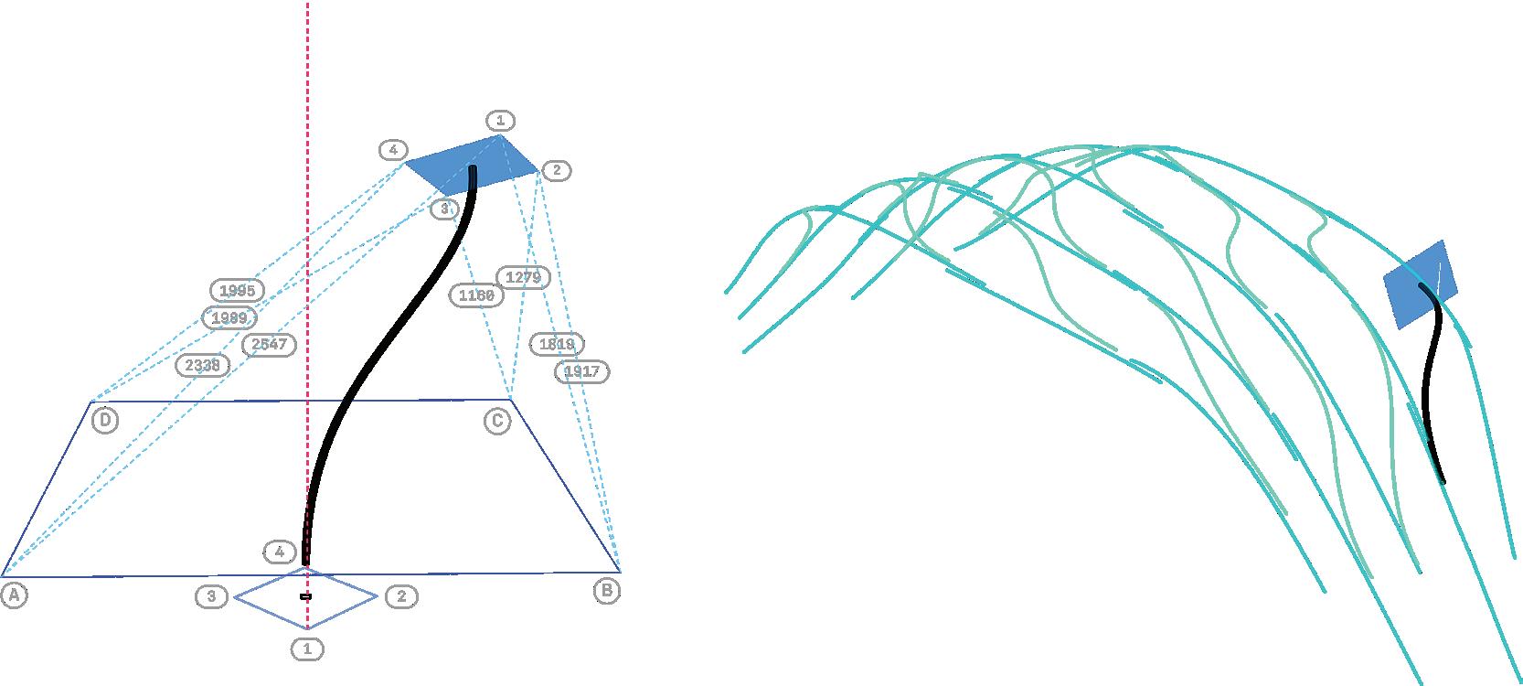
Image showing the bending range from Prototype 2 [LG]
49
Revised Workflow
It was decided to move away from the surface mapping logic because it was not giving generating interesting curves which the system is capable of fabricating.
[LG]
50
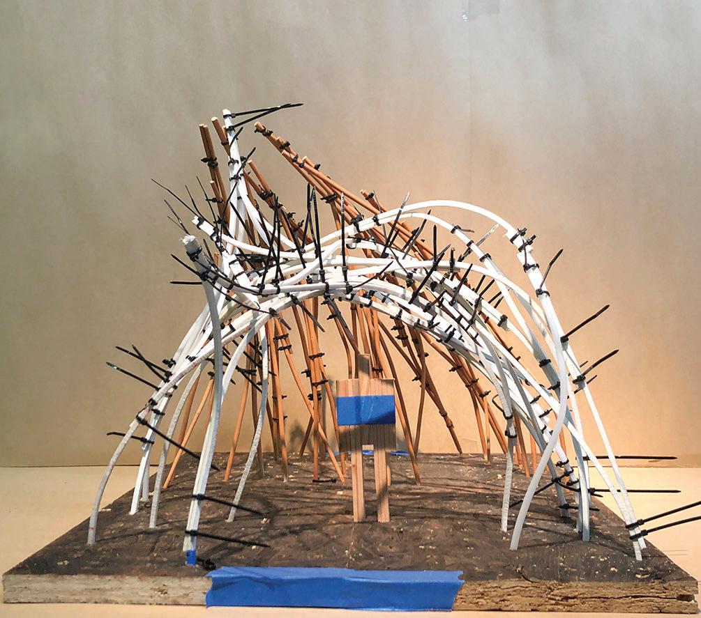
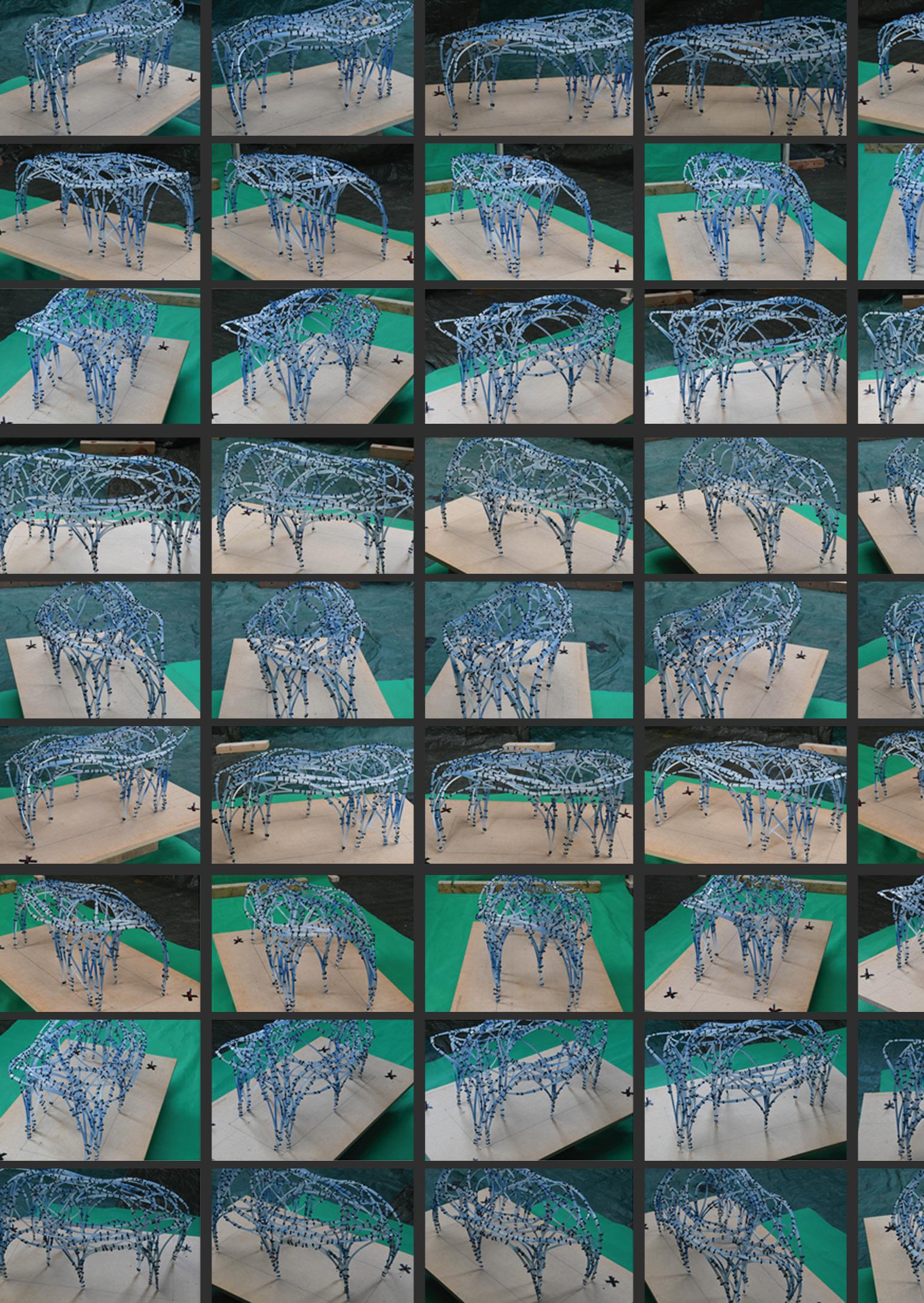
We decided to take a step back started making models with polypropylene sticks intuitively to generate a form.
51
Exploration of different arrangement and configurations to interlock the components between each other. This quick modeling exercise help us identify the different typologies from which we could build the pavilion.


52
Images of the model exploration for form-finding of the Pavilion

53
Model making
Dropping the surface mapping logic. We started making models Intuitively with our hands, Keeping in mind the learnings from prototypes.
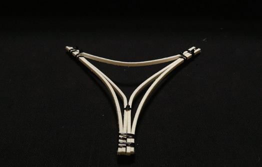
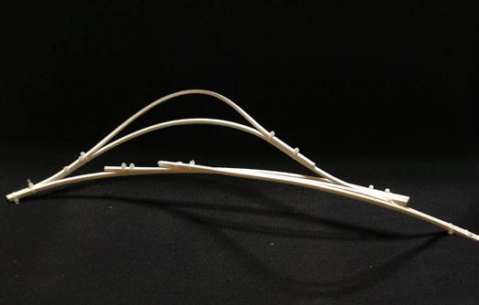
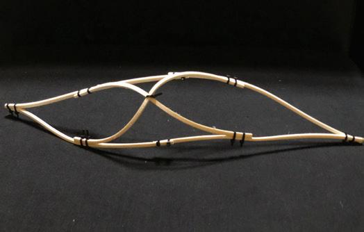
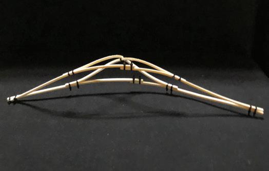
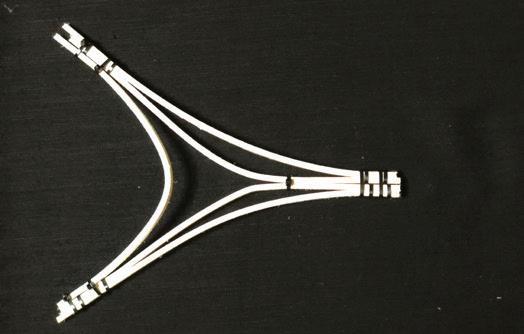
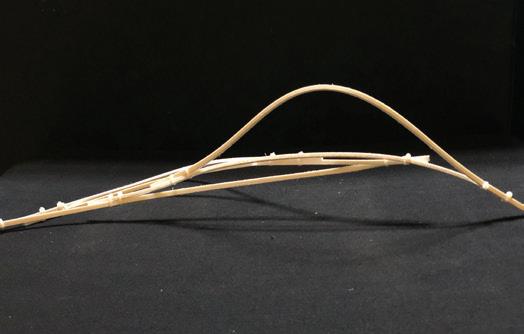
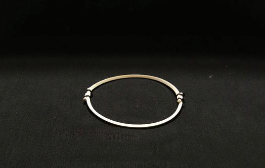
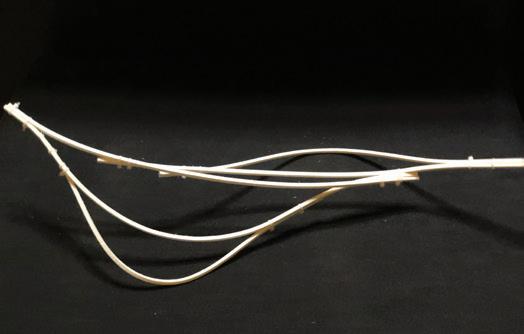
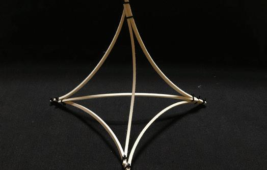
We used Zip ties and polypropylene sticks instead of wood, as the wooden sticks at 1:10 scale were not stiff enough to take the extreme bend and twist. We started modeling components to identify the moves that is leading to an interesting yet achievable curves. Out of all the explo rations, the Tetrahedron and Strand stood out the most interesting achievable bends
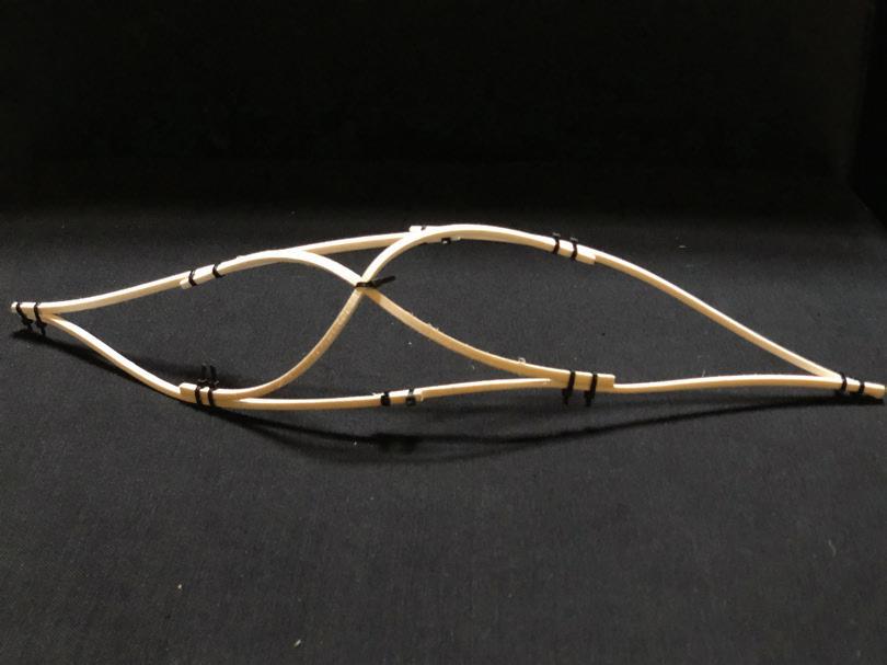
as well as their structural build-up. The tetrahedron could bear vertical load and strand could transfer horizontal load. We took the understanding from these typologies and started mak ing scaled models.

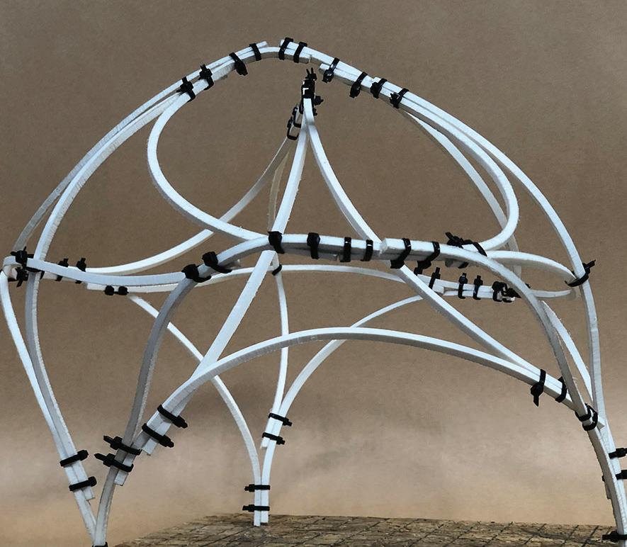
We explored some funky ones, too, to explore the ex perience we want to evoke.
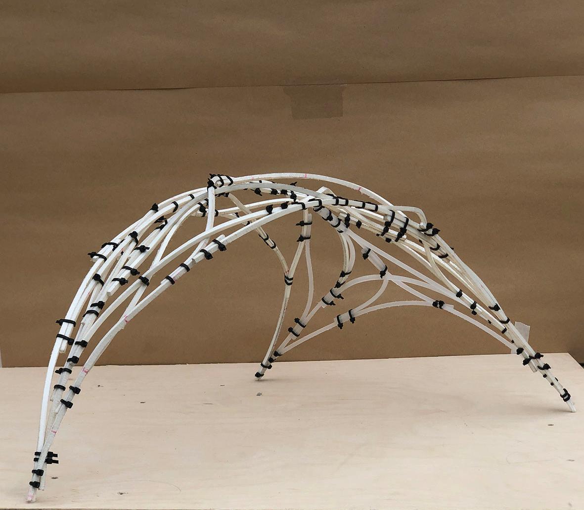
Out of many explorations. The ones that stood out the most were these two. The one on the left, had the structural stability to support its weight and the one on right has the spatial qualities creating an evoca tive experience. We decide
to merge these learnings into one.
Forming the final form of our pavilion. Consider ing the parameters defined throughout the process. The model was designed intu itively, through an under standing of the bends the system could achieve.
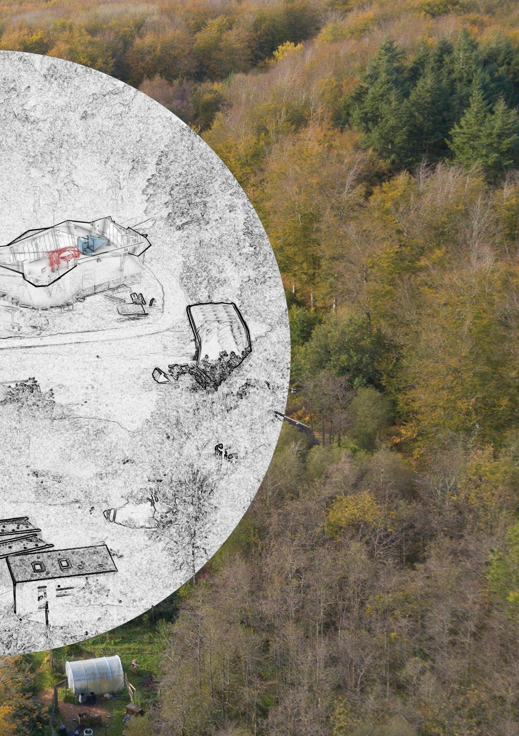
One of the things that we were able to bring into the design of the pavilion was our keenness of vision about what it means to be in a place like Hooke Park.
We want it to embrace Hooke Park and the forest around us.
54
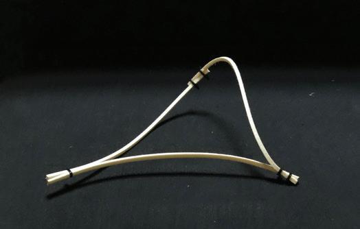
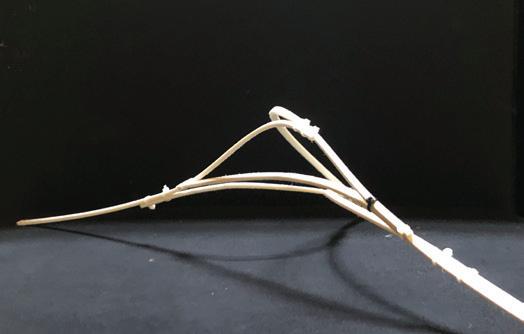
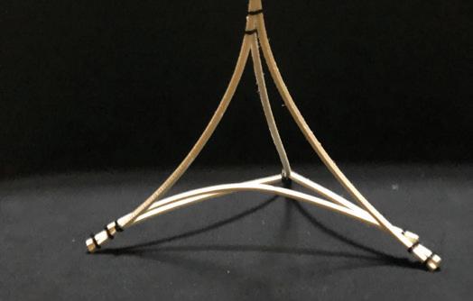
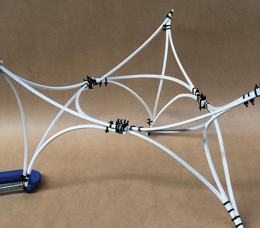
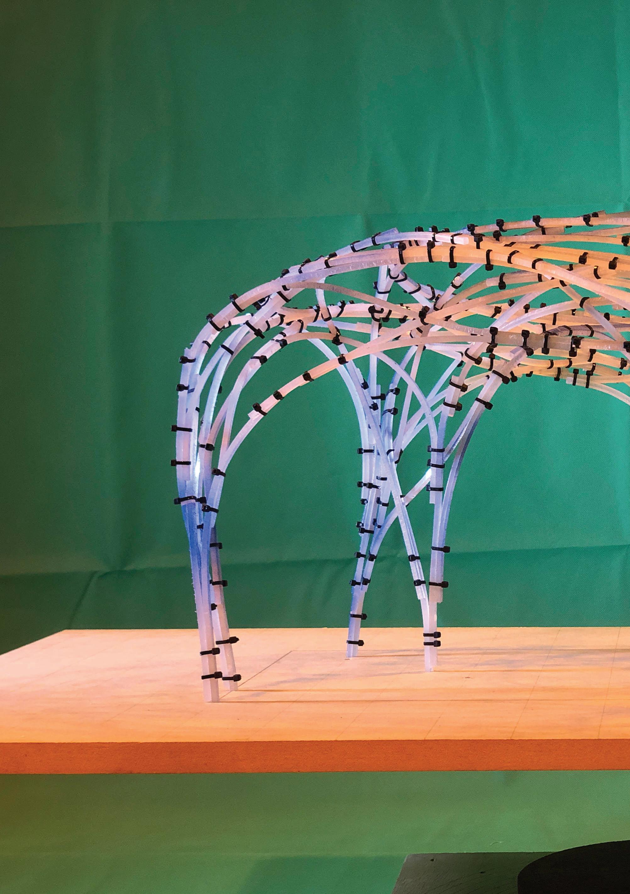
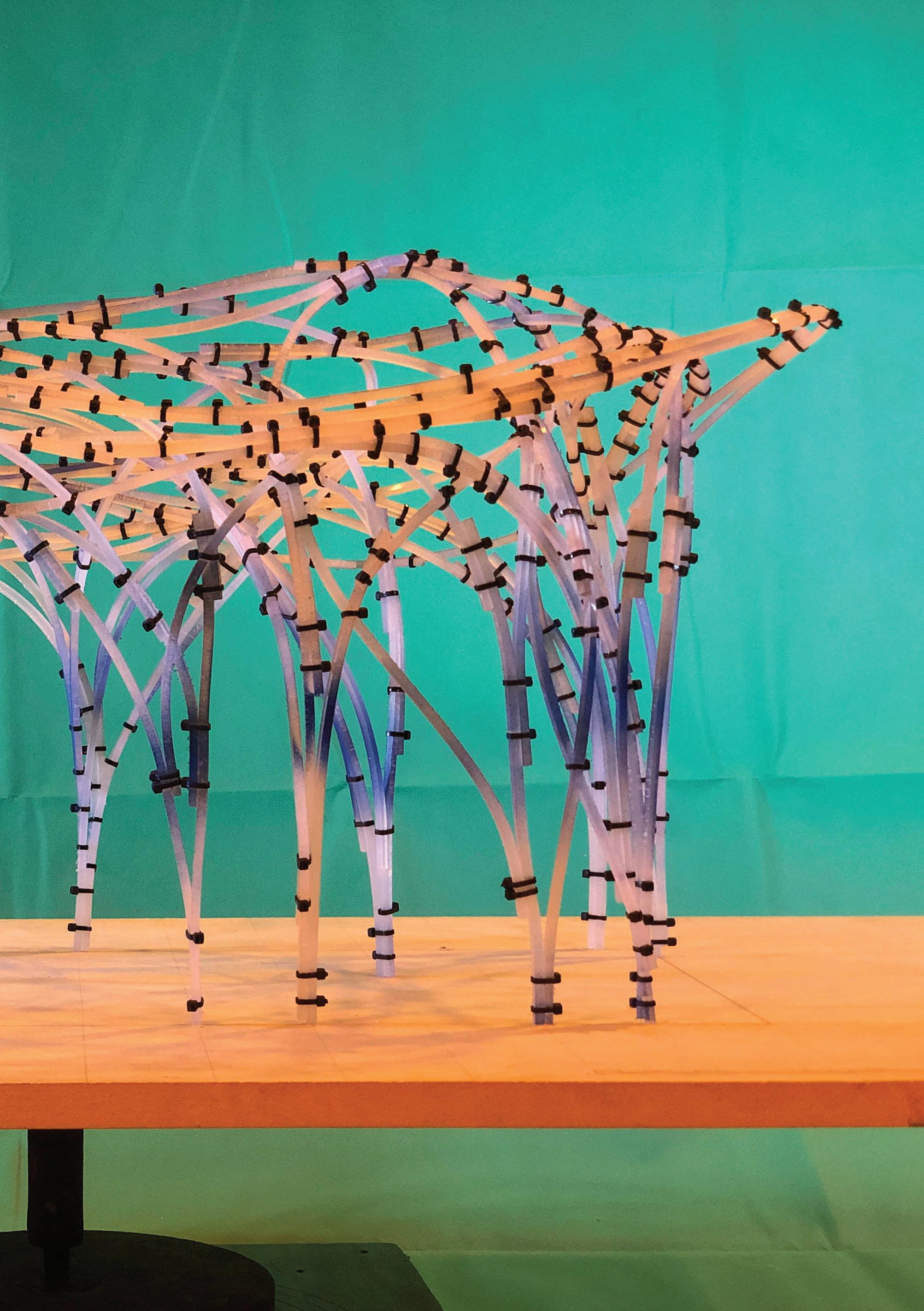
Tetrahedron component
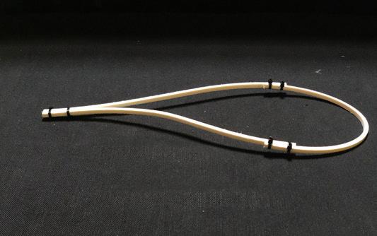
Strand component

55
Model combining Tetrahedron and Strand topologies to form a proposal for the pavilion [OE]
[RK]
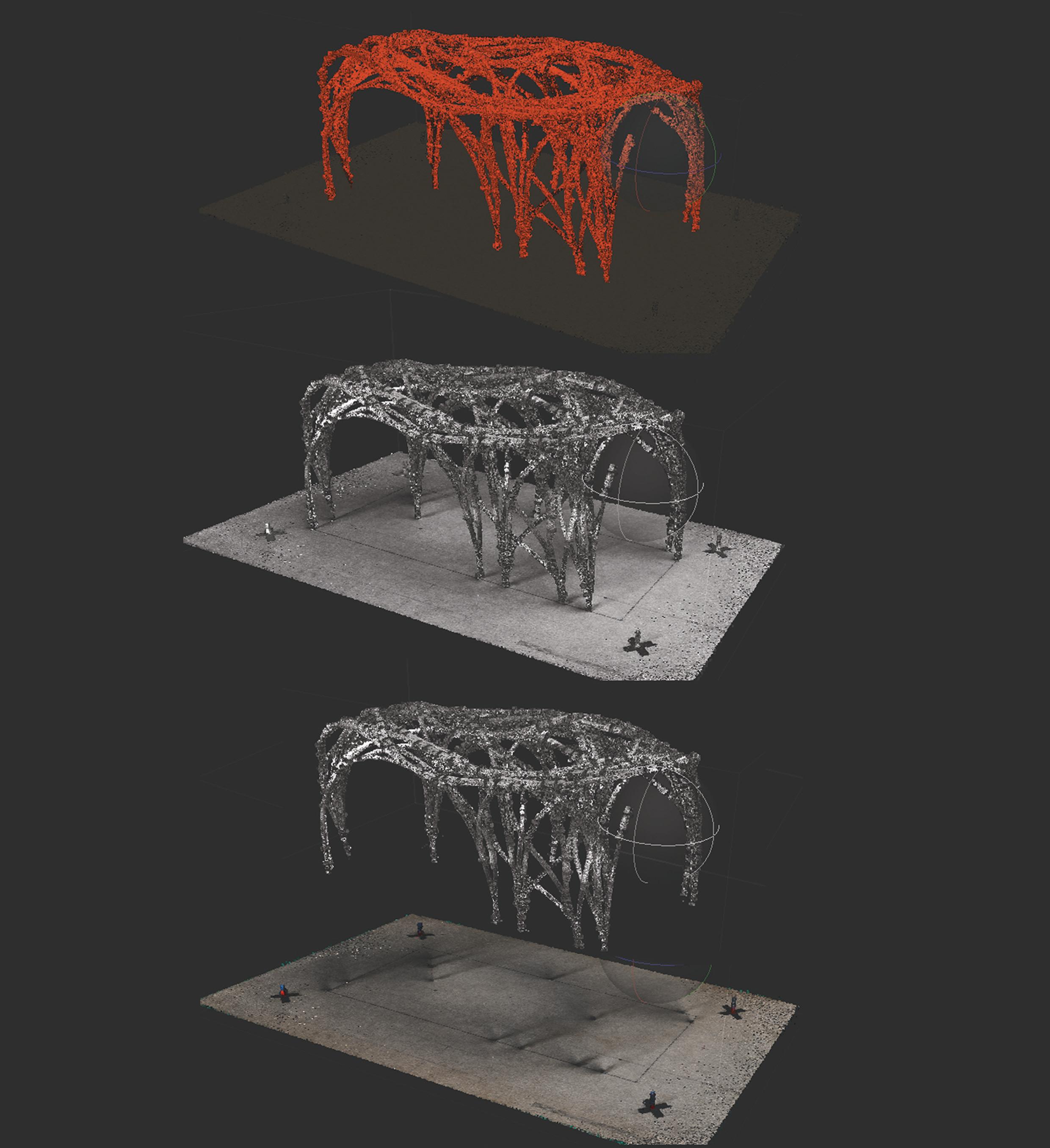
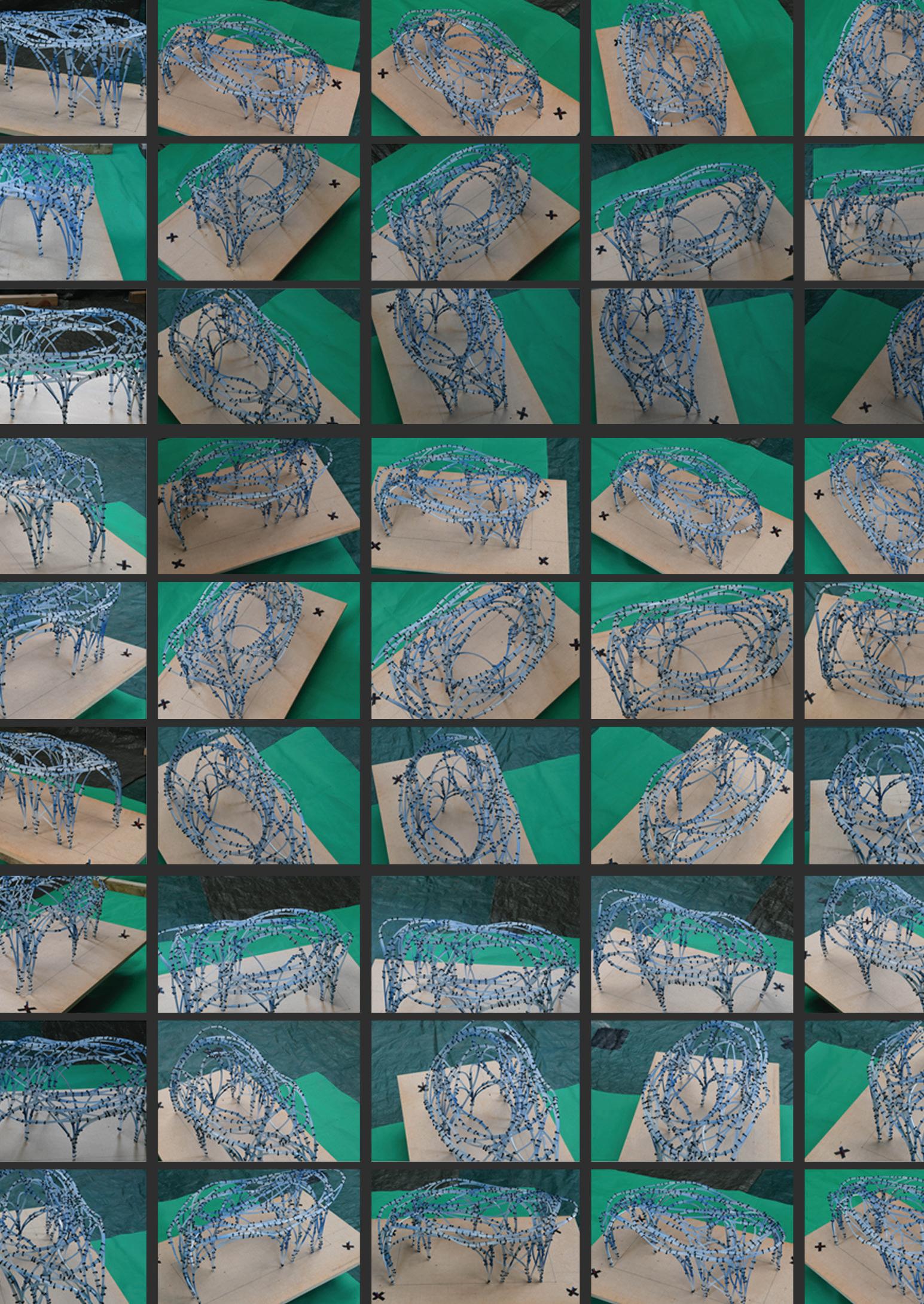
Scanning
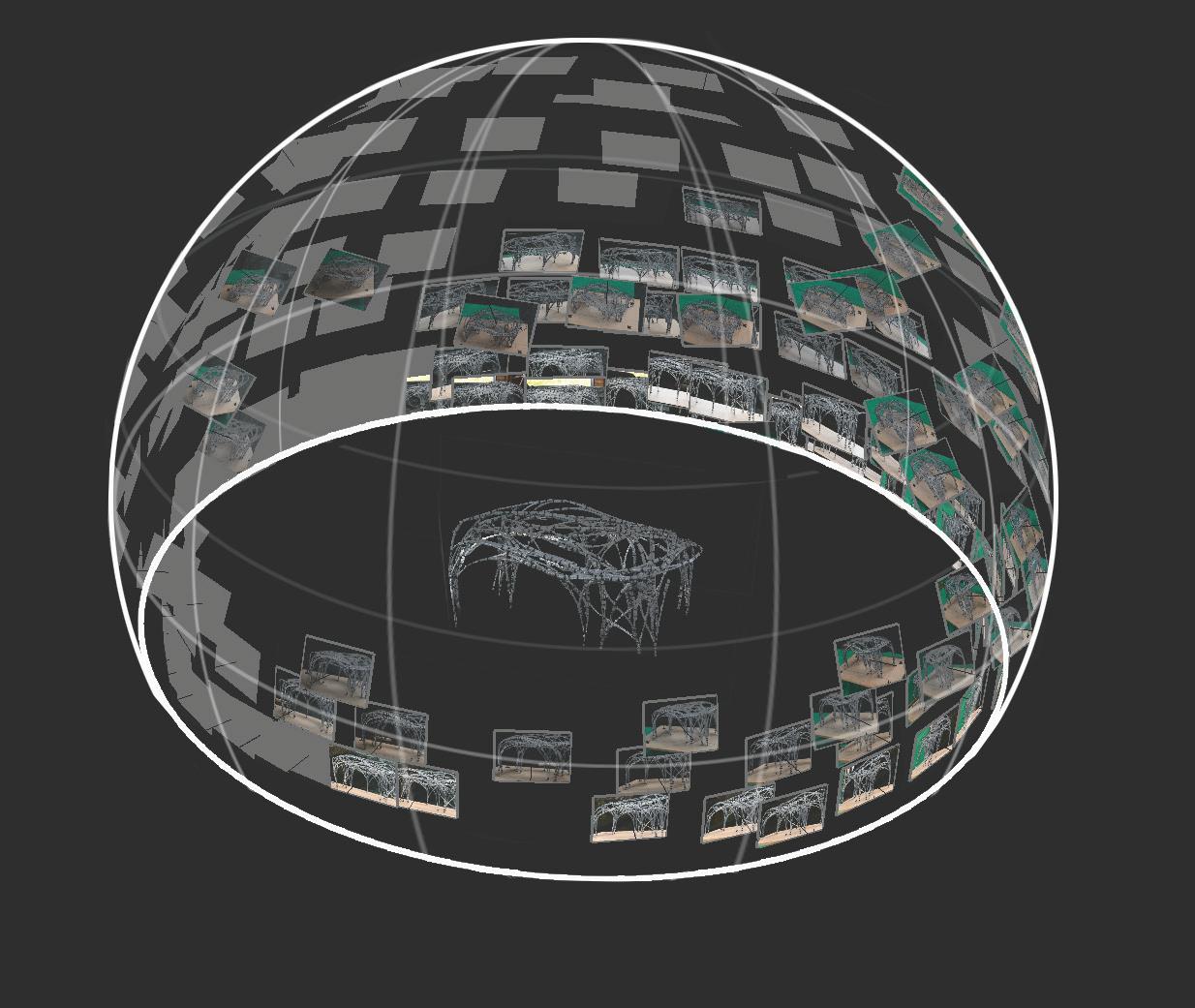
60 3D
200 strategically captured shots to get every single detail on the model. [RK]
3D Scanning
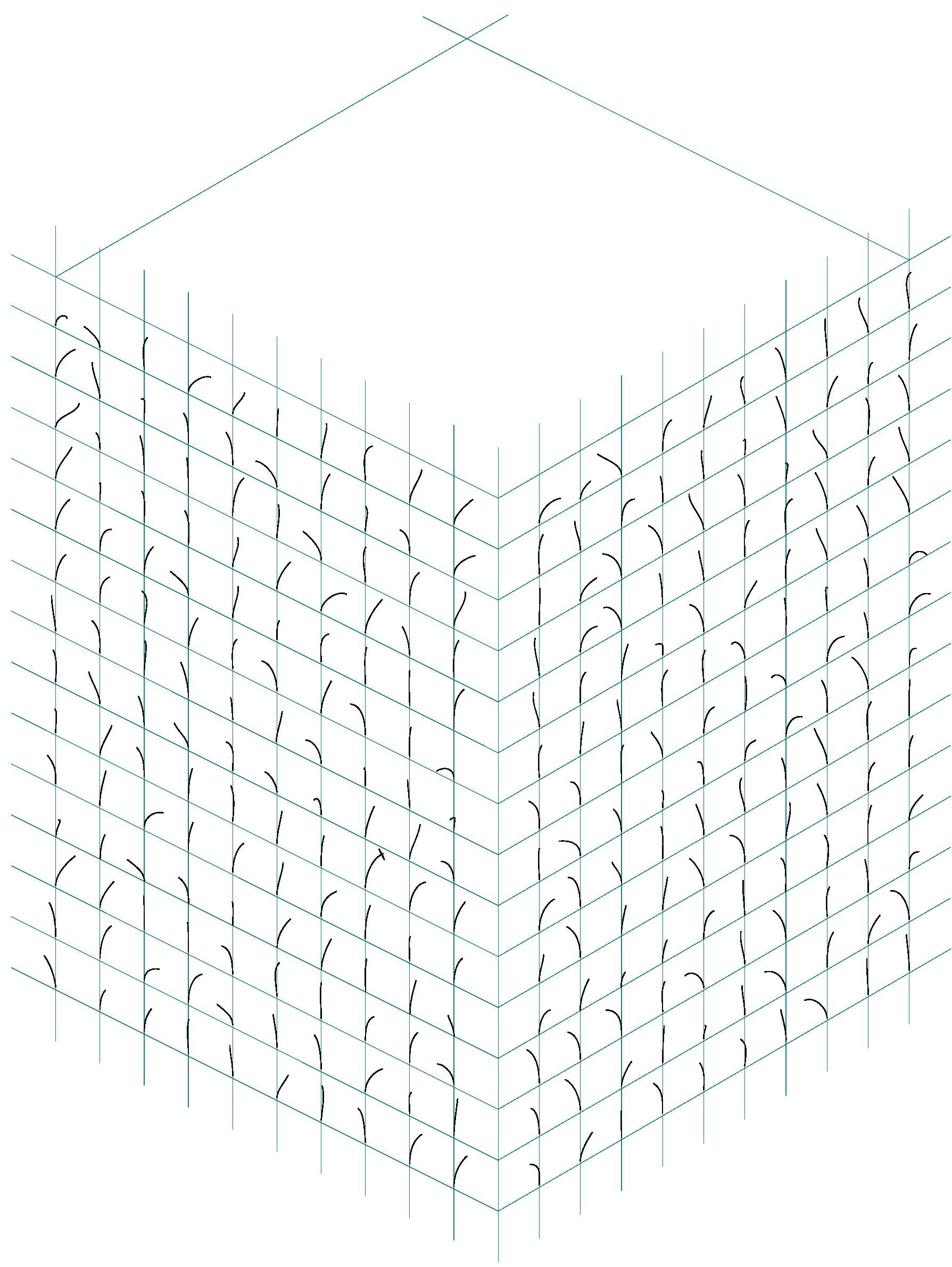
Etruded image showing the extraction of curve from the 3D scanned model. [RK]
We extracted the point cloud from the scan. brought it into rhino Model to generating data for Jig
61
[LG]
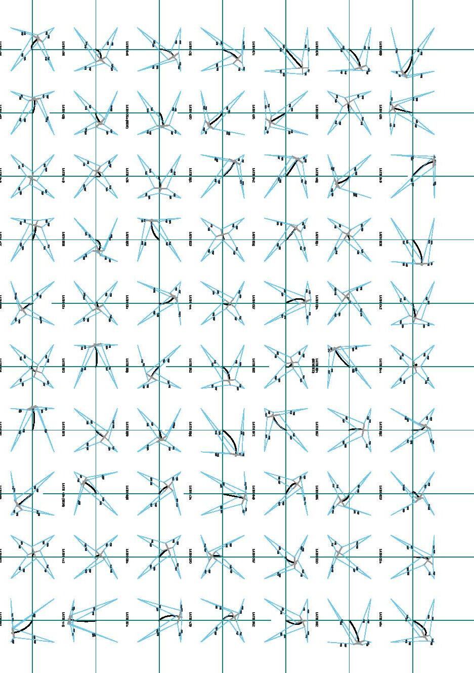
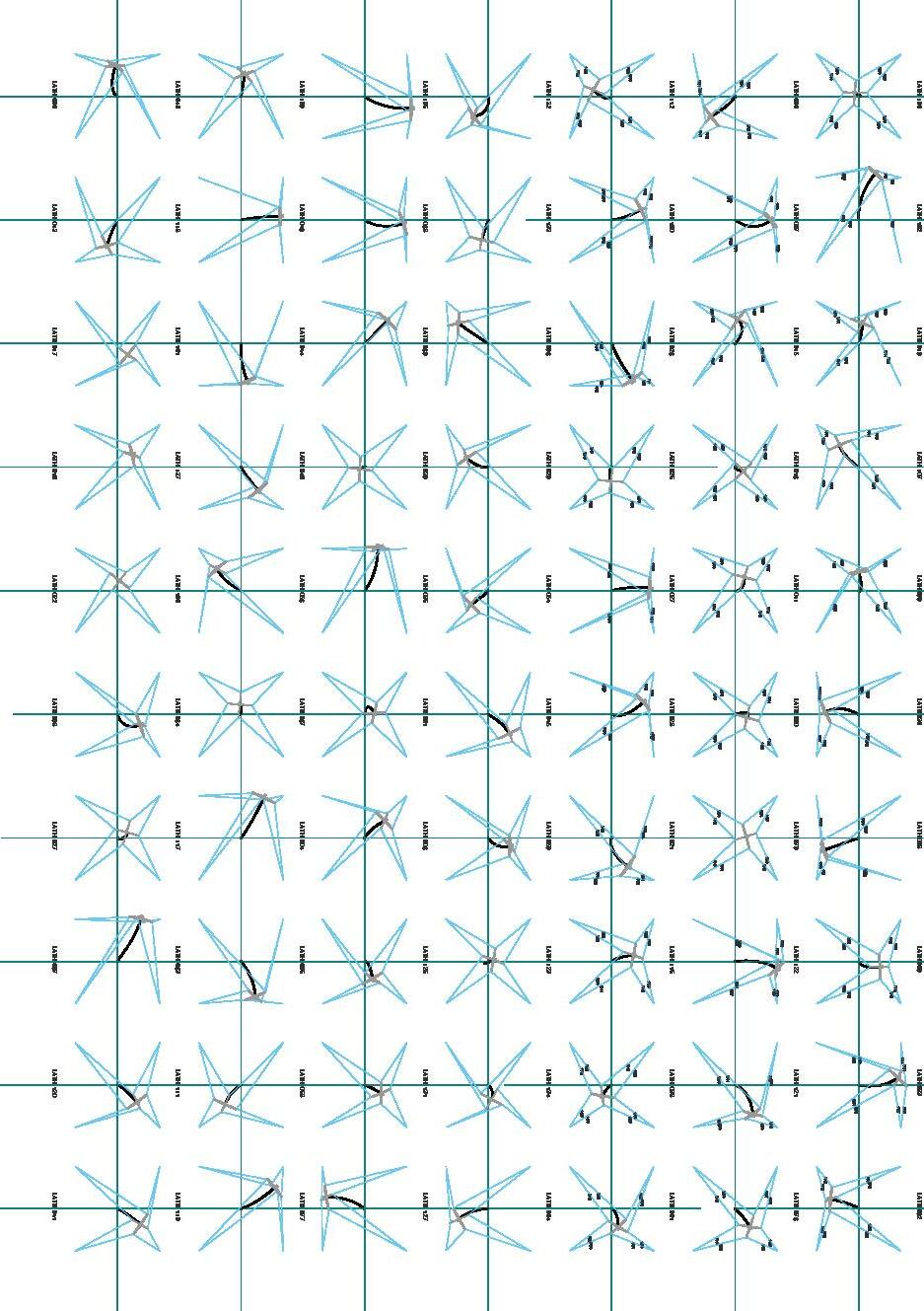
Digital workflow for pavilion
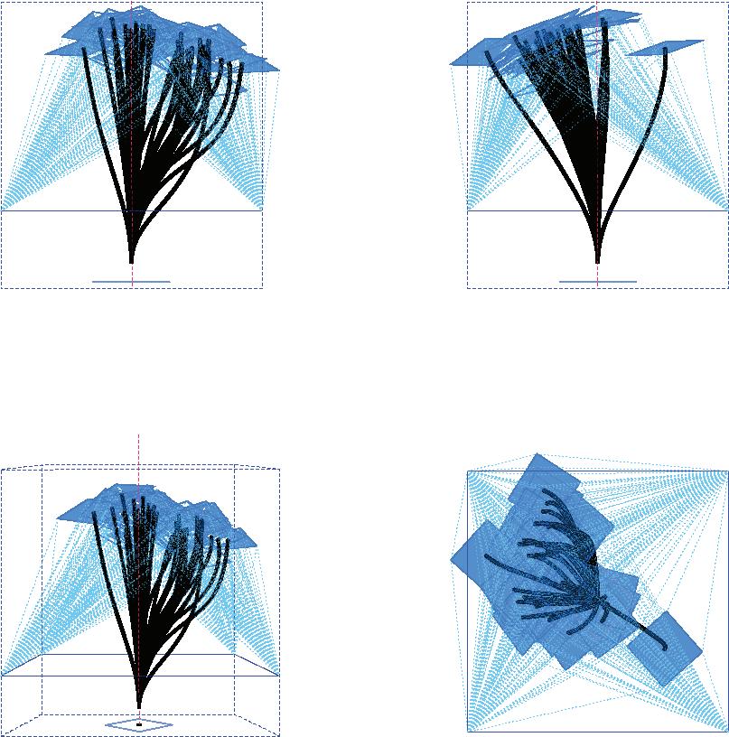
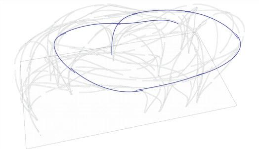
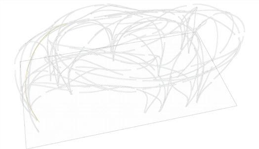
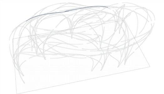
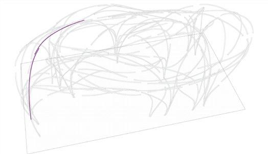
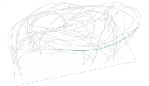
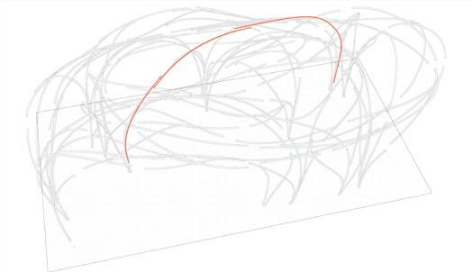
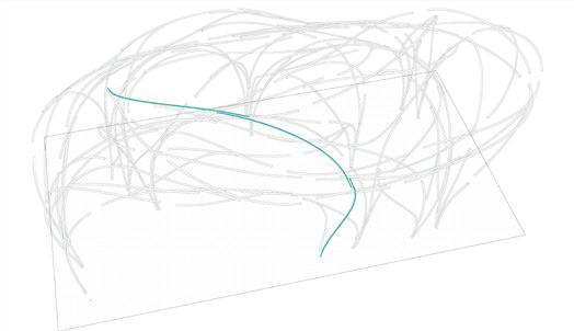
Drawing showing the pallet of intrest ing curves achieved through our new workflow. [LG]
66
New curve range. [LG] Through this method, we pushed the limits of the bending range. We could exploit the potential of Jig to achieve interesting bends and twists.
67
[RK]
[HD]
+ MAKE
&
FEEDBACK
FEEDBACK
GEOMETRY DESIGN
DRAWINGS
LATHS
72 Time line of the project October w.01 w.02 w.03 [ 21 - 25 ] w.04 [ 28 - 01 ] Oct- Nov [ 04 - 08 ] November [ PREPARE
FULL FAB. & ASSEMBLY
EXTRACT COMPONENTS LINES
TOPOLOGIES / CONFIGURATIONS PALETTE DEFINE GEOMETRY 3D SCAN/PHOTOGRAMMETRY FAB. DATA FOR JIG ITEM * MID-TERM JURY [04.11] CRITICAL PATH JIG CALIBRATION
TEST
LIFE
SYSTEM FIX STEAM BOX PAVILION PROJECT 2019 DESIGN
[ 14-18 ]
FINAL DETAILS
CONCLUSION
GATHER DOCUMANTATION
73 w.05 December w.06 [ 11 - 15 ] w.07 [ 18 - 22 ] w.08 [ 25 - 29 ] w.09 [ 02 - 06 ] [ 09 - 13 ] CUTTING LIST FULL PRODUCTION MODE
ASSEMBLY ANALYSIS
* LG in Mexico PAVILION [12.12]BUILT
Pre-marking
Pre-marking
A python script generated to premark the drill points and adjoining lath location on every lath.
74
We extracted the point cloud from the scan.
Rhino Model For generating data
Though which we drew the curves to feed in the JIG script
Pre-marking
>Connections
>Target points
>Lath orientation
Finding where faces meet and connect to each other, which later we use for pre-marking each lath
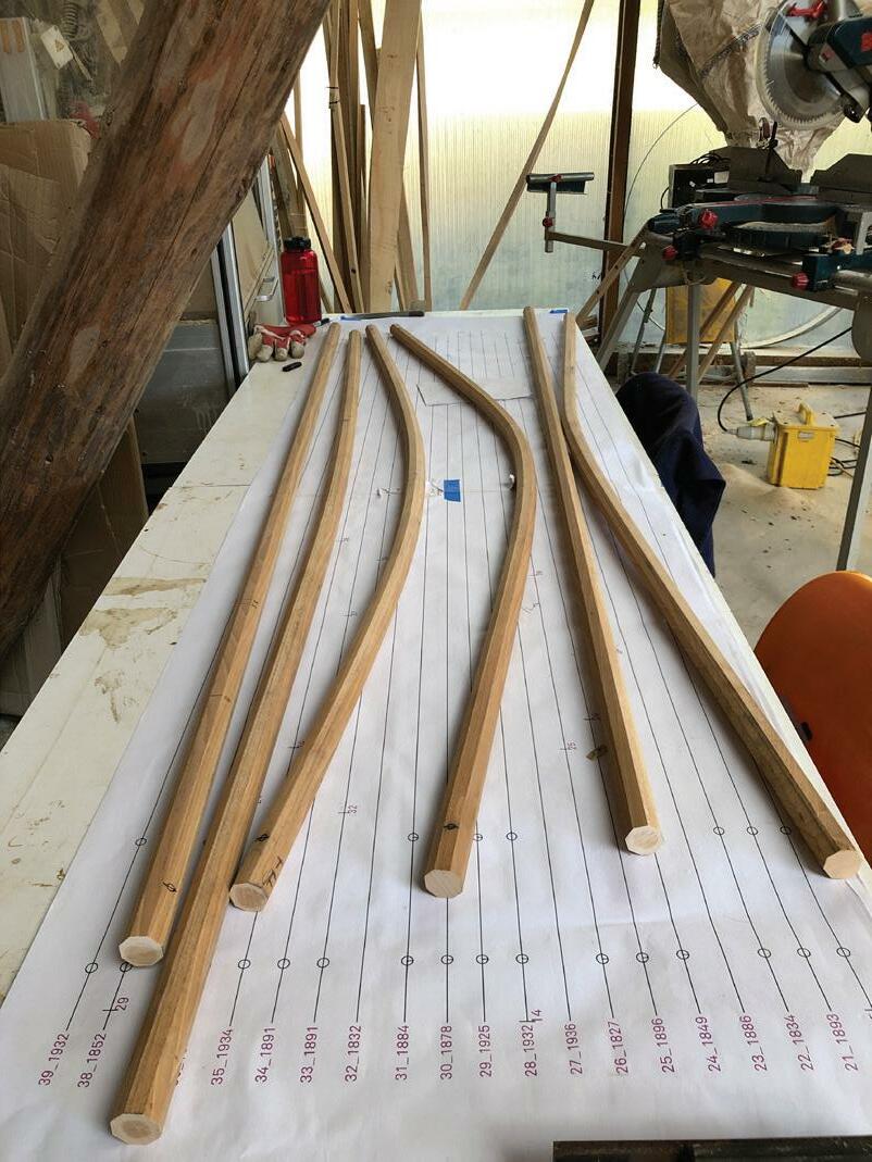
We pre-mark the components by plot ting a 1:1 scale length of laths. Marking the connections before bend ing.
Circular marking for dill holes and line for the adjacent lath Components
75
Image 2: Pre-marking connection and drill points form a 1:1 scale lath plotted sheet.
Image 1 : Pre-marking the orientaion on lath
set up
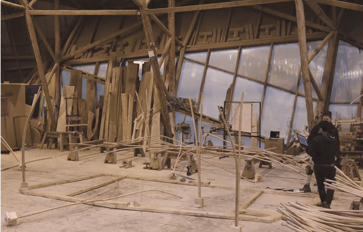
76 Production
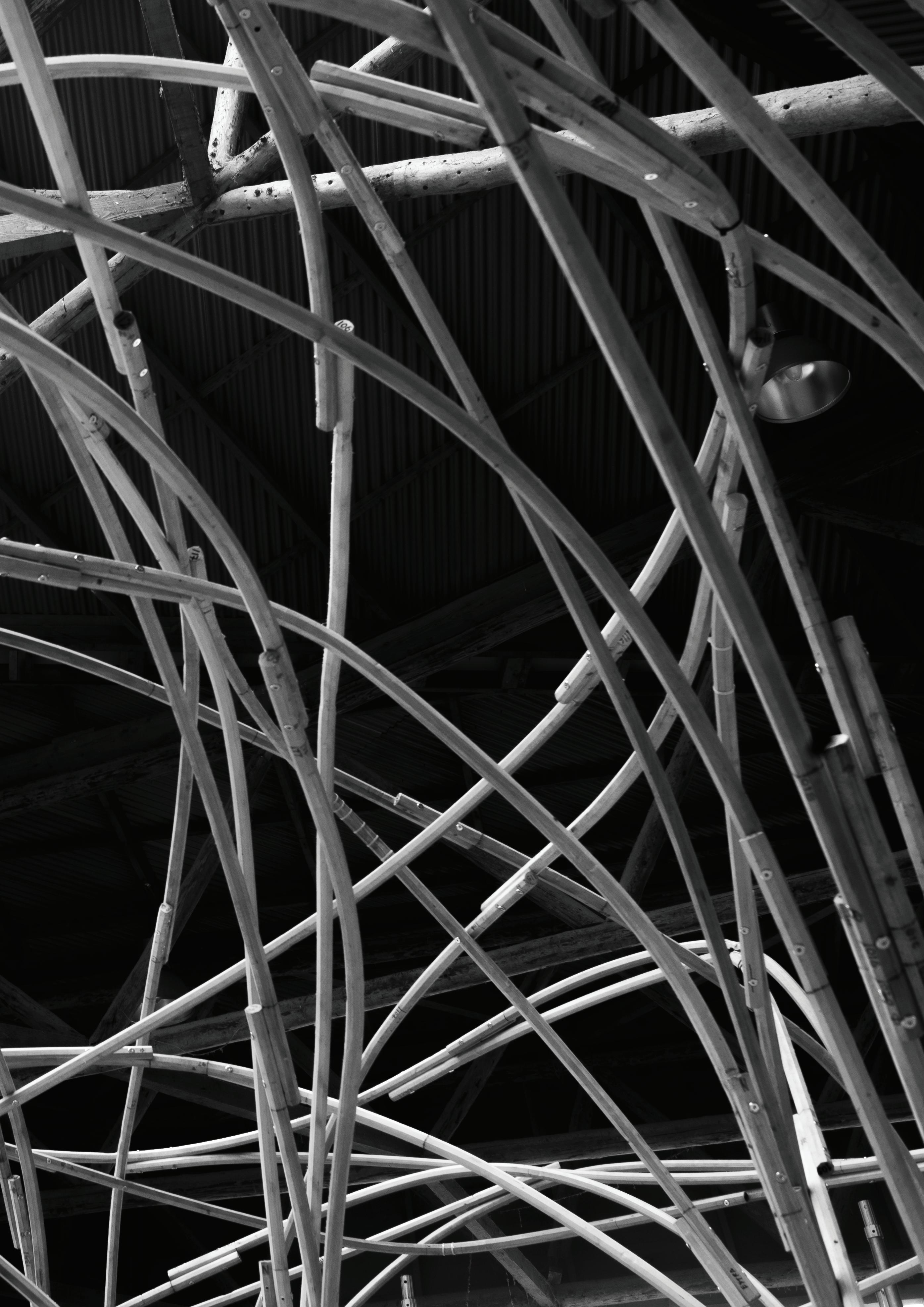
Image showing every component on side during the bending process.
77
Through this method, we pushed the limits of the bending range.
We could exploit the potential of the system to achieve interesting bends and twists.
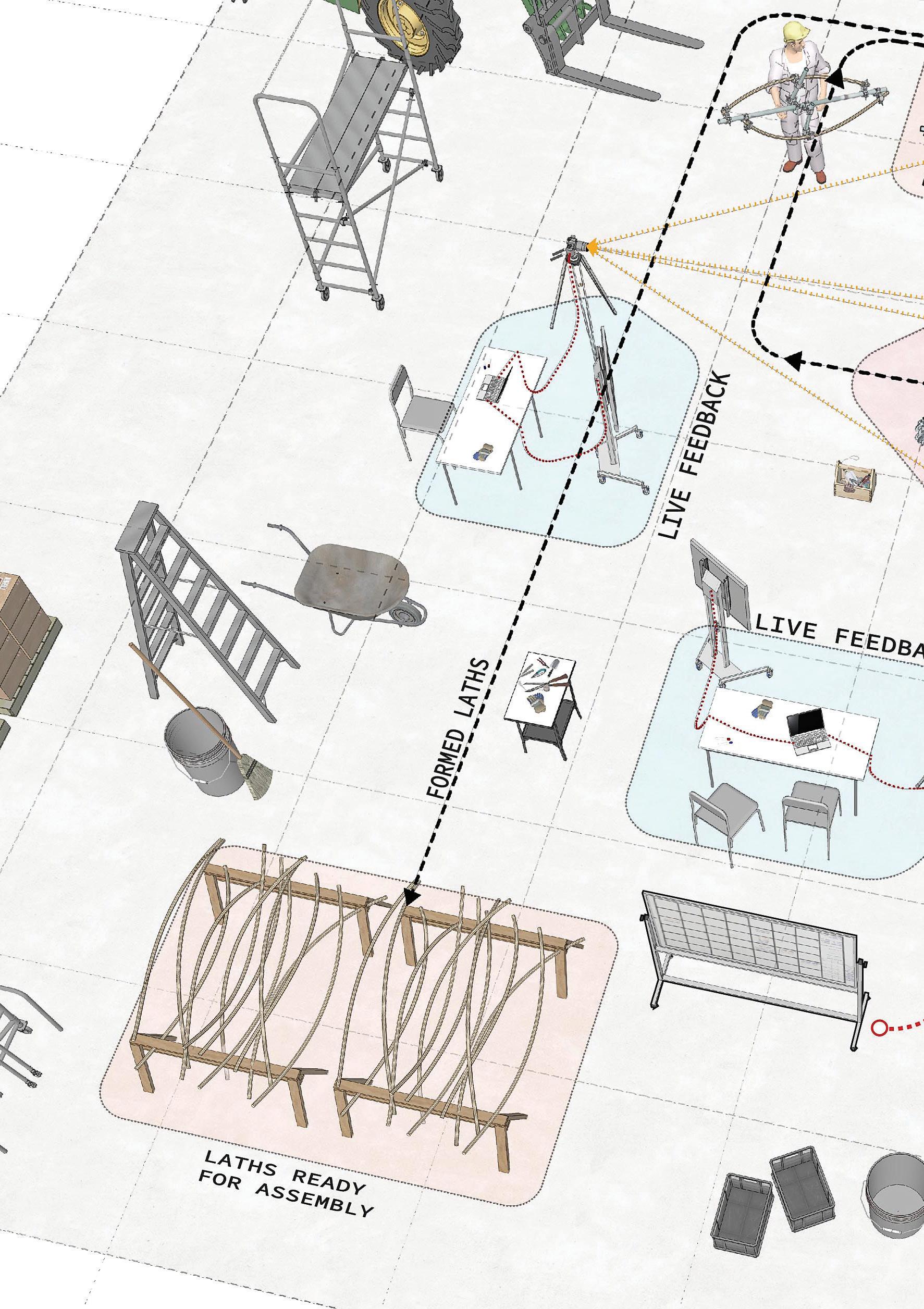
We set up a live feedback system to get a real time feed back of accuracy and shape of the bend.
Let the wood dry in holding Jig up to 36 hrs.
We produced 140 discrete curves to build the Pavillion.
78
Production
Image 1: Image showing the alterna tive movement of winching.

Image 2: Image showing the simulta neous winching from all directions to make a bend.
79
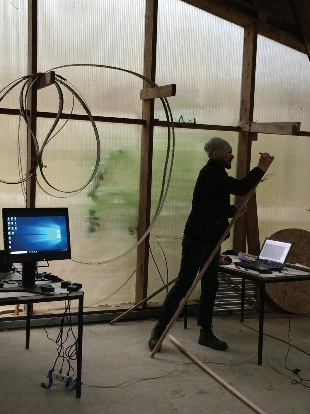
80 Live feedback
By overlaying the digital image of the digital shape with a real-live video of the process, a visual system was set to get a real-time feedback to check the accuracy and shape of the bend.

81

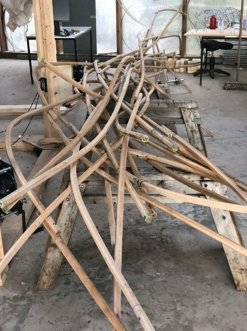
84
Aseembly of laths Image capturing a moment of discus sion during the assembly sequence
Images showing lath released from the holding Jig, ready for assembly
85
Sequence of strategically placed re oriented bent laths for assembly. [HD]


86


87
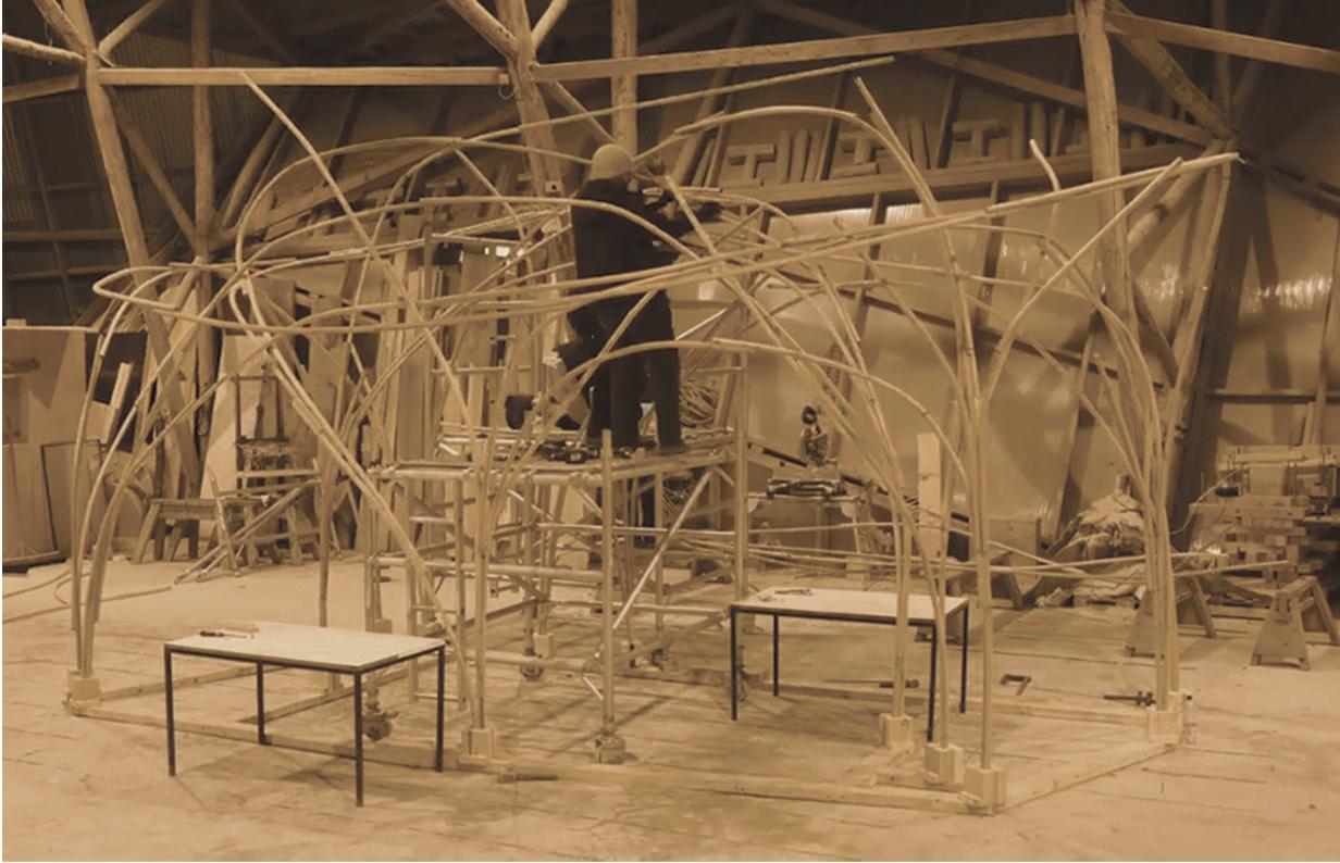
Assembly Process
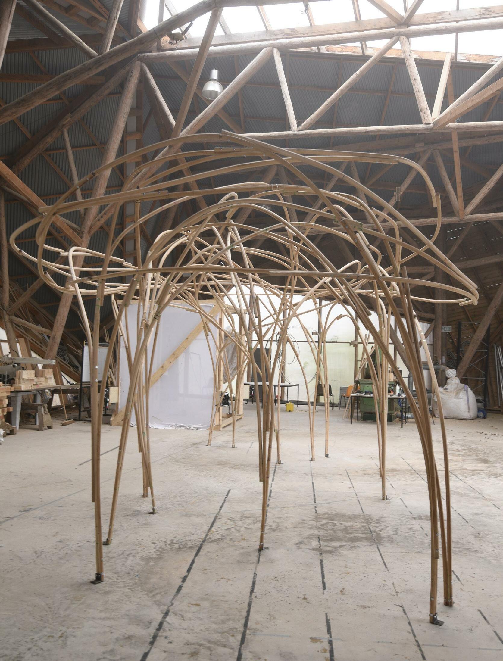
We identified and assembled the curves making the basic structure then added loops to develop the form and finally redundancy to add stiffness.

Ground condition acted as temporary reference placeholder on which the vertical laths forming the arches were standing.
Primary structure consisted of 70 pieces and strategic assembly of key weight bear ing lath components.
After the first seventy structural compo nents, the rest were redundant components used to create the final form.
Assembly sequence
88
89
Image 1 : Temporary ground condition Image 2 : Image showing the form of the pavilion emerging
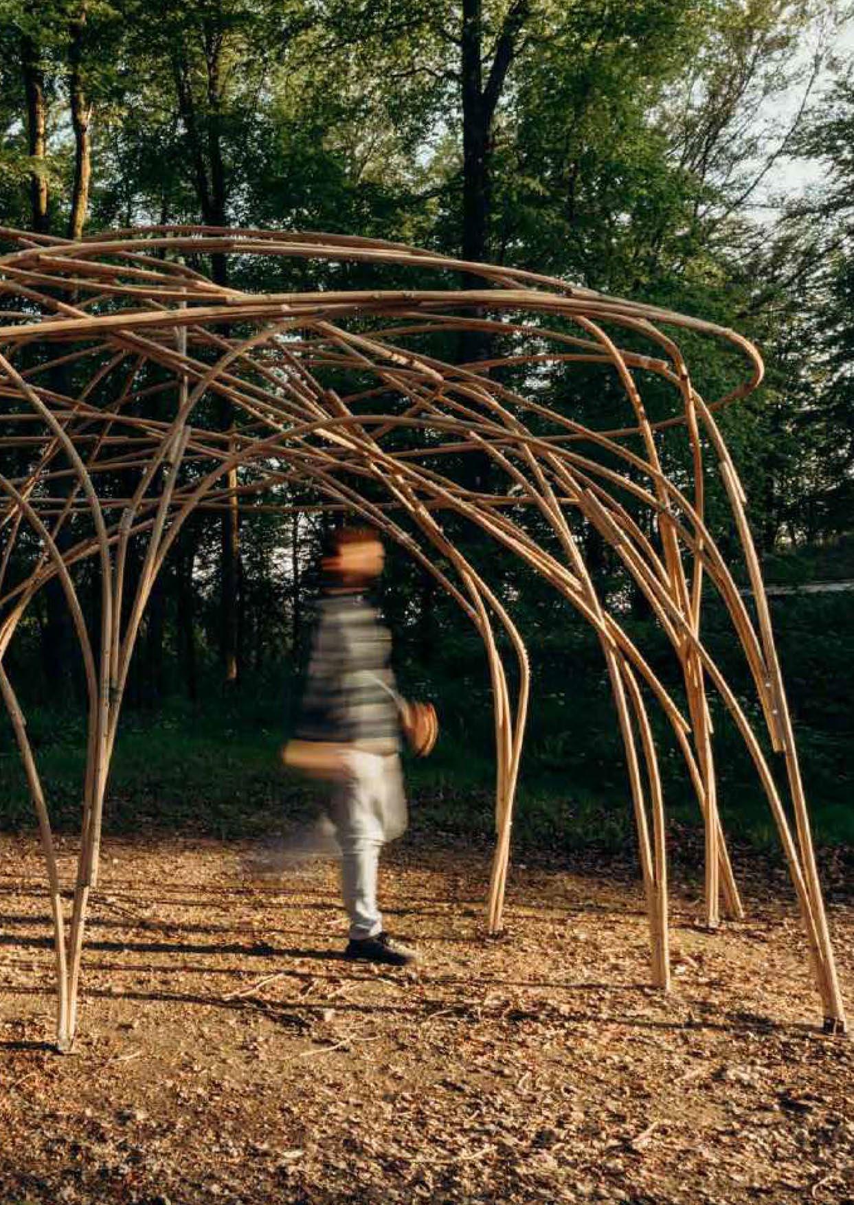
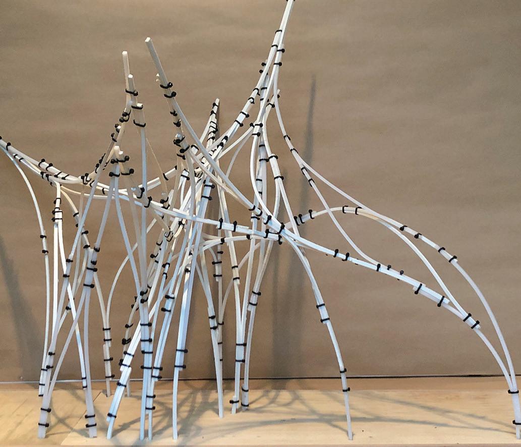
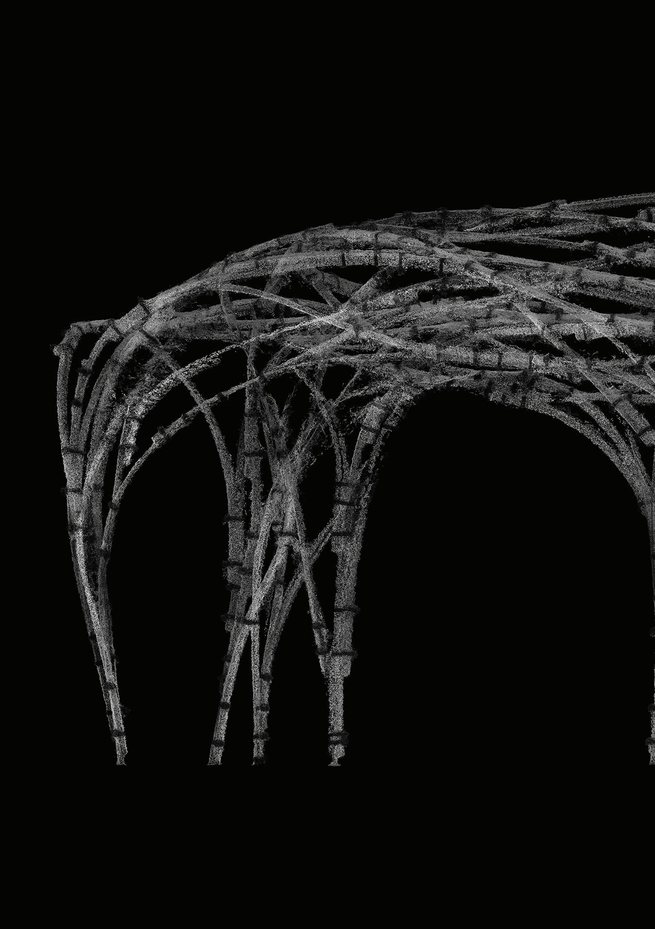
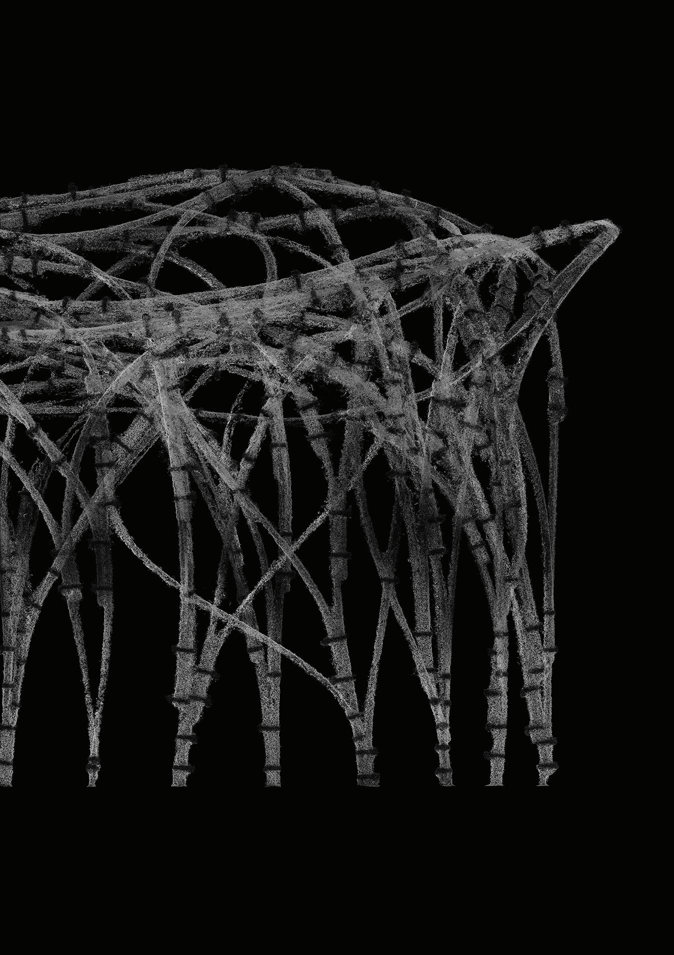
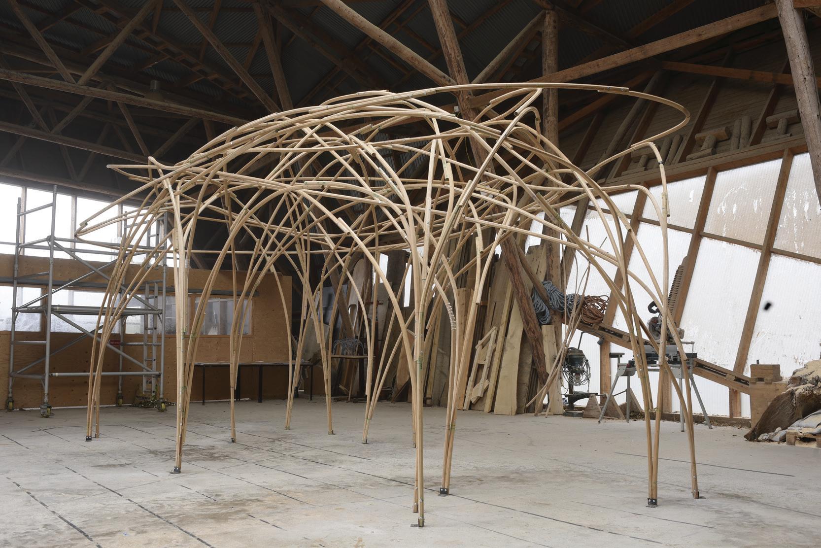
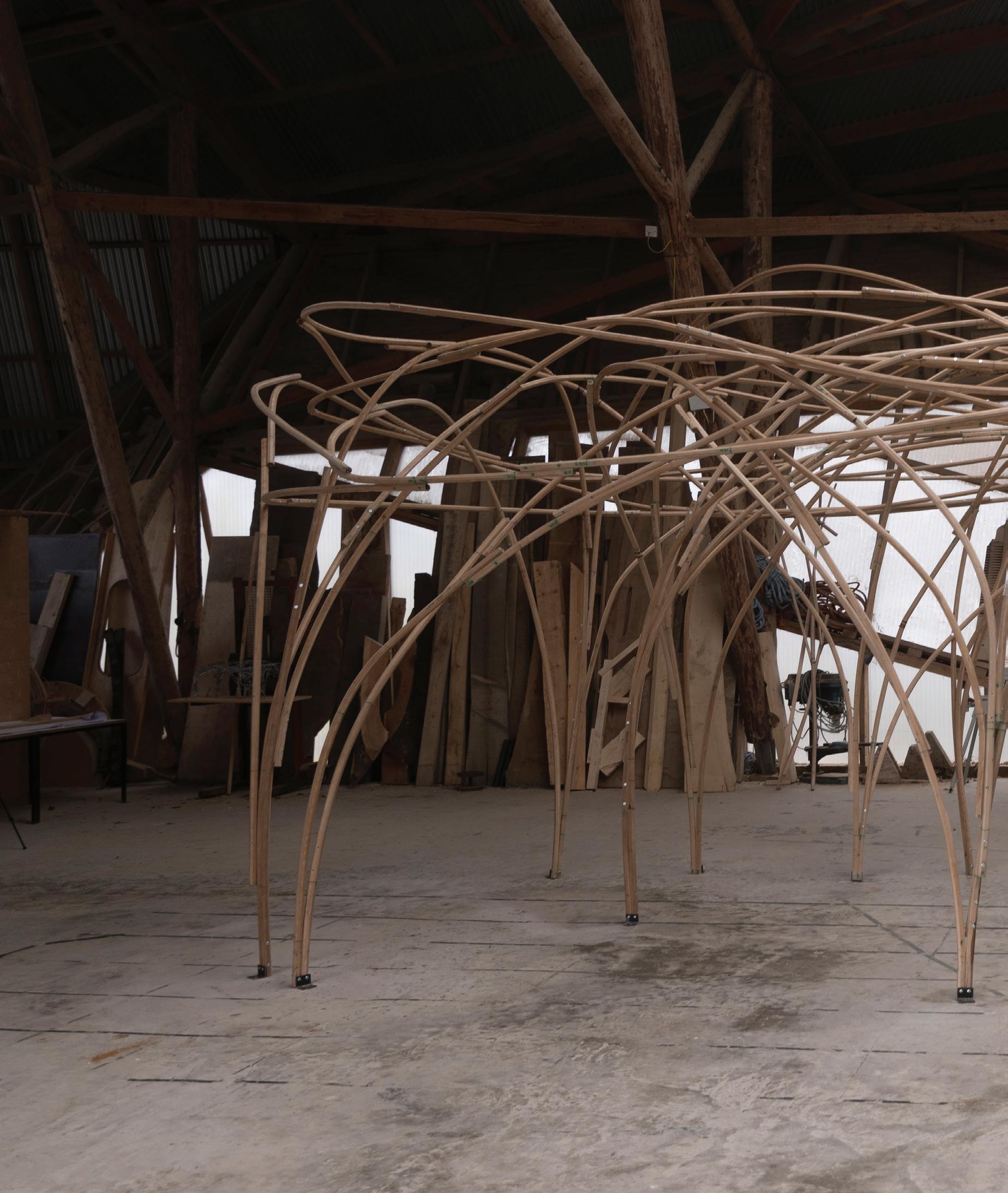
Final Pavilion
The process raises to questions, this desire to make complex form through parametric design and artificial generation of complexity.
Instead a physical mak ing process is celebrated and complexity is allowed to emerge from material behaviour.
90
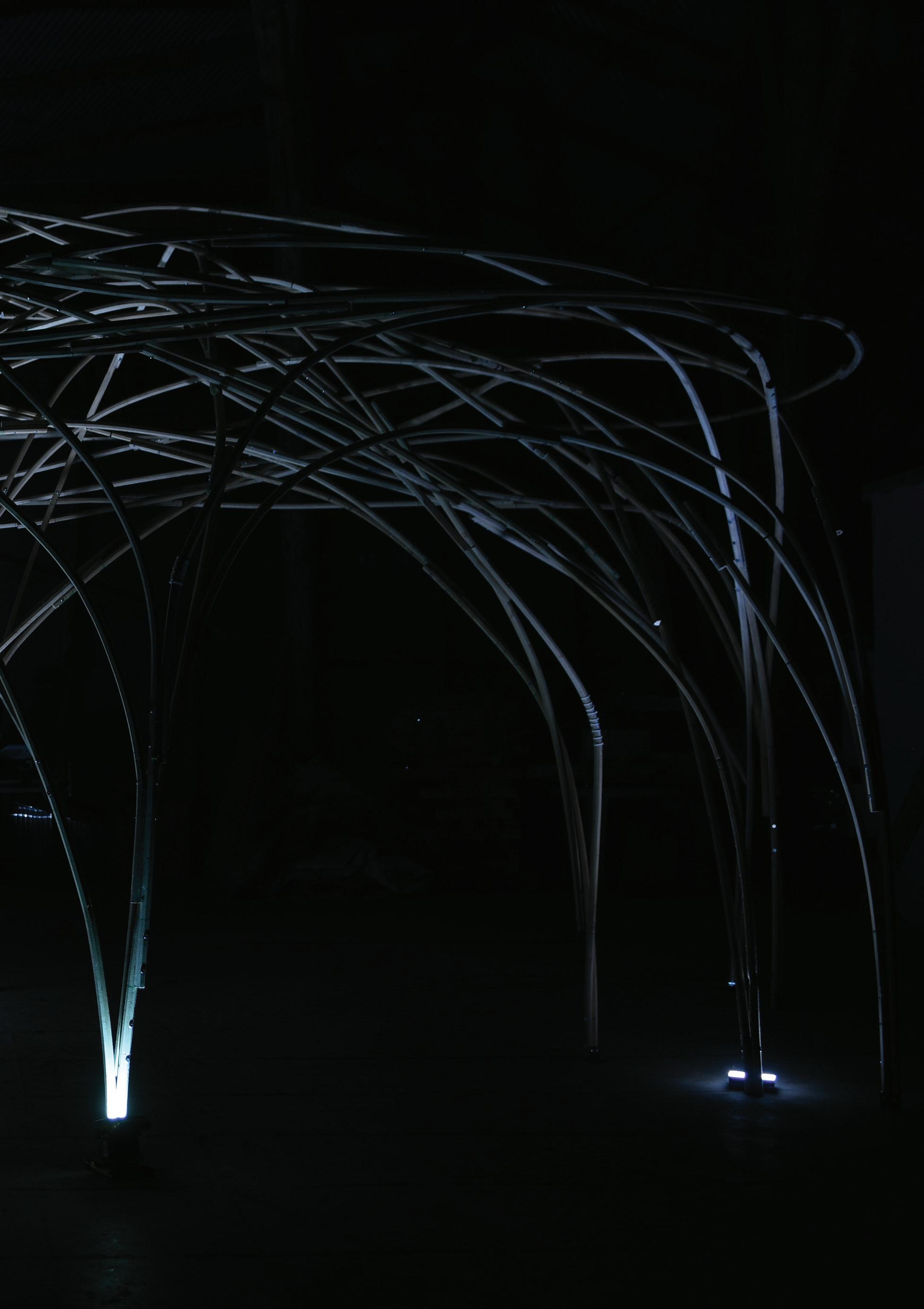
Pavilion prespective view

91
Pavilion front view
8
Pavilion as built.

9
