
Development Kit Selector http://embeddedcomputing.com/designs/iot_dev_kits/ embedded world PROFILES 2024 PG 26 SPRING 2024 | VOLUME 22 | 1 | EMBEDDEDCOMPUTING.COM VECOW Time Sync Technology for Edge AI Applications PG 27 SEALEVEL SYSTEMS, INC. Flexio Fanless Embedded Computers for Industrial Automation & Control PG 32 Executive Viewpoint Jason Kridner, BeagleBoard.org PG 6 Synaptics Astra™ SL-Series of AI-native SoCs Deliver Contextual Computing PG 28


COMPUTEX has grown, transformed with the industry, and established its reputation as the world’s leading platform. The show will bring the latest tech trends: AI Computing, Advanced Connectivity, Future Mobility, Immersive Reality, Sustainability, and Innovations.


Register Now
EMBEDDED COMPUTING BRAND DIRECTOR Rich Nass rich.nass@opensysmedia.com
SENIOR TECHNOLOGY EDITOR Ken Briodagh ken.briodagh@opensysmedia.com
ASSOCIATE EDITOR Tiera Oliver tiera.oliver@opensysmedia.com
ASSOCIATE EDITOR Taryn Engmark taryn.engmark@opensysmedia.com
PRODUCTION EDITOR Chad Cox chad.cox@opensysmedia.com
TECHNOLOGY EDITOR Curt Schwaderer curt.schwaderer@opensysmedia.com
CREATIVE DIRECTOR Stephanie Sweet stephanie.sweet@opensysmedia.com
WEB DEVELOPER Paul Nelson paul.nelson@opensysmedia.com
EMAIL MARKETING SPECIALIST Drew Kaufman drew.kaufman@opensysmedia.com
WEBCAST MANAGER Marvin Augustyn marvin.augustyn@opensysmedia.com
SALES/MARKETING
DIRECTOR OF SALES Tom Varcie tom.varcie@opensysmedia.com (734) 748-9660
STRATEGIC ACCOUNT MANAGER Rebecca Barker rebecca.barker@opensysmedia.com (281) 724-8021
STRATEGIC ACCOUNT MANAGER Bill Barron bill.barron@opensysmedia.com (516) 376-9838
STRATEGIC ACCOUNT MANAGER Kathleen Wackowski kathleen.wackowski@opensysmedia.com (978) 888-7367
SOUTHERN CAL REGIONAL SALES MANAGER Len Pettek len.pettek@opensysmedia.com (805) 231-9582
DIRECTOR OF SALES ENABLEMENT Barbara Quinlan barbara.quinlan@opensysmedia.com AND PRODUCT MARKETING (480) 236-8818
INSIDE SALES Amy Russell amy.russell@opensysmedia.com
STRATEGIC ACCOUNT MANAGER Lesley Harmoning lesley.harmoning@opensysmedia.com
EUROPEAN ACCOUNT MANAGER Jill Thibert jill.thibert@opensysmedia.com
TAIWAN SALES ACCOUNT MANAGER Patty Wu patty.wu@opensysmedia.com
CHINA SALES ACCOUNT MANAGER Judy Wang judywang2000@vip.126.com
PRESIDENT Patrick Hopper patrick.hopper@opensysmedia.com
EXECUTIVE VICE PRESIDENT John McHale john.mchale@opensysmedia.com
EXECUTIVE VICE PRESIDENT AND ECD BRAND DIRECTOR Rich Nass rich.nass@opensysmedia.com
DIRECTOR OF OPERATIONS AND CUSTOMER SUCCESS Gina Peter gina.peter@opensysmedia.com
GRAPHIC DESIGNER Kaitlyn Bellerson kaitlyn.bellerson@opensysmedia.com
FINANCIAL ASSISTANT Emily Verhoeks emily.verhoeks@opensysmedia.com
SUBSCRIPTION MANAGER subscriptions@opensysmedia.com
CORPORATE OFFICE
1505 N. Hayden Rd. #105 • Scottsdale, AZ 85257 • Tel: (480) 967-5581
REPRINTS
WRIGHT’S MEDIA REPRINT COORDINATOR Kathy Richey clientsuccess@wrightsmedia.com (281) 419-5725
2
1
36
–
13 Kudelski IoT –Revolutionizing IoT Security: A Seamless Approach to Device Provisioning
1 Sealevel Systems, Inc. –Flexio Fanless Embedded Computers for Industrial Automation & Control
17
1
1
Inc. –Flexio Fanless Industrial
www.embeddedcomputing.com Embedded Computing Design EMBEDDED WORLD | Spring 2024 3 PAGE ADVERTISER
Computex
Connecting
–
AI
Digi-Key Corporation –Development Kit Selector
Connecting
Embedded World
the Embedded Community
Sealevel
Embedded Computers
Systems,
Synaptics
Synaptics
–
Astra™ SL-Series of AI-native SoCs Deliver Contextual Computing
Vecow
Technology
SOCIAL AD LIST WWW.OPENSYSMEDIA.COM Facebook.com/Embedded.Computing.Design @Embedded_comp www.linkedin.com/showcase/ embedded-computing-design/ www.youtube.com/c/ EmbeddedComputingDesign EMBEDDED COMPUTING DESIGN ADVISORY BOARD Ian Ferguson, Lynx Software Technologies Jack Ganssle, Ganssle Group Bill Gatliff, Independent Consultant Andrew Girson, Barr Group David Kleidermacher, Google Jean LaBrosse, Independent Consultant Scot Morrison, Siemens Digital Industries Software Rob Oshana, NXP Kamran Shah, Klick Health
– Time Sync
for Edge AI Applications
8
By Luca Bettini,
By
By Yann LeFaou,


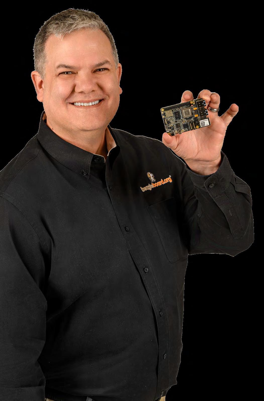
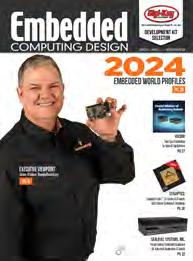
With a new offering hitting the shelves, Embedded Computing Design’s Brand Director, Rich Nass, catches up with Jason Kridner, the Co-Founder and Board President of BeagleBoard.org. In the Q & A, the two discuss the BeagleY-AI board and how it differs from what’s already available in the industry, and much more. Check out page 6 to learn more. Show profiles from embedded world 2024 begin on page 26.
COVER WEB EXTRAS
Embedded Insiders Podcast: Defining & Democratizing Edge AI
Tune In: https://embeddedcomputing.com/ technology/ai-machine-learning/ai-dev-toolsframeworks/defining-democratizing-edge-ai
White Paper: Edge Computing and Automation
Simplify Path to Green Manufacturing
Download here: https://embeddedcomputing. com/application/industrial/automationrobotics/edge-computing-and-automationsimplify-path-to-green-manufacturing
Embedded Insiders Podcast: Generating Circuit Designs with Architecture-Driven Deterministic AI
Tune In: https://embeddedcomputing. com/technology/analog-and-power/pcbscomponents/generating-circuit-designs-witharchitecture-driven-deterministic-ai
Published by:
2024 OpenSystems Media®
© 2024 Embedded Computing Design
All registered brands and trademarks within Embedded Computing Design magazine are the property of their respective owners.
ISSN: Print 1542-6408
Online: 1542-6459
4 Embedded Computing Design EMBEDDED WORLD | Spring 2024 www.embeddedcomputing.com Spring 2024 | Volume 22 | Number 1
CONTENTS FEATURES
COLUMNS 5 TRACKING TRENDS Get Rolling: Automotive AI and ADAS Innovations By Ken Briodagh, Senior Technology Editor 24 BACK TO BASICS Get Getting Connected to IoT By Embedded Computing Design Staff
Executive Viewpoint Q&A with Jason Kridner, BeagleBoard
6
Automobile Acoustics: Context Awareness Through Vibration Sensing
Product Line Manager,
Thukral, Sr. Director of Product Line Management, and Nikolay Skovorodnikov, Sr. Application Engineering Manager at Knowles Electronics 10 LEMs and OEMs: Different Set-ups, different scopes
Saket
CEO
GDCA, Inc. 14 How to Mitigate Timing and Interference Issues on Multicore Processors
Pitchford, Technical Specialist, LDRA 18 Ten Things to Consider When Developing ML at the Edge
Ethan Plotkin,
of
By Mark
Associate Director for Microchip’s Touch and Gesture Business Unit 22 ADC Decimation: Addressing High Data-Throughput Challenges
Chase Wood, Applications Engineer, High-Speed Data Converters, Texas Instruments 26 2024 EMBEDDED WORLD PROFILES 8 opsy.st/ECDLinkedIn @Embedded.Computing.Design To unsubscribe, email your name, address, and subscription number as it appears on the label to: subscriptions@opensysmedia.com bit.ly/ECDYouTubeChannel @embedded_comp 18 10 www.instagram.com/embeddedcomputingdesign
By
Get Rolling: Automotive AI and ADAS Innovations
By Ken Briodagh, Senior Technology Editor
Embedded for Automotive is the sleeping giant in the industry right now. The fact that so much of CES was about automotive technology and supporting applications would be indication enough, but we’ve also seen huge partnership announcements, new investments from the biggest RISC-V players, and tech innovations from major embedded companies like STMicroelectronics and Microchip.
This article won’t begin to cover what’s coming for Embedded Automotive this year, or all the things we saw at CES, especially when paired with AI enhancements, but we wanted to give you a taste.
Infineon and Aurora Labs Rock Predictive Maintenance
Infineon Technologies and Aurora Labs unveiled a new set of AI-based solutions designed to improve long-term reliability and safety of critical automotive components, the partners said. These systems include steering, braking, and airbags. They have paired Aurora Labs’ Line-ofCode Intelligence (LOCI) AI with Infineon’s 32-bit TriCore AURIX TC4x family of microcontrollers (MCUs) to improve the longevity of vehicles, according to the release.
“The solution supports real-time monitoring and response to software failures at the MCU- and ECU-level according to WP29 requirements. By protecting applications and over the air (OTA) updates, the joint solution helps prevent malicious attacks and hardware safety failure,” said Zohar Fox, CEO and Co-founder of Aurora Labs. “Our solution streamlines OEM software development at lines-of-code and hardware peripheral resolution to enable them to develop safer systems in accordance with ASIL-D.”
Thomas Schneid, Senior Director Software, Partner and Ecosystem Management of Infineon, added, “With the combination of Infineon’s proven AURIX MCUs, along with Aurora Labs’ software to prevent silent data corruption and software misbehavior in chipsets, our new solution gives car manufacturers and drivers an extended level of safety confidence for critical automotive applications such as steering, braking and airbags.”
The MCUs reportedly are designed for next-generation eMobility, advanced driver assistance (ADAS), automotive E/E architectures, and affordable artificial intelligence (AI) applications. The solution is already available here.
Luna Systems Layers AI into Electric Motorcycles
Luna Systems was showing its Advanced Rider Assistance Systems (ARAS) solutions, loaded with computer vision, set to be deployed on the Snapdragon Digital Chassis solution for 2-wheelers and other vehicles. The system offers in-ride warnings across a range of highrisk scenarios, post-ride safety analysis, and coaching technology to improve rider behavior and skill.
Reportedly, the ARAS solution is based on the QWM2290 and QWS2290 platforms from Qualcomm and will enable OEMs to offer:
› Forward Collision Warning
› Headway Monitoring Warning
› Pedestrian Detection
› Lane Type Detection (which can be used for Lane Departure Warning).
› Traffic Light Detection
“Safety is not just about increasing situational awareness in risk scenarios, but also giving riders the kind of education and self-awareness they need to improve their safety skills,” said Andrew Fleury, CEO and Co-Founder, Luna Systems. “Many accidents can be avoided through simple education, and it’s our goal that our technology will help with this.”
Automotive Grade Linux Sets a Standard for OS
Automotive Grade Linux (AGL) has set its sights on Android, and according to Dan Cauchy, General Manager of Automotive and Executive Director of the Automotive Grade Linux (AGL) Collaborative Project at The Linux Foundation, the AGL OS is already winning. The advantage for automotive OEMs to deploy a Linux OS rather than an Android one is the customization and platform ownership that comes with being open source. What’s more, the development process is shortened by the AGL team.
“We’ve already done 60-80 percent of the development process for them,” he said. “The biggest struggle with embedded [for automotive] is that it’s hard. So, we provide a full Yocto [Linux]based board.”
AGL has just announced a new UI, that includes “Flutter,” an open-source UI and app framework development toolkit built by Google, and customized for automotive by Toyota, then contributed back to AGL for use by anyone.
There’s LOTS more to tell you about, and we’ll be doing so all year, so keep an eye out for all the Software Defined Vehicle (SDV) goodness coming your way.

TRACKING TRENDS ken.briodagh@opensysmedia.com
www.embeddedcomputing.com Embedded Computing Design EMBEDDED WORLD | Spring 2024 5
Executive Viewpoint
Q&A with Jason Kridner, BeagleBoard
With a new offering hitting the shelves, I thought it was a good time to catch up with Jason Kridner, the Co-Founder and Board President of BeagleBoard.org.

RICH NASS: Tell me a little bit of the history of BeagleBoard and describe the current offerings.
JASON KRIDNER: BeagleBoard.org has a long history. The organization started building small, low-power single-board computers back in 2007. Our passion since the beginning has been to serve the open-source developer ecosystem, enabling education and better tools for building embedded systems. We do this with our open hardware designs and community-based support – and the results have been amazing. We’ve shifted the way people develop embedded systems, clearly for the better.
BeagleBoard.org has established itself as a trusted and reliable provider of SBCs. By prioritizing open-source principles and supporting both educational and industrial applications, BeagleBoard.org has played a pivotal role in democratizing access to technology and empowered individuals to innovate and create. Our dedication to these principles for over 15 years is a testament to the enduring impact and importance of open-source initiatives in driving technological advancement and fostering inclusive learning environments.
We have produced over 10 million boards, with consistent availability of products like BeagleBone Black, which debuted in 2013. We continue to make BeagleBone Black and an industrial temperature variant available, as well as several other designs, and we’ve introduced four new designs over the past year, including our first microcontroller board, BeagleConnect Freedom, featuring 1-Km-capable wireless communications running Zephyr and supported with Micropython. Another offering, BeaglePlay, is a flexible user-interface plus gateway design supporting the same 1-Km-wireless protocol and single-pair Ethernet, along with some innovative features to reduce the work required to add a huge body of sensors without complex wiring. We’ve also introduced a pair of interesting RISC-V-based development options for those looking to explore that emerging ISA.
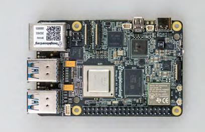
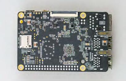
That said, we are really excited to talk about our latest offering, BeagleY-AI, which features the ability to work with a host of existing enclosures and add-on hardware over an emerging industry-standard 40-pin header. BeagleY-AI stands out with its open-source hardware design, fanless operation, and a 4 TOPS capable deep learning engine for AI workloads.
NASS: How does the BeagleY-AI board differ from what’s already available in the industry? I understand it employs the latest processor available from Texas Instruments. Was TI involved in the development of the board? And in what other ways was the company involved? And why is this important or beneficial to a developer?
KRIDNER: The long-standing partnership between BeagleBoard.org and Texas Instruments has been instrumental in our success. And the commitment to utilizing TI processors in BeagleBoard products, including the AM67X that’s in the BeagleY-AI board, underscores a shared vision for advancing technology and providing cutting-
edge development platforms to makers and industry partners. The AM67X processor brings significant benefits, such as energy-efficient machine-learning capabilities, low-latency cores for timingcritical applications, and support for standard high-speed I/O interfaces like USB 3 and PCIe Gen 3. I believe that the low power, accelerated vision processing, and production stability gained from using the AM67S SoC helps BeagleY-AI stand out from its peers.
The collaboration between BeagleBoard. org and Texas Instruments extends beyond hardware integration, with TI’s hardware and software design teams actively involved in the BeagleY-AI testing and review process. Their A supply chain and ongoing technological advancements underscore their commitment to supporting the open-source community, ensuring the success of initiatives like BeagleBoard.org.
NASS: The new board has AI in its name, so tell me what that means.
KRIDNER: The short answer is that it means that we have a built-in accelerator with the ability to execute a deep learning model at very high rates, similar to those on much bigger and more power-hungry systems.
The longer answer is that it means we are focused on providing developers with a better tool for understanding what is possible in AI, including things like object detection, pose estimation, and image segmentation. We do this through a body of easy to access examples and materials on our documentation site, docs.beagleboard.org.
Q&A
6 Embedded Computing Design EMBEDDED WORLD | Spring 2024 www.embeddedcomputing.com
NASS: In terms of real-world examples, what are some of the interesting places that Beagle is being deployed?
KRIDNER: It’s incredible to see the breadth of applications where Beagles have been utilized, ranging from healthcare solutions like affordable, opensource real-time PCR machines used in Covid detection to underwater rescue drones, AI-powered machines, and even space missions. This diversity highlights the robustness and adaptability of Beagles, making them a go-to choice for innovators across different industries seeking reliable and versatile opensource hardware solutions.
But we only hear about a small percentage of where Beagles are used, because it’s up to the developers to decide what they want to share with us. We suspect that there are thousands of applications out there, and we are here to support them when needed. One that we are aware of is a laser-engraving application.
NASS: BeagleY-AI is built with “open-source hardware.” What does that mean and why is it significant? Is open source something to fear? Is it secure and safe?
KRIDNER: Quoting the definition, “open-source hardware” is the hardware whose design is made publicly available
so that anyone can study, modify, distribute, make, and sell the design or hardware based on that design. This really gets to the heart of who BeagleBoard.org is and to fully answer, I think we need to start with a look back in history.
The history of open-source hardware closely parallels the history of open-source software. When computers were first introduced in the 1950s and 1960s, providing the software source along with hardware design information was standard practice, critical for users to understand how to program these complex machines and even repair them when something goes wrong. This is a level of understanding that is denied by keeping a design closed.
When building a safe and secure system, high-quality reviews are critical. This is why mission-critical systems for the New York Stock Exchange can run Linux. A broad group of experts are enabled to chime in on possible vulnerabilities. Developers have the option to choose when, where, and how to lock things down to meet their own goals, rather than the security goals of someone else. Lots of eyes are looking at that body of code to make sure it’s robust. Personally, I feel far more secure running software with that degree of scrutiny than anything produced by any single company, and it is the same thing for hardware.
Open-source hardware means you can choose to secure things where you best see fit. It means you can even build the boards yourself if that is what you need to meet your security goals.
NASS: What are the programming languages and environments you’d expect a developer to employ when working with the new BeagleY-AI, and why?
KRIDNER: All of them! The nice thing about building on Linux is that most languages are supported. We’ve moved away from trying to build language-specific bindings to control the hardware and have instead focused on the interfaces provided by Linux and Zephyr.
With Zephyr, we can build something as small as 4 kbytes and that’s usually small enough for just about any system or subsystem – certainly in the prototype stage. It lets you focus on your code and just pull in supporting code as you want it to save time in your development. And you can go as far as getting a full POSIX environment, so building runtimes like Micropython are pretty easy to achieve.
So, Python, JavaScript, C, C++, Go, and Rust get a lot of the focus. We enable a self-hosted Visual Studio Code environment, but we leave it to others to provide value-added libraries and make sure Linux and Zephyr provide the interfaces needed by developers.
For the deep learning algorithms, there’s a fair bit of higher-level language integration and that’s primarily focused around Python and C++ with familiar APIs, like TensorFlow Lite. This isn’t an area where operating systems have integrated the interfaces yet, but I expect that to change.
NASS: How can developers become part of the Beagle community?
KRIDNER: BeagleBoard stays closely aligned with the needs and feedback of its users and developers, ultimately leading to more relevant and impactful product designs. We encourage joining the BeagleBoard.org community through our forum at forum. beagleboard.org.
Q&A BeagleBoard.org www.beagleboard.org/ X/FORMERLY TWITTER @beagleboardorg LINKEDIN www.linkedin.com/groups/BeagleBoardorg-1474607?gid=1474607 YOUTUBE www.youtube.com/user/jadonk www.embeddedcomputing.com Embedded Computing Design EMBEDDED WORLD | Spring 2024 7

Automobile Acoustics: Context Awareness Through Vibration Sensing
By Luca Bettini, Product Line Manager, Saket Thukral, Sr. Director of Product Line Management, and Nikolay Skovorodnikov, Sr. Application Engineering Manager at Knowles Electronics
Thanks to the push in recent years to improve passenger safety and comfort, cars on the road today have more computing power and capabilities than supercomputers from a few decades ago. Self-driving cars seem ever closer to reality.
This automotive revolution is due, in large part, to the integration of a wealth of sensors deployed to build contextual awareness and help the on-board computers create a perception of the world around them.
Cameras, LiDAR, radar, and ultrasonic sensors are just a few examples. Traditional audio sensing has seen limited adoption in this context. However, several use cases are emerging, including external voice commands and emergency vehicle detection, that require the ability to pick-up sound outside the vehicle to complement the data sourced from the other sensors.
Today, microphones are used for this purpose, but they are prone to failure when exposed to harsh elements such as snow, dust, water, and other contaminants. Recently, an alternative sound pickup mechanism via vibration sensing has presented a novel solution to address this need while being practically immune to the elements. Additionally, it enables a lower integration complexity due to the fully sealed package of the sensor.
Emerging Automotive Use Cases
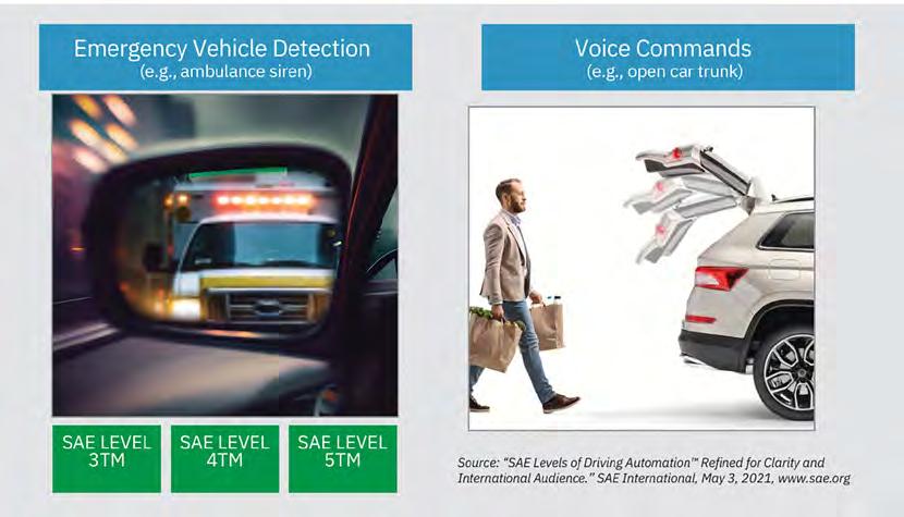
The adoption of microphones for in-vehicle sound pickup is already ubiquitous and enables several use cases ranging from hands-free phone calls and voice commands to road noise cancellation (RNC). More recently, the proliferation of Advanced Driver Assistance Systems (ADAS) and the advancement of in-vehicle infotainment have opened the doors to new use cases aimed at increasing safety and comfort while relying on sound pickup from outside the vehicle (Figure 1). These applications can be grouped into two broad categories: context awareness and external voice pickup.
› Context awareness: full and high driving automation (SAE Level 4 and Level 5, also referred to as Eyes-off Hands-off) require the system to detect and respond to dynamic driving situations, such as an approaching emergency vehicle. Even SAE
Level 3, which represents the first true step in autonomous driving, demands the driver to regain control in specific situations to put the vehicle in a safe position. Detecting an approaching emergency vehicle allows the driver or the autonomous driving system to react early, well before the potential danger is spotted by vision sensors, allowing more time to perform safety maneuvers.
› Voice pickup: external voice commands allow users to effortlessly open the car trunk or the vehicle doors on approach or when their hands are occupied. This application can replace unnatural gestures like kicking under the trunk with a natural voice-based user interface, which we already use to engage with smart speakers, smartphones, and other electronic devices.
Challenges with Existing Technologies
The use cases described above require external microphones to capture the sounds. However, traditional microphones need the soundwaves to enter the
AUTOMOTIVE SYSTEMS
8 Embedded Computing Design EMBEDDED WORLD | Spring 2024 www.embeddedcomputing.com
sensor package through the acoustic port to detect the sound (Figure 2a). The porthole makes them inherently vulnerable to contaminants, such as water, snow, and dust, that might obstruct the acoustic path, preventing the microphone from operating correctly. Something as innocuous as driving through a carwash could lead to a visit to the dealership for repairs. The traditional approach is to shield the acoustic path with a membrane, effectively trading sensitivity for protection. This adds to the cost and complexity of the solution. Yet the microphones remain at risk of failure in the field.
Sensing Sound through Vibrations
High bandwidth and low noise vibration sensors offer a practical solution to this problem. They are single-axis accelerometers that measure sound-induced vibrations generated by acoustic waves hitting the vehicle’s surface. Sensing vibrations does not require any porthole or acoustic channel, making vibration sensors intrinsically immune to external elements and much easier to integrate (Figure 2b). A vehicle has several metal, plastic, and glass panels that are ideal candidates to leverage such a technique. Vibration sensors can be mounted to the body of a vehicle in locations like on the front and rear windshield, door panels, side mirrors, and bumpers. Moreover, the sensor can be attached to the internal surface of a car panel (e.g., behind the side mirror). This makes it completely invisible, with a clear benefit for the vehicle’s aesthetics, while still able to capture external sounds.
Test Results
Knowles V2S200D vibration sensor achieved similar perfor-mance and signal capture to a regular microphone in the fre-quency bands of interest. Emergency vehicle sirens rely on a main tone sweeping between 500Hz and 1.5kHz, with most harmonic power concentrated below 8kHz. The siren sound pickup of V2S200D mounted on a car door was compared with a reference MEMS microphone and showed an excellent match between the two sensor outputs up to the desired bandwidth of 8kHz.

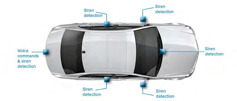
Emergency vehicle detection tests conducted with the sensor mounted at different locations on a vehicle traveling at various speeds showed promising results (Figure 3)
Conclusion
Audio vibration sensors represent a viable and preferred alternative to traditional MEMS microphones for picking-up external sounds in automotive applications thanks to their superior environmental robustness and lower system integration cost.
Luca Bettini, a resident of the greater Chicago area, is a product line manager at Knowles Corporation. Saket Thukral, from the greater Chicago area, is a senior director product line management & technical marketing at Knowles Corporation. Nikolay Skovorodnikov, a resident of California, is a senior manager of applications engineering (MEMS microphones) at Knowles Corporation.
AUTOMOTIVE SYSTEMS
Knowles Electronics www.knowles.com X/FORMERLY TWITTER @knowlescorp LINKEDIN www.linkedin.com/company/knowles-electronics/ YOUTUBE www.youtube.com/channel/ UCEz9LwcBNtnJc6_sLTFgRWw
FIGURE 1 Automotive use cases relying on external microphones for sound pick-up.
FIGURE 2 a/b Traditional bottom-port MEMS microphone (a) vs. vibration sensor (b) integration.
www.embeddedcomputing.com Embedded Computing Design EMBEDDED WORLD | Spring 2024 9
FIGURE 3 Detection tests conducted with the sensor mounted at different locations on a vehicle
LEMs and OEMs: Different Set-ups, different scopes
By Ethan Plotkin, CEO of GDCA, Inc.

Original Equipment Manufacturer (OEM) and Legacy Equipment Manufacturer (LEM) are two very similar terms for similar types of companies that perform vastly different roles in supply chain and manufacturing. A common problem that we see among embedded computing OEMs is that they attempt to perform the sustainment services that LEMs offer, but eventually end up draining valuable resources that could have been better used to develop new products. This is always out of a commitment to customers, attempting to support equipment and boards with long lifecycles.
LEMs saw the need for sustainment, which is why they centered their companies around supporting OEM products, so that the OEM could focus on making new products and supporting
technological developments. An LEM is a specialized manufacturer of embedded boards that supports and services the products of embedded computing OEMs after the OEMs decide to issue end-of-life (EOL) notices.
Because LEMs have strong manufacturing, engineering, and procurement capabilities, it’s not uncommon for them to be confused with other types of electronics companies, from contract manufacturers, to engineering services providers, and even distributors. But those types of companies are as different from LEMs as they are from each other.
OEMs vs. LEMs – Different Setups, Different Scopes
While OEMs and LEMs do perform similar operations – both are equipment manufacturers, outfitted with engineering, manufacturing, and production departments –these two types of businesses are set up very differently.
OEMs are started and built on the foundation of making profits on new and active products. That means that their resources and processes are catered towards supporting new product development and current product support.
LEMs are set up to profit by manufacturing and supporting legacy products, equipment that has been EOL’d, or has a long lifecycle to sustain that goes beyond what the OEM prefers to provide. Both types of companies have the same depart-
SUPPLY CHAIN AND MANUFACTURING
10 Embedded Computing Design EMBEDDED WORLD | Spring 2024 www.embeddedcomputing.com
A look at the difference between OEMs and LEMs–and why LEMs are so important for OEMs.

ments with relatively similar scopes, but the products on which they focus have very different needs.
For example:
Consider the difference between OEMs’ and LEMs’ engineering departments. While they both function similarly within their respective companies, they must solve very different types of engineering problems.
An OEM engineering team’s purpose is to quickly bring to market board-level features and functions that capture the “prime cut” of the value in the marketplace. Success is measured by both designwins for multi-year programs, as well as the high-rate follow-on manufacturing.
To be successful, OEM engineers must be current in leading edge embedded computing design theory and interoperability, contemporary components, tools, standards, and manufacturability techniques.
An LEM engineering team’s purpose is to sustain the product with minimal changes so that it remains form-fit-functionally identical to its original design and be reliably manufactured for as long as they are needed. Success is measured by quickly resolving and preventing electronics obsolescence issues - throughout the remaining years of low-rate manufacturing that occurs later in a product’s lifecycle.
To be successful, LEM engineers must not only be well versed in leading edge sustainment techniques, but also in legacy electronics architectures, standards, tools, and parts from when the designs were originally introduced, typically 10 or more years ago.
Unsurprisingly, the ‘prime cut” of the marketplace value that OEMs target means there is a much greater availability of design engineering capacity – making it more difficult to maintain a suitably sized sustaining engineering capability.
Increased Overhead from Process Exceptions
Sustainment projects are messy. This has always been the case.
Sustainment activities don’t fit into typical, standardized processes and almost always require a great deal of time and effort to successfully execute.
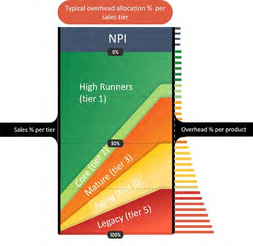
OEMs are set up for process–new product development to volume production to sales; sustaining production until the next project begins, then slowly phasing the old products out of their process to make room for new, improved technologies (Figure 1). To remain competitive, OEMs need clear and standardized processes that allow them to remain efficient and productive.
When OEMs try to provide the services that an LEM offers, one of the first major issues they run into is what they’re trying to do doesn’t match with their process.
Nearly everything to do with legacy sustainment creates exceptions to the OEM’s standard procedures and process, and can’t be automatically handled within the department. These exceptions, nearly every single time, require special oversight by the management in the department. The moment that management stops overseeing sustainment activities that can’t be automatically handled, the work typically gets snagged until they can get back to it.
SUPPLY CHAIN AND MANUFACTURING
GDCA Inc. www.gdca.com X/FORMERLY TWITTER @gdcainc YOUTUBE www.linkedin.com/company/gdca-inc
www.embeddedcomputing.com Embedded Computing Design EMBEDDED WORLD | Spring 2024 11
FIGURE 1
Typical OEM process for new product development.
LEMs, on the other hand, are organized to flexibly respond to the needs of sustainment projects. Their process accounts for changing situations, new information, and other unique circumstances. Sustainment of legacy electronics always presents some new, unique challenge that requires very specific needs. LEMs have the flexibility, capabilities, and the dedicated management to handle these challenges.
There is no way to standardize sustainment. We at GDCA know this because we have tried it in the past. Instead, we have found that sustainment requires collaboration, flexibility, and dedication in an ever-changing environment.
For example:
If an OEM has a request for a product that they have discontinued, they can’t just immediately source, manufacture, and deliver the product. The problems begin right here, in the quoting stage. As a part or piece of equipment gets older, its supply chain breaks down– the original materials and components may no longer be available, or they may no longer be available at the level of quality needed. Or perhaps these materials are available, but the lead time is far too long to be viable.
This immediately slows the entire sustainment process for the OEM, before the sales order is even received.
When this situation arises, management almost always needs to be involved to support their procurement personnel through these challenges and authorize them to take exceptional direction. However, to understand options and provide direction, management also has to bring in other departments, such as engineering, to ensure that they take a viable direction.
Finally, if all involved, management comes to an agreement, then a direction can be taken, and a customer quote can then be delivered. However, this overhead has consumed time and labor away from the products that account for the majority of OEM’s profits. It also provides no guarantee the customer will purchase the product. And that’s just getting everything needed to quote the product.
The Opportunity Cost of Time
Many OEM leadership teams view engineering capacity as infinite because salaried engineering payroll is largely fixed. At the same time, OEM leadership teams are engaged in a chronic struggle to hold and accelerate new-product-introduction (NPI) timelines. Legacy work undermines OEMs’ objective to develop new products, whether an OEM is set up to measure it.
The best way to view the legacy drain on resources is through time, mainly, and what these OEM personnel are not doing while they’re attempting to sort through a sustainment project. Although it is hard to calculate how much longer it took people to finish
more strategic activities related to core high-rate products, everyone agrees they want high-ROI work done faster.
While the OEM may indeed be able to eventually provide sustainment for a product, this will ultimately take resources away from their usual business: materials, labor, time, and costs. This leads to longer lead times on profitable products, delays, and other issues that ultimately make the OEM less competitive.
The more products that the OEM tries to simultaneously sustain, the more these problems accumulate and grow. That’s why LEMs are so important– they work with OEMs to provide the sustainment for legacy equipment that OEMs want to give their customers...without the distraction. This partnership releases more resources for more predictable NPI.
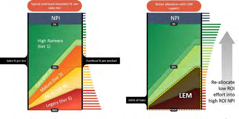
Legacy Equipment Manufacturers and Original Equipment Manufacturers, while having similar departments, are not set up to perform the same job. Sustainment is a complex and convoluted undertaking that does not fit into the OEM standardized process. Both types of companies work in very different niches of manufacturing (Figure 2).
LEMs allow OEMs to provide their customers with legacy sustainment solutions without having to set aside valuable resources that are necessary for new product development and other strategic priorities.

Ethan Plotkin is the CEO of GDCA, Inc., a manufacturing company specializing in legacy manufacturing and sustainment engineering for obsolete electronics. Over the past twenty years, Ethan has transformed GDCA from a small OEM into a trusted partner for obsolescence management and supply chain sustainability for embedded circuit board OEMs. Using his experience in manufacturing and supply chain risk management, Ethan has led GDCA into a mission that supports secure manufacturing, national security, and economic security for the US and its allies.
SUPPLY CHAIN AND MANUFACTURING
Comparison between LEMs and OEMs processes for new product development.
12 Embedded Computing Design EMBEDDED WORLD | Spring 2024 www.embeddedcomputing.com
FIGURE 2
Revolutionizing IoT Security: A Seamless Approach to Device Provisioning
By Hardy Schmidbauer, SVP of Kudelski IoT
In the rapidly evolving landscape of the Internet of Things (IoT), the security of connected devices has never been more critical. The complexity of traditional device provisioning processes, with their manual handling and diverse environments, has posed significant challenges, often leading to increased risks of security breaches and operational inefficiencies. At Kudelski IoT, we understand these challenges and are committed to transforming the IoT ecosystem with innovative, secure, and user-friendly solutions.
In a groundbreaking initiative, Kudelski IoT, in collaboration with semiconductor industry giants STMicroelectronics, Infineon, Microchip, and Silicon Labs, is proud to introduce an advanced identity provisioning solution also that integrates seamlessly with Matter. This strategic move is not just about enhancing device security; it represents a leap towards a future where IoT device provisioning is effortless, secure, and devoid of the complexities that have plagued the industry for years.
Simplifying IoT Provisioning Without Compromising Security
The cornerstone of our initiative is the simplification of the IoT provisioning process. Traditional methods, fraught with manual interventions and error-prone procedures, are no longer viable in an ecosystem that demands agility, security, and efficiency. Our approach, developed in partnership with leading silicon manufacturers, leverages secure, scalable, and automated provisioning solutions. This means devices can now be provisioned with zero-touch, directly in the field or factory, significantly reducing costs, complexity, and time-to-market for device manufacturers. More importantly, it enhances security and ease of use for end users, ensuring a seamless integration into smart ecosystems.
A Unified Effort for a Secure and Interoperable IoT Ecosystem
Our collaboration with semiconductor leaders is instrumental in equipping IoT devices with unparalleled security features. By facilitating the adoption of Matter standards, we are not only improving interoperability within smart home ecosystems but also across the broader IoT landscape. This unified effort

underscores the industry’s commitment to advancing IoT security and interoperability, ensuring that devices are not only equipped for today’s digital age but are also future-proof.
Setting New Standards for IoT Security and Interoperability
The significance of our partnerships extends beyond the technical advancements in device security. It embodies a shared vision for a seamlessly connected and secure IoT ecosystem. Together, we are setting new standards for security and interoperability, addressing the intricate challenges of device provisioning with simplified and secure solutions. Our initiative marks a pivotal advancement in the realm of IoT security and interoperability, made possible through strategic collaborations with industry leaders.
As we showcase these groundbreaking solutions at Embedded World, we invite device manufacturers and stakeholders across the IoT ecosystem to join us in this journey. Together, we can revolutionize IoT security, ensuring that connected devices are not only secure but also seamlessly integrated into our digital lives.
At Kudelski IoT, we are dedicated to simplifying the integration of robust security measures, enabling our clients to deploy secure, efficient, and compliant devices in a rapidly evolving digital landscape. Our initiative with STMicroelectronics, Infineon, Microchip, and Silicon Labs is a testament to our commitment to innovation, security, and the future of IoT. Join us as we pave the way for a more secure, interconnected world.
Kudelski IoT:
Your Partner in Secure, Seamless IoT Connectivity. Visit us at www.kudelski-iot.com to learn more about our solutions and how we can help secure your IoT ecosystem.
ADVERTORIAL EXECUTIVE SPEAKOUT
Kudelski IoT | www.kudelski-iot.com

How to Mitigate Timing and Interference Issues on Multicore Processors
By Mark Pitchford, Technical Specialist, LDRA
Embedded software developers face unique challenges when dealing with timing and interference issues on heterogeneous multicore systems. Such platforms offer higher CPU workload capacity and performance than single core processor (SCP) setups, but their complexity can make strict timing requirements extremely difficult to meet.
In hard real-time applications, deterministic execution times are crucial for meeting operational and safety goals. Although multicore processor (MCP) platforms generally exhibit lower average execution times for a given set of tasks than do SCP setups, the distribution of these times is often spread out. This variability makes it difficult for developers to ensure precise timing for
tasks, creating significant problems when they are building applications where meeting individual task execution times is just as critical as meeting goals for average times.
To address these challenges, embedded software developers can turn to guidance documents like CAST-32A, AMC 20-193, and AC 20-193. In CAST-32A, the Certification Authorities Software Team (CAST) outlines important considerations for MCP timing and sets Software Development Life Cycle (SDLC) objectives to better understand the behavior of a multicore system. While not prescriptive requirements, these objectives guide and support developers toward adhering to widely accepted standards like DO-178C.
RESOURCE-CONSTRAINED ENGINEERING
14 Embedded Computing Design EMBEDDED WORLD | Spring 2024 www.embeddedcomputing.com
In Europe, the AMC 20-193 document has superseded and replaced CAST-32A, and the AC 20-193 document is expected to do the same in the U.S. These successor documents, collectively referred to as A(M)C 20-193, largely duplicate the principles outlined in CAST-32A.
To apply the guidance from CAST-32A and its successors, developers can employ various techniques for measuring timing and interference on MCP-based systems.
The Importance of Understanding
Worst-Case Execution Times
In hard real-time systems, meeting strict timing requirements is essential for ensuring predictability and determinism. Such systems run mission- and safetycritical applications such as advanced driver-assistance systems (ADAS) and aircraft autopilots. In contrast to soft real-time systems, where missing timing deadlines has less severe consequences, understanding the worst-case execution time (WCET) for hard real-time tasks is essential because missed deadlines can be catastrophic.
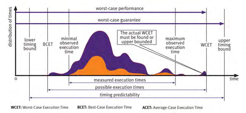
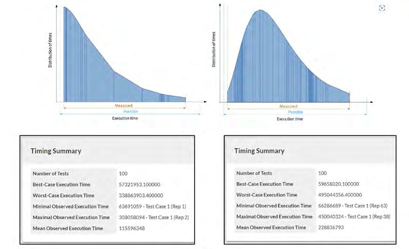
Developers must consider both the bestcase execution time (BCET) and the WCET for each CPU task. The BCET represents the shortest execution time, while the WCET represents the longest execution time. Figure 1 illustrates how these values are determined given an example set of timing measurements.
Measuring the WCET is particularly important because it provides an upper bound on the task’s execution time, ensuring that critical tasks complete within the required time constraints.
In SCP setups, meeting upper timing bounds can be guaranteed as long as there is sufficient CPU capacity planned and maintained. In MCP-based systems, meeting these bounds is more difficult due to the lack of effective methods for calculating a guaranteed tasking schedule that accounts for multiple processes running in parallel across heterogeneous
RESOURCE-CONSTRAINED ENGINEERING
cores. This complexity increases when applications share hardware between processor cores. Contention for the use of these Hardware Shared Resources (HSR) is largely unpredictable, disrupting the measurement of task timing.
Developers of hard real-time systems on MCPs – unlike their counterparts working with single-core systems – cannot rely on static approximation methods to generate usable approximations of BCETs and WCETs. Instead, they must rely on iterative tests and measurements to gain as much confidence as possible in understanding the timing characteristics of tasks.
Understanding CAST-32A and A(M)C 20-193
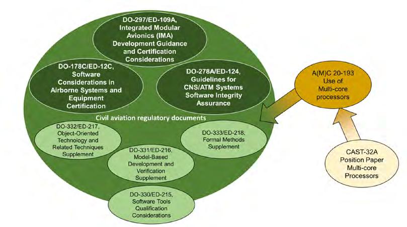
To better understand the landscape of guidance available to developers, Figure 2 provides a visual representation of the relationships between key civil aviation documents.
CAST-32A and A(M)C 20-193 place significant focus on developers providing evidence that the allocated resources of a system are sufficient to allow for worst-case execution times. This evidence requires adapting development processes and tools to iteratively collect and analyze execution times in controlled ways that help developers optimize code throughout the lifecycle.
Neither CAST-32A nor A(M)C 20-193 specify exact methods for achieving their objectives, leaving it to developers to implement in ways that best suit their projects.
YOUTUBE https://www.youtube.com/user/ldraltd LDRA www.ldra.com X/FORMERLY TWITTER @ldra_technology LINKEDIN www.linkedin.com/company/ldra-limited
Different execution times and guarantees for a given real-time task
FIGURE 1
Relationships between civil aviation regulatory and advisory documents
www.embeddedcomputing.com Embedded Computing Design EMBEDDED WORLD | Spring 2024 15
FIGURE 2
Guidance for Developers
CAST-32A and A(M)C 20-193 specify MCP timing and interference objectives for software planning through to verification that include the following:
› Documentation of MCP configuration settings throughout the project lifecycle, as the nature of software development and testing makes it likely that configurations will change.
(MCP_Resource_Usage_1)
› Identification of and mitigation strategies for MCP interference channels to reduce the likelihood of runtime issues.
(MCP_Resource_Usage_3)
› Ensuring MCP tasks have sufficient time to complete execution and adequate resources are allocated when hosted in the final deployed configuration. (MCP_Software_1 and MCP_Resource_Usage_4)
› Exercising data and control coupling between software components during testing to demonstrate that their impacts are restricted to those intended by the design.
(MCP_Software_2)
Both CAST-32A and A(M)C 20-193 cover partitioning in time and space, allowing developers to determine WCETs and verify applications separately if they have verified that the MCP platform itself supports robust resource and time partitioning. Making use of these partitioning methods helps developers mitigate interference issues, but not all HSRs can be partitioned in this way. In either case, the likes of DO-178C require evidence of adequate resourcing.
How to Analyze Execution Times on MCP Platforms
The methods that follow are proven effective to meet the needs of WCET analysis and to meet the guidance of CAST-32A and A(M)C 20-193 guidelines.
Halstead’s metrics and static analysis Halstead’s complexity metrics can act as an early warning system for developers, providing insights into the complexity and resource demands of specific segments in code. By employing static analysis, developers can use Halstead data
with actual measurements from the target system, resulting in a more efficient path to ensuring adequate application resourcing.
These metrics and others shed light on timing-related aspects of code, like module size, control flow structures, and data flow. Identifying sections with larger size, higher complexity, and intricate data flow patterns helps developers prioritize their efforts and fine-tune code segments that incur the highest demands on processing time. Optimizing these resource-intensive areas early in the lifecycle reduces the mitigation effort and risks of timing violations.
Empirical Analysis of Execution Times
Measuring, analyzing, and tracking individual task execution times helps mitigate issues in modules that fail to meet timing objectives. Dynamic analysis is essential to this process, as it automates the measurement and reporting of task timings to free up developer workloads.
To ensure accuracy, three considerations must be taken into account:
1. The analysis must occur in the actual environment where the application will run, eliminating the influence of configuration differences between development and production, such as compiler options, linker options, and hardware features.
2. Sufficient tests must be executed repeatedly to account for environmental and application variations between runs, ensuring reliable and consistent results.
3. Automation is highly recommended for executing sufficient tests within a reasonable timeframe and for eliminating the influence of relatively slower manual actions.
One example is the LDRA tool suite (Figure 3), which employs a “wrapper” test harness to exercise modules on the target device to automate timing measurements. Developers can define specific components under test, whether at the function level, a subsystem of components, or the overall system. Additionally, they can specify CPU stress tests, like using the open-source Stress-ng workload generator, to further improve confidence in the analysis results.
Analysis of application control and data coupling
Control and data coupling analysis play a crucial role in identifying task dependencies within applications. Through control coupling analysis, developers examine how the execution and data dependencies between tasks affect one another. The standards insist on these analyses not only to ensure that all couples have been exercised, but also because of their capacity to reveal potential problems.
RESOURCE-CONSTRAINED ENGINEERING
Execution time histograms from the LDRA tool suite (Source: LDRA)
16 Embedded Computing Design EMBEDDED WORLD | Spring 2024 www.embeddedcomputing.com
FIGURE 3
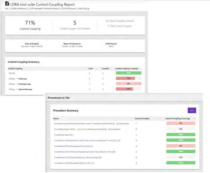
predictability and resource utilization of the application.
Conclusion
By understanding the CAST-32A and A(M)C 20-193 guidance and the analysis methods presented here, embedded software developers can better manage the complexities of Hardware Shared Resource interference and address coding issues that impact it – essential in ensuring the efficient and deterministic execution of critical workloads on multicore platforms.

Mark Pitchford, a technical specialist at LDRA, is a chartered engineer with over 20 years experience in software development, more lately focused on technical marketing. Proven ability as a developer, team leader, and manager, working in functional safety- and security-critical sectors. Communications skills demonstrated through project


 The LDRA tool suite provides robust support for control and data coupling anal-
Data coupling and control coupling analysis reports from the LDRA tool suite (Source: LDRA)
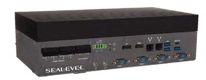
NEW Flexio Fanless Industrial Embedded Computers Sealevel Systems is the leading designer and manufacturer of rugged industrial computers, Ethernet serial servers, USB serial, PCI Express and PCI bus cards, and software for critical communications. We deliver proven, high-reliability automation, control, monitoring, and test and measurement solutions for industry leaders worldwide. The Flexibility You Need Meets The Performance You Demand Finally. • Industrial Processing & Performance with Long-Term Availability • Solid-State Design Guarantees Extended Operation • Unmatched I/O Configurability for Automation & Control ECD 7x4875.pdf 1 3/7/24 3:37 PM www.embeddedcomputing.com Embedded Computing Design EMBEDDED WORLD | Spring 2024 17
FIGURE 4

Ten Things to Consider When Developing ML at the Edge
By Yann LeFaou, Associate Director for Microchip’s touch and gesture business unit
From predictive maintenance and image recognition to remote asset monitoring and access control, the demand for industrial IoT applications capable of running machine learning (ML) models on local devices, rather than in the cloud, is growing rapidly.
EDGE COMPUTING 18 Embedded Computing Design EMBEDDED WORLD | Spring 2024 www.embeddedcomputing.com
As well as supporting environments where sensor data needs to be collected far from the cloud, these socalled ‘ML at the Edge’ or Edge ML deployments offer advantages that include low-latency, real-time inference, reduced communication bandwidth, improved security, and lower cost. Of course, implementing Edge ML is not without its challenges, whether that’s limited device processing power and memory, the availability or creation of suitable datasets or the fact that most embedded engineers do not have a data science background. The good news, however, is that there is a growing ecosystem of hardware, software, development tools, and support that is helping developers to address these challenges.
In this article we’ll take a look at the challenges and identify ten key factors that embedded designers should consider.
Introducing Edge ML
Fundamental to delivering artificial intelligence (AI), machine learning (ML) uses algorithms to make inferences from both fresh/live data and historic data. To date, ML applications have been implemented with most of the data processing performed in the cloud. Edge ML reduces or eliminates cloud dependency by enabling local IoT devices to analyze data, make models and predictions, and to take actions. Moreover, the machine can constantly improve its efficiency and accuracy, automatically and with little or no human intervention.
Edge ML has the potential to provide a great boost to Industry 4.0, with real-time edge processing improving manufacturing efficiency, while applications ranging from building automation to security and surveillance also stand to benefit. As a result, the potential of ML at the edge is huge, as reflected in a recent study by ABI Research, which forecasts that the edge ML enablement market will exceed US$5 billion by 20271. Also, while ML was once in the

domain of the mathematics and scientific communities, increasingly it is part of the engineering process and an important element of embedded systems engineering.
As such, the challenges associated with implementing Edge ML are not so much about “Where do we start?” but rather, “How do we do this quickly and cost-effectively?” The following 10 considerations should help answer this question.
1. Data Capture
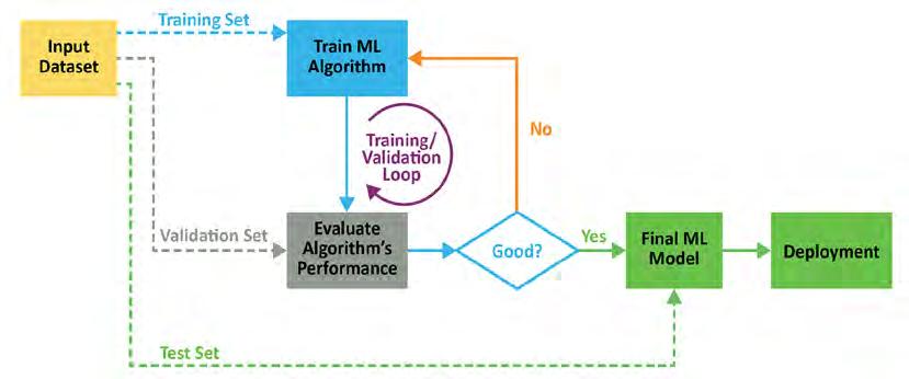
To date, most ML deployments have been implemented in powerful computers or cloud servers. However, Edge ML needs to be implemented in space- and powerconstrained embedded hardware. The use of smart sensors that perform some level of pre-processing at the data capture stage will make data organization and analysis much easier, as they cater for the first two steps in the ML process flow (Figure 1).
A smart sensor can create one of two types of smart model; those trained to solve for simple classification or those trained to solve regression-based problems.
2. Interfaces
ML models must be deployable, and that requires having interfaces between the constituent (software) parts of the machine. The quality of these will govern how efficiently the machine works and can self-learn. The boundary of an ML model comprises inputs and outputs. Catering for all input features is relatively easy. Catering for the model’s predictions is less so, particularly in an unsupervised system.
Of course, interfaces also relate to the physical connection between elements of the hardware. These may be as simple as connections for USB or external memory, or more sophisticated interfaces that support connections for video streams and user-specific inputs. By definition, Edge ML applications are space-, power-, and cost-constrained, so consideration must be given to the minimum number and type of interfaces needed.
3. Creating Optimized Datasets
The use of commercially available datasets (a collection of data that has already been arranged in some kind of order) is a good way to fast-track an Edge ML development
YOUTUBE www.youtube.com/user/MicrochipTechnology Microchip www.microchip.com X/FORMERLY TWITTER @MicrochipTech LINKEDIN www.linkedin.com/company/microchip-technology/
EDGE COMPUTING
The machine learning process flow
FIGURE 1
Above, the input dataset includes training data.
www.embeddedcomputing.com Embedded Computing Design EMBEDDED WORLD | Spring 2024 19
FIGURE 2
project. The dataset needs to be optimized for use, according to the purpose of the Edge ML device.
For example, consider a security scenario in which the behavior of people must be monitored, and suspicious behavior automatically flagged. If a local monitoring device has embedded vision and the ability to recognize what people are doing – standing, sitting, walking, running, or leaving a bag/case unattended for instance – decisions can be made at the source of the data.
Rather than train the device from scratch, part of the input dataset would be a training set (Figure 2) such as MPII Human Pose, which includes around 25,000 images extracted from online videos. The data is labeled, so it can be used for supervised machine learning.
4. Requirements for Processing Power
The computational power required for Edge ML varies depending on application. Image processing, for example, needs more computational power than an application based on polling a sensor or conditioning an input feed.
ML models deployed on smart devices work best if they are small and the tasks required of them are simple. As models grow in size and tasks in complexity, the need for greater processing power grows exponentially. Unless satisfied, there will be a system performance (in terms of speed and/or accuracy) penalty. However, the ability to use smaller chips for ML is being aided by improvements in algorithms and in open-source models (such as TinyML), ML frameworks, and modern IDEs to help engineers produce efficient designs.
5. Semiconductors/Smart Sensors
Many Edge ML applications require edge processing for image and audio recognition. MPUs and FPGAs capable of supporting cloud-based processing for such applications have been available for some time but now the availability of low-power semiconductors to integrate this functionality are making edge-based applications much simpler to develop.
For example, Microchip’s 1 GHz SAMA7G54 (Figure 3) is the industry’s first single-core MPU with a MIPI CSI-2 camera interface and advanced audio features. This device integrates complete imaging and audio subsystems, supports up to 8M pixels and 720p @ 60 fps, up to four I2S, one SPDIF transmitter and receiver, and a 4-stereo channel audio sample rate converter.
What’s more, no longer is a dedicated device needed to deliver advanced edge-based processing. Engineers are finding that advances in semiconductor technologies and ML algorithms are coming together to make commercially available 16-bit and even 8-bit MCUs an option for effective Edge ML. For many applications the use of such low-power, small form factor devices is a pre-requisite for delivering battery-powered, sensor-based industrial IoT Edge ML systems.
6. Open-Source Tools, Models, Frameworks, and IDEs
In any development the availability of open-source tools, models, frameworks, and well-understood integrated development environments will simplify and speed design, testing, prototyping, and minimize all-important time-to-market. In the case of Edge ML, the emergence of ‘Tiny Machine Learning’ or TinyML is particularly important. As per the definition of the tinyML Foundation, this is the “fast growing field of machine learning technologies and applications including hardware (dedicated integrated circuits), algorithms, and software capable of performing on-device sensor (vision, audio, IMU, biomedical, etc.) data analytics at extremely low power, typically in the mW range and below, and hence enabling a variety of always-on use-cases and targeting battery operated devices.”
Thanks to the TinyML movement, recent years have seen an exponential growth in the availability of tools and support that make the job of the embedded design engineer easier.
Good examples of such tools are those from Edge Impulse and SensiML™. Providing ‘TinyML as a service,’ in which the application of ML can be delivered in a footprint of just a few kilobytes, these tools are fully compatible with the TensorFlow™ Lite library for deploying models on mobile, microcontrollers, and other edge devices.
By choosing such tools, developers can deliver rapid classification, regression and anomaly detection, simplify the collection of real sensor data, ensure live signal processing from raw data to neural networks, and speed testing and subsequent deployment to a target device.
7. Development Kits
The increased availability of development kits is another factor helping to accelerate the implementation of Edge ML applications. Many products that go to market are based on the hardware and firmware found within (and drivers, software modules, and algorithms running on) embedded system development kits and those suitable for developing ML apps are available from a host of vendors. For example, the Raspberry Pi 4 Model B is based on the Broadcom® BCM2711 Quad-core Cortex®-A72 64-bit SoC (clocked at 1.5 GHz), has a Broadcom VideoCore® VI GPU and 1/2/4 GB LPDDR4 RAM, and can deliver 13.5 to 32 GFLOPS computing performance.
In creating a design, it is worth spending some time researching the parts used on the development kits as it can be beneficial to build the final application using the same silicon. For instance, if the ML application requires embedded vision, Microchip’s PolarFire® SoC FPGAs are ideal for compute-intensive edge vision processing, supporting up to 4k resolution with low-12.37 SERDES.
8. Data Security
When it comes to security, the good news is that with Edge ML, there is far less data being transferred to the cloud, meaning the potential surface for cyberattacks is significantly reduced. That said, an Edge ML deployment introduces new challenges as
EDGE COMPUTING
20 Embedded Computing Design EMBEDDED WORLD | Spring 2024 www.embeddedcomputing.com

all edge devices – whether ML-enabled or not – no longer have the inherent security of the cloud and must be independently protected just like any other IoT device or embedded system connected to a network.
Security considerations to consider include:
› How easy is it for hackers to change the data (being input and/or used for training) or the ML model?
› How secure is the data? Can it be accessed before encryption? Noting here that encryption requires keys to be kept in a safe (not obvious) place.
› How secure is the network? Is there a risk of unauthorized devices (or seemingly authorized) devices connecting and doing harm?
› Can the Edge ML device be cloned?
The level of security required will of course depend on the application (it could be safety-critical, for example) and/or the nature of the ‘bigger system’ of which the Edge ML device is a part.
9. In-House Capabilities
Within a typical engineering team there will be varying degrees of ML and AI understanding. Open-source tools, development kits, and off-the-shelf data sets mean that embedded engineers do not need an in-depth understanding of data science or deep learning neural networks. However, when embracing any new engineering discipline or methodology (or investing in tools), time spent on training can lead to shorter development times, fewer design spins, and improved output-per-engineer in the long run.
The wealth of information about ML online in the form of tutorials, whitepapers, and webinars (as well as the fact that engineering tradeshows run ML seminars and workshops) provides many opportunities to enhance development team capabilities. More formal courses include MIT’s Professional Certificate Program in ML and AI, while Imperial College, London, runs an online course that includes a module on how to develop and refine ML models using Python and industry standard tools to measure and improve performance.
Finally, it is now possible to augment an engineering team’s capabilities, with generative AI tools, allowing novices to code complex applications, while considering ML training versus direct coding could also lead to shorter development times, fewer re-spins, and improved outputs.
10. Supplier Support and Partnerships
Developing an ML-enabled application for a device is made much easier with support from suppliers already active in the field. For example, for cloud-based ML, AWS has its popular ‘Machine Learning Competency Partners’ program. In the case of Edge ML specifically, it is advisable to look beyond simply the product being supplied and consider the potential benefits of the supplier’s existing collaborations. Microchip, for instance, has invested significant resources in establishing relationships with partners ranging from sensor vendors to tool providers to ensure customers have access to everything from basic advice and guidance through to the delivery of turnkey solutions.
Conclusion
While each of the 10 points discussed in brief above could easily warrant an article of its own, the objective of this article was to help embedded systems designers identify some key factors to take into account before embarking on their Edge ML project.
By considering each of these issues carefully at the outset it should be possible to form a strategy that will create optimized solutions that meet size, power, cost, and performance objectives at the same time as de-risking the project, minimizing re-spins, and reducing overall time-to-market.
1. ABI Research Edge ML Enablement: Development Platforms, Tools and Solutions application analysis report, June 2022.

Yann LeFaou is Associate Director for Microchip’s touch and gesture business unit. In this role, LeFaou leads a team developing capacitive touch technologies and also drives the company’s Machine learning (ML) initiative for microcontrollers and microprocessors. He has held a series of successive technical and marketing roles at Microchip, including leading the company’s global marketing activities of capacitive touch, human machine interface, and home appliance technology. LeFaou holds a degree from ESME Sudria in France.
Microchip’s SAMA7G54 with integrated video and audio capabilities
FIGURE 3
www.embeddedcomputing.com Embedded Computing Design EMBEDDED WORLD | Spring 2024 21
ADC Decimation: Addressing High Data-Throughput Challenges
By Chase Wood, Applications Engineer, High-Speed Data Converters, Texas Instruments
As data converters push the boundaries of sampling rates and available bandwidth, system designers face challenges in ensuring high-speed (>10Gbps) signal integrity. The evolving landscape of analog-to-digital converters (ADCs) leans toward increased digitalization, leading to a reduction in the demands on digital signal processors (DSPs) or field-programmable gate array (FPGA) resources.
In an ADC, employing a digital downconverter (DDC) alongside digital decimation filters reduces the output data rate. Decimation proves particularly valuable in scenarios where only a specific portion of the Nyquist zone is applicable.
Typical Approach to RF Sampling
In recent years, direct RF sampling data converters have sampled at speeds in excess of 10GSPS, meaning that the Nyquist frequency and instantaneous bandwidth are both increasing, since they are directly related to the sample rate. With more instantaneous bandwidth, you have the option to use more of a Nyquist zone for data transmission, meaning more throughput. But there is a limit.
While in theory it is possible to demodulate an upper Nyquist zone into baseband and then simply filter at the Nyquist zone, this would only be useful if the entire Nyquist zone contained signals of interest and the converter had a very large input range and high resolution. As signal bandwidth increases, the amplitude of each frequency component of the signal must decrease in order to avoid over-ranging the converter. Frequencies will overlap in the time domain, causing signals in excess of the supported ADC input level. Implementing many lower bandwidth signals (with adequate spacing and cushion between the bands) and using dedicated analog mixers at each band’s center frequency (fc) is the typical
solution to avoid this problem. Scalability quickly becomes an issue, however, as each band of signals requires a dedicated analog mixer and data-converter channel.
Pairing a DDC stage with decimation filters to first demodulate the RF signal and remove out-of-band noise, spurs and harmonics leaves just the signals of interest at a reduced data bandwidth to pass to any downstream processor. For instance, if a
HIGH-SPEED SIGNAL PROCESSING
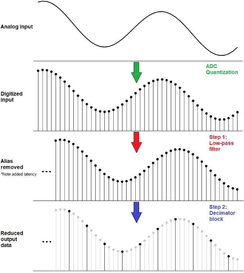
conversion itself is a process comprising two steps.
1 22 Embedded Computing Design EMBEDDED WORLD | Spring 2024 www.embeddedcomputing.com
Down
FIGURE
converter has 500MHz of usable bandwidth but you only care about a 15MHz band of signals, the converter’s bandwidth utilization is only 3%. If you were to implement a decimation-based solution, the converter’s overall useful bandwidth would drop by a decimation factor (M), while the 15MHz of input signal remained at 15MHz. If you chose to perform decimation by 32, the converter’s utilization would increase significantly – up to 96%. In layman’s terms, instead of taking a sip from a firehose, decimation allows you to take a sip from that firehose using a straw – and dump the extra water onto the grass.
Converter Decimation at a High Level
Decimation in its simplest form is the process of reducing a digital signal’s data rate to transmit a reduced portion of the data to a signal processor of choice, such as an FPGA or DSP. In recent years, integrating this function into RF sampling data converters helped system designers by reducing the downstream processing workload, enabling the selection of lower-cost FPGAs or DSPs (requiring less computational power), while also improving a system’s data processing efficiency.
Down conversion itself is a process comprising two steps, as shown in Figure 1. First, the sampled data must pass through an anti-aliasing filter. The digital low-pass filter acts to limit the bandwidth to the first Nyquist zone, preventing the effects of aliasing, often referred to as images. Aliasing occurs as a result of tones in higher Nyquist zones that fold back into the first Nyquist zone appearing as spurs to the ADC (and thus to any subsequent data processor).
After the filter stage, the data passes into a decimator, whose function is to perform downsampling on the digital data stream by passing a single ADC code every M number of ADC clock cycles, resulting in a reduced output data rate of 1/M. Each ADC code inherently contains information from the previous M-1 samples as a result of the finite impulse response (FIR) low-pass filter.
What is a Decimation Filter?
The ADC samples at a full data rate and downconverts the data based on an intermediate frequency generated by a numerically controlled oscillator (NCO) and a digital mixing stage. After downconversion, the data has aliasing and images at every
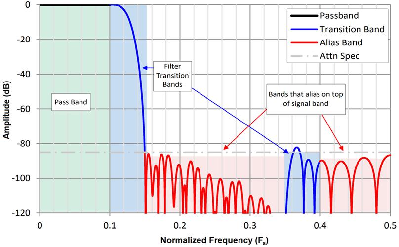
multiple of the NCO frequency, which is where the digital decimation filters come into play. These decimation filters are created using digital FIR filters and comprise a passband, many transition bands, and many alias bands, as shown in Figure 2.
Tones within the passband are unaffected by the decimation filter and as a result are not attenuated. Input signals in the transition bands experience some level of attenuation, which may be any level of attenuation from just a few decibels all the way down to the attenuation specification of the ADC. Tones within the alias bands fall outside the decimation filter and will be attenuated heavily. This attenuation level will be listed in the ADC data sheet as the decimation filter stop-band rejection level.
The transition band is also labeled at the alias frequency of higher Nyquist zones, indicating where second-order harmonic distortion (HD2), third-order harmonic distortion (HD3) or any higher harmonic may appear; however, these harmonics are attenuated at the alias band rate. Additionally, if operating near the useful band limitations for any decimation mode, it’s likely that the signals are heavily attenuated, more than preferred. Proper frequency planning will ensure that the input frequency lands within the pass band of the ADC in any specific decimation mode.
Conclusion
By addressing challenges linked to increasing bandwidth needs, integrating digital downconverters and decimation filters emerges as a viable solution for system designers.

Chase Wood is an experienced Applications Engineer in the High Speed Data Converters group at Texas Instruments, with a Bachelor of Science in Electrical Engineering from The University of Texas at Dallas.
HIGH-SPEED SIGNAL PROCESSING YOUTUBE https://www.youtube.com/texasinstruments Texas Instruments www.ti.com X/TWITTER @iarsystems LINKEDIN www.linkedin.com/company/texas-instruments
Decimation filters are created using digital FIR filters and comprise a passband, many transition bands, and many alias bands.
FIGURE 2
www.embeddedcomputing.com Embedded Computing Design EMBEDDED WORLD | Spring 2024 23
Getting Connected to IoT
By Embedded Computing Design Staff
Welcome to Back to Basics, a series where we review basic engineering concepts that may require a more complex explanation than a quick Google search could provide.
In the past decade, IoT, or the Internet of Things, has become increasingly prevalent in our day-to-day lives. Despite – or perhaps because of – the abundance of IoT devices commonly used in all sorts of places, it can often feel like a nebulous concept to define. So, what actually is the Internet of Things?
Essentially, the term “IoT” refers to a system of realworld nodes that communicate data to a central online hub. Now, this statement may be accurate, but it’s also still a bit vague, right? To simplify things, let’s split the term into its two parts: the things and the Internet.
The Eyes and Hands of the Internet
We live in a world that is bustling with all kinds of information. Temperature, color, weather, how many steps you took three days ago, the number of cars on the road, how old your grandmother was in 1985… the list is endless. The “things” part of IoT are physical devices that exist in the real world and can either gather or influence data – like the listed items above.
These “things” can be further simplified into two categories:
› Sensors take in real-world data, and turn it into digital data. For example, the heart-rate monitor in a smart watch collects real-world data (i.e. your heartbeat) and stores it online in a digital format.
› Affectors use that collected digital data to affect the physical space they exist in. Think of a self-driving car’s engine which takes digital information, like the desired traveling speed, and translates it into real-world motion.
The “Internet” part of IoT is where all of this digital data goes. Sensors upload data to the internet, and affectors use that data to alter something in the physical environment. To enable these real-world “things” to share information, the internet is a perfect vehicle.
An Interconnected World
Now that we have a broad view of what IoT is, it’s easy to see why it’s so useful. Once we have an IoT base to work from, we can then use programs or algorithms
to transform the world we live in more efficiently. As a general rule, a common way to market IoT devices is to describe them as “smart.” Because the device is IoTenabled, it can be algorithmically controlled, making it “smarter” than the average non-IoT device.
A good example of a simple IoT system would be the smart thermostat, where a building’s climate is controlled by a piece of internet-connected software. You can use a mobile app or the thermostat itself to set a desired digital data value for the temperature. Then, sensors in your building take in the indoor and outdoor temperatures and use an algorithm to move the fan in your AC unit to quickly and efficiently meet that desired value.
Obviously, IoT use cases extend far beyond thermostats and smart home appliances. A large part of the IoT industry is the Industrial IoT (IIoT) sector, where these principles are applied on a large scale to factories and warehouses. Imagine a factory that can sense the temperature, output speed, material levels, and use that data to control every machine in the building. Does wonders for production efficiency and overall factory health.
Now, there are some concerns that can come with IoT. More internet-connected devices means there’s more personal and critical data out in the aether, where hackers could potentially access and exploit it – so security precautions are a must when dealing with IoT.
On a less critical level, conversations about standardization naturally arise as more smart devices from tons of different manufacturers hit the consumer market. Standards are essential to ensure these devices can play well together. We’ve seen this play out with standards like USB, allowing for diverse manufacturers to have plug-and-play functionality across the board.
IoT continues to be a growing edge on the tech industry, and now you know a little something about it! Don’t worry, there are a lot of other intricacies that relate to IoT’s applications, but at least now you know enough for some really riveting dinner party conversation.
BACK TO BASICS
24 Embedded Computing Design EMBEDDED WORLD | Spring 2024 www.embeddedcomputing.com


BY ENGINEERS, FOR ENGINEERS
In the rapidly changing technology universe, embedded designers might be looking for an elusive component to eliminate noise, or they might want low-cost debugging tools to reduce the hours spent locating that last software bug. Embedded design is all about defining and controlling these details sufficiently to produce the desired result within budget and on schedule.
Embedded Computing Design (ECD) is the go-to, trusted property for information regarding embedded design and development.
embedded-computing.com
The 2024 Embedded Computing Design embedded world issue showcases embedded tools and solutions for those designing in the areas of industrial control, edge computing, autonomous machines, and more.

ReliaCOR 44-11
ReliaCOR 44-11 is a built-in secure edge AI platform that simplifies the complex process of bringing AI into daily operations, combining computing power and connectivity capabilities. Designed for easy integration, it tackles the challenge of implementing AI without the complexity of coding, drastically reducing time from concept to operational use. It simplifies onsite maintenance and security is integrated at every level (from hardware to software) to help protect against breaches and avoid operational disruptions. Flexible and scalable, it avoids vendor lock-in.
The reliable Edge AI platform brings innovation by combining highperformance computing, built-in security and ease of use, thanks to its software suite integrated with NVIDIA Triton. It minimizes implementation and operational risks through certifications like ANSI/ISA 62443, IEC 62443, while also ensuring long-term compatibility and support through Ubuntu certification.
https://www.eurotech.com/edge-ai/
Eurotech
www.eurotech.com
AI and Machine Learning
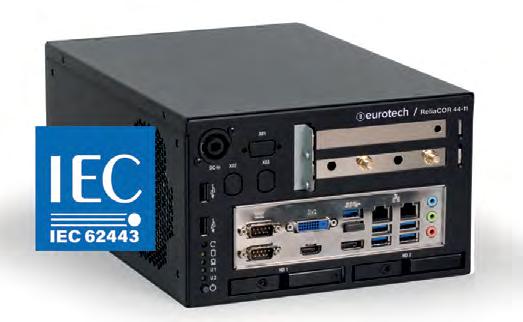
FEATURES
Ą FROM ZERO TO AI WITHOUT A SINGLE LINE OF CODE: Prompt the logic of your use case and get the application running in minutes.
Ą END-TO-END SECURITY: Full encryption across our software stack extends to the AI models, encompassing data and application orchestration.
Ą EFFICIENT INFERENCE: Run multiple AI models on a single device with capabilities for ongoing monitoring, management, and model updates. Full NVIDIA Triton support is included as standard.
Ą OPEN SOURCE AT HEART, ENTERPRISE-READY IN PRACTICE: Rely on the open-source framework at core, with enterpriseready support through Everyware Software Framework (ESF) and Everyware Cloud (EC).
marketing@eurotech.com
www.linkedin.com/company/eurotech/
2024 EMBEDDED
AI AND MACHINE LEARNING Eurotech 26 Vecow 27 Synaptics Incorporated 28 EMBEDDED HARDWARE, INCLUDING BOARDS AND SYSTEMS ASUSTek Computer Inc. 29 IBASE Technology Inc. 30 Pixus Technologies 30 SECO USA 31 Sealevel Systems, Inc. 32 EMBEDDED SOFTWARE, INCLUDING OSS AND IPS PLS Development Tools 32-33 INDUSTRIAL AUTOMATION AND CONTROL PEAK-System Technik GmbH 33-35 Embedded Computing Design
WORLD
26 Embedded Computing Design EMBEDDED WORLD | Spring 2024 www.embeddedcomputing.com

One-Stop Edge AI Solution Services
Vecow is a team of global embedded experts. We commit to designing, developing, producing, and selling industrial-grade computer products. All our products are leading in performance, trusted for reliability, and exhibit advanced technologies with innovative concepts.
Vecow offers One-Stop Edge AI Solution Services, AI Inference Systems, High-performance Fanless Systems, In-Vehicle Computing Systems, Expandable Computing Systems, Ultra-compact Fanless Systems, Single Board Computers (SBC), Industrial Motherboards, Multi-Touch Computers & Displays, Ethernet Switches, Frame Grabbers, Embedded Peripherals and Design & Manufacturing Services with leading performance, trusted reliability, advanced technology, and innovative concepts.
Vecow aims to be your trusted embedded business partner. Our experienced service team is dedicated to creating and maintaining strong partnerships and one-stop integrated solutions. Our services are specific and consider each partner’s unique needs in regards to Machine Vision, Autonomous Vehicles, Autonomous Mobile Robot (AMR), Digital Rail, Public Security, Transportation & V2X, Smart Factory, and any Edge AI Applications.
FEATURES
Time Synchronization Solution:
Crucial Mission of Autonomy Robots
This comprehensive solution leverages Vecow’s ECX-3000 and VTS-1000. It integrates three key technologies – Time Winding, Time Stamping, and Time Keeping. These advancements enhance multi-sensor synchronization, perception, precision, and positioning capabilities. The Vecow VTS-1000 Time Sync Box plays a crucial role in synchronizing interfaces and mechanisms among sensors and platforms. The ECX-3000 with essential software and algorithms for AI-powered computing completes this comprehensive solution.
https://reurl.cc/kryZ69
ICS-1000: Server-grade GPU-accelerated System
Powered by Intel® Xeon® D-2800/D-2700 Processor with discrete graphics, the ICS-1000 delivers server-grade computing capabilities. With up to 6 PCIe slot expansions, 1800W power budget for dual full-length graphics cards, Intel QuickAssis technology, high-speed interfaces like PCIe 4.0, USB 3.0, 10G SFP+, flexible power input DC 16V to 50V or AC 220V, and -25°C to 45°C operation, the ICS-1000 enables workload-optimized performance at the Edge.
https://reurl.cc/E46n3g
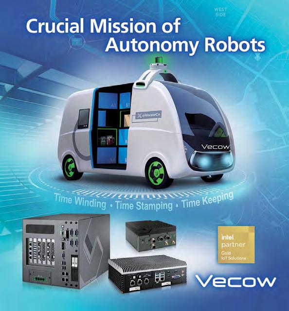
ECS-4700:
EN60945 Certified Marine-grade Rugged Embedded System
The Vecow ECS-4700 is an EN60945 Certified Marine-grade Rugged Embedded System. Powered by 13th Gen Intel® Core™ i7/i5 Processor with Intel® SoC and a 15W TDP CPU, the ECS-4700 is well-suited for AI applications in harsh environments. It features a marine-grade design, is EN60945 compliant, has isolated power protection, and includes 6 GigE LAN ports with 4 PoE+, 2 DP, and 1 USB Type-C with display function up to 4K. The ECS-4700 supports DDR5 memory up to 64GB, DC 9V to 50V Redundant Power Input, Software Ignition Control, and is fanless with an extended temperature range of -25°C to 75°C.
https://reurl.cc/nrvoe2
NVIDIA Jetson Solutions: Accelerate Edge AI Development
The Vecow EAC-6000/5000/4000 Series is built on advanced NVIDIA® Jetson AGX Orin™ or NVIDIA® Jetson Orin™ NX, with capabilities offering up to 275 TOPS. The Series features NVIDIA Ampere™ architecture, max 2048 NVIDIA® CUDA® cores and 64 Tensor cores; up to 6 GigE LAN with 4 PoE+, 5 USB, 2 Isolated CAN FD, 8 Fakra-Z connectors. Other features include DC 9V to 50V power input, fanless -25°C to 70°C operation, and support 24/7 OOB technology.
https://reurl.cc/973rMa
Vecow
www.vecow.com
Embedded Computing Design
sales@vecow.com +886 2 22685658 @VecowCo www.linkedin.com/company/vecow-co.-ltd AI and Machine Learning
www.embeddedcomputing.com Embedded Computing Design EMBEDDED WORLD | Spring 2024 27
Synaptics Astra™: The Biggest Step Forward in Edge AI
The infusion of AI into IoT edge devices can realize a context-aware environment. This is possible only when intelligent IoT islands are knit securely, reliably, and cost-effectively with the right compute solutions and right-sized wireless connectivity at each node. That is why Synaptics, an IoT company dedicated to changing how we interact with technology, has introduced Synaptics Astra™, the AI-native compute platform for the IoT.
Astra is an approach to IoT edge device design based on scalable AI-native hardware, unified software, an adaptive AI framework, a partner-based ecosystem, and seamless and robust wireless connectivity. This enables developers at any stage of their AI journey – from beginner to expert – to deploy AI at the edge at the power, performance, reliability, security, and cost points required to participate successfully in a rapidly unfolding future.
Accelerated shift to context-aware computing
With its multi-generational experience across key IoT functions and applications, Synaptics is accelerating this fundamental shift. Your AI journey begins with the first Astra processors, the SL Series (SL1680, SL1640, and SL1620) MPUs. Supported by
the Astra Machina™ Foundation Series development kit, the SL Series comprises highly integrated Linux™ and Android™ SoCs optimized for multi-modal consumer, enterprise, and industrial IoT workloads and features hardware accelerators for edge inferencing, security, video, graphics, and audio.
The SL Series provides high-performance and cost-effective solutions for developers of smart home, conferencing, retail, and industrial applications where secure AI-based processing can deliver an enhanced user experience with low cost of ownership.
The SL Series will be followed by the SR1xx Series of high-performance AI-native MCUs with intelligent tiered inferencing to ensure optimized context-aware computing from the home and office to the factory floor.
Synaptics Astra matches the SL and SR Series with its best-in-class wireless ICs to deliver optimal power, performance, and trusted connectivity for edge AI applications.
Meet our edge AI compute and wireless IoT experts at embedded world, Booth #4A-259. For an appointment, email press@synaptics.com.

Embedded Computing Design
AI and Machine Learning Synaptics Incorporated www.synaptics.com sales@synaptics.com www.synaptics.com/contact www.linkedin.com/company/synaptics @ SynaCorp
28 Embedded Computing Design EMBEDDED WORLD | Spring 2024 www.embeddedcomputing.com
R680EA-IM-Z

The ASUS IoT R680EA-IM-Z industrial motherboard, powered by Intel® 14th, 13th and 12th Gen Core™ processors, boasts robust features tailored for various industrial applications. Its integrated I/O shield design facilitates effortless system installation. The inclusion of PCIe® card brackets and DIMM lock design also enhances durability, ensuring reliable operation in demanding environments.
Additionally, the R680EA-IM-Z excels in performance and management capabilities. Its dedicated V-core and M.2 heatsink design enable support for CPUs with up to 125-watt TDP, for sustained high performance without throttling. Meanwhile, integrated smart management features enabled via embedded controller (EC) and intelligent board management controller (iBMC) enable remote monitoring and adjustments, enhancing system stability and administrative efficiency.
The R680EA-IM-Z offers versatile connectivity and expansion options, supporting up to two PCIe x16 slots, six COM ports, and three 2.5 GbE LAN ports. Users can tailor the motherboard to meet specific needs such as industrial engineering and manage ment (IEM), machine vision and AI inference.
FEATURES
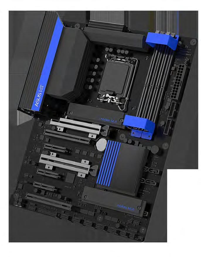
Embedded Computing Design
Embedded Hardware, including Boards and Systems ASUSTek Computer Inc. https://iot.asus.com/ ASUS_IoT@asus.com +886 2 2894 3447 www.linkedin.com/showcase/asus-iot/
Wide -10~60°C Operating Temperature
Ruggedized DIMM Lock and PCIe Slot Bracket
Immersion Tin Surface Protection
Integrated I/O Shield
3 x 2.5 GbE LAN Ports, 2 x PCIe x16 Slots and multiple COM Ports
Dedicated V-core and M.2 Heat Sink Design Ą Dual BIOS for Auto Recovery○
Integrated EC and iBMC www.embeddedcomputing.com Embedded Computing Design EMBEDDED WORLD | Spring 2024 29
Ą
Ą
Ą
Ą
Ą
Ą
Ą

AMI240 Fanless System
The rugged AMI240 fanless system is engineered to seamlessly integrate a variety of 14th/13th Gen Intel® Core™ processors. It is fully compatible with Sierra 5G modules and the Intel® i9-14900T processor (24 cores, 36M cache) with a TDP of 35W, enabling demanding workloads while maintaining power efficiency.
The system accommodates two DDR5-4800/5600 with up to 64GB capacity and has a wide-range operating temperature from -20°C to 70°C, allowing deployments in challenging thermal conditions and where temperature fluctuations can be a concern. It boasts a compact and spaceefficient design, measuring a mere 210(W) x 285(D) x 77(H)mm.
It provides various connectivity options, including dual SIM slots that support WWAN redundancy and four RJ45 ports featuring dual 2.5GbE and two PoE+ for versatile networking capabilities. It offers multiple M.2 slots (B-Key, E-Key, M-Key), and is equipped with a single 24V DC input to ensure stable power supply and over/under/reverse voltage protection.
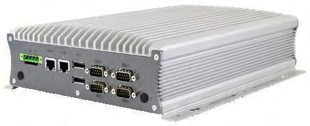

FEATURES
Ą Rugged fanless system with IBASE MBE240 customized board
Ą 14th/13th Gen Intel® Core™ i9/i7/i5/i3 Desktop Processors (35W TDP)
Ą Dual SIM slots support WWAN redundancy (5G/4G/LTE)
Ą 4x RJ45 Ethernet ports (2x 2.5GbE ports + 2x PoE+ ports support 802.3at)
Ą 3x M.2 (B-Key/E-Key/M-Key), iAMT (16.1), TPM (2.0)
Ą Single 24V DC input, supports over/under/reverse voltage protection
Ą Supports wide-range operating temperature from -20°C to 70°C
www.ibase.com.tw/en/product/category/Intelligent_System/Expandable_Embedded_System/AMI_Series_Expandable_Fanless_System/AMI240
IBASE Technology Inc
www.ibase.com.tw
sales@ibase.com.tw

Chassis managers, enclosures, & rugged NI SDRs
Pixus offers a vast array of specialty boards & accessories, enclosure cases, chassis hardware managers, & ruggedized NI SDRs. This includes card guides, handle/panel sets for plug-in cards, subracks, & more. The designs are used for various custom enclosures as well as openstandard architectures including OpenVPX/SOSA, CompactPCI/Serial, VME/64x, and ATCA/MTCA.
Pixus’ modular instrumentation cases, subracks and Eurocard enclosures come in various heights, depths, and widths. This includes 19" rackmountable, desktop, 1/2 19" size, and a wide variety of other options.
The ruggedized NI SDRs include versions for EW/SIG-INT, wideband spectrum monitoring, drone deterrence, advanced wireless prototyping, & more. Pixus offers IP67 outdoor units and MIL rugged types.
The chassis managers come in 3U/6U pluggable and mezzanine-based versions, including SOSA aligned configurations. Consult Pixus for customized options & specialty boards.
Pixus Technologies
www.pixustechnologies.com
+886 2 2655 7588 @ IBASE_Tech
Embedded Hardware, including Boards and Systems
FEATURES
Ą Modular enclosures for all types of devices. Includes EMC shielded, semi-rugged, IP67, and more.
Ą Chassis managers & specialty boards for power/fan monitoring, VITA 46.11 / IPMI, serial MUX, etc.
Ą Ruggedized versions of NI SDRs including the X310, X410, B210, N310, and others available upon request.
Ą Handle/panel sets and other accessories for OpenVPX, cPCI, VME, and more.
Ą Various components for enclosures and boards – card guides, sidewalls, panels, rails, etc.
Embedded Computing Design
sales@pixustechnologies.com
916-297-0020
https://www.linkedin.com/company/ibase-technology-inc-/ Embedded Hardware, including Boards and Systems 30 Embedded Computing Design EMBEDDED WORLD | Spring 2024 www.embeddedcomputing.com

End-To-End Technological Solutions: From Edge to Cloud
Leveraging decades of expertise in turnkey embedded computing design, manufacturing, Internet of Things (IoT) and Artificial Intelligence (AI) solutions, SECO enables businesses with smart solutions that accelerate digital transformation.
Edge Computing
SECO edge platforms feature state-of-the-art processing technologies, based on x86, Arm®, and FPGA architectures. Products include computer-on-module (COM) and single board computer (SBC) embedded boards, mountable human-machine interface (HMI) assemblies, and fully packaged devices – off-the-shelf or customized.
SECO HMI panel PCs are available with various processor, installation, and display size options from 7” to 21.5”. The newly available Modular Vision series provides flexibility in optimizing processing performance, peripherals, screen size, and cost.
Off-the-shelf COM and SBC products feature leading processing technologies (NXP, Intel®, AMD, Qualcomm, MediaTek) compliant with major standards (SMARC, QSeven®, COM-HPC®, COM Express®, Pico-ITX) or application-optimized. SECO also offers system integration-ready boxed fanless embedded computers, communication gateways, and payment systems.
The latest SECO solutions include: SOM-SMARCQCS6490 or -QCS5430 featuring Qualcomm processors (for industrial automation and AI at-the-edge); SOM-COM-HPC-A-MTL and SOM-COMe-BT6-MTL with Intel® Core™ Ultra Processors (for AI and IoT end devices); SOM-SMARC-MX95 with NXP processors (for low-power, headless, or simple display handheld devices); SOM-SMARC-Genio510 with MediaTek processors (for industrial automation); SBC-pITX-EHL with Intel® Atom™ x6000E Series (for AIoT applications); and Titan 300 TGL UP3 AI fanless computer featuring 11th Gen Intel® Core™ processors with a 120 TOPS Axelera AI engine (for edge computer vision).
SECO offers custom design and integration of electronic devices, built for reliability and robustness.
Intelligent Platform Solutions
SECO makes the implementation of IoT solutions easy with Clea, an edge and cloud modular software suite that harnesses field data. Based on open source and production ready, Clea is highly scalable, portable, and cost-effective. With instances running on edge devices managed by a cloud-based software hub, Clea facilitates real time infrastructure management, analytics, predictive maintenance, secure remote software updates, and more. Deploy intelligent apps and value-added revenue-generating subscription services via a monetization framework.
Building upon generative AI, SECO has developed StudioX, a solution for businesses to enhance operational efficiency, elevate product quality, improve customer satisfaction, and deploy novel revenue-generating services. Trained on your existing knowledge base, StudioX implements an intuitive chatbot with real-time ongoing learning.
FEATURES
Ą Off-the-shelf embedded products: COM, SBC, mountable HMI devices, and payment systems compliant with widely used standards that reduce time-to-market.
Ą Operating systems for edge devices: Linux, Android, Windows, RTOS.
Ą Customized computing platforms: custom-designed circuitry, software, and devices that meet unique product requirements.
Ą Clea edge and cloud IoT software suite: highly scalable open source solution for harnessing field data, managing devices, and monetizing value-added services.
Ą StudioX AI-power support system: platform for creating your own AI-powered support services via generative AI analysis of your existing knowledge base.
Ą Embedded AI: algorithms that autonomously analyze and optimize operation on the edge device.
Ą Product development: design and production of rugged high reliability electronic devices, including rugged tablets, devices, and industrial equipment.
Ą World-class electronics manufacturing: ISO 9001 and 13485 certified.

Embedded Computing Design
SECO www.seco.com +1-240-558-2014 sales.us@seco.com www.linkedin.com/company/seco-global Embedded Hardware, including Boards and Systems www.embeddedcomputing.com Embedded Computing Design EMBEDDED WORLD | Spring 2024 31

Flexio F1
Flexio Fanless Industrial Embedded Computers: Flexible, Limitless, Embedded, Xpandable I/O – and a whole lot more. Fueled by a QuadCore Intel Atom or Core processor, Flexio computers are intentionally designed to provide power, connectivity, and performance. This combination makes the Flexio an ideal controller for automation, point-ofsale, test and measurement, medical, and security applications.
With support for DIN rail or VESA mounting, the Flexio Fanless Industrial Embedded Computer is designed for easy installation in existing frameworks and for new system integrations. The Flexio features a solid-state design for an extended lifespan and diminished opportunities for failure. Flexio computers feature flexible connectivity, designed by the leader in I/O engineering. Combining industrial processing with applicationspecific I/O to meet requirements, the Flexio offers I/O configurations for a variety of USB to serial, USB to digital, and USB to analog-based control systems.
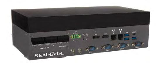
FEATURES
Ą Intel Atom and Intel Core Processor Options
Ą Atom base system I/O includes (2) USB 3.1 ports,
(2) Gigabit Ethernet ports, (1) DP++ port, and (1) VGA port
Ą Core base system I/O includes (3) USB 3.2
Gen2 ports, (1) USB Type-C (capable of DisplayPort), (1) Gigabit Ethernet port, (1) 2.5 Gigabit Ethernet port, (1) DisplayPort, and (1) HDMI port
Ą Fully integrated I/O configurations for a variety of USB to serial, USB to digital, and USB to analog-based control systems
Ą Rugged enclosure and fanless design for improved reliability
Ą Support for DIN rail or VESA mounting
Ą Compatible with Windows 11, Windows 10 IOT 2021 LTSC, and Ubuntu Linux
Sealevel Systems, Inc.
www.sealevel.com
sales@sealevel.com 864-843-4343
@SealevelSystems www.linkedin.com/company/sealevel-systems-inc/

UDE – Multicore Debugger for MCUs / Embedded MPUs
UDE Universal Debug Engine for Multicore Debugging is a powerful development platform for debugging, testing and system analysis of microcontroller software applications. UDE enables efficient and convenient control and monitoring of multiple cores for a wide range of multicore architectures within a single common user interface. This makes it easy to manage even complex heterogeneous multicore systems.
UDE supports a variety of multicore microcontrollers and embedded multicore processors including Infineon AURIX, TRAVEO, NXP S32 Automotive Platform, STMicroelectronics Stellar, Renesas RH850, R-Car, Synopsys ARC, RISC-V and others.
The UAD2pro, UAD2next and UAD3+ devices of the Universal Access Device family provide the hardware basis for the powerful functions of UDE and enable efficient and robust communication with the supported architectures and controllers. With its flexible adapter concept, the Universal Access Device family supports all commonly used debug interfaces.
FEATURES
Ą Debugging of homogeneous and heterogeneous 32-bit and 64-bit multicore MCUs and embedded MPUs
Ą Synchronous break, single step and restart for multicore systems
Ą One common debug session for complete system / all cores
Ą Convenient debugger user interfaces supporting multi-screen operation and perspectives
Ą Support for special cores including GTM, HSM, ICU, PPU, SCR
Ą Software API for tool automation and scripting
Ą AUTOSAR support and RTOS awareness
www.linkedin.com/company/pls-mc
Embedded Computing Design
Embedded Software, including OSs and IP PLS Development Tools
info@pls-mc.com
+49
www.pls-mc.com
35722 384-0
Hardware, including Boards and Systems 32 Embedded Computing Design EMBEDDED WORLD | Spring 2024 www.embeddedcomputing.com
Embedded

UDE – Trace and Test for MCUs / Embedded MPUs
The UDE Universal Debug Engine is the perfect tool for runtime analysis and testing of embedded multicore applications. With support for on-chip tracing, it offers comprehensive features for non-intrusive debugging, runtime observation, and runtime measurement. This helps developers to investigate, e.g., timing problems or misbehavior caused by parallel execution.
Used in conjunction with the UAD2next and UAD3+ devices from the Universal Access Device family, the UDE enables trace data to be captured from various trace sources and via external trace interfaces. Trace modules for the UAD2next or trace pods for the UAD3+ are provided for this purpose.
UDE's debugging and tracing capabilities, coupled with a flexible and open API for scripting and integrating with third-party tools, make UDE an ideal choice for automated testing on real target hardware. During the execution of automated tests, UDE can also determine the Code Coverage to validate the quality of the test cases that are being used.
PLS Development Tools
www.pls-mc.com
FEATURES
Ą Multicore trace support for various on-chip trace systems (incl. MCDS/miniMCDS for Infineon AURIX / TriCore, IEEE-ISTO 5001 Nexus for NXP MPC5xxx, STMicroelectronics SPC5, Arm CoreSight for Arm Cortex A/R/M based devices, Renesas RH850 on-chip trace)
Ą Visualization and analysis of recorded trace information (execution sequence chart, call graph visualization, profiling)
Ą Trace-based, non-intrusive statement coverage (C0 coverage) and branch coverage (C1 coverage) for proving test quality
Ą UDE SimplyTrace function for easy and context-sensitive trace configuration
Ą Open and flexible software API for scripting and test automation
info@pls-mc.com
www.linkedin.com/company/pls-mc
FEATURES:
Ą Form factor PC/104
Ą Multiple PC/104 cards can be operated in parallel (interrupt sharing)
Ą 14 port and 8 interrupt addresses are available for configuration using jumpers
Ą 1 or 2 High-speed CAN channels (ISO 11898-2)
Ą Bit rates from 5 kbit/s up to 1 Mbit/s
Ą Compliant with CAN specifications 2.0A (11-bit ID) and 2.0B (29-bit ID)
Ą Connection to CAN bus through D-Sub slot bracket, 9-pin (in accordance with CiA® 106)
Ą NXP SJA1000 CAN controller, 16 MHz clock frequency
Ą NXP PCA82C251 CAN transceiver
Ą 5 V supply to the CAN connection can be connected through a solder jumper, e.g., for external bus converter
Ą Optionally available with galvanic isolation on the CAN connection up to 500 V, separate for each CAN channel
Ą Extended operating temperature range from -40 to +85 °C (-40 to +185 °F)
+49 35722 384-0
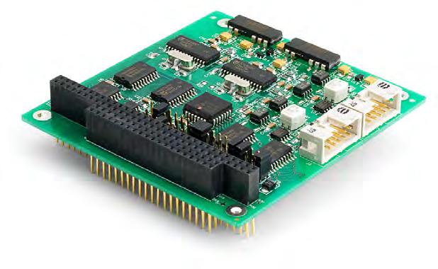
CAN Interface for PC/104
The PCAN-PC/104 card enables the connection of one or two CAN networks to a PC/104 system. Multiple PCAN-PC/104 cards can easily be operated using interrupt sharing. The card is available as a single- or dual-channel version. The opto-decoupled versions also guarantee galvanic isolation of up to 500 V between the PC and the CAN sides.
The package is also supplied with the CAN monitor PCAN-View for Windows and the programming interface PCAN-Basic.
Embedded Computing Design
PEAK-System Technik GmbH www.peak-system.com/quick/PC104-1 info@peak-system.com +49 (0) 6151-8173-20 www.linkedin.com/company/peak-system
PCAN-PC/104
Industrial Automation & Control
Embedded Software, including OSs and IP
www.embeddedcomputing.com Embedded Computing Design EMBEDDED WORLD | Spring 2024 33
PCAN-PC/104-Plus
FEATURES:
Ą Form factor PC/104
Ą Use of the 120-pin connection for the PCI bus
Ą Up to four cards can be used in one system
Ą 1 or 2 High-speed CAN channels (ISO 11898-2)
Ą Bit rates from 5 kbit/s up to 1 Mbit/s
Ą Compliant with CAN specifications 2.0A (11-bit ID) and 2.0B (29-bit ID)
Ą Connection to CAN bus through D-Sub slot bracket, 9-pin (in accordance with CiA® 106)
Ą NXP SJA1000 CAN controller, 16 MHz clock frequency
Ą NXP PCA82C251 CAN transceiver
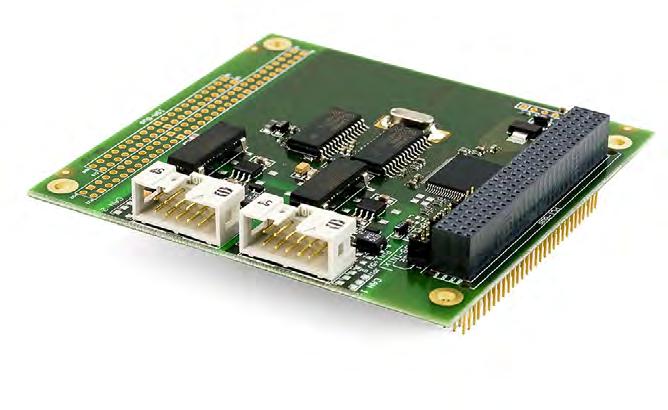
CAN Interface for PC/104-Plus
The PCAN-PC/104-Plus card enables the connection of one or two CAN networks to a PC/104-Plus system. Up to four cards can be operated, with each piggy-backing off the next. The CAN bus is connected using a 9-pin D-Sub plug on the slot bracket supplied.
Ą 5 V supply to the CAN connection can be connected through a solder jumper, e.g., for external bus converter
Ą Extended operating temperature range from -40 to +85 °C (-40 to +185 °F)
Ą Optionally available with galvanic isolation on the CAN connection up to 500 V, separate for each CAN channel
Ą Optionally available with PC/104-ISA stack-through connector
PEAK-System Technik GmbH
www.peak-system.com/quick/PC104-2

PCAN-PC/104-Plus Quad
FEATURES:
Ą Form factor PC/104
Ą Use of the 120-pin connection for the PCI bus
Ą Up to four cards can be used in one system
Ą 4 High-speed CAN channels (ISO 11898-2)
Ą Bit rates from 5 kbit/s up to 1 Mbit/s
Ą Compliant with CAN specifications 2.0A (11-bit ID) and 2.0B (29-bit ID)
Ą Connection to CAN bus through D-Sub slot brackets, 9-pin (in accordance with CiA® 106)
The card is available as a single or dual-channel version. The opto-decoupled versions also guarantee galvanic isolation of up to 500 V between the PC and the CAN sides.
info@peak-system.com
www.linkedin.com/company/peak-system
+49 (0) 6151-8173-20
Four-Channel CAN Interface for PC/104-Plus
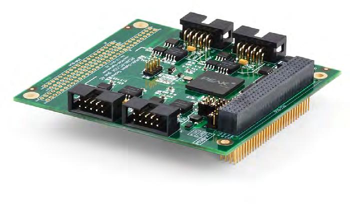
Ą FPGA implementation of the CAN controller (SJA1000 compatible)
Ą NXP PCA82C251 CAN transceiver
Ą Galvanic isolation on the CAN connection up to 500 V, separate for each CAN channel
Ą 5 V supply to the CAN connection can be connected through a solder jumper, e.g., for external bus converter
Ą Extended operating temperature range from -40 to +85 °C (-40 to +185 °F)
The PCAN-PC/104-Plus Quad card enables the connection of four CAN networks to a PC/104-Plus system. Up to four cards can be operated, with each piggy-backing off the next. The CAN bus is connected using a 9-pin D-Sub plug on the slot brackets supplied. There is galvanic isolation of up to 500 V between the computer and CAN sides.
Industrial Automation & Control PEAK-System Technik GmbH www.peak-system.com/quick/PC104-3 info@peak-system.com +49 (0) 6151-8173-20 www.linkedin.com/company/peak-system
34 Embedded Computing Design EMBEDDED WORLD | Spring 2024 www.embeddedcomputing.com
Embedded Computing Design
The package is also supplied with the CAN monitor PCAN-View for Windows and the programming interface PCAN-Basic. Industrial Automation & Control
The package is also supplied with the CAN monitor PCAN-View for Windows and the programming interface PCAN-Basic.
Ą Optionally available: PC/104-ISA stack-through connector

PCAN-PCI/104-Express
FEATURES:
Ą PCI/104-Express card, 1 lane (x1)
Ą Form factor PC/104
Ą Up to four cards can be used in one system
Ą 1 or 2 High-speed CAN channels (ISO 11898-2)
Ą Bit rates from 5 kbit/s up to 1 Mbit/s
Ą Compliant with CAN specifications 2.0A (11-bit ID) and 2.0B (29-bit ID)
Ą Connection to CAN bus through D-Sub slot bracket, 9-pin (in accordance with CiA® 106)
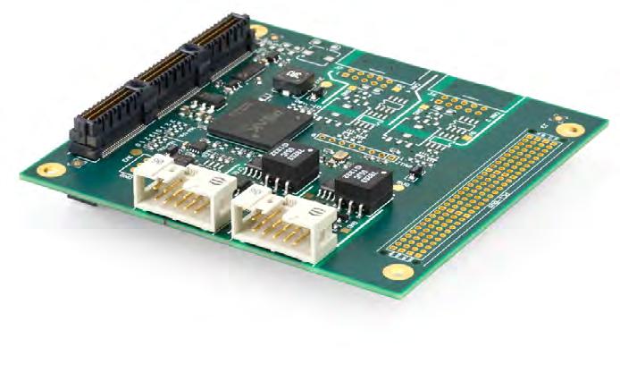
Ą FPGA implementation of the CAN controller (SJA1000 compatible)
Ą NXP PCA82C251 CAN transceiver
Ą Galvanic isolation on the CAN connection up to 500 V, separate for each CAN channel
Ą Supplied only via the 5 V line
Ą 5 V supply to the CAN connection can be connected through a solder jumper, e.g., for external bus converter
Ą Extended operating temperature range from -40 to +85 °C (-40 to +185 °F)
Ą Optionally available: PCI-104 stack-through connector
PEAK-System Technik GmbH
www.peak-system.com/quick/PC104-4

FEATURES:
Ą PCI/104-Express card, 1 lane (x1)
Ą Form factor PC/104
Ą Up to four cards can be used in one system
Ą 1, 2, or 4 High-speed CAN channels (ISO 11898-2)
Ą Complies with CAN specifications 2.0 A/B and FD (ISO and Non-ISO)
Ą CAN FD bit rates for the data field (64 bytes max.) from 20 kbit/s up to 12 Mbit/s
Ą CAN bit rates from 20 kbit/s up to 1 Mbit/s
Ą Connection to CAN bus through D-Sub slot bracket, 9-pin (in accordance with CiA® 106)
Ą FPGA implementation of the CAN FD controller
Ą Microchip CAN transceiver MCP2558FD
Ą Galvanic isolation on the CAN connection up to 500 V, separate for each CAN channel
Ą CAN termination and 5 V supply to the CAN connection can be activated through a solder jumper
Ą Extended operating temperature range from -40 to +85 °C (-40 to +185 °F)
Ą Optionally available: PCI-104 stack-through connector
CAN Interface for PCI/104-Express
The PCAN-PCI/104-Express card enables the connection of one or two CAN buses to a PCI/104-Express system. Up to four cards can be stacked together. The CAN bus is connected using a 9-pin D-Sub plug on the slot brackets supplied. There is galvanic isolation of up to 500 V between the computer and CAN sides.
The package is also supplied with the CAN monitor PCAN-View for Windows and the programming interface PCAN-Basic.
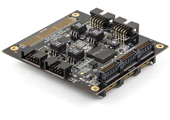
CAN FD Interface for PCI/104-Express
The PCAN-PCI/104-Express FD allows the connection of PCI/104Express systems to CAN and CAN FD buses. Up to four cards can be stacked together. The CAN bus is connected via 9-pin D-Sub connectors to the supplied slot brackets. There is a galvanic isolation between the computer and the CAN side up to 500 V. The card is available in single-, dual-, or four-channel versions.
The monitor software PCAN-View and the programming interface PCAN-Basic are included in the scope of supply and support the standard CAN FD.
Embedded Computing Design
Industrial Automation & Control PEAK-System Technik GmbH www.peak-system.com/quick/PC104-5 info@peak-system.com +49 (0) 6151-8173-20 www.linkedin.com/company/peak-system
PCAN-PCI/104-Express FD
Industrial Automation & Control
info@peak-system.com +49 (0) 6151-8173-20
www.linkedin.com/company/peak-system
www.embeddedcomputing.com Embedded Computing Design EMBEDDED WORLD | Spring 2024 35

Get your free ticket now! embedded-world.de/codes Use the voucher code ew24ELE CONNECTING THE EMBEDDED COMMUNITY 9 – 11.4.2024 Media partners


 The LDRA tool suite provides robust support for control and data coupling anal-
Data coupling and control coupling analysis reports from the LDRA tool suite (Source: LDRA)


