


@military_cots www.MilitaryEmbedded.com Jan/Feb 2023 | Volume 19 | Number 1 John McHale SOF Week, MOSA, and uncrewed news 7 Technology Update Sensors mission to protect GPS 8 Mil Tech Trends EW: Compatible with open standards? 22 Industry Spotlight EW to sport new RF, microwave hardware 34 P 18 SPEED, MANEUVERABILITY OF HYPERSONIC MISSILES CREATE CHALLENGES FOR MISSILE DEFENSE Hypersonic weapons systems: Getting in synch with MEMS-based timing By Odile Ronat, SiTime P 14 RADAR/EW
ISSUE


We Have You Covered from RF to Bits The industry’s most complete portfolio of ICs and modules. RF/µW Amplifiers/ TR Modules Analog Beamforming Frequency Conversion DAC ADC Converters and Transceivers Power Find your competitive advantage at analog.com/ADEF
 By John McHale
By Lisa Daigle
By Jacob Sealander
By John McHale
By Lisa Daigle
By Jacob Sealander
SPECIAL REPORT: Radar for missile/hypersonic defense
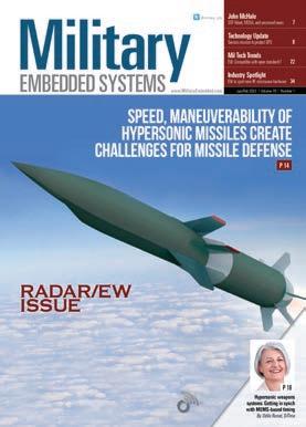
14 Speed, maneuverability of hypersonic missiles create challenges for missile defense

By Dan Taylor, Technology Editor
18 Hypersonic weapons systems: Getting in synch with MEMS-based timing
By Odile Ronat, SiTime
By Dan Taylor
MIL TECH TRENDS: Leveraging the Sensor Open Systems Architecture (SOSA) for radar applications


22 Is high-performance electronic warfare compatible with open standards?
By Robert Normoyle, Herrick Technology Laboratories
26 Realizing MOSA objectives: the developer’s role
By Will Keegan, Lynx Software Technologies
30 High-speed video: unlocking fast and reliable connectivity
By Michael Walmsley, TE Connectivity
INDUSTRY SPOTLIGHT: RF and microwave designs for electronic warfare
34 Next generation of electronic warfare systems to feature enhanced RF and microwave hardware By Flavia Camargos Pereira, Contributing Editor 38
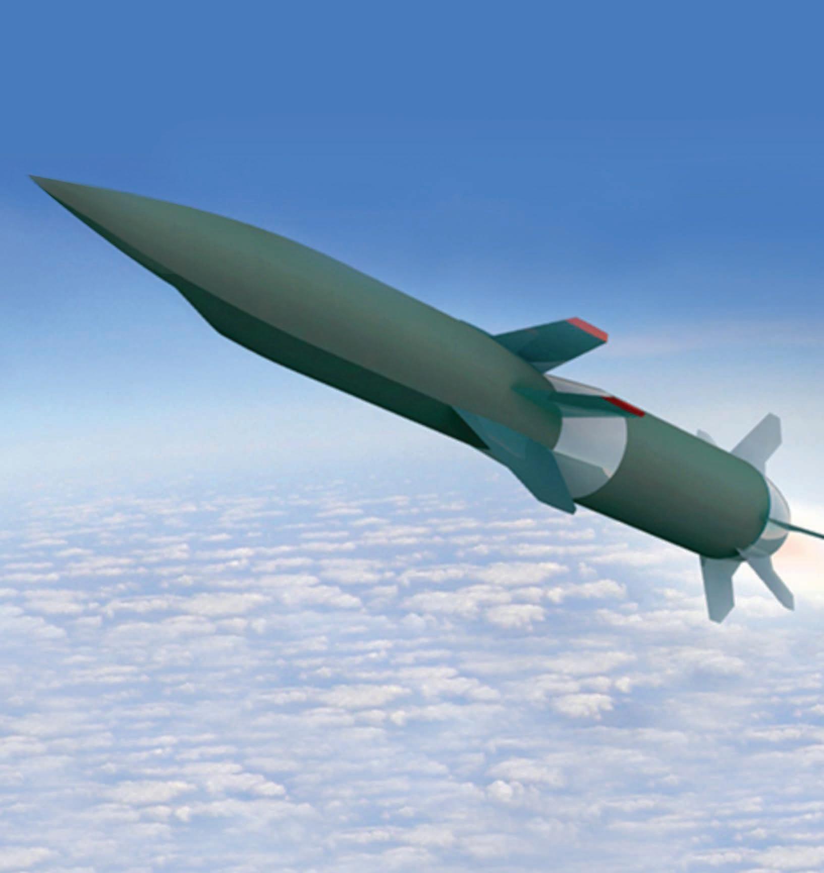
ON THE COVER:
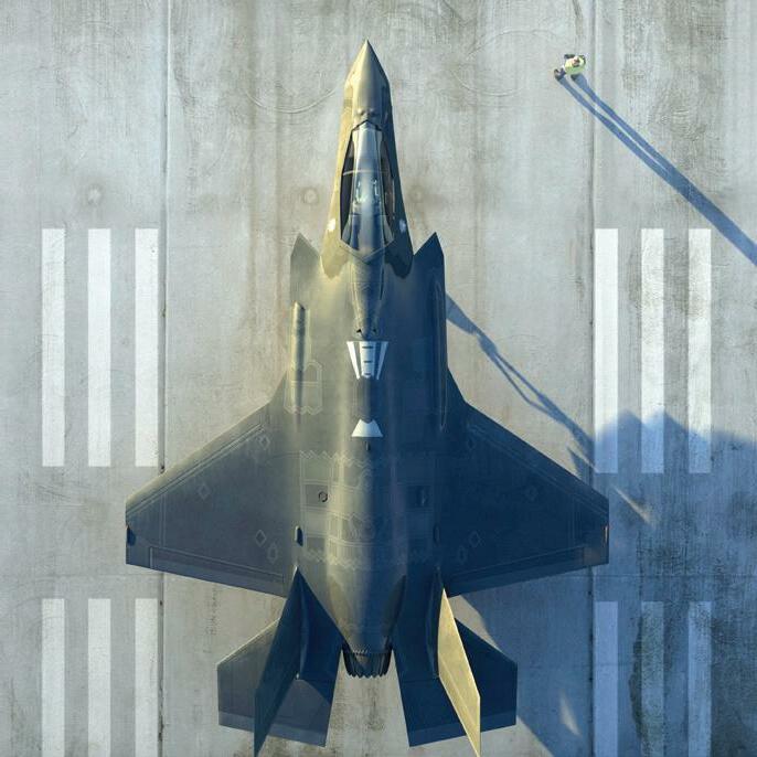
The Lockheed Martin-produced version of the Hypersonic Airbreathing Weapon Concept (HAWC) missile – a joint project of DARPA and the U.S. Air Force – completed test flights in January 2023. A DARPA statement said that the data collected will help the Air Force design future highly maneuverable hypersonic weapons. Artist rendering courtesy DARPA.

https://www.linkedin.com/groups/1864255/
@military_cots
Editor’s Perspective 7
COLUMNS
SOF Week, MOSA, and uncrewed news
Technology
8
CubeSat
Update
Enhanced GPS and comms the focus in AFRL/NASA
mission
Mil Tech Insider 9 Understanding
paradigm shift
vehicle architecture
GCIA: A
for establishing an overall ground-combat
Defense Tech Wire
Editor’s Choice Products
Mil Embedded
Guest Blog 44 How the military can speed data mobility for smart decisions on the move
Travis
Red Hat Connecting with Mil Embedded 46 By Mil Embedded Staff 4 January/February 2023 MILITARY EMBEDDED SYSTEMS www.militaryembedded.com All registered brands and trademarks within Military Embedded Systems magazine are the property of their respective owners. © 2023 OpenSystems Media © 2023 Military Embedded Systems ISSN: Print 1557-3222
THE LATEST
10
42 By
Staff
By
Steele,
FEATURES
Morcelles, Per Vices
by: www.militaryembedded.com
2023 Volume 19 | Number 1
Subscribe to the
or E-letter Live industry news | Submit new
http://submit.opensystemsmedia.com WHITE PAPERS – Read: https://militaryembedded.com/whitepapers WHITE PAPERS – Submit:
18 14 To unsubscribe, email your name, address, and subscription number as it appears on the label to: subscriptions@opensysmedia.com
Easing radar integration with SDR By Kaue
Published
January/February
TABLE OF CONTENTS WEB RESOURCES
magazine
products
http://submit.opensystemsmedia.com
BEHLMAN LEADS THE PACK

FIRST PROVEN VPX POWER SUPPLIES DEVELOPED IN ALIGNMENT WITH THE SOSA™ TECHNICAL STANDARD
Behlman introduces the first test-proven VPX power supplies developed in alignment with the SOSA Technical Standard. Like all Behlman VPXtra® power supplies, these 3U and 6U COTS DC-to-DC high-power dual output units feature Xtra-reliable design and Xtra-rugged construction to stand up to the rigors of all mission-critical airborne, shipboard, ground and mobile applications.
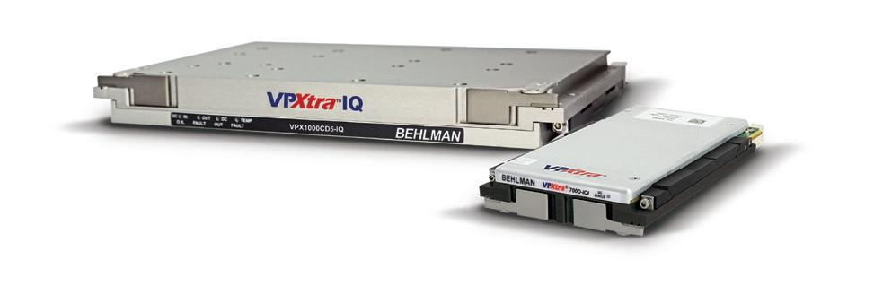
VPXtra® 1000CD5-IQI
> 6U power module developed in alignment with the SOSA Technical Standard
> Delivers 1050W DC power via two outputs
> VITA 46.11 IPMC for integration with system management
VPXtra® 700D-IQI

> 3U power module developed in alignment with the SOSA Technical Standard
> Delivers 700W DC power via two outputs
> VITA 46.11 IPMC for integration with system management
: 631-435-0410 : sales@behlman.com : www.behlman.com : 631-435-0410 : sales@behlman.com : www.behlman.com The Power Solutions Provider
AGAIN!
SOSA™ and logo design and The Open Group Certification Mark™ are trademarks of The Open Group in the United States and other countries.
ADVERTISERS
PAGE ADVERTISER/AD TITLE
2 Analog Devices, Inc. –We have you covered from RF to bits
3 Annapolis Micro Systems –The only full ecosystem of 3U & 6U 100 GbE products aligned with SOSA
5 Behlman Electronics, Inc. –Behlman leads the pack again!
16 Dawn VME Products –Dawn powers VPX
39 Elma Electronic – Award-winning development solutions
21 Embedded World – embedded world 2023 Exhibition & Conference ... it’s a smarter world
29
Embedded World – Join the embedded community 14 - 16.3.2023
13 GMS – X9 Spider. The world’s most powerful full-featured wearable computer
48 Mercury Systems, Inc. –The next big thing in RFSoC is here –and it’s only 2.5” x 4”
25 Phoenix International –Phalanx II: The ultimate NAS
31 PICO Electronics Inc –DC-DC converters
17 Quantic Electronics –Our hybrid wet tantalum capacitors are the most power dense in the industry
EVENTS
embedded world
Exhibition & Conference
March 14-16, 2023
Nuremburg, Germany
https://www.embedded-world.de/en
Sea-Air-Space
April 3-5, 2023
National Harbor, MD
https://seaairspacelorg
SOF Week 2023 (USSOCOM)
May 8-11, 2023
Tampa, FL
https://www.sofweek.org/
XPonential 2023 (AUVSI)
May 8-11, 2023
Denver, CO
https://www.auvsi.org/events/ xponential/xponential-2023
GROUP EDITORIAL DIRECTOR John McHale john.mchale@opensysmedia.com
ASSISTANT MANAGING EDITOR Lisa Daigle lisa.daigle@opensysmedia.com
TECHNOLOGY EDITOR – WASHINGTON BUREAU Dan Taylor dan.taylor@opensysmedia.com
CREATIVE DIRECTOR Stephanie Sweet stephanie.sweet@opensysmedia.com
WEB DEVELOPER Paul Nelson paul.nelson@opensysmedia.com
EMAIL MARKETING SPECIALIST Drew Kaufman drew.kaufman@opensysmedia.com
WEBCAST MANAGER Ryan Graff ryan.graff@opensysmedia.com
VITA EDITORIAL DIRECTOR Jerry Gipper jerry.gipper@opensysmedia.com
SALES/MARKETING
DIRECTOR OF SALES Tom Varcie tom.varcie@opensysmedia.com (734) 748-9660
DIRECTOR OF MARKETING Eric Henry eric.henry@opensysmedia.com
OPERATIONS & AUDIENCE DEVELOPMENT (541) 760-5361
STRATEGIC ACCOUNT MANAGER Rebecca Barker rebecca.barker@opensysmedia.com (281) 724-8021
STRATEGIC ACCOUNT MANAGER Bill Barron bill.barron@opensysmedia.com (516) 376-9838
STRATEGIC ACCOUNT MANAGER Kathleen Wackowski kathleen.wackowski@opensysmedia.com (978) 888-7367
SOUTHERN CAL REGIONAL SALES MANAGER Len Pettek len.pettek@opensysmedia.com (805) 231-9582
DIRECTOR OF SALES ENABLEMENT Barbara Quinlan barbara.quinlan@opensysmedia.com AND PRODUCT MARKETING (480) 236-8818
INSIDE SALES Amy Russell amy.russell@opensysmedia.com
STRATEGIC ACCOUNT MANAGER Lesley Harmoning lesley.harmoning@opensysmedia.com
EUROPEAN ACCOUNT MANAGER Jill Thibert jill.thibert@opensysmedia.com
TAIWAN SALES ACCOUNT MANAGER Patty Wu patty.wu@opensysmedia.com
CHINA SALES ACCOUNT MANAGER Judy Wang judywang2000@vip.126.com
WWW.OPENSYSMEDIA.COM
PRESIDENT Patrick Hopper patrick.hopper@opensysmedia.com
EXECUTIVE VICE PRESIDENT John McHale john.mchale@opensysmedia.com
EXECUTIVE VICE PRESIDENT AND ECD BRAND DIRECTOR Rich Nass rich.nass@opensysmedia.com
ECD EDITOR-IN-CHIEF Brandon Lewis brandon.lewis@opensysmedia.com
TECHNOLOGY EDITOR Curt Schwaderer curt.schwaderer@opensysmedia.com
ASSOCIATE EDITOR Tiera Oliver tiera.oliver@opensysmedia.com
ASSOCIATE EDITOR Taryn Engmark taryn.engmark@opensysmedia.com
ASSISTANT EDITOR Chad Cox chad.cox@opensysmedia.com
CREATIVE PROJECTS Chris Rassiccia chris.rassiccia@opensysmedia.com
GRAPHIC DESIGNER Kaitlyn Bellerson kaitlyn.bellerson@opensysmedia.com
FINANCIAL ASSISTANT Emily Verhoeks emily.verhoeks@opensysmedia.com
SUBSCRIPTION MANAGER subscriptions@opensysmedia.com CORPORATE
REPRINTS
WRIGHT’S
6 January/February 2023 MILITARY EMBEDDED SYSTEMS www.militaryembedded.com
OFFICE 1505 N. Hayden Rd. #105 • Scottsdale, AZ 85257 • Tel: (480) 967-5581
MEDIA REPRINT COORDINATOR Kathy Richey clientsuccess@wrightsmedia.com (281) 419-5725
SOF Week, MOSA, and uncrewed news
By John McHale, Editorial Director John.McHale@opensysmedia.com
We have big news: Military Embedded Systems, in partnership with Shephard Media in the United Kingdom, have been named the official Media and Show Daily Partners for SOF Week 2023, formerly known as Special Operations Forces Industry Conference (SOFIC). The event – scheduled to be held in Tampa, Florida, the week of May 8, 2023 – is managed by the Global SOF Foundation and Clarion Events on behalf of the U.S. Special Operations Command (USSOCOM).
process than the main services, so tech moves more quickly from industry into Special Operation Forces (SOF) hands. SOCOM is also embracing the Department of Defense (DoD) Modular Open System Approach (MOSA), perhaps even more so in some instances than other DoD entities.
While discussing open architectures, Jim Smith, Acquisition Executive for U.S. Special Operations Command (USSOCOM), told me last year: “It’s embedded in our acquisition strategy and the reason for that is that SOCOM being a joint force needs to be interoperable with the [other services].”

Last year, USSOCOM leadership chose to expand “to a broader convention for the entire SOF Community, akin to an ‘AUSA National Meeting’ for the U.S. Army or the ‘AFA National Convention’ for the U.S. Air Force,” according to a written statement from SOF Week. Military Embedded Systems and Shephard will be producing the official SOF Week Show Guide and official Show Daily e-newsletter, plus other event-related newsletters.
The newsletters will reach not only all of the show attendees but also the additional combined SOF-related audiences of Military Embedded Systems and Shephard.

We are quite excited about supporting this event. Of all the trade shows and conferences I attended last year, none had the enthusiasm or crowded exhibition halls of SOFIC. With SOCOM’s expansion plans, I expect that impact will only grow.
Attendees and our combined audiences will receive all of our news and features from the show, including interviews with military and industry leaders. For exhibitors, we have multiple advertising and sponsorship opportunities in the print Show Guide, digital newsletters, social media, and SOF Week TV channel.
For editorial, you can reach out to me at john.mchale@opensysmedia.com; for advertising/sponsorship opportunities, contact Military Embedded Systems Publisher Pat Hopper at patrick. hopper@opensysmedia.com.
Our coverage will also be featured on www.militaryembedded. com and on www.shephardmedia.com. Both sites will also feature updates on the opportunities mentioned above, or you can visit the show site at www.sofweek.org.
Covering SOCOM is unique, especially from an acquisitionstrategy standpoint as it has a faster acquisition and procurement
Speaking of MOSA, we have our second annual MOSA Virtual Summit later this month. David Tremper – Director, Acquisition Integration and Interoperability, Office of the Undersecretary of Defense (OUSD) for Acquisition and Sustainment (A&S) – will keynote the MOSA Virtual Summit, to be held February 22 at 11 a.m. EST. Other sessions will include “MOSA for Crewed and Uncrewed Aviation Platforms,” “Bringing MOSA to C5ISR and Electronic Warfare Applications,” and “Applying a MOSA Strategy Across Multiple Domains.”
MOSA will also be a featured topic at our second annual Uncrewed Systems Virtual Conference on April 13, where once again Dawn M.K. Zoldi (Colonel, USAF, Retired), CEO of P3 Tech Consulting, will host the keynote session: She’ll hold a fireside chat with Lt. Col. (USAF) Tom Meagher, Prime Division Chief, AFWERX. The other uncrewed-focused sessions include “Leveraging MOSA for Autonomous Systems,” “Autonomous ISR Payloads: Leveraging AI and Commercial Technology for Actionable Intelligence,” and “Navigating Safety Certification in UAS Platforms.”

For even more on MOSA, see our coverage in this issue: Our contributing editor Flavia Camargos Pereira’s article titled “Next generation of electronic warfare systems to feature enhanced RF and microwave hardware” is on page 34, and an article by Robert Normoyle of Herrick Labs titled “Is highperformance electronic warfare compatible with open standards?” is on page 22.
Lastly, just a reminder: We will also be producing our second annual FACE Special Edition in the spring (mailed with our April/May issue of Military Embedded Systems) and third annual SOSA Special Edition, which is mailed with the July/ August issue.
Whew! Busy year and that’s only the first half of 2023. Lots more to come – we hope to see you at SOF Week or elsewhere.
EDITOR’S PERSPECTIVE
www.militaryembedded.com MILITARY EMBEDDED SYSTEMS January/February 2023 7
Enhanced GPS and comms the focus in AFRL/NASA CubeSat mission
 By Lisa Daigle, Assistant Managing Editor

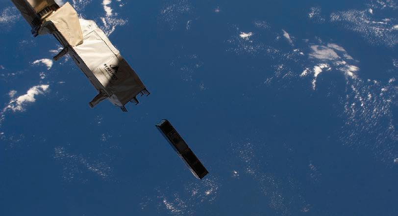
Sensor experiments recently deployed from the International Space Station (ISS) during late 2022 may lead to greater understanding of the Earth’s ionosphere that will in turn enable more accurate predictive modeling and lead to increased resilience in the navigation and communications realms.
The Air Force Research Laboratory (AFRL) reports that its new sensor experiment – riding along on NASA’s six-unit CubeSat –launched from the ISS on December 29, 2022. The mission of the CubeSat, named petitSat [Plasma Enhancements in the Ionosphere-Thermosphere Satellite], according to an AFRL update, is to study the Earth’s ionospheric layer to gain insight into weather conditions and disturbances in space and how they affect navigation and communication systems.
The AFRL sensor, developed at the agency’s Space Vehicles Directorate and operating out of NASA’s Goddard Space Flight Center, is called GRIDS [Gridded Retarding Ion Drift Sensor]. The AFRL team reports that GRIDS is a low size, weight, and power (SWaP) sensor built internally that will measure various ions in the ionosphere.
The ionosphere is the solar-radiation-ionized part of the upper atmosphere of Earth, from about 48 km to 965 km (29.83 miles to 599.62 miles) above sea level, a region that includes the thermosphere and parts of the mesosphere and exosphere. The National Oceanic and Atmospheric Administration (NOAA) explains that the ionosphere is important because it reflects and modifies radio waves used for communication and navigation. Other phenomena such as energetic charged particles and cosmic rays also have an ionizing effect and can contribute to conditions affecting the ionosphere.
The conditions in the ionosphere, and its constant changes, have practical repercussions, say teams at NASA, given the ever-increasing reliance on technology: This is the area through which radio communications and GPS signals travel. Variations here can result in distortions or even complete disruption of such signals.
Researchers at Penn State University’s College of Earth and Mineral Sciences report that large errors in GPS positioning can be attributable to shifts in the ionosphere and other portions of the Earth’s atmosphere. The long journey of the GPS signal through the virtual vacuum of space means that the signal can be affected as it passes through the earth’s atmosphere. Through both refraction and diffraction, the atmosphere alters the apparent speed and, to a lesser extent, the direction of the signal. These changes mean an apparent delay in the signal’s transit from the satellite to the receiver.
The Earth’s upper atmosphere is where most low-Earthorbit satellites operate; their orbits can be affected by sudden density changes created by space weather, explains Ryan Davidson, AFRL senior research physicist and the experiment’s program manager.
The accumulation of so-called cold plasma in the form of bubbles and globs affects radio propagation of satellite-based navigation and communications passing in the vicinity of these plasma formations, which interfere with GPS and radar signals, Davidson asserts.
“This experiment will increase our fundamental understanding of how the ionosphere works and allow us to determine operational models and strategies to increase the resiliency of the Space Force’s space-based assets,” Davidson says. “The GRIDS sensor is designed to measure how much plasma is present in the atmosphere and in what direction it is moving. This should allow us to detect the presence of plasma bubbles and globs and give us information into how they are formed.
“In this experiment, AFRL hopes to determine the formation mechanism of plasma perturbations and use that information to feed predictive ionospheric models and make them more accurate to increase satellite navigation and communication, thereby increasing the protection of vital assets such as the Global Positioning System,” he explains.
The AFRL petitSat team expects, according to the AFRL report on the experiment’s deployment, that GRIDS will remain in orbit for approximately six months. Another NASA/AFRL GRIDS experiment is expected to launch in 2024.
TECHNOLOGY UPDATE
8 January/February 2023 MILITARY EMBEDDED SYSTEMS www.militaryembedded.com
Figure 1 | A sensor experiment named GRID [Gridded Retarding Ion Drift Sensor] deploys from the International Space Station. The sensor, developed by the Air Force Research Laboratory’s Space Vehicles Directorate, is hosted on NASA’s six-unit cube satellite petitSat, or Plasma Enhancements in the Ionosphere-Thermosphere Satellite. NASA’s Heliophysics SPORT CubeSat, also studying the ionosphere, can be seen in the top left corner.
Understanding GCIA: A paradigm shift for establishing an overall ground-combat vehicle architecture
By Jacob Sealander
The U.S. Army has long pursued a standardized infrastructure and architecture for ground-combat vehicle hardware and networking. While the VICTORY [Vehicular Integration for C4ISR/EW Interoperability] standard helped make some progress and created some excitement, the need to converge on a more focused solution set soon became apparent. That reality resulted in hardware/software convergence which explored what such a solution set might look like, such as standardizing on 3U OpenVPX, as a way of driving a modular enough solution that could have a significant impact on interoperability. The next step was CMOSS [Command, Control, Communications, Computers, Cyber, Intelligence, Surveillance, Reconnaissance (C5ISR)/Electronic Warfare Modular Open Suite of Standards], which – in its effort to define the suite of standards for building the desired infrastructure and network – embraced the VICTORY, MORA [Modular Open RF Architecture], and OpenVPX standards.
When the SOSA [Sensor Open Systems Architecture] Technical Standard effort began, it focused initially on airborne sensor systems. While it makes use of many of the same standards as the CMOSS standards, such as OpenVPX, it became clear that these standards didn’t go far enough to satisfy the Army’s vision for combat vehicles. The Army has developed two new standards – the PEO [Program Executive Office] Aviation and PEO [Ground Combat Systems) GCS’s CMFF (CMOSS Mounted Form Factor) and the PEO GCS’s GCS Common Infrastructure Architecture (GCIA) – to define a detailed and comprehensive architecture for the desired interoperability, adaptability, and technology movement.
While CMFF focuses on the C4ISR piece of the vehicle infrastructure (communications and mission management), GCIA focuses on the requirements to enable a core compute networked infrastructure that will enable a system designer to simply “plug in” all the desired capabilities. Most importantly, GCIA is concerned with how the network moves and shares data to support all the resources needed to host the different functions on a ground-combat vehicle. For example, GCIA defines a version of Ethernet that supports TSN (time-sensitive network) standards for safety-critical data movement on the standard core network. In addition, GCIA directs the use of Intel hardware and Linux software and defines the types of displays (dumb vs. smart), security (multilevel security boxes vs. single-level boxes).
While GCIA looks to SOSA for system profile definitions and VITA hardware standards, it limits the approved use to only a handful of SOSA profiles and narrow subset of hardware standards. This stricture forces designers to build from a much smaller set of building blocks from the beginning in order to deliver the benefits of greatly reduced time to field new technology and tech refreshes for ground combat vehicles that GCIA promises. New functions often arrive in their own boxes that host their own computers and need space on an already crowded vehicle. Each box also has its own software that must be qualified and communicate with the next layer of software on the vehicle network: All of this adds time and program risk.
The GCIA network can accommodate very-low-latency paths while providing determinism. System designers can use the specified building blocks and develop their software on the very same hardware platform that all other GCIA-compliant suppliers are using; GCIA defines the internal vehicle network (IVN). Capabilities can be hosted anywhere on the platform because all of the resources will be networked, so solutions developed for GCIA-based applications will be transportable between different
hardware elements, not just within the platform, but platform to platform, from compute instance to compute instance. The ability to move applications and functions, using distributed network resources, to any spot in the vehicle will provide an unprecedented new level of fault resiliency compared to today’s vehicle architectures, where there is very little redundancy built in.
Going forward, ground-combat vehicle solutions will need to support GCIA, which has the needed specificity while leveraging SOSA and CMOSS. GCIA’s complete hardware and software ecosystem definition represents a paradigm shift on how to establish a vehicle architecture by defining an overall integrated solution. Curtiss-Wright’s next generation of modules, from switches to processors to payload and special-function cards, will all support TSN and GCIA and will implement the IPMI solutions for system and chassis management to make it easy to use all of the highly configurable resources on the network. (Figure 1.)

Curtiss-Wright Defense Solutions
https://www.curtisswrightds.com/
MIL TECH INSIDER
An industry perspective from Curtiss-Wright Defense Solutions
Jacob Sealander is Chief Architect, C5ISR Systems, for Curtiss-Wright Defense Solutions.
www.militaryembedded.com MILITARY EMBEDDED SYSTEMS January/February 2023 9
Figure 1 | Examples of GCIA Common Compute solutions include the 1/3 SAVE starter kit (shown), 1/2 SAVE enclosure, and full SAVE enclosure.
DEFENSE TECH WIRE
By Dan Taylor, Technology Editor

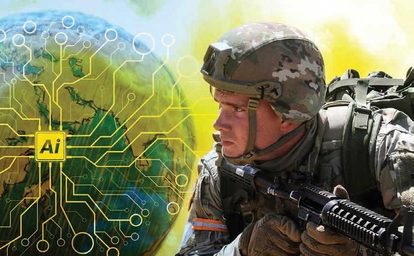
Army AI/ML project from Palantir gets $10.1 million extension
Software-engineering firm Palantir won a modification to an existing contract with the U.S. Army – the modification is in the amount of $10.1 million – to conduct research and development services in the area of artificial intelligence (AI) and machine learning (ML). The most recent contract and this extension enables the Army to continue to use Palantir’s software to support soldiers, the data science community, and AI companies with AI/ML research and development within the U.S. Department of Defense.
These moves extend a partnership between Palantir and the Army launched in 2018 to deliver operational data and AI capabilities; since the beginning of this pact, Palantir’s platform has handled the integration, management, and deployment of data and AI model training to all armed services and special operators worldwide.
Sikorsky, Boeing protest U.S. Army’s Future Long-Range Assault Aircraft award to Bell Lockheed Martin subsidiary Sikorsky and Boeing have filed a formal protest with the U.S. Government Accountability Office (GAO) over the U.S. Army’s decision to award the Future Long-Range Assault Aircraft (FLRAA) contract to Textron’s Bell Helicopter, Boeing announced in a statement. The Sikorsky/Boeing team, called Team DEFIANT, is filing the protest jointly.
The Army chose Bell’s V-280 Valor over the Sikorsky/Boeing Defiant X helicopter design during December 2022. The GAO must review the protest and make a ruling within 100 days, which could include dismissing the protest or having the Army reevaluate the bids. It is not uncommon for the losing party in a competition for a major new defense contract to file a protest. It is also not uncommon for the GAO to sustain such protests: In fiscal 2022, GAO sustained 13% of protests.
DARPA X-plane project progresses to next phase
Aurora Flight Sciences (a subsidiary company of Boeing) won phases 2 and 3 of the Defense Advanced Research Projects Agency (DARPA) Control of Revolutionary Aircraft with Novel Effectors (CRANE) program, which aims to design, build, and test a novel X-plane that leverages active flow control (AFC) as a primary design consideration.
The Aurora CRANE entry, according to a statement from the company, uses active flow control (AFC) for multiple effects, including flight control at tactical speeds and enhanced performance during flight. The experimental aircraft is designed around an AFC system that uses AFC effectors embedded in all flying surfaces to alter the flow of air over an aircraft to change its course and speed instead of using control surfaces such as ailerons, rudders, and flaps.
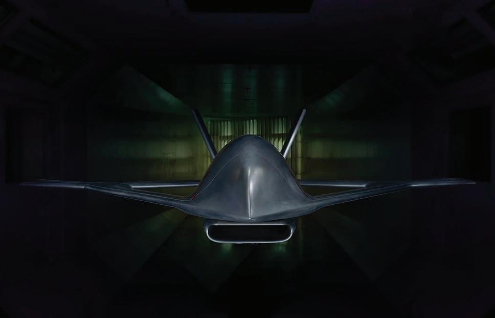 Figure 1 | U.S. Army/Shutterstock image.
Figure 2 | The Aurora Flight Sciences X-Plane, which is being developed on behalf of the Defense Advanced Research Projects Agency (DARPA). Photo courtesy of Aurora Flight Sciences.
Figure 1 | U.S. Army/Shutterstock image.
Figure 2 | The Aurora Flight Sciences X-Plane, which is being developed on behalf of the Defense Advanced Research Projects Agency (DARPA). Photo courtesy of Aurora Flight Sciences.
NEWS | TRENDS | D o D SPENDS | CONTRACTS | TECHNOLOGY UPDATES 10 January/February 2023 MILITARY EMBEDDED SYSTEMS www.militaryembedded.com
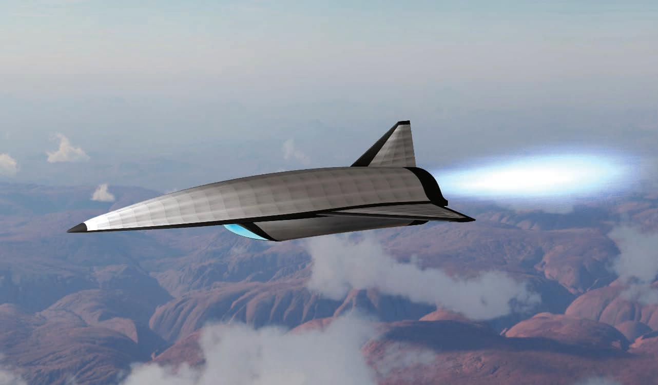
Hypersonic test bed contract awarded to Kratos Leidos has chosen Kratos to support the Expendable Hypersonic Multi-Mission ISR [intelligence, surveillance, and reconnaissance] and Strike Program – a program known as Mayhem – under an Air Force Research Laboratory project to develop an air-breathing hypersonic weapon system, Kratos announced in a statement. Kratos will serve as a subcontractor on the Leidos prime contract, acting as a member of the System Design Agent (SDA) team for the Mayhem program, which also includes Calspan and Draper, according to a Leidos statement.
According to company officials, the role of the SDA for this program is to perform research and development necessary for production of air-breathing multimission hypersonic system prototypes. The SDA will oversee designs, prototypes, and tests to ultimately produce and deliver a technical data package for the Air Force for high-performance hypersonic weapon systems.
Network and connectivity project for JADC2 gets tryout by Raytheon Technologies
Raytheon Technologies recently demonstrated FlexLink, an open system radio technology developed by Raytheon’s Collins Aerospace business unit intended to link multiple air and ground platforms that will ultimately connect defense networks and simplify U.S. Army command-and-control systems. During the Army’s Project Convergence exercise, Raytheon installed FlexLink on U.S. Army UH-60M helicopters and demonstrated that it was able to establish a joint command-and-control network at distances exceeding 200 nautical miles (about 230 miles).
The demonstration was regarded, according to the statement on the exercise, as crucial to validating the Army’s Project Convergence concept, which is the service’s contribution to the U.S. Department of Defense (DoD) Joint All-Domain Command and Control (JADC2) initiative. The FlexLink solution – the first open systems radio prototype integrated onto U.S. Army platforms –demonstrated that it could bridge four joint service and coalition networks, all operating at different security levels.
Microelectronics research to be led by DARPA, U.S. universities
DARPA announced that it will participate in a new long-term university research collaboration with the Semiconductor Research Corp. (SRC) and a consortium of companies in the defense and commercial semiconductor industries, called the Joint University Microelectronics Program (JUMP) 2.0.
According to the DARPA statement, the goal of JUMP 2.0 is to support high-risk, high-payoff research that addresses existing and emerging challenges in information and communications technologies, as identified in SRC’s “Decadal Plan for Semiconductors,” including the need for innovation in analog hardware, increasing demand for more memory and data storage, imbalance between data-generation and communication capacity, emerging security vulnerabilities in highly interconnected artificial intelligence (AI) systems, and unsustainable growth in energy demands for computing.
Radar sensing and perception for autonomous ground systems wins Army SBIR grant Metawave announced at the January 2023 CES trade show that it won a $1.7 million Small Business Innovation Research (SBIR) contract from the U.S. Army to develop long-range radar sensing and perception solutions for off-road autonomous vehicle (AGV) operation in adverse weather and complex operating conditions. Under the SBIR grant, Metawave will enhance its Carson radar technology platform to support off-road perception sensing and other advancements for AGVs; the resulting “Hudson” technology platform uses Metawave’s long-range and all-weather detection, tracking, and perception capabilities made possible by phased-array beamforming and steering front-end Marconi chips, highly integrated antenna-in-package (AiP) modules, and high-resolution radar algorithms. The new Hudson radar platform will also use enhanced NVIDIA GPUs. The contract also calls for Metawave to develop Anthem, a proprietary machine learning (ML) software platform comprising lidar, camera, and fusion stacks.
 Figure 3 | A concept illustration of the hypersonic test bed to be developed by Kratos. Image courtesy Kratos.
www.militaryembedded.com MILITARY EMBEDDED SYSTEMS January/February 2023 11
Figure 4 | An illustration of how Metawave's radar sensing platform works. Image courtesy of Metawave.
GPS-alternative satellite delivered to AFRL for testing
L3Harris Technologies recently delivered the Navigation Technology Satellite-3 (NTS-3) space vehicle to the Air Force Research Laboratory (AFRL) integration and test facility at Kirtland Air Force Base, New Mexico. NTS-3 is an experimental satellite funded by the AFRL that plans to broadcast positioning, navigation, and timing (PNT) signals from geostationary Earth orbit with the goal of demonstrating next-generation PNT technologies for the U.S. military and provide an alternative to GPS. NTS-3 is expected to launch in late 2023.
The Global Navigation Satellite System Test Architecture (GNSSTA) is a reprogrammable software-defined receiver that enables users to receive both legacy GPS signals along with the advanced signals generated by NTS-3. It is the precursor to planned future operational receivers to provide the military with options to prevent and respond quickly to common battlefield threats like GPS jamming and spoofing.
C4ISR market to grow by more than $60 billion over 10 years
The global market for command, control, communications, computers, intelligence, surveillance, and reconnaissance (C4ISR) will be worth $178.74 billion by 2030, experiencing a compound annual growth rate (CAGR) of 4.84%, a new report predicts. The report, from Verified Market Research, states that the C4ISR market is currently $117.23 billion and will experience this sharp growth due in part to advances in space-based technologies that enable governments to replace conventional C4ISR architecture with advanced systems. However, the market faces some limitations going forward, the report states. Some of the possible barriers to robust growth in the C4ISR market, say the study authors, include expense, as these systems incur expensive development, implementation, and maintenance costs. Moreover, development and deployment of these systems occur along a long timeline, which can be another barrier to the market’s expansion on a global scale.
Sensors for Eurodrone pods to be made by Hensoldt
Sensors maker Hensoldt has signed an agreement to develop sensor equipment that can be integrated into a pod to give the recently commissioned Eurodrone a signals-intelligence (SIGINT) capability.
The potentially 15 million euro ($16.31 million) contract – awarded by the Federal Office of Bundeswehr Equipment, Information Technology and In-Service Support (BAAINBw) – calls for the implementation and testing of a SIGINT demonstrator that can be easily integrated into flying platforms and scaled for sea and land applications. The sensor technology for reconnaissance of radio and radar signals is based on updated digitization, electronic beam-steering, and metallic 3D printing technologies, Hensoldt stated in its announcement.
Quartet of Italian companies wins contract for 6th-gen fighter
A team of Italian companies has signed a contract for the next development phase of the country’s 6th-generation air system, Leonardo announced in a statement. Leonardo, Elettronica, Avio Aero, and MBDA Italia are teamed to develop a concept, conduct an assessment, and perform demonstrations that will lay the foundation for Italy’s Global Combat Air Programme (GCAP).
According to a statement about the contract win, the project will draw on Italy’s universities, research centers, subject-matter experts, and start-up companies, all in close partnership with the Italian ministry of defense. The ministry will be responsible for defining operational needs and directing technological development, according to the Leonardo statement, while drawing on industry support. Italy has so far earmarked 6 billion euros ($6.52 billion) for investment in research and development for the GCAP program.
 Figure 6 | Artist’s concept of the Italian 6th-generation air combat system. Illustration courtesy Leonardo/BAE Systems.
Figure 5 | NTS-3 space vehicle is shown. AFRL photo.
Figure 6 | Artist’s concept of the Italian 6th-generation air combat system. Illustration courtesy Leonardo/BAE Systems.
Figure 5 | NTS-3 space vehicle is shown. AFRL photo.
DEFENSE TECH WIRE Continued 12 January/February 2023 MILITARY EMBEDDED SYSTEMS www.militaryembedded.com


Radar for missile/hypersonic defense
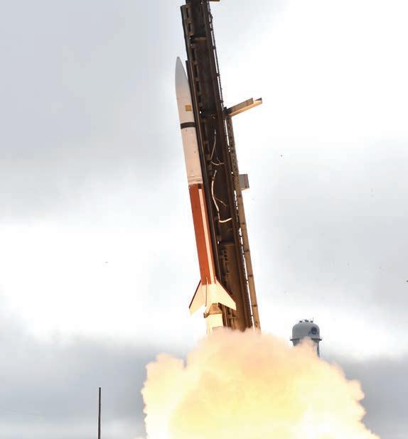
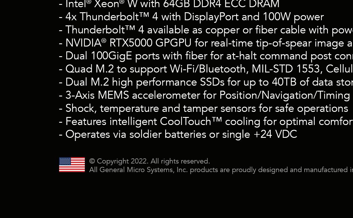
Speed, maneuverability of hypersonic missiles create challenges for missile defense
 By Dan Taylor
When it comes to missiles, the future is hypersonic. That creates an array of challenges for the defense industry – and radar technology is at the forefront when it comes to developing technology to counter this growing threat.
The U.S. Navy launches a hypersonic missile during a Navy Strategic Systems Programs (SSP) and Army Hypersonic Project Office (AHPO) test. U.S. Navy photo/Luke Lamborn.
REPORT
SPECIAL
14 January/February 2023 MILITARY EMBEDDED SYSTEMS www.militaryembedded.com
Tracking hypersonic missiles today isn’t like missile tracking in the old days. Missiles could be tracked by radar, troops could be warned, and hopefully disaster and death averted. The situation is very different today.
“Missile vehicles have gotten so fast that they are inside the target-tracking loop,” says David Murray, senior applications engineer at Times Microwave Systems (Wallingford, Connecticut). “By the time [the radar] sees it, it’s not there anymore. By the time you get a weapons lock on it, it’s gone. So the game changes completely.”
John W. Otto, senior director of advanced hypersonic weapons at Raytheon Missiles & Defense (Tucson, Arizona), says that tracking hypersonics is “exponentially” more challenging in today’s environment.

“Hypersonic missile systems alter warfighting on a strategic and tactical level and can deliver payloads farther and faster than ever before,” Otto says. “They move nimbly enough to avoid detection and dodge defensive countermeasures.”
Detecting, tracking, engaging hypersonic missiles
An end-to-end missile-defense system must effectively detect, track, and engage a missile moving at hypersonic speeds; the industry continues to work out the right solution to dealing with hypersonics. Murray believes this could take many forms: It could be networks of radars, or it could be satellites using networks of radars, for example. Moreover, the satellites might rely more on optical sensors than radar – after all, a missile moving at Mach 5 gives off an extensive heat signature, so using optics rather than radar may be a more effective way to track it. There are a variety of options, and the industry is examining many of them.
“All of this technology will be meshed in a network for the good guys to find the bad guys’ weapons,” Murray says. “What has to improve is closing that targeting loop down, which means faster processing and frequencies of higher resolutions. All of those are natural evolutions of radar technology.”
There are multiple ways to engage hypersonic weapons. Of course, the best option is to shoot it down on the launch pad – but once it leaves that launch pad, you have to be prepared to engage it. One option is the traditional bullet-on-bullet approach, while another is to blast the area with a “shotgun shell”-type weapon that would put up a screen the missile would have trouble getting past without colliding with the shrapnel, Murray says.
Multiple efforts are underway to find an interceptor that can more effectively destroy a hypersonic missile. Otto says that Raytheon is developing an interceptor focused on hypersonic missile defense, noting that while today’s interceptors like the SM-3 and SM-6 can defend against hypersonic missiles in the terminal phase, they are not optimized to defend against hypersonic glide vehicles in the long glide phase after launch. Raytheon’s Glide Phase Interceptor (GPI) aims to fill this gap and would fit into the Aegis Ballistic Missile Defense system, he says.
Lockheed Martin is also developing an interceptor for hypersonic threats known as the Next Generation Interceptor (NGI). It is designed for the Missile Defense Agency’s Ground-based Midcourse Defense system. (Figure 1.)
Seeking a holistic solution
The best way to tackle a challenge like this is by taking a holistic approach to solve it, Murray says. That means assembling experts on platforms, radars, missiles, and other tech to determine what technologies can help solve this challenge, whether advancements in high-temperature materials, direct-launch devices, or even coaxialcable assemblies.
The reality is that today’s conventional technology is not very effective in finding and tracking hypersonic weapons, so the U.S. military needs to come up with new solutions, Murray says.
“It’s a weapon with a different signature than a conventional weapon, so you would optimize your search technique based on the signature it’s giving off,” he says. “So you’ll still get a good radar cross-section return on it – actually larger because of the very nature of the plasma [surrounding the vehicle] – but you’ve got to be looking in the right direction at the right time. That’s the problem.”
The secret to defeating any missile threat, whether hypersonic or conventional, is to locate it as soon as possible. One possible way to make it easier to do that is to expand the range of the radar that is looking for those weapons. That carries its own set of challenges, Murray says.
www.militaryembedded.com MILITARY EMBEDDED SYSTEMS January/February 2023 15
Figure 1 | The NGI is a missile-defense interceptor program designed to protect and defend the U.S. from intercontinental ballistic missiles. This program will serve as a first line of a layered missile defense architecture against evolving threats from rogue nations.
“For radar to see farther, it has to be a higher or lower frequency or a higher power,” he says.


However, those improvements typically come at the expense of something else. “Higher power involves more expensive parts with lower reliability,” he says.
Increasing maneuverability: a challenge


The military uses so-called staring technology in the form of satellites that are able to keep an eye out for hypersonic launches. This reality prompts the question: How quickly can the military react to that launch and get the information to someone in the track of the missile?
“That’s a major problem with hypersonic missiles,” Murray says.

Dawn Powers VPX


And it’s not just their speed that is a problem, but also a growing unpredictability in the track of the missiles. “An ICBM [intercontinental ballistic missile] is hypersonic, but it’s a pretty predictable arc,” Murray says. “When you know the target based on the trajectory, you can identify the target location. [Hypersonics] get around that by putting something in orbit and releasing it from orbit when they want. Then you have cruise missile paths, glide vehicle paths, and they’re maneuverable. So it’s very hard to predict where something is going to hit.”
Raytheon’s Otto agrees: “Unlike the traditional BMD [ballistic missile defense] system, which was built for ballistic missile threats with a clear and predictable trajectory, like throwing [a] football, the future architecture needs to evolve to account for proliferation of unpredictable, survivable threats which can quickly change course and can occur simultaneously to evade our sensors,” Otto says. “A key strategy will be getting eyes on the threat through networked sensors from space to ground to create a better threat picture.”
Radar developments are key
Better radar technology may be able to help with spotting these maneuverable and unpredictable threats, Murray says. Developments in synthetic aperture radar/inverse synthetic aperture radar (SAR/ISAR) and processing speeds will be critical to that effort, Murray says. “So it isn’t the array itself, but maybe [the technology] behind the array,” he says.

Murray says that Times Microwave Systems is doing a lot of work at the component level and pursuing technology in all areas to find a breakthrough.
“It’s across the board: A better radome, the apertures themselves if they are not optimized for that, and whatever signal comes off of a radar needs to get to whatever processes it with maximum clarity and minimum loss,” he says.


For its part, Raytheon is focusing on improving digital technologies and computing power when it comes to radar, Otto says.

(510) 657-4444 dawnvme.com
Dawn is the leader in VITA 62 compliant power supplies for the mission critical market. Wide range of standard features, highly configurable through custom firmware.
Rugged,
Reliable and Ready. You need it right. You want Dawn.
Dawn’s PSC-6238 VITA 62 compliant 3U VPX Power Supply for conduction cooled systems is designed to operate in a military environment over a wide range of temperatures at high power levels. Up to 800 Watts available power.
SPECIAL REPORT Radar for missile/hypersonic defense 16 January/February 2023 MILITARY EMBEDDED SYSTEMS www.militaryembedded.com
Onboard embedded RuSH™ technology. Switchable Battleshort and NED functions.
“The development and engineering environment has changed greatly and will continue to get faster with new digital tools and engineering approaches,” he says. “To defend against hypersonics, we need to track the threat through their entire flight from launch to defeat. Distributed sensing is critical; networked sensors from space to ground using advanced command and control to detect and track the target create a better threat picture and enable timely decisions.”


Currently, Raytheon is building a radar for the U.S. Army known as the Lower Tier Air and Missile Defense Sensor (LTAMDS). (Figure 2.) It is a 360-degree Active Electronically Scanned Array (AESA) radar that is designed to track both ballistic and cruise missiles, along with drones and aircraft, Otto says. The company aims to increase radar signal, enhance sensitivity for longer range, and increase resolution, capacity, and reliability. The ability of a radar to sense


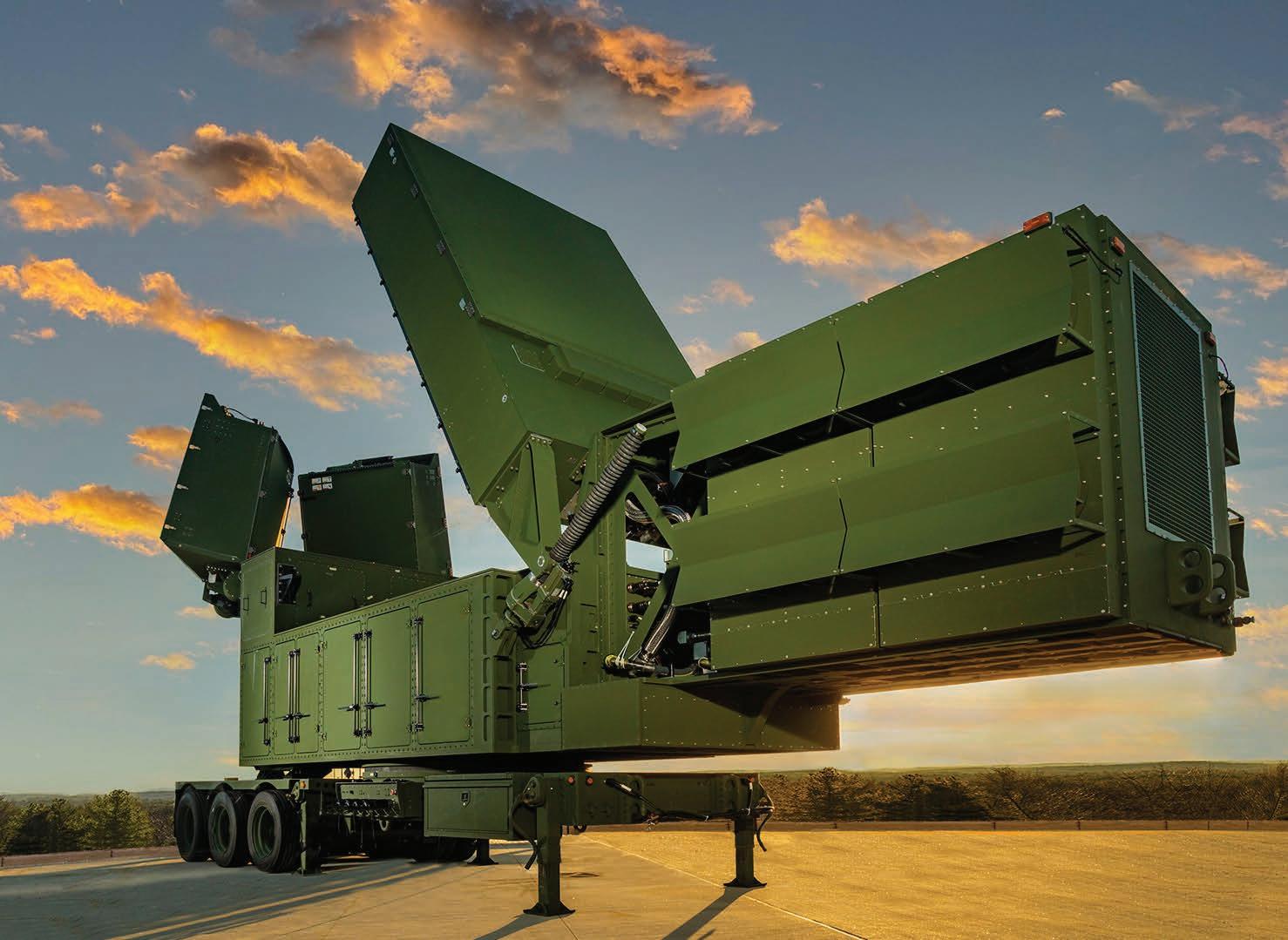
in all directions, as well as to detect at longer distances and at higher speeds, is key to defeating hypersonic missiles, he adds. MES


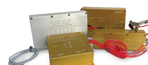
www.militaryembedded.com MILITARY EMBEDDED SYSTEMS January/February 2023 17 SWaP optimized, they are perfectly suited for avionics power hold-up [MIL-STD-704/DO-160]. Capacitors and custom capacitor banks available.
capacitors are the most power dense in the industry. http://bit.ly/3wgWQ0c Scan the QR code or follow the link to download our whitepaper: Specifying a Capacitor to Meet MIL-SDT-704/DO-160 Power Hold-up Requirements
Figure 2 | The Raytheon Missiles & Defense Lower Tier Air and Missile Defense Sensor (LTAMDS) radar system for the U.S. Army is designed to defeat advanced and next-generation threats, including hypersonic weapons, or those that fly faster than a mile a second. LTAMDS is the first in the family of radars the company calls GhostEye.
Our Hybrid Wet Tantalum
Hypersonic weapons systems: Getting in synch with MEMS-based timing
By Odile Ronat
Hypersonic systems operate in highly challenging environments. High temperatures and high-temperature transients create challenges for timing devices, sensors, and other electronic components, including radomes and antennas. Timing devices in hypersonic systems pose unique challenges because they synchronize mission computing, flight control, real-time signal processing, and communications. All of this is occurring while facing many environmental challenges, from extreme temperatures and pressure to vibration, shock, and extremely high G-forces. MEMS [microelectromechanical systems] oscillators can solve the challenges inherent in the hypersonic environment and outperform their quartz-based predecessors.
Quartz-based timing components have provided timing references for aerospace and defense applications for many decades. While quartz-based oscillators have been enhanced over the years to mitigate their shortcomings, they still have inherent disadvantages that make them a weak link in the design of nextgeneration defense systems such as hypersonic weapons systems.
The industry is transitioning to timing devices based on microelectromechanical systems (MEMS) technology to
overcome these shortcomings. MEMS-based timing devices outperform their crystalbased counterparts across many key metrics. They are smaller, more reliable, rugged, and ultra-stable over time, temperature, acceleration, and vibrations, which makes them better suited for extreme operating environments including hypersonic systems.
Hypersonic weapons are ultrafast, low-flying, agile, and highly maneuverable missiles and glide vehicles designed to travel at speeds between 3,000 and 15,000 mph. Moreover, they are capable of changing their trajectories to avoid detection and defense systems.

MEMS timing technology overview
MEMS-based oscillators – first introduced in 2006 – have continued to evolve their use of timing technology, including temperature compensation and phase-locked loops (PLLs), to deliver significantly higher frequency stability, lower jitter, and phase noise.
SPECIAL REPORT 18 January/February 2023 MILITARY EMBEDDED SYSTEMS www.militaryembedded.com
Radar for missile/hypersonic defense
MEMS timing devices are designed to be free of spurious mode crossings with the fundamental mode and free of resonator-induced activity dips. The MEMS device uses a single mechanical structure of pure silicon with a tensile strength of 7 gigapascals (GPa), which is about 14 times higher than titanium’s 330 to 500 megapascals (Mpa).
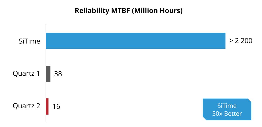
The reliability of a MEMS oscillator is significantly better than that of a quartz oscillator, which has a much higher failure rate. Figure 1 illustrates the reliability of MEMS oscillators, measured in mean time between failure (MTBF) when compared to quartz-based oscillators, and shows that the MTBF of MEMS oscillators is over 2.0 billion hours – about 50 times greater than quartz-based oscillators.
Contaminants are controlled to an ultralow parts-per-billion (ppb) level, while a process at 1,100 °C step-anneals the silicon crystal applied to the wafer. This process is done in an extremely pure high vacuum. The resulting clean resonator cavity effectively eliminates resonator aging mechanisms. Figure 2: a typical 10-year aging specification for a MEMS oscillator at +/-400 ppb vs. +/-3,000 ppb for quartz.
Quartz-based oscillators are typically housed in an open-cavity ceramic package with the IC and quartz resonator bonded to the package substrate with a different type of adhesive. In addition, each quartz device is individually trimmed to the desired output frequency using either ablation or deposition of metal onto the quartz resonator. The adhesives and metal trimming can be a source of contamination that can age a quartz resonator through mass loading and reduces reliability.
In contrast, MEMS resonators have about 1,000 to 3,000 times lower mass than quartz resonators and therefore are more resistant to shock and vibration. Acceleration imposed on a MEMS structure from shock or vibration will result in a lower force than on the quartz equivalent, which will induce a much lower frequency shift.
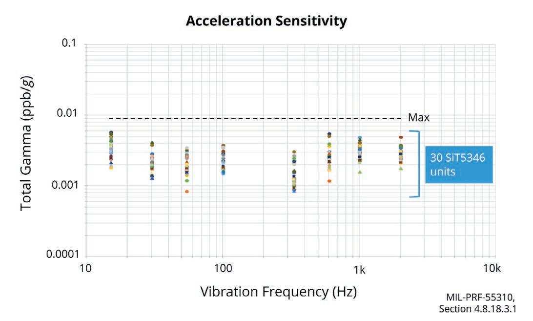
Another measure of vibration sensitivity is the frequency shift per g of applied sinusoidal acceleration. The most common unit
of measurement is parts per billion (ppb) frequency shift per g of acceleration or ppb/g. Figure 3 shows the total acceleration sensitivity gamma vector (over three axes) of 30 MEMS units over vibration frequencies from 15 Hz to 2 kHz. The maximum observed value of only 0.0058 ppb/g is the best performance achieved.
Shock resistance is another key parameter for hypersonic systems and is a metric in which MEMS technology outperforms quartz technology. For example, SiTime Endura products are shock-tested up to 30,000 g (a multiple of the acceleration of
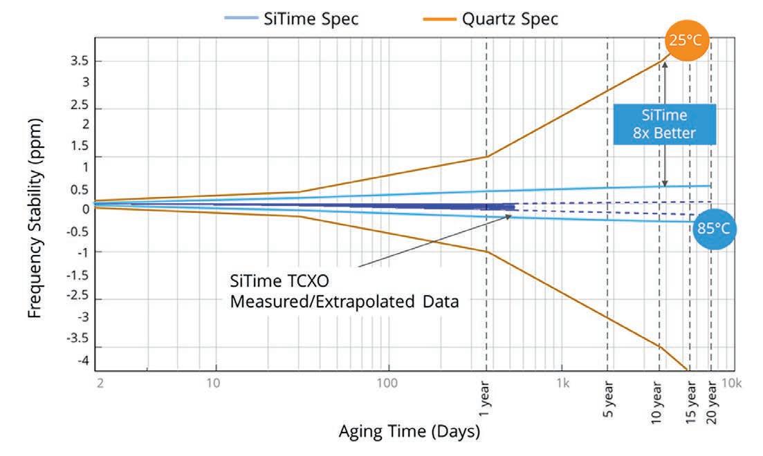 Figure 1 | The MTBF of MEMS oscillators exceeds that of typical quartz-based oscillators.
Figure 2 | Aging specifications for a MEMS oscillator versus quartz-based counterparts.
Figure 1 | The MTBF of MEMS oscillators exceeds that of typical quartz-based oscillators.
Figure 2 | Aging specifications for a MEMS oscillator versus quartz-based counterparts.
www.militaryembedded.com MILITARY EMBEDDED SYSTEMS January/February 2023 19
Figure 3 | Shown: MEMS units’ vibration sensitivity gamma from 15 Hz to 2 kHz.
gravity), which is significantly higher than most quartz products can achieve. To put this into perspective, a 155 mm howitzer projectile experiences a peak acceleration of 15,500 g over a 9-ms pulse. As typical system design margins are 1.5 times, this implies that 155 mm projectile components should be certified for up to 23,250 g.
Looking at oscillator technology
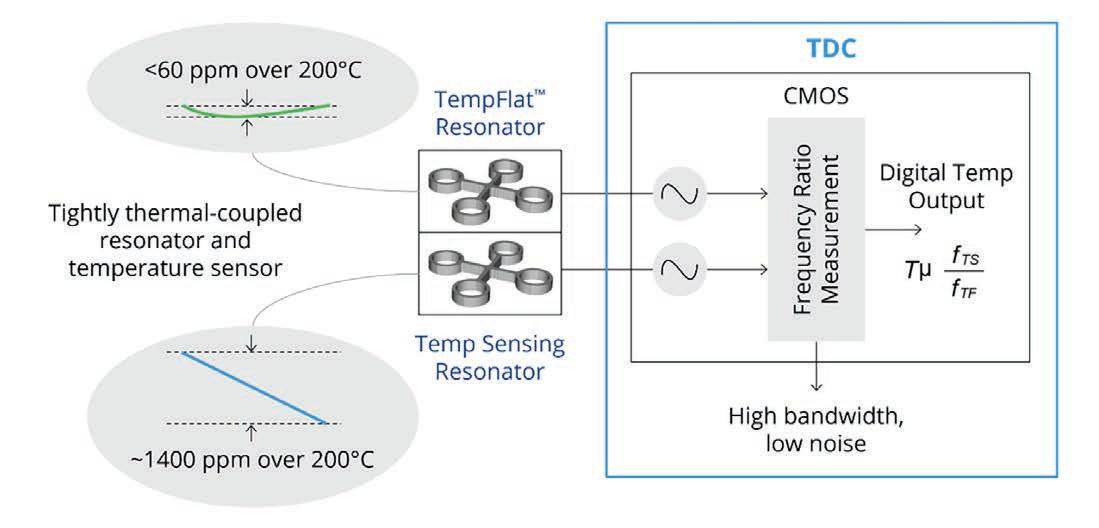
Recent advances in MEMS technology produce additional benefits, such as resilience to fast-temperature ramps and low-phase noise. One resonator is used as a temperature sensor, exploiting its relatively steep but linear -7 ppm/°C frequency versus temperature slope. The other resonator provides a reference clock for the downstream PLL, designed to have a relatively flat frequency-versus-temperature slope. Tight thermal coupling between the resonators results from their 100 µm fabrication on the same die substrate, eliminating the thermal gradient between them.
In contrast, the temperature sensor in a quartz-based temperature-controlled crystal oscillator (TCXO) is integrated within an IC sitting below the quartz resonator on the ceramic package substrate. The spatial separation between the temperature sensor and resonator creates a substantial thermal gradient between the two elements, introducing significant frequency error when subjected to fast thermal transients.
A key element of the MEMS temperature compensation architecture is the temperature-to-digital converter. As shown in Figure 4, this circuit block generates an output frequency proportional to the ratio between the frequencies generated by the two
resonators. It has 30 microKelvin (µK) temperature resolution and bandwidth up to 350 Hz, enabling excellent closeto-carrier phase noise performance and Allan deviation (ADEV) performance.
ADEV is a time-domain measure of frequency stability. The main advantage of ADEV over standard deviation is that it converges for most noise types and is used for characterizing the frequency stability of precision oscillators. Good ADEV performance is critical for hypersonic weapons, satellite communications, and various precision global navigation satellite system (GNSS) applications.
Frequency response to fast thermal transients
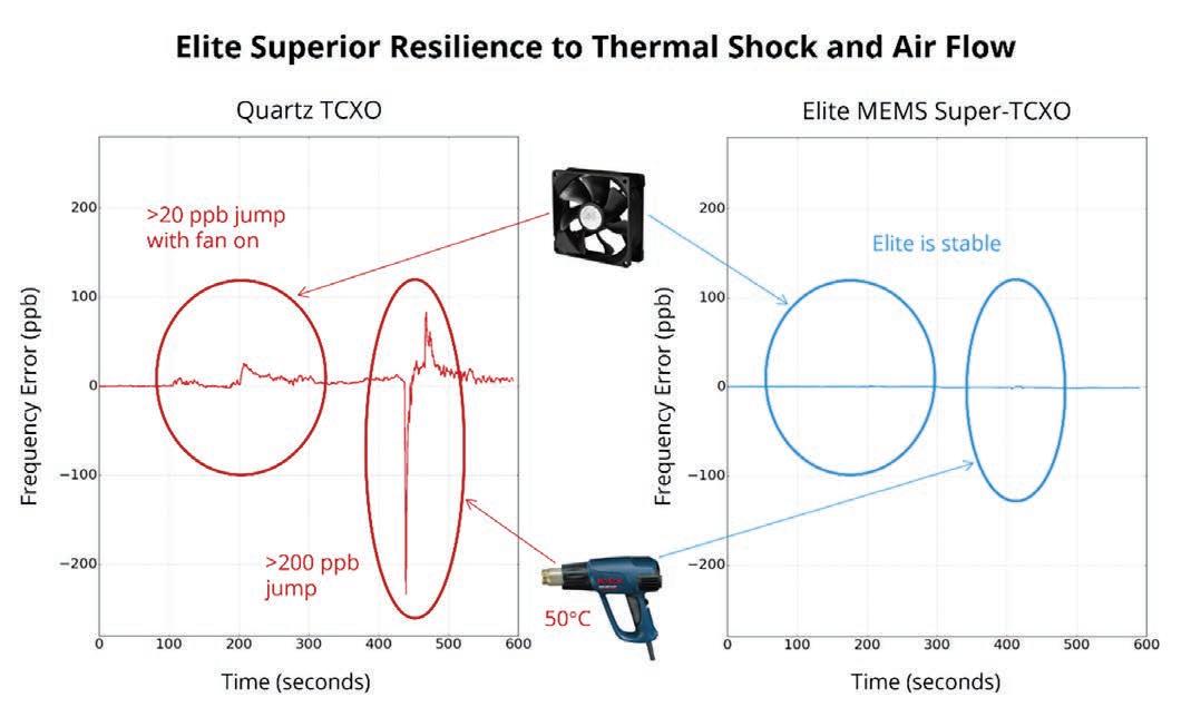
Figure 5 demonstrates the benefit of the DualMEMS architecture during fast thermal transients. This example shows the results of a heat gun simultaneously applied to two devices: a SiTime DualMEMS Super-TCXO and a ±50 ppb quartz-based TCXO. In response to the heat gun stimulus, the quartz TCXO deviates up to 650 ppb peak-to-peak from nominal temperature, exceeding its data sheet specification by a factor of up to 9. The frequency change of the DualMEMS Super-TCXO is barely noticeable, about 3 ppb or less, far below its specification limit of 100 ppb.
Air flow is another system stressor in hypersonic weapons and can cause die temperature changes produced by fluctuations in heat flow from the oscillator. Rapid, turbulent air flow can have an even more pronounced effect on heat flow from the oscillator to the environment and, in extreme cases, can cause vibration effects.
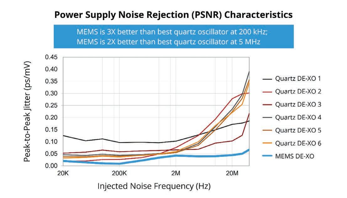
Rejecting power-supply noise
In addition to external stresses, hypersonic weapons systems are subject to internal system stresses, such as power-supply noise, which can produce data errors. It is critical for the oscillator to maintain low phase noise and jitter in the presence of noise on the power-supply line to maintain optimal system performance.
Power-supply noise rejection (PSNR) is a measure of the oscillator’s resilience to
Figure 5 | Screen shot of a +/-50 ppb quartz TCXO versus a MEMS Super-TCXO under fast temperature ramp conditions.
SPECIAL REPORT Radar for missile/hypersonic defense 20 January/February 2023 MILITARY EMBEDDED SYSTEMS www.militaryembedded.com
Figure 4 | A typical temperature-to-digital converter.
power supply noise. PSNR is the ratio of output jitter in picoseconds (ps) divided by the amplitude of the injected sinusoidal jitter on the supply pin in millivolts (mv). The MEMS device’s low jitter is achieved using multiple on-chip low-dropout regulators that isolate critical components such as the VCO and MEMS oscillator. Figure 6 shows a MEMS oscillator’s peak-to-peak jitter and superior PSNR compared to quartz oscillators from six different suppliers.
Hypersonic systems will be among the most effective defenses, with maneuverability and exceptionally high speeds. The harsh conditions that hypersonic weapons must


endure – such as very high temperatures, rapid temperature changes, and extreme levels of shock and vibration –also can be devastating to their systemlevel components. MEMS oscillators can outperform their quartz-based predecessors, as they meet the demanding performance and reliability requirements of hypersonic technology. MES

Odile Ronat is director of product marketing, Aerospace and Defense, SiTime. Prior to SiTime, she worked at International Rectifi er/Infi neon in the high-rel and rad-hard groups. She holds an MS in engineering from École des mines de Paris and an MS in engineering management from Stanford University (Palo Alto, California).

SiTime
https://www.sitime.com/


Media partners Get your free ticket now! embedded-world.com/voucher Use the voucher code GG4ew23 JOIN THE EMBEDDED COMMUNITY 14–16.3.2023 EW-23_Ad_Visitors_185x130mm_EN_3mm.indd 1 30.11.22 08:32
Figure 6 | Power-supply noise rejection of a MEMS DE-XO versus typical quartz oscillators.
MIL TECH TRENDS
Is high-performance electronic warfare compatible with open standards?
By Robert Normoyle
Today, multiple agencies are involved in open architecture standards to ensure that weapons and defense system features match up with their perception of future systems specified and beginning to be used by the U.S. Department of Defense (DoD). Examples of key attributes provided by these standards relevant to electronic warfare (EW) are the VPX backplane profiles and MORA/ V49.2 protocols. The DoD has had a hand in developing both of these in order to specify and develop reference architectures to verify performance.
Prior to the promulgation of the SOSA [Sensor Open Systems Architecture] framework, systems integrators based their designs on a standard such as VPX, VXS, or VME, and declared their
open architecture, though at that time there wasn’t a robust system-level specification to enable interoperability of 3rd-party components. The standards provided mechanical and high-level signal type definitions, leaving designers with a lot of leeway on signal protocols. Often the backplane, the board interfaces, and the data protocol interfaces were proprietary. Even though the designer could state the design as open architecture, the Modular Open Systems Approach (MOSA) goals were not effectively achieved –namely, the goals of interoperability, scalability, competition, faster refresh, and lower cost.
This disconnect was even more prevalent with high-performance electronic warfare (EW) systems, since the coordination between components and systems is expected at a nanosecond scale and extreme frequency coverage. A stretch goal for instantaneous frequency coverage has been 2 to 18 GHz, 16 GHz of instantaneous bandwidth, for electronic surveillance (ES), electronic attack, and digital RF memory (DRFM) capabilities. In addition to this range, banded capability at millimeter frequency was also desirable. Even though government agencies specified MOSA-based approaches, there was no technical detailed description of what this meant and how to verify it. The architectures were so intricately interdependent upon custom designs that changes could only be done by original equipment providers. The government agencies were still tied to a single source for simple upgrades to an architecture, resulting in simple changes to designs costing millions.
Do standards really support interoperability?
The pioneer computer programmer Grace Hopper coined the phrase: “The nice thing about standards is that there are so many of them to choose from”, implying that the use of standards is not effective, and every organization may “choose” to use something different, thus negating interoperability.

22 January/February 2023 MILITARY EMBEDDED SYSTEMS www.militaryembedded.com
Leveraging the Sensor Open Systems Architecture (SOSA) for radar applications
This statement has been a typical pushback about hewing to standards, though over the last five or 10 years there has been a convergence between DoD organizations and industry. Examples of this convergence are the CMOSS [C4ISR/ Electronic Warfare Modular Open Suite of Standards], SOSA, and CMFF [CMOSS Mounted Form Factor] efforts, which have been using the best attributes of multiple standards such as VPX, VITA 49, MORA [Modular Open RF Architecture], VICTORY [Vehicular Integration for C4ISR/ EW Interoperability], FACE [Future Airborne Capability Environment], and HOST [Hardware Open Systems Technologies] to develop a framework that is being adopted by a majority of the suppliers and becoming required by more and more DoD programs. These interfaces have been designed by a consortium of industry, government, and academia engineers who are vetting the proposed architecture components with their reallife experiences of EW, signals intelligence (SIGINT), radar, and communications systems requirements. This situation is a key difference from how standards were developed a decade earlier, at which time the primary drivers were just industry with very little government involvement.
Can standards really support high-performance EW requirements?
In the early days of digitized audio –namely the 1980s – a similar problem existed, as custom cards were needed to compress/expand audio signals. As personal computer (PC) technology evolved, it became viable to use software-based encoder/decoders on the processors as opposed to using custom hardware solutions. This maturation was an enabler for the development of audio and video compression software that provides interoperability across platforms, whether Mac or PC, at a low cost and with very little effort by the user. When programmable technology approaches the performance to directly process the signal phenomena of interest, then open architecture approaches and standards are viable.
Today we have arrived at a point where the latest processors used for EW analytics
and jamming can directly ingest, manipulate, and create jamming waveforms over ultra-wide bandwidths. These processors include FPGAs [field-programmable gate arrays] for front-end processing and detection. An EW system can provide frequency coverage of 16 GHz of instantaneous frequency coverage and also provide nanosecond precision control, status, and IQ data interfaces via SOSA standards.
A similar matured situation exists today: Capabilities of software-defined radio (SDR) have reached the information processing rate needed to handle multiple gigahertz of bandwidth. A two-slot 3U VPX card can provide simultaneous transmit and receive capability of 4+ GHz. Multiple copies can be integrated into a SOSA chassis to provide 16 GHz of coverage, such as in a range of 2-18 GHz.
Today, backplane architectures are available that can convey over 200 Gbps of data as GbE and PCI per slot, which is sufficient to convey 4 GHz of data each direction. MORA/V49.2 interfaces provide timestamped high-precision information including IQ data packets, control packets, and status packets between modules and systems. This protocol, combined with the 1 PPS and 100 MHz reference clocks in a system architecture, makes it possible to achieve nanosecond precision. The standards bodies continue to progress efforts to make the standards synergistic and move forward with new enhancements to support emerging technology. New VPX connectors are being defined that support bandwidth of 800 Gbps per module, which is sufficient to convey 16 GHz of instantaneous bandwidth at 16 bits resolution.
Interoperability advantages of SOSA standard for EW solutions
The SOSA standards group consists of more than 100 organizations and more than 1,000 members, all working to proactively develop an interoperable framework for multiple-intelligence (multi-int) applications. EW engineers are part of this group and voice their expertise to mold the standard to meet demands of high-performance EW. The consortium also takes into account the other
modalities of operation including communications, radar, and SIGINT. The resulting standards have enabled companies to build products based on the standards, anticipating that multiple DoD programs can leverage them.
This alignment reduces the time and schedule of acquisition programs because the chassis and the modules are being developed in advance of the acquisition cycle, rather than during the program’s NRE phase. This reality is quite different from legacy acquisitions where chassis were typically custom-designed for an acquisition effort, with commercial off-the-shelf (COTS) modules typically needing modification to support the customization required by the prime. Today, a chassis built for one program is being rapidly deployed for another.
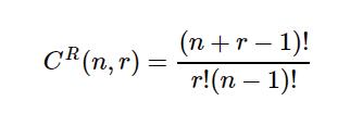
This same phenomenon is also true for VPX modules, where modules from a variety of vendors can be used in multiple chassis. Figure 1 shows the number of combinations viable in four and eight SOSA payload slots, based on 1 to 20 unique payload cards, such as EW SDR. The combination with repetition formula was used as shown. The repetitions do not include the same cards
HTLv-C11 HTLv-C19 Number of Slots 4 8 Card Types Combinations 1 1 1 2 5 9 3 15 45 4 35 165 5 70 495 6 126 1287 7 210 3003 8 330 6435 9 495 12870 10 715 24310 20 8855 2220075
www.militaryembedded.com MILITARY EMBEDDED SYSTEMS January/February 2023 23
Figure 1 configurations in a chassis as a function of card types and number of slots in a chassis.
configured differently in a chassis. The maximum number of SDR modules is based on a quick survey of vendors at the 2022 Association of Old Crows Annual International Symposium and is a conservative number.
The number of configurations is staggering, perhaps not all of them uniquely beneficial, though if only 10% are deployable architectures, it is still an impressive number of configurations compared to the single-purpose chassis of the past since it could provide dozens of architectures ready for redeployment for different missions and platforms. It was unprecedented in legacy EW architectures to reuse modules and chassis for multiple configurations for multiple programs and platforms that are not just EW focused, but multi-int. Companies are seeing the phenomenon in the integrations of SOSA aligned chassis and SIGINT/EW VPX modules. This situation enables SDR modules from multiple vendors to be used in multiple chassis for a diversity of programs and products providing fully integrated solutions can employ modules from multiple performers.
FPGA partial reconfiguration enables multi-int capability
The framework and interfaces for a generic mission manager which can support SDR reconfiguration is a being defined by SOSA. Just as there were many ways a chassis can be configured with different SDR modules, there are also many ways that the SDR cards can be dynamically configured to support different mission requirements at the depot or to dynamically change the SDR capability of the chassis in situ of a mission. There are three high-level use cases:
1. A SOSA chassis built for a specific EW program is redeployed to support a different EW program and/or another operational mode such as SIGINT or radar
2. SOSA chassis reconfigured at the depot with an alternate mission-specific card set
3. SOSA chassis dynamically reconfigured in situ to support different modalities of operation
An example of repurposing a notional SOSA chassis payload cards is shown in Figure 2 and 3. In Figure 2, the chassis provides a total of 16 GHz of ES and EA capability by configuring each of the eight payload slots with 2 GHz IBW [instantaneous bandwidth] UWB [ultra wideband] SDRs providing a 20 MHz to 20 GHz frequency coverage. In Figure 3, the same chassis is reconfigured at the depot to provide eight channels for instantaneous precision DF [direction finding] and eight channels for ES [electronic support]. The same chassis provides a high precision interferometer DF while simultaneously providing 8 GHz IBW of frequency coverage.
An example of dynamically reconfiguring a chassis in situ is presented in Table 1. For this notional example, the chassis is configured as shown in Figure 2. It has eight SDR cards each with 2 GHz IBW which can be dynamically configured for different operations during the mission. During the start of the mission, it is in Mode 1, utilizing all the channels for ES providing 16 GHz of IBW surveillance. As it detects targeting threat radar, it moves to Mode 2, reallocating ES channels for a look-thru jamming technique while still maintaining 14 GHz IBW for ES. When a missile-targeting radar is detected, it moves to
Mode 3, by dynamically reloading firmware and bonding channels coherently together to form a digital RF memory (DRFM) jamming channel. While in this mode, there is still 10 GHz of instantaneous BW ES capability. To determine the effectiveness of the EW technique, it switches to Mode 4, reconfiguring UWB SDR 4 and 5 to create a UWB radar. As mentioned earlier, this is a notional representation of one scenario to represent the potential value of dynamic in situ mission management. Many other dynamic configuration usages exist.
1 2 3 4 5 6 7 8 2 GHz IBW ES/EA 2 GHz IBW ES/EA 2 GHz IBW ES/EA 2 GHz IBW ES/EA 2 GHz IBW ES/EA 2 GHz IBW ES/EA 2 GHz IBW ES/EA 2 GHz IBW ES/EA
Figure 2 | Notional chassis configuration consisting of eight payload slots providing 16 GHz IBW, each with a 20 MHz to 20 GHz frequency range.
1 2 3 4 5 6 7 8 Dual 80 MHz IBW ES/EA Dual 80 MHz IBW ES/EA Dual 80 MHz IBW ES/EA Dual 80 MHz IBW ES/EA 2 GHz IBW ES/EA 2 GHz IBW ES/EA 2 GHz IBW ES/EA 2 GHz IBW ES/EA Mode ID Chassis Mode of Operation UWB Ch 1 UWB Ch 2 UWB Ch 3 UWB Ch 4 UWB Ch 5 UWB Ch 6 UWB Ch 7 UWB Ch 8 1 ES Only ES ES ES ES ES ES ES ES 2 ES + Jam ES ES ES ES ES ES ES EA + ES 3 ES + JAM + DRFM ES ES ES ES ES DRFM1 Rx DRFM1 Tx EA + ES 4 ES + JAM + DRFM + Radar ES ES ES Radar Rx Radar Tx DRFM1 Rx DRFM1 Tx EA + ES
Figure 3 | Notional chassis depot configuration consisting of four payload slots providing Instantaneous DF capability and four payload slots providing 8 GHz IBW, each with a 20 MHz to 20 GHz frequency range.
TRENDS Leveraging
radar
24 January/February 2023 MILITARY EMBEDDED SYSTEMS www.militaryembedded.com
Table 1 | Shown is a notional example of dynamic reallocation of SOSA SDR payloads throughout an EW mission.
MIL TECH
the Sensor Open Systems Architecture (SOSA) for
applications
RF and FPGA technology –SOSA aligned for EW

HTL’s UWB SDR module and 19-slot chassis capability is based on the HTLv-43 (RF converter) and HTLv-53 (digitizer + FPGA) which provides a total of 4 GHz of full-duplex simultaneous capability with a
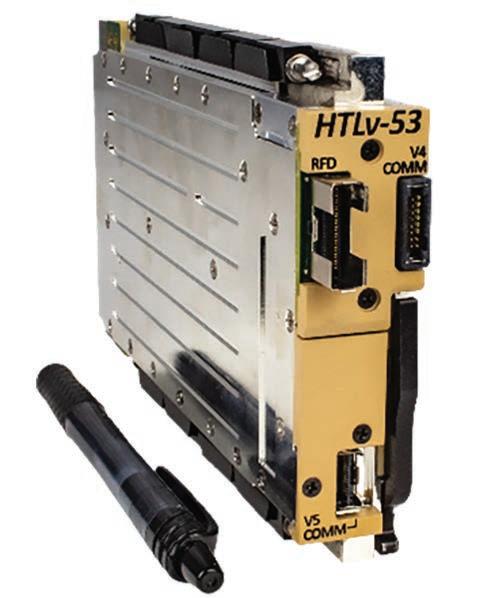
frequency range of 20 MHz to 20 GHz. The modules provide four 2 GHz RF tuners: two receivers and two exciters. Each of the channels are independently tunable, though can be made phase-coherent to one another and across multiple cards. The superheterodyne architecture enables the necessary selectivity when operating in congested and/or contested dynamic RF environments. (Figure 4.)
HTL provides both an 11-slot and 19-slot chassis aligned with SOSA release 1.0. These chassis can support dozens of configuration options. With the HTLv-43/53 cards they can support the UWB configuration capabilities presented. With the HTLv-43/53 cards, the 11-slot provides 8 GHz of IBW for both ES and EA or DRFM capability, whereas the 19-slot provides 16 GHz of the same type of capability. The frequency range for each chassis can be extended to 44 GHz with the use of HTL44E frequency extender.
Robert Normoyle is the Director of Open Systems at Herrick Technology Laboratories (HTL), where he leads the development of SOSA/CMOSS-based modules and chassis. Mr. Normoyle has more than 40 years of experience developing high-performance EW, radar, and SIGINT systems. He began his career at NRL and has worked at several SDR companies including L3 and DRS. He also worked at Johns Hopkins University Applied Physics Laboratory providing technical guidance to multiple programs for the Navy, ONR, Army C5ISR, and DARPA. He led the APL’s contributions to the V49.2 standard and VPX profi les, which are foundational for the CMOSS and SOSA standards. Readers may reach the author at RNormoyle@HerrickTechLabs.com
AS 9100D / ISO 9001:2015 CERTIFIED


Supports AES-256 and FIPS140-2 encryption


Herrick Technology Laboratories • https://www.herricktechlabs.com
www.militaryembedded.com MILITARY EMBEDDED SYSTEMS January/February 2023 25
Figure 4 | Shown is the HTLv-53 digitizer plus FPGA.
PHALANX II: THE ULTIMATE NAS
PHX_OSP_3.375_4.875.indd 1 1/22/18 11:36 AM
McHale Report,
THE ARCHIVED MCHALE REPORTS AVAILABLE AT: https://militaryembedded.com/newsletters/the-mchale-report
Utilizing two removable SSDs, the Phalanx II is a rugged Small Form Factor (SSF) Network Attached Storage (NAS) file server designed for manned and unmanned airborne, undersea and ground mobile applications.
www.phenxint.com
The
by mil-embedded.com Editorial Director John McHale, covers technology and procurement trends in the defense electronics community.
MIL TECH TRENDS
Realizing MOSA objectives: the developer’s role
By Will Keegan
Embedded software vendors for defense applications have a confession to make: There is more they can do to support customers adopting the modular open system approach (MOSA). Current platform components are not truly portable and hidden dependencies undercut real interoperability. There is, however, a path to improve developers’ ability to realize MOSA objectives.
The high-level benefits of open system standards all sound very logical and compelling. There’s avoiding vendor lock in, reductions in license and development costs and the benefit of leveling market competition. Vendors are obliged to adapt their products to the standards and to stay engaged with the community as requirements and technology evolves. The imposed cost to participate may be steep, but it’s clear that the lack of standardization costs more to the supply chain.
The complexities of MOSA
Nearly all the sought-after benefits of open system initiatives in the defense community – including the U.S. Army MOSA [Modular Open Systems Approach] Transformation Office, U.S.
Air Force OMS, and the U.K. MoD Pyramid – hinge on engineers’ ability to effectively reuse system components across different software platforms and/or product lines. Progress has been made at the hardware line replaceable unit (LRU) level but for software, technical specifications lack coverage to meet the intent of MOSA. So, let’s dive in and discuss some of the weaknesses in our modular standards that prohibit customers from achieving those compelling benefits.
Ideally, we want to enable system integrators to insert a software component into a system as easily as inserting a VPX card into a chassis. The current reality is that porting software across operating system] platforms is more

26 January/February 2023 MILITARY EMBEDDED SYSTEMS www.militaryembedded.com
Leveraging the Sensor Open Systems Architecture (SOSA) for radar applications
akin to performing heart transplant surgery than it is like replacing a line card!
Although standards like the Future Airborne Capability Environment (FACE)
Technical Standard describe interfaces of libraries that applications can link into to use operating system services, these interfaces only include descriptions for software that can run in the user application space. The standards lack descriptions of expected behavior and side effects that can inform real-time and hazard analysis. They do not account for the system information that’s needed to build, integrate and configure a comprehensive system to behave correctly. They also do not cover software components that reside in the operating system itself, such as drivers and health monitors.
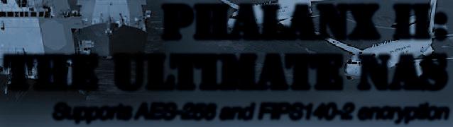
When building an LRU, it is common to have a software platform development team comprised of multiple companies each contributing a subsystem component: for example, MIL-STD 1553 driver, GPU driver, Ethernet driver with network stack integration, boot security modules, continuous built-in-test modules, and the like. The majority of the software is written against nonstandard kernel-level APIs and is packaged against proprietary configuration tools. The system integrator will integrate and qualify the complete system. This job can be incredibly inefficient if stakeholders have no common understanding of a component and how to qualify it before passing it on to the integrator. (Figure 1.)
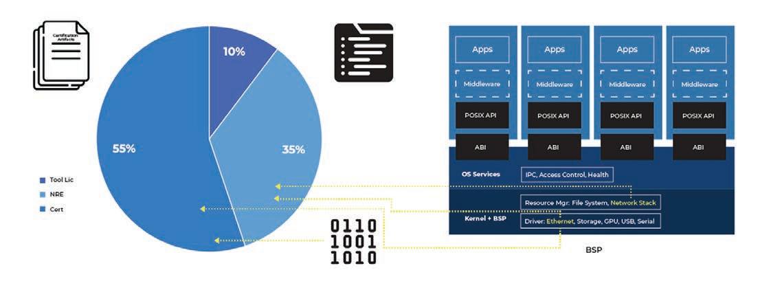
It’s also common to see huge investments in surrogate labs in which the entire mission system is loaned out to development teams to validate components against accuracy constraints. The project can easily reach into the hundreds of million dollars. A large portion of the software developed will be funded with taxpayer dollars, which means that the use and reuse rights are determined by the government. However, the software will not be easily transferable to another platform. As a result, once such an investment has been made in a specific software platform, that platform will have an extreme competitive advantage because it’s government-funded. (Figure 2.)
Standardizing is the solution
The key to untangling this situation is to standardize the ability to compose and validate complete software stacks out of substitutable components while improving the mechanics of composing and validating systems. If the government funds the development of a driver, a prime integrator should be able to reuse the driver in a different operating system with little to no modification.
The solution is basically the adoption of two enabling technologies to improve the mechanics and feasibility of real-time composability, namely hypervisors, which are

 Figure 1 | A diagram shows portability factors.
www.militaryembedded.com MILITARY EMBEDDED SYSTEMS January/February 2023 27
Figure 2 | Shown: A diagram of the cost structure of different programs.
used to partition resources and allocate components as individual virtual machines; and unikernels, which can be used as the runtime environment for each individual components instead of traditional guest operating systems to improve resource utilization and timing properties.
The intrinsic independence and timing properties of a unikernel simply make it a better unit of integration to compose systems where the integrity and predictability of a system is simpler to verify.
Hypervisors: adding control
The key difference in the hypervisor approach versus the operating system approach is the hypervisor’s ability to give components the control to manage their own local set of resources. A hypervisor-hosted component is a complete software module that can run on its own and is highly portable. Conventional operating systems, where software components are incomplete in their ability to run without linking to operating system libraries, impose a codependency that limits reusability.
Hypervisors also provide more independence between components and enable more robust architectures for layering safety and security reference monitors. The attack surface of a hypervisor is also significantly smaller than that of an operating system.
Hypervisors add resource and computational overhead and safety concerns from inserting an additional layer of complexity to the software stack. However, a different deployment strategy can make them very effective in making systems simpler and more predictable. This is where unikernels come in.
Unikernels enable all operating systems
Unikernels enable programs to link in all operating system services in a single address space, obviating the need to switch into a special kernel mode to call a system service. Applications hosted by the operating systems impose barriers that force applications to exit their context and enter a common kernel space to fulfill the request of calling processes.
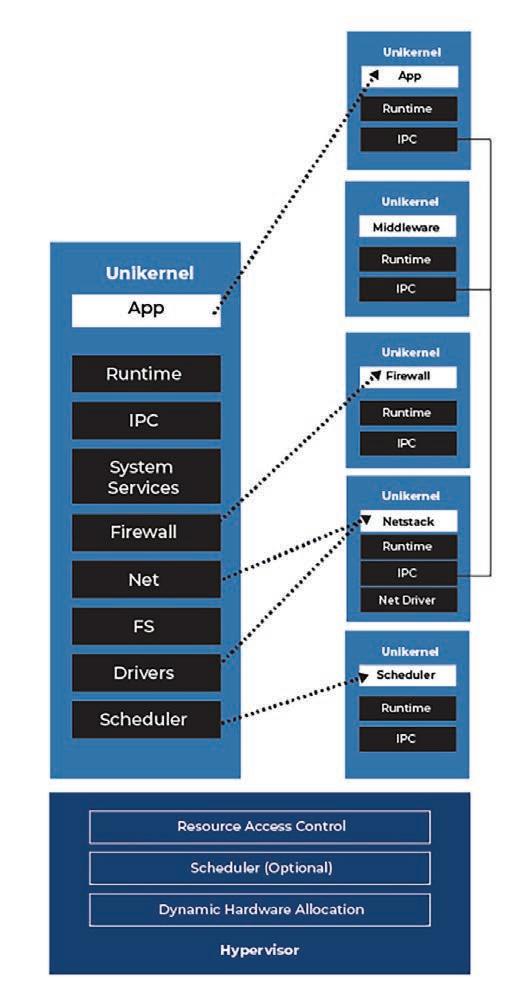
In the unikernel architecture, applications just link to the operating system features needed. The compiler will naturally omit unused features. Because unikernels are no longer context switching and subject to blocking by competing processes, unikernel execution behavior is much easier to observe and characterize. This reality reduces the burden of multicore timing analysis and makes the safety-certification process more manageable. The intrinsic independence and timing properties of a unikernel simply make it a better unit of integration to compose systems where the integrity and predictability of a system is simpler to verify.
Advancing the concept further, a unikernel wouldn’t just be a task or an application: it would constitute subsystems as well. Combining unikernels with hypervisors enables architects to compose systems with a higher level of fidelity and also gives them the option to explicitly create pipelines of software stacks out of individual unikernel components, where the components can assume roles of kernel services like network stacks and device drivers. (Figure 3.)
As we suggest modeling systems as an integration of software pipelines, it is absolutely critical to uphold the MOSA vision by ensuring components are linked via standard interfaces that exhibit the ability to interoperate in other pipelines for more than 10 years. Hypervisors are very well-suited to satisfy this concern, as they already have well-established standards to handle virtual machine-to-virtual machine interfaces via the OASIS VirtIO specification and virtual machine-to-physical machine interfaces reusing standard specifications such as PCI Express.
Hypervisors and unikernels are key to developing platform-level components without the dependency on proprietary kernel libraries. With the improved timing and performance properties of unikernel architecture, the performance and predictability of unikernel pipelines can easily match the real-time characteristics of RTOS [real-tiime operating system] services. Much work remains to be done in the areas of standardization efforts and refining the techniques of linking components with real-time constraints. MES
Will Keegan is the chief technology offi cer at Lynx Software Technologies. At Lynx, Will manages the safety and security platform product visions, interfaces with industry working groups and partners, and works with regulatory authorities for design review/risk mitigation.

Lynx Software Technologies
https://www.lynx.com/
Figure 3 | Unikernels plus hypervisors enable builders to compose more sophisticated systems.
MIL TECH TRENDS Leveraging the Sensor Open Systems Architecture (SOSA) for radar applications 28 January/February 2023 MILITARY EMBEDDED SYSTEMS www.militaryembedded.com


Get your free ticket now! embedded-world.com/voucher Use the voucher code GG4ew23 JOIN THE EMBEDDED COMMUNITY 14–16.3.2023 Media partners
MIL TECH TRENDS
High-speed video: unlocking fast and reliable connectivity
By Michael Walmsley
Today’s video applications, particularly in the defense arena, are challenged by more complex video-signal processing from an increasing number of video sources with higher bandwidth and higher resolutions. Critical to defense applications: minimizing latency between video capture and display.
Defense-related video applications increasingly require high-resolution sensors for image accuracy. Sensor data rates are increasing with capability for 4K and higher video streams. Systems

are processing video data as close to the sensor as possible for lower latency and reduced cabling complexity. These trends are driving new video architectures and the use of higher-speed protocols in video-signal transmission for capture, compression, processing, artificial intelligence (AI) inference, and encoding/decoding.
Higher-bandwidth video protocols such as ARINC 818 [avionics digital video bus], SDI [serial digital interface], and CoaXPress (CXP) support industry demands for speed and are driving new interconnect requirements for video-signal transmission between the sensor and processing platforms and displays. These standards include protocols with data rates as fast as 12 Gb/sec and higher.
Traditional connectors for video applications
Traditionally video signals have been transmitted on 75-ohm coax cable with standard coax connectors: 75-ohm BNC connectors, F-Type connectors (commonly used in CATV applications), MIL-C-39029 coax contacts for 75-ohm cable, or even 50-ohm coax connectors terminated to 75-ohm cable where the impedance mismatch didn’t adversely affect the signal because of the lower frequencies.
30 January/February 2023 MILITARY EMBEDDED SYSTEMS www.militaryembedded.com
Leveraging the Sensor Open Systems Architecture (SOSA) for radar applications
MIL-C-39029 coax contacts (populated in MIL-DTL-38999 circular connectors) were defined in the 1970s; some designations terminate to 75-ohm cable, but do not have 75-ohm impedancematched interfaces and construction. As a result, performance is typically limited to frequencies of 3 GHz or lower.
To transmit video signals with higherspeed protocols over coax, newer 75-ohm impedance matched coaxial cables and connectors are required for both box-to-box connectivity and within a chassis.

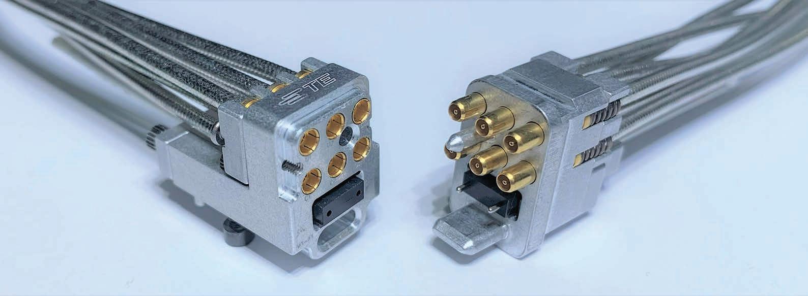
Emerging interconnect solutions: inside the box

Sensor platforms using OpenVPX architecture can leverage 75-ohm NanoRF connector modules for the interface between the plug-in modules and the backplane. New VPX slot profiles proposed for the next revision of VITA 65.1 feature connector modules with the high-density, high-frequency 75-ohm NanoRF coaxial interface with optical MT terminations to support highspeed video.
The 75-ohm NanoRF connectors leverage the rugged design of the original 50-ohm NanoRF interface already standardized for OpenVPX and SOSA aligned solutions. The NanoRF technology features contacts with a tapered pin and floating inserts that enable fine alignment of the array of coaxial contacts and optical MT [mechanical transfer] ferrules before they begin to mate. The 75-ohm NanoRF connector module configurations now undergoing standardization include a half-size VPX connector module with six 75-ohm NanoRF contacts and an MT, and a full-size module
with two of the same inserts (twelve coax contacts and two MTs). Other coax and/or optical configurations using the same interconnect technology are pos sible. (Figure 1.)
Integrating coax and optics into a common connector module adds versatility, especially in applications where – for example – video signals are received from multiple sensor devices over coax, then processed and transmitted over fiber using ARINC 818 for highbandwidth, low-latency, digital video transmission.

The VITA 67.3 standard is under revision to add 75-ohm coaxial interfaces for VPX plug-in modules and backplanes, including 75-ohm NanoRF and 75-ohm SMPM (miniature push-on connectors), a variant of the 50-ohm SMPM interface specified in the standard today. These contact interfaces and designs optimize return loss and isolation in 75-ohm transmission lines and will support nextgeneration video-signal requirements.

New applications are increasingly specifying 75-ohm coaxial cables with lower loss and attenuation; these are applications where traditional 75-ohm cables such as RG-179 may not have the shielding or size needed for higherdensity, higher-frequency defense applications. In such applications, 75-ohm conformable cables with shielding of both foil tape and tinned braid reduce the attenuation versus traditional braided cables. They also fit in tight packaging for high-density multicontact solutions by omitting an external jacket, effectively reducing the outer diameter and bend radius. Being conformable, these cables can be easily shaped and routed

See PICO’s full line catalog at www.picoelectronics.com • Custom Models • US Manufactured • AS 9100 Approved High Reliability AC/DC Power Supplies, Transformers and Inductors PICO ELECTRONICS, Inc. 143 Sparks Ave., Pelham, New York 10803 Call Toll Free 800-431-1064 • FAX 914-738-8225 E Mail: info@picoelectronics.com YOUR PROVEN SOURCE. Over 50 years providing reliable products. Over 2,500 Standard Modules. 800-431-1064 VISIT OUR EXCITING NEW WEBSITE www.picoelectronics.com Featuring our easy-to-use product Search Wizard! 2V to 10,000 VDC Outputs 1-300 Watt Modules Regulated/Proportional/Programmable Isolated/Single/Dual Outputs High Reliability Greater than 1,000,000 hrs. Mil Hbk 217F • Military Upgrades Expanded operating temperature -55˚ to +85˚ C, no derating required • Environmental Screening Selected Screening, Mil Std 883 • ULTRA Miniature From 0.5" x 0.5" x 0.2" • Surface Mount/Thru-Hole 2V to 10,000 VDC Outputs 1-300 Watt Modules Regulated/Proportional/Programmable Isolated/Single/Dual Outputs High Reliability Greater than 1,000,000 hrs. Mil Hbk 217F • Military Upgrades Expanded operating temperature -55˚ to +85˚ C, no derating required • Environmental Screening Selected Screening, Mil Std 883 • ULTRA Miniature From 0.5" x 0.5" x 0.2" • Surface Mount/Thru-Hole DC-DC CONVERTERS DC-DC CONVERTERS Certified to AS9100D ISO 9001:2015 A44_MES_2_125x10_NEWWEB.qxp_A44.qxd 12 www.militaryembedded.com MILITARY EMBEDDED SYSTEMS January/February 2023 31
Figure 1 | Shown are VITA 67.3 connector modules with 75-ohm NanoRF and optical MT.
in tight spaces, for example within a VPX plug-in module (Figure 2).
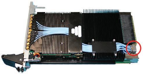
Emerging interconnect solutions: box-to-box

For box-to-box connectivity (for example, between a sensor turret and a compute chassis), both 75-ohm coax and optical solutions need to be supported.
For coax, 75-ohm impedance matched variants of size 12 SMPM contacts are designed for MIL-DTL-38999 circular connectors, using standard size-12 cavity inserts for high density. These feature the same 75-ohm SMPM interface being proposed for addition to the VITA 67.3 standard at the backplane interface but packaged for use in MIL-DTL-38999 connectors at the chassis interface.
Similarly, high-density optical circular connectors standardized by VITA 87 and specified in the SOSA standard can provide the bandwidth for ARINC 818 video signals. These MIL-STD-38999-based connectors have inserts for one, two, or four MTs; MTs designated for ARINC 818 can be populated in the same connector with MTs supporting Ethernet or other protocols. (Figure 3.)
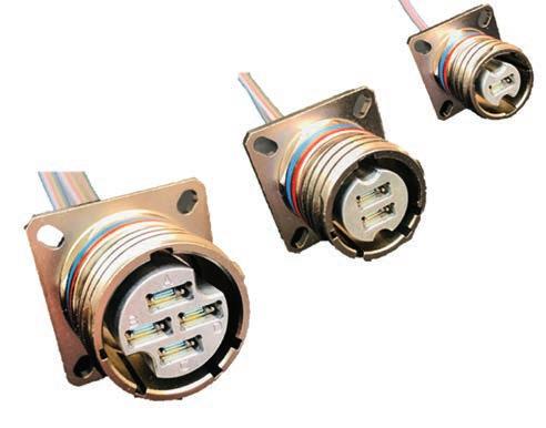
Outside of VPX architecture, small-form-factor (SFF) systems are being developed and standardized with requirements for video signal transmission. These same interconnect technologies – whether optical or coax – can be adopted for SFF platforms.
Demands for higher-bandwidth and higher-speed video-signal processing are growing, whether the application is a high-definition camera pod on an uncrewed aerial system (UAS), a sensor turret of a ground vehicle, or livestreaming video over an onboard spacecraft network. (Figure 4.)
Recent developments in high-speed interconnect will support the next-generation systems for video capture, processing, and display. The need to support higher-speed protocols running at data rates of 6 Gb/sec, 12 Gb/sec, and higher has driven new connector solutions and new interconnect packaging for both coaxial and optical signal transmission. In newer systems, 75-ohm coaxial cables and interconnects designed for improved signal integrity and higher density will replace traditional alternatives. Additionally, optics will play a larger role with the emergence of the ARINC 818 ecosystem in avionics and the advantages of fiber: high-density bandwidth, light weight, and immunity to EMI [electromagnetic interference].
Standards bodies such as the VITA Standards Organization (VSO) and the SOSA (Sensor Open Systems Architecture) Consortium are addressing the next-generation video signal requirements with open-architecture solutions that will meet the technical challenges and create an ecosystem for interoperability in the future. MES
Michael Walmsley has more than 35 years of experience with TE Connectivity (TE), and formerly AMP Inc., primarily in engineering and product management with an emphasis on newproduct development. His areas of expertise include interconnect solutions for embedded computing, rugged high-speed board level, and RF connectors. He serves on the board of directors of the VITA Standards Organization, which drives technology and standards for the bus and board industry. Mike earned his MBA from Penn State University Harrisburg and a bachelor’s degree in mechanical engineering from the University of Rochester (New York).
TE Connectivity
https://www.te.com/usa-en/home.html
Figure 3 | VITA 87 high-density optical connectors can handle the bandwidth for ARINC 818 video signals.
Figure 4 | A high-definition camera pod is shown mounted on an uncrewed aerial system (UAS). Stock image.
MIL TECH TRENDS Leveraging the Sensor Open Systems Architecture (SOSA) for radar applications 32 January/February 2023 MILITARY EMBEDDED SYSTEMS www.militaryembedded.com
Figure 2 | Shown: An example of a VPX plug-in module with VITA 67 coax cables routed. Image courtesy of Annapolis Micro Systems.
NAVIGATE ... THROUGH ALL PARTS OF THE DESIGN PROCESS
TECHNOLOGY, TRENDS, AND PRODUCTS DRIVING THE DESIGN PROCESS


Military Embedded Systems focuses on embedded electronics – hardware and software – for military applications through technical coverage of all parts of the design process. The website, Resource Guide, e-mags, newsletters, podcasts, webcasts, and print editions provide insight on embedded tools and strategies including technology insertion, obsolescence management, standards adoption, and many other military-specific technical subjects.
Coverage areas include the latest innovative products, technology, and market trends driving military embedded applications such as radar, electronic warfare, unmanned systems, cybersecurity, AI and machine learning, avionics, and more. Each issue is full of the information readers need to stay connected to the pulse of embedded technology in the military and aerospace industries.
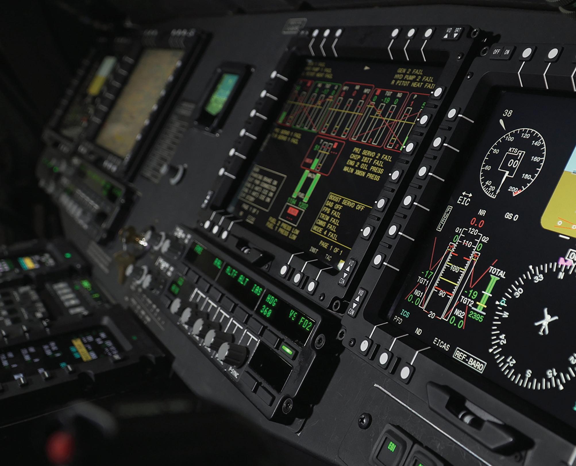
militaryembedded.com
Next generation of electronic warfare systems to feature enhanced RF and microwave hardware
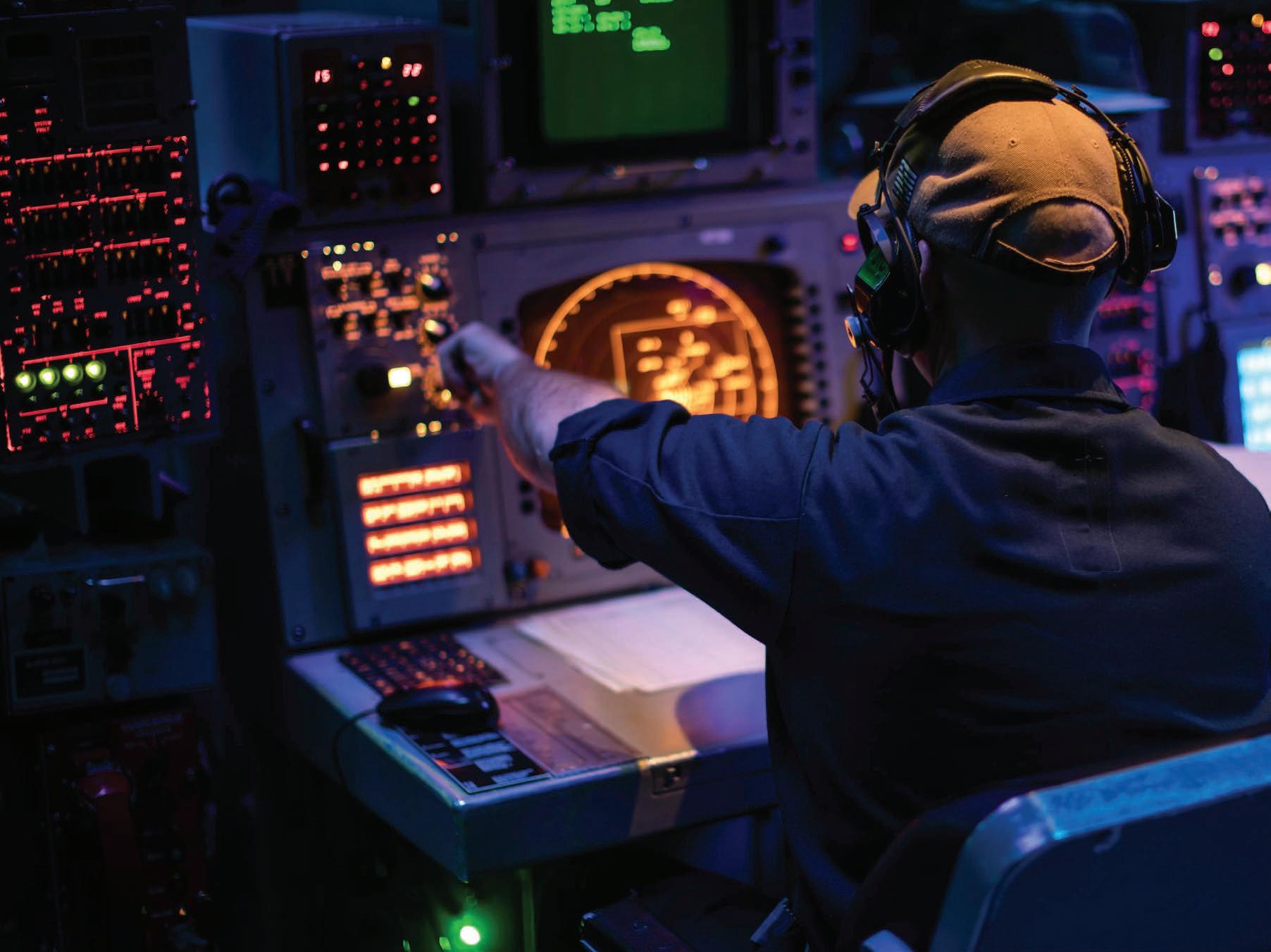 By Flavia Camargos Pereira, Contributing Editor
The proliferation of new, more lethal threats and the need for improved situational awareness in the electromagnetic spectrum fuel more sophisticated radio frequency (RF) and microwave designs. Meanwhile, open architecture efforts are enabling faster adoption of techbnlogy and lowering long-term costs.
As radar and electronic warfare (EW) system providers continue to reduce size, weight, and power (SWaP) while increasing performance demands, this move puts more and more pressure on RF and microwave component designers to pack more capability in ever-shrinking footprints.
Supporting a sensor chain that stretches across multiple nodes on a battlefield – from manpack radios, to uncrewed ground platforms, to phased array radars – requires high-speed and low-latency EW systems and innovative solutions from industry.
“We’re not only seeing tremendous advocacy and strong defense budgets but also cutting-edge technology we’ve had for decades being taken out of the lab and put into operation,” says Erin Kocourek, vice president of advanced technology and growth at CAES (Arlington, Virginia).
Crew members aboard the Wasp-class amphibious ship USS Kearsarge operate a radar console. U.S. Navy photo by Mass Communication Specialist Seaman Taylor Parker.
INDUSTRY SPOTLIGHT 34 January/February 2023 MILITARY EMBEDDED SYSTEMS www.militaryembedded.com
RF and microwave designs for electronic warfare
This direction is leading to higher speeds, greater maneuverability, increased range, and the use of more exotic materials for better thermal management, she adds.
Demand for multifunction capabilities is also increasing as warfighters face more complex threats, says John Cowles, senior director of technology for aerospace and defense at Analog Devices (Wilmington, Massachusetts). “What military customers are looking for is this idea of a receiver and transmitter that can do anything, a multifunction platform that can serve EW, radar, and telecom at the same time.”
Reduced size, increased performance Requirements for both EW and radar systems include increased performance systems in smaller form factors.
Systems Architecture (SOSA) Technical Standard 1.0 is an update to Elma’s original CMOSS [C5ISR/Electronic Warfare Modular Open Suite of Standards] reference backplane supporting the U.S. Army’s latest open-standards requirements. The new 3U OpenVPX backplane offers a mix of plugin card (PIC) slots that enable complex, high-speed signal processing and system development, supporting up to 100 Gbit Ethernet.
“There is always pressure to do more in a slot,” says Mark Littlefield, senior manager of embedded computing products for Elma Electronic (Fremont, California) “The latest VITA 65.1 revision (2021) has aperture fill blocks that have 10, 14, 20, and even 31 RF contacts. Clearly, folks are cramming more and more functionality into each VPX slot.” (Figure 1.)
There’s no single solution to optimizing for SWaP, notes Tony Capello, chief technologist at Mercury Systems (Andover, Massachusetts). “Instead, we consider design trade-offs throughout the development process. We carefully select the architecture to meet performance in the smallest size possible. Additionally, we work at chipscale to combine devices in much smaller space,” Capello says.
Even with these tradeoffs, design challenges persist: cooling the electronics, maintaining signal integrity, and avoiding unwanted coupling while squeezing more components into smaller spaces.
According to Cowles, apart from SWaP requirements, the “big thing is cooling, power, and dissipation. Even if, by contacting things, you maintain the efficiency, you still have to get the power and you still have to get that heat out.” Analog Devices supplies the ADRV9002, which is a high-performance, linear, dynamic range transceiver designed for providing performance and power-consumption system optimization. (Figure 2.)
Kocourek points out that wide-bandwidth low-noise amplifiers (LNAs) and mixers can offer increased bandwidths and smaller size, weight, power, and cost (SWaP-C), enabling more users to implement EW receivers to handle electronicsupport (ES), electronic-intelligence (ELINT), and signals-intelligence (SIGINT) applications.
Digitizing the signal earlier on in the sensor chain via advancements in semiconductor design also enables reduction in system size and increased product flexibility.
Capello says that Mercury is working with semiconductor companies to integrate their die (for example, data converters or FPGAs [field-programmable gate arrays]) at chipscale in extremely compact footprints. “However, integrating these devices on open architecture boards still requires compact and highperformance microwave components,” he adds.
Distributed, networked solutions across multiple military platforms can help solve SWaP challenges. Direct-todigital implementations will also show promise in the next few years, says Dr. Larry Scally, vice president advanced programs, CAES (Colorado Springs, Colorado). “Direct RF sampling adds a lot of capabilities to EW, but also adds a lot of power. For example, digital signal processing with ADCs and DACs [analog-to-digital converters and digitalto-analog converters] running at higher speeds requires much more power, size,
 Figure 1 | Elma’s 3U 12-slot backplane that aligns with The Open Group Sensor Open
www.militaryembedded.com MILITARY EMBEDDED SYSTEMS January/February 2023 35
Figure 2 | The Analog Devices ADRV9002 is a high-performance linear dynamic range transceiver designed to enable optimization of performance and power consumption.
and weight than RF components. Like everything in engineering, there is no free lunch – it is a trade-off for SWaP-C, programmability, and performance,” he explains.
In terms of reduced-form-factor solutions, CAES offers a new 0.5 to 18 GHz SOSA [Sensor Open Systems Architecture] aligned 3U ultra-wide-bandwidth RF converter which provides two channels of high-speed tuning in a single slot with the local oscillator and preselection for EW, ELINT, and electronic support, surveillance, and attack systems.
Modifying architectures
The design and architecture for RF and microwave hardware has been modified over the last years to improve such systems.
Sensor architecture implementation is changing in order to simplify the RF front end, says Ben Annino, systems and applications director for aerospace and defense at Analog Devices. “Data converters can now directly sample much wider swaths of bandwidth. Years ago, you could do tens of MHz, it moved up to hundreds of MHz, and now you are able to do GHz, multiple GHz, instantaneous bandwidth all at once. This is because data converters have moved into finer silicon.”
The digitization process is also changing the architecture and “the combination of noise, distortion gain, and power dissipation evolved to be different from what they used to be,” Cowles says
Efficiency challenges
Improving the efficiencies of components through the use of different materials and processes can also help reduce SWaP. Raytheon Missiles & Defense’s gallium nitride (GaN) program focuses on advancing the efficiency of the company’s GaN manufacturing process to improve yield and reduce cost, while generating more RF power.

Raytheon engineers have been working on new materials that offer higher current and voltage transistors, which could result in more efficient devices and offer new trade spaces to system designers for power per element vs. aperture size.
“At the subsystem level of an EW or radar system, RF microelectronics like GaN typically dominate overall power consumption and cost. At the system level, a GaN device with higher efficiency results in extended range, enhanced sensitivity, and/or reduced power consumption,” says Matt Tyhach, director of next generation sensors and microelectronics/advanced technology at Raytheon Missiles & Defense (Tucson, Arizona). (Figure 3.)
GaN is part of several U.S. Department of Defense (DoD) weapons programs, including the Enterprise Air Surveillance Radar (EASR); the Guidance Enhanced Missile Tactical Ballistic Missile (GEM-T), one of the Patriot missile variants; and the Lower Tier Air and Missile Defense Sensor (LTAMDS).
MOSA strategies
Even with those advancements, EW system designers continue to seek additional improvements that affordably enable future upgrades without significant impacts to the rest of the system. Such interoperability efforts fall under the DoD’s modular open systems approach (MOSA) mandate which calls for implementing MOSA strategies like
INDUSTRY SPOTLIGHT
Figure 3 | Raytheon’s gallium nitride (GaN) offerings can enable extended range, enhanced sensitivity, and reduced power consumption.
36 January/February 2023 MILITARY EMBEDDED SYSTEMS www.militaryembedded.com
RF and microwave designs for electronic warfare
SOSA and the OpenVPX standard. These MOSA examples and others enable the use of nonproprietary interfaces in designs.
“The trend towards open system architectures is only increasing. From the end-user perspective, they need to deploy new technology as soon as it’s available,” Mercury’s Capello points out.
Mercury offers multiple OpenVPX and SOSA aligned solutions, including the DRF3182 3U OpenVPX board. Designed for high-performance applications with SWaP constraints, it is a 4Rx/4Tx, ultra-high-speed data converter ideal for directly digitizing HF signals in radar, communications, and EW systems. (Figure 4.)
From Kocourek’s perspective, the requirements for open system standards are also helping to bring adaptability: “More EW systems are adding requirements for standardization with a clear definition of RF module and sensor system form factors, pinouts, I/O formats, and power requirements.”
Other open architecture benefits include shortening development cycles and reducing long-term life cycle costs. Moreover, enabling the operation of sensors and technologies
from different suppliers would also allow expanding the vendor base. “Enabling multiple sources for the same subsystem or components would make the system less impacted by potential supply-chain issues,” Tyhach adds. MES
RADAR AND EW: WHAT’S SIMILAR/WHAT’S DIFFERENT
Electronic warfare (EW) and radar differ slightly in the RF waveforms used and how they interact with the rest of the system. Electronic warfare typically operates via continuous wave (CW), which is on all the time. Radar waveforms, in contrast, are pulsed, which enables amplifiers to cool down between pulses.
Radar bandwidths are also generally smaller –even though there is a trend to move wider –and require higher peak powers. In the case of EW, it uses a much wider band, with its electronics needing to transmit and receive power over wider frequency ranges.
“These differences can prove challenging, particularly in EW thermal hardware design. Radar requires higher peak powers where RF peak voltages, including power storage, need to be properly accounted for to generate the pulses,” says Matt Tyhach, director of next-generation sensors and microelectronics/advanced technology at Raytheon Missiles & Defense (Tucson, Arizona).
There is “a big difference” between those types of systems because for radars, “you are transmitting a known waveform and then that waveform is coming back,” and the operator has a prior knowledge of what it is,” says Ben Annino, systems and applications director for aerospace and defense at Analog Devices (Wilmington, Massachusetts). “For EW, you don’t know what you’re trying to detect, and what you’re trying to detect can also be trying
to kill you. So, you need to have basically continuous monitoring [of a] higher RF spectrum.” EW systems “have to react very, very quickly to what’s coming in and decide what it is, and say what to do about it,” says John Cowles, senior director of technology for aerospace and defense at Analog Devices.
Although radars and EW solutions perform different missions, they have common needs. Both require high-frequency operation in the GHz realm, defense-grade reliability, and novel heat-rejection approaches. Lower
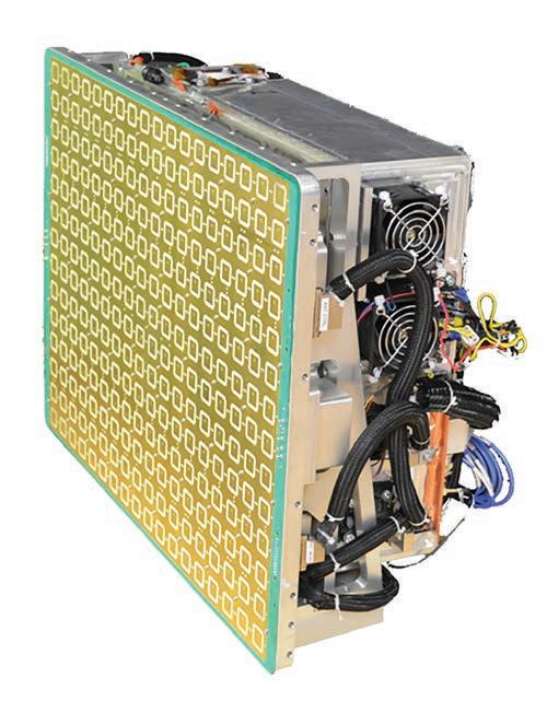
latency, higher speed, and reduced form factor are also necessary for each.
David Caserza, manager of embedded computing architects at Elma Electronic (Fremont, California), says that another similarity is the fact that it is necessary for both radar and EW to produce backplanes and chassis that can accommodate the RF signals/connectors/ cabling.
“For the fighter, both EW and radar need highend processing back ends to deal with the additional number of signals and threats,” says Erin Kocourek, vice president of advanced technology and growth at CAES (Arlington, Virginia). In terms of solutions, CAES offers the USTAR C-Band radar that provides autonomous collision avoidance for both manned and unmanned airborne platforms. (Sidebar Figure 1.)
Going forward
There is increased demand for next-generation active electronically scanned array (AESA) systems, which require “extremely compact RF/ digital hardware at each antenna element as well as high-performance microwave subassemblies throughout,” says Tony Capello, chief technologist at Mercury Systems (Andover, Massachusetts).
The push toward operating on even broader bands and moving to higher frequencies is also putting “a lot of pressure on maintaining efficiency and [controlling] cost,” Cowles adds.
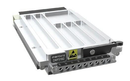 Sidebar Figure 1 | The CAES USTAR C-band radar promises autonomous collision avoidance for both manned and unmanned airborne platforms.
www.militaryembedded.com MILITARY EMBEDDED SYSTEMS January/February 2023 37
Figure 4 | The Mercury DRF3182 3U OpenVPX board is a 4Rx/4Tx, ultrahigh-speed data converter ideal for directly digitizing HF signals in radar, communications, and EW systems.
Easing radar integration with SDR
By Kaue Morcelles
Software-defined radio (SDR) can assist with the integration and use of radar as it is used in electronic warfare (EW) systems and give users the flexibility to adapt to modern and constantly evolving threats.
Radar is widely applied in military missions, from field monitoring of defense systems and support devices for situational awareness to use in electronic countermeasures, guidance, and many other electronic warfare (EW) applications.

Although there are many types of radars, the basic principle is the same: An RF [radio-frequency] signal is sent in a certain direction, and if the signal hits an object, the reflected response is measured by a receiver to acquire spatial data. After signal reception, electrical parameters including signal amplitude, phase, frequency, and time delay can be used to infer the target’s distance, size, and speed. In this process, a computer host system must perform heavy-signal processing operations, which depend on the radar technique and application specifications. along with system control and display of measurements. By implementing a duplexer switch, radars can use the same antenna or dish for both signal transmission and reception, shifting between functions during the process.
Independently of the approach, synthetic aperture radar (SAR), Doppler, and phased-array systems rely greatly on heavy signal-processing algorithms, to manage the huge amounts of data required and control the antenna signal, which includes techniques such as beamforming and beam-steering.
Software-defined radios (SDRs) are RF devices that perform most of the radio- and digital-processing functions on the digital side, keeping analog equipment to a minimum. These devices are divided into two main functional blocks: the radio front end (RFE) and the digital back end. The RFE is responsible for all the analog functionalities required for the transmit and receive chains, including signal amplification, filtering, mixing, and antenna coupling. The RFE is a crucial part of the SDR, limiting its performance in terms of frequency, sensitivity, noise, and dynamic
INDUSTRY SPOTLIGHT 38 January/February 2023 MILITARY EMBEDDED SYSTEMS www.militaryembedded.com
RF and microwave designs for electronic warfare
range. To address high-frequency applications, the highest-bandwidth SDRs in the market provide RFEs capable of providing several transmit/receive chains over a 0 to 18 GHz tuning range, that can be further upgraded to 40 GHz.
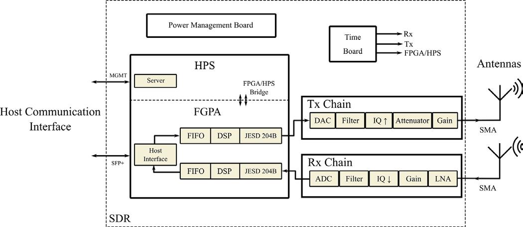
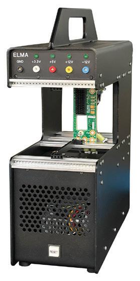
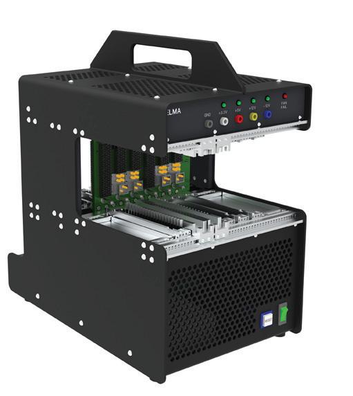
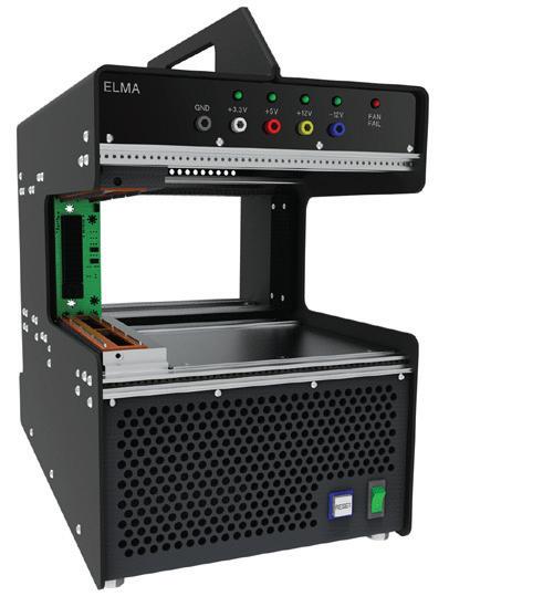
Multiple-input multiple-output (MIMO) capability can be achieved by implementing independent analog-to-digital converters/digital-to-analog converters (ADCs/DACs) at each RF channel of the RFE. The digital back end, on the other hand, handles all the digital signal processing (DSP) capabilities of the SDR, including modulation, demodulation, up/ down-converting, and data packaging. It is typically implemented using a highperformance FPGA [field-programmable gate array], which enables parallel computation of simultaneous radio channels, minimizing latency and increasing data throughput. (Figure 1.)
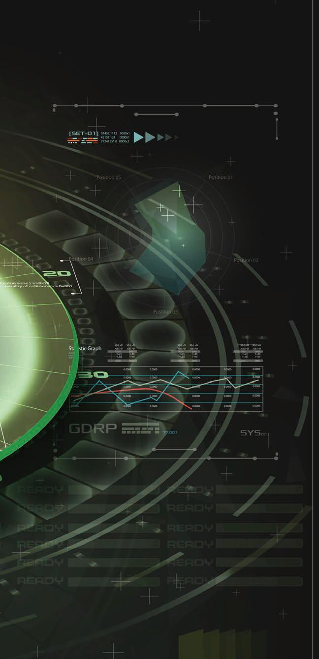
Award-Winning Development Solutions
elma.com Elma Electronic Inc. Learn More With you at every
Elma’s new
are
stage!
CompacFrames
innovative lightweight platforms for card or system development based on open standards like VPX or aligned to SOSA™.
www.militaryembedded.com MILITARY EMBEDDED SYSTEMS January/February 2023 39
Figure 1 | Shown: an overview of the SDR board.
How SDRs can be integrated into radar and EW systems
Regardless of the application and implemented technique, radar transceivers must fulfill a set of minimum requirements to ensure proper functioning and optimize use of resources.
The high-performance radio front end built in modern SDRs can be easily integrated into even the most complex and precise antenna system, providing a high degree of accuracy and flexibility to the radar. For one thing, high-end SDRs offer very wide tuning range in each channel, giving the user reliable channel spacing, the ability to use different radar protocols, and the option to use antijamming techniques. They provide receive signal chains with very low noise floor and high dynamic range, which improves the minimum and maximum detectable signals in the radar.
Up-to-date SDRs use multiple independent RF channels that can be tuned to different frequencies and can be simultaneously controlled and monitored over time. By integrating MIMO SDRs into antenna arrays, engineers can take advantage of their high phase and frequency stability to implement precision phased-array radars for EW applications and can program different beamforming/beam-steering algorithms to fit their application. High-end MIMO SDRs can offer as many as 16 channels in one device, each operating with an independent ADC/DAC for parallel acquisition. Naturally, radars implementing real-time monitoring of multiple channels require data-transfer systems with very high throughput, for further processing in the host units. To address this issue, the highest-throughput SDRs in the market offer quad 40 Gbps qSFP+ ports (upgradable to 100 Gbps) to handle the huge amounts of data involved. Figure 2 shows an SDR integrated into a radar system.
The use of an SDR confers a clear hardware benefit, but the software-based signal processing is a bigger advantage to radar systems. High-performance SDRs use FPGA and DSP resources to perform very fast signal processing and parallel computations with very low
latency, enabling the implementation of complex algorithms. Waveform digitization, with storage and triggering capabilities, is extremely important to a radar system, as it enables the radar to implement different waveforms in the same equipment while synchronizing components and sequentially triggering antenna arrays.
Sensitivity time control (STC) and sensitivity gain control (SGC) are examples of algorithms that can be embedded into the FPGA to precisely control the sensitivity of the radar to address power drops in the EM [electromagnetic] signal or saturation caused by unwanted signals. Finally, the DSP capabilities of the SDR can be used to implement complex mathematical algorithms, such as the fast Fourier transform (FFT), to analyze the frequency content of the signal and measure the Doppler shift, which can produce information about the velocity of the target. The ability to perform such algorithms in the radar itself is a huge advantage over conventional approaches, as much less data needs to be sent to the host system.
Beamforming and beam-steering are important for phased-array antennas, as they use multiple signals distributed in time (phase) and space to form a precise RF beam that can be pointed in a certain direction, therebv increasing the signal sensitivity and rejecting unwanted directions. The signal-processing algorithms are complex, requiring powerful computation resources to implement them fast enough to ensure phase coherency. These can actually be implemented in high-end FPGAs, which form the core of most SDRs. One of the most important steps in beam-steering is calculating the phase shift between channels. Figure 3 shows how to calculate this shift for a planar array of antennas, where the shift is a function of the distance between the radiating elements, the beam direction angle, and the wavelength of the signal.
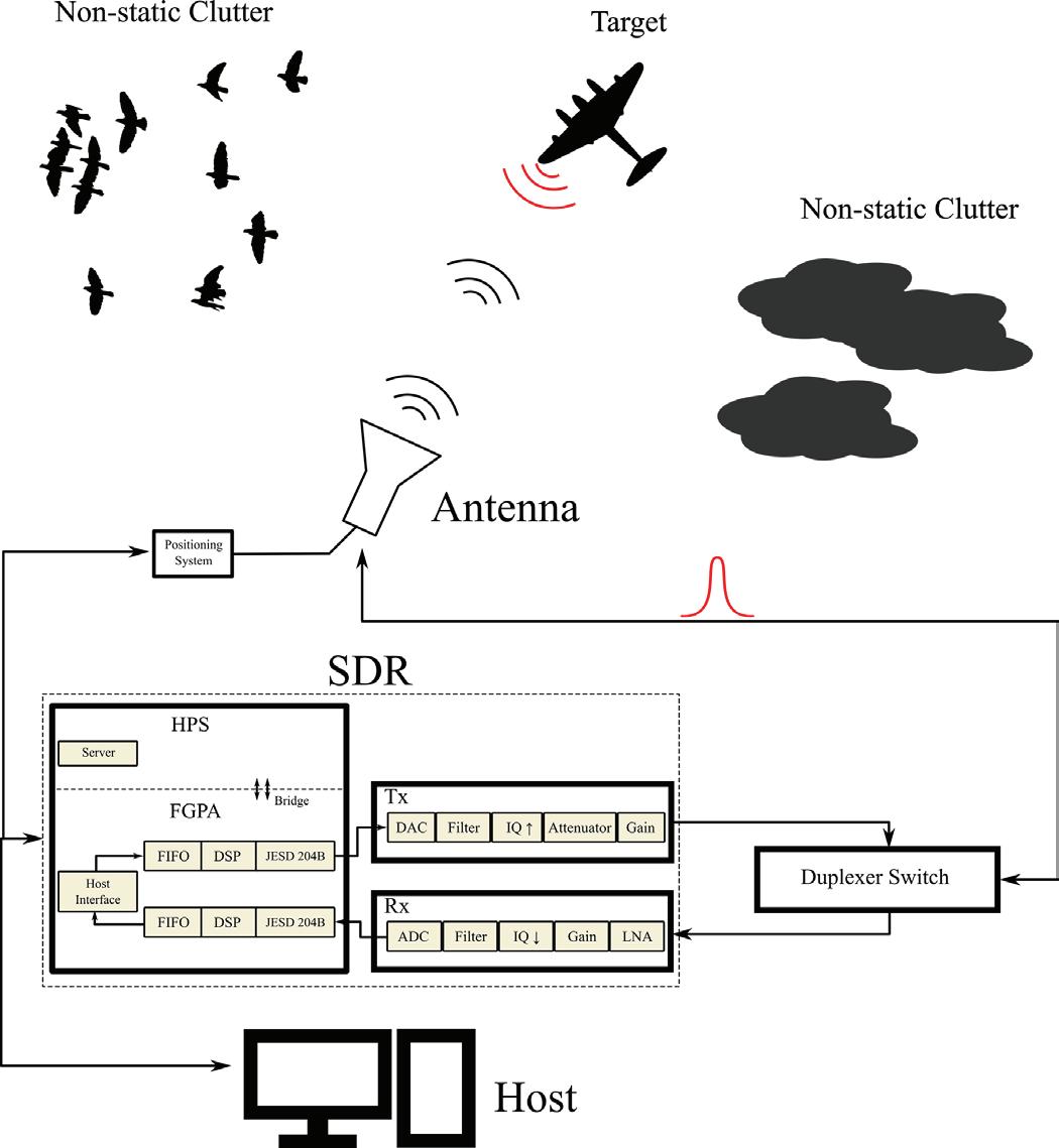
INDUSTRY SPOTLIGHT
Figure 2 | Diagram shows an SDR integrated into a radar system.
40 January/February 2023 MILITARY EMBEDDED SYSTEMS www.militaryembedded.com
RF and microwave designs for electronic warfare
Besides the functional advantages, SDRs can reduce the overall cost and complexity of a system: MIMO SDRs can perform many functions in the same device, which can dramatically lower the total equipment count in a system, which then reduces the maintenance and operation costs of the device and optimizes time to deployment. Further, SDRs are flexible enough to adapt to work with legacy radar systems; new EW deployments including electronic countermeasures and guidance; and servicelife extension programs. MES
Kaue Morcelles is an electrical engineer, with emphasis on electronic design and instrumentation. He also works on developing instrumentation devices for tissue engineering. Morcelles works with Per Vices.

Per Vices • https://www.pervices.com/
Cooling Systems: Removing Heat from Embedded Electronics Systems
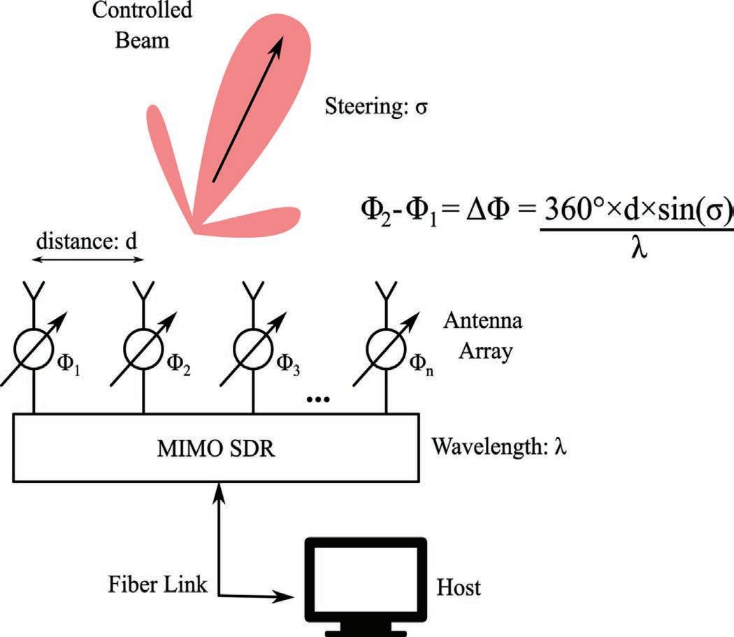
Sponsored by LCR Embedded Systems, nVent Schroff, Pixus Technologies
It has been said “With great power comes great responsibility.” In modern military electronics systems, that saying might be “With great processing capability comes a great responsibility to get the heat out.” Today’s processors all bring unprecedented capability to radar, avionics, and EW applications but also plague design engineers who must manage these devices’ excess thermals. In this webcast, thermal-management experts detail methods for reducing heat in modern military electronic systems. (This is an archived webcast.)
Watch this webcast: https://bit.ly/3Rv41vE
https://militaryembedded.com/webcasts/archive/

www.militaryembedded.com MILITARY EMBEDDED SYSTEMS January/February 2023 41
Figure 3 | Diagram shows a linear array of antennas and how the phase shift of each is calculated.
WATCH MORE WEBCASTS:
Temperature-compensated amplifiers for test and measurement
Fairview Microwave’s series of temperature-compensated amplifiers address precision performance and test and measurement applications. The coaxial-packaged, temperaturecompensated amplifiers cover broadband and ultra-broadband frequencies range from 0.5 GHz to 40 GHz. Designs use pin-diode attenuation circuitry that senses and adjusts broadband gain levels and maintains a minimum gain level of 35 dB over the full operational temperature range of -67 °F to +185 °F. The amplifier assemblies use MIC [microwave integrated circuit] thin film and MMIC [monolithic microwave integrated circuit] semiconductor technology in rugged, military-grade, compact coaxial packages that are designed for high reliability and meet a series of MIL-STD-202F environmental test conditions for altitude, vibration, humidity, and shock.
The group of temperature-compensated amplifiers is available with or without heat sinks to address multiple applications, notably for precision performance, test and measurement, and proof-of-concept applications. Designs support internal voltage regulation that covers DC voltages ranging from +12 Vdc to +15 Vdc, an output of 1.0 dB compression, and power levels from 15 dBm to 20 dBm.
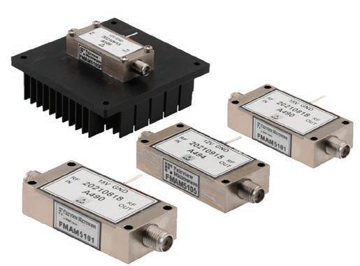
Military training & simulation software adds maps, radar
Bohemia Interactive offers a software update to its military training and simulation software products, VBS4 and VBS Blue IG 22.2. The updates include new features and graphics improvements. One new feature is that the VBS4 Map now enables users to create custom 2D mapping for each training scenario, while a “volumetric cloud” update improves lighting and 3D volume to clouds, in addition to customizable cloud density. The 3D Grass feature improves users’ view of regionally-specific 3D grass and other ground-cover vegetation.
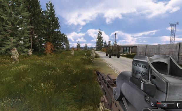
A new “fair fight” feature ensures soldiers lying in the grass are accurately hidden, and the software shows users flattening the grass as they move through it. A radar simulation feature adds radar, radio, and radar-signal detection, enabling training administrators to provide radar sensor capabilities to any entity or vehicle. Adjustable characteristics including range, detection altitudes, refresh rate, and effectiveness enable users to emulate many different types of radar.
Bohemia Interactive Simulations | https://www.bisimulations.com/
Holt releases application development kit for MIL-STD-1553A/B/C solution
Holt Integrated Circuits has released a new application development kit (ADK-6139) for its HI-6139, a device with a software-controlled MIL-STD-1553A mode, but otherwise functionally identical and drop-in compatible with Holt’s existing HI-6138 MAMBA device. The kit allows users to add 1553A capability to any existing MAMBA terminal design with minimal software changes. The hardware consists of two boards: The first is an upper HI-6139 board with configuration DIP switches, programmed self-configuration EEPROMs, and two transformercoupled MIL-STD-1553 bus interfaces. The lower microprocessor board has an Arm Cortex M3 16/32-bit MCU, JTAG debug interface, and regulated 3.3 VDC power supply. The HI-6139 board can be separated from the MCU board for connection to a user-supplied alternate microprocessor or FPGA platform.
The kit includes a software reference design written in ANSI C, illustrating the operation of the device in 1553A mode. The project source code can be customized and may be used as a starting point for customer application development, including MIL-STD-1553B or C terminal design. The included source code may be customized for specific customer application use, and provides the possibility of adding 1553A capability to any existing MAMBA terminal design.
Holt Integrated Circuits | https://www.holtic.com/
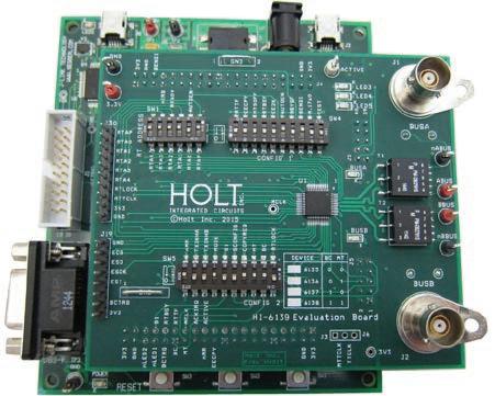
https://www.fairviewmicrowave.com/ EDITOR’S CHOICE PRODUCTS 42 January/February 2023 MILITARY EMBEDDED SYSTEMS www.militaryembedded.com
Fairview Microwave |
Emergency locator transmitter links to GNSS for distress signals
Orolia's Ultima-S Emergency Locator Transmitter (ELT) is installed in either the cabins or life rafts of aircraft and relays accurate aircraft location information to search and rescue teams. A feature called the Return Link Service (RLS) ensures that users are automatically notified when the distress signal is detected and located by the Cospas-Sarsat ground infrastructure (an international search-and-rescue organization). The Ultima-S links directly to the European Galileo GNSS satellite constellation, with the aim of providing timely information for reaching aircraft crew members in distress.
The Ultima-S is certified by Cospas-Sarsat and the European Union Aviation Safety Agency (EASA) that puts it in compliance with both EASA and FAA [U.S. Federal Aviation Administration] requirements. The ELT runs on nonrechargeable lithium batteries that are compliant with FAA and EASA special-conditions standards, also known under TSO-C142b/DO227A. The Ultima-S also meets the most recent ELT performance and environmental standards through TSO-C126c, both standards issued by the FAA. Once activated, a 406 MHz distress signal is transmitted, with the Ultima-S internal GNSS receiver showing the ELT location.
Orolia | https://www.orolia.com
Military-grade 4 kW, 270 Vdc input inverter optimized for harsh environments
SynQor has announced a new rugged 270 Vdc input, high-power, compact, military-grade inverter (MINV-4000-1U-270). The new 4000 W 115/230 AC output inverter is designed to be lighter and easier to use for military, airborne, naval, and mobile high-reliability applications. It is designed to withstand extreme electrical, shock, vibration, and environmental conditions. The inverter draws power from a standard 270 Vdc power supply and delivers a fully isolated, well-conditioned, pure-sinusoidal AC output. Compliant with military standards, this inverter is designed for applications concerned with output power, space, weight, and reliability in harsh environments.

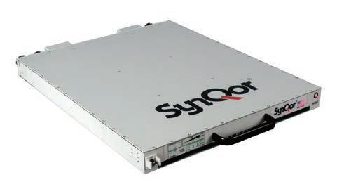
The MINV inverter supports parallel and N+M redundant configurations of up to 32 units for high-power and/or high-reliability requirements. Multiple MINV units can be arranged to deliver complex multiphase power schemes including three-phase and split-phase (or doubling line-to-line output voltage and total output power). The new MINV-4000-1U-270 has an SNMP Ethernet base module that enables configuration via a web interface and real-time remote monitoring with trap/email features that warn users and monitoring consoles of important system events. Additional options include the wide range of AC output characteristics (115 or 230 Vrms at 50, 60, or 400 Hz); a floating ground option for aerospace and naval applications; and an electronic AC output breaker that enables users to build fault-tolerant, dependable, redundant, high-output power solutions.
SynQor | https://www.synqor.com/
Rugged military display draws low power
Azumo offers military customers a low-reflective, low-power, ruggedized display in the LCD 2.0 display, a front-lit liquid crystal display that is designed to emit less intense blue light at a lower power than typical backlit LCD displays. The module uses substantially lower energy than conventional back light unit (BLU) LCDs and extends the device battery life. The resolution is 272 by 451 pixels, for high resolution onscreen in all lighting conditions. Each pixel comprises an R/G/B strip, with the integrated front light supplying 64 colors and good NTSC color saturation. The module's three-wire SPI interface at 7 MHz is paired with a 6-ms response time, which enables animation, and is interfaced via a touch panel.
The LCD display – aimed at use in rugged and hostile environments – is bonded via optically clear adhesive (OCA) to a ruggedized cover lens. Directly bonded displays will help keep out dust, mud, sand, snow, and water that can all wreak havoc on devices if they are allowed to penetrate the device casing. Such new lens-cover technologies and bonding techniques are used to increase the ruggedness of LCD displays without sacrificing display features and readability. Additionally, UV treatments can protect the display from premature degradation from extended sunlight exposure.
Azumo | https://www.azumotech.com/

EDITOR’S CHOICE PRODUCTS
www.militaryembedded.com MILITARY EMBEDDED SYSTEMS January/February 2023 43
How the military can speed data mobility for smart decisions on the move
By Travis Steele, Red Hat
The military is producing ever-larger amounts of valuable data from embedded systems at the edge. Now it needs more effective ways to share, understand, and act on that data – at or near the user and as close as possible to real time. By leveraging available technologies like containerization and tools to manage them, warfighters have the opportunity to make faster, smarter decisions where and when they’re needed to help achieve battlespace dominance.
In the recent past, the U.S. achieved battlespace dominance through the technical superiority of its weapons. Going forward, U.S. forces will face more near-peer, if not actual peer, adversaries across multiple domains. Dominance will increasingly be attained through information advantage and the ability to gather, process, and act on data – and do it faster than the adversary.
To achieve that goal, data-driven analysis and decision-making must occur in real time, very close to where these decisions are needed. Even as more data flows in from mobile devices, cameras, sensors, satellites, unmanned equipment, artificial intelligence (AI) systems, and the like, mission operators still need ways to turn that data into insights and information that lead to the right actions. Just as important, they need to quickly share data across every domain – land, air, sea, space, and cyberspace.
Fortunately, data-mobilizing technologies exist today in the form of containerization based on microservices architectures, platforms to automatically configure applications and networks, and API interchanges to translate data to and from applications.
Quickly deploying applications
Most edge solutions face multiple limiting factors such as size, weight, and power (SWaP), as well as denied, disrupted, intermittent, and limited (D/DIL) communication. Often, the decrease in resources is accompanied by a proliferation of devices. Therefore, workloads need to be portable across a broad range of systems, from the source of the data all the way to the data center.
A microservices architecture can help address portability challenges while also improving capability at the mission edge tiers. Microservices are modular components that together make up a robust software application. Such an approach enables the user to easily create and spin services up or down on demand. If an application needs to scale or update because of mission needs or changes, microservices help you rapidly respond.
Containerization is an effective way to employ your microservices architecture. Containers are lightweight and combine an application with the required frameworks and libraries that enable it to run on various platforms across the mission edge.
This functionality is key when considering applications and systems that will support agile combat employment or agile ops, as it enables the user to effectively move applications and subsequent workloads around while ensuring consistency and interoperability across environments.
Given the proliferation of edge devices and the ability to use containers to run mission-critical workloads close to the warfighter, what happens to all these containers? That’s where Kubernetes comes in: Kubernetes is an open-source orchestration platform for managing containers at scale that can help automate, track, and schedule the deployment of containers to keep systems running uninterrupted. It can also be optimized in a lightweight format to meet the SWaP needs users in the field.
Automatically configuring networks and data storage
Applications are not the only technology consideration at the edge: Warfighting missions need to dynamically combine the networks and data storage of each domain, and those resources must be able to reconfigure rapidly and adapt to change as missions launch and evolve.
Such is the advantage of software-defined networks and data storage, as a software-defined approach enables continuous alteration of the infrastructure at the software layer without having to change the underlying hardware.
A software-defined approach requires time and technical expertise, but with an automation platform, warfighters can replace manual process steps and provide necessary expertise. Instead of a technician typing keyboard commands while under duress, specialized software can couple technical expertise with sequenced commands, and automatically reconfigure networks and data storage – resulting in operational adaptability.
Such automation enables resources to become “event-driven.” Has a new unit mobilized, thereby changing the understanding of the current and expected environment? The automation platform automatically integrates its network and data resources. What if a cyberattacker flooded a critical node with denial-ofservice (DoS) traffic? The automation platform takes down the affected resource and deploys a new one.
44 January/February 2023 MILITARY EMBEDDED SYSTEMS www.militaryembedded.com BLOG: IT STRATEGY
Rapidly translating data for every domain
Rapid deployment of applications and networks is necessary for data mobility at the edge, but that’s not enough: Domains must also be able to quickly and easily share data.
The problem with this is that isolated and non-standards-based application development and data formats have plagued military service branches for years, which doesn’t only create interoperability challenges, it also means that at a technical level, there’s no awareness between applications and systems.
In the past, military teams addressed this issue in a centralized way, translating every mission data type into every other mission data type, a slow and resource-intensive process. Moreover, as data assets are added, the burden on systems only gets worse.
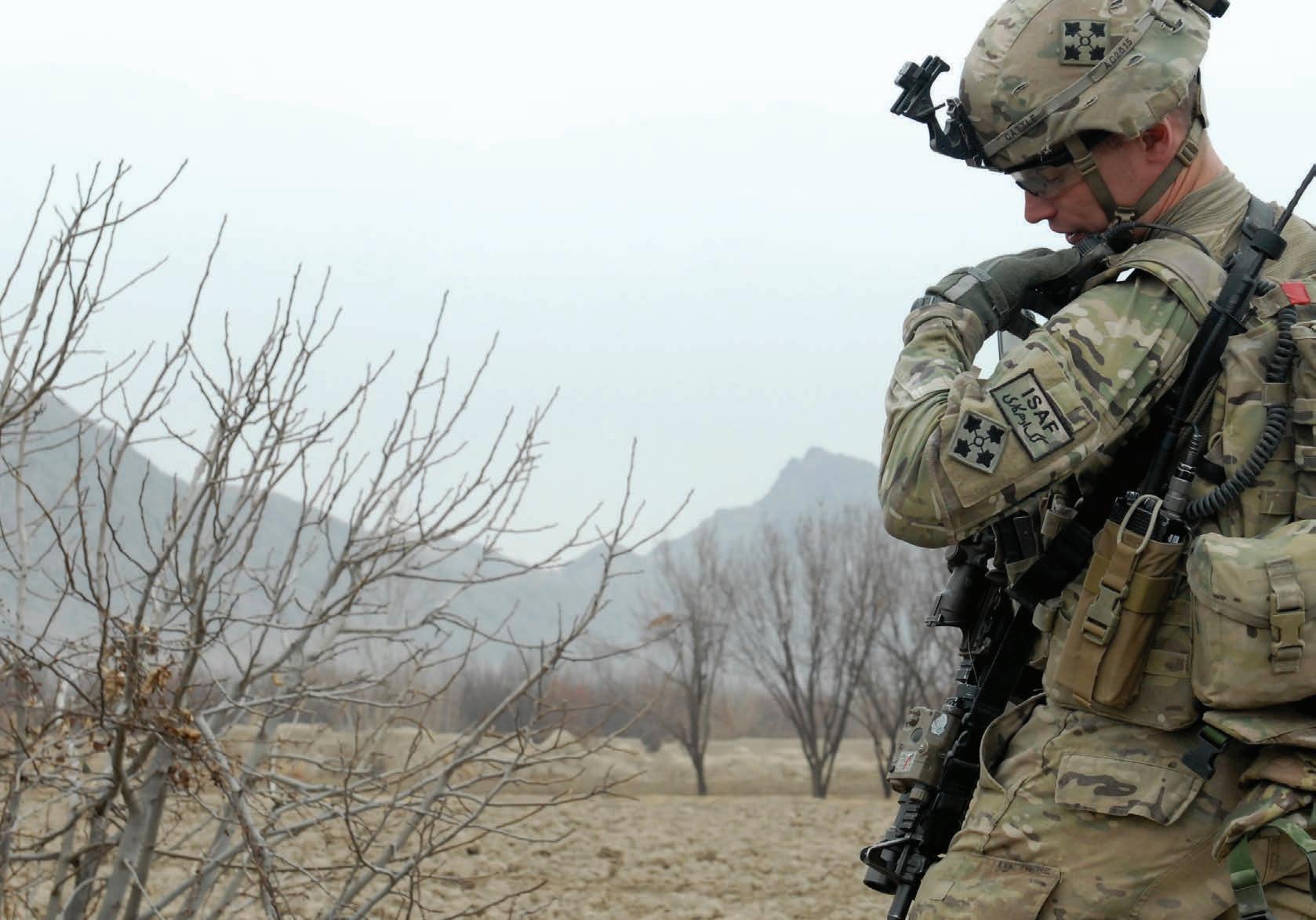
A modern approach is leveraging application programming interfaces (API). An API interchange uses a key to share data among various applications or sources without having to know anything about the applications themselves.
Using this approach, wherever data is produced – whether from an application, a sensor, or a satellite – the API enables access

to information and to input data. Then, wherever the data is consumed – by an AI algorithm, an analytics solution, or a weapons system – it’s translated from one application to another. This process makes data discoverable between domains and provides secure access to understand and act on data from every other domain.

Speeding data mobility at military scale
These technologies can revolutionize data consumption and decision-making across the spectrum of mission scenarios, as they’re secure and scalable. Some elements, such as portable containers, have been used by industries – for instance, automotive, telecommunications, and financial services – for nearly a decade. Finally, they can be built in a way that’s compliant with guidance from Common Criteria, the National Institute of Standards and Technology (NIST), and Federal Information Processing Standards (FIPS).
Travis Steele is a chief architect for Red Hat. He has more than two decades of expertise in technology leadership and transformation, with a focus on IT operations, infrastructure and applications, cloud delivery, and cybersecurity.
OpenSystems Media works with industry leaders to develop and publish content that educates our readers.
How to Select the Right Type of EMI Filter for Harsh Environment Operation

 By Quell, a Heico Company

Designers who must troubleshoot a product that failed an EMI test can sometimes get tunnel vision, working tirelessly to pass standards such as MIL-461 – but the device still needs to work. Ideally, when adding a filter, the goal is for nothing to change, other than reducing or eliminating the EMI.

This white paper discusses how engineers can consider traditional filters and EMI filter inserts – but which is right?
A filter insert will not alter the product’s functionality, ensuring a device that worked before will continue to work now.
Read this white paper at https://bit.ly/3HSVPlI

www.militaryembedded.com MILITARY EMBEDDED SYSTEMS January/February 2023 45
Red Hat • https://www.redhat.com/en
Read more white papers: https://militaryembedded.com/whitepapers
Editorial Staff
GIVING BACK
Each issue, the editorial staff of Military Embedded Systems will highlight a different charitable organization that benefits the military, veterans, and their families. We are honored to cover the technology that protects those who protect us every day. This issue we are highlighting Operation Hat Trick (OHT), an organization that seeks to generate awareness of and support for the recovery of wounded service members and veterans through the sale of OHT products. The charity was started in 2008 at the University of New Hampshire (UNH) following the combat deaths of two Navy SEALS connected to UNH, Nate Hardy and Mike Koch. Inspired by UNH’s longstanding hockey tradition, founder Dot Sheehan launched OHT, donating hats to Veterans Administration medical centers and selling them locally.
While the organization began by giving hats to service members with head and brain injuries, it expanded in 2012 into selling branded merchandise and products – hats and outdoor gear – and using the proceeds to support the recovery of service members and veterans. The 501(c)3 nonprofit now works with colleges and universities, athletic leagues, companies, and fans across the U.S. to help active-duty military and veterans as it raises money to fund carefully selected – typically smaller – military-support organizations. According to information from OHT, the brand and mission has been used by more than 500 colleges and universities in all 50 states, 130 high schools, 20 National Hockey League teams, 85 Minor League baseball teams, 13 NBA teams, and more than 100 companies. It reports that the organization has donated more than $3.5 million since 2014 to selected military and veteran organizations. It focuses on filling some critical gaps in care for military personnel and veterans, including such things as adaptive equipment for amputees; service dogs; shoes for prosthetic legs; critical care; and emergency rent, heating oil, or car payments. It also provides a cabin for a veterans’ summer camp; sponsors hunting, fishing, and skiing trips for vets; and endows a bed in a substance-abuse center solely for veterans needing help with substance abuse. For additional information, please visit https://operationhattrick.org/.

WEBCAST

Universal Storage for Fast Access to All Data at the Edge


Sponsored by Mercury
Today’s ubiquitous sensors are producing infinite amounts of data. Yesterday’s storage, access and analysis solutions are no longer enough. Military personnel require fast, direct access to all types of data to counteract adversarial threats in real time utilizing AI applications in the field. For the first time in the market, there is an affordable ruggedized allflash network-attached data storage solution purpose-built for challenging mission-critical applications.
In this webcast, participants can learn how defense companies are eliminating compromises between data performance, capacity, scalability, and affordability; enabling complete data access over network connections at low-latency, direct-attached speeds; simplifying data management with universal storage technology; and designing rugged data storage (RDS) systems that extend product life cycle and reduce total cost of ownership.
Watch this webcast: https://bit.ly/3JCDlr6
Watch more webcasts:
https://militaryembedded.com/webcasts/archive/
Combining the Best of Both Worlds: True Time Delays and Phase Shifters

 By Bilgin Kiziltas, Analog Devices
Electronically scanned arrays (ESAs) use phase shifters (PSs) or true time delays (TTDs) or a mix of both to point the beam toward the desired direction within an array’s steering angle limits. Adjustable attenuators used for tapering can also be considered as beamforming elements. A tiered approach between TTDs and PSs in the same ESA can be helpful to mitigate some phased-array design challenges.
This white paper reviews the strengths and weaknesses of two electronic beamforming techniques: PSs and TTDs. The paper asserts that these two methods can be combined in a hybrid beamforming architecture to offer better size, weight, power, and cost (SWaP-C) metrics and a comparatively less complex system design.


Read this white paper: https://bit.ly/3DBDrLz

Read more white papers: https://militaryembedded.com/whitepapers


EMBEDDED
GIVING
| PODCAST |
PAPER
BLOG | VIDEO | SOCIAL MEDIA | WEBCAST 46 January/February 2023 MILITARY EMBEDDED SYSTEMS www.militaryembedded.com
CONNECTING WITH MIL
By
BACK
WHITE
|
www.militaryembedded.com
WHITE PAPER
TECHNOLOGY MAKING YOUR HEAD SPIN?


WE CAN HELP YOU MAKE SENSE OF IT ALL

Military Embedded Systems focuses on embedded electronics – hardware and software – for military applications through technical coverage of all parts of the design process. The website, Resource Guide, e-mags, newsletters, podcasts, webcasts, and print editions provide insight on embedded tools and strategies including technology insertion, obsolescence management, standards adoption, and many other military-specific technical subjects.
Coverage areas include the latest innovative products, technology, and market trends driving military embedded applications such as radar, electronic warfare, unmanned systems, cybersecurity, AI and machine learning, avionics, and more. Each issue is full of the information readers need to stay connected to the pulse of embedded technology in the military and aerospace industries.
militaryembedded.com
THE NEXT BIG THING IN RFS o C IS HERE
AND IT’S ONLY 2.5" × 4"

POWERFUL SMALL DEPLOYABLE
Models 6001 and 6003 QuartzXM modules enable the rapid integration and deployment of RFSoC technology. And the SWaP-friendly design is ideal for aircraft pods, unmanned vehicles and mast-mounted radars.
A Zynq® UltraScale+™ RFSoC plus a full suite of pre-loaded IP modules, robust Navigator ® software, high-speed 100 GigE interfaces and fully integrated hardware from Mercury, formerly Pentek, helps shorten your development time and reduce your design risk.

mrcy.com/go/marfsoc


[Form Factors]


QuartzXM Module


SOSA aligned 3U VPX 3U VPX

SFF platforms
PCIe