

For mission critical applications, Analog Devices delivers proven, beamforming technology with trusted reliability when and where you need it most—from the unknown vastness of space to the unrelenting theater of war.

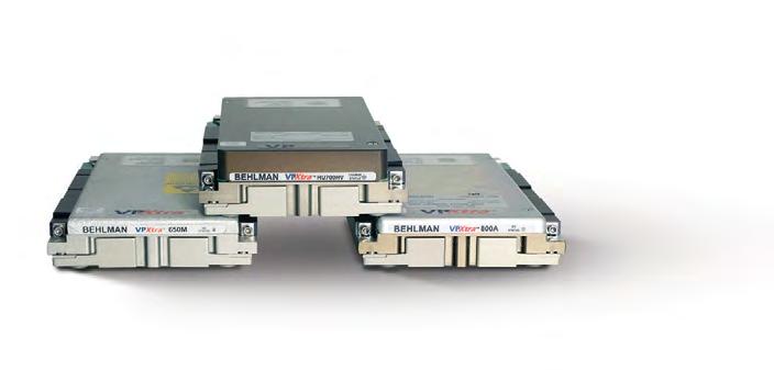
When the mission calls for a 3-phase 3U power supply that can stand up to the most rugged environments, the military chooses VPXtra 704™ from Behlman – the only VPX solution of its kind built to operate seamlessly from MIL-STD-704F power for mission-critical airborne, shipboard, ground and mobile applications.
> 3-phase AC or 270V DC input; high-power DC output
> Available holdup cards store 700W of DC power for up to 80 msec
> Overvoltage, short circuit, over-current and thermal protection
> Provides full output performance during both normal and abnormal transients The Power Solutions Provider

Editor’s Perspective
5 Fathers and sons By John M. McHale III, Editorial Director
Mil Tech Insider
7 The emerging era of intelligent deployed data storage By Steve Petric
Guest Blogs
50 Harnessing AI for the next-generation tactical edge By Anthony Verna, Cubic DTECH Mission Solutions
52 Enabling rapid deployment through modular software architectures and third-party ecosystems
By Erik Vallow & Dr. Justin Pearson, Lynx Software Technologies
Defense Tech Wire
8 By Dan Taylor
with Military Embedded
By Lisa Daigle
Subscribe to the magazine or E-letter Live industry news | Submit new products
http://submit.opensystemsmedia.com
WHITE PAPERS – Read: https://militaryembedded.com/whitepapers
WHITE PAPERS – Submit: http://submit.opensystemsmedia.com

ROUNDTABLE: The SOSA Technical Standard
12 SOSA having an impact on military program requirements, business practices By John M. McHale III, Editorial Director
PERSPECTIVE: Executive Interview
16 Multifunctionality for military sensor systems, defining AI at the edge Q&A with Jake Braegelmann, Vice President of Business Development at New Wave Design By John M. McHale III, Editorial Director
SPECIAL REPORT: Vetronics & CMOSS
20 Think tanks: How smarter vehicle electronics are enabled by open architectures By Dan Taylor, Technology Editor
24 CMOSS: True MOSA with high readiness level By Dr. Daniel Kilfoyle, Pacific Defense
28 Small UAS swarms and battle management: The evolving warfare landscape By Dr. Jason Adaska, Numerica
MIL TECH TRENDS: Test & measurement trends
32 VITA standards activity updates By Jerry Gipper, Editorial Director, VITA Technologies
34 Testing FPAs with protoboards versus COTS-based instrumentation By James Campbell, Viewpoint Systems
INDUSTRY SPOTLIGHT:
Managing supply chain, obsolescence, and counterfeit parts
36 Overcoming EOL and limited supply-chain visibility By Drew Thompson, Sealevel Systems
40 Leveraging technology for military fleet optimization By Rob Harrill, Lone Star Analysis
42 Defense demand is on the rise By Rob Mather, IFS
46 System upgradability: key for U.S. Army’s next-gen vehicle fleet By Brian Russell, Systel
To unsubscribe, email your name, address, and subscription number as it appears on the label to: subscriptions@opensysmedia.com
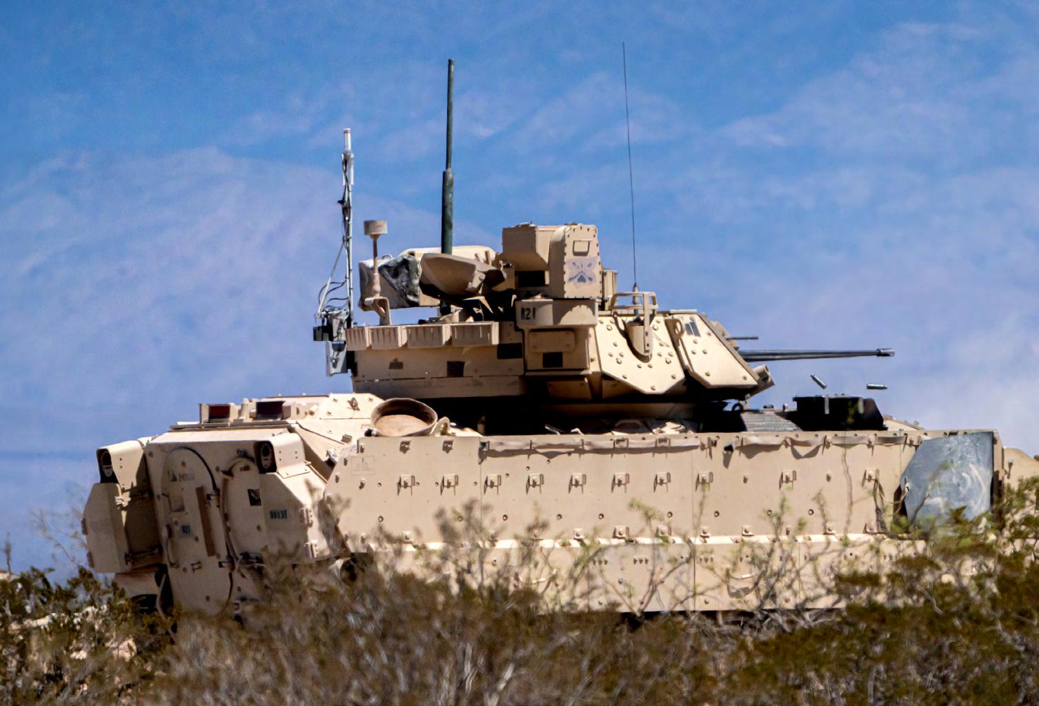
ON THE COVER:
An M2A3 Bradley Fighting Vehicle assigned to 2nd Squadron, 13th Cavalry Regiment, 3rd Armored Brigade Combat Team, 1st Armored Division, engages a target during a Bradley Table VI qualification course at McGregor Range, New Mexico. U.S. Army photo by Spc. David Poleski.
By John M. McHale III, Editorial Director
When I said I wanted to be a journalist and a writer, my dad, John McHale, Jr., told my mother, “Oh no, he’ll never make any money and we’ll have to support him forever.” That was more than 30 years ago, and I ended up doing OK. The best accolade I ever got wasn’t an award or a grade – it was my father asking me for my skills, requesting that I write family obituaries, letters, and eulogies. Last month I wrote his eulogy. He passed away on August 11, aged 81, surrounded by me, Mom, my brother, and our wives.
You may have noticed I changed my byline this issue to John M. McHale III. He’d ask me occasionally why I never put the proper suffix after my name, the III. My answer always was it seems pretentious. Seems I overthought that.
My dad didn’t have a public byline as a writer or a journalist, but he did have a talent that I wish I had inherited – a rare and beautiful singing voice. As a first tenor, he could belt out beautifully difficult songs like the “Ave Maria” and “Danny Boy” – a cappella. When I was a kid sitting next to him in church, he’d try to get my brother and me to sing along … we’d look at him like he was crazy. No way we could follow that. We mumbled along while Dad’s voice rose above the congregation.
It especially soared when singing showtunes or Irish singalong songs like “Irish Eyes.” In fact, that was playing as he passed.
While not everyone could follow his musical example, my dad did set many on the path of service to others. His career was literally bookended by service positions: After college at Saint Joseph’s University in Philadelphia, he took a position as a teacher and guidance counselor at Bishop Eustace High School in New Jersey. At the other end of his working years, he retired from the Woods Services, an organization in Pennsylvania dedicated to providing residential services to the developmentally disabled. Dad loved that job more than any other because he was helping those who could not help themselves.
Dad set many examples of service and work ethic over the 55 years we had together. Lots of lessons and love. But as with many fathers and sons, there was tension too. We could have some real tough arguments that strained our relationship.
But we had a moment five months ago that Dad really surprised me with – it had a profound impact on me and I want to share it with you.
I visited my parents in March for my mom’s 80th birthday, I’d come back from a run and found my dad sitting outside the garage. I sat down and he wanted to chat. I won’t get into
John.McHale@opensysmedia.com


specifics but suffice it to say that words of apology, forgiveness, and love conquered years of complex stuff in a simple way.
My father found grace and he gave it to me.
Finding grace is not something I ever write about in these pages and some may see it as religious in nature. I know my father did. A daily churchgoer, he prayed for nearly everyone he met. If there is a record for Hail Marys somewhere, he’s near or at the top. He’d pray for you and be grateful for you reading his son’s magazine.
But this is my prayer for you – or my wish, for those of you who are not religious: That you find the grace my father found and gave to me and in turn you give it to someone in your life.
Apologize without expecting forgiveness. Forgive without expecting acceptance. Forgiving someone is one of the most freeing things you can do … for yourself.
Honor my father or someone else who gave you grace in the next weeks or months by reaching out to someone you care about – maybe you talk to them every day or maybe you haven’t spoken to them in years. Tell them you care, tell them you love them.
Trust me – you can never say it enough.
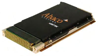
39 Abaco Systems –Powerful. Seamless. Fast. Flexible. Rugged. Cutting edge. SBC3513L
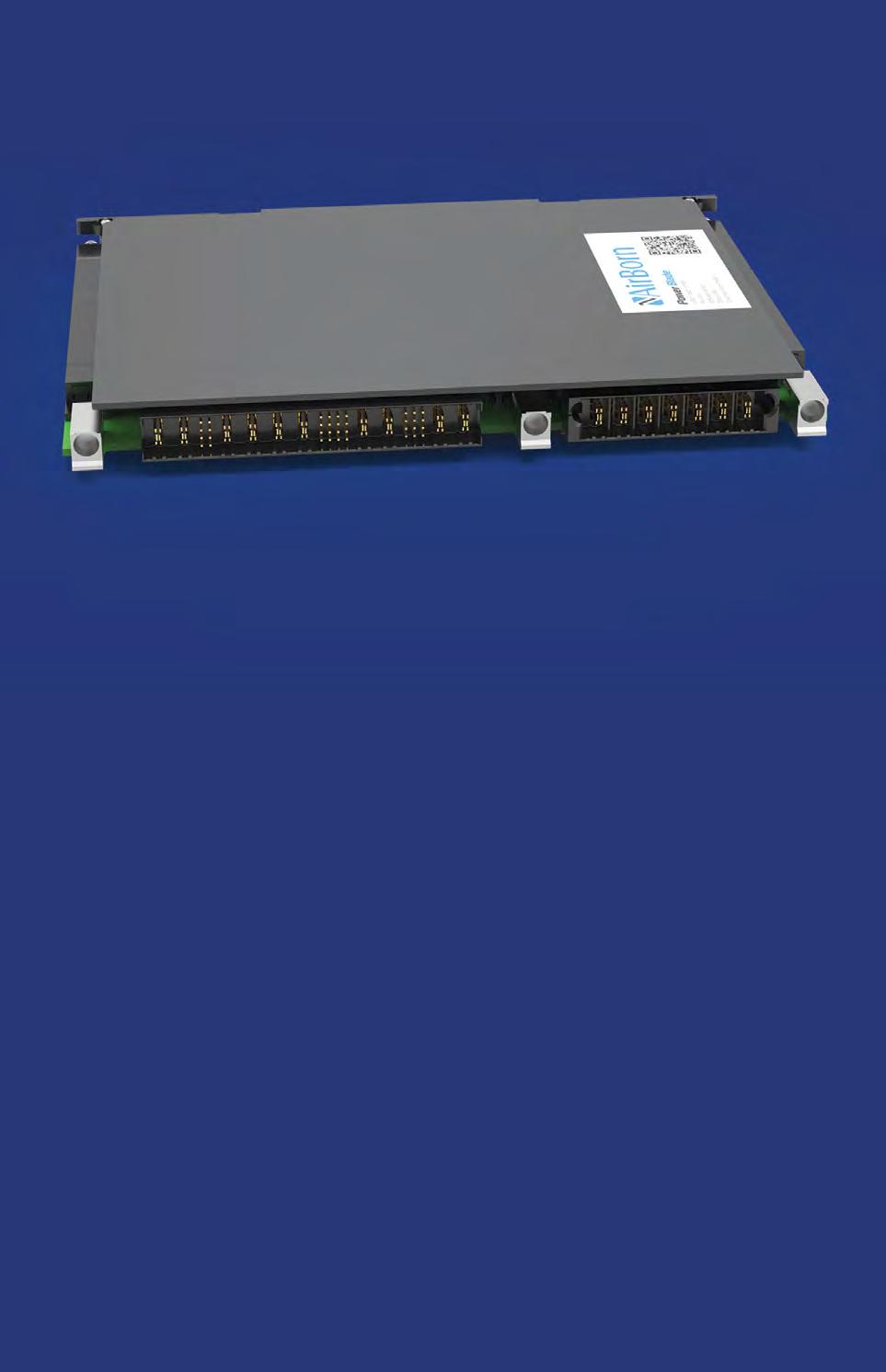
AirBorn – Introducing Power Blade. 2300W+ VPX power module
Elma Electronic –Accelerate development to deliver performance to the warfighter
emproof GmbH – Understanding the Threat of Reverse Engineering in the Defense Sector
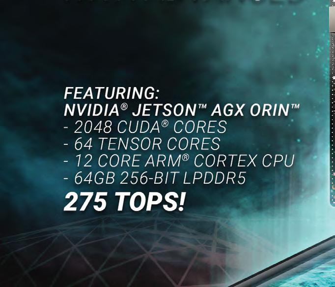
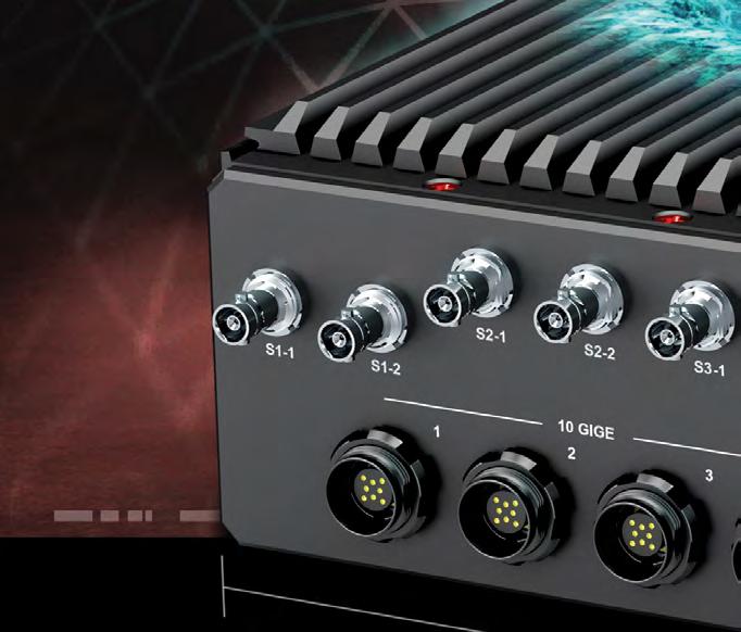
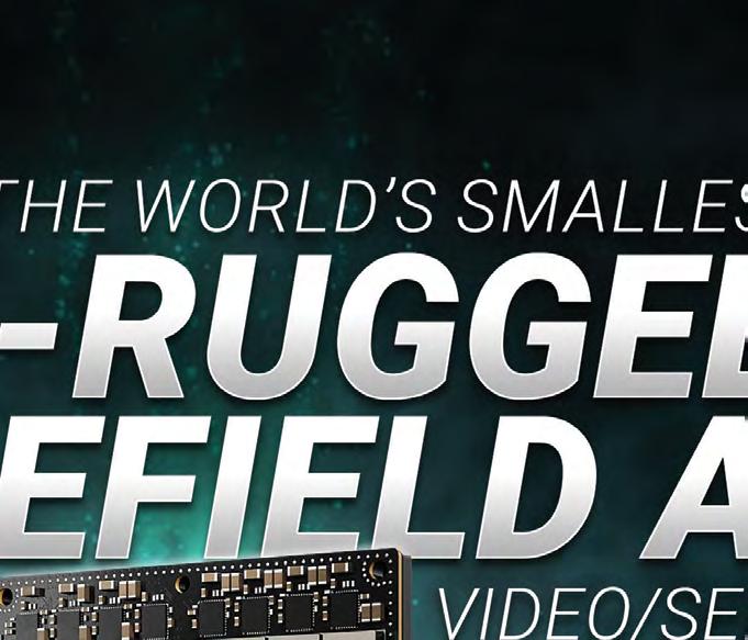
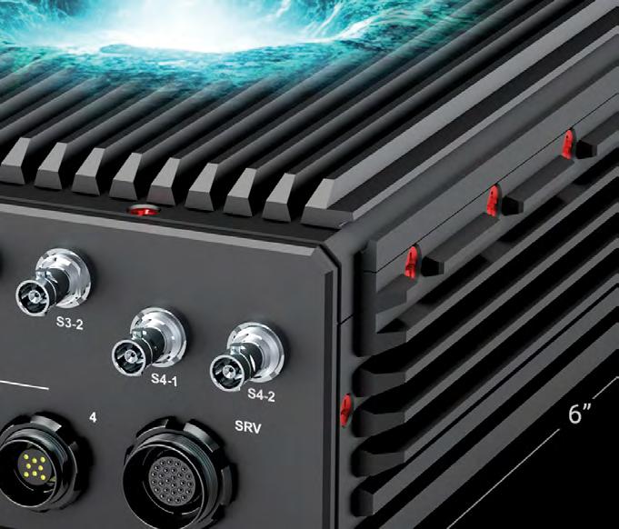
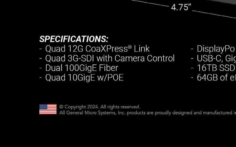
100 GMS – X9 Spider: The world's most powerful full-featured wearable AI computer
31 LCR Embedded Systems, Inc. –Mission possible. VPX and SOSA aligned system solutions
38 Microwave Products Group –Explore MPG's advanced capabilities
45 New Wave Design – We create precise, SOSA aligned VPX and XMC solutions for mission critical applications
53 Phoenix International –Phalanx II: The ultimate NAS 29 PICO Electronics Inc –Transformers and inductors. Surface mount (and plug in)
19 Pixus Technologies –SOSA aligned products in the slot profile configuration you need 26 Rantec Power Systems Inc. –Global leader in power supplies designed in alignment with the SOSA Technical Standard
43 Sealevel Systems, Inc. –Advancing architecture for the next generation of command & control
48 State of the Art, Inc. – No boundaries!
embedded world North America October 8-10, 2024
Austin, TX
https://www.embedded-world.de/en/embeddedworld-wide/embedded-world-north-america
AUSA 2024 Annual Meeting & Exposition October 14-16, 2024 Washington, DC
https://meetings.ausa.org/annual/2024/index.cfm
2024 IEEE International Symposium on Phased Array Systems & Technology October 15-18, 2024 Boston, MA
https://www.ieee-array.org/
GROUP EDITORIAL DIRECTOR John M. McHale III john.mchale@opensysmedia.com
ASSISTANT MANAGING EDITOR Lisa Daigle lisa.daigle@opensysmedia.com
TECHNOLOGY EDITOR – WASHINGTON BUREAU Dan Taylor dan.taylor@opensysmedia.com
CREATIVE DIRECTOR Stephanie Sweet stephanie.sweet@opensysmedia.com
WEB DEVELOPER Paul Nelson paul.nelson@opensysmedia.com
EMAIL MARKETING SPECIALIST Drew Kaufman drew.kaufman@opensysmedia.com
WEBCAST MANAGER Marvin Augustyn marvin.augustyn@opensysmedia.com
VITA EDITORIAL DIRECTOR Jerry Gipper jerry.gipper@opensysmedia.com
DIRECTOR OF SALES Tom Varcie tom.varcie@opensysmedia.com (734) 748-9660
STRATEGIC ACCOUNT MANAGER Rebecca Barker rebecca.barker@opensysmedia.com (281) 724-8021
STRATEGIC ACCOUNT MANAGER Bill Barron bill.barron@opensysmedia.com (516) 376-9838
STRATEGIC ACCOUNT MANAGER Kathleen Wackowski kathleen.wackowski@opensysmedia.com (978) 888-7367
SOUTHERN CAL REGIONAL SALES MANAGER Len Pettek len.pettek@opensysmedia.com (805) 231-9582
DIRECTOR OF SALES ENABLEMENT Barbara Quinlan barbara.quinlan@opensysmedia.com AND PRODUCT MARKETING (480) 236-8818
INSIDE SALES Amy Russell amy.russell@opensysmedia.com
STRATEGIC ACCOUNT MANAGER Lesley Harmoning lesley.harmoning@opensysmedia.com
EUROPEAN ACCOUNT MANAGER Jill Thibert jill.thibert@opensysmedia.com
TAIWAN SALES ACCOUNT MANAGER Patty Wu patty.wu@opensysmedia.com
CHINA SALES ACCOUNT MANAGER Judy Wang judywang2000@vip.126.com
PRESIDENT Patrick Hopper patrick.hopper@opensysmedia.com
EXECUTIVE VICE PRESIDENT John M. McHale III john.mchale@opensysmedia.com
EXECUTIVE VICE PRESIDENT AND ECD BRAND DIRECTOR Rich Nass rich.nass@opensysmedia.com
DIRECTOR OF OPERATIONS AND CUSTOMER SUCCESS Gina Peter gina.peter@opensysmedia.com
GRAPHIC DESIGNER Kaitlyn Bellerson kaitlyn.bellerson@opensysmedia.com
FINANCIAL ASSISTANT Emily Verhoeks emily.verhoeks@opensysmedia.com
SUBSCRIPTION MANAGER subscriptions@opensysmedia.com
System integrators seeking secure data-at-rest (DAR) solutions for deployed sensor-rich platforms are faced with handling increasing amounts of data from an ever-greater number of more powerful onboard sensors.
The need to capture and store the veritable firehose of incoming data, without introducing bottlenecks and losing data, is now being addressed with the availability of networkattached storage (NAS) devices that support data rates up to 100 Gigabit Ethernet. One beneficial trend for data storage is the advent of high-speed non-volatile memory (NVMe) solid-state memory devices that can keep up with the faster Ethernet. Additionally, NVMe devices are cost-effective and help reduce size, weight and power (SWaP), often a critical factor for extending the reach and duration of ISR [intelligence, surveillance, and reconnaissance] missions, many of which are deployed on uncrewed platforms.
Moore’s Law doesn’t just apply to processor performance –users of solid-state memory devices benefit from the increasing densities and affordability of rugged solid-state storage devices. Another important trend improving the capabilities of deployed NAS products is the use of two-layer encryption to protect the stored data, specifically the National Security Agency’s (NSA) Commercial Solutions for Classified (CSfC) program, which speeds the access to approved commercial offthe-shelf (COTS) data-protection technologies.
All of these converging trends are now driving the next major advance in data-storage solutions: the integration of built-in intelligence capable of processing and analyzing data during the mission. The usual way of handling data is that, after the sensor data is processed in real time by the mission computer, it is dealt with post-mission using removable storage media, usually delivered to a data center where it can be analyzed to identify patterns and signals of interest. Now, if the NAS features a cost-effective GPU processor with extreme parallel processing power, artificial intelligence/machine learning (AI/ML) and deep learning techniques can be developed to garner actionable information from the stored data on the platform during the mission.
GPU-enabled NAS systems deployed at the tactical edge can increase the precision of decision-making in applications such as predictive maintenance and logistic optimization, based on the analysis of the stored sensor and mission data well before that data can be physically delivered to the data center.
To leverage the possibilities of AI/ML, system integrators are now seeking GPU-enabled NAS solutions designed for use at the tactical edge. Work is now underway in lab settings to
By Steve Petric

collect data and build models. To speed and help foster efforts to develop AI/ML models for analyzing DAR on-platform, system integrators need access to cost-effective GPU-enabled NAS solutions.
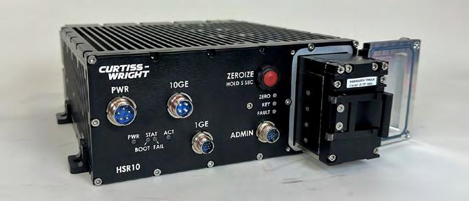
An example of a GPU-enabled 100GbE rugged secure DAR solution is Curtiss-Wright’s HSR100 Rackmount, a high-capacity NAS device packaged in a 1U rackmount form factor. It supports a pathway to NSA Type 1 or CSfC two-level encryption to provide secure DAR storage and recording, enabling near-linerate recording capabilities supported with more than 64 TB of high-speed NVMe storage. Two 100 GbE ports are provided via QSFP56 interfaces and four 10 GbE ports via RJ45 and SFP+ interfaces. The NAS – intended for storing and protecting critical DAR on air, sea, and ground platforms – can be used in the lab or deployed at the tactical edge. It can also be housed in a 901D ruggedized enclosure for use in harsh environments. (Figure 1.)
Going forward, fully rugged modular open systems approach (MOSA)-based NAS variants, with increasingly high-performance GPUs based on an adaptable, flexible framework, will become widely available.
The secure storage of DAR is moving from the previous generation of passive, nonintelligent mass collection of raw data to an era of actionable data analysis that takes advantage of the converging trends of 100 GbE, NVMe memory, CSfC encryption, and GPU processing for deep learning. The emergence of intelligent data storage at the tactical edge is exciting, but equally compelling are the deployed applications that might emerge from GPU-enabled secure NAS systems. These upcoming applications will enable large amounts of data to be analyzed, patterns identified, and answers found, improving users’ ability to make better decisions faster and with more accuracy.
Steve Petric is senior product manager, Curtiss-Wright Defense Solutions.
Curtiss-Wright Defense Solutions https://www.curtisswrightds.com/
By Dan Taylor, Technology Editor

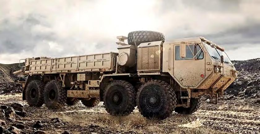
Oshkosh Defense wins Heavy Tactical Vehicle contract with U.S. Army
Oshkosh Defense won a five-year contract valued at approximately $1.54 billion from U.S. Army Contracting Command – Detroit Arsenal (ACC-DTA) for the Family of Heavy Tactical Vehicles (FHTV) V program, the company announced. Under the terms of the contract, Oshkosh will continue to deliver new and recapitalized Heavy Tactical Vehicles and associated trailers through 2031, according to the statement. The Oshkosh FHTV fleet includes vehicles such as the Heavy Expanded Mobility Tactical Truck (HEMTT A4), Palletized Load System (PLS Image via Oshkosh Defense. A1), PLS Trailer, and Heavy Equipment Transporter (HET A1).
Oshkosh plans to integrate enhanced capabilities into these vehicles to modernize the fleet, extend vehicle life, and reduce operating costs, the company says. The upgrades are slated to include features like drive-by-wire capability, condition-based maintenance (CBM), and electrification options.
Shield AI conducts first multijet autonomy flights using AI pilot
Shield AI conducted its first multijet autonomy flights using two Kratos MQM-178 Firejets piloted by its Hivemind artificial intelligence (AI) pilot. According to a company statement, two uncrewed aircraft piloted by Hivemind executed coordinated maneuvers that demonstrated collaborative operational behaviors. The flights showcased the potential for future unmanned jets and drones to operate autonomously, with all computing processed onboard and in-air communication seamlessly integrated, the company stated.
This event builds on previous successful flight tests and Live Virtual Constructive (LVC) integration completed earlier during 2024. Following the flights, Shield AI president Brandon Tseng said, “In the next decade, AI pilots will command and maneuver all unmanned systems.”
Missile-defense enhancement contract signed between U.S. Army and Teledyne
Teledyne Brown Engineering won a $114 million task order from the U.S. Army Space and Missile Defense Command under the Design, Development, Demon stration, and Integration (D3I) Domain 1 contract.
Under the terms of the contract, the company will design, build, and launch ballistic target missiles to test advanced missile-defense systems. Teledyne Brown Engineering will provide a range of test and evaluation target solutions with enhanced capabilities to simulate evolving threats faced by U.S. and allied forces, according to the company. The contract, an extension of Teledyne’s previous work with the Army since 2014, will continue through March 2028.


U.S. Army chooses Sierra Nevada as lead integrator for ISR transformation
The U.S. Army chose the Sierra Nevada Corporation (SNC) to be the lead system integrator for its High Accuracy Detection and Exploitation System (HADES), a program the Army is fielding in order to realize transformational increases in speed, range, payload, and endurance for Army aerial intelligence, surveillance, and reconnaissance (ISR) capabilities.
According to the announcement from the Army, the initial award on the 12-year indefinite-delivery/indefinite-quantity (ID/IQ) contract is $93.5 million, with an overall ceiling of $991.3 million over the life of the program. Army officials assert that SNC’s HADES program’s higher airspeeds and increased endurance will facilitate aerial ISR coverage for a much larger geographical area and will mean the ability to deploy anywhere in the world within days instead of the current transitional period of several weeks.
Robin Radar Systems to supply mobile radar systems for UAS detection in Ukraine
Robin Radar Systems won a contract from the Dutch ministry of defense for 51 mobile radar units designed for detection of uncrewed aerial systems (UASs), which will be donated to Ukraine later in 2024.
This latest order follows the Dutch ministry’s previous purchase of 51 static 3D IRIS drone radars made 18 months ago; these units are currently deployed across various locations. The newly ordered radars include on-the-move (OTM) functionality, enabling them to operate effectively when mounted on mobile platforms such as vehicles or ships. According to the Robin Radar Systems statement, its IRIS radars are specifically engineered to detect small, fast-moving drones, distinguishing them from birds and other flying objects.
General Dynamics Mission Systems
wins $20.7 million Navy contract mod for antisubmarine mines
General Dynamics Mission Systems won a $20.7 million modification to a previously awarded contract from the U.S. Navy to deliver Hammerhead Encapsulated Effector systems, the company announced.
The Hammerhead system, a moored antisubmarine mine, is capable of neutralizing threats to the naval fleet. The contract modification is structured as a cost-plus-fixed-fee agreement, with work scheduled to be completed by June 2026. General Dynamics Mission Systems will carry out the work in Taunton, Massachusetts. “The Hammerhead program will ensure that threats to the fleet will be neutralized safely and effectively,” said Paul Dalton, vice president of undersea systems at General Dynamics Mission Systems.
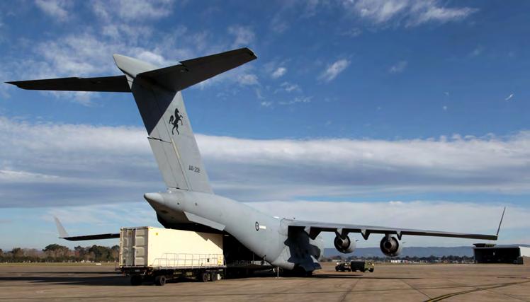
Ghost Shark XL-AUV arrives in the United States for testing
Anduril Industries’ advanced Extra-Large Autonomous Undersea Vehicle (XL-AUV), Ghost Shark, arrived in the U.S. for the first time, transported via a Royal Australian Air Force C-17A. According to the Anduril statement, the Ghost Shark is scheduled to be used for concurrent testing on both sides of the Pacific, expanding its test envelope and facilitating collaboration with U.S. government partners. The arrival was timed to coincide with the July 2024 Rim of the Pacific (RIMPAC) exercise near the Hawaiian Islands, one of the world’s largest maritime exercises focused on ensuring the security of global sea lanes.
Designed and built in Australia, Ghost Shark is a modular, multipurpose undersea vehicle intended to support global maritime missions. The vehicle is part of a codevelopment effort with the Royal Australian Navy and Australia government agency Defense Science and Technology Group, with the collaboration aimed at delivering three XL-AUVs by June 2025.
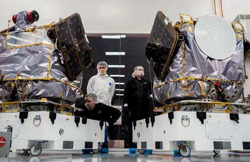
Rocket Lab ships twin satellites for NASA Mars mission
Rocket Lab USA shipped two Mars-bound spacecraft, named Blue and Gold, to Cape Canaveral, Florida, in preparation for launch as part of NASA’s ESCAPADE mission. According to the Rocket Lab statement, the ESCAPADE mission aims to measure plasma and magnetic fields around Mars to study the processes that strip atoms from the planet’s magnetosphere and upper atmosphere, contributing to greater understanding of Martian climate evolution.
The spacecraft were designed, built, integrated, and tested by Rocket Lab for the University of California Berkeley’s Space Science Laboratory and NASA. After completing assembly and final preparations at Rocket Lab’s Spacecraft Production Complex in Long Beach, the satellites arrived at NASA’s Kennedy Space Center, where they will undergo post-transport inspections and tests before being fueled for launch on Blue Origin’s New Glenn rocket in late 2024.
Final VH-92A presidential helicopter delivered to U.S. Marine Corps by Sikorsky Sikorsky delivered the 23rd and final VH-92A presidential helicopter to the U.S. Marine Corps, marking the completion of the next-generation fleet, the company announced.
The VH-92A helicopters – which transport the president, vice president, and other top U.S. officials – were built and modified at Sikorsky facilities in Owego, New York, and Stratford, Connecticut. The helicopters, known for their distinct white and green livery, are based on the FAAcertified S-92 aircraft. While this final helicopter delivery concludes the VH-92A program, the aircraft will continue to support presidential missions worldwide long after the current fleet of VH-3 and VH-60 aircraft is retired.
Hensoldt, via Thales, to supply radars for German Navy F126 frigates
Hensoldt won a contract from Thales to supply additional TRS-4D naval radars for the German navy’s F126 frigates. According to the Hensoldt statement, the added order increases the total value of the contract to more than 200 million euros ($223.65 million).
Initially contracted in 2022, the order included the delivery of TRS-4D radars for four F126 frigates and a radar segment for a test center. The recent contract extension will see the installation of the radar systems on two more F126 frigates, the company says. The nonrotating TRS-4D radars, which feature four fixed antenna arrays, will be integrated by Thales to meet the operational and combat requirements of the German navy, say Hensoldt officials.
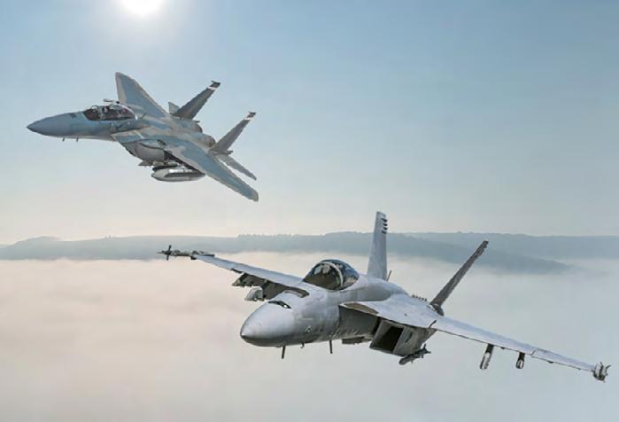
Flight-control computers for F-15EX, F/A-18E/F fighters to get upgrade
BAE Systems announced that Boeing has chosen it to upgrade the fly-by-wire (FBW) flight control computers (FCC) for the F-15EX Eagle II and F/A-18E/F Super Hornet fighter jets. The F/A-18E/F is used by the U.S. Navy, while the F-15EX Eagle II is an asset of the U.S. Air Force.
According to the BAE Systems announcement, the company will modernize the FCC electronics hardware and software to increase processing power, enhance cyber and product security, address obsolescence issues, and support sustainment well into the future for both aircraft. The FCC used in the F/A-18E/F will also host an additional processor to enable future capabilities for the fleet. The FCCs manage flight by processing pilot inputs, monitoring real-time aircraft movement conditions using onboard sensors, and transmitting commands to actuators that move the control surfaces.
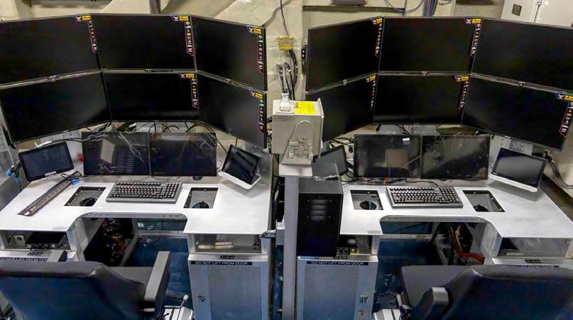
Uncrewed air warfare center installed on U.S. Navy aircraft carrier
The U.S. Navy recently installed the world’s first unmanned air warfare center (UAWC) aboard the USS George H.W. Bush (CVN 77) aircraft carrier, where air vehicle pilots (AVPs) will control future MQ-25 Stingray airborne operations. The Navy’s report states that the ship-based UAWC control room includes software and hardware systems that comprise the first fully operational and integrated unmanned carrier aviation mission control system (UMCS) MD-5E ground control station (GCS).
The Navy-developed GCS is powered by Lockheed Martin’s Skunk Works Multi Domain Combat System (MDCX) plus additional supporting equipment and hardware. The Navy says that the hardware installed in the racks and cockpits is the baseline for the production systems currently being fabricated for installation on CVNs 70, 71, and 76, with work beginning in fiscal year 2025.
Pacific Defense announces U.S. Army CMOSS mounted project team
Pacific Defense announced that it will lead a team to compete for the U.S. Army’s CMOSS Mounted Form Factor (CMFF) program; the team will also include Thales Defense & Security Inc., BAE Systems, Regal Technology Partners, Palantir, and STC (an Arcfield Company).
Pacific Defense leaders say that the Pacific Defense CMFF team’s layered standards will make it simpler, faster, and much less expensive to rapidly introduce new capabilities and commercial technology. The standards, they say, will also reduce complex integration challenges, eliminate proprietary interfaces, and enable greater competition and reuse.
According to the company statement, the Pacific Defense team plans to use such aspects as ground and aviation platform design and integration, multiwaveform communications, Type 1 cryptographic implementation, model-based systems engineering (MBSE), and production at scale.
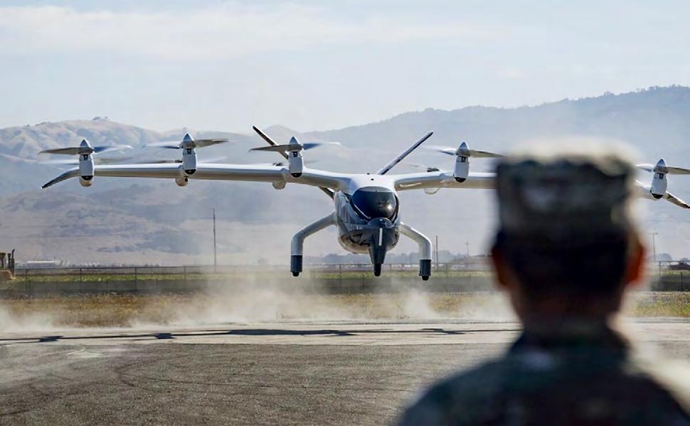
USAF takes first delivery of Midnight eVTOL aircraft from Archer Aviation
Electric vertical takeoff and landing (eVTOL) aircraft maker Archer Aviation delivered its first Midnight aircraft to the U.S. Air Force (USAF) to evaluate as part of its AFWERX Agility Prime contract, previously valued at as much as $142 million.
According to the announcement from Archer Aviation, delivery of the allelectric Midnight aircraft follows the U.S. Department of Defense (DoD) acceptance of Midnight’s military airworthiness assessment, a critical approval that enables flight testing by AFWERX, which intends to conduct government-directed testing of the aircraft for the U.S. Air Force and validate operational and military-specific mission concepts.
The company stated that a team of USAF personnel worked alongside the Archer flight-test team to ramp up Midnight’s operations, executing simulated medical evacuation, cargo, intelligence, surveillance, and reconnaissance flights.


CHRISTOPHER FADELEY
By John M. McHale III, Editorial Director
It’s been three years since ratification of the Sensor Open Systems Architecture, or SOSA, Technical Standard 1.0 and its impact is being felt across the services, as requests for SOSA aligned products are finding their way into program requirements. The SOSA standard, an example of the modular open systems approach (MOSA) mandated by the U.S. Department of Defense (DoD), is also changing the way government leverages commercial technology and existing open standards like VPX. To learn more, I gathered a roundtable of SOSA Consortium members to discuss the SOSA Technical Standard’s impact on the community, business practices, and common misconceptions. We also look into the future as to what the SOSA standard may look like five or ten years down the road.
Our panelists are: Ken Grob, Director of Embedded Computing Architecture, Elma Electronic; John Sturm, Chief Technology Officer, Vicor; Noah Donaldson, Chief Technical Officer, Annapolis Micro Systems; Emil Kheyfets Director of Engineering/Director, Military & Aerospace Product Line, Aitech Systems, Christopher Fadeley, Chief Technology Officer, EIZO Rugged Solutions; Dave Walsh, Senior Vice President and Chief Technology Officer, Parry Labs; and Marc Couture, Vice President, Hardware Products & Programs, Parry Labs.
MCHALE: The first release of the SOSA standard is nearing three years old. What has its impact been on radar and electronic warfare?
GROB: With the release of the Technical Standard 1.0 and subsequent snapshots, new designs are encouraged to make use of OpenVPX and the standardized profiles to realize modular systems, where 3U VPX and 6U VPX form factors are appropriate. With the COTS [commercial off-the-shelf] ecosystem now making many standard offthe-shelf cards, backplanes, and power supplies, building blocks are readily available to allow system integrators a choice of SBCs [single-board computers], transceivers, and switches to use as building blocks for radar and electronic warfare (EW) systems.
The standard provides guidance on how to implement custom VPX modules that may be required if off-the-shelf products are not available. In adopting SOSA, new radar and electronic warfare systems can gain the benefits of applying MOSA principles through the use of open standards.
STURM: From a design standpoint, as programs get upgraded we are starting to see designers take a closer look at SOSA aligned architectures. From a power perspective, we are also starting to see new statements of work (SOW) that are heavily skewed toward using SOSA aligned products. A key driver is in EW and radar systems, where the threat level on the sensor is evolving rapidly pushing faster time-to-market solutions that support the MOSA/SOSA design methodology.
KHEYFETS: The SOSA standard has a big impact on the radar, EW, and C5ISR [command, control, computers, communications, cyber, intelligence, surveillance, and reconnaissance] designs. All new designs include SOSA aligned cards and systems, and SOSA aligned modules are available from multiple vendors in the industry.
FADELEY: SOSA has been a welcome force in the past few years. I believe it has radically helped with the adoption of newer technology paradigms. It forced integrators to not immediately leverage existing hardware and solutions. And, with accepting that, integrators have used it as an opportunity to re-audit their solution from a clearer perspective.
The use of GPUs for processing of signal data has always been experimented with, but this SOSA induced reset has allowed everyone to consider alternate approaches to solutions like GPUs. In doing so, it has allowed for more software-defined approaches to solutions which, in turn, is going to allow much more rapid adoption of upgrades.
WALSH & COUTURE: The widespread implementation of blind-mate interconnect in SOSA via VITA 67.3 RF coax and VITA 66 fiber for wideband, high-density RF [radio-frequency] and IF [intermediate-frequency] signal transport has enabled wider bandwidth, deeper dynamic range, and higher channel count relating to EW and ISR applications. The additional benefit has been improved 2LM [two-level maintenance] logistical support with the removal of front-panel cable chaos.
MCHALE: How has the SOSA standard, and the MOSA mandate for that matter, changed how business is done with the DoD?
GROB: The mandate drives integrators and primes to use components for their system that follow MOSA principles, encouraging builders to use the SOSA Technical Standard to implement new system designs. From the hardware perspective, off-theshelf building blocks that are aligned to the SOSA standard must now be considered.
By mandating adherence to the SOSA standard, where practical, designers must consider hardware building blocks that follow standardized interfaces and make use of hardware form factors that adhere to open standards. In so doing, this promotes interoperability, and where standard hardware is available off the shelf, it can reduce overall development time by focusing on new system capability.
STURM: Relative to new SOW, more and more hardware designs in EW, radars, and C5ISR are moving toward SOSA aligned solutions. It’s not clear if the MOSA movement has yet to change or impact the DoD. However, we believe the goal is to make design requirements and sourcing more compatible and less custom, making systems more interchangeable to help simplify logistics and drive lower cost of operation. This should enable the DoD to react and pivot much quicker as new requirements are identified and flowed down to the defense primes.
KHEYFETS: All new RFIs/RFPs for DoD programs have SOSA/MOSA requirements. An RFI/RFP response is not even considered if the proposed solution is not based on a SOSA/MOSA implementation.
FADELEY: The DoD has always put emphasis on trying to procure COTS material, but how to convert that emphasis over to logistical implementation has been difficult. MOSA – specifically with SOSA as an implementation – has better directed a path forward for how to be successful.
There are, and will always be, competing factors and nuance for corner cases. I believe the key change recently is acknowledgement and acceptance of this complexity, but not accepting it as a system-wide excuse. MOSA isn’t just a blanket “all or none,” but can be iteratively applied, and the realization and acceptance of this from the DoD and vendors has been welcome.


WALSH & COUTURE: As government customers have begun to describe their desires and requirements relative to MOSA, and specifically SOSA, it is enabling industry to more consistently invest. As the government begins to consistently leverage standards like SOSA and consistently communicate their lower-level desires, it enables industry to lean forward and make investments in products that meet those requirements. This reduces the amount of guessing industry has to do relative to investments and makes it much easier to convince company leadership that the investment is a wise one.
With clear and transparent requirements being used across multiple programs, this further makes it easier to lean forward with investments and increases the amount of competition and the quality of the competition for the government PMs. If 10 companies are guessing on what the requirements will be, then when the requirements come out, it is likely that only three or four guessed well enough that they have a very competitive product.
MCHALE: In what areas are you seeing requirements for SOSA aligned solutions?
GROB: Elma is seeing requirements for SOSA aligned solutions in systems from all three service branches. There is demand for plug-in card (PIC) products, like switches, SBCs, and other payload functions, and development chassis required to set up labs, as well as [demand for] new rugged deployable hardware.
STURM: Since power is ubiquitous for any system, new SOSA aligned power solutions have the real potential to benefit a variety of defense platforms including EW, advanced radar, C5ISR, and directed-energy applications, just to mention a few. The ability to use interchangeable power supplies over a range of independent systems would yield significant advantages in design, routine maintenance, field repair, and supply-chain management.
DONALDSON: Mostly in Air Force systems, for airborne EW and other highperformance rugged applications. That’s a big part of our business, though, so maybe that’s sample bias. There might be similar levels of adoption in other [service] branches and applications. As we move forward, we expect procurement will specify SOSA even more often. After a conformance program is established and the DoD develops confidence in it, look for SOSA requirements in more contract opportunities.
KHEYFETS: We see requirements for SOSA aligned solutions for mission computers, I/O concentrators, radars, networking/communication systems, AI [artificial intelligence] systems, flight-control systems, etc.
FADELEY: Next-generation vehicles that are started from the ground up with a SOSA approach are the solutions getting headlines, but it’s been refreshing to see the penetration to legacy refresh. It isn’t possible in every situation, but we are seeing SOSA alignment – especially with slot-profile selection – being requested almost across the board.
WALSH & COUTURE: We are seeing SOSA requirements making their way through all of the services.
MCHALE: What is the biggest misconception about the SOSA standard within the military community?
GROB: SOSA provides a framework for how to build systems. It does not define a system design, but rather provides guidance on how to build systems using a modular approach. It is up to the prime or systems integrator to implement the hardware and software designs to realize a new type of system.
"As the SOSA standard and MOSA mature, new systems should benefit from the ecosystem offering products, including hardware and software, that enable more rapid development of system capabilities required by the services."
– Ken Grob, Elma
STURM: In the beginning SOSA was met with cautious optimism. The open standard approach has been a welcomed change, helping to streamline design processes while enabling companies to retain their IP internally and add value. For example, if power density needs to increase, those vendors that can scale in the same form factor (3U or 6U) will have a distinct advantage as the need for bandwidth or latency increases on the sensor.
DONALDSON: The biggest misconception about SOSA is that it throttles innovation. Our experience has been the opposite. We no longer spend thousands of hours on myriad PIC backplane profiles or custom system user IO. Instead, we have more time to focus on high performance advancements – like Direct RF – within the module, which is somewhere that SOSA encourages innovation.
KHEYFETS: While the SOSA standard is good in limiting the number and options of major modules in the SOSA aligned system, it may not be the best solution for all electronics in a specific platform. Some custom electronics, which are not SOSA/MOSA aligned, will still be needed to support smaller/custom size constraints and custom sensors interfaces.
FADELEY: That SOSA as a full specification is an “all or nothing” requirement. SOSA is a complex beast of many different modalities and elements. It would be unrealistic to assume every element of SOSA is at the same maturity level.
There is a lot of work still to be done in many areas, and that work will continue for many years. But many parts (especially hardware and its slot profiles) are mature and are readily being adopted. I think it’s important to keep the perspective that everything is an iterative approach and vendors and integrators should continue to lean forward as other elements reach maturity.
MCHALE: Predict the future: Where do you see the SOSA standard and MOSA impacting DoD procurement five years from now?
GROB: As the SOSA standard and MOSA mature, new systems should benefit from the ecosystem offering products, including hardware and software, that enable more rapid development of system capabilities required by the services. This should help the DoD get capability to the warfighter faster and in a more cost-effective way, and be in a position to affect upgrades using new building blocks that are aligned to the modular open systems approach.
STURM: We anticipate the open standard approach will continue to gain momentum over time as the benefits of quicker design times and lower program costs are realized. As the adoption rate of the open standard increases throughout the industry, it will enable the DoD to have more options regarding supplier selection. Ultimately it will provide more opportunities for vendors to align with solutions and form factors that will help increase their customer base, while also retaining their IP and value to the defense community.
KHEYFETS: Aitech strongly believes that five years from now the majority of electronic systems on DoD platforms will be SOSA/MOSA compliant. SOSA/MOSA requirements will be included in most of the RFIs/RFPs for DoD programs.
FADELEY: In five years, I expect a lot of the “MOSA from the ground up” implementations to be more settled and being used as clear proof of work of using MOSA. I also expect many of the legacy refreshes having implemented
MOSA over the past couple years will hit a refresh cycle. I am especially excited for that as it will show true proof of concept of upgradability ease.
Lastly, I expect the SOSA specification to be even more mature and the procurement to be further armed with knowledge on how to use SOSA in requirements specification.
WALSH & COUTURE: This is super dependent on the government. Congress has provided clear expectations relative to MOSA. If the government takes the time to define major system components and major system interfaces, and communicate which standards are important to them, then the government has the ability to bring substantial and healthy competition to the DoD marketplace to include small businesses that are the true heartbeat and innovation arm of the U.S. MES
AirBorn’s new VPX Power Module is a VITA 62, Open VPX compliant, 6U system with models for a 270 VDC input IAW MIL-STD-704. Power Blade is a SOSA aligned, conduction cooled, switch mode unit built for highend defense applications.
• Auxiliary DC Output: +3.3V/60A
• Efficiency of >94% Typical above 50% Load
• Input-Output Isolation 2100VDC
• Main DC Output: +12V/180A
• Overvoltage, Overload, & Overtemperature Protection
• Programmable Regulated Current Limit
• VITA 46.11 System Management


By John M. McHale III, Editorial Director

Multifunctionality at the component level is enabling multispectral, multifunction-type sensors, Jake Braegelmann, Vice President of Business Development at New Wave Design, told me in a recent McHale Report podcast. We discussed how artificial intelligence (AI) algorithms are impacting designs and discussed the proper definition of AI at the edge. Braegelmann’s definition: The edge is where the sensor collects the data and AI can enable the filtering of that data in real time to get actionable intelligence to decision-makers. We also covered the U.S. Department of Defense’s (DoD’s) modular open system approach (MOSA) mandate, being aligned to the Sensor Open Systems Architecture, or SOSA, Technical Standard, and more. Edited excerpts follow.
Daniel Deisz Director of Design Technology at Rochester Electronics
MCHALE: Please describe your responsibility at New Wave Design and your experience in the defense industry.
BRAEGELMANN: I’m the Vice President of Business Development at New Wave. That team incorporates the sales team, the marketing team, and our product owners, so the people with the responsibility of aligning the development efforts, our product development efforts, with what the industry is going to need, along with our Chief Technology Officer, our CTO, so we have that core team as part of bringing our products to market. My background is in computer engineering, specifically FPGA and ASIC [field-programmable gate array and application-specific integrated circuit] designs with high-speed serial, high-speed data transfer interfaces. Formerly, I did work for Lockheed Martin in their airborne mission computing team, and I bring that same experience, along with others at New Wave.
MCHALE: I know New Wave plays a lot in the radar, electronic warfare, ISR [intelligence, surveillance, and reconnaissance], and other sensor applications within the defense industry. These applications depend on the signal process and solutions that companies like New Wave [put out]. What trends are you seeing from your military customers in terms of requirements for sensor applications?
BRAEGELMANN: I love the question. Everything New Wave does, or almost everything New Wave does, is really big-data-centric – wherever you have sensors digitizing the real world. Radar, signals intelligence [SIGINT], EO/IR [electro-optical/infrared] sensors, wherever you’re digitizing the real world and then processing that data.
What are we seeing in that space? Bigger and bigger data aggregators, data concentrators, lots of sampling – high-rate sampling. What that all leads to is more and more data being moved, being processed, being subscribed to. Different applications subscribing to all this different data from different sensors.
A trend within that is really the multifunction apertures. What I mean by that is where you see sensors no longer being specifically radar, or specifically SIGINT or radar-warning receivers.
[When] you look at the current generation of [systems] deployed, you have discrete functions or discrete sensors for all these different modes of operation, or solutions, on these platforms. What you’re really seeing a trend towards is multifunction, that a given aperture has to serve multiple needs through really intelligent design and very capable electronics so that it can act as multispectral, multifunction-type sensors.
MCHALE: Would you say that FPGAs have gotten so sophisticated that they are enabling that multifunctionality, such as the ones from AMD Xilinx, and, of course, Altera [recently spun off by Intel].
BRAEGELMANN: I think the FPGA domain is certainly part of what’s enabling this. It is the FPGA, the programmable logic silicon itself. It’s also
multichip packages and what you’re putting either into single-die or multidie in package from RF to optics to processors to memory to the FPGA fabric itself, or programmable fabric itself. And security too.
Getting that all into a single package has allowed things like what they call staring in the RF [radio-frequency] domain, where you can look at very wideband at an open aperture.
The FPGA lines from the companies you just mentioned are really heterogeneous computing chips. [Having] all these different elements in one is enabling a lot of the multifunction capabilities we see demanded from the DoD.
MCHALE: Today, you see AI everywhere you go: AI is in your delivery service, it’s at the store, and wherever it is, it’s always “at the edge” but I’m always asking: at the edge of what? Which edge seems to depend on the market or application. The edge in the military world from an application point could be defined as to where the enemy is engaged, whether it’s in the cyber domain, space, air, sea, land. But how do you look at it from a sensor perspective? I attended a conference in January where you spoke, and I thought you nailed the answer to that question. What you said, if I have it right, was that the edge is where the sensor collects the data, and AI can enable the filter[ing] of that data in real time to get actionable intelligence to military decisionmakers. Do I have that right? And could you expand on that?
BRAEGELMANN: Yes. It is one of my favorite topics to talk about. I appreciate you bringing it up when you talk about the edge. It has become such an overloaded term to some extent. And as you said, you know [with] an edge definition, perspective matters a lot. You know, what perspective are you looking at the application or the concept of operations from to call it the edge. If I had to broadly characterize the space we work in, it’s high-performance embedded computing. If you look at that space, and all of our peers in that space, I think we
would all probably say that the edge, from that perspective, is wherever the sensor is digitizing real-world [data]. So analog data, whatever is happening in the visible light spectrum, or maybe some RF spectrum, wherever that’s getting digitized into bits and bytes. That’s the edge – wherever the sensor is interfacing with the real world, and that’s the soonest place you can make decisions [from] that data. So, whether you’re looking at something that flies or drives or a surface ship: that’s all kind of the same model. At some point you’ve taken real-world data and digitized it. That’s the edge.
But then the question becomes, how close to that edge do you process? And often people will say, well, push to the edge as far as possible. As you said, AI/machine learning (ML), there are some advantages to going all the way to the center as close as you can, but I will say there are other tradeoffs to be made. At times, you may want to not back up all the way into the cloud. I [don’t] mean process in the cloud, but sometimes you want to be able to aggregate multiple sensors from a geometric perspective [as] multiple sensors may be coming from different positions or different pointing angles on a given platform or different domains. Maybe you have a EO sensor and an RF or a radio-type sensor. You might want to be able to aggregate that data, at least locally, on a platform and then run your AI/ML or other high-performance computing applications right there.
In general, I think people would still mostly call that the edge in that while you’re on the deployed platform, you’re on the thing in the field, or in the air, or whatever it is. But I don’t think the edge, as far as all the way up into a single sensor aperture, is necessarily always the solution. It can be at times, though, and certainly AI and ML are part of that. AI and ML algorithms now and into the future have the capability to use data in ways that we can’t imagine today. By giving these multiple data streams into the processors that are going to host these algorithms, you give the best odds that future [systems will] develop and succeed in those environments.
MCHALE: New Wave is a member of the Sensor Open Systems Architecture Consortium, also known as SOSA. Your company develops products aligned to the SOSA Technical Standard. What does it mean to be SOSA aligned? And how does the SOSA approach as an example of a modular open systems approach, or MOSA, benefit the warfighter?
BRAEGELMANN: We are SOSA members and proud to be so. We do believe there are benefits to the warfighter, benefits to the entire ecosystem that we operate in, which ultimately benefits the warfighter as being SOSA and MOSA aligned.
At a very high level what does it mean to me at New Wave? Being SOSA or MOSA aligned generally means you’re going to design, develop, and manufacture to open standards, and even more so open interfaces. This doesn’t mean that every card has the same capability, the exact same chipsets, processors, and optics. I think sometimes that can be misconstrued. That is not really MOSA’s goal, necessarily. I think the real goal is open interfaces, whether we’re talking electrical things like power signaling or networking standards like Ethernet or PCI Express or data-interface standards, or whether we’re talking thermal and mechanical. It is so that you truly are designing to open interface standards such that you can change capability out, upgrade capability, develop with the expectation of future capability, and actually have those things insert into a system without a total redesign or a major redesign. It includes software interfaces, too, as there are applications where containers that are often used [and] segregation of different applications such that you can expect certain interfaces from a software perspective.
I think it benefits the warfighter in many ways, but there are two key ways: One is speed to the warfighter. How quickly can new capability get to the warfighter? Whether that’s application development, whether that’s new silicon at the chip
level, whether that’s maybe new thermal techniques and power techniques. [Designing to open standards] can quickly get those things get to the warfighter.
The other one is also technical in nature, but it’s actually also heavily supply chain in nature. One of the big benefits that I think can get overlooked in MOSA [strategies] and the SOSA [approach] is without them, you’re relying on a fairly vertically integrated delivery of a system. The sensor aperture, the sensor processor, and the sensor-processing algorithm all kind of have to come from a vertically integrated supply chain, because they all have to know these proprietary interfaces, proprietary standards to bring those pieces together. Again, algorithms, processing hardware, sensor, aperture hardware. In an open system with open interface standards, you can not only envision a supply chain, but realize the supply chain where your application developers, your sensor-processor hardware, and your sensor hardware itself can at least theoretically be separated and interfaced and pulled together, which provides for a more dynamic supply-chain environment. Someone could develop the algorithms, develop the applications that are ultimately not maybe the manufacturers of the sensors themselves, or even the sensor processors. I do think that has benefit for the warfighter and they can get a more diverse set of capabilities and options to actually bring to the field.
MCHALE: How does your prime-contractor experience at Lockheed Martin help when going to work with a COTS [commercial off-the-shelf] supplier like New Wave?
BRAEGELMANN: That’s a good question. I’m not the only one at New Wave that has a big defense prime history. A variety of us come from a similar background. I do think
it helps. The easiest way to say it is that “we get it,” we get that these programs have very long tails you’re going to need support for long periods of time, not just technical support, but operational support, maintenance. We understand the life cycle. The other thing I’d say, is we know how hard it is. And by that I mean a prime contractor is buying a chassis, buying computer boards, buying interface cards, getting software from somewhere, and they’re putting it all together. That’s hard. Integration is still really hard and a prime contractor has to live that in spades. And we know how hard that is. What that drives at New Wave is real, shoulder-to-shoulder work. We know that we’re selling a standard product, but we still understand that standard product has to work in your system, in your environment, in your application, and that integration is not easy. What that drives inside the company is a closeness to the customer and a willingness to really get in there with you and really work with you on how you need it to work, where can
Sponsored by LDRA and Wind River
Cloud Native platforms provide a DevSecOps (development/security/operations) solution enabling organizations to develop mission-critical intelligent systems at agile speed and without the issues of vendor lock-in.
In this webcast, learn how a COTS DevSecOps platform integrated with an analysis and verification toolsuite can ensure that intelligent systems such as airborne delivery drones, autonomous vehicles, and factory robots meet the most stringent criteria for safety and security. (This is an archived event.)
Watch this webcast: https://tinyurl.com/55dt86s3

it be improved, or [where] more performance can be eked out.
MCHALE: Let’s look forward a bit. What disruptive technology innovation do you see being a game-changer in the radar and electronic warfare world? Predict the future.
BRAEGELMANN: I can predict a little ways. We talked about it briefly in a couple of the earlier questions. But it’s worth kind of putting them together here: You combine the multifunction aperture, the desire, the need for truly multifunction apertures, with the disruptive technology that is going to be chiplets or heterogeneous chips.
I’ll put a definition on that. When you start seeing optics – true, high-density, high-bandwidth optics – go in a package with your high-bandwidth RF ADCs [analog-to-digital converters], your DACs [digital-to-analog converters], with your processor cores, with memory and with
your programmable logic. Imagine that all going into one chip, essentially. When you combine that world – again, big RF, ADCs, optics, processor cores, memory, and FPGA technology – all into one package and essentially have optical fibers out one side and maybe RF coax out the other side of this chip. Then you have multifunction aperture designs or deployments on platforms. Now you’re really disrupting what a current-generation platform would look like, whether [it is an aircraft, ground vehicle], surface ship, etc. – when you have that technology in your hands, which I think the industry will, that’s disruptive.
MCHALE: Is it all going to be in the same footprint?
BRAEGELMANN: We’re talking packages, so you’re talking [an] integrated circuit, essentially, that has all that in it. It can’t look exactly like the packages we have today, but I don’t think it’ll be dramatically different either. You’re going to get a lot into existing package architectures.
Jake Braegelmann currently serves as the Vice President of Business Development at New Wave Design and Verification (New Wave), where his blend of technical depth and customer-focused strategy has been instrumental in delivering innovative solutions to complex system challenges. Jake has been with the company since its inception in 2013 and has played a pivotal role in its growth, drawing on his extensive industry experience including as an engineer within Lockheed Martin’s tactical airborne processor group. He holds a master’s degree in computer engineering with a specialization in embedded design.
New Wave Design • https://newwavedesign.com/


With a huge selection of SOSA aligned backplane & configuration options, Pixus has a solution for you. We offer a vast array of slot sizes in speeds to 100GbE, PCIe Gen4, & beyond. Contact Pixus today!

By Dan Taylor
Imagine a battlefield where tanks predict enemy movements, armored personnel carriers self-diagnose mechanical issues, and infantry fighting vehicles automatically adjust their defensive systems based on incoming threats. Thanks to advancements in vehicle electronics – or vetronics – and open architecture initiatives like CMOSS [C4ISR/EW (command, control, communications, computers, intelligence, surveillance, and reconnaissance/electronic warfare) Modular Open Suite of Standards] this vision is closer to reality than ever before.
In the span of a generation, military vehicles have evolved from relatively simple mechanical beasts to rolling supercomputers. Today’s combat vehicles pack more processing power than entire command centers did just a few decades ago.
This exponential growth in capability brings with it a host of new questions: How do you keep these complex systems secure? How can you ensure they work seamlessly with older equipment? Perhaps most crucially, how do you design vehicle electronics (vetronics) to be easily upgraded as technology inevitably marches forward? These are the issues the defense industry must focus on in 2024 and beyond.
Open architectures enabling vetronics innovation
One way to solve these challenges is to leverage a modular open systems approach (MOSA) and develop open architecture solutions that meet open standards.
One solution that enables vetronics systems as a way to get new technology

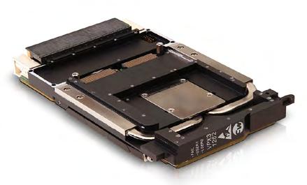
Figure 1 | Curtiss-Wright’s VPX3-1262 is a rugged 3U OpenVPX single-board computer designed for high-performance processing systems aligned to the Sensor Open Systems Architecture, or SOSA, Technical Standard.
integrated into vehicles more quickly is the C4ISR/EW [command, control, communications, computers, intelligence, surveillance, and reconnaissance/electronic warfare] Modular Open Suite of Standards (CMOSS). The standard addresses long-standing issues of interoperability and life cycle costs in military vehicle electronics. CMOSS is designed to streamline the integration of various subsystems and make future upgrades more cost-effective.
CMOSS is designed to streamline the integration of various subsystems and make future upgrades more cost-effective.
CMOSS aims to establish an open standard-based architecture for C5ISR/EW systems (with the extra C standing for “cyber”), says Shaun Fischer, division vice president for business development at Abaco Systems (Huntsville, Alabama). This approach has multiple benefits, including reducing size, weight, and power (SWaP) requirements; increasing interoperability; and accelerating the insertion of new technologies.
“Traditionally, they are all different subsystems with limited interoperability off the shelf,” Fischer explains. “Significant time and cost are spent to integrate such subsystems into a platform, and even more time and costs are typically required to add or change these subsystems after integration.”
CMOSS addresses these points by defining a reference architecture and set of standards. This standardization maximizes interoperability between subsystem components and enables upgrades without significant impact on other components.
John Ormsby, director of business development at Curtiss-Wright Defense Solutions (Ashburn, Virginia), highlights the cost-saving aspect of this approach. “CMOSS mitigates expensive replacement costs and the logistical impact of upgrades to resolve obsolescence and meet security and performance requirements to defeat the everchanging threats U.S. ground forces are facing on the battlefield,” he says. (Figure 1.)
CMOSS has been a requirement on BAE Systems Army programs for some time, notes Mark Brinkman, director of sustainment, BAE Systems (Falls Church, Virginia). “We have embraced this as a platform solution and engaged with industry leaders such as Curtiss-Wright, using their technology to implement our vehicle management systems and hosts for the required network-centric warfare applications used by our soldiers.”
Brinkman adds that while the full benefits of CMOSS are yet to be realized, they are expected to pay off in the future, particularly when dealing with subsystem obsolescence issues.
This approach has benefits beyond just the U.S. military, says Paul Mehney, vice president of strategy and communications at Thales Defense & Security (Clarksburg, Maryland). “We are embarking on efforts to develop technology that may be applicable to NATO and foreign security partner use as we see demand signals from coalition countries for CMOSS capability.”
Virtualizing radio capability through CMOSS will address SWaP challenges in both manned and unmanned platforms, he adds. Moreover, it will enable network transport security upgrades without requiring expensive hardware changes.
While CMOSS promises significant benefits for military vehicle electronics, its implementation is not without obstacles. Industry experts point to several key aspects that must be addressed for the standard to reach its potential.
Managing cost is always problematic with any new technology implementation. “The upfront cost of hardware that fits inside a common architecture approach is always the challenge,” Brinkman says.
Fischer agrees, noting that “the biggest challenge will be funding, as with most paradigm shifts.”
Artificial intelligence (AI) and machine learning (ML) solutions are rapidly becoming integral components of military vetronics systems, offering new capabilities and enhancing existing ones across many aspects of military vehicle operations.
“AI/ML technologies are critical for implementing and enhancing autonomous and semi-autonomous capabilities in nextgeneration vehicles,” says John Ormsby, director of business development at Curtiss-Wright Defense Solutions (Ashburn, Virginia). “[The technology] must support manned, optionally manned, and fully autonomous platforms all working in sync.”
The integration of AI/ML is driven by the need for faster and more efficient data processing, says Shaun Fischer, division vice president for business development at Abaco Systems (Huntsville, Alabama).
“AI/ML offers a potentially exponential acceleration in data processing at significantly higher volumes,” he says. “More sensors on a vehicle … require more processing at the edge where timing is critical and you can’t afford cloud-computing latency.” [Sidebar Figure 1]
Fischer points out that at present, the primary applications of AI/ML in vetronics focus on threat recognition, tracking in weapons systems, active protection systems, and autonomy features like obstacle avoidance in uncrewed systems. He also highlights the importance of sensor fusion, where AI/ML plays a crucial role in integrating data from multiple sources.
“Ultimately, the goal [of AI/ML] is to aid in decision-making by reducing the irrelevant data and focusing on the more critical data given the current contextual environment,” Fischer states.
Advancements in computing power have made it possible to implement ML algorithms directly in vehicle-mounted sensors, says Mark Brinkman, director of sustainment, BAE Systems (Falls Church, Virginia). “That means when we get a high-end sensor to integrate, such as a Teledyne FLIR EO/IR [electro-optical/ infrared] sensor, it has enough compute power in the sensor to run aided target recognition (AiTR) algorithms at or near the sensor, where those algorithms belong and not after the image has been compressed for distribution,” he explains. Such technology is enabled by better graphics processors (GPUs), Ormsby says: “[GPUs] are using a combination of AI/ML, image processing, and high-performance graphical generation in a high-density cost/power-efficient package.”
Real-world sensor applications are already taking advantage of this technology. “BAE Systems, in cooperation with KDA [Kongsberg Defense & Aerospace], can link and share sensor video streams, metadata, target information, slew-to-cue commands, and much more across a mobile ad hoc network (MANET) for a platoon (or higher) of vehicles and command operation centers – all in a matter of days,” Brinkman says.
This speed-up can make a big difference in battle situations, “effectively reducing the kill-chain timing from minutes to seconds,” Brinkman adds.
Looking to the future, Brinkman says he sees the potential for AI and large language models to support advanced logistics systems. He also emphasizes the growing importance of AI in uncrewed systems: “The speed and effectiveness of low-cost unmanned/remotely manned effectors necessitates an absolute need for an agile machine-in-the-loop algorithm to create an effective layered defense.” (Sidebar Figure 2.)
Paul Mehney, vice president of strategy and communications at Thales Defense & Security (Clarksburg, Maryland) points out a practical application of AI in vetronics: allowing vehicles to monitor themselves and adjust power distribution loads as capabilities are turned on and off. This capability demonstrates how AI can optimize vehicle performance and power management in real time.
“Significant amounts of vehicle data are being processed for predictive maintenance as well as sensor fusion for functions like threat identification, autonomy, etc.," Abaco's Fischer says. “In order to support the rapid evolution of such technologies, open standards are needed to create commonality and interoperability and enable rapid tech insertion at the subsystem level with minimal impact to other subsystems.”
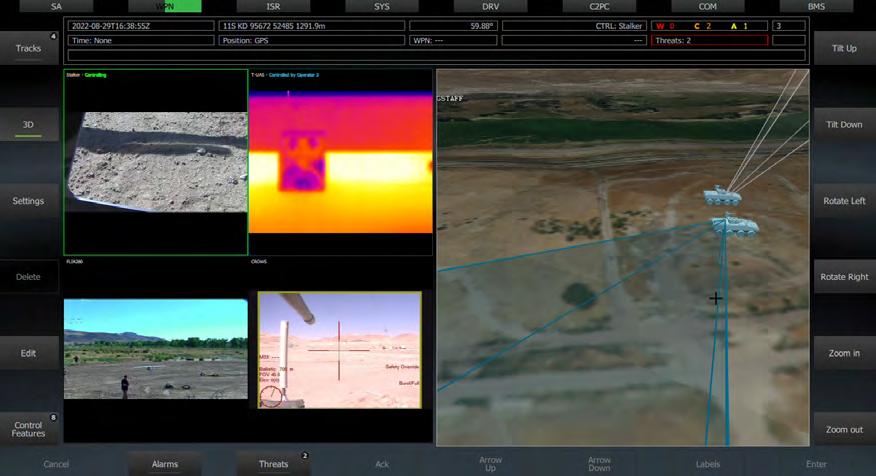
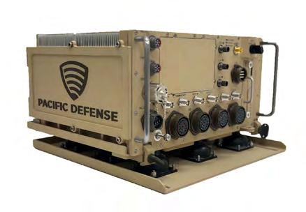
Figure 2 | Pacific Defense’s SX-3000 CMFF system. Thales collaborates with Pacific Defense and other providers as part of a CMFF team.
Cyber defense is an ongoing concern as well. “One of the major challenges is the implementation of certified cybersecurity enhancements to protect the computing and networking systems from emerging threats,” Ormsby says.
SDRs
The transition to software-defined radio (SDR) solutions is yet another element facing open architecture designers, Fischer adds. While running RF waveforms on open standards computing cards is relatively straightforward, he says that the real challenge lies elsewhere: “It’s connecting that card into the open standards architecture with the power amplifiers and radio heads –where the RF signals are transmitted and received – that still needs work,” Fischer says. He adds that Ethernetbased radio components, which form the backbone of CMOSS architectures, are still catching up in terms of robustness.
Mehney points out the complexity involved in CMOSS card development,
particularly when it comes to porting advanced secure waveforms. “Working with the government to define and prioritize requirements is key to delivering the right capability at the right time,” he says.
Those behind the CMOSS standard are also designing new ways to fit advanced electronics into vehicles, Mehney says. Thales is investing in CMOSS technology, with a focus on developing advanced secure CMOSS Mounted Form Factor (CMFF) card waveform technology for U.S. Army and Marine efforts, he notes.
“The government is actively designing and programming space in modernized tactical and combat vehicles to accept the CMFF chassis,” he says, noting that this approach makes it easier to upgrade vehicles without needing to completely overhaul their electronics. “The success of CMFF in part hinges upon not requiring expensive and complex vetronics upgrades.” (Figure 2.)
The Army created CMFF as way to reduce SWaP in vehicle systems. “[CMFF] capability is governed by the CMFF Reference Architecture which is guided and derived from technical requirements found in the CMOSS Interoperability Requirements Specification (IRS), specifically including the Sensor Open System Architecture (SOSA), Future Airborne Capability Environment (FACE), Vehicular Integration for C4ISR/ EW Interoperability (VICTORY), and the Modular Open RF Architecture (MORA),” according to the Leonardo DRS website. “CMFF systems and their payload cards are planned to be simple and intuitive to install, operate, and maintain by soldiers, and be resilient, reliable, and available to operate in all operational air and ground environments.”
CMOSS and CMFF will play an important role in consolidating mounted missioncommand solutions for the Army, particularly in upcoming combat platforms, Fischer predicts. “Common computing solutions based on open standards will become more prevalent in the newer combat platforms,” he says.
Mehney expects a “gradual potential reduction in size and power needs on the chassis, delivering a phased approach, gradually improving performance while reducing SWaP.” He also foresees the development of advanced waveforms for card integration, with a focus on NATO and coalition waveforms to enhance multinational interoperability.
He says he also believes there will be “continued development of advanced vehicle power and network management systems to better take advantage of CMOSS backplane capability.” MES
Time-sensitive networking (TSN), a more deterministic version of Ethernet, is helping designers of avionics, communications, and vetronics applications speed up data processing for real-time performance.
TSN is a particularly promising development, says Shaun Fischer, division vice president for business development at Abaco Systems (Huntsville, Alabama). With this technology, multiple subsystems at varying levels of safety and mission criticality can coexist on the same Ethernet network, greatly simplifying the network architecture and necessary equipment – “kind of a layer cake of transformation,” he says.
“TSN is a collection of IEEE standards,” according to a DornerWorks white paper titled “Time-Sensitive Networking: Transforming Military Networks for Enhanced Performance and Reliability.” “As the various TSN standards are ratified, many of them get added to the next version of IEEE 802.1Q. TSN updates to 802.1 are pending, and this is pivotal as it specifically addresses network management and Ethernet-based communication protocols. For example, IEEE 802.1Qbv enhances Ethernet by enabling time-sensitive networking, crucial for deterministic data transmission.”
By Dr. Daniel Kilfoyle
C5ISR Modular Open Suite of Standards (CMOSS) originated nearly 10 years ago as a concept within the U.S. Army RDECOM/CERDEC/I2WD office as CERDEC C4ISR/EW Hardware/Software Convergence. Eight years of subsequent research and development has created a comprehensive technology base that is currently being specified as a threshold requirement for U.S. Department of Defense (DoD) programs including CMOSS Mounted Form Factor (CMFF). With the potential for near-term disruptive innovation in both the acquisition and operational commands, broader awareness of CMOSS technology and manufacturing readiness levels is warranted.
The C5ISR Modular Open Suite of Standards (CMOSS) originated nearly 10 years ago as a concept within the U.S. Army RDECOM/CERDEC/I2WD office as CERDEC C4ISR/EW [command, control, communications, computers, intelligence, surveillance, and reconnaissance/electronic warfare] Hardware/Software Convergence 1 Eight years of subsequent research and development has created a comprehensive technology base that is finally being specified as a threshold requirement for U.S. Department of Defense (DoD) programs including CMOSS Mounted Form Factor (CMFF).
With more than 50 vendors offering CMOSS products, including single-board computers; network switches; software-defined radios (SDRs); position, navigation, and
timing (PNT) modules; chassis; and software – and following incorporation into the broader Sensor Open System Architecture (SOSA) Technical Standard – CMOSS is no longer just an Army experiment. Claims that CMOSS is not ready for use in programs of record are challenged on several fronts. All the technology components, hardware and software, of an integrated CMOSS system are available for acquisition.
Integrated CMOSS systems have been demonstrated in operationally relevant government-controlled environments repeatedly in recent years. Finally, the unique advantages of truly modular, multifunction radio frequency (MFRF) capability are increasingly recognized by defense leadership as necessary to fight and win in modern day conflicts, especially electronic warfare. CMOSS integration and technology readiness levels are such that evaluation in operationally relevant environments is warranted.
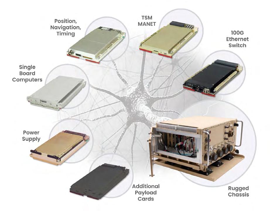
CMOSS is a specific and common modular open system approach (MOSA) comprising a suite of standards detailing various physical and logical interface definitions. Based on OpenVPX technology, a CMOSS system is a multicard chassis supporting a specific class of 3U VPX plug-in cards (PICs). Infrastructure such as networking, power, and reference timing are shared either as unique PICs or integrated into the chassis. Payload PICs missionize the system. (Figure 1.)
Key elements of CMOSS derive from two objectives. First, the modularity must enable a composable multifunction radio frequency (MFRF) system supporting the tactical communication, electronic warfare, command and related processing needs of military platforms. Second, any PIC must be replaceable with a like PIC from another vendor with little to no unique integration work required. CMOSS 3U slot and module profiles have been adopted by the SOSA Technical Standard, which is administered by The Open Group consortium2. The Modular Open RF Architecture (MORA) standard, also part of SOSA, defines data exchange with and control of SDRs. Vehicle Integration for C5ISR/EW Interoperability standard defines necessary platform, capability discovery, and timing/location services while remaining under the purview of the Army MOSA Management Office. Taken together, these detailed standards ensure the two objectives are met. (Note that references to CMOSS and SOSA are used interchangeably in this discussion.)
The SOSA Consortium has more than 180 member companies including government organizations, prime defense companies, and numerous smaller
non-traditional defense companies. Commercial off-the-shelf (COTS) ruggedized processing PICs are available from Concurrent, Kontron, Abaco, Curtiss-Wright, Annapolis Micro Systems, and Wolf Advanced Technology featuring, for example, modern Intel, Xilinx, and Nvidia processors including field-programmable gate arrays (FPGAs), general-purpose processors (GPP), and graphical processing units (GPUs).
Network switches, position/navigation/timing (PNT), and power-supply cards are available from an equally diverse set of vendors with advanced capability such as 100 GbE data rates and assured PNT in GPS-denied conditions. Infrastructure PIC vendors include Herrick Technologies, Curtiss-Wright, Concurrent, Annapolis Micro Systems, and Interface Concept. Chassis are available from Elma, LCR, Pacific Defense, Syracuse Research Inc., and Curtiss-Wright and others, although some are only suitable for development purposes. The chassis have robust chassis-manager solutions that use an Intelligent Platform Management Interface to manage the PICs with tier 1, 2, and 3 capabilities. MIL-STD-810H (environmental) and MIL-STD-461G (electromagnetic interference) evaluations have been accomplished for these components and integrated systems.
A rich ecosystem of software and firmware applications are available to missionize a CMOSS system. Key government software frameworks have been integrated with CMOSS systems including REDHAWK (open-source signals intelligence [SIGINT] environment), PHOTON (GPU-based toolset), Common Framework Environment (SIGINT/ EW software framework), and Mounted Mission Command Software. With modern container technology such as Docker and Kubernetes, applications can be reused on any CMOSS SBC PIC. Modern radios such as TSM6 and MN-MIMO are available as well as high-performance SDR-based electronic warfare PICs. More recently, SOSA aligned system managers for configuration, control and health monitoring have become available including task and resource managers, a diverse set of platform interfaces, security services, and intuitive, unified user interfaces. With a broad, mature technology base of hardware and software, CMOSS solutions may be composed for many RF sensing, communication, and analysis needs. The number and caliber of COTS suppliers also indicates a high manufacturing readiness.
CMOSS integration readiness
Integrated CMOSS systems (iCMOSS) have been successfully demonstrated in a broad range of relevant field events (Figure 2). Pacific Defense iCMOSS systems have been tried out at exercises including NETMODX, Cyber Quest, PNTAX, Bold Quest, and
Corvus Dawn. A system will be flown at Project Convergence 2025 and iCMOSS systems are slated for evaluation at the National Training Center and Muscatatuck Urban Training Center. In addition to the iCMOSS system field evaluations, the Office of Naval Research
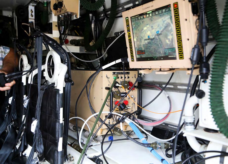
in partnership with the Naval Intelligence Warfare Center/Atlantic as well as the Air Force Life Cycle Management Center regularly evaluates iCMOSS systems in field events.
Importantly, iCMOSS systems have participated as part of the Army’s Integrated Tactical Network at these events through validated interfaces with Electronic Warfare Planning Management Tool, JICD 4.2, Open Mission Systems (OMS), Universal Command and Control Interface (UCI), JICD ELINT (JEL), ATAK, Cursor on Target, and Position Location Indicators. Additionally, new interfaces are being continually added to iCMOSS systems. During these events – during which a network of CMOSS systems simultaneously provides tactical communication, RF situational awareness, EW effects, and artificial intelligence (AI)-based intelligence analysis – prove that that the CMOSS vision first offered eight years ago is ready to be acquired and deployed in support of the warfighter.
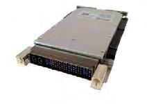
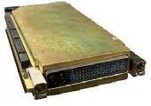
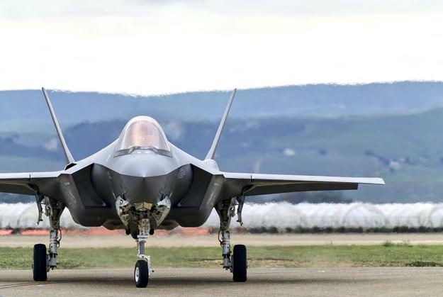
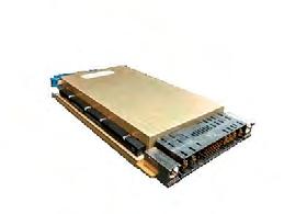
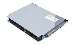
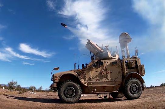
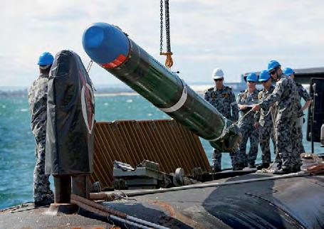
The warfighter needs CMOSS now
The U.S. Congress and the DoD have explicitly endorsed the use of the SOSA approach in future weapons systems. As the Tri-Service Committee, comprising the three service secretaries, noted in a 2019 memorandum, rapidly sharing information across domains and machines requires common standards. This Tri-Service memo called out the SOSA approach explicitly. The House Armed Services Committee (HASC) in 2021 recommended CMOSS should lead the charge and that the services should combine missions to achieve the benefits of CMOSS. HASC continued to directly promote SOSA in 2022 and 2023. By citing the common and specific standard of CMOSS rather than MOSA more gen erally, defense and political leadership recognizes that merely calling for MOSA is not sufficient and that MOSA must be the default. The 2024 Senate Armed Services Committee National Defense Authorization Act began recommenda tions for CMOSS with the statement, “Given the significant maturity of CMOSS technology,” and reaffirmed this position in its 2025 NDAA language.
While size, weight, and power (SWaP) reduction was C5ISR’s motivation eight years ago, the complex and evolving nature of peer adversary threats has highlighted additional transformative warfighter benefits:
› Converged, integrated missions: Synchronized systems and data, SWaP reduction, faster decisions
› Break vendor lock: Plug-and-play across vendors, data rights less important, dramatically faster upgrades
› Re-use for lower cost: Identicality of core, software-defined capability, modularity facilitates COTS
› Operations and maintenance savings: Simplified spares/ replacements, obsolescence-proof, common training
Notes
1 “CERDEC C4ISR/EW Hardware/Software Convergence,” 15 Mar 2016, Ben Peddicord, Chief, Intel Technology and Architecture Branch, CERDEC I2WD.
2 The Open Group: https://www.opengroup.org

Dr. Daniel Kilfoyle is currently serving as chief technology officer for Pacific Defense, specializing in non-kinetic warfare defense technology. His responsibilities include leading technology development with an emphasis on CMOSS and SOSA compliant EW products with embedded AI. He holds a doctorate in electrical and ocean engineering from the Massachusetts Institute of Technology.
Pacific Defense https://www.pacific-defense.com/

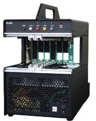

The debate over the perceived benefits and risks of requiring CMOSS and SOSA alignment for new weapons systems is lively and valuable, but the technology, integration, and even manufacturing maturity of CMOSS is now such that the benefits and risks can be directly assessed by warfighter evaluation. MES
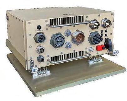
You can count on Elma to deliver reliable, rugged solutions wherever the mission takes you. We accelerate development and mitigate risk with platforms based open standards such as SOSA™ and OpenVPX. Talk to us about your next project.
With you at every stage!
Elma Electronic Inc.
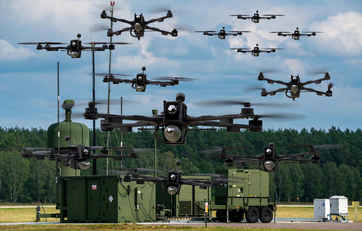
By Dr. Jason Adaska
Modern militaries face a new friend and foe: small uncrewed aircraft systems (sUASs). While these small craft enhance mission capabilities, they also pose serious threats when used by the enemy. The presence of sUAS swarms demands a shift to autonomous, artificial intelligence (AI)-driven countermeasures that optimize sensor resource management for smart realtime decision-making and situational awareness. Sensor resource management for the battlefield optimizes communications between systems enabling enhanced command, control, communications, computers, intelligence, surveillance, and reconnaissance (C4ISR); UASs and sUASs; position, navigation, and timing (PNT); electronic warfare (EW) capability; and connection to a larger defense network.
Today, military operations are being impacted on many technological fronts and small uncrewed aircraft systems (sUASs) have become game-changing tools, reshaping both tactical and strategic approaches. Their ability to carry out missions autonomously, supported by longer battery life and strong communications networks, has significantly increased their range, endurance, and flexibility. However, these technological
advancements have also provided adversaries with enhanced capabilities, enabling them to use sUASs for gathering intelligence, carrying out attacks, and even potentially spreading chemical, biological, or radiological agents, thereby posing a serious obstacle to operational readiness.
One particularly daunting threat is the emergence of sUAS swarms – large, coordinated groups of drones that work together to overwhelm or wear down targets through persistent ongoing attacks. These swarms have notable advantages over single or small groups of UASs, including their attritable nature, greater resilience, and high adaptability. When one or more of these small UASs are taken out, the remaining ones could share information, keep communication lines open, and theoretically
reassign mission objectives on the fly, adjusting to the changing battlefield conditions in real time.
Limitations of conventional counter-sUAS methodologies
Historically, counter-sUAS systems have relied on manual operation, providing operators with detailed sensor and weapon data – and a lot of it. This information glut not only complicates operator interactions but also slows down accurate decision-making, especially when facing sUAS swarm threats.
As autonomous drones coordinate their actions to achieve their goals, defensive forces must leverage increased decision support and automation of counter-sUAS resources to maintain an advantage. Sensor management must be closely tied to battle-management objectives, based on relevant data and timing. At the same time, battle-management support tools must consider the complex relationship between sensor control and weapon deployment.
Harnessing AI and automation: the path to operational dominance
The use of advanced algorithms and artificial intelligence (AI) has completely changed how we process and analyze the massive amount of data in sUAS swarms. With advanced pattern recognition, anomaly detection and predictive modeling, smart counter-sUAS systems can coordinate sensors and weapons to better detect, track, identify and engage threats. This gives decision-makers real-time, actionable intelligence when dealing with large groups of hostile drones.
Optimizing sensor resource management
Sensor resource management involves assigning sensors to optimize detection, tracking, and data fusion.
Traditional counter-sUAS systems often require humans to manage sensor tasking, leading to slowdowns and longer response times during attacks. Automated sensor management, on the other hand, enables software to handle the detailed sensor tasks while human operators focus on high-level guidance and oversight, making the whole process more efficient.
Automated sensor resource management has several advantages. First, it frees up operators to focus on higher-level planning and tactics in complex scenarios. It also enables rapid decision-making against multiple, dynamic threats by intelligently determining sensor dwell times and target-revisit intervals. This approach reduces risk to forces –who may be operating from the ground or in the air – by deploying automated sensing assets on unmanned robotic platforms, away from personnel. Additionally, it enables automated target cueing, where optical systems are directed based on radar-detection data as targets become visible, all without human intervention. Finally, automated sensor resource management supports low-signature mission concepts where systems scan for threats and activate radar resources only when needed, reducing the threat to those who may be below or above while maintaining effective counter-sUAS operations.
With the help of AI and algorithms for coordination, automated sensor resource management enhances the accuracy and adaptability of defense operations, ensuring optimal utilization of sensor assets and intelligence.
Optimizing weapon-target assignment
In battle management, it is important to be strategic in deciding which weapons to use against which targets and at what time. The weapon-target assignment “problem” involves figuring out the best way to distribute different weapons systems to targets in order to maximize the damage inflicted on the enemy. In scenarios with multiple threats, this decision-making can be a challenge for humans, who must quickly assess how to engage within seconds to minutes.
Automation in battle management enables systems to assess all available resources and prioritize actions based on the mission’s goals, rather than just responding to


Power & EMI Inductors
Pulse
Multiplex Data Bus
Pulse Transformers Plug-In units meet the requirements of QPL-MIL-PRF 21038/27. Surface units are electrical equivalentsof QPL-MIL-PRF 21038/27.
DC-DC Converter
Transformers
400Hz/800Hz
Power Transformers 0.4 Watts to 150 Watts. Secondary Voltages 5V to 300V. Units manufactured to MIL-PRF-27 Grade 5, Class S (Class V, 1550C available).


the most obvious threat. It enables real-time, evolving development of battle plans, using cutting-edge techniques in combinatorial optimization and AI to support tactical decision-making. These plans are adaptive, automatically updating as new intelligence is gathered and threats are identified, with sensor and weapons resources dynamically reassigned as needed. The system also enhances weapon-target assignment by leveraging the unique capabilities of each asset to achieve the best overall solution, integrating models for sensors, weapon-threat geometry, ballistic-missile trajectories, and interceptor guidance models. Moreover, such automation enhances strategic reasoning against sUAS adversaries, developing sophisticated responses to drones that actively adapt to countermeasures.
By automating key aspects of battle management, commanders can speed up combat operations and maneuvers. Decision speed aids in making the best decisions about which targets to hit and when to provide fire support, which is changing how warfare is conducted as information becomes more abundant. (Figure 1.)
sensors in battle management
Drone swarms generate an overwhelming influx of information, leaving operators inundated with data and insufficient time for effective decision-making. By implementing a solution that coordinates the management of sensor and weapons resources towards a unified outcome, forces can transform vast quantities of data and an overwhelming array of options into actionable intelligence.
When sensor resource management aligns with battle-management objectives, the combined capabilities exceed what each can achieve alone. Together, they ensure effective engagement and real-time damage assessment in complex, multithreat situations. They also make the most of limited sensor and weapons resources by tailoring responses to meet mission needs and support overall strategic goals. This teamwork lightens the load on operators in fast-paced environments by automating simpler tasks while still keeping the human-control aspect flexible. Using AI and optimizationdriven decision support helps battle managers make quicker, smarter decisions and adapt to the most effective course of action in real time.
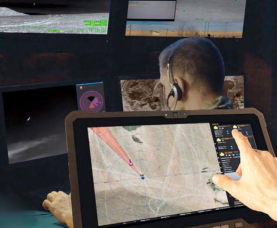
The future of counter-sUAS operations
The exponential growth of sUAS swarms and the increasing complexity of multithreat scenarios necessitate a fundamental reevaluation of counter-sUAS methodologies. Traditional methods, with their reliance on manual processes and siloed information systems, are not able to effectively tackle the challenges of synchronized, autonomous drone formations.
However, by using AI, automation, and advanced algorithms, modern countersUAS systems can seamlessly integrate sensor management and battle management, allocating sensors and weapons more efficiently towards a common goal. This integrated approach not only improves situational awareness and engagement capabilities but also reduces the mental load on operators, enabling quick and informed decisions in fast-paced environments.
As the battlefield continues to change, adopting AI and algorithm-driven counter-sUAS capabilities is essential for maintaining tactical superiority and protecting forces. With intelligent automation, military forces can effectively counter the threats posed by drone swarms, ensuring they maintain critical primacy at the tactical edge. MES

Dr. Jason Adaska is the vice president of Command and Control (C2) Systems at Numerica and leads a multidisciplinary team responsible for Numerica’s Mimir C2 software platform. Jason has more than 16 years of professional experience in advanced algorithms research, commercial software development, and technical leadership and has deep technical expertise in applied probability, optimization and modern AI/ML techniques. Jason holds a doctorate in applied mathematics from Harvard University and bachelor’s degrees in electrical engineering and computer science from Cornell University.
Numerica • https://numerica.us/

LCR products enable the fullest capabilities of the best aspects of VPX and SOSA aligned system architectures. Integrated systems, chassis, backplanes and de velopment platforms that help streamline the journey fr om early development t o deployment.
L ook to LCR to realize what’s possible in demanding envir onments across a wide range of defense applications.


By Jerry Gipper, Editorial Director, VITA Technologies
Note: This update is based on the results of the May 2024 VITA Standards Organization (VSO) meeting, held in Frederick, Maryland, and hosted by DRS Technologies. Contact VITA if you are interested in participating in any of these working groups. The full reports can be accessed at www.vita.com/StandardsUpdates. Visit the VITA website (http://www.vita.com) for details on upcoming VITA meetings.
ANSI accreditation
Accredited as an American National Standards Institute (ANSI) developer, VITA provides its members with the ability to develop and promote open technology standards.
The following standards have recently been ANSI- and VITAapproved via public VITA consensus ballot:
› ANSI/VITA 67.3-2023, Coaxial Interconnect on VPX –Spring-Loaded Contact on Backplane
› ANSI/VITA 87-2024: MT Circular Connectors - Type 1
› ANSI/VITA 91-2024: Connector for Higher Density VITA 46 Applications
All published standards are available for download by VITA members and are posted at the online VITA Store for purchase by nonmembers.
VSO study and working group activities
Standards within VITA may be initiated through the formation of a study group and developed by a working group. A study group requires the sponsorship of one VITA member, while a working group requires sponsorship of at least three VITA members.
Several working groups have current projects underway. Here’s a roundup of these projects:
Draft/VITA 46.31: Higher Data Rate VPX –Solder Tail in Blind Via
Abstract: This document defines a standard for a VPX connector that supports higher data rates, to at least 25 Gbaud – for protocols such as 100GBASE KR4 Ethernet and PCIe Gen 4. The connectors feature a short solder tail intended to be soldered into a blind via. The higher-data-rate connectors compliant to VITA 46.31 are intermateable to legacy VITA 46.0 connectors and follow the same form factor.
Status: VITA 46.31 is approved for VITA Standard Draft Trial Use available to VITA members and is available at the VITA online store. The plan is to complete the ANSI process and release once further connector qualification testing is completed.
Draft/VITA 47.1-2023: Common Requirements for Environments, Design and Construction, Safety, and Quality Standard
Abstract: The VITA 47 group of standards defines environmental, design and construction, safety, and quality requirements
for commercial off-the-shelf (COTS) plug-in modules intended for ground and aerospace applications. VITA 47.1 addresses requirements common across the VITA 47 group of standards. This revision updates the operating and non-operating temperature requirements, adds cold wall requirements for VITA 48.2 conduction-cooled plug-in modules, and adds additional temperature cycling and cold start requirements.
Status : Multiple additions and changes are being made to improve the usability of this standard. Revision draft is in review.
Draft/VITA 48.5-R2010 (S202x) Revision:
Mechanical Standard for VPX REDI AFT Cooling –Multi Pitch Air Flow Through Cooling, 1.52” Pitch
Abstract: This standard establishes the design requirements for an air-flow-through (AFT) cooled plug-in unit. Unlike ANSI/VITA 48.1, which uses cooling air impinged directly upon the components and circuit boards, this plug-in unit uses a compact core heat exchanger located within the central heat sink of the unit and uses a military/aerospace-qualified seal on the inlet and outlet of the heat exchanger eliminating any direct air contact with the PWB and components. This seal also provides ability for chassis-level flow balancing, allowing plug-in units with different cooling requirements in the same chassis. This standard defines both a 3U and 6U form factor in various pitches and air inlet sizes, providing a high-performance thermal solution for existing or new CCA [conduction-cooled assembly] designs.
Status: This standard is open for revisions to more clearly define some of the rules and recommendations. Verification method notation being added.
Draft/VITA 48.9: VPX AFT Cooling – Retractable Seals
Abstract: This standard defines an air-flow-through module format, 3U and 6U, that uses retractable module rack seals to strengthen module-chassis seal, simplifies design by eliminating tapered module and chassis features, and eases migration of existing CCA designs to an air-cooled module format.
Status: Working group is developing a draft document.
VITA 51.4: Reliability Component Derating
Abstract: The goal of this working group is to develop a new component derating standard.
Status: This working group has joined forces with the IEEE to jointly develop this standard under IEEE-2818. The working
group is reviewing comments on draft from public consensus ballot through IEEE.
VITA 65.x: OpenVPX System Standard
Abstract: The OpenVPX standard uses plug-in module mechanical, connectors, thermal, communications protocols, utility, and power definitions provided by specific VITA standards to define a series of slot, backplane, module, and standard development chassis profiles.
Status: The working group is adding additional profiles to this standard.
ANSI/VITA 67.3-2020: VPX: Coaxial Interconnect on VPX, Spring-Loaded Contact on Backplane
Abstract: The VITA 67.3 standard defines an open standard for configuration and interconnect (within the structure of VITA 67.0) enabling an interface compatible with VITA 46 containing multiposition blind-mate analog connectors with coaxial contacts, having fixed contacts on the plug-in module and spring action on the backplane.
Status: Now open for modifications to SMPS interface.
VITA 68.x: Reference SI Model Standard for Gen 4 and Higher Speeds
Abstract: This family of standards documents a reference model approach for OpenVPX signal-integrity compliance at baud rates above 10.3125 Gbaud. It defines reference OpenVPX plug-in module and backplane s-parameter models that can be used to create end-end OpenVPX reference channels in conjunction with reference VPX connector and device s-parameter models.
Status: The working group is addressing signal-integrity compliance for Gen4 and higher speeds for VPX and making general updates to remove errata from previous releases.
Draft/VITA 78.0-2022 Revision: SpaceVPX System
Abstract: This document describes an open standard for creating high-performance fault-tolerant interoperable backplanes and modules to assemble electronic systems for spacecraft and other high-availability applications. Such systems support a wide variety of use cases across the aerospace community. This standard leverages the OpenVPX standards family and the commercial infrastructure that supports these standards.
Status: The standard is open for revisions to the 2022 edition.
Draft/VITA 86-2019 Revision: High Voltage Input Sealed Connector Power Supply
Abstract: This standard defines an environmentally sealed connector pair which is compatible with the backplane footprint as defined in VITA 62.0 for 3U power supplies operating in harsh environments operating off of a high-voltage input.
Status: The standard is open for revisions.
Draft/VITA 89-202x: MT Circular Connectors – Type 2
Abstract: The VITA 89 MT circular connector standard defines a standard for circular connectors with optical MT. Circular connector shells are compliant to MIL-STD-38999. MT offer options for as many as 48 fibers per MT and for physical contact or lensed MT.
Status: VITA working group to develop a new standard for circular connectors with optical MT. Working group is developing draft document.
Draft/VITA 90.x: VNX+
Abstract: The VITA 90.x (VNX+) family of standards builds on the foundation established by VITA 74 VNX. VNX+ significantly increases performance and system versatility beyond VITA 74, while following its mechanical framework.
Status: Working groups are developing drafts for each level of VNX+.
Draft/VITA 92: High Performance Cable –Ruggedized 10 Gbaud Bulkhead High Speed, D- Sub, Rectangular Connector for Copper Cables
Abstract: This standard defines a rugged standardized 10 Gbaud interconnect system with a high pin count and highdensity, lightweight, rectangular connector (meets MIL-DTL24308 physical envelope) for I/O. It can support multiple highbandwidth protocols and power while optimizing SWaP [size, weight, and power] benefits in smaller systems with limited panel space availability.
Status: The working group is reviewing a draft document.
Draft/VITA 93.x: QMC – Small Form Factor Mezzanine
Abstract: This standard defines a small form factor mezzanine (SFFm) that is significantly smaller than XMC with host and I/O interface connectors. The host interface supports modern high-speed serial fabrics. The I/O interface supports either front-panel or backplane I/O. Multiple SFFm modules can be installed on various carrier-card form factors including 3U/6U Eurocards (VPX, cPCI, VME, etc.), VNX+, PCIe expansion cards, and others. It is suitable for deployment in commercial, industrial, space, or military-grade rugged environments with aircooled or conduction-cooled formats.
Status: The working group is developing draft documents.
Draft/VITA 94.0-2024xNew: Power Distribution Plug-In Module
Abstract: This standard provides requirements for building a power distribution plug-in module with digital controls that can be used in a VPX chassis. The plug-in module will fit within the standards envelope defined for VPX modules in the VITA 48.x standards.
Status: Working group is developing a draft document.
Draft/VITA 100.0-2024xNew: VITA 100 Base Standard
Abstract: The VITA 100 suite of standards is an evolution to OpenVPX, VPX, and related mechanical standards while embracing a paradigm shift in technology and capability with at least double the pin density, speed, and power for electrical contacts. This document, the VITA 100.0 Baseline Standard, outlines the essential electrical and system architecture for the VITA 100 ecosystem.
Status: Working group is developing draft documents.
For a complete list of VITA standards available for purchase and their status, go to https://www.vita.com/Standards.

By James Campbell
Image- and video-capture technologies have advanced significantly over the past decade, greatly benefiting warfighters and those on ISR [intelligence, surveillance, and reconnaissance] missions. Modern EO/IR [electro-optic/infrared] systems now demand extremely fast data transfer due to high-resolution focal plane arrays (FPAs). EO/IR systems are typically mission-critical and difficult to repair once deployed. One solution: FPGAs [field-programmable gate arrays] can be the backbone to support the design, development, and testing of EO/IR electronics, enhancing the capabilities and reliability of EO/IR systems for warfighters and ISR missions.
When designing a new modern EO/IR [electro-optic/infrared] system for use on the battlefield and for ISR [intelligence, surveillance, and reconnaissance] missions, component emulation and testing shortens development by enabling changes to functionality without needing to first build the system. The emulation device outputs signals just as the actual device would; it likely also takes inputs to control its operation. The test equipment takes input signals, just as the actual device would, to characterize the behavior of the component being tested.
The main focus is on emulating either the focal plane array (FPA) or readout integrated circuit (ROIC) to test the FPA electronics or vice versa. Emulation facilitates parallel development, eliminating a common scheduling bottleneck.
Modern EO/IR systems generate high data rates and have large pixel counts. Fieldprogrammable gate arrays (FPGAs) are preferred in emulation and test systems for two primary reasons: First, because FPGAs can be programmed to support different FPAs; and second, because FPGAs offer deterministic, no-jitter behavior. (Figure 1.)
These features ensure that an FPA/ROIC or FPA electronics device connected to a programmed FPGA behaves as if it were connected to the actual hardware. In other words, the electronics that “catch” the signals can’t tell that the electronics that “pitch” the signals are in fact using FPGAs to emulate the subsystem. The two main development paths when using FPGAs are prototype boards or commercial off-theshelf (COTS) modules. Each of these has its own pros and cons for use.
Traditionally, FPGA prototyping boards, also known as development or evaluation boards, are used due to their state-of-the-art hardware specifications, use of the latest FPGA models, and low cost. Using protoboards for FPA testing requires extending these standalone devices to include, for example, the ability to:
› Interface to device under test I/O via hardware and electrical connections
› Store and recall the large amounts of data contained in images
› Support of ancillary test equipment, such as DMMs [digital multimeters] and SMUs [source-measurement units]
› Define and run test procedures
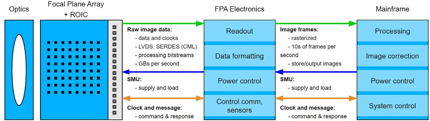
So while protoboards have a low initial cost and offers maximum customizability, the time and cost to develop and integrate them into a complete test platform is significant. Another aspect to consider with protoboards is their typically short life cycle, since prior protoboard models are displaced by newer ones with the introduction of new FPGA models.
COTS equipment can offer many of the capabilities that the protoboard lacks. For example, COTS standards offer:
› Multilane PXIe buses for high bandwidth and multiple-channel byte streams
› Synchronization between FPGA modules for large numbers of channels
› RAID [redundant array of independent disk] hardware for image-data storage/ recall at the data rates
› Tight integration with other instruments like DMMs or SMUs
› Test application development software platforms such as TestStand and LabVIEW
Further, COTS systems tend to have a longer life cycle than protoboards because the COTS vendors want to recover their development costs. This longevity is especially important for production testing, where the vendor of the FPA electronics will want a test system which can be purchased and supported for as long as they will be selling their product.
In the past, the major concerns about COTS systems have been twofold: Is the speed of a COTS system fast enough? And is the customization required based on COTS hardware nearly as large as a custom solution based on a protoboard?
These concerns have been mitigated in recent years mainly due to the fast multilane PXIe buses and emerging common electrical signal specifications – such as LVDS [low-voltage differential signaling] and current-mode logic (CML) serializer/deserializer (SerDes) – which reduce the need for so much customization. These technical advancements have led to systems built on COTS equipment that benefit military and government EO/IR imaging systems by accelerating development, easing deployment, and ensuring reliable products.
The next stage in the development of test and emulation systems for EO/IR FPA electronics leads to systems that heavily leverage COTS products into a ready-to-go instrument. Such an instrument would contain all the necessary hardware and software for emulating and testing, again, without the need for so much electronics integration.
Such instruments can be upwards of 80 percent complete for emulation and testing of FPA electronics, with the remaining customization driven by the unique requirements of every FPA, such as channel counts, connector and digital signal types, and byte stream packing. An example is the AEDIS platform, which can help accelerate FPA and downstream electronics testing by speeding up development times and significantly
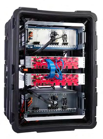
for testing FPAs and/or the downstream interface electronics. It is a pre-built system of both hardware and software components to meet the needs of custom FPA interface protocols.
reducing risk compared to an in-housedeveloped platform. (Figure 2.)
Whether using a protoboard or a COTSbased instrument, FPGAs can be the backbone to support the design, development, and testing of EO/IR electronics, enhancing the capabilities and reliability of EO/IR systems for warfighters and ISR missions. MES
James Campbell is co-founder and principal engineer of Viewpoint Systems. He is passionate about engineering automated measurements. Jim holds a Ph.D. in electrical engineering from the University of Rochester.
Viewpoint Systems https://www.viewpointusa.com/
Managing supply chain, obsolescence, and counterfeit parts
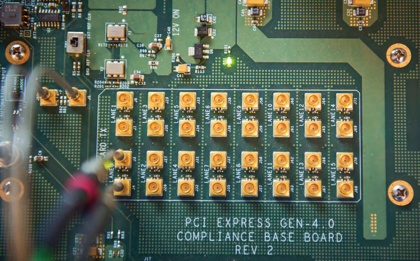
By Drew Thompson
Component obsolescence and end-of-life (EOL) issues can present major obstacles in the electronics supply chain. Designers and companies in the military-electronics arena can overcome these serious challenges by implementing proactive strategies such as obsolescence analysis and forecasting to identify at-risk components early. Also useful: second-sourcing as a way to identify alternative components during the design process. Establishing strong relationships with different suppliers is crucial to secure advance notice and support for transitions, maintain strategic inventory levels of critical components, and design products with flexibility to adjust as required. Additionally, investments in continuous redesign and qualification processes ensures that products remain up to date and compliant with industry standards and regulations.
Component obsolescence and end-oflife (EOL) are significant obstacles in the larger military-electronics supply chain. While hardly a new phenomenon, the rate at which electronic components reach EOL and obsolescence has dramatically increased over the past several years. The current state of the electronic component market, and the state of the supply chain overall, make it much more difficult to source even nonobsolete components. The acceleration of EOL announcements along with widespread trade disruptions across the globe has created a truly volatile environment.
Owing to the relatively long product life cycles required by the military and aerospace verticals the supply chains for these applications are even more susceptible to disruption.
To effectively meet the challenges in the current market, it is crucial to understand the root causes of product and component obsolescence and the factors that drive EOL. The insights gained from diagnosing these causes enable manufacturers to employ different strategies and practices to mitigate the effects of obsolescence, EOL, and various other supply chain disruptions.
The primary factors impacting obsolescence Before beginning to mitigate their effects, it is crucial to understand the root causes of component and product EOL and obsolescence. Broadly, the factors driving EOL and obsolescence can be categorized into: technological, economic, and regulatory. (Figure 1.)
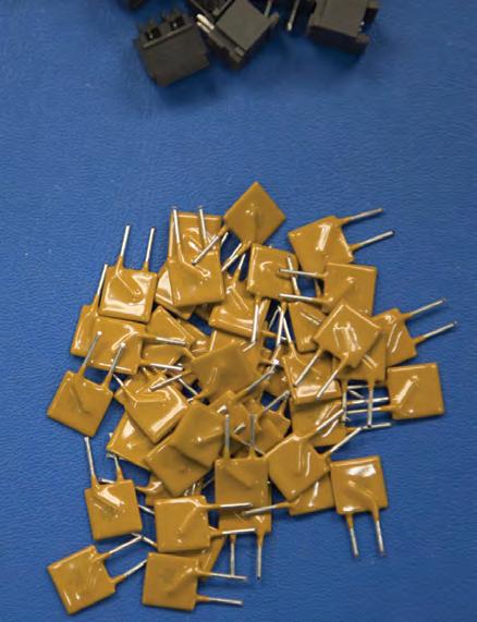

for both manufacturers and consumers in terms of component sustainability and legacy product support.
Technological: Electronics and their components are far and away the most rapidly advancing products across markets. Continuous research and development lead to frequent introductions of novel technologies while semiconductor, processor, and memory innovations rapidly surpass the capabilities of older components. Further, as electronics expand into new verticals, a wide degree of specialization must occur. To use military verticals as an example, the adoption of SWaP-C2 [size, weight, power, cost, and cooling] pushes manufacturers to improve and make nearly every component more efficient. Conversely, military hardware manufacturers also must support a considerable number of legacy products.
Economic: Newer components offer notably higher processing speeds and capabilities, making older components unable to meet evolving performance requirements. As manufacturers gain more experience with new techniques, it often becomes cheaper to manufacture these newer, more advanced products than older models.
Technological advancements drive a constant cycle of innovation and obsolescence, pushing older components to EOL as more advanced and efficient technologies emerge. This cycle is crucial for progress but creates challenges
Regulatory: The regulatory and compliance factors driving EOL and obsolescence are fairly straightforward. Wider and more comprehensive environmental laws and regulations [that affect the use of substances in products sold into the European market] – such as RoHS [Resistance of Hazardous Substances], WEEE [Waste Electrical and Electronic Equipment], and REACH [Registration, Evaluation, Authorization, and Restriction of Chemicals] – ban the use of certain chemicals, materials, or manufacturing processes used in older components. The same applies for safety and standards compliance: New standards can suddenly make older components and processes noncompliant and deemed unusable.
The dynamics of the electronic component supply chain influence the overall market, affecting production costs and product availability. The supply chain for electronic components is highly globalized, with different stages of production often spread across various countries. While this widened production helps in cost reduction, it does increase vulnerability to geopolitical and logistical issues. This reality is especially true for areas and regions that produce highly specialized components or products. (Figure 2.)
Natural disasters are among the most common and visible supply chain disruptions. One of the most recent examples was the 7.4 magnitude earthquake in Taiwan on April 3, 2024. Although Taiwanese manufacturers expect only minor impacts on their production, the event illustrates the inherent vulnerability of the electronic component supply chain. Taiwan is responsible for manufacturing more than 90% of the world’s most advanced semiconductors, and roughly 60% of the total semiconductor market.
In May 2024, in coordination with acts to increase U.S.-based component and semiconductor manufacturing, the U.S. government announced widespread tariffs on Chinese imports. Among the tariffs is a 50% duty on semiconductors, set to begin in 2025. While one of the main goals of this import tariff is to protect and accelerate U.S. semiconductor manufacturing, it has accelerated a supply-chain shift in Taiwan, thus concentrating more of the global manufacturing into a single geographic location. The
Managing supply chain, obsolescence, and counterfeit
concentration of manufacturing has essentially created a single point of failure for the entire semiconductor manufacturing industry.
The electronic component supply chain’s complexity and globalization make it both efficient and vulnerable. Effective management and risk-mitigation strategies are essential for maintaining market stability and competitiveness in the face of potential disruptions.
Obsolescence analysis and forecasting can largely improve the electroniccomponent supply chain by identifying and managing the risks associated with the life cycle changes of components, products, or systems. Such a move involves monitoring the status of components, forecasting their EOL dates,
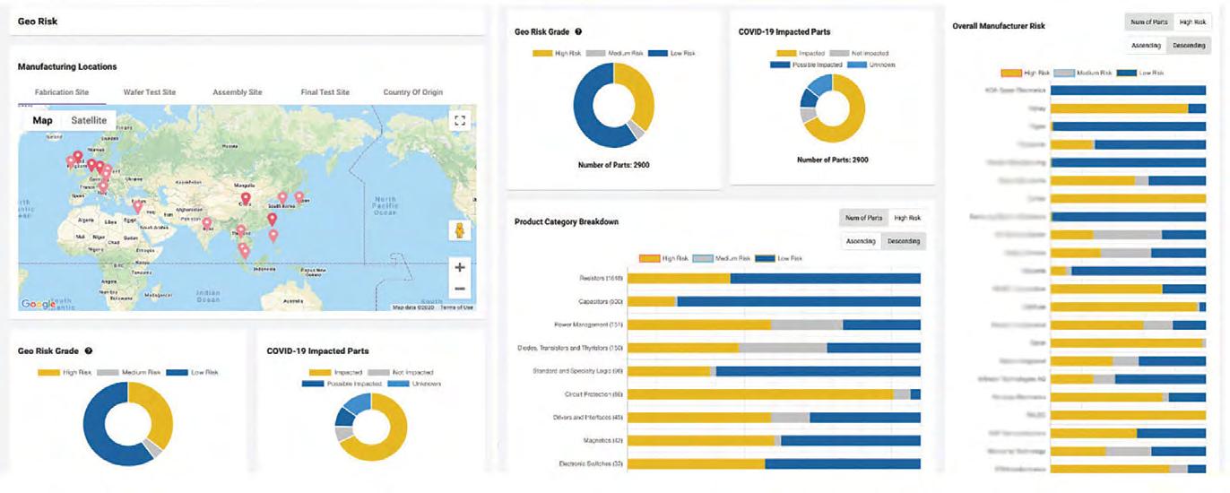
and implementing strategies to mitigate the impact of obsolescence, such as sourcing alternative components, proactively planning for redesigns, or managing inventory levels. A wide variety of software solutions and obsolescence databases are now available to aid in this process. (Figure 3.)
With a more informed and data-driven obsolescence forecast, manufacturers can more easily take steps to ensure supply-chain resilience. By fully understanding component life cycle status, manufacturers are better able to manage relationships with suppliers, enabling the identification of alternative components and suppliers in advance and ensuring a more resilient supply chain.
There are many benefits to forecasting and supplier management beyond fulfilling the need for components. By managing obsolescence effectively, manufacturers and designers can better allocate resources to focus on innovation and product development, rather than devoting resources and manpower to legacy component issues. All of this combines to create a smoother transition to newer technologies, minimizing disruption to ongoing projects and product lines.
If, however, a manufacturer is unable to transition a product away from obsolete parts, there are still a few viable alternatives to address for EOL components and products. One such option is a legacy equipment manufacturer (LEM). An LEM is a type of specialized electronics producer that manufactures, supports, and services embedded-board level products after an OEM is no longer able to support the product and EOL notices have been issued. LEMs offer an effective stopgap to support legacy and EOL products but should not be viewed as a long-term solution. Generally, the lead times associated with LEM manufacturing are longer and the finished product costs are higher.
Proactively combating obsolescence and EOL
Component obsolescence and EOL present major obstacles in the larger electronics supply chain, which can be a critical problem in the military electronics sector. These challenges can be overcome by implementing strategies
such as obsolescence analysis and forecasting to identify at-risk components early, together with second sourcing to identify alternative components during the design process. Establishing strong relationships with different suppliers is crucial to secure advance notice and support for transitions, maintain strategic inventory levels of critical components, and design products with flexibility to adjust as required. Additionally, investing in continuous redesign and qualification processes ensures that products remain up-to-date and compliant with industry standards and regulations. MES

Drew Thompson is a technical writer and marketing specialist for Sealevel Systems, the leading designer and manufacturer of embedded computers, industrial I/O, and software for critical communications. He holds an M.S. in global studies and international affairs from Northeastern University. Thompson can be reached at drew.thompson@sealevel.com.
Sealevel Systems • https://www.sealevel.com/
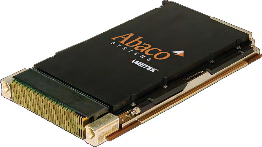
Discover Time Sensitive Networking (TSN) Enabled Computing Solutions for Next Generation Ground and Future Vertical Lift Systems. DISCOVER ABACO.


By Rob Harrill
Military aviation depots must overcome many hurdles to maintain operational readiness and fleet sustainment. Aircraft maintenance officers in the U.S. military constantly face mounting costs, antiquated support equipment, and challenges around training and keeping maintenance personnel. On top of these challenges, maintenance crews do not know what components of the aircraft need to be repaired or replaced until they open it up, making it virtually impossible to plan ahead for parts and personnel. All of these factors can substantially impact the mission readiness of aircraft fleets. Deployment of predictive modeling software can have a major impact on optimizing facilities, equipment, workflow, and assets in dynamic environments.
For those not familiar with military aircraft maintenance depot operations, here’s a short explanation: Each aircraft arriving at a depot requires its own unique maintenance. This reality is based on the environments it has been exposed to as well as its operational history. In other words, where has this aircraft been flying, what were the environmental conditions, and how long has it been in service? This data is not always readily available to the depot, which creates uncertainty. Combine that with the fact that most components of an aircraft don’t have sensors that can signal potential failures or point out where stresses may warrant repair or replacement.
Needless to say, this makes it very difficult to plan and execute for an arriving aircraft. Now multiply that one aircraft by hundreds of arriving aircraft across all maintenance depots annually, and it is easy to see that optimization is a huge ongoing readiness and sustainment problem.
This problem is further complicated by the fickle nature of global events. Geopolitical shifts can impact military operations with a potential need for rapid deployment and a heightened pace of operations. This uncertainty negatively impacts the ability to make informed decisions and further stretches already thin resources. The current processes simply can’t account for all of this uncertainty which frequently causes delays. These delays then create a domino effect across the entire maintenance chain. As
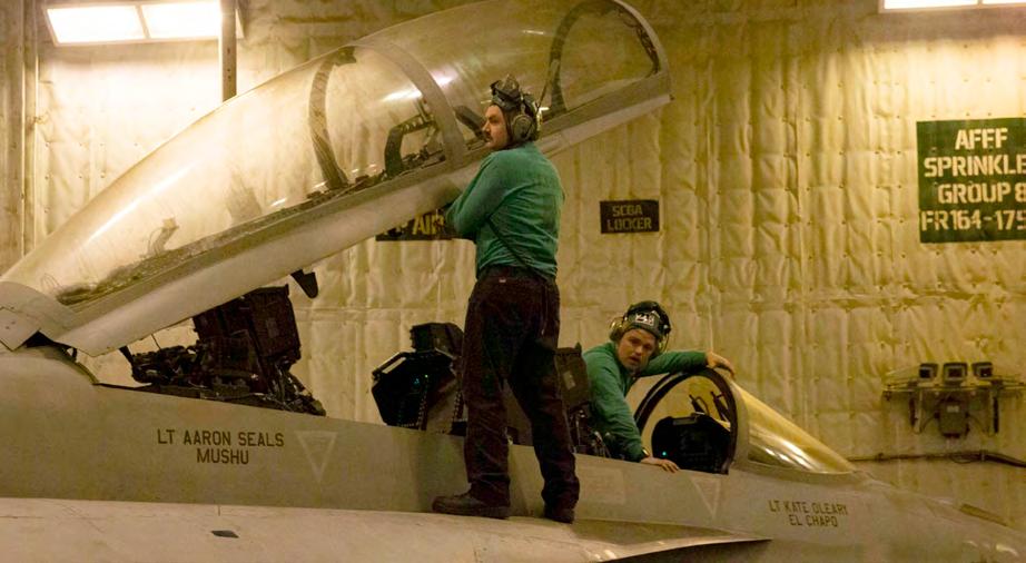
such, the industry needs to consider adopting innovative technology to help effectively implement maintenance and make sure fleets are maximizing readiness.
One answer to overcoming the uncertainties facing military depots is to deploy decision analysis technology. This technology can help depots more accurately forecast maintenance and staffing decisions even with the potential for extreme uncertainty. With advanced modeling software, it’s possible to predict maintenance needs and outcomes for numerous scenarios. This scenario-based software enables users to test decisions and have visibility into how each decision will impact the process prior to allocating resources. Each step in the aircraft maintenance process has a range of possible outcomes. Leaders and workers alike can analyze these different simulations to account for uncertainty and thus provide more reliable forecasts for maintenance schedules.
In military depots, this approach helps with forecasting and planning to reduce induction wait times from many months to weeks or even days. These moves can increase aircraft readiness and mitigate time lost to out-of-service aircraft waiting on parts and/ or personnel. (Figure 1.)
Shorter maintenance cycles are another crucial piece to ensuring fleet mission readiness. The main roadblocks here are procedural inefficiencies and the resistance of large organizations to change. However, technology and best practices can more than overcome these challenges.
Analyzing current maintenance procedures makes it easier to identify and eliminate any inefficiencies that may have surfaced. For instance, assessing hourly-based inspections across multiple locations can reveal variations in the required person-hours expended for each event. Prioritizing efficiency and standardizing procedures can reduce inspection length – saving both time and resources.
Implementing predictive “condition-based maintenance” software is another way to reduce maintenance cycle times. These systems use sensors and data analytics or sensorless digital twins to predict if and when a component will fail, enabling proactive maintenance before a problem surfaces. The condition-based maintenance approach is much more accurate than the calendar-based maintenance approach, thereby reducing downtime and extending the life of many different aircraft components.
Deploying predictive modeling software can have a sizable impact on optimizing facilities, equipment, workflow, and assets in dynamic environments. Developing a digital
twin of the entire operational process enables comprehensive optimization through simulation.
For example, models can examine the usage and availability of resources, pointing out any potential bottlenecks or other issues. Using modeling guarantees the right people, facilities, parts, and tools are available, reducing delays and improving efficiency.
Moreover, predictive models can improve overall fleet readiness for other operations, such as helping training commands successfully manage flighttraining operations across multiple bases. Optimizing aircraft and training schedules leads to significant improvements in pilot production output, ensuring a steady supply of personnel remains mission-ready.
The adoption of advanced analytics is critical to the future of military fleet maintenance. These technologies provide a clear snapshot into the challenging parts of aircraft maintenance and help deliver more precise forecasting, better resource allocation, and significant reductions in maintenance cycle times. Tools like these help military aviation depots keep the necessary high level of operational readiness. MES

Robert Harrill is the Vice President of Operational Optimization Solutions for Lone Star Analysis. Previously he served as the Director of Maintenance Repair and Overhaul (MRO). Harrill has over 40 years in the defense industry, with 26 of those years serving as active duty in the U.S. Navy as a CWO4 Aircraft Maintenance Officer. After he retired from the Navy, he worked for the Naval Air Systems Command (NAVAIR), supporting PMA-273 and the PEO in acquisition and sustainment. He obtained his Level 3 ACQ DAWIA [Defense Acquisition Workforce Improvement Act] certification. Readers may reach the author at rharrill@lone-star.com.
Lone Star Analysis https://www.lone-star.com/

By Rob Mather
There exist four operational trigger points where digital solutions can help solve defense-manufacturing issues and can extend a helping hand to production systems without increasing costs. Defense manufacturers can adopt several new technologies and tools to meet the pressing and ongoing demands for growth.
Over the last several years, diminishing demand and stock levels sparked a loss of as much as 40% of the U.S. defense sector’s value by some measures, causing manufacturers to scale back operations. Demand is increasing again, and the same manufacturers are struggling to keep up. Yes, the majority of issues faced by defense manufacturers are caused by
external factors, but some internal factors are also causing challenges, such as disparate internal manufacturing systems or inconsistent information sources that restrict the ability to streamline operations.
A recent Deloitte report1 pulled no punches when it argued that to unlock the necessary growth and efficiency to meet today’s growing defense market environments, aerospace and defense (A&D) organizations had to take digital transformation seriously: “Modernizing and integrating processes and enabling technologies are some significant steps for the A&D industry to improve production throughput and cost
efficiency. Embracing digital transformation can reshape A&D production processes at all stages, significantly reducing industrialization cycle times, improving efficiencies, increasing production yield, and elevating quality standards.”
This type of transformation demands a company-wide approach to software and information that connects the shop floor to the top floor so that all departments and processes operate effectively to increase production, precision, and agility. Companies must start with moving away from siloed and inconsistent information sources to a single integrated management system that gathers data from the manufacturing execution system (MES) and enterprise asset management (EAM) system to inform the customer relationship management (CRM) and enterprise resource planning (ERP) system – that single integrated system takes in all the data and provides a single source of the operational truth.
Here are the four key operational trigger points where technology will enable defense organizations to achieve the high-performance manufacturing operations they need to take advantage of the boom years ahead.
1. AI-powered troubleshooting encourages streamlined operations
To help deal with surges in demand, defense manufacturers have reversed inventory strategies from lean and justin-time principles to overstocking parts to ensure inventory buffer. Despite such a move reducing production risks, financial risks have been increased due to cost of purchase, storage, and tracking of materials and parts. To better balance risk, defense manufacturers can look to integrate operations and take advantage of demand-driven material requirements planning (DDMRP). This approach will ensure that inventory levels match demand levels and supply-chain variability. By looking at actual usage data, DDMRP can determine if the stock level for a part is sufficient to cover demand, making defense manufacturers more sensitive to supply-chain disruptions, variations in demand, and production downtime.
Additionally, the use of AI [artificial intelligence] within defense forces and manufacturers is on the rise. The U.S. Department of Defense (DoD) reports budgeting $1.8 billion during 2024 for AI applications2. It also states that AI applications3 will be used going forward to help defense forces and organizations recognize patterns, learn from experience, make predictions, and generate recommendations, all of which can be applied to supply chain.
AI can help further de-risk production and financial issues. Manufacturers should look to combine anomaly detection and pattern recognition with real-time data correlation; the combination of AI anomaly detection and DDMRP can radically increase the speed and accuracy of problem detection throughout all aspects of the organization and can alert users to potential chokepoints before they escalate into complex and costly problems. Sealevel Systems - MES
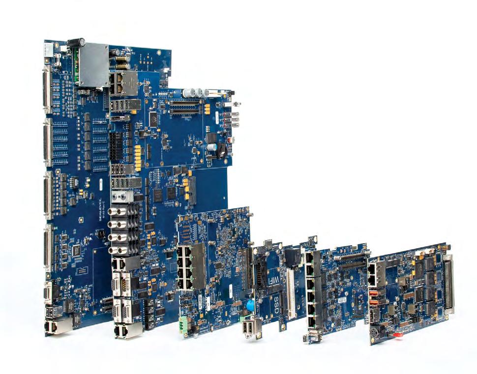


Managing supply chain, obsolescence, and counterfeit parts
Defense manufacturing projects by their very nature are complex, with multiple production lines needing to adhere to intricate assembly requirements. Project management, already a major challenge for defense manufacturers, is further exacerbated by the limitations of current types of ERP management software causing a disconnect throughout operations, alongside a lack of a skilled workforce readily available to defense manufacturers. Recent reports from Guidant Global4 highlight the workforce issues facing the U.K. [United Kingdom] defense sector, with key decision-makers stating they’re already facing a lack of skilled manufacturers and mechanics.
Implementing integrated project-management software will allow defense manufacturers to align their planning through their operations to optimize production and increase efficiency. The use of smart technologies such as integrated project-management software enables data to flow in real time so people, systems, and capabilities can be leveraged in every aspect of their operations.
The increased visibility brought by integrated project-management software enables manufacturing teams to react quickly to new priorities, thereby ensuring workers and machinery are coordinated to maximize efficiency and capacity and avoid wasting time, money, and resources.
3. Workflow engines combined with manufacturing execution systems enable efficiencies
One of the biggest challenges defense manufacturers are struggling to overcome due to rising demand levels is that of reducing lead times – in August 2023 the delivery time for production materials reached 87 days, according to numbers from Deloitte. Despite being reduced by 13 days compared to 2022, the average lead time has yet to recover to pre-pandemic levels. Integrated workflow tools can help defense manufacturers reduce lead time, with their ability to provide all relevant parties with data so that people, machines, and asset’s time and skills are all optimized.
A key part of digital transformation within the defense manufacturing industry is to move away from siloed data and toward real-time data that flows from the shop floor to the top floor of defense manufacturers. Powerful MESs with integrated workflow engines enable data to flow from end to end, so every worker has operational visibility of what’s happening and what needs prioritizing.

Utilizing powerful MES with integrated workflow engines brings far more benefits to defense manufacturers compared to typical ERP systems with data aggregators or business-intelligence reports. Integrated workflow systems are accessible for all relevant parties – providing vital insights into ongoing work everywhere. (Figure 1.)
The increased visibility brought by integrated project-management software enables manufacturing teams to react quickly to new priorities, thereby ensuring workers and machinery are coordinated to maximize efficiency and capacity and avoid wasting time, money, and resources.
4. Regulatory compliance –that last hurdle
Defense manufacturers operate in an industry defined by regulatory requirements, whether it’s supply chain, cybersecurity, sustainability, or employment –they all have their own regulations to comply with. This reality requires defense manufacturers to have fully traceable operations and processes that generate information readily available for regulatory reporting.
As regulations get stricter, current disjointed systems make it harder for defense manufacturers to meet requirements, with slow data compilation and increased risk of information being inaccurate or out of date. A real-time, single source of the truth is needed.
To this end, manufacturing-management platforms should include integrated and automated templates for mandatory government reports that are ready to use when called upon. Combining MES and ERP in one place will also help them comply with the ISA-95 standard5
from the International Society of Automation (ISA). Doing so ensures use of standardized data models and communications to enable consistent and accurate data exchanges throughout all business systems.
Choosing a strategic technology partner is common for defense manufacturers to realize operational and financial goals. Turning away from siloed and disparate data and instead adopting an integrated system such as MES and EAM systems being passed straight to the CRM and ERP system means that defense companies can boost productivity levels, empower their current workforce, and increase regulatory compliance.
Once in place, digital transformation can unlock a host of benefits for defense manufacturers and enable them to control inhouse hurdles while managing the current and any future rise in demand. MES
Notes
1 Deloitte Consulting, “2024 aerospace and defense industry outlook” https://www2.deloitte.com/ us/en/insights/industry/aerospace-defense/aerospace-and-defense-industry-outlook.html
2 U.S. Department of Defense, “Department of Defense Releases the President’s Fiscal Year 2024 Defense Budget” https://www.defense.gov/News/Releases/Release/ Article/3326875/department-of-defense-releases-the-presidents-fiscal-year-2024-defensebudget/#:~:text=The%20FY%202024%20DoD%20budget,allies%2C%20and%20partners%20for%20success.
3 U.S. Department of Defense, “U.S. Endorses Responsible AI Measures for Global Militaries” https://www.defense.gov/News/News-Stories/Article/Article/3597093/us-endorses-responsibleai-measures-for-global-militaries/
4 Guidant Global, “UK’s defence sector at risk of falling behind other countries as the STEM skills shortages rage on”https://www.guidantglobal.com/news/uk-s-defence-sector-at-risk-offalling-behind-other-countries-as-the-stem-skills-shortages-rage-on-
5 International Society of Automation, “ISA95, Enterprise-Control System Integration” https://www.isa.org/standards-and-publications/isa-standards/isa-standards-committees/isa95

Rob Mather is IFS Vice President, Aerospace and Defense Industries, responsible for leading the IFS global A&D industry marketing strategy, while also supporting product development, sales, and partner ecosystem growth. Rob has more than 15 years of experience in the A&D sector, having held a number of strategic R&D, presales and consulting positions at IFS, Mxi Technologies, and Fugro Aviation. Prior to his current position, Rob built and led the global A&D Presales Solution Architecture team at IFS. He holds a degree in aerospace engineering from Carleton University (Ottawa, Canada).
IFS • https://www.ifs.com/


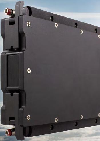


Managing supply chain, obsolescence, and counterfeit parts
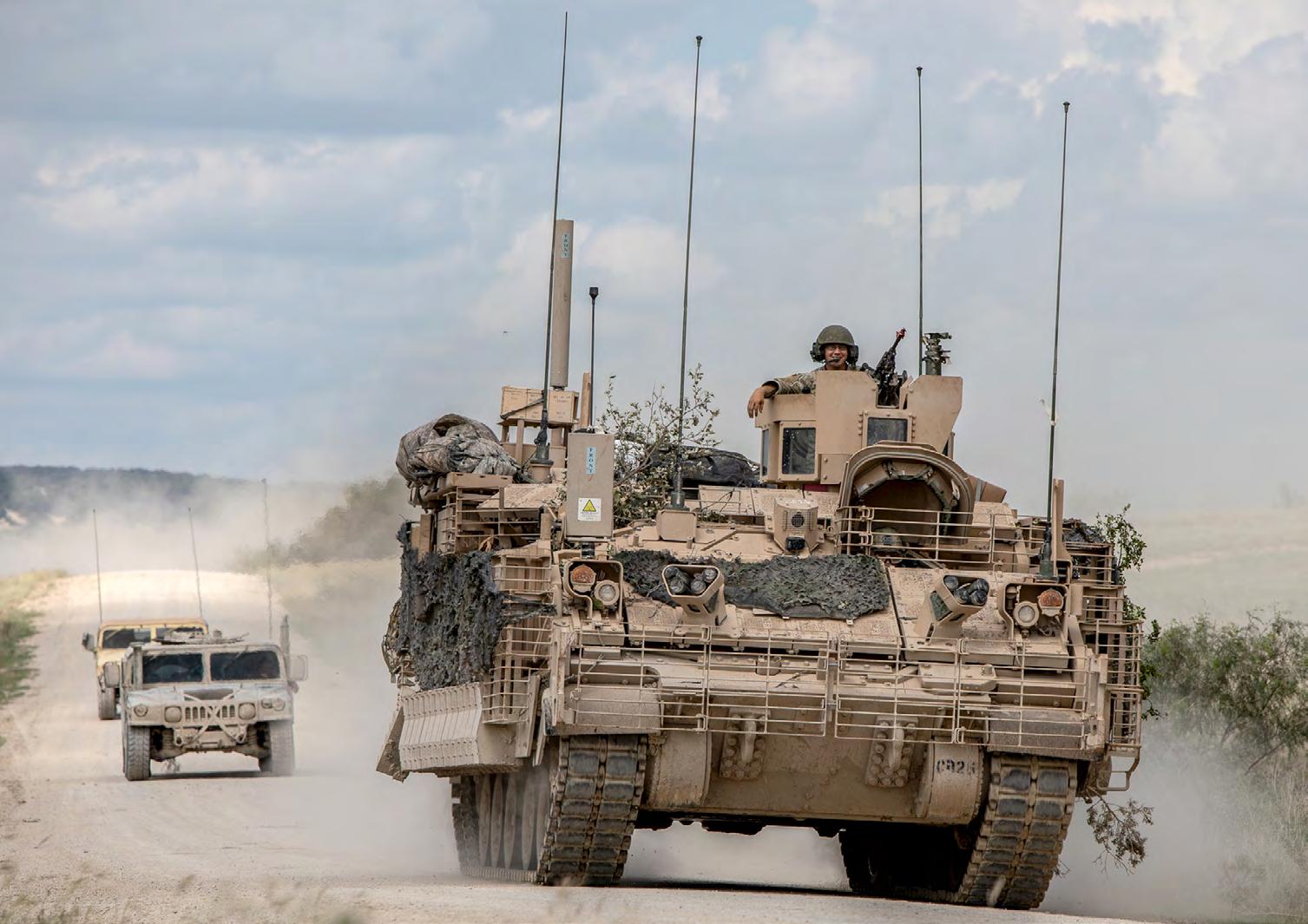
By Brian Russell
The U.S. Army is in a period of consequential modernization for its ground vehicle fleet. The vehicles that are set to be introduced over the remainder of this decade are likely to be in service for many decades to come, and will come up against a variety of threats in a range of different theatres. The need to easily upgrade electronic systems, spiral develop capabilities, and adhere to open standards, will be crucial for maintaining operational relevancy.
The global security environment is more dangerous than at any other time in a generation. Peer adversaries, including Russia and China, are now the pacing threats that are likely to challenge the U.S. and the wider global order for many years to come. The war in Ukraine in particular has demonstrated not only how dangerous Russia is, but also how the rapid pace of technology is transforming how nations fight.
Within this context, the U.S. Army is at a critical juncture and the decisions it makes today on modernizing its capabilities will have a significant impact on how it fights tomorrow. The U.S. Army is currently going through one of its biggest modernization periods since the Cold War, introducing a range of new capabilities that will provide U.S. soldiers with enhanced lethality, protection and mobility.
Critical to this modernization will be a range of new crewed ground vehicles, which includes the Armored Multi-Purpose Vehicle (AMPV), the XM30 Mechanized Infantry Combat Vehicle (formerly the Optionally Manned Fighting Vehicle), and the M10 Booker Mobile Protected Firepower (MPF). (Figure 1.)
Additionally, the U.S. Army plans to acquire robotic vehicles that will augment crewed vehicles on the battlefield. The platforms – known as Robotic Combat Vehicles (RCVs) – act as autonomous battlefield surrogates that can increase mass and remove humans from dull, dirty, and dangerous missions. Previously segmented into Light, Medium, and Heavy variants, the U.S. Army’s RCV is now concentrating efforts around a single weight class.
These new crewed and uncrewed vehicles will be the most advanced combat vehicles ever developed and provide a significant capability uplift compared with legacy vehicles, some of which have been in service since the 1980s.
Fundamental to this capability uplift will be the significant increase in computing power that will underpin each of the new vehicles’ electronic systems.
The requirement for computing capabilities on ground vehicles has seen constant, if not exponential, growth as vehicles have added more onboard systems. No longer are ground vehicles simply armor, guns, and drive systems, but instead are carriers of complex, integrated electronic systems that deliver a combined effect for the mission they need to carry out. (Figure 2.)
These modern vetronics systems are critical for areas such as real-time data processing, communications, navigation, and sensor-weapon control. As vehicle computers become more advanced, so too are the capabilities they enable, which include system health monitoring and predictive maintenance, data fusion, as well as decision support through artificial intelligence (AI)-powered edge processing.
The demand for optionally-manned capabilities and robotic “wingmen” such as the RCV will only push the requirement for advanced computing capabilities further, requiring significant edge compute power – leveraging the latest commercial AI processors – that can handle AI and machine learning (ML) algorithms for autonomous operations.
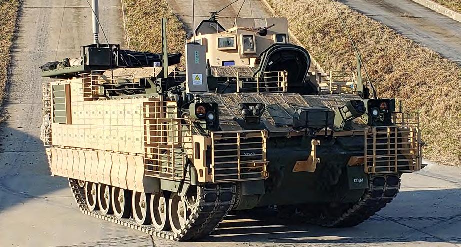
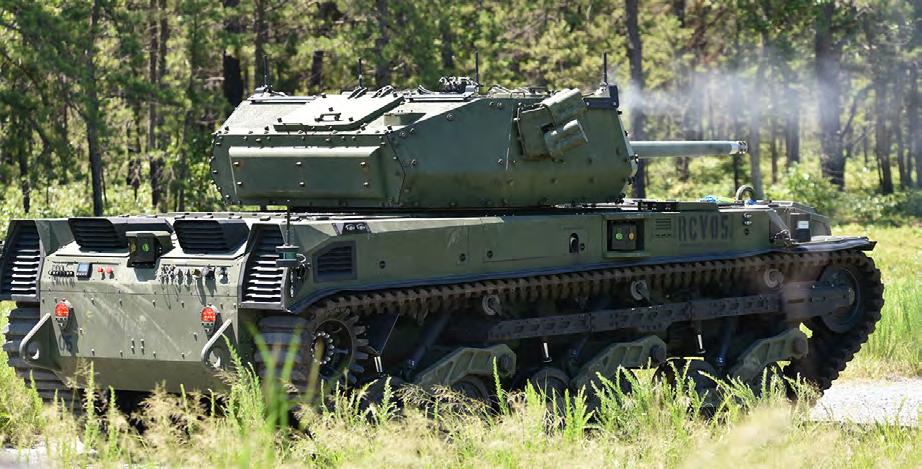
The ability to interoperate as a mixed crewed-uncrewed formation, sharing data from multiple sources across the echelons of a networked battlefield, will also drive the demand for systems that can collaborate using networks such as Combined Joint AllDomain Command and Control (CJADC2).
It is these advanced vetronics and network capabilities that will ultimately give U.S. warfighters the edge on the future battlefield, potentially even more so than the thickness of armor or the lethality of a gun.
Common standards and SWaP will be critical
It’s a common engineering challenge that as more electronic components are integrated into a system, complexity grows and integration challenges increase. That’s no different for armored vehicles, and legacy vehicles in particular have struggled to integrate additional electronics systems thanks to closed architectures and propri
etary interfaces.
A vehicle’s electronics can consist of many different boxes or systems that are designed for specific functions, whether that is core processing units/mission computers, sensor systems, communications, control systems, and much more.
Traditionally, many electronics systems installed on combat vehicles have had proprietary interfaces that have limited the upgradability of onboard systems, thus increasing
the cost of updating as integration challenges have been significant. Life cycle costs in particular have snowballed.
Moreover, vendor lock – or a situation in which a customer using a product or service cannot easily transition to a competitor’s product or service – has added layers of cost and complexity in areas such as vehicle development and upgrade programs.
In the threat environment the U.S. and its allies face, it is no longer feasible to wait years to upgrade platforms and spend billions of dollars for changes that often become outdated as soon as they are fielded. The rapid pace of technological change will require vetronics to be upgraded at an equally rapid pace, ensuring that U.S. forces stay ahead of the threat – which, as has been seen in Ukraine, can change on a daily basis.

When engineers need resistors for critical missions in a no-replace environment like Mars, they choose State of the Art. We are aboard three Mars orbiters: Odyssey, MRO, and Maven. We have been aboard all five NASA rovers that have, or are exploring, the surface of Mars: Sojourner, Spirit, Opportunity, Curiosity, and Perseverance. We are also aboard the InSight Lander that studied the interior of Mars. Working toward a manned mission to Mars, NASA chose State of the Art resistors. Whose resistors will you choose for your next mission?
Mission Critical?
Choose State of the Art resistors.
Made in the USA.
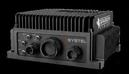
Figure 3 | Sparrow-Strike is Systel’s ultra-small-form-factor military-specification rugged edge mission computer – designed using a modular open systems approach (MOSA) – aimed at use in emerging autonomous and uncrewed missions.
Thankfully, the U.S. Army is moving in the direction of open architectures, which will be critical to this effort. This forward motion includes the modular open systems approach (MOSA), which is the U.S. Department of Defense (DoD) “preferred method of implementation of open systems,” and is now mandated for all major defense-acquisition programs.
Additional open architecture frameworks such as the C5ISR/EW Modular Open Suite of Standards (CMOSS) – which fits under the MOSA umbrella – will also ease integration and remove the need for multiple discrete boxes that address singular capabilities, replacing them instead with systems that handle multimission compute capabilities.
At the same time, designers and integrators face the ongoing requirement to optimize, and often reduce, SWaP [size, weight, and power] requirements, even as computers become more powerful. Armored vehicles, and especially smaller robotic vehicles, are extremely limited when it comes to space and power. Excess weight on such vehicles is a fundamental issue that can compromise other areas such as mobility.
Computer manufacturers such as Systel are constantly optimizing their designs and addressing the demand for smaller SWaP, all while maintaining the evermore-powerful compute capabilities required for modern military operations. (Figure 3.)
Computers must not only be open, but future-proofed The computers that underpin modern vehicle systems will have to be easily
upgradable and modular, allowing end users to configure and update them for the latest threat on the battlefield.
It is not enough just to be compliant with various open standards: Computers will also have to be designed for ongoing spiral development – another term for a systematic and iterative approach to software development – and rapid technology insertions that do not require full box replacements.
This is a critical area for developers: The architectural approach to rugged computer design enables customers to upgrade and customize chosen solutions, all while retaining the same form factor and interfaces, as well as being MOSA/ CMOSS-compliant.
Under this approach, the computers also continue to meet strict military standards, such as MIL-STD-810 environmental standards and MIL-STD-461G electromagnetic compatibility standards.
The ability to easily upgrade systems will have a major effect on life cycle costs and future-proofing, enabling end users to update vetronics components rapidly without the need to fundamentally change the vehicle’s electronic or physical architecture, including mounting points, interfaces, or vehicle wiring.
The requirement for computing capabilities on ground vehicles has seen constant, if not exponential, growth as vehicles have added more onboard systems.
This approach will be particularly important as AI is deployed closer to the edge, whether on crewed or uncrewed vehicles. AI at the edge requires huge amounts of processing capability, a situation that is constantly evolving, particularly as the commercial sector brings new AI and ML processors to market on a regular basis. Staying at the forefront of AI capabilities will require a steady cadence of processing upgrades to remain operationally relevant. MES

Brian Russell heads the product department at Systel, focused on creating and leading a product vision and strategy. He is a 22-year retired U.S. Army aviator, where he served as a CH/MH-47 Chinook pilot in both the conventional Army and Special Operations communities.
Systel • https://systelusa.com/
By Anthony Verna, Cubic DTECH Mission Solutions
In the ever-evolving landscape of modern warfare, the role of artificial intelligence (AI) in shaping the future of military operations cannot be underestimated. With the battlespace’s complexity escalating, the AI-accelerated battlespace’s emergence, enabled by advanced dataprocessing capabilities at the tactical edge, has become pivotal in assuring mission success. As the speed of warfare increases, we must recognize how edgebased compute technologies are crucial to increase the speed of decision-making.
Regarding AI, the U.S. Department of Defense (DoD) Chief Digital and Artificial Intelligence Office emphasized ensuring data, analytics, and AI capabilities are accessible across the DoD enterprise to support a variety of missions. Initiatives will be focused on leveraging mission analytics to drive decision-making behavior and ensuring data-driven capabilities are understandable and usable from the Pentagon to the battlefield.
Integrating AI and ML [machine learning] along with large language models (LLM) and multimodal large language models (MLLM) at the edge is a major step forward for military operations. The ability to process and analyze data in real time from a wide range of sensors at the point of collection empowers commanders with immediate insights, enabling swift and informed decision-making. Today’s operations require timely and accurate data that supports mission-critical decisions at the increasing speed of conflict. This edge-based approach is crucial in denied, disrupted, intermittent, and limited (DDIL) environments where traditional communication channels and cloud environments may be compromised or blocked.
The importance of data-rich processing solutions in DDIL environments cannot be overstated. These environments require systems that can handle complex

data-processing tasks without the luxury of constant cloud connectivity. Future solutions will need to provide data center performance and flexible compute and networking capabilities at the tactical edge.
While the U.S. Army benefits from significant bandwidth and storage capabilities, the device ecosystem continues to grow exponentially, sometimes including field devices that are intermittently disconnected from the communications networks. The result: These communications resources can become scarce in field operations. Deployed systems, especially in remote geographical areas, frequently suffer from inadequate connectivity, necessitating data-rich processing solutions at the edge to ensure personnel can operate effectively in DDIL environments, where traditional communications and navigation systems may be unusable.
Implementing AI and ML capabilities at the edge enables military leaders to increase operational effectiveness by translating sensor data into decisions in real time. This move in turn results in increasing speed of decision-making and related mission effects that increase overall mission readiness.
Missions, particularly those involving AI, ML, and video analysis, require dedicated graphics processing units (GPUs). Dedicated GPU design is tailored to handle the computationally intensive tasks efficiently. For instance, GPUs excel in processing large volumes of data with speed and precision, which is paramount for AI and ML algorithms to function effectively. The specialized architecture of GPUs enables them to perform complex calculations much faster than traditional CPUs.
Additionally, the success of such missions often hinges on the ability to process and analyze data swiftly and accurately. GPUs contribute considerably to these goals by providing the computational horsepower needed for rapid data processing, an especially critical aspect in scenarios where real-time data analysis is required. Leveraging the power of dedicated GPUs means that personnel on missions can achieve higher efficiency, better performance, and more accurate results in their AI, ML, and videoanalysis endeavors.
To sum up: AI and ML play a crucial role in disconnected edge environments where communication with centralized command may be compromised or delayed. Implementing AI and ML capabilities at the edge enables military leaders to increase operational effectiveness by translating sensor data into decisions in real time. This move in turn results in increasing speed of decision-making and related mission effects that increase overall mission readiness.
Anthony Verna is SVP and GM of Cubic DTECH Mission Solutions.
Cubic DTECH Mission Solutions https://www.cubic.com/defense


Military Embedded Systems focuses on embedded electronics – hardware and software – for military applications through technical coverage of all parts of the design process. The website, Resource Guide, e-mags, newsletters, podcasts, webcasts, and print editions provide insight on embedded tools and strategies including technology insertion, obsolescence management, standards adoption, and many other military-specific technical subjects.
Coverage areas include the latest innovative products, technology, and market trends driving military embedded applications such as radar, electronic warfare, unmanned systems, cybersecurity, AI and machine learning, avionics, and more. Each issue is full of the information readers need to stay connected to the pulse of embedded technology in the military and aerospace industries. militaryembedded.com
By Erik Vallow and Dr. Justin Pearson
At a time when digital superiority defines global security, the defense sector faces a critical challenge: that of deploying software updates swiftly without compromising safety or certification standards. There is a solution – modular, certifiable software architectures built on open standards. By fostering a collaborative ecosystem of innovation, this approach enables rapid deployment, seamless integration of third-party capabilities and streamlined certification processes.
In high-stakes domains like defense and aerospace, the ability to swiftly deploy and update software can mean the difference between victory and vulnerability. Yet, these critical sectors often find themselves constrained by legacy systems and cumbersome certification processes, struggling to keep pace with emerging threats. The solution? A shift toward open standards and modular, certifiable software architectures that enable rapid, secure deployment.
In modern operational environments, security is increasingly defined by both speed and performance. This principle isn’t just a technology goal; it’s a call to action in sectors where outdated software can have dire consequences. The strategy calls for the use of standards-based platforms and collaborative partnerships, laying the groundwork for transformative capabilities delivered at the new speed of dominance.
By embracing open standards, companies can create a universal language for these systems, enabling third parties to integrate and customize them seamlessly. This approach fosters an ecosystem where innovation can flourish, while maintaining the highest standards of safety and security.
The concept of “thriving on secure, safe, open standards” is becoming a mantra in the industry. In a field often wary of openness due to security concerns, this notion turns traditional thinking on its head. Leading-edge platforms are not merely adapted for open standards but are inherently designed around them. This approach ensures that systems remain interoperable and flexible while upholding the stringent safety and security certifications at the center of aerospace and defense.
For instance, prioritizing MOSA [modular open systems approach] use cases as defined by the end user enables a concentrated focus on the change containment boundaries, which are essential for supporting a delta-certification framework for ongoing updates and integration of new capabilities. Adopting established frameworks like ARINC-653; the Future Airborne Capability Environment, or FACE, Technical Standard; and


VirtIO to define these boundaries is key to a successful MOSA implementation. As acquisitions struggle to keep pace with the rapid releases and updates of open standards for hosted capabilities (e.g., user applications), this approach will optimize the use of high technology readiness level (TRL) technologies while minimizing alignment inconsistencies within the hosted capabilities.
By embracing open standards, companies can create a universal language for these systems, enabling third parties to integrate and customize them seamlessly. This approach fosters an ecosystem where innovation can flourish, while maintaining the highest standards of safety and security.
Based on standardized principles, the resulting modular platforms offer the added benefit of comprehensive certification data. This bureaucratic breakthrough transforms the highly regulated environments where each software update typically requires navigating a labyrinth of approvals. This newer, standards-based modular approach allows components to be rapidly fielded and updated without sacrificing compliance.
Furthermore, this approach is aligned with the best-in-class modern software methodologies. The ability to deploy software at speed and performance supports agile practices like DevSecOps [development, security, and operations] and continuous integration/continuous deployment (CI/CD). In a world where threats evolve by the hour, these platforms enable defense and aerospace to iterate quickly, test rigorously, and deploy confidently while maintaining top-tier security.
This is a vision that extends beyond any single company’s innovations. U.S. Department of Defense (DoD) programs are increasingly encouraging building lasting partnerships and interoperability between suppliers to foster enduring innovation. Companies are providing clear guidelines and hands-on support for partners to enhance and integrate their systems with core platforms, all of which require a collaborative ethos to ensure that the global network of innovators can rapidly develop and certify new capabilities as threats evolve, keeping critical
systems ahead of the curve. The use of open standards in platforms like LYNX MOSA.ic demonstrates how a collaborative, standards-based approach can enhance innovation and maintain the technological edge required to meet evolving threats.
The growing role of standards and collaboration is further exemplified by events such as the annual MOSA Industry & Government Summit This summit facilitates lasting partnerships among industry, academia, and government, helping to shape holistic business and technical strategies that meet the warfighter’s needs. Through demonstrated openness, panel sessions on execution strategies, need statements, lessons learned, and more, continuous participation in these events and the consortium bodies that govern the maturation of open standards is crucial for achieving the government’s MOSA objectives.
In essence, the DoD is rewriting the rules of engagement in critical domains. Standards-based, modular architectures don’t just enable rapid software deployment; they help make it secure, certified, and collaboratively driven. This approach is not just innovative; it’s essential in sectors where failure is not an option and adversaries are constantly probing for weakness.
Erik Vallow is director of technical product marketing at Lynx Software Technologies. Dr. Justin Pearson is Lynx’s director of systems architecture.
Lynx Software Technologies www.lynx.com
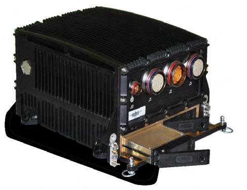
Utilizing two removable SSDs, the Phalanx II is a rugged Small Form Factor (SSF) Network Attached Storage (NAS) file server designed for manned and unmanned airborne, undersea and ground mobile applications.
www.phenxint.com

In the modern defense landscape, reverse engineering threatens a nation’s strategic and technological advancements. Despite stringent security measures, devices and equipment inevitably fall into the wrong hands during conflicts. This exposure opens the door to reverse engineering, where adversaries can dissect and analyze advanced technologies. Nation-states and defense manufacturers invest substantial resources in developing cutting-edge defense technologies. When these technologies are compromised, adversaries gain insights into their workings, effectively neutralizing any strategic advantage. The knowledge gained through reverse engineering allows enemies to identify and exploit vulnerabilities, leading to hacking and compromising national security.
The gravity of this threat cannot be overstated. The notion that reverse engineering is exclusive to expert hackers is changing rapidly. Sophiscticated tools like Ghidra, BinaryNinja, and IDAPro have made reverse engineering more accessible, lowering the entry barrier for novices and experts alike. This democratization dispels myths of exclusivity and crypticity, making it easier for a broader audience to understand software intricacies, particularly in embedded systems security.
In a defense context, protecting against reverse engineering is critical and often mandated by standards like NIST SP 800-53. This requires code obfuscation, anti-tamper, and anti-debug/ anti-emulation techniques to challenge even advanced reverse engineers. At Emproof, we have over 40 years of combined expertise to help you. Our unique solution, Emproof Nyx, hardens against reverse engineering and exploitation attacks, ensuring robust protection of mission-critical software, particularly in military devices.
Consider a military drone with advanced navigation and targeting systems. Protecting its software from reverse engineering is essential to maintain a strategic advantage. Emproof Nyx enhances embedded software security through techniques that protect algorithms, data, and devices. By integrating Emproof Nyx into military firmware, such as drone software, it becomes significantly harder to analyze and manipulate, with minimal disruption – preserving the integrity and confidentiality of sensitive technology within.
The X9 AI System is the first rugged system to utilize the NVIDIA® Jetson Orin™ processor family. NVIDIA’s family of systems-on-module are targeted for autonomous applications where live data collection and analysis in real time is essential. This flagship product line from NVIDIA® is being deployed in commercial, industrial and now military applications such as UAV/UAS, autonomous vehicles, and airborne applications. High bandwidth sensor-to-processing gives tremendous advantage to warfighters in at-the-edge battlefield applications.
GMS X9 AI utilizes NVIDIA’s most recent Jetson Orin™ module. The Jetson Orin™ contains 2048 CUDA® engines with an incredible 275 TFLOPS and 64 Tensor cores operating @ 1.3GHz. The Jetson Orin™ has 12 Arm® Cortex® 64bi/cp with 3MB of L2 Cache and 6MB of L3 Cache operating at 2.2 GHz max and 1.6GHz nominal. The Orin supports 64GB memory which is 256-bit wide with a 204.8 GB/s transfer rate.
The Orin is connected to two RMC I/O carrier modules to expand the system I/O to enhance the functionality of the system. The primary expansion card provides quad 10GBase-TX Ethernet ports with PoE+ to power cameras and target sensors. Additionally, it provides quad 3G-SDI ports for video capture via an FPGA. Each camera also supports an RS232/422/485 port for camera control such as PTZ and the other functions on the camera. This module also provides dual 40/100GigE fiber ports and dual M.2 (2280) sites for storage. Additional I/O such as 8K x 60Hz multi-mode 1.4a Display Port, USB-C, and sensors such as Shock, Temp, and Tamper.
The second expansion site is a Rugged Mezzanine Module (RMC-50). Although there are over 30 RMC modules that may be installed in this location, GMS’ standard offering is a Quad CoaXPress® module. CoaXPress® is the most advanced technology in video standards, its digital interface developed for high-speed image transmission in machine vision applications. The CoaXPress® standard supports up to 6.25 Gbps per coaxial cable and soon will support 12.5 Gbps. Unlike other video formats such as CameraLink, CoaXPress® transmission data is in packet form. This allows multiple cameras to utilize the same link, much like cellular data. This unique feature opens up applications where it has not been possible due to size, cost and power.
The X9 family of products redefines embedded computer architectures. The traditional computers in the market (rugged or commercial) require the user to pre-configure their systems up-front making systems over-built and expensive, under-developed for future growth, and inflexible when obsolescence sets in. The X9 Mission Computer’s open Distributed Computer Architecture (DCA) has each specific function available in a sub-system and linked together via Thunderbolt® 4 and a single LightBolt™ cable. Units can be placed up to 50 meters away from each other in any format: Daisy Chain or Star or direct-attach.
Micro Systems, Inc. www.gms4sbc.com
This open DCA mitigates obsolescence by upgrading/replacing only those functions required to be upgraded. The 100W power delivery in X9 systems allows each system to be powered on its own or by any of the other systems in the “loop”. There are also options for external power supplies (including MIL-STD-1275) with battery back-up, allowing the system to grow as needed without the limitation of available power. Other X9 modules include: Artificial Intelligence, Storage (fixed or removable), GPU, Workstation, Switch and Display as well as many others.
Ą NVIDIA® Jetson™ Orin™ with 12 Core Arm® 64-bit CPU @ 2.2GHz, 2048 CUDA® Cores, 275 TFOPS
Ą Memory/Storage: 64GB 256-bit LPDDR5; 16TB SSD; 64GB eMMC5
Ą High Speed I/O: 2x 100GigE Fiber; 4x 10GigE w/ PoE+; 4x 3G-SDI or 4x CoaXPress®
Ą Connectivity: Over 30 RMC add-in I/O; M.2 add-in I/O: 5G Cellular; Wi-Fi®/Bluetooth; HD-GPS
Ą GPU: 2x NVIDIA® v2.0 DL accelerator @ 1.6GHz, with vast array of video encoding: H.265, H.264, VP9 and AV1
Ą 8K x 60Hz multimode DisplayPort 1.4a port
Ą USB-C, GigE, USB2 and UART Service port
Ą Voltage, Shock and Temp sensors
Ą Eight tri-color LEDs for status and messaging
Ą Single +20VDC power operation
Ą Dual fan control with tachometer for external cooling
Ą Ultra-small at 6”x4.75”x2” and 2.1lbs.
Ą Temperature: Operates up to extended temp -40°C to +85°C (Optional)
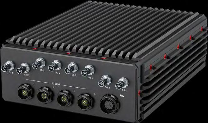
www.gms4sbc.com/x9spider
www.linkedin.com/company/general-micro-systems
AM2E1553-x
Introducing the world’s 1st MIL-STD-1553 M.2 Card in a popular 2260 small size M.2 form factor ideal for small form factor rugged embedded systems, laptops, and tablets. Applications include mission processors, displays, launchers, radar systems/ situational awareness, cyber intrusion detection, data loading, handheld test systems, databus analysis and much more!
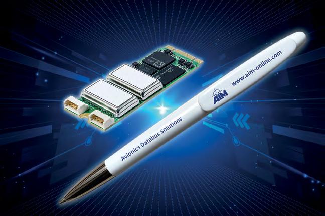
FEATURES
Ą 2Ch. MIL-STD-1553 / MIL-STD-1760 M.2 Card
Ą Small 2260 size with B + M Keying for Universal Compatibility
Ą Extended Temperature Range: -40°C to +85°C
Ą Rugged Locking Connectors for each 1553 Channel
Ą High Reliability and Low Power Design
https://www.aim-online.com/products/am2e1553 -x/
AIM-USA www.aim-online.com/
sales@aim-online.us 267-982-2600
www.linkedin.com/company/1640624/

The M.2-1553 is the smallest high-performance interface card designed for MIL-STD-1553 applications, featuring two independent, dual redundant channels with transformer coupling. Powered by the DDC Total-AceXtreme® chipset, it supports multiprotocol operations, including MIL-STD-1553A/B, STANAG-3838, and MIL-STD-1760, along with IRIG-106 Chapter 10 monitoring. It functions as a 1553 bus controller or remote terminal with a concurrent bus monitor, supporting up to 31 RT addresses simultaneously.
The M.2-1553-2 can filter on RT address, T/R, and Subaddress, offering precision in complex systems. Despite its ultra-compact M.2 form factor, it delivers full 1553 functionality, ideal for space-constrained embedded systems. Its rugged design ensures durability in harsh environments, while comprehensive software support ensures seamless integration. The M.2-1553 sets a new standard for reliable, high-performance 1553 communication in aerospace, defense, and industrial applications.
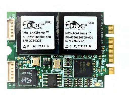
FEATURES
Ą M.2 3042 Key B & M PCI Express x1 lane interface
Avionics
Ą Two dual redundant MIL-STD-1553 Total-AceXtreme controllers (A/B channel), 2MB RAM per Channel
Ą Multiprotocol support: MIL-STD-1553A/B STANAG-3838 and MIL-STD-1760 , Transformer coupled
Ą Programmable mode: Bus Controller, Remote Terminal with concurrent bus monitor, IRIG-106 Chapter 10 monitor
Ą Emulate up to 31 RT addresses simultaneously
Ą Filter based on RT address, T/R bit, sub-address
Ą Suitable for integration into Compact Embedded Systems
www.alphitech.com/doc/DS-M.2-1553.pdf ALPHI Technology Corporation www..Alphitech.com
Sales@Alphitech.com
480-838-2428
M.2-2ETH1G
The M.2-2Eth1G is a versatile and high-performance Ethernet interface card, designed in the compact M.2 30x42 form factor. This board is configured with four channels: two with onboard transformers and two with off-board transformers, offering flexibility to meet various design and application needs. Powered by the Intel I350 Ethernet Controller, it supports 10/100/1000Mbps Ethernet connectivity, ensuring robust and efficient data transmission. Ideal for industrial, embedded, and server applications, the M.2-2Eth1G delivers advanced features like hardware-assisted virtualization, IEEE 1588 Precision Time Protocol (PTP) support, and enhanced power management. Despite its small size, this card offers reliable network connectivity and seamless integration into a variety of systems, setting a new benchmark for high-speed Ethernet communication in compact devices.
www.alphitech.com/doc/DS-M.2-ETH1G-4.pdf
ALPHI Technology Corporation www.Alphitech.com
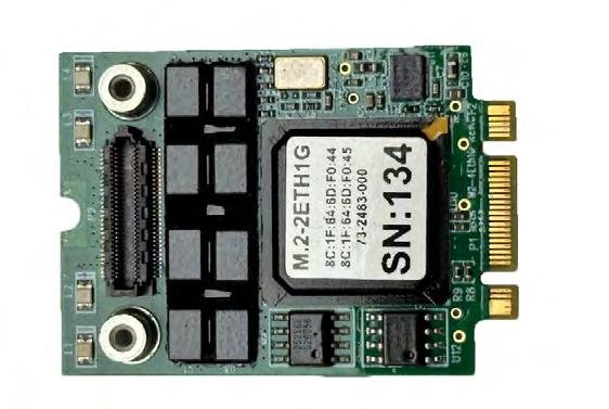
Ą Ultra-compact 30x42mm M.2-2Eth1G board size, ideal for spaceconstrained designs.
Ą Intel I350 Ethernet controller, supporting 10/100/1000 Mbps across multiple ports.
Ą Dual onboard transformers and two off-board transformers for flexible design options.
Ą Intel I350 supports SR-IOV and VMDq for optimized virtualization performance.
Ą Energy Efficient Ethernet (EEE) reduces power during low network activity, ideal for eco apps.
Ą I350 hardware offloading reduces CPU load by handling checksum calculations and segmentation.
Ą Ethernet boot support via onboard flash for network-based booting in server environments.
Sales@Alphitech.com 480-838-2428
IC-ARM-VPX3b – 3U VPX LX2080A/LX2160 Arm®-based Single Board Computer
The IC-ARM-VPX3b is a 3U VPX Single Board Computer based on a NXP QorIQ® Layerscape® LX2080A /LX2160A multicore communication processor (8/16 Arm® Cortex®-A72 32/64 bit cores). It is ideal for use in applications requiring high processing and communication performance together with low power. The IC-ARM-VPX3b features up to 32GB of DDR4-ECC and several storage capabilities (M.2 slot, eMMC, F-RAM) which enable system designers to meet large centralized systems’ topology demands and handle heavy traffic scenarios on specific backplane segments. The IC-ARM-VPX3b is partially compliant with VITA 65.0 Slot Profile SLT3PAY-1F4F2U-14.2.14., it provides multiple 10G/40G Ethernet and PCIe Gen2/3 interfaces available on the VPX backplane connectors for high bandwidth connections. This board complies with VITA 46.0 and 65.0 standards. It includes a boot loader firmware for initialization. A Board Support Package is available for Linux or VxWorks Real Time Operating Systems. Optional board accessories include an Engineering kit for debug (JTAG/COP, console) and a 3U Rear Transition Module for development purposes. This rugged board is available in air-cooled and conduction-cooled versions.
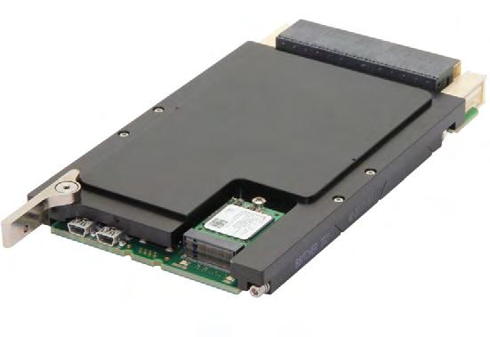
Ą 3U VPX
Ą NXP LX2080A/LX2160A Arm® processor
Ą VITA 65 Slot Profile SLT3-PAY1F4F2U-14.2.14 (partial)
Ą Data Plane: 10G or PCIe Gen3 interfaces
Ą Expansion plane PCIe Gen3
Ą up to 32GB of DDR4-ECC
Ą M.2 slot, eMMC, F-RAM
Instructions and data stored in external memory are vulnerable to attack, introspection or modification as they get loaded and executed. Immunity-IME is shimmed in between the processor and memory controller to provide just-in-time authentication, decryption and authentication for all memory write and read requests. ImmunityIME mitigates known run-time and at-rest vulnerabilities with minimal performance impact.
Immunity-IME features configuration at-compile and/or at-runtime flexibility including the ability to balance security while still maintaining system performance. Thanks to a dedicated, fully pipelined architecture, Immunity-IME provides industry-leading performance. If errors occur, Immunity-IME has a IRQ output and a separate AXI interface for reading out the errors. Designed and supported in the US, Immunity-IME is a proven must-have for any secure embedded design.
Ą Performs encryption, decryption and/or authentication using AES Counter Mode (CTR) or Galois Counter Mode (GCM)
Ą Internal key management with NIST-compliant key generation
Ą A driver is provided that has an API for programming entropy, which then allows keys to be generated automatically and stored internal to the core
Ą 10–20% of available memory addresses are consumed for overhead, 0% system memory overhead is possible
Ą Encrypt memory space into user-defined vaults, each with a unique key
Ą Encrypted memory segment sizes are user configurable, minimum is deposit size and maximum is subject to block RAM availability
Ą Compatible with AMBA AXI4 interface
Ą Supports hard or soft memory controllers in AMD’s Xilinx FPGA (ZU, ZU+, Versal) and Intel Agilex devices
Ą Supports modern operating systems with and without MMUs
Ą Robust countermeasure against physical attack including Side Channel Analysis (SCA) and Differential Power Analysis (DPA)
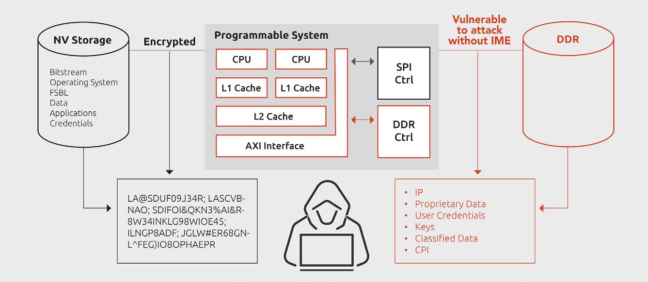
www.idahoscientific.com/products/immunity-inline-memory-encryption
Idaho Scientific
www.idahoscientific.com
Mitigate the exploitation of keys from vulnerable crypto implementations. Idaho Scientific's Immunity Crypto Cores are a suite of NIST-certified, hardwareaccelerated FPGA IP cores with robust countermeasures against side channel attacks including simple (SPA) and differential (DPA). Hardware-based crypto not only offloads the burden from the primary processor but is the industrystandard for protecting against virtual and physical threats at rest, during power up/boot, in transit/use and during power down. Software-based crypto may be simple to implement but is too vulnerable to side-channel and timing attacks.
Immunity Crypto Cores provide security for use cases including key generation/ exchange/storage, digital signature, bulk encryption, packet encryption and message authentication, and secure boot. Designers can select a single core from within the Immunity family of Crypto Cores or select a bundle, which has been integrated and enabled with key management, into the ImmunityHardware Security Module (HSM). Immunity Crypto Cores a NIST certified, Government validated and operating in DoD tactical and strategic systems. Immunity Crypto Cores were developed and are supported by engineers who work with DoD weapons systems every day and understand the need for the flexibility in features configurable at compile and/or run-time. Immunity
Crypto Cores are lower technical risk thanks to simple integration, full driver stack, reference designs and technical support from cleared US engineers who specialize in DoD use cases.
Ą Available cores include: Symmetric encryption (AES with variable key sizes up to 256 and most cipher modes), Asymmetric encryption (RSA up to 8192, ECC), Hashing (SHA2, SHA3, HMAC SHA2), Random Number Generator (TRNG)
Ą Quantum-safe algorithms coming soon
Ą NIST-certified, Government proven
Ą Easy-to-use command interface for loading keys and changing the mode of operation
Ą Industry-standard AXI and AXI-Stream interfaces
Ą Designed for and support focused on FPGA implementations for DoD use cases
Ą 3k–40k LUTs depending upon which core(s) and which configuration. Contact Idaho Scientific for full performance data including resource utilization, latency, throughput and Fmax
Ą Select a single core, any combination of cores, or pre-bundled and integrated cores combined with custom secure boot, a security controller and Extension of Trust to provide a full hardware-based Root of Trust
Ą Robust Side Channel Attack (SCA), Differential Power Analysis (DPA) countermeasures to provide hardware security protection from physical attacks
www.idahoscientific.com/products/immunityside-channel-resistant-crypto-cores

With a successful track record protecting combat systems in Aerospace and Defense (A&D), Star Lab helps customers implement build secure methodologies into Linuxbased embedded security technologies. Our products are easily integrated, flexible, and designed to handle worst-case threat scenarios: hands-on physical or privileged attackers. We prevent attackers from tampering with or altering software / firmware and limit their maneuverability, ensuring your systems remain protected, resilient, and operate even under attack.
Star Lab's Titanium Technology Protection is a comprehensive technology protection solution for Linux-based mission-critical systems in A&D that counters cyber and technology protection threats with secure boot, Linux hardening, and security for virtualization. The solution is comprised of the core product, Titanium for Linux, along with two available add-ons: Titanium Secure Boot and Titanium for KVM.
Titanium for Linux is designed using a threat model that assumes an attacker will gain administrative (root) access to the system, and still must maintain the integrity and confidentiality of critical applications, data, and configurations all while assuring operations. Titanium for Linux is compatible with Red Hat and other binary-compatible distributions.
Titanium Secure Boot provides the strongest boot-time authentication/trust on Intel chipsets, with a simple provisioning process and support for secure software updates. It is a truly zero-trust secure boot solution. Titanium Secure Boot verifies the authenticity of boot-time components with both static and dynamic chain of trust measurements, unlike other solutions that only use static measurements. Titanium Secure Boot is more robust than other solutions, like UEFI, that can be subverted by an attacker with physical access to the system.
For customers leveraging virtualization, Titanium for KVM extends the protection capabilities of Titanium Technology Protection to secure the KVM hypervisor. This includes extending secure boot from the host to guest VM images and configuration.
FEATURES
Ą Mandatory Access Control Policy
Ą Secure Key Management & Release
Ą Data Protection
Ą Integrity and Confidentiality
Ą Support for Secure Software Updates
Ą Application Allowlisting
Ą OS Hardening
Ą Attack Surface Reduction
Ą At Rest and Runtime Protection
Ą Secure Boot
Ą Security for KVM-based Virtualization

Cybersecurity for Government, Military & Avionics
Does your device or application need FIPS, DO-178 based TLS, Secure Boot, or Cryptography?
wolfSSL products are trusted by every branch of the US armed services, deployed in tanks, missile systems, satellites, and aircraft. Offering secure boot and cryptography software, wolfSSL supports full DO-178C DAL A certification and offers the first SP800-140BR1 FIPS 140-3 validated certificate #4718 compliance. As a commercial off-the-shelf (COTS) solution for avionics, we provide DAL A wolfBoot secure boot. For aircraft communications security, we offer DTLS 1.3 to ensure data integrity and confidentiality, mitigating MITM, relay, DoS, and spoofing attacks. wolfSSL’s embedded (D)TLS 1.3 library, secure boot, and cryptography are lightweight, portable, and C-based, seamlessly running on DO-178 operating systems like SYSGO, Wind River VxWorks, INTEGRITY, and DDC-I Deos, with portability to bare metal and custom OS's.
wolfSSL www.wolfssl.com
facts@wolfssl.com

Ą wolfCrypt – Embedded Crypto Engine
Ą FIPS 140-3 Validated certificate #4718
Ą RTCA DO 178C DAL A Support
Ą Low resource use with Bare Metal Support
Ą wolfBoot – Secure Boot Loader
Ą wolfSSH – Lightweight SSH Library
Ą TLS 1.3 and DTLS 1.3
www.dawnvme.com/shop /power-supplies/psc-8724/
425-245-8247
www.linkedin.com/company/wolfssl/ @ wolfssl
IC-FEP-VPX6e – 6U VPX FPGA board with two FMC+ sites
The IC-FEP-VPX6e is a 6U FPGA processing board based on 2* Kintex® UltraScale™/ Virtex® UltraScale+™ FPGAs and 1*QorIQ LS1046A processor.
The IC-FEP-VPX6e is the perfect solution to applications requiring intensive Digital Signal Processing (DSP) in a 6U VPX form factor. The QorIQ® LS1046A processor integrates quad 64-bit Arm® Cortex A72 cores with high-performance Data Path Acceleration Architecture (DPAA) and network peripheral interfaces required by demanding processing applications. The on-board PCIe advanced switch allows versatile coupling between the processor, the FPGAs and the fabric links of P1 VPX connector (Non-transparent configuration possible). The board provides one L2 Gigabit Ethernet switch with 1000BX and 1000G-BASE-T Ethernet ports. Furthermore, the Multiware software package and its simplified API allows to easily integrate the IC-FEP-VPX6e in heterogeneous multi-domains PCIe architectures. Two FMC+ (VITA 57.4) sites are provided to add FMC and FMC+ modules.
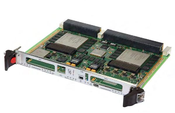
Ą 6U VPX
Ą 2 * Kintex® UltraScale™/ Virtex® Ul-traScale+™ FPGAs
Ą QorIQ LS1046A
Ą Gen2/3 PCIe switch
Ą Giga Ethernet L2 switch
Ą 2 * FMC+ sites
www.interfaceconcept.com
ComEth4682e – 3U VPX 1/10/25/40/100 Gigabit
Ethernet Switch
The ComEth4682e is a 3U OpenVPX Ethernet switch that is 25/100Gb Ethernet capable. It has been developed for high-speed applications, including radar, sensor, electronic warfare, and network processing. The ComEth4682e integrates a Layer 2 (Ethernet) and Layer 3 switch, as well as a control processor to support Control and Data Planes that are separated by software configuration settings for highly secured 3U VPX systems. The switch features a total of 56 x 25Gbps SerDes: 32 lanes are routed to the rear VPX connectors as 1/10/25Gbs Ethernet ports or can be merged into 4-lane Fat Pipes to obtain 8 lanes as 40/100Gbs Ethernet ports. Likewise for the 24 optical fiber ports, they are routed to the front panel (2*MPO connectors) as 1/10/25Gbs Ethernet ports or can be merged in set of 4 fibers to obtain 3 lanes as 40/100 Gbs Ethernet ports. The ComEth4682e benefits from the proven and expandable switchware network management application. It can be remotely configured by the switchware web interface, SNMP or CLI interfaces. The ComEth4682e complies with the following slot profiles SLT3-SWH2F24U-14.4.3 , SLT3-SWH-4F16U-14.4.13 and SLT3-SWH-8F-14.4.2.
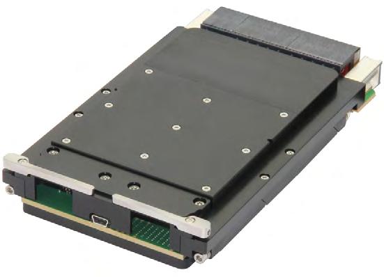
Ą 3U VPX Managed Layer 2+/3 switch
Ą VITA 65.0 SLT3-SWH-2F24U-14.4.3
Ą VITA 65.0 SLT3-SWH-6F1U7U-14.4.14 (option)
Ą Up to 56 ports
Ą 24 optical fibers (front MPO connector)
Ą 1GBASE-KX, 10 & 25GBASE-KR, 40 & 100GBASE-KR4 ports (rear)
www.interfaceconcept.com
Interface Concept www.interfaceconcept.com gnicot@interfaceconcept.com 510-656-3400 www.linkedin.com/company/interface-concept
ComEth4591a – 3U VPX Dual-Plane 40G Ethernet Switch for hybrid copper-optical backplanes
The ComEth4591a is a ruggedized 3U VPX dual-plane 10/40 Gigabit Ethernet Layer 2/3 Switch developed in alignment with the SOSA™ Technical Standard. It integrates two sets of independent Layer 2 (Ethernet) and Layer 3 Switches & control dual-core ARM processors to support Control and Data Planes that are physically separated. This board architecture is ideal for use in highly secured 3U VPX systems. The ComEth4591a supports the VITA 66.5 style C optical VPX connector through a LightCONEX™ 12-lane optical transceiver module. The ComEth4591a features up to 38 * 1/10/40 Gigabit Ethernet on VITA 46 (copper) & VITA 66.5 (optical) connectors. Ethernet Port allocation is easily configurable through the Switchware and several port combinations are available via the backplane (10GBASE-KR/10GBASE-KX4/40GBASE-KR4).The Switchware allows to remotely control the switch by web interface, SNMP or CLI interfaces. The ComEth4591a is available in conduction-cooled grade.
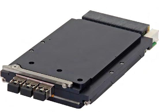
Ą 3U VPX
Ą Managed Layer 2+/ 3 switch
Ą Switching for 2 separate and independent domains
Ą Slot profile SLT3-SWH-4F1U7U1J-14.8.7-n
Ą Up to 38 * 1/10/40 GbE on VITA 46 & 66.5 connectors
Ą Developed in alignment with the SOSA™ Technical Standard

Rugged FIPS 140-2 Validated SSD
Apacer FIPS 140-2 Validated SSD is equipped with military-grade encryption that conforms to the FIPS 140-2 Level 2 cryptographic standard. The Level 2 validation ensures tamper-evidence through the use of special coatings, seals and labels to prevent security information from being detected.
This series can be shipped with many value-adding features, such as wide temperature operation for rugged applications, which Apacer is the first to offer. It’s also available in four form factors: 2.5", M.2 2280, mSATA and MO297. The 2.5" SSD is offered with optional support for rugged R-SATA connectors. Capacities are available up to 2TB.
Apacer’s diverse array of extremely secure FIPS validated SSDs take security to the next level for the industrial world.
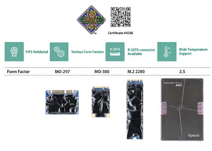
Ą Interface & form factor: SATA 2.5", M.2 2280, mSATA, MO297; PCIe M.2 2280
Ą Temperature: Wide Temperature & Standard Temperature
Ą AES 256-bit hardware encryption
Ą TCG Opal 2.0
Ą SMART Read Refresh™
Ą DataDefender™
Ą Thermal Throttling
www.apacer.com/en/product/industrial-product/industrialsearch/industrial_ssd/ssd_specialty/fips-tcg-series
Apacer Memory America Inc. www.apacer.com ssdsales@apacerus.com
408-518-8699 www.linkedin.com/company/apacer

Apacer always takes an outside-in perspective and strives for new breakthroughs, providing many value-added solutions and technologies for extreme environments to ensure product reliability, stability and durability.
Memory form factors includes SODIMM, ECC SODIMM, SORDIMM, UDIMM, ECC UDIMM, RDIMM and technology contains DDR5, DDR4, DDR3, DDR2, DDR to meet the varying needs of different platforms.
All Apacer Industrial Memory is supported up by over 25 years of design and manufacturing knowledge.
https://www.apacer.com/en/news/news-and-events/ content/retention_strap_pr
Apacer Memory America Inc.
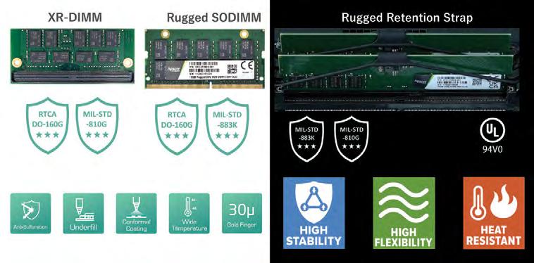
Ą Rugged SODIMM – Dual anti-shock and vibration certification: RTCA DO-160G / MIL-STD-883K
Ą XR-DIMM – Dual anti-shock and vibration certification: RTCA DO-160G / MIL-STD-810G
Ą Underfill technology – complies with MIL-STD-810G shock and vibration requirements
Ą Conformal Coating – uses automated spraying to maintain precise coating thickness
Ą Anti-sulfuration memory modules – pass the ASTM B809-95 anti-sulfuration test.
Ą Rugged Retention Strap – meets MIL-STD-810G / MIL-STD-883K standards.
Ą Supports operating temperature range: -40 °C ≤ TC ≤ 85°C
www.linkedin.com/company/apacer

Designed with the engineering developer in mind, the 524 Series development system incorporates a 9-slot OpenVPX backplane (9 payloads + 2 power slots) with profiles aligned to Sensor Open Systems Architecture (SOSA™) and C4ISR/EW Modular Open Suite of Standards (CMOSS) initiatives. Unobstructed accessibility to cards under test enables probe access with intelligent system monitoring capabilities.
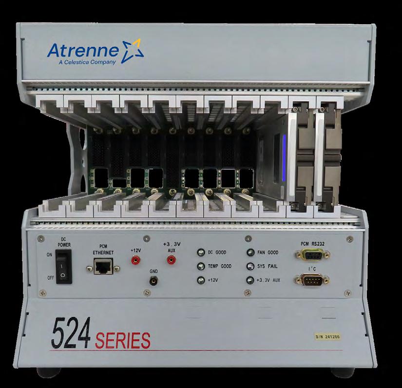
Ą SOSA Aligned
Ą 3U/6U 9 slot payload + 2 power slots SOSA aligned backplane with slot
Ą Open frame for easy card access
Ą Maximum unrestricted airflow and cooling for high-powered cards
Ą Supports 3U x 160mm Modules.
Ą Supports air-cooled modules using IEEE 1101.10 card guides.
Ą Supports conduction-cooled modules using VITA 48.2 aluminum slot guides.
Ą Front mounted LED Array for SOSA Aligned 12V and 3.3 Aux. DC Voltages
Ą DC voltage test jacks for SOSA Aligned 12V and 3.3 Aux. DC Voltages
Ą Front mounted power switch.
Ą Atrenne Chassis Manager System Monitoring Board
https://www.atrenne.com/products/524-series-development-chassis/

We can modify our existing platforms, or incorporate your requirements into a customized solution. Dawn Custom Enclosure products have been installed into everything from torpedoes to entertainment rides. See our website for visibility and insight into the variety and different types of designs created and manufactured by Dawn for a wide range of customers.
Modified COTS and full custom enclosure designs, standard or rugged, compliance tested. Customized solutions for prototyping and development of customer-specific requirements.
Custom designed Air Transport Racks. Custom military application products. Custom designed MIL-GRADE enclosures built as prototype and production units based on customer-specific requirements.
www.dawnvme.com/enclosures/custom-enclosures
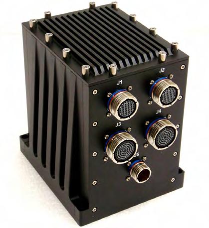
Ą Modified COTS and full custom enclosure designs, standard or rugged, compliance tested.
Ą Custom designed Air Transport Racks.
Ą Custom military application products.
Ą Custom designed MIL-GRADE enclosures.
Ą We can modify our existing platforms, or incorporate your requirements into a customized solution.
Dawn VME Products www.dawnvme.com sales@dawnvme.com 510-657-4444

TS-7100-Z
embeddedTS is proud to introduce the TS-7100-Z, our smallest single board computer in an optional DIN-mountable enclosure that measures 2.4" by 3.6" by 1.7", powered by the Arm® Cortex®-A7 based iMX6 UltraLite CPU. It ships with industry-standard interfaces, including Ethernet, USB, RS-232, RS-485, and CAN.
For wireless connectivity, the TS-7100-Z comes with WiFi and Bluetooth module, as well as a NimbeLink/Digi cellular modem and mesh network socket.
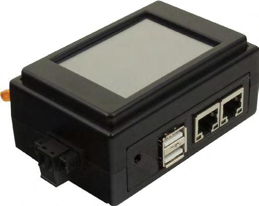
Ą NXP i.MX 6UltraLite 696 MHz Arm® Cortex®-A7 based SPC with FPU
Ą 4 GB eMMC Flash Storage
Ą 802.11 b/g/n WiFi and Bluetooth BT4 LE Radio
Ą Optional 3" 18-bit, 320x240, 135dpi Resistive Touchscreen Display
Ą Industrial Temperature Range (-40 °C to 85 °C)
https://www.embeddedts.com/products/TS-7100-z
embeddedTS www.embeddedts.com sales@embeddedts.com
https://www.embeddedts.com/products/TS-7100-z
Holt has been supplying MIL-STD-1553 ICs to the military and aerospace industries since 2001 and is a one-stop source for all MIL-STD-1553 components. In addition to Holt’s proprietary products, Holt offers drop-in replacements for existing competitor industry standard solutions, providing customers with a cost effective alternative, reducing lead times and mitigating future product obsolescence issues. Holt is the recipient of numerous supplier awards and coupled with its unparalleled technical support and customer service, Holt stands out as the number one choice for MIL-STD-1553 components.
Holt’s products cover the entire gamut of MIL-STD-1553 functionality, including protocol ICs, IP cores, transceivers and transformers. Holt specializes in mixed signal IC design, integrating both digital protocol and analog transceiver functions on a single IC. Select products also integrate MIL-STD-1553 transformers, transceivers and protocol in a single package, providing customers with the highest level of integration necessary to minimize size, weight, power and cost (SWaP-C).
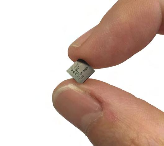
Ą IP Core Family: HI-6300
Ą Protocol, RAM, dual transceivers and dual transformers in a single 15mm x 15mm package: HI-2130
Ą Protocol ICs with integrated transceivers: HI-6130 and MAMBA™
Ą Error-correcting code (ECC) RAM or RAM parity with BIST
Ą Unparalleled free technical support including plug-and-play reference designs and software
Ą Drop-in replacements for existing competitor industry-standard solutions
Ą DO-254 Design Assurance Level A Compliant options
http://www.holtic.com/2024-MilitaryEmbeddedSystemsResourceGuide-MilStd1553.html
Holt Integrated Circuits www.holtic.com sales@holtic.com +1 949-859-8800 www.x.com/holtic www.linkedin.com/company/holt-integrated-circuits

The V1163 is a powerful heterogeneous computing XMC with high bandwidth IO featuring the Xilinx® Versal® ASoC and rugged optical and electrical IO. The V1163 provides options for Versal Prime or AI Core part selection. In a single mezzanine card, the V1163 provides 100G optical interfaces, FPGA fabric, ARM processor cores, and optional AI engines. The V1163 is designed for applications requiring any combination of the following: high speed optical/electrical interfaces, FPGA processing resources, ARM processing cores, and AI engines. Use cases include sensor interface design, digital signal processing, video processing, application co-processing, and multi-level secure networking. Radar, SIGINT, video, storage, medical imaging, and embedded communications systems all have the ability to benefit from the V1163 module. The XMC form factor and rugged design of the V1163 can turn a VPX-based single board computer into a single-slot sensor interface and heterogeneous computing solution.
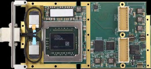
Ą Xilinx® Versal® ASoC (FPGA) with AI Engines (optional)
Ą Up to twelve (12) 1G to 25G optical ports via MPO front panel I/O or VITA 66 optical backplane I/O. Electrical I/O via Pn6 also available
Ą Supports PCIe Gen4/Gen3 x8/x16
Ą 2 banks of 4GB up to 1866MHz LPDDR4 SDRAM
Ą Thermal sensors for monitoring card temperature
Ą Robust FPGA development framework
https://newwavedesign.com/products/xmc-pmc/v1163-12-port-rugged-xmc-asoc-card/
The X9 SPIDER Host “Mission Computer” is a breakthrough in technology and contains many industry firsts in hardware, mechanical structures, interconnect and thermal innovation. With over 26 patents pending, its ultra-small, high performance, space-optimized CPU board, I/O bandwidth (455Gbps) and its unique stackable mechanical design, X9 modules can be configured into any system imaginable.
Featuring the world’s first rugged (IP67) 40 Gbps connectors which provide 100W of power up to 50 meters, the X9’s power delivery, management and density is unmatched in today’s market. Its unique design utilizes patented RuggedCool™ technology to provide four-sided cooling and full operation at up to +85°C.
The Mission Computer is a complete system-in-a-box with so much I/O, storage and processing that a single module meets most system needs. The CPU is the Intel® Xeon® W workstation class with 8 cores operating up to 4.7GHz, with up to 128GB of ECC DDR4 DRAM. The graphics engine drives up to four simultaneous displays over four Thunderbolt™ 4 ports. The four Thunderbolt™ 4 ports are capable of daisy chaining to multiple devices, and each provides 100W of DC power up to 50m.
Available I/O for the Mission Computer is impressive: within the Mission Computer are 20 PCIe Gen4 lanes and 20 PCIe Gen3 lanes used to add internal I/O modules such as MIL-STD-1553, serial, CANbus, 100Gb Ethernet and so much more. I/O is available on M.2 or 50W (RMC-50) and 100W (RMC-100) Rugged Mezzanine Carriers.
The available RMC-100 GPU is NVIDIA’s flagship GPU RTX-A4500 MXM, featuring 16GB of 512GB/s GDDR-6, and 5888 CUDA® cores with 17.66 TFLOPS FP-32. With rackmount server-like performance, the CPU is directly connected to the GPU via 8 lanes of PCIe Gen4 for 128GB/sec transfer rate. The Mission Computer provides up to four 100GigE ports via quad optical transceivers and small rugged connectors. 1/10Gb Ethernet is also available via RMC and/or M.2 add-in modules.
The X9 family of products redefines embedded computer architectures. The traditional computers in the market (rugged or commercial) require the user to pre-configure their systems up front making systems overbuilt and expensive, under-developed for future growth, and inflexible when obsolescence sets in. The X9 Mission Computer’s open Distributed Computer Architecture (DCA) has each specific function available in a sub-system and linked together via Thunderbolt® 4 and a single LightBolt™ cable. Units can be placed up to 50 meters away from each other in any format: Daisy Chain or Star or direct-attach.
This open DCA mitigates obsolescence by upgrading/replacing only those functions required to be upgraded. The 100W power delivery in X9 systems allows each system to be powered on its own or by any of the other systems in the “loop”. There are also options for external power supplies with battery back-up, allowing the system to grow as needed without the limitation of available power. Other X9 modules include: Storage (fixed or removable), GPU, Workstation, Switch and Display as well as many others.
Ą Intel® Xeon® W CPU 8 Cores @ 4.7GHz (Intel® embedded roadmap); 128GB RAM and up to 16TB SSD
Ą GPU co-processor: NVIDIA® RTX-A4500 with 5888 CUDA® Cores, +384 Tensor Cores @ 18TFLOPS with 16GB GDDR6 RAM
Ą Quad Thunderbolt™ 4 ports w/100W power each; copper or up to 50m fiber
Ą Quad 100GigE Fiber; 1/10 GbE via Rugged Mezzanine Carrier or M.2 add-in I/O
Ą Connectivity options: 3x M.2 sites for 5G Cell / Wi-Fi-6 / BT5 / HD-GPS / Dual MIL-STD-1553 / Much more
Ą Over 30 Rugged Mezzanine Carriers (RMC) for easy system customization and expansion
Ą System I/O port with USB / COM / GPIO / SAM™ I/O
Ą Shock, Temperature and Tamper sensors; 8x Tri-color LEDs for status and messaging
Ą Single +20VDC power operation; can be powered via Thunderbolt® 4 power delivery; optional MIL-STD-1275 w/50ms hold-up
Ą Fully-sealed, submersible and conduction coole
Ą Stackable, modular, interlocking systems use “QuadroLock™” wedgelocks to secure systems together only 6”x4.75”x2” and 2.1lbs
Ą Temperature: Operates up to extended temp -40°C to +85°C (Optional)
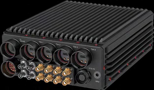
www.gms4sbc.com/x9spider
The X9 Spider “Server Computer” is a technology breakthrough that contains many industry firsts: 26 patents are pending for mechanical and thermal. Modular and scalable, X9 modules can be configured into any system imaginable. X9 Server Computer has the world’s first rugged (IP67) 40 Gbps connectors that also provide 100W of power up to 50 meters, and patented RuggedCool™ technology provides four-sided cooling and full operation at up to +85°C.
The CPU is Intel’s® 3.1GHz Xeon® D processor featuring 20 cores, with up to 128GB of ECC DDR4 DRAM. The graphics engine and two 40Gbps Thunderbolt™ 4 ports provide up to four 8K video streams, and the ports are capable of daisy chaining and each provide 100W of DC power up to 50m. The X9 Server Computer takes full advantage of this bandwidth via Rugged Mezzanine Carriers (RMC) and high speed I/O devices.
The Xeon® D has two directly piped 100GigE ports providing directto-memory RDMA and RoCE v2, plus there are 24 PCIe Gen4 lanes also under DMA control. With M.2 storage, the X9 Server provides ultra performance RAID via Intel VROC. The CPU is directly connected to the GPU via 8 lanes of 28GB/sec PCIe Gen4.
The available RMC-100 GPU is NVIDIA’s flagship GPU RTX-A4500 MXM, featuring 16GB of 512GB/s GDDR-6, and 5888 CUDA® cores with 17.66 TFLOPS FP-32. With rackmount server-like performance, the CPU is directly connected to the GPU via 8 lanes of PCIe Gen4 for 128GB/sec transfer rate. The Server Computer provides up to two 100GigE ports via quad optical transceivers and small rugged connectors. 1/10Gb Ethernet is also available via RMC and/or M.2 addin modules.
Available I/O for the Mission Computer is impressive: using 20 PCIe Gen4 lanes and 20 PCIe Gen3 lanes, users can choose internal I/O modules such as MIL-STD-1553, serial, CANbus, 100Gb Ethernet and so much more. I/O is available on M.2 or 50W (RMC-50) and 100W (RMC-100) Rugged Mezzanine Carriers.
The X9 family of products redefines embedded computer architectures. The traditional computers in the market (rugged or commercial) require the user to pre-configure their systems up front making systems over-built and expensive, under-developed for future growth, and inflexible when obsolescence sets in. The X9 Mission Computer’s open Distributed Computer Architecture (DCA) has each specific function available in a sub-system and linked together via Thunderbolt® 4 and a single LightBolt™ cable. Units can be placed up to 50 meters away from each other in any format: Daisy Chain or Star or direct-attach.
This open DCA mitigates obsolescence by upgrading/replacing only those functions required to be upgraded. The 100W power delivery in X9 systems allows each system to be powered on its own or by any of the other systems in the “loop”. There are also options for external power supplies with battery back-up, allowing the system to grow as needed without the limitation of available power. Other X9 modules include: Storage (fixed or removable), GPU, Workstation, Switch and Display as well as many others.
Ą Processor: Intel® Xeon® D CPU, 20 Cores @ 3.1GHz; 128GB RAM / 80TB SSD
Ą GPU co-processor: NVIDIA® RTX-A4500 with 5888 CUDA® Cores, +384 Tensor Cores @ 18TFLOPS with 16GB GDDR6 RAM
Ą Dual Thunderbolt™ 4 ports w/100W power each; copper or up to 50m fiber
Ą Dual 100GigE Fiber with RDMA; 1/10 GbE via Rugged Mezzanine Carrier or M.2 add-in I/O
Ą Connectivity options: 3x M.2 sites for 5G Cell / Wi-Fi-6 / BT5 / HD-GPS / Dual MIL-STD-1553 / >30 RMC carriers
Ą Up to 4TB native high-performance SSD
Ą Up to 64TB high-performance SSD w/RAID/RDMA (via RMC-50)
Ą System I/O port with USB/COM/GPIO/SAM™ I/O
Ą Single +20VDC power operation; can be powered via Thunderbolt® 4 power delivery; optional MIL-STD-1275 w/50ms hold-up
Ą Fully-sealed, submersible and conduction cooled
Ą Stackable, modular, interlocking systems use “QuadroLock™” wedgelocks to secure systems together
Ą Ultra-small at 6”x4.75”x2” and 2.1lbs.
Ą Temperature: Operates up to extended temp -40°C to +85°C (Optional)
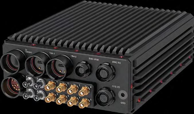
The X9 and Epic Intelligent Switches provide essential functions in any rugged system. They provide an astounding level of performance and bandwidth that is not even found in rackmount switches, yet fits in the palm of a hand! They are fully sealed, rugged, and battlefieldready with no compromise to performance.
The X9 Intelligent Switch (12 ports) provides an incredible four 100Gb Ethernet ports at a full data rate, as well as eight 10GBase-TX Ethernet ports via rugged mil-circular connectors or RJ-45 jacks for lab or industrial application use. The 36-port Epic Intelligent Switch has four 100Gb Ethernet ports and 32 10Gb Ethernet ports.
Both switches open up rugged applications which have never before been possible due to size restrictions, speed or power requirements. X9 Intelligent and Epic Switches may be cascaded for unmatched performance at any size or cost.
The heart of each switch is a Broadcom Ultra Low Latency, high bandwidth enterprise-class switch with up to 880Gbps of core switching bandwidth. This Layer 2/3 deployed switch architecture and Cumulus® Linux control software is well supported via GMS’s quad core Atom processor with 32GB of DRAM and 1TB of SSD. The embedded processor is responsible for configuring the switch and provides a browser-based user interface for control and programming. To facilitate this interface a service port is provided with video, dual USB and a 1Gb Ethernet port for remote access.
All the connectors for power, 100Gb Ethernet, Service and 10Gb Ethernet ports are fully rugged, waterproof (IP67) and have covers to prevent damage when no cables are connected.
The X9 family of products redefines embedded computer architectures. The traditional computers in the market (rugged or commercial) require the user to pre-configure their systems up front making systems over-built and expensive, under-developed for future growth, and inflexible when obsolescence sets in. The X9 Spider family’s open Distributed Computer Architecture (DCA) has each specific function available in a sub-system and linked together via Thunderbolt® 4 and a single LightBolt™ cable. Units can be placed up to 50 meters away from each other in any format: Daisy Chain or Star or direct-attach.
This open DCA mitigates obsolescence by upgrading/replacing only those functions required to be upgraded. The 100W power delivery in X9 systems allows each system to be powered on its own or by any of the other systems in the “loop”. There are also options for external power supplies with battery back-up, allowing the system to grow as needed without the limitation of available power. Other X9 modules include: Storage (fixed or removable), GPU, AI, Workstation, Switch and Display as well as many others.
Ą Ultra-fast, low latency, 12 port/36 port intelligent Layer 2/3 switches with onboard 416MHz MIPS CPU
Ą Switching: 4x 100GigE ports; 8x 10GigE ports (X9 Intelligent) or 32x 10GigE ports (X9 Epic)
Ą Up to 880Gbps bandwidth switching via non-blocking, enterpriseclass Broadcom 56760 Switch
Ą Quad core Intel CPU for packet operations and configuration
Ą Configured via Cumulus® Linux for advanced top-of-rack data center IP processing
Ą High-performance stacking; fast failover within 100ms
Ą ContentAware™ engine for scalable, high-density packet classification
Ą DHCP client and server support, plus SNMP
Ą Supports MLPS for short-path routing on WANs
Ą Unicast, multicast and spanning tree capabilities
Ą Advanced SmartHash for load balance across trunk groups
Ą Very low latency, VLAN support, QoS/differentiated services
Ą Only 6” x 4.75” x 2” @ 2lbs. (X9 Intelligent) or 9” x 6” x 4” @ 4lbs. (X9 Epic Intelligent)
Ą Shock, Temperature and Tamper sensors; 8x Tri-color LEDs for status and messaging
Ą Single +20VDC power operation; optional MIL-STD-1275 w/50ms hold-up
Ą Fully-sealed, submersible and conduction cooled
Ą Stackable, modular, interlocking systems use “QuadroLock™” wedgelocks to secure systems together
Ą Temperature: Operates up to extended temp -40°C to +85°C (Optional)
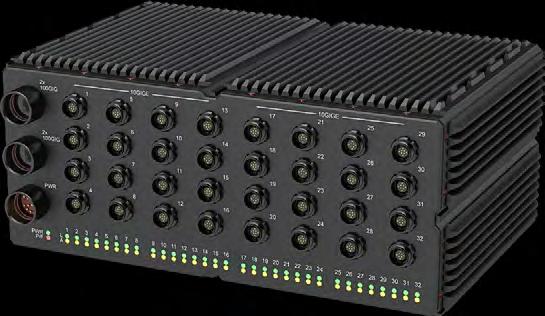
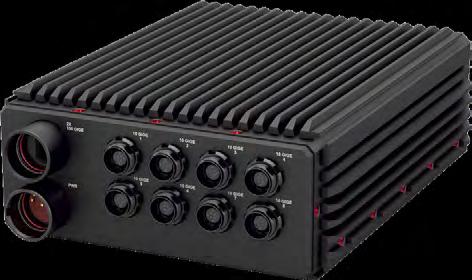
The X9 Storage module provides remote and local removable Mass Storage to the X9 Host computers. The storage canister is removable with over 5000 mating cycles. This makes the storage module ideal for applications where massive amounts of data must be captured at very high data rates and be removed for security or archive needs.
The X9 Storage connects an X9 Host computer (X9 Mission Computer, X9 Server Computer, X9 AI System) via Thunderbolt™ 4 up to 50 meters away without the need for an external power supply (powered by Host) with 40Gb/s transfer rate. Each Storage module supports four U.2 storage devices in a sealed canister. The U.2 may be Quad NVMe, SATA, or up to Eight M.2 (2280) memory sticks. Additionally, NSA approved encryption drives such as FIPS-140-2 or CSfC are available for total security. The locking mechanism of the canister is rugged and tamperproof. It alerts the system as soon as the lever is turned which allows the Host to initiate a Secure Erase cycle if so programmed. A hardware optional RAID controller may be ordered in lieu of the standard software controller.
Storage modules may be cascaded as needed by the system, and each Storage system may be up to 50 meters away from each other. Thunderbolt™ 4 provides the copper or fiber interconnect, and also transports up to 100W of power delivery over the cable. The X9 Storage capacity and speed have never been achieved in Network Attached Storage (NAS) residing 50 meters away. This removes the distance limitation of Direct attached Storage (DAS) and brings new applications for the battlefield such as ground vehicles, UAV/UAS platforms, command post installations, and shipboard or airborne platforms.
The X9 family of products redefines embedded computer architectures. The traditional computers in the market (rugged or commercial) require the user to pre-configure their systems up front making systems over-built and expensive, under-developed for future growth, and inflexible when obsolescence sets in. The X9 Spider family’s open Distributed Computer Architecture (DCA) has each specific function available in a sub-system and linked together via Thunderbolt® 4 and a single LightBolt™ cable. Units can be placed up to 50 meters away from each other in any format: Daisy Chain or Star or direct-attach.
This open DCA mitigates obsolescence by upgrading/replacing only those functions required to be upgraded. The 100W power delivery in X9 systems allows each system to be powered on its own or by any of the other systems in the “loop”. There are also options for external power supplies with battery back-up, allowing the system to grow as needed without the limitation of available power. Other X9 modules include: Storage (fixed or removable), GPU, Workstation, Switch and Display as well as many others.
General Micro Systems, Inc. www.gms4sbc.com
Ą Storage: Quad U.2 storage canister with high 5K mating cycles
Ą Rugged: fully-sealed, removable canister and mating unit
Ą Connectivity: dual Thunderbolt™ 4 ports with 100W power delivery (each port)
Ą Capacity: Secure, quad U.2 SSD up to 128TB
Ą Supports Quad NVMe™ (x4 PCIe) or SATA or Eight M.2 SSD
Ą Support for NSA approved drive encryption such as FIPS-140-2 or CSfC
Ą Supports RAID 0/1 via software; optional hardware RAID controller
Ą Only 6” x 4.75” x 2” @ 2lbs.
Ą Shock, Temperature and Tamper sensors; 8x Tri-color LEDs for status and messaging
Ą Single +20VDC power operation; optional MIL-STD-1275 w/50ms hold-up
Ą Power surge and spike power conditioners
Ą Fully-sealed, submersible and conduction cooled
Ą Self-retaining dust caps for each I/O connector
Ą Stackable, modular, interlocking systems use “QuadroLock™” wedgelocks to secure systems together
Ą Temperature: Operates up to extended temp -40°C to +85°C (Optional)
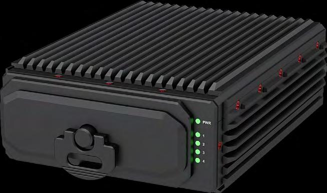
sales@gms4sbc.com
www.gms4sbc.com/x9spider
800-307-4863
www.linkedin.com/company/general-micro-systems
The X9 Workstation I/O (“WSIO”) is an integral function of the X9 system architecture, providing user interfaces including displays, networks, input devices, local dedicated secure storage. WSIO allows add-in application-specific I/O and has industry-standard rugged, sealed, dustproof and waterproof connectors to withstand a rugged environment for years of reliable operation.
The X9 WSIO is connected to the Host computer (X9 Mission or X9 Server) via a Thunderbolt™ 4 interface and may be powered directly from an X9 Host up to 50 meters away. Further, multiple X9 WSIOs may be daisy chained to an unlimited number of stations, while Thunderbolt™ 4 provides unlimited expansion to other X9 modules.
Built-in WSIO user interfaces are: one 10GBase-TX via a sealed RJ-45 connector, mini DisplayPort, five 10Gbit/s USB-C (3.2) ports with up to 15W (5V @ 3A) of power delivery to peripherals. All the X9 WSIO connectors are fully sealed and allow a rubber cover when not in use.
The X9 WSIO includes a removable U.2 tray for either a 2.5” NVMe™ or SATA drive, or two M.2 SSD sites. The drives may be NSA encrypted or CSfC type; can be easily removed to archive the data.
The X9 WSIO also provides twelve expansion I/O or sensor sites. There are: six M.2 (3042) for larger I/O modules such as 5G cell modems, dual MIL-STD-1553, or many others from GMS or a third party. Additionally, three M.2 (2242) and three Express Mini sites for I/O such as NTSC video capture, video out, dual 1Gb Ethernet, GPS, Wi-Fi®/Bluetooth and many more. Visit the GMS website for all SAM (Special Application Modules) available from GMS.
The X9 WSIO may be powered by the Host via Thunderbolt™ 4 or powered by external +20VDC power via an IP67 GMS Smart Power™ (patent pending) connector for safe, ultra low EMI.
The X9 family of products redefines embedded computer architectures. The traditional computers in the market (rugged or commercial) require the user to pre-configure their systems up front making systems over-built and expensive, under-developed for future growth, and inflexible when obsolescence sets in. The X9 Spider family’s open Distributed Computer Architecture (DCA) has each specific function available in a sub-system and linked together via Thunderbolt™ 4 and a single LightBolt™ cable. Units can be placed up to 50 meters away from each other in any format: Daisy Chain or Star or direct-attach. This open DCA mitigates obsolescence by upgrading/replacing only those functions required to be upgraded. The 100W power delivery in X9 systems allows each system to be powered on its own or by any of the other systems in the “loop”. There are also options for external power supplies with battery back-up, allowing the system to grow as needed without the limitation of available power. Other X9 modules include: Storage (fixed or removable), GPU, Workstation, Switch and Display as well as many others.
Ą Connection: commercial rugged I/O connectors
Ą Storage: fully-sealed removable storage, 2.5” SSD, 2x M.2, NVMe™ , SATA
Ą Connectivity: dual Thunderbolt™ 4 ports with 100W power delivery (each port)
Ą Expansion: 12 Expansion sites – 9x M.2, 3x Express Mini
Ą 10GBase-TX port with sealed RJ-45 connector (pat. pending)
Ą One sealed DisplayPort with 8K support (patent pending)
Ą Five USB-C ports with power
Ą Connects directly to X9 Host without a power supply; up to 100W downstream power
Ą Only 6” x 4.75” x 2” @ 2lbs.
Ą Shock, Temperature and Tamper sensors; 8x Tri-color LEDs for status and messaging
Ą Single +20VDC power operation; optional MIL-STD-1275 w/50ms hold-up
Ą Power surge and spike power conditioners
Ą Fully-sealed, submersible and conduction cooled
Ą Stackable, modular, interlocking systems use “QuadroLock™” wedgelocks to secure systems together
Ą System I/O, 4x Antennas, 4x Coax video
Ą Self-retaining dust caps for each I/O connector
Ą Temperature: Operates up to extended temp -40°C to +85°C (Optional)
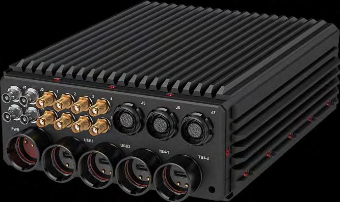

XEM8350 High-Bandwidth FPGA Module
With an AMD Kintex UltraScale XCKU060-1FFVA FPGA and industry-first fully-independent dual-SuperSpeed USB 3.0 host interface, the XEM8350 can transfer over 650 MB/s, making it an ideal solution for high-performance sensor management and data capture applications.
To manage that pipeline, Opal Kelly’s FrontPanel SDK provides a robust API for communication, configuration, and interfacing to your PC, Mac, or Linux hardware. FrontPanel surfaces not only the FPGA internals but integrated DDR4, power supplies, platform flash, gigabit transceivers, and voltage, current, and temperature monitors, all optimized for a minimal FPGA footprint. The result is a faster prototyping cycle and more reliable OEM integration process.
Typical applications include:
• LIDAR and RADAR Video
• Image Capture
• Software-Defined Radio
• 5G Systems
Opal Kelly Incorporated www.opalkelly.com
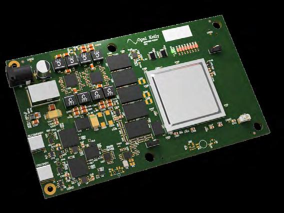
Ą Xilinx Kintex UltraScale XCKU060-1FFVA
Ą 2x 16-MiB serial flash
Ą 32-MiB dedicated serial flash for FPGA boot
Ą 4-GiB DDR4
Ą Dual SuperSpeed USB 3.0 interface (Cypress FX3)
Ą 28 Gigabit Transceivers
Ą 332 user I/O including GC pairs
https://opalkelly.com/products/xem8350/
sales@opalkelly.com 217-391-3724
www.linkedin.com/company/opal-kelly-incorporated @opalkelly

XEM8370 FPGA Development Board with Kintex UltraScale+
The XEM8370 is built to get the most out of the AMD Kintex UltraScale+ XCKU11P with high-quality integrated components and a suite of tools for developing and deploying your embedded hardware. Built-in USB 3.0 connects you to the Opal Kelly FrontPanel® SDK, a powerful ecosystem that includes gateware, firmware, and an API for building software-connected FPGA applications.
Access to 28 high-speed serial transceiver pairs (28 Rx and 28 Tx) corresponding to 5 GTH quads and 2 GTY quads on the FPGA are available on the expansion connectors. Kintex UltraScale+ transceivers support serial standards such as 10 GbE, JESD-204B, DisplayPort, PCI Express, SATA, HD-SDI, HDMI, XAUI, and Aurora up to 16.375 Gbps.
Opal Kelly integration modules reduce time-to-market, allow teams to focus on their core competencies, and simplify supply chains. Opal Kelly has been ISO 9001:2015 certified since 2019.
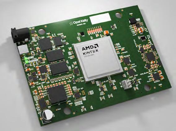
Ą AMD Kintex UltraScale+ XCKU11P-1FFVA1156E
Ą SuperSpeed USB 3.0 interface for configuration and data transfer
Ą 16-MiB system flash
Ą 32-MiB QSPI FPGA flash
Ą 2-GiByte DDR4 (32-bit wide data interface)
Ą Self-powered by single DC supply (5 to 18 VDC)
Ą 301 FPGA fabric I/O https://opalkelly.com/products/xem8370/
Opal Kelly Incorporated www.opalkelly.com
sales@opalkelly.com

SHM300 SOSA Aligned Chassis Manager, Mezzanine, Tier3
The Pixus SOSA aligned chassis manager is a mezzanine-based solution that affixes to the rear of an OpenVPX backplane so that you don't consume a slot. The compact Pixus solution can fit in smaller ATR or rackmount enclosures. The proven chassis manager has been deployed in systems that have gone through full MIL qualification testing.
With a PolarFire FPGA, the SHM300 is highly versatile. It allows a wide array of GPIO, MP port, and other pin options along with a KX/BX port, Base-T port, and other interfaces. The SHM300 features 100% USA based software and firmware.
Contact Pixus to discuss your application today!
Enclosure Systems Backplanes Chassis Managers
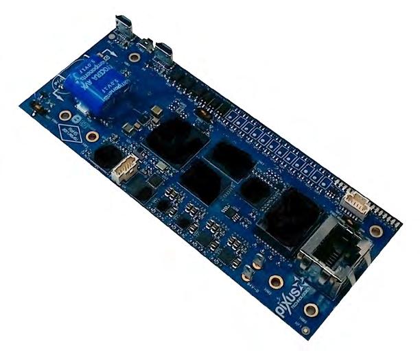
Ą Three versions available:
1) mezzanine-based (so you don't consume a slot)
2) 3U slot pluggable
3) Lab/test version for easy and cost-effective development
Ą 100% USA based software & firmware
Ą Proven in MIL rugged deployed systems
Ą RESTful API interface, versatile configurable design with PolarFire FPGA
Ą Compact size
Ą Readily available
www.pixustechnologies.com Pixus Technologies www.pixustechnologies.com
Pixus offers a full ecosystem of SOSA aligned products from backplanes, chassis platforms, and chassis managers as well as our 3rd party partners for SOSA aligned plug in cards and PSUs. The company has a wide range of SOSA slot profile backplane combinations and enclosure options in various cooling formats. This includes airflow over conduction-cooled fins, Air Flow By, Air Flow Through, and liquid cooling. The company has developed a wide range of backplane at 100GbE and PCIe Gen4 speeds as well as customized designs at higher data rates. The versatile Pixus SOSA aligned mezzanine based chassis manager fits behind a backplane without losing a slot. It features 100% USA based software/ firmware. Contact Pixus today for your SOSA/OpenVPX solution! Contact Pixus to discuss your application today!
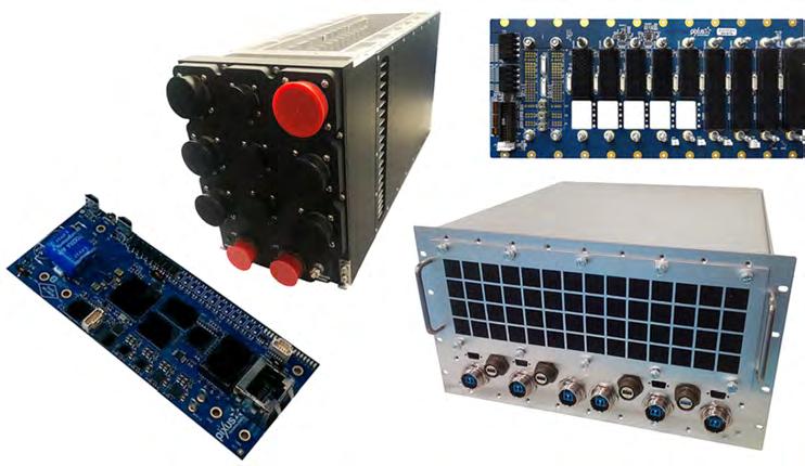
Ą SOSA Aligned OpenVPX chassis in ATR, MIL rugged rack-mount, and lab/test formats
Ą Backplane design expertise up to and above 100GbE speeds, RT3 connector
Ą SOSA Aligned SlotSaver mezzanine-based VPX chassis manager, Tier 3+, 100% US based software/firmware
Ą Various advanced cooling options for chassis platforms
Ą Experienced in advanced and creative design requirements
Enclosures Cases Subracks Backplanes Chassis Integrated Systems Components
www.pixustechnologies.com Pixus Technologies www.pixustechnologies.com
916-297-0020
Multi-Chip
Viking Technology’s newly released 16GB Multi-Chip Package (MCP) is part of the extreme density line of DDR4 memory products optimized for the embedded, industrial, and military/aerospace markets. Viking's 16GB DDR4 MCP has demonstrated its robustness and reliability in the most demanding environments. From missile applications to fighter jets, its performance has proven instrumental in enhancing guidance systems, ensuring precision targeting and mission success.
Additionally, its integration into Digital Signal Processing (DSP) boards unlocks advanced signal processing capabilities, enabling real-time data analysis and decision-making in complex battlefield situations underscoring the product's versatility and effectiveness in meeting the stringent requirements of defense applications. MCP memory products achieve significantly higher memory performance and density per cubic inch than conventional memory DIMMs.
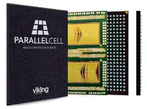
Ą Very small footprint: Saves up to 85% board space vs. Standard DIMM Modules sizes 15mm x 20mm & 13mm x 20mm
Ą Rugged: Soldered-down – No DIMM connector
Ą Speeds 2400/2667/2933
Ą Superior signal integrity
Ą Very high memory bandwidth and capacity per cu. in.
Ą Lower cost motherboard due to easier DDR routing
Ą 4GB/8GB/16GB densities, with data width of X32, X40, and X72
Ą Custom solutions x80, higher densities
https://www.vikingtechnology.com/rugged-memory/ddr4-mcp-multi-chip-package-module/
Viking Technology www.vikingtechnology.com/ sales@vikingtechnology.com 714-913-2221 www.linkedin.com/company/vikingtechnology/ @vikinology
LightABLE™ LLX12 Fiber Optic Transceiver
The LightABLE LLX12 fiber optic transceiver is Smiths Interconnect’s solution for up to 10 Gbps per lane mid-board optical connectivity. Offering 12 full-duplex lanes in a single compact package, this module provides maximum port count for moving 10 Gbps data to and from high-bandwidth density processor boards.
The LightABLE family also enables ease of PCB assembly and maintainability in its electrical and optical attachment. The LLX12 is production-qualified and shipping now.
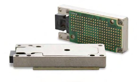
Ą 10 Gbps per channel data rates in a 12TRX channel configuration.
Ą Reduces optical interconnect SWaP with a low-profile, rugged MIL-STD qualified, midboard-mounted module.
Ą Provides high port-bandwidth density of up to 120 Gbps full-duplex in a solution less than 6 mm high and 14 mm wide.
Ą Simplifies assembly and rework via use of LGA interposer for electrical connection and MicroClip connection to a fiber optic cable (no pigtail).
Ą VPX single board computing, C4ISR embedded processing systems.
www.smithsinterconnect.com/products/optical-transceivers/embedded-transceivers/lightable-10g-ll-series-4trx-12tx-and-12rx/
Smiths Interconnect www.smithsinterconnect.com
focom.uscsr@smithsinterconnect.com
813-901-7200
www.linkedin.com/company/smiths-interconnect/ @smithsinterconn
Lauterbach Debugger for Intel x86/x64
Skylake/Kabylake
Lauterbach TRACE32 Debugger for Intel x86/x64:
In January of this year, Lauterbach introduced the new CombiProbe Whisker MIPI60-Cv2. The TRACE32
CombiProbe and TRACE32 QuadProbe now offer the same debug features for the Converged Intel® MIPI60 connector:
• Standard JTAG, Intel® debug hooks with Pmode, and I2C bus
• Merged debug ports (two JTAG chains)

• Intel® Survivability features (threshold, slew rate, ...)
However, these debug tools have different areas of application. The TRACE32 QuadProbe, which is expressly designed for server processors, is a dedicated debug tool that enables SMP debugging of hundreds of threads on targets with up to four debug connectors.
The TRACE32 CombiProbe with the MIPI60-Cv2 Whisker, designed for client as well as mobile device processors, can capture and evaluate system trace data in addition to its enhanced debugging features.
Trace capabilities include support of one 4-bit and one 8-bit trace port with nominal bandwidth.
The TRACE32 CombiProbe with the DCI OOB Whisker is specially designed for debugging and tracing of form factor devices without debug connectors. If the chip contains a DCI Manager, the target and the debugger can exchange debug and trace messages directly via the USB3 interface. The DCI protocol used to exchange messages supports standard JTAG and Intel® debug hooks as well as trace messages for recording system trace information.
Ą CombiProbe MIPI60-Cv2 provides debug and system trace capability
Ą Support for standard JTAG, debug HOOKs and I2C bus
Ą Support for merged debug ports (two JTAG chains per debug connector)
Ą Support for survivability features (threshold, slew rate, etc.)
Ą Support for system trace port with up to 8 trace data channels
Ą 128 MByte of trace memory
Ą SMP debugging (including hyperthreading)
Ą AMP debugging with other architectures
Ą BIOS/UEFI debugging with tailor-made GUI for all UEFI phases
Ą Linux- and Windows-aware debugging
Ą Hypervisor debugging
The Lauterbach TRACE32 Debugger now also operates as a TCF agent. This makes it possible to use the Wind River Workbench or the Eclipse debugger as an IDE and a TRACE32 debugger as a debugging back-end tool.
The Target Communication Framework (TCF) was developed by the Eclipse Foundation as a protocol framework with the goal of defining a uniform debugging communication protocol between an IDE and a target system.
TCF defines a series of standard services. At the same time, the framework is open for the definition of proprietary services.
After the TRACE32 software is started as a TCF agent, it provides its services to the Wind River Workbench or the Eclipse debugger via TCP/IP.
Using its TCF services, the TRACE32 debugger can now provide an open communication interface for debugging with Eclipse or the WindRiver Workbench for all processor architectures and compilers supported by TRACE32.
Lauterbach, Inc. www.lauterbach.com
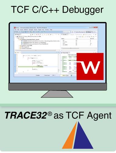
Ą TRACE32 operates as TCF agent
Ą Support for various launch mechanisms
Ą Support for all debug relevant TCF services
Ą Synchronized debugging between TRACE32 and TCF C/C++ Debugger in Wind River Workbench
Ą Support for multiple projects (multicore)
Ą Applicable for all processor architectures supported by TRACE32
Ą Based on Target Communication Framework (TCF)
www.lauterbach.com/intwindriver.html
Lauterbach provides support for seamless debugging of hypervisor-based systems. The introduction of the unique Lauterbach Machine ID allows the debugger to identify any virtual machine in the system. This gives the debugger full visibility of the context of all active and inactive virtual machines and provides a supporting framework to load OS specific awarenesses for each virtual machine.
The most important objective of the TRACE32 hypervisor-awareness is a seamless debugging of the overall system. This means that when the system has stopped at a breakpoint, one can check and change the current state of every single process, all VMs, plus the current state of the hypervisor and of the real hardware platform.
The TRACE32 hypervisor-awareness provides the debugger with all of the hypervisor’s information running on the hardware platform. After the OS-awareness is loaded for each guest/VM the debugger can display an overview of the overall system.
TRACE32 assigns each VM a number, the machine ID (mid column). The machine ID is a unique identifier that is used by TRACE32 and appears as an address extension; a concept already familiar to TRACE32 users.
The Global Task List represents the heart of the TRACE32 hypervisor-aware debugging. It lists all tasks/processes/threads of the guest OSes and the hypervisor. TRACE32 can visualize the context of any task in its GUI. Just double-click to on the task name.
The TRACE32 CORE List window displays in detail what is currently running on the individual cores of an SMP system.
The TRACE32 GUI visualizes the context of the current core/task by a double-click on the task name in the TRACE32 Global Task List.
TRACE32 allows the visualisation of any task, even if its VM is currently not active.
Since Lauterbach has systematically extended the well known concepts for OS-aware debugging to hypervisor debugging, it will be easy for TRACE32 users to get started with just a little practice.
Ą Seamless debugging of the total system in stop-mode
Ą Hypervisor-awareness as a loadable debug extension is provided by Lauterbach
Ą Machine ID allows the user to uniquely identify any virtual machine in the system
Ą Machine ID provides full visibility of context of active and inactive virtual machines
Ą OS-awareness can be loaded for each virtual machine
VPX7600 3U VPX SBC with Intel Tiger Lake-H Xeon W CPU
Acromag’s new VPX7600 is a SOSA aligned I/O Intensive single board computer. This SBC features Intel’s 11th Generation Tiger Lake-H Xeon W-11000E Series processor. The high-performance 8-core processor supports up to 32GB of dual-channel, soldered-down DDR4 ECC memory. It also contains an integrated Intel Gen12 UHD Gfx-32 graphics engine. A wide variety of I/O peripherals are supported. The XMC expansion site enables advanced computation capabilities with plug-in mezzanine modules. A DisplayPort 1.4 interface on the backplane with HBR3 data rates supports 4K resolution. NVME SSD on-board storage holds up to 1TB of data. Other peripheral interfaces include a 2.5GBASE-T port, USB 3.2, USB 2.0, SATA III, 4x GPIO, and an RS422 or dual RS232 ports. Air-cooled and conduction cooled versions are available. Board support packages facilitate use with Microsoft Windows®, Linux®, and VxWorks™ operating systems.
Acromag www.acromag.com
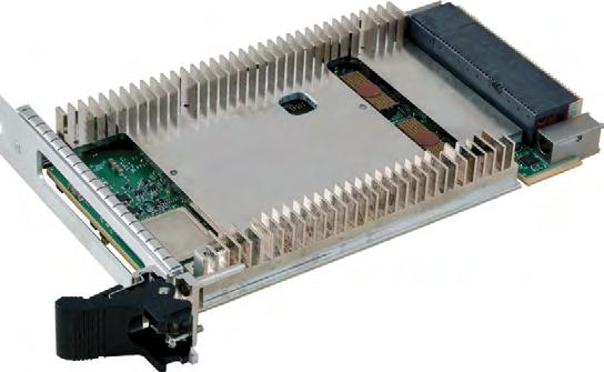
Ą Intel 11th Gen Xeon-W Tiger Lake-H 8-Core CPU
Ą 32GB of dual channel DDR4 SDRAM with ECC
Ą Up to 1TB NVMe SSD on-board storage
Ą 100Gb Ethernet Data Plane
Ą 10Gb Ethernet Control Plane
Ą x4 PCIe Gen3 Expansion Plane
Ą IPMC VITA 46.11 Tier-3 System Management
https://www.acromag.com/vpx7600
solutions@acromag.com 877-295-7088 www.linkedin.com/company/acromag @acromag
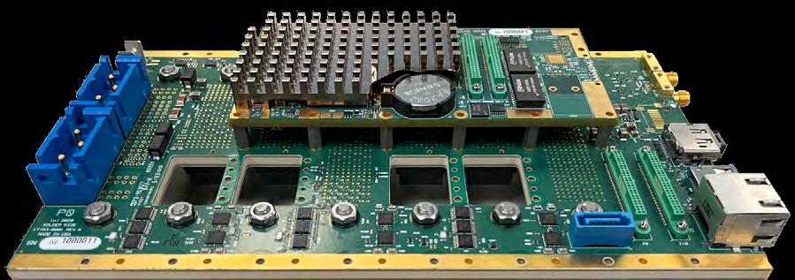
Chassis Manager / SoM Optimized for VITA 65/SOSA™ Profiles
The VITA 46.11-aligned WILD™ VPX Chassis Manager / System on Module (WABGM0/2/6) enable critical chassis control, maintenance, and security functions, are optimized for VITA 65/SOSA profiles, and offer commercial offthe-shelf (COTS) availability.
They are highly-integrated modules. They provide access to plug in card (PIC) JTAG and Maintenance ports, CLK1 usage via on-board Zynq FPGA, network functions, and some optional advanced security functions. For security, the Chassis Managers implement security signal interfaces and a Xilinx UltraScale+ Zynq MPSoC and latest Microsemi PolarFire FPGA, which can be end-user modified with the optional BSP.
MADE


Shown mounted to a 3U VPX Backplane
FEATURES
Ą Capability: Provides control and access to Plug-In Card JTAG and Maintenance ports, CLK1 usage, network functions & optional advanced security functions
Ą FPGAs: AMD Xilinx UltraScale+™ Zynq (ZU5EG or ZU11EG or ZU15EG) & MicroSemi PolarFire
Ą Mounting: Directly on backplane, cabled, or via 3U or 6U VPX plug-in carrier card
Ą Power: Only requires 3.3V
Ą Optional BSP: For customizing Zynq PS & PL for security
Ą Standards: VITA 46.11 & MIL-STD-1553
Ą Availability: Commercial off-the-shelf
www.annapmicro.com/product-category/chassis-and-backplane-accessories/
410-841-2514
The SBC3513L Rugged Single Board Computer (SBC) features the new high performance, highly integrated Intel® Xeon W processor (formerly known as ‘Tiger Lake H’) and support for deterministic Ethernet capabilities including Time Sensitive Networking (TSN). In alignment with the SOSA™ technical standards and in support of the DOD’s C4ISR/EW Modular Open Suite of Standards (CMOSS), the SBC3513L’s data plane fabric connectivity is via a 100G capable Ethernet fat pipe, with a Gen 4 capable PCIe™ fat pipe providing the expansion plane. Control plane connectivity on the backplane is via two 25G capable Ethernet ultra-thin pipes with an additional 2500BASE-T thin pipe for external connection. As an additional option, the ultra-thin pipes are multiplexed with SERDES connections from the FPGA to enable the implementation of FPGA based 10G Ethernet IP cores, which can support deterministic Ethernet capabilities including TSN for automotive, industrial, and flight certified applications. The Xeon W combines eight 11th Generation Core™ i7 technology processing cores with a rich I/O mix, all with the backing of Intel’s Embedded Use Conditions – ideal for long term, High Reliability Applications
The SBC3513L offers memory resources including 64 GB of high speed DDR4 SDRAM and up to 480 GB NAND Flash (NVMe SSD), plus a range of I/O including DisplayPort™, USB, GPIO and serial comms. An on-board mezzanine expansion site is also provided for enhanced system flexibility. Available in a range of air- and conduction cooled build levels with extended temperature capability, the SBC3513L is designed to meet the requirements of a wide range of applications from industrial through to fully rugged. The SBC3513L incorporates a range of security features that include an inherently secure FPGA solution (Xilinx® Zynq® UltraScale+™), and support for Intel Converged Boot Guard and Trusted Execution Technology (CBnT)”. The FPGA can be utilized to instantiate a range of Abaco defined security features. Customers who wish to embed their own application specific features, can also be supported.
Ą Single slot 3U VPX Single Board Computer
Ą Xeon W CPU
Ą Two channels of soldered DDR4 SDRAM with ECC up to 64 GB
Ą Up to 480 GB NAND Flash (NVMe SSD)
Ą 100G Ethernet Data Plane
Ą x4 PCIe Expansion Plane
Ą 25G Ethernet Control Plane
Ą IPMI Management Plane
Ą One XMC site
Ą Convection and conduction cooling variants
Ą Windows® and Linux® OS support
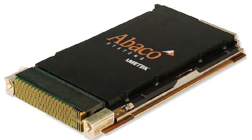
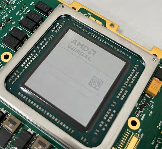
Annapolis WILDSTAR™ Versal Premium Boards are the highest performing OpenVPX COTS FPGA Processing Baseboards on the market, with capability for 100Gb Ethernet over copper on the VPX backplane. Blind mate optical and/or RF (VITA 66/67) is also available. All 100GbE boards are VITA 65-compliant and align with the SOSA Technical Standard.
These SOSA aligned Plug-In Cards (PIC) integrate the latest Versal Premium FPGAs. AMD’s new Versal Adaptive SoCs are engineered for processing-intensive applications like Radar, EW, and SIGINT.
High-performance digitization is via Mezzanine Card(s) connected to FMC+ based I/O site(s). Choose between a JESD-based (bandwidth optimized) or LVDS-based (latency optimized) approach.
Annapolis rugged FPGA boards are designed from the ground up to perform at the highest levels in the harshest environments. They are designed and tested for reliability, utilizing high performance air, conduction, or air-flow-through cooling for thermal control.
All Annapolis products are engineered and manufactured under one roof in the United States. This co-location of engineering and manufacturing allows for more aggressive design, and better quality control and production flexibility.


Ą General Features
• Up to two AMD Xilinx Versal Premium FPGAs
• Multiple levels of hardware and software security
• A Full Board Support Package for fast and easy Application Development
� BSP options include traditional RTL and new DFX RTL and Vitis™ paths
Ą Mezzanine I/O
• Optimized for VITA 66/67 interfaces
• Based on FMC+
• Available options:
� WHDMF1: Jariet Electra-MA: 2TX (64.0GSps)/2RX (61.4GSps)
� WHGM65: AMD Xilinx RFSoC: 4TX (5.0GSps)/4RX (9.85GSps)
� WHQMB1: ADI Apollo MxFE 4TX (20.0GSps)/4RX (28.0GSps)
� WLDM30: TI 2TX (3.2GSps)/2RX (3.2GSps)
� Others covered under NDA
Ą Mechanical and Environmental
• Air, conduction, or AFT cooled: -55°C to +85°C Operating
• Available in extended temperature grades
• Hot swappable for air-cooled variants
• Only requires +12V and +3.3VAUX from backplane
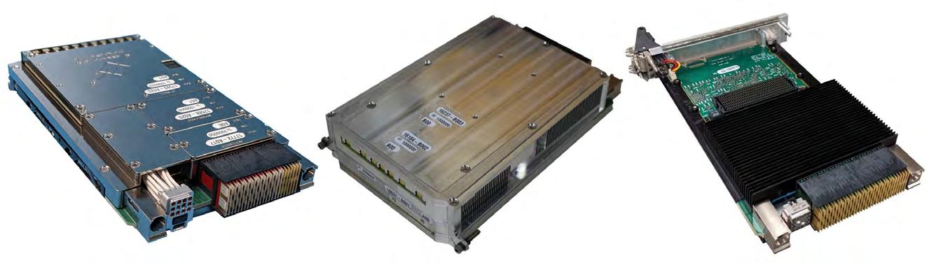
between Bandwidth or Latency-optimized Versal Boards www.annapmicro.com/versal-products/
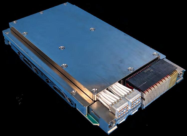
Direct RF sampling is transformative for Signal Acquisition and Signal Processing. Direct RF data converters operate directly at the antenna frequency, reducing latency and eliminating the need for intermediate frequency stages. Also, Direct RF conversion can instantaneously tune across a very wide frequency span – from 0.1 to 36 GHz. Now you can directly digitize and process wideband signals, simplifying system architecture and enabling new EW, SIGINT, and spectrum processing capabilities.
Annapolis is now offering the lowest latency and highest bandwidth 64 GSps Direct RF solutions on the market:
• WILDSTAR 3AE1 (top right) – a 3U OpenVPX Baseboard
• WILDSTAR SAF1 (below) – a Small Form Factor Module
• WILD WHDMF1/WWDME1 & WHQMB1 – Mezzanines
Ą WILDSTAR SAF1 Small Form Factor Module (photo below)
• Ideal for edge applications close to the sensor and in other tight envelope man-packable environments
• Intel Altera Agilex 9 MCP1 Direct RF-Series AGRW014 FPGA
• ADC: 4 Channel, 64 GS/s, 10 bit Resolution
• DAC: 4 Channel, 64 GS/s, 10 bit Resolution
• Mates with modular RF and digital I/O cards
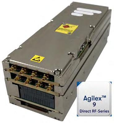
The SAF1 includes an option for NVIDIA Jetson AGX Orin GPU/CPU processing
The 3AE1 provides VITA 66 & 67 backplane RF support
Ą WILDSTAR 3AE1 3U OpenVPX FPGA Processor (photo above)
• 3U OpenVPX Plug-In Card
• Intel Altera Agilex 9 MCP2 Direct RF-Series AGRW027 FPGA
• ADC: 8 Channel, 64 GS/s, 10 bit Resolution
• DAC: 8 Channel, 64 GS/s, 10 bit Resolution
• Supports Analog Interface Cards for front-end personalization
• Air, Conduction, or Air-Flow-Through cooled
• Developed in alignment with SOSA™ Technical Standard
Ą WILD WHDMF1 & WWDME1 Mezzanines
• Pair one with a 3U Baseboard or two with a 6U Baseboard
• Jariet Technologies Electra-MA Transceiver
• ADC: 2 Channel, 64.0 GS/s, 10 bit Resolution
• DAC: 2 Channel, 61.4 GS/s, 10 bit Resolution
• Analog Input Bandwidth: 20GHz (-6dB) typical
• Maximum Instantaneous Bandwidth: 6.4GHz
• Run Time Selectable ADC Decimation: 8-1024x
• JESD204B/C interface with 16 lanes up to 30Gbps
• Developed in alignment with SOSA™ Technical Standard
Ą WILD WHQMB1 Mezzanine
• High bandwidth card is optimized for High-Speed Serial I/O
• Pair one with a 3U Baseboard or two with a 6U Baseboard
• Analog Devices Apollo MxFE
• ADC: 4 Channel, 20 GS/s, 12 bit Resolution
• DAC: 4 Channel, 28 GS/s, 16 bit Resolution
• JESD204B/C interface with 24 lanes
• Developed in alignment with SOSA™ Technical Standard
Contact us today to request block diagrams and additional specifications.
www.annapmicro.com/direct-rf-products/

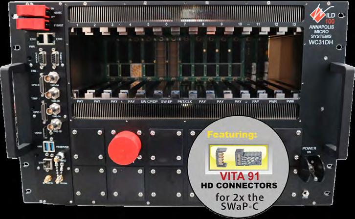
Chassis/Switches with VITA 91 HD Connectors Are Designed for High-Performance EW & SIGINT
Annapolis is the first embedded computing manufacturer to integrate new high-density VITA 91 connectors into its COTS products. With high density VITA 91 connectors, SOSA™ aligned VPX Switches and Chassis keep pace with the high speed and bandwidth of the latest highperformance transceivers and FPGAs, including Agilex 9 Direct RF-Series and Versal Premium. These boards and systems are ideal for challenging applications including low latency jamming, EW, or radar.
VITA 91 HD connectors allow for a completely switched backplane, so the expansion plane is no longer defined by a fixed backplane PCB, but is now flexible and fully reconfigurable. Chassis and backplanes with two HD switch slots allows for one switch to handle all Data and Control Plane Ethernet, with the second switch dedicated to the expansion plane. The expansion plane supports Dual 100Gb Ethernet, 8x Gen4 PCIe, or 128 LVDS.
The following SOSA aligned Chassis and Backplanes integrate high density VITA 91 connectors and VITA 46.11 conformant Chassis Managers.
The following SOSA aligned Switches integrate high density VITA 91 connectors and one or two AMD Xilinx Zynq UltraScale+ MPSoC Motherboard Controllers.
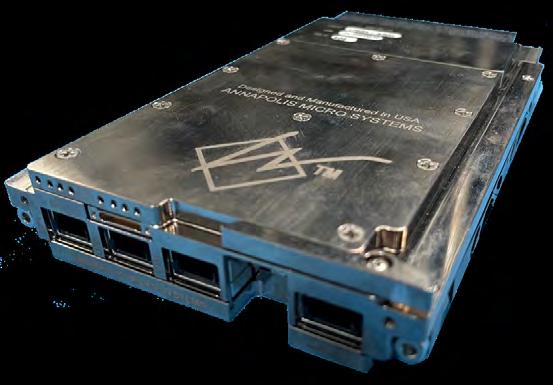
If you require high-performance data digitization, processing or storage in a compact, rugged environment, these high density Annapolis Chassis and Switches are for you. Contact us to have an FAE recommend the best approach for your application.
https://www.annapmicro.com/vita91/
Annapolis Micro Systems, Inc.
www.annapmicro.com
Atrenne, a Celestica company, offers a wide range of high-performance backplanes, with 6U, 3U and hybrid 3U/6U models available. Our Gen-4/5 OpenVPX backplanes are part of an innovative product family that enables end-to-end solutions for 64/100 Gigabit systems.
Designed to the demanding signal integrity requirements of PCIe Gen4 and 100GbE (100GBASE-KR4), these high-performance Gen-4/5 backplanes offer the highest signal integrity in the industry and are typically used in air-cooled or conduction-cooled development chassis. Atrenne can also design application-specific configurations to meet your individual requirements.
Ą High performance 25 Gbaud Gen-4/5 backplanes compatible with 100 GbE (100GBASE-KR4) and PCI Express® (PCIe) Gen-4 (16 Gbaud) on OpenVPX data plane and expansion plane fabrics
Ą Built with MEGTRON 6 – Ultra-low Loss, Highly Heat Resistant Circuit Board Materials
Ą Refined VPX connector with smaller press-fit pins, the VITA 46 Multigig RT-3 is fully compatible and interoperable with the original VPX connectors, providing superior signal integrity performance
Ą VITA 65 OpenVPX™ compliant backplanes
Ą VITA 46/VITA 48 VPX REDI™-compliant with VITA 46.30 compliant RT3 connectors
Ą VITA 46.10 RTM connectors
Ą Provisions for mechanical stops to prevent misinsertion of payload cards
Ą Stiffeners placed every other slot to ensure backplane rigidity
Ą Optional rear transition connectors
Ą Keying and alignment per VITA 65 and VITA 46
Ą Durability: mating and unmating for 200 cycles
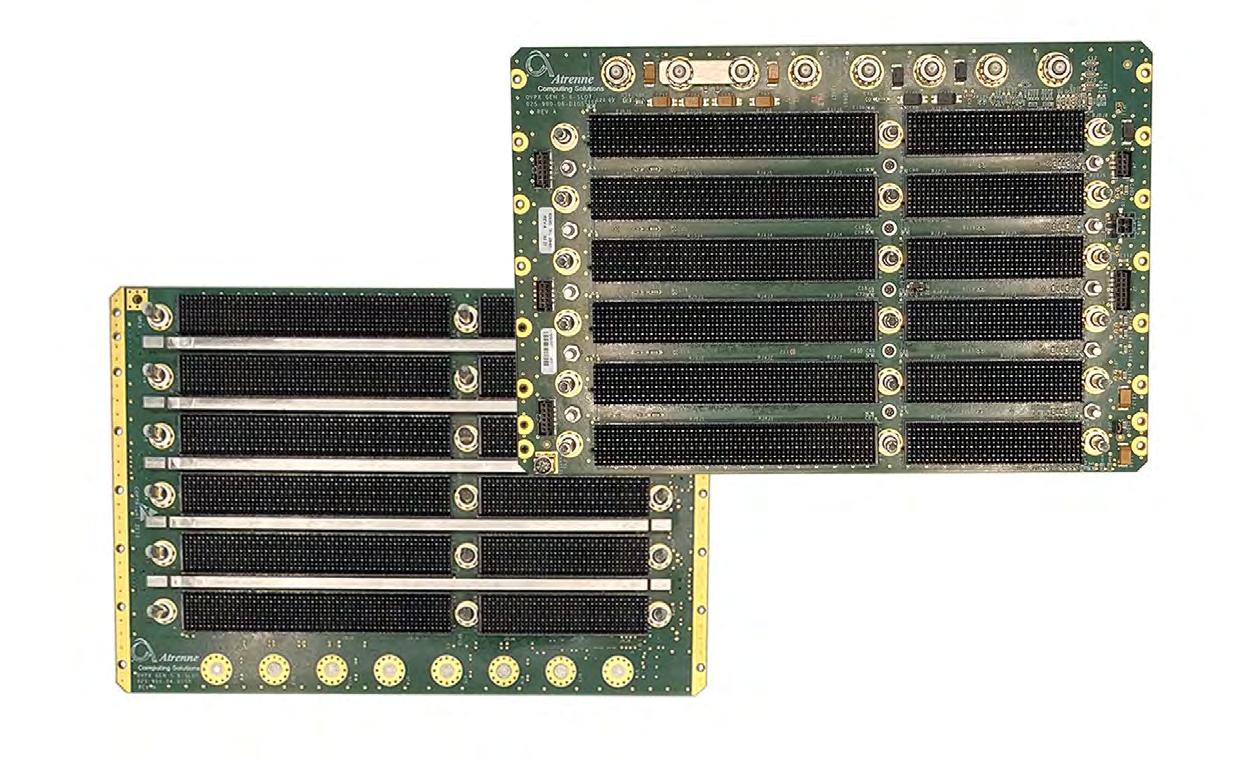
Kontron VPX power supplies are commercial off-the-shelf (COTS), rugged, conduction cooled, single stage converters according to the ANSI/ VITA 62.0 specification. Perfectly designed to power a VPX chassis, these units seamlessly fit within the VITA 48.0 specification envelope.
Using state-of-the-art switching power technology combined with sophisticated multi-stage input filtering, they offer a wide input voltage range and superior efficiency for challenging environments.
The new 600W VPX360 series is compliant with MIL-STD-461, 704 and 1275 as per VITA 62. Featuring an embedded microprocessor, it supports monitoring and control capabilities with I2C bus (IPMI) and USB interfaces. The VPX power supply mechanical dimensions are 3U x 5HP (1" slot) and includes connectors, keying and alignment mechanisms as per VITA 62.
The VPX360DMS version provides 12V/80A and 3.3V/20A and IPMC for system management integration.
Discover our cutting-edge VPX power supplies today.
https://www.wiener-d.com/product/vpx360-high-power-vpx-power-supply/ Kontron www.kontron.com sales@us.kontron.com
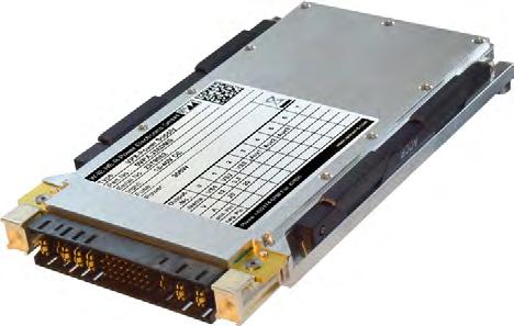
Ą Outputs: 12V main / 2 x 40A, 3.3Vaux / 20A
Ą High efficiency, 12V-peak > 90%
Ą Wide input voltage range: 11 V … 70 V DC (nominal 28V or 48V), reverse polarity protection
Ą Voltage sense controlled, Over Voltage, Under Voltage, Over Current, Over Temperature protection
Ą Microprocessor controlled, with I2C bus / IPMB for VITA48.11 system management, USB port
Ą MIL-STD-461, MIL-STD-704, MIL-STD-1275 compliance as per VITA 62, ruggedized to MIL-STD-810
Ą No liquid / wet / aluminum electrolytic capacitors
888-294-4558
www.linkedin.com/company/kontron-north-america/
SOSA™ Aligned BACKPLANE
Kontron’s SOSA™ Aligned BACKPLANE embodies exceptional high-speed performance and unparalleled flexibility. As a central connection element, the backplane is crucial for the performance of the overall system. Kontron has equipped this backplane, tailored for compute-demanding tasks, with significant capabilities, including lightning fast 100 Gigabit Ethernet transmission.
Its remarkable 100 Gbit/s speed performance has been validated through rigorous independent tests. The backplane’s seven-slot architecture allows for extensive functional integration. Drawing from extensive customer feedback, comprehensive expertise, and analytical insights, Kontron has incorporated a specific configuration for this backplane. Yet, it retains a flexible design ecosystem, welcoming custom adjustments to meet customer-specific requirements at any time.
Ready to experience Kontron’s high-performance solution? Contact us today to learn how our SOSA™ Aligned BACKPLANE can transform your operations.
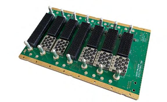
Ą High speed design for 100 Gbit/s Ethernet (100GBase-KR4)
Ą 7 Slots VPX, 1 SBC, 1 Switch, 1 Clock, 4 Payload Slots
Ą Payload and clock slots can optionally be equipped with coaxial modules as per VITA 67.3C
Ą Featuring MULTIGIG RT 3 connectors
Ą Max. Input current per backplane VS1:VS2:VS3 = 120A : 90A : 90A
Ą Flexible keying and alignment mechanism
Ą Custom assembly or modification on request
https://www.hartmann-electronic.com/product/3u-6u-sosa-aligned-vpx-backplanes/ Kontron www.kontron.com
sales@us.kontron.com
888-294-4558
www.linkedin.com/company/kontron-north-america/
Introducing the Kontron VX307H Computing Node, the ultimate SOSA™ Architecture Booster: Offering best-in-class performance and XMC support on VITA 48.8 Air Flow Through (AFT) models, this rugged 3U embedded server card redefines the SWaP-C limits and enhances the capabilities of your HPEC architectures.
Powered by the Intel® Xeon® D-2700 Platform, the VX307H is offered with a 12, 16, or 20-core processor with features like 100Gb Ethernet, PCIe gen4, and an on-chip DMA engine. AVX-512 VNNI support is engineered for AI, signal processing, and cryptography, offering double the performance over previous generations for critical applications like computer vision and media processing.
The VX307H is available in VITA48.8 AFT and conduction-cooled versions, operating in extended temperature ranges and aligned with industry standards. Unleash the potential of your engineering projects with the SOSA™ Architecture Booster – Kontron VX307H Computing Node. Contact us to learn more.
https://www.kontron.com/en/products/vx307h/p171195
Kontron www.kontron.com
sales@us.kontron.com
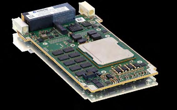
Ą Intel® Xeon® D-2700 HCC processor with 100Gb Integrated Ethernet
Ą From 12 to 20 processing cores to be adapted to SWaP-C applications
Ą Enhanced instructions for Artificial Intelligence and Signal processing (Intel AVX-512, VNNI)
Ą Up to 64GB DDR4 memory with ECC
Ą New VITA48.8 AFT (Air Flow Through) and VITA47 CC3 (Conduction-Cooled) support
Ą XMC support on VITA48.8 AFT versions
Ą Long term availability with 10-years of typical lifecycle
888-294-4558
www.linkedin.com/company/kontron-north-america/

The RMC3-160 is a feature rich 19" rackmount chassis for 3U SOSA aligned VPX payloads. The rugged construction of the chassis is ideally suited for performance in demanding environments across a range of applications. The 4U low profile design is a space saver in rackmount applications where SWaP considerations are critical. One of our emerging family of 19" chassis, the RMC3-160 is intended for VITA 48.2 conduction cooled modules and it incorporates dual high CFM fans for added cooling of high power payloads. The chassis has a hinged front panel that enables easy payload access and provides EMI protection. This system is offered with custom 40Gb / 100Gb backplanes for high speed performance in C5ISR applications. LCR backplane designers will work you to deliver the profile required for the specific data flows for your payload. Chassis manager and media conversion options round out the completed configuration to meet your requirements.
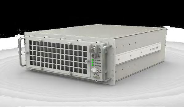
Ą 4U low profile for space constrained installations
Ą Up to 16 conduction cooled slots for VITA 48.2 modules at 1" spacing
Ą 40Gb / 100Gb backplane options supporting VPX SOSA aligned payloads
Ą Custom backplanes for SOSA aligned and VPX module payloads
Ą Customizable rear I/O panel for SMA, DB, RJ45 and 38999 connectors
Ą Hinged door allows easy access to the card cage and backplane
Ą Designed to meet MIL-810 , MIL-901D and MIL-46I standards
https://www.lcrembeddedsystems.com/15-slot-3u-vpx-19-rackmount-chassis/
LCR Embedded Systems www.lcrembeddedsystems.com
sales@lcrembedded.com
610-278-0840 https://www.linkedin.com/company/lcr-embedded-systems-inc-/

The RTS-510 meshes functional and environmental testing in a development chassis that is deployment capable. It is designed for functional testing and demonstration at or near application-level environments. Unique to the design as compared to competitive chassis is the capability to serve as a development / demonstration / deployment chassis as developers walk through the system realization process. The demonstration and test stage is made possible by the modular design of the chassis that enables access for iterative backplane profile and discrete I/O panel configuration testing leading to final I/O and backplane profile layout. When the final backplane and I/O panel are ready for testing, the base ATR design allows for modular reconfiguration leading to the deployment ready chassis.
A first in the industry, the RTS-510 allows integrators to move system development efforts from the lab to the field quickly. The 510 may be ordered with development backplanes ready for cable configuration or with backplanes designed with your specific application profile.
The chassis accommodates 5 VPX / SOSA aligned payload boards plus a single VITA 62 power supply slot however the RTS concept applies to chassis designed for slot counts ranging from 2-10. The base section of the chassis is designed to meet full mil specifications for deployed air and ground assets. It is an air over conduction cooled design intended for VITA 48.2 conduction cooled modules and reflects the design principals applied in LCR rugged ATR chassis. It is designed to meet MIL-STD-810, MIL-STD-461, and MIL-S-901D environmental standards – capabilities field proven through installed equipment performance using the LCR ATR line.
It provides cooling for up to a total dissipated power of 450W. The chassis is constructed with machined aluminum alloy 6061-T6. Bolt together construction incorporates full EMI and high ingress protection. The chassis is light weight by comparison to competitive products and weighs in at approximately 23lbs excluding payload and power supplies.
Ą Rugged test and demonstration platform
Ą Enables rapid reconfiguration for multiple test phases
Ą Supports 3U VPX and SOSA Aligned Conduction Cooled VITA 48.2 modules
Ą High speed 40Gb and 100Gb dedicated backplanes
Ą Pass through backplane options for development
Ą Deployment capable base chassis design
Ą 5 payload slots and 1 PSU slot
Ą Cooling for up to 400W of total power
Ą Conduction cooled with air assist for 450W payload TDP
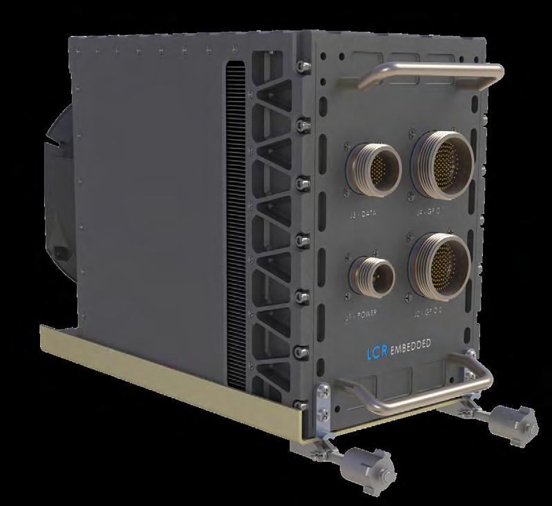
V6065 3U VPX Versal® Premium ASoC FPGA Optical I/O Module with XMC Site
The V6065 complements New Wave Design's other 3U VPX Modules, adding the AMD Versal® Premium Adaptive System-on-Chip (ASoC), rugged optical and electrical high-speed IO, XMC site, and SOSA aligned profile options. This powerhouse heterogenous computing solution is purpose-built for performance and is a game-changer for embedded system-level processing. In a single 3U VPX card, the V6065 features up to twelve 1G to 25G optical ports providing up to three 100G optical interfaces (300G aggregate), large FPGA fabric, ARM processor cores, and XMC site enabling single-slot 3U VPX combinations of FPGA/CPU, FPGA/GPU, or FPGA/Analog elements. These features make the V6065 of versatile choice for any application that requires robust heterogeneous processing. The integration of Versal® Premium parts (VP1502 or VP1702) underscores our focus on providing versatility and adaptability. By providing a large FPGA fabric and hard silicon implementations of MACSEC, Ethernet, and PCIe MACs supporting various protocols, users receive unmatched customization and functionality.
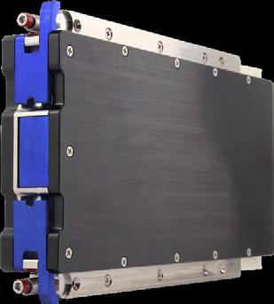
Ą AMD Versal® ASoC (FPGA): VP1502/VP1702
Ą Up to twelve (12) 1G to 25G optical ports via MPO front panel I/O or VITA 66 optical backplane I/O
Ą PCIe Gen3/Gen4 support
Ą Thermal sensors for monitoring card temperature
Ą Robust FPGA development framework
Ą 3 banks of 16GB (48GB total) up to 1866MHz/3733 Mbs LPDDR4 SDRAM
Ą Compute-intensive profile with XMC site routing to the Versal® as PCIe or high-speed serial
https://newwavedesign.com/products/vpx/v6065-3u-vpx-versal-premium-asoc-fpga-optical-i-o-module-with-xmc-site/ New Wave Design www.newwavedesign.com
info@newwavedesign.com
952-224-9201 www.linkedin.com/company/new-wave-design

V6063 3U VPX Versal® ASoC FPGA Optical I/O Module
The V6063 is a next generation heterogeneous embedded computing 3U VPX module featuring the Xilinx® Versal® Adaptive System-on-Chip (ASoC), rugged optical and electrical high-speed IO, and profile options aligned to the Sensor Open Systems Architecture™ (SOSA) Technical Standard. The V6063 provides options for Versal® Prime or Versal® AI Core part selection. In a single 3U VPX card, the V6063 provides three 100G optical interfaces (300Gbps aggregate), large FPGA fabric, ARM processor cores, and optional AI engines. The V6063 excels at high-bandwidth interface applications where data is processed or pre-processed locally and then distributed across the VPX backplane or optical interfaces. Use cases include sensor interface, data processing, data distribution, and FPGA co-processing applications. Radar, signals intelligence, electronic warfare, video, storage, medical imaging, and embedded communications systems all can benefit from the V6063 module.
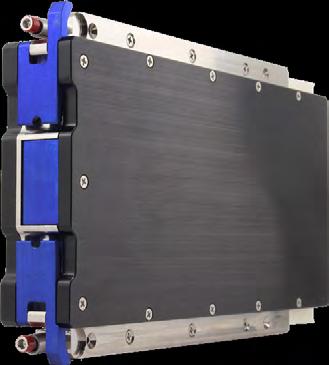
Ą Xilinx® Versal® ASoC (FPGA): VM1502/VM1802/VC1902
Ą Up to twelve (12) 1G to 25G optical ports via MPO front panel I/O or VITA 66 optical backplane I/O
Ą 2 banks of 4GB up to 1866MHz LPDDR4 SDRAM
Ą PCIe Gen3/Gen4 support
Ą Thermal sensors for monitoring card temperature
Ą Robust FPGA development framework
Ą 14.6.11 and 14.6.13 compute intensive profiles available
https://newwavedesign.com/products/vpx/v6063-3u-vpx-versal-asoc-fpga-optical-io-module/
New Wave Design
www.newwavedesign.com
info@newwavedesign.com
952-224-9201
www.linkedin.com/company/new-wave-design
LightCONEX® LCX12 Transceiver
Based on the LightABLE LLX12 mid-board fiber optic transceiver, the SOSA aligned LightCONEX LCX12 plug-in module is Smiths Interconnects’ solution for OpenVPX optical backplane interconnects.
Integrating a 12TRX transceiver module (12 full-duplex 10 Gbps lanes) with an optical backplane connector, the LCX12 offers flexibility, light weight, very high bandwidth, and forward compatibility.
The LightCONEX active blind-mate optical interconnect system is a revolutionary solution for VPX systems that includes a fixed, plugin module connector and a floating backplane connector compatible with the VITA 66.5 standard. The LCX12 is production-qualified and shipping now.
Ą Increases volumetric density of 3U and 6U high-speed switch and processing VPX boards by integrating optical transceivers with backplane connectors.
Ą Reduces SWaP with a rugged MIL-STD qualified, edge-mounted, integrated optical interconnect
Ą 10 Gbps per channel in a 12TRX configuration (2x12 MT).
Ą Available in VITA 66.5 connector Styles A, C, and D.
Ą Enables high port bandwidth density of up to 360 Gbps full-duplex in a VITA half-width slot (using Style D connector).
Ą OpenVPX single board computing, C4ISR embedded processing systems.
www.smithsinterconnect.com/products/optical-transceivers/vpx-optical-interconnects/lightconex-lc-series/
Smiths Interconnect www.smithsinterconnect.com
focom.uscsr@smithsinterconnect.com
813-901-7200 www.linkedin.com/company/smiths-interconnect/ @smithsinterconn
PSC-8724 Low Power High Efficiency Integrated Hold-up
Dawn PSC-8724 3U VITA 62 Low Power High Efficiency with Integrated Holdup Power Supply. 20W to 190W low power, high efficiency 28V DC/DC power supply with MIL-STD-704 Hold-up of 50 msec integrated for 135W load. Available in Standard VPX and SOSA VPX versions.
Dawn PSC-8724 (Standard VPX version) offers following output currents:
• +5V @ 20A, +3.3V @ 4A (& 3.3V_Aux).
(Note: Total wattage from +5V & +3.3V outputs not to exceed 100W).
• +12V @ 6A, -12V_Aux @ 3A, +12V_Aux @ 3A.
(Note: Total wattage from +12V & +12V_Aux outputs not to exceed 72W.)
Dawn PSC-8724 (SOSA VPX version) offers following output currents:
• +12V @ 10A (VS3), +3.3V @ 4A (& 3.3V_Aux).
(Note: Total wattage from +12V (VS3) & +3.3V outputs not to exceed 120W.)
• +12V @ 6A (VS1), -12V_Aux @ 3A, +12V_Aux @ 3A.
(Note: Total wattage from +12V & +12V_Aux outputs not to exceed 72W.)
(Note: Total wattage from -12V_Aux outputs not to exceed 36W.)
Dawn VME Products
www.dawnvme.com
sales@dawnvme.com
Ą 3U VITA 62 Low Power High Efficiency with Integrated Hold-up.
Ą 20W to 190W low power, high efficiency 28V DC/DC power supply.
Ą MIL-STD-704 Hold-up of 50 msec integrated for 135W load.
Ą Available in Standard VPX and SOSA VPX versions.
www.dawnvme.com/shop/power-supplies/psc-8724/
Military Power Distribution Units –DefPower MIL-PDU
Electronic Architecture Reinvented to Guarantee High-Tech in Armoured Vehicles.
Piedrafita’s DefPower MIL-PDU revolutionizes power electronics in military vehicles, addressing the escalating demand for electrical power and equipment. These solid-state technology units replace outdated relay and fuse boxes, providing compact, lightweight, and user-configurable solutions with excellent thermal efficiency and low electromagnetic interference.
Our Power Distribution Units meet stringent military certifications and are crucial for both manned and unmanned systems, ensuring peak performance in harsh environments. Their adaptability makes them ideal for vehicle and weapon system modernization, including next-gen platforms. DefPower MIL-PDUs also offer efficient retrofitting for older vehicles, enhancing reliability and connectivity with on-board diagnostics. MIL-STD and Def Stan certifications affirm their compliance with rigorous military standards.
Piedrafita Systems www.defpower.com
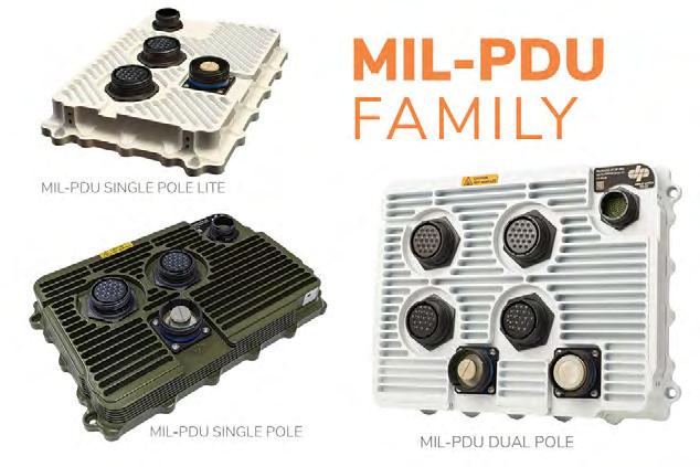
Ą High reliability: the absence of mechanical parts considerably increases the reliability of the system.
Ą Compact size, offering easy integration into any vehicle architecture.
Ą Adaptable to any low voltage architecture: 12 V - 24 V - 48 V
Ą Up to 12 kW of managed electrical power.
Ą Status and consumption reporting to the vehicle's communications bus
Ą Versatility and ease of use by both the system designer and the end-user.
Ą 100% programmable logic. The programmability of the solutions allows for much more efficient logistics by allowing a single reference to be used in any vehicle.
Rantec’s family of 3U VPX power supplies are designed to meet the rigorous demands of modern defense applications for airborne, land, and sea environments. Our family of 3U VPX power supplies offers versatile, reliable, and high-performance solutions for demanding defense applications. With strict adherence to industry standards, certifications, and a commitment to quality, these power supplies are a valuable choice for meeting the stringent requirements of the defense sector.
Our VITA compliant power supplies designed in alignment with the SOSA™ Technical Standard are designed with input voltages of either 28VDC or 270VDC and output power capabilities of up to 1200W. Rantec’s conformance to VITA 62.0, VITA 86.0, and the SOSA Technical Standard ensures seamless integration into MOSA-aligned defense systems, making these power supplies invaluable assets in mission critical systems. Manufactured in the USA in an AS9100 and ISO9001 certified facility, Rantec power supplies ensure the highest quality and reliability.
https://rantec.com/our-products/3u-vpx-mosa-power-supplies/
Rantec Power Systems Inc. www.rantec.com
inquiries@rantec.com

Ą Products designed in alignment with the SOSA™ Technical Standard conform to VITA 62.0 and VITA 86.0 standards
Ą Input voltages of 28VDC or 270VDC
Ą Output power up to 1200W
Ą Designed and tested to meet MIL-STD-461, MIL-STD-704 or MIL-STD-1275, and MIL-STD 810
Ą Designed using NAVSO P-3641A derating guidelines
Ą MTBF: 50,000 hours per MIL-HDBK-217
Ą IPMI Communication Bus per VITA 46.11
Ą Input/Output/Temperature protection
Ą Custom capabilities such as hold-up, nuclear event detection, lightning protection, inrush suppression, and more
805-596-6000
www.linkedin.com/company/18052437/ @rantecpowersys

MANNARINO Real-Time Operating System
M-RTOS is a modular, flexible and affordable operating system, compliant to ARINC 653 and RTCA/DO-178C DAL A, designed for a wide range of aerospace and defense applications, from Commercial Off-The-Shelf (COTS) electronic hardware to federated LRU (Line-Replaceable Unit) aircraft systems, to IMA (Integrated Modular Avionics) platforms.
M-RTOS was developed to minimize memory and timing usage and outperform the competition on key benchmarks. M-RTOS guarantees robust spatial and temporal partitioning and can run on microprocessors incorporating memory protection units.
MANNARINO Systems & Software Inc. provides safety-critical systems, software, and airborne electronic hardware engineering services to the aerospace, defense, space, simulation, power generation and rail industries.
MANNARINO is an authorized Design Approval Organization (DAO) for Airborne Software (RTCA DO-178C) and Airborne Electronic Hardware (AEH) (RTCA DO-254) of the National Aircraft Certification Branch of Transport Canada Civil Aviation (TCCA).
MANNARINO Systems & Software https://www.mss.ca

VITA 66.5 RF/Fiber Hybrid Connectors
Experience unparalleled performance with Amphenol SV Microwave's VITA 66.5 RF/Fiber Hybrid Connectors. Combining RF and fiber-optic signals in one module, these connectors are ideal for high-density, high-reliability applications in aerospace, defense, and communication systems. Available in SMPM and SMPS series, they ensure robust connectivity with simplified cable routing and reduced Mean-TimeTo-Repair (MTTR). These hybrid connectors support SIGINT, EWR, avionics, and radar systems applications.
This product line has undergone extensive design and testing to ensure it adheres to the latest Sensor Open Systems Architecture, or SOSA, specification. SV Microwave is an associate member of The Open Group and an active participant of the SOSA Electro-mechanical hardware group. Choose Amphenol SV Microwave for cutting-edge hybrid connectivity solutions.
https://bit.ly/3YbtS1f
Amphenol SV Microwave www.svmicrowave.com
Ą Unrivaled and Flexible Commercial Terms
Ą Customization with Modular and Scalable Architecture
Ą Designed to Outperform the Competition
Ą Certification Peace of Mind
Ą Unparalleled Customer Support and Service
Ą Supports Microcontrollers to Complex Multicore Processors
https://www.mss.ca/m-rtos
sales@svmicro.com
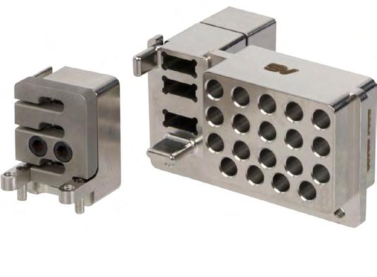
Ą Hybrid modules combine both RF and fiber-optical signals
Ą SMPS min pitch .155"
Ą Designed for side-by-side implementation with other VITA connector standards
Ą Blindmate and simplified cable routing reduces Mean-Time-To-Repair (MTTR)
Ą Aligned to the latest SOSA Technical Standard
Ą High-reliability, high-density for aerospace & defense applications
Ą Robust and rugged high speed cabled solution applications

Analog Devices expands True Time Delay Beamformer Portfolio, enabling wideband phased array applications.
Building off the success of its single channel time delay unit, the ADAR4002, ADI has expanded its True Time delay offerings. The ADAR4000 and ADAR4001 are highly integrated products, providing multiple channels operating from 2-18 GHz. The true time delay cores ensure beamsquint free wideband operations.
Both devices have four channels, each with a 7-bit true time delay (TDU) and a digital step attenuator (DSA). The total time delay range is 508ps per channel, and also includes programable amplifiers and on-chip memory, all in a 6mm x 6mm package.
Their small size and low DC power dissipation make them ideal for wideband phased array applications. The large time delay not only makes them ideal beamformers for the front-end, but also can be used for sub-array compensation on the back-end.
The ADAR4000 is a single input, quad output transmit device. The ADAR4001 is a quad input, single output receive device. The ADAR4002 is a single channel time delay unit.
Ą 2 GHz to 18 GHz frequency range
Ą Programmable Time Delay Modes: TD_Mode0 : 0 to 508ps range, 4ps resolution and TD_Mode1 : 0 to 254ps range, 2ps resolution
Ą Programmable time delay: 7-bit resolution
Ą Programmable gain: 6-bit resolution, 31.1 dB adjustment range, and 0.5 dB step size
Ą Programmable amplifier bias settings
Ą 3-wire and 4-wire SPI
Ą Package: 6 mm × 6mm LFCSP
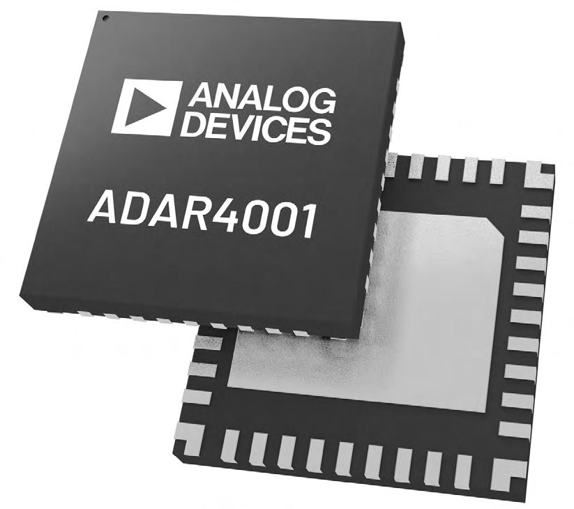
MRDP-Dev-Platform
This 3U OpenVPX MORA-Ready Development Platform (MRDP) provides slot profiles aligned with the SOSA™ Standard. It supports the latest profiles used to develop systems that follow the hardware requirements for CMOSS and other platforms that adhere to MOSA.
At the heart of the system is Elma’s 3U 6-slot 25Gb/100Gb backplane aligned to SOSA. Other backplane configurations can be provided. Designed to streamline development and meet the open standards approach mandated by MOSA, the MRDP includes the following plug-in cards (PICs): Abaco SBC; Interface Concept switch; an Epiq transceiver; and Sciens helux Core software tools. The MRDP is a proven reference platform that plugs in and turns on. A developer can instantly view, evaluate and control MORA resources to explore device capabilities and functionality, and create, view, or modify MORA Signal Resource Profiles (MSRPs). Moving from the lab to a deployable unit is easy with Elma's CMFF or SOSA ATR chassis options.
Elma Electronic www.elma.com
sales@elma.com
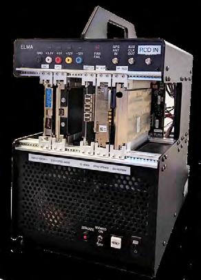
Ą Turn-key platform for MORA Specific Hardware Development that can be ported for deployment
Ą Uses the hardware-agnostic helux Core from Sciens – software libraries and firmware modules for MORA RF development
Ą 6-slot, 3U VPX backplane aligned to SOSA (8-slot option available)
Ą Built-in VITA 46.11 Tier 3 Out of Band chassis manager. See datasheet for complete details.
https://bit.ly/Elma-MRDP
215-527-8106
www.linkedin.com/company/elma-electronic @elma_electronic

Powered by an Intel® Core™ Ultra processor with integrated NPU AI engine, the Z14I rugged laptop unlocks new AI PC experiences to boost productivity, security and efficiency.
Built to withstand even the harshest environments, the Z14I’s IP66 rating protects against dust and water ingress, while MIL-STD 810H certification and six-foot drop resistance make it the most rugged device on the market. The Z14I has also been tested for explosive atmosphere, solar radiation, salt fog, and fungus resistance, going beyond standard testing for other rugged devices in its class.
The Z14I includes Durabook’s proprietary DynaVue® technology and highdefinition multi-touch screen to provide the highest contrast ratio, helping to eliminate internal reflections for enhanced viewing clarity from multiple angles and in bright sunshine or low light conditions.
In addition, the Z14I has MIL-STD-461G certification and Coolfinity™ fanless thermal design, making it more rugged than ever.
www.durabook.com/us/products/z14i-laptop
Durabook Federal www.durabook.com
Rugged Computing and Displays
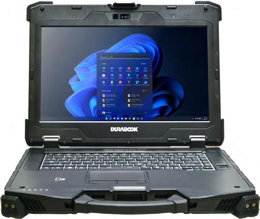
Ą 14.0” DynaVue® sunlight readable display up to 1,200 nits
Ą Powered by Intel® Core™ Ultra 5/7 processors
Ą Sports a Coolfinity™ fanless thermal design
Ą Versatile expansion design for unique customization
Ą IP 66 rating against dust and water intrusions
Ą Survive drops up to six feet
Ą MIL-STD 810H, 461G and ANSI/UL C1D2 certified
sales@durabookfederal.com
www.linkedin.com/company/durabook-usa/
888-414-9844
The Rugged ATMOS Server Stack is a powerful, mission-scalable solution for critical mobile operations. Each independent ATMOS node features 32 Physical Intel® Xeon® Cores with onboard UPS battery backup for uninterrupted C2 on-the-move operations. The ATMOS Chassis Integrated Rail System locks each server node together and removes the need for an outer transit case.
Core Systems features the ability to stack an unlimited number of independent compute nodes to form a mobile data center.
The ATMOS server has the highest CPU core count, memory capacity and hard drive capacity of any other tactical server in the nation. The ATMOS server compute density is unattached by any other manufacturer, not to mention the onboard UPS.
Enhance your operations with the Rugged ATMOS Full-Stack server.
Rugged Computing and Displays
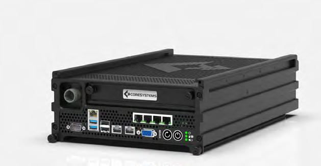
Full Stack
Ą Up to 160 Xeon® Scalable Cores (32 per node)
Ą Up to 5TB RAM (2TB per node)
Ą Expandable from 1 to 5+ Nodes
Ą Half-Rack-Width design
Single Node
Ą 32 Intel® Xeon® Total Cores, 64 Total Threads
Ą 512GB DDR4 ECC RAM
Ą 2 x 1.92TB NVME Hot-Swap SSD Drives (OS Drives)
Ą 2 x 15.36TB NVME Hot-Swap SSD Drives (Storage)
Ą 2 x 10G onboard NIC Ports
Ą NVIDIA L4 Tensor Core GPU Card
Ą TPM 2.0 Module
Ą Onboard UPS Battery Backup
Ą 24VDC power input
Ą Stackable Rugged MIL-Spec Chassis
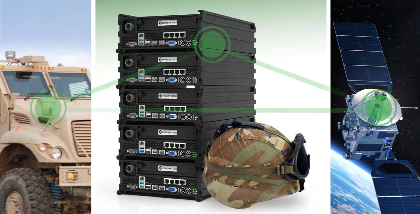

Rugged Embedded Computers up to 9th Gen. i7 and Xeon S
The PIP Family, CEC, and MXCS Server are powerful, highly integrated, robust and fanless embedded computer solutions. Selection of the components are purely made on the subject for long-term availability and low power consumption. The systems can be expanded in a very modular way and represent a unique solution for today's demanding and flexible defense requirements.
The products are designed to operate under extreme and normal conditions without the need of fans. MPL solutions are engineered and manufactured in Switzerland to meet MIL STD-810 as well as other MIL standards.
The systems include features like wide DC input, reverse polarity and more. Additional GPGPU, GPS, WLAN, CAN, 1553, ARINC, Sound, and UPS modules are available.
MPL AG Switzerland www.mpl.ch
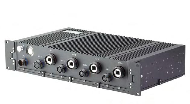
Ą Soldered CPU
Ą Ethernet (up to 10Gbit), USB (3.1/2.0), Serial ports
Ą PCIe, XMC, mPCIe, PCIe/104, MXM, m.2 expansion
Ą Extreme low power consumption
Ą Compliance: e.g. DO-160G, MIL-STD-461, -704, -1275
Ą Availability 10+ years (repair 20+ years)
Ą Optional -40°C to 85°C environment temperature
info@mpl.ch +41 56 483 34 34 www.linkedin.com/company/mpl-ag/ @MPL_AG
Rugged Computing and Displays
CMFF-SAVE-Chassis
Elma's CMOSS Modular Form Factor (CMFF) field-deployable chassis includes a tray compliant with the Standard A-Kit Envelope (SAVE) for use in Army ground and avionics vehicles. The platform includes a 7-slot 3U VPX backplane, chassis manager, and VITA 62 plug-in power supply.
The highly rugged, deployable unit is aligned with the SOSA Technical Standard and designed for C5ISR, EW and EO/IR applications. The chassis meets MIL-STDs for shock, vibration, and other environmental standards.
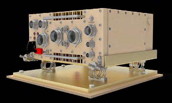
FEATURES
Ą Highly rugged CMOSS Mounted Form Factor (CMFF) chassis is compatible with VICTORY and MORA
Ą 7-slot dual domain backplane supports 3U plug-in cards (PICs) aligned to SOSA and VPX open standards
Ą 3 Payload slots, 1 PNT slot and 1 VITA 62 PSU slot - other configurations available
Ą Conduction-Convection cooled with VITA 48.2 conduction cooled slots
Ą VITA 46.11 Tier 2/3 out of band (OoB) chassis manager
Ą Single VITA 62 28V DC plug-in power supply included
Ą Environmental: MIL-STD-810G, MIL-STD-461E, MIL-STD-1275E
https://bit.ly/CMFF2SAVE
Elma Electronic www.elma.com sales@elma.com
510-656-3400 www.linkedin.com/company/elma-electronic @elma_electronic

Smallest, Lightest GPU-Capable Mission Computer
Compute Density-Optimized for Airborne ISR
The ZM3 delivers smaller, lighter, and faster computing in a rugged package, making it ideal for airborne environments. Featuring an Intel® Xeon® D one-package design with built-in AI, security, advanced I/O, and ethernet, it delivers high data throughput and addresses key edge requirements. It is also the industry’s smallest, lightest, most capable rugged computer with an NVIDIA Ada Lovelace GPU. The ZM3 is customizable, and with three PCIe expansion slots, up to two removable NVMe storage drives, and double-wide COTS high-end graphics cards, it provides the most compute-dense rugged solution on the market.
Customizable COM Express Type 7 Architecture
The ZM3 mission computer is a flexible powerhouse. It utilizes the COM Express Type 7 architecture to create a versatile system that can be configured to fit application requirements. It supports two 10GbE interfaces and includes onboard audio and configurable dual serial ports (RS422 or RS232). The ZM3 enables 32 PCI Express lanes to support NVMe storage and multiple lanes for PCIe expansion cards. The powerefficient ZM3 handles it all with a 440W, 18-36V DC input, and an EMI filter.
NVMe Rugged Removable Storage
The ZM3 provides up to 16TB of removable storage using two Tranzpak drives. These palm-sized drives combine high-speed performance with advanced protection. Tranzpak modules feature a robust camaction lever that lets you quickly remove and replace a storage drive and securely lock it.
Ą Lightweight aluminum construction, weighing less than 10 pounds.
Ą Compact size: 4.6”Hx5.6”Wx14.2”D
Ą MIL-DTL-38999 locking power connector
Ą Intel Xeon D processor up to 16 1.3GHZ+ cores
Ą NVIDIA Ada Lovelace GPU
Ą DDR4 RAM, up to 96GB
Ą Flexible PCI expansion options: up to 3 PCIe cards
Ą Up to 16TB NVMEe-based removable storage
Ą 2x front accessible USB 3.0 ports
Ą Onboard dual 10GibE and audio
Ą Configurable dual serial ports supporting RS422 or RS232
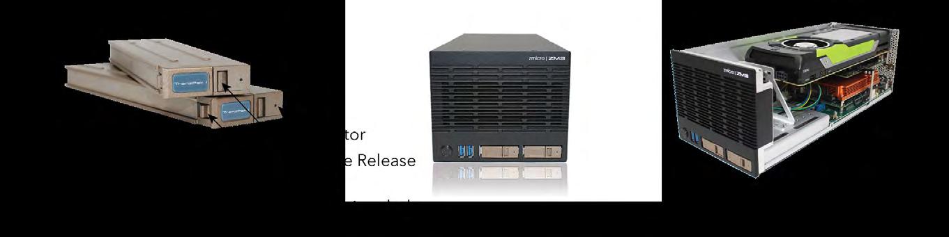
Markets all across the globe are focused on SWaP. In the defense world, designers are searching for newer componentry to usher in newer compact, smarter missile designs capable of protecting today’s modern warfighters. In the space world, the goal is similar: mass reduction! Companies such as NASA continue to focus on this requirement. Today, it is estimated to cost $10,000 to put a single pound of payload in Earth’s orbit. NASA's goal is to reduce the cost of getting to space to hundreds of dollars per pound within 25 years and tens of dollars per pound within 40 years. With this goal in mind, these newer SWaP options must not only be smaller than their incumbent, they too must survive and thrive in one of the harshest environments ever imagined.
Omnetics' Low Profile Micro-D series offers designers a saving of roughly 30% in height, all the while assuring users the same performance and reliability come to expect with previous MIL-DTL-83513 iterations. These connectors are ideal for critical, high-reliability industries, including aerospace, military, and medical. They are built to exceed the specifications of MIL-DTL-83513, while allowing designers the ability to squeeze more and more into less and less. The Low Profile Micro-D connector series offers proven military specification performance and reliability with reduced flange height and weight compared to standard Micro-D connectors.
Low-profile connector types enable designers to utilize boardstacking efforts. This allows for a fast design of each individual section of the instrumentation allowing for more components in a smaller form factor. Applications include hand-launched drones, portable robotic surveillance systems and cube satellites. Omnetics’ Low Profile Micro-D connectors offer the performance and reliability demanded by this industry niche and beyond. They are designed and manufactured using the identical pin to socket system, shell and insulator materials that pass MIL-DTL-83513. Pins are made of ruggedized BeCu copper alloy that insure continuous signal performance through 50 g's of shock and 20 g's of vibration. Their performance has been tested and certified from -55 degrees to +125 degrees centigrade. The low profile connector’s height is significantly reduced by 30% to less than .208” high with some designs.
Ą Durability: > 2000 Mating Cycles min
Ą Temperature: -55ºC to +125 ºC (200 ºC w/HTE)
Ą Current rating: 3 Amps per contact per MIL-DTL-83513
Ą Voltage Rating (DWV): 600 VAC RMS Sea Level
Ą Insulation Resistance: 5,000 Megohms @ 500 VDC
Ą Shock: 50 g’s with no discontinuities > 1 microsecond
Ą Vibration: 20 g’s with no discontinuities > 1 microsecond
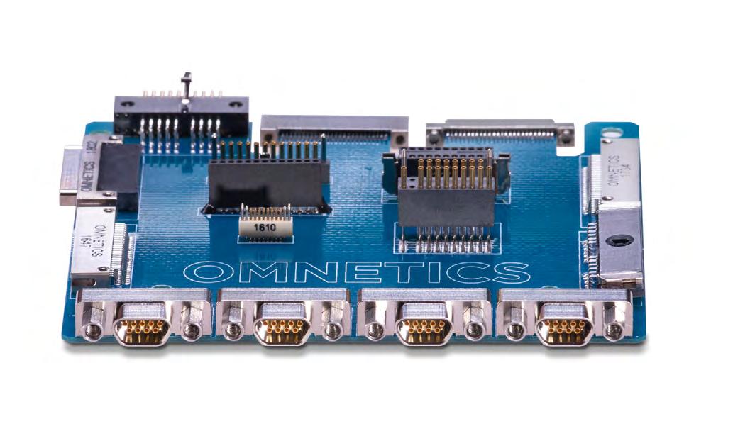
Ą Thermal Vacuum Outgassing: 1.0% max TML, 0.1% max CVCM - NASA SP-R-0022
Ą Contact Resistance: 26 milliohms (65 mV) max @ 2.5 Amps per MIL-DTL-83513
Ą Mating/Unmating Force: 3 oz. (.85g) typical per contact

Omnetics’ Nano-D connectors serve mainly in military and aerospace applications. These devices and the modern chip technology that makes them possible impact circuit board designs as well as connector and cable selections. They are fueling the demand for miniaturization at lower voltages and current levels. Our Nano-D connectors serve design engineers well in this new era.
Nano-D connectors are designed to perform at military specification levels for high reliability and to remain working in both portable applications and extreme environments. Most Nano-D connectors evolved rather directly from the older Micro-D connectors and follow similar specifications. As speeds go up, the wavelength of each signal is shorter, and at lower voltages, vibration and circuit noise could confuse the signal. Nano-D connector resistance is kept as low as 12 to 15 milliohms with a capacitance of 2.0pf to 2.4pf, which is ideal for most circuits with low current flow and low voltage.
Portable high-speed digital signal processing devices are expanding the demand for small, lightweight cable and connectors. Nano-D connectors are especially well suited for these ruggedized, environmentally sensitive applications. When specified, cable, signal-speed capability, and formats are designed to match the ultra-small NanoD connectors. Designs include IEEE 1394 fire-wire cable and extend to USB 3.1 formats and CAT 6a wiring. Many of these formats support a wide range of new designs, ranging from circuitry used in small military unmanned vehicles to soldier-worn equipment.
Omnetics’ groundbreaking Flex Pin contact design pre-dates the advent of the MIL-DTL-32139 nano-miniature specification and today all MIL-DTL-32139 sockets mate properly with the Flex Pin. The one-piece unit is stamped from ASTM B194 beryllium copper (BeCu) to deliver high conductivity, low interference, and high resiliency. Its excellent spring properties enable it to withstand shock, vibration, and other rugged conditions and it easily passes military specification requirements. Flex Pin contacts are plated with 50 micro-inches (1.27μm) of gold over 50 micro-inches (1.27μm) of nickel and are rated at 1 amp each. All pins are plated post-forming to verify a no raw edges surface. Our contacts are inspected by our quality assurance experts to guarantee perfection and performance.
Ą Durability: > 2000 Mating Cycles min
Ą Temperature: -55ºC to +125 ºC (200 ºC w/HTE)
Ą Current rating: 1 Amp per contact
Ą Voltage Rating (DWV): 250 VAC RMS Sea Level
Ą Insulation Resistance: 5,000 Megohms @ 100 VDC
Ą Shock: 100 g’s discontinuity < 10 nanoseconds
Ą Vibration: 20 g’s discontinuity < 10 nanoseconds
Ą Thermal Vacuum Outgassing: 1.0% max TML, 0.1% VCM
Ą Contact Resistance: 87 milliohms (87 mV) max @ 1 Amp
Ą Mating/Unmating Force: 2.5 oz. (.71g) typical per contact

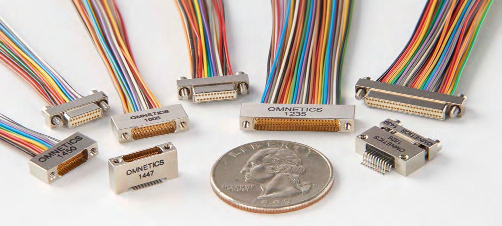


Military Embedded Systems focuses on embedded electronics – hardware and software – for military applications through technical coverage of all parts of the design process. The website, e-mags, newsletters, podcasts, virtual events, annual Resource Guide, and print editions cover topics including radar and electronic warfare, artificial intelligence/machine learning, uncrewed systems, C5ISR, avionics, and cybersecurity. Don’t miss any of it!
Military Embedded Systems is also the largest source for coverage of the Sensor Open System Architecture (SOSA) Technical Standard and the Future Airborne Capability Environment (FACE) Technical Standard. We exclusively produce the once-yearly SOSA Special Edition and FACE Special Edition. militaryembedded.com
Each issue, the editorial staff of Military Embedded Systems will highlight a different organization that benefits the military, veterans, and their families. We are honored to cover the technology that protects those who protect us every day.
By Editorial Staff

This issue we are highlighting Feed Our Vets, a 501(c)(3) nonprofit organization whose mission is to help U.S. veterans and their families who experience food insecurity.
Feed Our Vets was founded in 2008 by Navy veteran and Vernon Center, New York, postmaster Rich Synek. One day, a World War II veteran came into Rich’s post office and bought a single stamp. When Rich asked him why he didn’t buy a book of stamps, the man confessed that he and his wife only had enough money to eat properly for two weeks out of each month, and that the last few days of the month, the couple had nothing to eat at all. Following that incident, the Syneks realized the pervasive nature of food insecurity for veterans and families and established the first Feed Our Vets food pantry. According to information from Feed Our Vets, more than 130,000 veterans are unhoused and unfed on any given night in the U.S. and one in three homeless people in the country is a U.S. military veteran.
As of 2023, the organization reported providing food assistance to more than 43,000 veterans and families, with facilities and partners to assist both veterans and active-duty military personnel in 39 states. Feed Our Vets organizes community food pantries to provide free food distribution to veterans and families, distributes related goods and enables access to other services, and facilitates public education and outreach around the issue of hunger in the U.S.
The organization states that while running a brick-and-mortar pantry in every state is impossible because of high operating costs, it does coordinate a food-purchase gift-card program for veterans and personnel who live in states and communities that do not currently have a pantry.
For additional information, visit https://feedourvets.org/.
Sponsored by Micross
MIL-STD-1553 data buses have been ubiquitous on military aircraft, helicopters, uncrewed systems, ground vehicles, and spacecraft for the past 50 years. The longevity of 1553 can be ascribed to its robust physical layer, redundant nature, and deterministic and reliable command/response protocol. Further, 1553 enjoys an extremely large installed base – virtually every military aerospace platform globally uses the 1553 communications bus. In recent decades, there have been various communication standards vying to be “the next 1553,” yet 1553 remains the de facto backbone for defense and aerospace systems that will be prevalent for decades to come.
In this webcast, experts on the MIL-STD-1553 interface and systems design share their decades of knowledge and experience, provide system designers and engineers with an end-to-end overview of this fail-safe data bus protocol, and share best practices for its use in embedded military and aerospace applications. (This is an archived event.)
Watch this webcast: https://tinyurl.com/4ypmetwt
Watch more webcasts: https://militaryembedded.com/webcasts/
Sponsored by Mercury Systems
Future defense and aerospace platforms are becoming smarter and more autonomous. Operating in commercial as well as hostile military environments, these systems require high levels of proven system security engineering (SSE) and intrinsic trust for system-wide processing integrity and demonstrable operational safety in order to achieve airworthiness certification. System designers face a complex challenge: how to reconcile the often-divergent requirements of system-level safety and security to protect systems and mitigate risk.
In this white paper, experts lay out design practices for building safe and flight-certifiable systems; cyber- and physicalsecurity strategies, approaches, and technologies; evolving methods of combining "public" safety and "private" security disciplines; and new design approaches to building reliable, safe and secure systems.
Read this white paper: https://tinyurl.com/2vkmcx7n
Read more white papers: https://militaryembedded.com/whitepapers
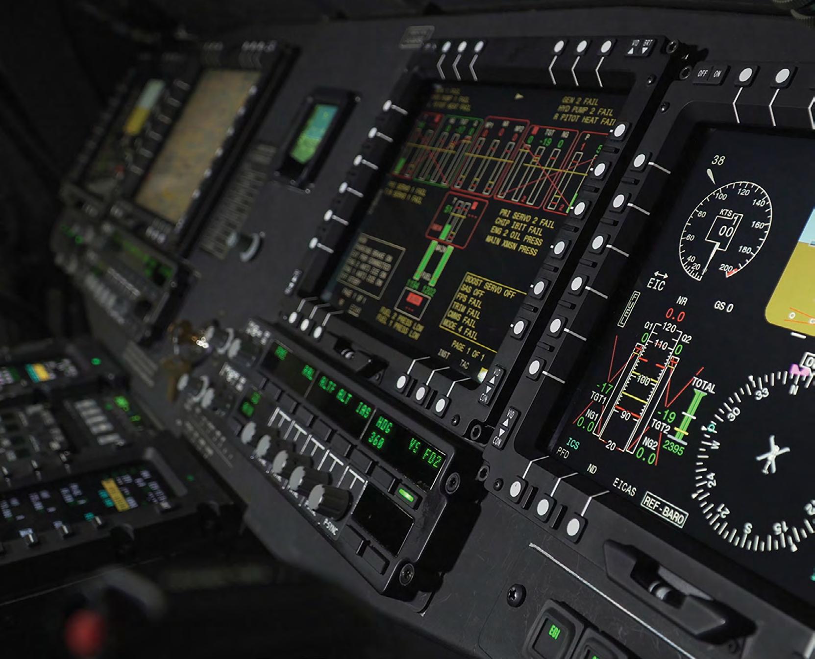


TECHNOLOGY, TRENDS, AND

Military Embedded Systems focuses on embedded electronics – hardware and software – for military applications through technical coverage of all parts of the design process. The website, Resource Guide, e-mags, newsletters, podcasts, webcasts, and print editions provide insight on embedded tools and strategies including technology insertion, obsolescence management, standards adoption, and many other military-specific technical subjects.
Coverage areas include the latest innovative products, technology, and market trends driving military embedded applications such as radar, electronic warfare, unmanned systems, cybersecurity, AI and machine learning, avionics, and more. Each issue is full of the information readers need to stay connected to the pulse of embedded technology in the military and aerospace industries.