
PG NUMBER VITA STANDARDS DEVELOPMENT LEADS THE WAY p.8 p. 5 Editor’s Foreword Masks off! p. 14 Technology Feature Space VPX & interconnect ANNAPOLIS MICRO SYSTEMS 64 GS/s Card with 0.1-36 GHz Coverage p.22 @VitaTechnology FALL 2022 | VOLUME 40 | NUMBER 2 2023 p.22 APPLICATION GUIDE
Pg Advertiser
VITA EDITORIAL DIRECTOR Jerry Gipper jerry.gipper@opensysmedia.com GROUP EDITORIAL DIRECTOR John McHale john.mchale@opensysmedia.com
ASSISTANT MANAGING EDITOR Lisa Daigle lisa.daigle@opensysmedia.com
TECHNOLOGY EDITOR – WASHINGTON BUREAU Dan Taylor dan.taylor@opensysmedia.com
CREATIVE DIRECTOR Stephanie Sweet stephanie.sweet@opensysmedia.com WEB DEVELOPER Paul Nelson paul.nelson@opensysmedia.com
EMAIL MARKETING SPECIALIST Drew Kaufman drew.kaufman@opensysmedia.com WEBCAST MANAGER Ryan Graff ryan.graff@opensysmedia.com
SALES/MARKETING
DIRECTOR OF SALES Tom Varcie tom.varcie@opensysmedia.com (734) 748-9660
DIRECTOR OF MARKETING Eric Henry eric.henry@opensysmedia.com OPERATIONS & AUDIENCE DEVELOPMENT (541) 760-5361
STRATEGIC ACCOUNT MANAGER Rebecca Barker rebecca.barker@opensysmedia.com (281) 724-8021
STRATEGIC ACCOUNT MANAGER Bill Barron bill.barron@opensysmedia.com (516) 376-9838
STRATEGIC ACCOUNT MANAGER Kathleen Wackowski kathleen.wackowski@opensysmedia.com (978) 888-7367
Profile Index
Advertiser Page
RADAR/ELECTRONIC WARFARE
Sponsored by Annapolis Micro Systems 22 Annapolis Micro Systems 22 Interface Concept 22 Interface Concept 23 TE Connectivity 23
COMMUNICATIONS
Dawn VME Products 23
SOUTHERN CAL REGIONAL SALES MANAGER Len Pettek len.pettek@opensysmedia.com (805) 231-9582
DIRECTOR OF SALES ENABLEMENT Barbara Quinlan barbara.quinlan@opensysmedia.com AND PRODUCT MARKETING (480) 236-8818
INSIDE SALES Amy Russell amy.russell@opensysmedia.com
STRATEGIC ACCOUNT MANAGER Lesley Harmoning lesley.harmoning@opensysmedia.com
EUROPEAN ACCOUNT MANAGER Jill Thibert jill.thibert@opensysmedia.com
TAIWAN SALES ACCOUNT MANAGER Patty Wu patty.wu@opensysmedia.com
CHINA SALES ACCOUNT MANAGER Judy Wang judywang2000@vip.126.com
www.opensysmedia.com
PRESIDENT Patrick Hopper patrick.hopper@opensysmedia.com
EXECUTIVE VICE PRESIDENT John McHale john.mchale@opensysmedia.com
EXECUTIVE VICE PRESIDENT AND ECD BRAND DIRECTOR Rich Nass rich.nass@opensysmedia.com
EVENTS
Embedded Tech Trends
January 23 & 24, 2023 Chandler, AZ http://www.embeddedtechtrends.com/ embedded world March 14-16, 2023 Nuremburg, Germany https://www.embedded-world.de/en
ECD EDITOR-IN-CHIEF Brandon Lewis brandon.lewis@opensysmedia.com
TECHNOLOGY EDITOR Curt Schwaderer curt.schwaderer@opensysmedia.com
ASSOCIATE EDITOR Tiera Oliver tiera.oliver@opensysmedia.com
ASSISTANT EDITOR Taryn Engmark taryn.engmark@opensysmedia.com
ASSISTANT EDITOR Chad Cox chad.cox@opensysmedia.com
CREATIVE PROJECTS Chris Rassiccia chris.rassiccia@opensysmedia.com
MARKETING COORDINATOR Katelyn Albani katelyn.albani@opensysmedia.com
FINANCIAL ASSISTANT Emily Verhoeks emily.verhoeks@opensysmedia.com
SUBSCRIPTION MANAGER subscriptions@opensysmedia.com
CORPORATE OFFICE 1505 N. Hayden Rd. #105 • Scottsdale, AZ 85257 • Tel: (480) 967-5581
REPRINTS
WRIGHT’S MEDIA REPRINT COORDINATOR Kathy Richey clientsuccess@wrightsmedia.com (281) 419-5725
2 | VITA Technologies with Application Guide Fall 2022 www.vita-technologies.com
1 Annapolis Micro Systems –64 GS/s Card with 0.1-36 GHz Coverage 3 Behlman Electronics, Inc. –The race to open systems 24 Behlman Electronics, Inc. –3 Phase. 3U. 1 Choice. 11 Elma Electronic –Award-winning development solutions 19 LCR Embedded Systems, Inc. –VPX systems for mission critical applications 13 Verotec –Commercial and rugged system components Advertiser Index
Dawn VME Products 22 TEST & MEASUREMENT


: 631-435-0410 : sales@behlman.com : www.behlman.com : 631-435-0410 : sales@behlman.com : www.behlman.com
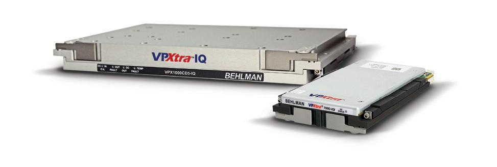
LEADS THE PACK AGAIN! VPXtra® 1000CD5-IQI > 6U power module developed in alignment with the SOSA Technical Standard > Delivers 1050W DC power via two outputs > VITA 46.11 IPMC for integration with system management VPXtra® 700D-IQI > 3U power module developed in alignment with the SOSA Technical Standard > Delivers 700W DC power via two outputs > VITA 46.11 IPMC for integration with system management FIRST PROVEN VPX POWER SUPPLIES DEVELOPED IN ALIGNMENT WITH THE SOSA™ TECHNICAL STANDARD Behlman introduces the first test-proven VPX power supplies developed in alignment with the SOSA Technical Standard. Like all Behlman VPXtra® power supplies, these 3U and 6U COTS DC-to-DC high-power dual output units feature Xtra-reliable design and Xtra-rugged construction to stand up to the rigors of all mission-critical airborne, shipboard, ground and mobile applications. SOSA™ and logo design and The Open Group Certification Mark™ are trademarks of The Open Group in the United States and other countries. The Power Solutions Provider
BEHLMAN





@VitaTechnology FALL 2022 | VOLUME 40 | NUMBER 2 All registered brands and trademarks within VITA Technologies magazine are the property of their respective owners. ™ VPX and its logo is a registered product/trademark of VITA. © 2022 OpenSystems Media © 2022 VITA Technologies enviroink.indd 1 10/1/08 10:44:38 AM On the cover The 2023 VITA Technologies Application Guide showcases technologies and products based on VITA standards. Featured on the cover: Annapolis Micro Systems 64 GS/s card with 0.1-36 GHz coverage. FEATURES Special Feature VITA Standards Development 8 VITA standards development leads the way By Jerry Gipper, VITA Editorial Director; Dean Holman, VITA Executive Director; Jing Kwok, VITA Technical Director Technology Feature SpaceVPX and interconnect 14 SpaceVPX (VITA 78) and the world of interconnect By Patrick Collier and Michael Walmsley Technology Feature Interconnect and VITA 76 18 Going faster with circular connectors By Ken Braund and Alan Roath, Meritec DEPARTMENTS 5 Editor’s Foreword Jerry Gipper Masks off! 6 VITA Standards Update Jerry Gipper VITA standards activity updates 22 VITA TECHNOLOGIES APPLICATION GUIDE VITA standards development leads the way p. 8 SpaceVPX (VITA 78) and the world of interconnect By Patrick Collier and Michael Walmsley p. 14 Going faster with circular connectors By Ken Braund and Alan Roath, Meritec p. 18 4 | VITA Technologies with Application Guide Fall 2022 www.vita-technologies.com To unsubscribe, email your name, address, and subscription number as it appears on the label to: subscriptions@opensysmedia.com
By Jerry Gipper
Life is back to normal! I’m starting to sweat vaccine! Flu, shingles, and five COVID-19 vaccinations in the past couple of years. Mask wearing is only as needed or required. Traveling is definitely feeling normal. We have held four VITA Standards Organization in-person meetings this year and the in-person participation has increased each time. We are finally back to the level of attendance we had pre-pandemic. It is great to have meetings in person once again!
2022 marks the 40th anniversary of the formation of what is now known as VITA. Originally the VMEbus Manufacturers group formed to build support for VMEbus, the organization evolved into the VMEbus International Trade Association. A few years later, after struggling with the process of making VMEbus a standard, VITA began working toward becoming an ANSI-accredited standards developer, and the rest is history! Today VITA is recognized worldwide as a leading standards- and ecosystem-development organization for critical embedded and intelligent computing technologies.
The level of activity with the VITA standards working groups is higher than ever. VITA membership is growing at record rates, with 25 new members so far this year! The interest level in VITA standards is booming: Check out the Standards Update column to view a summary of the most recent activities. Now is a great time to get involved because many of the projects currently under development will shape the course of the next genera tion of critical and intelligent embedded computing over the next several years.
As the complexity of embedded and critical com puting has increased, so has the need for standards. It has become so difficult to develop complex com puting technologies that no one company has the resources to go about it alone. The collaboration in developing standards goes a long way toward making it possible to get established. Much of the current work is going to be extremely difficult to sort out because of the plethora of viable options in many cases. At the same time, we are under extreme pres sure to map out the future direction of the major stan dards in the detail necessary to make critical strategy decisions now.
VITA working groups are busy defining standards for improved cooling schemes, high-bandwidth intercon nect solutions, mezzanines, and smaller form factors.
We have learned much with VPX over the past 20 years and are preparing to take it to the next level for the next generation based on the gained experience.


In this issue, we delve into the process used by VITA to develop and maintain standards. VITA has evolved its policies and procedures for standards development to keep current with best-in-industry practices, even leading in establishing patent ex-ante licensing disclo sure policy. After nearly 40 years, VITA has developed nearly 100 industry-recognized standards, closer to 300 if you count the associated dot standards. As Ray Alderman, VITA’s chairman of the board, would say, “VITA has aged like a fine Scotch!”
The world’s economies are entering into a new state of uncertainty as we emerge from COVID-19 and deal with the political challenges that are happening around the world. VITA has published two market reports that go into more detail at multiple levels. The first is analyst Brian Arbuckle’s quarterly “VITA Market Developments” (https://www.vita.com/VITA_Market_ Development) report, focusing on the VITA members and new products. The second is Ray Alderman’s “2022 State of the VITA Technology Industry” (https:// www.vita.com/VITA_Technology_Industry ) secondhalf report, in which Ray delves into economic and technology issues at a macro level. Both reports have interesting perspectives as we navigate through the current global challenges. One piece of good news: The military and aerospace markets look to be strong for the foreseeable future. Advances in technology innovation by VITA members is sure to keep the mar kets strong.


Stay healthy, stay safe.

www.vita-technologies.com VITA Technologies with Application Guide Fall 2022 | 5 Masks off!
Editor’s Foreword VITA HAS EVOLVED ITS POLICIES AND PROCEDURES FOR STANDARDS DEVELOPMENT TO KEEP CURRENT WITH BEST-IN-INDUSTRY PRACTICES, EVEN LEADING IN ESTABLISHING PATENT EX-ANTE LICENSING DISCLOSURE POLICY. AFTER NEARLY 40 YEARS, VITA HAS DEVELOPED NEARLY 100 INDUSTRYRECOGNIZED STANDARDS, CLOSER TO 300 IF YOU COUNT THE ASSOCIATED DOT STANDARDS.
@VitaTechnology Jerry@Vita.com
VITA Standards Update
VITA standards activity updates
By Jerry Gipper, Editorial Director

Note: This update is based on the results of the September 2022 VITA Standards Organization (VSO) meeting, held in San Diego and hosted by Cubic Corp. Contact VITA if you are interested in participating in any of these working groups. The full reports can be accessed at www.vita.com/StandardsUpdates Visit the VITA website (http://www.vita.com) for details on upcoming VITA meetings.
ANSI accreditation
Accredited as an American National Standards Institute (ANSI) developer, VITA provides its mem bers with the ability to develop and promote open technology standards.
The following standards have recently been ANSIand VITA-approved via public VITA consensus ballot:
› ANSI/VITA 48.0-2022, Mechanical Standard for Microcomputers using Ruggedized Enhanced Design Implementation (REDI) (revision)
› ANSI/VITA 48.2-2022, Mechanical Standard for VPX REDI Conduction Cooling (revision)
› ANSI/VITA 62.0-2022, Modular Power Supply Standard (revision)
› ANSI/VITA 74.0-2022: Compliant System Small Form Factor Module Base Standard (revision)
› ANSI/VITA 78-2022: SpaceVPX System Standard (revision)
All published standards are available for download by VITA members and are posted at the online VITA Store for purchase by nonmembers.
the provision of high-speed interconnects in harsh environment applications. This revision supports compliance requirements of higher-level open system standards, adds guide socket/pin rotations for addi tional power-supply configurations, and provides fur ther clarifications to power wafer current ratings.
Status: The standard is open for revisions. The working group is reviewing updates for compliance requirements and support for 12 V power.
ANSI/VITA 48.x: VPX REDI: Cooling
Abstract: The VITA 48 standards provide an over view of the associated plug-in units for air cooling, conduction cooling, and liquid-flow-thru (LFT) and spray-cooling applications.
Status: Several of the standards in this series are being updated to allow for a 100-mm-deep, 1.2-inchpitch VPX module, or other updates. The working group has completed the public consensus ballot and has submitted document for final ANSI/VITA approval.
VITA 51.4:
Reliability Component Derating
Abstract: The goal of this working group is to develop a new component derating standard.
VSO study and working group activities

Standards within VITA may be initiated through the formation of a study group and developed by a working group. A study group requires the spon sorship of one VITA member, while a working group requires sponsorship of at least three VITA members.
Several working groups have current projects underway. Here’s a roundup of these projects:
ANSI/VITA 46-2019: VPX Baseline
Abstract: This standard describes VITA 46.0 VPX Baseline Standard: an evolutionary step forward for
Status: This working group has joined forces with the IEEE to jointly develop this standard under IEEE2818. The working group is preparing for public con sensus ballot.
ANSI/VITA 62.0-2016: Modular
Power-Supply Standard
Abstract: This standard provides requirements for building a power-supply module that can be used to power a VPX chassis. The module will fit within the standard envelope defined for VPX modules in the VITA 48.0 standards.
Status: The standard is due for its five-year review. The working group is developing a draft of the revisions that are in review.
6 | VITA Technologies with Application Guide Fall 2022 www.vita-technologies.com
VITA 62.1: Power Supply Front End for High-Voltage/ 3-Phase 3U Module
Objective: The VITA 62.1 standard describes requirements for building a high-voltage/3-phase/3U-class front-end powersupply module that can be used to power a VPX chassis in the VITA 62 family of standards. The module will fit within the standard envelope defined for VPX modules in the VITA 48.0 standards.
Status: The working group is developing a draft document that is in review.
VITA
65.x: OpenVPX System Standard
Abstract: The OpenVPX System Standard was created to bring versatile system architectural solutions to the VPX market. Based on the extremely flexible VPX family of standards, the OpenVPX standard uses plug-in module mechanical, connec tors, thermal, communications protocols, utility, and power def initions provided by specific VITA standards to define a series of slot, backplane, module, and standard development chassis profiles. This revision adds additional profiles, additional com munication protocols, higher-speed copper connectors, and a new naming methodology for module profiles.
Status: The working group is adding additional profiles to this standard.
VITA 66.5: Optical Interconnect on VPX – Hybrid
Variant
Abstract: This document describes an open standard for con figuration and interconnect (within the structure of VITA 66.0) enabling an interface compatible with VITA 46 containing blind-mate optical connectors with fixed contacts on the plugin module and floating displacement on the backplane.
Status: The working group is developing the draft document.
ANSI/VITA 67.3-2020: VPX: Coaxial Interconnect on VPX, Spring-Loaded Contact on Backplane
Abstract: The VITA 67.3 standard defines an open standard for configuration and interconnect (within the structure of VITA 67.0) enabling an interface compatible with VITA 46 con taining multiposition blind-mate analog connectors with coaxial contacts, having fixed contacts on the plug-in module and spring action on the backplane.
Status: The standard is open for revision.
or backplane is based on simulation of end-end channel com pliance against the requirements of the applicable protocol standard.
Status: The working group is addressing signal integrity com pliance for Gen4 and higher speeds for VPX.
VITA 87: MT Circular Connectors – Type 1
Abstract: The VITA 87 MT circular connector standard defines a standard for circular connectors with optical MT. Circular connector shells are compliant to MIL-STD-38999. MT offer options for 12 or 24 fibers per MT and for physical contact or lensed MT.
Status: The working group is reviewing a draft document.
VITA 89: MT Circular Connectors – Type 2
Abstract: The VITA 89 MT circular connector standard defines a standard for circular connectors with optical MT. Circular con nector shells are compliant to MIL-STD-38999. MT offer options for 48 fibers per MT and for physical contact or lensed MT.
Status: The working group is reviewing a draft document.
VITA 90.x: VNX+
Abstract: Standards for an enhanced small-form-factor system that meets the growing needs of improved size, weight, and power (SWaP) with a rugged, low-cost, fast serial fabric inter connect-based plug-in module. The VITA 90.x family of stan dards builds on the foundation established by VITA 74 VNX. VNX+ significantly increases performance and system versatility beyond VITA 74, while following its mechanical framework.
Enabling Open Standards for Improved Capability
SOSA and VITA:
Status: New working group formed to make revisions to VNX under VNX+.
Sponsored by Annapolis Micro, Epiq Solutions, Pentek, and TE Connectivity
VITA 91: Connector for Higher Density VITA 46 Applications
Abstract: This standard defines a connector system that pro vides higher pin density to the backplane for VITA 46 3U and 6U VPX applications.
Elements of the Sensor Open System Architecture (SOSA) technical standard are leveraging standards developed by the VITA Standards Organization, specifically VITA 65, also known as OpenVPX. VITA has also become a participating member of the SOSA Consortium along with the Air Force, Army, and Navy.
Status: VITA working group to develop a new standard for higher pin density for VPX. Working group is reviewing draft.
Join a panel of industry experts for this webcast, which will cover how the SOSA Consortium is working with VITA to enable standardization of VITA-based standards within the SOSA Technical Standard.

For a complete list of VITA standards available for purchase and their status, go to www.vita.com/Standards
VITA 68.3:
Reference SI Model Standard for Gen4 and Higher Speeds
Abstract: This standard documents a reference model approach for OpenVPX Signal Integrity compliance at baud rates above 10.3125 Gbaud. It defines reference OpenVPX Plug-In Module and backplane s-parameter models that can be used to create end-end OpenVPX reference channels in conjunction with reference VPX connector and device s-parameter models. Signal Integrity compliance for an OpenVPX Plug-In Module
To watch the webcast: https://bit.ly/32HedJr WATCH
MORE WEBCASTS: https://militaryembedded.com/webcasts/
www.vita-technologies.com VITA Technologies with Application Guide Fall 2022 | 7
VITA standards development leads the way
VITA Standards Organization Background and History VITA is celebrating the 40th anniversary of its origination. VITA initially started in 1982 as the VMEbus Manufacturers Group to support the development of an ecosystem for the new VMEbus specification. Manufacturers developing VMEbus products joined together to educate potential users about the new VMEbus based technologies. In 1985 the VME Manufacturers Group became more organized under the VMEbus International Trade Association (VITA) to accelerate the technical and commercial acceptance of VME.
Work continued on VMEbus under the VITA technical committee as an IEEE stan dard until 1993 when VITA was granted American National Standards Institute (ANSI) accreditation in June of that year. This opened the doors to innovation and stan dards related to VMEbus technology. Soon after gaining ANSI accreditation, the VITA Standards Organization (VSO) was formed out of the VITA Technical Committee in the fall of 1993, under Section 5.6 of the VITA Bylaws, to provide VITA mem bers with a formal and accredited method of developing and promoting open tech nology standards.
One of the first projects of the VSO was the development of a new standard for the VMEbus. That standard was based on the original VMEbus standard written by Motorola, Mostek, and Signetics and placed into the public domain in the early 1980s. Once the VSO completed its work, the proposed standard was submitted under the ANSI standards process and ANSI/VITA 1, VME64, was recognized as an American National Standard (ANS) in 1995, becoming the first VITA standard to receive ANSI approval under the new ANSI/VITA standards development process.
The first non-VMEbus standard to utilize the new ANSI/VITA process was VITA 4 which became the ANSI/VITA 4: IP Module standard, defining the requirements for a business card-sized mezzanine module. The working group was chaired by Jerry Gipper while with the Motorola Computer Group. Kim Rubin, with Greenspring Computers, and the devel oper of the specification for the orig inal IndustryPacks, was the editor. Joe Primeau of Acromag was an active and significant contributor to the editing of the proposed standard.
Since 1995, more than 90 working groups have been approved to begin work on a standard. Included are over 100 sub-working groups established to develop associated dot standards to compliment a primary standard. Managing this standards development activity has required the VSO to evolve its processes while still maintaining its ANSI accreditation.

SPECIAL FEATURE VITA Standards Development 8 | VITA Technologies with Application Guide Fall 2022 www.vita-technologies.com
The VITA way
The procedures to develop standards within the VSO are outlined in the VITA Standards Organization (VSO) Policies and Procedures (www.vita.com/ Governance). This process has evolved over the years to meet changing require ments and processes. VITA recently released version 3.1 this past July with major revisions to simplify documenting the standards development process used by the VSO.
VITA is formally accredited by ANSI as a standards developer. This means that VITA follows a rigorous standards development process that adheres to the ANSI Essential Requirements: Due process requirements for American National Standards (www.ansi.org). VITA is required to be audited every five years by ANSI, a very rigorous and detailed procedure, to ensure that ANSI and VITA policies and processes are being followed. Issues are documented and corrective actions must be reviewed by ANSI and implemented before the audit is closed. Passing the audit is required to retain ANSI accreditation. In addition, ANSI issues annual updates to the ANSI Essential Requirements document that must be reviewed and implemented in the VSO Policies and Procedures as nec essary to remain accredited.


The development of a standard starts within the VSO in either a study group or a working group and moves through two distinct phases as shown in Figure 1, Process Flow. Development of the pro posed standard is conducted during Phase 1; Phase 2 details the process for completing an approval ballot. Before entering Phase 2, the working group chooses one of two tracks. Track 1 leads to a VITA Standard, while Track 2 leads to an ANSI/VITA Standard. The vast majority of proposed standards take the ANSI option.
A new standards project is often launched after a technology or industry problem presentation to the VSO at one of its bi-monthly meetings. Often the presentation leads to a call for a study
Figure 1 | Standard development: Process Flow.


group or working group to be formed. VITA encourages presentations on technology or issues within the technical scope of the VSO. VITA dropped reference to VMEbus International Trade Association in 2005 to enable broadening of its scope to critical and intelligent embedded computing, with a primary emphasis on backplane-related technologies. This widened focus enables study and working groups to address a broader technical scope.

Phase 1 is where the working group develops the draft documents and where the real work happens. Lively discussions are held, studies and research are conducted, and options discussed. The combined years of experience of the working group partici pants is invaluable as the working group considers options. Working groups range from small to large in size, depending on the impact of the project. The diligence of the working group is critical to the quality of the final work project.
VITA encourages open and thorough discussions on technical matters. VITA staff monitors the activities and advises as necessary on the process and the technology under discussion. The working group makes final recommendations and decisions. Throughout the process, consensus is encouraged through documented minutes and ballots.
The working group elects a chair and an editor (sometimes the same person in smaller working groups) who lead the process for developing the draft documents. They are required to follow a transparent process to document meetings and develop the draft documents. The working group holds regular meetings with documented minutes for as long as they need to complete a draft for approval. Once the working group has voted to approve the draft documents, it can move forward to Phase 2.
Phase 2 is the public-approval process during which interested parties can review and cast ballots on the proposed standard. A public announcement of a consensus ballot is made by VITA and ANSI so that interested stakeholders can participate in a final ballot if they desire. An interested stakeholder does not have to be a VITA member to participate in balloting during Phase 2.
Comments are often made that standards development organizations are slow, that there are many gates that take long periods of time to complete. The VITA process has minimal time requirements to adhere to during the development of draft stan dards. The only time constraints center on giving enough time to alert participants to upcoming meetings, to allow adequate time for a review prior to a ballot, and to make calls for public consensus ballots. The working group has full control over how much time they need to develop a draft of a proposed standard for approval. The time needed is usually a function of how complex the proposed standard is, whether or
SPECIAL FEATURE www.vita-technologies.com VITA Technologies with Application Guide Fall 2022 | 9
not they had prior work to reference, and how quickly the working group can develop consensus. In addition, the amount of time available to devote to the work is a direct influence on the total time. For most of the working group members, standards devel opment is a secondary job. Phase 1 can take months to years to complete, while Phase 2 can be weeks to months, depending on comment resolution after balloting. In short, the process is not a bottleneck, but rather the effort of the working group.
Standards: the details
A study group may be formed by any VSO member that wishes to investigate the need and to ascertain the interest in developing a standard. The VSO member requesting recognition of the study group is designated the chair of the study group. Membership in the study group is open to any VSO member. The study group chair is responsible for scheduling meetings, soliciting members, keeping minutes of meet ings, and reporting activities to the VSO Chair.
A study group can move to working group status by meeting working group forma tion criteria. A study group disbands if interest in developing a standard related to the study group effort was not achieved within a period deemed reasonable by the VSO membership.
Forming a study group is NOT a prerequisite for forming a working group. A standards activity can begin directly in a working group if the formation criteria are met.
The development of a draft proposed standard takes place in a working group. Three (or more) organizations which are VITA corporate members (regular, senior, or sponsor) may form a working group to carry out the development of a specific standard. Working groups achieve official VSO recognition by meeting the following criteria:
1. The development of the standard shall be proposed by three (or more) organizations that are VITA members and wish to sponsor the development of the standard.
2. The scope of the proposed standard shall fall within the technical scope of the VSO.
3. The sponsors shall notify the VSO Chair of their intentions to form a working group and must submit a document with the purpose, scope, and an outline for the proposed standard.
To maintain formal working group status, the working group must continue to have at least three sponsors that are VITA corporate member companies in good standing and show forward progress in the development of the standard. If the number of spon sors falls below three, then the remaining sponsor(s) may recruit new sponsor(s), may return to study group status, or may disband the working group. A working group is considered official once ANSI has been properly notified by VITA.
VITA has no other limitations on the formation of a study or working group. No busi ness case, industry studies, or other substantiating materials are needed to form a study or working group. VITA advocates that “Open Standards, Open Markets.” In other words, the market will decide how acceptable any given standard will become, not a VITA steering committee. VITA is relatively unique in this aspect in the critical embedded and intelligent computing industry.
Working Group officers
Working groups have a chair and a draft editor, sometimes the same individual on smaller projects. Working group officers are initially appointed by the sponsor orga nizations, but after two meetings, the working group may hold elections to either reaffirm or elect new officers.
The working group chair is initially appointed by the sponsor organizations and is responsible for the following:
› Soliciting membership for the working group.
› Maintaining a working group membership list.
› Scheduling meetings.
› Leading working group meetings.
› Keep meeting minutes unless the working group has a secretary.
› Reporting development status to the VSO Chair.
› Completing development in a timely manner.
› Submitting a draft for one or more working group ballots.
Working Group Membership: Any em ployee of or a consultant to a VITA member company or VITA Distinguished Fellow may be a member of a working group. To become a member of a working group, the interested individual formally regis ters with the chair of the working group committee. Working groups have three levels of participation: sponsor, partici pant, and observer. Sponsors formally commit to support the standards activity and put forth extra effort to achieve stan dardization. Participants regularly attend meetings and are expected to cast votes on all working group ballots and other committee matters. Observers may attend meetings and vote in ballots.
Working Group Meetings: VITA allows for in-person and virtual meetings as fre quently as desired. They may be held at standing VSO meetings or at other times as required. The date, time, and place for in-person must be announced to the working group members 15 days or more in advance, or 48 hours or more in advance for virtual meetings. Most study group and working group meetings are held virtually, with the exception of those held during the bimonthly VSO meetings.
At the start of each meeting, it is required that the chair advises the attendees of the VSO patent, antitrust, ITAR, and code of conduct policy statements. Meeting minutes must be reviewed, approved, and posted for each meeting.
SPECIAL FEATURE VITA Standards Development
10 | VITA Technologies with Application Guide Fall 2022 www.vita-technologies.com
Disclosure of patents
VITA takes patents related to a proposed standard very seriously. VITA broke new ground in the area of disclosure and licensing of patents in standards, becoming the first standards developer in the world to receive guidance for “ex ante” procedures from any legal authority. VITA requires essential patents related to an activity to be disclosed at the start of each working group meeting. An “essential” claim means any claim the use of which is necessary to create a compliant implementation and for which there is no technically and commercially feasible noninfringing alternative. The patent policy is included as part of the VSO Policies and Procedures. Patents filed as part of any standard require a disclosure, which is posted on the VITA website along with fair, reasonable and non-discriminatory (FRAND) terms (www.vita.com/Essential-Patents).
The policy has significant impact in two areas: The first is the change from a vol untary system to a mandatory system of disclosing of essential patents and patent applications. The second area of impact is the Fair, Reasonable, And Non-Discriminatory (FRAND) disclo sure of maximum fees or royalties and the most restrictive terms for licenses to technology essential to implementa tion of a standard that is in development by a working group. Members to newly formed working groups have 60 days to disclose essential patents or patent applications and license terms, while members in existing working groups have 30 days.

The objective of this policy is to elimi nate patent ambush. VSO working groups are expected to make sound technical and business decisions. Patent ambushes can delay or undermine the acceptance of new standards.

Working Group balloting Consensus is key to the open aspect of the development of standards within VITA, Consensus at the working group level is achieved through a webbased balloting process. Balloters during Phase 1 consist of the sponsors,
participants, and observers of the working group. Ballots can be anywhere from imme diate to 28 days depending on the material to be reviewed. The length of the ballot period shall be proposed by the working group chair with majority agreement of the working group. The working group chair may extend the ballot period up to an additional 14 days in order to allow more time for voting upon request of any of the working group members.
The working group chair shall review all working group ballots with the working group and shall attempt to resolve the NEGATIVE ballots and all comments. The results of working group ballots shall be reported to the VSO Chair. No specific number of working group ballots is required. However, most draft proposed standards require more than one ballot before the draft is completed.
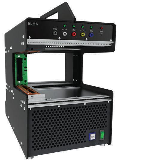
elma.com Elma Electronic Inc. Learn More With you at every stage! Elma’s new CompacFrames are innovative lightweight platforms for card or system development based on open standards like VPX or aligned to SOSA™. Award-Winning Development Solutions www.vita-technologies.com VITA Technologies with Application Guide Fall 2022 | 11
Either a working group ballot or a recirculation of a working group ballot is required when one or more substantive changes are made to a draft. A substantive change is any change which affects compliance with the draft. If a substantive change has been made to the draft, it is the responsibility of the chair of the working group to decide between a new, full working group ballot or a re-circulation ballot.
Phase 2 – Approval Ballot
Standards development takes place in one of two tracks during Phase 2 as decided by the working group during Phase 1. Track 1 becomes a VITA standard, with Track 2 moving to become an ANSI/VITA standard. Openness is emphasized during Phase 2 as a broader approval audience is pulled into the process.

Track 1: To be recognized as a standalone VITA standard, the draft proposed standard must pass a 75/75 VSO ballot. At least 75% of the ballots must be returned and 75% of the returned ballots must be affirmative. The VSO ballot is opened to working group members and to any other VSO members who register to vote. Once the ballot is completed and if the 75/75 criteria is met, the draft proposed standard shall be considered a VITA standard. Very few standards take this track to a standalone VITA standard.
Track 2: The result of Track 2 is an American National Standard/VITA Standard. Once a project has successfully completed the VSO process, the working group responsible for the project may decide to work toward ANSI recognition. Openness is reinforced through coordination of standards efforts with other groups.
Notification of standards development and coordination is key to building a public consensus body. Timely and adequate notice of standards development activity are
announced by ANSI and VITA to provide a meaningful opportunity for participation, debate, and deliberation by all directly and materially interested parties in a fair and equitable manner. VITA posts these notices through ANSI, VITA, social media, and relative publications and their websites.
Typical life cycle of a VITA standard
Maintenance of published standards is closely monitored by both ANSI and VITA. A rigorous process for maintenance is followed and audited. An approved standard has several maintenance options; revision, reaffirmation with no changes, and stabilized maintenance are the most common options. Revisions and reaffirmations typically happen in the first five to ten years. Stabilized maintenance (revisions no longer made) occurs in the following 10 to 20 years or more. VITA can notify anyone who has downloaded an approved and published version of a standard from VITA if the status changes. (Figure 2.)
 By Peter Delos, Technical Lead; Mike Jones, Principal Electrical Design Engineer; Hal Owens, Aerospace and Defense System Intern: Analog Devices, Inc.


This white paper details performance measurements vs. predictions of a 16-channel S-band direct sampling receiver design. The design is based on recently released direct sampling analog-to-digital converters (ADCs) clocked at 4 GSPS and sampling in the second Nyquist zone of the converter.
Read this paper at https://bit.ly/3tf5A5F

SPECIAL FEATURE VITA Standards Development
OpenSystems Media works with industry leaders to develop and publish content that educates our readers. Check out our white papers at http://vita.mil-embedded.com/ white-papers/ A Measurement Summary of Distributed Direct Sampling S-Band Receivers for Phased Arrays
12 | VITA Technologies with Application Guide Fall 2022 www.vita-technologies.com
The typical life cycle for a standard, once approved, is to experience one or two revision/reaffirmation cycles of five years maximum each cycle. A standard often goes to stabilized maintenance for up to 10 years, with an option to extend an additional stabilized maintenance cycle of up to 10 years. At the end of each stabilized maintenance cycle, the standard is reviewed for withdrawal as an ANSI National Standard and either retained as
a VITA stabilized maintenance standard or archived.
30 years and beyond
VITA is approaching 30 years since first gaining ANSI accreditation in 1993. Over the years, VITA has become recognized as an industry leader in standards and ecosystem development. Continued work to improve all processes makes VITA a leading choice as a




developer of key industry standards for the critical and intelligent embedded computing industry. The members of VITA are firmly dedicated to this continued leadership.




Authors: Jerry Gipper, VITA Marketing Director; Dean Holman, VITA Executive Director; Jing Kwok, VITA Technical Director
Whether it’s a graphics processor, a general-purpose processor, or an FPGA, these modern electronics all bring unprecedented capability to radar, avionics, and electronic warfare applications but also create headaches for design engineers who must craft unique ways to manage the excess thermals these devices generate.
In this webcast, thermal-management experts detail methods for reducing heat and thermals in modern military electronic systems. (This is an archived webcast.)
Ph: 203-745-3537 • sales@verotec.us • verotec.us VERO Electronic Enclosures Verotec are specialists in the design, manufacture and integration of electronic enclosure products. For over 50 years the name VERO has been synonymous with engineering excellence and product quality. With facilities in the UK and US, Verotec continues that tradition. 3u to 9u ieee 1101.10 and ieee 1101.10/11 Card Cages C ommer C ial and rugged system C omponents Front panels and modules supplies thermal solutions Cooling Systems: Removing Heat from Embedded Electronics Systems
by LCR Embedded Systems, nVent Schroff, and Pixus Technologies
Figure 2 | Typical life cycle of a standard.
Sponsored
To watch the webcast: https://bit.ly/3hvTfaN WATCH MORE WEBCASTS: https://militaryembedded.com/webcasts/ www.vita-technologies.com VITA Technologies with Application Guide Fall 2022 | 13
SpaceVPX (VITA 78) and the world of interconnect
By Patrick Collier and Michael Walmsley
[Editor’s Note: The ANSI/VITA 78 standard was recently revised to add additional profiles, additional communication protocols (such as Ethernet), higher-speed copper connectors, and an updated naming methodology for Slot and Module Profiles. ANSI/VITA 78.0-2022 is available at the VITA online store (www.VITA.com/Standards). The VITA 78 working group has begun documenting further enhancements to the standard.]
For decades, open systems architectures and open standards have helped accel erate innovation to end users in aero space and defense applications through the development of interfaces that are open, key, and well-defined. Today, space system designers and developers are truly embracing the SpaceVPX (ANSI/ VITA 78) standard, which leverages the OpenVPX (ANSI/VITA 65.0) architecture through its slot profile and module pro file level building blocks, which create interconnect solutions based on the user’s need.
What is the SpaceVPX standard?

SpaceVPX is a standard for creating plug-in cards (PICs) from the slot and module (protocol) profiles. In turn, these building blocks create interconnected subsys tems and systems. Developed under the auspices of The Next Generation Space Interconnect Standard (NGSIS), it is the result of a government-Industry collaboration. The primary goal of SpaceVPX is to cost-effectively remove bandwidth as a constraint for future space systems.
SpaceVPX is based on the VITA OpenVPX (VITA 65) standard with enhancements that extend the standard for space applications. The NGSIS team selected the OpenVPX standard family as the physical baseline for the SpaceVPX standard because VPX sup ports both 3U and 6U form factors with ruggedized and conduction-cooled features suitable for use in extreme environments. The infrastructure of OpenVPX also allows for prototyping and testing SpaceVPX on the ground.
TECHNOLOGY FEATURE SpaceVPX and interconnect 14 | VITA Technologies with Application Guide Fall 2022 www.vita-technologies.com
SpaceVPX is built upon several standards from VITA (www.vita.com/Standards) and the European Cooperation for Space Standardization (ECSS) (https://ecss.nl/):
› ANSI/VITA 46.0: VPX baseline standard
› ANSI/VITA 46.11: System management on VPX
› ANSI/VITA 48.2: Mechanical standard for VPX REDI conduction cooling
› ANSI/VITA 60: Alternative connector for VPX
› ANSI/VITA 62: Modular powersupply standard
› ANSI/VITA 63: Hyperboloid alternative connector for VPX
› ANSI/VITA 65.0: OpenVPX system standard
› ANSI/VITA 66: Optical interconnect on VPX
› ANSI/VITA 67: Coaxial interconnect on VPX
› ECSS – Remote Memory Access Protocol (RMAP)
› ECSS – SpaceWire standard
› ECSS – SpaceFibre standard
› Gigabit Ethernet
The limitations of OpenVPX for space applications
An evaluation of OpenVPX for space usage revealed several shortcomings: The key limitation was the lack of features available to support a full, single-faulttolerant, highly reliable configuration. Utility signals were bused and, in most cases, supported only one set of signals via signal pins to a module. As a result, a pure OpenVPX system has opportu nities for multiple failures. VITA 46.11, System management on VPX, is the basis for fault-tolerant management of a SpaceVPX system, but a suitably complete management-control mecha nism was not fully defined and so was expanded in SpaceVPX.
From a protocol perspective, SpaceWire is the dominant medium-speed data and control plane interface for most spacecraft, yet the typical OpenVPX control planes are peripheral component interconnect
EACH SLOT, MODULE, AND BACKPLANE PROFILE IN OPENVPX IS FULLY DEFINED AND INTERLINKED.
express (PCIe) or Ethernet which are not generally used in space applications. (Note: Gigabit Ethernet was added to the 2022 revision of the SpaceVPX standard.)
SpaceVPX mission: fault tolerance
The goal of SpaceVPX is to achieve an acceptable level of fault tolerance while maintaining a reasonable level of compatibility with existing OpenVPX components, including connector-pin assignments for the board and the backplane.
For the purposes of fault tolerance, a module (defined as a printed-wire assembly which conforms to defined mechanical and electrical specifications) is considered the mini-mum redundancy element, or the minimum fault containment region. The utility plane and control plane within SpaceVPX are all distributed redundantly and are arranged in star topologies, dual-star topologies, partial-mesh topologies, or fullmesh topologies to provide fault tolerance to the entire system. To meet the desired level of fault tolerance, the utility plane signals are dual-redundant and switched to each SpaceVPX card function.
A trade study, conducted in 2010 through a government and industry collaboration with the support of the SpaceVPX Working Group, compared various implementa tions including adding the switching to each card in various ways and creating a unique switching card. The latter approach was selected so SpaceVPX cards can each receive the same utility plane signals that an OpenVPX card receives, with minor adjustments for any changes in topology. This became known as the Space Utility Management module (SpaceUM), a major foundation of the SpaceVPX standard.
A 6U SpaceUM module contains up to eight sets of power and signal switches to support eight SpaceVPX payload modules – the 3U version of the SpaceUM can sup port up to five. It receives one power bus from each of two power supplies and one set of utility plane signals from each of two system controller functions required in the SpaceVPX backplane. The various parts of the SpaceUM module do not require their own redundancy. They are considered extensions of the power supply, system controller and other SpaceVPX modules for reliability calculation.
Figure 1 shows the reliability model diagram for the SpaceVPX use case system. The diagram includes the contents of two SpaceUM modules, dual power-supply mod ules, dual system-controller modules, dual-control switch modules, dual data-switch modules, four sets of dual payload modules, one set with an optionally attached peripheral module. The diagram also includes a peripheral module that is indepen dent. The utility, data, and control planes are all dual-redundant. The utility plane is indicated by P (Power) and S (System) connections. Data plane redundancy is shown as dual redundant but is application-dependent. Additional payloads, peripherals, and switches can be added according to the application and the redundancy. Note that the SpaceUM module is distributed across the various modules and not as a standalone module that must be spared.
Profiles for space defined
Each slot, module, and backplane profile in OpenVPX is fully defined and interlinked. Adapting these profiles for use in space requires specification of a SpaceVPX version of each profile.
TECHNOLOGY FEATURE
www.vita-technologies.com VITA Technologies with Application Guide Fall 2022 | 15
A slot profile provides a physical mapping of data ports onto a slot’s backplane con nector, which is agnostic to the type of protocol used to convey data from the slot to the backplane.
Module profiles are extensions of their accompanying slot profiles which enable mapping of protocols to each module port. A module profile includes information on thermal, power, and mechanical requirements for each module. Some module profiles for SpaceVPX are similar to OpenVPX, which enables use of OpenVPX modules and backplanes for prototyping or testing on the ground. However, most module profiles for space applications are significantly different from profiles for ground applications, so full specifications consistent with SpaceVPX are required. The section of the SpaceVPX standard that defines these profiles forms a majority of the standard.
Standardized SpaceVPX interconnects
Interconnects are another critical part of SpaceVPX. As with other elements of the standard, they are based on interconnects developed for OpenVPX, but designed for the extreme space environment. Problematic temperatures, vibration, outgassing, and other factors can catastrophically compromise interconnect systems as well as signal and power integrity. For decades, designers for space applications have relied on customized interconnect designs to ensure the reliability of embedded electronics exposed to the extremes of space. The high cost and long lead times of a custom interconnect solution were once considered a worthwhile investment against failures that are extremely costly or impossible to fix in space.
Today, the use of standard interconnects drives down cost, improves availability, and maintains a path for future expansion. By leveraging the OpenVPX architecture, SpaceVPX brings in the interconnect solutions which are defined in VITA standards and have gone through extensive testing to support their use in space.
The SpaceVPX slot profiles define the use of VPX connectors (VITA 46 or alternate VPX connectors) and enable implementation of RF (VITA 67) and optical (VITA 66) modules at the plug-in module to backplane interface. Power supplies follow the VITA 62 standard, which also defines the power supply connector interface. For XMC mezzanine cards in plug-in modules, XMC 2.0 connectors per VITA 61 are recom mended. Rather than defining new connectors with special characteristics, SpaceVPX slot profiles reference the appropriate VITA connector standards that support the OpenVPX architecture.
RF and optical modules
RF and optical connector modules can be integrated within an OpenVPX slot to carry signals through the backplane to/from the plug-in module. These con nector modules are mounted to the boards (including standard aperture cutouts on the backplane) to house mul tiple coaxial contacts or optical fibers. They can replace select VITA 46 connec tors within a slot. These RF and optical connector modules and contacts have been used in satellite systems and are suitable for other applications in space.
VITA 67 is the base standard for RF mod ules. VITA 67.3 is used for SpaceVPX architecture with apertures defined within specific slot profiles for RF and optical connector modules. VITA 67.3 offers coaxial contact solutions with the initial sub-miniature push-on micro (SMPM) contacts as well as higher-density coaxial interfaces NanoRF and switchedmode power supply (SMPS), which can increase the contact density two to three times over SMPM. A new revision to VITA 67.3 has begun to add 75 Ohm coaxial interfaces to support higher speed video.
VITA 66 is the base standard for optical modules, with MT ferrules as the pri mary optical interface between the plug-in module and backplane. The apertures in SpaceVPX slot profiles accommodate optical and hybrid RF/ optical connector modules meeting the
TECHNOLOGY FEATURE SpaceVPX and interconnect
16 | VITA Technologies with Application Guide Fall 2022 www.vita-technologies.com
Figure 1 | Typical SpaceVPX reliability model diagram. Illustration source: VITA.
requirements of VITA 66.5. MT interfaces can be specified for 12 or 24 fibers for highest density.

The future of SpaceVPX interconnects
By leveraging the OpenVPX architecture, SpaceVPX can also leverage the OpenVPX interconnect roadmap which addresses solutions having faster speeds, higher density, smaller size, and lighter weight. There is significant activity with new and revised VITA standards to defi ne technologies supporting nextgeneration embedded computing.
Higher data rate MULTIGIG RT 3 connectors are available and standardized in VITA 46.30 (compliant pin) and 46.31 (solder tail) to support channels to 25-32 Gigabits/sec, supporting 100G Ethernet and PCI Gen 4 and 5. These can be incorporated in a SpaceVPX slot by replacing VITA 46.0 connectors.
The latest revision of the VITA 67.3 standard includes higher-density RF interfaces NanoRF and SMPS, reducing size and weight – both critical for space systems – and accommodating higher frequencies to 70 GHz. A new revision to VITA 67.3 has begun to add 75 Ohm coaxial interfaces within a connector module to support higher speed video protocols.
The VITA 66.5 standard will be released in 2022, documenting higher-density optical interfaces, bringing up to three MT interfaces into a half-module and enabling integration of a fixed edgemount transceiver. In addition, VITA 66.5 provides solutions with NanoRF contacts and optical MTs integrated into a common connector module, providing unprecedented density within an OpenVPX slot.
New VITA 62 power supply standards have addressed three-phase power (VITA 62.1) and higher 270VDC input voltages (VITA 62.2). New MULTIBEAM XLE connectors from TE with isolating fi ns provide this upgrade for higher voltage levels while maintaining the same VITA 62.0 interface.
Key takeaways
› SpaceVPX is a set of standards for interconnects between space system components developed to cost-effectively remove bandwidth as a constraint for future space systems.
› The goal of SpaceVPX is to achieve an acceptable level of fault tolerance while maintaining a reasonable level of compatibility with existing OpenVPX components.
› SpaceVPX interconnect are based on interconnects developed for OpenVPX, adapted for the extreme space environment.
› New and revised VITA standards continue to define technologies that support the next generation of embedded computing while reducing costs, improving availability of components, and maintaining a path for future expansion.
› Numerous space agencies have become VITA members and are key contributors to the development and evolution of the SpaceVPX standard.
Patrick Collier is Open Systems Architect and lead systems engineer at Aspen Consulting Group. He focuses on the development and use of open architectures for both space and nonspace applications.
Michael Walmsley, global product manager for TE Connectivity, has more than 40 years of experience with interconnects, primarily in engineering and product management roles.
Aspen Consulting Group • https://www.aspenconsultinggroup.com/ TE Connectivity • https://www.te.com/usa-en/home.html

The McHale Report, by mil-embedded.com Editorial Director John McHale, covers technology and procurement trends in the defense electronics community. THE ARCHIVED MCHALE REPORTS AVAILABLE AT: https://militaryembedded.com/newsletters/the-mchale-report www.vita-technologies.com VITA Technologies with Application Guide Fall 2022 | 17
Going faster with circular connectors
 By Ken Braund and Alan Roath
Few interconnect systems have received the broad acceptance that the MIL-DTL-38999 (formerly MIL-C-38999) connector series has enjoyed over the many years since its inception.
Developed for severe wind and moisture problem (SWAMP) conditions in the 1930s, the 38999 connector served the U.S. Army and U.S. Navy well until the 1940s, when the U.S. Air Force introduced requirements for reduced weight. Space programs in the Seventies reinforced the weight restrictions along with additional environmental requirements. Needless to say, the 38999 interconnect system continued to evolve to meet environmental requirements for the first 70 years of its existence.
That said, little had been done prior to this past decade, with regards to the pin-andsocket contact interface to prepare it for the advent of high bandwidth electronics. Increased bandwidth requirements proved the ever-popular pin and socket contacts to be inadequate for the performance needed: Requirements driven by Ethernet, DisplayPort, USB, SATA, InfiniBand, etc. have forced innovation in contact designs and contact arrangements.
A Quadrax configuration is an early example of attempts to increased bandwidth by rearranging the signal and ground contacts within a 38999 insert to isolate the signals from one another for improved crosstalk characteristics. While increasing the bandwidth capability to 2.5Gb/s, the Quadrax pin and socket design incorporated little innovation in contact design to accommodate the ever-increasing need for higher bandwidths. The design resulted in a very large tradeoff between pin count/ pin density and overall performance. It was time for the old pin and socket contacts to move aside.
Defense prime contractors and integrators were clamoring for high-speed intercon nect systems for SWAMP conditions. The widespread use of high-speed switched serial fabric backplanes in the rugged embedded computer market created a need for a connector system capable of supporting serial I/O at full bandwidth between platforms. New backplane archi tectures were supporting link speeds in excess of 10 Gbaud. The desire of system designers to implement these speeds and to operate independent boxes or plat forms at full system bandwidth required a new generation of high bandwidth (10 Gbaud) ruggedized I/O connectors. These connectors must also be able to withstand the basic tests for shock and vibration that VPX and Mil-C-38999M, series III connec tors were subjected to. Unfortunately, little work was being done on standards for such an interconnect system.
TECHNOLOGY FEATURE Interconnect & VITA 76 18 | VITA Technologies with Application Guide Fall 2022 www.vita-technologies.com
Meritec had become involved with VITA and its standards as a result of the Meritec VPX+ connector/cable products developed in support of VPX. Meritec brought the issue of a lack of suitable high-speed 38999 solutions to the atten tion of the VITA Standards Organization (VSO) members, which led to the launch of the VITA 76 working group. The working group established the goal to develop a standard that addressed a new connector interface. The standard would support bandwidth greater than 10 Gbaud with both copper cabling and fiber optic cabling. Meritec turned full attention toward solving the problem. A leading contact interface to consider was Meritec’s time-proven HERMI contact, a hermaphroditic contact that Meritec had utilized in many previous connectors.
The HERMI contact design was not new, as it had been used in various Meritec connectors for over 30 years. It differed from the traditional pinand-socket design in that it was a flat hermaphroditic contact. The contact interface is identical in both the cable plug and the receptacle. When mated, the flat mating surfaces provide two points of contact and, when combined with welded wire termination tech niques, provide a virtually transparent signal impedance path. There are no electrical stubs like those typically found in pin-and-socket contact designs and no inductivity resulting from the added mass of the socket, as well as the added mass of solder cups or crimp features.
While many attempts have been made to embed commercial connectors such as Ethernet and USB within 38999 shells to make them stand up to rugged mili tary environments, the new hermaphro ditic contact design became the obvious solution for a smaller, lighter solution with tremendous bandwidth capability for accommodating the various protocols.

Working group objectives
When the VITA 76 working group was formed, they established the following objectives for the standard:
› It must be high pin count.

› It must be rugged, able to meet SWAMP conditions.

› The interconnect system must be capable of 10 Gbaud per differential pair.

› Describe the copper interface for a new generation of ruggedized circular connectors housed within a MIL-DTL-38999M, Series III circular shell.


› The connectors must be able to withstand the basic tests that VPX was subjected to for shock and vibration and Mil-C-38999M, series lll for the shell work.


› The copper contact interface of the bulkhead receptacle must be mateable with both the plug on the copper cabling as well as the plug on the active optic cabling allowing for interoperability between copper cables and active optic cables (AOC).
VPX Systems for Mission Critical


TECHNOLOGY FEATURE SERVING CRITICAL DEFENSE PROGRAMS FOR OVER 30 YEARS lcrembeddedsystems.com | (800) 747-5972 Thermal management solutions designed for demanding applications LCR integrated systems and chassis are recognized by defense suppliers for their reliability and performance. Conduction cooled and hybrid air- or liquid-over-conduction designs for VITA 48.2 architectures, support VPX and SOSA™ aligned plug in modules.
www.vita-technologies.com VITA Technologies with Application Guide Fall 2022 | 19
Applications
Overview of VITA 76
VITA 76 utilizes QPL MIL-DTL-38999 series III Standard circular shells. Designed for blind mating, high vibration, and elevated temperatures, they are also suitable for SWAMP conditions. The VITA 76 contact interface has been through similar testing to assure it’s up to the task.
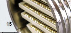
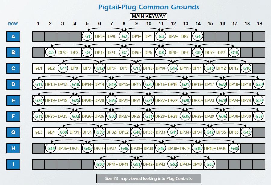
The interconnect system defined in the VITA 76 standard ranges in size from the #9 shell size MIL-D-38999M, Series III, to the #23 shell size. Both smaller and larger shell sizes may be added as the need arises. The #9 shell contains a total of eight contacts or two differential pairs and is suitable for USB 2.0, for example. The #23 shell contains a total 145 contacts or 44 differential pairs and four nondifferential contacts (spares) suitable for PCIe-X16 or 12X InfiniBand. The 44 differential pairs configured in 22 bidirectional data lanes at 10 GB/s per lane delivers an aggregate of 220 GB/sec bandwidth per connector. The capabilities of the in-between shell sizes of 11, 13, 15, 17 are scaled accordingly. (Figure 1.)
The use of standard shells allows for the use of most standard back shell hardware for straight or angled egress of cable and wire, strain reliefs, etc.


The copper interface of the bulkhead connector is common to both copper cabling solutions and active optic cabling solutions, allowing for interoperability between copper cable and active optic cables (AOC) utilizing a single copper contact interface in the panel mount receptacle while also meeting the necessary signal density emerging in the ruggedized embedded ecosystem.
DEFENSE PRIME CONTRACTORS AND INTEGRATORS WERE CLAMORING FOR HIGH-SPEED INTERCONNECT SYSTEMS FOR “SWAMP” CONDITIONS.


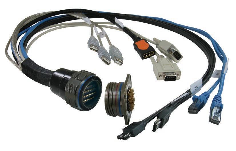
The ANSI/VITA 76.0-2016, High Performance Cable Standard with Meritec’s Hercules connector (Figure 2) was approved by VITA and ANSI in 2016 and reaffirmed in 2021. More recently, the Sensor Open Systems Architecture (SOSA) consortium adopted the standard as part of the high-speed, highdensity, multiple protocol interconnect designating the shell size 17 in the SOSA J-7 connector in the first release of the SOSA Technical Standard.


Conclusion Technology incorporated in highperformance critical embedded computing systems encompasses many components. High-performance cabling is an integral part of the system. The VITA 76 standard provides a solution for the key connector and cabling component. Other work has been inspired by the VITA 76 working group. VITA has at least two other working groups using MIL-DTL-38999 as the foundation connector strategy for MT optical connections:
› The VITA 87 MT Circular Connectors – Type 1 standard defines MT options for 12 or 24 fibers per MT and for physical contact or lensed MT.
› The VITA 89 MT Circular Connectors – Type 2 standard defines MT options for 48 fibers per MT and for physical contact or lensed MT. The working groups are reviewing draft documents in both cases.
Ken Braund is Business Development Manager and Alan Roath is a Senior Engineer at Meritec.
Meritec https://meritec.com/
TECHNOLOGY FEATURE Interconnect & VITA 76
1 | Size 23 shell with 44 differential data pairs (22
Figure
lanes).
20 | VITA Technologies with Application Guide Fall 2022 www.vita-technologies.com Figure 2 Meritec HERCULES-Octopus-Clip
THE
Spring 2023 VITA Technologies Resource Guide provides the latest technical information and updates on VPX, OpenVPX, SOSA, SpaceVPX, and other standards to engineers, managers, and decision-makers in the United States and internationally.
Resource Guide will also highlight such key electronics-buying categories as FMC, OpenVPX, Operating Systems and Tools, PMC/XMC, and VPX. Don’t miss this special jam-packed issue! THE RESOURCE GUIDE PROVIDES INSIGHT ON EMBEDDED TOOLS AND STRATEGIES FOR TECHNICAL SUBJECTS AND OPEN STANDARDS
LATEST, MOST INNOVATIVE PRODUCTS AND TECHNOLOGY The
The
Communications
Dawn VME Products
Dawn ECM-9958 Ethernet Conversion Module


10G-KR/KX/SGMII to 10G/1G-BASE-T Conversion Module.
• Convert Backplane SERDES interfaces (KR/KX/SGMII/USXGMII) to 10G/1000/100 BASE-T for External Chassis interface.
• (10GBASE-T/5GBASE-T/2.5GBASE-T/1000BASE T/100BASE-T) Ethernet PHY transceiver.
• IEEE® 802.3-2012 compliant auto-negotiation.
• High-Performance full KR (with auto negotiation)/XFI/ USXGMII/2500BASE-X/SGMII.
• Configurable as KR or XFI in 10G, 2500BASE-X in 2.5G, and SGMII in 1G/100M, or all rates via USXGMII/KR.
• 10G-Base T operation at 2.7W (Typical for 30 meters of CAT 6 cable).
https://www.dawnvme.com/shop/accessories-vpx-accessories/ecm-9958ethernet-conversion-module
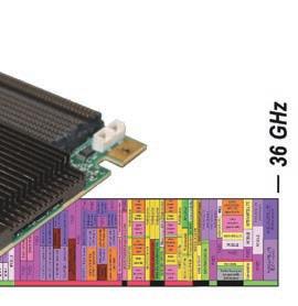
The DME1 Card is the first COTS card with 64 GS/s, 10-bit ADC and DAC capability. It is targeted at demanding applica tions requiring direct sampling frequency coverage from VHF through Ka-band, and/or wide instantaneous bandwidths.
The breakthrough direct sampling Jariet transceiver performs frequency conversion and filtering in the digital domain, elim inating the need for costly analog frequency conversion.
The card has a usable analog bandwidth of 36 GHz and a maximum instantaneous bandwidth of 6.4 GHz on both channels simultaneously. All transceiver channels feature onboard digital downconverters (DDCs) and digital upcon verters (DUCs), including sub-band channelizers for dynamic frequency selection.
GENERAL FEATURES
• ADC: 2 Channel, 40-64 GS/s, 10 bit Resolution
• DAC: 2 Channel, 40-64 GS/s, 10 bit Resolution
• Usable Analog Bandwidth: 36GHz
• Maximum Instantaneous Bandwidth: 6.4GHz
• Run Time Selectable ADC Decimation: 8-1024x
• Adjustable attenuation: 0-31.5dB
•
MECHANICAL & ENVIRONMENTAL
•


•
Radar/Electronic Warfare Annapolis Micro Systems
WILD™ SoM/Chassis Manager
Highly-Integrated, Secure & Aligned with SOSA™ 1.0
• Applications: System on Module/Chassis Manager
• Capability: Provides control and access to Plug-In Card JTAG and Maintenance ports, CLK1 usage, network functions & optional advanced security functions
• FPGAs: Xilinx UltraScale+™ Zynq (ZU5EG or ZU11EG) & Microsemi PolarFire
• Mounting: Directly on backplane, via 3U or 6U VPX plug-in carrier card, or cabled
• Power: Only requires 3.3V
• Optional BSP: For customizing Zynq PS & PL for security
• Standards: VITA 46.11, SOSA 1.0 & MIL-STD-1553

• Availability: Commercial off-the-shelf www.annapmicro.com/product-category/chassis-and-backplane-accessories/
Radar/Electronic Warfare

Interface Concept
IC-EM2-XMCa
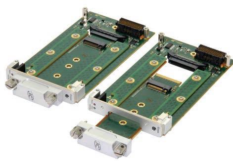
The IC-EM2-XMCa is an XMC storage module dedicated to add mass storage capability to any IC Single Board Computers (SBCs) or host carrier board, based on VPX, VME and cPCI formfactors. Connected to any host board by a PCIe x1/x2/x4 up to Gen3 interface, the IC-EM2-XMCa allows adding, remov ing, replacing and upgrading M.2 NVMe SSD mass storage units. This XMC module increases data storage capacity of high-performance embedded systems (up to 2TB today). The IC-EM2-XMCa is an XMC storage solution that allows the hard drive mounted on a carrier, such as a SBC, to be simply and easily removed through the front panel by unfastening two screws.
https://www.interfaceconcept.com
Technologiess Application Guide
VITA
CONNECTORS
I/O
Six 50Ω Front Panel or VITA 67 Connectors - Two Analog ADC Inputs - Two Analog DAC Outputs - One External Reference Clock Input - One High Precision Trigger Input
or Air-Flow-Through cooled
Air, Conduction,
alignment
Radar/Electronic Warfare Card Combines High Rates & Wide Coverage Sponsored By: wfinfo@annapmicro.com • 410-841-2514
VHF to Ka-band ADC/DAC: 64
10-bit 22 | VITA Technologies with Application Guide Fall 2022 www.vita-technologies.com
Developed in
with SOSA™ 1.0 www.annapmicro.com/products/wild-fmc-dme1/
COVERAGE:
GS/s,
Radar/Electronic Warfare
Interface Concept
IC-INT-VPX3k - 3U VPX Intel® Xeon® W

Single Board Computer
The IC-INT-VPX3k, is a 3U VPX single board computer based on the 11th Gen Intel Core Xeon® W series codename: Tiger Lake-H) processor. It is aimed at large band width and high-demanding applications located at the edge of networks which may have to meet thermal and environmental constraints and have real-time functionality and operational safety mechanisms. This COTS VPX board leverages the latest Intel 10nm Intel® Xeon® W series processor enhancements to provide high-computing performance and a complete set of high speed interfaces to system integrators with power, fast IO needs and latest generation video interfaces.

https://www.interfaceconcept.com
Radar/Electronic Warfare
TE Connectivity
NanoRF Optical Hybrid Modules
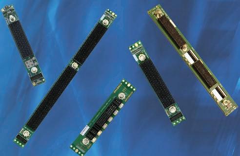
The NanoRF optical hybrid mod ules feature high-density RF and optical connections within common connector modules. Applications include radar, electronic warfare (EW) missile guidance and tactical communications, along with any other small footprint applications where high-frequency RF and optical signals are critical. The NanoRF optical hybrid modules make it possible to meet the need for open systems architecture while providing increased bandwidth and RF signaling capacity for C5ISR systems. The NanoRF contacts have a rated frequency of 70 GHz, and con nector modules support either cabled optics or transceivers mounted at the edge of the plug-in cards.
http://te.com/nanoRF-optical
Test & Measurement
Dawn VME Products
Dawn Single Slot OpenVPX Development Backplanes

The Dawn family of one-slot OpenVPX test station and development backplanes gives engineers the ability to perform compatibility tests and easily reconfigure payload module profiles and slot interoperability to meet custom requirements.
Highly useful as stand alone or in combination with other backplanes, with or without RTM connectors. Multiple units can be topology wired using MERITEC VPX Plus cables.
Available 3U and 6U in VITA 65, VITA 67.1, VITA 67.2, VITA 67.3, Nano-RF, SOSA aligned and Power Supply slot profiles. Cus tom configurations available.
www.dawnvme.com/single-slot-backplanes
SOSA and Small Form Factors
Sponsored by Elma and Samtec
It is common knowledge that the 3U OpenVPX form factor is integral to the Sensor Open Systems Architecture (SOSA) Technical Standard. It enables interoperability and commonality in military systems for radar, electronic warfare, signals intelligence, and more.
What is less known is that a smaller form factor is also being included in the standard. Applications where this is needed have requirements for even further reduced size, weight, and power (SWaP), adding more challenges for embedded computing designers.
This webcast of industry experts will look at how the SOSA standard is leveraging small form factor standards such as VITA 90 (VNX+) to address these smaller footprint needs. (This is an archived webcast.)
To watch the webcast: https://bit.ly/3hv698I WATCH

VITA Technologiess Application Guide www.vita-technologies.com VITA Technologies with Application Guide Fall 2022 | 23
WEBCASTS:
MORE
https://militaryembedded.com/webcasts/
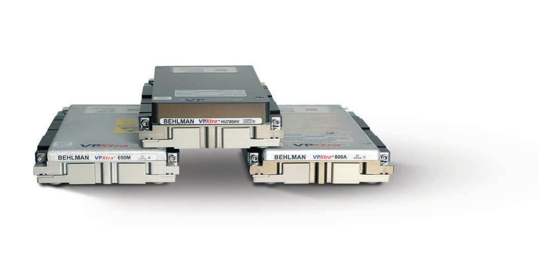
When the mission calls for a 3-phase 3U power supply that can stand up to the most rugged environments, the military chooses VPXtra 704™ from Behlman – the only VPX solution of its kind built to operate seamlessly from MIL-STD-704F power for mission-critical airborne, shipboard, ground and mobile applications. > 3-phase AC or 270V DC input; high-power DC output > Available holdup cards store 700W of DC power for up to 80 msec



: 631-435-0410: sales@behlman.com : www.behlman.com
choice.
The Power Solutions Provider THE MILITARY FLIES HIGH WITH VPXtra 704™ Developed in Alignment with the VITA and SOSA™ Technical Standards
3 phase. 3U.1
> Overvoltage, short circuit, over-current and thermal protection > Provides full output performance during both normal and abnormal transients


 By Ken Braund and Alan Roath


