BLUE PAPER TERRA
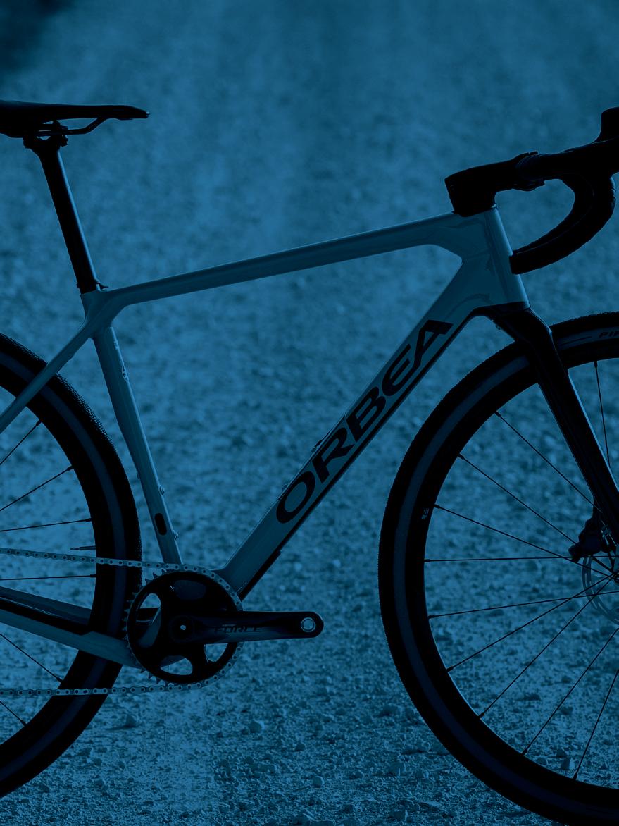
OMR
EN01|ES33|FR65|IT97|DE129 TECHNICAL MANUAL
2022
BLUE PAPER TERRA · OMR 2022 2 | ORBEA ORBEA | 3 TECHNICAL MANUAL 3 EN INDEX 01 KEY TO SYMBOLS 4 02 ORBEA WARRANTY 6 03 MAINTENANCE 8 Components maintenance schedule 9 Spare parts 11 After a crash or an impact 11 04 USE WARNINGS. TERRA OMR 12 Maximum tire width 12 Minimum seatpost insertion 12 Maximum number of headset spacers 12 Headset spacers above the stem 13 Intended use 13 05 TERRA OMR 2022 14 Geometry and sizing 16 Tyre-front derailleur compatibility 22 Assembly, use and spares 23 Headset 23 Axles and rear derailleur hanger 25 Frame hardware and protectors 27 Stems 29 LOCKR zone. Downtube storage 42 Handlebar 51 Cable routing 52 Bottle holder installation 60 Cutting the fork steerer tube 61 06 DECLARATION OF CONFORMITY 62 07 ADDITIONAL INFORMATION 63
This technical manual contains important information about your bicycle, its use, maintenance and replacement parts. Please read it carefully.
This document is a supplement to the General User’s Manual for Orbea bicycles and components, which describes in a more detailed manner their appropriate use and the adjustment of the general components of the bicycles for safe riding and operation. You can see and download the User’s Manual and the rest of the technical manuals for Orbea products from our website: www.orbea.com/gb-en/support/manuals/
You can consult the information on the use, maintenance and characteristics of the components of other manufacturers that are assembled on our bicycles, such as wheels, handlebars, pedaling assistance systems, suspension forks, etc, on the manufacturer’s website or through their dealer in your country.

01 KEY TO SYMBOLS
Throughout this technical manual, various symbols are used that indicate instructions and warnings for use, maintenance and assembly. Pay attention to these symbols to avoid hazardous situations and ensure the correct use and assembly of all components.
The meaning of these symbols is explained below. In this manual, the symbol may appear accompanied only by the relevant instruction for the component described. Read the following information carefully in order to understand their meanings.
SAFETY INSTRUCTIONS
DANGER: Immediately hazardous situation. If not avoided, serious injury or even death will occur.
WARNING: Potentially hazardous situation. If not avoided, serious injury or even death may occur.
TOOLS AND TIGHTENING TORQUES
The key number is indicated inside the symbol.
CAUTION: Potentially hazardous situation. If notavoided, minor or moderate injury may occur.
ASSEMBLY COMPOUNDS
Not related to injury. Property situation hazard.
The symbols DANGER and WARNING inform about a dangerous situation that, if not avoided, may cause an accident. An accident while riding a bicycle always poses risk of serious injury or even death. In this manual, the risk of death may therefore not always be mentioned when these symbols appear, since the risk is explained here.
OIL: Light lubrication of elements like chains and cables.
GREASE: High quality assembly grease to avoid creaking and seizing.
CARBON PASTE: compound to increase friction between
LOCTITE SERIES 600: Fixing cylindrical surfaces.
LOCTITE SERIES 200: Threadlock. Medium resistance.
LOCTITE SERIES 400: Instant adhesive.
BLUE PAPER TERRA · OMR 2022 4 | ORBEA ORBEA | 5 TECHNICAL MANUAL 5 EN
N.m
10
SPANNER ALLEN KEY TORX KEY PHILLIPS SCREWDRIVER
6 6 GREASE FIBER CARBON GRIP
ORBEA WARRANTY
Our continuous daily effort to provide maximum quality of our bicycles allows us to offer the following warranty and coverage conditions:
LEGAL WARRANTY
Orbea offers the original owner of the Orbea bicycle, rigid fork or OC component a legal warranty of 3 years from the date of purchase of the items, or the period stipulated as the legal warranty in the country of purchase.
This warranty covers all Orbea products against manufacturing defects and/or lack of compliance and guarantees the repair or replacement of the defective product at no cost to the affected customer. Likewise, this warranty also covers paint, varnish and corrosion defects on all frames and rigid forks assembled on our bicycles during the pe-
This warranty does not cover in any case damage derived from inappropriate use, falls or accidents or the lack of maintenance, as well as the normal wear and tear of consumable parts, such as, by way of example, but without limitation: seals, bearings, handlebar tape, spokes, tires, saddles, etc.
For a full description of the coverage conditions and the legal warranty, please visit:
www.orbea.com/gb-en/warranty
ORBEA LIFETIME WARRANTY
As a supplement to the legal warranty, Orbea offers the original buyer of the bicycle the Orbea lifetime commercial warranty, as long as they have registered their product on the Orbea website within 30 days of its purchase. This lifetime warranty covers the frames and rigid forks that we mount on our bicycles against manufacturing defects and material conformity issues with no time limitation.
This warranty extends the original period of coverage against paint, varnish or corrosion defects on the frames and rigid forks for one additional year after the end of the legal warranty period.
Orbea’s lifetime commercial warranty only covers frames and rigid forks, but not OC components.
For a full description of the warranty conditions for the lifetime warranty, please visit:


www.orbea.com/gb-en/warranty/#orbea-lifetime-warranty
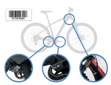
REGISTER YOUR BICYCLE
tension, you must register your bicycle within 30 days of its purchase at:
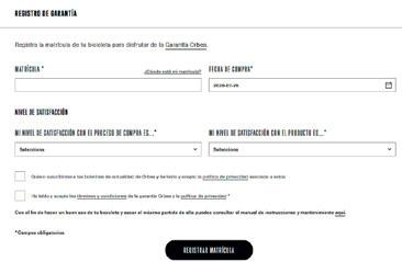
www.orbea.com/es-es/acceso-registro?from=register-plate/
WARRANTY CLAIM PROCESS

All warranty claims must be processed through an authorized Orbea dealer, who will perform the initial diagnosis and send Orbea or the affected component manufacturer all the necessary documentation for a complete diagnosis of the claim in question. The dealer will inform the owner about the status of the process and the decision made on the warranty claim by Orbea or the component manufacturer.
We recommend that you always visit the dealer where you purchased your bicycle to process a warranty claim, or the dealer you chose during the process of purchasing a bicycle that was delivered directly to your home. If you cannot visit the original dealer, you can check the list of authorized dealers on our website or contact Orbea directly so we can indicate the dealer you should visit.
www.orbea.com/gb-en/distribuidores/?country
www.orbea.com/gb-en/contacto/
BLUE PAPER TERRA · OMR 2022 6 | ORBEA ORBEA | 7 TECHNICAL MANUAL 7 EN 02
-
02. REGISTER YOUR BARCODE 03. WHERE TO FIND YOUR BARCODE
01. REGISTER YOUR ACCOUNT
Orbea products are carefully designed to be long-lasting, frames and forks are extremely corrosion-resistant. However, your bicycle needs regular maintenance of its components in order to ensure that it works properly and safely, and to ensure its longevity.
KEEP YOUR BICYCLE CLEAN
Clean your bicycle with mild soap and water on a regular basis to keep it working like new, and check the condition of the frame and its components. Do not use pressurized water, since it could damage components like bearings or the tubes of the frame.
Citrus-based degreasers are biodegradable and very effective in removing grease from drivetrain components and the chain.
Accumulated dirt can complicate the visual inspection of the components and hide damage that could potentially cause malfunctions or accidents.
Built-up dirt causes the premature wear of components and can even damage the bicycle frame in areas such as the bearing housings and moving parts. Damage due to the lack of cleaning and maintenance is not covered by the warranty.
KEEP YOUR DRIVETRAIN LUBRICATED
Once you have cleaned your bicycle, lubricate the drivetrain, to lubricate the links, removing any excess amounts to prevent them from attracting dirt, causing the drivetrain to not work properly and the premature wear of the components.
Avoid the use of aerosol lubricants to prevent them from adhering to the brake surfaces. Always check the brakes after lubricating the drivetrain.
INSPECT YOUR BICYCLE BEFORE EVERY RIDE
Do a quick check before each ride to make sure that your bicycle is in optimal operating conditions. You might discover small problems that could turn into major issues during the ride.
FRAME: Inspect the frame and the fork, looking for cracks or other damage. No strange noises should be heard. In the event of any damage to the frame, avoid using the bicycle and contact your authorized dealer for inspection.
CHAIN: Ensure it’s clean and lubricated. The drivetrain should not make any abnormal noises.
BRAKES: Check that the brakes operate properly and in a safe manner. Check the tightening torques of the components.
TIRES: Check for worn tires and look for cuts on the tread or sides. If you spot damage, replace the tire. Make sure that the tire pressure is adequate.
WHEELS: Check that the wheels turn smoothly and show no signs of lateral deviations. Turn the wheel slightly from side to side to check that there is no lateral play in the bearings. Make sure that there are no broken or loose spokes. Check that the axles or quick-release levers are securely tightened with the correct tightening torque.
HEADSET: Activate the front brake and move the front part of the bicycle back and forth, applying pressure on the handlebars with the rear wheel on the ground. Check for strange noises or movement of the headset, which could indicate that the bearings are worn or the headset has not been correctly tightened. Once the headset is correctly adjusted, check that it turns smoothly.
LINKAGE PIVOT POINTS: On full suspension bicycles, check that all the linkage pivot points rotate smoothly and show no signs of play in the bearings. Pull the linkages from side to side on the bicycle and pay attention to any noise or play at the pivot points. If the linkages do not operate smoothly or show signs of play, it could be a sign that the tightening torques are incorrect or that the bearings are worn or damaged.
BEARINGS: The bearings (bottom bracket, linkage pivot points, headset, wheels, etc.) are elements subject to wear that must be inspected on a regular basis to ensure that they operate correctly. Bearings in poor condition can damage the components in which they are installed. Adverse weather conditions speed up bearing wear. Bearings that have excessive play or that do not turn smoothly must be replaced immediately. In the case of any doubt, consult your authorized dealer.
Damage to components like the frame, bicycle wheels, etc. associated with the lack of maintenance and the replacement of the bearings are not covered by the warranty.
Failure to follow the recommendations outlined in this manual and riding a bicycle that shows signs of the symptoms described above may cause accidents and serious injuries.
TIGHTENING TORQUES. Always check the tightening torques and install the components described in this manual according -
components from other manufacturers installed on your Orbea bicycle. The failure to
malfunction of the components, accidents and even death.
MAINTENANCE SCHEDULE OF THE COMPONENTS
Maintenance periods for the components indicated below are general guidelines and largely depend on factors such as weather conditions in which your bicycle is ridden (adverse conditions considerably reduce the life of the components and increase maintenance frequency), the cleanliness of your bicycle and its components (components with accumulated dirt wear more quickly), and use (more demanding use of the bicycle will require more frequent maintenance periods).
For components from other brands mounted on Orbea bicycles, you can check the recommended or mandatory maintenance periods on the manufacturer’s website or by contacting the distributor of that brand in your country.
Damage to components as a result of failing to follow the recommended maintenance periods could result in damage that is not covered by the warranty conditions of Orbea or the component manufacturer.
The failure to comply with maintenance periods could result in damage to the components and lead to malfunctions and accidents.
HEADSET:
· Inspection of its operation before each ride.
· Disassembly and manual inspection of the bearings once every 6 months of use.
BOTTOM BRACKET:
· Inspection of its operation before each ride
· Disassembly and manual inspection of the bearings once every 6 months of use.
BLUE PAPER TERRA · OMR 2022 8 | ORBEA ORBEA | 9 TECHNICAL MANUAL 9 EN 03
MAINTENANCE
DRIVETRAIN:
· Inspection of its operation before each ride.
· Regular inspection of chain wear every 500 km. A chain that is worn beyond the manufacturer’s recommendations must be replaced to prevent damage to the rest of the drivetrain components. The failure to observe the manufacturer’s recommendations in terms of wear could necessitate the replacement of the rest of the parts of the drivetrain.
WHEELS:
· Inspection of its operation before each ride.
· Disassembly and manual inspection of the bearings and all components once every 6 months.
SHOCKS AND SUSPENSION FORKS:
· Inspection of its operation before each ride.
· Inspection and full maintenance every 125 hours orrer’s authorized dealer.
DROPPER SEAT POSTS:
· Inspection of its operation before each ride
· Inspection and full maintenance every 125 hours orrer’s authorized dealer.
PIVOT POINTS ON FULL SUSPENSION FRAMES:
· Inspection of its operation before each ride.
· Disassembly of the frame and the manual inspection of all the bearings every 125 hours of use or once ater depending on the conditions in which the bicycle is ridden. More demanding use of the bicycle or use in adverse weather conditions or in mud requires the disassembly and inspection of the frame once every 75 hours of use or once every 6 months (whichever comessive play, it must be replaced immediately.
GEAR CABLES AND HOUSING:
· Inspection of its operation before each ride.
· Replacement of gear cables every 6 months to 1 year depending on the conditions in which the bicycle is used.
BRAKES:
· Inspection of the operation and wear of the brake pads or shoes before each ride.
· Check the wear on disc brakes and the cables or hydraulic lines every 6 months to 1 year depending on the conditions in which the bicycle is used. Flush the hydraulic lines once a year.
Some of these checks and maintenance needs go beyond the mechanical knowledge of most bicycle users. If you are not quali-
always visit an Orbea dealer for maintenance on your bicycle and its components. The failure to perform proper maintenance can result in malfunctions and accidents with serious consequences.
Incorrectly performed maintenance can damage the components, which are not covered by the warranty conditions.
REPLACEMENT PARTS
Always use original Orbea replacement parts or those from the component manufacturer in question.
The use of non-original replacement parts may cause damage that results in malfunctions and accidents with serious consequences.
The installation of some of the replacement parts in this technical manual are beyond the mechanical knowledge of most bicycle replacement parts, always visit an Orbea dealer for maintenance on your bicycle and its components. The failure to properly install replacement parts can result in malfunctions, accidents and serious injuries.
The installation of non-original replacement parts can damage your bicycle and is not covered by the warranty conditions.
AFTER A CRASH OR AN IMPACT
Falling off your bike is part of cycling. If you have an accident on your Orbea bicycle, be sure that you’re okay and seek medical care, if necessary. If you are uninjured, you should check the condition of your bicycle before continuing to ride.
INSPECT THE FRAME AND THE BICYCLE COMPONENTS TO SEE IF THEY HAVE BEEN DAMAGED IN ANY WAY
If you detect any problem, do not continue to ride the bicycle.
POINTS TO CHECK
Inspect the frame and the fork to identify whether either of these components have been broken or bent. If you detect any damage or cracks, you must stop using the bicycle im-
mediately. On carbon frames, look for cracks or soft spots in the carbon. If you detect any of these symptoms, you must stop using the bicycle immediately.
The materials used on carbon frames and forks are rigid and strong, but if overloaded bend, and they will break. A strong enough impact to this material could cause damage cause the materials to fail in the future. In the case of any doubt about the consequences of a fall or accident, contact your Orbea dealer for a correct diagnosis of the materials.
Check the drivetrain and the wheels to make sure that the components operate correctly. If you discover any damage to the components, stop using the bicycle immediately.
Even if you do not observe any damage, pay close attention to the sound of your bicycle when you ride it again. Damage and other problems can cause unusual noises. If you notice any unusual noise, stop using your bicycle immediately and contact your Orbea dealer for a correct diagnosis of the problem.
TAKE YOUR ORBEA BICYCLE TO AN AUTHORIZED DEALER FOR A PROFESSIONAL INSPECTION
Some of the consequences of a fall or accident can only be detected by completely disassembling the bicycle to check for the presence of damage or other signs of deterioration.
A collision or impact can cause serious damage to your bicycle and its components, causing them to malfunction or wear out prematurely. Malfunctions can occur suddenly and without notice, causing you to lose control of your bicycle and suffer serious injuries, or even death.
BLUE PAPER TERRA · OMR 2022 10 | ORBEA ORBEA | 11 TECHNICAL MANUAL 11 EN
04 USE WARNINGS. TERRA OMR
MAXIMUM TYRE WIDTH
tyres that can be mounted on the frame. Always follow these guidelines when installing tyres on your bicycle.
However, the real measurements of the tyre circumference and width may change from one manufacturer to another. When installing a tyre other than that originally mounted on your Orbea bicycle, check that there is at least 6 mm between the top and the sides of the tyre and any part of the frame.
Terra OMR 2022 is compatible with ETRTO 622mm (700C)
tions table in this manual.
Consult also the maximum and minimum tyre width that can be installed on a given rim depending on its internal width. Read the OC wheels compatibility table on our website or the rim manufacturer's documentation.
Damage to the frame or components due to the use of a tyre that does not comply with these measurements is not covered by the warranty conditions.
MINIMUM SEATPOST INSERTION
the minimum insertion depth of the seatpost or the frame on road bicycles with exclusive Orbea seatposts. The failure to follow these instructions can cause stresses on the materials beyond the conditions for which they were designed and cause damage not covered by the warranty conditions, as well as accidents that can result in serious injuries.
MAXIMUM NUMBER OF HEADSET SPACERS
Never use more headset spacers below themaximum number of headset spacers that are acceptable for use on an Orbea frame. Installing more spacers than those permitted can stress the materials beyond the use for which they were designed, which can cause accidents and serious injuries.
POSITION OF THE STAR NUT INSIDE THE STEERER TUBE. HEADSET SPACERS ABOVE THE STEM
INTENDED USE
The intended use of all models is ASTM Condition 2, that includes Condition 1 as well as unpaved and gravel roads and trails with moderate grades with drops limited to 15 cm.
For information about all ASTM categories, consult the General User Manual.
Never install headset spacers above the stem. Placing spacers above the stem, especially on forks with a carbon steerer tube, can cause the expander inside the fork tube to be positioned above the lower limit of the steerer tube, which can stress the materials beyond the use for which they were designed, possibly causing accidents and serious injuries.
The length of the fork steerer tube must always be appropriate for the position of the stem in the fork. The stem must always be installed in the steerer tube of the fork so that both fastening bolts on the back of the stem are positioned above the surface of the steerer tube of the fork. Never mount the stem so that the top fastening bolt of the stem remains above the top edge of the fork steerer tube. This will stress the materials beyond the use for which they were designed, possibly causing accidents and serious injuries.
BLUE PAPER TERRA · OMR 2022 12 | ORBEA ORBEA | 13 NOT O.K. O.K. NOT O.K. O.K. TECHNICAL MANUAL 13 EN
-

BLUE PAPER TERRA · OMR 2022 14 | ORBEA ORBEA | 15 TECHNICAL MANUAL 15 EN 05 TERRA OMR 2022
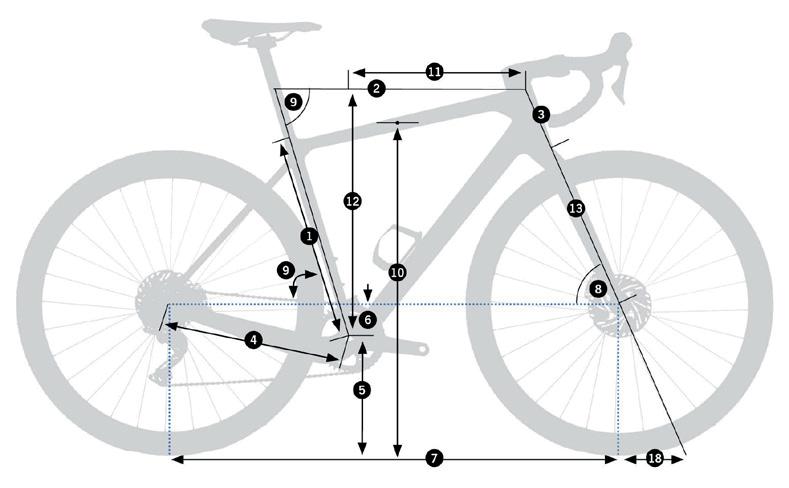
GEOMETRY AND SIZING GEOMETRY*
SIZEXSSMLXLXXL
2
3
4
(40-622) 6
* The geometry table measurements refer to 700C (622) wheels assemblies. Terra OMR is also compatible with 650B (584mm) wheels.
Using 650B wheels will lower the BB Height and Standover height as shown in the table below. These measurements may change depending on the size of the tyres used.
XSSMLXLXXL
BB height 267 mm267 mm267 mm269 mm269 mm269 mm
Standover height 716 mm744 mm772 mm
* The measurements in the sizing table are orientative. The best way to know the correct frame size for you is to try a bike at one of our authorized dealers.
BLUE PAPER TERRA · OMR 2022 16 | ORBEA ORBEA | 17 TECHNICAL MANUAL 17 EN
155-16661.1”-65.4”XS 167-17265.7”-67.7”S 173-179 M L 73.2”-75.2”XL 192-207 XXL
HEIGHT(CM)HEIGHT(IN)SIZE
Seat Tube
405 471504537570
1 -
(C-T)
- Top Tube (EFF) 526539 570590603
- Head Tube 110131152 199220
- Chainstay 420420420420420420
- BB Drop 767676
- Wheelbase 100910191029104410531062
- Head Angle 70º70.5º71º71º71.5º72º
- Seat Angle 74º74º73.5º73.5º73º73º 10 - Standover (30-622) / (40-622) 713/727746/755 11 - Reach 375 395402409 12 - Stack 526 570592614636 13 - Fork Length 390390390390390390 Trail (30-622) / (40-622) 66/71 59/6459/6456/61
5 - BB Height (30-622) /
7
8
9
TECHNICAL SPECIFICATIONS
TERRA OMR
MATERIAL
Frame
Orbea OMR carbon
Fork Orbea OMR carbon (steerer tube and blades)
INTENDED USE
All Road. ASTM Condition 2
AVAILABLE SIZES XS, S, M, L, XL, XXL
OC ICR stems for headset internal cable routing:
· ICR01 Road stem
BOTTOM BRACKET SHELL DIAMETER 46mm
FRONT HUB STANDARD 12x100mm (Thru-axle)
FRONT AXLE MEASUREMENTS
STEM
· OC1 Road stem
Compatible with standard stems with the use of the HS01 adapter
FORK RAKE 55mm (Same fork for all sizes)
MAXIMUM NUMBER OF HEADSET SPACERS 40mm
FORK STEERER TUBE
FORK LENGHT (axle-to-crown) 390mm
HEADSET BEARINGS
Lower 1" 1/2
WHEEL SIZE 700C or 650B
700C650B
ETRTO: 45-622ETRTO: 50-584
MAXIMUM TYRE WIDTH (without mudguards)
* Check the front derailleur compatibility table
Tyre maximum external diameter: 726mm
Tyre maximum external diameter: 697mm
Tyre maximum real external width: 51mm
There must be a minimum clrearance of 6mm between the tyre and the frame and fork
BOTTOM BRACKET
BOTTOM BRACKET SHELL WIDTH
BLUE PAPER TERRA · OMR 2022 18 | ORBEA ORBEA | 19 TECHNICAL MANUAL 19 EN
12x119mm
THREAD LENGHT 13mm
HUB STANDARD 12x142mm
AXLE MEASUREMENTS 12x165mm
Double
2P1.0 REAR AXLE THREAD LENGHT 15mm SEATPOST DIAMETER 27.2mm SEATPOST CLAMP SEATPOST MAXIMUM INSERTION XS = 175mm S = 175mm M = 177mm L = 210mm XL = 245mm XXL = 275mm FRONT DERAILLEUR Down-Pull. Braze-On. Removable hanger FRONT DERAILLEUR ANGLE 63º FRONT DERAILLEUR ANGLE 53T MAXIMUM BIG CHAINRING SIZE (2X) 46T MINIMUM BIG CHAINRING SIZE (2X) 34T MAXIMUM SMALL CHAINRING SIZE (2X) 30T MINIMUM SMALL CHAINRING SIZE (2X) 46T MAXIMUM ROUND CHAINRING SIZE (1X) 42T MAXIMUM OVAL CHAINRING SIZE (1X) 40T
FRONT AXLE THREAD PITCH Double lead Speed Release 2P1.0 FRONT AXLE
REAR
REAR
REAR AXLE THREAD PITCH
lead Speed Release
TECHNICAL SPECIFICATIONS TERRA
MINIMUM ROUND CHAINRING SIZE (1X) No
COMPATIBLE CHAINLINE 43.4mm-47.5mm (the front derailleur models affects tyre compatibility)
MINIMUM Q-FACTOR 146mm
MAXIMUM CRACKARM LENGTH 175mm
REAR DERAILLEUR HANGER Standard derailleurs (no Direct Mount)
DRIVETRAIN COMPATIBILITY (Disc brake groupsets only)
*Check the front derailleur compatibility table
Shimano Road: 10S, 11S, 12S (Mechanical and Di2 -internal battery-)
Shimano Gravel (GRX): 10S, 11S
Sram10S, 11S, 12S (Mechanical and Etap)
Campagnolo 11S, 12S, 13S (Mechanical) EPS not compatible
FRONT BRAKE Flat Mount*
FRONT ROTOR MÍNIMUM/MÁXIMUM DIAMETER
140mm/160mm (turning the Flat Mount adapter)
REAR BRAKE Disc. Flat Mount*
REAR ROTOR MÍNIMUM/MÁXIMUM DIAMETER
REAR CALIPER FLAT MOUNT BOLT LENGHT (Chainstay height=25mm)
CABLING
140mm/160mm (with 20mm adapter)
MUDGUARDS COMPATIBLE
Front: Threads on front thru-axle and fork´s crown
Rear: Threads on rear thru-axle and seatstays bridge adapter
REAR RACK COMPATIBLE No
CHILD SEAT COMPATIBLE No
TRAILER COMPATIBLE No
Shimano: Yes
SRM: No
POWER2MAX: No
POWERMETER COMPATIBILITY**
Stages: Yes. With gravel cranksets. For other crankset models, consult with the manufacturer: https://stagescycling.com/us/factory-install/
Rotor InSpider BCD 110 V3: No
Rotor InSpider BCD 104: No
4iii Precision: With gravel cranksets. For other crankset models, consult with the manufacturer: https://4iiii.com/c/pages/how-does-a-factory-install-work/
BOTTLE HOLDER
SRAM: 32mm
Rear and front derailleur: Internal through headset, downtube and chainstay. Full housing
Front brake: Internal through headset and fork blade
Rear brake: Internal through headset, downtube and chainstay
Dropper seatpost (1X assemblies): Internal through headset, downtube and seat tube
3. All sizes.
· 1 in seat tube
· 1 in downtube (top)
· 1 in downtube (bottom). Only 500ml bottle
Seatpost internal battery.
DROPPER SEATPOST COMPATIBLE
SUSPENSION FORKS COMPATIBILITY
STORAGE
Yes. Internal cabling through headset and frame Compatible with 1X Shimano GRX and Sram 1 Sti levers
Fox 32AX 2022
Rockshox
LOCKR zone inside downtube
UCI LEGAL CERTIFIED Yes
MAXIMUM STRUCTURAL WEIGHT LIMIT (RIDER+GEAR+LUGGAGE) Consult the Orbea Products Structural Weight Limit document on Orbea´s website
DI2 AND EPS COMPATIBLE
Di2: BT-DN110 and BT-DN300 batteries
EPS: No
* Not all calipers and rotors in the market are compatible with all frames. befores purchasing.
** For other powermeters different from the ones listed, consult dimensions and options with manufacturer.
BLUE PAPER TERRA · OMR 2022 20 | ORBEA ORBEA | 21 TECHNICAL MANUAL 21 EN
OMR
FRONT DERAILLEUR-TYRE COMPATIBILITY
Terra OMR is compatible with 700C tyres up to 45mm wide or 650B tyres up to 47mm wide. In some cases, the position of the front derailleur on some drivetrain assemblies will be the factor limiting the tyre width compatibility.
Consult the table below to know the maximum tyre width compatible with most groupsets in the market.
ASSEMBLY AND SPARES HEADSET HEADTUBE DIMENSIONS
*
HEADSET SPECIFICATIONS
**
BLUE PAPER TERRA · OMR 2022 22 | ORBEA ORBEA | 23 ø52.1 ø52.1 7.5 3.85 45° ø57 ø57 TECHNICAL MANUAL 23 EN
WHEEL SIZE ETRTO47 - 58432 - 62235 - 62238 - 62240 - 62245 - 622 MAXIMUM DIMENSIONSØ694 x 49Ø697 x 34Ø703 x 38Ø710 x 41Ø716 x 43Ø726 x 48 FRONT DERAILLEUR Shimano R9150 (Durace Di2) -Shimano R9100 (Durace) ---Shimano R7000 (105) -Sram Red Etap AXSSram Force Etap AXSSram Rival Etap AXSCampagnolo EPS Record/ Super RecordCampagnolo Ekar Shimano RX600 Shimano RX400Sram Force Etap AXS WideSram Rival Etap AXS WideTYPEID*OD** Frame bearing angle Preload ring / fork crown race angle SHIS CODE FSA bearing article code Bearing dimensions TOP 52.1mm57mm45º45ºIS52/40 TH-070E ACB 45°x45° 1.5 dualS MR170 Angular contact bearing 52x40x7mm BOTTOM 1-1/2" Integrated52.1mm57mm45º45ºIS52/40 TH-070E ACB 45°x45° 1.5 dualS MR170 Angular contact bearing 52x40x7mm
ID: Internal headtube diameter.
OD: External headtube diameter.
HEADSET SPARE PARTS AND ASSEMBLY
REAR AXLE AND DERAILLEUR HANGER
REAR AXLEFRONT AXLE
01HEADSETICRBEARINGS2022
ARTNº:XA41QTY.
1.1Headset bearing 1.5 (52x40x7mm. 45º/45º) 2
1.2Fork crown race 1.5 45º. FSA H61061
03HEADSETCOVERICRTERRAOMR
ARTNº:XA54QTY. Headset cover ICR Terra OMR 1
USE OF THE HEADSET EXPANDER ON CARBON FORKS
On carbon steerer tube forks, always use an expander inside the steerer tube to thread the headset compression bolt.
Never use a starnut on carbon sterer tubes. It will damage the material and cause component failure which can lead to serious injuries.
Consult the installation and torque settings instruction in the expander manufacturer instructions.
Consult the instructions about the use of headset spacers on bikes with carbon steerer tubes in the Use Warnings section of this manual.
02COMPRESSIONRING1-1/8ICR2022+SHIM
ARTNº:XA42QTY.
ICR 2022 + shim 1
04ICRHEADSETSPACERKIT.OVAL
ARTNº:X063QTY.
4.1Headset spacer ICR oval 5mm 1
4.2Headset spacer ICR oval 10mm 1
05REARDERAILLEURHANGERNº53X12ROADSTD
ARTNº:XA44QTY.
Rear derailleur hanger Nº53 X12 ROAD STD 1
07THRU-AXLEROAD12x165mm
DOUBLELEADTHREAD2P1.0x15mm
Inner thread for mudguard attachment
ARTNº:XA55QTY.
7.1Thru-axle 12x165x2P1.0x15mm M/guard thread 1
7.2Axle washer 12mm 1
06HANGERM18NUTNº02X12ROAD
ARTNº:X049QTY. 1
08THRU-AXLEROAD12x119mm
DOUBLELEADTHREAD2P1.0x13mm
Inner thread for mudguard attachment
ARTNº:X074QTY.
Thru-axle 12x119x2P1.0x13mm M/guard thread 1
Axle washer 12mm 1
Terra OMR is only compatible with Speed Release thru-axles with a double-lead 2P1.0 thread pitch for faster wheel changes. The use of axles with other thread pitch will damage the frame.
The Terra OMR dropouts are not open at the bottom, and therefore they are not compatible with the use of Mavic Speed Release axles, since it is necessary to remove the axle completely to remove the wheels.
BLUE PAPER TERRA · OMR 2022 24 | ORBEA ORBEA | 25 6 7-8 N.m Carbon Expander Fork´s steerer tube GREASE 1.1 1.1 1.2 2.1 3 2.2 4.1 4.2 8 N.m 17 GREASE 6 8 N.m 5 6 7.2 7.1 6 8 N.m GREASE 8.1 8.2 TECHNICAL MANUAL 25 EN
Always follow the recommended torque settings
HEADSET
REAR AXLE AND DERAILLEUR HANGER
TRAINER AXLES COMPATIBILITY
To use your Terra OMR on a trainer, a double-lead 2Px1.0 thread pitch trainer axle must be used. Installing axles with a different thread pitch will damage the frame.
FRAME HARDWARE AND PROTECTORS
09TRAINERAXLEROADX12 DOUBLELEADTHREAD2P1.0x35mm
ARTNº:X056QTY.
9.1 Trainer axle 12x183x2P1.0x35mm 1
BLUE PAPER TERRA · OMR 2022 26 | ORBEA ORBEA | 27 8 N.m 17 6 8 N.m GREASE 9.2 9.1 9.3 19 20.1 20.2 20.3 20.4 3 4 N.m 2 3 N.m 3 4 N.m 4 FIBER CARBON GRIP GREASE 3 4 N.m 10 11 12 13.1 13.2 14 15.1 15.2 15.3 15.4 16 17 18 8 N.m TECHNICAL MANUAL 27 EN
9.2 Axle washer 12mm 1
9.3 Axle nut 12mm 1
follow the recommended torque settings.
Always
FRAME HARDWARE AND PROTECTORS
10DI2SEATPOSTBATTERYMOUNT27.2
ARTNº:XA66QTY.
Di2 seatpost battery mount 27.2 1
12INTEGRATEDSEATPOSTWEDGE27.2TERRAOMR
ARTNº:XA57QTY.
141XFRONTDERAILLEURCOVERROADNº02
ARTNº:XA59QTY. 1X front derailleur cover road Nº02 1
16F.DERAILLEURCABLEGROMMETDIAM.5mm
ARTNº:X671QTY.
F. Derailleur cable grommet diam. 5mm 1
18CHAINSTAYPROTECTORTERRAOMR
ARTNº:XA60QTY.
Rubber adhesive chainstay protector
Terra OMR 1
Plug Di2 protector 1
20TRANSPARENTADHESIVEPROTECTORKIT.TERRAOMR
ARTNº:XA62QTY.
20.1Left chainstay inner protector 1
20.2Lower chain drop protector 1
20.3Upper chain drop protector 1
20.4Downtube protector 1
11SEATPOSTRUBBERCOLLAR27.2TERRAOMR
ARTNº:XA56QTY.
Seatpost rubber collar 27.2 Terra OMR 1
13F.DERAILLEURHANGERNº10ROAD
ARTNº:XA58QTY.
13.1Front derailleur hanger Nº10 Road 1
13.2Bolt M4x12 DIN912 2
15DOWNTUBECOVERKIT
ARTNº:X059QTY.
15.1DT cover bracket 1
15.2Cover juntion Di2 11S 1
15.3 Cover juntion Etap, Di2 12S 1
15.4 Bolt M3x12 DIN7991 2
17CABLEGUIDECLIPC/STAYBRAKE
ARTNº:X502QTY.
Cableguide clip c/stay brake 1
19DOWNTUBEPROTECTORTERRAOMR
ARTNº:XA61QTY.
Downtube protector Terra OMR 1
ICR01 R1 AND R2 STEM ASSEMBLIES ON TERRA OMR
The OC ICR01 R1 and R2 stems are identical in terms of geometry, weight and materials. However, the R2 version uses the new R2 faceplate, which allows for the use of the R2 OC computer mount.
STEM ICR 01
MATERIAL Aluminum
Ø STEERER TUBE
Ø HANDLEBAR
STEERER TUBE CLAMPING HEIGHT 35mm
FRAME
Headtube maximum external Ø
Headset bearing external Ø 52mm
INTERNAL CABLING
2 gear outers and 2 brake outers
SHIMANO DI2 Internal cabling in stem body (with internal cabling OC handlebar)
COMPUTER HOLDER
AVAILABLE LENGHTS (L)
TILT
HEADSET SPACERS
On faceplate
Max size cicle computer Garmin 1030
TOPCAP Standard round
WEIGHT 220 gr (100 mm)
BLUE PAPER TERRA · OMR 2022 28 | ORBEA ORBEA | 29 TILT -8° L TECHNICAL MANUAL 29 EN
STEM
Terra OMR
Integrated seatpost wedge 27.2
1
ASSEMBLY AND
SPARES. ICR01 R2 AND R2 STEM
Always follow the recommended torque settings.
03HEADSETCOVERICRTERRAOMR
ARTNº:XA54QTY.
Headset cover ICR Terra OMR 1
21ANGLETOPCOVERICR01STEM
ARTNº:X064QTY.
Angle top cover ICR01 stem 1
04ICRHEADSETSPACERKIT.OVAL
ARTNº:X063QTY.
4.1Headset spacer ICR oval 5mm 1
4.2Headset spacer ICR oval 10mm 1
22BOTTOMCOVERLENGHTSPECIFICICR01*
ARTNº:X067QTY.
22.1 1
22.2Bolt M3x10 DIN7991 2
* Available for each stem length: 80mm, 90mm, 100mm, 110mm, 120mm, 130mm (70mm stem does not use the bottom cover)
23ICR01STEMHARDWARE
ARTNº:X066QTY.
23.1Headset preload bolt M6x40 DIN912 1
23.2ICR topcap 1
23.3 Bolt M5x15 DIN912 Faceplate and steerer 6
23.4Bolt M3x10 DIN7991 2
23.5Orbea Logo faceplate 1
26ICR01STEMR2FACEPLATE*
For OC R2 computer mount
ARTNº:XA09QTY.
26.1ICR01 stem R2 faceplate road 1
26.2Rubber grommet ICR01 R2 faceplate 1
24OCR1COMPUTERMOUNT
FORICR01R1,OC2ANDOC1ROADSTEMS
ARTNº:X065QTY.
24.1R1 computer mount body 1
24.2Garmin/Sigma adaptor 1
24.3Wahoo adaptor 1
24.4Bolt M3x10 DIN7991 2
24.5Camera/light bracket 1
27OCR2COMPUTERMOUNT
ICR01R2STEMROAD
Compatible with ICR01 stems with the R2 faceplate
ARTNº:XA10QTY.
R2 computer mount body 1 Garmin/Sigma adaptor 1
Wahoo adaptor 1
Nut/plate/bolt faceplate 1
Camera/light bracket 1 OC cover unused position 1
BLUE PAPER TERRA · OMR 2022 30 | ORBEA ORBEA | 31 GARMIN WAHOO 5 6 N.m 4 6 N.m 2 2 N.m 2 2 N.m GARMIN WAHOO 2 2 N.m 4.1 4.2 3 21 22.1 22.2/23.4 23.1 23.2 23.3 23.3 23.5 GREASE GREASE 4 6 N.m GREASE 23.3 4 6 N.m GREASE 26.1 26.2 27 24 2 2 1 1 TECHNICAL MANUAL 31 EN
STEM
* The R2 faceplate allows for the use of the R2 computer mount with ICR01 R1 stems.
OC CYCLE COMPUTER MOUNT USE INSTRUCTIONS
1. Always use the correct adaptor for your computer brand. If you device is not Sigma, Garmin or Wahoo, check with the manufacturer what bracket standard it uses.
Using the incorrect bracket might damage the computer and cause it to fall from the mount during your ride.
When installing the adaptor on the mount, the name of the brand should be readable from the handlebar.
The Wahoo adaptor makes the lower camera/light turn 90º from its original position. To use it with a GoPro standard light or camera, it is necessary to use a 90º GoPro adaptor.
R2 MOUNT ANGLE ADJUSTMENT
The OC Road R2 computer mount allows for some angle adjustment for an optimal computer visibility.
You can install the adaptor in 2 positions (further or closer to the handlebar) depending on the computer size.
2. Orbea, as all computer manufacturers, recommends to use the tether included with the computer around the handlebar to avoid damage to the computer or its loss in case or a fall or an accident.
The OC R2 computer mount is only compatible with ICR01 stem with the R2 faceplate. To use it on ICR01 R1 stem, it is necessary to replace the R1 faceplate for the R2 faceplate.
BLUE PAPER TERRA · OMR 2022 32 | ORBEA ORBEA | 33
FACEPLATE ICR01 R1
TECHNICAL MANUAL 33 EN
FACEPLATE ICR01 R2
STEM
STEMSTEM
ICR01 R1 COMPLETE STEMS
With R1 faceplate for the OC R1 computer mount
ICR01 R2 COMPLETE STEMS
With R2 stems for the OC R2 computer mount
OC1 ROAD STEM ASSEMBLIES ON TERRA OMR
25ICR01R1ROADSTEM*
ARTNº:X068QTY.
and M5x15 (x6) bolts
Top angle cover and topcap not included.
1
39ICR01R2ROADSTEM*
ARTNº:XA08QTY.
and M5x15 (x6) bolts
Top angle cover and topcap not included. 1
* Available in sizes: 70mm, 80mm, 90mm, 100mm, 110mm, 120mm, 130mm (70mm stem does not use the bottom cover)
OC1 ROAD STEM (WITH ICR INTERNAL HEADSET CABLE ROUTING)
MATERIAL Aluminium
Ø FORK
Ø HANDLEBAR
STEERER TUBE CLAMPING HEIGHT
FRAME
Headtube maximum external Ø
Headset bearing external Ø 52mm
INTERNAL CABLING
2 gear outers and 2 brake outers (with ICR lower adapter and headset spacers)
SHIMANO DI2 Di2 junction inside stem body
COMPUTER MOUNT
AVAILABLE LENGHTS (L)
On faceplate
Max size cicle computer Garmin 1030
TILT -2,5º
HEADSET SPACERS
TOPCAP
WEIGHT
167 gr (100 mm)
BLUE PAPER TERRA · OMR 2022 34 | ORBEA ORBEA | 35 25 4 6 N.m 2 2 N.m 4 6 N.m 4 6 N.m GREASE GREASE L TILT -2.5° 39 4 6 N.m 2 2 N.m 4 6 N.m GREASE 4 6 N.m GREASE TECHNICAL MANUAL 35 EN
ASSEMBLY AND SPARES. OC1 ROAD STEM
Headset internal cabling
Always follow the recommended torque settings.
OC CYCLE COMPUTER MOUNT USE INSTRUCTIONS
1. Always use the correct adaptor for your computer brand. If you device is not Sigma, Garmin or Wahoo, check with the manufacturer what bracket standard it uses.
Using the incorrect bracket might damage the computer and cause it to fall from the mount during your ride.
When installing the adaptor on the mount, the name of the brand should be readable from the handlebar.
The Wahoo adaptor makes the lower camera/light turn 90º from its original position. To use it with a GoPro standard light or camera, it is necessary to use a 90º GoPro adaptor.
03HEADSETCOVERICRTERRAOMR
ARTNº:XA54QTY.
Headset cover ICR Terra OMR 1
28INTERNALCABLINGADAPTEROC1ROADSTEMOVAL
ARTNº:X070QTY.
Internal cabling adapter OC1 road stem Oval 1
24OCR1COMPUTERMOUNT.
FORICR/OC1/OC2ROADSTEMS
ARTNº:X065QTY.
24.1R1 computer mount body 1
24.2 Garmin/Sigma adaptor 1 24.3 Wahoo adaptor 1
24.4 Bolt M3x10 DIN7991 2
24.5 Camera/light bracket 1
04ICRHEADSETSPACERKIT.OVAL
ARTNº:X063QTY.
4.1Headset spacer ICR oval 5mm 1
4.2Headset spacer ICR oval 10mm 1
29OC1ROADSTEMHARDWAREKIT
ARTNº:X069QTY.
29.1Headset preload bolt M6x35 DIN7991 1
29.2OC1 STEM topcap 1
29.3 Bolt M5x15 DIN912 Faceplate and steerer 6
29.4 Bolt M3x10 DIN7991 2
29.5 Logo Orbea faceplate 1
You can install the adaptor in 2 positions (further or closer to the handlebar) depending on the computer size.
2. Orbea, as all computer manufacturers, recommends to use the tether included with the computer around the handlebar to avoid damage to the computer or its loss in case or a fall or an accident.
BLUE PAPER TERRA · OMR 2022 36 | ORBEA ORBEA | 37 4 5 N.m 4 6 N.m GARMIN WAHOO 2 2 N.m 4 6 N.m GREASE GREASE GREASE 4.1 4.2 3 28 29.1 29.2 29.3 29.3 29.4 29.5 1 2 TECHNICAL MANUAL 37 EN
STEM
OC1 ROAD COMPLETE STEMS STEM STANDARD STEMS ADAPTER FOR ICR HEADSETS
The OC HS01 standard stem adapter allows for the installation of non-OC external cabling stems compatible with standard round headset spacers on Orbea frames with ICR headsets.
When installing the HS01 adapter, the necessary headset spacers and the standard stem, the assembly height may differ from the previous height with an OC ICR stem.
Check that the distance between the headset cover and the bottom of the stem does not the bicycle´s technical manual.
Check that the length of the fork´s steerer tube allows for a secure installation of the stem and that the cables are long enough.
The HS01 adapter is only compatible with ICR headset assemblies that use oval ICR headset spacers (X063). Orca Aero OMX 2022 is compatible with the use of the HS01 adapter.
Never install headset spacers above the stem. The length of the fork´s steerer tube must be appropiate so no spacers are needed above the stem.
The stem must be installed onto the fork´s steerer tube so both stem bolts are over an area of the steerer tube. Never install the stem in a position where the top stem bolt is positioned above the upper limit of the fork´s steerer tube.
30OC1ROADSTEM*
ARTNº:X071QTY.
Topcap not included 1
* Available in sizes: 70mm, 80mm, 90mm, 100mm, 110mm, 120mm.
that are not included with the stem. They are both included in the OC1 stem hardware kit.
frame the OC1 stem is used on.
The HS01 adapter´s cable grommets allow for its use with
· 2-hole gommets: For mechanical drivetrain assemblies (2 brake hoses+2 gear outer cables) and electronic drivetrain assemblies with wired shifters.
· 1-hole grommets: For wireless Sram Etap and Shimano 12S Di2 (2 brake hoses).
· It is possible to combine the grommets for 1X drivetrain assemblies.
BLUE PAPER TERRA · OMR 2022 38 | ORBEA ORBEA | 39 30 4 6 N.m 2 4 6 N.m GREASE GREASE TECHNICAL MANUAL 39 EN
Always follow the recommended torque settings.
ASSEMBLIES WITH STEMS FROM OTHER MANUFACTURERS ASSEMBLIES WITH THE OC2 ROAD STEM
(WITH A ROUND HEADSET SPACER BETWEEN THE STEM AND THE ADAPTER)
STANDARD STEMS ADAPTER FOR ICR HEADSETS
The compatibility of the assembly may differ depending of the new stem´s geometry. The new stem must allow for the gear and brake lines to enter the adapter with a smooth bend for a correct operation of the gears and the brakes.
When using the HS01 adapter with stems from other manufacturers, no headset spacers must be installed between the bottom of the stem and the adapter.Any headset sapacers must be installed between the headset cover and the adapter.
When using the HS01 adapter with the OC2 external cabling stem, it may be necessary to use a 5mm headset spacer (X405) to achieve a correct bend of the gear a brake lines before they enter the adapter.
Consult the OC2 Road stem spare parts list in the OC Road Cockpit Components document from Orbea´s website.
31OCHS01STDSTEMSICRHEADSETSADAPTER
ARTNº:X882QTY.
31.1HS01 adapter body 1
31.2Two hole rubber grommet 2
31.3One hole rubber grommet 2
32OCICRSTANDARDSTEMADAPTERGROMMETKIT
ARTNº:X883QTY.
32.1Two hole rubber grommet 2
32.2 One hole rubber grommet 2
BLUE PAPER TERRA · OMR 2022 40 | ORBEA ORBEA | 41 10 mm 31.1 31.2/32 10 mm 5 mm 31.1 31.2/32 TECHNICAL MANUAL 41 EN STEM
LOCKR ZONE
LOCKR ZONE. DOWNTUBE STORAGE
Terra OMR allows you to store your tools and spares inside the downtube of the frame in two dedicated bags to empty your pockets and backpack, knowing that you always carry all the necessary items for your ride.
The nylon bag is designed to be positioned in the upper part of the downtube and can keep a tube (adequately folded) and two tyre levers (in the two pockets to that use).
The neoprene bag is positioned in the lower part of the downtube and is designed to store one or two CO2 cartridges and their adapter and a small multitool or pump.
UPPER BAGLOWER BAG
The tools and spares that can be stored in the downtube will greatly depend on their dimensions. Use the LOCKR zone in whatever
To avoid noises, it may be necessary not to use all the space available in the bag and thus be able to fold it before introducing it into the downtube so the tools do not move freely during your ride.
Use the velcro strap to join both bags together inside the downtube to stop them from moving within the frame and to pull
BLUE PAPER TERRA · OMR 2022 42 | ORBEA ORBEA | 43 OPEN 1 2 TECHNICAL MANUAL 43 EN
LOCKR ZONE INSTALLING A BOTTLE HOLDER ONTO THE LOCKR COVER
It is necessary to remove the LOCKR cover from the frame to install a bottle holder on it. bolt is removed.
BLUE PAPER TERRA · OMR 2022 44 | ORBEA ORBEA | 45 OPEN 1 2 3 3 4 N.m 5 4 CLOSED 6 7 TECHNICAL MANUAL 45 EN
1-2. Turn the LOCKR cover lever and remove the cover from the frame.
3. Remove the bottle holder bolts. The lower cover tab and spacer(s) will fall off the cover.
4-5. Install the bottle holder to the LOCK cover using the original bolts. Install the lower cover tab and spacer(s) with the lower bottle holder bolt.
6-7. position by turning the cover lever.
LOCKR ZONE
LOCKR COVER EXPLODED VIEW
LOCKR ZONE SPARES
38ORBEALOCKRTOOLBAGKIT
The LOCKR cover assembly is served as a spare with one rectangular spacer (33.9). However, the orignal cover may have 1 or no spacer installed, depending on the orignal frame tolerances. Install as many rectangular spacers as the original cover had.
If you do not know whether the original cover had a spacer installed, install the spacer. If when installing the cover in the downtube there is any play, remove the spacer.
BLUE PAPER TERRA · OMR 2022 46 | ORBEA ORBEA | 47 4 4 N.m 3 4 N.m 33.1 33.2 33.333.433.5 33.6 33.7 33.8 33.9 33.10 33.11 33.12 33.13 33.14 4 4 N.m 2.5 3 N.m TECHNICAL MANUAL 47 EN
ARTNº:XA63QTY. 33.1Cover lever LOCKR Rallon OMR 1 33.2LOCKR cover Rallon OMR. Black 1 33.3Lower cover tab 1 33.4Tool holder 1 33.5Tool holder rubber band 1 33.6Frame tab 1 33.7Upper cover tab 1 Lever spacer. Round 1 33.9Tab spacer. Rectangular 1 33.10 1 33.11 1 33.12 1 33.13 1 33.14 1
33LOCKRCOVERTERRAOMR.BLACK
ARTNº:XA39QTY. Toolbag Orbea LOCKR nylon 1 Toolbag Orbea LOCKR neopreno 1 The LOCKR cover as a
is available only in
spare
black.
SEATPOST OC SP-XP10 / SP-XP10-S SEATPOSTSADDLE ANGLE ADJUSTMENT
2. Turn the tilt adjustment nut clockwise to lift the saddle nose and counter-clockwise to lower it (20º total adjustment range).

Terra OMR is designed to be used with 0mm offset seatposts, although it is compatible with 20mm offset seatposts. Terra OMR is compatible with 27.2mm diameter seatposts.
MATERIAL CARBON
mm
AVAILABLE DIAMETERS
AVAILABLE LENGTHS (to saddle rails) 27.2 mm: 350 mm, 400 mm 31.6 mm: 400mm

AVAILABLE OFFSETS (Seatpost body)
Offset 0 mm (SP-XP10): 27.2x350 mm 27.2x400 mm 31.6x400 mm
Offset 20 mm (SP-XP10-S): 27.2x350 mm
MINIMUM INSERTION 350 mm = 90 mm 400 mm = 100 mm
SADDLE CLAMP
WEIGHT with saddle clamp +/-5%
SC03: Zero Offset Round (Ø 7mm) and oval (7x9 mm) saddle rails compatible.
Tilt adjustment range: 20º
Offset 0 mm (SP-XP10): 27.2x350mm = 190gr
27.2x400mm = 200gr
31.6x400mm = 195gr
Offset 20 mm (SP-XP10-S): 27.2x350mm = 207gr
20º total adjustment range
angle of the frame the seatpost is installed on.
BLUE PAPER TERRA · OMR 2022 48 | ORBEA ORBEA | 49 5 1 +3 2 8 N.m 5 3 TECHNICAL MANUAL 49 EN
27.2
31.6 mm
1. 3.
SEATPOST
ASSEMBLY AND SPARES
Always follow the recommended torque settings.
ed on Terra models, consult the OC components website or the OC components technical manuals on our website.
www.orbea.com/gb-en/soporte/manuales/
01OCSP-XP10/SP-XP10-SS/POSTSADDLECLAMP
Round and oval rails
ARTNº:XA64QTY.
1.1Inner/Outer saddle clamp (left/right) 1 1.2 1 1.3Bushing 2
OC
The saddle tilt bolt, tilt nuts and barrel nut assembly are pre-installed at the factory and cannot be purchased on their own.
SEATPOSTS
OCSP-XP10SEATPOSTSETBACK0mm*
Includes saddle clamp. Pre-installed tilt bolt, tilt nuts and barrel nut
ARTNº:XA65QTY.
OC SP-XP10 Carbon seatpost Setback 0mm 1
Inner/Outer saddle clamp (left/right) 1 1
Saddle tilt nut 2
Saddle tilt bolt 1
Inner barrel nut 1
Bushing 2
OCSP-XP10-SSEATPOST.SETBACK20mm*
Includes saddle clamp. Pre-installed tilt bolt, tilt nuts and barrel nut
ARTNº:XA67QTY.
OC SP-XP10-S Carbon seatpost Setback 20mm 1
Inner/Outer saddle clamp (left/right) 1 1
Saddle tilt nut 2
Saddle tilt bolt 1
Inner barrel nut 1
Bushing 2
* Available sizes: 27.2x350mm, 27.2x400mm, 31.6x400mm.* Available sizes: 27.2x350mm.
BLUE PAPER TERRA · OMR 2022 50 | ORBEA ORBEA | 51 5 8 N.m GREASE 5 Pre-assembled FIBER CARBON GRIP 1.1 1.1 1.2 1.3 1.3 0 mm 20mm TECHNICAL MANUAL 51 EN
HANDLEBAR
SP-XP10 / SP-XP10-S COMPLETE
-
CABLE ROUTING
MECHANICAL FRONT AND REAR DERAILLEURS CABLE ROUTING
BRAKE HOSES FRAME AND FORK CABLE ROUTING
BLUE PAPER TERRA · OMR 2022 52 | ORBEA ORBEA | 53 TECHNICAL MANUAL 53 EN
Front derailleur Rear derailleur Front brake Rear brake
CABLE ROUTING
DROPPER SEATPOST REMOTE CABLE ROUTING
Terra OMR allows for a dropper seatpost remote line to be guided through the ICR headset and inside the downtube and the seat tube.
The ICR headset compression ring allows to guide up to three cable outer through each of its slits. However, the STI levers available in the market compatible with the use of a dropper seatpost remote are 1X groupsets
cable funtion with the dropper seatpost remote function.Consult the manufacturers for the available options.
Dropper seatpost remote
ICR STEM AND HEADSET CABLE ROUTING
OC1 and ICR01 Road stems
Rear brake
Rear derailleur
Front derailleur / Dropper setapost remote
Front brake
Rear brake
Rear derailleur
Front derailleur / Dropper setapost remote
Front brake
BLUE PAPER TERRA · OMR 2022 54 | ORBEA ORBEA | 55 TECHNICAL MANUAL 55 EN
CABLE ROUTING
ELECTRONIC GROUPSETS CABLE ROUTINGDOWNTUBE CABLE ROUTING GUIDES
35DOWNTUBECABLEROUTINGGUIDESKIT
Double-sided tape not included ARTNº:XA68QTY.
35.1Downtube cable routing guide drive side 1
35.2 Downtube cable routing guide drive side 1
BLUE PAPER TERRA · OMR 2022 56 | ORBEA ORBEA | 57
EW-RS910
BT-DN110
SM-JC41
TECHNICAL MANUAL 57 EN
SM-JC41
(inside stem)
35
Double-side tape
MUDGUARD ASSEMBLY ON TERRA OMR
Terra OMR is compatible with standard mudguards. The rear mudguard rods attach to the rear thru-axle. The axle has integrated threads on the inside to this use. The top
The front mudguard rods attach to the front thru-axle. The axle has integrated threads on the inside to this use.
located at the back of the fork´s crown.
The mudguard option offered by Orbea on Terra OMR limits the maximum tyre width to 40-622.
36REARMUDGUARDBRIDGEADAPTER ROAD
ARTNº:X077QTY.
36.1Mudguard bridge right1
36.2Mudguard bridge left1
36.3Bolt M4x12 DIN79912
36.4Washer M53
36.5Locking nut M51
36.6Bolt M5x15 1
08THRU-AXLEROAD12x119mm
DOUBLELEADTHREAD2P1.0x13mm
Inner thread for mudguard attachment
ARTNº:X074QTY.
Thru-axle 12x119x2P1.0x13mm M/guard thread 1
Axle washer 12mm 1
07THRU-AXLEROAD12x165mm
DOUBLELEADTHREAD2P1.0x15mm
Inner thread for mudguard attachment
ARTNº:XA55QTY.
7.1Thru-axle 12x165x2P1.0x15mm M/guard thread 1
7.2Axle washer 12mm 1
37COMPLETEMUDGUARDSETTERRAOMR22SKS2846S1060BLACK
Includes rear mudguard bridge adapter
ARTNº:XA69QTY.
37.1 Mudguards SKS 46S + rods 325x4.5mm
BLUE PAPER TERRA · OMR 2022 58 | ORBEA ORBEA | 59 GREASE GREASE GREASE 36.1 36.2 36.3 36.4 36.5 36.6 37.2 37.2 37.3 37.3 37.4 37.4 37.5 37.6 36 / 37.8 37.6 37.1 37.7 37.2 8 M5 M5 M4 7 M5 M4 M4 TECHNICAL MANUAL 59 EN
1 37.2
5 37.3M5
washer 4 37.4 4 37.5 1 37.6M5 washer 2 37.7 Bolt
1 Rear mudguard
adapter (X077) 1
4,5mm spacer
locking
M4x12 DIN7991
bridhe
BOTTLE HOLDER ASSEMBLY
All the Terra OMR 2022 frames sizes are compatible with the installation of 3 bottle holders. Two are installed inside the front triangle (seat tube and downtube) and another one underneath the downtube.
CUTTING THE STEERER TUBE AND HEADSET SPACERS INSTALLATION
Due to the front brake hose being internally routed through the fork´s blade and steerer tube, removing the fork on Terra OMR requires to disconnect the front brake caliper hose.
However, it is not necessary to disconnect the front caliper to cut the fork´s steerer tube to the desired height.
Simply disassemble the ICR01 or OC1 road stem from the steerer tube and remove the headset spacers (these can be split in two halves to allow you to remove them without interfering with the cabling).
With the fork completely inserted into the headtube and the bike positioned so the fork is horizontally positioned to avoid debris from falling into the headset, use a steerer
(depending on the steerer tube material) to cut the steerer -
ponents before cutting the steerer.
When cutting the steerer tube, be careful not to damage any components or cables.
The installation or removal of headset spacers does not require to remove any cables. They are composed of two halves that allow for easy installation without interfering with the cabling.
When installing headset spacers (40mm maximum), make sure that the steerer tube is long enough to allow for a correct and safe installation of the stem and that the cables are long enough.
Cutting the fork steerer tube requires advanced mechanical skills and must by performed by a professional bicycle mechanic.
Never install headset spacers above the stem. The steerer tube lenght must be set so no spacers are needed above the stem.
When cutting carbon steerer tubes, make sure the safety measures are met to avoid inhaling carbon dust.
BLUE PAPER TERRA · OMR 2022 60 | ORBEA ORBEA | 61 TECHNICAL MANUAL 61 EN
DECLARATION OF CONFORMITY
08 ADDITIONAL INFORMATION
ORBEA participates actively on facebook and Twitter with our fantastic global community of riders. Looking to the answers:
FACEBOOK
www.facebook.com/OrbeaBicycles
TWITTER
www.twitter.com/Orbea/
YOUTUBE

setup and tech videos:
www.youtube.com/user/OrbeaBicycles
INSTAGRAM
www.instagram.com/orbeabicycles
ORBEA CONTENT
content.orbea.com/us-en/
BLOG ORBEA
www.orbea.com/es-es/blog/
YOUR ORBEA DEALE
Our dealers are experts and should be able to assist you with setting up and maintaining your Orbea bicycle. A com-plete listing of Orbea dealers and distributors can be located on our website:
www.orbea.com/us-en/dealers/?country=INT
CONTACT
Access Orbea´s contact details and form at: www.orbea.com/gb-en/contacto
USA: www.orbea.com/us-en/contact/
BLUE PAPER TERRA · OMR 2022 62 | ORBEA ORBEA | 63 TECHNICAL MANUAL 63 EN 07
BLUE PAPER TERRA
OMR
EN01|ES33|FR65|IT97|DE129 MANUAL TÉCNICO
2022
BLUE PAPER TERRA · OMR 2022 2 | ORBEA ORBEA | 3 MANUAL TÉCNICO 3 ES ÍNDICE 01 LEYENDA DE SÍMBOLOS 4 02 GARANTÍA ORBEA 6 03 MANTENIMIENTO 8 Periodos de mantenimiento 9 Recambios 11 Después de un golpe o impacto 11 04 ADVERTENCIAS DE USO 12 Tamaño máximo de cubierta 12 Inserción mínima de la tija de sillín 12 Máximo número de separadores de dirección 12 Separadores de dirección encima de la potencia 13 Uso previsto 13 05 TERRA OMR 2022 14 Geometría y ergonomía 16 Compatibilidad cubiertas-desviador 22 Montaje y repuestos 23 Dirección 23 Ejes y pata de cambio 25 Despiece de cuadro y protectores 27 Potencia 29 Zona LOCKR 42 Manillar 51 Cableado 52 Instalación de portabidones 60 Corte del tubo de dirección de la horquilla 61 06 DECLARACIÓN DE CONFORMIDAD 62 07 INFORMACIÓN ADICIONAL 63
Este manual técnico contiene información importante de tu bicicleta sobre su uso, mantenimiento y repuestos. Leelo con atención.
Este documento es un suplemento del Manual General de Usuario de bicicletas y componentes Orbea, que describe de forma más detallada el uso apropiado y ajuste de los componentes generales de las bicicletas para una circulación y operación seguras. Puedes ver y descargar el Manual de Usuario, así como el resto de manuales técnicos de productos Orbea, de nuestra página web: www.orbea.com/es-es/soporte/manuales
Puedes consultar la información relevante de uso, mantenimiento y características de los componentes de otros fabricantes montados en nuestras bicicletas, como ruedas, manillares, sistemas de asistencia al pedaleo, horquillas de suspensión, etc, en la web del fabricante en cuestión o a través de su distribuidor en tu país.
A lo largo de este manual técnico, se utilizan varios símbolos que detallan instrucciones y advertencias de uso, mantenimiento y montaje. Presta atención a estos símbolos para evitar situaciones peligrosas y asegurar el uso y montaje correcto de todos los componentes.
puede que el símbolo aparezca acompañado únicamente de la instrucción relevante para el componente en que describe. Lee la siguiente información con
INSTRUCCIONES DE SEGURIDADHERRAMIENTAS Y PARES DE APRIETE
PELIGRO: Situación peligrosa que, si no se evita, provocará lesiones graves o incluso la muerte.
ADVERTENCIA: Situación peligrosa que, si no se evita, puede causar lesiones graves o incluso la muerte.
El número de llave a usar se indica en el interior del símbolo
ATENCIÓN: Situación peligrosa que, de no evitarse, podría provocar lesiones leves o moderadas.
PARES DE APRIETE: El par de apriete correspondiente (en newton/metro) aparece indicado debajo del símbolo de la herramienta a usar para el elemento que describe.
TIPO DECOMPUESTO
Situación no relacionada con lesiones físicas. Información relevante.
Los símbolos PELIGRO y ADVERTENCIA siempre implican un riesgo de accidente si no se toman medidas para evitar la situación que describen. Un accidente circulando con una bicicleta siempre puede conllevar riesgo de lesiones graves o incluso de muerte. En este manual no siempre se repetirá el riesgo de muerte cuando aparezcan estos símbolos, ya que el riesgo se detalla en este punto.
ACEITE: Lubricación ligera de elementos como cadenas y cables.
GRASA: Grasa de montaje de calidad para
PASTA DE CARBONO: Compuesto de montaje para elementos de carbono para aumentar fricción entre elementos.
LOCTITE SERIE 600: Fijador de piezas cilíndricas.
LOCTITE SERIE 200: Fijador o trabarroscas. Resistencia media.
LOCTITE SERIE 400: Adhesivo instantáneo.
BLUE PAPER TERRA · OMR 2022 4 | ORBEA ORBEA | 5 MANUAL TÉCNICO 5 ES
LLAVE PLANA
LLAVE ALLEN
LLAVE TORX
DESTORNILLADOR TIPO PHILIPS
01 LEYENDA DE SÍMBOLOS
GREASE FIBER CARBON GRIP
6 6 10 N.m
GARANTÍA ORBEA
Nuestro esfuerzo continuo y diario por ofrecer la máxima calidad en nuestras bicicletas nos permite brindar la siguiente garantía y condiciones de cobertura:
GARANTÍA LEGAL
Orbea ofrece al propietario original de la bicicleta Orbea, horquilla rígida o el componente OC una garantía legal de 3 años desde el momento de la compra del artículo, o el periodo estipulado como garantía legal en el país de compra.
Esta garantía cubre todos los productos de Orbea frente a defectos de fabricación y/o falta de conformidad y garantiza la reparación o sustitución del producto defectuoso sin coste adicional para el cliente afectado. Igualmente, esta garantía cubre también los defectos de pintura, barniz y corrosión de todos los cuadros y horquillas rígidas que
cado en el párrafo anterior de esta garantía.
Esta garantía no cubre en ningún caso los daños derivados de un uso inadecuado, caídas o accidentes o falta de mantenimiento, así como el deterioro habitual de las piezas de desgaste tales como, a título meramente informativo y no limitativo: retenes, rodamientos, cinta de manillar, radios, cubiertas, sillines, etc.
Para conocer la descripción completa de las condiciones de la cobertura y la garantía legal, visita:
www.orbea.com/es-es/garantia
GARANTÍA DE POR VIDA ORBEA
Como complemento a la garantía legal, Orbea ofrece al comprador original de la bicicleta, siempre que haya registrado su producto en el sitio web de Orbea en los 30 días siguientes a la compra, la garantía comercial de por vida Orbea, que cubre los cuadros y horquillas rígidas que montamos en nuestras bicicletas sin límite temporal frente a defectos de fabricación y conformidad de los materiales.
Esta garantía amplía el periodo original de cobertura de los defectos de pintura, barniz y corrosión de los cuadros de garantía legal.
La garantía comercial de por vida Orbea sólo cubre cuadros y horquillas rígidas, no componentes OC.
Para conocer la descripción completa de las condiciones de la garantía de por vida, visita:
www.orbea.com/es-es/garantia/#garantia-deporvida-orbea
REGISTRA TU BICICLETA
vida Orbea, debes registrar tu bicicleta en los 30 días siguientes a su compra en:
www.orbea.com/es-es/acceso-registro?from=register-plate/
PROCESO DE RECLAMACIONES DE GARANTÍA
Todas las reclamaciones de garantía deben ser procesadas a través de un distribuidor autorizado Orbea, quien realizará el diagnóstico inicial y remitirá a Orbea toda la documentación necesaria para realizar un diagnóstico completo de la reclamación en cuestión. El distribuidor informará al propietario del estado del proceso y de la decisión sobre la reclamación de garantía por Orbea.
Te recomendamos que siempre acudas al distribuidor donde compraste tu bicicleta para tramitar una reclamación de garantía, o a aquel que elegiste durante el proceso de compra de una bicicleta que te fue entregada directamente en tu domicilio. En caso de no poder acudir al distribuidor original, puedes comprobar la lista de distribuidores autorizados en nuestra web o contactar con Orbea para que te indiquemos el distribuidor al que acudir.
www.orbea.com/es-es/distribuidores/?country
www.orbea.com/es-es/contacto/
BLUE PAPER TERRA · OMR 2022 6 | ORBEA ORBEA | 7 MANUAL TÉCNICO 7 ES 02
-
01. REGISTRA TU CUENTA
02. REGISTRA TU MATRÍCULA
03. DONDE ENCONTRAR TU MATRÍCULA
Los productos Orbea son cuidadosamente diseñados paradros y horquillas de carbono y aluminio son extremadamente resistentes a la corrosión.
Sin embargo, tu bicicleta necesita un mantenimiento periódico de sus componentes para asegurar su correcto funcionamiento, seguridad y longevidad.
MANTÉN LIMPIA TU BICICLETA
Limpia tu bicicleta con agua y jabón suave de manera regular para mantenerla como el primer día y poder comprobar el estado del cuadro y sus componentes. No utilices agua a presión, ya que podría dañar componentes como los rodamientos o los tubos del cuadro.
Los desengrasantes a base de cítricos son biodegradablesponentes de la transmisión y la cadena.
inspección visual de los componentes y ocultar daños que podrían potencialmente producir averías o accidentes.
La suciedad acumulada provoca el desgaste prematuro de los componentes, y puede incluso dañar el cuadro de la bicicleta en zonas como alojamientos de rodamientos y partes móviles. Los daños por falta de limpieza y mantenimiento no están contemplados por las coberturas de garantía.
MANTÉN LUBRICADA TU TRANSMISIÓN
Una vez hayas limpiado tu bicicleta, lubrica la transmisión, concretamente la cadena. Utiliza la mínima cantidad necesaria para lubricar los eslabones, limpiando cualquier exceso para evitar que éste atraiga la suciedad y provoque que la transmisión no funcione correctamente y el desgaste prematuro de los componentes.
Evita el uso de lubricantes en aerosol para de frenado. Siempre comprueba los frenos tras lubricar la transmisión.
INSPECCIONA TU BICICLETA ANTES DE CADA SALIDA
Realiza una inspección rápida antes de cada salida para de funcionamiento. Podrías encontrar pequeños problemas que se pueden convertir en incidencias importantes durante el trayecto.
CUADRO: Inspecciona el cuadro y la horquilla en busca de daños o grietas. No debe presentar ruidos extraños. Ante cualquier daño en el cuadro, evita el uso de la bicicleta y contacta con tu distribuidor autorizado para una revisión.
CADENA: Debe estar limpia y lubricada, y la transmisión no debe producir ruidos fuera de lo normal.
FRENOS: componentes.
CUBIERTAS: Comprueba el desgaste de las cubiertas y busca cortes en la banda de rodadura o en los laterales, si encuentras daños, reemplaza la cubierta. Comprueba que la presión de los neumáticos es la adecuada.
RUEDAS: Comprueba que las ruedas giran de manera suave y que no tiene desviaciones laterales. Tira ligeramente de la rueda hacia los lados para comprobar que no hay
cierres rápidos están apretados de manera segura y al par de apriete correcto.
DIRECCIÓN: Acciona el freno delantero y mueve la parte frontal de la bicicleta hacia adelante y hacia atrás ejerciendo presión en el manillar con la rueda delantera en el suelo. Comprueba que no haya ruidos extraños o movimiento de la dirección, que podría indicar que los rodamientos están gastados o la dirección no está apretada correctamente. Con la dirección ajustada correctamente, comprueba que la dirección gira de manera suave.
PUNTOS DE GIRO DEL BASCULANTE: En bicicletas de doble suspensión, comprueba que todos los puntos de giro del basculante giren de manera suave y no presenten juego en los rodamientos. Tira del basculante hacia un lado y otro de la bicicleta y presta atención a ruidos o juego en
los puntos de giro. Si el basculante no funciona suavemente o presenta juego, podría ser un indicador de que los pares de apriete no son correctos o que los rodamientos están desgastados o dañados.
RODAMIENTOS: Los rodamientos (eje de pedalier, puntos de giro del basculante, dirección, ruedas, etc) son elementos de desgaste que deben ser comprobados periódicamente para garantizar su correcto funcionamiento. Rodamientos en mal estado pueden dañar los componentes en los que están instalados. Condiciones meteorológicas adversas aceleran el desgaste de los rodamientos. Rodamientos que presentan juego o que no giran suavemente deben ser reemplazados inmediatamente. Ante cualquier duda, consulta con tu distribuidor autorizado.
Daños en componentes como el cuadro, ruedas de tu bicicleta, etc, derivados de falta de mantenimiento y sustitución de los rodamientos no están cubiertos por las condiciones de la garantía.
No seguir las indicaciones descritas en estos puntos y utilizar una bicicleta que presenta los síntomas descritos puede provocar accidentes y lesiones graves.
PARES DE APRIETE. Siempre comprueba los pares de apriete e instala los componentes descritos en este manual siguiendo las indicaciones del par de apriete. Sigue las indicaciones de pares de apriete para componentes de otros fabricantes instalados en tu bicicleta Orbea. No observar estas indicaciones puede conducir a la falla de los componentes, accidentes e incluso la muerte.
PERIODOS DE MANTENIMIENTO
Los periodos de mantenimiento de los componentes indicados a continuación son orientativos, y dependen en gran medida de factores como las condiciones meteorológicas de uso de la bicicleta (condiciones adversas reducen considerablemente la vida de los componentes y los tiempos de mantenimiento), limpieza de la bicicleta y sus componentes (componentes con suciedad acumulada se desgastan más rápidamente) y uso (un uso más exigente de la bicicleta requerirá periodos de mantenimiento más cortos).
Para componentes de otras marcas montados en bicicletas Orbea, puedes comprobar los periodos de mantenimiento recomendados u obligatorios en la web del fabricante o contactando con el distribuidor de la marca en tu país.
Daños en los componentes derivados del no cumplimiento de los periodos de mantenimiento podría ocasionar daños que no estarían cubiertos por las condiciones de garantía de Orbea o del fabricante del componente.
El no cumplimiento de los periodos de mantenimiento puede producir daños en los componentes que deriven en averías y accidentes.
DIRECCIÓN:
· Inspección del funcionamiento antes de cada uso de la bicicleta.
· Desmontaje e inspección manual de los rodamientos cada 6 meses de uso.
PEDALIER:
· Inspección del funcionamiento antes de cada uso de la bicicleta.
· Desmontaje e inspección manual de los rodamientos cada 6 meses de uso.
BLUE PAPER TERRA · OMR 2022 8 | ORBEA ORBEA | 9 MANUAL TÉCNICO 9 ES 03
MANTENIMIENTO
AVISO
AVISO
AVISO
AVISO
TRANSMISIÓN:
· Inspección del funcionamiento antes de cada uso de la bicicleta.
· Inspección regular del desgaste de la cadena cada 500 km. Una cadena gastada más allá de las recomendaciones del fabricante debe ser sustituida para evitar daños al resto de componentes de la transmisión. No observar las indicaciones de desgaste del fabricante podría requerir la sustitución del resto de elementos de la transmisión.
RUEDAS:
· Inspección del funcionamiento antes de cada uso de la bicicleta.
· Desmontaje y revisión manual de los rodamientos y todos los componentes cada 4-6 meses.
cer en más detalle el mantenimiento de las mismas.
AMORTIGUADORES Y HORQUILLAS DE SUSPENSIÓN:
· Inspección del funcionamiento antes de cada uso de la bicicleta.
· Revisión y mantenimiento completo cada 125 horas o anual (lo que antes ocurra) por el distribuidor autorizado por el fabricante.
TIJAS TELESCÓPICAS:
· Inspección del funcionamiento antes de cada uso de la bicicleta.
· Revisión y mantenimiento completo cada 125 horas o anual (lo que antes ocurra) por el distribuidor autorizado por el fabricante para conocer en más detalle el mantenimiento de la misma.
PUNTOS DE GIRO EN CUADROS DE DOBLE SUSPENSIÓN:
· Inspección del funcionamiento antes de cada uso de la bicicleta.
· Desmontaje del cuadro e inspección manual de todos los rodamientos cada 125 horas de uso o anual (lo que antes ocurra). Estos tiempos podrían acortarse dependiendo de las condiciones de uso de la bicicleta. Un uso exigente de la bicicleta o en condiciones meteorológicas adversas o con barro requiere el desmontaje e inspección del cuadro cada 75 horas de uso o cada 6 meses (lo que antes ocurra). Si un rodamiento no gira suavemente o tiene juego, debe ser reemplazado inmediatamente.
CABLES Y FUNDAS DE CAMBIO:
· Inspección del funcionamiento antes de cada uso de la bicicleta.
· Sustitución de cables de cambio cada 6 meses o un año, dependiendo de las condiciones de uso de la bicicleta.
FRENOS:
· Inspección del funcionamiento y del desgaste de las pastillas o zapatas de freno antes de cada uso de la bicicleta.
· Comprobación del desgaste de los discos de freno y los cables o líneas hidráulicas cada 6 meses o un año, dependiendo de las condiciones de uso de la bicicleta. Purgado de las líneas hidráulicas cada año.
Algunas de estas comprobaciones y manAlgunas de estas comprobaciones y mantenimientos están más allá del conocimiento mecánico de la mayoría de usuarios de bi-
los mantenimientos necesarios, acude siempre a un distribuidor Orbea para el mantenimiento de tu bicicleta y sus componentes. No realizar los mantenimientos de manera adecuada puede resultar en averías y accidentes de graves consecuencias.
Mantenimientos realizados de manera incorrecta pueden producir daños en los componentes que no están cubiertos por las condiciones de la garantía.
RECAMBIOS
Utiliza siempre recambios originales Orbea o del fabricante del componente en cuestión.
El uso de repuestos no originales puede producir daños que deriven en averías y accidentes de graves consecuencias.
La instalación de alguno de los repuestos en este manual técnico está más allá del conocimiento mecánico de la mayoría de
cado para instalar estos repuestos, acude siempre a un distribuidor Orbea para el mantenimiento de tu bicicleta y sus componentes. No instalar los repuestos de manera adecuada puede resultar en averías, accidentes y lesiones graves.
La instalación de repuestos no originales pueden producir daños en tu bicicleta que no están cubiertos por las condiciones de garantía.
DESPUÉS DE UN GOLPE O IMPACTO
Caerse de la bicicleta es inherente al ciclismo. Si sufres un accidente con tu bicicleta Orbea, asegúrate de que te encuentras bien y pide atención médica si es necesario. Si no has sufrido lesiones, deberás comprobar el estado de tu bicicleta antes de continuar.
INSPECCIONA EL CUADRO Y LOS COMPONENTES DE LA BICICLETA PARA COMPROBAR SI HAN SUFRIDO DAÑOS
Si detectas algún problema, no sigas circulando con la bicicleta.
PUNTOS A REVISAR
cualquiera de estos componentes se ha roto o doblado. Si detectas alguna rotura o grieta, debes dejar de utilizar la bicicleta inmediatamente. En cuadros de carbono, busca
grietas o zonas blandas en el carbono, si detectas alguno de estos síntomas, debes dejar de utilizar la bicicleta inmediatamente.
Los materiales utilizados en cuadros y horquillas de carbono son rígidos y fuertes, pero -
cientemente fuerte en este material podría producir daños que, aunque no visibles a primera vista, podrían producir un fallo de los materiales en el futuro. Ante cualquier duda de las consecuencias de una caída o accidente, contacta con tu distribuidor Orbea para un correcto diagnóstico de los materiales.
Comprueba la transmisión y las ruedas para asegurarte de que los componentes funcionen correctamente. Si descubres algún daño en los componentes, deja de utilizar la bicicleta inmediatamente.
Incluso en el caso de que no observes daño alguno, presta la máxima atención al sonido de tu bicicleta cuando vuelvas a montar en ella. Las roturas y otros problemas algún ruido poco habitual, deja de usar la bicicleta inmediatamente y contacta con tu distribuidor Orbea para un correcto diagnóstico de la misma.
LLEVA TU BICICLETA ORBEA A UN DISTRIBUIDOR AUTORIZADO PARA SOMETERLA A UNA INSPECCIÓN PROFESIONAL
Algunas de las consecuencias de una caída o accidente sólo pueden detectarse desmontando la bicicleta completamente para comprobar la presencia de roturas u otras señales de deterioro.
Un golpe o impacto pueden ocasionar graves desperfectos en tu bicicleta y en los componentes de ésta., provocando que fallen o se desgasten prematuramente. Los fallos pueden producirse de manera repentina y sin previo aviso, causando la pérdida de control de la bicicleta, lesiones graves o incluso la muerte.
BLUE PAPER TERRA · OMR 2022 10 | ORBEA ORBEA | 11 MANUAL TÉCNICO 11 ES
-
-
AVISO AVISO
DE USO DE TERRA OMR
TAMAÑO MÁXIMO DE CUBIERTA
cubierta que puede ser montado en el cuadro, siempre respeta estas indicaciones al instalar una cubierta en tu bicicleta.
Sin embargo, las medidas reales de circunferencia y ancho de cubierta pueden cambiar de un fabricante a otro. Al instalar una cubierta diferente a la que montaba tu bicicleta Orbea originalmente, comprueba que la distancia entre la parte superior y los laterales de la cubierta es de al menos 6 mm entre la misma y cualquier parte del cuadro.
Terra OMR 2022 es compatible con el uso de ruedas de las medidas máximas de cubierta en ambos casos en la
tancia entre la parte superior y los laterales de la cubierta siempre debe ser de al menos 6 mm entre la misma y cualquier parte del cuadro.
Comprueba también los tamaños máximos y mínimos de cubierta que pueden ser montados en una llanta dependiendo del ancho interno de la misma. Consulta la tabla de compatibilidades en el manual de ruedas OC de la web de Orbea o la documentación del fabricante de la rueda.
AVISO
INSERCIÓN MÍNIMA DE LA TIJA DE SILLÍN
Siempre respeta las indicaciones de inserción mínima de la tija a utilizar o del cuadro en bicicletas de carretera con tijas exclusivas Orbea. No respetar estas indicaciones puede producir esfuerzos en los materiales más allá de las condiciones para las que fueron diseñados y producir roturas no cubiertas por las condiciones de garantía, así como accidentes que pueden producir lesiones graves.
MÁXIMO NÚMERO DE SEPARADORES DE DIRECCIÓN
Nunca uses más separadores de dirección debajo de la potencia que los indicados para -
ciones para saber el número máximo de separadores de dirección que admite un cuadro Orbea. Instalar más separadores que los permitidos puede forzar los materiales más allá del uso para los que fueron diseñados, lo que puede provocar accidentes y lesiones graves.
POSICIÓN DEL EXPANSOR DE DIRECCIÓN DENTRO DEL TUBO DE LA HORQUILLA. HORQUILLAS DE CARBONO
USO PREVISTO
El uso previsto de todos los modelos es ASTM Condition 2, que prevé su uso bajo la condición 1, además de carreteras sin asfaltar, pistas forestales y senderos de desnivel moderado con cortados de hasta 15 cm.
Para conocer todas las categorías ASTM, consulta el manual general de usuario.
Daños en el cuadro o los componentes debidos al uso de una cubierta que no observe estas medidas no están cubiertas por las condiciones de la garantía.
Nunca instales separadores de dirección por encima de la potencia. Colocar separadores por encima de la potencia, especialmente en horquillas con el tubo de dirección de carbono, puede provocar que el expansor de dirección dentro del tubo de la horquilla quede posicionado por encima del límite inferior de la potencia, lo que puede forzar los materiales más allá del uso para los que fueron diseñados, potencialmente provocando accidentes y lesiones graves.
La longitud del tubo de dirección de la horquilla siempre debe ser el adecuado para la posición de la potencia en la horquilla. La potencia siempre debe instalarse en el tubo de dirección de la horquilla de manera que ambos tornillos de amarre de la zona posterior de la potencia estén posicionados sobre el tubo de dirección de la horquilla. Nunca montes la potencia de tal manera que el tornillo superior de amarre de la potencia al tubo de dirección quede más arriba del borde superior del tubo de dirección de la horquilla. Esto forzará los materiales más allá del uso para los que fueron diseñados, potencialmente provocando accidentes y lesiones graves.
BLUE PAPER TERRA · OMR 2022 12 | ORBEA ORBEA | 13 NOT O.K. O.K. NOT O.K. O.K. MANUAL TÉCNICO 13 ES 04 ADVERTENCIAS
-
BLUE PAPER TERRA · OMR 2022 14 | ORBEA ORBEA | 15 MANUAL TÉCNICO 15 ES 05 TERRA OMR 2022
GEOMETRÍA Y ERGONOMÍA
TALLAXSSMLXLXXL
1 - Tubo de sillín (C-T) 405
2 - Tubo horizontal (EFF)
3 - Tubo frontal 110131152
4 - Vaina
5 - Altura eje pedalier (30-622) / (40-622)
6 - Caída eje pedalier
7 - Distancia entre ejes 100910191029104410531062
8 - Ángulo frontal
9 - Ángulo del sillín
10 - Altura base (30-622) / (40-622)
11 - Largo del cuadro 375
12 - Altura del cuadro 526
13 - Longitud horquilla
Trail (30-622) / (40-622) 66/71
base cambian como se muestra en la tabla a continuación. Estas cotas puede variar dependiendo del ancho de las cubiertas montadas. ALTURA(CM)ALTURA(IN)TALLA
XSSMLXLXXL
Altura pedalier 267 mm267 mm267 mm269 mm269 mm269 mm
Altura base 716 mm744 mm772 mm
BLUE PAPER TERRA · OMR 2022 16 | ORBEA ORBEA | 17 MANUAL TÉCNICO 17 ES
TERRA OMR
M L 73.2”-75.2”XL 192-207 XXL
155-16661.1”-65.4”XS 167-17265.7”-67.7”S 173-179
471504537570
570590603
526539
199220
420420420420420420
767676
70º70.5º71º71º71.5º72º
74º74º73.5º73.5º73º73º
713/727746/755
395402409
570592614636
390390390390390390
59/6459/6456/61
ESPECIFICACIONES TÉCNICAS
TERRA OMR
MATERIAL
Cuadro Carbono OMR
Horquilla
USO RECOMENDADO
All Road. ASTM Condition 2
TALLAS DISPONIBLES XS, S, M, L, XL, XXL
Potencias Orbea Road compatibles con cableado interno en dirección:
· Potencia ICR01 Road
DIÁMETRO INTERNO CAJA DE PEDALIER 46mm
ESTÁNDAR PUNTERAS DELANTERAS 12x100mm (Eje pasante)
MEDIDAS EJE DELANTERO 12x119mm
PASO DE ROSCA EJE DELANTERO Paso doble Speed Release 2P1.0
LONGITUD ROSCA EJE DELANTERO 13mm
ESTÁNDAR PUNTERAS TRASERAS 12x142mm
POTENCIA
· Potencia OC1 Road
· Compatible con potencias estándar con el uso del adaptador de cableado interno en dirección HS01
AVANCE DE LA HORQUILLA
55mm (Una horquilla para todas las tallas)
MÁXIMA ALTURA DE SEPARADORES DIRECCIÓN 40mm
TUBO DIRECCIÓN HORQUILLA
LONGITUD DE HORQUILLA (axle-to-crown)
RODAMIENTOS DIRECCIÓN
TAMAÑO DE RUEDA COMPATIBLE
390mm
Inferior 1" 1/2
MEDIDAS EJE TRASERO 12x165mm
PASO DE ROSCA EJE TRASERO Paso doble Speed Release 2P1.0
LONGITUD ROSCA EJE TRASERO 15mm
DIÁMETRO DE LA TIJA 27.2mm
ABRAZADERA DE LA TIJA
INSERCIÓN MÁXIMA DE LA TIJA
XS = 175mm
S = 175mm
M = 177mm
L = 210mm
XL = 245mm
XXL = 275mm
MÁXIMO ANCHO DE CUBIERTA (sin guardabarros)
*Comprueba la tabla de compatibilidad de desviadores
PEDALIER
ANCHO CAJA PEDALIER
700C650B
ETRTO: 45-622ETRTO: 50-584
Diámetro externo máximo cubierta: 726mm
Diámetro externo máximo cubierta: 697mm
Ancho máximo cubierta: 51mm
Debe haber una distancia mínima de 6mm entre la cubierta y cualquier parte de la horquilla
DESVIADOR
ÁNGULO DE DESVIADOR 63º
TAMAÑO MÁXIMO PLATO GRANDE (2X) 53T
TAMAÑO MÍNIMO PLATO GRANDE (2X) 46T
TAMAÑO MÁXIMO PLATO PEQUEÑO (2X) 34T
TAMAÑO MÍNIMO PLATO PEQUEÑO (2X) 30T
TAMAÑO MÁXIMO PLATO REDONDO (1X) 46T
TAMAÑO MÁXIMO PLATO OVAL (1X) 42T
TAMAÑO MÍNIMO PLATO REDONDO (1X) 40T
BLUE PAPER TERRA · OMR 2022 18 | ORBEA ORBEA | 19 MANUAL TÉCNICO 19 ES
ESPECIFICACIONES TÉCNICAS
TERRA OMR
COMPATIBLE TRIPLE PLATO No
LÍNEA DE CADENA COMPATIBLE 43.4 mm - 47.5 mm (el desviador usado afecta la compatibilidad de cubierta)
Q-FACTOR MÍNIMO 146mm
MÁXIMA LONGITUD DE BIELA 175mm
PATA DE CAMBIO Sólo cambios estándar (no Direct Mount)
COMPATIBILIDAD TRANSMISIONES (Sólo grupos con freno de disco)
*Comprueba la tabla de compatibilidad de desviadores
Shimano Road: 10V, 11V, 12V (Mecánico y Di2-batería interna)
Shimano Gravel (GRX): 10V, 11V
Sram 10V, 11V, 12V (Mecánico y Etap)
Campagnolo 11V, 12V, 13V (Mecánico) EPS no compatible
FRENO DELANTERO Sólo cambios estándar (no Direct Mount)
DIÁMETRO MÍNIMO/MÁXIMO DISCO
DELANTERO
140mm/160mm (girando adaptador Flat Mount)
FRENO TRASERO Disco. Flat Mount*
DIÁMETRO MÍNIMO/MÁXIMO DISCO
TRASERO 140 mm/160 mm (con adaptador de 20mm)
LONGITUD TORNILLO PARA PINZA FRENO TRASERO
(Altura de bases = 25 mm)
SRAM: 32mm
Cambios: Interno a través de dirección, tubo diagonal y vaina. Funda completa
Freno delantero: Interno a través de dirección y brazo de la horquilla
COMPATIBLE GUARDABARROS
Delantero: Roscas en eje pasante delantero y puente de la horquilla
Trasero: Roscas en eje pasante+adaptador puente en tirantes
COMPATIBLE PORTABULTOS No
COMPATIBLE SILLA NIÑO No
COMPATIBLE TRAILER No
Shimano: Si
SRM: No
POWER2MAX: No
COMPATIBILIDAD POTENCIÓMETRO**
Stages: Si. Con bielas gravel. Para otros modelos o bielas, consulta con el fabricante: https://stagescycling.com/us/factory-install/
Rotor InSpider BCD 110 V3: No
Rotor InSpider BCD 104: No
4iii Precision: Si. Con bielas gravel. Para otras bieles, consulta con el fabricante: https://4iiii.com/c/pages/how-does-a-factory-install-work/
COMPATIBLE TIJA TELESCÓPICA
COMPATIBILIDAD HORQUILLAS DE SUPENSIÓN
CABLEADO
Freno trasero: Interno a través de dirección, tubo diagonal y vaina
Tija telescópica (montajes 1X): Interno a través de dirección, tubo diagonal y tubo de sillín
3. En todas las tallas
· 1 en tubo de sillín
PORTABIDÓN
· 1 en tubo diagonal (superior)
· 1 en tubo diagonal (inferior)
COMPATIBLE DI2 Y EPS
EPS: No
Sí. Cableado interno en dirección u cuadro. Compatible con palancas izquierdas 1X Shimano GRX y Sram 1
Fox 32AX 2022
Roackshox XPLR 2022
ALMACENAMIENTO Zona LOCKR integrado en tubo diagonal
UCI LEGAL CERTIFIED Sí
PESO MÁXIMO RECOMENDADO (CICLISTA+EQUIPACIÓN+EQUIPAJE)
Consulta el documento Pesos Máximos Recomendados de Producto Orbea en nuestra web
* No todos los modelos de pinza y disco en el mercado son compatibles con todos los cuadros. antes de la compra.
BLUE PAPER TERRA · OMR 2022 20 | ORBEA ORBEA | 21 MANUAL TÉCNICO 21 ES
COMPATIBILIDAD DE CUBIERTA/DESVIADOR
El cuadro de Terra OMR es compatible con el uso de cu-tos casos, será la posición del desviador de determinadas transmisiones el factor limitante a la hora de instalar la cubierta más ancha.
Consulta la tabla a continuación para conocer el tamaño de cubierta compatible con la mayoría de transmisiones en el mercado.
MONTAJE Y REPUESTOS DIRECCIÓN
DIMENSIONES DE LA PIPA DE DIRECCIÓN
Campagnolo Ekar
Shimano RX600
Shimano RX400
Sram Force Etap AXS Wide
Sram Rival Etap AXS Wide
ESPECIFICACIONES DE LA DIRECCIÓN
TIPOID*OD** Ángulo de la pista de rodamiento
Ángulo de contacto con anillo de compresión/ pista de la horquilla
SHIS CODE Código rodamiento FSA Dimensiones del rodamiento
SUPERIOR 52.1mm57mm45º45ºIS52/40
INFERIOR 1-1/2" Integrada52.1mm57mm45º45ºIS52/40
* ID: Diámetro interno de la pipa de dirección.
** OD: Diámetro externo de la pipa de dirección.
dualS MR170
dualS MR170
Angular contact bearing 52x40x7mm
Angular contact bearing 52x40x7mm
BLUE PAPER TERRA · OMR 2022 22 | ORBEA ORBEA | 23 ø52.1 ø52.1 7.5 3.85 45° ø57 ø57 MANUAL TÉCNICO 23 ES
TAMAÑO CUBIERTA ETRTO47 - 58432 - 62235 - 62238 - 62240 - 62245 - 622 DIMENSIONES MÁXIMASØ694 x 49Ø697 x 34Ø703 x 38Ø710 x 41Ø716 x 43Ø726 x 48 DESVIADOR
R9150 (Durace Di2) -Shimano R9100 (Durace) --- -
-
Shimano
Shimano R7000 (105) -
Sram Red Etap AXSSram Force Etap AXSSram Rival Etap AXSCampagnolo EPS Record/ Super Record -
-
-
-
1.5
45°x45°
45°x45° 1.5
DIRECCIÓN
DESPIECE Y MONTAJE DE LA DIRECCIÓN
EJES Y PATA DE CAMBIO
EJE TRASEROEJE DELANTERO
01RODAMIENTOSDIRECCIÓNICR2022
USO DE EXPANSOR DEL TUBO DE DIRECCIÓN EN HORQUILLAS DE CARBONO
En horquillas con tubo de dirección de carbono, usa siemtornillo de la tapa superior de la potencia y la compresión de la dirección.
Nunca utilices una araña en horquillas con tubo de dirección de carbono, ya que dañará los materiales y puede ser causa de accidentes y lesiones graves.
Consulta las instrucciones de instalación y par de apriete del expansor en la documentación del fabricante del mismo.
Consulta en la sección Advertencias de Uso de este manual las instrucciones de uso de separadores de dirección en horquillas con tubo de dirección de carbono.
02ANILLOCOMPRESIÓN1-1/8ICR2022+SEPARADOR
ARTNº:XA42CANT. 1
03TAPADIRECCIÓNICRTERRAOMR
ARTNº:XA54CANT.
Tapa dirección ICR Terra OMR 1
04KITSEPARADORESDIRECCIÓNICR.OVALES
ARTNº:X063CANT.
4.1 1
4.2Separador ICR anillo compresión 1
Realiza siempre el par de apriete recomendado por Orbea.
05PATADECAMBIONº53X12ROADSTD
ARTNº:XA44CANT.
Pata de cambio Nº53 X12 ROAD STD 1
07EJEPASANTEROAD12x165mm
ROSCAPASODOBLE2P1.0x15mm
Con rosca para montaje guardabarros
ARTNº:XA55CANT.
7.1Eje Road 12x165x2P1.0x15mm Rosca
g/barros 1
7.2Arandela eje 12mm 1
06TUERCAM18Nº02PATAX12ROAD
ARTNº:X049CANT.
08EJEPASANTEROAD12x119mm
ROSCAPASODOBLE2P1.0x13mm
Con rosca para montaje guardabarros
ARTNº:X074CANT.
Eje Road 12x119x2P1.0x13mm 1
Arandela eje 12mm 1
AVISO
Terra OMR es sólo compatible con ejes pasantes con el estándar de rosca Speed Release, con un paso de danará el cuadro.
Las punteras de Terra OMR no están abiertas en su parte inferior, por lo que no son compatibles con ejes Mavic Speed Release, ya que es necesario extraer el eje completamente para desmontar la rueda.
BLUE PAPER TERRA · OMR 2022 24 | ORBEA ORBEA | 25 6 7-8 N.m Carbon Expander Fork´s steerer tube GREASE 1.1 1.1 1.2 2.1 3 2.2 4.1 4.2 8 N.m 17 GREASE 6 8 N.m 5 6 7.2 7.1 6 8 N.m GREASE 8.1 8.2 MANUAL TÉCNICO 25 ES
1.1Rodamiento dirección 1.5 (52x40x7mm. 45º/45º) 2 1.2Pista de rodamiento horquilla 1.5 45º. FSA H6106
ARTNº:XA41CANT.
1
1
EJES Y PATA DE CAMBIO
COMPATIBILIDAD DE EJES PARA RODILLO DE ENTRENAMIENTO
AVISO Para montar Terra OMR en un rodillo de entrenamiento es necesario que el eje trasero a utilizar utilice el estándar de paso de rosca doble Speed Release 2Px1.0. El uso de un paso de rosca diferente dañaría el cuadro.
DESPIECE DE CUADRO Y PROTECTORES
BLUE PAPER TERRA · OMR 2022 26 | ORBEA ORBEA | 27 8 N.m 17 6 8 N.m GREASE 9.2 9.1 9.3 19 20.1 20.2 20.3 20.4 3 4 N.m 2 3 N.m 3 4 N.m 4 FIBER CARBON GRIP GREASE 3 4 N.m 10 11 12 13.1 13.2 14 15.1 15.2 15.3 15.4 16 17 18 8 N.m MANUAL TÉCNICO 27 ES
09EJERODILLOROADX12 ROSCAPASODOBLE2P1.0x35mm ARTNº:X056CANT.
9.1 Eje rodillo 12x183x2P1.0x35mm 1
9.2 Arandela eje 12mm 1
9.3 Tuerca eje rodillo 12mm 1
Realiza siempre el par de apriete recomendado por Orbea.
DESPIECE DE CUADRO Y PROTECTORES
10SOPORTEBATERÍADI2TIJA27.2
ARTNº:XA66CANT.
Soporte batería Di2 tija 27.2 1
12CUÑATIJAINTEGRADA27.2TERRAOMR
ARTNº:XA57CANT.
Cuña tija integrada 27.2 Terra OMR 1
14TAPASOPORTEDESVIADOR1XROADNº02
ARTNº:XA59CANT.
Tapa soporte desviador 1X Road Nº02 1
16TAPÓNGOMACABLEDESVIADORDIAM.5mm
ARTNº:X671CANT.
Tapón goma cable desviador diam. 5mm 1
18PROTECTORGOMAVAINATERRAOMR
ARTNº:XA60CANT.
Protector adhesivo goma vaina Terra OMR 1
Tapón cableado Di2 protector 1
20KITPROTECTORESADHESIVOSTRANSP.TERRAOMR
ARTNº:XA62CANT.
20.1Protector vaina izquierda interior 1
20.2Protector caída cadena inferior 1
20.3Protector caída cadena superior 1
20.4Protector tubo diagonal 1
POTENCIA
MONTAJES CON POTENCIAS ICR01 R1 Y R2 EN TERRA OMR
11COLLARGOMATIJA27.2TERRAOMR
ARTNº:XA56CANT.
Collar goma tija 27.2 Terra OMR 1
13CHAPILLADESVIADORNº10ROAD
ARTNº:XA58CANT.
13.1Chapilla desviador Nº10 Road 1
13.2Tornillo M4x12 DIN912 2
15KITTAPATUBODIAGONALROAD
ARTNº:X059CANT.
15.1Soporte tapa tubo diagonal road 1
15.2Tapa centralita Di2 1
15.3 Tapa mecánico, Etap, Di2 2022 1
15.4 Tornillo M3x12 DIN7991 2
17TOPEPLÁSTICOCLIPFRENO
ARTNº:X502CANT.
Tope plástico clip freno 1
19PROTECTORGOMATUBODIAGONALTERRAOMR
ARTNº:XA61CANT.
Protector adhesivo goma tubo diagonal Terra OMR 1
AVISO Las potencias OC ICR01 R1 y ICR01 R2 son idénticas en cuanto a geometría, peso y materiales, sin embargo, la versión R2 de la potencia ICR01 utiliza un nuevo faceplate que permite el uso del soporte para ciclocomputador OC R2.
POTENCIA ICR 01
MATERIAL Aluminio
Ø HORQUILLA
Ø MANILLAR
ALTURA DE AMARRE EN TUBO DE HORQUILLA 35mm CUADRO
Ø Exterior máx. pipa dirección
Ø Pista exterior rodamiento superior 52mm
CABLEADO INTERNO Hasta 2 latiguillos de freno y 2 fundas de cambio
SHIMANO DI2
Cableado interno en potencia para manillares de cableado interno
ADAPTADOR CICLOCOMPUTADOR En faceplate
Tamaño máximo ciclocomputador Garmin 1030
LONGITUDES DISPONIBLES (L)
ÁNGULO (TILT)
SEPARADORES DIRECCIÓN
TOPCAP Estándar redondo
PESO 220 gr (100 mm)
BLUE PAPER TERRA · OMR 2022 28 | ORBEA ORBEA | 29 TILT -8° L MANUAL TÉCNICO 29 ES
POTENCIA
Y MONTAJE. POTENCIAS ICR01 R1 Y R2
03TAPADIRECCIÓNICRTERRAOMR
ARTNº:XA54CANT.
Tapa dirección ICR terra OMR 1
21TAPAANGULODIRECCIÓNPOTENCIAICR01
ARTNº:X064CANT.
Tapa angulo dirección potencia ICR01 1
04KITSEPARADORESDIRECCIÓNICR.OVALES
ARTNº:X063CANT.
4.1Separador dirección ICR oval 10mm 1
4.2Separador dirección ICR oval 5mm 1
22TAPAINFERIORICRESPECÍFICATALLA*
ARTNº:X067CANT.
22.1 1
22.2Tornillo M3x10 DIN7991 2
23KITDESPIECEPOTENCIAICR01
ARTNº:X066CANT.
23.1Tornillo ajuste dirección M6x40 DIN912 1
23.2Tapa potencia ICR 1
23.3Tornillo M5x15 DIN912 faceplate y dirección 6
23.4Tornillo M3x10 DIN7991 2
23.5Logo Orbea faceplate 1
26FACEPLATER2POTENCIAICR01ROAD
Para soporte ciclocomputador OC R2
ARTNº:XA09CANT.
26.1Faceplate R2 potencia ICR01 Road 1
26.2Tapón goma Orbea agujero faceplate R2 1
24SOPORTECICLOCOMPUTADOROCR1 POTENCIAROADICR/OC1/OC2
ARTNº:X065CANT.
24.1Cuerpo soporte ciclocomputador 1
24.2Adaptador Garmin/Sigma 1
24.3 Adaptador Wahoo 1
24.4Tornillo M3x10 DIN7991 2
24.5Soporte cámara/luz 1
27SOPORTECICLOCOMPUTADOROCR2 POTENCIAICR01R2ROAD
Compatible con potencias ICR01 con faceplate R2
ARTNº:XA10CANT.
Cuerpo soporte ciclocomputador R2 1
Adaptador Garmin/Sigma 1
Adaptador Wahoo 1
Tuerca/pletina/tornillo amarre faceplate 1
Soporte cámara/luz 1
Tapa OC posición no usada 1
* El faceplate R2 para la potencia ICR01 permite la instalación del soporte de ciclocomputador OC R2 en versiones anteriores de la potencia ICR01.
BLUE PAPER TERRA · OMR 2022 30 | ORBEA ORBEA | 31 GARMIN WAHOO 5 6 N.m 4 6 N.m 2 2 N.m 2 2 N.m GARMIN WAHOO 2 2 N.m 4.1 4.2 3 21 22.1 22.2/23.4 23.1 23.2 23.3 23.3 23.5 GREASE GREASE 4 6 N.m GREASE 23.3 4 6 N.m GREASE 26.1 26.2 27 24 2 2 1 1 MANUAL TÉCNICO 31 ES
DESPIECE
Realiza siempre el par de apriete recomendado por Orbea.
POTENCIA
INSTRUCCIONES DE USO DEL SOPORTE CICLOCOMPUTADOR OC
1. Utiliza siempre el adaptador correcto para tu marca de ciclocomputador. Si tu unidad no es Garmin, Sigma o Wahoo, comprueba con el fabricante que es-
El uso de un adaptador incorrecto pordría dañar la unidad y provocar la caída del mismo durante el uso.
Al instalar el adaptador para tu unidad en el cuerpo del soporte, el nombre del fabricante (Garmin o Wahoo) debe quedar orientada de manera que sea legible desde el manillar.
El adaptador para computadores Wahoo hace que el soporte inferior para cámaras o luces (en caso de usarse) quede girado 90º, por lo que para devolver el soporte inferior a su posición original, es necesario el uso de un adaptador GoPro de 90º.
AJUSTE DEL ÁNGULO DEL SOPORTE R2
El soporte para ciclocomputador OC Road R2 permite el ajuste del ángulo de la unidad para una óptima visibilidad del ciclocompuatdor.
Puedes instalar el soporte en dos posiciones (una alejada y otra cercana) dependiendo del tamaño de tu ciclocomputador.
2. Orbea recuerda la recomendación de los fabricantes de unidades GPS del uso del cordón de seguridad suministrado con los ciclocomputadores alrededor del manillar para evitar daños a la unidad o su pérdida en caso de accidente.
AVISO El soporte para ciclocomputador OC R2 sólo es compatible con potencias ICR01 R2 con faceplate R2. Para su uso en potencias ICR01 R1 es necesario sustituir el faceplate R1 por el faceplate R2.
BLUE PAPER TERRA · OMR 2022 32 | ORBEA ORBEA | 33
FACEPLATE ICR01 R1
MANUAL TÉCNICO 33 ES
FACEPLATE ICR01 R2
POTENCIAPOTENCIA
POTENCIAS COMPLETAS ICR01 R1POTENCIAS COMPLETAS ICR01 R2
MONTAJES CON POTENCIA OC1 ROAD EN TERRA OMR
25POTENCIAICRROADR1*
ARTNº:X068CANT.
y tornillos M5x15 (x6)
Tapa inferior ángulo y topcap no incluídas 1
39POTENCIAICRROADR2*
ARTNº:XA08CANT.
y tornillos M5x15 (x6)
Tapa inferior ángulo y topcap no incluídas 1
POTENCIA OC1 ROAD (CON CABLEADO INTERNO EN DIRECCIÓN ICR)
MATERIAL Aluminio
Ø HORQUILLA
Ø MANILLAR
ALTURA DE AMARRE EN TUBO DE HORQUILLA
CUADRO
Ø Exterior máx. pipa dirección
Ø Pista exterior rodamiento superior 52mm
CABLEADO INTERNO Hasta 2 latiguillos de freno y 2 fundas de cambio (con tapa inferior y separadores de dirección ICR)
SHIMANO DI2 Centralita Di2 en exterior de potencia
ADAPTADOR CICLOCOMPUTADOR En faceplate
Tamaño máximo ciclocomputador Garmin 1030
LONGITUDES DISPONIBLES (L)
ÁNGULO (TILT) -2,5º
SEPARADORES DIRECCIÓN
TOPCAP Estándar redondo
PESO 167 gr (100 mm)
BLUE PAPER TERRA · OMR 2022 34 | ORBEA ORBEA | 35 25 4 6 N.m 2 2 N.m 4 6 N.m 4 6 N.m GREASE GREASE L TILT -2.5° 39 4 6 N.m 2 2 N.m 4 6 N.m GREASE 4 6 N.m GREASE MANUAL TÉCNICO 35 ES
POTENCIA
DESPIECE Y MONTAJE. POTENCIA OC1 ROAD
Cableado interno en dirección
INSTRUCCIONES DE USO DEL SOPORTE CICLOCOMPUTADOR OC
Realiza siempre el par de apriete recomendado por Orbea.
1. Utiliza siempre el adaptador correcto para tu marca de ciclocomputador. Si tu unidad no es Garmin, Sigma o Wahoo, comprueba con el fabricante que es-
El uso de un adaptador incorrecto pordría dañar la unidad y provocar la caída del mismo durante el uso.
Al instalar el adaptador para tu unidad en el cuerpo del soporte, el nombre del fabricante (Garmin o Wahoo) debe quedar orientada de manera que sea legible desde el manillar.
El adaptador para computadores Wahoo hace que el soporte inferior para cámaras o luces (en caso de usarse) quede girado 90º, por lo que para devolver el soporte inferior a su posición original, es necesario el uso de un adaptador GoPro de 90º.
03TAPADIRECCIÓNICRTERRAOMR
ARTNº:XA54CANT.
Tapa dirección ICR Terra OMR H2509 1
28TAPAINFERIORCABLEADOINTERNOPOTROADOC1OVAL
ARTNº:X070CANT.
Tapa inferior cableado interno Pot Road OC1 Oval 1
24SOPORTECICLOCOMPUTADOROCR1POTENCIAROAD
ICR/OC1/OC2
ARTNº:X065CANT.
24.1Cuerpo soporte ciclocomputador 1
24.2 Adaptador Garmin/Sigma 1
24.3 Adaptador Wahoo 1
24.4 Tornillo M3x10 DIN7991 2
24.5 Soporte cámara/luz 1
04KITSEPARADORESDIRECCIÓNICR.OVALES
ARTNº:X063CANT.
4.1Separador dirección ICR oval 10mm 1
4.2Separador dirección ICR oval 5mm 1
29KITDESPIECEPOTENCIAROADOC1
ARTNº:X069CANT.
29.1Tornillo M6x35 DIN7991 tapa potencia 1
29.2Tapa potencia OC1 1
29.3 Tornillo M5x15 DIN912 dirección y faceplate 6
29.4 Tornillo M3x10 DIN7991 2
29.5 Logo Orbea faceplate 1
Puedes instalar el soporte en dos posiciones (una alejada y otra cercana) dependiendo del tamaño de tu ciclocomputador.
2. Orbea recuerda la recomendación de los fabricantes de unidades GPS del uso del cordón de seguridad suministrado con los ciclocomputadores alrededor del manillar para evitar daños a la unidad o su pérdida en caso de accidente.
BLUE PAPER TERRA · OMR 2022 36 | ORBEA ORBEA | 37 4 5 N.m 4 6 N.m GARMIN WAHOO 2 2 N.m 4 6 N.m GREASE GREASE GREASE 4.1 4.2 3 28 29.1 29.2 29.3 29.3 29.4 29.5 1 2 MANUAL TÉCNICO 37 ES
POTENCIA ADAPTADOR DE POTENCIAS ESTÁNDAR
POTENCIAS COMPLETAS OC1
AVISO Las potencias OC1 usan la tapa de potenciallanado que no se incluyen con la potencia. Ambos están incluídos con el kit de piecerío de la potencia OC1.
Los separadores de dirección de cableado cuadro en el que la potencia vaya montada.
PARA DIRECCIONES ICR
El adaptador para potencias estándar OC HS01 permite instalar potencias estandar no OC para cableado externo compatibles con separadores estándar redondos en cuadros Orbea con dirección ICR.
Al instalar el adaptador HS01, los separadores de dirección necesarios y la potencia elegida, la altura del conjunto puede cambiar respecto a la altura original del conjunto con potencias OC.
Comprueba que la distancia entre la tapa de la dirección y la parte inferior de la potencia no -
El adaptador HS01 sólo es compatible con conjuntos de dirección ICR que utilicen separadores de dirección ovales (X063). Terra OMR 2022 es compatible con el uso del adaptador HS01.
nual técnico de tu modelo de bicicleta, que la longitud del tubo de dirección de la horquillarrecto y seguro montaje de la potencia y que la longitud de los cables lo permite.
Comprueba que la longitud del tubo de di-
largo para permitir el correcto y seguro montaje de la potencia y que la longitud de los cables lo permite.
Nunca instales separadores de dirección por encima de la potencia. La longitud del tubo de dirección de la horquilla debe ser la adecuada para no ser necesaria el uso de separadores por encima de la potencia.
Los tapones de entrada de cables del adaptador HS01 permiten su uso en todo tipo de montajes:
· Tapones de dos agujeros: Para montajes mecánicos (2 latiguillos de freno+2 fundas de cambio) y montajes electrónicos Di2 con palancas con cable (2 latiguillos de freno+2 cables Di2).
· Tapones de 1 agujero: Para montajes electrónicos Etap y Di2 2022 (2 latiguillos de freno).
· Es posible combinar los tapones para montajes monoplato.
La potencia siempre debe instalarse en el tubo de dirección de la horquilla de manera que ambos tornillos de amarre de la zona posterior de la potencia estén posicionados sobre el tubo de dirección de la horquilla. Nunca montes la potencia de tal manera que el tornillo superior de amarre de la potencia al tubo de dirección quede más arriba del borde superior del tubo de dirección de la horquilla. Esto forzará los materiales más allá del uso para los que fueron diseñados, potencialmente provocando accidentes y lesiones graves.
BLUE PAPER TERRA · OMR 2022 38 | ORBEA ORBEA | 39 30 4 6 N.m 2 4 6 N.m GREASE GREASE MANUAL TÉCNICO 39 ES
ARTNº:X071CANT. Topcap no incluída. 1
30POTENCIAOC1ROAD*
AVISO
Realiza siempre el par de apriete recomendado por Orbea.
POTENCIA
ADAPTADOR DE POTENCIAS ESTÁNDAR PARA DIRECCIONES ICR
AVISO La compatibilidad del montaje puede variar dependiendo de la geometría de la potencia montada. La geometría de la potencia usada debe permitir una curva de entrada de las fundas de cambio y freno al adaptador que permita la correcta operación de os cables.
MONTAJE CON POTENCIAS ESTÁNDAR DE OTROS FABRICANTES
AVISO Para el uso del adaptador HS01 junto a potencias de otros fabricantes, no debe instalarse ningún separador de dirección entre la potencia y el adaptador.
MONTAJE CON POTENCIA OC2 ROAD
(CON SEPARADOR DE DIRECCIÓN REDONDO ENTRE LA POTENCIA Y EL ADAPTADOR)
AVISO Para el uso del adaptador HS01 junto a potencias OC2 Road de cableado externo, puede ser necesario el uso de un separador de dirección de 5mm (X405) para conseguir una curva de las fundas de cambio y freno correcta antes de entrar en el adaptador HS01. Consulta los componentes de la potencia OC2 Road en el documento Road Cockpit components en la web de Orbea.
31ADAPTADOROCPOTENCIASSTDDIRECCIÓNICR
ARTNº:X882CANT.
31.1Cuerpo adaptador HS01 1
31.2Tapones goma 2 agujeros adaptador HS01 2
31.3Tapones goma 1 agujeros adaptador HS01 2
32ADAPTADOROCPOTENCIASSTDDIRECCIÓNICR
ARTNº:X883CANT.
32.1Tapones goma 2 agujeros adaptador HS01 2
32.2 Tapones goma 1 agujeros adaptador HS01 2
BLUE PAPER TERRA · OMR 2022 40 | ORBEA ORBEA | 41 10 mm 31.1 31.2/32 10 mm 5 mm 31.1 31.2/32 MANUAL TÉCNICO 41 ES
ZONAS LOCKR
ALMACENAMIENTO EN EL TUBO DIAGONAL
Terra OMR dispone de una zona LOCKR en el tubo diagonal en la cual podrás almacenar lo necesario para tus salidas sin cargar tus bolsillos.
Para acceder a la zona de almacenamiento del tubo diagonal, gira la leva de la tapa LOCKR y retira la tapa. Los artículos almacenados en el tubo diagonal se introducen en dos bolsas (una de neopreno y otra de nylon) para evitar ruidos en marcha.
La bolsa de nylon está diseñada para ser colocada en la parte superior del tubo diagonal y para almacenar una cámara (debidamente doblada) y dos desmontables para cubiertas (en los bolsillos para tal uso).
La bolsa de neopreno se coloca en la parte inferior del tubo diagonal y está diseñada para almacenar una o dos ampollas de CO2 y su adaptador, una multiherramienta de
AVISO Las herramientas que pueden ser almacenadas en la zona LOCKR dependerán en gran medida de las dimensiones de dichas herramientas. Usa la zona LOCKR como mejor se adapte a tus necesidades.
BOLSA SUPERIORBOLSA INFERIOR
AVISO Para evitar ruidos, es aconsejable no usar el espacio completo de la bolsa de neopreno para así poder doblarla por la mitad antes de introducirla en el tubo diagonal y que las herramientas en la bolsa no se muevan durante la marcha.
Usa la tira de velcro para unir las bolsas dentro del tubo diagonal para evitar que se muevan dentro del cuadro y para sacar del tubo diagonal primero la bolsas inferior y luego la superior.
BLUE PAPER TERRA · OMR 2022 42 | ORBEA ORBEA | 43 OPEN 1 2 MANUAL TÉCNICO 43 ES
ZONAS LOCKR
INSTALAR UN PORTABIDÓN EN LA TAPA DE LOCKR
AVISO Para instalar un portabidón en la tapa de LOCKR es necesario desmontar primero la tapa del cuadro. Si no se desmonta antes la tapa, la pestaña inferior de la tapa podría caer dentro dle cuadro al quitar el
BLUE PAPER TERRA · OMR 2022 44 | ORBEA ORBEA | 45 OPEN 1 2 3 3 4 N.m 5 4 CLOSED 6 7 MANUAL TÉCNICO 45 ES
1-2. Gira la palanca de apertura de la tapa de LOCKR y retira el conjunto del cuadro.
3. inferior de la tapa al cuadro quedarán sueltos.
4-5. los tornillos originales. Instala la pestaña de inferior del portabidón.
6-7. Vuelve a instalar la tapa en el cuadro y gira
ZONAS LOCKR DESPIECE DE LA TAPA DE LOCKR
RECAMBIOS ZONAS LOCKR
33TAPALOCKRTERRAOMR.NEGRA
AVISO
38KITBOLSASLOCKRORBEA
El recambio de tapa LOCKR se sirve con un separador rectangular (33.9). Sin embargo, la tapa original podría llevar instalado 1 o ningún separador dependiendo de las tolerancias del cuadro original. Instala tantos separadores rectangulares como tuviera la tapa LOCKR original en tu cuadro.
Si no dispones de la tapa original, monta el separador. Si la instalar la tapa LOCKR en el cuadro existiese alguna holgura en la parte inferior, retíralo.
BLUE PAPER TERRA · OMR 2022 46 | ORBEA ORBEA | 47 4 4 N.m 3 4 N.m 33.1 33.2 33.333.433.5 33.6 33.7 33.8 33.9 33.10 33.11 33.12 33.13 33.14 4 4 N.m 2.5 3 N.m MANUAL TÉCNICO 47 ES
ARTNº:XA63CANT. 33.1Palanca cierre tapa LOCKR Terra OMR 1 33.2Tapa LOCKR Terra OMR. Negra 1 33.3Pestaña cierre tapa LOCKR inferior 1 33.4Porta herramientas LOCKR 1 33.5 1 33.6Pestaña cierre cuadro LOCKR 1 33.7Pestaña cierre tapa LOCKR superior 1 Separador palanca LOCKR redondo 1 33.9Separador pestaña LOCKR rectangular 1 33.10 1 33.11 1 33.12 1 33.13 1 33.14 1
ARTNº:XA39CANT. Toolbag Orbea LOCKR nylon 1 Toolbag Orbea LOCKR neopreno 1
El conjunto de tapa LOCKR como repuesto sólo está disponible en negro.
TIJA TIJA DE SILLÍN OC SP-XP10 / SP-XP10-SAJUSTE DE LA INCLINACIÓN DEL SILLÍN
2. Gira la tuerca en sentido horario para subir la punta del sillín y en sentido antihorario para bajarla (20º de rango total de ajuste).
AVISO El diámetro de tija compatible con Terra OMR es 27.2mm.
MATERIAL
DIÁMETROS DISPONIBLES 27.2 mm 31.6 mm
LONGITUDES DISPONIBLES (a raíles de sillín)
OFFSETS DISPONIBLES (Cuerpo de la tija)
INSERCIÓN MÍNIMA
CONJUNTO DE NUEZ
27.2 mm: 350 mm, 400 mm
31.6 mm: 400mm
Offset 0 mm (SP-XP10): 27.2x350 mm
27.2x400 mm 31.6x400 mm
Offset 20 mm (SP-XP10-S): 27.2x350 mm
350 mm = 90 mm
400 mm = 100 mm
SC03: Zero Offset
Compatible con raíles redondos (Ø 7mm) y ovales (7x9 mm)
Rango de ajuste de inclinación: 20º
Offset 0 mm (SP-XP10): 27.2x350mm = 190gr
27.2x400mm = 200gr
PESO
Con conjunto de nuez +/-5%
31.6x400mm = 195gr
Offset 20 mm (SP-XP10-S): 27.2x350mm = 207gr
20º total adjustment range
Los rangos de ajuste positivo y negativo dependerán del ángulo del tubo de sillín del cuadro en el que se instale la tija.
BLUE PAPER TERRA · OMR 2022 48 | ORBEA ORBEA | 49 5 1 +3 2 8 N.m 5 3 MANUAL TÉCNICO 49 ES
1. 3.
TIJAMANILLAR
MONTAJE Y REPUESTOS
Realiza siempre el par de apriete recomendado por Orbea.
01KITNUEZTIJAOCSP-XP10/SP-XP10-S
Raíles redondos y ovalados
ARTNº:XA64CANT.
1.1Conjunto abrazadera nuez. Interno/externo 1 1.2 1
1.3Rodamiento deslizante 2
TIJAS COMPLETAS OC
TIJAOCSP-XP10.SETBACK0mm*
Incluye conjunto de nuez. Tornillo y tuercas de inclinación preinstalado
ARTNº:XA65CANT.
Tija OC SP-XP10 Carbon Setback 0mm 1
Conjunto abrazadera nuez. Interno/externo 1 1
Tuerca inclinación nuez 2
Tornillo inclinación nuez 1
Tuerca barrillete 1
Rodamiento deslizante 2
El conjunto de tornillo y tuercas de inclinación y la tuerca barrilete son pre-instalados en la tija en Orbea, y por lo tanto no pueden ser adquiridos por separado.
Para conocer las geometrías de los manillares de carretera OC, consulta el documento OC Road Cockpit Componentes de la sección de manuales de nuestra web.
https://www.orbea.com/es-es/soporte/manuales/
TIJAOCSP-XP10-S.SETBACK20mm*
Incluye conjunto de nuez. Tornillo y tuercas de inclinación preinstalado
ARTNº:XA67CANT.
Tija OC SP-XP10-S Carbon. Setback 20mm 1
Conjunto abrazadera nuez. Interno/externo 1 1
Tuerca inclinación nuez 2
Tornillo inclinación nuez 1
Tuerca barrillete 1
Rodamiento deslizante 2
* Disponible en tallas: 27.2x350mm, 27.2x400mm, 31.6x400mm.* Disponible en tallas: 27.2x350mm.
BLUE PAPER TERRA · OMR 2022 50 | ORBEA ORBEA | 51 5 8 N.m GREASE 5 Pre-assembled FIBER CARBON GRIP 1.1 1.1 1.2 1.3 1.3 0 mm 20mm MANUAL TÉCNICO 51 ES
SP-XP10 / SP-XP10-S
CABLEADO
CABLEADO DEL CAMBIO TRASERO Y DESVIADOR GRUPOS MECÁNICOS EN CUADRO
CABLEADO DE LATIGUILLOS DE FRENO EN CUADRO
BLUE PAPER TERRA · OMR 2022 52 | ORBEA ORBEA | 53 MANUAL TÉCNICO 53 ES
Desviador
Cambio trasero
Freno delantero
Freno trasero
CABLEADO
CABLEADO DEL REMOTO DE LA TIJA TELESCÓPICA
AVISO Es posible guiar la funda del remoto de la tija telecópica a través de la dirección ICR e internamente a través del tubo diagonal y tubo de sillín.
Las ranuras del anillo de compresión de la dirección ICR permiten guiar hasta 3 fundas a través de cada ranura, sin embargo, las manetas de carretera disponibles en el mercado que incoporan opción de remoto son para montajes 1X, sustituyendo en cable del desviador por la del remoto de la tija telescópica (Shimano GRX 1X y grupos Sram 1).
CABLEADO A TRAVÉS DE LA TAPA DE LA DIRECCIÓN Y EL ANILLO DE COMPRESIÓN DE DIRECCIÓN ICR
En potencia OC1 y ICR01 Road
Remoto tija telescópica
Freno trasero
Cambio trasero
Desviador/Remoto tija telescópica Freno delantero
Freno trasero
Cambio trasero
Desviador/Remoto tija telescópica Freno delantero
BLUE PAPER TERRA · OMR 2022 54 | ORBEA ORBEA | 55 MANUAL TÉCNICO 55 ES
CABLEADO
CABLEADO DE GRUPOS ELECTRÓNICOSTUBOS PARA CABLEADO EN TUBO DIAGONAL
35KITTUBOSCABLEADOZONATOOLBOX
Cinta de doble cara no incluída
ARTNº:XA68CANT.
35.1Tubo cableado TD zona Toolbox drive side 1
35.2Tubo cableado TD zona Toolbox non-drive side 1
BLUE PAPER TERRA · OMR 2022 56 | ORBEA ORBEA | 57
EW-RS910
BT-DN110
SM-JC41
MANUAL TÉCNICO 57 ES
SM-JC41
(dentro de la potencia)
35
Cinta de doble cara
INSTALACIÓN DE GUARDABARROS EN TERRA OMR
Terra OMR 2022 es compatible con el uso de guardabaintegradas en el eje pasante de rueda y la parte superior los tirantes.
que cuenta con roscas en su interior en ambos lados.
El conjunto de guardabarros ofrecido por Orbea como opción en montajes de Terra OMR 2022 y aftermarket limita el tamaño de cubierta a 40-622.
36PUENTEGUARDABARROSTRASERO ROAD
ARTNº:X077CANT.
36.1Puente g/barros derecha1
36.2Puente g/barros izquierda1
36.3Tornillo M4x12 DIN79912
36.4Arandela M53
36.5Tuerca blocante M51
36.6Tornillo M5x15 1
08EJEPASANTEROAD12x119mm
ROSCAPASODOBLE2P1.0x13mm
Con rosca para montaje guardabarros
ARTNº:X074CANT.
Eje Road 12x119x2P1.0x13mm 1
Arandela eje 12mm 1
07EJEPASANTEROAD12x165mm
ROSCAPASODOBLE2P1.0x15mm
Rosca interna guardabarros
ARTNº:XA55CANT.
7.1Eje Road 12x165x2P1.0x15mm Rosca g/barros 1
7.2Arandela eje12mm 1
37GUARDABARROSCOMPLETOTERRAOMRSKS2846S1060NEGRO
Incluye puente guardabarros trasero road
ARTNº:XA69CANT.
37.1 Guardabarros SKS 46S + varillas 325x4.5mm 1
37.2 Arandela sewparadora 4,5mm 5
37.3 Arandela dentada M5 4
37.4 4
37.5 1
37.6 Arandela M5 2
37.7Tornillo M4x12 DIN7991 1
Puente guardabarros trasero road (X077) 1
BLUE PAPER TERRA · OMR 2022 58 | ORBEA ORBEA | 59 GREASE GREASE GREASE 36.1 36.2 36.3 36.4 36.5 36.6 37.2 37.2 37.3 37.3 37.4 37.4 37.5 37.6 36 / 37.8 37.6 37.1 37.7 37.2 8 M5 M5 M4 7 M5 M4 M4 MANUAL TÉCNICO 59 ES
INSTALACIÓN DE PORTABIDONES
Todas las tallas de cuadro de Terra OMR 2022 son compatibles con la instalación de tres portabidones, dos en el interior del cuadro (tubo de sillín y tubo diagonal) y uno en la parte exterior inferior del tubo diagonal.
CORTE DEL TUBO DE DIRECCIÓN E INSTALACIÓN DE SEPARADORES
Debido al cableado interno del latiguillo del freno delantero a través del tubo de dirección de la horquilla, Terra OMR requiere desconectar el latiguillo de la pinza delantera si se quiere desmontar la horquilla.
Sin embargo, no es necesaria esta desconexión para cortar el tubo de dirección de la horquilla a la longitud deseada.
Simplemente desmonta la potencia OC1 o ICR01 del tubo de dirección y retira los separadores (éstos están compuestos de dos mitades que te permiten retirarlos sin interferir con el cableado).
Con la horquilla completamente instalada en el cuadro y con la bici posicionada de manera que la horquilla quede en posición horizontal para evitar que polvo caiga en la dirección, utiliza una guía de corte de tubo de horquilla y -
llas con tubo de dirección de este material) para cortar el tubo a la altura deseada.
realizar el corte.
Al realizar el corte, ten precaución para no marcar o dañar ninguno de los cables o componentes.
La instalación de separadores de dirección no requiere desmontar los cables, ya que estos están compuestos de dos mitades que permiten su instalación sin interferir con el cableado.
A la hora de instalar separadores (máximo 40mm), asegúrate de que la longitud del tubo de dirección de la hor-
y seguro montaje de la potencia y que la longitud de los cables lo permite.
El corte del tubo de la horquilla es un trabajo que requiere conocimientos avanzados de mecánica y debe ser llevado a cabo por un distribuidor Orbea o taller especializado de bicicletas.
Nunca instalar separadores de dirección por encima de la potencia. La longitud del tubo de dirección de la horquilla debe ser el adecuado para no ser necesaria el uso de separadores por encima de la potencia.
A la hora de instalar separadores (máximo 40mm), asegúrate de que la longitud delcientemente largo para permitir el correcto y seguro montaje de la potencia y que la longitud de los cables lo permite.
BLUE PAPER TERRA · OMR 2022 60 | ORBEA ORBEA | 61 MANUAL TÉCNICO 61 ES
DE CONFORMIDAD
lugar para andar en bici o pasar sus vacaciones? Seguro que alguien le ofrece ideas interesantes:
FACEBOOK TWITTER
www.twitter.com/Orbea/
YOUTUBE
Visite el canal de Orbea en YouTube; en él encontrará di-
INSTAGRAM
www.instagram.com/orbeabicycles
ORBEA CONTENT
Vea y descargue fotos, vídeos y documentos. content.orbea.com/us-en/
BLOG ORBEA
www.orbea.com/es-es/blog/
DISTRIBUIDORES ORBEA
Nuestros distribuidores poseen una elevada especialización, Orbea. Puede encontrar una relación completa de distribuidores Orbea en nuestro sitio web:
www.orbea.com/us-en/dealers/?country=INT
CONTACTO
Accede a nuestros datos y formulario de contacto en: www.orbea.com/es-es/contacto
USA: www.orbea.com/us-en/contact/
BLUE PAPER TERRA · OMR 2022 62 | ORBEA ORBEA | 63 MANUAL TÉCNICO 63 ES 07 DECLARACIÓN
08 INFORMACIÓN ADICIONAL
BLUE PAPER TERRA
OMR
EN01|ES33|FR65|IT97|DE129 MANUEL TECHNIQUE
2022
BLUE PAPER TERRA · OMR 2022 2 | ORBEA ORBEA | 3 MANUEL TECHNIQUE 3 FR INDEX 01 LÉGENDE DES SYMBOLES 4 02 GARANTIE ORBEA 6 03 ENTRETIEN 8 Calendrier d'entretien des composants 9 Pièces de rechange 11 Après une chute ou un choc 11 04 AVERTISSEMENTS D'UTILISATION. TERRA OMR 12 Largeur maximale des pneus 12 Insertion minimale de la tige de selle 12 Nombre maximum d'entretoises de jeu de direction 12 Entretoises de jeu de direction au-dessus de la potence 13 Utilisation prévue 13 05 TERRA OMR 2022 14 Géométrie et tailles 16 Caractéristiques techniques 18 Compatibilité des dérailleurs avant 22 Assemblage, utilisation et pièces de rechange 23 Jeu de direction 23 Axes et patte de dérailleur arrière 25 Boulonnerie et protections du cadre 27 Tiges 29 Zone LOCKR. Rangement dans le tube diagonal 42 Tige de selle 48 Guidon 51 Acheminement des câbles 52 Gardes boue 58 Installation des porte-bidons 60 Découpe du pivot de fourche 61 06 DÉCLARATION DE CONFORMITÉ 62 07 INFORMATIONS COMPLÉMENTAIRES 63
Ce manuel technique renferme d'importantes informations relatives à votre vélo, son utilisation, son entretien et ses pièces de rechange. Nous vous invitons à le lire attentivement.
Ce manuel est un complément du manuel de l'utilisateur général des vélos et composants Orbea. Il décrit plus en détail l'utilisation adéquate et le réglage des composants généraux du vélo en vue d'une utilisation sûre. Vous pouvez consulter ou télécharger le Manuel de l'utilisateur ainsi que les autres manuels www.orbea.com/gb-en/support/manuals/
Les informations relatives à l'utilisation, à l'entretien et aux caractéristiques techniques des composants d'autres fabricants, tels que les roues, les cintres, les systèmes d'assistance au pédalage, les fourches télescopiques, etc. sont disponibles sur le site Web des fabricants en question ou auprès de leurs revendeurs dans votre pays.
01 LÉGENDE DES SYMBOLES
Vous retrouverez tout au long de ce manuel différents symboles qui signalent des instructions ou des avertissements sur l'utilisation, l'entretien et l'assemblage. Il convient de prêter attention à ces symboles pour éviter les situations dangereuses et garantir l'assemblage et l'utilisation corrects de l'ensemble des ce manuel, un symbole peut être accompagné uniquement des instructions pertinentes pour le composant décrit. Lisez attentivement les informations sui-
CONSIGNES DE SÉCURITÉ
situation présentant un danger immédiat qui provoquera des blessures graves, voire mortelles, si elle n'est pas évitée.
situation présentant un danger potentiel qui pourrait provoquer des blessures graves, voire mortelles, si elle n'est pas évitée.
situation présentant un danger potentiel qui pourrait provoquer des blessures légères ou modérées si elle n'est pas évitée.
Sans lien avec un risque de blessure. Risque pour un bien.
que les chaînes et les câbles. graisse d'assemblage d'excellente qualité pour éviter les grincements et le grippage.
Les symboles DANGER et AVERTISSEMENT signalent une situation dangereuse qui, si elle n'est pas évitée, pourrait provoquer un accident. Un accident à vélo s'accompagne toujours d'un risque de blessures graves, voire mortelles. Dans ce manuel, il se peut que le risque de décès ne soit pas toujours cité en présence de ces symboles, vu que le risque est expliqué ici.
pâte de montage
cylindriques.
moyenne.
adhésif instantané.
BLUE PAPER TERRA · OMR 2022 4 | ORBEA ORBEA | 5 MANUEL TECHNIQUE 5 FR
10 N.m
OUTILLAGE ET COUPLES DE SERRAGE
CLÉ PLATE
CLÉ ALLEN
CLÉ TORX
TOURNEVIS CRUCIFORME
Le numéro de la clé est repris à l'intérieur du symbole.
PÂTES D'ASSEMBLAGE
6 6 GREASE FIBER CARBON GRIP
GARANTIE ORBEA
Les efforts constants que nous réalisons pour fournir des vélos de très haute qualité nous permettent de vous pro-
GARANTIE LÉGALE
Orbea offre au propriétaire d'origine d'un vélo Orbea, d'une fourche rigide ou d'un composant OC une garantie de trois ans à compter de la date d'achat des articles ou, légale dans le pays d'achat.
La présente garantie couvre tous les produits Orbea contre les défauts de fabrication et/ou de conformité et garantit la réparation ou le remplacement du produit défectueux sans frais pour le client concerné. Cette garantie couvre également tous les défauts liés à la peinture, au vernis et à la corrosion de tous les cadres et fourches rigides que au paragraphe antérieur de la présente garantie.
La présente garantie ne couvre en aucun cas les dommages liés à une utilisation inadéquate, aux chutes ou aux accidents ou au manque d'entretien, ni l'usure normale des éléments consommables dont la liste non-exhaustive inclut, entre autres, les joints, les roulements, la guidoline, les rayons, les pneus, etc.
Pour obtenir une description complète des conditions de couwww.orbea.com/gb-en/warranty
GARANTIE À VIE ORBEA
Outre la garantie légale, Orbea propose à l'acheteur original du vélo une garantie commerciale à vie, pour autant que l'acheteur ait enregistré son vélo sur le site Web d'Orbea dans les 30 jours suivant l'achat. La garantie à vie couvre les cadres et les fourches rigides que nous montons sur nos vélos contre les défauts de fabrication et les problèmes de conformité de matériaux sans limite dans le temps.
Cette garantie prolonge d'un an la durée de la couverture originale contre les défauts liés à la peinture, au vernis et à la corrosion sur les cadres et les fourches rigides à l'échéance de la garantie légale.
La garantie commerciale à vie Orbea couvre uniquement les cadres et les fourches rigides, pas les composants OC.
Pour obtenir une description complète des conditions de
www.orbea.com/gb-en/warranty/#orbea-lifetime-warranty
ENREGISTREMENT DE VOTRE VÉLO
vous devez enregistrer votre vélo dans les 30 jours suivant
www.orbea.com/es-es/acceso-registro?from=register-plate/
01. CRÉATION DU COMPTE
TRAITEMENT DES RÉCLAMATIONS DE GARANTIE
Toute réclamation au titre de la garantie doit être traitée par un revendeur Orbea autorisé. Celui-ci posera le diagnostic initial et enverra à Orbea ou au fabricant du composant concerné toute la documentation nécessaire pour poser un diagnostic complet dans le cadre de cette réclamation. Le revendeur informera le propriétaire de l'état d'avancement du traitement et lui communiquera la décision d'Orbea ou du fabricant du composant sur la réclamation au titre de la garantie.
Si vous devez introduire une réclamation au titre de la garantie, nous vous conseillons de vous rendre à chaque fois chez le revendeur où vous avez acheté votre vélo ou celui que vous avez sélectionné lors de l'achat d'un vélo livré directement à votre domicile. S'il vous est impossible de vous rendre chez le revendeur original, consultez la liste des revendeurs agréés sur notre site Web ou contactez le revendeur chez qui vous devriez vous rendre.
www.orbea.com/gb-en/distribuidores/?country
www.orbea.com/gb-en/contacto/
BLUE PAPER TERRA · OMR 2022 6 | ORBEA ORBEA | 7 MANUEL TECHNIQUE 7 FR
02
02. ENREGISTREMENT DU CODE-BARRES
03. OÙ TROUVER VOTRE CODE-BARRES ?
entretenir. Les cadres et fourches en carbone et en alucorrosion.
Cependant, pour garantir le fonctionnement adéquat et sûr du vélo et contribuer à sa longévité, il convient de réaliser l'entretien régulier du vélo et de ses composants.
NETTOYAGE DU VÉLO
Nettoyez régulièrement votre vélo au savon doux et à l'eau
l'état du cadre et des composants. Évitez le lavage sous pression, car il pourrait endommager des composants tels que les roulements ou les tubes du cadre.
Les dégraissants à base d'agrumes sont biodégradables et la transmission et de la chaîne.
Une accumulation de saletés peut compliquer l'inspection visuelle des composants et dissimuler des dommages qui pourraient provoquer un dysfonctionnement ou un accident.
Elle entraîne également l'usure prématurée des composants et peut même endommager le cadre du vélo à proximité des boîtiers de roulement ou des pièces mobiles. La garantie ne couvre pas les dommages provoqués par un manque de nettoyage ou d'entretien.
LUBRIFICATION DE LA TRANSMISSION
Après que vous ayez nettoyé votre vélo, il convient de graisser la transmission et plus particulièrement, la chaîne. Ap-
l'agglomération de débris et éliminer ainsi le risque de dysfonctionnement de la transmission et l'usure prématurée de ses composants.
transmission.
INSPECTION DU VÉLO AVANT CHAQUE SORTIE -
blèmes qui pourraient provoquer de graves incidents pendant votre sortie.
l'absence de bruits suspects. Si le cadre est endommagé, évitez d'utiliser le vélo et contactez votre revendeur agréé en vue de réaliser une inspection plus poussée.
assurez-vous que la chaîne soit propre et lubri-
sur un vélo tout-sus-
de pivot des biellettes et l'absence de jeu au niveau des roulements. Tirez latéralement sur les biellettes montées sur le vélo et soyez attentif à tout bruit ou jeu au niveau des points de pivot. Si les biellettes ne fonctionnent pas correctement ou si elles présentent un jeu, cela peut être dû à un couple de serrage incorrect ou à des roulements usés ou endommagés.
les roulements (boîtier de pédalier, points de pivot des biellettes, jeu de direction, roue, etc.) s'usent
le fonctionnement adéquat. Un roulement en mauvais état peut endommager le composant dans lequel il est installé. Le mauvais temps accélère l'usure des roulements. Il convient de remplacer sur le champ tout roulement qui présente un jeu excessif ou une résistance. En cas de doute, consultez votre revendeur agréé.
La garantie ne couvre pas les dommages au niveau des composants du vélo tels que le cadre, les roues, etc. provoqués par l'absence d'entretien ou de remplacement des roulements.
CALENDRIER D'ENTRETIEN DES COMPOSANTS
Le calendrier d'entretien des composants ci-dessous reprend des recommandations générales. Ce calendrier peut changer en fonction de différents éléments tels que les conditions météorologiques d'utilisation du vélo (le mauvais temps réduit considérablement la durée de vie des composants et augmente la fréquence des entretiens), la propreté du vélo et de ses composants (un composant sale s'use plus vite) ou l'utilisation (un usage plus intensif du vélo requiert des entretiens plus fréquents).
S'agissant des composants d'autres marques qui se trouvent sur les vélos Orbea, consultez les calendriers d'entretien obligatoires ou facultatifs sur le site Web des fabricants ou auprès du distributeur de ces marques dans votre pays.
présence éventuelle d'entailles sur la bande de roulementquate.
et qu'elles ne sont pas voilées. Faites bouger la roue laté-appliquez le frein avant et déplacez l'avant du vélo d'avant en arrière, en exerçant une pression sur le guidon, roue arrière au sol. Recherchez d'éventuels mouvements ou bruits étranges au niveau du jeu de direction. Cela pourrait indiquer l'usure des roulements ou le mauvais serrage du jeu de direction. Une fois
tourne sans résistance.
Le non-respect des recommandations formulées dans le présent manuel et l'utilisation d'un vélo présentant les symptômes décrits ci-dessus peuvent provoquer des accidents et des blessures graves.
les couples de serrage et installer les composants décrits dans ce manuel en suivant les couples de serrage prescrits. Respecter les couples de serrage prescrits par les fabricants des composants de votre vélo Orbea. Le non-respect de ces recommandations peut entraîner le dysfonctionnement des composants ainsi que des accidents ou la mort.
La garantie Orbea ou celle du fabricant du composant ne couvre pas les dégâts liés au non-respect du calendrier d'entretien recommandé.
Le non-respect du calendrier d'entretien peut endommager le composant et provoquer des dysfonctionnements et des accidents. les 6 mois d'utilisation. les 6 mois d'utilisation.
BLUE PAPER TERRA · OMR 2022 8 | ORBEA ORBEA | 9 MANUEL TECHNIQUE 9 FR
-
03 ENTRETIEN
de remplacer toute chaîne usée au-delà des recom-
les autres composants de la transmission. Si vous ne respectez pas les recommandations du fabricant en matière d'usure, vous pourriez être amené à devoir remplacer les autres composants de la transmission.
ou des plaquettes de frein avant chaque sortie. durites tous les 6 à 12 mois en fonction des conditions d'utilisation du vélo. Purger les durites de frein hydraulique une fois par an.
PIÈCES DE RECHANGE
Utilisez toujours des pièces de rechange d'origine Orbea ou du fabricant du composant en question.
le champ d'utiliser le vélo. Sur les cadres en carbone, rede faiblesse. En cas de détection d'un symptôme de ce genre, arrêtez sur le champ d'utiliser le vélo.
l'ensemble des composants tous les 6 mois.
Certains de ces besoins d'entretien et réparations vont au-delà des connaissances mécaniques de la majorité des cyclistes. Sitien de votre vélo et de ses composants à un revendeur Orbea. Un entretien mal exécuté peut provoquer des dysfonctionnements et des accidents aux conséquences graves.
heures ou une fois par an, selon la première échéance atteinte, chez un revendeur agréé du fabricant.
Les dégâts éventuels produits par un entretien mal exécuté ne sont pas couverts par la garantie.
Le recours à des pièces de rechange qui ne sont pas d'origine peut provoquer des dégâts avec des dysfonctionnements et des accidents graves.
La pose de certaines des pièces de rechange décrites dans ce Manuel va au-delà des connaissances mécaniques de la majorité des cyclistes. Si vous ne possédez pas
tien de votre vélo et de ses composants à un revendeur Orbea. La pose incorrecte de pièces de rechange peut entraîner des dysfonctionnements, des accidents et des blessures graves.
heures ou une fois par an, selon la première échéance atteinte, chez un revendeur agréé du fabricant.
POINTS DE PIVOT SUR LES CADRES DE VÉLOS TOUT-SUS-
· Démonter le cadre et réaliser une inspection visuelle delisation ou une fois par an, selon la première échéance atteinte. Ces délais peuvent être réduits en fonction des conditions d'utilisation du vélo. En cas d'utilisation plus intense du vélo ou dans des conditions météorologiques
tous les 6 mois, en fonction de la première échéance atteinte. Quand un roulement présente une résistance ou un jeu excessif, il convient de le remplacer sur le champ.
· Remplacer les câbles de changement de vitesse tous les 6 à 12 mois en fonction des conditions d'utilisation du vélo.
Les cadres et les fourches en carbone sont rigides et solides. Toutefois, en cas d'impact,
ce matériau peut provoquer des dégâts qui ne seront pas visibles à première vue, mais qui pourraient provoquer la défaillance du matériau à l'avenir. Si vous avez des doutes sur les conséquences d'une chute ou d'un accident, contactez votre revendeur Orbea en vue d'obtenir un diagnostic correct pour le matériau.
composants fonctionnent correctement. S'il s'avère que ces composants sont endommagés de la moindre manière, arrêtez d'utiliser le vélo sur le champ.
La garantie ne couvre pas les dégâts provoqués par l'installation de pièces de rechange qui ne sont pas d'origine.
APRÈS UNE CHUTE OU UN CHOC
Les chutes font partie de la pratique du cyclisme. Si vous chutez avec votre vélo Orbea, assurez-vous que vous allez bien et, le cas échéant, consultez un médecin. Si vous êtes
la route.
VÉRIFIER LE CADRE ET LES COMPOSANTS DU VÉLO AFIN D'IDENTIFIER TOUT DÉGÂT.
Si vous détectez le moindre problème, arrêtez d'utiliser le vélo.
POINTS À VÉRIFIER
Même si aucun dégât n'est visible, prêtez l'oreille aux sons que le vélo émet quand vous roulez à nouveau. Des dégâts et d'autres problèmes peuvent générer des bruits inhabituels. Si vous remarquez un bruit inhabituel, arrêtez sur le champ de rouler avec votre vélo et contactez votre revencorrect du problème.
CONDUIRE VOTRE VÉLO ORBEA CHEZ UN REVENDEUR AGRÉÉ EN VUE D'UNE INSPECTION PROFESSIONNELLE
Pour pouvoir détecter certaines des conséquences d'une chute ou d'un accident, il faut démonter complètement le ou d'autres signes de détérioration.
Une collision ou un impact peuvent sérieusement endommager le vélo et ses composants, ce qui peut provoquer un dysfonctionnement ou une usure prématurée. Un dysfonctionnement peut survenir soudainement et provoquer la perte du contrôle du vélo, avec un risque de blessures graves, voire mortelles.
BLUE PAPER TERRA · OMR 2022 10 | ORBEA ORBEA | 11 MANUEL TECHNIQUE 11 FR
-
-
AVERTISSEMENTS D'UTILISATION. TERRA OMR
LARGEUR MAXIMALE DES PNEUS
Ce manuel technique renseigne la largeur maximale des pneus compatible avec le cadre. Veillez à toujours suivre ces recommandations lors de la monte de pneus sur le vélo.
Cela étant, les valeurs réelles de la circonférence et de la largeur du pneu peuvent varier d'un fabricant à l'autre. En cas d'utilisation de pneus autres que ceux livrés de série
partie du cadre.
Le Terra OMR 2022 est compatible avec les roues ETRTO tableau des caractéristiques techniques dans ce manuel pour connaître la largeur maximale pour les pneus dans ces deux assemblages.
Consultez également les valeurs maximale et minimale compatibles pour la largeur d'un pneu pour une jante donnée en fonction de la largeur interne de celle-ci. Consultez le tableau de compatibilité des roues OC sur notre site Web ainsi que la documentation du fabricant des jantes.
La garantie ne couvre pas les dégâts au niveau du cadre ou des composants provoqués par l'utilisation de pneus qui ne sont pas conformes aux dimensions recommandées.
INSERTION MINIMALE DE LA TIGE DE SELLE -
tives à la profondeur d'insertion minimale de la tige de selle ou du cadre sur les vélos de route dotés de tiges de selle exclusives Orbea. Le non-respect de ces instructions peut soumettre les matériaux à des contraintes supérieures à celles prescrites et provoquer des dégâts que la garantie ne couvre pas ou des accidents pouvant entraîner des blessures graves.
NOMBRE MAXIMUM D'ENTRETOISES DE JEU DE DIRECTION
Ne placez jamais sous la potence un nombre d'entretoises de jeu de direction supérieur à celui prévu pour le cadre. Consultez les tableaux des caractéristiques techniques -
toises de jeu de direction que vous pouvez monter sur un cadre Orbea. La pose d'un nombre d'entretoises supérieur à la quantité autorisée peut soumettre les matériaux à des contraintes supérieures aux contraintes prescrites, ce qui pose un risque d'accidents et de blessures graves.
POSITION DE L'ÉTOILE DANS LE PIVOT DE FOURCHE. ENTRETOISES DE JEU DE DIRECTION AU-DESSUS DE LA POTENCE
UTILISATION PRÉVUE
Tous les modèles sont prévus pour une utilisation corresCatégorie 1 ainsi que les routes non asphaltées et les chemins de gravier tout comme les trails d'inclinaison moyennenir de plus amples informations sur les catégories ASTM, consultez le Manuel général de l'utilisateur.
N'installez jamais des entretoises de jeu de direction au-dessus de la potence. En cas de pose d'entretoises au-dessus de la potence, surtout sur les fourches dotées d'un pivot en carbone, l'expandeur au sein du tube de fourche peut se retrouver au-dessus de la limite inférieure du pivot, ce qui peut soumettre les matériaux à des contraintes supérieures aux contraintes prescrites, avec un risque d'accidents et de blessures graves.
La longueur du pivot de fourche doit toujours être adaptée à la position de la potence sur la fourche. La potence doit toujours être posée sur le pivot de la fourche de telle sorte
potence soient situées au-dessus de la surface du pivot de la fourche. Ne montez jamais la potence de telle sorte que la vis de
bord supérieur du pivot de la fourche. Cela soumettrait les matériaux à des contraintes supérieures aux contraintes prescrites, avec un risque d'accidents et de blessures graves.
BLUE PAPER TERRA · OMR 2022 12 | ORBEA ORBEA | 13 NOT O.K. O.K. NOT O.K. O.K. MANUEL TECHNIQUE 13 FR
04
BLUE PAPER TERRA · OMR 2022 14 | ORBEA ORBEA | 15 MANUEL TECHNIQUE 15 FR 05 TERRA OMR 2022
GÉOMÉTRIE ET TAILLES
TERRA OMR
HAUTEUR(CM)HAUTEUR(IN)TAILLE
155-16661.1”-65.4”XS
167-17265.7”-67.7”S
173-17968.1”-70.5”M
180-18570.9”-72.8”L
186-19173.2”-75.2”XL
192-20775.6”-81.5”XXL
TAILLEXSSMLXLXXL
1 - Tube de selle (C - T) 405438471504537570
2 - Tube horizontal (EFF) 526539558570590603
3 - Douille de direction 110131152178199220
4 - Base arrière 420420420420420420
5 - Garde au sol (30-622) / (40-622) 263/278263/278263/278265/280265/280265/280
6 - BB Drop 787878767676
7 - Empattement 100910191029104410531062
8 - Angle du tube de direction 70º70.5º71º71º71.5º72º
9 - Angle du tube de selle 74º74º73.5º73.5º73º73º
10 - Entrejambe (30-622) / (40-622) 713/727746/755768/783798/813825/840853/868
11 - Reach 375382389395402409
12 - Stack 526548570592614636
13 - Longueur de fourche 390390390390390390 Chasse (30-622) / (40-622) 66/7162/6859/6459/6456/6153/58
* Les dimensions du tableau de la géométrie correspondent à celles de l'assemblage avec des roues de 700C (622). Le
Le montage de roues 650B diminuera la garde au sol et l'entrejambe comme indiqué dans le tableau ci-dessous. Ces dimensions peuvent changer en fonction de la taille des pneus utilisés.
XSSMLXLXXL
Garde au sol 267 mm267 mm267 mm269 mm269 mm269 mm
Hauteur d'entrejambe 716 mm744 mm772 mm802 mm829 mm857 mm
* Les valeurs du tableau sont présentées à titre indicatif. La meilleure manière de trouver la taille de cadre qui vous convient est d'essayer un vélo chez uns de nos revendeurs autorisés.
BLUE PAPER TERRA · OMR 2022 16 | ORBEA ORBEA | 17 MANUEL TECHNIQUE 17 FR
CARACTÉRISTIQUES TECHNIQUES
TERRA OMR
MATÉRIAU
Cadre Orbea OMR carbone
Fourche Carbone Orbea OMR (pivot et fourreaux)
UTILISATION PRÉVUE
Tout chemin. ASTM Catégorie 2
TAILLES DISPONIBLES XS, S, M, L, XL, XXL
POTENCE
· Potence ICR01 · Potence route OC1
Compatible avec potences standard grâce à l'utilisation de l'adaptateur HS01
DÉPORT DE FOURCHE (identique pour toutes les tailles de fourche)
NOMBRE MAXIMUM D'ENTRETOISES DE JEU DE DIRECTION
PIVOT DE FOURCHE Conique 1" 1/8-1" 1/2
LONGUEUR DE FOURCHE MAXIMALE (HAUTEUR DE FOURCHE)
ROULEMENTS DE JEU DE DIRECTION Supérieur 1" 1/2 (avec adaptateur 1-1/2" vers 1-1/8" pour l'acheminement interne des câbles)
Inférieur 1" 1/2
TAILLE DE ROUE 700C ou 650B
700C650B
LARGEUR MAXIMALE DU PNEU (sans garde-boue)
* Référez-vous au tableau de compatibilité des dérailleurs avant
BOÎTIER DE PÉDALIER
LARGEUR DE COQUE DE BOÎTIER DE PÉDALIER
Diamètre extérieur maximal Diamètre extérieur maximal
Largeur externe maximale réelle Largeur externe maximale réelle
DIAMÈTRE DE COQUE DE BOÎTIER DE PÉDALIER
NORME MOYEU AVANT
DIMENSIONS AXE AVANT
PAS DE FILETAGE D'AXE AVANT
LONGUEUR DE FILET AXE AVANT
Double lead Speed Release 2P1.0
NORME AXE ARRIÈRE 12x142mm
MESURES AXE ARRIÈRE
PAS DE VIS D'AXE ARRIÈRE
LONGUEUR DE FILET AXE ARRIÈRE
DIAMÈTRE DE TIGE DE SELLE
COLLIER DE TIGE DE SELLE
Double lead Speed Release 2P1.0
BB386EVO
INSERTION MAXIMALE DE LA TIGE DE SELLE
DÉRAILLEUR AVANT À tirage bas. À braser. Patte amovible
ANGLE DE DÉRAILLEUR AVANT 63º
ANGLE DE DÉRAILLEUR AVANT
TAILLE MAXIMALE DE GRAND PLATEAU (2X)
TAILLE MINIMALE DE GRAND PLATEAU (2X)
TAILLE DE PETIT PLATEAU MAXIMALE (2X)
TAILLE MINIMALE DE PETIT PLATEAU (2X)
TAILLE MAXIMALE DE PLATEAU ROND (1X)
BLUE PAPER TERRA · OMR 2022 18 | ORBEA ORBEA | 19 MANUEL TECHNIQUE 19 FR
CARACTÉRISTIQUES TECHNIQUES TERRA OMR
TAILLE MAXIMALE DE PLATEAU OVALE (1X)
TAILLE DE PLATEAU ROND MINIMALE (1X) Non
LIGNE DE CHAÎNE COMPATIBLE sur la compatibilité des pneus)
Q-FACTOR MINIMUM
LONGUEUR MAXIMALE DE MANIVELLE
PATTE DE DÉRAILLEUR ARRIÈRE
COMPATIBILITÉ DE LA TRANSMISSION
(Groupes avec freins à disque uniquement)
* Référez-vous au tableau de compatibilité des dérailleurs avant
Sram10S, 11S, 12S (mécanique et électrique)
Campagnolo 11S, 12S, 13S (Mechanical) EPS non compatible
FREIN AVANT Flat Mount*
DIAMÈTRE MAX./MIN. DU DISQUE AVANT
FREIN ARRIÈRE Disque. Flat Mount*
DIAMÈTRE MAX./MIN. DU DISQUE ARRIÈRE
LONGUEUR DE VIS FLAT MOUNT D'ÉTRIER ARRIÈRE )
CÂBLAGE
interne via jeu de direction, tube diagonal et base. Gaines intégrales
interne via jeu de direction et fourreau de fourche interne via jeu de direction, tube diagonal et base
interne via jeu de direction, tube diagonal et base
3. Toutes tailles.
· 1 sur le tube de selle
COMPATIBLE AVEC GARDE-BOUE
COMPATIBLE AVEC PORTE-BAGAGES
Visser sur axe traversant avant et té de fourche
Filetages de l’axe arrière et adaptateur de tubus pour hauban
ARRIÈRE Non
COMPATIBLE AVEC SIÈGE POUR
ENFANT Non
COMPATIBLE AVEC REMORQUE Non
Oui Non Non
COMPATIBLE AVEC CAPTEUR DE PUISSANCE**
Oui. Avec des pédaliers pour le gravel. Pour d’autres modèles de pédaliers, Non Non
Avec des pédaliers pour le gravel. Pour d’autres modèles de pédaliers,
COMPATIBLE AVEC TIGE DE SELLE TÉLESCOPIQUE
Oui. Acheminement interne des câbles via jeu de direction et cadre Compatible avec leviers Shimano GRX 1X et Sram 1 Sti
COMPATIBILITÉ DES FOURCHES À SUSPENSION Fox 32AX 2022
RANGEMENT (STOCKAGE) Zone LOCKR dans le tube diagonal
CERTIFIÉ UCI Oui
LIMITE DE POIDS STRUCTURELLE MAXIMALE (CYCLISTE+ÉQUIPEMENT+BAGAGES)
Consultez le document dédié aux limites structurelles de poids des produits Orbea sur le site Web d'Orbea
PORTE-BIDON
· 1 sur le haut du tube diagonal
uniquement
Batterie interne de la tige de selle.
COMPATIBILITÉ Di2 ET EPS
* Tous les étriers et disques de frein disponibles sur le marché ne sont pas compatibles avec tous les cadres.
dimensions et les tolérances avant l'achat.
** S'agissant des capteurs de puissance qui ne sont pas repris ici, consultez les dimensions et les options auprès du fabricant
BLUE PAPER TERRA · OMR 2022 20 | ORBEA ORBEA | 21 MANUEL TECHNIQUE 21 FR
COMPATIBILITÉ DES DÉRAILLEURS AVANT
Terra OMR est compatible avec des pneus 700C jusqu’à large. Sur certaines transmissions, la position du dérailleur avant sera le facteur limitant la compatibilité de la largeur des pneus.
Consultez le tableau ci-dessous pour connaître la largeur maximale des pneus compatibles avec la plupart des groupes du marché.
TAILLE DE ROUE
ETRTO 32 - 62235 - 622
DIMENSIONS MAXIMALES DÉRAILLEUR AVANT
Shimano R9150 (Durace Di2) - -
Shimano R9100 (Durace) - -
Shimano R8050 (Ultegra Di2) - -
Shimano R8000 (Ultegra) - -
Shimano R7000 (105) - -
Sram Red Etap AXS -
Sram Force Etap AXS -
Sram Rival Etap AXS -
Campagnolo EPS Record/ Super Record -
ASSEMBLAGE ET PIÈCES DE RECHANGE JEU DE DIRECTION DIMENSIONS DE LA DOUILLE DE DIRECTION
CARACTÉRISTIQUES TECHNIQUES DU JEU DE DIRECTION
Shimano RX800
Shimano RX600
Shimano RX400 -
Sram Force Etap AXS Wide
Sram Rival Etap AXS Wide
BLUE PAPER TERRA · OMR 2022 22 | ORBEA ORBEA | 23 ø52.1 ø52.1 7.5 3.85 45° ø57 ø57 MANUEL TECHNIQUE 23 FR
-
-
TYPEDi*De** Roulement de direction angle Bague de précontrainte/ angle de course du té de fourche CODE SHIS FSA Code de roulement Dimensions des roulements HAUT 1-1/8" intégré 45º45ºIS52/40 TH-070E ACB 45°x45° 1.5 dualS MR170 Roulement de contact oblique BAS 1-1/2" intégré 45º45ºIS52/40 TH-070E ACB 45°x45° 1.5 dualS MR170 Roulement de contact oblique
JEU DE DIRECTION
PIÈCES DE RECHANGE ET MONTAGE DU JEU DE DIRECTION
AXE ARRIÈRE ET PATTE DE DÉRAILLEUR
AXE ARRIÈREAXE AVANT
01ROULEMENTSDEJEUDEDIRECTIONICR2022
RÉF :XA41QTÉ
1.1Roulement de jeu de direction 1.5 (52x40x7 mm. 45º/45º) 2
1.2Chemin de té de fourche 1.5 45° FSA H6106 1
03BOUCHONDEJEUDEDIRECTIONICRTERRAOMR
RÉF :XA54QTÉ
Bouchon de jeu de direction ICR Terra OMR 1
UTILISATION D'UN EXPANDEUR DE JEU DE DIRECTION SUR LES FOURCHES EN CARBONE
Sur les fourches à pivot en carbone, utilisez toujours un de jeu de direction.
N'utilisez jamais une étoile avec un pivot en carbone. Cela endommagerait le matériau et provoquerait une défaillance du composant, avec le risque de blessures graves.
Consultez les instructions d'installation et les couples de serrage dans la documentation fournie par le fabricant de l'expandeur.
Consultez la section Avertissements d'utilisation de ce manuel pour obtenir les instructions relatives à l'utilisation des entretoises de jeu de direction sur des pivots en carbone.
02BAGUEDECOMPRESSION1-1/8ICR2022+CALE
RÉF :XA42QTÉ
Bague de compression 1-1/8 ICR 2022 + cale 1
04ENSEMBLED'ENTRETOISESDEJEUDEDIRECTIONICR.OVALE
RÉF :X063QTÉ
4.1Entretoise de jeu de direction ICR ovale 1
4.2Entretoise de jeu de direction ICR ovale 1
05PATTEDEDÉRAILLEURARRIÈRENº53X12ROUTESTD
RÉF :XA44QTÉ
Patte de dérailleur arrière n°53 X12 ROUTE STD 1
07AXETRAVERSANTROUTE12x165 mm
FILETAGEDOUBLEPAS2P1.0x15 mm
RÉF :XA55QTÉ
06VISPOURPATTEM18Nº02X12ROUTE
RÉF. :X049QTÉ
Vis pour patte M18 Nº02 X12 route 1
08AXETRAVERSANTROUTE12x119mm
FILETAGEDOUBLEPAS2P1.0x13 mm
RÉF. :X074QTÉ
Le Terra H est uniquement compatible avec les axes traversants Speed Release à double pas 2P1.0 pour des
Les pattes du Terra H ne sont pas ouvertes sur le bas et ne sont donc pas compatibles avec l’utilisation d'axes Mavic Speed Release dans la mesure où il faut retirer complètement l’axe pour déposer les roues.
BLUE PAPER TERRA · OMR 2022 24 | ORBEA ORBEA | 25 6 7-8 N.m Carbon Expander Fork´s steerer tube GREASE 1.1 1.1 1.2 2.1 3 2.2 4.1 4.2 8 N.m 17 GREASE 6 8 N.m 5 6 7.2 7.1 6 8 N.m GREASE 8.1 8.2 MANUEL TECHNIQUE 25 FR
Toujours respecter le couple de serrage prescrit
7.1 1 7.2 1
8.1 1 8.2 1
AXE ARRIÈRE ET PATTE DE DÉRAILLEUR
COMPATIBILITÉ DES AXES SUR UN TRAINER
Pour pouvoir utiliser le Terra H sur un trainer, il faut utiliser un axe à double filet 2Px1.0 pour trainer. L'installation d'un axe doté d'un filet différent endommagera le cadre.
BOULONNERIE ET PROTECTIONS DU CADRE
09AXEPOURTRAINERROUTEX12
DOUBLEFILET2P1.0x35 mm
RÉF. :X056QTÉ 9.1 Axe pour trainer 12x183x2P1.0x35 mm 1 9.2 Rondelle d'axe 12 mm 1
Écrou d'axe 12 mm 1
BLUE PAPER TERRA · OMR 2022 26 | ORBEA ORBEA | 27 8 N.m 17 6 8 N.m GREASE 9.2 9.1 9.3 19 20.1 20.2 20.3 20.4 3 4 N.m 2 3 N.m 3 4 N.m 4 FIBER CARBON GRIP GREASE 3 4 N.m 10 11 12 13.1 13.2 14 15.1 15.2 15.3 15.4 16 17 18 8 N.m MANUEL TECHNIQUE 27 FR
Toujours respecter le couple de serrage prescrit.
9.3
BOULONNERIE ET PROTECTIONS DU CADREPOTENCE
MONTAGE DE POTENCE ICR01 R1 ET R2 SUR TERRA OMR
10SUPPORTDEBATTERIEINTERNEÀLATIGE DESELLEDI227.2
RÉF :XA66QTÉ
Support de batterie interne à la tige de selle Di2 27.2 1
12CHARIOTDETIGEDESELLE27.2TERRAOMR
RÉF :XA57QTÉ
Chariot de tige de selle 27.2 Terra OMR 1
14CACHEDEDÉRAILLEURAVANT1XROUTENº02
RÉF :XA59QTÉ
Cache de dérailleur avant route 1X N°02 1
16F.DIAM.CÂBLEDEDÉRAILLEURGROMMET5 mm
RÉF. :X671QTÉ 1
18PROTEGE-CHAÎNETERRAOMR
RÉF :XA60QTÉ
18.1Protection adhésive en caoutchouc pour base arrière Terra OMR 1
18.2Fiche de protection Di2 1
20KITDEPROTECTIONADHÉSIVETRANSPARENTE.
TERRAOMR
RÉF :XA62QTÉ
20.1Protection intérieure gauche de la base 1
20.2Anti saut de chaîne 1
20.3Anti saut de chaîne supérieur 1
20.4Protection de tube diagonal 1
11COLLIERDESELLE27.2TERRAOMR
RÉF :XA56QTÉ
Collier de selle 27.2 Terra OMR 1
13F.PATTEDEDÉRAILLEURN°10ROUTE
RÉF :XA58QTÉ
13.1Patte de dérailleur avant N°10 Route 1
13.2Vis M4x12 DIN912 2
15KITDECACHEDETUBEDIAGONAL
RÉF. :X059QTÉ
15.1Support de cache de tube diagonal 1
15.2Jonction de cache Di2 11 vit. 1
15.3 Jonction de cache Etap, Di2 12 vit. 1
15.4 Vis M3x12 DIN7991 2
17GUIDEDECÂBLEDEFREINARRIERE
RÉF. :X502QTÉ
Guide de câble de frein arrière 1
19PROTECTIONDETUBEDIAGONALTERRAOMR
RÉF :XA61QTÉ
Protection de tube diagonal Terra OMR 1
Les potences OC ICR01 R1 et R2 sont identiques en termes de géométrie, de poids et de matériaux. Toutefois, la version R2 utilise la plaque avant R2, qui permet de monter le support de compteur OC R2.
POTENCE ICR 01
MATÉRIAU Aluminium
Ø DU PIVOT DE FOURCHE 1" 1/8
Ø DU CINTRE
HAUTEUR DE SERRAGE DU PIVOT DE FOURCHE
CADRE
ACHEMINEMENT INTERNE DES CÂBLES Jusqu'à 2 durites de frein et 2 gaînes de changement de vitesse
SHIMANO DI2
SUPPORT DE COMPTEUR
LONGUEURS DISPONIBLES (L)
Acheminement des câbles dans le corps de la potence (avec guidon OC à acheminement interne)
Sur la plaque avant
Taille maximale du compteur Garmin 1030
70, 80, 90, 100, 110, 120, 130
INCLINAISON -8º
ENTRETOISES DE JEU DE DIRECTION
CAPOT
POIDS
Rond standard
BLUE PAPER TERRA · OMR 2022 28 | ORBEA ORBEA | 29 TILT -8° L MANUEL TECHNIQUE 29 FR
ASSEMBLAGE ET PIÈCES DE RECHANGE POTENCE ICR01 R2 ET R2
03BOUCHONDEJEUDEDIRECTIONICRTERRAOMR
RÉF :XA54QTÉ
Bouchon de jeu de direction ICR Terra OMR 1
21BOUCHONANGLEDEDIRECTIONPOTENCEICR01
RÉF. :X064QTÉ
Bouchon angle de directionPOTENCE ICR01 1
04ENSEMBLED'ENTRETOISESDEJEUDEDIRECTION
ICR.OVALE
RÉF :X063QTÉ
4.1Entretoise de jeu de direction ICR ovale 1
4.2Entretoise de jeu de direction ICR ovale 1
22CACHEINFÉRIEURICR01PROPREÀLATAILLEICR01*
RÉF. :X067QTÉ
22.1Cache inférieur (en fonction de la taille) 1
22.2Vis M3x10 DIN7991 2
23BOULONNERIEPOTENCEICR01
RÉF. :X066QTÉ
23.1Vis de précontrainte de jeu de direction M6x40 DIN912 1
23.2Capot ICR 1
23.3Vis M5x15 DIN912 Plaque avant et pivot 6
23.4Vis M3x10 DIN7991 2
23.5Plaque avant logo Orbea 1
26PLAQUEAVANTR2DEPOTENCEICR01*
Pour support de compteur OC R2
RÉF :XA09QTÉ
26.1Plaque avant R2 pour potence ICR01 route 1
26.2Œillet en caoutchouc ICR01 plaque avant R2 1
* La plaque avant R2 permet d’utiliser le support de
24SUPPORTPOURCOMPTEUROCR1
POURPOTENCESICR01R1,OC2ETOC1
RÉF. :X065QTÉ
24.1Corps de support de compteur R1 1
24.2Adaptateur pour Garmin/Sigma 1
24.3 Adaptateur pour Wahoo 1
24.4Vis M3x10 DIN7991 2
24.5Support caméra/feu 1
27SUPPORTDECOMPTEUROCR2
POTENCEROUTEICR01R2
Compatible avec les potences ICR01 utilisant la plaque avant R2
RÉF :XA10QTÉ
Corps de support de compteur R2 1
Adaptateur pour Garmin/Sigma 1
Adaptateur pour Wahoo 1
Écrou/plaque/vis plaque avant 1
Support caméra/feu 1
Cache OC en position non utilisée 1
BLUE PAPER TERRA · OMR 2022 30 | ORBEA ORBEA | 31 GARMIN WAHOO 5 6 N.m 4 6 N.m 2 2 N.m 2 2 N.m GARMIN WAHOO 2 2 N.m 4.1 4.2 3 21 22.1 22.2/23.4 23.1 23.2 23.3 23.3 23.5 GREASE GREASE 4 6 N.m GREASE 23.3 4 6 N.m GREASE 26.1 26.2 27 24 2 2 1 1 MANUEL TECHNIQUE 31 FR Toujours respecter le couple de serrage prescrit.
POTENCE
POTENCE
INSTRUCTIONS D'UTILISATION POUR LE SUPPORT DE COMPTEUR OC
1. Veillez à toujours utiliser l'adaptateur correspond à la marque de votre compteur. Si votre compteur est d'une marque autre que Sigma, Garmin ou Wahoo, consultez le fabricant pour connaître la norme de support que votre compteur utilise.
L'utilisation du support incorrect peut endommager le compteur et peut provoquer sa chute pendant la sortie. Lors de la pose de l'adaptateur sur le support, le nom de la marque du compteur doit être visible depuis le guidon.
L'adaptateur pour Wahoo entraîne une rotation de 90° du support inférieur de caméra/du feu par rapport à sa position originale. Aussi, pour pouvoir l'utiliser avec un feu ou une caméra standard GoPro, il faut utiliser un adaptateur GoPro de 90°.
RÉGLAGE DE L'INCLINAISON DU SUPPORT R2
de garantir la visibilité optimale du compteur.
ajustez l'inclinaison, puis serrez à nouveau la vis.
Vous pouvez poser l'adaptateur dans deux positions (plus ou moins éloignée du guidon) en fonction de la taille du compteur.
2. Orbea, ainsi que les fabricants de compteur, recommande d'utiliser le cordon (livré avec le compteur) et de l'attacher au guidon pour éviter de d'endommager ou de perdre le compteur en cas de chute ou d'accident.
Le support R2 OC pour compteur est compatible uniquement avec les potences ICR01 et la plaque avant R2.
Pour pouvoir l'utiliser sur une potence ICR01 R1, il faut remplacer la plaque avant R1 par une plaque avant R2.
BLUE PAPER TERRA · OMR 2022 32 | ORBEA ORBEA | 33
FACEPLATE ICR01 R1
MANUEL TECHNIQUE 33 FR
FACEPLATE ICR01 R2
POTENCE
POTENCES COMPLÈTES ICR01 R1POTENCES COMPLÈTES ICR01 R2
POTENCE
MONTAGE DE POTENCE OC1 SUR TERRA OMR
25POTENCEICR01R1*
RÉF. :X068QTÉ
Bouchon inférieur (selon sa taille) et vis M5x15 (x6) inclus
Bouchons supérieur et de l’angle supérieur non inclus.
1
39POTENCEICR01R2ROUTE*
RÉF :XA08QTÉ
Bouchon inférieur (selon sa taille) et vis M5x15 (x6) inclus
Bouchons supérieur et de l’angle supérieur non inclus.
POTENCE ROUTE OC1 (AVEC ACHEMINEMENT
DES CÂBLES ICR)
MATÉRIAU Aluminium
Ø DE LA FOURCHE 1" 1/8
Ø DU CINTRE
HAUTEUR DE SERRAGE DU PIVOT DE FOURCHE
CADRE
ACHEMINEMENT INTERNE DES CÂBLES
2 gaînes de changement de vitesse et 2 durites de frein (avec adaptateur et entretoises de direction ICR)
SHIMANO DI2 Boîtier de jonction Di2 dans le corps de la potence
FIXATION POUR COMPTEUR
Sur la plaque avant
Taille maximale du compteur Garmin 1030
LONGUEURS DISPONIBLES (L) 80, 90, 100, 110, 120
INCLINAISON -2,5º
ENTRETOISES DE JEU DE DIRECTION
CAPOT Propre à Orbea
POIDS
BLUE PAPER TERRA · OMR 2022 34 | ORBEA ORBEA | 35 25 4 6 N.m 2 2 N.m 4 6 N.m 4 6 N.m GREASE GREASE L TILT -2.5° 39 4 6 N.m 2 2 N.m 4 6 N.m GREASE 4 6 N.m GREASE MANUEL TECHNIQUE 35 FR
1
POTENCE
ASSEMBLAGE ET PIÈCES DE RECHANGE POTENCE ROUTE OC1
INSTRUCTIONS D'UTILISATION
POUR LE SUPPORT DE COMPTEUR OC
1. Veillez à toujours utiliser l'adaptateur correspond à la marque de votre compteur. Si votre compteur est d'une marque autre que Sigma, Garmin ou Wahoo, consultez le fabricant pour connaître la norme de support que votre compteur utilise.
L'utilisation du support incorrect peut endommager le compteur et peut provoquer sa chute pendant la sortie. Lors de la pose de l'adaptateur sur le support, le nom de la marque du compteur doit être visible depuis le guidon.
L'adaptateur pour Wahoo entraîne une rotation de 90° du support inférieur de caméra/du feu par rapport à sa position originale. Aussi, pour pouvoir l'utiliser avec un feu ou une caméra standard GoPro, il faut utiliser un adaptateur GoPro de 90°.
03BOUCHONDEJEUDEDIRECTIONICRTERRAOMR
RÉF :XA54QTÉ
Bouchon de jeu de direction ICR Terra OMR 1
28ADAPTATEURPOURACHEMINEMENTINTERNEPOTENCE
ROUTEOVALEOC1
RÉF. :X070QTÉ
Adaptateur pour acheminement interne potence route ovale OC1 1
24SUPPORTDECOMPTEURR1OC.
POURPOTENCESROUTEICR/OC1/OC2
RÉF. :X065QTÉ
24.1Corps de support de compteur R1 1
24.2 Adaptateur pour Garmin/Sigma 1
24.3 Adaptateur pour Wahoo 1
24.4 Vis M3x10 DIN7991 2
24.5 Support caméra/feu 1
04ENSEMBLED'ENTRETOISESDEJEUDEDIRECTION
ICR.OVALE
RÉF :X063QTÉ
4.1 Entretoise de jeu de direction ICR ovale 1
4.2 Entretoise de jeu de direction ICR ovale 1
29BOULONNERIEDEPOTENCEROUTEOC1
RÉF. :X069QTÉ
29.1 Vis de précontrainte de jeu de direction M6x35 DIN7991 1
29.2Bouchon de potence OC1 1
29.3 Vis M5x15 DIN912 Plaque avant et pivot 6
29.4 Vis M3x10 DIN7991 2
29.5 Plaque avant avec logo Orbea 1
Vous pouvez poser l'adaptateur dans deux positions (plus ou moins éloignée du guidon) en fonction de la taille du compteur.
2. Orbea, ainsi que les fabricants de compteur, recommande d'utiliser le cordon (livré avec le compteur) et de l'attacher au guidon pour éviter de d'endommager ou de perdre le compteur en cas de chute ou d'accident.
BLUE PAPER TERRA · OMR 2022 36 | ORBEA ORBEA | 37 4 5 N.m 4 6 N.m GARMIN WAHOO 2 2 N.m 4 6 N.m GREASE GREASE GREASE 4.1 4.2 3 28 29.1 29.2 29.3 29.3 29.4 29.5 1 2 MANUEL TECHNIQUE 37 FR
Toujours respecter le couple de serrage prescrit.
POTENCES COMPLÈTES ROUTE OC1 POTENCE
La potence route OC1 nécessite un bouchonsée qui ne sont pas fournis avec la potence. boulonnerie pour potence OC1.
Les entretoises de jeu de direction ICR sont OC1 est utilisée.
ADAPTATEUR DE POTENCES STANDARD
POUR JEUX DE DIRECTION ICR
L'adaptateur pour potence standard OC HS01 permet d'installer des potences non-OC pour acheminement externe compatibles avec les entretoises de jeu de direction rondes standard sur les cadres Orbea avec jeux de direction ICR.
Suite à la pose de l'adaptateur HS01, des entretoises de jeu de direction nécessaires et de la potence standard, la hauteur d'assemblage peut différer de la hauteur antérieure avec une potence ICR OC.
Assurez-vous que la distance entre le capot du jeu de direction et le bas de la potence ne
L'adaptateur HS01 est compatible uniquement avec les assemblages de jeux de direction qui utilisent des entretoises de jeux de direction IRC ovales (X063). L'Orca Aero OMX 2022 est compatible avec l'utilisation de l'adaptateur HS01.
Assurez-vous que la longueur du pivot de fourche permette la pose sûre de la potence et que les câbles sont assez longs.
N'installez jamais des entretoises de jeu de direction au-dessus de la potence. La longueur du pivot de fourche doit être adéquate de telle sorte qu'aucune entretoise n'est requise au-dessus de la potence.
La potence doit être installée sur le pivot de fourche de telle sorte que les deux vis de la potence se trouvent sur le pivot. Ne montez jamais la potence dans une position où la vis supérieure de la potence se trouverait au-dessus de la limite supérieure du pivot de fourche.
Les passe-câbles de l'adaptateur HS01 permettent son uti-
transmission mécanique (2 durites de frein+2 gaînes de câble extérieures) et avec transmissions électronique avec manettes de changement de vitesse câblées.
Sram Etap et Shimano 12S Di2 (2 durites de frein).
· Il est possible de combiner les passe-câbles pour les assemblages à transmission 1X.
BLUE PAPER TERRA · OMR 2022 38 | ORBEA ORBEA | 39 30 4 6 N.m 2 4 6 N.m GREASE GREASE MANUEL TECHNIQUE 39 FR
Toujours respecter le couple de serrage prescrit.
30POTENCEROUTEOC1* RÉF. :X071QTÉ Bouchon non inclus 1
POTENCE
ADAPTATEUR DE POTENCES STANDARD POUR JEUX DE DIRECTION ICR
La compatibilité de l'assemblage peut varier en fonction de la géométrie de la nouvelle potence. La nouvelle potence doit permettre l'entrée des câbles de changement de vitesse et des durites de frein dans l'adapta-
le bon fonctionnement du changement de vitesse et des freins.
ASSEMBLAGES AVEC POTENCES D'AUTRES FABRICANTS ASSEMBLAGES AVEC POTENCE ROUTE OC2
(AVEC UNE ENTRETOISE DE JEU DE DIRECTION RONDE ENTRE LA POTENCE ET L'ADAPTATEUR)
En cas d'utilisation de l'adaptateur HS01 avec des potences d'autres fabricants, il ne faut installer aucune entretoise de jeu de direction entre le bas de la potence et l'adaptateur. Les entretoises doivent être installées entre le bouchon de jeu de direction et l’adaptateur.
En cas d'utilisation de l'adaptateur HS01 avec la potence OC2 à acheminement externe des câbles, il faudra peut-être utiliser
des gaines de changement de vitesse et des durites de frein avant l'entrée dans l'adaptateur. Consultez la liste des pièces détachées de la potence OC2 Route dans le document intitulé Composants du poste de pilotage OC route sur le site d'Orbea.
31ADAPTATEUROCHS01DEPOTENCESTANDARD POURJEUXDEDIRECTIONICR
RÉF. :X882QTÉ
31.1Corps d'adaptateur HS01 1
31.2Passe-câble en caoutchouc à deux trous 2
31.3Passe-câble en caoutchouc à un trou 2
32KITDEPASSE-CÂBLESPOURADAPTATEUR DEPOTENCESTANDARDOCICR
RÉF :X883QTÉ
32.1Passe-câble en caoutchouc à deux trous 2
32.2 Passe-câble en caoutchouc à un trou 2
BLUE PAPER TERRA · OMR 2022 40 | ORBEA ORBEA | 41 10 mm 31.1 31.2/32 10 mm 5 mm 31.1 31.2/32 MANUEL TECHNIQUE 41 FR
ZONE LOCKR
ZONE LOCKR. RANGEMENT DANS TUBE DIAGONAL
Terra OMR offre des espaces de rangement pour vos outils et vos pièces de rechange à différents endroits du cadre
Ainsi, vous pourrez être certain de toujours emmener l'indispensable lors de vos sorties.
Le sac en nylon est prévu pour se ranger dans la partie supérieure du tube diagonal et il peut accueillir une chambre
à air (pliée comme il se doit) et deux démonte-pneus (dans les deux poches prévues à cet effet).
Le sac en néoprène occupe la partie inférieure du tube diagonal et accueille une ou deux cartouches de CO2 avec un adaptateur, ainsi qu'un petit multi-outil ou une pompe.
SAC SUPÉRIEURSAC INFÉRIEUR
Les outils et les pièces de rechange que vous pouvez ranger dans le tube diagonal dépendent de leurs dimensions. Utilisez la zone LOCKR de la manière qui vous convient le mieux.
Pour éviter le bruit, vous devrez peut-être vous abstenir d'utiliser tout l'espace disavant de l'introduire dans le tube diagonal. Ainsi, les outils ne bougeront pas pendant que vous roulez.
Utilisez la bande auto-agrippante pour maintenir les deux sacs ensemble dans le tube diagonal. Vous empêcherez ainsi leur mouvement dans le cadre et vous pourrez les retirer du cadre (d'abord le sac inférieur, puis le sac supérieur).
BLUE PAPER TERRA · OMR 2022 42 | ORBEA ORBEA | 43 OPEN 1 2 MANUEL TECHNIQUE 43 FR
ZONE LOCKR
POSE D'UN PORTE-BIDON SUR LE CACHE LOCKR
Vous devez retirer le cache LOCKR du cadre si vous souhaitez monter un porte-bidon. Si vous ne retirez inférieure du porte-bidon.
Posez le porte-bidon sur le cache LOCKR à l'aide des vis d'origine. Fixez l'onglet de cache inférieur et la ou les entretoises avec la vis inférieure de porte-bidon.
BLUE PAPER TERRA · OMR 2022 44 | ORBEA ORBEA | 45 OPEN 1 2 3 3 4 N.m 5 4 CLOSED 6 7 MANUEL TECHNIQUE 45 FR
1-2. Faites tourner le levier du cache LOCKR et retirez le cache du cadre.
3. Déposez les vis du porte-bidon. L'onglet de cache inférieur et la ou les entretoises se détacheront du cache.
6-7. positon en faisant tourner le levier.
ZONE LOCKR PIÈCES DE RECHANGE POUR LES ZONES LOCKR
1
33.14Vis M5x16 ISO7380 porte-bidon
L'ensemble de cache LOCKR est proposé en tant que pièce de rechange avec une entretoise rectangulaire (33.9). Toutefois, le cache d'origine peut être monté avec 1 entretoise ou sans entretoise, en fonction des tolérances d'origine du cadre. Utilisez le même nombre d'entretoises rectangulaires que sur le cache d'origine.
Si vous ne savez pas si le cache d'origine avait une entretoise, posez l'entretoise. En cas de jeu lors de la pose du cache sur le tube diagonal, retirez l'entretoise.
38KITDETROUSSEÀOUTILSLOCKRORBEA
RÉF :XA39QTÉ 38.1Trousse à outils Orbea LOCKR nylon 1 38.2Trousse à outils Orbea LOCKR néoprène 1
BLUE PAPER TERRA · OMR 2022 46 | ORBEA ORBEA | 47 4 4 N.m 3 4 N.m 33.1 33.2 33.333.433.5 33.6 33.7 33.8 33.9 33.10 33.11 33.12 33.13 33.14 4 4 N.m 2.5 3 N.m MANUEL TECHNIQUE 47 FR
VUE ÉCLATÉE DU CACHE LOCKR 33CACHELOCKRTERRAOMR.NOIR RÉF :XA63QTÉ 33.1Levier de cache LOCKR Rallon OMR 1 33.2Cache LOCKR Rallon OMR Noir 1 33.3Onglet de cache inférieur 1 33.4Porte-outil 1 33.5Élastique de porte-outil 1 33.6Onglet de cadre 1 33.7Onglet de cache supérieur 1 33.8Entretoise de levier. Rond 1 33.9Entretoise d'onglet. Rectangulaire 1 33.10 Vis M5x8 DIN7991 porte-outil 1 33.11Vis M5x8 DIN7991 levier 1 33.12 Vis M4x8 ISO7380 onglet de cadre 1
1
33.13Vis M5x12 ISO7380 porte-bidon
Le cache LOCKR n’est disponible qu’en noir.
TIGE DE SELLE
TIGE DE SELLE OC SP-XP10 / SP-XP10-S RÉGLAGE DE L'ANGLE DE SELLE
1. Desserrez les vis du chariot de selle.
2. Faites tourner l'écrou de réglage de l'inclinaison dans le sens horaire pour relever le bec de la selle ou dans le sens anti-horaire pour l'abaisser (plage de réglage totale de 20°).
-
MATÉRIAU CARBONE
DIAMETRES DIPONIBLES
LONGUEURS DISPONIBLES )
RECULS DISPONIBLES (Tige de selle)
INSERTION MINIMALE
COLLIER DE SELLE
POIDS
BLUE PAPER TERRA · OMR 2022 48 | ORBEA ORBEA | 49 5 1 +3 2 8 N.m 5 3 MANUEL TECHNIQUE 49 FR
Plage de réglage totale de 20°
du tube de selle du cadre sur lequel la tige de selle est installée.
3.
TIGE DE SELLE
ASSEMBLAGE ET PIÈCES DE RECHANGE
GUIDON
Pour connaître les caractéristiques technique des guidons OC qui équipent les modèles Terra, consultez le site Web du fabricant des composants OC ou les manuels techniques des composants OC sur notre site.
www.orbea.com/gb-en/soporte/manuales/
01COLLIERDESELLEOCSP-XP10/SP-XP10-SS/POST Rails ronds et ovales
RÉF :XA64QTÉ 1.1 Collier de selle interne/externe (gauche/droite) 1 1.2 1 1.3Bague 2
RECULDELASELLETÉLESCOPIQUEOCSP-XP100mm*
Collier de selle inclus. Ensemble avec vis de serrage et écrous de baril pour tige préinstallés
RÉF :XA65QTÉ 1
Collier de selle interne/externe (gauche/droite) 1 1
Écrou pour inclinaison de selle 2
Vis pour inclinaison de selle 1
Écrou interne 1
Bague 2
L’ensemble avec vis de serrage et écrous de baril pour tige sont préinstallés en usine et ne peuvent être achetés séparément.
TIGEDESELLEOCSP-XP10RECUL20 mm*
Collier de selle inclus. Ensemble avec vis de serrage et écrous de baril pour tige préinstallés
RÉF :XA67QTÉ 1
Collier de selle interne/externe (gauche/droite) 1 1
Écrou pour inclinaison de selle 2
Vis pour inclinaison de selle 1
Écrou interne 1
Bague 2
BLUE PAPER TERRA · OMR 2022 50 | ORBEA ORBEA | 51 5 8 N.m GREASE 5 Pre-assembled FIBER CARBON GRIP 1.1 1.1 1.2 1.3 1.3 0 mm 20mm MANUEL TECHNIQUE 51 FR Realiza siempre el par de apriete recomendado por Orbea.
SELLE TÉLESCOPIQUE OC SP-XP10 / SP-XP10-S
ACHEMINEMENT DES CÂBLES
ACHEMINEMENT DES CÂBLES DES DÉRAILLEURS
AVANT ET ARRIÈRE POUR GROUPE MÉCANIQUE
ACHEMINEMENT DES DURITES DE FREIN DANS LE CADRE ET LA FOURCHE
BLUE PAPER TERRA · OMR 2022 52 | ORBEA ORBEA | 53 MANUEL TECHNIQUE 53 FR
Dérailleur avant Dérailleur arrière
Frein avant Frein arrière
ACHEMINEMENT DES CÂBLES
ACHEMINEMENT DU CÂBLE DE COMMANDE DE TIGE DE SELLE TÉLESCOPIQUE AU GUIDON
Le Terra OMR permet d'acheminer la gaine de commande au guidon de la tige de selle télescopique via le jeu de direction ICR et à l'intérieur du tube diagonal et du tube de selle. La bague de compression du jeu de direction ICR permet de guider jusqu'à 3 câbles externes via les encoches. Toutefois, les leviers STI commercialisés et compatibles avec l'utilisation d'une commande au guidon de tige de selle télescopique sont propres aux groupes monoplateaux et le câble de commande de la tige de selle télescopique remplace celui du dérailleur avant. Veuillez consulter les fabricants pour connaître les options disponibles.
POTENCE ICR ET ACHEMINEMENT DES CÂBLES
Potences route OC1 et ICR01
Commande au guidon de tige de selle télescopique
Frein arrière
Dérailleur arrière
Dérailleur avant / Commande au guidon de tige de selle télescopique Frein avant
Frein arrière
Dérailleur arrière
Dérailleur avant / Commande au guidon de tige de selle télescopique Frein avant
BLUE PAPER TERRA · OMR 2022 54 | ORBEA ORBEA | 55 MANUEL TECHNIQUE 55 FR
ACHEMINEMENT DES CÂBLES
ACHEMINEMENT DES CÂBLES DES GROUPES ÉLECTRONIQUES
(dans la potence)
GUIDES POUR ACHEMINEMENT DES CÂBLES DANS LE TUBE DIAGONAL
35KITPOURACHEMINEMENTDESCÂBLES
DANSLETUBEDIAGONAL
Ruban adhésif non inclus
RÉF :XA68QTÉ
35.1 Guide d’acheminement des câbles dans le tube diagonal, côté moteur 1
35.2 Guide d’acheminement des câbles dans le tube diagonal, côté moteur 1
BLUE PAPER TERRA · OMR 2022 56 | ORBEA ORBEA | 57
EW-RS910
BT-DN110
SM-JC41
MANUEL TECHNIQUE 57 FR 35
SM-JC41
Ruban adhésif
MONTAGE DU GARDE-BOUE SUR LE TERRA OMR
Le Terra OMR est compatible avec l'utilisation de gardede barrette de hauban pour Terra OMR.
L'option de garde-boue proposée par Orbea sur le Terra OMR limite la largeur maximale de pneu à 40-622.
36ADAPTATEURDEBARRETTEPOURGARDE-BOUE ARRIÈREROUTE
RÉF. :X077QTÉ
36.1Barrette droite pour garde-boue1
36.2Barrette gauche pour garde-boue1
36.3Vis M4x12 DIN79912
36.4Rondelle M53
36.5Contre-écrou M51
36.6Vis M5x15 1
08AXETRAVERSANTROUTE12x119 mm
FILETAGEDOUBLEPAS2P1.0x13 mm RÉF. :X074QTÉ
07AXETRAVERSANTROUTE12x165 mm FILETAGEDOUBLEPAS2P1.0x15 mm
RÉF :XA55QTÉ
37SETCOMPLETDEGARDE-BOUETERRAOMR22SKS2846S1060NOIR
Adaptateur poignée de garde-boue arrière inclus
BLUE PAPER TERRA · OMR 2022 58 | ORBEA ORBEA | 59 GREASE GREASE GREASE 36.1 36.2 36.3 36.4 36.5 36.6 37.2 37.2 37.3 37.3 37.4 37.4 37.5 37.6 36 / 37.8 37.6 37.1 37.7 37.2 8 M5 M5 M4 7 M5 M4 M4 MANUEL TECHNIQUE 59 FR
7.1 1 7.2 1
8.1 1 8.2 1
37.1 1 37.2 5 37.3 Rondelle-frein M5 4 37.4 Vis M5x30 ISO7380 4 37.5 Vis M5x12 ISO7380 1 37.6 Rondelle M5 2 37.7 Vis M4x12 DIN7991 1 37.8 Adaptateur poignée pour garde-boue arrière (X077) 1
RÉF :XA69QTÉ
POSE DU PORTE-BIDON
Tous les cadres du Terra OMR 2022, toutes tailles confondues, acceptent trois porte-bidons. Deux sont montés à l'intérieur du triangle avant (tube de selle et tube diagonal) et le troisième, sous le tube diagonal.
DÉCOUPE DU PIVOT DE FOURCHE ET POSE DES ENTRETOISES DE JEU DE DIRECTION
Dans la mesure où la durite de frein avant est acheminée en interne via le fourreau de la fourche et le pivot, il faut déconnecter la durite de frein avant pour pouvoir déposer la fourche du Terra OMR.
Toutefois, il est pas nécessaire de déconnecter l'étrier avant pour couper le pivot de fourche à la hauteur souhaitée.
du pivot et de retirer les entretoises de jeu de direction déposer sans se préoccuper du câblage).
Fourche introduite complètement dans la douille de direction et vélo positionné horizontalement de telle sorte que les débris ne puissent pas tomber dans la douille de direction, utilisez un guide de coupe de pivot de fourche et une scie adaptée au carbone ou à l'aluminium (en fonction du matériau du pivot de fourche) pour couper le pivot à la composants avant de couper le pivot.
Lors de la découpe du pivot de fourche, veillez à n'endommager aucun composant ou câble.
La pose ou la dépose des entretoises de jeu de direction ne requiert la dépose d'aucun câble. Elles se scindent enterférer avec les câbles.
maximum), assurez-vous que la longueur du pivot de sûre de la potence. Veillez également à ce que la longueur
La découpe du pivot de fourche requiert des compétences mécaniques avancées. Cette cycle professionnel.
N'installez jamais des entretoises de jeu de direction au-dessus de la potence. La longueur du pivot de fourche doit être adéquate de telle sorte qu'aucune entretoise n'est requise au-dessus de la potence.
Lors de la découpe d'un pivot de fourche en carbone, adoptez les mesures de précaution nécessaires pour éviter de respirer la poussière de carbone.
BLUE PAPER TERRA · OMR 2022 60 | ORBEA ORBEA | 61 MANUEL TECHNIQUE 61 FR
07 DÉCLARATION DE CONFORMITÉ
08 INFORMATIONS SUPPLÉMENTAIRES
fantastique communauté de cyclistes à travers le monde. Vous cherchez un endroit pour rouler à vélo ou passer vos -
près des membres de cette communauté.
FACEBOOK
CONTENU ORBEA
Photos, vidéos et documents à consulter et à télécharger. content.orbea.com/us-en/
TWITTER
www.twitter.com/Orbea/
YOUTUBE
Visitez la chaîne d'Orbea sur Youtube pour découvrir nos www.youtube.com/user/OrbeaBicycles
INSTAGRAM
www.instagram.com/orbeabicycles
BLOG ORBEA
www.orbea.com/es-es/blog/
VOTRE REVENDEUR ORBEA
Nos revendeurs sont des experts et ils se feront un plaisir Vous trouverez la liste complète des revendeurs et distri-
www.orbea.com/us-en/dealers/?country=INT
CONTACT
Les coordonnées d'Orbea et le formulaire de contact sont
www.orbea.com/gb-en/contacto www.orbea.com/us-en/contact/
BLUE PAPER TERRA · OMR 2022 62 | ORBEA ORBEA | 63 MANUEL TECHNIQUE 63 FR
BLUE PAPER TERRA
OMR
EN01|ES33|FR65|IT97|DE129
TECNICO
2022
MANUALE
BLUE PAPER TERRA · OMR 2022 2 | ORBEA ORBEA | 3 MANUALE TECNICO 3 IT INDICE 01 LEGENDA DEI SIMBOLI 4 02 GARANZIA ORBEA 6 03 MANUTENZIONE 8 Programma di manutenzione dei componenti 9 Parti di ricambio 11 Dopo un incidente o un impatto 11 04 AVVERTENZE D’USO. TERRA OMR 12 Larghezza massima degli pneumatici 12 Inserimento minimo del reggisella 12 Numero massimo di spessori della serie sterzo 12 Spessori delle serie sterzo sopra l'attacco manubrio 13 Uso previsto 13 05 TERRA OMR 2022 14 Geometria e dimensioni 16 Compatibilità pneumatici-deragliatore ant. 22 Assemblaggio, uso e parti di ricambio 23 Faro 23 Assi e forcellino posteriore 25 Ferramenta e protezioni telaio 27 Attacchi manubrio 29 Area vano LOCKR. Vano di stoccaggio nel tubo obliquo 42 Manubrio 51 Passaggio dei cavi 52 Installazione portaborraccia 60 Taglio del canotto forcella 61 06 DICHIARAZIONE DI CONFORMITÀ 62 07 INFORMAZIONI AGGIUNTIVE 63
Questo manuale tecnico contiene informazioni importanti sulla tua bicicletta, il suo uso, la sua manutenzione e le parti di ricambio. Leggilo con attenzione. Questo documento è un supplemento del Manuale Generale dell'Utente per le biciclette e i componenti Orbea, che descrive in modo più dettagliato l'uso appropriato e la regolazione dei componenti generali delle biciclette per una circolazione e un funzionamento sicuri. Puoi vedere e scaricare il Manuale dell'utente e il resto dei manuali tecnici dei prodotti Orbea sul nostro sito internet: www.orbea.com/gb-en/support/manuals/
Puoi consultare le informazioni sull'uso, la manutenzione e le caratteristiche dei componenti di altri produttori che sono montati sulle nostre biciclette, come ruote, manubri, sistemi di pedalata assistita, forcelle ammortizzate, ecc., sul sito internet del produttore o attraverso il loro rivenditore nel tuo paese.
In questo manuale tecnico, vengono utilizzati simboli che indicano istruzioni e avvertenze per l'uso, la manutenzione e il montaggio. Presta attenzione a questi simboli per evitare situazioni pericolose e assicurare un uso e un montaggio corretti di tutti i componenti.
nuale, il simbolo apparirà unicamente in relazione all'istruzione pertinente per il componente descritto. Leggi attentamente le seguenti informazioni per
PERICOLO: Situazione immediatamente
AVVERTENZA: Situazione potenzialmente pericolosa. Se non evitata, si potrebbero
Il numero della chiave è indicato all'interno del simbolo.
ATTENZIONE: Situazione potenzialmente pericolosa. Se non evitata, si potrebbero
Nessuna correlazione a lesioni. Situazione pericolosa per i beni.
I simboli PERICOLO e AVVERTENZA informano di una situazione pericolosa che, se non evitata, potrebbe provocare un incidente. Un incidente in bicicletta comporta sempre un rischio di lesioni gravi o anche di morte. In questo manuale, il rischio di morte potrebbe pertanto non essere sempre menzionato quando compaiono questi simboli, dato che tale rischio viene spiegato in questi
COMPOSTI PER IL MONTAGGIO
OLIO: come catene e cavi.
GRASSO: Grasso per montaggio di alta qualità per evitare stridii e grippaggi.
PASTA AL CARBONIO: Composto per il mon-
LOCTITE SERIES 600: cilindriche.
LOCTITE SERIES 200: resistenza.
LOCTITE SERIES 400: Adesivo istantaneo.
BLUE PAPER TERRA · OMR 2022 4 | ORBEA ORBEA | 5 MANUALE TECNICO 5 IT
01 LEGENDA DEI SIMBOLI
10 N.m
ISTRUZIONI DI SICUREZZA
UTENSILI E COPPIE DI SERRAGGIO CHIAVE INGLESE CHIAVE A BRUGOLA
CHIAVE TORX
CACCIAVITE PHILLIPS
6 6 GREASE FIBER CARBON GRIP
-
AVVISO
Il nostro sforzo continuo per fornire la massima qualità delle nostre biciclette ci consente di offrire la seguente garanzia e le seguenti condizioni di copertura:
GARANZIA LEGALE
Orbea offre al proprietario originale della bicicletta Orbea, forcella rigida o componente OC una garanzia legale di 3 anni dal momento dell'acquisto degli articoli, o per il periodo stipulato come garanzia legale nel paese di acquisto.
Questa garanzia copre tutti i prodotti Orbea da difetti di fabbricazione e/o mancanza di conformità, e garantisce la riparazione o la sostituzione del prodotto difettoso senza costi aggiuntivi per il cliente. Allo stesso modo, questa garanzia copre anche i difetti di pittura, verniciatura e corrosione su tutti i telai e le forcelle rigide sulle nostre biciclette durante il periodo indicato nel precedente paragrafo della presente garanzia.
Questa garanzia non copre in alcun caso danni derivanti da uso inappropriato, cadute o incidenti o mancanza di manutenzione, né dal deterioramento ordionario delle parguarnizioni, cuscinetti, nastri manubrio, raggi, pneumatici, selle, ecc.
Per una completa descrizione delle condizioni della copertura e della garanzia legale, visita:
www.orbea.com/gb-en/warranty
GARANZIA A VITA ORBEA
A integrazione della garanzia legale, Orbea offre all'acquirente originale della bicicletta la garanzia a vita commerciale Orbea, purché abbia registrato il proprio prodotto sul sito internet Orbea entro 30 giorni dall'acquisto. Questa garanzia a vita copre i telai e le forcelle rigide che montiamo sulle nostre biciclette in relazione a difetti di fabbricazione e di conformità dei materiali, senza alcun limite temporale.
Questa garanzia amplia il periodo originale di copertura dai difetti di pittura, verniciatura e corrosione dei telai e delle forcelle rigide per un anno aggiuntivo a decorrere
La garanzia a vita commerciale Orbea copre unicamente i telai e le forcelle rigide, ma non i componenti OC.
Per una descrizione completa delle condizioni della garanzia a vita, consulta:
www.orbea.com/gb-en/warranty/#orbea-lifetime-warranty
REGISTRA LA TUA BICICLETTA
vita Orbea, dovrai registrare la tua bicicletta entro 30 giorni dall'acquisto su:
www.orbea.com/es-es/acceso-registro?from=register-plate/
PROCEDURA DI RICHIESTA DI PRESTAZIONI COPERTE DA GARANZIA
Tutte le richieste di prestazioni coperte da garanzia devono essere presentate presso un rivenditore autorizzato Orbea, che effettuerà la diagnosi iniziale e invierà a Orbea, o al produttore dei componenti in oggetto, tutta la documentazione necessaria per un esame completo della richiesta in questione. Il rivenditore informerà il proprietario sullo stato della procedura e sulla decisione di Orbea o del produttore del componente riguardante la richiesta di prestazioni coperte da garanzia.
Per effettuare una richiesta di prestazioni coperte da garanzia, ti consigliamo di rivolgerti sempre al rivenditore presso il quale hai acquistato la bicicletta, oppure al rivenditore che hai scelto durante la procedura d'acquisto della bicicletta consegnata direttamente a casa tua. Se non puoi rivolgerti al rivenditore originale, puoi controllare l’elenco dei rivenditori autorizzati sul nostro sito internet o contattare Orbea direttamente, in modo che ti possa essere indicato il rivenditore presso il quale recarti.
www.orbea.com/gb-en/distribuidores/?country
www.orbea.com/gb-en/contacto/
BLUE PAPER TERRA · OMR 2022 6 | ORBEA ORBEA | 7 MANUALE TECNICO 7 IT
01. REGISTRA IL TUO ACCOUNT
02 GARANZIA
ORBEA
02. REGISTRA IL TUO CODICE A BARRE
03. DOVE TROVARE IL CODICE A BARRE
I prodotti Orbea sono attentamente progettati per esserecelle in carbonio e alluminio sono estremamente resistenti alla corrosione.
Tuttavia, la tua bicicletta necessita di regolare manutenzione dei componenti per poter garantire il funzionamento adeguato e sicuro, e per assicurarne la longevità.
TIENI PULITA LA TUA BICICLETTA
Pulisci regolarmente la tua bicicletta con acqua e sapone neutro per mantenerla in buono stato di funzionamento,
Non utilizzare getti d'acqua ad alta pressione, in quanto potrebbero danneggiare componenti come i cuscinetti o i tubi del telaio.
Gli sgrassatori a base di agrumi sono biodegradabili e e dalla catena.
La sporcizia accumulata può complicare l'ispezione visiva dei componenti e nascondere danni che potrebbero causare potenzialmente malfunzionamenti o incidenti.
Lo sporco accumulato causa l'usura prematura dei componenti e può anche danneggiare il telaio della bicicletta in zone come le sedi dei cuscinetti e le parti mobili. La garanzia non copre i danni dovuti a mancata pulizia e manutenzione.
MANTIENI LUBRIFICATA LA TUA TRASMISSIONE
e in particolare la catena. Utilizza la quantità minima nequantità in eccesso per evitare che attiri sporco e causi un malfunzionamento della catena, e per evitare l'usura prematura dei componenti.
ISPEZIONA LA TUA BICICLETTA PRIMA DI OGNI USCITA -
curarti che la tua bicicletta sia in ottimo stato di funzionamento. Potresti riscontrare piccoli problemi che potrebbero diventare seri durante l'uscita in bici.
TELAIO: Ispeziona il telaio e la forcella, per individuare eventuali crepe o altri tipi di danni. Non devono esserci rumori strani. In caso di danni al telaio, evita di usare la bicicletta e contatta il tuo rivenditore autorizzato per una
CATENA:ne non deve produrre rumori anomali.
FRENI:
PNEUMATICI: di tagli sul battistrada o ai lati. Se rilevi danni, sostituisci sia adeguata.
RUOTE: non mostrino segni di deformazioni laterali. Muovi la ruotaraggio corretta.
SERIE STERZO: Attiva il freno anteriore e muovi la parte anteriore della bicicletta avanti e indietro, applicando pressione sul manubrio e mantenendo la ruota posteriore movimenti strani, il che potrebbe indicare che i cuscinetti sono usurati o che la serie sterzo non è stata serrata nel modo adeguato. Una volta regolata correttamente la serie
PUNTI DI ARTICOLAZIONE DEI LEVERAGGI: Sulle bici
questo potrebbe segnalare che le coppie di serraggio non sono corrette o che i cuscinetti sono usurati o danneggiati.
CUSCINETTI: I cuscinetti (movimento centrale, punti di articolazione dei leveraggi, serie sterzo, ruote, ecc.) sono elementi soggetti a usura che devono essere ispezionati regolarmente per garantirne il corretto funzionamento. I cuscinetti in cattive condizioni possono danneggiare i componenti nei quali sono installati. Le condizioni meteo avverse accelerano l'usura dei cuscinetti. I cuscinetti che -
vono essere immediatamente sostituiti. In caso di dubbi, chiedi al tuo rivenditore autorizzato.
I danni ai componenti come telaio, ruote, ecc., associati alla mancanza di manutenzione e alla mancata sostituzione dei cuscinetti, non sono coperti dalla garanzia.
Il mancato rispetto delle raccomandazioni descritte in questo manuale e l'uso di una bicicletta che mostra segni dei sintomi descritti sopra potrebbero causare incidenti e lesioni gravi.
coppie di serraggio e monta i componenti descritti in questo manuale secondo le
componenti di altri fabbricanti montati sulla tua bicicletta Orbea. Il mancato rispetto difunzionamento dei componenti, a incidenti
PROGRAMMA DI MANUTENZIONE DEI COMPONENTI
Il programma di manutenzione dei componenti indicato di seguito è una linea guida generale e dipende in gran parte da fattori come le condizioni meteo in cui si usa la bicicletta (le condizioni avverse riducono notevolmente la durata dei componenti e aumentano la frequenza della manutenzione), la pulizia della bicicletta e dei suoi componenti (i componenti con sporco accumulato si usurano più velocemente), e l’uso (un uso più impegnativo della bicicletta richiede periodi di manutenzione più frequenti).
Per i componenti di altri marchi montati sulle di manutenzione consigliato o obbligatorio sul sito internet del produttore o contattando il rivenditore di tale marchio nel tuo paese.
I danni ai componenti derivanti dal mancato rispetto del programma consigliato di manutenzione potrebbero a loro volta provocare danni non coperti dalle condizioni di garanzia di Orbea o del produttore del componente.
Il mancato rispetto del programma di manutenzione potrebbe provocare danni ai componenti e portare a malfunzionamenti e incidenti.
SERIE STERZO:
· Smontaggio e ispezione manuale dei cuscinetti una volta ogni 6 mesi di uso.
MOVIMENTO CENTRALE:
· Smontaggio e ispezione manuale dei cuscinetti una volta ogni 6 mesi di uso.
trasmissione.
di gioco nei cuscinetti. Tira i leveraggi da un lato all'altro corrispondenza dei punti di giunzione. Se i leveraggi non
BLUE PAPER TERRA · OMR 2022 8 | ORBEA ORBEA | 9 MANUALE TECNICO 9 IT
-
03 MANUTENZIONE AVVISO
AVVISO AVVISO
AVVISO
TRASMISSIONE:
Una catena usurata oltre i limiti consigliati dal produttore deve essere sostituita, per prevenire danni al resto dei componenti della trasmissione. Il mancato rispetto delle raccomandazioni del produttore relative all'usura potrebbe portare alla necessità di sostituire il resto dei componenti della trasmissione.
RUOTE:
· Smontaggio e ispezione manuale dei cuscinetti e di tutti i componenti una volta ogni 6 mesi.
AMMORTIZZATORI E FORCELLE AMMORTIZZATE:
te le 125 ore di uso, a cura del rivenditore autorizzato dal produttore.
REGGISELLA TELESCOPICI:
te le 125 ore di uso, a cura del rivenditore autorizzato dal produttore.
PUNTI DI ARTICOLAZIONE SUI TELAI BIAMMORTIZZATI:
· Smontaggio del telaio e ispezione manuale di tutti i cuscinetti raggiunte le 125 ore di uso oppure una volta l’anno. Questi intervalli possono essere più brevi a seconda delle condizioni di utilizzo della bici. Un uso più impegnativo della bicicletta o un uso in condizioni meteo avverse o in presenza di fango richiede lo smontaggio e l'ispezione del telaio raggiunte le 75 ore di uso o una volta ogni 6
essere immediatamente sostituito.
CAVI E GUAINE DEL CAMBIO:
· Sostituzione dei cavi del cambio ogni 6 mesi o una volta l'anno a seconda delle condizioni in cui si utilizza la bicicletta.
FRENI:
pinze dei freni prima di ogni utilizzo.
idraulici ogni 6 mesi o una volta all'anno, a seconda delle condizioni in cui si utilizza la bicicletta. Spurgo dei tubi idraulici una volta l'anno.
nutenzione vanno oltre le conoscenze di meccanica della maggior parte dei ciclisti. Se
zione necessaria, recarsi sempre presso un rivenditore Orbea per effettuare la manutenzione della bicicletta e dei suoi componenti. La mancanza di manutenzione adeguata può provocare malfunzionamenti e incidenti con gravi conseguenze.
La manutenzione non correttamente eseguita può danneggiare i componenti che non sono coperti dalle condizioni di garanzia.
PARTI DI RICAMBIO
Utilizza sempre componenti originali Orbea o gli articoli del produttore dei componenti in questione.
L'uso di parti di ricambio non originali può provocare danni che a loro volta portano a malfunzionamenti e incidenti con conseguenze gravi.
L'installazione di alcune parti di ricambio contemplate in questo manuale tecnico va oltre le conoscenze di meccanica della mag-
per l'installazione di queste parti di ricambio, recarsi presso un rivenditore Orbea per effettuare la manutenzione della bicicletta e dei suoi componenti. Una non adeguata installazione delle parti di ricambio può provocare malfunzionamenti, incidenti e lesioni gravi.
L'installazione di parti di ricambio non originali può danneggiare la tua bicicletta e non è coperta dalle condizioni di garanzia.
DOPO UN INCIDENTE O UN IMPATTO
Il ciclismo è fatto anche di cadute. Se hai avuto un incidente con la tua bicicletta Orbea, assicurati di stare bene e richiedi assistenza medica, se necessario. Se non sei fedella tua bicicletta.
ISPEZIONA IL TELAIO E I COMPONENTI DELLA BICICLETTA PER VERIFICARE CHE NON CI SIANO DANNI
Se rilevi qualsiasi problema, non continuare a usare la bici.
PUNTI DA VERIFICARE
Ispeziona il telaio e la forcella alla ricerca di eventuali rotture o curvature di questi componenti. Se rilevi danni o crepe, interrompi immediatamente l'uso della bicicletta.
aree compromesse nel carbonio. In presenza di qualsia-
si di questi segnali, interrompi immediatamente l'utilizzo della bicicletta.
I materiali utilizzati sui telai e le forcelle in carbonio sono rigidi e resistenti, ma se sovraccaricati o se subiscono un impatto, le
materiale potrebbe provocare danni che, pur non essendo evidenti a un primo esame visivo, potrebbero portare a un cedimento dei materiali in futuro. In caso di dubbi sulle conseguenze di una caduta o di un incidente, contatta il tuo rivenditore Orbea per una corretta diagnosi dei materiali.
Ispeziona la trasmissione e le ruote per assicurarti che i componenti funzionino correttamente. In presenza di danni di qualsiasi tipo ai componenti, interrompi immediatamente l'utilizzo della bicicletta.
Anche se non rilevi danni di alcun tipo, presta particolare attenzione al suono della tua bicicletta quando la utilizzi nuovamente. Danneggiamenti e altri problemi possono determinare rumori insoliti. Se noti qualsiasi rumore non abituale, interrompi immediatamente l'utilizzo della bicicletta e contatta il tuo rivenditore Orbea per una corretta diagnosi del problema.
AFFIDA LA TUA BICICLETTA ORBEA A UN RIVENDITORE AUTORIZZATO PER SOTTOPORLA A UN'ISPEZIONE PROFESSIONALE
Alcune delle conseguenze di una caduta o incidente possono essere rilevate unicamente smontando completamente la bicicletta alla ricerca di danni o altri segni di deterioramento.
Una collisione o un impatto possono provocare seri danni alla tua bicicletta e ai suoi componenti, causandone il malfunzionamento o l'usura prematura. I malfunzionamenti preavviso, provocando la perdita di controllo della bicicletta e causando lesioni gravi, o
BLUE PAPER TERRA · OMR 2022 10 | ORBEA ORBEA | 11 MANUALE TECNICO 11 IT
-
-
-
-
-
AVVISO AVVISO
OMR
LARGHEZZA MASSIMA DEGLI PNEUMATICI
degli pneumatici che possono essere montati sul telaio. Rispetta sempre queste linee guida quando monti gli pneumatici sulla tua bicicletta.
Tuttavia, le misure reali della circonferenza e della larghezza degli pneumatici potrebbero cambiare da un produttore a un altro. Quando monti uno pneumatico diverso da quelli
che ci siano almeno 6 mm di distanza tra la parte superiore e le spalle dello pneumatico e qualsiasi parte del telaio.
Terra OMR 2022 è compatibile con ruote ETRTO da 622 mm -
matici che possono essere installati e scegli il cerchio a seconda della sua larghezza interna. Consulta la tabella di compatibilità delle ruote OC sul nostro sito internet o la documentazione del produttore dei cerchi.
I danni al telaio o ai componenti dovuti all'uso di un pneumatico che non rispetti queste misure non sono coperti dalle condizioni di garanzia.
INSERIMENTO MINIMO DEL REGGISELLA
profondità minima di inserimento del reggisella o il telaio sulle bici da strada con reggisella esclusivi Orbea. Il mancato rispetto di queste istruzioni potrebbe sollecitare i materiali oltre le condizioni per le quali sono stati progettati e provocare danni non coperti dalle condizioni di garanzia, oltre ad incidenti che possono causare lesioni gravi.
NUMERO MASSIMO DI DISTANZIALI DELLA SERIE STERZO
Non utilizzare mai più distanziali della serie sterzo sotto l’attacco manubrio rispetto
il numero massimo di distanziali della serie sterzo accettabili per l'utilizzo su un telaio Orbea. Montare più distanziali di quelli consentiti può sollecitare i materiali oltre l’uso per il quale sono stati progettati, causando incidenti e lesioni gravi.
POSIZIONE DEL DADO A STELLA ALL'INTERNO DEL CANOTTO FORCELLA. SPESSORI DELLA SERIE STERZO
SOPRA L'ATTACCO MANUBRIO
USO PREVISTO
L'uso previsto di tutti i modelli corrisponde alla Condizione 2 ASTM, che include la Condizione 1 oltre a strade e sentieri sterrati e tracciati sterrati di livelli moderati, con drop di massimo 15 cm.
Per informazioni su tutte le categorie ASTM, consulta il Manuale Generale dell'Utente.
Non montare mai distanziali della serie sterzo sopra l'attacco manubrio. Montare distanziali sopra l'attacco manubrio, specialmente su forcelle con canotti forcella in carbonio, può far posizionare l'espander all'interno del canotto forcella sopra il limite inferiore del canotto forcella, sollecitando così i materiali oltre l'uso per il quale sono stati progettati e causando potenzialmente incidenti e lesioni gravi.
La lunghezza del canotto della forcella deve essere sempre adeguata alla posizione dell'attacco manubrio nella forcella. L'attacco manubrio deve essere sempre installato nel canotto della forcella in modo che en-
tacco manubrio siano posizionati sulla supermai l'attacco manubrio in modo tale che il
il bordo superiore del canotto della forcella. Questo solleciterebbe i materiali oltre l'uso per il quale sono stati progettati, causando potenzialmente incidenti e lesioni gravi.
BLUE PAPER TERRA · OMR 2022 12 | ORBEA ORBEA | 13 NOT O.K. O.K. NOT O.K. O.K. MANUALE TECNICO 13 IT
-
04 AVVERTENZE
D’USO. TERRA
AVVISO
BLUE PAPER TERRA · OMR 2022 14 | ORBEA ORBEA | 15 MANUALE TECNICO 15 IT 05 TERRA OMR 2022
GEOMETRIA E DIMENSIONI TERRA OMR
ALTEZZA(CM)ALTEZZA(POLLICI)TAGLIA
155-16661.1”-65.4”XS
167-17265.7”-67.7”S 173-179
TAGLIAXSSMLXLXXL
1 - Tubo piantone (C-T) 405 471504537570
2 - Tubo orizzontale (EFF)
3 - Tubo sterzo
4 - Fodero basso
5 - Altezza movimento centrale (30-622)/(40-622)
6 - Drop movimento centrale
7 - Interasse
8 - Angolo di sterzo
9 - Angolo piantone
L'utilizzo di ruote 650B ridurrà l'altezza del movimento centrale e l'altezza di standover come illustrato nella tabella qui di seguito. Queste misure potrebbero cambiare a seconda della dimensioni degli pneumatici utilizzati.
XSSMLXLXXL
Altezza movimento centrale 267 mm267 mm267 mm269 mm269 mm269 mm
Altezza standover 716 mm744 mm772 mm
* Le misure riportate nella tabella delle taglie sono orientative. Il modo migliore per sapere qual è la dimensione del telaio più adatta è di provare una bicicletta presso uno dei nostri rivenditori autorizzati.
BLUE PAPER TERRA · OMR 2022 16 | ORBEA ORBEA | 17 MANUALE TECNICO 17 IT
M L
192-207 XXL
73.2”-75.2”XL
526539 570590603
199220
110131152
420420420420420420
767676
100910191029104410531062
70º70.5º71º71º71.5º72º
74º74º73.5º73.5º73º73º
713/727746/755
- Reach 375 395402409
- Stack 526 570592614636
- Lunghezza
390390390390390390 Trail (30-622)/(40-622) 66/71 59/6459/6456/61
10 - Standover (30-622)/(40-622)
11
12
13
forcella
SPECIFICHE TECNICHE TERRA OMR
MATERIALE
Telaio Orbea OMR carbon
Forcella Orbea OMR Carbon (canotto e steli forcella)
USO PREVISTO All Road. ASTM Condizione 2
TAGLIE DISPONIBILI XS, S, M, L, XL, XXL
Attacchi manubrio OC ICR per cablaggio interno:
· Attacco manubrio da strada ICR01
ATTACCO MANUBRIO
· Attacco manubrio da strada OC1
Compatibile con attacchi manubrio standard, con l'uso dell'adattatore HS01
RAKE DELLA FORCELLA
55 mm (stessa forcella per tutte le taglie)
CUSCINETTI DELLA SERIE STERZO
DIMENSIONI RUOTE
LARGHEZZA MAX PNEUMATICO (senza parafanghi)
* Consultare la tabella compatibilità del deragliatore anteriore
MOVIMENTO
Inferiore 1" 1/2
700C650B
ETRTO: 45 - 622ETRTO: 50-584
Dim. max esterne pneumatici diametro: 726 mm
Dim. max esterne pneumatici diametro: 697 mm
Larghezza esterna reale massima degli Larghezza esterna reale massima degli pneumatici: 51 mm
Ci deve essere una distanza minima di 6 mm tra lo pneumatico e il telaio e la forcella
BLUE PAPER TERRA · OMR 2022 18 | ORBEA ORBEA | 19 MANUALE TECNICO 19 IT
40
LUNGHEZZA
(dall'asse alla testa) 390 mm
NUMERO MASSIMO DI DISTANZIALI DELLA SERIE STERZO
mm CANOTTO FORCELLA
DELLA FORCELLA
CENTRALE
MOVIMENTO CENTRALE DIAMETRO SCATOLA DEL MOVIMENTO CENTRALE 46 mm MOZZO ANTERIORE STANDARD 12 x 100 mm (asse passante) MISURE ASSE ANTERIORE 12 x 119 mm PASSO FILETTO ASSE ANTERIORE LUNGHEZZA FILETTO ASSE ANTERIORE 13 mm MOZZO POSTERIORE STANDARD 12 x 142 mm MISURE ASSE POSTERIORE 12 x 165 mm PASSO FILETTO ASSE POSTERIORE LUNGHEZZA FILETTO ASSE POSTERIORE 15 mm DIAMETRO REGGISELLA 27,2 mm COLLARINO REGGISELLA Cuneo integrato 27,2 mm. Spec. Terra OMR INSERIMENTO MASSIMO DEL REGGISELLA XS = 175 mm S = 175 mm M = 177 mm L = 210 mm XL = 245 mm XXL = 275 mm DERAGLIATORE ANTERIORE ANGOLO DERAGLIATORE ANTERIORE 63º ANGOLO DERAGLIATORE ANTERIORE 53D DIMENSIONI MASSIME CORONA GRANDE (2X) 46D DIMENSIONI MINIME CORONA GRANDE(2X) 34D DIMENSIONI MASSIME CORONA PICCOLA (2X) 30D DIMENSIONI MINIME CORONA PICCOLA (2X) 46D DIMENSIONI MASSIME CORONA ROTONDA (1X) 42D
LARGHEZZA SCATOLA DEL
SPECIFICHE TECNICHE TERRA OMR
DIMENSIONI MASSIME CORONA OVALE (1X) 40D
DIMENSIONI MINIME CORONA ROTONDA (1X) No
LINEA DI CATENA COMPATIBILE 43,4 mm-47,5 mm (la compatibilità con gli pneumatici dipende dai modelli di deragliatore anteriore)
Q-FACTOR MINIMO 146 mm
LUNGHEZZA MASSIMA PEDIVELLA 175 mm
FORCELLINO POSTERIORE Deragliatori standard (senza supporto diretto)
COMPATIBILITÀ TRASMISSIONE )
*Consultare la tabella compatibilità del deragliatore anteriore
Shimano Strada: 10v, 11v, 12v (meccanico e Di2 -batteria interna-) Shimano Gravel (GRX): 10v, 11v
Sram 10v, 11v, 12v (Meccanico ed Etap)
Campagnolo 11v, 12v, 13v (Meccanico) non compatibile EPS
FRENO ANTERIORE Flat Mount*
DIAMETRO MASSIMO/MINIMO DEL DISCO ANTERIORE 140 mm/160 mm (ruotando l'adattatore Flat Mount)
FRENO POSTERIORE Disco. Flat Mount*
DIAMETRO MASSIMO/MINIMO DEL DISCO POSTERIORE
LUNGHEZZA DEL BULLONE FLAT MOUNT DELLA PINZA POSTERIORE (Altezza foderi bassi=25 mm)
CABLAGGIO
140 mm/160 mm (con adattatore da 20 mm)
COMPATIBILE CON DI2 ED EPS
EPS: No
Anteriore: Filetti sull'asse passante anteriore e la testa della forcella
PORTABORRACCIA
SRAM: 32 mm
Deragliatore anteriore e posteriore: Interno attraverso la serie sterzo, il tubo obliquo e il fodero basso. Guaina completa
Freno anteriore: Interno attraverso la serie sterzo e lo stelo della forcella
Freno posteriore: Interno attraverso la serie sterzo, il tubo obliquo e il fodero basso
Interno attraverso la serie sterzo, il tubo obliquo e il tubo piantone.
· 1 nel tubo piantone
· 1 nel tubo obliquo (superiore)
· 1 nel tubo obliquo (inferiore). Solo borracce da 500 ml
COMPATIBILE CON PARAFANGHI
Posteriore: Filetti sull'asse passante posteriore e l'adattatore ponticello fodero alto
COMPATIBILE CON PORTAPACCHI No
COMPATIBILE CON SEGGIOLINO PER BAMBINI No
COMPATIBILE CON RIMORCHIO No
Shimano: Sì
SRM: No
POWER2MAX: No
COMPATIBILITÀ POTENZIOMETRO**
Stages: Sì. Con guarniture da Gravel. Per altri modelli di guarniture, consultare la casa produttrice. https://stagescycling.com/us/factory-install/
Disco InSpider BCD 110 V3: No
Disco InSpider BCD 104: No
Precisione 4iii: Con guarniture da Gravel. Per altri modelli di guarniture, consultare il produttore:
COMPATIBILE REGGISELLA TELESCOPICO Sì. Cablaggio interno attraverso la serie sterzo e il telaio Compatibile con leve 1X Shimano GRX e Sram 1 Sti
COMPATIBILITÀ CON FORCELLE AMMORTIZZATE Fox 32AX 2022
STOCCAGGIO Area vano LOCKR dentro il tubo obliquo
CERTIFICAZIONE LEGALE UCI Sì
PESO MASSIMO CONSIGLIATO (CICLISTA + CAMBIO + BAGAGLIO) Consulta il documento sul Peso massimo Strutturale per Prodotti Orbea sul sito internet Orbea
* Non tutte le pinze freno e i dischi sul mercato sono compatibili con tutti i telai.
componenti prima dell'acquisto.
** Per altri potenziometri diversi da quelli indicati, consulta le dimensioni e le opzioni con il produttore.
BLUE PAPER TERRA · OMR 2022 20 | ORBEA ORBEA | 21 MANUALE TECNICO 21 IT
COMPATIBILITÀ DERAGLIATORI ANTERIORI-PNEUMATICI
In alcuni casi, la posizione del deragliatore per alcune compatibilità della larghezza degli pneumatici.
Consulta la tabella sottostante per conoscere la larghezza massima dello pneumatico compatibile con la maggior parte dei gruppi in commercio.
MONTAGGIO E PARTI DI RICAMBIO SERIE STERZO
DIMENSIONI DEL TUBO STERZO
Shimano RX400
SPECIFICHE DELLA SERIE STERZO
TIPOID*OD** Angolo angolo
Angolo di contatto angolo della pista di scorrimento della forcella
CODICE SHIS FSA codice articolo Dimensioni del
SUPERIORE 52,1 mm57 mm45º45ºIS52/40 45° x 45° 1,5 dualS MR170
INFERIORE 1-1/2" Integrato52,1 mm57 mm45º45ºIS52/40 45° x 45° 1,5 dualS MR170
Sram Rival Etap AXS Wide
Cuscinetto a contatto angolare 52 x 40 x 7 mm
Cuscinetto a contatto angolare 52 x 40 x 7 mm
* ID: Diametro interno del tubo sterzo.
* ID: Diametro esterno del tubo sterzo.
BLUE PAPER TERRA · OMR 2022 22 | ORBEA ORBEA | 23 ø52.1 ø52.1 7.5 3.85 45° ø57 ø57 MANUALE TECNICO 23 IT
DIMENSIONI RUOTE ETRTO47 - 58432 - 62235 - 62238 - 62240 - 62245 - 622 DIMENSIONI MASSIMEØ694 x 49Ø697 x 34Ø703 x 38Ø710 x 41Ø716 x 43Ø726 x 48 DERAGLIATORE ANTERIORE Shimano R9150 (Durace Di2) -Shimano R9100 (Durace) ---Shimano R7000
-Sram Red Etap
Sram Force Etap
Sram Rival
(105)
AXS
AXS -
Etap AXSCampagnolo EPS Record/ Super RecordShimano RX600
-
-
-
Sram Force Etap AXS Wide
SERIE STERZO
PARTI DI RICAMBIO E MONTAGGIO SERIE STERZO
ASSE POSTERIORE E FORCELLINO
ASSE POSTERIOREASSE ANTERIORE
01CUSCINETTISERIESTERZOICR2022
ARTNº.XA41QTÀ.
1.1Cuscinetto serie sterzo 1,5 (52 x 40 x 7 mm. 45º/45º) 2
1.2Pista di scorrimento della forcella 1,5 45°.
FSA H6106 1
03COPERTURASERIESTERZOICRTERRAOMR ARTNº.XA54QTÀ.
Copertura serie sterzo ICR Terra OMR 1
Sulle forcelle con canotto in carbonio, utilizza sempre un expander all'interno del canotto per avvitare il bullone di compressione della serie sterzo.
Non utilizzare mai un dado a stella sui canotti in carbonio. Questo danneggerà il materiale e provocherà guasti dei componenti, con possibilità di lesioni gravi.
Consulta le istruzioni di installazione e delle impostazioni della coppia di serraggio nelle istruzioni del produttore dell'expander.Consulta le istruzioni per l'uso dei distanziali della serie sterzo sulle biciclette con canotti forcella in carbonio nella sezione Avvertenze d'uso del presente manuale.
02ANELLODICOMPRESSIONE1-1/8ICR2022+SPESSORE ARTNº.XA42QTÀ.
ICR 2022
+ spessore 1
04KITDISTANZIALISERIESTERZOICR.OVALE ARTNº.X063QTÀ.
4.1Distanziale serie sterzo ICR ovale da 5 mm 1
4.2Distanziale serie sterzo ICR ovale da 10 mm 1
05FORCELLINOPOSTERIORENº53X12STRADASTD
ARTNº.XA44QTÀ.
Forcellino posteriore nº53 X12 STRADA STD 1
07ASSEPASSANTESTRADA12x165mm
FILETTATURADOPPIA2P1.0x15mm
ARTNº.XA55QTÀ.
7.1Asse passante 12x165x2P1.0x15 mm 1
7.2Rondella per asse da 12 mm 1
06DADOM18PERFORCELLINONº02X12STRADA
ARTNº.X049QTÀ.
STRADA 1
08THRU-AXLEROAD12x119mm
FILETTATURADOPPIA2P1,0x13mm
ARTNº.X074QTÀ.
Asse passante 12 x 119 x 2P1.0 x 13 mm 1
Rondella per asse da 12 mm 1
AVVISO
I forcellini della Terra OMR non sono aperti nella parte inferiore, e pertanto non sono compatibili con l'uso di assi a sgancio rapido Mavic, dal momento che è necessario rimuovere completamente l'asse per rimuovere le ruote.
BLUE PAPER TERRA · OMR 2022 24 | ORBEA ORBEA | 25 6 7-8 N.m Carbon Expander Fork´s steerer tube GREASE 1.1 1.1 1.2 2.1 3 2.2 4.1 4.2 8 N.m 17 GREASE 6 8 N.m 5 6 7.2 7.1 6 8 N.m GREASE 8.1 8.2 MANUALE TECNICO 25 IT
UTILIZZO DELL'EXPANDER DELLA SERIE STERZO SULLE FORCELLE IN CARBONIO
Rispetta sempre le impostazioni consigliate per le coppie di serraggio
ASSE POSTERIORE E FORCELLINO
COMPATIBILITÀ ASSI TRAINER
AVVISO
Per utilizzare la tua Terra OMR su un trainer, deve essere utilizzato un asse per trainer con filettatura doppia 2Px1.0. L'installazione di assi con passo della filettatura diverso danneggerà il telaio.
FERRAMENTA E PROTEZIONI DEL TELAIO
09ASSEPERTRAINERSTRADAX12 FILETTATURADOPPIA2P1,0x35mm
ARTNº.X056QTÀ.
9.1 Asse per trainer 12 x 183 x 2P1,0 x 35 mm 1
9.2 Rondella per asse da 12 mm 1
9.3 Dado per asse da 12 mm 1
BLUE PAPER TERRA · OMR 2022 26 | ORBEA ORBEA | 27 8 N.m 17 6 8 N.m GREASE 9.2 9.1 9.3 19 20.1 20.2 20.3 20.4 3 4 N.m 2 3 N.m 3 4 N.m 4 FIBER CARBON GRIP GREASE 3 4 N.m 10 11 12 13.1 13.2 14 15.1 15.2 15.3 15.4 16 17 18 8 N.m MANUALE TECNICO 27 IT
Rispettare sempre le coppie di serraggio consigliate.
FERRAMENTA E PROTEZIONI DEL TELAIOATTACCO MANUBRIO
CONFIGURAZIONI CON ATTACCHI MANUBRIO ICR01 R1 E R2 SU TERRA OMR
10MONTAGGIOBATTERIADI2NELREGGISELLA27.2
ARTNº.XA66QTÀ.
Montaggio batteria di2 nel reggisella 27.2 1
12CUNEOREGGISELLAINTEGRATO27,2TERRAOMR
ARTNº.XA57QTÀ.
Cuneo reggisella integrato 27,2 Terra OMR 1
141XPROTEZIONEDERAGLIATOREANTERIORE STRADANº02
ARTNº.XA59QTÀ.
1X protezione deragliatore anteriore Nº02 1
16F.GOMMINOCAVODERAGLIATOREDIAM.5mm ARTNº.X671QTÀ.
F. Gommino cavo deragliatore diam. 5 mm 1
18PROTEZIONEFODEROBASSOTERRAOMR
ARTNº.XA60QTÀ.
Protezione fodero basso adesiva in gomma Terra OMR 1
Protezione spinotto Di2 1
20KITPROTEZIONIADESIVETRASPARENTI.TERRAOMR
ARTNº.XA62QTÀ.
20.1Protezione interna fodero basso sinistro 1
20.2Protezione inf. anticaduta della catena 1
20.3Protezione sup. anticaduta della catena 1
20.4Protezione tubo obliquo 1
11COLLARINOREGGISELLAGOMMA27,2TERRAOMR
ARTNº.XA56QTÀ.
Collarino reggisella gomma 27,2 Terra OMR 1
13F.FORCELLINONº10STRADA
ARTNº.XA58QTÀ.
13.1Forcellino deragliatore anteriore Nº10 Strada 1
13.2 2
15KITPROTEZIONETUBOOBLIQUO
ARTNº.X059QTÀ.
15.1Staffa protezione tubo obliquo 1
15.2Raccordo protezione Di2 11S 1
15.3 Raccordo protezione ETap, Di2 12v 1
15.4 2
17CLIPGUIDACAVOFRENOFODEROBASSO
ARTNº.X502QTÀ.
Clip guidacavo freno fodero basso 1
19PROTEZIONETUBOOBLIQUOTERRAOMR
ARTNº.XA61QTÀ.
Protezione tubo obliquo Terra OMR 1
AVVISO
Gli attacchi manubrio OC ICR01 R1 ed R2 sono identici in termini di geometria, peso e materiali. Tuttavia, la versione R2 utilizza la nuova piastrina anteriore R2 che consente l'uso del supportoper computer R2 OC.
ATTACCO MANUBRIO ICR 01
MATERIALE Alluminio
Ø CANOTTO FORCELLA
Ø MANUBRIO
ALTEZZA DI BLOCCAGGIO DEL CANOTTO STERZO 35 mm
TELAIO 52 mm
CABLAGGIO INTERNO
2 guaine per deragliatori e 2 per i freni
SHIMANO DI2 Cablaggio interno nel corpo dell'attacco manubrio (con manubrio OC con cablaggio interno)
PORTACOMPUTER
LUNGHEZZE DISPONIBILI (L)
INCLINAZIONE
DISTANZIALI DELLA SERIE STERZO
TAPPO SUPERIORE
Sulla piastra
Dimensioni massime ciclocomputer Garmin 1030
Circolare standard
PESO 220 g (100 mm)
BLUE PAPER TERRA · OMR 2022 28 | ORBEA ORBEA | 29 TILT -8° L MANUALE TECNICO 29 IT
MONTAGGIO E PARTI DI RICAMBIO. ATTACCO MANUBRIO ICR01 R2 AND R2 ATTACCO
MANUBRIO
03COPERTURASERIESTERZOICRTERRAOMR
ARTNº.XA54QTÀ.
Copertura serie sterzo ICR Terra OMR 1
21COPERTURAANGOLATASUP.ATTACCOMANUBRIO ICR01
ARTNº.X064QTÀ.
Attacco manubrio ICR01 con protezione superiore angolare 1
04KITDISTANZIALISERIESTERZOICR.OVALE
ARTNº.X063QTÀ.
4.1Distanziale serie sterzo ICR ovale da 5 mm 1
4.2Distanziale serie sterzo ICR ovale da 10 mm 1
22LUNGHEZZADELLACOPERTURAINFERIORESPEC. ICR01* ARTNº.X067QTÀ.
* Disponibile per ogni lunghezza dell'attacco manubrio:
23FERRAMENTADELL'ATTACCOMANUBRIOICR01
ARTNº.X066QTÀ.
23.1 M6 x 40 DIN912 1
23.2Tappo ICR 1
23.3 canotto forcella 6
23.4 2
23.5Piastrina anteriore con Logo Orbea 1
26PIASTRAFRONTALEATTACCOMANUBRIOICR01R2*
Per supporto computer OC R2
ARTNº.XA09QTÀ.
26.1Piastra R2 per attacco manubrio ICR01 strada 1
26.2Piastra R2 con gommino ICR01 1
* La piastra frontale R2 consente l'uso del supporto com-
24SUPPORTOCOMPUTEROCR1PERATTACCHI MANUBRIOICR01R1,OC2EOC1DASTRADA
ARTNº.X065QTÀ.
24.1Corpo supporto per computer R1 1
24.2Adattatore Garmin/Sigma 1
24.3 Adattatore Wahoo 1
24.4 2
24.5Staffa fotocamera/luce 1
27SUPPORTOPERCOMPUTEROCR2ATTACCO MANUBRIOICR01R2STRADA
Compatibile con attacchi manubrio ICR01 con la piastra R2
ARTNº.XA10QTÀ.
Corpo supporto per computer R2 1
Adattatore Garmin/Sigma 1
Adattatore Wahoo 1
Piastra con dado/placca/bullone 1
Staffa fotocamera/luce 1
Protezione OC per posizione inutilizzata 1
BLUE PAPER TERRA · OMR 2022 30 | ORBEA ORBEA | 31 GARMIN WAHOO 5 6 N.m 4 6 N.m 2 2 N.m 2 2 N.m GARMIN WAHOO 2 2 N.m 4.1 4.2 3 21 22.1 22.2/23.4 23.1 23.2 23.3 23.3 23.5 GREASE GREASE 4 6 N.m GREASE 23.3 4 6 N.m GREASE 26.1 26.2 27 24 2 2 1 1 MANUALE TECNICO 31 IT Rispettare sempre le coppie di serraggio consigliate.
22.1 1 22.2 2
ATTACCO MANUBRIO
SUPPORTO PER CICLOCOMPUTER OC ISTRUZIONI D'USO
1. Utilizza sempre l'adattatore corretto per il marchio del tuo computer. Se il tuo dispositivo non è Sigma, standard da utilizzare.
L'uso di una staffa non corretta potrebbe danneggiare il computer e farlo cadere dal supporto durante l'uso della bici.
Quando si monta l'adattatore sul supporto, il nome del marchio dovrebbe essere leggibile dal manubrio.
L'adattatore Wahoo fa ruotare la fotocamera/luce inferiore di 90° dalla sua posizione originaria. Per l'utilizzo con una luce o una fotocamera standard GoPro, è necessario utilizzare un adattatore GoPro a 90º.
REGOLAZIONE DELL'ANGOLO DEL SUPPORTO R2
Il supporto per computer OC Road R2 consente una regolazione dell'angolazione, per garantire la visibilità ottimale del computer.
gola l'angolo del supporto e serra nuovamente il bullone
È possibile installare l'adattatore in 2 posizioni (più lontano o più vicino al manubrio), a seconda delle dimensioni del computer.
2. Orbea, come tutti i produttori di computer, consiglia di utilizzare il laccetto fornito con il computer avvolgendolo attorno al manubrio, per evitare il danneggiamento o la perdita del computer in caso di caduta o incidente.
Il supporto per computer OC R2 è compatibile solo con l'attacco manubrio ICR01 con piastra anteriore R2.
Per utilizzarlo sull'attacco manubrio ICR01 R1, è necessario sostituire la piastra R1 con la piastra R2.
BLUE PAPER TERRA · OMR 2022 32 | ORBEA ORBEA | 33
FACEPLATE ICR01 R1
MANUALE TECNICO 33 IT
FACEPLATE ICR01 R2
-
AVVISO
ATTACCO MANUBRIO
ATTACCHI MANUBRIO COMPLETI ICR01 R1ATTACCHI MANUBRIO COMPLETI ICR01 R2
ATTACCO MANUBRIO
CONFIGURAZIONI CON ATTACCHI
OC1 STRADA SULLA TERRA OMR
MANUBRIO
25ATTACCOMANUBRIOICR01R1STRADA* ARTNº.X068QTÀ.
misura) e bulloni M5x15 (x6)
Copertura angolata sup. e tappo non inclusi 1
39ATTACCOMANUBRIODASTRADAICR01R2* ARTNº.XA08QTÀ.
misura) e bulloni M5x15 (x6)
Copertura angolata sup. e tappo non inclusi 1
ATTACCO MANUBRIO OC1 STRADA (CON CABLAGGIO INTERNO NELLA SERIE STERZO ICR)
MATERIALE Alluminio
Ø FORCELLA
Ø MANUBRIO
ALTEZZA DI BLOCCAGGIO DEL CANOTTO STERZO
TELAIO 52 mm
CABLAGGIO INTERNO
2 guaine per deragliatori e 2 per i freni (con adattatore inf. ICR e distanziali serie sterzo)
SHIMANO DI2 Giunzione Di2 all'interno del corpo dell'attacco manubrio
SUPPORTO COMPUTER Sulla piastra
Dimensioni massime ciclocomputer Garmin 1030
LUNGHEZZE DISPONIBILI (L)
INCLINAZIONE -2,5º
DISTANZIALI DELLA SERIE STERZO
TAPPO SUPERIORE
PESO 167 g (100 mm)
BLUE PAPER TERRA · OMR 2022 34 | ORBEA ORBEA | 35 25 4 6 N.m 2 2 N.m 4 6 N.m 4 6 N.m GREASE GREASE L TILT -2.5° 39 4 6 N.m 2 2 N.m 4 6 N.m GREASE 4 6 N.m GREASE MANUALE TECNICO 35 IT
ATTACCO MANUBRIO
MONTAGGIO E PARTI DI RICAMBIO. ATTACCO MANUBRIO OC1 STRADA.
Cablaggio interno serie sterzo
SUPPORTO PER CICLOCOMPUTER OC
ISTRUZIONI D'USO
1. Utilizza sempre l'adattatore corretto per il marchio del tuo computer. Se il tuo dispositivo non è Sigma, standard da utilizzare.
L'uso di una staffa non corretta potrebbe danneggiare il computer e farlo cadere dal supporto durante l'uso della bici.
Quando si monta l'adattatore sul supporto, il nome del marchio dovrebbe essere leggibile dal manubrio.
L'adattatore Wahoo fa ruotare la fotocamera/luce inferiore di 90° dalla sua posizione originaria. Per l'utilizzo con una luce o una fotocamera standard GoPro, è necessario utilizzare un adattatore GoPro a 90º.
03COPERTURASERIESTERZOICRTERRAOMR
ARTNº.XA54QTÀ.
Copertura serie sterzo ICR Terra OMR 1
28ADATTATOREOVALEOC1PERCABLAGGIOINTERNO PERATTACCOMANUBRIOOC1STRADA
ARTNº.X070QTÀ.
Adattatore ovale per cablaggio interno PER attacco manubrio OC1 strada 1
04KITDISTANZIALISERIESTERZOICR.OVALE
ARTNº.X063QTÀ.
4.1 Distanziale serie sterzo ICR ovale da 5 mm 1
4.2 Distanziale serie sterzo ICR ovale da 10 mm 1
29KITFERRAMENTAATTACCOMANUBRIOOC1STRADA
ARTNº.X069QTÀ.
29.1 M6 x 35 DIN7991
29.2Tappo superiore Attacco Manubrio OC1 1
29.3 canotto forcella
29.4
29.5 Piastra con logo Orbea
24SUPPORTOCOMPUTEROCR1.PERATTACCHI MANUBRIOICR/OC1/OC2
ARTNº.X065QTÀ.
24.1Corpo supporto per computer R1 1
24.2 Adattatore Garmin/Sigma 1
24.3 Adattatore Wahoo 1
24.4 2
24.5 Staffa fotocamera/luce 1
È possibile installare l'adattatore in 2 posizioni (più lontano o più vicino al manubrio), a seconda delle dimensioni del computer.
2. Orbea, come tutti i produttori di computer, consiglia di utilizzare il laccetto fornito con il computer avvolgendolo attorno al manubrio, per evitare il danneggiamento o la perdita del computer in caso di caduta o incidente.
BLUE PAPER TERRA · OMR 2022 36 | ORBEA ORBEA | 37 4 5 N.m 4 6 N.m GARMIN WAHOO 2 2 N.m 4 6 N.m GREASE GREASE GREASE 4.1 4.2 3 28 29.1 29.2 29.3 29.3 29.4 29.5 1 2 MANUALE TECNICO 37 IT
Rispettare sempre le coppie di serraggio consigliate.
1
6
2
1
ATTACCHI MANUBRIO COMPLETI OC1 STRADA ATTACCO MANUBRIO
L'attacco manubrio OC1 da strada monta il che non sono inclusi con l'attacco manubrio.co manubrio OC1.
I distanziali dell'attacco manubrio ICR sonotacco manubrio OC1.
ADATTATORE PER ATTACCHI MANUBRIO STANDARD PER SERIE STERZO ICR
L'adattatore per attacco manubrio standard OC HS01 consente l'installazione di attacchi manubrio con cablaggio esterno non OC compatibili con distanziali della serie sterzo circolari standard su telai Orbea con serie sterzo ICR.
Quando si installa l'adattatore HS01, i distanziali della serie sterzo necessari e l'attaccorazione potrebbero differire dalla precedente altezza con un attacco manubrio OC ICR.
serie sterzo e la parte inferiore dell'attacco manubrio non superi l'altezza massima di bicicletta.
L'adattatore HS01 è compatibile solo conlizzano distanziali della serie sterzo ICR ovali (X063). Orca Aero OMX 2022 è compatibile con l'uso dell'adattatore HS01.
consenta un'installazione sicura dell'attacco lunghi.
Non montare mai distanziali della serie sterzo sopra l'attacco manubrio. La lunghezza del canotto forcella deve essere tale da non richiedere l'utilizzo di distanziali sopra l'attacco manubrio.
L'attacco manubrio deve essere installato sul canotto forcella, in modo tale che entrambi i bulloni dell'attacco manubrio si trovino sopra
I passacavi dell'adattatore HS01 consentono l'uso con tut-
· Tappi a 2 fori: per gruppi trasmissione meccanica (2 tubi del freno + 2 cavi esterni del cambio) e gruppi trasmissione elettronici con comandi cambio cablati.
· Tappi a 1 foro: per Sram Etap wireless e Shimano 12S Di2 (2 tubi del freno).
con trasmissione 1X.
l'attacco manubrio in una posizione in cui il bullone superiore dell'attacco manubrio sia posizionato sopra il limite superiore del canotto forcella.
BLUE PAPER TERRA · OMR 2022 38 | ORBEA ORBEA | 39 30 4 6 N.m 2 4 6 N.m GREASE GREASE MANUALE TECNICO 39 IT
Rispettare sempre le coppie di serraggio consigliate.
30ATTACCOMANUBRIOOC1STRADA* ARTNº.X071QTÀ. Tappo superiore non incluso 1 AVVISO
AVVISO
ATTACCO MANUBRIO
ADATTATORE PER ATTACCHI MANUBRIO STANDARD PER SERIE STERZO ICR
AVVISO
be differire a seconda della nuova geometria dell'attacco manubrio. Il nuovo attacco manubrio deve consentire ai tubi del freno e del cambio di inserirsi nell'adattatore con una piegatura regolare, per un corretto funzionamento dei cambi e dei freni.
CONFIGURAZIONI CON ATTACCHI MANUBRIO DI ALTRI PRODUTTORI
CONFIGURAZIONI CON ATTACCO MANUBRIO OC2 STRADA
(CON UN DISTANZIALE DELLA SERIE STERZO CIRCOLARE TRA L'ATTACCO MANUBRIO E L'ADATTATORE)
AVVISO AVVISO
Quando si utilizza l'adattatore HS01 con attacchi manubrio di altri produttori, non devono essere installati distanziali per serie sterzo tra la parte inferiore dell'attacco manubrio e l'adattatore.
Quando si utilizza l'adattatore HS01 con l'attacco manubrio con cablaggio esterno OC2, potrebbe essere necessario utilizzare un distanziale per serie sterzo da 5 mm (X405) per ottenere la corretta curvatura dei tubi del cambio o del freno prima del loro inserimento nell'adattatore. Consulta il listino dei ricambi dell'attacco manubrio OC2 da stradada sul sito internet di Orbea.
31ATTACCHIMANUBRIOOCHS01STDADATTATORE SERIESTERZOICR
ARTNº.X882QTÀ.
31.1Corpo adattatore HS01 1
31.2Gommino passacavo con due fori 2
31.3Gommino passacavo con un foro 2
32KITTAPPOADATTATOREPERATTACCOMANUBRIO STANDARDOCICR
ARTNº.X883QTÀ.
32.1Gommino passacavo con due fori 2
32.2 Gommino passacavo con un foro 2
BLUE PAPER TERRA · OMR 2022 40 | ORBEA ORBEA | 41 10 mm 31.1 31.2/32 10 mm 5 mm 31.1 31.2/32 MANUALE TECNICO 41 IT -
AREA VANO LOCKR
AREA VANO LOCKR. VANO PORTAOGGETTI NEL TUBO OBLIQUO
Terra OMR ti permette di riporre i tuoi utensili e parti di ricambio all'interno del tubo obliquo, così potrai svuotare le tasche e lo zaino e portare sempre con te tutti gli oggetti di cui avrai bisogno durante la tua pedalata.
La borsa in nylon è progettata per essere posizionata nella parte superiore del tubo obliquo e può contenere una camera d'aria (adeguatamente piegata) e due leve
La borsa in neoprene è posizionata nella parte inferiore del tubo obliquo e può contenere una o due cartucce CO2 con il relativo adattatore e un piccolo multiutensile o una pompa.
BORSA SUPERIOREBORSA INFERIORE
AVVISO
Utensili e parti di ricambio potranno essere riposti nel tubo obliquo a seconda delle loro dimensioni. Utilizza la zona del vano LOCKR in base alle tue esigenze.
AVVISO
Per evitare che gli utensili si spostino mentre pedali, generando rumori indesiderati, potrebbe essere necessario lasciare un po' di spazio libero nella borsa per poterla piegare prima di inserirla nel tubo obliquo e tenere fermi gli utensili.
Utilizza la cinghia in velcro per ancorare insieme le due borse al tubo obliquo, evitando che si muovano nel telaio, e per estrarle più facilmente dal telaio (prima la borsa inferiore e poi quella superiore).
BLUE PAPER TERRA · OMR 2022 42 | ORBEA ORBEA | 43 OPEN 1 2 MANUALE TECNICO 43 IT
AREA VANO LOCKR
INSTALLAZIONE DI UN PORTABORRACCE SULLO SPORTELLINO LOCKR
AVVISO
Per installare un portaborracce sul telaio, è necessario rimuovere lo sportellino LOCKR. Se lo sportellino non viene rimosso per primo, la linguetta inferiore potrebbe cadere all'interno del tubo obliquo quando si rimuove il bullone inferiore del portaborraccia.
BLUE PAPER TERRA · OMR 2022 44 | ORBEA ORBEA | 45 OPEN 1 2 3 3 4 N.m 5 4 CLOSED 6 7 MANUALE TECNICO 45 IT
1-2. Ruota la leva dello sportellino LOCKR e rimuovi lo sportellino dal telaio.
3. Rimuovi i bulloni del portaborraccia. La linguetta dello sportellino inferiore e gli spessori si staccheranno dallo sportellino.
4-5. Installa il portaborraccia sullo sportellino LOCKR utilizzando i bulloni originali. Installa la linguetta dello sportellino inferiore e gli spessori con il bullone del portaborraccia inferiore.
6-7. posizione ruotando la leva dello sportellino.
AREA VANO LOCKR
SPORTELLINO LOCKR (ESPLOSO)
PARTI DI RICAMBIO VANO LOCKR ZONE
nibile con un distanziale rettangolare (33.9). Tuttavia, sullo sportellino originale lo spessore può anche non essere installato, a seconda delle tolleranze del telaio originale. Installa lo stesso numero di spessori rettangolari che erano presenti sullo sportellino originale .
Se non sai se lo sportellino originale era montato con uno spessore, installalo comunque. Se durante l'installazione dello sportellino sul tubo obliquo si riscontra del gioco, rimuovi lo spessore.
BLUE PAPER TERRA · OMR 2022 46 | ORBEA ORBEA | 47 4 4 N.m 3 4 N.m 33.1 33.2 33.333.433.5 33.6 33.7 33.8 33.9 33.10 33.11 33.12 33.13 33.14 4 4 N.m 2.5 3 N.m MANUALE TECNICO 47 IT
33SPORTELLINOVANOLOCKRTERRAOMR.NERO ARTNº.XA63QTÀ. 33.1Leva dello sportellino LOCKR Rallon OMR 1 33.2Sportellino LOCKR Rallon OMR. Nero 1 33.3Linguetta dello sportellino inferiore 1 33.4Portautensili 1 33.5Fascia in gomma del portautensili 1 33.6Linguetta telaio 1 33.7Linguetta dello sportellino superiore 1 Distanziale della leva. Circolare 1 33.9Spessore della linguetta. Rettangolare 1 33.10 1 33.11 1 33.12 1 33.13 1 33.14 1 38KITBORSADEGLIATTREZZILOCKRORBEA ARTNº.XA39QTÀ. 1 1
-
Il ricambio dello sportellino LOCKR è disponibile solo in nero.
AVVISO
REGGISELLA REGGISELLA OC SP-XP10 / SP-XP10-S
AVVISO
MATERIALE
La Terra OMR è progettata per essere utilizzata con un reggisella con offset di 0 mm, ma è compatibile con reggisella con offset di 20 mm. La Terra OMR è compatibile con reggisella con diametro da 27,2 mm.
DIAMETRI DISPONIBILI
27,2 mm
31,6 mm
LUNGHEZZE DISPONIBILI ) 27,2 mm: 350 mm, 400 mm
31,6 mm: 400 mm
Offset 0 mm (SP-XP10): 27,2x350 mm
27,2x400 mm
OFFSET DISPONIBILI (Corpo del reggisella)
INSERIMENTO MINIMO
MORSETTO SELLA
REGOLAZIONE DELL'ANGOLO DELLA SELLA
1.
2. Ruota il dado di regolazione dell'inclinazione in senso orario per sollevare la punta della sella, e in senso antiorario per abbassarlo (intervallo di regolazione totale di 20°).
PESO con morsetto sella +/-5%
31,6x400 mm
Offset 20 mm (SP-XP10-S): 27,2x350 mm
350 mm = 90 mm
400 mm = 100 mm
SC03: Zero Offset
Compatibilità guide sella circolari (Ø 7 mm) e ovali (7x9 mm).
Intervallo regolazione inlinazione (tilt): 20º
Offset 0 mm (SP-XP10): 27,2x350 mm = 190 gr
27,2x400 mm = 200 gr
31,6x400 mm = 195 gr
Offset 20 mm (SP-XP10-S): 27,2x350 mm = 207 gr
lo del piantone del telaio sul quale è installato il reggisella.
BLUE PAPER TERRA · OMR 2022 48 | ORBEA ORBEA | 49 5 1 +3 2 8 N.m 5 3 MANUALE TECNICO 49 IT
-
3. Intervallo regolazione totale 20º
MONTAGGIO E PARTI DI RICAMBIO REGGISELLA
MANUBRIO
i modelli Terra, consulta il sito internet dei componenti OC o i manuali tecnici dei componenti OC sul nostro sito internet.
www.orbea.com/gb-en/soporte/manuales/
01OCSP-XP10/SP-XP10-SS/POSTSADDLECLAMP
Guide tonde e ovali ARTNº.XA64QTÀ. 1.1Morsetto sella interno/esterno (sx/dx) 1 1.2 1 1.3 2
Il bullone e i dadi del tilt della sella e il dado cilindrico sono preinstallati in fabbrica e non possono essere acquistati separatamente.
ARRETRAMENTOREGGISELLAOCSP-XP100mm*
Include morsetto sella. Bullone e dadi del tilt della sella e dado cilindrico preinstallati
ARTNº.XA65QTÀ.
OC SP-XP10 Reggisella in carbonio 1
Morsetto sella interno/esterno (sx/dx) 1 1
Dado inclinazione sella 2
Perno inclinazione sella 1
Dado cilindrico interno 1 2
REGGISELLAOCSP-XP10-S.ARRETRAMENTO20mm*
Include il morsetto. Bullone e dadi del tilt della sella e dado cilindrico preinstallati
ARTNº.XA67QTÀ.
Reggisella in carbonio OC SP-XP10-S
Arretrmento 20 mm 1
Morsetto sella interno/esterno (sx/dx) 1 1
Dado inclinazione sella 2
Perno inclinazione sella 1
Dado cilindrico interno 1 2
* Misure disponibili: 27,2x350 mm, 27,2x400 mm, 31,6x400 mm.* Misure disponibili: 27,2x350 mm.
BLUE PAPER TERRA · OMR 2022 50 | ORBEA ORBEA | 51 5 8 N.m GREASE 5 Pre-assembled FIBER CARBON GRIP 1.1 1.1 1.2 1.3 1.3 0 mm 20mm MANUALE TECNICO 51 IT Rispettare sempre le coppie di serraggio consigliate.
REGGISELLA COMPLETI OC SP-XP10 / SP-XP10-S
PASSAGGIO DEI CAVI
PASSAGGIO DEI CAVI DERAGLIATORI MECCANICI ANTERIORE E POSTERIORE
PASSAGGIO DEI TUBI FRENI NEL TELAIO E NELLA FORCELLA
BLUE PAPER TERRA · OMR 2022 52 | ORBEA ORBEA | 53 MANUALE TECNICO 53 IT
Deragliatore anteriore
Deragliatore posteriore
Freno anteriore
Freno posteriore
PASSAGGIO DEI CAVI
PASSAGGIO DEI CAVI DEL COMANDO REGGISELLA TELESCOPICO
AVVISO
Terra OMR è predisposta perché un collegamento del comando del reggisella telescopico possa essere passato attraverso la serie sterzo ICR e all'interno del tubo obliquo e del tubo piantone. L'anello di compressione della serie sterzo ICR consente di fare pas-
delle sue aperture. Tuttavia, le leve STI disponibili sul mercato compatibili con l'uso di un comando del reggisella telescopico sono
funzione del cavo del deragliatore anteriore con la funzione del comando del reggisella telescopica. Consultare le case produttrici per le opzioni disponibili.
Comando reggisella telescopico
PASSAGGIO CAVI SERIE STERZO ED ATTACCO MANUBRIO ICR
Freno posteriore
Deragliatore posteriore
Deragliatore anteriore/Comando del reggisella telescopico Freno anteriore
Freno posteriore
Deragliatore posteriore
Deragliatore anteriore/Comando del reggisella telescopico Freno anteriore
BLUE PAPER TERRA · OMR 2022 54 | ORBEA ORBEA | 55 MANUALE TECNICO 55 IT
PASSAGGIO DEI CAVI
PASSAGGIO DEI CAVI GRUPPI ELETTRONICI
GUIDE PER PASSAGGIO CAVI SUL TUBO OBLIQUO
35KITGUIDEPERPASSAGGIOCAVISULTUBOOBLIQUO Nastro biadesivo non incluso
ARTNº.XA68QTÀ.
35.1 Guida per passaggio cavi sul tubo obliquo lato dx 1
35.2 Guida per passaggio cavi sul tubo obliquo lato dx 1
BLUE PAPER TERRA · OMR 2022 56 | ORBEA ORBEA | 57
EW-RS910
BT-DN110
SM-JC41
MANUALE TECNICO 57 IT 35
SM-JC41
(dentro l'attacco manubrio)
Nastro biadesivo
MONTAGGIO PARAFANGO SU TERRA OMR
Terra OMR è compatibile con l'uso di parafanghi standard.
riore della testa della forcella.
L'opzione del parafango offerta da Orbea sulla Terra OMR limita la larghezza massima degli pneumatici a 40-622.
36ADATTATOREPONTICELLOPERPARAFANGO POSTERIORESTRADA
ARTNº.X077QTÀ.
36.1Ponticello parafango dx1
36.2Ponticello parafango sx1 36.3 2
36.4Rondella M53
36.5Dado di bloccaggio M51 36.6 1
08ASSEPASSANTESTRADA12x119mm FILETTATURADOPPIA2P1.0x13mm
ARTNº.X074QTÀ.
Asse passante 12 x 119 x 2P1.0 x 13 mm 1
Rondella per asse da 12 mm 1
07ASSEPASSANTESTRADA12x165mm FILETTATURADOPPIA2P1,0x15mm
ARTNº.XA55QTÀ.
7.1Asse passante 12x165x2P1.0x15 mm 1
7.2Rondella per asse da 12 mm 1
37SETCOMPLETOPARAFANGOTERRAOMR22SKS2846S1060NERO
Include adattatore ponticello per parafango post.
ARTNº.XA69QTÀ.
BLUE PAPER TERRA · OMR 2022 58 | ORBEA ORBEA | 59 GREASE GREASE GREASE 36.1 36.2 36.3 36.4 36.5 36.6 37.2 37.2 37.3 37.3 37.4 37.4 37.5 37.6 36 / 37.8 37.6 37.1 37.7 37.2 8 M5 M5 M4 7 M5 M4 M4 MANUALE TECNICO 59 IT
-
-
37.1Parafanghi
1 37.2 Distanziale
mm 5 37.3 Rondella autobloccante M5 4 37.4 4 37.5 1 37.6 Rondella M5 2 37.7 1 Adattatore ponticello parafango post. (X077) 1
SKS 46S + aste 325x4,5 mm
4,5
MONTAGGIO PORTABORRACCIA
Tutte le misure dei telai della Terra OMR 2022 sono compatibili con l'installazione di 3 portaborracce. Due sono installate all'interno del triangolo anteriore (tubo piantone e tubo obliquo), e un'altra sotto il tubo obliquo.
TAGLIO DEL CANOTTO E INSTALLAZIONE DEI DISTANZIALI DELLA SERIE STERZO
Dal momento che il tubo del freno anteriore passa internamente attraverso lo stelo della forcella e il canotto, per rimuovere la forcella sulla Terra Hydro occorre scollegare il tubo della pinza del freno anteriore.
Tuttavia, non è necessario scollegare la pinza anteriore per tagliare il canotto forcella all'altezza desiderata.
o OC1 e rimuovere i distanziali della serie sterzo (questi possono essere divisi in due metà per poterli rimuovere senza interferire con il cablaggio).
Con la forcella completamente inserita nel tubo sterzo e la bicicletta posizionata in modo tale che la forcella sia posta
nella serie sterzo, utilizza una guida di taglio del canotto
seconda del materiale del canotto) per tagliare il canotto -
ponenti prima di tagliare il canotto.
Quando tagli il canotto, fai attenzione a non danneggiare componenti o cavi.
L'installazione o la rimozione dei distanziali della serie sterzo non richiede la rimozione di alcun cavo. Sono formati da due metà che consentono la semplice installazione senza interferire con il cablaggio.
Quando installi i distanziali della serie sterzo (massimo 40
da consentire un'installazione corretta e sicura dell'attac-
Il taglio del canotto forcella richiede competenze meccaniche di livello avanzato, e deve essere eseguito da un meccanico di biciclette professionista.
Non montare mai distanziali della serie sterzo sopra l'attacco manubrio. La lunghezza del canotto deve essere impostata in modo tale da non necessitare l'utilizzo di distanziali sopra l'attacco manubrio.
Quando tagli i canotti in carbonio, assicurati di rispettare le misure di sicurezza per evitare l'inalazione di polveri di carbonio.
BLUE PAPER TERRA · OMR 2022 60 | ORBEA ORBEA | 61 MANUALE TECNICO 61 IT
DICHIARAZIONE DI CONFORMITÀ 08 INFORMAZIONI INFORMAZIONI
con la sua fantastica comunità globale di ciclisti. Cerchi qualche luogo per andare in bici o trascorrere le ferie?
Qualcuno ti offrirà la risposta:
FACEBOOK
CONTENUTI
ORBEA
Guarda e scarica foto, video e documenti. content.orbea.com/us-en/
TWITTER
www.twitter.com/Orbea/
YOUTUBE
Visita il canale Orbea su You Tube: troverai vari video tec-
INSTAGRAM
www.instagram.com/orbeabicycles
BLOG ORBEA
www.orbea.com/es-es/blog/
DISTRIBUTORI ORBEA
I nostri rivenditori sono altamente specializzati e saranno in grado di aiutarti con l'impostazione e la manutenzione della tua bicicletta Orbea. Per l'elenco completo dei rivenditori e dei distributori Orbea, visita il nostro sito internet: www.orbea.com/us-en/dealers/?country=INT
CONTATTI
Accedi ai dati e al modulo di contatto all'indirizzo:
www.orbea.com/gb-en/contacto
USA: www.orbea.com/us-en/contact/
BLUE PAPER TERRA · OMR 2022 62 | ORBEA ORBEA | 63 MANUALE TECNICO 63 IT
07
BLUE PAPER TERRA
OMR
EN01|ES33|FR65|IT97|DE129 TECHNISCHES HANDBUCH
2022
BLUE PAPER TERRA · OMR 2022 2 | ORBEA ORBEA | 3 TECHNISCHES HANDBUCH 3 DE INHALT 01 BEDEUTUNG DER SYMBOLE 4 02 ORBEA GARANTIE 6 03 WARTUNG 8 Wartungsintervalle der Komponenten 9 Ersatzteile 11 Nach einem Sturz oder Aufprall 11 04 HINWEISE ZUR VERWENDUNG DES TERRA OMR 12 Maximale Reifengröße 12 Mindesteinschubtiefe der Sattelstütze 12 Maximale Anzahl der Spacer am Vorbau 12 Steuersatz-Spacer über dem Vorbau 13 Vorgesehener Einsatzzweck 13 05 TERRA OMR 2022 14 Geometrie und Ergonomie 16 Technische Daten 18 Kompatibilität von Reifen und Umwerfer 22 Montage, Nutzung und Ersatzteile 23 Steuersatz 23 Achsen und Schaltauge 25 Rahmenteile und Protektoren 27 Vorbauten 29 LOCKR-Staufach. Aufbewahrung im Unterrohr 42 Sattelstütze 48 Lenker 51 Kabelführung 52 Schutzbleche 58 Flaschenhaltermontage 60 Kürzen des Gabelschaftes 61 06 KONFORMITÄTSERKLÄRUNG 62 07 ZUSÄTZLICHE INFORMATIONEN 63
Dieses technische Handbuch enthält wichtige Informationen zu deinem Fahrrad, seiner Verwendung, seiner Wartung und seinen Ersatzteilen. Bitte lies es aufmerksam durch. Dieses Dokument bildet eine Ergänzung der allgemeinen Bedienungsanleitungen zu Orbea Fahrrädern und Komponenten, welche detaillierter auf die korrekte Nutzung und Einstellung der wichtigsten Bestandteile der Fahrräder eingehen, um einen sicheren Betrieb zu ermöglichen. Diese Handbüchern zu den Orbea Produkten, auf unserer Website: www.orbea.com/gb-en/support/manuals/
Wichtige Informationen zu Einsatz, Wartung und Eigenschaften von Kompoauf der Website des entsprechenden Herstellers oder über dessen Vertrieb in deinem Land. Bei den Komponenten kann es sich zum Beispiel um Laufräder, Lenker, Motoren, Federgabeln und weitere handeln.
In diesem technischen Handbuch kommen verschiedene Symbole zum Einsatz, um Anleitungen, Warnhinweise zur Nutzung, Wartung und Montage zu verdeutlichen. Achte auf diese Symbole, um Gefahrensituationen zu vermeiden und die korrekte Montage und Nutzung sämtlicher Bauteile zu gewährleisten.
Im Folgenden erklären wir die Bedeutung der einzelnen Symbole. In diesem Handbuch wird das Symbol jeweils zusammen mit der für das betroffene Bauteil relevanten Anweisung genutzt. Lies die folgenden Erklärungen aufmerksam durch, um ihre Bedeutung zu verstehen.
SICHERHEITSANWEISUNGEN
GEFAHR: Eine unmittelbar gefährliche Situation, die zum Tod oder zu schweren Verletzungen führt, wenn sie nicht gemieden wird.
WARNUNG: Eine möglicherweise gefährliche Situation, die zum Tod oder zu schweren Verletzungen führen kann, wenn sie nicht gemieden wird.
VORSICHT: Eine möglicherweise gefährliche Situation, die zu leichten bis mittelschweren Verletzungen führen kann, wenn sie nicht gemieden wird.
Situation, die nicht mit körperlicher Verletzung zusammenhängt. Wichtige Information.
WERKZEUGE
MAULSCHLÜSSEL INBUSSCHLÜSSEL
Die zu verwendende Werkzeuggröße wird in dem entsprechenden Symbol dargestellt.
TORXSCHLÜSSEL
KREUZSCHLITZSCHRAUBENDREHER
6
Die Symbole GEFAHR und WARNUNG weisen auf die Gefahr eines Unfalls hin, wenn die beschriebene Situation nicht gemieden wird. Ein Fahrradunfall birgt immer das Risiko schwerer oder gar tödlicher Verletzungen. In diesem Handbuch wird in Zusammenhang mit diesen Symbolen nicht jedes Mal auf die Todesgefahr hingewiesen, da diese hier ausführlich beschrieben wird.
ART DES VERBINDUNGSMITTELS
ÖL: Leichte Schmierung für Teile wie Ketten oder Züge.
FETT: Hochwertiges Montagefett zur Vermeidung von Geräuschentwicklung und Festsetzen einzelner Teile.
CARBONPASTE: Montagepaste für Carbonteile, um die Reibung zwischen den einzelnen Teilen zu erhöhen.
LOCTITE SERIE 600: Fixierung zylindrischer Teile.
LOCTITE SERIE 200: Fixiermittel oder Schraubensicherung. Mittelfest
BLUE PAPER TERRA · OMR 2022 4 | ORBEA ORBEA | 5 TECHNISCHES HANDBUCH 5 DE
01 BEDEUTUNG DER SYMBOLE 10 N.m
LOCTITE SERIE 400: Sekundenkleber. 6 GREASE FIBER CARBON GRIP
Dank des unermüdlichen Einsatzes zur Fertigung von Fahrrädern höchster Qualität kann Orbea folgende Konditionen zu Garantie und Gewährleistung anbieten:
GESETZLICHE GEWÄHRLEISTUNG
Orbea bietet dem Erstkäufer dieses Orbea Fahrrads, der Starrgabel und OC-Komponenten eine gesetzliche Gewährleistung von drei Jahren ab Kauf dieses Artikels, beziehungsweise der Dauer der im Land des Kaufs gesetzlich vorgeschriebenen Gewährleistungsfrist.
Diese Gewährleistung deckt Herstellungsfehler und/oder Nichtkonformität an sämtlichen Orbea Produkten ab und garantiert Reparatur oder Austausch des beschädigten Produktes ohne zusätzliche Kosten für die betroffene Kundin oder den Kunden. Zudem deckt diese Gewährleistung Farb-, Lack- und Korrosionsschäden an sämtlichen von uns in unseren Fahrrädern verbauten Rahmen und Starrgabeln für den im vorigen Abschnitt genannten Zeitraum ab.
Keinesfalls deckt diese Gewährleistung Schäden ab, die auf unsachgemäßen Gebrauch, Stürze, Unfälle oder fehlende Wartung sowie die übliche Abnutzung von Teilen wie etwa Dichtungen, Lager, Lenkerband, Speichen, Reifen oder Sättel zurückzuführen sind.
Die vollständige Beschreibung der Deckungsbedingungen und der gesetzlichen Gewährleistung gibt es unter:
www.orbea.com/gb-en/warranty
LEBENSLANGE ORBEA GARANTIE
Zusätzlich zur gesetzlichen Gewährleistung bietet Orbea der Erstkäuferin oder dem Erstkäufer des Fahrrads nach Registrierung des Fahrrads über die Orbea Website innerhalb von 30 Tagen nach dem Kauf eine gewerbliche, lebenslange Orbea Garantie. Diese deckt Herstellungsund Konformitätsfehler der von uns in unseren Fahrrädern verbauten Rahmen und Starrgabeln ohne zeitliche Befristung ab.
Diese Garantie verlängert zudem die Frist der Abdeckung von Farb-, Lack- oder Korrosionsschäden an Rahmen und Starrgabeln um ein Jahr nach Ablauf der gesetzlichen Gewährleistung.
Die gewerbliche, lebenslange Orbea Garantie gilt nur für Rahmen und Starrgabeln, nicht für OC-Komponenten.
Die vollständige Beschreibung der Bedingungen der lebenslangen Garantie gibt es unter:
www.orbea.com/gb-en/warranty/#orbea-lifetime-warranty
REGISTRIERE DEIN FAHRRAD
Um die lebenslange Orbea Garantie nutzen zu können, musst du dein Fahrrad innerhalb von 30 Tagen nach dem Kauf unter folgendem Link registrieren:
www.orbea.com/es-es/acceso-registro?from=register-plate/
INANSPRUCHNAHME DER GARANTIE
Alle Garantiefälle müssen über einen autorisierten Orbea Fachhandel abgewickelt werden, der eine erste Prüfung durchführt und sämtliche für die vollständige Prüfung des Falls benötigten Unterlagen an Orbea oder den Hersteller der betroffenen Komponenten weiterleitet. Der Fachhandel informiert den Kunden über den Bearbeitungsstatus sowie die von Orbea oder dem Komponentenhersteller bezüglich des Garantiefalls getroffene Entscheidung.
Wir empfehlen, zur Geltendmachung eines Garantiefalls stets den Fachhandel aufzusuchen, bei dem das Fahrrad gekauft wurde. Bei Direktlieferung des Fahrrads nach Hause wende dich an den beim Kauf gewählten Fachhandel. Solltest du dich nicht an den ursprünglichen Fachhandelrisierten Orbea Händler auf unserer Webseite. Du kannst auch direkt Kontakt mit Orbea aufnehmen, damit wir dir den passenden Fachhandel nennen können.
www.orbea.com/gb-en/distribuidores/?country
www.orbea.com/gb-en/contacto/
BLUE PAPER TERRA · OMR 2022 6 | ORBEA ORBEA | 7 TECHNISCHES HANDBUCH 7 DE
01. DEIN KONTO ANMELDEN
02 ORBEA
GARANTIE
02. REGISTRIERE DEINE RAHMENNUMMER
03. HIER FINDEST DU DEINE RAHMENNUMMER
Orbea Produkte werden mit besonderem Fokus auf Haltsind unsere Rahmen und Gabeln aus Carbon und Aluminium besonders korrosionsbeständig.
Nichtsdestotrotz müssen sämtliche Teile deines Rades regelmäßig gewartet werden. So stellst du sicher, dass dein Fahrrad ordnungsgemäß funktioniert, sicher ist und du lange Spaß damit hast.
FAHRRAD REINIGEN
Reinige dein Fahrrad regelmäßig mit Wasser und sanfter merkst du zudem schnell, ob Rahmen und Komponenten noch in einwandfreiem Zustand sind. Auf keinen Fall solltest du einen Hochdruckreiniger einsetzen! Der hohe Wasserdruck könnte Komponenten wie die Lager oder auch den Rahmen beschädigen.
Für das wirksame Entfernen von Fett von Antrieb und Kette empfehlen sich fettlösende, biologisch abbaubare Reiniger auf Zitrusbasis.
der Komponenten erschweren und dazu führen, dass Schäden und Defekte unentdeckt bleiben und so zu Problemen oder gar Unfällen führen.
Außerdem mindert angesammelter Schmutz die Lebensdauer der Komponenten und kann sogar zu Beschädigungen des Rahmens führen, besonders im Bereich der Lager und be-
tung zurückzuführende Schäden sind nicht durch die Gewährleistung abgedeckt.
KETTE SCHMIEREN
Nach der Reinigung deines Fahrrads solltest du die Kette schmieren. Verwende so wenig Schmiermittel wie möglich zur Behandlung der Kettenglieder und nimm überschüssiges Schmiermittel wieder auf. So vermeidest du die vermehrte Ablagerung von Schmutz, welche nicht nur die Funktion der Schaltung beeinträchtigen könnte, sondern auch die Lebensdauer der Komponenten mindert.
Verzichte auf Schmiermittel in Form von Sprays. Diese könnten auf die Bremse gelangen. Entsprechend solltest du die Bremsen nach jedem Schmiervorgang überprüfen.
ÜBERPRÜFUNG VOR JEDER FAHRT -
prüfung unterziehen. So stellst du sicher, dass es einwandfrei funktioniert und kannst kleine Probleme entdecken, die sich im Laufe der Fahrt zu größeren Schwierigkeiten auswachsen könnten.
RAHMEN:
oder Risse sowie ungewöhnliche Geräusche. Solltest du irgendwelche Beschädigungen feststellen, darfst du das Fahrrad nicht mehr verwenden und solltest dich mit deinem autorisierten Orbea Fachhandel in Kontakt setzen, um den Rahmen überprüfen zu lassen.
KETTE: Die Kette sollte sauber und gut geschmiert sein, der Antrieb sollte keine ungewöhnlichen Geräusche verursachen.
BREMSEN: Stelle sicher, dass die Bremsen ordnungsge-ten Sitz der Schrauben.
REIFEN:
Reifen aus, falls du Beschädigungen entdeckst. Kontrolliere vor der Fahrt zudem den Reifendruck.
LAUFRÄDER: und ohne Seitenschlag laufen. Ziehe die Laufräder leicht zur Seite, um dich zu vergewissern, dass die Lager kein Seitenspiel aufweisen. Stelle zudem sicher, dass keine oder Schnellspanner sicher und mit dem richtigen Drehmoment angezogen sind.
STEUERSATZ: Ziehe die Vorderradbremse und bewege das Fahrrad leicht vor und zurück, während du Druck auf den Lenker ausübst und das Hinterrad auf dem Boden hältst. Vergewissere dich, dass weder ungewöhnliche Geräusche noch Spiel im Steuersatz auftreten. Andernfalls könnte es sein, dass die Lager verschlissen oder nicht korrekt einge-
stellt sind. Ist der Steuersatz korrekt eingestellt, überprüfe, ob die Lenkung sauber und problemlos funktioniert.
DREHPUNKTE DES HINTERBAUS:derten Fahrrädern, ob sich die Drehpunkte des Hinterbaus sauber drehen und kein Lagerspiel aufweisen. Ziehe den Hinterbau erst zur einen und dann zur anderen Seite des Fahrrads und achte dabei auf ungewöhnliche Geräusche und Spiel an den Drehpunkten. Sollte der Hinterbau nicht sauber arbeiten oder Spiel aufweisen, solltest du die Anzugsmomente der Schrauben überprüfen. Zudem könnte es sein, dass die Lager verschlissen oder beschädigt sind.
LAGER: Bei den Lagern eines Fahrrads (Tretlager, Drehpunkte des Hinterbaus, Steuersatz, Laufradnaben etc.) handelt es sich um Verschleißelemente, die regelmäßig überprüft werden sollten, um ihre ordnungsgemäße Funktion zu gewährleisten. Andernfalls könnten verschlissene Lager die Komponenten, in welche sie eingebaut sind, beschädigen. Extreme Wetterbedingungen können den Verschleiß der Lager beschleunigen. Lager, die Spiel aufweisen oder nicht sauber laufen, müssen umgehend ersetzt werden. Ziehe im Zweifel immer deinen autorisierten Fachhandel zu Rate.
Schäden an Teilen deines Fahrrads, wie etwa dem Rahmen oder den Laufrädern etc., die sich auf fehlende Wartung und Austausch der Lager zurückführen lassen, sind nicht durch die Gewährleistung abgedeckt.
Die Missachtung der hier geschilderten Anweisungen und die Verwendung eines Fahrrads, das die hier beschriebenen Probleme aufweist, kann Unfälle und schwere Verletzungen nach sich ziehen.
die Anzugsdrehmomente und montiere die Komponenten gemäß der in diesem Handbuch angegebenen Anzugsdrehmomente. Folge den empfohlenen Anzugsdrehmomenten für Komponenten anderer Hersteller, die an deinem Orbea Fahrrad verbaut sind. Die Missachtung dieser Hinweise kann zum Ausfall der Komponenten, Unfällen und zum Tod führen.
WARTUNGSINTERVALLE DER KOMPONENTEN
Die im Folgenden für die Komponenten angegebenen Wartungsintervalle dienen der Einordnung und hängen stark von folgenden Faktoren ab: den Wetterbedingungen, unter denen das Fahrrad genutzt wird (widrige Wetterbedingungen können die Lebensdauer der Komponenten und die Wartungsinterdes Fahrrads und seiner Komponenten (Schmutzansammlungen sorgen für verstärkten Verschleiß der Komponenten), Einsatz des Fahrrads (wird das Fahrrad besonders stark beansprucht, verkürzen sich die Wartungsintervalle).
Die empfohlenen oder vorgeschriebenen Wartungsintervalle zu Komponenten anderer Hersteller, die an deinem Orbea Fahrrad verbaut sind, erfährst du auf der Website des Herstellers oder beim Fachgeschäft für die entsprechende Marke in deinem Land.
Die Nichteinhaltung der Wartungsintervalle kann zu Schäden an den Komponenten führen, die nicht über die Gewährleistung von Orbea oder des Herstellers der Komponenten abgedeckt sind.
Das Nichteinhalten der Wartungsintervalle kann Schäden an den Komponenten verursachen und zu Verletzungen und Unfällen führen.
STEUERSATZ:
Monate, die das Fahrrad genutzt wird.
TRETLAGER:
Monate, die das Fahrrad genutzt wird.
BLUE PAPER TERRA · OMR 2022 8 | ORBEA ORBEA | 9 TECHNISCHES HANDBUCH 9 DE
-
-
03 WARTUNG
ANTRIEB:
500 Kilometer. Eine über die Herstellerempfehlungen hinaus abgenutzte Kette muss zur Vermeidung von Schäden an den weiteren Antriebskomponenten ausgetauscht werden. Das Missachten der Anweisungen des Herstellers zur Abnutzung der Kette kann dazu führen, dass die weiteren Antriebskomponenten ausgetauscht werden müssen.
LAUFRÄDER:
Bauteile alle sechs Monate, die das Fahrrad genutzt wird.
DÄMPFER UND FEDERGABEL:
oder jährlich (je nachdem, welcher Fall früher eintritt) durch den vom Hersteller autorisierten Fachhandel.
VARIO-SATTELSTÜTZEN:
oder jährlich (je nachdem, welcher Fall früher eintritt) durch den vom Hersteller autorisierten Fachhandel.
DREHPUNKTE IN RAHMEN VOLLGEFEDERTER FAHRRÄDER:
alle 125 Stunden oder jährlich (je nachdem, welcher Fall früher eintritt). Je nachdem, unter welchen Bedingungen das Fahrrad genutzt wird, können sich diese Zeiträume verkürzen. Eine starke Beanspruchung des Fahrrads oder der Einsatz unter widrigen Wetterbedingungen oder im Schlamm erfordert den Ausbau und die sechs Monate (je nachdem, welcher Fall früher eintritt). Läuft ein Lager nicht sauber oder weist Spiel auf, muss es umgehend ersetzt werden.
SCHALTZÜGE UND ZUGHÜLLEN:
· Je nachdem, bei welchen äußeren Bedingungen das Fahrrad genutzt wird, müssen die Schaltzüge alle 6 bis 12 Monate, die das Fahrrad genutzt wird, erneuert werden.
BREMSEN:
Bremsbeläge oder Bremsklötze vor jeder Fahrt. der Bremszüge oder Hydraulikleitungen alle 6 bis 12 Monate, je nachdem, bei welchen äußeren Bedingungen das Fahrrad genutzt wird. Jährliches Entlüften der Bremsleitungen.
Einige der hier beschriebenen Prüfungen und Wartungsarbeiten übersteigen die Kenntnisse der meisten Radfahrerinnen und Radfahrer. Wende dich zur Wartung deines Fahrrads und seiner Komponenten stets an einen Orbea Fachhandel, falls du nicht selbst über die not-
Wartungsarbeiten verfügst. Eine unsachgemäß durchgeführte Wartung kann zu Verletzungen oder Unfällen mit schweren Folgen führen.
Eine unsachgemäß durchgeführte Wartung kann zu Beschädigungen an den Komponenten führen, die nicht durch die gesetzliche Gewährleistung abgedeckt sind.
ERSATZTEILE
Verwende stets Originalersatzteile von Orbea oder dem Hersteller der betroffenen Komponenten.
Die Verwendung nicht originaler Ersatzteile kann zu Schäden führen, die Verletzungen oder Unfälle mit schweren Folgen nach sich ziehen können.
Die Montage einiger der in diesem Handbuch beschriebenen Ersatzteile übersteigt die Kenntnisse der meisten Radfahrerinnen und Radfahrer. Wende dich zur Wartung deines Fahrrads und seiner Komponenten stets an einen Orbea Fachhandel, falls du nicht selbst
der Ersatzteile besitzt. Eine unsachgemäß durchgeführte Montage der Ersatzteile kann zu Verletzungen oder Unfällen mit schweren Folgen führen.
Die Montage nicht originaler Ersatzteile kann zu Beschädigungen an deinem Fahrrad führen, die nicht durch die gesetzliche Gewährleistung abgedeckt sind.
NACH EINEM STURZ ODER AUFPRALL
Stürze gehören zum Radsport dazu. Falls du einen Unfall mit deinem Orbea Fahrrad erleidest, solltest du dich zunächst vergewissern, dass mit dir soweit alles in Ordnung ist. Bitte um ärztliche Hilfe, falls dies notwendig sein sollte. Hast du keine Verletzungen erlitten, solltest du vor der Weiterfahrt unbedingt den Zustand deines Fahrrads überprüfen.
UNTERSUCHE DEN RAHMEN UND DIE KOMPONENTEN DEINES FAHRRADS AUF SCHÄDEN
Setzte deine Fahrt nicht fort, falls du eine Beschädigung feststellst.
ZU ÜBERPRÜFENDE ELEMENTE
Untersuche, ob Rahmen oder Gabel gebrochen oder verbogen sind. Solltest du einen Bruch oder einen Riss
einstellen. Prüfe Carbonrahmen auf Risse oder weiche Stelmusst du die Nutzung des Fahrrads umgehend einstellen.
Rahmen und Gabeln aus Carbon sind be-lastung oder einem Schlag auf das Material verbiegen sich die Carbonfasern nicht, sondern brechen. Selbst wenn die Schäden mit dem bloßen Auge nicht immer sichtbar sind: Heftige Schläge auf das Material können es derart beschädigen, dass es zu einem späteren Materialversagen kommen könnte. Bei irgendwelchen Zweifeln über den Zustand des Materials nach einem Sturz oder Unfall solltest du auf jeden Fall deinen Orbea Fachhandel kontaktieren, damit er eine entsprechende Diagnose vornehmen kann.
dass sie ordnungsgemäß funktionieren. Fahre auf keinen Fall weiter, falls du eine Beschädigung dieser Komponenten erkennen solltest. Auch wenn du keinerlei Beschädigungen feststellen kannst, solltest du auf deiner weiteren Fahrt sehr genau auf ungewöhnliche Geräusche deines Fahrrads achten. Diese könnten auf Schäden oder sonstige Probleme an deinem Fahrrad hinweisen. Fahre auf keinen Fall weiter, falls du solch ungewöhnliche Geräusche feststellen solltest. Kontaktiere deinen Orbea Fachhandel, damit er eine entsprechende Diagnose vornehmen kann.
BRING DEIN FAHRRAD ZU EINEM AUTORISIERTEN ORBEA FACHHANDEL, UM EINE PROFESSIONELLE INSPEKTION DURCHFÜHREN ZU LASSEN
Manche Folgen eines Sturzes oder Unfalls lassen sich nur erkennen, wenn das Fahrrad vollständig auseinandergebaut und auf Schäden untersucht wird.
Ein Sturz oder Schlag kann dein Fahrrad oder einzelne Komponenten stark beschädigen und zu Materialversagen oder vorzeitigem Verschleiß führen. Ein Materialversagen kann plötzlich und ohne Vorzeichen auftreten und den Kontrollverlust über das Fahrrad, schwere Verletzungen oder sogar den Tod nach sich ziehen.
BLUE PAPER TERRA · OMR 2022 10 | ORBEA ORBEA | 11 TECHNISCHES HANDBUCH 11 DE
HINWEISE ZUR VERWENDUNG DES TERRA OMR
MAXIMALE REIFENGRÖSSE
Dieses technische Handbuch beschreibt die maximale Größe von Reifen, die in diesem Rahmen montiert werden dürfen. Diese Angaben sind bei der Montage eines Reifens an deinem Fahrrad unbedingt zu beachten.
Die tatsächlichen Breiten und Umfänge der Reifen können allerdings von Hersteller zu Hersteller abweichen. Falls du einen Reifen montierst, der nicht der Originalbereifung deines Fahrrads entspricht, musst du sicherstellen, dass -
destens 6 mm Abstand zum Rahmen hat.
Das Terra OMR 2022 ist mit Laufrädern mit einem ETRTOMaß von 622 mm (700C) und 584 mm (650B) kompatibel.
der Tabelle mit den technischen Daten in diesem Handbuch.
die je nach Felgeninnenbreite auf eine Felge montiert werden kann. Schau in der Kompatibilitätstabelle zu OC-Laufrädern auf unserer Website oder in der Dokumentation des Felgenherstellers nach.
Schäden am Rahmen oder an Komponenten, die auf den Einsatz eines Reifens zurückzuführen sind, der nicht den beschriebenen Abmessungen entspricht, sind nicht durch die Gewährleistung abgedeckt.
MINDESTEINSCHUBTIEFE DER SATTELSTÜTZE
Halte dich immer an die Angaben zur Mindesteinschubtiefe der verwendeten Sattelstütze. Die Missachtung dieser Angaben kann das Material über die Grenzwerte belasten, für die es ausgelegt wurde, und so zu nicht durch die Gewährleistung gedecktem Materialversagen führen, welches Unfälle und schwere Verletzungen nach sich ziehen kann.
MAXIMALE ANZAHL
DER STEUERSATZ-SPACER
Verwende niemals mehr als die für deinen Rahmen angegebenen Steuersatz-Spacer un-
erfährst du, wie viele Steuersatz-Spacer der Orbea Rahmen maximal erlaubt. Der Einsatz von mehr als den maximal erlaubten Spacern kann das Material über die Grenzwerte belasten, für die es entwickelt wurde. Unfälle und schwere Verletzungen können die Folge sein.
POSITION DER STEUERSATZKRALLE IM GABELSCHAFT. STEUERSATZ-SPACER ÜBER DEM VORBAU
VORGESEHENER EINSATZZWECK
Sämtliche Modelle sind für den Einsatz nach ASTM Level 2 zugelassen, was Level 1 sowie unbefestigte Straßen und Schotterstraßen und -wege mit mäßiger Steigung einschließt. Drops sind dabei a uf 15 cm begrenzt.
ASTM-Levels.
Niemals darfst du Steuersatz-Spacer oberhalb des Vorbaus montieren. Die Platzierung von Spacern oberhalb des Vorbaus könnte speziell bei Gabeln mit Carbonschaft dazu führen, dass der Expander im Gabelschaft oberhalb der Mindesthöhe des Vorbaus sitzt. Dies könnte das Material über die Grenzwerte belasten, für die es entwickelt wurde. Unfälle und schwere Verletzungen können die Folge sein.
Die Länge des Gabelschafts muss immer der Position des Vorbaus am Gabelschaft entsprechen. Der Vorbau muss immer so am Gabelschaft montiert werden, dass sich die beiden Schrauben am Ende des Vorbaus auf Höhe
Vorbau nie so, dass sich die obere Schraube oberhalb des Abschlusses des Gabelschaftes
Grenzwerte belasten, für die es entwickelt wurde. Unfälle und schwere Verletzungen können die Folge sein.
BLUE PAPER TERRA · OMR 2022 12 | ORBEA ORBEA | 13 NOT O.K. O.K. NOT O.K. O.K. TECHNISCHES HANDBUCH 13 DE
04
BLUE PAPER TERRA · OMR 2022 14 | ORBEA ORBEA | 15 TECHNISCHES HANDBUCH 15 DE 05 TERRA OMR 2022
GEOMETRIE UND ERGONOMIE
TERRA OMR
GRÖSSEXSSMLXLXXL
1 - Sitzrohrlänge (C-T) 405438471504537570
2 - Oberrohrlänge (EFF) 526539558570590603
3
4 - Kettenstrebenlänge
5 - Tretlagerhöhe (30-622) / (40-622) 263/278263/278263/278265/280265/280265/280
KÖRPERGRÖSSE(CM)KÖRPERGRÖSSE(IN)GRÖSSE
155-16661.1”-65.4”XS
167-17265.7”-67.7”S
173-17968.1”-70.5”M
180-18570.9”-72.8”L
186-19173.2”-75.2”XL
192-20775.6”-81.5”XXL
* Die Maße in der Geometrietabelle beziehen sich auf Setups mit 700C (622er)-Laufrädern. Das Terra OMR ist auch mit 650B (584 mm)-Laufrädern kompatibel. Bei Verwendung von 650B-Laufrädern sinken die Tretlagerhöhe und die Überstandshöhe, wie aus der nachfolgenden Tabelle hervorgeht. Diese Maße können je nach Größe der verwendeten Reifen variieren.
XSSMLXLXXL
Tretlagerhöhe 267 mm267 mm267 mm269 mm269 mm269 mm
Überstandshöhe 716 mm744 mm772 mm802 mm829 mm857 mm
* Die Maße in der Ergonomietabelle dienen nur zur Orientierung. Am besten probierst du das Fahrrad in einem autori-
BLUE PAPER TERRA · OMR 2022 16 | ORBEA ORBEA | 17 TECHNISCHES HANDBUCH 17 DE
- Steuerrohrlänge 110131152178199220
420420420420420420
787878767676
Radstand 100910191029104410531062
- Lenkwinkel 70º70.5º71º71º71.5º72º
- Sitzwinkel 74º74º73.5º73.5º73º73º
- Überstandshöhe (30-622) / (40-622) 713/727746/755768/783798/813825/840853/868 11 - Reach 375382389395402409 12 - Stack 526548570592614636
- Gabellänge 390390390390390390 Trail (30-622) / (40-622) 66/7162/6859/6459/6456/6153/58
6 - Tretlagerabsenkung
7 -
8
9
10
13
TECHNISCHE DATEN
TERRA OMR
MATERIAL
Rahmen
Orbea OMR Carbon
Gabel Orbea OMR Carbon (Gabelschaft und Gabelscheiden)
VORGESEHENER EINSATZZWECK Road allgemein. ASTM Level 2
ERHÄLTLICHE GRÖSSEN XS, S, M, L, XL, XXL
OC ICR-Vorbauten für interne Kabelführung im Steuersatz:
· Vorbau ICR01 Road
DURCHMESSER TRETLAGERGEHÄUSE 46mm
STANDARD VORDERRADNABE 12 x 100 mm (Steckachse)
ABMESSUNGEN VORDERRADACHSE 12 x 119 mm
GEWINDESTEIGUNG VORDERRADACHSE Zweigängig Speed Release 2P1.0
GEWINDELÄNGE VORDERRADACHSE 13 mm
STANDARD HINTERRADNABE 12 x 142 mm
VORBAU
· Vorbau OC1 Road
Kompatibel mit Standardvorbauten bei Verwendung des Adapters HS01
GABELVORLAUF 55 mm (gleiche Gabel bei allen Größen)
MAXIMALE ANZAHL DER STEUERSATZSPACER 40mm
GABELSCHAFT Konisch 1 1/8" - 1 1/2"
GABELLÄNGE (Achse bis Krone) 390mm
STEUERSATZLAGER
Oben 1 1/2" (mit Adapter 1 1/2" auf 1 1/8" für interne Verkabelung)
Unten 1 1/2"
LAUFRADGRÖSSE 700C oder 650B
700C650B
ETRTO: 45-622ETRTO: 50-584
MAXIMALE REIFENBREITE (ohne Schutzbleche)
* Siehe Tabelle zur Kompatibilität mit dem Umwerfer
Max. Außendurchmesser des Reifens: 726 mm
Max. tatsächliche Außenbreite des Reifens: 48 mm
Max. Außendurchmesser des Reifens: 697 mm
Max. tatsächliche Außenbreite des Reifens: 51 mm
Es muss ein Mindestabstand von 6 mm zwischen dem Reifen und dem Rahmen bzw. der Gabel bestehen TRETLAGER BB386EVO
ABMESSUNGEN HINTERRADACHSE 12 x 165 mm
GEWINDESTEIGUNG HINTERRADACHSE Zweigängig Speed Release 2P1.0
GEWINDELÄNGE HINTERRADACHSE 15 mm
DURCHMESSER DER SATTELSTÜTZE 27,2 mm
SATTELSTÜTZENKLEMME Integrierter Keil 27,2 mm. Speziell für Terra OMR
XS = 175 mm
S = 175 mm
MAXIMALER EINSCHUB DER SATTELSTÜTZE
M = 177 mm
L = 210 mm
XL = 245 mm
XXL = 275 mm
UMWERFER Down-Pull. Zum Anlöten. Abnehmbarer Sockel
BLUE PAPER TERRA · OMR 2022 18 | ORBEA ORBEA | 19 TECHNISCHES HANDBUCH 19 DE
BREITE TRETLAGERGEHÄUSE 86.5mm
WINKEL UMWERFER 63º WINKEL UMWERFER 53T MAXIMALE GRÖSSE GROSSES KETTENBLATT (2X) 46T MINDESTGRÖSSE GROSSES KETTENBLATT (2X) 34T MAXIMALE GRÖSSE KLEINES KETTENBLATT (2X) 30T MINDESTGRÖSSE KLEINES KETTENBLATT (2X) 46T MAXIMALE GRÖSSE RUNDES KETTENBLATT (1X) 42T
TECHNISCHE DATEN TERRA OMR
MAXIMALE GRÖSSE OVALES KETTENBLATT (1X)
MINDESTGRÖSSE RUNDES KETTENBLATT (1X)
KOMPATIBLE KETTENLINIE 43,4 mm - 47,5 mm (Umwerfermodell wirkt sich auf die Reifenkompatibilität aus)
DI2- UND EPS-KOMPATIBEL
Akku zum Einbau in die Sattelstütze.
Di2: Akkus BT-DN110 und BT-DN300
EPS: Nein
Vorne: Gewinde an vorderer Steckachse und Gabelkrone
SCHALTAUGE Standard-Schaltwerke (nicht Direct Mount)
Shimano Road: 10-fach, 11-fach, 12-fach (mechanisch und Di2 - integrierter Akku)
SCHUTZBLECHMONTAGE
Hinten: Gewinde an hinterer Steckachse und Brückenadapter an Sitzstreben
GEPÄCKTRÄGERMONTAGE Nein
KINDERSITZMONTAGE Nein
ANHÄNGERMONTAGE Nein
KOMPATIBLE SCHALTUNGEN (nur Gruppen mit Scheibenbremsen)
*Siehe Tabelle zur Kompatibilität mit dem Umwerfer
Shimano Gravel (GRX): 10-fach, 11-fach
Sram 10-fach, 11-fach, 12-fach (mechanisch und Etap)
Campagnolo 11-fach, 12-fach, 13-fach (mechanisch) EPS nicht kompatibel
VORDERRADBREMSE Flat Mount*
MINIMALER/MAXIMALER DURCHMESSER VORDERE BREMSSCHEIBE 140 mm/160 mm (durch Drehen des Flat-Mount-Adapters)
HINTERRADBREMSE Scheibenbremse. Flat Mount*
MINIMALER/MAXIMALER DURCHMESSER HINTERE BREMSSCHEIBE 140 mm/160 mm (mit 20-mm-Adapter)
SCHRAUBENLÄNGE HINTERER FLATMOUNT-BREMSSATTEL (Kettenstrebenhöhe = 25 mm)
SHIMANO: 38 mm
SRAM: 32 mm
Schaltwerk und Umwerfer: Innen durch Steuersatz, Unterrohr und Kettenstrebe.Durchgehende Außenhülle
Vorderradbremse: Innen durch Steuersatz und Gabelscheide
POWERMETER-KOMPATIBILITÄT**
Shimano: Ja
SRM: No
POWER2MAX: Nein
Stages: Ja. Bei Gravel-Kurbeln. Bezüglich anderer Kurbelmodelle wende dich bitte an den Hersteller: https://stagescycling.com/us/factory-install/
Rotor InSpider BCD 110 V3: Nein
Rotor InSpider BCD 104: Nein
4iii Precision: Bei Gravel-Kurbeln. Bezüglich anderer Kurbelmodelle wende dich bitte an den Hersteller: https://4iiii.com/c/pages/how-does-a-factory-install-work/
VARIO-SATTELSTÜTZE MÖGLICH Ja. Interne Verkabelung durch Steuersatz und Rahmen Kompatibel mit 1-fach Shimano GRX und Sram 1 STI-Hebeln
FEDERGABEL-KOMPATIBILITÄT
VERKABELUNG
Hinterradbremse: Innen durch Steuersatz, Unterrohr und Kettenstrebe
Vario-Sattelstütze (1-fach-Systeme): Innen durch Steuersatz, Unterrohr und Sitzrohr
3. Alle Größen.
· 1 am Sitzrohr
Fox 32AX 2022
Rockshox
AUFBEWAHRUNG LOCKR-Staufach im Unterrohr
UCI-LEGAL/-ZERTIFIZIERT Ja
MAXIMALE ZULADUNG (FAHRER/-IN+AUSRÜSTUNG+GEPÄCK)
Informationen hierzu sind im Dokument „Orbea Products Structural Weight Limit“
FLASCHENHALTER
· 1 am Unterrohr (oben)
· 1 am Unterrohr (unten). Nur 500-ml-Flasche
* Nicht alle auf dem Markt erhältlichen Bremssättel und Bremsscheiben sind mit allen Rahmen kompatibel. Sämtliche von Orbea aufgeführten Kombinationen wurden entsprechend getestet. Überprüfe vor dem Kauf von Zubehör die Abmessungen und Toleranzen. ** Falls andere als die aufgeführten Powermeter verwendet werden sollen, erkundige dich bitte beim Hersteller nach den Abmessungen und Optionen.
BLUE PAPER TERRA · OMR 2022 20 | ORBEA ORBEA | 21 TECHNISCHES HANDBUCH 21 DE
40T
Nein
MINIMALER Q-FAKTOR 146
MAXIMALE KURBELLÄNGE
mm
175 mm
KOMPATIBILITÄT VON REIFEN UND UMWERFER
Das Terra OMR ist mit 700C-Reifen mit einer Breite von bis zu 45 mm oder 650B-Reifen mit einer Breite von bis zu 47 mm kompatibel. Bei manchen Antrieben wird die mögliche Reifenbreite jedoch durch die Position des Umwerfers begrenzt.
len Reifenbreite für die meisten handelsüblichen Gruppen.
MONTAGE UND ERSATZTEILE STEUERSATZ ABMESSUNGEN DES STEUERROHRS
Shimano R9150 (Durace Di2)
Shimano R9100 (Durace) - -
Shimano R8050 (Ultegra Di2) - -
Shimano R8000 (Ultegra) - -
Shimano R7000 (105) - -
Sram Red Etap AXS -
Sram Force Etap AXS -
Sram Rival Etap AXS -
Campagnolo EPS Record/ Super Record -
Campagnolo Ekar
Shimano RX800
Shimano RX600
Shimano RX400 -
Sram Force Etap AXS Wide -
Sram Rival Etap AXS Wide -
DATEN ZUM STEUERSATZ
TYPID*AD** Winkel des Rahmenlagers Zentrierrings / Gabelkonus
OBEN 1 1/8" Integriert52,1 mm57 mm45º45ºIS52/40
UNTEN 1 1/2" Integriert52,1 mm57 mm45º45ºIS52/40
* ID: Innendurchmesser des Steuerrohrs.
** AD: Außendurchmesser des Steuerrohrs.
BLUE PAPER TERRA · OMR 2022 22 | ORBEA ORBEA | 23 ø52.1 ø52.1 7.5 3.85 45° ø57 ø57 TECHNISCHES HANDBUCH 23 DE LAUFRADGRÖSSE ETRTO47 - 58432 - 62235 - 62238 - 62240 - 62245 - 622 MAXIMALMASSEØ694 x 49Ø697 x 34Ø703 x 38Ø710 x 41Ø716 x 43Ø726 x 48 UMWERFER
- -
-
SHIS CODE FSA Lager Artikelcode Lager-
abmessungen
TH-070E ACB 45° x 45° 1,5 dualS MR170 Schrägkugellager 52 x 40 x 7
mm
TH-070E ACB 45° x 45° 1,5 dualS MR170 Schrägkugellager 52 x 40 x 7 mm
STEUERSATZHINTERRADACHSE UND SCHALTAUGE
EXPLOSIONSZEICHNUNG UND MONTAGE DES STEUERSATZES
HINTERRADACHSEVORDERRADACHSE
01STEUERSATZLAGERICR2022
ARTNº:XA41ANZAHL
VERWENDUNG DES STEUERSATZEXPANDERS BEI CARBONGABELN
Verwende bei Carbongabelschäften immer einen Expander im Gabelschaft, um die Kompressionsschraube des Steuersatzes einzuschrauben.
Eine Spannkralle darf bei Carbongabelschäften nicht eingebaut werden. Sie kann das Material beschädigen und zum Versagen von Komponenten führen. Schwere Verletzungen können die Folge sein.
Beachte die Anweisungen zum Einbau und zur Drehmomenteinstellung in der Anleitung des Expanderherstellers. Beachte die Hinweise zur Verwendung von Steuersatz-Spacern bei Fahrrädern mit Carbongabelschäften im Abschnitt „HINWEISE ZUR VERWENDUNG“ in diesem Handbuch.
02ZENTRIERRING11/8ICR2022+SCHEIBE
ARTNº:XA42ANZAHL
Zentrierring 1 1/8 ICR 2022 + Scheibe 1
03STEUERSATZDECKELICRTERRAOMR
ARTNº:XA54ANZAHL. Steuersatzdeckel ICR Terra OMR 1
04STEUERSATZ-SPACER-SETICR.OVAL
ARTNº:X063ANZAHL
4.1Steuersatz-Spacer ICR oval 5 mm 1
4.2Steuersatz-Spacer ICR oval 10 mm 1
Das von Orbea empfohlene Anzugsdrehmoment ist unbedingt zu beachten
05SCHALTAUGENR.53X12ROADSTD
ARTNº:XA44ANZAHL
Schaltauge Nr. 53 X12 ROAD STD 1
07STECKACHSEROAD12x165mm
ZWEIGÄNGIGESGEWINDE2P1.0x15mm
Innengewinde zur Schutzblechbefestigung
ARTNº:XA55ANZAHL
7.1Steckachse 12 x 165 x 2P1.0 x 15 mm
Schutzblechgewinde 1
7.2Unterlegscheibe 12 mm 1
06M18-MUTTERFÜRSCHALTAUGENR.02X12ROAD
ARTNº:X049ANZAHL
M18-Mutter für Schaltauge Nr. 02 X12 ROAD 1
08STECKACHSEROAD12x119mm
ZWEIGÄNGIGESGEWINDE2P1.0x13mm
Innengewinde zur Schutzblechbefestigung
ARTNº:X074ANZAHL
8.1Steckachse 12 x 119 x 2P1.0 x 13 mm
Schutzblechgewinde 1
8.2Unterlegscheibe 12 mm 1
Terra OMR ist nur mit Speed-Release-Steckachsen mit zweigängiger 2P1.0-Gewindesteigung für schnellere Laufradwechsel kompatibel. Bei Verwendung von Achsen mit anderer Gewindesteigung können Schäden am Rahmen entstehen.
Die Ausfallenden des Terra OMR sind unten nicht offen und eignen sich daher nicht für die Verwendung von Mavic Speed-Release-Achsen, zumal die Achse zum Ausbau der Laufräder komplett entfernt werden muss.
BLUE PAPER TERRA · OMR 2022 24 | ORBEA ORBEA | 25 6 7-8 N.m Carbon Expander Fork´s steerer tube GREASE 1.1 1.1 1.2 2.1 3 2.2 4.1 4.2 8 N.m 17 GREASE 6 8 N.m 5 6 7.2 7.1 6 8 N.m GREASE 8.1 8.2 TECHNISCHES HANDBUCH 25 DE
1,5 (52 x 40 x 7 mm. 45º/45º) 2 1.2 Gabelkonus 1,5 45º. FSA H6106 1
1.1Steuersatzlager
HINTERRADACHSE UND SCHALTAUGE
RAHMENTEILE UND PROTEKTOREN
KOMPATIBILITÄT MIT TRAINERACHSEN
Wenn du dein Terra OMR auf einem Rollentrainer nutzen möchtest, musst du eine Trainerachse mit zweigängiger 2Px1.0-Gewindesteigung verwenden. Beim Einbau von Achsen mit einer anderen Gewindesteigung kann der Rahmen beschädigt werden.
09TRAINERACHSEROADX12 ZWEIGÄNGIGESGEWINDE2P1.0x35mm
BLUE PAPER TERRA · OMR 2022 26 | ORBEA ORBEA | 27 8 N.m 17 6 8 N.m GREASE 9.2 9.1 9.3 19 20.1 20.2 20.3 20.4 3 4 N.m 2 3 N.m 3 4 N.m 4 FIBER CARBON GRIP GREASE 3 4 N.m 10 11 12 13.1 13.2 14 15.1 15.2 15.3 15.4 16 17 18 8 N.m TECHNISCHES HANDBUCH 27 DE
Das von Orbea empfohlene Anzugsdrehmoment ist unbedingt zu beachten.
ARTNº:X056ANZAHL 9.1 Trainerachse 12 x 183 x 2P1.0 x 35 mm 1 9.2 Unterlegscheibe 12 mm 1 9.3 Mutter 12 mm 1
RAHMENTEILE UND PROTEKTORENVORBAU
VORBAUGRUPPEN ICR01 R1 UND R2 AM TERRA OMR
10AKKUHALTERUNGSATTELSTÜTZEFÜRDI227,2
ARTNº:XA66ANZAHL
Akkuhalterung Sattelstütze für Di2 27,2 1
12INTEGRIERTERSATTELSTÜTZENKEIL27,2TERRAOMR
ARTNº:XA57ANZAHL
Integrierter Sattelstützenkeil 27,2 Terra OMR 1
141XUMWERFERABDECKUNGROADNR.02
ARTNº:XA59ANZAHL
1X Umwerferabdeckung Road Nr. 02 1
16KABELFÜHRUNGSSTOPFENUMWERFERDURCHM.5mm
ARTNº:X671ANZAHL
Kabelführungsstopfen Umwerfer Durchm. 5 mm 1
18KETTENSTREBENSCHUTZTERRAOMR
ARTNº:XA60ANZAHL
18.1Selbstklebender Kunststoff-Kettenstrebenschutz Terra OMR 1
18.2Stopfen Di2 Schutz 1
20PROTEKTORENKITDURCHSICHTIG&SELBSTKLEBEND.
ARTNº:XA62ANZAHL
20.1Kettenstrebenschutz innen links 1
20.2Ketten-Absprungschutz unten 1
20.3Ketten-Absprungschutz oben 1
20.4Unterrohrschutz 1
11KUNSTSTOFF-SATTELSTÜTZENMANSCHETTE27,2TERRAOMR
ARTNº:XA56ANZAHL
Kunststoff-Sattelstützenmanschette 27,2
Terra OMR 1
13UMWERFERSOCKELNR.10ROAD
ARTNº:XA58ANZAHL
13.1Umwerfersockel Nr. 10 Road 1
13.2Schraube M4 x 12 DIN912 2
15KITUNTERROHRABDECKUNG
ARTNº:X059ANZAHL
15.1Halterung für Unterrohrabdeckung 1
15.2Abdeckung Verteilereinheit Di2 11-fach 1
15.3 Abdeckung Verteilereinheit Etap, Di2 12-fach 1
15.4 Schraube M3 x 12 DIN7991 2
17KABELFÜHRUNGS-CLIPKETTENSTREBEBREMSE
ARTNº:X502ANZAHL
Kabelführungs-Clip Kettenstrebe Bremse 1
19UNTERROHRSCHUTZTERRAOMR
ARTNº:XA61ANZAHL
Unterrohrschutz Terra OMR 1
Die Vorbauten OC ICR01 R1 und R2 sind in Bezug auf Geometrie, Gewicht und Materialien identisch. Die R2-Version ist jedoch mit der neuen R2-Frontplatte ausgestattet, an der die R2-OC-Computerhalterung angebracht werden kann.
VORBAU ICR 01
MATERIAL Aluminium
Ø GABELSCHAFT 1 1/8"
Ø LENKER 31,8 mm
KLEMMHÖHE AM GABELSCHAFT 35 mm
RAHMEN
Max. Außen-Ø Steuerrohr 58 mm
Außen-Ø Steuersatzlager 52 mm
INTERNE VERKABELUNG 2 Schaltaußenzüge und 2 Bremsaußenzüge
SHIMANO DI2 Interne Verkabelung in Vorbaukörper (mit OC-Lenker mit interner Verkabelung)
COMPUTERHALTER An Vorbau-Frontplatte Max. Größe Fahrradcomputer Garmin 1030
ERHÄLTLICHE LÄNGEN (L) 70, 80, 90, 100, 110, 120, 130
NEIGUNG -8º
STEUERSATZ-SPACER 5 mm und 10 mm. Speziell für Orbea ICR. Oval
VORBAUKAPPE Standard rund
GEWICHT 220 g (100 mm)
BLUE PAPER TERRA · OMR 2022 28 | ORBEA ORBEA | 29 TILT -8° L TECHNISCHES HANDBUCH 29 DE
VORBAU
MONTAGE UND ERSATZTEILE. VORBAU ICR01 R2 UND R2
03STEUERSATZDECKELICRTERRAOMR
ARTNº:XA54ANZAHL
Steuersatzdeckel ICR Terra OMR 1
21SCHRÄGDECKELVORBAUICR01
ARTNº:X064ANZAHL
Schrägdeckel Vorbau ICR01 1
04STEUERSATZ-SPACER-SETICR.OVAL
ARTNº:X063ANZAHL
4.1Steuersatz-Spacer ICR oval 5 mm 1
4.2Steuersatz-Spacer ICR oval 10 mm 1
22UNTEREABDECKUNGLÄNGENSPEZIFISCHICR01*
ARTNº:X067ANZAHL
22.1 1
22.2Schraube M3 x 10 DIN7991 2
* Erhältlich für jede Vorbaulänge: 80 mm, 90 mm, 100 mm, 110 mm, 120 mm, 130 mm (beim 70-mmVorbau wird die untere Abdeckung nicht verwendet)
23KLEINTEILEVORBAUICR01
ARTNº:X066ANZAHL
23.1Steuersatzeinstellschraube M6 x 40 DIN912 1
23.2Vorbaukappe ICR 1
23.3Schraube M5 x 15 DIN912
Vorbau-Frontplatte und Gabelschaft 6
23.4Schraube M3 x 10 DIN7991 2
23.5Orbea-Logo Frontplatte 1
26FRONTPLATTER2FÜRVORBAUICR01*
Für Computerhalterung OC R2
ARTNº:XA09ANZAHL
26.1Frontplatte R2 Road für Vorbau ICR01 1
26.2Kunststoff-Kabeldurchführung ICR01
Frontplatte R2 1
* Die Frontplatte R2 ermöglicht die Verwendung der Computerhalterung R2 am Vorbau ICR01 R1.
24COMPUTERHALTERUNGOCR1 FÜRVORBAUTENICR01R1,OC2UNDOC1ROAD
ARTNº:X065ANZAHL
24.1Computerhalterung R1 1
24.2Garmin/Sigma-Adapter 1
24.3Wahoo-Adapter 1
24.4Schraube M3 x 10 DIN7991 2
24.5Kamera-/Leuchtenhalterung 1
27COMPUTERHALTERUNGOCR2
VORBAUICR01R2ROAD
Kompatibel mit Vorbauten ICR01 mit Frontplatte R2
ARTNº:XA10ANZAHL
Computerhalterung R2 1
Garmin/Sigma-Adapter 1
Wahoo-Adapter 1
Mutter/Scheibe/Schraube für Frontplatte 1
Kamera-/Leuchtenhalterung 1
Abdeckung OC für unbenutzte Position 1
BLUE PAPER TERRA · OMR 2022 30 | ORBEA ORBEA | 31 GARMIN WAHOO 5 6 N.m 4 6 N.m 2 2 N.m 2 2 N.m GARMIN WAHOO 2 2 N.m 4.1 4.2 3 21 22.1 22.2/23.4 23.1 23.2 23.3 23.3 23.5 GREASE GREASE 4 6 N.m GREASE 23.3 4 6 N.m GREASE 26.1 26.2 27 24 2 2 1 1 TECHNISCHES HANDBUCH 31 DE
Das von Orbea empfohlene Anzugsdrehmoment ist unbedingt zu beachten.
VORBAU
GEBRAUCHSANLEITUNG FÜR DIE FAHRRADCOMPUTER-HALTERUNG OC
1. Verwende immer den für deine Computermarke vorgesehenen Adapter. Wenn dein Gerät nicht von Sigma, Garmin oder Wahoo ist, erkundige dich beim Hersteller, welcher Halterungsstandard für das Gerät geeignet ist.
Bei Verwendung einer falschen Halterung kann der Computer Schaden nehmen und während der Fahrt aus der Halterung fallen.
Bei der Montage des Adapters an der Halterung sollte der Markenname vom Lenker aus lesbar sein.
Beim Wahoo-Adapter wird die untere Kamera/ Leuchte um 90º zur ursprünglichen Position gedreht. Zur Verwendung mit einer Standardleuchte oder -kamera von GoPro wird ein 90º GoPro-Adapter benötigt.
WINKELEINSTELLUNG DER R2-HALTERUNG
Damit du den Computer immer gut im Blick hast, lässt sich der Winkel der Computerhalterung OC Road R2 verstellen.
Löse die Schraube, mit der die Halterung an der Frontplatte befestigt ist, stelle den Winkel der Halterung ein und ziehe die Befestigungsschraube wieder fest.
2.
das dem Computer beiliegende Halteband am Lenker zu befestigen, damit der Computer bei einem Sturz oder einem Unfall nicht beschädigt wird oder verloren geht.
Der Adapter lässt sich je nach Computergröße in zwei verschiedenen Positionen anbringen (näher am Lenker oder weiter entfernt).
Die Computerhalterung OC R2 ist nur mit dem Vorbau ICR01 in Kombination mit der Frontplatte R2 kompatibel.
Zur Verwendung am ICR01 R1 Vorbau muss die Frontplatte R1 gegen die Frontplatte R2 ausgetauscht werden.
BLUE PAPER TERRA · OMR 2022 32 | ORBEA ORBEA | 33
FACEPLATE ICR01 R1
TECHNISCHES HANDBUCH 33 DE
FACEPLATE ICR01 R2
VORBAU
KOMPLETTE VORBAUTEN ICR01 R1KOMPLETTE VORBAUTEN ICR01 R2
VORBAU
VORBAUGRUPPEN OC1 ROAD
AM TERRA OMR
25VORBAUICR01R1ROAD*
ARTNº:X068ANZAHL
Untere Abdeckung (größenabhängig) und M5x15-Schrauben (6 Stk.) enthalten
Schrägdeckel und Vorbaukappe nicht enthalten.
39VORBAUICR01R2ROAD*
ARTNº:XA08ANZAHL
Untere Abdeckung (größenabhängig) und M5x15-Schrauben (6 Stk.) enthalten
Schrägdeckel und Vorbaukappe nicht enthalten.
* Erhältlich in den Größen: 70 mm, 80 mm, 90 mm, 100 mm, 110 mm, 120 mm, 130 mm (beim 70-mm-Vorbau wird die untere Abdeckung nicht verwendet)
VORBAU OC1 ROAD (MIT INTERNER KABELFÜHRUNG DURCH STEUERSATZ)
MATERIAL Aluminium
Ø GABEL 1 1/8"
Ø LENKER 31,8 mm
KLEMMHÖHE AM GABELSCHAFT 38 mm
RAHMEN
Max. Außen-Ø Steuerrohr 58 mm
Außen-Ø Steuersatzlager 52 mm
INTERNE VERKABELUNG 2 Schaltaußenzüge und 2 Bremsaußenzüge (mit unterem ICR-Adapter und Steuersatz-Spacern)
SHIMANO DI2 Di2-Verteilereinheit im Vorbaukörper
COMPUTERHALTERUNG
An Vorbau-Frontplatte
Max. Größe Fahrradcomputer Garmin 1030
ERHÄLTLICHE LÄNGEN (L) 80, 90, 100, 110, 120
NEIGUNG -2,5º
STEUERSATZ-SPACER 5 mm und 10 mm. Speziell für Orbea ICR. Oval
VORBAUKAPPE
GEWICHT 167 g (100 mm)
BLUE PAPER TERRA · OMR 2022 34 | ORBEA ORBEA | 35 25 4 6 N.m 2 2 N.m 4 6 N.m 4 6 N.m GREASE GREASE L TILT -2.5° 39 4 6 N.m 2 2 N.m 4 6 N.m GREASE 4 6 N.m GREASE TECHNISCHES HANDBUCH 35 DE
1
1
MONTAGE UND ERSATZTEILE. VORBAU OC1 ROAD
Steuersatz mit interner Verkabelung
GEBRAUCHSANLEITUNG FÜR DIE FAHRRADCOMPUTER-HALTERUNG OC
1. Verwende immer den für deine Computermarke vorgesehenen Adapter. Wenn dein Gerät nicht von Sigma, Garmin oder Wahoo ist, erkundige dich beim Hersteller, welcher Halterungsstandard für das Gerät geeignet ist.
Bei Verwendung einer falschen Halterung kann der Computer Schaden nehmen und während der Fahrt aus der Halterung fallen.
Bei der Montage des Adapters an der Halterung sollte der Markenname vom Lenker aus lesbar sein.
Beim Wahoo-Adapter wird die untere Kamera/Leuchte um 90º zur ursprünglichen Position gedreht. Zur Verwendung mit einer Standardleuchte oder -kamera von GoPro wird ein 90º GoPro-Adapter benötigt.
03STEUERSATZDECKELICRTERRAOMR
ARTNº:XA54ANZAHL
Steuersatzdeckel ICR Terra OMR 1
28ADAPTERFÜRINTERNEVERKABELUNGVORBAUOC1
ROADOVAL
ARTNº:X070ANZAHL
Adapter für interne Verkabelung Vorbau OC1
Road oval 1
24COMPUTERHALTERUNGOCR1. FÜRVORBAUTENICR/OC1/OC2ROAD
ARTNº:X065ANZAHL
24.1Computerhalterung R1 1
24.2 Garmin/Sigma-Adapter 1
24.3 Wahoo-Adapter 1
24.4 Schraube M3 x 10 DIN7991 2
24.5 Kamera-/Leuchtenhalterung 1
04STEUERSATZ-SPACER-SETICR.OVAL
ARTNº:X063ANZAHL
4.1Steuersatz-Spacer ICR oval 5 mm 1
4.2Steuersatz-Spacer ICR oval 10 mm 1
29KLEINTEIL-KITVORBAUOC1ROAD
ARTNº:X069ANZAHL
29.1 Steuersatzeinstellschraube M6x35 DIN7991 1
29.2Vorbaukappe VORBAU OC1 1
29.3 Schraube M5 x 15 DIN912 Vorbau-Frontplatte und Gabelschaft 6
29.4 Schraube M3 x 10 DIN7991 2
29,5 Orbea-Logo Frontplatte 1
Der Adapter lässt sich je nach Computergröße in zwei verschiedenen Positionen anbringen (näher am Lenker oder weiter entfernt).
2.
das dem Computer beiliegende Halteband am Lenker zu befestigen, damit der Computer bei einem Sturz oder einem Unfall nicht beschädigt wird oder verloren geht.
BLUE PAPER TERRA · OMR 2022 36 | ORBEA ORBEA | 37 4 5 N.m 4 6 N.m GARMIN WAHOO 2 2 N.m 4 6 N.m GREASE GREASE GREASE 4.1 4.2 3 28 29.1 29.2 29.3 29.3 29.4 29.5 1 2 TECHNISCHES HANDBUCH 37 DE
Das von Orbea empfohlene Anzugsdrehmoment ist unbedingt zu beachten.
VORBAU
KOMPLETTE VORBAUTEN OC1 ROAD VORBAU
30VORBAUOC1ROAD*
ARTNº:X071ANZAHL
Vorbaukappe nicht enthalten 1
STANDARDVORBAU-ADAPTER FÜR STEUERSÄTZE MIT INTEGRIERTER KABELFÜHRUNG (ICR)
Der Standardvorbau-Adapter OC HS01 ermöglicht die Montage von nicht Orbea-eigenen Vorbauten mit externer Kabelführung, die mit standardmäßigen runden Steuersatz-Spacern an Orbea Rahmen mit ICR-Steuersätzen kompatibel sind.
Bei Montage des Adapters HS01, der erforderlichen Steuersatz-Spacer und des Standardvorbaus kann die Gesamthöhe gegenüber der vorherigen Höhe mit einem Orbea-eigenen ICR-Vorbau abweichen.
Vergewissere dich, dass der Abstand zwischen dem Steuersatzdeckel und der Unterseite des Vorbaus die im technischen Handbuch zum Fahrrad festgelegte maximale Stackhöhe nicht überschreitet.
Der Adapter HS01 ist nur mit ICR-Steuersatzsystemen kompatibel, bei denen ovale ICRSteuersatz-Spacer (X063) eingebaut werden. Beim Orca Aero OMX 2022 kann der Adapter HS01 verwendet werden.
für eine sichere Montage des Vorbaus richtig bemessen ist und dass die Kabel ausreichend lang sind.
Niemals darfst du Steuersatz-Spacer oberhalb des Vorbaus montieren. Die Länge des Gabelschaftes muss so bemessen sein, dass keine Spacer über dem Vorbau benötigt werden.
Der Vorbau muss so am Gabelschaft montiert werden, dass beide Vorbauschrauben unmittelbar am Gabelschaft sitzen. Es ist nicht zulässig, dass die obere Vorbauschraube über dem oberen Rand des Gabelschaftes sitzt.
Senkkopfschraube verwendet, die nicht im Lieferumfang des Vorbaus enthalten sind. Sie sind beide im Kleinteil-Kit Vorbau OC1 enthalten.
Die ICR-Steuersatzspacer sind auf den Rahmen, an dem der Vorbau OC1 verwendet wird, exakt abgestimmt und unterschiedlich.
Dank der Kabeldurchführungen des Adapters HS01 ist die möglich:
· 2-Loch-Kabeldurchführungen: für mechanische Schaltungen (2 Bremsleitungen + 2 Schaltaußenzüge) und elektronische Schaltungen mit kabelgebundenen Schalthebeln.
· 1-Loch-Kabeldurchführungen: für drahtlose Sram Etap und Shimano 12-fach Di2 (2 Bremsleitungen).
· Für 1-fach-Antriebe lassen sich die Kabeldurchführungen auch kombinieren.
BLUE PAPER TERRA · OMR 2022 38 | ORBEA ORBEA | 39 30 4 6 N.m 2 4 6 N.m GREASE GREASE TECHNISCHES HANDBUCH 39 DE
Das von Orbea empfohlene Anzugsdrehmoment ist unbedingt zu beachten.
-
* Erhältlich in den Größen: 70 mm, 80 mm, 90 mm, 100 mm, 110 mm, 120 mm.
VORBAU STANDARDVORBAU-ADAPTER FÜR STEUERSÄTZE MIT INTEGRIERTER KABELFÜHRUNG (ICR)
Die Kompatibilität des Setups kann je nach Geometrie des neuen Vorbaus variieren. Damit die Schaltung und die Bremsen einwandfrei funktionieren, muss der neue Vorbau so ausgelegt sein, dass die Schalt- und Bremszüge mit leichter Biegung in den Adapter eingeführt werden.
SETUPS MIT VORBAUTEN ANDERER HERSTELLER SETUPS MIT DEM OC2 ROAD VORBAU
(MIT RUNDEM STEUERSATZ-SPACER ZWISCHEN VORBAU UND ADAPTER)
Bei Verwendung des Adapters HS01 mit Vorbauten anderer Hersteller dürfen keine Steuersatz-Spacer zwischen der Unterseite des Vorbaus und dem Adapter eingebaut werden. Etwaige Steuersatz-Spacer müssen zwischen dem Steuersatzdeckel und dem Adapter eingebaut werden.
Bei Verwendung des Adapters HS01 mit dem Vorbau OC2 mit externer Verkabelung kann der Einbau eines 5-mm-Steuersatz-Spacers (X405) notwendig sein, um die korrekte Biegung der Schalt- und Bremsleitungen vor Eintritt in den Adapter sicherzustellen. Nähere Informationen sind in der Ersatzteilliste zum OC2 Road Vorbau im „Dokument OC Road Cockpit Components“ auf der Orbea
31ADAPTEROCHS01FÜRICR-STEUERSÄTZE ANSTANDARDVORBAUTEN
ARTNº:X882ANZAHL
31.1Adapter HS01 1
31.2Kunststoff-Kabeldurchführung mit zwei Löchern 2
31.3Kunststoff-Kabeldurchführung mit einem Loch 2
32KABELDURCHFÜHRUNGSSETOCICRFÜRSTANDARDVORBAU-ADAPTER
ARTNº:X883ANZAHL
32.1Kunststoff-Kabeldurchführung mit zwei Löchern 2
32.2 Kunststoff-Kabeldurchführung mit einem Loch 2
BLUE PAPER TERRA · OMR 2022 40 | ORBEA ORBEA | 41 10 mm 31.1 31.2/32 10 mm 5 mm 31.1 31.2/32 TECHNISCHES HANDBUCH 41 DE
LOCKR-STAUFACH
LOCKR-STAUFACH. AUFBEWAHRUNG IM UNTERROHR
Beim Terra OMR kannst du dein Werkzeug und deine Ersatzteile in zwei Spezialtaschen im Unterrohr des Rahmens verstauen. Du brauchst also nicht mit vollen Taschen und vollem Rucksack zu fahren und hast trotzdem alles Nötige für die Fahrt dabei.
Die Nylontasche ist für die Anbringung im oberen Bereich des Unterrohrs konzipiert und zur Aufbewahrung eines Schlauchs (zusammengelegt) und von zwei Reifenhebern (in den zwei dafür vorgesehenen Taschen) gedacht.
Die Neoprentasche wird im unteren Bereich des Unterrohrs platziert und ist so entworfen, dass sie eine oder zwei CO2-Kartuschen und einen Adapter sowie ein kleines Multitool oder eine kleine Luftpumpe aufnehmen kann.
OBERE TASCHEUNTERE TASCHE
Welche Werkzeuge und Ersatzteile sich im Unterrohr verstauen lassen, hängt im Wesentlichen von deren Größe ab. Nutze das LOCKR-Staufach ganz nach deinen Bedürfnissen.
sich gegebenenfalls, die Tasche nicht komplett zu füllen, damit sie vor dem Einschieben in das Unterrohr gefaltet werden kann. Dadurch wird verhindert, dass die Werkzeuge während der Fahrt hin und her rutschen.
Benutze den Klettverschluss, um beide Taschen im Unterrohr miteinander zu verbinden, damit sie nicht im Rahmen verrutschen können, und um die Taschen (erst die untere und dann die obere) aus dem Rahmen zu ziehen.
BLUE PAPER TERRA · OMR 2022 42 | ORBEA ORBEA | 43 OPEN 1 2 TECHNISCHES HANDBUCH 43 DE
LOCKR-STAUFACH
ANBRINGEN EINES FLASCHENHALTERS AN DER LOCKR-ABDECKUNG
Zur Anbringung eines Flaschenhalters an der LOCKR-Abdeckung muss die Abdeckung abgenommen werunteren Flaschenhalterschraube in das Unterrohr fällt.
die Halterung samt Abstandshalter mit der unteren Flaschenhalterschraube.
BLUE PAPER TERRA · OMR 2022 44 | ORBEA ORBEA | 45 OPEN 1 2 3 3 4 N.m 5 4 CLOSED 6 7 TECHNISCHES HANDBUCH 45 DE
1-2. Drehe den Hebel an der LOCKR-Abdeckung und löse die Abdeckung vom Rahmen.
3. Entferne die Befestigungsschrauben für den Flaschenhalter. Dabei löst sich die unten anstandshalter von der Abdeckung.
4-5. Montiere den Flaschenhalter an der LOCKR-Abdeckung. Benutze dazu die Originalschrauben. Befestige unten an der Abdeckung
6-7. Bringe die LOCKR-Abdeckung am Rahmen an und drehe den Hebel, um sie zu verriegeln.
LOCKR-STAUFACH
EXPLOSIONSZEICHNUNG DER LOCKR-ABDECKUNG
ERSATZTEILE LOCKR-STAUFACH
33LOCKR-ABDECKUNGTERRAOMR.SCHWARZ
Als Ersatzteil ist die LOCKR-Abdeckung nur in schwarz erhältlich.
Die LOCKR-Abdeckung wird als Ersatzteil mit einem rechteckigen Abstandshalter (33.9) geliefert. Je nach den Toleranzen des Originalrahmens kann es jedoch sein, dass an der Originalabdeckung ein einzelner oder kein Abstandshalter montiert ist. Bringe genauso viele rechteckige Abstandshalter wie an der Originalabdeckung an.
Wenn du nicht sicher bist, ob ein Abstandshalter an der Originalabdeckung angebracht war, setze einen ein. Entferne den Abstandshalter wieder, wenn du bei der Anbringung der Abdeckung im Unterrohr Spiel feststellst.
38ORBEALOCKRWERKZEUGTASCHENKIT
1
BLUE PAPER TERRA · OMR 2022 46 | ORBEA ORBEA | 47 4 4 N.m 3 4 N.m 33.1 33.2 33.333.433.5 33.6 33.7 33.8 33.9 33.10 33.11 33.12 33.13 33.14 4 4 N.m 2.5 3 N.m TECHNISCHES HANDBUCH 47 DE
ARTNº:XA63ANZAHL 33.1Hebel LOCKR-Abdeckung Rallon OMR 1 33.2LOCKR-Abdeckung Rallon OMR. Schwarz 1 33.3Untere Abdeckungshalterung 1 33.4Werkzeughalter 1 33.5Gummiband für Werkzeughalter 1 33.6Rahmenhalterung 1 33.7Obere Abdeckungshalterung 1 33.8Abstandshalter Hebel. Rund 1 33.9Abstandshalter Abdeckungshalterung. Rechteckig 1 33.10Schraube M5 x 8 DIN7991 Werkzeughalter 1 33.11Schraube M5 x 8 DIN7991 Hebel 1 33.12Schraube M4 x 8 ISO7380 Rahmenhalterung 1 33.13Schraube M5 x 12 ISO7380 Flaschenhalter 1 33.14Schraube M5 x 16 ISO7380 Flaschenhalter 1
38.1Werkzeugtasche Orbea LOCKR Nylon 1 38.2Werkzeugtasche Orbea LOCKR Neopren
ARTNº:XA39ANZAHL
SATTELSTÜTZE
SATTELSTÜTZE OC SP-XP10 / SP-XP10-S
Das Terra OMR ist für Sattelstützen mit 0 mm Offset konzipiert, allerdings können auch Sattelstützen mit 20 mm Offset verwendet werden. Das Terra OMR ist mit Sattelstützen mit 27,2 mm Durchmesser kompatibel.
MATERIAL CARBON
VERFÜGBARE DURCHMESSER
VERFÜGBARE LÄNGEN (bis Sattelstreben)
VERFÜGBARE OFFSETS (Sattelstützenbasis)
MINDESTEINSCHUBTIEFE
SATTELKLEMME
EINSTELLUNG DES SATTELWINKELS
1. Löse die Befestigungsschraube der Sattelklemme.
2. Drehe die Mutter zur Neigungseinstellung im Uhrzeigersinn, um die Sattelnase anzuheben, und gegen den Uhrzeigersinn, um sie abzusenken (Einstellbereich insgesamt 20°).
GEWICHT mit Sattelklemme +/-5 %
27,2 mm
31,6 mm
27,2 mm: 350 mm, 400 mm
31,6 mm: 400 mm
Offset 0 mm (SP-XP10): 27,2 x 350 mm
27,2 x 400 mm
31,6 x 400 mm
Offset 20 mm (SP-XP10-S): 27,2 x 350 mm
350 mm = 90 mm 400 mm = 100 mm
SC03: Null Offset Mit runden (Ø 7 mm) und ovalen (7 x 9 mm) Sattelstreben kompatibel. Neigungsverstellbereich: 20º
Offset 0 mm (SP-XP10): 27,2 x 350 mm = 190 g
27,2 x 400 mm = 200 g
31,6 x 400 mm = 195 g
Offset 20 mm (SP-XP10-S): 27,2 x 350 mm = 207 g
20º Gesamtverstellbereich
Die endgültige Neigungseinstellung hängt vom Sitzrohrwinkel des Rahmens ab, an dem die Sattelstütze montiert wird.
BLUE PAPER TERRA · OMR 2022 48 | ORBEA ORBEA | 49 5 1 +3 2 8 N.m 5 3 TECHNISCHES HANDBUCH 49 DE
3. Ziehe die Befestigungsmutter der Sattelklemme mit dem empfohlenen Drehmoment an.
SATTELSTÜTZE
MONTAGE UND ERSATZTEILE
LENKER
technischen Handbüchern zu den OC-Komponenten auf unserer Website.
www.orbea.com/gb-en/soporte/manuales/
01SATTELKLEMMEFÜRSATTELSTÜTZEOCSP-XP10/SP-XP10-S
Runde und ovale Streben
ARTNº:XA64ANZAHL
1.1Innere/äußere Sattelklemme (links/rechts) 1
1.2 Schraube M6 x 53 DIN912 Klemmenbefestigung 1
1.3Hülse 2
SATTELSTÜTZEOCSP-XP10.OFFSET0mm*
Inklusive Sattelklemme. Neigungsschraube, Neigungsmuttern und Zylindermutter vorinstalliert
ARTNº:XA65ANZAHL
Carbon-Sattelstütze OC SP-XP10
Offset 0 mm 1
Innere/äußere Sattelklemme (links/rechts) 1
Schraube M6 x 53 DIN912
Klemmenbefestigung 1
Sattelneigungsmutter 2
Sattelneigungsschraube 1
Zylindermutter 1
Hülse 2
Die Sattelneigungsschraube, die Neigungsmuttern und die Zylindermutter sind werkseitig vorinstalliert und können nicht einzeln erworben werden.
SATTELSTÜTZEOCSP-XP10-S.OFFSET20mm*
Inklusive Sattelklemme. Neigungsschraube, Neigungsmuttern und Zylindermutter vorinstalliert
ARTNº:XA67ANZAHL
Carbon-Sattelstütze OC SP-XP10-S, Offset 20 mm 1
Innere/äußere Sattelklemme (links/rechts) 1
Schraube M6 x 53 DIN912
Klemmenbefestigung 1
Sattelneigungsmutter 2
Sattelneigungsschraube 1
Zylindermutter 1
Hülse 2
BLUE PAPER TERRA · OMR 2022 50 | ORBEA ORBEA | 51 5 8 N.m GREASE 5 Pre-assembled FIBER CARBON GRIP 1.1 1.1 1.2 1.3 1.3 0 mm 20mm TECHNISCHES HANDBUCH 51 DE
Realiza siempre el par de apriete recomendado por Orbea.
* Verfügbare Größen: 27,2 x 350 mm, 27,2 x 400 mm, 31,6 x 400 mm.* Verfügbare Größen: 27,2 x 350 mm.
KOMPLETTE SATTELSTÜTZEN OC SP-XP10 / SP-XP10-S
KABELFÜHRUNG
KABELFÜHRUNG MECHANISCHER UMWERFER UND SCHALTWERK
KABELFÜHRUNG DER BREMSLEITUNGEN AN RAHMEN UND GABEL
BLUE PAPER TERRA · OMR 2022 52 | ORBEA ORBEA | 53 TECHNISCHES HANDBUCH 53 DE
Umwerfer Schaltwerk Vorderradbremse Hinterradbremse
KABELFÜHRUNG
KABELFÜHRUNG FÜR REMOTE-SCHALTHEBEL DER VARIO-SATTELSTÜTZE
Beim Terra OMR kann eine Leitung für den Remote-Schalthebel der Vario-Sattelstütze durch den Steuersatz mit integrierter Kabelführung (ICR) und innen durch das Unterrohr und das Sitzrohr geführt werden. Am Zentrierring des ICR-Steuersatzes können bis zu drei Kabel durch jeden der Schlitze geführt werden. Die auf dem Markt erhältlichen STI-Hebel, mit denen die Remote-Bedienung der Vario-Sattelstütze möglich ist, sind allerdings nur mit 1-fach-Systemen kompatibel. Die Funktion des Umwerferkabels wird dabei durch die Funktion der Remote-Steuerung für die VarioSattelstütze ersetzt. Erkundige dich bei den Herstellern nach den verfügbaren Optionen.
KABELFÜHRUNG DURCH ICR VORBAU UND STEUERSATZ
Vorbauten OC1 und ICR01 Road
Remote-Schalthebel der Vario-Sattelstütze
Hinterradbremse
Schaltwerk
Umwerfer / Remote-Schalthebel der Vario-Sattelstütze Vorderradbremse
Hinterradbremse
Schaltwerk
Umwerfer / Remote-Schalthebel der Vario-Sattelstütze Vorderradbremse
BLUE PAPER TERRA · OMR 2022 54 | ORBEA ORBEA | 55 TECHNISCHES HANDBUCH 55 DE
KABELFÜHRUNG
KABELFÜHRUNG ELEKTRONISCHE SCHALTGRUPPEN
KABELFÜHRUNGEN AM UNTERROHR
35KITUNTERROHR-KABELFÜHRUNGEN
Doppelseitiges Klebeband nicht enthalten
ARTNº:XA68ANZAHL
35.1Kabelführung am Unterrohr Antriebsseite 1
35.2 Kabelführung am Unterrohr Antriebsseite 1
BLUE PAPER TERRA · OMR 2022 56 | ORBEA ORBEA | 57
EW-RS910
BT-DN110
SM-JC41
TECHNISCHES HANDBUCH 57 DE
SM-JC41
(im Vorbau)
35
Doppelseitiges Klebeband
SCHUTZBLECHMONTAGE AM TERRA OMR
Das Terra OMR ist mit herkömmlichen Schutzblechen kompatibel. Die Streben des Hinterrad-Schutzblechs werden an der hinteren Steckachse befestigt. Dazu besitzt die Achse integrierte Gewinde auf der Innenseite. Der obere Befestigungspunkt ist der spezielle Brückenadapter des Terra OMR.
Die Streben des Vorderrad-Schutzblechs werden an der vorderen Steckachse befestigt. Dazu besitzt die Achse integrierte Gewinde auf der Innenseite. Der obere Befestigungspunkt des Vorderrad-Schutzblechs ist das Gewinde auf der Rückseite der Gabelkrone.
Die von Orbea beim Terra OMR angebotene Schutzblechoption begrenzt die maximale Reifenbreite auf 40-622.
36BRÜCKENADAPTERFÜRHINTERRAD-SCHUTZBLECH ROAD
ARTNº:X077ANZAHL
36.1Schutzblechbrücke rechts1
36.2Schutzblechbrücke links1
36.3Schraube M4 x 12 DIN79912
36.4Unterlegscheibe M53
36.5Sicherungsmutter M51
36.6Schraube M5 x 15 1
08STECKACHSEROAD12x119mm
ZWEIGÄNGIGESGEWINDE2P1.0x13mm
Innengewinde zur Schutzblechbefestigung
ARTNº:X074ANZAHL
8.1Steckachse 12 x 119 x 2P1.0 x 13 mm Schutzblechgewinde 1
8.2Unterlegscheibe 12 mm 1
07STECKACHSEROAD12x165mm
ZWEIGÄNGIGESGEWINDE2P1.0x15mm
Innengewinde zur Schutzblechbefestigung
ARTNº:XA55ANZAHL
7.1Steckachse 12 x 165 x 2P1.0 x 15 mm Schutzblechgewinde 1
7.2Unterlegscheibe 12 mm 1
37KOMPLETTERSCHUTZBLECHSATZTERRAOMR22SKS2846S1060SCHWARZ
Enthält Brückenadapter für Hinterrad-Schutzblech
ARTNº:XA69ANZAHL
37.1Schutzbleche SKS 46S + Streben 325 x 4,5 mm 1
37.2 4,5-mm-Spacer 5
37.3M5-Sicherungsscheibe
37.4Schraube M5 x 30 ISO7380
37.5Schraube M5 x 12 ISO7380
37.6 M5-Unterlegscheibe
37.7Schraube M4 x 12 DIN7991
37.8 Brückenadapter Hinterrad-Schutzblech (X077) 1
BLUE PAPER TERRA · OMR 2022 58 | ORBEA ORBEA | 59 GREASE GREASE GREASE 36.1 36.2 36.3 36.4 36.5 36.6 37.2 37.2 37.3 37.3 37.4 37.4 37.5 37.6 36 / 37.8 37.6 37.1 37.7 37.2 8 M5 M5 M4 7 M5 M4 M4 TECHNISCHES HANDBUCH 59 DE
4
4
1
2
1
FLASCHENHALTERMONTAGE
Bei allen Rahmengrößen des Terra OMR 2022 ist die Montage von drei Flaschenhaltern möglich. Zwei werden im vorderen Dreieck (Sitzrohr und Unterrohr) und ein weiterer unter dem Unterrohr angebracht.
KÜRZEN DES GABELSCHAFTES UND EINBAU
VON STEUERSATZ-SPACERN
Da die Leitung der Vorderradbremse innen durch Gabelscheide und Gabelschaft verläuft, muss beim Ausbau der Gabel am Terra OMR die Leitung des vorderen Bremssattels gelöst werden.
Zum Kürzen des Gabelschaftes auf die gewünschte Länge muss der vordere Bremssattel jedoch nicht ausgebaut werden.
Demontiere einfach den Vorbau ICR01 bzw. OC1 Road vom Gabelschaft und entferne die Steuersatz-Spacer (sie lassen sich in zwei Hälften teilen und ohne Beeinträchtigung der Verkabelung ausbauen).
Wenn die Gabel komplett in das Steuerrohr eingesteckt ist und das Fahrrad so gelagert ist, dass die Gabel waagerecht liegt (dadurch wird verhindert, dass Schmutz in den Steuersatz fällt), sägst du den Gabelschaft mit einer Schneideführung und einer speziellen Carbon- oder Aluminiumsäge (je nach Gabelschaftmaterial) auf die gewünschte Höhe. Miss die Endhöhe aller Komponenten, bevor du den Gabelschaft kürzt.
Achte beim Absägen des Gabelschafts darauf, dass du keine Komponenten oder Kabel beschädigst.
Für den Ein- oder Ausbau von Steuersatz-Spacern müssen keine Kabel entfernt werden. Die Spacer bestehen nämlich aus zwei Hälften, sodass sie sich ohne Probleme mit der Verkabelung einbauen lassen.
Achte beim Einbau von Steuersatz-Spacern (max. 40 mm) darauf, dass der Gabelschaft lang genug ist, um eine korrekte und sichere Montage des Vorbaus zu gewährleisten, und dass auch die Kabel ausreichend lang sind.
Das Ablängen des Gabelschaftes erfordert fortgeschrittene handwerkliche Fähigkeiten und muss von einem professionellen Fahrradmechaniker durchgeführt werden.
Niemals darfst du Steuersatz-Spacer oberhalb des Vorbaus montieren. Die Länge des Gabelschafts muss so bemessen werden, dass keine Spacer über dem Vorbau nötig sind.
Achte beim Kürzen von Carbon-Gabelschäften auf die Einhaltung der Sicherheitsmaßnahmen, um das Einatmen von Carbonstaub zu vermeiden.
BLUE PAPER TERRA · OMR 2022 60 | ORBEA ORBEA | 61 TECHNISCHES HANDBUCH 61 DE
ORBEA ist mit einer grandiosen, globalen Community von Radfahrerinnen und Radfahrern auf Facebook und Twitter unterwegs. Suchst du neue Herausforderungen für dich und dein Fahrrad? Oder vielleicht ein tolles Ziel für den Fahrradurlaub? Hier hat bestimmt jemand einen spannenden Tipp für dich:
FACEBOOK
www.facebook.com/OrbeaBicycles
TWITTER
www.twitter.com/Orbea/
YOUTUBE -
deos, etwa zur Technik und Ausstattung unserer Räder: www.youtube.com/user/OrbeaBicycles
INSTAGRAM
www.instagram.com/orbeabicycles
ORBEA CONTENT
content.orbea.com/us-en/
BLOG ORBEA
www.orbea.com/es-es/blog/
ORBEA FACHHANDEL
Unsere Händlerinnen und Händler sind speziell geschult, www.orbea.com/us-en/dealers/?country=INT
KONTAKT
www.orbea.com/gb-en/contacto
USA: www.orbea.com/us-en/contact/
BLUE PAPER TERRA · OMR 2022 62 | ORBEA ORBEA | 63 TECHNISCHES HANDBUCH 63 DE
07
KONFORMITÄTSERKLÄRUNG 08 ZUSÄTZLICHE INFORMATIONEN
WWW.ORBEA.COM

