SCALING THE HYDROGEN ECOSYSTEM


Comment
04 Are we there yet?
Jamie Maule, Cornwall Insight, UK, assesses the developments and ambitions of the hydrogen market in the UK and Europe.
10 Collaboration, communication and commitment
Sanders Anderson, Yokogawa, discusses why uniting policies, stakeholders, and communities is vital in building a sustainable hydrogen future.
15 Building an industry to last James Steven, DNV, explains how creating integrated industry standards will provide the consistency that the hydrogen sector needs to prove its viability.
19 CCUS: the viable interim solution
Nadim Chaudhry, World Hydrogen Leaders, looks at the opportunities for CCUS-enabled low-carbon hydrogen and how US policy is accelerating the advancement of this vital fuel of the future.
22 From colour to carbon intensity: reassessing the hydrogen colour spectrum
Dr. Balagopal Nair, John Crane, explains how embracing carbon intensity as a quantitative metric for evaluating hydrogen can drive emissions reduction.
27 Real-time quality measurement
In the second part of a two part article, Justin Distler and Vince Mazzoni, Black & Veatch, discuss the importance of developing safety codes and standards to ensure safe hydrogen use for all production pathways.
31 Precious cargo
Laura Chemler, Emerson, USA, evaluates hydrogen storage methods and examines current and developing measurement instrumentation technologies for buffer storage within the hydrogen value chain.
37 Adapt or develop?
Matthias Rudloff and Ines Bilas, AMBARtec, Germany, consider potential solutions to the challenges presented by hydrogen storage and transportation, and discuss the use of cyclic reduction of iron oxide as a storage medium.
43 Forging the missing link of Europe’s hydrogen value chain
Gareth Burton, ABS, and Per Roed, Provaris Energy, discuss how innovative compressed hydrogen carrier design can offer cost-competitive and efficient regional energy transport.
45 An energetic comparison
Daniel Ballorca, Hiperbaric, Spain, presents a comparison between the production of compressed hydrogen and liquid hydrogen energy storage systems.
49 In the spotlight: hydrogen compression
Chris Goulet and Ben Williams, Ariel Corp., explain the value of reciprocating compressors for use in the evolving hydrogen economy and sustainable fuel refineries.
55 Rethinking refuelling
Danny Seals, ANGI Energy Systems, considers how new regulations are shaping the future of hydrogen as a fuel for heavy-duty vehicles.
58 Profitable production
Akhil Batheja, Bloom Energy, USA, explores how the integration of solid oxide electrolysis cells (SOECs) and green ammonia can provide an efficient method of hydrogen production.
63 Hydrogen in the fuel, rather than as the fuel
Andrew Symes, OXCCU, UK, explains the key role of hydrogen in the creation of synthetic e-hydrocarbons and e-fuels.
Yokogawa provides advanced technologies and services in the areas of measurement, control, and information to customers across a broad range of industries, including energy, chemicals, materials, pharmaceuticals, food, and water. Yokogawa addresses customer issues regarding increasingly complex production, operations management, and the optimisation of assets, energy, and the supply chain with digitally enabled smart manufacturing, enabling the transition to autonomous operations.


MARENÉ RAUTENBACH
Principal Scientist
Topsoe

KNOWING YOUR LOW-CARBON POTENTIAL

Poppy Clements Assistant Editor
Managing Editor James Little james.little@palladianpublications.com
Senior Editor Callum O'Reilly callum.oreilly@palladianpublications.com
Assistant Editor Poppy Clements poppy.clements@palladianpublications.com
Sales Director Rod Hardy rod.hardy@palladianpublications.com
Sales Manager Chris Atkin chris.atkin@palladianpublications.com
Sales Manager Will Powell will.powell@palladianpublications.com
Sales Executive Ella Hopwood ella.hopwood@palladianpublications.com
Production Manager Kyla Waller kyla.waller@palladianpublications.com
Head of Events Louise Cameron louise.cameron@palladianpublications.com
Digital Events Coordinator Merili Jurivete merili.jurivete@palladianpublications.com
Digital Content Assistant Kristian Ilasko kristian.ilasko@palladianpublications.com
Digital Administrator Nicole Harman-Smith nicole.harman-smith@palladianpublications.com
Admin Manager Laura White laura.white@palladianpublications.com
As this issue of Global Hydrogen Review goes to press, the autumn equinox is imminent in the Northern Hemisphere. The equinox marks a rare point of balance where the day and night are almost exact equal lengths – soon after this however, light summer evenings become a thing of the past as the nights draw in and temperatures drop. Two people who won’t be observing these changes on Earth this autumn are NASA astronauts, Barry Wilmore and Sunita Williams, who are currently stuck in space.
After taking off for an eight-day mission on 5 June, the spacecraft carrying the astronauts, Boeing’s Starliner, experienced multiple helium leaks and five thruster failures before its arrival at the International Space Station, causing NASA to question the safety of its planned return journey. Whilst awaiting a decision regarding their return, Wilmore and Williams have been floating 400 km above Earth at the Space Station, which, fortunately, is larger than a six-bedroom house and features a gym, a 360° viewing window providing extraordinary views, and also receives regular deliveries of fresh fruit sent up on cargo missions. On 24 August, it was finally announced that the two veteran astronauts would have to stay on the International Space Station until February 2025, extending the original eight-day mission to more like eight months.
Steve Stich, Manager of NASA’s Commercial Crew Program, said that the reason for the delayed return ultimately came down to the ‘uncertainty’ regarding the safety of another crewed journey on the Starliner.
Certainty surrounding safety standards is an issue of equal gravity in the burgeoning hydrogen industry. Just how it was questioned whether the Starliner was safe enough to transport humans back to their home planet, similar concerns surround the safety of transportation methods for hydrogen. Where helium leaks triggered issues on the spacecraft, the threat of hydrogen leaks in pipelines transporting the fuel to its point of use back on earth is also a serious safety hazard. Hydrogen’s tiny molecule size risks leakage through even the smallest openings, causing potential embrittlement, with its high flammability and nearly-invisible flames providing yet another cause for concern. Strategies for managing these issues are explored in more detail in an article from Emerson on p.31 of this issue.
Upon its now unmanned return to Earth, all the data from Starliner will be scrupulously reviewed to confirm what steps are required to ensure the spacecraft meets NASA’s safety certifications for future missions. Comparably, ongoing research and analysis concerning risk mitigation and safe practice will be essential in helping to minimise the risks associated with the use of hydrogen as the industry grows. Sharing this research so it is understood industry-wide will provide the hydrogen economy with the foundation of trust it requires to flourish.
Editorial/advertisement offices: Palladian Publications
15 South Street, Farnham, Surrey GU9 7QU, UK
Tel: +44 (0) 1252 718 999 www.globalhydrogenreview.com
This issue of Global Hydrogen Review is the perfect place to start, with articles from experts including Black & Veatch, ANGI Energy Systems and DNV amongst others all providing critical insights into the development of hydrogen safety standards, covering all aspects of the value chain, from production and transportation, to the refuelling of vehicles.

Jamie Maule, Cornwall Insight, UK, assesses the developments and ambitions of the hydrogen market in the UK and Europe.

In recent years, the drive towards low-carbon hydrogen has been strong across the globe. This is evidenced in the number of countries publishing national hydrogen strategies, with around 60 in effect as of June 2024. Among these are major economies in every continent, all with ambitions to produce, utilise, and trade low-carbon hydrogen.
Covering these strategies in more detail, Cornwall Insight’s Low-carbon Hydrogen Policy (LCHP) Index interrogates the policy and strategy frameworks presented by 16 countries who have branded themselves as potential leaders in the new low-carbon hydrogen economy. In the latest iteration of the LCHP Index, published in April 2024, it was found that Germany had built the most ambitious and robust hydrogen policy framework so far, with the US close behind (Table 1).
While these aspirational national strategy documents are undoubtedly important and worth discussing, this article takes a closer look at the policies driving ‘on-the-ground’ change across Europe’s emerging low-carbon hydrogen sector, with a specific focus on the UK.
General trends across Europe
Across Europe, there have been many positive developments in the emergent low-carbon hydrogen sector in 2023 and early 2024. Over this period, the regulatory seedbed has been sewn to aid in the sector’s future success. In doing so, both the UK and EU have introduced detailed production standards for low-carbon hydrogen and set out robust mechanisms to provide revenue support and funding to prospective producers, with an aim to allow them to better compete with fossil hydrogen. Both jurisdictions have also been considering how the sector could evolve over time and what industries could take advantage of the fuel as they seek to decarbonise. With this in mind, plans for the transport and storage of low-carbon hydrogen have also been posed, with the first steps towards achieving them already in progress.
Following the successful implementation of these regulatory frameworks – which continue to be developed – the first low-carbon hydrogen production projects have been granted revenue support following successful auction rounds in the UK and EU. This is an encouraging development as while low-carbon hydrogen has been a subject of intense discussion over the past few years, it is now beginning to bear fruit, or more accurately, fuel.
Regardless of these successes, however, there are many areas of uncertainty surrounding the still-nascent sector. Among these are questions around the cost, viability of production methods, security of supply, certification, and transport and storage of low-carbon hydrogen. Moreover, while the potential use cases are well documented, the eventual end users are also uncertain as this will be partially determined by the economics of alternative pathways (e.g. electrification of domestic heat). The energy sector at large is also still feeling the effects of the macroeconomic and supply chain difficulties characterising the post COVID-19 period.
With supply chains for electrolysers and the renewable generation technologies that they rely upon located outside of Europe – largely in China1 – there has been economic and political pressure to further back domestic industry to support itself. Adding to these difficulties, the spectre of international competition looms large over the UK and Europe. For many low-carbon energy technologies, including hydrogen, concerns remain that the substantial subsidy and regulatory support offered in the US could lead to a partial offshoring of capital.2 Ultimately, continuing to develop a strong policy framework to support low-carbon hydrogen should help to alleviate these issues. Over the past year, both the UK and EU have been successful in this regard as both jurisdictions have implemented schemes to encourage the growth of domestic industry and supply chains – the Green Industries Growth Accelerator3 in the UK and the Green Deal Industrial Plan4 in the EU – and have successfully carried out the first auction rounds for electrolytic hydrogen.
Going once, going twice, sold!
In July 2022, the UK’s Department for Energy Security and Net Zero (DESNZ) announced its Hydrogen Allocation Round (HAR) scheme to provide revenue support to electrolytic low-carbon hydrogen producers, funded by the Hydrogen Production Business Model (HPBM). This came shortly after the announcement of the UK’s first two carbon capture use and storage (CCUS) clusters in November 2022 and one month
before the first successful projects therein – including four low-carbon hydrogen producers – were listed in August 2022.5 Following the Royal Assent of the Energy Act 2023 on 26 October 2023 – which included the legal basis for HPBM contracts, known as Low Carbon Hydrogen Agreements – DESNZ announced the first successful projects to receive HBPM funding in December 2023. Under Hydrogen Allocation Round 1 (HAR 1), 11 projects received contracts across eight areas in the UK, and totalled 125 MW of capacity scheduled to come online in 2025 at the earliest.6 Assuming the projects are able to successfully produce low-carbon hydrogen in accordance with the UK’s Low Carbon Hydrogen Standard (LCHS)7 – which sets a maximum greenhouse gas emissions intensity of 20gCO2e/MJ –they will receive a weighted average strike price of £241/MWh over a period of 15 years. DESNZ notes that this is comparable to the strike price set for similarly nascent technologies – such as floating offshore wind – in the Contracts for Difference scheme. Projects will also receive over £90 million in funding from the Net Zero Hydrogen Fund (NZHF) to support construction.
Source: Cornwall Insight.
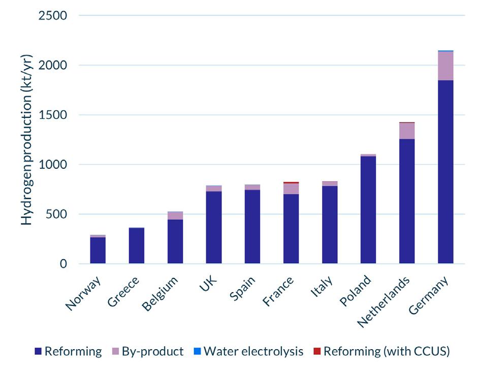
HAR 1 is an undoubtedly important step in the right direction for the UK as these first of a kind projects will contribute to a significant increase in production volumes of low-carbon hydrogen – which stood at only 1120 tpy in 2022 (Figure 1) –and contribute to decarbonisation efforts for hard-to-abate industries. DESNZ also contends that HAR 1 will offer significant value to the UK economy, with £413 million of private investment and 760 direct jobs created by the mid-2020s. Moreover, as HAR 1 projects are the first of their kind, they can offer valuable lessons for producers and off-takers looking to get involved in future rounds. By identifying best practice and encouraging efficiencies – such as how and when to use the plant’s inherent flexibility or the optimum size of on-site storage – they can help to reduce costs and perhaps give prospective developers the certainty they need to commit to enter future HARs. This is certainly the position the government takes as DESNZ contends that successfully delivering HAR 1 on time will give hydrogen developers, investors and supply chain companies the certainty they need to commit to the UK. The extent of this certainty will perhaps become evident with HAR 2, which aims to support up to 875 MW of electrolytic capacity, and opened applications in December 2023.8
While this is good news for the sector, there were some shortcomings from HAR 1. Principally, the round was only able to procure half of the government’s initially targeted capacity, with six projects representing 118 MW of capacity unsuccessful in securing support. Three further projects did not enter final negotiations. While the government addressed some of these issues in its December 2023 report, ‘Hydrogen Allocation Round 2022: process evaluation’, some concerns remain. Moreover, successful projects have encountered stumbling blocks as they seek to progress towards production, although strides have been made to help developers here. Most recently, for instance, Ofgem published its new Retail Energy Code R0160 to ‘compel suppliers to disclose the information needed to ensure electricity generated and consumed during the production of hydrogen is compliant with the LCHS.’ Once entered into application from 28 June 2024, this will go a long way to helping producers ensure that they are compliant with the LCHS and therefore satisfying the conditions of their HAR contract.9
Table 1. Low-carbon hydrogen policy index rankings, April 2024
Figure 1. The 10 largest European hydrogen producers, 2022. Source: European Clean Hydrogen Observatory.
Accelerating decarbonised hydrogen together
The world’s energy systems are changing. Hydrogen is becoming a key part of the future energy mix, with a need for very large volumes of hydrogen on the horizon. Decarbonised (blue) hydrogen can help meet that need, and Shell Catalysts & Technologies has developed a low cost, high capacity way to match those production requirements through the Shell Blue Hydrogen Process. This brings together several proven technologies to deliver 1,000 te/day of hydrogen from a single train with up to 99% CO2 capture rate at a very competitive Levelized Cost of Hydrogen (LCOH). It is a hydrogen solution designed to help decarbonise hard-to-abate industries, lower the CO2 footprint of heavy transport, and reduce home heating emissions.
Learn more at catalysts.shell.com/bluehydrogen.
What about the EU?
Low-carbon hydrogen is progressing down a similarly positive path in the EU. Following its announcement in September 2022,10 the European Hydrogen Bank’s (EHB’s) first auction round launched in November 2023. By the time the auction had closed in February 2024, it had attracted bids from 132 projects across 17 European countries, representing 8.5 GW of prospective electrolyser capacity. In April 2024 the EU published the final results of the auction, announcing seven successful projects comprising 1.5 GW electrolyser capacity, set to receive a share of approximately €720 million – ranging from €8 - 245 million per project – from the European Innovation Fund.11 Moreover, the EU established its ‘Auction-as-a-Service’ scheme wherein projects unsuccessful in the EHB auction but otherwise suitable to produce low-carbon hydrogen in line with EU standards, could be eligible for State Aid should Member States choose to participate in the scheme. Thus far, only Germany has chosen to do so, allocating €350 million to support 90 MW of capacity.12 While beneficial, it is felt that with a similar amount of funding, the EHB could have procured significantly more capacity. Additional support schemes are also in place at the Member State level.
Where do we go from here?
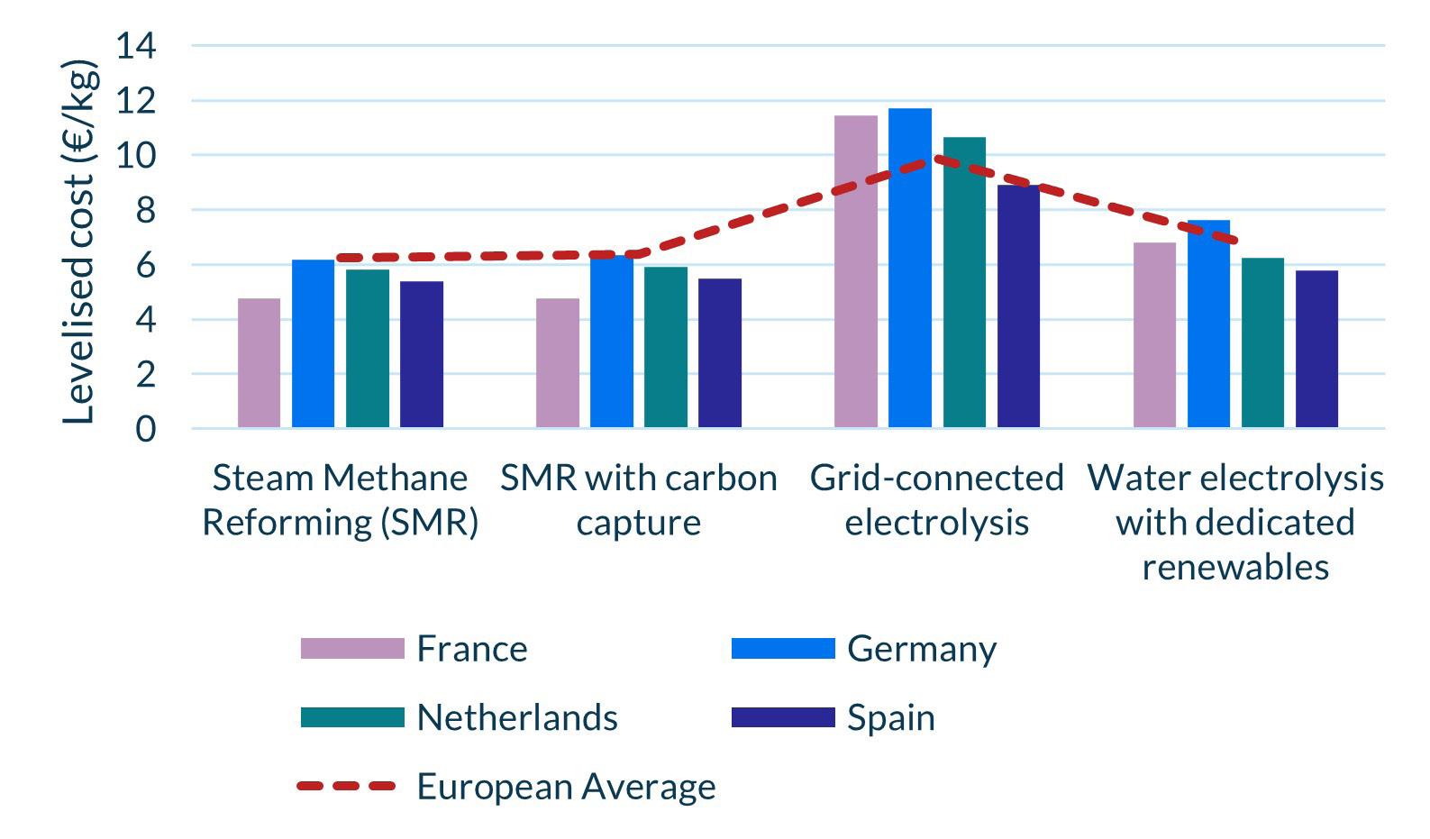
Building a low-carbon hydrogen economy is always going to take time, not least due to the nascency of the sector and the ongoing debates around its efficacy and safety as a ‘fuel of the future’. Nonetheless, recent successes across Europe have put the sector in a prime position to prove its worth by demonstrating its use-cases and working to bring its costs in line with carbon-intensive alternatives (Figure 2). In the first phase of development, this will be dependent on government support, but continued successes could enable a transition to merchant trading in the coming decades.
In the UK, all eyes are on HAR 1 as the successful delivery of projects will signal to developers that the UK is a prime location to site their projects. HAR 2 should provide an early sign of whether this confidence is growing. Similarly, the launch of the first allocation round for Transport and Storage Business Models is set to commence in late 2024, giving the sector further insight into how and where hydrogen networks could operate.
While much of the sector’s future remains an open question, it is imperative that the government gives as much certainty as possible on its use-cases to give the market a better idea of how demand could evolve. For instance, despite public disapproval and sentiment across industry, the government is yet to make its decision on whether hydrogen can be used within home heating systems. The decision, to be taken in 2026, will only be informed by one project within the UK – SGN’s H100 project in Fife, Scotland – as all other pilot projects have been cancelled or postponed until after 2026. A similar decision is also pending on blending hydrogen up to 20% in British gas distribution networks. Without answers to these questions, it is hard to get an idea of how the sector will emerge and what need the UK will have for the fuel moving forward. As such, delays to the uptake of alternative net-zero technologies are not unrealistic. This is certainly the argument made by heat pump manufacturers as continued delays to the hydrogen home heating decision is thought to be negatively impacting their sales as some consider all potential decarbonisation alternatives and their up-front associated costs.
Ultimately, despite some setbacks, the UK is making strong progress towards the development of its low-carbon hydrogen economy. While some key questions remain unanswered, the now former government took strides to provide the market with certainty and has moved at pace to develop the country’s first swathe of projects. It is imperative that the new government carries this strong progress forward to ensure that future auction rounds are as successful and streamlined as possible. In doing so, the UK will find itself among the frontrunners to develop a low-carbon hydrogen economy.
References
1. International Energy Agency, Global Hydrogen Review 2023, www.iea.org/reports/global-hydrogen-review-2023, (2023).
2. United States Department of the Treasury, Inflation Reduction Act 2022, https://home.treasury.gov/policy-issues/inflation-reduction-act, (2022).
3. Department for Energy Security and Net Zero, www.gov.uk/government/ calls-for-evidence/green-industries-growth-accelerator-hydrogen-andccus-supply-chains, (2023).
4. European Commission, Green Deal Industrial Plan, https://commission. europa.eu/strategy-and-policy/priorities-2019-2024/european-greendeal/green-deal-industrial-plan_en, (2023).
5. Department for Energy Security and Net Zero, https://www.gov.uk/ government/publications/cluster-sequencing-phase-2-eligible-projectspower-ccus-hydrogen-and-icc/cluster-sequencing-phase-2-shortlistedprojects-power-ccus-hydrogen-and-icc-august-2022, (2022).
6. Department for Energy Security and Net Zero, https://www.gov.uk/government/publications/hydrogenproduction-business-model-net-zero-hydrogen-fundshortlisted-projects/hydrogen-production-business-modelnet-zero-hydrogen-fund-har1-successful-projects, (2023).
7. Department for Energy Security and Net Zero, www.gov. uk/government/publications/uk-low-carbon-hydrogenstandard-emissions-reporting-and-sustainability-criteria, (2023).
8. Department for Energy Security and Net Zero, https://www.gov.uk/government/publications/hydrogenallocation-round-2, (2023).
9. Ofgem, www.ofgem.gov.uk/decision/authority-decisionretail-energy-code-rec-modification-r0160-electricitysupply-hydrogen-electrolysers#:~:text=Industry%20 sector&text=This%20is%20the%20Authority%20 decision,Electricity%20Supply%20to%20Hydrogen%20 Electrolysers, (2024).
10. European Commission, https://state-of-the-union. ec.europa.eu/state-union-2022_en, (2022).
11. European Commission, https://ec.europa.eu/commission/ presscorner/detail/en/IP_24_2333, (2024).
12. European Commission, https://ec.europa.eu/commission/ presscorner/detail/en/ip_24_657, (2024).
Figure 2. Levelised cost of hydrogen across major European economies, 2022.

economical options for hydrogen applications. Designed with proven Elliott compressor technology, the Flex-Op’s™ compact arrangement of four compressors on a single gearbox maximizes compression capability with enough flexibility to run in series, in parallel, or both. Turn to the experts at Ebara Elliott Energy for a partnership you can trust.
Learn more about our clean energy initiatives at elliott-turbo.com.
Advanced energy technologies for a sustainable future.


Sanders Anderson, Yokogawa, discusses why uniting policies, stakeholders, and communities is vital in building a sustainable hydrogen future.
Scaling the hydrogen ecosystem is not just an engineering and technology endeavour; it is a multi-faceted effort that requires navigating intricate policies, engaging diverse stakeholders, and seeding community support.
As the world continues to pivot toward sustainable energy solutions, hydrogen stands out as a potential game-changer. Nevertheless, the success of hydrogen projects hinges on the ability to skillfully move through the regulatory landscape, cultivate stakeholder relationships, and build strong community ties. This article delves into the importance of these elements, how they influence our considerations, and potential strategies to bridge the gap between policies, stakeholders, and communities.
The importance of policies, stakeholder engagement and communities
Policies play a pivotal role in shaping the hydrogen ecosystem. They provide a regulatory framework that can either accelerate or slow down the development of hydrogen projects. Effective policies in theory ensure safety, environmental sustainability, and economic viability, making them a tide riser for a clean hydrogen ecosystem.
Stakeholder engagement is crucial because hydrogen projects often involve various parties, including government agencies, private sector companies, non-governmental organisations, and the citizens in states, cities, and neighbourhoods. Engaging broad stakeholders early and often consistently helps to align interests, address concerns like environmental and economic impact, and foster collaborative efforts.
Community support is a consistent theme at hydrogen conventions, summit events, and a key element of the H2 Hubs programme from the US Department of Energy and the Office of Clean Energy Demonstrations. And for good reason – community support
is essential for the successful implementation of hydrogen projects. Communities are not just end-users; they are also impacted by the ecological and economic changes brought to life by such projects. Gaining community buy-in can lead to smoother project execution, long-term sustainability, and economic success.
Navigating policies
The first step in navigating policies is understanding the regulatory landscape at the local, state, and national levels. This includes becoming familiar with the existing laws, regulations, and standards that govern hydrogen production, distribution, and usage. For instance, safety regulations for hydrogen storage and transport are critical to preventing accidents and ensuring public trust. The US Department of Energy publishes information on codes and standards that is accessible to all.1
Active engagement with policymakers through advocacy and relationship-building is also vital. This involves presenting data-informed insights like the clean hydrogen market exceeding US$3.8 billion2 which help to buoy the benefits of hydrogen projects. Engaging with policymakers can help shape favourable regulations and secure incentives that support the development of hydrogen infrastructure.
Ensuring compliance with regulations cannot be avoided. This means adopting best practices and technologies that meet or exceed regulatory requirements. Additionally, remaining fluid when faced with changes in the regulatory environment is crucial for the long-term success of the hydrogen ecosystem.
Engaging stakeholders
Identifying all relevant stakeholders is the foundation of effective engagement. This includes government entities, industry partners, environmental groups, and local communities. Each stakeholder group has a unique interest focus and concerns that should be addressed.
Building trust through transparent communication is essential. Regular updates, open forums, and public consultations can help keep stakeholders informed and involved. Transparency fosters trust and can prevent misinformation and opposition to your project goals.
Forming collaborative partnerships can influence the support of hydrogen projects. Public-private partnerships, for instance, can leverage the strengths of both sectors to advance project goals. Similarly, collaborating with research institutions can

drive innovation and technological advancements. An example of a research institution doing great work in this space is the Stanford University Hydrogen Initiative, which is a collaboration between researchers in engineering, science, policy, and business working with industry and governments to use hydrogen to decarbonise the world’s energy systems.3
Getting to know regional players is equally important. There may be hydrogen hubs, associations, or coalitions near you. For instance, the ARCHES Hub in California is an initiative to accelerate renewable hydrogen infrastructure and projects. Its network is composed of industries, labour, government, and communities dedicated to creating a greener California.4
Industrial automation partners are pivotal in this journey, providing the expertise and technology necessary to streamline processes, optimise operations, and ensure safety and efficiency.
Building community support
Involving the community from the outset is crucial. This includes conducting impact assessments to understand how the project will affect the local area and addressing potential concerns.
Community meetings and workshops can provide platforms for dialogue and feedback. This is also an opportunity to hear about critical issues that may have not been addressed.
Educating the community about the benefits and safety of hydrogen early on is important. This can be achieved through informational campaigns, school programmes, and public demonstrations. An informed community is more likely to support hydrogen projects.
Highlighting the economic and social benefits of hydrogen projects can help gain community support. When communities see tangible benefits, they are more willing to jump on board and champion projects. Community support can influence decision-makers of future projects, such as Europe’s largest renewable hydrogen plant.5 Additionally, many posit that growing a robust middle class is the foundation for strong and sustainable economic growth. Clean hydrogen can create lift here with job creation, economic development, and the benefits of improved environmental quality.
Bridging the gap
Bridging the gap between policies, stakeholders, and communities requires an integrated approach. This means developing strategies that address regulatory compliance, on the one hand, and stakeholder and community engagement on the other. Joint project studies can effectively alleviate community concerns by fostering transparency, collaboration, and trust between stakeholders. For instance, the joint study to achieve carbon neutrality aims to make the Goi and Soga industrial complex carbon neutral by 2050.6
Conducting stakeholder mapping and analysis can help identify the interests, influence, and potential impact of each stakeholder group. This analysis can inform engagement strategies and help to prioritise efforts.
Combining policy advocacy with community engagement can create a powerful synergy. For example, advocating for policies that provide community benefits, such as local hiring requirements or underserved community investment funds, can align policy goals with community interests and economic growth. The Justice 40 Initiative is one such example of this kind of advocacy in action.7
Figure 1. A glimpse into our sustainable future – CO2 emissions decline, a necessary milestone in the energy transition.


Conclusion
Navigating the complex landscape of policies, stakeholder engagement, and communities is crucial for the success of clean hydrogen projects. Each element plays a vital role in shaping the project’s trajectory and ensuring its sustainability. By understanding the regulatory landscape, engaging stakeholders transparently, and building strong community ties, hydrogen projects can overcome challenges and achieve long-term success.
Scaling the hydrogen ecosystem and accelerating the path to net zero is not just a technical challenge; it is a comprehensive undertaking that requires collaboration, communication, and commitment. By bridging the gap between policies, stakeholders, and communities, hydrogen’s potential can be unlocked.
As industry moves forward, it is important to be fluid and responsive to the evolving landscape. The journey of clean hydrogen is a marathon, not a sprint, and its success will require continuous effort, innovation, and cooperation.
Establishing feedback loops input from stakeholders and the community can improve project outcomes. This includes regular surveys, feedback sessions, and being open to suggestions. Incorporating feedback into project planning and implementation demonstrates that a company is thinking about more than just the business bottom line.
Monitoring and evaluation are essential to assess policies, stakeholder engagement, and community involvement. This includes tracking key performance indicators, conducting regular reviews, and adjusting as needed. Continuous improvement ensures the project remains on track without leaving community concerns behind.
With the right strategies and partnerships, the complexities on the path to net zero can be navigated with both a practical and conscientious vision for the future.
References
1. https://www.hydrogen.energy.gov/program-areas/codes-standards
2. https://www.alliedmarketresearch.com/clean-hydrogen-market-A53698#
3. https://hydrogen.stanford.edu/
4. https://archesh2.org/community-benefits-2/
5. https://www.yokogawa.com/us/library/resources/articles/yokogawaselected-as-mac-for-constructing-europes-largest-renewable-hydrogenplant/
6. https://www.agc.com/en/news/detail/1204306_2814.html
7. https://www.whitehouse.gov/environmentaljustice/justice40/

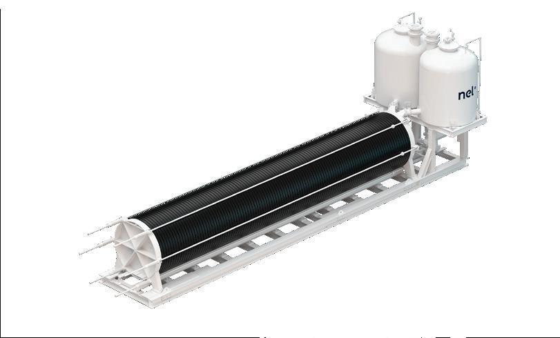
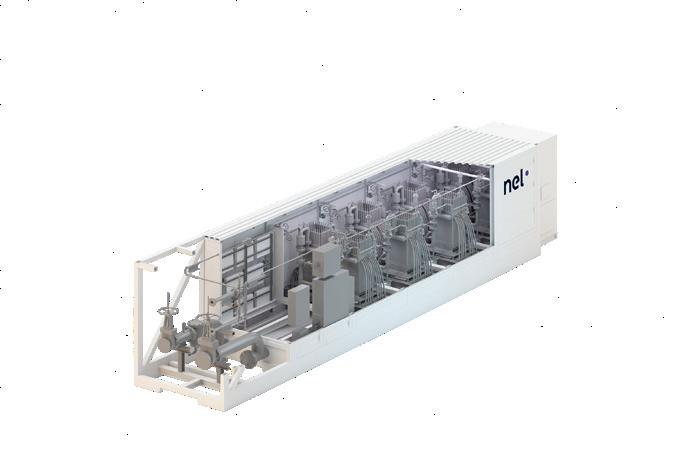
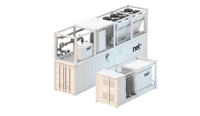
Figure 2. Sustainable success is built on collaboration. When teams and stakeholders align, good things happen.
James Steven, DNV, explains how creating integrated industry standards will provide the consistency that the hydrogen sector needs to prove its viability.

Debates about hydrogen’s role in the energy transition, its potential uses and which colour is best, have been commonplace in the industry in recent years. DNV has made its stance on the matter abundantly clear – hydrogen is critical for decarbonising economies and moving hard-to-electrify sectors towards net zero emissions. At the same time however, it is important to remain realistic about its ability to make the difference needed in the short-run.
In order to meet the Paris Agreement targets, hydrogen must account for approximately 15% of the world’s energy demand by 2050. But forecasts, included in DNV’s latest Energy Transition Outlook, indicate that the global adoption of hydrogen and its derivatives are well behind where they need to be, with hydrogen making up just 0.5% of the global final energy mix in 2030 and 5% in 2050. Nevertheless, developments in hydrogen technology and infrastructure over the next three decades will be significant, with the potential to transform various industries.
At a more granular level, DNV’s latest UK Energy Transition Outlook forecasts that the primary driver for long term hydrogen demand will be the increasing need for the fuel, as well as its derivatives, in the transport sector
But this is a long-term view, and without the swift creation of a clear business model or market support mechanism, high production costs likely mean that hydrogen will be uncompetitive for use in heavy industry and domestic heating, even by 2050 when the UK is aiming to be a net-zero nation.
The replacement molecule
By the middle of the century, DNV forecasts a 50/50 split between blue hydrogen (produced from natural gas through reformers with carbon capture and storage [CCS]) and green (electrolytic) hydrogen, with the fuel playing a vital role in decarbonising hard-to-abate sectors, like aviation and heavy industry where the energy demands render electrification unsuitable.
Numerous hydrogen projects, both blue and green and spanning the length of the UK, are in various stages of development, hoping to capture a share of what has the potential to be a £13 billion market by 2050. In the short to medium term, blue hydrogen will be key to priming the sector and establishing its associated supply chain. As we pass net zero, there will be a shift with green hydrogen capturing an ever-greater share of the market, becoming the carbon free molecule that will power much of the world for generations to come.
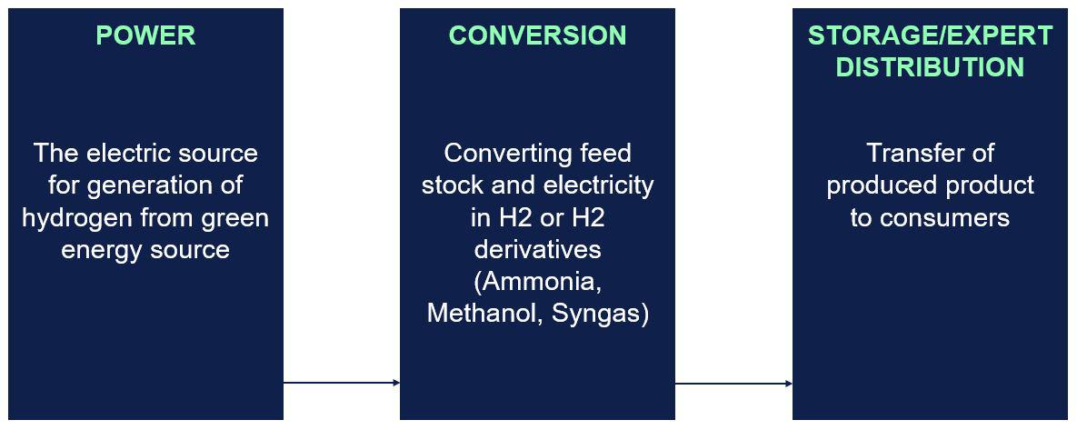
Earning trust through thorough planning
At this early stage for the sector, building trust and confidence across the three main green hydrogen project stages remains essential. Developers must be certain that they will have access to a reliable power source for generation, that their technology performs as expected in the conversion process, and that there is a consumer in place to receive the finished product.
Confidence does not occur organically however; it needs to be earned and shaped. Green hydrogen still has its detractors and concerns remain about its safety and efficacy. To allay these fears, it is important to get under the bonnet of projects and prove that all the components right across the chain function as promised and expected.
Going beyond regional regulations
It is often found that projects are solely focused on meeting the regional accreditation and regulations around green hydrogen, but are sometimes stopping short of addressing the technical and safety elements. While this is an important factor, it is all about apportioning blame should something go wrong. It is an essential box to tick from a legality and regulatory perspective, but it does not help to ensure there is a safe final product. This is already causing huge issues on projects and big delays, because companies are buying in equipment without properly assessing its compliance and safety performance.
This is fuelling much of the negativity and scepticism that is levelled at the hydrogen sector. Moreover, it underscores the need for the industry to have a standardised method that projects across the globe can follow with certainty. If this blueprint is in place, then developers are all approaching projects from the same place. They can follow a validated
path that starts with the components, builds them up into a package, and then shapes them into a green hydrogen production facility.
Proving concepts in the field
In order to steer the technical compliance and safety aspects of the green hydrogen industry, DNV teamed up with over 25 financial, end users and manufacturing partners. The aim was to come up with a new certification and industry best practice for hydrogen production systems to facilitate successful water electrolysis projects. It was inspired by a similar approach that DNV undertook for the wind energy industry about 30 years ago that helped to drive standardisation and safety in the sector.
Featuring some of the biggest names in the energy industry, the findings from this joint industry partnership have helped to validate the criteria for managing the safety risks arising from main electrolyser components and assembled systems. It also entailed the assessment of all the potential hazards of the electrolyser technologies currently on the market, as well as providing an oversight framework to reduce the threats faced by projects and financial stakeholders.
Crucially this initiative yielded new DNV standards to inform the equipment used in the production of green hydrogen and hydrogen derivatives, providing the consistency in certification and verification that the sector needs to prove its viability.
Amongst them is the first fully integrated standard for electrolysers, DNV-ST-J301, which addresses all potential hazards associated with this emerging technology. Complementary standards, such as DNV-ST-J302 (designed to benchmark electrolyser performance and allow for standardised methods of evaluation that do not currently exist) and DNV-ST-J30x (a product standard), are also in the pipeline and will be released soon.
DNV-ST-J301 is built on a risk-based approach, encompassing all technical safety considerations. This standard goes beyond typical guidelines, consolidating all safety aspects into a single, comprehensive document, making it more accessible and easier to follow. It includes detailed requirements and guidance on specific issues related to the use of hydrogen and its derivatives. By defining proportionate actions based on risk severity, this approach ensures thorough, yet cost-effective compliance. This proactive risk management methodology has gained global endorsement and is becoming the standard for ensuring safety and compliance in major projects.
Taken with regional product requirements, as well as other ISO or international standards, these new qualifications are the blocks that build DNV-SE-0674, the latest service specification for the verification and certification of Power-to-X equipment, reducing risk and independently documenting a high level of safety and compliance to all stakeholders.
Figure 1. Main stages of green hydrogen production.
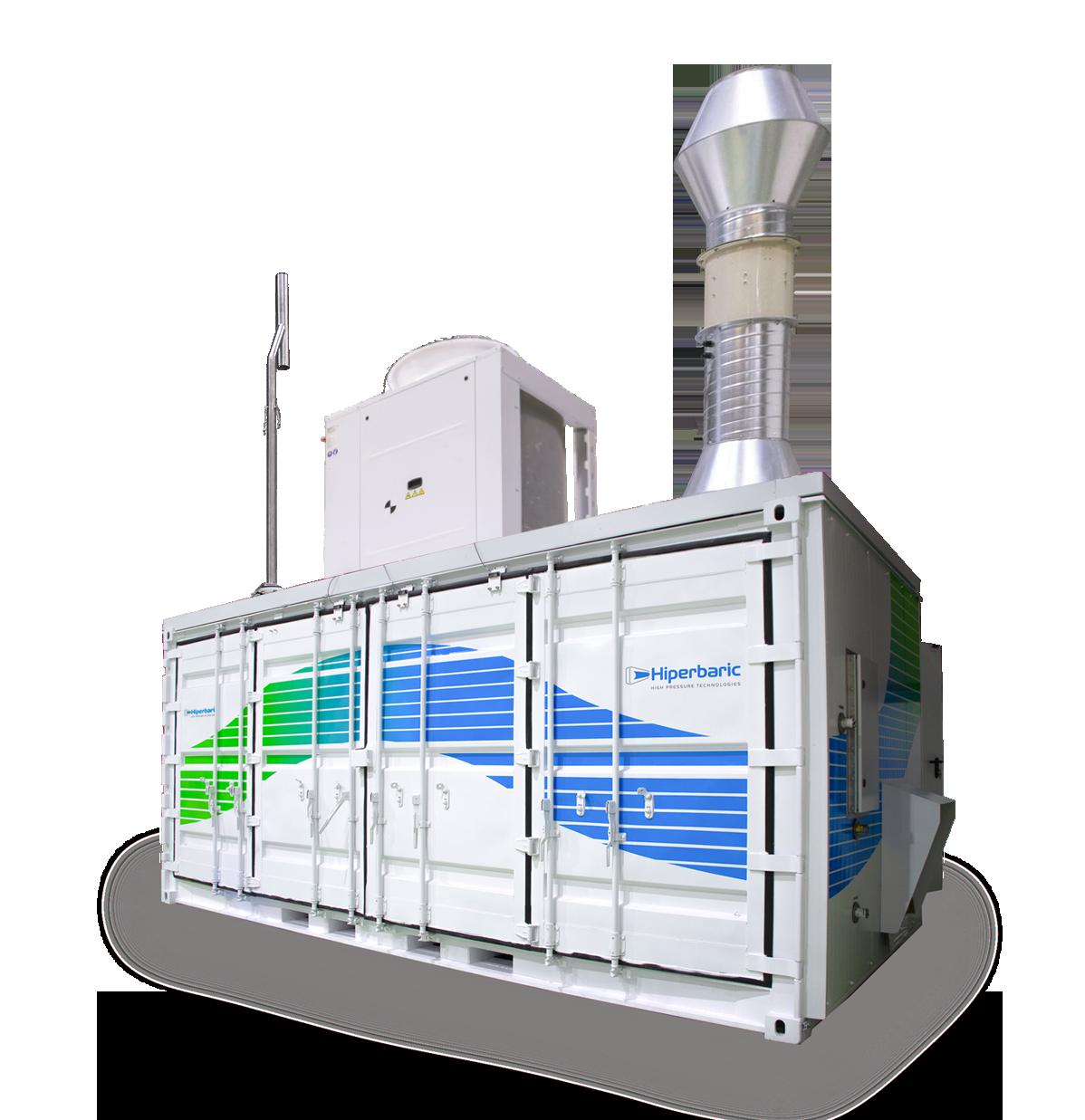
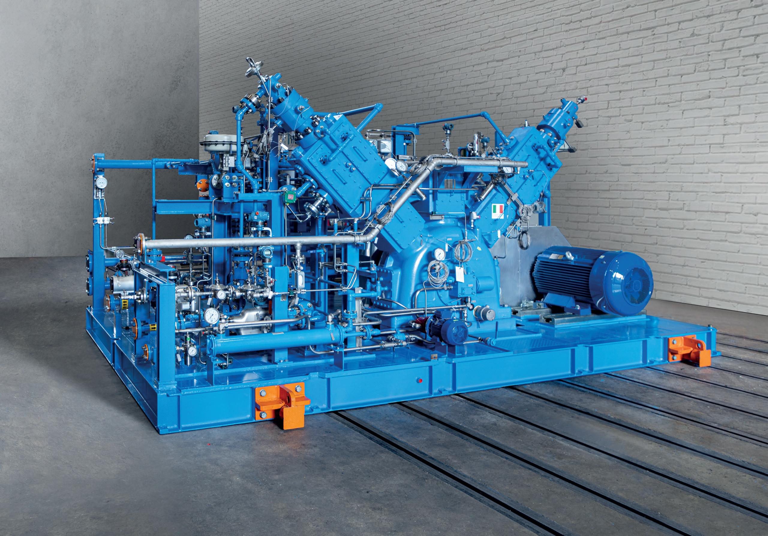
HIGH PRESSURE HYDROGEN COMPRESSION TECHNOLOGY
Advanced reciprocating piston compression technlogy of up to 500 - 1,000 bar
Oil Free design compressors, with a complete turndown: 0% to 100%
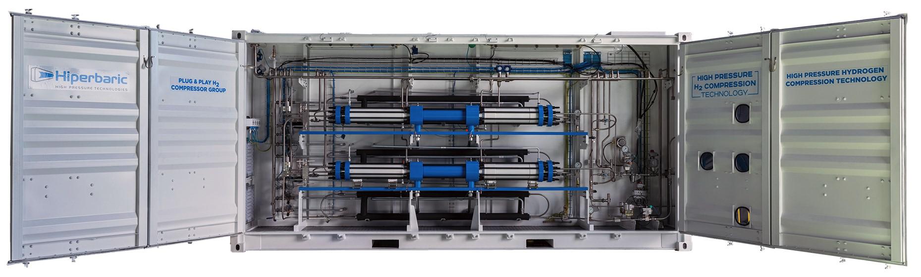
Modular and scalable design that can include one or two compressors
24/7 Aftersales service for installation and start-up, supply and manteinance


Validating green hydrogen production from the bottom to the top
This approach evaluates not only individual components, but also their collective contribution to green hydrogen production plants’ safety and compliance. It outlines various certification and verification requirements, along with the processes for achieving them, including guidelines for non-DNV standards. This ensures developers can comprehensively demonstrate their processes across the entire green hydrogen production chain, minimising oversights and ensuring equipment compliance and plant safety. The forthcoming introduction of additional product and system standards in 2024 will facilitate the assessment and certification of all products utilised in hydrogen or its derivatives, extending the standardisation efforts to other related products and supporting the accelerated adoption of hydrogen, alongside users of gases and e-fuels. Such measures are crucial in aiding users’ transition towards low-carbon fuels.
In turn, DNV-SE-0674 stands as a pivotal element within DNV-SE-0656, DNV’s comprehensive service specification for verifying (and soon certifying) Power-to-X facilities as an integrated whole. The other two bolt on factors that comprise this overarching benchmark are regional accredited services, which address provincial-specific regulations pertinent to projects, and DNV-SE-0654, a standard designed to authenticate developers’ claims regarding the environmental sustainability of the hydrogen produced. Together, they ensure a rigorous evaluation of Power-to-X facilities, considering both regulatory compliance and environmental impact, thereby fostering transparency and accountability in the green energy sector.
Released last year, DNV-SE-0656 covers the physical site where green hydrogen is actually produced, building up from the component level to create a fully functioning facility. It also allows the certification of systems that are already operational.
Conclusion
It is this ability to show the full transition, right through the validation pyramid, that will be vital to the establishment of a global green hydrogen industry. Not only will it pave the way for the standardisation of electrolysers and associated equipment, a prerequisite for scaling up the sector to meet demand, but it will confirm that the fuel and its derivatives can safely fill the gap that will one day be left by oil and gas.
Initiatives spearheaded by many of the world’s biggest energy companies, underpinned by government backing, mean the green hydrogen sector is inevitably set for growth, spurred on by the need for hard-to-abate sectors to clean up their act. But to what extent this growth is realised depends on the sector’s ability to iron out the creases now. In tandem, the government must do its bit to create a robust market, through the creation of clear business models and market support mechanisms designed to make this most vital of fuels cost-effective.
DNV’s collaborative efforts with industry partners have yielded standards and certifications that provide a foundation for the safe and efficient production of green hydrogen. As the transition progresses, the industry must continue to work together to ensure that set green hydrogen standards can help to deliver the decarbonisation that the world so desperately needs.
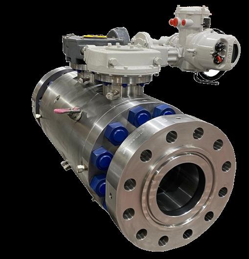
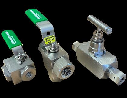
Valves Qualified

Hydrogen qualified valves for topside, subsea, and pipeline applications, endurance tested to over 400 Cycles with ZERO Leakage. Also available are 10/14/20mm full bore gaseous fuel station ball valves.


Nadim Chaudhry, World Hydrogen Leaders, looks at the opportunities for CCUS-enabled low-carbon hydrogen and how US policy is accelerating the advancement of this vital fuel of the future.

While its relevance in helping to reach climate goals has long been recognised, deployment of carbon capture, utilisation and storage (CCUS) has been slow and consistently accounting for less than 0.5% of global investment in clean energy technologies.
Although CCUS is not a new technology and there are currently around 41 operational facilities globally, it has typically been deployed at a small scale – mainly for research and development (R&D) projects and for enhanced oil recovery. In order for CCUS to meaningfully contribute to climate change goals, the amount of CO2 captured would need to grow four-fold from current levels by 2030). However, stronger climate targets and investment incentives are now starting to drive increased momentum into CCUS – and one of the key strategies to provide a boost to the technology is the efficient production of hydrogen.
The role of CCUS in low-carbon hydrogen production
Hydrogen is a versatile energy carrier that can help support the decarbonisation of a range of hard-to-abate sectors where electrification from renewable sources cannot deliver the level of energy output required. These include iron, steel, chemicals and cement production – as well as hydrogen-based fuels for aviation, shipping and long distance haulage.
CCUS can facilitate the production of low-carbon hydrogen (sometimes referred to as ‘blue’ hydrogen) from natural gas and provide an opportunity to bring it into new markets in the near term – and at reasonable cost.
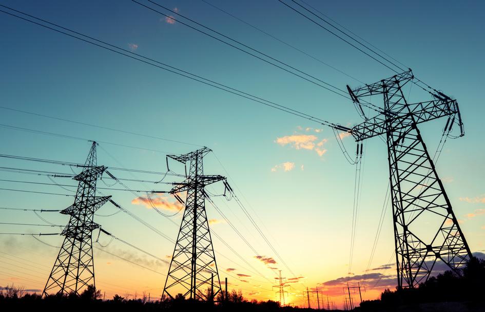
It can also help alleviate pressure on already constrained electricity grids, allowing renewable electricity generation and electrolytic hydrogen production to scale at a more manageable pace. This benefit of CCUS-enabled hydrogen over
the next decade has been recognised in the Committee on Climate Change’s recently published Climate Change Committee’s 2023 Progress Report to Parliament.
Today, the cost of CCUS-enabled hydrogen production is likely to be around 50% of hydrogen production via electrolysis powered by renewables-based electricity. While the cost of electrolytic hydrogen is anticipated to reduce over time with the onset of increasingly cheaper electrolysers and renewable electricity, CCUS-equipped hydrogen will most likely remain a competitive option across regions typically associated with low-cost fossil fuels.

Recently there has been a significant increase in the appetite to develop CCUS projects, with a 50% increase in CO2 capture in the 12 months between 2022 to 2023. This has been driven by governments internationally coming under increasing pressure to meet global climate targets, implementing robust legislation and providing clear pricing signals in order to make CCUS commercially viable.
Despite this positive news, there remain three significant issues. From the many announced CCUS projects, only around 5% have taken firm investment decisions due to the uncertainty of demand, a lack of clarity around certification and regulation and, a critically important factor, the lack of infrastructure available to actually deliver the hydrogen to customer sites. According to the IEA, to help deliver a heavily decarbonised heavy industry by 2030, a third of all hydrogen production will need to be dedicated to those hard to abate sectors – and currently these applications only account for around 0.1%. So, there is considerably more work to do.
Challenges with deploying CCUS at scale
Due to the fact that CCUS is far from a mature industry, a single stakeholder is typically unable to take on all the expertise, risk and CAPEX needed across the whole value chain. As such, the most significant challenges with deploying CCUS at scale are the multiple different, distinct stakeholders that need to be coordinated including: the industrial plants which are the CO2 emitters themselves; the various CCUS technology suppliers which separate and capture the CO2; providers of processing, compression solutions transportation solutions, and, finally, experienced storage providers who can inject and store the CO2 underground.
It is evident that urgent policy action is needed to create demand for low-carbon hydrogen and unlocking the necessary investment to accelerate the scale-up of production and the building of delivery infrastructure.
The US leading the way
Currently, different policy approaches are being undertaken by governments to encourage the deployment of CCUS at scale. In particular, the US has provided a much-needed shot in the arm for the infrastructure required to scale up technologies.
Incentives under the Inflation Reduction Act (IRA) provide project developers with a US$50/t of CO2 tax reduction where CO2 is stored in dedicated storage sites. Additionally, the Infrastructure Investment and Jobs Act passed in November 2021 provided a combined US$15 billion to support CCUS and low-carbon hydrogen production.
The IRA has had a considerable positive impact on hydrogen, enabling the US to have the largest hydrogen project pipeline of any country. It currently accounts for 18% of total announced capacity, allocating Australia to second place at 14%. And while the percentage of hydrogen projects in the EU surpass both of those (at 29%), it should be remembered that this figure accounts for the whole of the EU (consisting of 27 countries) and the UK, which ultimately results in relatively minor pipelines per country.
While Europe may be advancing the highest number of projects overall, the US is considerably closer to offering early scale-up, with the generous IRA tax credits, eventually helping
Figure 1. CCUS delivered hydrogen can help alleviate pressure on already constrained electricity grids.
Figure 2. The US is considerably closer to offering early CCUS hydrogen scale-up.
Figure 3. Despite relevance to help reach climate goals, deployment of CCUS has been slow.
a strong flow of US projects towards Final Investment Decision (FID).
The majority of announced projects are for green hydrogen, which is produced using renewable energy and electrolysis and is the cleanest form of hydrogen production. However, it is also expensive, making access to cheaper clean power necessary to achieve the desired economics.
While most of the recently announced projects are for carbon-free hydrogen, the projects that are most advanced are dominated by blue hydrogen, especially in the US. Blue hydrogen is mainly produced from natural gas and creates CO2 as a by-product – so it is a low-carbon solution, but not strictly a ‘clean’ one. However, it enjoys a significant cost advantage over green hydrogen, particularly where natural gas is cheap, as in the US and Canada.
Today, the cost of CCUS-enabled hydrogen production remains around half that of producing hydrogen through electrolysis powered by renewables-based electricity. While the cost of electrolytic hydrogen will decline over time, with cheaper electrolysers and renewable electricity, CCUS-equipped hydrogen will most likely remain a competitive option in regions with low-cost fossil fuels and CO2 storage resources.
Greg Bean, Director, Gutierrez Energy Management Institute at the University of Houston, commented: “Recent federal government policies affecting low-carbon intensity (LCI) hydrogen – specifically the funding of seven hydrogen hubs, along with IRA production tax credits for LCI hydrogen and enhanced CCUS tax credits – should accelerate the initial wave of CCS hydrogen given its current cost advantage over electrolytic hydrogen, especially in the US with low natural gas prices. However, the more favourable tax treatment for electrolytic hydrogen in the IRA and the likely reduction in electrolytic hydrogen cost suggests that it might ultimately have a larger market share in an aggressive decarbonisation scenario.”
Hydrogen trading is still at a relatively nascent stage but could see significant growth this decade. Even low-carbon hydrogen will be crucial for net importers to reach net-zero targets and for net exporters like the US to maximise benefits from clean energy deployment. CCUS-based hydrogen is likely to become an internationally traded commodity to help countries meet their hydrogen demand in a more economical way.
With main export markets likely to be in Europe and North Asia, there could be policy actions in these countries that penalise or limit CCS hydrogen imports. A relevant example is the ‘maximum methane intensity values’ and associate penalty structure being discussed for LNG imports into Europe. Only time will tell.
Conclusion
This is a decisive decade and it is essential to scale solutions today if the worst climate impacts on society and the global ecosystem are to be avoided. Both CCUS and low-carbon hydrogen are well-tested and the US has shown that they can be rapidly scalable solutions that can deliver decarbonised industries at a lower cost.
The significant opportunities for low-carbon hydrogen can only be delivered through coordinated international collaboration. This requires cross-industry partnerships that must work together based on guiding principles of lower costs, speed, and uncompromising quality.


Dr. Balagopal Nair, John Crane, explains how embracing carbon intensity as a quantitative metric for evaluating hydrogen can drive emissions reduction.
Hydrogen, which does not create any carbon emissions when burned, is a pivotal resource in the energy transition. This abundantly available natural element has the potential to accelerate decarbonisation, making it an essential part of a carbon-neutral society. As hydrogen continues to garner new levels of interest, so do the impacts of hydrogen production. But as the new energy economy matures, the hydrogen colour spectrum –which assigns colours to various production techniques with different levels of carbon emissions –is no longer the preferred approach to evaluating hydrogen’s environmental footprint. The colour spectrum ranges from green hydrogen, which is produced with renewable energy only and has the lowest carbon emissions, to black hydrogen, which is produced with the highest emissions. Not all hydrogen is created equally, and the colour spectrum can be a useful tool for understanding these various production methods at a high level. However, considering production methodologies in isolation from other factors is a misleading indicator. Simply put, a quantitative measure of the emissions associated with hydrogen will be essential as the hydrogen economy matures. An approach based on carbon intensity can provide a transparent, universal measure of hydrogen’s environmental impact across the value chain.
Blue hydrogen vs green hydrogen: understanding the colour spectrum
The colour spectrum categorises various approaches for producing hydrogen. Each colour describes a production method. While blue hydrogen vs green hydrogen is the most talked about, many other process colours exist.
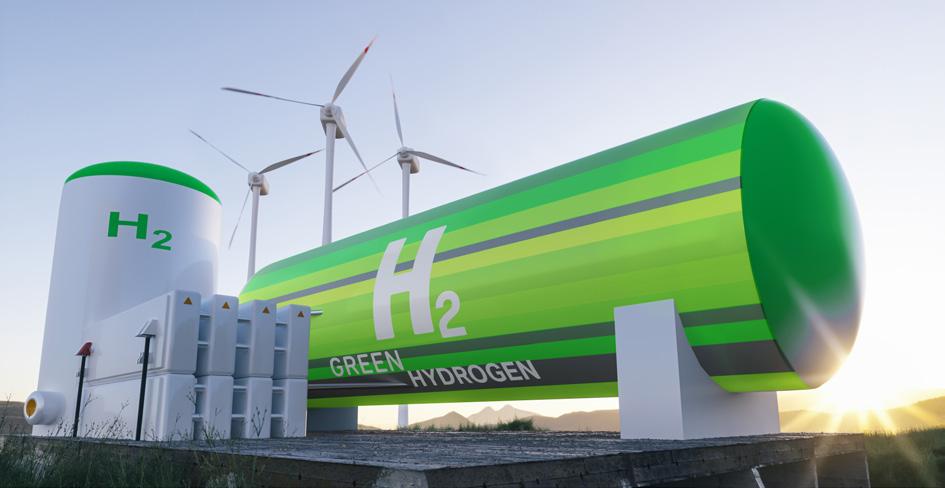
Green hydrogen
Electrolysis splits water into oxygen and hydrogen, utilising renewable electricity. The energy must come from renewable sources such as wind or solar, as this classification is intended to be emissions-free. John Crane supports one of the world’s largest green hydrogen projects with its dry gas seals, high-performance couplings, and gas filters. Planned for operations in 2026, the plant is set to produce 600 tpd of zero-carbon hydrogen.
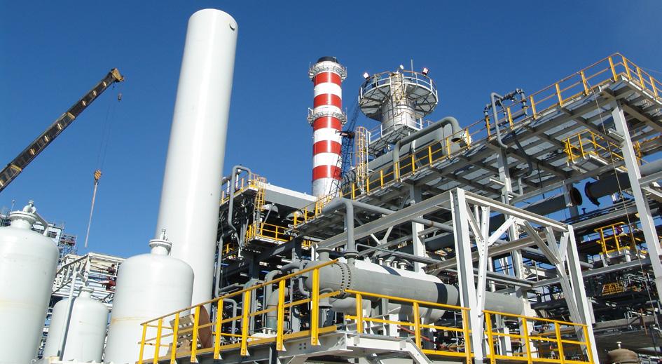
Blue hydrogen
Natural gas feedstock undergoes reforming, such as steam methane reforming (SMR) and partial oxidation or autothermal reforming (ATR), converting methane into hydrogen and CO2
The process pairs with carbon capture utilisation and storage (CCUS) to prevent the release of emissions. John Crane provides the sealing technology for one of Canada’s largest blue hydrogen production sites in Edmonton, Canada.
Grey hydrogen
Natural gas is separated into hydrogen and CO2 by reforming. Unlike blue hydrogen, CO2 emissions are discharged into the atmosphere.
Pink hydrogen
Nuclear-powered electrolysis produces hydrogen from water – the energy spent is non-renewable, but the process is low-carbon.
Turquoise hydrogen
A process called methane pyrolysis thermally decomposes methane into hydrogen and solid carbon, significantly reducing the release of CO2 gas.
Black and brown hydrogen
The gasification of hard coal (black) or soft lignite (brown) produces hydrogen. These production methods are considered some of the least environmentally conscious.
Yellow hydrogen
Electrolysis powered by a mix of solar energy and other non-renewable sources produces hydrogen. This mix could create a significant carbon footprint depending on the amount and type of non-renewable energy sources used.
White or gold hydrogen
Hydrogen production occurs underground through natural processes and chemical reactions. When conducted in abandoned gas or oil wells, microbes break down organic matter in the absence of oxygen, yielding ‘gold’ hydrogen gas as a byproduct. Gold hydrogen can also be
extracted via drilling similar to natural gas production, which offers a potentially attractive pathway if large and accessible underground hydrogen resources can be found.
While these colours offer a simple way to distinguish between blue hydrogen and green hydrogen and more, the descriptors only tell part of the story. Investors, industry leaders, and the public deserve to understand the complete picture when it comes to the hydrogen source’s carbon impact.
Looking beyond the hydrogen colour spectrum
The limitations of the hydrogen colour spectrum lie in its simplicity and the absence of any formal definition. It groups production methods but does not account for variations in carbon emissions within a colour category.
There is no simple answer to the question, ‘what is green hydrogen?’. Even terms such as ‘low-carbon’ or ‘clean’ hydrogen are inconsistent across projects, countries, and regulatory bodies.
A pragmatic characterisation of environmental impact is essential to hydrogen’s role in decreasing emissions. Carbon intensity (CI), a technology-agnostic measure of carbon footprint, offers a framework for describing hydrogen with universal commonality. CI is the quantity of carbon in CO2 equivalent emitted per unit of hydrogen produced. The higher the CI score, the more adverse the environmental footprint.
A quantitative measure like CI is more telling than the process colour alone. The transparency CI adds could help accelerate hydrogen projects by bolstering confidence with investors, creating consistency for astute market decisions, and enabling interoperability between regulatory bodies worldwide.
However, establishing CI is complex, and a clear approach to determining CI is critical to its success.
Factors contributing to CI
Carbon emissions along the hydrogen value chain fall into various categories: feedstock, production, transportation, storage, and final use. CI must consider emissions at every step of the value chain to accurately represent hydrogen’s potential in global decarbonisation.
For example, a study by Wood Mackenzie found that water electrolysis (typically associated with ‘green hydrogen’ production) could result in higher CO2 emissions than brown hydrogen if the electricity for the process came from grid power generated with unabated fossil fuels.1
Accounting for all the emissions released throughout the hydrogen lifecycle is particularly challenging in terms of production and transportation.
Hydrogen production
The CI of hydrogen varies greatly across production methods, so one colour is not always less carbon-intensive than another.
Take the following example: although using natural gas for SMR feedstock generates higher emissions than water electrolysis, the final CI depends on several factors, including the energy source powering the production, as well as the carbon capture rate.
Consider a situation that uses renewable power to produce hydrogen through electrolysis (green hydrogen). Due to the intermittent nature of solar and wind, it may be necessary to leverage grid energy to support electrolysis at scale. However, grid energy impacts CI, as it may be fossil fuel-based, and emissions may be abated or unabated at the power plant level. However, incorporating energy storage into renewable hydrogen production, rather than grid power, can enable 100% renewable hydrogen production.
As another example, the range of CI associated with blue hydrogen varies broadly depending on where carbon capture is used in the process. There are two opportunities to decarbonise the production of blue hydrogen by SMR: at the point where feedstock gas (methane) is burned to enable SMR, and after the SMR process has produced CO2. According to the International Energy Agency (IEA), capturing both sources of CO2 can result in a 93% capture rate, as contrasted with a much lower 60% for partial capture.2
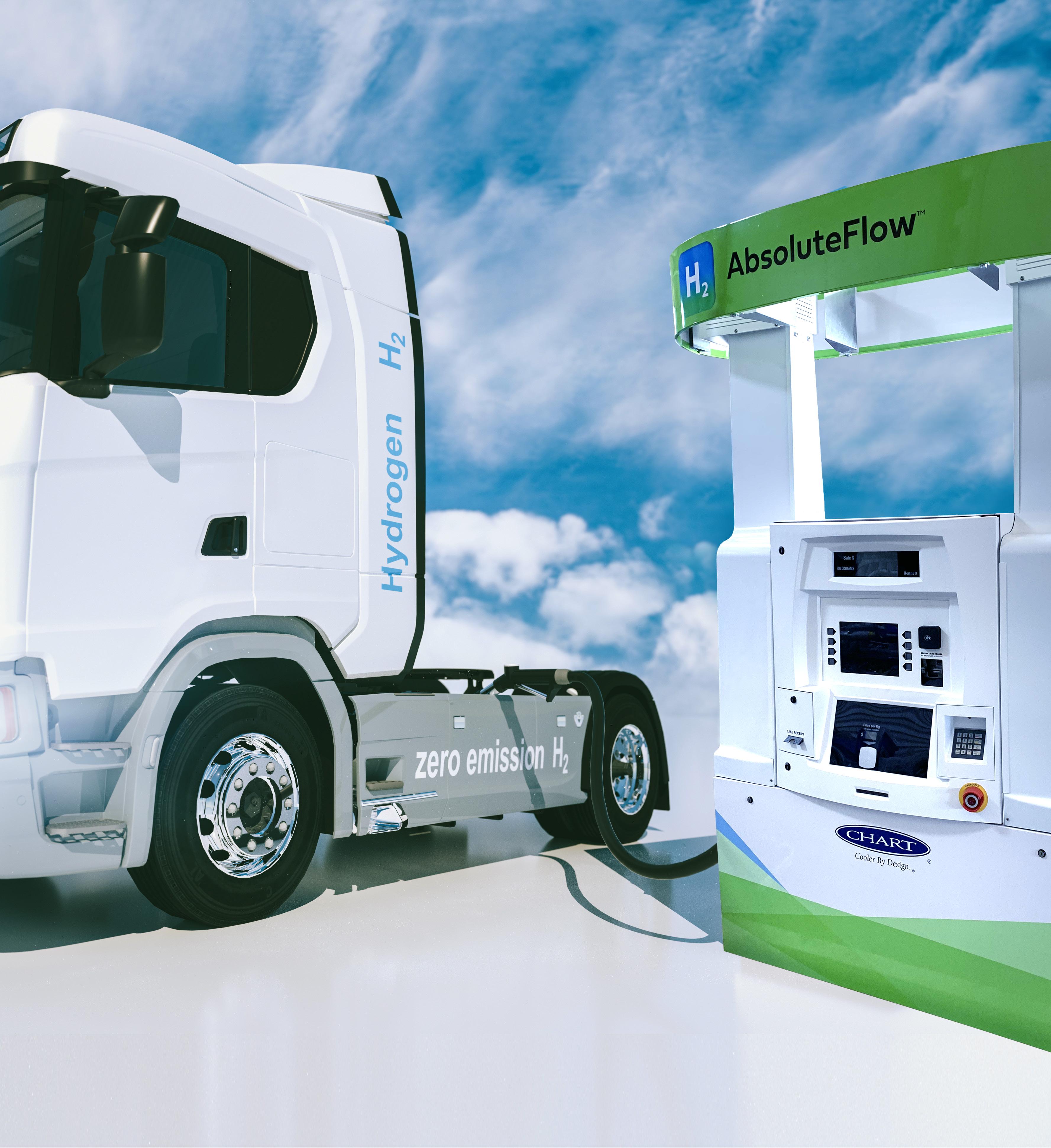
Hydrogen transportation
A complete evaluation of CI considers whether and in which form hydrogen is delivered by pipeline, truck, rail, or ship. The fuels that power these transportation modes emit carbon, driving higher CI scores. There are a few challenges.
Preparing hydrogen for transportation may involve liquefaction, which requires energy to maintain cryogenic temperatures. Pipeline transportation is possible at ambient temperature, but power is still needed to compress hydrogen gas, which impacts CI.
Converting hydrogen to ammonia for transportation is an appealing alternative. The infrastructure and expertise for this is already well-established. However, the Haber-Bosch process for creating ammonia consumes significant energy, and a large amount of energy is required to crack the ammonia back into hydrogen at the point of use.
There are, however, advantages in terms of carbon footprint when utilising the ammonia molecule instead of cracking it back into hydrogen and nitrogen. For example, advancements within the maritime sector suggest that using transported ammonia as fuel could lower carbon emissions and CI compared to using common marine fuels. Another idea is to use the boil-off gas from
Figure 1. Green hydrogen gas for clean electricity solar and wind turbine facility.
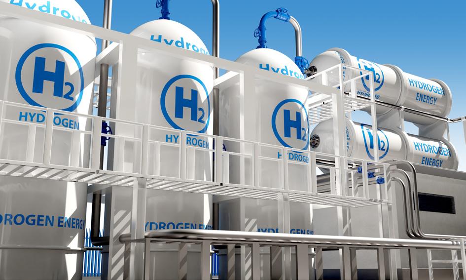
Figure 2. Hydrogen facility.
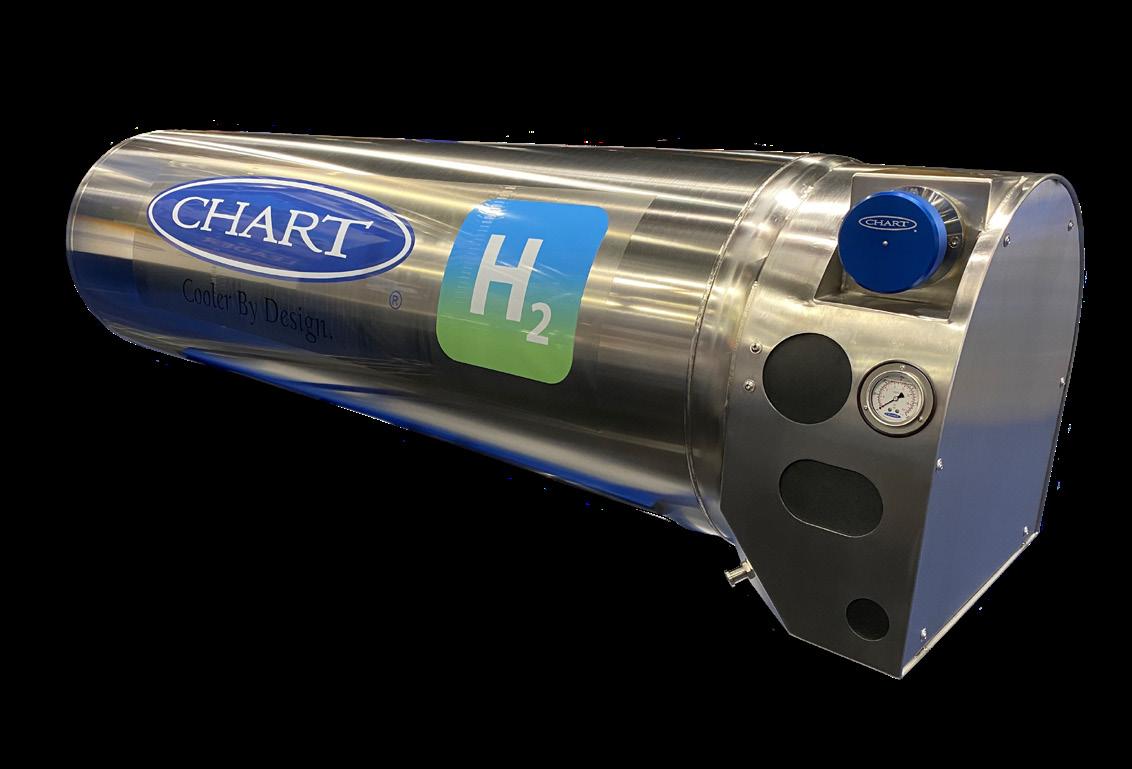
Chart’s HLH2 vehicle fuel systems provide greater range and payload advantages using liquid hydrogen storage and an integrated heat exchanger for Fuel Cell Electric Trucks (FCETs).
Chart’s liquid hydrogen fuel stations allow for quicker fueling of vehicles with more dense liquid hydrogen, using simpler equipment and requiring less infrastructure investment.
HLH2 vs. H35/H70
• Lighter Weight
• Smaller Footprint
• Easier to Install
• Faster Fill Times
• Customized Integration with Truck Manufacturer’s Fuel Cell Engine
www.ChartIndustries.com/Hydrogen hydrogen@chartindustries.com
Americas: +1 800 400 4683
Germany: +49 (0)2823 328 224 China: +86 519 8596 6000
Scan to download our brochure
liquid hydrogen as a fuel or part of the fuel in a liquid hydrogen carrier ship. To date, these technologies have yet to be widely adopted. Marine transport remains a significant contributor to CI, particularly for long-distance trade between Chile and Japan, for example.
CI as a standard definition for hydrogen
A report by the IEA states that “clear regulations and certification systems based on the emissions intensity of hydrogen production can bring much-needed transparency and be a useful enabler of investments in production and demand applications as well as infrastructure for hydrogen trade”.3
It is apparent that CI, rather than colour schemes like blue hydrogen vs green hydrogen, can provide a unified method for evaluating environmental impact. This clarity is especially important in regions with limited potential for locally producing low-carbon hydrogen. Economies in these areas will rely heavily on imports and must be aware of the carbon impact of the products they purchase and transport.
The role of policy
Regulation and certification are a critical aspect of hydrogen’s path forward. Policymakers should ensure that hydrogen is represented in a consistent way, ideally across the globe. CI could be a basis for internationally recognised hydrogen regulations.
Currently, Europe, the US, Canada, Korea, and Japan evaluate the environmental impact of hydrogen using slightly different schemes and system boundaries. Definitions from the IEA for system boundaries include:
y Well-to-gate: emissions produced by the supply of the fuels used in the hydrogen production process.
y Well-to-point-of-delivery or well-to-tank: includes all well-to-gate emissions and emissions associated with transport, as well as possible conversion and reconversion of hydrogen into other carriers.
y Well-to-wheel: includes all well-to-gate and well-to-point-of-delivery emissions, in addition to those associated with the use of hydrogen.
A unified CI scope and definition could encourage consistency and transparency across borders, smoothing the way to a scaled-up international hydrogen market.
A clear path to accelerating the hydrogen economy
While the simplicity of the hydrogen colour spectrum is useful at a high level, it does not provide a comprehensive measure of environmental impact. Embracing CI as a quantitative metric for evaluating hydrogen can aid decision-making, ultimately helping achieve emissions reduction and sustainability goals.
Hydrogen will undoubtedly play a role in the future global energy landscape. As the hydrogen economy continues to mature, industry must embrace the full spectrum of possibilities it offers – not just in colour, but in CI as well.
References
1. https://www.woodmac.com/horizons/hydrogen-colours-value-chaincarbon-intensity/
2. https://www.iea.org/data-and-statistics/charts/comparison-of-theemissions-intensity-of-different-hydrogen-production-routes-2021
3. https://www.iea.org/reports/towards-hydrogen-definitions-based-ontheir-emissions-intensity
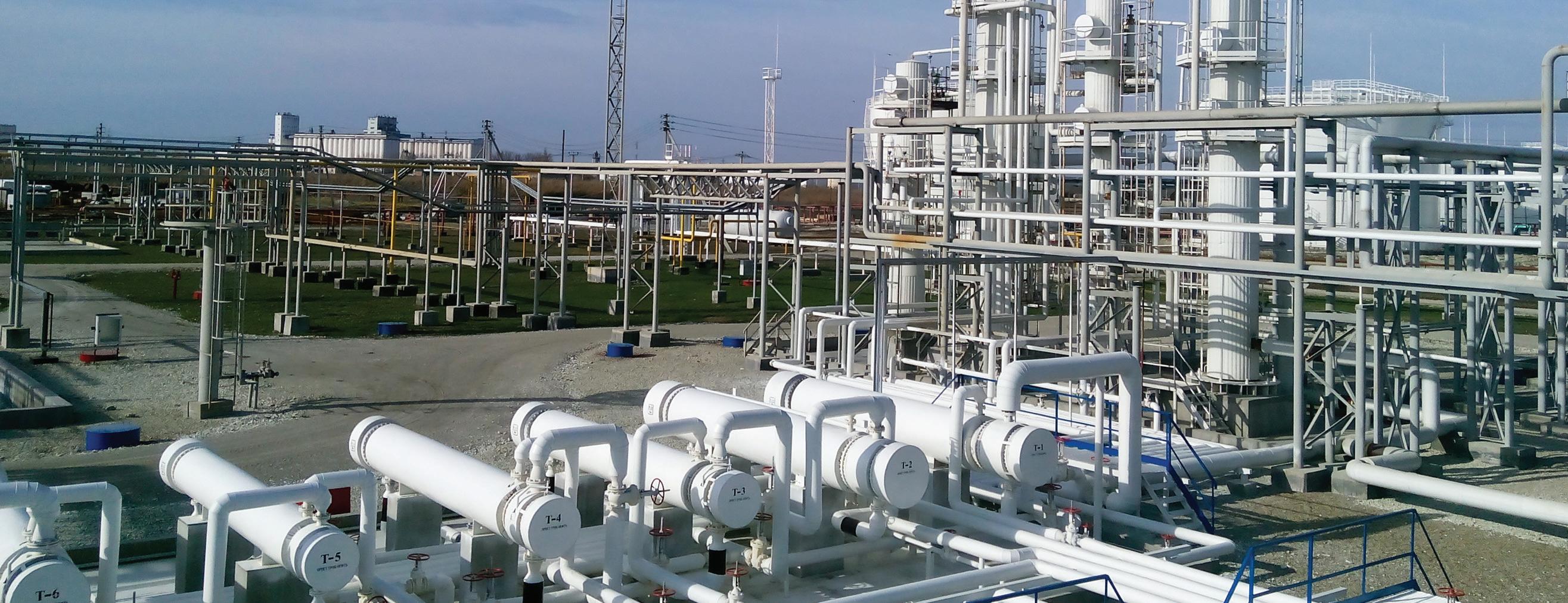
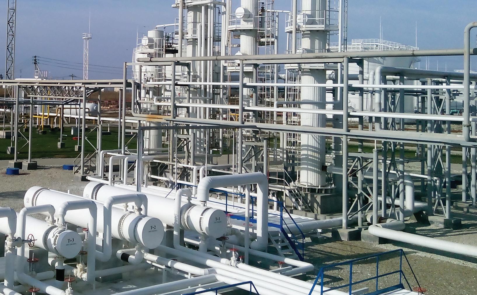
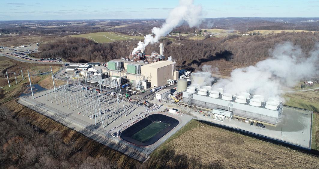
Hydrogen’s use as a decarbonised fuel for power generation is a peak interest for utilities looking to future-proof their power plant systems. Combined cycles, as pictured in Figure 1, are particularly of interest due to their high efficiency relative to other thermal power generation technologies, a large existing fleet, and their ability to provide grid stability required for the expanding renewable resource portfolio. Currently, there are limits to the level of hydrogen blending in natural gas-fuelled combined cycles, due to limitations in combustion turbine combustor design, as well as criteria air
In the second part of a two part article, Justin Distler and Vince Mazzoni, Black & Veatch, discuss the importance of developing safety codes and standards to ensure safe hydrogen use for all production pathways.

pollutant (e.g., nitrogen oxide or NOx) emission limitations. Currently the greatest impediment for widespread hydrogen blending in natural gas is the availability and economics of ‘green’ hydrogen rather than technical restrictions.
However, additional technical limitations and considerations also exist, including but not limited to:
� Embrittlement concerns of existing and future fuel gas piping based on the process flow, temperature, and pressure.
� Hydrogen attack at high fuel gas temperatures (particularly downstream of fuel gas heaters with temperatures above 200°C).
y Predictable, homogenous, and controlled hydrogen blending into natural gas.
y Retrofitting required for instruments in enclosures with hydrogen blended systems at 30% or more blend by volume (Class 1 Division 1 Group B NEC classification based on codes like NFPA 497 and API 500).1,2
Power generation projects using a hydrogen blend should first consider where the hydrogen is being blended with another fuel. If the hydrogen is blended upstream of the gas custody exchange, fuel gas compressors may also need to be evaluated for hydrogen use. As hydrogen is introduced, volumetric flowrate increases, which may result in larger fuel gas compression systems. However, if hydrogen is introduced on site, fuel gas compressor modifications may not be required. Thorough and controlled mixing of hydrogen into natural gas is important to stay within the allowed Wobbe Index and the rate of change requirements of the combustion turbine original equipment manufacturer (OEM). While hydrogen readily mixes with natural gas, depending on the distance between the mixing and the point of use, a baffled mixing drum or static mixer in the pipe may be required. Mixing drums may also be required if there was a disruption in the flow of hydrogen, which would otherwise result in a large swing of the Wobbe Index of the fuel.
Any system interacting with hydrogen should be evaluated on a case-by-case basis for embrittlement. In particular, any high-strength carbon steel systems and associated ancillaries require careful consideration. While low strength carbon steels can be used under certain hydrogen conditions (e.g., low pressure, low temperature, low cycling, etc.), austenitic stainless-steel grades like 304 or 316L are considered the best for high-pressure, high-temperature hydrogen applications.3 When using reduced hardness carbon steels, post weld heat treatment may be required to reduce the weld hardness. High temperature applications should also consider API RP 941 for material selection to avoid high temperature hydrogen attack.4 Piping should also minimise flanged joints and threaded joints within enclosures due to higher likelihood of hydrogen leakage. American Society of Mechanical Engineers (ASME) B31.3, ASME B31.12, and International Organization for Standardization (ISO) 15649 should be considered when designing hydrogen piping.
In addition, plants adding hydrogen cofiring capabilities at an existing natural gas fired facility should review the existing fuel gas system electrical area classifications for reclassification based on NEC requirements. For hydrogen blended volumes
of 30% or more, the hazardous area classification is typically Class 1 Division 1 or 2 Group B.5,6
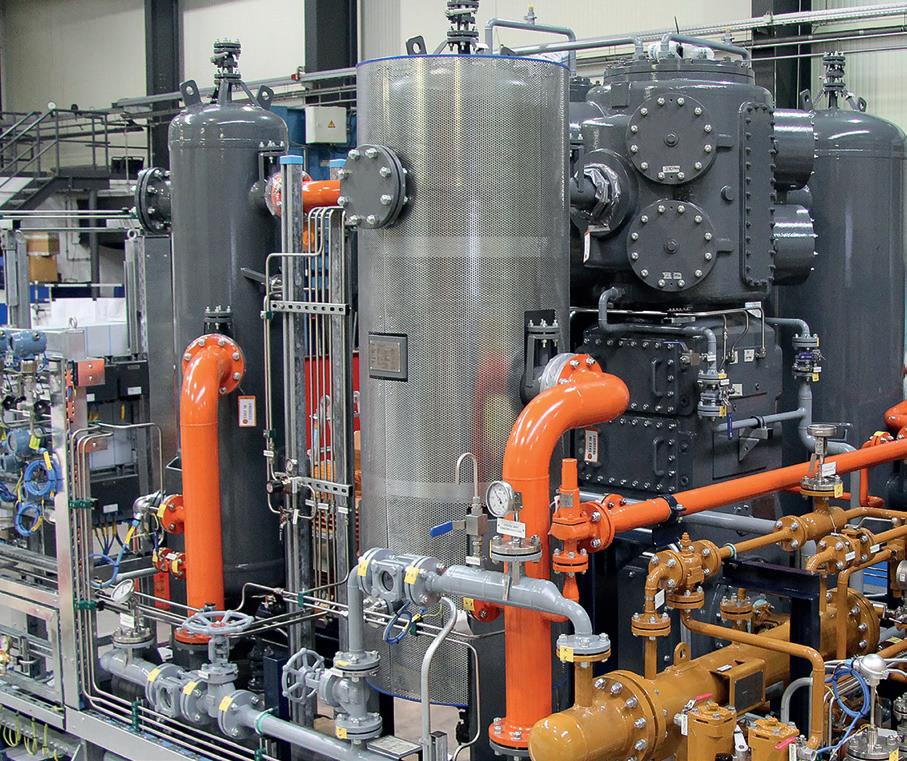
Gaseous hydrogen production
There is an increasing interest in using electrolysers to produce green hydrogen, at both large scale, centralised production applications and small scale, decentralised applications. Electrolysers split water into hydrogen and oxygen using direct current (DC) power and water as inputs to an electrolytic cell stack. The product gaseous hydrogen discharge from the electrolyser typically exits at pressures ranging from atmospheric to as high as approximately 600 psi(g) (40 barg) where it can be liquefied or further compressed for storage or usage. The gaseous oxygen is typically vented to atmosphere.
Electrolyser systems are typically installed indoors in a building or within a stand-alone enclosure. Outside of the electrolyser building, the electrolyser system includes balance of stack and balance of plant systems such as rectifiers, separators, water treatment equipment, pumps, piping, control rooms, and other supporting equipment. Hydrogen systems should be analysed using hazard and risk analysis processes. However, electrolysers pose specific risks with the potential for explosive mixtures to occur. All hydrogen system enclosures should provide proper ventilation and be designed to maintain hydrogen in air mixtures below 1% by volume.5 Additional considerations for the system include proper hydrogen venting, nitrogen purging, electrical equipment classification, proper leak/flame detection, combustion event arrestor design considerations, automated shutdown systems, and more.
Electrolysers present increased explosion risk due to the presence of both hydrogen and oxygen in high concentrations with co-located electrical systems that could be an ignition source. Continuous monitoring of crossover via electrochemical degradation is imperative to preventing an explosion risk. For example, electrochemical degradation of the membrane structure can be monitored through voltage and current abnormalities. Operators should work closely with electrolyser OEMs to understand the specific risk associated with their design. Typically, additional compression is required for most gaseous storage applications, and can go upwards of 14 500 psig (1000 barg). Compatible materials for compressor equipment, piping, valving, and instrumentation should be used. Routine maintenance and inspection of compressor components should be performed to ensure the equipment is in a safe working condition and is not in need of repair or replacement. Hydrogen discharged from pressure relief devices and other hydrogen vents, or hydrogen vented during startup or shutdown should be discharged to a vent/flare stack that is routed to a safe location. Because hydrogen gas temperature rises as it is compressed, interstage-coolers should be provided to maintain hydrogen temperature within the design temperature limit of the compressor system components. Design consideration should be given to any potential cross-leakage of high-pressure hydrogen to cooling systems from the compressor and other hydrogen equipment.
Hydrogen storage
Many hydrogen applications also require storage. Depending on the operation of the electrolyser and end use, storage can range from short-duration buffering to long-duration
Figure 1. Combined cycle power plant.

bulk storage, with hours to weeks of hydrogen stored. Hydrogen is also being evaluated to provide seasonal and long-duration energy storage for certain applications. Hydrogen storage should always be located outside if possible to mitigate risks associated with a leak. While alternative storage methods exist (e.g., metal hydride, geophysical storage, liquefied hydrogen, liquid organic hydrogen carriers, etc.), high-pressure gaseous hydrogen storage is typically the most common method for short term, low-quantity applications. Hydrogen compression and storage is typically included in project design to ensure enough hydrogen is available for use. Finite element analysis should be conducted by the storage equipment manufacturer with input from the project team on pressure cycle duration, frequency, and amplitude to better ensure safe operation for the life of the project. While typically hydrogen systems in buildings should be avoided, if compressors are installed indoors or inside enclosures, these areas should be properly ventilated. If compressors are located outdoors under a canopy or another form of weather protection, the covering should be properly sloped to avoid accumulation of hydrogen. Compressor equipment should be equipped with leak and flame detection that is integrated into the plant control system.
A hydrogen leak from storage poses a safety hazard because hydrogen is frequently stored at high pressures and in quantities that present the risk for a sustained release and creation of a hazardous environment. Pressurised hydrogen leaking from storage or downstream piping and components diffuses rapidly and turbulently and can easily ignite, resulting in a jet fire. Hydrogen jet fires are not visible in daylight and have low radiant heat, so may impinge on personnel, equipment, or other exposures initially undetected. Large, unignited releases can form a hydrogen plume which can later ignite, producing a deflagration or detonation. The fire and resulting pressure wave from the deflagration or detonation can cause harm to personnel, equipment, or other exposures.
NFPA 2 has developed guidelines for separation of gaseous hydrogen storage from different types of exposures. Exposures include people, equipment, property, and property characteristics. Gaseous hydrogen storage is classified as non-bulk storage when the quantity of hydrogen stored is less than 5000 ft3, and bulk storage when greater than or equal to 5000 ft3 6 NFPA 2 also considers whether the hydrogen is located indoors or outdoors.
In NFPA 2, bulk storage exposures are organised as Group 1 through 3 exposures, with separation distances applied to each group. These distances were developed by determining the distance at which the maximum allowable radiant heat flux criteria for the exposure group was met for an ignited hydrogen jet, along with other criteria. Pressure and the diameter of piping upstream of the source valve are considered as these parameters impact the size of the hydrogen jet in a leak scenario. Separation distances can be reduced for certain exposures by placing a barrier between the storage and the exposure.
While NFPA 2 is an important resource in hydrogen system design, it is not all encompassing, and siting of hydrogen storage should also consider best practices, and other requirements as prescribed in local codes and standards and/or by the local authority having jurisdiction (AHJ). Some examples of engineering best practices and other safety considerations include:
y During operation of the storage system, there will be pressure cycling when loading and unloading the hydrogen. Pressure cycling can lead to premature fatigue and failure of the
hydrogen storage, depending on the design of the storage. Storage vessel OEMs typically have identified the number of pressure cycles their storage vessels can withstand prior to failure through a finite element analysis. The project should understand the pressure cycle duration, frequency, and amplitude based on the intended operation of the system to ensure storage vessels purchased will meet the design life of the project.
y Hydrogen piping systems are typically required by code to undergo pressure and leak testing prior to being placed in service.7 Hydrostatic testing will not identify small leaks that could be penetrated by a hydrogen molecule, so pneumatic testing with helium, a helium/inert gas blend, or a hydrogen/inert gas blend should be considered to ensure the system is leak tight prior to placing in service.
y The use of welded connections is preferred to minimise potential for hydrogen leaks; however, welding does introduce heat which could lead to hydrogen embrittlement, so good welding practices should be followed, and welds should be tested for hardness. Post weld heat treatment may be required to reduce hardness. Note that additional considerations are required when welding different materials together such as stainless steel to carbon steel. The use of flanges or other connections should be minimised, when possible.
y Fixed hydrogen leak and flame detectors should be installed in multiple locations at project sites for monitoring hydrogen containing equipment. These instruments should be integrated into the plant controls which should activate audible/visible alarms and trigger a safe shutdown upon detection.
y Projects can conduct their own loss of containment modelling and analysis using computational fluid dynamics software or quantitative risk analysis to understand potential consequences for fires and explosions based on site specific criteria. The results of this modelling and/or project specific hazard and risk analyses, could inform the need for additional separation of hydrogen storage from exposures. Education and training of key stakeholders in the project, including neighbouring communities is of the upmost importance for a safe and successful project.
With renewed interest in using hydrogen for decarbonisation in varying applications, and as hydrogen market sectors continue to evolve, the need continues for ongoing development of codes, standards, and engineering best practices that incorporate lessons learned to ensure safe hydrogen use, regardless of the hydrogen production pathway.
References
1. NFPA 497, Recommended Practice for the Classification of Flammable Liquids, Gases, or Vapors and of Hazardous (Classified) Locations for Electrical Installations in Chemical Process Areas, National Fire Protection Agency.
2. API 500, Classification of Locations for Electrical Installations at Petroleum Facilities Classified as Class I, Division 1, and Division 2, American Petroleum Institute.
3. ASME B31.12-2019, Hydrogen Piping and Pipelines, Nonmandatory Appendix A – Precautionary Considerations
4. API RP 941, Steels for Hydrogen Service at Elevated Temperatures and Pressures in Petroleum Refineries and Petrochemical Plants
5. Ventilation, Hydrogen Tools: https://h2tools.org/bestpractices/ ventilation
6. NFPA 2- 2020, Hydrogen Technologies Code, National Fire Protection Association.
7. CGA G-5.4, Standard for Hydrogen Piping Systems at User Locations, Compressed Gas Association.
Laura Chemler, Emerson, USA, evaluates hydrogen storage methods and examines current and developing measurement instrumentation technologies for buffer storage within the hydrogen value chain.
The Industrial Revolution forever changed the world’s relationship with power generation, and innovators have been inventing, incorporating, and optimising new methods of energy production ever since. As energy sources have evolved, new ways of moving that energy to where it is needed most have been developed. Hydrogen as an energy source is no different as the world works to determine the best ways to get this valuable element where and when it is needed (Figure 1).
Hydrogen is used for:
� Temporary energy storage to help normalise intermittent power supplies, like solar and wind.
� Feedstock for chemical processes like ammonia synthesis.
� Fuel for use in fork trucks, cars, and trucks through fuel cells or combustion engines.
� Blended into natural gas lines to reduce the overall carbon dioxide emissions of natural gas combustion.

Unless production and consumption are located within the same facility, some type of hydrogen storage solution is needed. Fortunately, there are a variety of solutions developing for hydrogen storage.
Balancing production and consumption
Wind and solar are important energy generation innovations, but their intermittency remains a significant limitation. Energy buffer storage solutions, like batteries and hydrogen, offer a path forward where excess generated power can be stored for use during low power generation times. This normalises the power supplied from these sources, helping intermittent sources mimic base load power generation.
Using hydrogen to provide base load power supply is important for the electrical distribution grid, but it is also important to maintain a consistent supply for chemical processes, like ammonia synthesis, that have low plant-turndown ratios. These chemical processes are best
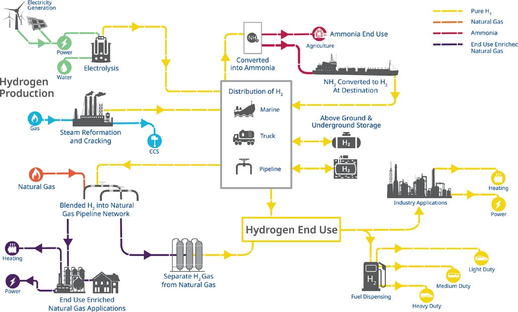
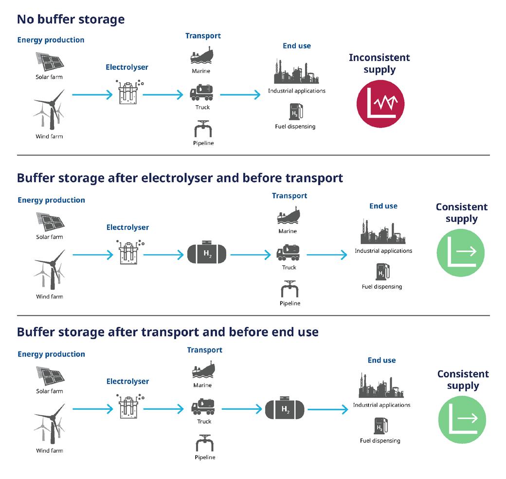
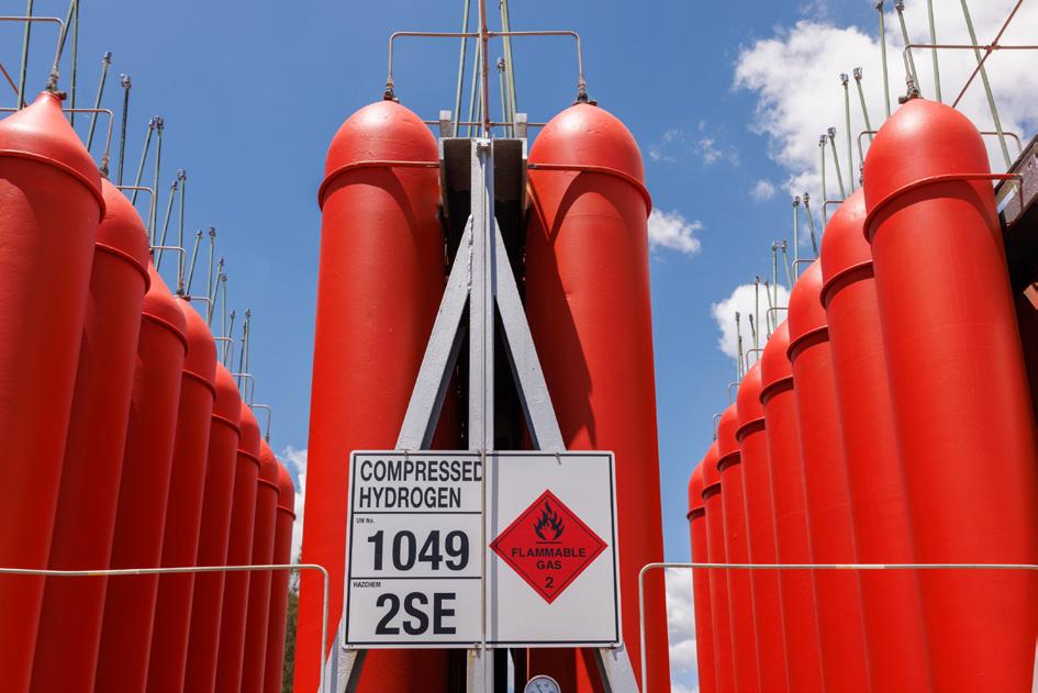
when they are running 24/7 at a consistent production rate, with the most complicated and dangerous parts of production being startup and shutdown.
When constant and consistent hydrogen production is needed but is not possible, a mechanism of some kind needs to be added to create consistency (Figure 2). One option adds storage via batteries to the energy source powering the electrolyser so it can run continuously and stabilise hydrogen production. Another option adds hydrogen buffer storage after the electrolyser to stabilise hydrogen distribution when production has paused due to a power interruption. Hydrogen can be pulled from the storage reserves for a consistent supply until power resumes.
Hydrogen buffer storage after the electrolyser is flexible in terms of where the hydrogen is being stored: at the production end of the transport system, at the off-taker end, or within the transport system itself. This article will focus on the storage aspect of the hydrogen distribution chain.
Storage concerns
There are various methods for storing hydrogen, either as a liquid or gas. Each poses challenges to conventional piping and vessel designs that differ from other industrial gases:
y Its small molecule size allows it to leak through the tiniest openings, making sealing of joints and valves critical.
y It causes embrittlement problems with many common metal alloys, shortening the service life of pipelines, while contributing to leaks and failures.
Extra attention must be paid to the materials used in the vessels, pipelines, joints, valves, and instruments used to contain and move hydrogen due to the risk of hydrogen permeation and embrittlement. Hydrogen permeation is when the hydrogen molecule is able to diffuse through the lattice structure of its containment material. This effect increases at higher pressures and with materials that have an open lattice structure.
Materials with tight lattice structures are more resistant to permeation. Appropriate choices include materials like gold, certain types of ceramics, composite materials, and austenitic stainless steels with a high nickel content, including Hastelloy and XM-19. End users should always consult equipment manufacturers for hydrogen compatibility as proper selection of these materials of construction is critical.
Hydrogen permeation should be prevented wherever possible because it can damage instruments and equipment that controls a process or provides containment. Where permeation takes place, it leads to safety concerns from larger and more expensive leaks. Wherever hydrogen is stored or processed, leak detection equipment must be installed.
That said, many of the basic concepts learned with natural gas transmission and storage apply to hydrogen.
Compressed hydrogen
The most versatile method of storage in low volumes is compressed hydrogen since the size range of available tanks varies widely, and they can be mobile or stationary as necessary for the applications.
Type II, type III, and type IV cylinders (Figure 3) are the most common, with the rating indicating their construction and maximum pressure rating, thereby determining hydrogen capacity.
Figure 1. The overall hydrogen production and distribution system is complex due its range of sources and uses.
Figure 2. Incorporating buffer storage into the value chain smooths out the peaks and valleys of green hydrogen production, enabling consistent hydrogen supply.
Figure 3.Tube tanks use heavy-walled pipe capable of withstanding high hydrogen pressures.
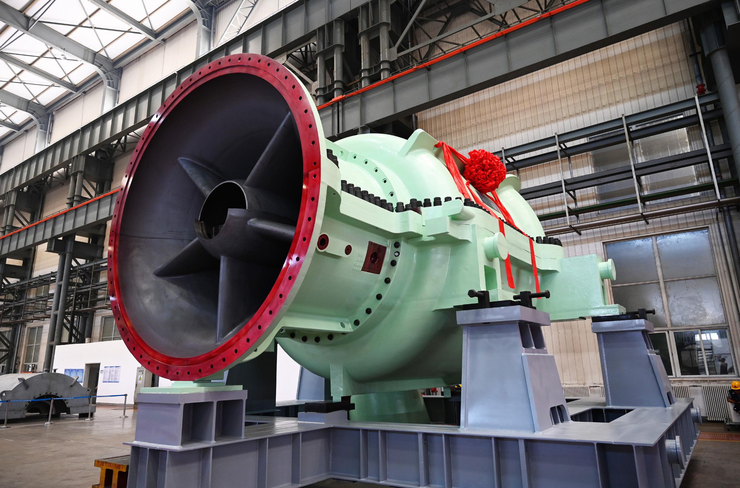


Increased pressures are achieved through different types of liners used within the cylinder, and with fibreglass reinforcements applied to the outside.
Tube trailers have an array of long cylinders stacked in a rack with interconnections. Depending on the type of cylinder, these handle pressures between 180 bar to 750 bar, or higher. Mobile storage can be managed as a tube trailer that can be filled, then moved, without having to build dedicated onsite storage.
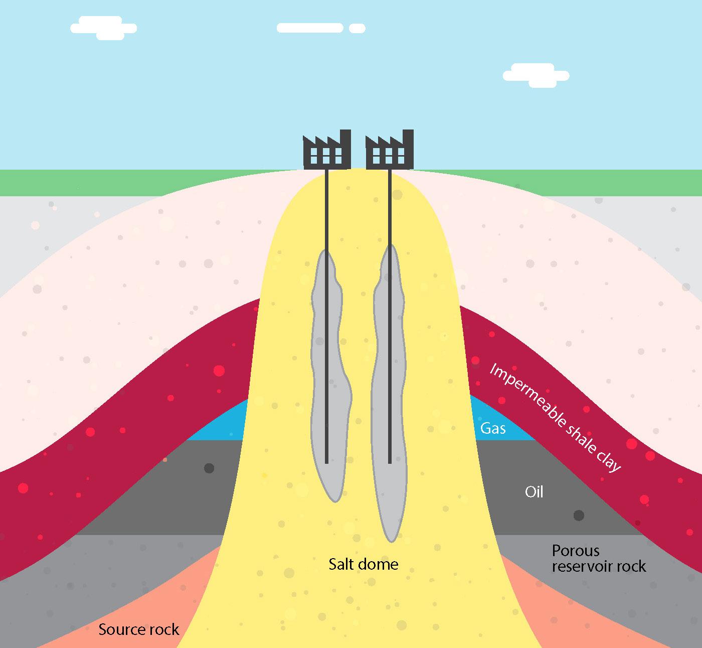
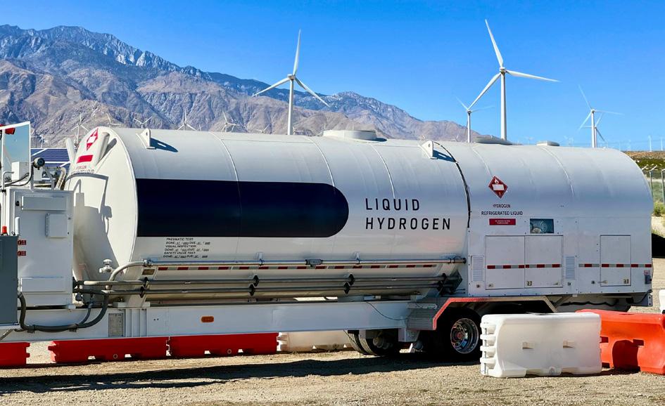
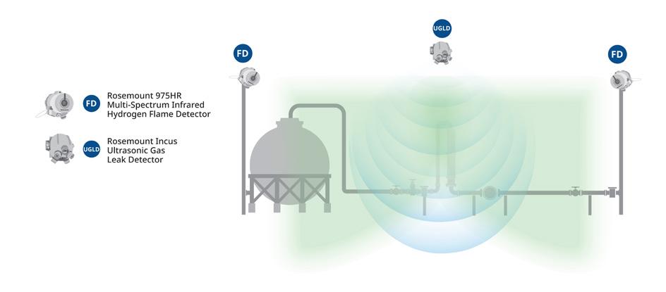
However, tube trailers have relatively low-pressure limitations due to transportation regulations. If the tube trailer is stationary and being used for permanent buffer storage, it may be possible to employ higher pressures to increase energy density.
Consequently, compressed hydrogen is the most straightforward and flexible way to move and store hydrogen since it is easy to add temporary capacity with mobile tube trailers. Leak mitigation and safety procedures should always be a part of hydrogen operations, but these are especially important with compressed hydrogen as the high pressures bring an elevated risk of hydrogen leaks and fires.
Pipeline storage
Labs around the world are researching the impacts of using existing natural gas pipelines for hydrogen distribution and what limitations may be necessary. In the meantime, natural gas concepts can be deployed for use in purpose-built hydrogen pipelines, specifically with line packing.
Line packing is used in natural gas distribution systems to meet projected demand spikes, and the same technique can be used for hydrogen. During times of excess production, the line can be packed with hydrogen to the pressure limit. This increases the mass of hydrogen in the pipeline, so long as the injection rate exceeds the withdrawal rate. When hydrogen production slows, users can continue to withdraw hydrogen from the pipeline without interruption, gradually lowering pipeline pressure. Care must be taken to ensure pipeline maximums and minimums are maintained, and the pipeline needs to be appropriately sized to enable this capability.
The main limitation to line packing is the availability of suitable pipelines. Over 4600 km of dedicated hydrogen pipelines already exist with more planned for the coming years, although access is often limited due to proximity and existing agreements.
Salt caverns
There are many layers of the Earth’s crust, and one of them is salt. This salt layer can push up through the younger sediment layers, creating a salt dome (Figure 4). These formations are impermeable and self-healing, making them suitable for storing gases, and they have been safely used for this purpose since the 1970s. Salt domes are geographic features and must be found, not created, but there are extensive salt dome formations around the world, especially in Northern Europe and North America’s Gulf Coast.
Depending on its size, a salt dome can host numerous salt caverns. A salt cavern is a long vertical void, and these have been used to store natural gas, oil, compressed air, and carbon dioxide – and now hydrogen. Each salt cavern is unique and may be a byproduct of hydraulic salt mining, or purpose-built for storage. If conditions in the salt dome allow, a salt cavern can store large amounts of energy. Caverns that begin deep underground can support high pressures with a greater energy density.
Considering that each salt dome can host multiple caverns, these geographic features have immense hydrogen storage potential. This puts salt caverns in the realm of regional hydrogen reservoirs rather than local bulk storage.
Liquified hydrogen
Liquifying hydrogen (Figure 5) provides the greatest energy density but presents a variety of challenges to ensure safety. It must be cooled to below -259°C, far lower than propane (-42°C),
Figure 4. Salt domes can contain multiple salt caverns, providing a significant hydrogen storage opportunity.
Figure 5. Liquifying hydrogen provides the highest energy density, but it is a costly process.
Figure 6. Where there are clusters of equipment, such as storage and transfer sites, it is critical to watch for leaks and fires.
INDUSTRIAL EMITTERS
Your roadmap to Low Carbon H2
HYDROGENATION DEHYDROGENATION STEAM REFORMER
and even LNG (-162°C). This requires a significant amount of energy, along with exceptionally well insulated storage vessels. However, once liquified, hydrogen becomes easier to handle.
The equipment necessary to liquify hydrogen is complex and expensive, making this method better suited for large installations, such as export facilities where tanker ships and trucks can be filled. The high energy density provided by liquified hydrogen makes the bulk transit on tanker ships more efficient than any other overwater method. Liquified hydrogen storage tanks are near atmospheric pressure and allow some degree of boil-off to avoid over-pressurisation. This loss is expected and calculated in shipping procedures.
Hydrogen carriers and ammonia
Hydrogen does not need to stay hydrogen from production to consumption. Hydrogen can be temporarily turned into a hydrogen carrier or hydrogen hydride to facilitate easier transport and storage.
There are a few options, but ammonia is the most common, with 60% of the global hydrogen supply being converted into ammonia according to the International Energy Agency’s (IEA) 2023
pressures and extreme temperatures. Each use case is different, and factors such as distance and duration are two important considerations in the equation.
Hydrogen safety
There is a reason hydrogen safety comes up regularly. Hydrogen leaks pose a serious hazard to safety and to operations. When released from high pressures through a leak point, hydrogen can catch fire and cause a chain reaction. Proper material and equipment selection, maintenance, and continuous monitoring are essential anywhere hydrogen is processed, moved, or stored.
Hydrogen fires are invisible to the human eye, but specialised hydrogen measurement instrumentation can be used to detect these types of fires, and other types of sensors can detect high-pressure hydrogen leaks (Figure 6), making it practical to monitor an entire operation from anywhere.
Partners for storage
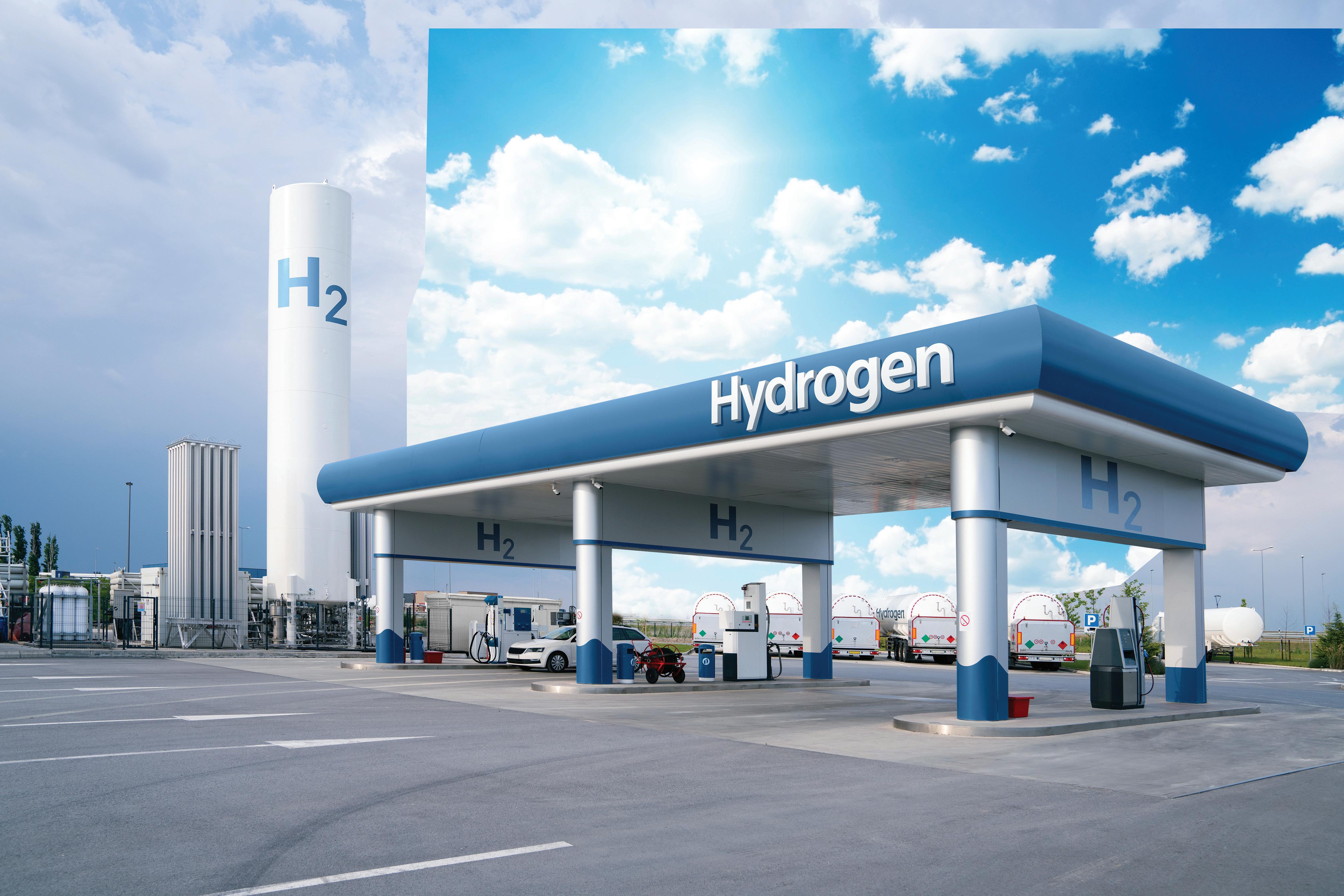
The growing importance of hydrogen as an energy storage mechanism is driving the need for more storage in more places. Techniques depending on brute compression may be reaching the limits of materials, but other options are adding flexibility and improved capabilities for increasing energy density. Just as hydrogen infrastructure is calling for new strategies and hardware, those providing it must also develop new expertise and the know-how needed for this evolving industry.
Companies wanting to create hydrogen infrastructure find that reliable experts and partners are critical to success.

Refueling Stations
Maximum performance in minimum space


Matthias Rudloff and Ines Bilas, AMBARtec, Germany, consider potential solutions to the challenges presented by hydrogen storage and transportation, and discuss the use of cyclic reduction of iron oxide as a storage medium.
The efficient storage of electrical energy is a key requirement worldwide for the successful transition of the global economy to renewable energy. Battery electric systems offer an acceptable solution for a few hours. However, space requirements and costs are very high, so gaseous storage solutions are being discussed for larger amounts of energy.
Hydrogen (H2) is the key. It can absorb fluctuations and, like a buffer, ensure a demand-based energy supply. However, hydrogen is not easy to transport. The hydrogen storing process using iron oxide is an already tried-and-tested process that can overcome many of these hurdles.
H2 storage and transport
H2 is currently primarily stored in two ways: by means of pressurised H2 in compressed gas cylinders, and in tanks or in underground caverns.
H2 under pressure is not only space-consuming, it is also a hazardous material. Extensive safety measures are required, and permitting procedures are extensive, time-consuming and costly. The safety aspect will also have a negative impact on public acceptance. Conversion losses from electricity to hydrogen to electricity are also so large that only a third of the original electrical energy is ultimately available for use.
Caverns are certainly a suitable option for the long-term storage of large quantities of H2, however, their low availability and the need to install separate H2 grid connections for users and producers limits widespread applications.
The unsolved H2 transport challenge
Transporting pressurised hydrogen in tanks is costly, risky and inefficient. The same applies to liquefied H2, where the energy balance is further worsened by the necessary cooling to -253°C and boil-off losses. In both cases, infrastructure must be adapted accordingly, resulting in lengthy permitting procedures, high investment costs and construction delays.
Liquid organic H2 carriers (LOHCs) can be transported using existing infrastructure, have a high energy density, and are not dangerous. However, disadvantages include the complex conversion to H2, the use of non-sustainable materials, and their unsatisfactory efficiency.
Transporting hydrogen derivatives such as ammonia and methanol is always the best option if they are ultimately used as a material. Converting them back to H2, on the other hand, makes less sense. The additional energy conversion losses and the extensive, costly safety measures and authorisation procedures required are just some of the disadvantages of this. In the case of ammonia, there is also the residual risk due to its toxicity.
The limits of an H2 grid
Many countries are planning to set up a hydrogen distribution network – in some cases using existing infrastructure. However, it will still take a lot of time and money before these networks are available. In addition, not all hydrogen consumers can be connected, at least for the foreseeable future. There are also limits to the construction and operation of hydrogen networks, both in
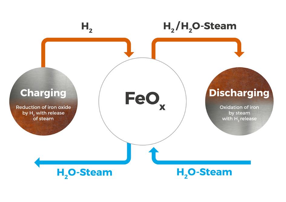

terms of geographical coverage and topography, and in terms of cost-effectiveness.
What about the alternatives?
In response to these challenges, companies and scientific institutions around the world are addressing this issue. On one hand, work is ongoing to optimise existing solutions, particularly in terms of efficiency and costs, and on the other hand, the process of developing alternative solutions has also begun. One approach is adsorption storage, where the H2 is physically bound to the surface of highly porous storage materials, such as metal-organic frameworks (MOFs). Another is metal hydride storage, where the H2 molecules are stored in the metal lattice. Although the metal lattice has a good volumetric storage capacity, it is expensive and heavy. The use is therefore currently limited to special applications, such as in submarines.
One solution that has already been proven on an industrial scale for approximately two years is the use of iron oxide as a storage material.
H2 storage and transport with iron
The method described here is based on the cyclic reduction of iron oxide as a storage medium by H2 and the oxidation of the iron by water vapour, which again releases H2 from the storage component (Figure 1). The proprietary storage material consists of a specially designed iron oxide (Figure 2) and possesses the unique properties of being easily reducible and oxidisable, while also exhibiting the high thermal stability necessary for long-term usage. The released H2 can then be used directly, or it can be converted into electrical energy in a fuel cell, internal combustion engine (ICE) or gas turbine.
During the H2 storage process, H2 can be stored at low-pressure (0.5 bar), but released at high-pressure (up to 100 bar), and is fully compatible with any H2 production unit. Fluctuating production rates (depending on wind speed or solar irradiation) are of no concern as the storage process can adapt to changing H2 flows within wide ranges. Additionally, the storage process is not affected by residual water contents or gas impurities from H2 production, eliminating the need for upstream gas treatment stages – particularly humidity from electrolysis or carbon monoxide (CO)/or hydrocarbons remaining from grey or turquoise H2 production, which is critical for other H2 storage technologies (e. g. pressurised or liquified storage).
Sustainable, safe, efficient
This technology offers several advantages when compared to other hydrogen storage technologies. It promises a significantly reduced footprint, typically by a factor of 2 to 5, while simultaneously doubling the ‘electricity-to-electricity’ efficiency in the entire chain of renewable power generation: H2 production, to H2 storage, to re-electrification. Furthermore, it can lead to cost savings of up to 30% in the process of H2 production. Notably, during the storage loading phase, the water required for electrolysis is efficiently reclaimed. This feature is particularly beneficial for H2 production in regions with abundant sunshine, but limited water resources. Since no H2 can escape from the storage systems, they are non-hazardous goods and can be easily transported, even over long distances, by normal means of transport. Due to the minimal hazard potential, permits can usually be issued easily and quickly.
Figure 1. The loading and unloading of H2 storage.
Figure 2. Iron oxide nuggets for the H2 storage © BLEND3 Frank Graetz.
We understand how you need to reduce complexities at your plant.
CLEAN PROCESS + CLEAR
You strengthen your plant’s safety, productivity and availability with innovations and resources.

Endress+Hauser helps you to improve your processes:
• With the largest portfolio of safety instruments that comply with international regulations
• With applied technologies and people who have extensive industry application know-how
• With access to accurate and traceable information
Do you want to learn more?
www.endress.com/oil-gas
The main advantages of this technology include:
y Energy can be stored for safely for a long period of time.
y No additional safety measures are required.
y Standard transport logistic and existing infrastructure is used.
y Transport over long distances is possible.
y It is more compact, efficient, and economical than conventional methods.
y 50% less space is required for H2 storage (Figure 3).
y 90% less water is required for H2 production during storage charging.
y There is 100% higher efficiency in long-term electricity storage.
y It uses market-available, cost-effective, and sustainable materials.
y The permitting procedures are easier.
y Quick loading/unloading is possible.
y High cycle stability can be achieved.
Potential uses
Due to these advantages, storage systems are very well-suited for storing excess renewable energy, transporting H2 over long distances, optimising the load management and energy availability for hydrogen plants and power-to-power systems, as well as ensuring a secure supply of hydrogen for hydrogen-powered ships and hydrogen-fuelled industrial burners. Comparative analyses conducted in collaboration with
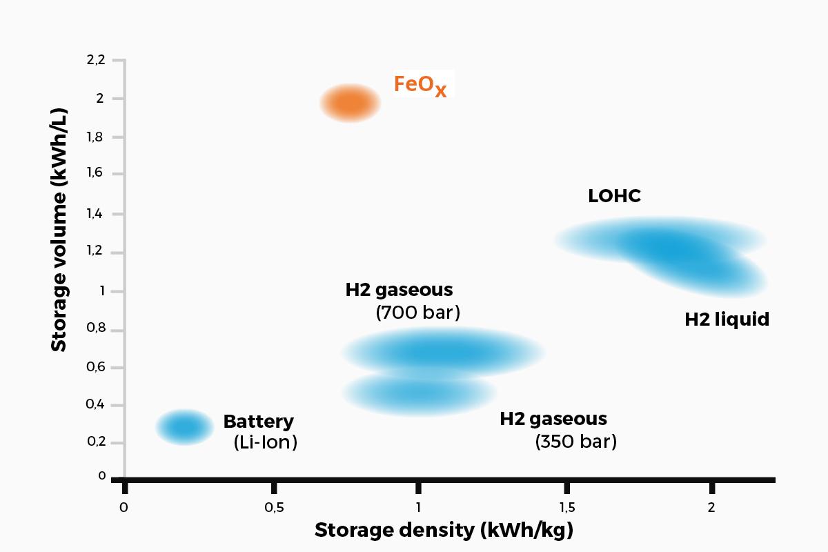
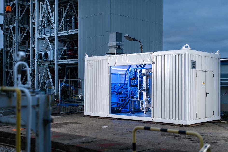
a partner in large-scale plant construction have revealed that the technology provides advantages for the short-term storage of H2 in Power-to-Liquid (PtL) projects and the production of methanol or synthetic fuels.
H2 transportation from centralised or decentralised producers to decentralised consumers
With this technology, energy can be supplied from wind farms and solar plants to, for example, a medium-sized company to be used in its manufacturing processes. The modular transport units can be used without major technical adjustments to the connected systems.
H2 transportation over long distances
The storage systems can be transported by trucks, ships and rail, e. g. from solar power plants in the desert to Europe.
Decentralised energy storage for energy producers and enterprises
By optimally integrating the storage unit with a solid oxide electrolyser cell (SOEC), as well as with a solid oxide fuel cell (SOFC), the technology can achieve significantly higher efficiencies. This is made possible by recycling heat from the charging process into the electrolysis process and effectively increasing the efficiency of electrolysis by up to 90%, and also by using the hot exhaust gas from the fuel cell for discharging the storage tank.
Hydrogen engines for ships
The storage systems could provide hydrogen continuously on demand. Thanks to its high density, ease of handling and the fact that they are non-hazardous goods, they can be easily accommodated in the engine room of a ship.
Hydrogen supply for industrial burners
The storage systems can provide hydrogen continuously on demand – significantly reducing space requirements and risks compared to large hydrogen tanks.
Off-grid supply systems
With 100% self-sufficient energy generation on site and flexible H2 storage, sensitive military and civilian zones can be supplied with energy without risky tank farms and without the need for fuel logistics.
Ready to use
AMBARtec has successfully validated this type of technology with various storage tank sizes in practical tests lasting several months at its demonstration plant in Freiberg, near Dresden, Germany (Figure 4). The certifier LRQA has confirmed the testing via ‘approval in principle’. A container with several 1000 litre storage modules from AMBARtec has a capacity of 600 to 900 kg H2 (20 to 30 MWh). This means that 50 to 75% fewer transport units per lorry/ship are required for the same amount of H2, and the transport costs are correspondingly lower. As there is no need for extensive authorisation procedures and adjustments to the infrastructure, the storage systems can be integrated immediately into H2 projects and can therefore accelerate developments in the hydrogen economy.
Figure 3. A comparison of the storage density of H2 storage systems.
Figure 4. AMBARtec’s pilot plant. © BLEND3 Frank Graetz.

COMMITTED TO A BETTER FUTURE
Optimizing combustion for a greener tomorrow WE’RE
There has never been a greater need to decarbonize fired equipment, produce cleaner energy sources, and operate in a more environmentally responsible way.
Optimized combustion and enhanced predictive analytics are key to reducing plant emissions and ensuring equipment uptime. Designed for safety systems, our Thermox® WDG-V combustion analyzer leads the way, monitoring and controlling combustion with unparalleled precision.
Setting the industry standard for more than 50 years, AMETEK process analyzers are a solution you can rely on. Let’s decarbonize tomorrow together by ensuring tighter emission control, efficient operations, and enhanced process safety for a greener future.


Gareth Burton, ABS, and Per Roed, Provaris Energy, discuss how innovative compressed hydrogen carrier design can offer cost-competitive and efficient regional energy transport.
The energy transition is driving innovation across the maritime industry, as producers and consumers look to create opportunities from new value chains. The process comes with challenges too; novel concepts call for first-time approaches that require detailed development work and a strong focus on safety.
Europe’s hydrogen value chain is developing at pace; the challenge is connecting producers with off-takers which will consume the clean energy delivered at the required cost and energy density.
When Australian clean hydrogen project developer Provaris unveiled the concept design for a compressed hydrogen carrier, it selected ABS as technical partner to provide class approvals for a ship that will close a gap in Europe’s clean energy supply chain.
Technology choices
For Provaris, the advanced stage of its H2Neo ship design underpins its operating model, providing an alternative to liquefaction for the transportation of hydrogen or use of

ammonia as a hydrogen carrier. While designs for liquid hydrogen (LH2) and ammonia carriers have taken more of the headlines, the company has continued to develop shipping concepts based on compression technology and targets operations by 2028.
This has involved striking collaboration agreements between producers in the Nordic countries and attracting the interest of leading energy utilities in Germany, including Uniper. Germany, in particular, is a core market for hydrogen. The country currently imports 90% of its energy needs and demand for clean fuels could see imported hydrogen grow to reach 1.5 - 3 million tpy by 2030.
To create the new value chain, final class approval of the innovative vessel design is the next milestone. The choice of compression technology is grounded firstly in economics.
In contrast to the shipping of ammonia from which hydrogen can be extracted, transporting compressed hydrogen results in reduced loss of energy content of the delivered product by maintaining the hydrogen in a gaseous state. Though the economics shift in favour of ammonia carriers over longer
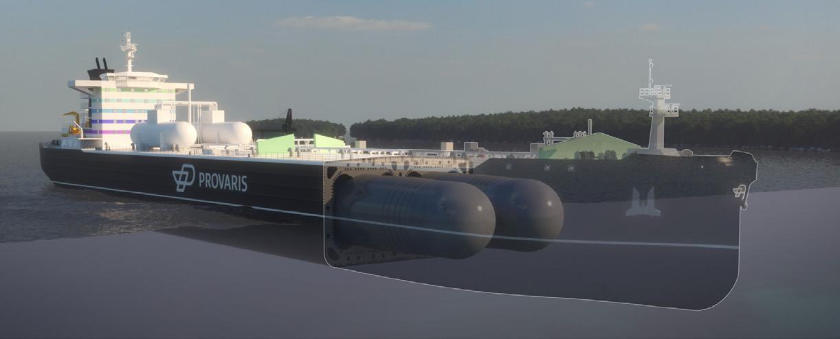
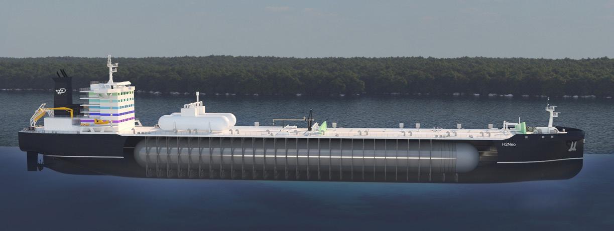
voyages, on a regional voyage basis compression requires lower capital outlay and delivers more energy to lower the overall cost of delivered hydrogen.
FEED level design approval
ABS awarded initial Approval in Principle (AiP) in 2021 for two classes of green compressed hydrogen (GH2) carriers, the H2Neo (26 000 m3) and the H2Max (120 000 m3 capacity). Provaris has taken the H2Neo through to construction-ready status and expects to issue an open tender to shipyards in 2025 for a vessel with delivery in 2027 - 2028.
The company spent 12 months completing an extensive FEED level design package for the H2Neo, a work programme which saw the granting of design approval in 2022, verifying the ship’s ability to transport compressed hydrogen at bulk scale at 250 bar pressure.
ABS’ affiliate, ABS Consulting, carried out risk and safety (HAZID) workshops and specialist studies concerning gas dispersion, explosion and fire analysis to help assess and mitigate the risks associated with the storage and transportation of hydrogen.
This was the first time that an extensive HAZID and FEED level design for a novel hydrogen carrier has been concluded. Provaris has continued to work with ABS through the subsequent phases of detailed production design, cargo tank testing and construction, with final class approval expected in due course.
Design innovation
At the heart of the vessel design is a proprietary multi-layered hydrogen storage tank which required extensive design and
structural assessment works for ship integration, as well as the creation of a digital twin for tank design and construction purposes. Optimisation through the development of a prototype tank will also focus on an automated robotic cell ready for a full scale production line.
Key to a safe and sustainable process was a focus on safe handling for the hydrogen cargo with extensive risk analysis and mitigation built into the project backbone. To achieve this, the tanks are constructed in layers of carbon steel that are fully welded, with an internal liner that has been tested in a high pressure hydrogen environment. A continuous monitoring system will be applied to verify the tank’s integrity. A single, fully welded header for loading and discharge is applied to limit the number of tank connections, and potential hydrogen leak points during cargo operations.
Provaris partnered with a Norwegian engineering firm to perform tank fabrication using robotic-laser welding to ensure precision and to eliminate a significant amount of associated labour cost. The robots are programmed for nanometer accuracy, verified through the prototype, delivering a very high quality of welding with proven fatigue life characteristics.
As with similar value chains for new fuels and cargo types, the approvals process depends on equivalency as no specific regulations covering compressed hydrogen exist at present. The process required using elements of the IGF and IGC Codes, as well as ABS’s own Guides for gas-carrying vessels.
Extension to barge storage solutions with AIP
Leveraging the FEED-level engineering, safety studies, and design approval for the H2Neo carrier received in December 2022, Provaris has launched the H2Leo compressed hydrogen floating storage solution, receiving AIP from ABS. The AIP allows for a flexible solution for specific industry applications with a design capacity range of 300 to 600 t of hydrogen. The future development and approvals include expanding the storage capacity from 100 to 2000 t of hydrogen storage.
The H2Leo is a flexible hydrogen floating storage unit that can be optimised in size, capacity, and operations for different applications. Its SIMOPs capability allows for continuous operations, and it has a large working deck and hull for installing auxiliary systems such as compression and H2 bunkering.
The company’s focus on using a novel design concept to build a completely new value chain has seen other energy interests investigate the potential of compression technology in shipping.
The cooperation between ABS and Provaris also demonstrates that progress can be achieved in the energy transition even when considering completely new approaches. The completion of the class approval process will enable Provaris to move forward with an initial vessel order that can take its place in the new value chain.
Figure 1. Provaris has taken the H2Neo through to construction-ready status and expects to issue an open tender to shipyards in 2025 for a vessel with delivery in 2027 - 2028.
Figure 2. At the heart of the design is a proprietary multi-layered hydrogen storage tank which required extensive design and structural assessment including creation of a digital twin.
Daniel Ballorca, Hiperbaric, Spain, presents a comparison between the production of compressed hydrogen and liquid hydrogen energy storage systems.


hydrogen, from the production point of view, as well as energy recovery. The maintenance cost of each production system is not assessed in this study as it requires a deep analysis on the state of the art of any system dedicated in each system line, and therefore their interconnectivity.
Compression process
Hydrogen compression is mainly achieved through volumetric reduction. From a certain amount of hydrogen mass, volume is reduced and then pressure and temperature increase following its state equation (1), that may not comply with the main ideal gas equation of state.
Although there are many different compression technologies 1, the most mature technology is the piston compressor, which is reliable and can be scaled to high production machines.
Although pressure rises, so does temperature, depending on the heat power evacuated during compression. Generally, compression is assessed between two bounds: isothermal and constant-entropy compression. When compared, the work applied on the constant-entropy is higher than that required to perform an isothermal compression. This is why isothermal compression is always desired but not always
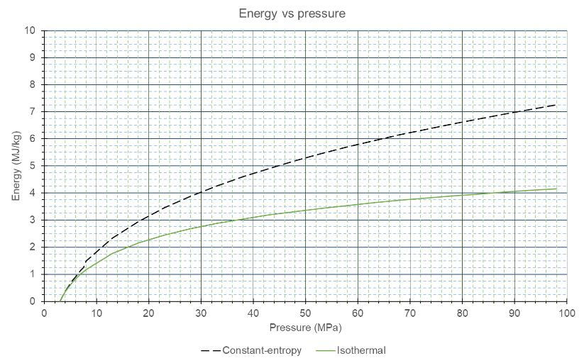
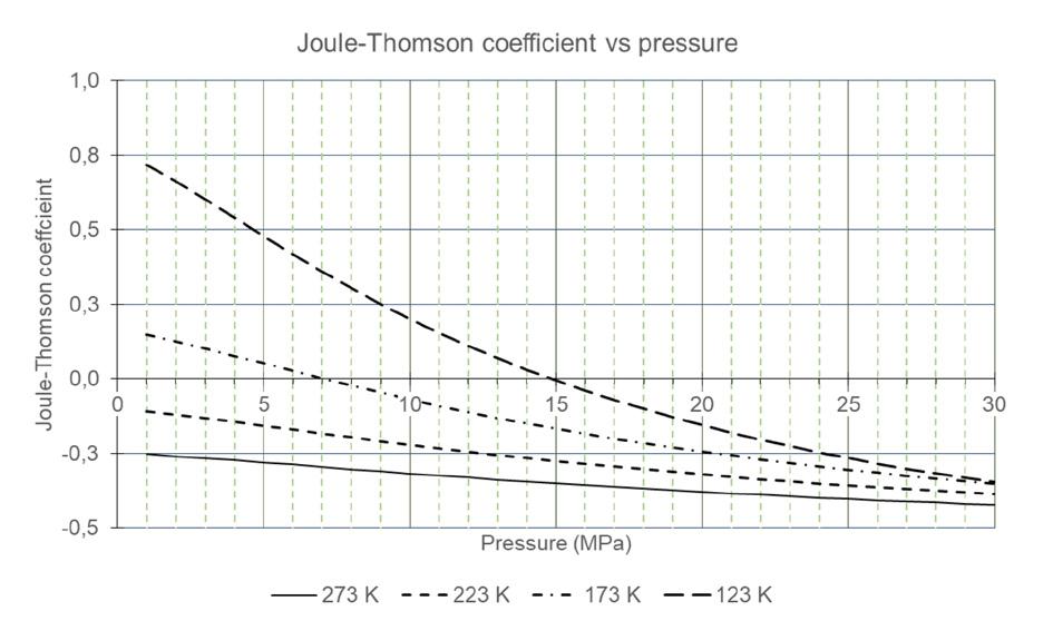
possible, because infinite thermal conductivity of hydrogen would be required, which is not viable as it is a function of state property of the fluid. Apart from the conductivity, other parameters that influence the thermal exchange process are the Nusselt number and the heat transfer coefficient which can be enhanced thanks to an adequate design of the compressor.
Figure 1 compares the energy as work required to compress hydrogen from 3 MPa to a range of pressure up to 95 MPa. When compressing from 3 MPa to 95 MPa, there is a difference of 3 MJ/kg between constant entropy and isothermal compression. Taking into account that isothermal compression requires almost 4.2 MJ/kg, constant-entropy compression requires 75% more work energy than isothermal compression.
In order to achieve a good isothermal efficiency, compression cylinder walls are cooled so that the physical boundaries of the compression region are kept at constant temperature. After each compression chamber, heat exchangers should be placed so that the final hydrogen temperature meets the application requirements.
The enthaply balance, when increasing hydrogen pressure from 3 MPa to 95 MPa, and 15˚ at outlet and inlet temperatures, is 0.65 MJ/kg. As work was 4.2 MJ/kg, the amount of heat that is extracted is 3.55 MJ/kg. With a coefficient of performance of 3.3, the total work applied on the process would be 5.3 MJ/kg. These values are kept as the minimum energy requirements for this process. For compression and for liquefection, the same value for the coefficient of performance is used.
Liquefaction process
In a simple liquefaction process, several compression and cooling stages expand the fluid so the fluid temperature decreases enough to separate between liquid and vapour phases. The fundamental relation that drives the temperature evolution through a valve is that, by means of a constant-enthalpy process, a coefficient is defined as follows:
μ JT is known as the Joule-Thomson coefficient, and describes the variation of temperature with pressure variation, when enthalpy remains constant. This coefficient, which is not constant and depends on the temperature and pressure – or the state of the gas – can be positive or negative. Only when it is positive does the expansion process decrease the fluid temperature. If it is negative, the expansion process increases the fluid temperature. In the case of hydrogen, only when temperature decreases below 200˚K, μ JT is positive, as is shown in Figure 2.
To help with the cooling stages previous to the final expansion, helium is used to reach the low temperature required. Together with the cooling stage, hydrogen has to be compressed, but not to the level described in the previous section.
A liquefaction process is designed, where hydrogen is first compressed from 3 to 7 MPa, then cooled to -230˚C and
p=f(ρ,T)
Figure 1. Energy applied per unit of hydrogen mass when compressing from 3 MPa to 95 MPa.
Figure 2. Joule-Thomson coefficient vs pressure, for various temperatures.
With our team of thought leaders specialized in emerging fuels, we serve as your capable partner in advancing your path through the energy transition. Four decades of experience in pipeline integrity management, own testing capabilities and a unique data pool are the basis for unparalleled integrity and risk assessments for the seamless integration of emerging fuels into your asset base. Choose ROSEN for the technology and competence needed to navigate the challenges of tomorrow’s energy landscape. hydrogen.rosen-group.com
Partners in De-risking the Energy Transition


then expanded down to 0.1 MPa. Following this sequence, the following results are obtained:
y Percentage of liquid: 25%.
y Minimum energy invested: 9.25 MJ/kg.
In order to decrease the hydrogen temperature, heat must be released to another heat sink. For example, three stages could be designed in which hydrogen releases heat to a carbon dioxide cooling loop, with a mean temperature of -40˚C. After this it can exchange heat with a nitrogen based heat loop, with a mean temperature of -170˚C, and finally with a helium based heat loop, that requires helium at a minimum of -230˚C. The cost of maintaining these heat exchanger loops is not considered as the target of this study – which is to calculate the minimum energy required for achieving the process – but this would imply perfect isolating walls of the piping lines and zero-emissions and losses among other parameters that may decrease the efficiency of the total process.
The process designed rejects the non-liquefied hydrogen resulted after expansion. If it was used in a feedback loop, efficiency could increase as more hydrogen would be liquefied, but also more energy would be required to compress the overcooled hydrogen again. In order to get the minimum invested energy, this study has considered that only 25% of the hydrogen is liquefied after the expansion process. Up to this moment, the energy required to sustain the first cooling stage and its efficiency has not been accounted for.
Comparison between processes
The minimum heat of combustion of hydrogen is 120 MJ/kg. Compared with this data, the energy invested in each
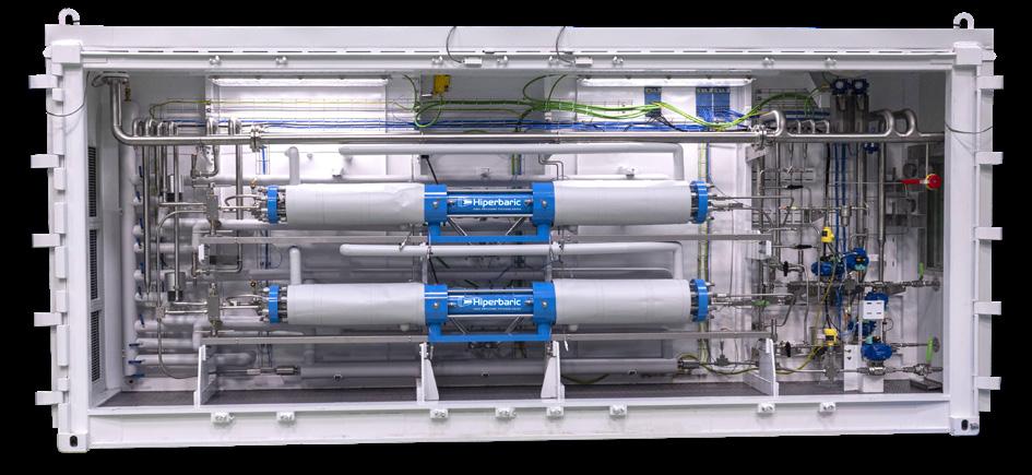
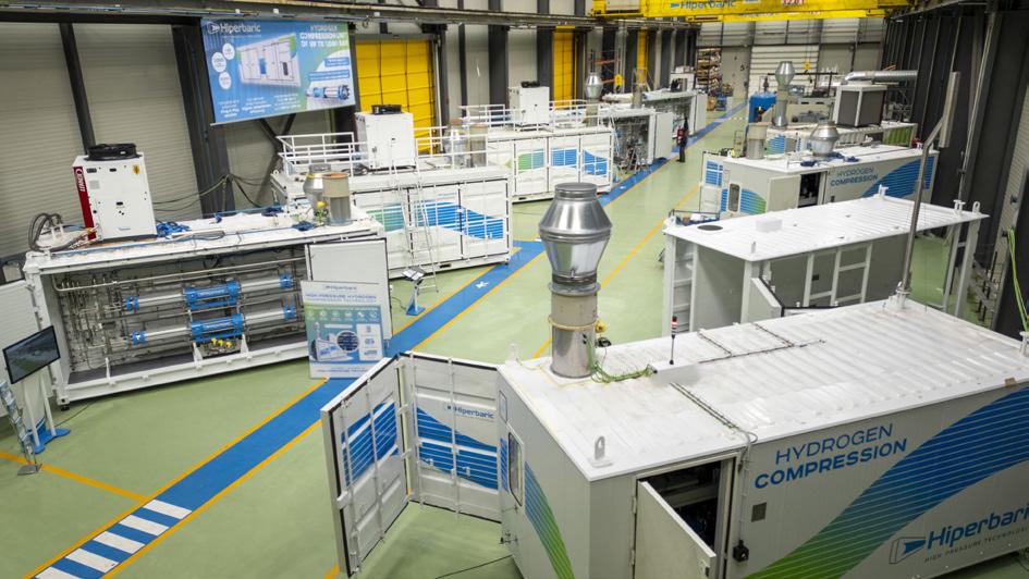
process is 4.45% (compression) and 7.71% (liquid) of the final disposable energy. These values should increase, as they are the theoretical minimum, while further research art could define more precisely the current efficiency that can now be achieved for each process.
Another interesting index could be the energy invested per unit of volume of the final product: α: density of hydrogen at 15˚C and 95 MPa at 49.85 kg/m3, while density of liquid hydrogen (-251˚C and 0.2 MPa) is 70.84 kg/m3
(3)
Then, α results 264.2 MJ/m3 for compressed hydrogen, while α results 636 MJ/m3. This result means that the energy cost per final volume of product is 1.4 times higher for liquid hydrogen than for compressed hydrogen.
It would be interesting to design a more complex liquefaction process in which the overcooled hydrogen is compressed again with incoming hydrogen and then with both currents expanded together. This would imply calculating the mixture of both currents and the cost of compressing the expanded, overcooled hydrogen up to the pressure of the incoming current.
Conclusion
A theoretical study has been performed to derive the minimum energy that may be necessary to produce both substances at different states: compressed hydrogen and liquid hydrogen. Efficiency in terms of energy cost per unit of energy and unit of volume has been compared, where the former has an efficiency of 4.45%, while the latter has a 7.71% of energy cost. This maximum efficiency is not reachable in practice, so it will always be higher. For the cost of liquefaction, it is important to note that maintenance costs are very high due to the losses of mass emissions, heat losses on the helium, nitrogen and carbon dioxide heat exchangers, and work losses on the fluid handling of these cooling loops. Only very large scale production facilities can currently provide a sustainable process for liquefaction. Finally, the cost per unit of volume, useful when designing hydrogen storage projects, suggests that liquid hydrogen is 1.4 times more costly than compressed hydrogen in terms of space.
Versatile technology that can be used in multiple applications and adapt to different suction and discharge pressures will be vital in the hydrogen industry. Hiperbaric aims to design safe, efficient, and reliable equipment, capable of compressing hydrogen with an inlet pressure range from 20 bar, to an outlet pressure up to 500 or 950 bar. This wide range of inlet and outlet pressures allows hydrogen to be positioned in the production stage and makes it possible for hydrogen to be fed directly from an electrolyser or a medium pressure storage tank (such as tube trailers at 200 bar).
Reference
1. SDANGHI, G., MARANZANA, G., CELZARD, A., and FIERRO, V., ‘Review of the current technologies and performances of hydrogen compression for stationary and automotive applications’, Renew. Sustain. Energy Rev., Vol. 102, pp. 150 - 170, (2019).
Figure 3. Plug and play compressor group.
Figure 4. Hiperbaric hydrogen compression factory.
Chris Goulet and Ben Williams, Ariel Corp., explain the value of reciprocating compressors for use in the evolving hydrogen economy and sustainable fuel refineries.

In the early 1990s, and again in the mid to late 2000s, reducing the sulfur content of diesel fuels and gasoline required a significant amount of hydrogen, and in turn, a significant amount of hydrogen compression. Today, as the goal of carbon neutrality moves forward, hydrogen and hydrogen compression are again in the spotlight. Hydrogen is considered a key component of the energy transition and will require compression for a variety of applications,
including hydrogen production and storage, green ammonia production and hydrogen fuelling, in addition to those hydrogen applications required for renewable and sustainable fuel refineries.
There are many different types of compressors currently operating in hydrogen service, including positive displacement (reciprocating, diaphragm, and rotary screw) and dynamic (centrifugal) types. The type of compressor
selected is dependent on a number of things, including the operating conditions and required throughput. The reciprocating compressor is the focus of this article. Reciprocating compressors used in hydrogen service can range from less than 25 hp (18 kW) to more than 15 000 hp (11 200kW). Since they can be engineered and tailored to a wide range of flow rates and compression ratios independent of gas density, reciprocating compressor technology presents an ideal fit for many of these hydrogen applications. Separable designs allow operators of these compressors to select highly configured equipment, while also fostering configuration changes in cylinder, valve, guide, and capacity control devices to suit each application appropriately through the life of the equipment.
Primary considerations in compressor selection are volumetric throughput, inlet, and discharge pressures. These factors will determine rated power and the number of units required. Secondary considerations will involve gas composition, required capacity control devices and monitoring equipment. The use of lubricated or unlubricated piston trim should also be considered. Where many refinery applications may use lubricated cylinders, often for hydrogen production via electrolysis and vehicle fuelling applications, non-lube cylinder technology must be used in accordance with strict gas purity standards, such as ISO 14687:2019 (Hydrogen Fuel Quality/Product Specification).
Another consideration for the compressor selection is the design specifications being used. Refineries and petrochemical applications typically follow API 618 or ISO 13707. These are purchasing specifications written with the goal of achieving three years of uninterrupted service. Whether that is required for today’s renewable hydrogen applications is up for debate, because much of the compressor requirements will depend on the availability of hydrogen or renewable power.
Reliability is paramount throughout all of these processes, with a premium on uninterrupted service for up to three years. A conservative approach is taken when designing and sizing equipment for hydrogen applications. Typical high-speed compressors are slowed to moderate ranges in accordance with API 618, to ranges between
600 and 1000 RPM, depending on the frame size of the unit. Reduced speed, coupled with lower lift valves, helps to reduce cyclic fatigue on valves, while lower lifts reduce impact velocities, aiding in extending service life. Reduced rotating speed also reduces piston speeds, minimising piston ring, wear band, and packing wear.
In addition to an extended service life, a conservative design approach will help to minimise maintenance costs. A rigorously applied and disciplined approach to thorough maintenance programmes is crucial to optimise the performance and longevity of reciprocating equipment.
Modern equipment monitoring technologies offer another degree for accurately controlling the operating conditions of the equipment to increase reliability and avoid catastrophic failures. Preventative, or predictive monitoring systems, and programmatic trending of operational data adds additional certainty to avoid more costly problems. Advanced monitoring systems can quickly identify vibration issues, valve leakage, any applicable lubrication issues, monitor bearing temperatures for anomalies, and track interstage pressures. Such systems may also help identify potential upset conditions through other areas of the process chain.
Reciprocating compression technology is not without its limitations. Low inlet pressures with high volume flow may require a blower in series to boost into the reciprocating compressor. Where this in series solution is not practical, a rotary screw may be a more appropriate fit at lower discharge pressures. Very high volumetric flows should also be considered. In high HP, high flow processes, dynamic centrifugal compressors may be a more appropriate fit for fixed inlet conditions with limited pressure ratios, and where design footprints are at a premium – though centrifugal solutions may be hampered by low mol weights.
Vibration is a key concern with reciprocating compressors. Packagers and front-end engineers of this equipment should plan on executing pulsation, mechanical, and torsional studies to ensure vibration of the equipment is minimised to increase service life and optimise operational safety. Detailed vibration standards and allowable limits may be found in API 618, 674 and 688. Mitigation techniques for acoustic vibration include, but are not limited to: properly sized pulsation vessels, orifice plates, and side branch absorbers. Meanwhile, dampers and crankshaft mass-detuners can minimise torsional/mechanical vibration excited by inherent system mechanical natural frequencies.
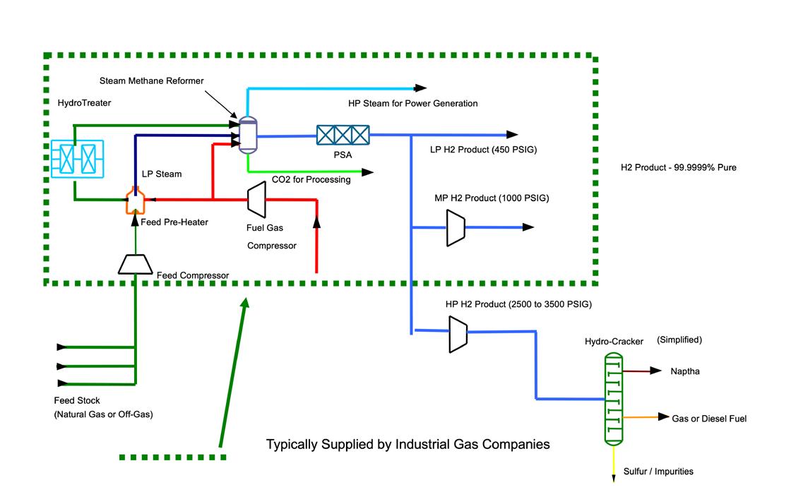
One of the primary advantages of reciprocating compressor equipment selection is the flexibility in operations. Where inlet flow volumes are relatively variable, reciprocating compressors can be optimised to flexibly operate at variable speeds. This can be accomplished through the mechanical flexibility of engine driven equipment, or, as is more common with these applications, with variable frequency drives when paired with an electric motor driver or capacity control devices installed on the compressor. Capacity control
Figure 1. Simplified steam methane reforming (SMR) process flow diagram.

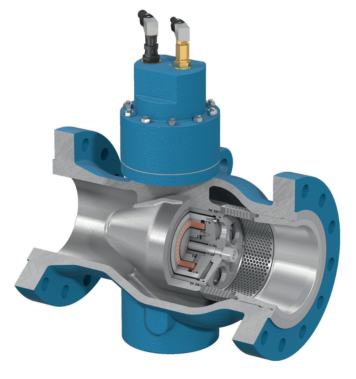
devices, such as variable volume clearance pockets (which can be manual, or programmable and electronically controlled), suction valve unloaders, and added fixed clearance are used to vary throughput.
Another significant advantage of a reciprocating compressor over other compressor technologies is the ability to operate with multiple services simultaneously. In a multi-service compressor, each service will have independent compressor cylinders, stages of compression,
piping, vessels, and coolers, as applicable. When determining whether a multi-service compressor is a possible option, operators should enquire whether the services are required to operate at the same time. An example of a multi-service compressor follows.
Case study: multi-service compressor used in hydrogen production
Currently, more than 94% of the hydrogen produced comes from reforming fossil fuels, primarily natural gas. This is through the steam methane reforming (SMR) process. In this process, natural gas reacts with high-temperature steam to produce hydrogen and carbon monoxide (CO). Subsequently, a shift conversion process of the CO and hydrogen forms hydrogen and carbon dioxide (CO2). A pressure swing adsorber (PSA) then removes any impurities in the hydrogen, resulting in a typical hydrogen purity level of 99.9999%. The hydrogen is then sent where it is needed, such as to a refinery, petrochemical facility, or to a pipeline. CO2 produced in the SMR process can also be used in other processes, such as methanol production.

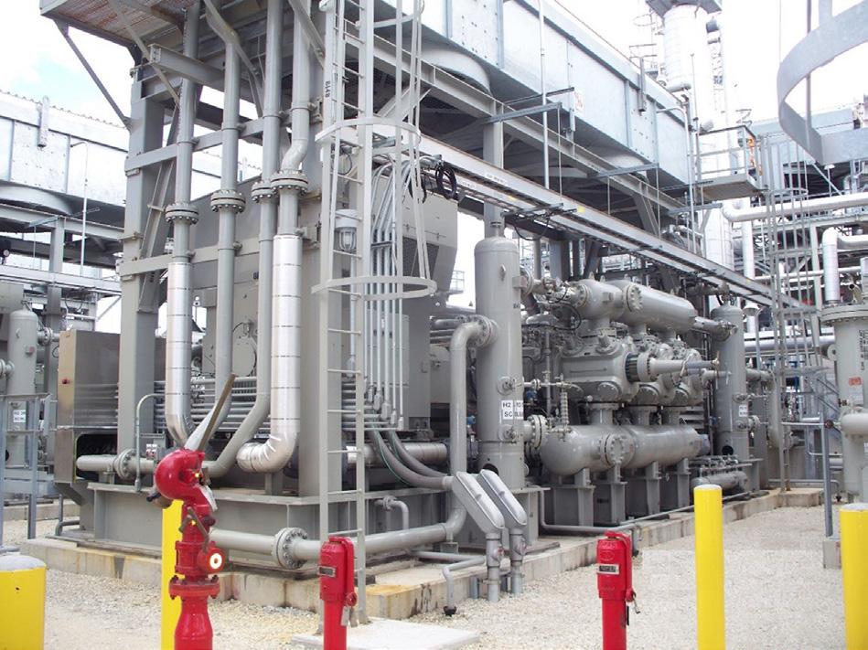
Figure 3. A natural gas feed and hydrogen product multi-service compressor operated by a global industrial gas company. This multi-service compressor supplies hydrogen to a refinery near Chicago, US. Operating since 2009, this is one of three units designed to compress 8000 kg/hr of natural gas to approximately 40 barG and 3000 kg/hr of hydrogen to nearly 100 barG. The total power requirement for each compressor is 3 MW.
A simplified SMR process schematic (Figure 1) shows multiple, independent gas streams are required. These include feed gas (natural gas), fuel gas (typically a stream containing methane and hydrogen), and hydrogen product streams at varying pressures. Depending on the source of the feed and fuel streams, compression may or may not be required for the SMR process.
In terms of compression, these independent gas streams can also be called services or applications. The compressor requirements for these streams could be carried out using individual compressors for each, or with one multi-service compressor.
Figure 2 shows the compressor operating conditions for a two-service compressor used at an industrial gas company’s hydrogen production facility.
This compressor has two services, natural gas feed and hydrogen product. The feed service is two stages and three stages are required for the hydrogen product service. One of three units is shown in Figure 3.
Hydrogen production methods are identified by some using the ‘colours of hydrogen’. Although more than 94% of the hydrogen produced today is by the SMR process, the process produces CO 2, therefore many do not consider this the preferred method of hydrogen production. Hydrogen produced by the SMR process is considered dirty or ‘grey’ hydrogen. If CO 2 capture is included in the hydrogen production process, it is considered ‘blue’ hydrogen. Renewable or ‘green’ hydrogen is currently believed, by many, to be the most effective means of achieving carbon net zero.
Figure 2. Typical performance calculation for a two-service hydrogen compressor in industrial gas production.


Pop-A-Plug ® Tube Plugs


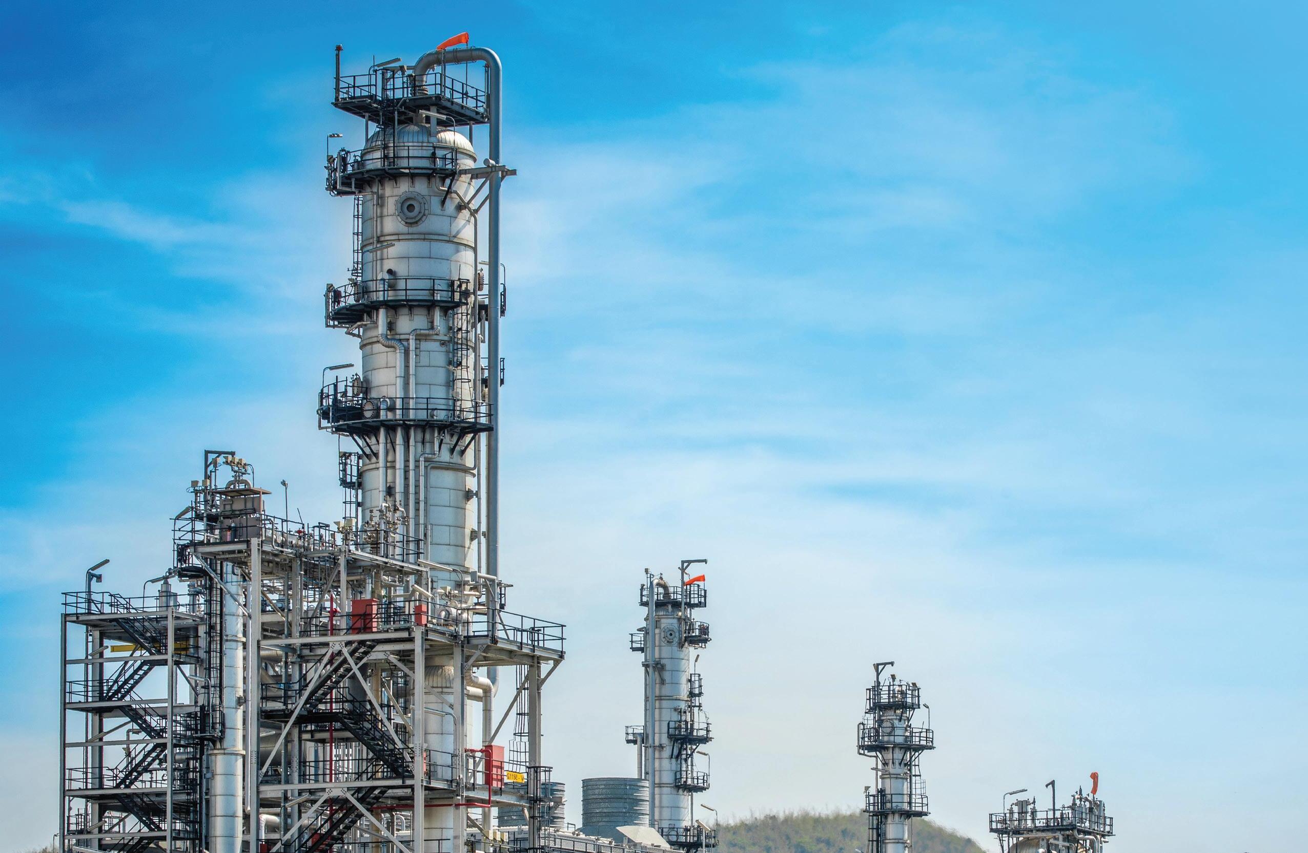


• Simple hydraulic installation − no welding
• Helium leak tight seal to 1x10 -10 cc/sec
• 100% Lot tested to ensure unmatched quality
• Pressure ratings Up to 7000 PsiG (483 BarG)
• Wide range of sizes and ASME/ASTM certified materials available


ASME PCC-2 Compliant Heat Exchanger Tube Plugging System


+1.800.355.7044 l est-sales@curtisswright.com l cw-estgroup.com/gh-24
Trusted by plants around the world as their go-to tube leak solution, Pop-A-Plug Tube Plugs from Curtiss-Wright are engineered for optimal performance throughout the life cycle of heat exchanger equipment. Controlled hydraulic installation eliminates welding and time-consuming pre-/post-weld heat treatments that can cause damage to tubes, tube sheet ligaments, and joints.


Renewable hydrogen is produced using renewable energy as the source of power. Typically, this involves wind or solar power as part of the electrolysis process. Electrolysis is the process of separating water into hydrogen and oxygen. Common electrolyser types are alkaline, proton exchange membrane (PEM), and solid oxide electrolyser cell (SOEC), with alkaline and PEM being the most prevalent. Alkaline and PEM will be the basis of discussion for this article. The electrolyser selected will have a huge impact on the compressor selection. An alkaline electrolyser typically discharges at, or near, atmospheric pressure. The discharge pressure of a PEM electrolyser can be anywhere from
8 to 30 bar. This increased suction pressure will reduce the number of stages and size of the compressor required for a given discharge pressure significantly.
Case study: compressor performance evaluation based on different electrolyser technologies
A tube trailer filling application requires 500 kg/h of hydrogen at 350 barA. Considering both alkaline and PEM electrolysers, the compressor selections are detailed below. It should be noted that although this is not a typical API 618 application, the discharge temperature limits of the standard are applied in the compressor selection.
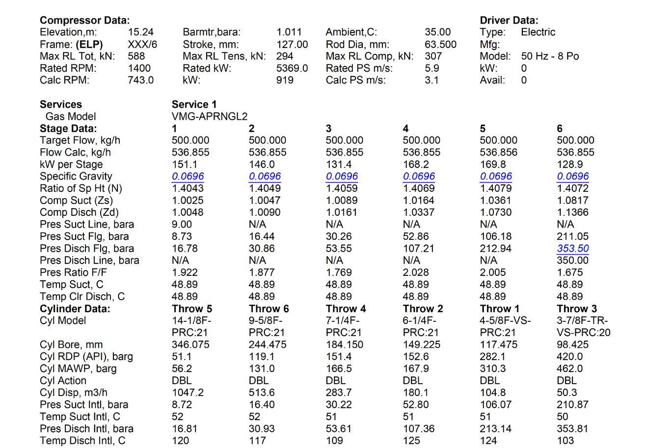

High pressure (HP) suction
The PEM electrolyser produced hydrogen at 9.0 bar. With that suction pressure, six stages of compression were required. The compressor required 0.92 MW of power. The abridged printout (Figure 4) shows the predicted compressor performance.
Low pressure (LP) suction
The alkaline electrolyser produces hydrogen at atmospheric pressure, in this case, 0.93 barA. To reach the required discharge pressure (350 bar), nine stages of compression are required. This will either require a very large compressor with large cylinders, or as shown in this case, multiple compressors (Figure 5 being the LP compressor). The approach taken for this example resulted in two compressors operating in series. The LP compressor has three stages feeding into the six-stage compressor shown in Figure 4.
Electrolyser availability, economics and available plot space are some of the factors that determine what type of compressor is required. The availability of the renewable power is also a factor as it can determine how much hydrogen is actually produced.
The electrolyser type has a significant impact on the amount of compression required to deliver a given amount of hydrogen.
The inherent flexibility of operation, demonstrated reliability, and constantly improving control and monitoring schemes attests to the value of reciprocating compressors for use in the evolving hydrogen economy. Continued investment and support of this technology will be vital in achieving global carbon neutral goals.
Figure 4. Performance data for hydrogen production from PEM electrolysis.
Figure 5. Performance data for hydrogen production for LP suction (alkaline electrolysis).
Danny
Seals, ANGI Energy Systems, considers how new regulations
are shaping the future of hydrogen as a fuel for heavy-duty vehicles.
The transportation sector faces a crucial challenge: reducing emissions while maintaining efficiency. Hydrogen, a clean-burning fuel, emerges as a promising solution, particularly for heavy-duty vehicles. However, refuelling large and powerful vehicles requires innovative solutions to ensure safety, speed, and efficiency. There are a raft of regulations and standards governing the sector, not least the J2601-5 standard protocol for high-flow fuelling of medium and heavy-duty vehicles. It is vital to understand the complexities of the hydrogen supply chain. While the J2601-5 protocol is yet to be fully validated by real world refuelling experience, it is crucial to stay up-to-date with the latest advancements and industry best practices in order to navigate the evolving regulatory landscape and ensure that technology and refuelling infrastructure meets future demands.
As regulations evolve to accomodate larger vehicles, the sector will need to develop dispensing equipment that is specifically

designed for the demands of heavy-duty hydrogen refuelling. Faster flowrates, precise measurement, and robust hardware will be required to handle increased pressures. ANGI Energy Systems’ goal is to provide solutions that facilitate rapid refuelling, minimise downtime, and ensure operator safety.
The transition to a net-zero future requires collaboration. Therefore companies must embrace technical expertise and show a commitment to innovation in order to support clean and efficient heavy-duty transportation today and in the future.
Faster filling, bigger tanks: the need for speed
One of the most important considerations for heavy-duty refuelling is flowrate. Unlike traditional internal combustion engine (ICE) trucks that can typically refuel within minutes, filling a large hydrogen tank on a truck or bus can take significantly longer using
existing technology that was originally developed for light duty hydrogen vehicles. This can lead to bottlenecks at refuelling stations and disrupt operations. To address this, the industry is developing regulations such as the SAE J2601-5 protocol, focused on developing methods to achieve faster flowrates, with a significant increase from 60 (under existing J2601) to 300 grams per second. This could involve advancements in compressor technology, improved pipeline design, and new nozzle technologies.
Balancing speed and efficiency
Faster refuelling times are crucial for the widespread adoption of hydrogen-powered vehicles, especially for heavy-duty trucks. However, achieving this speed comes with a challenge: keeping the hydrogen cool.
The stricter J2601 standard mandated a very cold hydrogen delivery temperature (between -17.5 and -40˚C). While this cold temperature allows for quicker refuelling, it requires expensive and bulky chilling systems for stations to keep up with high flow rates for large tanks on vehicles.
Recognising this challenge, the J2601-5 standard offers a solution. It relaxes the restriction on the upper limit of hydrogen delivery temperature, allowing it to be as warm as 20˚C for H35 tanks and 0˚C for H70 tanks. While this warmer hydrogen may mean slightly slower refuelling, it significantly reduces the burden on chilling infrastructure, making it more cost-effective and manageable for stations to handle the high-demand refuelling needs of heavy-duty vehicles.
The role of vehicle communication
For efficient and safe hydrogen refuelling, reliable communication between the fuelling station and the vehicle is paramount. The vehicle provides real-time data on its fuel tank size, pressure, temperature, flowrate, and pressure limitations. This information allows the station to tailor the fuelling process to the specific needs of the vehicle, enhancing efficiency and further contributing to safety. SAE J2799, the current standard that specifies the communications hardware and software requirements for refuelling hydrogen vehicles, is currently being updated to include additional safety measures and improved dispenser-to-vehicle communications, which will be required for the higher flowrates described in J2601-5. SAE J2799 is intended to be used in conjunction with the hydrogen fuelling protocols in SAE J2601 and should enable harmonised deployment of hydrogen fuelling interfaces.
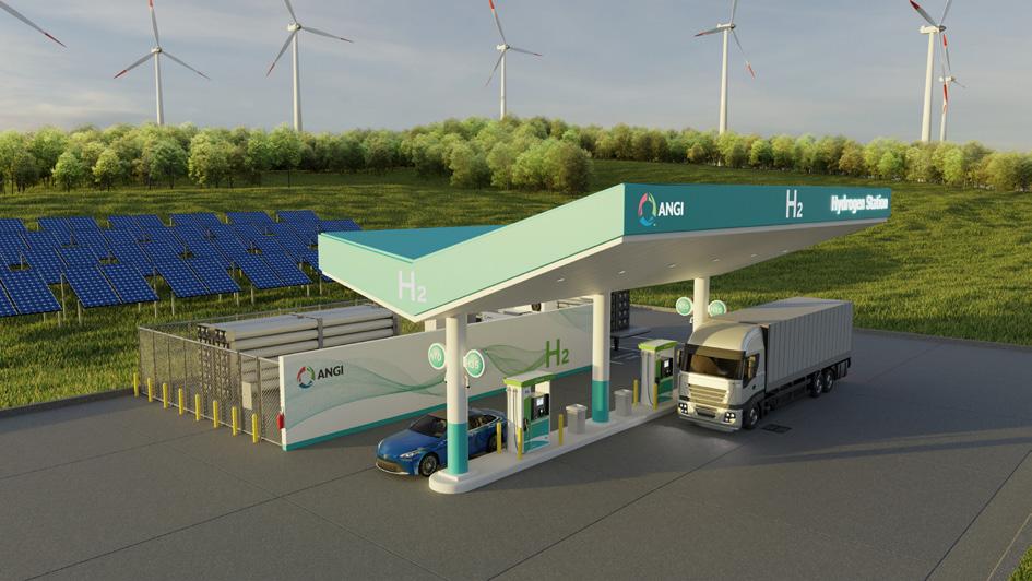
Hardware upgrades for heavy lifting
The increased flowrates associated with heavy-duty refuelling necessitate robust hardware infrastructure. The industry is developing new hanging hardware specifically designed to support H70 high flowrate refuelling, which is expected to enter the market in 2026. The SAE J2600 H70 standard which governs the design of fuelling connectors, nozzles, and receptacles for hydrogen vehicles is expected to be updated before then.
Building confidence in new algorithms
The increased complexity of heavy-duty refuelling requires advanced algorithms to manage the fuelling process. However, these algorithms require thorough validation before they can be widely deployed. ANGI utilises validation methods and tools such as the HGV 4.3 standard, HYSTEP and the MC Formula Validator, which will still need to be updated to provide validation methods and tools for the new J2601-5 protocol.
J2601-5: a standard in the making
The SAE J2601-5 standard is another piece of the puzzle for heavy-duty refuelling. It outlines best practices for fuelling larger vehicles with higher capacity tanks. However, it is currently not a fully released standard and it is still classified as a technical information report (TIR). Real-world data from operational deployments are required to validate its effectiveness before it can be formally adopted by industry.
Unification: a global standard for the hydrogen sector
The hydrogen sector is taking a giant leap towards standardisation. A critical aspect of this is aligning the ongoing development of the ISO 19880 series standards with the emerging SAE J2601 standard refuelling protocols. This unification will create a global language for hydrogen refuelling, ensuring seamless compatibility across borders. ISO working groups 24 and 38 are making updates to the ISO fuelling protocols for hydrogen-fuelled vehicles and are working closely with SAE to align as much as possible.
This has major implications for the heavy-duty vehicle sector. With unified standards, components and processes developed anywhere can be readily adopted for hydrogen refuelling infrastructure worldwide. This fosters innovation and streamlines the rollout of this vital technology, accelerating the transition to clean heavy-duty transportation.
Conclusion
The focus on heavy-duty refuelling within the hydrogen transport sector signifies a commitment to decarbonising even the most challenging transportation segments. By addressing issues like flowrate, measurement accuracy, temperature and pressure control, vehicle communication, and hardware upgrades, the industry paves the way for a more efficient and sustainable future. Continuous development in validation methods and the adoption of emerging standards like J2601-5 will further strengthen confidence in this technology. As these advancements materialise and more hydrogen combustion and fuel cell vehicles come to market, heavy-duty hydrogen refuelling will become more mainstream, enabling the cleaner and more sustainable transportation of goods and people across the globe.
Figure 1. Hydrogen fuelling station with hydrogen dispensers.
Delivering future-focused intelligent flow control
With the latest actuation technology from Rotork, you can improve efficiency, reduce emissions, minimise your environmental impact and ensure safety. We are experts in the movement, storage and transportation of liquified and gaseous hydrogen, delivering flow control solutions with the highest levels of safety and reliability. Contact us to find out more or speak to one


Akhil Batheja, Bloom Energy, USA, explores how the integration of solid oxide electrolysis cells (SOECs) and green ammonia can provide an efficient method of hydrogen production.
Climate science shows that the worst impacts of climate change can be avoided in order to preserve a livable planet by limiting the global temperature increase to 2°C above pre-industrial levels. The Paris Agreement was the outcome of the UN Climate Change Conference (COP21) in 2021, where long-term goals were set to guide all nations in keeping global temperature increase to within 2°C. To achieve this, global emissions need to be reduced by 45% by 2030 and reach net zero by 2050.1
This ambitious goal requires a significant retooling of the global economy. To that end, the Department of Energy’s decarbonisation roadmap identifies cross-cutting pillars to reduce emissions.2 These pillars are applicable across all industrial subsectors and can deliver near-term and future reductions. Specifically, they are:
� Energy efficiency.
� Carbon capture, utilisation and storage (CCUS).
� Electrification.
� Low carbon fuels, feedstocks and energy sources.

Hydrogen plays a big role in the fourth pillar and is advantageous for numerous reasons:3
� Hydrogen is the simplest element.
� It is an energy carrier without a carbon molecule.
� 10 million tpy are currently produced today.
� It can be expanded to use across multiple sectors to enable emissions reductions in other chemical and industrial processes.
Hydrogen is made almost exclusively through reformation, where methane or another hydrocarbon is cracked or ‘reformed’ at high temperatures, and the hydrogen is captured. This represents about 95% of the hydrogen currently produced in the US.4 This process is significantly carbon intensive, with estimates of 9.3 kg of carbon dioxide (CO2) emitted per kg of hydrogen produced. 5
To enable decarbonisation, the industry is currently developing projects which produce hydrogen with a low carbon intensity. One such way is via electrolysis, an electrochemical process that
uses electric energy to split the bond between hydrogen and oxygen in a water (H2O) molecule. When fed with renewable electricity, the resulting hydrogen is carbon free and is referred to as ‘green hydrogen’.
Despite its advantages, hydrogen has some limitations as an energy carrier. Specifically:
y It is a small molecule and requires care in design to maintain containment.
y It can damage pipelines and is hard to transport.
y While it has a great energy density from its mass, it takes up a lot of specific volume.
y It requires a lot of energy to compress.
y A very low temperature is required to liquefy it.
This is where ammonia (NH3) can play a key role as a hydrogen carrier. Ammonia is the second most produced chemical in the world.6 Today, 200 million tpy of ammonia are produced globally, which represents 2% of global emissions7 – a vast majority of which is used for fertilizer.
Ammonia does not have a carbon atom and is a well-understood molecule. It has a higher energy density than liquid hydrogen, which makes it an attractive fuel for heating, transportation, power applications, and industrial uses. Unlike hydrogen, substantial infrastructure exists to move ammonia around the world through ports and shipping.
Process to make ammonia
Today, most ammonia is produced through the Haber-Bosch process. This artificial nitrogen fixation process was developed in the first decade of the 20th Century. It is named after its two inventors, Fritz Haber, and Carl Bosch. The process uses a metal catalyst at a high temperature and pressure to combine atmospheric nitrogen and hydrogen to form ammonia. If ammonia is to be used as a path to decarbonisation, the production of ammonia must evolve into a low or no-carbon
process. Traditional ammonia production is energy-intensive, consuming 8 MWh of energy per ton. However, most of the energy consumed and around 90% of the carbon emitted is from the production of hydrogen.8
Hydrogen is typically produced through reformation, where steam is reacted with a hydrocarbon to produce synthesis gas – a blend of carbon monoxide and hydrogen. This gas is then put through a water gas shift reaction to increase the hydrogen content and convert the carbon monoxide to CO2, after which a pressure swing absorption system isolates the product hydrogen. This process is incredibly reliable, efficient, and low-cost –however, it does emit significant amounts of CO2. Where geographically possible, these CO2 emissions can be captured and stored – this concept is often called ‘blue hydrogen’, and the resulting ammonia is ‘blue ammonia’. However, this is not cost-effective or possible in many geographies. This is where an alternative process can be used – electrolysis of water/steam.
Electrolysis is an electrochemical technique that uses electricity to cause a non-spontaneous chemical reaction. Water/steam electrolysis splits an H2O molecule into its components, hydrogen and oxygen. When renewable electricity is used to create this split, hydrogen is produced with low/no carbon content. To make green hydrogen, there are several different electrolysis technologies, which are summarised in Table 1.
Solid oxide electrolysis
At the most fundamental level, the solid oxide electrolyser uses electricity and steam to create hydrogen. A chemical reaction on the surface of a cell produces hydrogen, which uses high temperatures to break down the steam molecule into hydrogen and oxygen. The hydrogen is captured as a product and can be delivered to the end user at whatever pressure and purity is required. The oxygen can be vented harmlessly to the atmosphere, and there are no other by-products of the hydrogen production. The purity of the product is simply a function of the degree of water removal, as the process does not contain any other contaminants. An electrolysis cell is comprised of an oxygen electrode, a solid oxide electrolyte, and a fuel electrode. Metal plates surrounding the electrolysis cell and channels within the plates conduct the hydrogen out. Stacks of these metal plates and cells are assembled together into a column and multiple columns are then assembled into a single electrolyser module for the production of hydrogen (Figure 1). These modules are then scaled to the relevant system size for a project. This approach creates a highly fault-tolerant architecture that does not require any system downtime for maintenance. Maintenance is performed at the individual electrolyser module level, so the impact of maintenance is minimal on production.
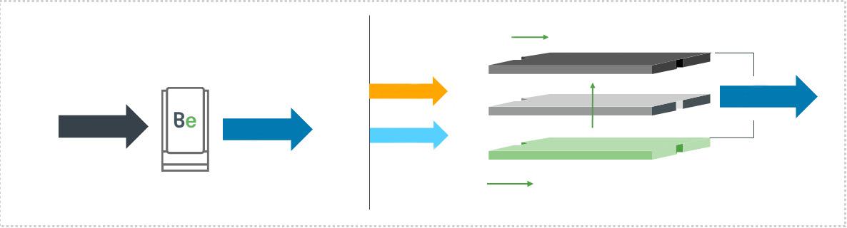
Technical advantages
Higher efficiency
The high temperature of solid oxide electrolysis cells (SOEC)’s electrochemical reaction (700 - 800°C for
Table 1. Comparison of electrolysis technology
Figure 1. The chemistry of electrolysis.
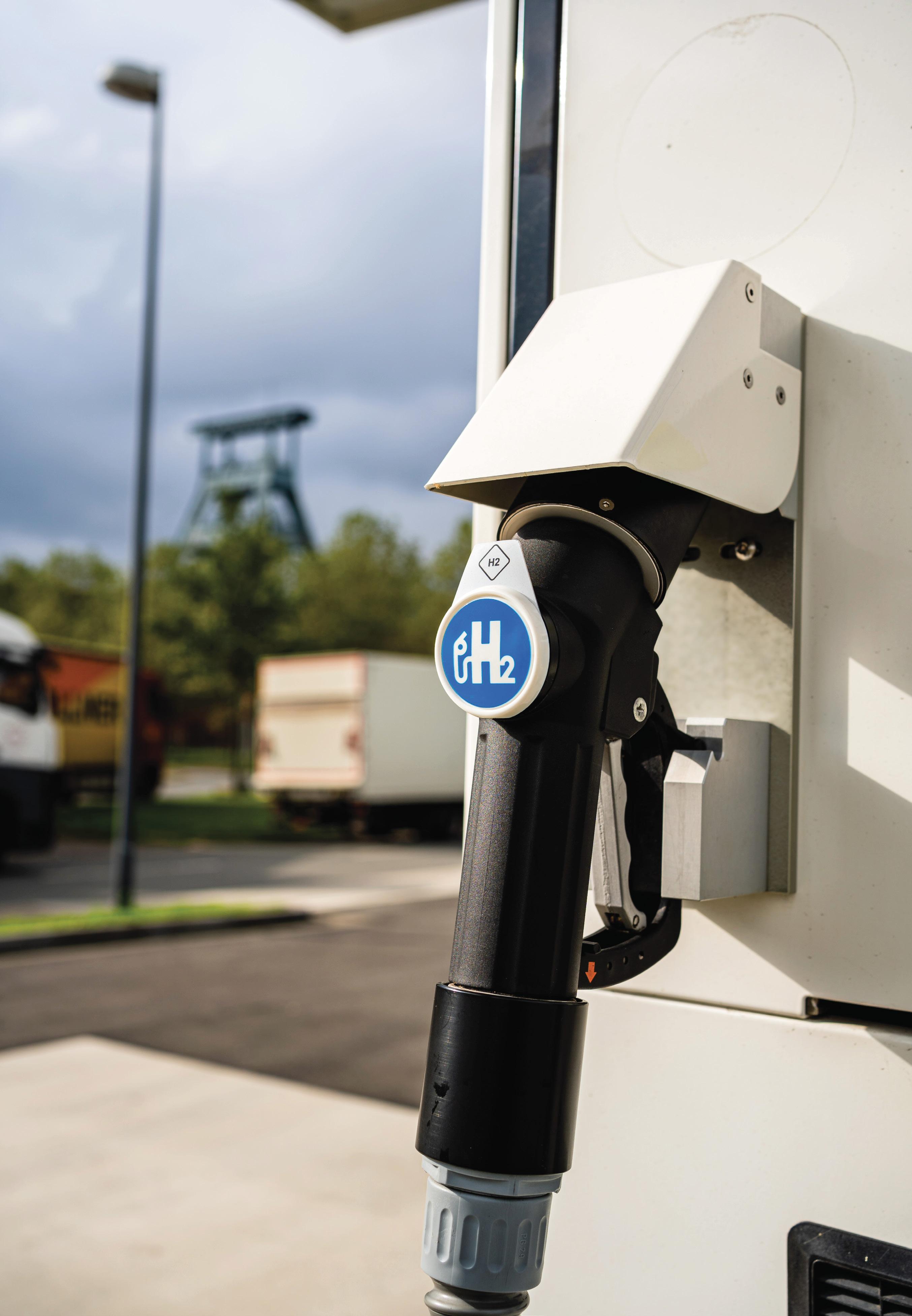
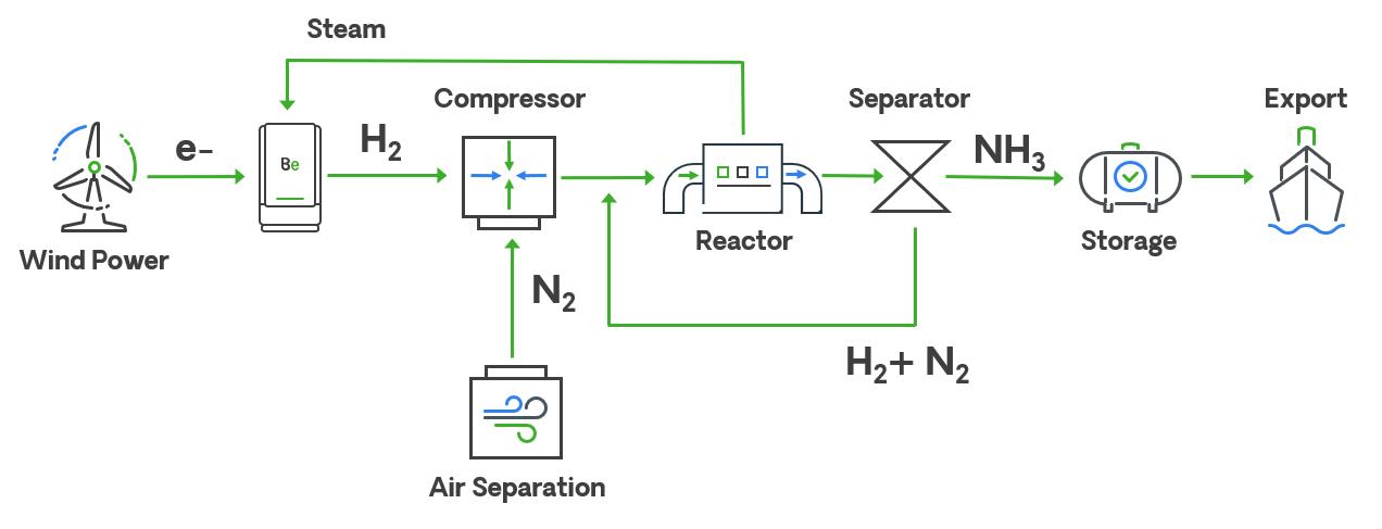
compared to less than 100°C for alkaline and PEM) leads to a fundamental efficiency advantage – more hydrogen is produced per unit of electricity input. This efficiency is a significant driver of hydrogen production costs. In the ammonia application, the SOECs will be integrated with a source of renewable energy and steam from the ammonia loop. This allows for efficient utilisation of waste heat from the Haber Bosch process, improving efficiency and producing the lowest levelised cost of hydrogen (LCOH) for ammonia synthesis.
Modular design and maintenance
A modular design enables targeted maintenance on individual electrolyser modules while the rest of the facility continues to operate, subject to the balance of plant design. When the electrolyser modules reach their end of life, they can be swapped quickly, with the work performed in phases and timed to coincide with periods of lower capacity factor, eliminating facility-wide outages due to the electrolyser component. This modular design allows hydrogen project developers and their end users to avoid lengthy and costly shutdowns, which, depending on the application, could result in millions of dollars of lost production.
Reduced balance of plant
Due to the high temperatures of the SOEC solution, zero oxygen enters the hydrogen stream, with only H2 at 90% mol and H2O being present. Therefore, de-oxygenation is not required with the Bloom SOEC solution. Furthermore, the volume of H2O dehydration required is significantly less than the PEM and alkaline alternatives. SOECs do not require system cooling and are externally housed, reducing the need for additional structures and limiting the amount of civil works required.
Solid oxide with ammonia
The solid oxide electrolysis process ties in smoothly with the ammonia synthesis loop, as pictured in Figure 2. As nitrogen and oxygen combine, steam is produced as waste from the synthesis loop. The solid oxide electrolysis process is unique in that it uses steam instead of water as its input. This heat energy, which would otherwise produce a small amount of electricity or drive utility loads such as pumps or compressors, can be used to substantially reduce the electrolysis energy draw, boosting project economics significantly.
There are some substantial differences when this is contrasted with the use of other electrolysis technologies:
y PEM/alkaline requires larger electrolysis sizes: they are less efficient, and to produce the same amount of hydrogen, more electrolysers are required. PEM/alkaline electrolysis efficiency degrades right from the first time that they are energised. SOECs, on the other hand, maintain the same efficiency for an extended period of time. As a result, to ensure operators are
achieving the appropriate amount of hydrogen production in the latter years of the project, one has to oversize the PEM/alkaline unit.
y Lower electricity consumption: with the ammonia synthesis loop integration, SOEC technology consumes 20 - 30% less kWhs to produce a unit kg of hydrogen.
Economic comparison
The following part of this article provides a sample comparison between a PEM ammonia project and a SOEC ammonia project.
Sizing
y Electrolysis: because of the efficiency advantage of the SOEC technology compared to PEM, a project needs less total installed capacity when choosing SOEC technology. A single MW of SOEC produces approximately 20% more hydrogen than a MW of PEM. This reduced size also reduces the electric infrastructure needed to feed the plant.
y Backup power: SOEC electrolysers require slightly more backup power to ensure they have an appropriate amount of energy to ramp down.
Electricity cost
The approximately 20% efficiency advantage of electricity results in a US$1 - US$1.2/kg of hydrogen advantage.
Balance of plant and capital outlay
For this analysis, the author assumed a full hydrogen plant and ammonia loop. The differences between the technology’s total capital budget can be attributed to the following factors:
PEM is cheaper in US$/kW, but requires more MWs.
PEM requires a building, while solid oxide is installed outdoors.
PEM requires deoxidation of the output hydrogen.
PEM requires a cooling tower, while SOEC is air cooled.
SOEC requires more compression due to its low-pressure output.
Use of heat
While the SOEC plant reuses the heat, the PEM plant uses the combined cycle turbine to convert the heat from the ammonia loop to electricity, generating revenue.
Conclusion
When considering all of these variables, the SOEC system costs more, but reduces the cost to produce hydrogen, improving the margin for the producer. Not only is the SOEC producing more hydrogen, but the hydrogen it produces is more profitable.
References
1. https://www.un.org/en/climatechange/net-zero-coalition
2. https://www.energy.gov/sites/default/files/2022-09/Industrial%20 Decarbonization%20Roadmap.pdf
3. https://www.energy.gov/eere/fuelcells/hydrogen-production
4. https://www.energy.gov/eere/fuelcells/hydrogen-production-naturalgas-reforming
5. https://www.forbes.com/sites/rrapier/2020/06/06/estimating-thecarbon-footprint-of-hydrogen-production/?sh=4afe61e524bd
6. https://www.forbes.com/sites/mitsubishiheavyindustries/2021/10/29/ scaling-ammonia-production-for-the-worlds-foodsupply/?sh=2fc9bdff68d1
7. https://www.icef.go.jp/pdf/summary/roadmap/icef2022_roadmap_LowCarbon_Ammonia.pdf
8. https://royalsociety.org/-/media/policy/projects/green-ammonia/greenammonia-policy-briefing.pdf
Figure 2. Solid oxide integration with ammonia plant.

Andrew Symes, OXCCU, UK, explains the key role of hydrogen in the creation of synthetic e-hydrocarbons and e-fuels.
Despite the growing prevalence of green electricity, fossil fuels still dominate the world’s primary energy needs. In 2023, they accounted for over 80%. To prevent global temperatures rising above 2˚C, a rapid transition to zero-emission energy sources must occur in less than 30 years. While sectors like power are making strides in this transition by adopting solar, wind, nuclear and hydropower, not all industries
can decarbonise by using green electricity directly. Some sectors need molecules, and whilst hydrogen is the key molecule to make from electricity, it often is not suitable as the final product. For many applications, the hydrogen needs to be combined with carbon dioxide to make synthetic e-hydrocarbons in a process called power-to-liquids (PtL). Hydrogen in the fuel, combined with carbon, rather than hydrogen as the fuel.
Wherever it is possible, the direct utilisation of green electricity should be encouraged, the reason being that the least amount of energy is lost in between the electricity generation and the end use. This means encouraging electric vehicles, the electrification of heat, and the electrification of industrial processes where possible. The challenge is synchronising supply and demand given the fluctuating nature of wind or solar generation, and the variable demand for the different end uses, as well as the cost of upgrading grids. The implementation of energy storage to balance becomes necessary. Batteries have rapidly developed for smaller, shorter time scale applications for short-term balancing. But scalable, cost-effective, long duration batteries that can securely store vast amounts of dispatchable energy for extended periods in relatively small spaces without degradation remain elusive due to the cost, material or space requirements of the new technologies proposed. This leaves hydro storage, interconnectors, or using more geothermal or nuclear generation instead. These should all be encouraged, but not all locations are suitable for them.
In addition, there are many applications where using green electricity directly simply is not possible. Often this is due to the application having energy density requirements which far exceeds battery storage i.e. there is unlimited space or weight for a large, heavy battery. This is true for long distance aviation and shipping, as well as for some ground transport and machinery applications with very high power or range requirements. Most military energy use also falls into this category. In other cases, such as chemicals and plastics, it is not just about needing an energy input. A physical material or product is sold which requires both material and energy input. The solution lies in converting green electricity into molecules. It involves expanding the energy transition beyond simply generating, transporting, storing and using green electrons in wires and batteries, to also encompass producing, transporting, storing and using green molecules, derived from green electrons. Molecules offer the solution for any applications where electrons in wires and batteries face challenges.
So which molecule should be made from green electricity, and how is it achieved? The bridge between electrons and molecules is electrochemistry and electrochemical processes. Electrons are added to substances to make higher energy
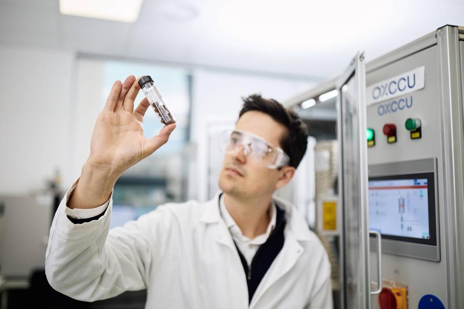
substances, a process sometimes described as ‘fuel making’. These processes are complex and expensive to scale, and the inputs to them need to be cheap and abundant. Hence, the focus is on making the simplest molecule in the universe, hydrogen, using one of the most abundant input materials on earth, water, in one of the most well-known electrochemical processes, water electrolysis. Even though this is fairly challenging, the technologies are now beginning to scale. The process puts green electricity into water to split the water molecules, H2O, into hydrogen (H2) and oxygen (O2). The oxygen is vented to the atmosphere, where it mixes with the vast amount of oxygen already present, leaving hydrogen as the valuable green molecule product, the easiest and cheapest molecule to make from electricity.
The question then arises: why not utilise hydrogen directly in all the applications discussed which are not suited to using electricity directly? At first thought, the so-called ‘hydrogen economy’ seems ideal as when the hydrogen is used, it recombines with oxygen in the atmosphere releasing energy and remaking water in a completely circular process. However, it is hydrogen’s physical properties that pose a major challenge. It is light and explosive in air, meaning it is difficult to transport and store, and it takes up a lot of space, even when pressurised. Additionally, the process of pressurising, or even liquifying, to reduce its volume requires significant energy, and it is chemically reactive, requiring specialist tanks and pipes. Therefore, while hydrogen shows potential for some applications, such as steel production, its properties present significant limitations for many applications.
However, even if hydrogen is not itself the answer to all fuels, it is still the key, as instead of using the hydrogen alone as the fuel, it can instead be in the fuel, in combination with another element. The two best options to react it with, as both exist in the air as gases, are nitrogen (N2) (to form ammonia [NH3]) and CO2 (to form hydrocarbons and water). NH3 is already a critical molecule in food production for making fertilizers, and therefore, this pathway to make green ammonia will undoubtedly require scaling. However, it is highly toxic to humans, even in small quantities, necessitating strict control and limiting its widespread distributed use. This is heightened as it serves as a precursor for illegal drugs and explosives. Additionally, it has fairly poor energy efficiency, problematic NOx emissions upon combustion, and is incompatible with existing infrastructure. This leaves CO2, which can be combined with hydrogen to form hydrocarbons. The benefit of hydrocarbons is that they have energy density and material properties superior to almost every other molecule. They are the ultimate material for energy security, long-duration storage, and long-distance transport, and are supported by robust safety measures and established infrastructure. Moreover, they are the backbone of chemical and plastic products.
The reaction to form hydrocarbons from CO2 has long been known to biologists as it is fundamental to the metabolism of all life. It may even be the reaction from which life originated in a deep ocean vent. However, until recently, chemists and chemical engineers have had little need to replicate this reaction industrially, as for the last 150 years, vast amounts of fossil hydrocarbons have been available to them in the form of oil, gas, and coal. The work to make these fossil hydrocarbons was already done for them by millions of years of algae and
Figure 1. Andrew Symes, CEO and Co-founder of OXCCU with OXCCU’s novel one step CO2 to jet fuel catalyst.
plant photosynthesis. Hence, their focus was not on making hydrocarbons, but on extracting, transforming and burning them. The problem with this is now well known. Large amounts of CO2 are released on use, and as CO2 is both a greenhouse gas and long lasting in the atmosphere, and because that CO2 was captured many years ago and is now being released suddenly, the additional spike of CO2 emissions is causing a short sharp warming of the planet which makes it harder for humans, and the ecosystems we depend on, to live comfortably.
But this does not necessarily mean we have to stop all hydrocarbon use. By directing efforts towards making our own hydrocarbons from CO2, the emissions from their use can be dramatically reduced. If the CO2 used to make them was recently derived from the air, either captured directly (DAC), or captured via a plant (biogenic), and the energy input to make the hydrogen was green electricity, then releasing this CO2 back into the atmosphere on use has little to no effect. And even if industrial sources of CO2 are used in the short-term, some of the carbon which is dug up is still being reused before it goes to the atmosphere, reducing fossil fuel demand, a step toward progress, though not perfection. So, whilst it is important to move away from using fossil hydrocarbons, the use of lower carbon hydrocarbons based on recycled CO2 can be continued and, over time, progressed to solely using circular, ‘carbon neutral’ hydrocarbons based on biogenic or DAC CO2
Making synthetic hydrocarbons from H2 and CO2 not only leverages the existing infrastructure designed for hydrocarbon fuels, but also addresses emissions concerns. It preserves the
advantages of hydrocarbons for those sectors which still need them whilst eliminating their emissions. Green electricity is able to extend its reach by also powering the sectors which need the energy density, storage and security benefits inherent in hydrocarbons. Regulators are increasingly recognising the need to support these e-fuels or PtL processes, seeing them not as a way of continuing fossil fuels, but as a serious way of reducing fossil fuel demand. A way of continuing to boost the deployment of wind and solar, rather than instead of wind and solar, especially in places where grids are constrained.
Biofuels, based on the starch or oil from crops, or from carbon waste, present another route to hydrocarbons which avoids the need for green energy or CO2 input; the plants have done this reaction themselves. With significant support over the last 30 years, biofuels have scaled – in particular ethanol in the US, and vegetable oil in Europe – but they now face strict limits due to land use and competition with food. Second-generation biofuels, which are based on carbon waste, face challenges with aggregating feedstocks and the conversion processes. In places where these can be made sustainably at scale, they should be used, and once made they can be easily combined with e-hydrocarbons using the PtL process. In addition the two pathways can, in fact, be integrated as most biofuel processes produce CO2 which can be used by PtL. However, alone, biofuels are simply not enough.
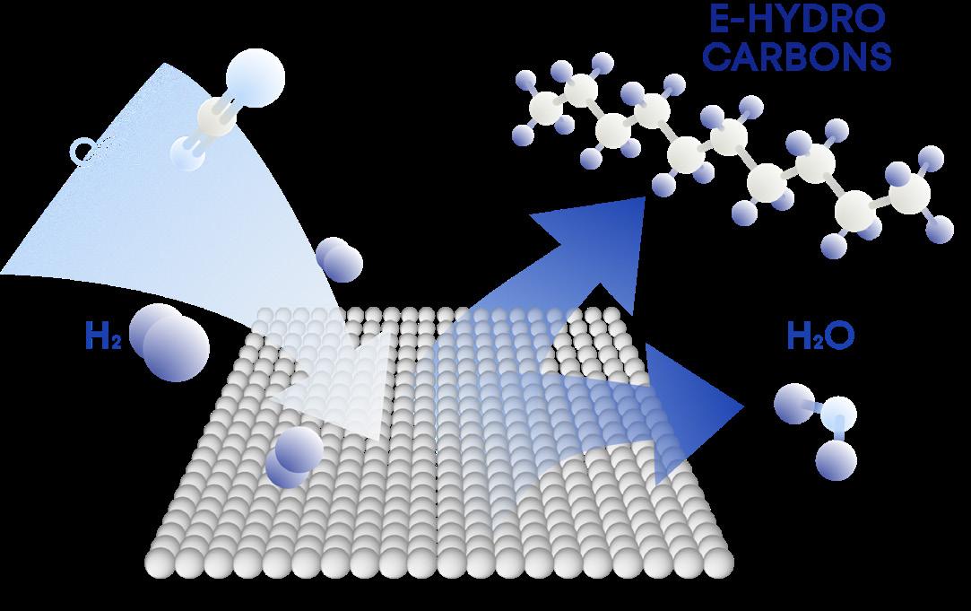
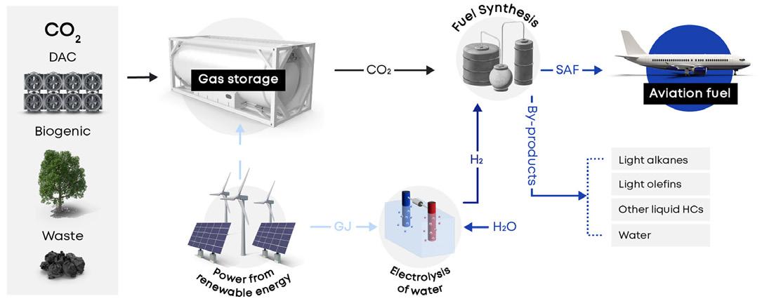
As countries and industries strive to meet their decarbonisation targets the future of fuel production appears poised for a significant transformation. The EU is leading the way by mandating that 1.2% of all aviation fuel must be CO2-derived PtL jet fuel by 2030. Looking further ahead, by 2050, the target is 50% of jet fuel via PtL. In the UK, there is a push for a sub-mandate for PtLs, while in the US, support is evident through initiatives like the Inflation Reduction Act. This means that e-fuels, particularly SAF, are poised to become one of the largest users of green electricity and electrolysers globally. In regions such as MENA and Chile, where abundant sunlight and wind may exist, there is also significant potential. These areas often lack local demand for the electricity generated, leading to surplus energy. PtL provides a way of converting this surplus electricity into molecules which can be transported. This approach aligns with the aspirations of countries with ample renewable resources, allowing them to utilise their surplus renewable energy and reduce their reliance on oil imports. The increasing interest in nuclear and small modular nuclear reactors offers an opportunity, as large amounts of green electricity would be available to make e-hydrocarbons. Looking ahead, there is also the potential to use nuclear energy to capture CO2 from the air.
Consumers are rightly pushing producers to be clear about the carbon intensity of fuel and to provide clear and transparent information. They need to be certain that this is not greenwashing and that real emissions reductions do occur due to the adoption of these fuels. Depending on the CO2 source and the energy inputs, the carbon intensity will vary, but strict, verifiable methodologies are now in place. One specific concern is that the green energy input is needed elsewhere, but this is clearly addressed within the various green hydrogen standards.
Figure 3. Illustration of OXCCU’s Power-to-Liquids (PtL) process.
Figure 2. Illustration of heterogeneous catalysis. Having a metal surface with the right active sites is key to catalysing the reaction between CO2 and H2 gases to make long chain hydrocarbons and water.

Things like ‘additionality’ are certified, in that the energy utilised has recently been built, or it can be proven that it would otherwise go unused due to grid constraints or lack of demand. They also certify the generation and demand are matched in time and by location. This is key as once demonstrated transparently, widespread acceptance and excitement ensue as consumers can be confident of the benefits.
Having an efficient industrial process to convert CO2 and H2 into hydrocarbons is critical. The minimum number of steps, the lowest energy input and the highest selectivity is required so the maximum amount possible of carbon and H2 goes into the product that is wanted rather than byproducts. The production of water is inevitable because both oxygens have to be taken off the CO2 and turned to water, to make a deoxygenated hydrocarbon fuel. The goal is to have all the remaining hydrogen not making water, and all the carbon, transformed into valuable hydrocarbon products. The good news is that if enough hydrogen is used in a 3:1 ratio, the reaction is thermodynamically favoured and the reactor will actually release heat (exothermic) rather than requiring energy input. The challenge is the kinetic stability of the CO2. The solution is a catalyst to reduce the activation energy. Once the pathway is provided, the reaction will proceed.
OXCCU focuses precisely on this, developing highly selective catalysts that result in a more efficient process with lower costs to convert CO2 and H2 to hydrocarbons. With fewer steps involved, there is a reduction in both capital and operational costs, ultimately leading to lower fuel costs. This emphasis on cost reduction is supported by independent researchers from
Imperial College London, who demonstrated that OXCCU’s one-step technology has a 50% lower capital cost, lower operation costs and a reduced environmental impact compared to other methods that utilise multi-step processes to create jet fuel.
With theoretically unlimited CO2 feedstocks available, PtL technology provides the path to making low-cost, scalable alternatives to existing fuel products. Neither green electricity nor hydrogen are the end product in PtL, but their role in the energy transition is massively expanded – green electricity being the key input and hydrogen being the key intermediate. Humanity can recreate the carbon cycle on an industrial scale, giving future generations the benefits of hydrocarbons but without the climate impact.
Hydrocarbons are incredible materials, deeply linked to human progress and cannot be substituted in many applications. The challenge with hydrocarbons is not necessarily the fuels themselves but the emissions which result when fossil-based hydrocarbons are used. The good news is that the fossil type does not always have to be used – hydrocarbons can be utilised another way which reduces their emissions, enabling their continued use. The world can adopt low or even zero-emission synthetic e-hydrocarbons made from green electricity, water and CO2, catalysed by technologies such as those provided by OXCCU. The resulting molecules are chemically identical, except this time, it is green energy that has done the work to make them. This is the approach which will ultimately allow future generations to use hydrocarbons indefinitely.