
Baker Hughes is looking to the future of hydrogen applications
Any process that moves or stores hydrogen requires a valve.
Rest assured that when designing systems for hydrogen production, transportation or storage you’ve got the best and safest in control and pressure relief.
Face new challenges with confidence with Baker
Hughes Valves
03 Comment
04 Hydrogen industry outlook for the MENA region
Aliaksei Patonia and Martin Lambert, Oxford Institute for Energy Studies, UK, explore the MENA region’s hydrogen outlook and the latest developments and challenges that it faces.
10 Navigating complex pathways
Eugene McKenna, Johnson Matthey, Henrik Solgaard Andersen, Equinor, and Nilay Shah, Imperial College London, explore the intricate landscape of energy transition decarbonisation and the critical role of hydrogen.
13 Capturing value from renewable hydrogen megaprojects
Hydrogen developers can use digital twins to improve the economic viability of renewable projects and meet increasing demand. Nas Andriopoulos, Dominik Don, Joaquin Ubogui, and Maurits Waardenburg, McKinsey & Co., illustrate how, using renewable hydrogen as an example.
17 Unlocking plant performance in an uncertain world
Ben Laws and Nicolai Szeliga, Siemens Digital Industries, explore how Digital Twins and the process optimisation capabilities that they bring are becoming essential components of green hydrogen projects.
24 A newly rising energy vector
Antoine Ghorayeb, Ali Natour, and Yann-Olivier Placiard-Fleys, Saipem SA, present a case study for the implementation of large-scale ammonia (NH3) storage and cracking on board of a unique concrete hull by means of a gravity-based structure (GBS).
29 Ambition, matched with pragmatism, can unleash hydrogen’s power
Javier Cavada, Mitsubishi Power, outlines the approach required from governments and decision-makers worldwide to fulfil the potential of
33 The sustainable energy turbomachinery infrastructure dilemma
Klaus Brun, Ebara Elliott Energy, USA, addresses the challenges associated with adapting turbomachinery in order to meet the demands of sustainable energy and hydrogen production.
36 From grey to blue
Scot Bauder, Emerson, USA, explains how properly specified valves and related control equipment can ensure reliable operations when designing the systems required to convert grey hydrogen to blue hydrogen.
41 Water saving solutions
Blair Garrett, BAC, USA, explores options to solve the challenges of water management in hydrogen production.
45 PEM’s promise
Matt Behrns and Dr. Alex Papandrew, Mott Corp., USA, explore how scaling up efficient proton exchange membrane (PEM) solutions will be key for the future energy landscape.
49 Switch to green
Richard Koeken, Fluid Components International (FCI), the Netherlands, and Florian Stahl, Ekomat Gmbh & Co., Germany, discuss the role of accurate liquid/air flow monitoring switches in producing green hydrogen from renewables using PEM fuel cells.
53 Sensing safety
Michael Nofal, H2scan, USA, and Robert H. Shelton, H2C Safety Pipe, USA, look at ways to enhance the safety and efficiency of green hydrogen transport.
57 Handle with care
Rosanna Tumolo, Neohance, the Netherlands, and Andrea Manfredi, Sensitron, Italy, outline why advanced detection technologies are vital in mitigating the safety risks associated with hydrogen use across various sectors.
61 Sustainable steelmaking
Rhys Jenkins, Servomex, UK, explores how greater hydrogen use can support the decarbonisation of the steelmaking industry.
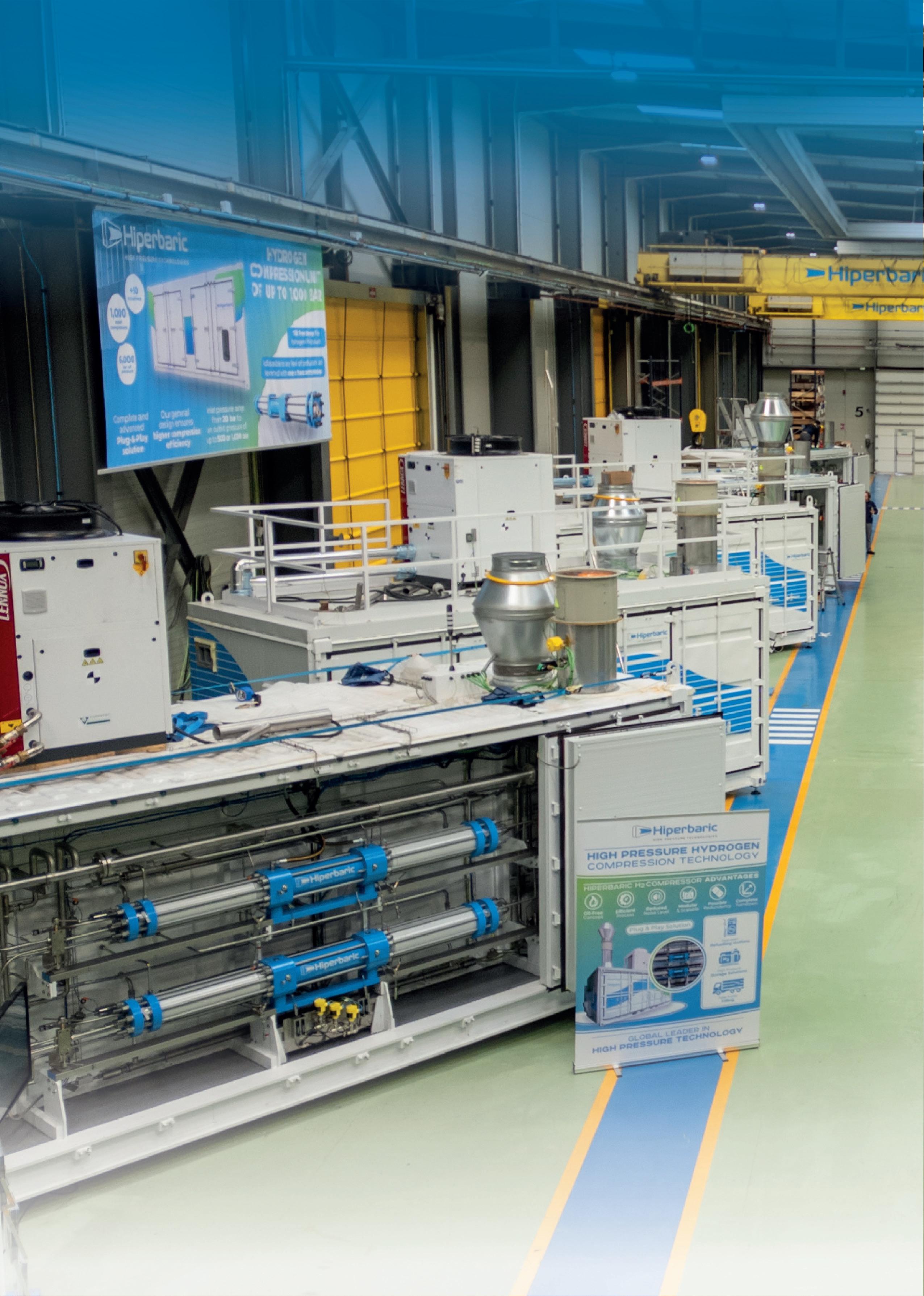
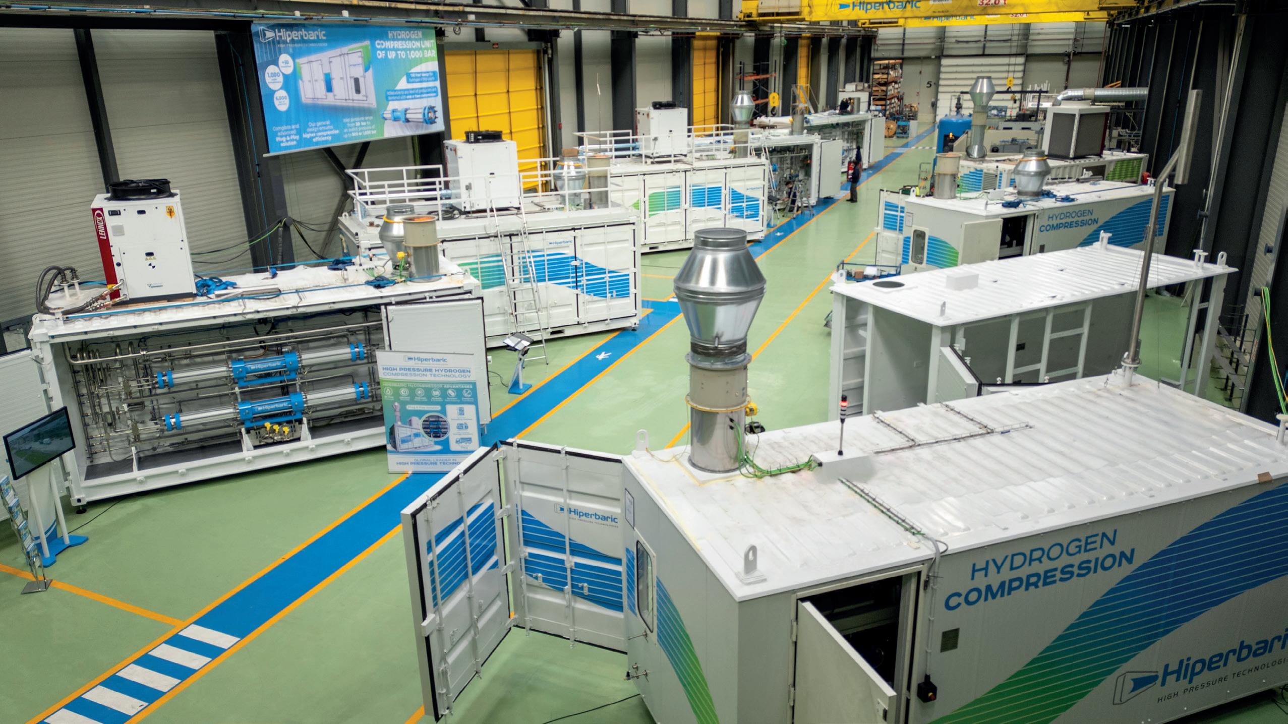
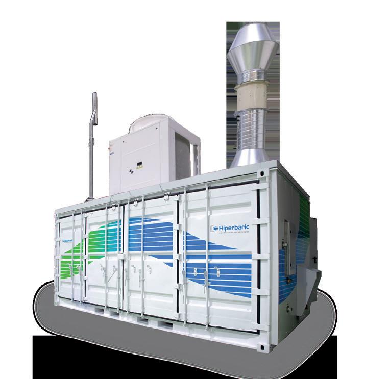
Hiperbaric is focused on the development, manufacture and commercialisation of hydrogen compression technology generating pressures of up to 500 and 1000 bar. Hiperbaric’s range of compressors offers a complete plug-and-play solution, adaptable to any level of production and demand. The hydraulically driven piston compressor units are safe, efficient and reliable. Hiperbaric is a global leader in the development of high pressure technologies for different sectors and applications, with installations in more than 50 countries.


Scaling the Hydrogen Ecosystem
Secure the project funding you need and advance to net zero

Ready to start your clean-hydrogen project? Yokogawa can help you qualify for investment, design profitable production, and ensure capturing critical government incentives, all while maintaining focus on safety and security. Our hands-on, solution-oriented approach will help you reduce risks, optimize processes, and enable faster, more informed decisions. Together, we can build a sustainable hydrogen economy, driving us toward a net-zero future. yokogawa.com

Poppy Clements Assistant Editor
Managing Editor James Little james.little@palladianpublications.com
Senior Editor Callum O'Reilly callum.oreilly@palladianpublications.com
Assistant Editor Poppy Clements poppy.clements@palladianpublications.com
Editorial Assistant Emilie Grant emilie.grant@palladianpublications.com
Sales Director Rod Hardy rod.hardy@palladianpublications.com
Sales Manager Chris Atkin chris.atkin@palladianpublications.com
Sales Executive Ella Hopwood ella.hopwood@palladianpublications.com
Production Manager Kyla Waller kyla.waller@palladianpublications.com
Head of Events Louise Cameron louise.cameron@palladianpublications.com
Digital Events Coordinator Merili Jurivete merili.jurivete@palladianpublications.com
Digital Content Coordinator Kristian Ilasko kristian.ilasko@palladianpublications.com
Digital Administrator Nicole Harman-Smith nicole.harman-smith@palladianpublications.com
Events Coordinator Chloe Lelliott chloe.lelliott@palladianpublications.com
Junior Video Assistant Amélie Meury-Cashman amelie.meury-cashman@palladianpublications.com
Admin Manager Laura White laura.white@palladianpublications.com
The British pop singer, Ed Sheeran, has been hitting the headlines in the UK for a couple of reasons in the last few weeks. It was not only his awkward interruption of a post-match interview with Manchester United’s new manager, Ruben Amorim, that has been criticised by the media, but also his objection to the 40 th anniversary edition of Band Aid’s charity Christmas song, ‘Do they know it’s Christmas?’
Sheeran’s vocals were used to create a new blended version of the single for Christmas this year, yet he has insisted that he would have declined participation if he had been asked for permission beforehand. The singer took to Instagram to cite his belief that the song projects dehumanising stereotypes of an Africa dependent on Western support and plagued by drought and poverty. Since making his opinion public, Sheeran has been praised in some quarters and criticised in others, with some perceiving his stance as a misinterpretation of the charity’s message. Over the years, the charity song has helped to raise nearly £150 million to support famine relief, an issue which threatens to become more widespread in the wake of climate change and extreme weather events.
The recent COP29 conference in Baku, Azerbaijan, shed light on the magnitude of the issue of water scarcity and the fact that nearly 50% of the world’s population live in water-stressed conditions. 1 In response to this stark reality, the COP29 Presidency introduced the COP29 Declaration on Water for Climate Action, an initiative focused on water-related climate action, including the improvement of water security, availability, quality and sanitation. Hydrogen was also in the spotlight at COP29, with the scale-up of clean hydrogen production being widely discussed, as well as a pledge being made to provide financial and technical support to facilitate the hydrogen industry in developing countries.
Considering the heavy hydrological footprint of hydrogen production and the intensified pressure on the world’s most critical resource, sensible water usage has never been more important in the hydrogen industry. As a critical component in hydrogen production, the industry must put responsible water management at the top of its list of priorities. Blair Garrett of Baltimore Aircoil (BAC) provides valuable insights into the different water consumption profiles of hydrogen production methods and outlines water saving techniques on page 41 of this issue of Global Hydrogen Review . This issue also features an interesting report by Aliaksei Patonia and Martin Lambert from the Oxford Institute for Energy Studies, focusing on the hydrogen industry’s outlook in the most water-scarce region of the world, the Middle East and North Africa.
Editorial/advertisement offices:
As outlined at COP29, the acceleration of decarbonised hydrogen production is set to continue through 2025 and with responsible growth, the industry should be hitting the headlines for all the right reasons.
1. https://cop29.az/en/pages/baku-dialogue-on-water-for-climate-action-backgroundinformation


Aliaksei Patonia and Martin Lambert, Oxford Institute for Energy Studies, UK, explore the MENA region’s hydrogen outlook and the latest developments and challenges that it faces.
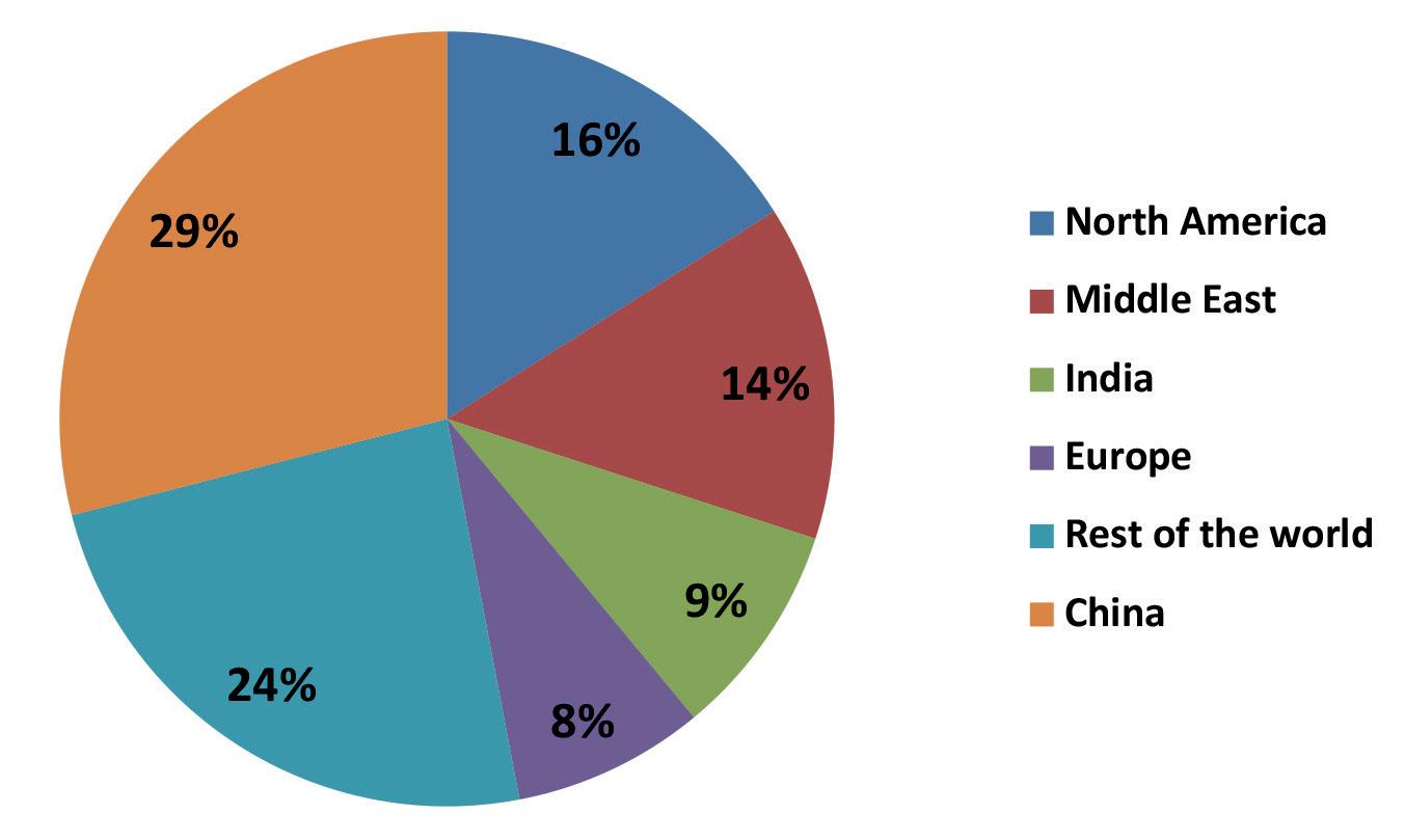
Hydrogen production is currently still largely dependent on unabated fossil fuels in general and natural gas in particular. At the moment, the Middle East alone produces one-fifth of the entire world’s hydrogen from unabated natural gas. It is also the second-largest consumer of hydrogen in industrial applications after China. Given its hydrocarbon endowment and almost perfect suitability for renewable power generation, it should therefore be no surprise that the MENA region is actively attracting promoters of both low-carbon blue and renewable green hydrogen. It may serve not only as a potential strategic supplier but also as a consumer of this ‘fuel of the future’.
Despite most of the global attention in the hydrogen sector currently being paid to Europe and North America, the MENA region also appears to have a large number of clean hydrogen initiatives and is currently constructing the world’s largest green hydrogen generation facility. With 27 hydrogen production projects currently under negotiation and development in Egypt, 19 in Oman, 16 in the UAE, 8 in Morocco, and 2 in Saudi Arabia, the region is gaining momentum as one of the key global hubs for clean hydrogen development. Nevertheless, experience worldwide has demonstrated the challenge of moving projects from the development phase to Final Investment Decision (FID), and the MENA region is likely to face similar challenges.
Egypt
Currently, Egypt has the greatest number of clean hydrogen initiatives in the entire MENA region. It should not be surprising, as the country has a historical legacy in clean hydrogen production, being one of the first countries to produce green hydrogen through the KIMA plant, which began operations in 1960 using hydroelectric power from the Aswan Dam to create ammonia. However, this initiative was halted in 2019 when the plant switched to natural gas
due to economic viability concerns, marking a shift towards grey hydrogen generation that emits CO2 without abatement. At the same time, while currently Egypt is a net importer of natural gas, it is actively exploring various projects aimed at harnessing its renewable energy and green hydrogen potential, with a number of important documents signed between local and international firms.
Most notably, this year’s offtake agreement with Yara Clean Ammonia made Egypt a step closer towards the annual manufacturing of 150 000 t of green ammonia in the country. In addition to that, in mid-2024, a collaboration between the Norwegian solar power generator Scatec and Fertiglobe, a UAE-based fertilizer company, appeared to be a sole winner in the pilot H2Global auction. It is therefore expected that Fertiglobe will deliver up to 397 000 t of green ammonia by 2033 from Egypt to Europe at a contract price of €1000/t including transport costs.
At the same time, despite these advancements and the country’s impressive green hydrogen ambitions, just like most other countries in the MENA region, Egypt appears to be one of the world’s most water-scarce nations. This has a tremendous impact not only on the nation’s agriculture, health and sanitation sectors, but also on social and economic development overall. Since the production of green hydrogen via electrolysis requires substantial fresh water – between 9 and 21 l/kg of hydrogen – and no currently commercialised electrolyser technology is able to run on salt water, intensive development of large-scale green hydrogen projects in Egypt is likely to raise concerns about competing demands for this vital resource in agriculture and residential use.
Oman
The government of Oman has developed an ambitious green hydrogen strategy, creating a specific organisation, Hydrom, to structure and accelerate development of the sector. Recognising its more limited hydrocarbon resources compared to many of its neighbours, the strategy has multiple objectives, including ensuring energy security, diversifying the economy while decarbonising and supporting innovation and investment. There is a target to produce 1 million t of green hydrogen by 2030. Hydrom has already held two
auctions resulting in awards of land and infrastructure support for 8 projects, five in Duqm and three in Salalah.
So far, however, just one 300 MW project, being developed by the Indian company, ACME, is under construction, with production expected to start in 2027. In March 2024, the project signed a binding offtake agreement for 100 000 tpy of green ammonia with Yara Clean Ammonia, covering effectively all the output from the first phase of the project.
As in all countries, bringing a major project to FID is a significant challenge, but with abundant wind and solar potential and a supportive government, Oman appears well placed to move forward with green hydrogen and is attracting serious attention from international investors including Shell, BP, Posco, Engie and Fortescue to name just a few.
UAE
Overall, the UAE’s updated hydrogen strategy sets an ambitious target of producing 1.4 million tpy of low-carbon hydrogen by 2031, scaling up to 15 million tpy by 2050. This includes a mix of green, blue, and pink hydrogen, with domestic demand projected to reach 2.1 million tpy by 2031 and 10.1 million t by mid-century. In contrast to Egypt’s focus primarily on electrolytic green hydrogen, the UAE welcomes all shades of clean hydrogen, aiming to turn the country’s ambition of becoming a ‘top global producer of low-carbon hydrogen’ into reality.
While the UAE is strategically aiming for gas self-sufficiency by 2030 through increased natural gas production – meaning natural gas is likely to remain a significant part of the national energy mix – the country plans to ensure that renewables and nuclear energy together constitute 40% of its energy sources. The Barakah Nuclear Power Plant is a key component of this strategy, as it is being explored for hydrogen generation, particularly pink hydrogen, which is produced via electrolysis powered by nuclear energy.
However, just like in any other countries, the reliance on hydrogen production raises concerns regarding cost-effectiveness compared to direct electricity use. While hydrogen can decarbonise sectors such as heavy industry and transport, high production costs and challenges related to transportation and storage hinder scalability. Therefore, while the UAE’s plans are ambitious, they must carefully balance hydrogen production with direct energy utilisation to optimise resource allocation effectively.
Morocco
With eight planned clean hydrogen initiatives, Morocco is making significant strides towards establishing a green hydrogen economy, dedicating 1 million ha. of land for hydrogen projects. This initiative is part of the government’s broader strategy to transition to renewable energy sources and capitalise on the country’s abundant solar and
MARENÉ RAUTENBACH
Principal Scientist
Topsoe
KNOWING YOUR LOW-CARBON POTENTIAL
As decarbonization requirements go up, refining companies are looking for cost-efficient ways to bring their carbon intensity down. One way to go is low-carbon hydrogen. Using low-carbon hydrogen has the potential to support refining businesses and the energy transition by reducing the carbon intensity of fossil transportation fuels.
wind resources. Investments in green hydrogen are being supported by international financial institutions, and projects like the KfW Development Bank’s reference plant in Guelmim are set to showcase large-scale hydrogen production using renewable energy. The government’s strategy includes a phased approach to hydrogen development, focusing initially on local usage (around 121 000 tpy), and then expanding to export markets (around 303 000 tpy) by 2030.
While the Moroccan government aims to produce 52% of its energy from renewable sources by 2030, the current national energy mix remains heavily dependent on coal and natural gas. In fact, at present, nearly half of Morocco’s electricity is generated from coal, with an additional 10% sourced from natural gas, which is predominantly imported. Although this heavy reliance on fossil fuels clearly explains why the country is omitting other hydrogen ‘colours’ and focusing primarily on green hydrogen development, it raises questions about the feasibility of ramping up renewables for domestic power use before dedicating wind and solar energy to the production of green molecules. This is particularly relevant given that the conversion and inefficiency-related losses associated with manufacturing hydrogen from water using renewable power are likely to result in at least 30 - 40% energy losses. Therefore, given the current energy landscape, it may be more prudent for Morocco to prioritise increasing its renewable energy capacity for domestic consumption before fully committing to large-scale hydrogen production.
Saudi Arabia
Saudi Arabia has historically been very reliant on the oil and gas industry, which reportedly contributes 50% of GDP, 70% of government revenue and 90% of export earnings. In 2016 the government launched Vision 2030 aiming to diversify the economy away from oil and achieve a far reaching social and economic transformation. This has included pursuing various new industries such as renewable energy, tourism, entertainment and culture. Positioning the country as a major hydrogen exporter is also part of Vision 2030. Unlike some other MENA countries, the Saudi hydrogen strategy is ‘colour-blind’ with emphasis on both CCS-enabled blue hydrogen as well as renewable power driven electrolytic green hydrogen.
Saudi Arabia is home to the world’s largest green hydrogen project under construction with the
Neom Green Hydrogen project, a joint venture between NEOM, ACWA Power and Air Products to produce 1.2 million tpy of green ammonia. The US$8.4 billion project achieved financial close in mid-2023 and is expected to start production in 2026, with a renewable energy capacity of 4 GW supplying 2.2 GW of electrolysers, considerably larger than any other renewable hydrogen project under construction. It will be interesting to see whether such a first-of-a-kind large scale electrolyser and ammonia complex can be brought onstream smoothly or whether it will take time to move up the learning curve.
Meanwhile, the state oil company, Saudi Aramco is focusing on blue hydrogen and ammonia. In 2020 the company demonstrated the shipment of blue ammonia to Japan, and in July 2024 it acquired an equity interest in the Jubail-based Blue Hydrogen Industrial Gases company.
In addition, it has been reported that the Kingdom is planning to invest at least US$10 billion in clean hydrogen (presumably both blue and green) through a new vehicle, the Energy Solutions Company, owned by the Public Investment Fund, the country’s sovereign wealth fund.
Conclusion
From the above snapshot of hydrogen developments in a selection of key MENA countries, it becomes clear that there are both similarities and differences. Given the abundance of both hydrocarbon resources and renewable energy potential, it is no surprise that there is widespread interest across the region in both blue and green hydrogen. It also follows the pattern seen elsewhere in the world of a large number of potential projects of which only a few have already achieved, or are indeed likely to ever reach, FID. Many projects in the region, unlike those in Europe and the US, are largely focused on export markets rather than domestic use, and therefore ammonia is commonly considered, given it is much easier to transport than hydrogen itself. In terms of differences, however, it is notable that some countries, for example Egypt and Oman, are focusing on green hydrogen, while others like the UAE and Saudi Arabia are taking a more technology-neutral approach. We remain at an early stage of development of the global hydrogen economy, but despite the undoubted challenges including water scarcity and the need to decarbonise their own energy systems, the countries of the MENA region are clearly important players.
Turn to Ebara Elliott Energy for operational flexibility in hydrogen applications.

Ebara Elliott Energy’s solution for hydrogen compression features flexible, configurable, and economical options for hydrogen applications. Designed with proven Elliott® compressor technology, the Flex-Op’s™ compact arrangement of four compressors on a single gearbox maximizes compression capability with enough flexibility to run in series, in parallel, or both. Turn to the experts at Ebara Elliott Energy for a partnership you can trust.
Learn more about our clean energy initiatives at elliott-turbo.com.
Advanced energy technologies for a sustainable future.

Eugene McKenna, Johnson Matthey, Henrik Solgaard Andersen, Equinor, and Nilay Shah, Imperial College London, explore the intricate landscape of energy transition decarbonisation and the critical role of hydrogen.

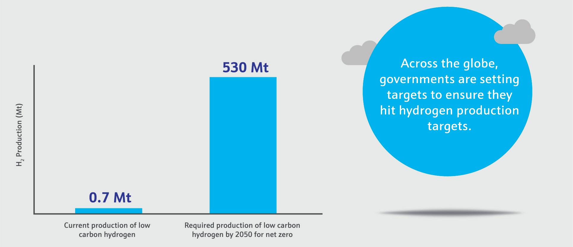
As demand for hydrogen surges, driven by ambitious sustainability targets from industries and governments, the conversation focuses on overcoming critical challenges related to scalability and cost efficiency. Despite the clean hydrogen project pipeline expanding to US$570 billion, only 7% of hydrogen projects have secured Final Investment Decisions (FID).
Challenges in scaling the hydrogen economy
The rising demand for hydrogen driven by industries and governments aiming for ambitious sustainability goals necessitates a focus on overcoming critical challenges such as scalability and cost efficiency.
Challenges and delays in scaling up the hydrogen economy underscore the complexity of this endeavour. Over the next 30 years, the objective is to entirely restructure the energy infrastructure that has driven global growth since the Industrial Revolution.
Scaling up the hydrogen economy to match the vast infrastructure of the fossil fuel economy is a monumental task. This transformation requires developing both upstream and downstream components simultaneously. Successful projects are those where stakeholders collaborate vertically, from initial energy input to the end user.
Types of clean hydrogen
There are two primary types of clean hydrogen: electrolytic hydrogen and low-carbon hydrogen.
Electrolytic hydrogen is produced by splitting water using renewable energy to create green hydrogen. This is a fascinating and rapidly growing industry, but the production method faces significant industrialisation and scaling challenges across the supply chain.
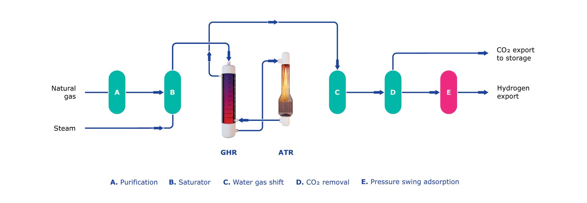
Low-carbon hydrogen is produced from natural gas with carbon capture and sequestration. This approach is mature and currently deployed worldwide, providing a scalable solution for kick-starting the hydrogen economy.
Role of low-carbon hydrogen
For now, scalability is best achieved with the mature technology of low-carbon hydrogen. This involves producing hydrogen from natural gas and sequestering the resulting carbon dioxide. Developing large-scale plants that produce substantial amounts of clean hydrogen will serve as lighthouse projects around which the rest of the hydrogen economy can develop.
One challenge is that low-carbon hydrogen is not yet a fungible commodity. Developing robust value chains and building out entire ecosystems simultaneously is essential for scaling. Developing a hydrogen project requires more than considering the inputs and production volume. Developers must also consider partners for hydrogen storage, transportation, and most importantly, the end users. Coordination and collaboration across the entire value chain are essential. Policy support, procurement subsidies, and government actions must be ecosystem-oriented, benefitting the whole value chain rather than focusing on individual players. A narrow focus on single entities will hinder scaling and development.
The companies likely to succeed in the next five years will not necessarily be those inventing new technologies but those effectively utilising the best available components and demonstrating strong project competence.
Connecting production with offtake is crucial. At Saltend (UK), Equinor built the plant next to all off-takers, but pipelines are essential for scaling up and reaching larger markets. In some areas of Europe there is a dual system initially based on the Groningen gas field, which is now shutting down. Much of the hydrogen pipeline development in northern Europe involves repurposing these low-calorific value pipelines.
While some modifications are needed, this presents a smaller barrier to developing the necessary infrastructure and, generally, in Europe, the TSOs are very proactive and forward-thinking.
Accessing talent and expertise
Scaling hydrogen production presents challenges in accessing expertise in project development and technology. Many project developers possess a high-level understanding of hydrogen projects. However, especially for green and to a lesser extent blue hydrogen, significant practical integration assistance is often required. This includes managing the integration of variable renewable energy, deciding on battery storage needs, and accessing carbon capture and storage infrastructure.
In the UK alone, there are 300 000 people who know how to work with natural gas from upstream and offshore to home boilers. These individuals can make an important contribution to hydrogen development.
Future of blue and green hydrogen
The debate on the best path forward for hydrogen – blue or green – remains significant, with both expected to play crucial roles in the energy transition. The answer varies by region, but both types of hydrogen are essential. Blue hydrogen facilities are advantageous in regions with a significant focus on industries requiring baseload hydrogen, while green hydrogen will progress rapidly as more clean electrons become available.
The goal is to develop chemical feedstocks and energy carriers essential for decarbonising the energy and chemicals sectors without greenhouse gas emissions. Focusing on the carbon intensity of these processes is crucial for future-proofing the technologies people invest in.
Deploying the best possible technology is essential to ensure scalability and futureproofing. In advancing large-scale projects,
low-carbon hydrogen from natural gas plays a significant role in optimising hydrogen production from methane while capturing the maximum amount of carbon dioxide. This approach utilises proven components already deployed in the global methanol market and ensures the lowest costs from both a CAPEX and OPEX perspective, giving the project the best chance for a competitive levelised cost of hydrogen and overall success.
The industry still needs initial support through subsidies and a regulatory framework that allows it to compete fairly with polluting alternatives. Taxing high-carbon fuels is also necessary to create a level playing field for hydrogen. Geography will significantly influence each region’s choice and technology requirements. Over the next few decades, low-carbon blue hydrogen and green hydrogen will be competing head-to-head to decarbonise the world. That they go quickly is much more important than which technology is in front at any particular time. Currently, natural gas prices set the cost of electricity in countries like the UK. Green hydrogen might set the gas price in the future, flipping the current situation.
Regional opportunities
Electrolysers can run at maximum capacity in regions with consistent wind and solar energy, making these the cheapest places to produce green hydrogen. Regions like Australia have ideal conditions for producing green hydrogen, ammonia, and methanol, while the UK and Norway have excellent geology for carbon dioxide sequestration and natural gas resources, making them prime locations for low-carbon blue hydrogen production. In the North Sea region, this creates a certain circularity. This was the cradle of enormous fossil fuel sources and due to its geological advantages, it can foster both a low-carbon blue hydrogen ecosystem and a green hydrogen ecosystem. This synergy is promising for the future of hydrogen production.
Conclusion
Despite the opportunities, challenges remain for the hydrogen economy. The biggest factor that will slow down its uptake is the lack of policies incentivising and supporting hydrogen use and demand. Many potential projects worldwide are stalling at the FID stage due to the absence of secure offtake agreements. These projects aim to limit spot market exposure because a proper hydrogen commodity market does not yet exist. To feel secure, they need over 90% offtake agreements. While there is strong ambition to produce hydrogen, there is not yet matching demand or large-scale counterparty agreements to support it. Establishing a viable hydrogen economy necessitates overcoming substantial technological, policy, and infrastructure hurdles. With concerted efforts from industry leaders, governments, and stakeholders, the hydrogen economy holds significant potential to drive the global energy transition towards a more sustainable future.

Hydrogen developers can use digital twins to improve the economic viability of renewable projects and meet increasing demand. Nas Andriopoulos, Dominik Don, Joaquin Ubogui, and Maurits Waardenburg, McKinsey & Co., illustrate how, using renewable hydrogen as an example.
As the world accelerates its decarbonisation plans, renewable hydrogen and its derivatives offer a promising alternative to fossil fuels – but to date, there are still no gigascale renewable hydrogen production plants in operation.
The demand for clean hydrogen is expected to increase significantly. New plants could be scaled to meet this growing demand, which could require investments of US$700 billion to maintain the 2030 net zero trajectory.
Currently, hydrogen demand is driven largely by the fertilizer and refining industries. The majority of hydrogen produced is grey hydrogen and, to a lesser degree, blue. To support net zero ambitions, developers and investors could use a trusted technical and financial blueprint that quantifies risk and may accelerate the scale-up of green hydrogen plants. Digital twins – which can simulate a physical plant from the planning stage before it is built to the end of its lifetime – could help reduce the risks of investment, save costs, and speed up project timelines.
This article highlights the obstacles preventing the build-out of large-scale renewable hydrogen production plants and explores how developers could overcome – or at least help to address –these challenges by using digital twins.
Challenges facing renewable hydrogen production today
Renewable hydrogen is still an emerging industry, facing short-term headwinds to realise its long-term potential. Costly infrastructure and the necessary hydrogen storage – as well as the variable nature of renewable energy sources themselves –also put pressure on plant economics. Developers struggle to confirm final grant and investment approvals, across Europe and other regions.
Uncertainties surrounding the technology, interest rates, regulatory schema, offtake market, and electrolyser availability all act as hurdles to achieving large-scale production:
� Electrolysers are a core component of any renewable hydrogen project. Recently, the CAPEX required for electrolysers increased by around 70%, driven by financing costs, labour, and materials. Variations in availability, price, and performance across a suite of options increase the complexity of project planning.
� While there are lower-cost options available for electrolysers, cheaper does not always mean better. For example, some of the first large plants in operation are now underperforming
on their minimum loads. This means that if the power output falls below 50%, these plants have to turn off the electrolysers and remove them for maintenance to solve the problem. In the future, this may change, but developers face tough choices. They need to consider the trade-off between CAPEX and performance, as well as the size and sequencing of electrolysers used in the plant.
y Investors require a high level of confidence to reach a Final Investment Decision (FID) due to the risks associated with megascale projects. Developers stand to benefit if they can secure offtake early on in the process. Once there is guaranteed offtake – ideally a minimum of 50 - 70% of production – it becomes easier to secure finance and increase investors’ confidence. However, in an environment of increased interest rates, securing a sufficiently low cost of debt to enable attractive equity internal rate of returns (IRRs) has become more difficult. This has led to some developers seeking less debt and requiring a greater share of equity – which typically increases upfront equity commitment costs by 10 - 25%.
y While recent legislations create a favourable environment for boosting renewable hydrogen demand, understanding multiple regulatory frameworks can be challenging for developers. Definitions and requirements for production – for instance, regarding carbon intensity and where production facilities can be located, and how they match output and electricity consumption – differ across regions, which compels hydrogen producers to consider a wide range of designs and operational plans to have a compliant product for multiple markets. Legislation to boost clean hydrogen production includes the 2021 US Bipartisan Infrastructure Law and the US Inflation Reduction Act of 2022 (IRA), both of which could require closer integration between renewable energy sources and the plant. Meanwhile, the EU’s Renewable Energy Directive (RED III) mandates renewable fuel of non-biological origin (RFNBO) compliant hydrogen, which introduces its own set of requirements on additionality of renewable energy and matching of renewable energy used and hydrogen production.
For megaprojects to get the green light for development, projects could be designed to ensure the lowest possible production costs over the lifetime of the plant, within some of the constraints described above. A digital twin can help to achieve this as it can evaluate hundreds or thousands of options and combinations of components to optimise plant design and increase investor confidence. The bulk of lifetime plant operating costs are locked in during design, and a digital twin supports decision making early on in the process before the plant is built.
How digital twins unlock value
Despite the challenges, hydrogen megaproject momentum is building as early movers transition to pre-FID design and engineering. Global developers are now looking for ways to solidify their business cases – and digital twins can play a significant role in this regard.
Reducing production costs
Leveraging probabilistic advanced analytics (AA) and generative-AI (gen AI) techniques, digital twins can help clarify project viability by quantifying the impact of external factors on the economic performance of a potential project design over its operating lifespan. By fully embracing digital twins, production costs (LCOx) could be reduced by 5 - 15% (Figure 1).
Some developers are already reining in production costs by using a digital twin to quantify risks and ensure that investments have the highest probability of delivering desired returns. For example, one global energy company with a series of megaprojects for renewable hydrogen and ammonia was able to identify US$500 million of NPV improvement potential (see sidebar ‘Case study: How a global energy company optimised the design of its renewable ammonia plant’).
Optimising plant design
The power of a digital twin lies in its ability to quickly evaluate plant complexities, identify optimised setups, and compare alternatives against a set of constraints (for example, regulatory requirements for green hydrogen). It can investigate all possible alternate design strategies, such as different storage sizes, multiple electrolysers and their yields, and balance of plant (BoP) setups, and can explore a broader solution space by using AI optimisation for process modelling. For instance, digital twins can simulate and compare the performance of multiple types of electrolysers under different conditions, which will increase the confidence in the planned design of the plant. For some projects, it might be beneficial to ‘oversize’ the electrolyser capacity while others may require more flexibility to balance electrolyser capacity with storage capacity.
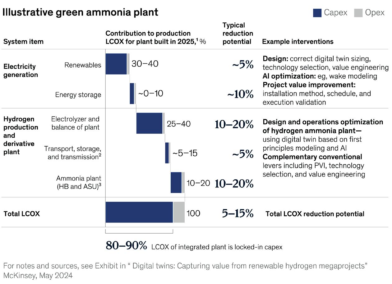
Digital twins can improve design where traditional approaches often fall short and can help to solve complex trade-offs inherent in e-plant design and engineering,


HIGH PRESSURE H₂ COMPRESSION TECHNOLOGY

Advanced Plug-&-Play Containerized Hydrogen Compression Solutions of up to 1,000 bar / 14,500 psi for sustainable and decarbonized mobility & industry storage
Reciprocating piston compression technlogy of up to 500 - 1,000 bar
Safe and reliable solution thanks to the venting system
Oil Free design compressors, with a complete turndown: 0% to 100%
Efficient cooling thanks to piston compressor innovative design
Some of our Hydrogen Customers


such as power firmness, load factor, or subcomponent selection. Some examples are provided in the following section.
Power firmness
Digital twins can help to solve complex trade-offs in power firmness by comparing the lowest-cost intermittent power sources with the need for energy storage or grid firming. This can achieve the balance of high-firmed output with an increased levelised cost of electricity (LCOE).
Load factor
Digital twins can help developers understand the electrolyser stack degradation impact on the levelised cost of hydrogen (LCOH) while defining an operative strategy. This includes defining the load factor of the different modules or arrays of the electrolysis plant. This can then be fed directly into the operating facility and planned maintenance strategy.
Process design integration
When operating a large-scale industrial process (such as direct reduction of iron, Fischer-Tropsch, Haber-Bosch, or Sabatier), high uptime and continuous process operation are critical for reactor stability and efficiency. However, renewables are inherently intermittent. Designing the end-to-end, power-to-molecules system that balances CAPEX on renewable energy sources, buffer stores, and reactor uptime is the largest driver of LCOx of the plant. Digital twins can rapidly assess and optimise the potential sizing of all elements of the system, even factoring in probabilistic elements, such as weather patterns, equipment failure, and evacuation schedules.
Sub-component selection
BoP selection is a major driver of system CAPEX and OPEX. Digital twins can help developers choose between equipment and component options. For example, modelling can show whether it is better for plant economics to pursue fewer, larger components (such as compressors or pumps) with concentrated failure points, or to install many modules of smaller components and embed additional redundancy in the process.
Product storage size
Hydrogen storage is expensive and different options can be explored. For example, a developer can invest in a smaller hydrogen or ammonia storage capacity with a great risk of stoppage, or they could choose a larger storage buffer and bear the related cost. This can be modelled to integrate with offtake schedules and contractual negotiations.
Maximising the value of a digital twin
Digital twins can deliver benefits far beyond initial design and development too. When properly set up during plant design, digital twins can form the basis of a variety of use cases throughout the plant’s life cycle.
Operations
Plant design and operations are initially considered and optimised together with a digital twin, providing greater clarity of the operation and maintenance needs of the plant to enhance planning. This technology can also provide greater cost certainty on the plant’s OPEX in advance.
Case study: how a global energy company optimised the design of its renewable ammonia plant
A global energy company with a series of megaprojects producing renewable hydrogen and ammonia faced challenges with project cost and establishing a repeatable development process across its projects. Its existing modelling approach had shortcomings in auditability and transferability between projects. The company was able to optimise its design using digital twin technology. The process included evaluating the existing design, validating key design components, and developing a probabilistic operating twin to suggest improvements. Alternative cases were analysed to optimise project design. Employees were core to developing the model and were trained on how to get the most use out of the digital twin, including how they could adapt and improve the twin after the initial study.
A US$500 million NPV improvement potential was identified, and risks were quantified and better understood. Furthermore, the number of employees who were able to use digital twin technology tripled, increasing transparency, usability, and auditability with one source of truth.
Financing and investment
Having a reliable and proven digital twin could make financing and investors’ decisions less risky, creating a better position to enhance financing rates and negotiate offtake contracts.
Serial project delivery
Having an established digital twin and embedded capability can allow faster, lower-cost development of all future projects, and enable developers to quickly test whether project concepts are viable. For example, when prioritising two projects, they can rapidly be virtually modelled and assessed. Developers can reuse their concepts for all future projects and can decide from very early on in the process which projects to drive forward and which ones to stop immediately.
Finance and management
A curated and customisable dashboard can be created to provide easy-to-access insights for a range of senior stakeholders, supporting negotiation and project stage gate reviews, as well as regular reporting once in operation.
Auditing
Digital twins can even be used as a basis for internal and external auditing, for example, by contrasting the real events on a plant’s unexpected cold stop with the model responses. They can also provide solid, future-looking economics for further operational choices.
Conclusion
Renewable hydrogen is a much-needed resource for helping the world achieve its decarbonisation goals. With the move toward hydrogen megaprojects, it is critical to make sure that plants are designed in the most economical fashion to help secure investments and reach FID. Digital twin technology can not only help to reduce initial CAPEX costs but also drive efficiency over the lifetime of the plant.

Ben Laws and Nicolai Szeliga, Siemens Digital Industries, explore how Digital Twins and the process optimisation capabilities that they bring are becoming essential components of green hydrogen projects.
The global energy landscape is transforming to mitigate climate change, with the International Energy Agency projecting that annual clean energy investment must triple to US$4.5 trillion by 2030 to reach net zero emissions by 2050.1 This shift to renewable energy sources like solar and wind faces challenges such as supply intermittency, grid instability, and the need for long duration energy storage.
The Digital Twin: optimising plant operations
A Digital Twin (DT) is defined by the Digital Twin Consortium as an integrated data-driven virtual representation of real-world entities or processes.6 In the process industry, DTs typically contain three components: the Plant Twin, Process Twin, and Automation Twin. Each element delivers distinct capabilities to different project teams and across the project lifecycle. When combined, they form an Integrated Digital Twin of an asset.
Green hydrogen offers a solution by serving as a renewable energy vector, providing long-term storage and enabling sector coupling. Power-to-X (PtX) processes, which use green hydrogen to synthesise feedstocks such as ammonia or methanol, are key to decarbonising hard-to-abate sectors from shipping to fertilizer production.2 However, large-scale use of green hydrogen and PtX faces technical and economic hurdles. Advanced digital technologies can help to overcome these challenges and accelerate adoption.
Green hydrogen: a major opportunity for decarbonisation
Green hydrogen, produced via water electrolysis using renewable electricity, is the most sustainable form of hydrogen, offering CO2-free emissions and relying solely on sustainable inputs. The electrolysis process is more efficient than traditional steam methane reformation (SMR) and can more easily adjust production rates to match demand and supply fluctuations. However, production and distribution of green hydrogen is complex and dynamic, with significant uncertainty arising from the inherent intermittency – and often higher cost – of renewables. Producers must also contend with changing demand profiles, evolving regulations, and a lack of industry-wide economies of scale. To run a production process efficiently, operators are tasked with deciding when and how to produce hydrogen to balance multiple, often competing objectives related to output, efficiency, equipment degradation, and sustainability. Decisions include how to run electrolyser clusters, what electricity source to use, and whether to store or export produced hydrogen – all of which can be constrained by operational or environmental parameters. Critically, decisions must be made and re-made continuously to adapt to constantly changing circumstances. When combined with the limited operational experience in the industry, this proves a formidable challenge for project owners. The impact is that green hydrogen is often significantly more expensive to produce than grey hydrogen.3
While global demand for clean hydrogen is projected to lie between 125 and 585 million tpy by 20504, forecasted supply lags far behind under most scenarios. To address this supply gap, project developers must bring production costs down, improving the economic viability of their assets and reducing reliance on support schemes like the UK’s Low Carbon Hydrogen Agreement.5 Digital Twins can help project owners achieve these goals.
For operating dynamic process plants, the Process Twin is particularly vital and is this article’s focus. When calibrated, Process Twins combine real-time plant data with mechanistic models to provide a predictive simulation of plant behaviour. Simulation enables continuous performance monitoring and analysis, and powers true mathematical optimisation of the process. A Process Twin typically incorporates:
y High-fidelity models: based on first-principles physics, thermodynamics, and electrochemistry, these models accurately represent the core process units and associated systems, including non-linearities and dynamics.
y Real-time data integration: live data streams from plant sensors and control systems ensure the virtual model reflects the current plant state.
y Advanced analytics: solvers and optimisation algorithms incorporate historical and real-time data to identify patterns, estimate the system’s state, and optimise operational parameters.
y Visualisation tools: intuitive interfaces allow operators to make informed decisions.
y Scenario simulation: operators can test strategies and optimise processes virtually without risking the physical plant.
By integrating each of these elements, Process Twins can empower project teams whether they are in the control room or situated remotely.
To address operational challenges in a plant, DTs must be deployed in an online environment. Deployment ensures the DT can access live information and communicate with the plant’s automation hierarchy in near real-time. Online implementation involves several steps, many of which can in fact be initiated during a project’s design phase. A full lifecycle approach to building the DT means its capabilities can be used for performance validation, scenario analysis, operator training, and other vital tasks even before plant commissioning.
The implementation process typically includes:
y Design specification and data collection.
y Model development (physics-based and data-driven).
y Digital infrastructure setup and deployment.
y User interface and visualisation creation.
y Integration and testing.
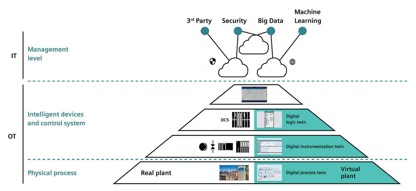
When deployed, a DT sits above the traditional automation hierarchy (Figure 1) in the IT layer, interfacing with various plant
COMMITTED TO A BETTER FUTURE
Optimizing combustion for a greener tomorrow WE’RE
There has never been a greater need to decarbonize fired equipment, produce cleaner energy sources, and operate in a more environmentally responsible way.
Optimized combustion and enhanced predictive analytics are key to reducing plant emissions and ensuring equipment uptime. Designed for safety systems, our Thermox® WDG-V combustion analyzer leads the way, monitoring and controlling combustion with unparalleled precision.
Setting the industry standard for more than 50 years, AMETEK process analyzers are a solution you can rely on. Let’s decarbonize tomorrow together by ensuring tighter emission control, efficient operations, and enhanced process safety for a greener future.
systems in the OT layer for data exchange and control. DTs can be used in either an open loop advisory mode or a closed loop implementation mode. While conventionally digital applications have been deployed in open loop mode to advise operators, development of autonomous operations in the process industry is an area of rapid evolution and increasing priority. Integrated DTs are increasingly seen as offering a reliable foundation to project owners pursuing fully autonomous and remote operations.
A Digital Twin for green hydrogen plants
Green hydrogen plants, with their inherent operational complexity, are ideal candidates for DT technology. In this application, a high-fidelity process model describes key system units, from energy input to hydrogen production, purification, compression, storage, and export. The DT application seamlessly integrates real-time plant data from critical units and flows, as well as external data such as energy supplies, tariffs, and demand profiles.
Operators interact with the online DT through dashboards that provide performance monitoring to different stakeholders located anywhere in the world. Advanced state estimation algorithms provide ‘soft-sensing’ capabilities, while rigorous production optimisation features allow for dynamic production scheduling to meet hydrogen demand efficiently.
Combining a physics-based model with live data streams improves plant behaviour simulation, aiding operators in confident decision-making. Crucially, the model adapts to short-term dynamics (e.g. weather changes) and long-term trends (e.g. equipment degradation), ensuring it remains ‘evergreen’. Its modular framework and industry-standard connectors allow easy expansion for additional data-driven capabilities, further enhancing operations and asset maintenance with features like anomaly detection, maintenance scheduling, and fleet monitoring.
DTs are becoming essential components of projects targeting a successful Final Investment Decision (FID), as they provide confidence to operators, project owners, and investors alike –especially when considering what are often highly innovative designs.
Digital Twins in action
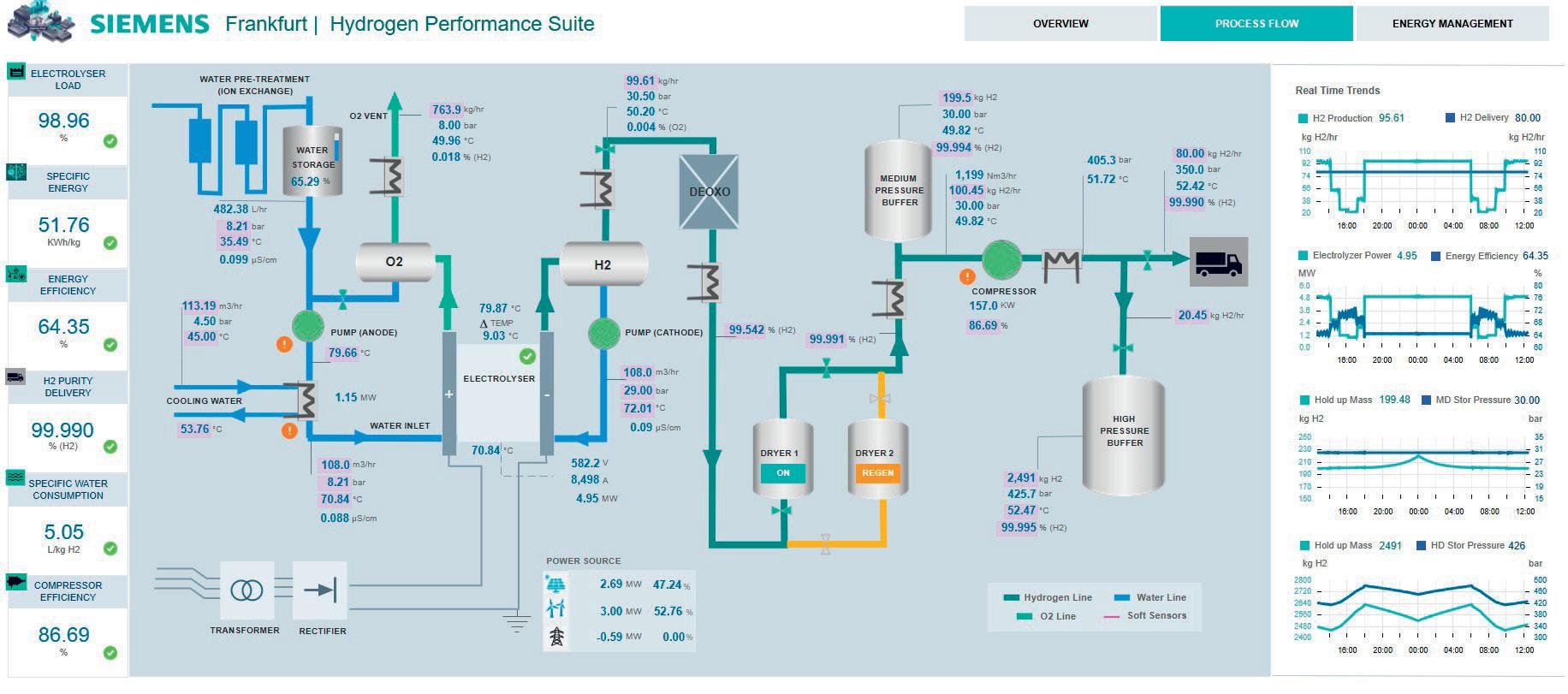
Consider a simplified demonstrator project with 5 MW proton exchange membrane (PEM) electrolyser capacity. This demonstrator uses wind, solar, and grid power to produce green hydrogen at a nominal rate of 80 kg/hr. The following case study represents capabilities that can be delivered by the Hydrogen Performance Suite, an an operational DT designed specifically for green hydrogen and PtX plants.
Dynamic real-time optimisation
Production optimisation is a task that operators face daily or even hourly. This involves scheduling the times to produce and store hydrogen – and deciding how to operate the process – to meet off-taker requirements while minimising levelised cost of production. Operators need the ability to prepare optimal production plans as well as the ability to re-optimise at short notice should the production environment change (e.g. through a sudden drop in demand or change in renewable energy supply).
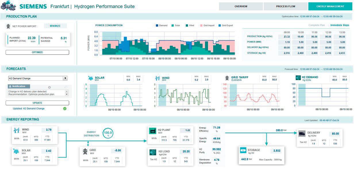
Figure 2 presents a dashboard from the Hydrogen Performance Suite, including production management information and relevant data streams. An hour-by-hour production schedule is provided for an upcoming 48-hour period, while the time profiles summarise renewable data, grid tariffs, and the hydrogen demand. In this baseline, hydrogen demand is a constant 80 kg/hr. The dashboard also delivers live


chartindustries.com howden.com
power monitoring across the asset for easy assessment of energy usage.
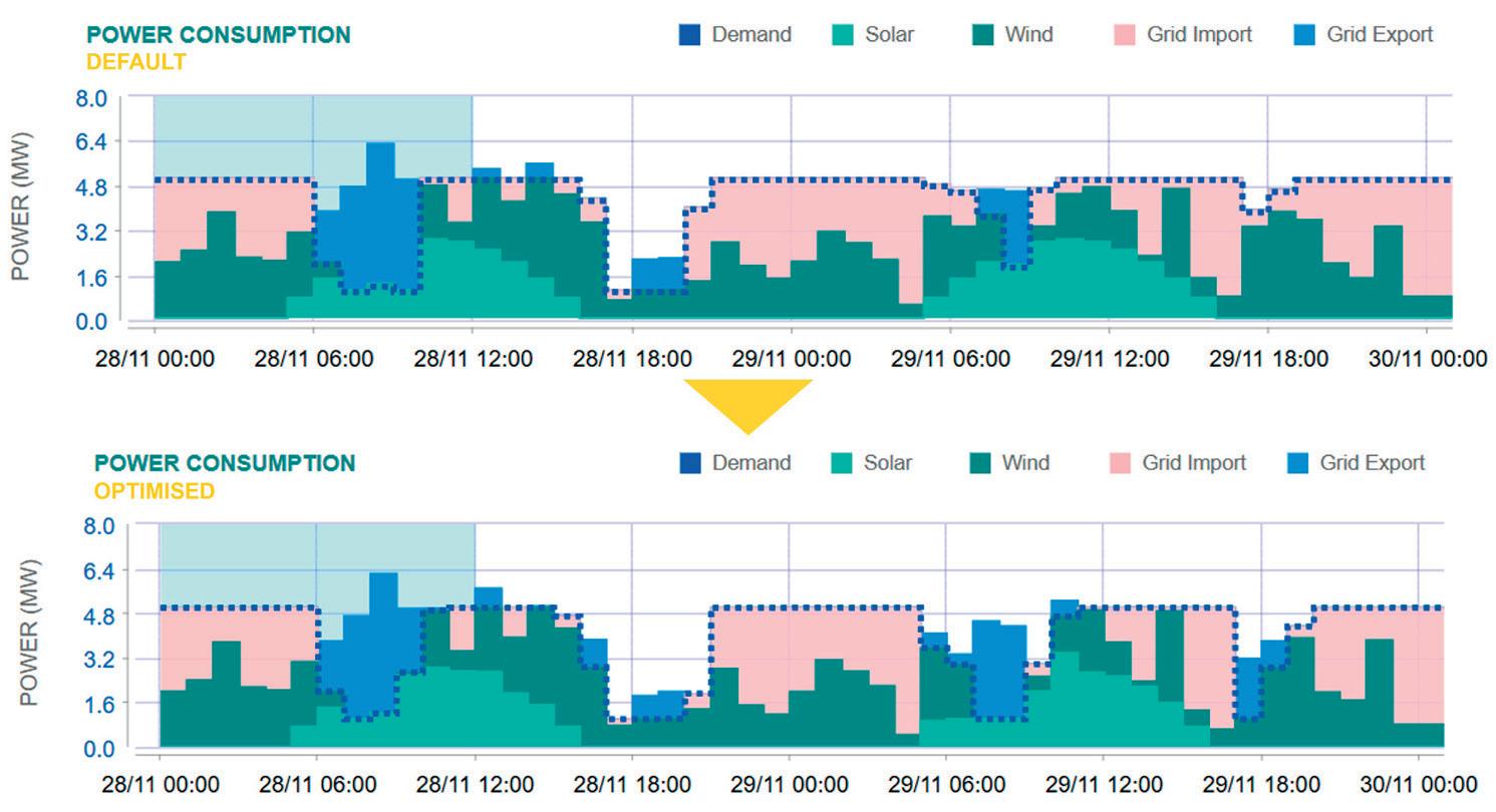
In Figure 3, a second day is represented, with different weather forecasts and a decrease in hydrogen demand for several hours. Under the baseline production schedule, 22.4 MWh grid power supply is needed to meet this demand profile. Figure 4 presents the same scenario with an optimised production plan. Hour-by-hour dynamic optimisation of electrolyser load, storage capacity, and production rate is used to minimise the use of grid energy, thereby reducing production costs and ensuring more certifiable green hydrogen is produced.
In this case, the optimiser suggests production of hydrogen at times when either renewable energy is plentiful or when the grid tariff is low. In some hours, sale of excess renewable energy to the grid is recommended to offset costs. Storage capacity is also used proactively: the stored quantity is adjusted to buffer differences between hydrogen production and demand.
Following dynamic optimisation, the total grid usage in the plan is 14.4 MWh, a 36% decrease. Realisable financial savings in this demonstrator were over 10%, indicating the significant economic potential of optimised production. Operators – or the application itself in a closed loop deployment – can implement production plans that maximise asset performance, while continuous data input and model simulation ensures every re-optimisation reflects the latest plant state.
Soft-sensing electrolyser performance
Effective dynamic real-time optimisation is only possible when an optimiser can obtain an accurate reflection of the plant state in real-time. Without this, production schedules may be based on incorrect or outdated unit efficiencies or system behaviour, limiting their utility. Equally, operators must understand the performance of critical units like electrolyser stacks to determine production cost, calculate energy usage, and plan maintenance efficiently.
While these needs may be partially addressed through sensor placement, some data cannot be measured physically due to design limitations or a lack of suitable sensors. In this scenario, soft-sensing plays a vital role. Soft-sensing is the continual calculation of key process variables using the calibrated process
model with advanced state estimation algorithms. This enables live assessment of streams or units without the need for installed sensors – or provides cost-effective redundancy for safety-critical values that are being measured.
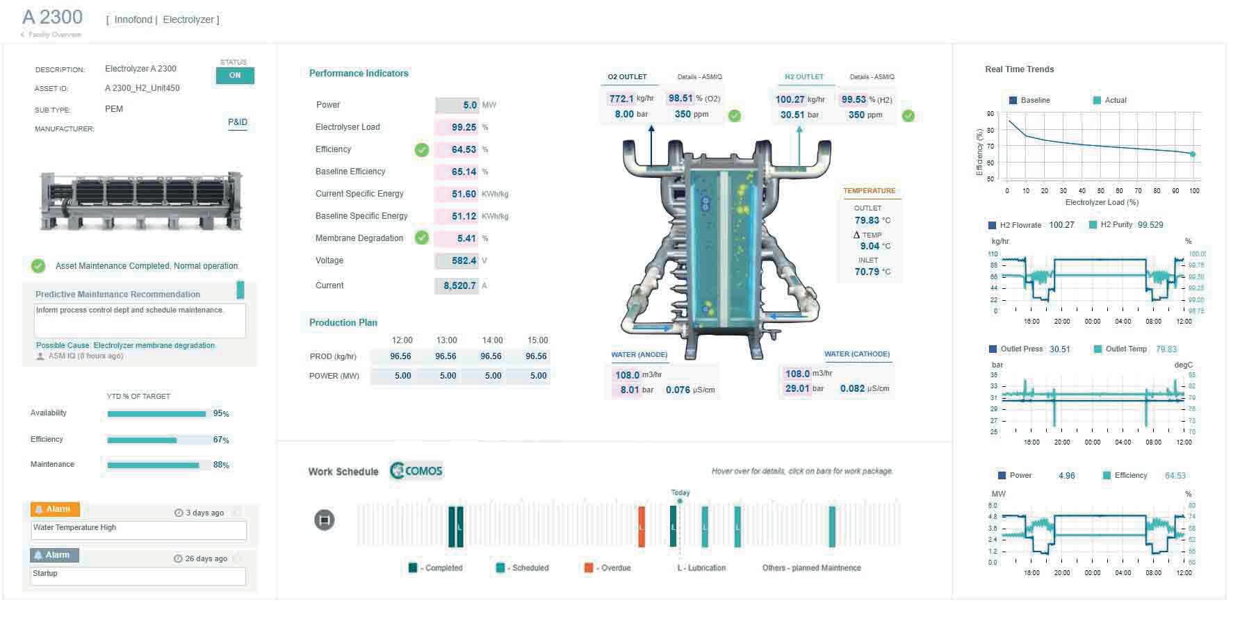
Figure 5 highlights an electrolyser monitoring page including soft-sensed variables such as efficiency, flow rates, and stream conditions. One graph compares soft-sensed efficiency to the performance information provided by the vendor. During long-term operation, efficiency may deviate from vendor-supplied expectations. With the soft-sensor installed, operators can pinpoint any deviation from the nominal performance and respond accordingly. The updated calculated values are subsequently used in the production optimisation to avoid reliance on incorrect data. Degradation models – either empirical or mechanistic – can also be incorporated and periodically re-calibrated to assess long-term performance decay.
The installation of soft-sensors leads to both superior process optimisation and a reduced need for redundant instrumentation throughout the asset. Collectively, these benefits result in significant cost savings in addition to the gains from optimised production scheduling.
Building holistic Digital Twins
Whilst dynamic process optimisation is a key route to reducing hydrogen production costs, other opportunities exist. A significant parallel challenge is the effective management of the power ecosystem. Integrating an energy management solution (EMS) – which may handle power distribution, demand response, and trading decisions – with process optimisation can unlock further performance enhancements and cost reductions while providing a more seamless workflow for operators. For PtX plants in particular, this synergy, facilitated by open data exchange, is crucial for achieving true optimality across both process and power systems. The modularity and flexible data connectors of the previously described DT enable easy EMS integration.
The industry now targets ‘holistic Digital Twins’, which unify EMS, online Process Twins, and predictive data-driven features within a single interface and application. These comprehensive tools promise to deliver superior performance improvements in a streamlined and cost-effective manner, and will represent an evolution in digital plant management.
Outlook: plants of the future
Green hydrogen has immense decarbonisation potential, but this will not be realised unless the gap between demand and supply narrows. The vital reductions in production costs are achievable through rigorous process optimisation. Online DTs, combining physics-based simulation with real-time data, offer powerful monitoring, analysis, and optimisation directly to operators. Continuous simulation can ensure plants operate near
optimal levels despite uncertainties, as shown in the Hydrogen Performance Suite case study.
DTs will continue to integrate an increasing array of capabilities, from power optimisation to predictive analytics and multi-asset remote management. These solutions are now deemed a necessary component of all major projects; owners and developers must leverage virtual replicas to navigate uncertainty, address critical production challenges, and increase the impact of their technology.
References
3. https://observatory.clean-hydrogen.europa.eu/index.php/ hydrogen-landscape/production-trade-and-cost/cost-hydrogenproduction#:~:text=Hydrogen%20production%20costs%20 via%20electrolysis,median%20of%206.20%20EUR%2Fkg.
4. https://www.mckinsey.com/industries/oil-and-gas/our-insights/ global-energy-perspective-2023-hydrogen-outlook
1. IEA Net Zero Roadmap, 2023 update, https://iea.blob.core. windows.net/assets/4d93d947-c78a-47a9-b223-603e6c3fc7d8/ NetZeroRoadmap_AGlobalPathwaytoKeepthe1.5CGoalinReach2023Update.pdf
2. World Economic Forum, November 2023, https://www.weforum.org/ agenda/2023/11/power-to-x-a-key-component-in-the-global-energytransition/
5. https://www.spglobal.com/commodityinsights/en/ market-insights/latest-news/natural-gas/081023-uksets-out-support-mechanism-for-low-carbon-hydrogenproduction#:~:text=Strike%20price%20and%20floor,gas%20 price%20setting%20a%20floor
6. https://www.digitaltwinconsortium.org/initiatives/thedefinition-of-a-digital-twin/


Antoine
and

Ghorayeb, Ali
Natour,
Yann-Olivier Placiard-Fleys,
Saipem SA, present a case study for the implementation of large-scale ammonia (NH3) storage and cracking on board of a unique concrete hull by means of a gravity-based structure (GBS).
The global demand for alternative clean fuels is gaining momentum at a constantly accelerating pace due to the pressing decarbonisation targets set at international and national levels for a multitude of industries. Low-carbon footprint, high volumetric energy density, safe storage, and easy transportation are the leading criteria for new potential commodities. In this race, one of the newly rising energy vectors that satisfies the enforced terms is ammonia (NH3), chiefly the clean ‘green’ and ‘blue’ NH3 for hydrogen (H2) applications, power generation, and propulsion.
Ammonia as a hydrogen carrier
When observing NH3 as a hydrogen carrier that combines high hydrogen density in its molecule, hydrogen has been well demonstrated as a fuel in combustion engines, gas turbines, and fuel cells, that can be converted efficiently into heat and electricity. But compared to liquid hydrogen (LH2), the refrigerated storage of liquid ammonia (LNH3) is a more feasible practice due to its larger volumetric energy density (approximately 13MJ/l for NH3 vs 8.5MJ/l for H2) and its reasonable liquefaction temperature at atmospheric pressure (-33°C for NH3 vs -253°C for H2). In comparison, the storage of LH2 requires at least five times more volume when compared to most petroleum-based liquified gases, while LNH3 requires approximately 2.4 times more volume. Therefore, the volume of LNH3 storage tanks is significantly less than storage tanks for LH2 at a similar energy requirement, even more upon counting the thermal insulation scheme of tanks. NH3 has been industrially produced for more than five decades with an extensively-established infrastructure and offtake, as well as known regulations and norms for handling and storage. A vital process to unlock this energy-dense and low-carbon hydrogen carrier lies in NH3 cracking for H2 production purposes.
Ammonia cracking process
Ammonia cracking involves a central process that reconverts NH3 into H2 at scale. The heart of this technology is the NH3 cracker, which is a catalytic cracking furnace in
which the NH3 synthesis is reversed at elevated temperatures and in the presence of a high-performance catalyst by means of the following endothermic chemical reaction:
2NH3 + (heat and catalyst) N2 + 3H2
The cracking process scheme comprises several steps (Figure 1). First, LNH3 is fed from the tank for its pre-treatment and vaporisation, and then it is cracked at approximately 800°C in the furnace unit. After the efficient integration of the heat recovery section, the purified H2 can be obtained in compliance with the predefined customer’s specifications after being processed through the pressure swing adsorption (PSA) purification unit to separate the nitrogen gas (N2) and other residual by-products. The PSA off-gas containing all the remaining H2 and N2 residues can be used as fuel to fire back the NH3 cracker, therefore maximising the overall efficiency of this process.
Presently, some distinguished licensors for NH3 cracking technology are Casale, Topsoe, KBR, Air Liquide, Duiker, Thyssenkrupp and H2SITE.
LNH3 storage: why is it special?
Anhydrous NH3 is stored in its liquid state, being either under convenient pressure at atmospheric temperature, or fully refrigerated at atmospheric pressure near its boiling point of approximately -33°C. Industrial-scale LNH3 is typically stored in a fully-refrigerated state as this scenario costs less than that of pressurisation. Onshore LNH3 tanks of capacities up to 80 000 m³ (55 000 t) are not uncommon.
The toxicity of the gas, the ability of liquid NH3 to conduct electricity, and the susceptibility of steel in direct contact with
either the gaseous or liquid phases of NH3 to stress corrosion cracking (SCC), render LNH3 storage as specific. The toxic nature of NH3 and its severe health hazards has always called for certain measures to be taken within the design and operation of bulk LNH3 facilities.
The phenomenon of SCC specific to NH3 service can be defined as an anodic degradation process that occurs when susceptible material under tensile stress is exposed to conditions leading to successive localised breakdowns of the corrosion product film formed at its surface. It has been the major preoccupation for designers and operators of LNH3 tanks in the industry, which imposes designers to set efficient preventive measures to avoid SCC and propose advanced types of crack monitoring system for NH3 primary containers. This engages the operators to have special respects for the internal inspection intervals and maintenance scheme of such storage tanks.
Resistant materials to ammonia’s SCC
Based on an interpretation of the IGC code, the principal candidate steels for LNH3 primary containment are low-nickel steels (nickel < 5%), low-temperature carbon steels (LTCSs) (with contents of manganese < 5% and carbon ≤ 0.23%), and austenitic stainless-steels. Besides, high yield strength steels are more prone to SCC than lower yield strength steels, and particularly for LTCSs, upper limits on their yield and tensile strengths are usually specified if the post-weld stress relief heat treatments are not applied.
LNH3 storage inside GBS hull


Saipem has conducted a development study to evaluate the business opportunity for a large-scale NH3 storage and cracking facility supported on a GBS. This facility comprises two identical NH3 cracking trains that are pre-sized to produce up to 150 000 Nm³/h of pure H2 product per train , in addition to trains’ associated utilities, technical buildings and rooms, auxiliary equipment, living quarters, unloading platform, and all interconnecting pipe racks that are strictly necessary to complete fully independently operable systems. Furthermore, the GBS is capable to contain inside its hull up to 300 000 m³ of LNH3 to be accommodated within a reliable technology of low-temperature storage tanks. The study was based on a plot plan of NH3 cracking technology provided by a well-recognised licensor, where the footprint envelope of each cracking train measures approximately 110 m x 80 m.
The GBS plot plan configuration adopted for the purpose of this study was fundamentally inspired from the return of experience and lessons-learnt during previous GBS projects that were designed and/or executed by Saipem. The GBS is made of monolithic concrete of 328 m long x 152 m wide at its base slab level. The GBS height was adjusted sufficiently to meet the floatability and in-place stability conditions, as well as to contain the required target gross storage volume of NH3

WHEN WE GIVE IT A NEW LIFE


Our goal is to lead the transition towards a net zero economy.
Our FLEXIBLUE® low carbon technologies o er advanced solutions in hydrogen and ammonia, reducing carbon emissions up to 99% while optimizing e ciency.
We are improving sustainable solutions that ensure future generations can meet their needs while respecting the planet, fully believing in research and innovation, integrating technologies, engineering, contracting and construction solutions that reconcile industrial progress with environmental responsibility.
Trust Casale to provide the high-performance, reliable solutions needed to meet your decarbonization goals.
Join us in pioneering a cleaner, more sustainable future.
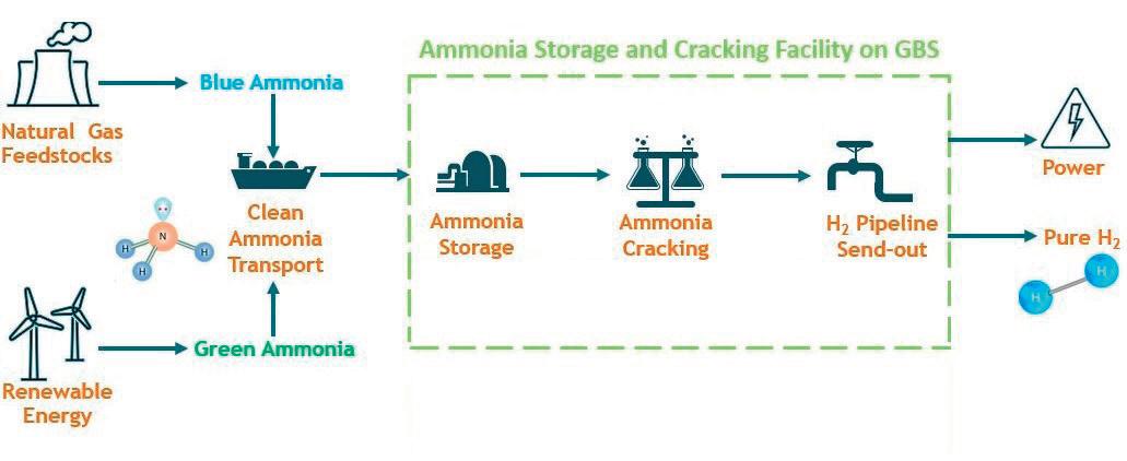
Figure 2 shows the plan view of the GBS at NH3 tanks level. The yellow rectangles represent the NH3 tanks, the brown areas are the wet-packed sand ballast tanks, and the blue areas are the seawater ballast tanks. The green compartments are reserved for utilities and storage of other products, and the remaining compartments are used for access ladders, stairways, ballast pumps, LNH3 transfer pumps, dry compartments, etc.
For the LNH3 primary containment system inside the GBS hull, a self-supported fully-refrigerated prismatic Type-A tank system was selected. It is a relatively thick-plated metallic tank made of 3.5% nickel steel with all required stiffeners inside. The tank insulation is made from closed-cell poly-urethane foam panels mounted directly on the outside of the tanks shell. The tanks prismatic shape offers wide flexibility for eventual integration into the caissons of GBS, regardless of any geometrical complexities. It also favours the optimisation of the quantities of construction materials. The GBS includes four metallic NH3 tanks of prismatic type satisfying a gross storage capacity of approximately 77 250 m³ each. The guaranteed daily boil-off rate for this configuration would be 0.03% - 0.04% by weight for each tank.
Around 225 000 m³ of concrete is estimated to construct the GBS hull structure. To allocate for sufficient GBS floatability during temporary and towing phases, the use of various concrete types of modified-density and light-weight aggregates should be considered. The overall GBS net dry weight is estimated to be about 690 000 t and the expected under keel draught during towing is projected not to surpass 14 m, closely depending on the prevailing metocean conditions from the GBS construction yard to its selected installation site, as well as on the general arrangement and actualised weights of the topside modules.
Why adopt the GBS concept?
Generally, GBS has demonstrated to be a robust, flexible, and adaptable solution that is suitable for the storage of various refrigerated liquified gases (RLGs), including LNG, LPG, and ethane. GBSs, in different forms, have been successfully deployed in the oil and gas industry for more than 30 years. Whilst its application set records with structures such as the Troll A platform in the late 1990s, the GBS technology is undergoing a strong comeback as the energy industries scramble to decarbonise on one side, and to meet the intensified global demand for LNG in the market on the other side.
Specifically, the GBS concept can allow the entire integration of all topside structures and modules necessary for NH3 cracking processes on a single concrete hull that contains the NH3 storage tanks itself. The performance of construction activities can be maximised in a safely protected and well-controlled
work environment, whether at the GBS construction yard or in the fabrication yards of topside modules, NH3 tanks, and other large mechanical outfitting elements. The GBS can be floated-out, towed, positioned, and sunk at its installation site with the strict minimum on-site works (ballasting, hook-up, commissioning, and ready-for-start-up). Additionally, the GBS design can be reproduced with limited customisation, and GBSs can even be relocated at any instance during their service lifecycle due to their ballast system at a minor maintenance cost.
Recently, to support natural gas pre-treatment and liquefaction, three GBS units (3 x 6.7 million tpy LNG trains) were designed for construction, with a storage capacity of 229 000 m³ of LNG contained inside each GBS. As part of this project, Saipem has carried out extensive FEED works including engineering and constructability studies, that was succeeded by key contribution to EPC phase.
Indeed, amongst all the liquid hydrogen carriers, NH3 has attested itself as a carbon-free and sustainable product. In close similitude with LNG applications, GBS can significantly contribute to the NH3 value chain by supporting NH3 storage and cracking for hydrogen production (Figure 3). It can also be utilised for inland H2 distribution systems, or for the generation of thermal power, or for bunkering vessels at-scale with LNH3 or LH2 as fuels.
In this context, the general architecture of GBS is designed to provide a rigidly massive structure, which is a basic requirement for NH3 storage. The GBS benefits from very high resistance and adaptation to harsh environmental conditions. The safety risks are markedly mitigated since all the facility components are situated relatively far enough from populated areas. In the worst-case scenario of high-speed collision inducing very significant local damages to the GBS caisson, this would never result in the loss of the primary containment due to wide buffer compartment corridors that entirely enclose the NH3 tanks.
Conclusion and perspectives
Saipem has developed an objective assessment of the opportunity for the development of a NH3 cracking and storage facility situated on board of a GBS that can produce up to 300 000 Nm³/h of H2, with GBS hull accommodating up to 300 000 m³ of LNH3, being equivalent to more than three times the storage capacity for conventional very-large LNH3 carriers.
In the near future, the number of GBSs has an opporunity to increase worldwide since this solution has proven to be convenient for most RLGs applications, for all types of vessels, and could be tailored to attain large storage capacities with negligible onshore space. The modular concept that is consistently adopted for GBS topside structures and its storage tanks offers countless advantages in terms of eased logistics, enhanced safety and quality control, cost-effectiveness, overcoming the lack of local skilled labour, and severe weather conditions at site, as well as time-saving benefits. The main complexity that could be met in such projects is that the GBS technology, being a site-specific solution, demands the timely availability of a suitable construction yard.
Saipem aims to capitalise on its expertise to provide reliable solutions to its clients during such large-scale GBS projects.
The electrification of everything will create a doubling of global electricity demand by 2050 according to the International Energy Agency (IEA).1 The simple truth is that renewables cannot meet this demand alone. The world is betting on a 100% renewables future without enough determination to fast-track the supporting clean technologies, such as renewable hydrogen that will make this possible.
Innovation is the currency for solving the world’s big problems. Hydrogen has unparalleled potential to drive the energy transition – but it faces barriers to growth. Two things are required to
Javier Cavada, Mitsubishi Power, outlines the approach required from governments and decision-makers worldwide to fulfil the potential of hydrogen in the energy transition.

overcome such barriers: a pragmatic approach that identifies where hydrogen can directly fit into energy systems now; and a vision for its long-term potential to decarbonise a range of high emitting sectors.
Europe is well behind on delivering its hydrogen goals, with a recent report from the European Court of Auditors suggesting a ‘reality check’ on Europe’s Hydrogen Strategy.2 Among the barriers to growth are high financing costs, investor confidence and a lack of off-takers. To overcome these, the hydrogen industry in Europe needs stronger demand signals from government – moving from policies to targets and commitments to contracts.3
If hydrogen is to scale, bold decisions must be made. Policy and regulation must be used to create the conditions for private capital to follow – to create cross-border and global trading and unlock the socio-economic benefits of this clean molecule with vast potential. This requires hydrogen to be recognised through an international certification to drive investor confidence, get projects to Final Investment Decision (FID) and demonstrate its potential through real-world projects. After this, hydrogen can be utilised and confidence can be built in its ability as an agent of decarbonisation, particularly for heavy industry.
Where hydrogen fits into the energy transition
Renewables will be the mainstay power source in a low-carbon future, but it is not possible to leapfrog to a system wholly reliant on wind and solar power. Otherwise, a route would have already been found. Renewable power is intermittent, unreliable and not domesticated enough to be directly delivered to homes via existing grid systems – it requires back up.
Across the world, natural gas is used in gas peaker plants to provide dispatchable power at peak demand and ensure grid stability – a factor that is rising in importance as more wild renewable energy comes onto grids. But in a low-carbon scenario, hydrogen will blend with gas, and longer-term, could fully replace gas in turbines to generate electricity. This is an immediate route for hydrogen to be incorporated into existing power systems to deliver emission reductions.
COP28 in Dubai, UAE, was important in many respects, including witnessing many historic agreements. The parties committed to tripling renewable energy capacity by 2030, and according to experts, this goal is the single biggest action the world can take for the climate in this decade.4 While there is no single solution to the decarbonisation puzzle, the technologies that will be prioritised are those supporting and enabling renewables.
Enabling electricity from renewables must always be the long-term solution towards decarbonisation. It plays two vital roles in the energy transition; it can mitigate emissions and decarbonise energy supply chains. As more energy is electrified for use with consumers, business and industry, the share of electricity will need to increase. In Europe, this is already happening.
From January to June 2024, emissions-free sources produced 74% of EU electricity, of which 50% was from wind and solar, according to industry association, Eurelectric.5 The rapid addition of
new renewable capacity in 2023 saw the EU build 56 GW of solar, and 16 GW of wind capacity.
Building more clean energy capacity is critical, but unless there are more technologies capable of storing electricity, more power will be wasted. Emerging, growing technologies like hydrogen, long duration energy storage (LDES), interconnectors and smart grids maximise the power of renewables. By doing this, the trajectory of decarbonisation can be changed if these technologies are scaled at the pace required – but more needs to be done to push these technologies forward.
Hydrogen’s ‘modest progress’
There has been ‘modest progress’ made in creating the demand for green hydrogen, according to IRENA.3 This is despite over 42 countries around the world having specific hydrogen strategies and tens of billions of dollars invested at a country level. A number of operators led by Mitsubishi Power have ‘hydrogen-ready’ gas fired power plants, but a full transition to hydrogen in the short-term is limited by the volumes available.
Europe, the US, Japan, Oman and Australia are amongst those heavily invested in hydrogen. If the 2030 global production goals of 60 - 70 million tpy of green hydrogen are to be achieved, major progress must be made in the next five years. The majority of hydrogen projects have not reached FID. While significant pieces of legislation have been passed such as the EU Fit for 55, Japan’s Green Transformation Basic Policy and the US’ Inflation Reduction Act (IRA), the progress of hydrogen is positive but lacking acceleration.
Certifying hydrogen as a renewable energy class of its own
Hydrogen must be viewed as a renewable energy asset class of its own with a certification scheme that reflects this. It is encouraging to see steps taken at COP28 to certify hydrogen and create a global standard – the signing of The Declaration of Intent by 38 countries is excellent progress and paves the way for scaling hydrogen, but things must move faster to have impact.6
As a technology developer, Mitsubishi Power works to global technical standards to ensure it meets the needs of all customers in every market. The same approach is needed for hydrogen – to create a level playing field to prove hydrogen’s green credentials and create the conditions for growth. Mitsubishi Power has highly invested in the creation of hydrogen value chains and recognises that the existing funding and subsidy mechanisms are not sufficient to meet demand.
A 100% renewables future
Mitsubishi Power has been exploring the potential of hydrogen for decades and recognises it as a solution that is creating a pathway towards a 100% renewable energy future. As a diverse and flexible molecule, its versatility is its ace card; it has all the power capabilities of a thermal power source like gas, while also solving the problems that renewables present on grids.
Beyond its role in stabilising and storing intermittent renewable energy, hydrogen can decarbonise existing (fossil-fuelled) power systems, which account for over 60% of global carbon emissions. It can transform energy intense sectors such as steel, cement and aluminium manufacturing to achieve net zero emissions, and open a pathway for highly industrialised countries towards full-scale decarbonisation.


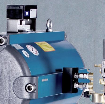


Germany’s Power Station Strategy is an excellent case study 7 , placing hydrogen at the centre of its long-term decarbonisation plan. This prioritises the installation of gas-fired power stations, to run on hydrogen, supporting German industry to make progress towards the production of steel, cement, and other energy-intensive products with zero carbon emissions by 2045.
Global hydrogen projects
Mitsubishi Power identifies where certain markets and regions are on their decarbonisation pathway and supports them with
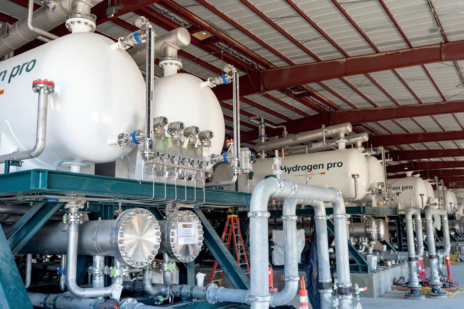
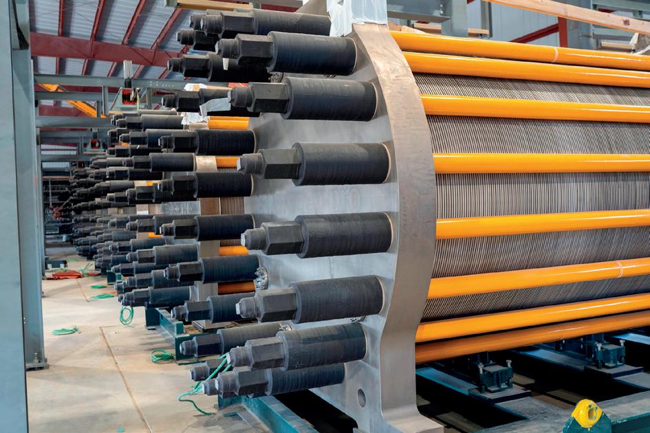
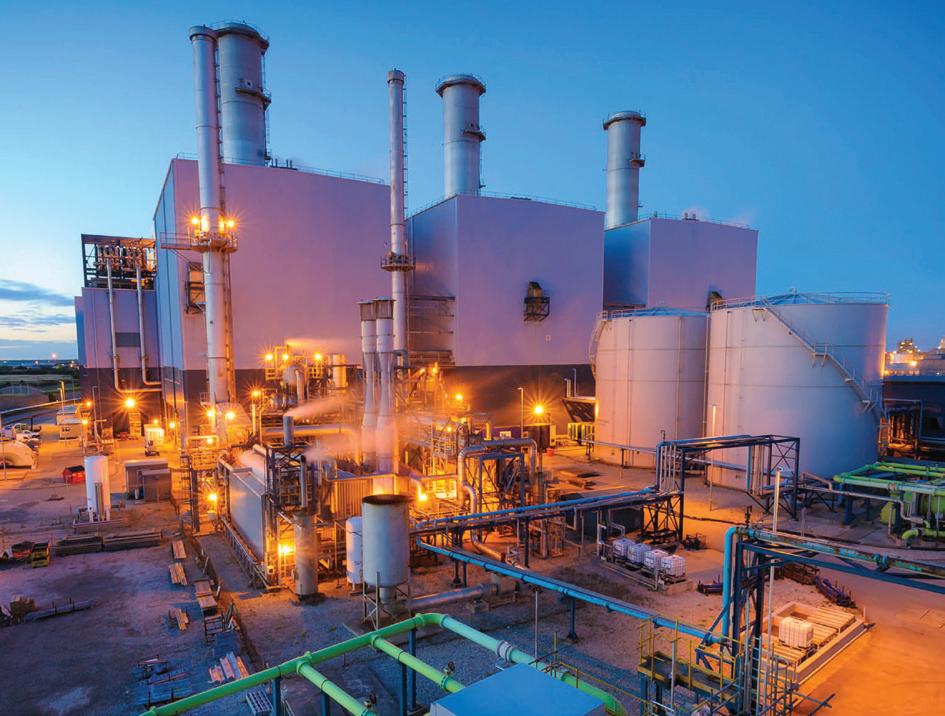
appropriate technologies and solutions to derive maximum efficiency in the process.
The Advanced Clean Energy Storage Hub, Aces Delta, Utah, US
The Advanced Clean Energy Storage Hydrogen Hub – or ACES Delta Hub – will be the US’ largest hydrogen storage facility when it enters operation. It will be the first project to combine utility and industrial scale renewable hydrogen production, storage, and transmission, and support Intermountain Power Agency’s ‘IPP Renewed’ project, which will transition from coal-fired electricity generation to clean power. The fully-funded project will enter commercial operation in 2025.
The main component of the project is the construction of an 840 MW hydrogen-capable combined-cycle power plant employing two Mitsubishi Power M501JAC gas turbines. These will initially run on a blend of 30% green hydrogen and 70% natural gas, starting in 2025 and incrementally expanding to 100% green hydrogen by 2045.
The project will convert green hydrogen using a large electrolysis facility and store it underground in salt dome caverns the size of the Empire State Building. During the first phase of the project, Mitsubishi Power is building two of these caverns, which will have 300 000 MWh of storage capacity.
In the future, the salt dome has the capacity for 70 - 100 caverns. This creates the potential to store a huge amount of hydrogen, enough to provide storage for the entire Western US.
H2H Saltend
In the UK, Mitsubishi Power has partnered with Equinor and SSE Thermal to provide hydrogen-ready gas turbines for H2H Saltend – a 600 MW low-carbon hydrogen production plant with carbon capture, as part of the Zero Carbon Humber partnership.
H2H Saltend will convert natural gas to hydrogen and capture the resultant CO2 emissions. In the first phase, the Saltend project could reduce emissions by 900 000 tpy. The partnership brings together stakeholders ranging from energy companies to academic institutions and organisations to create the world’s first net zero industrial cluster by 2040 through low-carbon hydrogen, carbon capture, and negative emissions, known as carbon removal technology.
The message to governments across the world is simple –unleash the potential of hydrogen now. Societies have already made the decision to use more and more power. To simultaneously make progress on pressing climate goals there is only one option – fast-track the technologies that will enable renewables, with maximum commitment and determination. Clean hydrogen has a central role to play – driving its potential forward is the key.
References
1. ‘Net zero by 2050: A roadmap for the global energy sector’, The International Energy Agency (IEA), (2021).
2. https://www.eca.europa.eu/en/publications/SR-2024-11
3. IRENA, ‘International cooperation to accelerate green hydrogen’, (2024).
4. https://ember-climate.org/insights/research/tracking-national-ambitiontowards-a-global-tripling-of-renewables/
5. https://www.reuters.com/sustainability/climate-energy/eus-power-mix2024-greenest-yet-industry-data-show-2024-06-30/
6. https://www.cop28.com/en/energy-and-industry/launch-of-declaration
7. https://www.bundesregierung.de/breg-en/news/power-stationstrategy-2257994

Klaus Brun, Ebara Elliott Energy, USA, addresses the challenges associated with adapting turbomachinery in order to meet the demands of sustainable energy and hydrogen production.
Public demand for reliable, affordable, clean energy is gradually shifting the global energy supply from a heavy reliance on fossil fuels to a mix of non-carbon-emitting sources such as renewables and nuclear power.
The US Energy Information Administration (IEA) forecasts estimate that by 2050, nearly one-third of the world’s primary energy will come from wind, solar, and hydropower, while the remainder will still largely consist of fossil fuels. 1
Expanding carbon-free energy sources alone will not achieve net zero decarbonisation or mitigate potential climate change. In tandem, the existing fossil fuel infrastructure must also be decarbonised through carbon capture and sequestration, while minimising socio-economic, safety, and environmental impacts.
The transition from a fossil-fuel-based energy economy to a sustainable energy economy presents significant infrastructure challenges. Much of the current energy production, transport, storage, and distribution infrastructure cannot be easily adapted to the new value chain of liquids and gases, and will need to be replaced. Traditional hydrocarbon fluids like crude oil, gasoline, and natural gas are set to be replaced by hydrogen, ammonia, and even carbon dioxide, to form the backbone of the new energy system for transport, utilisation, and decarbonisation toward a net zero economy.
While many countries aim to be fully decarbonised by 2050, a transition period of 30 to 50 years is more plausible given the scale of changes needed throughout the energy value chain. Turbomachinery plays a crucial role in the infrastructure and must be adapted or replaced to meet evolving demands of sustainable energy production. During this lengthy transition, the energy industry must continue to handle existing hydrocarbons while developing technologies to process decarbonised fluids.
Transitioning toward a sustainable energy economy
Four key fluids are critical in the energy shift toward net zero:
y Natural gas as a short-term, low-carbon transition fuel.
y Carbon dioxide captured for sequestration from fossil fuel power plants.
y Ammonia as a diesel substitute for marine and land transport.
y Hydrogen as a zero-carbon secondary energy carrier and chemical storage medium.
Natural gas
In the near-term, the turbomachinery industry is facing increased demand for LNG due to geopolitical instability. LNG, with its low carbon-to-hydrogen ratio, is also seen as a cost-effective transition fuel. For every 1000 hp of compression required in an LNG plant, approximately 10 000 hp is needed along the natural gas supply chain, causing short-term demand for turbomachinery to exceed global manufacturing capacity.
Carbon dioxide
In the mid-term, fossil fuel power plants will continue to produce carbon dioxide, which must be captured and sequestered. Currently, about 80% of the world’s primary energy comes from fossil fuels, and it is unlikely that non-carbon energy sources like wind, solar, hydro, nuclear, and wave power can fully replace this. Therefore, CO 2 must be captured using pre- or post-combustion
separation processes, and then transported to storage for long-term sequestration. While viable technologies for carbon capture and storage (CCS) exist and have been demonstrated, the necessary infrastructure – compression stations, pipelines, and injection sites – is expensive and still needs to be built. This poses a dilemma for technology providers, particularly turbomachinery manufacturers, as they must invest in developing new technologies with a relatively short commercial window of 20 - 30 years before non-fossil energy sources dominate. Fortunately, many CCS-related machinery technologies already exist or can be adapted from other applications, reducing the financial risk.
Ammonia
Ammonia, widely regarded as a viable carbon-free energy carrier for hydrogen, and a potential diesel replacement for marine and land transport, faces similar challenges. The technology for ammonia production, compression, and pumping already exists due to its widespread use in the fertilizer industry. While there are safety risks associated with ammonia handling and storage, these are well understood and can be managed based on industrial experience.
Hydrogen
The technology for handling hydrogen, the fourth critical fluid of the net zero transition, is significantly more complex than natural gas, carbon dioxide, or ammonia. As global energy demand shifts toward carbon-free sources, electrification will increase, but hydrogen will also play a key role in industries where electrification is not viable, such as chemical, petrochemical, cement, and heavy industrial processes. Blue hydrogen, due to its economic advantage over green hydrogen, is expected to be the main transition fuel in the near-term. Currently, blue hydrogen is three to five times less expensive than green hydrogen, even accounting for carbon capture costs, and this cost gap is expected to persist for the next 10 - 20 years until advances in electrolysis make green hydrogen more competitive. 2
Because blue hydrogen production relies on fossil fuels, it is not truly ‘green’ energy. Basic chemical stoichiometry shows that at least 6 kg of CO 2 is produced for every kg of hydrogen from natural gas. In reality, the actual figure is closer to 20 kg of CO 2 per kg of hydrogen due to energy requirements and losses in the natural gas supply chain. This number increases 2 - 3 times when hydrogen is produced from coal. A fuel that generates 20 times its own mass in CO 2 cannot be considered green, especially when produced on an industrial scale. Infrastructure needs for blue hydrogen are relatively limited, as natural gas or coal can be transported using existing pipelines, rail, barges, or trucks. Developing a dedicated hydrogen transport network for blue hydrogen makes little sense given that the fuel source is already efficiently transported. However, green hydrogen, which serves as an energy carrier, will likely be produced near wind and solar plants, requiring a new network
of hydrogen transport pipelines. Unless green hydrogen is produced solely to avoid energy curtailment, it would be inefficient to incur the power losses associated with transporting electricity over the grid before producing hydrogen through electrolysis. Additionally, blending hydrogen into the existing natural gas pipeline network is not a viable large-scale solution due to safety concerns. Most of the current natural gas infrastructure is not equipped to handle any significant percentage of hydrogen safely, particularly for domestic and small industrial users.
In summary, hydrogen from green sources is expensive and will require new pipelines and compression infrastructure, while blue hydrogen, though not truly green, will require new CO 2 transport and sequestration infrastructure.
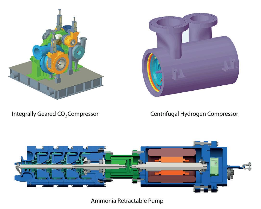
These changes represent significant challenges for turbomachinery manufactures who must invest in new technology without certainty about which solutions will ultimately be required. While the transition to sustainable energy sources offers many opportunities for turbomachinery OEMs, including rotating equipment for wind, solar, geothermal, hydro, and nuclear plants, or compressors and pumps for carbon capture and direct air capture, uncertainties remain. Hydrogen and ammonia will need to be transported through new pipelines, and intermittent energy sources require mechanical and thermal storage. Heat pumps and other systems will be essential for reducing energy consumption and improving industrial efficiency. All of these scenarios demand innovative turbomachinery solutions (Figure 1), which in turn will require significant research and development (R&D) funding, new fabrication and testing facilities, and robust service and supply chains.
From an R&D and engineering standpoint, these product challenges are manageable, though they require new machines and cycles for handling complex fluids like CO 2 , hydrogen, ammonia, methanol, ethanol, and dimethyl ether (Figure 1).
The main technical difficulty lies in the lack of test data, complex processes, and evolving specifications, codes, and standards. These are issues that most manufacturers’ product development teams know how to address. The more daunting challenge is the limited production capacity and supply chain uncertainty of all global turbomachinery manufacturers. High costs, lengthy design times, and the need for new facilities discourage rapid investment in the new technologies required to meet sustainability product objectives.
Summary
The global push for sustainable energy presents a risky transition for manufacturers, as many of these emerging markets are still speculative and uncertain, with some being more vision than reality. The total global manufacturing capacity for large industrial
barrel-style centrifugal compressors is currently around 500 - 600 units per year. Nearly all are purchased by traditional oil and gas companies, with lead times often exceeding 24 months. There is little spare capacity in the turbomachinery supply chain, and given the historically cyclical demand, manufacturers are hesitant to significantly increase turbomachinery production capacity.
However, if some projections for CO 2 capture and hydrogen demand prove accurate, turbomachinery manufacturers will need to drastically adjust their internal supply chains to meet the growing demand for these machines. Unfortunately, these compressors are fundamentally different from those used in hydrocarbon processing, requiring new manufacturing processes, testing facilities, and service networks. In the meantime, demand for conventional turbomachinery for oil and gas applications is still growing because of increasing energy demand from developing countries. Therefore, turbomachinery manufacturers are unlikely to risk their financial future on uncertain forecasts for the sustainable energy transition without clear, present demand for these products and while their traditional hydrocarbon markets are still solid.
Most manufacturers will likely adopt a gradual approach for sustainable energy product development, adjusting their technology, manufacturing, and service capabilities based on actual market demand rather than overly optimistic projections.
References
1. ‘Today in Energy’, US Energy Information Administration, (October 2021).
2. https://www.linkedin.com/pulse/blue-hydrogen-expensivedistraction-robert-walsh


Scot Bauder, Emerson, USA, explains how properly specified valves and related control equipment can ensure reliable operations when designing the systems required to convert grey hydrogen to blue hydrogen.
the less concentrated and impure CO2 associated with the flue gas is not so easily scrubbed and recovered.
Conversion of SMR systems to blue hydrogen production is relatively straightforward. The CO2 from the amine unit is further scrubbed, pressurised, and liquified to transfer it to a carbon storage facility. If flue gas is ducted to the amine unit as shown in Figure 1, it may require further processing steps to clean the gas. Most SMR plants converted to produce blue hydrogen tend to focus on the CO2 generated in the amine section, while venting the flue gas since it is so much more difficult and expensive to recover.
Blue hydrogen production using ATR
ATR is a newer process gaining traction in the blue hydrogen design arena. It utilises many of the same steps as SMR, but it is more fuel efficient and creates a single concentrated CO2 stream, rather than two as with SMR (Figure 2).
Natural gas is desulfurised and preheated, and then mixed with high-pressure steam and heated further in the presence of a catalyst. This gas is then burned with pure oxygen to create a very high-temperature syngas. The difference between ATR and SMR is that the initial ATR steps require very little fuel, if any, with the bulk of the energy coming from the oxygen injection step. This reduces energy requirements and generates a single, pure, and concentrated CO2 stream that is easily captured.
Downstream of the autothermal reformer, as shown in Figure 2, the SMR and ATR processes are essentially the same. The shift converters react any remaining CO and water into CO2 and hydrogen, and the amine section absorbs the CO2from gas stream before the hydrogen is purified in the PSA.
The chief advantage of ATR units is that they are more efficient than SMR for blue hydrogen production, and they make it possible to capture much more of the greenhouse gases than SMR. The disadvantage of ATR is the requirement of an oxygen source or an air separation unit. Also, far fewer ATR plant designs exist, so the technology is less mature and only now being brought into production. However, ATR is a promising and likely-preferred technology for future designs intended to produce blue hydrogen as it has been specifically designed for this service. There are several ATR plants in various stages of design and early construction across the globe.
Valves, regulators, and relief valves in blue hydrogen production
Whether using SMR or ATR technology, the blue hydrogen process poses a number of challenges for the automated valves, regulators, and relief valves that help control and protect the process. The presence of hydrogen in the hot syngas stream around the reformers, and in the final product, creates significant challenges for control equipment. Hydrogen embrittlement can degrade the mechanical integrity and performance of the valves,


Figure 1. SMR combines methane (from natural gas) and steam (heat recovery steam generators [HRSG]) at very high temperatures to create hydrogen, CO2, and CO. Shift converters change CO to CO2, which is removed in the amine section. Hydrogen purity is controlled in the pressure swing adsorber unit downstream.
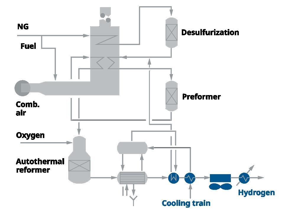
Figure 2. ATR combines methane (from natural gas) and steam, and it then adds pure oxygen to create syngas at very high temperatures. The resulting syngas feeds amine and hydrogen purity sections, similar to the SMR process.
and this can result in increased emissions and inefficiencies. High pressures and temperatures are also common, and the various gas components require a range of materials of construction to suit each application.
Manual and automated block valves must include the correct materials of construction, carry an API 607 certified firesafe rating, and may require SIL 3 certification for shutdown applications.
The selected ball valves should have durable seats for low temperature applications, and the correct materials for high temperature applications. They must also carry the required API and SIL certifications, offer live-loaded low-emission packing and a variety of body styles, and have a proven track record in high-pressure and hydrogen service.
Depending on specific conditions and pipe sizes, a double eccentric C-ball valve or a triple offset metal-to-metal seated butterfly valve may also serve as isolation valve alternatives. Both valves are suitable for a wide range of temperatures, pressures, and fluid conditions, and both are inherently fire-resistant. These valves are discussed in more detail below.
The wide range of material requirements can be a problem for regulator selection due to the limited range of options. Fortunately, some models can be specified in stainless steel, Monel, Hastelloy, or nickel-aluminium bronze to provide control across a wide range of pressures from 5 to 150 PSI.
High-capacity relief valves are often required for these processes, and these safety valves must seal tightly to avoid losing product. Additionally, the relief valves may operate close to their pressure setpoints, making a tight seal even more difficult to achieve and maintain. Enhanced seal tightness pilot relief valves work well in these applications. These types of pilot-operated relief valves have very high capacity, and newer models allow a valve to operate within 2% of its setpoint, with minimal leakage.
Carbon capture control valve selection
Whether SMR or ATR is used, the general processing steps are relatively similar between the two plant designs once the syngas has been produced. In both processes, the lean amine feed valve is critical for proper operation (Figure 3).
To efficiently scrub CO2 from the syngas, the lean amine feed valve must provide a consistent flow of amine to the top of the absorber, despite a high pressure drop and cavitating conditions. The best valve for this application will be a single-seated 316SS valve with hardened Alloy 6, anti-cavitation trim, and enhanced packinng.
PSA isolation valves
The valves around the PSAs are subjected to very challenging service conditions. These valves are continuously cycled and must maintain virtually zero leakage and low emissions while ensuring isolation performance, despite high pressure and vacuum conditions, elevated temperatures, and the presence of erosive powdered bed media.
Compared to other automated valve designs, triple offset designs (Figure 4) provide a smaller footprint and less weight, improved operability, reduced fugitive emissions, and a longer valve life for this difficult application.
The triple offset valve selected for this service should use Stellite™ 21 alloy as a standard for valve body welding overlay to achieve higher resistance to galling, abrasion, erosion, and corrosion. This feature – combined with a solid seal ring, reinforced


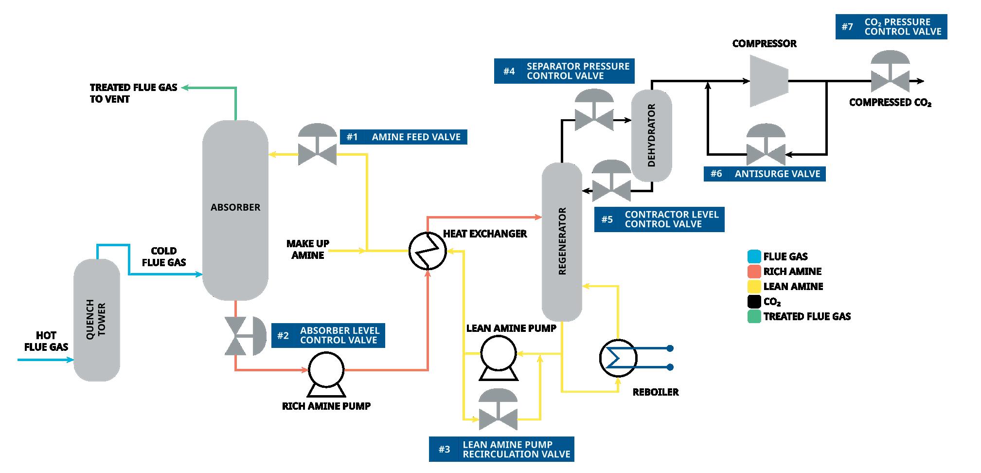
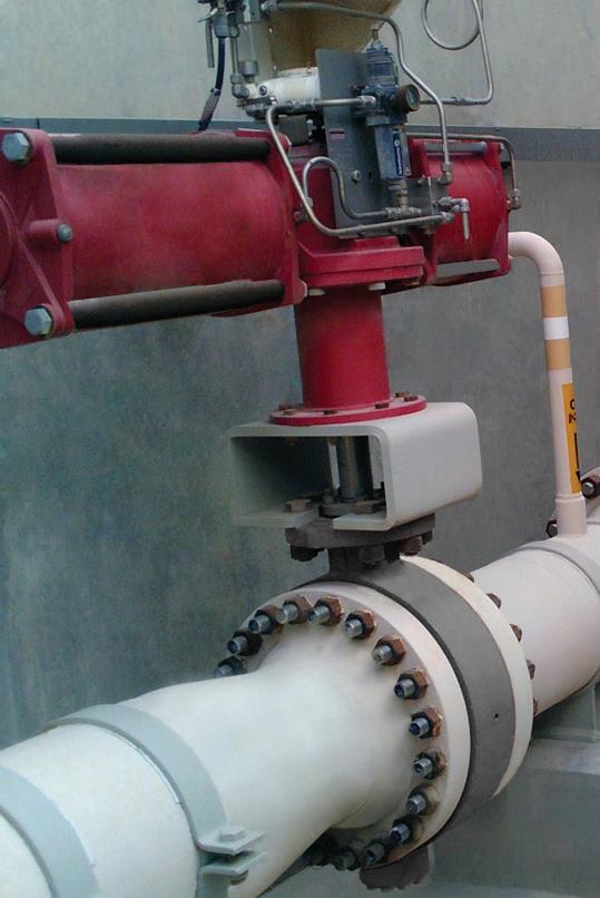
trim components, and live loaded packing – makes this type of valve the preferred choice for this application because it provides essentially zero leakage, despite very difficult service conditions.
Another option for PSA isolation valves is a double eccentric C-ball valve. It utilises a double offset design to create a zero-leakage seal that operates independently of applied pressure.
A camming effect moves the C-ball away from the seat during the opening stroke to minimise wear when abrasives are present. Its combination of fixed metal seats, mechanical sealing independent of process pressure, low wear, and a low emission design also works well in these difficult conditions.
Remote pipeline valve actuators
Some automated valves may be installed in locations where instrument air is not available. In such applications, electric actuators, or actuators driven from pipeline pressure, are required. Lower torque requirements can be satisfied with modern electric actuators, with or without spring fail capability.
Pipeline applications requiring high torque or involving multiple valves can utilise zero-emission hydraulic actuating systems. These units use pipeline pressure to drive hydraulic valves, and the pipeline gas is injected back into the pipe at the end of stroke, so there are no emissions.
Hydrogen process units have been operating for decades, but not at the scale envisioned in the future. Major automation suppliers have extensive experience with these units, with much of their expertise applicable to the new processes described in this article, namely the carbon capture and transport required to convert grey to blue hydrogen.
When designing the systems required to convert grey to blue hydrogen, operating companies would be wise to consult with a supplier that has extensive experience with hydrogen handling, along with the ability to apply this expertise worldwide at scale.
Blair Garrett, BAC, USA, explores options to solve
the challenges of water management in hydrogen production.
Consumption of our earth’s resources is one of the most critical considerations for the future of hydrogen production. Water and energy are intrinsically tied together. To produce one is often at the expense of another, but both work in conjunction to power manufacturing processes around the world. As our understanding of technology develops, our means of production for the fuels that power our innovation continue to improve. Both water and energy are required in the production of hydrogen, and its potential to power cars, rockets, and organic chemical production make it one of the most promising industries today. The big challenge with the production of hydrogen is the amount of water needed throughout the entirety of the process. From start to finish, water is consumed in high volumes, but there are key points along the way that can help reduce our water usage going forward.
Grey, blue or green hydrogen?
The three most popular types of hydrogen production all have different water consumption profiles. They all heavily rely on clean water, and the purification for clean process water uses additional water and energy. This purified water is obtained through reverse osmosis or distillation and accounts for a significant portion of the total water used throughout the process.
Because purification is a necessary first step for all forms of hydrogen, the opportunity to save water and energy will continue to develop as the technology and infrastructure for hydrogen evolves. Across purification, process water, and cooling, leading hydrogen production facilities will use 20 - 35 t of water to produce just 1 t of hydrogen.
Grey hydrogen
Grey hydrogen production will consume less total water than blue or green hydrogen using a process called steam methane reformation, but it does not utilise renewable resources and allows for the harmful release of approximately 10 t of CO2/t of hydrogen produced. While it is efficient and cheaper to produce, the negative impacts include significant energy consumption, and increased carbon footprint contributing to climate change.


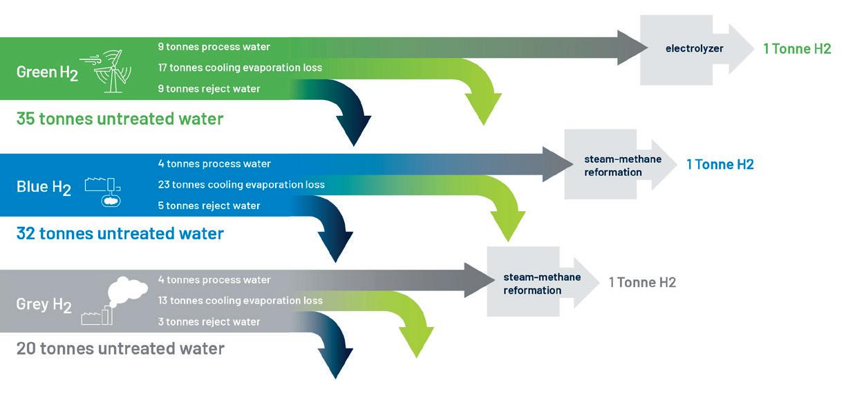
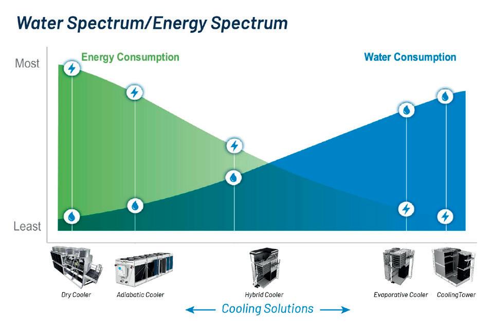
In an increasingly eco-friendly environment, many hydrogen facilities are looking for cleaner solutions.
Blue hydrogen
Blue hydrogen is another viable process that takes advantage of carbon capture utilisation and storage (CCUS) to transport the CO2 that would be released into the atmosphere in a typical grey hydrogen process. This steam methane reformation process combined with carbon capture systems, while environmentally beneficial, can add significant water and energy expenditure to the end product. The bulk of the water usage in blue hydrogen systems is lost due to evaporative cooling. With 22.6 t of water used to yield 1 t of hydrogen from evaporation alone, there are opportunities for water-stressed facilities to utilise less water-intensive cooling systems.
Green hydrogen
Green hydrogen on the other hand is a completely renewable process, yielding hydrogen without emitting CO2. Typically powered by wind, solar, or hydroelectric energy, green hydrogen is breaking ground on a new method to produce truly renewable, emissions-free fuel.
The positives of green hydrogen are evident. It emits oxygen as opposed to CO2, its energy source can be sustainably harvested, and electrolysers are getting more efficient by the day. The challenge with green hydrogen is in its substantial water demand. Electrolysis requires a lot of water to operate, using twice the amount of process water that grey or blue hydrogen requires.
It also needs an extremely high purity to prevent contaminants from fouling machinery, which adds to the total water consumed. Because of the level of purity needed for electrolysis, roughly double the amount of reject water is lost compared to grey or blue hydrogen production. With twice as much process water and twice as much purification reject water, green hydrogen facilities face massive utility requirements unless they take action to reduce water usage.
Methods of cooling and the reliance on water
Due to the high energy demands of hydrogen production, many facilities are being constructed close to renewable energy sources. However, these areas are often in water-stressed environments. To obtain the amount of water needed, the International Renewable Energy Agency (IRENA) has indicated that desalination of seawater is a viable option to procure the water necessary throughout the process. The initial investment may be higher for companies looking toward desalination as a means of getting water, but it is a sustainable alternative.
As of 2023, IRENA indicates that more than 12% of operational blue and green hydrogen plants are in water-stressed environments, but that number is set to climb dramatically in the coming years. More than a third of blue and green hydrogen facilities planned for construction will be in areas with significant water restrictions (per IRENA). This means that future hydrogen production needs to be increasingly focused on utilising water-saving solutions.
Evaporative cooling
The greatest opportunity to save water lies in the cooling process necessary to maintain systems. Evaporative cooling has been the gold standard for rejecting heat from manufacturing facilities for decades. It is extremely energy efficient and imperative to the process to prevent overheating and damage to machinery. Without proper cooling systems, facilities cannot operate optimally or safely, and the lifespan of equipment is significantly diminished.
The benefits that an evaporative cooling tower brings to temperature-sensitive manufacturing processes like hydrogen production cannot be overstated, and in an energy-conscious environment, cooling towers are the most efficient cooling technology available. However, it is not the only solution due to the growing problem of water scarcity. Just as methods of fuel production are becoming more innovative, so too are cooling units in the wake of energy and water conservation. Loss of water in evaporative cooling systems can account for roughly 15 t of water per t of green hydrogen produced. With nearly 44% of the total water required during the entire process being lost to evaporative cooling, alternatives are needed.
Dry cooling
Dry cooling is a hot topic among growing industries, such as data centres, and its application in hydrogen can be revolutionary going forward. A dry cooling unit does not use water to operate, and while air-cooled systems inherently use more energy, with modern wind and solar infrastructure, the additional energy load
We understand how you need to reduce complexities at your plant.
CLEAN PROCESS + CLEAR
You strengthen your plant’s safety, productivity and availability with innovations and resources.
Endress+Hauser helps you to improve your processes:
• With the largest portfolio of safety instruments that comply with international regulations
• With applied technologies and people who have extensive industry application know-how
• With access to accurate and traceable information
Do you want to learn more?
www.endress.com/oil-gas
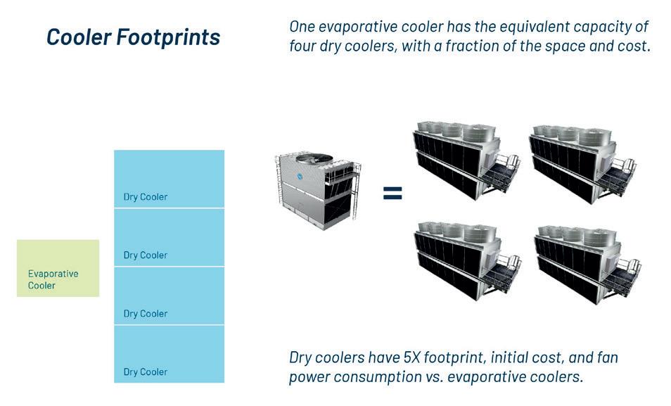
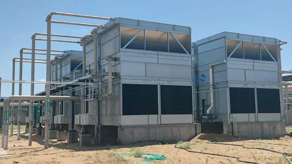
may be a necessary trade-off for operators that are forced to minimise water usage.
Aside from significantly higher energy consumption, another drawback of dry coolers is that they may require up to five times the upfront cost and footprint as evaporative cooling systems. However, in areas with little available water, dry cooling may be the best option, especially in areas where the ambient temperature is low.
Hybrid cooling systems
In addition to evaporative and dry cooling options, there is another alternative. Recently, there has been an increase in hybrid cooling systems, which combine the benefits of evaporative cooling with the need to minimise water consumption. With an increasing global demand for water and a constant need to reduce energy consumption, this is a great option for green hydrogen production in water-conscious environments.
Hybrid cooling provides a balance, combining the energy-saving benefits of evaporative cooling with the water-saving benefits of dry cooling, depending on water availability on a day-by-day basis. On hot days, hybrid coolers can efficiently drop temperatures by spraying water to cool process fluids, and on cooler days, cool ambient air is pushed over the dry finned coils to accomplish the same task while greatly reducing the water usage. Hybrid cooling can be useful for water-sensitive applications, and with a small footprint compared to dry coolers, it is an ideal system for water-challenged hydrogen production.
Adiabatic cooling systems
Another way to optimise water and energy usage is with adiabatic cooling. Instead of combining dry and evaporative cooling as two separate components, adiabatic cooling relies on dry finned
coils as the primary heat transfer mechanism but uses water evaporation to cool down the incoming ambient air before it hits the dry coil. This is done by wetted pads that are fitted in front of the finned coil. The transfer of cooled air onto the coil maximises heat transfer capacity, reduces footprint, and minimises fan power consumption. Adiabatic units fit well on the spectrum between evaporative cooling towers and dry coolers, giving users a way to find balance between water and energy depending on the given circumstances.
An adiabatic unit’s ability to switch to evaporative cooling during peak hours of the day and back to dry cooling when ambient temperatures drop can save up to 75% of water compared to traditional evaporative cooling. This solution allows for flexibility in climates with fluctuations in temperature throughout the year. With a smaller footprint, lower installation cost, and lower fan power consumption per unit than traditional dry coolers, it is a viable choice for future hydrogen production facilities.
Due to the large water demands of evaporative cooling in green hydrogen applications, many operators immediately turn to dry coolers as the primary solution. While the dry coolers will relieve much of the water requirements, the footprint and energy needed to accommodate these coolers may also be too much of an investment and may take away from using that energy toward the end goal – producing hydrogen. Considering a hybrid or an adiabatic solution can fill the niche for sites around the world that may have different needs based on geographic location, infrastructure, or financial support.
Case study
An end user based in Inner Mongolia, China – an extremely arid region without significant infrastructure or water resources – was concerned about the water usage of a planned green hydrogen production facility. Constructed in the desert with little surrounding population, this green hydrogen facility has the potential to produce 20 000 tpy of green ammonia, one of the most important compounds for reducing reliance on fossil fuels.
To cool a set of alkaline electrolysers with a combined capacity of approximately 25 MW, evaporative cooling towers would consume 500 000 t of water, which is not available at this location. Thanks to the hybrid cooling solution that was chosen, the evaporation loss has been limited to only 200 000 tpy of water, without making significant compromises on power consumption and installed cost. With an extreme shortage of water, hybrid cooling units have enabled this plant to seamlessly continue operations while balancing water and energy usage.
Conclusion
In summary, there are a myriad of choices to save water in regions lacking access to either freshwater or seawater. Cooling is the only part of the process where water is not essential, although it is beneficial to maximise production efficiency. It is also important to consider that the required amount of water may not always be available, depending on the site location.
With both evaporative and dry cooling working together, hybrid and adiabatic units can save millions of gallons of water, dramatically improve efficiency compared to dry cooler systems, and offer remote facilities a practical solution to a growing problem.

Matt Behrns and Dr. Alex Papandrew, Mott Corp., USA, explore how scaling up efficient proton exchange membrane (PEM) solutions will be key for the future energy landscape.
Despite the importance of green hydrogen to the world’s climate and energy future, analysts and investors tend to view hydrogen as a newer form of energy storage, and therefore, a riskier investment. However, the generation of hydrogen by electricity is a more than 200 year old process, and manufacturers understand that this technology is both reliable and viable when optimised. In fact, alternatives to liquid alkaline systems, such as proton exchange membrane (PEM) electrolysis, are poised to improve on previous electrolyser designs to realise the promise of green hydrogen. If renewable energy sources can power PEM processes, green energy can be produced without producing new emissions. However, this transition critically requires a sustainable technology infrastructure.
Experts have argued that PEM processes are one of the most promising technologies toward achieving carbon peak and neutrality goals.1 There are, however, current market problems that
serve as barriers to PEM capital costs. This is why recent advancements in PEM technologies serve as a sign that green hydrogen production is not only achievable at mass scale, but viable for manufacturers seeking to drive innovation and contribute to a sustainable energy future. This article will seek to show that the future of green hydrogen must move through PEM.
What is PEM?
There are two different kinds of PEM processes that are pertinent to the future of green hydrogen: PEM water electrolysis and PEM fuel cells. In electrolysis, water is electrochemically split into hydrogen (at the cathode) and oxygen (at the anode). Protons (i.e. hydrogen ions) generated at the anode travel through the PEM and recombine with supplied electrons at the cathode to evolve hydrogen. PEM possess a potential advantage over other kinds of water electrolysis because they allow for high efficiency, dynamic load following, and pressurised operation. According to experts, in terms of sustainability and environmental impact, PEM water electrolysis is one of the favourable methods for conversion of renewable energy to high purity hydrogen.2
Hydrogen produced via renewable electricity can be used to power PEM fuel cells. In this complementary process to electrolysis, hydrogen is supplied to the anode while air is supplied to the cathode. Once again, hydrogen is split, protons move across the PEM, and here, electrons are yielded to produce useful power to external devices, such as vehicles. Each of these processes is essential for powering a green energy future and reducing the CO2 emissions in the atmosphere. PEM fuel cells are especially important to the automotive industry, as these cells can produce power at low temperatures and scale output power quickly, all producing zero emissions. Heavy-duty trucking is an area recently identified to be particularly ripe for disruption by fuel cell engines. A fact sheet from the Department of Energy even goes so far as to claim that fuel cells are the most energy efficient devices for extracting power from fuels and contribute to a more than a 50% reduction in fuel consumption compared to a conventional vehicle with a gasoline internal combustion engine.3
A history of PEM
This initial design of PEM fuel cell technologies was realised by Willard Thomas Grubb at General Electric (GE) for the purposes of powering military and aeronautic vessels, such as the manned space missions for NASA’s Gemini programme in the 1960s. Shortly thereafter, another GE researcher refined the design by utilising platinum as a catalyst on the membranes. As the 1970s and 1980s passed, PEM fuel cells were viewed as a potentially more viable form of energy generation. However, the utilisation of this process remained stagnant until the 1990s when PEM technologies began being utilised in automotive industries across several countries. Moreover, as previously noted, PEM technologies have emerged in this century as a critical component of the movement to reduce carbon emissions.
The development of PEM water electrolysis followed a similar trajectory. After its discovery by GE in the 1960s, this process was relatively underutilised until the late 1970s
and early 1980s when researchers were searching for an alternative to alkaline electrolysis. GE sold its technology in the mid-1980s, but the primary purpose of PEM water electrolysis remained the same: to generate oxygen to power life support in closed environments (like those in space). It took another decade before the production of hydrogen from PEM water electrolysis started to become commercially viable for manufacturers.
From its outset, PEM has been viewed as the most efficient form of water electrolysis, so why was the process only utilised to power military and space applications for so long?
The simple answer is cost. Without a robust commercial (renewable energy) market, materials were expensive to produce. In fact, had it not been for the development of national climate protection programmes, it is unclear as to whether the now robust interest in water electrolysis that has emerged would have been seen this century. According to the Department of Energy, PEM uninstalled capital costs have decreased by 90% since the early 2000s, with stack cost reductions representing a majority share of that decrease.4 This overall reduction of costs is partially responsible for new developments and advances in PEM technology.
Advancements in PEM technology
Because PEM technology was initially designed for military and space operation, the industry was less focused on optimising production efficiency through, for example, developing thinner membranes. Because PEM is a more efficient process than other forms of water electrolysis, the goal for manufacturers is to reduce the overall cost of production while maintaining — and even increasing — PEM efficiency. This is especially important when considering that, by the end of the decade, PEM electrolyser capacity is expected to grow to a size between 170 and 365 GW, according to the International Energy Agency (IEA).5 To achieve that growth, manufacturers must continue to support the development of new advancements in PEM that can bring these technologies to scale.
In the Spring issue of Global Hydrogen Review, Magnus Thomassen of Hystar noted that 15 years ago, he and his co-founder, Alejandro Barnett, hypothesised that thinner membranes would allow higher electrolysis efficiency. As Thomassen wrote, thinner membranes allow PEM electrolysers “to either produce 150% more hydrogen or run at 10% lower energy consumption than conventional designs. This has a major impact on the levelised cost of hydrogen (LCOH), one of the most important key metrics influencing a project’s profitability.”6 Thinner membranes represent one example of a critical advancement in PEM water electrolysis as they build upon designs that are already present in PEM fuel cells.
Understanding the vital role of thinner membranes in improving electrolysis efficiency led Mott Corp. (Mott) to heavily invest in the development of porous transport layers (PTLs). The fragility of thin membranes (less than half the thickness of a human hair) can be overcome with highly surface-engineered PTLs that support the membrane equally across its active area. Beyond those next-generation advancements, Mott PTLs still serve conventional roles in PEM electrolyser processes: providing thermal and electrical
conduction, pathways for reactant liquid water delivery to the catalyst layer, and pathways for effective gas removal from the reaction sites to the outlet.7
What does the future hold for PEM?
In many respects, the future of PEM technologies is tied to the continued development of the green hydrogen market – and vice versa. Without green hydrogen demand, PEM technology advancement will languish; without the refined efficiency of new PEM electrolysis technology, the hydrogen market will struggle to fully transition from grey to green. And the demand is present: Deloitte predicts that the green hydrogen market will grow from what is currently a US$185 billion market to a US$1.4 trillion market in 2050 (a more than 600% increase).8 Furthermore, 2 million green hydrogen jobs can be expected between 2030 and 2050, which marks hydrogen as an especially viable economic market.
According to Deloitte’s hydrogen pathway explorer model, clean hydrogen can deliver up to 85 billion t in reductions to cumulative CO2 emissions by 2050, more than twice global CO2 emissions in 2021. This analysis is supported by individual experts: in her presentation to the MIT Energy Initiative, Kathy Ayers argued it is reasonable to assume that we can produce 100 MW plants through PEM electrolysers in the next 2 - 3 years, which would put the industry on track with the IEA’s estimates. Essentially, this means in the near-term that PEM is crucial to continue maximising green hydrogen production; in the long-term, costs from PEM are predicted by the IEA to reduce drastically over the next 20 - 30 years.
Conclusion
To conclude, because the future of green hydrogen and water electrolysis are so closely aligned, PEM represents the best hopes the industry has of rapidly scaling and commercialising hydrogen. Recent advancements in PEM technologies demonstrate that hydrogen production does not need to be cost prohibitive; in fact, increased investments in PEM stand to further reduce PEM material costs. As manufacturers seek to drive innovation and contribute to a sustainable energy future, the expansion of electrolysers will serve as a benchmark for the true measure of how far the industry has come. In short, whether a green hydrogen future is truly achieved will depend on the continued innovation of PEM technologies.
References
1. MO, S., L DU, HUANG , Z., et al, ‘Recent Advances on PEM Fuel Cells: From Key Materials to Membrane Electrode Assembly’, Electrochemical Energy Reviews 6, no. 28: 27, (2023).
2. SAMPANGI , SHIVA KUMAR , S., ‘Hydrogen Production by PEM Water Electrolysis – A Review.’ Materials Science for Energy Technologies 2, no. 3: 446, (2019).
3. Rep. Fuel Cell Fact Sheet, Washington D.C, US, Department of Energy, 2, (2015).
4. Rep. Historical Cost Reduction of PEM Electrolyzers, Washington D.C., US, Department of Energy,: 2, (2022).
5. THOMASSEN , M., ‘Revolutionising PEM Electroysers,’ Global Hydrogen Review, (Autumn 2024), pp. 51 - 54.
6. Ibid., 52.
7. LEE , J. K., CHUNGHYUK, L., FAHY, K. F., et al., ‘Spatially Graded Porous Transport Layers for Gas Evolving Electrochemical Energy Conversion: High Performance Polymer Electrolyte Membrane Electrolyzers,’ Energy Conversion and Management 226,(2020).
8. Rep. Green Hydrogen: Energizing the Path to Net Zero. New York, New York: Deloitte, 41, (2023).

Visit our website today: www.globalhydrogenreview.com

Richard Koeken, Fluid Components International (FCI), the Netherlands, and Florian Stahl, Ekomat Gmbh & Co., Germany, discuss the role of accurate liquid/air flow monitoring switches in producing green hydrogen from renewables using PEM fuel cells.
The conversion of surplus wind power and solar energy into green hydrogen (H 2 ) gas using proton exchange membrane (PEM) electrolyser stack units is becoming increasingly popular around the globe. At both wind and solar electric power plants, green H 2 is produced, fed and blended into the existing natural gas network or piped to large storage tank stations for later use as needed (Figure 1).
Producing green H 2 energy requires pure water and renewable electric energy such as wind or solar and a PEM electrolyser. When H 2 is produced with 100% renewable electricity, green H 2 makes an important contribution to reducing the
carbon dioxide (CO 2 ) emissions that are considered by many to be the primary cause of global warming.
Many countries have international long-term CO 2 emission reduction goals that cannot be achieved with blue or grey H 2 alone, which are produced using conventional fossil fuels. Green H 2 gas generated from surplus renewable energy resources can be utilised by many industries in multiple applications that include H 2 energy storage, decarbonisation of industrial processes, large district energy heating systems and syngas for industrial applications.
H 2 energy storage helps to balance the electric power grid when renewable energy is unavailable. Surplus electricity converted to green H 2 gas can be stored conveniently over long periods of time in tanks and then accessed again later on when renewables are not available or sufficient (e.g., at night time or on windless days or during peak demand periods for heating, ventilation and air conditioning [HVAC] systems).
Green H 2 will also help with the decarbonisation of industrial processes. Producing raw materials and goods requires large amounts of fossil-fuelled conventional electric or gas energy, and green H 2 can reduce/improve the CO 2 balance of these processes in many industries (e.g., glass, cement or steel production).
Large district energy heating systems are possible with green H 2 cogeneration. The PEM electrolysis process not only produces H 2 , but cogeneration heat is also a valuable byproduct (55°C/131°F) that can be fed into large commercial or campus district heating networks, or even into large multi-unit municipal residences.
Mixing captured CO 2 emissions and H 2 also produces high-quality syngas for industrial applications. Using this
lower carbon content syngas can help refineries to produce the major building blocks for chemicals, polymers or synthetic fuels. Even the production of ammonia (NH 3 ), the main ingredient for commercial agriculture fertilizer, is possible with green H 2
The challenge
All the processes to produce green, blue or grey H 2 and all its many industrial and commercial applications have one thing in common: they depend on the accurate monitoring of liquids, air and gases under rugged conditions that often include high/low pressure variability (turndowns) and/or demanding temperatures, corrosive materials and explosive environments that can jeopardise safety during production, storage, transportation and application.
H 2 is a colourless, odourless, tasteless gas, which is undetectable by the human senses. With a small molecular size, H 2 can leak relatively easily and can be spread quickly by wind or ventilation systems. When an accident occurs, H 2 fed fires can spread rapidly with terrible consequences for nearby workers and plant facilities, as well as potential damage to nearby communities.
The preferred electrolysis technology to convert surplus wind or solar renewable energy into H 2 is the PEM method. PEM fuel cells allow the electrolyser to be operated at a dynamic partial load (compensating for the load fluctuations of the available renewable energy). Additionally, the PEM electrolysis method does not require aggressive chemicals or liquid electrolytes and produces high-purity H 2 that can be used directly for the refuelling of systems and vehicles.
The design engineers at a European industrial equipment firm recognised early that its turnkey solution for a green H 2 PEM fuel cell electrolyser would require accurate liquid and air flow monitoring/switching instruments.
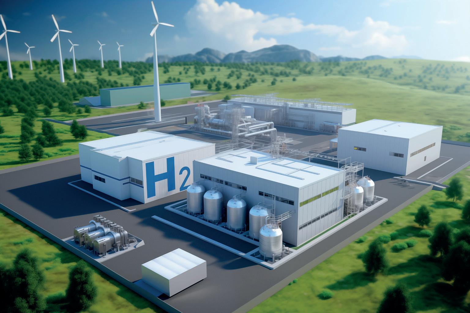
The engineering design/production firm’s turnkey equipment solution included all pipe work, measurements, the ventilation, the PEM electrolyser and other utilities placed inside a compact stack container that can be installed next to an existing wind farm or solar power plant. Each stack system would require one flow monitor/switch to


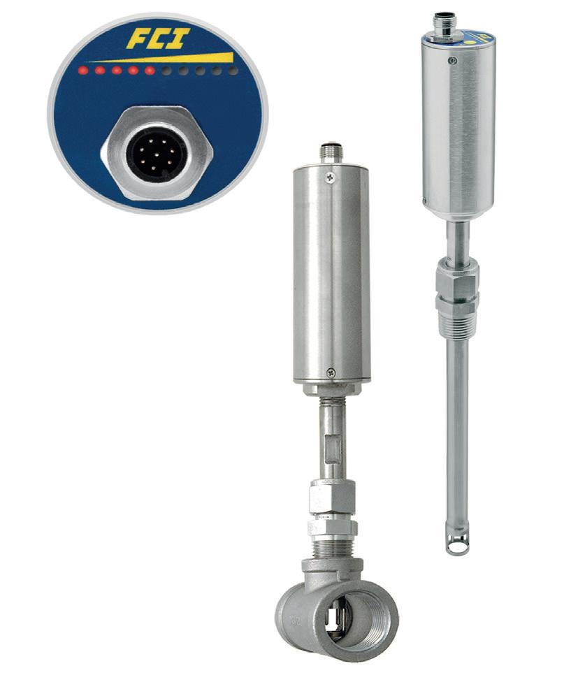
monitor the deionised water flow at the water inlet point into the PEM electrolyser and provide an alarm if the flow rate dropped below a pre-set flow switch point.
If the water flow were to drop below the pre-set flow rate, the efficiency of the electrolyser would be compromised and there is a possibility of hazardous gases building up and creating an unsafe condition. Therefore, the engineers knew that it was essential that the flow monitor/switch instrument specified for safeguarding the deionised water flow into the electrolyser must have SIL 2 compliance and be ATEX Zone 2 certified.
The engineers also determined that two flow monitors/switches were required to ensure the continuous flow of ventilation air into the container above a pre-set flow rate and that an alarm must be provided when the flow drops below this point. Due to the possibility of H2 gas collecting inside the container and/or in the case of a gas leak, the engineers recognised that the air/gas instrument safeguarding the ventilation air flow must have SIL 2 compliance and be ATEX Zone 2 certified.
The solution
With these instrumentation requirements set, the PEM electrolyser equipment engineers contacted a local manufacturers’ representative, Ekomat, for discussions about the project. The Ekomat team contacted thermal flow switch manufacturer, Fluid Components International (FCI), to discuss the project’s flow monitor/switch requirements.
In order to meet the requirements, the FCI applications engineering team recommended its thermal technology FS10i Flow Switch (Figure 2). This instrument’s trend analogue output (SIL 2 compliant) and relay output (SIL 1 compliant) offered an accurate liquid/gas flow switch monitoring suitable for the stringent demands of this operating environment.
The engineers designing the PEM electrolyser agreed the equipment met both their measurement and
safety requirements. They were also able to utilise other features of this flow switch that included:
y A standard design for both deionised water and ventilation air monitoring.
y Flexible installation and easy set-up with FCI’s FS10 software including field calibration that allowed for a shorter pipe installation length.
y ATEX Zone 2 certification even though IP64 certification was sufficient because these instruments are installed inside a container.
The equipment's flow sensitivity (setpoint range) in liquids is from 0.003 to 0.15 MPS (0.01 to 0.5 FPS) and in air or gases is from 0.076 to 122 MPS (0.25 to 400 SFPS). Its standard 1A relay trip point is easily set in the field for a low or high trip point and the trip and reset points can be further tuned with hysteresis and time delay adjustments.
Also provided with the equipment is a 4 - 20 mA trending output of the flow rate for connection to ancillary controls or alarm systems. It includes a 10-LED array for both an indication that the trip point has been exceeded (LED flashes on/off) and of relative flow rate (10% increments) across the flow range.
This versatile switch provides features for installation in rugged duty and long-life in industrial plants, process and large buildings. Its flow sensor’s thermowells are constructed of highly corrosion resistant Hastelloy C-22, and it will operate in fluid temperatures up to 121°C (250°F) with an IP protection rating to IP67. It carries a SIL 2 compliance rating on the 4-20 mA flow monitoring output and SIL 1 compliance on the alarm relay. It has no moving parts to clog and requires no routine maintenance, which saves technician time and expense over any mechanical-technology based flow switch.
To ensure best performance and installation ease, the FS10i Switch is available in a choice of flow element lengths (insertion depth) and process connections: a 50 mm (2 in.) length with a 0.25 in. NPT fixed threaded connection or a 150 mm (6 in.) length, variable depth, with 0.5 in. NPT compression fitting with either a Teflon or metal ferrule.
The FS10i carries an SIL 2 compliance rating with a 90% Safe Failure Fraction (SFF). The FS10i also carries global approvals: ATEX, CE, CRN, FM, FMc, IECEx and EAC/TR CU pending. Optional global agency approvals are also available for installation in Division 2/Zone 2 locations.
Conclusion
FCI initially supplied trial units of the FS10i Flow Switch for field evaluation by the equipment engineering team, which was pleased with the trial. The units were then ordered for installation into the first PEM electrolyser unit. To date, there have been no issues with the flow switches.
The PEM electrolyser equipment firm has informed both the teams at Ekomat and FCI that it is expecting to ramp up production of the PEM electrolysers over the next several years. The demand for green H2 is growing as part of electric energy decarbonisation efforts around the globe, which will speed the adoption of green H2 PEM electrolyser technologies and systems.
Michael Nofal, H2scan, USA, and Robert H. Shelton, H2C Safety Pipe, USA, look at ways to enhance the safety and efficiency of green hydrogen transport.

Hydrogen, the Earth’s most abundant and lightest element, is a safe, renewable, and clean resource capable of powering the most energy-intensive industries. When used to produce electricity in a fuel cell, hydrogen’s only emission is pure water. And, when hydrogen is generated through electrolysis powered by renewable energy sources such as wind, sun, geothermal, or hydropower, it becomes one of the most promising cornerstones for a clean energy future and essential to achieving the world’s net zero goals.
Green hydrogen can be produced at competitive prices in regions with abundant renewable energy, such as the Middle East, North Africa, Chile, and Western Australia. However, these areas are often thousands of miles
from the major consumer markets where hydrogen is most needed. This geographic mismatch requires long-distance transport solutions to economically bridge these vast distances, as well as pipelines to efficiently move hydrogen from regional production and distribution centres to end-user locations like major industrial facilities and vehicle dispensing centres.
The fossil fuel economy relies on major pipelines and fleets of tankers that crisscross the globe from where crude oil is produced to refineries and end-user locations. Nearly 3 million miles of pipeline traverse the US, and an additional 300 000 miles traverse Europe, primarily delivering natural gas, petroleum, and other non-renewable energy resources to homes
and businesses. Supplementing and, wherever possible, repurposing this infrastructure for hydrogen will play a pivotal role as nations transition to a hydrogen economy over the coming decades.
A new approach to the safe transport of hydrogen
To address these issues, there is an increasing focus on developing ‘midstream’ solutions. A number of industry players are developing technologies to transport liquid hydrogen across thousands of miles, from areas where it can be produced economically, and distributing gaseous hydrogen at scale using pipelines that are lower in cost and safer than the options available today.
Ideally, the distribution technology should utilise existing infrastructure, such as oil and gas pipelines, water pipes, sewer lines, and storm drains, to provide critical right-of-way for these projects. This will help companies to avoid stranded assets, reduce initial capital cost and deployment time, and will help stakeholders lower environmental impact and decrease disruption to city streets and roadways.
To be effective, the approach will need to solve the problem of pipe embrittlement, which arises from the contact of hydrogen with steel, and the problem of leakage, which arises from the nature of a gas made of remarkably tiny molecules. In fact, hydrogen can permeate through pipe walls over time and a buildup of hydrogen inside reutilised pipes could lead to dangerous conditions.
Testing through prototype
One company working on a solution to these challenges is H2Clipper Inc. (H2C) and its subsidiary, H2C Safety Pipe Inc. The company has developed an H2pipeline system comprised of a relatively low-cost fibreglass-reinforced polymer pipe inside a containment pipe and an automated system that will purge the containment pipe of any leaked hydrogen.
H2C engineers needed to test their pipeline system to validate installation, monitoring, and safety.
A major international hydrogen infrastructure company engaged H2C to build a 10 m prototype system and to test it from October 2023 to January 2024.
The engineers understood that safety depended in part on the ability to detect leaks and to measure how much hydrogen gas was present. They sought a sensitive and precise sensor technology that could measure hydrogen gas in the presence of other gases and required minimal maintenance. Low maintenance was a critical requirement because sensors would be located on pipelines at great distances, making sensor replacement or calibration very costly. The engineers selected sensors made by H2scan.
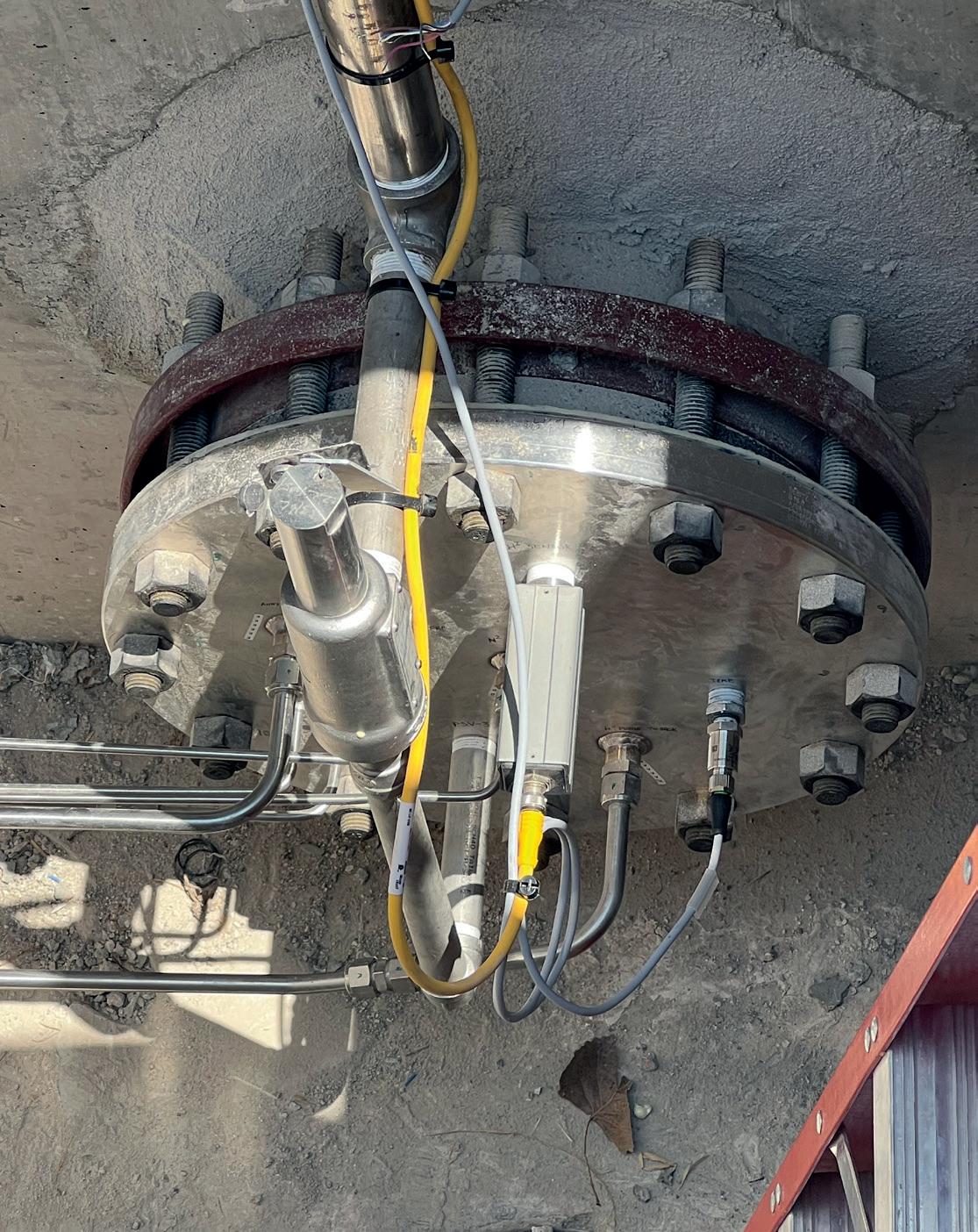
In 2023, H2C teamed with H2scan, NOV Fiber Glass Systems, and others to build a full-scale prototype and demonstrate the H2C Safety Pipe technology. A 47-page final report was prepared following fieldwork. The results validated the leakage rates previously observed by studies conducted by Oak Ridge National Laboratory and indicated these rates could lead to hazardous concentrations in confined spaces within several days unless adequately addressed. Importantly, the prototype demonstrated that H2C’s technology will mitigate such leakage risks and enhance system safety and reliability by continuously monitoring hydrogen concentration levels.
The advantages of safety pipe technology
The double-wall pipe system offers a solution for transporting gaseous hydrogen through existing pipelines and in new installations. This technology employs a secondary containment pipe to capture any leakage from the inner hydrogen carrier pipe, an inert sweep gas to remove hydrogen that escapes into the annulus space between these two pipes before it reaches potentially dangerous levels and incorporates sensors for continuous monitoring and control.

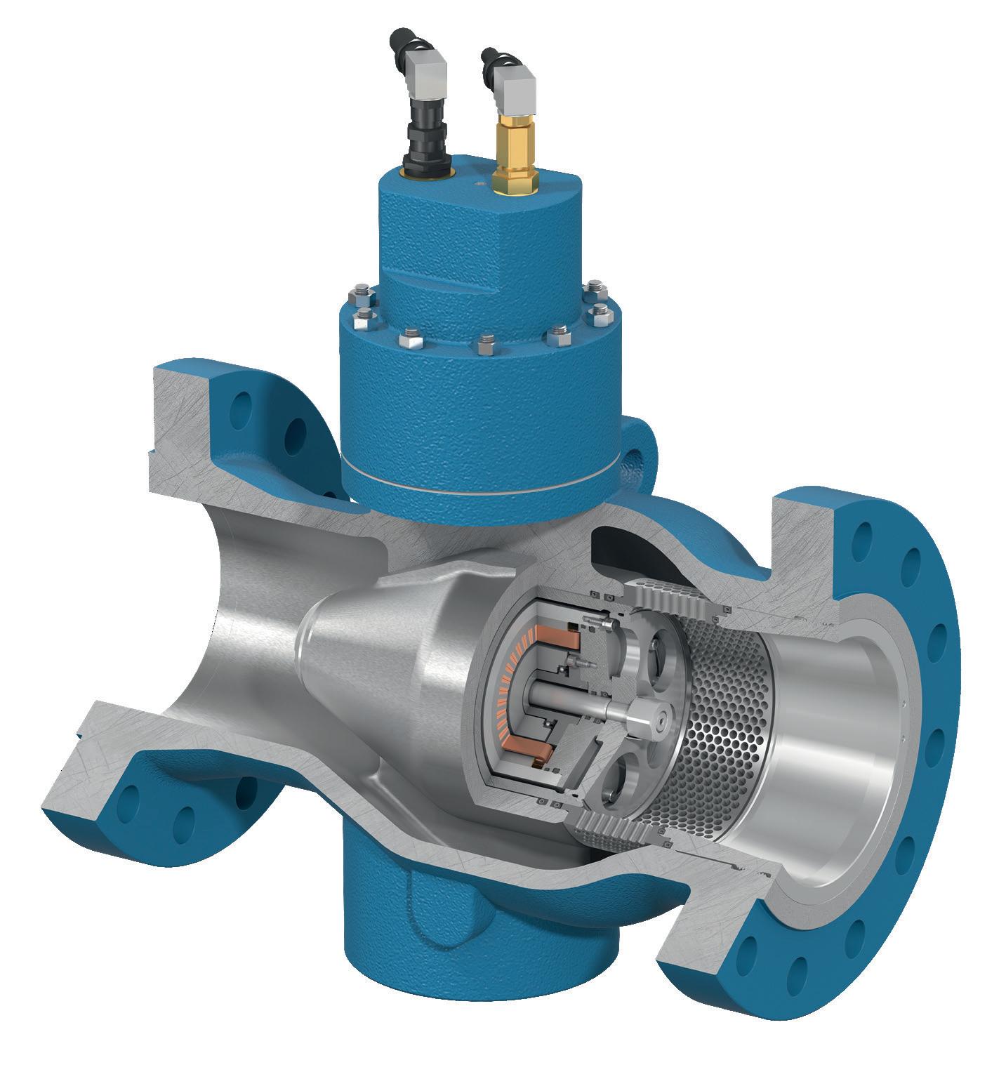
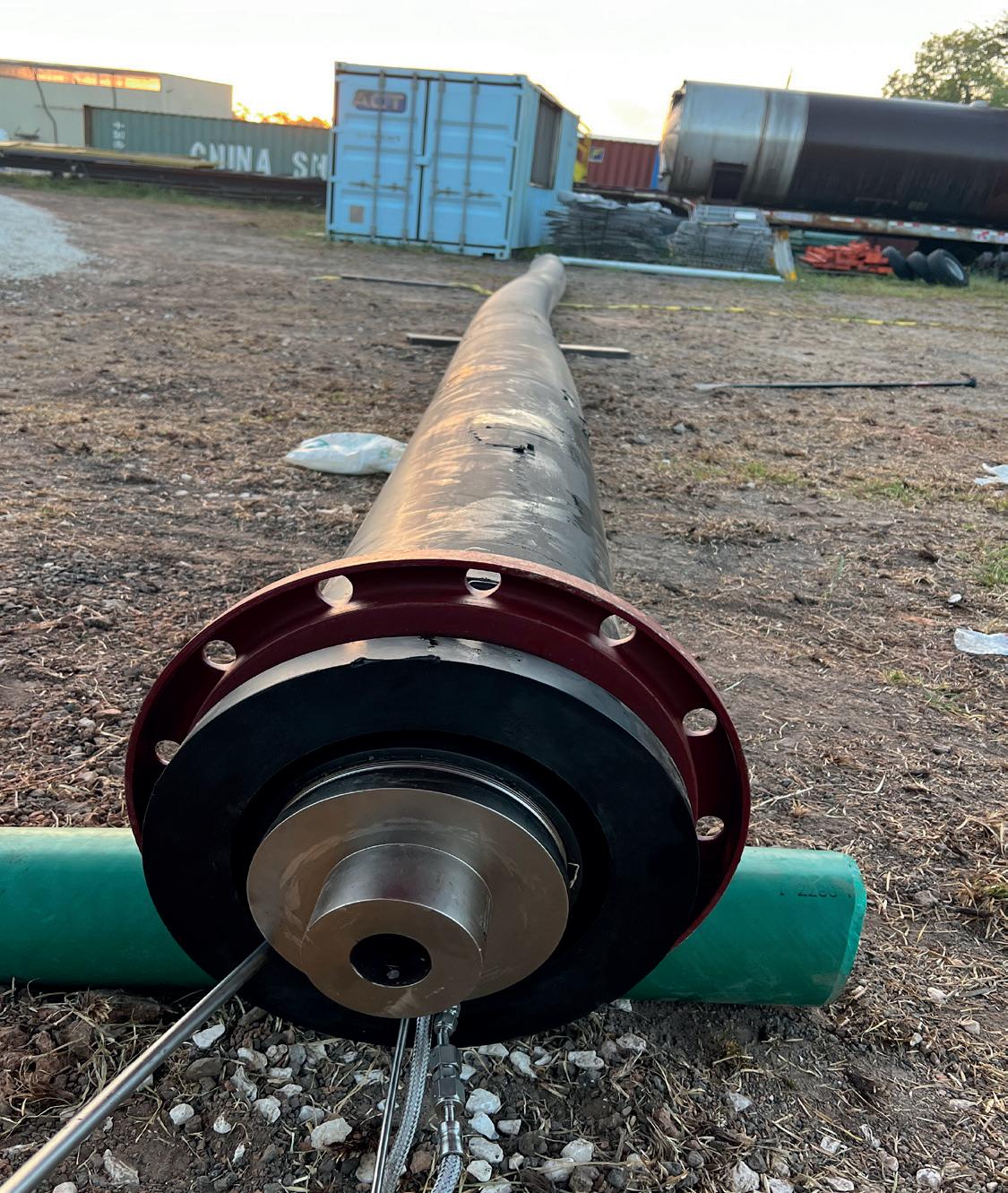
Figure 2. A hydrogen sensor, the HY-OPTIMA® 5031 from H2scan, is located in the annulus between the inner and outer carrier pipes. If the sensor detects that unsafe levels of hydrogen gas have leaked into this space, then a control system automatically initiates a purge of the annulus with an inert gas.
The sensors and the pipe design provide several key advantages:
Enhanced safety and control
The double-wall design isolates any hydrogen permeation or viscous leaks from escaping into the external environment, ensuring this hydrogen is safely removed well before its concentration reaches hazardous levels. Continuous monitoring of hydrogen concentration levels within the annulus space provides 24/7/365 integrity management. It connects to computer controls, ensuring that issues are detected in real-time, and any areas of emerging concern are promptly addressed before problems occur.
Reduced cost
By enabling the use of existing pipeline infrastructure for hydrogen delivery, the system reduces the cost of acquiring new right-of-way while avoiding the cost associated with abandoning older pipelines. The technology also enables the use of advanced materials, such as fibreglass reinforced polymer (FRP) pipe, which reduces total capital cost and entirely avoids corrosion and embrittlement, two risks concerning a traditional steel pipe.
Accelerated deployment
Retrofitting existing pipelines with this technology approach simplifies the logistical and regulatory challenges associated with new pipeline construction. This includes minimising the hurdles of right-of-way acquisition, which can often delay projects and increase costs.
Environmental benefits
The technology’s ability to capture leaks enhances safety and protects the environment by preventing potential hydrogen emissions into the atmosphere, which several prominent environmental groups have shown could be an indirect greenhouse gas, thereby leading to growing scrutiny over hydrogen’s adverse environmental impact.
Understanding the application of hydrogen sensors
Hydrogen presents unique safety challenges, while being an environmentally friendly alternative to fossil fuels. Its flammability and propensity to leak undetected through conventional materials and tiny openings require specialised monitoring techniques. Traditional detection methods often fall short, particularly in critical infrastructures where even minor leaks can pose significant safety risks. Existing sensor technologies include sensors that require a reference gas, consumable components, or periodic calibration. Frequent sensor maintenance is not practical in pipeline applications where the sensors may be located on buried pipeline across hundreds of miles in remote areas.
For this system, the engineers selected H2scan’s solid-state sensor to provide real-time continuous measurement of hydrogen levels. The sensors detect hydrogen specifically without cross-sensitivity to other gases. An auto-calibration capability eliminates the need for periodic maintenance. The sensor does not require a reference gas or consumable components.
Conclusion
H2C Safety Pipe technology may represent a significant advance for hydrogen distribution. By addressing safety concerns, leveraging existing infrastructure, lowering cost, optimising efficiency, and facilitating the transport and distribution of hydrogen, the double-wall safety pipe approach promises a smoother transition towards a hydrogen-based economy.
As the hydrogen economy continues to evolve, the role of advanced technologies becomes increasingly vital. Sensors must provide accurate, real-time monitoring of hydrogen levels to detect leaks, ensure safety, enhance operational efficiency, and support the widespread adoption of hydrogen across diverse applications – from transportation to industrial processes and beyond. Sensors are the enabling technology that will help the global community realise the vast potential of hydrogen as a transformative, clean energy solution.

Rosanna Tumolo, Neohance, the Netherlands, and Andrea Manfredi, Sensitron, Italy, outline why advanced detection technologies are vital in mitigating the safety risks associated with hydrogen use across various sectors.
Hydrogen is the most abundant element in the universe, and it has become an essential resource on Earth, especially as industries shift towards cleaner and more sustainable energy sources. Its unique properties make it suitable for a wide range of applications, from energy production to advanced technologies. However, the use of hydrogen also comes with significant safety challenges due to its flammability and difficulty in detection. As a highly flammable, odourless, and colourless gas, hydrogen is difficult to detect without the right equipment. For hydrogen to reach its full potential as a clean energy source, reliable detection systems and strict safety measures are essential. This article explores hydrogen’s diverse applications, the importance of reliable gas detection, and the crucial role that advanced detection technologies play in ensuring safe use in industrial and commercial settings.
Hydrogen’s role in the future of energy and industry
Hydrogen’s versatility makes it an ideal energy carrier and raw material for various sectors. It is expected to become a key player in the global shift toward sustainability, particularly as countries strive to reduce their carbon footprints and phase out fossil fuels. Hydrogen is already making a significant impact in a number of sectors.
Energy production
Hydrogen is increasingly being used to generate electricity through fuel cells. In a fuel cell, hydrogen reacts with oxygen, producing electricity, heat, and water (H2O) as by-products. This method is extremely efficient and has zero harmful emissions, making it an attractive solution for clean energy. Hydrogen fuel cells are also flexible and can be deployed in diverse settings, from small portable devices to large-scale power plants.
However, one of the biggest challenges of hydrogen energy production is its high cost. Green hydrogen, produced via electrolysis using renewable energy sources, is environmentally friendly but remains expensive. As renewable energy technologies advance, the cost of green hydrogen is expected to fall, making it more accessible for widespread adoption in electricity generation.
Sustainable mobility
The transportation sector is undergoing a significant transformation with the introduction of hydrogen-powered fuel cell vehicles (FCVs). Unlike traditional combustion engines, FCVs emit only water vapour, offering a cleaner alternative to gasoline and diesel-powered vehicles. Hydrogen-powered transportation is particularly promising for heavy-duty vehicles like buses, trucks, and trains, which require longer ranges and quicker refuelling times compared to battery-powered electric vehicles.
Hydrogen fuelling infrastructure is also expanding, especially in countries like Japan, South Korea, and Germany, where hydrogen refuelling stations are being built to support the growing number of FCVs on the road. As hydrogen becomes
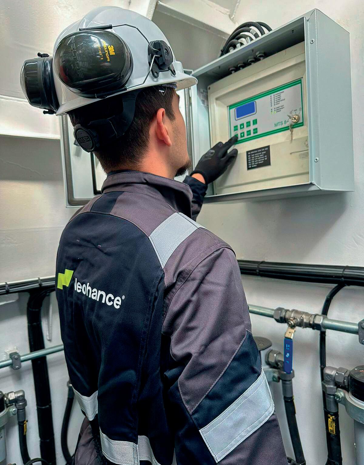
more readily available, its role in sustainable mobility will continue to grow.
Industrial applications
Hydrogen is already widely used in the chemical industry, primarily for the production of ammonia (NH3), which is essential for fertilizers. Ammonia production consumes approximately 1% of global energy, and the industry is a significant emitter of CO2. By shifting from fossil fuel-based hydrogen production to green hydrogen, the industry can significantly reduce its carbon footprint.
In steel production, hydrogen is also being explored as a potential replacement for carbon-based reducing agents, which are traditionally used in the iron ore reduction process. This could help to decarbonise one of the most carbon-intensive industries in the world, potentially reducing global CO2 emissions by a substantial amount.
Energy storage
One of the most promising uses of hydrogen is its ability to store energy. Hydrogen acts as a chemical energy carrier, storing surplus electricity generated from renewable energy sources like wind and solar. During periods of high renewable generation, excess electricity can be used to produce hydrogen through electrolysis. This hydrogen can later be converted back into electricity when renewable energy production is low, therefore helping to stabilise the grid and balance supply and demand.
Hydrogen-based energy storage systems are particularly valuable in regions where renewable energy production is abundant but intermittent. As countries strive to increase their reliance on renewables, hydrogen energy storage will play a critical role in ensuring consistent and reliable power.
Aerospace and space exploration
Hydrogen has long been used in the aerospace industry as rocket fuel due to its high energy content. Liquid hydrogen is used to propel spacecraft and satellites, playing a critical role in both manned and unmanned space missions. Its lightweight properties and ability to deliver high thrust make it ideal for this sector, and advancements in hydrogen propulsion are likely to further expand its use in space exploration.
The importance of hydrogen detection
While hydrogen offers enormous potential across many industries, it is a highly flammable gas that poses significant safety risks if not properly handled. Hydrogen is colourless, odourless, and lighter than air, making it difficult to detect without specialised equipment. Moreover, hydrogen can form explosive mixtures with air at concentrations as low as 4% by volume. For this reason, early and accurate detection is critical in preventing accidents during hydrogen production, transportation, storage, and use.
Key reasons for hydrogen detection
Prevention of explosions
Since hydrogen is highly flammable, even small leaks can lead to dangerous situations. Hydrogen detection systems play a
crucial role in identifying leaks early, allowing for immediate intervention to prevent explosions.
Ensuring safe storage and transportation
Hydrogen is often stored under high pressure or in liquid form at extremely low temperatures. Detecting leaks during storage or transportation is essential to prevent accidents, especially in facilities that handle large quantities of hydrogen.
Industrial process optimisation
In industries such as chemical manufacturing and refining, hydrogen is used in various processes. Continuous monitoring of hydrogen levels ensures that operations are efficient and safe, reducing the risk of accidents and optimising production processes.
Maintaining environmental safety
Hydrogen leaks can lead to potential environmental hazards. While hydrogen itself is not toxic, it can contribute to indirect risks, such as oxygen displacement in confined spaces, leading to asphyxiation hazards. Early detection of hydrogen leaks ensures that environmental and workplace safety standards are maintained.
Hydrogen detection technologies
Hydrogen detection systems have evolved to provide enhanced reliability, accuracy, and adaptability across various environments. Among the most widely used technologies are catalytic sensors, which are favoured for their durability and versatility in detecting hydrogen in diverse industrial settings.
Catalytic sensors
Catalytic sensors work by detecting hydrogen through a catalytic reaction. A small, heated element coated with a catalyst reacts with hydrogen gas upon contact. This reaction generates heat, which causes a measurable change in the electrical resistance of the element. By analysing this change, the sensor determines the hydrogen concentration in the air.
Catalytic sensors are highly regarded for their robustness and ability to function in harsh environments, including areas with high humidity, temperature fluctuations, or chemical exposure. These sensors are typically deployed in industrial environments such as chemical plants, refineries, and hydrogen production facilities.
One of the key advantages of catalytic sensors is their ability to detect hydrogen concentrations over a wide range, from low levels to concentrations near explosive limits. This makes them particularly valuable in high-risk applications, where fast and precise detection is essential.
Application in battery energy storage systems (BESS)
Catalytic sensors are especially effective in battery energy storage systems (BESS), where the safe detection of hydrogen is critical. BESS technologies, particularly lithium-ion batteries, are widely used due to their high energy density, long lifespan, and low maintenance costs. These systems play a crucial role in stabilising renewable energy sources like solar and wind by storing surplus energy during peak
production and releasing it when generation is low, ensuring a stable grid.
However, during the charging and discharging cycles, certain chemical reactions in the batteries can produce small amounts of hydrogen. If not detected early, this hydrogen accumulation could pose significant risks, including fire or explosion.
The selection of detection technology in BESS depends on environmental factors such as changes in temperature, humidity, and pressure, as well as the materials used in the system. Catalytic sensors, such as the SMART 3G gas detectors, are designed to perform reliably even in such challenging conditions. They can be integrated into alarm systems to ensure immediate intervention in the event of
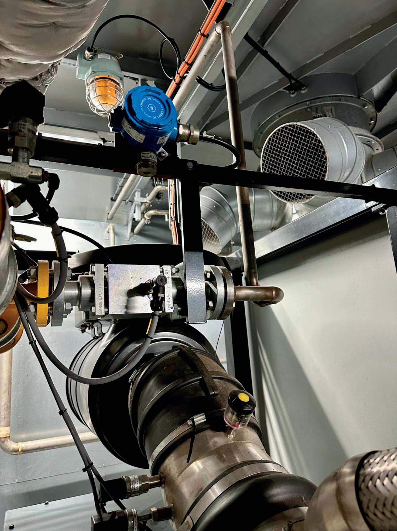
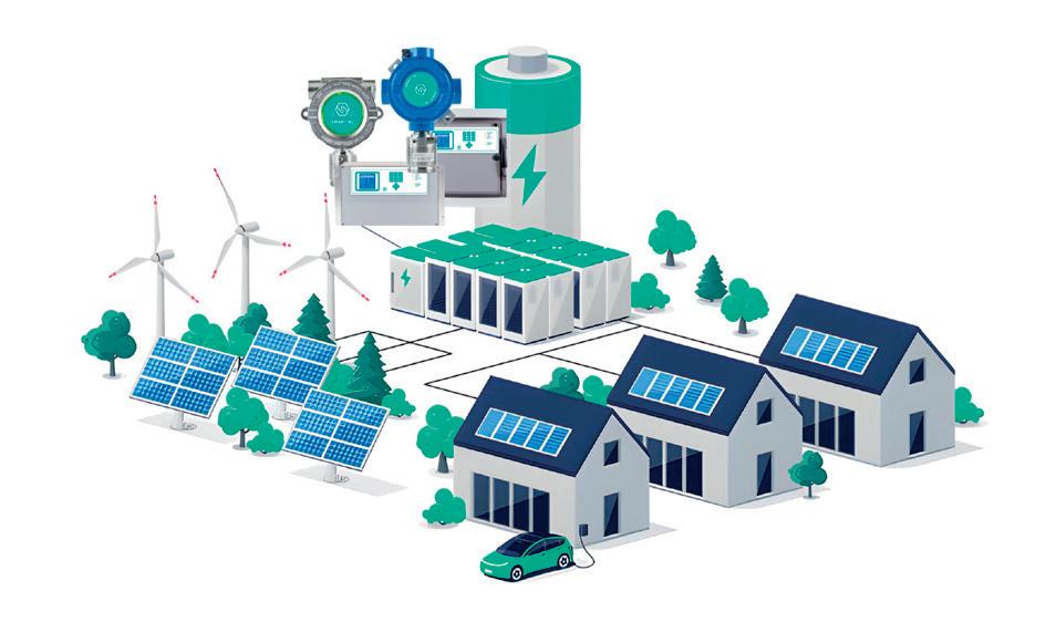
a hydrogen leak, significantly enhancing the safety and security of the energy storage infrastructure.
Ensuring long-term reliability through maintenance
The reliability of hydrogen detection systems is paramount, particularly in industries where safety is a priority. Regular maintenance of these systems is essential to ensure that sensors remain accurate over time. Hydrogen detectors can degrade due to environmental contaminants or sensor wear, leading to false alarms or missed detections.
Routine calibration is required to maintain accuracy, and in many industrial environments, non-intrusive calibration methods are preferred to minimise downtime. By integrating advanced diagnostics and automated calibration, modern hydrogen detection systems can reduce the need for manual intervention, increasing both reliability and efficiency.
Advanced hydrogen detection
As the demand for hydrogen continues to grow across industries, Neohance, in collaboration with Sensitron, is playing a key role in delivering advanced hydrogen detection solutions. Neohance offers a range of gas detection technologies that prioritise safety, reliability, and compliance with international standards such as ATEX, IECEx, and SIL2/3. The company’s SMART 3G D2 and D3 detectors are designed for detecting hydrogen
and other flammable gases in classified areas – these detectors are ATEX and SIL certified, offering non-intrusive field calibration and long-term reliability even in harsh conditions. The MULTISCAN++S2 is a versatile gas detection system that can manage up to 264 detectors, ensuring comprehensive monitoring across large industrial sites. This system integrates seamlessly with alarm systems, ensuring rapid response in the event of a hydrogen leak.
By focusing on maintenance efficiency, reliability, and safety, Neohance aims to help industries to confidently adopt hydrogen technologies while minimising risks and ensuring compliance with global safety standards.
Conclusion: a safe hydrogen future
In conclusion, as hydrogen emerges as a pivotal element in the transition to cleaner energy, the importance of reliable detection technologies cannot be overstated. The unique properties of hydrogen necessitate advanced monitoring solutions to mitigate safety risks and ensure safe usage across various sectors. Catalytic sensors provide robust, accurate detection even in challenging environments, making them ideal for applications in industries such as energy storage and transportation. Neohance and Sensitron are developing gas detection systems that adhere to the highest safety standards so that industries can confidently harness hydrogen’s potential while safeguarding people and the environment. Through collaboration, a safer, more sustainable future powered by hydrogen can be reached.

Rhys Jenkins, Servomex, UK, explores how greater hydrogen use can support the decarbonisation of the steelmaking industry.
For many years, the steelmaking industry has been a major contributor to global carbon emissions. However, increasing concerns about climate change and greenhouse gas emissions have led the steel industry to look for greener, more sustainable production methods.
Traditional steelmaking processes have a very high carbon footprint, so one of the primary considerations in operating more sustainably is to significantly reduce carbon emissions.
Direct reduced iron (DRI) production can play a key role in the transition to lower carbon emissions in steelmaking, as it offers far fewer emissions than traditional iron ore reduction methods.

This low-emission benefit is further enhanced by moving from the use of natural gas in the DRI process to natural gas/hydrogen mixes.
Reliable and accurate gas analysis can empower greater efficiency and productivity in the DRI process, leading to fewer carbon dioxide (CO2) emissions entering the atmosphere.
The DRI process
DRI can be used in electric arc furnaces (EAFs) to produce high-quality steel with a lower carbon footprint, providing a more sustainable alternative to blast furnace-produced iron.
Three different types of DRI are used in the steelmaking process: cold DRI, hot DRI, and hot briquetted iron (HBI).
These DRI forms all provide flexible metallic charge materials for the various proprietary DRI processes.
Most DRI processes use virgin iron ore in a gas-based shaft furnace, fuelled by natural gas, syngas, hydrogen, or a mixture of these.
Accurate measurement of gases given off by the furnace is important for safe and efficient operation while achieving low emissions targets.
In the DRI process, the iron ore is heated as it descends through a shaft furnace. Oxygen is removed from the ore using counterflowing gases with high hydrogen and carbon monoxide content.
These gases react with the iron oxide in the ore, reducing it to metallic iron, with water vapour and CO2 by-products.
The transition from DRI steelmaking using natural gas to a process using high hydrogen gas mixes, or even pure hydrogen, greatly decreases CO2 emissions.
Electrolysis and hydrogen production
Hydrogen is increasingly recognised as a crucial element in greener steelmaking. It can be used as a reducing agent in the production of DRI, replacing carbon-intensive materials like coke.
Hydrogen offers a promising pathway to further reduce emissions in the steel industry, since hydrogen-based DRI production not only lowers the carbon footprint, but also enhances the quality of steel, making it more attractive for various applications.
In turn, electrolysis is playing an increasingly prominent role as a key enabler for the hydrogen economy. Currently, the majority of operational electrolyser projects can be found in Europe. However, other regions – particularly China and India – are growing rapidly in terms of new and developing projects.
Electrolysers utilise electricity to split water (H2O) into hydrogen and oxygen, and so have significant potential for clean energy production. Compared to other production methods for high-purity hydrogen – such as ammonia cracking, coal gasification, and steam reforming – electrolysis delivers a very high-purity product.
However, mixtures of hydrogen and oxygen may be explosive over a wide range, and are capable of being ignited by low-energy sparks, making electrolysis plants potentially hazardous.
In normal operation, the gases are kept separate by a membrane, but this can rupture, allowing the gases to mix. Therefore, it is essential to monitor the hydrogen produced to ensure that oxygen impurity content remains low.
Electrolysis to produce hydrogen can be integrated with renewable energy sources such as solar and wind power. The stored hydrogen can later be converted back into electricity or be converted into other components, such as ammonia.
In other industrial processes, such as metallurgy, electronics, and pharmaceuticals, electrolysis plays a role in those processes that require hydrogen and oxygen. Based on increasing development, electrolysis will also play a role in green zero-carbon transportation, for example in hydrogen fuelling stations.
Electrolysis methods
There are three primary types of electrolyser: alkaline, proton exchange membrane (PEM), and solid oxide electrolyser cells (SOECs).
Alkaline electrolysers use an alkaline solution (typically potassium hydroxide) as the electrolyte, with electrodes made from nickel and iron. These electrolysers are known for their durability and low operating costs as they can use a variety of water sources (e.g. sea /wastewater) and are less sensitive to impurities in feed water, reducing the need for expensive water treatment systems. On the downside, alkaline electrolysers are less efficient than PEM electrolysers, and require higher operating pressures.
PEM electrolysers use a proton exchange membrane which allows protons to pass through the membrane while blocking other ions. They typically use platinum-based electrodes and iridium catalysts, which are costly but offer a long lifespan and high activity. PEM electrolysers are highly efficient, with a fast response which make them well-suited for applications that require rapid changes in hydrogen production. However, production is relatively expensive and requires pure water and electricity.
An SOEC is a fuel cell which runs in regenerative mode to achieve the electrolysis of steam (or CO2) into hydrogen (or carbon monoxide) and oxygen, using a solid oxide ceramic as electrolyte. It can be considered as more of an industrial application, as it is basically a reverse-mode fuel cell. The application shows high potential as an add-on for industrial sites which produce excess heat or steam (e.g. steel plants) and therefore could be considered more efficient because already existent energy resources such as steam or waste heat, can be used to maximise process efficiency.
An SOEC can be integrated in existing downstream industrial processes which generate synthetic fuels, ammonia, methanol, and/or recycle captured CO2. It is, historically, not the most widely-used technology, but its efficiency and ability to be integrated in upstream or downstream processes, as well as the adaptability to on/off cycles (which make it well suited for varying electrical power applications) give SOEC an advantage over other technologies.
Gas analysis in the electrolysis process
Regardless of the electrolysis technology used, gas analysis plays an essential role in helping to ensure both safety and product quality in the hydrogen production process.
During start-up and shutdown in particular, it is important to monitor the limiting oxygen concentration on the hydrogen side of the electrolyser, and hydrogen for the lower explosive limit on the oxygen side of the electrolyser, to prevent the accumulation of an explosive gas mixture. This requires measurements for hydrogen and oxygen in the 0 - 5% range.
This analysis becomes especially important in green hydrogen electrolysis production where the green source of energy (for example solar or wind power) is not continuously available, resulting in the electrolysis process having to shut down and restart more frequently.
For the final hydrogen product, moisture and oxygen are both considered contaminants, and their content must be monitored to ensure the impurities remain below acceptable quality limits, typically below 10 ppm. This is especially important when the hydrogen product is intended for use in power fuel cells.
Gas analysis solutions
For the measurement of oxygen in safety applications, Servomex offers the SERVOTOUGH Oxy 1900 and SERVOTOUGH OxyExact 2200 series oxygen analysers. These rugged, hazardous area analysers use the paramagnetic sensing technology, which gives an accurate and fast response.
Paramagnetic sensing is a physical measurement technique, so there are no chemicals or electrolyte to replace, and maintenance requirements are low. Certified versions are available for use in Zone 1 / Division 1 and Zone 2 / Division 2 hazardous areas.
For quality control measurements, it is necessary to measure trace O2 and lower traces of H2O.
Both measurements can be provided by the SERVOPRO MonoExact DF310E safe area analyser fitted with the SERVOPRO AquaXact 1688 moisture probe.
The coulometric digital oxygen sensor of the analyser offers the ppm-level O2 measurements required, while plug-and-play capability to operate the AquaXact Aluminium Oxide moisture sensor adds a simultaneous moisture measurement.
When connected to the moisture sensor, the screen is designed to simultaneously display both oxygen and moisture measurements.
It is a digital analyser that combines precision, trace-level measurements with an easy-to-operate icon-driven guided user interface (GUI) and advanced digital communications.
In addition, the SERVOPRO DF-700 Series can be used, either for moisture measurements alone or, using the DF-760E model, both moisture and oxygen.
Designed for ultra-high purity (UHP) gas measurements in quality control applications, the DF-700 Series uses high-stability tunable diode laser (TDL) sensing technology to measure ultra-low contaminant levels of H2O. The DF-760E is also configured with a non-depleting coulometric sensor.
The DF-760E offers very low lower detection limits (LDL) of 100 ppt (H2O) and 45 ppt (O2), with a fast speed of response, unsurpassed stability and immunity from trace acid damage.
Measurement performance is supported by a low-maintenance design, delivered through the resilient zero-drift sensing technologies which require no ongoing calibration.
All the analysers mentioned require a suitable sampling system which conditions the sample to meet the specific analyser requirements.
Conclusion
Switching to hydrogen as a replacement for natural gas in the DRI process will greatly reduce the significant CO2 emissions generated by the steelmaking industry.
The emergence of electrolysis as an increasingly prominent enabler of the hydrogen economy offers considerable benefits to steelmakers looking to decarbonise their process, while using hydrogen can also improve steel quality.
However, gas analysis is crucial to ensuring the safety of the electrolysis process, and to providing quality assurance for the final hydrogen product.


