Discover how advanced drilling uid management — sensor-driven optimization, magnetic debris removal, and next-gen lubricants — work together to drive performance, reduce downtime, and set a new standard in e ciency.
21 Digital shaker surveillance
Matt Bell, DrillDocs.
25 Production monitoring with fibre optic strain, acoustics and temperature
J. Andres Chavarria, Luna Innovations – OptaSense, and Veronique Mahue, Silixa – a Luna company. 29 Levelling the playing field
Andrew Law, Enteq Technologies.
33 An extra boost
Vijay Desiraju, Celonis.
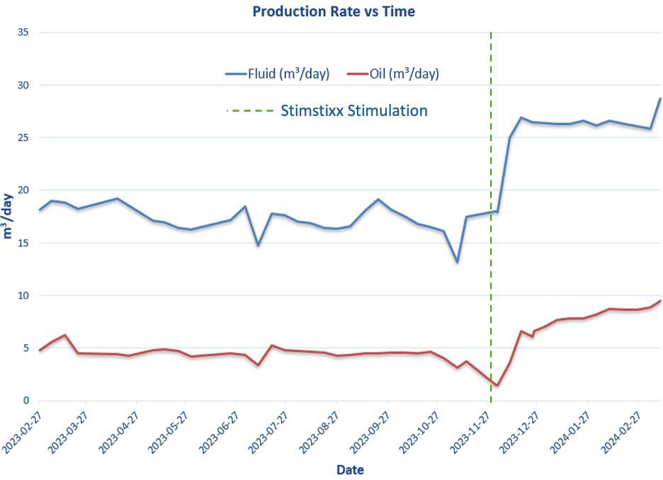
35 Low risk high rewards
Jeff Forsyth, Jan Frieling, and Fraser Smith, StimStixx.
39 Powering oil and gas operations with AI
Christian Keon and Indu Moola, NanoPrecise.
Comment
January/February 2025
Elizabeth Corner, Senior Editor elizabeth.corner@palladianpublications.com
Wood Mackenzie’s recently published report, Global Upstream:5ThingstoLookforin2025, notes that a prevailingly optimistic upstream sentiment comes at a time of high geopolitical tensions, and both supply and demand concerns, setting 2025 up to be a year of mixed messages.1 It cites the following as key themes for the year ahead: “an increased focus on efficiency, resource capture being back in vogue, strategic M&As, Americas liquids growth outside the Permian, a new wave of LNG projects”.
The report places emphasis on the importance of efficiency in upstream: “This focus is not a new phenomenon, but operators will progressively lean more heavily on artificial intelligence (AI) and other sophisticated tools to optimise costs, production and revenues. The risk of global tariffs and softer prices adds impetus.”
AI has been part of the upstream oil and gas sector for years, particularly in data analytics, reservoir modelling, predictive maintenance, and automation of drilling operations. However, what seems to be changing is the pace of adoption. Several factors are pushing companies to accelerate their AI-driven strategies, rather than just experimenting with them. Let’s look at some AI-related upstream announcements from the first few weeks of 2025.
Repsol will boost its digital programme by incorporating AI agent systems, designed and deployed with the help of Accenture and built on the NVIDIA AI platform. This will help to improve the efficiency of processes as they are scaled across all company businesses.
Baker Hughes has signed an agreement with NNPC/FIRST Exploration & Petroleum Development Company JV to deploy the Leucipa automated field production solution. Leucipa enables oil and gas companies to manage production while minimising carbon emissions, harnessing data to promote smart operations. The solution will be launched offshore in the Niger Delta, marking the first implementation of the solution in sub-Saharan Africa.
SLB has announced the opening of its Africa Performance Centre in Luanda, Angola. The 3200 ft2 state-of-the-art facility will serve as a collaborative hub for industry stakeholders, providing access to innovative digital and AI solutions within Angola and Africa.
AI is driving efficiency, but will it lead to true transformation, or is it just another overhyped tool in an industry known for slow adoption? It’s clear that companies like Repsol, Baker Hughes, and SLB are moving beyond experimental AI use and embedding it into core business processes. AI-enabled automation is becoming standard: tools like Leucipa (Baker Hughes) and recently-launched DeepSeek’s AI models are being deployed in major projects, reducing reliance on manual operations and improving real-time decision making. And the shift from cost-cutting to AI-driven growth is happening; AI is increasingly seen as a sophisticated tool to unlock new resources, boost production, and enhance exploration success rates.
In this issue of OilfieldTechnology, Andrew Law at Enteq Technologies explains why the adoption of AI in drilling marks a significant evolution in the sector (p.29), and Nanoprecise Sci Corp. presents the power of AI-driven maintenance (p.39). In addition, the Drill Docs article shows us how computer vision technology is supporting shaker surveillance on offshore rigs, and how the power of generative AI will further change the process of drilling automation (p.25).
AI adoption is no longer optional or a future consideration, it’s a necessity. The companies that adapt quickly will likely lead the next decade of energy production.
Digital Events Coordinator: Merili Jurivete merili.jurivete@palladianpublications.com
Junior Video Assistant: Amélie Meury-Cashman amelie.meury-cashman@palladianpublications.com
Website
Digital Content Coordinator: Kristian Ilasko kristian.ilasko@palladianpublications.com
Digital Administrator: Nicole Harman-Smith nicole.harman-smith@palladianpublications.com
Marketing
Administration Manager: Laura White laura.white@palladianpublications.com
Reprints: reprints@palladianpublications.com
Palladian Publications Ltd, 15 South Street, Farnham, Surrey GU9 7QU, UK Tel: +44 (0) 1252 718 999 Website: www.oilfieldtechnology.com
Still pioneers.
World news
Rystad Energy: US$150 billion in global upstream opportunities ahead as shale consolidation slows down
According to Rystad Energy, upstream merger and acquisition (M&A) activity is expected to slow significantly in 2025 following two years of record-high transactions driven by US shale mergers. The global deal pipeline value stands at approximately US$150 billion as much of the sector’s consolidation has run its course, making a return to recent peaks unlikely. North America will continue to lead global M&A activity, driven by nearly US$80 billion in upstream opportunities on the market. Elsewhere in the Americas, South American deal value rose from US$3.6 billion in 2023 to US$14.1 billion in 2024 (excluding Chevron’s acquisition of Hess), largely due to regional exploration and production (E&P) growth ambitions – and despite Petrobras halting its divestment program.
Atul Raina, Vice President, Oil & Gas Research, Rystad Energy, commented: “Last year marked a significant year of consolidation in the US shale sector, with approximately 17 consolidationfocused deals, compared to just three acquisitions in late 2023. Activity was always expected to fall after such dramatic highs, but there is still plenty of business to be done. North America is still a leader in M&A activity and will continue to play a key role in maintaining the market’s health. There is also potential for further upside if US shale gas M&A activity increases, assuming Henry Hub prices remain stable and conducive to deal-making.”
M&A deal value in Europe decreased by around 10% year-on-year, to US$14 billion in 2024. Around 75% of the regional total centred on the UK, where majors have been adopting an autonomous model strategy to expand their presence in the North Sea. The largest deal this year involved Shell and Equinor merging their UK North Sea upstream portfolios, excluding some of Equinor’s cross-border assets. The combined entity will become the largest producer in the UK North Sea, with a projected output of around 140 000 boe/d by 2025.
Despite US$8 billion worth of upstream opportunities in the region, the outlook for future M&A activity in Europe remains uncertain due to fiscal policy in the UK, which accounts for 73% of the potential deals, valued at about US$5.9 billion. Tightened government fiscal terms for offshore oil and gas threaten to dampen buyer interest. However, combining portfolios that balance deferred tax positions and future expenditure could be an emerging trend in the country’s M&A landscape, given the current fiscal challenges.
SLB OneSubsea signs agreement with Vår Energi for upcoming subsea developments in Norway
SLB has announced an agreement between its OneSubsea™ joint venture and Vår Energi to deliver a sizeable subsea production systems (SPS) work scope. This award leverages the existing strategic subsea partnership agreement between the two companies for standardised subsea equipment, supporting multiple upcoming oil and gas developments on the Norwegian Continental Shelf (NCS). Under this SPS pre-commitment program, work commences immediately to deliver two equipment packages. The first package consists of a complete SPS system, including four vertical subsea trees, wellheads, templates, manifolds, umbilicals and all other associated SPS equipment, which upon delivery can be expediently deployed by Vår Energi to any field in their portfolio. The second package includes the engineering and procurement of all components needed for another same-size SPS system, enabling a reduced lead time for any subsequent project developments.
“Simplification is key to unlocking more resources, faster, and this novel approach stems from Vår Energi’s long term, strong commitment to our standard, configurable solutions,” said Mads Hjelmeland, CEO of SLB OneSubsea. “This is a significant step forward for our partnership, and we are grateful for our open, collaborative relationship with Vår that now leads to such new ways of creating mutual value for both companies.”
The two four-well equipment packages leverage SLB OneSubsea’s standard, configurable subsea platform and will enable Vår Energi to fast-track subsea developments on the Norwegian Continental Shelf, significantly reducing time from final investment decisions to delivery across their project pipeline.
January/February 2025
Namibia
Impact Oil & Gas has announced spudding of Marula-1X exploration Block 2913 offshore Namibia.
Malaysia
McDermott has announced the completion of transportation, installation and commissioning activities for the Kikeh subsea gas lift project.
China
CNOOC Limited has announced that Bozhong 26-6 Oilfield Development Project (Phase I) has commenced production.
Libya
ABL has been awarded a contract to provide marine warranty survey services to Saipem for Libya’s Bouri Gas Utilisation Project.
USA
The US Senate on Monday 3 February confirmed Chris Wright, a fracking executive, to be President Donald Trump’s energy secretary.
UK
“Substantial green prize” lies ahead for UK as it decarbonises economy, according to a DNV report.
Guyana
Salunda has integrated monitoring solutions on four drilling rigs in Guyana with Intellilift’s digital technologies.
Kazakhstan
Chevron has started oil production at its Future Growth Project located at the Tengiz oil field in Kazakhstan.
World news
January/February
2025
Halliburton announces offshore drilling contract with Petrobras
18 - 20 February 2025
Subsea Expo Aberdeen, UK
https://www.subseaexpo.com/
5 - 8 May 2025
Offshore Technology Conference (OTC) 2025 Houston, USA
https://2025.otcnet.org/
19 - 23 May 2025
29th World Gas Conference (WGC2025) Beijing, China www.wgc2025.com
Ì Baker Hughes announces trio of electrification technologies for onshore, offshore operations
Ì Crescent Energy closes accretive central Eagle Ford bolt-on
Ì Pipetech announces launch of Downhole Scale Remediation technology
Ì Aize announced as one of bp’s global digital twin providers
Ì Diversified Energy announces acquisition of Maverick Natural Resources
Ì TXO Partners announces natural gas potential in the Mancos shale of the San Juan Basin
To read more about these articles and for more event listings go to: www.oilfieldtechnology.com
Halliburton has announced a contract award from Petrobras for integrated drilling services across several offshore fields in Brazil, the result of a competitive process. The contract scope includes drilling services for development and exploration wells over a three year period. In this contract, Halliburton will provide iCruise® intelligent rotary steerable system (RSS) to reduce well time and place wells accurately, and LOGIXTM automation and remote operations platform to improve well construction consistency and performance. Halliburton will also provide its ultra-deep resistivity service, EarthStar®, to position production boreholes and map reservoirs.
To address the technical limits of drilling fluids in offshore areas, Halliburton will deploy its BaraLogix® real-time service to reduce lost time through advanced hydraulic software, surface measurement automation, and predictive analytics.
Halliburton will also utilise several other exclusive technologies such as Cerebro® in-bit sensing and introduce innovative solutions such as the Reservoir Xaminer™ formation testing service. This service detects structural reservoir complexities and drives more informed decisions in drilling, completion, and production. Waldomiro Mendes, senior area manager, Brazil, Halliburton, said: “This contract demonstrates Halliburton’s strength in deep and ultradeep offshore drilling and well construction.”
The contract, expected to begin in 2025, represents Halliburton’s largest service contract with Petrobras. This significantly expands Halliburton’s drilling services footprint in the presalt and post-salt areas for both development and exploration wells.
DNV Cyber research reveals energy companies boosting investment in cybersecurity arms race, to manage the ‘greatest
risk’ to the industry today
According to the latest Energy Cyber Priority report from DNV Cyber, energy companies are making progress in cybersecurity. This includes greater awareness at leadership level, with 78% of energy professionals confident their leaders sufficiently understand cyber risk. Successes have been delivered by employee training, as more than eight in 10 (84%) say they know exactly what to do if they are concerned about a potential cyber threat. Growing attention is being paid to operational technology (OT) cybersecurity – securing the systems that manage, monitor, and automate physical assets – as two thirds (67%) expect greater OT security investment in the year ahead. Challenges remain, however, as the energy transition creates new attack surfaces and as threat actors become more sophisticated.
“Achieving the energy transition is central to society at large. The whole energy sector –companies and governments alike – are working together on this massive challenge, which is increasingly complex because the technologies underpinning the transition are largely digital and scaling rapidly. With this comes cybersecurity risks,” said Ditlev Engel, CEO, Energy Systems at DNV. “Cybersecurity should be a priority for all players in the energy sector to achieve the climate goals and guarantee energy security, as geopolitics make the world more hostile and uncertain.”
“Even as the energy industry becomes more mature in its cybersecurity posture, it must continue to strengthen and adapt to remain resilient against a growing number of increasingly sophisticated threats. From attacks on supply chains, recruitment of malicious insiders, and the use of AI, adversaries are upping their game and the energy industry needs to keep up,” said Auke Huistra, Director of Industrial and OT Cybersecurity at DNV Cyber.
“To further strengthen their cybersecurity, energy companies should – as a priority –broaden their efforts to secure OT and support greater security and transparency in the supply chain,” continued Huistra. “They should reset and redesign cyber’s relationship with the business, take a more innovative approach to training, and build understanding of AI.”
CleanSight®
Cuttings return rate
Automatic cavings detection
Cuttings size distribution
Data
Fewer crew visits to the shakers
Revolution Through Evolution
Nithiya Parameswaran, AspenTech, explains how asset performance management can transform upstream operations.
In the upstream oil and gas sector, the need to drive towards increased efficiency and cost reduction has become more critical than ever. As companies navigate fluctuating commodity prices and stringent regulatory environments, the adoption of advanced technologies becomes indispensable.
One such technology, asset performance management (APM), is redefining how oil and gas companies manage their assets, enhancing operational reliability and optimising performance. This article delves into the transformative role of APM in the upstream sector, with a focus on the evolution from predictive to prescriptive maintenance.
Understanding predictive and prescriptive maintenance
Predictive maintenance, a relatively well-established concept in APM, and in the industrial world in general, involves using data analytics to anticipate equipment failures before they occur. By monitoring various parameters and utilising historical data, predictive maintenance aims to identify patterns that signal potential
issues. This proactive approach allows for timely interventions, thereby minimising unplanned downtime and extending the lifespan of assets. However, while predictive maintenance offers significant benefits, it stops short of providing actionable solutions. This is where prescriptive maintenance comes into play. Prescriptive maintenance not only predicts potential failures but also recommends specific actions to prevent or mitigate these issues. Leveraging advanced algorithms, machine learning, and artificial intelligence, prescriptive maintenance transforms data into actionable insights, guiding operators on the best course of action to maintain optimal asset performance.
The shift from predictive to prescriptive maintenance represents a significant advancement in the capabilities of APM. Predictive maintenance, despite its advantages, primarily focuses on identifying when a failure might occur. This information, while valuable, often leaves operators with the challenge of determining the appropriate response. In contrast, prescriptive maintenance provides a more comprehensive solution by offering detailed recommendations on what actions to take; when to take them and how to execute them effectively, thereby helping to ensure maximum asset performance and reliability.
This evolution is driven by the increasing sophistication of data analytics and machine learning technologies. Modern APM systems can analyse vast amounts of data in real time, identifying complex patterns and correlations that were previously undetectable. By integrating these advanced capabilities, prescriptive maintenance offers a holistic approach to asset management, ensuring not only the early detection of issues but also the optimisation of maintenance strategies.
Benefits of prescriptive maintenance in upstream operations
The adoption of prescriptive maintenance in the upstream oil and gas sector brings about numerous benefits. Firstly, it significantly enhances asset reliability. By providing precise recommendations on maintenance actions, prescriptive maintenance helps prevent equipment failures, ensuring continuous production and reducing downtime. This is particularly crucial in the upstream sector, where unplanned shutdowns can result in substantial financial losses.
Second, prescriptive maintenance improves safety. Early detection of potential failures allows for timely interventions, reducing the risk of accidents during operations. This proactive approach also minimises the need for emergency repairs, which are often associated with higher safety risks. In addition, prescriptive maintenance contributes to better environmental performance. By avoiding unexpected shutdowns, it reduces flaring and other emissions, thereby lowering the environmental footprint of operations.
Another significant advantage is cost reduction. Prescriptive maintenance optimises the scheduling of maintenance activities, ensuring that resources are used efficiently. This not only lowers maintenance costs but also extends the lifespan of assets, providing a better return on investment. Furthermore, the ability to plan maintenance activities around production schedules helps maximise asset utilisation, enhancing overall operational efficiency. By integrating data from multiple sources, prescriptive maintenance provides a holistic view of asset health, enabling more informed decision-making and strategic planning for future investments.
From theory to practice
Several businesses in the upstream oil and gas sector have successfully implemented prescriptive maintenance strategies, reaping substantial benefits. We are seeing companies utilising advanced APM systems to
monitor compressors and pumps, benefiting from the opportunity to access early warnings of potential failures and recommended specific maintenance actions.
Systems can often provide lead times of several weeks for future failures, allowing upstream oil and gas companies to act before any disruption occurs and drive significant improvements in reliability and cost savings.
Operators dealing with high failure rates of pumps in batch processes received early warnings that avoided potential safety incidents, and significantly reduced maintenance costs. Such cases and many others like them highlight the versatility and effectiveness of prescriptive maintenance across different operational contexts within the oil and gas industry.
Overcoming challenges from implementation and beyond
While the benefits of prescriptive maintenance are clear, implementing such systems can pose challenges. One of the primary hurdles is the integration of new technologies with existing infrastructure. Many upstream operations still rely on legacy systems that may not be fully compatible with modern APM solutions. Overcoming this challenge requires careful planning and investment in upgrading and integrating infrastructure.
This involves a thorough assessment of current systems to identify gaps and areas that need enhancement. Upgrading might include deploying new sensors and control systems, enhancing data storage capabilities, and ensuring that communication networks are robust and secure. Additionally, it requires a phased implementation strategy to minimise disruption. Collaboration with technology providers can facilitate the integration process, providing the necessary technical support and expertise to address any compatibility issues.
Another challenge is that the sheer volume of data generated by modern oilfield operations can be overwhelming. Effective data management and analysis are crucial for extracting actionable insights, especially in the upstream oil and gas sector. Upstream operations generate vast amounts of data from various sources such as drilling rigs, production wells, and reservoir monitoring systems. The challenge lies in handling this data deluge effectively to drive meaningful decisions.
Advanced data analytics platforms that can handle the scale and complexity of upstream data are essential. These platforms should
integrate with existing oilfield infrastructure, providing real-time analytics and visualisation capabilities. Machine learning and artificial intelligence can further enhance data processing by identifying patterns and predicting future trends, allowing for proactive maintenance and operational strategies.
Coupled with this, upstream oil and gas operators also have to think about the human dimension. As the capability of technology grows, operators face an urgent and ever-growing need for skilled personnel to manage and interpret the outputs of prescriptive maintenance systems. While these systems provide detailed recommendations, human expertise is still required to validate and execute these actions. Training and developing a workforce capable of leveraging advanced APM technologies is essential for successful implementation.
Doing this does, however, also require ensuring that the business has a data-centric culture where data integrity, accessibility, and analysis are prioritised. Ensuring data integrity involves rigorous validation processes to maintain accuracy and consistency. Accessibility means making data readily available to all stakeholders, from field operators to corporate executives, enabling timely and informed decisions.
To cultivate this kind of culture, upstream operators should focus on continuous training and development, ensuring that their workforce is proficient in data analytics and comfortable using these tools in their daily operations. Leadership must also champion data-driven initiatives, setting clear expectations and rewarding data-driven decision-making practices.
This must all be accompanied by a clear focus on change management. Organisations must be willing to shift from traditional reactive or preventive maintenance approaches to a more proactive and data-driven strategy. This shift requires buy-in from all levels of the organisation, from executives to frontline workers. Clear communication of the benefits and a structured change management plan can help facilitate this transition.
Additionally, companies need to establish robust data governance frameworks to oversee data quality and security, ensuring that data is not only accurate but also protected against unauthorised access and breaches. By prioritising data management and fostering a culture that embraces data-driven insights, upstream oil and gas companies can turn vast data streams into valuable assets, enhancing efficiency, reducing costs, and improving overall operational performance.
The latest trends and innovations
The future of asset performance management (APM) in the upstream oil and gas sector is promising, with continuous advancements in technology poised to drive further improvements in asset performance and reliability. One of the emerging trends is the integration of APM with the industrial internet of things (IIoT). IIoT enables real-time data collection and analysis from a wide array of connected devices, providing a more comprehensive view of asset performance.
The integration of APM with IIoT works by embedding sensors and smart devices throughout the oil and gas infrastructure, from drilling rigs to processing plants. These devices continuously monitor various parameters such as temperature, pressure, vibration, and flowrates. The data collected is transmitted in real time to centralised systems where advanced analytics and machine learning algorithms process it to detect patterns, predict failures, and optimise operations.
One of the primary benefits of this integration is the ability to predict and prevent equipment failures before they occur. By analysing historical and real-time data, the system can identify early warning signs of potential issues, allowing for timely maintenance and reducing unplanned downtime. This predictive maintenance approach not only enhances equipment reliability but also extends the lifespan of critical assets.
Additionally, real-time data analysis enables more efficient resource allocation. Operators can make informed decisions about maintenance
schedules, inventory management, and operational adjustments, leading to cost savings and improved efficiency. The visibility provided by IIoTintegrated APM also supports better regulatory compliance and safety management, as operators can quickly identify and address potential safety hazards.
Furthermore, this integration fosters continuous improvement through feedback loops. The insights gained from data analysis help refine operational strategies and maintenance practices, leading to ongoing enhancements in asset performance. As a result, companies in the upstream oil and gas sector can achieve higher levels of operational excellence, sustainability, and organisation optimisation.
Another significant trend is the use of digital twins. A digital twin is a virtual replica of a physical asset that mimics its behaviour and performance. By integrating digital twins with APM systems, companies can simulate various scenarios and optimise maintenance strategies. This approach provides a deeper understanding of asset behaviour, enabling more accurate predictions and prescriptions.
Cloud-based APM solutions are also gaining traction, offering greater flexibility and scalability. These solutions allow companies to manage their assets more efficiently across multiple locations, facilitating centralised monitoring and decision-making. Additionally, cloud-based systems can leverage advanced analytics and machine learning capabilities, further enhancing the effectiveness of prescriptive maintenance.
Advancements in machine learning and artificial intelligence, like generative AI, will continue to enhance the capabilities of prescriptive maintenance systems. As these technologies evolve, they will not only become more adept at identifying complex patterns and correlations, leading to more accurate and timely recommendations, but also allow engineers to interact with a natural language interface to query information and receive meaningful insights. Furthermore, the development of more sophisticated algorithms will enable prescriptive maintenance systems to handle a wider range of equipment and operational conditions.
The integration of APM with broader digital transformation initiatives will also play a critical role in its future development. As companies adopt digital technologies across their operations, APM will become an integral part of a connected and intelligent ecosystem. This integration will enable data flow and collaboration between different systems and departments, enhancing overall operational efficiency and effectiveness.
Embracing the future
APM is revolutionising the upstream oil and gas sector by transitioning from predictive to prescriptive maintenance. This evolution is driven by advancements in data analytics, machine learning, and artificial intelligence, which enable more accurate predictions and actionable recommendations. By adopting prescriptive maintenance, companies can enhance asset reliability, improve safety, reduce costs, and minimise their environmental footprint.
The successful implementation of prescriptive maintenance requires careful planning, investment in technology, and the development of skilled personnel. Overcoming these challenges will pave the way for significant operational improvements and competitive advantages. As the industry continues to evolve, the integration of APM with emerging technologies like IIoT, digital twins, AI/ML and cloud computing will further enhance its capabilities and impact.
For upstream oil and gas companies, embracing APM is not just a technological upgrade but a strategic imperative to drive optimisation and sustainability in the digital age. By leveraging the power of prescriptive maintenance, these companies can achieve greater operational excellence and secure a competitive edge in a rapidly changing landscape.
Reducing fugitive emissions in upstream oil and gas
Arun Karupaiah, Celeros Flow Technology, outlines how OEM equipment manufacturers and specialist engineering companies are providing practical technological solutions and additional support to help mitigate fugitive emissions.
Fugitive emissions are a longstanding challenge for the oil and gas industry. They can occur at all stages in the hydrocarbon value chain. At the well, gases can escape through the casing during operations or through the soil after a well has been completed. During transportation, gases can escape at valve fittings or small leaks in pipes. Such emissions include unintentional releases of gases like methane (CH4) and carbon dioxide (CO2) through leaks, uncontrolled venting, equipment malfunctions, or during maintenance activities. The complexity and scale of oil and gas operations, combined with the diverse sources of emissions (such as wellheads, pipelines, and storage tanks), have made it difficult to identify, monitor, and manage emissions effectively.1
In the past, the key drivers for reducing emissions were primarily around maximising production and ensuring safety. Now, growing awareness of the mechanisms of climate change is increasing the regulatory pressure to reduce fugitive emissions in order to decarbonise the energy sector and achieve global environmental sustainability goals.
This article explores the multiple drivers for fugitive emissions reduction and explains how technological advancements, including improved valve and seal designs, are being developed to aid upstream oil and gas operations to dramatically reduce leakage – delivering enhanced environmental compliance, operational efficiency, and cost savings.
Environmental drivers
Despite the rapid development of alternative energy sources, it is widely accepted that fossil-based fuels such as natural gas will be required for many years to come. Fugitive emissions pose a serious challenge that, if not addressed, will diminish the role of natural gas in the future energy system.2
Methane – the primary component of natural gas – is a leading contributor to global warming. When it leaks into the atmosphere, it creates a powerful greenhouse gas effect, contributing to global temperature rises that in turn cause glacial deterioration, sea level rise, and more extreme weather events. Indeed, the greenhouse gas potential of methane is 86 times more than that of CO2 over a 20 year timeframe.3
According to the US Environmental Protection Agency, the production segment (including exploration, offshore production, and gathering and boosting) accounts for 60% of the total methane emissions from the oil and natural gas industry.4 Clearly there is considerable room for improvement – but reducing environmental impacts is not the only reason to target fugitive emissions.
Operational and financial drivers
Leaking gases represent lost product, which translates into financial losses. Research indicates that the upstream oil and gas sector could save in excess of US$30 billion by eradicating fugitive emissions.5 To put this into context, upstream fugitive emissions cost more than the entire GDP of countries such as Cambodia, Zimbabwe, or Jamaica.6 This represents an
enormous opportunity to improve resource efficiency and prevent product wastage, which will boost profitability.
Within the wider value chain, tackling fugitive emissions can also address concerns raised by institutional investors that the credibility of natural gas is being undermined, contributing to costly license-tooperate risks. Natural gas consumers, worried about their own carbon footprint, may also feel reassured that the industry is doing all it can to be environmentally responsible – ultimately helping to retain market share for longer.
Operational and financial considerations therefore have a direct link to reputation management for individual operators and the oil and gas industry as a whole. Demonstrating a commitment to environmental stewardship through reducing fugitive emissions enhances reputation and fosters trust and goodwill among stakeholders, including investors, customers, and local communities.
Safety aspects
Fugitive emissions can pose serious health risks to workers and nearby communities.
CO2 is naturally present in the air we breathe and is not harmful to health at low concentrations. It is not a flammable gas and does not support combustion. However, exposure to sufficient quantities can cause headaches, dizziness, confusion, and loss of consciousness. Since CO2 is heavier than air, fatalities from asphyxiation are a real risk where higher concentrations of the gas have entered confined spaces such as tanks, sumps, or cellars and have displaced the oxygen. It is also possible for CO2 to accumulate outside in trenches or depressions following leaks or a pressurised release where the CO2 is colder than the surrounding air.7
Safety risks associated with methane may occur anywhere it is extracted, produced, or used.
Like CO2, high levels of methane gas can reduce the amount of oxygen available to breathe. Effects include mood changes, slurred speech, vision problems, memory loss, headache, nausea, vomiting, and facial flushing. In severe cases, methane exposure can affect your breathing and heart rate, leading to balance problems, numbness, and unconsciousness. High doses or long exposure time can be fatal. In addition, skin or eye contact with liquefied methane released under pressure may cause frostbite.8
Reducing fugitive emissions therefore helps ensure a safer working environment and reduces potential health hazards. This in turn improves worker wellbeing and efficiency because there will be fewer hours lost to illness.
Regulatory landscape
The upstream oil and gas sector is no stranger to regulatory compliance, as well as the financial and legal consequences involved. In addition to licence-to-operate rules and safety regulations, stricter environmental regulations and policies are now coming into play, making the reduction of fugitive emissions a crucial part of any upstream planning and operational strategy.
One of the most recent legislative changes is the amendment to the US Clean Air Act (IRA Section 60113), which introduces a new section 136 on ‘methane emissions and waste reduction incentive program for petroleum and natural gas systems’.9 Section 136 appropriates US$1.55 billion to provide financial and technical assistance for methane monitoring and mitigation. The aim is to encourage better reporting of greenhouse gas emissions by the owners and operators of petroleum and natural gas facilities so that better data is available for research and innovation that will ultimately lead to a reduction in air pollution.
Section 136 also sets methane emissions thresholds for petroleum and natural gas production, processing, transmission, and storage facilities and gives the EPA Administrator the power to impose and collect
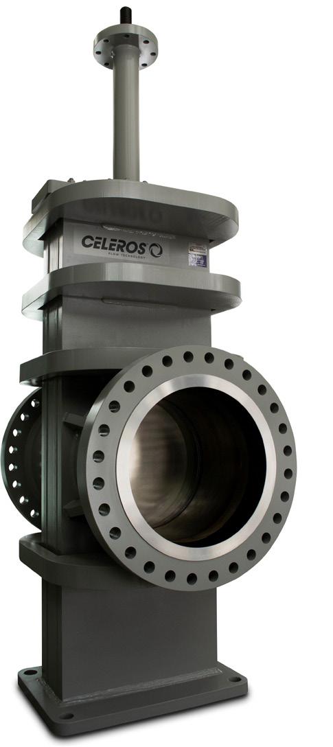
Figure 1. Recent improvements to the M-303 slab gate valve from M&J Valve focus on enhancing lifetime performance, reducing emissions, and minimising downtime.
For 50 years, Wild Well has been proud to stand alongside the oil and gas industry, providing unwavering support and expertise when it matters most.
Our legacy is built on trust, innovation, and a steadfast commitment to safety-values that have guided us from day one. We're honored to have earned the confidence of operators around the world, and as we celebrate this milestone, we remain dedicated to delivering the same level of excellence that has defined our work since 1975.
Our promise is to continue evolving, always upholding the high standards that make Wild Well a name the industry relies on.
Figure 2. The CFT-Green spring loaded seal exerts constant pressure and maintains the correct levels of compression throughout the seal’s lifetime, dramatically reducing maintenance and preventing leakage.
fines where these thresholds are exceeded. The methane emissions charge starts at US$900/t of methane emitted above the set threshold in 2024 and rises to US$1200 in 2026.
Tackling fugitive emissions
There is no doubt that tackling fugitive emissions calls for a multi-faceted approach. There is already much debate about how recent technological advancements in AI and digital solutions might be harnessed to meet the growing need for data collection, monitoring and analysis. But there is a more fundamental question to ask – what can be done to prevent fugitive emissions from occurring in the first place?
There is clear evidence that the majority of fugitive emissions – as distinct from venting operations – are caused by leaks in components including compressors, pipelines, and valves. Component leakage may be the result of poor product design or materials specification, incorrect installation and usage, or inadequate maintenance. All of these factors are eminently addressable.
Valve improvements
Leaking valves are not cheap to repair, particularly if they are weld-in valves that must be repaired in situ during planned outages. If a valve is leaking internally, it will not shut off completely. In addition to fugitive emissions and environmental impacts, the consequences of internal leakage include product loss and contamination. Better valve design is the first line of defence.
Celeros Flow Technology’s M&J Valve brand has recently made improvements to its M-303 slab gate valve for pipeline applications, focussed on enhancing lifetime performance, reducing emissions, and minimising downtime.10 The M-303 slab gate valve is designed for highpressure differential applications in the oil and gas sector and has a long and proven history in the field. It now features a new spring-loaded seal (SLS) design, which helps to maintain the correct compression throughout its lifetime, even as the packing material wears and ages.
This seal requires zero tightening intervention during its lifecycle, which minimises downtime for maintenance. Because the SLS packaging is always energised, it does not require line pressure to react. All these features make for a highly reliable seal that improves overall performance, reduces the likelihood of fugitive emissions, and minimises maintenance requirements. The M-303 is therefore particularly suited for remote or inaccessible valve locations and is certified to international standards including ISO 15848, API 6D, ASME Section VII, and Sour Service NACE MR0175/ISO 15156.
The improved M-303 valve has the same footprint as previous versions, which makes it easy to upgrade. Operator mounting and conversions are simplified thanks to a two-piece stem and common yoke design. The twopiece stem allows different materials to be used in wetted areas to improve service life, while standard material can be used for stem threads for a costcompetitive solution.
Seal innovation
Traditionally, stationary loading packing seal solutions have been used to control fugitive emissions, but this type of packing wears and fatigues over time and requires regular adjustment. It is common to temporarily mitigate packing leaks by injecting packing compound, but this is not a substitute for proper replacement.
The CFT-Green Valve Packing System addresses these issues. It reduces fugitive emissions and provides a safe and efficient sealing solution for valves without the need for any packing tightness intervention during the seal’s lifetime. The CFT-Green design is based on a stem spring-loaded seal mechanism that offers reliability with minimal maintenance. The spring exerts constant and reliable pressure on the sealing element, ensuring a tight and robust seal even under extreme conditions, and the force from the spring helps to maintain the correct levels of compression throughout the seal’s lifetime. This is an improvement compared with conventional packing, which suffers from loss of torque over time, resulting in leakage.
This next generation spring seal provides exceptional reliability over a long lifetime, as the packing materials have been carefully selected for their resistance to high temperatures and pressures as well as their ability to withstand harsh environments and corrosive fluids. A key advantage is this seal’s ability to accommodate slight misalignments or deformations in the valve stem or the valve body. This can help to prevent leaks and further reduce the need for frequent maintenance or repair of the valve, ultimately improving uptime.
The valve packing system is equally suited to critical or frequently cycled applications as well as valves that are not used for extended periods of time, such as those in remote and inaccessible locations. The seal is engineered to meet and exceed industry standards for fugitive emissions control and fire safety, enabling engineers to comply with regulations and reduce the risk of environmental contamination.11
Additional resources
New valves and seals may contain the most up-to-date technologies, but if they are incorrectly installed and maintained, fugitive emissions will likely occur. Choosing the right lifecycle partner can therefore be just as important as adopting the latest technologies when reducing fugitive emissions.
Conclusion
The upstream oil and gas industry still has a significant role to play in the global energy mix. Its continued success depends on embracing the challenges of climate change – alongside many other industries – and seeking the most effective ways of mitigating environmental impacts. Reduction of fugitive emissions is central to this goal. OEM equipment manufacturers and specialist engineering companies are already providing practical technological solutions and additional support to help mitigate fugitive emissions.
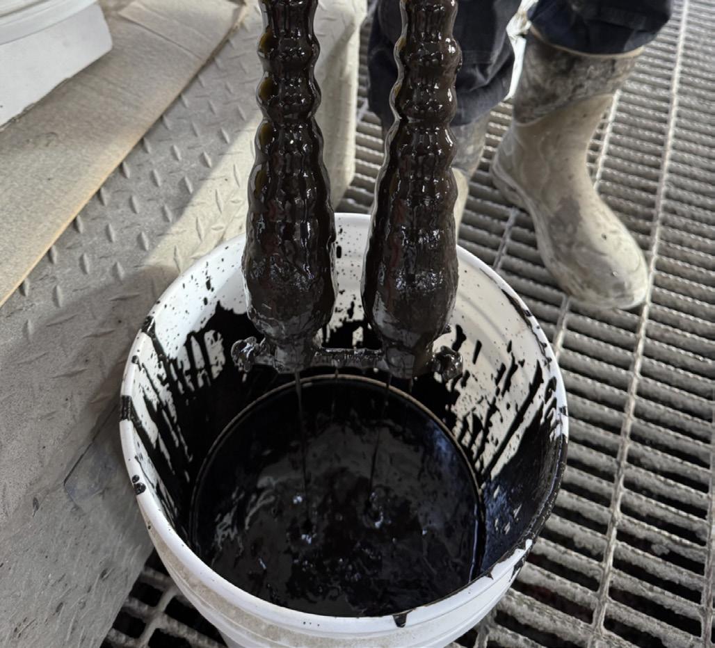
Richard Toomes, Strategic Business Development Manager, and Matthew Offenbacher, VP Marketing and Technology, AES Drilling Fluids, argue that a holistic viewpoint of drilling fluids’ impact on the drilling process is required to drive efficiency.
in the drilling fluid domain, tremendous resources are spent designing products to address wellbore challenges, reviewing offset data to optimise the drilling fluids programme, and managing logistics to minimise potential downtime. Those resources are well-spent, but to leverage drilling fluids for the greatest impact, operators must think system-wide.
Data and the drillstring
Drilling fluids are part of the larger drilling system, but their impact within the system is challenging to isolate. By marking key changes to the fluid while drilling, it is possible to review the impact across the suite of data acquired by multiple rig sensors on the electronic data recorder. This includes new methods to measure drilling fluids and marking treatment times in the rig electronic data recorder system.
Automated drilling fluid measurement systems capture changes in temperature, rheology, and density, providing faster responses to changes in well and fluid condition. This helps with faster resolution to challenges like water flows or density fluctuations. Relating these changes to data on the electronic data recorder provides improved context to drilling events for early detection and prevention of these issues.
Electronic data recorder information can capture lubricant performance, including effective concentration and application methods. A lubricant is designed to reduce torque in the drill string, but evaluation methods vary. In many situations, the lubricant is added as the rig torque limit is reached, limiting rate of penetration. Any torque reduction is then offset by increased rate of penetration, increasing the torque once more.
Electronic data recorders capture the lubricant contribution to the system through broader context of the drilling system. Mechanical specific energy (MSE) is a standardised equation to measure the energy per unit of rock drilled. In an efficient system, the drill rate increases in a linear relationship with weight on bit. Outside of the efficient region, energy is wasted through issues such as balling or whirl. These forms of dysfunction are regularly addressed through MSE trends where the energy required to drill falls off the linear path.
MSE analysis also aids in identifying when a lubricant is not the solution. In some cases, a lubricant is added when lubricity is not the primary issue contributing to excess torque. This assists in identifying the root cause of the issue while avoiding cost and misattribution of poor performance to the lubricant.
Ongoing studies combine lubricant addition times and rates with mechanical specific energy (MSE) trends to highlight the performance contribution of the lubricant. When dysfunction is addressed and the system remains in a stable drilling regime, MSE changes during lubricant addition can capture the energy efficiency delivered by the lubricant that was once lost to the drill string. More energy at the bit and less energy lost through the drill string appears as a lower MSE.
Laboratory equipment has many limitations. Most equipment cannot measure at temperature or pressure, and torque readings are far below drilling conditions. The coefficient of friction of most lubricity meters is calibrated with water, with no calibration at the lower coefficients of friction where many lubricants perform. This makes it difficult to distinguish materials once they reach lower coefficients of friction.
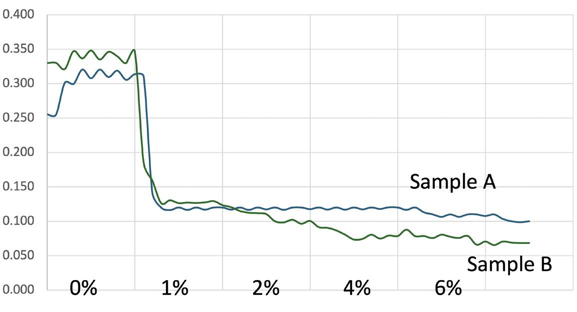
In the example below, two lubricants provide relatively similar coefficient of friction reductions. The lower the readings, the more inherent measurement error. This makes the two products effectively identical in performance.
Both products were trialled in the field, and Sample B outperformed Sample A on every single well of the trial. MSE demonstrated lower energy at higher rate of penetration – at lower concentrations. None of the laboratory data indicated this possibility, and drilling torque trends, while encouraging, would not clearly identify the impact of the lubricant on the drilling system.
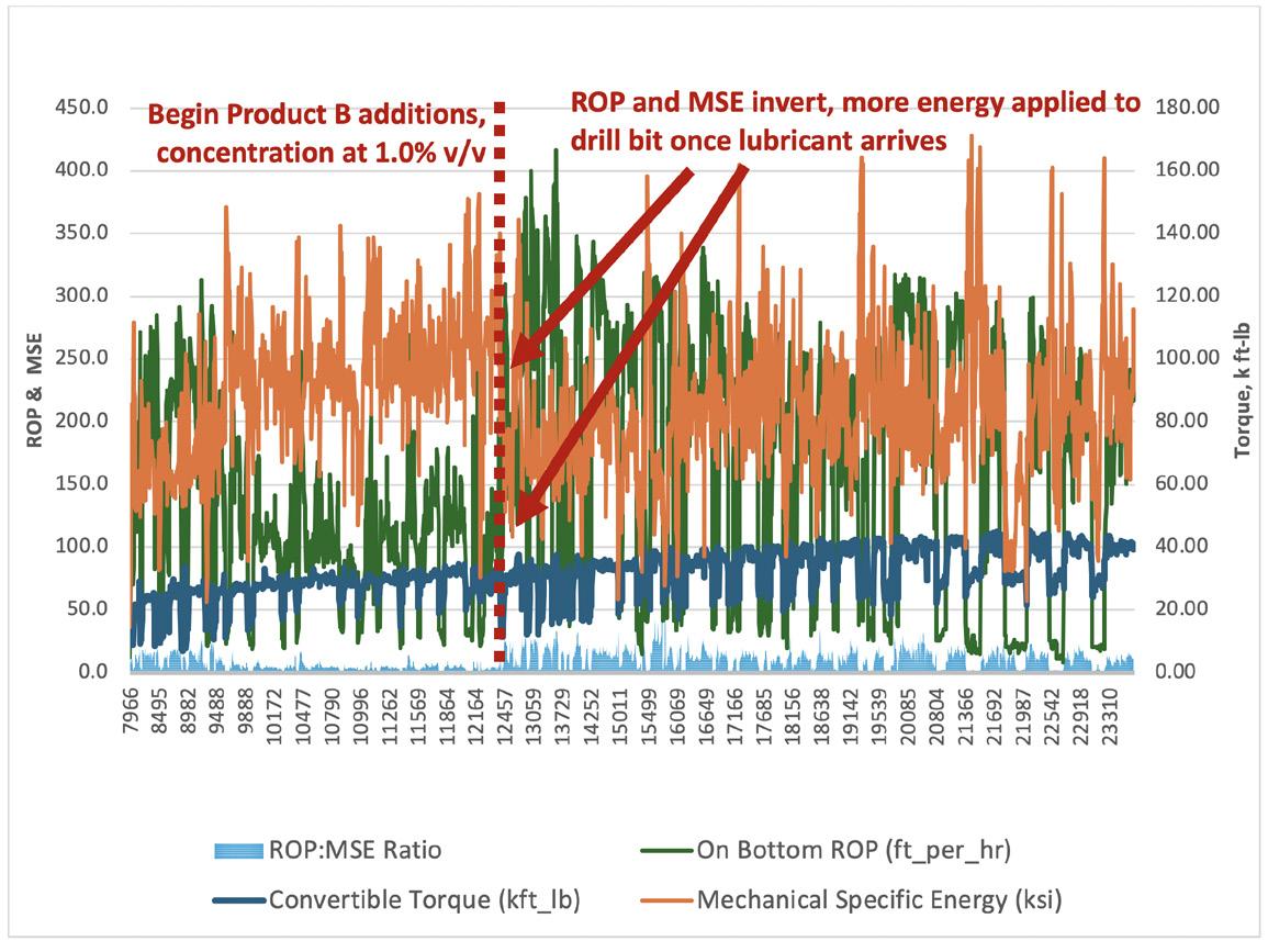
In Figure 3, the rate of penetration and MSE appear along with a marker when the lubricant is added. The drop in MSE –even with a faster drilling rate – confirms the lubricant lowers friction to improve system efficiency. This aids to quantify the value of the lubricant to the system – and to identify when an increase in concentration no longer improves system performance.
Table 1. Elemental analysis of magnet debris from three magnet trials
Figure 1. LEM graph, showing relatively similar coefficient of friction reduction.
Figure 2. MSE and ROP graph, where Product B is added and its impact on the drilling parameters is observed.
Extending tool life
Drilling fluids carry drilling fluid additives, cuttings, and anything else introduced to the system – intentionally or otherwise. Some of these materials may not impact drilling fluid properties, but they can impact drilling fluid performance through tool incompatibility.
To further drive cost and sustainability goals, recycled and recovered base oils are used in many invert emulsion systems. The wide variety of materials and quality risks incompatibility with elastomer materials found in power sections and sealing elements of downhole tools. This can undermine tool function or result in equipment failure.
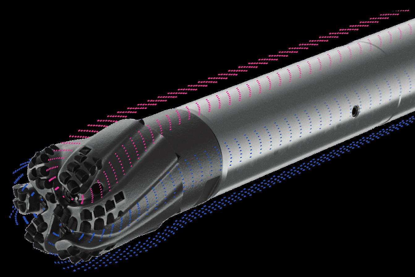
A new area of focus is fine magnetic material from casing and pipe wear. This material is continually generated throughout the drilling process, and it has the potential to accumulate over time. These particles risk interfering with measurement-while-drilling (MWD) tools and logs (including NMR). They also risk jamming tools including rotary steerable systems (RSS), leading to failure. Numerous analytical tests in the laboratory, including X-ray fluorescence, demonstrated that many RSS failures were the result of jamming from metal debris.
While magnet systems are recognised as best practice, their power and placement are often inadequate. This new system, deployed on numerous rigs downstream of existing conventional magnets, has demonstrated a surprising increase in debris removal, capturing finer particles often missed by traditional methods.
A new, high-powered magnet system reveals that traditional magnet systems leave large quantities of abrasive and magnetic materials in the fluid system undetected. Traditional ditch magnets remove larger particles (above 100 - 150 microns), while the new system utilises geometrically aligned neodymium magnets and a specialised flow path to capture a wider range of sizes, including much finer particles (D50 as low as 11.4 microns).
Multiple case studies have shown the scale of metallic debris removal from the magnet system. In one instance, the system retrieved over 1100 lb of debris in 30 days - compared to 375 lb collected by the conventional ditch magnet system. In another trial, more than 2000 lb of magnetic debris was removed over 29 days. In another case study, the reduced magnetic debris eliminated a dedicated magnet run prior to open-hole logging.
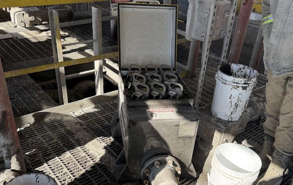
The same system was installed at AES Drilling Fluids’ liquid mud plant in Kermit, Texas to maximise fluid quality sent to customer rigs (Figure 3). Multiple 500 bbl batches of oil-based drilling fluid returned from the rig site were processed through the magnet system. Significant debris was captured and removed from the fluid. Figure 4 shows the amount of debris caught by one of nine magnet rods after 1 hour circulation.
The magnetic material was sent to the AES Drilling Fluids lab for analysis. X-ray fluorescence (XRF) analysis revealed abundant concentrations of iron, silicon, phosphorus, titanium, and other metal ions found in casing and drill pipe (Table 1).
Fluid quality for tool compatibility remains a focus towards increasing reliability and extending drilling performance. These methods may prove more impactful on longer laterals where RSS is used, fluid exposure times increase, and the cost to trip and replace tools is higher.
Pipe protection
Drill pipe has a limited life, encountering various costs to prevent failure during drilling. Hard banding requires periodic replacement, and inspections are required to ensure pipe will not fail under continued stress.
Corrosion control is the most common fluid option to extend pipe life through monitoring and fluid treatment. This includes corrosion coupon analysis, corrosion prevention additives, and keeping water-based drilling fluid at higher pH – usually above 9.0.
Anti-wear compounds developed as motor oil additives exhibit the potential to limit pipe wear. When materials slide past one another, asperities form in the smooth surface. These peaks and valleys rub against one another, increasing friction and resulting in metal loss. The anti-wear material bonds to the valleys of these asperities, and, over time, the peaks wear, resulting in a smooth metal surface.
Combining select chemistries with conventional lubricant additives results in superior lubricity with a strong, lubricating film between smooth surfaces. The strength of the lubricating film prevents galling and other forms of metal loss under extreme drilling conditions.
Summary
Drilling fluids contact everything in the drilling process. A holistic viewpoint of how fluids and fluid additives interact drives efficiency in all parts of the system.
Figure 3. A total of nine magnet rods are positioned in the flow box, affixed above a 500 bbl mix pit at AES Drilling Fluids’ wellsite in Kermit, Texas.
Figure 4. Magnet rod with metal debris attached after 1 hour circulation of 500 bbl used oil-based mud at the mix plant.
The Permian basin served as the backdrop for groundbreaking research aimed at unravelling the complex relationship between time-planned hydraulic injections and stress shadow effects in rock formations. This study employed cutting-edge microseismic monitoring techniques to detect dynamic stress changes occurring within the rock resulting from hydraulic fracturing methods. Initially, fractures slip according to local virgin-reservoir stress. Time-dependent stress shadow effects cause rotation of principal stress orientation and reduction of horizontal stress anisotropy. Over time, stress returns to the virgin reservoir stress state.
The team monitored individual stages of the fracturing process, seeking to establish a correlation between stage lag time and the location of virgin-reservoir events. This approach allowed for a comprehensive understanding of how the timing of treatments influences the formation and propagation of fractures within the rock matrix.
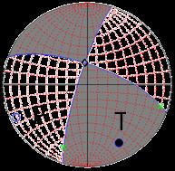
Central to this was the analysis of stress changes, which provided crucial insights into the dynamic nature of fracture characteristics (Figure 1). The stress inversion technique employed in this study is a sophisticated method used to determine the stress state that minimises the average difference between observed slip vectors and the theoretical orientations of maximum shear stress on faults. This analytical approach allowed the team to paint a detailed picture of the stress landscape within the reservoir, offering unprecedented clarity on the forces at play during hydraulic fracturing operations.
The results
The findings of this research have profound implications for the oil and gas industry. Perhaps most significantly, the study concluded that the stress changes induced by hydraulic fracturing persist for approximately seven days. This week-long window presents both challenges and opportunities for operators seeking to optimise their well treatment strategies.
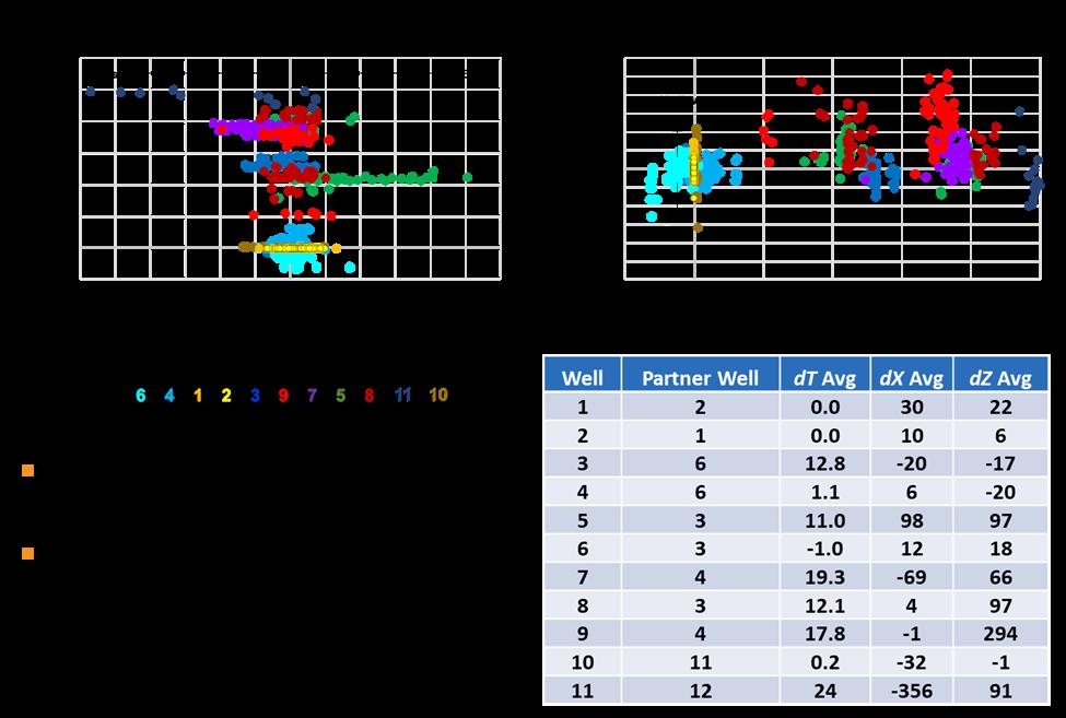
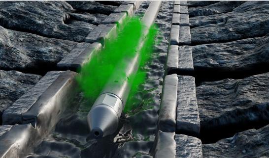
During this critical seven day period, stress shadows develop around previously treated wells and stages. These areas of elevated stress act as barriers, causing fluid injected into neighbouring wells to deviate from its intended path and move away from these high-stress regions (Figure 2). This phenomenon has significant implications for the planning and execution of multi-well pad operations, where the timing of treatments can dramatically influence the effectiveness of fracturing efforts.
However, the research also revealed that after the seven day period, these stress alterations begin to dissipate, gradually returning the reservoir to its virgin conditions. As this occurs, the stress shadows no longer act as boundaries allowing nearby injected fluid to propagate into previously opened fractures leading to poor fracture containment.
What it means
The implications of these findings are far-reaching and have the potential to revolutionise operational planning in the oil and gas sector. Armed with this knowledge, companies can now strategically plan their operations to capitalise on
Jonathan P. McKenna, MicroSeismic Inc., explains how ongoing research, technological innovation, and a steadfast commitment to environmental protection is helping to pave the way for a more sustainable future in oil and gas extraction.
find the stress state,
minimises the average difference between the slip vectors observed and the theoretical orientations of maximum shear stress on faults.
the seven day window during which they are most likely to achieve optimal oil or gas extraction from each well.
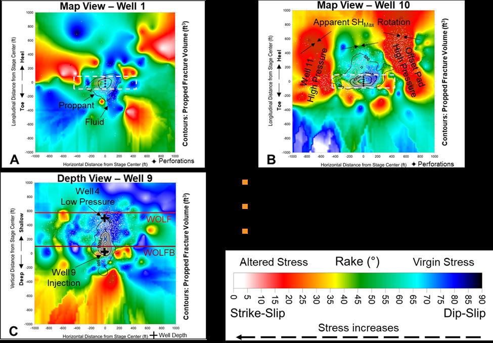
The key takeaway from this research is the critical importance of timeconscious well treatment. Operators should strive to ensure that the stage lag time is less than the stress relaxation time, a parameter that can now be quantified thanks to this study. This approach allows for the most effective utilisation of the stress shadow time dependency, potentially leading to significant improvements in well productivity and operational efficiency (Figure 3).
The research also sheds light on the identification of virgin and altered stress states within the reservoir. By performing a stress inversion of the microseismic focal mechanisms, operators can now pinpoint areas experiencing high stress with unprecedented accuracy. This information is invaluable, as these high-stress regions are likely to restrict slurry propagation from subsequent injections, potentially compromising the effectiveness of hydraulic fracturing efforts.
Once the initial stress has dissipated through the newly fractured system, operators face a choice in how to proceed with high-pressure fluid injection on offset wells. The research suggests two potential outcomes: the injected fluid can either overcome the dissipated pressure from previously treated wells, or it can migrate around these areas, causing new fractures to form (Figure 3). This understanding allows for more informed decision-making in the planning and execution of multi-well pad operations.
The time-dependent nature of stress shadow development and dissipation, as revealed by this study, introduces a new dimension to our understanding of hydraulic fracturing processes. By quantifying this phenomenon through stress relaxation time, operators now have a powerful tool at their disposal for optimising well treatment schedules.
The ability to distinguish between virgin and altered stress states through microseismic focal mechanism analysis represents a significant advancement in reservoir characterisation. Altered stress regions, indicative of high pore-pressure areas, can now be identified with greater confidence. This knowledge is crucial, as these areas may impede slurry propagation and exhibit low dilation tendency, potentially compromising the effectiveness of fracturing efforts.
Conversely, the identification of regions experiencing virgin stress offers valuable insights into areas where initial fluid propagation into unpressured rock is likely to occur. These virgin stress zones are characterised by fractures with high dilation tendency, presenting potentially lucrative targets for hydraulic fracturing operations.
The research also delves into the complexities of proppant propagation through the discrete fracture network (DFN). By demonstrating that this process is guided by fracture volume, the study provides valuable insights into the factors influencing the overall fracturing process. This understanding can inform decisions related to proppant selection, injection rates, and other critical operational parameters.
The implications of this research extend beyond immediate operational considerations. By enabling more precise and efficient hydraulic fracturing operations, these findings have the potential to reduce the environmental footprint of oil and gas extraction activities. More targeted and effective treatments could lead to reduced water usage, fewer chemical additives, and potentially lower seismic risks associated with hydraulic fracturing operations.
Conclusion
As the energy sector continues to evolve in response to global challenges, companies like MicroSeismic, Inc. will play an increasingly vital role in ensuring that our energy needs are met responsibly and sustainably. Ongoing research, technological innovation, and a steadfast commitment to environmental protection, is helping to pave the way for a more sustainable future in oil and gas extraction.
Figure 1. Stress inversion is used to
which
Figure 2. A detailed look into the effect of stage lag times on current wells.
Figure 3. Stress shadow impacts shown on neighbouring wells to demonstrate time-dependency on stage-lag time.
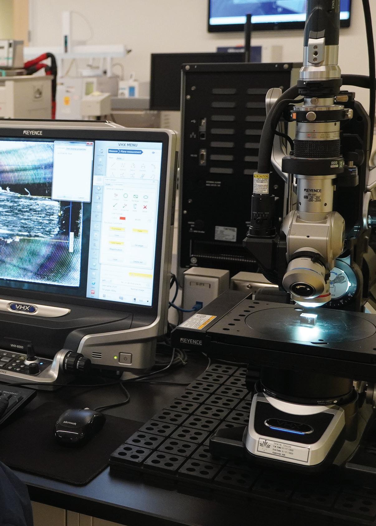
Matt Bell, DrillDocs, addresses how computer vision can help offshore drillers avoid incidents and optimise performance.
Offshore drilling is a complex and unpredictable business. Success depends on gathering, integrating, and interpreting a range of direct and indirect signals to monitor equipment performance, hole cleaning, borehole stability, and well control. Issues in any of the four categories can lead to diminished drilling performance, lost time, remedial costs, and – in the worst case –serious risks to asset integrity and human safety.
An area of significant interest is the shale shaker, where the quantity, size, and shape of recovered solids can tell us a lot about what’s going on downhole. And yet, the shakers are only monitored infrequently because they operate in a hazardous environment where crew access is restricted.
Computer vision technology, combined with advanced image analysis, offers an ideal solution. Using a camera, as an optical sensor, a shaker can be monitored and measured remotely and continuously without exposing rig crew to the hazardous environment.
In this article, we explore the challenges faced when developing a computer vision system for this application, some of the latest developments in digital shaker surveillance on offshore rigs, and how drilling operations might look in a few years’ time, once digital shaker surveillance becomes standard practice.
What the shakers are saying
Drillers and operations geologists have always known that rock fragments emerging from the borehole have a lot to tell us about what is going on between the drill floor and the drill bit.
If the quantity of cuttings being collected is less than expected, they must be accumulating somewhere downhole and there’s a risk of getting stuck. If the quantity is more than expected – or the size and shape of the rock pieces is that of cavings – the borehole is becoming unstable and might collapse.
The significance of this information was highlighted in a recent IOGP bulletin on pore pressure fracture gradient interpretation and uncertainty.1 Among the Association’s recommendations is real-time monitoring for “cavings and changes in caving morphology, size, or amount,” and the report describes how the quantity and shape of cavings can be used to evaluate the risk of a kick or mud losses.
The size distribution of the cuttings can also help spot formation boundaries and when the drill bit crosses a fault.
Prior to tripping out of hole, it is best practice to circulate several hole volumes of clean drilling mud, sometimes augmented by high-viscosity slugs known as ‘viscous pills’ or ‘sweeps’ to help the cleaning process. When no further cuttings are observed at the shale shaker, the borehole is assumed to be clean.
The shakers are always speaking, but how often is anyone listening?
What the models are showing
Modern-day drilling relies on predictive models during well design and construction. A digital twin is created of the wellbore, based on best-available geological information and well-established drilling and borehole performance equations.
Although the processes of borehole creation (drilling), cleaning (cuttings transport), and stability (geomechanics) have not changed much since the 1880s, the equations we use to model them are still approximate. Several of the input parameters cannot easily be measured, especially in real time as the well is being drilled, which means predictive models are inherently inaccurate, often by ±20% or worse.
Drilling decisions are made by comparing what is being observed against what is expected, based on predictive models. Deviations must be analysed to decide what is causing the difference. Since several variables can be contributing, it is almost impossible to uniquely identify an underlying cause.
To improve the fidelity and accuracy of our models, we need new and better ways of measuring the inputs.
The promise of computer vision
Cameras monitor all sorts of industrial processes, especially in hazardous or inaccessible areas. However, the images must usually be interpreted by an expert before useful information is generated. Combining a high-resolution camera and computer-based image analysis is where the magic begins. Instead of relying on humans, an algorithm is trained to interpret images based on rules derived from human experience.
We see this all around us – at toll plazas, in parking lots, tracking packages, parts, and people around industrial workplaces, and alerting workers to unsafe conditions. We also understand its limitations. Autonomous vehicles are not yet mainstream, and self-driving cars still get involved in accidents. The complexity of the task determines how effectively and consistently computer vision can work.
At the shale shaker, several issues complicate image interpretation, including:
Ì Variable light levels, leading to under- or over-exposure of the image.
Ì Dust or moisture on the camera that obscures part of the image.
Ì Cuttings lying on top of one another, blocking the camera’s view of some material.
Ì Observing irregular, tumbling, 3D objects with a camera that only sees in two dimensions.
Ì Very small cuttings, falling below the camera’s effective resolution.
Ì Residual mud coating the cuttings, making their size and number difficult to measure.
Ì Overloading of the shakers, causing mud and cuttings to overflow.
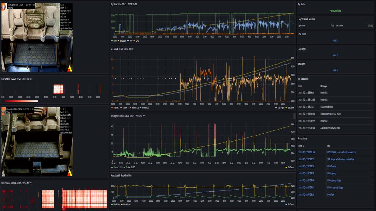
Figure 1. Real-time data from the CleanSight system is delivered to the offshore and onshore drilling team via interactive dashboards.
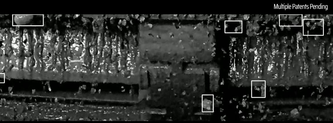
Figure 2. CleanSight employs patented object detection algorithms to identify and characterise drill cuttings falling off the shale shaker.
An effective computer vision system for digital shaker monitoring must handle these challenges to deliver reliable and valuable data to the drilling team.
Bringing computer vision to the shale shaker
Early attempts at applying computer vision to shale shakers focused on the shaker bed. This was compromised by inconsistent cutting movement along the bed and changes in cuttings depth and mud coating.
More recently, DrillDocs, a Houston-based oil and gas tech startup, has developed and patented an approach that observes separated cuttings as they fall off the shaker table. This reduces the risk of imaging cuttings more than once, since their direction of travel becomes constant once they are falling under the singular influence of gravity.
A camera positioned in front of the shale shaker captures images within a window of interest spanning the full width of the shaker table and several inches above and below the table end. Edge computing built into the camera pre-processes the image, so that data transmission across the rig and to shore can be optimised. Image analysis routines are applied to:
Ì Extract relevant parts of the image.
Ì Enhance contrast and separate objects from the background. Discriminate objects such as cuttings, cavings, and UFOs (unidentified falling objects).
Ì Label and, where possible quantify object features, dimensions, and other parameters.
Ì Train and deploy a classification algorithm to match objects to wellbore events and conditions.
Ì Produce alerts and statistical outputs for real-time display and trend analysis.
Typical outputs from the image analysis are:
Ì Shaker load distribution (SLD), describing cuttings distribution across the shaker table.
Ì Shaker load estimate (SLE), providing a qualitative trend of shaker load.
Ì Shaker load actual (SLA), providing a calibrated estimate of cuttings return rate.
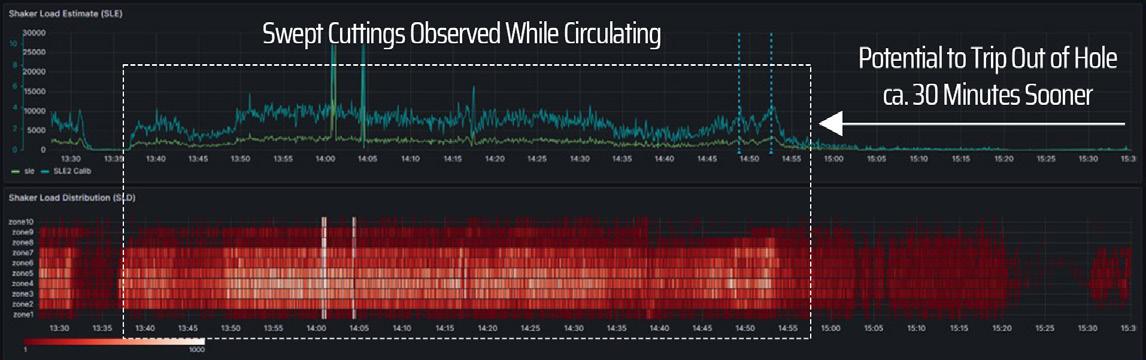
Figure 3. Real-time surveillance allows tripping out of hole as soon as the shakers are clean, rather than waiting for a prescribed time or pumped volume.
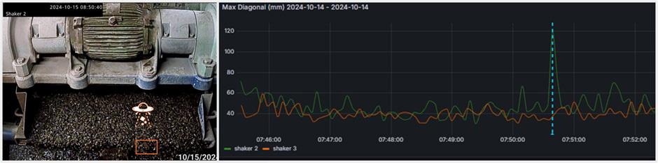
Figure 4. Image of the industry first caving detected automatically by a computer vision system for AkerBP in October 2024.
Ì Unidentified flowing object (UFO) detection, capturing images of unusually large objects and classifying them as cavings or other debris.
These outputs are displayed in real time on a touchscreen in the driller’s console, the geologist’s or drilling superintendent’s office, the remote operations centre (if applicable), and via a web-based remote monitoring platform for other permitted team members.
Validating digital shaker surveillance
Before deploying the technology on an active rig, the team worked with the TUDRP consortium to compare image analysis results with calculations and physical measurements made at its experimental flow loop. The results were encouraging and led to further improvements in hardware and software.2
Next, a prototype system was deployed on a land rig operating for XTO in the Delaware Basin, in Texas.3 Numerous issues were encountered with changes in natural lighting, mud and water splashing onto the camera, and loss of connectivity following rig moves. Nevertheless, qualitative and quantitative measurements of cuttings return rate were made, and successfully correlated with drilling operations – including connections, ROP changes, sweeps, and trips.
Moving offshore, an enhanced system was deployed on the Saipem Santorini, drilling for ENI offshore Egypt and Côte d’Ivoire. The results, which will be published at the Offshore Mediterranean Conference in April and the Offshore Technology Conference in May, prove that the system can be installed and operated on a drillship without interrupting regular operations. Two shakers were monitored while drilling approximately 10 000 m, across hole sizes ranging from 8.5 in. to 17.5 in., as well as five shoetrack drill-outs. A potential pack-off event was observed, and the effectiveness of several sweeps was monitored.
The system was next deployed on a jack-up rig drilling for Aker BP on the Norwegian Continental Shelf. Real-time cuttings data were delivered to rig personnel and the onshore Real-Time Operations Centre. This validated the technology and unlocked a second phase where object detection was used to observe unidentified falling objects (UFOs) to detect cavings. The results of this world-first accomplishment will be reported at the Offshore Drilling Conference in March.4
The technology is also being actively deployed for Exxon in Guyana as part of the company’s real-time cuttings recovery initiative, comparing calibrated cuttings return rate from digital shaker surveillance with physical measurements on the rig. This high-profile project aims to significantly improve drilling efficiency and safety using edge computing and real-time measurements.
The value of digital shaker surveillance
Digital shaker surveillance promises to impact drilling efficiency and safety in numerous ways.
The first will be derisking drilling at higher rates of penetration, relying on real-time shaker measurements to confirm that hole cleaning can keep up with cuttings generation. As the DrillDocs team likes to say, “Drill Faster Without Disaster.”
Next comes rig time savings from shorter circulating periods prior to tripping out of hole. With offshore spread rates reaching US$250 - 350/min., saving 30 minutes before each trip will save tens of thousands of dollars per well.
AI-enabled object classification will provide early warnings of potential borehole instability, loss of well control, or downhole equipment failure. Allowing the drilling team to quickly diagnose
and react to a deteriorating situation will reduce the frequency at which events escalate into incidents. Avoiding a stuck pipe incident by recognising ahead of time that the borehole is beginning to collapse can save many hours – and millions of dollars.
Finally, the widespread deployment of digital shaker surveillance will produce digital archives on which to train machine learning models to spot patterns in shale shaker images and relate them to events logged in offset wells. In this way, computer vision and data science will truly begin to replicate –and potentially exceed – the human learning process.
Where computer vision takes us next
Ever improving camera and processing technology will drive steady increases in the resolution and accuracy of computer vision systems. This will lead to superior cuttings characterisation. Combined with a growing database of previously imaged cuttings, cavings, and other objects, this will enable faster and clearer guidance for the drilling team.
Bringing computer vision to the offshore rig requires a culture change. Drilling crews are proud people who don’t like the idea of “Big Brother” watching them or of a computer taking over what has traditionally been a human’s job. Digital shaker surveillance should avoid this issue by focusing on an area of the rig where the crew doesn’t want to spend time monitoring a mundane process. As the data proves its worth, trust in the system will grow and become standard operating practice on high-performance offshore rigs.
Having established the efficacy of computer vision in the shaker room, we expect cameras will take on other tasks around the rig. For example, they could monitor other aspects of drilling mud management and observe for mechanical failures, incorrect equipment placement, or deficiencies in personal protective equipment.
The power of generative AI and large language models (LLM) is being explored throughout the industry. It will help transform digital shaker surveillance from a valuable cuttings measurement into an indispensable advisor supporting the wider process of drilling automation.
Acknowledgements
The DrillDocs team would like to acknowledge the invaluable support it has received from its service company and operating company partners, including AXIS Communications (camera technology), Blackhawk Datacom (rig surveys and equipment installation), TUDRP (University of Tulsa Drilling Research Project), ExxonMobil (and its subsidiary, XTO), Eni SpA, and Aker BP ASA.
References
1. International Association of Oil & Gas Producers (IOGP), ‘Communicating Pore Pressure Fracture Gradient (PPFG) Interpretation and Uncertainty.’, February 2024
2. JING, H., OZBAYOGLU, E., BALDINO, S., and WANG. J, TUDRP, HOLT, C., and RUEL, F., DrillDocs, ‘AI Camera System for Real-Time Load Concentration Estimation.’, Offshore Technology Conference, Houston, Texas, May 2024, OTC 35171.
3. GOSAVI, S., and GILROY, J., ExxonMobil, RUEL, F., and HOLT, C., DrillDocs, ‘Field Application of Image Analysis Models to Measure the Drill Cuttings Recovery Rate.’, SPE Annual Technical Conference and Exhibition, New Orleans, Louisiana, September 2024, SPE 220985.
4. SVENDSEN, K., KRISTIANSEN, T, ASKØ, A., BJØRLO, J., and KHOSRAVANIAN, R., AkerBP, HOLT, C., and RUEL, F., DrillDocs, ‘Automated Computer Vision System for Real-time Detection of Drilled Cuttings and Cavings’, SPE/ IADC International Drilling Conference and Exhibition, Stavanger, Norway, March 2025, SPE 25DC-P-496.
PRODUCTION MONITORING WITH FIBRE OPTIC STRAIN, ACOUSTICS AND TEMPERATURE
J. Andres Chavarria, Luna Innovations
– OptaSense, USA, and Veronique Mahue, Silixa – a Luna company, UK, present an outline of available analysis tools to assess conditions in producing wells.
In-well fibre optic surveillance has grown rapidly with the use of distributed temperature, acoustic and strain sensors (DTS/DAS/DSS) that provide full wellbore characterisation. This characterisation can take place at any or all stages in the life cycle of the well. As different reservoirs and well completions deploy fibre within them, there has been a growing demand for specific sensing and analytic techniques that can provide operators with actionable assessments of production and well operations.
Production monitoring with FO sensing consists predominantly of profiling to assess zonal allocation, fluids and rates, and wellbore integrity measurements to assess potential operational issues of various in-well devices, annular spaces and their interaction with the reservoir.
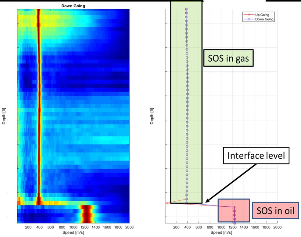
Figure 2. The speed of sound (SOS) is the measure of velocity of sound propagating in a media (fluids, etc.). This parameter is calculated from DAS data acquired along the FO cable. The SOS is different for each fluid and mixture of fluids, and is dependent on the composition of the mixture. The figure shows an example of liquid level detected using SOS in an oil storage well.
Figure 3. Example of production allocation results on 2-phase gas water producer, using an enthalpy thermal model constrained with DAS derivatives (slow strain transients, acoustic spectrum and speed of sound).
This article focuses on current FO analysis tools that are used to assess production and that make use of the various FO interrogator units (IUs) that are available. Each of these instruments is tracking various physical properties of the fluids and well. Their individual use or their combination can provide different assessments for the given challenges of the reservoir.
Optasense and Silixa focus specifically on the use strain and acoustic measurements of production, that when coupled with temperature measurements, provide a detailed look at the reservoir dynamics and producing conditions.
Production monitoring via acoustics
Distributed acoustic sensing (DAS) has been deployed for production monitoring since the early 2010s. This has complemented DTS measurements that have been around for many more years. At the core of DAS sensors is FO technology that effectively measures a strain response in the well. This strain can be of a mechanical and/or thermal (i.e. expansion/ contraction) nature and depending on the IU, these effects can be separated at the native sensing level or during real time processing. Depending on the IU, strain or strain-rate, measurements are provided and have different advantages depending on the final analysis tool. The main advantage of DAS sensors is that they provide the highest sensitivity due to their use of Rayleigh backscatter signals and the highest temporal and spatial sampling that are optimised to the configuration of the reservoir and well.
Other dedicated FO strain sensing (DSS) tools for production are available and can make use of the Brillouin spectra and more recently, the Rayleigh Frequency Shift (RFS), a subset of optical frequency domain reflectometry. In these methods the strain signals make use of weaker backscatter levels that require longer sensing times which makes them not as dynamic as conventional DAS strain techniques. Given the high sensitivity and fine resolution of DAS/DTS, this article focuses on the more dynamic Rayleigh OTDR techniques.
The use of DTS sensors becomes critical as more specific analysis of fluid compositions is required. This includes the situations when DAS or DSS measurements require compensation for temperature. Increasingly FO installations consist of a combination of DAS/DTS/DSS depending on the environment.
At higher frequencies, as fluids propagate from the reservoir into the wellbore, the vibrations imparted onto the fibre provide a high-resolution measurement of the dynamics and the interactions with the well architecture.
The earliest work on fibre optic sensing with DAS/DTS consisted of assessments of acoustics at higher frequency bands. These acoustics are created by the vibration of fluids as they propagate from the reservoir into the wellbore. Such analysis usually provides a real time assessment of zonal allocation and production zones and enables a real-time look at changing conditions in production levels. By using specific frequency band extracted data (FBE), insight can be gained into the different zones in the completion zone that are responding to the fluids being produced (Figure 1). This FBE analysis constitutes a rapid assessment of zonal allocation within the well.
Fluids and speed of sound
Sounds are naturally occurring within a well and will propagate in the fluid at the speed of sound (SOS) in that
Figure 1. Example of DAS frequency band extracted data across a producing zone. Higher acoustics on the top screen are indicative of higher production rates compared to the lower zone.
Figure 4. Left: High frequency (1 - 200 Hz) DAS RMS FBE data acquired during the stimulation of a 10 cluster stage, in February 2019. The acoustic responses in front of each cluster indicate the relative fluid intake. Cluster 2 appears quiet, indicating a lack of stimulation. Right: Low frequency DAS (<1 Hz) response over the same stage in April 2020, during the transition from production to shut-in, displaying cluster level strain responses, resulting from fractures dilating under the pressure build-up. Note that the strain response is rapid (about 4 min.) and is well captured on the DAS Slow strain data. Cluster 2 does not show any response on the Strain curve, aligning with the lack of measured stimulation in 2019.
medium. Therefore, tracking SOS propagation over depth can allow for composition profiling and the monitoring of changes in composition over time (Figure 2).
The basic principles of performing a sound speed analysis consist of selecting a window of DAS data in depth and time and transforming it into the frequency domain (both temporal and spatial frequency domains). This collapses propagating waves in both the direction of the flow and against the direction of the flow into ridges which can be observed on a 2DFFT (or two dimensional fast fourier transform) or KW plot. Applying a radial scanning algorithm over the KW image detects the highest intensity slopes in both directions and the SOS can then be estimated. The SOS in the direction of the flow will go slightly faster than that in the opposite direction of the flow, due to the Doppler shift, which is directly proportional to the flow velocity. This process is then repeated for every depth along the wellbore in order to estimate a profile with the depth of the SOS changes.
A fine spatial resolution and high acoustic SNR are both crucial for a good SOS estimation. Typically, for a 10 m GL DAS, the minimum distance window required for a good SOS estimate is of around 150 m; the window can be significantly reduced by using a finer GL DAS system. For example, a 2 m GL system will require a minimum shorter length of 30 m.
The extraction of an SOS profile along a production lateral allows for higher accuracy multiphase flow allocation by the constraining of a DTS based thermal model with DAS extracted quantities, which include SOS but also acoustic noise logging and the analysis of transient slow strain data (Figure 3).
Production strain monitoring from LF-DAS
Low frequency DAS (LF-DAS) has revolutionised completions in unconventional reservoirs. By measuring strain, it is possible to track the development and the geometry of fractures. More recently, it has been demonstrated that the strain associated with the actual production (i.e. depletion of reservoirs) can be measured in the low frequency regime of DAS sensors. DAS sensors provide a broad band response from high acoustics (i.e. vibration from valves, or fluids) to very low frequency regimes that are dominated by mechanical and thermal strain which are coupled. Downhole fibre optic cables
may include various FO strands and it is common to combine DAS/DTS/DSS measurements and apply different corrections. DTS can be used specifically to correct for the temperature effects that DAS or DSS have. When subtracting the temperature component to which DAS IUs are also sensitive, highly dynamic and sensitive strain profiles are generated, which are indicative of production conditions.
For example, in unconventional reservoirs where fibre-optic sensors are deployed behind casing, the opening and closing of fractures as proxy for fluids entering the wellbore as the reservoir depletes, is taken advantage of (Figure 4).
The value of permanent FO is that it monitors the well’s full life, from its cementing and completions, its production and all the way to its abandonment. DAS data for completions injection monitoring during hydraulic fracturing usually focuses on higher frequency acoustics that identify cluster efficiency and illuminate any operational issues with the stimulated stage. By using high resolution acoustic and temperature measurements, the geometry of the stimulated zone is determined. DAS/DTS systems are calibrated to delineate each of those producing clusters on a stage, and that vary from basin to basin, even if they are just a few feet apart.
It is common practice to use DAS and DTS warmback to additionally assess fluid conditions in the stimulated stage.
Using the LF-DAS strain compensated for temperature, it is possible to determine that DAS data also responds to the associated production of the reservoir (Figure 4).
This is an example of the injection monitoring with DAS, indicating that most of the clusters have been opened and received proppant. The production data was acquired a couple of months after completion. Analysis of the compensated LF-DAS reveals that the strain associated with the production is consistent with the cluster activation that was observed during completions monitoring.
Conclusion
This article presents an outline of available analysis tools to assess conditions in producing wells. Production monitoring with various fibre-optic sensors can be optimised for different well completions, production practices and reservoirs. Using permanent or temporary cables FO sensing can illuminate the entire well. Distributed strain, acoustic and temperature measurements provide production profiles that are representative of flow conditions in the wellbore and enable operators to assess the management and operation of downhole assets. Flow production analytics, with a wide range of sensing practices, helps ensure that the proper assessments of fluids, in-well devices and any well integrity issue are diagnosed in real time.
The selection of the hardware and analytics is dependent on well architecture and its relationship to the reservoir. Deployment of the technology for more than 15 years has now made intelligent permanent reservoir monitoring a reality even in the most complex well environments.
Levelling The Playing Field
Andrew Law, Enteq Technologies, illustrates why the adoption of AI in drilling marks a significant evolution in the energy sector, promising new levels of efficiency, precision and operational intelligence.
Since our predecessors broke ground on the very first oil well in 1859, drilling operations and technology in the energy sector have been in a constant and accelerating state of evolution. From the adoption of the rotary drilling rig in the 1920s to the advancement of measurement-while-drilling (MWD) technology in the 1980s, and the subsequent adoption of rotary steerable systems (RSS) in the late 1990s, each innovation
has moved through the stages of development to eventually disrupt the field and then become the new industry standard.
Now, the next innovation expected to shake things up is artificial intelligence (AI). Once a staple of science fiction and propelled into serious academic thought by pioneers like Alan Turing, it has crystallised into the key technological trend and buzzword of the 2020s. Much like the innovations that came before it, AI is expected to transform the energy industry, promising to drive efficiency, precision and intelligent operations unimaginable even five years ago.
The AI revolution is well underway
In our day-to-day lives, the impact of AI is already evident. From the Amazon Alexa in your kitchen and personalised recommendations on Netflix, through to autonomous vehicles and smart energy management in homes, AI has quickly moved into our everyday.
This has happened because the significant benefits the technology can provide, as well as the potential it holds for the future, are immediately apparent. In this respect, downhole drilling is no exception, with enormous returns, both current and future, to be gained.
The oil and gas industry, which, unfortunately, is often slower to adapt to change, has quickly embraced new AI technologies. These advanced systems, such as Corva's drilling optimisation platform, are already enabling drillers to extract valuable insights from data collected across operations to improve decision making, with significant efficiencies reported from AI-driven projects.
Furthermore, a survey by Ernst & Young found that 92% of oil and gas companies are already investing in AI or planning to do so within the next five years. This widespread investment highlights the industry's recognition of AI's potential to drive economic viability and competitiveness.
AI is quickly becoming a competitive necessity
With early adopters already bearing fruit from their investments, big industry players are increasingly investing in AI technologies to optimise their operations. Reduced operational times, costs and minimised carbon intensity are ensuring that AI is rapidly moving from being a consideration on the horizon to a must across many parts of the energy industry.
Smaller operators and drilling contractors may find it more challenging to integrate AI into their operations due to limited
resources and expertise but there is no time to delay in taking the first steps. With big players already making significant moves, smaller and independent operators must be ready to deploy AI as the significant benefits it promises will make it a competitive necessity before long.
Enabling drilling with AI
So, what will it take to integrate AI successfully? Firstly, it is important not to get carried away. AI is not ‘new’ by any means, and has, as a result, been a buzzword for some time, but many of the more outlandish claims have failed to materialise. The technology does indeed have transformative potential, but just like MWD or RSS the gains will begin to be realised over the course of months, years and decades.
Lessons can be learned from another recent and related technological disruption, the so-called ‘digital transformation’ of the last decade. In that case, many businesses rushed to introduce technology or digital solutions simply to avoid the risk of being left behind.
This often led to expensive investments without thoroughly considering how technology could be integrated to extract maximum value, resulting in lots of different tools that could, but did not, integrate together. For example, companies hastily adopted new database systems without proper integration strategies, leading to significant challenges such as data silos and misaligned processes, effectively creating digital filing cabinets that were no better than their physical counterparts.
To avoid repeating these mistakes with AI, it is vital for the industry to take a measured approach, ensuring that new technologies are thoughtfully integrated to maximise their potential and avoid costly inefficiencies. Guidance and support are essential to bridge this gap, as are clear explanations of how AI can be used in partnership with tools to get the most value from it.
In the drilling sector, hardware suppliers must collaborate with software providers and drilling contractors to integrate AI effectively. No single party will be an expert across every area of a drilling project, but they will understand where they fit in, and an open dialogue will ensure all parties can understand how these can be combined for the maximum effect.
Starting small
While the core components for full autonomous drilling are coming along at speed, maintaining a human in the loop will be a key consideration for any drilling run. One approach is starting small, by implementing an AI co-pilot on a minor project or test run. This allows the team to introduce and refine methods gradually, gaining familiarity and confidence with the technology before scaling up over time to realise the full benefits AI can offer across larger work scopes.
The immediate goal is to enable crews to work in partnership with technology, enhancing human decision-making with AI support. For effective change management and implementation, effort needs to be made to help rig crews ‘buy in’ to see the benefits of new technologies, requiring training, close consultation and an openness to trial and error to find the most effective methods. As technology improves, further refinement and implementation will be necessary, and once AI is being utilised, teams need to contribute to an ongoing process of feedback.
AI adoption should not just be seen as an obligation. The technology holds genuinely transformative potential, and for
Figure 1. The SABER tool.
those smaller players who, right now, are struggling to compete, it can be another tool that can help disrupt and level the playing field.
Where the software meets the hardware
Just as integrating AI will require the implementation of this mindset, drilling companies should also take the AI revolution as a chance to review the opportunities provided by innovation across their full operational footprint. If you have invested in full AI integration, training and optimisation, then it would be sensible to identify any inefficiencies in wider operations that could offset the benefits brought by AI.
One particularly relevant area for drilling businesses is the RSS technology they deploy. When introduced in the late 90s, the technology represented a disruptive step change, but in the quarter of a century since displacing mud motors as the directional drilling tool of choice, it has stagnated, with little to no innovation in the space, leading to a technology that is not fulfilling its potential.
A co-pilot is only as good as its tools
Commercial RSS systems have typically relied on external mechanical force to press against the wellbore and change direction. Although these technologies have more than proven their effectiveness over the years, the friction created by exterior pads and pistons during drilling can lead to high failure rates. Even with intelligent decision-making based on vast amounts of data, the most advanced AI co-pilot is only as effective as the technology it is helping to pilot.
While the industry accepted norm for RSS has not evolved in the last 20+ years, that does not mean that innovation has
not happened. For example, one approach, led by a passion to disrupt a stagnant market, has come in the form of the SABER Tool. This new approach removes external components entirely and instead deploys a system of high-velocity and low-velocity fluid flow at the base of the bit to create high-pressure and lowpressure zones. Better known as Bernoulli’s principle, these fluid forces can be harnessed to change the direction of the bit without external contact points.
By removing and simplifying the design, SABER has the potential to significantly lower the failure rate, enhancing reliability and efficiency. This technology is fully AI-compatible and is just one example of where software and hardware can already be married to provide the best possible outcomes during drilling runs.
Embracing the future
The adoption of AI in drilling marks a significant evolution in the energy sector, promising new levels of efficiency, precision and operational intelligence, but it is still early days. As the industry continues to integrate AI, it will not only transform how operations are conducted but could spark a shift in competitive dynamics, globally. Companies, both large and small, must embrace this, ensuring that they are not left behind.
The future of drilling will be characterised by intelligent operations, remote capabilities and streamlined processes, driven by AI. By starting small, collaborating openly and embracing ongoing innovation, smaller and independent players can harness the full potential of the technology. But they must also adopt the same mindset to hardware as they do software, remaining open-minded to innovations that can complement AI and enable them to keep up with the rapid rate of change.
LISTEN NOW
In this episode, Elizabeth Corner speaks to Kevin O’Donnell, Executive Director of the PLCAC, about how membership organisations benefit the pipeline sector and those who work in it, discussing events, networking, resources, training, skills development, and learning.
This episode of the podcast covers:
• The PLCAC’s primary aims as an association.
• The part community plays in fostering business connections.
• How to define success as a membership organisation.
• How events are evolving to meet the needs of pipeliners.
• How the PLCAC uses data from its members to advance the industry.
• And more!
Kevin O’Donnell Elizabeth Corner
An Extra Boost
Vijay Desiraju, Celonis, explains why process intelligence can help capture value in the upstream industry.
Organisations in the energy sector are grappling with challenges ranging from supply chain disruptions to extreme weather and political instability. It is harder than ever to predict outcomes, which only increases the importance of understanding and taking command of variables business leaders can control.
While recent surges in energy prices have led to record profits for many organisations in the space, leaders are all too aware that commodity price surges cannot be relied on for future success. Uncontrollable outcomes are a part of life in the energy sector, hence why business leaders are focusing on initiatives to boost operational performance. Process intelligence technology offers organisations in the oil and gas space a way to take control in an unpredictable world and gain an unprecedented understanding of their own operations. This can deliver millions of dollars in savings and increased visibility across everything from plant maintenance to processing invoices, offering a way to drive efficiency and change across the sector.
There is already a huge drive within the industry to incorporate more automation into business processes. Research by Gartner shows that 60% of CIOs in the oil and gas sector are increasing investments in business insights and data analytics, alongside 51% who are spending more on cloud platforms.1
The pandemic accelerated these efforts, as leaders in the sector were forced to do more with less, and turned to digital transformation and automation to mitigate the effects of workforce reduction. But now business leaders at organisations which have ‘lagged behind’ are seeing the success stories of those who have invested in digital transformation and are making their own efforts to catch up, further accelerating this push. This move away from legacy architecture and towards a less siloed future offers business leaders a key opportunity to improve liquidity, resilience and revenue. Process intelligence will be central to this.
Finding horizontal value
Leaders in the energy sector have already made efforts to rebalance insourcing and outsourcing, bringing noncore processes back in house to increase control, while improving data-integration capabilities. The ultimate goal is to achieve a setup where operational insights are actionable, accessible and reliable. This can be seen as delivering ‘horizontal value,’ where different departments and functions are connected by a common language,
revealing new ways to improve liquidity, revenue and productivity. This is where process intelligence technology comes into its own.
Process intelligence technology is built to model and optimise business processes, based on ‘event logs’ across processes such as invoicing or procurement. One way to think of it is as an MRI scan which shows how processes actually run across a business, rather than the way staff or management have always assumed they run. For companies in the oil and gas sector, process intelligence technology enables business leaders to create a living ‘digital twin’ of their entire business, taking in everything from hydrocarbon logistics to maintenance, and uncovering hidden value opportunities. Paired with artificial intelligence (AI) to offer rapid next-best-action recommendations, this can be a transformative technology in the sector.
Sustainable value for businesses in the energy sector lurks in the connections between departments and functions. Many energy companies have already invested significantly in digital transformation technology such as cloud-based enterprise resource planning (ERP) but even with the addition of digital solutions such as business process management tools, have yet to see significant returns. Process intelligence can offer a common language which enables business leaders to ‘connect the dots.’
Broadly speaking, the energy solutions market is divided into two halves. One half is saturated with products and digital services which generate process data, and the other half is saturated with solutions that help organisations to run automations. What is lacking is a solution to help analyse and improve the underlying processes, as many companies are still grappling with complex infrastructure, and the multiple acquisitions and mergers in the sector only serve to make this more complex. Process intelligence offers a bridge between these two halves, and a connection across the whole organisation, offering readily accessible and actionable insights which can highlight hidden value opportunities. This offers companies in the sector real and measurable ways to cut costs in operations.
Improving maintenance
Process intelligence, combined with artificial intelligence, can deliver measurable cash impact in several ways, including in helping to maximise asset uptime by increasing the efficiency of plant maintenance operations. Downtime is extremely expensive in the energy sector, where a mere 1% rate of unplanned downtime (3.65 days per year) can cost organisations upwards of US$5 million annually. Minimising downtime is very difficult using standard business process management software.
Plant maintenance sits at an intersection for manufacturing companies, depending on upstream processes such as procurement and inventory management. Business leaders need insight into how material procurement and logistics will affect maintenance schedules, and into the root cause for unplanned and unscheduled maintenance, and the real reasons for maintenance delay.
Process intelligence enables business leaders to visualise a process as it runs in source systems, based on event logs extracted directly from enterprise resource planning (ERP) systems. Plant maintenance often involves multiple teams from procurement, accounts payable, to inventory and materials management, each of which all too often operate in their own silos.
Process intelligence works as a ‘force multiplier’ here, enabling business leaders to orchestrate continuous process improvements and zoom in on the factors that are creating problems. Using process intelligence, business leaders can see how problems in one area connect to others, for example how delays in material procurement might affect maintenance schedules. Process intelligence can pull in data from systems to help business leaders understand why a scheduled adherence rate might be low, along with next-best-action recommendations, taking
in the real-time flows between material reservations, work orders and purchase orders. Business process management (BPM) tools are very limited when it comes to dealing with problems like this.
Improving flow and efficiency
Businesses are leveraging the combined power of process and task intelligence to improve efficiency and root out problems in operations. Organisations are using a task mining to capture pain points, for instance how many hours of manual data entry are required from console operators, who spend multiple hours a day copying and pasting data. With task specific data, business leaders can focus on how to adapt emerging technologies to eliminate low-value work and create safer operations.
In accounts payable, teams are using process intelligence to tap into invoice-management modules and identify duplicate invoices before they cause problems. The process intelligence platform groups together invoices that are suspected of being duplicates, using a machine-learning based ‘confidence score’ to pinpoint likely duplicates and prevent unnecessary payments. Built-in automation can then help to block future duplicates. Prior to using process intelligence, business users were all too often using Excel spreadsheets to analyse data on a monthly/quarterly basis: but business leaders are now able access data daily and are recovering millions of dollars across the organisation.
Process intelligence can also help to specifically root out delays in invoicing, helping to enhance resilience and secure longer-term value. Similarly to downtime, given the scale of large energy companies, even a day’s delay in invoicing lead time can result in millions of dollars in cashflow impact. For companies which have highly complex supply chains and product ranges, it can be difficult to hone in on the problems and track high-priority KPIs like customer cancellations and invoicing lead times. Process intelligence offers every team involved in the order-tocash process the same real-time, end-to-end picture.
Finnish oil refining company Neste was able to cut their invoice lead time in half, with a monthly cash flow impact estimated at €55 million, using process intelligence. Neste, the world’s largest producer of sustainable aviation fuel and renewable diesel, was able to gain visibility over supply chain processes and its commercial processes, allowing leaders at the company to home in on value opportunities, such as the 20% of invoices which were delayed. Process intelligence can also help to boost cash flow by accelerating slow-moving inventory and helping to reduce excess, offering an overview of real-time replenishment and consumption trend data. These data-driven assessments can help business leaders uncover further automation opportunities and move towards a future where invoice, sales order and purchase order processes are all touchless.
Towards a smarter future
Whether business leaders in the oil and gas sector are looking to capture value from upstream, midstream or downstream processes, process intelligence can help. Business leaders who can find a way to boost performance and maximise bottom-line revenue in today’s turbulent environment will be the winners of tomorrow.
Process intelligence is key to unravelling the web of hundreds of systems within energy companies and connecting the whole enterprise with a common language, enabling integration across systems from asset management to hydrocarbon logistics, to accounts payable. In a changing world, it’s a key tool to helping business leaders make faster, better-informed, and more profitable decisions.
Jeff Forsyth Jan Frieling and Fraser Smith, StimStixx, Canada, explore working with in-situ acid generation for oil and gas with opportunities in carbon capture and geothermal well stimulation.
Low
Risk High Rewards
Low Risk High Rewards
In the competitive stimulation market, new technologies must not only outperform conventional technologies, but more importantly do so more quickly and more cost effectively.
In the pursuit of stimulating wells and turning to more untapped horizons, such as deeper, hotter wells in unconventional plays, companies are turning to advanced chemistry and materials science to bring about new solutions.
One company embracing this challenge with in-situ generated stimulation technology is StimStixx Technologies. The company generates HCI and/or HCI/HF acid in situ via a tool which is delivered to the zones of interest by e-line, wireline or slickline. The company's acidising technology produces acid gases downhole rather than applying liquid acids through the wellbore which comes with a slew of concomitant operational and health and safety challenges.
Results to date have shown the following improvements post stimulation:
Ì Improved production (ranges 40 – 300% +).
Ì 60% reduction in cost to clients.
Ì 50% reduction in job time.
Ì 50% reduction in job footprint.
Ì 90%+ reduction in CO2 footprint.
Ì Greatly reduced safety risks in comparison to conventional liquid-based stimulations.
The tools are available in two basic types:
Ì Single stick tools: are utilised for short treatment intervals (Figure 1).
Ì Stackable sticks: are multiple co-joined tools utilised for longer intervals and multiple acid stimulation applications.
Unlike conventional acid deployment methods, acid is not delivered to the formation in a liquid form. Instead, hot acid and diverting gases are created at the zone of interest by the ignition and combustion of proprietary chemistry contained within the tool. Figure 2 shows the tool in place generating acid gas. The key technical advantage of generating an acid gas downhole is that the effective permeability of a gas compared to a liquid acid can be up to 10 times higher. Therefore, the acid gas generated has the potential to precisely contact a higher surface area within the formation, allowing it to penetrate further into the wellbore, rather than encounter the internals of the well whilst travelling from the surface.
Acid gas that is generated downhole is accurately delivered to the formation in a heated state. Acid in a heated gaseous state enhances the chemical reaction kinetics, allowing the quick dissolution of pore plugging debris such as scale or reservoir materials such as carbonates. A key challenge with conventional aqueous-based acid systems is stabilising the acid during the application to minimise its interaction with wellbore tubulars. Without the inclusion of acid inhibition chemistry, the stabilisation of liquid acid is a major problem that the technology avoids. The conventional methods of liquid acid deployment create wear and tear on tubulars due to the corrosive nature of the acid, often resulting in the need for costly pickling operations. Equally, pumping a reactive liquid acid from surface can often reduce the active concentration of the acid as it reacts with other materials in the wellbore prior to it reaching the treatment area. Generating an acid gas downhole can eliminate the need for inhibition chemistry and tubing pickling, therefore preserving the acids activity and reducing the potential for washing debris from the tubing into the perforations. Equally, stimulation can be effectively conducted using lower acid concentrations.
The technology eliminates the need for swabbing (fluid removal) spent and unspent acid back from the wellbore to surface with typical flow back showing a pH of between 6 – 7. The swabbing of unspent liquid acid is conducted so as to reduce the corrosive effects of unspent acid. This reduces rig time and eliminates the cost of containment, disposal of spent acid, contaminated solids and effluent. The technology eliminates the need for bulk acid transportation, iron mixing tanks, pump trucks, swabbing trucks, shower units, coiled tubing units, flow back equipment and storage tanks associated with conventional acid jobs. This greatly simplifies the logistics, safety, cost and speeds up the acidising process and the amount of well downtime. The technology is available in both a standard HCI and a HCI/HF blend in line with conventional treatment ratios. Conventional HF applications have been phased out of use in many jurisdictions due to the safety issues associated with transportation, storage and pumping. However, there are no such safety issues associated with running this technology. The deployment of this technology only requires one- or two-man
Figure 1. StimStixx tool.
Figure 2. Acid gas deployment at the zones of interest.
Figure 3. Candidate gas well before and after stimulation production data.
Figure 4. Well date 1 production rate before and after stimulation.
crews who work with E-Line, slickline and wireline companies to run our tools in the well bore and provide electrical power.
Case studies
North Sea
An operator had a field of mature gas producing wells in the North Sea with steadily declining production. The wells were drilled in the late 1980s in a low permeability sandstone, and some were hydraulically fractured. The decline was related to natural production decline, scale formation and fines migration into the near wellbore. The well presented here had a 5 in. production liner and a 4 ½ in. production tubing. The production liner was perforated over an interval of 155 ft. It was known that most wells in the field had accumulated scale and other deposits during their active lifetime and that the entire perforated interval was likely not accessible.
As part of a pilot project to investigate alternative stimulation techniques, the operator acidised the wells by deploying a downhole tool that generated acid gas in-situ. A primary driver for stimulating with this technique was the ability to safely stimulate the intervals with mud acid (HCI/HF) where historical treatments in offset wells in this field responded positively. Due to the higher risk to personnel when handling live HCI/HF acid on surface, treating with conventional mud acid was deemed too risky and was no longer permitted. Another secondary driver was the costeffectiveness due to simplified logistics. Acidising conventionally would have required vessels, lifts and deck space which would have been cost-prohibitive and logistically challenging.
The tools were deployed via slickline using a CCL to determine the depth. The dispersion tube was placed directly in front of the zone of interest and once the tool was at depth, a current of approximately 1.5 A was applied from the shooting panel to the tool which ignited the chemical in the chemical carrier to produce acid gas in situ. Figure 3 shows the candidate gas well before and after stimulation. Four main benefits of the technology were observed post the application:
Ì A safe manner in which to to stimulate using HCI/HF.
Ì Sustained well uptime and increased production.
Ì Simplified logistics.
Ì Cost-effective treatment.
The pilot project was deemed successful, and the pressure build-up rate showed a marked improvement with an increase in uptime of the well, improved flow with an overall increase in production of 38%.
Middle East
An operator in the Middle East wanted a cost-effective stimulation for two oil wells that were experiencing declining production. The wells had different intervals with varying permeability and previous experience had shown that bull heading liquid acid was not seen as an effective solution. Both wells contained multiple intervals and were treated with tools to produce HCI followed by HCI/HF mud acid. As seen in Table 1, post-treatment, a sustained production increase of 269% and 197% was observed. More details are shown in Figures 4 and 5.
Canada
A Canadian operator had wells that were producing on average 6 bpd and had shown a declining trend over a period of several years. Prior treatments consisted of bullheading 15% HCI acid
Figure 5. Well date 2 production rate before and after stimulation.
Figure 6. Well 2 comparison of production data before and after the stimulation.
Table 1. Well production improvement
Table 2. Production improvement summary
and it was believed that the acid was not all going to the desired zone. Using the new method, a total of seven wells were treated and the average increase in production increase was 342% 60 days post-treatment. The production increase was sustained with wells maintaining an average increase in production of 183% approximately nine months post-treatment.
The wells had been producing for several years with available production data going back to 2014. The production decline curve shows a decline over time that was characteristic of other wells in the field. The damage mechanism was understood to be a combination of calcium carbonate scale as well as damage in the near wellbore.
In conventional sandstone acidising, it is common to first pump a pre-flush and then followed by the main acid. The same approach was used when treating the Worsley sandstone. An HCI tool was run prior to the main acid (12:3 HCI/HF) and acts in the same manner as a pre-flush in a conventional acid treatment. The HCI has three main benefits: it dissolves HCI soluble scale; it reduces the risk of precipitation of HF reaction products; and reduces HF consumption by any carbonates found in the sandstone formation.
The use of the wireline deployed tools to acidise the wells proved to be successful and had many benefits. There were four main benefits observed: sustained increased production on all six of the seven wells treated, cost-effective use of different acids for different formations without any added operational complications, improved safety on the job due not having live acid at surface and finally an operation that was very simple in terms of logistics.
Post-treatment, the wells showed a 342% average increase in oil production. While the production had dropped over the
Worldwide Coverage
subsequent months, it still had an average 183% increase in production over 9 months post-treatment. Since the pH of posttreatment flow back fluid has historically been 6 - 7 when treating in this manner, flow-back equipment and associated time was eliminated. The entire stimulation was completed in less than a day and could be put immediately back on production. Table 2 and Figure 6 summarise the production improvement post stimulation.
Future developments
One future development area for technology is perforation and stimulation. Stimstixx and Hunting Titan are developing a combined perforation-stimulation tool aimed at reducing time, cost and environmental impact of the perforating and acidising process. Similar to the core acidising applications, this tool will save time by using less equipment and integrating the perforating gun with the tool, allowing the process to be completed in a single run.
Other potential applications include geothermal, carbon capture and plug and perforation.
Conclusion
In summary, operators in the North Sea, the Middle East and Canada successfully used Stimstixx tools to enhance well production. In the North Sea, the technique increase gas production by 38%, improved safety, and streamlined logistics. In the Middle East, treating two wells with HCI and HCI/HF mud acid variants boosted production by 269% and 197%. In Canada, seven wells saw a 342% production increase after 60 days, maintaining a 183% increase over nine months, with improved safety and simplified operations by avoiding live acid at surface.
Christian Keon and Indu Moola, Nanoprecise Sci Corp., Canada, describe fuelling energy operations with AI-driven maintenance.
Oil and gas production has never been more challenging. Expensive ageing infrastructure scattered all over the globe, coupled with an increased demand for oil and mounting regulatory pressure for cleaner, greener operations has made energy production harder than ever. The current approach to inspections doesn’t make sense from a staffing, efficiency, and profitability standpoint.
Traditionally, manual inspections and maintenance methods – reactive or preventive – are still prevalent, but these approaches are increasingly proving inadequate. They are costly, timeconsuming, and leave room for failures that disrupt production.
This is where AI-driven maintenance has arrived, transforming how energy plants are monitored and maintained. This ensures uninterrupted production while creating efficiencies and reducing operating costs. An investment in these maintenance approaches can deliver a 5x ROI or more, by extending the life of equipment, protecting production, improving operator safety, and reducing excess energy consumption.
Breaking down maintenance complexities in oil and gas
The oil and gas sector has had many challenges in the last few years. While oil prices have always been somewhat volatile, the subsequent supply change issues have made matters even worse. This, coupled with mounting pressure to meet stringent emissions targets with a dwindling talent pool of experienced operators, quickly adds up to be a formidable undertaking.
While the sector has always been good at ensuring production by building in redundancy where possible, downtime is still a very real concern. Plus, with increased pressures on the industry, the challenge to keep things flowing faster, cheaper, and cleaner is greater than ever before.
Lost production time and product is a concern in any manufacturing industry. Unfortunately, the oil and gas sector has several other obstacles to overcome as well.
Ì Scale: the machines themselves are massive and the plants incredibly complex. Keeping tabs on all aspects is challenging enough without having to deal with expensive, ageing equipment and infrastructure.
Ì Volume: the sheer volume of product moving through a refinery at any given time means that downtime is not only costly but has lasting effects downstream.
Ì Location: plants are built where the oil is, ensuring that infrastructure can be found in some of the remotest parts of the
world. This can make regular onsite testing and maintenance, not to mention replacement parts and repairs, challenging and expensive.
How traditional maintenance approaches fall short
Critical systems in refineries are often designed and built with a redundant backup system in place. Unfortunately, this isn’t the most efficient way of operating and a run- to-failure maintenance strategy isn’t recommended, as it can result in collateral damage to the plant, personnel, and environment.
Another common approach is route-based, manual testing of the equipment’s vital signs. This expensive, time-consuming approach to monitoring is intermittent and merely provides a snapshot of where the machine is at, with nothing known between measurements, and given the often-remote conditions, there can be sometime between measurements.
The more advanced plants may have moved to a vibrational or multi-modal sensor to detect issues. While this does give a better idea of the equipment’s current state, it doesn’t give real insight into its remaining useful life or diagnosing issues or energy savings!
The evolution of maintenance strategies
The digital transformation of Industry 4.0 brings a paradigm shift in maintenance strategies:
Ì Reactive maintenance: repairing equipment after a failure occurs.
Ì Preventive maintenance: scheduling maintenance at set intervals, regardless of equipment condition.
Ì Predictive and prescriptive maintenance: going beyond just predictions, it diagnoses issues, estimates useful life, and recommends specific corrective actions.
Ì Energy centred maintenance: this approach allows machines to reduce operating costs by lowering that energy consumption, ensuring uptime and ultimately reduces greenhouse gas emissions.
The power of AI-driven maintenance
Production quality and quantity are dependent on the efficiency and efficacy of the machinery being used. Leveraging prescriptive maintenance, maintenance teams gain unprecedented views into machine’s health. Knowing which machine needs attention and how best to keep them up and running, ensures meeting the production targets.
What else is possible?
Ì Sustainable operations: faulty equipment is shown to consume more electricity. This increased demand needlessly increases operating expenses, while expanding your organisation’s carbon footprint.
Ì Energy centred maintenance reveals what equipment needs maintenance and consumes additional energy. Thus, not only helping to protect your batch but tangibly reducing your operating expenses and environmental impact.
Ì Efficient staffing: staffing is becoming a growing concern, as finding skilled talent and keeping them has become a global challenge. Thankfully shifting to a proactive, prescriptive maintenance model empowers less skilled labour to identify and correct equipment issues. Limiting the need for a robust team of highly skilled labourers and ensuring you’re still running an accurate, efficient maintenance operation.
Ì Operator safety: insights into machine health empower operators to schedule maintenance before faults become failures threatening operator safety.
Figure 1. Nanoprecise sensor on critical compressor at an oil and gas plant.
Not to mention, it’s been shown that half of plant injuries happen during unplanned downtime, while everyone is frantically trying to make urgent repairs to get back up and running.
Critical assets across the energy value chain
Ongoing monitoring is essential for the performance and longevity of critical oil and gas assets. Key components requiring constant monitoring, pumps, fracking, mud, and reciprocating, are central to upstream and midstream operations. Compressors, turbines, and fans are downstream. Additionally, gearboxes and artificial lifts need to be closely observed to prevent breakdowns. The same is also true for sucker rod pumps and centrifugal pumps.
Stringent cybersecurity measures are required to safeguard the vast amounts of data collected from these assets, especially given the limited bandwidth for communication with cloud servers in remote locations. Furthermore, continuously variable speed equipment, which is often found in pumps and compressors, demands specialised monitoring.
Applications in oil and gas sector
Ì Upstream: monitoring of both water injection pumps and artificial lift can mitigate their expensive downtime risk.
Ì LNG: monitoring of the energy-intensive cooling process can drive a strong ROI in operating expenses.
Ì Refineries: the sheer volume of complex equipment onsite makes refineries an ideal target for digitisation.
Ì Offshore: the remote monitoring nature of IoT can save thousands in unneeded maintenance trips to the site and of tonnes of CO2 emission.
Case study
Let’s look at a real-world case where AI-driven prescriptive maintenance helped prevent a catastrophic failure in a critical 4000 hp compressor at an oil and gas plant. This case study shows how advanced technology can detect potential issues early, ensuring smooth operations and avoiding costly downtime.
Reciprocating compressors are among the most critical and expensive assets in energy plants, delivering higher compression ratios but incurring significantly higher maintenance costs compared to centrifugal or axial machines. Despite their importance, compressors are overlooked by monitoring teams, with inspections conducted less frequently. Traditional PdM tools are
not well-suited for monitoring the unique dynamics of reciprocating machines. As a result, operations often face increased maintenance expenses and frequent repairs.
To address these challenges AI Driven Maintenance monitoring technology was implemented on a 4000 hp compressor. This solution from Nanoprecise focused on detecting and analysing anomalies in the journal bearings, which are critical for the radial positioning of the compressor rotors. These rotors endure significant dynamic forces from rotor imbalance, misalignment, and other operational conditions.
By providing continuous, real-time data, the solution identified early warning signs of potential issues and also prescribed the right solutions to the concerned teams. This intervention not only avoided a catastrophic failure but also safeguarded one of the plant’s most vital assets through a prescriptive approach.
Smarter energy management with ECM
The electric motor is responsible for 65% of global electricity consumption and machines consume ~10% more electricity when they are in a fault state.
With visibility into which machines are consuming more electricity due to a fault, manufacturing and processing teams can prioritise maintenance.
This energy-centric maintenance approach allows them to reduce operating costs by lowering that energy consumption and ultimately reduces carbon footprint.
ECM offers the visibility needed to monitor machine health and to analyse the data. Identifying machine faults along with the associated excess energy consumption, informing the maintenance team and prescribing corrective action to remedy and ultimately reduces carbon footprint.
Final thoughts
Oil and gas production is evolving, with increased demands for production, compliance, and profitability, and because of this the old ways of doing things no longer make sense. A shift to Industry 4.0, specifically leveraging prescriptive and energy centred maintenance, will ensure the needed production levels, create operating efficiencies, and reduce maintenance and plant operating costs.
Not only will this shift maximise the life of equipment, but it will also be instrumental in driving profitability for years to come.