
12 minute read
SRU thermal stage revamps


Karen Hanlon Kinsberg, Dimitri Travlos and Attila Racz, Worley Comprimo, discuss best practices for sulfur recovery unit thermal stage revamp design.
Revamping or replacing the thermal stage of a sulfur recovery unit (SRU) is a common challenge faced by most facility operators, which requires a site-specifi c design analysis. Replacement could be considered as the thermal stage is a critical equipment cluster with a limited lifespan of typically 15 to 20 years, depending on the operating conditions to which they are exposed. The stage encompasses the main burner, thermal reactor, waste heat boiler (WHB), and the fi rst condenser. Figure 1 shows a typical thermal stage block fl ow diagram. As facilities age, operators can see a corresponding increase in the frequency of chronic issues around the thermal stage. WHB tube leaks, ferrule damage and refractory lining deterioration, leading to patches on the shell, are common challenges. Separate from mechanical issues, there could be debottlenecking requirements within a plant that warrant reviewing the thermal stage capacity. From a multitude of initiating events, facility operators are motivated to conduct a thorough review of the thermal stage performance.
As each thermal stage has unique confi guration details and operating requirements, every evaluation should be handled on a case-by-case basis, with no ‘one-size fi ts all’ solution. However, there are some common themes to be reviewed and considered to apply best practices in a thermal stage revamp design. The main areas of evaluation correspond to the key equipment items: the main burner, the thermal reactor with associated refractory lining and the WHB.

The main burner
As burner technology has advanced in recent decades, one of the fi rst issues to consider is upgrading a low intensity burner to


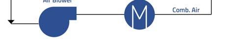

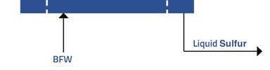
Figure 1. SRU thermal stage.
a high intensity model. Benefi ts of this change include improved mixing performance, which lowers the required residence time, better destruction effi ciency for contaminants such as ammonia and aromatic compounds (benzene, toluene and xylene [BTX]), and the opportunity to debottleneck the SRU capacity with the addition of oxygen enrichment. Moving to higher levels of oxygen enrichment requires a new burner design with a dedicated oxygen port. These process improvements do come with mechanical layout impacts. High intensity burners are normally longer and may have a larger diameter than low intensity designs, requiring a change to the thermal reactor sizing and confi guration. The plot space impact of a longer burner can be offset somewhat by reducing the length of the thermal reactor due to the lower residence time requirement afforded by the better mixing performance of high intensity designs. Additionally, if the current burner is a tangential design, moving to an axial burner arrangement (standard for high intensity) requires a different physical footprint for the overall thermal stage, depending on whether more length or a larger width are necessitated by the new equipment confi guration.
The demands placed on the burner have increased over the years, as the typical operating window has widened for most SRUs. Facilities can often require a whole spectrum of conditions: fuel gas fi ring during start-up and shutdown, 0 to 100% oxygen enrichment, 0 to 100% amine acid gas feed, and a range of sour water acid gas (SWAG) fl ows. To illustrate the increasing complexity: for 100% oxygen enrichment the design could require splitting some of the acid gas feed to the combustion air nozzle on the burner. This results in a more involved control and safeguarding system, and requires extra switching valves.
These conditions go far beyond the demands of simple ‘air-only’ operation and typically warrant a customised burner design to meet this challenging range of scenarios. Computational fl uid dynamics (CFD) modelling is typically provided by the burner vendor to predict the performance of these customised designs. Therefore, it is vital to have solid collaboration with the burner vendor over the course of the engineering development to align between the project requirements and equipment capabilities.
The thermal reactor
When evaluating the thermal reactor, key elements to consider are: Capacity and configuration. Engineered refractory design. Instrumentation for temperature measurement.
Thermal reactor capacity in terms of residence time is important when reviewing the NH3 and BTX destruction effi ciency. Both fl ame length and diameter must be accounted for in the confi guration, especially in case a low intensity (jet style) burner is part of the revamp design, which have longer fl ame lengths.
A robust engineered refractory design is critical, particularly when oxygen enrichment is part of the thermal stage design. Many units have experienced chronic refractory failures after switching to oxygen enrichment without upgrading the refractory. The higher process temperatures drive the need for higher refractory design temperatures. Current industry practice is a two-layer brick system for the thermal reactor lining. It is highly recommended to engage experienced refractory specialists to provide an engineered refractory design, including a thorough thermal analysis of the thermal stage. This is a multi-component system, where all the elements from the reactor lining, the weather shield and the WHB tubesheet protection (ferrules) must work together comprehensively for the best long-term reliability.
The design of the refractory and weather shield system should ensure the following: Refractory lining to withstand the whole operating temperature range including start-up and shutdown conditions.
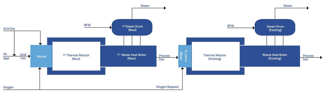
Figure 2. Two stage double combustion retrofit.
Control the thermal reactor shell metal temperature within a defined range to prevent high temperature sulfide corrosion or wet H2S/SO2 corrosion. Control the WHB tube and tubesheet temperature within a range to prevent the same corrosion conditions as above.
In conjunction with the refractory design considerations, it is important to have proper procedures in place for start-up (warming up rate) and shutdown (adequate purging). Without adequate purging, sulfur compounds can remain behind the refractory lining and/or ferrules, causing corrosion following a unit cooldown.
The temperature measurement in the thermal reactor takes specialised instrumentation and design considerations. Without oxygen enrichment, temperature measurement is merely informative with a straight through confi guration, except at start-up. But with split fl ow (or fuel gas co-fi ring), it is an actual (manual) control tool. With oxygen enrichment, temperature measurement is required for both control and safeguarding. Pyrometers should be installed free draining, looking at the opposing wall (however, if there is an option to measure gas temperature, that is valuable secondary information as it detects changes sooner). As pyrometers tend to drift, they require regular recalibration to continue providing reliable data. Thermocouples with ceramic sleeves are now available, which last longer if installed correctly (i.e. in the spot with least refractory movement and the hole drilled exactly right). With an inert purge, they do not corrode, but they can still break. Alternatively, there are also thermocouples now available which are embedded in a gas tight sapphire protection tube. This design has an integrated silicon carbide well and does not require an inert purge. They are promoted as being ideal for revamp applications due to their simplifi ed installation. So, depending on the situation, the temperature measurement requirements and possibilities need to be determined.
During revamps, it is possible to overlook what is working well within a unit. Specifi cally, if the plant is seeing stable and reliable temperature measurement, it is important to minimise the impact on that existing instrumentation and confi guration. This is an operational aspect worth preserving for the post-revamp. A balance must be struck between the requirements for replacing ageing equipment with improved technology and maintaining the existing dependable elements.
The waste heat boiler
The WHB is a very specialised heat exchanger and its design warrants careful evaluation. The constraints of the existing plot plan and equipment layout also require consideration when proposing changes in the WHB confi guration.
The progress towards higher levels of steam generation has also impacted the criticality of a robust design. In general, at higher operating pressures and temperatures, the margin for error in the mechanical reliability is much smaller.
Kettle type exchangers have been applied widely in the industry. Thermosyphon type exchangers with a separate elevated steam drum can achieve higher water side circulation rates and, all other things being equal, are therefore capable of handling higher heat fl uxes. In revamp situations this becomes an important factor as higher operating capacities and higher operating temperatures associated with oxygen enrichment result in higher heat fl uxes.
Traditionally, WHBs are designed with a thin (<30 mm) fl exible tubesheet to limit the temperature gradient over the tubesheet. This ensures the hot face temperature remains below the design limits for carbon steel with respect to high temperature H2S corrosion. Generating steam at higher pressure levels requires more thickness for strength and this limits the diameter for a kettle type exchanger, which by design has a large unstayed area above the tube bundle.
Traditionally, WHBs have been designed using limitations with respect to overall heat fl ux and/or mass velocity. These criteria do not account for confi guration details of the bundle and refractory, nor for steam or process gas operating conditions. Therefore, relying on generic criteria alone risks either replacing a WHB unnecessarily or, worse, overwhelming the boiler, resulting in a failure. CFD analysis of both water and process side have been utilised to better predict boiler capabilities, which is time consuming and needs highly specialised knowledge to provide the correct input data. Comprimo has developed a tool, based on fi nite element analysis, which can help to determine if the design is nearing its limits and if further evaluation is required.
If the boiler needs to be replaced and more surface area needs to be installed, this is typically achieved by increasing the tube count. This increases the overall diameter of the tube bundle and may exceed existing space constraints. It is possible to consider using smaller tubes (both in terms of tube diameter and pitch), as this will offer more surface area in a fi xed tube bundle volume. However, this comes at the cost of the
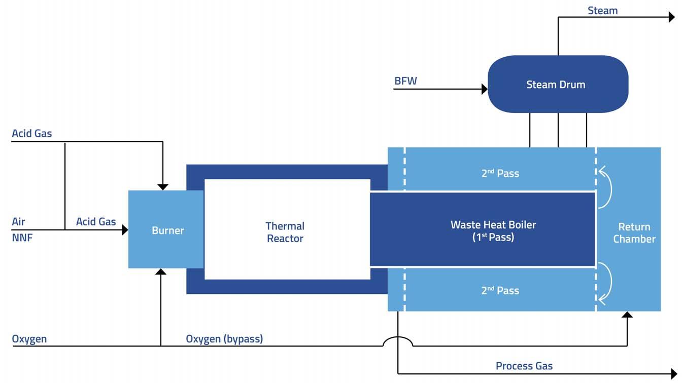
Figure 3. Double combustion with two-pass WHB – reduced plot space.
additional process side pressure drop. Moreover, bundle confi guration does affect the maximum allowable (critical) heat fl ux of the exchanger, above which vapour locking may occur, particularly at the front end of the tube bundle.
For facilities with a congested layout or in case of modular unit layouts, space for growth could be limited. For facilities with more spacious layouts, as is often the case in North America, height restrictions are not normally a concern. Therefore, switching to a thermosyphon design with separate steam drum would allow bigger bundles to be suitable.
The range of expected process gas outlet temperatures from the WHB is another issue. If the temperature is hot enough (higher than 320°C), the carbon steel outlet piping will require refractory lining to the fi rst condenser inlet nozzle. This could impact the unit hydraulics and the total scope of the revamp project. Alternatively, the outlet piping could be stainless steel to avoid the need for refractory lining.
Project example
The above principles can be illustrated by an example where a 75% capacity increase was targeted, which was possible by incorporating oxygen enrichment up to 40%. The ratio of amine gas to sour water stripping (SWS) off gas could vary considerably, in some cases resulting in low temperatures during air-based operation and high temperatures during oxygen enriched operation. The thermal stage was completely blocked in by structural steel and other equipment, except on top. The burner vendor performed extensive CFD modelling to ensure good mixing, prevent hot gas impingement, and determine which ports to combine to limit length. The increased duty required replacing the original kettle type boiler with a thermosyphon type, with smaller tube diameter and longer length. This length increase was compensated by shortening the combustion chamber and marginally increasing its diameter. In cooperation with refractory engineers, the thinnest possible refractory was installed to satisfy the residence time requirements as well as to limit the weight increase of the new design.
Double combustion option
In situations where higher oxygen enrichment could be necessary, double combustion can be considered to manage the high temperatures associated with high oxygen enrichment levels. In double combustion, the oxygen is introduced in two stages, essentially distributing the temperature over these two stages. The design can be done either by installing two thermal stages in series (see Figure 2) with the second stage not having a burner, or as a single thermal stage (see Figure 3), employing a two-pass WHB where a portion of the oxygen demand is injected in the channel between the fi rst and second pass of the WHB, essentially creating a second combustion zone. The second option is preferred for grassroots and certain retrofi ts where plot space may be limiting.
Comprehensive thermal stage supply
Once the extent of the revamp scope has been studied and determined, Worley Comprimo can offer the thermal stage as a complete engineering/procurement/fabrication supply contract in partnership with its Worley Chemetics colleagues. This contracting model can streamline the engineering and fabrication phases for the company’s clients under a single supplier umbrella and with the advantage of a single mechanical warranty for all the equipment in the full thermal stage.
Conclusion
Overall, many factors require special attention when evaluating an SRU thermal stage revamp. Careful consideration is necessary to overcome the existing confi guration limitations while also working to minimise the physical impacts of new equipment. When all the elements of the design are integrated cohesively, the unit has the best chance for long-term reliability, ensuring a successful retrofi t project.


