
9 minute read
Vapour control options


Anne Himmelberg, Aron Katz, and Victor Hoffman, John Zink Hamworthy Combustion, USA, assess vapour control options and introduce a suitable technology where vapour combustion technology is selected.

Vapour control equipment is used to control the release of volatile organic compounds (VOCs). VOCs can be harmful to the environment if released into the atmosphere, as they are chemical precursors to ozone and smog formation. Worldwide, a wide breadth of regulations require that the VOCs be captured or destroyed to prevent their release.
Technologies utilised to control VOC emissions are typically classifi ed into two main categories. Vapour recovery units (VRUs) capture VOCs and turn them back into a liquid product (Figure 1), whereas vapour combustion units (VCU) destroy the VOCs through combustion (Figure 2). Each technology has its own benefi ts and shortcomings.
For certain applications, VRUs are the greenest form of emission control. Unlike VCUs, VRUs do not produce nitrogen oxide (NOX) or carbon monoxide (CO) and do not require a supplemental fuel gas for effi cient operation. While VRUs are very green, they are not suitable for all applications. VRUs utilise activated carbon for VOC removal. Activated carbon is not chemically compatible with all VOCs including, but not limited to, strong oxidisers such as ketones and aldehydes. These compounds can cause heat-ups in the
carbon media which can increase the risk of hydrocarbon autoignition in the carbon bed. Activated carbon also has diffi culty capturing small volatile molecules, such as methane. VCUs have the benefi t of being able to simultaneously handle a larger range of VOCs compared to VRUs.
Other than being green, VRUs have the economic benefi t of recovering vapour and turning it back into a liquid product. In certain applications, selling the recovered liquid product can lead to a signifi cantly positive return on investment. Complications with the recovered product can also lead to a shortcoming of VRUs. Typically, all of the vapour sent to the VRU gets recovered into a single liquid product stream. In applications where high purity is required for the recovered product, mixed loading may not be suitable. VCUs can better handle mixed loading because the vapour is destroyed rather than recovered.
Other than component and process compatibility, a major reason for a VCU to be selected over a VRU is capital cost. VRUs have a signifi cantly larger capital cost compared to VCUs. This difference in capital cost is increased for vapour streams containing less than 6% hydrocarbon. Such units often require a vapour saturation step to allow the VRU to effectively recover the product. This pre-treatment device increases the overall size of the VRU signifi cantly. Where vapour combustion technology is employed, the John Zink Hamworthy Combustion NOxSTARTM VC System is an excellent vapour control technology. The system maintains or improves upon many of the benefi ts of a traditional VCU, including offering destruction effi ciency (DE) up to 99.99% and CO emissions as low or lower than 0.015 lbs/million Btu, while also achieving ultra-low NOX emissions.
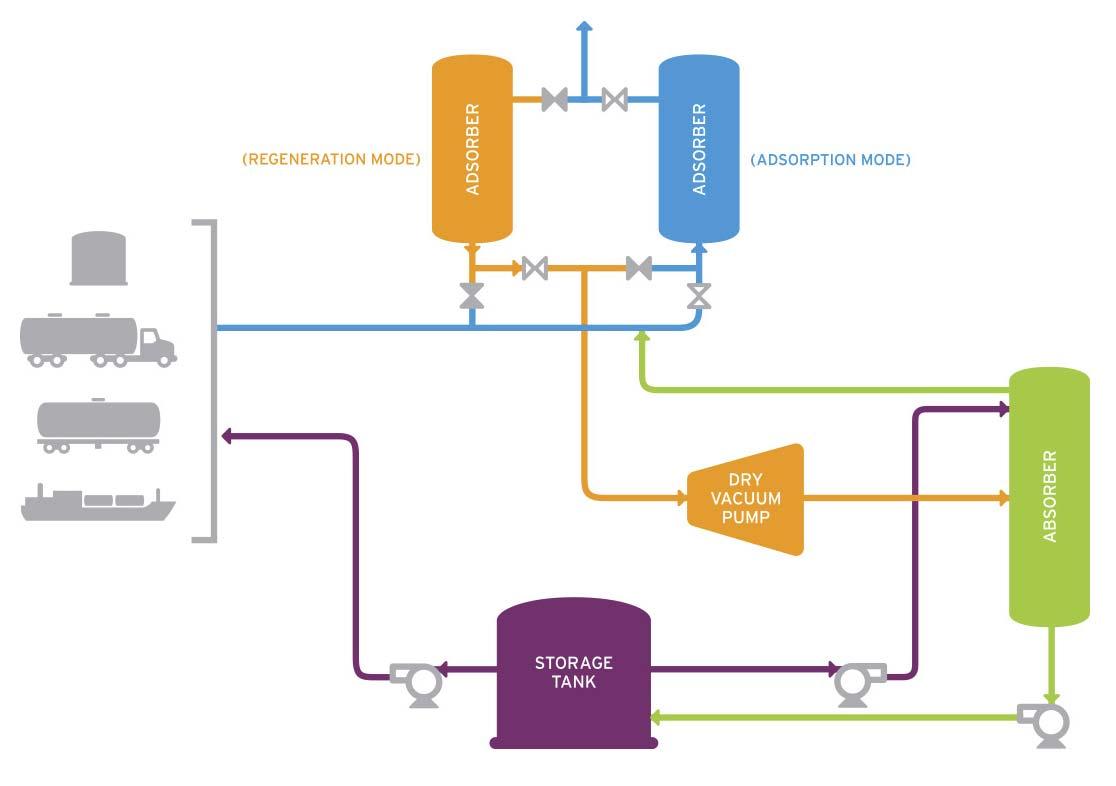
Figure 1. VRU process.
Figure 2. VCU process.
Controlling NOX
Low NOX vapour destruction in a petroleum products terminal setting presents many technical challenges. A variety of techniques often employed in ultra-low NOX process burner designs cannot be utilised in vapour combustion service. For example, in contrast to process burners, the waste gas in VCU service tends to be available at very low pressure, resulting in a poor amount of energy available for mixing. Additionally, the fl ow rate and composition of the waste gas can vary considerably. In terminal and marine service, hydrocarbon vapours can fl uctuate from very lean to very rich, they may have an inert balance gas or air as a balance gas (non-inert), and they may span an extremely wide range of fl ow rates necessitating high turndown capability.
To understand how the technology produces lower NOX than traditional VCU technology, it is important to understand how the most prevalent, individual NOX compounds in the combustion process are formed. NOX derived from the combustion process comes from three distinct categories: Thermal NOX, Fuel NOX, and Prompt NOX. Thermal NOX is the largest contributor to NOX formation in the combustion process and is defi ned as NOXthat is produced from the combustion air which contains atmospheric nitrogen (N2) and oxygen (O2). N2 and O2 in the combustion air are further
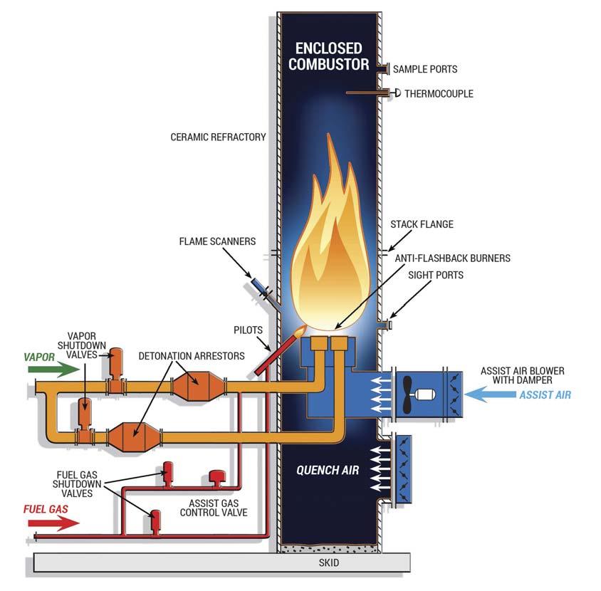
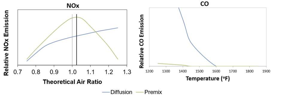
Figure 3. NOX, CO vs theoretical air graph.
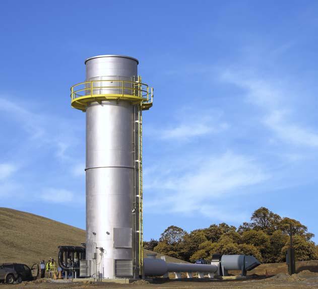
Figure 4. ZULE® Flare System.
broken down into N and O radicals with the addition of high heat, which is above 1300°C (2370°F).1 These N and O radicals can produce NO as follows:
O + N2 → NO + N N + O2 → NO + O N + OH → NO + H
By reducing the peak fl ame temperature, NOX formed from the Thermal NOX process is reduced. Fuel NOX is defi ned as that NOX produced from nitrogen that is chemically or organically bound in the fuel, such as ammonia (NH3) or coal. When the nitrogen-bound compound is exposed to high heat, the N radical is broken from the molecule and readily attaches to an O radical. Once NO is formed, it is also possible to further combine with an N radical to form N2 at low oxygen concentrations in the fl ue gas:
Fuel N + O2 → NO + O Fuel N + NO → N2 + O
Since fuel-bound nitrogen compounds are not typically present in VCU applications, targeting the reduction of NOX formation resulting from fuel-bound nitrogen by operating at lower oxygen concentrations in the fl ue gas is not a viable solution for NOX reduction in this application.
Prompt NOX is formed in a fuel-rich environment and is defi ned as NOX formed in the initial portion of the fl ame zone when fuel and air react. For example, when methane (CH4) is exposed to high heat, it is initially broken into CH/CH2 plus some hydrogen (H) radicals. This CH and CH2 then combine with N2 to form HCN and NH, which now act as fuel-bound nitrogen:
N2 + CH → HCN + N N2 + CH2 → HCN + NH
By combusting the fuel in a lean environment (air rich) the Prompt NOX process is reduced. This effect can be seen in Figure 3. In most applications, Prompt NOX is much less than Thermal NOX. With an understanding of the three mechanisms of NOX formation, it is apparent that the critical factor in NOX reduction is the reduction of peak fl ame temperature in an air rich environment, thus reducing the reactivity of the molecules involved, allowing them to more readily convert directly to carbon dioxide (CO2) and water vapour (H2O).
Designing a low NOX system
Building upon these principles, the NOxSTAR VC System is an adaptation of a similar John Zink technology, the ZULE® Flare System, which was fi rst introduced to the landfi ll industry in 1999 (Figure 4).
Gas from the anaerobic digestion process which forms landfi ll or biogas is produced at a relatively constant fl ow rate and chemical composition, primarily methane and carbon dioxide. The ZULE Flare System operates by precisely mixing air with biogas based on a fi xed methane concentration, pre-combustion. The primary challenge of safely and reliably adapting this system to the vapour control market is the variable fl ow rate and composition inherent to the vapour control applications.
To overcome this challenge, a NOxSTAR VC System utilises a total hydrocarbon analyser to measure and control the total hydrocarbons present, ensuring a consistently lean concentration of the waste gas just before combustion. By controlling the air and hydrocarbon mixture precisely, the technology can dynamically adapt to varying fl ow and composition while also optimising the combustion temperature, helping to ensure that destruction effi ciencies are met (Figure 5).
Altogether, a NOxSTAR VC System can attain NOX emissions as low or lower than 0.02 lb/million Btu in most applications whereas traditional VCUs may only achieve NOX emissions down to 0.12 – 0.15 lb/million Btu. Like traditional VCUs, the high heat capacity and signifi cant turndown of the system often allows multiple types of streams to be combined into a single end control device. This can eliminate the need to stage multiple end control devices, making regulatory compliance testing much easier, all while achieving the same performance standards.


ENERGY GL BAL
The home for the latest renewables news, analysis, comment and events

Visit our website today www.energyglobal.com
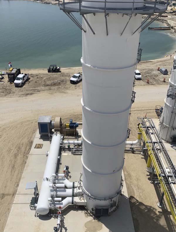
Figure 5. NOxSTAR VC System.
The versatility of this technology also extends itself to multiple fuel gas types and many services including ship/barge loading, truck/railcar loading, and tank venting applications across crude, refi ned, petrochemical, and renewable product markets alike. Understanding that operational personnel in these markets place an extremely high demand on the safety and availability of the vapour control system, the NOxSTAR VC System design places a similarly high priority on achieving these goals. John Zink employed computational fl uid dynamics (CFD) analyses to help ensure even burner duct distribution and system self-diagnostics to avoid operation in unsafe conditions.
Implemented for decades now, users of traditional vapour combustion systems have come to depend on their end control device to be there when it is needed because, simply put, they just run. Among many others, some of the more common features and benefi ts include the fact that they are proven in a multitude of services and applications, they can handle a wide range of process conditions, they do not require special fl uids or materials, and they completely hide the fl ame while combusting hydrocarbons in a safe and controlled manner.
Conclusion
Due to several potential technical or commercial constraints, vapour recovery technology cannot be universally employed to control VOC emissions. The system discussed in this article is a robust solution and a logical choice for applications requiring low NOX and high destruction effi ciency (less than 0.02 lbs NOX/million Btu, less than 0.015 lbs CO/million Btu, and destruction effi ciencies of up to 99.99%).
Reference
1. https://www3.epa.gov/ttncatc1/dir1/fnoxdoc.pdf


